Trapping dynamics of diindenoperylene (DIP) in self-assembled monolayers using molecular simulation
12
Trapping dynamics of diindenoperylene (DIP) in self-assembled monolayers using molecular simulation Ananth P. Kaushik, Paulette Clancy ⁎ School of Chemical and Biomolecular Engineering, Cornell University, Ithaca, NY 14853, United States abstract article info Article history: Received 16 November 2010 Accepted 28 March 2011 Available online 3 April 2011 Keywords: Molecular dynamics Computer simulations Diindenoperylene Adsorption dynamics Self-assembled monolayers All-atom Molecular Dynamics simulation methods employing a well-tested intermolecular potential model, MM3 (Molecular Mechanics 3), demonstrate the propensity for diindenoperylene (DIP) molecules to insert between molecules of a self-assembled monolayer (SAM) during a deposition process intended to grow a thin film of this organic semiconductor molecule onto the surface of self-assembled monolayers. The tendency to insert between SAM molecules is fairly prevalent at normal growth temperatures and conditions, but is most strongly dependent on the density and the nature of the SAM. We posit the existence of an optimal density to favor surface adsorption over insertion for this system. DIP is less likely to insert in fluorinated SAMs, like FOTS (fluorooctatrichlorosilane), than its unfluorinated analog, OTS (octatrichlorosilane). It is also less likely to insert between shorter SAMs (e.g., less insertion in OTS than ODTS (octadecyltrichlorosilane)). Very short length, surface-coating molecules, like HDMS (hexamethyldisilazane), are more likely to scatter energetic incoming DIP molecules with little insertion on first impact (depending on the incident energy of the DIP molecule). Grazing angles of incidence of the depositing molecules generally favor surface adsorption, at least in the limit of low coverage, but are shown to be dependent on the nature of the SAM. The validity of these predictions is confirmed by comparison of the predicted sticking coefficients of DIP at a variety of incident energies on OTS, ODTS, and FOTS SAMs with results obtained experimentally by Desai et al. (2010) [23]. The simulation predictions of the tendency of DIP to insert can be explained, in large part, in terms of binding energies between SAM and DIP molecules. However, we note that entropic and stochastic events play a role in the deposition outcomes. Preliminary studies of multiple deposition events, emulating growth, show an unexpected diffusion of DIP molecules inserted within the SAM matrix in a clear attempt of the DIP molecules to aggregate together. © 2011 Elsevier B.V. All rights reserved. 1. Introduction Self-assembled monolayers (SAMs) consist of a layer of functio- nalized long-chain molecules tethered to a solid substrate. Their presence as a “coating” on a surface is attractive in a number of applications due to the possibility they provide to tune the properties of the surface by selectively modifying functional groups on the SAM [1,2]. SAMs of organosilane molecules are of particular technological interest in organic electronics because they can be assembled on hydroxylated surfaces such as SiO 2 for applications in areas such as organic electronics, electronic sensors and biosensors [3,4]. Not surprisingly then, they have been the subject of extensive theoretical and experimental research due, for instance, to their ability to improve the mobility of organic thin films for electronic devices, presumably by improving surface order. There have been several molecular-level computational studies of SAMs, some relevant to the studies in this paper [1,4–10]. Yamamoto et al. studied the influence of hydrogen bond conformations of alkanesilane SAMs using molecular mechanics and Molecular Dynamics simulations [1]. A study of the diffusion of tricresyl phosphate (TCP) molecules on an octadecyltrichlorosilane SAM [4] found that TCP molecules are highly mobile on the surface with a small isotropic diffusion activation barrier of about 0.1 eV (9 kJ/mol). TCP molecules prefer to diffuse over the surface rather than become inserted between the SAM molecules. The structural properties of alkanethiol SAMs have been determined as a function of temperature, lattice spacing (density), and molecular chain length [5]. For instance, chains containing 13 carbons tilt from the surface normal by a collective angle of 25° along the next-nearest-neighbor direction at 300 K. The tilt angle can vary as much as 20° for a temperature increase of 200 K, and change by 30° for a lattice constant increase of 0.6 Å. There have also been studies of hyperthermal deposition of inert gas atoms on SAM surfaces. Simulations of Ar, Xe and Ne on SAMs showed inelastic scattering and trapping dynamics [4,11– 14]. Xe, in particular, showed a sort of directed ejection mechanism after insertion into the SAM matrix [15]. Surface Science 605 (2011) 1185–1196 ⁎ Corresponding author. E-mail address: [email protected] (P. Clancy). 0039-6028/$ – see front matter © 2011 Elsevier B.V. All rights reserved. doi:10.1016/j.susc.2011.03.023 Contents lists available at ScienceDirect Surface Science journal homepage: www.elsevier.com/ locate/susc
-
Upload
independent -
Category
Documents
-
view
0 -
download
0
Transcript of Trapping dynamics of diindenoperylene (DIP) in self-assembled monolayers using molecular simulation

Surface Science 605 (2011) 1185–1196
Contents lists available at ScienceDirect
Surface Science
j ourna l homepage: www.e lsev ie r.com/ locate /susc
Trapping dynamics of diindenoperylene (DIP) in self-assembled monolayers usingmolecular simulation
Ananth P. Kaushik, Paulette Clancy ⁎School of Chemical and Biomolecular Engineering, Cornell University, Ithaca, NY 14853, United States
⁎ Corresponding author.E-mail address: [email protected] (P. Clancy).
0039-6028/$ – see front matter © 2011 Elsevier B.V. Aldoi:10.1016/j.susc.2011.03.023
a b s t r a c t
a r t i c l e i n f oArticle history:Received 16 November 2010Accepted 28 March 2011Available online 3 April 2011
Keywords:Molecular dynamicsComputer simulationsDiindenoperyleneAdsorption dynamicsSelf-assembled monolayers
All-atom Molecular Dynamics simulation methods employing a well-tested intermolecular potential model,MM3 (Molecular Mechanics 3), demonstrate the propensity for diindenoperylene (DIP) molecules to insertbetween molecules of a self-assembled monolayer (SAM) during a deposition process intended to grow a thinfilm of this organic semiconductor molecule onto the surface of self-assembled monolayers. The tendency toinsert between SAM molecules is fairly prevalent at normal growth temperatures and conditions, but is moststrongly dependent on the density and the nature of the SAM. We posit the existence of an optimal density tofavor surface adsorption over insertion for this system. DIP is less likely to insert in fluorinated SAMs, like FOTS(fluorooctatrichlorosilane), than its unfluorinated analog, OTS (octatrichlorosilane). It is also less likely toinsert between shorter SAMs (e.g., less insertion in OTS than ODTS (octadecyltrichlorosilane)). Very shortlength, surface-coating molecules, like HDMS (hexamethyldisilazane), are more likely to scatter energeticincoming DIP molecules with little insertion on first impact (depending on the incident energy of the DIPmolecule). Grazing angles of incidence of the depositing molecules generally favor surface adsorption, at leastin the limit of low coverage, but are shown to be dependent on the nature of the SAM. The validity of thesepredictions is confirmed by comparison of the predicted sticking coefficients of DIP at a variety of incidentenergies on OTS, ODTS, and FOTS SAMs with results obtained experimentally by Desai et al. (2010) [23]. Thesimulation predictions of the tendency of DIP to insert can be explained, in large part, in terms of bindingenergies between SAM and DIPmolecules. However, we note that entropic and stochastic events play a role inthe deposition outcomes. Preliminary studies of multiple deposition events, emulating growth, show anunexpected diffusion of DIP molecules inserted within the SAMmatrix in a clear attempt of the DIP moleculesto aggregate together.
l rights reserved.
© 2011 Elsevier B.V. All rights reserved.
1. Introduction
Self-assembled monolayers (SAMs) consist of a layer of functio-nalized long-chain molecules tethered to a solid substrate. Theirpresence as a “coating” on a surface is attractive in a number ofapplications due to the possibility they provide to tune the propertiesof the surface by selectively modifying functional groups on the SAM[1,2]. SAMs of organosilane molecules are of particular technologicalinterest in organic electronics because they can be assembled onhydroxylated surfaces such as SiO2 for applications in areas such asorganic electronics, electronic sensors and biosensors [3,4]. Notsurprisingly then, they have been the subject of extensive theoreticaland experimental research due, for instance, to their ability toimprove the mobility of organic thin films for electronic devices,presumably by improving surface order.
There have been several molecular-level computational studies ofSAMs, some relevant to the studies in this paper [1,4–10]. Yamamotoet al. studied the influence of hydrogen bond conformations ofalkanesilane SAMs usingmolecular mechanics and Molecular Dynamicssimulations [1]. A study of the diffusion of tricresyl phosphate (TCP)molecules on an octadecyltrichlorosilane SAM [4] found that TCPmolecules are highly mobile on the surface with a small isotropicdiffusion activation barrier of about 0.1 eV (9 kJ/mol). TCP moleculesprefer to diffuse over the surface rather than become inserted betweenthe SAM molecules. The structural properties of alkanethiol SAMs havebeen determined as a function of temperature, lattice spacing (density),and molecular chain length [5]. For instance, chains containing 13carbons tilt from the surface normal by a collective angle of 25° along thenext-nearest-neighbor direction at300 K. The tilt angle canvary asmuchas 20° for a temperature increase of 200 K, and change by30° for a latticeconstant increase of 0.6 Å. There have also been studies of hyperthermaldeposition of inert gas atoms on SAM surfaces. Simulations of Ar, Xe andNe on SAMs showed inelastic scattering and trapping dynamics [4,11–14]. Xe, in particular, showed a sort of directed ejectionmechanism afterinsertion into the SAM matrix [15].
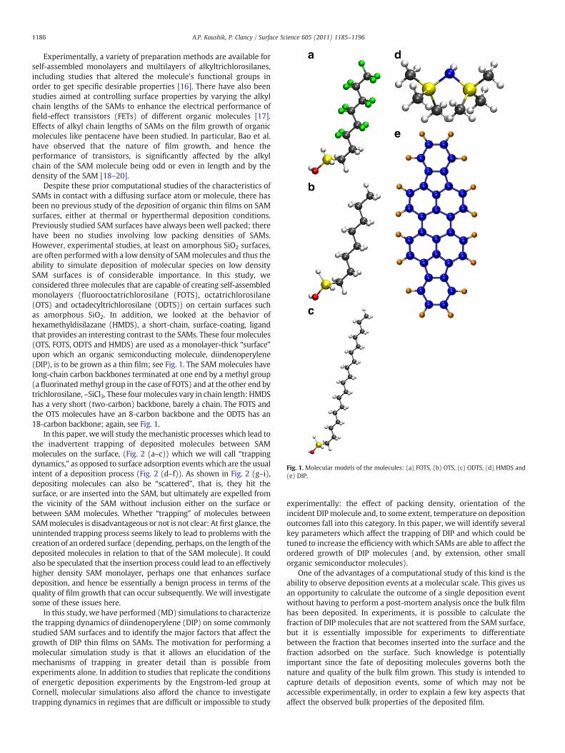
Fig. 1. Molecular models of the molecules: (a) FOTS, (b) OTS, (c) ODTS, (d) HMDS and(e) DIP.
1186 A.P. Kaushik, P. Clancy / Surface Science 605 (2011) 1185–1196
Experimentally, a variety of preparation methods are available forself-assembled monolayers and multilayers of alkyltrichlorosilanes,including studies that altered the molecule's functional groups inorder to get specific desirable properties [16]. There have also beenstudies aimed at controlling surface properties by varying the alkylchain lengths of the SAMs to enhance the electrical performance offield-effect transistors (FETs) of different organic molecules [17].Effects of alkyl chain lengths of SAMs on the film growth of organicmolecules like pentacene have been studied. In particular, Bao et al.have observed that the nature of film growth, and hence theperformance of transistors, is significantly affected by the alkylchain of the SAM molecule being odd or even in length and by thedensity of the SAM [18–20].
Despite these prior computational studies of the characteristics ofSAMs in contact with a diffusing surface atom or molecule, there hasbeen no previous study of the deposition of organic thin films on SAMsurfaces, either at thermal or hyperthermal deposition conditions.Previously studied SAM surfaces have always been well packed; therehave been no studies involving low packing densities of SAMs.However, experimental studies, at least on amorphous SiO2 surfaces,are often performedwith a low density of SAMmolecules and thus theability to simulate deposition of molecular species on low densitySAM surfaces is of considerable importance. In this study, weconsidered three molecules that are capable of creating self-assembledmonolayers (fluorooctatrichlorosilane (FOTS), octatrichlorosilane(OTS) and octadecyltrichlorosilane (ODTS)) on certain surfaces suchas amorphous SiO2. In addition, we looked at the behavior ofhexamethyldisilazane (HMDS), a short-chain, surface-coating, ligandthat provides an interesting contrast to the SAMs. These four molecules(OTS, FOTS, ODTS and HMDS) are used as a monolayer-thick “surface”upon which an organic semiconducting molecule, diindenoperylene(DIP), is to be grown as a thin film; see Fig. 1. The SAMmolecules havelong-chain carbon backbones terminated at one end by a methyl group(a fluorinatedmethyl group in the case of FOTS) and at the other end bytrichlorosilane, –SiCl3. These fourmolecules vary in chain length: HMDShas a very short (two-carbon) backbone, barely a chain. The FOTS andthe OTS molecules have an 8-carbon backbone and the ODTS has an18-carbon backbone; again, see Fig. 1.
In this paper, we will study themechanistic processes which lead tothe inadvertent trapping of deposited molecules between SAMmolecules on the surface, (Fig. 2 (a–c)) which we will call “trappingdynamics,” as opposed to surface adsorption events which are the usualintent of a deposition process (Fig. 2 (d–f)). As shown in Fig. 2 (g–i),depositing molecules can also be “scattered”, that is, they hit thesurface, or are inserted into the SAM, but ultimately are expelled fromthe vicinity of the SAM without inclusion either on the surface orbetween SAM molecules. Whether “trapping” of molecules betweenSAMmolecules is disadvantageous or not is not clear: At first glance, theunintended trapping process seems likely to lead to problems with thecreation of an ordered surface (depending, perhaps, on the length of thedeposited molecules in relation to that of the SAM molecule). It couldalso be speculated that the insertion process could lead to an effectivelyhigher density SAM monolayer, perhaps one that enhances surfacedeposition, and hence be essentially a benign process in terms of thequality of film growth that can occur subsequently. We will investigatesome of these issues here.
In this study, we have performed (MD) simulations to characterizethe trapping dynamics of diindenoperylene (DIP) on some commonlystudied SAM surfaces and to identify the major factors that affect thegrowth of DIP thin films on SAMs. The motivation for performing amolecular simulation study is that it allows an elucidation of themechanisms of trapping in greater detail than is possible fromexperiments alone. In addition to studies that replicate the conditionsof energetic deposition experiments by the Engstrom-led group atCornell, molecular simulations also afford the chance to investigatetrapping dynamics in regimes that are difficult or impossible to study
experimentally: the effect of packing density, orientation of theincident DIP molecule and, to some extent, temperature on depositionoutcomes fall into this category. In this paper, we will identify severalkey parameters which affect the trapping of DIP and which could betuned to increase the efficiency with which SAMs are able to affect theordered growth of DIP molecules (and, by extension, other smallorganic semiconductor molecules).
One of the advantages of a computational study of this kind is theability to observe deposition events at a molecular scale. This gives usan opportunity to calculate the outcome of a single deposition eventwithout having to perform a post-mortem analysis once the bulk filmhas been deposited. In experiments, it is possible to calculate thefraction of DIP molecules that are not scattered from the SAM surface,but it is essentially impossible for experiments to differentiatebetween the fraction that becomes inserted into the surface and thefraction adsorbed on the surface. Such knowledge is potentiallyimportant since the fate of depositing molecules governs both thenature and quality of the bulk film grown. This study is intended tocapture details of deposition events, some of which may not beaccessible experimentally, in order to explain a few key aspects thataffect the observed bulk properties of the deposited film.

Fig. 2. Possible events of DIP collision: (a–c) insertion event, (d–f) adsorption event and (g–i) scattering event.
1187A.P. Kaushik, P. Clancy / Surface Science 605 (2011) 1185–1196
2. Configuration of the system
In the experimental set up used by Engstrom et al. [21,22],molecules that form surface coatings, like the SAMs and HMDS, aredeposited on an amorphous silicon dioxide substrate. The head group,consisting of three Cl atoms, reacts with the –OH groups of thesubstrate, forming an –O–Si bond that tethers the molecule to thesurface. In the simulation, we simply tethered each SAM molecule toan x–y location on an undefined substrate surface. Since the ligandsare relatively long, an explicitly modeled surface beneath the SAMproved to be unnecessary. The FOTS, OTS and ODTS SAM moleculeswere tethered to hexagonal lattice points in free space at the oxygenatom, i.e., the position of the oxygen atom was fixed throughout thesimulation. This choice followed experimental evidence whichsuggests that the oxygen atoms are attached to the substrate surface,thereby anchoring the SAM molecules at this point. It is possible that,on real surfaces, the SAM molecule could be tethered via more thanone oxygen atom in the head group, which implies that the siliconatom of the head group is also essentially fixed in place [1]. To studythe impact of this eventuality and better define an appropriate initialsystem configuration, we conducted simulations in which both thesilicon and oxygen atoms were fixed in place. The energetics of thesystem differed by less than 5% in energy and with no observablestructural difference in the system whether just oxygen was fixed, orboth oxygen and silicon were fixed. Thus all the remainingsimulations described in this paper assumed that the SAM moleculeis tethered to the substrate by one oxygen atom.
For the short HMDS ligand, we could not use the same approachsince, at the lower densities considered here, incoming DIP molecules
could readily move through gaps in the x–y plane where the substratewould be located in a physical system. To avoid this, we placed onefixed layer of a Si (111) crystalline face to represent the surfacebeneath the HDMS layer. HMDSmolecules were arranged on a squarelattice appropriate for the underlying Si lattice and the density of theHMDS was chosen to be 3.24 molecules/nm2. The effect of changingthe density of all three tested SAMs (OTS, ODTS and FOTS) on thetrapping dynamics is explored below.
The simulation set up involved a hexagonal lattice of 98 SAMmolecules, consisting of 7×7 unit cells with two molecules per unitcell. For FOTS and OTS, this involves the consideration of 2940 atoms(and 5928 atoms for the longer ODTS molecule). The choice of ahexagonal lattice was arbitrary, but it is convenient as a close-packedlattice and is the most common choice in prior simulations of SAMmonolayers [4,18]. The characteristic lattice parameter of thehexagonal packing was chosen to match the packing densitydetermined from X-ray reflectivity measurements [23]. The densitiesof the SAM surfaces were estimated from the experiments to be2.0 molecules/nm2 for FOTS, 2.75 molecules/nm2 for OTS, and2.83 molecules/nm2 for ODTS.
The molecules were created using the Molden software package[24] and an energy minimization of the initial guessed structures wasperformed using a standard minimization algorithm—the limitedmemory L-BFGS minimization using a modified version of thealgorithm of Nocedal which is a part of the TINKER software package[25]. The lengths of the SAMs, measured from the center of the oxygenatom to the center of the top carbon atom, were found to be 11.12 Åfor FOTS and OTS; the length of the ODTS molecule was 22.96 Å. Theoptimized structures of the five molecules are shown in Fig. 1.
1188 A.P. Kaushik, P. Clancy / Surface Science 605 (2011) 1185–1196
3. Intermolecular potential models
The choice of intermolecular potential model is a very importantpart of a molecular simulation. We chose to use the non-reactivesemi-empirical MM3 potential to model all the SAM–SAM and DIP–SAM interactions. There are no DIP–DIP interactions to consider here,as we studied the fate of a single depositing DIP molecule. The MM3potential has been shown, by us and others [6–9], to accuratelydescribe hydrocarbons [6], fluorinated hydrocarbons [8] and multiplyringed molecules of the type we studied here. MM3 incorporatesstretching, bending, and torsional energies, as well as the van derWaals interaction energies based on phenomenologically determinedparameters. The total energy may be represented as follows:
E = Eb + Ea + Etor + Eaa + Esb + Estor + Evdw
with,
Evdw = Aexp −rρ
. o+ C
.r6
n
where Eb is the bond–stretch, Ea is the angle–bend, Etor is the torsion,Eaa is the bend–bend, Esb is the stretch–bend and Estor is the stretch–torsion potential. The potential does not involve electrostatic in-teractions. The intermolecular van der Waals interactions take theform of a Buckingham potential modified with tapering polynomialsso that the energy may smoothly decrease to zero at a cut-off distanceof 9 Å. The parameters used for the MM3models were taken, withoutmodification, from the TINKER database. There are no long-rangeelectrostatic interactions in the MM3 force field. The cross-interactionsare handled using standard Lorentz–Berthelotmixing rules. Some cross-interactions are handled explicitly with different parameters includedas part of the MM3 suite of potentials.
We have used this model extensively to study the energetics andstructural characteristics of an array of small organic semiconductingmolecules including the acenes, rubrene, DIP, sexiphenyl and C60[9,10] and have confidence in its ability to model conjugated systems.Our most recent study involved an extensive survey of twelve DensityFunctional Theory models, as well as the MM3 andMM3-πmodels forbiphenyl and eight models (four DFT and four semi-empirical models)for the sexiphenyl molecule. We found virtually all the models to giveconsistent energetically preferred structures [26]. Both MM3 models(with and without an additional term to represent pi-bonding)represented the behavior of sexiphenyl and biphenyl molecules withquantitative accuracy compared to the DFT models. Based on ourstudies and those of the Allinger group, we are confident in the abilityof MM3 to be sufficiently accurate to capture the fate of a single DIPmolecule on a SAM surfacewithout having to resort to usingMM3-π, avariant of MM3 which is more accurate for molecules with anextensive π-electron system but which is about 20 to 100 timesslower in execution time.
4. Simulation details
The time evolution of the system was followed using a simulationapproach using the Modified Beeman algorithm as part of the TINKERsoftware package. Asmentioned above, optimized structures of the SAMmolecules and the DIP molecule were obtained from an energyminimizationof an initial guess structuresusing a standardminimizationalgorithm, here, the limited memory L-BFGS minimization using amodified version of the algorithm of Nocedal [27]. The system was firstthermalized at 300 K using a Nosé-Hoover thermostat in the canonical(NVT) ensemble for a period of ~50 ps with a time step of 1.0 fs (i.e.,50,000 time steps) in order to suppress significant fluctuations intemperature and equilibrate the system of SAM molecules (before thedeposition of the DIP molecule). Anticipating a result described morefully below, the simulated value of the film thickness was found to be
within one standard deviation of the experimentally calculated value;this helps to justify the choice of hexagonal packing of the SAMmolecules, though it does not preclude another geometry fromworkingequally well.
Since the consideration of eachadditionalDIPmolecule adds another48 atoms to the system, following the deposition process of DIPmolecules onto the SAM surfaces quickly becomes computationallyexpensive. That being the case, the simulations in this paper weregenerally restricted to the deposition of only onemolecule of DIP on theSAM surface, though we report some preliminary results for thedeposition ofmultiple DIPmolecules in Section 7. The DIPmolecule wasgiven a randomorientation at a height of 30 Å above the SAM surface in3D space and a random initial (x–y) coordinate above the surface of theSAM. Simulations were performed at six incident energies of the DIPmolecule that match the energies used in Engstrom's experiments [23].Simulations of collisions between theDIPmolecule and the SAM surfacewere carried out in the microcanonical NVE ensemble to avoid anyunwanted bias due to velocity corrections used to scale the temperatureto a desired value in the canonical ensemble. The effect of using NVEversus NVThas been tested for a related system, pentacene, and no issuehas been found [9].
Each simulation in our study constitutes an individual depositionevent. The simulationswere routinely performed for a period of 25 pswith a time step of 0.5 fs (50,000 time steps). This time frame wasfound to be sufficient for themolecular collision to occur betweenDIPand the SAM surface and for the system to re-thermalize to itsoriginal state. Longer simulations (~2 ns) were also performed toconfirm this point, but no significant changes in the behavior of theDIP molecule or the structure of the SAM were found when thesystem is given longer to equilibrate post-collision. The systemrelaxes quickly, even following the highest incident energy collisions.Each simulation (at a given incident energy of the DIP molecule andSAM density) was carried out 100 times, each time with a differentinitial random orientation of the DIP molecule so that we couldgather enough statistics to accurately determine the probability ofthe DIP molecule sticking to the SAM surface. An alternative view ofthis set of 100 simulation runs is that we studied the low coveragelimit of DIP sub-monolayer growth for 2.5 ns at a deposition rate of4×1010 molecules/second (in which no DIP was close enough toencounter another DIP molecule). We report the “sticking fraction”as the ratio of the number of events that led to a particular outcome(adsorption on the surface, insertion and scattering) divided by thenumber of events studied (here, 100).
The outcome of each DIP collision with the surface was recordedand observed to fall into one of the following categories: The DIPmolecule can (a) deposit on top of the SAM monolayer (theexperimentally intended outcome), (b) insert itself between SAMmolecules, or (c) collide with the SAM and bounce off (a scatteringevent). The same process was carried out at six different incidentenergies matching the experimental values [23], E=1.5, 5.07, 7.69,9.0, 10.0 and 12.31 eV. Additional studies were carried out for theSAMs to look at the effect of varying the packing density (from 2.0 to4.0 molecules/nm2), the temperature (200 K to 400 K) and withdifferent initial orientations of the DIP molecule (with the longmolecular axis perpendicular to the surface, parallel to the surface andat orientations in between) to investigate the nature of the sticking ofDIP on the SAM surfaces. Thus the behavior of SAMs of OTS, ODTS andFOTS molecules was studied in about two thousand differentsimulations.
5. Results
After thermalization to 300 K, the initially vertically oriented SAMmolecules were observed to lean over to attain a minimum energyconfiguration, adopting a preferred angle with the surface normal.This translates to an observed film thickness that is smaller than the
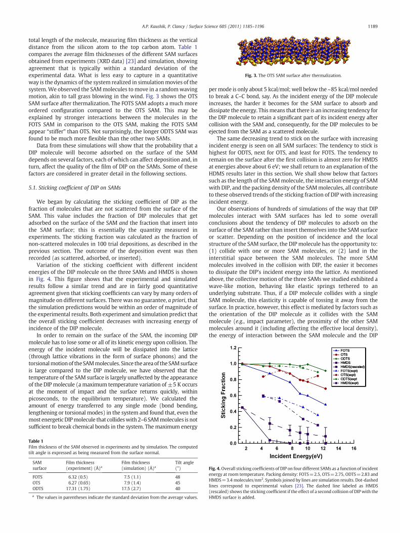
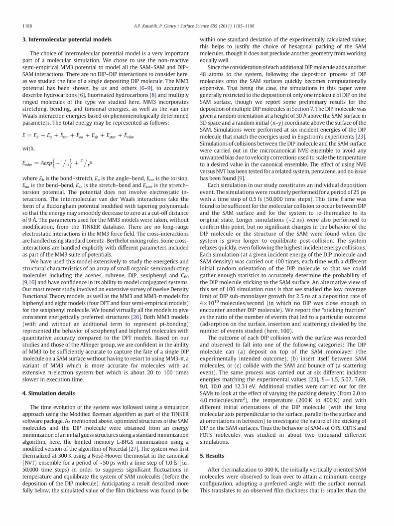
Fig. 3. The OTS SAM surface after thermalization.
1189A.P. Kaushik, P. Clancy / Surface Science 605 (2011) 1185–1196
total length of the molecule, measuring film thickness as the verticaldistance from the silicon atom to the top carbon atom. Table 1compares the average film thicknesses of the different SAM surfacesobtained from experiments (XRD data) [23] and simulation, showingagreement that is typically within a standard deviation of theexperimental data. What is less easy to capture in a quantitativeway is the dynamics of the system realized in simulationmovies of thesystem.We observed the SAMmolecules to move in a randomwavingmotion, akin to tall grass blowing in the wind. Fig. 3 shows the OTSSAM surface after thermalization. The FOTS SAM adopts a much moreordered configuration compared to the OTS SAM. This may beexplained by stronger interactions between the molecules in theFOTS SAM in comparison to the OTS SAM, making the FOTS SAMappear “stiffer” than OTS. Not surprisingly, the longer ODTS SAM wasfound to be much more flexible than the other two SAMs.
Data from these simulations will show that the probability that aDIP molecule will become adsorbed on the surface of the SAMdepends on several factors, each of which can affect deposition and, inturn, affect the quality of the film of DIP on the SAMs. Some of thesefactors are considered in greater detail in the following sections.
5.1. Sticking coefficient of DIP on SAMs
We began by calculating the sticking coefficient of DIP as thefraction of molecules that are not scattered from the surface of theSAM. This value includes the fraction of DIP molecules that getadsorbed on the surface of the SAM and the fraction that insert intothe SAM surface; this is essentially the quantity measured inexperiments. The sticking fraction was calculated as the fraction ofnon-scattered molecules in 100 trial depositions, as described in theprevious section. The outcome of the deposition event was thenrecorded (as scattered, adsorbed, or inserted).
Variation of the sticking coefficient with different incidentenergies of the DIP molecule on the three SAMs and HMDS is shownin Fig. 4. This figure shows that the experimental and simulatedresults follow a similar trend and are in fairly good quantitativeagreement given that sticking coefficients can vary by many orders ofmagnitude on different surfaces. There was no guarantee, a priori, thatthe simulation predictions would be within an order of magnitude ofthe experimental results. Both experiment and simulation predict thatthe overall sticking coefficient decreases with increasing energy ofincidence of the DIP molecule.
In order to remain on the surface of the SAM, the incoming DIPmolecule has to lose some or all of its kinetic energy upon collision. Theenergy of the incident molecule will be dissipated into the lattice(through lattice vibrations in the form of surface phonons) and thetorsionalmotionof theSAMmolecules. Since theareaof the SAMsurfaceis large compared to the DIP molecule, we have observed that thetemperature of the SAM surface is largely unaffected by the appearanceof the DIP molecule (amaximum temperature variation of ±5 K occursat the moment of impact and the surface returns quickly, withinpicoseconds, to the equilibrium temperature). We calculated theamount of energy transferred to any single mode (bond bending,lengthening or torsional modes) in the system and found that, even themost energeticDIPmolecule that collideswith 2–6 SAMmolecules is notsufficient to break chemical bonds in the system. The maximum energy
Table 1Film thickness of the SAM observed in experiments and by simulation. The computedtilt angle is expressed as being measured from the surface normal.
SAMsurface
Film thickness(experiment) (Å)a
Film thickness(simulation) (Å)a
Tilt angle(°)
FOTS 6.32 (0.5) 7.5 (1.1) 48OTS 6.27 (0.65) 7.9 (1.4) 45ODTS 17.31 (1.75) 17.5 (2.7) 40
a The values in parentheses indicate the standard deviation from the average values.
permode is only about 5 kcal/mol; well below the ~85 kcal/mol neededto break a C–C bond, say. As the incident energy of the DIP moleculeincreases, the harder it becomes for the SAM surface to absorb anddissipate the energy. Thismeans that there is an increasing tendency forthe DIP molecule to retain a significant part of its incident energy aftercollision with the SAM and, consequently, for the DIP molecules to beejected from the SAM as a scattered molecule.
The same decreasing trend to stick on the surface with increasingincident energy is seen on all SAM surfaces: The tendency to stick ishighest for ODTS, next for OTS, and least for FOTS. The tendency toremain on the surface after the first collision is almost zero for HMDSat energies above about 6 eV; we shall return to an explanation of theHDMS results later in this section. We shall show below that factorssuch as the length of the SAMmolecule, the interaction energy of SAMwith DIP, and the packing density of the SAMmolecules, all contributeto these observed trends of the sticking fraction of DIP with increasingincident energy.
Our observations of hundreds of simulations of the way that DIPmolecules interact with SAM surfaces has led to some overallconclusions about the tendency of DIP molecules to adsorb on thesurface of the SAM rather than insert themselves into the SAM surfaceor scatter. Depending on the position of incidence and the localstructure of the SAM surface, the DIP molecule has the opportunity to:(1) collide with one or more SAM molecules, or (2) land in theinterstitial space between the SAM molecules. The more SAMmolecules involved in the collision with DIP, the easier it becomesto dissipate the DIP's incident energy into the lattice. As mentionedabove, the collective motion of the three SAMs we studied exhibited awave-like motion, behaving like elastic springs tethered to anunderlying substrate. Thus, if a DIP molecule collides with a singleSAM molecule, this elasticity is capable of tossing it away from thesurface. In practice, however, this effect is mediated by factors such asthe orientation of the DIP molecule as it collides with the SAMmolecule (e.g., impact parameter), the proximity of the other SAMmolecules around it (including affecting the effective local density),the energy of interaction between the SAM molecule and the DIP
Fig. 4.Overall sticking coefficients of DIP on four different SAMs as a function of incidentenergy at room temperature. Packing density: FOTS=2.5, OTS=2.75, ODTS=2.83 andHMDS=3.4 molecules/nm2. Symbols joined by lines are simulation results. Dot-dashedlines correspond to experimental values [23]. The dashed line labeled as HMDS(rescaled) shows the sticking coefficient if the effect of a second collision of DIPwith theHMDS surface is added.
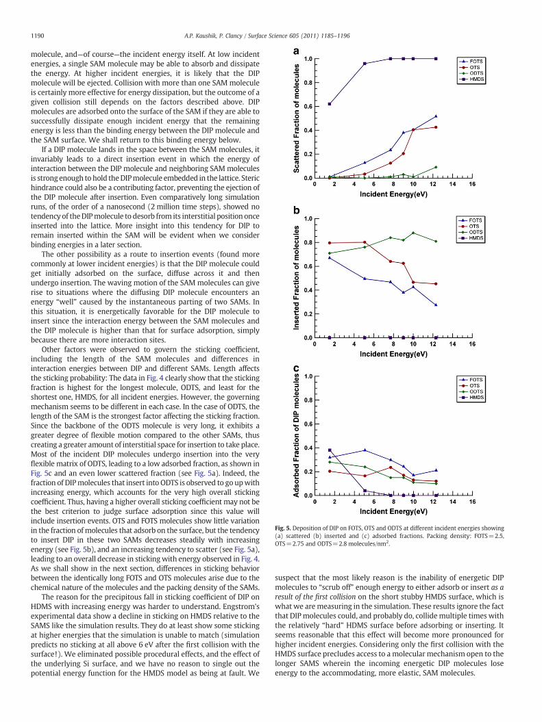
Fig. 5. Deposition of DIP on FOTS, OTS and ODTS at different incident energies showing(a) scattered (b) inserted and (c) adsorbed fractions. Packing density: FOTS=2.5,OTS=2.75 and ODTS=2.8 molecules/nm2.
1190 A.P. Kaushik, P. Clancy / Surface Science 605 (2011) 1185–1196
molecule, and—of course—the incident energy itself. At low incidentenergies, a single SAM molecule may be able to absorb and dissipatethe energy. At higher incident energies, it is likely that the DIPmolecule will be ejected. Collision with more than one SAM moleculeis certainly more effective for energy dissipation, but the outcome of agiven collision still depends on the factors described above. DIPmolecules are adsorbed onto the surface of the SAM if they are able tosuccessfully dissipate enough incident energy that the remainingenergy is less than the binding energy between the DIP molecule andthe SAM surface. We shall return to this binding energy below.
If a DIP molecule lands in the space between the SAM molecules, itinvariably leads to a direct insertion event in which the energy ofinteraction between the DIP molecule and neighboring SAMmoleculesis strongenough to hold theDIPmolecule embedded in the lattice. Sterichindrance could also be a contributing factor, preventing the ejection ofthe DIP molecule after insertion. Even comparatively long simulationruns, of the order of a nanosecond (2 million time steps), showed notendency of theDIPmolecule to desorb from its interstitial position onceinserted into the lattice. More insight into this tendency for DIP toremain inserted within the SAM will be evident when we considerbinding energies in a later section.
The other possibility as a route to insertion events (found morecommonly at lower incident energies) is that the DIP molecule couldget initially adsorbed on the surface, diffuse across it and thenundergo insertion. The waving motion of the SAM molecules can giverise to situations where the diffusing DIP molecule encounters anenergy “well” caused by the instantaneous parting of two SAMs. Inthis situation, it is energetically favorable for the DIP molecule toinsert since the interaction energy between the SAM molecules andthe DIP molecule is higher than that for surface adsorption, simplybecause there are more interaction sites.
Other factors were observed to govern the sticking coefficient,including the length of the SAM molecules and differences ininteraction energies between DIP and different SAMs. Length affectsthe sticking probability: The data in Fig. 4 clearly show that the stickingfraction is highest for the longest molecule, ODTS, and least for theshortest one, HMDS, for all incident energies. However, the governingmechanism seems to be different in each case. In the case of ODTS, thelength of the SAM is the strongest factor affecting the sticking fraction.Since the backbone of the ODTS molecule is very long, it exhibits agreater degree of flexible motion compared to the other SAMs, thuscreating a greater amount of interstitial space for insertion to take place.Most of the incident DIP molecules undergo insertion into the veryflexible matrix of ODTS, leading to a low adsorbed fraction, as shown inFig. 5c and an even lower scattered fraction (see Fig. 5a). Indeed, thefraction of DIPmolecules that insert into ODTS is observed to go upwithincreasing energy, which accounts for the very high overall stickingcoefficient. Thus, having a higher overall sticking coefficient may not bethe best criterion to judge surface adsorption since this value willinclude insertion events. OTS and FOTS molecules show little variationin the fraction of molecules that adsorb on the surface, but the tendencyto insert DIP in these two SAMs decreases steadily with increasingenergy (see Fig. 5b), and an increasing tendency to scatter (see Fig. 5a),leading to an overall decrease in stickingwith energy observed in Fig. 4.As we shall show in the next section, differences in sticking behaviorbetween the identically long FOTS and OTS molecules arise due to thechemical nature of the molecules and the packing density of the SAMs.
The reason for the precipitous fall in sticking coefficient of DIP onHDMS with increasing energy was harder to understand. Engstrom'sexperimental data show a decline in sticking on HMDS relative to theSAMS like the simulation results. They do at least show some stickingat higher energies that the simulation is unable to match (simulationpredicts no sticking at all above 6 eV after the first collision with thesurface!). We eliminated possible procedural effects, and the effect ofthe underlying Si surface, and we have no reason to single out thepotential energy function for the HMDS model as being at fault. We
suspect that the most likely reason is the inability of energetic DIPmolecules to “scrub off” enough energy to either adsorb or insert as aresult of the first collision on the short stubby HMDS surface, which iswhat we are measuring in the simulation. These results ignore the factthat DIP molecules could, and probably do, collide multiple times withthe relatively “hard” HDMS surface before adsorbing or inserting. Itseems reasonable that this effect will become more pronounced forhigher incident energies. Considering only the first collision with theHMDS surface precludes access to a molecular mechanism open to thelonger SAMS wherein the incoming energetic DIP molecules loseenergy to the accommodating, more elastic, SAM molecules.
1191A.P. Kaushik, P. Clancy / Surface Science 605 (2011) 1185–1196
For the “unforgiving” HMDS surface, we suggest that it isimportant to follow the fate of individual molecules as they makemultiple collisions with the surface. The scope of such a study,following every scattered molecule as it traverses the surface, isinaccessible from a computational resource point of view. Tocompensate for this inability, we estimated the sticking coefficientafter a second collision with the surface. To do this at a given incidentenergy, we measured the energy of the DIP molecule as it left thesurface for all 100 attempts and then averaged them to find a meanexiting energy. For example, a scattered DIP molecule initially havinga 5 eV incident energy is, on average, likely to leave the surface with3±0.6 eV. Similarly, DIP molecules possessing 12 eV incident energythat scattered from the surface did so with a mean energy of 4±1 eV.If we assume that the DIPmolecule has the opportunity to collide oncemore with the HMDS surface, we know from our measurement of its“exit” energy (which becomes its new incident energy for a secondcollision with the surface) its probability of sticking on the surface byinterpolating data from the sticking fraction corresponding to thatincident energy based on our data for first surface collisions. We thensimply add this additional, second collision, contribution to thesticking coefficient to the one that we found previously for the firstcollision. We show this “rescaled” sticking fraction of the DIP onHMDS in Fig. 4 as a dashed line. The results are clearly closer toEngstrom's experiments. This approach does not allow us to predictwhat the energy of the molecule might be after a third collision. It isnot unreasonable to imagine that experimental sticking coefficientsalso reflect a similar “ensemble average” of collision energies of DIPwith HMDS.
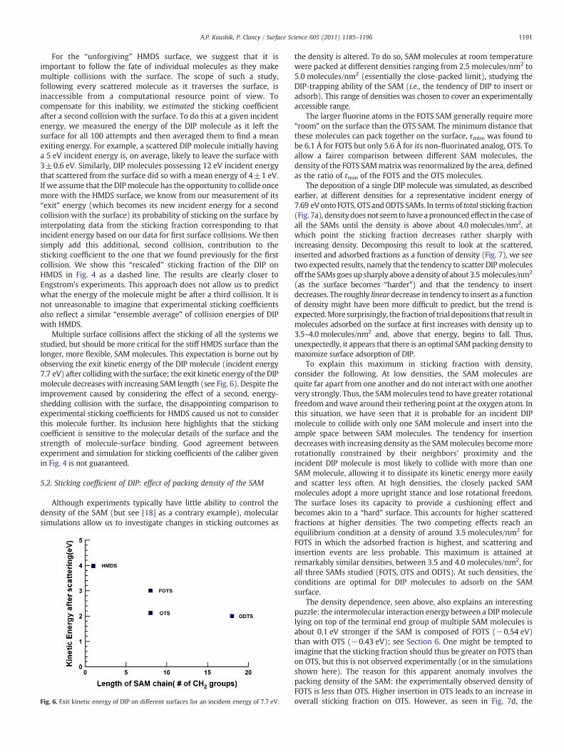
Multiple surface collisions affect the sticking of all the systems westudied, but should be more critical for the stiff HMDS surface than thelonger, more flexible, SAM molecules. This expectation is borne out byobserving the exit kinetic energy of the DIP molecule (incident energy7.7 eV) after collidingwith the surface; the exit kinetic energy of theDIPmolecule decreases with increasing SAM length (see Fig. 6). Despite theimprovement caused by considering the effect of a second, energy-shedding collision with the surface, the disappointing comparison toexperimental sticking coefficients for HMDS caused us not to considerthis molecule further. Its inclusion here highlights that the stickingcoefficient is sensitive to the molecular details of the surface and thestrength of molecule-surface binding. Good agreement betweenexperiment and simulation for sticking coefficients of the caliber givenin Fig. 4 is not guaranteed.
5.2. Sticking coefficient of DIP: effect of packing density of the SAM
Although experiments typically have little ability to control thedensity of the SAM (but see [18] as a contrary example), molecularsimulations allow us to investigate changes in sticking outcomes as
Fig. 6. Exit kinetic energy of DIP on different surfaces for an incident energy of 7.7 eV.
the density is altered. To do so, SAM molecules at room temperaturewere packed at different densities ranging from 2.5 molecules/nm2 to5.0 molecules/nm2 (essentially the close-packed limit), studying theDIP-trapping ability of the SAM (i.e., the tendency of DIP to insert oradsorb). This range of densities was chosen to cover an experimentallyaccessible range.
The larger fluorine atoms in the FOTS SAM generally require more“room” on the surface than the OTS SAM. The minimum distance thatthese molecules can pack together on the surface, rmin, was found tobe 6.1 Å for FOTS but only 5.6 Å for its non-fluorinated analog, OTS. Toallow a fairer comparison between different SAM molecules, thedensity of the FOTS SAMmatrix was renormalized by the area, definedas the ratio of rmin of the FOTS and the OTS molecules.
The deposition of a single DIP molecule was simulated, as describedearlier, at different densities for a representative incident energy of7.69 eVonto FOTS, OTSandODTS SAMs. In termsof total sticking fraction(Fig. 7a), density doesnot seemtohaveapronouncedeffect in the case ofall the SAMs until the density is above about 4.0 molecules/nm2, atwhich point the sticking fraction decreases rather sharply withincreasing density. Decomposing this result to look at the scattered,inserted and adsorbed fractions as a function of density (Fig. 7), we seetwo expected results, namely that the tendency to scatter DIPmoleculesoff theSAMsgoes up sharply above adensity of about3.5 molecules/nm2
(as the surface becomes “harder”) and that the tendency to insertdecreases. The roughly lineardecrease in tendency to insert as a functionof density might have been more difficult to predict, but the trend isexpected.More surprisingly, the fractionof trial depositions that result inmolecules adsorbed on the surface at first increases with density up to3.5–4.0 molecules/nm2 and, above that energy, begins to fall. Thus,unexpectedly, it appears that there is an optimal SAMpacking density tomaximize surface adsorption of DIP.
To explain this maximum in sticking fraction with density,consider the following. At low densities, the SAM molecules arequite far apart from one another and do not interact with one anothervery strongly. Thus, the SAMmolecules tend to have greater rotationalfreedom andwave around their tethering point at the oxygen atom. Inthis situation, we have seen that it is probable for an incident DIPmolecule to collide with only one SAM molecule and insert into theample space between SAM molecules. The tendency for insertiondecreases with increasing density as the SAMmolecules becomemorerotationally constrained by their neighbors' proximity and theincident DIP molecule is most likely to collide with more than oneSAM molecule, allowing it to dissipate its kinetic energy more easilyand scatter less often. At high densities, the closely packed SAMmolecules adopt a more upright stance and lose rotational freedom.The surface loses its capacity to provide a cushioning effect andbecomes akin to a “hard” surface. This accounts for higher scatteredfractions at higher densities. The two competing effects reach anequilibrium condition at a density of around 3.5 molecules/nm2 forFOTS in which the adsorbed fraction is highest, and scattering andinsertion events are less probable. This maximum is attained atremarkably similar densities, between 3.5 and 4.0 molecules/nm2, forall three SAMs studied (FOTS, OTS and ODTS). At such densities, theconditions are optimal for DIP molecules to adsorb on the SAMsurface.
The density dependence, seen above, also explains an interestingpuzzle: the intermolecular interaction energy between a DIPmoleculelying on top of the terminal end group of multiple SAM molecules isabout 0.1 eV stronger if the SAM is composed of FOTS (−0.54 eV)than with OTS (−0.43 eV); see Section 6. One might be tempted toimagine that the sticking fraction should thus be greater on FOTS thanon OTS, but this is not observed experimentally (or in the simulationsshown here). The reason for this apparent anomaly involves thepacking density of the SAM: the experimentally observed density ofFOTS is less than OTS. Higher insertion in OTS leads to an increase inoverall sticking fraction on OTS. However, as seen in Fig. 7d, the
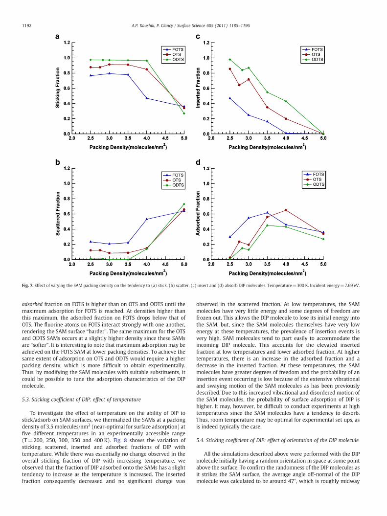
Fig. 7. Effect of varying the SAM packing density on the tendency to (a) stick, (b) scatter, (c) insert and (d) absorb DIP molecules. Temperature=300 K. Incident energy=7.69 eV.
1192 A.P. Kaushik, P. Clancy / Surface Science 605 (2011) 1185–1196
adsorbed fraction on FOTS is higher than on OTS and ODTS until themaximum adsorption for FOTS is reached. At densities higher thanthis maximum, the adsorbed fraction on FOTS drops below that ofOTS. The fluorine atoms on FOTS interact strongly with one another,rendering the SAM surface “harder”. The same maximum for the OTSand ODTS SAMs occurs at a slightly higher density since these SAMsare “softer”. It is interesting to note that maximum adsorption may beachieved on the FOTS SAM at lower packing densities. To achieve thesame extent of adsorption on OTS and ODTS would require a higherpacking density, which is more difficult to obtain experimentally.Thus, by modifying the SAM molecules with suitable substituents, itcould be possible to tune the adsorption characteristics of the DIPmolecule.
5.3. Sticking coefficient of DIP: effect of temperature
To investigate the effect of temperature on the ability of DIP tostick/adsorb on SAM surfaces, we thermalized the SAMs at a packingdensity of 3.5 molecules/nm2 (near-optimal for surface adsorption) atfive different temperatures in an experimentally accessible range(T=200, 250, 300, 350 and 400 K). Fig. 8 shows the variation ofsticking, scattered, inserted and adsorbed fractions of DIP withtemperature. While there was essentially no change observed in theoverall sticking fraction of DIP with increasing temperature, weobserved that the fraction of DIP adsorbed onto the SAMs has a slighttendency to increase as the temperature is increased. The insertedfraction consequently decreased and no significant change was
observed in the scattered fraction. At low temperatures, the SAMmolecules have very little energy and some degrees of freedom arefrozen out. This allows the DIP molecule to lose its initial energy intothe SAM, but, since the SAM molecules themselves have very lowenergy at these temperatures, the prevalence of insertion events isvery high. SAM molecules tend to part easily to accommodate theincoming DIP molecule. This accounts for the elevated insertedfraction at low temperatures and lower adsorbed fraction. At highertemperatures, there is an increase in the adsorbed fraction and adecrease in the inserted fraction. At these temperatures, the SAMmolecules have greater degrees of freedom and the probability of aninsertion event occurring is low because of the extensive vibrationaland swaying motion of the SAM molecules as has been previouslydescribed. Due to this increased vibrational and disordered motion ofthe SAM molecules, the probability of surface adsorption of DIP ishigher. It may, however, be difficult to conduct experiments at hightemperatures since the SAM molecules have a tendency to desorb.Thus, room temperature may be optimal for experimental set ups, asis indeed typically the case.
5.4. Sticking coefficient of DIP: effect of orientation of the DIP molecule
All the simulations described above were performed with the DIPmolecule initially having a random orientation in space at some pointabove the surface. To confirm the randomness of the DIP molecules asit strikes the SAM surface, the average angle off-normal of the DIPmolecule was calculated to be around 47°, which is roughly midway
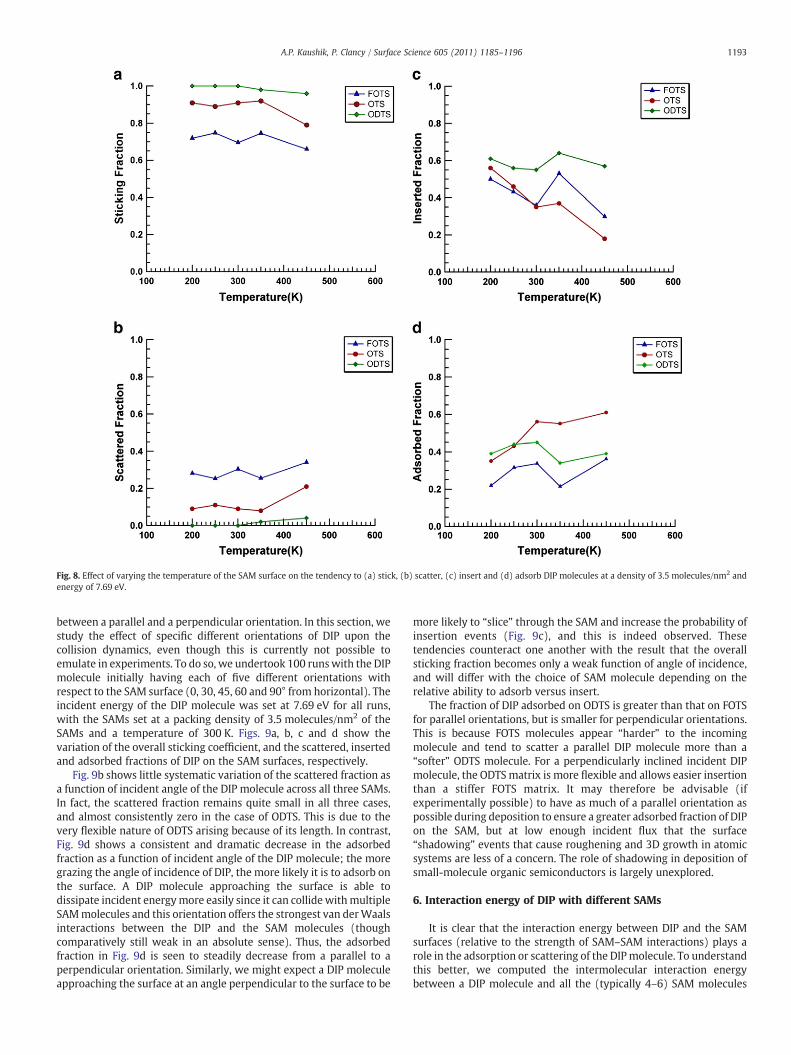
Fig. 8. Effect of varying the temperature of the SAM surface on the tendency to (a) stick, (b) scatter, (c) insert and (d) adsorb DIP molecules at a density of 3.5 molecules/nm2 andenergy of 7.69 eV.
1193A.P. Kaushik, P. Clancy / Surface Science 605 (2011) 1185–1196
between a parallel and a perpendicular orientation. In this section, westudy the effect of specific different orientations of DIP upon thecollision dynamics, even though this is currently not possible toemulate in experiments. To do so, we undertook 100 runswith the DIPmolecule initially having each of five different orientations withrespect to the SAM surface (0, 30, 45, 60 and 90° from horizontal). Theincident energy of the DIP molecule was set at 7.69 eV for all runs,with the SAMs set at a packing density of 3.5 molecules/nm2 of theSAMs and a temperature of 300 K. Figs. 9a, b, c and d show thevariation of the overall sticking coefficient, and the scattered, insertedand adsorbed fractions of DIP on the SAM surfaces, respectively.
Fig. 9b shows little systematic variation of the scattered fraction asa function of incident angle of the DIP molecule across all three SAMs.In fact, the scattered fraction remains quite small in all three cases,and almost consistently zero in the case of ODTS. This is due to thevery flexible nature of ODTS arising because of its length. In contrast,Fig. 9d shows a consistent and dramatic decrease in the adsorbedfraction as a function of incident angle of the DIP molecule; the moregrazing the angle of incidence of DIP, the more likely it is to adsorb onthe surface. A DIP molecule approaching the surface is able todissipate incident energymore easily since it can collide withmultipleSAMmolecules and this orientation offers the strongest van derWaalsinteractions between the DIP and the SAM molecules (thoughcomparatively still weak in an absolute sense). Thus, the adsorbedfraction in Fig. 9d is seen to steadily decrease from a parallel to aperpendicular orientation. Similarly, we might expect a DIP moleculeapproaching the surface at an angle perpendicular to the surface to be
more likely to “slice” through the SAM and increase the probability ofinsertion events (Fig. 9c), and this is indeed observed. Thesetendencies counteract one another with the result that the overallsticking fraction becomes only a weak function of angle of incidence,and will differ with the choice of SAM molecule depending on therelative ability to adsorb versus insert.
The fraction of DIP adsorbed on ODTS is greater than that on FOTSfor parallel orientations, but is smaller for perpendicular orientations.This is because FOTS molecules appear “harder” to the incomingmolecule and tend to scatter a parallel DIP molecule more than a“softer” ODTS molecule. For a perpendicularly inclined incident DIPmolecule, the ODTSmatrix is more flexible and allows easier insertionthan a stiffer FOTS matrix. It may therefore be advisable (ifexperimentally possible) to have as much of a parallel orientation aspossible during deposition to ensure a greater adsorbed fraction of DIPon the SAM, but at low enough incident flux that the surface“shadowing” events that cause roughening and 3D growth in atomicsystems are less of a concern. The role of shadowing in deposition ofsmall-molecule organic semiconductors is largely unexplored.
6. Interaction energy of DIP with different SAMs
It is clear that the interaction energy between DIP and the SAMsurfaces (relative to the strength of SAM–SAM interactions) plays arole in the adsorption or scattering of the DIPmolecule. To understandthis better, we computed the intermolecular interaction energybetween a DIP molecule and all the (typically 4–6) SAM molecules

Fig. 9. Effect of the orientation of the incident DIPmolecule on the tendency to (a) stick, (b) scatter, (c) insert or (d) adsorb. Temperature=300 K. Incident energy=7.69 eV. Packingdensity=3.5 molecules/nm2.
Table 2Interaction energies (in eV) of the DIP molecule in “T” and co-facial configurations withdifferent SAM surfaces. SAM–SAM interaction energies are given for comparison.
Configuration Binding energy(eV) FOTS
Binding energy(eV) OTS
Binding energy(eV) ODTS
T-config. DIP–SAM −0.5 (−0.35)a −0.4 (−0.3)a −0.4 (−0.3)a
Co-facial DIP–SAM −1.8 −1.5 −1.7SAM–SAM (at low densityb) −1.0 −0.6 −1.7SAM–SAM (at high densityc) −1.9 −1.0 −2.0
a Values in parentheses computed using DFT methods with M06 functional and a6–31 G(d,p) basis set.
b At the experimentally determined packing density.c At a packing density of 4.0 molecules/nm2.
1194 A.P. Kaushik, P. Clancy / Surface Science 605 (2011) 1185–1196
that interact with it at the respective densities of the SAMsmentionedin the previous sections. We performed such calculations for threeinteractions: DIP–SAM in a “T”-configuration redolent of the initialsurface adsorption configuration, DIP–SAM in a co-facial configurationcharacteristic of insertion events, and SAM–SAM interactions toprovide us with information about the competition for SAMmoleculesto prefer the proximity of other SAMs rather than interactingwith DIP.The results are summarized in Table 2.
For the “T”-configuration,we computed the interactionenergyas theDIP molecule was moved statically in incremental steps from a positionclose to the surface to one that was a large distance away from the SAMsurface (large enough so that the DIP does not “feel” the SAM surface).The difference between the energy at maximum interaction and theenergy at very large distance gives the binding energy of the DIPmolecule to the SAM surface. In this idealized T-configuration, thecomputed binding energies correspond to high SAM density situations.The maximum interaction energy for each DIP–SAM interaction in this“T”-configuration, representative of surfaceadsorption,was found to be:FOTS: −0.5 eV, OTS and ODTS: −0.4 eV (see Table 2). [OTS and ODTSare identical except for their length and should produce the samebinding energy]. At the experimental packing density of the SAMconsidered here, the DIP in the “T” configuration would be in contactwith about 4–5 SAM molecules. Binding energies do not change if wecalculate them dynamically at high packing densities of the SAM (like4.0 molecules/nm2), taking data directly from the MD simulations andaveraging them. This largely density-independent interaction energy isbecause the number of SAM molecules with which the DIP comes in
contact in the T-configuration does not change much in the range ofpacking densities considered. The stronger interaction found for DIPwith the FOTS SAM is due to the presence of the fluorine atoms, whichinteractmore stronglywith the delocalizedπ electron clouds on theDIP.For the MM3 model, used here, this is only taken into account throughthe phenomenological parameterization fitting process. For compari-son, the procedure was repeated using ab initio calculations with thesoftware package Gaussian09 [28]. The energies were computedwithinthe Density Functional Theory formalism using theM06 functionals andusing the6–31 G(d,p)basis set. TheunderlyingSAMsurface consistedofabout 12 truncated SAM molecules (the length of the SAM moleculeswas reduced to 3 carbons in length to save computational time). The 12
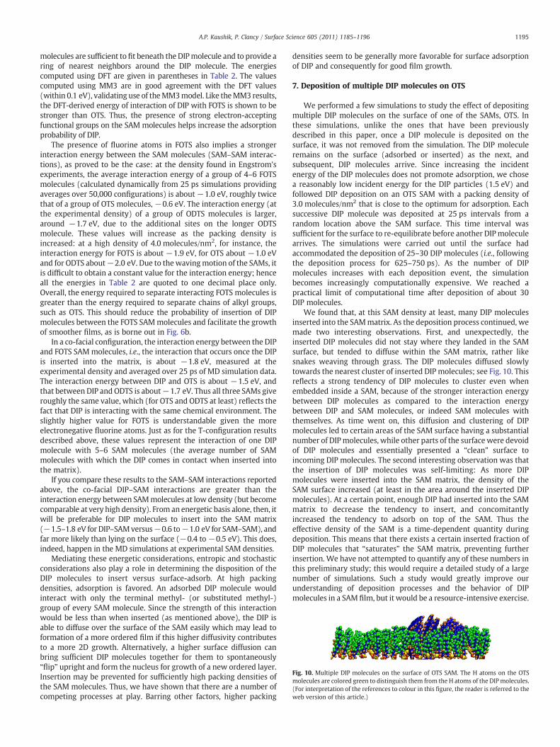
Fig. 10. Multiple DIP molecules on the surface of OTS SAM. The H atoms on the OTSmolecules are colored green to distinguish them from the H atoms of the DIP molecules.(For interpretation of the references to colour in this figure, the reader is referred to theweb version of this article.)
1195A.P. Kaushik, P. Clancy / Surface Science 605 (2011) 1185–1196
molecules are sufficient tofit beneath the DIPmolecule and to provide aring of nearest neighbors around the DIP molecule. The energiescomputed using DFT are given in parentheses in Table 2. The valuescomputed using MM3 are in good agreement with the DFT values(within 0.1 eV), validating use of theMM3model. Like theMM3 results,the DFT-derived energy of interaction of DIP with FOTS is shown to bestronger than OTS. Thus, the presence of strong electron-acceptingfunctional groups on the SAM molecules helps increase the adsorptionprobability of DIP.
The presence of fluorine atoms in FOTS also implies a strongerinteraction energy between the SAM molecules (SAM–SAM interac-tions), as proved to be the case: at the density found in Engstrom'sexperiments, the average interaction energy of a group of 4–6 FOTSmolecules (calculated dynamically from 25 ps simulations providingaverages over 50,000 configurations) is about−1.0 eV, roughly twicethat of a group of OTS molecules, −0.6 eV. The interaction energy (atthe experimental density) of a group of ODTS molecules is larger,around −1.7 eV, due to the additional sites on the longer ODTSmolecule. These values will increase as the packing density isincreased: at a high density of 4.0 molecules/nm2, for instance, theinteraction energy for FOTS is about −1.9 eV, for OTS about −1.0 eVand for ODTS about−2.0 eV. Due to thewavingmotion of the SAMs, itis difficult to obtain a constant value for the interaction energy; henceall the energies in Table 2 are quoted to one decimal place only.Overall, the energy required to separate interacting FOTS molecules isgreater than the energy required to separate chains of alkyl groups,such as OTS. This should reduce the probability of insertion of DIPmolecules between the FOTS SAMmolecules and facilitate the growthof smoother films, as is borne out in Fig. 6b.
In a co-facial configuration, the interaction energy between the DIPand FOTS SAMmolecules, i.e., the interaction that occurs once the DIPis inserted into the matrix, is about −1.8 eV, measured at theexperimental density and averaged over 25 ps of MD simulation data.The interaction energy between DIP and OTS is about −1.5 eV, andthat between DIP and ODTS is about−1.7 eV. Thus all three SAMs giveroughly the same value, which (for OTS and ODTS at least) reflects thefact that DIP is interacting with the same chemical environment. Theslightly higher value for FOTS is understandable given the moreelectronegative fluorine atoms. Just as for the T-configuration resultsdescribed above, these values represent the interaction of one DIPmolecule with 5–6 SAM molecules (the average number of SAMmolecules with which the DIP comes in contact when inserted intothe matrix).
If you compare these results to the SAM–SAM interactions reportedabove, the co-facial DIP–SAM interactions are greater than theinteraction energy between SAMmolecules at low density (but becomecomparable at very high density). From an energetic basis alone, then, itwill be preferable for DIP molecules to insert into the SAM matrix(−1.5–1.8 eV for DIP–SAMversus−0.6 to−1.0 eV for SAM–SAM), andfar more likely than lying on the surface (−0.4 to −0.5 eV). This does,indeed, happen in the MD simulations at experimental SAM densities.
Mediating these energetic considerations, entropic and stochasticconsiderations also play a role in determining the disposition of theDIP molecules to insert versus surface-adsorb. At high packingdensities, adsorption is favored. An adsorbed DIP molecule wouldinteract with only the terminal methyl- (or substituted methyl-)group of every SAM molecule. Since the strength of this interactionwould be less than when inserted (as mentioned above), the DIP isable to diffuse over the surface of the SAM easily which may lead toformation of a more ordered film if this higher diffusivity contributesto a more 2D growth. Alternatively, a higher surface diffusion canbring sufficient DIP molecules together for them to spontaneously“flip” upright and form the nucleus for growth of a new ordered layer.Insertion may be prevented for sufficiently high packing densities ofthe SAM molecules. Thus, we have shown that there are a number ofcompeting processes at play. Barring other factors, higher packing
densities seem to be generally more favorable for surface adsorptionof DIP and consequently for good film growth.
7. Deposition of multiple DIP molecules on OTS
We performed a few simulations to study the effect of depositingmultiple DIP molecules on the surface of one of the SAMs, OTS. Inthese simulations, unlike the ones that have been previouslydescribed in this paper, once a DIP molecule is deposited on thesurface, it was not removed from the simulation. The DIP moleculeremains on the surface (adsorbed or inserted) as the next, andsubsequent, DIP molecules arrive. Since increasing the incidentenergy of the DIP molecules does not promote adsorption, we chosea reasonably low incident energy for the DIP particles (1.5 eV) andfollowed DIP deposition on an OTS SAM with a packing density of3.0 molecules/nm2 that is close to the optimum for adsorption. Eachsuccessive DIP molecule was deposited at 25 ps intervals from arandom location above the SAM surface. This time interval wassufficient for the surface to re-equilibrate before another DIPmoleculearrives. The simulations were carried out until the surface hadaccommodated the deposition of 25–30 DIP molecules (i.e., followingthe deposition process for 625–750 ps). As the number of DIPmolecules increases with each deposition event, the simulationbecomes increasingly computationally expensive. We reached apractical limit of computational time after deposition of about 30DIP molecules.
We found that, at this SAM density at least, many DIP moleculesinserted into the SAMmatrix. As the deposition process continued, wemade two interesting observations. First, and unexpectedly, theinserted DIP molecules did not stay where they landed in the SAMsurface, but tended to diffuse within the SAM matrix, rather likesnakes weaving through grass. The DIP molecules diffused slowlytowards the nearest cluster of inserted DIP molecules; see Fig. 10. Thisreflects a strong tendency of DIP molecules to cluster even whenembedded inside a SAM, because of the stronger interaction energybetween DIP molecules as compared to the interaction energybetween DIP and SAM molecules, or indeed SAM molecules withthemselves. As time went on, this diffusion and clustering of DIPmolecules led to certain areas of the SAM surface having a substantialnumber of DIPmolecules, while other parts of the surface were devoidof DIP molecules and essentially presented a “clean” surface toincoming DIP molecules. The second interesting observation was thatthe insertion of DIP molecules was self-limiting: As more DIPmolecules were inserted into the SAM matrix, the density of theSAM surface increased (at least in the area around the inserted DIPmolecules). At a certain point, enough DIP had inserted into the SAMmatrix to decrease the tendency to insert, and concomitantlyincreased the tendency to adsorb on top of the SAM. Thus theeffective density of the SAM is a time-dependent quantity duringdeposition. This means that there exists a certain inserted fraction ofDIP molecules that “saturates” the SAM matrix, preventing furtherinsertion. We have not attempted to quantify any of these numbers inthis preliminary study; this would require a detailed study of a largenumber of simulations. Such a study would greatly improve ourunderstanding of deposition processes and the behavior of DIPmolecules in a SAM film, but it would be a resource-intensive exercise.
1196 A.P. Kaushik, P. Clancy / Surface Science 605 (2011) 1185–1196
8. Conclusions
Wehaveperformed thousands of simulations on three different SAMsurfaces (and a comparative HMDS surface) to study their propensity totrap DIP molecules incident on the SAM at hyperthermal velocities. Thesimulations yielded results for a sensitive property, the stickingcoefficient, which were in good agreement with experimental data forthe three SAMs studied. The results were much less impressive forHMDS, but highlighted the need for surface coatings to have degrees offreedom to dissipate the incident energy during collisions with thedepositing material. This agreement illustrated the competency of thechosen intermolecular potential tomodelDIP and theSAMs studied. Thesticking fraction of DIP decreased with increasing energy of incidencesuggesting that hyperthermal deposition processes offer no obviousbenefit in producing ordered thin films, in line with a complementaryexperimentally focused companion paper [23]. The molecular scale ofthe simulations enabled the distinction between adsorbed and insertedfractions of DIP—an important feature that is invariably unobtainableexperimentally. A new and unanticipated phenomenon deduced by thesimulations was the prediction of an optimal SAM packing density topromote sticking on the surface. While experimental control of thedensity may be very difficult in practice, this result has implications forthedesign and choiceof SAMmolecules tomaximize surface adsorption.
Wehave identified the key factors that govern the sticking fraction ofDIP molecules on these SAM surfaces, which we believe can bereasonably expected to carry over to other choices of long alkyl chainSAMs. Themore important factors seem to be the chemical functionalityof the SAM, the incident energy of theDIP, and the packing density of theSAM—all of which can be controlled experimentally. These results aredriven by a balance of binding energies between the SAMmolecules andthe incomingmolecule: T-configurationandco-facial energies comparedto SAM–SAM interactions help differentiate surface-binding frominsertion tendencies, respectively. Binding energies computed usingthe semi-empirical model MM3 are close to those generated usingDensity Functional Theory. Factors such as the temperature of thesurface seem less important in governing the deposition characteristicsof the DIPmolecule. The orientation of the incomingmolecule is capableof strongly affecting the tendency to adsorb on the surface, but isessentially not experimentally controllable. Overall, grazing angles favorsurface adsorption and normal deposition facilitates insertion, but this isalso dependent on the nature of the SAM. There is little or noexperimental or simulation studies of the effect of grazing incidenceon the nature of the grown film for small-molecule organicsemiconductors. It would be interesting to compare the role ofshadowing for simplemonatomic systems that causes orienteddendriticgrowth to that for small-molecule organics in which the highlyanisotropic interactions may disrupt or enhance this tendency.
While we were able to explain a lot of the observed tendency toinsert versus surface-adsorb in terms of the energetics of bindingenergies between DIP and SAM in comparison to SAM–SAM andDIP–DIP interactions, we noted that energetics alone do not controlthis complex process. Stochastic and entropically driven processesalso play a role.
Since we are able to predict the behavior of the deposition of DIPbased on the factors above, computation can be used to design asuitable SAM surface, which possesses the properties necessary toattain high adsorption of DIP on the surface. However, intelligentlydesigning an optimized SAM surface computationally can presentsignificant challenges of its own. For instance, the behavior of differentorganic semiconducting molecules such as the conformationally richmodes of rubrene molecules, or ones that differ considerably in shape,like C60, needs to be examined to determine whether their depositionbehavior is similar to that for the DIP molecules studied here. Thebehavior of similarly shaped, relatively rigid, acenes and perhaps thephenyls (biphenyl to sexiphenyl, say) might be expected to behavesimilarly to DIP.
The present study has not examined, in detail, the effect onsticking coefficient of the presence of other DIP molecules on thesurface (from preceding deposition events), which is bound to affectthe quality of subsequent film growth. But we have provided somepreliminary results of simulations of the deposition of multiple DIPmolecules on the surface of an OTS SAM at the optimum density forsurface adsorption as a glimpse of what might occur. We found thatDIP molecules tend to insert into the SAMmatrix and cluster togetherwithin the matrix. This clustering process eventually saturates theSAM with DIP molecules and artificially increases the density of theSAM surface. This was found to prevent the further insertion of the DIPmolecules into the surface and to increase the adsorbed fraction ofDIP. The resulting surfacewas found to become “patchy”with irregularclumps of DIP molecules interspersed between “clean” areas of theSAM surface that were devoid of DIP. The results of this preliminarystudy warrant further investigation due to their implications for filmgrowth. Examining the effects of depositing a large number of DIPmolecules on a SAM surface is computationally expensive, but it is thenext logical step for computational studies intended to follow thegrowth of thin films of small-molecule organic semiconductors.
Acknowledgments
This publication was based on work supported by Award No. KUS-C1-018-02,madebyKingAbdullahUniversity of ScienceandTechnology(KAUST). TheEngstromresearchgroupatCornell is thanked for access totheir experimental data in advance of publication. Intel Corporation isthanked for the donation of computing resources.
References
[1] H. Yamamoto, K. Nishiyama, I. Ohdomari, J. Phys. IV 132 (2006) 189.[2] L. Zuppiroli, K. Kamaras, M. Bussac, E. Moons, Eur. Phys. J. B 11 (1999) 505.[3] M. Halik, H. Klauk, U.e.a. Zschieschang, Nature 431 (2004) 963.[4] D.L. Irving, D.W. Brenner, J. Phys. Chem. B 110 (2006) 31.[5] S. Vemparala, B.B. Karki, R.K. Kalia, P. Vashishta, J. Chem. Phys. 121 (9) (2004)
4323.[6] N. Allinger, Y. Yuh, J.-H. Lii, J. Am. Chem. Soc. 111 (1989) 8551.[7] K.-H. Chen, J.-H. Lii, G.A.Walker, Y. Xie, H. F. S. III, N.L. Allinger, J. Phys. Chem. A 110
(2006) 7202.[8] K.-H. Chen, G.A. Walker, N.L. Allinger, J. Mol. Struct. Theochem 490 (1999) 87.[9] J.E. Goose, P. Clancy, J. Phys. Chem. C 111 (2007) 43.
[10] R. Cantrell, P. Clancy, Surf. Sci. 602 (22) (2008) 3499.[11] S.B.M. Bosio, W.L. Hase, J. Chem. Phys. 107 (1997) 9677.[12] N. Isa, K.D. Gibson, T. Yan, W.L. Hase, S.J. Sibener, J. Chem. Phys. 120 (2004) 2417.[13] B.S. Day, J.M. Morris, W.A. Alexander, D. Troya, J. Phys. Chem. B 110 (2006) 6832.[14] B.S. Day, J.M. Morris, D. Troya, J. Chem. Phys. 122 (2005) 214712.[15] K.D. Gibson, N. Isa, N. Sibener, J. Phys. Chem. A 110 (2006) 1469.[16] A. Ulman, Adv. Mater. 2 (1990) 12.[17] D.H.L. Kim, H.S. Yang, H. Yang, K.L. Cho, Adv. Funct. Mater. 18 (2008) 1363.[18] Y. Ito, A.A. Virkar, S. Mannsfeld, J.H. Oh, M. Toney, J. Locklin, Z. Bao, J. Am. Chem.
Soc. 131 (2009) 9396.[19] F. Tao, S.L. Bernasek, Chem. Rev. 107 (2007) 1408.[20] P.T. Mikulski, L.A. Herman, J.A. Harrison, Langmuir 21 (2005) 12197.[21] S. Hong, A. Amassian, A. Woll, S. Bhargava, J. Ferguson, G. Malliaras, J. Brock, J.R.
Engstrom, Appl. Phys. Lett. 92 (2008) 253304.[22] A. Amassian, T. Desai, S. Kowarik, S. Hong, A.R. Woll, G. Malliaras, F. Schreiber, J.R.
Engstrom, J. Chem. Phys. 130 (2009) 124701.[23] T.V. Desai, S. Hong, A.R. Woll, K.J. Hughes, A.P. Kaushik, P. Clancy, and J.R.
Engstrom, under review.[24] G. Schaftenaar, J. Noordik, J. Comput. Aided Mol. Des. 14 (2000) 123.[25] J.W. Ponder, Tinker—software tools for molecular design, http://dasher.wustl.edu/
tinker/2010.[26] J.E. Goose, E.L. First, P. Clancy, Phys. Rev. B 81 (2010) 205310.[27] J. Nocedal, Math. Comput. 35 (1980) 773.[28] M.J. Frisch, G.W. Trucks, H.B. Schlegel, G.E. Scuseria, M.A. Robb, J.R. Cheeseman, G.
Scalmani, V. Barone, B. Mennucci, G.A. Petersson, H. Nakatsuji, M. Caricato, X. Li, H.P. Hratchian, A.F. Izmaylov, J. Bloino, G. Zheng, J.L. Sonnenberg, M. Hada, M. Ehara,K. Toyota, R. Fukuda, J. Hasegawa, M. Ishida, T. Nakajima, Y. Honda, O. Kitao, H.Nakai, T. Vreven, J.A. Montgomery Jr., J.E. Peralta, F. Ogliaro, M. Bearpark, J.J. Heyd,E. Brothers, K.N. Kudin, V.N. Staroverov, R. Kobayashi, J. Normand, K. Raghava-chari, A. Rendell, J.C. Burant, S.S. Iyengar, J. Tomasi, M. Cossi, N. Rega, J.M. Millam,M. Klene, J.E. Knox, J.B. Cross, V. Bakken, C. Adamo, J. Jaramillo, R. Gomperts, R.E.Stratmann, O. Yazyev, A.J. Austin, R. Cammi, C. Pomelli, J.W. Ochterski, R.L. Martin,K. Morokuma, V.G. Zakrzewski, G.A. Voth, P. Salvador, J.J. Dannenberg, S. Dapprich,A.D. Daniels, Ö. Farkas, J.B. Foresman, J.V. Ortiz, J. Cioslowski, D.J. Fox, Gaussian 09,Revision A.1, Gaussian, Inc., Wallingford CT, 2009.