Concepts for external light trapping and its ... - erbium.nl
16
EU PVSEC PAPER Concepts for external light trapping and its utilization in colored and image displaying photovoltaic modules Lourens van Dijk 1† , Jorik van de Groep 2‡ , Leon W. Veldhuizen 3 , Marcel Di Vece 1 and Ruud E. I. Schropp 1,4 * 1 Nanophotonics – Physics of Devices, Debye Institute for Nanomaterials Science, Utrecht University, High Tech Campus, Building 21, Eindhoven 5656 AE, The Netherlands 2 Center for Nanophotonics, FOM Institute AMOLF, Science Park 104, Amsterdam 1098 XG, The Netherlands 3 Department of Applied Physics, Plasma and Materials Processing, Eindhoven University of Technology (TU/e), Eindhoven 5600 MB, The Netherlands 4 Energy Research Center of the Netherlands (ECN), Solar Energy, High Tech Campus 21, 5656 AE Eindhoven, The Netherlands ABSTRACT The reflection of incident sunlight prevents photovoltaic modules from reaching their full energy conversion potential. Recently, we demonstrated significant absorption enhancement in various solar cells by external light trapping, using 3D-printed and milled light traps. In order to facilitate direct module integration, we introduce an external light trapping design concept tackling the reflection issues at the module level. In this module design, a lens array on the module cover glass funnels the incident sunlight through small apertures in a reflective coating at the backside of the cover glass. This adapted cover glass can be applied on a conventional module design. The reflector and the solar cells together form an optical cavity, in which most reflected light is recycled by directing the reflected light back to the solar cell. A unique feature of this light trapping module is its capability to simultaneously recycle the broadband reflection from the metal front grid, the front interfaces, the reflective backside of the cell, and the white back sheet. Moreover, it allows separate integra- tion and contacting of low and high bandgap solar cells for highly efficient hybrid tandem modules that have no current matching related losses. We show five module designs for improved light management combined with additional features such as color and image display. We discuss the optimal harvesting of the diffuse and direct component of the sunlight. The outlook of highly efficient, colored, and even image displaying modules makes this technology an interesting candidate for a new class of photovoltaic modules. Copyright © 2017 John Wiley & Sons, Ltd. KEYWORDS external light trapping; colored solar modules; light management; spectrum splitting; compound parabolic concentrator (CPC); four- terminal contacting *Correspondence Ruud E. I. Schropp, Nanophotonics - Physics of Devices, Debye Institute for Nanomaterials Science, Utrecht University, High Tech Campus, building 21, 5656 AE Eindhoven, The Netherlands. E-mail: [email protected] † Present address: Exasun, Laan van Ypenburg 122, Den Haag 2497 GC, The Netherlands ‡ Present address: Geballe Laboratory for Advanced Materials, Stanford University, 476 Lomita Mall, Stanford 94305, CA, USA Received 2 May 2016; Revised 5 November 2016; Accepted 13 December 2016 1. INTRODUCTION TO THE LIGHT TRAPPING MODULE All solar modules exhibit optical reflection losses preventing the power conversion efficiency from reaching its full potential. For example, industrial crystalline silicon (c-Si) based solar modules are hindered by reflection from the metal front grid (fingers and bus bars), front inter- faces, and incomplete fill factor of the module area (“dead area”). Furthermore, light with a wavelength close to the band gap of the semiconductor is reflected out of the module because of incomplete absorption. Therefore, highly efficient solar modules require a general light management solution that simultaneously recycles the PROGRESS IN PHOTOVOLTAICS: RESEARCH AND APPLICATIONS Prog. Photovolt: Res. Appl. 2017; 25:553–568 Published online 3 February 2017 in Wiley Online Library (wileyonlinelibrary.com). DOI: 10.1002/pip.2863 Copyright © 2017 John Wiley & Sons, Ltd. 553
-
Upload
khangminh22 -
Category
Documents
-
view
3 -
download
0
Transcript of Concepts for external light trapping and its ... - erbium.nl
EU PVSEC PAPER
Concepts for external light trapping and its utilization incolored and image displaying photovoltaic modulesLourens van Dijk1†, Jorik van de Groep2‡, Leon W. Veldhuizen3, Marcel Di Vece1 andRuud E. I. Schropp1,4*1 Nanophotonics – Physics of Devices, Debye Institute for Nanomaterials Science, Utrecht University, High Tech Campus, Building21, Eindhoven 5656 AE, The Netherlands2 Center for Nanophotonics, FOM Institute AMOLF, Science Park 104, Amsterdam 1098 XG, The Netherlands3 Department of Applied Physics, Plasma and Materials Processing, Eindhoven University of Technology (TU/e), Eindhoven 5600 MB,The Netherlands4 Energy Research Center of the Netherlands (ECN), Solar Energy, High Tech Campus 21, 5656 AE Eindhoven, The Netherlands
ABSTRACT
The reflection of incident sunlight prevents photovoltaic modules from reaching their full energy conversion potential.Recently, we demonstrated significant absorption enhancement in various solar cells by external light trapping, using3D-printed and milled light traps. In order to facilitate direct module integration, we introduce an external light trappingdesign concept tackling the reflection issues at the module level. In this module design, a lens array on the module coverglass funnels the incident sunlight through small apertures in a reflective coating at the backside of the cover glass. Thisadapted cover glass can be applied on a conventional module design. The reflector and the solar cells together form anoptical cavity, in which most reflected light is recycled by directing the reflected light back to the solar cell. A uniquefeature of this light trapping module is its capability to simultaneously recycle the broadband reflection from the metal frontgrid, the front interfaces, the reflective backside of the cell, and the white back sheet. Moreover, it allows separate integra-tion and contacting of low and high bandgap solar cells for highly efficient hybrid tandem modules that have no currentmatching related losses. We show five module designs for improved light management combined with additional featuressuch as color and image display. We discuss the optimal harvesting of the diffuse and direct component of the sunlight. Theoutlook of highly efficient, colored, and even image displaying modules makes this technology an interesting candidate fora new class of photovoltaic modules. Copyright © 2017 John Wiley & Sons, Ltd.
KEYWORDS
external light trapping; colored solar modules; light management; spectrum splitting; compound parabolic concentrator (CPC); four-terminal contacting
*Correspondence
Ruud E. I. Schropp, Nanophotonics - Physics of Devices, Debye Institute for Nanomaterials Science, Utrecht University, High TechCampus, building 21, 5656 AE Eindhoven, The Netherlands.E-mail: [email protected]†Present address: Exasun, Laan van Ypenburg 122, Den Haag 2497 GC, The Netherlands‡Present address: Geballe Laboratory for Advanced Materials, Stanford University, 476 Lomita Mall, Stanford 94305, CA, USA
Received 2 May 2016; Revised 5 November 2016; Accepted 13 December 2016
1. INTRODUCTION TO THE LIGHTTRAPPING MODULE
All solar modules exhibit optical reflection lossespreventing the power conversion efficiency from reachingits full potential. For example, industrial crystalline silicon(c-Si) based solar modules are hindered by reflection from
the metal front grid (fingers and bus bars), front inter-faces, and incomplete fill factor of the module area (“deadarea”). Furthermore, light with a wavelength close to theband gap of the semiconductor is reflected out of themodule because of incomplete absorption. Therefore,highly efficient solar modules require a general lightmanagement solution that simultaneously recycles the
PROGRESS IN PHOTOVOLTAICS: RESEARCH AND APPLICATIONSProg. Photovolt: Res. Appl. 2017; 25:553–568
Published online 3 February 2017 in Wiley Online Library (wileyonlinelibrary.com). DOI: 10.1002/pip.2863
Copyright © 2017 John Wiley & Sons, Ltd. 553
broadband light reflection from these four sources on themodule level.
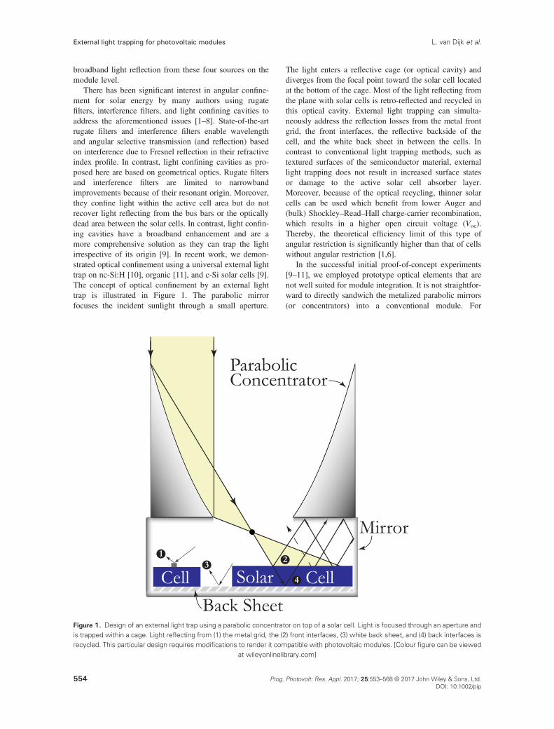
There has been significant interest in angular confine-ment for solar energy by many authors using rugatefilters, interference filters, and light confining cavities toaddress the aforementioned issues [1–8]. State-of-the-artrugate filters and interference filters enable wavelengthand angular selective transmission (and reflection) basedon interference due to Fresnel reflection in their refractiveindex profile. In contrast, light confining cavities as pro-posed here are based on geometrical optics. Rugate filtersand interference filters are limited to narrowbandimprovements because of their resonant origin. Moreover,they confine light within the active cell area but do notrecover light reflecting from the bus bars or the opticallydead area between the solar cells. In contrast, light confin-ing cavities have a broadband enhancement and are amore comprehensive solution as they can trap the lightirrespective of its origin [9]. In recent work, we demon-strated optical confinement using a universal external lighttrap on nc-Si:H [10], organic [11], and c-Si solar cells [9].The concept of optical confinement by an external lighttrap is illustrated in Figure 1. The parabolic mirrorfocuses the incident sunlight through a small aperture.
The light enters a reflective cage (or optical cavity) anddiverges from the focal point toward the solar cell locatedat the bottom of the cage. Most of the light reflecting fromthe plane with solar cells is retro-reflected and recycled inthis optical cavity. External light trapping can simulta-neously address the reflection losses from the metal frontgrid, the front interfaces, the reflective backside of thecell, and the white back sheet in between the cells. Incontrast to conventional light trapping methods, such astextured surfaces of the semiconductor material, externallight trapping does not result in increased surface statesor damage to the active solar cell absorber layer.Moreover, because of the optical recycling, thinner solarcells can be used which benefit from lower Auger and(bulk) Shockley–Read–Hall charge-carrier recombination,which results in a higher open circuit voltage (Voc).Thereby, the theoretical efficiency limit of this type ofangular restriction is significantly higher than that of cellswithout angular restriction [1,6].
In the successful initial proof-of-concept experiments[9–11], we employed prototype optical elements that arenot well suited for module integration. It is not straightfor-ward to directly sandwich the metalized parabolic mirrors(or concentrators) into a conventional module. For
Figure 1. Design of an external light trap using a parabolic concentrator on top of a solar cell. Light is focused through an aperture andis trapped within a cage. Light reflecting from (1) the metal grid, the (2) front interfaces, (3) white back sheet, and (4) back interfaces isrecycled. This particular design requires modifications to render it compatible with photovoltaic modules. [Colour figure can be viewed
at wileyonlinelibrary.com]
External light trapping for photovoltaic modules L. van Dijk et al.
554 Prog. Photovolt: Res. Appl. 2017; 25:553–568 © 2017 John Wiley & Sons, Ltd.DOI: 10.1002/pip

example, the hollow parabolic concentrator (Figure 1)needs a glass protective layer that causes additional inter-face reflection of around 8% for conventional glass. As thisconsiderable loss is unacceptable for module integration,we explore alternative options.
In addition to improving the efficiency of photovoltaicmodules, there is also a strong interest in colored andimage displaying photovoltaic modules. Recently, coloredmodules were developed by CSEM and are now developedby Solaxess [12,13]. These modules are based on interfer-ence filters and reflect part of the visible light at the ex-pense of a reduction in the energy conversion efficiency.This enables white solar modules, which can for instancebe applied on buildings. Besides, image-displaying bill-boards that harvest solar energy were developed bySunpartner Technologies, Rousset, France; their power rat-ing is limited: 90Wp/m
2 (Wysips® Cameleon) [14].Here, we present five designs of light trapping photo-
voltaic modules. First, we present a basic light trappingmodule (design 1). Subsequently, we illustrate severalmodifications of the basic light trapping module leadingto interesting additional features that can be achieveduniquely by this light trapping mechanism. Design 2shows an arbitrarily colored module, and design 3 showsa module that displays images. Design 4 shows an alter-native lens design based on compound parabolic concen-trators (CPCs) that can be integrated in designs 1–3.Further, we discuss potential consequences for incomingdiffuse sunlight for this type of module. For geographicregions with a large fraction of diffuse irradiance, wepropose design 5, which also completely absorbs thediffuse sunlight.
Ultimately, these designs show interesting opportunitiesfor esthetic modules, such as colored and image displayingmodules, for potential use in building integrated photovol-taics and energy harvesting billboards.
2. DESIGNS OF PHOTOVOLTAICMODULES WITH EXTERNAL LIGHTTRAPPING
2.1. Design 1: Basic light trapping moduledesign
Figure 2 shows a concept of a light trapping module, inwhich the external light trap is integrated in the glass of aconventional solar module. An array of lenses is appliedon the front side of the glass. A reflector (e.g., a mirroror white paint) is applied at the inner (lower) side of theglass. The reflector contains openings through which thesunlight is funneled into the cavity between the reflectorand the solar cell plane where the light is trapped effec-tively. As indicated, the four broadband sources of reflec-tion are recycled, resulting in an increase of the moduleefficiency.
This light trap design minimizes the number of addi-tionally required layers in the solar module. The incidentlight that is focused between the reflective areas (“theopenings”) is transmitted to the ethylene vinyl acetate(EVA) encapsulation layer. The focal length of the lensesshould be roughly equal to the thickness of the front glassto allow most of the incoming light to pass through theopenings at the backside of the glass. At this focal length,the angle of incidence at which the light can propagatethrough the openings is maximal. The associated accep-tance angle is optimal for the module performance. For dif-ferent focal lengths, a higher fraction of the light isreflected outwards and therefore lost. Generally, the glassof solar modules is between 2 and 4mm thick. The spacebetween the reflector and the white back sheet forms a cav-ity (or cage) in which the light is trapped. The spacer thick-ness determines the divergence (i.e., width) of the beam inthe cavity and the uniformity of the cell illumination [9].
Figure 2. Design 1. Basic concept of integration of an external light trapping scheme in a photovoltaic module (not to scale). Light isfocused by lenses on the front side of the glass through openings in a reflector applied at the backside of the glass. The reflector canbe made of a metal (e.g., Ag or Al) or of white paint. The reflected light from (1) the metal grid, (2) the front interfaces, (3)white backsheet, and (4) the back interfaces is trapped in the optical cavity between the reflector and the white back sheet. EVA, ethylene vinyl
acetate. [Colour figure can be viewed at wileyonlinelibrary.com]
External light trapping for photovoltaic modulesL. van Dijk et al.
555Prog. Photovolt: Res. Appl. 2017; 25:553–568 © 2017 John Wiley & Sons, Ltd.DOI: 10.1002/pip
Its thickness needs to be such that (most of) the reflectedlight from the cell is redirected backwards by the reflector,instead of escaping through an opening after the firstreflection. This condition is satisfied when the spacer thick-ness is around half of that of the glass thickness. Therefore,for a light trapping module with 3-mm thick glass, a1.5-mm thick EVA would be sufficient. The associatedJsc loss due to the EVA is ~3.8%, while for a conventional0.5-mm thick EVA the Jsc loss is ~2.8%, as calculatedusing Tracey [15]. This parasitic absorptance can bereduced by adding a second sheet of glass as spacer (withEVA on top and bottom side) to obtain a sufficient spacerthickness with less parasitic absorptance.
The area of the openings with respect to the totalreflector area is variable. An opening fraction of ~30%can eliminate the need for tracking as we show inSection 3. Different geometries (e.g., rectangular, hexago-nal, and circular) are allowed for the openings as shownpreviously [11].
The light trapping module also enables different solarmodule designs; for example, the series resistance can be
reduced effectively using an electrical grid pattern withlarger surface coverage at the front side of the cells withoutincreasing the performance losses due to shadowing.
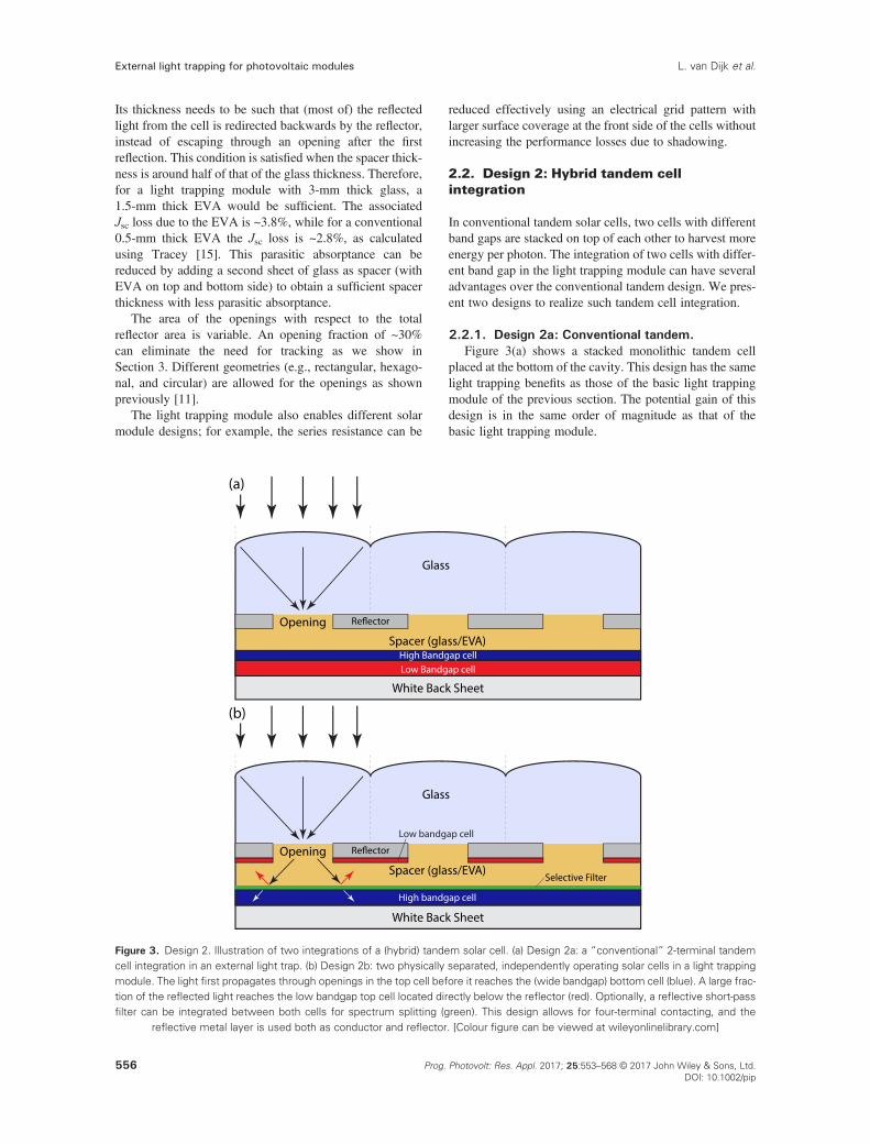
2.2. Design 2: Hybrid tandem cellintegration
In conventional tandem solar cells, two cells with differentband gaps are stacked on top of each other to harvest moreenergy per photon. The integration of two cells with differ-ent band gap in the light trapping module can have severaladvantages over the conventional tandem design. We pres-ent two designs to realize such tandem cell integration.
2.2.1. Design 2a: Conventional tandem.Figure 3(a) shows a stacked monolithic tandem cell
placed at the bottom of the cavity. This design has the samelight trapping benefits as those of the basic light trappingmodule of the previous section. The potential gain of thisdesign is in the same order of magnitude as that of thebasic light trapping module.
Figure 3. Design 2. Illustration of two integrations of a (hybrid) tandem solar cell. (a) Design 2a: a “conventional” 2-terminal tandemcell integration in an external light trap. (b) Design 2b: two physically separated, independently operating solar cells in a light trappingmodule. The light first propagates through openings in the top cell before it reaches the (wide bandgap) bottom cell (blue). A large frac-tion of the reflected light reaches the low bandgap top cell located directly below the reflector (red). Optionally, a reflective short-passfilter can be integrated between both cells for spectrum splitting (green). This design allows for four-terminal contacting, and the
reflective metal layer is used both as conductor and reflector. [Colour figure can be viewed at wileyonlinelibrary.com]
External light trapping for photovoltaic modules L. van Dijk et al.
556 Prog. Photovolt: Res. Appl. 2017; 25:553–568 © 2017 John Wiley & Sons, Ltd.DOI: 10.1002/pip
2.2.2. Design 2b: Spectral splitting by two facingcells.
Previously, various light splitting concepts have beendemonstrated, and the potential of spectral splitting iswidely recognized [3,16–20]. Figure 3(b) shows an alter-native and relatively simple design for spectral splitting.In this design, the physical order of the low and highbandgap cell is inverted compared with a conventionaltandem cell. The potential of several variations of thisconcept was demonstrated by Goetzberger et al. [3]. Thisdesign can be realized by applying a low bandgap cell(like c-Si) at the top of the cavity and a high bandgap cell(like a-Si or perovskite) at the bottom of the cavity. Inconventional monolithically interconnected tandem solarcells, the incoming light travels not much more than a sin-gle pass through the high bandgap cell before it reachesthe bottom (low bandgap) solar cell. The proposed designwith two facing cells has a significant advantage as thelight makes at least a double pass through the highbandgap cell before it propagates outwards in the direc-tion of the low bandgap cell (with a certain probabilityof escaping through the opening). The integration of areflective optical filter can further enhance the lightmanagement. Perforating the low bandgap cell bringsadditional costs, while at the other hand, the ultimate effi-ciency limit of 46% for tandem cells is significantlyhigher than the ~33% for single solar cells [21].
2.2.3. Fabrication.The reflector and low bandgap cell are processed on the
inner side of the glass sheet. Openings are made in thereflector or small areas of the glass and are left uncoatedto enable the light to enter the cavity. If the top cell is c-Si, a laser can be used to drill openings in it. Such a drillingprocess is commonly used for c-Si metal wrap through(MWT) solar cells [22]. Below the top cell, the space isfilled with EVA, and the high bandgap cell is located atthe bottom of the cavity.
2.2.4. Separate cell fabrication and contacting.Another advantage of the two facing cells design
(Figure 3(b)) is the ability to separately contact the two cellarrays by four electrical terminals, which provides morefreedom in choosing the respective band gaps of the twocells as the need for current matching is eliminated[18,23]. Moreover, the two individual cells can be fabri-cated and optimized separately, thereby circumventingthe matching of the lattice constants and integration of atunnel-junction as required for conventional tandem cells.The metal reflector can be used both as reflector and elec-trical conductor for the top cell. There are various optionsto contact the low bandgap cell stripes. For example, inter-connection of the stripes can be achieved using bus bars or(monolithic series) interconnected cell stripes [24]. Alter-natively, stripes of interdigitated back contact or MWTcells can be used that are contacted using defined areason the reflector. Stripes of MWT cells can be contactedusing a copper electric contacting foil placed between the
cell stripes and the reflector. The economic feasibility ofthis tandem concept is the scope of further work; it is ex-pected to be highly dependent on the cell costs becausethe increase in expenses needs to be justified by the in-crease in efficiency.
2.2.5. Spectrum splitting.Long wavelength light that travels through a high
bandgap bottom cell is subject to a certain degree of para-sitic absorptance in the active cell material, contactingelectrodes, and/or encapsulation layers. This can beprevented by the integration of a reflective optical filter(i.e., dichroic mirror) that is transparent for short wave-lengths but reflective for long wavelengths. The use ofsuch a short-pass filter can thus split the solar spectrumand direct different spectral components to the appropriatesolar cell. This reduces the overall parasitic absorptance ofsub-bandgap photons in the high bandgap cell [25]. Suchoptical filters are already used in “cool-beam halogen”light bulbs to retro-reflect the infrared radiation (“heat”),thereby improving their energy efficiency. Only minormodifications of these filters are needed for the integrationin light trapping modules. The spectral selectivity ofdichroic mirrors depends on the angle of incidence.However, filters exist of which the cutoff wavelength onlyshifts ~50 nm for an angular variation of 45° [26]. Theseare suitable filters for this technology. The use of opticalfilters is mostly interesting when the high bandgap cellexhibits significant sub-bandgap absorptance. Forexample, perovskite solar cells exhibit parasitic absorptionat long wavelengths, especially in the four-terminal config-uration with multiple (parasitically absorbing) TransparentConductive Oxide (TCO) layers [27,28].
2.3. Design 3: Solar panels with a color,logo, or image
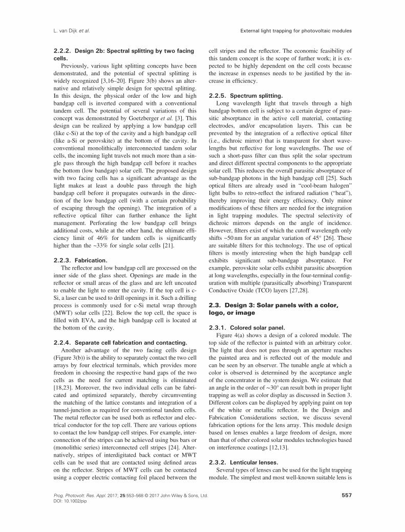
2.3.1. Colored solar panel.Figure 4(a) shows a design of a colored module. The
top side of the reflector is painted with an arbitrary color.The light that does not pass through an aperture reachesthe painted area and is reflected out of the module andcan be seen by an observer. The tunable angle at which acolor is observed is determined by the acceptance angleof the concentrator in the system design. We estimate thatan angle in the order of ∼30° can result both in proper lighttrapping as well as color display as discussed in Section 3.Different colors can be displayed by applying paint on topof the white or metallic reflector. In the Design andFabrication Considerations section, we discuss severalfabrication options for the lens array. This module designbased on lenses enables a large freedom of design, morethan that of other colored solar modules technologies basedon interference coatings [12,13].
2.3.2. Lenticular lenses.Several types of lenses can be used for the light trapping
module. The simplest and most well-known suitable lens is
External light trapping for photovoltaic modulesL. van Dijk et al.
557Prog. Photovolt: Res. Appl. 2017; 25:553–568 © 2017 John Wiley & Sons, Ltd.DOI: 10.1002/pip
the lenticular lens, which consists of an array of cylindricallenses. By refracting the incoming light (using a lenticularlens array) to one of the interlaced images, lenticular post-cards can show different images in different directions[29]. These lenticular lenses have also been used for devel-oping (glasses-free) 3D-displays [30,31]. Such a lens de-sign can be adapted for solar modules in such a way thatlight coming from the normal direction is guided towardthe opening, while light from oblique angles reaches thecolored areas and is reflected toward an observer. The col-ored solar panel looks uniformly dark (Figure 4(b)) whenseen from angles within the acceptance angle and coloredfrom an oblique angle larger than the acceptance angle(Figure 4(c)).
2.3.3. Image displaying solar panel.By replacing the colored areas by a colored pattern
(e.g., a logo or photo), images can be displayed, seeFigure 4(d). This technology resembles that of lenticularpostcards with a “flip image effect.” The most convenientdesign for an image displaying module is an image (atthe back of the glass on the reflector plane) with a pixelsize equal to that of the lenses. When the lens is a fewmillimeter, each module has a resolution in the order ofhundreds by hundreds of pixels, which is sufficient forshowing simple patterns and images in all directionsexcept for angles within the acceptance solid angle. Atlarge viewing angles, some aberrations of the image canoccur.
2.4. Design 4: Lens array of compoundparabolic concentrators
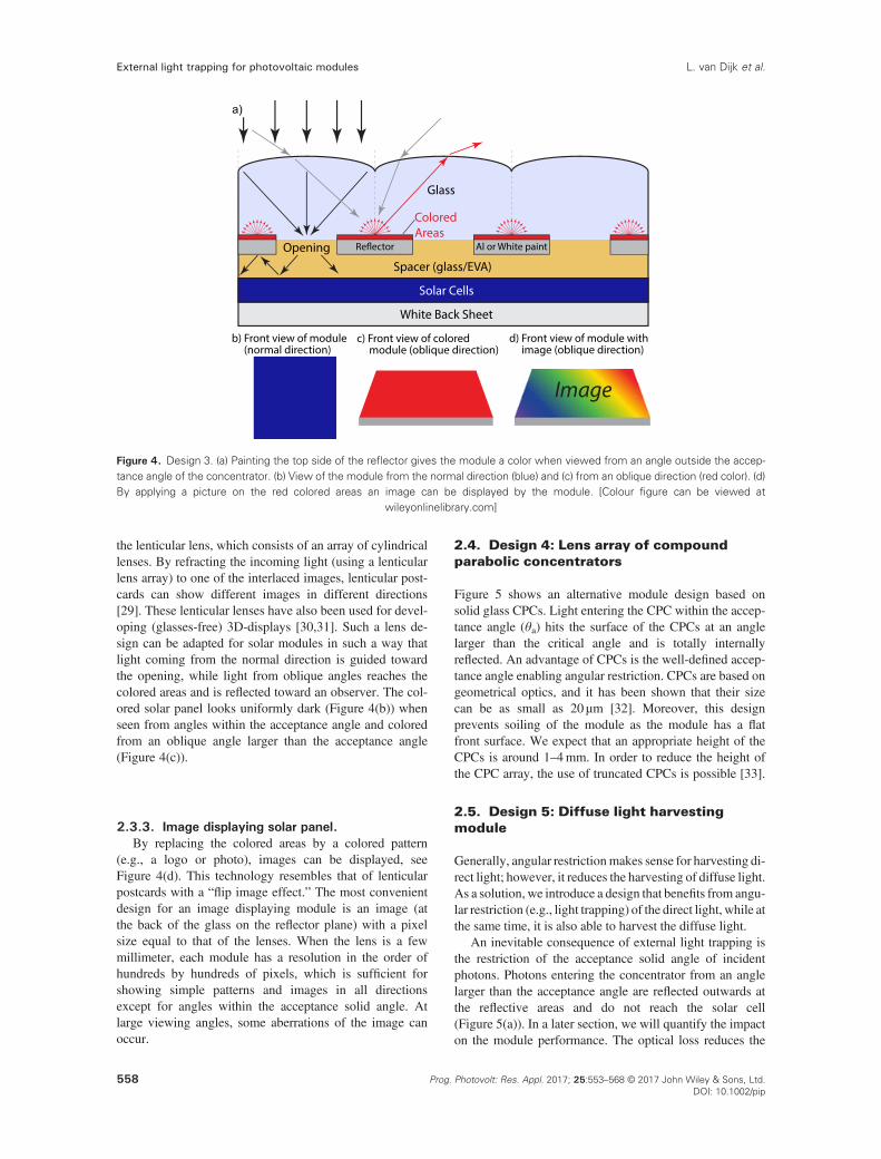
Figure 5 shows an alternative module design based onsolid glass CPCs. Light entering the CPC within the accep-tance angle (θa) hits the surface of the CPCs at an anglelarger than the critical angle and is totally internallyreflected. An advantage of CPCs is the well-defined accep-tance angle enabling angular restriction. CPCs are based ongeometrical optics, and it has been shown that their sizecan be as small as 20 μm [32]. Moreover, this designprevents soiling of the module as the module has a flatfront surface. We expect that an appropriate height of theCPCs is around 1–4mm. In order to reduce the height ofthe CPC array, the use of truncated CPCs is possible [33].
2.5. Design 5: Diffuse light harvestingmodule
Generally, angular restrictionmakes sense for harvesting di-rect light; however, it reduces the harvesting of diffuse light.As a solution, we introduce a design that benefits from angu-lar restriction (e.g., light trapping) of the direct light, while atthe same time, it is also able to harvest the diffuse light.
An inevitable consequence of external light trapping isthe restriction of the acceptance solid angle of incidentphotons. Photons entering the concentrator from an anglelarger than the acceptance angle are reflected outwards atthe reflective areas and do not reach the solar cell(Figure 5(a)). In a later section, we will quantify the impacton the module performance. The optical loss reduces the
Figure 4. Design 3. (a) Painting the top side of the reflector gives the module a color when viewed from an angle outside the accep-tance angle of the concentrator. (b) View of the module from the normal direction (blue) and (c) from an oblique direction (red color). (d)By applying a picture on the red colored areas an image can be displayed by the module. [Colour figure can be viewed at
wileyonlinelibrary.com]
External light trapping for photovoltaic modules L. van Dijk et al.
558 Prog. Photovolt: Res. Appl. 2017; 25:553–568 © 2017 John Wiley & Sons, Ltd.DOI: 10.1002/pip

module efficiency, which can be solved by geometricallyseparating the diffuse and direct light [34].
Figure 6 demonstrates a solution to this issue: a diffuselight harvesting module in which both optical componentsare directed to two separate cells, enabling higher moduleefficiency. A dedicated top cell for diffuse light may be cho-sen such that the module operates well under low irradianceby diffuse light, for example, a dye-sensitized solar cell[35]. The top cell receives the diffuse light, which doesnot travel through one of the apertures. This light containsa relatively high amount of blue light because of atmo-spheric scattering. Although this module can outperformconventional modules, the costs are expected to be signifi-cantly higher because of the large solar cell area. As a roughindication, the efficiency of this diffuse harvesting module
increases by ~10%rel w.r.t. a conventional module, whilethe solar cell area increases by 67% (if C = 3×). The effi-ciency per solar cell area is therefore around (110/167=)65% of that of a conventional module. This concept there-fore is only economically feasible when the costs per unitarea of the additional diffuse-light absorbing cells are lessthan 10% of the total balance of system costs.
3. INCOUPLING OF DIFFUSE LIGHTFOR EXTERNAL LIGHT TRAPPINGMODULES
The demonstrated designs have a specific acceptance solidangle, which is defined by the angular directions for which
Figure 6. Design 5: Diffuse light harvesting module. By integration of a solar cell on top of the reflector, the diffuse light can be har-vested by the top cell. [Colour figure can be viewed at wileyonlinelibrary.com]
Figure 5. Design 4. Illustration of a colored light trapping module based on compound parabolic concentrators (CPCs, not drawn toscale). An array of compound parabolic concentrators is applied at the inner side of the front glass sheet. Light originating from angleslarger than the acceptance angle illuminates the areas between the exit apertures and is specularly reflected. The gray ray entered themodule at an angle larger than the acceptance angle (θa) and is reflected backwards, out of the module. A color is observed when the
module is viewed from an angle larger than θa. [Colour figure can be viewed at wileyonlinelibrary.com]
External light trapping for photovoltaic modulesL. van Dijk et al.
559Prog. Photovolt: Res. Appl. 2017; 25:553–568 © 2017 John Wiley & Sons, Ltd.DOI: 10.1002/pip

the light is transmitted to the solar cell. Light originatingfrom the remaining part of the sky is rejected (i.e., reflectedoutwards at the CPC to the sky). Therefore, only when thesun is within this acceptance solid angle, the direct lightreaches the solar cell. On the other hand, the sun moveson a well-defined path of the sky for a fixed geographicallocation during the year. For optimal performance, the lensdesign and/or the shape of the openings in the reflector canbe tuned to match the acceptance solid angle to the dailyand yearly path of the sun. To estimate the performanceof the external light trapping module, we analyze whichfraction of the direct and diffuse light is transmittedthrough the openings in the reflector (Figure 2). In this sec-tion, we discuss the use of solar tracking, the acceptancesolid angle of concentrators, and the path of the sun, andfinally, we introduce a lens design with an acceptance solidangle matched to the path of the sun.
In nature, many plants (e.g., sunflowers) orient theirflowers and leaves toward the sun to collect more light,which is called heliotropism. In concentrated photovoltaics(CPV), the sun is tracked by aligning the concentrator axistoward the position of the sun. The concentration factor (C)for CPV is generally in the order of 100-2000×, and thussignificantly higher than we suggest to use for the lighttrapping module (2-10×, as defined by C=Alens/Aopening).The benefit of such low concentration factors is that theacceptance angle is relatively large.
3.1. Solar tracking versus static lighttrapping module
Currently, solar tracking is rarely deployed in non-concentrated photovoltaics. Using single or double axis,tracking the amount of collected sunlight generallyincreases by 15–20% and 25–40%, respectively [36].Tracking systems are mostly used in utility-scale solarpanel arrays [37]. As tracking the sun brings additionalcost, it is of interest to design a static (fixed mount) modulethat accepts most of the incoming light. Here, we analyzesome potential static designs for the light trapping module.For each geographical location, the path of the sun coversonly a small geometric area of the sky. Therefore, it isrelevant to see whether it is possible to design a (static)concentrator that only collects the light from the part ofthe sky in which the sun moves. The incoupling of directlight is determined by the acceptance solid angle of theconcentrator.
3.2. Acceptance angle and concentrationfactor
Each type of concentrator has a specific acceptance solidangle as determined by its shape [38]. An ideal concentra-tor, such as a CPC, gives the maximal theoretically possi-ble concentration factor for light entering within a certainacceptance angle (θa). The acceptance angle is measuredwith respect to the concentrator axis (Figure 5). The totalacceptance angle is thus 2 � θa. For an ideal linear
concentrator (also known as parabolic trough or 2D geom-etry), the concentration factor (C) is related to the accep-tance angle (θa) and the refractive index of the glass(nglass) according to the following equation [33]:
C 2Dð Þ ¼ nglasssin θað Þ (1)
Light is accepted when its projected angle (the angle asprojected on a cross section of the CPC) is smaller than θa;otherwise, it is rejected. In the next section, we show thecorresponding polar plot.
In contrast, for an ideal (rotationally symmetric) 3Dconcentrator, the angle of light with respect to the normalof the concentrator must be smaller than θa to be accepted.The concentration factor of an ideal 3D concentrator isgiven by
C 3Dð Þ ¼ nglasssin θað Þ
� �2
(2)
The associated acceptance solid angle for a verticallyorientated ideal 3D concentrator is a directional cone.
Refractive lenses have different transmission character-istics as compared with ideal concentrators. For non-idealconcentrators like lenses, there is no well-defined accep-tance angle; instead, there is a transmission curve.Incident rays having an angle smaller than a certain angleθ1 (w.r.t. the optical axis of the lens) are 100% accepted(neglecting interface losses). The value of θ1 depends onthe system design (e.g., lens and aperture). For angleslarger than θ1, the rays will be partially transmittedthrough the aperture.
3.3. Path of the sun and acceptance ofdirect sunlight
Figure 7(a) shows a polar plot with the yearly path of thesun, as seen from a location on the equator. The markedangles indicate the angle to the zenith (the zenith marksthe point in the sky directly above an observer). The posi-tion of the sun is calculated using the local time, equationof time, and some correction factors [39–41].
Figure 7(b) and (c) shows the yearly path of the sun fora geographic location with a latitude of 30° north (Figure 7(b)) and 52° north (Figure 7(c)), respectively. The tiltangles given in the caption are close to the typical optimalmodule tilt angles for conventional fixed modules and havenot been optimized for external light trapping modules. Todetermine the optimal acceptance solid angle for maximumenergy yield of the light trapping module, a yearly angularirradiance map is essential. This yearly irradiance mapincludes several effects like scattering by clouds and theangular dependent solar intensity (as determined by theatmospheric path length).
External light trapping for photovoltaic modules L. van Dijk et al.
560 Prog. Photovolt: Res. Appl. 2017; 25:553–568 © 2017 John Wiley & Sons, Ltd.DOI: 10.1002/pip
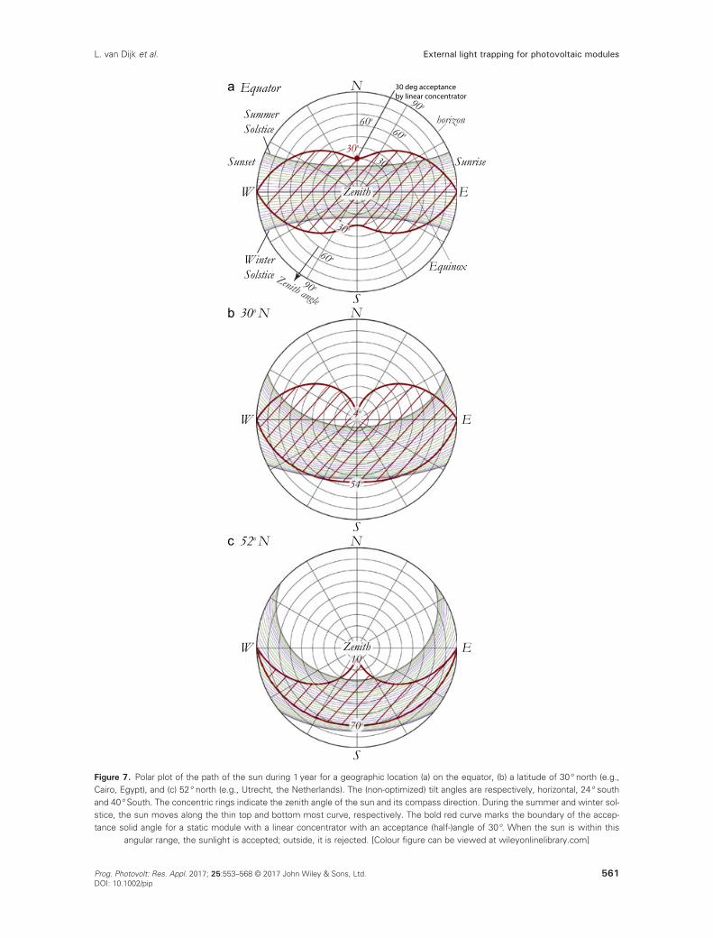
Figure 7. Polar plot of the path of the sun during 1 year for a geographic location (a) on the equator, (b) a latitude of 30° north (e.g.,Cairo, Egypt), and (c) 52° north (e.g., Utrecht, the Netherlands). The (non-optimized) tilt angles are respectively, horizontal, 24° southand 40° South. The concentric rings indicate the zenith angle of the sun and its compass direction. During the summer and winter sol-stice, the sun moves along the thin top and bottom most curve, respectively. The bold red curve marks the boundary of the accep-tance solid angle for a static module with a linear concentrator with an acceptance (half-)angle of 30°. When the sun is within this
angular range, the sunlight is accepted; outside, it is rejected. [Colour figure can be viewed at wileyonlinelibrary.com]
External light trapping for photovoltaic modulesL. van Dijk et al.
561Prog. Photovolt: Res. Appl. 2017; 25:553–568 © 2017 John Wiley & Sons, Ltd.DOI: 10.1002/pip

3.4. Matching of the path of the sun andacceptance region
Most of the direct sunlight can be accepted using a linearconcentrator which is oriented along the east–west direc-tion. The tilt of the earth axis with respect to its orbitalplane is ∼23.45°; this angle is important for choice of theacceptance solid angle of the lens. Because of this tilt,the path of the sun varies during the year. At the equator,the axial tilt equals the zenith angle at noon during thesummer solstice (20–22 June) and winter solstice (21–23December). By using an ideal concentrator with an accep-tance angle larger than the tilt angle, the direct sunlight canbe completely harvested during every day at noon through-out the year. The bold red curve in Figure 7(a) illustratesthis acceptance by showing the outer boundary of theacceptance solid angle for a horizontally orientated modulewith a linear CPC with an acceptance angle of 30°. Whenthe (angular) position of the sun is within this red shadedarea, the light is accepted completely; otherwise, it isrejected. Although the overlap of this linear concentratoris perfect most of the day, at the hours just after sunriseand just before sunset the overlap is poor for most days.Alternative concentrator designs could improve thismatching. A concentrator with an acceptance angle that ismuch smaller than 30° would reject a significant fractionof the direct sunlight. Therefore, this result suggests thatthe optimal acceptance angle (at the equator) is in the orderof around ~30°. This acceptance angle corresponds to aconcentration factor of C= 3× for a glass (n= 1.5) CPC(Eq. 1).
For a location on the equator during the equinox (sun oneast–west line), the direct light of the sun is accepted fromsunrise (east) to sunset (west). For other days of the year,there is a small cut-off just after sunrise and just beforesunset. However, this is only a small fraction of thedaytime, and moreover, the intensity at low elevation(sun close to horizon) on the solar module is low becauseof the long path length through the atmosphere as well asthe decrease of the effective intensity on the module dueto an area projection of the incidence angle (θi) accordingto I = Isun � cos(θi) [42].
Non-ideal concentrators, like the refractive lenses insome of our designs, do not have a well-defined acceptanceangle (Section 3). As a consequence of their transmissioncurve, there are certain angular directions from which thelight is partially accepted. Therefore, there is no well-defined border of the acceptance solid angle; instead, thereis a gradual (transmission) transition.
For locations at a latitude of 30° and 52° north (Figure 7(b),(c)), the matching of the path of the sun and the accep-tance solid angle is less optimal for the lenticular lensdesign. Further optimization is thus required of the lensdesign (and associated acceptance solid angle and moduleorientation) using accurate angular dependent irradiancemodels [43,44].
The introduced concepts are particularly interesting forthe sun facing side of gable roofs in countries with
moderate latitude. By modifying the acceptance solid angleby tuning the design (e.g., shifting the position of theopenings w.r.t. the lens array), there is also potential forvertical façades of buildings, especially for the sun facingside of the building (i.e., facing south on the northernhemisphere).
4. ACCEPTANCE OF DIFFUSE ANDDIRECT LIGHT
The power conversion efficiency of design 1–4 is sensitiveto the fraction of diffuse sunlight. It is noted that the bright-ness of the colored solar modules is also determined by thisfraction, this aspect is not further discussed here. To ana-lyze the absorptance of module design 1, the transmittanceof diffuse light by the concentrator needs to be determined.For isotropically distributed incident diffuse light, a frac-tion 1
C is transmitted by the CPC, and the remaining partis rejected [45,46]. A C= 2× concentrator thus transmits50% of the diffuse light. The fraction of diffusely incidentphotons is determined by the geographic location of themodule. Regions with a high time-average of clear skyconditions are favorable for external light trapping.Moreover, it is advantageous to have a geographic locationwith a short (averaged) optical path length through theatmosphere to reduce Rayleigh scattering to minimizediffuse irradiance.
For areas around the equator, the fraction of diffuseincoming photons is relatively low. For example, forTamanrasset (Algeria), the diffuse irradiance is ∼10%[47]of which a fraction 1� 1
C is rejected by the CPC. So whena C= 3× concentrator is used at this location, 6.7%¼ 0:1� 1� 1
C
� �� �of the total (diffuse and direct) light is
rejected. For other geographic areas with more diffuselight, this loss can be too large for a net improvement ofthe module efficiency. For these high diffuse irradianceregions, design 5 can be used to capture both the directand diffuse light.
4.1. Optimal acceptance angle
A remaining question is whether an optimal concentrationfactor for a given fraction of diffuse light can be deter-mined. To address this question, we first assume that thedirect light is completely accepted. This is possible usinga static module at low concentration factors as discussedbefore or, if needed, by tracking the sun. When the concen-tration factor is changed, both the trapping performance (ofboth diffuse and direct accepted light) and the fraction ofaccepted diffuse sunlight are affected. Light in the trapmoves back and forth between the cell and the reflector.During each pass, there is a certain probability for the lightto be absorbed or to escape via the openings. As previouslyderived from the associated geometrical series [10], the(integrated) absorptance of the cell in a light trap underdirect illumination is given by
External light trapping for photovoltaic modules L. van Dijk et al.
562 Prog. Photovolt: Res. Appl. 2017; 25:553–568 © 2017 John Wiley & Sons, Ltd.DOI: 10.1002/pip

Atrap ¼ T cAsc
1� Rsc 1� C�1� �
Rreflector(3)
with Atrap the total absorptance of the module with trap, Tcthe transmittance of the concentrator with concentrationfactor C, Asc and Rsc(=1�Asc) the absorptance and reflec-tance of the solar cell, respectively (without trap), andRreflector the reflectance of the reflector. Previously, weanalyzed the effect of Tc and Rreflector on the device perfor-mance; both need to be as high as possible for maximalperformance [11]. Additionally, the parasitic loss due toabsorptance by the encapsulant can be included bysubstituting Tc→TcTenc and Rreflector→RreflectorT2
enc withTenc the transmittansce of light through the encapsulantduring a single pass.
This equation can be adapted to include both the directand diffuse component. As a first order approximation, weassume that the diffuse light is isotropically distributed. Inreality, however, the intensity (and spectrum) of diffuselight on a cloudless sky decreases (to first order) withincrease of the zenith angle as the path length through theatmosphere increases with the zenith angle. Accuratemodels and/or local measurements of the angular depen-dent irradiance are needed to improve the accuracy of Eq.(3) [43,44,48,49]. The potential impact of non-uniform il-lumination on the cell performance as well as several solu-tions to re-homogenize the light has been discussedpreviously [9,50]. For the designs presented here, the in-tensity variations are mild, and therefore, no severe impacton cell performance is expected [51]. A fraction fd of theintensity of the incoming light is assumed to be diffused;the remaining intensity (1� fd) is direct. A fraction 1
C ofthe diffuse light is accepted. In that case, Eq. (3) becomes
Atrap ¼ 1� f d þ1Cf d
� �T c
Asc
1� Rsc 1� C�1� �
Rreflector(4)
Because of the underlying assumptions of this adaptedmodel, such as isotropically distributed diffuse light,(quasi-)randomization of light in the cage, and completeacceptance of the direct light, this equation only gives arough estimate of the total yearly absorptance of an exter-nal light trapping module in the field [9]. For a lenticularlens array, Eq. (4) slightly overestimates the contribution(i.e., acceptance) of the direct light as this component isnot always accepted (Figure 7). The contribution of diffuselight is expected to be underestimated as the fraction of dif-fuse light from angles close to the sun (which are mostlywithin the acceptance solid angle of the concentrator) isrelatively high. This model can be improved by making itspectrally dependent. This requires the use of a representa-tive spectrum for the direct and diffuse light and thushighly depends on the geographical location.
Figure 8a and b shows the total absorptance (Atrap) ofthe diffuse, direct, and total irradiance as a function ofthe concentration factor (C) for a solar module having aspectrally weighted average absorptance (Asc) of 0.5 and
0.87 for above bandgap light, respectively. This figurewas obtained by calculating the individual components ofEq. (4), assuming Rreflector = 1.
An absorptance of Asc = 0.5 is unrealistically low butgives an impression of how the absorptance of photonswith wavelengths close to the band gap can improve. Thevalue Asc = 0.87 represents a typical effective absorptanceof the plane with solar cells at normal incidence. Thisabsorptance value can be calculated as unity minus thereflection from the solar cell, the white back sheet betweenthe solar cells and the surface coverage by the electricalgrid on the cell [9]. The four different lines of the samecolor indicate four different fractions of diffuse irradiance(fd). Sun tracking is not required when the acceptanceangle is larger than ~30°, corresponding to concentrationfactor of C< ~3×, as discussed earlier.
Figure 8(a) shows the total absorptance for a solar cellthat has an absorptance of 0.5 without integration of anexternal light trap. The total cell absorptance, the sum ofdiffuse and direct light, increases when fd< 0.5. Withincreasing C, a smaller fraction of the diffuse light isaccepted, while the absorptance of the direct light increasesbecause of improved light trapping. As a net result of theexternal light trapping, the total absorptance shows amonotonic increase or decrease with increasing C; so nooptimum concentration factor can be determined.
Figure 8(b) shows that it is more challenging to realizesignificant absorptance improvement for a (more realistic)cell with an absorptance of Asc = 0.87. For a module withsuch cells, an efficiency gain is obtained when fd< 0.1.Hence, under the present assumptions, we conclude thatthe basic light trapping module is expected to performbetter than conventional modules in geographical regionswith a diffuse irradiance of around 10% and lower, likein Algeria and Egypt [47]. If the diffuse light is moreintensely distributed closely to the position of the sun, alarger fraction of the diffuse light originates from withinthe acceptance solid angle, leading to improved moduleperformance.
To appreciate the light trapping module, we providerough estimates of its potential. As a rule of thumb fordirect light, the presented light trapping module (withconcentrators with C = 3×) reduces the overall reflectanceby a factor 3 [9]. When conventional cells are used indesign 1 or design 4, a reflectance reduction from ~15%(for conventional modules) to ~5% is expected for mostof the direct light. A fraction of ~1/3 of the diffuse lightreaches the bottom cell and is absorbed. Besides theiradvantage of being colored, these designs might benefiteven more from using thin solar cells with less bulk recom-bination resulting in a higher Voc.
For design 5, the absorption of direct light is similar, butin this case also, most of the diffuse light is harvested. Dif-fuse light reaching the top cell travels through the cell as ina conventional module with ~85% absorption. Diffuselight reaching the bottom cell is trapped, and effectively,~95% is absorbed. For this design, the direct light of thesun on moments when the sun is outside the angular
External light trapping for photovoltaic modulesL. van Dijk et al.
563Prog. Photovolt: Res. Appl. 2017; 25:553–568 © 2017 John Wiley & Sons, Ltd.DOI: 10.1002/pip

acceptance solid angle (e.g., see sunset and sunrise inFigure 7) is not rejected but reaches the top cell. Again,an even bigger gain can be expected when the cell thick-ness is reduced as this leads to a gain in Voc.
5. DESIGN AND FABRICATIONCONSIDERATIONS
5.1. Design of Lens Array
There are several options for the configuration of the lensesin an array [11]. For example, one can use square or hexago-nal arrays or rows of lenses. The shape of the lens determinesthe geometrical area of the sky (or the angular space) fromwhich the sunlight is accepted (and the complementary areawhere light is rejected and reflected out of the module).
The lens array can be fabricated by shaping the frontglass or by applying a polymer coating on top of the glass.A liquid polymer layer can be molded in the right shapeusing a stamp, after which the polymer solidifies. Theoptimal shape of the lens depends on several conditions,including the thickness of the glass, the tolerable curvatureof the glass or polymer cover layer (preventing accumula-tion of dust and strong Fresnel reflectance), and thepreferred acceptance solid angle, which is directly relatedto the concentration factor and light trapping efficiencyaccording to Eqs (2) and (4). If the lens has a focal lengthsimilar to its diameter, the optimal lateral dimension of thelenses in the same order of magnitude as the thickness ofthe glass (2 to 5mm). The associated dimension of theopenings in the reflector is in the order of 1 to 2.5mm.To limit the aspect ratio of the lenses, Fresnel lenses canbe used.
Figure 8. Plots of the absorptance by an external light trapping module for the direct and diffuse components of sunlight as a functionof the concentration factor for (a) a module with solar cells having an absorptance of Asc = 0.5 and (b) an absorptance of Asc = 0.87.Shown is the absorptance for isotropically distributed diffuse light (red), direct light (dashed, green), and total light (thick, blue). Thecurves are shown for various fractions of the diffuse light (fd = 0.05, 0.1, 0.2, 0.5). [Colour figure can be viewed at wileyonlinelibrary.
com]
External light trapping for photovoltaic modules L. van Dijk et al.
564 Prog. Photovolt: Res. Appl. 2017; 25:553–568 © 2017 John Wiley & Sons, Ltd.DOI: 10.1002/pip

5.2. Commonly available lenses
There are many commercially applied lens designs that canbe adapted for light trapping modules [52–55]. Microlensarrays are commonly used in Complementary Metal-OxideSemiconductor (CMOS) imaging and wavefront sensors[56]. However, they are not expected to be optimal forthe light trapping module because of their relative lowtransmittance, relative long focal length (f), and low nu-merical aperture (NA). Small lenses are commonly usedin optical cameras, and there is much development of smalllenses for camera integration in mobile phones. The tech-nology developed for fabricating these lenses can beemployed for the fabrication of the lens array of the exter-nal light trapping module. Hollow CPC could be usedwhen dust accumulation is prevented. Alternatively, di-electric CPCs are expected to be more interesting as theyoffer a higher degree of light trapping (e.g., concentrationfactor) for a fixed acceptance angle than hollow CPCs.
5.3. Ultra-precision glass pressing for lens
The transmittance of the lens (or CPC) array plays acrucial role in the device performance, as indicated byTc in Eq. (3). The lens/CPC array can be fabricated fromseveral materials by various fabrication processes. Forexample, ultra-precision glass pressing (also known asprecision glass molding), is a commonly used processused for fabricating lenses in, for example, photo cam-eras. The costs of a mold process are much lower thanthe costs of mechanically processed (e.g., by diamondturning) glass. This process is commonly used for thefabrication of automotive headlight lenses. In this pro-cess, fire-polished preforms are molded in their finalshape such that the surface quality of the preform is pre-served. A commonly used mold material is SCHOTTB270 (Mainz, Germany) superwite, which has an internaltransmission of close to 100%. The only reflection lossesoccur at the interfaces and can be minimized using anti-reflection coatings. A lens swith an AR-coating stillbends the light in the same way as a lens without anAR-coating, so this improves the optical efficiency ofthe lens. The manufacturing cost of this process is notexpected to become sufficiently low for PV application;however, the process can be highly suited to fabricate aprototype. Several companies offer CPCs fabricated byultra-precision glass pressing at relatively low cost[57,58]. The transmittance of these solid glass CPCs issufficiently high for light trapping modules; their trans-mittance is mainly determined by the reflectance fromthe top and bottom interfaces. Alternatively, the polymerZeonex®, which is used in many optical instruments, canbe an interesting option; it provides the design freedomof molded plastic and the optical properties of glass.The knowledge of concentrators that was developed forCPV[59] can be used for the relatively low concentrationfactors used in the light trapping module.
5.4. Poly(methyl methacrylate) windowlayer
Instead of applying lenses on top of a glass sheet, apolymer based window sheet can be used. For example,Evonik offers Poly(methyl methacrylate) Fresnel lensesfor solar applications that can be made by thermoforming[60]. Fresnel lenses are also suited for the light trappingmodule.
5.5. Reflector
The reflector can be fabricated from a metal with highspecular reflectance or a diffusely reflecting white paint(e.g., TiO2). The diffuse or specular reflectivity can haveimportant consequences on the homogeneity of the cellillumination and the light trapping efficiency [9]. A reflec-tivity of >90% is desired and is technically feasible.
5.6. Large area fabrication
Mass production of external light traps can, for example,be realized through injection molding. Generally, the preci-sion molds that are used as a master in injection moldingprocesses are fabricated by milling and diamond turning.These highly precise parts are rather expensive (hundredsof thousands of dollars), but as each mold can be used tofabricate millions of items, the costs per item are still rela-tively low compared with other fabrication techniques. Theaccuracy of the mold is of utmost importance as thisdetermines the accuracy of the final parts.
6. OUTLOOK
6.1. Need for stable high bandgap cell
The main benefits provided by the external light trappingmodule for tandem integration are the four-terminalcontacting, separate cell fabrication, and improved lightmanagement. These significant advantages can render theexternal light trapping module as the superior technologyfor modules with tandem cells. Essential to the success ofsuch tandem cells is the availability of a stable, low-cost,high bandgap solar cell. Recently, a high bandgap GaInPcell and a c-Si cell were mechanically stacked resultingin an efficiency of 29.8% [61]. Alternatively, there is alarge potential for high bandgap cells based on perovskitematerials [62,63].
6.2. Inter-cell spacing
Some solar modules manufacturers (e.g., Trina Solar[64])increase the inter-cell spacing to enlarge the module areaand reduce the cost per Wp. This concept works formodules having a dedicated white back sheet: lightreflecting on this white back sheet is (laterally) redirectedtoward a neighboring cell via internal light trapping in
External light trapping for photovoltaic modulesL. van Dijk et al.
565Prog. Photovolt: Res. Appl. 2017; 25:553–568 © 2017 John Wiley & Sons, Ltd.DOI: 10.1002/pip

the glass. This improves the power output of the moduleand reduce the cost per Wp. Note: although increasing theinter-cell spacing slightly reduces the module efficiency,it effectively increases the module area (and power)without requiring additional (costly) solar cells. Similarly,the light trapping module can benefit from increased cellspacing, as this results in larger module area and highertotal power output of the module (compared with aconventional module), while effectively only adding thecosts of additional glass.
7. CONCLUSIONS
We introduced and discussed five design concepts forexternal light trapping on solar modules with novelfeatures. The broadband optical confinement offered bythe external light trap enables a higher power conversionefficiency. The light trapping module can be effective formost types of solar cells, and it also enables using thinnersolar cells with less bulk recombination. The hybridtandem cell concept allows for simple integration ofphysically separated solar cells. Besides the light trappingcapabilities of the module, we presented modified modulesthat can display a color and even images. In white modulesbased on interference coatings the solar cell receives a re-duced amount of light and its efficiency drops by ∼40%relatively [65]. Our colored external light trapping modulescan be expected to result in significantly lower efficiencyloss because of the splitting of the direct and diffuse light.A fraction of ~13 of the diffuse light is reflected out of themodule. This is expected to result in a net optical loss inthe order of 7–35% of the total sunlight depending on thegeographic location. Moreover, we presented a first designof a lens tailored to the path of the sun, avoiding the needof sun tracking. The illustrated design 5 collects and(partly) traps both the diffuse and direct sunlight compo-nent, which can be particularly interesting for geographicregions with a high fraction of diffuse irradiance. This de-sign brings down the reflectance of direct light by a factorof ~3, while concurrently the diffuse light is also harvestedand even partly trapped. We showed that external lighttrapping offers a simple and effective overall light manage-ment solution. The possibility of highly efficient, colored,and image displaying modules makes this technology aninteresting candidate for a new generation of photovoltaicmodules.
ACKNOWLEDGEMENTS
The authors acknowledge the insightful discussions withK. Sinapis, A. Polman, and W.C. Sinke. This work issupported by NanoNextNL, a micro and nanotechnologyconsortium of the Government of the Netherlands and130 partners.
REFERENCES
1. Campbell P. The Limiting Efficiency of SiliconSolar Cells under Concentrated Sunlight. 1986;D:234–239.
2. Luque A, Miñano JC. Optical aspects in photovoltaicenergy conversion. Sol Cells. 1991; 31: 237–258
3. Goetzberger A, Goldschmidt JC, Peters M, Löper P.Light trapping, a new approach to spectrum splitting.Solar Energy Materials and Solar Cells 2008; 92(12):1570–1578. DOI:10.1016/j.solmat.2008.07.007
4. Peters M, Goldschmidt JC, Bläsi B. Angular confine-ment and concentration in photovoltaic converters.Solar Energy Materials and Solar Cells 2010; 94(8):1393–1398. DOI:10.1016/j.solmat.2010.04.009
5. Braun A, Katz E, Feuermann A, Kayes BM D, GordonJM. Photovoltaic performance enhancement by exter-nal recycling of photon emission. Energy and Environ-mental Science 2013; 6(5): 1499. DOI:10.1039/c3ee40377g
6. Kosten ED, Newman BK, Lloyd JV, Polman A,Atwater HA. Limiting light escape angle in siliconphotovoltaics: ideal and realistic cells. IEEE Journalof Photovoltaics 2015; 5(1): 61–69. DOI:10.1109/JPHOTOV.2014.2360566
7. Weinstein L, Kraemer D, McEnaney K, Chen G.Optical cavity for improved performance of solarreceivers in solar-thermal systems. Solar Energy2014; 108: 69–79
8. Tvingstedt K, Dal Zilio S, Inganäs O, Tormen M.Trapping light with micro lenses in thin film organicphotovoltaic cells. Optics Express 2008; 16(26):21608–21615. DOI:10.1364/OE.16.021608
9. van Dijk L, van de Groep J, Di Vece M, Schropp REI.Exploration of external light trapping for photovoltaicmodules. Optics Express 2016; 24(14): A1158.DOI:10.1364/OE.24.0A1158
10. van Dijk L, Paetzold UW, Blab GA, Schropp REI, DiVece M. 3D-printed external light trap for solar cells.Progress in Photovoltaics: Research and Applications2016; 24(5): 623–633. DOI:10.1002/pip.2702
11. van Dijk L, Marcus EAP, Oostra AJ, Schropp REI, DiVece M. 3D-printed concentrator arrays for externallight trapping on thin film solar cells. Solar EnergyMaterials and Solar Cells 2015; 139: 19–26.DOI:10.1016/j.solmat.2015.03.002
12. Solaxess, Neuchâtel, Switzerland, www.solaxess.ch.13. Ballif C, Scharf T, Escarre J. Solar photovoltaic module.
Patent WO 2014170323 2014; A1 Oct. 23, 2014.14. Sunpartner Technologies, Rousset, France, www.
sunpartnertechnologies.com.15. PVLighthouse–Tracey software, pvlighthouse.com.au.16. Imenes AG, Mills DR. Spectral beam splitting technol-
ogy for increased conversion efficiency in solar
External light trapping for photovoltaic modules L. van Dijk et al.
566 Prog. Photovolt: Res. Appl. 2017; 25:553–568 © 2017 John Wiley & Sons, Ltd.DOI: 10.1002/pip

concentrating systems: a review. Solar Energy Mate-rials and Solar Cells 2004; 84(1–4): 19–69.DOI:10.1016/j.solmat.2004.01.038
17. Goldschmidt JC, Do C, Peters M, Goetzberger A.Spectral splitting module geometry that utilizes lighttrapping. Solar Energy Materials and Solar Cells2013; 108: 57–64. DOI:10.1016/j.solmat.2012.09.001
18. Mitchell B, Peharz G, Siefer G, et al. Four-junctionspectral beam-splitting photovoltaic receiver with highoptical efficiency. Progress in Photovoltaics: Researchand Applications 2011; 19: 61–72
19. Mojiri A, Taylor R, Thomsen E, Rosengarten G.Spectral beam splitting for efficient conversion of solarenergy—A review. Renewable and SustainableEnergy Reviews 2013; 28: 654–663. DOI:10.1016/j.rser.2013.08.026
20. Green MA, Keevers MJ, Concha-Ramon B, et al.Improvements in sunlight to electricity conversionefficiency: above 40% for direct sunlight and over30% for global. Proc EUPVSEC 2015.
21. Bremner SP, Levy MY, Honsberg CB. Analysis oftandem solar cell efficiencies under AM1.5G spectrumusing a rapid flux calculation method. Progress inPhotovoltaics: Research and Applications 2008;16(3): 225–233. DOI:10.1002/pip.799
22. Lamers MWPE, Tjengdrawira C, Koppes M, et al.17.9% metal-wrap-through mc-Si cells resulting inmodule efficiency of 17.0%. Progress in Photovol-taics: Research and Applications 2012; 20(1): 62–73.DOI:10.1002/pip.1110
23. Almansouri I, Ho-Baillie A, Bremner SP, Green MA.Supercharging silicon solar cell performance by meansof multijunction concept. IEEE Journal ofPhotovoltaics 2015; 5(3): 968–976. DOI:10.1109/JPHOTOV.2015.2395140
24. Soppe WJ, Van Aken BB, Dörenkämper M, DevileeC, Heijna MCR, Löffler J. Roll to roll fabricationprocess of thin-film silicon solar cells on steel foil.In: Proc. 24th European Photovoltaic Solar EnergyConf. and Exhibition (Hamburg, Germany, 21–25thSeptember 2009). ; 2009:2750–2753.
25. Uzu H, Ichikawa M, Hino M, et al. High efficiencysolar cells combining a perovskite and a siliconheterojunction solar cells via an optical splittingsystem. Applied Physics Letters 2015; 106(1): 13506.DOI:10.1063/1.4905177
26. Thorlabs.de, Red Dichroic Filters, thorlabs.de/newgrouppage9.cfm?objectgroup_id = 986 (section“graphs”).
27. Werner J, Dubuis G,Walter A, et al. Sputtered rear elec-trode with broadband transparency for perovskite solarcells. Solar Energy Materials and Solar Cells 2015;141: 407–413. DOI:10.1016/j.solmat.2015.06.024
28. Almansouri I, Ho-Baillie A, Green MA. Ultimateefficiency limit of single-junction perovskite anddual-junction perovskite/silicon two-terminal devices.Japanese Journal of Applied Physics 2015;54(8S108KD04). DOI:10.7567/JJAP.54.08KD04
29. Johnson R, Jacobsen G. Lenticular lens array and toolfor making a lenticular lens array. 2003.
30. Jung J-H, Yeom J, Hong J, Hong K, Min S-W, Lee B.Effect of fundamental depth resolution and cardboardeffect to perceived depth resolution on multi-viewdisplay. Optics Express 2011; 19(21): 20468–20482.DOI:10.1364/OE.19.020468
31. Dimenco, www.dimenco.eu.32. Atwater JH, Spinelli P, Kosten E, et al. Microphotonic
parabolic light directors fabricated by two-photonlithography. Applied Physics Letters 2011; 99: 151113
33. Winston R, Miñano JC, Benítez P. NonimagingOptics. Elsevier Academic Press: Burlington, SanDiego, London; 2005.
34. Tormen M, Inganäs O, Tvingstedt K, Zilio SD. PatentUS20100186798, Photovoltaic device with enhancedlight harvesting. 2010.
35. Bandara T, Jayasundara W, Fernado H, et al.Efficiency of 10% for quasi-solid state dye-sensitizedsolar cells under low light irradiance. Journal ofApplied Electrochemistry 2015; 45(4): 289–298
36. Luque A, Hegedus S.Handbook of Photovoltaic Scienceand Engineering. JohnWiley & Sons: New York; 2011.
37. Sunpower C7 tracker, www.us.sunpower.com.38. Victoria M, Domínguez C, Antón I, Sala G. Compara-
tive analysis of different secondary optical elementsfor aspheric primary lenses. Optics Express 2009;17(8): 6487–6492. DOI:10.1364/OE.17.006487
39. Vant-Hull LL, Hildebrandt AF. Solar thermal power sys-tem based on optical transmission. Solar Energy.1976;18(1):31–39. doi:10.1016/0038-092X(76)90033-5.
40. Blanco-Muriel M, Alarcón-Padilla DC, López-Moratalla T, Lara-Coira M. Computing the solarvector. Solar Energy 2001; 70(5): 431–441.DOI:10.1016/S0038-092X(00)00156-0
41. PVEducation, http://pveducation.org.42. Beal RJ, Potter BG, Simmons JH. Angle of incidence
effects on external quantum efficiency inmulticrystalline silicon photovoltaics. IEEE Journalof Photovoltaics 2014; 4(6): 1459–1464.DOI:10.1109/JPHOTOV.2014.2350672
43. Muneer T, Gul MS, Kubie J. Models for estimatingsolar radiation and illuminance from meteorologicalparameters. Journal of Solar Energy Engineering2000; 122(3): 146. DOI:10.1115/1.1313529
44. Muneer T. Solar radiation and daylight models.Chemistry (Easton) 2004; 345. DOI:10.1016/B978-075065974-1/50015-2
External light trapping for photovoltaic modulesL. van Dijk et al.
567Prog. Photovolt: Res. Appl. 2017; 25:553–568 © 2017 John Wiley & Sons, Ltd.DOI: 10.1002/pip

45. Welford WT, Winston R, Sinclair DC. The optics ofnonimaging concentrators: light and solar energy.Physics Today 1980; 33: 56.
46. Rabl A. Comparison of solar concentrators. SolarEnergy 1976; 18(2): 93–111. DOI:10.1016/0038-092X(76)90043-8
47. Meteonorm, http://meteonorm.com.48. Perez R, Ineichen P, Seals R, Michalsky J, Stewart R.
Modeling daylight availability and irradiancecomponents from direct and global irradiance. SolarEnergy 1990; 44(5): 271–289. DOI:10.1016/0038-092X(90)90055-H
49. Solar spectrum calculator, https://pvlighthouse.com.au.50. Luque A, Sala G, Arboiro JC. Electric and thermal
model for non-uniformly illuminated concentrationcells. Solar Energy Materials and Solar Cells 1998;51(3): 269–290
51. Gordon JM, Feuermann D, Mashaal H. Micro-opticaldesigns for angular confinement in solar cells. JournalPhotoenergy 2015; 5(1): 55599
52. Mills DR, Giutronich JE. Ideal prism solar concentra-tors. Solar Energy 1978; 21(5): 423–430.DOI:10.1016/0038-092X(78)90175-5
53. Schuetz MA, Shell KA, Brown SA, Reinbolt GS,French RH, Davis RJ. Design and construction of a7× low-concentration photovoltaic system based oncompound parabolic concentrators. IEEE Journal ofPhotovoltaics 2012; 2(3): 382–386. DOI:10.1109/JPHOTOV.2012.2186283
54. Jared BH, Saavedra MP, Anderson BJ, et al. Micro-concentrators for a microsystems-enabled photovoltaic
system. Optics Express 2014; 22(S2): A521.DOI:10.1364/OE.22.00A521
55. Lee K, Lee J, Mazor BA, Forrest SR. Transforming thecost of solar-to-electrical energy conversion: integrat-ing thin-film GaAs solar cells with non-trackingmini-concentrators. Light Science Application 2015;4(5e288). DOI:10.1038/lsa.2015.61
56. Thorlabs, www.thorlabs.com.57. Edmund optics, item #63-229, www.edmundoptics.
com.58. Isuzu glass, http://www.isuzuglass.com.59. Araki K, Emery K, Siefer G, et al. Comparison of
efficiency measurements for a HCPV module with 3 Jcells in 3 sites. In: Photovoltaic SpecialistsConference, 2005. Conference Record of the Thirty-First IEEE. ; 2005:846–849.
60. Evonik, www.evonik.com.61. Essig S, Steiner MA, Allebe C, et al. Realization of
GaInP/Si dual-junction solar cells with 29.8% 1-sunefficiency. IEEE Journal of Photovoltaics 2016; 6(4):1012–1019. DOI:10.1109/JPHOTOV.2016.2549746
62. DyeSol, www.dyesol.com.63. OxfordPV, www.oxfordpv.com.64. Interview with P. Verlinden (Trina Solar): limit for
industrial c-Si solar cells reached in 2030: what next?- www.pv-tech.org.
65. Escarre J, Li H-Y, Sansonnens L, et al. When PV mod-ules are becoming real building elements: white solarmodule, a revolution for BIPV. In: 2015 IEEE 42ndPhotovoltaic Specialist Conference (PVSC). IEEE;2015:1–2. doi:10.1109/PVSC.2015.7355630.
External light trapping for photovoltaic modules L. van Dijk et al.
568 Prog. Photovolt: Res. Appl. 2017; 25:553–568 © 2017 John Wiley & Sons, Ltd.DOI: 10.1002/pip