tliillfiSI - International Nuclear Information System (INIS)
Upload
khangminh22Category
view
5download
0
CH01000243
INIS-CH--038
TransactionsOral Presentations and Posters
war *
3 2 / 25
5th International Topical Meeting onResearch Reactor Fuel ManagementApril 1 to 3, 2001, Aachen, GermanyOrganised by the European Nuclear Society

European Nuclear SocietyBelpstrasse 23P.O.Box 5032CH-3001 Berne/Switzerland
Phone Number: +41 58 286 6111Fax Number: +41 58 286 6845
E-mail: rrfm2001 @to.aey.chhttp://www.euronuclear.org/meetings
/W.S-CH -CH01000243
RRFM 2001
5th International Topical Meeting on
Research Reactor Fuel Management
Eurogress Aachen, Germany
April 1-3,2001
Organised by the European Nuclear Society
in cooperation with the International Atomic Energy Agency
Invited and Contributed Papers
Oral and Poster Presentations
RRFM 2001 PROGRAM COMMITTEE
Chairman: Pol Gubel, CEN/SCK Mol, Belgium
Vladimir L. Afanasjev, Novosibirsk CPP, Russia
Philip Beeley, HMS Sultan, United Kingdom
Andre Chabre, CEA Saclay, France
Joel Guidez, EC Joint Research Centre Petten, The Netherlands
Jean Le Pape, Cerca, France
Hans Muller, Nukem, Germany
lain G. Ritchie, International Atomic Energy Agency, Austria
Gerd Thamm, Research Centre Julich, Germany
Istvan Vidovszky, KFKI Atomic Energy Research Institute, Hungary
Jacob W. de Vries, Interfaculty Reactor Institute Delft, The Netherlands
Published by the European Nuclear Society (ENS)
Belpstrasse 23, P.O. Box 5032, CH-3001 Berne (Switzerland)
Phone: +41 58 286 61 11 Fax: +41 58 286 68 45
INDEX
Session 1: Fissile materials supply, fuel fabrication and licensing Page
FRM-II: status of construction, licensing and fuel tests 1A. Axmann, K. Boning and M. Nuding, Technical University of Munich, and H.-J. Didier,Framatome ANP GmbH, Germany
Reduction of fuel enrichment for research reactors built-up in accordance withRussian (Soviet) projects 127A.B. Aleksandrov, A.A. Enin and A.A. Tkachyov, Novosibirsk Chemical Concentrates Plant,Russia
CERCA 01: a new safe multidesign MTR transport cask 6B.S. Faure-Geors, Framatome ANP Nuclear Fuel - Cerca, and M.E. Doucet,Framatome ANP Nuclear Fuel, France
The new context for transport of radioactive and nuclear material 12C. Anne and J. Galtier, Transnucleaire, France
Session 2: Development and qualification
The qualification of a new fuel — the operator's perspective 17E. Koonen, SCK/CEN, Belgium
Status of research reactor fuel test in the High Flux Reactor (Petten) 22J. Guidez and S. Casalta, European Commission, JRC, and F.J. Wijtsma, P.J.M. Thijssen,J.A. Hendriks and G. Dassel, NRG Petten, The Netherlands, and H. Vacelet, Cerca Framatome,and A. Languille, CEA Cadarache, France
Progress in qualifying low-enriched U-Mo dispersion fuels 27J.L. Snelgrove, G.L. Hofman, S.L. Hayes and M.K. Meyer, Argonne National Laboratory, USA
Safety assessments of IRIS irradiation tests performed in SILOE and OSIRIS for thequalification of new fuels for research reactors 35H. Abou Yehia, G. Bars, A. Orjol and P. Tran Dai', IPSN, France
Experimental irradiation of full-sized plates of high density UMo fuels 41P. Sacristan, A. Languille and F. Souchon, CEA Saclay/Cadarache, and H. Vacelet, Cerca, andJ.M. Hamy, Framatome, and J.L. Guillet, Cogema, and E. Le Borgne, Technicatome, France
Qualification of high density fuel manufacturing for research reactors at CNEA 46P. Adelfang, L. Alvarez, N. Boero, R. Calabrese, M. De La Fuente, P. Echenique, M. Markiewicz,E. Pasqualini, G. Ruggirello and H. Taboada, CNEA, Argentina
Session 3: Reactor operation, fuel safety and core conversion
New nuclear technologies will help to ensure the public trust and further developmentof research reactors 51S.V. Miasnikov, Kurchatov Institute, Russia
Fast reactor core management in Japan: twenty years of evolution at JOYO 56S. Maeda, T. Sekine and T. Aoyama, Japan Nuclear Cycle Development Institute, Japan
Absolute on-line in-pile measurement of neutron fluxes using self-powered neutrondetectors: Monte Carlo sensitivity calculations 61L. Vermeeren, SCK/CEN, Belgium
New research possibilities at the Budapest research reactor 66T. Hargitai and I. Vidovszky, KFKI Atomic Energy Research Institute, Hungary
Session 4: Spent fuel management, corrosion and degradation
Dry storage of the BR3 spent fuel in the Castor BR3 cask 73L. Ooms, V. Massaut and L. Noynaert, SCK/CEN, and M. Braeckeveldt, Niras/Ondraf, Belgium
Management and physical assessment of the spent fuel from research reactors in Poland 78S. Chwaszczewski, W. Czajkowski, E. Borek-Kruszewska, T. Matysiak and M. Madry, Institute ofAtomic Energy, Poland
Nuclear spent fuel dry storage in the EWA reactor shaft 83W. Mieleszczenko, A. Moldysz, A. Hryczuk and T. Matysiak, Institute of Atomic Energy, Poland
Activities, problems and prospects related to safe disposal ofresearch reactor RA spent fuel 88M.V. Matausek, Z. Vukadin, I. Plecas and R. Pavlovic, VINCA Institute of Nuclear Sciences,Yugoslavia, and S. Bulkin, A. Sokolov and A. Morduhai, R&D Institute for Power Engineering,Russia
Evaluation of aluminium-clad spent fuel corrosion in Argentine basins 93R. Haddad, A.N. Loberse, C.J. Semino and R. Guasp, CNEA, Argentina
Session 5: Back-end options and transportation
R&D for back-end options for irradiated research reactor fuel in Germany 99H. Brucher, H. Curtius and J. Fachinger, Research Centre Julich, Germany
Spent fuel management — two alternatives at the FiR 1 reactor 104S.E.J. Salmenhaara, Technical Research Centre of Finland (VTT), Finland
The long-term behaviour of cemented research reactor waste under the geologicaldisposal conditions of the Boom Clay Formation: results from leach experiments 107A. Sneyers, J. Fays and P. Van Iseghem, SCK/CEN, Belgium
Reprocessing RTR fuel in the La Hague plants 112J. Thomasson, Cogema, and F. Drain and A. David, SGN, France
Silicon behaviour during reprocessing of uranium silicide fuel by the PUREX process 117E. Touron and L. Cheroux, CEA, France
Ultimate disposition of aluminum clad spent nuclear fuel in the United States 122C.E. Messick and W.D. Clark, U.S. Department of Energy, and M. Clapper and T.P. Mustin, DOEHeadquarters, USA
Posters
1 The review of fuel types for Russian research reactors — their fabrication andquality control 133A.A. Enin, A.B. Alexandrov and I.E. Zaporozhets, Novosibirsk Chemical Concentrates Plant,Russia
2 Safety of fuel using 1370. Kondratskyy, P. Ponomarenko and 0. Vasiliev, Sevastopol Inst. of Nuclear Energy, Ukraine
3 The change of the stress condition for the cladding of the research reactorfuel element after conversion to a low-enriched fuel 142V.V. Popov, V.M. Troyanov and M.Ya. Khmelevsky, IPPE, Russia
4 A gamma heating calculation methodology for research reactor application 147Y.K. Lee, J.-C. David and H. Carcreff, CEA - Saclay, France
5 Criticality safety calculations of the Soreq research reactor storage pool 152M. Caner, H. Hirshfeld. A. Nagler, I. Silverman and M. Bettan, Soreq Nuclear ResearchCenter, Israel, and S.H. Levine, Penn State University, USA
6 FRG-1: new millenium — new compact core 157P. Schreiner and W. Knop, GKSS Research Centre, Germany
7 Stand for visual and ultrasonic testing of spent fuel 160W. Czajkowski and E. Borek-Kruszewska, Institute of Atomic Energy, Poland
8 Status and future of WWR-M research reactor in Kiev 165D.A. Bazavov, V.I. Gavrilyuk, V.I. Kirischuk, V.V. Kochetkov, M.V. Lysenko,V. N. Makarovskiy, A.M. Scherbachenko, V.N. Shevel and V.I. Slisenko, Scientific Center"Institute for Nuclear Research", Ukraine
9a Neutron multiplication method for measuring the amount offissile isotopes in the spent fuel 170S. Chwaszczewski and K. Pytel, Institute of Atomic Energy, Poland, and A.A. Abou-Zaid,Atomic Energy Authority, Egypt
9b Treatment of irradiated fuel elements of the Rossendorf Research Reactor —concept, status, experiences 175W. Boessert, Nuclear Engineering and Analytics Rossendorf Inc., Germany
10 Safety aspects of receipt and storage of spent nuclear fuel at the Savannah river site 179A.S. Busby and T.C. Andes, Westinghouse Savannah River Co., USA
11 Research reactors spent fuel management in the Nuclear Research Institute Rez 184J. Rychecky, NRI Rez, Czech Republic
12 Sealing of failed spent fuel assemblies discharged from the research reactorsby means of a conserving agent "ATOMIC" 190V.G. Aden, V.P. Aleksandrov, S.Yu. Bulkin and A.V. Sokolov, ENTEK, and T.V. Lapitskaya,SMC "EPITAL", Russia
13 Decommissioning the Jason Argonaut research reactor at a world heritage site 195R.J.S. Lockwood and P.A. Beeley, HMS Sultan, United Kingdom
14 Neutronic design and comparative characteristics of new pin type control rodfor 14-MW-TR1GA-SSR reactor 200C. lorgulis and C. Truta, Institute for Nuclear Research, Romania
15 Uranium retrieval support, storage and marketing 208J.D. Jackson and E.M. Marshall, U.S. Department of Energy, USA
16 Operation of the SLOWPOKE-2 reactor in Jamaica 211C.N. Grant, G.C. Lalor and M.K. Vuchkov, University of the West Indies, Jamaica

Session 1
Fissile materials supply, fuel fabricationand licensing
CH01000244
FRM-II: STATUS OF CONSTRUCTION, LICENSINGAND FUEL TESTS
A. AXMANN, K. BONING, M. NUDINGTechnische Universitdt Miinchen
ZBE FRM-H-Bau85747 Garching - Germany
and
H.-J. DIDIERFramatome ANP GmbH
91056 Erlangen - Germany
1. Introduction
The research reactor FRM-II of the Technische Universitat Miinchen is now ready for the nuclearstart-up, but still waiting for the operational license.
The high-flux neutron-source FRM-II (8 x 10¹⁴ n/(s cm2)) is a unique tool for
solid state physics and materials research by neutron scattering, positron annihilation experimentsand activation analysisfundamental physicsisotope productionsilicon dopingcancer therapy by irradiation with fission neutronstomography with fast and thermal neutrons
Reactor built in facilities as
a hot sourcea cold sourcean uranium loaded converter plate producing an intense beam of fission neutrons
allow to expand the range of usable neutron energies far beyond the thermal spectrum. In addition, asource providing an intense beam of fission products is planned to be constructed by the Ludwig-Maximilians-Universitat Miinchen and a source of ultra cold neutrons is planned by the PhysicsDepartment of the Technische Universitat Miinchen. The reactor is already prepared for both of thesefacilities.
Tangential beam tubes beginning in the flux peak of the D2O-moderator and equipped with large sizedapertures will supply the experiments with the highest neutron flux possible. The available areasaround the reactor block and in the neutron guide hall are optimally used by neutron guides coatedwith Nickel-58 or multilayers. For background reduction the biological shieldings are made of heavyconcrete with the highest densities possible (4.5 to 6 g/cm3).
For these reasons the FRM-II is a highly optimized neutron source with the highest signal to noiseratio for neutron beam experiments worldwide. An important basis for the high performance of theneutron-source is the compact core with only 17 liters of active volume using highly enricheduranium.
The thermal power of the source has been limited to 20 MW for reasons of safety and costs. TheFRM-II operates within the well established safety margins of the high flux reactor in Grenoble.Furthermore, due to the low power and unique construction features (safety with respect to impacts
1
due to earthquakes and airplane crashes) the FRM-II fulfills the demands on nuclear power stations ofparagraph 7, point 2a of the German Atomic Law concerning the limitation of necessities of severeaccident control measures (no evacuation of the population must be taken into consideration).
2. Status of the licensing procedure
In the Federal Republic of Germany the regional state governments are responsible for the licensingprocedures of nuclear reactors, however, the state administration jurisdiction depends on theinstructions of the federal authority, the Federal Ministry of Environmental Protection and ReactorSafety (BMU).Appropriate licensing authority in Bavaria is the Bavarian State Ministry of State Development andEnvironmental Questions (Bay. StMLU). In 1993 the Technische Universitat Miinchen applied for thelicenses to construct and operate the FRM-II. This application was divided into three partial licenses:
- construction of the reactor building with preliminary positive general assessment- construction of the additional buildings and the electrical and mechanical installations- introduction of the fuel element and nuclear operation of the research reactor.
The 1st and the 2nd partial licenses were granted in 1996 and 1997, respectively. At court it was suedagainst these licenses without any success. As a result of the court decisions the construction licensesare legally binding in all aspects.In May 1999 the TUM applied for the operational license which was expected and needed inSeptember 2000.In August 2000 the state authority presented the draft operational license to the federal authority,however, the final decision is still pending.As ordered by the BMU the new Reactor Safety Commission (RSK) and the Radiation ProtectionCommission (SSK) - the highest nuclear experts bodies in Germany - examine in detail all aspectsconcerning the fuel elements and the nuclear operation and such topics of the construction licenseswhich could be influenced by a change of the so-called "current status of science and technology"(paragraph 7 of the German Atomic Law).
3. Status of the plant erection
6.5 years after commissioning of the Siemens AG the erection of the reactor is completed. Included inthe work finished is the "cold" start up procedure of the reactor systems. Now the reactor is ready forthe nuclear start up.
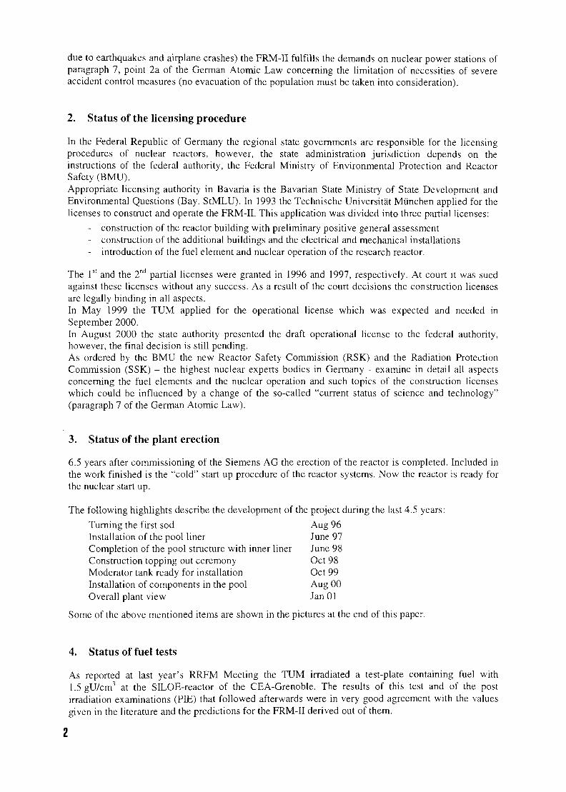
The following highlights describe the development of the project during the last 4.5 years:
Turning the first sod Aug 96Installation of the pool liner June 97Completion of the pool structure with inner liner June 98Construction topping out ceremony Oct 98Moderator tank ready for installation Oct 99Installation of components in the pool Aug 00Overall plant view Jan 01
Some of the above mentioned items are shown in the pictures at the end of this paper.
4. Status of fuel tests
As reported at last year's RRFM Meeting the TUM irradiated a test-plate containing fuel with1.5 gU/cm3 at the SILOE-reactor of the CEA-Grenoble. The results of this test and of the postirradiation examinations (PIE) that followed afterwards were in very good agreement with the valuesgiven in the literature and the predictions for the FRM-II derived out of them.
2
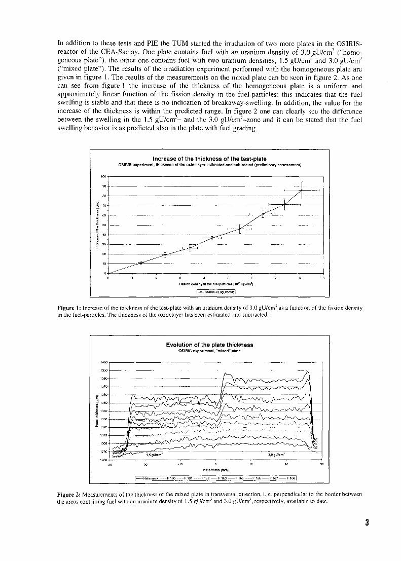
In addition to these tests and PIE the TUM started the irradiation of two more plates in the OSIRIS-reactor of the CEA-Saclay. One plate contains fuel with an uranium density of 3.0 gU/cm3 ("homo-geneous plate"), the other one contains fuel with two uranium densities, 1.5 gU/cm3 and 3.0 gU/cm3
("mixed plate"). The results of the irradiation experiment performed with the homogeneous plate aregiven in figure 1. The results of the measurements on the mixed plate can be seen in figure 2. As onecan see from figure 1 the increase of the thickness of the homogeneous plate is a uniform andapproximately linear function of the fission density in the fuel-particles; this indicates that the fuelswelling is stable and that there is no indication of breakaway-swelling. In addition, the value for theincrease of the thickness is within the predicted range. In figure 2 one can clearly see the differencebetween the swelling in the 1.5 gU/cm3- and the 3.0 gU/cm3-zone and it can be stated that the fuelswelling behavior is as predicted also in the plate with fuel grading.
Increase of the thickness of the test-plateOSIRIS-experiment, thickness of the oxidelayer estimated and subtracted (preliminary assessment)
9 0 •
: 40-
Fission density in the fuel particles [1031 Sp/cm1]
j — OSIHIS(3,0gU/cm3)l
Figure 1: Increase of the thickness of the test-plate with an uranium density of 3.0 gU/cm3 as a function of the fission densityin the fuel-particles. The thickness of the oxidelayer has been estimated and subtracted.
Evolution of the plate thicknessOSIRiS-experiment, "mixed" plate
Plats width [mm]
-Reference F 160 F 161 F 162 F 163 F 165 F 166 F 167 F 168
Figure 2: Measurements of the thickness of the mixed plate in transversal direction, i. e. perpendicular to the border betweenthe areas containing fuel with an uranium density of 1.5 gU/cm3 and 3.0 gU/cm3, respectively, available to date.
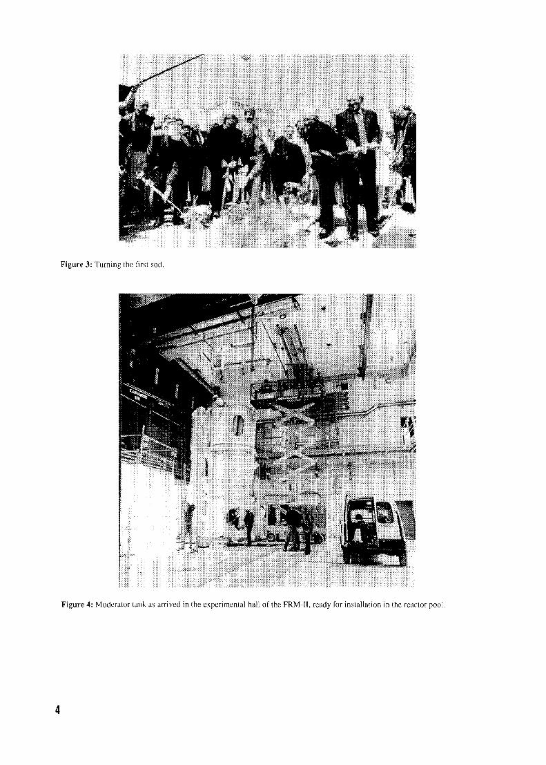
Figure 3: Turning the first sod.
fc-'M
/I
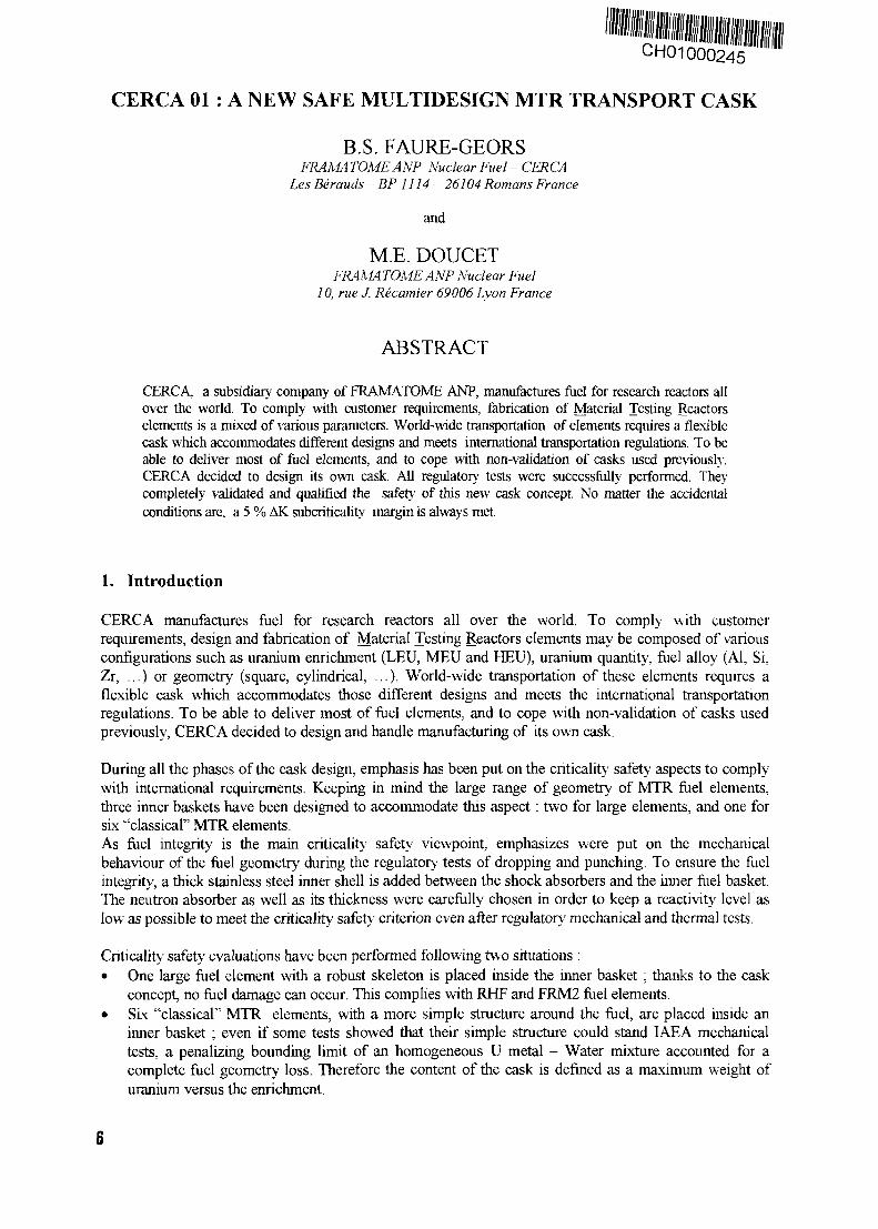
Figure 4: Moderator tank as arrived in the experimental hall of the FRM-II, ready for installation in the reactor pool.
Figure 5: View of the reactor pool of the FRM-II.
• f
If '
;;»»» tt«m:>"il»'fS¥i'' !i j , i ' I
Figure 6: Overall plant view with the air coolers in front and the old FRM on the left.
•ICH01000245
CERCA 01 : A NEW SAFE MULTIDESIGN MTR TRANSPORT CASK
B.S. FAURE-GEORSFRAMATOMEANP Nuclear Fuel - CERCA
Les Berauds ~ BP 1114 - 26104 Romans France
and
M.E. DOUCETFRAMA TOME ANP Nuclear Fuel
10, rue J. Recamier 69006 Lyon France
ABSTRACT
CERCA, a subsidiary company of FRAMATOME ANP, manufactures fuel for research reactors allover the world. To comply with customer requirements, fabrication of Material Testing Reactorselements is a mixed of various parameters. World-wide transportation of elements requires a flexiblecask which accommodates different designs and meets international transportation regulations. To beable to deliver most of fuel elements, and to cope with non-validation of casks used previously,CERCA decided to design its own cask. All regulatory tests were successfully performed. Theycompletely validated and qualified the safety of this new cask concept. No matter the accidentalconditions are, a 5 % AK subcriticality margin is always met.
1. Introduction
CERCA manufactures fuel for research reactors all over the world. To comply with customerrequirements, design and fabrication of Material Testing Reactors elements may be composed of variousconfigurations such as uranium enrichment (LEU, MEU and HEU), uranium quantity, fuel alloy (Al, Si,Zr, ...) or geometry (square, cylindrical, ...). World-wide transportation of these elements requires aflexible cask which accommodates those different designs and meets the international transportationregulations. To be able to deliver most of fuel elements, and to cope with non-validation of casks usedpreviously, CERCA decided to design and handle manufacturing of its own cask.
During all the phases of the cask design, emphasis has been put on the criticality safety aspects to complywith international requirements. Keeping in mind the large range of geometry of MTR fuel elements,three inner baskets have been designed to accommodate this aspect : two for large elements, and one forsix "classical" MTR elements.As fuel integrity is the main criticality safety viewpoint, emphasizes were put on the mechanicalbehaviour of the fuel geometry during the regulatory tests of dropping and punching. To ensure the fuelintegrity, a thick stainless steel inner shell is added between the shock absorbers and the inner fuel basket.The neutron absorber as well as its thickness were carefully chosen in order to keep a reactivity level aslow as possible to meet the criticality safety criterion even after regulatory mechanical and thermal tests.
Criticality safety evaluations have been performed following two situations :• One large fuel element with a robust skeleton is placed inside the inner basket ; thanks to the cask
concept, no fuel damage can occur. This complies with RHF and FRM2 fuel elements.• Six "classical" MTR elements, with a more simple structure around the fuel, are placed inside an
inner basket ; even if some tests showed that their simple structure could stand IAEA mechanicaltests, a penalizing bounding limit of an homogeneous U metal - Water mixture accounted for acomplete fuel geometry loss. Therefore the content of the cask is defined as a maximum weight ofuranium versus the enrichment.
2. Shipping cask design and fissile and material contents
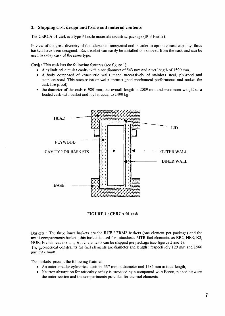
The CERCA 01 cask is a type 3 fissile materials industrial package (IP-3 Fissile).
In view of the great diversity of fuel elements transported and in order to optimise cask capacity, threebaskets have been designed. Each basket can easily be installed or removed from the cask and can beused in every cask of the same type.
Cask : This cask has the following features (see figure 1):• A cylindrical circular cavity with a net diameter of 543 mm and a net length of 1590 mm,• A body composed of concentric walls made successively of stainless steel, plywood and
stainless steel. This succession of walls ensures good mechanical performance and makes thecask fire-proof,
• the diameter of the ends is 980 mm, the overall length is 2089 mm and maximum weight of aloaded cask with basket and fuel is equal to 1490 kg.
HEAD
PLYWOOD
CAVITY FOR BASKETS
BASE
LID
OUTER WALL
INNER WALL
FIGURE 1 : CERCA 01 cask
Baskets : The three inner baskets are the RHF / FRM2 baskets (one element per package) and themulti-compartments basket: this basket is used for «standard» MTR fuel elements, as BR2, HFR, R2.HOR, French reactors ....; 6 fuel elements can be shipped per package (see figures 2 and 3).The geometrical constraints for fuel elements are diameter and length : respectively 129 mm and 1566mm maximum.
The baskets present the following features:• An outer circular cylindrical section, 537 mm in diameter and 1585 mm in total length,• Neutron absorption for criticality safety is provided by a compound with Boron, placed between
the outer section and the compartments provided for the fuel elements.
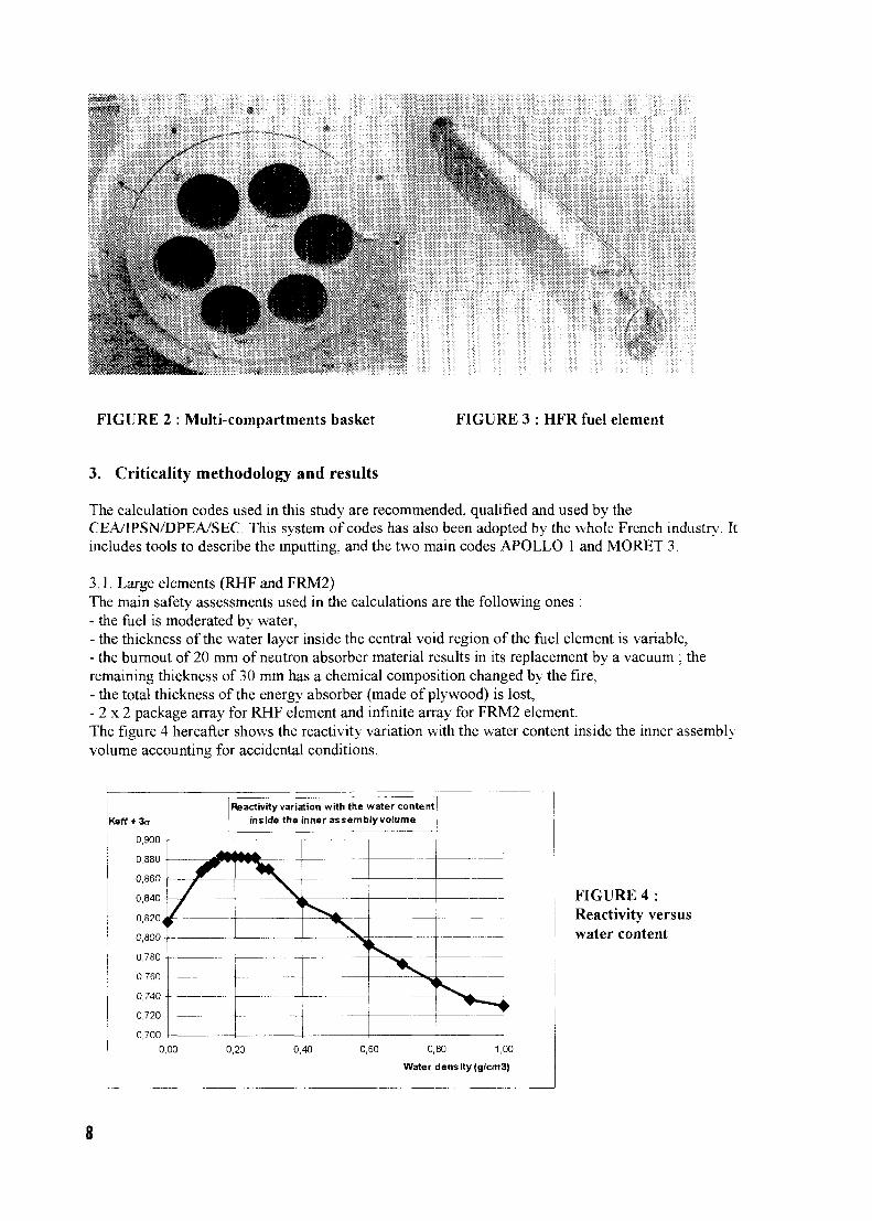
FIGURE 2 : Multi-compartments basket FIGURE 3 : HFR fuel element
3. Criticality methodology and results
The calculation codes used in this study are recommended, qualified and used by theCEA/IPSN/DPEA/SEC. This system of codes has also been adopted by the whole French industry. Itincludes tools to describe the inputting, and the two main codes APOLLO 1 and MORET 3.
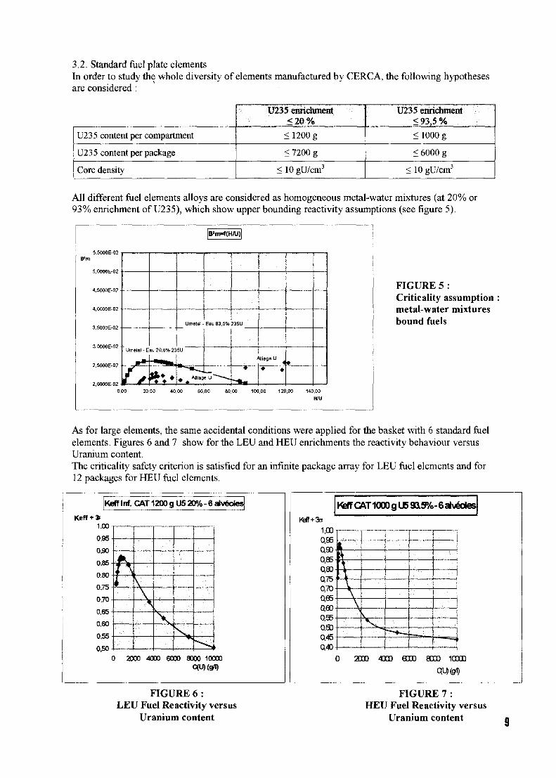
3.1. Large elements (RHF and FRM2)The main safety assessments used in the calculations are the following ones :- the fuel is moderated by water,- the thickness of the water layer inside the central void region of the fuel element is variable.- the burnout of 20 mm of neutron absorber material results in its replacement by a vacuum ; theremaining thickness of 30 mm has a chemical composition changed by the fire,- the total thickness of the energy absorber (made of plywood) is lost,- 2 x 2 package array for RHF element and infinite array for FRM2 element.The figure 4 hereafter shows the reactivity variation with the water content inside the inner assemblyvolume accounting for accidental conditions.
KeffReactivity variation with the water content
inside the inner assembly volume
FIGURE 4 :Reactivity versuswater content
0,7000,00 0,20 0,40 0 60 0,80 1,00
Water density (g/cm3)
3.2. Standard fuel plate elementsIn order to study the whole diversity of elements manufactured by CERCA, the following hypothesesare considered :
U235 content per compartment
U235 content per package
Core density
U235 enrichment<20%
<1200 g
< 7200 g
< 10 gU/cm3
U235 enrichment<93,5%
<1000 g
< 6000 g
< 10 gU/cm3
All different fuel elements alloys are considered as homogeneous metal-water mixtures (at 20% or93% enrichment of U235), which show upper bounding reactivity assumptions (see figure 5).
5.OOOOE-02
4.5OO0E-02
4.0000E-02
3.5000E-02
3.0000E-02
2.5000E-02
' Umttal - Eau 20,0% 23
* • • •
Umital -
5U
• A Alll"»
B*m-f(H/U)
Eau 93,5%
eU ^
2351.
Ullage U
• ••
0,00 20,00 40,00 60,00 80,00 100,00 120,00 140,00
H/U
FIGURE 5 :Criticality assumptionmetal-water mixturesbound fuels
As for large elements, the same accidental conditions were applied for the basket with 6 standard fuelelements. Figures 6 and 7 show for the LEU and HEU enrichments the reactivity behaviour versusUranium content.The criticality safety criterion is satisfied for an infinite package array for LEU fuel elements and for12 packages for HEU fuel elements.
KefT Inf. CAT 1200 gU5 20%-6 alveoles
Keff+*
1,00
0,95
0,90
0,85
0,80
0,75
0,70
0,65
0,60
0,55
0,50
A
1Vj 1
\
2000 4000 6000 8000 10000C(U)(9«)
Keff CAT 1000 g U6 93LS%-6al^oies
1,001 T
2D0O 4000 6000 8000 10000
mmFIGURE 6 :
LEU Fuel Reactivity versusUranium content
FIGURE 7 :HEU Fuel Reactivity versus
Uranium content
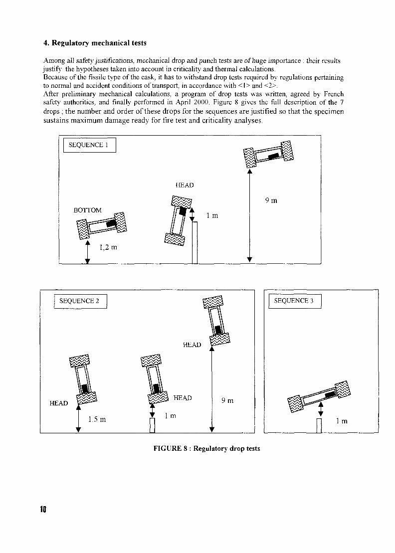
4. Regulatory mechanical tests
Among all safety justifications, mechanical drop and punch tests are of huge importance : their resultsjustify the hypotheses taken into account in criticality and thermal calculations.Because of the fissile type of the cask, it has to withstand drop tests required by regulations pertainingto normal and accident conditions of transport, in accordance with <1> and <2>.After preliminary mechanical calculations, a program of drop tests was written, agreed by Frenchsafety authorities, and finally performed in April 2000. Figure 8 gives the full description of the 7drops; the number and order of these drops for the sequences are justified so that the specimensustains maximum damage ready for fire test and criticality analyses.
SEQUENCE 1
HEAD
BOTTOM
1,2 m
1 m
9 m
FIGURE 8 : Regulatory drop tests
10
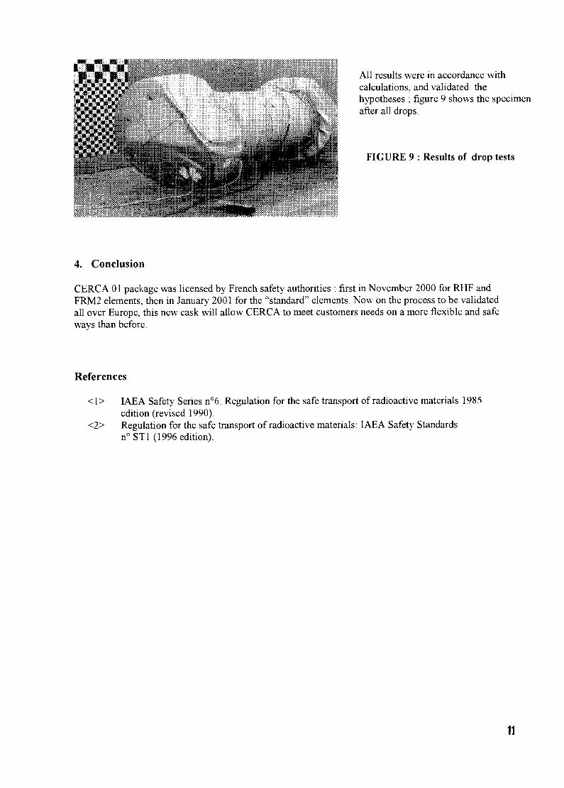
All results were in accordance withcalculations, and validated thehypotheses ; figure 9 shows the specimenafter all drops.
FIGURE 9 : Results of drop tests
4. Conclusion
CERCA 01 package was licensed by French safety authorities : first in November 2000 for RHF andFRM2 elements, then in January 2001 for the "standard" elements. Now on the process to be validatedall over Europe, this new cask will allow CERCA to meet customers needs on a more flexible and safeways than before.
References
<1> IAEA Safety Series n°6. Regulation for the safe transport of radioactive materials 1985edition (revised 1990).
<2> Regulation for the safe transport of radioactive materials: IAEA Safety Standardsn°STl (1996 edition).
11
CH01000246
THE NEW CONTEXT FOR TRANSPORTOF RADIOACTIVE AND NUCLEAR MATERIAL
Catherine ANNE - Marketing & Sales DivisionJerome GALTIER - Laboratories and Research Department
Transnucleaire, 9-11, Rue Cliristoplie Colomb, 75008 PARIS
Initially considered as ,,a subsidiary" activity of the nuclear industry, the transport activity isnowadays considered as a keystone for the industry as the whole.
The transportation of radioactive and nuclear materials involves all modes of transportation (road, air,sea. rail) with a predominance for road and for air (air for radioisotopes).It is but a minute fraction dangerous good transportation. Around 10 millions of radioactive packagesare shipped annually all over the world of which ninety percent total corresponds to shipments ofradioisotopes. For example, about 200 000 sealed sources are delivered every year in France. InFrance and in the US, radioactive shipments represent only two percent of the total of dangerous goodshipments. This percentage is about the same in all industrials countries.
In spite of the small volume transported, experience, evolution of transport means and technologies.the trend to constantly improve security and safety and public acceptance have modified the transportenvironment.
During the last few years, new evolutions have applied to the transport of radioactive and nuclearmaterials in various fields and especially:
• Safety• Security• Logistics means• Public acceptance• Quality Assurance
We propose to examine the evolution of these different fields and their impact on transportationmethods and means:
1. Safety
Most of the radioactive transport regulations are based on IAEA recommendations which are nowrevised with a two years interval (instead often years previously). In 1996, the IAEA has published anew regulation identified as Safety Standard N° TS-R-1. This new recommendation is applicable as of2001 (with transitional period till 2002).
The International Commission of radiological protection has also issued in 1990 a newrecommendation (CIPR 60) applicable in 2000 which has been included in IAEA recommendation:Safety series n° 115 ..International basic safety standards for protection against ionizing radiation andfor the safety of radiation sources".
What are the main evolutions of these new recommendations?
Essentially, revisions of the new safety transportation regulation have been prompted by:
the necessity to transport new material such as various types of waste and reprocessed uranium.
12
the introduction of specific requirements for air transportation . Indeed, in the past, the differentmodes of transportation were not considered an issue. The tests required on packagings in theprevious regulation were defined to envelop most accidental situations but the severe air transportcondition (even if the probability of an accident is lower) was not taken into account. In the newregulation and for material with high activity, additional tests have been introduced for airtransport packages (type C )
The necessity to take into account the chemical risk associated with UF6 transportation.
Further more, modal transport regulation has been revised. For maritime transport :
the publication by the OMI, in 1993, of a new code (INF code) with complementary specificationsrelated to : stability, fire, hold temperature controls, stowage, radiological protection, stafftraining and emergency plan. Three categories of ship have been defined depending of the type ofradioactive material and activity inventory. For example, for irradiated materials with an activityfrom 4000 TBq to 2.10/6 TBq an INF2 ship is required. Specific regulations can applyadditionally for example in Japan where the specifications are more restrictive.
The revision of the radiation dose recommendation has also impact transport activity :
The reduction of the maximum allowable annual radiation dose. As the exposition related totransportation activity is far below the new annual limits, the contamination and radiation levelsapplicable for transportation have not been revised but some new dispositions are required :
Beyond the ALARA principle, radiation protection programs are now a requirement for all stagesof transport operation. Radiological Protection Plan (RPP) has to be implemented.
But the most significant evolution is probably not the revisions mentioned above but the fact that,nowadays, the Competent Authorities require deeper justifications (safety in depth). A complianceassurance system for design, operation has been implemented in the recent years. For older designs,we faced difficulties providing new formal demonstrations of conformity of the package model.Temporary solutions have been implemented for this older designs and the necessity to produceadditional justifications for new ones has been integrated. This evolution has obviously impacted timeto market. It has also improved the standard to which new equipment is designed and operated.
It is also important to point out that as there is no complete standardization for research reactor fuelelements and because of the diversity of these fuel elements, casks owners must frequently apply forlicense amendment in order to include these fuels characteristics in the license. Additionally, forinternational shipments, validation of the license has to be issued by each country involved (crossed,overflight countries, flag of the vessel). In order to solve these licensing issues, a lot of anticipation isnow needed to meet the transport schedule. The organization of a shipment must be initiated at leasttwo years prior to implementation.
Unfortunately, on the other hand, Competent Authorities ask for increasingly more details about thecontents to be transported meaning that using ,,envelope content" is more difficult to define.A new evolution is for example, the fact that Competent Authorities have recently implemented safetyinspection during transport operations. Few inspections have been performed on Transnucleaireshipments during the year 2000. Transnucleaire has also developed its own internal inspection systemin order to improve services and maintain a high level of quality.
2. Security
The security related to transportation of nuclear material is regulated by International Conventions butalso by complementary specifications enforced by each state. The objective of these regulations is toprevent any loose or robbery of sensitive materials.
For example in France, complementary requirements have been issued:
• For shipment of category 1 and 2 (more than 5 kg of high and low enriched uranium), trucks andcontainers equipped with specific devices are required to guarantee the material security. Due tothe permanent technology evolution, regular improvements are implemented on specificationsissued by the Competent Authority.
• For shipment of category 3 (most of the other shipments without irradiated fuels classified in aspecific category), new instructions have been issued by the Competent Authority in order toimprove security of the packaging: the vehicle must constantly be under control of the truckdrivers. Consequently, two drivers are now required for long distance relation.
3. Logistics means
An important evolvement of the nuclear industry is new logistics issues: the routes and the transportmeans previously commonly used are not always longer valid. As we are confronted to various issues,we are going to examine practical examples to develop the evolution of logistic means:
Ispra shipment:
Transnucleaire was awarded a contract to return to US Spent Essor fuel from the research reactor atIspra, in Italy. The services consisted of providing a licensed cask and of performing the transportoperation from the reactor site to Savannah River Site in South Carolina. The transport operation hadto integrate the following constraints:
• no port authorized in Italy for nuclear material
• no route already experienced and authorized through Europe : as the cask used was a Germancask (consequently approved in Germany), the option selected was to combine the loadingoperation onboard the ship in Germany. Because of the incertitude to obtain transport licenses, wehave work in parallel on alternatives routes trough Switzerland and Austria, cask validation andtransport licenses have been applied in these two countries. For logistic reason and lowprobability to get transport license through Austria, rail transport have been studied. However,Switzerland State Railway rejected our submission. The only alternative then was to perform aroad transport using our affiliated truck company located in South of France (Celestin). Again wehad to face difficulties, road transport trough the St Ghottard tunnel was rejected in a firstapproach by the canton authorities and finally authorized by the Swiss federal authorities troughthe St Ghottart alpine pass (with an escort of a Swiss radiation protection vehicle).
Because of their experience as radioactive and nuclear services providers, Transnucleaire haveconcluded successfully this shipment but however, the time spent for transport preparation andorganization trough Europe has been significant.
Studsvik Fresh MTR shipment
On behalf of Cerca, Transnucleaire is shipping every year fresh fuel MTR elements from Cerca plant,south of France to the Studsvik research reactor in Sweden. The packaging used was the MTRD. Inpast years, 8 casks were needed to deliver the 48 elements. In 1999, due to the difficulties to obtainthe French validation of the MTRD (German design), the alternative solution to deliver the fuels wasto use the TNBGC1 packaging (developed by Transnucleaire) mainly used for Uranium andPlutonium shipments. Due to its limited capacity for this geometry of material (Only one fuelperTNBGCl), the number of packagings to be transported was multiplied by six. Consequently the
14

type of aircraft previously chartered (a BAE 146 with payload capacity of 12 tons) was not any morecompatible. An Airbus with a payload capacity of 42 tons has been chartered.
Additionally, as handling operations have been multiplied by six, the time for loading/unloadingoperations has been increased significantly.
Acceptance of liner ship and aircraft
A significant change in 2001, has been the rejection by some shipping lines to carry radioactivematerials. For example, a Japanese maritime company has announced that no radioactive containerwould be transported on their liner ship from 2001 on for nuclear liability reason. For the frond endmaterial, new solution based on the utilization of chartered (dedicated) vessel is presently developed.Such a solution includes more complex logistics in order to optimize the combination of radioactivecontainers and offers a reasonable (affordable) price. For the shipment of fresh MTR fuels fromFrance to Japan, the liner company has temporary agreed to accept the freight but an alternativetransport system has to be found for the future.
Further more, aircraft companies are no longer interested in transporting radioactive material.Recently, uranium shipments for a European research reactor, usually transported by a large airlinecompany, have been declined. Consequently, our selection for carrying this material was restricted toone company who fortunately did transport.
We have to face the fact that liner maritime and air companies are not interested in transportation ofradioactive and nuclear material: this activity represents a very small turnover and potentially badadvertising even in case of minor problems. New transport systems are going to be developed.Dedicated ship and aircraft can sometimes be a solution but with a new logistic dimension in order tocombine different radioactive materials shipments.
4. Communication/Public Acceptance
Radioactive and nuclear material transportation were rarely mentioned by the media few years ago.Nowadays, not only specialized but also general media report more and more information on nuclearactivity and especially transportation.
The public wants to understand and we must explain. Communication and public acceptance has alsobeen a growing activity in the recent years.
Further more, some recent maritime accidents (Erica Sun sinking for example) though not related tonuclear activity but to other dangerous goods for which the regulation is not as restrictive, raise morequestions about our activity. Our role is also to answer to these questions and demonstrate the highlevel of safety and security provided.
5. Quality Assurance
More quality assurance is always nowadays required. For example, in France since 1999, all the truckcompanies have to be certified in conformity with the ISO 9002 code. Each company carryingradioactive goods have developed a checking system to guarantee the conformity of the services underperformance.
CONCLUSION
All the aspects developed above have contributed to improve the safety and the security, to answer tonew needs from the environment. But they have also disrupt (disturb) the methods and transport
15

system usually practiced. The field of actions is tighter. However, the adaptation to the evolution ofour environment is a key for the future.
Our challenge is to continue to built up experience, know how and adapted equipment, developcreative and reliable services for transportation at an acceptable price.
16

Session 2
Development and qualification
CH01000247
THE QUALIFICATION OF A NEW FUELTHE OPERATOR'S PERSPECTIVE
E. KOONENBR2 Department
SCK-CEN, Boeretang 200, B-2400 Mol, Belgium
ABSTRACT
Operators of a research reactor generally have as their primary mission toprovide the users with a safe, reliable and economic source of neutrons. Theyhave to assure the availability of that source, while respecting the requirementsof the license. The fuel management is one of the major aspects they have totackle in order to fulfill their mission. This sometimes includes the qualificationof a new fuel and the core conversion. The operator has to assure that the wholeprocess is conducted in such manner that the availability of the neutron source isonly minimally disturbed, that the costs are kept under control and thecharacteristics of the neutron source are preserved. This paper gives an overviewof the various issues that the operator has to consider.
1. Introduction
Historically most research reactors were started up using highly enriched uranium (HEU) as fuel meat,mainly under the form of U-Al alloy and later UAlx-Al dispersion fuels.The major suppliers of the enriched material were the USA and the former USSR in their respectivespheres of influence.
For the Western countries the costs were rather low especially since the return of spent fuel was assuredto the country of origin and moreover a credit was given for the remaining uranium when purchasing anew amount of HEU. For the countries supplied by the former USSR there was seemingly never anyreturn of spent fuel but apparently there were sufficient storage capacities available to cope with thatsituation. The fact that there was only one supplier serving a particular operator was not seen as a threat.
The Western countries could choose between several fuel manufacturers (some of them have disappearednowadays) to assure some form of competition. Transport of fuel wasn't a big issue either.
The cost of the fuel cycle was not the dominant factor in the overall operation costs and this cost wasforeseeable and could be planned according to the budgetary situation.
In the late seventies (1978-1980) the INFCE effort was conducted at the instigation of the USA. Theobjective was to evaluate the nuclear fuel cycle and propose measures to reduce the proliferation risk [1].Concurrently the RERTR Programme was established in 1978 at ANL by the US-DOE, which up to thisday continues to fund the programme and to manage it in coordination with the US-DOS and the US-NRC. The prime objective of this programme is to develop the technology needed to minimize and
17
eventually eliminate the use of HEU for civilian applications worldwide; in facts these applications almostexclusively concern research and test reactors.Therefore the RERTR programme concentrates on the conversion from HEU to low-enriched uranium(LEU) in these reactors by initiating collaborations with the concerned organizations and conducting LEUfuel development programmes in order to make conversion feasible "without significant penalties inexperiment performance, in economic and safety aspects of the reactors".
Since the end of the cold war the RERTR programme has taken a truly worldwide dimension as Russiaand China are nowadays also progressively participating in the programme.It is worthwhile to notice that the former USSR had also initiated a conversion programme for researchreactors, at least for those foreign reactors supplied by them. However the enrichment of the proposednew fuel (36 %) is still being considered HEU material by the RERTR programme.
2. Present situation
2.1. conversion to LEU and qualification of new fuel
Since the qualification of U3Si2 fuel with a density of up to 4.8 g U/cc was achieved, most researchreactors are 'in principle' able to convert to LEU fuel.The latest statistics on already converted, presently converting and conversion candidate reactors arepresented each year at the annual RERTR conference by the programme manager [2].
However some high power research reactors are not yet in the position to convert to this fuel as theperformances of the reactor would suffer significant drawbacks.
Recently the USA has launched activities within the RERTR programme to develop higher density UMofuel. However they presently concentrate on 'medium' densities up to 6 g U/cc. This is done to present analternative to the U3Si2 fuel (up to 4.8 g U/cc) because the use of this fuel, at least not easilyreprocessable, could become problematic after the crucial date of May 13 2006. The development ofhigher densities is foreseen in a later step.
France has started activities within the 'groupe pentapartite' (CEA, CERCA, COGEMA,TECHN1CATOM, FRAMATOME) for the direct development of high density UMo fuel (up to 9 g U/cc),including all aspects of the fuel cycle, notably the reprocessing of this fuel.The French activities are primarily driven by the RJH project (a new MTR reactor of 100 MW to beerected in Cadarache).
2.2. the operator's perspective
Research reactors are generally the main infrastructure of a nuclear research centers. Nowadays many ofthem are scrutinized with regard to their usefulness and their operating costs.
Each research reactor has his particularities with regard to the conversion problematic:remaining amounts of fresh HEU material and fresh HEU fuel,the foreseen or expected remaining lifetime of the installation,future operating schedule and the corresponding annual consumption.the type of utilization, which actually defines the specific requirements for a suitable LEU fuel,available solutions for back-end of the fuel cycle,available budgets and specific requirements for external income.national political situation with regard to nuclear energy.
18
In general the justification for operating a research reactor is to provide a neutron source for specificneeds: support of the national nuclear programme, availability of neuron beams, a national source forradio-isotope production, a tool to acquire or maintain know-how in nuclear science and technology, ...The operators have to provide these neutrons in a safe, reliable and economic manner. They are asked toprovide a good service and keep their performances at a constant level or improve them.The fuel management (including front- and back-end aspects) is just one of the issues that the operator hasto tackle in order to fulfil his mission.
The efforts made in the conversion business and in the qualification of new fuel are generally notperceived as a research programme by the general management but as an additional cost to be carried bythe operator. Indeed the expected benefit is not very convincing: the flux characteristics will not beimproved but just a little downgraded with respect to thermal flux. On the other hand some operatorsexperienced an increase of the cycle length after conversion to LEU U3Si2 fuel. Using higher densityUMo fuel should enhance this advantage.Switching to another type of fuel is not likely to facilitate the back-end issue for those who still usealuminide fuel. For those already converted to silicide fuel, switching to UMo may constitute anadvantage concerning the back-end issue.
Generally the operator has to carry out the conversion project with no additional personnel provided, andin some cases he is asked to analyze the benefit of future operation compared to the conversion costs. Thegeneral opinion seems to be that the cost of the fuel cycle will increase. For some research reactors thiswill cause a serious threat for their survival in the medium term.
3. The major issues from the operator's point of view
3.1. front-end issues
The operator needs a secure and reliable source for raw material supply. The price should be foreseeablein order to allow budgetary previsions and medium term planning of major financial outfluxes.Likewise at least one secure and reliable fuel manufacturer is needed.Some form of competition, at least for the manufacturing, would be desirable. However in recent years thesituation has evolved the opposite way.
3.2. back-end issues
The present US-DOE policy to take back the spent fuel of US origin will expire in 2006.Those who want to continue operation beyond this point will have to establish a national solution or find asolution abroad.
Based on present knowledge only one solution abroad will be available after 2006: reprocessing at the LaHague plant in France. This solution is compatible with the goals of the non-proliferation policy as therecovered HEU material will be diluted. However this is limited to fuel types that can be reprocessed withexisting industrial processes. This is not the case for U3Si2 fuels. Moreover the waste will be returned tothe country of origin and consequently a waste disposal solution (national or abroad) will still be required.
There are a few national disposal schemes for spent fuel under discussion/implementation, but this islimited to a rather small group of countries, which all have an active nuclear power programme.
Whether Russia is willing and able to take back Russian origin fuel is not clear to he author.
19
Therefore when one envisages the qualification of a new fuel, a future back-end solution should also beestablished before actually starting to use this new fuel.
In some cases where a back-end solution is presently available for the current fuel, the new fuel will haveto be compatible with the existing solution. It is unrealistic to think that a second back-end solution couldbe implemented in parallel with the existing one.
3.3. economical issues
The overall fuel cycle comprises a number of cost factors: raw material supply and shipment, fuelfabrication, shipment of fresh fuel, shipment of spent fuel and a back-end solution.In particular the back-end issue can generate to high costs.
Many operators have to establish annual budgets and have to make assumptions concerning the overallcost of the fuel cycle. Some operators are also obliged to constitute financial provisions for the futuredismantling and the waste treatment. In many cases the future back-end solution is not well defined andthe operator has almost no control regarding these future costs: this may result in conservativeassumptions and high provisions.On the other hand the research reactor world is increasingly placed under severe competition and the costsare a prime issue when making bids for irradiations.
3.4. fuel performance and acceptance criteria
In assessing the practical feasibility of utilizing LEU fuel in a particular research reactors, the criteria arenot totally well defined and may lead to discussion and disagreement:
safety margins and fuel reliability should not be lower than the current design based on HEUneither the loss in reactor performance, e.g. flux-per-unit power, nor any increase in operating costsshould be 'significant' (or 'more than marginal' as some sources state).
Unfortunately the upper level of 'insignificance' or 'marginality' is apparently not been unequicocallydefined. What has been experienced by those who converted is approximately 15 % penalty in thermalfluxes in the nearby reflector positions.
The safety margins must be kept to the values agreed upon with the national licensing authorities.
Fuel reliability should also not be deteriorated as an increase in fuel failure cannot be totally excluded butshould certainly not be accepted up-front as an unavoidable fact, which it is not. In many cases thelicensing authorities will anyway not accept lower fuel reliability as a given fact.
In today's highly competitive environment amongst research reactors, including contractual commitmentsto operate during predefined time-periods, reliability of operation is a competitive edge and a 'must'.Unforeseen interruptions of operation can lead to the direct loss of income and may damage thecompetitive position of the reactor.
3.5. qualification process
The generally accepted qualification process looks like this:micro (or nano) plates irradiations up to high burnup, followed by post-irradiation examination (PIE)fuel plate testing under representative and 'bounding' conditions, followed by PIEfuel element testing, followed by PIEqualification report of the new fuel, including qualification of the manufacturer
20
prototype fuel element tests in the concerned research reactorlicense applications for the conversion of the concerned research reactorprocurement of the new fuelconversion of the research reactor, including temporary operation with mixed cores
The operator has to esablish the necessary cooperation agreements and incorporate these actions in hisplanning. He also has to assign manpower to this project. One should realize that the whole process takesseveral years although only part of the workload is with the operator and some overlapping betweenvarious stages is possible.
The licensing requirements are country dependent and may in some cases be quite cumbersome.The safety analysis has to include the determination of power peaking factors, a revision of thermal-hydraulic assessment, the determination of the maximum allowed heat flux and the behaviour of the fuelunder accidental conditions.
The qualification procedure of the new high density UMo fuel should result in the establishment of areport like NUREG-1313 (1988) for the fuel qualification and a report like IAEA TEC DOC-643 (1992)concerning the impact of that fuel on the physical, safety and radiological characteristics. This should givea sound basis upon which operators can build their safety case and have confidence that the conversionprocess can be handled.One may recall that the qualification process of U3Si2 included a whole core conversion demonstration ofthe 30 MW ORR.
4. Conclusions
Only the 'fittest' research reactors will survive. This 'fitness' will mainly depend on the ability to establisha relevant and useful utilization programme (in many cases this translates into the generation of a'sufficient' amount of income). The ability to actually do this depends on many factors on which theoperators sometimes have only limited control over. This is particularly true for the fuel cycle.
As the qualification of a new fuel and the core conversion generates additional costs for the operation of aresearch reactor, the operators should be assisted in this task by all other parties and institutions involvedin this matter. Actually this is one of the objectives of the RERTR programme. In particular suppliers offissile material and fuel manufacturers should handle reasonable prices and conditions and assist theircustomers in finding acceptable solutions for all aspects of the fuel cycle.
A viable, affordable and proven solution for the back-end of the fuel cycle is a crucial point for manyresearch reactors to survive. This is a complex issue as this includes the implementation of an acceptablestorage and final disposal solution. A major problem seems to be that the amount and overall activityinventory is not big enough to trigger decisions at high level. Clearly it is not reasonable to expect a smallcountry with only one research reactor to establish a national solution for the rather small amounts ofradioactive waste. For these countries a commercially and financially viable solution needs to be defined.
5. References
[ 1 ] INFCE Summary Volume, IAEA, Vienna, 1980
[2] A. Travelli, Status and Progress of the RERTR program in the year 2000, 2000 Intl. Meeting onReduced Enrichment for Research and Test Reactors, Las Vegas, Nevada, USA, October 1-6, 2000
21
CH01000248
STATUS OF RESEARCH REACTOR FUEL TEST IN THE HIGHFLUX REACTOR (PETTEN, THE NETHERLANDS)
J. GUIDEZ, S. CASALTAHFR Unit, Institute for Advanced Materials
European commission, Joint Research Centre, Postbus2, NL-1755 ZG Petten - The Netherlands
F.J. WIJTSMA, PJ.M. THIJSSEN, J.A. HENDRIKS, G. DASSELNRG Petten
Westerduinweg 3, P.O. Box 25, NL-1755 ZG Petten - The Netherlands
H. VACELETCERCA Fra ma to me
Les Bemuds, B.P. 1114, F-26104 Romans - France
A. LANGUILLECEA Cadarache
F-13108 Saint Paul Lez Durance - France
ABSTRACTEven if the research reactors are using very well known MTR-fuel, a need existsfor research in this field mainly for 3 reasons:
• industrial qualification of fuel assemblies (built with qualified fuel);• improvement or modifications on a qualified fuel (e.g. increase of density);• qualification of a new fuel such UMo.
For these types of tests, the High Flux Reactor located in Petten (the Netherlands)has a lot of specific advantages:
• a large core with various interesting positions ranging from high to lowfluence rate;
• a high number of operating days (>280 days/year) that gives - with the highflux available - a possibility to reach quickly high burn-up;
• a downward coolant flow that simplifies the device engineering;• all possibilities of non-destructive and destructive examinations in the hot-
cells (visual inspection, swelling, y-scanning, macro- and light microscopy,SEM and EPMA examinations, tomography....).
Two types of tests can be performed at the plant: either a full-scale test or a test ofplates in dedicated devices.A presentation is made of the irradiation test on four UMo plates, begun in March2000 in the device UMUS.A status is made of the full-scale test to be done in the near future, especially theUMo tests to begin the next year.In conclusion it appears that the HFR, that had already given an excellentcontribution to silicide fuel qualification in the 1980's, will also give a significantcontribution to the current UMo qualification programs.
1. Introduction
The High Flux Reactor (HFR) is located at Petten (Netherlands). It is owned and managed bythe Institute for Advanced Materials of the Joint Research Centre (JRC) of the EuropeanCommission and is operated and commercially exploited under contract by the NuclearResearch and Consultancy Group (NRG).The HFR is of the tank-in-pool type, light water cooled and moderated. It is operated at 45MW. It has been in operation since 1961, and following vessel replacement in 1984, the HFRstill has a technical life beyond the year 2015. It is one of the most powerful multi-purposematerials testing reactors in the world.
22
The decision to convert the reactor to LEU was made in the year 2000, and the choice wasmade to use the classical silicide fuel with a density of 4.8g/cm3, [1]&[2].
The close co-operation between the Joint Research Centre and the Nuclear Research andconsultancy Group (NRG) on all aspects of nuclear research and technology is essential tomaintain the key position of the HFR amongst research reactors world-wide. This co-operation has led to a unique HFR structure, in which both organisations are involved with theaim to adopt a more market oriented approach and offer their long standing and recognisedcompetence in exploiting a powerful, reliable set of nuclear facilities to world-wide interestedparties.
The HFR is also in the heart of the Medical Valley Association. This association betweenIAM, NRG, Mallinckrodt and hospitals leads to a medical structure unique in Europe, andmore than 50% of the reactor is already used for medical applications: radio-isotopeproduction, Boron Neutron Capture Therapy, research on new medical applications, etc.
2. Presentation of HFR possibilities
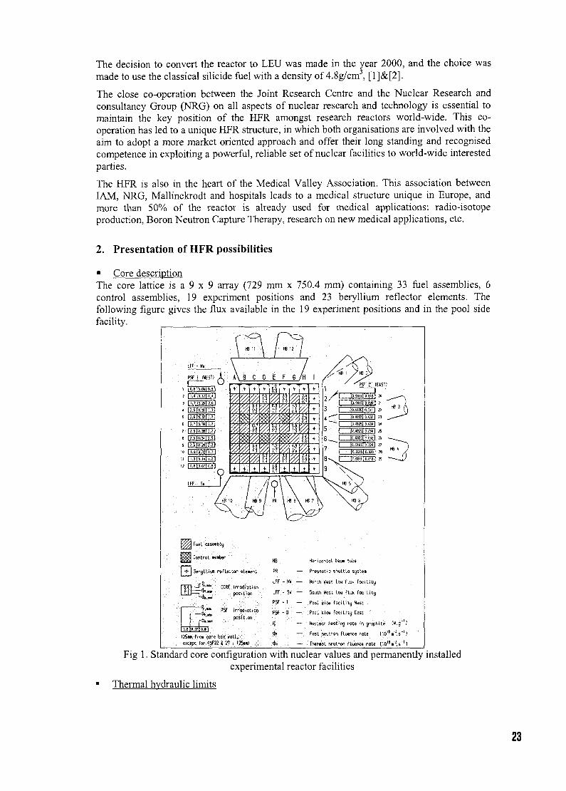
• Core descriptionThe core lattice is a 9 x 9 array (729 mm x 750.4 mm) containing 33 fuel assemblies, 6control assemblies, 19 experiment positions and 23 beryllium reflector elements. Thefollowing figure gives the flux available in the 19 experiment positions and in the pool sidefacility.
n/ HB Q /
A\ B C D E F G /Ht
iI1iwi
'0+
•f
mVA
tiY/,!;?Y/,+
+
1:1V/,$Y/,$Y/,9t
Y//<hiY/,h
i
+
yA
(if+
+
%$
y//.
'0
0.4* l '
Y/ty'%.u+
I++ 1t
+-f
++++
0.610.07)0.8]
C26w Frc» core box KOIL,except for PSF22 « 27 , I25u) .
Hocizorrtot b*»i tube
Pneijfiotic shyttL« systei
North Vest Low flux Foes Lity
South Vest Itw flux fociLtty
Pool side foc i lUy V«st
.Pool side f a c i l i t y Eost
Wucteor heating rots in grophtte C. 9 *
Fast rteutron fLuence rat« t10 IBn"J.5"']
rtwroot rwutron fluenc* rale [101B i"?,5"']
Fig 1. Standard core configuration with nuclear values and permanently installedexperimental reactor facilities
Thermal hydraulic limits
23
Operation is restricted to a maximum power per plate. To respect thermal hydraulic safetymargins, an experiment can be started in a place with lower flux. After several cycles, thefinal burn-up, can be reached in another place where a higher flux is available.
• Number of operating daysWith more than 280 operating days/year, the necessary burn-up can be reached faster in HFRthan in most other reactors.
• DeviceTwo possibilities exist for the MTR fuel test: the plates are made in the final form of HFRfuel assemblies and tested as normal element; or plates with other dimensions are used andirradiated in fuel boxes.The downward coolant flow simplifies the engineering of these holders, which serve only as amechanical support of the plates.
• Post Irradiation ExaminationAll necessary measurements can be performed within easy access to the hot-cells
visual inspection with digital photography,swelling measurements by mechanical apparatus in the hot-cells,y-scanning,all destructive examinations (macro- and light microscopy, SEM examinations andEPMA analysis, ....).
• Calculation and engineeringAll the possibilities of neutronics thermalhydraulic calculations and engineering designs andmanufacture are available on-site.
3. UMUStest
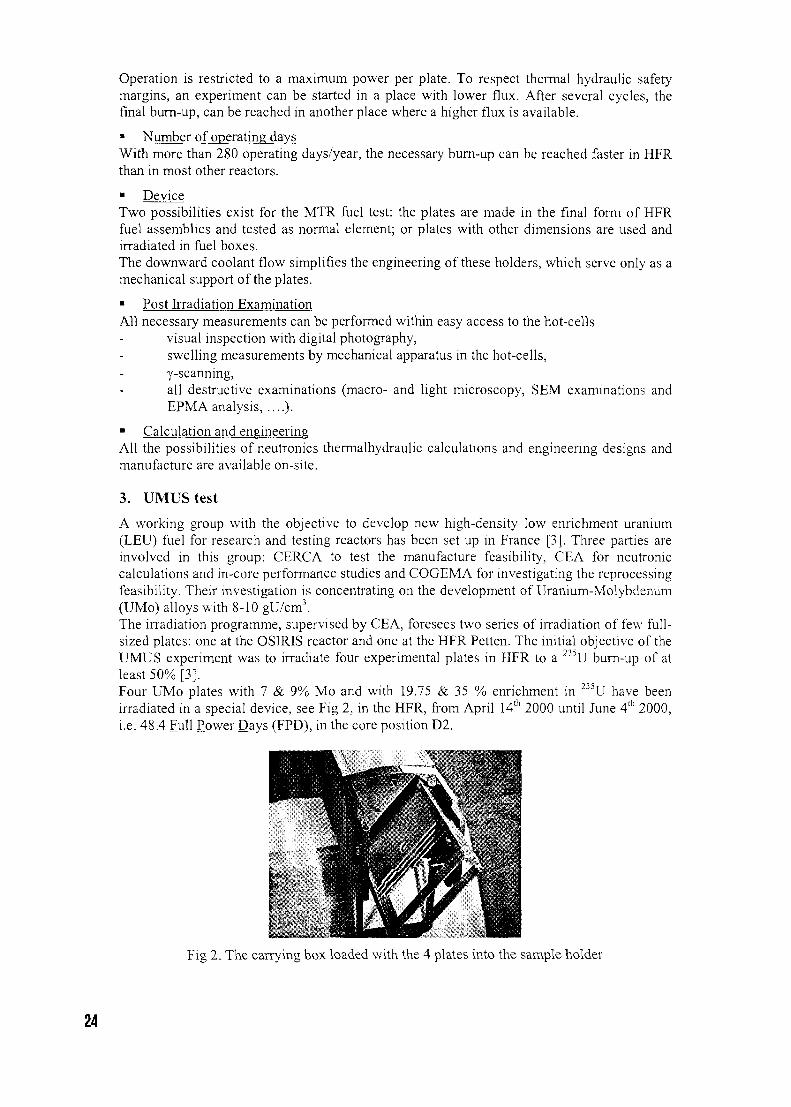
A working group with the objective to develop new high-density low enrichment uranium(LEU) fuel for research and testing reactors has been set up in France [3]. Three parties areinvolved in this group: CERCA to test the manufacture feasibility, CEA for neutroniccalculations and in-core performance studies and COGEMA for investigating the reprocessingfeasibility. Their investigation is concentrating on the development of Uranium-Molybdenum(UMo) alloys with 8-10 gU/cm3.The irradiation programme, supervised by CEA, foresees two series of irradiation of few full-sized plates: one at the OSIRIS reactor and one at the HFR Petten. The initial objective of theUMUS experiment was to irradiate four experimental plates in HFR to a 235U burn-up of atleast 50% [3].Four UMo plates with 7 & 9% Mo and with 19.75 & 35 % enrichment in 235U have beenirradiated in a special device, see Fig 2, in the HFR, from April 14th 2000 until June 4th 2000,i.e. 48.4 Full Power Days (FPD), in the core position D2.
Fig 2. The carrying box loaded with the 4 plates into the sample holder
24
The 3rd June first peaks of activity in primary water were observed. After a decrease and astabilization of the activity, a new release of fission products occurred the 4th June. It has beendecided to stop the reactor the 4th June at 16:00h. The UMUS sample holder was unloadedfrom the core and stored in the pool water for cooling down. The activity measurements ofwater taken above UMUS experiment confirmed the failure of the UMUS plate. After 3months of storage, the device has been transported to the NRG hot cell laboratory in Pettenfor examinations.
At present, post-irradiation examinations of plates are being performed. Some preliminaryresults of non-destructive examinations have been communicated. Based on the informationpresently available from non-destructive examinations, we come to the following preliminaryobservations.
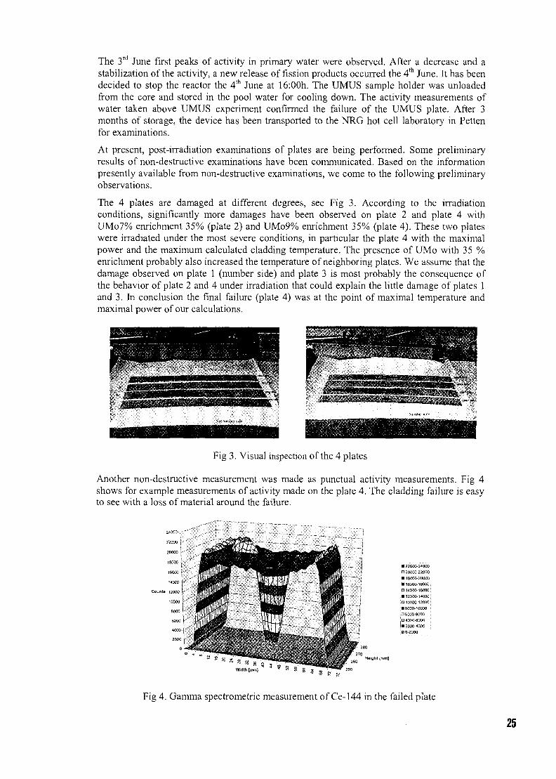
The 4 plates are damaged at different degrees, see Fig 3. According to the irradiationconditions, significantly more damages have been observed on plate 2 and plate 4 withUMo7% enrichment 35% (plate 2) and UMo9% enrichment 35% (plate 4). These two plateswere irradiated under the most severe conditions, in particular the plate 4 with the maximalpower and the maximum calculated cladding temperature. The presence of UMo with 35 %enrichment probably also increased the temperature of neighboring plates. We assume that thedamage observed on plate 1 (number side) and plate 3 is most probably the consequence ofthe behavior of plate 2 and 4 under irradiation that could explain the little damage of plates 1and 3. In conclusion the final failure (plate 4) was at the point of maximal temperature andmaximal power of our calculations.
Fig 3. Visual inspection of the 4 plates
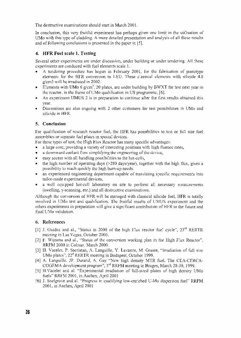
Another non-destructive measurement was made as punctual activity measurements. Fig 4shows for example measurements of activity made on the plate 4. The cladding failure is easyto see with a loss of material around the failure.
24000 r '
22000 [- '
20000
18000
16000 t '
14000
Counto 12000
10000
8000
• 22000-2-SOOQD 20000-22000• ieooo-20000• 16000-18000;• 14000-16000• 12000-1*000• 10000-12000• 6000-10000neooo-aoooO 4000-6000
) • 2000-4000 :HO-2000
Fig 4. Gamma spectrometric measurement of Ce-144 in the failed plate
25
The destructive examinations should start in March 2001.
In conclusion, this very fruitful experiment has perhaps given one limit in the utilisation ofUMo with this type of cladding. A more detailed presentation and analysis of all these resultsand of following conclusions is presented in the paper in [5].
4. HFR Fuel scale 1. Testing
Several other experiments are under discussion, under building or under tendering. All theseexperiments are conduced with fuel elements scale 1.• A tendering procedure has begun in February 2001, for the fabrication of prototype
elements for the HFR conversion to LEU. These classical elements with silicide 4.8g/cm3 will be irradiated in 2002.
• Elements with UMo 6 g/cm3, 20 plates, are under building by BWXT for test next year inthe reactor, in the frame of UMo qualification in US programme, [6].
• An experiment UMUS 2 is in preparation to continue after the first results obtained thisyear.
• Discussions are also ongoing with 2 other customers for test possibilities in UMo andsilicide in HFR.
5. Conclusion
For qualification of research reactor fuel, the HFR has possibilities to test or full size fuelassemblies or separate fuel plates in special devices.For these types of test, the High Flux Reactor has many specific advantages:• a large core, providing a variety of interesting positions with high fluence rates,• a downward coolant flow simplifying the engineering of the device,• easy access with all handling possibilities to the hot-cells,• the high number of operating days (>280 days/year), together with the high flux, gives a
possibility to reach quickly the high burn-up needs,• an experienced engineering department capable of translating specific requirements into
tailor-made experimental devices,• a well equipped hot-cell laboratory on site to perform all necessary measurements
(swelling, y-scanning, etc.) and all destructive examinations.Although the conversion of HFR will be managed with classical silicide fuel, HFR is totallyinvolved in UMo test and qualification. The fruitful results of UMUS experiment and theothers experiments in preparation will give a significant contribution of HFR to the future andfinal UMo validation.
6. References
[1] J. Guidez and al., "Status in 2000 of the high Flux reactor fuel cycle", 23rd RERTRmeeting in Las Vegas, October 2000.
[2] F. Wijtsma and al., "Status of the conversion working plan in the High Flux Reactor",RRFM 2000 in Colmar, March 2000.
[3] H. Vacelet, P. Sacristan, A. Languille, Y. Lavastre, M. Grasse, "Irradiation of full sizeUMo plates", 22d RERTR meeting in Budapest, October 1999.
[4] A. Languille, JP. Durand, A. Gay "New high density MTR fuel. The CEA-CERCA-COGEMA development program", 3rd RRFM meeting in Bruges, March 28-30, 1999.
[5] H.Vacelet and al. "Experimental irradiation of full-sized plates of high density UMofuels" RRFM 2001, in Aachen, April 2001
[6] J. Snelgrove and al. "Progress in qualifying low-enriched U-Mo dispersion fuel" RRFM2001, in Aachen, April 2001
26
CH01000249
PROGRESS IN QUALIFYING LOW-ENRICHEDU-MO DISPERSION FUELS
J. L. SNELGROVE AND G. L. HOFMANArgonne National Laboratory, 9700 S. Cass Avenue, Argonne, Illinois 60439-4815 U.S.A.
and
S. L. HAYES AND M. K. MEYERArgonne National Laboratory, P.O. Box 2528, Idaho Falls, Idaho 83403-2528 U.S.A.
ABSTRACT
The U.S. Reduced Enrichment for Research and Test Reactors program is working toqualify dispersions of U-Mo alloys in aluminum with fuel-meat densities of 8 to 9 gU cm"3.Postirradiation examinations of the small fuel plates irradiated in the Advanced TestReactor during the high-temperature RERTR-3 tests are virtually complete, and analysis ofthe large quantity of data obtained is underway. We have observed that the swelling of thefuel plates is stable and modest and that the swelling is dominated by the temperature-dependent interaction of the U-Mo fuel and the aluminum matrix. In order to extractdetailed information about the behavior of these fuels from the data, a complex fuel-platethermal model is being developed to account for the effects of the changing fission rate andthermal conductivity of the fuel meat during irradiation. This paper summarizes theempirical results of the postirradiation examinations and the preliminary results of themodel development. In addition, the schedule for irradiation of full-sized elements in theHFR-Petten is briefly discussed.
1. Introduction
For the past several years the focus of the fuels area of the U.S. Reduced Enrichment for Researchand Test Reactors (RERTR) program has been the development of aluminum-based dispersion fuelsthat will accommodate uranium densities in the fuel meat of 8 to 9 gU cm'-' [1]. Our primary focushas been on determining the irradiation behavior of candidate fuels. Thus far, data are available fromthree irradiation tests of very small fuel plates—RERTR-1, -2, and -3. The first two tests resulted inthe identification of U-Mo alloys with Mo contents of at least 6 wt.% as very promising candidates[2]. The third test, which is the principal subject of this paper, was focused on the behavior of theU-Mo fuels under high-temperature (up to ~250°C) irradiation conditions.
The small test plates irradiated in RERTR-3 contained either atomized or machined fuel particlesranging in composition from, nominally, 6 wt.% Mo (U-6M0) to 10 wt.% Mo (U-lOMo); actualcompositions ranged from 6.7 to 10.6 wt.% Mo. Of the plates discussed in this paper, one set wasfabricated using either atomized or machined U-lOMo powder that had been given a solution heattreatment in the gamma phase; all other plates discussed in this paper were fabricated using powder inthe as-fabricated state. The fuel plates in the RERTR-3 test measured 10.0 mm x 41.1 mm x 1.52mm; the meat was in an elliptical zone nominally 0.76 mm thick and contained, nominally, 8 gU cm"3 of fuel meat. The actual average uranium densities in the plates were probably somewhat higher,and uranium densities in some areas of the plates were significantly higher.
27

2. Postirradiation Data
Because of the small size of the test plates, volumetric measurement with the customary immersionmethod would not yield swelling data with sufficient accuracy; therefore swelling was determinedfrom plate thickness measurements. The measured plate-thickness increases are shown in Fig. 1,normalized to a meat fission density of 10^1 cm~3 (-30% burnup), as a function of beginning of life(BOL) fuel centerline temperature. These BOL temperatures were calculated using a one-dimensional (1-D) heat transfer model. It is clear from Fig. 1 that the plate swelling is a strongfunction of temperature and that there appears to be no clear difference, within the measurementuncertainty, among the various compositions. It is important to note at this point that these thicknessincreases are quite small, and since thickness measurements always overestimate the swelling, themaximum fuel-meat swelling at this burnup is no more than 10% at the highest temperatures tested.
A.TOMEHJV, •2, VR,«8 ,0
10 Mo10 Mo,77 Mo« Mo
MAO*ED
B,'BC.O
10 Mo10 Mo,78 Mo6 Mo
ESTMATEOUNCERTAKTY
°/mm/
T •
- 0
Fig.
200
°C (BOO 1-D
260
Thickness increase of RERTR-3test fuel plates normalized to a fuel-meat fission density of 10^1 cm~J
(30% burnup) vs. calculated BOLpeak fuel meat temperature.
The 1-D BOL temperatures plotted in Fig. 1 onlyserve to illustrate the trend in swelling withincreasing temperature. The actual fuel temperatureis a complex function of irradiation time andposition in the fuel meat. Not only are theresubstantial temperature gradients in the fuel meat,but the temperature changes during the irradiation asa result of the competing effects of decreasingthermal conductivity and U-235 burnup. This issueis treated in detail later in this paper.
Two irradiation effects singly, or in combination,may be responsible for the observed temperaturedependence of the swelling. One is the behavior offission gas in the LJ-Mo alloy (the swelling owing tosolid fission products can be considered to beathermal); the other is irradiation-enhancedinterdiffusion of the fuel and the matrix aluminum.Inspection of the optical micrographs shown inFig. 2 suggests that the latter is the major contributorto the temperature dependence of the swelling. Note
Meat Center
Cladding Cladding
40
Fig. 2. Optical micrographs of sections of plate V03 taken near the center of the plate showing28 the change in interaction-layer thickness from the cladding/fuel-meat interface to the
center of the fuel meat.
the large increase in interaction thickness when going from a fuel temperature of 175°C (1-D BOL) atthe cladding interface to 217°C at the center of the meat in U-10 Mo. It should also be noted thatalthough virtually all of the matrix aluminum near the center of the plate has been consumed,resulting in a mass of reacted and unreacted fuel, there is no evidence of instability of this fuel mass.
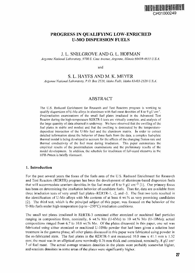
There are indications of the presence of small gas bubbles at the grain boundaries in the unreactedfuel. This is better illustrated in the SEM fractographs shown in Fig. 3. Small gas bubbles havebegun to form in the I75°C sample and are more numerous and larger at 217°C. However, the 175°Csample reached only 30% burnup compared to 40% for the 217°C sample. Comparison of the bubblemorphology in this latter sample with that of the same fuel irradiated previously in RERTR-1 to the
30% Burnup, 175°C
40% Burnup, 217°C\
40% Burnup, 65°C
Fig. 3. Fuel microstructure of U-lOMo at low and high temperature,showing apparent athermal fission gas behavior. 29
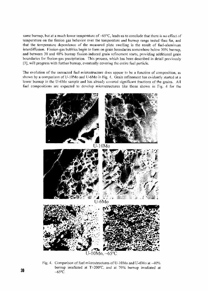
same burnup, but at a much lower temperature of ~65°C, leads us to conclude that there is no effect oftemperature on the fission gas behavior over the temperature and burnup range tested thus far, andthat the temperature dependence of the measured plate swelling is the result of fuel-aluminuminterdiffusion. Fission-gas bubbles begin to form on grain boundaries somewhere below 30% burnup,and between 30 and 40% burnup fission-induced grain refinement starts, providing additional grainboundaries for fission-gas precipitation. This process, which has been described in detail previously[3], will progress with further burnup, eventually covering the entire fuel particle.
The evolution of the unreacted fuel microstructure does appear to be a function of composition, asshown by a comparison of U-lOMo and U-6M0 in Fig. 4. Grain refinement has evidently started at alower burnup in the U-6M0 sample and has already covered significant fractions of the grains. Allfuel compositions are expected to develop microstructures like those shown in Fig. 4 for the
30
U-10Mo,~65°C
Fig. 4. Comparison of fuel microstructures of U-lOMo and U-6M0 at -40%burnup irradiated at T>200cC, and at 70% burnup irradiated at~65°C.
low-temperature, 70%-burnup sample from RERTR-2, but the lower-Mo compositions will completetheir restructuring at lower burnup and should therefore have a somewhat higher fuel-swelling rate.
In summary, we have observed through metallographic examinations that (1) fuel plate swelling isstable and modest, (2) overall swelling owes predominantly to temperature-dependent U-Mo/Alinterdiffusion up to the burnup where the matrix aluminum is fully consumed by this interdiffusionprocess, (3) the aluminide interaction product appears stable and contains no fission gas bubbles,(4) the swelling behavior of the unreacted fuel appears to be athermal in the range of burnup andtemperature tested, and (5) reducing the molybdenum content of the alloy results in somewhat higherrates of interdiffusion and fission gas swelling. Although not discussed in this paper, we have alsoshown that small ternary additions of other elements to the alloy, shown to reduce the rate ofthermally driven interdiffusion, do not reduce the rate of irradiation-induced interdiffusion.
3. Fuel Plate Thermal Analysis
3.1 Motivation
As described above, results from postirradiation examinations of U-Mo alloy dispersion fuels indicatethat the interaction between the fuel and matrix phases is apparently a sensitive function oftemperature. As the interaction proceeds, a low-conductivity reaction-product phase builds up, whileat the same time the high-conductivity aluminum-matrix phase is depleted. Thus, fuel temperaturesare likely to increase with burnup even if plate powers decrease. This interplay between fueltemperature and fuel-matrix interaction makes the development of a simple empirical correlationbetween the two difficult, since it is unclear what temperature to employ. For this reason, a complexthermal model was developed to calculate fuel temperatures, taking into account the changing volumefractions of fuel, matrix, and reaction-product phases within the fuel meat, as well as gasgeneration/swelling in the fuel phase. Then, within the context of this best-estimate temperaturecalculation, a fuel-matrix reaction-rate equation can be developed in an integral manner.
3.2 Model Description
The thermal model developed is based upon a steady-state, three-dimensional, control-volume-basedfinite-difference temperature calculation implemented within a FORTRAN computer code. Althoughthe calculation is a steady-state calculation, a series of such calculations are made while marchingalong in time (while under irradiation), allowing fuel-matrix interaction to proceed based upon aphysics-based reaction-rate equation; a correlation developed for U3Si2/Al interaction was taken asan initial guess [4]. As the reaction-product phase increases and the matrix phase depletes, theeffective fuel-meat thermal conductivity is changed through the use of an analytical multiphaseconductivity model [5]. The multiphase conductivity model employed was derived for a two-phasematerial from purely theoretical considerations. The matrix aluminum constitutes one phase and thefuel, consisting of the spherical fuel particles surrounded by a uniform spherical shell of reactionproduct, constitutes the other. The reaction product produces a thermal resistance to radial heat flowout of the spheres that increases with time as the reaction-product thickness increases. This resistanceis calculated directly and used to decrease the fuel alloy thermal conductivity accordingly. Therevised value for the fuel thermal conductivity, representing both the fuel and interaction-productphases, is then used in the multiphase conductivity model to reevaluate the effective fuel-meatthermal conductivity.
As fuel-matrix interaction proceeds, volume fractions of the meat constituents change. The volumefraction of the reaction product is initially zero, but increases with irradiation time/burnup. Thematrix phase decreases from its as-fabricated value as it is consumed both by the fuel-matrix reactionand by incorporation into solution with the 'unreacted' fuel alloy. The incorporation of matrixaluminum into solution with the 'unreacted' fuel alloy kernels has been observed during the "•
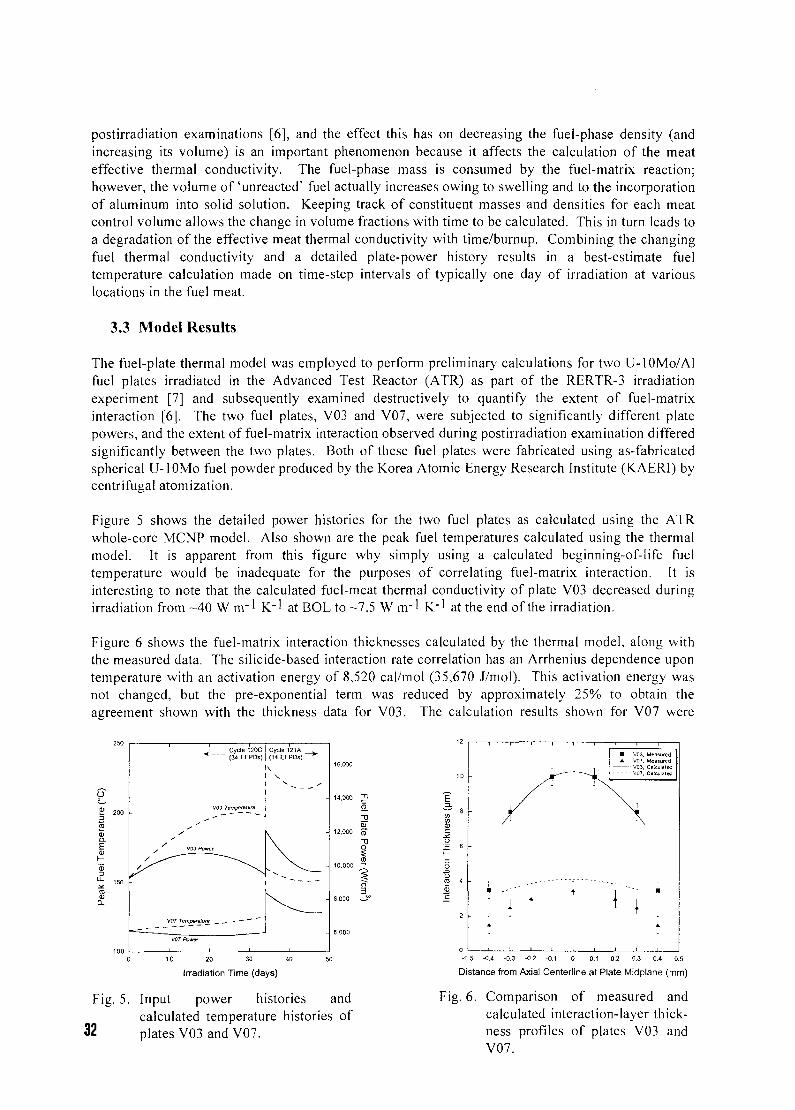
postirradiation examinations [6], and the effect this has on decreasing the fuel-phase density (andincreasing its volume) is an important phenomenon because it affects the calculation of the meateffective thermal conductivity. The fuel-phase mass is consumed by the fuel-matrix reaction;however, the volume of'unreacted' fuel actually increases owing to swelling and to the incorporationof aluminum into solid solution. Keeping track of constituent masses and densities for each meatcontrol volume allows the change in volume fractions with time to be calculated. This in turn leads toa degradation of the effective meat thermal conductivity with time/burnup. Combining the changingfuel thermal conductivity and a detailed plate-power history results in a best-estimate fueltemperature calculation made on time-step intervals of typically one day of irradiation at variouslocations in the fuel meat.
3.3 Model Results
The fuel-plate thermal model was employed to perform preliminary calculations for two U-lOMo/Alfuel plates irradiated in the Advanced Test Reactor (ATR) as part of the RERTR-3 irradiationexperiment [7] and subsequently examined destructively to quantify the extent of fuel-matrixinteraction [6]. The two fuel plates, V03 and V07, were subjected to significantly different platepowers, and the extent of fuel-matrix interaction observed during postirradiation examination differedsignificantly between the two plates. Both of these fuel plates were fabricated using as-fabricatedspherical U-lOMo fuel powder produced by the Korea Atomic Energy Research Institute (KAERI) bycentrifugal atomization.
Figure 5 shows the detailed power histories for the two fuel plates as calculated using the ATRwhole-core MCNP model. Also shown are the peak fuel temperatures calculated using the thermalmodel. It is apparent from this figure why simply using a calculated beginning-of-life fueltemperature would be inadequate for the purposes of correlating fuel-matrix interaction. It isinteresting to note that the calculated fuel-meat thermal conductivity of plate V03 decreased duringirradiation from -40 W nr 1 K"1 at BOL to -7.5 W nr1 K"1 at the end of the irradiation.
Figure 6 shows the fuel-matrix interaction thicknesses calculated by the thermal model, along withthe measured data. The silicide-based interaction rate correlation has an Arrhenius dependence upontemperature with an activation energy of 8,520 cai/mol (35,670 J/mol). This activation energy wasnot changed, but the pre-exponential term was reduced by approximately 25% to obtain theagreement shown with the thickness data for V03. The calculation results shown for V07 were
<-
, ^ V03Powo
V07 Temperatvn
V07 Powtr
Cycle 120C(34 EFPDs)
V03 Tompenlure
Cycle 121A(14 EFPDs)
\ .
0 10 20 30
Irradiation Time (days)
2}
q_-oCD
"0
i
E
i03C
J£O
XII—
Fig. 5. Input power histories andcalculated temperature histories of
32 plates V03 and V07.
" I
i B
i —
^ L_
I'
V03. MeasuredVQ7, Measured
— V03, CtilculBl&a- - V07, Calculated
1
-0.5 -0.4 -0.3 -0.2 -O.1 0 0.1 02 0.3 0.4 0.5
Distance from Axial Centerline at Plate Midplane (mm)
Fig. 6. Comparison of measured andcalculated interaction-layer thick-ness profiles of plates V03 andV07.
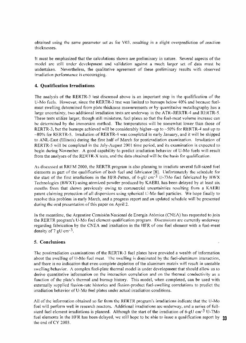
obtained using the same parameter set as for V03, resulting in a slight overprediction of reactionthicknesses.
It must be emphasized that the calculations shown are preliminary in nature. Several aspects of themodel are still under development and validation against a much larger set of data must beundertaken. Nevertheless, the qualitative agreement of these preliminary results with observedirradiation performance is encouraging.
4. Qualification Irradiations
The analysis of the RERTR-3 test discussed above is an important step in the qualification of theU-Mo fuels. However, since the RERTR-3 test was limited to burnups below 40% and because fuel-meat swelling determined from plate thickness measurements or by quantitative metallography has alarge uncertainty, two additional irradiation tests are underway in the ATR-RERTR-4 and RERTR-5.These tests utilize larger, though still miniature, fuel plates so that the fuel-meat volume increase canbe determined by the immersion method. The temperatures will be somewhat lower than those ofRERTR-3, but the burnups achieved will be considerably higher—up to -50% for RERTR-4 and up to-80% for RERTR-5. Irradiation of RERTR-4 was completed in early January, and it will be shippedto ANL-East (Illinois) during the first half of March for postirradiation examination. Irradiation ofRERTR-5 will be completed in the July-August 2001 time period, and its examination is expected tobegin during November. A good capability to predict irradiation behavior of U-Mo fuels will resultfrom the analyses of the RERTR-X tests, and the data obtained will be the basis for qualification.
As discussed at RRFM 2000, the RERTR program is also planning to irradiate several full-sized fuelelements as part of the qualification of both fuel and fabricator [8]. Unfortunately the schedule forthe start of the first irradiations in the HFR-Petten, of 6-gU cnr3 U-7Mo fuel fabricated by BWXTechnologies (BWXT) using atomized powder produced by KAERI, has been delayed by at least sixmonths from that shown previously owing to commercial uncertainties resulting from a KAERIpatent claiming protection of all dispersions using spherical U-Mo fuel particles. We hope finally toresolve this problem in early March, and a progress report and an updated schedule will be presentedduring the oral presentation of this paper on April 2.
In the meantime, the Argentine Comision Nacional de Energia Atomica (CNEA) has requested to jointhe RERTR program's U-Mo fuel element qualification program. Discussions are currently underwayregarding fabrication by the CNEA and irradiation in the HFR of one fuel element with a fuel-meatdensity of 7 gU crrr-*.
5. Conclusions
The postirradiation examinations of the RERTR-3 fuel plates have provided a wealth of informationabout the swelling of U-Mo fuel meat. The swelling is dominated by the fuel-aluminum interaction,and there is no indication that even complete depletion of the aluminum matrix will result in unstableswelling behavior. A complex fuel-plate thermal model is under development that should allow us toderive quantitative information on the interaction correlation and on the thermal conductivity as afunction of the plate's thermal and burnup history. This model, when completed, can be used withexternally supplied fission-rate histories and fission-product fuel-swelling correlations to predict theirradiation behavior of U-Mo fuel plates under actual irradiation conditions.
All of the information obtained so far from the RERTR program's irradiations indicate that the U-Mofuel will perform well in research reactors. Additional irradiations are underway, and a series of full-sized fuel element irradiations is planned. Although the start of the irradiation of 6-gU cm'3 U-7Mofuel elements in the HFR has been delayed, we still hope to be able to issue a qualification report bythe end of CY 2003.
6. References
[1] J. L. Snelgrove, G. L. Hofman, M. K. Meyer, C. L. Trybus, and T. C. Wiencek, "Developmentof very-high-density low-enriched uranium fuels," Niicl Eng. and Desigfi 178 (1), pp. 119-126(Dec. 1997).
[2] J. L. Snelgrove, G. L. Hofman, M. K. Meyer, S. L. Hayes, T. C. Wiencek, and R. V. Strain,"Progress in Developing Very-High-Density Low-Enriched-Uranium Fuels," Transactions ofthe 3rd International Topical Meeting on Research Reactor Fuel Management, Bruges,Belgium, March 28-30, 1999, pp. 44-49 (March 1999).
[3] G. L. Hofman, M. K. Meyer, J. L. Snelgrove, M. L. Dietz, R. V. Strain, and K-H. Kim, "InitialAssessment of Radiation Behavior of Very-High-Density Low-Enriched-Uranium Fuels,"Proceedings of the 22nc> International Meeting on Reduced Enrichment for Research and TestReactors, Budapest, Hungary, October 3-8, 1999 (to be published).
[4] J. Rest, "A Theoretical Model for the Irradiation-Enhanced Interdiffusion of Al and U Alloys,"Proceedings of the 23r^ International Meeting on Reduced Enrichment for Research and TestReactors, Las Vegas, NV, October 1-6, 2000 (to be published).
[5] Z. Hashin and S. Shtrikman, "A Variational Approach to the Theory of the Effective MagneticPermeability of Multiphase Materials," Journal of Applied Physics, Vol. 33 (1962) pp. 3125-3131.
[6] M. K. Meyer, G. L. Hofman, R. V. Strain, C. R. Clark and J. R. Stuart, "MetallographicAnalysis of Irradiated RERTR-3 Fuel Test Specimens," Proceedings of the 23rd InternationalMeeting on Reduced Enrichment for Research and Test Reactors, Las Vegas, NV, October 1-6,2000 (to be published).
[7] S. L. Hayes, M. K. Meyer, C. R. Clark, J. R. Stuart, I. G. Prokofiev and T. C. Wiencek,"Prototypic Irradiation Testing of High-Density U-Mo Alloy Dispersion Fuels," Proceedings ofthe 22"d International Meeting on Reduced Enrichment for Research and Test Reactors,Budapest, Hungary, October 3-8, 1999 (to be published).
[8] J. L. Snelgrove and A. Languille, "Qualification of Uranium-Molybdenum Alloy Fuel—Conclusions of an International Workshop," Transactions of the 4™ International TopicalMeeting on Research Reactor Fuel Management, Colmar, France, March 19-21, 2000,pp. 104-109 (March 2000).
34
CH01000250
SAFETY ASSESSMENTS OF IRIS IRRADIATION TESTSPERFORMED IN SILOE AND OSIRIS FOR THE QUALIFICATION OF
NEW FUELS FOR RESEARCH REACTORS
H. ABOU YEHIA, G. BARS, A. ORJOL AND P. TRAN DAISafety Evaluation Department
Institut de Protection et de Surete Nucleaire (IPSN) - B.P. 6 - 92265 Fontenay-aux-Roses cedex - France
ABSTRACT
The conditions for use of the IRIS irradiation device in SILOE and OSIRIS reactors for thequalification of new fuel types dedicated to research reactors have been the subject ofsafety assessments carried out by the IPSN for the benefit of the French safety authority(Directorate for the Safety of Nuclear Installations - DSIN). This institute has alsoassessed the results of qualification tests carried out at SILOE in the scope of a contract inagreement with GRS in 1997, on a U3Si2 fuel plate enriched to 93 % in 235U andcontaining 1.5 g of uranium per cm3, which is representative of the planned fuel for theFRM-II reactor of the Technical University of Munich. After a general description of theIRIS irradiation device, this paper presents the main conclusions of the above-mentionedsafety evaluations.
1. Presentation of the IRIS device
The IRIS device is intended to qualify various types of fuel plates for research reactors. It includes an inpile part consisting of a fuel plate irradiation box made of aluminium alloy and a part consisting of aplate thickness measurement bench and associated control and acquisition rack.
A similar device was used in the SILOE reactor (35 MW) to qualify various types of silicide fuels andfuels based on uranium and aluminium alloy. After the definitive shutdown of the SILOE reactor at theend of 1997, a new device was built for the OSIRIS reactor (70 MW). It enables qualification tests tobe carried out on the fuel at a higher power level. It is currently being used for further qualification teststo those carried out at SILOE for the FRM-II reactor silicide fuel, and for the qualification of UMoplanned fuel for the future RJH reactor.
The irradiation box comprises a massive unit prolonged by two grooved side plates. Fuel plates to beirradiated and inert plates are placed in these grooves, alternating (see figures 1 and 2). The width of thecooling channel between the plates is 3mm in the case of SILOE and 3.6mm in the case of OSIRIS. Inboth cases the device occupies, on the perimeter of the core, a location equivalent to that of a standardfuel element. The fuel plates to be tested are removable and the inert plates are crimped in the device.The mid-height plane of the plates corresponds to the mid-height plane of the core.
The IRIS device is cooled by the water of the reactor core cooling system. Because of the ascendingdirection of the flow in the case of the OSIRIS reactor (different from that of the SILOE reactor),special attention was paid to the locking of the irradiation device and of the experimental fuel plates, toavoid the risk of their taking off because of the hydrodynamic thrust.
There is no alarm or automatic shutdown of the reactor directly associated with the IRIS irradiationdevice, which is not instrumented. In the course of the irradiations, the experimental fuel plates placed inthe irradiation box receive the same surveillance as the fuel elements of the reactor core, in particular
35
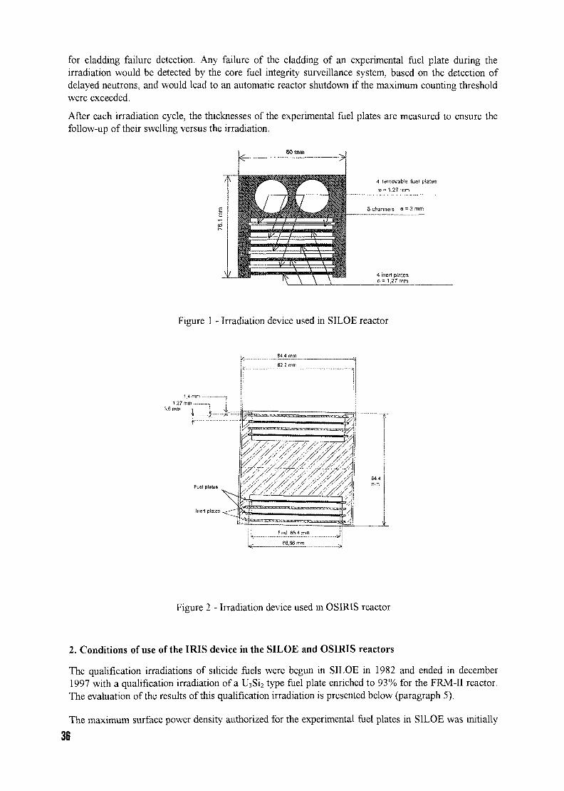
for cladding failure detection. Any failure of the cladding of an experimental fuel plate during theirradiation would be detected by the core fuel integrity surveillance system, based on the detection ofdelayed neutrons, and would lead to an automatic reactor shutdown if the maximum counting thresholdwere exceeded.
After each irradiation cycle, the thicknesses of the experimental fuel plates are measured to ensure thefollow-up of their swelling versus the irradiation.
80 mm
Figure 1 - Irradiation device used in SILOE reactor
1 4 ou1.27 mm
3,6 mm
Inert plates
Figure 2 - Irradiation device used in OSIRIS reactor
2. Conditions of use of the IRIS device in the SILOE and OSIRIS reactors
The qualification irradiations of silicide fuels were begun in SILOE in 1982 and ended in december1997 with a qualification irradiation of a U3Si2 type fuel plate enriched to 93% for the FRM-II reactor.The evaluation of the results of this qualification irradiation is presented below (paragraph 5).
The maximum surface power density authorized for the experimental fuel plates in SILOE was initially
36
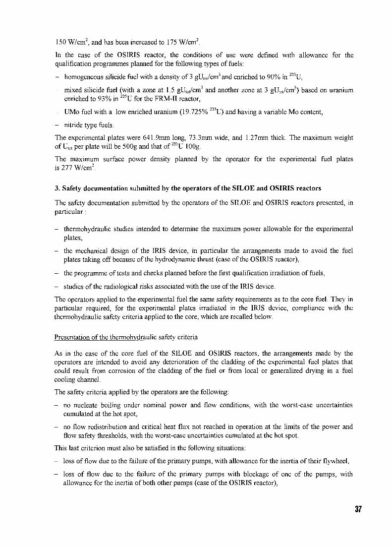
150 W/cm2, and has been increased to 175 W/cm2.
In the case of the OSIRIS reactor, the conditions of use were defined with allowance for thequalification programmes planned for the following types of fuels:
- homogeneous silicide fuel with a density of 3 gUtot/cm3 and enriched to 90% in 235U,
- mixed silicide fuel (with a zone at 1.5 gUtot/cm3 and another zone at 3 gUtot/cm3) based on uraniumenriched to 93% in 235U for the FRM-II reactor,
- UMo fuel with a low enriched uranium (19.725% 235U) and having a variable Mo content,
- nitride type fuels.
The experimental plates were 641.9mm long, 73.3mm wide, and 1.27mm thick. The maximum weightof Utot per plate will be 500g and that of 235U lOOg.
The maximum surface power density planned by the operator for the experimental fuel platesis 277 W/cm2.
3. Safety documentation submitted by the operators of the SILOE and OSIRIS reactors
The safety documentation submitted by the operators of the SILOE and OSIRIS reactors presented, inparticular:
- thermohydraulic studies intended to determine the maximum power allowable for the experimentalplates,
- the mechanical design of the IRIS device, in particular the arrangements made to avoid the fuelplates taking off because of the hydrodynamic thrust (case of the OSIRIS reactor),
- the programme of tests and checks planned before the first qualification irradiation of fuels,
- studies of the radiological risks associated with the use of the IRIS device.
The operators applied to the experimental fuel the same safety requirements as to the core fuel. They inparticular required, for the experimental plates irradiated in the IRIS device, compliance with thethermohydraulic safety criteria applied to the core, which are recalled below.
Presentation of the thermohydraulic safety criteria
As in the case of the core fuel of the SILOE and OSIRIS reactors, the arrangements made by theoperators are intended to avoid any deterioration of the cladding of the experimental fuel plates thatcould result from corrosion of the cladding of the fuel or from local or generalized drying in a fuelcooling channel.
The safety criteria applied by the operators are the following:
- no nucleate boiling under nominal power and flow conditions, with the worst-case uncertaintiescumulated at the hot spot,
- no flow redistribution and critical heat flux not reached in operation at the limits of the power andflow safety thresholds, with the worst-case uncertainties cumulated at the hot spot.
This last criterion must also be satisfied in the following situations:
- loss of flow due to the failure of the primary pumps, with allowance for the inertia of their flywheel,
- loss of flow due to the failure of the primary pumps with blockage of one of the pumps, withallowance for the inertia of both other pumps (case of the OSIRIS reactor),
37
- guillotine break of the primary circuit downstream of the primary pumps and upstream of the heatexchangers.
It is recalled that these situations lead to automatic shutdown of the reactor and to a changeover to thenatural convection cooling configuration.
Check of satisfaction of the above-mentioned criteria
In the case of the SILOE reactor, the operator used the SILCOR code for the thermohydrauliccalculations concerning the reactor core. These calculations showed that:
- the heat flux at the hot spot leading to nucleate boiling under the nominal reactor operatingconditions is 190 W/cm2,
- a flow redistribution could occur for a heat flux at the hot spot of 212 W/cm2.
In the case of the qualification irradiation of the fuel plate representative of the fuel planned for theFRM-II reactor, the maximum surface thermal power density at the hot spot was limited to 175 W/cm2,leaving a margin of approximately 8% with respect to nucleate boiling.
Case of the OSIRIS reactor
In the case of the OSIRIS reactor, the thermohydraulic calculations were done using the FLICA andSIRENE codes developed at the CEA, which had already been used in 1995 when the OSIRIS reactorwas converted to the silicide fuel.
The results of these calculations, performed with allowance for the uncertainties and operating margins,show that:
- the maximum heat flux that must not be exceeded to avoid the onset of nucleate boiling is280 W/cm2, in the mid-height plane of the experimental fuel plate,
- the heat flux not to be exceeded in normal operation to avoid flow redistribution at the limits of thesafety thresholds is 459 W/cm2,
- the heat flux not to be exceeded in normal operation to avoid any risk of critical heat flux at thelimits of the safety thresholds is 277 W/cm2.
The operator has accordingly chosen 277 W/cm2 as the peak surface power density value not to beexceeded in the mid-height plane of the hot channel of the experimental fuel plates.
4. Main results of the safety evaluations performed by the IPSN
Limitation of maximum power of the experimental plates
In the case of the SILOE reactor, the operator was able to show, thanks to the instrumentation placed inthe irradiation device, that the fuel was suitably cooled for the maximum power planned for theexperimental fuel plates (175 W/cm2). The check of compliance with the thermohydraulic safety criteriatherefore posed no problem.
In the case of the OSIRIS reactor, following the analysis performed by the IPSN, the operator wasasked to limit the surface power density at the level of the experimental fuel plates to the valueauthorized for the fuel elements of the reactor, namely 231 W/cm2, instead of the 277 W/cm2 proposedin the operator's documentation.
This limitation was motivated by the uncertainties associated with the calculation codes used, which do
38
not correctly reflect the core fuel plate cladding temperature measurements made in 1997 using aninstrumented fuel element. These measurements also showed a significant disagreement between thecalculated and measured evolutions during the shutdown transients of the pumps on their inertia.Furthermore, the measured heating of the water in the channels was 37°C, whereas the calculatedheating was 17°C. This difference was ascribed by the operator to an inadequate representation of theprimary circuit by the SIRENE code, in particular as regards the operation of the natural convectionvalves.
In conclusion, the safety authority authorized the operator to perform the experimental irradiations inthe IRIS device while limiting the surface power density to 231 W/cm2, pending further informationconcerning the validation of the calculation codes used. To date, the operator has not yet submitted thisadditional information.
This approach enabled the operator to use the IRIS device for the experimental irradiationsapproximately three months after submitting its documentation to the safety authority.
Radiological risks
Possible radiological risks in connection with the use of the IRIS device are:
- risk of irradiation of the personnel while handling the irradiation box and the experimental fuelplates,
- risk of irradiation and/or of contamination of the personnel if there is a loss of integrity of thecladding of a fuel plate or melting of the plate.
The arrangements proposed by the operator to limit these risks have been judged acceptable.Nevertheless, the operator has been asked to update the evaluation of the radiological consequences ofmelting in air of the experimental fuel plates to take account of the inventory of fission products at theend of irradiation.
5. Evaluation by the IPSN of qualification of the fuel planned for the FRM-II reactor
The new research reactor for the Technical University of Munich (FRM-II reactor, P=20 MW) will usea silicide fuel enriched to about 90% in 235U (densities of 1.5 g/cm3 and 3 g/cm3). In 1997, the futureoperator of this reactor had a U3Si2 fuel plate enriched to 90% with a density of 1.5 g/cm3 irradiated inthe SILOE reactor. The aim of this irradiation was to qualify the thermal-mechanical behaviour of thistype of fuel. The burn-up level attained was 1.2xlO22 fissions/cm3 (corresponding to 55.8% ofconsumed 235U).
The IPSN has assessed (for the benefit of the German safety organization GRS) the results of theabove-mentioned irradiation. This assessment covered the report submitted by the future operator of thereactor giving the results obtained after 16 irradiation test cycles of the U3S12 fuel plate and the post-irradiation examinations carried out, as well as a brief analysis of them.
The assessment carried out by the IPSN has been focused on the only one fuel plate with a density of1.5 g/cm3, which is representative regarding the uranium density of part of the fuel to be loaded into theFRM-II reactor. The fuel assembly of FRM-II reactor will also contain U3Si2 fuel with a density of3 g/cm3, on which irradiation tests are currently being performed in the OSIRIS reactor.
The above-mentioned assessment made it possible to verify mainly :
- the validity of the measurements and analyses made as regards burn-up (based on gammaspectrometry) and oxide layer thickness, making allowance for various uncertainties,
39
- the correct behaviour of the fuel plate in the presence of the swelling phenomenon, which did not leadto any loss of the integrity of the fuel cladding. In particular, it was possible to demonstrate thevalidity of the linear relationship between swelling and burn-up, and consistency with results takenfrom the literature for plates enriched to a lower extent has been verified,
- the swelling measured (around 50 um after subtracting the oxide layer thickness) is consistent withthe predictions (54 um) for a fission density of 1.2xlO22 fissions/cm3, making allowance foruncertainties.
The results obtained from the irradiation campaigns carried out in the SILOE reactor indicate that theuse of the tested fuel type for the FRM-II reactor is acceptable.
Conclusion
The safety documentation concerning experimental devices used for the qualification of new fuels forresearch reactors must include clear information about the validation of the calculation codes used, inparticular as regards thermohydraulics. The use of fuel plates instrumented with thermocouples whenthe qualification irradiations are begun may be an efficient way to confirm the adequate cooling of theexperimental fuel. The evaluation performed by the IPSN for GRS did not call into question the choiceof type of fuel for the FRM-II reactor. It was a good example of co-operation between two safetyorganizations.
40
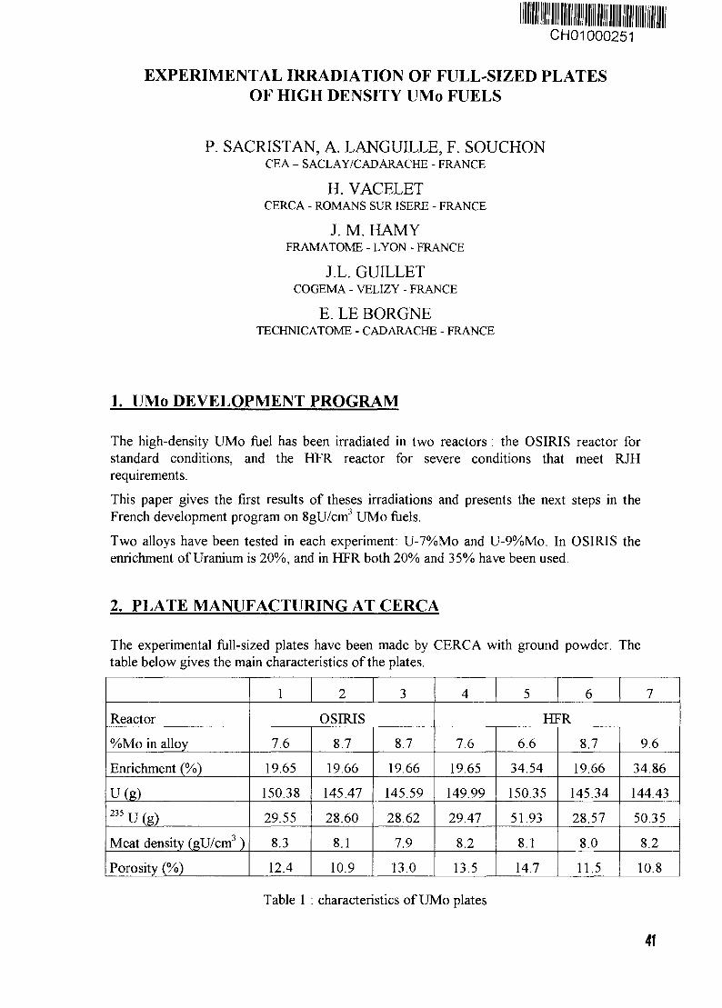
CH01000251
EXPERIMENTAL IRRADIATION OF FULL-SIZED PLATESOF HIGH DENSITY UMo FUELS
P. SACRISTAN, A. LANGUILLE, F. SOUCHONCEA - SACLAY/CADARACHE - FRANCE
H. VACELETCERCA - ROMANS SUR ISERE - FRANCE
J. M. HAMYFRAMATOME - LYON - FRANCE
J.L. GUILLETCOGEMA - VELIZY - FRANCE
E. LE BORGNETECHNICATOME - CAD ARACHE - FRANCE
1. UMo DEVELOPMENT PROGRAM
The high-density UMo fuel has been irradiated in two reactors : the OSIRIS reactor forstandard conditions, and the HFR reactor for severe conditions that meet RJHrequirements.
This paper gives the first results of theses irradiations and presents the next steps in theFrench development program on SgU/cnf UMo fuels.
Two alloys have been tested in each experiment: U-7%Mo and U-9%Mo. In OSIRIS theenrichment of Uranium is 20%, and in HFR both 20% and 35% have been used.
2. PLATE MANUFACTURING AT CERCA
The experimental full-sized plates have been made by CERCA with ground powder. Thetable below gives the main characteristics of the plates.
Reactor
%Mo in alloy
Enrichment (%)
Ufe)235 u (g)Meat density (gU/cm3 )
Porosity (%)
1 2 3
OSIRIS
7.6
19.65
150.38
29.55
8.3
12.4
8.7
19.66
145.47
28.60
8.1
10.9
8.7
19.66
145.59
28.62
7.9
13.0
4 5 6 7
HFR
7.6
19.65
149.99
29.47
8.2
13.5
6.6
34.54
150.35
51.93
8.1
14.7
8.7
19.66
145.34
28.57
8.0
11.5
9.6
34.86
144.43
50.35
8.2
10.8
Table 1 : characteristics of UMo plates
41
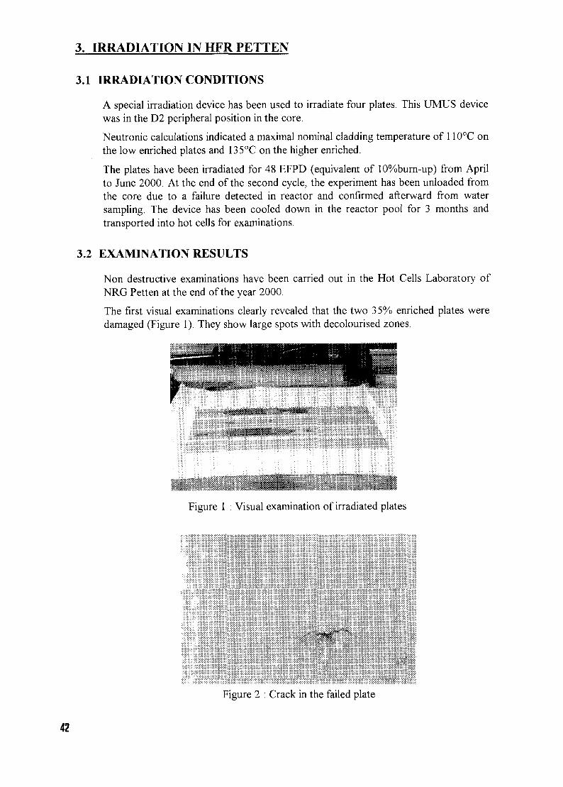
3. IRRADIATION IN HFR PETTEN
3.1 IRRADIATION CONDITIONS
A special irradiation device has been used to irradiate four plates. This UMUS devicewas in the D2 peripheral position in the core.
Neutronic calculations indicated a maximal nominal cladding temperature of 110°C onthe low enriched plates and 135°C on the higher enriched.
The plates have been irradiated for 48 EFPD (equivalent of 10%burn-up) from Aprilto June 2000. At the end of the second cycle, the experiment has been unloaded fromthe core due to a failure detected in reactor and confirmed afterward from watersampling. The device has been cooled down in the reactor pool for 3 months andtransported into hot cells for examinations.
3.2 EXAMINATION RESULTS
Non destructive examinations have been carried out in the Hot Cells Laboratory ofNRG Petten at the end of the year 2000.
The first visual examinations clearly revealed that the two 35% enriched plates weredamaged (Figure 1). They show large spots with decolourised zones.
Figure 1 : Visual examination of irradiated plates
Figure 2 : Crack in the failed plate
42
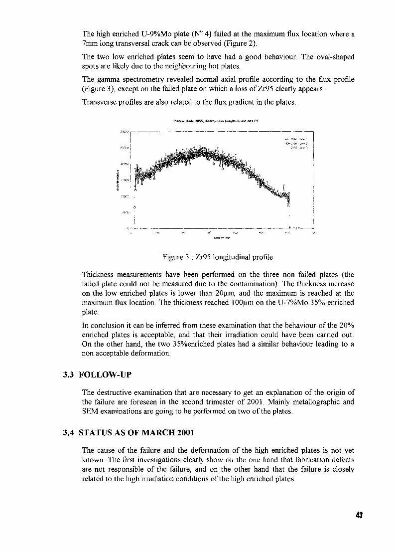
The high enriched U-9%Mo plate (N° 4) failed at the maximum flux location where a7mm long transversal crack can be observed (Figure 2).
The two low enriched plates seem to have had a good behaviour. The oval-shapedspots are likely due to the neighbouring hot plates.
The gamma spectrometry revealed normal axial profile according to the flux profile(Figure 3), except on the failed plate on which a loss of Zr95 clearly appears.
Transverse profiles are also related to the flux gradient in the plates.
Plaque U-Mo 2055. distribution longitudinal <Jes PP
Figure 3 : Zr95 longitudinal profile
Thickness measurements have been performed on the three non failed plates (thefailed plate could not be measured due to the contamination). The thickness increaseon the low enriched plates is lower than 20um, and the maximum is reached at themaximum flux location. The thickness reached 100 urn on the U-7%Mo 35% enrichedplate.
In conclusion it can be inferred from these examination that the behaviour of the 20%enriched plates is acceptable, and that their irradiation could have been carried out.On the other hand, the two 35%enriched plates had a similar behaviour leading to anon acceptable deformation.
3.3 FOLLOW-UP
The destructive examination that are necessary to get an explanation of the origin ofthe failure are foreseen in the second trimester of 2001. Mainly metallographic andSEM examinations are going to be performed on two of the plates.
3.4 STATUS AS OF MARCH 2001
The cause of the failure and the deformation of the high enriched plates is not yetknown. The first investigations clearly show on the one hand that fabrication defectsare not responsible of the failure, and on the other hand that the failure is closelyrelated to the high irradiation conditions of the high enriched plates.
43
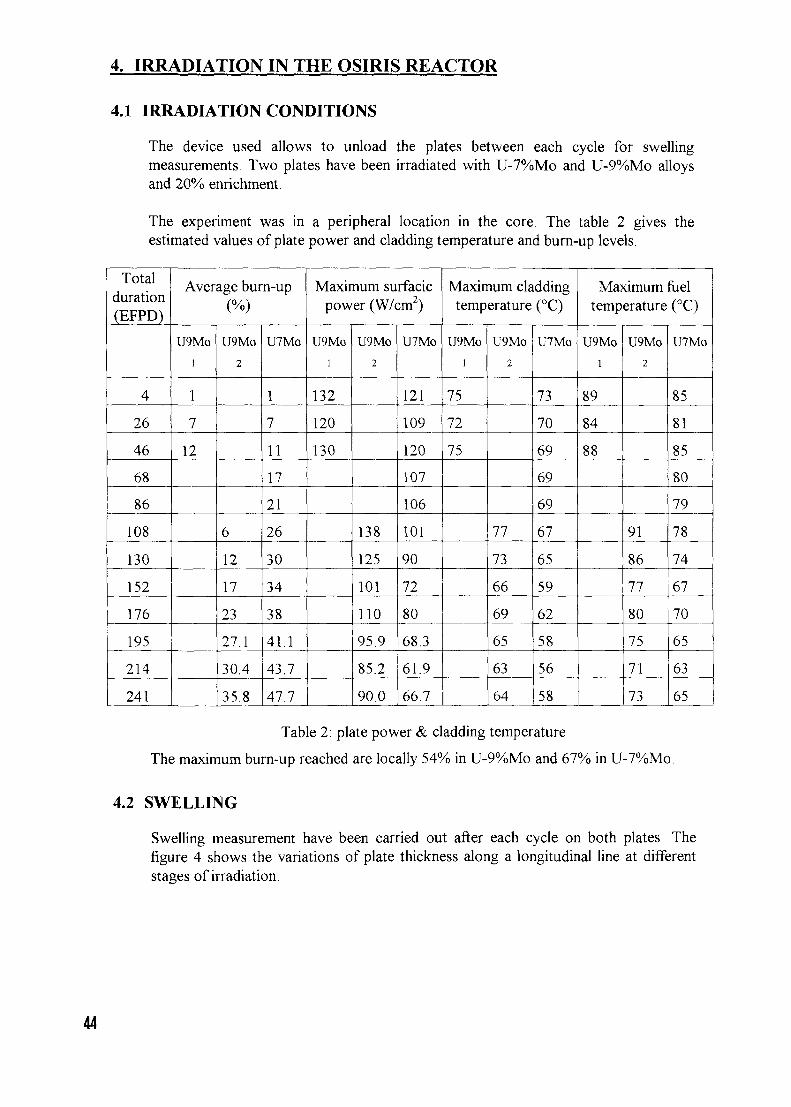
4. IRRADIATION IN THE OSIRIS REACTOR
4.1 IRRADIATION CONDITIONS
The device used allows to unload the plates between each cycle for swellingmeasurements. Two plates have been irradiated with U-7%Mo and U-9%Mo alloysand 20% enrichment.
The experiment was in a peripheral location in the core. The table 2 gives theestimated values of plate power and cladding temperature and burn-up levels.
Totalduration(EFPD)
4
26
46
68
86
108
130
152
176
195
214
241
Average burn-up(%)
U9Mo
i
1
7
12
U9Mo
2
6
12
17
23
27.1
30.4
35.8
U7Mo
1
7
11
17
21
26
30
34
38
41.1
43.7
47.7
Maximum surfacicpower (W/cm2)
U9Mo
I
132
120
130
U9Mo
2
138
125
101
110
95.9
85.2
90.0
U7Mo
121
109
120
107
106
101
90
72
80
68.3
61.9
66.7
Maximum claddingtemperature (°C)
U9Mo
1
75
72
75
U9Mo
2
77
73
66
69
65
63
64
U7Mo
73
70
69
69
69
67
65
59
62
58
56
58
Maximum fueltemperature (°C)
U9Mo
I
89
84
88
U9Mo
2
91
86
77
80
75
71
73
U7Mo
85
81
85
80
79
78
74
67
70
65
63
65
Table 2: plate power & cladding temperature
The maximum burn-up reached are locally 54% in U-9%Mo and 67% in U-7%Mo.
4.2 SWELLING
Swelling measurement have been carried out after each cycle on both plates. Thefigure 4 shows the variations of plate thickness along a longitudinal line at differentstages of irradiation.
44
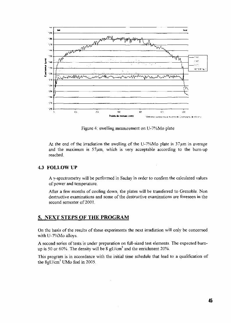
-386
'3^6
2. -Y
•in
UK
.jyA'V
Iil
/i
y V ^v V
I
uut
1',V\
PoWs d> masure (mml
Figure 4: swelling measurement on U-7%Mo plate
At the end of the irradiation the swelling of the U-7%Mo plate is 37jim in averageand the maximum is 57um, which is very acceptable according to the burn-upreached.
4.3 FOLLOW UP
A y-spectrometry will be performed in Saclay in order to confirm the calculated valuesof power and temperature.
After a few months of cooling down, the plates will be transferred to Grenoble. Nondestructive examinations and some of the destructive examinations are foreseen in thesecond semester of 2001.
5. NEXT STEPS OF THE PROGRAM
On the basis of the results of these experiments the next irradiation will only be concernedwith U-7%Mo alloys.
A second series of tests is under preparation on full-sized test elements. The expected bum-up is 50 or 60%. The density will be 8 gU/cm3 and the enrichment 20%.
This program is in accordance with the initial time schedule that lead to a qualification ofthe 8gU/cm3 UMo fuel in 2005.
45
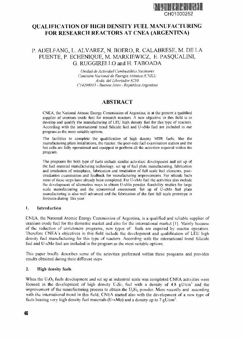
CH01000252
QUALIFICATION OF HIGH DENSITY FUEL MANUFACTURINGFOR RESEARCH REACTORS AT CNEA (ARGENTINA)
P. ADELFANG, L. ALVAREZ, N. BOERO, R. CALABRESE, M. DE LAFUENTE, P. ECHENIQUE, M. MARKIEWICZ, E. PASQUALINI,
G. RUGGIRELLO and H. TABOADAUnidad de Actividad Combustibles Nucleares
Comisión Nacional de Energía Atómica (CNEA)Avda. del Libertador 8250
C1429BNO - Buenos Aires - República Argentina
ABSTRACT
CNEA, the National Atomic Energy Commission of Argentina, is at the present a qualifiedsupplier of uranium oxide fuel for research reactors. A new objective in this field is todevelop and qualify the manufacturing of LEU high density fuel for this type of reactors.According with the international trend Suicide fuel and U-xMo fuel are included in ourprogram as the most suitable options.
The facilities to complete the qualification of high density MTR fuels, like themanufacturing plant installations, the reactor, the pool-side fuel examination station and thehot cells are fully operational and equipped to perform all the activities required within theprogram.
The programs for both type of fuels include similar activities: development and set up ofthe fuel material manufacturing technology, set up of fuel plate manufacturing, fabricationand irradiation of miniplates, fabrication and irradiation of full scale fuel elements, post-irradiation examination and feedback for manufacturing improvements. For suicide fuelsmost of these steps have already been completed. For U-xMo fuel the activities also includethe development of alternative ways to obtain U-xMo powder, feasibility studies for largescale manufacturing and the economical assessment. Set up of U-xMo fuel platemanufacturing is also well advanced and the fabrication of the first full scale prototype isforeseen during this year.
1. Introduction
CNEA. the National Atomic Energy Commission of Argentina, is a qualified and reliable supplier ofuranium oxide fuel for the domestic market and also for the international market [1J. Mainly becauseof the reduction of enrichment programs, new types of fuels are required by reactor operators.Therefore CNEA's objectives in this field include the development and qualification of LEU highdensity fuel manufacturing for this type of reactors. According with the international trend Suicidefuel and U-xMo fuel are included in the program as the most suitable options.
This paper briefly describes some of the activities performed within these programs and providesresults obtained during their different steps.
2. High density fuels
When the U3O8 fuels development and set up at industrial scale was completed CNEA activities werefocused in the development of high density U3Si2 fuel with a density of 4.8 gU/cm3 and theimprovement of the manufacturing process to obtain the U3SÍ2 powder. More recently and accordingwith the international trend in this field, CNEA started also with the development of a new type offuels bearing very high density fuel materials (U-xMo) and a density up to 7 gU/cm3.
46
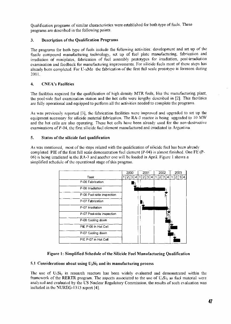
Qualification programs of similar characteristics were established for both type of fuels. Theseprograms are described in the following points.
3. Description of the Qualification Programs
The programs for both type of fuels include the following activities: development and set up of thefissile compound manufacturing technology, set up of fuel plate manufacturing, fabrication andirradiation of miniplates, fabrication of fuel assembly prototypes for irradiation, post-irradiationexamination and feedback for manufacturing improvements. For silicide fuels most of these steps hasalready been completed. For U-xMo the fabrication of the first full scale prototype is foreseen during2001.
4. CNEA's Facilities
The facilities required for the qualification of high density MTR fuels, like the manufacturing plant,the pool-side fuel examination station and the hot cells were lengthy described in [2]. This facilitiesare fully operational and equipped to perform all the activities needed to complete the programs.
As was previously reported [3], the fabrication facilities were improved and upgraded to set up theequipment necessary for silicide material fabrication. The RA-3 reactor is being upgraded to 10 MWand the hot cells are also operating. These hot cells have been already used for the non-destructiveexaminations of P-04, the first silicide fuel element manufactured and irradiated in Argentina.
5. Status of the silicide fuel qualification
As was mentioned, most of the steps related with the qualification of silicide fuel has been alreadycompleted. PIE of the first full scale demonstration fuel element (P-04) is almost finished. One FE (P-06) is being irradiated in the RA-3 and another one will be loaded in April. Figure 1 shows asimplified schedule of the operational stage of this program.
Task
P-06 Fabrication
P-06 Irradiation
P-06 Pool-side inspection
P-07 Fabrication
P-07 Irradiation
P-07 Pool-side inspection
P-06 Cooling down
PIE P-06 in Hot Cell
P-07 Cooling down
PIE P-07 in Hot Cell
20001 2 3 | 4
\
20011|2 3 4
• —
L.
20021 2 3 4
1
2003
1 | 2 | 3 4
h
Figure 1: Simplified Schedule of the Silicide Fuel Manufacturing Qualification
5.1 Considerations about using U3Si2 and its manufacturing process
The use of U3Si2 in research reactors has been widely evaluated and demonstrated within theframework of the RERTR program. The aspects associated to the use of U3Si2 as fuel material wereanalyzed and evaluated by the US Nuclear Regulatory Commission, the results of such evaluation wasincluded in the NUREG-1313 report [4].
47
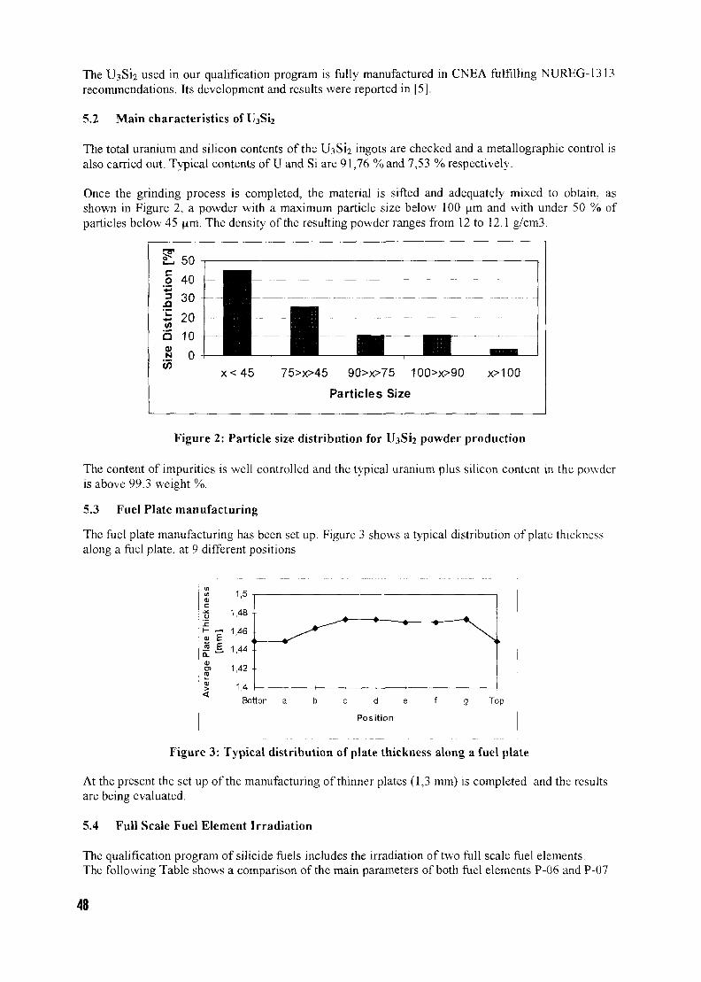
The U3Si2 used in our qualification program is fully manufactured in CNEA fulfilling NUREG-1313recommendations. Its development and results were reported in [5],
5.2 Main characteristics of U3Si2
The total uranium and silicon contents of the U3Si2 ingots are checked and a metallographic control isalso carried out. Typical contents of U and Si are 91,76 % and 7,53 % respectively.
Once the grinding process is completed, the material is sifted and adequately mixed to obtain, asshown in Figure 2, a powder with a maximum particle size below 100 urn and with under 50 % ofparticles below 45 urn. The density of the resulting powder ranges from 12 to 12.1 g/cm3.
x < 4 5 75>x>45 90>x>75 100>x>90
Particles Size
x>100
Figure 2: Particle size distribution for U3S12 powder production
The content of impurities is well controlled and the typical uranium plus silicon content in the powderis above 99.3 weight %.
5.3 Fuel Plate manufacturing
The fuel plate manufacturing has been set up. Figure 3 shows a typical distribution of plate thicknessalong a fuel plate, at 9 different positions
Figure 3: Typical distribution of plate thickness along a fuel plate
At the present the set up of the manufacturing of thinner plates (1,3 mm) is completed and the resultsare being evaluated.
5.4 Full Scale Fuel Element Irradiation
The qualification program of silicide fuels includes the irradiation of two full scale fuel elements.The following Table shows a comparison of the main parameters of both fuel elements P-06 and P-07
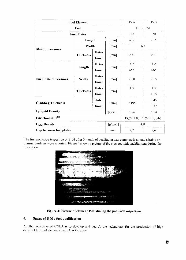
Fuel Element
Fuel
Fuel Plates
Meat dimensions
Fuel Plate dimensions
Length
Width
Thickness
Length
Width
Thickness
Cladding Thickness
Outer
Inner
Outer
Inner
Outer
Inner
Outer
Inner
Outer
Inner
U3Si2-Al Density
[mm]
[mm]
[mm]
[mm]
[mm]
[mm]
[mm]
[g/cm3]
Enrichment U235
Utotai Density
Gap between fuel plates
[g/cm3]
mm
P-06 P-07
U3S12 - Al
19
619
20
615
60
0,51
735
655
70,8
1,5
0,495
6,54
0,61
735
665
70,5
1.5
1,35
0,45
0,37
6,54
19,78 ± 0,012 %U weight
4,8
2,7 2,6
The first pool-side inspection of P-06 after 3 month of irradiation was completed; no undesirable orunusual findings were reported. Figure 4 shows a picture of the element with backlighting during theinspection.
Figure 4: Picture of element P-06 during the pool-side inspection
6. Status of U-Mo fuel qualification
Another objective of CNEA is to develop and qualify the technology for the production of high-density LEU fuel elements using U-xMo alloy.
49
6.1 Alternative manufacturing routes
One of the main activities related with this program is the development of alternative U-Mofabrication routes. The most suitable options at the present are: Conventional Atomization, CyclonicCentrifugal Atomization (CCA) and the hydriding and dehydriding technique. Initial results using thisprocess were reported in [6]. The activities related with the alternative routes will include full testingand irradiation with U-Mo powder coming from different routes and finally the development ofpowder specifications. The main characteristics under analysis are the shape and size distribution ofthe U-Mo particles and the content of impurities.
6.2 Setup of Fuel Plate Manufacturing and Irradiations
Currently the main activity within this program is the adjustment of fuel plates manufacturing usingnatural U-7Mo powder supplied by KAERI and prepared by the centrifugal atomization process.Several fuel plates have been manufactured. The influence of filling technique and tooling has beenanalyzed. Uranium density is 7 gU/cm3. Porosity within the plates is close to 5 %. The process is nowunder further improvements and refinements. Quality control techniques arc also being set up for thismaterial and the fuel plate fabrication is expected to be consolidated before the end of this year.
6.3 Irradiation
The next step will be the fabrication and irradiation of full-size fuel elements. To fulfil this objectivefuel plates will be fabricated using LEU U-7Mo also from KAERI. At the present it is planned to buildthree full-sized fuel elements for irradiation in the RA-3 reactor. The target burnup will be 50-70 %and the irradiation of the first of these fuel elements is expected to start by the end of 2001.
7. Conclusions
CNEA has built a wide experience on designing, development, qualification and fabrication of MTRfuel elements. In the high density fuels area, U3Si; qualification is well advanced and U-Modevelopment and qualification is in progress. The development and qualification of these technologiesassociated with the fabrication and irradiation of U^Si? and U-xMo fuels in Argentine research reactorswill allow CNEA to fulfill satisfactorily the new requirements of potential customers.
8. References
[ 1 ] P. Adelfang ct al, "Argentine MTR Fuel Program: Status of the Silicidc Project", 3rd
International Topical Meeting on Research Reactors Fuel Management, Bruges. Belgium.(1999)
[2] G. Ruggircllo ct al, "Program Description for the Qualification of CNEA-ARGENTINA as aSupplier of LEU Silicide Fuel and Post-Irradiation Examinations Plan for the First PrototypeIrradiated in Argentina", 21st RERTR Meeting, Sao Paulo, Brazil, (1998).
[31 L. Alvarez et al, "RERTR Activities in Argentina", RERTR-2000, Las Vegas, (2000).(4| US Nuclear Regulatory Commission, Safety Evaluation Report related to the evaluation of low
enriched silicidc aluminum dispersion fuels for use in non-power reactors. NUREG 1313 (July.1988).
|5 | E. Pasqualim ct al, "Tuning Up and Fabrication of U3Si2 Nuclear Material", AATN Meeting,(November, 2000).
[6] S. Balart et al. "'U-Mo Alloy Powder Obtained by a Hydride-Dehydride Process". RERTR-2000, Las Vegas, (2000).
9. Acknowledgments
We deeply recognize the work of A. Piazza, A. Perez and many other contributors to the CNEAQualification Program
50

Session 3
Reactor operation, fuel safetyand core conversion
CH01000253
NEW NUCLEAR TECHNOLOGIESWILL HELP TO ENSURE THE PUBLIC TRUST
AND FURTHER DEVELOPMENTOF RESEARCH REACTORS
S.V. MIASNIKOVInstitute of Nuclear Reactors
The Russian Research Centre "Kurchatov Institute ",Kurchatov sq., 1, 123182 Moscow, Russian Federation
ABSTRACT
Decrease of public trust to research reactors causes the concern of experts working in thisfield. In the paper the reasons of public mistrust to research reactors are given. A newtechnology of 99Mo production in the "Argus" solution reactor developed in the RussianResearch Centre "Kurchatov Institute" is presented as an example assisting to eliminatethese reasons. 99Mo is the most widespread and important medical isotope. The productreceived employing a new technology completely meets the international specifications.Besides, the proposed technology raises the efficiency of 235U consumption practically upto 100 % and allows to use a reactor with power 10 and more times lower than that in thetarget technology. The developed technology meets the requirements of the community tonuclear safety of manufacture, reduction of radioactive waste and non-proliferation ofnuclear materials.
Introduction
RRFM annual conferences held by the ENS allowed to achieve a certain success in the increase of theunderstanding degree of research reactors (RR) necessity, both in the scientific societies and at thepolitical level. At the same time, it is necessary to discuss not only the problems of the RR persistencebut to proceed to a "new" level of discussion - the complex approach to a choice of new nucleartechnologies and as consequence to RR development.
Unfortunately from the beginning of 1990s the tendency to the decrease of public trust to RR,premature shutdown and refusal to construct new RRs is observed in the world. The principal reasonfor this are the community concern about:
the RR nuclear and radiation safety;employment and proliferation of highly-enriched nuclear materials;safety in processing and storage of spent nuclear fuel and radioactive wastes.
The new technology of 99Mo production in the"Argus" solution reactor developed in the RussianResearch Centre "Kurchatov Institute" (RRC KI) is proposed as an example of assisting to eliminatethese reasons.
99Mo is the most widespread and important medical isotope. Production of that in necessary quantitiesis feasible only by means of extraction from 235U fission products and the research type reactors areused for these purposes . The satisfaction of public demands for 99Mo can be an important factorincreasing the public interest to RRs and development of those.
The traditional method of "Mo production based on irradiation and processing of uranium targets iswidely spread and protected by the Cintichem, Nordion, etc patents. This method includes thefollowing stages: fabrication of uranium targets; irradiation of targets in a nuclear reactor; dissolutionof targets; "Mo extraction from uranium and purification from fission products [1,2].
51
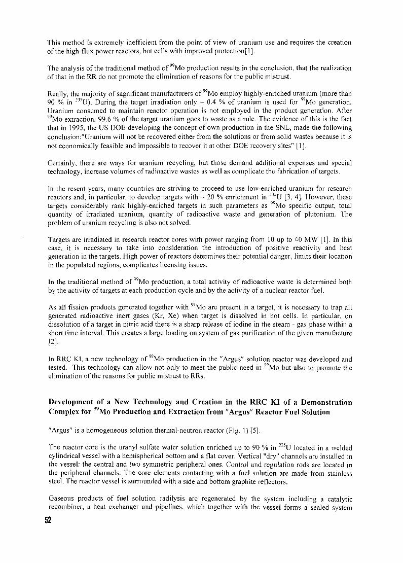
This method is extremely inefficient from the point of view of uranium use and requires the creationof the high-flux power reactors, hot cells with improved protection]!].
The analysis of the traditional method of 99Mo production results in the conclusion, that the realizationof that in the RR do not promote the elimination of reasons for the public mistrust.
Really, the majority of sagnificant manufacturers of 99Mo employ highly-enriched uranium (more than90 % in 235U). During the target irradiation only ~ 0.4 % of uranium is used for 99Mo generation.Uranium consumed to maintain reactor operation is not employed in the product generation. After99Mo extraction, 99.6 % of the target uranium goes to waste as a rule. The evidence of this is the factthat in 1995, the US DOE developing the concept of own production in the SNL, made the followingconclusion:"Uranium will not be recovered either from the solutions or from solid wastes because it isnot economically feasible and impossible to recover it at other DOE recovery sites" [1].
Certainly, there are ways for uranium recycling, but those demand additional expenses and specialtechnology, increase volumes of radioactive wastes as well as complicate the fabrication of targets.
In the resent years, many countries are striving to proceed to use low-enriched uranium for researchreactors and, in particular, to develop targets with ~ 20 % enrichment in 235U [3, 4]. However, thesetargets considerably rank highly-enriched targets in such parameters as 99Mo specific output, totalquantity of irradiated uranium, quantity of radioactive waste and generation of plutonium. Theproblem of uranium recycling is also not solved.
Targets are irradiated in research reactor cores with power ranging from 10 up to 40 MW [1]. In thiscase, it is necessary to take into consideration the introduction of positive reactivity and heatgeneration in the targets. High power of reactors determines their potential danger, limits their locationin the populated regions, complicates licensing issues.
In the traditional method of 99Mo production, a total activity of radioactive waste is determined bothby the activity of targets at each production cycle and by the activity of a nuclear reactor fuel.
As all fission products generated together with 99Mo are present in a target, it is necessary to trap allgenerated radioactive inert gases (Kr, Xe) when target is dissolved in hot cells. In particular, ondissolution of a target in nitric acid there is a sharp release of iodine in the steam - gas phase within ashort time interval. This creates a large loading on system of gas purification of the given manufacture[2].
In RRC K.I, a new technology of 99Mo production in the "Argus" solution reactor was developed andtested. This technology can allow not only to meet the public need in 99Mo but also to promote theelimination of the reasons for public mistrust to RRs.
Development of a New Technology and Creation in the RRC KI of a DemonstrationComplex for 99Mo Production and Extraction from "Argus" Reactor Fuel Solution
"Argus" is a homogeneous solution thermal-neutron reactor (Fig. 1) [5].
The reactor core is the uranyl sulfate water solution enriched up to 90 % in 235U located in a weldedcylindrical vessel with a hemispherical bottom and a flat cover. Vertical "dry" channels are installed inthe vessel: the central and two symmetric peripheral ones. Control and regulation rods are located inthe peripheral channels. The core elements contacting with a fuel solution are made from stainlesssteel. The reactor vessel is surrounded with a side and bottom graphite reflectors.
Gaseous products of fuel solution radilysis are regenerated by the system including a catalyticrecombiner, a heat exchanger and pipelines, which together with the vessel forms a sealed system
52
excluding the leakage of fission products into the environments. The regeneration system is based onthe principle of the natural circulation of a gas mixture along the circuit.
99»In the course of the new technology development for Mo production in the "Argus" solution reactorin the RRC KI various organic and inorganic sorbents were investigated and modified for Moselective extraction from the fuel solution. The inorganic sorbent based on titanium oxide was chosen,and studies on 99Mo desorption and purification from fission products were carried out. As a result ofthese works, 99Mo purification process was developed that now undergoes tests. To realize this processa special equipment for remote operations in hot cells was designed and fabricated.
99In order to improve the technology of Mo production the demonstration complex for Moproduction and extraction from the "Argus" reactor fuel solution was created in the RRC KI. Acondensate collector was installed into the reactor regeneration system to accumulate a part ofregenerated water during the reactor power operation. The experimental facility which included ahydraulic circuit with the necessary equipment, the system for the remote installation of a sorptioncolumn and pumping a fuel solution through as well as a control system was mounted to the reactor.
Installationsystem
Hi - O) recombiner
Reactor vessel with UO2SO4
Pump
Reflector(graphite)
Fig 1. The scheme of a Demonstration Complex on the Basis of the "Argus" Reactor.
The process of Mo production in the solution reactor is carried out as follows.
99The reactor is brought to power and produces Mo in the reactor fuel solution. All uranium requiredfor maintenance of the reactor power, is spent for Mo production. Then the reactor is shutdown, heldfor some time, and then the fuel solution is pumped through the sorption column containing a specialinorganic sorbent based on titanium oxide which provides the first stage of 99Mo extraction from thebulk of fission products. The fuel solution is returned into the reactor, in this case uranium is notsorbed. In order to remove completely the fuel solution from the sorption column, it is washed out bythe accumulated regenerated water. The regenerated water is also returned into the reactor. Thus, the
53
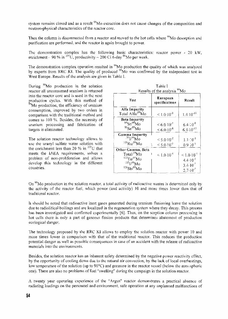
system remains closed and as a result 99Mo extraction does not cause changes of the composition andneutron-physical characteristics of the reactor core.
Then the column is disconnected from a reactor and moved to the hot cells where 99Mo desorption andpurification are performed, and the reactor is again brought to power.
The demonstration complex has the following basic characteristics: reactor power - 20 kW,enrichment - 90 % in U, productivity ~ 200 Ci 6-day Mo per week.
The demonstration complex operation resulted in 99Mo production the quality of which was analyzedby experts from RRC KI. The quality of produced 99Mo was confirmed by the independent test inWest Europe. Results of the analysis are given in Table I.
During 99Mo production in the solutionreactor all unconsumed uranium is returnedinto the reactor core and is used in the nextproduction cycles. With this method of9Mo production, the efficiency of uranium
consumption, improved by two orders incomparison with the traditional method andcomes to 100 %. Besides, the necessity ofuranium processing and fabrication oftargets is eliminated.
The solution reactor technology allows touse the uranyl sulfate water solution withthe enrichment less than 20 % in 235U thatmeets the IAEA requirements, solves aproblem of non-proliferation and allowsdevelop this technology in the differentcountries.
Table IResults of the analysis 99Mo
Test
Alfa ImpurityTotal Alfa/99Mo
Beta ImpurityS9Sr/99Mo90Sr/99Mo
Gamma Impurity13lI/"Mo
103Ru/99Mo
Other Gamma, BetaTotal/99Mol32Te/99Mo
133I/99Mo126Sb/99Mo
Europeanspecifications
< 1.0-10"9
<6.0-10"7
<6.0-10"8
<5.0-10"5
<5.0-10"5
< 1.0-10"4
Result
1.4-10-10
6.4-10"9
6.4-10"10
1.1-10"5
0.9-10"6
<1.0-10"4
4.4-10"5
3.4-10"7
2.7-10"7
On " M o production in the solution reactor, a total activity of radioactive wastes is determined only bythe activity of the reactor fuel, which power (and activity) 10 and more times lower than that oftraditional reactor.
It should be noted that radioactive inert gases generated during uranium fissioning leave the solutiondue to radiolitical boilings and are localized in the regeneration system where they decay. This processhas been investigated and confirmed experimentally [6]. Thus, on the sorption column processing inhot cells there is only a part of gaseous fission products that determines abatement of productionecological danger.
The technology proposed by the RRC KI allows to employ the solution reactor with power 10 andmore times lower in comparison with that of the traditional reactor. This reduces the productionpotential danger as well as possible consequences in case of an accident with the release of radioactivematerials into the environments.
Besides, the solution reactor has an inherent safety determined by the negative power reactivity effect,by the opportunity of cooling down due to the natural air convection, by the lack of local overheatings,low temperature of the solution (up to 90°C) and pressure in the reactor vessel (below the atmosphericone). There are also no problems of fuel "swelling" during the campaign in the solution reactor.
A twenty year operating experience of the "Argus" reactor demonstrates a practical absence ofradiating loadings on the personnel and environment, safe operation at any unplanned malfunctions of
54
the equipment and mistakes of the personnel and the opportunity to locate the reactor in the populatedregions.
Thus, the developed technology of 99Mo production is capable not only to meet the public need in99Mo but also to promote the elimination of the reasons for the public mistrust to research reactors.This is the fact that explains the interest of our partners in the development of this technology, both theprivate (TCInternational Inc., Albuquerque, US) and federal ones (US DOE, Argonne NationalLaboratory), as well as the attractiveness of this project for young experts. The participation of younggeneration may play an important role in the ensuring of public trust and further progress of researchreactors.
As the following stage of work in the RRC KI in this line of RR employment there will be a project onthe creation of the technological module consisting of the reactor facility and hot cells, with thefollowing basic characteristics: reactor power - 100 kW, enrichment < 20 % in 235U, productivity ~1000 Ci 6-day 99Mo per week.
Conclusions
1. The new technology of 99Mo production in the "Argus" solution reactor wss developed andexperimentally tested in RRC KI. 99Mo sample, produced in the RRC KI, completely satisfies theadopted international specifications.
2. The proposed technology allows to improve the efficiency of 235U consumption practically up to100 % and also to use the reactor with power 10 and more times lower than that used in thetraditional technology.
3. The developed technology allows to improve the safety level of 99Mo production and to reducethe quantity of radioactive wastes that promotes the elimination for the reasons of public mistrustto research reactors.
4. The new technology may transfer 99Mo production to the use of only low-enriched uranium thatalso meets the public interests.
References
1. D.E. Glenn "Feasibility study for utilization of solution reactors in the production ofmolybdenum-99", MS Thesis, University of the New Mexico, 1995.
2. M.P.Zykov, G.E.Kodina "Methods of 99Mo production (review)", Radiochemistry, v. 41, # 3,1999.
3. Myung-Hyun Kim, Dong-Keun Cho "Comparison of Fission Moly Target Characteristics forHANARO", Trans. ANS, v. 77, 1997, pp. 360-362.
4. G.F. Vandegrift, C.J. Conner, J. Sedlet, D.G. Wygmans (ANL) "Converting 99Mo Production fromHigh- to Low-Enriched Uranium", Trans. ANS, v. 77, 1997, pp. 98-99.
5. V.Ye. Khvostionov "Research solution reactor "Argus-21". Proceedings of the meeting of expertson the exchange of experience in the reconstruction of research reactors in the countries - CEAmembers, #1., 1984.
6. S.V Loboda, V.Ye. Khvostionov etc. "Release of fission products from the "Argus" reactor fuelsolution". VANT, Physics of nuclear reactors, Moscow, # 1, 1990, pp. 60-65.
55
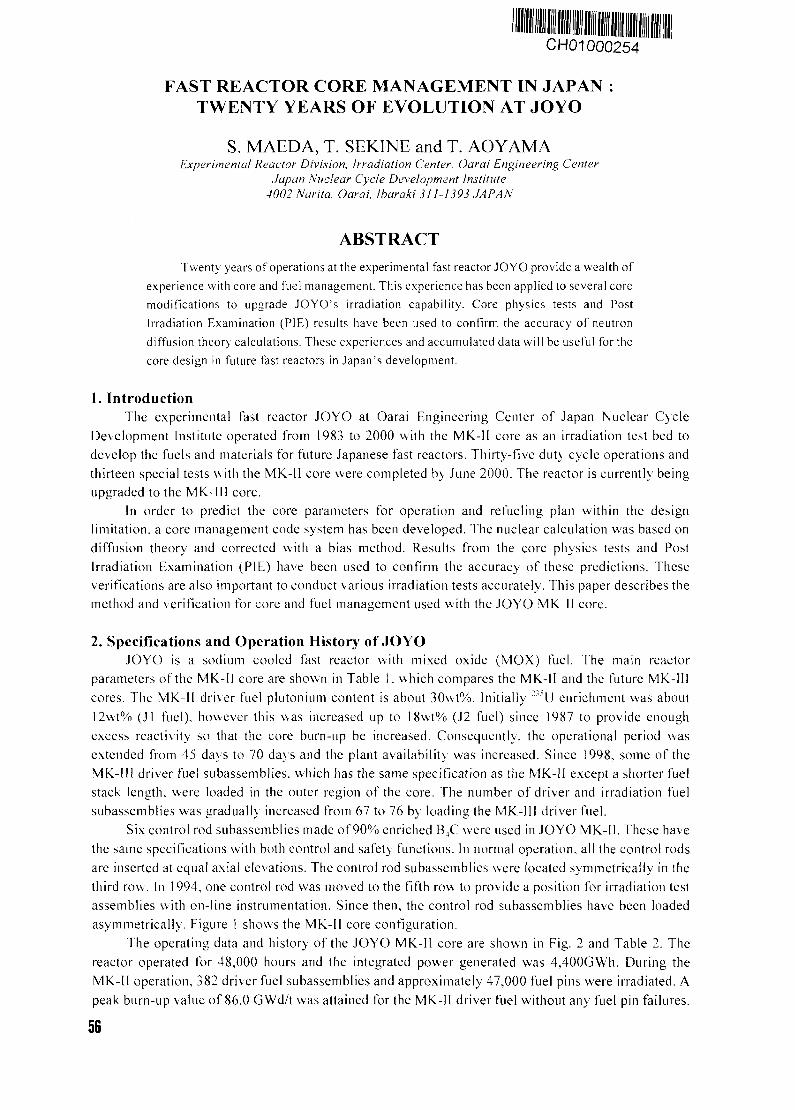
CH01000254
FAST REACTOR CORE MANAGEMENT IN JAPAN :TWENTY YEARS OF EVOLUTION AT JOYO
S. MAEDA, T. SEKINE and T. AOYAMAExperimental Reaetor Division, Irradiation Center, Oarai Engineering Center
Japan Nuclear Cycle Development Institute4002 Narita, Oarai, Ibaraki 311-1393 JAPAN
ABSTRACTTwenty years of operations at the experimental fast reactor JOYO provide a wealth of
experience with core and fuel management. This experience has been applied to several core
modifications to upgrade JOYO's irradiation capability. Core physics tests and Post
Irradiation Examination (PIE) results have been used to confirm the accuracy of neutron
diffusion theory calculations. These experiences and accumulated data will be useful for the
core design in future fast reactors in Japan's development.
1. IntroductionThe experimental fast reactor JOYO at Oarai Engineering Center of Japan Nuclear Cycle
Development Institute operated from 1983 to 2000 with the MK-II core as an irradiation test bed todevelop the fuels and materials for future Japanese fast reactors. Thirty-five duty cycle operations andthirteen special tests with the MK-1I core were completed by June 2000. The reactor is currently beingupgraded to the MK-II I core.
In order to predict the core parameters for operation and refueling plan within the designlimitation, a core management code system has been developed. The nuclear calculation was based ondiffusion theory and corrected with a bias method. Results from the core physics tests and PostIrradiation Examination (PIE) have been used to confirm the accuracy of these predictions. Theseverifications are also important to conduct various irradiation tests accurately. This paper describes themethod and verification for core and fuel management used with the JOYO MK-II core.
2. Specifications and Operation History of JOYOJOYO is a sodium cooled fast reactor with mixed oxide (MOX) fuel. The main reactor
parameters of the MK-II core are shown in Table 1, which compares the MK-II and the future MK-1IIcores. The MK-II driver fuel plutonium content is about 30wt%. Initially l oU enrichment was about12\vt% (J1 fuel), however this was increased up to 1 8wt% (J2 fuel) since 1987 to provide enoughexcess reactivity so that the core burn-up be increased. Consequently, the operational period wasextended from 45 days to 70 days and the plant availability was increased. Since 1998, some of theMK-I11 driver fuel subassemblies. which lias the same specification as the MK-II except a shorter fuelstack length, were loaded in the outer region of the core. The number of driver and irradiation fuelsubassemblies was gradually increased from 67 to 76 by loading the MK-III driver fuel.
Six control rod subassemblies made of 90% enriched B4C were used in JOYO MK-II. These havethe same specifications with both control and safety functions. In normal operation, all the control rodsare inserted at equal axial elevations. The control rod subassemblies were located symmetrically in thethird row. In 1994, one control rod was moved to the fifth row to provide a position for irradiation testassemblies with on-line instrumentation. Since then, the control rod subassemblies have been loadedasymmetrically. Figure 1 shows the MK-II core configuration.
The operating data and history of the JOYO MK-II core are shown in Fig. 2 and Table 2. Thereactor operated for 48,000 hours and the integrated power generated was 4,400GWh. During theMK-II operation. 382 driver fuel subassemblies and approximately 47,000 fuel pins were irradiated. Apeak burn-up value of 86.0 GWd/t was attained for the MK-II driver fuel without any fuel pin failures.
56
3. Core Management MethodThe MAGI calculation code system was developed to predict the reactor parameters required for
core and fuel management of JOYO MK-II1'1'21. Figure 3 shows the MAGI system outline. MAGI is aneutronic and thermo-hydraulic coupling code system that calculate the excess reactivity, powerdistributions, fuel bum-ups, coolant flow rate and temperature condition of each subassembly. MAGIuses diffusion theory with seven neutron energy groups for the nuclear calculations.
The neutron cross section was collapsed from the 70 group JFS-3-J21'1 cross section set processedfrom the JENDL-2 library. The gamma-ray cross section including delayed fission gamma-ray was alsoprocessed from the JENDL-2 library to improve the calculations of gamma heating in stainless steel.The core configuration was modeled in three-dimensional Hex-Z geometry for each operational cycle.The actual reactor power history was used in the burn-up calculation.
MAGI supported the refueling plan for each operational cycle. The number of fresh driver fuelsubassemblies and their position were determined within design limitations of neutronic and thermalparameters with consideration for the following items; (1) burn-up of fuel subassembly, (2) operationperiod of the cycle, (3) neutron fluence and temperature condition of the irradiation test subassemblies.The number of discharged spent fuel subassemblies is approximately from 10 to 12, one sixth of totaldriver fuel subassemblies. Therefore, the MAGI calculation needs to be verified in each operation cycledue to frequent refueling which affects the core characteristics and irradiation conditions significantly.
4. Verification of Core Management4.1. Core Physics Tests in Each Operational CycleCriticality and Burn-up Reactivity
The excess reactivity in a zero power critical condition was measured at the reactor start-up ofeach operational cycle. Measured data were compared with the calculated values by MAGI thatincluded the bias factor (C-E) correction obtained for the previous cycle. The comparison of calculatedand measured values is shown in Table 3. By using this bias method, it was found that the excessreactivity after refueling can be well predicted within an error of 0.1 %Ak/kk'.
The burn-up reactivity was determined by measuring the reactivity change during rated poweroperation. Measured values were compared with the MAGI burn-up calculation and both agreed within5 % as shown in Table 3. It is considered that the decrease of atomic number densities of major fissilenuclides as ~"U and ~9Pu are the dominant factor of burn-up reactivity because of JOYO's smallreactor size, which results in hard neutron spectrum and small internal conversion ratio (-0.3).Therefore, the burn-up reactivity can be predicted accurately even at a high burn-up.
Control Rod WorthEvery control rod worth was calibrated with either the positive period method or the inverse
kinetics method during the low power test of each operational cycle. The calculation was conductedwith the CITATION code based on 3-D diffusion theory using the same cross section, geometry andatomic number densities as MAGI. After correcting with the previous cycle's C/E, the calculatedvalues were compared with the measurements. Table 3 shows that both agreed within 2%. When onecontrol rod was moved from the third row to the fifth row in 1992, the worth of the relocated rod wasreduced to one third. The accuracy of calculation, however, was not changed significantly.
Reactivity CoefficientsReactivity coefficients are important not only for safety reasons but also to account for reactivity
change associated with temperature and power changes during the reactor operation. The measuredvalues are used to predict the reactivity change for the next operational cycle.
The isothermal temperature coefficients were measured by taking the difference of reactivity atapproximately 250 °C and 370°C during reactor start-up. The measured isothermal temperaturecoefficients were constant through the MK-II operation because they were determined mainly by radial
57
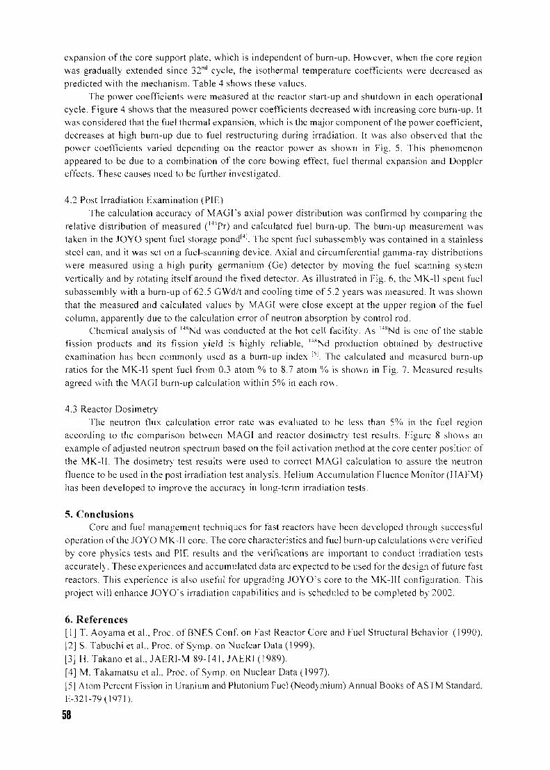
expansion of the core support plate, which is independent of burn-up. However, when the core regionwas gradually extended since 32nd cycle, the isothermal temperature coefficients were decreased aspredicted with the mechanism. Table 4 shows these values.
The power coefficients were measured at the reactor start-up and shutdown in each operationalcycle. Figure 4 shows that the measured power coefficients decreased with increasing core burn-up. Itwas considered that the fuel thermal expansion, which is the major component of the power coefficient,decreases at high burn-up due to fuel restructuring during irradiation. It was also observed that thepower coefficients varied depending on the reactor power as shown in Fig. 5. This phenomenonappeared to be due to a combination of the core bowing effect, fuel thermal expansion and Dopplereffects. These causes need to be further investigated.
4.2 Post Irradiation Examination (PIE)The calculation accuracy of MAGI's axial power distribution was confirmed by comparing the
relative distribution of measured (mPr) and calculated fuel burn-up. The burn-up measurement wastaken in the JOYO spent fuel storage pond'4). The spent fuel subassembly was contained in a stainlesssteel can, and it was set on a fuel-scanning device. Axial and circumferential gamma-ray distributionswere measured using a high purity germanium (Ge) detector by moving the fuel scanning systemvertically and by rotating itself around the fixed detector. As illustrated in Fig. 6, the MK-11 spent fuelsubassembly with a burn-up of 62.5 GWd/t and cooling time of 5.2 years was measured. It was shownthat the measured and calculated values by MAGI were close except at the upper region of the fuelcolumn, apparently due to the calculation error of neutron absorption by control rod.
Chemical analysis of M8Nd was conducted at the hot cell facility. As M8Nd is one of the stablefission products and its fission yield is highly reliable, ltsNd production obtained by destructiveexamination has been commonly used as a burn-up index [S|. The calculated and measured burn-upratios for the MK-11 spent fuel from 0.3 atom % to 8.7 atom % is shown in Fig. 7. Measured resultsagreed with the MAGI burn-up calculation within 5% in each row.
4.3 Reactor DosimetryThe neutron flux calculation error rate was evaluated to be less than 5% in the fuel region
according to the comparison between MAGI and reactor dosimetry test results. Figure 8 shows anexample of adjusted neutron spectrum based on the foil activation method at the core center position ofthe MK-11. The dosimetry test results were used to correct MAGI calculation to assure the neutronfluence to be used in the post irradiation test analysis. Helium Accumulation Fluence Monitor (HAFM)has been developed to improve the accuracy in long-term irradiation tests.
5. ConclusionsCore and fuel management techniques for fast reactors have been developed through successful
operation of the JOYO MK-II core. The core characteristics and fuel burn-up calculations were verifiedby core physics tests and PIE results and the verifications are important to conduct irradiation testsaccurately. These experiences and accumulated data are expected to be used for the design of future fastreactors. This experience is also useful for upgrading JOYO's core to the MK-111 configuration. Thisproject will enhance JOYO's irradiation capabilities and is scheduled to be completed by 2002.
6. References[1] T. Aoyama etal., Proc. of BNES Conf. on Fast Reactor Core and Fuel Structural Behavior (1990).[2] S. Tabuchi et al., Proc. of Symp. on Nuclear Data (1999).
[3] H. Takanoetal. , JAERI-M 89-141, JAERI (1989).
[4] M. Takamatsu et al., Proc. of Symp. on Nuclear Data (1997).
[5] Atom Percent Fission in Uranium and Plutonium Fuel (Neodymium) Annual Books of ASTM Standard,
E-321-79 (1971).
58
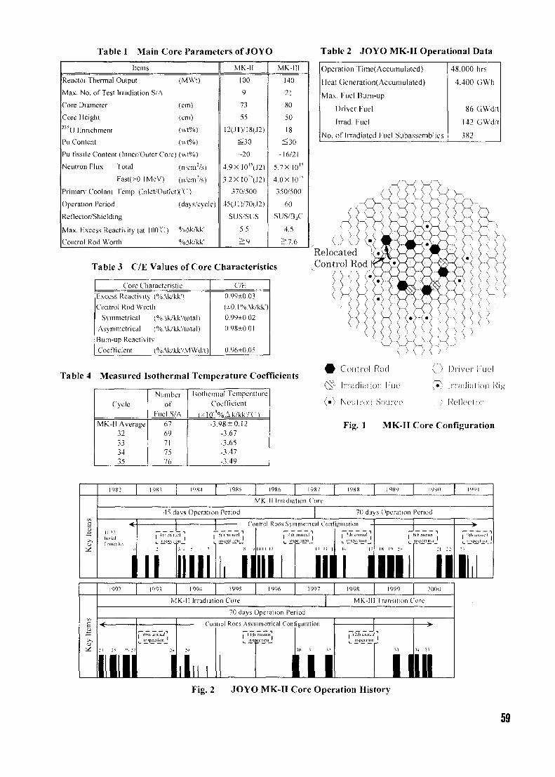
Table 1 Main Core Parameters of JOYO
Items
Reactor Thermal Output (MWt)
Max. No. of Test Irradiation S/A
Core Diameter (cm)
Core Height (cm)2'"U Enrichment (\vt%)
Pu Content (wt%)
Pu fissile Content (Inner/Outer Core) (wt%)
Neutron Flux Total (n/enr'/s)
Fast(>0. IMeV) (n/cnr/s)
Primary Coolant Temp. (Inlet/OutletX=C)
Operation Period (days/cycle)
Reflector/Shielding
Max. Excess Reactivity (at 1001) %Ak/kk'
Control Rod Worth %Ak/kk'
MK-ll
100
9
73
55
12(.!1)/18(J2)
3S30
-20
4.9X 10"(J2)
3.2XI0"(J2)
370/500
45(.ll)/70(.12)
SUS/SLJS
5.5
^ 9
MK-ll!
140
21
80
50
18
^ 3 0
-16/21
5.7X 10"
4.0X10"
350/500
60
SUS/BjC
4.5
^7 .6
Table 3 C/E Values of Core Characteristics
Core Characteristic
Excess Reactivity (%Ak/kk'lControl Rod Worth
Symmetrical (%Ak/kk7total)
Asymmetrical (%.\k/kk'/to1al)
Bum-up Reactivity
Coefficient (%.\k/kk7MWd/t)
C/E;
0.99±0.03
(±0.1%\k/kk')
0.99±0.02
0.98±0.01
0.96±0.05
Table 4 Measured Isothermal Temperature Coefficients
Cycle
MK-ll Average32333435
Numberof
f-uel S/A6769717576
Isothermal TemperatureCoefficient
(>10"%Ak/kkrCl-3.98 + 0.12
-3.67-3.65-3.47-3.49
Table 2 JOYO MK-II Operational Data
Operation Time(Accumulated)
Heat Generation(Accumulated)
Max. Fuel Burn-up
Driver Fuel
Irrad. Fuel
No. of Irradiated Fuel Subassemblics
48.000 hrs
4.400 GWh
86 GWd/t
142 GWd/t
382
RelocatedControl Rod
# Control Rod
{Sy liTadicition 1'ucl
(m) Noulfon Source
1 ) •' >
V..) ]3ri\ror Kucl
(•) Irriidialion Rig
: ; Reflector
\ ) \ )
Fig. 1 MK-II Core Configuration
1982 1983 1984 1985 1986 1987
MK-II Irradiation Core
45 days Operation Period 70 days Operation Period
lnui.il
rrnicalil'
Control Rods Symmetrical Configuration
i •"
II4 5 Ii 7
i i •_ ISCCCIJOIIJ
mi mn ii I1993 1995 1996 1998 2000
MK-II Irradiation Core MK-lll Transition Core
70 days Operation Period
2 4 25 2(. 2
• I l lIllili annual"1Illili annualinspection '
Control Rods Asymmetrica! Configuration
Plio.mn^al''., I L. .
I N, I II^I'Vl l IUM
1Fig. 2 JOYO MK-II Core Operation History
59
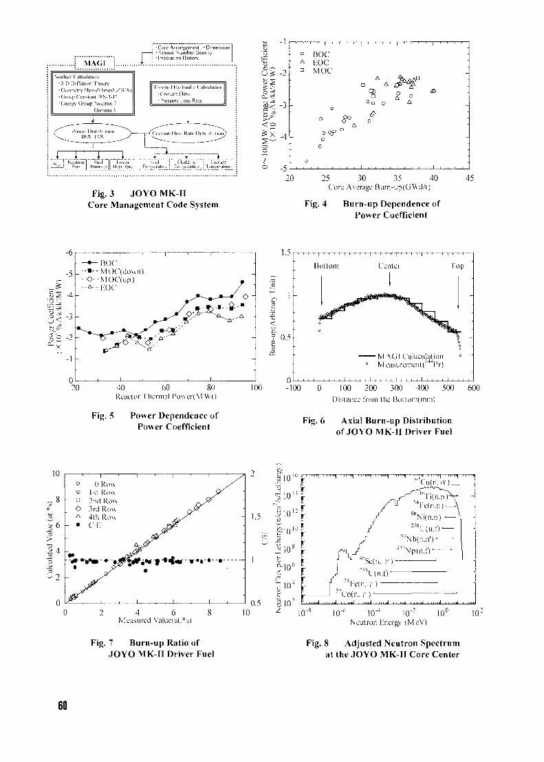
MAGI
Core Arrangement • Dimension•Atomic Number DensityIrradiation History
Nuc• 3
ear CalculationD Diffusion Theon/
•Geometry He\-/(lme•C
• \
>h/S A)roupConslant JFS-.l-j:icruv Ciroup Neutro
Uamm;7
Thermal Hydraulic Calculation•Coolant How• Pressure Loss Rate
Kucl Claddinn Coolantlu^v J' Jcmrx'ralurcJ LT.-mpcraiun
Fig. 3 JOYO MK-IICore Management Code System
v -1
- 2 -
< o
-4 -
° -5
o
• A
n
•
•
-
o
BOCKOCMOC
0
oc
o0
1
1 1 , 1 1
Aa
CDD
Oo
A>
—i—i—1—i—1_
A
0
1
4
oA
1
•
/ r
0A
•
-
-
i i , i i . i i i
20 25 30 35 40Core Average Burn-up(GWd/t)
Fig. 4 Burn-up Dependence ofPower Coefficient
45
-6
-5
2 -4
. _^_•-•--
©• - A - -
-
-
-
1
BOCMOC(down)MOC(up)KOC
^> o ^ v?&- ~A-
l ' I '
•
--91''''' A"'"
1 , 1 ,
1.5
20 40 60 80Reactor Thermal 1'ow er( M Wt)
Fig. 5 Power Dependence ofPower Coefficient
0.5
CD
100
Bottom Center
•MAGI CalculationMcasuremcnt(''44Pr)
Top
-100 0 100 200 300 400 500 600Distance from the Bottoni(mm)
Fig. 6 Axial Burn-up Distributionof JOYO MK-II Driver Fuel
(at
lue
>
ited
8
6
4
"i
n
o
- D
OA
- *
_
-
01st2nd3rd4thC,T
1
RowRowRowRowRow
i
1 i ' I ' y
« • ! ' < • » • • • •
I , I ,
4 6Measnred Value(at.%)
- 1.5
0.510 10u 10'
Neutron l̂ nerg\; (MeV)
Fig. 7 Burn-up Ratio ofJOYO MK-II Driver Fuel
Fig. 8 Adjusted Neutron Spectrumat the JOYO MK-II Core Center
60
CH01000255
ABSOLUTE ON-LINE IN-PILE MEASUREMENT OF NEUTRONFLUXES USING SELF-POWERED NEUTRON DETECTORS :
MONTE CARLO SENSITIVITY CALCULATIONS
L. VERMEERENReactor Experiments
SCK-CEN, Nuclear Research Centre, Boeretang 200, B-2400 Mol, Belgium
ABSTRACT
Self-powered neutron detectors (SPND) are well suited to monitor continuously theneutronic operating conditions of driver fuel of research reactors and to follow its burnupevolution. This is of particular importance when advanced or new MTR fuel designs needto be qualified. We have developed a detailed MCNP-4B based Monte Carlo approach forthe calculation of neutron sensitivities of SPNDs. Results for the neutron sensitivity of aRh SPND are in excellent agreement with experimental data recently obtained at the BR2research reactor. A critical comparison of the Monte Carlo results with results fromstandard analytical methods reveals an important deficiency of the analytical methods in thedescription of the electron transport efficiency. Our calculation method allows a reliableon-line determination of the absolute in-pile neutron flux.
1. Introduction
On-line in-pile monitoring of the neutron flux is routinely performed in many research reactors bymeans of self-powered neutron detectors (SPNDs). This information is of crucial importance forprograms dealing with the production of radioisotopes, the activation of samples (e.g. Si doping) andalso for the study of the radiation impact on fuel and material properties. With respect to the driverfuel of research reactors, SPNDs can be used effectively to monitor continuously the neutronic - andhence thermal - operating conditions of such fuel and to follow its burnup evolution. This is ofparticular importance when advanced or new MTR fuel designs need to be qualified throughrepresentative irradiation tests in the same or another research reactor. In this case well-calibratedSPNDs will allow to verify the actual irradiation conditions of the MTR fuel as compared to theneutronic calculations.
The general SPND operation principle is well understood, but a detailed knowledge of allcontributions to the detector sensitivity is often lacking, and SPND signals are considered to bereliable for interpretation only in a relative way. As the detector sensitivity depends on the neutronspectrum, on the detector surroundings, on the temperature,..., experimental calibrations are only validas long as these conditions remain the same. From the theoretical side, analytical models weredeveloped already in the early 70s [1-3] and, albeit with some modifications, they are still being used[4-6], but they require experimental input and they exhibit some important failures in the detaileddescription of all relevant physical phenomena.
This paper deals with the recent development of a detailed MCNP-4B-based Monte Carlo approach forthe calculation of the absolute neutron sensitivity of several SPNDs. The method contains noadjustable parameters, but the global sensitivity can of course only be computed if the neutronspectrum is known. A critical comparison between our Monte Carlo method and the standardanalytical model [1-2] will be presented.
61
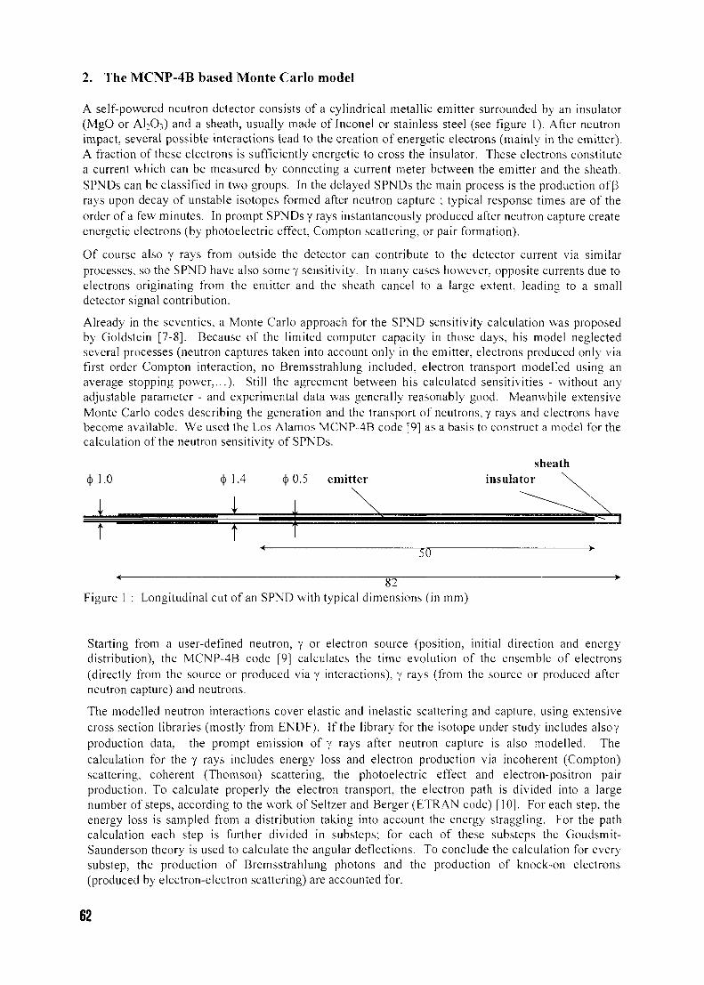
2. The MCNP-4B based Monte Carlo model
A self-powered neutron detector consists of a cylindrical metallic emitter surrounded by an insulator(MgO or A12O3) and a sheath, usually made of Inconel or stainless steel (see figure 1). After neutronimpact, several possible interactions lead to the creation of energetic electrons (mainly in the emitter).A fraction of these electrons is sufficiently energetic to cross the insulator. These electrons constitutea current which can be measured by connecting a current meter between the emitter and the sheath.SPNDs can be classified in two groups. In the delayed SPNDs the main process is the production of Prays upon decay of unstable isotopes formed after neutron capture ; typical response times are of theorder of a few minutes. In prompt SPNDs y rays instantaneously produced after neutron capture createenergetic electrons (by photoelectric effect, Compton scattering, or pair formation).
Of course also y rays from outside the detector can contribute to the detector current via similarprocesses, so the SPND have also some y sensitivity. In many cases however, opposite currents due toelectrons originating from the emitter and the sheath cancel to a large extent, leading to a smalldetector signal contribution.
Already in the seventies, a Monte Carlo approach for the SPND sensitivity calculation was proposedby Goldstein [7-8]. Because of the limited computer capacity in those days, his model neglectedseveral processes (neutron captures taken into account only in the emitter, electrons produced only viafirst order Compton interaction, no Bremsstrahlung included, electron transport modelled using anaverage stopping power,...). Still the agreement between his calculated sensitivities - without anyadjustable parameter - and experimental data was generally reasonably good. Meanwhile extensiveMonte Carlo codes describing the generation and the transport of neutrons, y rays and electrons havebecome available. We used the Los Alamos MCNP-4B code [9] as a basis to construct a model for thecalculation of the neutron sensitivity of SPNDs.
sheathinsulator
50
82Figure 1 : Longitudinal cut of an SPND with typical dimensions (in mm)
Starting from a user-defined neutron, y or electron source (position, initial direction and energydistribution), the MCNP-4B code [9] calculates the time evolution of the ensemble of electrons(directly from the source or produced via y interactions), y rays (from the source or produced afterneutron capture) and neutrons.
The modelled neutron interactions cover elastic and inelastic scattering and capture, using extensivecross section libraries (mostly from ENDF). If the library for the isotope under study includes alsoyproduction data, the prompt emission of y rays after neutron capture is also modelled. Thecalculation for the y rays includes energy loss and electron production via incoherent (Compton)scattering, coherent (Thomson) scattering, the photoelectric effect and electron-positron pairproduction. To calculate properly the electron transport, the electron path is divided into a largenumber of steps, according to the work of Seltzer and Berger (ETRAN code) [10]. For each step, theenergy loss is sampled from a distribution taking into account the energy straggling. For the pathcalculation each step is further divided in substeps; for each of these substeps the Goudsmit-Saunderson theory is used to calculate the angular deflections. To conclude the calculation for everysubstep, the production of Bremsstrahlung photons and the production of knock-on electrons(produced by electron-electron scattering) are accounted for.
62
MCNP-4B does not follow the history of the unstable activated nuclei, produced by neutron capture.These will decay with their characteristic time and emit (3 and/or y rays. To include this effect, whichis crucial for the calculation of the sensitivity of delayed SPND, the calculation has to be performed intwo (or three) steps : first the production rate and the spatial distribution of the activated nuclei iscalculated from a specified neutron source, and next this information is used to define the spatialdistribution of an electron (P) source (or a y source) for the calculation of the electron currents. Forthe initial velocity direction a random distribution is assumed. The energy distribution for theelectrons is calculated according to the Fermi (3 energy distribution [11,12] with the appropriate Pend-point energy ; for they ray energy distribution and intensity, experimental data are needed.
For some isotopes (e.g. 103Rh), the libraries associated with MCNP-4B do not include the generationof y rays upon neutron capture. In this case a similar procedure as described above has to be appliedto take into account the effect of prompt y rays.
A neutron (or y) source is defined with an origin uniformly sampled on the outer surface of thedetector and with an initial direction proportional to cos(9), 6 being the angle between the directionand the surface normal. As initial energy 40 energy bins in the range from 1 meV to 10 MeV weretaken for the neutron source and 20 energy bins from 0.02 MeV to 14 MeV for the y source. Asoutput of the code we obtain (directly or in two steps as explained above) the net charge deposit in therespective parts of the detector (emitter, insulator, sheath). Usually the major contribution to theresulting current is the net charge deposit in the emitter (usually positive since negatively chargedelectrons are leaving). If all electrons stopped in the insulator would diffuse further to the sheath, itwould be the only contribution. In order to determine the fraction of electrons stopped in the insulatorthat return to the emitter, the insulator is divided into 25 concentric segments and the chargedeposition in each of these segments is calculated (by MCNP-4B). This information is used to solvethe Poisson equation for the potential profile in the insulator, assuming a zero potential at the innerand the outer insulator radius. Assuming that all electrons that are stopped closer to the emitter thanthe potential extremum position, are driven back to the emitter by the space charge field, the fraction/ of electrons ultimately returning to the emitter can be calculated. The net current is finallycalculated as the net charge deposit in the emitter plus/times the net charge deposit in the insulator(which is negative if more electrons are stopped than emitted). To convert the obtained 'current perincoming particle1 into a sensitivity ('current per flux unit'), MCNP also calculates the neutron (ory)flux per incoming particle at the detector surface.
It should be stressed that this calculation model is straightforward, without any adjustable parameters.This is not the case for the commonly used analytical Warren model [2], in which an adjustablepseudopotential is defined to bias the final destination of the electrons stopped in the insulator. Theadjustment is performed using experimental data, so the Warren model is in a sense more a "fitting"model than a purely predictive model.
3. Evaluation of the standard analytical sensitivity calculation method
In the following we concentrate on the calculations for a specific SPND, which we recently irradiatedin the BR2 reactor. This exemplaric approach will facilitate a detailed comparison of the differentmodels ; the conclusions are quite generally valid. The considered SPND is a NEUTROCOAX RhSPND of the type 2NNI-10. It consists of a rhodium emitter (length 5 cm, diameter 0.05 cm),surrounded by an A12O3 layer (thickness 0.025 cm) and closed by an lnconel collector (thickness 0.02cm) (see figure 1).
The calculated sensitivities for a neutron energy of 25 meV (thermal neutrons at 20 °C) are :analytical Warren model : 1.31 10"21 A / cm / (n/cm2s)Goldstein MC calculation : 0.98 10'21 A / cm / (n/cm2s)actual MCNP calculation : 1.15 10"21 A /cm /(n/cm2s).
The MCNP value is 18% higher than the Goldstein value, which can be explained by the fact thatGoldstein does not include the contribution from the capture y rays and makes some otherapproximations (no photoelectric effect, less complete electron transport model,...).
63
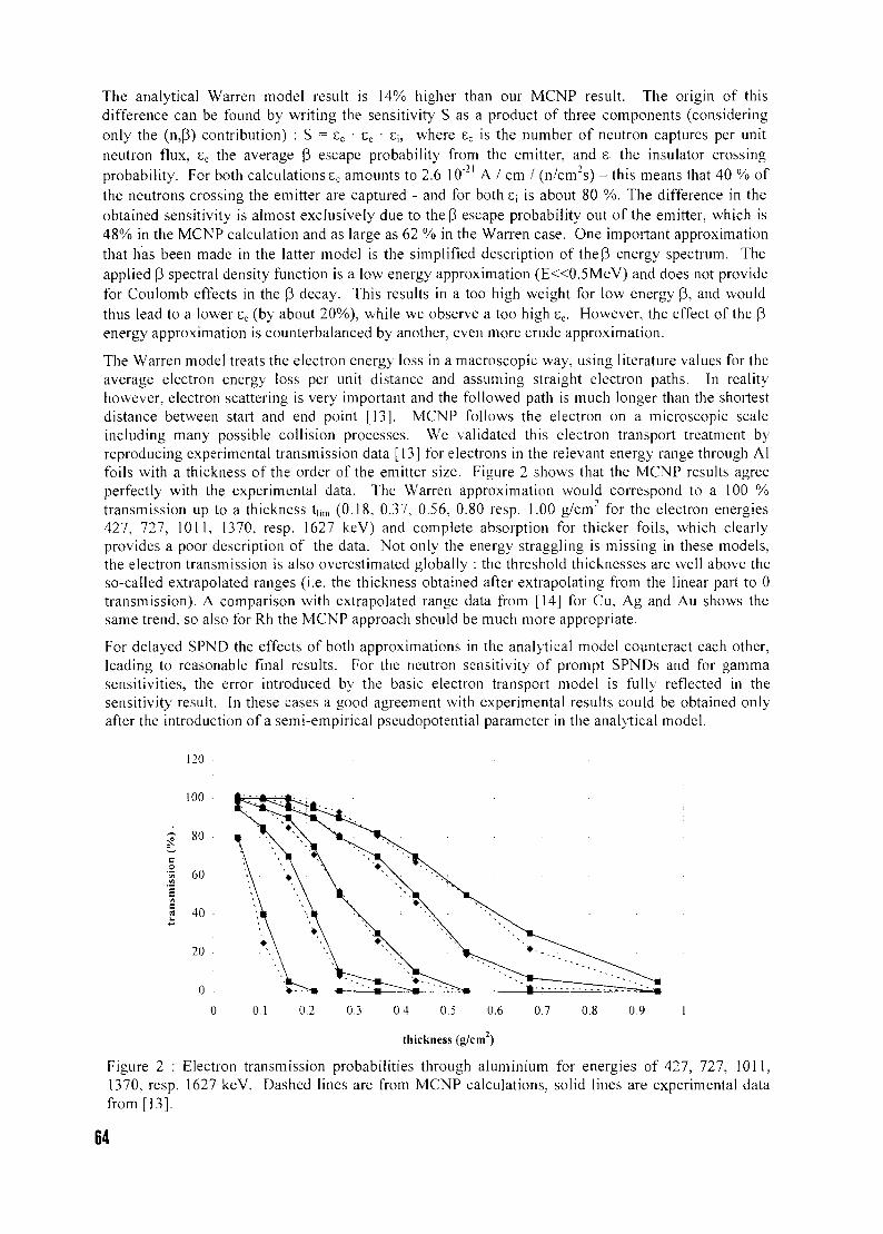
The analytical Warren model result is 14% higher than our MCNP result. The origin of thisdifference can be found by writing the sensitivity S as a product of three components (consideringonly the (n,P) contribution) : S = sc • se • £\, where ec is the number of neutron captures per unitneutron flux, ee the average P escape probability from the emitter, and 8j the insulator crossingprobability. For both calculations ec amounts to 2.6 10"21 A / cm / (n/cm2s) - this means that 40 % ofthe neutrons crossing the emitter are captured - and for both S; is about 80 %. The difference in theobtained sensitivity is almost exclusively due to theP escape probability out of the emitter, which is48% in the MCNP calculation and as large as 62 % in the Warren case. One important approximationthat has been made in the latter model is the simplified description of the P energy spectrum. Theapplied P spectral density function is a low energy approximation (E«0.5MeV) and does not providefor Coulomb effects in the P decay. This results in a too high weight for low energy p, and wouldthus lead to a lower ec (by about 20%), while we observe a too high se. However, the effect of the penergy approximation is counterbalanced by another, even more crude approximation.
The Warren model treats the electron energy loss in a macroscopic way, using literature values for theaverage electron energy loss per unit distance and assuming straight electron paths. In realityhowever, electron scattering is very important and the followed path is much longer than the shortestdistance between start and end point [13]. MCNP follows the electron on a microscopic scaleincluding many possible collision processes. We validated this electron transport treatment byreproducing experimental transmission data [13] for electrons in the relevant energy range through Alfoils with a thickness of the order of the emitter size. Figure 2 shows that the MCNP results agreeperfectly with the experimental data. The Warren approximation would correspond to a 100 %transmission up to a thickness t|im (0.18, 0.37, 0.56, 0.80 resp. 1.00 g/cirT for the electron energies427, 727, 1011, 1370, resp. 1627 keV) and complete absorption for thicker foils, which clearlyprovides a poor description of the data. Not only the energy straggling is missing in these models,the electron transmission is also overestimated globally : the threshold thicknesses are well above theso-called extrapolated ranges (i.e. the thickness obtained after extrapolating from the linear part to 0transmission). A comparison with extrapolated range data from [14] for Cu, Ag and Au shows thesame trend, so also for Rh the MCNP approach should be much more appropriate.
For delayed SPND the effects of both approximations in the analytical model counteract each other,leading to reasonable final results. For the neutron sensitivity of prompt SPNDs and for gammasensitivities, the error introduced by the basic electron transport model is fully reflected in thesensitivity result. In these cases a good agreement with experimental results could be obtained onlyafter the introduction of a semi-empirical pseudopotential parameter in the analytical model.
120
100
80
1 60
40
20 •
0.1 0.2 0.3 0.4 0.5 0.6 0.7 0.8 0.9
thickness (g/cm )
Figure 2 : Electron transmission probabilities through aluminium for energies of 427, 727, 1011,1370, resp. 1627 keV. Dashed lines are from MCNP calculations, solid lines are experimental datafrom [13].
64
4. Comparison with experimental data
In order to validate our Monte Carlo model, we compare our results for the Rh SPND withexperimental data. SPND currents during irradiations in two BR2 channels (E30 and LI80) wererecorded, and the corresponding thermal, epithermal and fast neutron flux were measured byactivation dosimetry (total fluxes 8.9 1014 n/cm2s and 2.8 1014 n/cm2s). From the calculated relativeneutron spectra the total SPND sensitivities, integrated over the complete spectrum, were calculated.Using the measured absolute thermal flux data, these sensitivities were converted into expected SPNDcurrents, which can be directly compared with the measured currents :
Measured currentExpected current from MCNP (this work)Expected current from Goldstein [9]Expected current from manufacturer's calibrationExpected current from the analytical model [1]
Channel E30 Channel L180
2.64 |uA 0.93 \xA2.65 nA 0.94 [iA2.06 |uA 0.74 ^A2.06 nA 0.76 \xA3.05 |iA 1.08 nA
The MCNP sensitivities account perfectly for the observed current Iobs. Averaged over the twochannels, the Goldstein Monte Carlo calculation leads to an expected current of 79 % of Iot,s. Fromthe detector sensitivity specified by the manufacturer, 80 % of Iobs is predicted, but here thecontribution of the epithermal neutrons is neglected. Finally, the analytical model calculations for thecomplete neutron spectrum overestimate the current by about 16%.
5. Conclusion
A new Monte Carlo model was developed to calculate the neutron and the y sensitivity of self-powered neutron detectors. The commonly used analytical model is critically evaluated through adetailed comparison with the Monte Carlo method. Provided the spectra are known, the methodallows a reliable in-pile on-line measurement of the absolute neutron flux which is important for aquantitative study of fuel behaviour.
Acknowledgement
The author wants to thank Marcel Weber for providing the experimental data used as benchmarks forthe Monte Carlo method.
References
[I] H.D. Warren, Nucl. Sci. Eng. 48 (1972) 331.[2] H. D. Warren and N. H. Shah, Nucl. Sci. Eng. 54 (1974) 395.[3] W. Jaschik and W. Seifritz, Nucl. Sci. Eng. 53 (1974) 61.[4] M. N. Agu and H. Petitcolas, Nucl. Sci. Eng. 107 (1991) 374.[5] M. do Carmo Lopes and J. Molina Avila, Nucl. Sci. Eng. 113 (1993) 217.[6] A.K. Mahant, P.S. Rao and S.C. Misra, Nucl. Instr. Meth. in Phys. Res. A 346 (1994) 279.[7] N.P. Goldstein, IEEE Trans. Nucl. Sci. 20 (1973) 549.[8] N. P. Goldstein , C.L. Chen and W.H. Todt, IEEE Trans. Nucl. Sci. 27 (1980) 838.[9] J.F. Briesmeister, LA-12625-M (1997).[10] S.M. Seltzer, eds. T.M Jenkins, W.R. Nelson and A. Rindi, Plenum Press, New York (1988) 153.II1] R. D. Evans, McGraw-Hill, New York-Toronto-London (1955), p.536.[12] F.G. Houtermans, J. Geiss and H. Muller, Landolt-Bornstein 1/5 (1952), p.414.[13] S.V. Starodubtsev and A.M. Romanov, Israel Program for Scientific Translations, Jerusalem(1965)[14] T. Tabata, R. Ito and S. Okabe, Nucl. Instr. Meth. 103 (1972) 85.
65
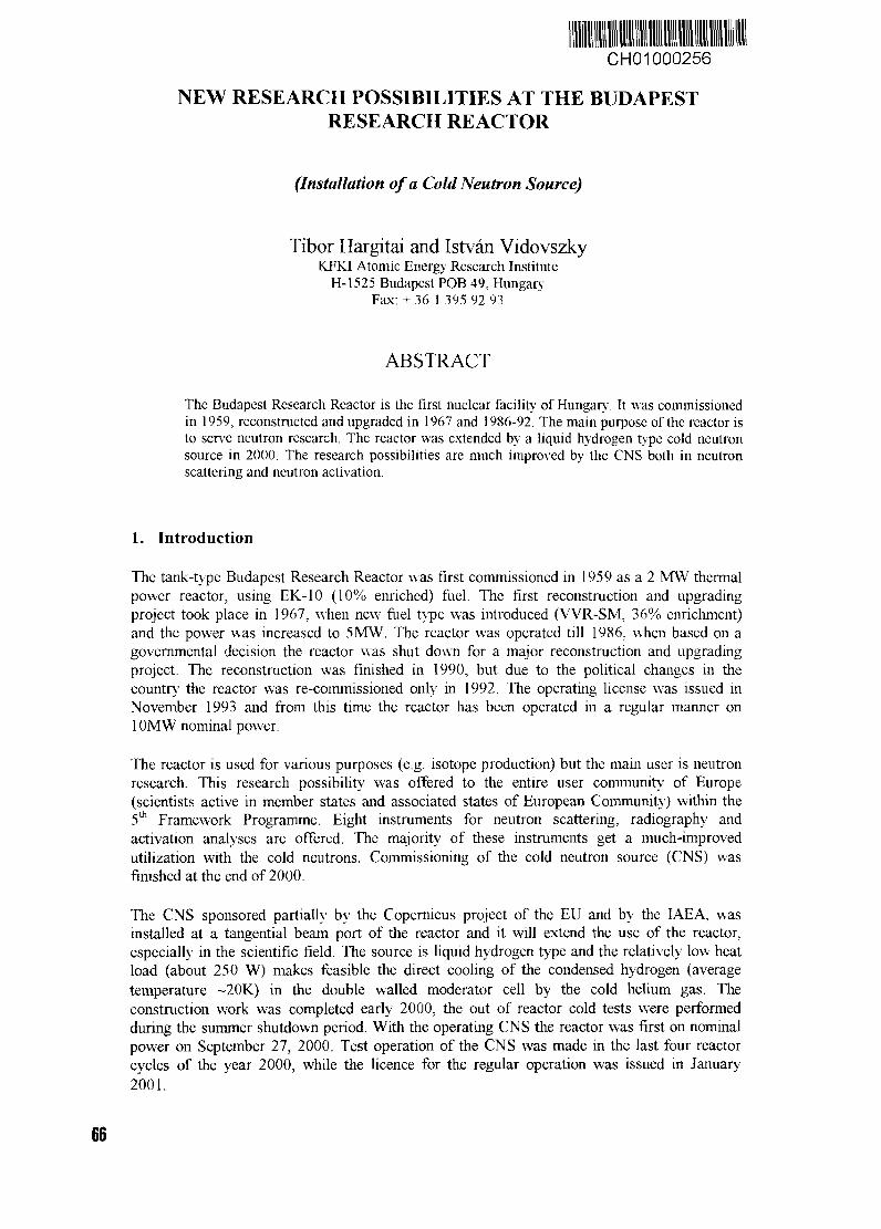
CH01000256
NEW RESEARCH POSSIBILITIES AT THE BUDAPESTRESEARCH REACTOR
(Installation of a Cold Neutron Source)
Tibor Hargitai and Istvan VidovszkyKFKI Atomic Energy Research Institute
H-1525 Budapest POB 49, HungaryFax: + 36 1 395 92 93
ABSTRACT
The Budapest Research Reactor is the first nuclear facility of Hungary. It was commissionedin 1959, reconstructed and upgraded in 1967 and 1986-92. The main purpose of the reactor isto serve neutron research. The reactor was extended by a liquid hydrogen type cold neutronsource in 2000. The research possibilities are much improved by the CNS both in neutronscattering and neutron activation.
1. Introduction
The tank-type Budapest Research Reactor was first commissioned in 1959 as a 2 MW thermalpower reactor, using EK-10 (10% enriched) fuel. The first reconstruction and upgradingproject took place in 1967. when new fuel type was introduced (WR-SM. 36% enrichment)and the power was increased to 5MW. The reactor was operated till 1986, when based on agovernmental decision the reactor was shut down for a major reconstruction and upgradingproject. The reconstruction was finished in 1990, but due to the political changes in thecountry the reactor was re-commissioned only in 1992. The operating license was issued inNovember 1993 and from this time the reactor has been operated in a regular manner on10MW nominal power.
The reactor is used for various purposes (e.g. isotope production) but the main user is neutronresearch. This research possibility was offered to the entire user community of Europe(scientists active in member states and associated states of European Community) within the5th Framework Programme. Eight instruments for neutron scattering, radiography andactivation analyses are offered. The majority of these instruments get a much-improvedutilization with the cold neutrons. Commissioning of the cold neutron source (CNS) wasfinished at the end of 2000.
The CNS sponsored partially by the Copernicus project of the EU and by the IAEA, wasinstalled at a tangential beam port of the reactor and it will extend the use of the reactor,especially in the scientific field. The source is liquid hydrogen type and the relatively low heatload (about 250 W) makes feasible the direct cooling of the condensed hydrogen (averagetemperature ~20K) in the double walled moderator cell by the cold helium gas. Theconstruction work was completed early 2000, the out of reactor cold tests were performedduring the summer shutdown period. With the operating CNS the reactor was first on nominalpower on September 27, 2000. Test operation of the CNS was made in the last four reactorcycles of the year 2000, while the licence for the regular operation was issued in January2001.
66
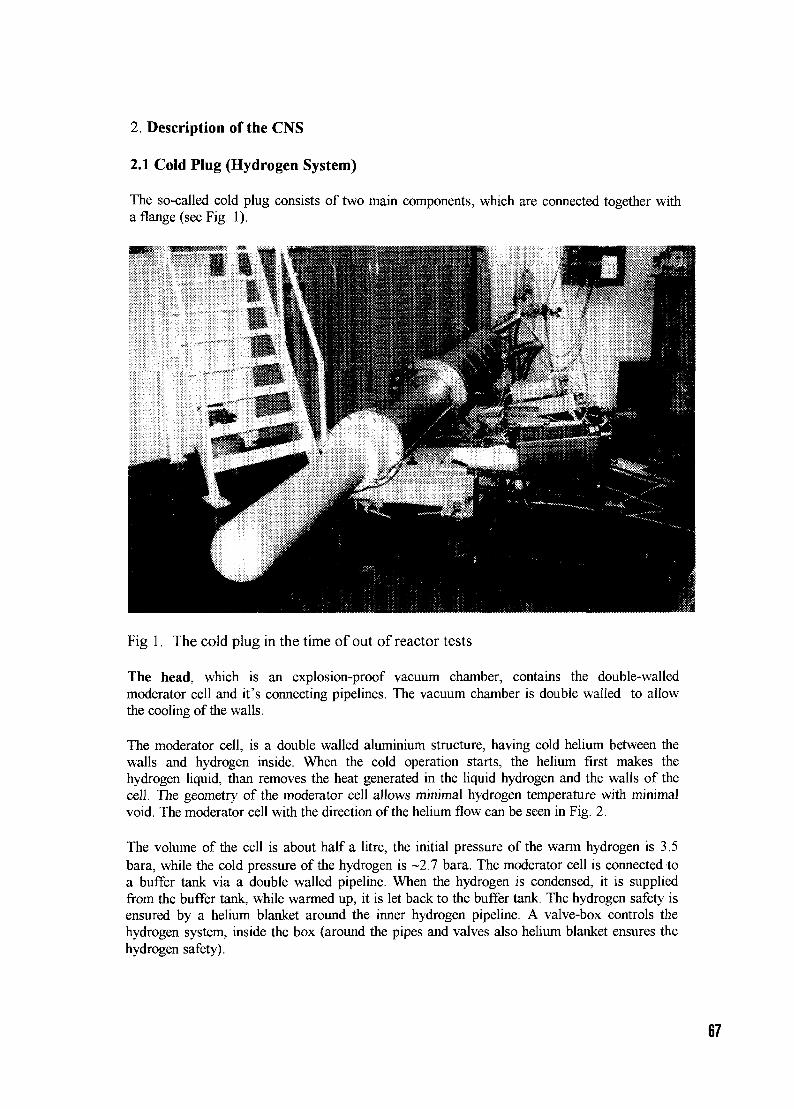
2 Description of the CNS
2.1 Cold Plug (Hydrogen System)
The so-called cold plug consists of two main components, which are connected together witha flange (see Fig. 1).
Fig 1. The cold plug in the time of out of reactor tests
The head, which is an explosion-proof vacuum chamber, contains the double-walledmoderator cell and it's connecting pipelines. The vacuum chamber is double walled to allowthe cooling of the walls.
The moderator cell, is a double walled aluminium structure, having cold helium between thewalls and hydrogen inside. When the cold operation starts, the helium first makes thehydrogen liquid, than removes the heat generated in the liquid hydrogen and the walls of thecell. The geometry of the moderator cell allows minimal hydrogen temperature with minimalvoid. The moderator cell with the direction of the helium flow can be seen in Fig. 2.
The volume of the cell is about half a litre, the initial pressure of the warm hydrogen is 3.5bara, while the cold pressure of the hydrogen is -2.7 bara. The moderator cell is connected toa buffer tank via a double walled pipeline. When the hydrogen is condensed, it is suppliedfrom the buffer tank, while warmed up, it is let back to the buffer tank. The hydrogen safety isensured by a helium blanket around the inner hydrogen pipeline. A valve-box controls thehydrogen system, inside the box (around the pipes and valves also helium blanket ensures thehydrogen safety).
67
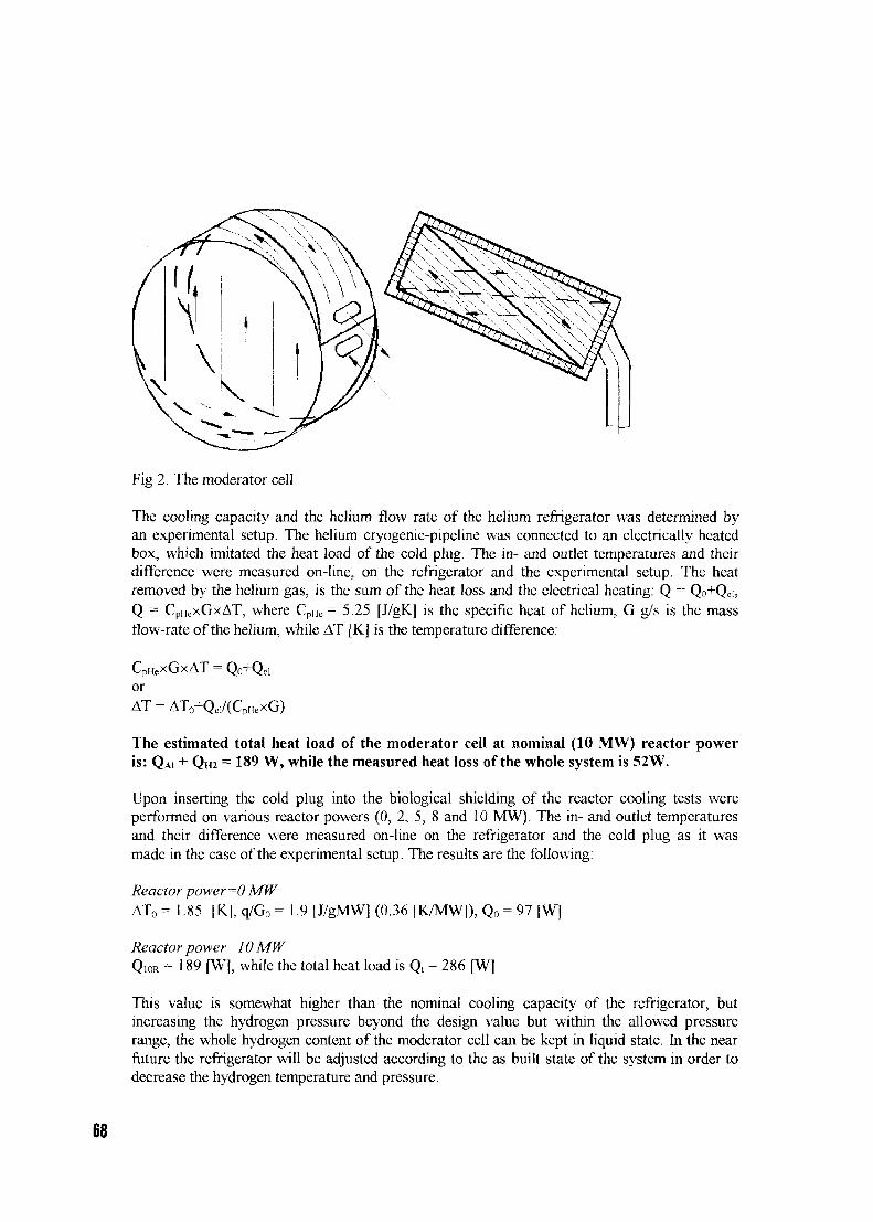
Fig 2. The moderator cell
The cooling capacity and the helium flow rate of the helium refrigerator was determined byan experimental setup. The helium cryogenic-pipeline was connected to an electrically heatedbox, which imitated the heat load of the cold plug. The in- and outlet temperatures and theirdifference were measured on-line, on the refrigerator and the experimental setup. The heatremoved by the helium gas, is the sum of the heat loss and the electrical heating: Q = Qo+Qd,Q = CpHexGxAT, where CPHe = 5.25 [J/gK] is the specific heat of helium, G g/s is the massflow-rate of the helium, while AT [K] is the temperature difference:
CpHeXGxAT = Qo+QclorAT = AT0+Qel/(CpHeXG)
The estimated total heat load of the moderator cell at nominal (10 MW) reactor poweris: QAI + QH2 = 189 W, while the measured heat loss of the whole system is 52W.
Upon inserting the cold plug into the biological shielding of the reactor cooling tests wereperformed on various reactor powers (0, 2, 5, 8 and 10 MW). The in- and outlet temperaturesand their difference were measured on-line on the refrigerator and the cold plug as it wasmade in the case of the experimental setup. The results are the following:
Reactor power ==0 MWAT0 = 1.85 [K], q/G0 = 1.9 LJ/gMW] (0.36 [K/MW]), Qo = 97 [W]
Reactor power =10 MWQ10R = 189 [W], while the total heat load is Qt = 286 [W]
This value is somewhat higher than the nominal cooling capacity of the refrigerator, butincreasing the hydrogen pressure beyond the design value but within the allowed pressurerange, the whole hydrogen content of the moderator cell can be kept in liquid state. In the nearfuture the refrigerator will be adjusted according to the as built state of the system in order todecrease the hydrogen temperature and pressure.
The steel body of the cold plug (see Fig 3) holds the explosion proof vacuum chamber andcontains the three neutron guides. The steel body also provides biological shielding and thereis a lead beam shutter in its front part, which makes possible the maintenance on the neutronguides and the beam shutters.
Fig 3. The steel body of the cold plug with the holes of the neutron guides.
The neutron guide system consists of three curved super-mirror neutron guides havingdifferent lengths. The first part, which is built in the steel body of the cold plug, is made of aspecial ceramics, having higher irradiation resistance. The out-of reactor part of the neutronguide is made of boronized glass. The coating is nickel, containing titanium. The first part ofthe guide (to the beam shutters and one meter after them) is in vacuum jacket. The end part ofthe guide is vacuumed directly.
The beam shutters ensure the individual closing and opening of the beam ports. The designprovides inherent safety, so that the basic position of the shutter is closed. In closed state it isa 50 cm long sandwich structure, containing several layers of boronized polyethylene, steeland lead. The shutter can be opened by compressed air, when a 50 cm long super-mirrorneutron guide is lifted into the opening position. In case of emergency the shutter can beclosed simply by releasing the air pressure.
2.2 The refrigerator system
The refrigerator system, which was installed in a new building connected to the reactor hall,has the following four major components:
a. / CompressorsTwo KAESER type screw compressors can provide 6 g/s and 12 g/s helium flowrespectively. When the CNS is operated in cold mode both compressors are runningparallel, while in the so-called warm mode the smaller one is enough to cool the moderatorcell and the vacuum chamber.
69
b. / Oil removal systemThe built-in filter removes the oil from the helium gas and four pumps (two-two) feed backthe oil into the compressors.
c. / Bypass filterThe bypass filter should be used before the CNS cold operation every time when the heliumsystem is opened. The helium gas shall be rotated through the filter until the gas puritymeasured by a built-in gas analyser reaches the needed value.
d. / Cold boxThe cold box is the heart of the refrigerator system. The cooling process is made by twoturbine type expanders, which expand the helium gas from 10.5 bar to 1.5 bar pressure.Control of the cooling process is performed by a microprocessor-based controller (PLC),which not only controls the whole system, but also collects and displays the measured dataof the system including the valve positions. The operation including the transients, i.e.cooling down and warming up the system are entirely automatic, only the start-uppreparations such as gas cleaning and helium filling of the cooling system is mademanually. There is a water cooler connected to the cold box to cool the brake gas of theturbines and the diffusion vacuum pump, providing the heat insulation of the cold box.
2.3 Cryogenic pipelines
The cold plug is connected to the refrigerator by cryogenic pipelines. The pipelines are doublewalled, the insulation of the cold helium pipeline is provided by special heat insulationcoating of the inner pipe and by high vacuum made by a turbo molecular vacuum pump.
2.4 High vacuum pipeline
The high-vacuum pipeline is connected to the double walled explosion proof high vacuumchamber providing the insulation of the moderator cell. A helium blanket covers the high-vacuum inner pipe, so in case of a leakage no air can freeze on the surface of the moderatorcell and of the connecting pipes. The high-vacuum pipeline is connected to a turbo molecularpump via a valve box containing a helium blanket around the valve.
2.5 Instrumentation and control (I&C)
As it was mentioned, the refrigerator system has a PLC based controller, which controls therefrigerator including the gas management system and the compressors. There is a higherlever controller, which gives orders to the controller of the refrigerator, controls the heliumblanket and handles the emergency situations.
Four display and control panels were designed and built in the I&C system:The first panel is situated in the new refrigerator building. From this building not only themeasured parameters of the whole system can be displayed but also all the valves can bemanually operated.
The second panel is in the reactor hall. This panel serves only as a display where everymeasured value can be seen and also contains a data acquisition computer too. No manualcontrol of the valves is possible from this panel.
The third panel is in the control room of the reactor. On this panel the most importantmeasurements are displayed, which inform the operator about the status of the system. Themain safety' philosophy of the CNS is that the cold source cannot be harmful for the reactor
70
but the reactor can cause damage in the moderator cell and the explosion proof chamber. Thisis why the CNS measurements are not connected to the reactor safety system, but the operatorshall be kept informed about the status of the system. In case of a cooling problem (failure ofboth compressors) the reactor power should be decreased or the reactor should be shut down.
3. Conclusions
Installation and commissioning of the cold source proved that the inner heat-exchangerconcept could be used in those cases where the irradiation heat load is relatively low. The firstneutron spectrum measurements showed that the efficiency of the system as a whole(including the new neutron guides and beam shutters) improved by a factor of forty in case ofneutron scattering and by a factor of sixty for neutron capture type measurements.

Session 4
Spent fuel management, corrosionand degradation
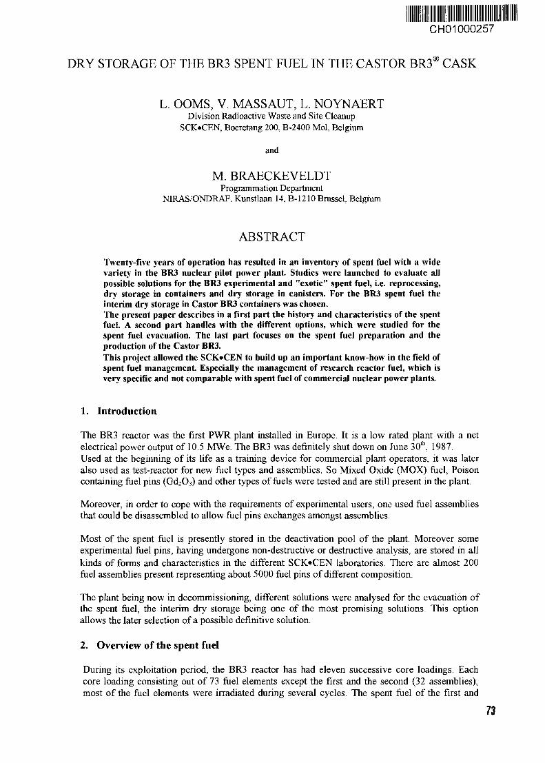
CH01000257
DRY STORAGE OF THE BR3 SPENT FUEL IN THE CASTOR BR3® CASK
L. OOMS, V. MASSAUT, L. NOYNAERTDivision Radioactive Waste and Site Cleanup
SCK«CEN, Boeretang 200, B-2400 Mol, Belgium
and
M. BRAECKEVELDTProgrammation Department
MRAS/ONDRAF, Kunstlaan 14, B-1210 Bmssel Belgium
ABSTRACT
Twenty-five years of operation has resulted in an inventory of spent fuel with a widevariety in the BR3 nuclear pilot power plant Studies were launched to evaluate allpossible solutions for the BR3 experimental and "exotic" spent fuel, i.e. reprocessing,dry storage in containers and dry storage in canisters. For the BR3 spent fuel theinterim dry storage in Castor BR3 containers was chosen.The present paper describes in a first part the history and characteristics of the spentfuel. A second part handles with the different options, which were studied for thespent fuel evacuation. The last part focuses on the spent fuel preparation and theproduction of the Castor BR3.This project allowed the SCK«CEN to build up an important know-how in the field ofspent fuel management Especially the management of research reactor fuel, which isvery specific and not comparable with spent fuel of commercial nuclear power plants.
1. Introduction
The BR3 reactor was the first PWR plant installed in Europe. It is a low rated plant with a netelectrical power output of 10.5 MWe. The BR3 was definitely shut down on June 30th. 1987.Used at the beginning of its life as a training device for commercial plant operators, it was lateralso used as test-reactor for new fuel types and assemblies. So Mixed Oxide (MOX) fuel, Poisoncontaining fuel pins (Gd2O3) and other types of fuels were tested and are still present in the plant.
Moreover, in order to cope with the requirements of experimental users, one used fuel assembliesthat could be disassembled to allow fuel pins exchanges amongst assemblies.
Most of the spent fuel is presently stored in the deactivation pool of the plant. Moreover someexperimental fuel pins, having undergone non-destructive or destructive analysis, are stored in allkinds of forms and characteristics in the different SCIOCEN laboratories. There are almost 200fuel assemblies present representing about 5000 fuel pins of different composition.
The plant being now in decommissioning, different solutions were analysed for the evacuation ofthe spent fuel, the interim dry storage being one of the most promising solutions. This optionallows the later selection of a possible definitive solution.
2. Overview of the spent fuel
During its exploitation period, the BR3 reactor has had eleven successive core loadings. Eachcore loading consisting out of 73 fuel elements except the first and the second (32 assemblies),most of the fuel elements were irradiated during several cycles. The spent fuel of the first and
73
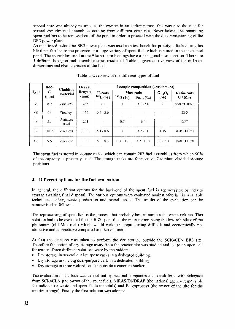
second core was already returned to the owners in an earlier period, this was also the case forseveral experimental assemblies coming from different countries. Nevertheless, the remainingspent fuel has to be removed out of the pond in order to proceed with the decommissioning of theBR3 power plant.As mentioned before the BR3 power plant was used as a test bench for prototype fuels during hislife time, this led to the presence of a large variety of spent fuel, which is stored in the spent fuelpond. The assemblies used in the 9 latest core loadings have a hexagonal cross-section. There are5 different hexagon fuel assemblie types irradiated. Table 1 gives an overview of the differentdimensions and characteristics of the fuel.
Table 1: Overview of the different types of fuel
Type
Z
Gf
IK
G
Go
Rod-0
(mm)
8.7
9.4
8.5
10.7
9.5
Claddingmaterial
Zircalov4
Zircaloy4
Stainlesssteel
Zirealoy4
Zircaloy4
OveralIlength(mm)
1235
1136
1251
1136
1136
Isotopic composition (enrichment)
U-rods235U (%)
7.1
6.4 - 8.6
-
5.1 -8 .6
5.0-8 .3
Mox-rods235U (%)
3
-
0.7
3
0.3 - 0.7
Punss (%)
3.1-5.0
-
6.4
3.7-7.0
3.7- 10.3
Gd2O3
(%)
-
-
-
1.35
3.0-7.0
Ratio-rodsU/Mox
36/0 -» 10/26
28/0
0/37
20/0 -» 0/20
28/0 -» 0/28
The spent fuel is stored in storage racks, which can contain 203 fuel assemblies from which 90%of the capacity is presently used. The storage racks are foreseen of Cadmium cladded storagepositions.
3. Different options for the fuel evacuation
In general, the different options for the back-end of the spent fuel is reprocessing or interimstorage awaiting final disposal. The various options were evaluated against criteria like availabletechniques, safety, waste production and overall costs. The results of the evaluation can besummarised as follows.
The reprocessing of spent fuel is the process that probably best minimises the waste volume. Thissolution had to be excluded for the BR3 spent fuel, the main reason being the low solubility of theplutonium (old Mox-rods) which would make the reprocessing difficult and economically notattractive and competitive compared to other options.
At first the decision was taken to perform the dry storage outside the SCK»CEN BR3 site.Therefore the option of dry storage away from the reactor site was studied and led to an open callfor tender. Three different solutions were by the bidders:• Dry storage in several dual-purpose casks in a dedicated building.• Dry storage in one big dual-purpose cask in a dedicated building.• Dry storage in three welded canisters inside a concrete bunker.
The evaluation of the bids was carried out by external companies and a task force with delegatesfrom SCK«CEN (the owner of the spent fuel), NIRAS/ONDRAF (the national agency responsiblefor radioactive waste and spent fisile materials) and Belgoprocess (the owner of the site for theinterim storage). Finally the first solution was adopted.
74
4. CASTOR BR3®
The CASTOR BR3® is derived from the CASTOR THTR and is designed as a transport andstorage cask for accommodating 30 BR3 spent fuel assemblies. As a type B(U) cask fitted withshock absorbers, it meets the transport requirements according to the IAEA regulations and fulfilsthe conditions for cask storage in Germany. For the transport, the cask needs a Type B(U) licencefrom the Belgian competent authority.
The necessary modifications to the original THTR design refer to an additional neutron shieldingin the cask wall, the secondary lid and the cask bottom as well as to the basket. The basket isdesigned with closed loading tubes and can be handled separately by a crane even in loadedcondition. This allows to unload a cask if some leak was detected.
The main cask components are:> The cask body constructed out of ductile cast iron foreseen of an internal cavity, which is
coated to avoid corrosion. The dimensions of the cask (table 2) are derived from the necessaryshielding capability.For neutron shielding, 30 axial boreholes are machined in the cask wall, which are filled withpolyethylene rods.
> The primary lid, foreseen with an inner metallic and outer elastomer seal, closes the cavity andacts as first independent safety barrier both for the leaktight confinement of the fuel and forthe radiological shielding. The closure of the metallic seal is controlled by a Helium leaktightness test performed on the inter-seal volume.The primary lid contains an opening into the cavity, which is used for dewatering, drying andgas filling of the cask cavity after loading (He at 500 hPa abs).
> The secondary lid, also foreseen with an inner metallic and outer elastomer seal, serves as anadditional shielding as well as a second independent tightness barrier.An opening into the secondary lid, giving access to the space between primary and secondarylid, allows adjusting the pressure in the inter-lid space (He at 6000 hPa abs).Additionally a pressure sensor system is mounted in the secondary lid to monitor the pressurein the inter-lid space hence providing a continuous check-up of the leak-tightness of theCASTOR cask during the long-term storage period.
> The inner basket consists of 30 hexagon tubes, which are mounted on a bottom steel plate. Thetubes are made of borated stainless steel and the bottom plate of stainless steel and is providedwith some small holes (diameter approx. 20 mm) for dewatering purposes. Apart from thesesmall holes in the bottom plate, the basket structure is closed and designed for being handledin loaded condition. The hexagons can accept both BR3 fuel assemblies and canisters loadedwith fuel remnants.
Table 2: Dimensions and weights of the CASTOR BR3 parts.
Part
Cask bodyCask cavityPrimary lid
Secondary lidBasket
Inventory
Height(mm)2493165227070
1638150
0(mm)14286909111122685
(Hex) 85
Wall thickness(mm)370
-----
Weight(tonne)
20-
1.30.6
10.8
Due to the diversity of the spent fuel and in order to simplify the calculations, 4 fuel cases weredefined which covered the most important and worst case of loading. The main characteristics ofthese fuel cases (residual heat production, neutron and gamma radiation) were used to perform thesafety calculations (except for criticality) of the CASTOR BR3. These four fuel cases are coveringeach assembly and canister, which will be evacuated in a CASTOR BR3®.
75
Calculations have showed that the worst case for criticality was a non-irradiated type Z fuelassembly. A CASTOR BR3® loaded with 30 fresh type Z assembly showed a Keff< 0.82 after atype B(U) test.
To obtain the necessary transport licence, a complete safety report has been issued by GNB (themanufacturer of the CASTOR BR3®). The following main items have been checked according tothe IAEA regulations for the safe transport of radioactive material (1996 Edition No ST-1):> Study of the sealing system and activity retention of the Castor BR3®.> Criticality calculations> Shielding calculations> Mechanical analyses under accident conditions> Thermal analyses
For the storage licence, additional safety calculations had to be performed like:> Cask behaviour in case of an earthquake> Cask behaviour in case of a shock wave> Mechanical interaction of casks in the storage facility> Airplane crash onto the lid system> Drop of the cask in the storage facility
5. Spent fuel preparation
During the consecutive core loadings, a large number of rods were withdrawn from their originalassembly position to perform post-irradiation examinations or another irradiation in a differentassembly position. This led to a situation that 25% of the assemblies were not complete and about380 rods were stored in temporary storage cans.Therefore, it was necessary to organise large consolidation campaigns in order to complete thesefuel assemblies. The consolidation is quite time consuming. In total there are three consolidationcampaigns foreseen over a total period of 12 weeks.
Each assembly, which is complete and ready for evacuation, is submitted to a leak tightness testusing the "Wet sipping" method. The "Wet sipping" is used in several nuclear power plants and isdescribed in an IAEA guidebook on non-destructive examination of water reactor fuel. During the"Wet sipping" of 161 assemblies, we found 4 suspected fuel assemblies of which two of them arealready successfully treated to remove the non-intact fuel pins. An external safety inspectorateverifies the results of the leak tightness test.
Non-intact and cut fuel pins were loaded into canisters, which were welded and tested on leaktightness. Each canister can contain 15 equivalent fuel pins; pieces of rods were first loaded in azircaloy tube before being put into the canister. The loading of the canister was performed in a hotcell.
6. Castor BR3* production
The production of the Castor BR3® started in March 2000, the first cask being complete and readyin January 2001. The others will be delivered in a period of 4 months.The quality assurance on the design and the fabrication is performed according to the GNS/GNBquality management system based on the international standard DIN EN ISO9001. In addition tothis QA follow up, a spot check follow up is performed by an independent organism on behalf ofthe SCK-CEN.
76
Important steps in the fabrication process were:> The casting of the cask body (figure 1),> Coating of the cavity in the cask body,> The basket fabrication,^ The forging of the lids and trunnions,y The assembly of the cask,> Final tests: overload test of the trunnions and leak tightness test.
Figure 1: Casting of the first CASTOR BR3**
7. Conclusions
Studies were launched to evaluate all possible solutions for the BR3 experimental and "exotic"spent fuel, i.e. reprocessing, dry storage in containers and dry storage in canisters. These studieswere intended to compare the different options against criteria like available techniques, safety,waste production and overall costs.For the BR3 spent fuel the dry storage in CASTOR BR3® containers was chosen.
This project allowed the SCK«CEN to build up an important know-how in the field of spent fuelmanagement. Especially the management of research reactor fuel, which is very specific and notdirectly comparable with spent fuel of commercial nuclear power plants.
8. References
[1] Noynaert L., Massaut V., Braeckeveldt M.The back-end management of fissile material at the SCK>CEN, ENS RRFM 1999.
[2] Sannen L., Claes W., Noynaert L., Maris P., Ooms L.The conditioning of fuel rod remnants from research programmes for long termintermediate storage.IAEA Technical Committee Meeting on Requirements for long term storage facilities, 16-20October 2000, Vienna
77
CH01000258
MANAGEMENT AND PHYSICAL ASSESSMENT OF THE SPENTFUEL FROM RESEARCH REACTORS IN POLAND
S. CHWASZCZEWSKI, W. CZAJKOWSKI,E. BOREK-KRUSZEWSKA, T. MATYSIAK,
M. MADRYInstitute of Atomic Energy, 05-400 Otwock Swierk POLAND.
ABSTRACT
The inventory of the spent nuclear fuel in Poland comes from two research reactors: the firstPolish reactor EWA, which was operated from 1958 to 1995, and the second, reactor MARIA,operated from 1974 until now. In the paper, the basic information about these reactors and usednuclear fuels i.e. Ek-10, WWR-SM, WWR-M2 and MR type, is presented. After discharging fromthe reactors, the spent fuel was stored in the wet storage facilities. The Ek-10 fuel rods have beenstored in wet storage since 1958. WWR-SM fuel assemblies have been stored since 1968 andWWR-M2 since 1990. The basic design information on these facilities and experience from theiroperation are presented in the paper.
Taking into account the fact that the fuel was stored for the long period of time in wetcondition, the wide program of physical investigation of spent fuel and storage facilities wascarried out. The visual investigation of cladding material was performed. Only initial claddingcorrosion was observed for the fuel with 20 years of storage, and the strong corrosion process wasvisible on elements stored for 30 years. It was observed that corrosion processes is faster if fuelmeat is present under cladding material.
On the basis of the results of the sipping tests of WWR-SM fuel assemblies with differentstorage time (from 4 to 31 years), the assessment of the time limit of their storage in wet conditionhas been made. Based on this assessment, the value of the daily leakage of Cs-137 from WWR-SM and WWR-M2 spent fuel in the wet pool was estimated and compared with the measurementsperformed in 1999 and 2000. The results of systematic sipping tests of Ek-10 fuel rods and WWR-SM fuel assemblies discharged from EWA reactor before 1970 is presented in the paper.
The condition of the stainless steel liner and aluminium tank of the storage poo! wasinvestigated. For this purpose the wide range of techniques e.g. penetrating, ultrasonic wasapplied. On the basis of the investigation necessary repairs were made.
Taking into account the fact that storage in wet condition is limited in time, the concept ofdry storage facility was put forward.
1. Introduction
In Poland, the problem of spent nuclear fuel management appeared when the first fuel was dischargedfrom the EWA reactor in 1959. The first spent fuel, after short storage in the EWA reactor storagetank, was transported to the EK-10 storage facility. At the beginning, it was assumed, that spent fuelproblem would be solved by the supplier of the nuclear fuel i.e. the Soviet Union organisations. It wasplanned that after the initial cooling in the wet storage, the spent fuel would be returned to thesupplier. The common effort for such solution continued until the end of 1992. But after political,economical and social transformation of the Soviet Union into Russian Federation, and thetransformations in the countries of Eastern and Central Europe, the spent fuel management principleshave to be established anew, in the radically new conditions. Several options of future spent fuelmanagement were analysed: reprocessing in Russian Federation, in the United Kingdom and in Franceor a long time storage in a dry storage facility. In the last option the CASTOR containers, NUCHOMScontainers and dry storage facility at the EWA reactor (decommissioned) were considered. Taking intoaccount legal, technical and economical aspects, the reprocessing solution was eliminated. It isexpensive, legally complicated and technically difficult. In all the variants of reprocessing , the highlevel waste originating in the process should be returned and stored in Poland. The magnitude ofproblems connected with spent fuel and HLW management is similar. Therefore, the concept of long-term storage of the spent fuel in the dry condition has been chosen. From the possible dry storageoptions the design of the dry storage in EWA facility was chosen as optimal [1].
78
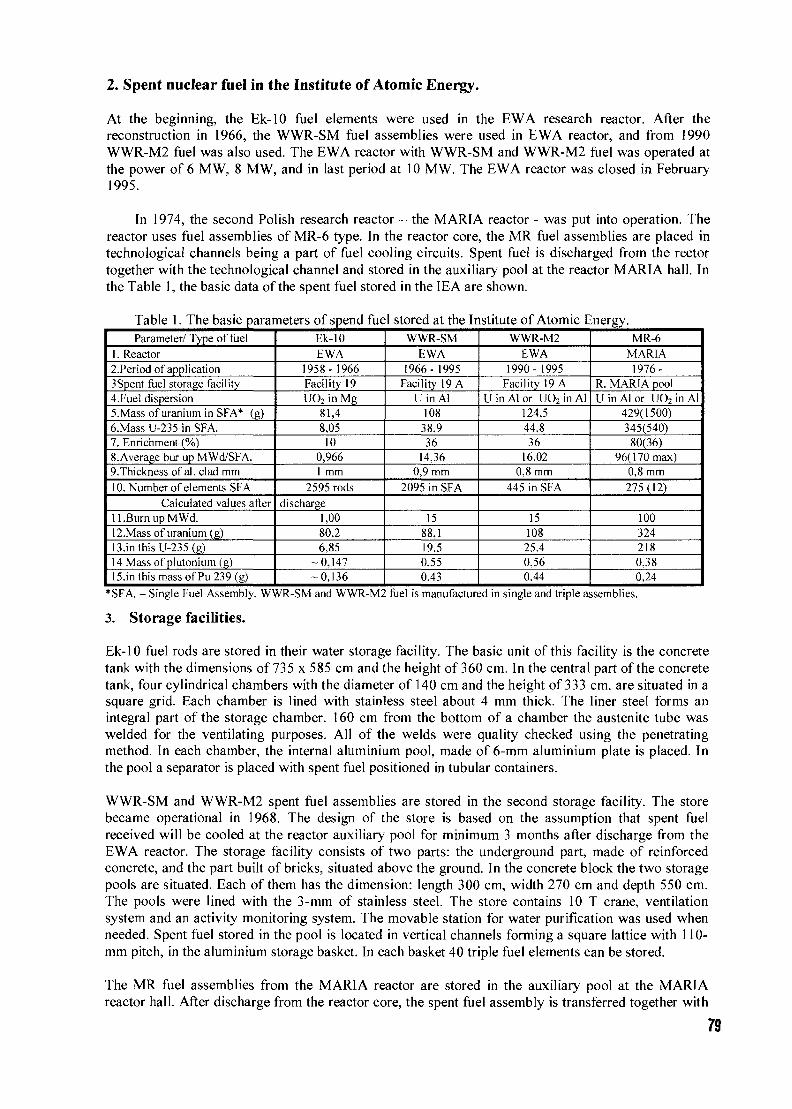
2. Spent nuclear fuel in the Institute of Atomic Energy.
At the beginning, the Ek-10 fuel elements were used in the EWA research reactor. After thereconstruction in 1966, the WWR-SM fuel assemblies were used in EWA reactor, and from 1990WWR-M2 fuel was also used. The EWA reactor with WWR-SM and WWR-M2 fuel was operated atthe power of 6 MW, 8 MW, and in last period at 10 MW. The EWA reactor was closed in February1995.
In 1974, the second Polish research reactor - the MARIA reactor - was put into operation. Thereactor uses fuel assemblies of MR-6 type. In the reactor core, the MR fuel assemblies are placed intechnological channels being a part of fuel cooling circuits. Spent fuel is discharged from the rectortogether with the technological channel and stored in the auxiliary pool at the reactor MARIA hall. Inthe Table 1, the basic data of the spent fuel stored in the IEA are shown.
Table 1. The basic parameters of spend fuel stored at the Institute of Atomic Energy.Parameter/ Type of fuel
1. Reactor2.Period of application3Spent fuel storage facility4.Fuel dispersion5.Mass of uranium in SFA* (g)6.Mass U-235 in SFA.7. Enrichment (%)8.Average bur up MWd/SFA.9.Thickness of al. clad mm10. Number of elements SFA
Calculated values afterll.BurnupMWd.12.Mass of uranium (g)13.in this U-235 (g)14 Mass of plutonium (g)15.in this mass of Pu 239 (g)
Ek-10EWA
1958-1966Facility 19UO2 in Mg
81,48,0510
0,9661 mm
2595 rodsdischarge
1,0080,26,85
-0,147-0,136
WWR-SMEWA
1966-1995Facility 19 A
U in Al10838,936
14,360,9 mm
2095 in SFA
1588.119.50,550,43
WWR-M2EWA
1990- 1995Facility 19 A
U in Al or UO2 in Al124,544,836
16,020,8 mm
445 in SFA
1510825,40,560.44
MR-6MARIA1976-
R. MARIA poolUinAlor UO2 in Al
429(1500)345(540)
80(36)96(170 max)
0,8 mm275(12)
1003242180.380.24
*SFA. - Single Fuel Assembly. WWR-SM and WWR-M2 fuel is manufactured in single and triple assemblies.
3. Storage facilities.
Ek-10 fuel rods are stored in their water storage facility. The basic unit of this facility is the concretetank with the dimensions of 735 x 585 cm and the height of 360 cm. In the central part of the concretetank, four cylindrical chambers with the diameter of 140 cm and the height of 333 cm. are situated in asquare grid. Each chamber is lined with stainless steel about 4 mm thick. The liner steel forms anintegral part of the storage chamber. 160 cm from the bottom of a chamber the austenite tube waswelded for the ventilating purposes. All of the welds were quality checked using the penetratingmethod. In each chamber, the internal aluminium pool, made of 6-mm aluminium plate is placed. Inthe pool a separator is placed with spent fuel positioned in tubular containers.
WWR-SM and WWR-M2 spent fuel assemblies are stored in the second storage facility. The storebecame operational in 1968. The design of the store is based on the assumption that spent fuelreceived will be cooled at the reactor auxiliary pool for minimum 3 months after discharge from theEWA reactor. The storage facility consists of two parts: the underground part, made of reinforcedconcrete, and the part built of bricks, situated above the ground. In the concrete block the two storagepools are situated. Each of them has the dimension: length 300 cm, width 270 cm and depth 550 cm.The pools were lined with the 3-mm of stainless steel. The store contains 10 T crane, ventilationsystem and an activity monitoring system. The movable station for water purification was used whenneeded. Spent fuel stored in the pool is located in vertical channels forming a square lattice with 110-mm pitch, in the aluminium storage basket. In each basket 40 triple fuel elements can be stored.
The MR fuel assemblies from the MARIA reactor are stored in the auxiliary pool at the MARIAreactor hall. After discharge from the reactor core, the spent fuel assembly is transferred together with
79
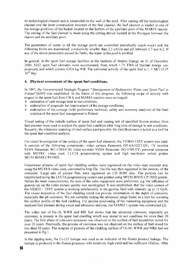
its technological channel and is suspended on the wall of the pool. After cutting off the technologicalchannel and the inner construction structure of the fuel channel, the fuel element is loaded in one ofthe storage positions of the basket located on the bottom of the auxiliary pool of the MARIA reactor.The cutting of the fuel channel is made using the cutting device located in the floodgate between thereactor and the auxiliary pool.
The parameters of water in all the storage pools are controlled periodically (each week) and thefollowing limits are maintained: conductivity smaller than 3,5 u.S/cm and pH between 5,7 and 6,2. Ifany of the above parameters exceed its limits, the water in the pool is purified.
In general, in the spent fuel storage facilities at the Institute of Atomic Energy on 31 of December2000, 5422 spent fuel elements were accumulated, from which 1,75 TWh of thermal energy wasproduced, and which contain 635,6 kg HM. The estimated activity of the spent fuel is 1, 5 MCi (5.5*10l6Bq).
4. Physical assessment of the spent fuel conditions.
In 1997, the Governmental Strategic Program "Management of Radioactive Waste arid Spent Fuel inPoland "(GSP) was established. In the frame of this program, the following scope of activity withrespect to the spent fuel from EWA and MARIA reactors were envisaged:> estimation of safe storage time in wet condition;> elaboration of proposals for improvement of the storage conditions;> elaboration of the concept (with preliminary technical, safety and economy analysis) of the final
solution of the spent fuel management in Poland.
Visual testing of the outside surface of spent fuel and sipping test of specified fission product fromfuel element were used to analyse the spent fuel condition after long time of storage in wet conditions.Recently, the ultrasonic scanning of clad surface (and possibly the clad thickness) is tested as a tool forthe spent fuel condition analysis.
For visual investigation of the surface of the spent fuel elements, the VIDEO-TEST system was used.It consists of the following components: video camera Panasonic GP-KS162CUDE; TV monitorSVHS Panasonic WC-CM14150; video recorder SVHS Panasonic AG-4700 EY; personal computerwith MUTEC video card, LUCIA programming system and high resolution colour printerMITSUBISHI CP4700D.
Underwater pictures of spent fuel cladding surface were registered on the video tape recorder and,using the MUTEX video card, converted to bmp file. The file was then registered in the memory of thecomputer. Large sets of picture files were registered on CD ROM disc. The pictures can betransformed using the LUCIA programming system and printed using MITSUBISHI CP-700D printer.Before the main measurements, the tests of the video equipment were performed, e.g. the influence ofgamma ray on the video picture quality was investigated. It was established, that the video camera ofthe VIDEO - TEST system is working satisfactorily in the gamma field with intensity up to 15 Gy/h.The visual inspection of the fuel cladding could not provide information on the depth of corrosion,especially the pit corrosion. We are currently testing the ultrasonic range finder as a tool for scanningthe surface profile of the fuel cladding. For precise positioning of the measuring equipment and theanalysed fuel element during visual and ultrasonic analysis, the STEND 1 system was constructed [2].
The video test of Ek-10, WWR and MR fuel shows that the advanced corrosion, especially pitcorrosion, is present in the spent fuel cladding which was stored in wet condition for more then 30years. The first phase of corrosion processes was observed on the surface of fuel assemblies stored forover 20 years. Practically, the process of corrosion was not observed on the surface of fuel stored forless than 20 years. The samples of pictures of the cladding surface of Ek-10, WWR and MR6 fuel arepresented in fig 1.
In the sipping tests, the Cs-137 isotope was used as an indicator of the fission product leakage. Theisotope is produced in the fission processes with relatively high yield and has sufficient lifetime. After
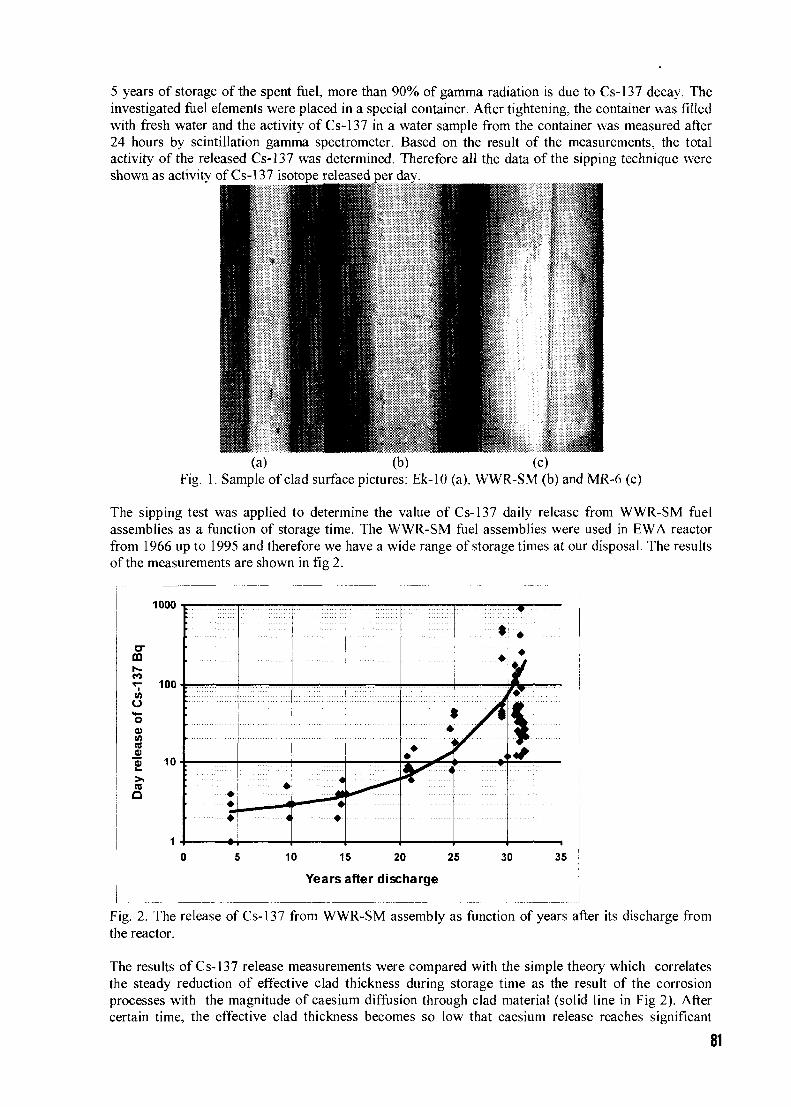
5 years of storage of the spent fuel, more than 90% of gamma radiation is due to Cs-137 decay. Theinvestigated fuel elements were placed in a special container. After tightening, the container was filledwith fresh water and the activity of Cs-137 in a water sample from the container was measured after24 hours by scintillation gamma spectrometer. Based on the result of the measurements, the totalactivity of the released Cs-137 was determined. Therefore all the data of the sipping technique wereshown as activity of Cs-137 isotope released per day.
i(a) (b) (c)
Fig. 1. Sample of clad surface pictures: Ek-10 (a), WWR-SM (b) and MR-6 (c)
The sipping test was applied to determine the value of Cs-137 daily release from WWR-SM fuelassemblies as a function of storage time. The WWR-SM fuel assemblies were used in EWA reactorfrom 1966 up to 1995 and therefore we have a wide range of storage times at our disposal. The resultsof the measurements are shown in fig 2.
1000
mr--
o"S0)I/)(0
COQ
100
10
-- •-•
•
—r *+4 •
<
•
• • x
•
10 15 20 25
Years after discharge
30 35
Fig. 2. The release of Cs-137 from WWR-SM assembly as function of years after its discharge fromthe reactor.
The results of Cs-137 release measurements were compared with the simple theory which correlatesthe steady reduction of effective clad thickness during storage time as the result of the corrosionprocesses with the magnitude of caesium diffusion through clad material (solid line in Fig 2). Aftercertain time, the effective clad thickness becomes so low that caesium release reaches significant
81
value. This indicates the limit of time for storage of spent fuel in wet condition. In the WWR-SM fuelassembly, the estimated maximum storage time is 41 years. Of course, this value depends on thestorage conditions and may be different from assembly to assembly. Therefore, taking into account thepresented results, the WWR-SM fuel assemblies discharged from EWA reactor in the period of 1968 +-1969 were investigated and several of them were selected for encapsulation in dry condition as soonas possible. In similar way, the Ek-10 fuel rods were investigated and some of them were selected forencapsulation in dry condition.
The release of Cs-137 isotope from all the stored spent fuel elements may be determined by themeasurements of the growth in time of Cs-137 concentration in the pool water. In 1999, thisparameter, determined for all WWR-SM and WWR-M2 stored in pool of storage facility, was 103kBq/day. In 2000, this value was 153 kBq/day. The simple theory gives 83 kBq/day in 1999 and 173kBq/day in 2000. The daily intensity of Cs-137 source in the Ek-10 storage pool determined from theCs-137 concentration growth was 45±15 kBq. The sum of Cs-137 release from all Ek-10 elementsmeasured separately was equal to 6,68 kBq/day. The reason for this discrepancy is as yet not clear.
In the frame of GSP the technical state of the spent fuel storage facility was also investigated. Thequality of the stainless steel liner of the pools in the storage facility for Ek-10 and for WWR fuel wasanalysed using destructive and non destructive techniques. It was established, that the stainless steelplates (1H18N9T) used both in the Ek-10 (~ 45 years) and WWR (36 years) storage facilities are ingood condition. Some defects were identified as design errors and errors in the welding connections.In the WWR storage facility, the new cover of the 6 mm stainless steel was made in the two storagepools. In the Ek-10 storage facility, some new welding was necessary.
Contrary to the stainless steel, the state of the inner aluminium tank in the Ek-10 storage pool is in avery poor condition. In the 6-mm aluminium plate the pit corrosion more than 5 mm deep wasobserved on the outer surface. In the Ek-10 storage facility the condensation water with poor chemicalquality fills the volume between the lining and the inner aluminium tank. The value of pitting rateindex (PRI) [3] for aluminium, calculated on the basis of chemical impurities of this water, is 52weeks. As a consequence the new inner tank was made for Ek-10 storage facility.
5. Final remarks.
The main result of the investigations is that there are no failed spent fuel assemblies stored in thestorage facilities. The failed elements or assemblies are stored in special containers. But the results ofthe visual investigation and sipping test show that in the next few years some of the spent elementsshould be removed from wet condition and placed in containers filled with inert gas. Besides, thedecision on construction of the dry storage facility in the decommissioned EWA reactor building wasaccepted. The concept of the dry storage facility is presented in this seminar [4].
After reconstruction, the existing storage facilities (for Ek-10 and WWR spent fuel elements) are ingood condition and can be used for further storage of the spent fuel elements. The National RegulatoryBody will determine the period of licence on the operation of these facilities.
6. References.
[1] S.Chwaszczewski, J. Wlodarski,: Nuclear Safety and Rad. Prot. 1(41) 2000 Warszawa, p.3
[2] W.Czajkowski, Stand for visual and ultrasonic testing of spent fuel. Poster in this meeting
[3] P.M. Aziz, H.P. Godart, Journal of Industrial and Engineering Chemistry, 44, 8, August 1952 p.1791-1795. Also: J. P. Howell: Durability of Aluminium-Clad Spent Nuclear Fuels in Wet BasinStorage. Paper No 128 The NACE International Annual Conference and ExpositionCORROSION 96.
[4] W. Mieleszczenko,: Nuclear spent fuel dry storage in the EWA reactor shaft. Paper in thismeeting.
82
CH01000259
NUCLEAR SPENT FUEL DRY STORAGE
IN THE EWA REACTOR SHAFT
W. MIELESZCZENKO, A. MOLDYSZ
A. HRYCZUK, T. MATYSIAK
Safety Analysis Department, Institute of Atomic Energy
05-400 Otwock-Swierk, Poland
ABSTRACT
The EWA reactor was in operation from 1958 until February 1995. Then it was subjectedto the decommissioning procedure. Resulting from a prolonged operation of Polishresearch reactors a substantial amount of nuclear spent fuel of various types, enrichmentand degree of burn-up have been accumulated.
The technology of storage of spent nuclear fuel foresees two stages:
wet storing in water pool (deferral period from tens to several dozens years);
dry storing (deferral period from 50 to 80 years).
In our case the deferral time in the water environment is pretty significant (the oldest fuelelements has been stored in water for more than 40 years). Though the state of stored fuelelements is satisfactory, there is a real need for changing the storage conditions of spentfuel.
The paper is covering the description of philosophy and conceptual design for constructionof the spent fuel dry storage in the decommissioned EWA reactor shaft.
83
1. Introduction
At the Institute of Atomic Energy at Swierk in Poland two research reactors EWA and MARIA havebeen operated for many years. The 30 MW(th) MARIA reactor which was commissioned in 1974 wasmodernized in the period of 1985-1992 and it is anticipated to operate this reactor until 2015. The pooltype reactor EWA was in the operation from 1958 until February 1995. Then it was permanently shutdown and a bit later successfully decommissioned. Resulting from a many years operation of bothreactors a substantial amount of nuclear spent fuel of various types, enrichment and degree of burn-uphas been accumulated.
Actually in several water pools about 610 kg uranium and fission products of activities from 300 to25000 GBq/fuel element is being stored. These comprise nuclides (such as e.g. Kr-85, Cs-134 and Sr-90) of substantial activity and long decay half-times. Another 900 kg of uranium and fission productswill be accumulated after the operation of MARIA reactor will be terminated.
Our spent fuel elements canned with aluminum alloy have been stored in wet conditions for a long time,e.g. the EK-10 type for more than 39 years and the WWR-SM type for about 28 years and though thestate of their cladding is still satisfactory there is a need for changing their storage conditions into thedry ones.
• After having analyzed different options of management of the spent fuel including eventualshipment for reprocessing abroad we have chosen the most promising economical solution based onstoring fuel on the site in the shaft of the decommissioned reactor EWA
The paper contains a brief characteristic of the proposed solution.
2. J u s t i f i c a t i o n of the pro jec t
The aim of construction of the spent fuel dry storage facility at the Institute of Atomic Energy at Swierkis to create appropriate conditions which can substantially slow down corrosion process in the fuelcladding and which will not allow to lose the integrity of spent fuel.
According to the world practice the conversion of storing conditions from wet into dry ones andproviding the neutral gas atmosphere inside the hermetic fuel cans will create the acceptable conditionsenabling the safe storage of spent fuel for at least 50 years. Poland doesn't plan to construct a nuclearpower plant in this decade so it also doesn't intend to utilize presently any deep geological formations,e.g. as salt mine as a repository for high level activity wastes. After having considered and analyzed alltechnologically and economically feasible options of management of the spent fuel in Poland, the mostreasonable solution seems to use the well in the reactor tank of the decommissioned reactor EWA.
The basic threat for the fuel cladding integrity is caused by the corrosion of aluminum. Though thenatural process of aluminum surface corrosion in water proceeds very slowly, around 0.08 mg/dm2, butthe other forms of its such as the pitting corrosion or intercrystalline corrosion are occurring rathernonuniformly. They are exhibited by local damaging of the surface, which brings about to the release ofthe fission products. The accelerated corrosion can be prohibited by proper chemistry of water, in whichthe spent fuel elements are stored.
For the time being at the Institute of Atomic Energy the research works on the release of fissionproducts to determine the limit period for wet storage are being carried on. It is very difficult todetermine the limit period for wet storage of the spent fuel elements in water. In some publications onthe subject this limit has been constrained to 35 years [1], The substantial majority of the spent fuelfrom Polish research reactors already meets this quantity.
Bearing this in mind it has been decided to construct dry storage facility in the former EWA reactorbuilding.
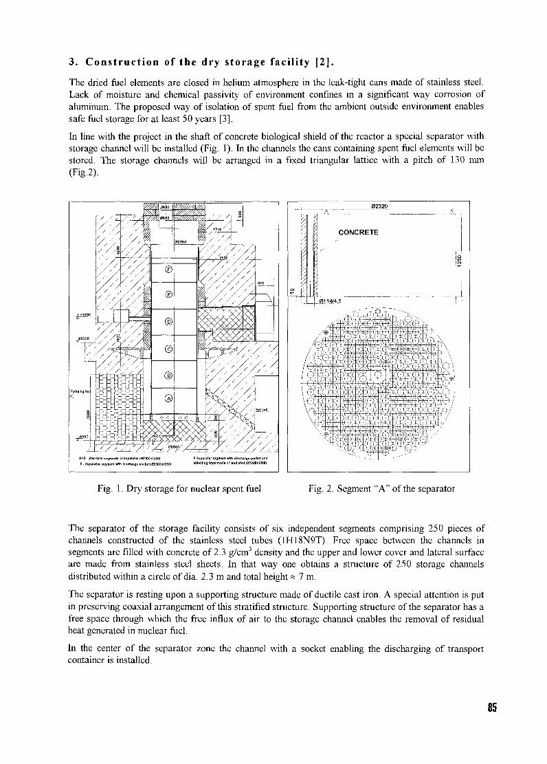
3. Construction of the dry storage facility [2].
The dried fuel elements are closed in helium atmosphere in the leak-tight cans made of stainless steel.Lack of moisture and chemical passivity of environment confines in a significant way corrosion ofaluminum. The proposed way of isolation of spent fuel from the ambient outside environment enablessafe fuel storage for at least 50 years [3].
In line with the project in the shaft of concrete biological shield of the reactor a special separator withstorage channel will be installed (Fig. 1). In the channels the cans containing spent fuel elements will bestored. The storage channels will be arranged in a fixed triangular lattice with a pitch of 130 mm(Fig.2).
A+D-Standard tismintt ol teptnler (32300x1250) F-Sipire
E-$.p.rttor..a,™il»m<ll.t>..rBnoel.it<ro00«l2M) iM.MIng li nd .M(B23M«I2M>
Fig. 1. Dry storage for nuclear spent fuel Fig. 2. Segment "A" of the separator
The separator of the storage facility consists of six independent segments comprising 250 pieces ofchannels constructed of the stainless steel tubes (1H18N9T). Free space between the channels insegments are filled with concrete of 2.3 g/cm3 density and the upper and lower cover and lateral surfaceare made from stainless steel sheets. In that way one obtains a structure of 250 storage channelsdistributed within a circle of dia. 2.3 m and total height« 7 m.
The separator is resting upon a supporting structure made of ductile cast iron. A special attention is putin preserving coaxial arrangement of this stratified structure. Supporting structure of the separator has afree space through which the free influx of air to the storage channel enables the removal of residualheat generated in nuclear fuel.
In the center of the separator zone the channel with a socket enabling the discharging of transportcontainer is installed.
85
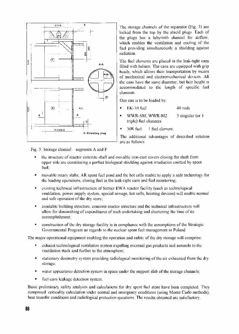
©A-A
®
0114/4,51- Shielding plug
The storage channels of the separator (Fig. 3) arelocked from the top by the shield plugs. Each ofthe plugs has a labyrinth channel for airflow,which enables the ventilation and cooling of thefuel providing simultaneously a shielding againstradiation.
The fuel elements are placed in the leak-tight cansfilled with helium. The cans are equipped with gripheads, which allows their transportation by meansof mechanical and electromechanical devices. Allthe cans have the same diameter, but heir height isaccommodated to the length of specific fuelelements.
One can is to be loaded by:
• EK-10 fuel
• WWR-SM, WWR-M2triple) fuel elements
• MR fuel: 1 fuel element.
40 rods
3 singular (or 1
The additional advantages of described solutionare as follows:
Fig. 3. Storage channel - segments A and F
• the structure of reactor concrete shaft and movable iron-cast covers closing the shaft fromupper side are constituting a perfect biological shielding against irradiation emitted by spentfuel;
• movable rotary slabs, AR spent fuel pond and the hot cells enable to apply a safe technology forthe loading operations, closing fuel in the leak-tight cans and fuel monitoring;
• existing technical infrastructure of former EWA reactor facility (such as technologicalventilation, power supply system, special sewage, hot cells, hoisting devices) will enable normaland safe operation of the dry store;
• available building structure, concrete reactor structure and the technical infrastructure willallow for diminishing of expenditures of such undertaking and shortening the time of itsaccomplishment;
• construction of the dry storage facility is in compliance with the assumptions of the StrategicGovernmental Program as regards to the nuclear spent fuel management in Poland.
The major operational equipment enabling the operation and safety of the dry storage will comprise:
• exhaust technological ventilation system expelling eventual gas products and aerosols to theventilation stack and further to the atmosphere;
• stationary dosimetry system providing radiological monitoring of the air exhausted from the drystorage;
• water appearance detection system in space under the support slab of the storage channels;
• fuel cans leakage detection system.
Basic preliminary safety analyses and calculations for dry spent fuel store have been completed. Theycomprised, criticality calculation under normal and emergency conditions (using Monte Carlo methods),heat transfer conditions and radiological protection questions. The results obtained are satisfactory.
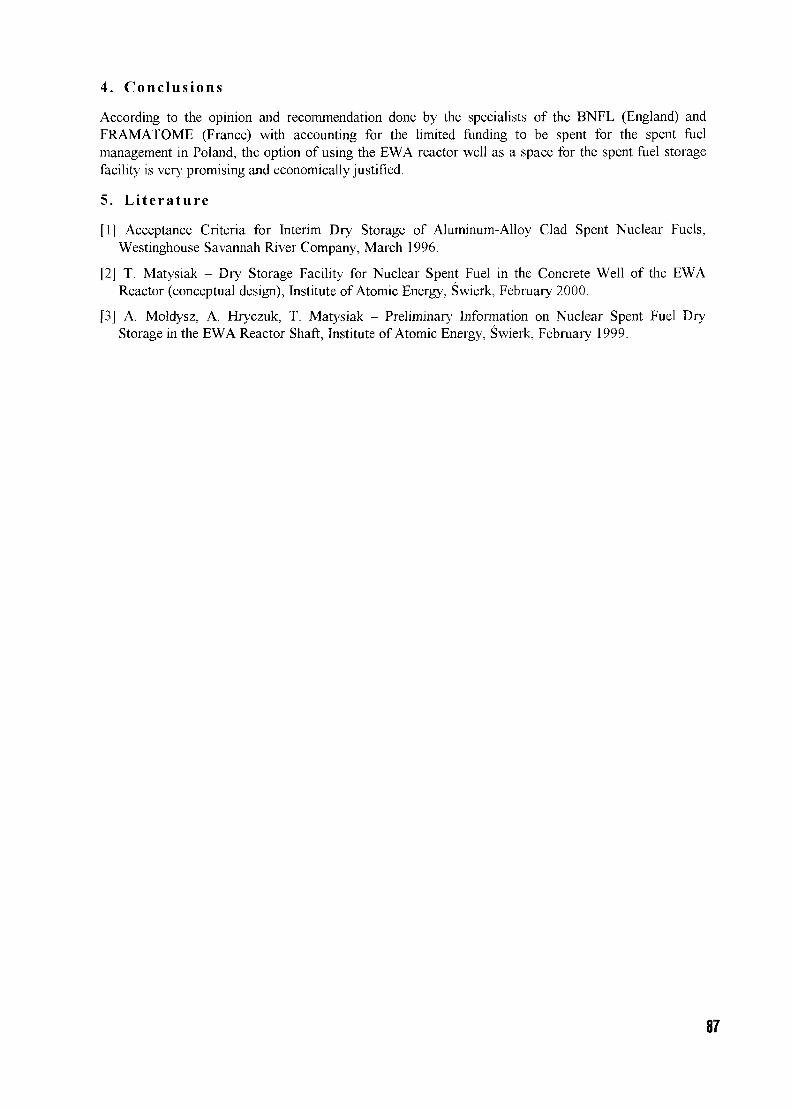
4. Conclusions
According to the opinion and recommendation done by the specialists of the BNFL (England) andFRAMATOME (France) with accounting for the limited funding to be spent for the spent fuelmanagement in Poland, the option of using the EWA reactor well as a space for the spent fuel storagefacility is very promising and economically justified.
5. Literature
[1] Acceptance Criteria for Interim Dry Storage of Aluminum-Alloy Clad Spent Nuclear Fuels,Westinghouse Savannah River Company, March 1996.
[2] T. Matysiak - Dry Storage Facility for Nuclear Spent Fuel in the Concrete Well of the EWAReactor (conceptual design), Institute of Atomic Energy, Swierk, February 2000.
[3] A. Moldysz, A. Hryczuk, T. Matysiak - Preliminary Information on Nuclear Spent Fuel DryStorage in the EWA Reactor Shaft, Institute of Atomic Energy, Swierk, February 1999.
87
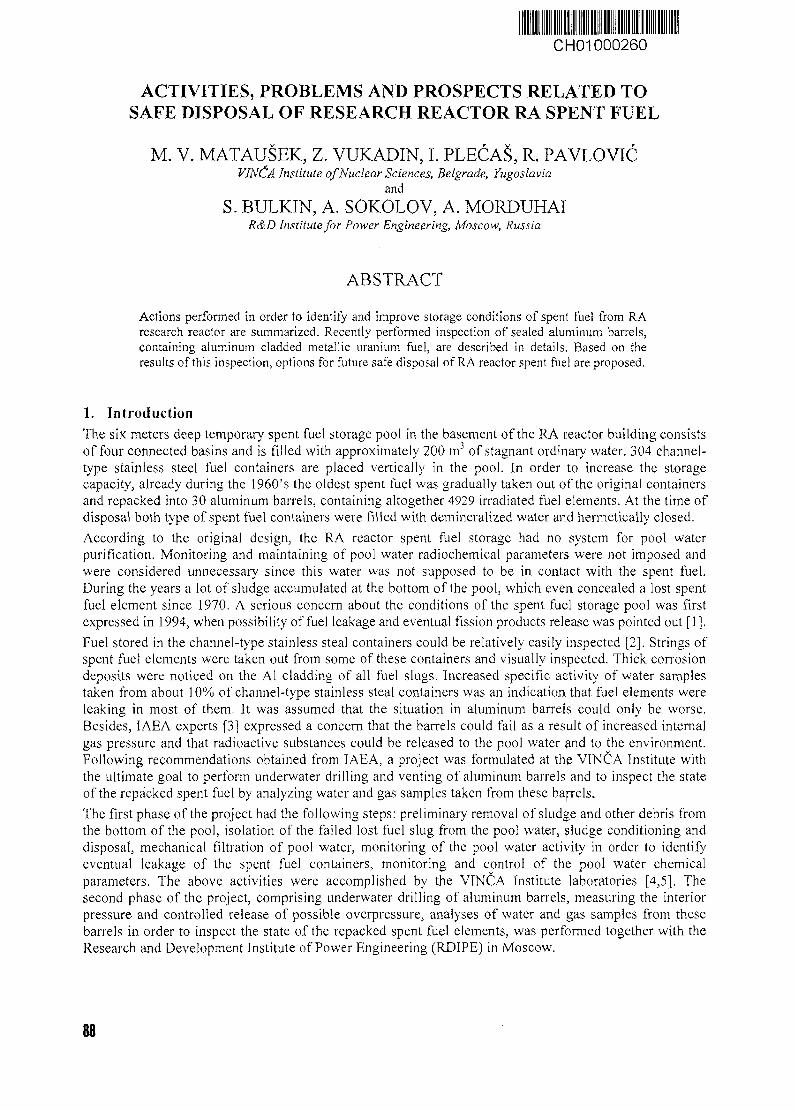
CH01000260
ACTIVITIES, PROBLEMS AND PROSPECTS RELATED TOSAFE DISPOSAL OF RESEARCH REACTOR RA SPENT FUEL
M. V. MATAUSEK, Z. VUKADIN, I. PLECAS, R. PAVLOVICVINCA Institute of Nuclear Sciences, Belgrade, Yugoslavia
and
S. BULKTN, A. SOKOLOV, A. MORDUHAIR&D Institute for Power Engineering, Moscow, Russia
ABSTRACT
Actions performed in order to identify and improve storage conditions of spent fuel from RAresearch reactor are summarized. Recently performed inspection of sealed aluminum barrels,containing aluminum cladded metallic uranium fuel, are described in details. Based on theresults of this inspection, options for future safe disposal of RA reactor spent fuel are proposed.
1. IntroductionThe six meters deep temporary spent fuel storage pool in the basement of the RA reactor building consistsof four connected basins and is filled with approximately 200 m3 of stagnant ordinary water. 304 channel-type stainless steel fuel containers are placed vertically in the pool. In order to increase the storagecapacity, already during the 1960's the oldest spent fuel was gradually taken out of the original containersand repacked into 30 aluminum barrels, containing altogether 4929 irradiated fuel elements. At the time ofdisposal both type of spent fuel containers were filled with demineralized water and hermetically closed.
According to the original design, the RA reactor spent fuel storage had no system for pool waterpurification. Monitoring and maintaining of pool water radiochemical parameters were not imposed andwere considered unnecessary since this water was not supposed to be in contact with the spent fuel.During the years a lot of sludge accumulated at the bottom of the pool, which even concealed a lost spentfuel element since 1970. A serious concern about the conditions of the spent fuel storage pool was firstexpressed in 1994, when possibility of fuel leakage and eventual fission products release was pointed out [1].
Fuel stored in the channel-type stainless steal containers could be relatively easily inspected [2]. Strings ofspent fue! elements were taken out from some of these containers and visually inspected. Thick corrosiondeposits were noticed on the Al cladding of all fuel slugs. Increased specific activity of water samplestaken from about 10% of channel-type stainless steal containers was an indication that fuel elements wereleaking in most of them. It was assumed that the situation in aluminum barrels could only be worse.Besides, IAEA experts [3] expressed a concern that the barrels could fail as a result of increased internalgas pressure and that radioactive substances could be released to the pool water and to the environment.Following recommendations obtained from IAEA, a project was formulated at the VINCA Institute withthe ultimate goal to perform underwater drilling and venting of aluminum barrels and to inspect the stateof the repacked spent fuel by analyzing water and gas samples taken from these barrels.
The first phase of the project had the following steps: preliminary removal of sludge and other debris fromthe bottom of the pool, isolation of the failed lost fuel slug from the pool water, sludge conditioning anddisposal, mechanical filtration of pool water, monitoring of the pool water activity in order to identifyeventual leakage of the spent fuel containers, monitoring and control of the pool water chemicalparameters. The above activities were accomplished by the VINCA Institute laboratories [4,5], Thesecond phase of the project, comprising underwater drilling of aluminum barrels, measuring the interiorpressure and controlled release of possible overpressure, analyses of water and gas samples from thesebarrels in order to inspect the state of the repacked spent fuel elements, was performed together with theResearch and Development Institute of Power Engineering (RDIPE) in Moscow.
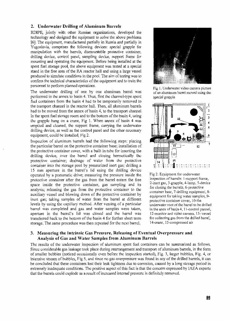
2. Underwater Drilling of Aluminum BarrelsRDIPB, jointly with other Russian organizations, developed thetechnology and designed the equipment to solve the above problems[6]. The equipment, manufactured partially in Russia and partially inYugoslavia, comprises the following devices: special grapple formanipulation with the barrels, dismountable protective container,drilling device, control panel, sampling device, support frame formounting and operating the equipment. Before being installed at thespent fuel storage pool, the above equipment was tested at a specialstand in the free area of the RA reactor hall and using a large vesselproduced to simulate conditions in the pool. The aim of testing was toconfirm the technical characteristics of the equipment and to train thepersonnel to perform planned operations.
The underwater drilling of one by one aluminum barrel wasperformed in the annex to basin 4. Thus, first the channel-type spentfuel containers from the basin 4 had to be temporarily removed tothe transport channel in the reactor hall. Then, all aluminum barrelshad to be moved from the annex of basin 4, to the transport channelin the spent fuel storage room and to the bottom of the basin 4, usingthe grapple hang on a crane, Fig 1. When annex of basin 4 wasemptied and cleaned, the support frame, carrying the underwaterdrilling device, as well as the control panel and the other necessaryequipment, could be installed, Fig 2.
Inspection of aluminum barrels had the following steps: placingthe particular barrel on the protective container base; installation ofthe protective container cover, with a built in tube for inserting thedrilling device, over the barrel and closing hermetically theprotective container; drainage of water from the protectivecontainer into the storage pool by pressurized inert gas; drilling a15 mm aperture in the barrel's lid using the drilling deviceoperated by a pneumatic drive; measuring the pressure inside theprotective container after the gas from the barrel enters the freespace inside the protective container, gas sampling and itsanalysis; releasing the gas from the protective container to theauxiliary vessel and blowing down of the protective container byinert gas; taking samples of water from the barrel at differentlevels by using the capillary method. After venting of a particularbarrel was completed and gas and water samples were taken,aperture in the barrel's lid was closed and the barrel wastransferred back to the bottom of the basin 4 for further short termstorage. The same procedure was then repeated for the next barrel.
3.
Fig 1. Underwater video camera pictureof an aluminum barrel moved using thespecial grapple
Fig 2. Equipment for underwaterinspection of barrels: 1-support frame,2-inert gas, 3-grapple, 4-lamp, 5-devicefor closing the barrels, 6-protectivecontainer base, 7-drilling equipment, 8-equipment for taking water samples, 9-protective container cover, 10-theunderwater root of the barrel to be drilledin the anex of basin 4, 11-control pannel,12-monitor and video camera, 13- vesselfor collecting gas from the drilled barrel,14-crane, 15-compressed air
Measuring the Intrinsic Gas Pressure, Releasing of Eventual Overpressure andAnalysis of Gas and Water Samples from Aluminum Barrels
The results of the underwater inspection of aluminum spent fuel containers can be summarized as follows.Since considerable gas leakage took place during rearrangement and transport of aluminum barrels, in the formof smaller bubbles (noticed occasionally even before the inspection started), Fig. 3, larger bubbles, Fig. 4, orintensive stream of bubbles, Fig 5, and since no gas overpressure was found in any of the drilled barrels, it canbe concluded that these containers lost their leak tightness due to corrosion, caused by a long storage period inextremely inadequate conditions. The positive aspect of this fact is that the concern expressed by IAEA expertsthat the barrels could explode as a result of increased internal pressure is definitely removed.
89
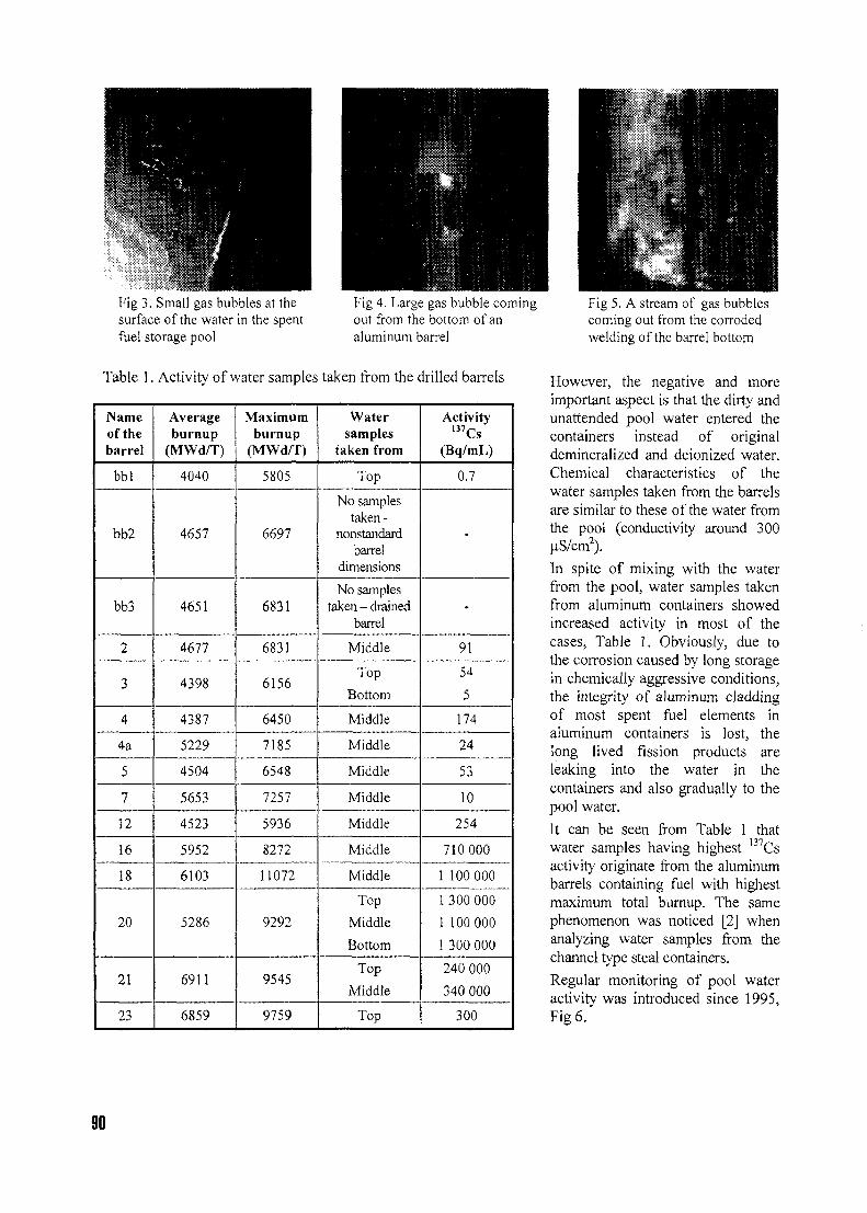
.*••Fig 3. Small gas bubbles at thesurface of the water in the spentfuel storage pool
Fig 4. LargL- \i-.\~ xibble comingout from the bottom of analuminum barrel
Table 1. Activity of water samples taken from the drilled barrels
Nameof thebarrel
bbl
bb2
bb3
2
3
4
4a
5
7
12
16
18
20
21
23
Averageburnup
(MWd/T)
4040
4657
4651
4677
4398
4387
5229
4504
5653
4523
5952
6103
5286
6911
6859
Maximumburnup
(MWd/T)
5805
6697
6831
6831
6156
6450
7185
6548
7257
5936
8272
11072
9292
9545
9759
Watersamples
taken from
Top
No samplestaken-
nonstandardbarrel
dimensions
No samplestaken - drained
barrel
Middle
Top
Bottom
Middle
Middle
Middle
Middle
Middle
Middle
Middle
Top
Middle
Bottom
Top
Middle
Top
Activity137Cs
(Bq/mL)
0.7
-
-
91
54
5
174
24
53
10
254
710 000
1 100 000
1 300 000
1 100 000
1 300 000
240 000
340 000
300
Fig 5. A stream of gas bubblescoming out from the corrodedwelding of the barrel bottom
However, the negative and moreimportant aspect is that the dirty andunattended pool water entered thecontainers instead of originaldemineralized and deionized water.Chemical characteristics of thewater samples taken from the barrelsare similar to these of the water fromthe pool (conductivity around 300uS/cm2).
In spite of mixing with the waterfrom the pool, water samples takenfrom aluminum containers showedincreased activity in most of thecases, Table 1. Obviously, due tothe corrosion caused by long storagein chemically aggressive conditions,the integrity of aluminum claddingof most spent fuel elements inaluminum containers is lost, thelong lived fission products areleaking into the water in thecontainers and also gradually to thepool water.
It can be seen from Table 1 thatwater samples having highest 137Csactivity originate from the aluminumbarrels containing fuel with highestmaximum total burnup. The samephenomenon was noticed [2] whenanalyzing water samples from thechannel type steal containers.
Regular monitoring of pool wateractivity was introduced since 1995,Fig 6.
90
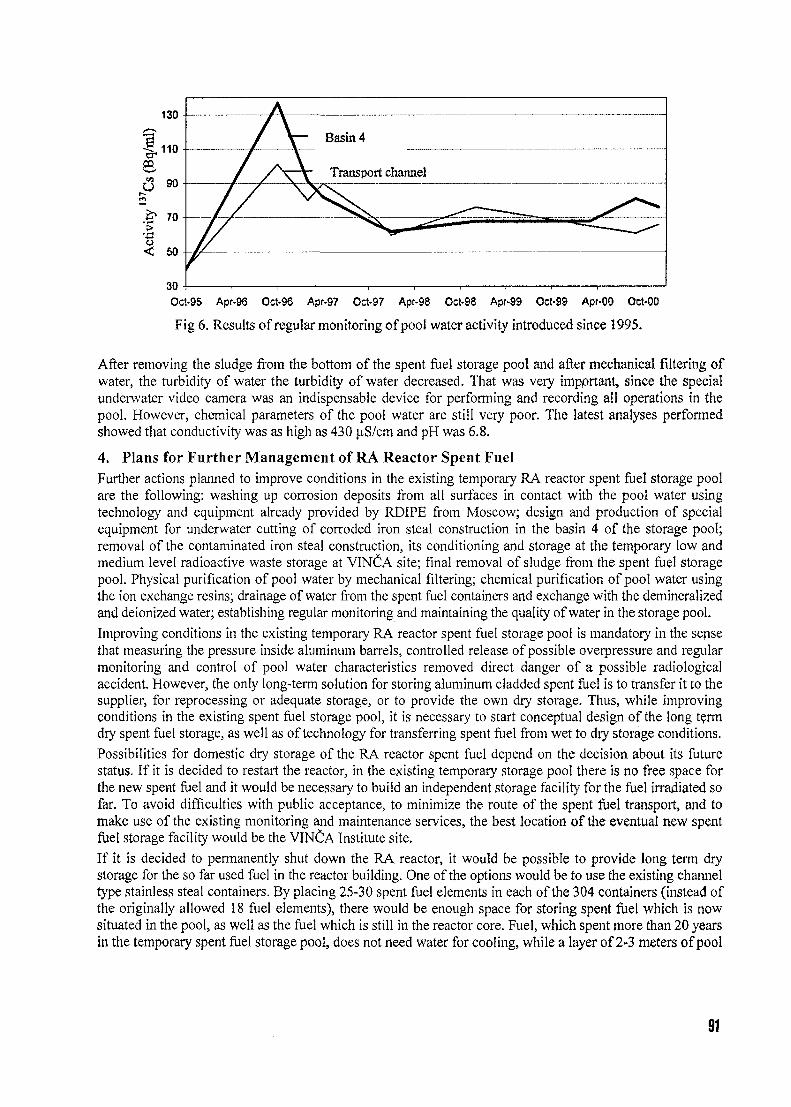
Oct-95 Apr-96 Oct-96 Apr-97 Oct-97 Apr-98 Oct-98 Apr-99 Oct-99 Apr-00 Oct-00
Fig 6. Results of regular monitoring of pool water activity introduced since 1995.
After removing the sludge from the bottom of the spent fuel storage pool and after mechanical filtering ofwater, the turbidity of water the turbidity of water decreased. That was very impprtant, since the specialunderwater video camera was an indispensable device for performing and recording all operations in thepool. However, chemical parameters of the pool water are still very poor. The latest analyses performedshowed that conductivity was as high as 430 jiS/cm and pH was 6.8.
4. Plans for Further Management of RA Reactor Spent FuelFurther actions planned to improve conditions in the existing temporary RA reactor spent fuel storage poolare the following: washing up corrosion deposits from all surfaces in contact with the pool water usingtechnology and equipment already provided by RDIPE from Moscow; design and production of specialequipment for underwater cutting of corroded iron steal construction in the basin 4 of the storage pool;removal of the contaminated iron steal construction, its conditioning and storage at the temporary low andmedium level radioactive waste storage at VIN^A site; final removal of sludge from the spent fuel storagepool. Physical purification of pool water by mechanical filtering; chemical purification of pool water usingthe ion exchange resins; drainage of water from the spent fuel containers and exchange with the demineralizedand deionized water; establishing regular monitoring and maintaining the quality of water in the storage pool.
Improving conditions in the existing temporary RA reactor spent fuel storage pool is mandatory in the sensethat measuring the pressure inside aluminum barrels, controlled release of possible overpressure and regularmonitoring and control of pool water characteristics removed direct danger of a possible radiologicalaccident. However, the only long-term solution for storing aluminum cladded spent fuel is to transfer it to thesupplier, for reprocessing or adequate storage, or to provide the own dry storage. Thus, while improvingconditions in the existing spent fuel storage pool, it is necessary to start conceptual design of the long termdry spent foe! storage, as well as of technology for transferring spent fuel from wet to dry storage conditions.
Possibilities for domestic dry storage of the RA reactor spent fuel depend on the decision about its futurestatus. If it is decided to restart the reactor, in the existing temporary storage pool there is no free space forthe new spent fuel and it would be necessary to build an independent storage facility for the fuel irradiated sofar. To avoid difficulties with public acceptance, to minimize the route of the spent fuel transport, and tomake use of the existing monitoring and maintenance services, the best location of the eventual new spentfuel storage facility would be the VINCA Institute site.
If it is decided to permanently shut down the RA reactor, it would be possible to provide long term drystorage for the so far used fuel in the reactor building. One of the options would be to use the existing channeltype stainless steal containers. By placing 25-30 spent fuel elements in each of the 304 containers (instead ofthe originally allowed 18 fuel elements), there would be enough space for storing spent fuel which is nowsituated in the pool, as well as the fuel which is still in the reactor core. Fuel, which spent more than 20 yearsin the temporary spent fuel storage pool, does not need water for cooling, while a layer of 2-3 meters of pool
91
water above its upper surface would provide sufficient radiological protection. The second possibility wouldbe to use the emptied reactor, while the concrete reactor shield would provide radiological protection.
Both options may look attractive at the first sight. It should be noted, however, that making a new building forthe spent fuel storage would not be the most difficult, nor the most expensive part of the dry storage project.Besides, adaptation and refurbishing of the existing pool, or of the reactor body, would also require aconsiderable effort. On the other hand, if the RA reactor is decommissioned, by removing the spent fuel fromits location, the reactor building could be used for other purposes.
Most sophisticated and most expensive operations would be taking out the spent fuel from their presentcontainers, inspection of this fuel, separating the leaking fuel from the fuel, which does not leak, providingadditional containers for the leaking fuel. These operations have to be performed in the same way both inthe case that a new storage facility is to be built or in the case that RA reactor building is used forproviding dry spent fuel storage. Since VINCA Institute has no experience in the above activities, theproject should be realized in cooperation with foreign partners. RJDIPE has already elaborated andproposed some parts of the necessary technology [7],
5. Conclusions
Activities described in the present paper, results presented and conclusion drown represent finalization ofthe project, initiated several years ago with an aim to get information about the state of the spent fuel, toimprove conditions in the existing storage pool in order to minimize further corrosion of the spent fuel andthe spent fuel containers, as well as to propose solutions for long term, i.e. final storage of spent fuel. It iswell known that the only long-term solution for the aluminum cladded spent fuel is to transfer it back tothe supplier, for reprocessing or adequate storage, or to build the own dry storage facility.
The following steps would be necessary for providing a domestic dry storage facility for the RA reactorspent fuel: making decision about the future status of the RA reactor; making decision about the mostadequate solution for safe disposal of the spent fuel; providing or building a new dry storage facility;transfer of the research reactor RA spent fuel from the existing wet storage conditions to the new drystorage conditions; adopting regulations, procedures and an adequate organization for long-termsupervision, monitoring and control of spent fuel storage.
6. References
[1] M. V. MatauSek, "Research Reactor RA at VINCA Institute of Nuclear Sciences", NUKLEARNATEHNOLOGIJA Journal, Vol. 10, 2(1995)3.
[2] M. V. Matausek, Z. Vukadin, R. Pavlovic, N. Marinkovic, "Current Activities on Improving StorageConditions of the Research Reactor RA Spent Fuel", Transactions, 1st International Topical Meeting onResearch Reactor Fuel Management, Bruges, Belgium, 1997.
[3] I. Ritchie, D. Litai, Travel Reports, IAEA", November 1995, October 1996, February 1997.
[4] M. V. Matausek, M. Kopecni, Z. Vukadin, I. Plecag, R. Pavlovic, 0 . §oti6, N. Marinkovic, "CurrentActivities on Improving Storage Condition of the Research Reactor RA Spent Fuel - Part II", Transactions,2nd International Topical meeting on Research Reactor Fuel Management, Bruges, Belgium, 1998.
[5] M. V. MatauSek, N. Marinkovic, "Criticality Safety Studies for Safe Disposal of Research ReactorSpent Fuel", Proc. Topical Meeting on Criticality Safety, Chellan (WA USA), 1997.
[6] V. G. Aden, S. YU. Bulkin, A. V. Sokolov, M. V. MatauSek, Z. Vukadin, "Inspection of State of SpentFuel Elements Stored in RA Reactor Spent Fuel Storage Pool", Transactions, 3rd International TopicalMeeting on Research Reactor Fuel Management, Bruges, Belgium, 1999.
[7] V. G. Aden, S. Yu. Bulkin, A. V. Sokolov, M. V. Matausek, Z. Vukadin, "Options for theManagement of Spent Fuel from RA Reactor", Transactions, 4th International Topical Meeting onResearch Reactor Fuel Management, Colmar, France, 2000.
92
CH01000261
EVALUATION OF ALUMINIUM-CLAD SPENT FUEL CORROSION INARGENTINE BASINS.
R. HADDAD, A. N. LOBERSE, C. J. SEMINO and R. GUASPDiv. Corrosion, Unidad de Actividad Materiales
Comision National de Energia Atomica, Av. Gral Paz 1499, (1650) San Martin (Buenos Aires) - Argentina
ABSTRACT
An IAEA sponsored Coordinated Research Program was extended to study corrosioneffects in several sites. Racks containing Aluminium samples were placed in differentpositions of each basin and periodic sampling of all the waters was performed to conductchemical analysis. Different forms of corrosion have been encountered during theprogramme. In general, the degree of degradation is inversely proportional to the purity ofthe water. Maximum pit depths after 2 years of exposure are in the range of 100-200 urn.However, sediments deposited on the coupon surfaces seem to be responsible for thedeveloping of large pits (1-2 mm in diameter). In many cases, what appears to be iron oxideparticles were found, originated by the corrosion of carbon steel components presentelsewhere in the basin. These results correlate with observations made on the fuel itself,during exhaustive visual inspection.
1. Introduction
Aluminium clad MTR spent fuel is usually stored underwater to shield the gamma emissions. Due toits good corrosion resistance, corrosion problems should not be expected in the few years needed toallow for a fair reduction in the activity levels, provided the water quality is maintained intospecifications values for nuclear reactors: conductivity lower than 1-3 uS/cm, pH in the range of 5 to 7and chlorides in the parts per billion range [1]. However, aqueous corrosion starts to be a concernwhen storage time becomes decades. In relation to this, the International Atomic Energy Agency(IAEA) established an international Program on "Corrosion of Research Reactor Aluminium-CladSpent Fuel in Water"; as part of it, an extensive spent fuel corrosion monitoring program has beenconducted in Argentine research reactors spent fuel storage facilities from years 1996 to 2000. TheIAEA sponsored Coordinated Research Program was extended to study corrosion effects in severaldifferent sites: the Central Storage Facility and the RA3 reactor Decay Pool, both located at the EzeizaAtomic Centre, the RA6 Reactor Pool and the RA6 Decay Pool, at the Bariloche Atomic Centre.
2. Experimental Set-up
2.1. SELECTED SITES
MTR-type fuel elements have a residence time of about 2 years in the RA3 reactor; after that, they aremoved to a decay pool (RA3 DP), an open stainless steel pool, to cool down enough before they aretransferred to another basin, the Central Storage Facility (CSF); although less than a year is supposedto be enough time in the DP, the fuel elements may stay there for periods of up to 10 years. In the CSFthe fuel is placed inside buried steel tubes some 3 meters long; lines of 16 of these tubes connected toshare the water are arranged to hold several hundreds of fuel elements (two elements can be placedinto each tube, one on top of the other). One channel at the extreme of each line is left empty, to beused as a control channel, for water level, etc. Storage in this basin began in the late sixties. The RA6reactor started to work in 1982; due to its low power some of the fuel elements have not been replacedand have stayed for almost 20 years inside the reactor pool (RA6 RP); some others have beendeposited in an adjacent decay pool (RA6 DP).
93
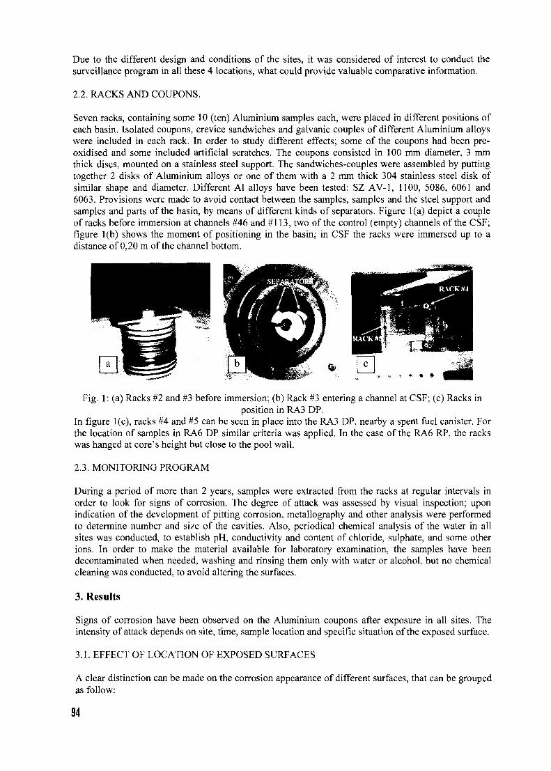
Due to the different design and conditions of the sites, it was considered of interest to conduct thesurveillance program in all these 4 locations, what could provide valuable comparative information.
2.2. RACKS AND COUPONS.
Seven racks, containing some 10 (ten) Aluminium samples each, were placed in different positions ofeach basin. Isolated coupons, crevice sandwiches and galvanic couples of different Aluminium alloyswere included in each rack. In order to study different effects; some of the coupons had been pre-oxidised and some included artificial scratches. The coupons consisted in 100 mm diameter, 3 mmthick discs, mounted on a stainless steel support. The sandwiches-couples were assembled by puttingtogether 2 disks of Aluminium alloys or one of them with a 2 mm thick 304 stainless steel disk ofsimilar shape and diameter. Different Al alloys have been tested: SZ AV-1, 1100, 5086, 6061 and6063. Provisions were made to avoid contact between the samples, samples and the steel support andsamples and parts of the basin, by means of different kinds of separators. Figure l(a) depict a coupleof racks before immersion at channels #46 and #113, two of the control (empty) channels of the CSF;figure l(b) shows the moment of positioning in the basin; in CSF the racks were immersed up to adistance of 0,20 m of the channel bottom.
Fig. 1: (a) Racks #2 and #3 before immersion; (b) Rack #3 entering a channel at CSF; (c) Racks inposition in RA3 DP.
In figure l(c), racks #4 and #5 can be seen in place into the RA3 DP, nearby a spent fuel canister. Forthe location of samples in RA6 DP similar criteria was applied. In the case of the RA6 RP, the rackswas hanged at core's height but close to the pool wall.
2.3. MONITORING PROGRAM
During a period of more than 2 years, samples were extracted from the racks at regular intervals inorder to look for signs of corrosion. The degree of attack was assessed by visual inspection; uponindication of the development of pitting corrosion, metallography and other analysis were performedto determine number and size of the cavities. Also, periodical chemical analysis of the water in allsites was conducted, to establish pH, conductivity and content of chloride, sulphate, and some otherions. In order to make the material available for laboratory examination, the samples have beendecontaminated when needed, washing and rinsing them only with water or alcohol, but no chemicalcleaning was conducted, to avoid altering the surfaces.
3. Results
Signs of corrosion have been observed on the Aluminium coupons after exposure in all sites. Theintensity of attack depends on site, time, sample location and specific situation of the exposed surface.
3.1. EFFECT OF LOCATION OF EXPOSED SURFACES
A clear distinction can be made on the corrosion appearance of different surfaces, that can be groupedas follow:
94
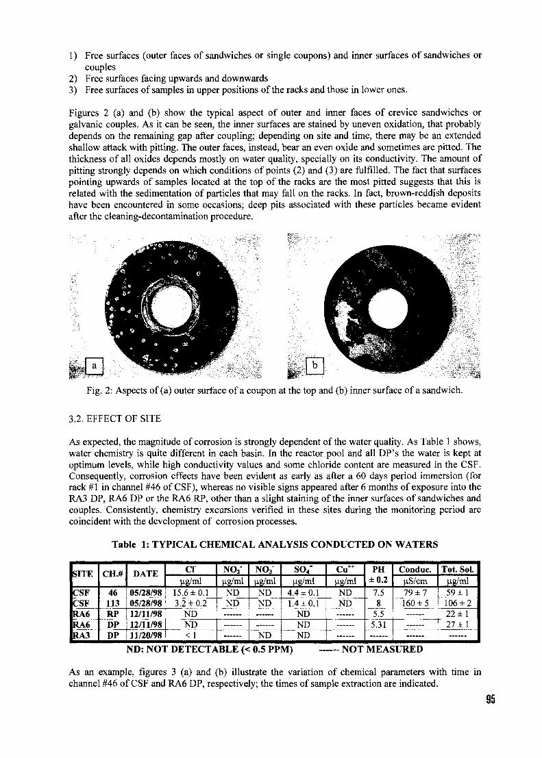
1) Free surfaces (outer faces of sandwiches or single coupons) and inner surfaces of sandwiches orcouples
2) Free surfaces facing upwards and downwards3) Free surfaces of samples in upper positions of the racks and those in lower ones.
Figures 2 (a) and (b) show the typical aspect of outer and inner faces of crevice sandwiches orgalvanic couples. As it can be seen, the inner surfaces are stained by uneven oxidation, that probablydepends on the remaining gap after coupling; depending on site and time, there may be an extendedshallow attack with pitting. The outer faces, instead, bear an even oxide and sometimes are pitted. Thethickness of all oxides depends mostly on water quality, specially on its conductivity. The amount ofpitting strongly depends on which conditions of points (2) and (3) are fulfilled. The fact that surfacespointing upwards of samples located at the top of the racks are the most pitted suggests that this isrelated with the sedimentation of particles that may fall on the racks. In fact, brown-reddish depositshave been encountered in some occasions; deep pits associated with these particles became evidentafter the cleaning-decontamination procedure.
Fig. 2: Aspects of (a) outer surface of a coupon at the top and (b) inner surface of a sandwich.
3.2. EFFECT OF SITE
As expected, the magnitude of corrosion is strongly dependent of the water quality. As Table 1 shows,water chemistry is quite different in each basin. In the reactor pool and all DP's the water is kept atoptimum levels, while high conductivity values and some chloride content are measured in the CSF.Consequently, corrosion effects have been evident as early as after a 60 days period immersion (forrack #1 in channel #46 of CSF), whereas no visible signs appeared after 6 months of exposure into theRA3 DP, RA6 DP or the RA6 RP, other than a slight staining of the inner surfaces of sandwiches andcouples. Consistently, chemistry excursions verified in these sites during the monitoring period arecoincident with the development of corrosion processes.
Table 1: TYPICAL CHEMICAL ANALYSIS CONDUCTED ON WATERS
SITE
CSFCSFRA6RA6RA3
CH.#
46113RPDPDP
DATE
05/28/9805/28/9812/11/9812/11/9811/20/98
ClHg/ml
15.6 ±0.13.2 ±0.2
NDND<1
NO2
Hg/mlNDND
NO3
Hg/mlNDND
ND
SO4=
u-g/ml4.4 ±0.11.4±0.1
NDNDND
Hg/mlNDND
PH±0.2
7.58
5.55.31
Conduc.US/cm79 ±7160 ±5
Tot. Sol.ug/ml59 ±1106 ± 222 ±127 ±1
ND: NOT DETECTABLE (< 0.5 PPM) — NOT MEASURED
As an example, figures 3 (a) and (b) illustrate the variation of chemical parameters with time inchannel #46 of CSF and RA6 DP, respectively; the times of sample extraction are indicated.
95
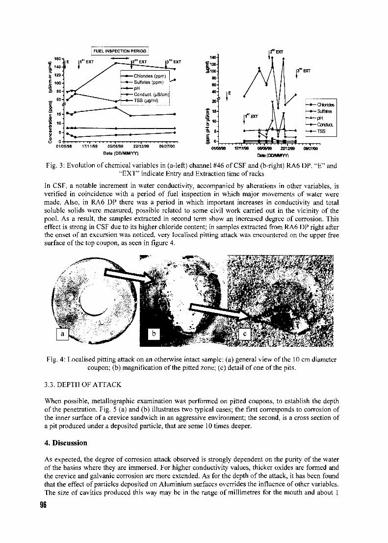
FUEL INSPECTION PERIOD
160-
g 120-
I 100-
I_ 60-
H
|3R°EXT
Chlorides (ppm)
Sulfates (ppm)
pH
Conduct
TSS (ug/ml)
01/05/98 17/11/98 OS/06/99 22/12/99
Date (DD/MM/YY)
09/07/00 17/11/98 ososro 22*1299
DatofDONMYY)
09/07M)
Fig. 3: Evolution of chemical variables in (a-left) channel #46 of CSF and (b-right) RA6 DP. "E" and"EXT" indicate Entry and Extraction time of racks
In CSF, a notable increment in water conductivity, accompanied by alterations in other variables, isverified in coincidence with a period of fuel inspection in which major movements of water weremade. Also, in RA6 DP there was a period in which important increases in conductivity and totalsoluble solids were measured, possible related to some civil work carried out in the vicinity of thepool. As a result, the samples extracted in second term show an increased degree of corrosion. Thiseffect is strong in CSF due to its higher chloride content; in samples extracted from RA6 DP right afterthe onset of an excursion was noticed, very localised pitting attack was encountered on the upper freesurface of the top coupon, as seen in figure 4.
Fig. 4: Localised pitting attack on an otherwise intact sample: (a) general view of the 10 cm diametercoupon; (b) magnification of the pitted zone; (c) detail of one of the pits.
3.3. DEPTH OF ATTACK
When possible, metal lographic examination was performed on pitted coupons, to establish the depthof the penetration. Fig. 5 (a) and (b) illustrates two typical cases; the first corresponds to corrosion ofthe inner surface of a crevice sandwich in an aggressive environment; the second, is a cross section ofa pit produced under a deposited particle, that are some 10 times deeper.
4. Discussion
As expected, the degree of corrosion attack observed is strongly dependent on the purity of the waterof the basins where they are immersed. For higher conductivity values, thicker oxides are formed andthe crevice and galvanic corrosion are more extended. As for the depth of the attack, it has been foundthat the effect of particles deposited on Aluminium surfaces overrides the influence of other variables.The size of cavities produced this way may be in the range of millimetres for the mouth and about 1
96
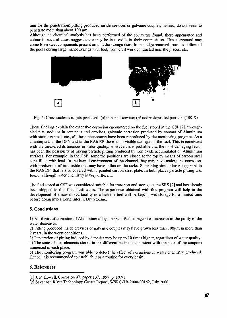
mm for the penetration; pitting produced inside crevices or galvanic couples, instead, do not seem topenetrate more than about 100 um.Although no chemical analysis has been performed of the sediments found, there appearance andcolour in several cases suggest there may be iron oxide in their composition. This compound maycome from steel components present around the storage sites, from sludge removed from the bottom ofthe pools during large manoeuvrings with fuel, from civil work conducted near the places, etc.
Fig. 5: Cross sections of pits produced: (a) inside of crevice; (b) under deposited particle. (100 X)
These findings explain the extensive corrosion encountered on the fuel stored in the CSF [2]: through-clad pits, nodules in scratches and crevices, galvanic corrosion produced by contact of Aluminiumwith stainless steel, etc., all these phenomena have been reproduced by the monitoring program. As acounterpart, in the DP's and in the RA6 RP there is no visible damage on the fuel. This is consistentwith the measured differences in water quality. However, it is probable that the most damaging factorhas been the possibility of having particle pitting produced by iron oxide accumulated on Aluminiumsurfaces. For example, in the CSF, some the positions are closed at the top by means of carbon steelcaps filled with lead. In the humid environment of the channel they may have undergone corrosion,with production of iron oxide that may have fallen on the racks. Something similar have happened inthe RA6 DP, that is also covered with a painted carbon steel plate. In both places particle pitting wasfound, although water chemistry is very different.
The fuel stored at CSF was considered suitable for transport and storage at the SRS [2] and has alreadybeen shipped to this final destination. The experience obtained with this program will help in thedevelopment of a new mixed facility in which the fuel will be kept in wet storage for a limited timebefore going into a Long Interim Dry Storage.
5. Conclusions
1) All forms of corrosion of Aluminium alloys in spent fuel storage sites increases as the purity of thewater decreases.2) Pitting produced inside crevices or galvanic couples may have grown less than lOOum in more than2 years, in the worst conditions.3) Penetration of pitting induced by deposits may be up to 10 times higher, regardless of water quality.4) The state of fuel elements stored in the different basins is consistent with the state of the couponsimmersed in each place.5) The monitoring program was able to detect the effect of excursions in water chemistry produced.Hence, it is recommended to establish it as a routine for every basin.
6. References
[1] J. P. Howell, Corrosion 97, paper 107, 1997, p. 107/1.[2] Savannah River Technology Center Report, WSRC-TR-2000-00152, July 2000.
97

Session 5
Back-end options and transportation
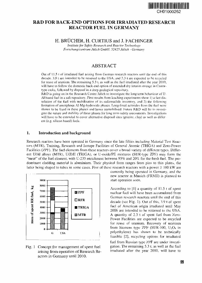
CH01000262
R&D FOR BACK-END OPTIONS FOR IRRADIATED RESEARCHREACTOR FUEL IN GERMANY
H. BRUCHER, H. CURTIUS and J. FACHINGERInstitute for Safety Research and Reactor Technology
Forschungszentrum Jiilich GmbH, 52425 Jiilich - Germany
ABSTRACT
Out of 11.5 t of irradiated fuel arising from German research reactors until the end of thisdecade, 3.9 t are intended to be returned to the USA, and 2.3 t are expected to be recycledfor reuse of uranium. The remaining 5.3 t, as well as the fuel irradiated after the year 2010,will have to follow the domestic back-end option of extended dry interim storage in Castor-type casks, followed by disposal in a deep geological repository.R&D is going on in the Research Centre Julich to investigate the long term behaviour of U-Al based fuel in a salt repository. First results from leaching experiments show 1) a fast dis-solution of the fuel with mobilisation of its radionuclidc inventory, and 2) the followingformation of amorphous Al-Mg-hydroxide phases. Long-lived actinides from the fuel wereshown to be fixed in these phases and hence immobilised. Future R&D will be to investi-gate the nature and stability of these phases for long term safety assessments. Investigationswill have to be extended to cover alternative disposal sites (granite, clay) as well as differ-ent (e.g. silicon based) fuels.
1. Introduction and background
Research reactors have been operated in Germany since the late fifties including Material Test Reac-tors (MTR), Training, Research and Isotope Facilities of General Atomic (TRIGA) and Zero-PowerFacilities (ZPF). The fuel elements from these reactors cover a broad variety of different types. Differ-ent U/Al alloys (MTR), U/ZrH (TRIGA), or U-oxide/PE mixtures (SUR-type ZPF) may form the"meat" of the fuel element, with U-235 enrichment between 93% and 20% for the fresh fuel. The pre-dominant cladding material is aluminium. Their physical form ranges from pins to thin plates, thelatter being shaped to tubes in some cases. Five of these research reactors with a power > 100 kW are
currently being operated in Germany, and thenew reactor at Munich (FRMII) is planned tostart operation soon.
According to [1] a quantity of 11.5 t of spentnuclear fuel will have been accumulated fromGerman research reactors until the end of thisdecade (see Fig. 1). Out of this, 3.9 t of spentfuel of American origin irradiated until May2006 are intended to be returned to the USA.A quantity of 2.3 t of spent fuel from Zero-Power Facilities are expected to be recycledfor reuse of uranium. Recovery of uraniumfrom Siemens type ZPF (SUR-100, U,O8 inpolyethylene) has shown to be technicallyfeasible [2], recycling options for irradiated
fuel from Russian type ZPF are under investi-gation. The remaining 5.3 t, as well as the fuelirradiated after the year 2010, will have to
Fig. 1 Concept for management of spent fuelarising from operation of Research Re-actors in Germany until 2010.
99
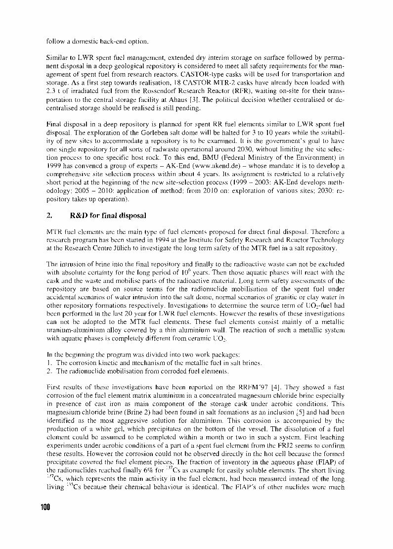
follow a domestic back-end option.
Similar to LWR spent fuel management, extended dry interim storage on surface followed by perma-nent disposal in a deep geological repository is considered to meet all safety requirements for the man-agement of spent fuel from research reactors. CASTOR-type casks will be used for transportation andstorage. As a first step towards realisation, 18 CASTOR MTR-2 casks have already been loaded with2.3 t of irradiated fuel from the Rossendorf Research Reactor (RFR), waiting on-site for their trans-portation to the central storage facility at Ahaus [3]. The political decision whether centralised or de-centralised storage should be realised is still pending.
Final disposal in a deep repository is planned for spent RR fuel elements similar to LWR spent fueldisposal. The exploration of the Gorleben salt dome will be halted for 3 to 10 years while the suitabil-ity of new sites to accommodate a repository is to be examined. It is the government's goal to haveone single repository for all sorts of radwaste operational around 2030, without limiting the site selec-tion process to one specific host rock. To this end, BMU (Federal Ministry of the Environment) in1999 has convened a group of experts - AK-End (www.akend.de) — whose mandate it is to develop acomprehensive site selection process within about 4 years. Its assignment is restricted to a relativelyshort period at the beginning of the new site-selection process (1999 - 2003: AK-End develops meth-odology; 2005 - 2010: application of method; from 2010 on: exploration of various sites; 2030: re-pository takes up operation).
2. R&D for final disposal
MTR fuel elements are the main type of fuel elements proposed for direct final disposal. Therefore aresearch program has been started in 1994 at the Institute for Safety Research and Reactor Technologyat the Research Centre Jiilich to investigate the long term safety of the MTR fuel in a salt repository.
The intrusion of brine into the final repository and finally to the radioactive waste can not be excludedwith absolute certainty for the long period of 10 years. Then those aquatic phases will react with thecask and the waste and mobilise parts of the radioactive material. Long term safety assessments of therepository are based on source terms for the radionuclide mobilisation of the spent fuel underaccidental scenarios of water intrusion into the salt dome, normal scenarios of granitic or clay water inother repository formations respectively. Investigations to determine the source term of UO2-fuel hadbeen performed in the last 20 year for LWR fuel elements. However the results of these investigationscan not be adopted to the MTR fuel elements. These fuel elements consist mainly of a metallicuranium-aluminium alloy covered by a thin aluminium wall. The reaction of such a metallic systemwith aquatic phases is completely different from ceramic UO2.
In the beginning the program was divided into two work packages:1. The corrosion kinetic and mechanism of the metallic fuel in salt brines.2. The radionuclide mobilisation from corroded fuel elements.
First results of these investigations have been reported on the RRFM'97 [4]. They showed a fastcorrosion of the fuel element matrix aluminium in a concentrated magnesium chloride brine especiallyin presence of cast iron as main component of the storage cask under aerobic conditions. Thismagnesium chloride brine (Brine 2) had been found in salt formations as an inclusion [5] and had beenidentified as the most aggressive solution for aluminium. This corrosion is accompanied by theproduction of a white gel, which precipitates on the bottom of the vessel. The dissolution of a fuelelement could be assumed to be completed within a month or two in such a system. First leachingexperiments under aerobic conditions of a part of a spent fuel element from the FRJ2 seems to confirmthese results. However the corrosion could not be observed directly in the hot cell because the formedprecipitate covered the fuel element pieces. The fraction of inventory in the aqueous phase (FIAP) ofthe radionuclides reached finally 6% for B7Cs as example for easily soluble elements. The short livingmCs, which represents the main activity in the fuel element, had been measured instead of the longliving 135Cs because their chemical behaviour is identical. The FIAP's of other nuclides were much
100
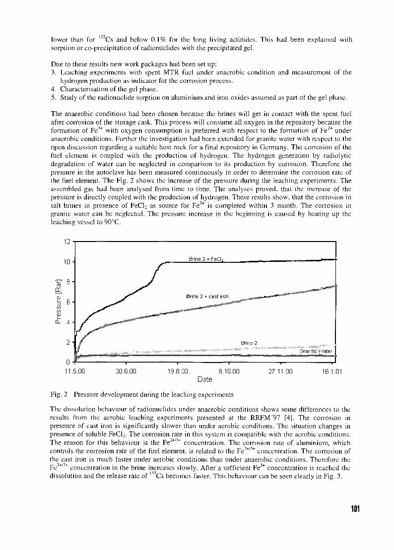
lower than for I37Cs and below 0.1% for the long living actinides. This had been explained withsorption or co-precipitation of radionuclides with the precipitated gel.
Due to these results new work packages had been set up:3. Leaching experiments with spent MTR fuel under anaerobic condition and measurement of the
hydrogen production as indicator for the corrosion process.4. Characterisation of the gel phase.5. Study of the radionuclide sorption on aluminium and iron oxides assumed as part of the gel phase.
The anaerobic conditions had been chosen because the brines will get in contact with the spent fuelafter corrosion of the storage cask. This process will consume all oxygen in the repository because theformation of Fe3+ with oxygen consumption is preferred with respect to the formation of Fe2+ underanaerobic conditions. Further the investigation had been extended for granite water with respect to theopen discussion regarding a suitable host rock for a final repository in Germany. The corrosion of thefuel element is coupled with the production of hydrogen. The hydrogen generation by radiolyticdegradation of water can be neglected in comparison to its production by corrosion. Therefore thepressure in the autoclave has been measured continuously in order to determine the corrosion rate ofthe fuel element. The Fig. 2 shows the increase of the pressure during the leaching experiments. Theassembled gas had been analysed from time to time. The analyses proved, that the increase of thepressure is directly coupled with the production of hydrogen. These results show, that the corrosion insalt brines in presence of FeCl2 as source for Fe2+ is completed within 3 month. The corrosion ingranite water can be neglected. The pressure increase in the beginning is caused by heating up theleaching vessel to 90°C.
11.5.00 30.6.00 19.8.00 8.10.00Date
27.11.00 16.1.01
Fig. 2 Pressure development during the leaching experiments
The dissolution behaviour of radionuclides under anaerobic conditions shows some differences to theresults from the aerobic leaching experiments presented at the RRFM'97 [4], The corrosion inpresence of cast iron is significantly slower than under aerobic conditions. The situation changes inpresence of soluble FeCl2. The corrosion rate in this system is compatible with the aerobic conditions.The reason for this behaviour is the Fe2+/3+ concentration. The corrosion rate of aluminium, whichcontrols the corrosion rate of the fuel element, is related to the Fe2+/3+ concentration. The corrosion ofthe cast iron is much faster under aerobic conditions than under anaerobic conditions. Therefore theFe2+/3+ concentration in the brine increases slowly. After a sufficient Fe2+ concentration is reached thedissolution and the release rate of 137Cs becomes faster. This behaviour can be seen clearly in Fig. 3.
101
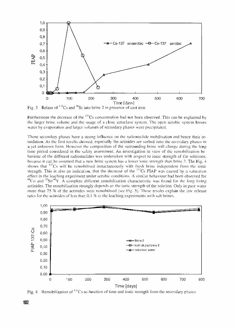
1,0
0 100 200 300 400Time [daysl
Fig. 3 Relase of Ll7Cs and 90Sr into brine 2 in presence of cast iron
500 600 700
Furthermore the decrease of the l37Cs concentration had not been observed. This can be explained bythe larger brine volume and the usage of a close autoclave system. The open aerobic system looseswater by evaporation and larger volumes of secondary phases were precipitated.
Those secondary phases have a strong influence on the radionuclide mobilisation and hence their re-tardation. As the first results showed, especially the actinides are sorbed onto the secondary phases ina yet unknown form. However the composition of the surrounding brine will change during the longtime period considered in the safety assessment. An investigation in view of the remobilization be-haviour of the different radionuclides was undertaken with respect to ionic strength of the solutions,because it can be assumed that a new brine system has a lower ionic strength than brine 2. The Fig. 4shows that Cs will be remobilised instantaneously with fresh brine independent from the ionicstrength. This is also an indication, that the decrease of the ' Cs FIAP was caused by a saturationeffect in the leaching experiment under aerobic conditions. A similar behaviour had been observed for
Co and ; Sr/9 Y. A complete different remobilisation characteristic was found for the long livingactinides. The remobilisation strongly depends on the ionic strength of the solution. Only in pure watermore than 75 % of the actinides were remobilised (see Fig. 5). These results explain the low releaserates for the actinides of less than 0.1 % in the leaching experiments with salt brines.
Oi
r--
100 200 300 400 500
Time [days]
600 700 800
• 137Fig. 4 Remobilization of " Cs as function of time and ionic strength from the secondary phases
102
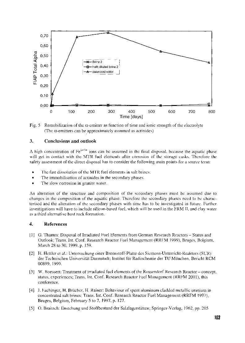
Brine 2 i
halft diluted brine 2
deionised water J
0,00100 200 300 400 500
Time [days]600 700 800
Fig. 5 Remobilization of the a-emitter as function of time and ionic strength of the electrolyte(The a-emitters can be approximately assumed as actinides)
3. Conclusions and outlook
2+/}+A high concentration of Fe " ions can be assumed in the final disposal, because the aquatic phasewill get in contact with the MTR fuel elements after corrosion of the storage casks. Therefore thesafety assessment of the direct disposal has to consider the following main points for a source term:
• The fast dissolution of the MTR fuel elements in salt brines.• The immobilisation of actinides in the secondary phases.• The slow corrosion in granite water.
An alteration of the structure and composition of the secondary phases must be assumed due tochanges in the composition of the aquatic phase. Therefore the secondary phases need to be charac-terised and the alteration of the secondary phases with time has to be investigated in future. Furtherinvestigations will have to include silicon-based fuel, which will be used in the FRM II, and clay wateras a third alternative host rock formation.
4. References
[ 1 ] G. Thamm: Disposal of Irradiated Fuel Elements from German Research Reactors - Status andOutlook; Trans. Int. Conf. Research Reactor Fuel Management (RRFM 1999), Bruges, Belgium,March 28 to 30, 1999, p. 159.
[2] H. Hettler et al.: Untersuchung einer Brennstoff-Platte des Siemens-Unterricht-Reaktors (SUR)der Technischen Universitat Darmstadt; Institut fur Radiochemie der TU Miinchen, Bericht RCM00899,1999.
[3] W. Boessert; Treatment of irradiated fuel elements of the Rossendorf Research Reactor - concept,status, experiences; Trans. Int. Conf. Research Reactor Fuel Management (RRFM 2001), thisconference.
[4] J. Fachinger, H. Brticher, H. Rainer: Behaviour of spent aluminum cladded metallic uranium inconcentrated salt brines; Trans. Int. Conf. Research Reactor Fuel Management (RRFM 1997),Bruges, Belgium, February 5 to 7, 1997, p. 127.
[5] O. Braitsch: Enstehung und Stoffbestand der Salzlagerstatten; Springer-Verlag, 1962, pp. 205
103
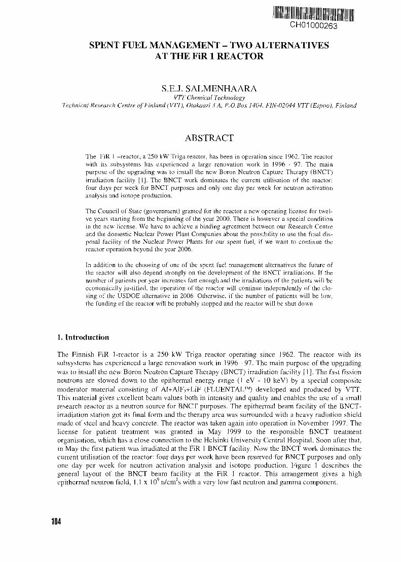
CH01000263
SPENT FUEL MANAGEMENT - TWO ALTERNATIVESAT THE FiR 1 REACTOR
S.E.J. SALMENHAARAVTT Chemical Technology
Technical Research Centre of Finland (VTT), Otakaari 3 A, P.O.Box 1404, FIN-02044 VTT(Espoo), Finland
ABSTRACT
The FiR 1 -reactor, a 250 kW Triga reactor, has been in operation since 1962. The reactorwith its subsystems has experienced a large renovation work in 1996 - 97. The mainpurpose of the upgrading was to install the new Boron Neutron Capture Therapy (BNCT)irradiation facility [1]. The BNCT work dominates the current utilisation of the reactor:four days per week for BNCT purposes and only one day per week for neutron activationanalysis and isotope production.
The Council of State (government) granted for the reactor a new operating license for twel-ve years starting from the beginning of the year 2000. There is however a special conditionin the new license. We have to achieve a binding agreement between our Research Centreand the domestic Nuclear Power Plant Companies about the possibility to use the final dis-posal facility of the Nuclear Power Plants for our spent fuel, if we want to continue thereactor operation beyond the year 2006.
In addition to the choosing of one of the spent fuel management alternatives the future ofthe reactor will also depend strongly on the development of the BNCT irradiations. If thenumber of patients per year increases fast enough and the irradiations of the patients will beeconomically justified, the operation of the reactor will continue independently of the clo-sing of the USDOE alternative in 2006. Otherwise, if the number of patients will be low,the funding of the reactor will be probably stopped and the reactor will be shut down
1. Introduction
The Finnish FiR 1-reactor is a 250 kW Triga reactor operating since 1962. The reactor with itssubsystems has experienced a large renovation work in 1996 - 97. The main purpose of the upgradingwas to install the new Boron Neutron Capture Therapy (BNCT) irradiation facility [1]. The fast fissionneutrons are slowed down to the epithermal energy range (1 eV - 10 keV) by a special compositemoderator material consisting of Al+AlF3+LiF (FLUENTAL™) developed and produced by VTT.This material gives excellent beam values both in intensity and quality and enables the use of a smallresearch reactor as a neutron source for BNCT purposes. The epithermal beam facility of the BNCT-irradiation station got its final form and the therapy area was surrounded with a heavy radiation shieldmade of steel and heavy concrete. The reactor was taken again into operation in November 1997. Thelicense for patient treatment was granted in May 1999 to the responsible BNCT treatmentorganisation, which has a close connection to the Helsinki University Central Hospital. Soon after that,in May the first patient was irradiated at the FiR 1 BNCT facility. Now the BNCT work dominates thecurrent utilisation of the reactor: four days per week have been reserved for BNCT purposes and onlyone day per week for neutron activation analysis and isotope production. Figure 1 describes thegeneral layout of the BNCT beam facility at the FiR 1 reactor. This arrangement gives a highepithermal neutron field, 1.1 x 10⁹ n/cm2s with a very low fast neutron and gamma component.
104
Al/AlF3/LiFFLUENTAL
moderator
110 mm aperture
EnrichedLi-poly
Pb
FiR(K63)
Fig 1. FiR 1 epithermal neutron beam facility
2. Current situation
The Council of State (government) granted for the reactor a new operating license for twelve yearsstarting at the beginning of the year 2000. There is however a special condition in the new license. Wehave to achieve a binding agreement between our Research Centre and the domestic Nuclear PowerPlant Companies about the possibility to use the joint final disposal facility of the Nuclear PowerPlants for our spent fuel, if we want to continue the reactor operation beyond the year 2006. We havehad already for twelve years an agreement in principle with one of the Nuclear Power Companiesabout the final disposal matter, but it does not satisfy the requirements any more. If an acceptableagreement will not be accomplished in about four years' time, we have to use the USDOE alternativewith the well-known time limits. The Ministry of Trade and Industry has the duty to decide, if theagreement is acceptable or not. Before we can start the real negotiations about the final disposal of ourspent fuel with the Nuclear Power Companies, we have to prepare a safety study about the behaviourof the Triga fuel in the final disposal surroundings. We need also a description how our spent fuel willbe handled at the final disposal facility. We assume that these reports will be ready this year and afterthat the agreement should be ready in one or two years. If we can keep this time schedule, we can"freely" choose one of these two spent fuel management alternatives. This will happen in 2004 atlatest. If we choose the USDOE alternative, it means the shut down of the reactor clearly before theyear 2006. The BNCT facility is completely ready for the treatment of the patients, but there are stilltoo few patients annually to be irradiated. This means lack in funding the reactor operation. If there isnot enough funding for the reactor, there is also no reason and no means to continue the operation.
3. Alternatives of back end solutions
USDOE's Program
According to the US Department of Energy's Foreign Research Reactor Spent Nuclear FuelAcceptance Program the ultimate time limits are May 2006, when you have to stop burning the fuel inthe reactor and May 2009, when the fuel has to be at its destination in the USA. In practice thearrangements needed to send the spent fuel back to USA have to be done much earlier. When therepresentatives of USDOE visited our reactor in 1999, we told them that our intention is to choose theback end solution of the fuel in 2004. Next year, in 2000, USDOE reminded us that our possiblenegotiations with USDOE about the return of the spent fuel should start already in 2004 or earlier.
105
Domestic alternative
The Council of State (government) outlined already in 1983 the time schedule for the final disposal ofspent fuel of the nuclear power plants. Since that the Finnish Nuclear Power Companies have maderesearch work aiming for the final disposal of the radwaste. Later, in 1995 they founded a separatecompany Posiva to develop the technology and carry out safety analysis and site investigations forimplementing spent fuel final disposal. In 1999 Posiva submitted an application for a decision inprinciple for a final repository to be built at Olkiluoto, the site of two nuclear power units. At the endof the year 2000 the Finnish government approved the application and sent it to the parliament forratification. After the ratification, if positive, separate licenses still will be needed for the constructionof the facility, scheduled to start in 2010, and also for the operation, 10 years later. The governmentalone will decide, if these licenses are granted or not.
For the final repository the spent fuel will be encapsulated in airtight copper canisters and situated inthe bedrock at a depth of 500 m. The safety of this deep underground repository is based on multiplenatural and engineered barriers. Each canister contains 9-12 normal fuel assemblies from nuclearpower plants. The present concept for Triga fuel elements is that the elements will be loaded incontainers, which have the same outer dimensions as the nuclear power plant fuel assemblies. Thisensures that the Triga fuel will be easily handled in the final disposal facility and also loaded in theheavy copper canisters.
4. Decisions in the near future
As was mentioned earlier the BNCT work is today the main purpose to run the reactor. The amount ofBNCT irradiations is still rather low: twelve irradiations during the first eighteen months. If thefrequency of the treatments is not growing up soon, the funding of the reactor will be stopped, whichleads inevitably to the permanent shut down of the reactor. In that case the USDOE alternative seemsto be the right one. The economic situation of the reactor will be the basic factor when we have todecide about the future of the reactor. The economic situation will be analysed during the next two orthree years at latest. If the turnover of the BNCT and other irradiations will be satisfactory and thepositive trend seems to continue, there is no reason to use the USDOE alternative. Instead it isreasonable to continue the reactor operation beyond the year 2006, which means inevitable also thechoosing of the domestic alternative for the treatment of the spent fuel.
5. Conclusions
The choosing between the USDOE and the domestic back end solution will be based on the economicsituation and the economic forecasts of the reactor and the BNCT irradiations, not the economics ofthe spent fuel management. At the moment the expenses of both of the spent fuel managementalternatives seem to be of the same magnitude. The time of the decision will be very soon, in 2003 -2004 at latest.
References
[1] Iiro Auterinen, Carita Aschan, Pekka Hiismaki, Mika Kortesniemi, Antti Kosunen, PetriKotiluoto, Juha Laminen, Rolf J. Rosenberg, Seppo Salmenhaara, Sauli Savolainen, TiinaSeppala, Tom Seren, Vesa Tanner, Matti Toivonen and Petteri Valimaki: Metamorphosis of a35 Years Old TRIGA Reactor into a Modern BNCT Facility. Proc. of the Eighth InternationalSymposium on Neutron Capture Therapy for Cancer, La lolla, California, USA, 13-18 Sept.1998
106
CH01000264
THE LONG-TERM BEHAVIOUR OF CEMENTED RESEARCHREACTOR WASTE UNDER THE GEOLOGICAL DISPOSAL
CONDITIONS OF THE BOOM CLAY FORMATION:RESULTS FROM LEACH EXPERIMENTS
A. SNEYERS, J. FAYS and P. VAN ISEGHEMWaste and Disposal Department
SCK'CEN, Boeretang 200, B-2400 Mol - Belgium
ABSTRACT
The Belgian Nuclear Research Centre SCK'CEN has carried out a number of studies toevaluate the long-term behaviour of cemented research reactor waste under the geologicaldisposal conditions of the Boom Clay Formation. Static leach experiments in synthetic claywater were performed on active samples of cemented research reactor waste. The leachexperiments were carried out under anaerobic conditions at two testing temperatures (23and 85°C). Leach rates of seven radionuclides (60Co, 90Sr, l34Cs, 137Cs, 144Ce, l54Eu and241Am) were measured. Most investigated radionuclides are well retained within thecement matrix over a 280 days testing period. Results on the source term of radionuclideswere complemented with data on the leaching behaviour of cement matrix constituents asCa, Si, Al, Na, K, Mg and SO4 as well as with data from performance assessmentcalculations and in situ tests. Despite limitations inherent to short-term experiments,combined results from these investigations indicate only limited interactions of disposedresearch reactor waste with the near field of a geological repository in clay.
1. Introduction
Between November 1993 and April 1994, a total of 240 fuel elements from the BR-2 ResearchReactor were shipped to the Dounreay facility of UK Atomic Energy Authority (UKAEA) forreprocessing and conditioning in a cement matrix [1]. As the reprocessing raffinate contains long-livedradionuclides, deep geological disposal is considered as the most appropriate option for themanagement of these wastes. However until recently, few data existed on the behaviour of cementedresearch reactor waste under site-specific geological disposal conditions. In Belgium, the Boom Clayis investigated as a potential host rock for the deep geological disposal of long-lived and high-levelradioactive waste. This article summarises results from active leach experiments investigatingradionuclide release from cemented research reactor waste under simulated repository conditions. Dataobtained from leach experiments provide important information on (i) the quality of cement matriceswith respect to the immobilisation of critical radionuclides; (ii) the source term of radionuclides and(iii) release rates of chemical elements having a potential effect on the near-field (e.g., alkaline plume)of a geological repository in clay. Data derived from these studies can be integrated in performanceassessments and environmental impact studies. As part of a broader research programme on cement-clay interactions, in situ tests were performed in the HADES Underground Laboratory (Mol, Belgium)to investigate the long-term physical and chemical stability of cemented research reactor waste underreal geological disposal conditions. Most of these investigation were performed in the context of theFourth Framework Programme of the European Commission. Main results and conclusions relevant tothe safety of disposal are summarised.
2. Laboratory leach experiments on active simulant cemented RESEARCH REACTORwaste samples
2.1 Experimental
Static leach experiments were carried out on active samples of cemented research reactor waste. Theleach rates of cations, anions and radionuclides were measured and the leach experiments were
107
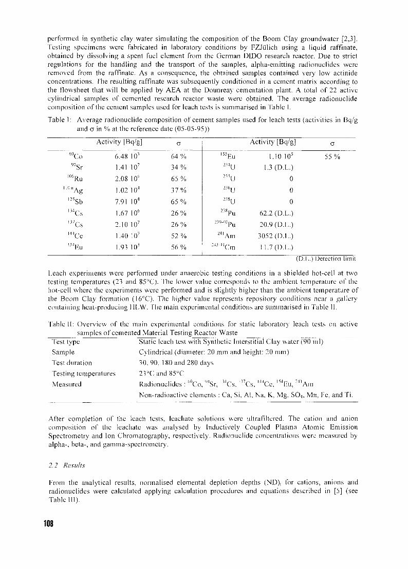
performed in synthetic clay water simulating the composit ion of the Boom Clay groundwater [2,3],Testing specimens were fabricated in laboratory conditions by FZJulich using a liquid raffinate,obtained by dissolving a spent fuel element from the German DIDO research reactor. Due to strictregulations for the handling and the transport of the samples, alpha-emitt ing radionuclides wereremoved from the raffinate. As a consequence, the obtained samples contained very low actinideconcentrat ions. The resulting raffinate was subsequently conditioned in a cement matrix according tothe flowsheet that will be applied by AEA at the Dounreay cementation plant. A total of 22 activecylindrical samples of cemented research reactor waste were obtained. The average radionuciidecomposit ion of the cement samples used for leach tests is summarised in Table I.
Table I: Average radionuciide composit ion of cement samples used for leach tests (activities in Bq/g
and a in % at the reference date (05-05-95))
6 0Co90Sr
IO6Ru
" O m Ag
l 2 5Sbm C s
' " C sl 4 4Ce154 Eu
Activity [Bq/g]
6.48 103
1.41 107
2.08 106
1.02 104
7.91 104
1.67 106
2.10 107
1.40 107
1.93 105
o
6 4 %
3 4 %
6 5 %
3 7 %
6 5 %
2 6 %
2 6 %
5 2 %
5 6 %
l55Eu
"4U
"5UB6UB8U
238Pu239-40pu
241 Am2«-44Cm
Activity [Bq/g]
1.10 105
1.3 (D.L.)
0
0
0
62.2 (D.L.)
20.9 (D.L.)
3052 (D.L.)
11.7 (D.L.)
a
55 %
(D.L.) Detection limit
Leach experiments were performed under anaerobic testing conditions in a shielded hot-cell at twotesting temperatures (23 and 85°C). The lower value corresponds to the ambient temperature of thehot-cell where the experiments were performed and is slightly higher than the ambient temperature ofthe Boom Clay formation (16°C). The higher value represents repository conditions near a gallerycontaining heat-producing HLW. The main experimental conditions are summarised in Table II.
fable II: Overview of the main experimental conditions for static laboratory leach tests on activesamples of cemented Material Testing Reactor Waste
Test type
Sample
Test duration
Testing temperatures
Measured
Static leach test with Synthetic Interstitial Clay water (90 ml)
Cylindrical (diameter: 20 mm and height: 20 mm)
30,90, 180 and 280 days
23°C and 85°CP , j - i - i 6 0 ^ 10o 1 3 4 ^ 1 1 7 . - . 1 4 4 , " . I 5 4 r 2 4 1 .
Radionuclides : Co, Sr, Cs, Cs, Ce, hu, Am
Non-radioactive elements : Ca, Si, Al, Na, K, Mg, SO4, Mn, Fe, and Ti.
After completion of the leach tests, leachate solutions were ultrafiltered. The cation and anioncomposition of the leachate was analysed by Inductively Coupled Plasma Atomic EmissionSpectrometry and Ion Chromatography, respectively. Radionuciide concentrations were measured byalpha-, beta-, and gamma-spectrometry.
2.2 Results
From the analytical results, normalised elemental depletion depths (ND), for cations, anions andradionuclides were calculated applying calculation procedures and equations described in [5] (seeTable III).
108
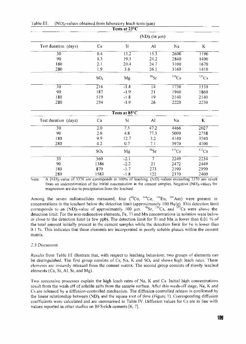
Table III:
Test
(ND)i-values obtained
duration (days)
from
Ca
laboratory leach tests (um)Tests at 23°C
(ND); (in
Si Al
um)
Na K
3090180280
0.41.32.11.9
13.219.520.43.6
15.324.224.726.1
90Sr
14211926
2600284031003160
m C s
1730194021402220
1190140016701410
SO4 Mg 137Cs
3090180280
216187519234
-1.8-1.9-1.8-1.9
1530186021402230
Tests at 85°C
Test duration (days) Ca Si Al Na K
3090180280
2.02.69.94.2
SO4
56013868791583
7.54.812.70.7
Mg
-2.1-2.2-1.7-1.8
47.277.33.27.1
90Sr
721
273122
4466500941403970
134Cs
2249247221902370
2027275835404100B7Cs
2234244921902400
3090180280
Note: A (ND)j-value of 3370 urn corresponds to 100% of leaching. (ND)j-values exceeding 3370 um resultfrom an underestimation of the initial concentration in the cement samples. Negative (ND)j-values formagnesium are due to precipitation from the leachant.
144,- 154T 241Among the seven radionuclides measured, four ( Co, '""Ce, '3I|Eu, a i A m ) were present inconcentrations in the leachant below the detection limit (approximately 100 Bq/g). This detection limitcorresponds to an (ND)j-value of approximately 100 um. 90Sr, 134Cs, and n 7 Cs were above thedetection limit. For the non-radioactive elements, Fe, Ti and Mn concentrations in solution were belowor close to the detection limit (a few ppb). The detection limit for Ti and Mn is lower than 0.01 % ofthe total amount initially present in the cement samples while the detection limit for Fe is lower than0.1 %. This indicates that these elements are incorporated in poorly soluble phases within the cementmatrix.
2.3 Discussion
Results from Table III illustrate that, with respect to leaching behaviour, two groups of elements canbe distinguished. The first group consists of Cs, Na, K and SO4 and shows high leach rates. Theseelements are instantly released from the cement matrix. The second group consists of slowly leachedelements (Ca, Si, Al, Sr, and Mg).
Two successive processes explain the high leach rates of Na, K and Cs. Initial high concentrationsresult from the wash off of soluble salts from the sample surface. After this wash-offstage, Na, K andCs are released by a diffusion-controlled mechanism. The diffusion controlled release is confirmed bythe linear relationship between (ND), and the square root of time (Figure 1). Corresponding diffusioncoefficients were calculated and are summarised in Table IV. Diffusion values for Cs are in line withvalues reported in other studies on BFS-rich cements [6, 7],
109
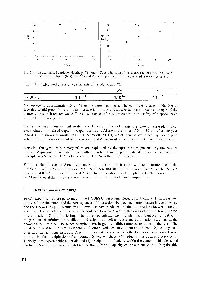
ND[H
2500 -
2000 •!
1500
1000 •;
500
0 -
"Cs
10
Vdays
20
30
25
ND 20
I [Mm] ] 5
10
5
0
Sr
10
Vdav
20
Fig. 1 : The normalised depletion depths of 90Sr and 137Cs as a function of the square root of time. The linearrelationship between (ND); for 137Cs and Vtime supports a diffusion-controlled release mechanism
Table IV: Calculated diffusion coefficients of Cs, Na, K at 25°C
Cs Na KD [m7s] 3.10 -14 3.10 -14 7.10 -15
Na represents approximately 3 wt % in the cemented waste. The complete release of Na due toleaching would probably result in an increase in porosity and a decrease in compressive strength of thecemented research reactor waste. The consequences of these processes on the safety of disposal havenot yet been investigated.
Ca, Si, Al are main cement matrix constituents. These elements are slowly released: typicalextrapolated normalised depletion depths for Si and Al are in the order of 20 to 30 urn after one yearleaching. Sr shows a similar leaching behaviour as Ca, which can be explained by isomorphicsubstitution in various cement phases. Also Si and Al are mostly combined with Ca in cement phases.
Negative (ND)j-values for magnesium are explained by the uptake of magnesium by the cementmatrix. Magnesium may either react with the solid phase or precipitate at the sample surface, forexample as a Si-Al-Mg-H2O gel as shown by EMPA in the in situ tests [8].
For most elements and radionuclides measured, release rates increase with temperature due to theincrease in solubility and diffusion rate. For silicon and aluminium however, lower leach rates areobserved at 85°C compared to tests at 23°C. This observation may be explained by the formation of aSi-Al-gel layer at the sample surface that would form faster at elevated temperatures.
3. Results from in situ testing
In situ experiments were performed in the HADES Underground Research Laboratory (Mol, Belgium)to investigate the extent and the consequences of interactions between cemented research reactor wasteand the Boom Clay [8], Results from in situ tests have evidenced distinct interactions between cementand clay. The affected area is however confined to a zone with a thickness of only a few hundredmicrons after 18 months testing. The observed interactions include mass transport of calcium,magnesium, aluminium, iron, silicon, and sulphur as well as redox and carbonation reactions at thecement-clay interface. The tested samples were in good condition after completion of the tests. Themost prominent features are (1) leaching of cement with loss of calcium and silicon; (2) developmentof a calcium-rich zone in Boom Clay close to or at the contact; (3) the formation of a contact zonemarked by the precipitation of a hydrated Si-Mg-Al phase; (4) reduction in apparent porosity ofinitially porous/permeable materials and (5) precipitation of calcite within the cement. This elementalexchange tends to diminish pH and reduce the buffering capacity of the cement. Although hydroxide
110
will diffuse into the clay, the development of an extensive alkaline halo in the surrounding clay isunlikely owing to the buffering capacity of the Boom Clay.
4. Conclusions
The behaviour of cemented research reactor waste under geological disposal conditions of the BoomClay was investigated. Results derived from active leach experiments indicate that most of theinvestigated radionuclides are well retained within the cement matrix over the 280 days testing period.Results on the source term of inactive constituents shows that Na (3 wt %) is readily released. Inaddition to leach tests, in situ experiments were performed to investigate the behaviour of cementmatrices under realistic repository conditions of the Boom Clay Formation. Although mass transportof matrix components occurs at the interface cement-clay, the extent of the affected zone is limited.Experimental studies were complemented with preliminary performance assessment calculations toevaluate the radiological consequences of the geological disposal of 69 canisters of cemented researchreactor waste in a hypothetical repository in the Boom Clay [2]. Maximum dose rates were calculatedfor major actinides and fission products and were found to be approximately two orders of magnitudelower than the maximum dose rates calculated for the disposal of the reprocessing waste resultingfrom the Belgian reference scenario (based on an installed nuclear power of 5.5 GW(e) operatedduring 40 years). The highest contribution to the dose rate (5 10"<; Sv/a ) was calculated for I29I.Despite limitations inherent to short-term experiments, combined results from these studies suggestonly a limited impact of disposed research reactor waste on the near field of a repository in clay.
5. Acknowledgements
Leach experiments and in situ tests on cemented research reactor waste were performed in the contextof the Forth Framework Programme of the European Commission under contract FI4W-CT-0030.
6. References
[1] P. Gubel, G. Collard, Spent fuel strategy for the BR2 reactor. Transactions of the 2"d
International Topical Meeting on Research Reactor Fuel Management RRFM'98 (Bruges,Belgium, 29-31 March 1998). Organised by the European Nuclear Society, p. 110-1 14 (1998)
[2] A. Sneyers, J. Marivoet, P. Van Iseghem, The experimental testing of the long-term behaviourof cemented radioactive waste from nuclear research reactors in the geological disposalconditions of the Boom Clay. Transactions of the 2"d International Topical Meeting on ResearchReactor Fuel Management RRFM'98 (Bruges, Belgium, 29-31 March 1998). Organised by theEuropean Nuclear Society, p. 119-123 (1998)
[3] A. Dierckx, Boom Clay in situ porewater chemistry. Belgian Nuclear Research CentreSCK'CEN, Report BLG-734, 4 pp. (1998)
[4] J. Marivoet, Updating of the performance assessments of the geological disposal of high-leveland medium-level wastes in the Boom Clay Formation. Belgian Nuclear Research CentreSCK'CEN, Report BLG-634 (1991)
[5] Nuclear Waste Materials Handbook. Test methods. MCC-1P Static Leach Test Method. PacificNorthwest Laboratory, Richland, Washington, PNL-3990, p. 1-35
[6] H.Aalto, A. Ipatti. Leach test of spent ion-exchange resins solidified in concrete Cement andConcrete Research, vol. 22, 375-380 (1992)
[7] M. Noe, C. Riglet, A.G. de la Huebra, AA. Pihlak, E. Lippmaa, Basic leaching tests for purelong-lived p emitters in radioactive waste, Report EUR 17104 (1996)
[8] A. Sneyers, M. Paul, M. Tyrer, F.P. Glasser, J. Fays, P. Van Iseghem "In situ interactionbetween cement and clay, implications for geological disposal". Paper presented at theSymposium of the Materials Research Society (Symposium held 27-31 August 2000, Sidney,Australia). Accepted for publication in "Scientific Basis for Nuclear Waste Management", pp. 6(2000)
111
RRFM2001 CH01000265AACHEN, GERMANY, APRIL 1-4, 2001
REPROCESSING RTR FUEL IN THE LA HAGUE PLANTS
J. THOMAS SONCOGEMA, 2 rue Paul Dautier, BP 4, 78140 Velizy Cedex, France
F. DRAIN - A. DAVIDSGN, I rue des Herons, 78182 Saint Quentin en Yvelines Cedex, France
ABSTRACT
Starting in 2006, research reactors operators will be fully responsible for their research and testing reactors spent fuel back-endmanagement.It appears that the only solution for this management is treatment-conditioning, which could be done at the La Haguereprocessing complex in France. The fissile material can be separated in the reprocessing plants and the final waste can beencapsulated in a matrix adapted to its potential hazards.RTR reprocessing at La Hague would require some modifications, since the plant had been primarily designed to reprocessfuel from light water reactors. Many provisions have been taken at the plant design stage, however, and the modificationswould be feasible even during active operations, as was done from 1993 to 1995 when a new liquid waste management wasimplemented, and when one of the two vitrification facilities was improved.To achieve RTR back-end management, COG EM A and its partners are also conducting R&D to define a new generation ofLHU fuel with performance characteristics approximating those of HELJ fuel. This new-generation fuel would be easier toreprocess.
Introduction : Reprocessing, the long-term solution for RTR spent fuel back-end
Research and testing reactors (RTR) are used for nuclear applications in many fields, includingmedicine, with boron neutron capture therapy, industry, with gauges, detectors, and other devices .research and education with irradiators and calibration sources. All these applicat ions generateradioactive waste , in particular spent fuel, whose back-end management has experienced many stopsand starts in the past ten years.Until the end of 1988, US obligated materials were subject to the "Off Site Fuels Policy'" whichrequired spent fuel to be returned to the United States and to be reprocessed there. Since this policyterminated on the 31 s 1 of December 1988. research reactors operators were then required to implementother management solutions.At the same t ime, the Reduced Enrichment for Research of Test Reactors ( R E R T R ) Program wasleading to a new Low Enrichment Uranium (LEU) fuel to replace High Enrichment Uranium ( H E U )fuel.Since new LEU fuel was not as easy to reprocess as HEU fuel (the LEU fuel is made of silicide,whereas the HEU fuel is made of aluminide) , a new US spent fuel return policy was introduced inearly 1996 for all research reactors converted (or that had agreed to be converted) to LEU, and forreactors operat ing with HEU for which no suitable LEU was available. This policy covers all the spentfuels discharged until the 12"' of May. 2006. After that date, each operator will again be fullyresponsible for its spent fuel.
For the ultimate back-end management , there are three options [1] :
© Interim storage© Direct disposal(D Treatment-condi t ioning by reprocessing
m
The interim storage option does not constitute a reliable solution, while some research reactoroperators have been confronted with corrosion and material degradation problems in existing facilities.Extended storage of RTR fuel would obviously require extensive R&D programs, as well as newfacilities designed for long term storage. Most significantly, this option does not provide a definitivesolution.
The direct disposal option entails several unsolved difficulties. First, one has to ensure that theenriched uranium content will not lead to criticality hazards through long term processes as selectiveleaching. Moreover, RTR spent fuel is generally considered as unstable (high corrosion rate, hydrogenbuild-up) under the conditions of a geological repository. It requires watertight and durableconditioning on a geological time-scale, for which no satisfactory solution has yet been found. Finally,direct disposal remains a "virtual" solution that has never been implemented.
The reprocessing option avoids the above difficulties because it produces residues which are suitablefor direct disposal. The 30 years of experience gained at COGEMA's reprocessing site in La Haguedemonstrates the industrial expertise achieved in commercial reprocessing.
Principles of reprocessing : the example of La Hague
Reprocessing has two main objectives :
© Recover the recyclable materials (plutonium and residual uranium),
© Generate final waste according to their potential hazards, in order to dispose them safely for the
environment.
Reprocessing at the La Hague complex, in the UP2-800 and UP3 plants, uses the PUREX process,including the following steps (see flow sheet in figure 1) :
> Transport of fuel to the plant and cooling in storage ponds. This cooling, or "deactivation",decreases the radioactivity of the fission products substantially.
r- Shearing and dissolution of the fuel, followed by clarification of the liquor generated :
The first reprocessing operation consists of stripping the fuel rod to prepare it for chemical attack.The process employed for zircalloy cladding rods is cutting them into pieces with a shearingmachine. At La Hague, as in many reprocessing plants, the shearing machine is placed above acontinuous dissolver, and the rod pieces fall into a perforated basket, which, placed in thedissolver, allows the selective dissolution of the oxide in nitric acid without attacking the hulls.At the end of the operation, the hulls are removed and sent for storage awaiting future compactingand conditioning as a solid High Active Level Waste (HALW).Depending on the fuel type, it is possible that some insoluble products may remain afterdissolution. This is the case for example for oxide fuels for which the insoluble particles are madeof cladding residues and metallic inclusions. These solids, which would hamper furtherpurification steps, are removed from the solution by centrifugation. A centrifugal clarifier hasbeen selected for La Hague because it provides good efficiency with high throughput.
r- Uranium and plutonium splitting and purification by a liquid-liquid extraction process :
Basically, extraction consists in transferring a solute from one liquid phase to another one that isnot miscible with the first. This operation enables separation of salts whose suitability forextraction by a given solvent is different.For the extraction of uranium and plutonium, tri-butyl phosphate diluted in hydrocarbons hasbeen universally adopted. In the extraction operation, most of the fission products and actinides,except U and Pu, remain in the aqueous phase. Scrubbing by nitric acid improves the separationby stripping most of the fission products entrained by the solvent.Several extraction cycles of the clarified liquor, in pulsed columns, mixer-settler banks, orcentrifugal extractors are necessary to meet the end-product specifications. At the end of thesecycles, different kinds of solutions are generated :- a solution containing specifically the uranium- a solution containing specifically the plutonium- raffinates containing the fission products and the minor actinides- the solvent, which is regenerated by a treatment with sodium carbonate followed by caustic
soda, and then recycled.
113
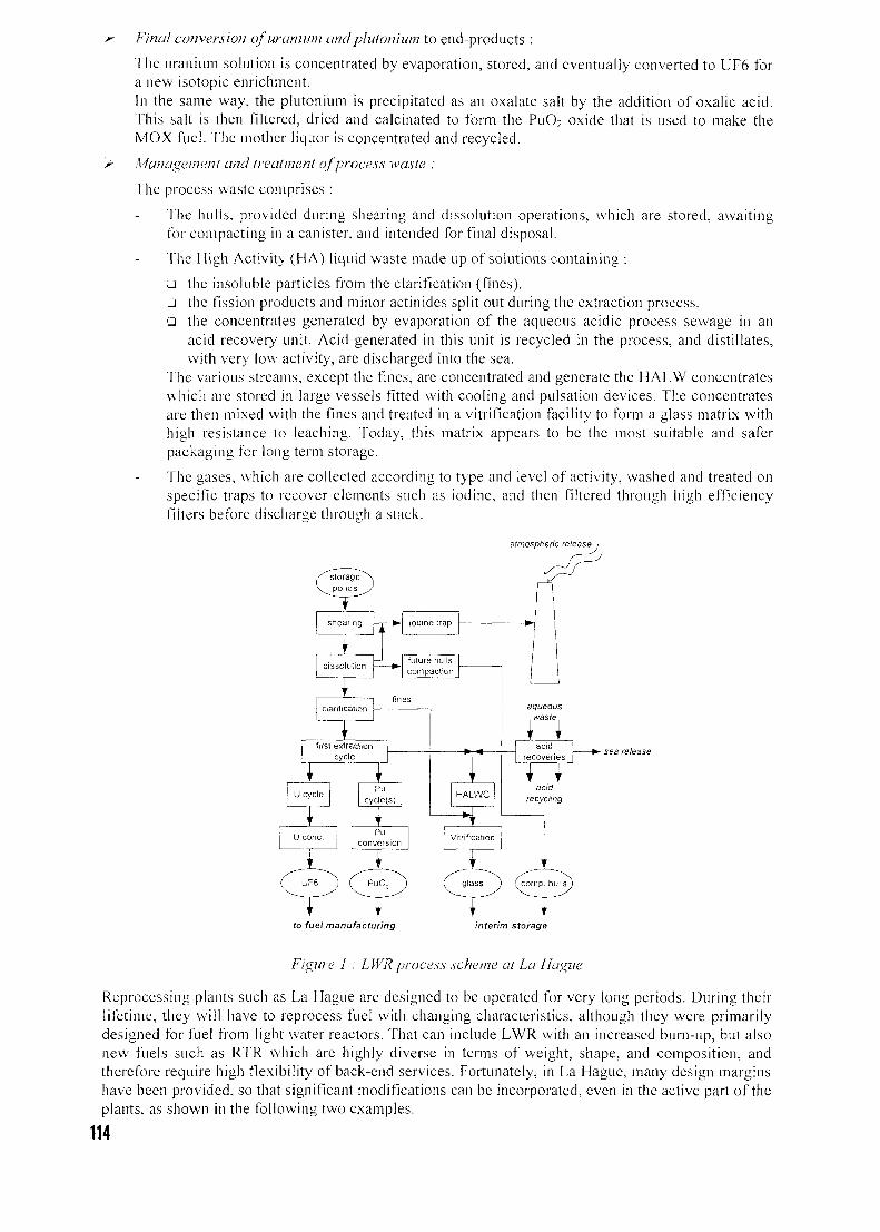
Final conversion of uranium and plutonium to end-products :
The uranium solution is concentrated by evaporation, stored, and eventually converted to LJF6 fora new isotopic enrichment.In the same way, the plutonium is precipitated as an oxalate salt by the addition of oxalic acid.This salt is then filtered, dried and calcinated to form the PuO2 oxide that is used to make theMOX fuel. The mother liquor is concentrated and recycled.
Management and treatment of process waste :
The process waste comprises :
The hulls, provided during shearing and dissolution operations, which are stored, awaitingfor compacting in a canister, and intended for final disposal.
The High Activity (HA) liquid waste made up of solutions containing :
G the insoluble particles from the clarification (fines),a the fission products and minor actinides split out during the extraction process,a the concentrates generated by evaporation of the aqueous acidic process sewage in an
acid recovery unit. Acid generated in this unit is recycled in the process, and distillates,with very low activity, are discharged into the sea.
The various streams, except the fines, are concentrated and generate the HALW concentrateswhich are stored in large vessels fitted with cooling and pulsation devices. The concentratesare then mixed with the fines and treated in a vitrification facility to form a glass matrix withhigh resistance to leaching. Today, this matrix appears to be the most suitable and saferpackaging for long term storage.
The gases, which are collected according to type and level of activity, washed and treated onspecific traps to recover elements such as iodine, and then filtered through high efficiencyfilters before discharge through a stack.
atmospheric release
to fuel manufacturing interim storage
Figure I : LWRprocess scheme at La Hague
Reprocessing plants such as La Hague are designed to be operated for very long periods. During theirlifetime, they will have to reprocess fuel with changing characteristics, although they were primarilydesigned for fuel from light water reactors. That can include LWR with an increased burn-up, but alsonew fuels such as RTR which are highly diverse in terms of weight, shape, and composition, andtherefore require high flexibility of back-end services. Fortunately, in La Hague, many design marginshave been provided, so that significant modifications can be incorporated, even in the active part of theplants, as shown in the following two examples.
114
Two examples of La Hague design flexibility [2]
Implementation of a new liquid waste management process
Active operation of UP3 started in 1989. The initial liquid waste management process led to theproduction of two types of solid waste : high level active waste (glass canisters) containing the bulk ofactivity, and intermediate level waste (issued from medium and low level liquid waste generatedmainly by gas scrubbers, rinsing of equipment and solvent regeneration, and which underwent atreatment by co-precipitation, with the sludge generated incorporated in bitumen).
The excellent decontamination performance of the first extraction cycle opened up the possibility ofmodifying the liquid waste management process in order to eliminate production of intermediate levelwaste. The main characteristics of this new process were :- Concentrate all salt-free acidic waste and the most active salt-bearing waste, in order to route it to
the vitrification facilities.Release in the sea the remaining salt-bearing waste, after a filtration stage, and control of itsactivity.
To implement this new management process, three new evaporation units, a specific unit for thetreatment of laboratory waste, and new piping and vessels were installed. The main challenges were :- To have the radiation exposure of construction personnel negligible,- To lay out most of the new units in facilities already in active operation, which involved difficulties
for the active area access and for the piping connections,- To perform the construction without any interference with operations of existing facilities.
These challenges were overcome mainly thanks to the original design of the La Hague plants, and tothe excellent co-ordination between the design teams and the construction teams.The lay-out of UP3 facilities, as well as those of its sister UP2-800, is characterised by a central activegallery, which houses all connecting pipes between various units. The active cells are located on eachside of this backbone, and surrounded by inactive areas. The process equipment is installed in activecells separated by concrete walls. The equipment is gathered according to function and activity level,to enable an easier access.In the case of a cell with medium or low level activity, draining and rinsing of equipment is sufficientto permit maintenance. In the case of a cell with high-level activity, most of the active pipes andtransfer systems are duplicated. Hold-up pipes, most of which are fitted with decontamination nozzles,are provided for connection to future process extensions. In addition, extra space has been foreseen tohouse possible process extensions, and inactive areas have been designed with large corridors to makemaintenance easier.
These conditions enabled :- implementing 10 new active cells, both in existing facilities and in extensions,- creating new piping between units inside the same facility and between facilities,
minimising maintenance in active cells both in term of space and duration,- limiting radiation exposure of construction personnel to about 10 man-mSv per year during the
main construction period from 1993 to 1995.
Improvement of the vitrification facilities
La Hague has two vitrification facilities, R7 and T7, which are located respectively in UP2-800 andUP3. The process includes first converting the HALW solutions to a solid form in a rotary calciner andthen vitrifying the solid in an induction-heated metallic melter.Each facility has three vitrification lines capable of producing 25 kg/h of glass. Keeping two lines inoperation and one on stand-by meets the production requirements and provides considerableflexibility.R7 entered active service in 1989, and T7, three years later in 1992. The design of T7 took advantageof R7's experience, by including some improvement, identified on R7 but which could not beimplemented in active conditions :
implementation of a new connecting device between the pouring nozzle and the canister,associated with an improved off-gas system,addition of an in-cell washable pre-filtering device on the ventilation of main hot cells, in orderprotect the filters from contamination,improvement of the canister decontamination device,
115
modification of the cranes to improve the reliability of certain components and reduce theirmaintenance.
In addition, T7's operators had the unique opportunity to train on R7 before T7's active start-up. As aconsequence, T7 was able to achieve its production goals quickly, and the modification mentionedabove proved to be very beneficial in terms of reduction of operating costs, reduction of waste volume,and personnel irradiation exposure.
In early 1994, it was possible to remove R7 from service for one year, since most of the backlog ofHALW solutions had been vitrified, and the decision was taken to upgrade R7 to the same level as T7,by implementing the same improvements.The project, which included in-cell operations in the most active part of the plant, was feasible thanksto careful preparation. In particular, all the most difficult operations were rehearsed beforehand usinginactive mock-ups.The main objective during the project was to minimise the personnel exposure, andthe careful training on inactive mock-ups was an essential element to reach it. The other two goalswere to minimise the waste volume and to comply with the deadlines to avoid interfering with theproduction schedule of the facility.The work was conducted in two steps. During the first one (5 months), only one line was stopped,while vitrification operation continued on the other ones. During the second step (11 months), all thelines were stopped. These modifications in active conditions were possible thanks to the designprinciples of the vitrification facilities, in which all equipment is installed in mechanical cells and canbe assembled and disassembled using overhead cranes, master-slave manipulators and remotecontrolled tools.
RTR back-end industrial implementation
To be reprocessed, RTR fuel must be diluted in power reactor UO2 spent fuel to lower the 233U contentto a maximum of 2 %.
La Hague is already available to reprocess aluminide HEU spent fuel, since head-end modifications —especially in the shearing and dissolution units- are provided. Some adaptations may also benecessary, on a case-by-case basis, to accommodate specific characteristics of each HEU fuel type.However, as indicated above, the flexibility of the plant would enable such modifications andadaptations, even during active operations.
It is not the same for silicide LEU fuel, which is not easy to reprocess. COGEMA therefore teamedwith other partners in R&D programs to develop a new generation of LEU fuel that should :
® provide higher performance characteristics than current silicide LEU fuel,© be easy to reprocess in existing industrial reprocessing plants, thus providing the best response
to long-term management concerns.(D enable as yet unconverted HEU reactors to switch to LEU fuel, in accordance with non-
proliferation commitments.
Conclusion
Apart from treatment-conditioning by reprocessing, none of the spent fuel management optionsavailable for RTR operators is satisfactory. Due to the nature of the fuel, long term interim storage ordirect disposal would require extensive R&D programs and specially designed costly facilities.However, the treatment-conditioning of RTR spent fuel through reprocessing is a proven and fullyoperational management scheme. By separating and recycling the fissile material, it enables isolatingthe final waste which is encapsulated inside an adapted matrix according to the potential hazards.COGEMA can reprocess spent RTR fuels in its La Hague reprocessing plants. Only somemodifications are required, due to the specific characteristics of each RTR fuel type (both HEU andLEU), but the La Hague complex has already demonstrated its capacity to perform modifications,sometimes extensive, even after the start of active operations.
References
11 ] lRTR Spent Fuel Treatment and Final Waste Storage", J. THOMASSON, RRFM 2000
[2] "COGEMA Reprocessing Complex : Already 9 Years of Operation, Mature and Flexible", JLDESVAUX et al, RECOD 98
116
SILICON BEHAVIOR DURING REPROCESSING OF URANIUM SILICIDE FUELBY PUREX PROCESS
E. TOURON and L. CHEROUXCommissariat a I'Energie Atomique (CEA), Valrhd-Marcoule, DEN/DRCp/<:;rp<:
BP17171, 30207 Bagnols-sur-Ceze Cedex, France
Abstract " " CH01000266
Uranium silicide nuclear fuel is substantially different from power reactor fuel.Reprocessing of spent U3SJ2 fuel is a promising alternative to storage in order to reduce thewaste volume and improve containment while separating reusable material from the waste.Among the possible spent fuel reprocessing scenarios, a study of dissolution of UjSii fuelcomponents in acidic media has shown that the PUREX process is applicable with a fewmodifications in the initial process steps. This study provided valuable data on severalaspects of silicon behavior in nitric acid media, and suggests that the presence of silicondoes not hinder the extraction of reusable materials.
1. IntroductionResearch reactors are characterized by a wide diversity of designs, operating conditions and fuelcompositions. As with power reactors, spent nuclear fuel management is a fundamental issue, and theback end of the fuel cycle (interim storage, disposal or reprocessing) has yet to be defined for thesefuels. While the final choice will be based primarily on political, strategic and/or economic criteria, thetechnical feasibility of reprocessing has not been demonstrated to date for all the fuels used in suchreactors.
In the case of uranium silicide fuel, the CEA recently began to consider and then to assess variousreprocessing scenarios. A comparison of the advantages and drawbacks of each scenario led to theselection of a process using exclusively a nitric acid medium with no mercury catalysts. The techniqueis thus compatible with the PUREX process that has successfully been used on an industrial basis inFrance for many years. Prior studies in France and abroad indicated, however, that furtherinvestigation was necessary to allow for the particular behavior of uranium silicide fuel, notablyarising from the presence of silicon and its effects on the process [1].
The study described here was therefore undertaken on fresh fuel in order to identify and solve anyproblems encountered in designing and validating an industrial-scale process suitable for uraniumsilicides. The work focused on the behavior of silicon in highly concentrated nitric acid media and itsinteractions with the solvent (TBP).
2. Fuel Dissolution
Uranium silicide powder in the size fraction between 90 \xm and 125 \\m was dissolved at 100°C in 3Nto 6N nitric acid with or without aluminum. Complete dissolution was obtained in less than one hourdue to the large surface area of the powder sample.
The dissolution of fuel plate sections with aluminum concentrations of up to about 1,3M in hotconcentrated nitric acid revealed two kinetic regimes directly related to the geometry of the fuelelements used for laboratory testing. The first regime corresponded to the initial attack of the edges ofthe fuel core and of the AG3NE cladding; the second, after elimination of the cladding, correspondedto dissolution of the fuel. The kinetics observed were directly dependent on the surface area in contactwith the dissolution solution (Figure 1).
Under all the operating conditions tested, the aluminum was completely dissolved at a linear overallrate. The cladding was totally eliminated after 3 hours at 100°C, and complete dissolution wasobtained after 6 to 8 hours. While the aluminum cladding dissolution rate was practically independentof the initial acidity between 4N and 9N, dissolution kinetics increased appreciably with thetemperature.
The dissolution off-gases consisted essentially of nitrogen monoxide (NO) with smaller amounts ofnitrogen dioxide (NO2). The overall nitric acid consumption ranged from 3 to 4 moles per mole ofdissolved aluminum, depending on whether or not the acid recombined from the nitrous fumes wasrecycled. Small quantities of hydrogen were measured (at acidity values between IN and 6N), but
117
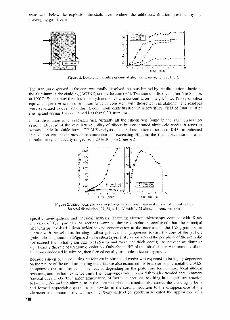
were well below the explosion threshold even without the additional dilution provided by thescavenging gas stream.
\ \
Figure 1. Dissolution kinetics of unirradiated fuel plate sections at 100°C
The uranium dispersed in the core was totally dissolved, but was limited by the dissolution kinetic ofthe aluminum in the cladding (AG3NE) and in the core (A5). The uranium dissolved after 6 to 8 hoursat 100°C. Silicon was then found as hydrated silica at a concentration of 5 g-L"1, i.e. 170 kg of silicaequivalent per metric ton of uranium (a value consistent with theoretical calculations). The residueswere separated to over 98% during continuous centrifugation in a centrifugal field of 2000 g; afterrinsing and drying, they contained less than 0.3% uranium.
In the dissolution of unirradiated fuel, virtually all the silicon was found in the solid dissolutionresidue. Because of the very low solubility of silicon in concentrated nitric acid media, it tends toaccumulate in insoluble form. ICP-AES analysis of the solution after filtration to 0.45 \im indicatedthat silicon was never present at concentrations exceeding 50 ppm; the final concentrations afterdissolution systematically ranged from 20 to 30 ppm (Figure 2).
140d
1 i2oa
c 100ao3 eoo:S ~% 6oa
-> 40acoJ zoa
^ n-i
i
•
•
•
—•— measured- •"' calculated
« H H » M — „ ——'—•—i—'—'—'—i—'—•—>~~7/—r
2 4 6 8Time (hours)
24 0 2 4 6Time (hours)
Figure 2. Silicon concentration in solution versus time: measured versus calculated valuesfor total dissolution of U?Si2 at 100°C with 1.3M aluminum concentration
Specific investigations and physical analyses (scanning electron microscopy coupled with X-rayanalysis) of fuel particles or sections sampled during dissolution confirmed that the principalmechanisms involved silicon oxidation and condensation at the interface of the U?Si2 particles incontact with the solution, forming a silica gel layer that progressed toward the core of the particlegrain, releasing uranium (Figure 3). The silica layers that formed around the periphery of the grain didnot exceed the initial grain size (< 125 urn) and were not thick enough to prevent or diminishsignificantly the rate of uranium dissolution. Only about 15% of the initial silicon was found as silicicacid that condensed in solution, then formed equally insoluble siliceous byproducts.
Because silicon behavior during dissolution in nitric acid media was expected to be highly dependenton the nature of the uranium-bearing material, we also examined the behavior of intermetallic U,Al,Sicompounds that are formed in the reactor depending on the plate core temperature, local nuclearreactions, and the fuel residence time. The compounds were obtained through extended heat treatment(several days at 600°C in argon atmosphere) of fuel plate sections, resulting in a significant reactionbetween U3Si2 and the aluminum in the core material; the reaction also caused the cladding to burstand formed appreciable quantities of powder in the core. In addition to the disappearance of thecharacteristic uranium silicide lines, the X-ray diffraction spectrum revealed the appearance of a
118
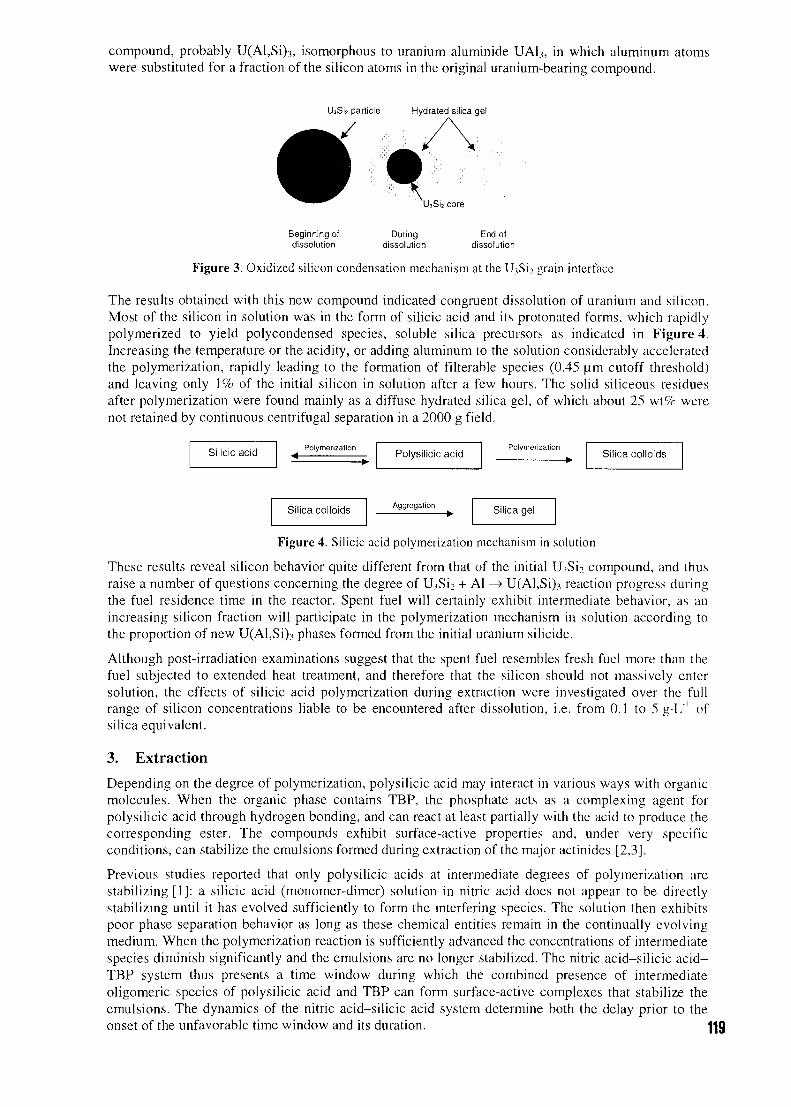
compound, probably U(Al,Si)3, isomorphous to uranium aluminide UA13, in which aluminum atomswere substituted for a fraction of the silicon atoms in the original uranium-bearing compound.
Siz particle Hydrated silica gel
Beginning of During End ofdissolution dissolution dissolution
Figure 3. Oxidized silicon condensation mechanism at the U3Si2 grain interface
The results obtained with this new compound indicated congruent dissolution of uranium and silicon.Most of the silicon in solution was in the form of silicic acid and its protonated forms, which rapidlypolymerized to yield polycondensed species, soluble silica precursors as indicated in Figure 4.Increasing the temperature or the acidity, or adding aluminum to the solution considerably acceleratedthe polymerization, rapidly leading to the formation of filterable species (0.45 urn cutoff threshold)and leaving only 1% of the initial silicon in solution after a few hours. The solid siliceous residuesafter polymerization were found mainly as a diffuse hydrated silica gel, of which about 25 wt% werenot retained by continuous centrifugal separation in a 2000 g field.
Silicic acid PolymerizationPolysilicic acid
Polymerization• Silica colloids
Silica colloids Aggregation Silica gel
Figure 4. Silicic acid polymerization mechanism in solution
These results reveal silicon behavior quite different from that of the initial U.̂ Si? compound, and thusraise a number of questions concerning the degree of UiSi2 + Al —> U(Al,Si).i reaction progress duringthe fuel residence time in the reactor. Spent fuel will certainly exhibit intermediate behavior, as anincreasing silicon fraction will participate in the polymerization mechanism in solution according tothe proportion of new U(Al,Si)3 phases formed from the initial uranium silicide.
Although post-irradiation examinations suggest that the spent fuel resembles fresh fuel more than thefuel subjected to extended heat treatment, and therefore that the silicon should not massively entersolution, the effects of silicic acid polymerization during extraction were investigated over the fullrange of silicon concentrations liable to be encountered after dissolution, i.e. from 0.1 to 5 g-L'1 ofsilica equivalent.
3. Extraction
Depending on the degree of polymerization, polysilicic acid may interact in various ways with organicmolecules. When the organic phase contains TBP, the phosphate acts as a complexing agent forpolysilicic acid through hydrogen bonding, and can react at least partially with the acid to produce thecorresponding ester. The compounds exhibit surface-active properties and, under very specificconditions, can stabilize the emulsions formed during extraction of the major actinides [2,3].
Previous studies reported that only polysilicic acids at intermediate degrees of polymerization arestabilizing [1]: a silicic acid (monomer-dimer) solution in nitric acid does not appear to be directlystabilizing until it has evolved sufficiently to form the interfering species. The solution then exhibitspoor phase separation behavior as long as these chemical entities remain in the continually evolvingmedium. When the polymerization reaction is sufficiently advanced the concentrations of intermediatespecies diminish significantly and the emulsions are no longer stabilized. The nitric acid-silicic acid-TBP system thus presents a time window during which the combined presence of intermediateoligomeric species of polysilicic acid and TBP can form surface-active complexes that stabilize theemulsions. The dynamics of the nitric acid-silicic acid system determine both the delay prior to theonset of the unfavorable time window and its duration. J
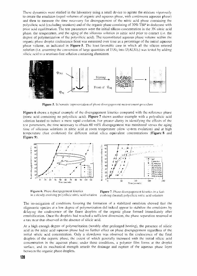
These dynamics were studied in the laboratory using a small device to agitate the mixture vigorouslyto create the emulsion (equal volumes of organic and aqueous phase, with continuous aqueous phase)and then to measure the time necessary for disengagement of the nitric acid phase containing thepolysilicic acid (excluding uranium) and of the organic phase consisting of 30% TBP in dodecane withprior acid equilibration. The test parameters were the initial silicon concentration in the 3N nitric acidphase, the temperature, and the aging of the siliceous solution in nitric acid prior to contact (i.e. thedegree of polymerization of the polysilicic acid). The reconstituted aqueous phase volume within theorganic phase droplet coalescence front was measured over time as a percentage of the initial aqueousphase volume, as indicated in Figure 5. The least-favorable case in which all the silicon enteredsolution (i.e. assuming the conversion of large quantities of U;,Si2 into U(Al,Si).i) was tested by addingsilicic acid to a uranium-free solution containing aluminum.
<POr:
-Me]
Stirring
Front of raq
Figure 5. Schemat ic representation of phase d isengagement measurement procedure
Figure 6 shows a typical example of the disengagement kinetics compared with the reference phase(nitric acid containing no polysilicic acid). Figure 7 shows another example with a polysilicic acidsolution heated to induce a more rapid evolution. For greater clarity in identifying the effects of thetest parameters, the time necessary to obtain 60 vol% disengagement was monitored versus the agingtime of siliceous solutions in nitric acid at room temperature (slow system evolution) and at hightemperature (fast evolution) for different initial silica equivalent concentrations (Figure 8 andFigure 9).
ua9ff
8O
5O
50
4a
30
20
Iff
i r
T
7 ^
/ <
/ '
— . — _ _
_ — — — ~2- • - Rcl.• • - - 1 [by
i 4ib>-<fl (bV5
• 7 ib>s
20 30 40 50 60 7011 lit- (seconds)
90 100 110
5T 1 0°^ 90
1 8C
t. 70
3 60
i" 50
a. 40
ativ
e di.
s
P. 0
*
*
ft¥
i /'y • >'i # x • !W : ! :f f I1 •••'
. : - - • - ' - " - ' "
—*- Ref.x 0 minutes
•••""" 20 minutes• 45 minutes
~ " ~ 180mirutes" 210 minutes
240 minutes
• 1440 minute:;. | T 1 1
60 120Time (seconds)
Figure 6. Phase disengagement kinetics Figure 7. Phase disengagement kinetics in a fast-in a slowly evolving polysilicic nitric acid solution evolving (heated) polysilicic nitric acid solution
The investigation of conditions favoring the formation of a stabilized emulsion showed that theoligomeric species at a low degree of polymerization did indeed appear to stabilize the emulsions bydelaying the coalescence of the finest droplets of the organic phase formed immediately afteremulsification. Once the droplets had reached a sufficient dimension, the phase separation resumed ata rate near that observed in the absence of silicic acid.
At a high enough degree of polymerization (notably after prolonged heating), the presence of silicicacid in the nitric acid aqueous phase had no further effect on phase disengagement regardless of theinitial silicic acid concentration. Only a slowdown was observed in the coalescence of the finaldroplets of the organic phase, the extent of which generally increased with the initial silicic acidconcentration in the aqueous phase; under these conditions, a polymer film forms at the dropletsurface, and its mechanical strength retards the drainage and rupture of the aqueous phase layerbetween the organic phase droplets.
120
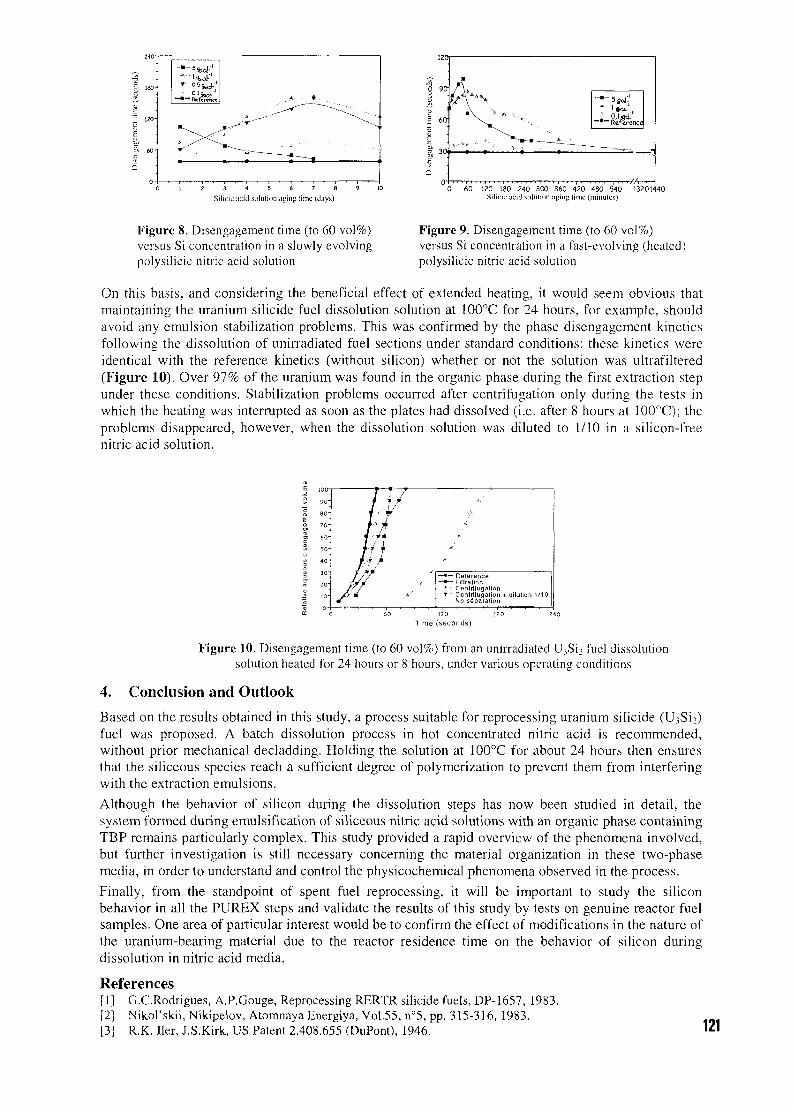
gf 120-
^ 60-
9.3
0 1 2 3 4 5 6 7 8 9 10
Silicic iicid solution aying time (d;iys)0 60 120 180 240 300 360 420 480 540 13201440
Silicic acid solution ayiny time (minutes)
Figure 8. Disengagement time (to 60 vol%)versus Si concentration in a slowly evolvingpolysilicic nitric acid solution
Figure 9. Disengagement time (to 60 vol%)versus Si concentration in a fast-evolving (heated)polysilicic nitric acid solution
On this basis, and considering the beneficial effect of extended heating, it would seem obvious thatmaintaining the uranium silicide fuel dissolution solution at 100°C for 24 hours, for example, shouldavoid any emulsion stabilization problems. This was confirmed by the phase disengagement kineticsfollowing the dissolution of unirradiated fuel sections under standard conditions: these kinetics wereidentical with the reference kinetics (without silicon) whether or not the solution was ultrafiltered(Figure 10). Over 97% of the uranium was found in the organic phase during the first extraction stepunder these conditions. Stabilization problems occurred after centrifugation only during the tests inwhich the heating was interrupted as soon as the plates had dissolved (i.e. after 8 hours at 100°C); theproblems disappeared, however, when the dissolution solution was diluted to 1/10 in a silicon-freenitric acid solution.
90"
80 -
70 -
60-
50"
40 "
ZQ-
n-
]
j/
r T: "/ i?i-7hnhif /
—•— Reterence—«— Filtration
•T • Cenirilugation + dilution 1/10No separalion
Time (seconds)
Figure 10. Disengagement time (to 60 vol%) from an unirradiated U3Si2 fuel dissolutionsolution heated for 24 hours or 8 hours, under various operating conditions
4. Conclusion and Outlook
Based on the results obtained in this study, a process suitable for reprocessing uranium silicide (U;,Si2)fuel was proposed. A batch dissolution process in hot concentrated nitric acid is recommended,without prior mechanical decladding. Holding the solution at 100°C for about 24 hours then ensuresthat the siliceous species reach a sufficient degree of polymerization to prevent them from interferingwith the extraction emulsions.
Although the behavior of silicon during the dissolution steps has now been studied in detail, thesystem formed during emulsification of siliceous nitric acid solutions with an organic phase containingTBP remains particularly complex. This study provided a rapid overview of the phenomena involved,but further investigation is still necessary concerning the material organization in these two-phasemedia, in order to understand and control the physicochemical phenomena observed in the process.
Finally, from the standpoint of spent fuel reprocessing, it will be important to study the siliconbehavior in all the PUREX steps and validate the results of this study by tests on genuine reactor fuelsamples. One area of particular interest would be to confirm the effect of modifications in the nature ofthe uranium-bearing material due to the reactor residence time on the behavior of silicon duringdissolution in nitric acid media.
References[1] G.C.Rodrigues, A.P.Gouge, Reprocessing RERTR silicide fuels, DP-1657, 1983.[2] Nikol'skii, Nikipelov, Atomnaya Energiya, Vol.55, n°5, pp. 315-316, 1983.[3] R.K. Her, J.S.Kirk, US Patent 2.408.655 (DuPont), 1946. 121
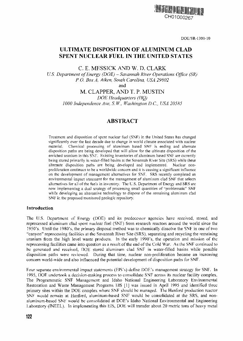
CH01000267
DOE/SR-1300-10
ULTIMATE DISPOSITION OF ALUMINUM CLADSPENT NUCLEAR FUEL IN THE UNITED STATES
C. E. MESSICK AND W. D. CLARKU.S. Department of Energy (DOE) - Savannah River Operations Office (SR)
P.O. Box A, Aiken, South Carolina, USA 29802and
M. CLAPPER, AND T. P. MUSTINDOE Headquarters (HQ)
1000 Independence Ave, S. W., Washington D.C., USA 20585
ABSTRACT
Treatment and disposition of spent nuclear fuel (SNF) in the United States has changedsignificantly over the last decade due to change in world climate associated with nuclearmaterial. Chemical processing of aluminum based SNF is ending and alternatedisposition paths are being developed that will allow for the ultimate disposition of theenriched uranium in this SNF. Existing inventories of aluminum based SNF are currentlybeing stored primarily in water-filled basins at the Savannah River Site (SRS) while thesealternate disposition paths are being developed and implemented. Nuclear non-proliferation continues to be a worldwide concern and it is causing a significant influenceon the development of management alternatives for SNF. SRS recently completed anenvironmental impact statement for the management of aluminum clad SNF that selectsalternatives for all of the fuels in inventory. The U.S. Department of Energy and SRS arenow implementing a dual strategy of processing small quantities of "problematic" SNFwhile developing an alternative technology to dispose of the remaining aluminum cladSNF in the proposed monitored geologic repository.
Introduction
The U.S. Department of Energy (DOE) and its predecessor agencies have received, stored, andreprocessed aluminum clad spent nuclear fuel (SNF) from research reactors around the world since the1950's. Until the 1980's, the primary disposal method was to chemically dissolve the SNF in one of two"canyon" reprocessing facilities at the Savannah River Site (SRS), separating and recycling the remaininguranium from the high level waste products. In the early 1990's, the operation and mission of thereprocessing facilities came into question as a result of the end of the Cold War. As the SNF continued tobe generated and received, DOE stored aluminum clad SNF in water-filled basins while possibledisposition paths were reviewed. During that time, nuclear non-proliferation became an increasingconcern world-wide and also influenced the potential development of disposition paths for SNF.
Four separate environmental impact statements (EIS's) define DOE's management strategy for SNF. In1995, DOE undertook a decision-making process to consolidate SNF across its nuclear facility complex.The Programmatic SNF Management and Idaho National Engineering Laboratory EnvironmentalRestoration and Waste Management Programs EIS [1] was issued in April 1995 and identified threeprimary sites within the DOE complex where SNF should be managed. The Hanford production reactorSNF would remain at Hanford, aluminum-based SNF would be consolidated at the SRS, and non-aluminum-based SNF would be consolidated at DOE's Idaho National Environmental and EngineeringLaboratory (FNEEL). In implementing this EIS, DOE will transfer about 20 metric tons of heavy metal
122
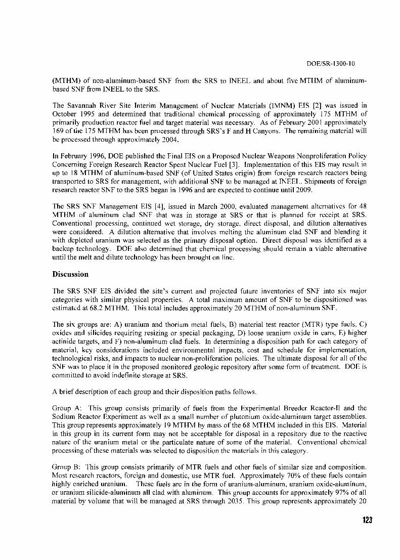
DOE/SR-1300-10
(MTHM) of non-aluminum-based SNF from the SRS to INEEL and about five MTHM of aluminum-based SNF from INEEL to the SRS.
The Savannah River Site Interim Management of Nuclear Materials (IMNM) EIS [2] was issued inOctober 1995 and determined that traditional chemical processing of approximately 175 MTHM ofprimarily production reactor fuel and target material was necessary. As of February 2001 approximately169 of the 175 MTHM has been processed through SRS's F and H Canyons. The remaining material willbe processed through approximately 2004.
In February 1996, DOE published the Final EIS on a Proposed Nuclear Weapons Nonproliferation PolicyConcerning Foreign Research Reactor Spent Nuclear Fuel [3]. Implementation of this EIS may result inup to 18 MTHM of aluminum-based SNF (of United States origin) from foreign research reactors beingtransported to SRS for management, with additional SNF to be managed at INEEL. Shipments of foreignresearch reactor SNF to the SRS began in 1996 and are expected to continue until 2009.
The SRS SNF Management EIS [4], issued in March 2000, evaluated management alternatives for 48MTHM of aluminum clad SNF that was in storage at SRS or that is planned for receipt at SRS.Conventional processing, continued wet storage, dry storage, direct disposal, and dilution alternativeswere considered. A dilution alternative that involves melting the aluminum clad SNF and blending itwith depleted uranium was selected as the primary disposal option. Direct disposal was identified as abackup technology. DOE also determined that chemical processing should remain a viable alternativeuntil the melt and dilute technology has been brought on line.
Discussion
The SRS SNF EIS divided the site's current and projected future inventories of SNF into six majorcategories with similar physical properties. A total maximum amount of SNF to be dispositioned wasestimated at 68.2 MTHM. This total includes approximately 20 MTHM of non-aluminum SNF.
The six groups are: A) uranium and thorium metal fuels, B) material test reactor (MTR) type fuels, C)oxides and silicides requiring resizing or special packaging, D) loose uranium oxide in cans, E) higheractinide targets, and F) non-aluminum clad fuels. In determining a disposition path for each category ofmaterial, key considerations included environmental impacts, cost and schedule for implementation,technological risks, and impacts to nuclear non-proliferation policies. The ultimate disposal for all of theSNF was to place it in the proposed monitored geologic repository after some form of treatment. DOE iscommitted to avoid indefinite storage at SRS.
A brief description of each group and their disposition paths follows.
Group A: This group consists primarily of fuels from the Experimental Breeder Reactor-II and theSodium Reactor Experiment as well as a small number of plutonium oxide-aluminum target assemblies.This group represents approximately 19 MTHM by mass of the 68 MTHM included in this EIS. Materialin this group in its current form may not be acceptable for disposal in a repository due to the reactivenature of the uranium metal or the particulate nature of some of the material. Conventional chemicalprocessing of these materials was selected to disposition the materials in this category.
Group B: This group consists primarily of MTR fuels and other fuels of similar size and composition.Most research reactors, foreign and domestic, use MTR fuel. Approximately 70% of these fuels containhighly enriched uranium. These fuels are in the form of uranium-aluminum, uranium oxide-aluminum,or uranium silicide-aluminum all clad with aluminum. This group accounts for approximately 97% of allmaterial by volume that will be managed at SRS through 2035. This group represents approximately 20
123
DOE/SR-1300-10
MTHM by mass of the estimated 68 MTHM included in this EIS. The melt and dilute technology, whichwill be discussed in detail later in this paper, was selected as the treatment method for making thesematerials suitable for geologic disposal.
Group C: This group is very similar in composition to materials in Group B except that their physicalconfiguration may preclude packaging them in standard (43.2 cm diameter) repository disposal canisters.It includes material such as the High Flux Isotope Reactor (HFIR) cores. With the exception of somesectioned pieces of fuel assemblies or cores that will be processed through SRS's canyon facilities, thematerial in this group will also be prepared for disposal using the "melt/dilute" technology. This grouprepresents approximately eight MTHM by mass of the 68 MTHM included in this EIS.
Group D: This group consists of loose uranium oxide with fission products distributed through thematerial that is being stored in aluminum cans. This material most likely would not be acceptable fordirect disposal in a repository because it is not in a tightly bound metal or ceramic matrix. This groupalso includes target material that may be received from foreign research reactors under the DOE FRRSNF Acceptance Program. This group represents approximately 0.7 MTHM of the 68 MTHM includedin this EIS. Current inventories in this group will be stabilized using traditional chemical processingtechnology in H-Canyon. Future receipts of material in this group will be stabilized using the melt anddilute technology.
Group E: This group contains irradiated and unirradiated target materials used to generate transuranicradionuclides. This material could be used to support such national programs as space exploration ormedical research. These targets are typically aluminum clad plutonium oxide and have been heavilyirradiated. This material will continue to be stored at SRS pending future programmatic decisions torecover the isotopes. This group represents approximately less then 0.1 MTHM of the 68 MTHMincluded in this EIS.
Group F: This group consists of fuel clad in material other than aluminum, zirconium or stainless steelfor example. The approximately 20 MTHM of material in this category will be sent to the INEEL atsome point in the future to be prepared for disposal.
As noted above, the melt and dilute technology has been selected as the primary alternative to traditionalchemical processing for preparing aluminum based SNF for ultimate disposal. DOE has been developingthe melt and dilute technology in the laboratory for approximately 5 years. A detailed program, scheduleand approach has been laid out that will result in implementation of this technology and the start ofstabilization activities in late 2008. The basic approach is to demonstrate the technology on a small scaleprior to initiating the majority of the design effort for what is referred to as the Treatment and StorageFacility (TSF).
As a back-up to the melt and dilute technology, DOE will continue to evaluate the possibility of directdisposal and direct co-disposal and would pursue implementation of these options if melt and dilute werefound to not be feasible. In addition, if DOE identifies any imminent health and safety concernsinvolving any aluminum-based SNF before TSF becomes operational, conventional processing will beused to stabilize the material of concern. The melt and dilute technology is fully compatible with andsupportive of the nonproliferation objectives of the United States.
With the selection of melt and dilute as the alternative treatment technology for aluminum SNF, DOEalso determined that the most cost-effective approach to construct TSF would be to utilize the old 105-Lreactor building to house the treatment portion of the facility. This approach eliminates the need todouble handle the SNF by using an existing pathway from the water storage basin into the room wherethe melter and associated equipment will be located. This room, referred to as the process room, is
124
DOE/SR-1300-10
heavily shielded and can be easily modified to accommodate the TSF equipment. Modular dry storageoutside of the 105-L facility will be used to store the SNF canisters while they await shipment to ageologic repository.
In order to eliminate uncertainties in the design of TSF and to prove the technology, DOE has decided toconstruct the L-Area Experimental Facility (LEF). LEF is a small scale, single assembly melter that willclosely model the planned processes for TSF. Construction on LEF is under way and should be completeby September 2001. Once operational, LEF will undertake an 18 to 24 month testing program that willcollect data on the performance of all of the systems that will comprise TSF. Eight assemblies thatprovide bounding characteristics (e.g., enrichment, U-235 loading, irradiation history) for the fuels to bestabilized in TSF have been selected for the testing program.
When constructed and operational, the TSF is projected to include the following process steps [5]. Caskreceipt and unloading capability will be provided through the existing L-Basin early on but the ability toreceive and unload a cask directly into TSF will be considered. Fuel will be cropped and storedtemporarily in underwater bundles until scheduled for TSF. Fuel will then be moved via underwatercanal into the process room where it will be characterized and resized if necessary. The fuel will beplaced into the melter, having been selected to ensure appropriate isotopic concentrations in the endproduct. Fuel will be preheated to dry it followed by melting and diluting with depleted uranium. Themolten alloy will be sampled and analyzed and when acceptable will be cast into ingots approximately40.6 cm. diameter and up to 83.8 cm. long. The ingots will then placed into the SNF disposal canisterwhich is evacuated, sealed, and decontaminated. Weight, dose rate and other parameters will bemeasured prior to placing the finished canister in modular dry storage.
Many of the functional performance requirements of the TSF are relatively well defined at this point. Forexample, the SNF will be heated to 200 degrees C for two to four hours to remove free water. Fuelassemblies or pieces can weigh up to 13 kilograms prior to charging. The melter will be operated in batchmode with a maximum batch size of 25 assemblies. The melter must have the capability to stir the moltenconstituents to ensure a homogeneous mixture. The melter will be capable of melting and heating 300 to400 kilograms of aluminum from ambient to a temperature of 800 to 1000 degrees C in a short period oftime. Analytically, TSF's systems must be able to determine the U-Al composition and the U-235enrichment to within five weight percent. Sufficient convection cooling must be available to solidify themolten alloy within two hours. The disposal canister, once fully loaded with ingots and sealed will weighup to 2,250 kilograms and with natural convection cooling be maintained at a temperature less than 200degrees C during storage.
Current plans call for the TSF to be operational in the last quarter of FY 2008. Projected fuel inventoriescoupled with TSF's planned throughput will allow for the deinventory of L-Basin, i.e., stabilization ofavailable aluminum clad SNF, by 2022 [6]. Production of an average of one canister per week iscurrently planned. If conditions or cost warranted, higher production rates can be achieved. Withcontinued operation on an as needed basis beyond 2022, the total number of canisters projected to beproduced by TSF through 2035 is approximately 400. The design life of TSF will be 40 years.
The TSF is estimated to cost on the order of $240 million for design and construction. Once operational,annual operating costs will be on the order of $24 million per year. The current schedule for TSF calls forthe completion of conceptual design work in September, 2002 followed by the initiation of design efforts.Design for TSF will be completed by September 2005 and construction will begin. Operation during thelast quarter of FY 2008 is planned. The LEF will remain available during the design and constructionphases of TSF to provide support for the resolution of any technical issues that may arise.
125
DOE/SR-1300-10
DOE and SRS have begun to think about the application of the melt and dilute technology to otherproblematic special nuclear materials at other DOE sites or around the world. The concept of a small-scale complete unit that includes a melter, off gas system, analytical capabilities, and canister loading hasbeen postulated. This small scale, relatively low cost unit could be constructed inside an existing facilityand provide a disposal mechanism for materials that otherwise might require long term storage with noclear path to ultimate disposal. As the design of TSF is finalized, the concept of applying its technologyon a smaller, modular scale will be further developed.
Conclusion
The U.S. has documented a path forward for preparing existing and projected future inventories ofaluminum clad SNF for ultimate disposal. We have embarked on a technology development anddemonstration program that should result in the construction of a treatment and storage facility at the SRSby 2008. This facility will melt aluminum clad spent nuclear fuel and dilute it with depleted uraniumresulting in a material form that will be acceptable for disposal in a geologic repository. This treatmenttechnology appears to be scalable and could be implemented at other locations for stabilization of otheraluminum spent fuel inventories.
References
[1] DOE/EIS-0203-F, Programmatic Spent Nuclear Fuel Management and Idaho National EngineeringLaboratory Environmental Restoration and Waste Management Programs Environmental ImpactStatement, April 1995.
[2] DOE/EIS-0220F, Savannah River Site Interim Management of Nuclear Materials Environmental ImpactStatement, October 1995.
[3] DOE/EIS-0218F, U.S. Department Of Energy Final Environmental Impact Statement, Proposed NuclearWeapons Nonproliferation Policy Concerning Foreign Research Reactor Spent Nuclear Fuel, February,1996.
[4] DOE/EIS-0279, Savannah River Site Spent Nuclear Fuel Management Final Environmental ImpactStatement, March, 2000.
[5] WSRC-TR-2000-00237, DOE Aluminum Spent Nuclear Fuel Alternate Treatment Technology ProgramTechnology Development Program Plan, July, 2000.
[6] WSRC-RP-2000-00883, Savannah River Site FY 2001 Spent Nuclear Fuel Integrated Management Plan,October, 2000.
126
• •"**y^/rMJ/r """'""""Hl11 "HI Hill Hill Hill i l i
"REDUCTION OF FUEL ENRICHMENT FOR RESEARCHREACTORS BUILT-UP IN ACCORDANCE WITH RUSSIAN (SOVIET)
PROJECTS"
A.B. Alexandrov, A.A. Enin, A.A.TkachyovAO "Novosibirsk Chemical Concentrates Plant", 94 B. Khmelnitsky St,
Novosibirsk 630110, Russia,
Research reactors fuel management (RRFM 2001)Aachen, Germany, April H4, 2001
ABSTRACT
In accordance with the Russian program of reduced enrichment for research and test reactors(RERTR) built-up in accordance with Russian (Soviet) projects, AO "NCCP" performs workson FA fabrication with reduced enrichment fuel. The main trends and results of performed workson research reactors FEs and FAs based on UO2 and U-9%Mo fuel with U""°19,7 ck enrichmentare described.
IntroductionWorks concerning research reactors conversion, built-up in accordance with Russian (Soviet)projects, to low-enriched ( down to U 2 J 5 1 9 , 7 % enrichment) nuclear fuel are performed at AO"NCCP" as per "Russian RERTR program" under the direction of AO "TVEL".In accordance with the present program the works are performed in the following 2 trends:
• Development of FEs and FAs with UO2+AI conventional fuel• Development of FEs based on U-9%Mo fuel
1. Development of FEs and FAs with UO2+A1 fuel
/./ Development of WR-M2 FA with U23519,7% enrichment (for reactors in Hungary, Ukraine and Vietnam)
In the frames of performed works the design of VVR-M2 FA based on UO2 fuel withU23519,7 % enrichment, 2,5 g/cm3 (29,5 vol.% ) uranium concentration and 50 g U235 mass inFA was developed.The technology of FEs and FAs fabrication was worked out.5 VVR-M2 FAs were produced and put into service life tests into VVR-M reactor (PetersburgNuclear Physics Institute, Russia).In 2000 FA reactor tests were completed. Reached U" average burn-up in the tested FA
made up more than 70 %.The licensing of these FAs was planned for 2001.
1.2 Development ofIRT-4MFA with U23519,7 % enrichment (for reactors in Czech, Uzbekistan and Libya)
In the frames of performed works for IRT-2M and IRT-3M FAs replacement the design ofIRT-4M FA based on UO2fuel with U235 19,7 % enrichment, 3,0 g/cm3 (34,5 vol.%) uraniumconcentration was developed. U235 mass in 8-channel IRT-4M FA is 300 g, in 6-channel FA -267 g. 1 2 7
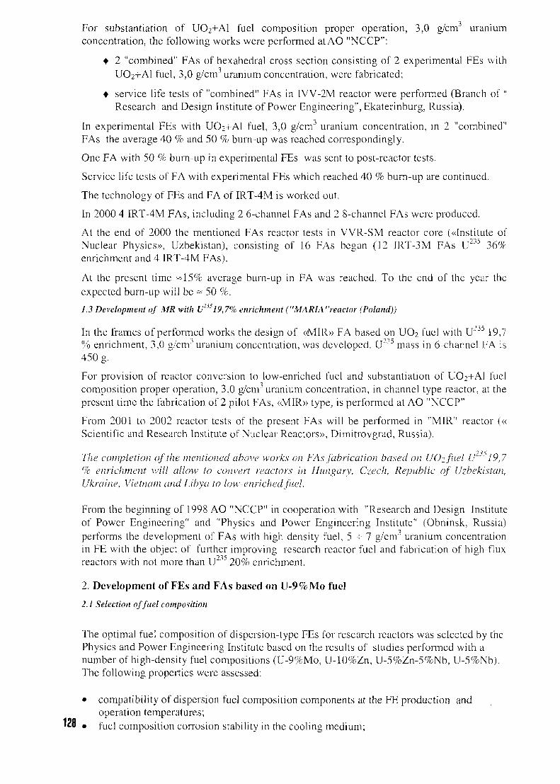
For substantiation of UO2+A1 fuel composition proper operation, 3,0 g/cm3 uraniumconcentration, the following works were performed atAO "NCCP":
• 2 "combined" FAs of hexahedral cross section consisting of 2 experimental FEs withUO2+AI fuel, 3,0 g/cm" uranium concentration, were fabricated;
• service life tests of "combined" FAs in IVV-2M reactor were performed (Branch of "Research and Design Institute of Power Engineering", Ekaterinburg, Russia).
In experimental FEs with UO2+AI fuel, 3,0 g/cmJ uranium concentration, in 2 "combined"FAs the average 40 % and 50 % burn-up was reached correspondingly.
One FA with 50 % burn-up in experimental FEs was sent to post-reactor tests.
Service life tests of FA with experimental FEs which reached 40 % burn-up are continued.
The technology of FEs and FA of IRT-4M is worked out.
In 2000 4 IRT-4M FAs, including 2 6-channel FAs and 2 8-channel FAs were produced.
At the end of 2000 the mentioned FAs reactor tests in VVR-SM reactor core («Institute ofNuclear Physics», Uzbekistan), consisting of 16 FAs began (12 IRT-3M FAs U2° 36%enrichment and 4 IRT-4M FAs).
At the present time =15% average bum-up in FA was reached. To the end of the year theexpected burn-up will be ~ 50 %.
1.3 Development of MR with Uns19,7% enrichment ("MARIA"reactor (Poland))
In the frames of performed works the design of «MIR» FA based on UO2 fuel with U233 19,7% enrichment, 3,0 g/cm'1 uranium concentration, was developed. U2'5 mass in 6-channel FA is450 g.
For provision of reactor conversion to low-enriched fuel and substantiation of UO2+A1 fuelcomposition proper operation, 3,0 g/cm3 uranium concentration, in channel type reactor, at thepresent time the fabrication of 2 pilot FAs, «MIR» type, is performed at AO "NCCP"
From 2001 to 2002 reactor tests of the present FAs will be performed in "MIR" reactor («Scientific and Research Institute of Nuclear Reactors», Dimitrovgrad, Russia).
The completion of the mentioned above works on FAs fabrication based on UOifuel U"^ 19,7% enrichment will allow to convert reactors in Hungary, Czech, Republic of Uzbekistan,Ukraine, Vietnam and Libya to low-enriched fuel.
From the beginning of 1998 AO "NCCP" in cooperation with "Research and Design Instituteof Power Engineering" and "Physics and Power Engineering Institute" (Obninsk, Russia)performs the development of FAs with high density fuel, 5 + 7 g/cm3 uranium concentrationin FE with the object of further improving research reactor fuel and fabrication of high-fluxreactors with not more than U23= 20% enrichment.
2. Development of FEs and FAs based on U-9%Mo fuel
2.1 Selection of fuel composition
The optimal fuel composition of dispersion-type FEs for research reactors was selected by thePhysics and Power Engineering Institute based on the results of studies performed with anumber of high-density fuel compositions (U-9%Mo, U-10%Zn, U-5%Zn-5%Nb, U-5%Nb).The following properties were assessed:
• compatibility of dispersion fuel composition components at the FE production andoperation temperatures;
Via • fue] composition corrosion stability in the cooling medium;
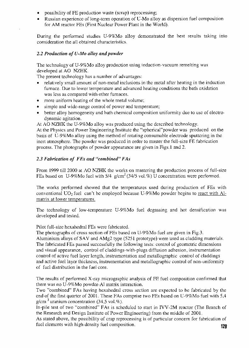
• possibility of FE production waste (scrap) reprocessing;• Russian experience of long-term operation of U-Mo alloy as dispersion fuel composition
for AM reactor FEs (First Nuclear Power Plant in the World).
During the performed studies U-9%Mo alloy demonstrated the best results taking intoconsideration the all obtained characteristics.
2.2 Production of U-Mo alloy and powder
The technology of U-9%Mo alloy production using induction-vacuum remelting wasdeveloped at AO NZHK.The present technology has a number of advantages:• relatively small amount of non-metal inclusions in the metal after heating in the induction
furnace. Due to lower temperature and advanced heating conditions the bath oxidationwas less as compared with other furnaces.
• more uniform heating of the whole metal volume;• simple and wide-range control of power and temperature;• better alloy homogeneity and bath chemical composition uniformity due to use of electro-
dynamic agitation.At AO NZHK the U-9%Mo alloy was produced using the described technology.At the Physics and Power Engineering Institute the "spherical"powder was produced on thebasis of U-9%Mo alloy using the method of rotating consumable electrode sputtering in theinert atmosphere. The powder was produced in order to master the full-size FE fabricationprocess. The photographs of powder appearance are given in Figs. 1 and 2.
2.3 Fabrication of FEs and "combined" FAs
From 1999 till 2000 at AO NZHK the works on mastering the production process of full-sizeFEs based on U-9%Mo fuel with 5/4 g/cm2 (34/5 vol.%) U concentration were performed.
The works performed showed that the temperatures used during production of FEs withconventional UO2 fuel can't be employed because U-9%Mo powder begins to react with Al-matrix at lower temperatures.
The technology of low-temperature U-9%Mo fuel degassing and hot densification wasdeveloped and tested.
Pilot full-size hexahedral FEs were fabricated.The photographs of cross section of FEs based on U-9%Mo fuel are given in Fig.3.Aluminium alloys of SAV and AMg2 type (5251 prototype) were used as cladding materials.The fabricated FEs passed successfully the following tests: control of geometric dimensionsand visual appearance, control of claddings-with-plugs diffusion adhesion, instrumentationcontrol of active fuel layer length, instrumentation and metallographic control of claddingsand active fuel layer thickness, instrumentation and metallographic control of non-uniformityof fuel distribution in the fuel core.
The results of performed X-ray micrographic analysis of FE fuel composition confirmed thatthere was no U-9%Mo powder-Al matrix interaction.Two "combined" FAs having hexahedral cross section are expected to be fabricated by theend of the first quarter of 2001. These FAs comprise two FEs based on U-9%Mo fuel with 5,4g/cm 3 uranium concentration (34,5 vol.%).In-pile test of two "combined" FAs is scheduled to start in IVV-2M reactor (The Branch ofthe Research and Design Institute of Power Engineering) from the middle of 2001.As stated above, the possibility of crap reprocessing is of particular concern for fabrication offuel elements with high density fuel composition. jnn
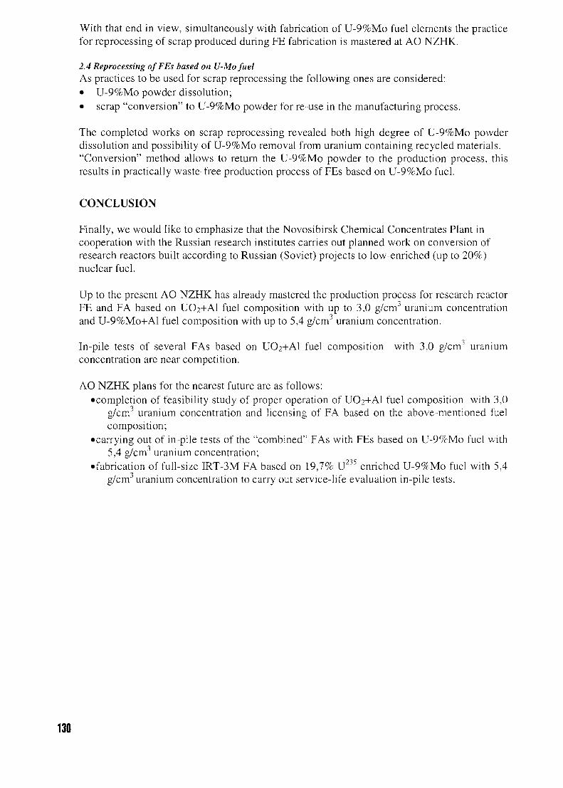
With that end in view, simultaneously with fabrication of U-9%Mo fuel elements the practicefor reprocessing of scrap produced during FE fabrication is mastered at AO NZHK.
2.4 Reprocessing ofFEs based on U-Mo fuelAs practices to be used for scrap reprocessing the following ones are considered:• U-9%Mo powder dissolution;• scrap "conversion" to U-9%Mo powder for re-use in the manufacturing process.
The completed works on scrap reprocessing revealed both high degree of U-9%Mo powderdissolution and possibility of U-9%Mo removal from uranium containing recycled materials."Conversion" method allows to return the U-9%Mo powder to the production process, thisresults in practically waste-free production process of FEs based on U-9%Mo fuel.
CONCLUSION
Finally, we would like to emphasize that the Novosibirsk Chemical Concentrates Plant incooperation with the Russian research institutes carries out planned work on conversion ofresearch reactors built according to Russian (Soviet) projects to low-enriched (up to 20%)nuclear fuel.
Up to the present AO NZHK has already mastered the production process for research reactorFE and FA based on UO2+AI fuel composition with up to 3,0 g/cm3 uranium concentrationand U-9%Mo+Al fuel composition with up to 5,4 g/cm uranium concentration.
In-pile tests of several FAs based on UO?+A1 fuel composition with 3,0 g/cmJ uraniumconcentration are near competition.
AO NZHK plans for the nearest future are as follows:•completion of feasibility study of proper operation of UO2+AI fuel composition with 3,0
g/cm3 uranium concentration and licensing of FA based on the above-mentioned fuelcomposition;
•carrying out of in-pile tests of the "combined" FAs with FEs based on U-9%Mo fuel with5,4 g/cmJ uranium concentration;
• fabrication of full-size IRT-3M FA based on 19,7% U235 enriched U-9%Mo fuel with 5,4g/cm3 uranium concentration to carry out service-life evaluation in-pile tests.
130
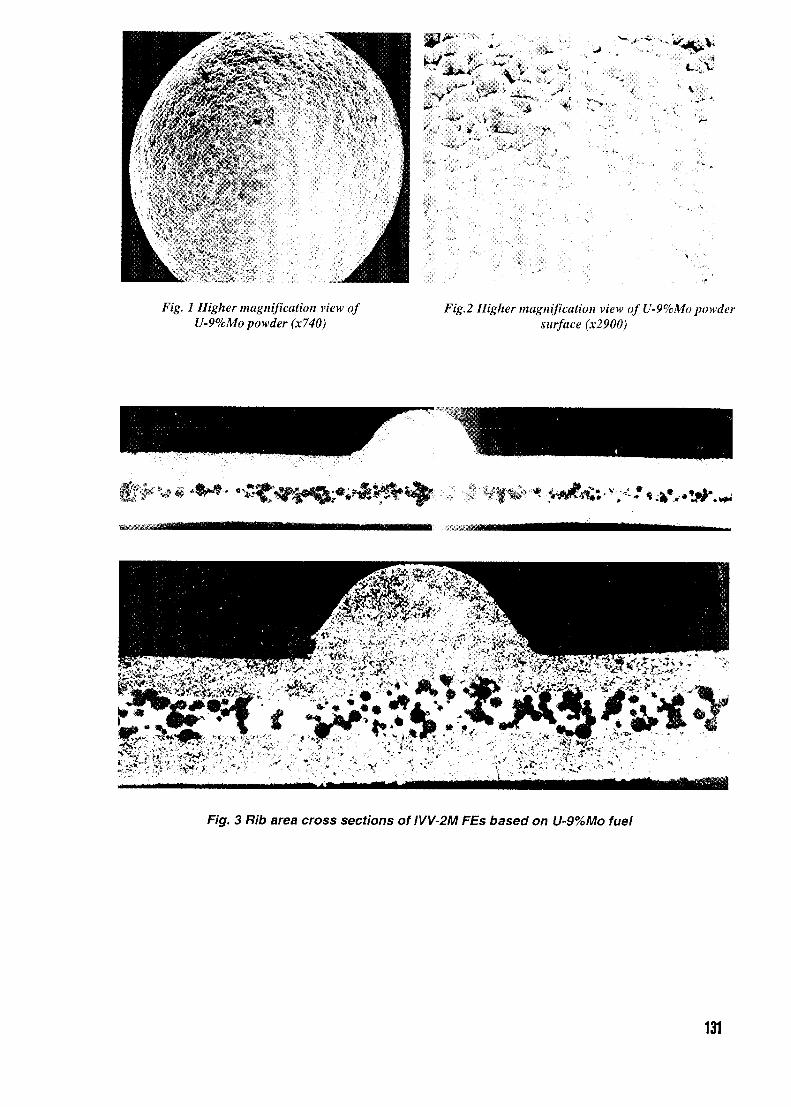
7 Higher magnification view ofU-9%Mo powder (x740)
/g.2 Higher magnification view of U-9%Mo powdersurface (x2900)
•#• i»«a' «**, v«% -̂ •
F/g. 3 Rib area cross sections of IVV-2M FEs based on U-9%Mo fuel
131

Posters
H3XK
'THE REVIEW OF FUEL TYPES FOR RUSSIAN RESEARCH REACTOR,THEIR FABRICATION AND QUALITY CONTROL"
A.A. Enin, A.B. Alexandrov, I.E. ZaporozhetsAO "Novosibirsk Chemical ConcentratesPlant',
94 B. Khmelnitsky St, Novosibirsk 630110, Russia
ABSTRACT
Research reactors fuel management (RRFM 2001)Aachen, Germany, April 1-4, 2001
The design of tubular fuel elements (FEs) for research reactor fuel assemblies (FAs) is considered.
Commercial extrusion and annular-type technologies for tubular FE fabrication are described.
"Extrusion" technology is based on fabrication of tubular billet of fuel core by means of powder
metallurgy followed by hot extrusion of fuel core tubular billet and tubular cladding billet. The
process is completed with FE assembly operation.
"Annular" technology is based on fuel core fabrication using powder metallurgy followed by
chemical treatment of fuel core surface and fuel core insertion into the cladding.
The list of FE and FA control operations to check their conformance to the required quality level is
given.
The most common FA designs (WWR-M2, WWR-M5, IRT-2M, IRT-3M, MR, MIR, WWR-TS,
IVV-2M, IVV-10, TWR-S, IR-100) for research reactors built according to the Russian projects are
described.
Quality Assurance System acting at "Novosibirsk Chemical Concentrates Plant" is presented.
"Novosibirsk Chemical Concentrates Plant" (NZHK) is a manufacturer of nuclear fuel (fuel
elements and fuel assemblies) for power, commercial and research reactors.
Since 1973 NZHK has supplied more than 25 000 Fuel Assemblies (FAs) of 56 modifications
for thirty pool and channel research reactors built up under the Russian projects.
Tubular and rod-type Fuel Elements (FEs) are used in FAs produced at our enterprise. The most
widely used FA design is as follows: FA consists of tubular FEs (inserted in one another) in a coaxial
position.133
Tubular FE is a seamless three-layer tube. This is the main distinctive feature of our FEs in
comparison with plate-type FEs supplied by foreign companies. The middle layer consists of uranium
containing fuel composition, the external layers - Al-alloy claddings. FEs produced at "Novosibirsk
Chemical Concentrates Plant" are characterized by different cross-section profiles. Varying both the
profiles and the uranium mass in FE one can produce FAs according to the requirements specified by
the Customer.
Tubular FEs are manufactured using the following two primary production processes:
- "extrusion" technology,
- "annular" technology.
The "extrusion" technology comprises the following primary operations:
- mixing of components of uranium-containing fuel core;
- cold compacting of metal-ceramic cylindrical tube;
- degassing and sintering of metal-ceramic cylindrical tube;
- hot calibration of metal-ceramic cylindrical tube;
- turning of metal-ceramic cylindrical tube;
- assembly of metal-ceramic cylindrical tube with aluminium cylinder and plug;
- hot co-extrusion;
- formation of different FE cross-section profiles.
The "annular" technology comprises the following primary operations:
- mixing of components of uranium-containing fuel core;
- cold compacting of metal-ceramic cylindrical tube;
- egassing and sintering of metal-ceramic cylindrical tube;
- hot calibration of metal-ceramic cylindrical tube;
- turning of metal-ceramic cylindrical tube;
- extrusion of metal-ceramic cylindrical tube;
- metal-ceramic cylindrical tube cutting to fuel cores;
- chemical treatment of fuel cores;
- assembly of the fuel core with aluminium cladding billet;
- cold calibration of the assembly;
- FE pressurization by welding;
- FE high-temperature gas reduction.
The FE quality is evaluated in accordance with the following main parameters:
- visual appearance;
- structure of cladding material;
- length and continuity of the fuel layer;
- uniformity of the fuel layer composition;
- cladding layer thickness;
- cladding-to-fuel layer adjoining (adhesion);
134
- uranium mass;
- geometric dimensions;
- FE surface contamination by the uranium.
In-process control of FE technological parameters is performed. The results of the main
technological control results are archived in a file.
Numerous FA modifications have been developed at our enterprise to meet the requirements of a
great number of reactors having specific features.
The table containing technical data on FAs for research reactor cores is given in Fig.l.
Some FAs have modifications with different number of FEs in FAs, e.g. FA of MR-type. This
makes it possible to supply FAs with the internal hollow cavity in which the control and protection
system (CPS) elements and different experimental devices are placed.
There are also the FA designs (e.g. FA of FRT-2M type) in which the required internal hollow
cavity can be created by the Customer in the reactor by means of withdrawal of internal FEs from FA .
There are complex FA designs consisting of several FAs combined together, e.g. three-sectional
FAs of WWR-M2 and WWR-M5 types. The mentioned FA designs provide for prompt performance of
in-reactor nuclear fuel reloading.
FAs are assembled from well-tested FEs and end pieces. The finished FA undergoes acceptance
inspection aimed at control of the following parameters :
- visual appearance;
- geometrical dimensions;
- FE spacing;
- free insertion into measuring gauge (simulator of FA in-reactor positioning);
- internal cavity size and shape (if any).
As it is seen from the table (Fig.l), FAs supplied by "Novosibirsk Chemical Concentrates Plant"
have 90% and 36% U-235 enriched fuel composition. Uranium weight concentration in the FAs fuel
core is up to 2.5 g/cm3 (volume concentration - up to 29.5%). The FAs quality is proved by their
successful long-term operation in both Russian and foreign reactors.
Due to the existing trend of research reactors conversion to low-enriched nuclear fuel our
enterprise develops nuclear fuel with up to 20% U-235 enrichment in cooperation with the following
Russian Institutions: State Unitary Institution "Research and Design Institute of Power Engineering"
(GUP NIKIET), Russian Federation State Scientific Center "Bochvar Ail-Russian Research Institute of
Inorganic Materials" (GNTS RF VNIINM), Russian Scientific Center "Kurchatov Institute" (RNTS
KI) and State Scientific Center " Physics and Power Engineering Institute" (GNTS RF FEI).
The existing at "Novosibirsk Chemical Concentrates Plant" FE and FA production cycle
beginning from uranium hexafluoride conversion and uranium wastes reprocessing allows to supply the
Customers both FAs and uranium feedstock for FA production.
The FE technologies mastered and used at our enterprise provide for manufacture of targets for
isotopes and radiation-alloyed silicon production.
135
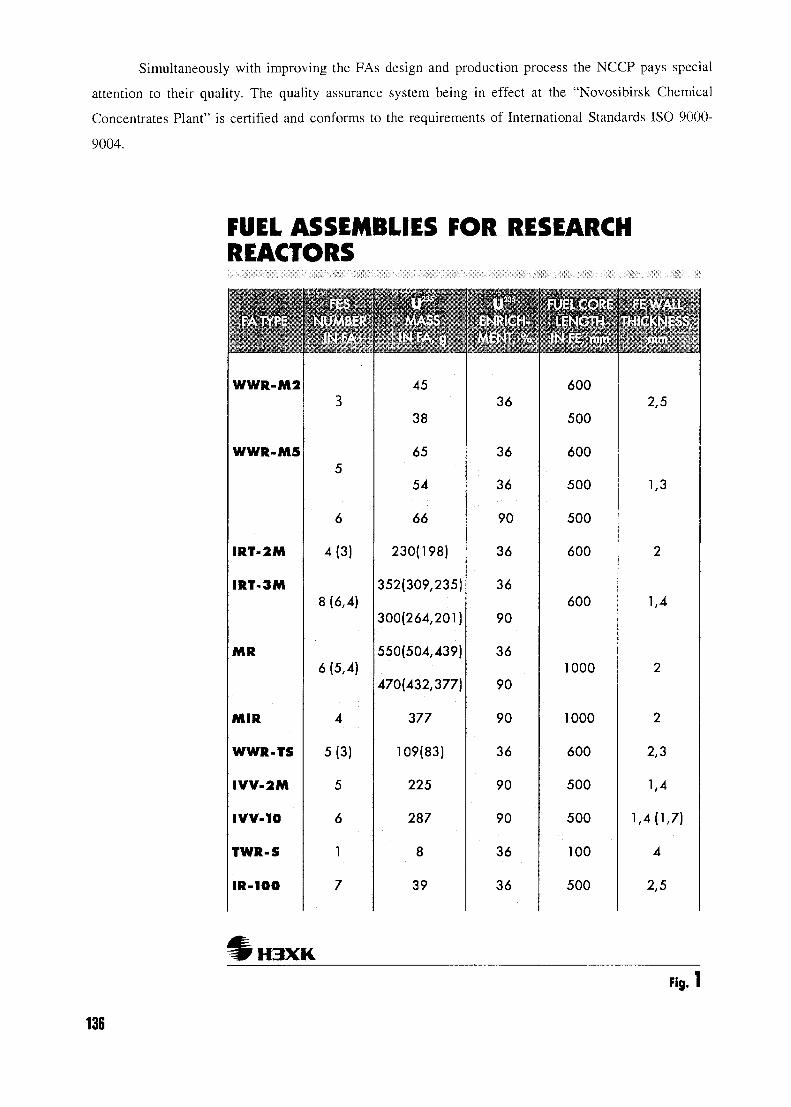
Simultaneously with improving the FAs design and production process the NCCP pays special
attention to their quality. The quality assurance system being in effect at the "Novosibirsk Chemical
Concentrates Plant" is certified and conforms to the requirements of International Standards ISO 9000-
9004.
FUEL ASSEMBLIES FOR RESEARCHREACTORS
WWR-M2
WWR-M5
IRT-2M
IRT-3M
MR
MIR
WWR-TS
IVV-2M
IVV-10
TWR-S
IR-100
3
5
6
4(3)
8 (6,4)
6 (5,4)
4
5(3)
5
6
1
7
' • ' • 'i' ,
1. i • ' ; : • . • • ' •
45
38
65
54
66
230(198)
352(309,235)
300(264,201)
550(504,439)
470(432,377)
377
109(83)
225
287
8
39
36
36
36
90
36
36
90
36
90
90
36
90
90
36
36
600
500
600
500
500
600
600
1000
2,5
1,3
1,4
1000
600
500
500
100
500
2
2,3
1,4
1,4(1,7)
4
2,5
H3XKFig. 1
136
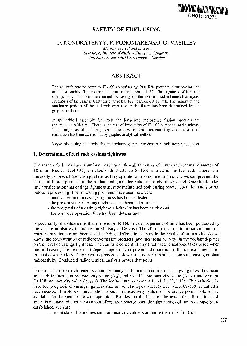
CH01000270
SAFETY OF FUEL USING
O. KONDRATSKYY, P. PONOMARENKO, O. VASILIEVMinistry of Fuel and Energy
Sevastopol Institute of Nuclear Energy and IndustryKurchatov Street, 99033 Sevastopol - Ukraine
ABSTRACT
The research reactor complex IR-100 comprises the 200 KW power nuclear reactor andcritical assembly. The reactor fuel rods operate since 1967. The tightness of fuel rodcasings now has been determined by using of the coolant radiochemical analysis.Prognosis of the casings tightness change has been carried out as well. The minimum andmaximum periods of the fuel rods operation in the future has been determined by thegraphic method.
In the critical assembly fuel rods the long-lived radioactive fission products areaccumulated with time. There is the risk of irradiation of IR-100 personnel and students.The prognosis of the long-lived radioactive isotopes accumulating and increase ofemanation has been carried out by graphic-analytical method.
Keywords: casing, fuel rods, fission products, gamma-ray dose rate, radioactive, tightness
1. Determining of fuel rods casings tightness
The reactor fuel rods have aluminum casings with wall thickness of 1 mm and external diameter of10 mms. Nuclear fuel UO2 enriched with U-235 up to 10% is used in the fuel rods. There is anecessity to forecast fuel casings state, as they operate for a long time. In this way we can prevent theescape of fission products in the coolant and guarantee radiation safety of personnel. One should takeinto consideration that casings tightness must be maintained both during reactor operation and storingbefore reprocessing. The following problems have been resolved:
- main criterion of a casings tightness has been selected- the present state of casings tightness has been determined- the prognosis of a casings tightness behavior has been carried out- the fuel rods operation time has been determined.
A peculiarity of a situation is that the reactor IR-100 in various periods of time has been possessed bythe various ministries, including the Ministry of Defense. Therefore, part of the information about thereactor operation has not been saved. It brings definite inaccuracy in the results of our activity. As weknow, the concentration of radioactive fission products (and their total activity) in the coolant dependson the level of casings tightness. The constant concentration of radioactive isotopes takes place whenfuel rod casings are hermetic. It depends upon reactor power and operation of the ion-exchange filter.In most cases the loss of tightness is proceeded slowly and does not result in sharp increasing coolantradioactivity. Conducted radiochemical analysis proves that point.
On the basis of research reactors operation analysis the main criterion of casings tightness has beenselected: iodines sum radioactivity value (An), iodine 1-131 radioactivity value (AI_BI) and cesiumCs-138 radioactivity value (Acs-i3g). The iodines sum comprises 1-131, 1-133, 1-135. This criterion isused for prognosis of casings tightness state as well. Isotopes 1-131,1-133, 1-135, Cs-138 are called areference-point isotopes. Information about radioactivity value of reference-point isotopes isavailable for 16 years of reactor operation. Besides, on the basis of the available information andanalysis of standard documents about of research reactor operation three states of fuel rods have beenestablished, such as:
- normal state - the iodines sum radioactivity value is not more than 5 10"7 to Ci/1
137

- permissible state - the iodines sum radioactivity value is from 5 10"7 to 5 10"6 Ci/1- non-permissible state - the iodines sum radioactivity value is more than 5 • 10"6 Ci/1.
Variation graph of the iodines sum radioactivity value from 1968 to 1995 has been represented onfig. 1. The so-called method of "smoothing out" has been used for decrease of errors influence duringthe radioactivity value is measurement: (A£1 +An + • • • + ASI ) / 7.
1CT
10-"
10'"'
a (Ci/I)
Non-permissible state
Permissible state
Normal state
III IV V
1968 1972 1976 1980 1984 1988 1992 1996 2004 2008 2012 20162000
Fig. 1. Variation of iodine radioactivity.
From fig. 1 it is seen, that time of fuel rods operation can be divided into 5 periods, such as:Period 1 (1968-1981) - stabilization of iodine isotopes content.Period 11 (1981-1990) - iodine isotopes content on the average is at one level.Period 111(1990-1995) - iodine isotopes content rises slowly.Period IV (1995-2000) - reactor did not operate.Period V - prognosis period.
On the basis of fig. 1 we can see that the reactor fuel rods are in normal state now. Also we can makeapproximated conclusions, that:
- iodine isotopes content will rise slowly at next years, that speaks about fuel rod casingtightness loss starting process
- in the period from 2005 to 2011 fuel rods will be supposed to transit to permissible state(more careful inspection of fuel rod casings will be needed)
- supposedly after 2014 the core will transit to non-permissible state, therefore, necessity of thecore reloading may arise.
On the basis of operating experience of research reactors it is known that ratio Acs-138 / A j .n idecreases few times when the core transits to non-permissible state. Graph of the ratio variation ACs-iW Ai.i3i is represented in fig. 2. From fig. 2 it is seen that ratio Acs-138 / Aj_ 131 decreases slowly.It reinforces conclusions about the fuel rod casings tightness loss starting process.
138
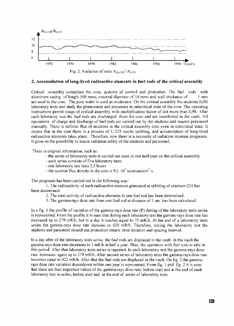
12
10
1970 1974 1978 1982 1986 1990 1994 T(ycars)
Fig. 2. Variation of ratio ACs_i38/ Ai.ni
2. Accumulation of long-lived radioactive elements in fuel rods of the critical assembly
Critical assembly comprises the core, systems of control and protection. The fuel rods withaluminum casing of length 500 mms, external diameter of 10 mms and wall thickness of 1 mmare used in the core. The pure water is used as moderator. On the critical assembly the students fulfillaboratory tests and study the phenomena and processes in subcritical state of the core. The operatinginstructions permit usage of critical assembly with multiplication factor of not more than 0,98. Aftereach laboratory test the fuel rods are discharged from the core and are transferred in the vault. Alloperations of charge and discharge of fuel rods are carried out by the students and reactor personnelmanually. There is definite flux of neutrons in the critical assembly core even in subcritical state. Itmeans that in the core there is a process of U-235 nuclei splitting, and accumulation of long-livedradioactive elements takes place. Therefore, now there is a necessity of radiation increase prognosis.It gives us the possibility to insure radiation safety of the students and personnel.
There is original information, such as:- the series of laboratory tests is carried out once in one half-year on the critical assembly- each series consists of five laboratory tests- one laboratory test lasts 2,5 hours- the neutron flux density in the core is 9,1 103 neutrons/cm2 s.
The prognosis has been carried out in the following way:1. The radioactivity of each radioactive element generated at splitting of uranium-235 has
been determined.2. The total activity of radioactive elements in one fuel rod has been determined.3. The gamma-rays dose rate from one fuel rod at distance of 1 sm. has been calculated.
In a fig. 1 the profile of variation of the gamma-rays dose rate (P) during of the laboratory tests seriesis represented. From the profile it is seen that during each laboratory test the gamma-rays dose rate hasincreased up to 279 mR/h, but in a day it reaches equal to 75 mR/h. At the end of a laboratory testsseries the gamma-rays dose rate increase to 420 mR/h. Therefore, during the laboratory test thestudents and personnel should use protection means: time duration and spacing interval.
In a day after of the laboratory tests series the fuel rods are displaced in the vault. In the vault thegamma-rays dose rate decreases to 1 mR/h in half a year. Thus, the operation with fuel rods is safe inthis period. After that laboratory tests series is repeated. In each laboratory test the gamma-rays doserate increases again up to 279 mR/h. After second series of laboratory tests the gamma-rays dose ratebecomes equal to 422 mR/h. After that the fuel rods are displaced in the vault. On fig. 2 the gamma-rays dose rate variation dependence within one year is represented. From fig. 1 and fig. 2 it is seenthat there are four important values of the gamma-rays dose rate: before start and at the end of eachlaboratory test in series, before start and at the end of series of laboratory tests.
139
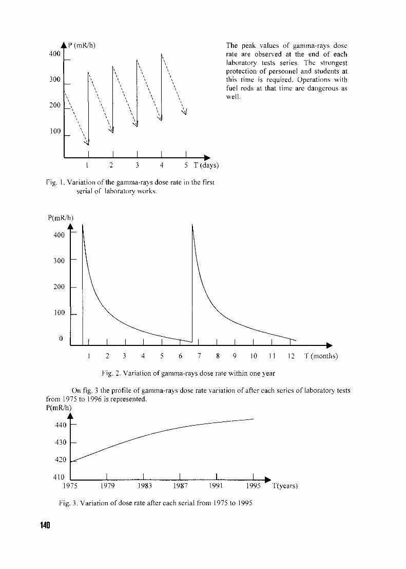
A
400
300
200
100
LP(mR/h)
—\\\\\\
\\\\
\
\\\\
V\\
\\
\
\\
\
\\\\\\
\\
\\\
\\\
•
\
\
\
\
The peak values of gamma-rays doserate are observed at the end of eachlaboratory tests series. The strongestprotection of personnel and students atthis time is required. Operations withfuel rods at that time are dangerous aswell.
1 5 T(days)
Fig. 1. Variation of the gamma-rays dose rate in the firstserial of laboratory works.
P(mR/h)
400
300
200
100
1 2 3 4 5 6 7 8 9 10 11 12 T (months)
Fig. 2. Variation of gamma-rays dose rate within one year
On fig. 3 the profile of gamma-rays dose rate variation of after each series of laboratory testsfrom 1975 to 1996 is represented.P(mR/h)
440
430
420
4101975 1979 1983 1987 1991 1995 T(years)
Fig. 3. Variation of dose rate after each serial from 1975 to 1995
140
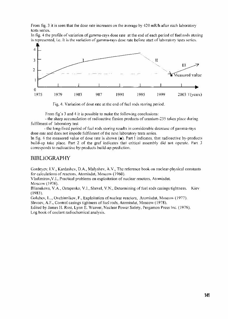
From fig. 3 it is seen that the dose rate increases on the average by 420 mR/h after each laboratorytests series.In fig. 4 the profile of variation of gamma-rays dose rate at the end of each period of fuel rods storingis represented, i.e. it is the variation of gamma-rays dose rate before start of laboratory tests series.
IIIII
Measured value
0
1975 1979 1983 987 1991 1995 1999 2003 T(years)
Fig. 4. Variation of dose rate at the end of fuel rods storing period.
From fig's 3 and 4 it is possible to make the following conclusions:- the sharp accumulation of radioactive fission products of uranium-235 takes place during
fulfilment of laboratory test- the long-lived period of fuel rods storing results in considerable decrease of gamma-rays
dose rate and does not impede fulfilment of the next laboratory tests series.In fig. 4 the measured value of dose rate is shown (•). Part 1 indicates, that radioactive by-productsbuild-up take place. Part 2 of the graf indicates that critical assembly did not operate. Part 3corresponds to radioactive by-products build-up prediction.
BIBLIOGRAPHY
Gordeyev, I.V., Kardashev, D.A., Malyshev, A.V., The reference book on nuclear-physical constantsfor calculations of reactors, Atomisdat, Moscow (1960).Vladimirov,V.L, Practical problems on exploitation of nuclear reactors, Atomisdat,Moscow (1976).Blisnukova, V.A., Ostapenko, V.I., Shevel, V.N., Determining of fuel rods casings tightness, Kiev(1983).Golubev, L.., Ovchinnikov, F., Exploitation of nuclear reactors, Atomisdat, Moscow (1977).Shvoev, A.F., Control casings tightness of fuel rods, Atomisdat, Moscow (1978).Edited by James H. Rust, Lynn E. Weaver, Nuclear Power Safety, Pergamon Press Inc. (1976).Log book of coolant radiochemical analysis.
141
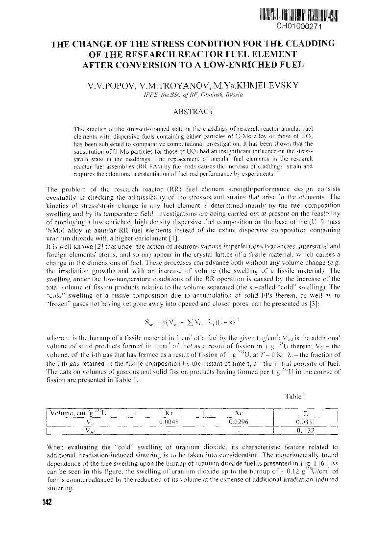
CH01000271
THE CHANGE OF THE STRESS CONDITION FOR THE CLADDINGOF THE RESEARCH REACTOR FUEL ELEMENT
AFTER CONVERSION TO A LOW-ENRICHED FUEL
V.V.POPOV, V.M.TROYANOV, M.Ya.KHMELEVSKYIPPE, the SSC ofRF, Obnin.sk, Russia
ABSTRACT
The kinetics of the stressed-strained state in the claddings of research reactor annular fuelelements with dispersive fuels containing either particles of U-Mo alloy or those of UO2
has been subjected to comparative computational investigation. It has been shown that thesubstitution of U-Mo particles for those of UO? had an insignificant influence on the stress-strain state in the claddings. The replacement of annular fuel elements in the researchreactor fuel assemblies (RR FAs) by fuel rods causes the increase of claddings' strain andrequires the additional substantiation of fuel rod performance by experiments.
The problem of the research reactor (RR) fuel element strength/performance design consistseventually in checking the admissibility of the stresses and strains that arise in the elements. Thekinetics of stress/strain change in any fuel element is determined mainly by the fuel compositionswelling and by its temperature field. Investigations are being carried out at present on the feasibilityof employing a low-enriched, high density dispersive fuel composition on the base of the (U-9 mass%Mo) alloy in annular RR fuel elements instead of the extant dispersive composition containinguranium dioxide with a higher enrichment [I].It is well known [2] that under the action of neutrons various imperfections (vacancies, interstitial andforeign elements' atoms, and so on) appear in the crystal lattice of a fissile material, which causes achange in the dimensions of fuel. These processes can advance both without any volume change (e.g.the irradiation growth) and with an increase of volume (the swelling of a fissile material). Theswelling under the low-temperature conditions of the RR operation is caused by the increase of thetotal volume of fission products relative to the volume separated (the so-called "cold" swelling). The'•cold"1 swelling of a fissile composition due to accumulation of solid FPs therein, as well as to"frozen" gases not having yet gone away into opened and closed pores, can be presented as [3]:
Ssol =Y(VS,,+IVD, -? s)0 -e ) - 1
where y is the burn up of a fissile material in 1 cm' of a fuel by the given t, g/cnr: VS,,| is the additionalvolume of solid products formed in 1 cm' of fuel as a result of fission in 1 g ""°U therein; Vo, — thevolume, of the i-tin gas that has formed as a result of fission of 1 g " ' \ J , at T= 0 K; >., - the fraction ofthe i-th gas retained in the fissile composition by the instant of time t; e - the initial porosity of fuel.The data on volumes of gaseous and solid fission products having formed per 1 g 2 o U in the course offission are presented in Table 1.
Table I
Volume , crrrVg ~"°U
VOl
VSl,i
i Kr0.0045
~t " - "Xe
0.0296-
00
y.
0331132
When evaluating the '"cold" swelling of uranium dioxide, its characteristic feature related toadditional irradiation-induced sintering is to be taken into consideration. The experimentally founddependence of the free swelling upon the burnup of uranium dioxide fuel is presented in Fig. 1 [6]. Ascan be seen in this figure, the swelling of uranium dioxide up to the burnup o f - 0.12 g~J'U/cnr offuel is counterbalanced by the reduction of its volume at the expense of additional irradiation-inducedsintering.
142
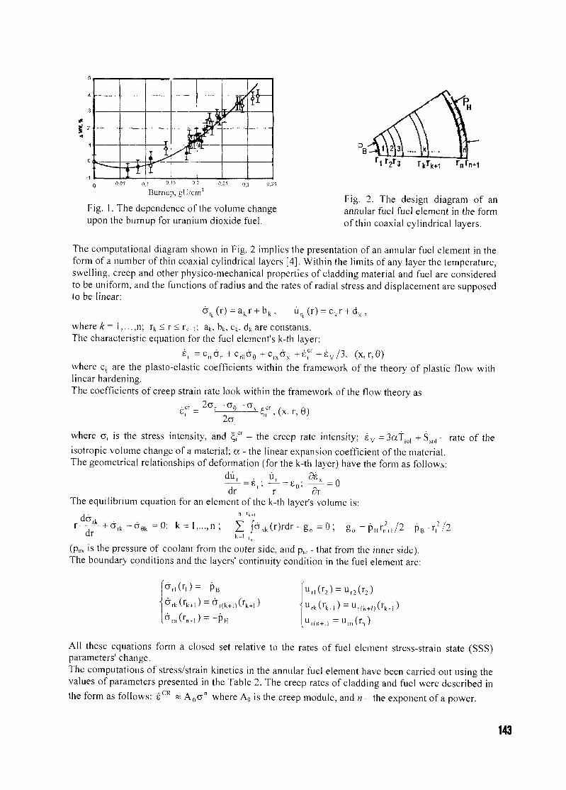
x %
0,05 0,1 °-15 °2
Burnup, glJ/cm'0.25 o,3
Fig. 1. The dependence of the volume changeupon the burnup for uranium dioxide fuel.
rnrn+1
Fig. 2. The design diagram of anannular fuel fuel element in the formof thin coaxial cylindrical layers.
The computational diagram shown in Fig. 2 implies the presentation of an annular fuel element in theform of a number of thin coaxial cylindrical layers [4]. Within the limits of any layer the temperature,swelling, creep and other physico-mechanical properties of cladding material and fuel are consideredto be uniform, and the functions of radius and the rates of radial stress and displacement are supposedto be linear:
where k= l,...,n; r k <r<r k . , ; ak, bk, ck, dk are constants.The characteristic equation for the fuel element's k-th layer:
s,, =c n d r +c r edred9 S V / 3 , (x,r,9)where c,, are the plasto-elastic coefficients within the framework of the theory of plastic flow withlinear hardening.The coefficients of creep strain rate look within the framework of the flow theory as
c =•2a,
where af is the stress intensity, and ^cr - the creep rate intensity; s v =3atso, + Ss0, - rate of theisotropic volume change of a material; a - the linear expansion coefficient of the material.The geometrical relationships of deformation (for the k-th layer) have the form as follows:
dr r drThe equilibrium equation for an element of the k-th layer's volume is:
dr k=lJaxk(r)rdr + go = 0; go = pHrn
2+l/2 - pB • rf /2
(pex is the pressure of coolant from the outer side, and p,,, - that from the inner side).The boundary conditions and the layers' continuity condition in the fuel element are:
Ur(n + l) = u r a ( r n )
All these equations form a closed set relative to the rates of fuel element stress-strain state (SSS)parameters' change.The computations of stress/strain kinetics in the annular fuel element have been carried out using thevalues of parameters presented in the Table 2. The creep rates of cladding and fuel were described inthe form as follows: sCR ~ A o a n where Ao is the creep module, and n - the exponent of a power.
143
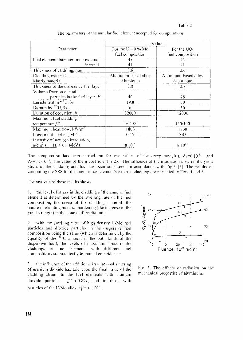
Table 2
The parameters of the annular fuel element accepted for computations
Parameter
Fuel element diameter, mm: externalinternal
Thickness of cladding, mmCladding materialMatrix materialThickness of the dispersive fuel layerVolume fraction of fuel
particles in the fuel layer, %Enrichment in 2 3 DU, %
Burnup by "'U, %Duration of operation, hMaximum fuel claddingtemperature,°CMaximum heat flow, kW/m"Pressure of coolant, MPaIntensity of neutron irradiation,n/cm2-s (E>0 .1 MeV)
ValueFor the U - 9 % Mo
fuel composition45410.6
Aluminum-based alloyAluminum
0.8
4019.850
12000
150/10018000.45
8-1014
For the UO2
fuel composition45410.6
Aluminum-based allovAluminum
0.8
285050
12000
150/10018000.45
8-1014
The computation has been carried out for two values of the creep modulus, A0=6-10"L' andAo= 1.5-10" . The value of the n coefficient is 2.6. The influence of the irradiation dose on the yieldstress of the cladding and fuel has been considered in accordance with Fig.3 [5]. The results ofcomputing the SSS for the annular fuel element's external cladding are presented in Figs. 4 and 5.
The analysis of these results shows:
1. the level of stress in the cladding of the annular fuelelement is determined by the swelling rate of the fuelcomposition, the creep of the cladding material, thenature of cladding material hardening (the increase of theyield strength) in the course of irradiation;
2. with the swelling rates of high density U-Mo fuelparticles and dioxide particles in the dispersive fuelcomposition being the same (which is determined by theequality of the 2'5U amount in the both kinds of thedispersive fuel), the levels of maximum stress in thecladdings of fuel elements with different fuelcompositions are practically in mutual coincidence;
3 the influence of the additional irradiational sinteringof uranium dioxide has told upon the final value of thecladding strain. In the fuel elements with uranium
dioxide particles SQiax ~ 0 . 8 % , and in those with
25 • 5 . %
Fluence, 10 n/cm'
Fig. 3. The effects of radiation on themechanical properties of aluminum.
particles of the U-Mo alloy E[ 1.0%.
144
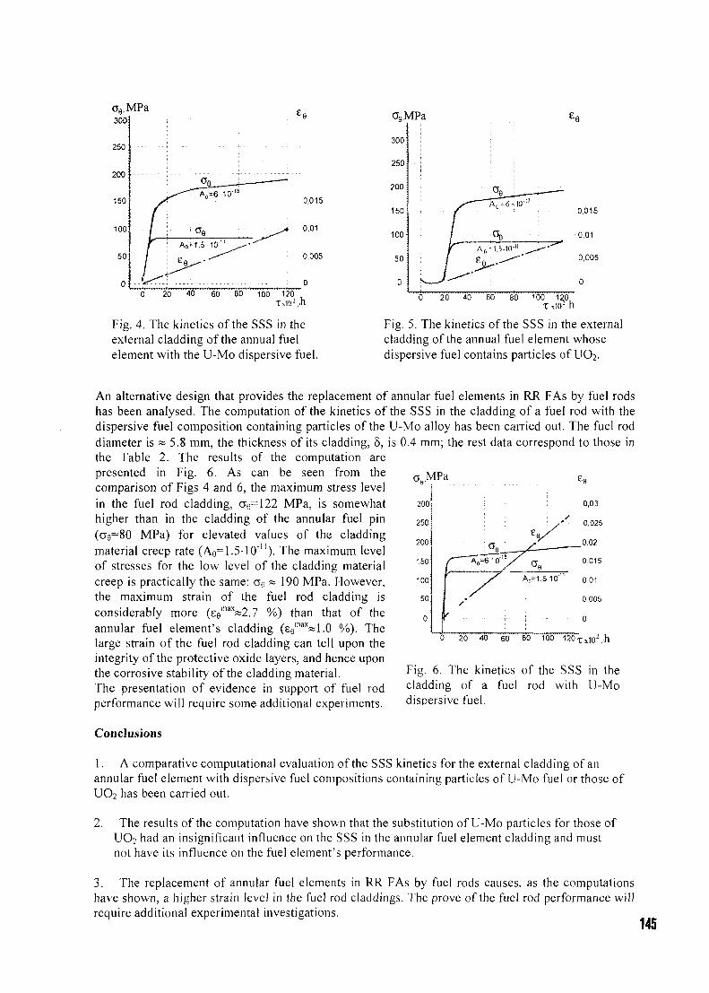
oe,MPa300:
250 :
200
150
100
so:
0
0,015
0.01
0,005
0
300
250
200
150
100
50
0
0 20 40 60 80 100 120
Fig. 4. The kinetics of the SSS in theexternal cladding of the annual fuelelement with the U-Mo dispersive fuel.
0 20 40 60 80 100 120T xlO2 ,h
Fig. 5. The kinetics of the SSS in the externalcladding of the annual fuel element whosedispersive fuel contains particles of UO2.
MPa
300
An alternative design that provides the replacement of annular fuel elements in RR FAs by fuel rodshas been analysed. The computation of the kinetics of the SSS in the cladding of a fuel rod with thedispersive fuel composition containing particles of the U-Mo alloy has been carried out. The fuel roddiameter is « 5.8 mm, the thickness of its cladding, 5, is 0.4 mm; the rest data correspond to those inthe Table 2. The results of the computation arepresented in Fig. 6. As can be seen from thecomparison of Figs 4 and 6, the maximum stress levelin the fuel rod cladding, cre=122 MPa, is somewhathigher than in the cladding of the annular fuel pin(ae=80 MPa) for elevated values of the claddingmaterial creep rate (A0=1.5-10""). The maximum levelof stresses for the low level of the cladding materialcreep is practically the same: ae ~ 190 MPa. However,the maximum strain of the fuel rod cladding isconsiderably more (se
max~2.7 %) than that of theannular fuel element's cladding (ee
max«1.0 %). Thelarge strain of the fuel rod cladding can tell upon theintegrity of the protective oxide layers, and hence uponthe corrosive stability of the cladding material.The presentation of evidence in support of fuel rodperformance will require some additional experiments.
Conclusions
0,03
0,025
0,02
0015
0,01
0,005
Fig. 6. The kinetics of the SSS in thecladding of a fuel rod with U-Modispersive fuel.
1. A comparative computational evaluation of the SSS kinetics for the external cladding of anannular fuel element with dispersive fuel compositions containing particles of U-Mo fuel or those ofUO2 has been carried out.
2. The results of the computation have shown that the substitution of U-Mo particles for those ofUO2 had an insignificant influence on the SSS in the annular fuel element cladding and mustnot have its influence on the fuel element's performance.
3. The replacement of annular fuel elements in RR FAs by fuel rods causes, as the computationshave shown, a higher strain level in the fuel rod claddings. The prove of the fuel rod performance willrequire additional experimental investigations.
14S
References
[1]. V.G. Aden. V.V. Popov. A.Ye.Rusanov, V.M. Troyanov. Investigations of a reduced enrichmentdispersion fuel composition (U-Mo alloy in aluminum matrix) for research reactor fuel pins.Transactions Oral Presentation Posters ENS RRFM'99, 1999.
[2], S.T.Konobeevsky. The effects of irradiation on materials. Moscow, Atomizdat, 1967{available in Russian only).
[3]. Yu.I.Likhachev, V.Ya.Pupko, V.V.Popov. Methods of stress design for nuclear reactor fuelelements {available in Russian only).
[4], M.Ya.Khmelevsky, Ye.l.Malakhova, Yu.N.Mironovich. Testing and verification of a finite-element program complex "FEMINA" in the simulation of plastic deformation and creepprocesses. An IPPE preprint O3M-2704, Obninsk, 1998 {available in Russian only).
[5], A.G.Samoilov, A.I.Kashtanov, V.S.Volkov. Dispersive fuel elements. Volume 1. Materialsand technology. Moscow, Energoatomizdat {available in Russian only).
[6], V.I.Kuzmin et al. The change in the state of fuel in the WWER fuel pins with a burnup of 40 - 60MW-day/kg U. In Transactions of the 5" Conference on Reactor Material Science, vol. 1. part 1,Dimitrovgrad, 1998 {available in Russian only).
146
CH01000272
A GAMMA HEATING CALCULATION METHODOLOGY FORRESEARCH REACTOR APPLICATION
Y. K. LEECEA - Saclay, DEN/DM2S/SERMA/LEPP, 91191 Gifsur Yvette Cedex, France
and
J.-C. DAVID and H. CARCREFFCEA-Saclay, DEN/DRSN/SIREN/LASPI, 91191 Gifsur Yvette Cedex, France
ABSTRACT
Gamma heating is an important issue in research reactor operation and fuel safety. Heatdeposition in irradiation targets and temperature distribution in irradiation facility should bedetermined so as to obtain the optimal irradiation conditions. This paper presents a recentlydeveloped gamma heating calculation methodology and its application on the researchreactors. Based on the TRIPOLI-4 Monte Carlo code under the continuous-energy option,this new calculation methodology was validated against calorimetric measurements realizedwithin a large ex-core irradiation facility of the 70 MWth OSIRIS materials testing reactor(MTR). The contributions from prompt fission neutrons, prompt fission y-rays, capture y-rays and inelastic y-rays to heat deposition were evaluated by a coupled (n,y) transportcalculation. The fission product decay y-rays were also considered but the activation y-rayswere neglected in this study.
1. Introduction
After the shutdown of SILOE reactor in 1997, OSIRIS is the only operational MTR in France. Tocontinue operating this research reactor, which achieved its first criticality on Sep. 1966, therefurbishment programs concerning reactor fuel rack, reactor tank and other equipments, were realizedduring past years [1]. To optimize the irradiation program, the modern radiation transport codeTRIPOLI-4 [2] was recently introduced to calculate the plate-by-plate full core model and to improvethe design and the performance of the irradiation facility in the OSIRIS reactor.
On design of irradiation targets and irradiation facility, one of the goals is to determine if the neutronflux is high enough for irradiation program and another goal is to evaluate the gamma heating in orderto obtain an optimal temperature distribution in targets. The auxiliary heating system could beintroduced according to the need of the experiments and the safety-related cooling system must beconsidered when the gamma heating is too high in the irradiation facility.
To evaluate the gamma heating in the in-core or ex-core irradiation targets of the 70 MWth OSIRISreactor, a calculation scheme has been used since several years. This calculation scheme computescapture y-rays production using the neutron flux evaluated by the diffusion code DAIXY [3]. Tocalculate the gamma heating and the gamma attenuation in materials, the point-kernel codeMERCURE-5 [4] is applied. Usually this calculation scheme is satisfactory for in-core irradiationprogram and acceptable for ex-core small target.
When a large target is settled in an ex-core irradiation position where the perturbed neutron flux couldnot be easily determined by the diffusion code or when the irradiation facility is complex and the y-raymulti-layer buildup factors are difficult to evaluate, the above cited calculation scheme could lead to alarger uncertainty in gamma heating estimation. That is why the new gamma heating calculationmethodology based on the TRIPOLI-4 Monte Carlo code was established in this study. With a specificcontinuous-energy library and an exact description of reactor core, reactor tank and irradiation facility,the coupled (n,y) TRIPOLI-4 calculation should be better to estimate gamma heating.
147
This paper presents first the experimental calorimetric measurements in a large ex-core irradiationfacility settled in the OSIRIS reactor and secondly, the associated heat deposition calculations basedon the TRIPOLI-4 code. Comparisons of results and discussions will then be shown.
2. Research reactor OSIRIS and ex-core calorimetric measurement
The OSIRIS research reactor is a light water pool type reactor. The reactor core is made up of 38MTR-type fuel elements in 7 x 8 matrix (Fig.l). Aluminium-clad fuel plates are arranged in edgeplates to form fuel elements. Fuel elements are arranged into aluminium rack to form the reactor core.Several positions in the fuel rack are not occupied by fuel elements but by 6 control elements, 7beryllium reflectors, and 5 experimental elements containing capsules.
The reactor core is designed with a Zircaloy tank containing 86 cooling channels and cords. The fuelmeat in the fuel elements and control elements is composed of UiSi? in aluminium matrix. The lengthof the fuel meat is 63 cm. The 20% enriched uranium is used in the fresh fuel for present operation.
The material testing experiments can be realized within the capsules of in-core experimental elementsor within the peripheral ex-core facilities. The irradiation facility considered in this study was locatedin the northwest ex-core corner close to the reactor tank (Fig. 2). Shielding plates were fixed on the hotsides of the irradiation facility to reduce the gamma heating from the reactor core. The coolingchannels are designed in hot faces for pumped coolant water flows. A cylinder space of 16.5 cmdiameter prepared in the central part of irradiation facility is reserved for receiving the irradiationtargets.
To carry out the calorimetric experiment, the irradiation target is removed from the central space ofthe irradiation facility while the calorimeter is inserted. The experiment was realized in the centre ofthe central space filled with water. Under the operating power between 60.47 and 61 MWth, theexperiments were executed during 5 hours. The differential calorimeter, manufactured and calibratedby different teams of CEA-Saclay, is composed of four cylindrical aluminium cells (diameter 0.9 andheight 5.2 cm, see Fig. 2). Two of the cells are filled with graphite, and the thermocouples are installedunder the cylinder cells. The temperature difference between the graphite cell and the empty cellprovides a measure of the nuclear heat deposition in the graphite.
The additional shielding plate, SS304 (thickness 1.1 cm), was inserted into the large cooling waterchannel of the irradiation facility to study the shield effect of y-rays from the reactor core. Severalaxial positions were measured to test the axial distribution of gamma heating in the irradiation facility.
3. TRIPOLI-4 Monte Carlo code and research reactor heat deposition calculation
The TRIPOLI-4 Monte Carlo transport code, developed at CEA-Saclay, has been extensively used inthe reactor core physics, criticality safety and radiation shielding calculations. Its lattice geometry isvery helpful to define the repeated reactor core structure [5]. With continuous-energy library, the self-shielding calculations of radiative capture reaction are not necessary. The biasing techniques and theparallel calculation capability [6] of TRIPOLI-4 are indispensable to reduce the waiting time incoupled (n,y) calculations.
With the powerful geometry package, the OSIRIS reactor core was exactly described with theTRIPOLI-4 code so as to take into account the water layers between fuel plates, the cooling channelsin the fuel rack and the annular channels of the reactor tank. (Fig. 2). The configuration of the ex-coreirradiation facility and the measurement device were also described in detail using the combinativeand the analytical geometry options of the TRIPOLI-4 code. Since the measurements were realized onthe middle level of fuel meat to obtain the maximum axial gamma heating, only reactor tank and poolwater were considered in TRIPOLI-4 model for the upper and the lower parts of the reactor core.
148
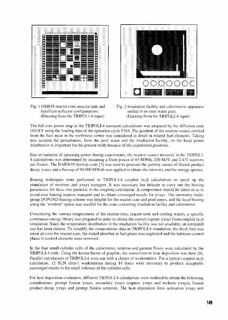
ooooooc
Fig. 1 OSIRIS reactor core, reactor tank andberyllium reflector configurations.(Drawing from the TRIPOLI-4 input)
Fig. 2 Irradiation facility and calorimetric apparatussettled in ex-core water pool.
(Drawing from the TRIPOLI-4 input)
The full core power map in the TRIPOLI-4 transport calculations was prepared by the diffusion codeDAIXY using the loading data of the operation cycle F164. The gradient of the neutron source emittedfrom the fuel meat in the northwest corner was considered in detail in related fuel elements. Takinginto account the perturbation, from the pool water and the irradiation facility, on the local powerdistribution is important for the present study because of the experiment positions.
Due to variation of operating power during experiments, the neutron source intensity in the TRIPOLI-4 calculations was determined by assuming a fixed power of 65 MWth, 200 MeV and 2.432 neutronsper fission. The DARWIN burnup code [7] was used to generate the gamma source of fission productdecay y-rays and a burnup of 90,000 MWd/t was applied to obtain the intensity and the energy spectra.
Biasing techniques were performed in TRIPOLI-4 coupled (n,y) calculations to speed up thesimulation of neutrons and y-rays transport. It was necessary but delicate to carry out the biasingparameters for these two particles in the coupling calculation. A compromise should be taken so as toavoid over biasing neutron transport and to obtain converged results for y-rays. The automatic multi-group INIPOND biasing scheme was helpful for the reactor core and pool zones, and the local biasingusing the 'window' option was needful for the zone containing irradiation facility and calorimeter.
Considering the various temperatures of the reactor core, reactor tank and cooling waters, a specificcontinuous-energy library was prepared in order to obtain the correct capture y-rays from coupled (n,y)simulation. Since the temperature distribution in the irradiation facility was not available, an estimatedone has been chosen. To simplify the compositions data in TRIPOLI-4 simulation, the fresh fuel wastaken all over the reactor core, the nickel absorber in fuel plates was neglected and the hafnium controlplates in control elements were removed.
In the four small cylinder cells of the calorimeter, neutron and gamma fluxes were calculated by theTRIPOLI-4 code. Using the kerma factor of graphite, the conversion to heat deposition was done [8].Parallel calculations of TRIPOLI-4 were run with a cluster of workstations. For a typical coupled (n,y)calculation, 12 SUN ultra-1 workstations during 14 hours were necessary to produce acceptableconverged results in the small volumes of the cylinder cells.
For heat deposition evaluation, different TRIPOLI-4 calculations were realized to obtain the followingcontributions: prompt fission y-rays, secondary y-rays (capture y-rays and inelastic y-rays), fissionproduct decay y-rays and prompt fission neutrons. The heat deposition from activation y-rays and
149
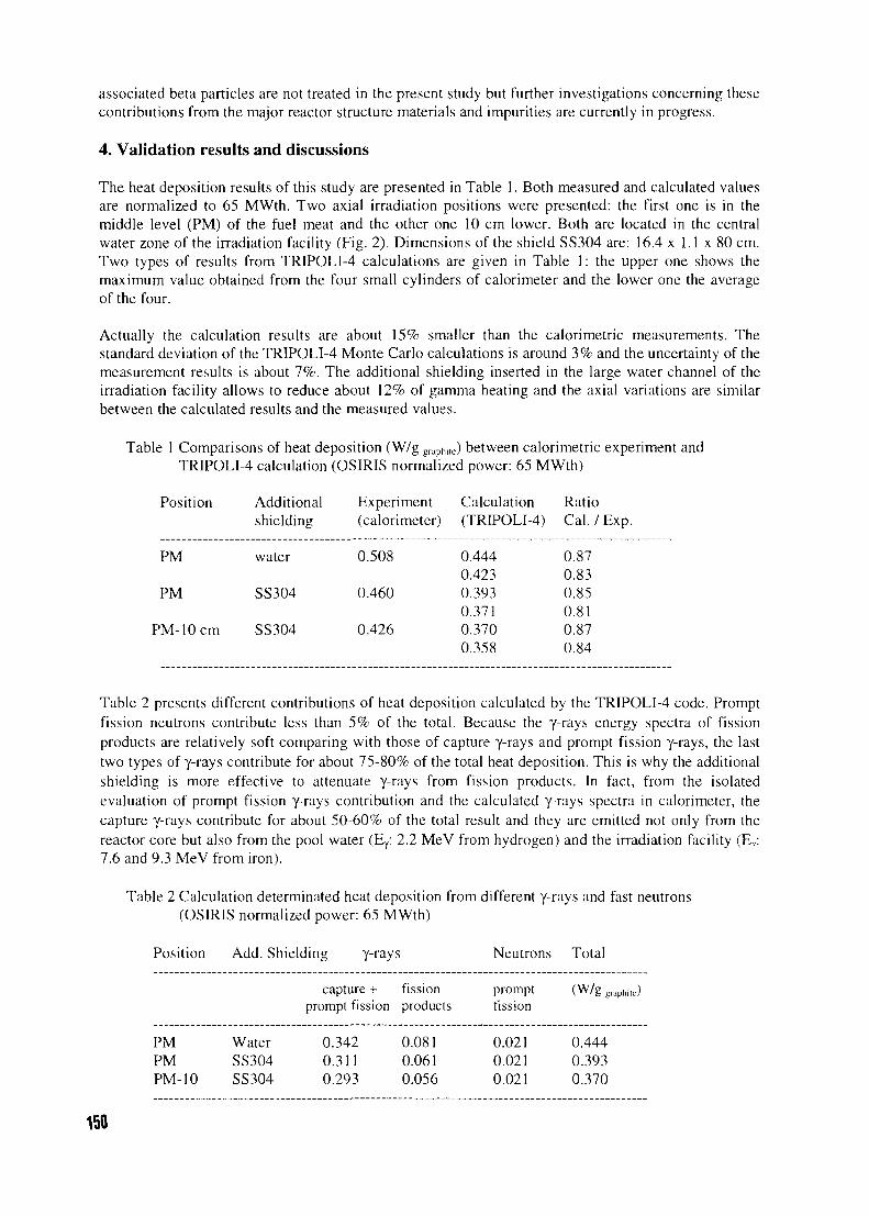
associated beta particles are not treated in the present study but further investigations concerning thesecontributions from the major reactor structure materials and impurities are currently in progress.
4. Validation results and discussions
The heat deposition results of this study are presented in Table 1. Both measured and calculated valuesare normalized to 65 MWth. Two axial irradiation positions were presented: the first one is in themiddle level (PM) of the fuel meat and the other one 10 cm lower. Both are located in the centralwater zone of the irradiation facility (Fig. 2). Dimensions of the shield SS304 are: 16.4 x 1.1 x 80 cm.Two types of results from TRIPOLI-4 calculations are given in Table 1: the upper one shows themaximum value obtained from the four small cylinders of calorimeter and the lower one the averageof the four.
Actually the calculation results are about 15% smaller than the calorimetric measurements. Thestandard deviation of the TRIPOLI-4 Monte Carlo calculations is around 3% and the uncertainty of themeasurement results is about 7%. The additional shielding inserted in the large water channel of theirradiation facility allows to reduce about 12% of gamma heating and the axial variations are similarbetween the calculated results and the measured values.
Table 1 Comparisons of heat deposition (W/g graphite) between calorimetric experiment andTRIPOLI-4 calculation (OSIRIS normalized power: 65 MWth)
Position Additional Experiment Calculation Ratio
shielding (calorimeter) (TRIPOLI-4) Cal./Exp.
PM water 0.508
PM SS304 0.460
PM-lOcm SS304 0.426
Table 2 presents different contributions of heat deposition calculated by the TRIPOLI-4 code. Promptfission neutrons contribute less than 5% of the total. Because the y-rays energy spectra of fissionproducts are relatively soft comparing with those of capture y-rays and prompt fission y-rays, the lasttwo types of y-rays contribute for about 75-80% of the total heat deposition. This is why the additionalshielding is more effective to attenuate y-rays from fission products. In fact, from the isolatedevaluation of prompt fission y-rays contribution and the calculated y-rays spectra in calorimeter, thecapture y-rays contribute for about 50-60% of the total result and they are emitted not only from thereactor core but also from the pool water (Ey: 2.2 MeV from hydrogen) and the irradiation facility (Ey7.6 and 9.3 MeV from iron).
Table 2 Calculation determinated heat deposition from different y-rays and fast neutrons(OSIRIS normalized power: 65 MWth)
0.4440.4230.3930.3710.3700.358
0.870.830.850.810.870.84
Position
PMPMPM-10
Add. Shielding y-rays
WaterSS304SS304
capture +prompt fission
0.3420.3110.293
fissionproducts
0.0810.0610.056
Neutrons
promptfission
0.0210.0210.021
Total
(W/g graphi le)
0.4440.3930.370
150
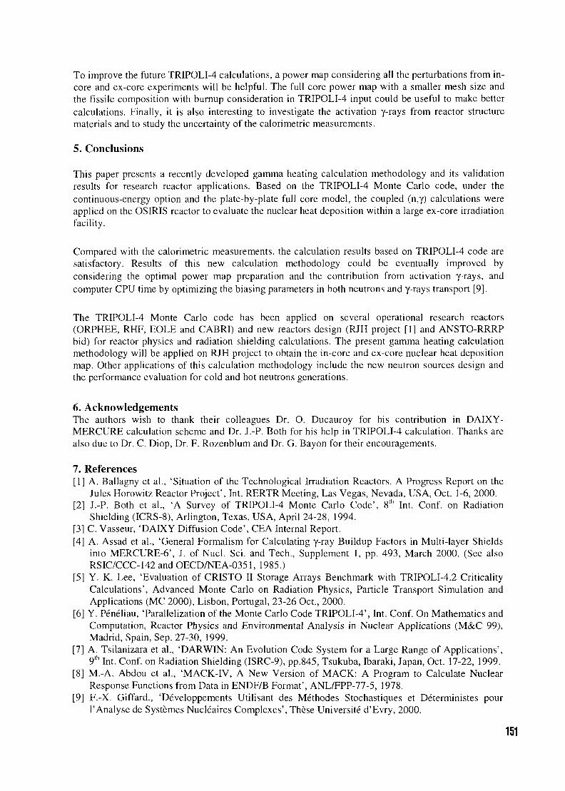
To improve the future TRIPOLI-4 calculations, a power map considering all the perturbations from in-core and ex-core experiments will be helpful. The full core power map with a smaller mesh size andthe fissile composition with burnup consideration in TRIPOLI-4 input could be useful to make bettercalculations. Finally, it is also interesting to investigate the activation y-rays from reactor structurematerials and to study the uncertainty of the calorimetric measurements.
5. Conclusions
This paper presents a recently developed gamma heating calculation methodology and its validationresults for research reactor applications. Based on the TRIPOLI-4 Monte Carlo code, under thecontinuous-energy option and the plate-by-plate full core model, the coupled (n,y) calculations wereapplied on the OSIRIS reactor to evaluate the nuclear heat deposition within a large ex-core irradiationfacility.
Compared with the calorimetric measurements, the calculation results based on TRIPOLI-4 code aresatisfactory. Results of this new calculation methodology could be eventually improved byconsidering the optimal power map preparation and the contribution from activation y-rays, andcomputer CPU time by optimizing the biasing parameters in both neutrons and y-rays transport [9].
The TRIPOLI-4 Monte Carlo code has been applied on several operational research reactors(ORPHEE, RHF, EOLE and CABRI) and new reactors design (RJH project [1] and ANSTO-RRRPbid) for reactor physics and radiation shielding calculations. The present gamma heating calculationmethodology will be applied on RJH project to obtain the in-core and ex-core nuclear heat depositionmap. Other applications of this calculation methodology include the new neutron sources design andthe performance evaluation for cold and hot neutrons generations.
6. AcknowledgementsThe authors wish to thank their colleagues Dr. O. Ducauroy for his contribution in DAIXY-MERCURE calculation scheme and Dr. J.-P. Both for his help in TRIPOLI-4 calculation. Thanks arealso due to Dr. C. Diop, Dr. F. Rozenblum and Dr. G. Bayon for their encouragements.
7. References[1] A. Ballagny et al., 'Situation of the Technological Irradiation Reactors. A Progress Report on the
Jules Horowitz Reactor Project', Int. RERTR Meeting, Las Vegas, Nevada, USA, Oct. 1-6, 2000.[2] J.-P. Both et al., 'A Survey of TRIPOLI-4 Monte Carlo Code', 8th Int. Conf. on Radiation
Shielding (ICRS-8), Arlington, Texas, USA, April 24-28, 1994.[3] C. Vasseur, 'DAIXY Diffusion Code', CEA Internal Report.[4] A. Assad et al., 'General Formalism for Calculating y-ray Buildup Factors in Multi-layer Shields
into MERCURE-6', J. of Nucl. Sci. and Tech., Supplement 1, pp. 493, March 2000. (See alsoRSIC/CCC-142 and OECD/NEA-0351, 1985.)
[5] Y. K. Lee, 'Evaluation of CRISTO II Storage Arrays Benchmark with TRIPOLI-4.2 CriticalityCalculations', Advanced Monte Carlo on Radiation Physics, Particle Transport Simulation andApplications (MC 2000), Lisbon, Portugal, 23-26 Oct., 2000.
[6] Y. Peneliau, 'Parallelization of the Monte Carlo Code TRIPOLI-4', Int. Conf. On Mathematics andComputation, Reactor Physics and Environmental Analysis in Nuclear Applications (M&C 99),Madrid, Spain, Sep. 27-30, 1999.
[7] A. Tsilanizara et al., 'DARWIN: An Evolution Code System for a Large Range of Applications',9Ih Int. Conf. on Radiation Shielding (ISRC-9), pp.845, Tsukuba, Ibaraki, Japan, Oct. 17-22, 1999.
[8] M.-A. Abdou et al., 'MACK-IV, A New Version of MACK: A Program to Calculate NuclearResponse Functions from Data in ENDF/B Format', ANL/FPP-77-5, 1978.
[9] F.-X. Giffard., 'Developpements Utilisant des Methodes Stochastiques et Deterministes pourl'Analyse de Systemes Nucleaires Complexes', These Universite d'Evry, 2000.
151
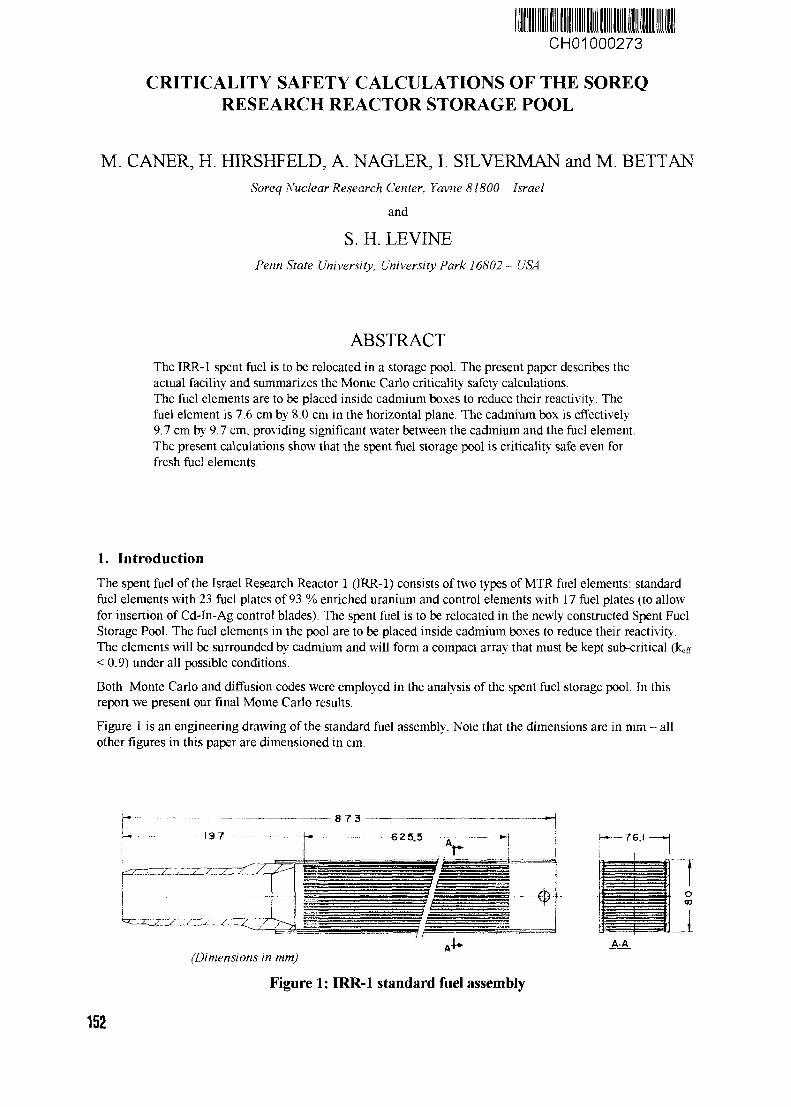
CH01000273
CRITICALITY SAFETY CALCULATIONS OF THE SOREQRESEARCH REACTOR STORAGE POOL
M. CANER, H. HIRSHFELD, A. NAGLER, I. SILVERMAN and M. BETTANSoreq Nuclear Research Center, Yavne 81800 - Israel
and
S. H. LEVINEPenn State University, University Park 16802 - USA
ABSTRACTThe IRR-1 spent fuel is to be relocated in a storage pool. The present paper describes theactual facility and summarizes the Monte Carlo criticality safety calculations.The fuel elements are to be placed inside cadmium boxes to reduce their reactivity. Thefuel element is 7.6 cm by 8.0 cm in the horizontal plane. The cadmium box is effectively9.7 cm by 9.7 cm, providing significant water between the cadmium and the fuel element.The present calculations show that the spent fuel storage pool is criticality safe even forfresh fuel elements.
1. IntroductionThe spent fuel of the Israel Research Reactor 1 (IRR-1) consists of two types of MTR fuel elements: standardfuel elements with 23 fuel plates of 93 % enriched uranium and control elements with 17 fuel plates (to allowfor insertion of Cd-In-Ag control blades). The spent fuel is to be relocated in the newly constructed Spent FuelStorage Pool. The fuel elements in the pool are to be placed inside cadmium boxes to reduce their reactivity.The elements will be surrounded by cadmium and will form a compact array that must be kept sub-critical (keff
< 0.9) under all possible conditions.
Both Monte Carlo and diffusion codes were employed in the analysis of the spent fuel storage pool. In thisreport we present our final Monte Carlo results.
Figure 1 is an engineering drawing of the standard fuel assembly. Note that the dimensions are in mmother figures in this paper are dimensioned in cm.
all
-76.1
o
iA-A
(Dimensions in mm)
Figure 1: IRR-1 standard fuel assembly
152
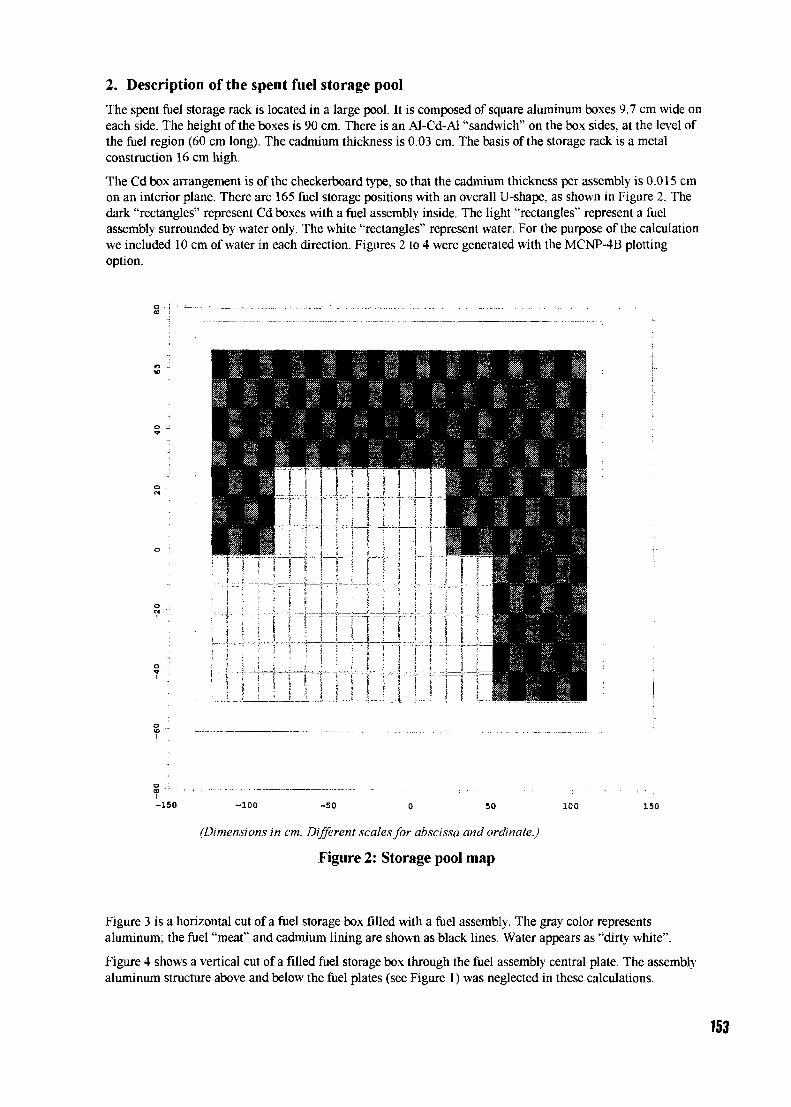
2. Description of the spent fuel storage pool
The spent fuel storage rack is located in a large pool. It is composed of square aluminum boxes 9.7 cm wide oneach side. The height of the boxes is 90 cm. There is an Al-Cd-Al "sandwich" on the box sides, at the level ofthe fuel region (60 cm long). The cadmium thickness is 0.03 cm. The basis of the storage rack is a metalconstruction 16 cm high.
The Cd box arrangement is of the checkerboard type, so that the cadmium thickness per assembly is 0.015 cmon an interior plane. There are 165 fuel storage positions with an overall U-shape, as shown in Figure 2. Thedark "rectangles" represent Cd boxes with a fuel assembly inside. The light "rectangles" represent a fuelassembly surrounded by water only. The white "rectangles" represent water. For the purpose of the calculationwe included 10 cm of water in each direction. Figures 2 to 4 were generated with the MCNP-4B plottingoption.
;• i
i 1
s i../.... L.._
\
I '
iJ_
" !
1
•• i
; i: i
i i
•.
ii
|
I
i
i»
,,,-4_- - -
I
t
-150 -100 -50 50 100 150
(Dimensions in cm. Different scales for abscissa and ordinate.)
Figure 2: Storage pool map
Figure 3 is a horizontal cut of a fuel storage box filled with a fuel assembly. The gray color representsaluminum; the fuel "meat" and cadmium lining are shown as black lines. Water appears as "dirty white".
Figure 4 shows a vertical cut of a filled fuel storage box through the fuel assembly central plate. The assemblyaluminum structure above and below the fuel plates (see Figure 1) was neglected in these calculations.
153
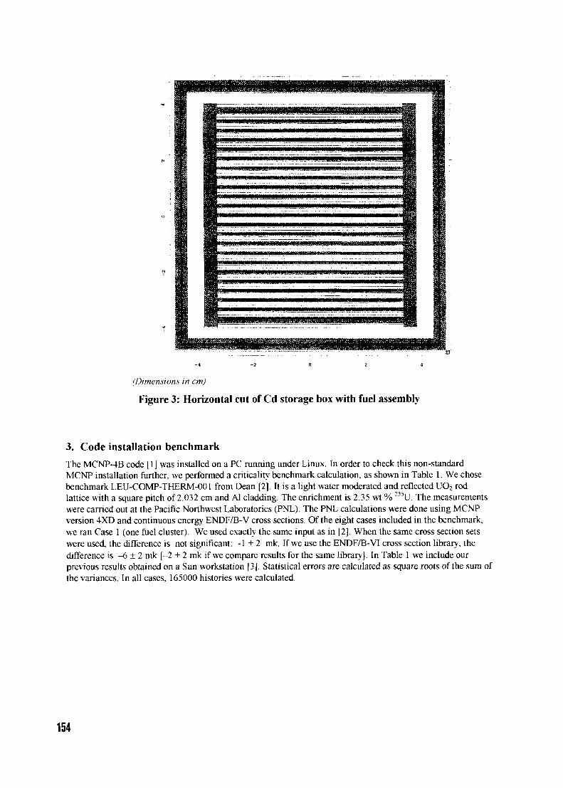
(Dimensions in cm)
Figure 3: Horizontal cut of Cd storage box with fuel assembly
3. Code installation benchmark
The MCNP-4B code [ 1 ] was installed on a PC running under Linux. In order to check this non-standardMCNP installation further, we performed a criticality benchmark calculation, as shown in Table 1. We chosebenchmark LEU-COMP-THERM-001 from Dean [2], It is a light water moderated and reflected UO2 rodlattice with a square pitch of 2.032 cm and Al cladding. The enrichment is 2.35 wt % 235U. The measurementswere carried out at the Pacific Northwest Laboratories (PNL). The PNL calculations were done using MCNPversion 4XD and continuous energy ENDF/B-V cross sections. Of the eight cases included in the benchmark,we ran Case 1 (one fuel cluster). We used exactly the same input as in [2]. When the same cross section setswere used, the difference is not significant: -1 ± 2 mk. If we use the ENDF/B-V1 cross section library, thedifference is -6 ± 2 mk [-2 ± 2 mk if we compare results for the same library]. In Table 1 we include ourprevious results obtained on a Sun workstation [3]. Statistical errors are calculated as square roots of the sum ofthe variances. In all cases, 165000 histories were calculated.
154
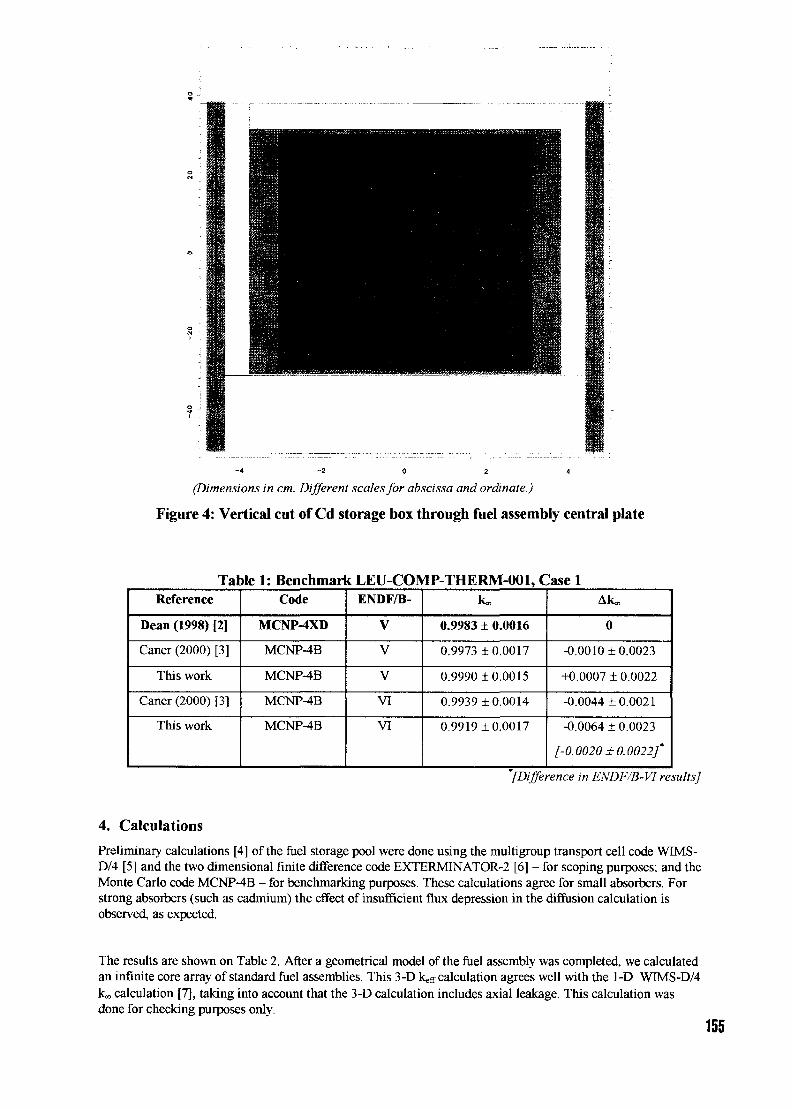
- 4 - 2 0 2 4
(Dimensions in cm. Different scales for abscissa and ordinate.)
Figure 4: Vertical cut of Cd storage box through fuel assembly central plate
Table 1: Benchmark LEU-COMP-THERM-001, Case 1Reference
Dean (1998) [2]
Caner (2000) [3]
This work
Caner (2000) [3]
This work
Code
MCNP-4XD
MCNP-4B
MCNP-4B
MCNP-4B
MCNP-4B
ENDF/B-
V
V
V
VI
VI
k«,
0.9983 ± 0.0016
0.9973 ±0.0017
0.9990 ±0.0015
0.9939 ±0.0014
0.9919 ±0.0017
0
-0.0010 ±0.0023
+0.0007 ± 0.0022
-0.0044 ±0.0021
-0.0064 ± 0.0023
[-0.0020 ±0.0022]*
[Difference in ENDF/B-VI results]
4. Calculations
Preliminary calculations [4] of the fuel storage pool were done using the multigroup transport cell code WIMS-D/4 [5] and the two dimensional finite difference code EXTERMINATOR-2 [6] - for scoping purposes; and theMonte Carlo code MCNP-4B - for benchmarking purposes. These calculations agree for small absorbers. Forstrong absorbers (such as cadmium) the effect of insufficient flux depression in the diffusion calculation isobserved, as expected.
The results are shown on Table 2. After a geometrical model of the fuel assembly was completed, we calculatedan infinite core array of standard fuel assemblies. This 3-D k<.ff calculation agrees well with the 1-D WTMS-D/4kx, calculation [7], taking into account that the 3-D calculation includes axial leakage. This calculation wasdone for checking purposes only.
155
The second set of calculations involved the actual storage facility configuration. We defined an array of 24 by12 positions (measuring 9.7 cm by 9.7 cm each) which were filled by one of three "universes" (in MCNPparlance):
• A fuel assembly filled with water and surrounded on four sides by an Al-Cd-Al box.
• A fuel assembly filled with water.
• Water
The aluminum in the top and bottom of the assemblies was neglected in the criticality safety calculation. Itseffect is to decrease the criticality coefficient slightly, due to higher leakage.
For each case, short (15000 neutrons) and long (400000 neutrons) calculations were done. The standarddeviations were checked to be inversely proportional to the square root of the number of histories.
Table 2: Criticality calculationsType of calculation
Assembly in infinite core
Storage pool, no cadmium boxes
Storage pool with cadmium boxes
krff (MCNP-4B)
1.595 ±0.001
1.303 ±0.001
0.752 ± 0.001
k*, (WIMS-D/4)
1.669
5. Conclusion
The present work is part of the MCNP-4B criticality safety' evaluation for the constructed fuel storage poolfacility.
As the cadmium plate boxes are fixed in the base structure, there is no possibility of accidental removal of thecadmium. The present calculations, as well as previous ones, show that the spent fuel storage pool is criticalitysafe even for fresh fuel elements.
References
[1] J. F. Briesmeister, (1997) (Editor) MCNP-A General Monte Carlo N-Particle Transport Code, LA-12625-M, Version 4B.
[2] V. F. Dean, (1998) International Handbook of Evaluated Criticality Safety Benchmark Experiments,NEA/NSC/DOC (95) 03, IV, NEA Nuclear Science Committee. Evaluated Experiment LEU-COMP-THERM-001.
[3] M. Caner, and E. T., Dugan, THO2-UO2 Annular Pins for High Burmtp Fuels, Annals of NuclearEnergy 27 (2000) 759.
[4] S. H. Levine, A. Nagler, H. Hirshfeld and M. Bettan, Analyses of Soreq MTR Type Fuel in StoragePool and Core Configurations Using Both Monte Carlo and Diffusion Codes, The 20th Conf. of theNuclear Societies in Israel, Dead Sea, 20-21 December 1999.
[5] J. R. Askew, F. J. Fayers and P. B. Kemshell, Jour. Brit. Nucl. Energy Soc. 5, 564 (1966).
[6] T. B. Fowler, M. L. Tobias and D. R. Vondy, EXTERMINATOR-2: A Fortran IVCode for SolvingMultigroup Neutron Diffusion Equations in Two Dimensions, ORNL-4078 (1967).
[7] M. Caner, M. Shapira, M. Bettan, A. Nagler and J. Gilat, HEU Benchmark Calculations and LEUPreliminary Calculation for IRR-I, in: Reduced Enrichment for Research and Test Reactors,Proceedings of the XVIII International Meeting, Paris, 17-21 September 1995.
156
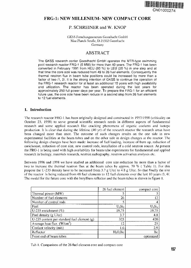
CH01000274
FRG-1: NEW MILLENIUM- NEW COMPACT CORE
P. SCHREINER and W. KNOP
GKSS-Forscbungszentrum Geesthacht GmbHMax-Planck-Strafk, D-21502 Geesthacht
Germany
ABSTRACT
The GKSS research center Geesthacht GmbH operates the MTR-type swimmingpool research reactor FRG-1 (5 MW) for more than 40 years. The FRG-1 has beenconverted in February 1991 from HEU (93 %) to LEU (20 %) in one step and atthat time the core size was reduced from 49 to 26 fuel elements. Consequently thethermal neutron flux in beam tube positions could be increased by more than afactor of two / 1 , 2.1. It is the strong intention of GKSS to continue the operation ofthe FRG-1 research reactor for at least an additional 15 years with high availabilityand utilization. The reactor has been operated during the last years forapproximately 250 full power days per year. To prepare the FRG-1 for an efficientfuture use, the core size have been reduce in a second step from 26 fuel elementsto 12 fuel elements.
1. Introduction
The research reactor FRG-1 has been originally designed and constructed in 1957/1958 (criticality onOctober 23, 1958) to serve general scientific research needs in different aspects of fundamentalresearch and some applied research like cracking phenomena of organic coolants and isotopeproduction. It is clear that during the lifetime (40 yr) of the research reactor the research areas havebeen changed more than once. The outcome of such changes results on the one side in newexperimental facilities at the beam tubes and on the other side in design changes at the reactor. Thefollowing design changes have been made: increase of fuel loading, increase of burn up, reduction ofenrichment, reduction of core size, new control rods, installation of a cold neutron source. At presentthe FRG-1 is being used with high availability for beam tube experiments for fundamental and appliedresearch in biology, materials research, neutron radiography, neutron activation analyses etc.
Between 1996 and 1998 we have studied an additional core size reduction by more than a factor oftwo to increase the thermal neutron flux at the beam tubes by approx. 70 % ( Table 1). For thispurpose the U-235 density have to be increased from 3.7 g U/cc to 4.8 g U/cc. So that finally the sizeof the reactor is being reduced from 48 fuel elements to 12 fuel elements over the last 10 years /3, 4/.The model for the future core with the beryllium reflector and the beam tubes is shown in figure 1.
Thermal power (MW)Number of fuel elementsNumber of control rodsFuelU-235 enrichment (%)Fuel density (g U/cc)U-235 content per standard fuel element (g)Average heat flux (W/cm )Coolant velocity (m/s)ReflectorFront end of beam tubes
26 fuel element5
265
U3Si2
19,753.7
32312
1,6H2O,Be
compact core5
124
U3Si2
_ 19,754.8
420252,9Be
optimized
Tab 1. Comparison of the 26 fuel element core and compact core157
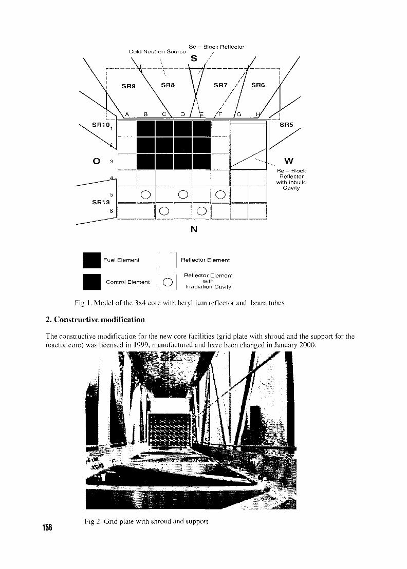
Cold Neutron Source
\ S
Be - Block Reflector
Be - BlockReflector
with inbuildCavity
Fuel Element
Control Element o
Reflector Element
Reflector Elementwith
Irradiation Cavity
Fig 1. Model of the 3x4 core with beryllium reflector and beam tubes
2. Constructive modification
The constructive modification for the new core facilities (grid plate with shroud and the support for thereactor core) was licensed in 1999, manufactured and have been changed in January 2000.
158Fig 2. Grid plate with shroud and support
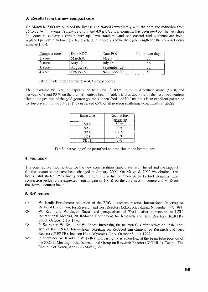
3. Results from the new compact core
On March 8. 2000 we obtained the license and started immediately with the core site reduction from26 to 12 fuel elements. A mixture of 3.7 and 4.8 g U/cc fuel elements has been used for the first three3x4 cores to achieve a certain burn up. Two standard and one control fuel elements are beingreplaced per cycle following a fixed schedule. Table 2 shows the cycle length for the compact coresnumber 1 to 4.
Compact core1. core2. core3. core4. core
Date BOCMarch 8.May 12.August 18.October 5.
Date EOCMay 7.July 15.September 28.November 30.
Full power days27565253
Tab 2. Cycle length for the 1. - 4. Compact cores
The conversion yields to the expexted neutron gain of 100 % on the cold neutron source (SR 8) andbetween 0 % and 80 % on the thermal neutron beam (Table 3). This doubling of the perturbed neutronflux at the position of the cold neutron source (unpertubed 1.4*1014 n/s cm2) is an excellent guaranteefor top research in the future. The ens served 65% of all neutron scattering experiments at GKSS.
Beam tube
SR5SR7SR8SR9SR 13
Neutron fluxIncreasing
80%70%100%70%0%
Tab 3. Increasing of the perturbed neutron flux at the beam tubes
4. Summary
The constructive modification for the new core facilities (grid plate with shroud and the supportfor the reactor core) have been changed in January 2000. On March 8. 2000 we obtained thelicense and started immediately with the core site reduction from 26 to 12 fuel elements. Theconversion yields to the expexted neutron gain of 100 % on the cold neutron source and 80 % onthe thermal neutron beam
5. References
III W. Krull: Enrichment reduction of the FRG-1 research reactor, International Meeting onReduced Enrichment for Research and Test Reactors (RERTR), Jakarta, November 4-7, 1991.
Ill W. Krull and W. Jager: Status and perspectives of FRG-1 after conversion to LEU,International Meeting on Reduced Enrichment for Research and Test Reactors (RERTR),Seoul, October 6-10, 1996.
131 P. Schreiner, W. Krull and W. Feltes: Increasing the neutron flux after reduction of the coresize of the FRG-1, International Meeting on Reduced Enrichment for Research and TestReactors (RERTR), Jackson Hole, Wyoming USA, October 5 - 10, 1997.
141 P. Schreiner, W. Krull and W. Feltes: Increasing the neutron flux at the beam tube position ofthe FRG-1, Meeting of the International Group on Research Reactor (IGORR 6), Taejon, TheRepublic of Korea, April 29 - May 1,1998.
159
CH01000275STAND FOR VISUAL
AND ULTRASONIC TESTING OF SPENT FUEL
W. CZAJKOWSKI and E. BOREK-KRUSZEWSKADepartment of Nuclear Energy
Institute of Atomic Energy,05-400 OTWOCK-SWIERK, Poland
ABSTRACT
Stand for visual and ultrasonic testing of spent fuel, constructed under Strategic GovernmentalProgramme for management of spent fuel and radioactive waste, is presented in the paper.Stand, named "STEND-1", build up in Institute of Atomic Energy in Swierk, is appointed forunderwater visual testing of spent fuel elements type MR6 and WWR by means of TV-CCDcamera and image processing system and for ultrasonic scanning of external surface of theseelements by means of videoscan immersion transducer and straight UHT connector."STEND-1" is built using flexible in use, high-tensile, anodised aluminium profiles. All theprofiles feature longitudinal grooves to accommodate connecting elements and for theattachment of accessories at any position. They are also characterised by straight-through corebores for use with standard fastening elements and to accommodate accessory components.Stand, equipped with automatic control and processing system based on personal computer,may be manually or automatically controlled.Control system of movements of the camera in the vertical axis and rotational movement ofspent fuel element permits to fix chosen location of fuel element with accuracy better than0.1 mm. High resolution of ultrasonic method allows to record damages of outer surface oforder 0.1 mm.The results of visual testing of spent fuel are recorded on video tape and then may be stored onthe hard disc of the personal computer and presented in shape of photo or picture. Onlyselected damage surfaces of spent fuel elements are tested by means of ultrasonic scanning.All possibilities of the stand and results of visual testing of spent fuel type WWR are presentedin the paper.
1. Introduction
During the operation of two research reactors EWA and MARIA located in INSTITUTE OFATOMIC ENERGY in Swierk 6300 of fuel elements WWR and MR and Ek-10 type were burnt up.The first part of these elements were moved to wet storage in 1968 and have been stored there tillnow.
After such a long period of wet storage the decision to investigate the spent fuel elements, by means ofpossible to use methods, have been taken, to estimate the safe time of wet storage and to decidewhether to change this environment into the dry storage.
The technical analysis and analysis of the costs of realization of this task have shown, that maximuminformation about the condition of all population entire amount of fuel elements will be received byvisual testing, ultrasonic scanning of external surface of these elements, and also by investigatingchecking tightness of each element using measurement of fission products release.
The construction of stand and instrumentation equipment, which have been using to visual testing andultrasonic scanning of spent fuel elements surface, is presented in the report.
160
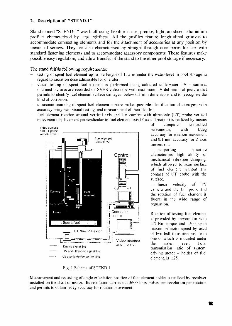
2. Description of "STEND-1"
Stand named "STEND-1" was built using flexible in use, precise, light, anodised aluminiumprofiles characterized by large stiffness. All the profiles feature longitudinal grooves toaccommodate connecting elements and for the attachment of accessories at any position bymeans of screws. They are also characterised by straight-through core bores for use withstandard fastening elements and to accommodate accessory components. These features makepossible easy regulation, and allow transfer of the stand to the other pool storage if necessary.
The stand fulfils following requirements:- testing of spent fuel element up to the length of 1, 5 m under the water-level in pool storage in
regard to radiation dose admissible for operator,- visual testing of spent fuel element is performed using coloured underwater TV - camera;
obtained pictures are recorded on SVHS video tape with maximum TV definition of picture thatpermits to identify fuel element surface damages below 0.1 mm dimensions and to recognise thekind of corrosion,
- ultrasonic scanning of spent fuel element surface makes possible identification of damages, withaccuracy bring near visual testing, and measurement of their depths,
- fuel element rotation around vertical axis and TV camera with ultrasonic (UT) probe verticalmovement displacement perpendicular to fuel element axis (Z axis direction) is realized by means
of computer controlledservomotor; with 1/degaccuracy for rotation movementand 0,1 mm accuracy for Z axismovement,- supporting structurecharacterises high ability ofmechanical vibration damping,which allowed to scan surfaceof fuel element without anycontact of UT probe with thesurface.- linear velocity of TVcamera and the UT probe andthe rotation of fuel element isfluent in the wide range ofregulation.
Video cameraand UT probevertical driver
Fuel elementrotate driver
Controll
UTflaw detektor
• ComputerI control
Driving signal line
TV and ultrasonic signal line
Ultrasonic devise control line
Fig. 1 Schema of STEND 1
ID
Video recorderand monitor
Rotation of testing fuel elementis provided by servomotor with2.3 Nm torque and 1500 r.p.mmaximum motor speed by usedof two belt transmissions, fromone of which is mounted underthe water level. Totaltransmission ratio of system:driving motor - holder of fuelelement, is 1:25.
Measurement and recording of angle orientation position of fuel element holder is realized by rezolwerinstalled on the shaft of motor. Its resolution carries out 3600 lines pulses per revolution per rotationand permits to obtain 1/deg accuracy for rotation movement.
161
TV camera with UT detector vertical movement is also realized by servomotor with 1.7 Nm torqueand 750 r.p.m maximum engine speed and byrolling gear with 10 mm per rotation pitch.Measurement and recording of angleorientation position is realized by identicalrezolwer. It gives the real accuracy of TVcamera and UT probe position equal 0.1 mm.Holder of fuel element consists of two parts.The bottom one consists of an alignmentelement shift manually in vertical direction.The upper part is connected by the drive shaftwith belt transmission and servomotor. Rateand force of closing of fuel element in handleis regulated. Closing force of holder amountsto30N.
The scheme of stand, illustrating location oftheir main elements and their mutualconnections, is presented below in Fig. 1. Theview of stand situated in wet storage ispresented in Fig.2.
Spent fuel elements under testing arecomputer controlled with special software,written in VISUAL BASIC.
Fig. 2 View of stend in wet storage
Software contains the following tasks: fuel element movement control, TV camera together with UTprobe movement and ultrasonic probe control:- acquisition and processing data on the form of scanned surface map, what determinethe basic idea of working stand and his abilities to be a precise device to remote testing ofspent fuel elements.
- choice the kind of testing(visual- static or dynamic, ultrasonic-circumferential or vertical).
The main programme cooperates withprogramme of synthesis of speechSYNTALK., which imparts all parametersof investigations with voice (officialreport), and also topical position of cameraand UT probe in relation to testing fuelelement in select earlier coordinates.Report together with images of testingsurface are recorded on video tape. Itpermits to identify the testing part of fuelelement surface during the analysis ofresults is presented in Fig.4 and 5
File TrassnNion SstSngi Tasting Into
Mg»nl 1 Tooted 1 Uafk
GOTO
STOP aSaCamera
J 2
Band: 3 Frame. 2Drive tyndmwited
Fig. 3 The main page preview of control program
3. Optical and image system
Visual testing can be carried out automatically or manually:- in automatic mode:
162
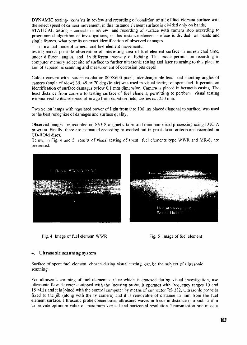
DYNAMIC testing- consists in review and recording of condition of all of fuel element surface withthe select speed of camera movement, in this instance element surface is divided only on bands,STATICAL testing - consists in review and recording of surface with camera stop according toprogrammed algorithm of investigations, in this instance element surface is divided on bands andsingle frames, what permits on exact identification of observed damages.- in manual mode of camera and fuel element movements:testing makes possible observation of interesting area of fuel element surface in unrestricted time,under different angles, and in different intensity of lighting. This mode permits on recording incomputer memory select site of surface to further ultrasonic testing and later returning to this place inaim of supersonic scanning and measurement of corrosion pits depth.
Colour camera with screen resolution 800X600 pixel, interchangeable lens and shooting angles ofcamera (angle of view) 35, 49 or 70 deg (in air) was used to visual testing of spent fuel. It permits onidentification of surface damages below 0,1 mm dimension. Camera is placed in hermetic casing. Theleast distance from camera to testing surface of fuel element, permitting to perform visual testingwithout visible disturbances of image from radiation field, carries out 250 mm.
Two xenon lamps with regulated power of light from 0 to 100 lux placed diagonal to surface, was usedto the best recognize of damages and surface quality.
Observed images are recorded on SVHS magnetic tape, and then numerical processing using LUCIAprogram. Finally, there are estimated according to worked out in great detail criteria and recorded onCD-ROM discs.Below, in Fig. 4 and 5 results of visual testing of spent fuel elements type WWR and MR-6, arepresented.
Fig. 4 Image of fuel element WWR Fig. 5 Image of fuel element
4. Ultrasonic scanning system
Surface of spent fuel element, chosen during visual testing, can be the subject of ultrasonicscanning.
For ultrasonic scanning of fuel element surface which is choosed during visual investigation, useultrasonic flaw detector equipped with the focusing probe. It operates with frequency ranges 10 and15 MHz and it is joined with the control computer by means of connector RS 232. Ultrasonic probe isfixed to the jib (along with the tv camera) and it is removable of distance 15 mm from the fuelelement surface. Ultrasonic probe concentrates ultrasonic waves in focus in distance of about 15 mmto provide optimum value of maximum vertical and horizontal resolution. Transmission rate of data
163
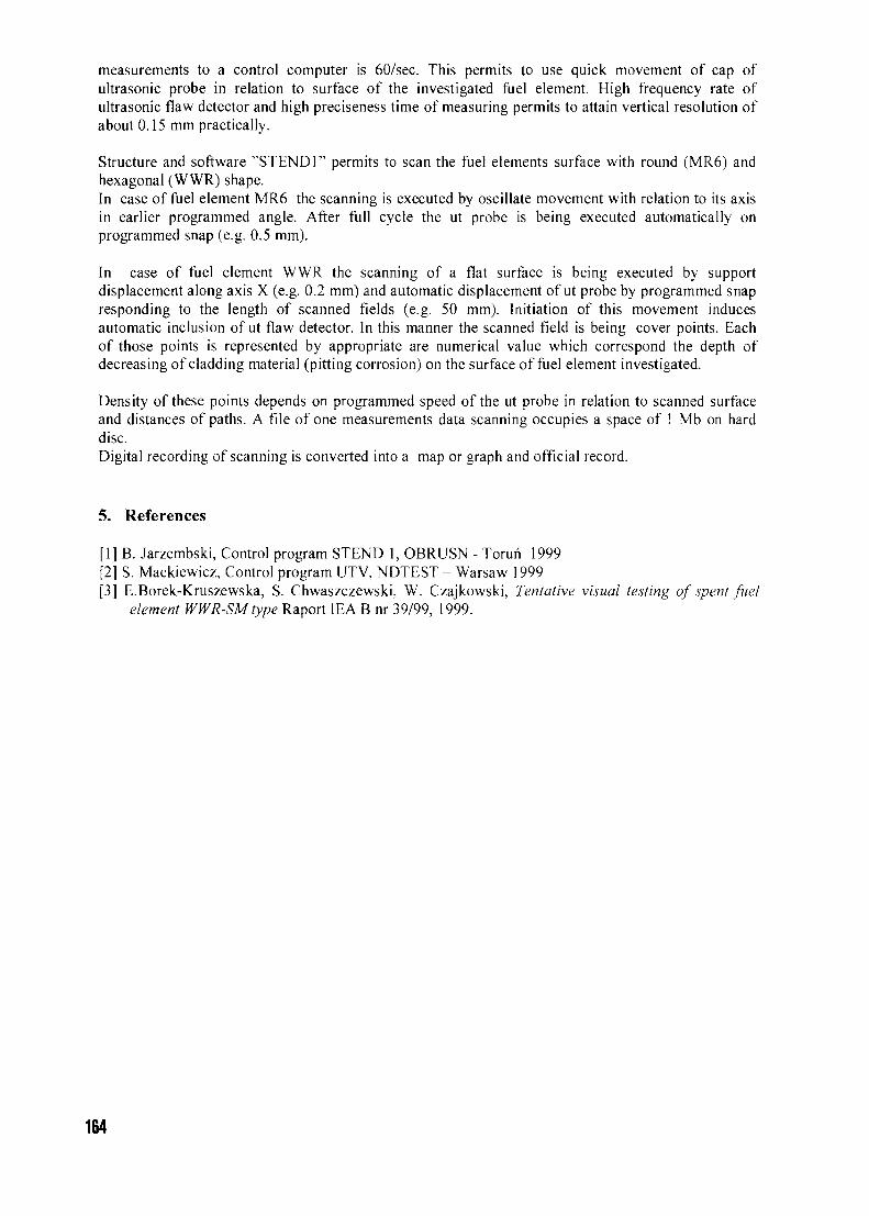
measurements to a control computer is 60/sec. This permits to use quick movement of cap ofultrasonic probe in relation to surface of the investigated fuel element. High frequency rate ofultrasonic flaw detector and high preciseness time of measuring permits to attain vertical resolution ofabout 0.15 mm practically.
Structure and software "STEND1" permits to scan the fuel elements surface with round (MR6) andhexagonal (WWR) shape.In case of fuel element MR6 the scanning is executed by oscillate movement with relation to its axisin earlier programmed angle. After full cycle the ut probe is being executed automatically onprogrammed snap (e.g. 0.5 mm).
In case of fuel element WWR the scanning of a flat surface is being executed by supportdisplacement along axis X (e.g. 0.2 mm) and automatic displacement of ut probe by programmed snapresponding to the length of scanned fields (e.g. 50 mm). Initiation of this movement inducesautomatic inclusion of ut flaw detector. In this manner the scanned field is being cover points. Eachof those points is represented by appropriate are numerical value which correspond the depth ofdecreasing of cladding material (pitting corrosion) on the surface of fuel element investigated.
Density of these points depends on programmed speed of the ut probe in relation to scanned surfaceand distances of paths. A file of one measurements data scanning occupies a space of 1 Mb on harddisc.Digital recording of scanning is converted into a map or graph and official record.
5. References
[1] B. Jarzembski, Control program STEND 1, OBRUSN - Torun 1999[2] S. Mackiewicz, Control program UTV, NDTEST - Warsaw 1999[3] E.Borek-Kruszewska, S. Chwaszczewski, W. Czajkowski, Tentative visual testing of spent fuel
element WWR-SMtype Raport IEA B nr 39/99, 1999.
164
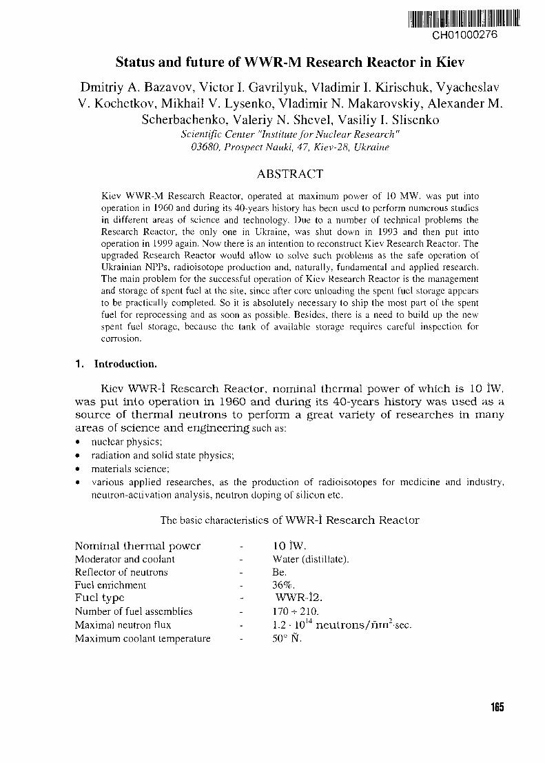
CH01000276
Status and future of WWR-M Research Reactor in Kiev
Dmitriy A. Bazavov, Victor I. Gavrilyuk, Vladimir I. Kirischuk, VyacheslavV. Kochetkov, Mikhail V. Lysenko, Vladimir N. Makarovskiy, Alexander M.
Scherbachenko, Valeriy N. Shevel, Vasiliy I. SlisenkoScientific Center "Institute for Nuclear Research"
03680, Prospect Nauki, 47, Kiev-28, Ukraine
ABSTRACT
Kiev WWR-M Research Reactor, operated at maximum power of 10 MW, was put intooperation in 1960 and during its 40-years history has been used to perform numerous studiesin different areas of science and technology. Due to a number of technical problems theResearch Reactor, the only one in Ukraine, was shut down in 1993 and then put intooperation in 1999 again. Now there is an intention to reconstruct Kiev Research Reactor. Theupgraded Research Reactor would allow to solve such problems as the safe operation ofUkrainian NPPs, radioisotope production and, naturally, fundamental and applied research.The main problem for the successful operation of Kiev Research Reactor is the managementand storage of spent fuel at the site, since after core unloading the spent fuel storage appearsto be practically completed. So it is absolutely necessary to ship the most part of the spentfuel for reprocessing and as soon as possible. Besides, there is a need to build up the newspent fuel storage, because the tank of available storage requires careful inspection forcorrosion.
1. Introduction.
Kiev WWR-I Research Reactor, nominal thermal power of which is 10 IW,was put into operation in 1960 and during its 40-years history was used as asource of thermal neutrons to perform a great variety of researches in manyareas of science and engineering such as:• nuclear physics;• radiation and solid state physics;• materials science;• various applied researches, as the production of radioisotopes for medicine and industry,
neutron-activation analysis, neutron doping of silicon etc.
The basic characteristics of WWR-I Research Reactor
Nominal thermal powerModerator and coolantReflector of neutronsFuel enrichmentFuel typeNumber of fuel assembliesMaximal neutron fluxMaximum coolant temperature
10 IW.Water (distillate).Be.36%.WWR-I2.170-210.1.250° N.
1014 neutrons/rim2-sec.
165
The maximal coolant pressure - 2.0 kg/nm2.
The Control and Protection System (CPS) characteristics
Control rods, total - 9.Including:• emergency protection - 3;• compensating - 5;• automatic control ones - 1.
Ion chambers, total - 9.Including:• power measurement and protection - 3;• period measurement and protection - 2;• automatic control - 1;• power measurement and recording ones - 3.
After physical start-up of the reactor, practically all its systems and equipment wereupgraded or replaced, some new systems were developed to increase the operation safety andimprove physical characteristics of the reactor, including:• CPS;• emergency core cooling system;• power supply;• radiation control system;• fresh fuel storage;• spent fuel storage;• filtered vent system;• fire control system;• physical protection system.
Some of these works were performed during planned repair and maintenance, but basically- during rather long reactor shutdowns in 1988^-1989 and 1993-^1998. In 1988 we were forced toreplace heat exchangers and partly primary pipes due to poor-quality joint welds. The mainreason for the reactor shutdown in 1993 was inconsistency of its systems and equipment to thenew requirements, accepted by the Regulatory Body of Ukraine according to the IAEArecommendations and international practice. Another important factor of the reactor shutdownappeared to be the absence of financial support enough for the reactor safe operation. The reactorwas started-up again in 1998.
1. Basic activity carried out at our Research Reactor.
1988-1989A. Coolant system.
Along with the mentioned above replacement of heat exchanges and primary pipes, duringthis reactor shutdown the new emergency core cooling system, not provided by design, wasdeveloped and installed. In the case of coolant loss, water from an area spray system will remove
166
the residual heat from fuel assemblies. As a source of water, the distillate from reserve tanks isused. The special system provides the return of water through the area spray system to the reactorcore (water flow is u p to 30 i3 /h, p ressure - 2 kg/ni2). In emergencies, if for any reasonsother sources of water are not available, there is an opportunity to supply water from the watertower as well.B. Reactor vent system.
In 1989 the new reactor vent system, also not provided by design, was developed. Atnormal operation the air from reactor vessel goes to the stack through gasholder and claydite filter(neither the gasholder, nor the claydite filter were provided by design). In emergency, when thefission gas appears in the reactor vessel or hall, the air passes additional filtration in scrubber. Inthis event the special high-pressure fan is turned on and the air passes through, first, an acidsolution (pH 9+10), secondly, the area spray system and at last the gasholder and claydite filter.According to our estimates, the fission gas absorption for such the system should be up to 95%.
1993-1998A. CPS.
The positive overshoot of reactivity during scram rod removal was reduced and now it doesnot exceed 0.07 (3eff / s en . For this purpose the scram rod drives were modernized. The sensorof upper position of emergency protection rods was developed, just as the blocking of control rodremoval in the case of breakage of at least one of the rods. Two additional channels of powermeasurement, in the range of 10"5 % - 100 % of nominal power, were developed and installed aswell. As a result of annual special testes the service life of CPS was prolonged till March 31,2002.
B. Power supply.The emergency battery (1 lOA, 600Ah) and two CPS bat ter ies (48A, 125Ah)
were replaced. Besides, two diesel engines - power stations of 100 kW each were put intooperation as the reserve emergency power supplies.
C. Physical protection system and fresh fuel storage.Modern physical protection system of the reactor and fresh fuel storage were designed and
constructed in accordance to requirements of Regulatory Bodies of Ukraine, IAEArecommendations and international practice. All the work was done at financial support of the USDOE and active assistance of the experts of Advantor (USA).
D. Spent fuel storage.The system of remote measurement of water temperature and the system of water filtration,
which were not provided by the design of reactor, have been mounted in the spent fuel storage.
1. Main problems, which we did not manage to solve yet.
A. Spent fuel.During its operation the Research Reactor accumulated and continues to accumulate large
number of irradiated and spent assemblies. In order to increase the capacity of spent fuel storage,it was reconstructed as the double-deck one. Unfortunately, after the USSR collapse there were
167
essential problems to ship the spent fuel for reprocessing in Russia. As a result, last time whenthe spent fuel was shipped from our reactor was in 1988.
There is rather bad situation at Kiev Research Reactor, since after core unloading the spentfuel storage appears to be practically completed. In the nearest time it is absolutely necessary toship the most part of spent fuel for the reprocessing, but now it is impossible due to the absenceof funds. Besides, in any case there is an urgent need to build up the new spent fuel storage,because the tank of available storage requires careful inspection for corrosion. Thus, ifnevertheless the most part of spent fuel will be shipped for reprocessing, the new storage could beof smaller capacity.
B. CPS.The equipment of CPS and technological parameter control of reactor are obsolete, control
and power cables have not any fire-prevention isolation and are installed with infringements ofexisting rules. There is no reserve control panel of reactor and that is the infringement ofrequirements and rules as well.
C. Primary system.It is also necessary to replace the pumps and part of the primary pipes, which were not
replaced during the reactor shutdown in 1988-1989.
D. Reactor decommissioning plan.At present there is only a concept of decommissioning plan for Kiev Research Reactor.
E. Conversion to low enriched fuel.Additional problem arises in connection with the Nuclear Weapon Non-Proliferation
Agreement and planned conversion to the low enriched (<20%) fuel. This question is consideredby our reactor experts, Regulatory Bodies of Ukraine and at participation and assistance of theexperts of the US DOE. Anyway, it could be solved only at the positive reaction of Russia as thefuel supplier.
1. Prospect of the further operation of Kiev Research Reactor.
As a result of measures on the reactor modernization, Regulatory Bodies of Ukraine issuedthe license for the reactor operation valid till the end of 2000. Only in December 2000 Kiev-Research Reactor was operated at the nominal power more than 300 hours.
Now we have a choice: either decommissioning of the reactor or further reactormodernization to meet the requirements for its safe operation. Unfortunately, funds provided forthe reactor modernization are not enough. At the same time. Research Reactor is absolutelynecessary for Ukraine at least for solving such the problems as:• Safe operation of the Ukrainian Nuclear Power Plants (NPP).
First of all Ukraine needs to develop and keep at the high level the infrastructure of scientificand technical support for Ukrainian NPPs. There are a lot of problems that can not be solvedwithout scientific research and testing at Research Reactor. The reactor is also playing animportant role in education and training of specialists for Ukrainian NPPs, for instant Kiev
16B
Technical University and Kiev State University used to exploit permanently the reactor for thepractical training of students.
• Production of radioisotopes for medicine and industry.The use of radioisotopes in medicine for the diagnostics instead of the traditional x-raydiagnostics is extremely important for Ukraine taking into account extra irradiation ofUkrainian citizens due to the Chernobyl accident. The technology of 99mTc production at KievResearch Reactor was developed and licensed in 1998. Now, in order to obtain the license foruse of 99mTc in medicine, this technology should pass clinical tests and get the approval ofUkrainian Pharmacology Committee. Reactor technologies of other radioisotope productionsuch as I3II, 125I, I23I, I27Xe, 32P, 51Cr are developing now as well.Another example of the radioisotope production at WWR-M Research Reactor is therenewing of l92Ir sources used in gamma-defectoscopy.
• Fundamental and applied research.For many years at WWR-M reactor a great variety of researches were carried out, results ofwhich are used for nuclear databases. These results are very important for the successfuldevelopment of nuclear industry.
1. Conclusions.
Having highly qualified staff and keeping all the reactor systems in proper state we haveoperated the WWR-M Research Reactor for more than 40 years without any serious accidents.Such type reactors are also operated in a number of other countries and showed themselves asvery safe. Besides, some of them are operated much longer time than our reactor and, as a result,their equipment acquired higher neutron fluence. All these facts, just as the results of tests for thereactor vessel metal and other reactor systems, allow us to make a conclusion that our reactor canbe operated for some time. In the case of complete modernization and replacement of oldequipment in accordance to the modern requirements, we have a feeling that the reactor could besafely operated till 2010-2012.
In order to solve the problem of spent fuel, we hope for a help and assistance of the IAEA,other international organizations and a number of states (USA, Russia, etc.).
169
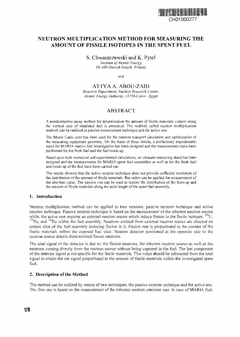
CH01000277
NEUTRON MULTIPLICATION METHOD FOR MEASURING THEAMOUNT OF FISSILE ISOTOPES IN THE SPENT FUEL
S. Chwaszczewski and K. PytelInstitute of Atomic Energy,
05-400 Otwock-Swierk -Poland
and
ATTYA A. ABOU-ZAIDReactors Department, Nuclear Research Center,Atomic Energy Authority, 13759-Cairo - Egypt
ABSTRACT
A nondestructive assay method for determination the amount of fissile materials content alongthe vertical axis of irradiated fuel is presented. The method, called neutron multiplicationmethod, can be realized as passive measurement technique and the active one.
The Monte Carlo code has been used for the neutron transport simulation and optimization ofthe measuring equipment geometry. On the basis of these results, a preliminary experimentalstand for MARIA reactor fuel investigation has been designed and the measurements have beenperformed for the fresh fuel and the fuel mock-up.
Based upon both numerical and experimental simulations, an ultimate measuring stand has beendesigned and the measurements for MARIA spent fuel assemblies as well as for the fresh fueland mock-up of the fuel have been carried out.
The results showed that the active neutron technique does not provide sufficient resolution ofthe distribution of the amount of fissile materials. But rather can be applied for measurement ofthe absolute value. The passive one can be used to restore the distribution of the burn-up andthe amount of fissile materials along the axial length of the spent fuel assembly.
1. Introduction
Neutron multiplication method can be applied in two versions: passive neutron technique and activeneutron technique. Passive neutron technique is based on the measurement of the inherent neutron sourcewhile, the active one requires an external neutron source which induce fission in the fissile isotopes: 235U,"wPu, and 24lPu within the fuel assembly. Neutrons emitted from external neutron source are directed oncertain slice of the fuel assembly inducing fission in it. Fission rate is proportional to the content of thefissile materials within the exposed fuel slice. Neutron detector positioned at the opposite side to theneutron source detects these emitted fission neutrons.
The total signal of the detector is due to: the fission neutrons, the inherent neutron source as well as theneutrons coming directly from the neutron source without being captured in the fuel. The last componentof the detector signal is not specific for the fissile materials. This value should be subtracted from the totalsignal to obtain the net signal proportional to the amount of fissile materials within the investigated spentfuel.
2. Description of the Method
The method can be realized by means of two techniques, the passive neutron technique and the active one.The first one is based on the measurement of the inherent neutron emission rate. In case of MARIA fuel,
170
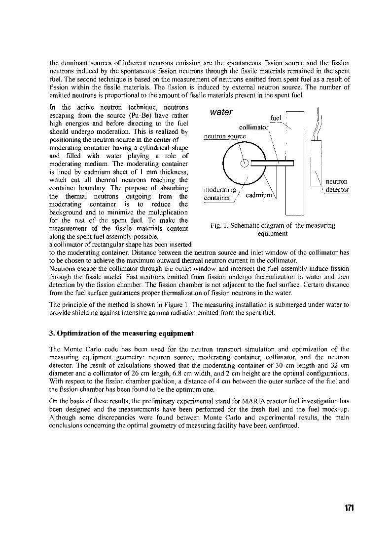
the dominant sources of inherent neutrons emission are the spontaneous fission source and the fissionneutrons induced by the spontaneous fission neutrons through the fissile materials remained in the spentfuel. The second technique is based on the measurement of neutrons emitted from spent fuel as a result offission within the fissile materials. The fission is induced by external neutron source. The number ofemitted neutrons is proportional to the amount of fissile materials present in the spent fuel.
water
neutrondetector
Fig. 1. Schematic diagram of the measuringequipment
In the active neutron technique, neutronsescaping from the source (Pu-Be) have ratherhigh energies and before directing to the fuelshould undergo moderation. This is realized bypositioning the neutron source in the center ofmoderating container having a cylindrical shapeand filled with water playing a role ofmoderating medium. The moderating containeris lined by cadmium sheet of 1 mm thickness,which cut all thermal neutrons reaching thecontainer boundary. The purpose of absorbingthe thermal neutrons outgoing from themoderating container is to reduce thebackground and to minimize the multiplicationfor the rest of the spent fuel. To make themeasurement of the fissile materials contentalong the spent fuel assembly possible,a collimator of rectangular shape has been insertedto the moderating container. Distance between the neutron source and inlet window of the collimator hasto be chosen to achieve the maximum outward thermal neutron current in the collimator.Neutrons escape the collimator through the outlet window and intersect the fuel assembly induce fissionthrough the fissile nuclei. Fast neutrons emitted from fission undergo thermalization in water and thendetection by the fission chamber. The fission chamber is not adjacent to the fuel surface. Certain distancefrom the fuel surface guarantees proper thermalization of fission neutrons in the water.
The principle of the method is shown in Figure 1. The measuring installation is submerged under water toprovide shielding against intensive gamma radiation emitted from the spent fuel.
3. Optimization of the measuring equipment
The Monte Carlo code has been used for the neutron transport simulation and optimization of themeasuring equipment geometry: neutron source, moderating container, collimator, and the neutrondetector. The result of calculations showed that the moderating container of 30 cm length and 32 cmdiameter and a collimator of 26 cm length, 6.8 cm width, and 2 cm height are the optimal configurations.With respect to the fission chamber position, a distance of 4 cm between the outer surface of the fuel andthe fission chamber has been found to be the optimum one.
On the basis of these results, the preliminary experimental stand for MARIA reactor fuel investigation hasbeen designed and the measurements have been performed for the fresh fuel and the fuel mock-up.Although some discrepancies were found between Monte Carlo and experimental results, the mainconclusions concerning the optimal geometry of measuring facility have been confirmed.
171

4. Neutron multiplication method
4.1 Active Neutron Technique
The total signal (counting rate) measured by the fission chamber comes mainly from three sources: thesignal due to induced fission neutrons CR f , signal from neutrons coming directly from neutron sourcewithout being captured in the fuel CRd , and signal due to inherent neutron emission CRin .
C R t o t = C R f + C R d + C R i n
The CRm signal can be obtained by performing the measurement for the spent fuel assembly without
neutron source. The CRd signal can be determined by measuring for the mock-up of the fuel and
introducing a correction factor r to take into account the difference in neutron transmission between thefuel material and the mock-up material (Al instead of UA1X):
The relation between the detector signal and the amount of fissile materials is assumed to be linear. Thislinearity has been verified numerically.
To measure the amount of fissile materials within the spent fuel assembly, at least two calibration pointsare required. These two points are the signal from the fresh fuel and from the mock-up of the fuel,corresponding to the nominal content and zero content of fissile materials respectively.
Assume CR°tot is the neutron signal measured from the fresh fuel assembly, which contains the nominalvalue of U-235,m25 while CRtot is the neutron signal measured from the spent fuel due to the remainedamount of fissile materials which are mainly U-235. The amount of fissile materials of any spent fuel,m25 can then be calculated using the following relation:
m 2 5 =tot ~ C R bg — r •
where CRbg 's are measured without neutron source.
4.2 Passive Neutron Technique
The idea behind this technique is to establish a functional relationship between the fuel burn-up and theexperimentally measured inherent neutron source.
The signal of the inherent neutron source is proportional to the amount of actinide isotopes having asignificant spontaneous neutron emission, and on the neutron emission rate of each isotope. The emittedneutrons undergo multiplication within the fissile materials remained in the spent fuel.The ORIGEN code has been used to calculate the spontaneous neutron source (fission rate) as a functionof burn-up for certain cooling time values. The spontaneous fission rate Rs has been found to becorrelated with the burn-up above 60 MWd/fuel assembly by a power functional relationship:
Rs = a - ( B u ) r
Thus, the burn-up can be expressed as:
Bu = K-(CR i n)1 / T
where K can be recognized as a calibration constant.The bum-up and the amounts of fissile materials distribution along the axial length of the spent fuel can beevaluated using the detector count rate given the values of y and K.
172
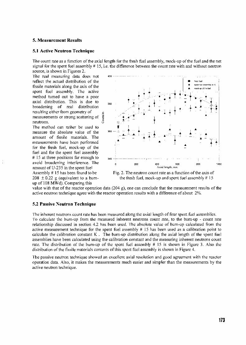
5. Measurement Results
5.1 Active Neutron Technique
The count rate as a function of the axial length for the fresh fuel assembly, mock-up of the fuel and the netsignal for the spent fuel assembly # 15, i.e. the difference between the count rate with and without neutronsource, is shown in Figures 2.The real measuring data does notreflect the actual distribution of thefissile materials along the axis of thespent fuel assembly. The activemethod turned out to have a pooraxial distribution. This is due tobroadening of real distributionresulting either from geometry ofmeasurements or strong scattering ofneutrons.The method can rather be used tomeasure the absolute value of theamount of fissile materials. The
!I
360
340
I l - „
i
•A
-1.1i
fresh fuel
spenr fuel assembly # IS
mock-up of the fuel
;_ •
200 400 600Axial length, mm
800 1000
Fig. 2. The neutron count rate as a function of the axis ofthe fresh fuel, mock-up and spent fuel assembly # 15
measurements have been performedfor the fresh fuel, mock-up of thefuel and for the spent fuel assembly# 15 at three positions far enough toavoid broadening interference. Theamount of U-235 in the spent fuelAssembly # 15 has been found to be208 ± 0.22 g (equivalent to a burn-up of 108 MWd). Comparing thisvalue with that of the reactor operation data (204 g), one can conclude that the measurement results of theactive neutron technique agree with the reactor operation results with a difference of about 2%.
5.2 Passive Neutron Technique
The inherent neutrons count rate has been measured along the axial length of four spent fuel assemblies.To calculate the burn-up from the measured inherent neutrons count rate, to the burn-up - count raterelationship discussed in section 4.2 has been used. The absolute value of bum-up calculated from theactive measurement technique for the spent fuel assembly # 15 has been used as a calibration point tocalculate the calibration constant K . The burn-up distribution along the axial length of the spent fuelassemblies have been calculated using the calibration constant and the measuring inherent neutrons countrate. The distribution of the burn-up of the spent fuel assembly # 15 is shown in Figure 3. Also thedistribution of the fissile materials contents of this spent fuel assembly is shown in Figure 4.
The passive neutron technique showed an excellent axial resolution and good agreement with the reactoroperation data. Also, it makes the measurements much easier and simpler than the measurements by theactive neutron technique.
173
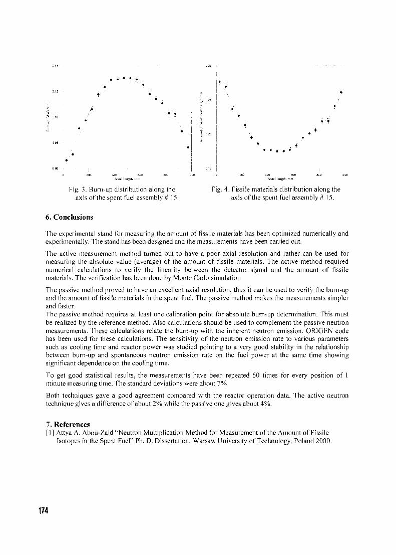
=3
S 0 10
400 600 600 1000Axial length, mm
Fig. 3. Burn-up distribution along theaxis of the spent fuel assembly # 15.
0 200 400 600 300 1Axial length, mm
Fig. 4. Fissile materials distribution along theaxis of the spent fuel assembly # 15.
6. Conclusions
The experimental stand for measuring the amount of fissile materials has been optimized numerically andexperimentally. The stand has been designed and the measurements have been carried out.
The active measurement method turned out to have a poor axial resolution and rather can be used formeasuring the absolute value (average) of the amount of fissile materials. The active method requirednumerical calculations to verify the linearity between the detector signal and the amount of fissilematerials. The verification has been done by Monte Carlo simulation
The passive method proved to have an excellent axial resolution, thus it can be used to verify the burn-upand the amount of fissile materials in the spent fuel. The passive method makes the measurements simplerand faster.The passive method requires at least one calibration point for absolute burn-up determination. This mustbe realized by the reference method. Also calculations should be used to complement the passive neutronmeasurements. These calculations relate the burn-up with the inherent neutron emission. ORIGEN codehas been used for these calculations. The sensitivity of the neutron emission rate to various parameterssuch as cooling time and reactor power was studied pointing to a very good stability in the relationshipbetween burn-up and spontaneous neutron emission rate on the fuel power at the same time showingsignificant dependence on the cooling time.
To get good statistical results, the measurements have been repeated 60 times for every position of 1minute measuring time. The standard deviations were about 7%
Both techniques gave a good agreement compared with the reactor operation data. The active neutrontechnique gives a difference of about 2% while the passive one gives about 4%.
7. References[1] Attya A. Abou-Zaid "Neutron Multiplication Method for Measurement of the Amount of Fissile
Isotopes in the Spent Fuel" Ph. D. Dissertation, Warsaw University of Technology, Poland 2000.
174
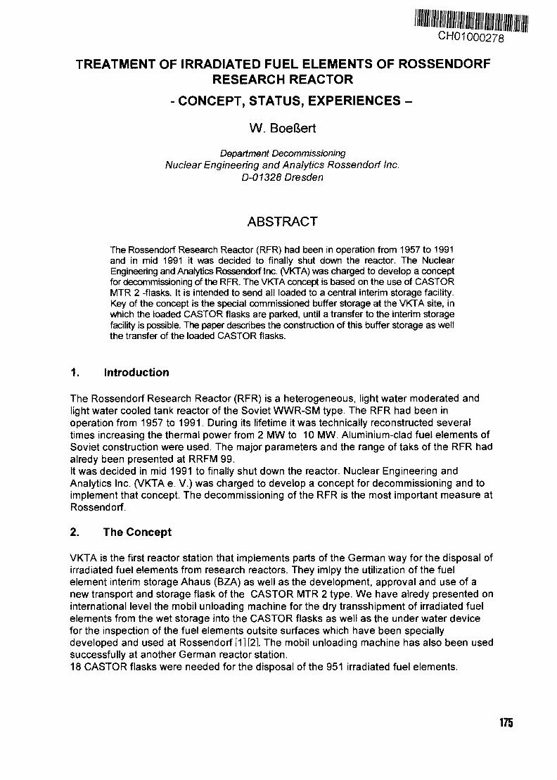
CH01000278
TREATMENT OF IRRADIATED FUEL ELEMENTS OF ROSSENDORFRESEARCH REACTOR
- CONCEPT, STATUS, EXPERIENCES -
W. BoeSert
Department DecommissioningNuclear Engineering and Analytics Rossendorf Inc.
D-01328 Dresden
ABSTRACT
The Rossendorf Research Reactor (RFR) had been in operation from 1957 to 1991and in mid 1991 it was decided to finally shut down the reactor. The NuclearEngineering and Analytics Rossendorf Inc. (VKTA) was charged to develop a conceptfor decommissioning of the RFR. The VKTA concept is based on the use of CASTORMTR 2 -flasks. It is intended to send all loaded to a central interim storage facility.Key of the concept is the special commissioned buffer storage at the VKTA site, inwhich the loaded CASTOR flasks are parked, until a transfer to the interim storagefacility is possible. The paper describes the construction of this buffer storage as wellthe transfer of the loaded CASTOR flasks.
1. Introduction
The Rossendorf Research Reactor (RFR) is a heterogeneous, light water moderated andlight water cooled tank reactor of the Soviet WWR-SM type. The RFR had been inoperation from 1957 to 1991. During its lifetime it was technically reconstructed severaltimes increasing the thermal power from 2 MW to 10 MW. Aluminium-clad fuel elements ofSoviet construction were used. The major parameters and the range of taks of the RFR hadairedy been presented at RRFM 99.It was decided in mid 1991 to finally shut down the reactor. Nuclear Engineering andAnalytics Inc. (VKTA e. V.) was charged to develop a concept for decommissioning and toimplement that concept. The decommissioning of the RFR is the most important measure atRossendorf.
2. The Concept
VKTA is the first reactor station that implements parts of the German way for the disposal ofirradiated fuel elements from research reactors. They imlpy the utilization of the fuelelement interim storage Ahaus (BZA) as well as the development, approval and use of anew transport and storage flask of the CASTOR MTR 2 type. We have airedy presented oninternational level the mobil unloading machine for the dry transshipment of irradiated fuelelements from the wet storage into the CASTOR flasks as well as the under water devicefor the inspection of the fuel elements outsite surfaces which have been speciallydeveloped and used at Rossendorf [1] [2]. The mobil unloading machine has also been usedsuccessfully at another German reactor station.18 CASTOR flasks were needed for the disposal of the 951 irradiated fuel elements.
175
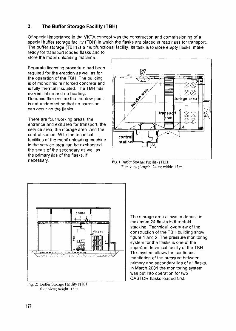
3. The Buffer Storage Facility (TBH)
Of special importance in the VKTA concept was the construction and commissioning of aspecial buffer storage facility (TBH) in which the flasks are placed in readiness for transport.The buffer storage (TBH) is a multifunctional facility. Its task is to store empty flasks, makeready for transport loaded flasks and tostore the mobil unloading machine.
Separate licensing procedure had beenrequired for the erection as well as forthe oparation of the TBH. The buildingis of monolithic reinforced concrete andis fully thermal insulated. The TBH hasno ventilation and no heating.Dehumidiffier ensure tha the dew pointis not undershot so that no corrosioncan occur on the flasks.
There are four working areas, theentrance and exit area for transport, theservice area, the storage area and thecontrol station. With the technicalfacilities of the mobil unloading machinein the service area can be exchangedthe seals of the secondary as well asthe primary lids of the flasks, ifnecessary.
controlstation'
Fig. 1 Buffer Storage Facility (TBH)Plan view ; length: 24 m; width: 15 m
crane
LLL
flasks
Fig. 2: Buffer Storage Facility (TBH)Side view; height: 15 m
The storage area allows to deposit inmaximum 24 flasks in threefoldstacking. Technical overview of theconstruction of the TBH building showfigure 1 and 2. The pressure monitoringsystem for the flasks is one of theimportant technical facility of the TBH.This system allows the continousmonitoring of the pressure betweenprimary and secondary lids of all flasks.In March 2001 the monitoring systemwas put into operation for twoCASTOR-flasks loaded first.
176
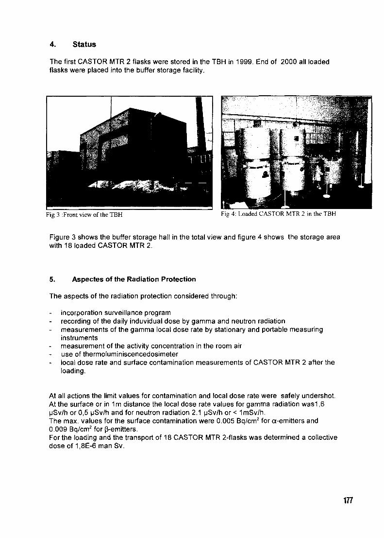
4. Status
The first CASTOR MTR 2 flasks were stored in the TBH in 1999. End of 2000 all loadedflasks were placed into the buffer storage facility.
Fig 3 :Front view of the TBH Fig 4: Loaded CASTOR MTR 2 in the TBH
Figure 3 shows the buffer storage hall in the total view and figure 4 shows the storage areawith 18 loaded CASTOR MTR 2.
5. Aspectes of the Radiation Protection
The aspects of the radiation protection considered through:
incorporation surveillance programrecording of the daily induvidual dose by gamma and neutron radiationmeasurements of the gamma local dose rate by stationary and portable measuringinstrumentsmeasurement of the activity concentration in the room airuse of thermoluminiscencedosimeterlocal dose rate and surface contamination measurements of CASTOR MTR 2 after theloading.
At all actions the limit values for contamination and local dose rate were safely undershot.At the surface or in 1m distance the local dose rate values for gamma radiation was1,6uSv/h or 0,5 uSv/h and for neutron radiation 2.1 uSv/h or < 1mSv/h.The max. values for the surface contamination were 0.005 Bq/cm2 for a-emitters and0.009 Bq/cm2 for (3-emitters.For the loading and the transport of 18 CASTOR MTR 2-flasks was determined a collectivedose of 1.8E-6 man Sv.
177
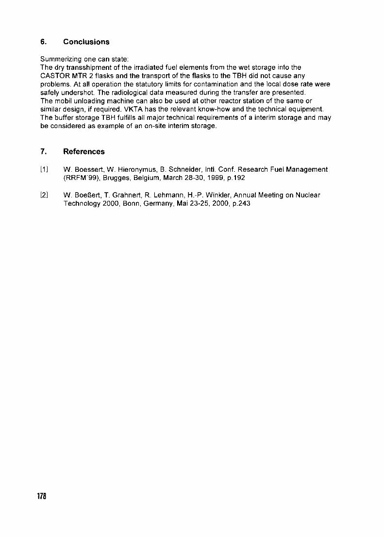
6. Conclusions
Summerizing one can state:The dry transshipment of the irradiated fuel elements from the wet storage into theCASTOR MTR 2 flasks and the transport of the flasks to the TBH did not cause anyproblems. At all operation the statutory limits for contamination and the local dose rate weresafely undershot. The radiological data measured during the transfer are presented.The mobil unloading machine can also be used at other reactor station of the same orsimilar design, if required. VKTA has the relevant know-how and the technical equipment.The buffer storage TBH fulfills all major technical requirements of a interim storage and maybe considered as example of an on-site interim storage.
7. References
[1] W. Boessert, W. Hieronymus, B. Schneider, Intl. Conf. Research Fuel Management(RRFM'99), Brugges, Belgium, March 28-30, 1999, p.192
[2] W. BoeSert, T. Grahnert, R. Lehmann, H.-P. Winkler, Annual Meeting on NuclearTechnology 2000, Bonn, Germany, Mai 23-25, 2000, p.243
178
SAFETY ASPECTS OF RECEIPT AND STORAGE OF SPENTNUCLEAR FUEL AT THE SAVANNAH RIVER SITE
ALAN S. BUSBY and TRENT C. ANDESWestinghouse Savannah River Co.
Building 707-C CH01000279Aiken, South Carolina, 29808 USA
ABSTRACT
The Savannah River Site receives and stores aluminum-based spent nuclear fuel fromresearch reactors world-wide in support of the U.S. Department of Energy's take backpolicy for U.S. origin enriched uranium. For over 35 years the Savannah River Site hassupported this policy in a safe and deliberate manner. Facilities dedicated to this missioninclude the Receiving Basin for Offsite Fuels and L-Basin. Current inventories are about6,500 aluminum-based research reactor assemblies and about 700 stainless-steel orzirconium clad prototype power reactor assemblies. The purpose of this paper is tobriefly describe the processes that the Savannah River Site employs to safely receive,handle, and store spent nuclear fuel.
1. Introduction
The Savannah River Site (SRS), located near Aiken, S.C., is operated for the U.S. Department ofEnergy (USDOE) by Westinghouse Savannah River Company (WSRC). SRS has been receivingspent nuclear fuel (SNF), primarily aluminum-based, from a wide variety of domestic and foreignresearch reactors since 1964. From 1964 until 1997, the Receiving Basin for Offsite Fuels (RBOF)was the predominant SRS facility for receipt and storage. In 1997, the L-Basin was brought intooperation to receive RBOF overflow. In 1998, decisions were made to have L-Basin replace RBOFas the primary receipt and storage facility with RBOF deinventoried to L-Basin by 2007. Thisdecision corresponds to the projected disposition of the aluminum-based fuels through a "melt-dilute" process that will most likely be located in close proximity to the L-Basin facility.
2. Facility Descriptions
RBOF is a steel frame structure that encloses water-filled basins for cask unloading, and SNFrepackaging and storage. The building includes the basin areas, a control room, and an attachedfacility for water filtration and deionization. The basin area consists of two storage basins, threeworking basins (for cropping, bundling, inspection, and interim storage), a cask loading/unloadingbasin, and a cask decontamination pit.
L-Basin is a subsection of the deactivated 105-L Reactor Complex. L-Basin is a reinforced concretestructure that houses water-filled basins with functions similar to RBOF. The basin water volume inL-Basin is about 7 times that of RBOF and L-Basins potential storage capacity is about 3 timesgreater. Other major differences include separated buildings for cask decontamination and waterfiltration and deionization.
3. Processes
The operational processes of RBOF and L-Basin are quite similar and the discussion in this sectionwill treat each facility without distinction. SNF assemblies are typically received in the form ofmaterial test reactor (MTR) fuels about 90 cm in length and a cross-section of 7.6 cm x 8.3 cm. Theassemblies are packaged in aluminum bundles (up to five) which are then stored in vertical racks
179
with fixed spaced storage positions. Other fissile materials in various forms (i.e., tubes, rods,solutions) are typically received in cans which are placed inside of a bundle for storage.
The process activities for the basin facilities are generally divided into four categories. CaskLoading / Unloading places the loaded cask into the basin and removes the SNF (or the reverseprocess in the case of cask loading). SNF Movement transports fuel assemblies between basins. SNFPackaging are operations to crop, as required, fuel assemblies and place them into bundles. SNFStorage involves tasks of selecting the approved storage positions and loading the bundles into theracks. These processes are of particular concern to nuclear criticality safety.
3.1 Cask Loading / Unloading
Heavily shielded casks transport SNF assemblies to and from the basin facilities. Overhead cranestransfer the casks between the cask handling basins and the rail or truck cars. Nuclear Safety DataSheet (NSDS) limits are applied to each fuel type being handled. Procedures are customized basedupon the fuel specific NSDS limits and in the case of cask operations, deal primarily with a safenumber of assemblies allowed to be handled as a group. Operations, Engineering, and Criticalityorganizations review and approve the procedures.
On arrival at SRS, the cask 's bill of lading is compared to the Appendix A to ensure the designatedfuel was received. All further moves of the cask and fuel are then performed per specific operatingprocedures. The cask is brought into the facility where temperature, contamination, and radiationmeasurements are taken and evaluated. The cask is then filled with water and sampled to ensurethere has not been a gross failure during shipment. If the cask meets the activity criteria it is placedin the cask transfer pit (out of limit results may require a greater level of care to preventcontamination of worker and facilities). Once in the basin, the cask lid is removed and the contentsinspected. If at any time during the unloading process a deviation from the loading arrangement isdiscovered, work is stopped and the deviation is evaluated before processing may resume.
Fuel assemblies are removed from the cask and/or basket one at a time. Each assembly is placed inan unloading bucket, identified, and then placed in a transfer bucket. An empty isolation bucket islocated between the unloading and transfer buckets to ensure that a critically safe spacing ismaintained. The transfer bucket contains an insert to prevent loading more than the safe number.Once the transfer bucket is filled, it is removed from the unloading area for packaging before anymore fuel is unloaded from the cask.
3.2 SNF Movement
SNF assemblies are transported within the basins using hand tools, hoists, transfer buckets,monorails, etc. The fuel is passed through systems of canals connecting the various basins either asan individual unit or as a group of units. Nuclear criticality safety during transportation is controlledby mass and spacing. Operations procedures restrict the number of units transported to the safenumber or less and verify that the transport path is clear of other fuels prior to movement.
3.3 SNF Packaging
SNF packaging occurs in working basins that contain machinery for cropping (cutting) or bundling.Cropping of inert end fittings is performed on fuel assemblies in order to maximize basin storagecapacity. Underwater saws are used to remove the fittings. The process involves placing the fuelassembly on the table in which the saw is attached, positioning the assembly against a stop (sized fora precise cut length), and clamping the assembly in place while the cut is made. The scrap end fittingis placed in a scrap bucket. A second cut may be made on the opposing end of the assembly ifnecessary.
180
For cropping, the engineering group issues a technical report setting cut lengths, visual cues for sawoperators, and specification of saw stop settings. Attached to the report is a "red lined" assemblydrawing with the revised length. The report is then incorporated into a cropping procedure to ensurethe safety of the cropping activity. The safety concerns associated with inadvertent cutting of fuelmeat are radiological (fission product release) and criticality (unanalyzed configuration). A fuelassembly is removed from the transfer bucket and placed in a measuring tray to confirm the statedAppendix A assembly length. The saw stop settings are also verified with a gauge. After cropping,the removed end fitting is then inspected to ensure no fuel plates were cut. Basin water is alsoperiodically sampled during cropping to check for any increase in activity.
Bundling occurs at what is called the tilt table. An empty bundle and lid are assigned identificationnumbers and placed on the tilt table. Using underwater tools, fuel elements are placed one at a timein the bundle. As an assembly is loaded into the bundle, the table is tilted vertically to allow theassembly to descend to the bundle bottom. The table is then raised to the horizontal position and theprocess repeated. Once loaded, the bundle is verticalized and the lid attached (by crimping tabs).The bundle has been qualified for loads up to 70 kilograms and accidental drops of about 4 meters.Criticality assumption for the bundle is that it holds its contents in the event of a drop during thestorage process, the highest elevation in which the bundle is carried.
3.4 SNF Storage
Bundled fuel assemblies are stored in a vertical orientation in parallel lanes of modular racks. Eachrack consists of 30 tube sections in a 3 x 10 array with a minimum center to center separation of 19centimeters. The primary function of the tube sections is to maintain spacing requirements.
Fuel assemblies of the High Flux Isotope Reactor (HFIR) type are stored in specifically designedracks. These racks are modular and can store up to 2 cores. The core assemblies (an inner and anouter) are stored separately on posts that are positioned at a fixed, safe distance.
Procedures require verification of the proposed fuel storage locations before and after storage of afuel bundle or core.
4.0 Safety Controls
Basin operations are controlled or managed in a way that protects the offsite public, site workers, andthe environment from radiological and chemical dangers. Safety controls are documented in theauthorization basis for the basin facilities, i.e., the Safety Analysis Report (SAR) and the TechnicalSafety Requirements (TSR). The SAR establishes safety management, the safety envelope, andanalysis. The TSR provides operating limits and surveillance requirements, the administrativecontrols, and the design features that have significant effect on safe operation. Lower tier safetydocuments that detail features of design or administrative controls include double contingencyanalysis (criticality) and process hazards analysis.
4.1 Pre-Receipt Preparations
Site InspectionsInspections of SNF at the reactor or shipping facility allows characterization of the fuel assemblieswhich is utilized for cask containment analysis (corrosion assessment) and Appendix A development.
Appendix A ReviewsThe Appendix A is prepared by the reactor or shipping facility and reviewed by SRS personnel foraccuracy and completeness. Fuel assembly drawings are the primary reference in used to completephysical description and U-235 mass sheets or fabricator reports document fissile loading.
181
Information sources such as the IAEA Research Reactor Books, U.S. supplier records, or fuelfabricators may be utilized by WSRC for independent confirmation of data.
Table G of the Appendix A contains information regarding irradiation history. Although no burn-upcredit is taken for criticality evaluations, isotopic inventory and other irradiation characteristics areneeded in order to perform radionuclide release calculations or satisfy Material Control andAccountability (MC&A) requirements. Table G irradiation data is reviewed utilizing ArgonneNational Laboratory technical reports on MTR type fuel performance.
Authorization Basis PreparationsCriticality evaluations are summarized in a Nuclear Criticality Safety Evaluation (NCSE) andprovided to operations in the form of a Nuclear Safety Data Sheet (NSDS). Depending upon the fueldesign and storage location, criticality evaluations can be explicit or homogenized. Several boundingfuels have been established for several safe numbers and a comparison of the incoming fuel is madeagainst the bounding fuels to determine its ranking.
An engineering evaluation is then performed to ensure the fuel is bounded by the storage facility'sauthorization basis limiting source term. This evaluation compares the SNF against a fictitiousReference Fuel Assembly (RFA), which is a compilation assembly built upon the bounding attributesof any known fuel that is expected to be stored in the SRS basins. If the fuel is bounded by the RFAand meets requirements for heat load and cooling time, it is then approved for receipt and storage.
Upon completion of the facility evaluation, an authorization to receive and store procedure iscompleted. This procedure documents the acceptability of the fuel and performs a compliance checkwith the cask license. Discrepancies that are identified are provided to the DOE. Additional itemsrequired to complete the authorization procedure include letters from the shipper concerningcorrosion, structural integrity, and the results of the SIP test. The Appendix B of the contractualagreement provides the SIP acceptance limits for each cask currently used in the program. The SIPtest determines the activity release rates, which are based upon radionuclide removal capabilities ofthe basin deionization system.
4.2 Programs
Nuclear SafetyNuclear Safety is of primary importance for SNF receipt, handling, and storage. The previousdiscussions show that Nuclear Safety is integrated throughout the basin processes. It is interlinkedwith other programs to ensure safety of the workers.
A Double Contingency Analysis (DCA) is an integral part of the Nuclear Safety Program. The intentof a DCA is to show that when implemented, sufficient engineered controls are in place andsufficient administrative controls are provided in procedures to prevent a situation (or configuration)in which criticality is possible as a result of a single process upset. Initiating events that could resultin a criticality have been identified for both basin facilities and two or more defenses have beenestablished for each initiating event.
Procedures and TrainingProcedures are developed to ensure routine, off-normal, and emergency activities are conducted in asafe manner. Operations, maintenance, administrative procedures guide the applicable activitiesdescribed in the facility's TSR. Procedures are prepared, reviewed, and approved in accordance withquality assurance and administrative procedures. Operating procedures define the criticality safetyenvelope when performing fuel handling/process operations. The procedures define the steps tocomplete various operations (i.e. Cask unloading) and prior to use, are customized with detailedinformation (i.e., safe numbers, storage location) for the specific operation. This customization is
182
reviewed and approved by Operations, Engineering, and Criticality Safety personnel. Theprocedures contain detailed steps (Nuclear Safety Controls are highlighted) which have peerverifications on "important to safety" steps.
The SRS training program involves initial, continuing, and re-training carried out in formalclassroom instructions and on-the-job. Fuel Handling Supervisors are certified through written andoral examinations, operational evaluations, and physical condition. Fuel Handling Operators arequalified based upon written examinations, operational evaluations, and physical condition.Qualified Fuel Handling Operators under the direct supervision of a certified Fuel HandlingSupervisor perform all fuel handling activities.
Chemistry ControlsWater chemistry maintenance for the basins ensures a safe, long-term storage environment for theSNF. The purpose of the program is to maintain fuel integrity. Basin water quality is monitoredthrough sampling, trending, and coupon immersion. The basin water quality is maintained by filtersand deionizer systems, which utilize anion, cation and sometimes zeolite resins for chemistry control.The program provides operating limits for pH, conductivity, temperature, radionuclides, chlorides,and metals. Microbiological analysis is conducted on an as-needed basis.
Hoisting and RiggingThis program ensures that hoisting and rigging equipment is sufficiently maintained, inspected, andtested to lower the frequency of failure below that of human failure rates. This is most criticallyinvolved with cask handling.
Radiological ProtectionThe Radiological Protection Program protects on-site workers from excessive radiation exposure. Inthe basin areas, radiation monitors with both audio and visual alarm systems are employed. Themonitors alarm in the presence of high gamma fields which would be an indication of reduced orunshielded SNF.
4.3 Equipment Design
Natural phenomena for seismic hazards has impacted the design of racks and bundles. Thequalification of both the RBOF and L-Basin structures are to PC-3 NPH effects. Due to theirimportance to criticality control through geometry and spacing, basin racks and bundles are likewisedesigned to withstand PC-3 events. The fuel storage racks serve as a passive engineering control toprovide a subcritical configuration for storage by providing a fixed spacing at all times.
Underwater tools, used for remote handling of the SNF, are typically required to have positiveengagement features, which would preclude the dropping of an assembly. This also is a criticalityprotection with respect to creating an unanalyzed configuration. From a radiological standpoint, toolshafts are tube construction with weep holes to allow water ingress and provide shielding (preventshine) to the operator.
5.0 Conclusion
Controls are in place at the Savannah River Site's basin facilities that address the potential safety-related problems that could occur with the receipt and storage of spent nuclear fuel. Nuclearcriticality safety is the primary concern with basin operations and thus safety controls areimplemented for its prevention. A review of the operational processes and the concerns thereinindicate that the most important aspects of safe operations are accurate fuel documentation throughthe Appendix A process and procedure compliance.
183
Research Reactors Spent Fuel Management in NRI Rez, Czech Republic
CH01000280
Research Reactors Spent Fuel Management in NRI Rez, Czech Republic
Jiri RycheckyNuclear Research Institute, 250 68 Rez, Czech Republic
IntroductionIn Czech Republic 3 research and testing nuclear reactors are operated at present time, withthe biggest one being the Nuclear Research Institute (NRI) reactor LVR -15, operated withmaximum power 10 MW. This reactor serves as a radiation source for material testing,producing of ionising radiation sources, theoretical studies, and in the last time, for boronneutron capture therapy. Another NRI reactor LR-0 is reactor of zero power used mainly forthe studies of WWER 1000 spent fuel criticality. For training of students the reactor calledVRABEC (VR-1), operated also with very low power, serves since 1990 at the Faculty ofNuclear Engineering, of Czech Technical University. The similar testing type reactor (SR-0),already decommissioned, was also used since 1974 to 1989 in Skoda, Nuclear Machinery,Plzen. This contribution summarises the present state of the spent fuel (SF) management ofthese nuclear reactors. As the SF management is different for very low or zero power reactorsand power reactors, the SF management from very low or zero power reactors will be onlybriefly discussed first, and then the main attention will be devoted to SF management of NRIexperimental reactor LVR-15.
The management of spent fuel from zero or low power research reactorsThe irradiated nuclear fuel from reactors with zero or very low power (LR-0, VR-1, or SR-0)is not usually classified as radioactive wastes. Only a very small quantity of radionuclides isproduced and the dose rate at the surface of spent fuel assemblies is less than 0.1 mSv/h. Thereactor LR-0, operated with large reconstruction in 1982 since 1972, contain 65 VVER 1000model fuel assemblies with enrichment in the range 1,6 to 4,4 %. The total amount of Uraniumis 10 469,7 kg. The reactor VR-1 utilises now 18 assemblies of the fuel IRT-3M withenrichment 36 %. The reactor of Skoda Plzen before decommissioning used first EK-10 fueland then IRT-2M fuel with enrichment 80 %.The irradiated fuel assemblies after reactors decommissioning (the expected time of LR-0decommissioning is 2010 and VR-1 in 2020 or later), or changing the type of fuel for whateverreason, can be transferred to some of nuclear fuel producers or to another research reactoroperators, as was the case with assemblies from the SR-0 reactor, from which the EK-10assemblies were transferred to Hungary (Technical University) and IRT-2M transferred to NRILVR-15 reactor in Rez. But, if there is no one interested in taking over the irradiated fuelassemblies, then they will have to be disposed of in an appropriate way. The problem is thatspent fuel assemblies from research reactors, and especially those with high enrichment, haveto be safeguarded after they are taken out of reactor to prevent the use of its fissile material fornuclear weapons construction. They cannot be easily disposed of as low or intermediate levelwaste to near surface radioactive waste repositories.
184
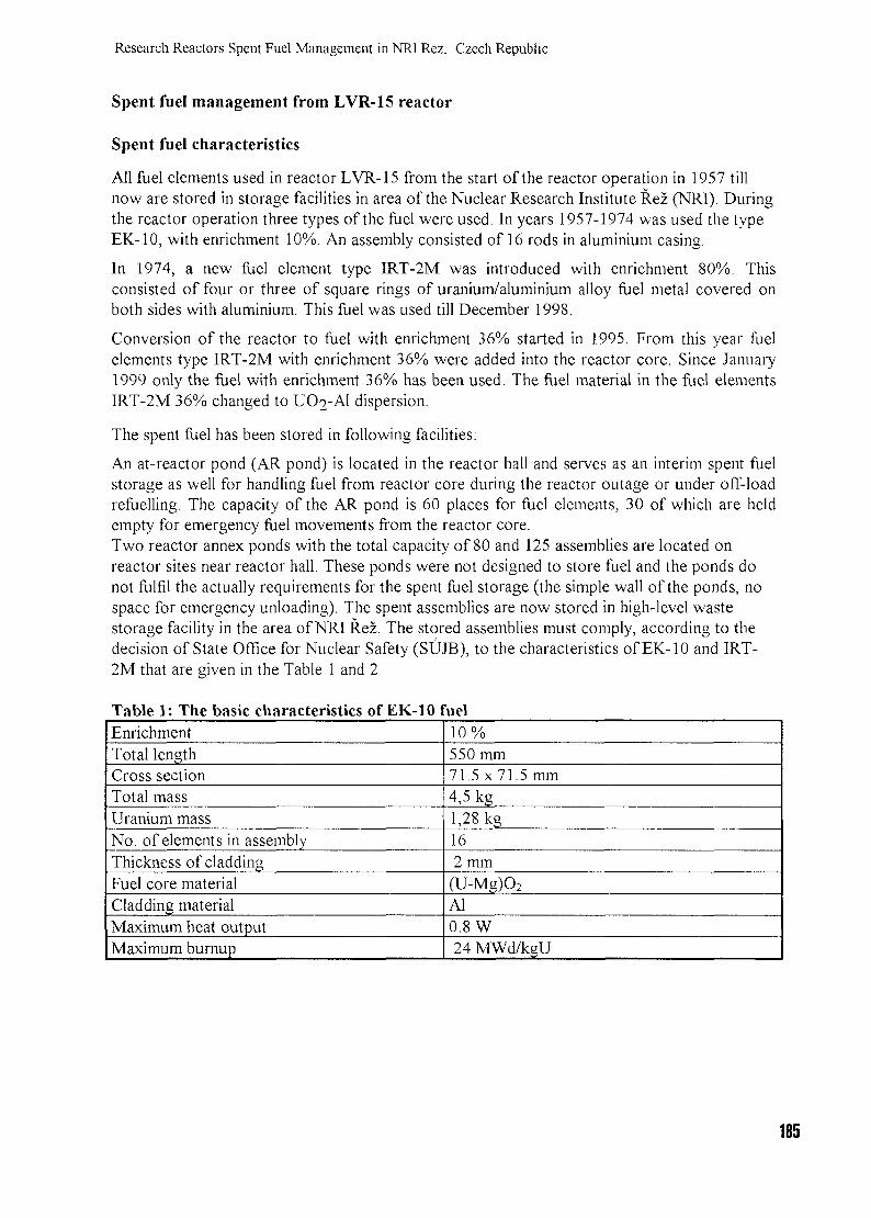
Research Reactors Spent Fuel Management in NR1 Rez. Czech Republic
Spent fuel management from LVR-15 reactor
Spent fuel characteristics
All fuel elements used in reactor LVR-15 from the start of the reactor operation in 1957 tillnow are stored in storage facilities in area of the Nuclear Research Institute Rez (NRI). Duringthe reactor operation three types of the fuel were used. In years 1957-1974 was used the typeEK-10, with enrichment 10%. An assembly consisted of 16 rods in aluminium casing.
In 1974, a new fuel element type IRT-2M was introduced with enrichment 80%. Thisconsisted of four or three of square rings of uranium/aluminium alloy fuel metal covered onboth sides with aluminium. This fuel was used till December 1998.
Conversion of the reactor to fuel with enrichment 36% started in 1995. From this year fuelelements type IRT-2M with enrichment 36% were added into the reactor core. Since January1999 only the fuel with enrichment 36% has been used. The fuel material in the fuel elementsIRT-2M 36% changed to UO2-AI dispersion.
The spent fuel has been stored in following facilities:
An at-reactor pond (AR pond) is located in the reactor hall and serves as an interim spent fuelstorage as well for handling fuel from reactor core during the reactor outage or under off-loadrefuelling. The capacity of the AR pond is 60 places for fuel elements, 30 of which are heldempty for emergency fuel movements from the reactor core.Two reactor annex ponds with the total capacity of 80 and 125 assemblies are located onreactor sites near reactor hall. These ponds were not designed to store fuel and the ponds donot fulfil the actually requirements for the spent fuel storage (the simple wall of the ponds, nospace for emergency unloading). The spent assemblies are now stored in high-level wastestorage facility in the area of NRI Rez. The stored assemblies must comply, according to thedecision of State Office for Nuclear Safety (SUJB), to the characteristics of EK-10 and IRT-2M that are given in the Table 1 and 2.
Table 1: The basic characteristics of EK-10 fuelEnrichmentTotal lengthCross sectionTotal massUranium massNo. of elements in assemblyThickness of claddingFuel core materialCladding materialMaximum heat outputMaximum burnup
10%550 mm71.5x71.5 mm4,5 kg1,28 kg162 mm
(U-Mg)O2
Al0.8 W24 MWd/kgU
185
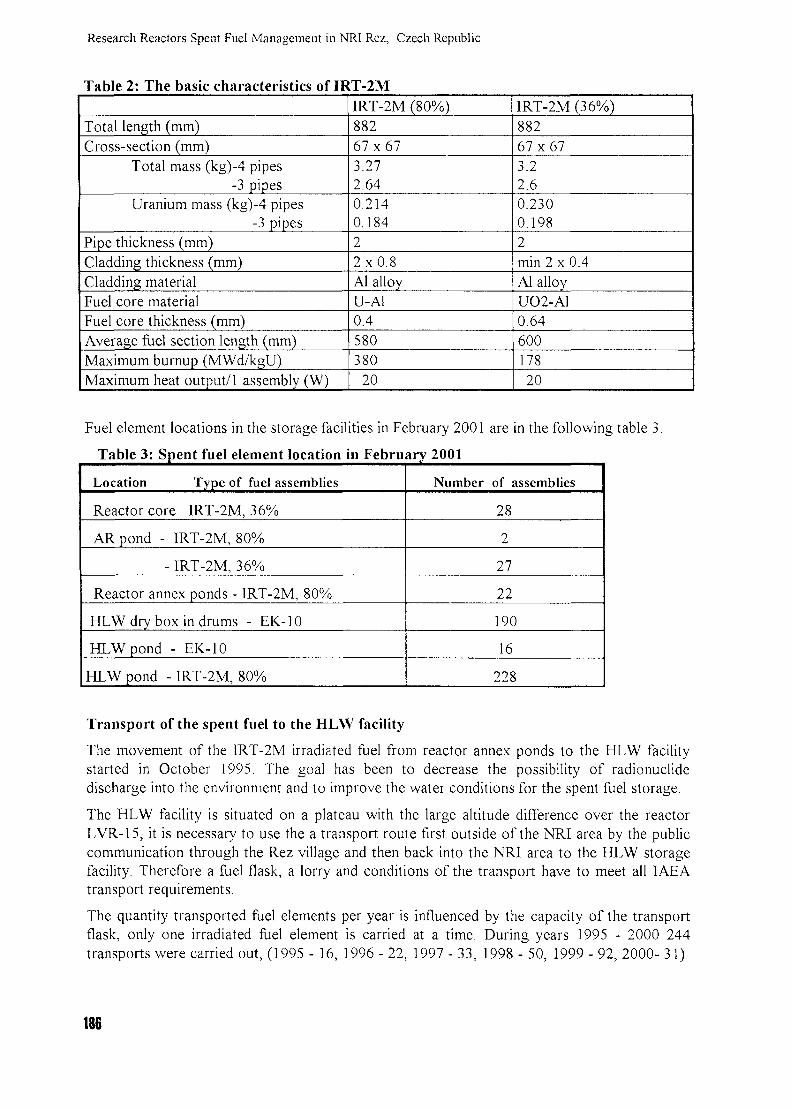
Researcli Reactors Spent Fuel Management in NRI Rez, Czech Republic
Table 2: The basic characteristics of IRT-2M
Total length (mm)Cross-section (mm)
Total mass (kg)-4 pipes-3 pipes
Uranium mass (kg)-4 pipes-3 pipes
Pipe thickness (mm)Cladding thickness (mm)Cladding materialFuel core materialFuel core thickness (mm)Average fuel section length (mm)Maximum burnup (MWd/kgU)Maximum heat output/1 assembly (W)
IRT-2M (80%)88267x673.272.640.2140.18422x0.8Al alloyU-Al0.4580380
20
IRT-2M(36%)88267x673.22.60.2300.1982min 2 x 0.4Al alloyUO2-A10.6460017820
Fuel element locations in the storage facilities in February 2001 are in the following table 3.
Table 3: Spent fuel element location in February 2001
Location Type of fuel assemblies
Reactor core IRT-2M, 36%
AR pond - IRT-2M, 80%
- IRT-2M, 36%
Reactor annex ponds - IRT-2M, 80%
HLW dry box in drums - EK-10
HLW pond - EK-10
HLW pond - IRT-2M, 80%
Number of assemblies
28
2
27
22
190
16
228
Transport of the spent fuel to the HLW facility
The movement of the IRT-2M irradiated fuel from reactor annex ponds to the HLW facilitystarted in October 1995. The goal has been to decrease the possibility of radionuclidedischarge into the environment and to improve the water conditions for the spent fuel storage.
The HLW facility is situated on a plateau with the large altitude difference over the reactorLVR-15, it is necessary to use the a transport route first outside of the NRI area by the publiccommunication through the Rez village and then back into the NRI area to the HLW storagefacility. Therefore a fuel flask, a lorry and conditions of the transport have to meet all IAEAtransport requirements.
The quantity transported fuel elements per year is influenced by the capacity of the transportflask, only one irradiated fuel element is carried at a time. During years 1995 - 2000 244transports were carried out, (1995 - 16, 1996-22, 1997- 33, 1998- 50, 1999-92, 2000-31)
186
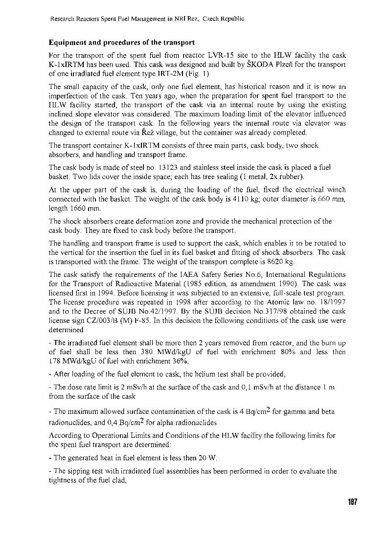
Research Reactors Spent Fuel Management in NRJ Rez, Czech Republic
Equipment and procedures of the transport
For the transport of the spent fuel from reactor LVR-15 site to the HLW facility the caskK-lxIRTM has been used. This cask was designed and built by SKODA Plzen for the transportof one irradiated fuel element type IRT-2M (Fig. 1).
The small capacity of the cask, only one fuel element, has historical reason and it is now animperfection of the cask. Ten years ago, when the preparation for spent fuel transport to theHLW facility started, the transport of the cask via an internal route by using the existinginclined slope elevator was considered. The maximum loading limit of the elevator influencedthe design of the transport cask. In the following years the internal route via elevator waschanged to external route via Rez village, but the container was already completed.
The transport container K-lxIRTM consists of three main parts, cask body, two shockabsorbers, and handling and transport frame.
The cask body is made of steel no. 13123 and stainless steel inside the cask is placed a fuelbasket. Two lids cover the inside space; each has tree sealing (1 metal, 2x rubber).
At the upper part of the cask is, during the loading of the fuel, fixed the electrical winchconnected with the basket. The weight of the cask body is 4110 kg; outer diameter is 660 mm,length 1660 mm.
The shock absorbers create deformation zone and provide the mechanical protection of thecask body. They are fixed to cask body before the transport.
The handling and transport frame is used to support the cask, which enables it to be rotated tothe vertical for the insertion the fuel in its fuel basket and fitting of shock absorbers. The caskis transported with the frame. The weight of the transport complete is 8620 kg.
The cask satisfy the requirements of the IAEA Safety Series No.6, International Regulationsfor the Transport of Radioactive Material (1985 edition, as amendment 1990). The cask waslicensed first in 1994. Before licensing it was subjected to an extensive, full-scale test program.The license procedure was repeated in 1998 after according to the Atomic law no. 18/1997and to the Decree of SUJB No.42/1997. By the SUJB decision No.317/98 obtained the casklicense sign CZ/003/B (M) F-85. In this decision the following conditions of the cask use weredetermined
- The irradiated fuel element shall be more then 2 years removed from reactor, and the burn upof fuel shall be less then 380 MWd/kgU of fuel with enrichment 80% and less then178 MWd/kgU of fuel with enrichment 36%.
- After loading of the fuel element to cask, the helium test shall be provided,
- The dose rate limit is 2 mSv/h at the surface of the cask and 0,1 mSv/h at the distance 1 mfrom the surface of the cask
- The maximum allowed surface contamination of the cask is 4 Bq/cm^ for gamma and beta
radionuclides, and 0,4 Bq/cm^ for alpha radionuclides
According to Operational Limits and Conditions of the HLW facility the following limits forthe spent fuel transport are determined:
- The generated heat in fuel element is less then 20 W.
- The sipping test with irradiated fuel assemblies has been performed in order to evaluate thetightness of the fuel clad,
187
Research Reactors Spent Fuel Management in NRI Rez, Czech Republic
During the sipping test the fuel element is placed in the pond inside a closed aluminiumcontainer. The container is filled by clean water and after three hours a sample from thecontainer water is collected and the gamma-ray spectrometry analysis is carried out. When the
activity of 137Cs is lower then 300 Bq/1 the transport of fuel assembly to the HLW facility ispossible. The generated heat of each fuel assembly is calculated.
Fig. 1. Transport cask K-lxIRTM
188
Research Reactors Spent Fuel Management in NRI Rez. Czech Republic
The High Level Waste Storage Facility
The HLW storage facility is constructed as a hall. The lower part of the hall is made ofreinforced concrete monolith to the height of 5.65 m and the upper part is made ofprefabricated panels. Outer dimensions are 36.95 x 16.26 x 9.91m. The lower part is dividedinto 12 square boxes (6x6m). 8 of them will serve for dry storage and 2 for the wet storage ofspent fuel assemblies in water pools of diameter 4.6 m and height 5 m; the storage is permittedonly in one of the pools under the shielding layer of water, the second pool must be empty incase of the need to store leaking assemblies. In the pool it is allowed to store 284 of 1RT-2Massemblies and 16 of EK-10 assemblies. They are stored in one layer in vertical position in pipereceivers with the grid spacing of 200 mm. The storage of leaking assemblies is allowed only ina special hermetically tight tube in an individual grid of 200 mm spacing.
In one of the boxes of the HLW facility storage capacity (box No. 5) it is allowed thedry storage of EK-10 assemblies in concrete containers after one assembly in each; they arearranged in three layers after 72 assemblies. The containers are cylindrical with diameter 565mm and length 890 mm; maximum weight is 600 kg.
Spent fuel disposal optionsWhen designing and constructing research reactors in NRI, it was assumed that spent fuel willbe returned to the producer for reprocessing without any intergovernmental agreement. Only in1999 it was achieved an agreement between the government of Czech Republic and theRussian Federation that the Russian Federation will accept the spent fuel for reprocessing withreturning vitrified high level waste to Czech Republic. This service should be, of course, oncommercial base. There still exist, however, a variety of other alternatives; no decision hasbeen made so far. Below are some alternatives of LVR-15 spent fuel disposal now considered:
1) The spent fuel assemblies transport to the Russian Federation, their reprocessing withreturning of vitrified waste and their storage or disposal to deep geological repository (DGR) -the negotiations of NRI and Russian Co.Texnabexport about the transport, reprocessing ofspent fuel, vitrification of high level waste and a temporary storage in Majak facility alreadystarted.2) The storage of spent fuel to the time of DGR operation in the dry state in the suitablecontainers (till about 2050), i.e. the transfer of SF assemblies from water pools, repackaging,and then their disposal in DGR.3) The transport and reprocessing of spent fuel to some of European facilities with returningHLW facility waste.
The activity of all spent fuel assemblies from research reactor LVR-15 corresponds,approximately, only to 15 assemblies from WWER 440 reactor or 3 assemblies from WWER1000 reactor. Nevertheless, the high enrichment or research spent fuel assemblies and lowcorrosion resistance of Al cladding makes this problem a very important issue.
Financial coverageFinancing of expenses for research reactor spent fuel management is covered partly by theState under the so-called old ecological (radiation) burden item in agreement with Atomic Lawissued in 1987. The State will provide a subsidy to eliminate this burden originated prior toprivatisation of NRI. The necessary expenses must be specified on the basis of feasibility study.
189
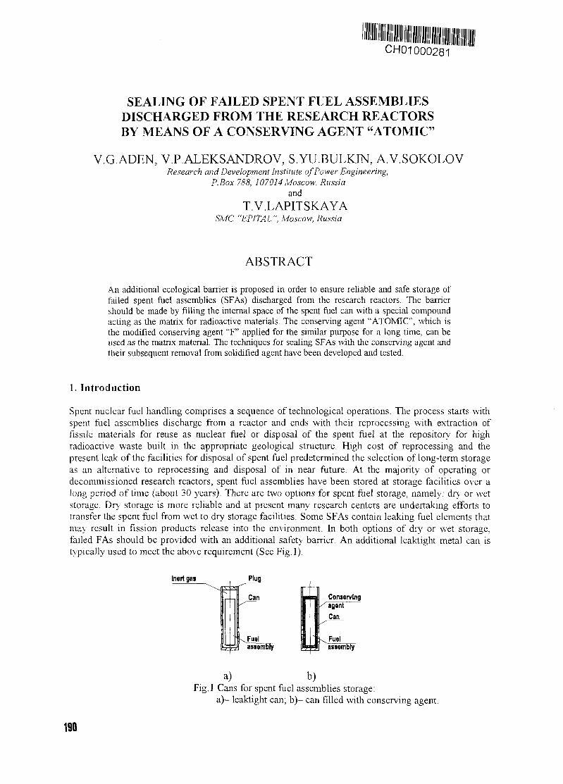
CH01000281
SEALING OF FAILED SPENT FUEL ASSEMBLIESDISCHARGED FROM THE RESEARCH REACTORSBY MEANS OF A CONSERVING AGENT "ATOMIC"
V.G.ADEN, V.P.ALEKSANDROV, S.YU.BULKIN, A.V.SOKOLOVResearch and Development Institute of Power Engineering,
P.Box 788, ]07014 Moscow, Russiaand
T.V.LAPITSKAYASMC "EPITAL ", Moscow, Russia
ABSTRACT
An additional ecological barrier is proposed in order to ensure reliable and safe storage offailed spent fuel assemblies (SFAs) discharged from the research reactors. The barriershould be made by filling the internal space of the spent fuel can with a special compoundacting as the matrix for radioactive materials. The conserving agent "ATOMIC", which isthe modified conserving agent "F" applied for the similar purpose for a long time, can beused as the matrix material. The techniques for sealing SFAs with the conserving agent andtheir subsequent removal from solidified agent have been developed and tested.
1. Introduction
Spent nuclear fuel handling comprises a sequence of technological operations. The process starts withspent fuel assemblies discharge from a reactor and ends with their reprocessing with extraction offissile materials for reuse as nuclear fuel or disposal of the spent fuel at the repository for highradioactive waste built in the appropriate geological structure. High cost of reprocessing and thepresent leak of the facilities for disposal of spent fuel predetermined the selection of long-term storageas an alternative to reprocessing and disposal of in near future. At the majority of operating ordecommissioned research reactors, spent fuel assemblies have been stored at storage facilities over along period of time (about 30 years). There are two options for spent fuel storage, namely: dry or wetstorage. Dry storage is more reliable and at present many research centers are undertaking efforts totransfer the spent fuel from wet to dry storage facilities. Some SFAs contain leaking fuel elements thatmay result in fission products release into the environment. In both options of dry or wet storage,failed FAs should be provided with an additional safety barrier. An additional leaktight metal can istypically used to meet the above requirement (See Fig. 1).
Inert gas
a) b)Fig. 1 Cans for spent fuel assemblies storage:
a)- leaktight can; b)- can filled with conserving agent.
190
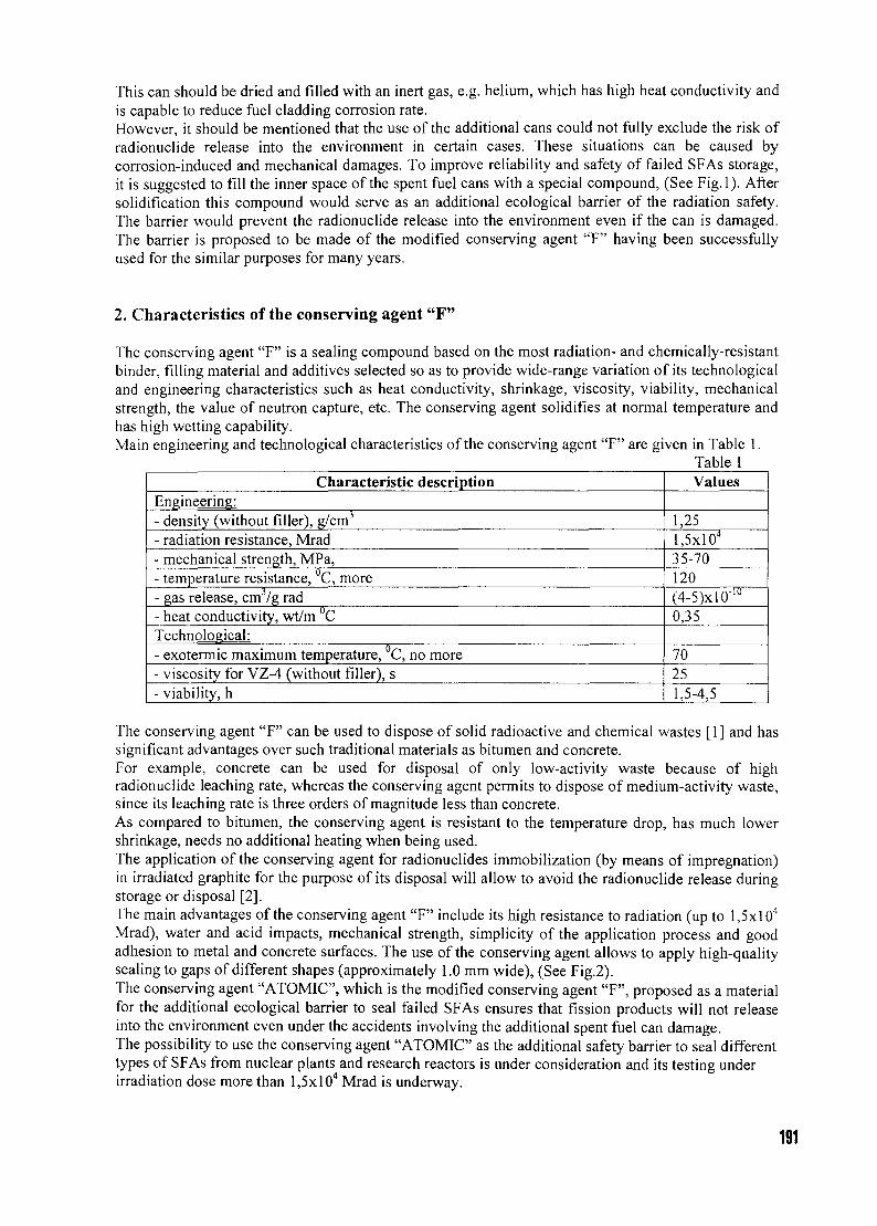
This can should be dried and filled with an inert gas, e.g. helium, which has high heat conductivity andis capable to reduce fuel cladding corrosion rate.However, it should be mentioned that the use of the additional cans could not fully exclude the risk ofradionuclide release into the environment in certain cases. These situations can be caused bycorrosion-induced and mechanical damages. To improve reliability and safety of failed SFAs storage,it is suggested to fill the inner space of the spent fuel cans with a special compound, (See Fig.l). Aftersolidification this compound would serve as an additional ecological barrier of the radiation safety.The barrier would prevent the radionuclide release into the environment even if the can is damaged.The barrier is proposed to be made of the modified conserving agent "F" having been successfullyused for the similar purposes for many years.
2. Characteristics of the conserving agent "F"
The conserving agent "F" is a sealing compound based on the most radiation- and chemically-resistantbinder, filling material and additives selected so as to provide wide-range variation of its technologicaland engineering characteristics such as heat conductivity, shrinkage, viscosity, viability, mechanicalstrength, the value of neutron capture, etc. The conserving agent solidifies at normal temperature andhas high wetting capability.Main engineering and technological characteristics of the conserving agent "F" are given in Table 1.
Table 1Characteristic description
Engineering:- density (without filler), g/cm3
- radiation resistance, Mrad- mechanical strength, MPa,- temperature resistance, C, more- gas release, cm /g rad- heat conductivity, wt/m °CTechnological:- exotermic maximum temperature, C, no more- viscosity for VZ-4 (without filler), s- viability, h
Values
1,25l,5xlO4
35-70120(4-5)xlO"10
0,35
70251,5-4,5
The conserving agent "F" can be used to dispose of solid radioactive and chemical wastes [1] and hassignificant advantages over such traditional materials as bitumen and concrete.For example, concrete can be used for disposal of only low-activity waste because of highradionuclide leaching rate, whereas the conserving agent permits to dispose of medium-activity waste,since its leaching rate is three orders of magnitude less than concrete.As compared to bitumen, the conserving agent is resistant to the temperature drop, has much lowershrinkage, needs no additional heating when being used.The application of the conserving agent for radionuclides immobilization (by means of impregnation)in irradiated graphite for the purpose of its disposal will allow to avoid the radionuclide release duringstorage or disposal [2].The main advantages of the conserving agent "F" include its high resistance to radiation (up to l,5xl04
Mrad), water and acid impacts, mechanical strength, simplicity of the application process and goodadhesion to metal and concrete surfaces. The use of the conserving agent allows to apply high-qualitysealing to gaps of different shapes (approximately 1.0 mm wide), (See Fig.2).The conserving agent "ATOMIC", which is the modified conserving agent "F", proposed as a materialfor the additional ecological barrier to seal failed SFAs ensures that fission products will not releaseinto the environment even under the accidents involving the additional spent fuel can damage.The possibility to use the conserving agent "ATOMIC" as the additional safety barrier to seal differenttypes of SFAs from nuclear plants and research reactors is under consideration and its testing underirradiation dose more than l,5x!04 Mrad is underway.
191
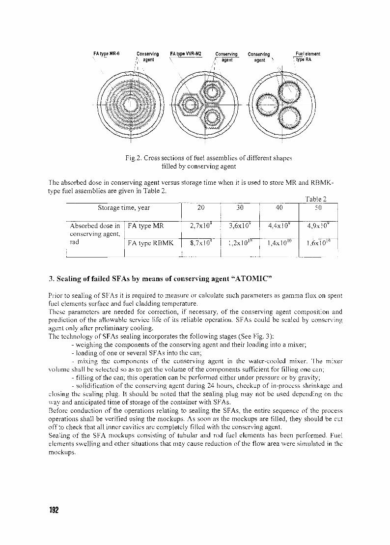
FAtypeMR-6 Conservingagent
FA type WR-M2 Conserving ConservingT agent agent \
Fuel elementrtype RA
Fig.2. Cross sections of fuel assemblies of different shapesfilled by conserving agent
The absorbed dose in conserving agent versus storage time when it is used to store MR and RBMK-type fuel assemblies are given in Table 2.
Table 2Storage time, year
Absorbed dose inconserving agent,rad
FA type MR
FA type RBMK
20
2,7x10⁹
8,7x10y
30
3,6x10"
l,2x!0lu
40
4,4x10⁹
1,4x10'"
50
4,9xlO9
l,6xlOlu
3. Sealing of failed SFAs by means of conserving agent "ATOMIC"
Prior to sealing of SFAs it is required to measure or calculate such parameters as gamma flux on spentfuel elements surface and fuel cladding temperature.These parameters are needed for correction, if necessary, of the conserving agent composition andprediction of the allowable service life of its reliable operation. SFAs could be sealed by conservingagent only after preliminary cooling.The technology of SFAs sealing incorporates the following stages (See Fig. 3):
- weighing the components of the conserving agent and their loading into a mixer;- loading of one or several SFAs into the can;- mixing the components of the conserving agent in the water-cooled mixer. The mixer
volume shall be selected so as to get the volume of the components sufficient for filling one can;- filling of the can; this operation can be performed either under pressure or by gravity;- solidification of the conserving agent during 24 hours, checkup of in-process shrinkage and
closing the sealing plug. It should be noted that the sealing plug may not be used depending on theway and anticipated time of storage of the container with SFAs.Before conduction of the operations relating to sealing the SFAs, the entire sequence of the processoperations shall be verified using the mockups. As soon as the mockups are filled, they should be cutoff to check that all inner cavities are completely filled with the conserving agent.Sealing of the SFA mockups consisting of tubular and rod fuel elements has been performed. Fuelelements swelling and other situations that may cause reduction of the flow area were simulated in themockups.
192
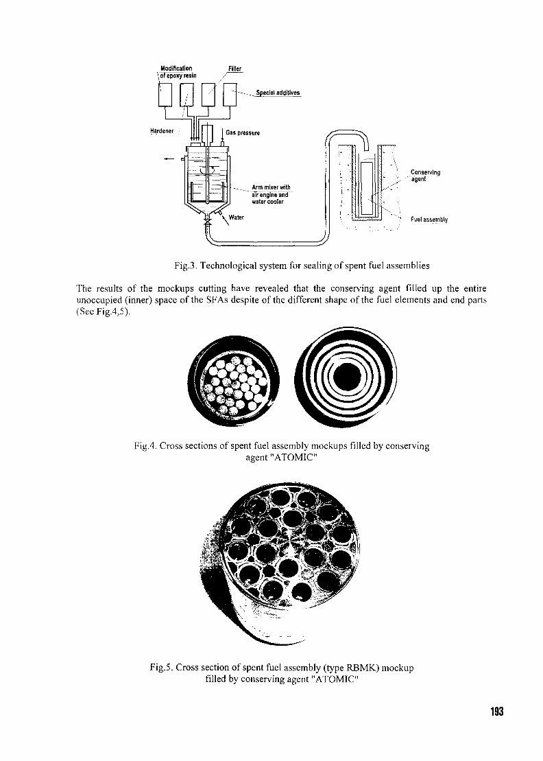
Modification Filler
Special additives
Conserving; agehT
Fuel assembly
Fig.3. Technological system for sealing of spent fuel assemblies
The results of the mockups cutting have revealed that the conserving agent filled up the entireunoccupied (inner) space of the SFAs despite of the different shape of the fuel elements and end parts(See Fig.4,5).
Fig.4. Cross sections of spent fuel assembly mockups filled by conservingagent "ATOMIC"
Fig. 5. Cross section of spent fuel assembly (type REMK) mockupfilled by conserving agent "ATOMIC"
193
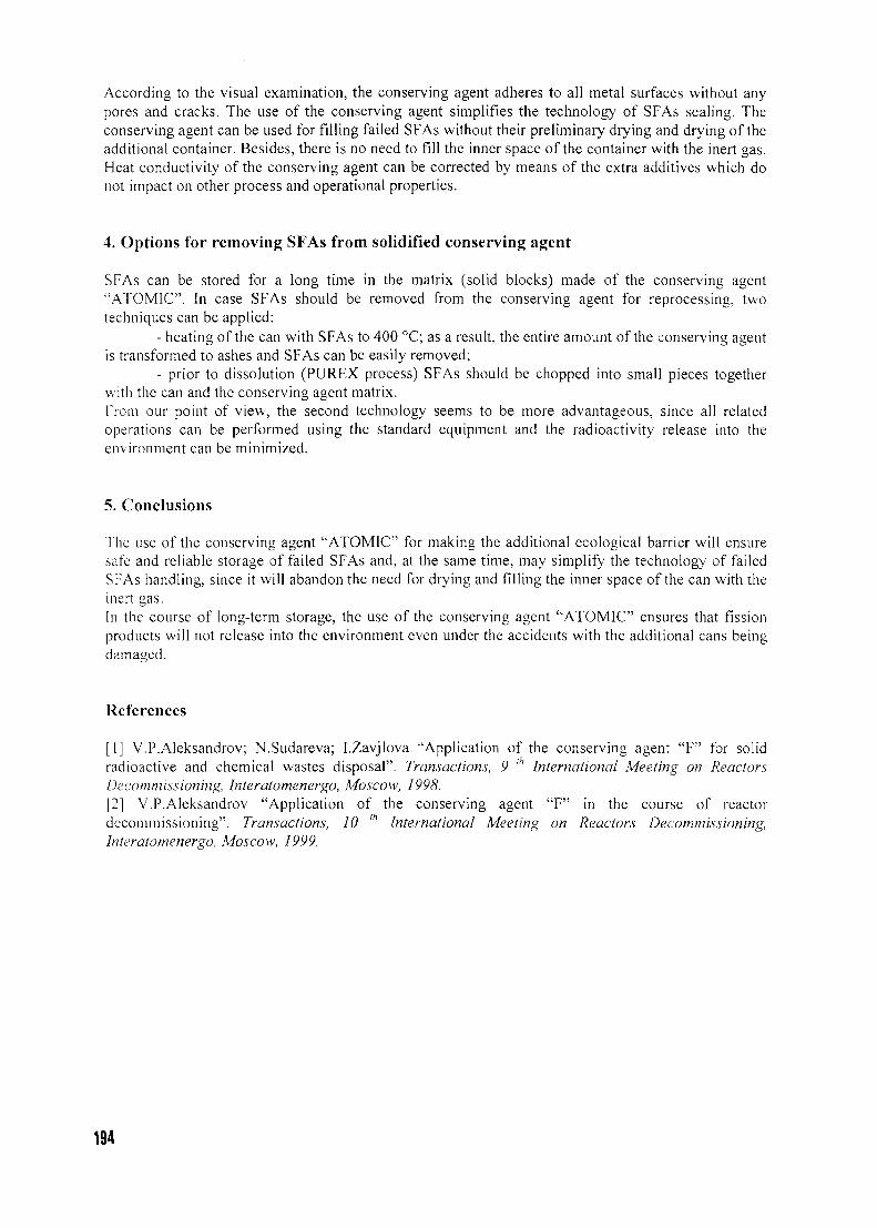
According to the visual examination, the conserving agent adheres to all metal surfaces without anypores and cracks. The use of the conserving agent simplifies the technology of SFAs sealing. Theconserving agent can be used for filling failed SFAs without their preliminary drying and drying of theadditional container. Besides, there is no need to fill the inner space of the container with the inert gas.Heat conductivity of the conserving agent can be corrected by means of the extra additives which donot impact on other process and operational properties.
4. Options for removing SFAs from solidified conserving agent
SFAs can be stored for a long time in the matrix (solid blocks) made of the conserving agent"ATOMIC". In case SFAs should be removed from the conserving agent for reprocessing, twotechniques can be applied:
- heating of the can with SFAs to 400 °C; as a result, the entire amount of the conserving agentis transformed to ashes and SFAs can be easily removed;
- prior to dissolution (PUREX process) SFAs should be chopped into small pieces togetherwith the can and the conserving agent matrix.From our point of view, the second technology seems to be more advantageous, since all relatedoperations can be performed using the standard equipment and the radioactivity release into theenvironment can be minimized.
5. Conclusions
The use of the conserving agent "ATOMIC" for making the additional ecological barrier will ensuresafe and reliable storage of failed SFAs and, at the same time, may simplify the technology of failedSFAs handling, since it will abandon the need for drying and filling the inner space of the can with theinert gas.In the course of long-term storage, the use of the conserving agent "ATOMIC" ensures that fissionproducts will not release into the environment even under the accidents with the additional cans beingdamaged.
References
[1] V.P.Aleksandrov; N.Sudareva; I.Zavjlova "Application of the conserving agent "F" for solidradioactive and chemical wastes disposal". Transactions, 9 lh International Meeting on ReactorsDecommissioning, Interatomenergo, Moscow, 1998.[2] V.P.Aleksandrov "Application of the conserving agent "F" in the course of reactordecommissioning". Transactions, 10 ' International Meeting on Reactors Decommissioning,Interatomenergo, Moscow, 1999.
194
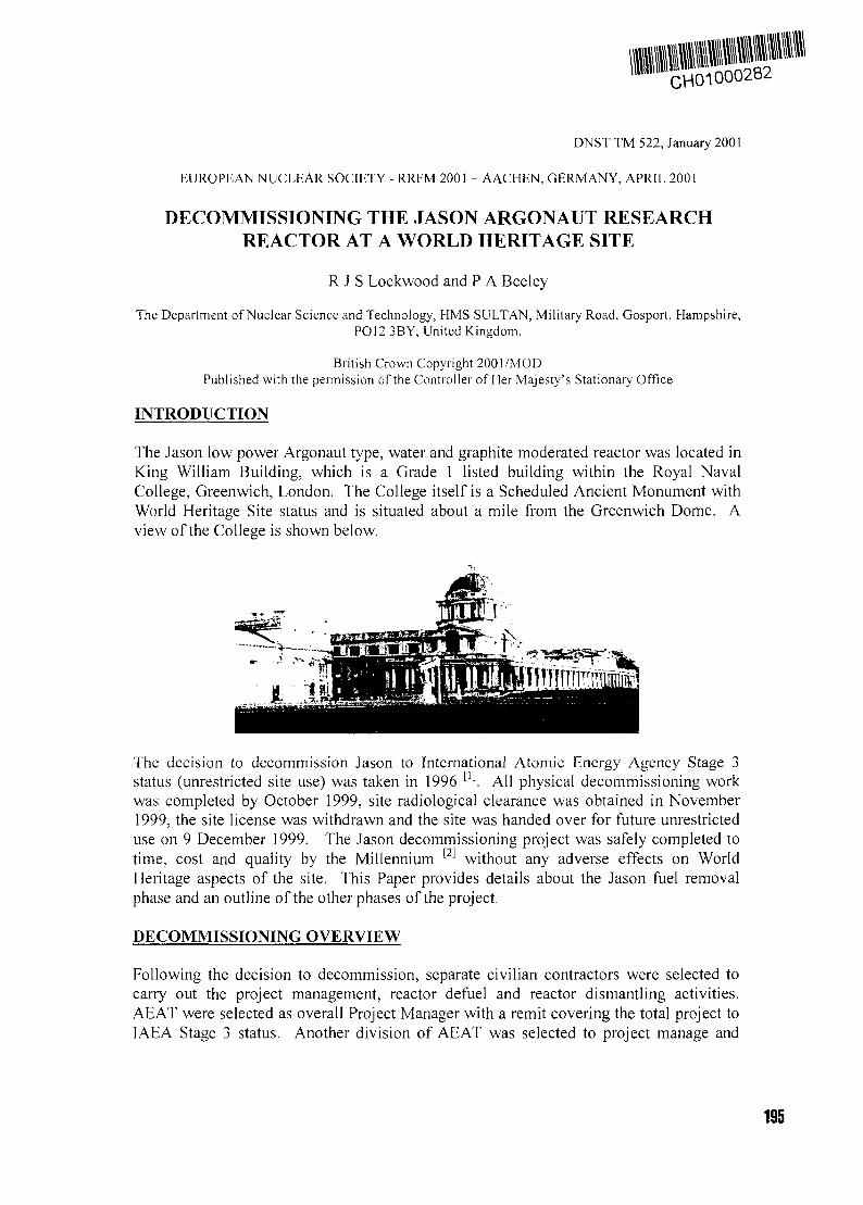
CH01000282
DNST TM 522, January 2001
EUROPEAN NUCLEAR SOCIETY - RRFM 2001 - AACHEN, GERMANY, APRIL 2001
DECOMMISSIONING THE JASON ARGONAUT RESEARCHREACTOR AT A WORLD HERITAGE SITE
R J S Lockwood and P A Beeley
The Department of Nuclear Science and Technology, HMS SULTAN, Military Road, Gosport, Hampshire,PO12 3BY, United Kingdom.
British Crown Copyright 2001/MODPublished with the permission of the Controller of Her Majesty's Stationary Office
INTRODUCTION
The Jason low power Argonaut type, water and graphite moderated reactor was located inKing William Building, which is a Grade 1 listed building within the Royal NavalCollege, Greenwich, London. The College itself is a Scheduled Ancient Monument withWorld Heritage Site status and is situated about a mile from the Greenwich Dome. Aview of the College is shown below.
The decision to decommission Jason to International Atomic Energy Agency Stage 3status (unrestricted site use) was taken in 1996 [1]. All physical decommissioning workwas completed by October 1999, site radiological clearance was obtained in November1999, the site license was withdrawn and the site was handed over for future unrestricteduse on 9 December 1999. The Jason decommissioning project was safely completed totime, cost and quality by the Millennium [2] without any adverse effects on WorldHeritage aspects of the site. This Paper provides details about the Jason fuel removalphase and an outline of the other phases of the project.
DECOMMISSIONING OVERVIEW
Following the decision to decommission, separate civilian contractors were selected tocarry out the project management, reactor defuel and reactor dismantling activities.AEAT were selected as overall Project Manager with a remit covering the total project toIAEA Stage 3 status. Another division of AEAT was selected to project manage and
195
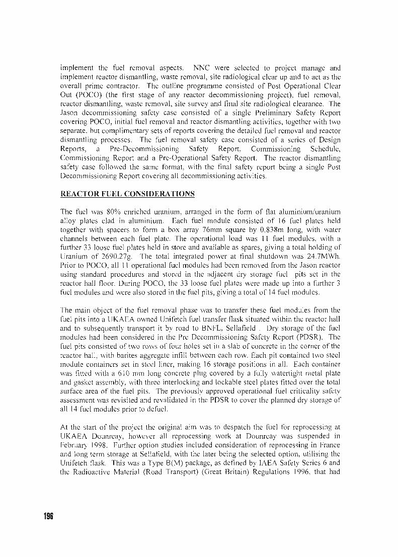
implement the fuel removal aspects. NNC were selected to project manage andimplement reactor dismantling, waste removal, site radiological clear up and to act as theoverall prime contractor. The outline programme consisted of Post Operational ClearOut (POCO) (the first stage of any reactor decommissioning project), fuel removal,reactor dismantling, waste removal, site survey and final site radiological clearance. TheJason decommissioning safety case consisted of a single Preliminary Safety Reportcovering POCO, initial fuel removal and reactor dismantling activities, together with twoseparate, but complimentary sets of reports covering the detailed fuel removal and reactordismantling processes. The fuel removal safety case consisted of a series of DesignReports, a Pre-Decommissioning Safety Report, Commissioning Schedule,Commissioning Report and a Pre-Operational Safety Report. The reactor dismantlingsafety case followed the same format, with the final safety report being a single PostDecommissioning Report covering all decommissioning activities.
REACTOR FUEL CONSIDERATIONS
The fuel was 80% enriched uranium, arranged in the form of flat aluminium/uraniumalloy plates clad in aluminium. Each fuel module consisted of 16 fuel plates heldtogether with spacers to form a box array 76mm square by 0.838m long, with waterchannels between each fuel plate. The operational load was 11 fuel modules, with afurther 33 loose fuel plates held in store and available as spares, giving a total holding ofUranium of 2690.27g. The total integrated power at final shutdown was 24.7MWh.Prior to POCO, all 11 operational fuel modules had been removed from the Jason reactorusing standard procedures and stored in the adjacent dry storage fuel pits set in thereactor hall floor. During POCO, the 33 loose fuel plates were made up into a further 3fuel modules and were also stored in the fuel pits, giving a total of 14 fuel modules.
The main object of the fuel removal phase was to transfer these fuel modules from thefuel pits into a UKAEA owned Unifetch fuel transfer flask situated within the reactor halland to subsequently transport it by road to BNFL, Sellafield . Dry storage of the fuelmodules had been considered in the Pre Decommissioning Safety Report (PDSR). Thefuel pits consisted of two rows of four holes set in a slab of concrete in the corner of thereactor hall, with barites aggregate infill between each row. Each pit contained two steelmodule containers set in steel liner, making 16 storage positions in all. Each containerwas fitted with a 610 mm long concrete plug covered by a fully watertight metal plateand gasket assembly, with three interlocking and lockable steel plates fitted over the totalsurface area of the fuel pits. The previously approved operational fuel criticality safetyassessment was revisited and invalidated in the PDSR to cover the planned dry storage ofall 14 fuel modules prior to defuel.
At the start of the project the original aim was to despatch the fuel for reprocessing atUKAEA Dounreay, however all reprocessing work at Dounreay was suspended inFebruary 1998. Further option studies included consideration of reprocessing in Franceand long term storage at Sellafield, with the later being the selected option, utilising theUnifetch flask. This was a Type B(M) package, as defined by IAEA Safety Series 6 andthe Radioactive Material (Road Transport) (Great Britain) Regulations 1996, that had
196
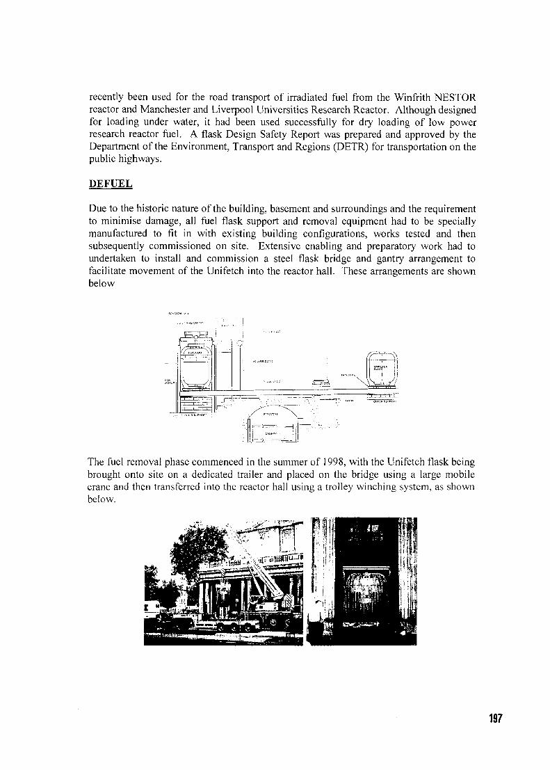
recently been used for the road transport of irradiated fuel from the Winfrith NESTORreactor and Manchester and Liverpool Universities Research Reactor. Although designedfor loading under water, it had been used successfully for dry loading of low powerresearch reactor fuel. A flask Design Safety Report was prepared and approved by theDepartment of the Environment, Transport and Regions (DETR) for transportation on thepublic highways.
DEFUEL
Due to the historic nature of the building, basement and surroundings and the requirementto minimise damage, all fuel flask support and removal equipment had to be speciallymanufactured to fit in with existing building configurations, works tested and thensubsequently commissioned on site. Extensive enabling and preparatory work had toundertaken to install and commission a steel flask bridge and gantry arrangement tofacilitate movement of the Unifetch into the reactor hall. These arrangements are shownbelow
The fuel removal phase commenced in the summer of 1998, with the Unifetch flask beingbrought onto site on a dedicated trailer and placed on the bridge using a large mobilecrane and then transferred into the reactor hall using a trolley winching system, as shownbelow.
197
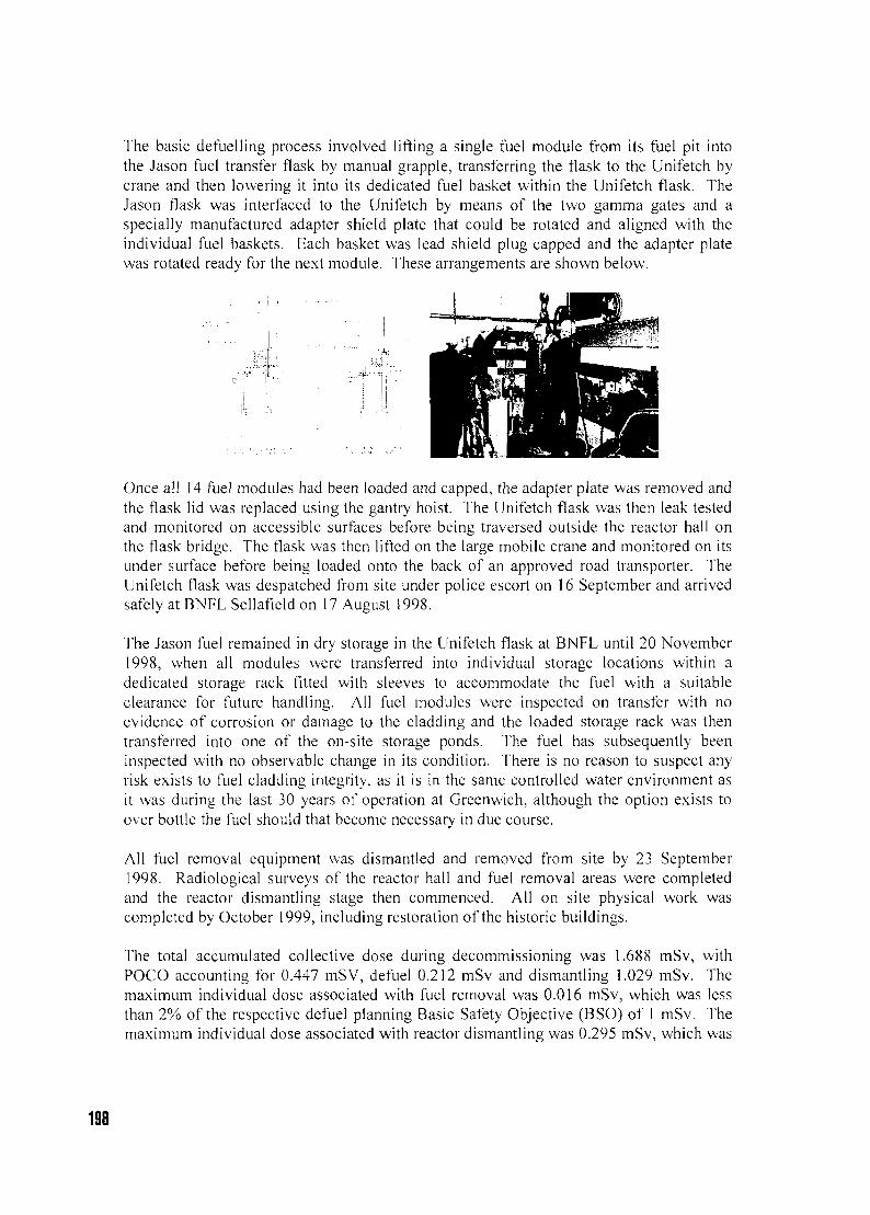
The basic defuelling process involved lifting a single fuel module from its fuel pit intothe Jason fuel transfer flask by manual grapple, transferring the flask to the Unifetch bycrane and then lowering it into its dedicated fuel basket within the Unifetch flask. TheJason flask was interfaced to the Unifetch by means of the two gamma gates and aspecially manufactured adapter shield plate that could be rotated and aligned with theindividual fuel baskets. Each basket was lead shield plug capped and the adapter platewas rotated ready for the next module. These arrangements are shown below.
Once all 14 fuel modules had been loaded and capped, the adapter plate was removed andthe flask lid was replaced using the gantry hoist. The Unifetch flask was then leak testedand monitored on accessible surfaces before being traversed outside the reactor hall onthe flask bridge. The flask was then lifted on the large mobile crane and monitored on itsunder surface before being loaded onto the back of an approved road transporter. TheUnifetch flask was despatched from site under police escort on 16 September and arrivedsafely at BNFL Sellafield on 17 August 1998.
The Jason fuel remained in dry storage in the Unifetch flask at BNFL until 20 November1998, when all modules were transferred into individual storage locations within adedicated storage rack fitted with sleeves to accommodate the fuel with a suitableclearance for future handling. All fuel modules were inspected on transfer with noevidence of corrosion or damage to the cladding and the loaded storage rack was thentransferred into one of the on-site storage ponds. The fuel has subsequently beeninspected with no observable change in its condition. There is no reason to suspect anyrisk exists to fuel cladding integrity, as it is in the same controlled water environment asit was during the last 30 years of operation at Greenwich, although the option exists toover bottle the fuel should that become necessary in due course.
All fuel removal equipment was dismantled and removed from site by 23 September1998. Radiological surveys of the reactor hall and fuel removal areas were completedand the reactor dismantling stage then commenced. All on site physical work wascompleted by October 1999, including restoration of the historic buildings.
The total accumulated collective dose during decommissioning was 1.688 mSv, withPOCO accounting for 0.447 mSV, defuel 0.212 mSv and dismantling 1.029 mSv. Themaximum individual dose associated with fuel removal was 0.016 mSv, which was lessthan 2% of the respective defuel planning Basic Safety Objective (BSO) of 1 mSv. Themaximum individual dose associated with reactor dismantling was 0.295 mSv, which was
198

~ 15% of the dismantling BSO and ~ 1% of the Basic Safety Limit. The controls,procedures and methods employed in planning and implementing the variousdecommissioning activities resulted in doses well below the BSO and demonstrated thatJason decommissioning fully complied with the principles of ALARP.
Nuclear safety considerations were paramount during the Jason decommissioning project.The project was formally completed by 9 December 1999, to time, cost and qualitywithout any adverse effects on World Heritage aspects of the buildings and the site.
REFERENCES
1. 'The Jason Decommissioning Project'. EW Hansford, RJ Francis and JH Broadbent.C539/ 012/98. IMechE/BNES Nuclear Decommissioning Conference, London,December 1998.
2. 'Decommissioning the Jason low power reactor at Greenwich - an overview of theproject, nuclear safety management arrangements and important lessons learnt'. RJSLockwood and PA Beeley. DNST TM 515. 7th IBC International DecommissioningConference, London, November 2000.
199
CHOI 000283
NEUTRONIC DESIGN AND COMPARATIVE CHARACTERISTICS OFNEW PIN TYPE CONTROL ROD FOR 14-MW-TRIGA-SSR REACTOR
C. IORGULIS CTRUTA
Institute for Nuclear Research Pitesti, PO Box 1-78, 0300 Pitesti,Romania
ABSTRACT
This paper presents the structural changes of the control rods (CR-s) which will be done in orderto manufacture new ones and therefore to replace the original rods and to increase the presentsafety features of TRIGA 14MW reactor in Pitesti.
Few years ago two CR-s became inoperable due to the combined effect of welding corrosion,water penetration into the absorbent section of the CR and finally the swelling caused from thehigh internal pressure of the radiolyse-generated gases (gases which accelerated weldingcorrosion, water penetration, etc).
Although safe reactor operation is not yet affected a decision to re-design a new CR was taken,entirely suitable to the general reactor design. The new CR will use boron carbide (sameabsorbent as in the original one ) , this boron carbide will be packed in a different way.A set of 16Incoloy pins filled with a column of boron carbide pellets ,leak-tight welded ,will bemanufactured. These 16 pins will be mounted in a square array with 5 pins on each side of thesquare.( corner pins being the same for two sides).
Neutronic analysis on the preliminary design was done using specific computer codes (WIMS.DFA, and MCNP). Reactivity worth of this new rod would be slight less (8%) than that of theoriginal one, but still with full compensation capacity.
Helium release analysis showed that gas pressure in the Incoloy tube after 15 years of normaloperation would not exceed 57 ATM.
1. Introduction
The problem of control rods replacement was seriously put in 1996 - 1997 due to theprogressive damages of the rods installed in the reactor since start-up and operated till now.Hence, in a total of 9 CR-s (8 currently operated and one as spare part), three are out-of-work andit seems that the rest of them will follow the same path in the close future.Note that the minimumnumber of CR-s allowed for safe operation by the present core configuration load is 6(six).Alsonote that the latest researches in the field show that boron carbide based control rods have not anindefinite time of life .
200
In our previous research causes that made CR-s inoperable were identified. Although the firstconcept surely was the best for the neutronic needs of a 14 MW fresh core, we had to generate anew design that would be able to meet the same safety requirements as the genuine ones, butcapable to avoid the major drawback of them . It is the swelling generated of accidental waterpenetration inside the unique shell of the absorbent section, through the Aluminum bottomweldings damaged of long exposure to radiation and corrosion .
2. Principles of design
The new design maintains unchanged all the components of the CR but the shape and theenclosure of the boron carbide absorbent. Therefore:• Same, boron carbide is the neutron absorbent. Instead of square rings of boron carbide having
theoretical density, the absorbent is 70% th.density in form of cylindrical pellets.• Absorbent pellets are definitely cladded in SS tubes for all the estimated time of use• The absorbent pins will be disposed in a square array, 5 on each side of a standard rod
location./see Fig. 1/.• All hydraulic and thermal conditions are preserved.• Most important, the absorbent structure has to accomplish the major demand of safe
operation - shutdown with the most reactive control rod fully withdrawn
3. Mechanical design
The absorbent section of the CR consists of a 16-pin bundle . Each pin is an Incoloy-800 tubefilled with a column of boron carbide pellets. The upper part of the tube is empty and has the roleof an expansion plenum for helium released from the carbide during reactor operation. The pelletsare kept in a stable position by a helicoidal spring placed din the plenum. Both ends of the tubeare sealed with end fittings leak-tight welded.
The main features of the absorbent pins are (see also Fig 2):• Incoloy 800H tube, o.d. = 13.77mm, i.d. = 12.95mm• Boron carbide pellet density 1.70g/cm3
• Boron carbide column height 584 mm (same as GA's absorbent height)• Plenum height 178 mm• Tube - pellet gap 0.1 to 0.4 mm
The 16 pins are fixed in three grids (upper, middle and bottom grid). These grids are joinedtogether by the outer and inner clads, which maintain the flow conditions unchanged with respectto the original design.
The joints to the CR follower and to the extension tube are also unchanged. One may see thatboron carbide has no link to the environment or to any vacuum system. For this reason, the tubeand the weldings have to withstand the internal pressure generated by helium release for thewhole estimated time-of-life.
Boron carbide quantity contained in 16 pins is 2.032kg ( 3.950 kg are contained in an originalCR). Other design changes would induce different weight . In order to preserve the initialapparent (in-pool) weight a float vessel in length of 0.850m has to replace the original heliumexpansion vessel.
201
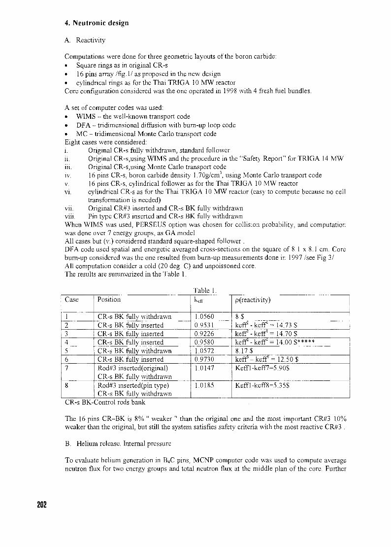
4. Neutronic design
A. Reactivity
Computations were done for three geometric layouts of the boron carbide:• Square rings as in original CR-s• 16 pins array /fig. 1/ as proposed in the new design• cylindncal rings as for the Thai TRIGA 10 MW reactorCore configuration considered was the one operated in 1998 with 4 fresh fuel bundles.
A set of computer codes was used:• WIMS - the well-known transport code• DFA - tndimensional diffusion with bum-up loop code• MC - tridimensional Monte Carlo transport codeEight cases were considered:i. Original CR-s fully withdrawn, standard followerii. Original CR-s,using WIMS and the procedure in the "Safety Report" for TRIGA 14 MW
Original CR-s,using Monte Carlo transport code16 pins CR-s, boron carbide density 1.70g/cm3, using Monte Carlo transport code16 pins CR-s, cylindrical follower as for the Thai TRIGA 10 MW reactorcylindrical CR-s as for the Thai TRIGA 10 MW reactor (easy to compute because no celltransformation is needed)Original CR#3 inserted and CR-s BK fully withdrawnPin type CR#3 inserted and CR-s BK fully withdrawn
When WIMS was used, PERSEUS option was chosen for collision probability, and computationwas done over 7 energy groups, as GA model.All cases but (v.) considered standard square-shaped follower .DFA code used spatial and energetic averaged cross-sections on the square of 8.1 x 8.1 cm. Corebum-up considered was the one resulted from bum-up measurements done in 1997 /see Fig 3/All computation consider a cold (20 deg. C) and unpoissoned core.The results are summarized in the Table 1.
Table 1.
in
IV,
V.
vi
VII.
viii
Case
1234567
8
Position
CR-s BK fully withdrawnCR-s BK fully insertedCR-s BK fully insertedCR-s BK fully insertedCR-s BK fully withdrawnCR-s BK fullv insertedRod#3 inserted(original)CR-s BK fully withdrawnRod#3 inserted(pin type)CR-s BK fully withdrawn
keff
1.05600.95310.92260.95801.05720.97301.0147
1.0185
p(reactivity)
8$keff2 - keff = 14.73$keff3- keff4 = 14.70$keff2 - keff4 = 14.00$*****8.17$keff'-keff = 12.50$Keffl-keff7=5.90$
Keffl-keff8=5.35$
CR-s BK-Control rods bank
The 16 pins CR-BK is 8% " weaker " than the original one and the most important CR#3 10%weaker than the original, but still the system satisfies safety criteria with the most reactive CR#3 .
B. Helium release. Internal pressure
To evaluate helium generation in B4C pins, MCNP computer code was used to compute averageneutron flux for two energy groups and total neutron flux at the middle plan of the core. Further
202
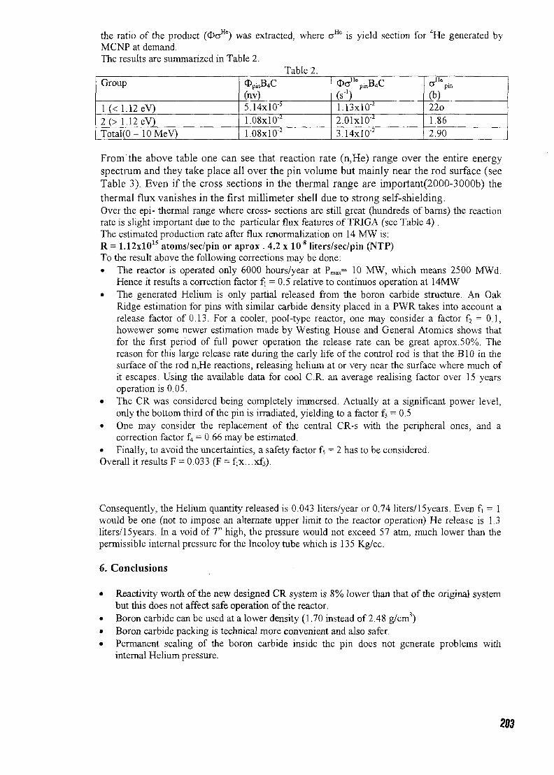
the ratio of the product (OaHe) was extracted, where aHe is yield section for 4He generated byMCNP at demand.The results are summarized in Table 2.
Table 2.Group
1 (<1.12eV)2(> 1.12 eV)Total(O-lOMeV)
OpinB4C(nv)5.14xlO'5
1.08x10"'I.08xI0"2
OoHepmB4C
1.13xlO"2
2.01x10""3.14x10"2
_He& pin
(b)22o1.862.90
From the above table one can see that reaction rate (n,He) range over the entire energyspectrum and they take place all over the pin volume but mainly near the rod surface (seeTable 3). Even if the cross sections in the thermal range are important(2000-3000b) the
thermal flux vanishes in the first millimeter shell due to strong self-shielding.Over the epi- thermal range where cross- sections are still great (hundreds of barns) the reactionrate is slight important due to the particular flux features of TRIGA (see Table 4) .The estimated production rate after flux renormalization on 14 MW is:R = 1.12xlOls atoms/sec/pin or aprox . 4.2 x 10"8 liters/sec/pin (NTP)To the result above the following corrections may be done:• The reactor is operated only 6000 hours/year at Pmax= 10 MW, which means 2500 MWd.
Hence it results a correction factor fi = 0.5 relative to continuos operation at 14MW• The generated Helium is only partial released from the boron carbide structure. An Oak
Ridge estimation for pins with similar carbide density placed in a PWR takes into account arelease factor of 0.13. For a cooler, pool-type reactor, one may consider a factor f2 = 0.1,howewer some newer estimation made by Westing House and General Atomics shows thatfor the first period of full power operation the release rate can be great aprox.50%. Thereason for this large release rate during the early life of the control rod is that the B10 in thesurface of the rod n,He reactions, releasing helium at or very near the surface where much ofit escapes. Using the available data for cool C.R. an average realising factor over 15 yearsoperation is 0.05.
• The CR was considered being completely immersed. Actually at a significant power level,only the bottom third of the pin is irradiated, yielding to a factor f3 = 0.5
• One may consider the replacement of the central CR-s with the peripheral ones, and acorrection factor £j = 0.66 may be estimated.
• Finally, to avoid the uncertainties, a safety factor f5 = 2 has to be considered.Overall it results F = 0.033 (F = fix. ..xf5).
Consequently, the Helium quantity released is 0.043 liters/year or 0.74 liters/15years. Even fi = 1would be one (not to impose an alternate upper limit to the reactor operation) He release is 1.3liters/ 15years. In a void of 7" high, the pressure would not exceed 57 atm, much lower than thepermissible internal pressure for the Incoloy tube which is 135 Kg/cc.
6. Conclusions
• Reactivity worth of the new designed CR system is 8% lower than that of the original systembut this does not affect safe operation of the reactor.
• Boron carbide can be used at a lower density (1.70 instead of 2.48 g/cm3)• Boron carbide packing is technical more convenient and also safer.• Permanent sealing of the boron carbide inside the pin does not generate problems with
internal Helium pressure.
203
\\\\\\\\\\\\\\\\\\\\\\\\\\\\\
/////////////////7///////////
Newdesign
Originaldesign
V///////X Aluminum
Water
Boron carbide
Boron carbidepin
Fig. 1204
end cap
heliumnlenum
Incoloy clad
boron carbidepellets
Main features of the absorbent pins:• Incoloy 800H tube, o.d. = 13.77mm,
i.d. = 12.95mm• Boron carbide pellet density 1.70g/cm3
• Boron carbide column height 584 mm• Boron carbide mass• Natural B-10 abundance• Plenum height 178 mm• Tube - pellet gap 0.1 to 0.4 mm• Helium max. pressure• Max. temperature on clad• Number of pins in a cell 16
Fig. 2
205
FIGURE-314-MW TRIGA CORE CONFIGURATION
K J I H G F E D C B A
12
11
10
8
R R R R R R R R R
R R H12 H26 H15 R R
R R H17 H25 H21 H34 H27 R P
R R '50 '51 H31 EL R
R R '40 '47 '38 H36 R
R R '42 '46 '44 '39 EL-EL R
R R '52 '53 H33 H13 R
R R H18 '30 H28 H37 EL H16 R
R R H14 H22 Hn R R
R R R R R R R R R
1
PRHLEL
• plug- reflector- Heu fuel- Leu fuel- Experimental Location
Control rod
206
TABLE 3
4.200OO0E-O3
3.700O0OE-O3
3.20COOOE-03
1 2.700000E-03
1
« 2.200000E-03
1 1.700000E-03
1.200000E-O3
7.0OOOOOE-O4
2.00COOOE-O4
Power-Radius
0 1 02 0 3 0
C.R. Exier
4 0
-\ai surface
5 0
IfJ0 7 C
Radius (cm)
e
TABLE 4
1 OOE-03 -
1.00E-04 •
X3U.
1.00E-05 •
• '
1.00E-09 1.
/
J
|
DOE-08 1.
-
3-111
Vf\[I
3OE-O7 1 .
• i r
\
FlI
ft
\
3OE-O6 1
Triga Spectrum
I —
I—r-1—i
Hi
R
ill
/
f
OOE-05 1.00E-04 1.
Energy(MeV)
t(-—•
I
L - - •
OOE-03 1.00E-02 1
z
1
OOE-01 1.00E+00 1
fi:.i
OOE+01
207
CH01000284
URANIUM RETRIEVAL SUPPORT, STORAGE, AND MARKETING
J. D. JACKSONUranium Management Group
Department of Energy, Oak Ridge, Tennessee-United States
and
E. M. MARSHALLUranium Management Group
Department of Energy, Oak Ridge, Tennessee-United States
ABSTRACT
The United States Department of Energy is implementing a stewardship approach tomanagement of uranium assets. This life-cycle approach to managing uranium addressescurrent needs in the context of a long-term strategy. In June 1998, the United StatesDepartment of Energy established the Uranium Management Group. The mission of theUMG is to safely collect and store commercially viable uranium from various DOEfacilities at a central location. The Oak Ridge Operations Office, in Oak Ridge, Tennessee,was given the task to establish a facility for the storage of these uranium materials.Materials collected are non-waste uranium and packaged to allow transport and long-termstorage. Coordination of uranium management under the Uranium Management Groupoffers significant opportunities for savings through improved planning and efficiency andcreates an environmentally sound approach for the storage and reuse of excess uranium.
1. Introduction
Since the beginning of the nuclear era, the management of nuclear materials has been a fundamental,compelling, and enduring challenge for the United States Department of Energy (DOE) and itspredecessor organizations. Recently, to meet the emerging challenges of the 21st century, whichinclude the management-to-closure of the facilities and the safe disposition of tons of nuclear materialsthat exceed programmatic needs, DOE established the Uranium Management Group (UMG). Themission of the UMG is to safely, effectively, and efficiently transfer usable, excess uranium to adesignated storage facility and store the uranium at these interim facilities with the ultimate objectiveof material for reuse. In order to fulfill this mission the UMG acts as the central point of contact for theconsolidation, stabilization, and storage of surplus uranium. The Oak Ridge Operations Office, in OakRidge, Tennessee, was given the task of establishing a facility for the storage of these uraniummaterials. The materials collected are non-waste uranium that is packaged for interim storage andsubsequent transport to the buyer.
2. Origin of the Uranium Management Group
DOE's dominant involvement with nuclear materials has been in national security and uraniumenrichment for commercial reactor applications. However, with the end of the Cold War, the closureand environmental restoration of several production and processing sites has necessitated the removalof surplus uranium. At the end of the 1990s, it was recognized that the cost of environmentalrestoration could be offset by cost avoidance (by integrating and consolidating the activities andmaterials) and by selling or bartering the "surplus" uranium for use in nuclear fuel for commercialutilities and/or research reactors (both foreign and domestic). The UMG was formed to provide thiscoordinated, cost-effective, and efficient program for management of the nation's uranium material. In
208
addition, surplus uranium returns from universities and laboratories are collected and placed intostorage.
3. Capabilities of the Uranium Management Group
The UMG provides a complete range of services relative to uranium packaging, handling, processing,storage, and disposition. These services are available to sites possessing DOE uranium includinguniversities and, as appropriate, to commercial customers. The UMG utilizes existing commercialcapabilities, to the extent available, and works to foster new commercial development in the uraniumindustry. The UMG staff is composed of a small core team, which has expertise in all aspects ofuranium management. The UMC core team, in turn, can supplement its personnel needs by accessingthe extensive expertise within the DOE Complex.
4. Uranium Storage Facility
The site of the first UMG storage facility is the Portsmouth Gaseous Diffusion Plant in Piketon, Ohio.In keeping with the "save and reuse" philosophy of the UMG, the building, one of the first permanentstructures built at Portsmouth, was refurbished and converted into a storage facility for a fraction of thecost of a new structure. Over the years, it has been used for a variety of activities. Most recently it wasused for storage and sorting of contaminated scrap materials. There is an 18.5-meter high bay areainside the building with approximately 8200 m2 of available storage space. Across the north side of thebuilding is a covered open area with 1900 m" of storage area.
The Portsmouth facility was chosen because it already had the infrastructure desired for safe, efficient,and cost-effective operation. Support systems were in place and operational (e.g., Cnticality AccidentAlarm System, Fire Protection Sprinklers, Emergency Preparedness Response Organization). DOEowns the building; the UMG uses the western side of the structure. The eastern section, currentlyleased to the United States Enrichment Corporation, is available for expansion as needed.
5. Types of Material Stored
The storage facility is designated for the storage of commercially viable solid uranium in severalphysical forms and uranium enrichments ranging from depleted to low enriched uranium (< 20%). Forthe past two years uranium in the form of compounds (e.g., UF4, UO3, U3Og) and metal from theFernald Environmental Management Project has been processed and placed into storage.Approximately 4,000 metric tons of uranium will eventually be transferred.
The storage facility is capable of receiving uranium in forms suitable for transport and storage in thecontainer used for shipping. Shipping containers are stored in a manner that allows access forinspections, any necessary sampling activities, and retrieval for transfer to others. The enrichedmaterials are maintained in an area separate from the normal and depleted uranium materials.Containers are grouped by type and hazard.
In order to be accepted, shipping containers must meet the applicable requirements of Title 49 Code ofFederal Regulations Part 173, Transportation, which include passing a free drop test and a stackingtest. Once the containers have been placed in their storage location, little activity is required on a day-to-day basis to maintain the facility and material. These activities include minor building repairs,cleanup, material inventory, maintenance, and sampling.
After a shipment arrives at the site, transfer documentation is reviewed and once approved, thecontainers and/or overpacks are inspected for damage, defects, and leakage. Weight measurementsmay be made for comparison to the shipper's weights. Information for each container is entered intothe site's Nuclear Material Inventory system, after which the container is placed in storage.
209
The facility staff maintains the material condition of the uranium as received until an end-user hasbeen identified. This means that the duration of material storage is unknown. Consequently, prior toacceptance for storage, the uranium material is evaluated for suitability for inclusion in the UMGinventory. Some factors considered are its physical characteristics and probability for reuse, theenvironmental and safety risks of storage, and the costs and technical maturity of the alternativematerial flow paths.
6. Conclusion
The UMG facility stores commercially marketable solid uranium in several physical forms. Thefacility is maintained radiologically clean. The uranium material in storage is not waste and hascommercial value. The UMG, by not accepting material, serves as a basis for material to be declaredwaste and further disposed. Materials stored are in solid form, such as metals and compounds.
The UMG provides a single point of contact with a complete range of services relative to uraniumpackaging, handling, processing, storage, and disposition. The UMG staff and facilities are available toassist commercial users, as appropriate, to foster new commercial development in the uraniumindustry.
210
CH01000285
OPERATION OF THE SLOWPOKE-2
REACTOR IN JAMAICA
C.N.GRANT, G.C.LALOR, M.K.VUCHKOV
International Centre for Environmental and Nuclear Sciences
University of the West Indies,
Kingston, Jamaica
ABSTRACT
Over the past sixteen years ICENS has operated a SLOWPOKE 2 nuclear reactor
almost exclusively for the purpose of neutron activation analysis. During this period
we have adopted a strategy of minimum irradiation times while optimizing our output
in an effort to increase the lifetime of the reactor core and to maintaining fuel
integrity. An inter-comparison study with results obtained with a much larger reactor
at IPEN has validated this approach. The parameters routinely monitored at ICENS
are also discussed and the method used to predict the next shim adjustment.
INTRODUCTION
SLOWPOKE is an acronym for Safe Low Power C(K)ritical Experiment. The reactor wasdesigned by Atomic Energy of Canada Ltd. SLOWPOKE is simple to operate and provides arelatively high and remarkably stable neutron flux over long periods of time.
The SLOWPOKE-2 reactor at the International Centre for Environmental and Nuclear Sciences(ICENS) is the only nuclear research reactor in the Caribbean. It is mainly used for NeutronActivation Analysis (NAA) [1], at this time the main sample types are soils, rocks, sediments, andincreasingly, plant and animal tissues. The reactor achieved criticality for the first time in March1984. The reactor normally operates at a power of 20 kW for approximately 5 hours per day, 5days per week. It has now operated for a total 5.63 x 10⁴ -kilowatt hours out of a calculatedlifetime of 3.395 x 10⁵ kWh or 16.5% of total lifetime. A detailed database has been kept of someof the essential measurable reactor parameters. The data collected has not only been used toensure the safe use of the reactor but also to predict the schedule of preventative maintenance andassist in the efficient use of reactor time and eventually aid during the decommissioning of thereactor.
This paper outlines the performance and current status of the SLOWPOKE-2 in Jamaica.
211
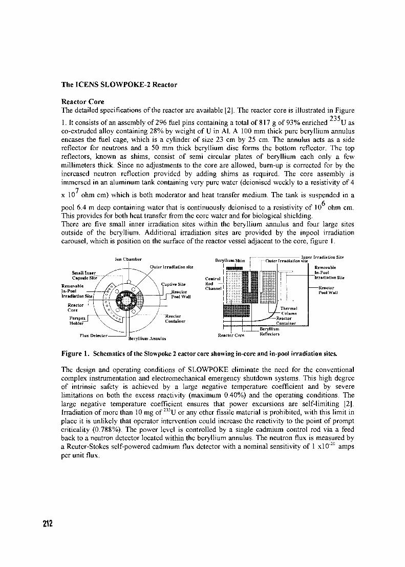
The ICENS SLOWPOKE-2 Reactor
Reactor CoreThe detailed specifications of the reactor are available [2]. The reactor core is illustrated in Figure
2351. It consists of an assembly of 296 fuel pins containing a total of 817 g of 93% enriched U asco-extruded alloy containing 28% by weight of U in Al. A 100 mm thick pure beryllium annulusencases the fuel cage, which is a cylinder of size 23 cm by 25 cm. The annulus acts as a sidereflector for neutrons and a 50 mm thick beryllium disc forms the bottom reflector. The topreflectors, known as shims, consist of semi circular plates of beryllium each only a fewmillimeters thick. Since no adjustments to the core are allowed, burn-up is corrected for by theincreased neutron reflection provided by adding shims as required. The core assembly isimmersed in an aluminum tank containing very pure water (deionised weekly to a resistivity of 4
x 10 ohm cm) which is both moderator and heat transfer medium. The tank is suspended in a
pool 6.4 m deep containing water that is continuously deionised to a resistivity of 10 ohm cm.This provides for both heat transfer from the core water and for biological shielding.There are five small inner irradiation sites within the beryllium annulus and four large sitesoutside of the beryllium. Additional irradiation sites are provided by the inpool irradiationcarousel, which is position on the surface of the reactor vessel adjacent to the core, figure 1.
Ion Chamber Beryllium Shim
Small ICapsuli
RemovablIn-PoolIrradiation Site
Outer Irradiation site
Captive Site
\ ReactorPool Wall
Inner Irradiation Site
Irradiation Site
PerjpexHoldei"
FIUJ DetectorBeryllium Annulus
Reactor Core
Figure 1. Schematics of the Slowpoke 2 eactor core showing in-core and in-pool irradiation sites.
The design and operating conditions of SLOWPOKE eliminate the need for the conventionalcomplex instrumentation and electromechanical emergency shutdown systems. This high degreeof intrinsic safety is achieved by a large negative temperature coefficient and by severelimitations on both the excess reactivity (maximum 0.40%) and the operating conditions. Thelarge negative temperature coefficient ensures that power excursions are self-limiting [2].Irradiation of more than 10 mg of 235U or any other fissile material is prohibited, with this limit inplace it is unlikely that operator intervention could increase the reactivity to the point of promptcriticality (0.788%). The power level is controlled by a single cadmium control rod via a feedback to a neutron detector located within the beryllium annulus. The neutron flux is measured bya Reuter-Stokes self-powered cadmium flux detector with a nominal sensitivity of 1 x 10"20 ampsper unit flux.
212
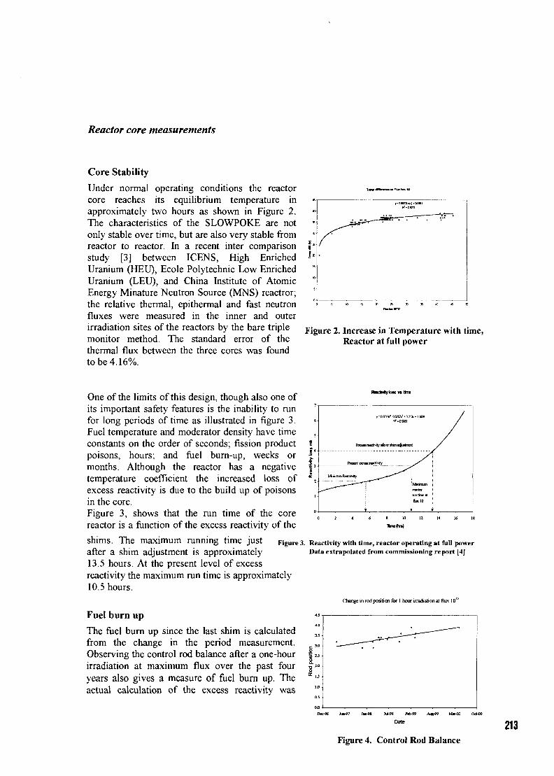
Reactor core measurements
Core Stability
Under normal operating conditions the reactorcore reaches its equilibrium temperature inapproximately two hours as shown in Figure 2.The characteristics of the SLOWPOKE are notonly stable over time, but are also very stable fromreactor to reactor. In a recent inter comparisonstudy [3] between ICENS, High EnrichedUranium (HEU), Ecole Polytechnic Low EnrichedUranium (LEU), and China Institute of AtomicEnergy Minature Neutron Source (MNS) reactror;the relative thermal, epithermal and fast neutronfluxes were measured in the inner and outerirradiation sites of the reactors by the bare triplemonitor method. The standard error of thethermal flux between the three cores was foundto be 4.16%.
Figure 2. Increase in Temperature with time,Reactor at full power
One of the limits of this design, though also one ofits important safety features is the inability to runfor long periods of time as illustrated in figure 3.Fuel temperature and moderator density have timeconstants on the order of seconds; fission productpoisons, hours; and fuel burn-up, weeks ormonths. Although the reactor has a negativetemperature coefficient the increased loss ofexcess reactivity is due to the build up of poisonsin the core.Figure 3, shows that the run time of the corereactor is a function of the excess reactivity of the
shims. The maximum running time justafter a shim adjustment is approximately13.5 hours. At the present level of excessreactivity the maximum run time is approximately10.5 hours.
Fuel burn up
The fuel burn up since the last shim is calculatedfrom the change in the period measurement.Observing the control rod balance after a one-hourirradiation at maximum flux over the past fouryears also gives a measure of fuel burn up. Theactual calculation of the excess reactivity was
PnxlecmnrtNiry
1
MMTUDractarnntmrifkctlO
/
Figure 3. Reactivity with time, reactor operating at full powerData extrapolated from commissioning report [4]
Change in rod position for I hour irradiation at flux 1012
213Figure 4. Control Rod Balance
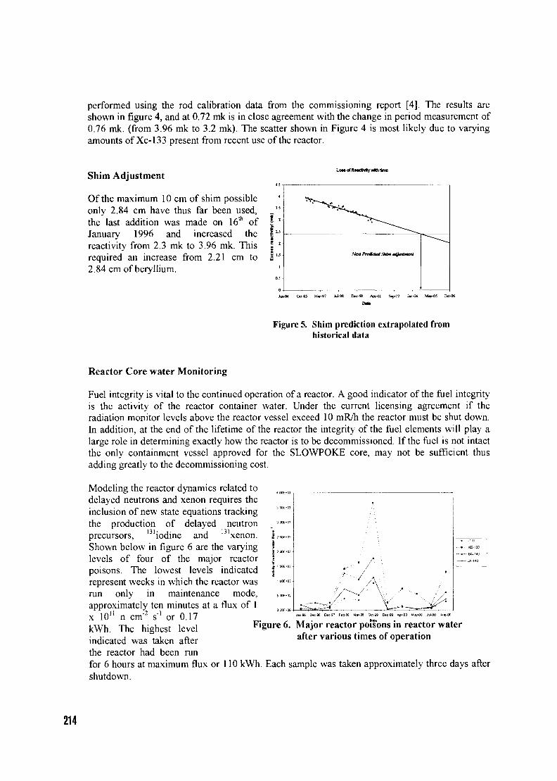
performed using the rod calibration data from the commissioning report [4]. The results areshown in figure 4, and at 0.72 mk is in close agreement with the change in period measurement of0.76 mk. (from 3.96 mk to 3.2 mk). The scatter shown in Figure 4 is most likely due to varyingamounts of Xe-133 present from recent use of the reactor.
Shim Adjustment
Of the maximum 10 cm of shim possibleonly 2.84 cm have thus far been used,the last addition was made on 16th ofJanuary 1996 and increased thereactivity from 2.3 mk to 3.96 mk. Thisrequired an increase from 2.21 cm to2.84 cm of beryllium.
Low rf Raadiviy «*ti time
Figure 5. Shim prediction extrapolated fromhistorical data
Reactor Core water Monitoring
Fuel integrity is vital to the continued operation of a reactor. A good indicator of the fuel integrityis the activity of the reactor container water. Under the current licensing agreement if theradiation monitor levels above the reactor vessel exceed 10 mR/h the reactor must be shut down.In addition, at the end of the lifetime of the reactor the integrity of the fuel elements will play alarge role in determining exactly how the reactor is to be decommissioned. If the fuel is not intactthe only containment vessel approved for the SLOWPOKE core, may not be sufficient thusadding greatly to the decommissioning cost.
Modeling the reactor dynamics related todelayed neutrons and xenon requires theinclusion of new state equations trackingthe production of delayed neutronprecursors, 131iodine and 131xenon.Shown below in figure 6 are the varyinglevels of four of the major reactorpoisons. The lowest levels indicatedrepresent weeks in which the reactor wasrun only in maintenance mode,approximately ten minutes at a flux of 1x 10" n cm"2 s"! or 0.17kWh. The highest levelindicated was taken afterthe reactor had been runfor 6 hours at maximum flux or 110 kWh. Each sample was taken approximately three days aftershutdown.
Figure 6. Major reactor poisons in reactor waterafter various times of operation
214
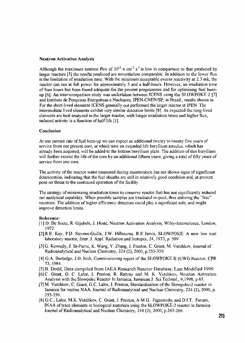
Neutron Activation Analysis
Although the maximum neutron flux of 1012 n cm"2 s"1 is low in comparison to that produced bylarger reactors [5] the results produced are nevertheless comparable. In addition to the lower fluxis the limitation of irradiation time. With the minimum acceptable excess reactivity at 2.3 mk, thereactor can run at full power for approximately 5 and a half-hours. However, an irradiation timeof four hours has been found adequate for the present programmes and for optimising fuel burn-up [6]. An inter-comparison study was undertaken between ICENS using the SLOWPOKE 2 [7]and Institute de Pesquisas Energeticas e Nucleares, IPEN-CNEN/SP, in Brazil, results shown inFor the short-lived elements ICENS generally out performed the larger reactor at IPEN. Theintermediate lived elements exhibit very similar detection limits [8]. As expected the long-livedelements are best analyzed in the larger reactor, with longer irradiation times and higher flux,induced activity is a function of half life [1].
Conclusion
At our current rate of fuel burn-up we can expect an additional twenty to twenty five years ofservice from our present core, at which time an extended life beryllium annulus, which hasalready been acquired, will be added to the bottom beryllium plate. The addition of this berylliumwill further extend the life of the core by an additional fifteen years, giving a total of fifty years ofservice from one core.
The activity of the reactor water measured during maintenance has not shown signs of significantdeterioration, indicating that the fuel sheaths are still in relatively good condition and, at presentpose no threat to the continued operation of the facility.
The strategy of minimizing irradiation times to conserve reactor fuel has not significantly reducedour analytical capability. When possible samples are irradiated in-pool, thus utilizing the "free"neutrons. The addition of higher efficiency detectors could play a significant role; and mightimprove detection limits.
Reference:[1] D. De Soete, R. Gijebels, J. Hoste, Neutron Activation Analysis, Wiley-Interscience, London,
1972.[2] R.E. Kay, P.D. Stevens-Guille, J.W. Hilbourne, R.E Jervis, SLOWPOKE: A new low cost
laboratory reactor, Inter. J. Appl. Radiation and Isotopes, 24, 1973, p. 509
[3]G. Kennedy, J. St-Pierre, K. Wang, Y. Zhang, J. Preston, C. Grant, M. Vutchkov, Journal ofRadioanalytical and Nuclear Chemistry, 224 (2), 2000, p.355-359.
[4] G.A. Burbidge, J.D. Irish, Commissioning report of the SLOWPOKE II (UWI) Reactor, CPR73, 1984.
[5]B. Dodd, Data compiled from IAEA Research Reactor Database, Last Modified 1999.[6] C. Grant, G. C. Lalor, J. Preston, R. Rattray and M. K. Vutchkov, Neutron Activation
Analysis with the Slowpoke Reactor In Jamaica, Jamaican J. Sci Technol., 9,1998, p.63.[7]M. Vutchkov, C. Grant, G.C. Lalor, J. Preston, Standardization of the Slowpoke-2 reactor in
Jamaica for routine NAA, Journal of Radioanalytical and Nuclear Chemistry, 224 (2), 2000, p.355-359.
[8] G.C., Lalor, M.K. Vutchkov, C. Grant, J. Preston, A.M.G. Figueiredo, and D.I.T. Favaro,INAA of trace elements in biological materials using the SLOWPOKE-2 reactor in Jamaica:Journal of Radioanalytical and Nuclear Chemistry, 244 (2), 2000, p.263-266.
215
Copyright © 2022 FDOKUMEN