
Conversational User Interfaces on Mobile Devices - DiVA portal
Upload
khangminh22Category
view
2download
0
Traffic Management User Guide for NFXSeries Devices
Published
2022-03-11

Juniper Networks, Inc.1133 Innovation WaySunnyvale, California 94089USA408-745-2000www.juniper.net
Juniper Networks, the Juniper Networks logo, Juniper, and Junos are registered trademarks of Juniper Networks, Inc.in the United States and other countries. All other trademarks, service marks, registered marks, or registered servicemarks are the property of their respective owners.
Juniper Networks assumes no responsibility for any inaccuracies in this document. Juniper Networks reserves the rightto change, modify, transfer, or otherwise revise this publication without notice.
Traffic Management User Guide for NFX Series DevicesCopyright © 2022 Juniper Networks, Inc. All rights reserved.
The information in this document is current as of the date on the title page.
YEAR 2000 NOTICE
Juniper Networks hardware and software products are Year 2000 compliant. Junos OS has no known time-relatedlimitations through the year 2038. However, the NTP application is known to have some difficulty in the year 2036.
END USER LICENSE AGREEMENT
The Juniper Networks product that is the subject of this technical documentation consists of (or is intended for usewith) Juniper Networks software. Use of such software is subject to the terms and conditions of the End User LicenseAgreement ("EULA") posted at https://support.juniper.net/support/eula/. By downloading, installing or using suchsoftware, you agree to the terms and conditions of that EULA.
ii

Table of Contents
About This Guide | ix
1 CoS Overview
Basic Concepts | 2
Overview of Junos OS CoS | 2
Configuring CoS | 5
Understanding Junos CoS Components | 12
Assigning CoS Components to Interfaces | 17
Understanding CoS Packet Flow | 19
Understanding Default CoS Settings | 24
CoS Inputs and Outputs Overview | 38
Overview of Policers | 39
2 Classifying and Rewriting Traffic
Using Classifiers, Forwarding Classes, and Rewrite Rules | 50
Understanding CoS Classifiers | 50
Defining CoS BA Classifiers (DSCP, DSCP IPv6, IEEE 802.1p) | 60
Example: Configuring Classifiers | 63
Requirements | 64
Overview | 64
Verification | 65
Understanding Default CoS Scheduling and Classification | 67
Understanding Applying CoS Classifiers and Rewrite Rules to Interfaces | 78
Understanding CoS Code-Point Aliases | 92
Defining CoS Code-Point Aliases | 95
Understanding CoS Forwarding Classes | 96
iii

Defining CoS Forwarding Classes | 103
Example: Configuring Forwarding Classes | 105
Requirements | 106
Overview | 106
Example 1: Configuring Forwarding Classes for Switches Except QFX10000 | 108
Verification | 109
Example 2: Configuring Forwarding Classes for QFX10000 Switches | 110
Verification | 111
Understanding CoS Rewrite Rules | 112
Defining CoS Rewrite Rules | 115
Troubleshooting an Unexpected Rewrite Value | 117
3 Scheduling Traffic
Using Schedulers | 121
Understanding CoS Scheduling Behavior and Configuration Considerations | 121
Defining CoS Queue Schedulers for Port Scheduling | 128
Defining CoS Queue Scheduling Priority | 132
Example: Configuring Queue Scheduling Priority | 133
Requirements | 134
Overview | 135
Verification | 137
Understanding CoS Traffic Control Profiles | 138
Understanding CoS Priority Group Scheduling | 140
Defining CoS Traffic Control Profiles (Priority Group Scheduling) | 144
Example: Configuring Traffic Control Profiles (Priority Group Scheduling) | 145
Requirements | 146
Overview | 147
Verification | 148
Understanding CoS Priority Group and Queue Guaranteed Minimum Bandwidth | 149
Example: Configuring Minimum Guaranteed Output Bandwidth | 152
iv

Requirements | 154
Overview | 154
Verification | 156
Understanding CoS Priority Group Shaping and Queue Shaping (Maximum Bandwidth) | 159
Example: Configuring Maximum Output Bandwidth | 162
Requirements | 164
Overview | 164
Verification | 165
4 Configuration Statements and Operational Commands
Configuration Statements (Basic Concepts) | 170
class-of-service | 170
traceoptions (Class of Service) | 175
Configuration Statements (Classifiers and Rewrite Rules) | 179
class (Forwarding Classes) | 180
class (Forwarding Class Sets) | 182
classifiers | 184
code-point (Rewrite Rules) | 187
code-point-aliases | 188
code-points (CoS) | 190
dscp | 191
dscp-ipv6 | 195
exp | 198
forwarding-class | 200
forwarding-classes | 204
ieee-802.1 | 209
import | 213
interfaces (Class of Service) | 215
loss-priority (Classifiers) | 217
v

loss-priority (Rewrite Rules) | 219
queue-num | 220
rewrite-rules | 223
unit | 225
Configuration Statements (Scheduling) | 227
buffer-size | 227
excess-rate | 233
fill-level | 235
forwarding-class | 237
guaranteed-rate | 241
interpolate | 243
output-traffic-control-profile | 244
priority (Schedulers) | 245
scheduler | 248
scheduler-map | 249
scheduler-maps | 250
schedulers | 252
shaping-rate | 253
traffic-control-profiles | 256
transmit-rate | 260
Operational Commands (Basic Concepts) | 266
Monitoring Interfaces That Have CoS Components | 266
show class-of-service | 268
show class-of-service interface | 274
show class-of-service shared-buffer | 320
show pfe filter hw summary | 323
vi

show pfe next-hop | 326
show pfe route | 332
show pfe terse | 346
show pfe version | 349
show interfaces voq | 350
Operational Commands (Classifiers and Rewrite Rules) | 369
Monitoring CoS Classifiers | 369
Monitoring CoS Forwarding Classes | 371
Monitoring CoS Rewrite Rules | 375
Monitoring CoS Code-Point Value Aliases | 377
show class-of-service classifier | 378
show class-of-service code-point-aliases | 382
show class-of-service forwarding-class | 384
show class-of-service forwarding-table | 388
show class-of-service forwarding-table classifier | 393
show class-of-service forwarding-table classifier mapping | 395
show class-of-service forwarding-table rewrite-rule | 398
show class-of-service forwarding-table rewrite-rule mapping | 400
show class-of-service interface | 402
show class-of-service rewrite-rule | 447
Operational Commands (Scheduling) | 450
Monitoring CoS Scheduler Maps | 450
show class-of-service drop-profile | 452
show class-of-service forwarding-table | 457
show class-of-service forwarding-table drop-profile | 462
show class-of-service forwarding-table scheduler-map | 464
vii

show class-of-service interface | 468
show class-of-service scheduler-map | 513
show interfaces queue | 517
show interfaces voq | 575
viii

About This Guide
Use this guide to understand and configure class of service (CoS) features in Junos OS to define servicelevels that provide different delay, jitter, and packet loss characteristics to particular applications servedby specific traffic flows. Applying CoS features to each device in your network ensures quality of service(QoS) for traffic throughout your entire network.
ix

1PART
CoS Overview
Basic Concepts | 2

CHAPTER 1
Basic Concepts
IN THIS CHAPTER
Overview of Junos OS CoS | 2
Configuring CoS | 5
Understanding Junos CoS Components | 12
Assigning CoS Components to Interfaces | 17
Understanding CoS Packet Flow | 19
Understanding Default CoS Settings | 24
CoS Inputs and Outputs Overview | 38
Overview of Policers | 39
Overview of Junos OS CoS
IN THIS SECTION
CoS Standards | 3
How Junos OS CoS Works | 4
Default CoS Behavior | 5
When a network experiences congestion and delay, some packets must be dropped. Junos OS class ofservice (CoS) enables you to divide traffic into classes and set various levels of throughput and packetloss when congestion occurs. You have greater control over packet loss because you can configure rulestailored to your needs.
You can configure CoS features to provide multiple classes of service for different applications. CoS alsoallows you to rewrite the Differentiated Services code point (DSCP) or IEEE 802.1p code-point bits of
2

packets leaving an interface, thus allowing you to tailor packets for the network requirements of theremote peers.
CoS provides multiple classes of service for different applications. You can configure multiple forwardingclasses for transmitting packets, define which packets are placed into each output queue, schedule thetransmission service level for each queue, and manage congestion using a weighted random earlydetection (WRED) algorithm.
In designing CoS applications, you must carefully consider your service needs, and you must thoroughlyplan and design your CoS configuration to ensure consistency and interoperability across all platforms ina CoS domain.
Because CoS is implemented in hardware rather than in software, you can experiment with and deployCoS features without affecting packet forwarding and switching performance.
NOTE: CoS policies can be enabled or disabled on each switch interface. Also, each physical andlogical interface on the switch can have associated custom CoS rules.
When you change or when you deactivate and then reactivate the class-of-service configuration,the system experiences packet drops because the system momentarily blocks traffic to changethe mapping of incoming traffic to input queues.
This topic describes:
CoS Standards
The following RFCs define the standards for CoS capabilities:
• RFC 2474, Definition of the Differentiated Services Field in the IPv4 and IPv6 Headers
• RFC 2597, Assured Forwarding PHB Group
• RFC 2598, An Expedited Forwarding PHB
• RFC 2698, A Two Rate Three Color Marker
• RFC 3168, The Addition of Explicit Congestion Notification (ECN) to IP
The following data center bridging (DCB) standards are also supported to provide the CoS (and othercharacteristics) that Fibre Channel over Ethernet (FCoE) requires for transmitting storage traffic over anEthernet network:
• IEEE 802.1Qbb, priority-based flow control (PFC)
• IEEE 802.1Qaz, enhanced transmission selection (ETS)
3

• IEEE 802.1AB (LLDP) extension called Data Center Bridging Capability Exchange Protocol (DCBX)
NOTE: OCX Series switches and NFX250 Network Services platforms do not support PFC andDCBX.
Juniper Networks QFX10000 switches support both enhanced transmission selection (ETS)hierarchical port scheduling and direct port scheduling.
How Junos OS CoS Works
Junos OS CoS works by examining traffic entering the edge of your network. The switch classifies trafficinto defined service groups to provide the special treatment of traffic across the network. For example,you can send voice traffic across certain links and data traffic across other links. In addition, the datatraffic streams can be serviced differently along the network path to ensure that higher-payingcustomers receive better service. As the traffic leaves the network at the far edge, you can reclassify thetraffic to meet the policies of the targeted peer by rewriting the DSCP or IEEE 802.1 code-point bits.
To support CoS, you must configure each switch in the network. Generally, each switch examines thepackets that enter it to determine their CoS settings. These settings dictate which packets aretransmitted first to the next downstream switch. Switches at the edges of the network might berequired to alter the CoS settings of the packets that enter the network to classify the packets into theappropriate service groups.
In Figure 1 on page 5, Switch A is receiving traffic. As each packet enters, Switch A examines thepacket’s current CoS settings and classifies the traffic into one of the groupings defined on the switch.This definition allows Switch A to prioritize its resources for servicing the traffic streams it receives.Switch A might alter the CoS settings (forwarding class and loss priority) of the packets to better matchthe defined traffic groups.
When Switch B receives the packets, it examines the CoS settings, determines the appropriate trafficgroups, and processes the packet according to those settings. It then transmits the packets to Switch C,which performs the same actions. Switch D also examines the packets and determines the appropriate
4

groups. Because Switch D sits at the far end of the network, it can reclassify (rewrite) the CoS code-point bits of the packets before transmitting them.
Figure 1: Packet Flow Across the Network
Default CoS Behavior
If you do not configure CoS settings, the software performs some CoS functions to ensure that thesystem forwards traffic and protocol packets with minimum delay when the network is experiencingcongestion. Some CoS settings, such as classifiers, are automatically applied to each logical interface thatyou configure. Other settings, such as rewrite rules, are applied only if you explicitly associate them withan interface.
RELATED DOCUMENTATION
Overview of Policers
Understanding Junos CoS Components
Understanding CoS Packet Flow
Understanding CoS Hierarchical Port Scheduling (ETS)
Configuring CoS
The traffic management class-of-service topics describe how to configure the Junos OS class-of-service(CoS) components. Junos CoS provides a flexible set of tools that enable you to fine tune control overthe traffic on your network.
5

• Define classifiers that classify incoming traffic into forwarding classes to place traffic in groups fortransmission.
• Map forwarding classes to output queues to define the type of traffic on each output queue.
• Configure schedulers for each output queue to control the service level (priority, bandwidthcharacteristics) of each type of traffic.
• Provide different service levels for the same forwarding classes on different interfaces.
• On switches that support data center bridging standards, configure lossless transport across theEthernet network using priority-based flow control (PFC), Data Center Bridging Exchange protocol(DCBX), and enhanced transmission selection (ETS) hierarchical scheduling (OCX Series switches andNFX250 Network Services platform do not support lossless transport, PFC, and DCBX).
• Configure various CoS components individually or in combination to define CoS services.
NOTE: When you change the CoS configuration or when you deactivate and then reactivate theCoS configuration, the system experiences packet drops because the system momentarily blockstraffic to change the mapping of incoming traffic to input queues.
Table 1 on page 7 lists the primary CoS configuration tasks by platform and provides links to thosetasks.
NOTE: Links to features that are not supported on the platform for which you are looking upinformation might not be functional.
6

Table 1: CoS Configuration Tasks
CoS Configuration Task Platforms Supported Links
Basic CoS Configuration:
• Configure code-point aliases to assign aname to a pattern of code-point bits thatyou can use instead of the bit pattern whenyou configure CoS components such asclassifiers and rewrite rules
• Configure classifiers and multidestinationclassifiers
• Set the forwarding class and loss priorityof a packet based on the incoming CoSvalue and assign packets to outputqueues based on the associatedforwarding class
• Change the host default output queueand mapping of DSCP bits used in thetype of service (ToS) field
• Configure forwarding classes
• Configure rewrite rules to alter code pointbit values in outgoing packets on theoutbound interfaces of a switch so that theCoS treatment matches the policies of atargeted peer
• Configure Ethernet PAUSE flow control, acongestion relief feature that provides link-level flow control for all traffic on a full-duplex Ethernet link, including those thatbelong to Ethernet link aggregated (LAG)interfaces. On any particular interface,symmetric and asymmetric flow control aremutually exclusive.
• Assign the following CoS components tophysical or logical interfaces:
• QFX3500
• QFX3600
• EX4600
• NFX250
• QFX5100
• QFX5200
• QFX5210
• QFX10000
• OCX1100switches
• QFabric systems
• Defining CoS Code-Point Aliases
• (QFX10000 only) Example:Configuring Classifiers
• (Except QFX10000) Defining CoSBA Classifiers (DSCP, DSCP IPv6,IEEE 802.1p)
• (Except NFX250 and QFX10000)Example: ConfiguringMultidestination (Multicast,Broadcast, DLF) Classifiers
• Changing the Host OutboundTraffic Default Queue Mapping
• Example: Configuring ForwardingClasses
• Defining CoS Rewrite Rules
• (Except NFX250) Enabling andDisabling CoS Symmetric EthernetPAUSE Flow Control
• (Except NFX250 and OCX1100)Configuring CoS AsymmetricEthernet PAUSE Flow Control
• Assigning CoS Components toInterfaces
7

Table 1: CoS Configuration Tasks (Continued)
CoS Configuration Task Platforms Supported Links
• Classifiers
• Congestion notification profiles
• Forwarding classes
• Forwarding class sets
• Output traffic control profiles
• Port schedulers
• Rewrite rules
Configure Weighted random early detection(WRED) drop profiles that define the dropprobability of packets of different packet lossprobabilities (PLPs) as the output queue fills:
• Configure WRED drop profiles where youassociate WRED drop profiles with losspriorities in a scheduler. When you map thescheduler to a forwarding class (queue), youapply the interpolated drop profile to trafficof the specified loss priority on that queue.
• Configure drop profile maps that map adrop profile to a packet loss priority, andassociate the drop profile and packet losspriority with a scheduler
• Configure explicit congestion notification(ECN) to enable end-to-end congestionnotification between two endpoints onTCP/IP based networks. Apply WRED dropprofiles to forwarding classes to controlhow the switch marks ECN-capablepackets.
• QFX3500
• QFX3600
• EX4600
• QFX5100
• QFX5200
• QFX5210
• QFX10000
• OCX1100switches
• QFabric systems
• Example: Configuring WRED DropProfiles
• Example: Configuring Drop ProfileMaps
• Example: Configuring ECN
8

Table 1: CoS Configuration Tasks (Continued)
CoS Configuration Task Platforms Supported Links
Configure queue schedulers and the bandwidthscheduling priority of individual queues.Schedulers define the CoS properties of outputqueues (output queues are mapped toforwarding classes, and classifiers map trafficinto forwarding classes based on IEEE 802.1por DSCP code points). Queue scheduling workswith priority group scheduling to create a two-tier hierarchical scheduler. CoS schedulingproperties include the amount of interfacebandwidth assigned to the queue, the priorityof the queue, whether explicit congestionnotification (ECN) is enabled on the queue, andthe WRED packet drop profiles associated withthe queue.
• QFX3500
• QFX3600
• EX4600
• NFX250
• QFX5100
• QFX5200
• QFX5210
• QFX10000
• OCX1100switches
• QFabric systems
• (Except QFX10000) Example:Configuring Queue Schedulers
• Example: Configuring QueueScheduling Priority
• (QFX10000 only) Example:Configuring Queue Schedulers forPort Scheduling
Configure traffic control profiles to define theoutput bandwidth and schedulingcharacteristics of forwarding class sets (prioritygroups). The forwarding classes (queues)mapped to a forwarding class set share thebandwidth resources that you configure in thetraffic control profile.
• QFX3500
• QFX3600
• EX4600
• NFX250
• QFX5100
• QFX5200
• QFX5210
• QFX10000
• OCX1100switches
• QFabric systems
• (Except NFX250) Defining CoSTraffic Control Profiles (PriorityGroup Scheduling)
• (Except NFX250) Example:Configuring Traffic Control Profiles(Priority Group Scheduling)
• Example: Configuring MinimumGuaranteed Output Bandwidth
• (Except NFX250) Example:Configuring Maximum OutputBandwidth
9

Table 1: CoS Configuration Tasks (Continued)
CoS Configuration Task Platforms Supported Links
Configure enhanced transmission selection(ETS) and forwarding class sets, and disable theETS recommendation TLV. Hierarchical portscheduling, the Junos OS implementation ofETS, enables you to group priorities thatrequire similar CoS treatment into prioritygroups. You define the port bandwidthresources for a priority group, and you definethe amount of the priority group’s resourcesthat each priority in the group can use.
• QFX3500
• QFX3600
• EX4600
• QFX5100
• OCX1100switches
• QFX10000
• QFabric systems
• Example: Configuring ForwardingClass Sets
• Example: Configuring CoSHierarchical Port Scheduling (ETS)
• (Except OCX1100)Disabling theETS Recommendation TLV
Configure Data Center Bridging CapabilityExchange protocol (DCBX), which discovers thedata center bridging (DCB) capabilities of peersby exchanging feature configurationinformation and is an extension of the LinkLayer Discovery Protocol (LLDP)
• Configure the DCBX mode that an interfaceuses to communicate with the connectedpeer
• Configure DCBX autonegotiation on a per-interface basis for each supported featureor application
• Define each application for which you wantDCBX to exchange application protocolinformation
• Map applications to IEEE 802.1p codepoints
• Apply an application map to a DCBXinterface
• QFX3500
• QFX3600
• EX4600
• QFX5100
• QFX5200
• QFX5210
• QFX10000
• QFabric systems
• Example: Configuring DCBXApplication Protocol TLV Exchange
• Configuring the DCBX Mode
• Configuring DCBX Autonegotiation
• Defining an Application for DCBXApplication Protocol TLV Exchange
• Configuring an Application Map forDCBX Application Protocol TLVExchange
• Applying an Application Map to anInterface for DCBX ApplicationProtocol TLV Exchange
10

Table 1: CoS Configuration Tasks (Continued)
CoS Configuration Task Platforms Supported Links
Configure CoS for FCoE:
• Configure priority-based flow control (PFC)to divide traffic on one physical link intoeight priorities
• Configure a congestion notification profile(CNP) that enables priority-based flowcontrol (PFC) on specified IEEE 802.1ppriorities
• Configure Multichassis link aggregationgroups (MC-LAGs) to provide redundancyand load balancing between two switches
• Configure two or more lossless forwardingclasses and map them to different priorities
• Configure lossless FCoE transport if yournetwork uses a different priority than 3
• Configure multiple lossless FCoE prioritieson a converged Ethernet network
• If the FCoE network uses a different prioritythan priority 3 for FCoE traffic, configure arewrite value to remap incoming traffic fromthe FC SAN to that priority after theinterface encapsulates the FC packets inEthernet
• Configure lossless priorities for multipletypes of traffic, such as FCoE and iSCSI
• QFX3500
• QFX3600
• EX4600
• QFX5100
• QFX5200
• QFX5210
• QFX10000
• QFabric systems
• Example: Configuring CoS PFC forFCoE Traffic
• Example: Configuring CoS for FCoETransit Switch Traffic Across anMC-LAG
• Configuring CoS PFC (CongestionNotification Profiles)
• (QFX3500 and QFabric only)Example: Configuring IEEE 802.1pPriority Remapping on an FCoE-FCGateway
• Example: Configuring Two or MoreLossless FCoE IEEE 802.1pPriorities on Different FCoE TransitSwitch Interfaces
• Example: Configuring LosslessFCoE Traffic When the ConvergedEthernet Network Does Not UseIEEE 802.1p Priority 3 for FCoETraffic (FCoE Transit Switch)
• Example: Configuring Two or MoreLossless FCoE Priorities on theSame FCoE Transit Switch Interface
• (QFX3500, NFX250, and QFabriconly) Configuring CoS FixedClassifier Rewrite Values for NativeFC Interfaces (NP_Ports)
• Example: Configuring Lossless IEEE802.1p Priorities on EthernetInterfaces for Multiple Applications(FCoE and iSCSI)
11

Understanding Junos CoS Components
IN THIS SECTION
Code-Point Aliases | 12
Policers | 12
Classifiers | 12
Forwarding Classes | 13
Forwarding Class Sets | 14
Flow Control (Ethernet PAUSE, PFC, and ECN) | 15
WRED Profiles and Tail Drop | 16
Schedulers | 16
Rewrite Rules | 17
This topic describes the Junos OS class-of-service (CoS) components:
Code-Point Aliases
A code-point alias assigns a name to a pattern of code-point bits. You can use this name instead of thebit pattern when you configure other CoS components such as classifiers and rewrite rules.
Policers
Policers limit traffic of a certain class to a specified bandwidth and burst size. Packets exceeding thepolicer limits can be discarded, or can be assigned to a different forwarding class, a different loss priority,or both. You define policers with filters that you can associate with input interfaces.
Classifiers
Packet classification associates incoming packets with a particular CoS servicing level. In Junos OS,classifiers associate packets with a forwarding class and loss priority and assign packets to outputqueues based on the associated forwarding class. Junos OS supports two general types of classifiers:
• Behavior aggregate (BA) or CoS value traffic classifiers—Examine the CoS value in the packet header.The value in this single field determines the CoS settings applied to the packet. BA classifiers allow
12

you to set the forwarding class and loss priority of a packet based on the Differentiated Servicescode point (DSCP) value, IEEE 802.1p value, or MPLS EXP value.
NOTE: OCX Series switches and NFX250 Network Services platform do not support MPLS.
• Multifield traffic classifiers—Examine multiple fields in the packet, such as source and destinationaddresses and source and destination port numbers of the packet. With multifield classifiers, you setthe forwarding class and loss priority of a packet based on firewall filter rules.
On switches that require the separation of unicast and multidestination (multicast, broadcast, anddestination lookup fail) traffic, you create separate unicast classifiers and multidestination classifiers.You cannot assign unicast traffic and multidestination traffic to the same classifier. You can apply unicastclassifiers to one or more interfaces. Multidestination classifiers apply to all of the switch interfaces andcannot be applied to individual interfaces. Switches that require the separation of unicast andmultidestination traffic have 12 output queues to provide 4 output queues reserved for multidestinationtraffic.
On switches that do not separate unicast and multidestination traffic, unicast and multidestinationtraffic use the same classifiers, and you do not create a separate special classifier for multidestinationtraffic. Switches that do not separate unicast and multidestination traffic have eight output queuesbecause no extra queues are required to separate the traffic.
Forwarding Classes
Forwarding classes group packets for transmission and CoS. You assign each packet to an output queuebased on the packet’s forwarding class. Forwarding classes affect the forwarding, scheduling, and rewritemarking policies applied to packets as they transit the switch.
Switches provide up to five default forwarding classes:
• best-effort—Best-effort traffic
• fcoe—Fibre Channel over Ethernet traffic
• no-loss—Lossless traffic
• network-control—Network control traffic
• mcast—Multicast traffic
NOTE: The default mcast forwarding class applies only to switches that require the separation ofunicast and multidestination (multicast, broadcast, and destination lookup fail) traffic. On these
13

switches, you create separate forwarding classes for the two types of traffic. The default mcastforwarding class transports only multidestination traffic, and the default best-effort, fcoe, no-loss,and network-control forwarding classes transport only unicast traffic. Unicast forwarding classesmap to unicast output queues, and multidestination forwarding classes map to multidestinationoutput queues. You cannot assign unicast traffic and multidestination traffic to the sameforwarding class or to the same output queue. Switches that require the separation of unicastand multidestination traffic have 12 output queues, 8 for unicast traffic and 4 formultidestination traffic.
On switches that do not separate unicast and multidestination traffic, unicast andmultidestination traffic use the same forwarding classes and output queues, so the mcastforwarding class is not valid. You do not create separate forwarding classes for multidestinationtraffic. Switches that do not separate unicast and multidestination traffic have eight outputqueues because no extra queues are required to separate the traffic.
NOTE: On OCX Series switches only, do not map traffic to the default fcoe and no-lossforwarding classes. By default, the DSCP default classifier does not map traffic to the fcoe andno-loss forwarding classes, so by default, OCX Series switches do not classify traffic into thoseforwarding classes. (On other switches, the fcoe and no-loss forwarding classes provide losslesstransport for Layer 2 traffic. OCX Series switches do not support lossless Layer 2 transport.)
Switches support a total of either 12 forwarding classes (8 unicast forwarding classes and 4 multicastforwarding classes), or 8 forwarding classes (unicast and multidestination traffic use the same forwardingclasses), which provides flexibility in classifying traffic.
NFX250 Network Services platform provide the following forwarding classes:
• best-effort (be)—Provides no service profile. Loss priority is typically not carried in a CoS value.
• expedited-forwarding (ef)—Provides a low loss, low latency, low jitter, assured bandwidth, end-to-endservice.
• assured-forwarding (af)—Provides a group of values you can define and includes four subclasses: AF1,AF2, AF3, and AF4, each with two drop probabilities: low and high.
• network-control (nc)—Supports protocol control and thus is typically high priority.
Forwarding Class Sets
You can group forwarding classes (output queues) into forwarding class sets to apply CoS to groups oftraffic that require similar treatment. Forwarding class sets map traffic into priority groups to supportenhanced transmission selection (ETS), which is described in IEEE 802.1Qaz.
14

You can configure up to three unicast forwarding class sets and one multicast forwarding class set. Forexample, you can configure different forwarding class sets to apply CoS to unicast groups of local areanetwork (LAN) traffic, storage area network (SAN) traffic, and high-performance computing (HPC) traffic,and configure another group for multicast traffic.
Within each forwarding class set, you can configure special CoS treatment for the traffic mapped to eachindividual queue. This provides the ability to configure CoS in a two-tier hierarchical manner. At theforwarding class set tier, you configure CoS for groups of traffic using a traffic control profile. At thequeue tier, you configure CoS for individual output queues within a forwarding class set using ascheduler that you map to a queue (forwarding class) using a scheduler map.
Flow Control (Ethernet PAUSE, PFC, and ECN)
Ethernet PAUSE (described in IEEE 802.3X) is a link-level flow control mechanism. During periods ofnetwork congestion, Ethernet PAUSE stops all traffic on a full-duplex Ethernet link for a period of timespecified in the PAUSE message.
NOTE: QFX10000 switches do not support Ethernet PAUSE.
Priority-based flow control (PFC) is described in IEEE 802.1Qbb as part of the IEEE data center bridging(DCB) specifications for creating a lossless Ethernet environment to transport loss-sensitive flows suchas Fibre Channel over Ethernet (FCoE) traffic.
NOTE: OCX Series switches do not support PFC.
PFC is a link-level flow control mechanism similar to Ethernet PAUSE. However, Ethernet PAUSE stopsall traffic on a link for a period of time. PFC decouples the pause function from the physical link anddivides the traffic on the link into eight priorities (3-bit IEEE 802.1p code points). You can think of theeight priorities as eight “lanes” of traffic. You can apply pause selectively to the traffic on any prioritywithout pausing the traffic on other priorities on the same link.
The granularity that PFC provides allows you to configure different levels of CoS for different types oftraffic on the link. You can create lossless lanes for traffic such as FCoE, LAN backup, or management,while using standard frame-drop methods of congestion management for IP traffic on the same link.
NOTE: If you transport FCoE traffic, you must enable PFC on the priority assigned to FCoE traffic(usually IEEE 802.1p code point 011 on interfaces that carry FCoE traffic).
15

Explicit congestion notification (ECN) enables end-to-end congestion notification between twoendpoints on TCP/IP based networks. ECN must be enabled on both endpoints and on all of theintermediate devices between the endpoints for ECN to work properly. Any device in the transmissionpath that does not support ECN breaks the end-to-end ECN functionality. ECN notifies networks aboutcongestion with the goal of reducing packet loss and delay by making the sending device decrease thetransmission rate until the congestion clears, without dropping packets. RFC 3168, The Addition ofExplicit Congestion Notification (ECN) to IP, defines ECN.
WRED Profiles and Tail Drop
A weighted random early detection (WRED) profile (drop profile) defines parameters that enable thenetwork to drop packets during periods of congestion. A drop profile defines the conditions under whichpackets of different loss priorities drop, by determining the probability of dropping a packet for each losspriority when output queues become congested. Drop profiles essentially set a value for a level of queuefullness—when the queue fills to the level of the queue fullness value, packets drop. The combination ofqueue fill level, the probability of dropping a packet at that fill level, and loss priority of the packet,determine whether a packet is dropped or forwarded. Each pairing of a fill level with a drop probabilitycreates a point on a drop profile curve.
You can associate different drop profiles with different loss priorities to set the probability of droppingpackets. You can apply a drop profile for each loss priority to a forwarding class (output queue) byapplying a drop profile to a scheduler, and then mapping the scheduler to a forwarding class using ascheduler map. When the queue mapped to the forwarding class experiences congestion, the dropprofile determines the level of packet drop for traffic of each loss priority in that queue.
Loss priority affects the scheduling of a packet without affecting the packet’s relative ordering. Typicallyyou mark packets exceeding a particular service level with a high loss priority.
Tail drop is a simple drop mechanism that drops all packets indiscriminately during periods of congestion,without differentiating among the packet loss priorities of traffic flows. Tail drop requires only one curvepoint that corresponds to the maximum depth of the output queue, and drop probability when trafficexceeds the buffer depth is 100 percent (all packets that cannot be stored in the queue are dropped).WRED is superior to tail-drop because WRED enables you to treat traffic of different priorities in adifferentiated manner, so that higher priority traffic receives preference, and because of the ability to setmultiple points on the drop curve.
Schedulers
Each switch interface has multiple queues assigned to store packets. The switch determines whichqueue to service based on a particular method of scheduling. This process often involves determiningthe sequence in which different types of packets should be transmitted.
You can define the scheduling priority (priority), minimum guaranteed bandwidth (transmit-rate),maximum bandwidth (shaping-rate), and WRED profiles to be applied to a particular queue (forwarding
16

class) for packet transmission. By default, extra bandwidth is shared among queues in proportion to theminimum guaranteed bandwidth of each queue. On switches that support the excess-rate statement, youcan configure the percentage of shared extra bandwidth an output queue receives independently fromthe minimum guaranteed bandwidth transmit rate, or you can use default bandwidth sharing based onthe transmit rate.
A scheduler map associates a specified forwarding class with a scheduler configuration. You canassociate up to four user-defined scheduler maps with the interfaces.
Rewrite Rules
A rewrite rule sets the appropriate CoS bits in the outgoing packet. This allows the next downstreamdevice to classify the packet into the appropriate service group. Rewriting (marking) outbound packets isuseful when the switch is at the border of a network and must change the CoS values to meet thepolicies of the targeted peer.
NOTE: Ingress firewall filters can also rewrite forwarding class and loss priority values.
RELATED DOCUMENTATION
Understanding CoS Packet Flow
Assigning CoS Components to Interfaces
After you define the following CoS components, you assign them to physical or logical interfaces.Components that you assign to physical interfaces are valid for all of the logical interfaces configured onthe physical interface. Components that you assign to a logical interface are valid only for that logicalinterface.
• Classifiers—Assign only to logical interfaces; on some switches, you can apply classifiers to physicalLayer 3 interfaces and the classifiers are applied to all logical interfaces on the physical interface.
• Congestion notification profiles—Assign only to physical interfaces.
NOTE: OCX Series switches and NFX250 Network Services platform do not supportcongestion notification profiles.
17

• Forwarding classes—Assign to interfaces by mapping to forwarding class sets.
• Forwarding class sets—Assign only to physical interfaces.
• Output traffic control profiles—Assign only to physical interfaces (with a forwarding class set).
• Port schedulers—Assign only to physical interfaces on switches that support port scheduling.Associate the scheduler with a forwarding class in a scheduler map and apply the scheduler map tothe physical interface.
• Rewrite rules—Assign only to logical interfaces; on some switches, you can apply classifiers tophysical Layer 3 interfaces and the classifiers are applied to all logical interfaces on the physicalinterface.
You can assign a CoS component to a single interface or to multiple interfaces using wildcards. You canalso assign a congestion notification profile or a forwarding class set globally to all interfaces.
To assign CoS components to interfaces:
Assign a CoS component to a physical interface by associating a CoS component (for example, aforwarding class set named be-priority-group) with an interface:
[edit class-of-service interfaces]user@switch# set xe-0/0/7 forwarding-class-set be-priority-group
Assign a CoS component to a logical interface by associating a CoS component (for example, a classifiernamed be_classifier) with a logical interface:
[edit class-of-service interfaces]user@switch# set xe-0/0/7 unit 0 classifiers dscp be_classifier
Assign a CoS component to multiple interfaces by associating a CoS component (for example, a rewriterule named customup-rw) to all 10-Gigabit Ethernet interfaces on the switch, use wildcard characters forthe interface name and logical interface (unit) number:
[edit class-of-service interfaces]user@switch# set xe-* unit * rewrite-rules ieee-802.1 customup-rw xe-* unit * rewrite-rulesieee-802.1 customup-rw
18

Assign a congestion notification profile or a forwarding class set globally to all interfaces using the setclass-of-service interfaces all statement. For example, to assign a forwarding class set named be-priority-group to all interfaces:
[edit class-of-service interfaces]user@switch# set all forwarding-class-set be-priority-group
NOTE: If there is an existing CoS configuration of any type on an interface, the globalconfiguration is not applied to that particular interface. The global configuration is applied to allinterfaces that do not have an existing CoS configuration.
For example, if you configure a rewrite rule, assign it to interfaces xe-0/0/20.0 and xe-0/0/22.0, andthen configure a forwarding class set and apply it to all interfaces, the forwarding class set isapplied to every interface except xe-0/0/20 and xe-0/0/22.
RELATED DOCUMENTATION
Monitoring Interfaces That Have CoS Components | 266
Understanding Junos CoS Components
Understanding CoS Packet Flow
When a packet traverses a switch, the switch provides the appropriate level of service to the packetusing either default class-of-service (CoS) settings or CoS settings that you configure. On ingress ports,the switch classifies packets into appropriate forwarding classes and assigns a loss priority to thepackets. On egress ports, the switch applies packet scheduling and (if you have configured them) rewriterules to re-mark packets.
You can configure CoS on Layer 2 logical interfaces, and you can configure CoS on Layer 3 physicalinterfaces if you have defined at least one logical interface on the Layer 3 physical interface. You cannotconfigure CoS on Layer 2 physical interfaces and Layer 3 logical interfaces.
For Layer 2 traffic, either use the default CoS settings or configure CoS on each logical interface. You canapply different CoS settings to different Layer 2 logical interfaces.
19

NOTE: OCX Series switches do not support Layer 2 interfaces (family ethernet-switching).
For Layer 3 traffic, either use the default CoS settings or configure CoS on the physical interface (not onthe logical unit). The switch uses the CoS applied on the physical Layer 3 interface for all logical Layer 3interfaces configured on the physical Layer 3 interface.
The switch applies CoS to packets as they flow through the system:
• An interface has one or more classifiers of different types applied to it (configure this at the [editclass-of-service interfaces] hierarchy level). The classifier types are based on the portion of theincoming packet that the classifier examines (IEEE 802.1p code point bits or DSCP code point bits).
• When a packet enters an ingress port, the classifier assigns the packet to a forwarding class and aloss priority based on the code point bits of the packet (configure this at the [edit class-of-serviceclassifiers] hierarchy level).
• The switch assigns each forwarding class to an output queue (configure this at the [edit class-of-service forwarding-classes] hierarchy level).
• Input (and output) policers meter traffic and can change the forwarding class and loss priority if atraffic flow exceeds its service level.
• A scheduler map is applied to each interface. When a packet exits an egress port, the scheduler mapcontrols how it is treated (configure this at the [edit class-of-service interfaces] hierarchy level). Ascheduler map assigns schedulers to forwarding classes (configure this at the [edit class-of-servicescheduler-maps] hierarchy level).
• A scheduler defines how traffic is treated at the egress interface output queue (configure this at the[edit class-of-service schedulers] hierarchy level). You control the transmit rate, shaping rate, priority,and drop profile of each forwarding class by mapping schedulers to forwarding classes in schedulermaps, then applying scheduler maps to interfaces.
• A drop-profile defines how aggressively to drop packets that are mapped to a particular scheduler(configure this at the [edit class-of-service drop-profiles] hierarchy level).
• A rewrite rule takes effect as the packet leaves an interface that has a rewrite rule configured(configure this at the [edit class-of-service rewrite-rules] hierarchy level). The rewrite rule writesinformation to the packet (for example, a rewrite rule can re-mark the code point bits of outgoingtraffic) according to the forwarding class and loss priority of the packet.
20

Figure 2 on page 22 is a high-level flow diagram of how packets from various sources enter switchinterfaces, are classified at the ingress, and then scheduled (provided bandwidth) at the egress queues.
21

Figure 2: CoS Classifier, Queues, and Scheduler
22

Figure 3 on page 23 shows the packet flow through the CoS components that you can configure.
Figure 3: Packet Flow Through Configurable CoS Components
The middle box (Forwarding Class and Loss Priority) represents two values that you can use on ingressand egress interfaces. The system uses these values for classifying traffic on ingress interfaces and forrewrite rule re-marking on egress interfaces. Each outer box represents a process component. Thecomponents in the top row apply to incoming packets. The components in the bottom row apply tooutgoing packets.
The solid-line arrows show the direction of packet flow from ingress to egress. The dotted-line arrowsthat point to the forwarding class and loss priority box indicate processes that configure (set) theforwarding class and loss priority. The dotted-line arrows that point away from the forwarding class andloss priority box indicate processes that use forwarding class and loss priority as input values on whichto base actions.
For example, the BA classifier sets the forwarding class and loss priority of incoming packets, so theforwarding class and loss priority are outputs of the classifier and the arrow points away from theclassifier. The scheduler receives the forwarding class and loss priority settings, and queues the outgoingpackets based on those settings, so the arrow points toward the scheduler.
23

Understanding Default CoS Settings
IN THIS SECTION
Default Forwarding Classes and Queue Mapping | 24
Default Forwarding Class Sets (Priority Groups) | 25
Default Code-Point Aliases | 26
Default Classifiers | 28
Default Rewrite Rules | 33
Default Drop Profile | 33
Default Schedulers | 33
Default Scheduler Maps | 37
Default Shared Buffer Configuration | 37
If you do not configure CoS settings, Junos OS performs some CoS functions to ensure that traffic andprotocol packets are forwarded with minimum delay when the network experiences congestion. Somedefault mappings are automatically applied to each logical interface that you configure.
You can display default CoS settings by issuing the show class-of-service operational mode command.
This topic describes the default configurations for the following CoS components:
Default Forwarding Classes and Queue Mapping
Table 2 on page 24 shows the default mapping of the default forwarding classes to queues and packetdrop attribute.
Table 2: Default Forwarding Classes and Queue Mapping
Default Forwarding Class Description Default QueueMapping
Packet Drop Attribute
best-effort (be) Best-effort traffic class(priority 0, IEEE 802.1pcode point 000)
0 drop
24

Table 2: Default Forwarding Classes and Queue Mapping (Continued)
Default Forwarding Class Description Default QueueMapping
Packet Drop Attribute
fcoe Guaranteed delivery forFCoE traffic (priority 3,IEEE 802.1p code point011)
3 no-loss
no-loss Guaranteed delivery forTCP no-loss traffic(priority 4, IEEE 802.1pcode point 100)
4 no-loss
network-control (nc) Network control traffic(priority 7, IEEE 802.1pcode point 111)
7 drop
(Excluding QFX10000)
mcast
Multidestination traffic 8 drop
NOTE: You cannotconfiguremultidestinationforwarding classes asno-loss (lossless)traffic classes.
NOTE: On the QFX10000 switch, unicast and multidestination (multicast, broadcast, anddestination lookup fail) traffic use the same forwarding classes and output queues 0 through 7.
Default Forwarding Class Sets (Priority Groups)
If you do not explicitly configure forwarding class sets, the system automatically creates a defaultforwarding class set that contains all of the forwarding classes on the switch. The system assigns 100percent of the port output bandwidth to the default forwarding class set.
Ingress traffic is classified based on the default classifier settings. The forwarding classes (queues) in thedefault forwarding class set receive bandwidth based on the default scheduler settings. Forwardingclasses that are not part of the default scheduler receive no bandwidth.
25

The default forwarding class set is transparent. It does not appear in the configuration and is used forData Center Bridging Capability Exchange (DCBX) protocol advertisement.
Default Code-Point Aliases
Table 3 on page 26 shows the default mapping of code-point aliases to IEEE code points.
Table 3: Default IEEE 802.1 Code-Point Aliases
CoS Value Types Mapping
be 000
be1 001
ef 010
ef1 011
af11 100
af12 101
nc1 110
nc2 111
Table 4 on page 26 shows the default mapping of code-point aliases to DSCP and DSCP IPv6 codepoints.
Table 4: Default DSCP and DCSP IPv6 Code-Point Aliases
CoS Value Types Mapping
ef 101110
af11 001010
26

Table 4: Default DSCP and DCSP IPv6 Code-Point Aliases (Continued)
CoS Value Types Mapping
af12 001100
af13 001110
af21 010010
af22 010100
af23 010110
af31 011010
af32 011100
af33 011110
af41 100010
af42 100100
af43 100110
be 000000
cs1 001000
cs2 010000
cs3 011000
27

Table 4: Default DSCP and DCSP IPv6 Code-Point Aliases (Continued)
CoS Value Types Mapping
cs4 100000
cs5 101000
nc1 110000
nc2 111000
Default Classifiers
The switch applies default unicast IEEE 802.1, unicast DSCP, and multidestination classifiers to eachinterface that does not have explicitly configured classifiers. If you explicitly configure one type ofclassifier but not other types of classifiers, the system uses only the configured classifier and does notuse default classifiers for other types of traffic.
NOTE: The QFX10000 switch applies the default MPLS EXP classifier to a logical interface if youenable the MPLS protocol family on that interface.
There are two different default unicast IEEE 802.1 classifiers, a trusted classifier for ports that are intrunk mode or tagged-access mode, and an untrusted classifier for ports that are in access mode. Table 5on page 28 shows the default mapping of IEEE 802.1 code-point values to forwarding classes and losspriorities for ports in trunk mode or tagged-access mode.
Table 5: Default IEEE 802.1 Classifiers for Ports in Trunk Mode or Tagged Access Mode (TrustedClassifier)
Code Point Forwarding Class Loss Priority
be (000) best-effort low
be1 (001) best-effort low
28

Table 5: Default IEEE 802.1 Classifiers for Ports in Trunk Mode or Tagged Access Mode (TrustedClassifier) (Continued)
Code Point Forwarding Class Loss Priority
ef (010) best-effort low
ef1 (011) fcoe low
af11 (100) no-loss low
af12 (101) best-effort low
nc1 (110) network-control low
nc2 (111) network-control low
Table 6 on page 29 shows the default mapping of IEEE 802.1p code-point values to forwarding classesand loss priorities for ports in access mode (all incoming traffic is mapped to best-effort forwardingclasses).
Table 6: Default IEEE 802.1 Classifiers for Ports in Access Mode (Untrusted Classifier)
Code Point Forwarding Class Loss Priority
000 best-effort low
001 best-effort low
010 best-effort low
011 best-effort low
100 best-effort low
101 best-effort low
29

Table 6: Default IEEE 802.1 Classifiers for Ports in Access Mode (Untrusted Classifier) (Continued)
Code Point Forwarding Class Loss Priority
110 best-effort low
111 best-effort low
Table 7 on page 30 shows the default mapping of IEEE 802.1 code-point values to multidestination(multicast, broadcast, and destination lookup fail traffic) forwarding classes and loss priorities.
Table 7: Default IEEE 802.1 Multidestination Classifiers
Code Point Forwarding Class Loss Priority
be (000) mcast low
be1 (001) mcast low
ef (010) mcast low
ef1 (011) mcast low
af11 (100) mcast low
af12 (101) mcast low
nc1 (110) mcast low
nc2 (111) mcast low
Table 8 on page 31 shows the default mapping of DSCP code-point values to forwarding classes andloss priorities for DSCP IP and DCSP IPv6.
30

NOTE: There are no default DSCP IP classifiers for multidestination traffic. DSCP IPv6 classifiersare not supported for multidestination traffic.
Table 8: Default DSCP IP and IPv6 Classifiers
Code Point Forwarding Class Loss Priority
ef (101110) best-effort low
af11 (001010) best-effort low
af12 (001100) best-effort low
af13 (001110) best-effort low
af21 (010010) best-effort low
af22 (010100) best-effort low
af23 (010110) best-effort low
af31 (011010) best-effort low
af32 (011100) best-effort low
af33 (011110) best-effort low
af41 (100010) best-effort low
af42 (100100) best-effort low
af43 (100110) best-effort low
31

Table 8: Default DSCP IP and IPv6 Classifiers (Continued)
Code Point Forwarding Class Loss Priority
be (000000) best-effort low
cs1 (001000) best-effort low
cs2 (010000) best-effort low
cs3 (011000) best-effort low
cs4 (100000) best-effort low
cs5 (101000) best-effort low
nc1 (110000) network-control low
nc2 (111000) network-control low
On QFX10000 switches, Table 9 on page 32 shows the default mapping of MPLS EXP code-pointvalues to forwarding classes and loss priorities.
Table 9: Default EXP Classifiers on QFX10000 Switches
Code Point Forwarding Class Loss Priority
000 best-effort low
001 best-effort high
010 expedited-forwarding low
011 expedited-forwarding high
100 assured-forwarding low
32

Table 9: Default EXP Classifiers on QFX10000 Switches (Continued)
Code Point Forwarding Class Loss Priority
101 assured-forwarding high
110 network-control low
111 network-control high
Default Rewrite Rules
There are no default rewrite rules. If you do not explicitly configure rewrite rules, the switch does notreclassify egress traffic.
Default Drop Profile
Table 10 on page 33 shows the default drop profile configuration.
Table 10: Default Drop Profile
Fill Level Drop Probability
100 100
Default Schedulers
Table 11 on page 34 shows the default scheduler configuration.
33

Table 11: Default Schedulers
Default Scheduler andQueue Number
Transmit Rate(GuaranteedMinimum Bandwidth)
Shaping Rate(MaximumBandwidth)
ExcessBandwidthSharing
Priority BufferSize
best-effort forwarding classscheduler (queue 0)
5% (QFX10000 15%) None 5%(QFX1000015%)
low 5%(QFX10000 15%)
fcoe forwarding classscheduler (queue 3)
35% None 35% low 35%
no-loss forwarding classscheduler (queue 4)
35% None 35% low 35%
network-control forwardingclass scheduler (queue 7)
5% (QFX10000 15%) None 5%(QFX1000015%)
low 5%(QFX10000 15%)
(Excluding QFX10000)
mcast forwarding classscheduler (queue 8)
20% None 20% low 20%
NOTE: The minimum guaranteed bandwidth (transmit rate) also determines the amount of excess(extra) bandwidth that the queue can share. Extra bandwidth is allocated to queues in proportionto the transmit rate of each queue. On QFX10000 switches, you can use the excess-ratestatement to override the default transmit rate setting and configure the excess bandwidthpercentage independently of the transmit rate.
By default, only the five default schedulers shown in Table 11 on page 34, excluding the mcast scheduleron QFX10000 switches, have traffic mapped to them. Only the queues associated with the defaultschedulers, and forwarding classes on QFX10000 switches, receive default bandwidth, based on thedefault scheduler transmit rate. (You can configure schedulers and forwarding classes to allocatebandwidth to other queues or to change the default bandwidth of a default queue.) In addition, otherthan on QFX5200, QFX5210, and QFX10000 switches, multidestination queue 11 receives enoughbandwidth from the default multidestination scheduler to handle CPU-generated multidestination
34

traffic. If a forwarding class does not transport traffic, the bandwidth allocated to that forwarding class isavailable to other forwarding classes.
NOTE: On QFX10000 switches, unicast and multidestination (multicast, broadcast, anddestination lookup fail) traffic use the same forwarding classes and output queues.
Default hierarchical scheduling, known as enhanced transmission selection (ETS, defined in IEEE802.1Qaz), divides the total port bandwidth between two groups of traffic: unicast traffic andmultidestination traffic. By default, unicast traffic consists of queue 0 (best-effort forwarding class),queue 3 (fcoe forwarding class), queue 4 (no-loss forwarding class), and queue 7 (network-controlforwarding class). Unicast traffic receives and shares a total of 80 percent of the port bandwidth. Bydefault, multidestination traffic (mcast queue 8) receives a total of 20 percent of the port bandwidth. Soon a 10-Gigabit port, default scheduling provides unicast traffic 8-Gbps of bandwidth andmultidestination traffic 2-Gbps of bandwidth.
NOTE: Except on QFX5200, QFX5210, and QFX10000 switches, multidestination queue 11 alsoreceives a small amount of default bandwidth from the multidestination scheduler. CPU-generated multidestination traffic uses queue 11, so you might see a small number of packetsegress from queue 11. In addition, in the unlikely case that firewall filter match conditions mapmultidestination traffic to a unicast forwarding class, that traffic uses queue 11.
On QFX10000 switches, default scheduling is port scheduling. Default hierarchical scheduling, known asETS, allocates the total port bandwidth to the four default forwarding classes served by the four defaultschedulers, as defined by the four default schedulers. The result is the same as direct port scheduling.Configuring hierarchical port scheduling, however, enables you to group forwarding classes that carrysimilar types of traffic into forwarding class sets (also called priority groups),and to assign portbandwidth to each forwarding class set. The port bandwidth assigned to the forwarding class set is thenassigned to the forwarding classes within the forwarding class set. This hierarchy enables you to controlport bandwidth allocation with greater granularity, and enables hierarchical sharing of extra bandwidthto better utilize link bandwidth.
Default scheduling for all switches uses weighted round-robin (WRR) scheduling. Each queue receives aportion (weight) of the total available interface bandwidth. The scheduling weight is based on thetransmit rate of the default scheduler for that queue. For example, queue 7 receives a default schedulingweight of 5 percent, 15 percent on QFX10000 switches, of the available bandwidth, and queue 4receives a default scheduling weight of 35 percent of the available bandwidth. Queues are mapped toforwarding classes (for example, queue 7 is mapped to the network-control forwarding class and queue4 is mapped to the no-loss forwarding class), so forwarding classes receive the default bandwidth for thequeues to which they are mapped. Unused bandwidth is shared with other default queues.
35

If you want non-default (unconfigured) queues to forward traffic, you should explicitly map traffic tothose queues (configure the forwarding classes and queue mapping) and create schedulers to allocatebandwidth to those queues. For example, except on QFX5200, QFX5210, and QFX10000 switches, bydefault, queues 1, 2, 5, and 6 are unconfigured, and multidestination queues 9, 10, and 11 areunconfigured. Unconfigured queues have a default scheduling weight of 1 so that they can receive asmall amount of bandwidth in case they need to forward traffic. (However, queue 11 can use more ofthe default multidestination scheduler bandwidth if necessary to handle CPU-generatedmultidestination traffic.)
NOTE: Except on QFX10000 switches, all four multidestination queues, or two for QFX5200and QFX5210, switches, have a scheduling weight of 1. Because by default multidestinationtraffic goes to queue 8, queue 8 receives almost all of the multidestination bandwidth. (There isno default traffic on queue 9 and queue 10, and very little default traffic on queue 11, so there isalmost no competition for multidestination bandwidth.)
However, if you explicitly configure queue 9, 10, or 11 (by mapping code points to theunconfigured multidestination forwarding classes using the multidestination classifier), theexplicitly configured queues share the multidestination scheduler bandwidth equally with defaultqueue 8, because all of the queues have the same scheduling weight (1). To ensure thatmultidestination bandwidth is allocated to each queue properly and that the bandwidthallocation to the default queue (8) is not reduced too much, we strongly recommend that youconfigure a scheduler if you explicitly classify traffic into queue 9, 10, or 11.
If you map traffic to an unconfigured queue, the queue receives only the amount of group bandwidthproportional to its default weight (1). The actual amount of bandwidth an unconfigured queue receivesdepends on how much bandwidth the other queues in the group are using.
On QFX 10000 switches, if you map traffic to an unconfigured queue and do not schedule portresources for the queue (configure a scheduler, map it to the forwarding class that is mapped to thequeue, and apply the scheduler mapping to the port), the queue receives only the amount of excessbandwidth proportional to its default weight (1). The actual amount of bandwidth an unconfiguredqueue gets depends on how much bandwidth the other queues on the port are using.
If the other queues use less than their allocated amount of bandwidth, the unconfigured queues canshare the unused bandwidth. Configured queues have higher priority for bandwidth than unconfiguredqueues, so if a configured queue needs more bandwidth, then less bandwidth is available forunconfigured queues. Unconfigured queues always receive a minimum amount of bandwidth based ontheir scheduling weight (1). If you map traffic to an unconfigured queue, to allocate bandwidth to thatqueue, configure a scheduler for the forwarding class that is mapped to the queue and apply it to theport.
36

Default Scheduler Maps
Table 12 on page 37 shows the default mapping of forwarding classes to schedulers.
Table 12: Default Scheduler Maps
Forwarding Class Scheduler
best-effort Default BE scheduler
fcoe Default FCoE scheduler
no-loss No-loss scheduler
network-control Default network-control scheduler
(Excluding QFX10000)
mcast-be
Default multidestination scheduler
Default Shared Buffer Configuration
Table Table 13 on page 37 and Table 14 on page 38 show the default shared buffer allocations:
NOTE: Shared buffers do not apply to QFX10000 switches.
Table 13: Default Ingress Shared Buffer Configuration
Total Shared Ingress Buffer Lossless Buffer Lossless-Headroom Buffer Lossy Buffer
100% 9% 45% 46%
37

Table 14: Default Egress Shared Buffer Configuration
Total Shared Egress Buffer Lossless Buffer Lossy Buffer Multicast Buffer
100% 50% 31% 19%
RELATED DOCUMENTATION
Overview of Junos OS CoS
Understanding Junos CoS Components
Understanding Default CoS Scheduling and Classification
Understanding CoS Classifiers
Understanding CoS Classifiers
Understanding Applying CoS Classifiers and Rewrite Rules to Interfaces
Understanding CoS Code-Point Aliases
Understanding CoS Forwarding Classes
Understanding CoS Rewrite Rules
Understanding CoS Output Queue Schedulers
Understanding CoS Port Schedulers on QFX Switches
Understanding CoS WRED Drop Profiles
CoS Inputs and Outputs Overview
Some CoS components map one set of values to another set of values. Each mapping contains one ormore inputs and one or more outputs. When you configure a mapping, you set the outputs for a givenset of inputs, as shown in Table 15 on page 39.
38

Table 15: CoS Mappings—Inputs and Outputs
CoS Mappings Inputs Outputs Comments
classifiers code-points forwarding-class, loss-priority
The map sets the forwarding class and packet losspriority (PLP) for a specific set of code points.
drop-profile-map loss-priority,protocol
drop-profile The map sets the drop profile for a specific PLP andprotocol type.
rewrite-rules loss-priority,forwarding-class
code-points The map sets the code points for a specific forwardingclass and PLP.
rewrite-value(Fibre ChannelInterfaces)
forwarding-class code-point (Systems that support native Fibre Channel interfacesonly) The map sets the code point for the forwardingclass specified in the fixed classifier attached to thenative Fibre Channel (NP_Port) interface.
RELATED DOCUMENTATION
Understanding CoS Packet Flow
Overview of Policers
IN THIS SECTION
Policer Overview | 40
Policer Types | 43
Policer Actions | 44
Policer Colors | 45
Filter-Specific Policers | 45
Suggested Naming Convention for Policers | 45
39

Policer Counters | 46
Policer Algorithms | 46
How Many Policers Are Supported? | 46
Policers Can Limit Egress Firewall Filters | 47
A switch polices traffic by limiting the input or output transmission rate of a class of traffic according touser-defined criteria. Policing (or rate-limiting) traffic allows you to control the maximum rate of trafficsent or received on an interface and to provide multiple priority levels or classes of service.
Policing is also an important component of firewall filters. You can achieve policing by including policersin firewall filter configurations.
Policer Overview
You use policers to apply limits to traffic flow and set consequences for packets that exceed these limits—usually applying a higher loss priority—so that if packets encounter downstream congestion, they canbe discarded first. Policers apply only to unicast packets.
Policers provide two functions: metering and marking. A policer meters (measures) each packet againsttraffic rates and burst sizes that you configure. It then passes the packet and the metering result to the
40

marker, which assigns a packet loss priority that corresponds to the metering result. Figure 4 on page42 illustrates this process.
41

Figure 4: Flow of Tricolor Marking Policer Operation
42

After you name and configure a policer, you can use it by specifying it as an action in one or morefirewall filters.
Policer Types
A switch supports three types of policers:
• Single-rate two-color marker—A two-color policer (or “policer” when used without qualification)meters the traffic stream and classifies packets into two categories of packet loss priority (PLP)according to a configured bandwidth and burst-size limit. You can mark packets that exceed thebandwidth and burst-size limit with a specified PLP or simply discard them.
You can specify this type of policer in an ingress or egress firewall.
NOTE: A two-color policer is most useful for metering traffic at the port (physical interface)level.
• Single-rate three-color marker—This type of policer is defined in RFC 2697, A Single Rate Three ColorMarker, as part of an assured forwarding (AF) per-hop-behavior (PHB) classification system for aDifferentiated Services (DiffServ) environment. This type of policer meters traffic based on one rate—the configured committed information rate (CIR) as well as the committed burst size (CBS) and theexcess burst size (EBS). The CIR specifies the average rate at which bits are admitted to the switch.The CBS specifies the usual burst size in bytes and the EBS specifies the maximum burst size inbytes. The EBS must be greater than or equal to the CBS, and neither can be 0.
You can specify this type of policer in an ingress or egress firewall.
NOTE: A single-rate three-color marker (TCM) is most useful when a service is structuredaccording to packet length and not peak arrival rate.
• Two-rate three-color marker—This type of policer is defined in RFC 2698, A Two Rate Three ColorMarker, as part of an assured forwarding per-hop-behavior classification system for a DifferentiatedServices environment. This type of policer meters traffic based on two rates—the CIR and peakinformation rate (PIR) along with their associated burst sizes, the CBS and peak burst size (PBS). ThePIR specifies the maximum rate at which bits are admitted to the network and must be greater thanor equal to the CIR.
You can specify this type of policer in an ingress or egress firewall.
43

NOTE: A two-rate three-color policer is most useful when a service is structured according toarrival rates and not necessarily packet length.
See Table 16 on page 44 for information about how metering results are applied for each of thesepolicer types.
Policer Actions
Policer actions are implicit or explicit and vary by policer type. Implicit means that Junos OS assigns theloss priority automatically. Table 16 on page 44 describes the policer actions.
Table 16: Policer Actions
Policer Marking Implicit Action Configurable Action
Single-rate two-color Green (conforming) Assign low loss priority None
Red (nonconforming) None Discard
Single-rate three-color Green (conforming) Assign low loss priority None
Yellow (above the CIR andCBS)
Assign medium-high losspriority
None
Red (above the EBS) Assign high loss priority Discard
Two-rate three-color Green (conforming) Assign low loss priority None
Yellow (above the CIR andCBS)
Assign medium-high losspriority
None
Red (above the PIR andPBS)
Assign high loss priority Discard
44

NOTE: If you specify a policer in an egress firewall filter, the only supported action is discard.
Policer Colors
Single-rate and two-rate three-color policers can operate in two modes:
• Color-blind—In color-blind mode, the three-color policer assumes that all packets examined have notbeen previously marked or metered. In other words, the three-color policer is “blind” to any previouscoloring a packet might have had.
• Color-aware—In color-aware mode, the three-color policer assumes that all packets examined havebeen previously marked or metered. In other words, the three-color policer is “aware” of the previouscoloring a packet might have had. In color-aware mode, the three-color policer can increase the PLPof a packet but cannot decrease it. For example, if a color-aware three-color policer meters a packetwith a medium PLP marking, it can raise the PLP level to high but cannot reduce the PLP level to low.
Filter-Specific Policers
You can configure policers to be filter-specific, which means that Junos OS creates only one policerinstance regardless of how many times the policer is referenced. When you do this on some QFXswitches, rate limiting is applied in aggregate, so if you configure a policer to discard traffic that exceeds1 Gbps and reference that policer in three different terms, the total bandwidth allowed by the filter is1 Gbps. However, the behavior of a filter-specific policer is affected by how the firewall filter terms thatreference the policer are stored in TCAM. If you create a filter-specific policer and reference it inmultiple firewall filter terms, the policer allows more traffic than expected if the terms are stored indifferent TCAM slices. For example, if you configure a policer to discard traffic that exceeds 1 Gbps andreference that policer in three different terms that are stored in three separate memory slices, the totalbandwidth allowed by the filter is 3 Gbps, not 1 Gbps. (This behavior does not occur in QFX10000switches.)
To prevent this unexpected behavior from occurring, use the information about TCAM slices presentedin Planning the Number of Firewall Filters to Create to organize your configuration file so that all thefirewall filter terms that reference a given filter-specific policer are stored in the same TCAM slice.
Suggested Naming Convention for Policers
We recommend that you use the naming convention policertypeTCM#-color type when configuring three-color policers and policer# when configuring two-color policers. TCM stands for three-color marker.Because policers can be numerous and must be applied correctly to work, a simple naming conventionmakes it easier to apply the policers properly. For example, the first single-rate, color-aware three-color
45

policer configured would be named srTCM1-ca. The second two-rate, color-blind three-color configuredwould be named trTCM2-cb. The elements of this naming convention are explained below:
• sr (single-rate)
• tr (two-rate)
• TCM (tricolor marking)
• 1 or 2 (number of marker)
• ca (color-aware)
• cb (color-blind)
Policer Counters
On some QFX switches, each policer that you configure includes an implicit counter that counts thenumber of packets that exceed the rate limits that are specified for the policer. If you use the samepolicer in multiple terms—either within the same filter or in different filters—the implicit counter countsall the packets that are policed in all of these terms and provides the total amount. (This does not applyto QFX10000 switches.) If you want to obtain separate packet counts for each term on an affectedswitch, use these options:
• Configure a unique policer for each term.
• Configure only one policer, but use a unique, explicit counter in each term.
Policer Algorithms
Policing uses the token-bucket algorithm, which enforces a limit on average bandwidth while allowingbursts up to a specified maximum value. It offers more flexibility than the leaky bucket algorithm inallowing a certain amount of bursty traffic before it starts discarding packets.
NOTE: In an environment of light bursty traffic, QFX5200 might not replicate all multicastpackets to two or more downstream interfaces. This occurs only at a line rate burst—if traffic isconsistent, the issue does not occur. In addition, the issue occurs only when packet size increasesbeyond 6k in a one gigabit traffic flow.
How Many Policers Are Supported?
QFX10000 switches support 8K policers (all policer types). QFX5100 and QFX5200 switches support1535 ingress policers and 1024 egress policers (assuming one policer per firewall filter term). QFX5110
46

switches support 6144 ingress policers and 1024 egress policers (assuming one policer per firewall filterterm).
QFX3500 and QFX3600 standalone switches and QFabric Node devices support the following numbersof policers (assuming one policer per firewall filter term):
• Two-color policers used in ingress firewall filters: 767
• Three-color policers used in ingress firewall filters: 767
• Two-color policers used in egress firewall filters: 1022
• Three-color policers used in egress firewall filters: 512
Policers Can Limit Egress Firewall Filters
On some switches, the number of egress policers you configure can affect the total number of allowedegress firewall filters. Every policer has two implicit counters that take up two entries in a 1024-entryTCAM. These are used for counters, including counters that are configured as action modifiers in firewallfilter terms. (Policers consume two entries because one is used for green packets and one is used fornongreen packets regardless of policer type.) If the TCAM becomes full, you are unable to commit anymore egress firewall filters that have terms with counters. For example, if you configure and commit 512egress policers (two-color, three-color, or a combination of both policer types), all of the memory entriesfor counters get used up. If later in your configuration file you insert additional egress firewall filters withterms that also include counters, none of the terms in those filters are committed because there is noavailable memory space for the counters.
Here are some additional examples:
• Assume that you configure egress filters that include a total of 512 policers and no counters. Later inyour configuration file you include another egress filter with 10 terms, 1 of which has a counteraction modifier. None of the terms in this filter are committed because there is not enough TCAMspace for the counter.
• Assume that you configure egress filters that include a total of 500 policers, so 1000 TCAM entriesare occupied. Later in your configuration file you include the following two egress filters:
• Filter A with 20 terms and 20 counters. All the terms in this filter are committed because there isenough TCAM space for all the counters.
• Filter B comes after Filter A and has five terms and five counters. None of the terms in this filterare committed because there is not enough memory space for all the counters. (Five TCAMentries are required but only four are available.)
You can prevent this problem by ensuring that egress firewall filter terms with counter actions are placedearlier in your configuration file than terms that include policers. In this circumstance, Junos OS commits
47

policers even if there is not enough TCAM space for the implicit counters. For example, assume thefollowing:
• You have 1024 egress firewall filter terms with counter actions.
• Later in your configuration file you have an egress filter with 10 terms. None of the terms havecounters but one has a policer action modifier.
You can successfully commit the filter with 10 terms even though there is not enough TCAM space forthe implicit counters of the policer. The policer is committed without the counters.
RELATED DOCUMENTATION
Understanding Color-Blind Mode for Single-Rate Tricolor Marking
Understanding Color-Blind Mode for Two-Rate Tricolor Marking
Understanding Color-Aware Mode for Single-Rate Tricolor Marking
Understanding Color-Aware Mode for Two-Rate Tricolor Marking
Configuring Two-Color and Three-Color Policers to Control Traffic Rates
48

2PART
Classifying and Rewriting Traffic
Using Classifiers, Forwarding Classes, and Rewrite Rules | 50

CHAPTER 2
Using Classifiers, Forwarding Classes, and RewriteRules
IN THIS CHAPTER
Understanding CoS Classifiers | 50
Defining CoS BA Classifiers (DSCP, DSCP IPv6, IEEE 802.1p) | 60
Example: Configuring Classifiers | 63
Understanding Default CoS Scheduling and Classification | 67
Understanding Applying CoS Classifiers and Rewrite Rules to Interfaces | 78
Understanding CoS Code-Point Aliases | 92
Defining CoS Code-Point Aliases | 95
Understanding CoS Forwarding Classes | 96
Defining CoS Forwarding Classes | 103
Example: Configuring Forwarding Classes | 105
Understanding CoS Rewrite Rules | 112
Defining CoS Rewrite Rules | 115
Troubleshooting an Unexpected Rewrite Value | 117
Understanding CoS Classifiers
IN THIS SECTION
Interfaces and Output Queues | 51
Output Queues for Unicast and Multidestination Traffic | 52
Classifier Support by Type | 53
Behavior Aggregate Classifiers | 54
50

Fixed Classifiers on Ethernet Interfaces | 58
Fixed Classifiers on Native Fibre Channel Interfaces (NP_Ports) | 59
Multifield Classifiers | 59
MPLS EXP Classifiers | 59
Packet Classification for IRB Interfaces and RVIs | 60
Packet classification maps incoming packets to a particular class-of-service (CoS) servicing level.Classifiers map packets to a forwarding class and a loss priority, and they assign packets to outputqueues based on the forwarding class. There are three general types of classifiers:
• Behavior aggregate (BA) classifiers—DSCP and DSCP IPv6 classify IP and IPv6 traffic, EXP classifiesMPLS traffic, and IEEE 802.1p classifies all other traffic. (Although this topic covers EXP classifiers,for more details, see Understanding CoS MPLS EXP Classifiers and Rewrite Rules. EXP classifiers areapplied only on family mpls interfaces.)
• Fixed classifiers—Fixed classifiers classify all ingress traffic on a physical interface into one forwardingclass, regardless of the CoS bits in the packet header.
• Multifield (MF) classifiers—MF classifiers classify traffic based on more than one field in the packetheader and take precedence over BA and fixed classifiers.
Classifiers assign incoming unicast and multidestination (multicast, broadcast, and destination lookupfail) traffic to forwarding classes, so that different classes of traffic can receive different treatment.Classification is based on CoS bits, DSCP bits, EXP bits, a forwarding class (fixed classifier), or packetheaders (multifield classifiers). Each classifier assigns all incoming traffic that matches the classifierconfiguration to a particular forwarding class. Except on QFX10000 switches, classifiers and forwardingclasses handle either unicast or multidestination traffic. You cannot mix unicast and multidestinationtraffic in the same classifier or forwarding class. On QFX10000 switches, a classifier can assign bothunicast and multidestination traffic to the same forwarding class.
Interfaces and Output Queues
On Gigabit Ethernet interfaces, 10-Gigabit Ethernet interfaces, and link aggregation (LAG) interfaces,you can apply classifiers to Layer 2 logical interface unit 0 (but not to other logical interfaces), and toLayer 3 physical interfaces if the Layer 3 physical interface has at least one defined logical interface.Classifiers applied to Layer 3 physical interfaces are used on all logical interfaces on that physicalinterface. Understanding Applying CoS Classifiers and Rewrite Rules to Interfaces describes theinteraction between classifiers and interfaces in greater detail.
51

NOTE: On QFX10000 switches you can apply different classifiers to different Layer 3 logicalinterfaces. You cannot apply classifiers to physical interfaces.
You can configure both a BA classifier and an MF classifier on an interface. If you do this, the BAclassification is performed first, and then the MF classification is performed. If the two classificationresults conflict, the MF classification result overrides the BA classification result.
You cannot configure a fixed classifier and a BA classifier on the same interface.
Except on QFX10000 switches, you can configure both a DSCP or DSCP IPv6 classifier and an IEEE802.1p classifier on the same interface. IP traffic uses the DSCP or DSCP IPv6 classifier. All other trafficuses the IEEE classifier (except when you configure a global EXP classifier; in that case, MPLS traffic usesthe EXP classifier providing that the interface is configured as family mpls). You can configure only oneDSCP classifier on a physical interface (either one DSCP classifier or one DSCP IPv6 classifier, but notboth).
On QFX10000 switches, you can configure either a DSCP or a DSCP IPv6 classifier and also an IEEE802.1p classifier on the same interface. IP traffic uses the DSCP or DSCP IPv6 classifier. If you configurean interface as family mpls, then the interface uses the default MPLS EXP classifier. If you configure anMPLS EXP classifier, then all MPLS traffic on the switch uses the global EXP classifier. All other trafficuses the IEEE classifier. You can configure up to 64 EXP classifiers with up to 8 entries per classifier (oneentry for each forwarding class) and apply them to logical interfaces.
Except on QFX10000 switches, although you can configure as many EXP classifiers as you want, theswitch uses only one MPLS EXP classifier as a global classifier on all interfaces.
After you configure an MPLS EXP classifier, you can configure it as the global EXP classifier by includingthe EXP classifier at the [edit class-of-service system-defaults classifiers exp] hierarchy level. All switchinterfaces that are configured as family mpls use the EXP classifier, on QFX10000 switches either thedefault or the global EXP classifier, specified in this configuration statement to classify MPLS traffic.
Output Queues for Unicast and Multidestination Traffic
NOTE: This section applies to switches except QFX10000.
You can create unicast BA classifiers for unicast traffic and multicast BA classifiers for multidestinationtraffic, which includes multicast, broadcast, and destination lookup fail (DLF) traffic. You cannot assignunicast traffic and multidestination traffic to the same BA classifier.
On each interface, the switch has separate output queues for unicast traffic and for multidestinationtraffic:
52

NOTE: QFX5200 switches support 10 output queues, with 8 queues dedicated to unicast trafficand 2 queues dedicated to multidestination traffic.
• The switch supports 12 output queues, with 8 queues dedicated to unicast traffic and 4 queuesdedicated to multidestination traffic.
• Queues 0 through 7 are unicast traffic queues. You can apply only unicast BA classifiers to unicastqueues. A unicast BA classifier should contain only forwarding classes that are mapped to unicastqueues.
• Queues 8 through 11 are multidestination traffic queues. You can apply only multidestination BAclassifiers to multidestination queues. A multidestination BA classifier should contain only forwardingclasses that are mapped to multidestination queues.
You can apply unicast classifiers to one or more interfaces. Multidestination classifiers and EXPclassifiers apply to all of the switch interfaces and cannot be applied to individual interfaces. Use theDSCP multidestination classifier for both IP and IPv6 multidestination traffic. The DSCP IPv6 classifier isnot supported for multidestination traffic.
Classifier Support by Type
NOTE: This section applies only to QFX10000 switches.
You can configure enough classifiers to handle most, if not all, network scenarios. Table 17 on page 53shows how many of each type of classifiers you can configure, and how many entries you can configureper classifier.
Table 17: Classifier Support by Classifier Type
Classifier Type Default Classifier Name Maximum Numberof Classifiers
Maximum Number ofEntries per Classifier
IEEE 802.1p (Layer 2) ieee8021p-default (for ports in trunkmode)
ieee8021p-untrust (for ports in accessmode)
64 16
53

Table 17: Classifier Support by Classifier Type (Continued)
Classifier Type Default Classifier Name Maximum Numberof Classifiers
Maximum Number ofEntries per Classifier
DSCP (Layer 3) dscp-default 64 64
DSCP IPv6 (Layer 3) dscp-ipv6-default 64 64
EXP (MPLS) exp-default 64 8
Fixed There is no default fixed classifier 8 16
The number of fixed classifiers supported (8) equals the number of supported forwarding classes (fixedclassifiers assign all incoming traffic on an interface to one forwarding class).
Behavior Aggregate Classifiers
Behavior aggregate classifiers map a class-of-service (CoS) value to a forwarding class and loss priority.The forwarding class determines the output queue. A scheduler uses the loss priority to control packetdiscard during periods of congestion by associating different drop profiles with different loss priorities.
The switch supports three types of BA classifiers:
• Differentiated Services code point (DSCP) for IP DiffServ (IP and IPv6)
• IEEE 802.1p CoS bits
• MPLS EXP (applies only to interfaces configured as family mpls)
BA classifiers are based on fixed-length fields, which makes them computationally more efficient thanMF classifiers. Therefore, core devices, which handle high traffic volumes, are normally configured toperform BA classification.
Unicast and multicast traffic cannot share the same classifier. You can map unicast traffic and multicasttraffic to the same classifier CoS value, but the unicast traffic must belong to a unicast classifier and themulticast traffic must belong to a multidestination classifier.
54

Default Behavior Aggregate Classification
Juniper Networks Junos OS automatically assigns implicit default classifiers to all logical interfacesbased on the type of interface. Table 18 on page 55 lists different types of interfaces and thecorresponding implicit default BA classifiers.
Table 18: Default BA Classification
Type of Interface Default BA Classification
Layer 2 interface in trunk mode or, except onQFX10000, tagged-access mode
ieee8021p-default
(QFX10000 only) Layer 2 interface in accessmode
ieee8021p-untrusted
Layer 3 interface dscp-default
dscp-ipv6-default
(Except QFX10000) Layer 2 interface in accessmode
ieee8021p-untrusted
(QFX10000 only) MPLS interface exp-default
NOTE: Default BA classifiers assign traffic only to the best-effort, fcoe, no-loss, network-control, and,except on QFX10000 switches, mcast forwarding classes.
NOTE: Except on QFX10000 switches, there is no default MPLS EXP classifier. You mustconfigure an EXP classifier and apply it globally to all interfaces that are configured as family mplsby including it in the [edit class-of-service system-defaults classifiers exp] hierarchy. On family mplsinterfaces, if a fixed classifier is present on the interface, the EXP classifier overrides the fixedclassifier.
If an EXP classifier is not configured, then if a fixed classifier is applied to the interface, the MPLStraffic uses the fixed classifier. If no EXP classifier and no fixed classifier is applied to the
55

interface, MPLS traffic is treated as best-effort traffic. DSCP classifiers are not applied to MPLStraffic.
Because the EXP classifier is global, you cannot configure some ports to use a fixed IEEE 802.1pclassifier for MPLS traffic on some interfaces and the global EXP classifier for MPLS traffic onother interfaces. When you configure a global EXP classifier, all MPLS traffic on all interfacesuses the EXP classifier, even interfaces that have a fixed classifier.
When you explicitly associate a classifier with a logical interface, you override the default classifier withthe explicit classifier. For other than QFX10000 switches, this applies to unicast classifiers.
NOTE: You can apply only one DSCP and one IEEE 802.1p classifier to a Layer 2 interface. Ifboth types of classifiers are present, DSCP classifiers take precedence over IEEE 802.1pclassifiers. If on QFX10000 switches you configure an EXP classifier, or on other switches aglobal EXP classifier, and apply it on interfaces configured as family mpls, then MPLS traffic usesthat classifier on those interfaces.
Importing a Classifier
You can use any existing classifier, including the default classifiers, as the basis for defining a newclassifier. You accomplish this using the import statement.
The imported classifier is used as a template and is not modified. The modifications you make becomepart of a new classifier (and a new template) identified by the name of the new classifier. Whenever youcommit a configuration that assigns a new forwarding class-name and loss-priority value to a code-pointalias or set of bits, it replaces the old entry in the new classifier template. As a result, you must explicitlyspecify every CoS value in every packet classification that requires modification.
Multidestination Classifiers
NOTE: This section applies to switches except QFX10000.
Multidestination classifiers are applied to all interfaces and cannot be applied to individual interfaces.You can configure both a DSCP multidestination classifier and an IEEE multidestination classifer. IP andIPv6 traffic use the DSCP classifier, and all other traffic uses the IEEE classifier.
DSCP IPv6 multidestination classifiers are not supported, so IPv6 traffic uses the DSCP multidestinationclassifier.
56

The default multidestination classifier is the IEEE 802.1p multidestination classifier.
PFC Priorities
The eight IEEE 802.1p code points correspond to the eight priorities that priority-based flow control(PFC) uses to differentiate traffic classes for lossless transport. When you map a forwarding class (whichmaps to an output queue) to an IEEE 802.1p CoS value, the IEEE 802.1p CoS value identifies the PFCpriority.
Although you can map a priority to any output queue (by mapping the IEEE 802.1p code point value to aforwarding class), we recommend that the priority and the forwarding class (unicast except forQFX10000 switches) match in a one-to-one correspondence. For example, priority 0 is assigned toqueue 0, priority 1 is assigned to queue 1, and so on, as shown in Table 19 on page 57. A one-to-onecorrespondence of queue and priority numbers makes it easier to configure and maintain the mapping offorwarding classes to priorities and queues.
Table 19: Default IEEE 802.1p Code Point to PFC Priority, Output Queue, and Forwarding ClassMapping
IEEE 802.1p CodePoint
PFC Priority Output Queue
(Unicast except forQFX10000)
Forwarding Class and Packet DropAttribute
000 0 0 best-effort (drop)
001 1 1 best-effort (drop)
010 2 2 best-effort (drop)
011 3 3 fcoe (no-loss)
100 4 4 no-loss (no-loss)
101 5 5 best-effort (drop)
110 6 6 network-control (drop)
111 7 7 network-control (drop)
57

NOTE: By convention, deployments with converged server access typically use IEEE 802.1ppriority 3 (011) for FCoE traffic. The default mapping of the fcoe forwarding class is to queue 3.Apply priority-based flow control (PFC) to the entire FCoE data path to configure the end-to-endlossless behavior that FCoE requires. We recommend that you use priority 3 for FCoE trafficunless your network architecture requires that you use a different priority.
Fixed Classifiers on Ethernet Interfaces
Fixed classifiers map all traffic on a physical interface to a forwarding class and a loss priority, unlike BAclassifiers, which map traffic into multiple different forwarding classes based on the IEEE 802.1p CoSbits field value in the VLAN header or the DSCP field value in the type-of-service bits in the packet IPheader. Each forwarding class maps to an output queue. However, when you use a fixed classifier,regardless of the CoS or DSCP bits, all Incoming traffic is classified into the forwarding class specified inthe fixed classifier. A scheduler uses the loss priority to control packet discard during periods ofcongestion by associating different drop profiles with different loss priorities.
You cannot configure a fixed classifier and a DSCP or IEEE 802.1p BA classifier on the same interface. Ifyou configure a fixed classifier on an interface, you cannot configure a DSCP or an IEEE classifier on thatinterface. If you configure a DSCP classifier, an IEEE classifier, or both classifiers on an interface, youcannot configure a fixed classifier on that interface.
NOTE: For MPLS traffic on the same interface, you can configure both a fixed classifier and anEXP classifier on QFX10000, or a global EXP classifier on other switches. When both an EXPclassifier or global EXP classifier and a fixed classifier are applied to an interface, MPLS traffic oninterfaces configured as family mpls uses the EXP classifier, and all other traffic uses the fixedclassifier.
To switch from a fixed classifier to a BA classifier, or to switch from a BA classifier to a fixed classifier,deactivate the existing classifier attachment on the interface, and then attach the new classifier to theinterface.
NOTE: If you configure a fixed classifier that classifies all incoming traffic into the fcoe forwardingclass (or any forwarding class designed to handle FCoE traffic), you must ensure that all trafficthat enters the interface is FCoE traffic and is tagged with the FCoE IEEE 802.1p code point(priority).
58

Fixed Classifiers on Native Fibre Channel Interfaces (NP_Ports)
NOTE: This section applies to switches except QFX10000.
Applying a fixed classifier to a native Fibre Channel (FC) interface (NP_Port) is a special case. By default,native FC interfaces classify incoming traffic from the FC SAN into the fcoe forwarding class and map thetraffic to IEEE 802.1p priority 3 (code point 011). When you apply a fixed classifier to an FC interface,you also configure a priority rewrite value for the interface. The FC interface uses the priority rewritevalue as the IEEE 802.1p tag value for all incoming packets instead of the default value of 3.
For example, if you specify a priority rewrite value of 5 (code point 101) for an FC interface, theinterface tags all incoming traffic from the FC SAN with priority 5 and classifies the traffic into theforwarding class specified in the fixed classifier.
NOTE: The forwarding class specified in the fixed classifier on FC interfaces must be a losslessforwarding class.
Multifield Classifiers
Multifield classifiers examine multiple fields in a packet such as source and destination addresses andsource and destination port numbers of the packet. With MF classifiers, you set the forwarding class andloss priority of a packet based on firewall filter rules.
MF classification is normally performed at the network edge because of the general lack of DiffServcode point (DSCP) support in end-user applications. On a switch at the edge of a network, an MFclassifier provides the filtering functionality that scans through a variety of packet fields to determinethe forwarding class for a packet. Typically, a classifier performs matching operations on the selectedfields against a configured value.
MPLS EXP Classifiers
You can configure up to 64 EXP classifiers for MPLS traffic and apply them to family mpls interfaces. OnQFX10000 switches you can use the default MPLS EXP, but on other switches there is no default MPLSclassifier. You can configure an EXP classifier and apply it globally to all interfaces that are configured asfamily mpls by including it in the [edit class-of-service system-defaults classifiers exp] hierarchy level. Onfamily mpls interfaces, if a fixed classifier is present on the interface, the EXP classifier overrides the fixedclassifier for MPLS traffic only.
Except on QFX10000 switches, if an EXP classifier is not configured, then if a fixed classifier is appliedto the interface, the MPLS traffic uses the fixed classifier. If no EXP classifier and no fixed classifier is
59

applied to the interface, MPLS traffic is treated as best-effort traffic. DSCP classifiers are not applied toMPLS traffic.
Because the EXP classifier is global, you cannot configure some ports to use a fixed IEEE 802.1pclassifier for MPLS traffic on some interfaces and the global EXP classifier for MPLS traffic on otherinterfaces. When you configure a global EXP classifier, all MPLS traffic on all interfaces uses the EXPclassifier, even interfaces that have a fixed classifier.
For details about EXP classifiers, see Understanding CoS MPLS EXP Classifiers and Rewrite Rules. EXPclassifiers are applied only on family mpls interfaces.
Packet Classification for IRB Interfaces and RVIs
On QFX10000 switches, you cannot apply classifiers directly to integrated routing and bridging (IRB)interfaces. Similarly, on other switches you cannot apply classifiers directly to routed VLAN interfaces(RVIs). This results because the members of IRBs and RVIs are VLANs, not ports. However, you canapply classifiers to the VLAN port members of an IRB interface. You can also apply MF classifiers to IRBsand RVIs.
RELATED DOCUMENTATION
Understanding CoS MPLS EXP Classifiers and Rewrite Rules
Understanding CoS Packet Flow
Understanding Default CoS Settings
Understanding Applying CoS Classifiers and Rewrite Rules to Interfaces
Defining CoS BA Classifiers (DSCP, DSCP IPv6, IEEE 802.1p)
Example: Configuring Unicast Classifiers
Defining CoS BA Classifiers (DSCP, DSCP IPv6, IEEE 802.1p)
Example: Configuring Multidestination (Multicast, Broadcast, DLF) Classifiers
Configuring a Global MPLS EXP Classifier
Configuring Rewrite Rules for MPLS EXP Classifiers
Defining CoS BA Classifiers (DSCP, DSCP IPv6, IEEE 802.1p)
Packet classification associates incoming packets with a particular CoS servicing level. Behavioraggregate (BA) classifiers examine the Differentiated Services code point (DSCP or DSCP IPv6) value,the IEEE 802.1p CoS value, or the MPLS EXP value in the packet header to determine the CoS settingsapplied to the packet. (See Configuring a Global MPLS EXP Classifier to learn how to define EXP
60

classifiers for MPLS traffic.) BA classifiers allow you to set the forwarding class and loss priority of apacket based on the incoming CoS value.
NOTE: OCX Series switches do not support MPLS EXP classifiers.
On switches except QFX10000 and NFX Series devices, unicast traffic must use different classifiers thanmultidestination (mulitcast, broadcast, and destination lookup fail) traffic. You use the multi-destinationstatement at the [edit class-of-service] hierarhcy level to configure a multidestination BA classifier.
On QFX10000 switches and NFX Series devices, unicast and multidestination traffic use the sameclassifiers and forwarding classes.
Multidestination classifiers apply to all of the switch interfaces and handle multicast, broadcast, anddestination lookup fail (DLF) traffic. You cannot apply a multidestination classifier to a single interface orto a range of interfaces.
To configure a DSCP, DSCP IPv6, or IEEE 802.1p BA classifier using the CLI:
1. Create a BA classifier:
• To create a DSCP, DSCP IPv6, or IEEE 802.1p BA classifier based on the default classifier, importthe default DSCP, DSCP IPv6, or IEEE 802.1p classifier and associate it with a forwarding class, aloss priority, and a code point:
[edit class-of-service classifiers]user@switch# set (dscp | dscp-ipv6 | ieee-802.1) classifier-name import default forwarding-class forwarding-class-name loss-priority level code-points [aliases] [bit-patterns]
• To create a BA classifier that is not based on the default classifier, create a DSCP, DSCP IPv6, orIEEE 802.1p classifier and associate it with a forwarding class, a loss priority, and a code point:
[edit class-of-service classifiers]user@switch# set (dscp | dscp-ipv6 | ieee-802.1) classifier-name forwarding-class forwarding-class-name loss-priority level code-points [aliases] [bit-patterns]
61

2. For multidestination traffic, except on QFX10000 switches or NFX Series devices, configure theclassifier as a multidestination classifier:
[edit class-of-service]user@switch# set multi-destination classifiers (dscp | dscp-ipv6 | ieee-802.1 | inet-precedence) classifier-name
3. Apply the classifier to a specific Ethernet interface or to all Ethernet interfaces, or to all FibreChannel interfaces on the device.
• To apply the classifier to a specific interface:
[edit class-of-service interfaces]user@switch# set interface-name unit unit classifiers (dscp | dscp-ipv6 | ieee-802.1) classifier-name
• To apply the classifier to all Ethernet interfaces on the switch, use wildcards for the interfacename and the logical interface (unit) number:
[edit class-of-service interfaces]user@switch# set xe-* unit * classifiers (dscp | dscp-ipv6 | ieee-802.1) classifier-name
RELATED DOCUMENTATION
Example: Configuring CoS Hierarchical Port Scheduling (ETS)
Example: Configuring Unicast Classifiers
Configuring a Global MPLS EXP Classifier
Configuring Rewrite Rules for MPLS EXP Classifiers
Monitoring CoS Classifiers
Understanding CoS Classifiers
Understanding CoS Classifiers
Understanding CoS MPLS EXP Classifiers and Rewrite Rules
Understanding Applying CoS Classifiers and Rewrite Rules to Interfaces
Understanding Applying CoS Classifiers and Rewrite Rules to Interfaces
62

Example: Configuring Classifiers
IN THIS SECTION
Requirements | 64
Overview | 64
Verification | 65
Packet classification associates incoming packets with a particular CoS servicing level. Classifiersassociate packets with a forwarding class and loss priority and assign packets to output queues based onthe associated forwarding class. You apply classifiers to ingress interfaces.
Configuring Classifiers
Step-by-Step Procedure
To configure an IEEE 802.1 BA classifier named ba-classifier as the default IEEE 802.1 classifier:
1. Associate code point 000 with forwarding class be and loss priority low:
[edit class-of-service classifiers]user@switch# set ieee-802.1 ba-classifier import default forwarding-class be loss-priority low code-points 000
2. Associate code point 011 with forwarding class fcoe and loss priority low:
[edit class-of-service classifiers]user@switch# set ieee-802.1 ba-classifier forwarding-class fcoe loss-priority low code-points 011
63

3. Associate code point 100 with forwarding class no-loss and loss priority low:
[edit class-of-service classifiers]user@switch# set ieee-802.1 ba-classifier forwarding-class no-loss loss-priority low code-points 100
4. Associate code point 110 with forwarding class nc and loss priority low:
[edit class-of-service classifiers]user@switch# set ieee-802.1 ba-classifier forwarding-class nc loss-priority low code-points 110
5. Apply the classifier to ingress interface xe-0/0/10:
[edit class-of-service interfaces]user@switch# set xe-0/0/10 unit 0 classifiers ieee-802.1 ba-classifier
Requirements
This example uses the following hardware and software components:
• One switch.
• Junos OS Release 15.1X53-D10 or later for the QFX Series.
Overview
Junos OS supports three general types of classifiers:
• Behavior aggregate or CoS value traffic classifiers—Examine the CoS value in the packet header. Thevalue in this single field determines the CoS settings applied to the packet. BA classifiers allow you toset the forwarding class and loss priority of a packet based on the Differentiated Services code point(DSCP or DSCP IPv6) value, IEEE 802.1p value, or MPLS EXP value. (EXP classifiers can be appliedonly to family mpls interfaces.)
• Fixed classifiers. Fixed classifiers classify all ingress traffic on a physical interface into one forwardingclass, regardless of the CoS bits in the VLAN header or the DSCP bits in the IP packet header.
• Multifield traffic classifiers—Examine multiple fields in the packet, such as source and destinationaddresses and source and destination port numbers of the packet. With multifield classifiers, you setthe forwarding class and loss priority of a packet based on firewall filter rules.
64

This example describes how to configure a BA classifier called ba-classifier as the default IEEE 802.1mapping of incoming traffic to forwarding classes, and apply it to ingress interface xe-0/0/10. The BAclassifier assigns loss priorities, as shown in Table 20 on page 65, to incoming packets in the fourdefault forwarding classes. You can adapt the example to DSCP traffic by specifying a DSCP classifierinstead of an IEEE classifier, and by applying DSCP bits instead of CoS bits.
To set multifield classifiers, use firewall filter rules.
Table 20: ba-classifier Loss Priority Assignments
ForwardingClass
CoS Traffic Type ba-classifier Loss Priority toIEEE 802.1p Code PointMapping
Packet Drop Attribute
be Best-effort traffic Low loss priority code point:000
drop
fcoe Guaranteed delivery forFibre Channel overEthernet (FCoE) traffic
Low loss priority code point:011
no-loss
no-loss Guaranteed delivery forTCP traffic
Low loss priority code point:100
no-loss
nc Network-control traffic Low loss priority code point:110
drop
Verification
IN THIS SECTION
Verifying the Classifier Configuration | 66
Verifying the Ingress Interface Configuration | 66
To verify the classifier configuration, perform these tasks:
65

Verifying the Classifier Configuration
Purpose
Verify that you configured the classifier with the correct forwarding classes, loss priorities, and codepoints.
Action
List the classifier configuration using the operational mode command show configuration class-of-serviceclassifiers ieee-802.1 ba-classifier:
user@switch> show configuration class-of-service classifiers ieee-802.1 ba-classifier forwarding-class be { loss-priority low code-points 000; } forwarding-class fcoe { loss-priority low code-points 011; } forwarding-class no-loss { loss-priority low code-points 100; } forwarding-class nc loss-priority low code-points 110; }
Verifying the Ingress Interface Configuration
Purpose
Verify that the classifier ba-classifier is attached to ingress interface xe-0/0/10.
Action
List the ingress interface using the operational mode command show configuration class-of-serviceinterfaces xe-0/0/10:
user@switch> show configuration class-of-service interfaces xe-0/0/10congestion-notification-profile fcoe-cnp;unit 0 {
66

classifiers { ieee-802.1 ba-classifier; }}
RELATED DOCUMENTATION
Example: Configuring CoS Hierarchical Port Scheduling (ETS)
Defining CoS BA Classifiers (DSCP, DSCP IPv6, IEEE 802.1p)
Configuring a Global MPLS EXP Classifier
Configuring Rewrite Rules for MPLS EXP Classifiers
Monitoring CoS Classifiers
Understanding CoS Classifiers
Understanding Applying CoS Classifiers and Rewrite Rules to Interfaces
Understanding Default CoS Scheduling and Classification
IN THIS SECTION
Default Classification | 68
Default Scheduling | 73
Default DCBX Advertisement | 77
Default Scheduling and Classification Summary | 77
If you do not explicitly configure classifiers and apply them to interfaces, the switch uses the defaultclassifier to group ingress traffic into forwarding classes. If you do not configure scheduling on aninterface, the switch uses the default schedulers to provide egress port resources for traffic. Defaultclassification maps all traffic into default forwarding classes (best-effort, fcoe, no-loss, network-control,and mcast). Each default forwarding class has a default scheduler, so that the traffic mapped to eachdefault forwarding class receives port bandwidth, prioritization, and packet drop characteristics.
The switch supports direct port scheduling and enhanced transmission selection (ETS), also known ashierarchical port scheduling, except on QFX5200 and QFX5210 switches.
67

Hierarchical scheduling groups IEEE 802.1p priorities (IEEE 802.1p code points, which classifiers map toforwarding classes, which in turn are mapped to output queues) into priority groups (forwarding classsets). If you use only the default traffic scheduling and classification, the switch automatically creates adefault priority group that contains all of the priorities (which are mapped to forwarding classes andoutput queues), and assigns 100 percent of the port output bandwidth to that priority group. Theforwarding classes (queues) in the default forwarding class set receive bandwidth based on the defaultclassifier settings. The default priority group is transparent. It does not appear in the configuration and isused for Data Center Bridging Capability Exchange (DCBX) protocol advertisement.
NOTE: If you explicitly configure one or more priority groups on an interface, any forwardingclass that is not assigned to a priority group on that interface receives no bandwidth. This meansthat if you configure hierarchical scheduling on an interface, every forwarding class (priority) thatyou want to forward traffic on that interface must belong to a forwarding class set (prioritygroup). ETS is not supported on QFX5200 or QFX5210 switches.
The following sections describe:
Default Classification
On switches except QFX10000 and NFX Series devices, the default classifiers assign unicast andmulticast best-effort and network-control ingress traffic to default forwarding classes and loss priorities.The switch applies default unicast IEEE 802.1, unicast DSCP, and multidestination classifiers to eachinterface that does not have explicitly configured classifiers.
On QFX10000 switches and NFX Series devices, the default classifiers assign ingress traffic to defaultforwarding classes and loss priorities. The switch applies default IEEE 802.1, DSCP, and DSCP IPv6classifiers to each interface that does not have explicitly configured classifiers. If you do not configureand apply EXP classifiers for MPLS traffic to logical interfaces, MPLS traffic on interfaces configured asfamily mpls uses the IEEE classifier.
If you explicitly configure one type of classifier but not other types of classifiers, the system uses onlythe configured classifier and does not use default classifiers for other types of traffic. There are twodefault IEEE 802.1 classifiers: a trusted classifier for ports that are in trunk mode or tagged-accessmode, and an untrusted classifier for ports that are in access mode.
NOTE: The default classifiers apply to unicast traffic except on QFX10000 switches and NFXSeries devices. Tagged-access mode does not apply to QFX10000 switches or NFX Seriesdevices.
68

Table 21 on page 69 shows the default mapping of IEEE 802.1 code-point values to forwarding classesand loss priorities for ports in trunk mode or tagged-access mode.
Table 21: Default IEEE 802.1 Classifiers for Ports in Trunk Mode or Tagged-Access Mode (TrustedClassifier)
Code Point Forwarding Class Loss Priority
be (000) best-effort low
be1 (001) best-effort low
ef (010) best-effort low
ef1 (011) fcoe low
af11 (100) no-loss low
af12 (101) best-effort low
nc1 (110) network-control low
nc2 (111) network-control low
Table 22 on page 69 shows the default mapping of IEEE 802.1p code-point values to forwardingclasses and loss priorities for ports in access mode (all incoming traffic is mapped to best-effortforwarding classes).
NOTE: Table 22 on page 69 applies only to unicast traffic except on QFX10000 switches andNFX Series devices.
Table 22: Default IEEE 802.1 Classifiers for Ports in Access Mode (Untrusted Classifier)
Code Point Forwarding Class Loss Priority
000 best-effort low
69

Table 22: Default IEEE 802.1 Classifiers for Ports in Access Mode (Untrusted Classifier) (Continued)
Code Point Forwarding Class Loss Priority
001 best-effort low
010 best-effort low
011 best-effort low
100 best-effort low
101 best-effort low
110 best-effort low
111 best-effort low
Table 23 on page 70 shows the default mapping of IEEE 802.1 code-point values to multidestination(multicast, broadcast, and destination lookup fail traffic) forwarding classes and loss priorities.
NOTE: Table 23 on page 70 does not apply to QFX10000 switches or NFX Series devices.
Table 23: Default IEEE 802.1 Multidestination Classifiers
Code Point Forwarding Class Loss Priority
be (000) mcast low
be1 (001) mcast low
ef (010) mcast low
ef1 (011) mcast low
70

Table 23: Default IEEE 802.1 Multidestination Classifiers (Continued)
Code Point Forwarding Class Loss Priority
af11 (100) mcast low
af12 (101) mcast low
nc1 (110) mcast low
nc2 (111) mcast low
Table 24 on page 71 shows the default mapping of DSCP code-point values to forwarding classes andloss priorities for DSCP IP and DCSP IPv6.
NOTE: Table 24 on page 71 applies only to unicast traffic except on QFX10000 switches andNFX Series devices.
Table 24: Default DSCP IP and IPv6 Classifiers
Code Point Forwarding Class Loss Priority
ef (101110) best-effort low
af11 (001010) best-effort low
af12 (001100) best-effort low
af13 (001110) best-effort low
af21 (010010) best-effort low
af22 (010100) best-effort low
af23 (010110) best-effort low
71

Table 24: Default DSCP IP and IPv6 Classifiers (Continued)
Code Point Forwarding Class Loss Priority
af31 (011010) best-effort low
af32 (011100) best-effort low
af33 (011110) best-effort low
af41 (100010) best-effort low
af42 (100100) best-effort low
af43 (100110) best-effort low
be (000000) best-effort low
cs1 (001000) best-effort low
cs2 (010000) best-effort low
cs3 (011000) best-effort low
cs4 (100000) best-effort low
cs5 (101000) best-effort low
nc1 (110000) network-control low
nc2 (111000) network-control low
72

NOTE: There are no default DSCP IP or IPv6 multidestination classifiers for multidestinationtraffic. DSCP IPv6 multidestination classifiers are not supported for multidestination traffic.
Table 25 on page 73 shows the default mapping of MPLS EXP code-point values to forwarding classesand loss priorities, which apply only on QFX10000 switches and NFX Series devices.
Table 25: Default EXP Classifiers on QFX10000 Switches and NFX Series Devices
Code Point Forwarding Class Loss Priority
000 best-effort low
001 best-effort high
010 expedited-forwarding low
011 expedited-forwarding high
100 assured-forwarding low
101 assured-forwarding high
110 network-control low
111 network-control high
Default Scheduling
The default schedulers allocate egress bandwidth resources to egress traffic as shown in Table 26 onpage 74:
73

Table 26: Default Scheduler Configuration
Default Scheduler andQueue Number
Transmit Rate(GuaranteedMinimum Bandwidth)
Shaping Rate(MaximumBandwidth)
ExcessBandwidthSharing
Priority BufferSize
best-effort forwarding classscheduler (queue 0)
5%
15% (QFX10000,NFX Series)
None 5%
15%(QFX10000, NFXSeries)
low 5%
15%(QFX10000, NFXSeries)
fcoe forwarding classscheduler (queue 3)
35% None 35% low 35%
no-loss forwarding classscheduler (queue 4)
35% None 35% low 35%
network-control forwardingclass scheduler (queue 7)
5%
15% (QFX10000,NFX Series)
None 5%
15%(QFX10000, NFXSeries)
low 5%
15%(QFX10000, NFXSeries)
(Excluding QFX10000 andNFX Series)
mcast forwarding classscheduler (queue 8)
20% None 20% low 20%
NOTE: By default, the minimum guaranteed bandwidth (transmit rate) determines the amount ofexcess (extra) bandwidth that a queue can share. Extra bandwidth is allocated to queues inproportion to the transmit rate of each queue. On switches that support the excess-ratestatement, you can override the default setting and configure the excess bandwidth percentageindependently of the transmit rate on queues that are not strict-high priority queues.
By default, only the four (QFX10000 switches and NFX Series devices) or five (other switches) defaultschedulers shown in Table 26 on page 74 have traffic mapped to them. Only the forwarding classes and
74

queues associated with the default schedulers receive default bandwidth, based on the defaultscheduler transmit rate. (You can configure schedulers and forwarding classes to allocate bandwidth toother queues or to change the bandwidth and other scheduling properties of a default queue.)
On QFX10000 switches and NFX Series devices, if a forwarding class does not transport traffic, thebandwidth allocated to that forwarding class is available to other forwarding classes. Unicast andmultidestination (multicast, broadcast, and destination lookup fail) traffic use the same forwardingclasses and output queues.
On switches other than QFX10000 and NFX Series devices, multidestination queue 11 receives enoughbandwidth from the default multidestination scheduler to handle CPU-generated multidestinationtraffic.
On QFX10000 and NFX Series devices, default scheduling is port scheduling. Default hierarchicalscheduling, known as enhanced transmission selection (ETS, defined in IEEE 802.1Qaz), allocates thetotal port bandwidth to the four default forwarding classes served by the four default schedulers, asdefined by the four default schedulers. The result is the same as direct port scheduling. Configuringhierarchical port scheduling, however, enables you to group forwarding classes that carry similar types oftraffic into forwarding class sets (also called priority groups),and to assign port bandwidth to eachforwarding class set. The port bandwidth assigned to the forwarding class set is then assigned to theforwarding classes within the forwarding class set. This hierarchy enables you to control port bandwidthallocation with greater granularity, and enables hierarchical sharing of extra bandwidth to better utilizelink bandwidth.
Except on QFX10000 switches and NFX Series devices, default hierarchical scheduling divides the totalport bandwidth between two groups of traffic: unicast traffic and multidestination traffic. By default,unicast traffic consists of queue 0 (best-effort forwarding class), queue 3 (fcoe forwarding class), queue 4(no-loss forwarding class), and queue 7 (network-control forwarding class). Unicast traffic receives andshares a total of 80 percent of the port bandwidth. By default, multidestination traffic (mcast queue 8)receives a total of 20 percent of the port bandwidth. So on a 10-Gigabit port, unicast traffic receives 8-Gbps of bandwidth and multidestination traffic receives 2-Gbps of bandwidth.
NOTE: Except on QFX5200, QFX5210, and QFX10000 switches and NFX Series devices, whichdo not support queue 11, multidestination queue 11 also receives a small amount of defaultbandwidth from the multidestination scheduler. CPU-generated multidestination traffic usesqueue 11, so you might see a small number of packets egress from queue 11. In addition, in theunlikely case that firewall filter match conditions map multidestination traffic to a unicastforwarding class, that traffic uses queue 11.
Default scheduling uses weighted round-robin (WRR) scheduling. Each queue receives a portion (weight)of the total available interface bandwidth. The scheduling weight is based on the transmit rate of thedefault scheduler for that queue. For example, queue 7 receives a default scheduling weight of 5percent, or 15 percent on QFX10000 and NFX Series devices, of the available bandwidth, and queue 4
75

receives a default scheduling weight of 35 percent of the available bandwidth. Queues are mapped toforwarding classes, so forwarding classes receive the default bandwidth for the queues to which theyare mapped.
On QFX10000 switches and NFX Series devices, for example, queue 7 is mapped to the network-control forwarding class and queue 4 is mapped to the no-loss forwarding class. Each forwarding classreceives the default bandwidth for the queue to which it is mapped. Unused bandwidth is shared withother default queues.
If you want non-default (unconfigured) queues to forward traffic, you should explicitly map traffic tothose queues (configure the forwarding classes and queue mapping) and create schedulers to allocatebandwidth to those queues. By default, queues 1, 2, 5, and 6 are unconfigured.
Except on QFX5200, QFX5210, and QFX10000 switches and NFX Series devices, which do not supportthem, multidestination queues 9, 10, and 11 are unconfigured. Unconfigured queues have a defaultscheduling weight of 1 so that they can receive a small amount of bandwidth in case they need toforward traffic. However, queue 11 can use more of the default multidestination scheduler bandwidth ifnecessary to handle CPU-generated multidestination traffic.
NOTE: All four (two on QFX5200 and QFX5210 switches) multidestination queues have ascheduling weight of 1. Because by default multidestination traffic goes to queue 8, queue 8receives almost all of the multidestination bandwidth. (There is no traffic on queue 9 and queue10, and very little traffic on queue 11, so there is almost no competition for multidestinationbandwidth.)
However, if you explicitly configure queue 9, 10, or 11 (by mapping code points to theunconfigured multidestination forwarding classes using the multidestination classifier), theexplicitly configured queues share the multidestination scheduler bandwidth equally with defaultqueue 8, because all of the queues have the same scheduling weight (1). To ensure thatmultidestination bandwidth is allocated to each queue properly and that the bandwidthallocation to the default queue (8) is not reduced too much, we strongly recommend that youconfigure a scheduler if you explicitly classify traffic into queue 9, 10, or 11.
If you map traffic to an unconfigured queue, the queue receives only the amount of excess bandwidthproportional to its default weight (1). The actual amount of bandwidth an unconfigured queue getsdepends on how much bandwidth the other queues are using.
If some queues use less than their allocated amount of bandwidth, the unconfigured queues can sharethe unused bandwidth. Sharing unused bandwidth is one of the key advantages of hierarchical portscheduling. Configured queues have higher priority for bandwidth than unconfigured queues, so if aconfigured queue needs more bandwidth, then less bandwidth is available for unconfigured queues.Unconfigured queues always receive a minimum amount of bandwidth based on their scheduling weight(1). If you map traffic to an unconfigured queue, to allocate bandwidth to that queue, configure ascheduler for the forwarding class that is mapped to the queue.
76

Default DCBX Advertisement
When you configure hierarchical scheduling on an interface, DCBX advertises each priority group, thepriorities in each priority group, and the bandwidth properties of each priority and priority group.
If you do not configure hierarchical scheduling on an interface, DCBX advertises the automaticallycreated default priority group and its priorities. DCBX also advertises the default bandwidth allocationof the priority group, which is 100 percent of the port bandwidth.
Default Scheduling and Classification Summary
If you do not configure scheduling on an interface:
• Default classifiers classify ingress traffic.
• Default schedulers schedule egress traffic.
• DCBX advertises a single default priority group with 100 percent of the port bandwidth allocated tothat priority group. All priorities (forwarding classes) are assigned to the default priority group andreceive bandwidth based on their default schedulers. The default priority group is generatedautomatically and is not user-configurable.
RELATED DOCUMENTATION
Understanding CoS Packet Flow
Understanding CoS Hierarchical Port Scheduling (ETS)
Understanding Default CoS Settings
Understanding CoS Virtual Output Queues (VOQs) on QFX10000 Switches
Understanding Applying CoS Classifiers and Rewrite Rules to Interfaces
Understanding DCB Features and Requirements
Understanding Default CoS Scheduling on QFabric System Interconnect Devices (Junos OS Release13.1 and Later Releases)
Example: Configuring Unicast Classifiers
Example: Configuring Queue Schedulers
77

Understanding Applying CoS Classifiers and Rewrite Rules to Interfaces
IN THIS SECTION
Supported Classifier and Rewrite Rule Types | 78
Ethernet Interfaces Supported for Classifier and Rewrite Rule Configuration | 81
Default Classifiers | 84
Default Rewrite Rules | 85
Classifier Precedence | 85
Classifier Behavior and Limitations | 87
Rewrite Rule Precedence and Behavior | 88
Classifier and Rewrite Rule Configuration Interaction with Ethernet Interface Configuration | 89
At ingress interfaces, classifiers group incoming traffic into classes based on the IEEE 802.1p, DSCP, orMPLS EXP class of service (CoS) code points in the packet header. At egress interfaces, you can userewrite rules to change (re-mark) the code point bits before the interface forwards the packets.
You can apply classifiers and rewrite rules to interfaces to control the level of CoS applied to each packetas it traverses the system and the network. This topic describes:
Supported Classifier and Rewrite Rule Types
Table 27 on page 78 shows the supported types of classifiers and rewrite rules supports:
Table 27: Supported Classifiers and Rewrite Rules
Classifier or Rewrite Rule Type Description
Fixed classifier Classifies all ingress traffic on a physical interface into one fixedforwarding class, regardless of the CoS bits in the packet header.
DSCP and DSCP IPv6 unicast classifiers Classifies IP and IPv6 traffic into forwarding classes and assigns losspriorities to the traffic based on DSCP code point bits.
78

Table 27: Supported Classifiers and Rewrite Rules (Continued)
Classifier or Rewrite Rule Type Description
IEEE 802.1p unicast classifier Classifies Ethernet traffic into forwarding classes and assigns losspriorities to the traffic based on IEEE 802.1p code point bits.
MPLS EXP classifier Classifies MPLS traffic into forwarding classes and assigns losspriorities to the traffic on interfaces configured as family mpls.
QFX5200, QFX5100, EX4600, QFX3500, and QFX3600 switches,and QFabric systems, use one global EXP classifier on all family mplsswitch interfaces.
QFX10000 switches do not support global EXP classifiers. You canapply the same EXP classifier or different EXP classifiers to differentfamily mpls interfaces.
DSCP multidestination classifier (alsoused for IPv6 multidestination traffic)
NOTE: This applies only to switches thatuse different classifiers for unicast andmultidestination traffic. It does not applyto switches that use the same classifiersfor unicast and multidestination traffic.
Classifies IP and IPv6 multicast, broadcast, and destination lookupfail (DLF) traffic into multidestination forwarding classes.Multidestination classifiers are applied to all interfaces and cannotbe applied to individual interfaces.
IEEE 802.1p multidestination classifier
NOTE: This applies only to switches thatuse different classifiers for unicast andmultidestination traffic. It does not applyto switches that use the same classifiersfor unicast and multidestination traffic.
Classifies Ethernet multicast, broadcast, and destination lookup fail(DLF) traffic into multidestination forwarding classes.Multidestination classifiers are applied to all interfaces and cannotbe applied to individual interfaces.
DSCP and DSCP IPv6 rewrite rules Re-marks the DSCP code points of IP and IPv6 packets beforeforwarding the packets.
IEEE 802.1p rewrite rule Re-marks the IEEE 802.1p code points of Ethernet packets beforeforwarding the packets.
79

Table 27: Supported Classifiers and Rewrite Rules (Continued)
Classifier or Rewrite Rule Type Description
MPLS EXP rewrite rule Re-marks the EXP code points of MPLS packets before forwardingthe packets on interfaces configured as family mpls.
NOTE: On switches that support native Fibre Channel (FC) interfaces, you can specify a rewritevalue on native FC interfaces (NP_Ports) to set the IEEE 802.1p code point of incoming FC trafficwhen the NP_Port encapsulates the FC packet in Ethernet before forwarding it to the FCoEnetwork (see Understanding CoS IEEE 802.1p Priority Remapping on an FCoE-FC Gateway).
DSCP, IEEE 802.1p, and MPLS EXP classifiers are behavior aggregate (BA) classifiers. On QFX5100,QFX5200, EX4600, QFX3500, and QFX3600 switches, and on QFabric systems, unlike DSCP and IEEE802.1p classifiers, EXP classifiers are global and apply only to all interfaces that are configured as familympls. On QFX10000 switches, you apply EXP classifiers to individual logical interfaces, and differentinterfaces can use different EXP classifiers.
Unlike DSCP and IEEE 802.1p BA classifiers, there is no default EXP classifier. Also unlike DSCP andIEEE 802.1p classifiers, for MPLS traffic on family mpls interfaces only, EXP classifiers overwrite fixedclassifiers. (An interface that has a fixed classifier uses the EXP classifier for MPLS traffic, not the fixedclassifier, and the fixed classifier is used for all other traffic.)
On switches that use different classifiers for unicast and multidestination traffic, multidestinationclassifiers are global and apply to all interfaces; you cannot apply a multidestination classifier toindividual interfaces.
Classifying packets into forwarding classes assigns packets to the output queues mapped to thoseforwarding classes. The traffic classified into a forwarding class receives the CoS scheduling configuredfor the output queue mapped to that forwarding class.
NOTE: In addition to BA classifiers and fixed classifiers, which classify traffic based on the CoSfield in the packet header, you can use firewall filters to configure multifield (MF) classifiers. MFclassifiers classify traffic based on more than one field in the packet header and take precedenceover BA and fixed classifiers.
80

Ethernet Interfaces Supported for Classifier and Rewrite Rule Configuration
To apply a classifier to incoming traffic or a rewrite rule to outgoing traffic, you need to apply theclassifier or rewrite rule to one or more interfaces. When you apply a classifier or rewrite rule to aninterface, the interface uses the classifier to group incoming traffic into forwarding classes and uses therewrite rule to re-mark the CoS code point value of each packet before it leaves the system.
Not all interfaces types support all types of CoS configuration. This section describes:
Interface Types That Support Classifier and Rewrite Rule Configuration
You can apply classifiers and rewrite rules to Ethernet interfaces. For Layer 3 LAGs, configure BA orfixed classifiers on the LAG (ae) interface. The classifier configured on the LAG is valid on all of the LAGmember interfaces.
On switches that support native FC interfaces, you can apply fixed classifiers to native FC interfaces(NP_Ports). You cannot apply other types of classifiers or rewrite rules to native FC interfaces. You canrewrite the value of the IEEE 802.1p code point of incoming FC traffic when the interface encapsulatesit in Ethernet before forwarding it to the FCoE network as described in Understanding CoS IEEE 802.1pPriority Remapping on an FCoE-FC Gateway.
Classifier and Rewrite Rule Physical and Logical Ethernet Interface Support
The Ethernet ports can function as:
• Layer 2 physical interfaces (family ethernet-switching)
• Layer 2 logical interfaces (family ethernet-switching)
• Layer 3 physical interfaces (family inet/inet6)
• Layer 3 logical interfaces (family inet/inet6)
• MPLS interfaces (family mpls)
You can apply CoS classifiers and rewrite rules only to the following interfaces:
• Layer 2 logical interface
NOTE: On a Layer 2 interface, use unit * to apply the rule to all of the logical units on thatinterface.
• On QFX5100, QFX5200, EX4600, QFX3500, and QFX3600 switches, and on QFabric systems, Layer3 physical interfaces if at least one logical Layer 3 interface is configured on the physical interface
81

NOTE: The CoS you configure on a Layer 3 physical interface is applied to all of the Layer 3logical interfaces on that physical interface. This means that each Layer 3 interface uses thesame classifiers and rewrite rules for all of the Layer 3 traffic on that interface.
• On QFX10000 switches, Layer 3 logical interfaces. You can apply different classifiers and rewriterules to different Layer 3 logical interfaces.
Ethernet Interface Support for Most QFX Series Switches, and QFabric Systems
You cannot apply classifiers or rewrite rules to Layer 2 physical interfaces or to Layer 3 logical interfaces.Table 28 on page 82 shows on which interfaces you can configure and apply classifiers and rewriterules.
NOTE: The CoS feature support listed in this table is identical on single interfaces andaggregated Ethernet interfaces.
Table 28: Ethernet Interface Support for Classifier and Rewrite Rule Configuration (QFX5100,QFX5200, EX4600, QFX3500, and QFX3600 Switches, and QFabric Systems)
CoS Classifiers andRewrite Rules
Layer 2 PhysicalInterfaces
Layer 2 LogicalInterface (unit *applies rule to alllogical interfaces)
Layer 3 PhysicalInterfaces (If at LeastOne Logical Layer 3Interface Is Defined)
Layer 3 LogicalInterfaces
Fixed classifier No Yes Yes No
DSCP classifier No Yes Yes No
DSCP IPv6classifier
No Yes Yes No
IEEE 802.1pclassifier
No Yes Yes No
EXP classifier Global classifier, applies only to all switch interfaces that are configured as family mpls.Cannot be configured on individual interfaces.
82

Table 28: Ethernet Interface Support for Classifier and Rewrite Rule Configuration (QFX5100,QFX5200, EX4600, QFX3500, and QFX3600 Switches, and QFabric Systems) (Continued)
CoS Classifiers andRewrite Rules
Layer 2 PhysicalInterfaces
Layer 2 LogicalInterface (unit *applies rule to alllogical interfaces)
Layer 3 PhysicalInterfaces (If at LeastOne Logical Layer 3Interface Is Defined)
Layer 3 LogicalInterfaces
DSCP rewrite rule No Yes Yes No
DSCP IPv6 rewriterule
No Yes Yes No
IEEE 802.1prewrite rule
No Yes Yes No
EXP rewrite rule No Yes Yes No
NOTE: IEEE 802.1p mutidestination and DSCP multidestination classifiers are applied to allinterfaces and cannot be applied to individual interfaces. No DSCP IPv6 multidestinationclassifier is supported. IPv6 multidestination traffic uses the DSCP multidestination classifier.
Ethernet Interface Support for QFX10000 Switches
You cannot apply classifiers or rewrite rules to Layer 2 or Layer 3 physical interfaces. You can applyclassifiers and rewrite rules only to Layer 2 logical interface unit 0. You can apply different classifiers andrewrite rules to different Layer 3 logical interfaces. Table 29 on page 84 shows on which interfaces youcan configure and apply classifiers and rewrite rules.
NOTE: The CoS feature support listed in this table is identical on single interfaces andaggregated Ethernet interfaces.
83

Table 29: Ethernet Interface Support for Classifier and Rewrite Rule Configuration (QFX10000Switches)
CoS Classifiers andRewrite Rules
Layer 2 PhysicalInterfaces
Layer 2 LogicalInterface (Unit 0Only)
Layer 3 PhysicalInterfaces
Layer 3 LogicalInterfaces
Fixed classifier No Yes No Yes
DSCP classifier No Yes No Yes
DSCP IPv6 classifier No Yes No Yes
IEEE 802.1p classifier No Yes No Yes
EXP classifier No Yes No Yes
DSCP rewrite rule No Yes No Yes
DSCP IPv6 rewrite rule No Yes No Yes
IEEE 802.1p rewrite rule No Yes No Yes
EXP rewrite rule No Yes No Yes
Routed VLAN Interfaces (RVIs) and Integrated Routing and Bridging (IRB) Interfaces
You cannot apply classifiers and rewrite rules directly to routed VLAN interfaces (RVIs) or integratedrouting and bridging (IRB) interfaces because the members of RVIs and IRBs are VLANs, not ports.However, you can apply classifiers and rewrite rules to the VLAN port members of an RVI or an IRB. Youcan also apply MF classifiers to RVIs and IRBs.
Default Classifiers
If you do not explicitly configure classifiers on an Ethernet interface, the switch applies default classifiersso that the traffic receives basic CoS treatment. The factors that determine the default classifier applied
84

to the interface include the interface type (Layer 2 or Layer 3), the port mode (trunk, tagged-access, oraccess), and whether logical interfaces have been configured.
The switch applies default classifiers using the following rules:
• If the physical interface has at least one Layer 3 logical interface configured, the logical interfaces usethe default DSCP classifier.
• If the physical interface has a Layer 2 logical interface in trunk mode or tagged-access mode, it usesthe default IEEE 802.1p trusted classifier.
NOTE: Tagged-access mode is available only on QFX3500 and QFX3600 devices when usedas standalone switches or as QFabric system Node devices.
• If the physical interface has a Layer 2 logical interface in access mode, it uses the default IEEE 802.1puntrusted classifier.
• If the physical interface has no logical interface configured, no default classifier is applied.
• On switches that use different classifiers for unicast and multidestination traffic, the defaultmultidestination classifier is the IEEE 802.1p multidestination classifier.
• There is no default MPLS EXP classifier. If you want to classify MPLS traffic using EXP bits on theseswitches, on QFX10000 switches, configure an EXP classifier and apply it to a logical interface that isconfigured as family mpls. On QFX5100, QFX5200, EX4600, QFX3500 and QFX3600 switches, andon QFabric systems, configure an EXP classifier and configure it as the global system default EXPclassifier.
Default Rewrite Rules
No default rewrite rules are applied to interfaces. If you want to re-mark packets at the egress interface,you must explicitly configure a rewrite rule.
Classifier Precedence
You can apply multiple classifiers (MF, fixed, IEEE 802.1p, DSCP, or EXP) to an Ethernet interface tohandle different types of traffic. (EXP classifiers are global and apply only to all MPLS traffic on all familympls interfaces.) When you apply more than one classifier to an interface, the system uses an order ofprecedence to determine which classifier to use on interfaces:
85

Classifier Precedence on Physical Ethernet Interfaces (QFX5200, QFX5100, EX4600,QFX3500, and QFX3600 Switches, and QFabric Systems)
QFX10000 switches do not support configuring classifiers on physical interfaces. The precedence ofclassifiers on physical interfaces, from the highest-priority classifier to the lowest-priority classifier, is:
• MF classifier on a logical interface (no classifier has a higher priority than MF classifiers)
• Fixed classifier on the physical interface
• DSCP or DSCP IPv6 classifier on the physical interface
• IEEE 802.1p classifier on the physical interface
NOTE: If an EXP classifier is configured, MPLS traffic uses the EXP classifier on all family mplsinterfaces, even if an MF or fixed classifier is applied to the interface. If an EXP classifier is notconfigured, then if a fixed classifier is applied to the interface, the MPLS traffic uses the fixedclassifier. If no EXP classifier and no fixed classifier is applied to the interface, MPLS traffic istreated as best-effort traffic. DSCP classifiers are not applied to MPLS traffic.
You can apply a DSCP classifier, an IEEE 802.1p classifier, and an EXP classifier on a physical interface.When all three classifiers are on an interface, IP traffic uses the DSCP classifier, MPLS traffic on familympls interfaces uses the EXP classifier, and all other traffic uses the IEEE classifier.
NOTE: You cannot apply a fixed classifier and a DSCP or IEEE classifier to the same interface. If aDSCP classifier, an IEEE classifier, or both are on an interface, you cannot apply a fixed classifierto that interface unless you first delete the DSCP and IEEE classifiers. If a fixed classifier is on aninterface, you cannot apply a DSCP classifier or an IEEE classifier unless you first delete the fixedclassifier.
Classifier Precedence on Logical Ethernet Interfaces (All Switches)
The precedence of classifiers on logical interfaces, from the highest priority classifier to the lowestpriority classifier, is:
• MF classifier on a logical interface (no classifier has a higher priority than MF classifiers).
• Fixed classifier on the logical interface.
• DSCP or DSCP IPv6 classifier on the physical or logical interface..
• IEEE 802.1p classifier on the physical or logical interface.
86

NOTE: If a global EXP classifier is configured, MPLS traffic uses the EXP classifier on all familympls interfaces, even if a fixed classifier is applied to the interface. If a global EXP classifier is notconfigured, then:
• If a fixed classifier is applied to the interface, the MPLS traffic uses the fixed classifier. If noEXP classifier and no fixed classifier is applied to the interface, MPLS traffic is treated as best-effort traffic.
You can apply both a DSCP classifier and an IEEE 802.1p classifier on a logical interface. When both aDSCP and an IEEE classifier are on an interface, IP traffic uses the DSCP classifier, and all other trafficuses the IEEE classifier. Only MPLS traffic on interfaces configured as family mpls uses the EXP classifier.
Classifier Behavior and Limitations
Consider the following behaviors and constraints when you apply classifiers to Ethernet interfaces.Behaviors for applying classifiers to physical interfaces do not pertain to QFX10000 switches.
• You can configure only one DSCP classifier (IP or IPv6) on a physical interface. You cannot configureboth types of DSCP classifier on one physical interface. Both IP and IPv6 traffic use whichever DSCPclassifier is configured on the interface.
• When you configure a DSCP or a DSCP IPv6 classifier on a physical interface and the physicalinterface has at least one logical Layer 3 interface, all packets (IP, IPv6, and non-IP) use that classifier.
• An interface with both a DSCP classifier (IP or IPv6) and an IEEE 802.1p classifier uses the DSCPclassifier for IP and IPv6 packets, and uses the IEEE classifier for all other packets.
• Fixed classifiers and BA classifiers (DSCP and IEEE classifiers) are not permitted simultaneously on aninterface. If you configure a fixed classifier on an interface, you cannot configure a DSCP or an IEEEclassifier on that interface. If you configure a DSCP classifier, an IEEE classifier, or both classifiers onan interface, you cannot configure a fixed classifier on that interface.
• When you configure an IEEE 802.1p classifier on a physical interface and a DSCP classifier is notexplicitly configured on that interface, the interface uses the IEEE classifier for all types of packets.No default DSCP classifier is applied to the interface. (In this case, if you want a DSCP classifier onthe interface, you must explicitly configure it and apply it to the interface.)
• The system does not apply a default classifier to a physical interface until you create a logicalinterface on that physical interface. If you configure a Layer 3 logical interface, the system uses thedefault DSCP classifier. If you configure a Layer 2 logical interface, the system uses the default IEEE802.1p trusted classifier if the port is in trunk mode or tagged-access mode, or the default IEEE802.1p untrusted classifier if the port is in access mode.
87

• MF classifiers configured on logical interfaces take precedence over BA and fixed classifiers, with theexception of the global EXP classifier, which is always used for MPLS traffic on family mpls interfaces.(Use firewall filters to configure MF classifiers.) When BA or fixed classifiers are present on aninterface, you can still configure an MF classifier on that interface.
• There is no default EXP classifier for MPLS traffic.
• You can configure up to 64 EXP classifiers. On QFX10000 switches, you can apply different EXPclassifiers to different interfaces.
However, on On QFX5200, QFX5100, EX4600, QFX3500, and QFX3600 switches, and on QFabricsystems, the switch uses only one MPLS EXP classifier as a global classifier on all family mplsinterfaces. After you configure an MPLS EXP classifier, you can configure it as the global EXPclassifier by including the EXP classifier in the [edit class-of-service system-defaults classifiers exp]hierarchy level.
All family mpls switch interfaces use the EXP classifier specified using this configuration statement toclassify MPLS traffic, even on interfaces that have a fixed classifier. No other traffic uses the EXPclassifier.
Rewrite Rule Precedence and Behavior
The following rules apply on Ethernet interfaces for rewrite rules:
• If you configure one DSCP (or DSCP IPv6) rewrite rule and one IEEE 802.1p rewrite rule on aninterface, both rewrite rules take effect. Traffic with IP and IPv6 headers use the DSCP rewrite rule,and traffic with a VLAN tag uses the IEEE rewrite rule.
• If you do not explicitly configure a rewrite rule, there is no default rewrite rule, so the system doesnot apply any rewrite rule to the interface.
• You can apply a DSCP rewrite rule or a DSCP IPv6 rewrite rule to an interface, but you cannot applyboth a DSCP and a DSCP IPv6 rewrite rule to the same interface. Both IP and IPv6 packets use thesame DSCP rewrite rule, regardless of whether the configured rewrite rule is DSCP or DSCP IPv6.
• MPLS EXP rewrite rules apply only to logical interfaces on family mpls interfaces. You cannot apply toan EXP rewrite rule to a physical interface. You can configure up to 64 EXP rewrite rules, but you canonly use 16 EXP rewrite rules at any time on the switch.
• A logical interface can use both DSCP (or DSCP IPv6) and EXP rewrite rules.
• DSCP and DSCP IPv6 rewrite rules are not applied to MPLS traffic.
• If the switch is performing penultimate hop popping (PHP), EXP rewrite rules do not take effect. Ifboth an EXP classifier and an EXP rewrite rule are configured on the switch, then the EXP value from
88

the last popped label is copied into the inner label. If either an EXP classifier or an EXP rewrite rule(but not both) is configured on the switch, then the inner label EXP value is sent unchanged.
NOTE: On each physical interface, either all forwarding classes that are being used on theinterface must have rewrite rules configured or no forwarding classes that are being used on theinterface can have rewrite rules configured. On any physical port, do not mix forwarding classeswith rewrite rules and forwarding classes without rewrite rules.
NOTE: Rewrite rules are applied before the egress filter is matched to traffic. Because the codepoint rewrite occurs before the egress filter is matched to traffic, the egress filter match is basedon the rewrite value, not on the original code point value in the packet.
Classifier and Rewrite Rule Configuration Interaction with Ethernet InterfaceConfiguration
On QFX5100, QFX5200, EX4600, QFX3500, and QFX3600 switches used as standalone switches or asQFabric system Node devices, you can apply classifiers and rewrite rules only on Layer 2 logicalinterface unit 0 and Layer 3 physical interfaces (if the Layer 3 physical interface has at least one definedlogical interface). On QFX10000 switches, you can apply classifiers and rewrite rules only to Layer 2logical interface unit 0 and to Layer 3 logical interfaces. This section focuses on BA classifiers, but theinteraction between BA classifiers and interfaces described in this section also applies to fixed classifiersand rewrite rules.
NOTE: On QFX5100, QFX5200, EX4600, QFX3500, and QFX3600 switches used as standaloneswitches or as QFabric system Node devices, EXP classifiers, are global and apply to all switchinterfaces. See Defining CoS BA Classifiers (DSCP, DSCP IPv6, IEEE 802.1p) for how to configuremultidestination classifiers and see Configuring a Global MPLS EXP Classifier for how toconfigure EXP classifiers.
On switches that use different classifiers for unicast and multidestination traffic, multidestinationclassifiers are global and apply to all switch interfaces.
There are two components to applying classifiers or rewrite rules to interfaces:
1. Setting the interface family (inet, inet6, or ethernet-switching; ethernet-switching is the defaultinterface family) in the [edit interfaces] configuration hierarchy.
2. Applying a classifier or rewrite rule to the interface in the [edit class-of-service] hierarchy.
89

These are separate operations that can be set and committed at different times. Because the type ofclassifier or rewrite rule you can apply to an interface depends on the interface family configuration, thesystem performs checks to ensure that the configuration is valid. The method the system uses to notifyyou of an invalid configuration depends on the set operation that causes the invalid configuration.
NOTE: QFX10000 switches cannot be misconfigured in the following two ways because you canconfigure classifiers only on logical interfaces. Only switches that allow classifier configuration onphysical and logical interfaces can experience the following misconfigurations.
If applying the classifier or rewrite rule to the interface in the [edit class-of-service] hierarchy causes aninvalid configuration, the system rejects the configuration and returns a commit check error.
If setting the interface family in the [edit interfaces] configuration hierarchy causes an invalidconfiguration, the system creates a syslog error message. If you receive the error message, you need toremove the classifier or rewrite rule configuration from the logical interface and apply it to the physicalinterface, or remove the classifier or rewrite rule configuration from the physical interface and apply it tothe logical interface. For classifiers, if you do not take action to correct the error, the system programsthe default classifier for the interface family on the interface. (There are no default rewrite rules. If thecommit check fails, no rewrite rule is applied to the interface.)
Two scenarios illustrate these situations:
• Applying a classifier to an Ethernet interface causes a commit check error
• Configuring the Ethernet interface family causes a syslog error
These scenarios differ on different switches because some switches support classifiers on physical Layer3 interfaces but not on logical Layer 3 interfaces, while other switches support classifiers on logicalLayer 3 interfaces but not on physical Layer 3 interfaces.
Two scenarios illustrate these situations:
NOTE: Both of these scenarios also apply to fixed classifiers and rewrite rules.
QFX5100, QFX5200, EX4600, QFX3500, and QFX3600 Switch Scenarios
The following scenarios also apply the QFX5100, QFX5200, EX4600, QFX3500, and QFX3600 switcheswhen they are used as QFabric system Node devices.
Scenario 1: Applying a Classifier to an Ethernet Interface Causes a Commit Check Error
In Scenario 1, we set the interface family, and then specify an invalid classifier.
90

1. Set and commit the interface as a Layer 3 (family inet) interface:
[edit interfaces]user@switch# set xe-0/0/20 unit 0 family inetuser@switch# commit
This commit operation succeeds.
2. Set and commit a DSCP classifier on the logical interface (this example uses a DSCP classifier nameddscp1):
[edit class-of-service]user@switch# set interfaces xe-0/0/20 unit 0 classifiers dscp dscp1user@switch# commit
This configuration is not valid, because it attempts to apply a classifier to a Layer 3 logical interface.Because the failure is caused by the class-of-service configuration and not by the interfaceconfiguration, the system rejects the commit operation and issues a commit error, not a syslogmessage.
Note that the commit operation succeeds if you apply the classifier to the physical Layer 3 interfaceas follows:
[edit class-of-service]user@switch# set interfaces xe-0/0/20 classifiers dscp dscp1user@switch# commit
Because the logical unit is not specified, the classifier is applied to the physical Layer 3 interface in avalid configuration, and the commit check succeeds.
Scenario 2: Configuring the Ethernet Interface Family Causes a Syslog Error
In Scenario 2, we set the classifier first, and then set an invalid interface type.
1. Set and commit a DSCP classifier on a logical interface that has no existing configuration:
[edit class-of-service]user@switch# set interfaces xe-0/0/20 unit 0 classifiers dscp dscp1user@switch# commit
91

This commit succeeds. Because no explicit configuration existed on the interface, it is by default aLayer 2 (family ethernet-switching) interface. Layer 2 logical interfaces support BA classifiers, soapplying the classifier is a valid configuration.
2. Set and commit the interface as a Layer 3 interface (family inet) interface:
[edit interfaces]user@switch# set xe-0/0/20 unit 0 family inetuser@switch# commit
This configuration is not valid because it attempts to change an interface from Layer 2 (familyethernet-switching) to Layer 3 (family inet) when a classifier has already been applied to a logicalinterface. Layer 3 logical interfaces do not support classifiers. Because the failure is caused by theinterface configuration and not by the class-of-service configuration, the system does not issue acommit error, but instead issues a syslog message.
When the system issues the syslog message, it programs the default classifier for the interface typeon the interface. In this scenario, the interface has been configured as a Layer 3 interface, so thesystem applies the default DSCP profile to the physical Layer 3 interface.
In this scenario, to install a configured DSCP classifier, remove the misconfigured classifier from theLayer 3 logical interface and apply it to the Layer 3 physical interface. For example:
[edit]user@switch# delete class-of-service interfaces xe-0/0/20 unit 0 classifiers dscp dscp1user@switch# commituser@switch# set class-of-service interfaces xe-0/0/20 classifiers dscp dscp1user@switch# commit
RELATED DOCUMENTATION
Understanding CoS Packet Flow
Configuring CoS
Understanding CoS Code-Point Aliases
A code-point alias assigns a name to a pattern of code-point bits. You can use this name instead of thebit pattern when you configure other CoS components such as classifiers and rewrite rules.
92

NOTE: This topic applies to all EX Series switches except the EX4600. Because the EX4600 usesa different chipset than other EX Series switches, the code-point aliases on EX4600 match thoseon QFX Series switches. For EX4600 code-point aliases, see Understanding CoS Code-PointAliases.
Behavior aggregate classifiers use class-of-service (CoS) values such as Differentiated Services CodePoints (DSCPs) or IEEE 802.1 bits to associate incoming packets with a particular forwarding class andthe CoS servicing level associated with that forwarding class. You can assign a meaningful name or aliasto the CoS values and use that alias instead of bits when configuring CoS components. These aliases arenot part of the specifications but are well known through usage. For example, the alias for DSCP101110 is widely accepted as ef (expedited forwarding).
When you configure forwarding classes and define classifiers, you can refer to the markers by aliasnames. You can configure code point alias names for user-defined classifiers. If the value of an aliaschanges, it alters the behavior of any classifier that references it.
You can configure code-point aliases for the following type of CoS markers:
• dscp or dscp-ipv6—Handles incoming IP and IPv6 packets.
• ieee-802.1—Handles Layer 2 frames.
Table 30 on page 93 shows the default mapping of code-point aliases to IEEE code points.
Table 30: Default IEEE 802.1 Code-Point Aliases
CoS Value Types Mapping
be 000
be1 001
ef 010
ef1 011
af11 100
af12 101
93

Table 30: Default IEEE 802.1 Code-Point Aliases (Continued)
CoS Value Types Mapping
nc1 110
nc2 111
Table 31 on page 94 shows the default mapping of code-point aliases to DSCP and DSCP IPv6 codepoints.
Table 31: Default DSCP and DSCP IPv6 Code-Point Aliases
CoS Value Types Mapping
ef 101110
af11 001010
af12 001100
af13 001110
af21 010010
af22 010100
af23 010110
af31 011010
af32 011100
af33 011110
af41 100010
94

Table 31: Default DSCP and DSCP IPv6 Code-Point Aliases (Continued)
CoS Value Types Mapping
af42 100100
af43 100110
be 000000
cs1 001000
cs2 010000
cs3 011000
cs4 100000
cs5 101000
nc1 110000
nc2 111000
RELATED DOCUMENTATION
Understanding Junos CoS Components
Defining CoS Code-Point Aliases
Defining CoS Code-Point Aliases
You can use code-point aliases to streamline the process of configuring CoS features on your switch. Acode-point alias assigns a name to a pattern of code-point bits. You can use this name instead of the bitpattern when you configure other CoS components such as classifiers and rewrite rules.
95

You can configure code-point aliases for the following CoS marker types:
• DSCP or DSCP IPv6—Handles incoming IPv4 or IPv6 packets.
• IEEE 802.1p—Handles Layer 2 frames.
To configure a code-point alias:
1. Specify a CoS marker type (IEEE 802.1 or DSCP).
2. Assign an alias.
3. Specify the code point that corresponds to the alias.
[edit class-of-service code-point-aliases]user@switch# set (dscp | dscp-ipv6 | ieee-802.1) alias-name code-point-bits
For example, to configure a code-point alias for an IEEE 802.1 CoS marker type that has the alias namebe2 and maps to the code-point bits 001:
[edit class-of-service code-point-aliases]user@switch# set ieee-802.1 be2 001
RELATED DOCUMENTATION
Monitoring CoS Code-Point Value Aliases
Understanding CoS Code-Point Aliases
Understanding CoS Forwarding Classes
IN THIS SECTION
Default Forwarding Classes | 98
Forwarding Class Configuration Rules | 99
Lossless Transport Support | 101
96

Forwarding classes group traffic and assign the traffic to output queues. Each forwarding class is mappedto an output queue. Classification maps incoming traffic to forwarding classes based on the code pointbits in the packet or frame header. Forwarding class to queue mapping defines the output queue usedfor the traffic classified into a forwarding class.
Except on NFX Series devices, a classifier must associate each packet with one of the following four(QFX10000 switches) or five (other switches) default forwarding classes or with a user-configuredforwarding class to assign an output queue to the packet:
• fcoe—Guaranteed delivery for Fibre Channel over Ethernet (FCoE) traffic.
• no-loss—Guaranteed delivery for TCP lossless traffic.
• best-effort—Provides best-effort delivery without a service profile. Loss priority is typically notcarried in a class-of-service (CoS) value.
• network-control—Supports protocol control and is typically high priority.
• mcast—(Except QFX10000) Delivery of multidestination (multicast, broadcast, and destinationlookup fail) packets.
On NFX Series devices, a classifier must associate each packet with one of the following four defaultforwarding classes or with a user-configured forwarding class to assign an output queue to the packet:
• best-effort (be)—Provides no service profile. Loss priority is typically not carried in a CoS value.
• expedited-forwarding (ef)—Provides a low loss, low latency, low jitter, assured bandwidth, end-to-endservice.
• assured-forwarding (af)—Provides a group of values you can define and includes four subclasses: AF1,AF2, AF3, and AF4, each with two drop probabilities: low and high.
• network-control (nc)—Supports protocol control and thus is typically high priority.
The switch supports up to eight (QFX10000 and NFX Series devices), 10 (QFX5200 switches), or 12(other switches) forwarding classes, thus enabling flexible, differentiated, packet classification. Forexample, you can configure multiple classes of best-effort traffic such as best-effort, best-effort1, andbest-effort2.
On QFX10000 and NFX Series devices, unicast and multidestination (multicast, broadcast, anddestination lookup fail) traffic use the same forwarding classes and output queues.
Except on QFX10000 and NFX Series devices, a switch supports 8 queues for unicast traffic (queues 0through 7) and 2 (QFX5200 switches) or 4 (other switches) output queues for multidestination traffic(queues 8 through 11). Forwarding classes mapped to unicast queues are associated with unicast traffic,and forwarding classes mapped to multidestination queues are associated with multidestination traffic.You cannot map unicast and multidestination traffic to the same queue. You cannot map a strict-high
97

priority queue to a multidestination forwarding class because queues 8 through 11 do not supportstrict-high priority configuration.
Default Forwarding Classes
Table 32 on page 98 shows the four default forwarding classes that apply to all switches but not NFXSeries devices. Except on QFX10000, these forwarding classes apply to unicast traffic. You can renamethe forwarding classes. Assigning a new forwarding class name does not alter the default classificationor scheduling applied to the queue that is mapped to that forwarding class. CoS configurations can becomplex, so unless it is required by your scenario, we recommend that you use the default class namesand queue number associations.
Table 32: Default Forwarding Classes
Forwarding Class Name Default Queue Mapping Comments
best-effort 0 The software does not apply any special CoS handlingto best-effort traffic. This is a backward compatibilityfeature. Best-effort traffic is usually the first traffic tobe dropped during periods of network congestion.
By default, this is a lossy forwarding class with a packetdrop attribute of drop.
fcoe 3 By default, the fcoe forwarding class is a losslessforwarding class designed to handle Fibre Channel overEthernet (FCoE) traffic. The no-loss packet dropattribute is applied by default.
NOTE: By convention, deployments with convergedserver access typically use IEEE 802.1p priority 3 (011)for FCoE traffic. The default mapping of the fcoeforwarding class is to queue 3. Apply priority-basedflow control (PFC) to the entire FCoE data path toconfigure the end-to-end lossless behavior that FCoErequires.
We recommend that you use priority 3 for FCoE trafficunless your network architecture requires that you usea different priority.
no-loss 4 By default, this is a lossless forwarding class with apacket drop attribute of no-loss.
98

Table 32: Default Forwarding Classes (Continued)
Forwarding Class Name Default Queue Mapping Comments
network-control 7 The software delivers packets in this service class with ahigh priority. (These packets are not delay-sensitive.)
Typically, these packets represent routing protocol helloor keepalive messages. Because loss of these packetsjeopardizes proper network operation, packet delay ispreferable to packet discard.
By default, this is a lossy forwarding class with a packetdrop attribute of drop.
NOTE: Table 33 on page 99 applies only to multidestination traffic except on QFX10000switches and NFX Series devices.
Table 33: Default Forwarding Classes for Multidestination Packets
Forwarding Class Name Default Queue Mapping Comments
mcast 8 The software does not apply any special CoS handlingto the multidestination packets. These packets areusually dropped under congested network conditions.
By default, this is a lossy forwarding class with a packetdrop attribute of drop.
NOTE: Mirrored traffic is always sent to the queue that corresponds to the multidestinationforwarding class. The switched copy of the mirrored traffic is forwarded with the prioritydetermined by the behavior aggregate classification process.
Forwarding Class Configuration Rules
Take the following rules into account when you configure forwarding classes:
99

Queue Assignment Rules
The following rules govern queue assignment:
• CoS configurations that specify more queues than the switch can support are not accepted. Thecommit operation fails with a detailed message that states the total number of queues available.
• All default CoS configurations are based on queue number. The name of the forwarding class thatappears in the default configuration is the forwarding class currently mapped to that queue.
• (Except QFX10000 and NFX Series devices) Only unicast forwarding classes can be mapped tounicast queues (0 through 7), and only multidestination forwarding classes can be mapped tomultidestination queues (8 through 11).
• (Except QFX10000 and NFX Series devices) Strict-high priority queues cannot be mapped tomultidestination forwarding classes. (Strict-high priority traffic cannot be mapped to queues 8through 11).
• If you map more than one forwarding class to a queue, all of the forwarding classes mapped to thesame queue must have the same packet drop attribute: either all of the forwarding classes must belossy or all of the forwarding classes must be lossless.
You can limit the amount of traffic that receives strict-high priority treatment on a strict-high priorityqueue by configuring a transmit rate. The transmit rate sets the amount of traffic on the queue thatreceives strict-high priority treatment. The switch treats traffic that exceeds the transmit rate as lowpriority traffic that receives the queue excess rate bandwidth. Limiting the amount of traffic thatreceives strict-high priority treatment prevents other queues from being starved while also ensuring thatthe amount of traffic specified in the transmit rate receives strict-high priority treatment.
NOTE: Except on QFX10000 and NFX Series devices, you can use the shaping-rate statement tothrottle the rate of packet transmission by setting a maximum bandwidth. On QFX10000 andNFX Series devices, you can use the transmit rate to set a limit on the amount of bandwidth thatreceives strict-high priority treatment on a strict-high priority queue.
On QFX10000 and NFX Series devices, if you configure more than one strict-high priority queue on aport, you must configure a transmit rate on each of the strict-high priority queues. If you configure morethan one strict-high priority queue on a port and you do not configure a transmit rate on the strict-highpriority queues, the switch treats only the first queue you configure as a strict-high priority queue. Theswitch treats the other queues as low priority queues. If you configure a transmit rate on some strict-high priority queues but not on other strict-high priority queues on a port, the switch treats the queuesthat have a transmit rate as strict-high priority queues, and treats the queues that do not have a transmitrate as low priority queues.
100

Scheduling Rules
When you configure a forwarding class and map traffic to it (that is, you are not using a default classifierand forwarding class), you must also define a scheduling policy for the forwarding class.
Defining a scheduling policy means:
• Mapping a scheduler to the forwarding class in a scheduler map
• Including the forwarding class in a forwarding class set
• Associating the scheduler map with a traffic control profile
• Attaching the traffic control profile to a forwarding class set and applying the traffic control profile toan interface
On QFX10000 switches and NFX Series devices, you can define a scheduling policy using portscheduling as follows:
• Mapping a scheduler to the forwarding class in a scheduler map
• Applying the scheduler map to one or more interfaces
Rewrite Rules
On each physical interface, either all forwarding classes that are being used on the interface must haverewrite rules configured, or no forwarding classes that are being used on the interface can have rewriterules configured. On any physical port, do not mix forwarding classes with rewrite rules and forwardingclasses without rewrite rules.
Lossless Transport Support
The switch supports up to six lossless forwarding classes. For lossless transport, you must enable PFC onthe IEEE 802.1p code point of lossless forwarding classes. The following limitations apply to supportlossless transport:
• The external cable length from the switch or QFabric system Node device to other devices cannotexceed 300 meters.
• The internal cable length from the QFabric system Node device to the QFabric system Interconnectdevice cannot exceed 150 meters.
• For FCoE traffic, the interface maximum transmission unit (MTU) must be at least 2180 bytes toaccommodate the packet payload, headers, and checks.
• Changing any portion of a PFC configuration on a port blocks the entire port until the change iscompleted. After a PFC change is completed, the port is unblocked and traffic resumes. Changing the
101

PFC configuration means any change to a congestion notification profile that is configured on a port(enabling or disabling PFC on a code point, changing the MRU or cable-length value, or specifying anoutput flow control queue). Blocking the port stops ingress and egress traffic, and causes packet losson all queues on the port until the port is unblocked.
NOTE: QFX10002-60C does not support PFC and lossless queues; that is, default losslessqueues (fcoe and no-loss) will be lossy queues.
NOTE: Junos OS Release 12.2 introduces changes to the way lossless forwarding classes (the fcoeand no-loss forwarding classes) are handled.
In Junos OS Release 12.1, both explicitly configuring the fcoe and no-loss forwarding classes, andusing the default configuration for these forwarding classes, resulted in the same losslessbehavior for traffic mapped to those forwarding classes.
However, in Junos OS Release 12.2, if you explicitly configure the fcoe or the no-loss forwardingclass, that forwarding class is no longer treated as a lossless forwarding class. Traffic mapped tothese forwarding classes is treated as lossy (best-effort) traffic. This is true even if the explicitconfiguration is exactly the same as the default configuration.
If your CoS configuration from Junos OS Release 12.1 or earlier includes the explicitconfiguration of the fcoe or the no-loss forwarding class, then when you upgrade to Junos OSRelease 12.2, those forwarding classes are not lossless. To preserve the lossless treatment ofthese forwarding classes, delete the explicit fcoe and no-loss forwarding class configuration beforeyou upgrade to Junos OS Release 12.2.
See Overview of CoS Changes Introduced in Junos OS Release 12.2 for detailed informationabout this change and how to delete an existing lossless configuration.
In Junos OS Release 12.3, the default behavior of the fcoe and no-loss forwarding classes is thesame as in Junos OS Release 12.2. However, in Junos OS Release 12.3, you can configure up tosix lossless forwarding classes. All explicitly configured lossless forwarding classes must includethe new no-loss packet drop attribute or the forwarding class is lossy.
RELATED DOCUMENTATION
Overview of CoS Changes Introduced in Junos OS Release 12.2
Understanding Junos CoS Components
Understanding CoS Packet Flow
Understanding CoS Flow Control (Ethernet PAUSE and PFC)
102

Example: Configuring Forwarding Classes
Defining CoS Forwarding Classes
Defining CoS Forwarding Classes
Forwarding classes allow you to group packets for transmission. The switch supports a total of eight(QFX10000 and NFX Series devices), 10 (QFX5200 switches), or 12 (other switches) forwarding classes.To forward traffic, you map (assign) the forwarding classes to output queues. Starting in Junos OSRelease 22.1R1, QFX10000 Series devices support 16 forwarding classes.
The QFX10000 switches and NFX Series devices have eight output queues, queues 0 through 7. Thesequeues support both unicast and multidestination traffic.
Except on QFX10000 and NFX Series devices, the switch has 10 output queues (QFX5200) or 12output queues (other switches). Queues 0 through 7 are for unicast traffic and queues 8 through 11 arefor multicast traffic. Forwarding classes mapped to unicast queues must carry unicast traffic, andforwarding classes mapped to multidestination queues must carry multidestination traffic. There arefour default unicast forwarding classes and one default multidestination forwarding class.
The default forwarding classes, except on NFX Series devices, are:
NOTE: Except on QFX10000, these are the default unicast forwarding classes.
• best-effort—Best-effort traffic
• fcoe—Guaranteed delivery for Fibre Channel over Ethernet traffic (do not use on OCX Seriesswitches)
• no-loss—Guaranteed delivery for TCP no-loss traffic (do not use on OCX Series switches)
• network-control—Network control traffic
NOTE: QFX10002-60C does not support PFC and lossless queues; that is, default losslessqueues (fcoe and no-loss) will be lossy queues.
The default multidestination forwarding class, except on QFX10000 switches and NFX Series devices,is:
• mcast—Multidestination traffic
103

The NFX Series devices have the following default forwarding classes:
• best-effort (be)—Provides no service profile. Loss priority is typically not carried in a CoS value.
• expedited-forwarding (ef)—Provides a low loss, low latency, low jitter, assured bandwidth, end-to-endservice.
• assured-forwarding (af)—Provides a group of values you can define and includes four subclasses: AF1,AF2, AF3, and AF4, each with two drop probabilities: low and high.
• network-control (nc)—Supports protocol control and thus is typically high priority.
You can map forwarding classes to queues using the class statement. You can map more than oneforwarding class to a single queue. Except on QFX10000 or NFX Series devices, all forwarding classesmapped to a particular queue must be of the same type, either unicast or multicast. You cannot mixunicast and multicast forwarding classes on the same queue.
All of the forwarding classes mapped to the same queue must have the same packet drop attribute:either all of the forwarding classes must be lossy or all of the forwarding classes must be lossless. This isimportant because the default fcoe and no-loss forwarding classes have the no-loss drop attribute, whichis not supported on OCX Series switches. On OCX Series switches, do not map traffic to the defaultfcoe and no-loss forwarding classes.
[edit class-of-service forwarding-classes]user@switch# set class class-name queue-num queue-number <no-loss>
One example is to create a forwarding class named be2 and map it to queue 1:
[edit class-of-service forwarding-classes]user@switch# set class be2 queue-num 1
Another example is to create a lossless forwarding class named fcoe2 and map it to queue 5:
[edit class-of-service forwarding-classes]user@switch# set class fcoe2 queue-num 5 no-loss
NOTE: On switches that do not run ELS software, if you are using Junos OS Release 12.2 or later,use the default forwarding-class-to-queue mapping for the lossless fcoe and no-loss forwardingclasses. If you explicitly configure the lossless forwarding classes, the traffic mapped to thoseforwarding classes is treated as lossy (best-effort) traffic and does not receive lossless treatment
104

unless you include the optional no-loss packet drop attribute introduced in Junos OS Release 12.3in the forwarding class configuration..
NOTE: On switches that do not run ELS software, Junos OS Release 11.3R1 and earliersupported an alternate method of mapping forwarding classes to queues that allowed you tomap only one forwarding class to a queue using the statement:
[edit class-of-service forwarding-classes]user@switch# set queue queue-number class-name
The queue statement has been deprecated and is no longer valid in Junos OS Release 11.3R2 andlater. If you have a configuration that uses the queue statement to map forwarding classes toqueues, edit the configuration to replace the queue statement with the class statement.
Release History Table
Release Description
22.1R1 Starting in Junos OS Release 22.1R1, QFX10000 Series devices support 16 forwarding classes.
RELATED DOCUMENTATION
Example: Configuring CoS Hierarchical Port Scheduling (ETS)
Example: Configuring Forwarding Classes
Monitoring CoS Forwarding Classes
Understanding CoS Forwarding Classes
Understanding CoS Port Schedulers on QFX Switches
Example: Configuring Forwarding Classes
IN THIS SECTION
Requirements | 106
105

Overview | 106
Example 1: Configuring Forwarding Classes for Switches Except QFX10000 | 108
Example 2: Configuring Forwarding Classes for QFX10000 Switches | 110
Forwarding classes group packets for transmission. Forwarding classes map to output queues, so thepackets assigned to a forwarding class use the output queue mapped to that forwarding class. Except onQFX10000, unicast traffic and multidestination (multicast, broadcast, and destination lookup fail) trafficuse separate forwarding classes and output queues.
Requirements
This example uses the following hardware and software components for two configuration examples:
Configuring forwarding classes for switches except QFX10000
• One switch except QFX10000 (this example was tested on a Juniper Networks QFX3500 Switch)
• Junos OS Release 11.1 or later for the QFX Series or Junos OS Release 14.1X53-D20 or later for theOCX Series
Configuring forwarding classes for QFX10000 switches
• One QFX10000 switch
• Junos OS Release 15.1X53-D10 or later for the QFX Series
Overview
The QFX10000 switch supports eight forwarding classes. Other switches support up to 12 forwardingclasses. To forward traffic, you must map (assign) the forwarding classes to output queues. On theQFX10000 switch, queues 0 through 7 are for both unicast and multidestination traffic. On otherswitches, queues 0 through 7 are for unicast traffic, and queues 8 through 9 (QFX5200 switch) or 8through 11 (other switches) are for multidestination traffic. Except for OCX Series switches, switchessupport up to six lossless forwarding classes. (OCX Series switches do not support lossless Layer 2transport.)
The switch provides four default forwarding classes, and except on QFX10000 switches, these fourforwarding classes are unicast, plus one default multidestination forwarding class. You can define theremaining forwarding classes and configure them as unicast or multidestination forwarding classes bymapping them to unicast or multidestination queues. The type of queue, unicast or multidestination,determines the type of forwarding class.
The four default forwarding classes (unicast except on QFX10000) are:
106

• be—Best-effort traffic
• fcoe—Guaranteed delivery for Fibre Channel over Ethernet traffic (do not use on OCX Seriesswitches)
• no-loss—Guaranteed delivery for TCP no-loss traffic (do not use on OCX Series switches)
• nc—Network control traffic
Except on QFX10000 switches, the default multidestination forwarding class is:
• mcast—Multidestination traffic
Map forwarding classes to queues using the class statement. You can map more than one forwardingclass to a single queue, but all forwarding classes mapped to a particular queue must be of the sametype:
• Except on QFX10000 switches, all forwarding classes mapped to a particular queue must be eitherunicast or multicast. You cannot mix unicast and multicast forwarding classes on the same queue.
• On QFX10000 switches, all forwarding classes mapped to a particular queue must have the samepacket drop attribute: all of the forwarding classes must be lossy, or all of the forwarding classesmapped to a queue must be lossless.
[edit class-of-service forwarding-classes]user@switch# set class class-name queue-num queue-number;
NOTE: On switches that do not run ELS software, if you are using Junos OS Release 12.2, usethe default forwarding-class-to-queue mapping for the lossless fcoe and no-loss forwardingclasses. If you explicitly configure the lossless forwarding classes, the traffic mapped to thoseforwarding classes is treated as lossy (best-effort) traffic and does not receive lossless treatment.
In Junos OS Release 12.3 and later, you can include the no-loss packet drop attribute in explicitforwarding class configurations to configure a lossless forwarding class.
NOTE: On switches that do not run ELS software, Junos OS Release 11.3R1 and earliersupported an alternate method of mapping forwarding classes to queues that allowed you tomap only one forwarding class to a queue using the statement:
[edit class-of-service forwarding-classes]user@switch# set queue queue-number class-name
107

The queue statement has been deprecated and is no longer valid in Junos OS Release 11.3R2 andlater. If you have a configuration that uses the queue statement to map forwarding classes toqueues, edit the configuration to replace the queue statement with the class statement.
NOTE: Hierarchical scheduling controls output queue forwarding. When you define a forwardingclass and classify traffic into it, you must also define a scheduling policy for the forwarding class.Defining a scheduling policy means:
• Mapping a scheduler to the forwarding class in a scheduler map
• Including the forwarding class in a forwarding class set
• Associating the scheduler map with a traffic control profile
• Attaching the traffic control profile to a forwarding class set and applying the traffic controlprofile to an interface
On QFX10000 switches, you can define a scheduling policy using port scheduling:
• Mapping a scheduler to the forwarding class in a scheduler map.
• Applying the scheduler map to one or more interfaces.
Example 1: Configuring Forwarding Classes for Switches Except QFX10000
IN THIS SECTION
Verification | 109
Configuration
Step-by-Step Procedure
Table 34 on page 109 shows the configuration forwarding-class-to-queue mapping for this example:
108

Table 34: Forwarding-Class-to-Queue Example Configuration Except on QFX10000
Forwarding Class Queue
best-effort 0
nc 7
mcast 8
To configure CoS forwarding classes for switches except QFX10000:
1. Map the best-effort forwarding class to queue 0:
[edit class-of-service forwarding-classes]user@switch# set class best-effort queue-num 0
2. Map the nc forwarding class to queue 7:
[edit class-of-service forwarding-classes] user@switch# set class nc queue-num 7
3. Map the mcast-be forwarding class to queue 8:
[edit class-of-service forwarding-classes] user@switch# set class mcast-be queue-num 8
Verification
IN THIS SECTION
Verifying the Forwarding-Class-to-Queue Mapping | 110
109

Verifying the Forwarding-Class-to-Queue Mapping
Purpose
Verify the forwarding-class-to-queue mapping. (The system shows only the explicitly configuredforwarding classes; it does not show default forwarding classes such as fcoe and no-loss.)
Action
Verify the results of the forwarding class configuration using the operational mode command showconfiguration class-of-service forwarding-classes:
user@switch> show configuration class-of-service forwarding-classesclass best-effort queue-num 0;class network-control queue-num 7;class mcast queue-num 8;
Example 2: Configuring Forwarding Classes for QFX10000 Switches
IN THIS SECTION
Verification | 111
Configuration
Step-by-Step Procedure
Table 35 on page 110 shows the configuration forwarding-class-to-queue mapping for this example:
Table 35: Forwarding-Class-to-Queue Example Configuration on QFX10000
Forwarding Class Queue
best-effort 0
be1 1
110

Table 35: Forwarding-Class-to-Queue Example Configuration on QFX10000 (Continued)
Forwarding Class Queue
nc 7
To configure CoS forwarding classes for QFX10000 switches:
1. Map the best-effort forwarding class to queue 0:
[edit class-of-service forwarding-classes]user@switch# set class best-effort queue-num 0
2. Map the be1 forwarding class to queue 1:
[edit class-of-service forwarding-classes] user@switch# set class be1 queue-num 1
3. Map the nc forwarding class to queue 7:
[edit class-of-service forwarding-classes] user@switch# set class nc queue-num 7
Verification
IN THIS SECTION
Verifying the Forwarding-Class-to-Queue Mapping | 112
111
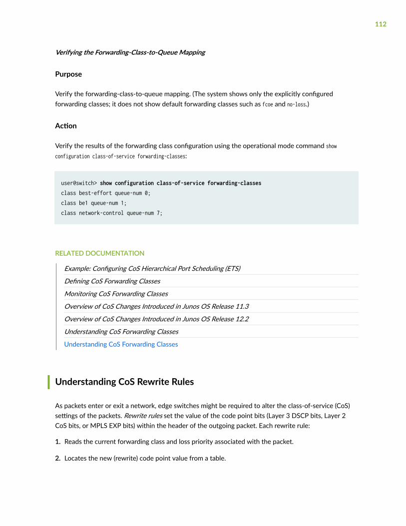
Verifying the Forwarding-Class-to-Queue Mapping
Purpose
Verify the forwarding-class-to-queue mapping. (The system shows only the explicitly configuredforwarding classes; it does not show default forwarding classes such as fcoe and no-loss.)
Action
Verify the results of the forwarding class configuration using the operational mode command showconfiguration class-of-service forwarding-classes:
user@switch> show configuration class-of-service forwarding-classesclass best-effort queue-num 0;class be1 queue-num 1;class network-control queue-num 7;
RELATED DOCUMENTATION
Example: Configuring CoS Hierarchical Port Scheduling (ETS)
Defining CoS Forwarding Classes
Monitoring CoS Forwarding Classes
Overview of CoS Changes Introduced in Junos OS Release 11.3
Overview of CoS Changes Introduced in Junos OS Release 12.2
Understanding CoS Forwarding Classes
Understanding CoS Forwarding Classes
Understanding CoS Rewrite Rules
As packets enter or exit a network, edge switches might be required to alter the class-of-service (CoS)settings of the packets. Rewrite rules set the value of the code point bits (Layer 3 DSCP bits, Layer 2CoS bits, or MPLS EXP bits) within the header of the outgoing packet. Each rewrite rule:
1. Reads the current forwarding class and loss priority associated with the packet.
2. Locates the new (rewrite) code point value from a table.
112

3. Writes that code point value into the packet header, replacing the old code point value.
Rewrite rules must be assigned to an interface for rewrites to take effect.
You can apply (bind) one DSCP or DSCP IPv6 rewrite rule and one IEEE 802.1p rewrite rule to eachinterface. You can also bind EXP rewrite rules to family mpls logical interfaces to rewrite the CoS bits ofMPLS traffic.
NOTE: OCX Series switches do not support MPLS and do not support EXP rewrite rules.
You cannot apply both a DSCP and a DSCP IPv6 rewrite rule to the same physical interface. Eachphysical interface supports only one DSCP rewrite rule. Both IP and IPv6 packets use the same DSCPrewrite rule, regardless if the configured rewrite rule is DSCP or DSCP IPv6. You can apply an EXPrewrite rule on an interface that has DSCP or IEEE rewrite rules. Only MPLS traffic on family mplsinterfaces uses the EXP rewrite rule.
You can apply both a DSCP rewrite rule and a DSCP IPv6 rewrite rule to a logical interface. IPv6 packetsare rewritten with DSCP-IPv6 rewrite-rules and IPv4 packets are remarked with DSCP rewrite-rules.
NOTE: There are no default rewrite rules. If you want to apply a rewrite rule to outgoing packets,you must explicitly configure the rewrite rule.
You can look at behavior aggregate (BA) classifiers and rewrite rules as two sides of the same coin. A BAclassifier reads the code point bits of incoming packets and classifies the packets into forwarding classes,then the system applies the CoS configured for the forwarding class to those packets. Rewrite ruleschange (rewrite) the code point bits just before the packets leave the system so that the next switch orrouter can apply the appropriate level of CoS to the packets. When you apply a rewrite rule to aninterface, the rewrite rule is the last CoS action performed on the packet before it is forwarded.
Rewrite rules alter CoS values in outgoing packets on the outbound interfaces of an edge switch toaccommodate the policies of a targeted peer. This allows the downstream switch in a neighboringnetwork to classify each packet into the appropriate service group.
NOTE: On each physical interface, either all forwarding classes that are being used on theinterface must have rewrite rules configured or no forwarding classes that are being used on theinterface can have rewrite rules configured. On any physical port, do not mix forwarding classeswith rewrite rules and forwarding classes without rewrite rules.
113

NOTE: Rewrite rules are applied before the egress filter is matched to traffic. Because the codepoint rewrite occurs before the egress filter is matched to traffic, the egress filter match is basedon the rewrite value, not on the original code point value in the packet.
For packets that carry both an inner VLAN tag and an outer VLAN tag, the rewrite rule rewrites only theouter VLAN tag.
MPLS EXP rewrite rules apply only to family mpls logical interfaces. You cannot apply to an EXP rewriterule to a physical interface. You can configure up to 64 EXP rewrite rules, but you can only use 16 EXPrewrite rules at any time on the switch. On a given logical interface, all pushed MPLS labels have thesame EXP rewrite rule applied to them. You can apply different EXP rewrite rules to different logicalinterfaces on the same physical interface.
NOTE: If the switch is performing penultimate hop popping (PHP), EXP rewrite rules do not takeeffect. If both an EXP classifier and an EXP rewrite rule are configured on the switch, then theEXP value from the last popped label is copied into the inner label. If either an EXP classifier oran EXP rewrite rule (but not both) is configured on the switch, then the inner label EXP value issent unchanged.
You can configure enough rewrite rules to handle most, if not all, network scenarios. Table 36 on page114 shows how many of each type of rewrite rules you can configure, and how many entries you canconfigure per rewrite rule.
Table 36: Configuring Rewrite Rules
Rewrite Rule Type Maximum Number of Rewrite Rules Maximum Number of Entries per Rewrite Rule
IEEE 802.1p 64 128
DSCP 32 128
DSCP IPv6 32 128
MPLS EXP 64 128
114

You cannot apply rewrite rules directly to integrated routing and bridging (IRB), also known as routedVLAN interfaces (RVIs), because the members of IRBs/RVIs are VLANs, not ports. However, you canapply rewrite rules to the VLAN port members of an IRB/RVI.
NOTE: OCX Series witches do not support IRBs/RVIs.
RELATED DOCUMENTATION
Understanding Junos CoS Components
Defining CoS Rewrite Rules
Configuring Rewrite Rules for MPLS EXP Classifiers
Defining CoS Rewrite Rules
Edge switches might need to change the class-of-service (CoS) settings of the packets. You can configurerewrite rules to alter code point bit values in outgoing packets on the outbound interfaces of a switch sothat the CoS treatment matches the policies of a targeted peer. Policy matching allows the downstreamrouting platform or switch in a neighboring network to classify each packet into the appropriate servicegroup.
To configure a CoS rewrite rule, create the rule by giving it a name and associating it with a forwardingclass, loss priority, and code point. This creates a rewrite table. After the rewrite rule is created, enable iton an interface (EXP rewrite rules can only be enabled on family mpls logical interfaces, not on physicalinterfaces). You can also apply an existing rewrite rule on an interface.
NOTE: OCX Series switches do not support MPLS, so they do not support EXP rewrite rules.
NOTE: On each physical interface, either all forwarding classes that are being used on theinterface must have rewrite rules configured, or no forwarding classes that are being used on theinterface can have rewrite rules configured. On any physical port, do not mix forwarding classeswith rewrite rules and forwarding classes without rewrite rules.
115

NOTE: To replace an existing rewrite rule on the interface with a new rewrite rule of the sametype, first explicitly remove the existing rewrite rule and then apply the new rule.
NOTE: For packets that carry both an inner VLAN tag and an outer VLAN tag, the rewrite rulerewrites only the outer VLAN tag.
To create rewrite rules and enable them on interfaces:
• To create an 802.1p rewrite rule named customup-rw in the rewrite table for all Layer 2 interfaces:
[edit class-of-service rewrite-rules]user@switch# set ieee-802.1 customup-rw forwarding-class be loss-priority low code-point 000user@switch# set ieee-802.1 customup-rw forwarding-class be loss-priority high code-point 001user@switch# set ieee-802.1 customup-rw forwarding-class be loss-priority low code-point 010user@switch# set ieee-802.1 customup-rw forwarding-class fcoe loss-priority low code-point 011user@switch# set ieee-802.1 customup-rw forwarding-class ef-no-loss loss-priority low code-point 100user@switch# set ieee-802.1 customup-rw forwarding-class ef-no-loss loss-priority high code-point 101user@switch# set ieee-802.1 customup-rw forwarding-class nc loss-priority low code-point 110user@switch# set ieee-802.1 customup-rw forwarding-class nc loss-priority high code-point 111
• To enable an 802.1p rewrite rule named customup-rw on a Layer 2 interface:
[edit]user@switch# set class-of-service interfaces xe-0/0/7 unit 0 rewrite-rules ieee-802.1 customup-rw
NOTE: All forwarding classes assigned to port xe-0/0/7 must have rewrite rules. Do not mixforwarding classes that have rewrite rules with forwarding classes that do not have rewriterules on the same physical interface.
116

• To enable an 802.1p rewrite rule named customup-rw on all 10-Gigabit Ethernet interfaces on theswitch, use wildcards for the interface name and logical interface (unit) number:
[edit]user@switch# set class-of-service interfaces xe-* unit * rewrite-rules customup-rw
NOTE: In this case, all forwarding classes assigned to all 10-Gigabit Ethernet ports must haverewrite rules. Do not mix forwarding classes that have rewrite rules with forwarding classesthat do not have rewrite rules on the same physical interface.
RELATED DOCUMENTATION
Monitoring CoS Rewrite Rules
Configuring Rewrite Rules for MPLS EXP Classifiers
Understanding CoS Rewrite Rules
Understanding CoS MPLS EXP Classifiers and Rewrite Rules
Troubleshooting an Unexpected Rewrite Value
IN THIS SECTION
Problem | 117
Cause | 118
Solution | 118
Problem
Description
Traffic from one or more forwarding classes on an egress port is assigned an unexpected rewrite value.
117

NOTE: For packets that carry both an inner VLAN tag and an outer VLAN tag, the rewrite rulesrewrite only the outer VLAN tag.
Cause
If you configure a rewrite rule for a forwarding class on an egress port, but you do not configure arewrite rule for every forwarding class on that egress port, then the forwarding classes that do not havea configured rewrite rule are assigned random rewrite values.
For example:
1. Configure forwarding classes fc1, fc2, and fc3.
2. Configure rewrite rules for forwarding classes fc1 and fc2, but not for forwarding class fc3.
3. Assign forwarding classes fc1, fc2, and fc3 to a port.
When traffic for these forwarding classes flows through the port, traffic for forwarding classes fc1 andfc2 is rewritten correctly. However, traffic for forwarding class fc3 is assigned a random rewrite value.
Solution
If any forwarding class on an egress port has a configured rewrite rule, then all forwarding classes onthat egress port must have a configured rewrite rule. Configuring a rewrite rule for any forwarding classthat is assigned a random rewrite value solves the problem.
TIP: If you want the forwarding class to use the same code point value assigned to it by theingress classifier, specify that value as the rewrite rule value. For example, if a forwarding classhas the IEEE 802.1 ingress classifier code point value 011, configure a rewrite rule for thatforwarding class that uses the IEEE 802.1p code point value 011.
NOTE: There are no default rewrite rules. You can bind one rewrite rule for DSCP traffic and onerewrite rule for IEEE 802.1p traffic to an interface. A rewrite rule can contain multipleforwarding-class-to-rewrite-value mappings.
118

1. To assign a rewrite value to a forwarding class, add the new rewrite value to the same rewrite rule asthe other forwarding classes on the port:
[edit class-of-service rewrite-rules]user@switch# set (dscp | ieee-802.1) rewrite-name forwarding-class class-name loss-priority priority code-point (alias | bits)
For example, if the other forwarding classes on the port use rewrite values defined in the rewrite rulecustom-rw, the forwarding class be2 is being randomly rewritten, and you want to use IEEE 802.1 codepoint 002 for the be2 forwarding class:
[edit class-of-service rewrite-rules]user@switch# set ieee-802.1 custom-rw forwarding-class be2 loss-priority low code-point 002
2. Enable the rewrite rule on an interface if it is not already enabled on the desired interface:
[edit]user@switch# set class-of-service interfaces interface-name unit unit rewrite-rules (dscp | ieee-802.1) rewrite-rule-name
For example, to enable the rewrite rule custom-rw on interface xe-0/0/24.0:
[edit]user@switch# set class-of-service interfaces xe-0/0/24 unit 0 rewrite-rules ieee-802.1 custom-rw
RELATED DOCUMENTATION
interfaces
rewrite-rules
Defining CoS Rewrite Rules
Monitoring CoS Rewrite Rules
119

3PART
Scheduling Traffic
Using Schedulers | 121

CHAPTER 3
Using Schedulers
IN THIS CHAPTER
Understanding CoS Scheduling Behavior and Configuration Considerations | 121
Defining CoS Queue Schedulers for Port Scheduling | 128
Defining CoS Queue Scheduling Priority | 132
Example: Configuring Queue Scheduling Priority | 133
Understanding CoS Traffic Control Profiles | 138
Understanding CoS Priority Group Scheduling | 140
Defining CoS Traffic Control Profiles (Priority Group Scheduling) | 144
Example: Configuring Traffic Control Profiles (Priority Group Scheduling) | 145
Understanding CoS Priority Group and Queue Guaranteed Minimum Bandwidth | 149
Example: Configuring Minimum Guaranteed Output Bandwidth | 152
Understanding CoS Priority Group Shaping and Queue Shaping (Maximum Bandwidth) | 159
Example: Configuring Maximum Output Bandwidth | 162
Understanding CoS Scheduling Behavior and ConfigurationConsiderations
Many factors affect scheduling configuration and bandwidth requirements, including:
• When you configure bandwidth for a forwarding class (each forwarding class is mapped to a queue)or a forwarding class set (priority group), the switch considers only the data as the configuredbandwidth. The switch does not account for the bandwidth consumed by the preamble and theinterframe gap (IFG). Therefore, when you calculate and configure the bandwidth requirements for aforwarding class or for a forwarding class set, consider the preamble and the IFG as well as the datain the calculations.
• When you configure a forwarding class to carry traffic on the switch (instead of using only defaultforwarding classes), you must also define a scheduling policy for the user-configured forwardingclass. Some switches support enhanced transmission selection (ETS) hierarchical port scheduling,
121

some switches support direct port scheduling, and some switches support both methods ofscheduling.
For ETS hierarchical port scheduling, defining a hierarchical scheduling policy using ETS means:
• Mapping a scheduler to the forwarding class in a scheduler map
• Including the forwarding class in a forwarding class set
• Associating the scheduler map with a traffic control profile
• Attaching the traffic control profile to a forwarding class set and an interface
On switches that support port scheduling, defining a scheduling policy means:
• Mapping a scheduler to the forwarding class in a scheduler map.
• Applying the scheduler map to one or more interfaces.
• On each physical interface, either all forwarding classes that are being used on the interface musthave rewrite rules configured, or no forwarding classes that are being used on the interface can haverewrite rules configured. On any physical port, do not mix forwarding classes with rewrite rules andforwarding classes without rewrite rules.
• For packets that carry both an inner VLAN tag and an outer VLAN tag, rewrite rules rewrite only theouter VLAN tag.
• For ETS hierarchical port scheduling, configuring the minimum guaranteed bandwidth (transmit-rate)for a forwarding class does not work unless you also configure the minimum guaranteed bandwidth(guaranteed-rate) for the forwarding class set in the traffic control profile.
Additionally, the sum of the transmit rates of the forwarding classes in a forwarding class set shouldnot exceed the guaranteed rate for the forwarding class set. (You cannot guarantee a minimumbandwidth for the queues that is greater than the minimum bandwidth guaranteed for the entire setof queues.) If you configure transmit rates whose sum exceeds the guaranteed rate of the forwardingclass set, the commit check fails and the system rejects the configuration.
• For ETS hierarchical port scheduling, the sum of the forwarding class set guaranteed rates cannotexceed the total port bandwidth. If you configure guaranteed rates whose sum exceeds the portbandwidth, the system sends a syslog message to notify you that the configuration is not valid.However, the system does not perform a commit check. If you commit a configuration in which thesum of the guaranteed rates exceeds the port bandwidth, the hierarchical scheduler behavesunpredictably.
• For ETS hierarchical port scheduling, if you configure the guaranteed-rate of a forwarding class set as apercentage, configure all of the transmit rates associated with that forwarding class set aspercentages. In this case, if any of the transmit rates are configured as absolute values instead ofpercentages, the configuration is not valid and the system sends a syslog message.
122

• There are several factors to consider if you want to configure a strict-high priority queue (forwardingclass):
• On QFX5200, QFX3500, and QFX3600 switches and on QFabric systems, you can configure onlyone strict-high priority queue (forwarding class).
On QFX5100 and EX4600 switches, you can configure only one forwarding-class-set (prioritygroup) as strict-high priority. All queues which are part of that strict-high forwarding class set thenact as strict-high queues.
On QFX10000 switches, there is no limit to the number of strict-high priority queues you canconfigure.
• You cannot configure a minimum guaranteed bandwidth (transmit-rate) for a strict-high priorityqueue on QFX5200, QFX5100, EX4600, QFX3500, and QFX3600 switches, and on QFabricsystems.
On QFX5200 and QFX10000 switches, you can set the transmit-rate on strict-high priority queuesto set a limit on the amount of traffic that the queue treats as strict-high priority traffic. Traffic inexcess of the transmit-rate is treated as best-effort traffic, and receives an excess bandwidthsharing weight of “1”, which is the proportion of extra bandwidth the strict-high priority queuecan share on the port. Queues that are not strict-high priority queues use the transmit rate(default) or the configured excess rate to determine the proportion (weight) of extra portbandwidth the queue can share. However, you cannot configure an excess rate on a strict-highpriority queue, and you cannot change the excess bandwidth sharing weight of “1” on a strict-highpriority queue.
For ETS hierarchical port scheduling, you cannot configure a minimum guaranteed bandwidth(guaranteed-rate) for a forwarding class set that includes a strict-high priority queue.
• Except on QFX10000 switches, for ETS hierarchical port scheduling only, you must create aseparate forwarding class set for a strict-high priority queue. On QFX10000 switches, you canmix strict-high priority and low priority queues in the same forwarding class set.
• Except on QFX10000 switches, for ETS hierarchical port scheduling, only one forwarding class setcan contain a strict-high priority queue. On QFX10000 switches, this restriction does not apply.
• Except on QFX10000 switches, for ETS hierarchical port scheduling, a strict-high priority queuecannot belong to the same forwarding class set as queues that are not strict-high priority. (Youcannot mix a strict-high priority forwarding class with forwarding classes that are not strict-highpriority in one forwarding class set.) On QFX10000 switches, you can mix strict-high priority andlow priority queues in the same forwarding class set.
• For ETS hierarchical port scheduling on switches that use different forwarding class sets forunicast and multidestination (multicast, broadcast, and destination lookup fail) traffic, a strict-highpriority queue cannot belong to a multidestination forwarding class set.
123

• On QFX10000 systems, we recommend that you always configure a transmit rate on strict-highpriority queues to prevent them from starving other queues. If you do not apply a transmit rate tolimit the amount of bandwidth strict-high priority queues can use, then strict-high priority queuescan use all of the available port bandwidth and starve other queues on the port.
On QFX5200, QFX5100, EX4600, QFX3500, and QFX3600 switches, and on QFabric systems,we recommend that you always apply a shaping rate to the strict-high priority queue to prevent itfrom starving other queues. If you do not apply a shaping rate to limit the amount of bandwidth astrict-high priority queue can use, then the strict-high priority queue can use all of the availableport bandwidth and starve other queues on the port.
• On QFabric systems, if any queue that contains outgoing packets does not transmit packets for 12consecutive seconds, the port automatically resets. Failure of a queue to transmit packets for 12consecutive seconds might be due to:
• A strict-high priority queue consuming all of the port bandwidth
• Several queues consuming all of the port bandwidth
• Any queue or port receiving continuous priority-based flow control (PFC) or 802.3x EthernetPAUSE messages (received PFC and PAUSE messages prevent a queue or a port, respectively,from transmitting packets because of network congestion)
• Other conditions that prevent a queue from obtaining port bandwidth for 12 consecutive seconds
If the cause is a strict-high priority queue consuming all of the port bandwidth, use rate shaping toconfigure a maximum rate for the strict-high priority queue and prevent it from using all of the portbandwidth. To configure rate shaping, include the shaping-rate (rate | percent percentage) statement atthe [edit class-of-service schedulers scheduler-name] hierarchy level and apply the shaping rate to thestrict-high priority scheduler. We recommend that you always apply a shaping rate to strict-highpriority traffic to prevent the strict-high priority queue from starving other queues.
If several queues consume all of the port bandwidth, you can use a scheduler to rate shape thosequeues and prevent them from using all of the port bandwidth.
• For transmit rates below 1 Gbps, we recommend that you configure the transmit rate as a percentageinstead of as a fixed rate. This is because the system converts fixed rates into percentages and mightround small fixed rates to a lower percentage. For example, a fixed rate of 350 Mbps is roundeddown to 3 percent instead of 3.5 percent.
• When you set the maximum bandwidth for a queue or for a priority group (shaping-rate) at 100 Kbpsor lower, the traffic shaping behavior is accurate only within +/– 20 percent of the configured shaping-rate.
• On QFX10000 switches, configuring rate shaping ([set class-of-service schedulers scheduler-nametransmit-rate (rate | percentage) exact) on a LAG interface using the [edit class-of-service interfaces lag-
124

interface-name scheduler-map scheduler-map-name] statement can result in scheduled traffic streamsreceiving more LAG link bandwidth than expected.
You configure rate shaping in a scheduler to set the maximum bandwidth for traffic assigned to aforwarding class on a particular output queue on a port. For example, you can use a scheduler toconfigure rate shaping on traffic assigned to the best-effort forwarding class mapped to queue 0, andthen apply the scheduler to an interface using a scheduler map, to set the maximum bandwidth forbest-effort traffic mapped to queue 0 on that port. Traffic in the best-effort forwarding can use nomore than the amount of port bandwidth specified by the transmit rate when you use the exactoption.
LAG interfaces are composed of two or more Ethernet links bundled together to function as a singleinterface. The switch can hash traffic entering a LAG interface onto any member link in the LAGinterface. When you configure rate shaping and apply it to a LAG interface, the way that the switchapplies the rate shaping to traffic depends on how the switch hashes the traffic onto the LAG links.
To illustrate how link hashing affects the way the switch applies a shaping rate to LAG traffic, let’slook at a LAG interface (ae0) that has two member links (xe-0/0/20 and xe-0/0/21). On LAG ae0, weconfigure rate shaping of 2g for traffic assigned to the best-effort forwarding class, which is mapped tooutput queue 0. When traffic in the best-effort forwarding class reaches the LAG interface, the switchhashes the traffic onto one of the two member links.
If the switch hashes all of the best-effort traffic onto the same LAG link, the traffic receives amaximum of 2g bandwidth on that link. In this case, the intended cumulative limit of 2g for best-effort traffic on the LAG is enforced.
However, if the switch hashes the best-effort traffic onto both of the LAG links, the traffic receives amaximum of 2g bandwidth on each LAG link, not 2g as a cumulative total for the entire LAG, so thebest-effort traffic receives a maximum of 4g on the LAG, not the 2g set by the rate shapingconfiguration. When hashing spreads the traffic assigned to an output queue (which is mapped to aforwarding class) across multiple LAG links, the effective rate shaping (cumulative maximumbandwidth) on the LAG is:
(number of LAG member interfaces) x (rate shaping for the output queue) = cumulative LAG rateshaping
• On switches that do not use virtual output queues (VOQs), ingress port congestion can occur duringperiods of egress port congestion if an ingress port forwards traffic to more than one egress port, andat least one of those egress ports experiences congestion. If this occurs, the congested egress portcan cause the ingress port to exceed its fair allocation of ingress buffer resources. When the ingressport exceeds its buffer resource allocation, frames are dropped at the ingress. Ingress port framedrop affects not only the congested egress ports, but also all of the egress ports to which thecongested ingress port forwards traffic.
If a congested ingress port drops traffic that is destined for one or more uncongested egress ports,configure a weighted random early detection (WRED) drop profile and apply it to the egress queue
125

that is causing the congestion. The drop profile prevents the congested egress queue from affectingegress queues on other ports by dropping frames at the egress instead of causing congestion at theingress port.
NOTE: On systems that support lossless transport, do not configure drop profiles for losslessforwarding classes such as the default fcoe and no-loss forwarding classes. FCoE and otherlossless traffic queues require lossless behavior. Use priority-based flow control (PFC) toprevent frame drop on lossless priorities.
•On systems that use different classifiers for unicast and multidestination traffic and that supportlossless transport, on an ingress port, do not configure classifiers that map the same IEEE 802.1pcode point to both a multidestination traffic flow and a lossless unicast traffic flow (such as thedefault lossless fcoe or no-loss forwarding classes). Any code point used for multidestination traffic ona port should not be used to classify unicast traffic into a lossless forwarding class on the same port.
If a multidestination traffic flow and a lossless unicast traffic flow use the same code point on a port,the multidestination traffic is treated the same way as the lossless traffic. For example, if priority-based flow control (PFC) is applied to the lossless traffic, the multidestination traffic of the samecode point is also paused. During periods of congestion, treating multidestination traffic the same aslossless unicast traffic can create ingress port congestion for the multidestination traffic and affectthe multidestination traffic on all of the egress ports the multidestination traffic uses.
For example, the following configuration can cause ingress port congestion for the multidestinationflow:
1. For unicast traffic, IEEE 802.1p code point 011 is classified into the fcoe forwarding class:
user@switch# set class-of-service classifiers ieee-802.1 ucast_cl forwarding-class fcoe loss-priority low code-points 011
2. For multidestination traffic, IEEE 802.1p code point 011 is classified into the mcast forwarding class:
user@switch# set class-of-service classifiers ieee-802.1 mcast-cl forwarding-class mcast loss-priority low code-points 011
126

3. The unicast classifier that maps traffic with code point 011 to the fcoe forwarding class is mappedto interface xe-0/0/1:
user@switch# set class-of-service interfaces xe-0/0/1 unit 0 classifiers ieee-802.1 ucast_cl
4. The multidestination classifier that maps traffic with code point 011 to the mcast forwarding class ismapped to all interfaces (multidestination traffic maps to all interfaces and cannot be mapped toindividual interfaces):
user@switch# set class-of-service multi-destination classifiers ieee-802.1 mcast-cl
Because the same code point (011) maps unicast traffic to a lossless traffic flow and also mapsmultidestination traffic to a multidestination traffic flow, the multidestination traffic flow mightexperience ingress port congestion during periods of congestion.
To avoid ingress port congestion, do not map the code point used by the multidestination traffic tolossless unicast traffic. For example:
1. Instead of classifying code point 011 into the fcoe forwarding class, classify code point 011 into thebest-effort forwarding class:
user@switch# set class-of-service classifiers ieee-802.1 ucast_cl forwarding-class best-effort loss-priority low code-points 011
2. user@switch# set class-of-service classifiers ieee-802.1 mcast-cl forwarding-class mcast loss-priority low code-points 011
3. user@switch# set class-of-service interfaces xe-0/0/1 unit 0 classifiers ieee-802.1 ucast_cl
4. user@switch# set class-of-service multi-destination classifiers ieee-802.1 mcast-cl
Because the code point 011 does not map unicast traffic to a lossless traffic flow, themultidestination traffic flow does not experience ingress port congestion during periods ofcongestion.
127

The best practice is to classify unicast traffic with IEEE 802.1p code points that are also used formultidestination traffic into best-effort forwarding classes.
Defining CoS Queue Schedulers for Port Scheduling
Schedulers define the CoS properties of output queues. You configure CoS properties in a scheduler,then map the scheduler to a forwarding class. Forwarding classes are in turn mapped to output queues.Classifiers map incoming traffic into forwarding classes based on IEEE 802.1p, DSCP, or EXP codepoints. CoS scheduling properties include the amount of interface bandwidth assigned to the queue, thepriority of the queue, whether explicit congestion notification (ECN) is enabled on the queue, and theWRED packet drop profiles associated with the queue.
The parameters you configure in a scheduler define the following characteristics for the queues mappedto the scheduler:
• priority—One of three bandwidth priorities that queues associated with a scheduler can receive:
• low—The scheduler has low priority.
• high—The scheduler has high priority. High priority traffic takes precedence over low prioritytraffic.
• strict-high—The scheduler has strict-high priority. Strict-high priority queues receive preferentialtreatment over low-priority queues and receive all of their configured bandwidth before low-priority queues are serviced. Low-priority queues do not transmit traffic until strict-high priorityqueues are empty.
NOTE: We strongly recommend that you configure a transmit rate on all strict-highpriority queues to limit the amount of traffic the switch treats as strict-high priority trafficand prevent strict-high priority queues from starving other queues on the port. This isespecially important if you configure more than one strict-high priority queue on a port. Ifyou do not configure a transmit rate to limit the amount of bandwidth strict-high priorityqueues can use, then the strict-high priority queues can use all of the available portbandwidth and starve other queues on the port.
The switch treats traffic in excess of the transmit rate as best-effort traffic that receivesbandwidth from the leftover (excess) port bandwidth pool. On strict-high priority queues,all traffic that exceeds the transmit rate shares in the port excess bandwidth pool based onthe strict-high priority excess bandwidth sharing weight of “1”, which is not configurable.The actual amount of extra bandwidth that traffic exceeding the transmit rate receives
128

depends on how many other queues consume excess bandwidth and the excess rates ofthose queues.
• transmit-rate—Minimum guaranteed bandwidth, also known as the committed information rate (CIR),set as a percentage rate or as an absolute value in bits per second. By default, the transmit rate alsodetermines the amount of excess (extra) port bandwidth the queue can share if you do not explicitlyconfigure an excess rate. Extra bandwidth is allocated among the queues on the port in proportion tothe transmit rate of each queue. Except on QFX10000 switches, you can configure shaping-rate tothrottle the rate of packet transmission. On QFX10000 switches, on queues that are not strict-highpriority queues, you can configure a transmit rate as exact, which shapes the transmission by settingthe transmit rate as the maximum bandwidth the queue can consume on the port.
NOTE: On QFX10000 switches, oversubscribing all 8 queues configured with the transmit rateexact (shaping) statement at the [edit class-of-service schedulers scheduler-name] hierarchy levelmight result in less than 100 percent utilization of port bandwidth.
On strict-high priority queues, the transmit rate sets the amount of bandwidth used for strict-highpriority forwarding; traffic in excess of the transmit rate is treated as best-effort traffic that receivesthe queue excess rate.
NOTE: Include the preamble bytes and interframe gap (IFG) bytes as well as the data bytes inyour bandwidth calculations.
• excess-rate—Percentage of extra bandwidth (bandwidth that is not used by other queues) a low-priority queue can receive. If not set, the switch uses the transmit rate to determine extra bandwidthsharing. You cannot set an excess rate on a strict-high priority queue.
• drop-profile-map—Drop profile mapping to a packet loss priority to apply WRED to the scheduler andcontrol packet drop for different packet loss priorities during periods of congestion.
• buffer-size—Size of the queue buffer as a percentage of the dedicated buffer space on the port, or asa proportional share of the dedicated buffer space on the port that remains after the explicitlyconfigured queues are served.
• explicit-congestion-notification—ECN enable on a best-effort queue. ECN enables end-to-endcongestion notification between two ECN-enabled endpoints on TCP/IP based networks. ECN mustbe enabled on both endpoints and on all of the intermediate devices between the endpoints for ECNto work properly. ECN is disabled by default.
129

NOTE: Do not configure drop profiles for the fcoe and no-loss forwarding classes. FCoE andother lossless traffic queues require lossless behavior. Use priority-based flow control (PFC) toprevent frame drop on lossless priorities.
To apply scheduling properties to traffic, map schedulers to forwarding classes using a scheduler map,and then apply the scheduler map to interfaces. Using different scheduler maps, you can map differentschedulers to the same forwarding class on different interfaces, to apply different scheduling to thattraffic on different interfaces.
To configure a scheduler using the CLI:
1. Name the scheduler and set the minimum guaranteed bandwidth for the queue; optionally, set amaximum bandwidth limit (shaping rate) on a low priority queue by configuring either shaping-rate(except on QFX10000 switches) or the exact option (only on QFX10000 switches):
[edit class-of-service] user@switch# set schedulers scheduler-name transmit-rate (rate | percent percentage) <exact>
2. Set the amount of excess bandwidth a low-priority queue can share:
[edit class-of-service]user@switch# set schedulers scheduler-name excess-rate percent percentage
3. Set the queue priority:
[edit class-of-service schedulers scheduler-name] user@switch# set priority level
4. Specify drop profiles for packet loss priorities using a drop profile map:
[edit class-of-service schedulers scheduler-name]user@switch# set drop-profile-map loss-priority (low | medium-high | high) drop-profile drop-profile-name
130

5. Configure the size of the buffer space for the queue:
[edit class-of-service schedulers scheduler-name]user@switch# set buffer-size (percent percent | remainder)
6. Enable ECN, if desired (on best-effort traffic only):
[edit class-of-service schedulers scheduler-name]user@switch# set explicit-congestion-notification
7. Configure a scheduler map to map the scheduler to a forwarding class, which applies the scheduler’sproperties to the traffic in that forwarding class:
[edit class-of-service]user@switch# set scheduler-maps scheduler-map-name forwarding-class forwarding-class-name scheduler scheduler-name
8. Assign the scheduler map and its associated schedulers to one or more interfaces.
[edit class-of-service]user@switch# set interfaces interface-name scheduler-map scheduler-map-name
RELATED DOCUMENTATION
Example: Configuring Queue Schedulers for Port Scheduling
Example: Configuring ECN
Defining CoS Queue Scheduling Priority
Configuring CoS WRED Drop Profiles
Monitoring CoS Scheduler Maps
Understanding CoS Port Schedulers on QFX Switches
Understanding CoS Explicit Congestion Notification
131

Defining CoS Queue Scheduling Priority
You can configure the scheduling priority of individual queues by specifying the priority in a scheduler,and then associating the scheduler with a queue by using a scheduler map. On QFX5100, QFX5200,EX4600, QFX3500, and QFX3600 switches, and on QFabric systems, queues can have one of twobandwidth scheduling priorities, strict-high priority or low priority. On QFX10000 Series switches,queues can also be configured as high priority.
NOTE: By default, all queues are low priority queues.
The switch services low priority queues after servicing any queue that has strict-high priority traffic orhigh priority traffic. Strict-high priority queues receive preferential treatment over all other queues andreceive all of their configured bandwidth before other queues are serviced. Low-priority queues do nottransmit traffic until strict-high priority queues are empty, and receive the bandwidth that remains afterthe strict-high queues have been serviced. High priority queues receive preference over low priorityqueues.
Different switches handle traffic configured as strict-high priority traffic in different ways:
• QFX5100, QFX5200, QFX3500, QFX3600, and EX4600 switches, and QFabric systems—You canconfigure only one queue as a strict-high priority queue.
On these switches, we recommend that you always apply a shaping rate to strict-high priority queuesto prevent them from starving other queues. If you do not apply a shaping rate to limit the amount ofbandwidth a strict-high priority queue can use, then the strict-high priority queue can use all of theavailable port bandwidth and starve other queues on the port.
• QFX10000 switches—You can configure as many queues as you want as strict-high priority. However,keep in mind that too much strict-high priority traffic can starve low priority queues on the port.
NOTE: We strongly recommend that you configure a transmit rate on all strict-high priorityqueues to limit the amount of traffic the switch treats as strict-high priority traffic andprevent strict-high priority queues from starving other queues on the port. This is especiallyimportant if you configure more than one strict-high priority queue on a port. If you do notconfigure a transmit rate to limit the amount of bandwidth strict-high priority queues can use,then the strict-high priority queues can use all of the available port bandwidth and starveother queues on the port.
The switch treats traffic in excess of the transmit rate as best-effort traffic that receivesbandwidth from the leftover (excess) port bandwidth pool. On strict-high priority queues, alltraffic that exceeds the transmit rate shares in the port excess bandwidth pool based on the
132

strict-high priority excess bandwidth sharing weight of “1”, which is not configurable. Theactual amount of extra bandwidth that traffic exceeding the transmit rate receives dependson how many other queues consume excess bandwidth and the excess rates of those queues.
• To configure queue priority using the CLI:
[edit class-of-service]
user@switch# set schedulers scheduler-name priority level
RELATED DOCUMENTATION
Example: Configuring Queue Scheduling Priority
Monitoring CoS Scheduler Maps
Example: Configuring Queue Scheduling Priority
IN THIS SECTION
Requirements | 134
Overview | 135
Verification | 137
You can configure the bandwidth scheduling priority of individual queues by specifying the priority in ascheduler, and then using a scheduler map to associate the scheduler with a queue.
133

Configuring Queue Scheduling Priority
CLI Quick Configuration
To quickly configure queue scheduling priority, copy the following commands, paste them in a text file,remove line breaks, change variables and details to match your network configuration, and then copyand paste the commands into the CLI at the [edit] hierarchy level:
[edit class-of-service]set schedulers fcoe-sched priority lowset schedulers nl-sched priority lowset scheduler-maps schedmap1 forwarding-class fcoe scheduler fcoe-schedset scheduler-maps schedmap1 forwarding-class no-loss scheduler nl-sched
Step-by-Step Procedure
To configure queue priority using the CLI:
1. Create the FCoE scheduler with low priority:
[edit class-of-service]user@switch# set schedulers fcoe-sched priority low
2. Create the no-loss scheduler with low priority:
[edit class-of-service]user@switch# set schedulers nl-sched priority low
3. Associate the schedulers with the desired queues in the scheduler map:
[edit class-of-service]user@switch# set scheduler-maps schedmap1 forwarding-class fcoe scheduler fcoe-scheduser@switch# set scheduler-maps schedmap1 forwarding-class no-loss scheduler nl-sched
Requirements
This example uses the following hardware and software components:
134

• One switch.
• Junos OS Release 11.1 or later for the QFX Series or Junos OS Release 14.1X53-D20 or later for theOCX Series.
Overview
Queues can have one of several bandwidth priorities:
• strict-high—Strict-high priority allocates bandwidth to the queue before any other queue receivesbandwidth. Other queues receive the bandwidth that remains after the strict-high queue has beenserviced. On QFX10000 switches, you can configure as many queues as you want as strict-highpriority queues. On QFX5200, QFX3500, and QFX3600 switches and on QFabric systems, you canconfigure only one queue as a strict-high queue. On QFX5100 and EX4600 switches, you canconfigure only one forwarding-class-set (priority group) as strict-high priority. All queues which arepart of that strict-high forwarding class set then act as strict-high queues.
NOTE: On QFX5200 switches, it is not possible to support multiple queues with strict-highpriority because QFX5200 doesn’t support flexible hierarchical scheduling. When multiplestrict-high priority queues are configured, all of those queues are treated as strict-highpriority but the higher number queue among them is given highest priority.
On QFX10000 switches, if you configure strict-high priority queues on a port, we stronglyrecommend that you configure a transmit rate on those queues. The transmit rate sets the amount oftraffic that the switch forwards as strict-high priority; traffic in excess of the transmit rate is treatedas best-effort traffic that receives the queue excess rate. Even if you configure only one strict-highpriority queue, we strongly recommend that you configure a transmit rate the queue to prevent itfrom starving other queues. If you do not configure a transmit rate to limit the amount of bandwidtha strict-high priority queue can use, then the strict-high priority queue can use all of the availableport bandwidth and starve other queues on the port.
On QFX5200, QFX5100, QFX3500, QFX3600, and EX4600 switches and on QFabric systems, werecommend that you always apply a shaping rate to strict-high priority queues to prevent them fromstarving other queues. If you do not apply a shaping rate to limit the amount of bandwidth a strict-high priority queue can use, then the strict-high priority queue can use all of the available portbandwidth and starve other queues on the port.
NOTE: On switches that support enhanced transmission selection (ETS) hierarchicalscheduling, if you use ETS and you configure a strict-high priority queue, you must create aforwarding class set that is dedicated only to strict-high priority traffic. Only one forwarding
135

class set can contain a strict-high priority queue. Queues that are not strict-high prioritycannot belong to the same forwarding class set as strict-high priority queues.
On switches that use different output queues for unicast and multidestination traffic, themultidestination forwarding class set cannot contain strict-high priority queues.
• high (QFX10000 Series switches only)—High priority. Traffic with high priority is serviced after anyqueue that has a strict-high priority, and before queues with low priority.
• low—Low priority. Traffic with low priority is serviced after any queue that has a strict-high priority.
NOTE: By default, all queues are low priority queues.
Table 37 on page 136 shows the configuration components for this example.
This example describes how to set the queue priority for two forwarding classes (queues) named fcoeand no-loss. Both queues have a priority of low. The scheduler for the fcoe queue is named fcoe-sched andthe scheduler for the no-loss queue is named nl-sched. One scheduler map, schedmap1, associates theschedulers to the queues.
Table 37: Components of the Queue Scheduler Priority Configuration Example
Component Settings
Hardware One switch
Schedulers fcoe-sched for FCoE traffic
nl-sched for no-loss traffic
Priority low for FCoE traffic
low for no-loss traffic
Scheduler map schedmap1:
FCoE mapping: scheduler fcoe-sched to forwarding classfcoe
No-loss mapping: scheduler nl-sched to forwarding classno-loss
136

NOTE: OCX Series switches do not support lossless transport. On OCX Series switches, thedefault DSCP classifier does not map traffic to the default fcoe and no-loss forwarding classes.On an OCX Series switch, you could use this example by substituting other forwarding classes(for example, best-effort or network-control) for the fcoe and no-loss forwarding classes, andnaming the schedulers appropriately. The active forwarding classes (best-effort, network-control,and mcast) share the unused bandwidth assigned to the fcoe and no-loss forwarding classes.
Verification
IN THIS SECTION
Verifying the Queue Scheduling Priority | 137
Verifying the Scheduler-to-Forwarding-Class Mapping | 138
To verify that you configured the queue scheduling priority for bandwidth and mapped the schedulers tothe correct forwarding classes, perform these tasks:
Verifying the Queue Scheduling Priority
Purpose
Verify that you configured the queue schedulers fcoe-sched and nl-sched with low queue schedulingpriority.
Action
Display the fcoe-sched scheduler priority configuration using the operational mode command showconfiguration class-of-service schedulers fcoe-sched priority:
user@switch> show configuration class-of-service schedulers fcoe-sched prioritypriority low;
137

Display the nl-sched scheduler priority configuration using the operational mode command showconfiguration class-of-service schedulers nl-sched priority:
user@switch> show configuration class-of-service schedulers nl-sched prioritypriority low;
Verifying the Scheduler-to-Forwarding-Class Mapping
Purpose
Verify that you configured the scheduler map schedmap1 to map scheduler fcoe-sched to forwarding classfcoe and schedule nl-sched to forwarding class no-loss.
Action
Display the scheduler map schedmap1 using the operational mode command show configuration class-of-service scheduler-maps schedmap1:
user@switch> show configuration class-of-service scheduler-maps schedmap1forwarding-class fcoe scheduler fcoe-sched;forwarding-class no-loss scheduler nl-sched;
RELATED DOCUMENTATION
Defining CoS Queue Scheduling Priority
Monitoring CoS Scheduler Maps
Understanding CoS Traffic Control Profiles
A traffic control profile defines the output bandwidth and scheduling characteristics of forwarding classsets (priority groups). The forwarding classes (which are mapped to output queues) that belong to aforwarding class set (fc-set) share the bandwidth that you assign to the fc-set in the traffic controlprofile.
This two-tier hierarchical scheduling architecture provides flexibility in allocating resources amongforwarding classes, and also:
138

• Assigns a portion of port bandwidth to an fc-set. You define the port resources for the fc-set in atraffic control profile.
• Allocates fc-set bandwidth among the forwarding classes (queues) that belong to the fc-set. Ascheduler map attached to the traffic control profile defines the amount of the fc-set’s resources thateach forwarding class can use.
Attaching an fc-set and a traffic control profile to a port defines the hierarchical scheduling properties ofthe group and the forwarding classes that belong to the group.
The ability to create fc-sets supports enhanced transmission selection (ETS), which is described in IEEE802.1Qaz. When an fc-set does not use its allocated port bandwidth, ETS shares the excess portbandwidth among other fc-sets on the port in proportion to their guaranteed minimum bandwidth(guaranteed rate). This utilizes the port bandwidth better than scheduling schemes that reservebandwidth for groups even if that bandwidth is not used. ETS shares unused port bandwidth, so trafficgroups that need extra bandwidth can use it if the bandwidth is available, while preserving the ability tospecify the minimum guaranteed bandwidth for traffic groups.
Traffic control profiles define the following CoS properties for fc-sets:
• Minimum guaranteed bandwidth—Also known as the committed information rate (CIR). This is theminimum amount of port bandwidth the priority group receives. Priorities in the priority groupreceive their minimum guaranteed bandwidth as a portion of the priority group’s minimumguaranteed bandwidth. The guaranteed-rate statement defines the minimum guaranteed bandwidth.
NOTE: You cannot apply a traffic control profile with a minimum guaranteed bandwidth to apriority group that includes strict-high priority queues.
• Shared excess (extra) bandwidth—When the priority groups on a port do not consume the fullamount of bandwidth allocated to them or there is unallocated link bandwidth available, prioritygroups can contend for that extra bandwidth if they need it. Priorities in the priority group contendfor extra bandwidth as a portion of the priority group’s extra bandwidth. The amount of extrabandwidth for which a priority group can contend is proportional to the priority group’s guaranteedminimum bandwidth (guaranteed rate).
• Maximum bandwidth—Also known as peak information rate (PIR). This is the maximum amount ofport bandwidth the priority group receives. Priorities in the priority group receive their maximumbandwidth as a portion of the priority group’s maximum bandwidth. The shaping-rate statementdefines the maximum bandwidth.
• Queue scheduling—Each traffic control profile includes a scheduler map. The scheduler map mapsforwarding classes (priorities) to schedulers to define the scheduling characteristics of the individualforwarding classes in the fc-set. The resources scheduled for each forwarding class representportions of the resources that the traffic control profile schedules for the entire fc-set, not portions
139

of the total link bandwidth. The scheduler-maps statement defines the mapping of forwarding classes toschedulers.
RELATED DOCUMENTATION
Understanding CoS Hierarchical Port Scheduling (ETS)
Example: Configuring CoS Hierarchical Port Scheduling (ETS)
Example: Configuring Traffic Control Profiles (Priority Group Scheduling)
Defining CoS Traffic Control Profiles (Priority Group Scheduling)
Understanding CoS Priority Group Scheduling
IN THIS SECTION
Priority Group Scheduling Components | 141
Default Traffic Control Profile | 142
Guaranteed Rate (Minimum Guaranteed Bandwidth) | 142
Sharing Extra Bandwidth | 142
Shaping Rate (Maximum Bandwidth) | 143
Scheduler Maps | 143
Priority group scheduling defines the class-of-service (CoS) properties of a group of output queues(priorities). Priority group scheduling works with output queue scheduling to create a two-tierhierarchical scheduler. The hierarchical scheduler allocates bandwidth to a group of queues (a prioritygroup, called a forwarding class set in Junos OS configuration). Queue scheduling determines theportion of the priority group bandwidth that the particular queue can use.
You configure priority group scheduling in a traffic control profile and then associate the traffic controlprofile with a forwarding class set and an interface. You attach a scheduler map to the traffic controlprofile to specify the queue scheduling characteristics.
140

NOTE: When you configure bandwidth for a queue or a priority group, the switch considers onlythe data as the configured bandwidth. The switch does not account for the bandwidth consumedby the preamble and the interframe gap (IFG). Therefore, when you calculate and configure thebandwidth requirements for a queue or for a priority group, consider the preamble and the IFGas well as the data in the calculations.
Priority Group Scheduling Components
Table 38 on page 141 provides a quick reference to the traffic control profile components you canconfigure to determine the bandwidth properties of priority groups, and Table 39 on page 141 providesa quick reference to some related scheduling configuration components.
Table 38: Priority Group Scheduler Components
Traffic Control Profile Component Description
Guaranteed rate Sets the minimum guaranteed port bandwidth for the prioritygroup. Extra port bandwidth is shared among priority groups inproportion to the guaranteed rate of each priority group on theport.
Shaping rate Sets the maximum port bandwidth the priority group can consume.
Scheduler map Maps schedulers to queues (forwarding classes, also calledpriorities). This determines the portion of the priority groupbandwidth that a queue receives.
Table 39: Other Scheduling Components
Other Scheduling Components Description
Forwarding class Maps traffic to a queue (priority).
Forwarding class set Name of a priority group. You map forwarding classes to prioritygroups. A forwarding class set consists of one or more forwardingclasses.
141

Table 39: Other Scheduling Components (Continued)
Other Scheduling Components Description
Scheduler Sets the bandwidth and scheduling priority of individual queues(forwarding classes).
Default Traffic Control Profile
There is no default traffic control profile.
Guaranteed Rate (Minimum Guaranteed Bandwidth)
The guaranteed rate determines the minimum guaranteed bandwidth for each priority group. It alsodetermines how much excess (extra) port bandwidth the priority group can share; each priority groupshares extra port bandwidth in proportion to its guaranteed rate. You specify the rate in bits per secondas a fixed value such as 3 Mbps or as a percentage of the total port bandwidth.
The minimum transmission bandwidth can exceed the configured rate if additional bandwidth isavailable from other priority groups on the port. In case of congestion, the configured guaranteed rate isguaranteed for the priority group. This property enables you to ensure that each priority group receivesthe amount of bandwidth appropriate to its level of service.
NOTE: Configuring the minimum guaranteed bandwidth (transmit rate) for a forwarding classdoes not work unless you also configure the minimum guaranteed bandwidth (guaranteed rate)for the forwarding class set in the traffic control profile.
Additionally, the sum of the transmit rates of the queues in a forwarding class set should notexceed the guaranteed rate for the forwarding class set. (You cannot guarantee a minimumbandwidth for the queues that is greater than the minimum bandwidth guaranteed for the entireset of queues.)
You cannot configure a guaranteed rate for forwarding class sets that include strict-high priorityqueues.
Sharing Extra Bandwidth
Extra bandwidth is available to priority groups when the priority groups do not use the full amount ofavailable port bandwidth. This extra port bandwidth is shared among the priority groups based on theminimum guaranteed bandwidth of each priority group.
142

For example, Port A has three priority groups: fc-set-1, fc-set-2, and fc-set-3. Fc-set-1 has a guaranteedrate of 2 Gbps, fc-set-2 has a guaranteed rate of 2 Gbps, and fc-set-3 has a guaranteed rate of 4 Gbps.After servicing the minimum guaranteed bandwidth of these priority groups, the port has an extra 2Gbps of available bandwidth, and all three priority groups have still have packets to forward. The prioritygroups receive the extra bandwidth in proportion to their guaranteed rates, so fc-set-1 receives an extra500 Mbps, fc-set-2 receives an extra 500 Mbps, and fc-set-3 receives an extra 1 Gbps.
Shaping Rate (Maximum Bandwidth)
The shaping rate determines the maximum bandwidth the priority group can consume. You specify therate in bits per second as a fixed value such as 5 Mbps or as a percentage of the total port bandwidth.
The maximum bandwidth for a priority group depends on the total bandwidth available on the port andhow much bandwidth the other priority groups on the port consume.
Scheduler Maps
A scheduler map maps schedulers to queues. When you associate a scheduler map with a traffic controlprofile, then associate the traffic control profile with an interface and a forwarding class set, thescheduling defined by the scheduler map determines the portion of the priority group resources thateach individual queue can use.
You can associate up to four user-defined scheduler maps with traffic control profiles.
RELATED DOCUMENTATION
Understanding Junos CoS Components
Understanding CoS Output Queue Schedulers
Understanding CoS Hierarchical Port Scheduling (ETS)
Understanding CoS Scheduling Behavior and Configuration Considerations
Understanding CoS Scheduling on QFabric System Node Device Fabric (fte) Ports
Understanding Default CoS Scheduling on QFabric System Interconnect Devices (Junos OS Release13.1 and Later Releases)
Example: Configuring CoS Hierarchical Port Scheduling (ETS)
Example: Configuring Minimum Guaranteed Output Bandwidth
Example: Configuring Maximum Output Bandwidth
Example: Configuring Queue Schedulers
Example: Configuring Traffic Control Profiles (Priority Group Scheduling)
Example: Configuring WRED Drop Profiles
143

Example: Configuring Drop Profile Maps
Defining CoS Traffic Control Profiles (Priority Group Scheduling)
A traffic control profile defines the output bandwidth and scheduling characteristics of forwarding classsets (priority groups). The forwarding classes (which are mapped to output queues) contained in aforwarding class set (fc-set) share the bandwidth resources that you configure in the traffic controlprofile. A scheduler map associates forwarding classes with schedulers to define how the individualforwarding classes that belong to an fc-set share the bandwidth allocated to that fc-set.
The parameters you configure in a traffic control profile define the following characteristics for the fc-set:
• guaranteed-rate—Minimum bandwidth, also known as the committed information rate (CIR). Theguaranteed rate also determines the amount of excess (extra) port bandwidth that the fc-set canshare. Extra port bandwidth is allocated among the fc-sets on a port in proportion to the guaranteedrate of each fc-set.
NOTE: You cannot configure a guaranteed rate for a, fc-set that includes strict-high priorityqueues. If the traffic control profile is for an fc-set that contains strict-high priority queues, donot configure a guaranteed rate.
• shaping-rate—Maximum bandwidth, also known as the peak information rate (PIR).
• scheduler-map—Bandwidth and scheduling characteristics for the queues, defined by mappingforwarding classes to schedulers. (The queue scheduling characteristics represent amounts orpercentages of the fc-set bandwidth, not the amounts or percentages of total link bandwidth.)
NOTE: Because a port can have more than one fc-set, when you assign resources to an fc-set,keep in mind that the total port bandwidth must serve all of the queues associated with thatport.
To configure a traffic control profile using the CLI:
144

1. Name the traffic control profile and define the minimum guaranteed bandwidth for the fc-set:
[edit class-of-service ] user@switch# set traffic-control-profiles traffic-control-profile-name guaranteed-rate (rate | percent percentage)
2. Define the maximum bandwidth for the fc-set:
[edit class-of-service traffic-control-profiles traffic-control-profile-name] user@switch# set shaping-rate (rate | percent percentage)
3. Attach a scheduler map to the traffic control profile:
[edit class-of-service traffic-control-profiles ] user@switch# set scheduler-map scheduler-map-name
RELATED DOCUMENTATION
Example: Configuring CoS Hierarchical Port Scheduling (ETS)
Example: Configuring Traffic Control Profiles (Priority Group Scheduling)
Example: Configuring Minimum Guaranteed Output Bandwidth
Example: Configuring Maximum Output Bandwidth
Defining CoS Queue Schedulers
Understanding CoS Traffic Control Profiles
Example: Configuring Traffic Control Profiles (Priority Group Scheduling)
IN THIS SECTION
Requirements | 146
Overview | 147
145

Verification | 148
A traffic control profile defines the output bandwidth and scheduling characteristics of forwarding classsets (priority groups). The forwarding classes (queues) mapped to a forwarding class set share thebandwidth resources that you configure in the traffic control profile. A scheduler map associatesforwarding classes with schedulers to define how the individual queues in a forwarding class set sharethe bandwidth allocated to that forwarding class set.
Configuring a Traffic Control Profile
Step-by-Step Procedure
This example describes how to configure a traffic control profile named san-tcp with a scheduler mapnamed san-map1 and allocate to it a minimum bandwidth of 4 Gbps and a maximum bandwidth of 8 Gbps:
1. Create the traffic control profile and set the guaranteed-rate (minimum guaranteed bandwidth) to 4g:
[edit class-of-service]user@switch# set traffic-control-profiles san-tcp guaranteed-rate 4g
2. Set the shaping-rate (maximum guaranteed bandwidth) to 8g:
[edit class-of-service]user@switch# set traffic-control-profiles san-tcp shaping-rate 8g
3. Associate the scheduler map san-map1 with the traffic control profile:
[edit class-of-service]user@switch# set traffic-control-profiles san-tcp scheduler-map san-map1
Requirements
This example uses the following hardware and software components:
• A Juniper Networks QFX3500 Switch
• Junos OS Release 11.1 or later for the QFX Series
146

Overview
The parameters you configure in a traffic control profile define the following characteristics for thepriority group:
• guaranteed-rate—Minimum bandwidth, also known as the committed information rate (CIR). Each fc-setreceives a minimum of either the configured amount of absolute bandwidth or the configuredpercentage of bandwidth. The guaranteed rate also determines the amount of excess (extra) portbandwidth that the fc-set can share. Extra port bandwidth is allocated among the fc-sets on a port inproportion to the guaranteed rate of each fc-set.
NOTE: In order for the transmit-rate option (minimum bandwidth for a queue that you setusing scheduler configuration) to work properly, you must configure the guaranteed-rate for thefc-set. If an fc-set does not have a guaranteed minimum bandwidth, the forwarding classesthat belong to the fc-set cannot have a guaranteed minimum bandwidth.
NOTE: Include the preamble bytes and interframe gap bytes as well as the data bytes in yourbandwidth calculations.
• shaping-rate—Maximum bandwidth, also known as the peak information rate (PIR). Each fc-setreceives a maximum of the configured amount of absolute bandwidth or the configured percentageof bandwidth, even if more bandwidth is available.
NOTE: Include the preamble bytes and interframe gap bytes as well as the data bytes in yourbandwidth calculations.
• scheduler-map—Bandwidth and scheduling characteristics for the queues, defined by mappingforwarding classes to schedulers. (The queue scheduling characteristics represent amounts orpercentages of the fc-set bandwidth, not the amounts or percentages of total link bandwidth.)
NOTE: Because a port can have more than one fc-set, when you assign resources to an fc-set,keep in mind that the total port bandwidth must serve all of the queues associated with thatport.
For example, if you map three fc-sets to a 10-Gigabit Ethernet port, the queues associated withall three of the fc-sets share the 10-Gbps bandwidth as defined by the traffic control profiles.Therefore, the total combined guaranteed-rate value of the three fc-sets should not exceed 10
147

Gbps. If you configure guaranteed rates whose sum exceeds the port bandwidth, the systemsends a syslog message to notify you that the configuration is not valid. However, the systemdoes not perform a commit check. If you commit a configuration in which the sum of theguaranteed rates exceeds the port bandwidth, the hierarchical scheduler behaves unpredictably.
The sum of the forwarding class (queue) transmit rates cannot exceed the total guaranteed-rate ofthe fc-set to which the forwarding classes belong. If you configure transmit rates whose sumexceeds the fc-set guaranteed rate, the commit check fails and the system rejects theconfiguration.
If you configure the guaranteed-rate of an fc-set as a percentage, configure all of the transmit ratesassociated with that fc-set as percentages. In this case, if any of the transmit rates are configuredas absolute values instead of percentages, the configuration is not valid and the system sends asyslog message.
Verification
IN THIS SECTION
Verifying the Traffic Control Profile Configuration | 148
Verifying the Traffic Control Profile Configuration
Purpose
Verify that you created the traffic control profile san-tcp with a minimum guaranteed bandwidth of 4Gbps, a maximum bandwidth of 8 Gbps, and the scheduler map san-map1.
Action
List the traffic control profile using the operational mode command show configuration class-of-servicetraffic-control-profiles san-tcp:
user@switch> show configuration class-of-service traffic-control-profiles san-tcpscheduler-map san-map1;shaping-rate percent 8g;guaranteed-rate 4g;
148

RELATED DOCUMENTATION
Example: Configuring CoS Hierarchical Port Scheduling (ETS)
Example: Configuring Minimum Guaranteed Output Bandwidth
Example: Configuring Maximum Output Bandwidth
Example: Configuring Queue Schedulers
Defining CoS Traffic Control Profiles (Priority Group Scheduling)
Understanding CoS Traffic Control Profiles
Understanding CoS Hierarchical Port Scheduling (ETS)
Understanding CoS Priority Group and Queue Guaranteed MinimumBandwidth
IN THIS SECTION
Guaranteeing Bandwidth Using Hierarchical Scheduling | 149
Priority Group Guaranteed Rate (Guaranteed Minimum Bandwidth) | 151
Queue Transmit Rate (Guaranteed Minimum Bandwidth) | 151
You can set a guaranteed minimum bandwidth for individual forwarding classes (queues) and for groupsof forwarding classes called forwarding class sets (priority groups). Setting a minimum guaranteedbandwidth ensures that priority groups and queues receive the bandwidth required to support theexpected traffic.
Guaranteeing Bandwidth Using Hierarchical Scheduling
The guaranteed-rate value for the priority group (configured in a traffic control profile) defines theminimum amount of bandwidth allocated to a forwarding class set on a port, whereas the transmit-ratevalue of the queue (configured in a scheduler) defines the minimum amount of bandwidth allocated to aparticular queue in a priority group. The queue bandwidth is a portion of the priority group bandwidth.
NOTE: You cannot configure a minimum guaranteed bandwidth (transmit rate) for a forwardingclass that is mapped to a strict-high priority queue, and you cannot configure a minimum
149

guaranteed bandwidth (guaranteed rate) for a priority group that includes strict-high priorityqueues.
Figure 5 on page 150 shows how the total port bandwidth is allocated to priority groups (forwardingclass sets) based on the guaranteed rate of each priority group. It also shows how the guaranteedbandwidth of each priority group is allocated to the queues in the priority group based on the transmitrate of each queue.
Figure 5: Allocating Guaranteed Bandwidth Using Hierarchical Scheduling
The sum of the priority group guaranteed rates cannot exceed the total port bandwidth. If you configureguaranteed rates whose sum exceeds the port bandwidth, the system sends a syslog message to notifyyou that the configuration is not valid. However, the system does not perform a commit check. If youcommit a configuration in which the sum of the guaranteed rates exceeds the port bandwidth, thehierarchical scheduler behaves unpredictably.
The sum of the queue transmit rates cannot exceed the total guaranteed rate of the priority group towhich the queues belong. If you configure transmit rates whose sum exceeds the priority groupguaranteed rate, the commit check fails and the system rejects the configuration.
150

NOTE: You must set both the priority group guaranteed-rate value and the queue transmit-ratevalue in order to configure the minimum bandwidth for individual queues. If you set the transmit-rate value but do not set the guaranteed-rate value, the configuration fails.
You can set the guaranteed-rate value for a priority group without setting the transmit-rate value forindividual queues in the priority group. However, queues that do not have a configured transmit-rate value can become starved for bandwidth if other higher-priority queues need the prioritygroup’s bandwidth. To avoid starving a queue, it is a good practice to configure a transmit-ratevalue for most queues.
If you configure the guaranteed rate of a priority group as a percentage, configure all of thetransmit rates associated with that priority group as percentages. In this case, if any of thetransmit rates are configured as absolute values instead of percentages, the configuration is notvalid and the system sends a syslog message.
Priority Group Guaranteed Rate (Guaranteed Minimum Bandwidth)
Setting a priority group (forwarding class set) guaranteed-rate enables you to reserve a portion of the portbandwidth for the forwarding classes (queues) in that forwarding class set. The minimum bandwidth(guaranteed-rate) that you configure for a priority group sets the minimum bandwidth available to all of theforwarding classes in the forwarding class set.
The combined guaranteed-rate value of all of the forwarding class sets associated with an interface cannotexceed the amount of bandwidth available on that interface.
You configure the priority group guaranteed-rate in the traffic control profile. You cannot apply a trafficcontrol profile that has a guaranteed rate to a priority group that includes a strict-high priority queue.
Queue Transmit Rate (Guaranteed Minimum Bandwidth)
Setting a queue (forwarding class) transmit-rate enables you to reserve a portion of the priority groupbandwidth for the individual queue. For example, a queue that handles Fibre Channel over Ethernet(FCoE) traffic might require a minimum rate of 4 Gbps to ensure the class of service that storage areanetwork (SAN) traffic requires.
The priority group guaranteed-rate sets the aggregate minimum amount of bandwidth available to thequeues that belong to the priority group. The cumulative total minimum bandwidth the queues consumecannot exceed the minimum bandwidth allocated to the priority group to which they belong. (Thecombined transmit rates of the queues in a priority group cannot exceed the priority group’s guaranteedrate.)
151

You must configure the guaranteed-rate value of the priority group in order to set a transmit-rate value forindividual queues that belong to the priority group. The reason is that if there is no guaranteedbandwidth for a priority group, there is no way to guarantee bandwidth for queues in that priority group.
You configure the queue transmit-rate in the scheduler configuration. You cannot configure a transmitrate for a strict-high priority queue.
RELATED DOCUMENTATION
Understanding CoS Output Queue Schedulers
Understanding CoS Traffic Control Profiles
Example: Configuring CoS Hierarchical Port Scheduling (ETS)
Example: Configuring Queue Schedulers
Example: Configuring Traffic Control Profiles (Priority Group Scheduling)
Defining CoS Queue Schedulers
Defining CoS Traffic Control Profiles (Priority Group Scheduling)
Example: Configuring Minimum Guaranteed Output Bandwidth
IN THIS SECTION
Requirements | 154
Overview | 154
Verification | 156
Scheduling the minimum guaranteed output bandwidth for a queue (forwarding class) requiresconfiguring both tiers of the two-tier hierarchical scheduler. One tier is scheduling the resources for theindividual queue. The other tier is scheduling the resources for the priority group (forwarding class set)to which the queue belongs. You set a minimum guaranteed bandwidth to ensure than priority groupsand queues receive the bandwidth required to support the expected traffic.
152

Configuring Guaranteed Minimum Bandwidth
CLI Quick Configuration
To quickly configure the minimum guaranteed bandwidth for a priority group and a queue, copy thefollowing commands, paste them in a text file, remove line breaks, change variables and details to matchyour network configuration, and then copy and paste the commands into the CLI at the [edit] hierarchylevel:
[edit class-of-service]set schedulers be-sched transmit-rate 2gset traffic-control-profiles be-tcp guaranteed-rate 4gset scheduler-maps be-map forwarding-class best-effort scheduler be-schedset traffic-control-profiles be-tcp scheduler-map be-mapset forwarding-class-sets be-pg class best-effortset interfaces xe-0/0/7 forwarding-class-set be-pg output-traffic-control-profile be-tcp
Step-by-Step Procedure
To configure the minimum guaranteed bandwidth hierarchical scheduling for a queue and a prioritygroup:
1. Configure the minimum guaranteed queue bandwidth of 2 Gbps for scheduler be-sched:
[edit class-of-service schedulers]user@switch# set be-sched transmit-rate 2g
2. Configure the minimum guaranteed priority group bandwidth of 4 Gbps for traffic control profile be-tcp:
[edit class-of-service traffic-control-profiles]user@switch# set be-tcp guaranteed-rate 4g
3. Associate the scheduler be-sched with the best-effort queue in the scheduler map be-map:
[edit class-of-service scheduler-maps]user@switch# set be-map forwarding-class best-effort scheduler be-sched
153

4. Associate the scheduler map with the traffic control profile:
[edit class-of-service traffic-control-profiles]user@switch# set be-tcp scheduler-map be-map
5. Assign the best-effort queue to the priority group be-pg:
[edit class-of-service forwarding-class-sets]user@switch# set be-pg class best-effort
6. Apply the configuration to interface xe-0/0/7:
[edit class-of-service interfaces]user@switch# set xe-0/0/7 forwarding-class-set be-pg output-traffic-control-profile be-tcp
Requirements
This example uses the following hardware and software components:
• A Juniper Networks QFX3500 Switch
• Junos OS Release 11.1 or later for the QFX Series or Junos OS Release 14.1X53-D20 or later for theOCX Series
Overview
The priority group minimum guaranteed bandwidth defines the minimum total amount of bandwidthavailable for all of the queues in the priority group to meet their minimum bandwidth requirements.
The transmit-rate setting in the scheduler configuration determines the minimum guaranteed bandwidthfor an individual queue. The transmit rate also determines the amount of excess (extra) priority groupbandwidth that the queue can share. Extra priority group bandwidth is allocated among the queues inthe priority group in proportion to the transmit rate of each queue.
The guaranteed-rate setting in the traffic control profile configuration determines the minimum guaranteedbandwidth for a priority group. The guaranteed rate also determines the amount of excess (extra) portbandwidth that the priority group can share. Extra port bandwidth is allocated among the priority groupson a port in proportion to the guaranteed rate of each priority group.
154

NOTE: You must configure both the transmit-rate value for the queue and the guaranteed-rate valuefor the priority group to set a valid minimum bandwidth guarantee for a queue. (If the prioritygroup does not have a guaranteed minimum bandwidth, there is no guaranteed bandwidth poolfrom which the queue can take its guaranteed minimum bandwidth.)
The sum of the queue transmit rates in a priority group should not exceed the guaranteed ratefor the priority group. (You cannot guarantee a minimum bandwidth for the queues that isgreater than the minimum bandwidth guaranteed for the entire set of queues.)
NOTE: When you configure bandwidth for a queue or a priority group, the switch considers onlythe data as the configured bandwidth. The switch does not account for the bandwidth consumedby the preamble and the interframe gap (IFG). Therefore, when you calculate and configure thebandwidth requirements for a queue or for a priority group, consider the preamble and the IFGas well as the data in the calculations.
NOTE: You cannot configure minimum guaranteed bandwidth on strict-high priority queues oron a priority group that contains strict-high priority queues.
This example describes how to:
• Configure a transmit rate (minimum guaranteed queue bandwidth) of 2 Gbps for queues in ascheduler named be-sched.
• Configure a guaranteed rate (minimum guaranteed priority group bandwidth) of 4 Gbps for a prioritygroup in a traffic control profile named be-tcp.
• Assign the scheduler to a queue named best-effort by using a scheduler map named be-map.
• Associate the scheduler map be-map with the traffic control profile be-tcp.
• Assign the queue best-effort to a priority group named be-pg.
• Assign the priority group and the minimum guaranteed bandwidth scheduling to the egress interfacexe-0/0/7.
Table 40 on page 156 shows the configuration components for this example:
155

Table 40: Components of the Minimum Guaranteed Output Bandwidth Configuration Example
Component Settings
Hardware QFX3500 switch
Minimum guaranteed queue bandwidth Transmit rate: 2g
Minimum guaranteed priority group bandwidth Guaranteed rate: 4g
Scheduler be-sched
Scheduler map be-map
Traffic control profile be-tcp
Forwarding class set (priority group) be-pg
Queue (forwarding class) best-effort
Egress interface xe-0/0/7
Verification
IN THIS SECTION
Verifying the Minimum Guaranteed Queue Bandwidth | 157
Verifying the Priority Group Minimum Guaranteed Bandwidth and Scheduler Map Association | 157
Verifying the Scheduler Map Configuration | 158
Verifying Queue (Forwarding Class) Membership in the Priority Group | 158
Verifying the Egress Interface Configuration | 158
To verify the minimum guaranteed output bandwidth configuration, perform these tasks:
156

Verifying the Minimum Guaranteed Queue Bandwidth
Purpose
Verify that you configured the minimum guaranteed queue bandwidth as 2g in the scheduler be-sched.
Action
Display the minimum guaranteed bandwidth in the be-sched scheduler configuration using the operationalmode command show configuration class-of-service schedulers be-sched transmit-rate:
user@switch> show configuration class-of-service schedulers be-sched transmit-rate2g;
Verifying the Priority Group Minimum Guaranteed Bandwidth and Scheduler Map Association
Purpose
Verify that the minimum guaranteed priority group bandwidth is 4g and the attached scheduler map is be-map in the traffic control profile be-tcp.
Action
Display the minimum guaranteed bandwidth in the be-tcp traffic control profile configuration using theoperational mode command show configuration class-of-service traffic-control-profiles be-tcp guaranteed-rate:
user@switch> show configuration class-of-service traffic-control-profiles be-tcp guaranteed-rate4g;
Display the scheduler map in the be-tcp traffic control profile configuration using the operational modecommand show configuration class-of-service traffic-control-profiles be-tcp scheduler-map:
user@switch> show configuration class-of-service traffic-control-profiles be-tcp scheduler-mapscheduler-map be-map;
157

Verifying the Scheduler Map Configuration
Purpose
Verify that the scheduler map be-map maps the forwarding class best-effort to the scheduler be-sched.
Action
Display the be-map scheduler map configuration using the operational mode command show configurationclass-of-service schedulers maps be-map:
user@switch> show configuration class-of-service scheduler-maps be-mapforwarding-class best-effort scheduler be-sched;
Verifying Queue (Forwarding Class) Membership in the Priority Group
Purpose
Verify that the forwarding class set be-pg includes the forwarding class best-effort.
Action
Display the be-pg forwarding class set configuration using the operational mode command showconfiguration class-of-service forwarding-class-sets be-pg:
user@switch> show configuration class-of-service forwarding-class-sets be-pgclass best-effort;
Verifying the Egress Interface Configuration
Purpose
Verify that the forwarding class set be-pg and the traffic control profile be-tcp are attached to egressinterface xe-0/0/7.
158

Action
Display the egress interface using the operational mode command show configuration class-of-serviceinterfaces xe-0/0/7:
user@switch> show configuration class-of-service interfaces xe-0/0/7forwarding-class-set { be-pg { output-traffic-control-profile be-tcp; }}
RELATED DOCUMENTATION
Example: Configuring CoS Hierarchical Port Scheduling (ETS)
Example: Configuring Queue Schedulers
Example: Configuring Traffic Control Profiles (Priority Group Scheduling)
Example: Configuring Queue Scheduling Priority
Example: Configuring Forwarding Class Sets
Understanding CoS Traffic Control Profiles
Understanding CoS Hierarchical Port Scheduling (ETS)
Understanding CoS Priority Group Shaping and Queue Shaping(Maximum Bandwidth)
IN THIS SECTION
Priority Group Shaping | 160
Queue Shaping | 160
Shaping Maximum Bandwidth Using Hierarchical Scheduling | 161
159

If the amount of traffic on an interface exceeds the maximum bandwidth available on the interface, itleads to congestion. You can use priority group (forwarding class set) shaping and queue (forwardingclass) shaping to manage traffic and avoid congestion.
Configuring a maximum bandwidth sets the most bandwidth a priority group or a queue can use after allof the priority group and queue minimum bandwidth requirements are met, even if more bandwidth isavailable.
This topic covers:
Priority Group Shaping
Priority group shaping enables you to shape the aggregate traffic of a forwarding class set on a port to amaximum rate that is less than the line or port rate. The maximum bandwidth (shaping-rate) that youconfigure for a priority group sets the maximum bandwidth available to all of the forwarding classes(queues) in the forwarding class set.
If a port has more than one priority group and the combined shaping-rate value of the priority groups isgreater than the amount of port bandwidth available, the bandwidth is shared proportionally among thepriority groups.
You configure the priority group shaping-rate in the traffic control profile.
Queue Shaping
Queue shaping throttles the rate at which queues transmit packets. For example, using queue shaping,you can rate-limit a strict-high priority queue so that the strict-priority queue does not lock out (orstarve) low-priority queues.
NOTE: We recommend that you always apply a shaping rate to strict-high priority queues toprevent them from starving other queues. If you do not apply a shaping rate to limit the amountof bandwidth a strict-high priority queue can use, then the strict-high priority queue can use allof the available port bandwidth and starve other queues on the port.
Similarly, for any queue, you can configure queue shaping (shaping-rate) to set the maximum bandwidthfor a particular queue.
The shaping-rate value of the priority group sets the aggregate maximum amount of bandwidth availableto the queues that belong to the priority group. On a port, the cumulative total bandwidth the queuesconsume cannot exceed the maximum bandwidth of the priority group to which they belong.
160

If a priority group has more than one queue, and the combined shaping-rate of the queues is greater thanthe amount of bandwidth available to the priority group, the bandwidth is shared proportionally amongthe queues.
You configure the queue shaping-rate in the scheduler configuration, and you set the shaping-rate forpriority groups in the traffic control profile configuration.
Shaping Maximum Bandwidth Using Hierarchical Scheduling
Priority group shaping defines the maximum bandwidth allocated to a forwarding class set on a port,whereas queue shaping defines a limit on maximum bandwidth usage per queue. The queue bandwidthis a portion of the priority group bandwidth.
Figure 6 on page 161 shows how the port bandwidth is allocated to priority groups (forwarding classsets) based on the shaping rate of each priority group, and how the bandwidth of each priority group isallocated to the queues in the priority group based on the shaping rate of each queue.
Figure 6: Setting Maximum Bandwidth Using Hierarchical Scheduling
161

RELATED DOCUMENTATION
Understanding CoS Output Queue Schedulers
Understanding CoS Traffic Control Profiles
Example: Configuring CoS Hierarchical Port Scheduling (ETS)
Example: Configuring Queue Schedulers
Example: Configuring Traffic Control Profiles (Priority Group Scheduling)
Defining CoS Queue Schedulers
Defining CoS Traffic Control Profiles (Priority Group Scheduling)
Example: Configuring Maximum Output Bandwidth
IN THIS SECTION
Requirements | 164
Overview | 164
Verification | 165
Scheduling the maximum output bandwidth for a queue (forwarding class) requires configuring both tiersof the hierarchical scheduler. One tier is scheduling the resources for the individual queue. The other tieris scheduling the resources for the priority group (forwarding class set) to which the queue belongs. Youcan use priority group and queue shaping to prevent traffic from using more bandwidth than you wantthe traffic to receive.
Configuring Maximum Bandwidth
CLI Quick Configuration
To quickly configure the maximum bandwidth for a priority group and a queue, copy the followingcommands, paste them in a text file, remove line breaks, change variables and details to match yournetwork configuration, and then copy and paste the commands into the CLI at the [edit] hierarchy level:
[edit class-of-service]set schedulers be-sched shaping-rate percent 4g
162

set traffic-control-profiles be-tcp shaping-rate 6gset scheduler-maps be-map forwarding-class best-effort scheduler be-schedset traffic-control-profiles be-tcp scheduler-map be-mapset forwarding-class-sets be-pg class best-effortset interfaces xe-0/0/7 forwarding-class-set be-pg output-traffic-control-profile be-tcp
Step-by-Step Procedure
To configure the maximum bandwidth hierarchical scheduling for a queue and a priority group:
1. Configure the maximum queue bandwidth of 4 Gbps for scheduler be-sched:
[edit class-of-service schedulers]user@switch# set be-sched shaping-rate 4g
2. Configure the maximum priority group bandwidth of 6 Gbps for traffic control profile be-tcp:
[edit class-of-service traffic-control-profiles]user@switch# set be-tcp shaping-rate 6g
3. Associate the scheduler be-sched with the best-effort queue in the scheduler map be-map:
[edit class-of-service scheduler-maps]user@switch# set be-map forwarding-class best-effort scheduler be-sched
4. Associate the scheduler map with the traffic control profile:
[edit class-of-service traffic-control-profiles]user@switch# set be-tcp scheduler-map be-map
5. Assign the best-effort queue to the priority group be-pg:
[edit class-of-service forwarding-class-sets]user@switch# set be-pg class best-effort
163

6. Apply the configuration to interface xe-0/0/7:
[edit class-of-service interfaces]user@switch# set xe-0/0/7 forwarding-class-set be-pg output-traffic-control-profile be-tcp
Requirements
This example uses the following hardware and software components:
• One switch (this example was tested on a Juniper Networks QFX3500 Switch)
• Junos OS Release 11.1 or later for the QFX Series or Junos OS Release 14.1X53-D20 or later for theOCX Series
Overview
The priority group maximum bandwidth defines the maximum total amount of bandwidth available forall of the queues in the priority group.
The shaping-rate setting in the scheduler configuration determines the maximum bandwidth for anindividual queue.
The shaping-rate setting in the traffic control profile configuration determines the maximum bandwidthfor a priority group.
NOTE: When you configure bandwidth for a queue or a priority group, the switch considers onlythe data as the configured bandwidth. The switch does not account for the bandwidth consumedby the preamble and the interframe gap (IFG). Therefore, when you calculate and configure thebandwidth requirements for a queue or for a priority group, consider the preamble and the IFGas well as the data in the calculations.
NOTE: When you set the maximum bandwidth (shaping-rate) for a queue or for a priority group at100 Kbps or less, the traffic shaping behavior is accurate only within +/– 20 percent of theconfigured shaping-rate value.
This example describes how to:
• Configure a maximum rate of 4 Gbps for queues in a scheduler named be-sched.
• Configure a maximum rate of 6 Gbps for a priority group in a traffic control profile named be-tcp.
164

• Assign the scheduler to a queue named best-effort by using a scheduler map named be-map.
• Associate the scheduler map be-map with the traffic control profile be-tcp.
• Assign the queue best-effort to a priority group named be-pg.
• Assign the priority group and the bandwidth scheduling to the interface xe-0/0/7.
Table 41 on page 165 shows the configuration components for this example:
Table 41: Components of the Maximum Output Bandwidth Configuration Example
Component Settings
Hardware QFX3500 switch
Maximum queue bandwidth Shaping rate: 4g
Maximum priority group bandwidth Shaping rate: 6g
Scheduler be-sched
Scheduler map be-map
Traffic control profile be-tcp
Forwarding class set (priority group) be-pg
Queue (forwarding class) best-effort
Egress interface xe-0/0/7
Verification
IN THIS SECTION
Verifying the Maximum Queue Bandwidth | 166
165

Verifying the Priority Group Maximum Bandwidth and Scheduler Map Association | 166
Verifying the Scheduler Map Configuration | 167
Verifying Queue (Forwarding Class) Membership in the Priority Group | 167
Verifying the Egress Interface Configuration | 168
To verify the maximum output bandwidth configuration, perform these tasks:
Verifying the Maximum Queue Bandwidth
Purpose
Verify that you configured the maximum queue bandwidth as 4g in the scheduler be-sched.
Action
List the maximum bandwidth in the be-sched scheduler configuration using the operational modecommand show configuration class-of-service schedulers be-sched shaping-rate:
user@switch> show configuration class-of-service schedulers be-sched shaping-rate4g;
Verifying the Priority Group Maximum Bandwidth and Scheduler Map Association
Purpose
Verify that the maximum priority group bandwidth is 6g and the attached scheduler map is be-map in thetraffic control profile be-tcp.
Action
List the maximum bandwidth in the be-tcp traffic control profile configuration using the operational modecommand show configuration class-of-service traffic-control-profiles be-tcp shaping-rate:
user@switch> show configuration class-of-service traffic-control-profiles be-tcp shaping-rate6g;
166

List the scheduler map in the be-tcp traffic control profile configuration using the operational modecommand show configuration class-of-service traffic-control-profiles be-tcp scheduler-map:
user@switch> show configuration class-of-service traffic-control-profiles be-tcp scheduler-mapscheduler-map be-map;
Verifying the Scheduler Map Configuration
Purpose
Verify that the scheduler map be-map maps the forwarding class best-effort to the scheduler be-sched.
Action
List the be-map scheduler map configuration using the operational mode command show configuration class-of-service schedulers maps be-map:
user@switch> show configuration class-of-service scheduler-maps be-mapforwarding-class best-effort scheduler be-sched;
Verifying Queue (Forwarding Class) Membership in the Priority Group
Purpose
Verify that the forwarding class set be-pg includes the forwarding class best-effort.
Action
List the be-pg forwarding class set configuration using the operational mode command show configurationclass-of-service forwarding-class-sets be-pg:
user@switch> show configuration class-of-service forwarding-class-sets be-pgclass best-effort;
167

Verifying the Egress Interface Configuration
Purpose
Verify that the forwarding class set be-pg and the traffic control profile be-tcp are attached to egressinterface xe-0/0/7.
Action
List the egress interface using the operational mode command show configuration class-of-serviceinterfaces xe-0/0/7:
user@switch> show configuration class-of-service interfaces xe-0/0/7forwarding-class-set { be-pg { output-traffic-control-profile be-tcp; }}
RELATED DOCUMENTATION
Example: Configuring CoS Hierarchical Port Scheduling (ETS)
Example: Configuring Queue Schedulers
Example: Configuring Traffic Control Profiles (Priority Group Scheduling)
Example: Configuring Forwarding Class Sets
Understanding CoS Traffic Control Profiles
Understanding CoS Hierarchical Port Scheduling (ETS)
168

4PART
Configuration Statements andOperational Commands
Configuration Statements (Basic Concepts) | 170
Configuration Statements (Classifiers and Rewrite Rules) | 179
Configuration Statements (Scheduling) | 227
Operational Commands (Basic Concepts) | 266
Operational Commands (Classifiers and Rewrite Rules) | 369
Operational Commands (Scheduling) | 450

CHAPTER 4
Configuration Statements (Basic Concepts)
IN THIS CHAPTER
class-of-service | 170
traceoptions (Class of Service) | 175
class-of-service
IN THIS SECTION
Syntax | 170
Hierarchy Level | 174
Description | 174
Default | 174
Required Privilege Level | 174
Release Information | 175
Syntax
class-of-service { classifiers { (dscp | dscp-ipv6 | ieee-802.1 | exp) classifier-name { import (classifier-name | default); forwarding-class class-name { loss-priority level { code-points [ aliases ] [ bit-patterns ];
170

} } } } code-point-aliases { (dscp| dscp-ipv6 | ieee-802.1) { alias-name bits; } } congestion-notification-profile profile-name { input { (dscp | ieee-802.1) { code-point [code-point-bits] { pfc { mru mru-value; } } } cable-length cable-length-value; } output { ieee-802.1 { code-point [code-point-bits] { flow-control-queue [queue | list-of-queues]; } } } } drop-profiles { profile-name { interpolate { fill-level low-value fill-level high-value drop-probability 0 drop-probability high-value; } } } forwarding-class class-name { scheduler scheduler-name; loss-priority level { code-points [ aliases ] [ bit-patterns ]; } } forwarding-class-sets forwarding-class-
171

set-name { class class-name; } forwarding-classes { class class-name { pfc-priority pfc-priority; no-loss; queue-num queue-number <no-loss>; } } host-outbound-traffic{ forwarding-class class-name; dscp-code-point code-point; } interfaces interface-name { classifiers { (dscp | dscp-ipv6 | ieee-802.1 | exp) (classifier-name | default); } congestion-notification-profile profile-name; forwarding-class lossless-forwarding-class-name; forwarding-class-set forwarding-class-set-name { output-traffic-control-profile profile-name; } rewrite-value { input { ieee-802.1{ code-point code-point-bits; } } } scheduler-map scheduler-map-name; unit logical-unit-number { classifiers { (dscp | dscp-ipv6 | ieee-802.1 | exp) (classifier-name | default); } forwarding-class class-name; rewrite-rules { (dscp | dscp-ipv6 | ieee-802.1 | exp) (classifier-name | default); } } } multi-destination {
172

classifiers { (dscp | ieee-802.1) classifier-name; } } rewrite-rules { (dscp | dscp-ipv6 | ieee-802.1 | exp) classifier-name { import (rewrite-name | default); forwarding-class class-name { loss-priority priority code-point (alias | bits); } } } scheduler-map-forwarding-class-sets { fabric-scheduler-map-name { forwarding-class-set fabric-forwarding-class-set-name scheduler scheduler-name; } } scheduler-maps { map-name { forwarding-class class-name scheduler scheduler-name; } } schedulers { scheduler-name { buffer-size (percent percentage | remainder); drop-profile-map loss-priority (low | medium-high | high) protocol protocol drop-profile drop-profile-name; excess-rate percent percentage; explicit-congestion-notification; priority priority; shaping-rate (rate | percent percentage); transmit-rate (percent percentage) <exact>; } } shared-buffer { egress { percent percent;
173

buffer-partition (lossless | lossy | multicast) { percent percent } } ingress { percent percent; buffer-partition (lossless | lossless-headroom | lossy) { percent percent } } } system-defaults { classifiers exp classifier-name; } traffic-control-profiles profile-name { guaranteed-rate(rate| percent percentage); scheduler-map map-name; shaping-rate (rate| percent percentage); }}
Hierarchy Level
[edit]
Description
Configure class-of-service parameters on the switch.
The remaining statements are explained separately. Search for a statement in CLI Explorer or click alinked statement in the Syntax section for details.
Default
If you do not configure any CoS features, the default CoS settings are used.
Required Privilege Level
interface—To view this statement in the configuration.interface-control—To add this statement to the configuration.
174

Release Information
Statement introduced in Junos OS Release 11.1.
NOTE: Not all switches support all portions of the class of service hierarchy. For example, someswitches use the same classifiers for unicast and multidestination traffic, and those switches donot support the multi-destination classifier hierarchy, and some switches do not support sharedbuffer configuration, and those switches do not support the shared-buffer hierarchy.
NOTE: OCX Series switches do not support MPLS exp classifiers and rewrite rules (includingMPLS system defaults), and they do not support congestion notification profiles.
RELATED DOCUMENTATION
Assigning CoS Components to Interfaces
Overview of Junos OS CoS
traceoptions (Class of Service)
IN THIS SECTION
Syntax | 176
Hierarchy Level | 176
Description | 176
Default | 176
Options | 176
Required Privilege Level | 178
Release Information | 178
175

Syntax
traceoptions { file filename <size size> <files number> <world-readable | no-world-readable>; flag flag <flag-modifier>; no-remote-trace}
Hierarchy Level
[edit class-of-service]
Description
Set class-of-service (CoS) tracing options.
NOTE: The traceoptions statement is not supported on the QFabric system.
Default
Traceoptions is disabled.
Options
filefilename
Name of the file to receive the tracing operation output. Enclose the name in quotationmarks. Traceoption output files are located in the /var/log/ directory.
filesnumber
(Optional) Maximum number of trace files. When a trace file named trace-file reaches itsmaximum size, it is renamed trace-file.0. The traceoption output continues in a secondtrace file named trace-file.1. When trace-file.1 reaches its maximum size, output continuesin a third file named trace-file.2, and so on. When the maximum number of trace files isreached, the oldest trace file is overwritten.
If you specify a maximum number of files, you must also specify a maximum file size withthe size option.
176

• Range: 2 through 1000 files
• Default: 1 trace file
flag Tracing operation to perform. To specify more than one tracing operation, include multipleflag statements:
• all—Trace all operations.
• asynch—Trace asynchronous configuration processing.
• chassis-scheduler—Trace chassis stream scheduler processing.
• cos-adjustment—Trace CoS rate adjustments.
• dynamic—Trace dynamic CoS functions.
• hardware-database—Trace the chassis hardware database related processing.
• init—Trace initialization events.
• performance-monitor—Trace performance monitor countors.
• process—Trace configuration processing.
• restart—Trace restart processing.
• route-socket—Trace route-socket events.
• show—Trace show command servicing.
• snmp—Trace SNMP-related processing.
• util—Trace utilities.
The following are the global tracing options:
• all—Perform all tracing operations
• parse—Trace parser processing.
no-remote-trace
(Optional) Disable remote tracing.
no-world-readable
(Optional) Prevent any user from reading the log file.
size size (Optional) Maximum size of each trace file, in kilobytes (KB), megabytes (MB), or gigabytes(GB). When a trace file named trace-file reaches its maximum size, it is renamed trace-file.0. Incoming tracefile data is logged in the now empty trace-file. When trace-file again
177

reaches its maximum size, trace-file.0 is renamed trace-file.1 and trace-file is renamedtrace-file.0. This renaming scheme continues until the maximum number of trace files isreached. Then the oldest trace file is overwritten.
If you specify a maximum file size, you must also specify a maximum number of trace fileswith the files option.
• Syntax: xk to specify KB, xm to specify MB, or xg to specify GB
• Range: 10 KB through the maximum file size of 4 GB (maximum is lower if 4 GB is notsupported on your system)
• Default: 1 MB
world-readable
(Optional) Allow any user to read the log file.
Required Privilege Level
routing—To view this statement in the configuration.routing-control—To add this statement to the configuration.
Release Information
Statement introduced in Junos OS Release 11.1.
178

CHAPTER 5
Configuration Statements (Classifiers and RewriteRules)
IN THIS CHAPTER
class (Forwarding Classes) | 180
class (Forwarding Class Sets) | 182
classifiers | 184
code-point (Rewrite Rules) | 187
code-point-aliases | 188
code-points (CoS) | 190
dscp | 191
dscp-ipv6 | 195
exp | 198
forwarding-class | 200
forwarding-classes | 204
ieee-802.1 | 209
import | 213
interfaces (Class of Service) | 215
loss-priority (Classifiers) | 217
loss-priority (Rewrite Rules) | 219
queue-num | 220
rewrite-rules | 223
unit | 225
179

class (Forwarding Classes)
IN THIS SECTION
Syntax for QFX Series and OCX Series Routers | 180
Syntax for M120, M320, MX Series routers, T Series routers, and EX Series switches | 180
Hierarchy Level | 181
Description | 181
Options | 182
Required Privilege Level | 182
Release Information | 182
Syntax for QFX Series and OCX Series Routers
class { class-name { pfc-priority pfc-priority; queue-num queue-number <no-loss>; }}
Syntax for M120, M320, MX Series routers, T Series routers, and EX Series switches
class { class-name { queue-num queue-number ; priority (high | low) ; }}
180

Hierarchy Level
[edit class-of-service forwarding-classes]
Description
On M120 , M320, MX Series routers, T Series routers and EX Series switches only, specify the outputtransmission queue to which to map all input from an associated forwarding class.
This statement enables you to configure up to 16 forwarding classes with multiple forwarding classesmapped to single queues. If you want to configure up to eight forwarding classes with one-to-onemapping to output queues, use the queue statement instead of the class statement at the [edit class-of-service forwarding-classes] hierarchy level.
Map one or more forwarding classes to a single queue. Also, when configuring DSCP-based PFC, map aforwarding class to a PFC priority value to use in pause frames when traffic on a DSCP value becomescongested (see Configuring DSCP-based PFC for Layer 3 Untagged Traffic for details).
You can map unicast forwarding classes to a unicast queue (0 through 7) and multidestinationforwarding classes to a multicast queue (8 through 11). The queue to which you map a forwarding classdetermines if the forwarding class is a unicast or multicast forwarding class.
NOTE: On systems that do not use the ELS CLI, if you are using Junos OS Release 12.2, use thedefault forwarding-class-to-queue mapping for the lossless fcoe and no-loss forwarding classes. Ifyou explicitly configure the lossless forwarding classes, the traffic mapped to those forwardingclasses is treated as lossy (best effort) traffic and does not receive lossless treatment.
NOTE: On systems that do not use the ELS CLI, if you are using Junos OS Release 12.3 or later,the default configuration is the same as the default configuration for Junos OS Release 12.2, andthe default behavior is the same (the fcoe and no-loss forwarding classes receive losslesstreatment). However, if you explicitly configure lossless forwarding classes, you can configure upto six lossless forwarding classes by specifying the no-loss option. If you do not specify the no-lossoption in an explicit forwarding class configuration, the forwarding class is lossy. For example, ifyou explicitly configure the fcoe forwarding class and you do not include the no-loss option, thefcoe forwarding class is lossy, not lossless.
181

Options
class-name—Name of the forwarding class.
queue-number—Output queue number.
• Range: 0 through 7. Some T Series router PICs are restricted to 0 through 3.
The remaining statements are explained separately. See CLI Explorer for details.
Required Privilege Level
interface—To view this statement in the configuration.interface-control—To add this statement to the configuration.
Release Information
Statement introduced in Junos OS Release 8.1.
No-loss option introduced in Junos OS Release 12.3 for the QFX Series.
PFC-priority statement introduced in Junos OS Release 17.4R1 for the QFX Series.
RELATED DOCUMENTATION
Example: Configuring Forwarding Classes
Understanding CoS Forwarding Classes
Understanding CoS Forwarding Classes
Configuring a Custom Forwarding Class for Each Queue
queue (Global Queues)
class (Forwarding Class Sets)
IN THIS SECTION
Syntax | 183
Hierarchy Level | 183
182

Description | 183
Options | 183
Required Privilege Level | 183
Release Information | 183
Syntax
class class-name;
Hierarchy Level
[edit class-of-service forwarding-class-sets forwarding-class-set-name]
Description
Group forwarding classes into sets of forwarding classes (priority groups). You can group some or all ofthe configured forwarding classes into up to three unicast forwarding class sets and onemultidestination forwarding class set.
Options
class-name —Name of the forwarding class.
Required Privilege Level
interfaces—To view this statement in the configuration.interface-control—To add this statement to the configuration.
Release Information
Statement introduced in Junos OS Release 11.1.
183

RELATED DOCUMENTATION
Example: Configuring CoS Hierarchical Port Scheduling (ETS)
Example: Configuring Forwarding Class Sets
Understanding CoS Forwarding Class Sets (Priority Groups)
classifiers
IN THIS SECTION
Syntax (BA Classifiers) | 184
Syntax (Multidestination BA Classifiers) | 185
Syntax (Interface Classifier Association: DSCP, DSCP IPv6, IEEE) | 185
Syntax (Global EXP Interface Classifier Association with Interfaces) | 185
Hierarchy Level (BA Classifiers) | 185
Hierarchy Level (Multidestination BA Classifiers) | 185
Hierarchy Level (Interface Classifier Association: DSCP, DSCP IPv6, IEEE) | 186
Hierarchy Level (Global EXP Classifier) | 186
Description | 186
Options | 186
Required Privilege Level | 186
Release Information | 186
Syntax (BA Classifiers)
classifiers { (dscp | dscp-ipv6 | ieee-802.1) classifier-name { import (classifier-name | default); forwarding-class class-name { loss-priority level { code-points [ aliases ] [ bit-patterns ]; } }
184

}}
Syntax (Multidestination BA Classifiers)
Multidestination BA Classifiers
classifiers { (dscp | ieee-802.1) classifier-name;}
Syntax (Interface Classifier Association: DSCP, DSCP IPv6, IEEE)
Interface Classifier Association
classifiers { (dscp | dscp-ipv6 | ieee-802.1) (default | classifier-name);}
Syntax (Global EXP Interface Classifier Association with Interfaces)
classifiers { exp classifier-name;}
Hierarchy Level (BA Classifiers)
[edit class-of-service],
Hierarchy Level (Multidestination BA Classifiers)
[edit class-of-service multi-destination],
185

Hierarchy Level (Interface Classifier Association: DSCP, DSCP IPv6, IEEE)
[edit class-of-service interfaces interface-name unit logical-unit-number]
Hierarchy Level (Global EXP Classifier)
[edit class-of-service system-defaults]
Description
Define a unicast or multidestination CoS behavior aggregate (BA) classifier.
NOTE: OCX Series switches do not support MPLS, so they do not support EXP classifierconfiguration.
Options
The remaining statements are explained separately. See CLI Explorer.
Required Privilege Level
interface—To view this statement in the configuration.interface-control—To add this statement to the configuration.
Release Information
Statement introduced in Junos OS Release 11.1.
EXP statement introduced in Junos OS Release 12.3 for the QFX Series.
RELATED DOCUMENTATION
Defining CoS BA Classifiers (DSCP, DSCP IPv6, IEEE 802.1p)
Configuring a Global MPLS EXP Classifier
Example: Configuring Unicast Classifiers
186

Example: Configuring Multidestination (Multicast, Broadcast, DLF) Classifiers
Understanding CoS Classifiers
Understanding CoS Classifiers
Understanding CoS MPLS EXP Classifiers and Rewrite Rules
code-point (Rewrite Rules)
IN THIS SECTION
Syntax | 187
Hierarchy Level | 187
Description | 187
Options | 188
Required Privilege Level | 188
Release Information | 188
Syntax
code-point [ alias ] [ bit-pattern ];
Hierarchy Level
[edit class-of-service rewrite-rules (dscp | ieee-802.1) forwarding-class class-name loss-priority level]
Description
Configure a code-point alias or bit set to apply to a forwarding class for a rewrite rule.
187

NOTE: OCX Series switches do not support MPLS, so they do not support EXP rewrite rules.
Options
alias—Name of the alias.
bit-pattern—Value of the code-point bits, in decimal form.
Required Privilege Level
interfaces—To view this statement in the configuration.interface-control—To add this statement to the configuration.
Release Information
Statement introduced in Junos OS Release 11.1.
RELATED DOCUMENTATION
Defining CoS Rewrite Rules
Understanding CoS Classifiers
Understanding CoS Classifiers
code-point-aliases
IN THIS SECTION
Syntax | 189
Hierarchy Level | 189
Description | 189
Options | 189
Required Privilege Level | 189
188

Release Information | 190
Syntax
code-point-aliases { (dscp| dscp-ipv6 | ieee-802.1 | exp) { alias-name bits; }}
Hierarchy Level
[edit class-of-service]
Description
Define an alias for a CoS marker. You can use the alias instead of the bit pattern when you specify thecode point during configuration.
NOTE: OCX Series switches do not support MPLS, so they do not support EXP code-pointaliases.
Options
(dcsp | dscp-ipv6 | ieee-802.1 | exp)—Set the type of classifier for which you are creating an alias.
alias-name—Name of the code-point alias.
bits —Value of the code-point bits, in decimal form.
Required Privilege Level
interface—To view this statement in the configuration.interface-control—To add this statement to the configuration.
189

Release Information
Statement introduced in Junos OS Release 11.1.
RELATED DOCUMENTATION
Defining CoS Code-Point Aliases
Understanding CoS Code-Point Aliases
code-points (CoS)
IN THIS SECTION
Syntax | 190
Hierarchy Level | 190
Description | 191
Options | 191
Required Privilege Level | 191
Release Information | 191
Syntax
code-points ([ aliases ] | [ bit-patterns ]);
Hierarchy Level
[edit class-of-service classifiers type classifier-name forwarding-class class-name loss-priority level]
190

Description
Specify one or more DSCP code-point aliases or bit sets to apply to a forwarding class..
NOTE: OCX Series switches do not support MPLS, and therefore, do not support EXP codepoints or code point aliases.
Options
aliases—Name of the DSCP alias.
bit-patterns—Value of the code-point bits, in six-bit binary form.
Required Privilege Level
interface—To view this statement in the configuration.
interface-control—To add this statement to the configuration.
Release Information
Statement introduced before Junos OS Release 7.4.
RELATED DOCUMENTATION
Understanding Interfaces
Understanding How Behavior Aggregate Classifiers Prioritize Trusted Traffic
Example: Configuring Behavior Aggregate Classifiers
Example: Configuring BA Classifiers on Transparent Mode Security Devices
dscp
IN THIS SECTION
Syntax (Classifier) | 192
191

Syntax (Code-Point Alias) | 192
Syntax (Multidestination Classifier) | 193
Syntax (Interface Classifier Association) | 193
Syntax (Rewrite Rule) | 193
Hierarchy Level (Classifier) | 193
Hierarchy Level (Code-Point Aliases) | 193
Hierarchy Level (Multidestination Classifier) | 194
Hierarchy Level (Interface Classifier Association) | 194
Hierarchy Level (Rewrite Rule) | 194
Description | 194
Options | 194
Required Privilege Level | 194
Release Information | 194
Syntax (Classifier)
dscp classifier-name { import (classifier-name | default); forwarding-class class-name { loss-priority level { code-points [ aliases ] [ bit-patterns ]; } }}
Syntax (Code-Point Alias)
Code-Point Alias Configuration
dscp alias-name bit-pattern;
192

Syntax (Multidestination Classifier)
Multidestination Classifier Configuration
dscp classifier-name;
Syntax (Interface Classifier Association)
Interface Classifier Association
dscp (classifier-name | default);
Syntax (Rewrite Rule)
Rewrite Rule Configuration
dscp rewrite-name { import (rewrite-name | default); forwarding-class class-name { loss-priority level { code-point [ aliases ] [ bit-patterns ]; } }}
Hierarchy Level (Classifier)
[edit class-of-service classifiers],
Hierarchy Level (Code-Point Aliases)
[edit class-of-service code-point-aliases],
193

Hierarchy Level (Multidestination Classifier)
[edit class-of-service multi-destination classifiers],
Hierarchy Level (Interface Classifier Association)
[edit class-of-service interfaces interface-name unit logical-unit-number classifiers],[edit class-of-service interfaces interface-name unit logical-unit-number rewrite-rules],
Hierarchy Level (Rewrite Rule)
[edit class-of-service rewrite-rules]
Description
Define the Differentiated Services code point (DSCP) mapping that is applied to the packets.
Options
classifier-name—Name of the classifier.
The remaining statements are explained separately. See CLI Explorer.
Required Privilege Level
interfaces—To view this statement in the configuration.interface-control—To add this statement to the configuration.
Release Information
Statement introduced in Junos OS Release 11.1.
RELATED DOCUMENTATION
Example: Configuring Unicast Classifiers
Example: Configuring Classifiers
194

Defining CoS Code-Point Aliases
Defining CoS Rewrite Rules
Assigning CoS Components to Interfaces
Understanding CoS Classifiers
Understanding CoS Classifiers
Understanding CoS Rewrite Rules
Understanding Applying CoS Classifiers and Rewrite Rules to Interfaces
Understanding Applying CoS Classifiers and Rewrite Rules to Interfaces
dscp-ipv6
IN THIS SECTION
Syntax (Classifier) | 195
Syntax (Code-Point Alias) | 196
Syntax (Interface Classifier Association) | 196
Syntax (Rewrite Rule) | 196
Hierarchy (Classifier) | 196
Hierarchy (Code-Point Alias) | 196
Hierarchy (Interface Classifier Association) | 197
Hierarchy (Rewrite Rule) | 197
Description | 197
Options | 197
Required Privilege Level | 197
Release Information | 197
Syntax (Classifier)
dscp-ipv6 classifier-name { import (classifier-name | default); forwarding-class class-name {
195

loss-priority level { code-points [ aliases ] [ bit-patterns ]; } }}
Syntax (Code-Point Alias)
dscp-ipv6 alias-name bit-pattern;
Syntax (Interface Classifier Association)
dscp-ipv6 (classifier-name | default);
Syntax (Rewrite Rule)
dscp-ipv6 rewrite-name { import (rewrite-name | default); forwarding-class class-name { loss-priority level { code-point [ aliases ] [ bit-patterns ]; } }}
Hierarchy (Classifier)
[edit class-of-service classifiers],
Hierarchy (Code-Point Alias)
[edit class-of-service code-point-aliases],
196

Hierarchy (Interface Classifier Association)
[edit class-of-service interfaces interface-name unit logical-unit-number classifiers],[edit class-of-service interfaces interface-name unit logical-unit-number rewrite-rules],
Hierarchy (Rewrite Rule)
[edit class-of-service rewrite-rules]
Description
Define the Differentiated Services code point (DSCP) IPv6 mapping that is applied to the packets.
NOTE: On switches that use different classifiers for unicast and multidestination (multicast,broadcast, and destination lookup fail) traffic, there is no DSCP IPv6 classifier formultidestination (multicast, broadcast, and destination lookup fail) traffic. Multidestination IPv6traffic uses the multidestination DSCP classifier.
Options
The remaining statements are explained separately. See CLI Explorer.
Required Privilege Level
interface—To view this statement in the configuration.interface-control—To add this statement to the configuration.
Release Information
Statement introduced in Junos OS Release 12.2.
RELATED DOCUMENTATION
Defining CoS Code-Point Aliases
Understanding Applying CoS Classifiers and Rewrite Rules to Interfaces
197

Understanding Applying CoS Classifiers and Rewrite Rules to Interfaces
exp
IN THIS SECTION
Syntax | 198
Hierarchy Level | 199
Description | 199
Options | 199
Required Privilege Level | 199
Release Information | 199
Syntax
exp classifier-name { import (classifier-name | default); forwarding-class class-name { loss-priority level { code-points [ aliases ] [ bit-patterns ]; } }}
Rewrite Rule Configuration
exp rewrite-name { import (rewrite-name | default); forwarding-class class-name { loss-priority level { code-point [ aliases ] [ bit-patterns ]; } }}
198

Global Classifier Association with Interfaces
exp classifier-name;
Hierarchy Level
[edit class-of-service classifiers][edit class-of-service rewrite-rules][edit class-of-service system-defaults classifiers]
Description
Define the EXP code point mapping that is applied to MPLS packets. EXP classifiers are not applied toany traffic except MPLS traffic. EXP classifiers are applied only to interfaces that are configured as familympls (for example, set interfaces xe-0/0/35 unit 0 family mpls.)
There are no default EXP classifiers. You can configure up to 64 EXP classifiers.
On QFX10000 switches, you can configure and apply EXP classifiers to interfaces in the same way thatyou configure and apply DSCP, DSCP IPv6, and IEEE classifiers to interfaces. Different interfaces canhave different EXP classifiers. QFX10000 switches do not support global EXP classifiers.
However, QFX5100, EX4600, QFX3500, and QFX3600 switches, and on QFabric systems, the switchuses only one EXP classifier as a global MPLS classifier on all interfaces. You specify the global EXPclassifier in the [edit class-of-service system-defaults] hierarchy.
Options
classifier-name—Name of the EXP classifier.
Required Privilege Level
interfaces—To view this statement in the configuration.interface-control—To add this statement to the configuration.
Release Information
Statement introduced in Junos OS Release 12.3X50.
199

RELATED DOCUMENTATION
Configuring Rewrite Rules for MPLS EXP Classifiers
Understanding CoS MPLS EXP Classifiers and Rewrite Rules
Understanding Applying CoS Classifiers and Rewrite Rules to Interfaces
forwarding-class
IN THIS SECTION
Classifier | 200
Classifier (EX Series switches) | 201
Rewrite Rule | 201
Scheduler Map | 201
Interface | 201
Classifier Hierarchy Level | 201
Classifier Hierarchy Level (EX Series Switches) | 202
Rewrite Rule Hierarchy Level | 202
Rewrite Rule Hierarchy Level (EX Series Switches) | 202
Scheduler Map Hierarchy Level | 202
Interface Hierarchy Level | 202
Host-Outbound Traffic Hierarchy Level (EX Series Switches) | 202
Description | 202
Options | 203
Required Privilege Level | 203
Release Information | 203
Classifier
forwarding-class class-name { loss-priority level { code-points [ aliases ] [ bit-patterns ];
200

}}
Classifier (EX Series switches)
forwarding-class class-name { loss-priority level { code-points [aliases] [6–bit-patterns]; }}
Rewrite Rule
forwarding-class class-name { loss-priority level { code-point [ aliases ] [ bit-patterns ]; }}
Scheduler Map
forwarding-class class-name { scheduler scheduler-name;}
Interface
forwarding-class class-name;
Classifier Hierarchy Level
[edit class-of-service classifiers (dscp | dscp-ipv6 | ieee-802.1 | exp) classifier-name]
201

Classifier Hierarchy Level (EX Series Switches)
[edit class-of-service classifiers (dscp | ieee-802.1 | inet-precedence) classifier-name]
Rewrite Rule Hierarchy Level
[edit class-of-service rewrite-rules] (dscp | dscp-ipv6 | ieee-802.1) rewrite-name | exp]
Rewrite Rule Hierarchy Level (EX Series Switches)
[edit class-of-service rewrite-rules] (dscp | ieee-802.1 | inet-precedence) rewrite-rule-name]
Scheduler Map Hierarchy Level
[edit class-of-service scheduler-maps map-name]
Interface Hierarchy Level
[edit class-of-service interfaces interface-name unit logical-unit-number]
Host-Outbound Traffic Hierarchy Level (EX Series Switches)
[edit class-of-service host-outbound-traffic]
Description
Define forwarding class name and option values.
• Classifiers—Assign incoming traffic to the specified forwarding class based on the specified codepoint values and assign that traffic the specified loss priority.
202

• Rewrite rules—At the egress interface, change (rewrite) the value of the code point bits and the losspriority to specified new values for traffic assigned to the specified forwarding class, beforeforwarding the traffic to the next hop.
• Scheduler maps—Apply the specified scheduler to the specified forwarding class.
• Interfaces—Assign the specified forwarding class to the interface to use as a fixed classifier (allincoming traffic on the interface is classified into that forwarding class).
NOTE: OCX Series switches do not support MPLS, so they do not support EXP classifiers orrewrite rules.
Options
class-name—Name of the forwarding class.
The remaining statements are explained separately. See CLI Explorer.
Required Privilege Level
interface—To view this statement in the configuration.interface-control—To add this statement to the configuration.
Release Information
Statement introduced in Junos OS Release 9.0.
RELATED DOCUMENTATION
Example: Configuring CoS on EX Series Switches
Defining CoS Forwarding Classes (CLI Procedure)
Defining CoS Forwarding Classes (J-Web Procedure)
Understanding CoS Forwarding Classes
203

forwarding-classes
IN THIS SECTION
SRX Series | 204
QFX Series and OCX Series | 204
EX Series (Except EX4300) | 205
EX4300 | 205
M320, MX Series, T Series, and PTX Series | 205
Hierarchy Level | 206
Description | 206
Options | 208
Required Privilege Level | 208
Release Information | 209
SRX Series
forwarding-classes { class class-name { priority (high | low); queue-num number; spu-priority (high | low | medium); } queue queue-number { class class-name { priority (high | low); } }}
QFX Series and OCX Series
forwarding-classes { class class-name {
204

pfc-priority pfc-priority; no-loss; queue-num queue-number <no-loss>; }}
EX Series (Except EX4300)
forwarding-classes { class class-name { queue-num queue-number; priority (high | low); }}
EX4300
forwarding-classes { class class-name ; queue-num queue-number; }}
M320, MX Series, T Series, and PTX Series
forwarding-classes { class class-name { queue queue-number; priority (high | low); } queue queue-number { class class-name { priority (high | low) [policing-priority (premium | normal)]; } }}
205

Hierarchy Level
[edit class-of-service]
Description
Command used to associate forwarding classes with class names and queues with queue numbers.
SRX Series Devices
All traffic traversing the SRX Series device is passed to an SPC to have service processing applied. JunosOS provides a configuration option to enable packets with specific Differentiated Services (DiffServ)code points (DSCP) precedence bits to enter a high-priority queue, a medium-priority queue, or a low-priority queue on the SPC. The Services Processing Unit (SPU) draws packets from the highest priorityqueue first, then from the medium priority queue, and last from the low priority queue. The processingof the queue is weighted-based not strict-priority-based. This feature can reduce overall latency for real-time traffic, such as voice traffic.
Initially, the spu-priority queue options were "high" and "low". Then, these options (depending on thedevices) were expanded to "high", "medium-high", "medium-low", and "low". The two middle options("medium-high" and "medium-low") have now been deprecated (again, depending on the devices) andreplaced with "medium". So, the available options for spu-priority queue are "high", "medium", and "low".
We recommend that the high-priority queue be selected for real-time and high-value traffic. The otheroptions would be selected based on user judgement on the value or sensitivity of the traffic.
M320, MX Series, and T Series Routers and EX Series Switches
For M320, MX Series, and T Series routers, and EX Series switches only, you can configure fabric priorityqueuing by including the priority statement. For Enhanced IQ PICs, you can include the policing-priorityoption.
NOTE: The priority and policing-priority options are not supported on PTX Series routers.
EX Series Switches
For the EX Series switches, this statement associates the forwarding class with a class name and queuenumber. It can define the fabric queuing priority as high, medium-high, medium-low, or low.
Map one or more forwarding classes to a single output queue. Also, when configuring DSCP-basedpriority-based flow control (PFC), map a forwarding class to a PFC priority value to use in pause frameswhen traffic on a DSCP value becomes congested (see Configuring DSCP-based PFC for Layer 3Untagged Traffic for details).
206

Switches that use different forwarding classes for unicast and multidestination (multicast, broadcast, anddestination lookup fail) traffic support 12 forwarding classes and 12 output queues (0 through 11). Youmap unicast forwarding classes to a unicast queue (0 through 7) and multidestination forwarding classesto a multidestination queue (8 through 11). The queue to which you map a forwarding class determinesif the forwarding class is a unicast or multidestination forwarding class.
Switches that use the same forwarding classes for unicast and multidestination traffic support eightforwarding classes and eight output queues (0 through 7). You map forwarding classes to output queues.All traffic classified into one forwarding class (unicast and multidestination) uses the same output queue.
You cannot configure weighted random early detection (WRED) packet drop on forwarding classesconfigured with the no-loss packet drop attribute. Do not associate a drop profile with losslessforwarding classes.
NOTE: If you map more than one forwarding class to a queue, all of the forwarding classesmapped to the same queue must have the same packet drop attribute (all of the forwardingclasses must be lossy, or all of the forwarding classes mapped to a queue must be lossless).
OCX Series Switches
OCX Series switches do not support the no-loss packet drop attribute and do not support losslessforwarding classes. On OCX Series switches, do not configure the no-loss packet drop attribute onforwarding classes, and do not map traffic to the default fcoe and no-loss forwarding classes (both ofthese default forwarding classes carry the no-loss packet drop attribute).
NOTE: On switches that do not use the Enhanced Layer 2 Software (ELS) CLI, if you are usingJunos OS Release 12.2, use the default forwarding-class-to-queue mapping for the lossless fcoeand no-loss forwarding classes. If you explicitly configure the lossless forwarding classes, thetraffic mapped to those forwarding classes is treated as lossy (best effort) traffic and does notreceive lossless treatment.
NOTE: On switches that do not use the ELS CLI, if you are using Junos OS Release 12.3 or later,the default configuration is the same as the default configuration for Junos OS Release 12.2, andthe default behavior is the same (the fcoe and no-loss forwarding classes receive losslesstreatment). However, if you explicitly configure lossless forwarding classes, you can configure upto six lossless forwarding classes by specifying the no-loss option. If you do not specify the no-lossoption in an explicit forwarding class configuration, the forwarding class is lossy. For example, if
207

you explicitly configure the fcoe forwarding class and you do not include the no-loss option, thefcoe forwarding class is lossy, not lossless.
Options
queue-numqueue-number
Output queue number to associate with forwarding class.
• Range: 0 through 7.
class class-name
Displays the forwarding class name assigned to the internal queue number.
NOTE: This option is supported only on SRX5400, SRX5600, and SRX5800devices.
NOTE: AppQoS forwarding classes must be different from those defined forinterface-based rewriters.
priority Fabric priority value:
high Forwarding class fabric queuing has high priority.
low Forwarding class fabric queuing has low priority.
The default priority is low.
spu-priority SPU priority queue, high, medium, or low. The default spu-priority is low.
NOTE: The spu-priority option is supported only on the SRX5000 line of devices.
The remaining statements are explained separately. See CLI Explorer for details.
Required Privilege Level
interface—To view this statement in the configuration.interface-control—To add this statement to the configuration.
208

Release Information
The policing-priority option was introduced in Junos OS Release 9.5.
Statement updated in Junos OS Release 11.4.
The spu-priority option was introduced in Junos OS Release 11.4R2.
The no-loss option was introduced in Junos OS Release 12.3 on QFX Series switches.
Change from two to four queues made in Junos OS Release 12.3X48-D40 and in Junos OS Release15.1X49-D70.
The pfc-priority statement was introduced in Junos OS Release 17.4R1 on QFX Series switches.
The medium-high and medium-low priorities for spu-priority were deprecated and medium priority was added inJunos OS Release 19.1R1.
RELATED DOCUMENTATION
Configuring a Custom Forwarding Class for Each Queue
Forwarding Classes and Fabric Priority Queues
Configuring Hierarchical Layer 2 Policers on IQE PICs
Classifying Packets by Egress Interface
ieee-802.1
IN THIS SECTION
Syntax (Classifier) | 210
Syntax (Code-Point Alias) | 210
Syntax (Multidestination Classifier) | 210
Syntax (Interface Classifier Association) | 211
Syntax (Rewrite Rule) | 211
Hierarchy Level (Classifier) | 211
Hierarchy Level (Code-Point Alias) | 211
Hierarchy Level (Multidestination Classifier) | 211
209

Hierarchy Level (Interface Classifier Association) | 212
Hierarchy Level (Rewrite Rule) | 212
Description | 212
Options | 212
Required Privilege Level | 212
Release Information | 212
Syntax (Classifier)
ieee-802.1 classifier-name { import (classifier-name | default); forwarding-class class-name { loss-priority level { code-points [ aliases ] [ bit-patterns ]; } }}
Syntax (Code-Point Alias)
Code-Point Alias Configuration
ieee-802.1 alias-name bit-pattern;
Syntax (Multidestination Classifier)
Multidestination Classifier Configuration
ieee-802.1 classifier-name;
210

Syntax (Interface Classifier Association)
Interface Classifier Association
ieee-802.1 (classifier-name | default);
Syntax (Rewrite Rule)
Rewrite Rule Configuration
ieee-802.1 rewrite-name { import (rewrite-name | default); forwarding-class class-name { loss-priority level { code-point [ aliases ] [ bit-patterns ]; } }}
Hierarchy Level (Classifier)
[edit class-of-service classifiers],
Hierarchy Level (Code-Point Alias)
[edit class-of-service code-point-aliases],
Hierarchy Level (Multidestination Classifier)
[edit class-of-service multi-destination classifiers ],
211

Hierarchy Level (Interface Classifier Association)
[edit class-of-service interfaces interface-name unit logical-unit-number classifiers],[edit class-of-service interfaces interface-name unit logical-unit-number rewrite-rules],
Hierarchy Level (Rewrite Rule)
[edit class-of-service rewrite-rules]
Description
Configure an IEEE 802.1 classifier, configure an IEEE 802.1 code-point alias, apply a fixed IEEE 802.1classifier to an interface, or apply an IEEE-802.1 rewrite rule.
Options
classifier-name—Name of the classifier.
The remaining statements are explained separately. See CLI Explorer.
Required Privilege Level
interfaces—To view this statement in the configuration.interface-control—To add this statement to the configuration.
Release Information
Statement introduced in Junos OS Release 11.1.
RELATED DOCUMENTATION
Example: Configuring Unicast Classifiers
Defining CoS Code-Point Aliases
Defining CoS Rewrite Rules
Assigning CoS Components to Interfaces
Understanding Applying CoS Classifiers and Rewrite Rules to Interfaces
212

Understanding Applying CoS Classifiers and Rewrite Rules to Interfaces
Understanding CoS Classifiers
Understanding CoS Classifiers
Understanding CoS Rewrite Rules
import
IN THIS SECTION
Syntax | 213
Hierarchy Level | 213
Description | 213
Options | 214
Required Privilege Level | 214
Release Information | 214
Syntax
import (import | default);
Hierarchy Level
[edit class-of-service classifiers (dscp | dscp-ipv6 | ieee-802.1 | exp) classifier-name],[edit class-of-service rewrite-rules (dscp | dscp-ipv6 | ieee-802.1 | exp) classifier-name]
Description
Specify a default or previously defined classifier.
213

NOTE: OCX Series switches do not support MPLS, so they do not support EXP classifiers andrewrite rules.
Options
import —Name of the classifier mapping configured at the [edit class-of-service classifiers] hierarchylevel.
default—Default classifier mapping.
The remaining statements are explained separately. See CLI Explorer.
Required Privilege Level
interfaces—To view this statement in the configuration.interface-control—To add this statement to the configuration.
Release Information
Statement introduced in Junos OS Release 11.1.
RELATED DOCUMENTATION
Example: Configuring Unicast Classifiers
Defining CoS BA Classifiers (DSCP, DSCP IPv6, IEEE 802.1p)
Defining CoS Rewrite Rules
Understanding CoS Classifiers
Understanding CoS Classifiers
Understanding CoS Classifiers
Understanding CoS Rewrite Rules
214

interfaces (Class of Service)
IN THIS SECTION
Syntax | 215
Hierarchy Level | 216
Description | 216
Options | 216
Required Privilege Level | 216
Release Information | 217
Syntax
interfaces interface-name { classifiers { (dscp | dscp-ipv6 | ieee-802.1 | exp) (classifier-name | default); } congestion-notification-profile profile-name; forwarding-class forwarding-class-name; forwarding-class-set forwarding-class-set-name { output-traffic-control-profile profile-name; } rewrite-value { input { ieee-802.1{ code-point code-point-bits; } } } scheduler-map scheduler-map-name unit logical-unit-number { classifiers { (dscp | dscp-ipv6 | ieee-802.1 | exp) (classifier-name | default); } forwarding-class class-name; rewrite-rules { (dscp | dscp-ipv6 | ieee-802.1 | exp) (classifier-name | default);
215

} }}
Hierarchy Level
[edit class-of-service]
Description
Configure interface-specific CoS properties for incoming packets.
NOTE: Only switches that support direct port scheduling also support applying a scheduler mapdirectly to an interface. When using enhanced transmission selection (ETS) hierarchical portscheduling, you cannot apply a scheduler map directly to an interface; instead, you associate thescheduler map with a traffic control profile and apply the traffic control profile to the interface.
NOTE: Only switches that support native Fibre Channel interfaces support the rewrite-valuestatement, which enables you to rewrite the IEEE 802.1p code points on native Fibre Channelinterfaces.
NOTE: OCX Series switches do not support MPLS, so they do not support EXP classifiers orrewrite rules. OCX Series switches do not support the congestion-notification-profileconfiguration statement, which applies priority-based flow control (PFC) to interface outputqueues.
Options
interface-name—Name of the interface.
The remaining statements are explained separately. See CLI Explorer.
Required Privilege Level
interfaces—To view this statement in the configuration.
216

interface-control—To add this statement to the configuration.
Release Information
Statement introduced in Junos OS Release 11.1.
RELATED DOCUMENTATION
Assigning CoS Components to Interfaces
Interfaces Overview for Switches
loss-priority (Classifiers)
IN THIS SECTION
Syntax | 217
Hierarchy Level | 218
Description | 218
Options | 218
Required Privilege Level | 218
Release Information | 218
Syntax
loss-priority level { No Link Title [ aliases ] [ bit-patterns ];}
217

Hierarchy Level
[edit class-of-service classifiers (dscp | dscp-ipv6 | ieee-802.1) classifier-name forwarding-class class-name]
Description
Configure packet loss priority value for a specific set of code-point aliases and bit patterns.
NOTE: OCX Series switches do not support MPLS, so they do not support EXP classifiers.
Options
level—Can be one of the following:
• low—Packet has low loss priority.
• medium-low—Packet has medium-low loss priority.
• medium-high—Packet has medium-high loss priority.
• high—Packet has high loss priority.
The remaining statement is explained separately. See CLI Explorer.
Required Privilege Level
interfaces—To view this statement in the configuration.interface-control—To add this statement to the configuration.
Release Information
Statement introduced in Junos OS Release 11.1.
RELATED DOCUMENTATION
Example: Configuring Unicast Classifiers
Defining CoS BA Classifiers (DSCP, DSCP IPv6, IEEE 802.1p) | 60
218

Understanding CoS Classifiers | 50
loss-priority (Rewrite Rules)
IN THIS SECTION
Syntax | 219
Hierarchy Level | 219
Description | 219
Options | 220
Required Privilege Level | 220
Release Information | 220
Syntax
loss-priority level { No Link Title (alias | bit-pattern);}
Hierarchy Level
[edit class-of-service rewrite-rules (dscp | ieee-802.1) rewrite-name forwarding-class class-name]
Description
Specify a loss priority to which to apply a rewrite rule. The rewrite rule sets the code-point aliases andbit patterns for a specific forwarding class and loss priority. Packets that match the forwarding class andloss priority are rewritten with the rewrite code-point alias or bit pattern.
NOTE: OCX Series switches do not support MPLS, so they do not support EXP rewrite rules.
219

Options
level—Can be one of the following:
• low—Packet has low loss priority.
• medium-low—Packet has medium-low loss priority.
• medium-high—Packet has medium-high loss priority.
• high—Packet has high loss priority.
The remaining statement is explained separately. See CLI Explorer.
Required Privilege Level
interfaces—To view this statement in the configuration.interface-control—To add this statement to the configuration.
Release Information
Statement introduced in Junos OS Release 11.1.
RELATED DOCUMENTATION
Understanding CoS Rewrite Rules | 112
Defining CoS Rewrite Rules | 115
queue-num
IN THIS SECTION
Syntax | 221
Hierarchy Level | 221
Description | 221
Options | 222
Required Privilege Level | 222
220

Release Information | 223
Syntax
queue-num queue-number <no-loss>;
Hierarchy Level
[edit class-of-service forwarding-classes class class-name]
Description
Map a forwarding class to an output queue number. Optionally, configure the forwarding class as alossless forwarding class. Each switch provides enough output queues so that you can map forwardingclasses to queues on a one-to-one basis, so each forwarding class can have a dedicated output queue.
On switches that use different forwarding classes and output queues for unicast and multidestination(multicast, broadcast, destination lookup fail) traffic, the switch supports 12 forwarding classes and 12output queues, eight of each for unicast traffic and four of each for multidestination traffic. You can mapsome or all of the eight unicast forwarding classes to a unicast queue (0 through 7) and some or all ofthe four multidestination forwarding classes to the a multidestination queue (8 through 11). You cannotmap a forwarding class to more than one queue (each forwarding class maps to one and only onequeue), but you can map multiple forwarding classes to one queue. The queue to which you map aforwarding class determines if the forwarding class is a unicast or multidestination forwarding class.
On switches that use the same forwarding classes and output queues for unicast and multidestinationtraffic, the switch supports eight forwarding classes and eight output queues. You can map some or all ofthe eight of the forwarding classes to queues (0 through 7). You cannot map a forwarding class to morethan one queue (each forwarding class maps to one and only one queue), but you can map multipleforwarding classes to one queue.
You cannot configure weighted random early detection (WRED) packet drop on forwarding classesconfigured with the no-loss packet drop attribute. Do not associate a drop profile with losslessforwarding classes. Instead, use priority-based flow control (PFC) to prevent frame drop on losslessforwarding classes.
221

NOTE: If you map more than one forwarding class to a queue, all of the forwarding classesmapped to the same queue must have the same packet drop attribute (all of the forwardingclasses must be lossy, or all of the forwarding classes mapped to a queue must be lossless).
OCX Series switches do not support the no-loss packet drop attribute and do not supportlossless forwarding classes. On OCX Series switches, do not configure the no-loss packet dropattribute on forwarding classes, and do not map traffic to the default fcoe and no-loss forwardingclasses (both of these default forwarding classes carry the no-loss packet drop attribute).
NOTE: On systems that do not use the ELS CLI, if you are using Junos OS Release 12.2, use thedefault forwarding-class-to-queue mapping for the lossless fcoe and no-loss forwarding classes. Ifyou explicitly configure lossless forwarding classes, the traffic mapped to those forwardingclasses is treated as lossy (best effort) traffic and does not receive lossless treatment.
NOTE: On systems that do not use the ELS CLI, if you are using Junos OS Release 12.3 or later,the default configuration is the same as the default configuration for Junos OS Release 12.2, andthe default behavior is the same (the fcoe and no-loss forwarding classes receive losslesstreatment). However, if you explicitly configure lossless forwarding classes, you can configure upto six lossless forwarding classes by specifying the no-loss option. If you do not specify the no-lossoption in an explicit forwarding class configuration, the forwarding class is lossy. For example, ifyou explicitly configure the fcoe forwarding class and you do not include the no-loss option, thefcoe forwarding class is lossy, not lossless.
Options
queue-number—(Switches that use different output queues for unicast and multidestination traffic)Number of the CoS unicast queue (0 through 7) or the CoS multidestination queue (8 through 11).
queue-number—(Switches that use the same output queues for unicast and multidestination traffic)Number of the CoS queue (0 through 7).
no-loss—Optional packet drop attribute keyword to configure the forwarding class as lossless.
Required Privilege Level
interfaces—To view this statement in the configuration.interface-control—To add this statement to the configuration.
222

Release Information
Statement introduced in Junos OS Release 11.1.
No-loss option introduced in Junos OS Release 12.3 for the QFX Series.
rewrite-rules
IN THIS SECTION
Syntax (Rewrite Rule Configuration) | 223
Syntax (Rewrite Rule Association with Interface) | 224
Hierarchy Level (Rewrite Rule Configuration) | 224
Hierarchy Level (Rewrite Rule Association with Interface) | 224
Description | 224
Options | 224
Required Privilege Level | 224
Release Information | 225
Syntax (Rewrite Rule Configuration)
rewrite-rules { (dscp | dscp-ipv6 | ieee-802.1 | exp) rewrite-name { import (rewrite-name | default); forwarding-class class-name { loss-priority priority code-point (alias | bits); } }}
223

Syntax (Rewrite Rule Association with Interface)
rewrite-rules { (dscp | dscp-ipv6 | ieee-802.1 | exp) rewrite-name;}
Hierarchy Level (Rewrite Rule Configuration)
[edit class-of-service],
Hierarchy Level (Rewrite Rule Association with Interface)
[edit class-of-service interfaces interface-name unit logical-unit-number]
Description
Configure rewrite rules that map traffic to code points when traffic exits the system, and apply therewrite rules to a specific interface.
MPLS EXP rewrite rules can only be bound to logical interfaces, not to physical interfaces. You canconfigure up to 64 EXP rewrite rules, but you can use only 16 EXP rewrite rules on switch interfaces atany given time.
NOTE: OCX Series switches do not support MPLS, so they do not support EXP rewrite rules.
Options
The remaining statements are explained separately. See CLI Explorer.
Required Privilege Level
interface—To view this statement in the configuration.interface-control—To add this statement to the configuration.
224

Release Information
Statement introduced in Junos OS Release 11.1.
EXP statement introduced in Junos OS Release 12.3 for the QFX Series.
RELATED DOCUMENTATION
Defining CoS Rewrite Rules
Configuring Rewrite Rules for MPLS EXP Classifiers
Understanding CoS Rewrite Rules
Understanding CoS MPLS EXP Classifiers and Rewrite Rules
unit
IN THIS SECTION
Syntax | 225
Hierarchy Level | 226
Description | 226
Options | 226
Required Privilege Level | 226
Release Information | 226
Syntax
unit logical-unit-number { classifiers { (dscp | dscp-ipv6 | ieee-802.1 | exp) (classifier-name | default); } forwarding-class class-name; rewrite-rules { (dscp | dscp-ipv6 | ieee-802.1 | exp) (classifier-name | default);
225

}}
Hierarchy Level
[edit class-of-service interfaces interface-name]
Description
Configure a logical interface on the physical device. You must configure a logical interface to use thephysical device.
NOTE: OCX Series switches do not support MPLS, so they do not support EXP classifiers andrewrite rules.
Options
logical-unit-number—Number of the logical unit.
• Range: 0 through 16,385
The remaining statements are explained separately. See CLI Explorer.
Required Privilege Level
interface—To view this statement in the configuration.interface-control—To add this statement to the configuration.
Release Information
Statement introduced in Junos OS Release 11.1.
RELATED DOCUMENTATION
Assigning CoS Components to Interfaces
226

CHAPTER 6
Configuration Statements (Scheduling)
IN THIS CHAPTER
buffer-size | 227
excess-rate | 233
fill-level | 235
forwarding-class | 237
guaranteed-rate | 241
interpolate | 243
output-traffic-control-profile | 244
priority (Schedulers) | 245
scheduler | 248
scheduler-map | 249
scheduler-maps | 250
schedulers | 252
shaping-rate | 253
traffic-control-profiles | 256
transmit-rate | 260
buffer-size
IN THIS SECTION
Syntax | 228
Hierarchy Level | 228
Description | 228
Default | 230
227

Options | 232
Required Privilege Level | 233
Release Information | 233
Syntax
buffer-size (percent percent | remainder);
buffer-size (exact | percent percentage | remainder | temporal);
Hierarchy Level
[edit class-of-service schedulers scheduler-name]
[edit class-of-service schedulers scheduler-name]
Description
Specify buffer size in a scheduler configuration.
On all switches, you configure the proportion of port buffers allocated to a particular output queueusing the following process:
1. Configure a scheduler and set the buffer-size option.
2. Use a scheduler map to map the scheduler to the forwarding class that is mapped to the queue towhich you want to apply the buffer size.
For example, suppose that you want to change the dedicated buffer allocation for FCoE traffic. FCoEtraffic is mapped to the fcoe forwarding class, and the fcoe forwarding class is mapped to queue 3(this is the default configuration). To use default FCoE traffic mapping, in the scheduler mapconfiguration, map the scheduler to the fcoe forwarding class.
228

3. If you are using enhanced transmission selection (ETS) hierarchical scheduling, associate thescheduler map with the traffic control profile you want to use on the egress ports that carry FCoEtraffic. If you are using direct port scheduling, skip this step.
4. If you are using ETS, associate the traffic control profile that includes the scheduler map with thedesired egress ports. For this example, you associate the traffic control profile with the ports thatcarry FCoE traffic. If you are using port scheduling, associate the scheduler map with the desiredegress ports.
Queue 3, which is mapped to the fcoe forwarding class and therefore to the FCoE traffic, receives thededicated buffer allocation specified in the buffer-size statement.
NOTE: The total of all of the explicitly configured buffer size percentages for all of the queues ona port cannot exceed 100 percent.
QFX10000 Switches
On QFX10000 switches, the buffer size is the amount of time in milliseconds of port bandwidth that aqueue can use to continue to transmit packets during periods of congestion, before the buffer runs outand packets begin to drop.
The switch can use up to 100 ms total (combined) buffer space for all queues on a port. A buffer-sizeconfigured as one percent is equal to 1 ms of buffer usage. A buffer-size of 15 percent (the default valuefor the best effort and network control queues) is equal to 15 ms of buffer usage.
The total buffer size of the switch is 4 GB. A 40-Gigabit port can use up to 500 MB of buffer space,which is equivalent to 100 ms of port bandwidth on a 40-Gigabit port. A 10-Gigabit port can use up to125 MB of buffer space, which is equivalent to 100 ms of port bandwidth on a 10-Gigabit port. Thetotal buffer sizes of the eight output queues on a port cannot exceed 100 percent, which is equal to thefull 100 ms total buffer available to a port. The maximum amount of buffer space any queue can use isalso 100 ms (which equates to a 100 percent buffer-size configuration), but if one queue uses all of thebuffer, then no other queue receives buffer space.
There is no minimum buffer allocation, so you can set the buffer-size to zero (0) for a queue. However,we recommend that on queues on which you enable PFC to support lossless transport, you allocate aminimum of 5 ms (a minimum buffer-size of 5 percent). The two default lossless queues, fcoe and no-loss, have buffer-size default values of 35 ms (35 percent).
Queue buffer allocation is dynamic, shared among ports as needed. However, a queue cannot use morethan its configured amount of buffer space. For example, if you are using the default CoS configuration,the best-effort queue receives a maximum of 15 ms of buffer space because the default transmit ratefor the best-effort queue is 15 percent.
229

If a switch experiences congestion, queues continue to receives their full buffer allocation until 90percent of the 4 GB buffer space is consumed. When 90 percent of the buffer space is in use, theamount of buffer space per port, per queue, is reduced in proportion to the configured buffer size foreach queue. As the percentage of consumed buffer space rises above 90 percent, the amount of bufferspace per port, per queue, continues to be reduced.
On 40-Gigabit ports, because the total buffer is 4 GB and the maximum buffer a port can use is 500 MB,up to seven 40-Gigabit ports can consume their full 100 ms allocation of buffer space. However, if aneighth 40-Gigabit port requires the full 500 MB of buffer space, then the buffer allocations areproportionally reduced because the buffer consumption is above 90 percent.
On 10-Gigabit ports, because the total buffer is 4 GB and the maximum buffer a port can use is 125 MB,up to 28 10-Gigabit ports can consume their full 100 ms allocation of buffer space. However, if a 29th10-Gigabit port requires the full 125 MB of buffer space, then the buffer allocations are proportionallyreduced because the buffer consumption is above 90 percent.
QFX5100, EX4600, QFX3500, and QFX3600 Switches, and QFabric Systems
Set the dedicated buffer size of the egress queue that you bind the scheduler to in the scheduler mapconfiguration. The switch allocates space from the global dedicated buffer pool to ports and queues in ahierarchical manner. The switch allocates an equal number of dedicated buffers to each egress port, soeach egress port receives the same amount of dedicated buffer space. The amount of dedicated bufferspace per port is not configurable.
However, the buffer-size statement allows you to control the way each port allocates its share ofdedicated buffers to its queues. For example, if a port only uses two queues to forward traffic, you canconfigure the port to allocate all of its dedicated buffer space to those two queues and avoid wastingbuffer space on queues that are not in use. We recommend that the buffer size should be the same sizeas the minimum guaranteed transmission rate (the transmit-rate).
Default
The default behavior differs on different switches.
QFX10000 Switches
If you do not configure buffer-size and you do not explicitly configure a queue scheduler, the defaultbuffer-size is the default transmit rate of the queue. If you explicitly configure a queue scheduler, thedefault buffer allocations are not used. If you explicitly configure a queue scheduler, configure thebuffer-size for each queue in the scheduler, keeping in mind that the total buffer-size of the queuescannot exceed 100 percent (100 ms).
Table 42 on page 231 shows the default queue buffer sizes on QFX10000 switches. The default buffersize is the same as the default transmit rate for each default queue:
230

Table 42: Default Output Queue Buffer Sizes (QFX10000 Switches)
Queue Number Forwarding Class Transmit Rate Buffer Size
0 best-effort 15% 15%
3 fcoe 35% 35%
4 no-loss 35% 35%
7 network-control 15% 15%
By default, only the queues mapped to the default forwarding classes receive buffer space from the portbuffer pool. (Buffers are not wasted on queues that do not carry traffic.)
QFX5100, EX4600, QFX3500, and QFX3600 Switches, and QFabric Systems
The port allocates dedicated buffers to queues that have an explicitly configured scheduler buffer size. Ifyou do not explicitly configure a scheduler buffer size for a queue, the port serves the explicitlyconfigured queues first. Then the port divides the remaining dedicated buffers equally among thequeues that have an explicitly attached scheduler without an explicitly configured buffer sizeconfiguration. (If you configure a scheduler, but you do not configure the buffer size parameter, thedefault is equivalent to configuring the buffer size with the remainder option.)
If you use the default scheduler and scheduler map on a port (no explicit scheduler configuration), thenthe port allocates its dedicated buffer pool to queues based on the default scheduling. Table 43 on page231 shows the default queue buffer sizes. The default buffer size is the same as the default transmit ratefor each default queue:
Table 43: Default Output Queue Buffer Sizes (QFX5100, EX4600, QFX3500, and QFX3600 Switches,and QFabric Systems)
Queue Number Forwarding Class Transmit Rate Buffer Size
0 best-effort 5% 5%
3 fcoe 35% 35%
4 no-loss 35% 35%
231

Table 43: Default Output Queue Buffer Sizes (QFX5100, EX4600, QFX3500, and QFX3600 Switches,and QFabric Systems) (Continued)
Queue Number Forwarding Class Transmit Rate Buffer Size
7 network-control 5% 5%
8 mcast 20% 20%
By default, only the queues mapped to the default forwarding classes receive buffer space from the portbuffer pool. (Buffers are not wasted on queues that do not carry traffic.)
NOTE: OCX Series switches do not support lossless transport. On OCX Series switches, do notmap traffic to the lossless default fcoe and no-loss forwarding classes. OCX Series default DSCPclassification does not map traffic to the fcoe and no-loss forwarding classes, so by default, theOCX system does not classify traffic into those forwarding classes. (On other switches, the fcoeand no-loss forwarding classes provide lossless transport for Layer 2 traffic. OCX Series switchesdo not support lossless Layer 2 transport.) The active forwarding classes (best-effort, network-control, and mcast) share the unused bandwidth assigned to the fcoe and no-loss forwarding classes.
On EX Series switches except EX4300 switches, the default scheduler transmission rate and buffer sizepercentages for queues 0 through 7 are 95, 0, 0, 0, 0, 0, 0, and 5 percent, respectively. On EX4300switches, the default scheduler transmission rate and buffer size for queues 0 through 11 are 75, 0, 0, 5,0, 0, 0, 0, 15, 0, 0 and 5 percent, respectively, of the total available buffer.
Options
percentpercent
Percentage of the port dedicated buffer pool allocated to the queue (or queues) mappedto the scheduler.
remainder Remaining dedicated buffer pool after the port satisfies the needs of the explicitlyconfigured buffers. The port divides the remaining buffers equally among the queuesthat are explicitly attached to a scheduler but that do not have an explicit buffer sizeconfiguration (or are configured with remainder as the buffer size).
exact (Except on EX8200 standalone switches and EX8200 Virtual Chassis) Enforce the exactbuffer size. When this option is configured, sharing is disabled on the queue, restrictingthe usage to guaranteed buffers only.
232

percentage Buffer size as a percentage of the total buffer.
remainder Remaining buffer available.
temporal (EX4200 standalone switches, EX4200 Virtual Chassis, EX4300 standalong switches,EX4300 Virtual Chassis, EX8200 standalone switches, and EX8200 Virtual Chassis only)Buffer size as a temporal value.
Required Privilege Level
interface—To view this statement in the configuration.interface-control—To add this statement to the configuration.
Release Information
Statement introduced in Junos OS Release 9.0.
RELATED DOCUMENTATION
Example: Configuring CoS on EX Series Switches
Defining CoS Schedulers and Scheduler Maps (CLI Procedure)
Defining CoS Schedulers (J-Web Procedure)
Understanding CoS Schedulers
excess-rate
IN THIS SECTION
Syntax | 234
Hierarchy Level | 234
Description | 234
Options | 234
Required Privilege Level | 234
Release Information | 234
233

Syntax
excess-rate percent percentage;
Hierarchy Level
[edit class-of-service traffic-control-profiles profile-name],[edit class-of-service schedulers scheduler-name]
Description
Determine the percentage of excess port bandwidth for which a queue (forwarding class) that is not astrict-high priority queue or forwarding class set (priority group) can contend. Excess bandwidth is theextra port bandwidth left after strict-high priority queues and the guaranteed minimum bandwidthrequirements of other queues (as determined by each queue’s transmit rate) are satisfied. With theexception of strict-high priority queues, the switch allocates extra port bandwidth to queues or topriority groups based on the configured excess rate. If you do not configure an excess rate for a queue,the default excess rate is the same as the transmit rate.
You cannot configure an excess rate on strict-high priority queues. Strict-high priority queues receiveextra bandwidth based on an extra bandwidth sharing weight of “1”, which is not configurable. However,the switch serves traffic on strict-high priority queues up to the configured transmit rate before it servesany other queues, so by configuring an appropriate transmit rate on a strict-high priority queue, you canguarantee strict-high priority traffic on that queue is treated in the manner you want.
Options
percent percentage—Percentage of the excess bandwidth to share.
• Range: 0 through 100 percent
Required Privilege Level
interface—To view this statement in the configuration.
interface-control—To add this statement to the configuration.
Release Information
Statement introduced in Junos OS Release 15.1X53-D10.
234

RELATED DOCUMENTATION
Defining CoS Queue Schedulers for Port Scheduling
Example: Configuring Traffic Control Profiles (Priority Group Scheduling)
Understanding CoS Port Schedulers on QFX Switches
Understanding CoS Traffic Control Profiles
fill-level
IN THIS SECTION
QFX5100, EX4600, QFX3500, and QFX3600, Switches, QFabric Systems | 235
QFX10000 Switches | 235
Hierarchy Level | 235
Description | 236
Options | 236
Required Privilege Level | 236
Release Information | 237
QFX5100, EX4600, QFX3500, and QFX3600, Switches, QFabric Systems
fill-level low-value fill-level high-value;
QFX10000 Switches
fill-level level1 level2 ... level32;
Hierarchy Level
[edit class-of-service drop-profiles profile-name interpolate]
235

Description
When configuring weighted random early detection (WRED), map the fullness of a queue to a packetdrop-probability value. You configure the fill-level and drop-probability statements in related pairs. Thepairs of fill level and drop probability values set a probability of dropping packets at a specified queuefullness value.
The first fill level is the packet drop start point. Packets do not drop until the queue fullness reaches thefirst fill level. The last fill level is the packet drop end point. After the queue exceeds the fullness set bythe drop end point, all non-ECN packets are dropped. As the queue fills from the drop start point to thedrop end point, the rate of packet drop increases in a curve pattern. The higher the queue fill level, thehigher the probability of dropping packets.
On switches that support only two fill level/drop probability pairs, the two pairs are the drop start pointand the drop end point. On switches that support up to 32 fill level/drop probability pairs, you canconfigure intermediate interpolations between the drop start point and the drop end point, whichprovides greater flexibility in controlling the packet drop curve.
NOTE: Do not configure the last fill level as 100 percent.
Options
low-value (switches that support only two fill level/drop probability pairs)—Fullness of the queue beforepackets begin to drop, expressed as a percentage. The low value must be less than the high value.
• Range: 0 through 100
high-value (switches that support only two fill level/drop probability pairs)—Fullness of the queue beforeit reaches the maximum drop probability. If the queue fills beyond the fill level high value, all packetsdrop. The high value must be greater than the low value.
• Range: 0 through 100
level1 level2 ... level32 (switches that support 32 fill level/drop probability pairs)—The queue fullnesslevel, expressed as a percentage. Each fill level pairs with a drop probability to define the probability of apacket dropping at a specified queue fullness.
• Range: 0 through 100
Required Privilege Level
interface—To view this statement in the configuration.
236

interface-control—To add this statement to the configuration.
Release Information
Statement introduced in Junos OS Release 11.1.
forwarding-class
IN THIS SECTION
Classifier | 237
Classifier (EX Series switches) | 238
Rewrite Rule | 238
Scheduler Map | 238
Interface | 238
Classifier Hierarchy Level | 238
Classifier Hierarchy Level (EX Series Switches) | 239
Rewrite Rule Hierarchy Level | 239
Rewrite Rule Hierarchy Level (EX Series Switches) | 239
Scheduler Map Hierarchy Level | 239
Interface Hierarchy Level | 239
Host-Outbound Traffic Hierarchy Level (EX Series Switches) | 239
Description | 239
Options | 240
Required Privilege Level | 240
Release Information | 240
Classifier
forwarding-class class-name { loss-priority level { code-points [ aliases ] [ bit-patterns ];
237

}}
Classifier (EX Series switches)
forwarding-class class-name { loss-priority level { code-points [aliases] [6–bit-patterns]; }}
Rewrite Rule
forwarding-class class-name { loss-priority level { code-point [ aliases ] [ bit-patterns ]; }}
Scheduler Map
forwarding-class class-name { scheduler scheduler-name;}
Interface
forwarding-class class-name;
Classifier Hierarchy Level
[edit class-of-service classifiers (dscp | dscp-ipv6 | ieee-802.1 | exp) classifier-name]
238

Classifier Hierarchy Level (EX Series Switches)
[edit class-of-service classifiers (dscp | ieee-802.1 | inet-precedence) classifier-name]
Rewrite Rule Hierarchy Level
[edit class-of-service rewrite-rules] (dscp | dscp-ipv6 | ieee-802.1) rewrite-name | exp]
Rewrite Rule Hierarchy Level (EX Series Switches)
[edit class-of-service rewrite-rules] (dscp | ieee-802.1 | inet-precedence) rewrite-rule-name]
Scheduler Map Hierarchy Level
[edit class-of-service scheduler-maps map-name]
Interface Hierarchy Level
[edit class-of-service interfaces interface-name unit logical-unit-number]
Host-Outbound Traffic Hierarchy Level (EX Series Switches)
[edit class-of-service host-outbound-traffic]
Description
Define forwarding class name and option values.
• Classifiers—Assign incoming traffic to the specified forwarding class based on the specified codepoint values and assign that traffic the specified loss priority.
239

• Rewrite rules—At the egress interface, change (rewrite) the value of the code point bits and the losspriority to specified new values for traffic assigned to the specified forwarding class, beforeforwarding the traffic to the next hop.
• Scheduler maps—Apply the specified scheduler to the specified forwarding class.
• Interfaces—Assign the specified forwarding class to the interface to use as a fixed classifier (allincoming traffic on the interface is classified into that forwarding class).
NOTE: OCX Series switches do not support MPLS, so they do not support EXP classifiers orrewrite rules.
Options
class-name—Name of the forwarding class.
The remaining statements are explained separately. See CLI Explorer.
Required Privilege Level
interface—To view this statement in the configuration.interface-control—To add this statement to the configuration.
Release Information
Statement introduced in Junos OS Release 9.0.
RELATED DOCUMENTATION
Example: Configuring CoS on EX Series Switches
Defining CoS Forwarding Classes (CLI Procedure)
Defining CoS Forwarding Classes (J-Web Procedure)
Understanding CoS Forwarding Classes
240

guaranteed-rate
IN THIS SECTION
Syntax | 241
Hierarchy Level | 241
Description | 241
Default | 242
Options | 242
Required Privilege Level | 242
Release Information | 242
Syntax
guaranteed-rate (rate| percent percentage);
Hierarchy Level
[edit class-of-service traffic-control-profiles traffic-control-profile-name]
Description
Configure a guaranteed minimum rate of transmission for a traffic control profile. The sum of theguaranteed rates of all of the forwarding class sets (priority groups) on a port should not exceed the totalport bandwidth. The guaranteed rate also determines the amount of excess (extra) port bandwidth thatthe priority group (forwarding class set) can share. Extra port bandwidth is allocated among the prioritygroups on a port in proportion to the guaranteed rate of each priority group.
NOTE: You cannot configure a guaranteed rate for a forwarding class set (priority group) thatincludes strict-high priority queues. If the traffic control profile is for a forwarding class set thatcontains strict-high priority queues, do not configure a guaranteed rate.
241

Default
If you do not specify a guaranteed rate, the guaranteed rate is zero (0) and there is no minimumguaranteed bandwidth.
NOTE: If you do not configure a guaranteed rate for a traffic control profile, the queues thatbelong to any forwarding class set (priority group) that uses that traffic control profile cannothave a configured transmit rate. The result is that there is no minimum guaranteed bandwidth forthose queues and that those queues can be starved during periods of congestion.
Options
percent percentage—Minimum percentage of transmission capacity allocated to the forwarding class set orlogical interface.
• Range: 1 through 100 percent
rate—Minimum transmission rate allocated to the forwarding class set or logical interface, in bits persecond (bps). You can specify a value in bits per second either as a complete decimal number or as adecimal number followed by the abbreviation k (1000), m (1,000,000), or g (1,000,000,000).
• Range: 1000 through 10,000,000,000 bps
Required Privilege Level
interfaces—To view this statement in the configuration.interface-control—To add this statement to the configuration.
Release Information
Statement introduced in Junos OS Release 11.1.
RELATED DOCUMENTATION
Example: Configuring CoS Hierarchical Port Scheduling (ETS)
Example: Configuring Traffic Control Profiles (Priority Group Scheduling)
Example: Configuring Minimum Guaranteed Output Bandwidth
Understanding CoS Traffic Control Profiles
output-traffic-control-profile
242

interpolate
IN THIS SECTION
QFX5100, EX4600, QFX3500, and QFX3600, Switches, QFabric Systems | 243
QFX10000 Switches | 243
Hierarchy Level | 243
Description | 243
Required Privilege Level | 244
Release Information | 244
QFX5100, EX4600, QFX3500, and QFX3600, Switches, QFabric Systems
interpolate { fill-level low-value fill-level high-value; drop-probability 0 drop-probability high-value;}
QFX10000 Switches
interpolate { fill-level level1 level2 ... level32 drop-probability percent1 percent2 ... percent32;}
Hierarchy Level
[edit class-of-service drop-profiles profile-name]
Description
Specify values for interpolating the relationship between queue fill level and drop probability forweighted random early detection (WRED) drop profiles.
243

The remaining statements are explained separately. See CLI Explorer.
Required Privilege Level
interface—To view this statement in the configuration.interface-control—To add this statement to the configuration.
Release Information
Statement introduced in Junos OS Release 11.1.
output-traffic-control-profile
IN THIS SECTION
Syntax | 244
Hierarchy Level | 244
Description | 245
Options | 245
Required Privilege Level | 245
Release Information | 245
Syntax
output-traffic-control-profile profile-name;
Hierarchy Level
[edit class-of-service interfaces interface-name forwarding-class-set forwarding-class-set-name]
244

Description
Apply an output traffic scheduling and shaping profile to a forwarding class set (priority group).
Options
profile-name—Name of the traffic-control profile to apply to the specified forwarding class set.
Required Privilege Level
interfaces—To view this statement in the configuration.interface-control—To add this statement to the configuration.
Release Information
Statement introduced in Junos OS Release 11.1.
RELATED DOCUMENTATION
Example: Configuring CoS Hierarchical Port Scheduling (ETS)
Example: Configuring Traffic Control Profiles (Priority Group Scheduling)
Assigning CoS Components to Interfaces
Understanding CoS Traffic Control Profiles
priority (Schedulers)
IN THIS SECTION
Syntax | 246
Hierarchy Level | 246
Description | 246
Options | 246
Required Privilege Level | 247
Release Information | 247
245

Syntax
priority priority;
Hierarchy Level
[edit class-of-service schedulers scheduler-name]
Description
Specify the packet bandwidth-scheduling priority value.
NOTE: On QFabric systems, the priority statement is valid only for Node device queuescheduling. The priority statement is notallowed for Interconnect device queue scheduling. If youmap a schedulerthat includes a priority configuration to a fabric forwardingclass at the [editclass-of-service scheduler-map-fcset] hierarchylevel, the system generates a commit error. (Onthe Interconnect device,fabric fc-sets are not user-definable. Only the fabric_fcset_strict_highfabric fc-set is configured with high priority, and this configurationcannot be changed.)
Options
priority—It can be one of the following:
• low—Scheduler has low priority.
• medium-low—Scheduler has medium-low priority. (QFX10000 Series switches only)
• medium-high—Scheduler has medium-high priority. (QFX10000 Series switches only)
• high—Scheduler has high priority. Assigning high priority to a queue prevents the queue from beingunderserved. (QFX10000 Series switches only)
• strict-high—Scheduler has strict high priority. On QFX5100, EX4600, QFX3500, and QFX3600switches, and on QFabric systems, you can configure only one queue as a strict-high priority queue.On QFX10000 switches, you can configure as many strict-high priority queues as you want.However, because strict-high priority traffic takes precedence over all other traffic, too much strict-high priority traffic can starve the other output queues.
246

Strict-high priority allocates the scheduled bandwidth to the packets on the queue before any otherqueue receives bandwidth. Other queues receive the bandwidth that remains after the strict-highqueue has been serviced.
NOTE: On QFX10000 switches, we strongly recommend that you apply a transmit rate tostrict-high priority queues to prevent them from starving other queues. A transmit rateconfigured on a strict-high priority queue limits the amount of traffic that receives strict-highpriority treatment to the amount or percentage set by the transmit rate. The switch treatstraffic in excess of the transmit rate as best-effort traffic that receives bandwidth from theleftover (excess) port bandwidth pool. On strict-high priority queues, all traffic that exceedsthe transmit rate shares in the port excess bandwidth pool based on the strict-high priorityexcess bandwidth sharing weight of “1”, which is not configurable. The actual amount of extrabandwidth that traffic exceeding the transmit rate receives depends on how many otherqueues consume excess bandwidth and the excess rates of those queues.
On QFX5100, EX4600, QFX3500, and QFX3600 switches, and on QFabric systems, werecommend that you always apply a shaping rate to strict-high priority queues to preventthem from starving other queues. A shaping rate (shaper) sets the maximum amount ofbandwidth a queue can consume. (Unlike using the transmit rate on a QFX10000 switch tolimit traffic that receives strict-high priority treatment, traffic that exceeds the shaping rate isdropped, and is not treated as best-effort traffic that shares in excess bandwidth.) If you donot apply a shaping rate to limit the amount of bandwidth a strict-high priority queue can use,then the strict-high priority queue can use all of the available port bandwidth and starve otherqueues on the port.
Required Privilege Level
interface—To view this statement in the configuration.interface-control—To add this statement to the configuration.
Release Information
Statement introduced in Junos OS Release 11.1.
medium-low and medium-low options introduced for QFX10000 Series switches in Junos OS 19.2R3.
247

scheduler
IN THIS SECTION
Syntax | 248
Hierarchy Level | 248
Description | 248
Options | 248
Required Privilege Level | 249
Release Information | 249
Syntax
scheduler scheduler-name;
Hierarchy Level
[edit class-of-service scheduler-maps map-name forwarding-class class-name]
Description
Map a scheduler to a forwarding class using a scheduler map.
NOTE: On QFX5200 only, absolute CoS rate limits for transmit rate and shaping rate do notreflect 50g and 100g interfaces. Therefore this statement does not affect those interfaces forQFX5200 in release 15.1X53-D30.
Options
scheduler-name—Name of the scheduler to map to the forwarding class.
248

Required Privilege Level
interfaces—To view this statement in the configuration.interface-control—To add this statement to the configuration.
Release Information
Statement introduced in Junos OS Release 11.1.
scheduler-map
IN THIS SECTION
Syntax | 249
Enhanced Transmission Selection (ETS) Hierarchical Scheduling | 249
Port Scheduling | 250
Description | 250
Options | 250
Required Privilege Level | 250
Release Information | 250
Syntax
scheduler-map map-name;
Enhanced Transmission Selection (ETS) Hierarchical Scheduling
[edit class-of-service traffic-control-profiles traffic-control-profile-name]
249

Port Scheduling
[edit class-of-service interfaces interface-name]
Description
Associate a scheduler map with a traffic control profile.
Options
map-name—Name of the scheduler map.
Required Privilege Level
interface—To view this statement in the configuration.interface-control—To add this statement to the configuration.
Release Information
Statement introduced in Junos OS Release 11.1.
scheduler-maps
IN THIS SECTION
Syntax | 251
Hierarchy Level | 251
Description | 251
Options | 251
Required Privilege Level | 251
Release Information | 251
250

Syntax
scheduler-maps { map-name { forwarding-class class-name scheduler scheduler-name; }}
Hierarchy Level
[edit class-of-service]
Description
Specify a scheduler map name to map a scheduler configuration to a forwarding class.
Options
map-name—Name of the scheduler map.
The remaining statements are explained separately. See CLI Explorer.
Required Privilege Level
interface—To view this statement in the configuration.interface-control—To add this statement to the configuration.
Release Information
Statement introduced in Junos OS Release 11.1.
251

schedulers
IN THIS SECTION
QFX5100, EX4600, QFX3500, and QFX3600, Switches, QFabric Systems | 252
QFX10000 Switches | 252
Hierarchy Level | 253
Description | 253
Options | 253
Required Privilege Level | 253
Release Information | 253
QFX5100, EX4600, QFX3500, and QFX3600, Switches, QFabric Systems
schedulers { scheduler-name { buffer-size (percent percentage | remainder); drop-profile-map loss-priority (low | medium-high | high) protocol protocol drop-profile drop-profile-name; explicit-congestion-notification; priority priority; shaping-rate (rate | percent percentage); transmit-rate (percent percentage); }}
QFX10000 Switches
schedulers { scheduler-name { buffer-size (percent percentage | remainder); drop-profile-map loss-priority (low | medium-high | high) protocol protocol drop-profile drop-profile-name; excess-rate; explicit-congestion-notification;
252

priority priority; shaping-rate (rate | percent percentage); transmit-rate (percent percentage) <exact>; }}
Hierarchy Level
[edit class-of-service]
Description
Specify scheduler name and parameter values such as minimum bandwidth (transmit-rate), maximumbandwidth (shaping-rate), and priority (priority).
Options
scheduler-name —Name of the scheduler.
The remaining statements are explained separately. See CLI Explorer.
Required Privilege Level
interface—To view this statement in the configuration.interface-control—To add this statement to the configuration.
Release Information
Statement introduced in Junos OS Release 11.1.
shaping-rate
IN THIS SECTION
Syntax | 254
253

Hierarchy Level | 254
Description | 254
Default | 255
Options | 255
Required Privilege Level | 256
Release Information | 256
Syntax
shaping-rate (rate | percent percentage);
Hierarchy Level
[edit class-of-service schedulers scheduler-name],[edit class-of-service traffic-control-profiles profile-name]
NOTE: Only switches that support enhanced transmission selection (ETS) hierarchical schedulingsupport the traffic-control-profiles hierarchy.
Description
Configure the shaping rate. The shaping rate throttles the rate of packet transmission by setting amaximum bandwidth (rate in bits per second) or a maximum percentage of bandwidth for a queue or aforwarding class set. You specify the maximum bandwidth for a queue by using a scheduler map toassociate a forwarding class (queue) with a scheduler that has a configured shaping rate.
For ETS configuration, you specify the maximum bandwidth for a forwarding class set by setting theshaping rate for a traffic control profile, then you associate the scheduler map with the traffic controlprofile, and then you apply the traffic control profile and a forwarding class set to an interface.
For simple port scheduling configuration, you apply the scheduler map directly to an interface (insteadof indirectly through the traffic control profile as in ETS).
254

We recommend that you configure the shaping rate as an absolute maximum usage and not asadditional usage beyond the configured transmit rate (the minimum guaranteed bandwidth for a queue)or the configured guaranteed rate (the minimum guaranteed bandwidth for a forwarding class set).
NOTE: When you set the maximum bandwidth (shaping-rate value) for a queue or for a prioritygroup at 100 Kbps or less, the traffic shaping behavior is accurate only within +/– 20 percent ofthe configured shaping-rate value.
NOTE: On QFX5200, QFX5100, EX4600, QFX3500, and QFX3600 switches, and on QFabricsystems, we recommend that you always apply a shaping rate to strict-high priority queues toprevent them from starving other queues. If you do not apply a shaping rate to limit the amountof bandwidth a strict-high priority queue can use, then the strict-high priority queue can use allof the available port bandwidth and starve other queues on the port.
NOTE: On QFX5200 Series switches, a granularity of 64kbps is supported for the shaping rate.Therefore, the shaping rate on queues for 100g interfaces might not be applied correctly.
NOTE: QFX10000 Series switches do not support the shaping-rate statement. However, you canconfigure the transmit-rate exact option to prevent a queue from consuming more bandwidththan you want the queue to consume.
On QFX10000 Series switches, we recommend that you use the transmit rate to set a limit onthe amount of bandwidth that receives strict-high priority treatment on a strict-high priorityqueue. Traffic up to the transmit rate receives strict-high priority treatment. Traffic in excess ofthe transmit rate is treated as best-effort traffic that receives the strict-high priority queueexcess rate weight of “1”. Do not use a shaping rate to set a maximum bandwidth limit on strict-high priority queues on QFX10000 Series switches.
Default
If you do not configure a shaping rate, the default shaping rate is 100 percent (all of the availablebandwidth), which is the equivalent of no rate shaping.
Options
percent percentage—Shaping rate as a percentage of the available interface bandwidth.
255

• Range: 1 through 100 percent
rate—Peak (maximum) rate, in bits per second (bps). You can specify a value in bits per second either as acomplete decimal number or as a decimal number followed by the abbreviation k (1000), m (1,000,000),or g (1,000,000,000).
• Range: 1000 through 10,000,000,000 bps
Required Privilege Level
interface—To view this statement in the configuration.interface-control—To add this statement to the configuration.
Release Information
Statement introduced in Junos OS Release 11.1.
RELATED DOCUMENTATION
Example: Configuring CoS Hierarchical Port Scheduling (ETS)
Example: Configuring Queue Schedulers
Example: Configuring Queue Schedulers for Port Scheduling
Example: Configuring Traffic Control Profiles (Priority Group Scheduling)
Understanding CoS Output Queue Schedulers
Understanding CoS Port Schedulers on QFX Switches
Understanding CoS Traffic Control Profiles
traffic-control-profiles
IN THIS SECTION
Syntax | 257
Hierarchy Level | 258
Description | 258
Options | 259
256

Required Privilege Level | 259
Release Information | 259
Syntax
EX Series (Except EX4600), M Series, MX Series, PTX Series, T Series
traffic-control-profiles profile-name { adjust-minimum rate; atm-service (cbr | rtvbr | nrtvbr); delay-buffer-rate (percent percentage | rate); excess-rate (percent percentage | proportion value ); excess-rate-high (percent percentage | proportion value); excess-rate-low (percent percentage | proportion value); guaranteed-rate (percent percentage | rate) <burst-size bytes>; max-burst-size cells; overhead-accounting (frame-mode | cell-mode | frame-mode-bytes | cell-mode-bytes) <bytes (byte-value)>; peak-rate rate; scheduler-map map-name; shaping-rate (percent percentage | rate) <burst-size bytes>; shaping-rate-excess-high (percent percentage | rate) <burst-size bytes>; shaping-rate-excess-medium-high (percent percentage | rate) <burst-size bytes>; shaping-rate-excess-medium-low (percent percentage | rate) <burst-size bytes>; shaping-rate-excess-low (percent percentage | rate) <burst-size bytes>; shaping-rate-priority-high (percent percentage | rate) <burst-size bytes>; shaping-rate-priority-low (percent percentage | rate) <burst-size bytes>; shaping-rate-priority-medium (percent percentage | rate) <burst-size bytes>; shaping-rate-priority-medium-low (percent percentage | rate) <burst-size bytes>; shaping-rate-priority-strict-high (percent percentage | rate) <burst-size bytes>; strict-priority-scheduler; sustained-rate rate;}
QFX Series including QFabric, OCX OCX1100, EX4600, NFX Series
traffic-control-profiles profile-name { guaranteed-rate (rate| percent percentage);
257

scheduler-map map-name; shaping-rate (rate| percent percentage);}
ACX Series
traffic-control-profiles profile-name { atm-service (cbr | nrtvbr | rtvbr); delay-buffer-rate cps; max-burst-size max-burst-size; peak-rate peak-rate; sustained-rate sustained-rate;}
Hierarchy Level
[edit class-of-service]
Description
ACX Series Routers
Configure traffic-shaping profiles.
NOTE: For CoS on ACX6360-OR, see the documentation for the PTX1000.
EX Series (Except EX4600), M Series, MX Series, T Series, and PTX Series Routers
For Gigabit Ethernet IQ, Channelized IQ PICs, FRF.15 and FRF.16 LSQ interfaces, Enhanced Queuing(EQ) DPCs, and PTX Series routers only, configure traffic shaping and scheduling profiles. For EnhancedEQ PICs, EQ DPCs, and PTX Series routers only, you can include the excess-rate statement.
QFX Series QFabric, OCX1100, EX4600, NFX Series
Configure traffic shaping and scheduling profiles for forwarding class sets (priority groups) to implementenhanced transmission selection (ETS) or for logical interfaces.
258

Options
profile-name—Name of the traffic-control profile. This name is also used to specify an output trafficcontrol profile.
The remaining statements are explained separately. See CLI Explorer or click a linked statement in theSyntax section for details.
Required Privilege Level
interface—To view this statement in the configuration.
interface-control—To add this statement to the configuration.
Release Information
Statement was introduced in Junos OS Release 7.6 (EX series, M series, MX series, T series, and PTXseries devices).
Statement was introduced in Junos OS Release 11.1 for the QFX Series.
Statement was introduced in Junos OS Release 12.3 for ACX series routers.
Statement was introduced in Junos OS Release 14.1X53-D20 for the OCX Series.
RELATED DOCUMENTATION
Oversubscribing Interface Bandwidth
Understanding Scheduling on PTX Series Routers
Example: Configuring CoS Hierarchical Port Scheduling (ETS)
Example: Configuring Traffic Control Profiles (Priority Group Scheduling)
Example: Configuring Forwarding Class Sets
Assigning CoS Components to Interfaces
output-traffic-control-profile
Understanding CoS Traffic Control Profiles
259

transmit-rate
IN THIS SECTION
QFX5100, EX4600, QFX3500, and QFX3600, Switches, QFabric Systems | 260
QFX10000 Switches | 260
Hierarchy Level | 260
Description | 260
Default | 262
Options | 264
Required Privilege Level | 264
Release Information | 264
QFX5100, EX4600, QFX3500, and QFX3600, Switches, QFabric Systems
transmit-rate (rate | percent percentage);
QFX10000 Switches
transmit-rate (rate | percent percentage) <exact>;
Hierarchy Level
[edit class-of-service schedulers scheduler-name]
Description
On QFX5100, EX4600, QFX3500, and QFX3600 switches, and on QFabric systems, the transmit ratespecifies the minimum guaranteed transmission rate or percentage for a queue (forwarding class)scheduler. The queue transmit rate also determines the amount of excess (extra) priority groupbandwidth that the queue can share on switches that support enhanced transmission selection (ETS)hierarchical scheduling.
260

On QFX10000 switches, the transmit rate specifies the minimum guaranteed transmission rate orpercentage for a queue (forwarding class) scheduler. The queue transmit rate also determines theamount of excess (extra) port bandwidth the queue can share if you do not explicitly configure an excessrate in the scheduler. The transmit rate also determines the amount of excess (extra) priority groupbandwidth that the queue can share on switches that support enhanced transmission selection (ETS)hierarchical scheduling.
On QFX10000 switch strict-high priority queues, the transmit rate limits the amount of traffic theswitch treats as strict-high priority traffic. Traffic up to the transmit rate receives strict-high prioritytreatment. The switch treats traffic that exceeds the transmit rate as best-effort traffic that receives anexcess bandwidth sharing weight of “1”; you cannot configure an excess rate on a strict-high priorityqueue, and unlike queues with other scheduling priorities, the switch does not use the transmit rate todetermine extra bandwidth sharing for strict-high priority queues.
CAUTION: We strongly recommend that you configure a transmit rate on strict-highpriority queues to limit the amount of traffic the switch treats as strict-high prioritytraffic on those queues. This is especially important if you configure more than onestrict-high priority queue on a port. To prevent a strict-high priority queue from starvingthe other queues on a port, we recommend that you always configure a transmit rate,even if you only configure one strict-high priority queue.
NOTE: For ETS, the transmit-rate setting works only if you also configure the guaranteed-rate inthe traffic control profile that is attached to the forwarding class set to which the queue belongs.If you do not configure the guaranteed rate, the minimum guaranteed rate for individual queuesthat you set using the transmit-rate statement does not work. The sum of all queue transmit ratesin a forwarding class set should not exceed the traffic control profile guaranteed rate.
NOTE: On QFX5100, EX4600, QFX3500, and QFX3600 switches, and on QFabric systems, youcannot configure a transmit rate for a strict-high priority queue. Queues (forwarding classes) witha configured transmit rate cannot be included in a forwarding class set that has a strict-highpriority queue. To prevent strict-high priority queues from consuming all of the availablebandwidth on these switches, we recommend that you configure a shaping rate to set amaximum amount of bandwidth for strict-high priority queues.
NOTE: For transmit rates below 1 Gbps, we recommend that you configure the transmit rate as apercentage instead of as a fixed rate. This is because the system converts fixed rates into
261

percentages and may round small fixed rates to a lower percentage. For example, a fixed rate of350 Mbps is rounded down to 3 percent instead of 3.5 percent.
Default
On QFX5100, EX4600, QFX3500, and QFX3600 switches, and on QFabric systems, if you do notconfigure the transmit rate, the default scheduler transmission rate and buffer size percentages forqueues 0 through 11 are:
Table 44: Default Transmit Rates for QFX5100, EX4600, QFX3500, and QFX3600 Switches, andQFabric Systems
Queue Number Default Minimum Guaranteed Bandwidth (Transmit Rate)
0 (best-effort) 5 %
1 0
2 0
3 (fcoe) 35 %
4 (no-loss) 35 %
5 0
6 0
7 (network control) 5 %
8 (mcast) 20 %
9 0
10 0
262

Table 44: Default Transmit Rates for QFX5100, EX4600, QFX3500, and QFX3600 Switches, andQFabric Systems (Continued)
Queue Number Default Minimum Guaranteed Bandwidth (Transmit Rate)
11 0
NOTE: OCX Series switches do not support lossless transport. The OCX Series default DSCPclassifier does not classify traffic into the default lossless fcoe and no-loss forwarding classes.The bandwidth that the default scheduler allocates to the default fcoe and no-loss forwardingclasses on other switches is allocated to the default best-effort, network-control, and mcastforwarding classes on OCX Series switches.
On QFX10000 switches, if you do not configure the transmit rate, the default scheduler transmissionrate and buffer size percentages for queues 0 through 7 are:
Table 45: Default Transmit Rates for QFX10000 Switches
Queue Number Default Minimum Guaranteed Bandwidth (Transmit Rate)
0 (best-effort) 15 %
1 0
2 0
3 (fcoe) 35 %
4 (no-loss) 35 %
5 0
6 0
7 (network control) 15 %
263

Configure schedulers if you want to change the minimum guaranteed bandwidth and other queuecharacteristics.
Options
rate—Minimum transmission rate for the queue, in bps. You can specify a value in bits-per-second eitheras a complete decimal number or as a decimal number followed by the abbreviation k (1000), m(1,000,000), or g (1,000,000,000).
• Range: 1000 through 10,000,000,000 bps on 10-Gigabit interfaces, 1000 through 40,000,000,000bps on 40-Gigabit interfaces.
percent percentage—Minimum percentage of transmission capacity allocated to the queue.
• Range: 1 through 100 percent
exact—(QFX10000 switches only) Shape queues that are not strict-high priority queues to the transmitrate so that the transmit rate is the maximum bandwidth limit. Traffic that exceeds the exact transmitrate is dropped. You cannot set an excess rate on queues configured as transmit-rate (rate | percentage)exact because the purpose of setting an exact transmit rate is to set a maximum bandwidth (shaping rate)on the traffic.
NOTE: On QFX10000 switches, oversubscribing all 8 queues configured with the transmit rateexact (shaping) statement at the [edit class-of-service schedulers scheduler-name] hierarchy levelmight result in less than 100 percent utilization of port bandwidth.
Required Privilege Level
interfaces—To view this statement in the configuration.interface-control—To add this statement to the configuration.
Release Information
Statement introduced in Junos OS Release 11.1.
Exact option introduced in Junos OS Release 15.1X53-D10 for the QFX Series.
RELATED DOCUMENTATION
Example: Configuring CoS Hierarchical Port Scheduling (ETS)
Example: Configuring Queue Schedulers
264

Example: Configuring Queue Schedulers for Port Scheduling
Understanding CoS Output Queue Schedulers
Understanding CoS Port Schedulers on QFX Switches
265

CHAPTER 7
Operational Commands (Basic Concepts)
IN THIS CHAPTER
Monitoring Interfaces That Have CoS Components | 266
show class-of-service | 268
show class-of-service interface | 274
show class-of-service shared-buffer | 320
show pfe filter hw summary | 323
show pfe next-hop | 326
show pfe route | 332
show pfe terse | 346
show pfe version | 349
show interfaces voq | 350
Monitoring Interfaces That Have CoS Components
IN THIS SECTION
Purpose | 266
Action | 267
Meaning | 267
Purpose
Use the monitoring functionality to display details about the physical and logical interfaces and the CoScomponents assigned to them.
266

Action
To monitor interfaces that have CoS components in the CLI, enter the command:
user@switch> show class-of-service interface
To monitor a specific interface in the CLI, enter the command:
user@switch> show class-of-service interface interface-name
Meaning
Table 46 on page 267 summarizes key output fields for CoS interfaces.
Table 46: Summary of Key CoS Interfaces Output Fields
Field Values
Physical interface Name of a physical interface to which CoS components are assigned.
Index Index of this interface or the internal index of a specific object.
Queues supported Number of queues you can configure on the interface.
Queues in use Number of queues currently configured.
Scheduler map Name of the scheduler map associated with this interface.
Congestion-notification Status of congestion notification (enabled or disabled).
NOTE: OCX Series switches do not support congestion notificationprofiles.
Rewrite Input IEEE Code-point (Fibre Channel NP_Port interfaces only) IEEE 802.1p code point(priority) the interface assigns to incoming Fibre Channel (FC) trafficwhen the interface encapsulates the FC traffic in Ethernet beforeforwarding it onto the FCoE network.
Logical Interface Name of a logical interface on the physical interface to which CoScomponents are assigned.
267

Table 46: Summary of Key CoS Interfaces Output Fields (Continued)
Field Values
Object Category of an object—for example, classifier, scheduler-map, orrewrite.
Name Name of the object—for example, ba-classifier.
Type Type of the object—for example, ieee8021p for a classifier.
RELATED DOCUMENTATION
Assigning CoS Components to Interfaces
show class-of-service
IN THIS SECTION
Syntax | 268
Description | 269
Required Privilege Level | 269
Output Fields | 269
Sample Output | 271
Release Information | 274
Syntax
show class-of-service
268

Description
Display the class-of-service (CoS) information.
Required Privilege Level
view
Output Fields
Table 47 on page 269 lists the output fields for the show class-of-service command. Output fields arelisted in the approximate order in which they appear.
Table 47: show class-of-service Output Fields
Field Name Field Description Level of Output
Forwarding class The forwarding class configuration:
• Forwarding class—Name of the forwarding class.
• ID—Forwarding class ID.
• Queue—Queue number.
All levels
Code point type The type of code-point alias:
• dscp—Aliases for DiffServ code point (DSCP) values.
• ieee–802.1—Aliases for IEEE 802.1p values.
• exp—Aliases for MPLS EXP values.
All levels
Alias Names given to CoS values. All levels
Bit pattern Set of bits associated with an alias. All levels
Classifier Name of the classifier. All levels
Code point Code-point values. All levels
269

Table 47: show class-of-service Output Fields (Continued)
Field Name Field Description Level of Output
Loss priority Loss priority assigned to specific CoS values and aliases of the classifier. All levels
Rewrite rule Name of the rewrite rule if one has been configured. All levels
Drop profile Name of the drop profile. All levels
Type Type of drop profile. QFX Series supports only the discrete type ofdrop-profile.
All levels
Fill level Percentage of queue buffer fullness in a drop profile at which packetsbegin to drop during periods of congestion.
All levels
Scheduler map Name of the scheduler map. All levels
Scheduler Name of the scheduler. All levels
Transmit rate Transmission rate of the scheduler. All levels
Buffer size Delay buffer size in the queue. All levels
Drop profiles Drop profiles configured for the specified scheduler. All levels
Protocol Transport protocol corresponding to the drop profile. All levels
Name Name of the drop profile. All levels
Queues supported Number of queues that can be configured on the interface. All levels
Queues in use Number of queues currently configured. All levels
270

Table 47: show class-of-service Output Fields (Continued)
Field Name Field Description Level of Output
Physical interface Name of the physical interface. All levels
Scheduler map Name of the scheduler map. All levels
Congestion-notification
Enabled if a congestion notification profile is applied to the interface;disabled if no congestion notification profile is applied to the interface.
NOTE: OCX Series switches do not support congestion notificationprofiles.
All levels
Forwarding classset
Name of the forwarding class set (priority group).
NOTE: Only on systems that support enhanced transmission selection(ETS) hierarchical port scheduling.
Index Internal index of an object. All levels
Sample Output
show class-of- service
user@switch> show class-of-service Forwarding class ID Queue best-effort 0 0 fcoe 1 3 no-loss 2 4 network-control 3 7 mcast 8 8
Code point type: dscp Alias Bit pattern af11 001010 af12 001100 ... ...
271

Code point type: ieee-802.1 Alias Bit pattern af11 100 ... ...
Classifier: dscp-default, Code point type: dscp, Index: 7 Code point Forwarding class Loss priority 000000 best-effort low 000001 best-effort low ... ... ...
Classifier: ieee8021p-default, Code point type: ieee-802.1, Index: 11 Code point Forwarding class Loss priority 000 best-effort low 001 best-effort low 010 best-effort low 011 fcoe low 100 no-loss low 101 best-effort low 110 network-control low 111 network-control low
Drop profile:<default-drop-profile>, Type: discrete, Index: 1 Fill level 100
Scheduler map: <default>, Index: 2
Scheduler: <default-be>, Forwarding class: best-effort, Index: 21 Transmit rate: 5 percent, Rate Limit: none, Buffer size: 5 percent, Buffer Limit: none, Priority: low Excess Priority: low drop-profile-map-set-type: mark Drop profiles: Loss priority Protocol Index Name Low any 1 <default-drop-profile> Medium high any 1 <default-drop-profile> High any 1 <default-drop-profile>
Scheduler: <default-fcoe>, Forwarding class: fcoe, Index: 50 Transmit rate: 35 percent, Rate Limit: none, Buffer size: 35 percent, Buffer Limit: none, Priority: low Excess Priority: low
272

drop-profile-map-set-type: mark Drop profiles: Loss priority Protocol Index Name Low any 1 <default-drop-profile> Medium high any 1 <default-drop-profile> High any 1 <default-drop-profile>
Scheduler: <default-noloss>, Forwarding class: no-loss, Index: 51 Transmit rate: 35 percent, Rate Limit: none, Buffer size: 35 percent, Buffer Limit: none, Priority: low Excess Priority: low drop-profile-map-set-type: mark Drop profiles: Loss priority Protocol Index Name Low any 1 <default-drop-profile> Medium high any 1 <default-drop-profile> High any 1 <default-drop-profile>
Scheduler: <default-nc>, Forwarding class: network-control, Index: 23 Transmit rate: 5 percent, Rate Limit: none, Buffer size: 5 percent, Buffer Limit: none, Priority: low Excess Priority: low drop-profile-map-set-type: mark Drop profiles: Loss priority Protocol Index Name Low any 1 <default-drop-profile> Medium high any 1 <default-drop-profile> High any 1 <default-drop-profile>
Scheduler: <default-mcast>, Forwarding class: mcast, Index: 49 Transmit rate: 20 percent, Rate Limit: none, Buffer size: 20 percent, Buffer Limit: none, Priority: low Excess Priority: low drop-profile-map-set-type: mark Drop profiles: Loss priority Protocol Index Name Low any 1 <default-drop-profile> Medium high any 1 <default-drop-profile> High any 1 <default-drop-profile>
Physical interface: xe-0/0/0, Index: 129Queues supported: 12, Queues in use: 12 Scheduler map: <default>, Index: 2
273

Congestion-notification: Disabled
Physical interface: xe-0/0/1, Index: 130Queues supported: 12, Queues in use: 12 Scheduler map: <default>, Index: 2 Congestion-notification: Disabled
... ... ...
Forwarding class set: lan-fcset, Type: normal-type, Forwarding class set index: 7 Forwarding class Index best-effort 0
Release Information
Command introduced in Junos OS Release 11.1.
RELATED DOCUMENTATION
Monitoring CoS Code-Point Value Aliases
Monitoring CoS Classifiers
Monitoring CoS Forwarding Classes
Monitoring Interfaces That Have CoS Components | 266
Monitoring CoS Scheduler Maps
Monitoring CoS Rewrite Rules
show class-of-service interface
IN THIS SECTION
Syntax | 275
Description | 275
Options | 275
Required Privilege Level | 276
274

Output Fields | 276
Sample Output | 297
Release Information | 319
Syntax
show class-of-service interface <comprehensive | detail> <interface-name>
Description
Display the logical and physical interface associations for the classifier, rewrite rules, and scheduler mapobjects.
NOTE: On routing platforms with dual Routing Engines, running this command on the backupRouting Engine, with or without any of the available options, is not supported and produces thefollowing error message:
error: the class-of-service subsystem is not running
Options
none Display CoS associations for all physical and logical interfaces.
comprehensive (M Series, MX Series, and T Series routers) (Optional) Display comprehensive quality-of-service (QoS) information about all physical and logical interfaces.
detail (M Series, MX Series, and T Series routers) (Optional) Display QoS and CoS informationbased on the interface.
If the interfaceinterface-name is a physical interface, the output includes:
• Brief QoS information about the physical interface
• Brief QoS information about the logical interface
• CoS information about the physical interface
275

• Brief information about filters or policers of the logical interface
• Brief CoS information about the logical interface
If the interfaceinterface-name is a logical interface, the output includes:
• Brief QoS information about the logical interface
• Information about filters or policers for the logical interface
• CoS information about the logical interface
interface-name (Optional) Display class-of-service (CoS) associations for the specified interface.
none Display CoS associations for all physical and logical interfaces.
NOTE: ACX5000 routers do not support classification on logical interfaces and therefore do notshow CoS associations for logical interfaces with this command.
Required Privilege Level
view
Output Fields
Table 48 on page 276 describes the output fields for the show class-of-service interface command. Outputfields are listed in the approximate order in which they appear.
Table 48: show class-of-service interface Output Fields
Field Name Field Description
Physical interface Name of a physical interface.
Index Index of this interface or the internal index of this object.
(Enhanced subscriber management for MX Series routers) Index values for dynamic CoStraffic control profiles and dynamic scheduler maps are larger for enhanced subscribermanagement than they are for legacy subscriber management.
276

Table 48: show class-of-service interface Output Fields (Continued)
Field Name Field Description
Dedicated Queues Status of dedicated queues configured on an interface. Supported only on Trio MPC/MICinterfaces on MX Series routers.
(Enhanced subscriber management for MX-Series routers) This field is not displayed forenhanced subscriber management.
Maximum usablequeues
Number of queues you can configure on the interface.
Maximum usablequeues
Maximum number of queues you can use.
Total non-defaultqueues created
Number of queues created in addition to the default queues. Supported only on TrioMPC/MIC interfaces on MX Series routers.
(Enhanced subscriber management for MX Series routers) This field is not displayed forenhanced subscriber management.
Rewrite Input IEEECode-point
(QFX3500 switches only) IEEE 802.1p code point (priority) rewrite value. Incoming trafficfrom the Fibre Channel (FC) SAN is classified into the forwarding class specified in thenative FC interface (NP_Port) fixed classifier and uses the priority specified as the IEEE802.1p rewrite value.
Shaping rate Maximum transmission rate on the physical interface. You can configure the shaping rateon the physical interface, or on the logical interface, but not on both. Therefore, theShaping rate field is displayed for either the physical interface or the logical interface.
Scheduler map Name of the output scheduler map associated with this interface.
(Enhanced subscriber management for MX Series routers) The name of the dynamicscheduler map object is associated with a generated UID (for example, SMAP-1_UID1002)instead of with a subscriber interface.
Scheduler mapforwarding classsets
(QFX Series only) Name of the output fabric scheduler map associated with a QFabricsystem Interconnect device interface.
277

Table 48: show class-of-service interface Output Fields (Continued)
Field Name Field Description
Input shaping rate For Gigabit Ethernet IQ2 PICs, maximum transmission rate on the input interface.
Input scheduler map For Gigabit Ethernet IQ2 PICs, name of the input scheduler map associated with thisinterface.
Chassis schedulermap
Name of the scheduler map associated with the packet forwarding component queues.
Rewrite Name and type of the rewrite rules associated with this interface.
Traffic-control-profile
Name of the associated traffic control profile.
(Enhanced subscriber management for MX Series routers) The name of the dynamic trafficcontrol profile object is associated with a generated UID (for example,TC_PROF_100_199_SERIES_UID1006) instead of with a subscriber interface.
Classifier Name and type of classifiers associated with this interface.
Forwarding-class-map Name of the forwarding map associated with this interface.
Congestion-notification
(QFX Series and EX4600 switches only) Congestion notification state, enabled or disabled.
Logical interface Name of a logical interface.
Object Category of an object: Classifier, Fragmentation-map (for LSQ interfaces only), Scheduler-map, Rewrite, Translation Table (for IQE PICs only), or traffic-class-map (for T4000 routerswith Type 5 FPCs).
Name Name of an object.
278

Table 48: show class-of-service interface Output Fields (Continued)
Field Name Field Description
Type Type of an object: dscp, dscp-ipv6, exp, ieee-802.1, ip, inet-precedence, or ieee-802.1ad (fortraffic class map on T4000 routers with Type 5 FPCs)..
Link-level type Encapsulation on the physical interface.
MTU MTU size on the physical interface.
Speed Speed at which the interface is running.
Loopback Whether loopback is enabled and the type of loopback.
Source filtering Whether source filtering is enabled or disabled.
Flow control Whether flow control is enabled or disabled.
Auto-negotiation (Gigabit Ethernet interfaces) Whether autonegotiation is enabled or disabled.
Remote-fault (Gigabit Ethernet interfaces) Remote fault status.
• Online—Autonegotiation is manually configured as online.
• Offline—Autonegotiation is manually configured as offline.
279

Table 48: show class-of-service interface Output Fields (Continued)
Field Name Field Description
Device flags The Device flags field provides information about the physical device and displays one ormore of the following values:
• Down—Device has been administratively disabled.
• Hear-Own-Xmit—Device receives its own transmissions.
• Link-Layer-Down—The link-layer protocol has failed to connect with the remoteendpoint.
• Loopback—Device is in physical loopback.
• Loop-Detected—The link layer has received frames that it sent, thereby detecting aphysical loopback.
• No-Carrier—On media that support carrier recognition, no carrier is currently detected.
• No-Multicast—Device does not support multicast traffic.
• Present—Device is physically present and recognized.
• Promiscuous—Device is in promiscuous mode and recognizes frames addressed to allphysical addresses on the media.
• Quench—Transmission on the device is quenched because the output buffer isoverflowing.
• Recv-All-Multicasts—Device is in multicast promiscuous mode and therefore providesno multicast filtering.
• Running—Device is active and enabled.
280

Table 48: show class-of-service interface Output Fields (Continued)
Field Name Field Description
Interface flags The Interface flags field provides information about the physical interface and displaysone or more of the following values:
• Admin-Test—Interface is in test mode and some sanity checking, such as loop detection,is disabled.
• Disabled—Interface is administratively disabled.
• Down—A hardware failure has occurred.
• Hardware-Down—Interface is nonfunctional or incorrectly connected.
• Link-Layer-Down—Interface keepalives have indicated that the link is incomplete.
• No-Multicast—Interface does not support multicast traffic.
• No-receive No-transmit—Passive monitor mode is configured on the interface.
• Point-To-Point—Interface is point-to-point.
• Pop all MPLS labels from packets of depth—MPLS labels are removed as packets arriveon an interface that has the pop-all-labels statement configured. The depth value canbe one of the following:
• 1—Takes effect for incoming packets with one label only.
• 2—Takes effect for incoming packets with two labels only.
• [ 1 2 ]—Takes effect for incoming packets with either one or two labels.
• Promiscuous—Interface is in promiscuous mode and recognizes frames addressed to allphysical addresses.
• Recv-All-Multicasts—Interface is in multicast promiscuous mode and provides nomulticast filtering.
• SNMP-Traps—SNMP trap notifications are enabled.
• Up—Interface is enabled and operational.
281

Table 48: show class-of-service interface Output Fields (Continued)
Field Name Field Description
Flags The Logical interface flags field provides information about the logical interface anddisplays one or more of the following values:
• ACFC Encapsulation—Address control field Compression (ACFC) encapsulation isenabled (negotiated successfully with a peer).
• Device-down—Device has been administratively disabled.
• Disabled—Interface is administratively disabled.
• Down—A hardware failure has occurred.
• Clear-DF-Bit—GRE tunnel or IPsec tunnel is configured to clear the Don't Fragment(DF) bit.
• Hardware-Down—Interface protocol initialization failed to complete successfully.
• PFC—Protocol field compression is enabled for the PPP session.
• Point-To-Point—Interface is point-to-point.
• SNMP-Traps—SNMP trap notifications are enabled.
• Up—Interface is enabled and operational.
Encapsulation Encapsulation on the logical interface.
Admin Administrative state of the interface (Up or Down)
Link Status of physical link (Up or Down).
Proto Protocol configured on the interface.
Input Filter Names of any firewall filters to be evaluated when packets are received on the interface,including any filters attached through activation of dynamic service.
Output Filter Names of any firewall filters to be evaluated when packets are transmitted on theinterface, including any filters attached through activation of dynamic service.
282

Table 48: show class-of-service interface Output Fields (Continued)
Field Name Field Description
Link flags Provides information about the physical link and displays one or more of the followingvalues:
• ACFC—Address control field compression is configured. The Point-to-Point Protocol(PPP) session negotiates the ACFC option.
• Give-Up—Link protocol does not continue connection attempts after repeated failures.
• Loose-LCP—PPP does not use the Link Control Protocol (LCP) to indicate whether thelink protocol is operational.
• Loose-LMI—Frame Relay does not use the Local Management Interface (LMI) to indicatewhether the link protocol is operational.
• Loose-NCP—PPP does not use the Network Control Protocol (NCP) to indicate whetherthe device is operational.
• Keepalives—Link protocol keepalives are enabled.
• No-Keepalives—Link protocol keepalives are disabled.
• PFC—Protocol field compression is configured. The PPP session negotiates the PFCoption.
Hold-times Current interface hold-time up and hold-time down, in milliseconds.
CoS queues Number of CoS queues configured.
Last flapped Date, time, and how long ago the interface went from down to up. The format is Lastflapped: year-month-day hour:minute:second:timezone (hour:minute:second ago). Forexample, Last flapped: 2002-04-26 10:52:40 PDT (04:33:20 ago).
283

Table 48: show class-of-service interface Output Fields (Continued)
Field Name Field Description
Statistics lastcleared
Number and rate of bytes and packets received and transmitted on the physical interface.
• Input bytes—Number of bytes received on the interface.
• Output bytes—Number of bytes transmitted on the interface.
• Input packets—Number of packets received on the interface.
• Output packets—Number of packets transmitted on the interface.
Exclude OverheadBytes
Exclude the counting of overhead bytes from aggregate queue statistics.
• Disabled—Default configuration. Includes the counting of overhead bytes in aggregatequeue statistics.
• Enabled—Excludes the counting of overhead bytes from aggregate queue statistics forjust the physical interface.
• Enabled for hierarchy—Excludes the counting of overhead bytes from aggregate queuestatistics for the physical interface as well as all child interfaces, including logicalinterfaces and interface sets.
IPv6 transitstatistics
Number of IPv6 transit bytes and packets received and transmitted on the logicalinterface if IPv6 statistics tracking is enabled.
284

Table 48: show class-of-service interface Output Fields (Continued)
Field Name Field Description
Input errors Input errors on the interface. The labels are explained in the following list:
• Errors—Sum of the incoming frame terminations and FCS errors.
• Drops—Number of packets dropped by the input queue of the I/O Manager ASIC. If theinterface is saturated, this number increments once for every packet that is droppedby the ASIC's RED mechanism.
• Framing errors—Number of packets received with an invalid frame checksum (FCS).
• Runts—Number of frames received that are smaller than the runt threshold.
• Giants—Number of frames received that are larger than the giant threshold.
• Bucket Drops—Drops resulting from the traffic load exceeding the interface transmit orreceive leaky bucket configuration.
• Policed discards—Number of frames that the incoming packet match code discardedbecause they were not recognized or not of interest. Usually, this field reportsprotocols that Junos OS does not handle.
• L3 incompletes—Number of incoming packets discarded because they failed Layer 3(usually IPv4) sanity checks of the header. For example, a frame with less than20 bytes of available IP header is discarded. Layer 3 incomplete errors can be ignoredby configuring the ignore-l3-incompletes statement.
• L2 channel errors—Number of times the software did not find a valid logical interfacefor an incoming frame.
• L2 mismatch timeouts—Number of malformed or short packets that caused theincoming packet handler to discard the frame as unreadable.
• HS link CRC errors—Number of errors on the high-speed links between the ASICsresponsible for handling the router interfaces.
• HS link FIFO overflows—Number of FIFO overflows on the high-speed links betweenthe ASICs responsible for handling the router interfaces.
285

Table 48: show class-of-service interface Output Fields (Continued)
Field Name Field Description
Output errors Output errors on the interface. The labels are explained in the following list:
• Carrier transitions—Number of times the interface has gone from down to up. Thisnumber does not normally increment quickly, increasing only when the cable isunplugged, the far-end system is powered down and up, or another problem occurs. Ifthe number of carrier transitions increments quickly (perhaps once every 10 seconds),the cable, the far-end system, or the PIC is malfunctioning.
• Errors—Sum of the outgoing frame terminations and FCS errors.
• Drops—Number of packets dropped by the output queue of the I/O Manager ASIC. Ifthe interface is saturated, this number increments once for every packet that isdropped by the ASIC's RED mechanism.
NOTE: Due to accounting space limitations on certain Type 3 FPCs (which aresupported in M320 and T640 routers), the Drops field does not always use the correctvalue for queue 6 or queue 7 for interfaces on 10-port 1-Gigabit Ethernet PICs.
• Aged packets—Number of packets that remained in shared packet SDRAM so long thatthe system automatically purged them. The value in this field should never increment.If it does, it is most likely a software bug or possibly malfunctioning hardware.
• HS link FIFO underflows—Number of FIFO underflows on the high-speed linksbetween the ASICs responsible for handling the router interfaces.
• MTU errors—Number of packets whose size exceeds the MTU of the interface.
Egress queues Total number of egress Maximum usable queues on the specified interface.
Queue counters CoS queue number and its associated user-configured forwarding class name.
• Queued packets—Number of queued packets.
• Transmitted packets—Number of transmitted packets.
• Dropped packets—Number of packets dropped by the ASIC's RED mechanism.
NOTE: Due to accounting space limitations on certain Type 3 FPCs (which aresupported in M320 and T640 routers), the Dropped packets field does not alwaysdisplay the correct value for queue 6 or queue 7 for interfaces on 10-port 1-GigabitEthernet PICs.
286

Table 48: show class-of-service interface Output Fields (Continued)
Field Name Field Description
SONET alarms
SONET defects
(SONET) SONET media-specific alarms and defects that prevent the interface frompassing packets. When a defect persists for a certain period, it is promoted to an alarm.Based on the router configuration, an alarm can ring the red or yellow alarm bell on therouter or light the red or yellow alarm LED on the craft interface. See these fields forpossible alarms and defects: SONET PHY, SONET section, SONET line, and SONET path.
SONET PHY Counts of specific SONET errors with detailed information.
• Seconds—Number of seconds the defect has been active.
• Count—Number of times that the defect has gone from inactive to active.
• State—State of the error. A state other than OK indicates a problem.
The SONET PHY field has the following subfields:
• PLL Lock—Phase-locked loop
• PHY Light—Loss of optical signal
287

Table 48: show class-of-service interface Output Fields (Continued)
Field Name Field Description
SONET section Counts of specific SONET errors with detailed information.
• Seconds—Number of seconds the defect has been active.
• Count—Number of times that the defect has gone from inactive to active.
• State—State of the error. A state other than OK indicates a problem.
The SONET section field has the following subfields:
• BIP-B1—Bit interleaved parity for SONET section overhead
• SEF—Severely errored framing
• LOS—Loss of signal
• LOF—Loss of frame
• ES-S—Errored seconds (section)
• SES-S—Severely errored seconds (section)
• SEFS-S—Severely errored framing seconds (section)
288

Table 48: show class-of-service interface Output Fields (Continued)
Field Name Field Description
SONET line Active alarms and defects, plus counts of specific SONET errors with detailed information.
• Seconds—Number of seconds the defect has been active.
• Count—Number of times that the defect has gone from inactive to active.
• State—State of the error. A state other than OK indicates a problem.
The SONET line field has the following subfields:
• BIP-B2—Bit interleaved parity for SONET line overhead
• REI-L—Remote error indication (near-end line)
• RDI-L—Remote defect indication (near-end line)
• AIS-L—Alarm indication signal (near-end line)
• BERR-SF—Bit error rate fault (signal failure)
• BERR-SD—Bit error rate defect (signal degradation)
• ES-L—Errored seconds (near-end line)
• SES-L—Severely errored seconds (near-end line)
• UAS-L—Unavailable seconds (near-end line)
• ES-LFE—Errored seconds (far-end line)
• SES-LFE—Severely errored seconds (far-end line)
• UAS-LFE—Unavailable seconds (far-end line)
289

Table 48: show class-of-service interface Output Fields (Continued)
Field Name Field Description
SONET path Active alarms and defects, plus counts of specific SONET errors with detailed information.
• Seconds—Number of seconds the defect has been active.
• Count—Number of times that the defect has gone from inactive to active.
• State—State of the error. A state other than OK indicates a problem.
The SONET path field has the following subfields:
• BIP-B3—Bit interleaved parity for SONET section overhead
• REI-P—Remote error indication
• LOP-P—Loss of pointer (path)
• AIS-P—Path alarm indication signal
• RDI-P—Path remote defect indication
• UNEQ-P—Path unequipped
• PLM-P—Path payload (signal) label mismatch
• ES-P—Errored seconds (near-end STS path)
• SES-P—Severely errored seconds (near-end STS path)
• UAS-P—Unavailable seconds (near-end STS path)
• ES-PFE—Errored seconds (far-end STS path)
• SES-PFE—Severely errored seconds (far-end STS path)
• UAS-PFE—Unavailable seconds (far-end STS path)
290

Table 48: show class-of-service interface Output Fields (Continued)
Field Name Field Description
Received SONEToverhead
Transmitted SONEToverhead
Values of the received and transmitted SONET overhead:
• C2—Signal label. Allocated to identify the construction and content of the STS-levelSPE and for PDI-P.
• F1—Section user channel byte. This byte is set aside for the purposes of users.
• K1 and K2—These bytes are allocated for APS signaling for the protection of themultiplex section.
• J0—Section trace. This byte is defined for STS-1 number 1 of an STS-N signal. Used totransmit a 1-byte fixed-length string or a 16-byte message so that a receiving terminalin a section can verify its continued connection to the intended transmitter.
• S1—Synchronization status. The S1 byte is located in the first STS-1 number of an STS-N signal.
• Z3 and Z4—Allocated for future use.
Received path trace
Transmitted pathtrace
SONET/SDH interfaces allow path trace bytes to be sent inband across the SONET/SDHlink. Juniper Networks and other router manufacturers use these bytes to help diagnosemisconfigurations and network errors by setting the transmitted path trace message sothat it contains the system hostname and name of the physical interface. The receivedpath trace value is the message received from the router at the other end of the fiber. Thetransmitted path trace value is the message that this router transmits.
HDLC configuration Information about the HDLC configuration.
• Policing bucket—Configured state of the receiving policer.
• Shaping bucket—Configured state of the transmitting shaper.
• Giant threshold—Giant threshold programmed into the hardware.
• Runt threshold—Runt threshold programmed into the hardware.
Packet ForwardingEngine configuration
Information about the configuration of the Packet Forwarding Engine:
• Destination slot—FPC slot number.
• PLP byte—Packet Level Protocol byte.
291

Table 48: show class-of-service interface Output Fields (Continued)
Field Name Field Description
CoS information Information about the CoS queue for the physical interface.
• CoS transmit queue—Queue number and its associated user-configured forwardingclass name.
• Bandwidth %—Percentage of bandwidth allocated to the queue.
• Bandwidth bps—Bandwidth allocated to the queue (in bps).
• Buffer %—Percentage of buffer space allocated to the queue.
• Buffer usec—Amount of buffer space allocated to the queue, in microseconds. Thisvalue is nonzero only if the buffer size is configured in terms of time.
• Priority—Queue priority: low or high.
• Limit—Displayed if rate limiting is configured for the queue. Possible values are noneand exact. If exact is configured, the queue transmits only up to the configuredbandwidth, even if excess bandwidth is available. If none is configured, the queuetransmits beyond the configured bandwidth if bandwidth is available.
Forwarding classes Total number of forwarding classes supported on the specified interface.
Egress queues Total number of egress Maximum usable queues on the specified interface.
Queue Queue number.
Forwarding classes Forwarding class name.
Queued Packets Number of packets queued to this queue.
Queued Bytes Number of bytes queued to this queue. The byte counts vary by PIC type.
292

Table 48: show class-of-service interface Output Fields (Continued)
Field Name Field Description
Transmitted Packets Number of packets transmitted by this queue. When fragmentation occurs on the egressinterface, the first set of packet counters shows the postfragmentation values. The secondset of packet counters (displayed under the Packet Forwarding Engine Chassis Queues field)shows the prefragmentation values.
Transmitted Bytes Number of bytes transmitted by this queue. The byte counts vary by PIC type.
Tail-dropped packets Number of packets dropped because of tail drop.
RED-dropped packets Number of packets dropped because of random early detection (RED).
• (M Series and T Series routers only) On M320 and M120 routers and the T Seriesrouters, the total number of dropped packets is displayed. On all other M Seriesrouters, the output classifies dropped packets into the following categories:
• Low, non-TCP—Number of low-loss priority non-TCP packets dropped because ofRED.
• Low, TCP—Number of low-loss priority TCP packets dropped because of RED.
• High, non-TCP—Number of high-loss priority non-TCP packets dropped because ofRED.
• High, TCP—Number of high-loss priority TCP packets dropped because of RED.
• (MX Series routers with enhanced DPCs, and T Series routers with enhanced FPCsonly) The output classifies dropped packets into the following categories:
• Low—Number of low-loss priority packets dropped because of RED.
• Medium-low—Number of medium-low loss priority packets dropped because of RED.
• Medium-high—Number of medium-high loss priority packets dropped because ofRED.
• High—Number of high-loss priority packets dropped because of RED.
NOTE: Due to accounting space limitations on certain Type 3 FPCs (which are supportedin M320 and T640 routers), this field does not always display the correct value forqueue 6 or queue 7 for interfaces on 10-port 1-Gigabit Ethernet PICs.
293

Table 48: show class-of-service interface Output Fields (Continued)
Field Name Field Description
RED-dropped bytes Number of bytes dropped because of RED. The byte counts vary by PIC type.
• (M Series and T Series routers only) On M320 and M120 routers and the T Seriesrouters, only the total number of dropped bytes is displayed. On all other M Seriesrouters, the output classifies dropped bytes into the following categories:
• Low, non-TCP—Number of low-loss priority non-TCP bytes dropped because of RED.
• Low, TCP—Number of low-loss priority TCP bytes dropped because of RED.
• High, non-TCP—Number of high-loss priority non-TCP bytes dropped because ofRED.
• High, TCP—Number of high-loss priority TCP bytes dropped because of RED.
NOTE: Due to accounting space limitations on certain Type 3 FPCs (which are supportedin M320 and T640 routers), this field does not always display the correct value forqueue 6 or queue 7 for interfaces on 10-port 1-Gigabit Ethernet PICs.
Transmit rate Configured transmit rate of the scheduler. The rate is a percentage of the total interfacebandwidth.
Rate Limit Rate limiting configuration of the queue. Possible values are :
• None—No rate limit.
• exact—Queue transmits at the configured rate.
Buffer size Delay buffer size in the queue.
Priority Scheduling priority configured as low or high.
Excess Priority Priority of the excess bandwidth traffic on a scheduler: low, medium-low, medium-high, high, ornone.
294

Table 48: show class-of-service interface Output Fields (Continued)
Field Name Field Description
Drop profiles Display the assignment of drop profiles.
• Loss priority—Packet loss priority for drop profile assignment.
• Protocol—Transport protocol for drop profile assignment.
• Index—Index of the indicated object. Objects that have indexes in this output includeschedulers and drop profiles.
• Name—Name of the drop profile.
• Type—Type of the drop profile: discrete or interpolated.
• Fill Level—Percentage fullness of a queue.
• Drop probability—Drop probability at this fill level.
Excess Priority Priority of the excess bandwidth traffic on a scheduler.
Drop profiles Display the assignment of drop profiles.
• Loss priority—Packet loss priority for drop profile assignment.
• Protocol—Transport protocol for drop profile assignment.
• Index—Index of the indicated object. Objects that have indexes in this output includeschedulers and drop profiles.
• Name—Name of the drop profile.
• Type—Type of the drop profile: discrete or interpolated.
• Fill Level—Percentage fullness of a queue.
• Drop probability—Drop probability at this fill level.
295

Table 48: show class-of-service interface Output Fields (Continued)
Field Name Field Description
Adjustmentinformation
Display the assignment of shaping-rate adjustments on a scheduler node or queue.
• Adjusting application—Application that is performing the shaping-rate adjustment.
• The adjusting application can appear as ancp LS-0, which is the Junos OS AccessNode Control Profile process (ancpd) that performs shaping-rate adjustments onschedule nodes.
• The adjusting application can appear as DHCP, which adjusts the shaping-rate andoverhead-accounting class-of-service attributes based on DSL Forum VSAconveyed in DHCP option 82, suboption 9 (Vendor Specific Information). Theshaping rate is based on the actual-data-rate-downstream attribute. The overheadaccounting value is based on the access-loop-encapsulation attribute and specifieswhether the access loop uses Ethernet (frame mode) or ATM (cell mode).
• The adjusting application can also appear as pppoe, which adjusts the shaping-rateand overhead-accounting class-of-service attributes on dynamic subscriberinterfaces in a broadband access network based on access line parameters inPoint-to-Point Protocol over Ethernet (PPPoE) Tags [TR-101]. This feature issupported on MPC/MIC interfaces on MX Series routers. The shaping rate is basedon the actual-data-rate-downstream attribute. The overhead accounting value isbased on the access-loop-encapsulation attribute and specifies whether the accessloop uses Ethernet (frame mode) or ATM (cell mode).
• Adjustment type—Type of adjustment: absolute or delta.
• Configured shaping rate—Shaping rate configured for the scheduler node or queue.
• Adjustment value—Value of adjusted shaping rate.
• Adjustment target—Level of shaping-rate adjustment performed: node or queue.
• Adjustment overhead-accounting mode—Configured shaping mode: frame or cell.
• Adjustment overhead bytes—Number of bytes that the ANCP agent adds to or subtractsfrom the actual downstream frame overhead before reporting the adjusted values toCoS.
• Adjustment target—Level of shaping-rate adjustment performed: node or queue.
• Adjustment multicast index—
296

Sample Output
show class-of-service interface (Physical)
user@host> show class-of-service interface so-0/2/3 Physical interface: so-0/2/3, Index: 135Maximum usable queues: 8, Queues in use: 4Total non—default queues created: 4 Scheduler map: <default>, Index: 2032638653
Logical interface: fe-0/0/1.0, Index: 68, Dedicated Queues: no Shaping rate: 32000 Object Name Type Index Scheduler-map <default> 27 Rewrite exp-default exp 21 Classifier exp-default exp 5 Classifier ipprec-compatibility ip 8 Forwarding—class—map exp-default exp 5
show class-of-service interface (Logical)
user@host> show class-of-service interface so-0/2/3.0 Logical interface: so-0/2/3.0, Index: 68, Dedicated Queues: no Shaping rate: 32000 Object Name Type Index Scheduler-map <default> 27 Rewrite exp-default exp 21 Classifier exp-default exp 5 Classifier ipprec-compatibility ip 8 Forwarding—class—map exp-default exp 5
show class-of-service interface (Gigabit Ethernet)
user@host> show class-of-service interface ge-6/2/0 Physical interface: ge-6/2/0, Index: 175Maximum usable queues: 4, Queues in use: 4 Scheduler map: <default>, Index: 2
297

Input scheduler map: <default>, Index: 3 Chassis scheduler map: <default-chassis>, Index: 4
show class-of-service interface (ANCP)
user@host> show class-of-service interface pp0.1073741842 Logical interface: pp0.1073741842, Index: 341Object Name Type IndexTraffic-control-profile TCP-CVLAN Output 12408Classifier dscp-ipv6-compatibility dscp-ipv6 9Classifier ipprec-compatibility ip 13
Adjusting application: ancp LS-0 Adjustment type: absolute Configured shaping rate: 4000000 Adjustment value: 11228000 Adjustment overhead-accounting mode: Frame Mode Adjustment overhead bytes: 50 Adjustment target: node
show class-of-service interface (PPPoE Interface)
user@host> show class-of-service interface pp0.1 Logical interface: pp0.1, Index: 85 Object Name Type Index Traffic-control-profile tcp-pppoe.o.pp0.1 Output 2726446535 Classifier ipprec-compatibility ip 13 Adjusting application: PPPoE Adjustment type: absolute Adjustment value: 5000000 Adjustment overhead-accounting mode: cell Adjustment target: node
show class-of-service interface (DHCP Interface)
user@host> show class-of-service interface demux0.1 Logical interface: pp0.1, Index: 85
298

Object Name Type Index Traffic-control-profile tcp-dhcp.o.demux0.1 Output 2726446535 Classifier ipprec-compatibility ip 13 Adjusting application: DHCP Adjustment type: absolute Adjustment value: 5000000 Adjustment overhead-accounting mode: cell Adjustment target: node
show class-of-service interface (T4000 Routers with Type 5 FPCs)
user@host> show class-of-service interface xe-4/0/0 Physical interface: xe-4/0/0, Index: 153 Maximum usable queues: 8, Queues in use: 4 Shaping rate: 5000000000 bps Scheduler map: <default>, Index: 2 Congestion-notification: Disabled Logical interface: xe-4/0/0.0, Index: 77 Object Name Type Index Classifier ipprec-compatibility ip 13
show class-of-service interface detail
user@host> show class-of-service interface ge-0/3/0 detail
Physical interface: ge-0/3/0, Enabled, Physical link is Up Link-level type: Ethernet, MTU: 1518, Speed: 1000mbps, Loopback: Disabled, Source filtering: Disabled, Flow control: Enabled, Auto-negotiation: Enabled, Remote fault: Online Device flags : Present Running Interface flags: SNMP-Traps Internal: 0x4000
Physical interface: ge-0/3/0, Index: 138 Maximum usable queues: 4, Queues in use: 5 Shaping rate: 50000 bps Scheduler map: interface-schedular-map, Index: 58414 Input shaping rate: 10000 bps Input scheduler map: schedular-map, Index: 15103 Chassis scheduler map: <default-chassis>, Index: 4
299

Congestion-notification: Disabled
Logical interface ge-0/3/0.0 Flags: SNMP-Traps 0x4000 VLAN-Tag [ 0x8100.1 ] Encapsulation: ENET2 inet mplsInterface Admin Link Proto Input Filter Output Filter ge-0/3/0.0 up up inet mplsInterface Admin Link Proto Input Policer Output Policerge-0/3/0.0 up up inet mpls Logical interface: ge-0/3/0.0, Index: 68 Object Name Type Index Rewrite exp-default exp (mpls-any) 33 Classifier exp-default exp 10 Classifier ipprec-compatibility ip 13
Logical interface ge-0/3/0.1 Flags: SNMP-Traps 0x4000 VLAN-Tag [ 0x8100.2 ] Encapsulation: ENET2 inetInterface Admin Link Proto Input Filter Output Filterge-0/3/0.1 up up inetInterface Admin Link Proto Input Policer Output Policerge-0/3/0.1 up up inet Logical interface: ge-0/3/0.1, Index: 69 Object Name Type Index Classifier ipprec-compatibility ip 13
show class-of-service interface comprehensive
user@host> show class-of-service interface ge-0/3/0 comprehensivePhysical interface: ge-0/3/0, Enabled, Physical link is Up Interface index: 138, SNMP ifIndex: 601, Generation: 141 Link-level type: Ethernet, MTU: 1518, Speed: 1000mbps, BPDU Error: None, MAC-REWRITE Error: None, Loopback: Disabled, Source filtering: Disabled, Flow control: Enabled, Auto-negotiation: Enabled, Remote fault: Online Device flags : Present Running
300

Interface flags: SNMP-Traps Internal: 0x4000 CoS queues : 4 supported, 4 maximum usable queues Schedulers : 256 Hold-times : Up 0 ms, Down 0 ms Current address: 00:14:f6:f4:b4:5d, Hardware address: 00:14:f6:f4:b4:5d Last flapped : 2010-09-07 06:35:22 PDT (15:14:42 ago) Statistics last cleared: Never Exclude Overhead Bytes: Disabled Traffic statistics: Input bytes : 0 0 bps Output bytes : 0 0 bps Input packets: 0 0 pps Output packets: 0 0 pps IPv6 total statistics: Input bytes : 0 Output bytes : 0 Input packets: 0 Output packets: 0 Ingress traffic statistics at Packet Forwarding Engine: Input bytes : 0 0 bps Input packets: 0 0 pps Drop bytes : 0 0 bps Drop packets: 0 0 pps Label-switched interface (LSI) traffic statistics: Input bytes : 0 0 bps Input packets: 0 0 pps Input errors: Errors: 0, Drops: 0, Framing errors: 0, Runts: 0, Policed discards: 0, L3 incompletes: 0, L2 channel errors: 0, L2 mismatch timeouts: 0, FIFO errors: 0, Resource errors: 0 Output errors: Carrier transitions: 5, Errors: 0, Drops: 0, Collisions: 0, Aged packets: 0, FIFO errors: 0, HS link CRC errors: 0, MTU errors: 0, Resource errors: 0 Ingress queues: 4 supported, 5 in use Queue counters: Queued packets Transmitted packets Dropped packets 0 af3 0 0 0 1 af2 0 0 0 2 ef2 0 0 0 3 ef1 0 0 0 Egress queues: 4 supported, 5 in use Queue counters: Queued packets Transmitted packets Dropped packets 0 af3 0 0 0 1 af2 0 0 0 2 ef2 0 0 0 3 ef1 0 0 0
301

Active alarms : None Active defects : None MAC statistics: Receive Transmit Total octets 0 0 Total packets 0 0 Unicast packets 0 0 Broadcast packets 0 0 Multicast packets 0 0 CRC/Align errors 0 0 FIFO errors 0 0 MAC control frames 0 0 MAC pause frames 0 0 Oversized frames 0 Jabber frames 0 Fragment frames 0 VLAN tagged frames 0 Code violations 0 Filter statistics: Input packet count 0 Input packet rejects 0 Input DA rejects 0 Input SA rejects 0 Output packet count 0 Output packet pad count 0 Output packet error count 0 CAM destination filters: 0, CAM source filters: 0 Autonegotiation information: Negotiation status: Complete Link partner: Link mode: Full-duplex, Flow control: Symmetric/Asymmetric, Remote fault: OK Local resolution: Flow control: Symmetric, Remote fault: Link OK Packet Forwarding Engine configuration: Destination slot: 0 CoS information: Direction : Output CoS transmit queue Bandwidth Buffer Priority Limit % bps % usec 2 ef2 39 19500 0 120 high none Direction : Input CoS transmit queue Bandwidth Buffer Priority Limit % bps % usec 0 af3 30 3000 45 0 low none
302

Physical interface: ge-0/3/0, Enabled, Physical link is Up Interface index: 138, SNMP ifIndex: 601Forwarding classes: 16 supported, 5 in useIngress queues: 4 supported, 5 in useQueue: 0, Forwarding classes: af3 Queued: Packets : 0 0 pps Bytes : 0 0 bps Transmitted: Packets : 0 0 pps Bytes : 0 0 bps Tail-dropped packets : Not Available RED-dropped packets : 0 0 pps RED-dropped bytes : 0 0 bpsQueue: 1, Forwarding classes: af2 Queued: Packets : 0 0 pps Bytes : 0 0 bps Transmitted: Packets : 0 0 pps Bytes : 0 0 bps Tail-dropped packets : Not Available RED-dropped packets : 0 0 pps RED-dropped bytes : 0 0 bpsQueue: 2, Forwarding classes: ef2 Queued: Packets : 0 0 pps Bytes : 0 0 bps Transmitted: Packets : 0 0 pps Bytes : 0 0 bps Tail-dropped packets : Not Available RED-dropped packets : 0 0 pps RED-dropped bytes : 0 0 bpsQueue: 3, Forwarding classes: ef1 Queued: Packets : 0 0 pps Bytes : 0 0 bps Transmitted: Packets : 0 0 pps Bytes : 0 0 bps Tail-dropped packets : Not Available
303

RED-dropped packets : 0 0 pps RED-dropped bytes : 0 0 bpsForwarding classes: 16 supported, 5 in useEgress queues: 4 supported, 5 in useQueue: 0, Forwarding classes: af3 Queued: Packets : 0 0 pps Bytes : 0 0 bps Transmitted: Packets : 0 0 pps Bytes : 0 0 bps Tail-dropped packets : Not Available RL-dropped packets : 0 0 pps RL-dropped bytes : 0 0 bps RED-dropped packets : 0 0 pps RED-dropped bytes : 0 0 bpsQueue: 1, Forwarding classes: af2 Queued: Packets : 0 0 pps Bytes : 0 0 bps Transmitted: Packets : 0 0 pps Bytes : 0 0 bps Tail-dropped packets : Not Available RL-dropped packets : 0 0 pps RL-dropped bytes : 0 0 bps RED-dropped packets : 0 0 pps RED-dropped bytes : 0 0 bpsQueue: 2, Forwarding classes: ef2 Queued: Packets : 0 0 pps Bytes : 0 0 bps Transmitted: Packets : 0 0 pps Bytes : 0 0 bps Tail-dropped packets : Not Available RL-dropped packets : 0 0 pps RL-dropped bytes : 0 0 bps RED-dropped packets : 0 0 pps RED-dropped bytes : 0 0 bpsQueue: 3, Forwarding classes: ef1 Queued: Packets : 0 0 pps
304

Bytes : 0 0 bps Transmitted: Packets : 0 0 pps Bytes : 0 0 bps Tail-dropped packets : Not Available RL-dropped packets : 0 0 pps RL-dropped bytes : 0 0 bps RED-dropped packets : 0 0 pps RED-dropped bytes : 0 0 bps
Packet Forwarding Engine Chassis Queues:Queues: 4 supported, 5 in useQueue: 0, Forwarding classes: af3 Queued: Packets : 0 0 pps Bytes : 0 0 bps Transmitted: Packets : 0 0 pps Bytes : 0 0 bps Tail-dropped packets : 0 0 pps RED-dropped packets : Not Available RED-dropped bytes : Not AvailableQueue: 1, Forwarding classes: af2 Queued: Packets : 0 0 pps Bytes : 0 0 bps Transmitted: Packets : 0 0 pps Bytes : 0 0 bps Tail-dropped packets : 0 0 pps RED-dropped packets : Not Available RED-dropped bytes : Not AvailableQueue: 2, Forwarding classes: ef2 Queued: Packets : 0 0 pps Bytes : 0 0 bps Transmitted: Packets : 0 0 pps Bytes : 0 0 bps Tail-dropped packets : 0 0 pps RED-dropped packets : Not Available RED-dropped bytes : Not AvailableQueue: 3, Forwarding classes: ef1
305

Queued: Packets : 108546 0 pps Bytes : 12754752 376 bps Transmitted: Packets : 108546 0 pps Bytes : 12754752 376 bps Tail-dropped packets : 0 0 pps RED-dropped packets : Not Available RED-dropped bytes : Not Available
Physical interface: ge-0/3/0, Index: 138Maximum usable queues: 4, Queues in use: 5 Shaping rate: 50000 bps
Scheduler map: interface-schedular-map, Index: 58414
Scheduler: ef2, Forwarding class: ef2, Index: 39155 Transmit rate: 39 percent, Rate Limit: none, Buffer size: 120 us, Buffer Limit: none, Priority: high Excess Priority: unspecified Drop profiles: Loss priority Protocol Index Name Low any 1 < default-drop-profile> Medium low any 1 < default-drop-profile> Medium high any 1 < default-drop-profile> High any 1 < default-drop-profile>Drop profile: < default-drop-profile>, Type: discrete, Index: 1 Fill level Drop probability 100 100Drop profile: < default-drop-profile>, Type: discrete, Index: 1 Fill level Drop probability 100 100Drop profile: < default-drop-profile>, Type: discrete, Index: 1 Fill level Drop probability 100 100Drop profile: < default-drop-profile>, Type: discrete, Index: 1 Fill level Drop probability 100 100 Input shaping rate: 10000 bps Input scheduler map: schedular-map
Scheduler map: schedular-map, Index: 15103
306

Scheduler: af3, Forwarding class: af3, Index: 35058 Transmit rate: 30 percent, Rate Limit: none, Buffer size: 45 percent, Buffer Limit: none, Priority: low Excess Priority: unspecified Drop profiles: Loss priority Protocol Index Name Low any 40582 green Medium low any 1 < default-drop-profile> Medium high any 1 < default-drop-profile> High any 18928 yellowDrop profile: green, Type: discrete, Index: 40582 Fill level Drop probability 50 0 100 100Drop profile: < default-drop-profile>, Type: discrete, Index: 1 Fill level Drop probability 100 100Drop profile: < default-drop-profile>, Type: discrete, Index: 1 Fill level Drop probability 100 100Drop profile: yellow, Type: discrete, Index: 18928 Fill level Drop probability 50 0 100 100 Chassis scheduler map: < default-drop-profile>Scheduler map: < default-drop-profile>, Index: 4
Scheduler: < default-drop-profile>, Forwarding class: af3, Index: 25 Transmit rate: 25 percent, Rate Limit: none, Buffer size: 25 percent, Buffer Limit: none, Priority: low Excess Priority: low Drop profiles: Loss priority Protocol Index Name Low any 1 < default-drop-profile> Medium low any 1 < default-drop-profile> Medium high any 1 < default-drop-profile> High any 1 < default-drop-profile>Drop profile: < default-drop-profile>, Type: discrete, Index: 1 Fill level Drop probability 100 100Drop profile: < default-drop-profile>, Type: discrete, Index: 1 Fill level Drop probability 100 100
307

Drop profile: < default-drop-profile>, Type: discrete, Index: 1 Fill level Drop probability 100 100Drop profile: < default-drop-profile>, Type: discrete, Index: 1 Fill level Drop probability 100 100
Scheduler: < default-drop-profile>, Forwarding class: af2, Index: 25 Transmit rate: 25 percent, Rate Limit: none, Buffer size: 25 percent, Buffer Limit: none, Priority: low Excess Priority: low Drop profiles: Loss priority Protocol Index Name Low any 1 < default-drop-profile> Medium low any 1 < default-drop-profile> Medium high any 1 < default-drop-profile> High any 1 < default-drop-profile>Drop profile: < default-drop-profile>, Type: discrete, Index: 1 Fill level Drop probability 100 100Drop profile: < default-drop-profile>, Type: discrete, Index: 1 Fill level Drop probability 100 100Drop profile: < default-drop-profile>, Type: discrete, Index: 1 Fill level Drop probability 100 100Drop profile: < default-drop-profile>, Type: discrete, Index: 1 Fill level Drop probability 100 100
Scheduler: < default-drop-profile>, Forwarding class: ef2, Index: 25 Transmit rate: 25 percent, Rate Limit: none, Buffer size: 25 percent, Buffer Limit: none, Priority: low Excess Priority: low Drop profiles: Loss priority Protocol Index Name Low any 1 < default-drop-profile> Medium low any 1 < default-drop-profile> Medium high any 1 < default-drop-profile> High any 1 < default-drop-profile>Drop profile: < default-drop-profile>, Type: discrete, Index: 1 Fill level Drop probability 100 100
308

Drop profile: < default-drop-profile>, Type: discrete, Index: 1 Fill level Drop probability 100 100Drop profile: < default-drop-profile>, Type: discrete, Index: 1 Fill level Drop probability 100 100Drop profile: < default-drop-profile>, Type: discrete, Index: 1 Fill level Drop probability 100 100
Scheduler: < default-drop-profile>, Forwarding class: ef1, Index: 25 Transmit rate: 25 percent, Rate Limit: none, Buffer size: 25 percent, Buffer Limit: none, Priority: low Excess Priority: low Drop profiles: Loss priority Protocol Index Name Low any 1 < default-drop-profile> Medium low any 1 < default-drop-profile> Medium high any 1 < default-drop-profile> High any 1 < default-drop-profile>Drop profile: , Type: discrete, Index: 1 Fill level Drop probability 100 100Drop profile: < default-drop-profile>, Type: discrete, Index: 1 Fill level Drop probability 100 100Drop profile: < default-drop-profile>, Type: discrete, Index: 1 Fill level Drop probability 100 100Drop profile: < default-drop-profile>, Type: discrete, Index: 1 Fill level Drop probability 100 100 Congestion-notification: DisabledForwarding class ID Queue Restricted queue Fabric priority Policing priority af3 0 0 0 low normal af2 1 1 1 low normal ef2 2 2 2 high normal ef1 3 3 3 high normal
309

af1 4 4 0 low normal
Logical interface ge-0/3/0.0 (Index 68) (SNMP ifIndex 152) (Generation 159) Flags: SNMP-Traps 0x4000 VLAN-Tag [ 0x8100.1 ] Encapsulation: ENET2 Traffic statistics: Input bytes : 0 Output bytes : 0 Input packets: 0 Output packets: 0 Local statistics: Input bytes : 0 Output bytes : 0 Input packets: 0 Output packets: 0 Transit statistics: Input bytes : 0 0 bps Output bytes : 0 0 bps Input packets: 0 0 pps Output packets: 0 0 pps Protocol inet, MTU: 1500, Generation: 172, Route table: 0 Flags: Sendbcast-pkt-to-re Input Filters: filter-in-ge-0/3/0.0-i, Policer: Input: p1-ge-0/3/0.0-inet-i Protocol mpls, MTU: 1488, Maximum labels: 3, Generation: 173, Route table: 0 Flags: Is-Primary Output Filters: exp-filter,,,,,
Logical interface ge-1/2/0.0 (Index 347) (SNMP ifIndex 638) (Generation 156) Forwarding class ID Queue Restricted queue Fabric priority Policing priority SPU prioritybest-effort 0 0 0 low normal low
Aggregate Forwarding-class statistics per forwarding-class Aggregate Forwarding-class statistics: Forwarding-class statistics:
Forwarding-class best-effort statistics: Input unicast bytes: 0 Output unicast bytes: 0 Input unicast packets: 0 Output unicast packets: 0
Input multicast bytes: 0
310

Output multicast bytes: 0 Input multicast packets: 0 Output multicast packets: 0
Forwarding-class expedited-forwarding statistics: Input unicast bytes: 0 Output unicast bytes: 0 Input unicast packets: 0 Output unicast packets: 0
Input multicast bytes: 0 Output multicast bytes: 0 Input multicast packets: 0 Output multicast packets: 0
IPv4 protocol forwarding-class statistics: Forwarding-class statistics: Forwarding-class best-effort statistics:
Input unicast bytes: 0 Output unicast bytes: 0 Input unicast packets: 0 Output unicast packets: 0
Input multicast bytes: 0 Output multicast bytes: 0 Input multicast packets: 0 Output multicast packets: 0
Forwarding-class expedited-forwarding statistics: Input unicast bytes: 0 Output unicast bytes: 0 Input unicast packets: 0 Output unicast packets: 0
Input multicast bytes: 0 Output multicast bytes: 0 Input multicast packets: 0 Output multicast packets: 0
IPv6 protocol forwarding-class statistics: Forwarding-class statistics: Forwarding-class best-effort statistics:
311

Input unicast bytes: 0 Output unicast bytes: 0 Input unicast packets: 0 Output unicast packets: 0
Input multicast bytes: 0 Output multicast bytes: 0 Input multicast packets: 0 Output multicast packets: 0
Forwarding-class expedited-forwarding statistics: Input unicast bytes: 0 Output unicast bytes: 0 Input unicast packets: 0 Output unicast packets: 0
Input multicast bytes: 0 Output multicast bytes: 0 Input multicast packets: 0 Output multicast packets: 0
Logical interface ge-0/3/0.0 (Index 68) (SNMP ifIndex 152) Flags: SNMP-Traps 0x4000 VLAN-Tag [ 0x8100.1 ] Encapsulation: ENET2 Input packets : 0 Output packets: 0
Interface Admin Link Proto Input Filter Output Filterge-0/3/0.0 up up inet filter-in-ge-0/3/0.0-i mpls exp-filterInterface Admin Link Proto Input Policer Output Policerge-0/3/0.0 up up inet p1-ge-0/3/0.0-inet-i mpls
Filter: filter-in-ge-0/3/0.0-iCounters:Name Bytes Packetscount-filter-in-ge-0/3/0.0-i 0 0
Filter: exp-filterCounters:Name Bytes Packets
312

count-exp-seven-match 0 0count-exp-zero-match 0 0Policers:Name Packetsp1-ge-0/3/0.0-inet-i 0
Logical interface: ge-0/3/0.0, Index: 68 Object Name Type Index Rewrite exp-default exp (mpls-any) 33
Rewrite rule: exp-default, Code point type: exp, Index: 33 Forwarding class Loss priority Code point af3 low 000 af3 high 001 af2 low 010 af2 high 011 ef2 low 100 ef2 high 101 ef1 low 110 ef1 high 111 Object Name Type Index Classifier exp-default exp 10
Classifier: exp-default, Code point type: exp, Index: 10 Code point Forwarding class Loss priority 000 af3 low 001 af3 high 010 af2 low 011 af2 high 100 ef2 low 101 ef2 high 110 ef1 low 111 ef1 high Object Name Type Index Classifier ipprec-compatibility ip 13
Classifier: ipprec-compatibility, Code point type: inet-precedence, Index: 13 Code point Forwarding class Loss priority 000 af3 low 001 af3 high 010 af3 low 011 af3 high
313

100 af3 low 101 af3 high 110 ef1 low 111 ef1 highForwarding class ID Queue Restricted queue Fabric priority Policing priority af3 0 0 0 low normal af2 1 1 1 low normal ef2 2 2 2 high normal ef1 3 3 3 high normal af1 4 4 0 low normal
Logical interface ge-0/3/0.1 (Index 69) (SNMP ifIndex 154) (Generation 160) Flags: SNMP-Traps 0x4000 VLAN-Tag [ 0x8100.2 ] Encapsulation: ENET2 Traffic statistics: Input bytes : 0 Output bytes : 0 Input packets: 0 Output packets: 0 Local statistics: Input bytes : 0 Output bytes : 0 Input packets: 0 Output packets: 0 Transit statistics: Input bytes : 0 0 bps Output bytes : 0 0 bps Input packets: 0 0 pps Output packets: 0 0 pps Protocol inet, MTU: 1500, Generation: 174, Route table: 0 Flags: Sendbcast-pkt-to-re
Logical interface ge-0/3/0.1 (Index 69) (SNMP ifIndex 154) Flags: SNMP-Traps 0x4000 VLAN-Tag [ 0x8100.2 ] Encapsulation: ENET2 Input packets : 0 Output packets: 0
314

Interface Admin Link Proto Input Filter Output Filterge-0/3/0.1 up up mpls Interface Admin Link Proto Input Policer Output Policerge-0/3/0.1 up up mpls
Logical interface: ge-0/3/0.1, Index: 69 Object Name Type Index Classifier ipprec-compatibility ip 13
Classifier: ipprec-compatibility, Code point type: inet-precedence, Index: 13 Code point Forwarding class Loss priority 000 af3 low 001 af3 high 010 af3 low 011 af3 high 100 af3 low 101 af3 high 110 ef1 low 111 ef1 highForwarding class ID Queue Restricted queue Fabric priority Policing priority af3 0 0 0 low normal af2 1 1 1 low normal ef2 2 2 2 high normal ef1 3 3 3 high normal af1 4 4 0 low normal
show class-of-service interface (ACX Series Routers)
user@host-g11# show class-of-service interfacePhysical interface: at-0/0/0, Index: 130Maximum usable queues: 4, Queues in use: 4 Scheduler map: <default>, Index: 2
315

Congestion-notification: Disabled
Logical interface: at-0/0/0.0, Index: 69
Logical interface: at-0/0/0.32767, Index: 70
Physical interface: at-0/0/1, Index: 133Maximum usable queues: 4, Queues in use: 4 Scheduler map: <default>, Index: 2 Congestion-notification: Disabled
Logical interface: at-0/0/1.0, Index: 71
Logical interface: at-0/0/1.32767, Index: 72
Physical interface: ge-0/1/0, Index: 146Maximum usable queues: 8, Queues in use: 5 Scheduler map: <default>, Index: 2 Congestion-notification: DisabledObject Name Type IndexRewrite dscp-default dscp 31Classifier d1 dscp 11331Classifier ci ieee8021p 583
Logical interface: ge-0/1/0.0, Index: 73Object Name Type IndexRewrite custom-exp exp (mpls-any) 46413
Logical interface: ge-0/1/0.1, Index: 74
Logical interface: ge-0/1/0.32767, Index: 75
Physical interface: ge-0/1/1, Index: 147Maximum usable queues: 8, Queues in use: 5 Scheduler map: <default>, Index: 2 Congestion-notification: DisabledObject Name Type IndexClassifier ipprec-compatibility ip 13
Logical interface: ge-0/1/1.0, Index: 76
Physical interface: ge-0/1/2, Index: 148Maximum usable queues: 8, Queues in use: 5
316

Scheduler map: <default>, Index: 2 Congestion-notification: DisabledObject Name Type IndexRewrite ri ieee8021p (outer) 35392Classifier ci ieee8021p 583
Physical interface: ge-0/1/3, Index: 149Maximum usable queues: 8, Queues in use: 5 Scheduler map: <default>, Index: 2 Congestion-notification: DisabledObject Name Type IndexClassifier ipprec-compatibility ip 13
Logical interface: ge-0/1/3.0, Index: 77Object Name Type IndexRewrite custom-exp2 exp (mpls-any) 53581
Physical interface: ge-0/1/4, Index: 150Maximum usable queues: 8, Queues in use: 5 Scheduler map: <default>, Index: 2 Congestion-notification: DisabledObject Name Type IndexClassifier ipprec-compatibility ip 13
Physical interface: ge-0/1/5, Index: 151Maximum usable queues: 8, Queues in use: 5 Scheduler map: <default>, Index: 2 Congestion-notification: DisabledObject Name Type IndexClassifier ipprec-compatibility ip 13
Physical interface: ge-0/1/6, Index: 152Maximum usable queues: 8, Queues in use: 5 Scheduler map: <default>, Index: 2 Congestion-notification: DisabledObject Name Type IndexClassifier ipprec-compatibility ip 13
Physical interface: ge-0/1/7, Index: 153Maximum usable queues: 8, Queues in use: 5 Scheduler map: <default>, Index: 2 Congestion-notification: DisabledObject Name Type Index
317

Classifier d1 dscp 11331
Physical interface: ge-0/2/0, Index: 154Maximum usable queues: 8, Queues in use: 5 Scheduler map: <default>, Index: 2 Congestion-notification: DisabledObject Name Type IndexClassifier ipprec-compatibility ip 13
Physical interface: ge-0/2/1, Index: 155Maximum usable queues: 8, Queues in use: 5 Scheduler map: <default>, Index: 2 Congestion-notification: DisabledObject Name Type IndexClassifier ipprec-compatibility ip 13
Logical interface: ge-0/2/1.0, Index: 78
Logical interface: ge-0/2/1.32767, Index: 79
Physical interface: xe-0/3/0, Index: 156Maximum usable queues: 8, Queues in use: 5 Scheduler map: <default>, Index: 2 Congestion-notification: DisabledObject Name Type IndexClassifier ipprec-compatibility ip 13
Logical interface: xe-0/3/0.0, Index: 80
Physical interface: xe-0/3/1, Index: 157Maximum usable queues: 8, Queues in use: 5 Scheduler map: <default>, Index: 2 Congestion-notification: DisabledObject Name Type IndexClassifier ipprec-compatibility ip 13
Logical interface: xe-0/3/1.0, Index: 81
[edit]user@host-g11#
318

show class-of-service interface (PPPoE Subscriber Interface for Enhanced SubscriberManagement)
user@host> show class-of-service interface pp0.3221225474 Logical interface: pp0.3221225475, Index: 3221225475Object Name Type IndexTraffic-control-profile TC_PROF_100_199_SERIES_UID1006 Output 4294967312Scheduler-map SMAP-1_UID1002 Output 4294967327Rewrite-Output ieee-rewrite ieee8021p 60432Rewrite-Output rule1 ip 50463
Adjusting application: PPPoE IA tags Adjustment type: absolute Configured shaping rate: 11000000 Adjustment value: 5000000 Adjustment target: node
Adjusting application: ucac Adjustment type: delta Configured shaping rate: 5000000 Adjustment value: 100000 Adjustment target: node
Release Information
Command introduced before Junos OS Release 7.4.
Forwarding class map information added in Junos OS Release 9.4.
Options detail and comprehensive introduced in Junos OS Release 11.4.
RELATED DOCUMENTATION
Verifying and Managing Junos OS Enhanced Subscriber Management
319

show class-of-service shared-buffer
IN THIS SECTION
Syntax | 320
Description | 320
Options | 320
Required Privilege Level | 321
Output Fields | 321
Sample Output | 322
Release Information | 323
Syntax
show class-of-service shared-buffer<egress | ingress>
Description
Display the shared buffer allocation and partitioning configuration.
NOTE: Due to QFX5200 cross-point architecture, all buffer usage counters are maintainedseparately. When usage counters are displayed with the command show class-of-service shared-buffer on QFX5200, various pipe counters are displayed separately.
Options
none Display ingress and egress shared buffer settings.
egress (Optional) Display the egress shared buffer settings.
ingress (Optional) Display the ingress shared buffer settings.
320

Required Privilege Level
view
Output Fields
Table 49 on page 321 describes the output fields for the show class-of-service shared-buffer command.Output fields are listed in the approximate order in which they appear.
Table 49: show class-of-service shared-buffer Output Fields
Field Name Field Description
Ingress Ingress shared buffer configuration.
Total Buffer Total buffer space available to the ports in KB. This is the combined dedicated bufferpool and shared buffer pool.
Dedicated Buffer Buffer space allocated to the dedicated buffer pool in KB.
Shared Buffer Buffer space allocated to the shared buffer pool in KB.
Lossless Buffer space allocated to the lossless traffic buffer pool in KB.
Lossless Headroom Buffer space allocated to the lossless headroom traffic buffer pool to support priority-based flow control (PFC) and Ethernet PAUSE in KB. (Ingress ports only.)
NOTE: OCX Series switches do not support PFC.
Lossy Buffer space allocated to the lossy (best-effort) traffic buffer pool in KB.
Lossless HeadroomUtilization
Utilization of the ingress lossless headroom buffer pool. (These fields can help you todetermine how much headroom buffer space you need to reserve to support PFC andEthernet PAUSE for lossless flows.)
NOTE: OCX Series switches do not support PFC.
321

Table 49: show class-of-service shared-buffer Output Fields (Continued)
Field Name Field Description
Node Device Index number that identifies the switch. On a QFX3500 switch, this field always has avalue of zero (0).
Total Size of the lossless headroom ingress buffer pool in KB.
Used Amount in KB of lossless headroom ingress buffer used.
Free Amount in KB of lossless headroom ingress buffer free (unused).
Egress Egress shared buffer configuration.
Multicast Buffer space allocated to the multicast traffic buffer pool in KB. (Egress ports only.)
Sample Output
show class-of-service shared-buffer
user@switch> show class-of-service shared-buffer Ingress: Total Buffer : 9360.00 KB Dedicated Buffer : 2158.00 KB Shared Buffer : 7202.00 KB Lossless : 648.18 KB Lossless Headroom : 3240.90 KB Lossy : 3312.92 KB
Lossless Headroom Utilization: Node Device Total Used Free 0 3240.90 KB 0.00 KB 3240.90 KB
Egress: Total Buffer : 9360.00 KB Dedicated Buffer : 2704.00 KB
322

Shared Buffer : 6656.00 KB Lossless : 3328.00 KB Multicast : 1264.64 KB Lossy : 2063.36 KB
Release Information
Command introduced in Junos OS Release 12.3.
RELATED DOCUMENTATION
Example: Recommended Configuration of the Shared Buffer Pool for Networks with Mostly Best-Effort Unicast Traffic
Example: Recommended Configuration of the Shared Buffer Pool for Networks with Mostly MulticastTraffic
Example: Recommended Configuration of the Shared Buffer Pool for Networks with Mostly LosslessTraffic
Configuring Global Ingress and Egress Shared Buffers
Understanding CoS Buffer Configuration
show pfe filter hw summary
IN THIS SECTION
Syntax | 324
Description | 324
Required Privilege Level | 324
Output Fields | 324
Sample Output | 325
Release Information | 325
323

Syntax
show pfe filter hw summary
Description
Display a summary of the access control list (ACL; also known as firewall filter) ternary content-addressable memory (TCAM) hardware utilization to show the allocated, used, and free TCAM entryspace.
Command supported on standalone QFX Series switches, QFX5100-only (pure QFX5100) VirtualChassis Fabric (VCF), QFX5100-only (pure QFX5100) Virtual Chassis (VC), and QFX3500-only (pureQFX3500) VC.
Required Privilege Level
view
Output Fields
Table 50 on page 324 lists the output fields for the show pfe filter hw summary command. Output fields arelisted in the approximate order in which they appear.
Table 50: show pfe filter hw summary Output Fields
Field Name Field Description
Group ACL ingress and egress filter groups:
• iRACL group—ingress routing ACL filter group
• iVACL group—ingress VLAN ACL filter group
• iPACL group—ingress port ACL filter group
• ePACL group—egress port ACL filter group
• eVACL group—egress VLAN ACL filter group
• eRACL group—egress routing ACL filter group
• eRACL IPv6 group—egress IPv6 routing ACL filter group
324

Table 50: show pfe filter hw summary Output Fields (Continued)
Field Name Field Description
Group-ID Internal identification number of the filter group.
Allocated Number of TCAM filter entries allocated to the filter group.
Used Number of TCAM filter entries used by the filter group.
Free Number of TCAM filter entries available for use by the filter group.
Sample Output
show pfe filter hw summary
user@switch> show pfe filter hw summary
Group Group-ID Allocated Used Free---------------------------------------------------------------------------> Ingress filter groups: iRACL group 14 512 4 508 iVACL group 13 512 2 510 iPACL group 12 256 2 254> Egress filter groups: ePACL group 20 256 3 253 eVACL group 21 256 4 252 eRACL group 22 256 245 11 eRACL IPV6 group 24 256 3 253
Release Information
Command introduced in Junos OS Release 14.1X53-D10.
325

RELATED DOCUMENTATION
Planning the Number of Firewall Filters to Create
show pfe next-hop
IN THIS SECTION
Syntax | 326
Syntax (TX Matrix and TX Matrix Plus Routers) | 326
Description | 326
Options | 327
Required Privilege Level | 328
Output Fields | 328
Sample Output | 329
Release Information | 332
Syntax
show pfe next-hop <interface interface-name>
Syntax (TX Matrix and TX Matrix Plus Routers)
show pfe next-hop <fpc slot> <interface interface-name> <lcc number>
Description
Display Packet Forwarding Engine next-hop information.
326

Options
none Display all Packet Forwarding Engine next-hop information.
fpc slot (TX Matrix and TX Matrix Plus routers only) (Optional) Show the next hops for aFlexible PIC Concentrator (FPC) slot.
• On a TX Matrix router, if you specify the number of a T640 router by usingthe lccnumber option (the recommended method), replace slot with a valuefrom 0 through 7. Otherwise, replace slot with a value from 0 through 31.
• On a TX Matrix Plus router, if you specify the number of a T1600 router byusing the lccnumber option (the recommended method), replace slot with avalue from 0 through 7. Otherwise, replace slot with a value from 0 through 31.
• On a TX Matrix Plus router in the TXP-T1600-3D, TXP-T4000-3D, or TXP-Mixed-LCC-3D configuration, if you specify the number of a T1600 or T4000router by using the lccnumber option (the recommended method), replaceslot with a value from 0 through 7. Otherwise, replace slot with a value from 0through 63.
For example, the following commands have the same result:
user@host> show pfe next-hop fpc 1 lcc 1user@host> show pfe next-hop fpc 9
interface interface-name
(Optional) Display the Packet Forwarding Engine next-hop interface.
lcc number (TX Matrix and TX Matrix Plus routers only) (Optional) On a TX Matrix router,display Packet Forwarding Engine next-hop interface for a specific T640 router(or line-card chassis) that is connected to a TX Matrix router. On a TX MatrixPlus router, display Packet Forwarding Engine next-hop interface for the router(or line-card chassis) that is connected to a TX Matrix Plus router.
Replace number with the following values depending on the LCC configuration:
• 0 through 3, when T640 routers are connected to a TX Matrix router in arouting matrix.
• 0 through 3, when T1600 routers are connected to a TX Matrix Plus router ina routing matrix.
327

• 0 through 7, when T1600 routers are connected to a TX Matrix Plus routerwith 3D SIBs in a routing matrix.
• 0, 2, 4, or 6, when T4000 routers are connected to a TX Matrix Plus routerwith 3D SIBs in a routing matrix.
Required Privilege Level
admin
Output Fields
Table 51 on page 328 lists the output fields for the show pfe next hop command. Output fields are listed inthe approximate order in which they appear.
Table 51: show pfe next-hop Output Fields
Field Name Field Description
ID The next-hop ID for the entry.
Type The next-hop type for the entry.
Interface The interface to which the next-hop entry is assigned.
Protocol The protocol type for the next-hop entry.
Encap Encapsulation type for the next-hop entry.
Next Hop Addr Next-hop address for the next-hop entry.
MTU MTU value for the nexthop entry.
328

Sample Output
show pfe next-hop
user@host> show pfe next-hopNexthop Info: ID Type Interface Protocol Encap Next Hop Addr MTU----- -------- ------------- --------- ------------ --------------- ----- 4 Mcast - IPv4 - 0.0.0.0 0 5 Bcast - IPv4 - - 0 7 Discard - IPv4 - - 0 8 MDiscard - IPv4 - - 0 9 Reject - IPv4 - - 0 13 Local - IPv4 - 192.168.4.60 0 14 Resolve fxp0.0 IPv4 Unspecified - 0 17 Local - IPv4 - 127.0.0.1 0 18 Unicast fxp0.0 IPv4 Unspecified 192.168.4.254 0 21 Local - IPv4 - 11.1.0.1 0 22 Unicast at-0/1/0.0 IPv4 ATM SNAP 11.1.0.2 4482 ...
show pfe next-hop fpc (TX Matrix Router)
user@host> show pfe next-hop fpc 1 Slot 1Nexthop Info: ID Type Interface Next Hop Addr Protocol Encap MTU----- -------- ------------- --------------- ---------- ------------ ---- 5 Mcast - default IPv4 - 0 6 Bcast - - IPv4 - 0 8 Discard - - IPv4 - 0 9 MDiscard - - IPv4 - 0 13 Mcast - default IPV6 - 0 17 MDiscard - - IPV6 - 0 18 Reject - - IPV6 - 0 24 Discard - - None - 0 68 Local - 192.168.66.113 IPv4 - 0 69 Resolve fxp0.0 - IPv4 Unspecified 0 70 Unicast fxp0.0 192.168.71.254 IPv4 Unspecified 0 256 Local - 10.71.71.1 IPv4 - 0
329

257 Local - 127.0.0.1 IPv4 - 0 258 Mcast.local..1 default IPv4 Unspecified 0 259 Bcast.local..1 - IPv4 Unspecified 0 261 Discard.local..1 - IPv4 Unspecified 0 262 MDiscard.local..1 - IPv4 Unspecified 0 269 Mcast.local..1 default IPV6 Unspecified 0 271 Discard.local..1 - IPV6 Unspecified 0...
show pfe next-hop fpc (TX Matrix Plus Router)
user@host> show pfe next-hop fpc 0
Slot 0
ID Type Interface Next Hop Addr Protocol Encap MTU----- -------- ------------- --------------- ---------- ------------ ---- 31 Mcast - default IPv4 - 0 32 Bcast - - IPv4 - 0 34 Discard - - IPv4 - 0 35 MDiscard - - IPv4 - 0 36 Reject - - IPv4 - 0 39 Mcast - default IPv6 - 0 42 Discard - - IPv6 - 0 43 MDiscard - - IPv6 - 0 44 Reject - - IPv6 - 0 49 Receive - - MPLS - 0 50 Discard - - MPLS - 0 111 Mcast .local..1 default IPv4 Unspecified 0 112 Bcast .local..1 - IPv4 Unspecified 0 114 Discard .local..1 - IPv4 Unspecified 0 115 MDiscard .local..1 - IPv4 Unspecified 0 116 Reject .local..1 - IPv4 Unspecified 0 119 Mcast .local..1 default IPv6 Unspecified 0 122 Discard .local..1 - IPv6 Unspecified 0 123 MDiscard .local..1 - IPv6 Unspecified 0 124 Reject .local..1 - IPv6 Unspecified 0 191 Mcast .local..2 default IPv4 Unspecified 0 192 Bcast .local..2 - IPv4 Unspecified 0 194 Discard .local..2 - IPv4 Unspecified 0 195 MDiscard .local..2 - IPv4 Unspecified 0
330

196 Reject .local..2 - IPv4 Unspecified 0 322 Local - 10.1.0.5 IPv4 - 0 323 Resolve bcm0.0 - IPv4 Unspecified 0 326 Local - 129.0.0.5 IPv4 - 0 327 Resolve bcm0.0 - IPv4 Unspecified 0 328 Local - fe80::201:ff:fe01:5 IPv6 - 0 329 Receive bcm0.0 ff02::1:ff01:5 IPv6 Unspecified 0 330 Receive bcm0.0 fe80:: IPv6 Unspecified 0 331 Resolve bcm0.0 - IPv6 Unspecified 0 332 Local - fec0::a:1:0:5 IPv6 - 0 333 Receive bcm0.0 ff02::1:ff00:5 IPv6 Unspecified 0 334 Receive bcm0.0 fec0:: IPv6 Unspecified 0 335 Resolve bcm0.0 - IPv6 Unspecified 0 348 Local - 192.168.178.4 IPv4 - 0 349 Resolve em0.0 - IPv4 Unspecified 0 350 Unicast em0.0 192.168.178.126 IPv4 Unspecified 0 357 Local - fe80::201:1ff:fe01:5 IPv6 - 0 512 Local - 10.255.178.11 IPv4 - 0 513 Local - 127.0.0.1 IPv4 - 0 515 Local - abcd::10:255:178:11 IPv6 - 0 516 Local - fe80::200:ff:fe00:0 IPv6 - 0 517 Local - 127.0.0.1 IPv4 - 0 518 Mcast .local..3 default IPv4 Unspecified 0 519 Bcast .local..3 - IPv4 Unspecified 0 521 Discard .local..3 - IPv4 Unspecified 0 522 MDiscard .local..3 - IPv4 Unspecified 0 523 Reject .local..3 - IPv4 Unspecified 0 531 Mcast .local..3 default IPv6 Unspecified 0 533 Discard .local..3 - IPv6 Unspecified 0 534 MDiscard .local..3 - IPv6 Unspecified 0 535 Reject .local..3 - IPv6 Unspecified 0 539 Mgroup - - IPv4 - 0 540 Bcast ge-15/0/3.0 - IPv4 Ethernet 0 541 Receive ge-15/0/3.0 14.2.1.0 IPv4 Ethernet 0 542 Local - 14.2.1.1 IPv4 - 0 543 Resolve ge-15/0/3.0 - IPv4 Ethernet 0 544 Bcast ge-31/0/4.0 - IPv4 Ethernet 0 545 Receive ge-31/0/4.0 14.1.1.0 IPv4 Ethernet 0 546 Local - 14.1.1.1 IPv4 - 0
331

547 Resolve ge-31/0/4.0 - IPv4 Ethernet 0 548 Unicast ge-31/0/4.0 14.1.1.2 IPv4 Ethernet 0 549 Unicast ge-15/0/3.0 14.2.1.2 IPv4 Ethernet 0 550 Bcast ae1.0 - IPv4 Ethernet 0 551 Receive ae1.0 11.1.1.0 IPv4 Ethernet 0 552 Local - 11.1.1.1 IPv4 - 0 553 Resolve ae1.0 - IPv4 Ethernet 0 554 Aggreg. ae1.0 - IPv4 Ethernet 0 555 Unicast ge-23/0/8.0 11.1.1.2 IPv4 Ethernet 0 556 Unicast ge-7/0/9.0 11.1.1.2 IPv4 Ethernet 0 557 Aggreg. ae1.0 - MPLS Ethernet 0 558 Unicast ge-23/0/8.0 - MPLS Ethernet 0 559 Unicast ge-7/0/9.0 - MPLS Ethernet 0 560 Aggreg. ae1.0 - MPLS Ethernet 0 561 Unicast ge-23/0/8.0 - MPLS Ethernet 0 562 Unicast ge-7/0/9.0 - MPLS Ethernet 0
Release Information
Command introduced before Junos OS Release 7.4.
RELATED DOCUMENTATION
Routing Matrix with TXP-T1600 Configuration
Routing Matrix with TXP-T1600-3D Configuration
Routing Matrix with TXP-T4000-3D Configuration
Routing Matrix with a TXP-Mixed-LCC-3D Configuration
show pfe route
IN THIS SECTION
Syntax | 333
Syntax (EX Series Switches) | 333
Syntax (QFX Series) | 333
332

Syntax (MX Series) | 334
Syntax (TX Matrix and TX Matrix Plus Routers) | 334
Description | 334
Options | 334
Required Privilege Level | 336
Output Fields | 336
Sample Output | 338
Release Information | 345
Syntax
show pfe route <<inet6 | ip | iso> <prefix prefix> | <table <table-name> <index index> <prefix prefix>>><mpls> <summary>
Syntax (EX Series Switches)
show pfe route <<inet6 | ip> <prefix prefix> | <table <table-name> <index index> <prefix prefix>>><mpls> <summary>
Syntax (QFX Series)
show pfe route <<inet6 | ip> <prefix prefix> | <table <table-name> <index index> <prefix prefix>> <hw (host | lpm | multicast)>><<clnp> <prefix prefix> | <table <table-name> <index index> <prefix prefix>>><mpls> <summary> <hw>
333

Syntax (MX Series)
show pfe route <<inet6 | ip> <prefix prefix> | <table <table-name> <index index> <prefix prefix>>><dhcp> <mpls> <summary>
Syntax (TX Matrix and TX Matrix Plus Routers)
show pfe route <fpc slot> <<inet6 | ip | iso> <prefix prefix> | <table <table-name> <index index> <prefix prefix>>><lcc number><mpls> <summary>
Description
Display the routes in the Packet Forwarding Engine forwarding table. The Packet Forwarding Engineforwards packets between input and output interfaces.
NOTE: The Routing Engine maintains a master copy of the forwarding table. It copies theforwarding table to the Packet Forwarding Engine, which is the part of the router or switchresponsible for forwarding packets. To display the routes in the Routing Engine forwarding table,use the show route forwarding table command. For more information, see the CLI Explorer.
Options
none Display all Packet Forwarding Engine forwarding table information.
clnp (Optional) Show International Standards Organization (ISO) connectionless-modenetwork protocol (CLNP) route table information.
dhcp (Optional) Display Packet Forwarding Engine DHCP-Snooping route table information.
334

fpc slot (TX Matrix and TX Matrix Plus routers only) (Optional) Show the next hops for aFlexible PIC Concentrator (FPC) slot.
• On a TX Matrix router, if you specify the number of a T640 router by using the lccnumber option (the recommended method), replace slot with a value from 0through 7. Otherwise, replace slot with a value from 0 through 31.
• On a TX Matrix Plus router, if you specify the number of a T1600 router by usingthe lcc number option (the recommended method), replace slot with a value from 0through 7. Otherwise, replace slot with a value from 0 through 31
• On a TX Matrix Plus router in the TXP-T1600-3D, TXP-T4000-3D, or TXP-Mixed-LCC-3D configuration, if you specify the number of a T1600 or T4000 router byusing the lcc number option (the recommended method), replace slot with a valuefrom 0 through 7. Otherwise, replace slot with a value from 0 through 63.
For example, the following commands have the same result:
user@host> show pfe route fpc 1 lcc 1 user@host> show pfe route fpc 9
host (QFX standalone switches, pure mode QFX5100-only VCF and VC, and pure modeQFX3500-only VC) (Optional) Display host routes installed in the on-chip hardwaretable.
hw (QFX standalone switches, pure mode QFX5100-only VCF and VC, and pure modeQFX3500-only VC) (Optional) Display routes installed in the on-chip hardware table(as opposed to displaying routes from the routing table and the PFE forwarding tablebefore they are installed in the hardware).
index index (Optional) Display table index.
inet6 (Optional) Display Packet Forwarding Engine IPv6 routes.
ip (Optional) Display Packet Forwarding Engine IPv4 routes.
iso (Optional) Display ISO version routing tables.
lcc number (TX Matrix and TX Matrix Plus routers only) (Optional) On a TX Matrix router, the slotnumber of the T640 router (or line-card chassis) that houses the FPC. On a TX MatrixPlus router, the slot number of the router (line-card chassis) that houses the FPC.
Replace number with the following values depending on the LCC configuration:
335

• 0 through 3, when T640 routers are connected to a TX Matrix router in a routingmatrix.
• 0 through 3, when T1600 routers are connected to a TX Matrix Plus router in arouting matrix.
• 0 through 7, when T1600 routers are connected to a TX Matrix Plus router with3D SIBs in a routing matrix.
• 0, 2, 4, or 6, when T4000 routers are connected to a TX Matrix Plus router with3D SIBs in a routing matrix.
lpm (QFX standalone switches, pure mode QFX5100-only VCF and VC, and pure modeQFX3500-only VC) (Optional) Display longest prefix match (LPM) routes installed inthe on-chip hardware table.
mpls (Optional) Display Packet Forwarding Engine MPLS information.
multicast (QFX standalone switches, pure mode QFX5100-only VCF and VC, and pure modeQFX3500-only VC) (Optional) Display multicast routes installed in the on-chiphardware table.
prefix prefix (Optional) IPv4 or IPv6 prefix for which to show table entries.
summary (Optional) Display summary of Packet Forwarding Engine information.
table <table-name>
(Optional) Display table information.
Required Privilege Level
admin
Output Fields
Table 52 on page 336 lists the output fields for the show pfe route command. Output fields are listed inthe approximate order in which they appear.
Table 52: show pfe route Output Fields
Field Name Field Description
Destination Destination address for the entry.
336

Table 52: show pfe route Output Fields (Continued)
Field Name Field Description
NH IP Addr Next-hop IP address for the entry.
Type Next-hop type for the entry
NH ID Next-hop ID for the entry
Encap Encapsulation type for the next-hop entry.
Interface Interface to which the next-hop entry is assigned.
Table 53 on page 337 lists the output fields for the QFX Series show pfe route hardware table (hw)commands. Output fields are listed in the approximate order in which they appear.
Table 53: QFX Series, EX4600 switches, and OCX Series show pfe route Hardware Table Output Fields
Field Name Field Description
Max Maximum routing entries per route type.
Used Number of routing entries consumed per route type.
Free Number of unused routing entries per route type.
% Free Percentage of unused routing entries per route type.
Rtt Internal routing engine index number of the route table.
VRF Internal hardware index number for the corresponding route table.
Destination Destination address for the entry.
337

Table 53: QFX Series, EX4600 switches, and OCX Series show pfe route Hardware Table Output Fields(Continued)
Field Name Field Description
Type (show pfe route summary hw)—Route type for the entry: IPv4 or IPv6 route, and host, LPM, ormulticast route.
(show pfe route (ip | inet6) hw)—Next-hop type for the entry.
NH ID Next-hop ID for the entry
Interface Interface to which the next-hop entry is assigned.
HW NH-ID Internal hardware index number of the next-hop.
Src-MAC-Address Source MAC address.
Port Port number.
Dst-MAC-Address Destination MAC address.
VLAN ID of the multicast group VLAN.
GROUP Internal hardware index number of the multicast group next-hop.
CLASS Internal class number of the multicast group.
Sample Output
show pfe route ip
user@host> show pfe route ip
IPv4 Route Table 0, default.0, 0x0:Destination NH IP Addr Type NH ID Interface
338

--------------------------------- --------------- -------- ----- ---------default Discard 8127.0.0.1 127.0.0.1 Local 256172.16/12 192.168.71.254 Unicast 68 fxp0.0192.168.0/18 192.168.71.254 Unicast 68 fxp0.0192.168.40/22 192.168.71.254 Unicast 68 fxp0.0192.168.64/18 192.168.71.254 Unicast 68 fxp0.0192.168.64/21 Resolve 67 fxp0.0192.168.71.249 192.168.71.249 Local 66192.168.220.0/30 Resolve 303 fe-0/0/0.0192.168.220.0 192.168.220.0 Receive 301 fe-0/0/0.0224.0.0.1 Mcast 5255.255.255.255 Bcast 6
...
show pfe route iso
user@host# show pfe route iso
CLNS Route Table 0, CLNP.0, 0x0:Destination Type NH ID Interface---------------------------------------- -------- ----- ---------default Reject 6047.0005.80ff.f800.0000.0108.0001.0102.5508.2159/152 Local 51449.0001.00a0.c96b.c491/72 Local 536
show pfe route lcc summary (TX Matrix Router)
user@host> show pfe route lcc 2 summary
Slot 0
IPv4 Route Tables:Index Routes Size(b)-------- ---------- ----------Default 43 30811 4 281
MPLS Route Tables:
339

Index Routes Size(b)-------- ---------- ----------Default 1 68
IPV6 Route Tables:Index Routes Size(b)-------- ---------- ----------Default 9 7171 5 389
Slot 1
IPv4 Route Tables:Index Routes Size(b)-------- ---------- ----------Default 43 30811 4 281
MPLS Route Tables:
Index Routes Size(b)-------- ---------- ----------Default 1 68
IPV6 Route Tables:Index Routes Size(b)-------- ---------- ----------Default 9 7171 5 389
Slot 16
IPv4 Route Tables:Index Routes Size(b)-------- ---------- ----------Default 41 29381 4 281
MPLS Route Tables:Index Routes Size(b)-------- ---------- ----------Default 1 68
340

IPV6 Route Tables:Index Routes Size(b)-------- ---------- ----------Default 9 7171 5 389
Slot 17
IPv4 Route Tables:Index Routes Size(b)-------- ---------- ----------Default 41 29381 4 281
MPLS Route Tables:Index Routes Size(b)-------- ---------- ----------Default 1 68
IPV6 Route Tables:Index Routes Size(b)-------- ---------- ----------Default 9 7171 5 389
show pfe route lcc summary (TX Matrix Plus Router)
user@host> show pfe route lcc 2 summary
Slot 0
IPv4 Route Tables:Index Routes Size(b)-------- ---------- ----------Default 25 22661 9 8152 6 5453 5 453
341

4 15 13715 5 4536 13 1187
MPLS Route Tables:Index Routes Size(b)-------- ---------- ----------Default 1 884 5 452
IPv6 Route Tables:Index Routes Size(b)-------- ---------- ----------Default 7 6971 13 13053 4 3854 4 3855 4 3856 18 1833
Slot 6
IPv4 Route Tables:Index Routes Size(b)-------- ---------- ----------Default 25 22661 9 8152 6 5453 5 4534 15 13715 5 4536 13 1187
MPLS Route Tables:Index Routes Size(b)-------- ---------- ----------Default 1 884 5 452
IPv6 Route Tables:Index Routes Size(b)-------- ---------- ----------
342

Default 7 6971 13 13053 4 3854 4 3855 4 3856 18 1833...
show pfe route summary (MX Series Router)
user@host> show pfe route summary
Slot 0
DHCP-Snooping Route Tables: Index Routes Size(b) -------- ---------- ---------- Default 1 144
IPv4 Route Tables:Index Routes Size(b)-------- ---------- ----------Default 25 22661 9 8152 6 5453 5 4534 15 13715 5 4536 13 1187
MPLS Route Tables:Index Routes Size(b)-------- ---------- ----------Default 1 884 5 452
IPv6 Route Tables:Index Routes Size(b)-------- ---------- ----------Default 7 697
343

1 13 13053 4 3854 4 3855 4 3856 18 1833
...
show pfe route summary hw (QFX Series, EX4600 Switches, OCX Series)
user@switch> show pfe route summary hwSlot 0Unit: 0Profile active: l2-profile-threeType Max Used Free % free----------------------------------------------------IPv4 Host 8192 103 8073 98.55IPv4 LPM 16384 9 16369 99.91IPv4 Mcast 4096 2 4037 98.56
IPv6 Host 4096 6 4037 98.56IPv6 LPM(< 64) 8192 3 8185 99.91IPv6 LPM(> 64) 256 1 255 99.61IPv6 Mcast 2048 0 2019 98.58
show pfe route ip hw host (QFX Series)
user@switch> show pfe route ip hw hostSlot 0Unit: 0IPv4 Host entries present: 103Rtt VRF Destination Type NH-ID Interface HW NH-ID Src-MAC-Address Port Dst-MAC-Address-------------------------------------------------------------------------------------------------------------------------------------------4 3 255.255.255.255 Bcast 1695 .local. .4 ifl 550 100003 00:00:00:01:02:03 127 00:00:00:01:02:030 1 200.1.1.42 Unicast 1743 et-0/1/1 .0 ifl 559 100268 84:18:88:de:96:fd 53 00:00:00:21:12:23
344

0 1 200.1.1.56 Unicast 1743 et-0/1/1 .0 ifl 559 100268 84:18:88:de:96:fd 53 00:00:00:21:12:230 1 200.1.1.61 Unicast 1743 et-0/1/1 .0 ifl 559 100268 84:18:88:de:96:fd 53 00:00:00:21:12:230 1 11.1.1.2 Unicast 1743 et-0/1/1 .0 ifl 559 100268 84:18:88:de:96:fd 53 00:00:00:21:12:230 1 200.1.1.73 Unicast 1743 et-0/1/1 .0 ifl 559 100268 84:18:88:de:96:fd 53 00:00:00:21:12:230 1 200.1.1.76 Unicast 1743 et-0/1/1 .0 ifl 559 100268 84:18:88:de:96:fd 53 00:00:00:21:12:230 1 200.1.1.18 Unicast 1743 et-0/1/1 .0 ifl 559 100268 84:18:88:de:96:fd 53 00:00:00:21:12:230 1 200.1.1.5 Unicast 1743 et-0/1/1 .0 ifl 559 100268 84:18:88:de:96:fd 53 00:00:00:21:12:230 1 200.1.1.23 Unicast 1743 et-0/1/1 .0 ifl 559 100268 84:18:88:de:96:fd 53 00:00:00:21:12:230 1 101.1.1.255 Bcast 1664 ae0 .0 ifl 544 100003 00:00:00:01:02:03 127 00:00:00:01:02:030 1 200.1.1.40 Unicast 1743 et-0/1/1 .0 ifl 559 100268 84:18:88:de:96:fd 53 00:00:00:21:12:230 1 200.1.1.58 Unicast 1743 et-0/1/1 .0 ifl 559 100268 84:18:88:de:96:fd 53 00:00:00:21:12:23. . .. . .
Release Information
Command introduced before Junos OS Release 7.4.
Command option hw introduced in Junos OS Release 14.1X53-D10 for the QFX Series.
RELATED DOCUMENTATION
Routing Matrix with TXP-T1600 Configuration
Routing Matrix with TXP-T1600-3D Configuration
Routing Matrix with TXP-T4000-3D Configuration
Routing Matrix with a TXP-Mixed-LCC-3D Configuration
345

show pfe terse
IN THIS SECTION
Syntax | 346
Syntax (TX Matrix and TX Matrix Plus Router) | 346
Syntax (MX Series Router) | 346
Description | 347
Options | 347
Required Privilege Level | 348
Sample Output | 348
Release Information | 349
Syntax
show pfe terse
Syntax (TX Matrix and TX Matrix Plus Router)
show pfe terse<lcc number | scc><sfc number>
Syntax (MX Series Router)
show pfe terse <all-members><local><member member-id>
346

Description
Display Packet Forwarding Engine status information.
Options
none Display brief information about the Packet Forwarding Engine.
all-members (MX Series routers only) (Optional) Display Packet Forwarding Engine status informationfor all members in the Virtual Chassis configuration.
lcc number (TX Matrix and TX Matrix Plus routers only) (Optional) On a TX Matrix router, displayPacket Forwarding Engine information for a T640 router (or line-card chassis) that isconnected to a TX Matrix router. On a TX Matrix Plus router, display Packet ForwardingEngine information for the router (or line-card chassis) that is connected to a TX MatrixPlus router.
Replace number with the following values depending on the LCC configuration:
• 0 through 3, when T640 routers are connected to a TX Matrix router in a routingmatrix.
• 0 through 3, when T1600 routers are connected to a TX Matrix Plus router in arouting matrix.
• 0 through 7, when T1600 routers are connected to a TX Matrix Plus router with 3DSIBs in a routing matrix.
• 0, 2, 4, or 6, when T4000 routers are connected to a TX Matrix Plus router with 3DSIBs in a routing matrix.
local (MX Series routers only) (Optional) Display Packet Forwarding Engine status informationfor the local Virtual Chassis member.
membermember-id
(MX Series routers only) (Optional) Display Packet Forwarding Engine status informationfor the specified member of the Virtual Chassis configuration. Replace member-id with avalue of 0 or 1.
scc (TX Matrix routers only) (Optional) Display Packet Forwarding Engine information for theTX Matrix router (or switch-card chassis).
sfc (TX Matrix Plus routers only) (Optional) Display Packet Forwarding Engine informationfor the TX Matrix Plus router (or switch-fabric chassis).
347

Required Privilege Level
admin
Sample Output
show pfe terse (TX Matrix Router)
user@host> show pfe terseSlot Type Slot State Flags Uptime 0 SFM Present Online 0x0bf 01:25:42 2 SFM Present Online 0x0bf 01:25:40 0 FPC Present Online 0x102 01:25:57 1 FPC Present Online 0x102 01:25:55 2 FPC Present Online 0x102 01:25:53
show pfe terse (TX Matrix Plus Router)
user@host> show pfe tersesfc0-re0:--------------------------------------------------------------------------Slot Type Slot State Uptime 0 LCC Present Online 2d 05:26
lcc0-re0:--------------------------------------------------------------------------Slot Type Slot State Uptime 0 GFPC Present Online 2d 05:25 1 GFPC Present Online 2d 05:25
show pfe terse sfc (TX Matrix Plus Router)
user@host> show pfe terse sfc 0sfc0-re0:--------------------------------------------------------------------------Slot Type Slot State Uptime 0 LCC Present Online 2d 05:25
348

Release Information
Command introduced before Junos OS Release 7.4.
show pfe version
IN THIS SECTION
Syntax | 349
Description | 349
Options | 349
Required Privilege Level | 349
Sample Output | 350
Release Information | 350
Syntax
show pfe version <brief | detail>
Description
Display Packet Forwarding Engine version information.
Options
brief | detail Display the specified level of output.
Required Privilege Level
admin
349

Sample Output
show pfe version brief
user@host> show pfe version briefPFED release 11.1D0 built by builder on 2010-11-11 05:16:11 UTC
show pfe version detail
user@host> show pfe version detailPFED release 11.1D0 built by builder on 2010-11-11 05:16:11 UTC device01.example.com:/volume/build/junos/rpd_feb11/11.1/development/20101111.0/obj-i386/junos/usr.sbin/pfed
Release Information
Command introduced before Junos OS Release 7.4.
show interfaces voq
IN THIS SECTION
Syntax | 351
Syntax (Junos OS Evolved) | 351
Description | 351
Options | 351
Additional Information | 352
Required Privilege Level | 352
Output Fields | 352
Sample Output | 353
Release Information | 368
350

Syntax
show interfaces voq interface-name<forwarding-class forwarding-class-name> <non-zero>
Syntax (Junos OS Evolved)
show interfaces voq interface-name<forwarding-class forwarding-class-name> <non-zero> <source-fpc source-fpc-number>
Description
Display the random early detection (RED) drop statistics from all ingress Packet Forwarding Enginesassociated with the specified physical egress interface. In the VOQ architecture, egress output queues(shallow buffers) buffer data in virtual queues on ingress Packet Forwarding Engines. In cases ofcongestion, you can use this command to identify which ingress Packet Forwarding Engine is the sourceof RED-dropped packets contributing to congestion.
NOTE: On the PTX Series routers and QFX10000 switches, these statistics include tail-droppedpackets.
Options
interface interface-name Display the ingress VOQ RED drop statistics for the specified egressinterface.
forwarding-class forwarding-class-name
Display VOQ RED drop statistics for a specified forwarding class.
non-zero Display only non-zero VOQ RED drop statistics counters.
source-fpc source-fpc-number
Display VOQ RED drop statistics for the specified source FPC.
351

Additional Information
• On PTX Series routers, you can display VOQ statistics for only the WAN physical interface.
• VOQ statistics for aggregated physical interfaces are not supported. Statistics for an aggregatedinterface are the summation of the queue statistics of the child links of that aggregated interface.You can use the show interfaces queue command to identify the child link which is experiencingcongestion and then view the VOQ statistics on the respective child link using the show interfaces voqcommand.
For information on virtual output queuing on PTX routers, see Understanding Virtual Output Queues onPTX Series Packet Transport Routers. For information on virtual output queueing on QFX10000switches, see Understanding CoS Virtual Output Queues (VOQs) on QFX10000 Switches.
Required Privilege Level
view
Output Fields
Table 54 on page 352 lists the output fields for the show interfaces queue command. Output fields arelisted in the approximate order in which they appear.
Table 54: show interfaces voq Output Fields
Field Name Field Description
Physical interface Name of the physical interface.
Enabled State of the interface. Possible values are described in the“Enabled Field” section under Common Output FieldsDescription.
Interface index Physical interface's index number, which reflects itsinitialization sequence.
SNMP ifIndex SNMP index number for the interface.
Queue Egress queue number.
352

Table 54: show interfaces voq Output Fields (Continued)
Field Name Field Description
Forwarding classes Forwarding class name.
FPC number Number of the Flexible PIC Concentrator (FPC) located oningress.
PFE Number of the Packet Forwarding Engine providing virtualoutput queues on the ingress.
RED-dropped packets Number of packets per second (pps) dropped because ofrandom early detection (RED).
NOTE: On the PTX Series routers, these statistics include tail-dropped packets.
RED-dropped bytes Number of bytes per second dropped because of RED. Thebyte counts vary by interface hardware.
NOTE: On the PTX Series routers, these statistics include tail-dropped packets.
Sample Output
show interfaces voq (For a Specific Physical Interface) (PTX Series Routers)
The following example shows ingress RED-dropped statistics for the egress Ethernet interfaceconfigured on port 0 of Physical Interface Card (PIC) 0, located on the FPC in slot 7.
The sample output below shows that the cause of the congestion is ingress Packet Forwarding EnginePFE 0, which resides on FPC number 4, as denoted by the count of RED-dropped packets and RED-dropped bytes for egress queue 0, forwarding classes best-effort and egress queue 3, forwarding classnetwork control.
user@host> show interfaces voq et-7/0/0Physical interface: et-7/0/0, Enabled, Physical link is Up Interface index: 155, SNMP ifIndex: 699
353

Queue: 0, Forwarding classes: best-effort
FPC number: 1 PFE: 0 RED-dropped packets : 0 0 pps RED-dropped bytes : 0 0 bps PFE: 1 RED-dropped packets : 0 0 pps RED-dropped bytes : 0 0 bps PFE: 2 RED-dropped packets : 0 0 pps RED-dropped bytes : 0 0 bps PFE: 3 RED-dropped packets : 0 0 pps RED-dropped bytes : 0 0 bps
FPC number: 4 PFE: 0 RED-dropped packets : 19969426 2323178 pps RED-dropped bytes : 2196636860 2044397464 bps PFE: 1 RED-dropped packets : 0 0 pps RED-dropped bytes : 0 0 bps PFE: 2 RED-dropped packets : 0 0 pps RED-dropped bytes : 0 0 bps PFE: 3 RED-dropped packets : 0 0 pps RED-dropped bytes : 0 0 bps
FPC number: 6 PFE: 0 RED-dropped packets : 19969424 2321205 pps RED-dropped bytes : 2196636640 2042660808 bps PFE: 1 RED-dropped packets : 0 0 pps RED-dropped bytes : 0 0 bps PFE: 2 RED-dropped packets : 0 0 pps RED-dropped bytes : 0 0 bps PFE: 3 RED-dropped packets : 0 0 pps RED-dropped bytes : 0 0 bps
354

PFE: 4 RED-dropped packets : 0 0 pps RED-dropped bytes : 0 0 bps PFE: 5 RED-dropped packets : 0 0 pps RED-dropped bytes : 0 0 bps PFE: 6 RED-dropped packets : 0 0 pps RED-dropped bytes : 0 0 bps PFE: 7 RED-dropped packets : 0 0 pps RED-dropped bytes : 0 0 bps
FPC number: 7 PFE: 0 RED-dropped packets : 0 0 pps RED-dropped bytes : 0 0 bps PFE: 1 RED-dropped packets : 0 0 pps RED-dropped bytes : 0 0 bps PFE: 2 RED-dropped packets : 0 0 pps RED-dropped bytes : 0 0 bps PFE: 3 RED-dropped packets : 0 0 pps RED-dropped bytes : 0 0 bps
Queue: 1, Forwarding classes: expedited-forwarding
FPC number: 1 PFE: 0 RED-dropped packets : 0 0 pps RED-dropped bytes : 0 0 bps PFE: 1 RED-dropped packets : 0 0 pps RED-dropped bytes : 0 0 bps PFE: 2 RED-dropped packets : 0 0 pps RED-dropped bytes : 0 0 bps PFE: 3 RED-dropped packets : 0 0 pps RED-dropped bytes : 0 0 bps
355

FPC number: 4 PFE: 0 RED-dropped packets : 0 0 pps RED-dropped bytes : 0 0 bps PFE: 1 RED-dropped packets : 0 0 pps RED-dropped bytes : 0 0 bps PFE: 2 RED-dropped packets : 0 0 pps RED-dropped bytes : 0 0 bps PFE: 3 RED-dropped packets : 0 0 pps RED-dropped bytes : 0 0 bps
FPC number: 6 PFE: 0 RED-dropped packets : 0 0 pps RED-dropped bytes : 0 0 bps PFE: 1 RED-dropped packets : 0 0 pps RED-dropped bytes : 0 0 bps PFE: 2 RED-dropped packets : 0 0 pps RED-dropped bytes : 0 0 bps PFE: 3 RED-dropped packets : 0 0 pps RED-dropped bytes : 0 0 bps PFE: 4 RED-dropped packets : 0 0 pps RED-dropped bytes : 0 0 bps PFE: 5 RED-dropped packets : 0 0 pps RED-dropped bytes : 0 0 bps PFE: 6 RED-dropped packets : 0 0 pps RED-dropped bytes : 0 0 bps PFE: 7 RED-dropped packets : 0 0 pps RED-dropped bytes : 0 0 bps
FPC number: 7 PFE: 0 RED-dropped packets : 0 0 pps
356

RED-dropped bytes : 0 0 bps PFE: 1 RED-dropped packets : 0 0 pps RED-dropped bytes : 0 0 bps PFE: 2 RED-dropped packets : 0 0 pps RED-dropped bytes : 0 0 bps PFE: 3 RED-dropped packets : 0 0 pps RED-dropped bytes : 0 0 bps
Queue: 2, Forwarding classes: assured-forwarding
FPC number: 1 PFE: 0 RED-dropped packets : 0 0 pps RED-dropped bytes : 0 0 bps PFE: 1 RED-dropped packets : 0 0 pps RED-dropped bytes : 0 0 bps PFE: 2 RED-dropped packets : 0 0 pps RED-dropped bytes : 0 0 bps PFE: 3 RED-dropped packets : 0 0 pps RED-dropped bytes : 0 0 bps
FPC number: 4 PFE: 0 RED-dropped packets : 0 0 pps RED-dropped bytes : 0 0 bps PFE: 1 RED-dropped packets : 0 0 pps RED-dropped bytes : 0 0 bps PFE: 2 RED-dropped packets : 0 0 pps RED-dropped bytes : 0 0 bps PFE: 3 RED-dropped packets : 0 0 pps RED-dropped bytes : 0 0 bps
FPC number: 6 PFE: 0
357

RED-dropped packets : 0 0 pps RED-dropped bytes : 0 0 bps PFE: 1 RED-dropped packets : 0 0 pps RED-dropped bytes : 0 0 bps PFE: 2 RED-dropped packets : 0 0 pps RED-dropped bytes : 0 0 bps PFE: 3 RED-dropped packets : 0 0 pps RED-dropped bytes : 0 0 bps PFE: 4 RED-dropped packets : 0 0 pps RED-dropped bytes : 0 0 bps PFE: 5 RED-dropped packets : 0 0 pps RED-dropped bytes : 0 0 bps PFE: 6 RED-dropped packets : 0 0 pps RED-dropped bytes : 0 0 bps PFE: 7 RED-dropped packets : 0 0 pps RED-dropped bytes : 0 0 bps
FPC number: 7 PFE: 0 RED-dropped packets : 0 0 pps RED-dropped bytes : 0 0 bps PFE: 1 RED-dropped packets : 0 0 pps RED-dropped bytes : 0 0 bps PFE: 2 RED-dropped packets : 0 0 pps RED-dropped bytes : 0 0 bps PFE: 3 RED-dropped packets : 0 0 pps RED-dropped bytes : 0 0 bps
Queue: 3, Forwarding classes: network-control
FPC number: 1 PFE: 0 RED-dropped packets : 0 0 pps
358

RED-dropped bytes : 0 0 bps PFE: 1 RED-dropped packets : 0 0 pps RED-dropped bytes : 0 0 bps PFE: 2 RED-dropped packets : 0 0 pps RED-dropped bytes : 0 0 bps PFE: 3 RED-dropped packets : 0 0 pps RED-dropped bytes : 0 0 bps
FPC number: 4 PFE: 0 RED-dropped packets : 16338670 1900314 pps RED-dropped bytes : 1797253700 1672276976 bps PFE: 1 RED-dropped packets : 0 0 pps RED-dropped bytes : 0 0 bps PFE: 2 RED-dropped packets : 0 0 pps RED-dropped bytes : 0 0 bps PFE: 3 RED-dropped packets : 0 0 pps RED-dropped bytes : 0 0 bps
FPC number: 6 PFE: 0 RED-dropped packets : 16338698 1899163 pps RED-dropped bytes : 1797256780 1671263512 bps PFE: 1 RED-dropped packets : 0 0 pps RED-dropped bytes : 0 0 bps PFE: 2 RED-dropped packets : 0 0 pps RED-dropped bytes : 0 0 bps PFE: 3 RED-dropped packets : 0 0 pps RED-dropped bytes : 0 0 bps PFE: 4 RED-dropped packets : 0 0 pps RED-dropped bytes : 0 0 bps PFE: 5 RED-dropped packets : 0 0 pps
359

RED-dropped bytes : 0 0 bps PFE: 6 RED-dropped packets : 0 0 pps RED-dropped bytes : 0 0 bps PFE: 7 RED-dropped packets : 0 0 pps RED-dropped bytes : 0 0 bps
FPC number: 7 PFE: 0 RED-dropped packets : 0 0 pps RED-dropped bytes : 0 0 bps PFE: 1 RED-dropped packets : 0 0 pps RED-dropped bytes : 0 0 bps PFE: 2 RED-dropped packets : 0 0 pps RED-dropped bytes : 0 0 bps PFE: 3 RED-dropped packets : 0 0 pps RED-dropped bytes : 0 0 bps
show interfaces voq (For a Specific Physical Interface) (QFX10000 Switches)
The sample output below shows congestion on ingress PFE 1 on FPC number 0, and on ingress PFE 2on FPC number 1, as denoted by the count of RED-dropped packets and RED-dropped bytes for best-effort egress queue 0.
user@host> show interfaces voq et-1/0/0Physical interface: et-1/0/0, Enabled, Physical link is Up Interface index: 659, SNMP ifIndex: 539
Queue: 0, Forwarding classes: best-effort
FPC number: 0 PFE: 0 RED-dropped packets : 0 0 pps RED-dropped bytes : 0 0 bps PFE: 1 RED-dropped packets : 411063248 16891870 pps RED-dropped bytes : 52616095744 17297275600 bps
360

PFE: 2 RED-dropped packets : 0 0 pps RED-dropped bytes : 0 0 bps
FPC number: 1 PFE: 0 RED-dropped packets : 0 0 pps RED-dropped bytes : 0 0 bps PFE: 1 RED-dropped packets : 0 0 pps RED-dropped bytes : 0 0 bps PFE: 2 RED-dropped packets : 411063012 16891870 pps RED-dropped bytes : 52616065536 17297275376 bps
Queue: 3, Forwarding classes: fcoe
FPC number: 0 PFE: 0 RED-dropped packets : 0 0 pps RED-dropped bytes : 0 0 bps PFE: 1 RED-dropped packets : 0 0 pps RED-dropped bytes : 0 0 bps PFE: 2 RED-dropped packets : 0 0 pps RED-dropped bytes : 0 0 bps
FPC number: 1 PFE: 0 RED-dropped packets : 0 0 pps RED-dropped bytes : 0 0 bps PFE: 1 RED-dropped packets : 0 0 pps RED-dropped bytes : 0 0 bps PFE: 2 RED-dropped packets : 0 0 pps RED-dropped bytes : 0 0 bps
Queue: 4, Forwarding classes: no-loss
FPC number: 0 PFE: 0
361

RED-dropped packets : 0 0 pps RED-dropped bytes : 0 0 bps PFE: 1 RED-dropped packets : 0 0 pps RED-dropped bytes : 0 0 bps PFE: 2 RED-dropped packets : 0 0 pps RED-dropped bytes : 0 0 bps
FPC number: 1 PFE: 0 RED-dropped packets : 0 0 pps RED-dropped bytes : 0 0 bps PFE: 1 RED-dropped packets : 0 0 pps RED-dropped bytes : 0 0 bps PFE: 2 RED-dropped packets : 0 0 pps RED-dropped bytes : 0 0 bps
Queue: 7, Forwarding classes: network-control
FPC number: 0 PFE: 0 RED-dropped packets : 0 0 pps RED-dropped bytes : 0 0 bps PFE: 1 RED-dropped packets : 0 0 pps RED-dropped bytes : 0 0 bps PFE: 2 RED-dropped packets : 0 0 pps RED-dropped bytes : 0 0 bps
FPC number: 1 PFE: 0 RED-dropped packets : 0 0 pps RED-dropped bytes : 0 0 bps PFE: 1 RED-dropped packets : 0 0 pps RED-dropped bytes : 0 0 bps PFE: 2
362

RED-dropped packets : 0 0 pps RED-dropped bytes : 0 0 bps
show interfaces voq et-7/0/0 (For a Specific Forwarding Class)
user@host> show interfaces voq et-7/0/0 forwarding-class best-effortPhysical interface: et-7/0/0, Enabled, Physical link is Up Interface index: 155, SNMP ifIndex: 699
Queue: 0, Forwarding classes: best-effort
FPC number: 1 PFE: 0 RED-dropped packets : 0 0 pps RED-dropped bytes : 0 0 bps PFE: 1 RED-dropped packets : 0 0 pps RED-dropped bytes : 0 0 bps PFE: 2 RED-dropped packets : 0 0 pps RED-dropped bytes : 0 0 bps PFE: 3 RED-dropped packets : 0 0 pps RED-dropped bytes : 0 0 bps
FPC number: 4 PFE: 0 RED-dropped packets : 66604786 2321519 pps RED-dropped bytes : 7326526460 2042936776 bps PFE: 1 RED-dropped packets : 0 0 pps RED-dropped bytes : 0 0 bps PFE: 2 RED-dropped packets : 0 0 pps RED-dropped bytes : 0 0 bps PFE: 3 RED-dropped packets : 0 0 pps RED-dropped bytes : 0 0 bps
FPC number: 6 PFE: 0
363

RED-dropped packets : 66604794 371200 pps RED-dropped bytes : 7326527340 326656000 bps PFE: 1 RED-dropped packets : 0 0 pps RED-dropped bytes : 0 0 bps PFE: 2 RED-dropped packets : 0 0 pps RED-dropped bytes : 0 0 bps PFE: 3 RED-dropped packets : 0 0 pps RED-dropped bytes : 0 0 bps PFE: 4 RED-dropped packets : 0 0 pps RED-dropped bytes : 0 0 bps PFE: 5 RED-dropped packets : 0 0 pps RED-dropped bytes : 0 0 bps PFE: 6 RED-dropped packets : 0 0 pps RED-dropped bytes : 0 0 bps PFE: 7 RED-dropped packets : 0 0 pps RED-dropped bytes : 0 0 bps
FPC number: 7 PFE: 0 RED-dropped packets : 0 0 pps RED-dropped bytes : 0 0 bps PFE: 1 RED-dropped packets : 0 0 pps RED-dropped bytes : 0 0 bps PFE: 2 RED-dropped packets : 0 0 pps RED-dropped bytes : 0 0 bps PFE: 3 RED-dropped packets : 0 0 pps RED-dropped bytes : 0 0 bps
364

show interfaces voq et-5/0/12 (For a Specific Source FPC)
user@host> show interfaces voq et-5/0/12 source-fpc 0Physical interface: et-5/0/12, Enabled, Physical link is Up Interface index: 166, SNMP ifIndex: 1104 Queue: 0, Forwarding classes: best-effort FPC number: 0 PFE: 0 RED-dropped packets : 0 0 pps RED-dropped bytes : 0 0 bps PFE: 1 RED-dropped packets : 0 0 pps RED-dropped bytes : 0 0 bps PFE: 2 RED-dropped packets : 0 0 pps RED-dropped bytes : 0 0 bps PFE: 3 RED-dropped packets : 0 0 pps RED-dropped bytes : 0 0 bps Queue: 1, Forwarding classes: expedited-forwarding FPC number: 0 PFE: 0 RED-dropped packets : 0 0 pps RED-dropped bytes : 0 0 bps PFE: 1 RED-dropped packets : 0 0 pps RED-dropped bytes : 0 0 bps PFE: 2 RED-dropped packets : 0 0 pps RED-dropped bytes : 0 0 bps PFE: 3 RED-dropped packets : 0 0 pps RED-dropped bytes : 0 0 bps Queue: 2, Forwarding classes: assured-forwarding FPC number: 0 PFE: 0
365

RED-dropped packets : 0 0 pps RED-dropped bytes : 0 0 bps PFE: 1 RED-dropped packets : 0 0 pps RED-dropped bytes : 0 0 bps PFE: 2 RED-dropped packets : 0 0 pps RED-dropped bytes : 0 0 bps PFE: 3 RED-dropped packets : 0 0 pps RED-dropped bytes : 0 0 bps Queue: 3, Forwarding classes: network-control FPC number: 0 PFE: 0 RED-dropped packets : 0 0 pps RED-dropped bytes : 0 0 bps PFE: 1 RED-dropped packets : 0 0 pps RED-dropped bytes : 0 0 bps PFE: 2 RED-dropped packets : 0 0 pps RED-dropped bytes : 0 0 bps PFE: 3 RED-dropped packets : 0 0 pps RED-dropped bytes : 0 0 bps
show interfaces voq et-5/0/12 (For a Specific Forwarding Class and Source FPC)
user@host> show interfaces voq et-5/0/12 forwarding-class best-effort source-fpc 5Physical interface: et-5/0/12, Enabled, Physical link is Up Interface index: 166, SNMP ifIndex: 1104 Queue: 0, Forwarding classes: best-effort FPC number: 5 PFE: 0 RED-dropped packets : 0 0 pps RED-dropped bytes : 0 0 bps PFE: 1
366

RED-dropped packets : 0 0 pps RED-dropped bytes : 0 0 bps PFE: 2 RED-dropped packets : 0 0 pps RED-dropped bytes : 0 0 bps PFE: 3 RED-dropped packets : 0 0 pps RED-dropped bytes : 0 0 bps PFE: 4 RED-dropped packets : 0 0 pps RED-dropped bytes : 0 0 bps PFE: 5 RED-dropped packets : 0 0 pps RED-dropped bytes : 0 0 bps PFE: 6 RED-dropped packets : 0 0 pps RED-dropped bytes : 0 0 bps PFE: 7 RED-dropped packets : 0 0 pps RED-dropped bytes : 0 0 bps
show interfaces voq et-7/0/0 (Non-Zero)
user@host> show interfaces voq et-7/0/0 non-zero
Physical interface: et-7/0/0, Enabled, Physical link is Up Interface index: 155, SNMP ifIndex: 699
Queue: 0, Forwarding classes: best-effort
FPC number: 4 PFE: 0 RED-dropped packets : 95862238 2301586 pps RED-dropped bytes : 10544846180 2025396264 bps
FPC number: 6 PFE: 0 RED-dropped packets : 95866639 2322569 pps RED-dropped bytes : 10545330290 2043860728 bps
367

Queue: 3, Forwarding classes: network-control
FPC number: 4 PFE: 0 RED-dropped packets : 78433066 1899727 pps RED-dropped bytes : 8627637260 1671760384 bps
FPC number: 6 PFE: 0 RED-dropped packets : 78436704 1900628 pps RED-dropped bytes : 8628037440 1672553432 bps
show interfaces voq et-7/0/0 (For a Specific Forwarding Class and Non-Zero)
user@host show interfaces voq et-7/0/0 forwarding-class best-effort non-zeroPhysical interface: et-7/0/0, Enabled, Physical link is Up Interface index: 155, SNMP ifIndex: 699
Queue: 0, Forwarding classes: best-effort
FPC number: 4 PFE: 0 RED-dropped packets : 119540012 2322319 pps RED-dropped bytes : 13149401320 2043640784 bps
FPC number: 6 PFE: 0 RED-dropped packets : 119540049 2322988 pps RED-dropped bytes : 13149405390 2044229744 bps
Release Information
Command introduced in Junos OS Release 14.1.
RELATED DOCUMENTATION
Understanding Virtual Output Queues on PTX Series Packet Transport Routers
Understanding CoS Virtual Output Queues (VOQs) on QFX10000 Switches
368

CHAPTER 8
Operational Commands (Classifiers and RewriteRules)
IN THIS CHAPTER
Monitoring CoS Classifiers | 369
Monitoring CoS Forwarding Classes | 371
Monitoring CoS Rewrite Rules | 375
Monitoring CoS Code-Point Value Aliases | 377
show class-of-service classifier | 378
show class-of-service code-point-aliases | 382
show class-of-service forwarding-class | 384
show class-of-service forwarding-table | 388
show class-of-service forwarding-table classifier | 393
show class-of-service forwarding-table classifier mapping | 395
show class-of-service forwarding-table rewrite-rule | 398
show class-of-service forwarding-table rewrite-rule mapping | 400
show class-of-service interface | 402
show class-of-service rewrite-rule | 447
Monitoring CoS Classifiers
IN THIS SECTION
Purpose | 370
Action | 370
Meaning | 370
369

Purpose
Display the mapping of incoming CoS values to forwarding class and loss priority for each classifier.
Action
To monitor CoS classifiers in the CLI, enter the CLI command:
user@switch> show class-of-service classifier
To monitor a particular classifier in the CLI, enter the CLI command:
user@switch> show class-of-service classifier name classifier-name
To monitor a particular type of classifier in the CLI, enter the CLI command:
user@switch> show class-of-service classifier type classifier-type
Meaning
Table 55 on page 370 summarizes key output fields for CoS classifiers.
Table 55: Summary of Key CoS Classifier Output Fields
Field Values
Classifier Name of a classifier.
Code point type Type of classifier:
• dscp—All classifiers of the DSCP type.
• ieee-802.1—All classifiers of the IEEE 802.1 type.
• ieee-mcast—All classifiers of the IEEE 802.1 multicast type.
NOTE: QFX10000 switches do not use different classifiers forunicast and multidestination (multicast, broadcast, destinationlookup fail) traffic, so multicast-specific classifiers are notsupported.
• exp—All classifiers of the MPLS exp type.
NOTE: OCX Series switches do not support MPLS.
370

Table 55: Summary of Key CoS Classifier Output Fields (Continued)
Field Values
Index Internal index of the classifier.
Code point DSCP or IEEE 802.1 code point value of the incoming packets, inbits. These values are used for classification.
Forwarding Class Name of the forwarding class that the classifier assigns to anincoming packet. This class affects the forwarding and schedulingpolicies that are applied to the packet as it transits the switch.
Loss Priority Loss priority value that the classifier assigns to the incoming packetbased on its code point value.
Monitoring CoS Forwarding Classes
IN THIS SECTION
Purpose | 371
Action | 371
Meaning | 372
Purpose
Use the monitoring functionality to view the current assignment of CoS forwarding classes to queuenumbers on the system.
Action
To monitor CoS forwarding classes in the CLI, enter the following CLI command:
user@switch> show class-of-service forwarding-class
371

Meaning
Some switches use different forwarding classes, output queues, and classifiers for unicast andmultidestination (multicast, broadcast, destination lookup fail) traffic. These switches support 12forwarding classes and output queues, eight for unicast traffic and four for multidestination traffic.
Some switches use the same forwarding classes, output queues, and classifiers for unicast andmultidestination traffic. These switches support eight forwarding classes and eight output queues.
Table 56 on page 372 summarizes key output fields on switches that use different forwarding classesand output queues for unicast and multidestination traffic.
Table 56: Summary of Key CoS Forwarding Class Output Fields on Switches that Separate Unicast andMultidestination Traffic
Field Values
Forwarding Class Names of forwarding classes assigned to queue numbers. By default,the following unicast forwarding classes are assigned to queues 0, 3,4, and 7, respectively:
• best-effort—Provides no special CoS handling of packets. Losspriority is typically not carried in a CoS value.
• fcoe—Provides guaranteed delivery for Fibre Channel overEthernet (FCoE) traffic.
• no-loss—Provides guaranteed delivery for TCP lossless traffic
• network-control—Packets can be delayed but not dropped.
By default, the following multidestination forwarding class isassigned to queue 8:
• mcast—Provides no special CoS handling of packets.
372

Table 56: Summary of Key CoS Forwarding Class Output Fields on Switches that Separate Unicast andMultidestination Traffic (Continued)
Field Values
Queue Queue number corresponding to (mapped to) the forwarding classname.
By default, four queues (0, 3, 4, and 7) are assigned to unicastforwarding classes and one queue (8) is assigned to amultidestination forwarding class:
• Queue 0—best-effort
• Queue 3—fcoe
• Queue 4—no-loss
• Queue 7—network-control
• Queue 8—mcast
No-Loss Packet drop attribute associated with each forwarding class:
• Disabled—The forwarding class is configured for lossy transport(packets might drop during periods of congestion)
• Enabled—The forwarding class is configured for lossless transport
NOTE: To achieve lossless transport, you must ensure thatpriority-based flow control (PFC) and DCBX are properlyconfigured on the lossless priority (IEEE 802.1p code point), andthat sufficient port bandwidth is reserved for the lossless trafficflows.
OCX Series switches do not support lossless transport.
NOTE: OCX Series switches do not support the default lossless forwarding classes fcoe and no-loss, and do not support the no-loss packet drop attribute used to configure lossless forwardingclasses. On OCX Series switches, do not map traffic to the default fcoe and no-loss forwardingclasses (both of these default forwarding classes carry the no-loss packet drop attribute), and donot configure the no-loss packet drop attribute on forwarding classes.
373

Table 57 on page 374 summarizes key output fields on switches that use the same forwarding classesand output queues for unicast and multidestination traffic.
Table 57: Summary of Key CoS Forwarding Class Output Fields on Switches That Do Not SeparateUnicast and Multidestination Traffic
Field Values
Forwarding Class Names of forwarding classes assigned to queue numbers. By default,the following forwarding classes are assigned to queues 0, 3, 4, and7, respectively:
• best-effort—Provides no special CoS handling of packets. Losspriority is typically not carried in a CoS value.
• fcoe—Provides guaranteed delivery for Fibre Channel overEthernet (FCoE) traffic.
• no-loss—Provides guaranteed delivery for TCP lossless traffic
• network-control—Packets can be delayed but not dropped.
Queue Queue number corresponding to (mapped to) the forwarding classname.
By default, four queues (0, 3, 4, and 7) are assigned to forwardingclasses:
• Queue 0—best-effort
• Queue 3—fcoe
• Queue 4—no-loss
• Queue 7—network-control
374

Table 57: Summary of Key CoS Forwarding Class Output Fields on Switches That Do Not SeparateUnicast and Multidestination Traffic (Continued)
Field Values
No-Loss Packet drop attribute associated with each forwarding class:
• Disabled—The forwarding class is configured for lossy transport(packets might drop during periods of congestion).
• Enabled—The forwarding class is configured for losslesstransport.
NOTE: To achieve lossless transport, you must ensure thatpriority-based flow control (PFC) and DCBX are properlyconfigured on the lossless priority (IEEE 802.1p code point), andthat sufficient port bandwidth is reserved for the lossless trafficflows.
OCX Series switches do not support lossless transport.
Monitoring CoS Rewrite Rules
IN THIS SECTION
Purpose | 375
Action | 375
Meaning | 376
Purpose
Use the monitoring functionality to display information about CoS value rewrite rules, which are basedon the forwarding class and loss priority.
Action
To monitor CoS rewrite rules in the CLI, enter the CLI command:
375

user@switch> show class-of-service rewrite-rule
To monitor a particular rewrite rule in the CLI, enter the CLI command:
user@switch> show class-of-service rewrite-rule name rewrite-rule-name
To monitor a particular type of rewrite rule (for example, DSCP, DSCP IPv6, IEEE-802.1, or MPLS EXP) inthe CLI, enter the CLI command:
user@switch> show class-of-service rewrite-rule type rewrite-rule-type
Meaning
Table 58 on page 376 summarizes key output fields for CoS rewrite rules.
Table 58: Summary of Key CoS Rewrite Rule Output Fields
Field Values
Rewrite rule Name of the rewrite rule.
Code point type Rewrite rule type:
• dscp—For IPv4 DiffServ traffic.
• dscp-ipv6—For IPv6 Diffserv traffic.
• ieee-802.1—For Layer 2 traffic.
• exp—For MPLS traffic.
NOTE: OCX Series switches do not support MPLS.
Index Internal index for the rewrite rule.
Forwarding class Name of the forwarding class that is used to determine CoS valuesfor rewriting in combination with loss priority.
Rewrite rules are applied to CoS values in outgoing packets based onforwarding class and loss priority setting.
Loss priority Level of loss priority that is used to determine CoS values forrewriting in combination with forwarding class.
376

Table 58: Summary of Key CoS Rewrite Rule Output Fields (Continued)
Field Values
Code point Rewrite code point value.
RELATED DOCUMENTATION
Defining CoS Rewrite Rules
Monitoring CoS Code-Point Value Aliases
IN THIS SECTION
Purpose | 377
Action | 377
Meaning | 378
Purpose
Use the monitoring functionality to display information about the CoS code-point value aliases that thesystem is currently using to represent DSCP and IEEE 802.1p code point bits.
Action
To monitor CoS value aliases in the CLI, enter the CLI command:
user@switch> show class-of-service code-point-aliases
To monitor a specific type of code-point alias (DSCP, DSCP IPv6, IEEE 802.1, or MPLS EXP) in the CLI,enter the CLI command:
user@switch> show class-of-service code-point-aliases ieee-802.1
377

Meaning
Table 59 on page 378 summarizes key output fields for CoS value aliases.
Table 59: Summary of Key CoS Value Alias Output Fields
Field Values
Code point type Type of the CoS value:
• dscp—Examines Layer 3 packet headers for IP packet classification.
• dscp-ipv6—Examines Layer 3 packet headers for IPv6 packetclassification.
• ieee-802.1—Examines Layer 2 packet headers for packetclassification.
• exp—Examines MPLS packet headers for packet classification.
NOTE: OCX Series switches do not support MPLS.
Alias Name given to a set of bits—for example, af11 is a name for bits 001010.
Bit pattern Set of bits associated with the alias.
RELATED DOCUMENTATION
Defining CoS Code-Point Aliases
show class-of-service classifier
IN THIS SECTION
Syntax | 379
Description | 379
378

Options | 379
Required Privilege Level | 380
Output Fields | 380
Sample Output | 380
Release Information | 382
Syntax
show class-of-service classifier<name name><type dscp | type dscp-ipv6 | type exp | type ieee-802.1 | type inet-precedence>
Description
For each class-of-service (CoS) classifier, display the mapping of code point value to forwarding class andloss priority.
Options
none Display all classifiers.
name name (Optional) Display named classifier.
type dscp (Optional) Display all classifiers of the Differentiated Services code point (DSCP)type.
type dscp-ipv6 (Optional) Display all classifiers of the DSCP for IPv6 type.
type exp (Optional) Display all classifiers of the MPLS experimental (EXP) type.
type ieee-802.1 (Optional) Display all classifiers of the ieee-802.1 type.
type inet-precedence (Optional) Display all classifiers of the inet-precedence type.
379

Required Privilege Level
view
Output Fields
Table 60 on page 380 describes the output fields for the show class-of-service classifier command.Output fields are listed in the approximate order in which they appear.
Table 60: show class-of-service classifier Output Fields
Field Name Field Description
Classifier Name of the classifier.
Code point type Type of the classifier: exp (not on EX Series switch), dscp, dscp-ipv6 (not on EXSeries switch), ieee-802.1, or inet-precedence.
Index Internal index of the classifier.
Code point Code point value used for classification
Forwarding class Classification of a packet affecting the forwarding, scheduling, and markingpolicies applied as the packet transits the router.
Loss priority Loss priority value used for classification. For most platforms, the value is highor low. For some platforms, the value is high, medium-high, medium-low, or low.
Sample Output
show class-of-service classifier type ieee-802.1
user@host> show class-of-service classifier type ieee-802.1 Classifier: ieee802.1-default, Code point type: ieee-802.1, Index: 3Code Point Forwarding Class Loss priority 000 best-effort low 001 best-effort high
380

010 expedited-forwarding low 011 expedited-forwarding high 100 assured-forwarding low 101 assured-forwarding medium-high 110 network-control low 111 network-control high
Classifier: users-ieee802.1, Code point type: ieee-802.1 Code point Forwarding class Loss priority 100 expedited-forwarding low
show class-of-service classifier type ieee-802.1 (QFX Series)
user@switch> show class-of-service classifier type ieee-802.1 Classifier: ieee8021p-default, Code point type: ieee-802.1, Index: 11 Code point Forwarding class Loss priority 000 best-effort low 001 best-effort low 010 best-effort low 011 fcoe low 100 no-loss low 101 best-effort low 110 network-control low 111 network-control low
Classifier: ieee8021p-untrust, Code point type: ieee-802.1, Index: 16 Code point Forwarding class Loss priority 000 best-effort low 001 best-effort low 010 best-effort low 011 best-effort low 100 best-effort low 101 best-effort low 110 best-effort low 111 best-effort low
Classifier: ieee-mcast, Code point type: ieee-802.1, Index: 46 Code point Forwarding class Loss priority 000 mcast low 001 mcast low
381

010 mcast low 011 mcast low 100 mcast low 101 mcast low 110 mcast low 111 mcast low
Release Information
Command introduced before Junos OS Release 7.4.
show class-of-service code-point-aliases
IN THIS SECTION
Syntax | 382
Description | 382
Options | 383
Required Privilege Level | 383
Output Fields | 383
Sample Output | 384
Release Information | 384
Syntax
show class-of-service code-point-aliases <dscp | dscp-ipv6 | exp | ieee-802.1 | inet-precedence>
Description
Display the mapping of class-of-service (CoS) code point aliases to corresponding bit patterns.
382

Options
none Display code point aliases of all code point types.
dscp (Optional) Display Differentiated Services code point (DSCP) aliases.
dscp-ipv6 (Optional) Display IPv6 DSCP aliases.
exp (Optional) Display MPLS EXP code point aliases.
ieee-802.1 (Optional) Display IEEE-802.1 code point aliases.
inet-precedence (Optional) Display IPv4 precedence code point aliases.
Required Privilege Level
view
Output Fields
Table 61 on page 383 describes the output fields for the show class-of-service code-point-aliases command.Output fields are listed in the approximate order in which they appear.
Table 61: show class-of-service code-point-aliases Output Fields
Field Name Field Description
Code point type Type of the code points displayed: dscp, dscp-ipv6 (not on EX Series switch), exp(not on EX Series switch or the QFX Series), ieee-802.1, or inet-precedence (noton the QFX Series).
Alias Alias for a bit pattern.
Bit pattern Bit pattern for which the alias is displayed.
383

Sample Output
show class-of-service code-point-aliases exp
user@host> show class-of-service code-point-aliases exp Code point type: exp Alias Bit pattern af11 100 af12 101 be 000 be1 001 cs6 110 cs7 111 ef 010 ef1 011 nc1 110 nc2 111
Release Information
Command introduced before Junos OS Release 7.4.
show class-of-service forwarding-class
IN THIS SECTION
Syntax | 385
Description | 385
Required Privilege Level | 385
Output Fields | 385
Sample Output | 386
Sample Output | 387
Sample Output | 387
Release Information | 388
384

Syntax
show class-of-service forwarding-class
Description
Display information about forwarding classes, including the mapping of forwarding classes to queuenumbers.
Required Privilege Level
view
Output Fields
Table 62 on page 385 describes the output fields for the show class-of-service forwarding-class command.Output fields are listed in the approximate order in which they appear.
Table 62: show class-of-service forwarding-class Output Fields
Field Name Field Description
Forwarding class Name of the forwarding class.
ID Forwarding class identifier.
(QFX5110, QFX5200, and QFX5210 switches only) For DSCP-based PFC, theforwarding class ID is assigned from (and should be the same as) theconfigured PFC priority for the forwarding class. See Configuring DSCP-basedPFC for Layer 3 Untagged Traffic for details.
Queue CoS output queue mapped to the forwarding class.
Policing priority Not supported on EX Series switches or the QFX Series and can be ignored.
Fabric priority (EX8200 switches only) Fabric priority for the forwarding class, either high orlow. Determines the priority of packets entering the switch fabric.
385

Table 62: show class-of-service forwarding-class Output Fields (Continued)
Field Name Field Description
No-Loss (QFX Series only) Packet loss attribute to differentiate lossless forwardingclasses from lossy forwarding classes:
• Disabled—Lossless transport is not configured on the forwarding class(packet drop attribute is drop).
• Enabled—Lossless transport is configured on the forwarding class (packetdrop attribute is no-loss).
PFC Priority (QFX5110, QFX5200, and QFX5210 switches only) For DSCP-based PFC, theexplicitly configured PFC priority configured for the forwarding class.
The DSCP value on which PFC is enabled maps to this priority, and thispriority is used in PFC pause frames sent to the peer to request to pausetraffic on the mapped DSCP value when the link becomes congested. Theforwarding class ID is assigned from and should match this value in the outputof this command. See Configuring DSCP-based PFC for Layer 3 UntaggedTraffic for details.
Sample Output
show class-of-service forwarding-class
user@switch> show class-of-service forwarding-class Forwarding class ID Queue Policing priority best-effort 0 0 normal expedited-forwarding 1 5 normal assured-forwarding 2 1 normal network-control 3 7 normal
386

Sample Output
show class-of-service forwarding-class (EX8200 Switch)
user@switch> show class-of-service forwarding-class Forwarding class ID Queue Fabric priority best-effort 0 0 low expedited-forwarding 1 5 low assured-forwarding 2 1 low network-control 3 7 low mcast-be 4 2 low mcast-ef 5 4 low mcast-af 6 6 low
Sample Output
show class-of-service forwarding-class (QFX Series)
user@switch> show class-of-service forwarding-class Forwarding class ID Queue Policing priority No-Loss best-effort 0 0 normal Disabled fcoe 1 3 normal Enabled no-loss 2 4 normal Enabled network-control 3 7 normal Disabled mcast 8 8 normal Disabled
show class-of-service forwarding-class (QFX Series with DSCP-based PFC)
user@switch> show class-of-service forwarding-class Forwarding class ID Queue Policing priority No-Loss PFC priority best-effort 0 0 normal Disabled fcoe 1 3 normal Enabled no-loss 2 4 normal Enabled fc2 3 2 normal Enabled 3 network-control 5 7 normal Disabled fc1 7 1 normal Enabled 7
387

mcast 8 8 normal Disabled
On switches that do not use different forwarding classes and output queues for unicast andmultidestination (multicast, broadcast, destination lookup fail) traffic, there is no mcast forwarding classand there is no queue 8. (Switches that use different forwarding classes and output queues for unicastand multidestination traffic support 12 forwarding classes and output queues, of which four of each arededicated to multidestination traffic. Switches that use the same forwarding classes and output queuesfor unicast and multidestination traffic support eight forwarding classes and eight output queues.)
Release Information
Command introduced in Junos OS Release 9.0.
PFC priority output field introduced for DSCP-based PFC in Junos OS Release 17.4R1 for the QFXSeries.
RELATED DOCUMENTATION
Monitoring CoS Forwarding Classes
Monitoring CoS Forwarding Classes
Understanding PFC Using DSCP at Layer 3 for Untagged Traffic
show class-of-service forwarding-table
IN THIS SECTION
Syntax | 389
Syntax (TX Matrix and TX Matrix Plus Router) | 389
Description | 389
Options | 389
Required Privilege Level | 389
Output Fields | 390
Sample Output | 390
Release Information | 393
388

Syntax
show class-of-service forwarding-table
Syntax (TX Matrix and TX Matrix Plus Router)
show class-of-service forwarding-table<lcc number> | <sfc number>
Description
Display the entire class-of-service (CoS) configuration as it exists in the forwarding table. Executing thiscommand is equivalent to executing all show class-of-service forwarding-table commands in succession.
Options
lccnumber
(TX Matrix and TX Matrix Plus router only) (Optional) On a TX Matrix router, display theforwarding table configuration for a specific T640 router (or line-card chassis) configured ina routing matrix. On a TX Matrix Plus router, display the forwarding table configuration fora specific router (or line-card chassis) configured in the routing matrix.
Replace number with the following values depending on the LCC configuration:
• 0 through 3, when T640 routers are connected to a TX Matrix router in a routing matrix.
• 0 through 3, when T1600 routers are connected to a TX Matrix Plus router in a routingmatrix.
• 0 through 7, when T1600 routers are connected to a TX Matrix Plus router with 3D SIBsin a routing matrix.
• 0, 2, 4, or 6, when T4000 routers are connected to a TX Matrix Plus router with 3D SIBsin a routing matrix.
sfcnumber
(TX Matrix Plus routers only) (Optional) Display the forwarding table configuration for theTX Matrix Plus router. Replace number with 0.
Required Privilege Level
view
389

Output Fields
See the output field descriptions for show class-of-service forwarding-table commands:
• show class-of-service forwarding-table classifier
• show class-of-service forwarding-table classifier mapping
• show class-of-service forwarding-table drop-profile
• show class-of-service forwarding-table fabric scheduler-map
• show class-of-service forwarding-table rewrite-rule
• show class-of-service forwarding-table rewrite-rule mapping
• show class-of-service forwarding-table scheduler-map
Sample Output
show class-of-service forwarding-table
user@host> show class-of-service forwarding-table Classifier table index: 9, # entries: 8, Table type: EXPEntry # Code point Forwarding-class # PLP 0 000 0 0 1 001 0 1 2 010 1 0 3 011 1 1 4 100 2 0 5 101 2 1 6 110 3 0 7 111 3 1
Table Index/Interface Index Q num Table typesp-0/0/0.1001 66 11 IPv4 precedencesp-0/0/0.2001 67 11 IPv4 precedencesp-0/0/0.16383 68 11 IPv4 precedencefe-0/0/0.0 69 11 IPv4 precedence
Interface: sp-0/0/0 (Index: 129, Map index: 2, Map type: FINAL, Num of queues: 2): Entry 0 (Scheduler index: 16, Forwarding-class #: 0):
390

Tx rate: 0 Kb (95%), Buffer size: 95 percentPriority low PLP high: 1, PLP low: 1, PLP medium-high: 1, PLP medium-low: 1 Entry 1 (Scheduler index: 18, Forwarding-class #: 3): Tx rate: 0 Kb (5%), Buffer size: 5 percentPriority low PLP high: 1, PLP low: 1, PLP medium-high: 1, PLP medium-low: 1
Interface: fe-0/0/0 (Index: 137, Map index: 2, Map type: FINAL, Num of queues: 2): Entry 0 (Scheduler index: 16, Forwarding-class #: 0): Tx rate: 0 Kb (95%), Buffer size: 95 percentPriority low PLP high: 1, PLP low: 1, PLP medium-high: 1, PLP medium-low: 1 Entry 1 (Scheduler index: 18, Forwarding-class #: 3): Tx rate: 0 Kb (5%), Buffer size: 5 percentPriority low PLP high: 1, PLP low: 1, PLP medium-high: 1, PLP medium-low: 1Interface: fe-0/0/1 (Index: 138, Map index: 2, Map type: FINAL, Num of queues: 2): Entry 0 (Scheduler index: 16, Forwarding-class #: 0): Tx rate: 0 Kb (95%), Buffer size: 95 percentPriority low PLP high: 1, PLP low: 1, PLP medium-high: 1, PLP medium-low: 1 Entry 1 (Scheduler index: 18, Forwarding-class #: 3): Tx rate: 0 Kb (5%), Buffer size: 5 percentPriority low PLP high: 1, PLP low: 1, PLP medium-high: 1, PLP medium-low: 1
...
RED drop profile index: 1, # entries: 1 DropEntry Fullness(%) Probability(%) 0 100 100
show class-of-service forwarding-table lcc (TX Matrix Plus Router)
user@host> show class-of-service forwarding-table lcc 0 lcc0-re0:--------------------------------------------------------------------------
391

Classifier table index: 9, # entries: 64, Table type: IPv6 DSCPEntry # Code point Forwarding-class # PLP 0 000000 0 0 1 000001 0 0 2 000010 0 0 3 000011 0 0 4 000100 0 0 5 000101 0 0 6 000110 0 0 7 000111 0 0 8 001000 0 0 9 001001 0 0 10 001010 0 0 11 001011 0 0 12 001100 0 0 13 001101 0 0 14 001110 0 0 15 001111 0 0 16 010000 0 0 17 010001 0 0 18 010010 0 0 19 010011 0 0 20 010100 0 0 21 010101 0 0 22 010110 0 0 23 010111 0 0 24 011000 0 0 25 011001 0 0 26 011010 0 0 27 011011 0 0 28 011100 0 0 29 011101 0 0 30 011110 0 0 31 011111 0 0 32 100000 0 0 33 100001 0 0 34 100010 0 0 35 100011 0 0 36 100100 0 0 37 100101 0 0 38 100110 0 0 39 100111 0 0
392

40 101000 0 0 41 101001 0 0 42 101010 0 0 43 101011 0 0 44 101100 0 0 45 101101 0 0 46 101110 0 0...
Release Information
Command introduced before Junos OS Release 7.4.
show class-of-service forwarding-table classifier
IN THIS SECTION
Syntax | 393
Description | 393
Options | 394
Required Privilege Level | 394
Output Fields | 394
Sample Output | 395
Release Information | 395
Syntax
show class-of-service forwarding-table classifier
Description
Display the mapping of code point value to queue number and loss priority for each classifier as it existsin the forwarding table.
393

Options
This command has no options.
Required Privilege Level
view
Output Fields
Table 63 on page 394 describes the output fields for the show class-of-service forwarding-table classifiercommand. Output fields are listed in the approximate order in which they appear.
Table 63: show class-of-service forwarding-table classifier Output Fields
Field Name Field Description
Classifier table index Index of the classifier table.
entries Total number of entries.
Table type Type of code points in the table: DSCP, EXP (not on the QFX Series), IEEE 802.1,IPv4 precedence (not on the QFX Series), or IPv6 DSCP.
Entry # Entry number.
Code point Code point value used for classification.
Forwarding-class # Forwarding class to which the code point is assigned.
PLP Packet loss priority value set by classification. For most platforms, the valuecan be 0 or 1. For some platforms, the value is 0, 1, 2, or 3. The value 0represents low PLP. The value 1 represents high PLP. The value 2 representsmedium-low PLP. The value 3 represents medium-high PLP.
394

Sample Output
show class-of-service forwarding-table classifier
user@host> show class-of-service forwarding-table classifier Classifier table index: 62436, # entries: 64, Table type: DSCP
Entry # Code point Forwarding-class # PLP 0 000000 0 0 1 000001 0 0 2 000010 0 0 3 000011 0 0 4 000100 0 0 5 000101 0 0 6 000110 0 0 7 000111 0 0 8 001000 0 0 9 001001 0 0 10 001010 1 1 11 001011 0 0... 60 111100 0 0 61 111101 0 0 62 111110 0 0 63 111111 0 0
Release Information
Command introduced before Junos OS Release 7.4.
show class-of-service forwarding-table classifier mapping
IN THIS SECTION
Syntax | 396
Description | 396
395

Options | 396
Required Privilege Level | 396
Output Fields | 396
Sample Output | 397
Release Information | 397
Syntax
show class-of-service forwarding-table classifier mapping
Description
For each logical interface, display either the table index of the classifier for a given code point type orthe queue number (if it is a fixed classification) in the forwarding table.
Options
This command has no options.
Required Privilege Level
view
Output Fields
Table 64 on page 396 describes the output fields for the show class-of-service forwarding-table classifiermapping command. Output fields are listed in the approximate order in which they appear.
Table 64: show class-of-service forwarding-table classifier mapping Output Fields
Field Name Field Description
Table index/ Q num If the table type is Fixed, the number of the queue to which the interface ismapped. For all other types, this value is the classifier index number.
396

Table 64: show class-of-service forwarding-table classifier mapping Output Fields (Continued)
Field Name Field Description
Interface Name of the logical interface. This field can also show the physical interface(QFX Series).
Index Logical interface index.
Table type Type of code points in the table: DSCP, EXP (not on the QFX Series), Fixed, IEEE802.1, IPv4 precedence (not on the QFX Series),or IPv6 DSCP. none if no-defaultoption set.
Sample Output
show class-of-service forwarding-table classifier mapping
user@host> show class-of-service forwarding-table classifier mapping Table index/Interface Index Q num Table typeso-5/0/0.0 10 62436 DSCP so-0/1/0.0 11 62436 DSCP so-0/2/0.0 12 1 Fixed so-0/2/1.0 13 62436 DSCP so-0/2/1.0 13 62437 IEEE 802.1 so-0/2/2.0 14 62436 DSCP so-0/2/2.0 14 62438 IPv4 precedence
Release Information
Command introduced before Junos OS Release 7.4.
397

show class-of-service forwarding-table rewrite-rule
IN THIS SECTION
Syntax | 398
Description | 398
Options | 398
Required Privilege Level | 398
Output Fields | 398
Sample Output | 399
Release Information | 399
Syntax
show class-of-service forwarding-table rewrite-rule
Description
Display mapping of queue number and loss priority to code point value for each rewrite rule as it existsin the forwarding table.
Options
This command has no options.
Required Privilege Level
view
Output Fields
Table 65 on page 399 describes the output fields for the show class-of-service forwarding-table rewrite-rulecommand. Output fields are listed in the approximate order in which they appear.
398

Table 65: show class-of-service forwarding-table rewrite-rule Output Fields
Field Name Field Description
Rewrite table index Index for this rewrite rule.
# entries Number of entries in this rewrite rule.
Table type Type of table: DSCP, EXP (not on the QFX Series), EXP-PUSH-3 (not on theQFX Series), IEEE 802.1,IPv4 precedence (not on the QFX Series), IPv6 DSCP,or Fixed.
Q# Queue number to which this entry is assigned.
Low bits Code point value for low-priority loss profile.
State State of this code point: enabled, rewritten, or disabled.
High bits Code point value for high-priority loss profile.
Sample Output
show class-of-service forwarding-table rewrite-rule
user@host> show class-of-service forwarding-table rewrite-rule Rewrite table index: 3753, # entries: 4, Table type: DSCPQ# Low bits State High bits State 0 000111 Enabled 001010 Enabled 2 000000 Disabled 001100 Enabled 1 101110 Enabled 110111 Enabled 3 110000 Enabled 111000 Enabled
Release Information
Command introduced before Junos OS Release 7.4.
399

show class-of-service forwarding-table rewrite-rule mapping
IN THIS SECTION
Syntax | 400
Description | 400
Options | 400
Required Privilege Level | 400
Output Fields | 400
Sample Output | 401
Release Information | 401
Syntax
show class-of-service forwarding-table rewrite-rule mapping
Description
For each logical interface, display the table identifier of the rewrite rule map for each code point type.
Options
This command has no options.
Required Privilege Level
view
Output Fields
Table 66 on page 401 describes the output fields for the show class-of-service forwarding-table rewrite-rulemapping command. Output fields are listed in the approximate order in which they appear.
400

Table 66: show class-of-service forwarding-table rewrite-rule mapping Output Fields
Field Name Field Description
Interface Name of the logical interface. This field can also show the physical interface(QFX Series).
Index Logical interface index.
Table index Rewrite table index.
Type Type of classifier: DSCP, EXP (not on the QFX Series), EXP-PUSH-3 (not onthe QFX Series), EXP-SWAP-PUSH-2 (not on the QFX Series), IEEE 802.1,IPv4 precedence (not on the QFX Series), IPv6 DSCP, or Fixed.
Sample Output
show class-of-service forwarding-table rewrite-rule mapping
user@host> show class-of-service forwarding-table rewrite-rule mapping Interface Index Table index Typeso-5/0/0.0 10 3753 DSCP so-0/1/0.0 11 3753 DSCP so-0/2/0.0 12 3753 DSCP so-0/2/1.0 13 3753 DSCP so-0/2/2.0 14 3753 DSCP so-0/2/3.0 15 3753 DSCP
Release Information
Command introduced before Junos OS Release 7.4.
401

show class-of-service interface
IN THIS SECTION
Syntax | 402
Description | 402
Options | 402
Required Privilege Level | 403
Output Fields | 403
Sample Output | 424
Release Information | 446
Syntax
show class-of-service interface <comprehensive | detail> <interface-name>
Description
Display the logical and physical interface associations for the classifier, rewrite rules, and scheduler mapobjects.
NOTE: On routing platforms with dual Routing Engines, running this command on the backupRouting Engine, with or without any of the available options, is not supported and produces thefollowing error message:
error: the class-of-service subsystem is not running
Options
none Display CoS associations for all physical and logical interfaces.
comprehensive (M Series, MX Series, and T Series routers) (Optional) Display comprehensive quality-of-service (QoS) information about all physical and logical interfaces.
402

detail (M Series, MX Series, and T Series routers) (Optional) Display QoS and CoS informationbased on the interface.
If the interfaceinterface-name is a physical interface, the output includes:
• Brief QoS information about the physical interface
• Brief QoS information about the logical interface
• CoS information about the physical interface
• Brief information about filters or policers of the logical interface
• Brief CoS information about the logical interface
If the interfaceinterface-name is a logical interface, the output includes:
• Brief QoS information about the logical interface
• Information about filters or policers for the logical interface
• CoS information about the logical interface
interface-name (Optional) Display class-of-service (CoS) associations for the specified interface.
none Display CoS associations for all physical and logical interfaces.
NOTE: ACX5000 routers do not support classification on logical interfaces and therefore do notshow CoS associations for logical interfaces with this command.
Required Privilege Level
view
Output Fields
Table 67 on page 404 describes the output fields for the show class-of-service interface command. Outputfields are listed in the approximate order in which they appear.
403

Table 67: show class-of-service interface Output Fields
Field Name Field Description
Physical interface Name of a physical interface.
Index Index of this interface or the internal index of this object.
(Enhanced subscriber management for MX Series routers) Index values for dynamic CoStraffic control profiles and dynamic scheduler maps are larger for enhanced subscribermanagement than they are for legacy subscriber management.
Dedicated Queues Status of dedicated queues configured on an interface. Supported only on Trio MPC/MICinterfaces on MX Series routers.
(Enhanced subscriber management for MX-Series routers) This field is not displayed forenhanced subscriber management.
Maximum usablequeues
Number of queues you can configure on the interface.
Maximum usablequeues
Maximum number of queues you can use.
Total non-defaultqueues created
Number of queues created in addition to the default queues. Supported only on TrioMPC/MIC interfaces on MX Series routers.
(Enhanced subscriber management for MX Series routers) This field is not displayed forenhanced subscriber management.
Rewrite Input IEEECode-point
(QFX3500 switches only) IEEE 802.1p code point (priority) rewrite value. Incoming trafficfrom the Fibre Channel (FC) SAN is classified into the forwarding class specified in thenative FC interface (NP_Port) fixed classifier and uses the priority specified as the IEEE802.1p rewrite value.
Shaping rate Maximum transmission rate on the physical interface. You can configure the shaping rateon the physical interface, or on the logical interface, but not on both. Therefore, theShaping rate field is displayed for either the physical interface or the logical interface.
404

Table 67: show class-of-service interface Output Fields (Continued)
Field Name Field Description
Scheduler map Name of the output scheduler map associated with this interface.
(Enhanced subscriber management for MX Series routers) The name of the dynamicscheduler map object is associated with a generated UID (for example, SMAP-1_UID1002)instead of with a subscriber interface.
Scheduler mapforwarding classsets
(QFX Series only) Name of the output fabric scheduler map associated with a QFabricsystem Interconnect device interface.
Input shaping rate For Gigabit Ethernet IQ2 PICs, maximum transmission rate on the input interface.
Input scheduler map For Gigabit Ethernet IQ2 PICs, name of the input scheduler map associated with thisinterface.
Chassis schedulermap
Name of the scheduler map associated with the packet forwarding component queues.
Rewrite Name and type of the rewrite rules associated with this interface.
Traffic-control-profile
Name of the associated traffic control profile.
(Enhanced subscriber management for MX Series routers) The name of the dynamic trafficcontrol profile object is associated with a generated UID (for example,TC_PROF_100_199_SERIES_UID1006) instead of with a subscriber interface.
Classifier Name and type of classifiers associated with this interface.
Forwarding-class-map Name of the forwarding map associated with this interface.
Congestion-notification
(QFX Series and EX4600 switches only) Congestion notification state, enabled or disabled.
405

Table 67: show class-of-service interface Output Fields (Continued)
Field Name Field Description
Logical interface Name of a logical interface.
Object Category of an object: Classifier, Fragmentation-map (for LSQ interfaces only), Scheduler-map, Rewrite, Translation Table (for IQE PICs only), or traffic-class-map (for T4000 routerswith Type 5 FPCs).
Name Name of an object.
Type Type of an object: dscp, dscp-ipv6, exp, ieee-802.1, ip, inet-precedence, or ieee-802.1ad (fortraffic class map on T4000 routers with Type 5 FPCs)..
Link-level type Encapsulation on the physical interface.
MTU MTU size on the physical interface.
Speed Speed at which the interface is running.
Loopback Whether loopback is enabled and the type of loopback.
Source filtering Whether source filtering is enabled or disabled.
Flow control Whether flow control is enabled or disabled.
Auto-negotiation (Gigabit Ethernet interfaces) Whether autonegotiation is enabled or disabled.
Remote-fault (Gigabit Ethernet interfaces) Remote fault status.
• Online—Autonegotiation is manually configured as online.
• Offline—Autonegotiation is manually configured as offline.
406

Table 67: show class-of-service interface Output Fields (Continued)
Field Name Field Description
Device flags The Device flags field provides information about the physical device and displays one ormore of the following values:
• Down—Device has been administratively disabled.
• Hear-Own-Xmit—Device receives its own transmissions.
• Link-Layer-Down—The link-layer protocol has failed to connect with the remoteendpoint.
• Loopback—Device is in physical loopback.
• Loop-Detected—The link layer has received frames that it sent, thereby detecting aphysical loopback.
• No-Carrier—On media that support carrier recognition, no carrier is currently detected.
• No-Multicast—Device does not support multicast traffic.
• Present—Device is physically present and recognized.
• Promiscuous—Device is in promiscuous mode and recognizes frames addressed to allphysical addresses on the media.
• Quench—Transmission on the device is quenched because the output buffer isoverflowing.
• Recv-All-Multicasts—Device is in multicast promiscuous mode and therefore providesno multicast filtering.
• Running—Device is active and enabled.
407

Table 67: show class-of-service interface Output Fields (Continued)
Field Name Field Description
Interface flags The Interface flags field provides information about the physical interface and displaysone or more of the following values:
• Admin-Test—Interface is in test mode and some sanity checking, such as loop detection,is disabled.
• Disabled—Interface is administratively disabled.
• Down—A hardware failure has occurred.
• Hardware-Down—Interface is nonfunctional or incorrectly connected.
• Link-Layer-Down—Interface keepalives have indicated that the link is incomplete.
• No-Multicast—Interface does not support multicast traffic.
• No-receive No-transmit—Passive monitor mode is configured on the interface.
• Point-To-Point—Interface is point-to-point.
• Pop all MPLS labels from packets of depth—MPLS labels are removed as packets arriveon an interface that has the pop-all-labels statement configured. The depth value canbe one of the following:
• 1—Takes effect for incoming packets with one label only.
• 2—Takes effect for incoming packets with two labels only.
• [ 1 2 ]—Takes effect for incoming packets with either one or two labels.
• Promiscuous—Interface is in promiscuous mode and recognizes frames addressed to allphysical addresses.
• Recv-All-Multicasts—Interface is in multicast promiscuous mode and provides nomulticast filtering.
• SNMP-Traps—SNMP trap notifications are enabled.
• Up—Interface is enabled and operational.
408

Table 67: show class-of-service interface Output Fields (Continued)
Field Name Field Description
Flags The Logical interface flags field provides information about the logical interface anddisplays one or more of the following values:
• ACFC Encapsulation—Address control field Compression (ACFC) encapsulation isenabled (negotiated successfully with a peer).
• Device-down—Device has been administratively disabled.
• Disabled—Interface is administratively disabled.
• Down—A hardware failure has occurred.
• Clear-DF-Bit—GRE tunnel or IPsec tunnel is configured to clear the Don't Fragment(DF) bit.
• Hardware-Down—Interface protocol initialization failed to complete successfully.
• PFC—Protocol field compression is enabled for the PPP session.
• Point-To-Point—Interface is point-to-point.
• SNMP-Traps—SNMP trap notifications are enabled.
• Up—Interface is enabled and operational.
Encapsulation Encapsulation on the logical interface.
Admin Administrative state of the interface (Up or Down)
Link Status of physical link (Up or Down).
Proto Protocol configured on the interface.
Input Filter Names of any firewall filters to be evaluated when packets are received on the interface,including any filters attached through activation of dynamic service.
Output Filter Names of any firewall filters to be evaluated when packets are transmitted on theinterface, including any filters attached through activation of dynamic service.
409

Table 67: show class-of-service interface Output Fields (Continued)
Field Name Field Description
Link flags Provides information about the physical link and displays one or more of the followingvalues:
• ACFC—Address control field compression is configured. The Point-to-Point Protocol(PPP) session negotiates the ACFC option.
• Give-Up—Link protocol does not continue connection attempts after repeated failures.
• Loose-LCP—PPP does not use the Link Control Protocol (LCP) to indicate whether thelink protocol is operational.
• Loose-LMI—Frame Relay does not use the Local Management Interface (LMI) to indicatewhether the link protocol is operational.
• Loose-NCP—PPP does not use the Network Control Protocol (NCP) to indicate whetherthe device is operational.
• Keepalives—Link protocol keepalives are enabled.
• No-Keepalives—Link protocol keepalives are disabled.
• PFC—Protocol field compression is configured. The PPP session negotiates the PFCoption.
Hold-times Current interface hold-time up and hold-time down, in milliseconds.
CoS queues Number of CoS queues configured.
Last flapped Date, time, and how long ago the interface went from down to up. The format is Lastflapped: year-month-day hour:minute:second:timezone (hour:minute:second ago). Forexample, Last flapped: 2002-04-26 10:52:40 PDT (04:33:20 ago).
410

Table 67: show class-of-service interface Output Fields (Continued)
Field Name Field Description
Statistics lastcleared
Number and rate of bytes and packets received and transmitted on the physical interface.
• Input bytes—Number of bytes received on the interface.
• Output bytes—Number of bytes transmitted on the interface.
• Input packets—Number of packets received on the interface.
• Output packets—Number of packets transmitted on the interface.
Exclude OverheadBytes
Exclude the counting of overhead bytes from aggregate queue statistics.
• Disabled—Default configuration. Includes the counting of overhead bytes in aggregatequeue statistics.
• Enabled—Excludes the counting of overhead bytes from aggregate queue statistics forjust the physical interface.
• Enabled for hierarchy—Excludes the counting of overhead bytes from aggregate queuestatistics for the physical interface as well as all child interfaces, including logicalinterfaces and interface sets.
IPv6 transitstatistics
Number of IPv6 transit bytes and packets received and transmitted on the logicalinterface if IPv6 statistics tracking is enabled.
411

Table 67: show class-of-service interface Output Fields (Continued)
Field Name Field Description
Input errors Input errors on the interface. The labels are explained in the following list:
• Errors—Sum of the incoming frame terminations and FCS errors.
• Drops—Number of packets dropped by the input queue of the I/O Manager ASIC. If theinterface is saturated, this number increments once for every packet that is droppedby the ASIC's RED mechanism.
• Framing errors—Number of packets received with an invalid frame checksum (FCS).
• Runts—Number of frames received that are smaller than the runt threshold.
• Giants—Number of frames received that are larger than the giant threshold.
• Bucket Drops—Drops resulting from the traffic load exceeding the interface transmit orreceive leaky bucket configuration.
• Policed discards—Number of frames that the incoming packet match code discardedbecause they were not recognized or not of interest. Usually, this field reportsprotocols that Junos OS does not handle.
• L3 incompletes—Number of incoming packets discarded because they failed Layer 3(usually IPv4) sanity checks of the header. For example, a frame with less than20 bytes of available IP header is discarded. Layer 3 incomplete errors can be ignoredby configuring the ignore-l3-incompletes statement.
• L2 channel errors—Number of times the software did not find a valid logical interfacefor an incoming frame.
• L2 mismatch timeouts—Number of malformed or short packets that caused theincoming packet handler to discard the frame as unreadable.
• HS link CRC errors—Number of errors on the high-speed links between the ASICsresponsible for handling the router interfaces.
• HS link FIFO overflows—Number of FIFO overflows on the high-speed links betweenthe ASICs responsible for handling the router interfaces.
412

Table 67: show class-of-service interface Output Fields (Continued)
Field Name Field Description
Output errors Output errors on the interface. The labels are explained in the following list:
• Carrier transitions—Number of times the interface has gone from down to up. Thisnumber does not normally increment quickly, increasing only when the cable isunplugged, the far-end system is powered down and up, or another problem occurs. Ifthe number of carrier transitions increments quickly (perhaps once every 10 seconds),the cable, the far-end system, or the PIC is malfunctioning.
• Errors—Sum of the outgoing frame terminations and FCS errors.
• Drops—Number of packets dropped by the output queue of the I/O Manager ASIC. Ifthe interface is saturated, this number increments once for every packet that isdropped by the ASIC's RED mechanism.
NOTE: Due to accounting space limitations on certain Type 3 FPCs (which aresupported in M320 and T640 routers), the Drops field does not always use the correctvalue for queue 6 or queue 7 for interfaces on 10-port 1-Gigabit Ethernet PICs.
• Aged packets—Number of packets that remained in shared packet SDRAM so long thatthe system automatically purged them. The value in this field should never increment.If it does, it is most likely a software bug or possibly malfunctioning hardware.
• HS link FIFO underflows—Number of FIFO underflows on the high-speed linksbetween the ASICs responsible for handling the router interfaces.
• MTU errors—Number of packets whose size exceeds the MTU of the interface.
Egress queues Total number of egress Maximum usable queues on the specified interface.
Queue counters CoS queue number and its associated user-configured forwarding class name.
• Queued packets—Number of queued packets.
• Transmitted packets—Number of transmitted packets.
• Dropped packets—Number of packets dropped by the ASIC's RED mechanism.
NOTE: Due to accounting space limitations on certain Type 3 FPCs (which aresupported in M320 and T640 routers), the Dropped packets field does not alwaysdisplay the correct value for queue 6 or queue 7 for interfaces on 10-port 1-GigabitEthernet PICs.
413

Table 67: show class-of-service interface Output Fields (Continued)
Field Name Field Description
SONET alarms
SONET defects
(SONET) SONET media-specific alarms and defects that prevent the interface frompassing packets. When a defect persists for a certain period, it is promoted to an alarm.Based on the router configuration, an alarm can ring the red or yellow alarm bell on therouter or light the red or yellow alarm LED on the craft interface. See these fields forpossible alarms and defects: SONET PHY, SONET section, SONET line, and SONET path.
SONET PHY Counts of specific SONET errors with detailed information.
• Seconds—Number of seconds the defect has been active.
• Count—Number of times that the defect has gone from inactive to active.
• State—State of the error. A state other than OK indicates a problem.
The SONET PHY field has the following subfields:
• PLL Lock—Phase-locked loop
• PHY Light—Loss of optical signal
414

Table 67: show class-of-service interface Output Fields (Continued)
Field Name Field Description
SONET section Counts of specific SONET errors with detailed information.
• Seconds—Number of seconds the defect has been active.
• Count—Number of times that the defect has gone from inactive to active.
• State—State of the error. A state other than OK indicates a problem.
The SONET section field has the following subfields:
• BIP-B1—Bit interleaved parity for SONET section overhead
• SEF—Severely errored framing
• LOS—Loss of signal
• LOF—Loss of frame
• ES-S—Errored seconds (section)
• SES-S—Severely errored seconds (section)
• SEFS-S—Severely errored framing seconds (section)
415

Table 67: show class-of-service interface Output Fields (Continued)
Field Name Field Description
SONET line Active alarms and defects, plus counts of specific SONET errors with detailed information.
• Seconds—Number of seconds the defect has been active.
• Count—Number of times that the defect has gone from inactive to active.
• State—State of the error. A state other than OK indicates a problem.
The SONET line field has the following subfields:
• BIP-B2—Bit interleaved parity for SONET line overhead
• REI-L—Remote error indication (near-end line)
• RDI-L—Remote defect indication (near-end line)
• AIS-L—Alarm indication signal (near-end line)
• BERR-SF—Bit error rate fault (signal failure)
• BERR-SD—Bit error rate defect (signal degradation)
• ES-L—Errored seconds (near-end line)
• SES-L—Severely errored seconds (near-end line)
• UAS-L—Unavailable seconds (near-end line)
• ES-LFE—Errored seconds (far-end line)
• SES-LFE—Severely errored seconds (far-end line)
• UAS-LFE—Unavailable seconds (far-end line)
416

Table 67: show class-of-service interface Output Fields (Continued)
Field Name Field Description
SONET path Active alarms and defects, plus counts of specific SONET errors with detailed information.
• Seconds—Number of seconds the defect has been active.
• Count—Number of times that the defect has gone from inactive to active.
• State—State of the error. A state other than OK indicates a problem.
The SONET path field has the following subfields:
• BIP-B3—Bit interleaved parity for SONET section overhead
• REI-P—Remote error indication
• LOP-P—Loss of pointer (path)
• AIS-P—Path alarm indication signal
• RDI-P—Path remote defect indication
• UNEQ-P—Path unequipped
• PLM-P—Path payload (signal) label mismatch
• ES-P—Errored seconds (near-end STS path)
• SES-P—Severely errored seconds (near-end STS path)
• UAS-P—Unavailable seconds (near-end STS path)
• ES-PFE—Errored seconds (far-end STS path)
• SES-PFE—Severely errored seconds (far-end STS path)
• UAS-PFE—Unavailable seconds (far-end STS path)
417

Table 67: show class-of-service interface Output Fields (Continued)
Field Name Field Description
Received SONEToverhead
Transmitted SONEToverhead
Values of the received and transmitted SONET overhead:
• C2—Signal label. Allocated to identify the construction and content of the STS-levelSPE and for PDI-P.
• F1—Section user channel byte. This byte is set aside for the purposes of users.
• K1 and K2—These bytes are allocated for APS signaling for the protection of themultiplex section.
• J0—Section trace. This byte is defined for STS-1 number 1 of an STS-N signal. Used totransmit a 1-byte fixed-length string or a 16-byte message so that a receiving terminalin a section can verify its continued connection to the intended transmitter.
• S1—Synchronization status. The S1 byte is located in the first STS-1 number of an STS-N signal.
• Z3 and Z4—Allocated for future use.
Received path trace
Transmitted pathtrace
SONET/SDH interfaces allow path trace bytes to be sent inband across the SONET/SDHlink. Juniper Networks and other router manufacturers use these bytes to help diagnosemisconfigurations and network errors by setting the transmitted path trace message sothat it contains the system hostname and name of the physical interface. The receivedpath trace value is the message received from the router at the other end of the fiber. Thetransmitted path trace value is the message that this router transmits.
HDLC configuration Information about the HDLC configuration.
• Policing bucket—Configured state of the receiving policer.
• Shaping bucket—Configured state of the transmitting shaper.
• Giant threshold—Giant threshold programmed into the hardware.
• Runt threshold—Runt threshold programmed into the hardware.
Packet ForwardingEngine configuration
Information about the configuration of the Packet Forwarding Engine:
• Destination slot—FPC slot number.
• PLP byte—Packet Level Protocol byte.
418

Table 67: show class-of-service interface Output Fields (Continued)
Field Name Field Description
CoS information Information about the CoS queue for the physical interface.
• CoS transmit queue—Queue number and its associated user-configured forwardingclass name.
• Bandwidth %—Percentage of bandwidth allocated to the queue.
• Bandwidth bps—Bandwidth allocated to the queue (in bps).
• Buffer %—Percentage of buffer space allocated to the queue.
• Buffer usec—Amount of buffer space allocated to the queue, in microseconds. Thisvalue is nonzero only if the buffer size is configured in terms of time.
• Priority—Queue priority: low or high.
• Limit—Displayed if rate limiting is configured for the queue. Possible values are noneand exact. If exact is configured, the queue transmits only up to the configuredbandwidth, even if excess bandwidth is available. If none is configured, the queuetransmits beyond the configured bandwidth if bandwidth is available.
Forwarding classes Total number of forwarding classes supported on the specified interface.
Egress queues Total number of egress Maximum usable queues on the specified interface.
Queue Queue number.
Forwarding classes Forwarding class name.
Queued Packets Number of packets queued to this queue.
Queued Bytes Number of bytes queued to this queue. The byte counts vary by PIC type.
419

Table 67: show class-of-service interface Output Fields (Continued)
Field Name Field Description
Transmitted Packets Number of packets transmitted by this queue. When fragmentation occurs on the egressinterface, the first set of packet counters shows the postfragmentation values. The secondset of packet counters (displayed under the Packet Forwarding Engine Chassis Queues field)shows the prefragmentation values.
Transmitted Bytes Number of bytes transmitted by this queue. The byte counts vary by PIC type.
Tail-dropped packets Number of packets dropped because of tail drop.
RED-dropped packets Number of packets dropped because of random early detection (RED).
• (M Series and T Series routers only) On M320 and M120 routers and the T Seriesrouters, the total number of dropped packets is displayed. On all other M Seriesrouters, the output classifies dropped packets into the following categories:
• Low, non-TCP—Number of low-loss priority non-TCP packets dropped because ofRED.
• Low, TCP—Number of low-loss priority TCP packets dropped because of RED.
• High, non-TCP—Number of high-loss priority non-TCP packets dropped because ofRED.
• High, TCP—Number of high-loss priority TCP packets dropped because of RED.
• (MX Series routers with enhanced DPCs, and T Series routers with enhanced FPCsonly) The output classifies dropped packets into the following categories:
• Low—Number of low-loss priority packets dropped because of RED.
• Medium-low—Number of medium-low loss priority packets dropped because of RED.
• Medium-high—Number of medium-high loss priority packets dropped because ofRED.
• High—Number of high-loss priority packets dropped because of RED.
NOTE: Due to accounting space limitations on certain Type 3 FPCs (which are supportedin M320 and T640 routers), this field does not always display the correct value forqueue 6 or queue 7 for interfaces on 10-port 1-Gigabit Ethernet PICs.
420

Table 67: show class-of-service interface Output Fields (Continued)
Field Name Field Description
RED-dropped bytes Number of bytes dropped because of RED. The byte counts vary by PIC type.
• (M Series and T Series routers only) On M320 and M120 routers and the T Seriesrouters, only the total number of dropped bytes is displayed. On all other M Seriesrouters, the output classifies dropped bytes into the following categories:
• Low, non-TCP—Number of low-loss priority non-TCP bytes dropped because of RED.
• Low, TCP—Number of low-loss priority TCP bytes dropped because of RED.
• High, non-TCP—Number of high-loss priority non-TCP bytes dropped because ofRED.
• High, TCP—Number of high-loss priority TCP bytes dropped because of RED.
NOTE: Due to accounting space limitations on certain Type 3 FPCs (which are supportedin M320 and T640 routers), this field does not always display the correct value forqueue 6 or queue 7 for interfaces on 10-port 1-Gigabit Ethernet PICs.
Transmit rate Configured transmit rate of the scheduler. The rate is a percentage of the total interfacebandwidth.
Rate Limit Rate limiting configuration of the queue. Possible values are :
• None—No rate limit.
• exact—Queue transmits at the configured rate.
Buffer size Delay buffer size in the queue.
Priority Scheduling priority configured as low or high.
Excess Priority Priority of the excess bandwidth traffic on a scheduler: low, medium-low, medium-high, high, ornone.
421

Table 67: show class-of-service interface Output Fields (Continued)
Field Name Field Description
Drop profiles Display the assignment of drop profiles.
• Loss priority—Packet loss priority for drop profile assignment.
• Protocol—Transport protocol for drop profile assignment.
• Index—Index of the indicated object. Objects that have indexes in this output includeschedulers and drop profiles.
• Name—Name of the drop profile.
• Type—Type of the drop profile: discrete or interpolated.
• Fill Level—Percentage fullness of a queue.
• Drop probability—Drop probability at this fill level.
Excess Priority Priority of the excess bandwidth traffic on a scheduler.
Drop profiles Display the assignment of drop profiles.
• Loss priority—Packet loss priority for drop profile assignment.
• Protocol—Transport protocol for drop profile assignment.
• Index—Index of the indicated object. Objects that have indexes in this output includeschedulers and drop profiles.
• Name—Name of the drop profile.
• Type—Type of the drop profile: discrete or interpolated.
• Fill Level—Percentage fullness of a queue.
• Drop probability—Drop probability at this fill level.
422

Table 67: show class-of-service interface Output Fields (Continued)
Field Name Field Description
Adjustmentinformation
Display the assignment of shaping-rate adjustments on a scheduler node or queue.
• Adjusting application—Application that is performing the shaping-rate adjustment.
• The adjusting application can appear as ancp LS-0, which is the Junos OS AccessNode Control Profile process (ancpd) that performs shaping-rate adjustments onschedule nodes.
• The adjusting application can appear as DHCP, which adjusts the shaping-rate andoverhead-accounting class-of-service attributes based on DSL Forum VSAconveyed in DHCP option 82, suboption 9 (Vendor Specific Information). Theshaping rate is based on the actual-data-rate-downstream attribute. The overheadaccounting value is based on the access-loop-encapsulation attribute and specifieswhether the access loop uses Ethernet (frame mode) or ATM (cell mode).
• The adjusting application can also appear as pppoe, which adjusts the shaping-rateand overhead-accounting class-of-service attributes on dynamic subscriberinterfaces in a broadband access network based on access line parameters inPoint-to-Point Protocol over Ethernet (PPPoE) Tags [TR-101]. This feature issupported on MPC/MIC interfaces on MX Series routers. The shaping rate is basedon the actual-data-rate-downstream attribute. The overhead accounting value isbased on the access-loop-encapsulation attribute and specifies whether the accessloop uses Ethernet (frame mode) or ATM (cell mode).
• Adjustment type—Type of adjustment: absolute or delta.
• Configured shaping rate—Shaping rate configured for the scheduler node or queue.
• Adjustment value—Value of adjusted shaping rate.
• Adjustment target—Level of shaping-rate adjustment performed: node or queue.
• Adjustment overhead-accounting mode—Configured shaping mode: frame or cell.
• Adjustment overhead bytes—Number of bytes that the ANCP agent adds to or subtractsfrom the actual downstream frame overhead before reporting the adjusted values toCoS.
• Adjustment target—Level of shaping-rate adjustment performed: node or queue.
• Adjustment multicast index—
423

Sample Output
show class-of-service interface (Physical)
user@host> show class-of-service interface so-0/2/3 Physical interface: so-0/2/3, Index: 135Maximum usable queues: 8, Queues in use: 4Total non—default queues created: 4 Scheduler map: <default>, Index: 2032638653
Logical interface: fe-0/0/1.0, Index: 68, Dedicated Queues: no Shaping rate: 32000 Object Name Type Index Scheduler-map <default> 27 Rewrite exp-default exp 21 Classifier exp-default exp 5 Classifier ipprec-compatibility ip 8 Forwarding—class—map exp-default exp 5
show class-of-service interface (Logical)
user@host> show class-of-service interface so-0/2/3.0 Logical interface: so-0/2/3.0, Index: 68, Dedicated Queues: no Shaping rate: 32000 Object Name Type Index Scheduler-map <default> 27 Rewrite exp-default exp 21 Classifier exp-default exp 5 Classifier ipprec-compatibility ip 8 Forwarding—class—map exp-default exp 5
show class-of-service interface (Gigabit Ethernet)
user@host> show class-of-service interface ge-6/2/0 Physical interface: ge-6/2/0, Index: 175Maximum usable queues: 4, Queues in use: 4 Scheduler map: <default>, Index: 2
424

Input scheduler map: <default>, Index: 3 Chassis scheduler map: <default-chassis>, Index: 4
show class-of-service interface (ANCP)
user@host> show class-of-service interface pp0.1073741842 Logical interface: pp0.1073741842, Index: 341Object Name Type IndexTraffic-control-profile TCP-CVLAN Output 12408Classifier dscp-ipv6-compatibility dscp-ipv6 9Classifier ipprec-compatibility ip 13
Adjusting application: ancp LS-0 Adjustment type: absolute Configured shaping rate: 4000000 Adjustment value: 11228000 Adjustment overhead-accounting mode: Frame Mode Adjustment overhead bytes: 50 Adjustment target: node
show class-of-service interface (PPPoE Interface)
user@host> show class-of-service interface pp0.1 Logical interface: pp0.1, Index: 85 Object Name Type Index Traffic-control-profile tcp-pppoe.o.pp0.1 Output 2726446535 Classifier ipprec-compatibility ip 13 Adjusting application: PPPoE Adjustment type: absolute Adjustment value: 5000000 Adjustment overhead-accounting mode: cell Adjustment target: node
show class-of-service interface (DHCP Interface)
user@host> show class-of-service interface demux0.1 Logical interface: pp0.1, Index: 85
425
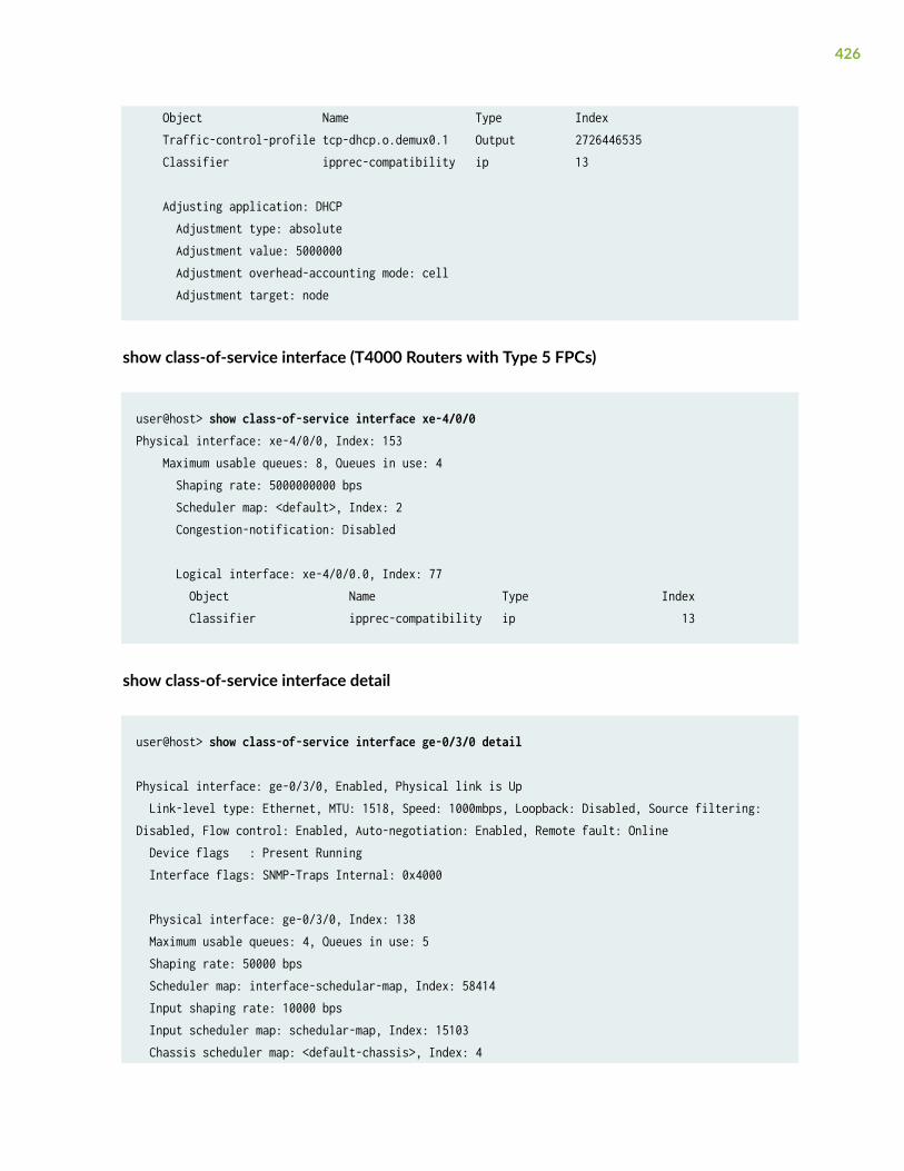
Object Name Type Index Traffic-control-profile tcp-dhcp.o.demux0.1 Output 2726446535 Classifier ipprec-compatibility ip 13 Adjusting application: DHCP Adjustment type: absolute Adjustment value: 5000000 Adjustment overhead-accounting mode: cell Adjustment target: node
show class-of-service interface (T4000 Routers with Type 5 FPCs)
user@host> show class-of-service interface xe-4/0/0 Physical interface: xe-4/0/0, Index: 153 Maximum usable queues: 8, Queues in use: 4 Shaping rate: 5000000000 bps Scheduler map: <default>, Index: 2 Congestion-notification: Disabled Logical interface: xe-4/0/0.0, Index: 77 Object Name Type Index Classifier ipprec-compatibility ip 13
show class-of-service interface detail
user@host> show class-of-service interface ge-0/3/0 detail
Physical interface: ge-0/3/0, Enabled, Physical link is Up Link-level type: Ethernet, MTU: 1518, Speed: 1000mbps, Loopback: Disabled, Source filtering: Disabled, Flow control: Enabled, Auto-negotiation: Enabled, Remote fault: Online Device flags : Present Running Interface flags: SNMP-Traps Internal: 0x4000
Physical interface: ge-0/3/0, Index: 138 Maximum usable queues: 4, Queues in use: 5 Shaping rate: 50000 bps Scheduler map: interface-schedular-map, Index: 58414 Input shaping rate: 10000 bps Input scheduler map: schedular-map, Index: 15103 Chassis scheduler map: <default-chassis>, Index: 4
426

Congestion-notification: Disabled
Logical interface ge-0/3/0.0 Flags: SNMP-Traps 0x4000 VLAN-Tag [ 0x8100.1 ] Encapsulation: ENET2 inet mplsInterface Admin Link Proto Input Filter Output Filter ge-0/3/0.0 up up inet mplsInterface Admin Link Proto Input Policer Output Policerge-0/3/0.0 up up inet mpls Logical interface: ge-0/3/0.0, Index: 68 Object Name Type Index Rewrite exp-default exp (mpls-any) 33 Classifier exp-default exp 10 Classifier ipprec-compatibility ip 13
Logical interface ge-0/3/0.1 Flags: SNMP-Traps 0x4000 VLAN-Tag [ 0x8100.2 ] Encapsulation: ENET2 inetInterface Admin Link Proto Input Filter Output Filterge-0/3/0.1 up up inetInterface Admin Link Proto Input Policer Output Policerge-0/3/0.1 up up inet Logical interface: ge-0/3/0.1, Index: 69 Object Name Type Index Classifier ipprec-compatibility ip 13
show class-of-service interface comprehensive
user@host> show class-of-service interface ge-0/3/0 comprehensivePhysical interface: ge-0/3/0, Enabled, Physical link is Up Interface index: 138, SNMP ifIndex: 601, Generation: 141 Link-level type: Ethernet, MTU: 1518, Speed: 1000mbps, BPDU Error: None, MAC-REWRITE Error: None, Loopback: Disabled, Source filtering: Disabled, Flow control: Enabled, Auto-negotiation: Enabled, Remote fault: Online Device flags : Present Running
427

Interface flags: SNMP-Traps Internal: 0x4000 CoS queues : 4 supported, 4 maximum usable queues Schedulers : 256 Hold-times : Up 0 ms, Down 0 ms Current address: 00:14:f6:f4:b4:5d, Hardware address: 00:14:f6:f4:b4:5d Last flapped : 2010-09-07 06:35:22 PDT (15:14:42 ago) Statistics last cleared: Never Exclude Overhead Bytes: Disabled Traffic statistics: Input bytes : 0 0 bps Output bytes : 0 0 bps Input packets: 0 0 pps Output packets: 0 0 pps IPv6 total statistics: Input bytes : 0 Output bytes : 0 Input packets: 0 Output packets: 0 Ingress traffic statistics at Packet Forwarding Engine: Input bytes : 0 0 bps Input packets: 0 0 pps Drop bytes : 0 0 bps Drop packets: 0 0 pps Label-switched interface (LSI) traffic statistics: Input bytes : 0 0 bps Input packets: 0 0 pps Input errors: Errors: 0, Drops: 0, Framing errors: 0, Runts: 0, Policed discards: 0, L3 incompletes: 0, L2 channel errors: 0, L2 mismatch timeouts: 0, FIFO errors: 0, Resource errors: 0 Output errors: Carrier transitions: 5, Errors: 0, Drops: 0, Collisions: 0, Aged packets: 0, FIFO errors: 0, HS link CRC errors: 0, MTU errors: 0, Resource errors: 0 Ingress queues: 4 supported, 5 in use Queue counters: Queued packets Transmitted packets Dropped packets 0 af3 0 0 0 1 af2 0 0 0 2 ef2 0 0 0 3 ef1 0 0 0 Egress queues: 4 supported, 5 in use Queue counters: Queued packets Transmitted packets Dropped packets 0 af3 0 0 0 1 af2 0 0 0 2 ef2 0 0 0 3 ef1 0 0 0
428

Active alarms : None Active defects : None MAC statistics: Receive Transmit Total octets 0 0 Total packets 0 0 Unicast packets 0 0 Broadcast packets 0 0 Multicast packets 0 0 CRC/Align errors 0 0 FIFO errors 0 0 MAC control frames 0 0 MAC pause frames 0 0 Oversized frames 0 Jabber frames 0 Fragment frames 0 VLAN tagged frames 0 Code violations 0 Filter statistics: Input packet count 0 Input packet rejects 0 Input DA rejects 0 Input SA rejects 0 Output packet count 0 Output packet pad count 0 Output packet error count 0 CAM destination filters: 0, CAM source filters: 0 Autonegotiation information: Negotiation status: Complete Link partner: Link mode: Full-duplex, Flow control: Symmetric/Asymmetric, Remote fault: OK Local resolution: Flow control: Symmetric, Remote fault: Link OK Packet Forwarding Engine configuration: Destination slot: 0 CoS information: Direction : Output CoS transmit queue Bandwidth Buffer Priority Limit % bps % usec 2 ef2 39 19500 0 120 high none Direction : Input CoS transmit queue Bandwidth Buffer Priority Limit % bps % usec 0 af3 30 3000 45 0 low none
429

Physical interface: ge-0/3/0, Enabled, Physical link is Up Interface index: 138, SNMP ifIndex: 601Forwarding classes: 16 supported, 5 in useIngress queues: 4 supported, 5 in useQueue: 0, Forwarding classes: af3 Queued: Packets : 0 0 pps Bytes : 0 0 bps Transmitted: Packets : 0 0 pps Bytes : 0 0 bps Tail-dropped packets : Not Available RED-dropped packets : 0 0 pps RED-dropped bytes : 0 0 bpsQueue: 1, Forwarding classes: af2 Queued: Packets : 0 0 pps Bytes : 0 0 bps Transmitted: Packets : 0 0 pps Bytes : 0 0 bps Tail-dropped packets : Not Available RED-dropped packets : 0 0 pps RED-dropped bytes : 0 0 bpsQueue: 2, Forwarding classes: ef2 Queued: Packets : 0 0 pps Bytes : 0 0 bps Transmitted: Packets : 0 0 pps Bytes : 0 0 bps Tail-dropped packets : Not Available RED-dropped packets : 0 0 pps RED-dropped bytes : 0 0 bpsQueue: 3, Forwarding classes: ef1 Queued: Packets : 0 0 pps Bytes : 0 0 bps Transmitted: Packets : 0 0 pps Bytes : 0 0 bps Tail-dropped packets : Not Available
430

RED-dropped packets : 0 0 pps RED-dropped bytes : 0 0 bpsForwarding classes: 16 supported, 5 in useEgress queues: 4 supported, 5 in useQueue: 0, Forwarding classes: af3 Queued: Packets : 0 0 pps Bytes : 0 0 bps Transmitted: Packets : 0 0 pps Bytes : 0 0 bps Tail-dropped packets : Not Available RL-dropped packets : 0 0 pps RL-dropped bytes : 0 0 bps RED-dropped packets : 0 0 pps RED-dropped bytes : 0 0 bpsQueue: 1, Forwarding classes: af2 Queued: Packets : 0 0 pps Bytes : 0 0 bps Transmitted: Packets : 0 0 pps Bytes : 0 0 bps Tail-dropped packets : Not Available RL-dropped packets : 0 0 pps RL-dropped bytes : 0 0 bps RED-dropped packets : 0 0 pps RED-dropped bytes : 0 0 bpsQueue: 2, Forwarding classes: ef2 Queued: Packets : 0 0 pps Bytes : 0 0 bps Transmitted: Packets : 0 0 pps Bytes : 0 0 bps Tail-dropped packets : Not Available RL-dropped packets : 0 0 pps RL-dropped bytes : 0 0 bps RED-dropped packets : 0 0 pps RED-dropped bytes : 0 0 bpsQueue: 3, Forwarding classes: ef1 Queued: Packets : 0 0 pps
431

Bytes : 0 0 bps Transmitted: Packets : 0 0 pps Bytes : 0 0 bps Tail-dropped packets : Not Available RL-dropped packets : 0 0 pps RL-dropped bytes : 0 0 bps RED-dropped packets : 0 0 pps RED-dropped bytes : 0 0 bps
Packet Forwarding Engine Chassis Queues:Queues: 4 supported, 5 in useQueue: 0, Forwarding classes: af3 Queued: Packets : 0 0 pps Bytes : 0 0 bps Transmitted: Packets : 0 0 pps Bytes : 0 0 bps Tail-dropped packets : 0 0 pps RED-dropped packets : Not Available RED-dropped bytes : Not AvailableQueue: 1, Forwarding classes: af2 Queued: Packets : 0 0 pps Bytes : 0 0 bps Transmitted: Packets : 0 0 pps Bytes : 0 0 bps Tail-dropped packets : 0 0 pps RED-dropped packets : Not Available RED-dropped bytes : Not AvailableQueue: 2, Forwarding classes: ef2 Queued: Packets : 0 0 pps Bytes : 0 0 bps Transmitted: Packets : 0 0 pps Bytes : 0 0 bps Tail-dropped packets : 0 0 pps RED-dropped packets : Not Available RED-dropped bytes : Not AvailableQueue: 3, Forwarding classes: ef1
432

Queued: Packets : 108546 0 pps Bytes : 12754752 376 bps Transmitted: Packets : 108546 0 pps Bytes : 12754752 376 bps Tail-dropped packets : 0 0 pps RED-dropped packets : Not Available RED-dropped bytes : Not Available
Physical interface: ge-0/3/0, Index: 138Maximum usable queues: 4, Queues in use: 5 Shaping rate: 50000 bps
Scheduler map: interface-schedular-map, Index: 58414
Scheduler: ef2, Forwarding class: ef2, Index: 39155 Transmit rate: 39 percent, Rate Limit: none, Buffer size: 120 us, Buffer Limit: none, Priority: high Excess Priority: unspecified Drop profiles: Loss priority Protocol Index Name Low any 1 < default-drop-profile> Medium low any 1 < default-drop-profile> Medium high any 1 < default-drop-profile> High any 1 < default-drop-profile>Drop profile: < default-drop-profile>, Type: discrete, Index: 1 Fill level Drop probability 100 100Drop profile: < default-drop-profile>, Type: discrete, Index: 1 Fill level Drop probability 100 100Drop profile: < default-drop-profile>, Type: discrete, Index: 1 Fill level Drop probability 100 100Drop profile: < default-drop-profile>, Type: discrete, Index: 1 Fill level Drop probability 100 100 Input shaping rate: 10000 bps Input scheduler map: schedular-map
Scheduler map: schedular-map, Index: 15103
433

Scheduler: af3, Forwarding class: af3, Index: 35058 Transmit rate: 30 percent, Rate Limit: none, Buffer size: 45 percent, Buffer Limit: none, Priority: low Excess Priority: unspecified Drop profiles: Loss priority Protocol Index Name Low any 40582 green Medium low any 1 < default-drop-profile> Medium high any 1 < default-drop-profile> High any 18928 yellowDrop profile: green, Type: discrete, Index: 40582 Fill level Drop probability 50 0 100 100Drop profile: < default-drop-profile>, Type: discrete, Index: 1 Fill level Drop probability 100 100Drop profile: < default-drop-profile>, Type: discrete, Index: 1 Fill level Drop probability 100 100Drop profile: yellow, Type: discrete, Index: 18928 Fill level Drop probability 50 0 100 100 Chassis scheduler map: < default-drop-profile>Scheduler map: < default-drop-profile>, Index: 4
Scheduler: < default-drop-profile>, Forwarding class: af3, Index: 25 Transmit rate: 25 percent, Rate Limit: none, Buffer size: 25 percent, Buffer Limit: none, Priority: low Excess Priority: low Drop profiles: Loss priority Protocol Index Name Low any 1 < default-drop-profile> Medium low any 1 < default-drop-profile> Medium high any 1 < default-drop-profile> High any 1 < default-drop-profile>Drop profile: < default-drop-profile>, Type: discrete, Index: 1 Fill level Drop probability 100 100Drop profile: < default-drop-profile>, Type: discrete, Index: 1 Fill level Drop probability 100 100
434

Drop profile: < default-drop-profile>, Type: discrete, Index: 1 Fill level Drop probability 100 100Drop profile: < default-drop-profile>, Type: discrete, Index: 1 Fill level Drop probability 100 100
Scheduler: < default-drop-profile>, Forwarding class: af2, Index: 25 Transmit rate: 25 percent, Rate Limit: none, Buffer size: 25 percent, Buffer Limit: none, Priority: low Excess Priority: low Drop profiles: Loss priority Protocol Index Name Low any 1 < default-drop-profile> Medium low any 1 < default-drop-profile> Medium high any 1 < default-drop-profile> High any 1 < default-drop-profile>Drop profile: < default-drop-profile>, Type: discrete, Index: 1 Fill level Drop probability 100 100Drop profile: < default-drop-profile>, Type: discrete, Index: 1 Fill level Drop probability 100 100Drop profile: < default-drop-profile>, Type: discrete, Index: 1 Fill level Drop probability 100 100Drop profile: < default-drop-profile>, Type: discrete, Index: 1 Fill level Drop probability 100 100
Scheduler: < default-drop-profile>, Forwarding class: ef2, Index: 25 Transmit rate: 25 percent, Rate Limit: none, Buffer size: 25 percent, Buffer Limit: none, Priority: low Excess Priority: low Drop profiles: Loss priority Protocol Index Name Low any 1 < default-drop-profile> Medium low any 1 < default-drop-profile> Medium high any 1 < default-drop-profile> High any 1 < default-drop-profile>Drop profile: < default-drop-profile>, Type: discrete, Index: 1 Fill level Drop probability 100 100
435

Drop profile: < default-drop-profile>, Type: discrete, Index: 1 Fill level Drop probability 100 100Drop profile: < default-drop-profile>, Type: discrete, Index: 1 Fill level Drop probability 100 100Drop profile: < default-drop-profile>, Type: discrete, Index: 1 Fill level Drop probability 100 100
Scheduler: < default-drop-profile>, Forwarding class: ef1, Index: 25 Transmit rate: 25 percent, Rate Limit: none, Buffer size: 25 percent, Buffer Limit: none, Priority: low Excess Priority: low Drop profiles: Loss priority Protocol Index Name Low any 1 < default-drop-profile> Medium low any 1 < default-drop-profile> Medium high any 1 < default-drop-profile> High any 1 < default-drop-profile>Drop profile: , Type: discrete, Index: 1 Fill level Drop probability 100 100Drop profile: < default-drop-profile>, Type: discrete, Index: 1 Fill level Drop probability 100 100Drop profile: < default-drop-profile>, Type: discrete, Index: 1 Fill level Drop probability 100 100Drop profile: < default-drop-profile>, Type: discrete, Index: 1 Fill level Drop probability 100 100 Congestion-notification: DisabledForwarding class ID Queue Restricted queue Fabric priority Policing priority af3 0 0 0 low normal af2 1 1 1 low normal ef2 2 2 2 high normal ef1 3 3 3 high normal
436

af1 4 4 0 low normal
Logical interface ge-0/3/0.0 (Index 68) (SNMP ifIndex 152) (Generation 159) Flags: SNMP-Traps 0x4000 VLAN-Tag [ 0x8100.1 ] Encapsulation: ENET2 Traffic statistics: Input bytes : 0 Output bytes : 0 Input packets: 0 Output packets: 0 Local statistics: Input bytes : 0 Output bytes : 0 Input packets: 0 Output packets: 0 Transit statistics: Input bytes : 0 0 bps Output bytes : 0 0 bps Input packets: 0 0 pps Output packets: 0 0 pps Protocol inet, MTU: 1500, Generation: 172, Route table: 0 Flags: Sendbcast-pkt-to-re Input Filters: filter-in-ge-0/3/0.0-i, Policer: Input: p1-ge-0/3/0.0-inet-i Protocol mpls, MTU: 1488, Maximum labels: 3, Generation: 173, Route table: 0 Flags: Is-Primary Output Filters: exp-filter,,,,,
Logical interface ge-1/2/0.0 (Index 347) (SNMP ifIndex 638) (Generation 156) Forwarding class ID Queue Restricted queue Fabric priority Policing priority SPU prioritybest-effort 0 0 0 low normal low
Aggregate Forwarding-class statistics per forwarding-class Aggregate Forwarding-class statistics: Forwarding-class statistics:
Forwarding-class best-effort statistics: Input unicast bytes: 0 Output unicast bytes: 0 Input unicast packets: 0 Output unicast packets: 0
Input multicast bytes: 0
437

Output multicast bytes: 0 Input multicast packets: 0 Output multicast packets: 0
Forwarding-class expedited-forwarding statistics: Input unicast bytes: 0 Output unicast bytes: 0 Input unicast packets: 0 Output unicast packets: 0
Input multicast bytes: 0 Output multicast bytes: 0 Input multicast packets: 0 Output multicast packets: 0
IPv4 protocol forwarding-class statistics: Forwarding-class statistics: Forwarding-class best-effort statistics:
Input unicast bytes: 0 Output unicast bytes: 0 Input unicast packets: 0 Output unicast packets: 0
Input multicast bytes: 0 Output multicast bytes: 0 Input multicast packets: 0 Output multicast packets: 0
Forwarding-class expedited-forwarding statistics: Input unicast bytes: 0 Output unicast bytes: 0 Input unicast packets: 0 Output unicast packets: 0
Input multicast bytes: 0 Output multicast bytes: 0 Input multicast packets: 0 Output multicast packets: 0
IPv6 protocol forwarding-class statistics: Forwarding-class statistics: Forwarding-class best-effort statistics:
438

Input unicast bytes: 0 Output unicast bytes: 0 Input unicast packets: 0 Output unicast packets: 0
Input multicast bytes: 0 Output multicast bytes: 0 Input multicast packets: 0 Output multicast packets: 0
Forwarding-class expedited-forwarding statistics: Input unicast bytes: 0 Output unicast bytes: 0 Input unicast packets: 0 Output unicast packets: 0
Input multicast bytes: 0 Output multicast bytes: 0 Input multicast packets: 0 Output multicast packets: 0
Logical interface ge-0/3/0.0 (Index 68) (SNMP ifIndex 152) Flags: SNMP-Traps 0x4000 VLAN-Tag [ 0x8100.1 ] Encapsulation: ENET2 Input packets : 0 Output packets: 0
Interface Admin Link Proto Input Filter Output Filterge-0/3/0.0 up up inet filter-in-ge-0/3/0.0-i mpls exp-filterInterface Admin Link Proto Input Policer Output Policerge-0/3/0.0 up up inet p1-ge-0/3/0.0-inet-i mpls
Filter: filter-in-ge-0/3/0.0-iCounters:Name Bytes Packetscount-filter-in-ge-0/3/0.0-i 0 0
Filter: exp-filterCounters:Name Bytes Packets
439

count-exp-seven-match 0 0count-exp-zero-match 0 0Policers:Name Packetsp1-ge-0/3/0.0-inet-i 0
Logical interface: ge-0/3/0.0, Index: 68 Object Name Type Index Rewrite exp-default exp (mpls-any) 33
Rewrite rule: exp-default, Code point type: exp, Index: 33 Forwarding class Loss priority Code point af3 low 000 af3 high 001 af2 low 010 af2 high 011 ef2 low 100 ef2 high 101 ef1 low 110 ef1 high 111 Object Name Type Index Classifier exp-default exp 10
Classifier: exp-default, Code point type: exp, Index: 10 Code point Forwarding class Loss priority 000 af3 low 001 af3 high 010 af2 low 011 af2 high 100 ef2 low 101 ef2 high 110 ef1 low 111 ef1 high Object Name Type Index Classifier ipprec-compatibility ip 13
Classifier: ipprec-compatibility, Code point type: inet-precedence, Index: 13 Code point Forwarding class Loss priority 000 af3 low 001 af3 high 010 af3 low 011 af3 high
440

100 af3 low 101 af3 high 110 ef1 low 111 ef1 highForwarding class ID Queue Restricted queue Fabric priority Policing priority af3 0 0 0 low normal af2 1 1 1 low normal ef2 2 2 2 high normal ef1 3 3 3 high normal af1 4 4 0 low normal
Logical interface ge-0/3/0.1 (Index 69) (SNMP ifIndex 154) (Generation 160) Flags: SNMP-Traps 0x4000 VLAN-Tag [ 0x8100.2 ] Encapsulation: ENET2 Traffic statistics: Input bytes : 0 Output bytes : 0 Input packets: 0 Output packets: 0 Local statistics: Input bytes : 0 Output bytes : 0 Input packets: 0 Output packets: 0 Transit statistics: Input bytes : 0 0 bps Output bytes : 0 0 bps Input packets: 0 0 pps Output packets: 0 0 pps Protocol inet, MTU: 1500, Generation: 174, Route table: 0 Flags: Sendbcast-pkt-to-re
Logical interface ge-0/3/0.1 (Index 69) (SNMP ifIndex 154) Flags: SNMP-Traps 0x4000 VLAN-Tag [ 0x8100.2 ] Encapsulation: ENET2 Input packets : 0 Output packets: 0
441

Interface Admin Link Proto Input Filter Output Filterge-0/3/0.1 up up mpls Interface Admin Link Proto Input Policer Output Policerge-0/3/0.1 up up mpls
Logical interface: ge-0/3/0.1, Index: 69 Object Name Type Index Classifier ipprec-compatibility ip 13
Classifier: ipprec-compatibility, Code point type: inet-precedence, Index: 13 Code point Forwarding class Loss priority 000 af3 low 001 af3 high 010 af3 low 011 af3 high 100 af3 low 101 af3 high 110 ef1 low 111 ef1 highForwarding class ID Queue Restricted queue Fabric priority Policing priority af3 0 0 0 low normal af2 1 1 1 low normal ef2 2 2 2 high normal ef1 3 3 3 high normal af1 4 4 0 low normal
show class-of-service interface (ACX Series Routers)
user@host-g11# show class-of-service interfacePhysical interface: at-0/0/0, Index: 130Maximum usable queues: 4, Queues in use: 4 Scheduler map: <default>, Index: 2
442

Congestion-notification: Disabled
Logical interface: at-0/0/0.0, Index: 69
Logical interface: at-0/0/0.32767, Index: 70
Physical interface: at-0/0/1, Index: 133Maximum usable queues: 4, Queues in use: 4 Scheduler map: <default>, Index: 2 Congestion-notification: Disabled
Logical interface: at-0/0/1.0, Index: 71
Logical interface: at-0/0/1.32767, Index: 72
Physical interface: ge-0/1/0, Index: 146Maximum usable queues: 8, Queues in use: 5 Scheduler map: <default>, Index: 2 Congestion-notification: DisabledObject Name Type IndexRewrite dscp-default dscp 31Classifier d1 dscp 11331Classifier ci ieee8021p 583
Logical interface: ge-0/1/0.0, Index: 73Object Name Type IndexRewrite custom-exp exp (mpls-any) 46413
Logical interface: ge-0/1/0.1, Index: 74
Logical interface: ge-0/1/0.32767, Index: 75
Physical interface: ge-0/1/1, Index: 147Maximum usable queues: 8, Queues in use: 5 Scheduler map: <default>, Index: 2 Congestion-notification: DisabledObject Name Type IndexClassifier ipprec-compatibility ip 13
Logical interface: ge-0/1/1.0, Index: 76
Physical interface: ge-0/1/2, Index: 148Maximum usable queues: 8, Queues in use: 5
443

Scheduler map: <default>, Index: 2 Congestion-notification: DisabledObject Name Type IndexRewrite ri ieee8021p (outer) 35392Classifier ci ieee8021p 583
Physical interface: ge-0/1/3, Index: 149Maximum usable queues: 8, Queues in use: 5 Scheduler map: <default>, Index: 2 Congestion-notification: DisabledObject Name Type IndexClassifier ipprec-compatibility ip 13
Logical interface: ge-0/1/3.0, Index: 77Object Name Type IndexRewrite custom-exp2 exp (mpls-any) 53581
Physical interface: ge-0/1/4, Index: 150Maximum usable queues: 8, Queues in use: 5 Scheduler map: <default>, Index: 2 Congestion-notification: DisabledObject Name Type IndexClassifier ipprec-compatibility ip 13
Physical interface: ge-0/1/5, Index: 151Maximum usable queues: 8, Queues in use: 5 Scheduler map: <default>, Index: 2 Congestion-notification: DisabledObject Name Type IndexClassifier ipprec-compatibility ip 13
Physical interface: ge-0/1/6, Index: 152Maximum usable queues: 8, Queues in use: 5 Scheduler map: <default>, Index: 2 Congestion-notification: DisabledObject Name Type IndexClassifier ipprec-compatibility ip 13
Physical interface: ge-0/1/7, Index: 153Maximum usable queues: 8, Queues in use: 5 Scheduler map: <default>, Index: 2 Congestion-notification: DisabledObject Name Type Index
444

Classifier d1 dscp 11331
Physical interface: ge-0/2/0, Index: 154Maximum usable queues: 8, Queues in use: 5 Scheduler map: <default>, Index: 2 Congestion-notification: DisabledObject Name Type IndexClassifier ipprec-compatibility ip 13
Physical interface: ge-0/2/1, Index: 155Maximum usable queues: 8, Queues in use: 5 Scheduler map: <default>, Index: 2 Congestion-notification: DisabledObject Name Type IndexClassifier ipprec-compatibility ip 13
Logical interface: ge-0/2/1.0, Index: 78
Logical interface: ge-0/2/1.32767, Index: 79
Physical interface: xe-0/3/0, Index: 156Maximum usable queues: 8, Queues in use: 5 Scheduler map: <default>, Index: 2 Congestion-notification: DisabledObject Name Type IndexClassifier ipprec-compatibility ip 13
Logical interface: xe-0/3/0.0, Index: 80
Physical interface: xe-0/3/1, Index: 157Maximum usable queues: 8, Queues in use: 5 Scheduler map: <default>, Index: 2 Congestion-notification: DisabledObject Name Type IndexClassifier ipprec-compatibility ip 13
Logical interface: xe-0/3/1.0, Index: 81
[edit]user@host-g11#
445

show class-of-service interface (PPPoE Subscriber Interface for Enhanced SubscriberManagement)
user@host> show class-of-service interface pp0.3221225474 Logical interface: pp0.3221225475, Index: 3221225475Object Name Type IndexTraffic-control-profile TC_PROF_100_199_SERIES_UID1006 Output 4294967312Scheduler-map SMAP-1_UID1002 Output 4294967327Rewrite-Output ieee-rewrite ieee8021p 60432Rewrite-Output rule1 ip 50463
Adjusting application: PPPoE IA tags Adjustment type: absolute Configured shaping rate: 11000000 Adjustment value: 5000000 Adjustment target: node
Adjusting application: ucac Adjustment type: delta Configured shaping rate: 5000000 Adjustment value: 100000 Adjustment target: node
Release Information
Command introduced before Junos OS Release 7.4.
Forwarding class map information added in Junos OS Release 9.4.
Options detail and comprehensive introduced in Junos OS Release 11.4.
RELATED DOCUMENTATION
Verifying and Managing Junos OS Enhanced Subscriber Management
446

show class-of-service rewrite-rule
IN THIS SECTION
Syntax | 447
Description | 447
Options | 447
Required Privilege Level | 448
Output Fields | 448
Sample Output | 449
Release Information | 449
Syntax
show class-of-service rewrite-rule<name name> <type type>
Description
Display the mapping of forwarding classes and loss priority to code point values.
Options
none Display all rewrite rules.
namename
(Optional) Display the specified rewrite rule.
type type (Optional) Display the rewrite rule of the specified type. The rewrite rule type can be oneof the following:
• dscp—For IPv4 traffic.
• dscp-ipv6—For IPv6 traffic.
447

• exp—For MPLS traffic.
• frame-relay-de—(SRX Series only) For Frame Relay traffic.
• ieee-802.1—For Layer 2 traffic.
• inet-precedence—For IPv4 traffic.
Required Privilege Level
view
Output Fields
Table 68 on page 448 describes the output fields for the show class-of-service rewrite-rule command.Output fields are listed in the approximate order in which they appear.
Table 68: show class-of-service rewrite-rule Output Fields
Field Name Field Description
Rewrite rule Name of the rewrite rule.
Code point type Type of rewrite rule: dscp, dscp-ipv6, exp, frame-relay-de, or inet-precedence.
Forwarding class Classification of a packet affecting the forwarding, scheduling, and markingpolicies applied as the packet transits the router or switch.
Index Internal index for this particular rewrite rule.
Loss priority Loss priority for rewriting.
Code point Code point value to rewrite.
448

Sample Output
show class-of-service rewrite-rule type dscp
user@host> show class-of-service rewrite-rule type dscp Rewrite rule: dscp-default, Code point type: dscp Forwarding class Loss priority Code point gold high 000000 silver low 110000 silver high 111000 bronze low 001010 bronze high 001100 lead high 101110
Rewrite rule: abc-dscp-rewrite, Code point type: dscp, Index: 3245Forwarding class Loss priority Code point gold low 000111 gold high 001010 silver low 110000 silver high 111000 bronze high 001100 lead low 101110 lead high 110111
Release Information
Command introduced before Junos OS Release 7.4.
RELATED DOCUMENTATION
Rewrite Rules Overview
449

CHAPTER 9
Operational Commands (Scheduling)
IN THIS CHAPTER
Monitoring CoS Scheduler Maps | 450
show class-of-service drop-profile | 452
show class-of-service forwarding-table | 457
show class-of-service forwarding-table drop-profile | 462
show class-of-service forwarding-table scheduler-map | 464
show class-of-service interface | 468
show class-of-service scheduler-map | 513
show interfaces queue | 517
show interfaces voq | 575
Monitoring CoS Scheduler Maps
IN THIS SECTION
Purpose | 450
Action | 451
Meaning | 451
Purpose
Use the monitoring functionality to display assignments of CoS forwarding classes to schedulers.
450

Action
To monitor CoS scheduler maps in the CLI, enter the CLI command:
user@switch> show class-of-service scheduler-map
To monitor a specific scheduler map in the CLI, enter the CLI command:
user@switch> show class-of-service scheduler-map scheduler-map-name
Meaning
Table 69 on page 451 summarizes key output fields for CoS scheduler maps.
Table 69: Summary of Key CoS Scheduler Maps Output Fields
Field Values
Scheduler map Name of a scheduler map that maps forwarding classes toschedulers.
Index Index of a specific object—scheduler maps, schedulers, or dropprofiles.
Scheduler Name of a scheduler that controls queue properties such asbandwidth and scheduling priority.
Forwarding class Name(s) of the forwarding class(es) to which the scheduler ismapped.
Transmit rate Guaranteed minimum bandwidth configured on the queue mappedto the scheduler. On strict-high priority queues on QFX10000switches, defines the maximum amount of traffic on the queue thatis treated as strict-high priority traffic.
451

Table 69: Summary of Key CoS Scheduler Maps Output Fields (Continued)
Field Values
Priority Scheduling priority of traffic on a queue:
• strict-high or high—Packets on a strict-high priority queue aretransmitted first, before all other traffic, up to the configuredmaximum bandwidth (shaping rate). On QFX3500, QFX3600,EX4600, and OCX series switches, and on QFabric system, onlyone queue can be configured as strict-high or high priority. OnQFX10000 switches, you can configure more than one strict-highpriority queue.
• low—Packets in this queue are transmitted after packets in thestrict-high queue.
Drop Profiles Name and index of a drop profile that is mapped to a specific losspriority and protocol pair. The drop profile determines the way besteffort queues drop packets during periods of congestion.
Loss Priority Packet loss priority mapped to the drop profile. You can configuredifferent drop profiles for low, medium-high, and high loss prioritytraffic.
Protocol Transport protocol of the drop profile for the particular priority.
Name Name of the drop profile.
show class-of-service drop-profile
IN THIS SECTION
Syntax | 453
Description | 453
Options | 453
452

Required Privilege Level | 453
Output Fields | 453
Sample Output | 454
Release Information | 457
Syntax
show class-of-service drop-profile <profile-name profile-name>
Description
Display data points for each class-of-service (CoS) random early detection (RED) drop profile.
Options
none Display all drop profiles.
profile-name profile-name (Optional) Display the specified profile only.
Required Privilege Level
view
Output Fields
Table 70 on page 453 describes the output fields for the show class-of-service drop-profile command.Output fields are listed in the approximate order in which they appear.
Table 70: show class-of-service drop-profile Output Fields
Field Name Field Description
Drop profile Name of a drop profile.
453

Table 70: show class-of-service drop-profile Output Fields (Continued)
Field Name Field Description
Type Type of drop profile:
• discrete (default)
• interpolated (EX8200 switches, QFX Series switches, QFabric systems,EX4600 switches, OCX Series switches only)
Index Internal index of this drop profile.
Fill Level Percentage fullness of a queue.
Drop probability Drop probability at this fill level.
Sample Output
show class-of-service drop-profile
user@host> show class-of-service drop-profile Drop profile: <default-drop-profile>, Type: discrete, Index: 1 Fill level Drop probability 100 100Drop profile: user-drop-profile, Type: interpolated, Index: 2989 Fill level Drop probability 0 0 1 1 2 2 4 4 5 5 6 6 8 8 10 10 12 15 14 20 15 23 ... 64 entries total
454

90 96 92 96 94 97 95 98 96 98 98 99 99 99 100 100
show class-of-service drop-profile (EX4200 Switch)
user@switch> show class-of-service drop-profileDrop profile: <default-drop-profile>, Type: discrete, Index: 1 Fill level 100Drop profile: dp1, Type: discrete, Index: 40496 Fill level 10
show class-of-service drop-profile (EX8200 Switch)
user@switch> show class-of-service drop-profileDrop profile: <default-drop-profile>, Type: discrete, Index: 1 Fill level Drop probability 100 100Drop profile: dp1, Type: interpolated, Index: 40496 Fill level Drop probability 0 0 1 80 2 90 4 90 5 90 6 90 8 90 10 90 12 91 14 91 15 91 16 91 18 91
455

20 91 22 92 24 92 25 92 26 92 28 92 30 92 32 93 34 93 35 93 36 93 38 93 40 93 42 94 44 94 45 94 46 94 48 94 49 94 51 95 52 95 54 95 55 95 56 95 58 95 60 95 62 96 64 96 65 96 66 96 68 96 70 96 72 97 74 97 75 97 76 97 78 97 80 97 82 98 84 98 85 98 86 98 88 98
456

90 98 92 99 94 99 95 99 96 99 98 99 99 99 100 100Drop profile: dp2, Type: discrete, Index: 40499 Fill level Drop probability 10 5 50 50
Release Information
Command introduced before Junos OS Release 7.4.
show class-of-service forwarding-table
IN THIS SECTION
Syntax | 457
Syntax (TX Matrix and TX Matrix Plus Router) | 458
Description | 458
Options | 458
Required Privilege Level | 458
Output Fields | 458
Sample Output | 459
Release Information | 462
Syntax
show class-of-service forwarding-table
457

Syntax (TX Matrix and TX Matrix Plus Router)
show class-of-service forwarding-table<lcc number> | <sfc number>
Description
Display the entire class-of-service (CoS) configuration as it exists in the forwarding table. Executing thiscommand is equivalent to executing all show class-of-service forwarding-table commands in succession.
Options
lccnumber
(TX Matrix and TX Matrix Plus router only) (Optional) On a TX Matrix router, display theforwarding table configuration for a specific T640 router (or line-card chassis) configured ina routing matrix. On a TX Matrix Plus router, display the forwarding table configuration fora specific router (or line-card chassis) configured in the routing matrix.
Replace number with the following values depending on the LCC configuration:
• 0 through 3, when T640 routers are connected to a TX Matrix router in a routing matrix.
• 0 through 3, when T1600 routers are connected to a TX Matrix Plus router in a routingmatrix.
• 0 through 7, when T1600 routers are connected to a TX Matrix Plus router with 3D SIBsin a routing matrix.
• 0, 2, 4, or 6, when T4000 routers are connected to a TX Matrix Plus router with 3D SIBsin a routing matrix.
sfcnumber
(TX Matrix Plus routers only) (Optional) Display the forwarding table configuration for theTX Matrix Plus router. Replace number with 0.
Required Privilege Level
view
Output Fields
See the output field descriptions for show class-of-service forwarding-table commands:
• show class-of-service forwarding-table classifier
458

• show class-of-service forwarding-table classifier mapping
• show class-of-service forwarding-table drop-profile
• show class-of-service forwarding-table fabric scheduler-map
• show class-of-service forwarding-table rewrite-rule
• show class-of-service forwarding-table rewrite-rule mapping
• show class-of-service forwarding-table scheduler-map
Sample Output
show class-of-service forwarding-table
user@host> show class-of-service forwarding-table Classifier table index: 9, # entries: 8, Table type: EXPEntry # Code point Forwarding-class # PLP 0 000 0 0 1 001 0 1 2 010 1 0 3 011 1 1 4 100 2 0 5 101 2 1 6 110 3 0 7 111 3 1
Table Index/Interface Index Q num Table typesp-0/0/0.1001 66 11 IPv4 precedencesp-0/0/0.2001 67 11 IPv4 precedencesp-0/0/0.16383 68 11 IPv4 precedencefe-0/0/0.0 69 11 IPv4 precedence
Interface: sp-0/0/0 (Index: 129, Map index: 2, Map type: FINAL, Num of queues: 2): Entry 0 (Scheduler index: 16, Forwarding-class #: 0): Tx rate: 0 Kb (95%), Buffer size: 95 percentPriority low PLP high: 1, PLP low: 1, PLP medium-high: 1, PLP medium-low: 1 Entry 1 (Scheduler index: 18, Forwarding-class #: 3): Tx rate: 0 Kb (5%), Buffer size: 5 percent
459

Priority low PLP high: 1, PLP low: 1, PLP medium-high: 1, PLP medium-low: 1
Interface: fe-0/0/0 (Index: 137, Map index: 2, Map type: FINAL, Num of queues: 2): Entry 0 (Scheduler index: 16, Forwarding-class #: 0): Tx rate: 0 Kb (95%), Buffer size: 95 percentPriority low PLP high: 1, PLP low: 1, PLP medium-high: 1, PLP medium-low: 1 Entry 1 (Scheduler index: 18, Forwarding-class #: 3): Tx rate: 0 Kb (5%), Buffer size: 5 percentPriority low PLP high: 1, PLP low: 1, PLP medium-high: 1, PLP medium-low: 1Interface: fe-0/0/1 (Index: 138, Map index: 2, Map type: FINAL, Num of queues: 2): Entry 0 (Scheduler index: 16, Forwarding-class #: 0): Tx rate: 0 Kb (95%), Buffer size: 95 percentPriority low PLP high: 1, PLP low: 1, PLP medium-high: 1, PLP medium-low: 1 Entry 1 (Scheduler index: 18, Forwarding-class #: 3): Tx rate: 0 Kb (5%), Buffer size: 5 percentPriority low PLP high: 1, PLP low: 1, PLP medium-high: 1, PLP medium-low: 1
...
RED drop profile index: 1, # entries: 1 DropEntry Fullness(%) Probability(%) 0 100 100
show class-of-service forwarding-table lcc (TX Matrix Plus Router)
user@host> show class-of-service forwarding-table lcc 0 lcc0-re0:--------------------------------------------------------------------------
Classifier table index: 9, # entries: 64, Table type: IPv6 DSCPEntry # Code point Forwarding-class # PLP 0 000000 0 0 1 000001 0 0
460

2 000010 0 0 3 000011 0 0 4 000100 0 0 5 000101 0 0 6 000110 0 0 7 000111 0 0 8 001000 0 0 9 001001 0 0 10 001010 0 0 11 001011 0 0 12 001100 0 0 13 001101 0 0 14 001110 0 0 15 001111 0 0 16 010000 0 0 17 010001 0 0 18 010010 0 0 19 010011 0 0 20 010100 0 0 21 010101 0 0 22 010110 0 0 23 010111 0 0 24 011000 0 0 25 011001 0 0 26 011010 0 0 27 011011 0 0 28 011100 0 0 29 011101 0 0 30 011110 0 0 31 011111 0 0 32 100000 0 0 33 100001 0 0 34 100010 0 0 35 100011 0 0 36 100100 0 0 37 100101 0 0 38 100110 0 0 39 100111 0 0 40 101000 0 0 41 101001 0 0 42 101010 0 0 43 101011 0 0 44 101100 0 0
461

45 101101 0 0 46 101110 0 0...
Release Information
Command introduced before Junos OS Release 7.4.
show class-of-service forwarding-table drop-profile
IN THIS SECTION
Syntax | 462
Description | 462
Options | 462
Required Privilege Level | 463
Output Fields | 463
Sample Output | 463
Release Information | 464
Syntax
show class-of-service forwarding-table drop-profile
Description
Display the data points of all random early detection (RED) drop profiles as they exist in the forwardingtable.
Options
This command has no options.
462

Required Privilege Level
view
Output Fields
Table 71 on page 463 describes the output fields for the show class-of-service forwarding-table drop-profilecommand. Output fields are listed in the approximate order in which they appear.
Table 71: show class-of-service forwarding-table drop-profile Output Fields
Field Name Field Description
RED drop profile index Index of this drop profile.
# entries Number of entries in a particular RED drop profile index.
Entry Drop profile entry number.
Fullness(%) Percentage fullness of a queue.
Drop probability(%) Drop probability at this fill level.
Sample Output
show class-of-service forwarding-table drop-profile
user@host> show class-of-service forwarding-table drop-profile RED drop profile index: 4, # entries: 1 DropEntry Fullness(%) Probability(%) 0 100 100
RED drop profile index: 8742, # entries: 3 DropEntry Fullness(%) Probability(%) 0 10 10 1 20 20
463

2 30 30
RED drop profile index: 24627, # entries: 64 DropEntry Fullness(%) Probability(%) 0 0 0 1 1 1 2 2 2 3 4 4 ... 61 98 99 62 99 99 63 100 100
RED drop profile index: 25393, # entries: 64 DropEntry Fullness(%) Probability(%) 0 0 0 1 1 1 2 2 2 3 4 4 ... 61 98 98 62 99 99 63 100 100
Release Information
Command introduced before Junos OS Release 7.4.
show class-of-service forwarding-table scheduler-map
IN THIS SECTION
Syntax | 465
Description | 465
Options | 465
464

Required Privilege Level | 465
Output Fields | 465
Sample Output | 467
Release Information | 468
Syntax
show class-of-service forwarding-table scheduler-map
Description
For each physical interface, display the scheduler map information as it exists in the forwarding table.
Options
This command has no options.
Required Privilege Level
view
Output Fields
Table 72 on page 465 describes the output fields for the show class-of-service forwarding-table scheduler-mapcommand. Output fields are listed in the approximate order in which they appear.
Table 72: show class-of-service forwarding-table scheduler-map Output Fields
Field Name Field Description
Interface Name of the physical interface.
Index Physical interface index.
465

Table 72: show class-of-service forwarding-table scheduler-map Output Fields (Continued)
Field Name Field Description
Map index Scheduler map index.
Num of queues Number of queues defined in this scheduler map.
Entry Number of this entry in the scheduler map.
Scheduler index Scheduler policy index.
Forwarding-class # Forwarding class number to which this entry is applied.
Tx rate Configured transmit rate of the scheduler (in bps). The rate is a percentage of the totalinterface bandwidth, or the keyword remainder, which indicates that the scheduler receivesthe remaining bandwidth of the interface.
Max buffer delay Amount of transmit delay (in milliseconds) or buffer size of the queue. This amount is apercentage of the total interface buffer allocation or the keyword remainder, which indicatesthat the buffer is sized according to what remains after other scheduler buffer allocations.
Priority • high—Queue priority is high.
• low—Queue priority is low.
PLP high Drop profile index for a high packet loss priority profile.
PLP low Drop profile index for a low packet loss priority profile.
PLP medium-high Drop profile index for a medium-high packet loss priority profile.
PLP medium-low Drop profile index for a medium-low packet loss priority profile.
TCP PLP high Drop profile index for a high TCP packet loss priority profile.
466

Table 72: show class-of-service forwarding-table scheduler-map Output Fields (Continued)
Field Name Field Description
TCP PLP low Drop profile index for a low TCP packet loss priority profile.
Policy is exact If this line appears in the output, exact rate limiting is enabled. Otherwise, no rate limiting isenabled.
Sample Output
show class-of-service forwarding-table scheduler-map
user@host> show class-of-service forwarding-table scheduler-map Interface: so-5/0/0 (Index: 9, Map index: 17638, Num of queues: 2): Entry 0 (Scheduler index: 6090, Forwarding-class #: 0): Tx rate: 0 Kb (30%), Max buffer delay: 39 bytes (0%) Priority low PLP high: 25393, PLP low: 24627, TCP PLP high: 25393, TCP PLP low:8742 Policy is exact Entry 1 (Scheduler index: 38372, Forwarding-class #: 1): Traffic chunk: Max = 0 bytes, Min = 0 bytes Tx rate: 0 Kb (40%), Max buffer delay: 68 bytes (0%) Priority high PLP high: 25393, PLP low: 24627, TCP PLP high: 25393, TCP PLP low: 8742
Interface: at-6/1/0 (Index: 10, Map index: 17638, Num of queues: 2): Entry 0 (Scheduler index: 6090, Forwarding-class #: 0): Traffic chunk: Max = 0 bytes, Min = 0 bytes Tx rate: 0 Kb (30%), Max buffer delay: 39 bytes (0%) Priority high PLP high: 25393, PLP low: 24627, TCP PLP high: 25393, TCP PLP low: 8742 Entry 1 (Scheduler index: 38372, Forwarding-class #: 1): Traffic chunk: Max = 0 bytes, Min = 0 bytes Tx rate: 0 Kb (40%), Max buffer delay: 68 bytes (0%) Priority low PLP high: 25393, PLP low: 24627, TCP PLP high: 25393, TCP PLP low: 8742
467

Release Information
Command introduced before Junos OS Release 7.4.
show class-of-service interface
IN THIS SECTION
Syntax | 468
Description | 468
Options | 469
Required Privilege Level | 469
Output Fields | 470
Sample Output | 490
Release Information | 512
Syntax
show class-of-service interface <comprehensive | detail> <interface-name>
Description
Display the logical and physical interface associations for the classifier, rewrite rules, and scheduler mapobjects.
NOTE: On routing platforms with dual Routing Engines, running this command on the backupRouting Engine, with or without any of the available options, is not supported and produces thefollowing error message:
error: the class-of-service subsystem is not running
468

Options
none Display CoS associations for all physical and logical interfaces.
comprehensive (M Series, MX Series, and T Series routers) (Optional) Display comprehensive quality-of-service (QoS) information about all physical and logical interfaces.
detail (M Series, MX Series, and T Series routers) (Optional) Display QoS and CoS informationbased on the interface.
If the interfaceinterface-name is a physical interface, the output includes:
• Brief QoS information about the physical interface
• Brief QoS information about the logical interface
• CoS information about the physical interface
• Brief information about filters or policers of the logical interface
• Brief CoS information about the logical interface
If the interfaceinterface-name is a logical interface, the output includes:
• Brief QoS information about the logical interface
• Information about filters or policers for the logical interface
• CoS information about the logical interface
interface-name (Optional) Display class-of-service (CoS) associations for the specified interface.
none Display CoS associations for all physical and logical interfaces.
NOTE: ACX5000 routers do not support classification on logical interfaces and therefore do notshow CoS associations for logical interfaces with this command.
Required Privilege Level
view
469

Output Fields
Table 73 on page 470 describes the output fields for the show class-of-service interface command. Outputfields are listed in the approximate order in which they appear.
Table 73: show class-of-service interface Output Fields
Field Name Field Description
Physical interface Name of a physical interface.
Index Index of this interface or the internal index of this object.
(Enhanced subscriber management for MX Series routers) Index values for dynamic CoStraffic control profiles and dynamic scheduler maps are larger for enhanced subscribermanagement than they are for legacy subscriber management.
Dedicated Queues Status of dedicated queues configured on an interface. Supported only on Trio MPC/MICinterfaces on MX Series routers.
(Enhanced subscriber management for MX-Series routers) This field is not displayed forenhanced subscriber management.
Maximum usablequeues
Number of queues you can configure on the interface.
Maximum usablequeues
Maximum number of queues you can use.
Total non-defaultqueues created
Number of queues created in addition to the default queues. Supported only on TrioMPC/MIC interfaces on MX Series routers.
(Enhanced subscriber management for MX Series routers) This field is not displayed forenhanced subscriber management.
Rewrite Input IEEECode-point
(QFX3500 switches only) IEEE 802.1p code point (priority) rewrite value. Incoming trafficfrom the Fibre Channel (FC) SAN is classified into the forwarding class specified in thenative FC interface (NP_Port) fixed classifier and uses the priority specified as the IEEE802.1p rewrite value.
470

Table 73: show class-of-service interface Output Fields (Continued)
Field Name Field Description
Shaping rate Maximum transmission rate on the physical interface. You can configure the shaping rateon the physical interface, or on the logical interface, but not on both. Therefore, theShaping rate field is displayed for either the physical interface or the logical interface.
Scheduler map Name of the output scheduler map associated with this interface.
(Enhanced subscriber management for MX Series routers) The name of the dynamicscheduler map object is associated with a generated UID (for example, SMAP-1_UID1002)instead of with a subscriber interface.
Scheduler mapforwarding classsets
(QFX Series only) Name of the output fabric scheduler map associated with a QFabricsystem Interconnect device interface.
Input shaping rate For Gigabit Ethernet IQ2 PICs, maximum transmission rate on the input interface.
Input scheduler map For Gigabit Ethernet IQ2 PICs, name of the input scheduler map associated with thisinterface.
Chassis schedulermap
Name of the scheduler map associated with the packet forwarding component queues.
Rewrite Name and type of the rewrite rules associated with this interface.
Traffic-control-profile
Name of the associated traffic control profile.
(Enhanced subscriber management for MX Series routers) The name of the dynamic trafficcontrol profile object is associated with a generated UID (for example,TC_PROF_100_199_SERIES_UID1006) instead of with a subscriber interface.
Classifier Name and type of classifiers associated with this interface.
Forwarding-class-map Name of the forwarding map associated with this interface.
471

Table 73: show class-of-service interface Output Fields (Continued)
Field Name Field Description
Congestion-notification
(QFX Series and EX4600 switches only) Congestion notification state, enabled or disabled.
Logical interface Name of a logical interface.
Object Category of an object: Classifier, Fragmentation-map (for LSQ interfaces only), Scheduler-map, Rewrite, Translation Table (for IQE PICs only), or traffic-class-map (for T4000 routerswith Type 5 FPCs).
Name Name of an object.
Type Type of an object: dscp, dscp-ipv6, exp, ieee-802.1, ip, inet-precedence, or ieee-802.1ad (fortraffic class map on T4000 routers with Type 5 FPCs)..
Link-level type Encapsulation on the physical interface.
MTU MTU size on the physical interface.
Speed Speed at which the interface is running.
Loopback Whether loopback is enabled and the type of loopback.
Source filtering Whether source filtering is enabled or disabled.
Flow control Whether flow control is enabled or disabled.
Auto-negotiation (Gigabit Ethernet interfaces) Whether autonegotiation is enabled or disabled.
472

Table 73: show class-of-service interface Output Fields (Continued)
Field Name Field Description
Remote-fault (Gigabit Ethernet interfaces) Remote fault status.
• Online—Autonegotiation is manually configured as online.
• Offline—Autonegotiation is manually configured as offline.
Device flags The Device flags field provides information about the physical device and displays one ormore of the following values:
• Down—Device has been administratively disabled.
• Hear-Own-Xmit—Device receives its own transmissions.
• Link-Layer-Down—The link-layer protocol has failed to connect with the remoteendpoint.
• Loopback—Device is in physical loopback.
• Loop-Detected—The link layer has received frames that it sent, thereby detecting aphysical loopback.
• No-Carrier—On media that support carrier recognition, no carrier is currently detected.
• No-Multicast—Device does not support multicast traffic.
• Present—Device is physically present and recognized.
• Promiscuous—Device is in promiscuous mode and recognizes frames addressed to allphysical addresses on the media.
• Quench—Transmission on the device is quenched because the output buffer isoverflowing.
• Recv-All-Multicasts—Device is in multicast promiscuous mode and therefore providesno multicast filtering.
• Running—Device is active and enabled.
473

Table 73: show class-of-service interface Output Fields (Continued)
Field Name Field Description
Interface flags The Interface flags field provides information about the physical interface and displaysone or more of the following values:
• Admin-Test—Interface is in test mode and some sanity checking, such as loop detection,is disabled.
• Disabled—Interface is administratively disabled.
• Down—A hardware failure has occurred.
• Hardware-Down—Interface is nonfunctional or incorrectly connected.
• Link-Layer-Down—Interface keepalives have indicated that the link is incomplete.
• No-Multicast—Interface does not support multicast traffic.
• No-receive No-transmit—Passive monitor mode is configured on the interface.
• Point-To-Point—Interface is point-to-point.
• Pop all MPLS labels from packets of depth—MPLS labels are removed as packets arriveon an interface that has the pop-all-labels statement configured. The depth value canbe one of the following:
• 1—Takes effect for incoming packets with one label only.
• 2—Takes effect for incoming packets with two labels only.
• [ 1 2 ]—Takes effect for incoming packets with either one or two labels.
• Promiscuous—Interface is in promiscuous mode and recognizes frames addressed to allphysical addresses.
• Recv-All-Multicasts—Interface is in multicast promiscuous mode and provides nomulticast filtering.
• SNMP-Traps—SNMP trap notifications are enabled.
• Up—Interface is enabled and operational.
474

Table 73: show class-of-service interface Output Fields (Continued)
Field Name Field Description
Flags The Logical interface flags field provides information about the logical interface anddisplays one or more of the following values:
• ACFC Encapsulation—Address control field Compression (ACFC) encapsulation isenabled (negotiated successfully with a peer).
• Device-down—Device has been administratively disabled.
• Disabled—Interface is administratively disabled.
• Down—A hardware failure has occurred.
• Clear-DF-Bit—GRE tunnel or IPsec tunnel is configured to clear the Don't Fragment(DF) bit.
• Hardware-Down—Interface protocol initialization failed to complete successfully.
• PFC—Protocol field compression is enabled for the PPP session.
• Point-To-Point—Interface is point-to-point.
• SNMP-Traps—SNMP trap notifications are enabled.
• Up—Interface is enabled and operational.
Encapsulation Encapsulation on the logical interface.
Admin Administrative state of the interface (Up or Down)
Link Status of physical link (Up or Down).
Proto Protocol configured on the interface.
Input Filter Names of any firewall filters to be evaluated when packets are received on the interface,including any filters attached through activation of dynamic service.
Output Filter Names of any firewall filters to be evaluated when packets are transmitted on theinterface, including any filters attached through activation of dynamic service.
475

Table 73: show class-of-service interface Output Fields (Continued)
Field Name Field Description
Link flags Provides information about the physical link and displays one or more of the followingvalues:
• ACFC—Address control field compression is configured. The Point-to-Point Protocol(PPP) session negotiates the ACFC option.
• Give-Up—Link protocol does not continue connection attempts after repeated failures.
• Loose-LCP—PPP does not use the Link Control Protocol (LCP) to indicate whether thelink protocol is operational.
• Loose-LMI—Frame Relay does not use the Local Management Interface (LMI) to indicatewhether the link protocol is operational.
• Loose-NCP—PPP does not use the Network Control Protocol (NCP) to indicate whetherthe device is operational.
• Keepalives—Link protocol keepalives are enabled.
• No-Keepalives—Link protocol keepalives are disabled.
• PFC—Protocol field compression is configured. The PPP session negotiates the PFCoption.
Hold-times Current interface hold-time up and hold-time down, in milliseconds.
CoS queues Number of CoS queues configured.
Last flapped Date, time, and how long ago the interface went from down to up. The format is Lastflapped: year-month-day hour:minute:second:timezone (hour:minute:second ago). Forexample, Last flapped: 2002-04-26 10:52:40 PDT (04:33:20 ago).
476

Table 73: show class-of-service interface Output Fields (Continued)
Field Name Field Description
Statistics lastcleared
Number and rate of bytes and packets received and transmitted on the physical interface.
• Input bytes—Number of bytes received on the interface.
• Output bytes—Number of bytes transmitted on the interface.
• Input packets—Number of packets received on the interface.
• Output packets—Number of packets transmitted on the interface.
Exclude OverheadBytes
Exclude the counting of overhead bytes from aggregate queue statistics.
• Disabled—Default configuration. Includes the counting of overhead bytes in aggregatequeue statistics.
• Enabled—Excludes the counting of overhead bytes from aggregate queue statistics forjust the physical interface.
• Enabled for hierarchy—Excludes the counting of overhead bytes from aggregate queuestatistics for the physical interface as well as all child interfaces, including logicalinterfaces and interface sets.
IPv6 transitstatistics
Number of IPv6 transit bytes and packets received and transmitted on the logicalinterface if IPv6 statistics tracking is enabled.
477

Table 73: show class-of-service interface Output Fields (Continued)
Field Name Field Description
Input errors Input errors on the interface. The labels are explained in the following list:
• Errors—Sum of the incoming frame terminations and FCS errors.
• Drops—Number of packets dropped by the input queue of the I/O Manager ASIC. If theinterface is saturated, this number increments once for every packet that is droppedby the ASIC's RED mechanism.
• Framing errors—Number of packets received with an invalid frame checksum (FCS).
• Runts—Number of frames received that are smaller than the runt threshold.
• Giants—Number of frames received that are larger than the giant threshold.
• Bucket Drops—Drops resulting from the traffic load exceeding the interface transmit orreceive leaky bucket configuration.
• Policed discards—Number of frames that the incoming packet match code discardedbecause they were not recognized or not of interest. Usually, this field reportsprotocols that Junos OS does not handle.
• L3 incompletes—Number of incoming packets discarded because they failed Layer 3(usually IPv4) sanity checks of the header. For example, a frame with less than20 bytes of available IP header is discarded. Layer 3 incomplete errors can be ignoredby configuring the ignore-l3-incompletes statement.
• L2 channel errors—Number of times the software did not find a valid logical interfacefor an incoming frame.
• L2 mismatch timeouts—Number of malformed or short packets that caused theincoming packet handler to discard the frame as unreadable.
• HS link CRC errors—Number of errors on the high-speed links between the ASICsresponsible for handling the router interfaces.
• HS link FIFO overflows—Number of FIFO overflows on the high-speed links betweenthe ASICs responsible for handling the router interfaces.
478

Table 73: show class-of-service interface Output Fields (Continued)
Field Name Field Description
Output errors Output errors on the interface. The labels are explained in the following list:
• Carrier transitions—Number of times the interface has gone from down to up. Thisnumber does not normally increment quickly, increasing only when the cable isunplugged, the far-end system is powered down and up, or another problem occurs. Ifthe number of carrier transitions increments quickly (perhaps once every 10 seconds),the cable, the far-end system, or the PIC is malfunctioning.
• Errors—Sum of the outgoing frame terminations and FCS errors.
• Drops—Number of packets dropped by the output queue of the I/O Manager ASIC. Ifthe interface is saturated, this number increments once for every packet that isdropped by the ASIC's RED mechanism.
NOTE: Due to accounting space limitations on certain Type 3 FPCs (which aresupported in M320 and T640 routers), the Drops field does not always use the correctvalue for queue 6 or queue 7 for interfaces on 10-port 1-Gigabit Ethernet PICs.
• Aged packets—Number of packets that remained in shared packet SDRAM so long thatthe system automatically purged them. The value in this field should never increment.If it does, it is most likely a software bug or possibly malfunctioning hardware.
• HS link FIFO underflows—Number of FIFO underflows on the high-speed linksbetween the ASICs responsible for handling the router interfaces.
• MTU errors—Number of packets whose size exceeds the MTU of the interface.
Egress queues Total number of egress Maximum usable queues on the specified interface.
Queue counters CoS queue number and its associated user-configured forwarding class name.
• Queued packets—Number of queued packets.
• Transmitted packets—Number of transmitted packets.
• Dropped packets—Number of packets dropped by the ASIC's RED mechanism.
NOTE: Due to accounting space limitations on certain Type 3 FPCs (which aresupported in M320 and T640 routers), the Dropped packets field does not alwaysdisplay the correct value for queue 6 or queue 7 for interfaces on 10-port 1-GigabitEthernet PICs.
479

Table 73: show class-of-service interface Output Fields (Continued)
Field Name Field Description
SONET alarms
SONET defects
(SONET) SONET media-specific alarms and defects that prevent the interface frompassing packets. When a defect persists for a certain period, it is promoted to an alarm.Based on the router configuration, an alarm can ring the red or yellow alarm bell on therouter or light the red or yellow alarm LED on the craft interface. See these fields forpossible alarms and defects: SONET PHY, SONET section, SONET line, and SONET path.
SONET PHY Counts of specific SONET errors with detailed information.
• Seconds—Number of seconds the defect has been active.
• Count—Number of times that the defect has gone from inactive to active.
• State—State of the error. A state other than OK indicates a problem.
The SONET PHY field has the following subfields:
• PLL Lock—Phase-locked loop
• PHY Light—Loss of optical signal
480

Table 73: show class-of-service interface Output Fields (Continued)
Field Name Field Description
SONET section Counts of specific SONET errors with detailed information.
• Seconds—Number of seconds the defect has been active.
• Count—Number of times that the defect has gone from inactive to active.
• State—State of the error. A state other than OK indicates a problem.
The SONET section field has the following subfields:
• BIP-B1—Bit interleaved parity for SONET section overhead
• SEF—Severely errored framing
• LOS—Loss of signal
• LOF—Loss of frame
• ES-S—Errored seconds (section)
• SES-S—Severely errored seconds (section)
• SEFS-S—Severely errored framing seconds (section)
481

Table 73: show class-of-service interface Output Fields (Continued)
Field Name Field Description
SONET line Active alarms and defects, plus counts of specific SONET errors with detailed information.
• Seconds—Number of seconds the defect has been active.
• Count—Number of times that the defect has gone from inactive to active.
• State—State of the error. A state other than OK indicates a problem.
The SONET line field has the following subfields:
• BIP-B2—Bit interleaved parity for SONET line overhead
• REI-L—Remote error indication (near-end line)
• RDI-L—Remote defect indication (near-end line)
• AIS-L—Alarm indication signal (near-end line)
• BERR-SF—Bit error rate fault (signal failure)
• BERR-SD—Bit error rate defect (signal degradation)
• ES-L—Errored seconds (near-end line)
• SES-L—Severely errored seconds (near-end line)
• UAS-L—Unavailable seconds (near-end line)
• ES-LFE—Errored seconds (far-end line)
• SES-LFE—Severely errored seconds (far-end line)
• UAS-LFE—Unavailable seconds (far-end line)
482

Table 73: show class-of-service interface Output Fields (Continued)
Field Name Field Description
SONET path Active alarms and defects, plus counts of specific SONET errors with detailed information.
• Seconds—Number of seconds the defect has been active.
• Count—Number of times that the defect has gone from inactive to active.
• State—State of the error. A state other than OK indicates a problem.
The SONET path field has the following subfields:
• BIP-B3—Bit interleaved parity for SONET section overhead
• REI-P—Remote error indication
• LOP-P—Loss of pointer (path)
• AIS-P—Path alarm indication signal
• RDI-P—Path remote defect indication
• UNEQ-P—Path unequipped
• PLM-P—Path payload (signal) label mismatch
• ES-P—Errored seconds (near-end STS path)
• SES-P—Severely errored seconds (near-end STS path)
• UAS-P—Unavailable seconds (near-end STS path)
• ES-PFE—Errored seconds (far-end STS path)
• SES-PFE—Severely errored seconds (far-end STS path)
• UAS-PFE—Unavailable seconds (far-end STS path)
483

Table 73: show class-of-service interface Output Fields (Continued)
Field Name Field Description
Received SONEToverhead
Transmitted SONEToverhead
Values of the received and transmitted SONET overhead:
• C2—Signal label. Allocated to identify the construction and content of the STS-levelSPE and for PDI-P.
• F1—Section user channel byte. This byte is set aside for the purposes of users.
• K1 and K2—These bytes are allocated for APS signaling for the protection of themultiplex section.
• J0—Section trace. This byte is defined for STS-1 number 1 of an STS-N signal. Used totransmit a 1-byte fixed-length string or a 16-byte message so that a receiving terminalin a section can verify its continued connection to the intended transmitter.
• S1—Synchronization status. The S1 byte is located in the first STS-1 number of an STS-N signal.
• Z3 and Z4—Allocated for future use.
Received path trace
Transmitted pathtrace
SONET/SDH interfaces allow path trace bytes to be sent inband across the SONET/SDHlink. Juniper Networks and other router manufacturers use these bytes to help diagnosemisconfigurations and network errors by setting the transmitted path trace message sothat it contains the system hostname and name of the physical interface. The receivedpath trace value is the message received from the router at the other end of the fiber. Thetransmitted path trace value is the message that this router transmits.
HDLC configuration Information about the HDLC configuration.
• Policing bucket—Configured state of the receiving policer.
• Shaping bucket—Configured state of the transmitting shaper.
• Giant threshold—Giant threshold programmed into the hardware.
• Runt threshold—Runt threshold programmed into the hardware.
Packet ForwardingEngine configuration
Information about the configuration of the Packet Forwarding Engine:
• Destination slot—FPC slot number.
• PLP byte—Packet Level Protocol byte.
484

Table 73: show class-of-service interface Output Fields (Continued)
Field Name Field Description
CoS information Information about the CoS queue for the physical interface.
• CoS transmit queue—Queue number and its associated user-configured forwardingclass name.
• Bandwidth %—Percentage of bandwidth allocated to the queue.
• Bandwidth bps—Bandwidth allocated to the queue (in bps).
• Buffer %—Percentage of buffer space allocated to the queue.
• Buffer usec—Amount of buffer space allocated to the queue, in microseconds. Thisvalue is nonzero only if the buffer size is configured in terms of time.
• Priority—Queue priority: low or high.
• Limit—Displayed if rate limiting is configured for the queue. Possible values are noneand exact. If exact is configured, the queue transmits only up to the configuredbandwidth, even if excess bandwidth is available. If none is configured, the queuetransmits beyond the configured bandwidth if bandwidth is available.
Forwarding classes Total number of forwarding classes supported on the specified interface.
Egress queues Total number of egress Maximum usable queues on the specified interface.
Queue Queue number.
Forwarding classes Forwarding class name.
Queued Packets Number of packets queued to this queue.
Queued Bytes Number of bytes queued to this queue. The byte counts vary by PIC type.
485

Table 73: show class-of-service interface Output Fields (Continued)
Field Name Field Description
Transmitted Packets Number of packets transmitted by this queue. When fragmentation occurs on the egressinterface, the first set of packet counters shows the postfragmentation values. The secondset of packet counters (displayed under the Packet Forwarding Engine Chassis Queues field)shows the prefragmentation values.
Transmitted Bytes Number of bytes transmitted by this queue. The byte counts vary by PIC type.
Tail-dropped packets Number of packets dropped because of tail drop.
RED-dropped packets Number of packets dropped because of random early detection (RED).
• (M Series and T Series routers only) On M320 and M120 routers and the T Seriesrouters, the total number of dropped packets is displayed. On all other M Seriesrouters, the output classifies dropped packets into the following categories:
• Low, non-TCP—Number of low-loss priority non-TCP packets dropped because ofRED.
• Low, TCP—Number of low-loss priority TCP packets dropped because of RED.
• High, non-TCP—Number of high-loss priority non-TCP packets dropped because ofRED.
• High, TCP—Number of high-loss priority TCP packets dropped because of RED.
• (MX Series routers with enhanced DPCs, and T Series routers with enhanced FPCsonly) The output classifies dropped packets into the following categories:
• Low—Number of low-loss priority packets dropped because of RED.
• Medium-low—Number of medium-low loss priority packets dropped because of RED.
• Medium-high—Number of medium-high loss priority packets dropped because ofRED.
• High—Number of high-loss priority packets dropped because of RED.
NOTE: Due to accounting space limitations on certain Type 3 FPCs (which are supportedin M320 and T640 routers), this field does not always display the correct value forqueue 6 or queue 7 for interfaces on 10-port 1-Gigabit Ethernet PICs.
486

Table 73: show class-of-service interface Output Fields (Continued)
Field Name Field Description
RED-dropped bytes Number of bytes dropped because of RED. The byte counts vary by PIC type.
• (M Series and T Series routers only) On M320 and M120 routers and the T Seriesrouters, only the total number of dropped bytes is displayed. On all other M Seriesrouters, the output classifies dropped bytes into the following categories:
• Low, non-TCP—Number of low-loss priority non-TCP bytes dropped because of RED.
• Low, TCP—Number of low-loss priority TCP bytes dropped because of RED.
• High, non-TCP—Number of high-loss priority non-TCP bytes dropped because ofRED.
• High, TCP—Number of high-loss priority TCP bytes dropped because of RED.
NOTE: Due to accounting space limitations on certain Type 3 FPCs (which are supportedin M320 and T640 routers), this field does not always display the correct value forqueue 6 or queue 7 for interfaces on 10-port 1-Gigabit Ethernet PICs.
Transmit rate Configured transmit rate of the scheduler. The rate is a percentage of the total interfacebandwidth.
Rate Limit Rate limiting configuration of the queue. Possible values are :
• None—No rate limit.
• exact—Queue transmits at the configured rate.
Buffer size Delay buffer size in the queue.
Priority Scheduling priority configured as low or high.
Excess Priority Priority of the excess bandwidth traffic on a scheduler: low, medium-low, medium-high, high, ornone.
487

Table 73: show class-of-service interface Output Fields (Continued)
Field Name Field Description
Drop profiles Display the assignment of drop profiles.
• Loss priority—Packet loss priority for drop profile assignment.
• Protocol—Transport protocol for drop profile assignment.
• Index—Index of the indicated object. Objects that have indexes in this output includeschedulers and drop profiles.
• Name—Name of the drop profile.
• Type—Type of the drop profile: discrete or interpolated.
• Fill Level—Percentage fullness of a queue.
• Drop probability—Drop probability at this fill level.
Excess Priority Priority of the excess bandwidth traffic on a scheduler.
Drop profiles Display the assignment of drop profiles.
• Loss priority—Packet loss priority for drop profile assignment.
• Protocol—Transport protocol for drop profile assignment.
• Index—Index of the indicated object. Objects that have indexes in this output includeschedulers and drop profiles.
• Name—Name of the drop profile.
• Type—Type of the drop profile: discrete or interpolated.
• Fill Level—Percentage fullness of a queue.
• Drop probability—Drop probability at this fill level.
488

Table 73: show class-of-service interface Output Fields (Continued)
Field Name Field Description
Adjustmentinformation
Display the assignment of shaping-rate adjustments on a scheduler node or queue.
• Adjusting application—Application that is performing the shaping-rate adjustment.
• The adjusting application can appear as ancp LS-0, which is the Junos OS AccessNode Control Profile process (ancpd) that performs shaping-rate adjustments onschedule nodes.
• The adjusting application can appear as DHCP, which adjusts the shaping-rate andoverhead-accounting class-of-service attributes based on DSL Forum VSAconveyed in DHCP option 82, suboption 9 (Vendor Specific Information). Theshaping rate is based on the actual-data-rate-downstream attribute. The overheadaccounting value is based on the access-loop-encapsulation attribute and specifieswhether the access loop uses Ethernet (frame mode) or ATM (cell mode).
• The adjusting application can also appear as pppoe, which adjusts the shaping-rateand overhead-accounting class-of-service attributes on dynamic subscriberinterfaces in a broadband access network based on access line parameters inPoint-to-Point Protocol over Ethernet (PPPoE) Tags [TR-101]. This feature issupported on MPC/MIC interfaces on MX Series routers. The shaping rate is basedon the actual-data-rate-downstream attribute. The overhead accounting value isbased on the access-loop-encapsulation attribute and specifies whether the accessloop uses Ethernet (frame mode) or ATM (cell mode).
• Adjustment type—Type of adjustment: absolute or delta.
• Configured shaping rate—Shaping rate configured for the scheduler node or queue.
• Adjustment value—Value of adjusted shaping rate.
• Adjustment target—Level of shaping-rate adjustment performed: node or queue.
• Adjustment overhead-accounting mode—Configured shaping mode: frame or cell.
• Adjustment overhead bytes—Number of bytes that the ANCP agent adds to or subtractsfrom the actual downstream frame overhead before reporting the adjusted values toCoS.
• Adjustment target—Level of shaping-rate adjustment performed: node or queue.
• Adjustment multicast index—
489

Sample Output
show class-of-service interface (Physical)
user@host> show class-of-service interface so-0/2/3 Physical interface: so-0/2/3, Index: 135Maximum usable queues: 8, Queues in use: 4Total non—default queues created: 4 Scheduler map: <default>, Index: 2032638653
Logical interface: fe-0/0/1.0, Index: 68, Dedicated Queues: no Shaping rate: 32000 Object Name Type Index Scheduler-map <default> 27 Rewrite exp-default exp 21 Classifier exp-default exp 5 Classifier ipprec-compatibility ip 8 Forwarding—class—map exp-default exp 5
show class-of-service interface (Logical)
user@host> show class-of-service interface so-0/2/3.0 Logical interface: so-0/2/3.0, Index: 68, Dedicated Queues: no Shaping rate: 32000 Object Name Type Index Scheduler-map <default> 27 Rewrite exp-default exp 21 Classifier exp-default exp 5 Classifier ipprec-compatibility ip 8 Forwarding—class—map exp-default exp 5
show class-of-service interface (Gigabit Ethernet)
user@host> show class-of-service interface ge-6/2/0 Physical interface: ge-6/2/0, Index: 175Maximum usable queues: 4, Queues in use: 4 Scheduler map: <default>, Index: 2
490

Input scheduler map: <default>, Index: 3 Chassis scheduler map: <default-chassis>, Index: 4
show class-of-service interface (ANCP)
user@host> show class-of-service interface pp0.1073741842 Logical interface: pp0.1073741842, Index: 341Object Name Type IndexTraffic-control-profile TCP-CVLAN Output 12408Classifier dscp-ipv6-compatibility dscp-ipv6 9Classifier ipprec-compatibility ip 13
Adjusting application: ancp LS-0 Adjustment type: absolute Configured shaping rate: 4000000 Adjustment value: 11228000 Adjustment overhead-accounting mode: Frame Mode Adjustment overhead bytes: 50 Adjustment target: node
show class-of-service interface (PPPoE Interface)
user@host> show class-of-service interface pp0.1 Logical interface: pp0.1, Index: 85 Object Name Type Index Traffic-control-profile tcp-pppoe.o.pp0.1 Output 2726446535 Classifier ipprec-compatibility ip 13 Adjusting application: PPPoE Adjustment type: absolute Adjustment value: 5000000 Adjustment overhead-accounting mode: cell Adjustment target: node
show class-of-service interface (DHCP Interface)
user@host> show class-of-service interface demux0.1 Logical interface: pp0.1, Index: 85
491

Object Name Type Index Traffic-control-profile tcp-dhcp.o.demux0.1 Output 2726446535 Classifier ipprec-compatibility ip 13 Adjusting application: DHCP Adjustment type: absolute Adjustment value: 5000000 Adjustment overhead-accounting mode: cell Adjustment target: node
show class-of-service interface (T4000 Routers with Type 5 FPCs)
user@host> show class-of-service interface xe-4/0/0 Physical interface: xe-4/0/0, Index: 153 Maximum usable queues: 8, Queues in use: 4 Shaping rate: 5000000000 bps Scheduler map: <default>, Index: 2 Congestion-notification: Disabled Logical interface: xe-4/0/0.0, Index: 77 Object Name Type Index Classifier ipprec-compatibility ip 13
show class-of-service interface detail
user@host> show class-of-service interface ge-0/3/0 detail
Physical interface: ge-0/3/0, Enabled, Physical link is Up Link-level type: Ethernet, MTU: 1518, Speed: 1000mbps, Loopback: Disabled, Source filtering: Disabled, Flow control: Enabled, Auto-negotiation: Enabled, Remote fault: Online Device flags : Present Running Interface flags: SNMP-Traps Internal: 0x4000
Physical interface: ge-0/3/0, Index: 138 Maximum usable queues: 4, Queues in use: 5 Shaping rate: 50000 bps Scheduler map: interface-schedular-map, Index: 58414 Input shaping rate: 10000 bps Input scheduler map: schedular-map, Index: 15103 Chassis scheduler map: <default-chassis>, Index: 4
492

Congestion-notification: Disabled
Logical interface ge-0/3/0.0 Flags: SNMP-Traps 0x4000 VLAN-Tag [ 0x8100.1 ] Encapsulation: ENET2 inet mplsInterface Admin Link Proto Input Filter Output Filter ge-0/3/0.0 up up inet mplsInterface Admin Link Proto Input Policer Output Policerge-0/3/0.0 up up inet mpls Logical interface: ge-0/3/0.0, Index: 68 Object Name Type Index Rewrite exp-default exp (mpls-any) 33 Classifier exp-default exp 10 Classifier ipprec-compatibility ip 13
Logical interface ge-0/3/0.1 Flags: SNMP-Traps 0x4000 VLAN-Tag [ 0x8100.2 ] Encapsulation: ENET2 inetInterface Admin Link Proto Input Filter Output Filterge-0/3/0.1 up up inetInterface Admin Link Proto Input Policer Output Policerge-0/3/0.1 up up inet Logical interface: ge-0/3/0.1, Index: 69 Object Name Type Index Classifier ipprec-compatibility ip 13
show class-of-service interface comprehensive
user@host> show class-of-service interface ge-0/3/0 comprehensivePhysical interface: ge-0/3/0, Enabled, Physical link is Up Interface index: 138, SNMP ifIndex: 601, Generation: 141 Link-level type: Ethernet, MTU: 1518, Speed: 1000mbps, BPDU Error: None, MAC-REWRITE Error: None, Loopback: Disabled, Source filtering: Disabled, Flow control: Enabled, Auto-negotiation: Enabled, Remote fault: Online Device flags : Present Running
493

Interface flags: SNMP-Traps Internal: 0x4000 CoS queues : 4 supported, 4 maximum usable queues Schedulers : 256 Hold-times : Up 0 ms, Down 0 ms Current address: 00:14:f6:f4:b4:5d, Hardware address: 00:14:f6:f4:b4:5d Last flapped : 2010-09-07 06:35:22 PDT (15:14:42 ago) Statistics last cleared: Never Exclude Overhead Bytes: Disabled Traffic statistics: Input bytes : 0 0 bps Output bytes : 0 0 bps Input packets: 0 0 pps Output packets: 0 0 pps IPv6 total statistics: Input bytes : 0 Output bytes : 0 Input packets: 0 Output packets: 0 Ingress traffic statistics at Packet Forwarding Engine: Input bytes : 0 0 bps Input packets: 0 0 pps Drop bytes : 0 0 bps Drop packets: 0 0 pps Label-switched interface (LSI) traffic statistics: Input bytes : 0 0 bps Input packets: 0 0 pps Input errors: Errors: 0, Drops: 0, Framing errors: 0, Runts: 0, Policed discards: 0, L3 incompletes: 0, L2 channel errors: 0, L2 mismatch timeouts: 0, FIFO errors: 0, Resource errors: 0 Output errors: Carrier transitions: 5, Errors: 0, Drops: 0, Collisions: 0, Aged packets: 0, FIFO errors: 0, HS link CRC errors: 0, MTU errors: 0, Resource errors: 0 Ingress queues: 4 supported, 5 in use Queue counters: Queued packets Transmitted packets Dropped packets 0 af3 0 0 0 1 af2 0 0 0 2 ef2 0 0 0 3 ef1 0 0 0 Egress queues: 4 supported, 5 in use Queue counters: Queued packets Transmitted packets Dropped packets 0 af3 0 0 0 1 af2 0 0 0 2 ef2 0 0 0 3 ef1 0 0 0
494

Active alarms : None Active defects : None MAC statistics: Receive Transmit Total octets 0 0 Total packets 0 0 Unicast packets 0 0 Broadcast packets 0 0 Multicast packets 0 0 CRC/Align errors 0 0 FIFO errors 0 0 MAC control frames 0 0 MAC pause frames 0 0 Oversized frames 0 Jabber frames 0 Fragment frames 0 VLAN tagged frames 0 Code violations 0 Filter statistics: Input packet count 0 Input packet rejects 0 Input DA rejects 0 Input SA rejects 0 Output packet count 0 Output packet pad count 0 Output packet error count 0 CAM destination filters: 0, CAM source filters: 0 Autonegotiation information: Negotiation status: Complete Link partner: Link mode: Full-duplex, Flow control: Symmetric/Asymmetric, Remote fault: OK Local resolution: Flow control: Symmetric, Remote fault: Link OK Packet Forwarding Engine configuration: Destination slot: 0 CoS information: Direction : Output CoS transmit queue Bandwidth Buffer Priority Limit % bps % usec 2 ef2 39 19500 0 120 high none Direction : Input CoS transmit queue Bandwidth Buffer Priority Limit % bps % usec 0 af3 30 3000 45 0 low none
495

Physical interface: ge-0/3/0, Enabled, Physical link is Up Interface index: 138, SNMP ifIndex: 601Forwarding classes: 16 supported, 5 in useIngress queues: 4 supported, 5 in useQueue: 0, Forwarding classes: af3 Queued: Packets : 0 0 pps Bytes : 0 0 bps Transmitted: Packets : 0 0 pps Bytes : 0 0 bps Tail-dropped packets : Not Available RED-dropped packets : 0 0 pps RED-dropped bytes : 0 0 bpsQueue: 1, Forwarding classes: af2 Queued: Packets : 0 0 pps Bytes : 0 0 bps Transmitted: Packets : 0 0 pps Bytes : 0 0 bps Tail-dropped packets : Not Available RED-dropped packets : 0 0 pps RED-dropped bytes : 0 0 bpsQueue: 2, Forwarding classes: ef2 Queued: Packets : 0 0 pps Bytes : 0 0 bps Transmitted: Packets : 0 0 pps Bytes : 0 0 bps Tail-dropped packets : Not Available RED-dropped packets : 0 0 pps RED-dropped bytes : 0 0 bpsQueue: 3, Forwarding classes: ef1 Queued: Packets : 0 0 pps Bytes : 0 0 bps Transmitted: Packets : 0 0 pps Bytes : 0 0 bps Tail-dropped packets : Not Available
496

RED-dropped packets : 0 0 pps RED-dropped bytes : 0 0 bpsForwarding classes: 16 supported, 5 in useEgress queues: 4 supported, 5 in useQueue: 0, Forwarding classes: af3 Queued: Packets : 0 0 pps Bytes : 0 0 bps Transmitted: Packets : 0 0 pps Bytes : 0 0 bps Tail-dropped packets : Not Available RL-dropped packets : 0 0 pps RL-dropped bytes : 0 0 bps RED-dropped packets : 0 0 pps RED-dropped bytes : 0 0 bpsQueue: 1, Forwarding classes: af2 Queued: Packets : 0 0 pps Bytes : 0 0 bps Transmitted: Packets : 0 0 pps Bytes : 0 0 bps Tail-dropped packets : Not Available RL-dropped packets : 0 0 pps RL-dropped bytes : 0 0 bps RED-dropped packets : 0 0 pps RED-dropped bytes : 0 0 bpsQueue: 2, Forwarding classes: ef2 Queued: Packets : 0 0 pps Bytes : 0 0 bps Transmitted: Packets : 0 0 pps Bytes : 0 0 bps Tail-dropped packets : Not Available RL-dropped packets : 0 0 pps RL-dropped bytes : 0 0 bps RED-dropped packets : 0 0 pps RED-dropped bytes : 0 0 bpsQueue: 3, Forwarding classes: ef1 Queued: Packets : 0 0 pps
497

Bytes : 0 0 bps Transmitted: Packets : 0 0 pps Bytes : 0 0 bps Tail-dropped packets : Not Available RL-dropped packets : 0 0 pps RL-dropped bytes : 0 0 bps RED-dropped packets : 0 0 pps RED-dropped bytes : 0 0 bps
Packet Forwarding Engine Chassis Queues:Queues: 4 supported, 5 in useQueue: 0, Forwarding classes: af3 Queued: Packets : 0 0 pps Bytes : 0 0 bps Transmitted: Packets : 0 0 pps Bytes : 0 0 bps Tail-dropped packets : 0 0 pps RED-dropped packets : Not Available RED-dropped bytes : Not AvailableQueue: 1, Forwarding classes: af2 Queued: Packets : 0 0 pps Bytes : 0 0 bps Transmitted: Packets : 0 0 pps Bytes : 0 0 bps Tail-dropped packets : 0 0 pps RED-dropped packets : Not Available RED-dropped bytes : Not AvailableQueue: 2, Forwarding classes: ef2 Queued: Packets : 0 0 pps Bytes : 0 0 bps Transmitted: Packets : 0 0 pps Bytes : 0 0 bps Tail-dropped packets : 0 0 pps RED-dropped packets : Not Available RED-dropped bytes : Not AvailableQueue: 3, Forwarding classes: ef1
498

Queued: Packets : 108546 0 pps Bytes : 12754752 376 bps Transmitted: Packets : 108546 0 pps Bytes : 12754752 376 bps Tail-dropped packets : 0 0 pps RED-dropped packets : Not Available RED-dropped bytes : Not Available
Physical interface: ge-0/3/0, Index: 138Maximum usable queues: 4, Queues in use: 5 Shaping rate: 50000 bps
Scheduler map: interface-schedular-map, Index: 58414
Scheduler: ef2, Forwarding class: ef2, Index: 39155 Transmit rate: 39 percent, Rate Limit: none, Buffer size: 120 us, Buffer Limit: none, Priority: high Excess Priority: unspecified Drop profiles: Loss priority Protocol Index Name Low any 1 < default-drop-profile> Medium low any 1 < default-drop-profile> Medium high any 1 < default-drop-profile> High any 1 < default-drop-profile>Drop profile: < default-drop-profile>, Type: discrete, Index: 1 Fill level Drop probability 100 100Drop profile: < default-drop-profile>, Type: discrete, Index: 1 Fill level Drop probability 100 100Drop profile: < default-drop-profile>, Type: discrete, Index: 1 Fill level Drop probability 100 100Drop profile: < default-drop-profile>, Type: discrete, Index: 1 Fill level Drop probability 100 100 Input shaping rate: 10000 bps Input scheduler map: schedular-map
Scheduler map: schedular-map, Index: 15103
499

Scheduler: af3, Forwarding class: af3, Index: 35058 Transmit rate: 30 percent, Rate Limit: none, Buffer size: 45 percent, Buffer Limit: none, Priority: low Excess Priority: unspecified Drop profiles: Loss priority Protocol Index Name Low any 40582 green Medium low any 1 < default-drop-profile> Medium high any 1 < default-drop-profile> High any 18928 yellowDrop profile: green, Type: discrete, Index: 40582 Fill level Drop probability 50 0 100 100Drop profile: < default-drop-profile>, Type: discrete, Index: 1 Fill level Drop probability 100 100Drop profile: < default-drop-profile>, Type: discrete, Index: 1 Fill level Drop probability 100 100Drop profile: yellow, Type: discrete, Index: 18928 Fill level Drop probability 50 0 100 100 Chassis scheduler map: < default-drop-profile>Scheduler map: < default-drop-profile>, Index: 4
Scheduler: < default-drop-profile>, Forwarding class: af3, Index: 25 Transmit rate: 25 percent, Rate Limit: none, Buffer size: 25 percent, Buffer Limit: none, Priority: low Excess Priority: low Drop profiles: Loss priority Protocol Index Name Low any 1 < default-drop-profile> Medium low any 1 < default-drop-profile> Medium high any 1 < default-drop-profile> High any 1 < default-drop-profile>Drop profile: < default-drop-profile>, Type: discrete, Index: 1 Fill level Drop probability 100 100Drop profile: < default-drop-profile>, Type: discrete, Index: 1 Fill level Drop probability 100 100
500

Drop profile: < default-drop-profile>, Type: discrete, Index: 1 Fill level Drop probability 100 100Drop profile: < default-drop-profile>, Type: discrete, Index: 1 Fill level Drop probability 100 100
Scheduler: < default-drop-profile>, Forwarding class: af2, Index: 25 Transmit rate: 25 percent, Rate Limit: none, Buffer size: 25 percent, Buffer Limit: none, Priority: low Excess Priority: low Drop profiles: Loss priority Protocol Index Name Low any 1 < default-drop-profile> Medium low any 1 < default-drop-profile> Medium high any 1 < default-drop-profile> High any 1 < default-drop-profile>Drop profile: < default-drop-profile>, Type: discrete, Index: 1 Fill level Drop probability 100 100Drop profile: < default-drop-profile>, Type: discrete, Index: 1 Fill level Drop probability 100 100Drop profile: < default-drop-profile>, Type: discrete, Index: 1 Fill level Drop probability 100 100Drop profile: < default-drop-profile>, Type: discrete, Index: 1 Fill level Drop probability 100 100
Scheduler: < default-drop-profile>, Forwarding class: ef2, Index: 25 Transmit rate: 25 percent, Rate Limit: none, Buffer size: 25 percent, Buffer Limit: none, Priority: low Excess Priority: low Drop profiles: Loss priority Protocol Index Name Low any 1 < default-drop-profile> Medium low any 1 < default-drop-profile> Medium high any 1 < default-drop-profile> High any 1 < default-drop-profile>Drop profile: < default-drop-profile>, Type: discrete, Index: 1 Fill level Drop probability 100 100
501

Drop profile: < default-drop-profile>, Type: discrete, Index: 1 Fill level Drop probability 100 100Drop profile: < default-drop-profile>, Type: discrete, Index: 1 Fill level Drop probability 100 100Drop profile: < default-drop-profile>, Type: discrete, Index: 1 Fill level Drop probability 100 100
Scheduler: < default-drop-profile>, Forwarding class: ef1, Index: 25 Transmit rate: 25 percent, Rate Limit: none, Buffer size: 25 percent, Buffer Limit: none, Priority: low Excess Priority: low Drop profiles: Loss priority Protocol Index Name Low any 1 < default-drop-profile> Medium low any 1 < default-drop-profile> Medium high any 1 < default-drop-profile> High any 1 < default-drop-profile>Drop profile: , Type: discrete, Index: 1 Fill level Drop probability 100 100Drop profile: < default-drop-profile>, Type: discrete, Index: 1 Fill level Drop probability 100 100Drop profile: < default-drop-profile>, Type: discrete, Index: 1 Fill level Drop probability 100 100Drop profile: < default-drop-profile>, Type: discrete, Index: 1 Fill level Drop probability 100 100 Congestion-notification: DisabledForwarding class ID Queue Restricted queue Fabric priority Policing priority af3 0 0 0 low normal af2 1 1 1 low normal ef2 2 2 2 high normal ef1 3 3 3 high normal
502

af1 4 4 0 low normal
Logical interface ge-0/3/0.0 (Index 68) (SNMP ifIndex 152) (Generation 159) Flags: SNMP-Traps 0x4000 VLAN-Tag [ 0x8100.1 ] Encapsulation: ENET2 Traffic statistics: Input bytes : 0 Output bytes : 0 Input packets: 0 Output packets: 0 Local statistics: Input bytes : 0 Output bytes : 0 Input packets: 0 Output packets: 0 Transit statistics: Input bytes : 0 0 bps Output bytes : 0 0 bps Input packets: 0 0 pps Output packets: 0 0 pps Protocol inet, MTU: 1500, Generation: 172, Route table: 0 Flags: Sendbcast-pkt-to-re Input Filters: filter-in-ge-0/3/0.0-i, Policer: Input: p1-ge-0/3/0.0-inet-i Protocol mpls, MTU: 1488, Maximum labels: 3, Generation: 173, Route table: 0 Flags: Is-Primary Output Filters: exp-filter,,,,,
Logical interface ge-1/2/0.0 (Index 347) (SNMP ifIndex 638) (Generation 156) Forwarding class ID Queue Restricted queue Fabric priority Policing priority SPU prioritybest-effort 0 0 0 low normal low
Aggregate Forwarding-class statistics per forwarding-class Aggregate Forwarding-class statistics: Forwarding-class statistics:
Forwarding-class best-effort statistics: Input unicast bytes: 0 Output unicast bytes: 0 Input unicast packets: 0 Output unicast packets: 0
Input multicast bytes: 0
503

Output multicast bytes: 0 Input multicast packets: 0 Output multicast packets: 0
Forwarding-class expedited-forwarding statistics: Input unicast bytes: 0 Output unicast bytes: 0 Input unicast packets: 0 Output unicast packets: 0
Input multicast bytes: 0 Output multicast bytes: 0 Input multicast packets: 0 Output multicast packets: 0
IPv4 protocol forwarding-class statistics: Forwarding-class statistics: Forwarding-class best-effort statistics:
Input unicast bytes: 0 Output unicast bytes: 0 Input unicast packets: 0 Output unicast packets: 0
Input multicast bytes: 0 Output multicast bytes: 0 Input multicast packets: 0 Output multicast packets: 0
Forwarding-class expedited-forwarding statistics: Input unicast bytes: 0 Output unicast bytes: 0 Input unicast packets: 0 Output unicast packets: 0
Input multicast bytes: 0 Output multicast bytes: 0 Input multicast packets: 0 Output multicast packets: 0
IPv6 protocol forwarding-class statistics: Forwarding-class statistics: Forwarding-class best-effort statistics:
504

Input unicast bytes: 0 Output unicast bytes: 0 Input unicast packets: 0 Output unicast packets: 0
Input multicast bytes: 0 Output multicast bytes: 0 Input multicast packets: 0 Output multicast packets: 0
Forwarding-class expedited-forwarding statistics: Input unicast bytes: 0 Output unicast bytes: 0 Input unicast packets: 0 Output unicast packets: 0
Input multicast bytes: 0 Output multicast bytes: 0 Input multicast packets: 0 Output multicast packets: 0
Logical interface ge-0/3/0.0 (Index 68) (SNMP ifIndex 152) Flags: SNMP-Traps 0x4000 VLAN-Tag [ 0x8100.1 ] Encapsulation: ENET2 Input packets : 0 Output packets: 0
Interface Admin Link Proto Input Filter Output Filterge-0/3/0.0 up up inet filter-in-ge-0/3/0.0-i mpls exp-filterInterface Admin Link Proto Input Policer Output Policerge-0/3/0.0 up up inet p1-ge-0/3/0.0-inet-i mpls
Filter: filter-in-ge-0/3/0.0-iCounters:Name Bytes Packetscount-filter-in-ge-0/3/0.0-i 0 0
Filter: exp-filterCounters:Name Bytes Packets
505

count-exp-seven-match 0 0count-exp-zero-match 0 0Policers:Name Packetsp1-ge-0/3/0.0-inet-i 0
Logical interface: ge-0/3/0.0, Index: 68 Object Name Type Index Rewrite exp-default exp (mpls-any) 33
Rewrite rule: exp-default, Code point type: exp, Index: 33 Forwarding class Loss priority Code point af3 low 000 af3 high 001 af2 low 010 af2 high 011 ef2 low 100 ef2 high 101 ef1 low 110 ef1 high 111 Object Name Type Index Classifier exp-default exp 10
Classifier: exp-default, Code point type: exp, Index: 10 Code point Forwarding class Loss priority 000 af3 low 001 af3 high 010 af2 low 011 af2 high 100 ef2 low 101 ef2 high 110 ef1 low 111 ef1 high Object Name Type Index Classifier ipprec-compatibility ip 13
Classifier: ipprec-compatibility, Code point type: inet-precedence, Index: 13 Code point Forwarding class Loss priority 000 af3 low 001 af3 high 010 af3 low 011 af3 high
506
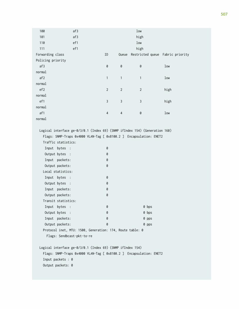
100 af3 low 101 af3 high 110 ef1 low 111 ef1 highForwarding class ID Queue Restricted queue Fabric priority Policing priority af3 0 0 0 low normal af2 1 1 1 low normal ef2 2 2 2 high normal ef1 3 3 3 high normal af1 4 4 0 low normal
Logical interface ge-0/3/0.1 (Index 69) (SNMP ifIndex 154) (Generation 160) Flags: SNMP-Traps 0x4000 VLAN-Tag [ 0x8100.2 ] Encapsulation: ENET2 Traffic statistics: Input bytes : 0 Output bytes : 0 Input packets: 0 Output packets: 0 Local statistics: Input bytes : 0 Output bytes : 0 Input packets: 0 Output packets: 0 Transit statistics: Input bytes : 0 0 bps Output bytes : 0 0 bps Input packets: 0 0 pps Output packets: 0 0 pps Protocol inet, MTU: 1500, Generation: 174, Route table: 0 Flags: Sendbcast-pkt-to-re
Logical interface ge-0/3/0.1 (Index 69) (SNMP ifIndex 154) Flags: SNMP-Traps 0x4000 VLAN-Tag [ 0x8100.2 ] Encapsulation: ENET2 Input packets : 0 Output packets: 0
507

Interface Admin Link Proto Input Filter Output Filterge-0/3/0.1 up up mpls Interface Admin Link Proto Input Policer Output Policerge-0/3/0.1 up up mpls
Logical interface: ge-0/3/0.1, Index: 69 Object Name Type Index Classifier ipprec-compatibility ip 13
Classifier: ipprec-compatibility, Code point type: inet-precedence, Index: 13 Code point Forwarding class Loss priority 000 af3 low 001 af3 high 010 af3 low 011 af3 high 100 af3 low 101 af3 high 110 ef1 low 111 ef1 highForwarding class ID Queue Restricted queue Fabric priority Policing priority af3 0 0 0 low normal af2 1 1 1 low normal ef2 2 2 2 high normal ef1 3 3 3 high normal af1 4 4 0 low normal
show class-of-service interface (ACX Series Routers)
user@host-g11# show class-of-service interfacePhysical interface: at-0/0/0, Index: 130Maximum usable queues: 4, Queues in use: 4 Scheduler map: <default>, Index: 2
508

Congestion-notification: Disabled
Logical interface: at-0/0/0.0, Index: 69
Logical interface: at-0/0/0.32767, Index: 70
Physical interface: at-0/0/1, Index: 133Maximum usable queues: 4, Queues in use: 4 Scheduler map: <default>, Index: 2 Congestion-notification: Disabled
Logical interface: at-0/0/1.0, Index: 71
Logical interface: at-0/0/1.32767, Index: 72
Physical interface: ge-0/1/0, Index: 146Maximum usable queues: 8, Queues in use: 5 Scheduler map: <default>, Index: 2 Congestion-notification: DisabledObject Name Type IndexRewrite dscp-default dscp 31Classifier d1 dscp 11331Classifier ci ieee8021p 583
Logical interface: ge-0/1/0.0, Index: 73Object Name Type IndexRewrite custom-exp exp (mpls-any) 46413
Logical interface: ge-0/1/0.1, Index: 74
Logical interface: ge-0/1/0.32767, Index: 75
Physical interface: ge-0/1/1, Index: 147Maximum usable queues: 8, Queues in use: 5 Scheduler map: <default>, Index: 2 Congestion-notification: DisabledObject Name Type IndexClassifier ipprec-compatibility ip 13
Logical interface: ge-0/1/1.0, Index: 76
Physical interface: ge-0/1/2, Index: 148Maximum usable queues: 8, Queues in use: 5
509

Scheduler map: <default>, Index: 2 Congestion-notification: DisabledObject Name Type IndexRewrite ri ieee8021p (outer) 35392Classifier ci ieee8021p 583
Physical interface: ge-0/1/3, Index: 149Maximum usable queues: 8, Queues in use: 5 Scheduler map: <default>, Index: 2 Congestion-notification: DisabledObject Name Type IndexClassifier ipprec-compatibility ip 13
Logical interface: ge-0/1/3.0, Index: 77Object Name Type IndexRewrite custom-exp2 exp (mpls-any) 53581
Physical interface: ge-0/1/4, Index: 150Maximum usable queues: 8, Queues in use: 5 Scheduler map: <default>, Index: 2 Congestion-notification: DisabledObject Name Type IndexClassifier ipprec-compatibility ip 13
Physical interface: ge-0/1/5, Index: 151Maximum usable queues: 8, Queues in use: 5 Scheduler map: <default>, Index: 2 Congestion-notification: DisabledObject Name Type IndexClassifier ipprec-compatibility ip 13
Physical interface: ge-0/1/6, Index: 152Maximum usable queues: 8, Queues in use: 5 Scheduler map: <default>, Index: 2 Congestion-notification: DisabledObject Name Type IndexClassifier ipprec-compatibility ip 13
Physical interface: ge-0/1/7, Index: 153Maximum usable queues: 8, Queues in use: 5 Scheduler map: <default>, Index: 2 Congestion-notification: DisabledObject Name Type Index
510

Classifier d1 dscp 11331
Physical interface: ge-0/2/0, Index: 154Maximum usable queues: 8, Queues in use: 5 Scheduler map: <default>, Index: 2 Congestion-notification: DisabledObject Name Type IndexClassifier ipprec-compatibility ip 13
Physical interface: ge-0/2/1, Index: 155Maximum usable queues: 8, Queues in use: 5 Scheduler map: <default>, Index: 2 Congestion-notification: DisabledObject Name Type IndexClassifier ipprec-compatibility ip 13
Logical interface: ge-0/2/1.0, Index: 78
Logical interface: ge-0/2/1.32767, Index: 79
Physical interface: xe-0/3/0, Index: 156Maximum usable queues: 8, Queues in use: 5 Scheduler map: <default>, Index: 2 Congestion-notification: DisabledObject Name Type IndexClassifier ipprec-compatibility ip 13
Logical interface: xe-0/3/0.0, Index: 80
Physical interface: xe-0/3/1, Index: 157Maximum usable queues: 8, Queues in use: 5 Scheduler map: <default>, Index: 2 Congestion-notification: DisabledObject Name Type IndexClassifier ipprec-compatibility ip 13
Logical interface: xe-0/3/1.0, Index: 81
[edit]user@host-g11#
511

show class-of-service interface (PPPoE Subscriber Interface for Enhanced SubscriberManagement)
user@host> show class-of-service interface pp0.3221225474 Logical interface: pp0.3221225475, Index: 3221225475Object Name Type IndexTraffic-control-profile TC_PROF_100_199_SERIES_UID1006 Output 4294967312Scheduler-map SMAP-1_UID1002 Output 4294967327Rewrite-Output ieee-rewrite ieee8021p 60432Rewrite-Output rule1 ip 50463
Adjusting application: PPPoE IA tags Adjustment type: absolute Configured shaping rate: 11000000 Adjustment value: 5000000 Adjustment target: node
Adjusting application: ucac Adjustment type: delta Configured shaping rate: 5000000 Adjustment value: 100000 Adjustment target: node
Release Information
Command introduced before Junos OS Release 7.4.
Forwarding class map information added in Junos OS Release 9.4.
Options detail and comprehensive introduced in Junos OS Release 11.4.
RELATED DOCUMENTATION
Verifying and Managing Junos OS Enhanced Subscriber Management
512

show class-of-service scheduler-map
IN THIS SECTION
Syntax | 513
Description | 513
Options | 513
Required Privilege Level | 513
Output Fields | 514
Sample Output | 515
Release Information | 516
Syntax
show class-of-service scheduler-map<name>
Description
Display the mapping of schedulers to forwarding classes and a summary of scheduler parameters foreach entry.
Options
none Display all scheduler maps.
name (Optional) Display a summary of scheduler parameters for each forwarding class to which thenamed scheduler is assigned.
Required Privilege Level
view
513

Output Fields
Table 74 on page 514 describes the output fields for the show class-of-service scheduler-map command.Output fields are listed in the approximate order in which they appear.
Table 74: show class-of-service scheduler-map Output Fields
Field Name Field Description
Scheduler map Name of the scheduler map.
(Enhanced subscriber management for MX Series routers) The name of the dynamicscheduler map object is associated with a generated UID (for example, SMAP-1_UID1002)instead of with a subscriber interface.
Index Index of the indicated object. Objects having indexes in this output include scheduler maps,schedulers, and drop profiles.
(Enhanced subscriber management for MX Series routers) Index values for dynamic CoStraffic control profiles are larger for enhanced subscriber management than they are forlegacy subscriber management.
Scheduler Name of the scheduler.
Forwarding class Classification of a packet affecting the forwarding, scheduling, and marking policies appliedas the packet transits the router.
Transmit rate Configured transmit rate of the scheduler (in bps). The rate is a percentage of the totalinterface bandwidth, or the keyword remainder, which indicates that the scheduler receivesthe remaining bandwidth of the interface.
Rate Limit Rate limiting configuration of the queue. Possible values are none, meaning no rate limiting,and exact, meaning the queue only transmits at the configured rate.
Maximum buffer delay Amount of transmit delay (in milliseconds) or the buffer size of the queue. The buffer size isshown as a percentage of the total interface buffer allocation, or by the keyword remainderto indicate that the buffer is sized according to what remains after other scheduler bufferallocations.
Priority Scheduling priority: low or high.
514

Table 74: show class-of-service scheduler-map Output Fields (Continued)
Field Name Field Description
Excess priority Priority of excess bandwidth: low, medium-low, medium-high, high, or none.
Explicit CongestionNotification
(QFX Series, OCX Series, and EX4600 switches only) Explicit congestion notification (ECN)state:
• Disable—ECN is disabled on the specified scheduler
• Enable—ECN is enabled on the specified scheduler
ECN is disabled by default.
Adjust minimum Minimum shaping rate for an adjusted queue, in bps.
Adjust percent Bandwidth adjustment applied to a queue, in percent.
Drop profiles Table displaying the assignment of drop profiles by name and index to a given loss priorityand protocol pair.
Loss priority Packet loss priority for drop profile assignment.
Protocol Transport protocol for drop profile assignment.
Name Name of the drop profile.
Sample Output
show class-of-service scheduler-map
user@host> show class-of-service scheduler-map Scheduler map: dd-scheduler-map, Index: 84
Scheduler: aa-scheduler, Index: 8721, Forwarding class: aa-forwarding-class Transmit rate: 30 percent, Rate Limit: none, Maximum buffer delay: 39 ms, Priority: high
515

Drop profiles: Loss priority Protocol Index Name Low non-TCP 8724 aa-drop-profile Low TCP 9874 bb-drop-profile High non-TCP 8833 cc-drop-profile High TCP 8484 dd-drop-profile
Scheduler: bb-scheduler, Forwarding class: aa-forwarding-class Transmit rate: 40 percent, Rate limit: none, Maximum buffer delay: 68 ms, Priority: high Drop profiles: Loss priority Protocol Index Name Low non-TCP 8724 aa-drop-profile Low TCP 9874 bb-drop-profile High non-TCP 8833 cc-drop-profile High TCP 8484 dd-drop-profile
show class-of-service scheduler-map (QFX Series)
user@switch# show class-of-service scheduler-mapScheduler map: be-map, Index: 12240
Scheduler:be-sched, Forwarding class: best-effort, Index: 115 Transmit rate: 30 percent, Rate Limit: none, Buffer size: remainder, Buffer Limit: none, Priority: low Excess Priority: unspecified, Explicit Congestion Notification: disable
Drop profiles: Loss priority Protocol Index Name Low any 3312 lan-dp Medium-high any 2714 be-dp1 High any 3178 be-dp2
Release Information
Command introduced before Junos OS Release 7.4.
516
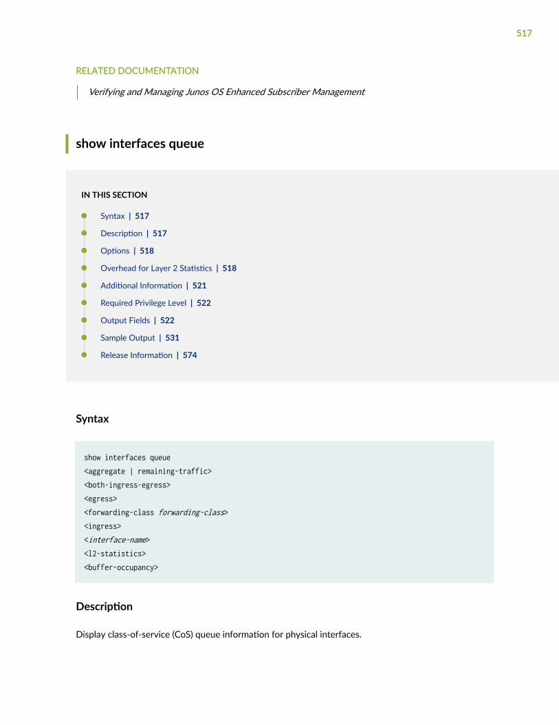
RELATED DOCUMENTATION
Verifying and Managing Junos OS Enhanced Subscriber Management
show interfaces queue
IN THIS SECTION
Syntax | 517
Description | 517
Options | 518
Overhead for Layer 2 Statistics | 518
Additional Information | 521
Required Privilege Level | 522
Output Fields | 522
Sample Output | 531
Release Information | 574
Syntax
show interfaces queue<aggregate | remaining-traffic><both-ingress-egress><egress><forwarding-class forwarding-class><ingress><interface-name><l2-statistics><buffer-occupancy>
Description
Display class-of-service (CoS) queue information for physical interfaces.
517

Options
none Show detailed CoS queue statistics for all physical interfaces.
aggregate (Optional) Display the aggregated queuing statistics of all logical interfaces thathave traffic-control profiles configured. (Not on the QFX Series.)
both-ingress-egress
(Optional) On Gigabit Ethernet Intelligent Queuing 2 (IQ2) PICs, display bothingress and egress queue statistics. (Not on the QFX Series.)
egress (Optional) Display egress queue statistics.
forwarding-classforwarding-class
(Optional) Forwarding class name for this queue. Shows detailed CoS statistics forthe queue associated with the specified forwarding class.
ingress (Optional) On Gigabit Ethernet IQ2 PICs, display ingress queue statistics. (Not onthe QFX Series.)
interface-name (Optional) Show detailed CoS queue statistics for the specified interface.
l2-statistics (Optional) Display Layer 2 statistics for MLPPP, FRF.15, and FRF.16 bundles
buffer-occupancy Displays the peak buffer occupancy for each queue while buffer-monitor-enable isenabled at the [edit chassis fpc slot-number traffic-manager] hierarchy level.
remaining-traffic (Optional) Display the queuing statistics of all logical interfaces that do not havetraffic-control profiles configured. (Not on the QFX Series.)
Overhead for Layer 2 Statistics
Transmitted packets and transmitted byte counts are displayed for the Layer 2 level with the addition ofencapsulation overheads applied for fragmentation, as shown in Table 75 on page 519. Otherscounters, such as packets and bytes queued (input) and drop counters, are displayed at the Layer 3 level.In the case of link fragmentation and interleaving (LFI) for which fragmentation is not applied,corresponding Layer 2 overheads are added, as shown in Table 75 on page 519.
518

Table 75: Layer 2 Overhead and Transmitted Packets or Byte Counts
Protocol Fragmentation LFI
First fragmentation Second to n fragmentations
Bytes Bytes
MLPPP (Long) 13 12 8
MLPPP (short) 11 10 8
MLFR (FRF15) 12 10 8
MFR (FRF16) 10 8 -
MCMLPPP(Long) 13 12 -
MCMLPPP(Short) 11 10 -
Layer 2 Statistics—Fragmentation Overhead Calculation
MLPPP/MC-MLPPP Overhead details: =============================== Fragment 1:
Outer PPP header : 4 bytes Long or short sequence MLPPP header : 4 bytes or 2 bytes Inner PPP header : 1 byte HDLC flag and FCS bytes : 4 bytes
Fragments 2 .. n : Outer PPP header : 4 bytes Long or short sequence MLPPP header : 4 bytes or 2 bytes HDLC flag and FCS bytes : 4 bytes
519

MLFR (FRF15) Overhead details: ============================= Fragment 1: Framerelay header : 2 bytes Control,NLPID : 2 bytes Fragmentaion header : 2 bytes Inner proto : 2 bytes HDLC flag and FCS : 4 bytes
Fragments 2 ...n : Framerelay header : 2 bytes Control,NLPID : 2 bytes Fragmentaion header : 2 bytes HDLC flag and FCS : 4 bytes
MFR (FRF16) Overhead details: ============================== Fragment 1: Fragmentaion header : 2 bytes Framerelay header : 2 bytes Inner proto : 2 bytes HDLC flag and FCS : 4 bytes
Fragments 2 ...n : Fragmentaion header : 2 bytes Framerelay header : 2 bytes HDLC flag and FCS : 4 bytes
Overhead with LFI
MLPPP(Long & short sequence): ============================ Outer PPP header : 4 bytes HDLC flag and FCS : 4 bytes
MLFR (FRF15): ============= Framerelay header : 2 bytes
520

Control,NLPID : 2 bytes HDLC flag and FCS : 4 bytes
The following examples show overhead for different cases:
• A 1000-byte packet is sent to a mlppp bundle without any fragmentation. At the Layer 2 level, bytestransmitted is 1013 in 1 packet. This overhead is for MLPPP long sequence encap.
• A 1000-byte packet is sent to a mlppp bundle with a fragment threshold of 250byte. At the Layer 2level, bytes transmitted is 1061 bytes in 5 packets.
• A 1000-byte LFI packet is sent to an mlppp bundle. At the Layer 2 level, bytes transmitted is 1008 in1 packet.
Additional Information
For rate-limited interfaces hosted on Modular Interface Cards (MICs), Modular Port Concentrators(MPCs), or Enhanced Queuing DPCs, rate-limit packet-drop operations occur before packets are queuedfor transmission scheduling. For such interfaces, the statistics for queued traffic do not include thepackets that have already been dropped due to rate limiting, and consequently the displayed statisticsfor queued traffic are the same as the displayed statistics for transmitted traffic.
NOTE: For rate-limited interfaces hosted on other types of hardware, rate-limit packet-dropoperations occur after packets are queued for transmission scheduling. For these other interfacetypes, the statistics for queued traffic include the packets that are later dropped due to ratelimiting, and consequently the displayed statistics for queued traffic equals the sum of thestatistics for transmitted and rate-limited traffic.
On M Series routers (except for the M320 and M120 routers), this command is valid only for a PICinstalled on an enhanced Flexible PIC Concentrator (FPC).
Queue statistics for aggregated interfaces are supported on the M Series and T Series routers only.Statistics for an aggregated interface are the summation of the queue statistics of the child links of thataggregated interface. You can view the statistics for a child interface by using the show interfacesstatistics command for that child interface.
When you configure tricolor marking on a 10-port 1-Gigabit Ethernet PIC, for queues 6 and 7 only, theoutput does not display the number of queued bytes and packets, or the number of bytes and packetsdropped because of RED. If you do not configure tricolor marking on the interface, these statistics areavailable for all queues.
521

For the 4-port Channelized OC12 IQE PIC and 1-port Channelized OC48 IQE PIC, the Packet ForwardingEngine Chassis Queues field represents traffic bound for a particular physical interface on the PIC. For allother PICs, the Packet Forwarding Engine Chassis Queues field represents the total traffic bound for the PIC.
For Gigabit Ethernet IQ2 PICs, the show interfaces queue command output does not display the number oftail-dropped packets. This limitation does not apply to Packet Forwarding Engine chassis queues.
When fragmentation occurs on the egress interface, the first set of packet counters shows thepostfragmentation values. The second set of packet counters (under the Packet Forwarding Engine ChassisQueues field) shows the prefragmentation values.
The behavior of the egress queues for the Routing Engine-Generated Traffic is not same as the configuredqueue for MLPPP and MFR configurations.
For related CoS operational mode commands, see the CLI Explorer.
Required Privilege Level
view
Output Fields
Table 76 on page 522 lists the output fields for the show interfaces queue command. Output fields arelisted in the approximate order in which they appear.
Table 76: show interfaces queue Output Fields
Field Name Field Description
Physical interface Name of the physical interface.
Enabled State of the interface. Possible values are described in the “Enabled Field” section underCommon Output Fields Description.
Interface index Physical interface's index number, which reflects its initialization sequence.
SNMP ifIndex SNMP index number for the interface.
Forwarding classessupported
Total number of forwarding classes supported on the specified interface.
522

Table 76: show interfaces queue Output Fields (Continued)
Field Name Field Description
Forwarding classesin use
Total number of forwarding classes in use on the specified interface.
Ingress queuessupported
On Gigabit Ethernet IQ2 PICs only, total number of ingress queues supported on thespecified interface.
Ingress queues inuse
On Gigabit Ethernet IQ2 PICs only, total number of ingress queues in use on the specifiedinterface.
Output queuessupported
Total number of output queues supported on the specified interface.
Output queues in use Total number of output queues in use on the specified interface.
Egress queuessupported
Total number of egress queues supported on the specified interface.
Egress queues in use Total number of egress queues in use on the specified interface.
Queue counters(Ingress)
CoS queue number and its associated user-configured forwarding class name. Displayedon IQ2 interfaces.
• Queued packets—Number of queued packets.
NOTE: This field is not supported on QFX5100, QFX5110, QFX5200, and QFX5210switches due to hardware limitations.
• Transmitted packets—Number of transmitted packets.
• Dropped packets—Number of packets dropped by the ASIC's RED mechanism.
Burst size (Logical interfaces on IQ PICs only) Maximum number of bytes up to which the logicalinterface can burst. The burst size is based on the shaping rate applied to the interface.
523

Table 76: show interfaces queue Output Fields (Continued)
Field Name Field Description
The following output fields are applicable to both interface component and Packet Forwarding component in theshow interfaces queue command:
Queue Queue number.
Forwarding classes Forwarding class name.
Queued Packets Number of packets queued to this queue.
NOTE: For Gigabit Ethernet IQ2 interfaces, the Queued Packets count is calculated by theJunos OS interpreting one frame buffer as one packet. If the queued packets are verylarge or very small, the calculation might not be completely accurate for transit traffic. Thecount is completely accurate for traffic terminated on the router.
For rate-limited interfaces hosted on MICs or MPCs only, this statistic does not includetraffic dropped due to rate limiting. For more information, see "Additional Information" onpage 521.
NOTE: This field is not supported on QFX5100, QFX5110, QFX5200, and QFX5210switches due to hardware limitations.
This field is not supported on EX Series switches due to hardware limitations.
Queued Bytes Number of bytes queued to this queue. The byte counts vary by interface hardware. Formore information, see Table 77 on page 528.
For rate-limited interfaces hosted on MICs or MPCs only, this statistic does not includetraffic dropped due to rate limiting. For more information, see "Additional Information" onpage 521.
NOTE: This field is not supported on QFX5100, QFX5110, QFX5200, and QFX5210switches due to hardware limitations.
This field is not supported on EX Series switches due to hardware limitations.
Transmitted Packets Number of packets transmitted by this queue. When fragmentation occurs on the egressinterface, the first set of packet counters shows the postfragmentation values. The secondset of packet counters (displayed under the Packet Forwarding Engine Chassis Queues field)shows the prefragmentation values.
NOTE: For Layer 2 statistics, see "Overhead for Layer 2 Statistics" on page 518
524

Table 76: show interfaces queue Output Fields (Continued)
Field Name Field Description
Transmitted Bytes Number of bytes transmitted by this queue. The byte counts vary by interface hardware.For more information, see Table 77 on page 528.
NOTE: On MX Series routers, this number can be inaccurate when you issue thecommand for a physical interface repeatedly and in quick succession, because thestatistics for the child nodes are collected infrequently. Wait ten seconds betweensuccessive iterations to avoid this situation.
NOTE: For Layer 2 statistics, see "Overhead for Layer 2 Statistics" on page 518
Tail-dropped packets Number of packets dropped because of tail drop.
NOTE: Starting with Junos OS 18.3R1, the Tail-dropped packets counter is supported onPTX Series Packet Transport Routers.
RL-dropped packets Number of packets dropped due to rate limiting.
For rate-limited interfaces hosted on MICs, MPCs, and Enhanced Queuing DPCs only, thisstatistic is not included in the queued traffic statistics. For more information, see"Additional Information" on page 521.
NOTE: The RL-dropped packets counter is not supported on the PTX Series PacketTransport Routers, and is omitted from the output.
RL-dropped bytes Number of bytes dropped due to rate limiting.
For rate-limited interfaces hosted on MICs, MPCs, and Enhanced Queuing DPCs only, thisstatistic is not included in the queued traffic statistics. For more information, see"Additional Information" on page 521.
525

Table 76: show interfaces queue Output Fields (Continued)
Field Name Field Description
RED-dropped packets Number of packets dropped because of random early detection (RED).
• (M Series and T Series routers only) On M320 and M120 routers and the T Seriesrouters, the total number of dropped packets is displayed. On all other M Seriesrouters, the output classifies dropped packets into the following categories:
• Low, non-TCP—Number of low-loss priority non-TCP packets dropped because ofRED.
• Low, TCP—Number of low-loss priority TCP packets dropped because of RED.
• High, non-TCP—Number of high-loss priority non-TCP packets dropped because ofRED.
• High, TCP—Number of high-loss priority TCP packets dropped because of RED.
• (MX Series routers with enhanced DPCs, and T Series routers with enhanced FPCsonly) The output classifies dropped packets into the following categories:
• Low—Number of low-loss priority packets dropped because of RED.
• Medium-low—Number of medium-low loss priority packets dropped because of RED.
• Medium-high—Number of medium-high loss priority packets dropped because ofRED.
• High—Number of high-loss priority packets dropped because of RED.
NOTE: Due to accounting space limitations on certain Type 3 FPCs (which are supportedin M320 and T640 routers), this field does not always display the correct value forqueue 6 or queue 7 for interfaces on 10-port 1-Gigabit Ethernet PICs.
526

Table 76: show interfaces queue Output Fields (Continued)
Field Name Field Description
RED-dropped bytes Number of bytes dropped because of RED. The byte counts vary by interface hardware.For more information, see Table 77 on page 528.
• (M Series and T Series routers only) On M320 and M120 routers and the T Seriesrouters, only the total number of dropped bytes is displayed. On all other M Seriesrouters, the output classifies dropped bytes into the following categories:
• Low, non-TCP—Number of low-loss priority non-TCP bytes dropped because of RED.
• Low, TCP—Number of low-loss priority TCP bytes dropped because of RED.
• High, non-TCP—Number of high-loss priority non-TCP bytes dropped because ofRED.
• High, TCP—Number of high-loss priority TCP bytes dropped because of RED.
NOTE: Due to accounting space limitations on certain Type 3 FPCs (which are supportedin M320 and T640 routers), this field does not always display the correct value forqueue 6 or queue 7 for interfaces on 10-port 1-Gigabit Ethernet PICs.
Queue-depth bytes Displays queue-depth average, current, peak, and maximum values for RTP queues.Because queue-depth values cannot be aggregated, displays the values for RTP queuesregardless of whether aggregate, remaining-traffic, or neither option is selected.
Peak (QFX5000 Series switches only) Diplays the peak buffer occupancy for the queue whilebuffer-monitor-enable is enabled at the [edit chassis fpc slot-number traffic-manager]hierarchy level.
Last-packet enqueued Starting with Junos OS Release 16.1, Last-packet enqueued output field is introduced. Ifpacket-timestamp is enabled for an FPC, shows the day, date, time, and year in the formatday-of-the-week month day-date hh:mm:ss yyyy when a packet was enqueued in the CoSqueue. When the timestamp is aggregated across all active Packet Forwarding Engines,the latest timestamp for each CoS queue is reported.
Byte counts vary by interface hardware. Table 77 on page 528 shows how the byte counts on theoutbound interfaces vary depending on the interface hardware. Table 77 on page 528 is based on theassumption that outbound interfaces are sending IP traffic with 478 bytes per packet.
527

Table 77: Byte Count by Interface Hardware
Interface Hardware Output Level Byte Count Includes Comments
Gigabit Ethernet IQand IQE PICs
Interface Queued: 490 bytes per packet, representing478 bytes of Layer 3 packet + 12 bytes
Transmitted: 490 bytes per packet,representing 478 bytes of Layer 3 packet + 12bytes
RED dropped: 496 bytes per packetrepresenting 478 bytes of Layer 3 packet + 18bytes
The 12 additionalbytes include 6 bytesfor the destinationMAC address +4 bytes for the VLAN+ 2 bytes for theEthernet type.
For RED dropped, 6bytes are added forthe source MACaddress.
Packetforwardingcomponent
Queued: 478 bytes per packet, representing478 bytes of Layer 3 packet
Transmitted: 478 bytes per packet,representing 478 bytes of Layer 3 packet
–
528
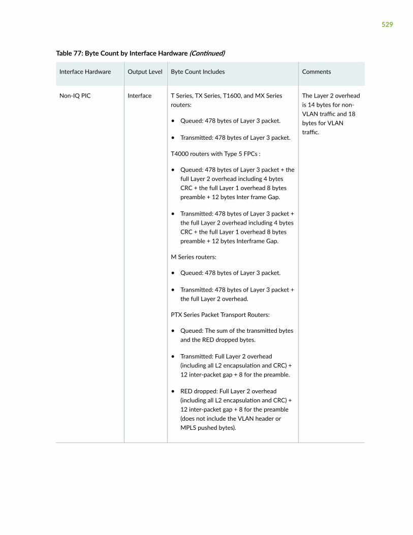
Table 77: Byte Count by Interface Hardware (Continued)
Interface Hardware Output Level Byte Count Includes Comments
Non-IQ PIC Interface T Series, TX Series, T1600, and MX Seriesrouters:
• Queued: 478 bytes of Layer 3 packet.
• Transmitted: 478 bytes of Layer 3 packet.
T4000 routers with Type 5 FPCs :
• Queued: 478 bytes of Layer 3 packet + thefull Layer 2 overhead including 4 bytesCRC + the full Layer 1 overhead 8 bytespreamble + 12 bytes Inter frame Gap.
• Transmitted: 478 bytes of Layer 3 packet +the full Layer 2 overhead including 4 bytesCRC + the full Layer 1 overhead 8 bytespreamble + 12 bytes Interframe Gap.
M Series routers:
• Queued: 478 bytes of Layer 3 packet.
• Transmitted: 478 bytes of Layer 3 packet +the full Layer 2 overhead.
PTX Series Packet Transport Routers:
• Queued: The sum of the transmitted bytesand the RED dropped bytes.
• Transmitted: Full Layer 2 overhead(including all L2 encapsulation and CRC) +12 inter-packet gap + 8 for the preamble.
• RED dropped: Full Layer 2 overhead(including all L2 encapsulation and CRC) +12 inter-packet gap + 8 for the preamble(does not include the VLAN header orMPLS pushed bytes).
The Layer 2 overheadis 14 bytes for non-VLAN traffic and 18bytes for VLANtraffic.
529

Table 77: Byte Count by Interface Hardware (Continued)
Interface Hardware Output Level Byte Count Includes Comments
IQ and IQE PICs witha SONET/SDHinterface
Interface Queued: 482 bytes per packet, representing478 bytes of Layer 3 packet + 4 bytes
Transmitted: 482 bytes per packet,representing 478 bytes of Layer 3 packet + 4bytes
RED dropped: 482 bytes per packet,representing 478 bytes of Layer 3 packet + 4bytes
The additional 4 bytesare for the Layer 2Point-to-PointProtocol (PPP)header.
Packetforwardingcomponent
Queued: 478 bytes per packet, representing478 bytes of Layer 3 packet
Transmitted: 486 bytes per packet,representing 478 bytes of Layer 3 packet + 8bytes
For transmittedpackets, theadditional 8 bytesincludes 4 bytes forthe PPP header and 4bytes for a cookie.
Non-IQ PIC with aSONET/SDH interface
Interface T Series, TX Series, T1600, and MX Seriesrouters:
• Queued: 478 bytes of Layer 3 packet.
• Transmitted: 478 bytes of Layer 3 packet.
M Series routers:
• Queued: 478 bytes of Layer 3 packet.
• Transmitted: 483 bytes per packet,representing 478 bytes of Layer 3 packet +5 bytes
• RED dropped: 478 bytes per packet,representing 478 bytes of Layer 3 packet
For transmittedpackets, theadditional 5 bytesincludes 4 bytes forthe PPP header and 1byte for the packetloss priority (PLP).
Interfaces configuredwith Frame RelayEncapsulation
Interface The default Frame Relay overhead is 7 bytes.If you configure the Frame Check Sequence(FCS) to 4 bytes, then the overhead increasesto 10 bytes.
530

Table 77: Byte Count by Interface Hardware (Continued)
Interface Hardware Output Level Byte Count Includes Comments
1-port 10-GigabitEthernet IQ2 andIQ2–E PICs
4-port 1G IQ2 andIQ2-E PICs
8-port 1G IQ2 andIQ2-E PICs
Interface Queued: 478 bytes of Layer 3 packet + thefull Layer 2 overhead including CRC.
Transmitted: 478 bytes of Layer 3 packet +the full Layer 2 overhead including CRC.
The Layer 2 overheadis 18 bytes for non-VLAN traffic and 22bytes for VLANtraffic.
Packetforwardingcomponent
Queued: 478 bytes of Layer 3 packet.
Transmitted: 478 bytes of Layer 3 packet.
–
Sample Output
show interfaces queue (Rate-Limited Interface on a Gigabit Ethernet MIC in an MPC)
The following example shows queue information for the rate-limited interface ge-4/2/0 on a GigabitEthernet MIC in an MPC. For rate-limited queues for interfaces hosted on MICs or MPCs, rate-limitpacket drops occur prior to packet output queuing. In the command output, the nonzero statisticsdisplayed in the RL-dropped packets and RL-dropped bytes fields quantify the traffic dropped to rate-limitqueue 0 output to 10 percent of 1 gigabyte (100 megabits) per second. Because the RL-dropped trafficis not included in the Queued statistics, the statistics displayed for queued traffic are the same as thestatistics for transmitted traffic.
user@host> show interfaces queue ge-4/2/0Physical interface: ge-4/2/0, Enabled, Physical link is Up Interface index: 203, SNMP ifIndex: 1054Forwarding classes: 16 supported, 4 in useEgress queues: 8 supported, 4 in useQueue: 0, Forwarding classes: best-effort Queued: Packets : 131300649 141751 pps Bytes : 11287964840 99793248 bps Transmitted: Packets : 131300649 141751 pps Bytes : 11287964840 99793248 bps Tail-dropped packets : 0 0 pps RL-dropped packets : 205050862 602295 pps
531
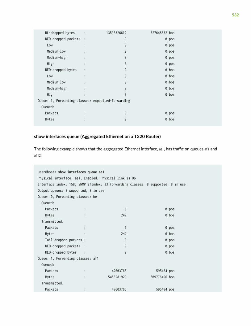
RL-dropped bytes : 13595326612 327648832 bps RED-dropped packets : 0 0 pps Low : 0 0 pps Medium-low : 0 0 pps Medium-high : 0 0 pps High : 0 0 pps RED-dropped bytes : 0 0 bps Low : 0 0 bps Medium-low : 0 0 bps Medium-high : 0 0 bps High : 0 0 bpsQueue: 1, Forwarding classes: expedited-forwarding Queued: Packets : 0 0 pps Bytes : 0 0 bps
show interfaces queue (Aggregated Ethernet on a T320 Router)
The following example shows that the aggregated Ethernet interface, ae1, has traffic on queues af1 andaf12:
user@host> show interfaces queue ae1Physical interface: ae1, Enabled, Physical link is UpInterface index: 158, SNMP ifIndex: 33 Forwarding classes: 8 supported, 8 in useOutput queues: 8 supported, 8 in useQueue: 0, Forwarding classes: be Queued: Packets : 5 0 pps Bytes : 242 0 bps Transmitted: Packets : 5 0 pps Bytes : 242 0 bps Tail-dropped packets : 0 0 pps RED-dropped packets : 0 0 pps RED-dropped bytes : 0 0 bpsQueue: 1, Forwarding classes: af1 Queued: Packets : 42603765 595484 pps Bytes : 5453281920 609776496 bps Transmitted: Packets : 42603765 595484 pps
532

Bytes : 5453281920 609776496 bps Tail-dropped packets : 0 0 pps RED-dropped packets : 0 0 pps RED-dropped bytes : 0 0 bpsQueue: 2, Forwarding classes: ef1 Queued: Packets : 0 0 pps Bytes : 0 0 bps Transmitted: Packets : 0 0 pps Bytes : 0 0 bps Tail-dropped packets : 0 0 pps RED-dropped packets : 0 0 pps RED-dropped bytes : 0 0 bpsQueue: 3, Forwarding classes: nc Queued: Packets : 45 0 pps Bytes : 3930 0 bps Transmitted: Packets : 45 0 pps Bytes : 3930 0 bps Tail-dropped packets : 0 0 pps RED-dropped packets : 0 0 pps RED-dropped bytes : 0 0 bpsQueue: 4, Forwarding classes: af11 Queued: Packets : 0 0 pps Bytes : 0 0 bps Transmitted: Packets : 0 0 pps Bytes : 0 0 bps Tail-dropped packets : 0 0 pps RED-dropped packets : 0 0 pps RED-dropped bytes : 0 0 bpsQueue: 5, Forwarding classes: ef11 Queued: Packets : 0 0 pps Bytes : 0 0 bps Transmitted: Packets : 0 0 pps Bytes : 0 0 bps Tail-dropped packets : 0 0 pps RED-dropped packets : 0 0 pps
533

RED-dropped bytes : 0 0 bpsQueue: 6, Forwarding classes: af12 Queued: Packets : 31296413 437436 pps Bytes : 4005940864 447935200 bps Transmitted: Packets : 31296413 437436 pps Bytes : 4005940864 447935200 bps Tail-dropped packets : 0 0 pps RED-dropped packets : 0 0 pps RED-dropped bytes : 0 0 bpsQueue: 7, Forwarding classes: nc2 Queued: Packets : 0 0 pps Bytes : 0 0 bps Transmitted: Packets : 0 0 pps Bytes : 0 0 bps Tail-dropped packets : 0 0 pps RED-dropped packets : 0 0 pps RED-dropped bytes : 0 0 bps
show interfaces queue (Gigabit Ethernet on a T640 Router)
user@host> show interfaces queue Physical interface: ge-7/0/1, Enabled, Physical link is Up Interface index: 150, SNMP ifIndex: 42 Forwarding classes: 8 supported, 8 in use Output queues: 8 supported, 8 in use Queue: 0, Forwarding classes: be Queued: Packets : 13 0 pps Bytes : 622 0 bps Transmitted: Packets : 13 0 pps Bytes : 622 0 bps Tail-dropped packets : 0 0 pps RED-dropped packets : 0 0 pps RED-dropped bytes : 0 0 bps Queue: 1, Forwarding classes: af1 Queued:
534

Packets : 1725947945 372178 pps Bytes : 220921336960 381110432 bps Transmitted: Packets : 1725947945 372178 pps Bytes : 220921336960 381110432 bps Tail-dropped packets : 0 0 pps RED-dropped packets : 0 0 pps RED-dropped bytes : 0 0 bps Queue: 2, Forwarding classes: ef1 Queued: Packets : 0 0 pps Bytes : 0 0 bps Transmitted: Packets : 0 0 pps Bytes : 0 0 bps Tail-dropped packets : 0 0 pps RED-dropped packets : 0 0 pps RED-dropped bytes : 0 0 bps Queue: 3, Forwarding classes: nc Queued: Packets : 571 0 pps Bytes : 49318 336 bps Transmitted: Packets : 571 0 pps Bytes : 49318 336 bps Tail-dropped packets : 0 0 pps RED-dropped packets : 0 0 pps RED-dropped bytes : 0 0 bps
show interfaces queue aggregate (Gigabit Ethernet Enhanced DPC)
user@host> show interfaces queue ge-2/2/9 aggregatePhysical interface: ge-2/2/9, Enabled, Physical link is Up Interface index: 238, SNMP ifIndex: 71Forwarding classes: 16 supported, 4 in useIngress queues: 4 supported, 4 in useQueue: 0, Forwarding classes: best-effort Queued: Packets : 148450735 947295 pps Bytes : 8016344944 409228848 bps Transmitted:
535

Packets : 76397439 487512 pps Bytes : 4125461868 210602376 bps Tail-dropped packets : Not Available RED-dropped packets : 72053285 459783 pps Low : 72053285 459783 pps Medium-low : 0 0 pps Medium-high : 0 0 pps High : 0 0 pps RED-dropped bytes : 3890877444 198626472 bps Low : 3890877444 198626472 bps Medium-low : 0 0 bps Medium-high : 0 0 bps High : 0 0 bpsQueue: 1, Forwarding classes: expedited-forwarding Queued: Packets : 0 0 pps Bytes : 0 0 bps Transmitted: Packets : 0 0 pps Bytes : 0 0 bps Tail-dropped packets : Not Available RED-dropped packets : 0 0 pps Low : 0 0 pps Medium-low : 0 0 pps Medium-high : 0 0 pps High : 0 0 pps RED-dropped bytes : 0 0 bps Low : 0 0 bps Medium-low : 0 0 bps Medium-high : 0 0 bps High : 0 0 bpsQueue: 2, Forwarding classes: assured-forwarding Queued: Packets : 410278257 473940 pps Bytes : 22156199518 204742296 bps Transmitted: Packets : 4850003 4033 pps Bytes : 261900162 1742256 bps Tail-dropped packets : Not Available RED-dropped packets : 405425693 469907 pps Low : 405425693 469907 pps Medium-low : 0 0 pps Medium-high : 0 0 pps
536

High : 0 0 pps RED-dropped bytes : 21892988124 203000040 bps Low : 21892988124 203000040 bps Medium-low : 0 0 bps Medium-high : 0 0 bps High : 0 0 bpsQueue: 3, Forwarding classes: network-control Queued: Packets : 0 0 pps Bytes : 0 0 bps Transmitted: Packets : 0 0 pps Bytes : 0 0 bps Tail-dropped packets : Not Available RED-dropped packets : 0 0 pps Low : 0 0 pps Medium-low : 0 0 pps Medium-high : 0 0 pps High : 0 0 pps RED-dropped bytes : 0 0 bps Low : 0 0 bps Medium-low : 0 0 bps Medium-high : 0 0 bps High : 0 0 bpsForwarding classes: 16 supported, 4 in useEgress queues: 4 supported, 4 in useQueue: 0, Forwarding classes: best-effort Queued: Packets : 76605230 485376 pps Bytes : 5209211400 264044560 bps Transmitted: Packets : 76444631 484336 pps Bytes : 5198235612 263478800 bps Tail-dropped packets : Not Available RED-dropped packets : 160475 1040 pps Low : 160475 1040 pps Medium-low : 0 0 pps Medium-high : 0 0 pps High : 0 0 pps RED-dropped bytes : 10912300 565760 bps Low : 10912300 565760 bps Medium-low : 0 0 bps Medium-high : 0 0 bps
537

High : 0 0 bpsQueue: 1, Forwarding classes: expedited-forwarding Queued: Packets : 0 0 pps Bytes : 0 0 bps Transmitted: Packets : 0 0 pps Bytes : 0 0 bps Tail-dropped packets : Not Available RED-dropped packets : 0 0 pps Low : 0 0 pps Medium-low : 0 0 pps Medium-high : 0 0 pps High : 0 0 pps RED-dropped bytes : 0 0 bps Low : 0 0 bps Medium-low : 0 0 bps Medium-high : 0 0 bps High : 0 0 bpsQueue: 2, Forwarding classes: assured-forwarding Queued: Packets : 4836136 3912 pps Bytes : 333402032 2139056 bps Transmitted: Packets : 3600866 1459 pps Bytes : 244858888 793696 bps Tail-dropped packets : Not Available RED-dropped packets : 1225034 2450 pps Low : 1225034 2450 pps Medium-low : 0 0 pps Medium-high : 0 0 pps High : 0 0 pps RED-dropped bytes : 83302312 1333072 bps Low : 83302312 1333072 bps Medium-low : 0 0 bps Medium-high : 0 0 bps High : 0 0 bpsQueue: 3, Forwarding classes: network-control Queued: Packets : 0 0 pps Bytes : 0 0 bps Transmitted: Packets : 0 0 pps
538

Bytes : 0 0 bps Tail-dropped packets : Not Available RED-dropped packets : 0 0 pps Low : 0 0 pps Medium-low : 0 0 pps Medium-high : 0 0 pps High : 0 0 pps RED-dropped bytes : 0 0 bps Low : 0 0 bps Medium-low : 0 0 bps Medium-high : 0 0 bps High : 0 0 bps
Packet Forwarding Engine Chassis Queues:Queues: 4 supported, 4 in useQueue: 0, Forwarding classes: best-effort Queued: Packets : 77059796 486384 pps Bytes : 3544750624 178989576 bps Transmitted: Packets : 77059797 486381 pps Bytes : 3544750670 178988248 bps Tail-dropped packets : 0 0 pps RED-dropped packets : 0 0 pps Low : 0 0 pps Medium-low : 0 0 pps Medium-high : 0 0 pps High : 0 0 pps RED-dropped bytes : 0 0 bps Low : 0 0 bps Medium-low : 0 0 bps Medium-high : 0 0 bps High : 0 0 bpsQueue: 1, Forwarding classes: expedited-forwarding Queued: Packets : 0 0 pps Bytes : 0 0 bps Transmitted: Packets : 0 0 pps Bytes : 0 0 bps Tail-dropped packets : 0 0 pps RED-dropped packets : 0 0 pps Low : 0 0 pps
539

Medium-low : 0 0 pps Medium-high : 0 0 pps High : 0 0 pps RED-dropped bytes : 0 0 bps Low : 0 0 bps Medium-low : 0 0 bps Medium-high : 0 0 bps High : 0 0 bpsQueue: 2, Forwarding classes: assured-forwarding Queued: Packets : 4846580 3934 pps Bytes : 222942680 1447768 bps Transmitted: Packets : 4846580 3934 pps Bytes : 222942680 1447768 bps Tail-dropped packets : 0 0 pps RED-dropped packets : 0 0 pps Low : 0 0 pps Medium-low : 0 0 pps Medium-high : 0 0 pps High : 0 0 pps RED-dropped bytes : 0 0 bps Low : 0 0 bps Medium-low : 0 0 bps Medium-high : 0 0 bps High : 0 0 bpsQueue: 3, Forwarding classes: network-control Queued: Packets : 0 0 pps Bytes : 0 0 bps Transmitted: Packets : 0 0 pps Bytes : 0 0 bps Tail-dropped packets : 0 0 pps RED-dropped packets : 0 0 pps Low : 0 0 pps Medium-low : 0 0 pps Medium-high : 0 0 pps High : 0 0 pps RED-dropped bytes : 0 0 bps Low : 0 0 bps Medium-low : 0 0 bps
540

Medium-high : 0 0 bps High : 0 0 bps
show interfaces queue (Gigabit Ethernet IQ2 PIC)
user@host> show interfaces queue ge-7/1/3Physical interface: ge-7/1/3, Enabled, Physical link is Up Interface index: 170, SNMP ifIndex: 70 Forwarding classes: 16 supported, 4 in use Ingress queues: 4 supported, 4 in useQueue: 0, Forwarding classes: best-effort Queued: Packets : 418390039 10 pps Bytes : 38910269752 7440 bps Transmitted: Packets : 418390039 10 pps Bytes : 38910269752 7440 bps Tail-dropped packets : Not Available RED-dropped packets : 0 0 pps RED-dropped bytes : 0 0 bpsQueue: 1, Forwarding classes: expedited-forwarding Queued: Packets : 0 0 pps Bytes : 0 0 bps Transmitted: Packets : 0 0 pps Bytes : 0 0 bps Tail-dropped packets : Not Available RED-dropped packets : 0 0 pps RED-dropped bytes : 0 0 bpsQueue: 2, Forwarding classes: assured-forwarding Queued: Packets : 0 0 pps Bytes : 0 0 bps Transmitted: Packets : 0 0 pps Bytes : 0 0 bps Tail-dropped packets : Not Available RED-dropped packets : 0 0 pps RED-dropped bytes : 0 0 bpsQueue: 3, Forwarding classes: network-control Queued:
541

Packets : 7055 1 pps Bytes : 451552 512 bps Transmitted: Packets : 7055 1 pps Bytes : 451552 512 bps Tail-dropped packets : Not Available RED-dropped packets : 0 0 pps RED-dropped bytes : 0 0 bpsForwarding classes: 16 supported, 4 in use Egress queues: 4 supported, 4 in useQueue: 0, Forwarding classes: best-effort Queued: Packets : 1031 0 pps Bytes : 143292 0 bps Transmitted: Packets : 1031 0 pps Bytes : 143292 0 bps Tail-dropped packets : Not Available RL-dropped packets : 0 0 pps RL-dropped bytes : 0 0 bps RED-dropped packets : 0 0 pps RED-dropped bytes : 0 0 bpsQueue: 1, Forwarding classes: expedited-forwarding Queued: Packets : 0 0 pps Bytes : 0 0 bps Transmitted: Packets : 0 0 pps Bytes : 0 0 bps Tail-dropped packets : Not Available RL-dropped packets : 0 0 pps RL-dropped bytes : 0 0 bps RED-dropped packets : 0 0 pps RED-dropped bytes : 0 0 bpsQueue: 2, Forwarding classes: assured-forwarding Queued: Packets : 0 0 pps Bytes : 0 0 bps Transmitted: Packets : 0 0 pps Bytes : 0 0 bps Tail-dropped packets : Not Available RL-dropped packets : 0 0 pps RL-dropped bytes : 0 0 bps
542

RED-dropped packets : 0 0 pps RED-dropped bytes : 0 0 bpsQueue: 3, Forwarding classes: network-control Queued: Packets : 77009 11 pps Bytes : 6894286 7888 bps Transmitted: Packets : 77009 11 pps Bytes : 6894286 7888 bps Tail-dropped packets : Not Available RL-dropped packets : 0 0 pps RL-dropped bytes : 0 0 bps RED-dropped packets : 0 0 pps RED-dropped bytes : 0 0 bps
Packet Forwarding Engine Chassis Queues:Queues: 4 supported, 4 in useQueue: 0, Forwarding classes: best-effort Queued: Packets : 1031 0 pps Bytes : 147328 0 bps Transmitted: Packets : 1031 0 pps Bytes : 147328 0 bps Tail-dropped packets : 0 0 pps RED-dropped packets : 0 0 pps Low, non-TCP : 0 0 pps Low, TCP : 0 0 pps High, non-TCP : 0 0 pps High, TCP : 0 0 pps RED-dropped bytes : 0 0 bps Low, non-TCP : 0 0 bps Low, TCP : 0 0 bps High, non-TCP : 0 0 bps High, TCP : 0 0 bpsQueue: 1, Forwarding classes: expedited-forwarding Queued: Packets : 0 0 pps Bytes : 0 0 bps Transmitted: Packets : 0 0 pps Bytes : 0 0 bps Tail-dropped packets : 0 0 pps
543

RED-dropped packets : 0 0 pps Low, non-TCP : 0 0 pps Low, TCP : 0 0 pps High, non-TCP : 0 0 pps High, TCP : 0 0 pps RED-dropped bytes : 0 0 bps Low, non-TCP : 0 0 bps Low, TCP : 0 0 bps High, non-TCP : 0 0 bps High, TCP : 0 0 bpsQueue: 2, Forwarding classes: assured-forwarding Queued: Packets : 0 0 pps Bytes : 0 0 bps Transmitted: Packets : 0 0 pps Bytes : 0 0 bps Tail-dropped packets : 0 0 pps RED-dropped packets : 0 0 pps Low, non-TCP : 0 0 pps Low, TCP : 0 0 pps High, non-TCP : 0 0 pps High, TCP : 0 0 pps RED-dropped bytes : 0 0 bps Low, non-TCP : 0 0 bps Low, TCP : 0 0 bps High, non-TCP : 0 0 bps High, TCP : 0 0 bpsQueue: 3, Forwarding classes: network-control Queued: Packets : 94386 12 pps Bytes : 13756799 9568 bps Transmitted: Packets : 94386 12 pps Bytes : 13756799 9568 bps Tail-dropped packets : 0 0 pps RED-dropped packets : 0 0 pps Low, non-TCP : 0 0 pps Low, TCP : 0 0 pps High, non-TCP : 0 0 pps High, TCP : 0 0 pps RED-dropped bytes : 0 0 bps Low, non-TCP : 0 0 bps
544

Low, TCP : 0 0 bps High, non-TCP : 0 0 bps High, TCP : 0 0 bps
show interfaces queue both-ingress-egress (Gigabit Ethernet IQ2 PIC)
user@host> show interfaces queue ge-6/2/0 both-ingress-egress Physical interface: ge-6/2/0, Enabled, Physical link is Up Interface index: 175, SNMP ifIndex: 121Forwarding classes: 8 supported, 4 in useIngress queues: 4 supported, 4 in useQueue: 0, Forwarding classes: best-effort Queued: Packets : Not Available Bytes : 0 0 bps Transmitted: Packets : 254 0 pps Bytes : 16274 0 bps Tail-dropped packets : Not Available RED-dropped packets : 0 0 pps RED-dropped bytes : 0 0 bpsQueue: 1, Forwarding classes: expedited-forwarding Queued: Packets : Not Available Bytes : 0 0 bps Transmitted: Packets : 0 0 pps Bytes : 0 0 bps Tail-dropped packets : Not Available RED-dropped packets : 0 0 pps RED-dropped bytes : 0 0 bpsQueue: 2, Forwarding classes: assured-forwarding Queued: Packets : Not Available Bytes : 0 0 bps Transmitted: Packets : 0 0 pps Bytes : 0 0 bps Tail-dropped packets : Not Available RED-dropped packets : 0 0 pps RED-dropped bytes : 0 0 bps
545

Queue: 3, Forwarding classes: network-control Queued: Packets : Not Available Bytes : 0 0 bps Transmitted: Packets : 0 0 pps Bytes : 0 0 bps Tail-dropped packets : Not Available RED-dropped packets : 0 0 pps RED-dropped bytes : 0 0 bpsForwarding classes: 8 supported, 4 in useEgress queues: 4 supported, 4 in useQueue: 0, Forwarding classes: best-effort Queued: Packets : Not Available Bytes : 0 0 bps Transmitted: Packets : 3 0 pps Bytes : 126 0 bps Tail-dropped packets : Not Available RED-dropped packets : 0 0 pps RED-dropped bytes : 0 0 bpsQueue: 1, Forwarding classes: expedited-forwarding Queued: Packets : Not Available Bytes : 0 0 bps Transmitted: Packets : 0 0 pps Bytes : 0 0 bps Tail-dropped packets : Not Available RED-dropped packets : 0 0 pps RED-dropped bytes : 0 0 bpsQueue: 2, Forwarding classes: assured-forwarding Queued: Packets : Not Available Bytes : 0 0 bps Transmitted: Packets : 0 0 pps Bytes : 0 0 bps Tail-dropped packets : Not Available RED-dropped packets : 0 0 pps RED-dropped bytes : 0 0 bpsQueue: 3, Forwarding classes: network-control
546

Queued: Packets : Not Available Bytes : 0 0 bps Transmitted: Packets : 0 0 pps Bytes : 0 0 bps Tail-dropped packets : Not Available RED-dropped packets : 0 0 pps RED-dropped bytes : 0 0 bpsPacket Forwarding Engine Chassis Queues:Queues: 4 supported, 4 in useQueue: 0, Forwarding classes: best-effort Queued: Packets : 80564692 0 pps Bytes : 3383717100 0 bps Transmitted: Packets : 80564692 0 pps Bytes : 3383717100 0 bps Tail-dropped packets : 0 0 pps RED-dropped packets : 0 0 pps RED-dropped bytes : 0 0 bpsQueue: 1, Forwarding classes: expedited-forwarding Queued: Packets : 80564685 0 pps Bytes : 3383716770 0 bps Transmitted: Packets : 80564685 0 pps Bytes : 3383716770 0 bps Tail-dropped packets : 0 0 pps RED-dropped packets : 0 0 pps RED-dropped bytes : 0 0 bpsQueue: 2, Forwarding classes: assured-forwarding Queued: Packets : 0 0 pps Bytes : 0 0 bps Transmitted: Packets : 0 0 pps Bytes : 0 0 bps Tail-dropped packets : 0 0 pps RED-dropped packets : 0 0 pps RED-dropped bytes : 0 0 bpsQueue: 3, Forwarding classes: network-control Queued:
547

Packets : 9397 0 pps Bytes : 3809052 232 bps Transmitted: Packets : 9397 0 pps Bytes : 3809052 232 bps Tail-dropped packets : 0 0 pps RED-dropped packets : 0 0 pps RED-dropped bytes : 0 0 bps
show interfaces queue ingress (Gigabit Ethernet IQ2 PIC)
user@host> show interfaces queue ge-6/2/0 ingressPhysical interface: ge-6/2/0, Enabled, Physical link is Up Interface index: 175, SNMP ifIndex: 121Forwarding classes: 8 supported, 4 in useIngress queues: 4 supported, 4 in useQueue: 0, Forwarding classes: best-effort Queued: Packets : Not Available Bytes : 0 0 bps Transmitted: Packets : 288 0 pps Bytes : 18450 0 bps Tail-dropped packets : Not Available RED-dropped packets : 0 0 pps RED-dropped bytes : 0 0 bpsQueue: 1, Forwarding classes: expedited-forwarding Queued: Packets : Not Available Bytes : 0 0 bps Transmitted: Packets : 0 0 pps Bytes : 0 0 bps Tail-dropped packets : Not Available RED-dropped packets : 0 0 pps RED-dropped bytes : 0 0 bpsQueue: 2, Forwarding classes: assured-forwarding Queued: Packets : Not Available Bytes : 0 0 bps Transmitted:
548

Packets : 0 0 pps Bytes : 0 0 bps Tail-dropped packets : Not Available RED-dropped packets : 0 0 pps RED-dropped bytes : 0 0 bpsQueue: 3, Forwarding classes: network-control Queued: Packets : Not Available Bytes : 0 0 bps Transmitted: Packets : 0 0 pps Bytes : 0 0 bps Tail-dropped packets : Not Available RED-dropped packets : 0 0 pps RED-dropped bytes : 0 0 bps
show interfaces queue egress (Gigabit Ethernet IQ2 PIC)
user@host> show interfaces queue ge-6/2/0 egressPhysical interface: ge-6/2/0, Enabled, Physical link is Up Interface index: 175, SNMP ifIndex: 121Forwarding classes: 8 supported, 4 in useEgress queues: 4 supported, 4 in useQueue: 0, Forwarding classes: best-effort Queued: Packets : Not Available Bytes : 0 0 bps Transmitted: Packets : 3 0 pps Bytes : 126 0 bps Tail-dropped packets : Not Available RED-dropped packets : 0 0 pps RED-dropped bytes : 0 0 bpsQueue: 1, Forwarding classes: expedited-forwarding Queued: Packets : Not Available Bytes : 0 0 bps Transmitted: Packets : 0 0 pps Bytes : 0 0 bps Tail-dropped packets : Not Available
549
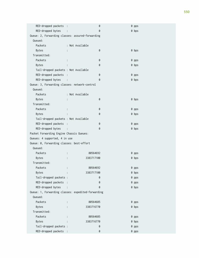
RED-dropped packets : 0 0 pps RED-dropped bytes : 0 0 bpsQueue: 2, Forwarding classes: assured-forwarding Queued: Packets : Not Available Bytes : 0 0 bps Transmitted: Packets : 0 0 pps Bytes : 0 0 bps Tail-dropped packets : Not Available RED-dropped packets : 0 0 pps RED-dropped bytes : 0 0 bpsQueue: 3, Forwarding classes: network-control Queued: Packets : Not Available Bytes : 0 0 bps Transmitted: Packets : 0 0 pps Bytes : 0 0 bps Tail-dropped packets : Not Available RED-dropped packets : 0 0 pps RED-dropped bytes : 0 0 bpsPacket Forwarding Engine Chassis Queues:Queues: 4 supported, 4 in useQueue: 0, Forwarding classes: best-effort Queued: Packets : 80564692 0 pps Bytes : 3383717100 0 bps Transmitted: Packets : 80564692 0 pps Bytes : 3383717100 0 bps Tail-dropped packets : 0 0 pps RED-dropped packets : 0 0 pps RED-dropped bytes : 0 0 bpsQueue: 1, Forwarding classes: expedited-forwarding Queued: Packets : 80564685 0 pps Bytes : 3383716770 0 bps Transmitted: Packets : 80564685 0 pps Bytes : 3383716770 0 bps Tail-dropped packets : 0 0 pps RED-dropped packets : 0 0 pps
550
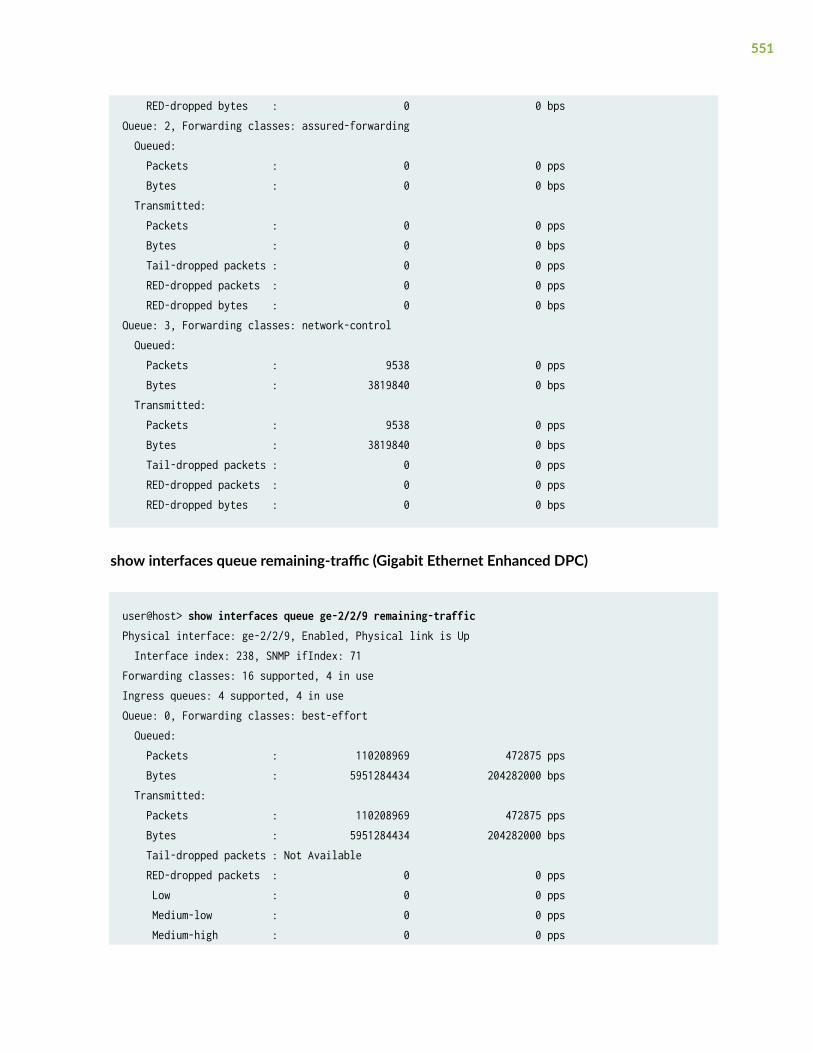
RED-dropped bytes : 0 0 bpsQueue: 2, Forwarding classes: assured-forwarding Queued: Packets : 0 0 pps Bytes : 0 0 bps Transmitted: Packets : 0 0 pps Bytes : 0 0 bps Tail-dropped packets : 0 0 pps RED-dropped packets : 0 0 pps RED-dropped bytes : 0 0 bpsQueue: 3, Forwarding classes: network-control Queued: Packets : 9538 0 pps Bytes : 3819840 0 bps Transmitted: Packets : 9538 0 pps Bytes : 3819840 0 bps Tail-dropped packets : 0 0 pps RED-dropped packets : 0 0 pps RED-dropped bytes : 0 0 bps
show interfaces queue remaining-traffic (Gigabit Ethernet Enhanced DPC)
user@host> show interfaces queue ge-2/2/9 remaining-trafficPhysical interface: ge-2/2/9, Enabled, Physical link is Up Interface index: 238, SNMP ifIndex: 71Forwarding classes: 16 supported, 4 in useIngress queues: 4 supported, 4 in useQueue: 0, Forwarding classes: best-effort Queued: Packets : 110208969 472875 pps Bytes : 5951284434 204282000 bps Transmitted: Packets : 110208969 472875 pps Bytes : 5951284434 204282000 bps Tail-dropped packets : Not Available RED-dropped packets : 0 0 pps Low : 0 0 pps Medium-low : 0 0 pps Medium-high : 0 0 pps
551

High : 0 0 pps RED-dropped bytes : 0 0 bps Low : 0 0 bps Medium-low : 0 0 bps Medium-high : 0 0 bps High : 0 0 bpsQueue: 1, Forwarding classes: expedited-forwarding Queued: Packets : 0 0 pps Bytes : 0 0 bps Transmitted: Packets : 0 0 pps Bytes : 0 0 bps Tail-dropped packets : Not Available RED-dropped packets : 0 0 pps Low : 0 0 pps Medium-low : 0 0 pps Medium-high : 0 0 pps High : 0 0 pps RED-dropped bytes : 0 0 bps Low : 0 0 bps Medium-low : 0 0 bps Medium-high : 0 0 bps High : 0 0 bpsQueue: 2, Forwarding classes: assured-forwarding Queued: Packets : 0 0 pps Bytes : 0 0 bps Transmitted: Packets : 0 0 pps Bytes : 0 0 bps Tail-dropped packets : Not Available RED-dropped packets : 0 0 pps Low : 0 0 pps Medium-low : 0 0 pps Medium-high : 0 0 pps High : 0 0 pps RED-dropped bytes : 0 0 bps Low : 0 0 bps Medium-low : 0 0 bps Medium-high : 0 0 bps High : 0 0 bpsQueue: 3, Forwarding classes: network-control
552

Queued: Packets : 0 0 pps Bytes : 0 0 bps Transmitted: Packets : 0 0 pps Bytes : 0 0 bps Tail-dropped packets : Not Available RED-dropped packets : 0 0 pps Low : 0 0 pps Medium-low : 0 0 pps Medium-high : 0 0 pps High : 0 0 pps RED-dropped bytes : 0 0 bps Low : 0 0 bps Medium-low : 0 0 bps Medium-high : 0 0 bps High : 0 0 bpsForwarding classes: 16 supported, 4 in useEgress queues: 4 supported, 4 in useQueue: 0, Forwarding classes: best-effort Queued: Packets : 109355853 471736 pps Bytes : 7436199152 256627968 bps Transmitted: Packets : 109355852 471736 pps Bytes : 7436198640 256627968 bps Tail-dropped packets : Not Available RED-dropped packets : 0 0 pps Low : 0 0 pps Medium-low : 0 0 pps Medium-high : 0 0 pps High : 0 0 pps RED-dropped bytes : 0 0 bps Low : 0 0 bps Medium-low : 0 0 bps Medium-high : 0 0 bps High : 0 0 bpsQueue: 1, Forwarding classes: expedited-forwarding Queued: Packets : 0 0 pps Bytes : 0 0 bps Transmitted: Packets : 0 0 pps
553

Bytes : 0 0 bps Tail-dropped packets : Not Available RED-dropped packets : 0 0 pps Low : 0 0 pps Medium-low : 0 0 pps Medium-high : 0 0 pps High : 0 0 pps RED-dropped bytes : 0 0 bps Low : 0 0 bps Medium-low : 0 0 bps Medium-high : 0 0 bps High : 0 0 bpsQueue: 2, Forwarding classes: assured-forwarding Queued: Packets : 0 0 pps Bytes : 0 0 bps Transmitted: Packets : 0 0 pps Bytes : 0 0 bps Tail-dropped packets : Not Available RED-dropped packets : 0 0 pps Low : 0 0 pps Medium-low : 0 0 pps Medium-high : 0 0 pps High : 0 0 pps RED-dropped bytes : 0 0 bps Low : 0 0 bps Medium-low : 0 0 bps Medium-high : 0 0 bps High : 0 0 bpsQueue: 3, Forwarding classes: network-control Queued: Packets : 0 0 pps Bytes : 0 0 bps Transmitted: Packets : 0 0 pps Bytes : 0 0 bps Tail-dropped packets : Not Available RED-dropped packets : 0 0 pps Low : 0 0 pps Medium-low : 0 0 pps Medium-high : 0 0 pps High : 0 0 pps
554

RED-dropped bytes : 0 0 bps Low : 0 0 bps Medium-low : 0 0 bps Medium-high : 0 0 bps High : 0 0 bps
show interfaces queue (Channelized OC12 IQE Type 3 PIC in SONET Mode)
user@host> show interfaces queue t3-1/1/0:7 Physical interface: t3-1/1/0:7, Enabled, Physical link is Up Interface index: 192, SNMP ifIndex: 1948 Description: full T3 interface connect to 6ce13 t3-3/1/0:7 for FR testing - Lam Forwarding classes: 16 supported, 9 in use Egress queues: 8 supported, 8 in use Queue: 0, Forwarding classes: DEFAULT Queued: Packets : 214886 13449 pps Bytes : 9884756 5164536 bps Transmitted: Packets : 214886 13449 pps Bytes : 9884756 5164536 bps Tail-dropped packets : 0 0 pps RED-dropped packets : 0 0 pps Low : 0 0 pps Medium-low : 0 0 pps Medium-high : 0 0 pps High : 0 0 pps RED-dropped bytes : 0 0 bps Low : 0 0 bps Medium-low : 0 0 bps Medium-high : 0 0 bps High : 0 0 bps Queue: 1, Forwarding classes: REALTIME Queued: Packets : 0 0 pps Bytes : 0 0 bps Transmitted: Packets : 0 0 pps Bytes : 0 0 bps Tail-dropped packets : 0 0 pps RED-dropped packets : 0 0 pps
555

Low : 0 0 pps Medium-low : 0 0 pps Medium-high : 0 0 pps High : 0 0 pps RED-dropped bytes : 0 0 bps Low : 0 0 bps Medium-low : 0 0 bps Medium-high : 0 0 bps High : 0 0 bps Queue: 2, Forwarding classes: PRIVATE Queued: Packets : 0 0 pps Bytes : 0 0 bps Transmitted: Packets : 0 0 pps Bytes : 0 0 bps Tail-dropped packets : 0 0 pps RED-dropped packets : 0 0 pps Low : 0 0 pps Medium-low : 0 0 pps Medium-high : 0 0 pps High : 0 0 pps RED-dropped bytes : 0 0 bps Low : 0 0 bps Medium-low : 0 0 bps Medium-high : 0 0 bps High : 0 0 bps Queue: 3, Forwarding classes: CONTROL Queued: Packets : 60 0 pps Bytes : 4560 0 bps Transmitted: Packets : 60 0 pps Bytes : 4560 0 bps Tail-dropped packets : 0 0 pps RED-dropped packets : 0 0 pps Low : 0 0 pps Medium-low : 0 0 pps Medium-high : 0 0 pps High : 0 0 pps RED-dropped bytes : 0 0 bps Low : 0 0 bps Medium-low : 0 0 bps
556

Medium-high : 0 0 bps High : 0 0 bps Queue: 4, Forwarding classes: CLASS_B_OUTPUT Queued: Packets : 0 0 pps Bytes : 0 0 bps Transmitted: Packets : 0 0 pps Bytes : 0 0 bps Tail-dropped packets : 0 0 pps RED-dropped packets : 0 0 pps Low : 0 0 pps Medium-low : 0 0 pps Medium-high : 0 0 pps High : 0 0 pps RED-dropped bytes : 0 0 bps Low : 0 0 bps Medium-low : 0 0 bps Medium-high : 0 0 bps High : 0 0 bps Queue: 5, Forwarding classes: CLASS_C_OUTPUT Queued: Packets : 0 0 pps Bytes : 0 0 bps Transmitted: Packets : 0 0 pps Bytes : 0 0 bps Tail-dropped packets : 0 0 pps RED-dropped packets : 0 0 pps Low : 0 0 pps Medium-low : 0 0 pps Medium-high : 0 0 pps High : 0 0 pps RED-dropped bytes : 0 0 bps Low : 0 0 bps Medium-low : 0 0 bps Medium-high : 0 0 bps High : 0 0 bps Queue: 6, Forwarding classes: CLASS_V_OUTPUT Queued: Packets : 0 0 pps Bytes : 0 0 bps Transmitted:
557

Packets : 0 0 pps Bytes : 0 0 bps Tail-dropped packets : 0 0 pps RED-dropped packets : 0 0 pps Low : 0 0 pps Medium-low : 0 0 pps Medium-high : 0 0 pps High : 0 0 pps RED-dropped bytes : 0 0 bps Low : 0 0 bps Medium-low : 0 0 bps Medium-high : 0 0 bps High : 0 0 bps Queue: 7, Forwarding classes: CLASS_S_OUTPUT, GETS Queued: Packets : 0 0 pps Bytes : 0 0 bps Transmitted: Packets : 0 0 pps Bytes : 0 0 bps Tail-dropped packets : 0 0 pps RED-dropped packets : 0 0 pps Low : 0 0 pps Medium-low : 0 0 pps Medium-high : 0 0 pps High : 0 0 pps RED-dropped bytes : 0 0 bps Low : 0 0 bps Medium-low : 0 0 bps Medium-high : 0 0 bps High : 0 0 bps Packet Forwarding Engine Chassis Queues: Queues: 8 supported, 8 in use Queue: 0, Forwarding classes: DEFAULT Queued: Packets : 371365 23620 pps Bytes : 15597330 7936368 bps Transmitted: Packets : 371365 23620 pps Bytes : 15597330 7936368 bps Tail-dropped packets : 0 0 pps RED-dropped packets : 0 0 pps
558

Low : 0 0 pps Medium-low : 0 0 pps Medium-high : 0 0 pps High : 0 0 pps RED-dropped bytes : 0 0 bps Low : 0 0 bps Medium-low : 0 0 bps Medium-high : 0 0 bps High : 0 0 bps Queue: 1, Forwarding classes: REALTIME Queued: Packets : 0 0 pps Bytes : 0 0 bps Transmitted: Packets : 0 0 pps Bytes : 0 0 bps Tail-dropped packets : 0 0 pps RED-dropped packets : 0 0 pps Low : 0 0 pps Medium-low : 0 0 pps Medium-high : 0 0 pps High : 0 0 pps RED-dropped bytes : 0 0 bps Low : 0 0 bps Medium-low : 0 0 bps Medium-high : 0 0 bps High : 0 0 bps Queue: 2, Forwarding classes: PRIVATE Queued: Packets : 0 0 pps Bytes : 0 0 bps Transmitted: Packets : 0 0 pps Bytes : 0 0 bps Tail-dropped packets : 0 0 pps RED-dropped packets : 0 0 pps Low : 0 0 pps Medium-low : 0 0 pps Medium-high : 0 0 pps High : 0 0 pps RED-dropped bytes : 0 0 bps Low : 0 0 bps Medium-low : 0 0 bps
559

Medium-high : 0 0 bps High : 0 0 bps Queue: 3, Forwarding classes: CONTROL Queued: Packets : 32843 0 pps Bytes : 2641754 56 bps Transmitted: Packets : 32843 0 pps Bytes : 2641754 56 bps Tail-dropped packets : 0 0 pps RED-dropped packets : 0 0 pps Low : 0 0 pps Medium-low : 0 0 pps Medium-high : 0 0 pps High : 0 0 pps RED-dropped bytes : 0 0 bps Low : 0 0 bps Medium-low : 0 0 bps Medium-high : 0 0 bps High : 0 0 bps Queue: 4, Forwarding classes: CLASS_B_OUTPUT Queued: Packets : 0 0 pps Bytes : 0 0 bps Transmitted: Packets : 0 0 pps Bytes : 0 0 bps Tail-dropped packets : 0 0 pps RED-dropped packets : 0 0 pps Low : 0 0 pps Medium-low : 0 0 pps Medium-high : 0 0 pps High : 0 0 pps RED-dropped bytes : 0 0 bps Low : 0 0 bps Medium-low : 0 0 bps Medium-high : 0 0 bps High : 0 0 bps Queue: 5, Forwarding classes: CLASS_C_OUTPUT Queued: Packets : 0 0 pps Bytes : 0 0 bps Transmitted:
560

Packets : 0 0 pps Bytes : 0 0 bps Tail-dropped packets : 0 0 pps RED-dropped packets : 0 0 pps Low : 0 0 pps Medium-low : 0 0 pps Medium-high : 0 0 pps High : 0 0 pps RED-dropped bytes : 0 0 bps Low : 0 0 bps Medium-low : 0 0 bps Medium-high : 0 0 bps High : 0 0 bps Queue: 6, Forwarding classes: CLASS_V_OUTPUT Queued: Packets : 0 0 pps Bytes : 0 0 bps Transmitted: Packets : 0 0 pps Bytes : 0 0 bps Tail-dropped packets : 0 0 pps RED-dropped packets : 0 0 pps Low : 0 0 pps Medium-low : 0 0 pps Medium-high : 0 0 pps High : 0 0 pps RED-dropped bytes : 0 0 bps Low : 0 0 bps Medium-low : 0 0 bps Medium-high : 0 0 bps High : 0 0 bps Queue: 7, Forwarding classes: CLASS_S_OUTPUT, GETS Queued: Packets : 0 0 pps Bytes : 0 0 bps Transmitted: Packets : 0 0 pps Bytes : 0 0 bps Tail-dropped packets : 0 0 pps RED-dropped packets : 0 0 pps Low : 0 0 pps Medium-low : 0 0 pps Medium-high : 0 0 pps
561

High : 0 0 pps RED-dropped bytes : 0 0 bps Low : 0 0 bps Medium-low : 0 0 bps Medium-high : 0 0 bps High : 0 0 bps
show interfaces queue (QFX Series)
user@switch> show interfaces queue xe-0/0/15 Physical interface: xe-0/0/15, Enabled, Physical link is Up Interface index: 49165, SNMP ifIndex: 539 Forwarding classes: 12 supported, 8 in use Egress queues: 12 supported, 8 in use Queue: 0, Forwarding classes: best-effort Queued: Packets : 0 0 pps Bytes : 0 0 bps Transmitted: Packets : 0 0 pps Bytes : 0 0 bps Tail-dropped packets : Not Available Total-dropped packets: 0 0 pps Total-dropped bytes : 0 0 bps Queue: 3, Forwarding classes: fcoe Queued: Packets : 0 0 pps Bytes : 0 0 bps Transmitted: Packets : 0 0 pps Bytes : 0 0 bps Tail-dropped packets : Not Available Total-dropped packets: 0 0 pps Total-dropped bytes : 0 0 bps Queue: 4, Forwarding classes: no-loss Queued: Packets : 0 0 pps Bytes : 0 0 bps Transmitted: Packets : 0 0 pps Bytes : 0 0 bps
562

Tail-dropped packets : Not Available Total-dropped packets: 0 0 pps Total-dropped bytes : 0 0 bps Queue: 7, Forwarding classes: network-control Queued: Packets : 0 0 pps Bytes : 0 0 bps Transmitted: Packets : 0 0 pps Bytes : 0 0 bps Tail-dropped packets : Not Available Total-dropped packets: 0 0 pps Total-dropped bytes : 0 0 bps Queue: 8, Forwarding classes: mcast Queued: Packets : 0 0 pps Bytes : 0 0 bps Transmitted: Packets : 0 0 pps Bytes : 0 0 bps Tail-dropped packets : Not Available Total-dropped packets: 0 0 pps Total-dropped bytes : 0 0 bps
show interfaces queue l2-statistics (lsq interface)
user@switch> show interfaces queue lsq-2/2/0.2 l2-statisticsLogical interface lsq-2/2/0.2 (Index 69) (SNMP ifIndex 1598)Forwarding classes: 16 supported, 4 in useEgress queues: 8 supported, 4 in useBurst size: 0Queue: 0, Forwarding classes: be Queued: Packets : 1 0 pps Bytes : 1001 0 bps Transmitted: Packets : 5 0 pps Bytes : 1062 0 bps Tail-dropped packets : 0 0 pps RED-dropped packets : 0 0 pps RED-dropped bytes : 0 0 bps
563

Queue: 1, Forwarding classes: ef Queued: Packets : 1 0 pps Bytes : 1500 0 bps Transmitted: Packets : 6 0 pps Bytes : 1573 0 bps Tail-dropped packets : 0 0 pps RED-dropped packets : 0 0 pps RED-dropped bytes : 0 0 bpsQueue: 2, Forwarding classes: af Queued: Packets : 1 0 pps Bytes : 512 0 bps Transmitted: Packets : 3 0 pps Bytes : 549 0 bps Tail-dropped packets : 0 0 pps RED-dropped packets : 0 0 pps RED-dropped bytes : 0 0 bpsQueue: 3, Forwarding classes: nc Queued: Packets : 0 0 pps Bytes : 0 0 bps Transmitted: Packets : 0 0 pps Bytes : 0 0 bps Tail-dropped packets : 0 0 pps RED-dropped packets : 0 0 pps RED-dropped bytes : 0 0 bps=========
show interfaces queue lsq (lsq-ifd)
user@switch> show interfaces queue lsq-1/0/0Logical interface lsq-1/0/0 (Index 348) (SNMP ifIndex 660)Forwarding classes: 16 supported, 4 in useEgress queues: 8 supported, 4 in useBurst size: 0Queue: 0, Forwarding classes: be Queued:
564

Packets : 55576 1206 pps Bytes : 29622008 5145472 bps Transmitted: Packets : 55576 1206 pps Bytes : 29622008 5145472 bps Tail-dropped packets : 0 0 pps RL-dropped packets : 0 0 pps RL-dropped bytes : 0 0 bps RED-dropped packets : 0 0 pps Low : 0 0 pps Medium-low : 0 0 pps Medium-high : 0 0 pps High : 0 0 pps RED-dropped bytes : 0 0 bps Low : 0 0 bps Medium-low : 0 0 bps Medium-high : 0 0 bps High : 0 0 bpsQueue: 1, Forwarding classes: ef Queued: Packets : 0 0 pps Bytes : 0 0 bps Transmitted: Packets : 0 0 pps Bytes : 0 0 bps Tail-dropped packets : 0 0 pps RL-dropped packets : 0 0 pps RL-dropped bytes : 0 0 bps RED-dropped packets : 0 0 pps Low : 0 0 pps Medium-low : 0 0 pps Medium-high : 0 0 pps High : 0 0 pps RED-dropped bytes : 0 0 bps Low : 0 0 bps Medium-low : 0 0 bps Medium-high : 0 0 bps High : 0 0 bpsQueue: 2, Forwarding classes: af Queued: Packets : 0 0 pps Bytes : 0 0 bps Transmitted:
565

Packets : 0 0 pps Bytes : 0 0 bps Tail-dropped packets : 0 0 pps RL-dropped packets : 0 0 pps RL-dropped bytes : 0 0 bps RED-dropped packets : 0 0 pps Low : 0 0 pps Medium-low : 0 0 pps Medium-high : 0 0 pps High : 0 0 pps RED-dropped bytes : 0 0 bps Low : 0 0 bps Medium-low : 0 0 bps Medium-high : 0 0 bps High : 0 0 bpsQueue: 3, Forwarding classes: nc Queued: Packets : 22231 482 pps Bytes : 11849123 2057600 bps Transmitted: Packets : 22231 482 pps Bytes : 11849123 2057600 bps Tail-dropped packets : 0 0 pps RL-dropped packets : 0 0 pps RL-dropped bytes : 0 0 bps RED-dropped packets : 0 0 pps Low : 0 0 pps Medium-low : 0 0 pps Medium-high : 0 0 pps High : 0 0 pps RED-dropped bytes : 0 0 bps Low : 0 0 bps Medium-low : 0 0 bps Medium-high : 0 0 bps High : 0 0 bps
show interfaces queue (Aggregated Ethernet on a MX series Router)
user@host> show interfaces queue ae0 remaining-trafficPhysical interface: ae0 , Enabled, Physical link is Up Interface index: 128, SNMP ifIndex: 543
566

Forwarding classes: 16 supported, 4 in useEgress queues: 8 supported, 4 in useQueue: 0, Forwarding classes: best-effort Queued: Packets : 16 0 pps Bytes : 1896 0 bps Transmitted: Packets : 16 0 pps Bytes : 1896 0 bps Tail-dropped packets : 0 0 pps RL-dropped packets : 0 0 pps RL-dropped bytes : 0 0 bps RED-dropped packets : 0 0 pps Low : 0 0 pps Medium-low : 0 0 pps Medium-high : 0 0 pps High : 0 0 pps RED-dropped bytes : 0 0 bps Low : 0 0 bps Medium-low : 0 0 bps Medium-high : 0 0 bps High : 0 0 bps Queue-depth bytes : Average : 0 Current : 0 Peak : 0 Maximum : 119013376Queue: 1, Forwarding classes: expedited-forwarding Queued: Packets : 0 0 pps Bytes : 0 0 bps Transmitted: Packets : 0 0 pps Bytes : 0 0 bps Tail-dropped packets : 0 0 pps RL-dropped packets : 0 0 pps RL-dropped bytes : 0 0 bps RED-dropped packets : 0 0 pps Low : 0 0 pps Medium-low : 0 0 pps Medium-high : 0 0 pps High : 0 0 pps RED-dropped bytes : 0 0 bps
567

Low : 0 0 bps Medium-low : 0 0 bps Medium-high : 0 0 bps High : 0 0 bps Queue-depth bytes : Average : 0 Current : 0 Peak : 0 Maximum : 32768Queue: 2, Forwarding classes: assured-forwarding Queued: Packets : 0 0 pps Bytes : 0 0 bps Transmitted: Packets : 0 0 pps Bytes : 0 0 bps Tail-dropped packets : 0 0 pps RL-dropped packets : 0 0 pps RL-dropped bytes : 0 0 bps RED-dropped packets : 0 0 pps Low : 0 0 pps Medium-low : 0 0 pps Medium-high : 0 0 pps High : 0 0 pps RED-dropped bytes : 0 0 bps Low : 0 0 bps Medium-low : 0 0 bps Medium-high : 0 0 bps High : 0 0 bps Queue-depth bytes : Average : 0 Current : 0 Peak : 0 Maximum : 32768Queue: 3, Forwarding classes: network-control Queued: Packets : 0 0 pps Bytes : 0 0 bps Transmitted: Packets : 0 0 pps Bytes : 0 0 bps Tail-dropped packets : 0 0 pps RL-dropped packets : 0 0 pps
568

RL-dropped bytes : 0 0 bps RED-dropped packets : 0 0 pps Low : 0 0 pps Medium-low : 0 0 pps Medium-high : 0 0 pps High : 0 0 pps RED-dropped bytes : 0 0 bps Low : 0 0 bps Medium-low : 0 0 bps Medium-high : 0 0 bps High : 0 0 bps Queue-depth bytes : Average : 0 Current : 0 Peak : 0 Maximum : 6258688
show interfaces queue ge-0/0/0 (EX2200 Switch)
user@switch> show interfaces queue ge–0/0/0Physical interface: ge-0/0/0, Enabled, Physical link is Down Interface index: 130, SNMP ifIndex: 501Forwarding classes: 16 supported, 4 in useEgress queues: 8 supported, 4 in useQueue: 0, Forwarding classes: best-effort Queued: Transmitted: Packets : 0 Bytes : 0 Tail-dropped packets : 0Queue: 1, Forwarding classes: assured-forwarding Queued: Transmitted: Packets : 0 Bytes : 0 Tail-dropped packets : 0Queue: 5, Forwarding classes: expedited-forwarding Queued: Transmitted: Packets : 0 Bytes : 0
569

Tail-dropped packets : 0Queue: 7, Forwarding classes: network-control Queued: Transmitted: Packets : 0 Bytes : 0 Tail-dropped packets : 0
show interfaces queue xe-6/0/39 (Line Card with Oversubscribed Ports in an EX8200 Switch)
user@switch> show interfaces queue xe-6/0/39Physical interface: xe-6/0/39, Enabled, Physical link is Up Interface index: 291, SNMP ifIndex: 1641Forwarding classes: 16 supported, 7 in useIngress queues: 1 supported, 1 in use Transmitted: Packets : 337069086018 Bytes : 43144843010304 Tail-dropped packets : 8003867575PFE chassis queues: 1 supported, 1 in use Transmitted: Packets : 0 Bytes : 0 Tail-dropped packets : 0Forwarding classes: 16 supported, 7 in useEgress queues: 8 supported, 7 in useQueue: 0, Forwarding classes: best-effort Queued: Transmitted: Packets : 334481399932 Bytes : 44151544791024 Tail-dropped packets : 0 Queue: 1, Forwarding classes: assured-forwarding Queued: Transmitted: Packets : 0 Bytes : 0 Tail-dropped packets : 0 Queue: 2, Forwarding classes: mcast-be Queued: Transmitted:
570

Packets : 274948977 Bytes : 36293264964 Tail-dropped packets : 0Queue: 4, Forwarding classes: mcast-ef Queued: Transmitted: Packets : 0 Bytes : 0 Tail-dropped packets : 0 Queue: 5, Forwarding classes: expedited-forwarding Queued: Transmitted: Packets : 0 Bytes : 0 Tail-dropped packets : 0 Queue: 6, Forwarding classes: mcast-af Queued: Transmitted: Packets : 0 Bytes : 0 Tail-dropped packets : 0 Queue: 7, Forwarding classes: network-control Queued: Transmitted: Packets : 46714 Bytes : 6901326 Tail-dropped packets : 0
Packet Forwarding Engine Chassis Queues:Queues: 8 supported, 7 in useQueue: 0, Forwarding classes: best-effort Queued: Transmitted: Packets : 739338141426 Bytes : 94635282101928 Tail-dropped packets : 0 RED-dropped packets : 5606426444 Low : 5606426444 High : 0 RED-dropped bytes : 683262846464 Low : 683262846464 High : 0Queue: 1, Forwarding classes: assured-forwarding
571

Queued: Transmitted: Packets : 0 Bytes : 0 Tail-dropped packets : 0 RED-dropped packets : 0 Low : 0 High : 0 RED-dropped bytes : 0 Low : 0 High : 0Queue: 2, Forwarding classes: mcast-be Queued: Transmitted: Packets : 0 Bytes : 0 Tail-dropped packets : 0 RED-dropped packets : 0 Low : 0 High : 0 RED-dropped bytes : 0 Low : 0 High : 0Queue: 4, Forwarding classes: mcast-ef Queued: Transmitted: Packets : 0 Bytes : 0 Tail-dropped packets : 0 RED-dropped packets : 0 Low : 0 High : 0 RED-dropped bytes : 0 Low : 0 High : 0Queue: 5, Forwarding classes: expedited-forwarding Queued: Transmitted: Packets : 0 Bytes : 0 Tail-dropped packets : 0 RED-dropped packets : 0 Low : 0
572

High : 0 RED-dropped bytes : 0 Low : 0 High : 0Queue: 6, Forwarding classes: mcast-af Queued: Transmitted: Packets : 0 Bytes : 0 Tail-dropped packets : 0 RED-dropped packets : 0 Low : 0 High : 0 RED-dropped bytes : 0 Low : 0 High : 0Queue: 7, Forwarding classes: network-control Queued: Transmitted: Packets : 97990 Bytes : 14987506 Tail-dropped packets : 0 RED-dropped packets : 0 Low : 0 High : 0 RED-dropped bytes : 0 Low : 0 High : 0
show interfaces queue xe-0/0/2 buffer-occupancy (QFX5000 Series switch)
user@switch> show interfaces queue xe-0/0/2 buffer-occupancyPhysical interface: xe-0/0/2, Enabled, Physical link is Up Interface index: 689, SNMP ifIndex: 514Forwarding classes: 12 supported, 5 in useEgress queues: 12 supported, 5 in use Queue: 0, Forwarding classes: fc0 Queue-depth bytes : Peak : 1786720 Queue: 3, Forwarding classes: fcoe Queue-depth bytes :
573

Peak : 0 Queue: 4, Forwarding classes: no-loss Queue-depth bytes : Peak : 0 Queue: 7, Forwarding classes: network-control Queue-depth bytes : Peak : 416 Queue: 8, Forwarding classes: mcast Queue-depth bytes : Peak : 0
Release Information
Command introduced before Junos OS Release 7.4.
both-ingress-egress, egress, and ingress options introduced in Junos OS Release 7.6.
l2-statistics option introduced in Junos OS Release 12.1.
buffer-occupancy statement introduced in Junos OS Release 19.1R1 for QFX5000 Series switches.
Release History Table
Release Description
18.3R1 Starting with Junos OS 18.3R1, the Tail-dropped packets counter is supported on PTX Series PacketTransport Routers.
16.1 Starting with Junos OS Release 16.1, Last-packet enqueued output field is introduced.
RELATED DOCUMENTATION
Monitoring Interface Status and Traffic
Monitoring Interfaces That Have CoS Components
Defining CoS Schedulers and Scheduler Maps (CLI Procedure)
Configuring CoS Traffic Classification for Ingress Queuing on Oversubscribed Ports on EX8200 LineCards (CLI Procedure)
ATM Interfaces User Guide for Routing Devices
Layer 2 Bridging, Address Learning, and Forwarding User Guide
574

show interfaces voq
IN THIS SECTION
Syntax | 575
Syntax (Junos OS Evolved) | 575
Description | 575
Options | 576
Additional Information | 576
Required Privilege Level | 576
Output Fields | 576
Sample Output | 578
Release Information | 593
Syntax
show interfaces voq interface-name<forwarding-class forwarding-class-name> <non-zero>
Syntax (Junos OS Evolved)
show interfaces voq interface-name<forwarding-class forwarding-class-name> <non-zero> <source-fpc source-fpc-number>
Description
Display the random early detection (RED) drop statistics from all ingress Packet Forwarding Enginesassociated with the specified physical egress interface. In the VOQ architecture, egress output queues(shallow buffers) buffer data in virtual queues on ingress Packet Forwarding Engines. In cases of
575

congestion, you can use this command to identify which ingress Packet Forwarding Engine is the sourceof RED-dropped packets contributing to congestion.
NOTE: On the PTX Series routers and QFX10000 switches, these statistics include tail-droppedpackets.
Options
interface interface-name Display the ingress VOQ RED drop statistics for the specified egressinterface.
forwarding-class forwarding-class-name
Display VOQ RED drop statistics for a specified forwarding class.
non-zero Display only non-zero VOQ RED drop statistics counters.
source-fpc source-fpc-number
Display VOQ RED drop statistics for the specified source FPC.
Additional Information
• On PTX Series routers, you can display VOQ statistics for only the WAN physical interface.
• VOQ statistics for aggregated physical interfaces are not supported. Statistics for an aggregatedinterface are the summation of the queue statistics of the child links of that aggregated interface.You can use the show interfaces queue command to identify the child link which is experiencingcongestion and then view the VOQ statistics on the respective child link using the show interfaces voqcommand.
For information on virtual output queuing on PTX routers, see Understanding Virtual Output Queues onPTX Series Packet Transport Routers. For information on virtual output queueing on QFX10000switches, see Understanding CoS Virtual Output Queues (VOQs) on QFX10000 Switches.
Required Privilege Level
view
Output Fields
Table 78 on page 577 lists the output fields for the show interfaces queue command. Output fields arelisted in the approximate order in which they appear.
576

Table 78: show interfaces voq Output Fields
Field Name Field Description
Physical interface Name of the physical interface.
Enabled State of the interface. Possible values are described in the“Enabled Field” section under Common Output FieldsDescription.
Interface index Physical interface's index number, which reflects itsinitialization sequence.
SNMP ifIndex SNMP index number for the interface.
Queue Egress queue number.
Forwarding classes Forwarding class name.
FPC number Number of the Flexible PIC Concentrator (FPC) located oningress.
PFE Number of the Packet Forwarding Engine providing virtualoutput queues on the ingress.
RED-dropped packets Number of packets per second (pps) dropped because ofrandom early detection (RED).
NOTE: On the PTX Series routers, these statistics include tail-dropped packets.
RED-dropped bytes Number of bytes per second dropped because of RED. Thebyte counts vary by interface hardware.
NOTE: On the PTX Series routers, these statistics include tail-dropped packets.
577

Sample Output
show interfaces voq (For a Specific Physical Interface) (PTX Series Routers)
The following example shows ingress RED-dropped statistics for the egress Ethernet interfaceconfigured on port 0 of Physical Interface Card (PIC) 0, located on the FPC in slot 7.
The sample output below shows that the cause of the congestion is ingress Packet Forwarding EnginePFE 0, which resides on FPC number 4, as denoted by the count of RED-dropped packets and RED-dropped bytes for egress queue 0, forwarding classes best-effort and egress queue 3, forwarding classnetwork control.
user@host> show interfaces voq et-7/0/0Physical interface: et-7/0/0, Enabled, Physical link is Up Interface index: 155, SNMP ifIndex: 699
Queue: 0, Forwarding classes: best-effort
FPC number: 1 PFE: 0 RED-dropped packets : 0 0 pps RED-dropped bytes : 0 0 bps PFE: 1 RED-dropped packets : 0 0 pps RED-dropped bytes : 0 0 bps PFE: 2 RED-dropped packets : 0 0 pps RED-dropped bytes : 0 0 bps PFE: 3 RED-dropped packets : 0 0 pps RED-dropped bytes : 0 0 bps
FPC number: 4 PFE: 0 RED-dropped packets : 19969426 2323178 pps RED-dropped bytes : 2196636860 2044397464 bps PFE: 1 RED-dropped packets : 0 0 pps RED-dropped bytes : 0 0 bps PFE: 2 RED-dropped packets : 0 0 pps RED-dropped bytes : 0 0 bps
578

PFE: 3 RED-dropped packets : 0 0 pps RED-dropped bytes : 0 0 bps
FPC number: 6 PFE: 0 RED-dropped packets : 19969424 2321205 pps RED-dropped bytes : 2196636640 2042660808 bps PFE: 1 RED-dropped packets : 0 0 pps RED-dropped bytes : 0 0 bps PFE: 2 RED-dropped packets : 0 0 pps RED-dropped bytes : 0 0 bps PFE: 3 RED-dropped packets : 0 0 pps RED-dropped bytes : 0 0 bps PFE: 4 RED-dropped packets : 0 0 pps RED-dropped bytes : 0 0 bps PFE: 5 RED-dropped packets : 0 0 pps RED-dropped bytes : 0 0 bps PFE: 6 RED-dropped packets : 0 0 pps RED-dropped bytes : 0 0 bps PFE: 7 RED-dropped packets : 0 0 pps RED-dropped bytes : 0 0 bps
FPC number: 7 PFE: 0 RED-dropped packets : 0 0 pps RED-dropped bytes : 0 0 bps PFE: 1 RED-dropped packets : 0 0 pps RED-dropped bytes : 0 0 bps PFE: 2 RED-dropped packets : 0 0 pps RED-dropped bytes : 0 0 bps PFE: 3 RED-dropped packets : 0 0 pps RED-dropped bytes : 0 0 bps
579

Queue: 1, Forwarding classes: expedited-forwarding
FPC number: 1 PFE: 0 RED-dropped packets : 0 0 pps RED-dropped bytes : 0 0 bps PFE: 1 RED-dropped packets : 0 0 pps RED-dropped bytes : 0 0 bps PFE: 2 RED-dropped packets : 0 0 pps RED-dropped bytes : 0 0 bps PFE: 3 RED-dropped packets : 0 0 pps RED-dropped bytes : 0 0 bps
FPC number: 4 PFE: 0 RED-dropped packets : 0 0 pps RED-dropped bytes : 0 0 bps PFE: 1 RED-dropped packets : 0 0 pps RED-dropped bytes : 0 0 bps PFE: 2 RED-dropped packets : 0 0 pps RED-dropped bytes : 0 0 bps PFE: 3 RED-dropped packets : 0 0 pps RED-dropped bytes : 0 0 bps
FPC number: 6 PFE: 0 RED-dropped packets : 0 0 pps RED-dropped bytes : 0 0 bps PFE: 1 RED-dropped packets : 0 0 pps RED-dropped bytes : 0 0 bps PFE: 2 RED-dropped packets : 0 0 pps RED-dropped bytes : 0 0 bps PFE: 3 RED-dropped packets : 0 0 pps
580

RED-dropped bytes : 0 0 bps PFE: 4 RED-dropped packets : 0 0 pps RED-dropped bytes : 0 0 bps PFE: 5 RED-dropped packets : 0 0 pps RED-dropped bytes : 0 0 bps PFE: 6 RED-dropped packets : 0 0 pps RED-dropped bytes : 0 0 bps PFE: 7 RED-dropped packets : 0 0 pps RED-dropped bytes : 0 0 bps
FPC number: 7 PFE: 0 RED-dropped packets : 0 0 pps RED-dropped bytes : 0 0 bps PFE: 1 RED-dropped packets : 0 0 pps RED-dropped bytes : 0 0 bps PFE: 2 RED-dropped packets : 0 0 pps RED-dropped bytes : 0 0 bps PFE: 3 RED-dropped packets : 0 0 pps RED-dropped bytes : 0 0 bps
Queue: 2, Forwarding classes: assured-forwarding
FPC number: 1 PFE: 0 RED-dropped packets : 0 0 pps RED-dropped bytes : 0 0 bps PFE: 1 RED-dropped packets : 0 0 pps RED-dropped bytes : 0 0 bps PFE: 2 RED-dropped packets : 0 0 pps RED-dropped bytes : 0 0 bps PFE: 3 RED-dropped packets : 0 0 pps RED-dropped bytes : 0 0 bps
581

FPC number: 4 PFE: 0 RED-dropped packets : 0 0 pps RED-dropped bytes : 0 0 bps PFE: 1 RED-dropped packets : 0 0 pps RED-dropped bytes : 0 0 bps PFE: 2 RED-dropped packets : 0 0 pps RED-dropped bytes : 0 0 bps PFE: 3 RED-dropped packets : 0 0 pps RED-dropped bytes : 0 0 bps
FPC number: 6 PFE: 0 RED-dropped packets : 0 0 pps RED-dropped bytes : 0 0 bps PFE: 1 RED-dropped packets : 0 0 pps RED-dropped bytes : 0 0 bps PFE: 2 RED-dropped packets : 0 0 pps RED-dropped bytes : 0 0 bps PFE: 3 RED-dropped packets : 0 0 pps RED-dropped bytes : 0 0 bps PFE: 4 RED-dropped packets : 0 0 pps RED-dropped bytes : 0 0 bps PFE: 5 RED-dropped packets : 0 0 pps RED-dropped bytes : 0 0 bps PFE: 6 RED-dropped packets : 0 0 pps RED-dropped bytes : 0 0 bps PFE: 7 RED-dropped packets : 0 0 pps RED-dropped bytes : 0 0 bps
FPC number: 7 PFE: 0
582

RED-dropped packets : 0 0 pps RED-dropped bytes : 0 0 bps PFE: 1 RED-dropped packets : 0 0 pps RED-dropped bytes : 0 0 bps PFE: 2 RED-dropped packets : 0 0 pps RED-dropped bytes : 0 0 bps PFE: 3 RED-dropped packets : 0 0 pps RED-dropped bytes : 0 0 bps
Queue: 3, Forwarding classes: network-control
FPC number: 1 PFE: 0 RED-dropped packets : 0 0 pps RED-dropped bytes : 0 0 bps PFE: 1 RED-dropped packets : 0 0 pps RED-dropped bytes : 0 0 bps PFE: 2 RED-dropped packets : 0 0 pps RED-dropped bytes : 0 0 bps PFE: 3 RED-dropped packets : 0 0 pps RED-dropped bytes : 0 0 bps
FPC number: 4 PFE: 0 RED-dropped packets : 16338670 1900314 pps RED-dropped bytes : 1797253700 1672276976 bps PFE: 1 RED-dropped packets : 0 0 pps RED-dropped bytes : 0 0 bps PFE: 2 RED-dropped packets : 0 0 pps RED-dropped bytes : 0 0 bps PFE: 3 RED-dropped packets : 0 0 pps RED-dropped bytes : 0 0 bps
FPC number: 6
583

PFE: 0 RED-dropped packets : 16338698 1899163 pps RED-dropped bytes : 1797256780 1671263512 bps PFE: 1 RED-dropped packets : 0 0 pps RED-dropped bytes : 0 0 bps PFE: 2 RED-dropped packets : 0 0 pps RED-dropped bytes : 0 0 bps PFE: 3 RED-dropped packets : 0 0 pps RED-dropped bytes : 0 0 bps PFE: 4 RED-dropped packets : 0 0 pps RED-dropped bytes : 0 0 bps PFE: 5 RED-dropped packets : 0 0 pps RED-dropped bytes : 0 0 bps PFE: 6 RED-dropped packets : 0 0 pps RED-dropped bytes : 0 0 bps PFE: 7 RED-dropped packets : 0 0 pps RED-dropped bytes : 0 0 bps
FPC number: 7 PFE: 0 RED-dropped packets : 0 0 pps RED-dropped bytes : 0 0 bps PFE: 1 RED-dropped packets : 0 0 pps RED-dropped bytes : 0 0 bps PFE: 2 RED-dropped packets : 0 0 pps RED-dropped bytes : 0 0 bps PFE: 3 RED-dropped packets : 0 0 pps RED-dropped bytes : 0 0 bps
584

show interfaces voq (For a Specific Physical Interface) (QFX10000 Switches)
The sample output below shows congestion on ingress PFE 1 on FPC number 0, and on ingress PFE 2on FPC number 1, as denoted by the count of RED-dropped packets and RED-dropped bytes for best-effort egress queue 0.
user@host> show interfaces voq et-1/0/0Physical interface: et-1/0/0, Enabled, Physical link is Up Interface index: 659, SNMP ifIndex: 539
Queue: 0, Forwarding classes: best-effort
FPC number: 0 PFE: 0 RED-dropped packets : 0 0 pps RED-dropped bytes : 0 0 bps PFE: 1 RED-dropped packets : 411063248 16891870 pps RED-dropped bytes : 52616095744 17297275600 bps PFE: 2 RED-dropped packets : 0 0 pps RED-dropped bytes : 0 0 bps
FPC number: 1 PFE: 0 RED-dropped packets : 0 0 pps RED-dropped bytes : 0 0 bps PFE: 1 RED-dropped packets : 0 0 pps RED-dropped bytes : 0 0 bps PFE: 2 RED-dropped packets : 411063012 16891870 pps RED-dropped bytes : 52616065536 17297275376 bps
Queue: 3, Forwarding classes: fcoe
FPC number: 0 PFE: 0 RED-dropped packets : 0 0 pps RED-dropped bytes : 0 0 bps PFE: 1 RED-dropped packets : 0 0 pps
585

RED-dropped bytes : 0 0 bps PFE: 2 RED-dropped packets : 0 0 pps RED-dropped bytes : 0 0 bps
FPC number: 1 PFE: 0 RED-dropped packets : 0 0 pps RED-dropped bytes : 0 0 bps PFE: 1 RED-dropped packets : 0 0 pps RED-dropped bytes : 0 0 bps PFE: 2 RED-dropped packets : 0 0 pps RED-dropped bytes : 0 0 bps
Queue: 4, Forwarding classes: no-loss
FPC number: 0 PFE: 0 RED-dropped packets : 0 0 pps RED-dropped bytes : 0 0 bps PFE: 1 RED-dropped packets : 0 0 pps RED-dropped bytes : 0 0 bps PFE: 2 RED-dropped packets : 0 0 pps RED-dropped bytes : 0 0 bps
FPC number: 1 PFE: 0 RED-dropped packets : 0 0 pps RED-dropped bytes : 0 0 bps PFE: 1 RED-dropped packets : 0 0 pps RED-dropped bytes : 0 0 bps PFE: 2 RED-dropped packets : 0 0 pps RED-dropped bytes : 0 0 bps
Queue: 7, Forwarding classes: network-control
FPC number: 0
586

PFE: 0 RED-dropped packets : 0 0 pps RED-dropped bytes : 0 0 bps PFE: 1 RED-dropped packets : 0 0 pps RED-dropped bytes : 0 0 bps PFE: 2 RED-dropped packets : 0 0 pps RED-dropped bytes : 0 0 bps
FPC number: 1 PFE: 0 RED-dropped packets : 0 0 pps RED-dropped bytes : 0 0 bps PFE: 1 RED-dropped packets : 0 0 pps RED-dropped bytes : 0 0 bps PFE: 2 RED-dropped packets : 0 0 pps RED-dropped bytes : 0 0 bps
show interfaces voq et-7/0/0 (For a Specific Forwarding Class)
user@host> show interfaces voq et-7/0/0 forwarding-class best-effortPhysical interface: et-7/0/0, Enabled, Physical link is Up Interface index: 155, SNMP ifIndex: 699
Queue: 0, Forwarding classes: best-effort
FPC number: 1 PFE: 0 RED-dropped packets : 0 0 pps RED-dropped bytes : 0 0 bps PFE: 1 RED-dropped packets : 0 0 pps RED-dropped bytes : 0 0 bps PFE: 2 RED-dropped packets : 0 0 pps RED-dropped bytes : 0 0 bps PFE: 3 RED-dropped packets : 0 0 pps
587

RED-dropped bytes : 0 0 bps
FPC number: 4 PFE: 0 RED-dropped packets : 66604786 2321519 pps RED-dropped bytes : 7326526460 2042936776 bps PFE: 1 RED-dropped packets : 0 0 pps RED-dropped bytes : 0 0 bps PFE: 2 RED-dropped packets : 0 0 pps RED-dropped bytes : 0 0 bps PFE: 3 RED-dropped packets : 0 0 pps RED-dropped bytes : 0 0 bps
FPC number: 6 PFE: 0 RED-dropped packets : 66604794 371200 pps RED-dropped bytes : 7326527340 326656000 bps PFE: 1 RED-dropped packets : 0 0 pps RED-dropped bytes : 0 0 bps PFE: 2 RED-dropped packets : 0 0 pps RED-dropped bytes : 0 0 bps PFE: 3 RED-dropped packets : 0 0 pps RED-dropped bytes : 0 0 bps PFE: 4 RED-dropped packets : 0 0 pps RED-dropped bytes : 0 0 bps PFE: 5 RED-dropped packets : 0 0 pps RED-dropped bytes : 0 0 bps PFE: 6 RED-dropped packets : 0 0 pps RED-dropped bytes : 0 0 bps PFE: 7 RED-dropped packets : 0 0 pps RED-dropped bytes : 0 0 bps
FPC number: 7
588

PFE: 0 RED-dropped packets : 0 0 pps RED-dropped bytes : 0 0 bps PFE: 1 RED-dropped packets : 0 0 pps RED-dropped bytes : 0 0 bps PFE: 2 RED-dropped packets : 0 0 pps RED-dropped bytes : 0 0 bps PFE: 3 RED-dropped packets : 0 0 pps RED-dropped bytes : 0 0 bps
show interfaces voq et-5/0/12 (For a Specific Source FPC)
user@host> show interfaces voq et-5/0/12 source-fpc 0Physical interface: et-5/0/12, Enabled, Physical link is Up Interface index: 166, SNMP ifIndex: 1104 Queue: 0, Forwarding classes: best-effort FPC number: 0 PFE: 0 RED-dropped packets : 0 0 pps RED-dropped bytes : 0 0 bps PFE: 1 RED-dropped packets : 0 0 pps RED-dropped bytes : 0 0 bps PFE: 2 RED-dropped packets : 0 0 pps RED-dropped bytes : 0 0 bps PFE: 3 RED-dropped packets : 0 0 pps RED-dropped bytes : 0 0 bps Queue: 1, Forwarding classes: expedited-forwarding FPC number: 0 PFE: 0 RED-dropped packets : 0 0 pps RED-dropped bytes : 0 0 bps
589

PFE: 1 RED-dropped packets : 0 0 pps RED-dropped bytes : 0 0 bps PFE: 2 RED-dropped packets : 0 0 pps RED-dropped bytes : 0 0 bps PFE: 3 RED-dropped packets : 0 0 pps RED-dropped bytes : 0 0 bps Queue: 2, Forwarding classes: assured-forwarding FPC number: 0 PFE: 0 RED-dropped packets : 0 0 pps RED-dropped bytes : 0 0 bps PFE: 1 RED-dropped packets : 0 0 pps RED-dropped bytes : 0 0 bps PFE: 2 RED-dropped packets : 0 0 pps RED-dropped bytes : 0 0 bps PFE: 3 RED-dropped packets : 0 0 pps RED-dropped bytes : 0 0 bps Queue: 3, Forwarding classes: network-control FPC number: 0 PFE: 0 RED-dropped packets : 0 0 pps RED-dropped bytes : 0 0 bps PFE: 1 RED-dropped packets : 0 0 pps RED-dropped bytes : 0 0 bps PFE: 2 RED-dropped packets : 0 0 pps RED-dropped bytes : 0 0 bps PFE: 3 RED-dropped packets : 0 0 pps RED-dropped bytes : 0 0 bps
590

show interfaces voq et-5/0/12 (For a Specific Forwarding Class and Source FPC)
user@host> show interfaces voq et-5/0/12 forwarding-class best-effort source-fpc 5Physical interface: et-5/0/12, Enabled, Physical link is Up Interface index: 166, SNMP ifIndex: 1104 Queue: 0, Forwarding classes: best-effort FPC number: 5 PFE: 0 RED-dropped packets : 0 0 pps RED-dropped bytes : 0 0 bps PFE: 1 RED-dropped packets : 0 0 pps RED-dropped bytes : 0 0 bps PFE: 2 RED-dropped packets : 0 0 pps RED-dropped bytes : 0 0 bps PFE: 3 RED-dropped packets : 0 0 pps RED-dropped bytes : 0 0 bps PFE: 4 RED-dropped packets : 0 0 pps RED-dropped bytes : 0 0 bps PFE: 5 RED-dropped packets : 0 0 pps RED-dropped bytes : 0 0 bps PFE: 6 RED-dropped packets : 0 0 pps RED-dropped bytes : 0 0 bps PFE: 7 RED-dropped packets : 0 0 pps RED-dropped bytes : 0 0 bps
show interfaces voq et-7/0/0 (Non-Zero)
user@host> show interfaces voq et-7/0/0 non-zero
Physical interface: et-7/0/0, Enabled, Physical link is Up
591

Interface index: 155, SNMP ifIndex: 699
Queue: 0, Forwarding classes: best-effort
FPC number: 4 PFE: 0 RED-dropped packets : 95862238 2301586 pps RED-dropped bytes : 10544846180 2025396264 bps
FPC number: 6 PFE: 0 RED-dropped packets : 95866639 2322569 pps RED-dropped bytes : 10545330290 2043860728 bps
Queue: 3, Forwarding classes: network-control
FPC number: 4 PFE: 0 RED-dropped packets : 78433066 1899727 pps RED-dropped bytes : 8627637260 1671760384 bps
FPC number: 6 PFE: 0 RED-dropped packets : 78436704 1900628 pps RED-dropped bytes : 8628037440 1672553432 bps
show interfaces voq et-7/0/0 (For a Specific Forwarding Class and Non-Zero)
user@host show interfaces voq et-7/0/0 forwarding-class best-effort non-zeroPhysical interface: et-7/0/0, Enabled, Physical link is Up Interface index: 155, SNMP ifIndex: 699
Queue: 0, Forwarding classes: best-effort
FPC number: 4 PFE: 0 RED-dropped packets : 119540012 2322319 pps RED-dropped bytes : 13149401320 2043640784 bps
FPC number: 6
592

PFE: 0 RED-dropped packets : 119540049 2322988 pps RED-dropped bytes : 13149405390 2044229744 bps
Release Information
Command introduced in Junos OS Release 14.1.
RELATED DOCUMENTATION
Understanding Virtual Output Queues on PTX Series Packet Transport Routers
Understanding CoS Virtual Output Queues (VOQs) on QFX10000 Switches
593
Copyright © 2022 FDOKUMEN