688 User Guide - Sound Devices
216
® 688 Field Production Mixer with Integrated Recorder and MixAssist ™ User Guide
-
Upload
khangminh22 -
Category
Documents
-
view
2 -
download
0
Transcript of 688 User Guide - Sound Devices
®
688Field Production Mixer with
Integrated Recorder and MixAssist™
User Guide
Sound Devices, LLCE7556 Road 23 and 33Reedsburg, Wisconsin 53959 USA
Direct: +1 (608) 524-0625Toll Free: (800) 505-0625 Fax: +1 (608) 524-0655
www.sounddevices.com
Legal Notices
Product specifications and features are subject to change without prior notification.
Copyright © 2017 Sound Devices, LLC. All rights reserved.
This product is subject to the terms and conditions of a software license agreement provided with the product, and may be used in accordance with the license agreement.
This document is protected under copyright law. An authorized licensee of this product may reproduce this publication for the licensee’s own personal use. This document may not be reproduced or distrib-uted, in whole or in part, for commercial purposes, such as selling copies or providing educational ser-vices or support.
This document is supplied as a technical guide. Spe-cial care has been taken in preparing the information for publication; however, since product specifications are subject to change, this document might contain omissions and technical or typographical inaccura-cies. Sound Devices, LLC does not accept responsi-bility for any losses due to the user of this guide.
Trademarks
The “wave” logo and USBPre are registered trademarks; FileSafe, PowerSafe, SuperSlot, MixAssist, QuickBoot, and Wave Agent are trade-marks of Sound Devices, LLC. Mac and OS X are trademarks of Apple Inc., registered in the U.S. and other countries. Windows and Microsoft Excel are registered trademarks of Microsoft Corporation in the U.S. and other countries. All other trademarks herein are the property of their respective owners.
FCC Notice
This device complies with part 15 of the FCC Rules. Operation is subject to the following two conditions: (1) This device may not cause harmful interference, and (2) This device must accept any interference received, including interference that may cause undesired operation.
FCC Part 15.19(a)(3)
Symbol Description > This symbol is used to show the order
in which you select menu commands and sub-options, such as: Main Menu > Audio indicates you press the Menu button for the Main Menu, then scroll to and select Audio by pushing the Control Knob.
+ A plus sign is used to show button or keystroke combinations.
For instance, Ctrl+V means to hold the Control key down and press the V key simultaneously. This also applies to other controls, such as switches and encoders. For instance, MIC+HP turn means to slide and hold the MIC/TONE switch left while turning the Headphone (HP) encoder. METERS+SELECT means to hold the METERS button down as you press the SELECT encoder.
i A note provides recommendations and important related information. The text for notes also appears italicized in a dif-ferent color.
⚠ A cautionary warning about a specific action that could cause harm to you, the device, or cause you to lose data. Follow the guidelines in this document or on the unit itself when handling elec-trical equipment. The text for caution-ary notes also appears italicized and bold in a different color.
Manual Conventions
This document is distributed by Sound Devices, LLC in online electronic (PDF) format only. E-published in the USA.
688 User Guide • Rev 4-C • January 15, 2019
3
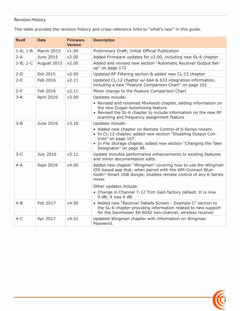
Revision History
This table provides the revision history and cross-reference links to “what’s new” in this guide.
Rev# Date Firmware Version
Description
1-A; 1-B March 2015 v1.00 Preliminary Draft; Initial Official Publication2-A June 2015 v2.00 Added Firmware updates for v2.00, including new SL-6 chapter2-B; 2-C August 2015 v2.00 Added and revised new section “Automatic Receiver Output Set-
up” on page 1722-D Oct 2015 v2.00 Updated RF Filtering section & added new CL-12 chapter2-E Feb 2016 v2.11 Updated CL-12 chapter w/ 664 & 633 integration information,
including a new “Feature Comparison Chart” on page 1612-F Feb 2016 v2.11 Minor change to the Feature Comparison Chart3-A April 2016 v3.00 Updates include:
• Revised and renamed MixAssist chapter, adding information on the new Dugan Automixing feature
• Revised the SL-6 chapter to include information on the new RF scanning and frequency assignment feature
3-B June 2016 v3.10 Updates include:• Added new chapter on Remote Control of 6-Series mixers.• In CL-12 chapter, added new section “Disabling Output Con-
trols” on page 167.• In File Storage chapter, added new section “Changing the Take
Designator” on page 98.3-C July 2016 v3.11 Update includes performance enhancements to existing features
and minor documentation edits.4-A Sept 2016 v4.00 Added new chapter “Wingman” covering how to use the Wingman
iOS-based app that, when paired with the WM-Connect Blue-tooth® Smart USB dongle, enables remote control of any 6-Series mixer.
Other updates include:• Change in Channel 7-12 Trim Gain factory default. It is now
0 dB; it was 6 dB.4-B Feb 2017 v4.50 • Added new “Receiver Details Screen - Example C” section to
the SL-6 chapter providing information related to new support for the Sennheiser EK-6042 two-channel, wireless receiver.
4-C Apr 2017 v4.51 Updated Wingman chapter with information on Wingman Password.
User Guide
4
5
Table of ContentsOverview of ChassisFront, Top, and Bottom Panels . . . . . . . . . . . . . . . . . . . . . 9Left Side Panel . . . . . . . . . . . . . . . . . . . . . . . . . . . . . . . . . . 12
Right Side Panel . . . . . . . . . . . . . . . . . . . . . . . . . . . . . . . . 12Back Panel . . . . . . . . . . . . . . . . . . . . . . . . . . . . . . . . . . . . . 13
The LCD and User InterfaceMeter Views . . . . . . . . . . . . . . . . . . . . . . . . . . . . . . . . . . . . 15
Using Meter Views . . . . . . . . . . . . . . . . . . . . . . . . . . . . 16Customizing Meter Views . . . . . . . . . . . . . . . . . . . . . . 16
Accessing the Main Menu . . . . . . . . . . . . . . . . . . . . . . . . 17Customizing the LCD and LEDs . . . . . . . . . . . . . . . . . . . . 18
Using LCD Daylight Mode . . . . . . . . . . . . . . . . . . . . . . 18
Headphone MonitoringConnecting Headphones . . . . . . . . . . . . . . . . . . . . . . . . . 21Selecting Headphone Source . . . . . . . . . . . . . . . . . . . . . 22Setting Headphone Encoder Mode . . . . . . . . . . . . . . . . 22Configuring the Headphone Preset List . . . . . . . . . . . . . 22
Defining Custom Headphone Presets . . . . . . . . . . . . 23Choosing a Favorite Headphone Preset . . . . . . . . . . 24
Using Headphone Source Shortcuts . . . . . . . . . . . . . . . . 24Headphone Peak LED . . . . . . . . . . . . . . . . . . . . . . . . . . . . 25
PowerPowering the 688 . . . . . . . . . . . . . . . . . . . . . . . . . . . . . . . 27
Using External Power . . . . . . . . . . . . . . . . . . . . . . . . . . 27Using Battery Power . . . . . . . . . . . . . . . . . . . . . . . . . . 28
Voltage Ranges and Thresholds . . . . . . . . . . . . . . . . . . . 28Configuring Power Settings . . . . . . . . . . . . . . . . . . . . . . 29
PowerSafe . . . . . . . . . . . . . . . . . . . . . . . . . . . . . . . . . . . . . 30QuickBoot . . . . . . . . . . . . . . . . . . . . . . . . . . . . . . . . . . . . . 30Forcing Power Off (Optional) . . . . . . . . . . . . . . . . . . . . . 30Power Consumption . . . . . . . . . . . . . . . . . . . . . . . . . . . . . 31
InputsPhysical Input Controls . . . . . . . . . . . . . . . . . . . . . . . . . . . 33Activating an Input . . . . . . . . . . . . . . . . . . . . . . . . . . . . . . 34Accessing the Input Setting Screens . . . . . . . . . . . . . . . . 34
Setting Input Source . . . . . . . . . . . . . . . . . . . . . . . . . . . 35Setting Input High-Pass Filters . . . . . . . . . . . . . . . . . . 36Setting L, R, X1, and X2 Routing . . . . . . . . . . . . . . . . 36Using a Track Name Shortcut . . . . . . . . . . . . . . . . . . . 37Inverting the Phase . . . . . . . . . . . . . . . . . . . . . . . . . . . 37
Adjusting Trim and Fader Controls . . . . . . . . . . . . . . . . . 38
Adjusting Trim - Inputs 7-12 . . . . . . . . . . . . . . . . . . . . 39Adjusting Pan . . . . . . . . . . . . . . . . . . . . . . . . . . . . . . . . . . 40Accessing Input Settings . . . . . . . . . . . . . . . . . . . . . . . . . . 40
Configuring Linking . . . . . . . . . . . . . . . . . . . . . . . . . . . 40Configuring Phantom Voltage . . . . . . . . . . . . . . . . . . 42Configuring the PFL Toggle Mode . . . . . . . . . . . . . . . 42Configuring Input to ISO Routing . . . . . . . . . . . . . . . 43Configuring Input Delay . . . . . . . . . . . . . . . . . . . . . . . 43
OutputsOutput Connections . . . . . . . . . . . . . . . . . . . . . . . . . . . . . 45Adjusting Output Gain . . . . . . . . . . . . . . . . . . . . . . . . . . . 45Accessing Output Settings . . . . . . . . . . . . . . . . . . . . . . . . 46Configuring Output Linking . . . . . . . . . . . . . . . . . . . . . . 47Setting Output Type and Nominal Level . . . . . . . . . . . . 47Output Routing . . . . . . . . . . . . . . . . . . . . . . . . . . . . . . . . . 48
Accessing AES Output Routing Screen . . . . . . . . . . . 48
Accessing Aux (X1 - X6) Routing Screen . . . . . . . . . . 49Routing Tape Output . . . . . . . . . . . . . . . . . . . . . . . . . . 50
Enabling Playback to LR Outputs . . . . . . . . . . . . . . . . . . 51Adjusting Output Delay . . . . . . . . . . . . . . . . . . . . . . . . . . 51Entering Return Loopback Mode . . . . . . . . . . . . . . . . . . 52Sending Tone to Outputs . . . . . . . . . . . . . . . . . . . . . . . . . 53
MixAssist & Dugan AutomixingAuto Mixer Screen . . . . . . . . . . . . . . . . . . . . . . . . . . . . . . 55
Turning the Auto Mixer On or Off . . . . . . . . . . . . . . . 56Assigning Inputs to the Auto Mixer . . . . . . . . . . . . . . 57
Overview of MixAssist . . . . . . . . . . . . . . . . . . . . . . . . . . . 57Setting MixAssist Off-Attenuation . . . . . . . . . . . . . . . 58
LCD Views During MixAssist Automixing . . . . . . . . . 59Overview of Dugan Automixing . . . . . . . . . . . . . . . . . . . 60
LCD Views During Dugan Automixing . . . . . . . . . . . 60
User Guide
6
LimitersOverview . . . . . . . . . . . . . . . . . . . . . . . . . . . . . . . . . . . . . . 63Enabling the Limiters . . . . . . . . . . . . . . . . . . . . . . . . . . . . 64
Adjusting the Threshold . . . . . . . . . . . . . . . . . . . . . . . . . 64Linking Limiters . . . . . . . . . . . . . . . . . . . . . . . . . . . . . . . . . 64
RecordingUsing Media . . . . . . . . . . . . . . . . . . . . . . . . . . . . . . . . . . . . 67Using the Transport Control . . . . . . . . . . . . . . . . . . . . . . 68Arming or Disarming Recording Tracks . . . . . . . . . . . . . 69Accessing Recorder Settings . . . . . . . . . . . . . . . . . . . . . . 70Setting File Type and Media Track Assignment . . . . . . 71
WAV (Broadcast WAV) . . . . . . . . . . . . . . . . . . . . . . . . . 71MP3 . . . . . . . . . . . . . . . . . . . . . . . . . . . . . . . . . . . . . . . . 71
Changing the MP3 Bit Rate . . . . . . . . . . . . . . . . . . . . . . . 72
Setting the Sample Rate . . . . . . . . . . . . . . . . . . . . . . . . . 72F Sample Modes . . . . . . . . . . . . . . . . . . . . . . . . . . . . . . 73
Setting the Bit Depth . . . . . . . . . . . . . . . . . . . . . . . . . . . . 73Setting the Pre-roll . . . . . . . . . . . . . . . . . . . . . . . . . . . . . . 74Using the Slate Microphone . . . . . . . . . . . . . . . . . . . . . . 74Playing Back Active Takes . . . . . . . . . . . . . . . . . . . . . . . . 75Viewing Approved Media List via Smart Phone . . . . . . 75
Comms and ReturnsOverview of Slate Mic . . . . . . . . . . . . . . . . . . . . . . . . . . . 77Setting up an External Slate Microphone . . . . . . . . . . . 77Setting Slate Mic Gain . . . . . . . . . . . . . . . . . . . . . . . . . . . 78Routing the Slate Mic . . . . . . . . . . . . . . . . . . . . . . . . . . . . 78Using the Slate for Notation . . . . . . . . . . . . . . . . . . . . . . 79Private Comms . . . . . . . . . . . . . . . . . . . . . . . . . . . . . . . . . . 79
Activating Comms . . . . . . . . . . . . . . . . . . . . . . . . . . . . 79
Monitoring COM/RTN . . . . . . . . . . . . . . . . . . . . . . . . . 80Com Send Routing . . . . . . . . . . . . . . . . . . . . . . . . . . . . 80
Comms / Returns Settings . . . . . . . . . . . . . . . . . . . . . . . . 80Adjusting Com Return Gain . . . . . . . . . . . . . . . . . . . . . . . 81Adjusting Comms Muting Behavior . . . . . . . . . . . . . . . . 81Customizing MIC/TONE and RTN/FAV . . . . . . . . . . . . . . 82
Timecode and SyncTimecode . . . . . . . . . . . . . . . . . . . . . . . . . . . . . . . . . . . . . . 83
Setting the Timecode Mode . . . . . . . . . . . . . . . . . . . . 84Setting the Frame Rate . . . . . . . . . . . . . . . . . . . . . . . . 85Setting Timecode Hold Off . . . . . . . . . . . . . . . . . . . . . 85Jamming the Timecode . . . . . . . . . . . . . . . . . . . . . . . . 86
Setting the Timecode Generator . . . . . . . . . . . . . . . . 86Setting User Bits . . . . . . . . . . . . . . . . . . . . . . . . . . . . . . 87Setting Display Mode . . . . . . . . . . . . . . . . . . . . . . . . . . 88
Synchronizing the Word Clock . . . . . . . . . . . . . . . . . . . . 88Setting Word Clock Sensitivity . . . . . . . . . . . . . . . . . . 89
File StorageFile Structure . . . . . . . . . . . . . . . . . . . . . . . . . . . . . . . . . . . 91Transferring Files to PC . . . . . . . . . . . . . . . . . . . . . . . . . . . 92Take List and File List . . . . . . . . . . . . . . . . . . . . . . . . . . . . 93
Accessing the File List . . . . . . . . . . . . . . . . . . . . . . . . . . 93Deleting Files or Folders . . . . . . . . . . . . . . . . . . . . . . . 94
File Storage Settings . . . . . . . . . . . . . . . . . . . . . . . . . . . . . 95Setting Folder Options . . . . . . . . . . . . . . . . . . . . . . . . . . . 96Generating Sound Reports . . . . . . . . . . . . . . . . . . . . . . . 97
Changing the Take Designator . . . . . . . . . . . . . . . . . . . . 98Defining File Max Size . . . . . . . . . . . . . . . . . . . . . . . . . . . 98Setting Scene Increment Mode . . . . . . . . . . . . . . . . . . . . 99Setting Take Reset Mode . . . . . . . . . . . . . . . . . . . . . . . . . 99Setting File Playback Mode . . . . . . . . . . . . . . . . . . . . . . 100Selecting a Default Playback Card . . . . . . . . . . . . . . . . 100Erasing / Formatting Media . . . . . . . . . . . . . . . . . . . . . . 101
Metadata and Take ListTake List Overview . . . . . . . . . . . . . . . . . . . . . . . . . . . . . 103
Accessing the Take List . . . . . . . . . . . . . . . . . . . . . . . . 104Playing Takes . . . . . . . . . . . . . . . . . . . . . . . . . . . . . . . . . . 104Editing Metadata on the 688 . . . . . . . . . . . . . . . . . . . . 104Using the Phrase List for Notes . . . . . . . . . . . . . . . . . . . 105
Clearing Scene List . . . . . . . . . . . . . . . . . . . . . . . . . . . . . 106Metadata Overview . . . . . . . . . . . . . . . . . . . . . . . . . . . . 107Renaming or Deleting Previous Takes . . . . . . . . . . . . . 108Editing Metadata in Other Programs . . . . . . . . . . . . . . 108
SystemSetting up Tones and Bells . . . . . . . . . . . . . . . . . . . . . . . 109
Configuring Record/Stop and Warning Bells . . . . . 110Configuring the Meters . . . . . . . . . . . . . . . . . . . . . . . . . 111
Setting Meter Ballistics and Peak Hold . . . . . . . . . . 112Setting Peak Hold . . . . . . . . . . . . . . . . . . . . . . . . . . . . 113
Setting up Date and Time Parameters . . . . . . . . . . . . . 113
7
Calibrating Faders & Pans . . . . . . . . . . . . . . . . . . . . . . . 115Using a USB Keyboard . . . . . . . . . . . . . . . . . . . . . . . . . . 116Viewing Shortcut Information . . . . . . . . . . . . . . . . . . . 116
Viewing User Guide via Smart Phone QR Code . . . . . 116Viewing Version Information . . . . . . . . . . . . . . . . . . . . 117Updating Firmware . . . . . . . . . . . . . . . . . . . . . . . . . . . . 117
Quick SetupSaving Settings . . . . . . . . . . . . . . . . . . . . . . . . . . . . . . . . 119
Copying Quick Setup Files . . . . . . . . . . . . . . . . . . . . . 120Deleting Quick Setup Files . . . . . . . . . . . . . . . . . . . . 120
Loading Previously Saved Settings . . . . . . . . . . . . . . . . 121
ShortcutsFront Panel Shortcuts . . . . . . . . . . . . . . . . . . . . . . . . . . . 123 USB Keyboard Shortcuts . . . . . . . . . . . . . . . . . . . . . . . . 125
Wingman Integration: 6-SeriesStarting Wingman . . . . . . . . . . . . . . . . . . . . . . . . . . . . . 127Setting up Wingman Password . . . . . . . . . . . . . . . . . . . 127User Interface . . . . . . . . . . . . . . . . . . . . . . . . . . . . . . . . . 128Transport View . . . . . . . . . . . . . . . . . . . . . . . . . . . . . . . . 130
Connecting to a 6-Series Mixer . . . . . . . . . . . . . . . . . 131Using Transport Controls . . . . . . . . . . . . . . . . . . . . . . 133Designating Circle and False Takes . . . . . . . . . . . . . . 133Using Meter Views . . . . . . . . . . . . . . . . . . . . . . . . . . . 134
Editing Track Names . . . . . . . . . . . . . . . . . . . . . . . . . . 135Arming/Disarming Tracks . . . . . . . . . . . . . . . . . . . . . . 136
Take List View . . . . . . . . . . . . . . . . . . . . . . . . . . . . . . . . . 137Editing a Take’s Metadata . . . . . . . . . . . . . . . . . . . . . 138
Reports View . . . . . . . . . . . . . . . . . . . . . . . . . . . . . . . . . . 139Creating Sound Reports . . . . . . . . . . . . . . . . . . . . . . . 141
About View . . . . . . . . . . . . . . . . . . . . . . . . . . . . . . . . . . . 141Track View on iPhone or iPod Touch . . . . . . . . . . . . . . 142
Third-Party Remote ControlControl in the Palm of Your Hand . . . . . . . . . . . . . . . . 145
iOS Remote Control Connection Diagrams . . . . . . . 147iOS Remote Control Examples . . . . . . . . . . . . . . . . . 148
Web-based Wireless Remote Control . . . . . . . . . . . . . . 149Web-based Remote Control Connection Diagrams 150Web-based Remote Control Examples . . . . . . . . . . 151
SpecificationsAnalog Inputs . . . . . . . . . . . . . . . . . . . . . . . . . . . . . . . . . 153Digital Inputs . . . . . . . . . . . . . . . . . . . . . . . . . . . . . . . . . . 154Analog Outputs . . . . . . . . . . . . . . . . . . . . . . . . . . . . . . . . 154Digital Outputs/Recorder . . . . . . . . . . . . . . . . . . . . . . . 155
Timecode and Sync . . . . . . . . . . . . . . . . . . . . . . . . . . . . . 155Power . . . . . . . . . . . . . . . . . . . . . . . . . . . . . . . . . . . . . . . . 156Environmental . . . . . . . . . . . . . . . . . . . . . . . . . . . . . . . . 156Dimensions and Weight . . . . . . . . . . . . . . . . . . . . . . . . 156
AccessoriesElectronic Accessories . . . . . . . . . . . . . . . . . . . . . . . . . . . 157Cables and Connectors . . . . . . . . . . . . . . . . . . . . . . . . . . 158
Cases . . . . . . . . . . . . . . . . . . . . . . . . . . . . . . . . . . . . . . . . . 160Software . . . . . . . . . . . . . . . . . . . . . . . . . . . . . . . . . . . . . . 161
SL-6 Powering and Wireless SystemFront Panel . . . . . . . . . . . . . . . . . . . . . . . . . . . . . . . . . . . . 163Right Panel . . . . . . . . . . . . . . . . . . . . . . . . . . . . . . . . . . . . 164Left Panel . . . . . . . . . . . . . . . . . . . . . . . . . . . . . . . . . . . . . 164Powering with the SL-6 . . . . . . . . . . . . . . . . . . . . . . . . . 165
Power Screen . . . . . . . . . . . . . . . . . . . . . . . . . . . . . . . . 166SL-6 DC Outputs . . . . . . . . . . . . . . . . . . . . . . . . . . . . . 166SL-6 Power Settings . . . . . . . . . . . . . . . . . . . . . . . . . . 166
Turning Off Power to Rx Slots . . . . . . . . . . . . . . . . . . . . 167Using Antenna Distribution . . . . . . . . . . . . . . . . . . . . . . 167
Antenna Bias Power . . . . . . . . . . . . . . . . . . . . . . . . . . 168Radio Frequency (RF) Filter . . . . . . . . . . . . . . . . . . . . 168
Using Wireless Receivers . . . . . . . . . . . . . . . . . . . . . . . . 169Selecting a Wireless Source . . . . . . . . . . . . . . . . . . . . 170Accessing the Receiver Overview Screen . . . . . . . . . 170
Unislot Receivers . . . . . . . . . . . . . . . . . . . . . . . . . . . . . . . 171Using SuperSlot Receivers . . . . . . . . . . . . . . . . . . . . . . . 171
Automatic Receiver Output Setup . . . . . . . . . . . . . . 172Receiver Details Screen - Example A . . . . . . . . . . . . 173Receiver Details Screen - Example B . . . . . . . . . . . . . 175Receiver Details Screen - Example C . . . . . . . . . . . . . 177
Scanning for Radio Frequencies . . . . . . . . . . . . . . . . . . 178
User Guide
8
CL-12 Linear Fader ControllerOverview of Panels . . . . . . . . . . . . . . . . . . . . . . . . . . . . 181
Top: EQ & OUTPUTS Sections . . . . . . . . . . . . . . . . . . 184Left: Channel Strip Section . . . . . . . . . . . . . . . . . . . . 185Right: Buttons and HP Encoder . . . . . . . . . . . . . . . . 187
Altered Functionality . . . . . . . . . . . . . . . . . . . . . . . . . . . 189Feature Comparison Chart . . . . . . . . . . . . . . . . . . . . 189CL-12 Sub-menu . . . . . . . . . . . . . . . . . . . . . . . . . . . . . 190
Selecting One or More Input Channels . . . . . . . . . . . . 191Activating PFL of an Input . . . . . . . . . . . . . . . . . . . . . . . 192
Setting SEL to follow PFL . . . . . . . . . . . . . . . . . . . . . . 192Trim Level Adjustment on 6-Series . . . . . . . . . . . . . . . . 192
Adjusting Trim Levels (688 only) . . . . . . . . . . . . . . . . 193Adjusting Trim Levels (664 only) . . . . . . . . . . . . . . . . 193Adjusting Trim Levels (633 only) . . . . . . . . . . . . . . . . 193
Routing Input Channels . . . . . . . . . . . . . . . . . . . . . . . . . 194Adjusting Output or Track Levels . . . . . . . . . . . . . . . . . 194
Configuring Output Meters (688 only) . . . . . . . . . . 195Disabling Output Controls . . . . . . . . . . . . . . . . . . . . . . . 195Arming L, R, X1, X2 Tracks . . . . . . . . . . . . . . . . . . . . . . . 195Using the 3-Band Equalizer (688 only) . . . . . . . . . . . . . 196
Accessing the EQ Submenu . . . . . . . . . . . . . . . . . . . . 197Bypassing EQ . . . . . . . . . . . . . . . . . . . . . . . . . . . . . . . . 199Setting the Q-Factor . . . . . . . . . . . . . . . . . . . . . . . . . . 199Setting LF and HF Frequency Defaults . . . . . . . . . . . 200Setting LF and HF Filter Types . . . . . . . . . . . . . . . . . . 200Setting EQ Routing . . . . . . . . . . . . . . . . . . . . . . . . . . . 201
Using High-pass Filters . . . . . . . . . . . . . . . . . . . . . . . . . . 201Naming Tracks . . . . . . . . . . . . . . . . . . . . . . . . . . . . . . . . . 201Configuring User Programmable Buttons . . . . . . . . . . 202Adjusting CL-12’s LED Brightness . . . . . . . . . . . . . . . . . 203Specifications . . . . . . . . . . . . . . . . . . . . . . . . . . . . . . . . . . 203
CL-6 Input ControllerFront Panel . . . . . . . . . . . . . . . . . . . . . . . . . . . . . . . . . . . 205Top and Bottom Panels . . . . . . . . . . . . . . . . . . . . . . . . . 206Trim Levels (688 only) . . . . . . . . . . . . . . . . . . . . . . . . . . . 207Trim Levels (664 only) . . . . . . . . . . . . . . . . . . . . . . . . . . . 207
Using High-pass Filters . . . . . . . . . . . . . . . . . . . . . . . . . . 207Quick Routing of L and R Tracks . . . . . . . . . . . . . . . . . . 208Specifications . . . . . . . . . . . . . . . . . . . . . . . . . . . . . . . . . . 208
CS-688 Features . . . . . . . . . . . . . . . . . . . . . . . . . . . . . . . . . . . . . . 209 Specifications . . . . . . . . . . . . . . . . . . . . . . . . . . . . . . . . . . 209
Software License
9
Topics in this section include:
Overview of Chassis
Front, Top, and Bottom Panels
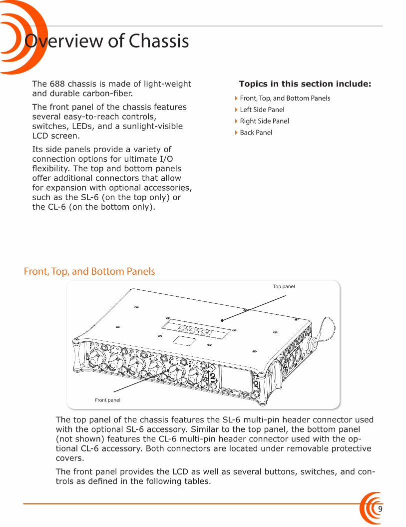
The 688 chassis is made of light-weight and durable carbon-fiber.
The front panel of the chassis features several easy-to-reach controls, switches, LEDs, and a sunlight-visible LCD screen.
Its side panels provide a variety of connection options for ultimate I/O flexibility. The top and bottom panels offer additional connectors that allow for expansion with optional accessories, such as the SL-6 (on the top only) or the CL-6 (on the bottom only).
Front panel
Top panel
The top panel of the chassis features the SL-6 multi-pin header connector used with the optional SL-6 accessory. Similar to the top panel, the bottom panel (not shown) features the CL-6 multi-pin header connector used with the op-tional CL-6 accessory. Both connectors are located under removable protective covers.
The front panel provides the LCD as well as several buttons, switches, and con-trols as defined in the following tables.
�Front, Top, and Bottom Panels
�Left Side Panel
�Right Side Panel
�Back Panel
User Guide
10
Power Switch and LED
Menu Button
Headphone Encoder
Headphone Clipping LEDRTN/FAV SwitchMIC/TONE SwitchSlate/Tone LED
Select Encoder
Meters Button
Transport Control
Timecode LED
Feature Description
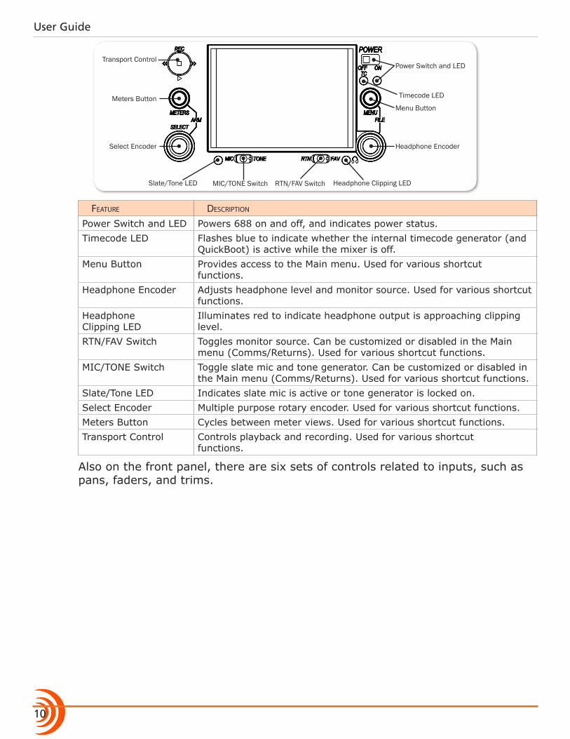
Power Switch and LED Powers 688 on and off, and indicates power status.Timecode LED Flashes blue to indicate whether the internal timecode generator (and
QuickBoot) is active while the mixer is off. Menu Button Provides access to the Main menu. Used for various shortcut
functions.Headphone Encoder Adjusts headphone level and monitor source. Used for various shortcut
functions.Headphone Clipping LED
Illuminates red to indicate headphone output is approaching clipping level.
RTN/FAV Switch Toggles monitor source. Can be customized or disabled in the Main menu (Comms/Returns). Used for various shortcut functions.
MIC/TONE Switch Toggle slate mic and tone generator. Can be customized or disabled in the Main menu (Comms/Returns). Used for various shortcut functions.
Slate/Tone LED Indicates slate mic is active or tone generator is locked on.Select Encoder Multiple purpose rotary encoder. Used for various shortcut functions.Meters Button Cycles between meter views. Used for various shortcut functions.Transport Control Controls playback and recording. Used for various shortcut
functions.
Also on the front panel, there are six sets of controls related to inputs, such as pans, faders, and trims.
11
OVERVIEW OF CHASSIS
Fader (1-6)
Pan (1-6)PFL (Left: 1-6, Right: 7-12)
Trim (1-6)
PFL status / Activity LED (7-12)
PFL status / Activity LED (1-6)
Mini-Fader (7-12)
Feature Description
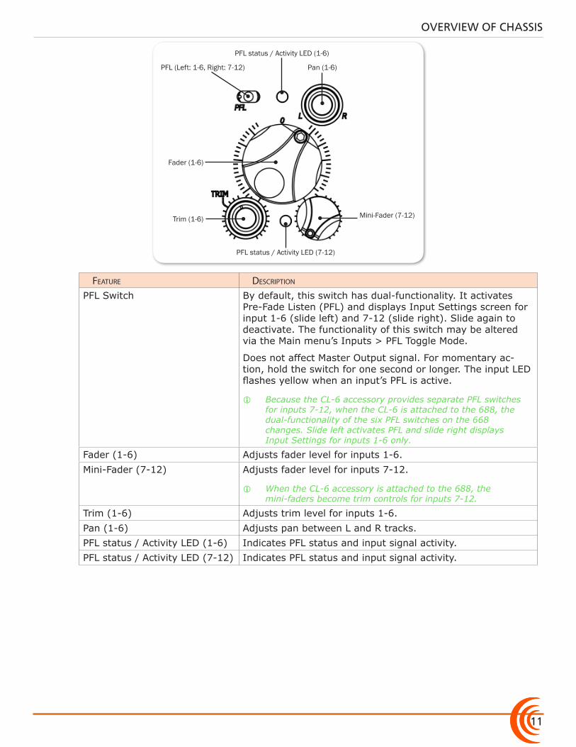
PFL Switch By default, this switch has dual-functionality. It activates Pre-Fade Listen (PFL) and displays Input Settings screen for input 1-6 (slide left) and 7-12 (slide right). Slide again to deactivate. The functionality of this switch may be altered via the Main menu’s Inputs > PFL Toggle Mode.
Does not affect Master Output signal. For momentary ac-tion, hold the switch for one second or longer. The input LED flashes yellow when an input’s PFL is active.
i Because the CL-6 accessory provides separate PFL switches for inputs 7-12, when the CL-6 is attached to the 688, the dual-functionality of the six PFL switches on the 668 changes. Slide left activates PFL and slide right displays Input Settings for inputs 1-6 only.
Fader (1-6) Adjusts fader level for inputs 1-6.Mini-Fader (7-12) Adjusts fader level for inputs 7-12.
i When the CL-6 accessory is attached to the 688, the mini-faders become trim controls for inputs 7-12.
Trim (1-6) Adjusts trim level for inputs 1-6.Pan (1-6) Adjusts pan between L and R tracks.PFL status / Activity LED (1-6) Indicates PFL status and input signal activity.PFL status / Activity LED (7-12) Indicates PFL status and input signal activity.
User Guide
12
Left Side Panel
XLR Inputs
TA3 Inputs Headphone Outputs
Feature Description
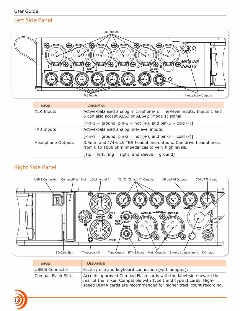
XLR Inputs Active-balanced analog microphone- or line-level inputs. Inputs 1 and 6 can also accept AES3 or AES42 (Mode 1) signal.
[Pin-1 = ground, pin-2 = hot (+), and pin-3 = cold (-)]TA3 Inputs Active-balanced analog line-level inputs.
[Pin-1 = ground, pin-2 = hot (+), and pin-3 = cold (-)]Headphone Outputs 3.5mm and 1/4-inch TRS headphone outputs. Can drive headphones
from 8 to 1000 ohm impedances to very high levels.
[Tip = left, ring = right, and sleeve = ground]
Right Side Panel
10-pin A and C
SD Card Slot
CompactFlash SlotUSB B Connector
Battery CompartmentTimecode I/O DC InputMain OutputsRTN B InputTape Output
COM/RTN InputX5 and X6 OutputsX1, X2, X3, and X4 Outputs
Feature Description
USB B Connector Factory use and keyboard connection (with adapter).CompactFlash Slot Accepts approved CompactFlash cards with the label-side toward the
rear of the mixer. Compatible with Type I and Type II cards. High-speed UDMA cards are recommended for higher track count recording.
13
OVERVIEW OF CHASSIS
Feature Description
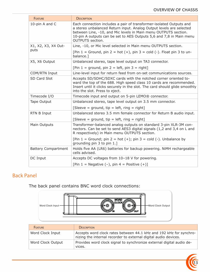
10-pin A and C Each connection includes a pair of transformer-isolated Outputs and a stereo unbalanced Return input. Analog Output levels are selected between Line, -10, and Mic levels in Main menu OUTPUTS section. 10-pin A outputs can be set to AES Outputs 5,6 and 7,8 in Main menu OUTPUTS section.
X1, X2, X3, X4 Out-puts
Line, -10, or Mic level selected in Main menu OUTPUTS section.
[Pin 1 = Ground, pin 2 = hot (+), pin 3 = cold (-). Float pin 3 to un-balance.]
X5, X6 Output Unbalanced stereo, tape level output on TA3 connector.
[Pin 1 = ground, pin 2 = left, pin 3 = right]COM/RTN Input Line-level input for return feed from on-set communications sources. SD Card Slot Accepts SD/SDHC/SDXC cards with the notched corner oriented to-
ward the top of the 688. High speed class 10 cards are recommended. Insert until it clicks securely in the slot. The card should glide smoothly into the slot. Press to eject.
Timecode I/O Timecode input and output on 5-pin LEMO® connector.Tape Output Unbalanced stereo, tape level output on 3.5 mm connector.
[Sleeve = ground, tip = left, ring = right]RTN B Input Unbalanced stereo 3.5 mm female connector for Return B audio input.
[Sleeve = ground, tip = left, ring = right]Main Outputs Transformer-balanced analog outputs on standard 3-pin XLR-3M con-
nectors. Can be set to send AES3 digital signals (1,2 and 3,4 on L and R respectively) in Main menu OUTPUTS section.
[Pin 1 = Ground; pin 2 = hot (+); pin 3 = cold (-). Unbalance by grounding pin 3 to pin 1.]
Battery Compartment Holds five AA (LR6) batteries for backup powering. NiMH rechargeable cells advised.
DC Input Accepts DC voltages from 10–18 V for powering.
[Pin 1 = Negative (–), pin 4 = Positive (+)]
Back Panel
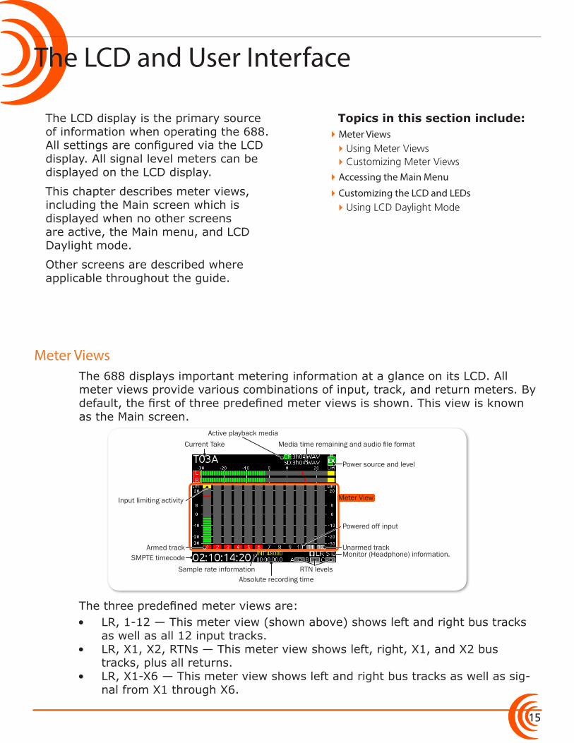
The back panel contains BNC word clock connections:
Word Clock Input Word Clock Output
Feature Description
Word Clock Input Accepts word clock rates between 44.1 kHz and 192 kHz for synchro-nizing the internal recorder to external digital audio devices.
Word Clock Output Provides word clock signal to synchronize external digital audio de-vices.

User Guide
14
15
Topics in this section include:
The LCD and User Interface
Meter Views
The LCD display is the primary source of information when operating the 688. All settings are configured via the LCD display. All signal level meters can be displayed on the LCD display.
This chapter describes meter views, including the Main screen which is displayed when no other screens are active, the Main menu, and LCD Daylight mode.
Other screens are described where applicable throughout the guide.
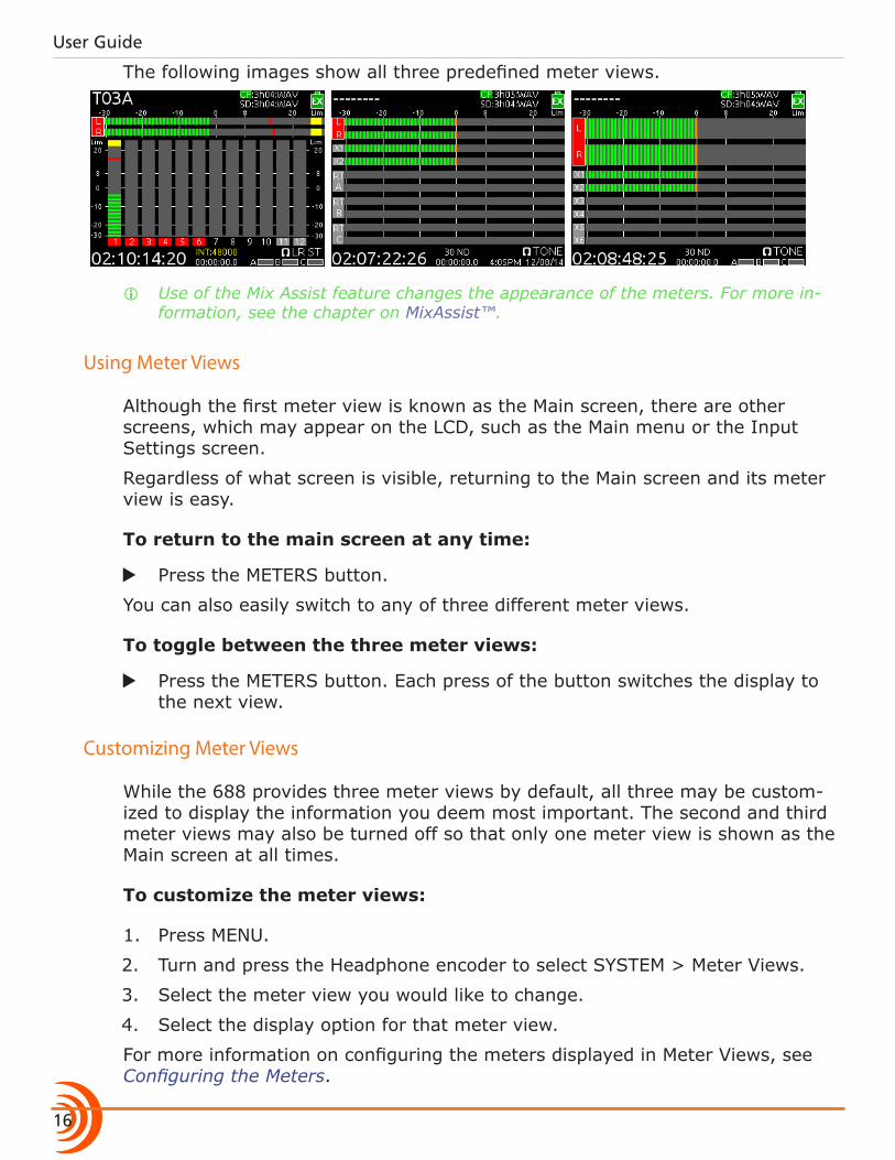
The 688 displays important metering information at a glance on its LCD. All meter views provide various combinations of input, track, and return meters. By default, the first of three predefined meter views is shown. This view is known as the Main screen.
Current TakeActive playback media
Media time remaining and audio file format
Power source and level
Input limiting activity
Monitor (Headphone) information.
RTN levelsSample rate informationAbsolute recording time
SMPTE timecode
Powered off input
Armed track Unarmed track
Meter View
The three predefined meter views are:• LR, 1-12 — This meter view (shown above) shows left and right bus tracks
as well as all 12 input tracks.• LR, X1, X2, RTNs — This meter view shows left, right, X1, and X2 bus
tracks, plus all returns.• LR, X1-X6 — This meter view shows left and right bus tracks as well as sig-
nal from X1 through X6.
�Meter Views �Using Meter Views �Customizing Meter Views
�Accessing the Main Menu
�Customizing the LCD and LEDs �Using LCD Daylight Mode
User Guide
16
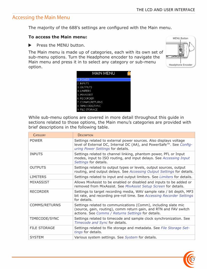
The following images show all three predefined meter views.
i Use of the Mix Assist feature changes the appearance of the meters. For more in-formation, see the chapter on MixAssist™.
Using Meter Views
Although the first meter view is known as the Main screen, there are other screens, which may appear on the LCD, such as the Main menu or the Input Settings screen.
Regardless of what screen is visible, returning to the Main screen and its meter view is easy.
To return to the main screen at any time:
X Press the METERS button.
You can also easily switch to any of three different meter views.
To toggle between the three meter views:
X Press the METERS button. Each press of the button switches the display to the next view.
Customizing Meter Views
While the 688 provides three meter views by default, all three may be custom-ized to display the information you deem most important. The second and third meter views may also be turned off so that only one meter view is shown as the Main screen at all times.
To customize the meter views:
1. Press MENU.
2. Turn and press the Headphone encoder to select SYSTEM > Meter Views.
3. Select the meter view you would like to change.
4. Select the display option for that meter view.
For more information on configuring the meters displayed in Meter Views, see Configuring the Meters.
17
THE LCD AND USER INTERFACE
Accessing the Main Menu
The majority of the 688’s settings are configured with the Main menu.
To access the Main menu:
X Press the MENU button.
The Main menu is made up of categories, each with its own set of sub-menu options. Turn the Headphone encoder to navigate the Main menu and press it in to select any category or sub-menu option.
While sub-menu options are covered in more detail throughout this guide in sections related to those options, the Main menu’s categories are provided with brief descriptions in the following table.
category Description
POWER Settings related to external power sources. Also displays voltage level of External DC, Internal DC (AA), and PowerSafe™. See Config-uring Power Settings for details.
INPUTS Settings related to channel linking, phantom power, PFL or Input modes, input to ISO routing, and input delays. See Accessing Input Settings for details.
OUTPUTS Settings related to output types or levels, output sources, output routing, and output delays. See Accessing Output Settings for details.
LIMITERS Settings related to input and output limiters. See Limiters for details.MIXASSIST Allows MixAssist to be enabled or disabled and inputs to be added or
removed from MixAssist. See MixAssist Setup Screen for details.RECORDER Settings to target recording media, WAV sample rate / bit depth, MP3
bit rate, and recording pre-roll time. See Accessing Recorder Settings for details.
COMMS/RETURNS Settings related to communications (Comm), including slate mic (source, gain, routing), comm return gain, and RTN and FAV switch actions. See Comms / Returns Settings for details.
TIMECODE/SYNC Settings related to timecode and sample clock synchronization. See Timecode and Sync for details.
FILE STORAGE Settings related to file storage and metadata. See File Storage Set-tings for details.
SYSTEM Various system settings. See System for details.
MENU Button
Headphone Encoder
User Guide
18
category Description
QUICK SETUP Allows user to save and recall user settings to and from SD, CF, and internal memory. Also allows resetting all settings to factory default. See Quick Setup for details.
Customizing the LCD and LEDs
Because the 688 is a portable field mixer, it may be used in a variety of environ-ments, including some where lighting is an issue that requires adjustments to the mixer. With some System settings, you can modify the brightness levels of the LCD, the brightness levels of the LEDs, and even enable or disable the LCD Daylight mode.
To set the LCD brightness level:
1. Press the MENU button.
2. Turn and press the Headphone encoder to select SYSTEM > LCD Brightness.
3. Turn the Headphone encoder to change the value from 10 to 100%. Then press the encoder to make your selection.
By default, the LCD brightness level is set to 100%.
To set the LED brightness level:
1. Press the MENU button.
2. Turn and press the Headphone encoder to select SYSTEM > LED Brightness.
3. Turn the Headphone encoder to change the value from 5 to 100%. Then press the encoder to make your selection.
By default, the LED brightness level is set to 60%.
Using LCD Daylight Mode
The default appearance of the LCD screen is a dark theme. However, a lighter theme is available as an alternative mode, which can make viewing in bright conditions easier. When enabled, the LCD Daylight mode may be toggled between dark and light themes.
To enable or disable LCD Daylight mode:
1. Press the MENU button.
2. Turn and press the Headphone encoder to select SYSTEM > LCD Daylight Mode.
3. Do one of the following: X Select On to enable. X Select Off to disable.

19
THE LCD AND USER INTERFACE
To toggle LCD Daylight mode:
X SELECT + HP: simultaneously press the SELECT and Headphone encoders.

User Guide
20

21
Topics in this section include:
Headphone Monitoring
Connecting Headphones
The 688 provides two headphone outputs on its left panel, several options for headphone sources including up to 10 custom presets, plus a variety of other customizable features related to audio monitoring.
Connect headphones to either the 1/4-inch or 3.5mm headphone outputs, lo-cated on the left panel of the 688.
⚠ The 688 can drive headphones to dangerously high vol-umes. Turn down the headphone gain before attaching headphones or selecting a headphone source to prevent accidental high levels. The range for headphone levels may be set from OFF, -42 dB to +20 dB.
To adjust Headphone gain:
X Turn the Headphone encoder.
While adjustment is in progress, the gain value will be dis-played in the lower-right corner of the Main screen next to the Headphone Source icon.
1/4”
3.5mm
�Connecting Headphones
�Selecting Headphone Source
�Setting Headphone Encoder Mode
�Configuring the Headphone Preset List �Defining Custom Headphone Presets �Choosing a Favorite Headphone Preset
�Using Headphone Source Shortcuts
�Headphone Peak LED
User Guide
22
Selecting Headphone Source
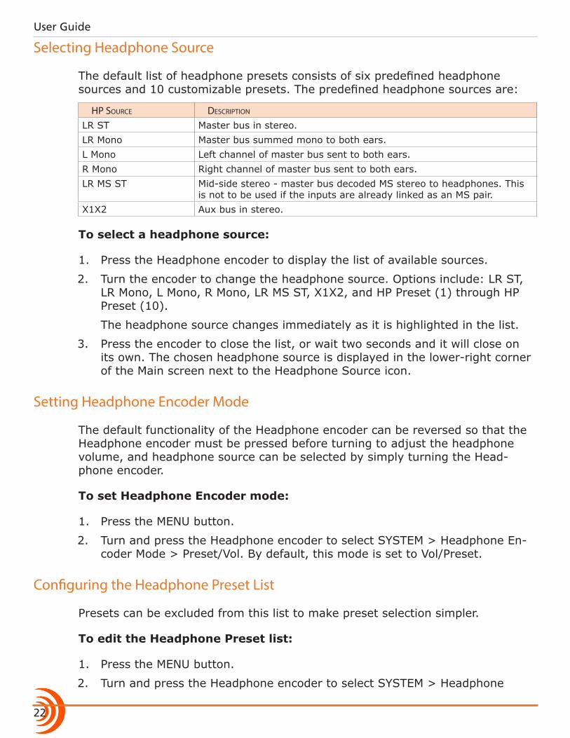
The default list of headphone presets consists of six predefined headphone sources and 10 customizable presets. The predefined headphone sources are:
Hp source Description
LR ST Master bus in stereo.LR Mono Master bus summed mono to both ears.L Mono Left channel of master bus sent to both ears.R Mono Right channel of master bus sent to both ears.LR MS ST Mid-side stereo - master bus decoded MS stereo to headphones. This
is not to be used if the inputs are already linked as an MS pair.X1X2 Aux bus in stereo.
To select a headphone source:
1. Press the Headphone encoder to display the list of available sources.
2. Turn the encoder to change the headphone source. Options include: LR ST, LR Mono, L Mono, R Mono, LR MS ST, X1X2, and HP Preset (1) through HP Preset (10).
The headphone source changes immediately as it is highlighted in the list.
3. Press the encoder to close the list, or wait two seconds and it will close on its own. The chosen headphone source is displayed in the lower-right corner of the Main screen next to the Headphone Source icon.
Setting Headphone Encoder Mode
The default functionality of the Headphone encoder can be reversed so that the Headphone encoder must be pressed before turning to adjust the headphone volume, and headphone source can be selected by simply turning the Head-phone encoder.
To set Headphone Encoder mode:
1. Press the MENU button.
2. Turn and press the Headphone encoder to select SYSTEM > Headphone En-coder Mode > Preset/Vol. By default, this mode is set to Vol/Preset.
Configuring the Headphone Preset List
Presets can be excluded from this list to make preset selection simpler.
To edit the Headphone Preset list:
1. Press the MENU button.
2. Turn and press the Headphone encoder to select SYSTEM > Headphone
23
HEADPHONE MONITORING
Preset List.
The Headphone Preset List will be displayed; presets with a blue back-ground are visible, and presets with a black background are hidden.
3. Turn and press the Headphone encoder to toggle visibility of each preset.
Defining Custom Headphone Presets
In addition to the six predefined headphone sources, 10 options are available as custom headphone presets.
To customize a headphone preset:
1. Press the Headphone encoder to display the list of available sources.
2. Turn the encoder to choose one of the 10 customizable preset options, such as HP Preset(1).
3. Slide the MIC/TONE switch left or right.
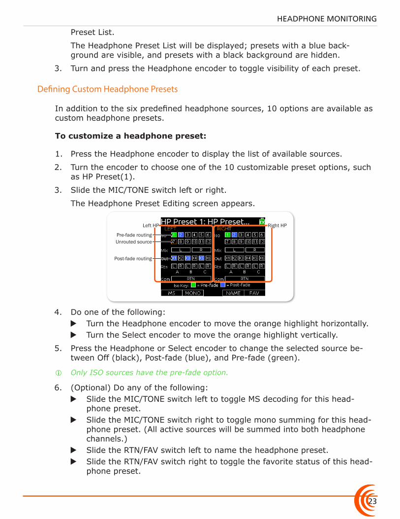
The Headphone Preset Editing screen appears.
Pre-fade routing
Post-fade routing
Unrouted source
Right HPLeft HP
4. Do one of the following: X Turn the Headphone encoder to move the orange highlight horizontally. X Turn the Select encoder to move the orange highlight vertically.
5. Press the Headphone or Select encoder to change the selected source be-tween Off (black), Post-fade (blue), and Pre-fade (green).
i Only ISO sources have the pre-fade option.
6. (Optional) Do any of the following: X Slide the MIC/TONE switch left to toggle MS decoding for this head-
phone preset. X Slide the MIC/TONE switch right to toggle mono summing for this head-
phone preset. (All active sources will be summed into both headphone channels.)
X Slide the RTN/FAV switch left to name the headphone preset. X Slide the RTN/FAV switch right to toggle the favorite status of this head-
phone preset.
User Guide
24
7. Press MENU or METERS to save the preset and exit the Headphone Preset Editing screen.
i Only one preset at a time can be set as a favorite. Marking a preset as favorite will remove the favorite status of all other presets.
Choosing a Favorite Headphone Preset
A single headphone preset can be designated as a favorite. This favorite head-phone preset can be quickly accessed via the front panel.
To choose a predefined Headphone preset as favorite:
1. Press the Headphone encoder to display the list of available sources.
2. Turn the Headphone encoder to highlight the predefined preset you want. Options include: LR ST, LR Mono, L Mono, R Mono, LR MS ST, and X1X2.
3. Slide the RTN/FAV switch right to set the highlighted Headphone preset as your new favorite.
Using Headphone Source Shortcuts
There are a total of four headphone monitor shortcuts on the 688. By default, these shortcuts go to: RTN A, RTN B, COM RTN, and the headphone source set as favorite.
To monitor RTN A:
X Slide the RTN/FAV switch to the left.
To monitor RTN B:
X Hold down the Select encoder and simultaneously slide the RTN/FAV switch to the right.
To monitor COM RTN:
X Hold down the Select encoder and simultaneously slide the RTN/FAV switch to the left.
To monitor the favorite headphone source:
X Slide the RTN/FAV switch to the right.
i These are the default headphone source shortcuts. These shortcuts may be cus-tomized via the Main menu’s COMMS/RETURNS settings.
25
HEADPHONE MONITORING
Headphone Peak LED
The Headphone Peak LED, located just left of the Headphone encoder, illumi-nates red to indicate headphone output is approaching clipping level. Monitoring without a visual indication of headphone clipping can mislead a sound mixer into thinking the output or return feeds are distorted.

User Guide
26

27
Topics in this section include:
Power
The 688 utilizes different powering options, such as external DC power, or it may be powered by five AA batteries. When used with the SL-6 accessory, an optional powering and wireless system, the 688 may be powered via an NP1 battery.
The 688 also incorporates exclusive PowerSafe™ technology with smart sensing of available power sources, front panel power warning indication, and an integrated 10-second power reserve that safely stops recording and shuts down in the event of a power loss.
Power LED
The 688 operates on either external DC power or internal AA battery power.
To turn on the 688:
X Flip the Power switch to the ON position.
The Power LED illuminates yellow then green. The Sound Devices splash screen appears briefly on the LCD, and then the Main screen is displayed.
As part of the Main screen, the LCD displays a DC voltage indi-cator in the form of a battery icon that indicates the level and type of the power source currently in use.
Normal Voltage (Green)
Warning Voltage (Yellow)
Low Voltage (Orange)
Critical Voltage (Red)
i Letters in the icon indicate the type of power source in use, such as EX for external power (as shown), SL for when the optional SL-6 is attached, and so forth.
Using External Power
The 688 uses only one power source at a time, with external DC power taking precedence over internal AA battery power.
�Powering the 688 �Using External Power �Using Battery Power
�Voltage Ranges and Thresholds
�Configuring Power Settings
�PowerSafe
�QuickBoot
�Forcing Power Off (Optional)
�Power Consumption
Powering the 688

User Guide
28
To connect an external power source:
X Plug a DC power source (not included) into the 10-18 VDC input on the right panel.
i Pin-4 of the locking, Hirose connector is positive (+) and pin-1 is negative (-).
Using Battery Power
The 688 uses five AA batteries as a backup to external power. Alkaline AA bat-teries may be used with the 688; however, NiMH batteries are the preferred type because they provide for longer run times compared to Alkaline batteries.
To insert batteries:
1. Unscrew the battery cap (counter-clockwise).
2. Insert five AA NiMH batteries (not included) into the battery tube. Orient the batteries with the positive (+) end facing in and the negative (-) end facing out.
i With external power connected, depleted AA batteries may be removed from the 688 and replaced with new ones without affecting operations.
Voltage Ranges and Thresholds
The DC voltage indicator provides power status information based on the Ex-ternal DC Reference parameter, which defines the voltage range and warning threshold for external DC power sources. Setting the External DC Reference to a value appropriate for the type of external power being used maximizes runtime with that source.
For instance, the indicator appears solid green when the active power source is full or operating within the defined high voltage range. As the voltage depletes, the indicator’s color changes from green to yellow (warning) to orange (low) and to red (critical), based on the external power source’s range and threshold, as shown in the following table:
ext Dc reF Low VoLtage warning VoLtage HigH VoLtage
12V Ext DC 9 10 11NiMH 11 11.5 13Expanded NiMH 11 11.5 1812V Lead Acid 10 11.4 1414V Li-ion 12.5 13.5 16.3Full Range 6 11.5 18
If the active power source is removed or its voltage drops to the critical thresh-old, the 688 switches to alternative battery power or shuts down, according to how its External DC Loss parameter is configured in the Power settings.
29
POWER
⚠ The DC voltage indicator flashes red when there are no other connected backup power sources remaining with adequate voltage. When all power sources are depleted, PowerSafe shutdown occurs automatically.
Configuring Power Settings
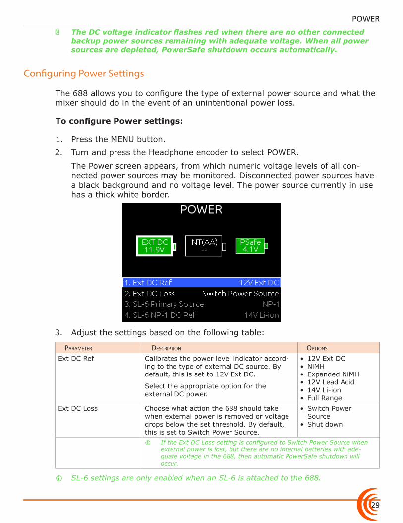
The 688 allows you to configure the type of external power source and what the mixer should do in the event of an unintentional power loss.
To configure Power settings:
1. Press the MENU button.
2. Turn and press the Headphone encoder to select POWER.
The Power screen appears, from which numeric voltage levels of all con-nected power sources may be monitored. Disconnected power sources have a black background and no voltage level. The power source currently in use has a thick white border.
3. Adjust the settings based on the following table:
parameter Description options
Ext DC Ref Calibrates the power level indicator accord-ing to the type of external DC source. By default, this is set to 12V Ext DC.
Select the appropriate option for the external DC power.
• 12V Ext DC• NiMH• Expanded NiMH• 12V Lead Acid• 14V Li-ion• Full Range
Ext DC Loss Choose what action the 688 should take when external power is removed or voltage drops below the set threshold. By default, this is set to Switch Power Source.
• Switch Power Source
• Shut down
i If the Ext DC Loss setting is configured to Switch Power Source when external power is lost, but there are no internal batteries with ade-quate voltage in the 688, then automatic PowerSafe shutdown will occur.
i SL-6 settings are only enabled when an SL-6 is attached to the 688.
User Guide
30
PowerSafe
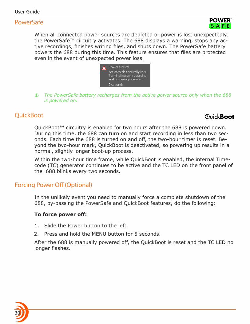
When all connected power sources are depleted or power is lost unexpectedly, the PowerSafe™ circuitry activates. The 688 displays a warning, stops any ac-tive recordings, finishes writing files, and shuts down. The PowerSafe battery powers the 688 during this time. This feature ensures that files are protected even in the event of unexpected power loss.
i The PowerSafe battery recharges from the active power source only when the 688 is powered on.
QuickBoot
QuickBoot™ circuitry is enabled for two hours after the 688 is powered down. During this time, the 688 can turn on and start recording in less than two sec-onds. Each time the 688 is turned on and off, the two-hour timer is reset. Be-yond the two-hour mark, QuickBoot is deactivated, so powering up results in a normal, slightly longer boot-up process.
Within the two-hour time frame, while QuickBoot is enabled, the internal Time-code (TC) generator continues to be active and the TC LED on the front panel of the 688 blinks every two seconds.
Forcing Power Off (Optional)
In the unlikely event you need to manually force a complete shutdown of the 688, by-passing the PowerSafe and QuickBoot features, do the following:
To force power off:
1. Slide the Power button to the left.
2. Press and hold the MENU button for 5 seconds.
After the 688 is manually powered off, the QuickBoot is reset and the TC LED no longer flashes.
31
POWER
Power Consumption
Many factors influence the rate at which the 688 uses battery power (current draw). The following list highlights the larger current drawing functions.
• Microphone powering — The main source of extra 688 current draw. 48 V Phantom can draw a large amount of current depending on what model mi-crophone is used. Two identical phantom powered microphones draw twice as much current as one.
• Audio Recorder — The recorder, whether in record or playback, draws extra current. Higher sample rate WAV recordings draw more current during re-cording.
• Digital Outputs — Disable digital outputs in the Main menu when they are not needed since they draw additional current.
• Output level — Higher output levels into multiple, low-impedance inputs increases current draw.
• Headphone Output circuit - High headphone output levels and low imped-ance headphones increase current draw.
• LED and LCD Brightness — Decrease LED and LCD brightness to reduce cur-rent draw.

User Guide
32
33
Topics in this section include:
Inputs
The 688 has 12 analog inputs, which are assignable pre- or post- fade to outputs for optimum routing flexibility.
The inputs include six high-bandwidth mic/line inputs on XLR connectors, each complete with phantom power, high-pass filter, analog input limiter and variable pan.
Six additional line-level inputs on TA3 connectors offer increased flexibility for more complex productions.
In addition to the primary inputs there are three stereo, unbalanced return (RTN) inputs.
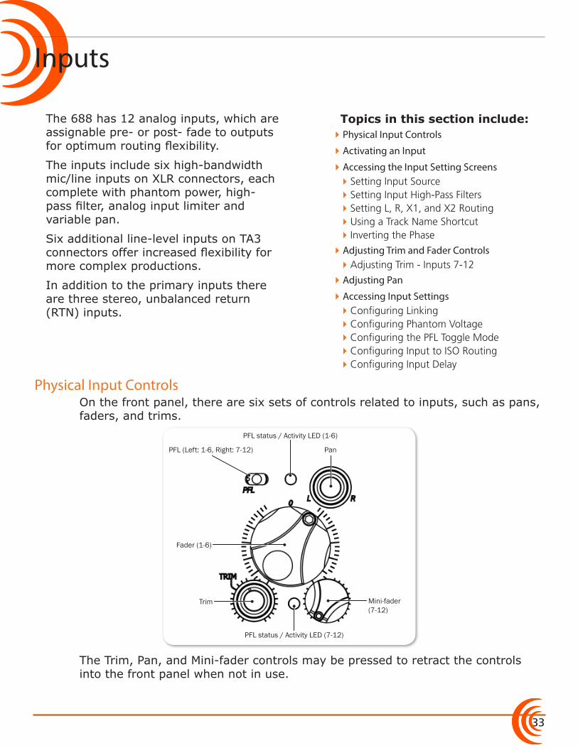
On the front panel, there are six sets of controls related to inputs, such as pans, faders, and trims.
Fader (1-6)
PanPFL (Left: 1-6, Right: 7-12)
Trim
PFL status / Activity LED (7-12)
PFL status / Activity LED (1-6)
Mini-fader (7-12)
The Trim, Pan, and Mini-fader controls may be pressed to retract the controls into the front panel when not in use.
�Physical Input Controls
�Activating an Input
�Accessing the Input Setting Screens �Setting Input Source �Setting Input High-Pass Filters �Setting L, R, X1, and X2 Routing �Using a Track Name Shortcut �Inverting the Phase
�Adjusting Trim and Fader Controls �Adjusting Trim - Inputs 7-12
�Adjusting Pan
�Accessing Input Settings �Configuring Linking �Configuring Phantom Voltage �Configuring the PFL Toggle Mode �Configuring Input to ISO Routing �Configuring Input Delay
Physical Input Controls
User Guide
34
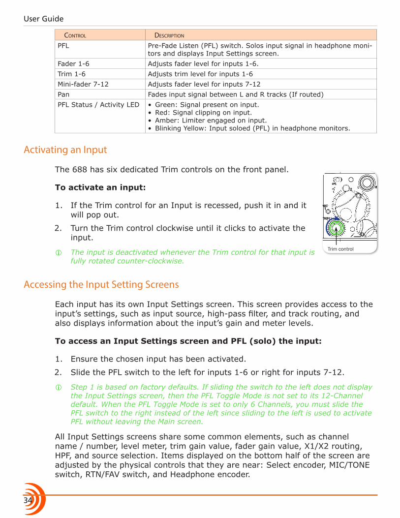
controL Description
PFL Pre-Fade Listen (PFL) switch. Solos input signal in headphone moni-tors and displays Input Settings screen.
Fader 1-6 Adjusts fader level for inputs 1-6.Trim 1-6 Adjusts trim level for inputs 1-6Mini-fader 7-12 Adjusts fader level for inputs 7-12Pan Fades input signal between L and R tracks (If routed)PFL Status / Activity LED • Green: Signal present on input.
• Red: Signal clipping on input.• Amber: Limiter engaged on input.• Blinking Yellow: Input soloed (PFL) in headphone monitors.
Activating an Input
The 688 has six dedicated Trim controls on the front panel.
To activate an input:
1. If the Trim control for an Input is recessed, push it in and it will pop out.
2. Turn the Trim control clockwise until it clicks to activate the input.
i The input is deactivated whenever the Trim control for that input is fully rotated counter-clockwise.
Accessing the Input Setting Screens
Each input has its own Input Settings screen. This screen provides access to the input’s settings, such as input source, high-pass filter, and track routing, and also displays information about the input’s gain and meter levels.
To access an Input Settings screen and PFL (solo) the input:
1. Ensure the chosen input has been activated.
2. Slide the PFL switch to the left for inputs 1-6 or right for inputs 7-12.
i Step 1 is based on factory defaults. If sliding the switch to the left does not display the Input Settings screen, then the PFL Toggle Mode is not set to its 12-Channel default. When the PFL Toggle Mode is set to only 6 Channels, you must slide the PFL switch to the right instead of the left since sliding to the left is used to activate PFL without leaving the Main screen.
All Input Settings screens share some common elements, such as channel name / number, level meter, trim gain value, fader gain value, X1/X2 routing, HPF, and source selection. Items displayed on the bottom half of the screen are adjusted by the physical controls that they are near: Select encoder, MIC/TONE switch, RTN/FAV switch, and Headphone encoder.
Trim control
35
INPUTS
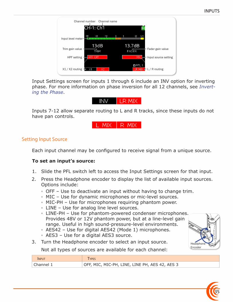
Channel nameChannel number
L / R routing
Input source setting
Fader gain value
X1 / X2 routing
HPF setting
Trim gain value
Input level meter
Input Settings screen for inputs 1 through 6 include an INV option for inverting phase. For more information on phase inversion for all 12 channels, see Invert-ing the Phase.
Inputs 7-12 allow separate routing to L and R tracks, since these inputs do not have pan controls.
Headphone Encoder
Setting Input Source
Each input channel may be configured to receive signal from a unique source.
To set an input’s source:
1. Slide the PFL switch left to access the Input Settings screen for that input.
2. Press the Headphone encoder to display the list of available input sources. Options include: ◦ OFF – Use to deactivate an input without having to change trim. ◦ MIC – Use for dynamic microphones or mic-level sources. ◦ MIC-PH – Use for microphones requiring phantom power. ◦ LINE – Use for analog line level sources. ◦ LINE-PH – Use for phantom-powered condenser microphones. Provides 48V or 12V phantom power, but at a line-level gain range. Useful in high sound-pressure-level environments.
◦ AES42 – Use for digital AES42 (Mode 1) microphones. ◦ AES3 – Use for a digital AES3 source.
3. Turn the Headphone encoder to select an input source.
Not all types of sources are available for each channel:
input types
Channel 1 OFF, MIC, MIC-PH, LINE, LINE PH, AES 42, AES 3
User Guide
36
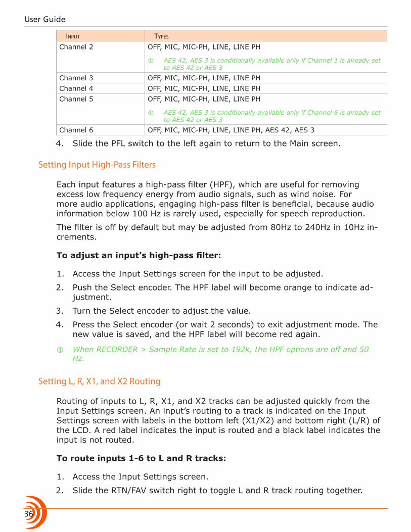
input types
Channel 2 OFF, MIC, MIC-PH, LINE, LINE PH
i AES 42, AES 3 is conditionally available only if Channel 1 is already set to AES 42 or AES 3
Channel 3 OFF, MIC, MIC-PH, LINE, LINE PHChannel 4 OFF, MIC, MIC-PH, LINE, LINE PHChannel 5 OFF, MIC, MIC-PH, LINE, LINE PH
i AES 42, AES 3 is conditionally available only if Channel 6 is already set to AES 42 or AES 3
Channel 6 OFF, MIC, MIC-PH, LINE, LINE PH, AES 42, AES 3
4. Slide the PFL switch to the left again to return to the Main screen.
Setting Input High-Pass Filters
Each input features a high-pass filter (HPF), which are useful for removing excess low frequency energy from audio signals, such as wind noise. For more audio applications, engaging high-pass filter is beneficial, because audio information below 100 Hz is rarely used, especially for speech reproduction.
The filter is off by default but may be adjusted from 80Hz to 240Hz in 10Hz in-crements.
To adjust an input’s high-pass filter:
1. Access the Input Settings screen for the input to be adjusted.
2. Push the Select encoder. The HPF label will become orange to indicate ad-justment.
3. Turn the Select encoder to adjust the value.
4. Press the Select encoder (or wait 2 seconds) to exit adjustment mode. The new value is saved, and the HPF label will become red again.
i When RECORDER > Sample Rate is set to 192k, the HPF options are off and 50 Hz.
Setting L, R, X1, and X2 Routing
Routing of inputs to L, R, X1, and X2 tracks can be adjusted quickly from the Input Settings screen. An input’s routing to a track is indicated on the Input Settings screen with labels in the bottom left (X1/X2) and bottom right (L/R) of the LCD. A red label indicates the input is routed and a black label indicates the input is not routed.
To route inputs 1-6 to L and R tracks:
1. Access the Input Settings screen.
2. Slide the RTN/FAV switch right to toggle L and R track routing together.
37
INPUTS
i Independent assignment of signal to the L and R tracks for inputs 1-6 is adjusted using the input’s dedicated Pan control.
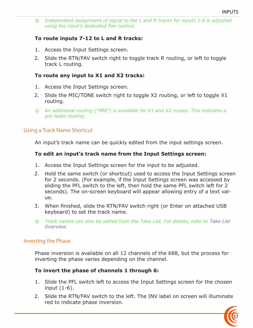
To route inputs 7-12 to L and R tracks:
1. Access the Input Settings screen.
2. Slide the RTN/FAV switch right to toggle track R routing, or left to toggle track L routing.
To route any input to X1 and X2 tracks:
1. Access the Input Settings screen.
2. Slide the MIC/TONE switch right to toggle X2 routing, or left to toggle X1 routing.
i An additional routing (“PRE”) is available for X1 and X2 routes. This indicates a pre-fader routing.
Using a Track Name Shortcut
An input’s track name can be quickly edited from the input settings screen.
To edit an input’s track name from the Input Settings screen:
1. Access the Input Settings screen for the input to be adjusted.
2. Hold the same switch (or shortcut) used to access the Input Settings screen for 2 seconds. (For example, if the Input Settings screen was accessed by sliding the PFL switch to the left, then hold the same PFL switch left for 2 seconds). The on-screen keyboard will appear allowing entry of a text val-ue.
3. When finished, slide the RTN/FAV switch right (or Enter on attached USB keyboard) to set the track name.
i Track names can also be edited from the Take List. For details, refer to Take List Overview.
Inverting the Phase
Phase inversion is available on all 12 channels of the 688, but the process for inverting the phase varies depending on the channel.
To invert the phase of channels 1 through 6:
1. Slide the PFL switch left to access the Input Settings screen for the chosen input (1-6).
2. Slide the RTN/FAV switch to the left. The INV label on screen will illuminate red to indicate phase inversion.
User Guide
38
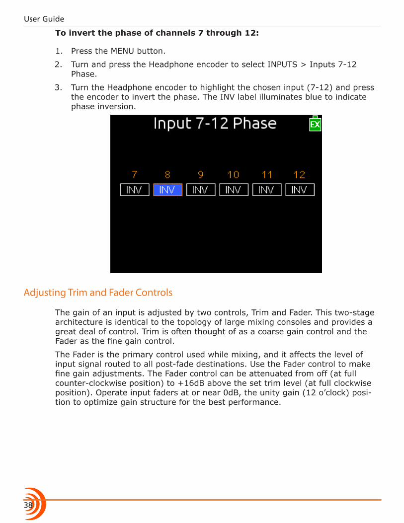
To invert the phase of channels 7 through 12:
1. Press the MENU button.
2. Turn and press the Headphone encoder to select INPUTS > Inputs 7-12 Phase.
3. Turn the Headphone encoder to highlight the chosen input (7-12) and press the encoder to invert the phase. The INV label illuminates blue to indicate phase inversion.
Adjusting Trim and Fader Controls
The gain of an input is adjusted by two controls, Trim and Fader. This two-stage architecture is identical to the topology of large mixing consoles and provides a great deal of control. Trim is often thought of as a coarse gain control and the Fader as the fine gain control.
The Fader is the primary control used while mixing, and it affects the level of input signal routed to all post-fade destinations. Use the Fader control to make fine gain adjustments. The Fader control can be attenuated from off (at full counter-clockwise position) to +16dB above the set trim level (at full clockwise position). Operate input faders at or near 0dB, the unity gain (12 o’clock) posi-tion to optimize gain structure for the best performance.

39
INPUTS
Trim (1-6) Mini-Fader (7-12)
Fader (1-6)
To adjust trim and fade:
1. Access the Input Settings screen for the chosen input.
2. Do one of the following: X For inputs 1-6: Set Fader control to 0 dB, the unity gain position. X For inputs 7-12: Set Mini-Fader control to 0 dB. If the Mini-fader control
is recessed, push it in and it will pop out.
3. Adjust the input’s Trim control clockwise until optimal level is achieved on metering and in headphones.
For inputs 1-6, analog mic level is adjustable from +22 dB to +70 dB of gain. Analog line level is adjustable from -18 dB to +30 dB, and AES digital trim level is adjustable from -20 to +38 dB.
For inputs 7-12, line level is adjustable from -30 dB to +22 dB.
i If the SL-6 accessory is attached, the trim level for all inputs 1-12 are adjustable from -20 dB to +38 dB.
Adjusting Trim - Inputs 7-12
Inputs 1-6 have dedicated Trim controls, but that is not the case for inputs 7-12.
i By attaching the optional CL-6 accessory, which provides additional dedicated controls, the functionality of the Mini-faders on the 688 changes to become Trim controls.
To adjust trim for inputs 7-12:
1. Access the Input Settings screen for the input chosen from 7-12.
2. Rotate the SELECT encoder to adjust the trim level. The gain value is dis-played on the Input Settings screen.
User Guide
40
Adjusting Pan
The Pan pot routes inputs to the left (L) and right (R) channels of the stereo Master Bus. The Pan pot has a detent in its center (12 o’clock) position.
To adjust an input’s pan:
X Turn the Pan pot.
After setting the pan, press the Pan pot in to recess the control when not in use.
Accessing Input Settings
The Main menu has a sub-menu of settings related to inputs. These may be used to customize the configuration of the 688.
To access Inputs sub-menu:
1. Press the MENU button.
2. Turn and press the Headphone encoder to select INPUTS.
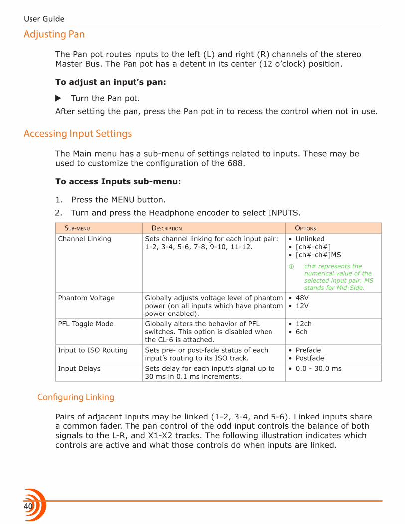
sub-menu Description options
Channel Linking Sets channel linking for each input pair: 1-2, 3-4, 5-6, 7-8, 9-10, 11-12.
• Unlinked• [ch#-ch#]• [ch#-ch#]MS
i ch# represents the numerical value of the selected input pair. MS stands for Mid-Side.
Phantom Voltage Globally adjusts voltage level of phantom power (on all inputs which have phantom power enabled).
• 48V• 12V
PFL Toggle Mode Globally alters the behavior of PFL switches. This option is disabled when the CL-6 is attached.
• 12ch• 6ch
Input to ISO Routing Sets pre- or post-fade status of each input’s routing to its ISO track.
• Prefade• Postfade
Input Delays Sets delay for each input’s signal up to 30 ms in 0.1 ms increments.
• 0.0 - 30.0 ms
Configuring Linking
Pairs of adjacent inputs may be linked (1-2, 3-4, and 5-6). Linked inputs share a common fader. The pan control of the odd input controls the balance of both signals to the L-R, and X1-X2 tracks. The following illustration indicates which controls are active and what those controls do when inputs are linked.
41
INPUTS
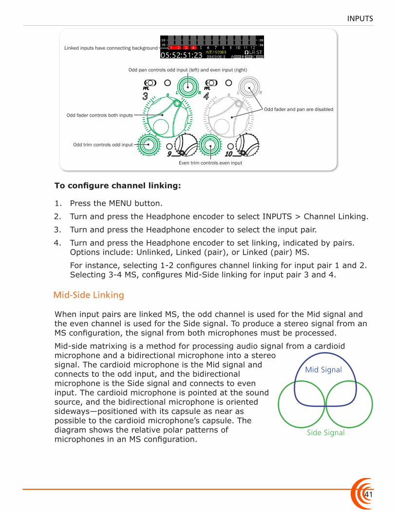
Linked inputs have connecting background
Odd pan controls odd input (left) and even input (right)
Odd fader controls both inputs
Even trim controls even input
Odd fader and pan are disabled
Odd trim controls odd input
To configure channel linking:
1. Press the MENU button.
2. Turn and press the Headphone encoder to select INPUTS > Channel Linking.
3. Turn and press the Headphone encoder to select the input pair.
4. Turn and press the Headphone encoder to set linking, indicated by pairs. Options include: Unlinked, Linked (pair), or Linked (pair) MS.
For instance, selecting 1-2 configures channel linking for input pair 1 and 2. Selecting 3-4 MS, configures Mid-Side linking for input pair 3 and 4.
Mid-Side Linking
When input pairs are linked MS, the odd channel is used for the Mid signal and the even channel is used for the Side signal. To produce a stereo signal from an MS configuration, the signal from both microphones must be processed.
Mid Signal
Side Signal
Mid-side matrixing is a method for processing audio signal from a cardioid microphone and a bidirectional microphone into a stereo signal. The cardioid microphone is the Mid signal and connects to the odd input, and the bidirectional microphone is the Side signal and connects to even input. The cardioid microphone is pointed at the sound source, and the bidirectional microphone is oriented sideways—positioned with its capsule as near as possible to the cardioid microphone’s capsule. The diagram shows the relative polar patterns of microphones in an MS configuration.
User Guide
42
Configuring Phantom Voltage
Phantom powering is a fixed DC voltage of either 12 or 48 volts. This voltage is resistively applied to pin 2 and pin 3 of an input’s XLR-3F connector, relative to pin 1. In this configuration, there is no voltage difference between signal pins 2 and 3.
On the 688, the factory default sets phantom power voltage to 48 volts, but that may be changed.
To configure phantom voltage:
1. Press the MENU button.
2. Turn and press the Headphone encoder to select INPUTS > Phantom Volt-age.
3. Turn the Headphone encoder to change the setting. Options include: 48V or 12V.
This setting globally adjusts the voltage level of phantom power on all in-puts with phantom power enabled.
Configuring the PFL Toggle Mode
By default, access to PFL and the Input Settings screen for inputs 1-12 can be achieved with one hand. This is called 12-Channel mode.
However, the PFL switches on the 688 may be configured to focus operation solely on inputs 1-6, while leaving inputs 7-12 accessible via a button combina-tion. This configuration option is called 6-Channel mode.
To enable 6-Channel PFL Toggle mode:
1. Press the MENU button.
2. Turn and press the Headphone encoder to select INPUTS > PFL Toggle Mode > 6ch.
i The INPUTS > PFL Toggle Mode submenu is disabled when the CL-12 linear fader controller is connected to the mixer.
Solo (PFL) for inputs 1-6 while in 6-Channel mode:
X Slide PFL switch left.
Access inputs 1-6 Input Settings screens while in 6-Channel mode:
X Slide PFL switch right.
Solo (PFL) for inputs 7-12 while in 6-Channel mode:
X SELECT + PFL: press SELECT encoder and slide PFL switch left.
43
INPUTS
Access inputs 7-12 Input Settings screens while in 6-Channel mode:
X SELECT + PFL: press SELECT encoder and slide PFL switch right.
Configuring Input to ISO Routing
By default, each input is routed to its associated ISO track pre-fade (The fader does not affect the signal on the ISO track). This routing can be configured (on a per-input basis) to be post-fade (The fader does affect the signal on the ISO track).
To configure Input ISO Routing:
1. Press the MENU button.
2. Turn and press the Headphone encoder to select INPUTS > Input to ISO Routing.
3. Turn and press the Headphone encoder to select the desired input routing and edit its value.
4. Turn and press the Headphone encoder to select Prefade or Postfade.
i Input to ISO Routing for inputs 1-8 also affects the pre- or post-fade status of those inputs’ routing to AES digital tracks.
Configuring Input Delay
Input delay is applied before the signal is sent to the recorder and outputs. Each input can be delayed up to 30ms.
To configure input delay:
1. Press the MENU button.
2. Turn and press the Headphone encoder to select INPUTS > Input Delays.
3. Turn and press the Headphone encoder to select the input. The background of the value will become orange to indicate the value is being edited.
4. Turn and press the Headphone encoder to set the new delay value for the chosen input.

User Guide
44
45
Topics in this section include:
Outputs
Output Connections
The 688 offers multiple outputs with flexible configuration. Whether you need to send the LR mix to multiple cameras, the camera RTN feed via IFB, or AES digital signals, the 688 is up to the task.
The right panel features three master LR bus transformer balanced outputs via two 10-pin hirose connectors and two XLR-M connectors, which can alternatively be used to send up to eight signals (four pairs) of AES digital, four active balanced Aux outputs via TA3, an additional unbalanced stereo Aux output via TA3, and a 3.5 mm unbalanced stereo Tape Output.
On the 688, the Left and Right XLR-M and Hirose 10-pin connectors are each transformer balanced from separate windings. This improves isolation from po-tential interference. Aux outputs X1 to X4 use active-balanced TA3 connections. The Tape Out (3.5mm), X5/X6 output (TA3), and Headphone output (3.5mm and 1/4”) are all unbalanced stereo connections.
i See Specifications chapter for full details on the electronic specifications of the var-ious output connections.
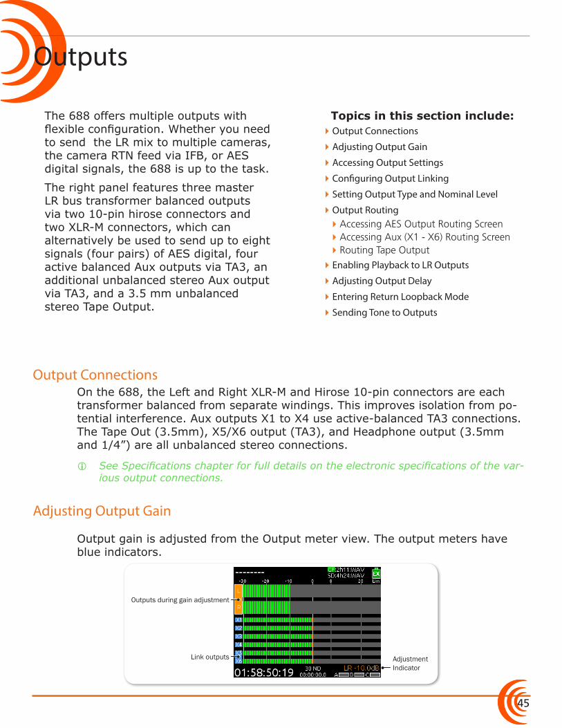
Adjusting Output Gain
Output gain is adjusted from the Output meter view. The output meters have blue indicators.
Adjustment Indicator
Outputs during gain adjustment
Link outputs
�Output Connections
�Adjusting Output Gain
�Accessing Output Settings
�Configuring Output Linking
�Setting Output Type and Nominal Level
�Output Routing �Accessing AES Output Routing Screen �Accessing Aux (X1 - X6) Routing Screen �Routing Tape Output
�Enabling Playback to LR Outputs
�Adjusting Output Delay
�Entering Return Loopback Mode
�Sending Tone to Outputs
User Guide
46
To adjust output gain:
1. Press the METERS button repeatedly until the Output meter view is visible.
i If the Output Meters view is not available, it must be selected as one of the three views in main menu option SYSTEM > Meter Views.
2. Turn and press the SELECT encoder to choose an output and enter gain ad-justment. The background color of the chosen output becomes orange, and the output gain value is displayed in the lower-right corner of the screen.
3. Turn the SELECT encoder to adjust the output gain.
4. Press the SELECT encoder or wait two seconds to exit Gain Adjustment mode.
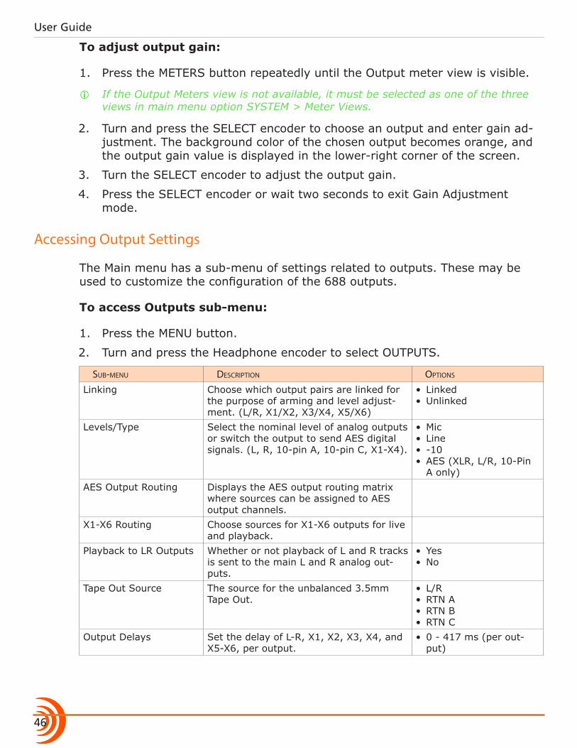
Accessing Output Settings
The Main menu has a sub-menu of settings related to outputs. These may be used to customize the configuration of the 688 outputs.
To access Outputs sub-menu:
1. Press the MENU button.
2. Turn and press the Headphone encoder to select OUTPUTS.
sub-menu Description options
Linking Choose which output pairs are linked for the purpose of arming and level adjust-ment. (L/R, X1/X2, X3/X4, X5/X6)
• Linked• Unlinked
Levels/Type Select the nominal level of analog outputs or switch the output to send AES digital signals. (L, R, 10-pin A, 10-pin C, X1-X4).
• Mic• Line• -10• AES (XLR, L/R, 10-Pin
A only)AES Output Routing Displays the AES output routing matrix
where sources can be assigned to AES output channels.
X1-X6 Routing Choose sources for X1-X6 outputs for live and playback.
Playback to LR Outputs Whether or not playback of L and R tracks is sent to the main L and R analog out-puts.
• Yes• No
Tape Out Source The source for the unbalanced 3.5mm Tape Out.
• L/R• RTN A• RTN B• RTN C
Output Delays Set the delay of L-R, X1, X2, X3, X4, and X5-X6, per output.
• 0 - 417 ms (per out-put)
47
OUTPUTS
sub-menu Description options
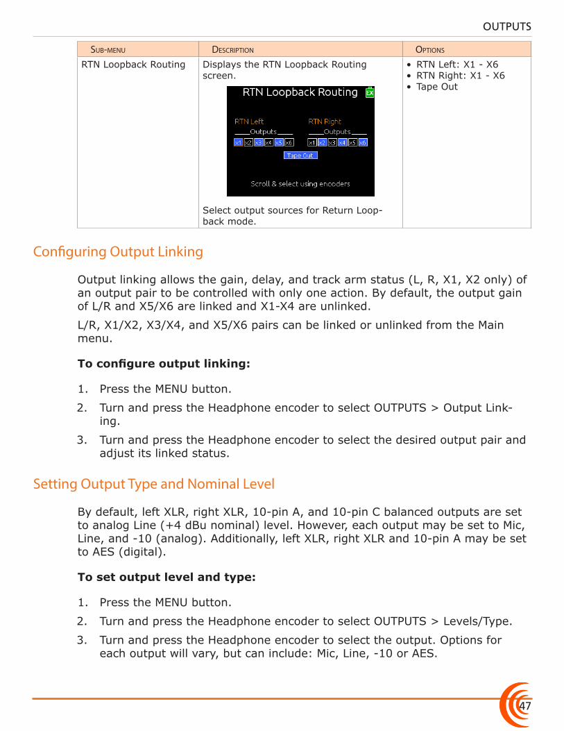
RTN Loopback Routing Displays the RTN Loopback Routing screen.
Select output sources for Return Loop-back mode.
• RTN Left: X1 - X6• RTN Right: X1 - X6• Tape Out
Configuring Output Linking
Output linking allows the gain, delay, and track arm status (L, R, X1, X2 only) of an output pair to be controlled with only one action. By default, the output gain of L/R and X5/X6 are linked and X1-X4 are unlinked.
L/R, X1/X2, X3/X4, and X5/X6 pairs can be linked or unlinked from the Main menu.
To configure output linking:
1. Press the MENU button.
2. Turn and press the Headphone encoder to select OUTPUTS > Output Link-ing.
3. Turn and press the Headphone encoder to select the desired output pair and adjust its linked status.
Setting Output Type and Nominal Level
By default, left XLR, right XLR, 10-pin A, and 10-pin C balanced outputs are set to analog Line (+4 dBu nominal) level. However, each output may be set to Mic, Line, and -10 (analog). Additionally, left XLR, right XLR and 10-pin A may be set to AES (digital).
To set output level and type:
1. Press the MENU button.
2. Turn and press the Headphone encoder to select OUTPUTS > Levels/Type.
3. Turn and press the Headphone encoder to select the output. Options for each output will vary, but can include: Mic, Line, -10 or AES.
User Guide
48
Output Routing
The master L and R tracks are permanently routed to their respective outputs, unless the connections have been set to AES, in which case they use AES out-put routing.
Accessing AES Output Routing Screen
There is a total of 8 channels of digital output on 4 connections. Each of the XLR-3M or 10-pin A outputs can be configured to output AES3 digital signals. For more information, see Setting Output Type and Nominal Level.
Any track can be routed to any AES output in any combination. No sources are assigned to any of the 8 AES outputs by default.
To access the AES Output Routing screen:
1. Press the MENU button.
2. Turn and press the Headphone encoder to select OUTPUTS > AES Output Routing.
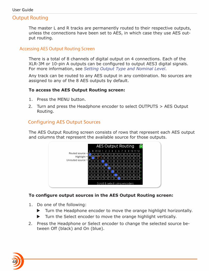
Configuring AES Output Sources
The AES Output Routing screen consists of rows that represent each AES output and columns that represent the available source for those outputs.
Routed source
Unrouted sourceHighlight
To configure output sources in the AES Output Routing screen:
1. Do one of the following: X Turn the Headphone encoder to move the orange highlight horizontally. X Turn the Select encoder to move the orange highlight vertically.
2. Press the Headphone or Select encoder to change the selected source be-tween Off (black) and On (blue).
49
OUTPUTS
Accessing Aux (X1 - X6) Routing Screen
X1 and X2 tracks are routed to their respective outputs by default. Output sources are configured in the Output routing screen.
To access the Aux Output Routing screen:
1. Press the MENU button.
2. Turn and press the Headphone encoder to select OUTPUTS > X1-X6 Rout-ing.
3. Turn and press the Headphone encoder to select an output.
Configuring Aux Output Sources
The Aux Output Routing screen consists of boxes that indicate sources available for routing to the chosen output.
The sources are arranged in two sections:• Live (left half of screen) • Playback (Right half of screen)
Upon playback, all sources configured in the Playback section will be used. Sources configured in the Live section are used at all other times.
Routed sourcePre-fade routed source
Unrouted sourceHighlight
i The Aux Output Routing screens have a Com Send option, a feature explained in the Comms/Returns section of this guide.
This flexibility in routing is useful for situations where the live feed to the Aux outputs is not the same program you want to send when playing back. For in-stance:• Live source sent to the Aux output was not recorded and therefore does not
playback.• During playback, you want to feed loud speakers, but in Live mode, you
don’t want anything feeding the speakers.• Boom op gets fed a mono mix of his isolated channel during Live mode, but
during playback, he will receive the LR mix.
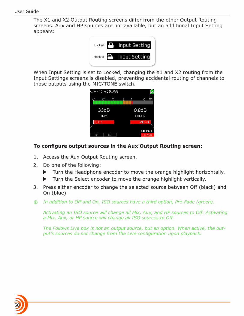
User Guide
50
The X1 and X2 Output Routing screens differ from the other Output Routing screens. Aux and HP sources are not available, but an additional Input Setting appears:
Locked
Unlocked
When Input Setting is set to Locked, changing the X1 and X2 routing from the Input Settings screens is disabled, preventing accidental routing of channels to those outputs using the MIC/TONE switch.
To configure output sources in the Aux Output Routing screen:
1. Access the Aux Output Routing screen.
2. Do one of the following: X Turn the Headphone encoder to move the orange highlight horizontally. X Turn the Select encoder to move the orange highlight vertically.
3. Press either encoder to change the selected source between Off (black) and On (blue).
i In addition to Off and On, ISO sources have a third option, Pre-Fade (green). Activating an ISO source will change all Mix, Aux, and HP sources to Off. Activating a Mix, Aux, or HP source will change all ISO sources to Off. The Follows Live box is not an output source, but an option. When active, the out-put’s sources do not change from the Live configuration upon playback.
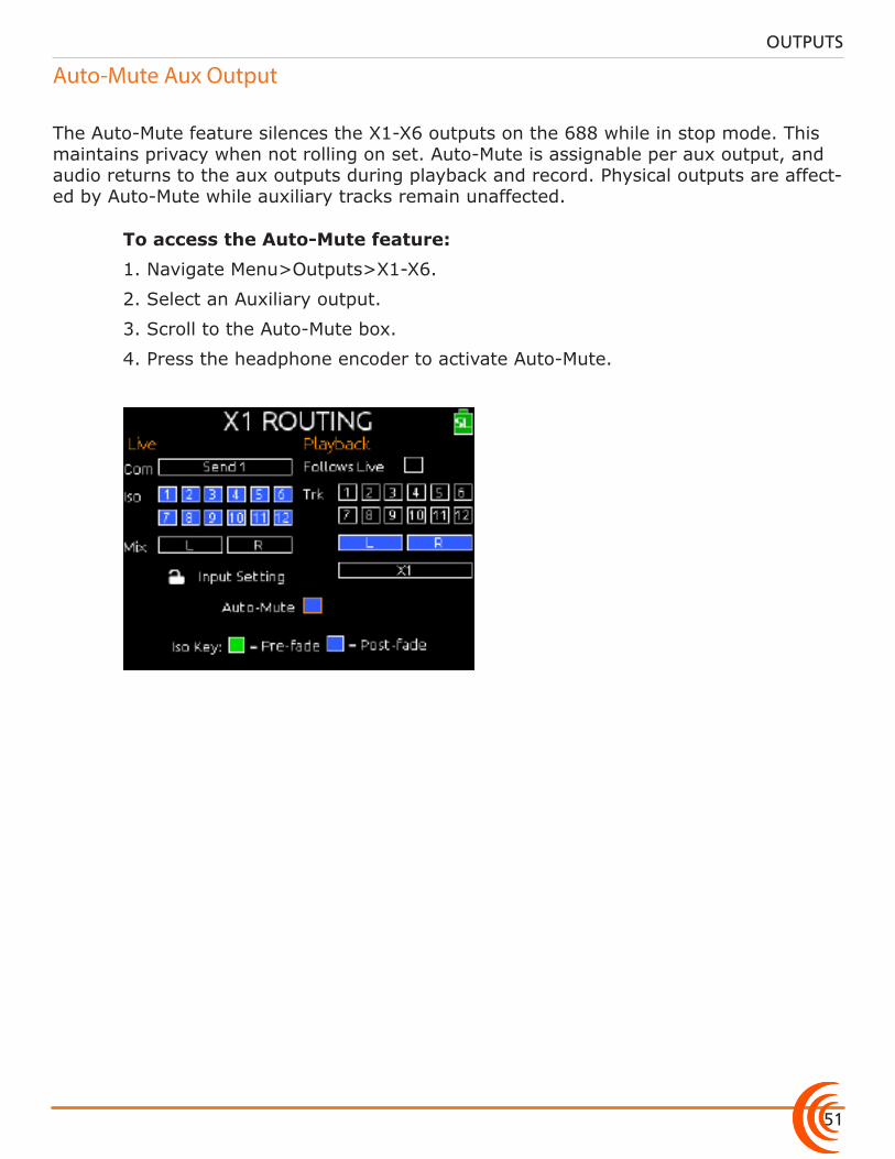
51
OUTPUTS
Auto-Mute Aux Output
The Auto-Mute feature silences the X1-X6 outputs on the 688 while in stop mode. This maintains privacy when not rolling on set. Auto-Mute is assignable per aux output, and audio returns to the aux outputs during playback and record. Physical outputs are affect-ed by Auto-Mute while auxiliary tracks remain unaffected.
To access the Auto-Mute feature:
1. Navigate Menu>Outputs>X1-X6.
2. Select an Auxiliary output.
3. Scroll to the Auto-Mute box.
4. Press the headphone encoder to activate Auto-Mute.
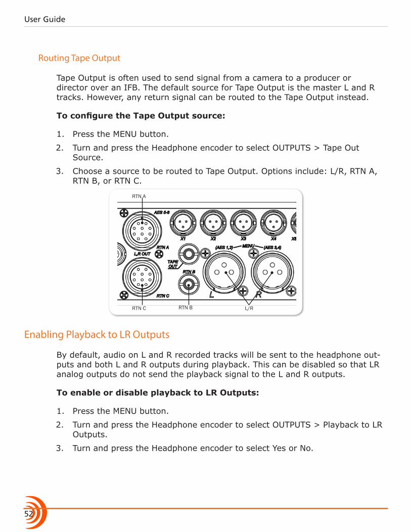
User Guide
52
Routing Tape Output
Tape Output is often used to send signal from a camera to a producer or director over an IFB. The default source for Tape Output is the master L and R tracks. However, any return signal can be routed to the Tape Output instead.
To configure the Tape Output source:
1. Press the MENU button.
2. Turn and press the Headphone encoder to select OUTPUTS > Tape Out Source.
3. Choose a source to be routed to Tape Output. Options include: L/R, RTN A, RTN B, or RTN C.
RTN C RTN B
RTN A
L/R
Enabling Playback to LR Outputs
By default, audio on L and R recorded tracks will be sent to the headphone out-puts and both L and R outputs during playback. This can be disabled so that LR analog outputs do not send the playback signal to the L and R outputs.
To enable or disable playback to LR Outputs:
1. Press the MENU button.
2. Turn and press the Headphone encoder to select OUTPUTS > Playback to LR Outputs.
3. Turn and press the Headphone encoder to select Yes or No.
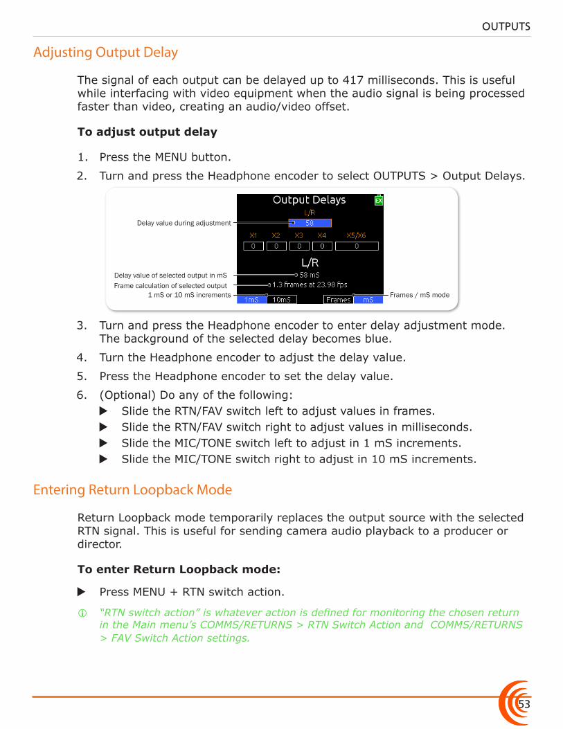
53
OUTPUTS
Adjusting Output Delay
The signal of each output can be delayed up to 417 milliseconds. This is useful while interfacing with video equipment when the audio signal is being processed faster than video, creating an audio/video offset.
To adjust output delay
1. Press the MENU button.
2. Turn and press the Headphone encoder to select OUTPUTS > Output Delays.
Delay value during adjustment
Delay value of selected output in mSFrame calculation of selected output
1 mS or 10 mS increments Frames / mS mode
3. Turn and press the Headphone encoder to enter delay adjustment mode. The background of the selected delay becomes blue.
4. Turn the Headphone encoder to adjust the delay value.
5. Press the Headphone encoder to set the delay value.
6. (Optional) Do any of the following: X Slide the RTN/FAV switch left to adjust values in frames. X Slide the RTN/FAV switch right to adjust values in milliseconds. X Slide the MIC/TONE switch left to adjust in 1 mS increments. X Slide the MIC/TONE switch right to adjust in 10 mS increments.
Entering Return Loopback Mode
Return Loopback mode temporarily replaces the output source with the selected RTN signal. This is useful for sending camera audio playback to a producer or director.
To enter Return Loopback mode:
X Press MENU + RTN switch action.
i “RTN switch action” is whatever action is defined for monitoring the chosen return in the Main menu’s COMMS/RETURNS > RTN Switch Action and COMMS/RETURNS > FAV Switch Action settings.
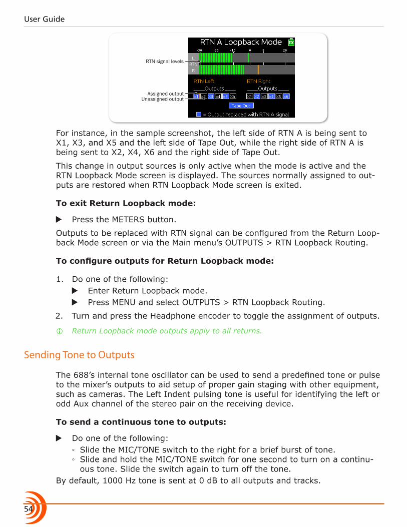
User Guide
54
RTN signal levels
Assigned outputUnassigned output
For instance, in the sample screenshot, the left side of RTN A is being sent to X1, X3, and X5 and the left side of Tape Out, while the right side of RTN A is being sent to X2, X4, X6 and the right side of Tape Out.
This change in output sources is only active when the mode is active and the RTN Loopback Mode screen is displayed. The sources normally assigned to out-puts are restored when RTN Loopback Mode screen is exited.
To exit Return Loopback mode:
X Press the METERS button.
Outputs to be replaced with RTN signal can be configured from the Return Loop-back Mode screen or via the Main menu’s OUTPUTS > RTN Loopback Routing.
To configure outputs for Return Loopback mode:
1. Do one of the following: X Enter Return Loopback mode. X Press MENU and select OUTPUTS > RTN Loopback Routing.
2. Turn and press the Headphone encoder to toggle the assignment of outputs.
i Return Loopback mode outputs apply to all returns.
Sending Tone to Outputs
The 688’s internal tone oscillator can be used to send a predefined tone or pulse to the mixer’s outputs to aid setup of proper gain staging with other equipment, such as cameras. The Left Indent pulsing tone is useful for identifying the left or odd Aux channel of the stereo pair on the receiving device.
To send a continuous tone to outputs:
X Do one of the following: ◦ Slide the MIC/TONE switch to the right for a brief burst of tone. ◦ Slide and hold the MIC/TONE switch for one second to turn on a continu-ous tone. Slide the switch again to turn off the tone.
By default, 1000 Hz tone is sent at 0 dB to all outputs and tracks.

55
Topics in this section include:
MixAssist & Dugan Automixing
Auto Mixer Screen
The 688’s digital processing engine delivers 12-channel auto-mixing capability using the most sophisticated algorithms on the market.
Commonly used in multi-mic speech applications, auto-mixing automatically attenuates the level of inputs that are not open and helps maintain consistent background sound levels regardless of the number of open microphones.
On the 688, sound professionals have two powerful Auto Mixers from which to choose: MixAssist™ and Dan Dugan automixing. These are two flavors, which accomplish the same end—improved speech intelligibility, reduction of ambient noise and reverberation, and improved gain-before-feedback.
While the 688 is capable of auto-mixing all 12 inputs, it may be configured from the Auto Mixer screen to attenuate fewer inputs or none at all.
The 688 also features two auto mixers: Sound Devices own automixing feature called MixAssist and Dan Dugan automixing.
To access the Auto Mixer screen:
1. Press the MENU button.
2. Turn and press the Headphone encoder to select AUTO MIXER. The Auto Mixer screen is displayed.
Input not assigned to Auto Mixer
Mode Selection
Input assigned to Auto Mixer
�Auto Mixer Screen �Turning the Auto Mixer On or Off �Assigning Inputs to the Auto Mixer
�Overview of MixAssist �Setting MixAssist Off-Attenuation �LCD Views During MixAssist Automixing
�Overview of Dugan Automixing �LCD Views During Dugan Automixing
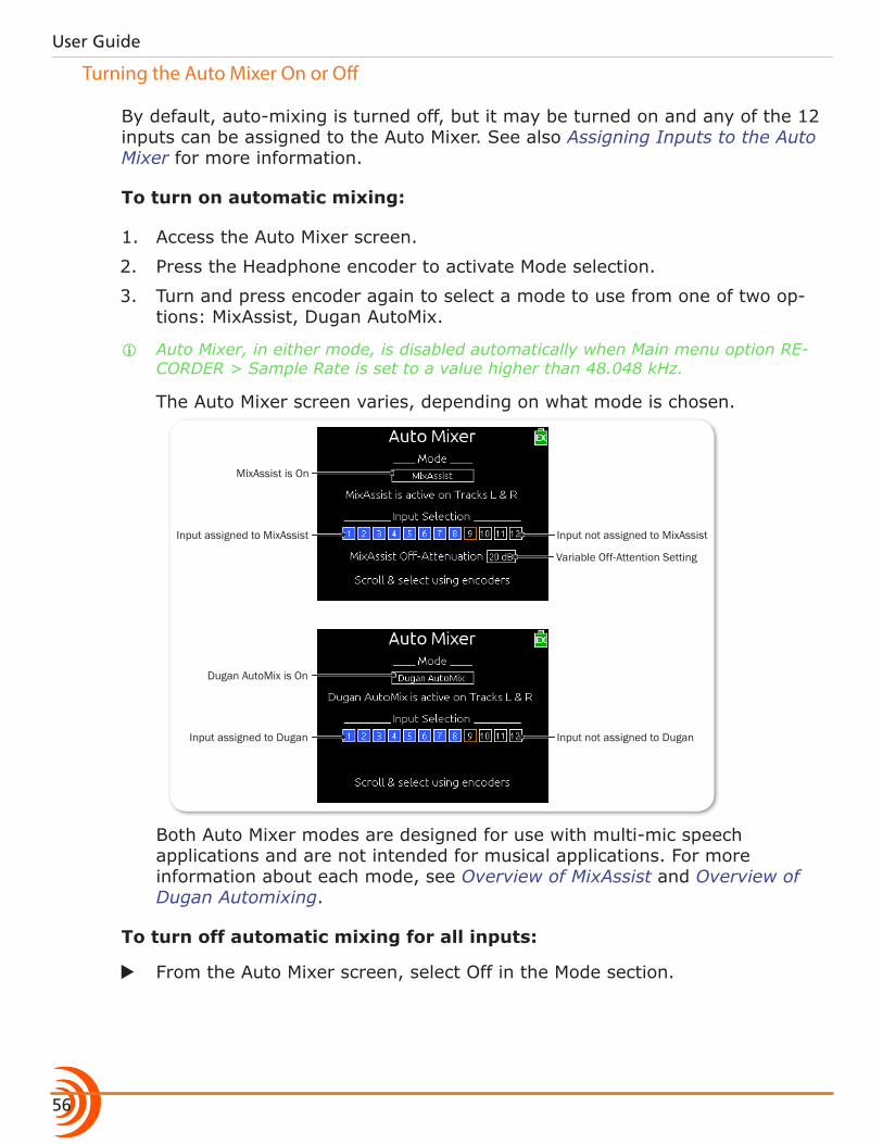
User Guide
56
Turning the Auto Mixer On or Off
By default, auto-mixing is turned off, but it may be turned on and any of the 12 inputs can be assigned to the Auto Mixer. See also Assigning Inputs to the Auto Mixer for more information.
To turn on automatic mixing:
1. Access the Auto Mixer screen.
2. Press the Headphone encoder to activate Mode selection.
3. Turn and press encoder again to select a mode to use from one of two op-tions: MixAssist, Dugan AutoMix.
i Auto Mixer, in either mode, is disabled automatically when Main menu option RE-CORDER > Sample Rate is set to a value higher than 48.048 kHz.
The Auto Mixer screen varies, depending on what mode is chosen.
Input not assigned to MixAssist
MixAssist is On
Input assigned to MixAssist
Variable Off-Attention Setting
Input not assigned to Dugan
Dugan AutoMix is On
Input assigned to Dugan
Both Auto Mixer modes are designed for use with multi-mic speech applications and are not intended for musical applications. For more information about each mode, see Overview of MixAssist and Overview of Dugan Automixing.
To turn off automatic mixing for all inputs:
X From the Auto Mixer screen, select Off in the Mode section.
57
MIXASSIST & DUGAN AUTOMIXING
Assigning Inputs to the Auto Mixer
Inputs that are assigned to an Auto Mixer (MixAssist or Dugan) are referred to as active automixed inputs and will be included in the mix. Inputs not assigned to the Auto Mixer are referred to as inactive automixed inputs and will not be included in the mix.
To assign inputs to MixAssist or Dugan AutoMix:
1. Access the Auto Mixer screen.
2. Turn the Select encoder to move the orange highlight vertically down to the Input Selection section.
3. Turn the Headphone encoder to move the orange highlight horizontally.
4. With the orange highlight positioned on the selected source, press either encoder to change the selected input to either Not Assigned (black) or Assigned (blue).
i Inputs that are routed post-fader to the L or R bus and do not have Auto Mixer activated will not be auto-mixed but will still be analyzed by MixAssist for the purposes of Last Mic Lock-On, One Mic Per Sound Source, and Number of Open Mics Attenuation.
Overview of MixAssist
The Sound Devices MixAssist feature auto-mixes post-fade input signals to the left (L) and right (R) buses. Other signals are not affected by MixAssist.
MixAssist does not limit the number of open microphones and will allow several microphones to be open simultaneously if there are several talkers. MixAssist also intelligently attenuates redundant mics that are picking up the same sound source, which significantly helps to reduce comb filtering and phasing artifacts.
Inputs that are automixed will be open (unattenuated) when a person talks into the input’s microphone and closed (attenuated) when the person stops talking.
Microphone channels open with ultra-sensitive responsiveness to voice levels to ensure that no syllables are lost, and then will “gate off” smoothly over 500mS. This gating action is smooth and imperceptible when switching between micro-phones. MixAssist is more sophisticated than a simple gate, and uses four dif-ferent principles to automix input signals: noise adaptive threshold, one mic per sound source, number of open mic attenuation, and last mic lock-on.
User Guide
58
Noise Adaptive Threshold
When an input’s post-fade level surpasses the MixAssist threshold, it will be opened. Unlike a simple limiter or gate, this threshold is dynamic: MixAssist continuously analyzes all inputs assigned to it to determine an average noise floor level and uses that level as the threshold. This prevents common back-ground noise (fans, crowd murmur, etc.) from causing the input to open, while allowing normal sounds to open the mic.
One Mic Per Sound Source
Often a sound source, such as someone speaking, is captured by more than one microphone. MixAssist actively compares signals from all inputs and when it senses the same audio on multiple inputs, it will only open the input in which that specific program audio arrived first and is loudest.
i This does not prevent another input from opening when unique program audio is sensed at that input.
Number of Open Microphone Attenuation
As the number of open inputs increases, the level of each input as it is routed to the track will decrease by 3 dB per doubling of open mics. This ensures that the overall level of the track is consistent regardless of the amount of open inputs routed to it.
Last Mic Lock-On
When talking stops, the last input to be active will remain open. This maintains a consistent level of natural sound and avoids a dramatic transition to silence on the track, even when no inputs are in use.
Setting MixAssist Off-Attenuation
The 688 also lets the user define the amount of off-attenuation that MixAssist uses during the auto-mixing process.
To set the amount of off-attenuation for MixAssist:
1. From the Auto Mixer screen, with MixAssist set as the Mode, use the Select encoder to move the orange highlight vertically down to the MixAssist Off-Attenuation field.
2. Press the Headphone encoder to select the field; its background will appear orange.

59
MIXASSIST & DUGAN AUTOMIXING
3. Turn the Headphone encoder to change the setting. Range is from 6 dB to 40 dB in 1 dB increments.
LCD Views During MixAssist Automixing
A circle icon is displayed next to the meter for each active automixed input. When the input is open, the circle will be green. As the input closes, the circle will fade to black.
Closed input
Open input
The Meters view displays these circle icons above (vertical meters) or to the right of (horizontal meters) the active automixed inputs.
The Input Settings screen will display the circle icon to the right of the meter.
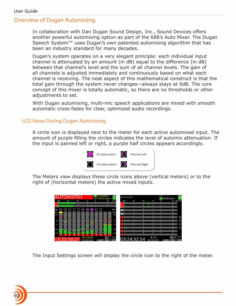
User Guide
60
Overview of Dugan Automixing
In collaboration with Dan Dugan Sound Design, Inc., Sound Devices offers another powerful automixing option as part of the 688’s Auto Mixer. The Dugan Speech System™ uses Dugan’s own patented automixing algorithm that has been an industry standard for many decades.
Dugan’s system operates on a very elegant principle: each individual input channel is attenuated by an amount (in dB) equal to the difference (in dB) between that channel’s level and the sum of all channel levels. The gain of all channels is adjusted immediately and continuously based on what each channel is receiving. The neat aspect of this mathematical construct is that the total gain through the system never changes—always stays at 0dB. The core concept of this mixer is totally automatic, so there are no thresholds or other adjustments to set.
With Dugan automixing, multi-mic speech applications are mixed with smooth automatic cross-fades for clear, optimized audio recordings.
LCD Views During Dugan Automixing
A circle icon is displayed next to the meter for each active automixed input. The amount of purple filling the circles indicates the level of automix attenuation. If the input is panned left or right, a purple half circles appears accordingly.
Full attenuation
No attenuation
Panned Right
Panned Left
The Meters view displays these circle icons above (vertical meters) or to the right of (horizontal meters) the active mixed inputs.
The Input Settings screen will display the circle icon to the right of the meter.
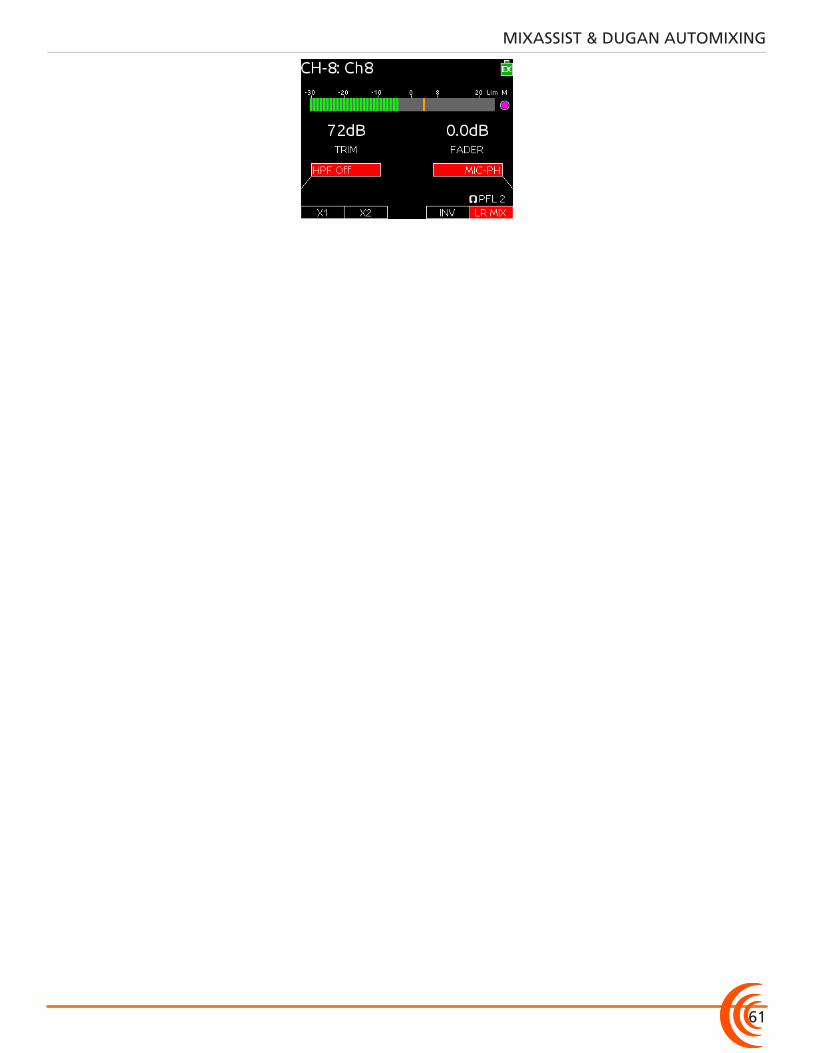
61
MIXASSIST & DUGAN AUTOMIXING

User Guide
62
63
Topics in this section include:
Limiters
Overview
Limiters prevent clipping by attenuating signals that exceed a set threshold. The amount of attenuation is defined by the ratio of the limiter and expressed as two numbers.
The time it takes for limiting to begin once signal has exceeded the threshold is referred to as the attack time, and the time it takes for limiting to cease once signal has fallen back below the threshold is referred to as release time.
Sound Devices recommends using limiters at all times. Without input limiters, high signal conditions can overload a channel and cause distortion. In normal operation, with a properly set gain structure, the threshold of the input limiter is rarely reached. The default threshold of all limiters on the 688 is 16 dBu.
All 688 limiters use a 20:1 compression ratio. This means that any signal that exceeds the threshold by 20 dB will exit the limiting stage at only 1 dB above the threshold. The 688 limiters have a 1 ms attack time and a 500 ms release time.
The input limiter is actively limiting when the respective input’s Input Activity LED illuminates yellow. Limiting activity will also be displayed as a yellow square on the right side of the input’s meter on the Main screen. If the limiting activity is regularly indicated, reduce the amount of gain applied to the channel by turn-ing down the Trim control.
�Overview
�Enabling the Limiters
�Adjusting the Threshold
�Linking Limiters
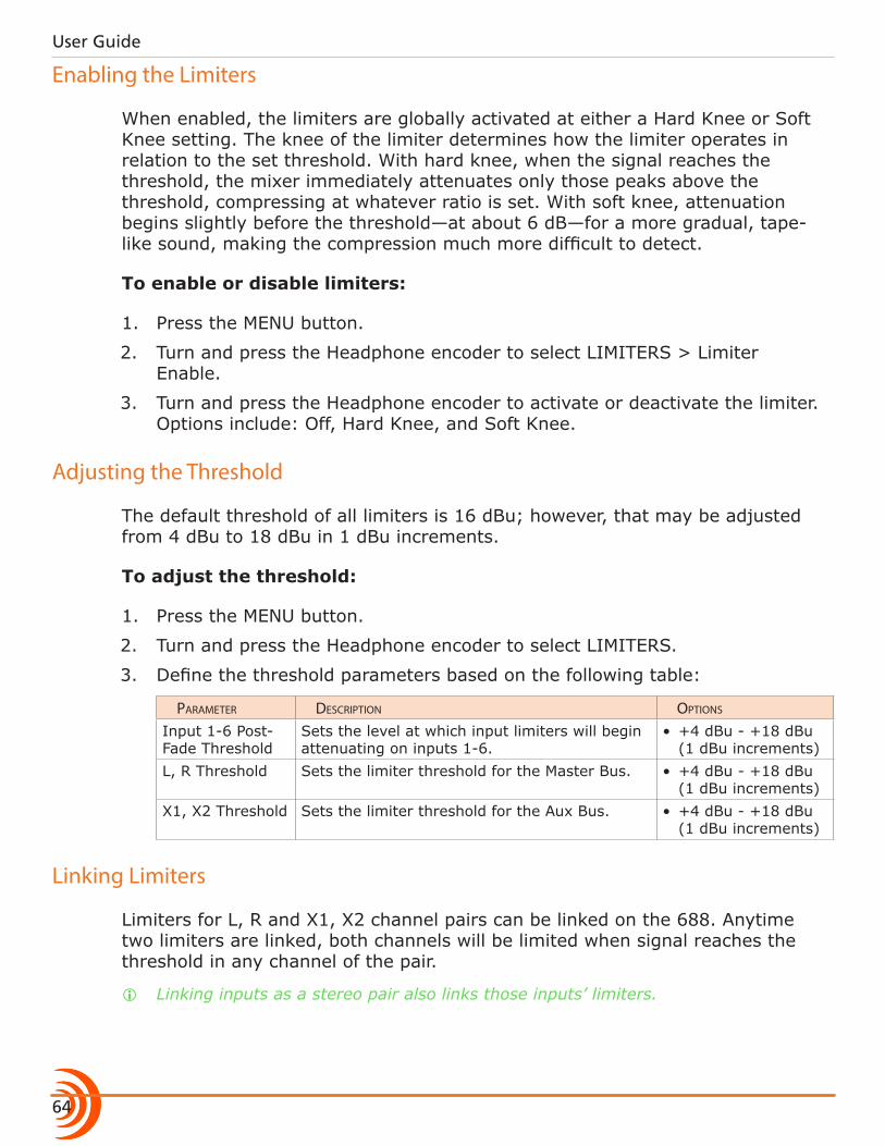
User Guide
64
Enabling the Limiters
When enabled, the limiters are globally activated at either a Hard Knee or Soft Knee setting. The knee of the limiter determines how the limiter operates in relation to the set threshold. With hard knee, when the signal reaches the threshold, the mixer immediately attenuates only those peaks above the threshold, compressing at whatever ratio is set. With soft knee, attenuation begins slightly before the threshold—at about 6 dB—for a more gradual, tape-like sound, making the compression much more difficult to detect.
To enable or disable limiters:
1. Press the MENU button.
2. Turn and press the Headphone encoder to select LIMITERS > Limiter Enable.
3. Turn and press the Headphone encoder to activate or deactivate the limiter. Options include: Off, Hard Knee, and Soft Knee.
Adjusting the Threshold
The default threshold of all limiters is 16 dBu; however, that may be adjusted from 4 dBu to 18 dBu in 1 dBu increments.
To adjust the threshold:
1. Press the MENU button.
2. Turn and press the Headphone encoder to select LIMITERS.
3. Define the threshold parameters based on the following table:
parameter Description options
Input 1-6 Post-Fade Threshold
Sets the level at which input limiters will begin attenuating on inputs 1-6.
• +4 dBu - +18 dBu (1 dBu increments)
L, R Threshold Sets the limiter threshold for the Master Bus. • +4 dBu - +18 dBu (1 dBu increments)
X1, X2 Threshold Sets the limiter threshold for the Aux Bus. • +4 dBu - +18 dBu (1 dBu increments)
Linking Limiters
Limiters for L, R and X1, X2 channel pairs can be linked on the 688. Anytime two limiters are linked, both channels will be limited when signal reaches the threshold in any channel of the pair.
i Linking inputs as a stereo pair also links those inputs’ limiters.
65
LIMITERS
To link limiters:
1. Press the MENU button.
2. Do either one or both of the following: X Turn and press the Headphone encoder to select LIMITERS > L, R Link-
ing. X Turn and press the Headphone encoder to select LIMITERS > X1, X2
Linking.
3. Turn and press the Headphone encoder to set linking. Options include: On or Off.

User Guide
66

67
Topics in this section include:
Recording
Using Media
The 688 offers 16-track, polyphonic or monophonic broadcast WAV file recording to Secure Digital (SD) and CompactFlash (CF) cards. These memory cards are an easy-to-source, reliable, and affordable file storage option that also may be quickly delivered to post immediately after recording stops.
All common sampling rates are supported, including up to six tracks at 192 kHz.
The memory cards can be set independently, recording either identical material for real-time backup, or combinations of WAV Poly, WAV Mono and MP3 files.
Before recording anything, install and format the media storage memory cards you intend to use in the 688. The slots for memory cards are located on the right panel behind the Media Door, which is held closed magnetically.
Media DoorTo insert media:
1. Firmly pull open the Media Door.
2. Insert your choice of media memory card into the slots provided.
When inserting the SD card, ensure the bottom of the card (the side with metal contacts visible) is facing the rear of the unit. When inserting a CF card, ensure the top of the card (the side with the branding label) is facing the rear of the unit.
i Sound Devices Quality Assurance engineers have done extensive testing to ensure media approved for use with the 688 works re-liably and provides the best performance in a variety of extreme conditions. When choosing your media, please refer to the Ap-proved Media List available on the Sound Devices website at: www.SoundDevices.com/ApprovedMedia. For more information, see also Viewing Approved Media List via Smart Phone.
CF Memory Card Slot
SD Memory Card Slot
�Using Media
�Using the Transport Control
�Arming or Unarming Recording Tracks
�Accessing Recorder Settings
�Setting File Type and Media Track Assignment
�Changing the MP3 Bit Rate
�Setting the Sample Rate �F Sample Modes
�Setting the Bit Depth
�Setting the Pre-roll
�Using the Slate Microphone
�Playing Back Active Takes
�Viewing Approved Media List via Smart Phone
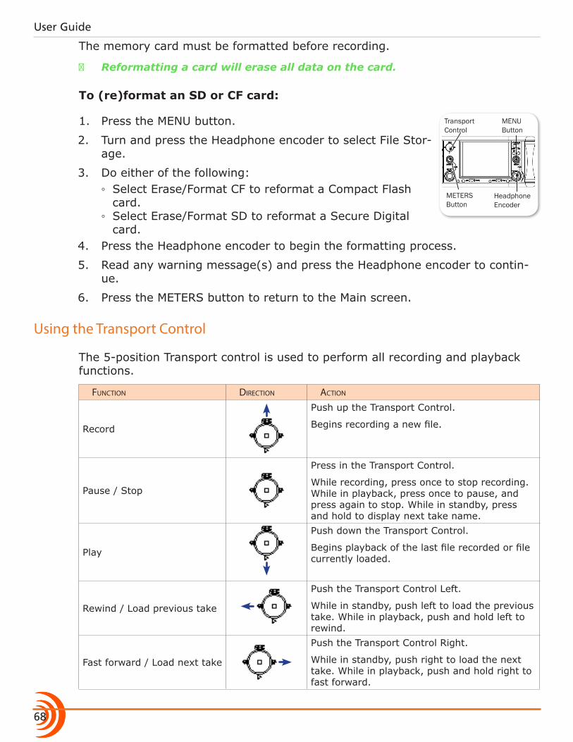
User Guide
68
The memory card must be formatted before recording.
⚠ Reformatting a card will erase all data on the card.
To (re)format an SD or CF card:
1. Press the MENU button.
2. Turn and press the Headphone encoder to select File Stor-age.
3. Do either of the following: ◦ Select Erase/Format CF to reformat a Compact Flash card.
◦ Select Erase/Format SD to reformat a Secure Digital card.
4. Press the Headphone encoder to begin the formatting process.
5. Read any warning message(s) and press the Headphone encoder to contin-ue.
6. Press the METERS button to return to the Main screen.
Using the Transport Control
The 5-position Transport control is used to perform all recording and playback functions.
Function Direction action
Record
Push up the Transport Control.
Begins recording a new file.
Pause / Stop
Press in the Transport Control.
While recording, press once to stop recording. While in playback, press once to pause, and press again to stop. While in standby, press and hold to display next take name.
Play
Push down the Transport Control.
Begins playback of the last file recorded or file currently loaded.
Rewind / Load previous take
Push the Transport Control Left.
While in standby, push left to load the previous take. While in playback, push and hold left to rewind.
Fast forward / Load next take
Push the Transport Control Right.
While in standby, push right to load the next take. While in playback, push and hold right to fast forward.
METERS Button
Headphone Encoder
MENU Button
Transport Control
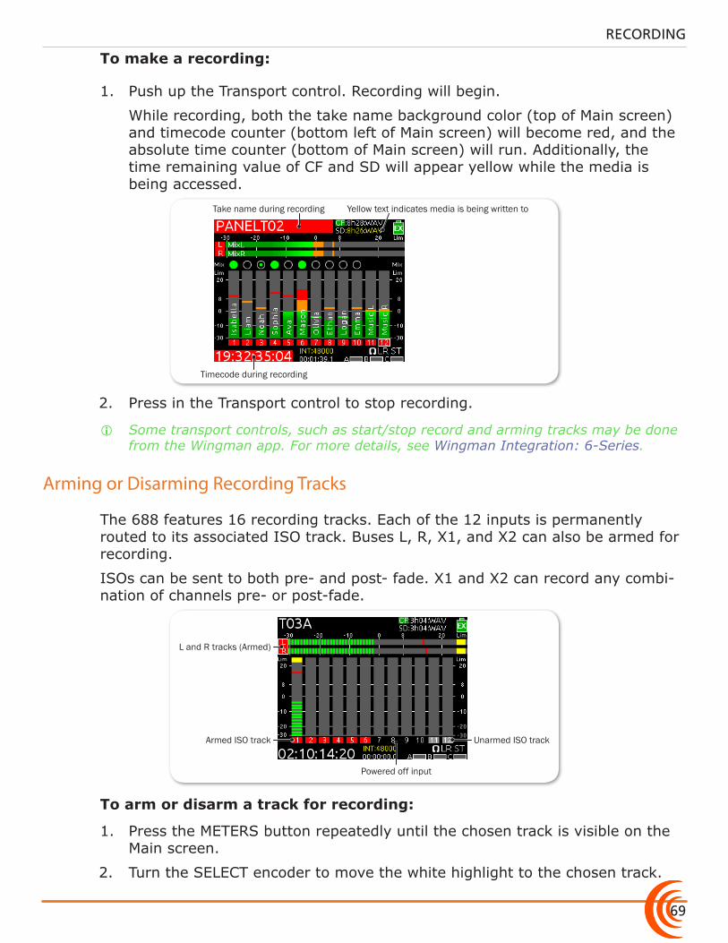
69
RECORDING
To make a recording:
1. Push up the Transport control. Recording will begin.
While recording, both the take name background color (top of Main screen) and timecode counter (bottom left of Main screen) will become red, and the absolute time counter (bottom of Main screen) will run. Additionally, the time remaining value of CF and SD will appear yellow while the media is being accessed.
Take name during recording
Timecode during recording
Yellow text indicates media is being written to
2. Press in the Transport control to stop recording.
i Some transport controls, such as start/stop record and arming tracks may be done from the Wingman app. For more details, see Wingman Integration: 6-Series.
Arming or Disarming Recording Tracks
The 688 features 16 recording tracks. Each of the 12 inputs is permanently routed to its associated ISO track. Buses L, R, X1, and X2 can also be armed for recording.
ISOs can be sent to both pre- and post- fade. X1 and X2 can record any combi-nation of channels pre- or post-fade.
L and R tracks (Armed)
Armed ISO track Unarmed ISO track
Powered off input
To arm or disarm a track for recording:
1. Press the METERS button repeatedly until the chosen track is visible on the Main screen.
2. Turn the SELECT encoder to move the white highlight to the chosen track.
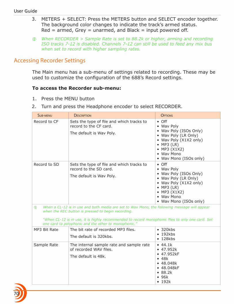
User Guide
70
3. METERS + SELECT: Press the METERS button and SELECT encoder together. The background color changes to indicate the track’s armed status. Red = armed, Grey = unarmed, and Black = input powered off.
i When RECORDER > Sample Rate is set to 88.2k or higher, arming and recording ISO tracks 7-12 is disabled. Channels 7-12 can still be used to feed any mix bus when set to record with higher sampling rates.
Accessing Recorder Settings
The Main menu has a sub-menu of settings related to recording. These may be used to customize the configuration of the 688’s Record settings.
To access the Recorder sub-menu:
1. Press the MENU button
2. Turn and press the Headphone encoder to select RECORDER.
sub-menu Description options
Record to CF Sets the type of file and which tracks to record to the CF card.
The default is Wav Poly.
• Off• Wav Poly• Wav Poly (ISOs Only)• Wav Poly (LR Only)• Wav Poly (X1X2 only)• MP3 (LR)• MP3 (X1X2)• Wav Mono• Wav Mono (ISOs only)
Record to SD Sets the type of file and which tracks to record to the SD card.
The default is Wav Poly.
• Off• Wav Poly• Wav Poly (ISOs Only)• Wav Poly (LR Only)• Wav Poly (X1X2 only)• MP3 (LR)• MP3 (X1X2)• Wav Mono• Wav Mono (ISOs only)
i When a CL-12 is in use and both media are set to Wav Mono, the following message will appear when the REC button is pressed to begin recording. “When CL-12 is in use, it is highly recommended to record monophonic files to only one card. Set one card to polyphonic and the other to monophonic.”
MP3 Bit Rate The bit rate of recorded MP3 files.
The default is 320kbs.
• 320kbs• 192kbs• 128kbs
Sample Rate The internal sample rate and sample rate of recorded WAV files.
The default is 48k.
• 44.1k• 47.952k• 47.952kF• 48k• 48.048k• 48.048kF• 88.2k• 96k• 192k
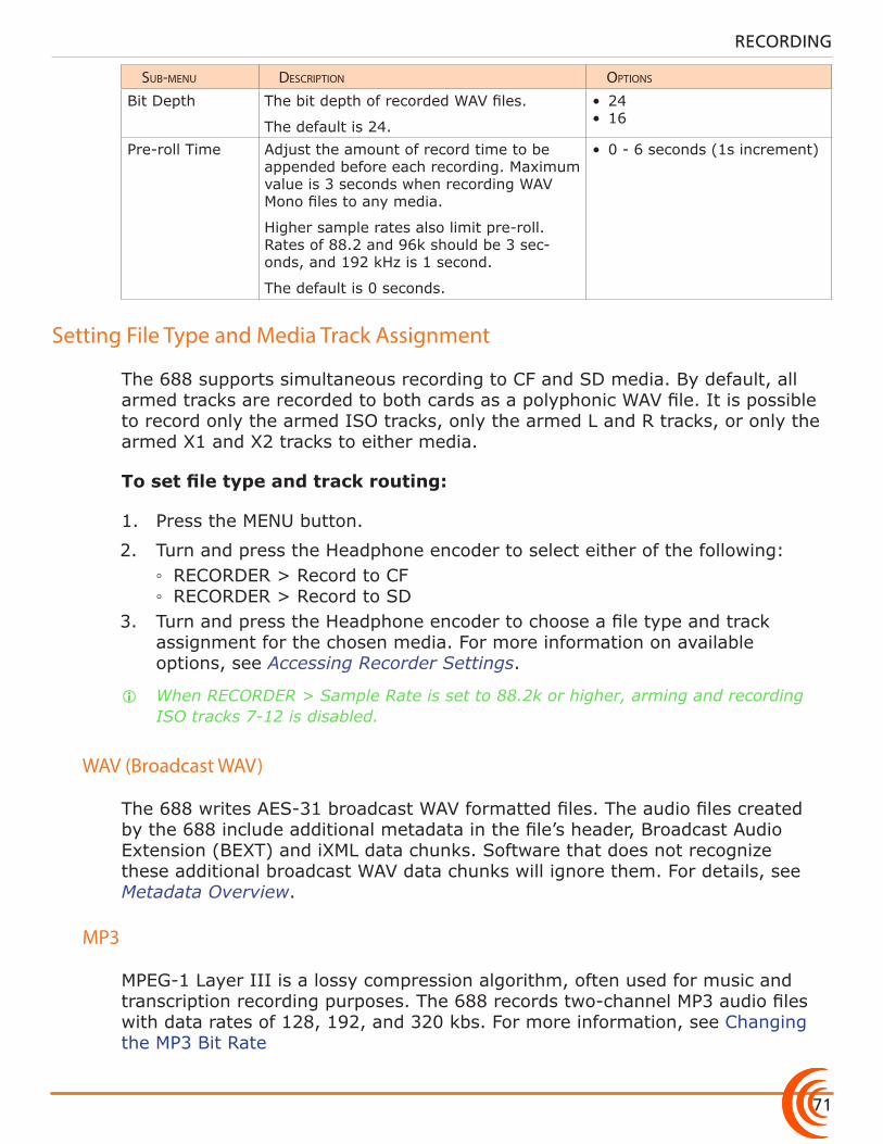
71
RECORDING
sub-menu Description options
Bit Depth The bit depth of recorded WAV files.
The default is 24.
• 24• 16
Pre-roll Time Adjust the amount of record time to be appended before each recording. Maximum value is 3 seconds when recording WAV Mono files to any media.
Higher sample rates also limit pre-roll. Rates of 88.2 and 96k should be 3 sec-onds, and 192 kHz is 1 second.
The default is 0 seconds.
• 0 - 6 seconds (1s increment)
Setting File Type and Media Track Assignment
The 688 supports simultaneous recording to CF and SD media. By default, all armed tracks are recorded to both cards as a polyphonic WAV file. It is possible to record only the armed ISO tracks, only the armed L and R tracks, or only the armed X1 and X2 tracks to either media.
To set file type and track routing:
1. Press the MENU button.
2. Turn and press the Headphone encoder to select either of the following: ◦ RECORDER > Record to CF ◦ RECORDER > Record to SD
3. Turn and press the Headphone encoder to choose a file type and track assignment for the chosen media. For more information on available options, see Accessing Recorder Settings.
i When RECORDER > Sample Rate is set to 88.2k or higher, arming and recording ISO tracks 7-12 is disabled.
WAV (Broadcast WAV)
The 688 writes AES-31 broadcast WAV formatted files. The audio files created by the 688 include additional metadata in the file’s header, Broadcast Audio Extension (BEXT) and iXML data chunks. Software that does not recognize these additional broadcast WAV data chunks will ignore them. For details, see Metadata Overview.
MP3
MPEG-1 Layer III is a lossy compression algorithm, often used for music and transcription recording purposes. The 688 records two-channel MP3 audio files with data rates of 128, 192, and 320 kbs. For more information, see Changing the MP3 Bit Rate
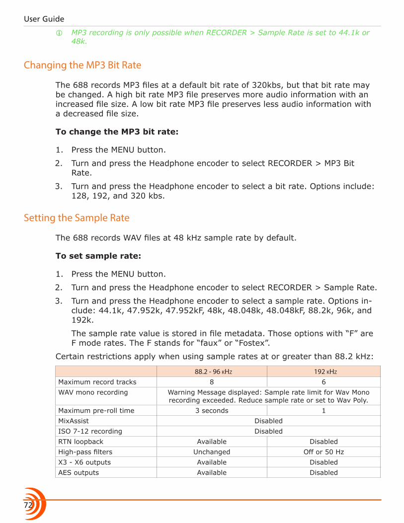
User Guide
72
i MP3 recording is only possible when RECORDER > Sample Rate is set to 44.1k or 48k.
Changing the MP3 Bit Rate
The 688 records MP3 files at a default bit rate of 320kbs, but that bit rate may be changed. A high bit rate MP3 file preserves more audio information with an increased file size. A low bit rate MP3 file preserves less audio information with a decreased file size.
To change the MP3 bit rate:
1. Press the MENU button.
2. Turn and press the Headphone encoder to select RECORDER > MP3 Bit Rate.
3. Turn and press the Headphone encoder to select a bit rate. Options include: 128, 192, and 320 kbs.
Setting the Sample Rate
The 688 records WAV files at 48 kHz sample rate by default.
To set sample rate:
1. Press the MENU button.
2. Turn and press the Headphone encoder to select RECORDER > Sample Rate.
3. Turn and press the Headphone encoder to select a sample rate. Options in-clude: 44.1k, 47.952k, 47.952kF, 48k, 48.048k, 48.048kF, 88.2k, 96k, and 192k.
The sample rate value is stored in file metadata. Those options with “F” are F mode rates. The F stands for “faux” or “Fostex”.
Certain restrictions apply when using sample rates at or greater than 88.2 kHz:
88.2 - 96 kHz 192 kHz
Maximum record tracks 8 6WAV mono recording Warning Message displayed: Sample rate limit for Wav Mono
recording exceeded. Reduce sample rate or set to Wav Poly.Maximum pre-roll time 3 seconds 1MixAssist DisabledISO 7-12 recording DisabledRTN loopback Available DisabledHigh-pass filters Unchanged Off or 50 HzX3 - X6 outputs Available DisabledAES outputs Available Disabled
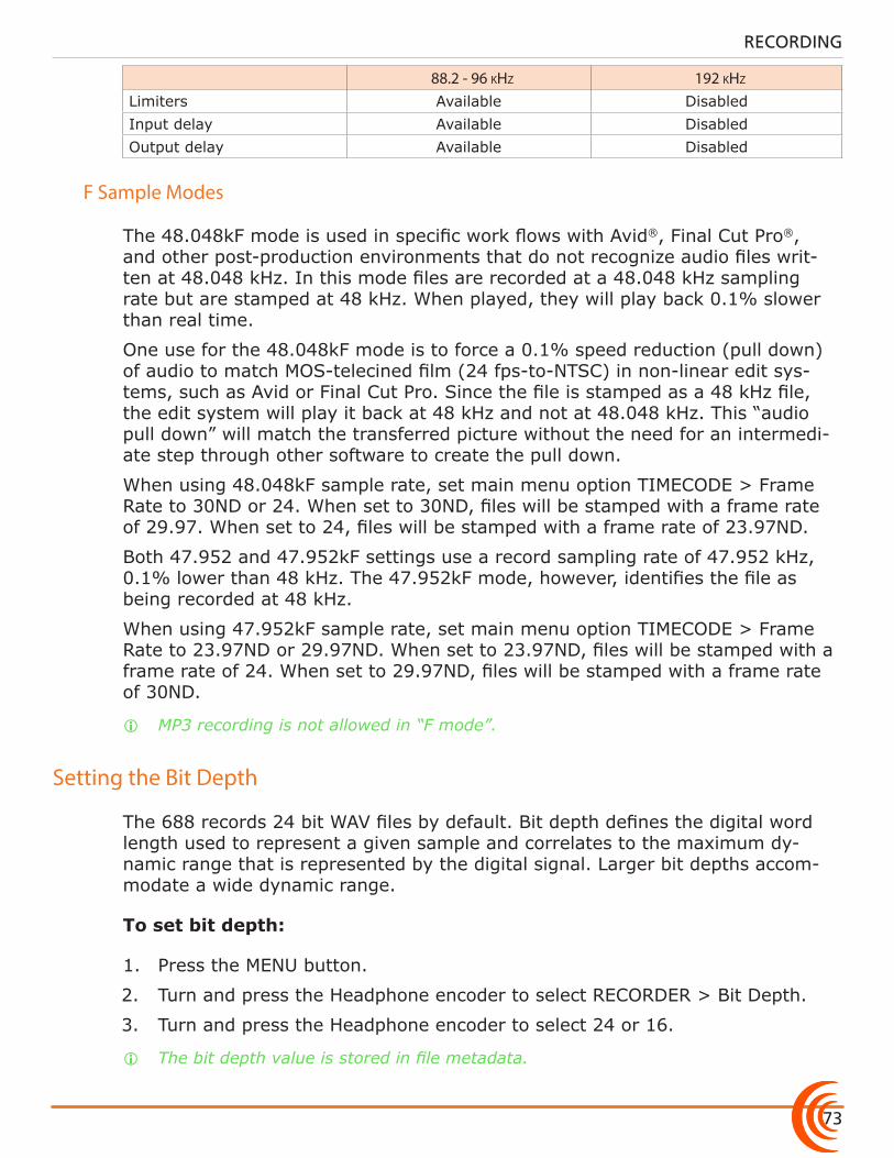
73
RECORDING
88.2 - 96 kHz 192 kHz
Limiters Available DisabledInput delay Available DisabledOutput delay Available Disabled
F Sample Modes
The 48.048kF mode is used in specific work flows with Avid®, Final Cut Pro®, and other post-production environments that do not recognize audio files writ-ten at 48.048 kHz. In this mode files are recorded at a 48.048 kHz sampling rate but are stamped at 48 kHz. When played, they will play back 0.1% slower than real time.
One use for the 48.048kF mode is to force a 0.1% speed reduction (pull down) of audio to match MOS-telecined film (24 fps-to-NTSC) in non-linear edit sys-tems, such as Avid or Final Cut Pro. Since the file is stamped as a 48 kHz file, the edit system will play it back at 48 kHz and not at 48.048 kHz. This “audio pull down” will match the transferred picture without the need for an intermedi-ate step through other software to create the pull down.
When using 48.048kF sample rate, set main menu option TIMECODE > Frame Rate to 30ND or 24. When set to 30ND, files will be stamped with a frame rate of 29.97. When set to 24, files will be stamped with a frame rate of 23.97ND.
Both 47.952 and 47.952kF settings use a record sampling rate of 47.952 kHz, 0.1% lower than 48 kHz. The 47.952kF mode, however, identifies the file as being recorded at 48 kHz.
When using 47.952kF sample rate, set main menu option TIMECODE > Frame Rate to 23.97ND or 29.97ND. When set to 23.97ND, files will be stamped with a frame rate of 24. When set to 29.97ND, files will be stamped with a frame rate of 30ND.
i MP3 recording is not allowed in “F mode”.
Setting the Bit Depth
The 688 records 24 bit WAV files by default. Bit depth defines the digital word length used to represent a given sample and correlates to the maximum dy-namic range that is represented by the digital signal. Larger bit depths accom-modate a wide dynamic range.
To set bit depth:
1. Press the MENU button.
2. Turn and press the Headphone encoder to select RECORDER > Bit Depth.
3. Turn and press the Headphone encoder to select 24 or 16.
i The bit depth value is stored in file metadata.
User Guide
74
Setting the Pre-roll
Pre-roll buffering is available on the 688 to help prevent missing record cues or up-cutting takes. By default, the pre-roll time is 0 seconds (off). When active, pre-roll begins recording at a set number of seconds preceding the record but-ton being pressed.
To set pre-roll time:
1. Press the MENU button.
2. Turn and press the Headphone encoder to select RECORDER > Pre-roll Time.
3. Turn and press the Headphone encoder to select a value (0 s to 6 s).
i While a pre-roll time may be set regardless of the timecode mode, pre-roll is ig-nored whenever timecode mode is set to Record Run. Additionally, when the mix-er’s timecode mode is set to either External Timecode Auto Record, or External Timecode Continuous Auto Record, pre-roll is only applied within the Hold Off period and never before receiving rolling timecode value from the master external timecode source. This prevents possible overlapping timecode numbers between adjacent files. For more information, see Setting the Timecode Mode and Setting Timecode Hold Off.
i Maximum pre-roll time is 3 seconds when RECORDER > Sample Rate is set to 88.2k or 96k. Maximum pre-roll time is 1 second when RECORDER > Sample Rate is set to 192k.
Using the Slate Microphone
The 688’s built-in slate and external microphone is used to notate scenes from the mixer location. Its audio performance is not suitable for critical recording applications. It should be used for documenting scenes and for communication purposes only.
To use the slate microphone:
1. Slide the MIC/TONE switch left to activate the slate mic. The Slate/Tone LED illuminates green to indicate the slate mic is active.
2. Slide the MIC/TONE switch left again to deactivate the slate mic.
i By default, the slate mic is routed to all tracks and outputs. The gain of the slate mic can be adjusted and an external mic can be used optionally. For details, see Comms and Returns.
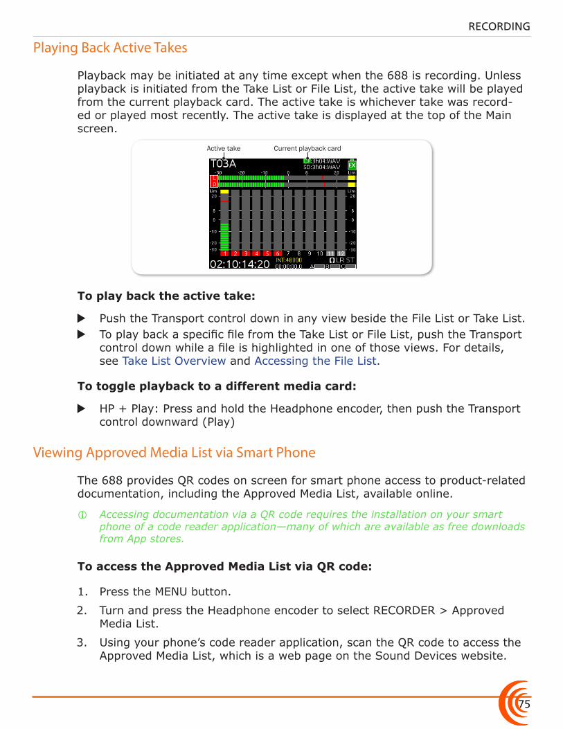
75
RECORDING
Playing Back Active Takes
Playback may be initiated at any time except when the 688 is recording. Unless playback is initiated from the Take List or File List, the active take will be played from the current playback card. The active take is whichever take was record-ed or played most recently. The active take is displayed at the top of the Main screen.
Active take Current playback card
To play back the active take:
X Push the Transport control down in any view beside the File List or Take List. X To play back a specific file from the Take List or File List, push the Transport
control down while a file is highlighted in one of those views. For details, see Take List Overview and Accessing the File List.
To toggle playback to a different media card:
X HP + Play: Press and hold the Headphone encoder, then push the Transport control downward (Play)
Viewing Approved Media List via Smart Phone
The 688 provides QR codes on screen for smart phone access to product-related documentation, including the Approved Media List, available online.
i Accessing documentation via a QR code requires the installation on your smart phone of a code reader application—many of which are available as free downloads from App stores.
To access the Approved Media List via QR code:
1. Press the MENU button.
2. Turn and press the Headphone encoder to select RECORDER > Approved Media List.
3. Using your phone’s code reader application, scan the QR code to access the Approved Media List, which is a web page on the Sound Devices website.

User Guide
76
77
Topics in this section include:
Comms and Returns
Overview of Slate Mic
The 688 is equipped with three stereo returns (RTN A, B, C) which allow the Sound Mixer to hear camera audio directly from the 688 interface to ensure quality audio is being sent to camera. RTN audio can be quickly monitored on the 688 headphone output with a toggle of the RTN/FAV switch. The 688 can utilize an external slate mic or the built-in slate mic for an “all call” (Slate) to any of its outputs or record tracks. The Slate mic can also be used to send private communications (COM) to any of the six Aux outputs.
This section discusses the flexible options and setup of the returns and communication systems.
The slate microphone can be used to audibly identify a scene or slate at the start of recording or communicate with other members of the production crew. The 688 incorporates a built-in slate mic and a TA3 connector for an external slate mic. The built-in mic is the default. Its audio performance is not suitable for critical recording applications; it should be used for documenting scenes and for communication purposes only. Use an external slate mic when higher quality communications are required.
Setting up an External Slate Microphone
An external microphone can be used instead of the built-in microphone.
To set up an external slate microphone:
1. Connect the microphone to the SLATE MIC IN TA3 connector on the left panel.
2. Press the MENU button.
3. Turn and press the Headphone encoder to select COMMS/RETURNS > Slate/Com Mic Source.
4. Turn and press the Headphone encoder to select Ext Mic (for dynamic mi-
�Overview of Slate Mic
�Setting up an External Slate Microphone
�Setting Slate Mic Gain
�Routing the Slate Mic
�Using the Slate for Notation
�Private Comms �Activating the Comms �Monitoring COM/RTN �Com Send Routing
�Comms / Returns Settings
�Adjusting Com Return Gain
�Adjusting Comms Muting Behavior
�Customizing MIC/TONE and RTN/FAV
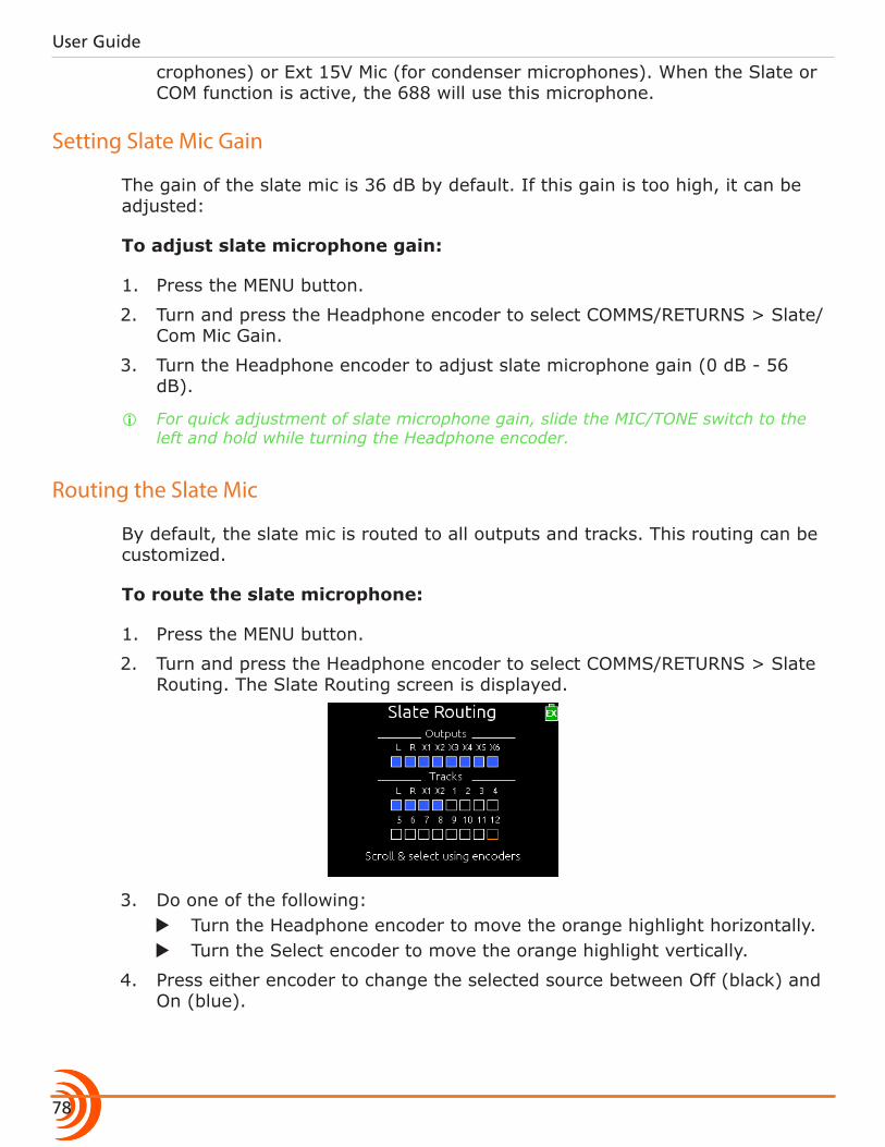
User Guide
78
crophones) or Ext 15V Mic (for condenser microphones). When the Slate or COM function is active, the 688 will use this microphone.
Setting Slate Mic Gain
The gain of the slate mic is 36 dB by default. If this gain is too high, it can be adjusted:
To adjust slate microphone gain:
1. Press the MENU button.
2. Turn and press the Headphone encoder to select COMMS/RETURNS > Slate/Com Mic Gain.
3. Turn the Headphone encoder to adjust slate microphone gain (0 dB - 56 dB).
i For quick adjustment of slate microphone gain, slide the MIC/TONE switch to the left and hold while turning the Headphone encoder.
Routing the Slate Mic
By default, the slate mic is routed to all outputs and tracks. This routing can be customized.
To route the slate microphone:
1. Press the MENU button.
2. Turn and press the Headphone encoder to select COMMS/RETURNS > Slate Routing. The Slate Routing screen is displayed.
3. Do one of the following: X Turn the Headphone encoder to move the orange highlight horizontally. X Turn the Select encoder to move the orange highlight vertically.
4. Press either encoder to change the selected source between Off (black) and On (blue).
79
COMMS AND RETURNS
Using the Slate for Notation
The following procedures describe default behavior of the MIC/TONE switch; however, it may be modified to behave differently. See Customizing MIC/TONE and RTN/FAV for more information.
To activate the slate function momentarily:
1. Slide and hold the MIC/TONE switch left. The slate mic activates, the Slate/Tone LED illuminates green, and the headphone monitor source changes to SLATE when slate is active.
2. Release the MIC/TONE switch. The slate mic deactivates, the Slate/Tone LED turns off, and the headphone monitor reverts to its previous source.
To lock the slate function on:
1. Slide the MIC/TONE switch left. The slate mic activates, the Slate/Tone LED illuminates green, and the headphone monitor source changes to SLATE.
2. Slide the MIC/TONE switch left again. The slate mic deactivates, the Slate/Tone LED turns off, and the headphone monitor reverts to its previous source.
Private Comms
The 688 features Comms for private communication between the 688 operator and other members of the crew. The most common use of Comms is for the sound mixer to communicate with the boom operator. The same mic used for slate is also used to send comms.
Activating Comms
When Comms are active, the slate mic signal is sent to auxiliary outputs which have the COM Send source activated and the other sources of that output are muted. The COM signal is sent to the right channel of the headphone monitor and the selected headphone source is attenuated. See Accessing Aux (X1 - X6) Routing Screen for details.
i Comms will never go to record tracks or affect recordings.
The following procedures describe default behavior of the MIC/TONE switch; however, it may be modified to behave differently. See Customizing MIC/TONE and RTN/FAV for more information.
To activate Comms momentarily:
1. SELECT + MIC: Press and hold the SELECT encoder while sliding and hold-ing the MIC/TONE switch left. The slate mic activates, and the Slate/Tone LED illuminates green.
User Guide
80
2. Release the MIC/TONE switch. The slate mic deactivates, and the Slate/Tone LED turns off.
To lock Comms on:
1. SELECT + MIC: Press and hold the SELECT encoder while sliding the MIC/TONE switch left. The slate mic activates, and the Slate/Tone LED illu-minates green.
2. Slide the MIC/TONE switch left again. The slate mic deactivates and the Slate/Tone LED turns off.
Monitoring COM/RTN
The COM RTN allows the Sound Mixer to hear communication back from other members of the production crew, such as the boom operator. The COM RTN signal can be quickly heard in headphones by using the assigned RTN/FAV toggle action or by assigning it to a custom HP preset. For two-way communication, activate the COM RTN and the COM Send at the same time.
The following procedure describes default behavior of the RTN/FAV switch; however, it may be modified to behave differently. See Customizing MIC/TONE and RTN/FAV for more information.
To monitor COM RTN:
1. SELECT + RTN: Press and hold the SELECT encoder while sliding the RTN/FAV switch left. The headphone monitor source changes to COM RTN.
2. When finished, slide the RTN/FAV switch right to return to the selected monitor source.
Com Send Routing
The com send source can be assigned to any of the auxiliary outputs (X1 - X6). Com send sources are assigned in the Aux Output Routing screens. See Access-ing Aux (X1 - X6) Routing Screen for details.
Comms / Returns Settings
The 688 has a COMMS/RETURNS menu to allow for various setting adjustments. Most of these settings are described in greater detail in other sections of this guide, where applicable. The menu’s entire sub-menu listing and options are provided in the following reference table as a convenience.
sub-menu Description options
Slate/Com Mic Source Select internal or external slate micro-phone. Use Ext 15V setting for external condenser microphones.
• OFF• Int Mic• Ext Mic• Ext 15V Mic
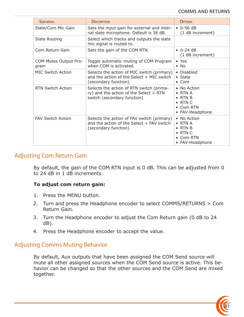
81
COMMS AND RETURNS
sub-menu Description options
Slate/Com Mic Gain Sets the input gain for external and inter-nal slate microphone. Default is 36 dB.
• 0-56 dB (1 dB increment)
Slate Routing Select which tracks and outputs the slate mic signal is routed to.
Com Return Gain Sets the gain of the COM RTN. • 0-24 dB (1 dB increment)
COM Mutes Output Pro-gram
Toggle automatic muting of COM Program when COM is activated.
• Yes• No
MIC Switch Action Selects the action of MIC switch (primary) and the action of the Select + MIC switch (secondary function)
• Disabled• Slate• Com
RTN Switch Action Selects the action of RTN switch (prima-ry) and the action of the Select + RTN switch (secondary function)
• No Action• RTN A• RTN B• RTN C• Com RTN• FAV-Headphone
FAV Switch Action Selects the action of FAV switch (primary) and the action of the Select + FAV switch (secondary function)
• No Action• RTN A• RTN B• RTN C• Com RTN• FAV-Headphone
Adjusting Com Return Gain
By default, the gain of the COM RTN input is 0 dB. This can be adjusted from 0 to 24 dB in 1 dB increments.
To adjust com return gain:
1. Press the MENU button.
2. Turn and press the Headphone encoder to select COMMS/RETURNS > Com Return Gain.
3. Turn the Headphone encoder to adjust the Com Return gain (0 dB to 24 dB).
4. Press the Headphone encoder to accept the value.
Adjusting Comms Muting Behavior
By default, Aux outputs that have been assigned the COM Send source will mute all other assigned sources when the COM Send source is active. This be-havior can be changed so that the other sources and the COM Send are mixed together.
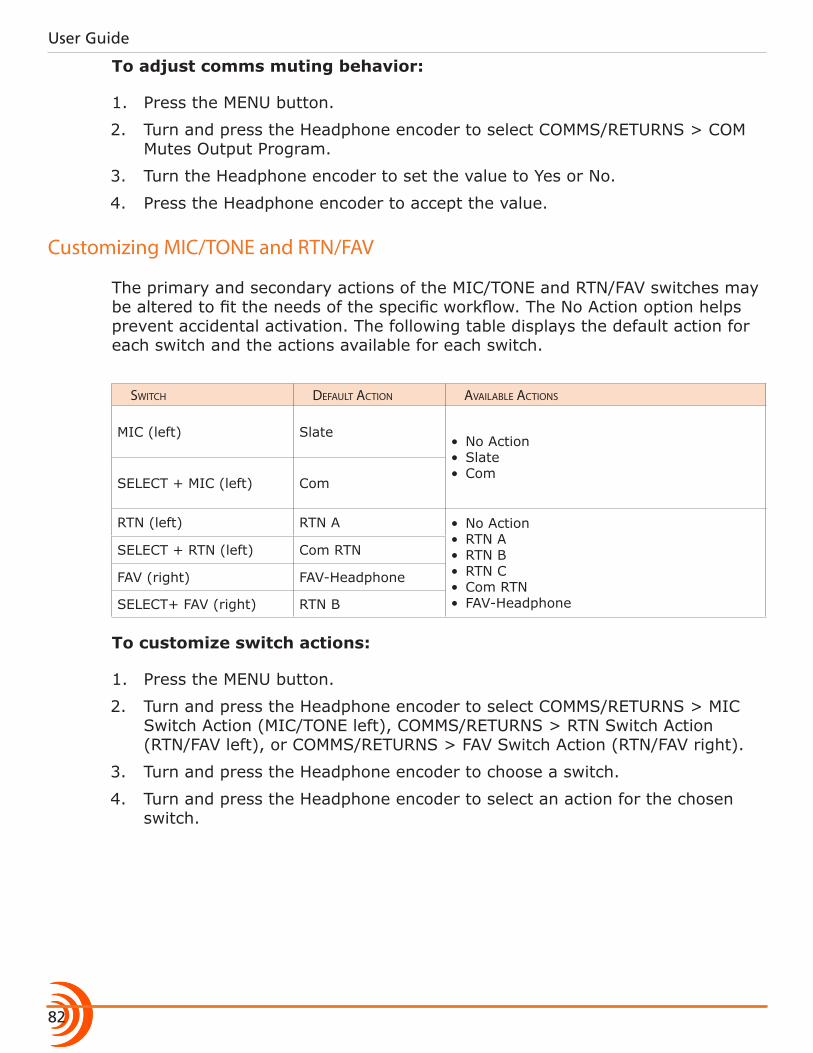
User Guide
82
To adjust comms muting behavior:
1. Press the MENU button.
2. Turn and press the Headphone encoder to select COMMS/RETURNS > COM Mutes Output Program.
3. Turn the Headphone encoder to set the value to Yes or No.
4. Press the Headphone encoder to accept the value.
Customizing MIC/TONE and RTN/FAV
The primary and secondary actions of the MIC/TONE and RTN/FAV switches may be altered to fit the needs of the specific workflow. The No Action option helps prevent accidental activation. The following table displays the default action for each switch and the actions available for each switch.
switcH DeFauLt action aVaiLabLe actions
MIC (left) Slate• No Action• Slate• Com
SELECT + MIC (left) Com
RTN (left) RTN A • No Action• RTN A• RTN B• RTN C• Com RTN• FAV-Headphone
SELECT + RTN (left) Com RTN
FAV (right) FAV-Headphone
SELECT+ FAV (right) RTN B
To customize switch actions:
1. Press the MENU button.
2. Turn and press the Headphone encoder to select COMMS/RETURNS > MIC Switch Action (MIC/TONE left), COMMS/RETURNS > RTN Switch Action (RTN/FAV left), or COMMS/RETURNS > FAV Switch Action (RTN/FAV right).
3. Turn and press the Headphone encoder to choose a switch.
4. Turn and press the Headphone encoder to select an action for the chosen switch.
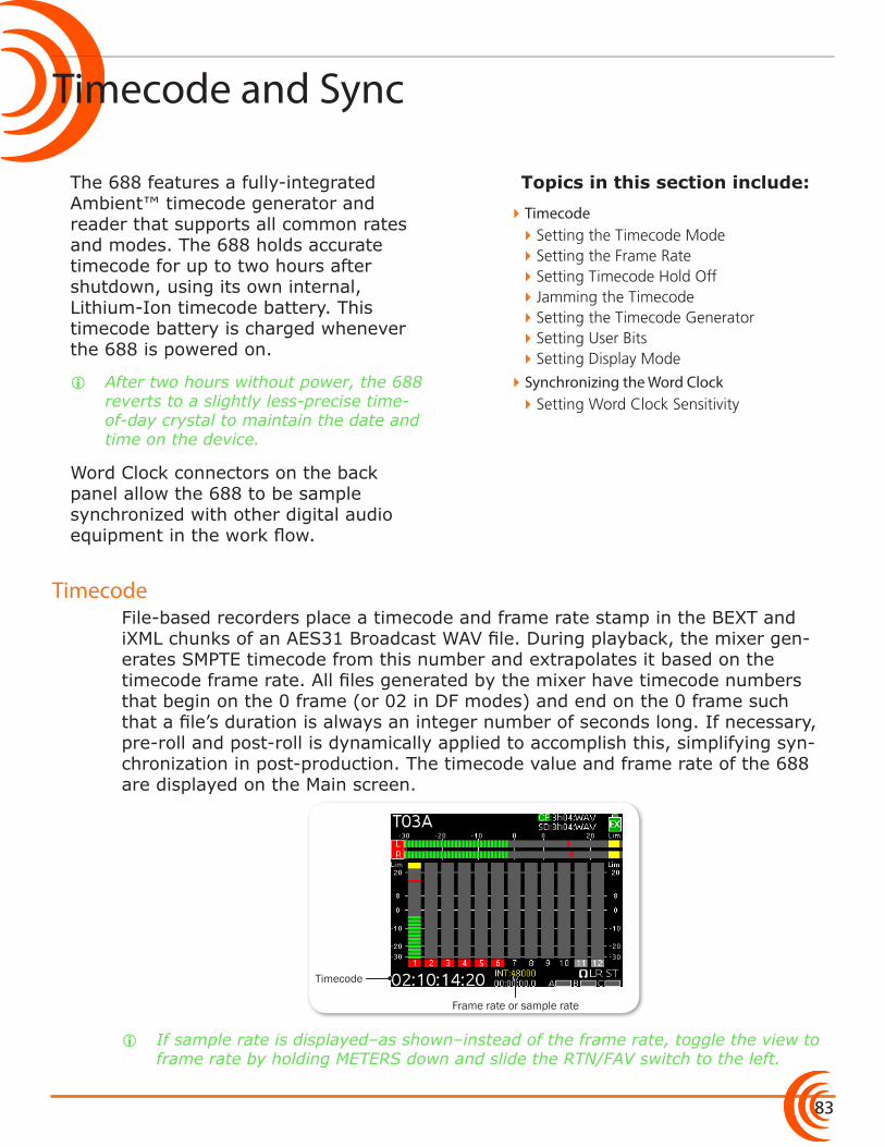
83
Topics in this section include:
Timecode and Sync
Timecode
The 688 features a fully-integrated Ambient™ timecode generator and reader that supports all common rates and modes. The 688 holds accurate timecode for up to two hours after shutdown, using its own internal, Lithium-Ion timecode battery. This timecode battery is charged whenever the 688 is powered on.
i After two hours without power, the 688 reverts to a slightly less-precise time-of-day crystal to maintain the date and time on the device.
Word Clock connectors on the back panel allow the 688 to be sample synchronized with other digital audio equipment in the work flow.
File-based recorders place a timecode and frame rate stamp in the BEXT and iXML chunks of an AES31 Broadcast WAV file. During playback, the mixer gen-erates SMPTE timecode from this number and extrapolates it based on the timecode frame rate. All files generated by the mixer have timecode numbers that begin on the 0 frame (or 02 in DF modes) and end on the 0 frame such that a file’s duration is always an integer number of seconds long. If necessary, pre-roll and post-roll is dynamically applied to accomplish this, simplifying syn-chronization in post-production. The timecode value and frame rate of the 688 are displayed on the Main screen.
Timecode
Frame rate or sample rate
i If sample rate is displayed–as shown–instead of the frame rate, toggle the view to frame rate by holding METERS down and slide the RTN/FAV switch to the left.
�Timecode �Setting the Timecode Mode �Setting the Frame Rate �Setting Timecode Hold Off �Jamming the Timecode �Setting the Timecode Generator �Setting User Bits �Setting Display Mode
�Synchronizing the Word Clock �Setting Word Clock Sensitivity
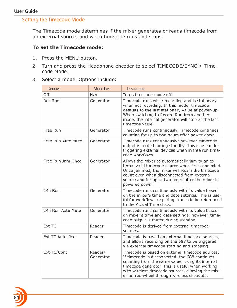
User Guide
84
Setting the Timecode Mode
The Timecode mode determines if the mixer generates or reads timecode from an external source, and when timecode runs and stops.
To set the Timecode mode:
1. Press the MENU button.
2. Turn and press the Headphone encoder to select TIMECODE/SYNC > Time-code Mode.
3. Select a mode. Options include:
options moDe type Description
Off N/A Turns timecode mode off.Rec Run Generator Timecode runs while recording and is stationary
when not recording. In this mode, timecode defaults to the last stationary value at power-up. When switching to Record Run from another mode, the internal generator will stop at the last timecode value.
Free Run Generator Timecode runs continuously. Timecode continues counting for up to two hours after power-down.
Free Run Auto Mute Generator Timecode runs continuously; however, timecode output is muted during standby. This is useful for triggering external devices when in free run time-code workflows.
Free Run Jam Once Generator Allows the mixer to automatically jam to an ex-ternal valid timecode source when first connected. Once jammed, the mixer will retain the timecode count even when disconnected from external source and for up to two hours after the mixer is powered down.
24h Run Generator Timecode runs continuously with its value based on the mixer’s time and date settings. This is use-ful for workflows requiring timecode be referenced to the Actual Time clock.
24h Run Auto Mute Generator Timecode runs continuously with its value based on mixer’s time and date settings; however, time-code output is muted during standby.
Ext-TC Reader Timecode is derived from external timecode sources.
Ext-TC Auto-Rec Reader Timecode is based on external timecode sources, and allows recording on the 688 to be triggered via external timecode starting and stopping.
Ext-TC/Cont Reader/ Generator
Timecode is based on external timecode sources. If timecode is disconnected, the 688 continues counting from the same value, using its internal timecode generator. This is useful when working with wireless timecode sources, allowing the mix-er to free-wheel through wireless dropouts.
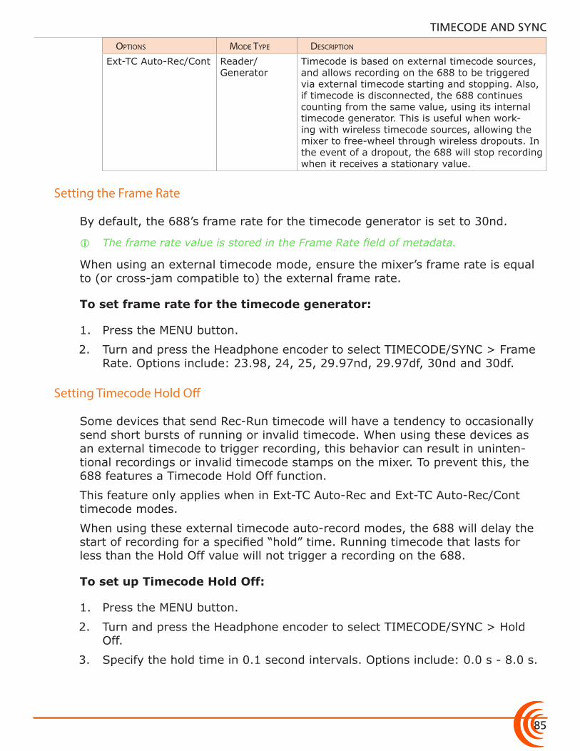
85
TIMECODE AND SYNC
options moDe type Description
Ext-TC Auto-Rec/Cont Reader/ Generator
Timecode is based on external timecode sources, and allows recording on the 688 to be triggered via external timecode starting and stopping. Also, if timecode is disconnected, the 688 continues counting from the same value, using its internal timecode generator. This is useful when work-ing with wireless timecode sources, allowing the mixer to free-wheel through wireless dropouts. In the event of a dropout, the 688 will stop recording when it receives a stationary value.
Setting the Frame Rate
By default, the 688’s frame rate for the timecode generator is set to 30nd.
i The frame rate value is stored in the Frame Rate field of metadata.
When using an external timecode mode, ensure the mixer’s frame rate is equal to (or cross-jam compatible to) the external frame rate.
To set frame rate for the timecode generator:
1. Press the MENU button.
2. Turn and press the Headphone encoder to select TIMECODE/SYNC > Frame Rate. Options include: 23.98, 24, 25, 29.97nd, 29.97df, 30nd and 30df.
Setting Timecode Hold Off
Some devices that send Rec-Run timecode will have a tendency to occasionally send short bursts of running or invalid timecode. When using these devices as an external timecode to trigger recording, this behavior can result in uninten-tional recordings or invalid timecode stamps on the mixer. To prevent this, the 688 features a Timecode Hold Off function.
This feature only applies when in Ext-TC Auto-Rec and Ext-TC Auto-Rec/Cont timecode modes.
When using these external timecode auto-record modes, the 688 will delay the start of recording for a specified “hold” time. Running timecode that lasts for less than the Hold Off value will not trigger a recording on the 688.
To set up Timecode Hold Off:
1. Press the MENU button.
2. Turn and press the Headphone encoder to select TIMECODE/SYNC > Hold Off.
3. Specify the hold time in 0.1 second intervals. Options include: 0.0 s - 8.0 s.
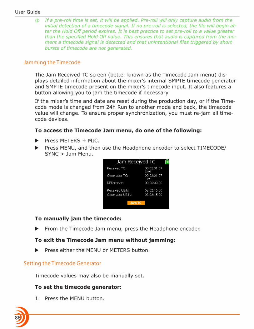
User Guide
86
i If a pre-roll time is set, it will be applied. Pre-roll will only capture audio from the initial detection of a timecode signal. If no pre-roll is selected, the file will begin af-ter the Hold Off period expires. It is best practice to set pre-roll to a value greater than the specified Hold Off value. This ensures that audio is captured from the mo-ment a timecode signal is detected and that unintentional files triggered by short bursts of timecode are not generated.
Jamming the Timecode
The Jam Received TC screen (better known as the Timecode Jam menu) dis-plays detailed information about the mixer’s internal SMPTE timecode generator and SMPTE timecode present on the mixer’s timecode input. It also features a button allowing you to jam the timecode if necessary.
If the mixer’s time and date are reset during the production day, or if the Time-code mode is changed from 24h Run to another mode and back, the timecode value will change. To ensure proper synchronization, you must re-jam all time-code devices.
To access the Timecode Jam menu, do one of the following:
X Press METERS + MIC. X Press MENU, and then use the Headphone encoder to select TIMECODE/
SYNC > Jam Menu.
To manually jam the timecode:
X From the Timecode Jam menu, press the Headphone encoder.
To exit the Timecode Jam menu without jamming:
X Press either the MENU or METERS button.
Setting the Timecode Generator
Timecode values may also be manually set.
To set the timecode generator:
1. Press the MENU button.
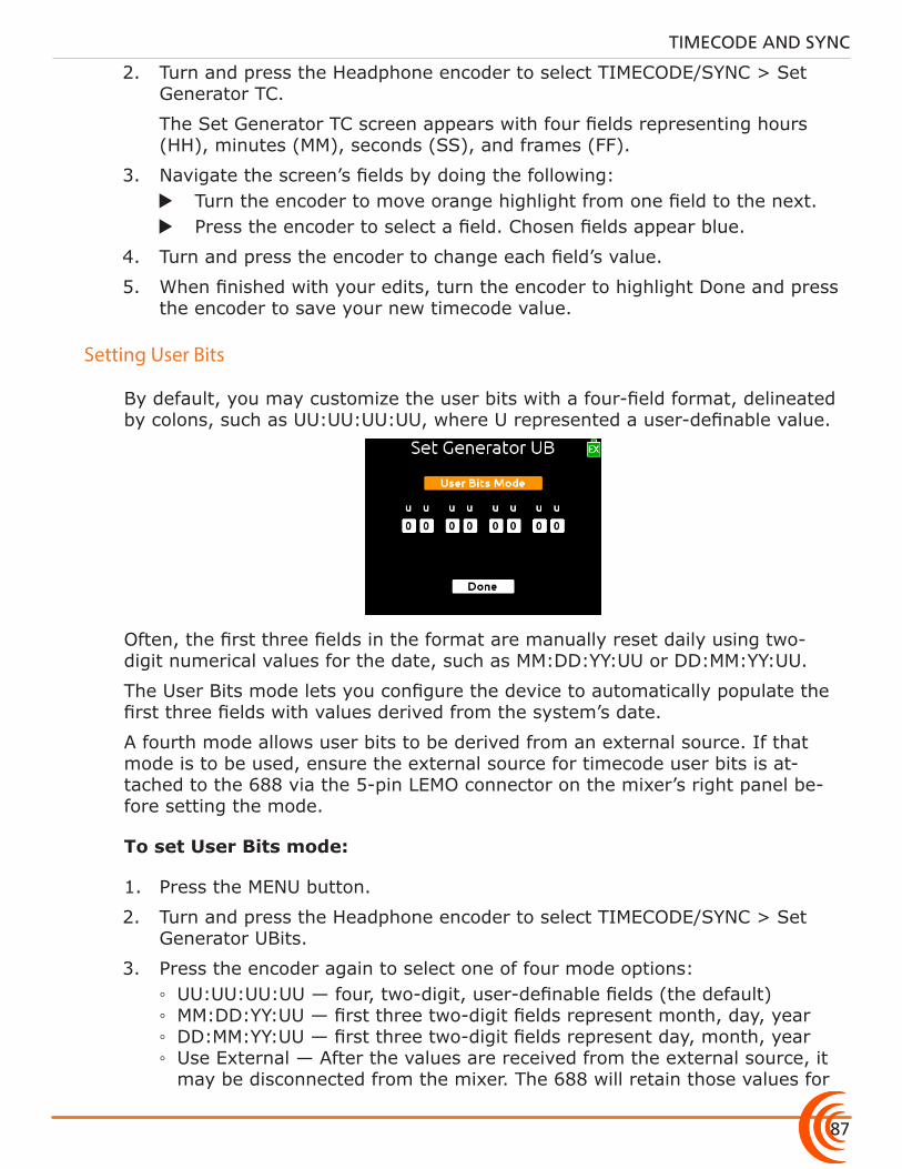
87
TIMECODE AND SYNC
2. Turn and press the Headphone encoder to select TIMECODE/SYNC > Set Generator TC.
The Set Generator TC screen appears with four fields representing hours (HH), minutes (MM), seconds (SS), and frames (FF).
3. Navigate the screen’s fields by doing the following: X Turn the encoder to move orange highlight from one field to the next. X Press the encoder to select a field. Chosen fields appear blue.
4. Turn and press the encoder to change each field’s value.
5. When finished with your edits, turn the encoder to highlight Done and press the encoder to save your new timecode value.
Setting User Bits
By default, you may customize the user bits with a four-field format, delineated by colons, such as UU:UU:UU:UU, where U represented a user-definable value.
Often, the first three fields in the format are manually reset daily using two- digit numerical values for the date, such as MM:DD:YY:UU or DD:MM:YY:UU.
The User Bits mode lets you configure the device to automatically populate the first three fields with values derived from the system’s date.
A fourth mode allows user bits to be derived from an external source. If that mode is to be used, ensure the external source for timecode user bits is at-tached to the 688 via the 5-pin LEMO connector on the mixer’s right panel be-fore setting the mode.
To set User Bits mode:
1. Press the MENU button.
2. Turn and press the Headphone encoder to select TIMECODE/SYNC > Set Generator UBits.
3. Press the encoder again to select one of four mode options: ◦ UU:UU:UU:UU — four, two-digit, user-definable fields (the default) ◦ MM:DD:YY:UU — first three two-digit fields represent month, day, year ◦ DD:MM:YY:UU — first three two-digit fields represent day, month, year ◦ Use External — After the values are received from the external source, it may be disconnected from the mixer. The 688 will retain those values for
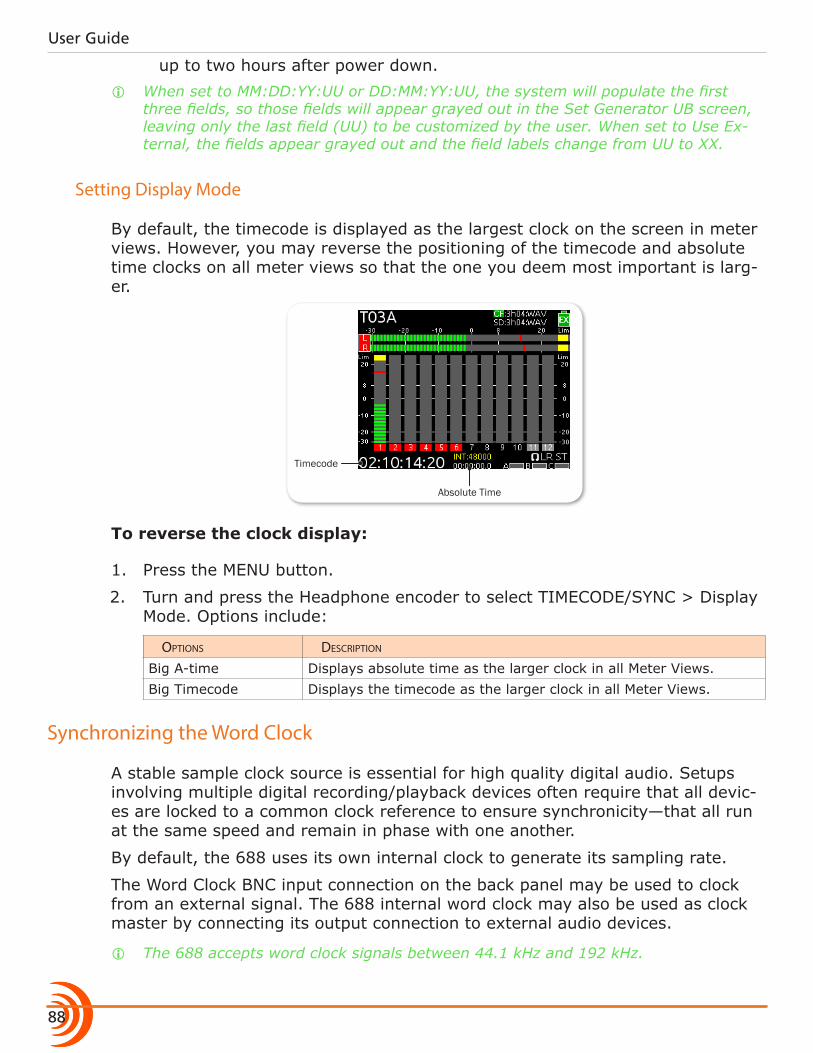
User Guide
88
up to two hours after power down. i When set to MM:DD:YY:UU or DD:MM:YY:UU, the system will populate the first
three fields, so those fields will appear grayed out in the Set Generator UB screen, leaving only the last field (UU) to be customized by the user. When set to Use Ex-ternal, the fields appear grayed out and the field labels change from UU to XX.
Setting Display Mode
By default, the timecode is displayed as the largest clock on the screen in meter views. However, you may reverse the positioning of the timecode and absolute time clocks on all meter views so that the one you deem most important is larg-er.
Timecode
Absolute Time
To reverse the clock display:
1. Press the MENU button.
2. Turn and press the Headphone encoder to select TIMECODE/SYNC > Display Mode. Options include:
options Description
Big A-time Displays absolute time as the larger clock in all Meter Views.Big Timecode Displays the timecode as the larger clock in all Meter Views.
Synchronizing the Word Clock
A stable sample clock source is essential for high quality digital audio. Setups involving multiple digital recording/playback devices often require that all devic-es are locked to a common clock reference to ensure synchronicity—that all run at the same speed and remain in phase with one another.
By default, the 688 uses its own internal clock to generate its sampling rate.
The Word Clock BNC input connection on the back panel may be used to clock from an external signal. The 688 internal word clock may also be used as clock master by connecting its output connection to external audio devices.
i The 688 accepts word clock signals between 44.1 kHz and 192 kHz.
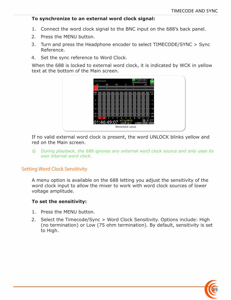
89
TIMECODE AND SYNC
To synchronize to an external word clock signal:
1. Connect the word clock signal to the BNC input on the 688’s back panel.
2. Press the MENU button.
3. Turn and press the Headphone encoder to select TIMECODE/SYNC > Sync Reference.
4. Set the sync reference to Word Clock.
When the 688 is locked to external word clock, it is indicated by WCK in yellow text at the bottom of the Main screen.
Wordclock value
If no valid external word clock is present, the word UNLOCK blinks yellow and red on the Main screen.
i During playback, the 688 ignores any external word clock source and only uses its own internal word clock.
Setting Word Clock Sensitivity
A menu option is available on the 688 letting you adjust the sensitivity of the word clock input to allow the mixer to work with word clock sources of lower voltage amplitude.
To set the sensitivity:
1. Press the MENU button.
2. Select the Timecode/Sync > Word Clock Sensitivity. Options include: High (no termination) or Low (75 ohm termination). By default, sensitivity is set to High.

User Guide
90
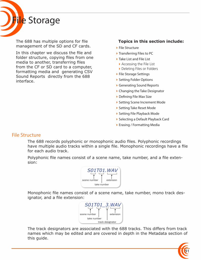
91
Topics in this section include:
File Storage
File Structure
The 688 has multiple options for file management of the SD and CF cards.
In this chapter we discuss the file and folder structure, copying files from one media to another, transferring files from the CF or SD card to a computer, formatting media and generating CSV Sound Reports directly from the 688 interface.
The 688 records polyphonic or monophonic audio files. Polyphonic recordings have multiple audio tracks within a single file. Monophonic recordings have a file for each audio track.
Polyphonic file names consist of a scene name, take number, and a file exten-sion:
scene number
take number
extension
S01T01.WAV
Monophonic file names consist of a scene name, take number, mono track des-ignator, and a file extension:
scene number
take number track designator
extension
S01T01_3.WAV
The track designators are associated with the 688 tracks. This differs from track names which may be edited and are covered in depth in the Metadata section of this guide.
�File Structure
�Transferring Files to PC
�Take List and File List �Accessing the File List �Deleting Files or Folders
�File Storage Settings
�Setting Folder Options
�Generating Sound Reports
�Changing the Take Designator
�Defining File Max Size
�Setting Scene Increment Mode
�Setting Take Reset Mode
�Setting File Playback Mode
�Selecting a Default Playback Card
�Erasing / Formatting Media
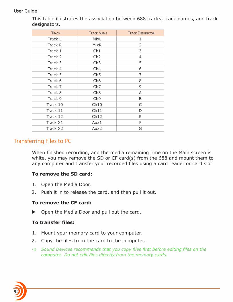
User Guide
92
This table illustrates the association between 688 tracks, track names, and track designators.
track track name track Designator
Track L MixL 1Track R MixR 2Track 1 Ch1 3Track 2 Ch2 4Track 3 Ch3 5Track 4 Ch4 6Track 5 Ch5 7Track 6 Ch6 8Track 7 Ch7 9Track 8 Ch8 ATrack 9 Ch9 BTrack 10 Ch10 CTrack 11 Ch11 DTrack 12 Ch12 ETrack X1 Aux1 FTrack X2 Aux2 G
Transferring Files to PC
When finished recording, and the media remaining time on the Main screen is white, you may remove the SD or CF card(s) from the 688 and mount them to any computer and transfer your recorded files using a card reader or card slot.
To remove the SD card:
1. Open the Media Door.
2. Push it in to release the card, and then pull it out.
To remove the CF card:
X Open the Media Door and pull out the card.
To transfer files:
1. Mount your memory card to your computer.
2. Copy the files from the card to the computer.
i Sound Devices recommends that you copy files first before editing files on the computer. Do not edit files directly from the memory cards.
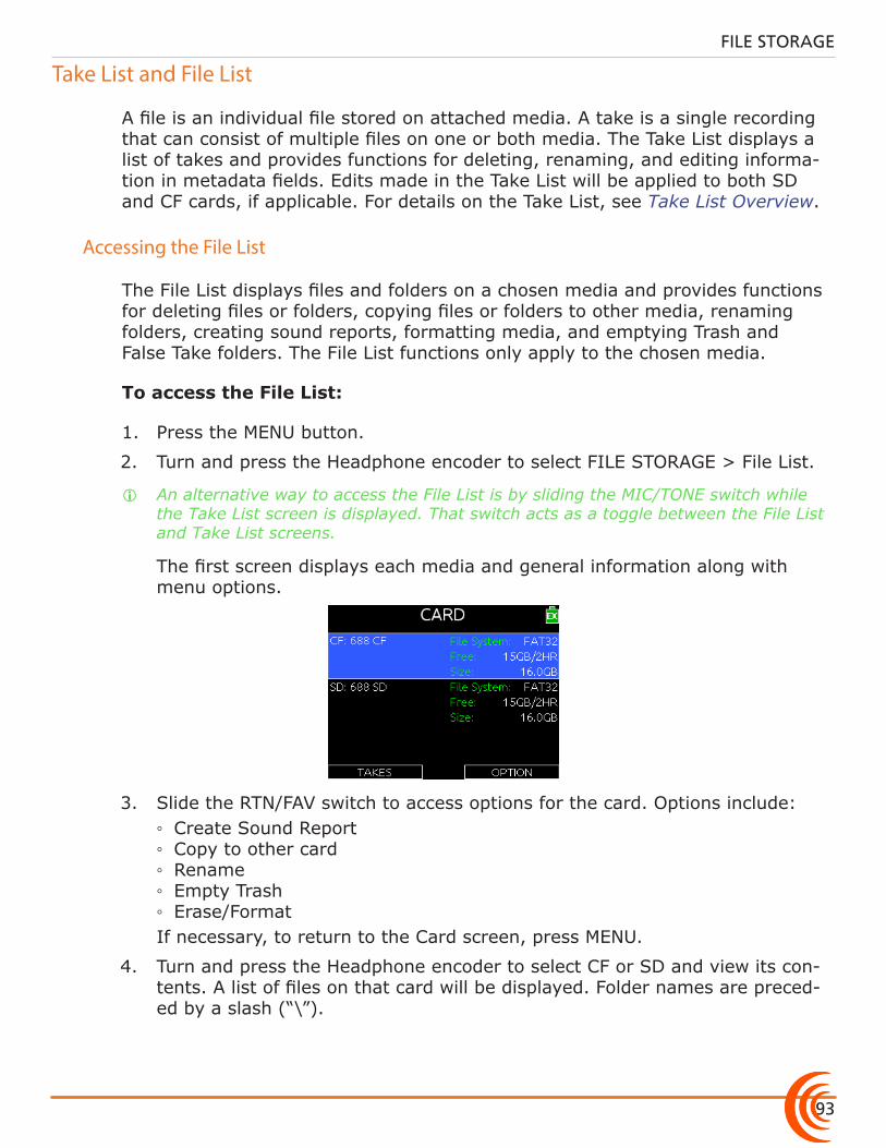
93
FILE STORAGE
Take List and File List
A file is an individual file stored on attached media. A take is a single recording that can consist of multiple files on one or both media. The Take List displays a list of takes and provides functions for deleting, renaming, and editing informa-tion in metadata fields. Edits made in the Take List will be applied to both SD and CF cards, if applicable. For details on the Take List, see Take List Overview.
Accessing the File List
The File List displays files and folders on a chosen media and provides functions for deleting files or folders, copying files or folders to other media, renaming folders, creating sound reports, formatting media, and emptying Trash and False Take folders. The File List functions only apply to the chosen media.
To access the File List:
1. Press the MENU button.
2. Turn and press the Headphone encoder to select FILE STORAGE > File List.
i An alternative way to access the File List is by sliding the MIC/TONE switch while the Take List screen is displayed. That switch acts as a toggle between the File List and Take List screens.
The first screen displays each media and general information along with menu options.
3. Slide the RTN/FAV switch to access options for the card. Options include: ◦ Create Sound Report ◦ Copy to other card ◦ Rename ◦ Empty Trash ◦ Erase/Format
If necessary, to return to the Card screen, press MENU.
4. Turn and press the Headphone encoder to select CF or SD and view its con-tents. A list of files on that card will be displayed. Folder names are preced-ed by a slash (“\”).
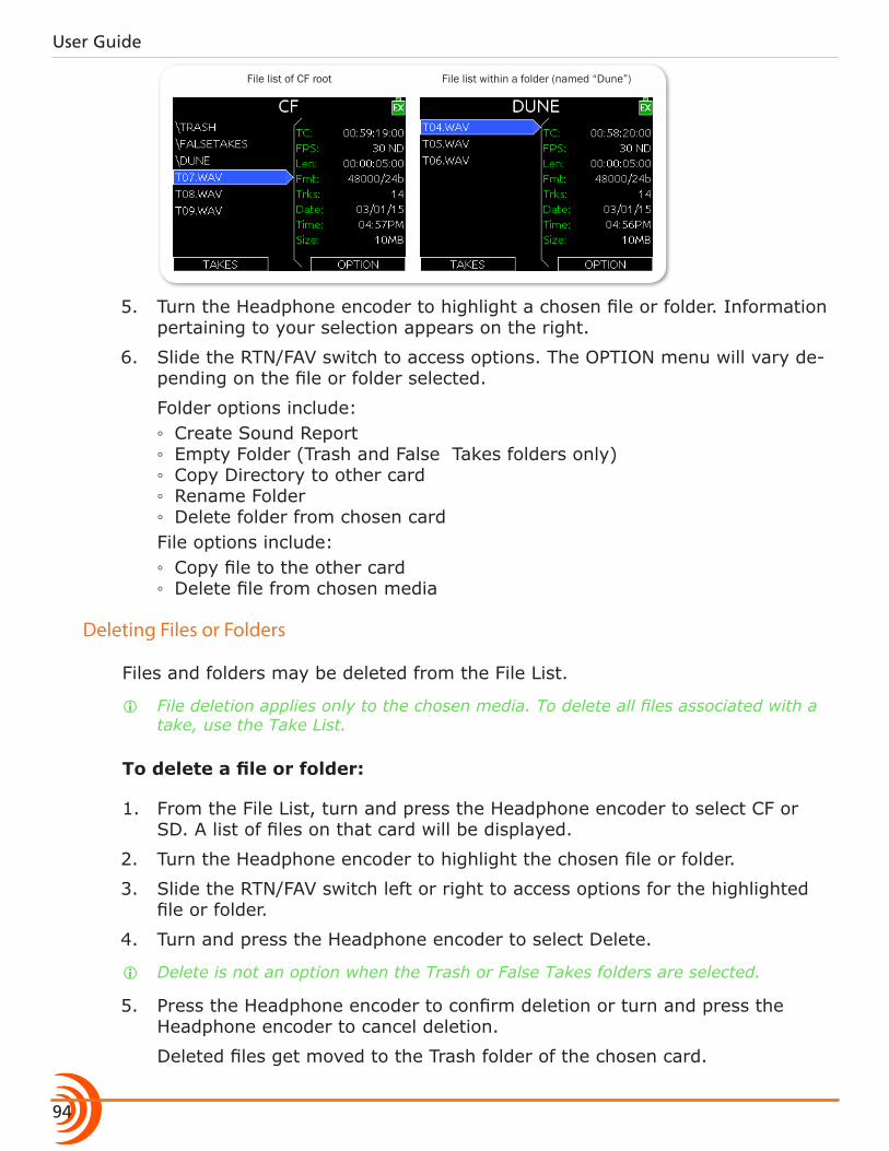
User Guide
94
File list of CF root File list within a folder (named “Dune”)
5. Turn the Headphone encoder to highlight a chosen file or folder. Information pertaining to your selection appears on the right.
6. Slide the RTN/FAV switch to access options. The OPTION menu will vary de-pending on the file or folder selected.
Folder options include: ◦ Create Sound Report ◦ Empty Folder (Trash and False Takes folders only) ◦ Copy Directory to other card ◦ Rename Folder ◦ Delete folder from chosen card
File options include: ◦ Copy file to the other card ◦ Delete file from chosen media
Deleting Files or Folders
Files and folders may be deleted from the File List.
i File deletion applies only to the chosen media. To delete all files associated with a take, use the Take List.
To delete a file or folder:
1. From the File List, turn and press the Headphone encoder to select CF or SD. A list of files on that card will be displayed.
2. Turn the Headphone encoder to highlight the chosen file or folder.
3. Slide the RTN/FAV switch left or right to access options for the highlighted file or folder.
4. Turn and press the Headphone encoder to select Delete.
i Delete is not an option when the Trash or False Takes folders are selected.
5. Press the Headphone encoder to confirm deletion or turn and press the Headphone encoder to cancel deletion.
Deleted files get moved to the Trash folder of the chosen card.
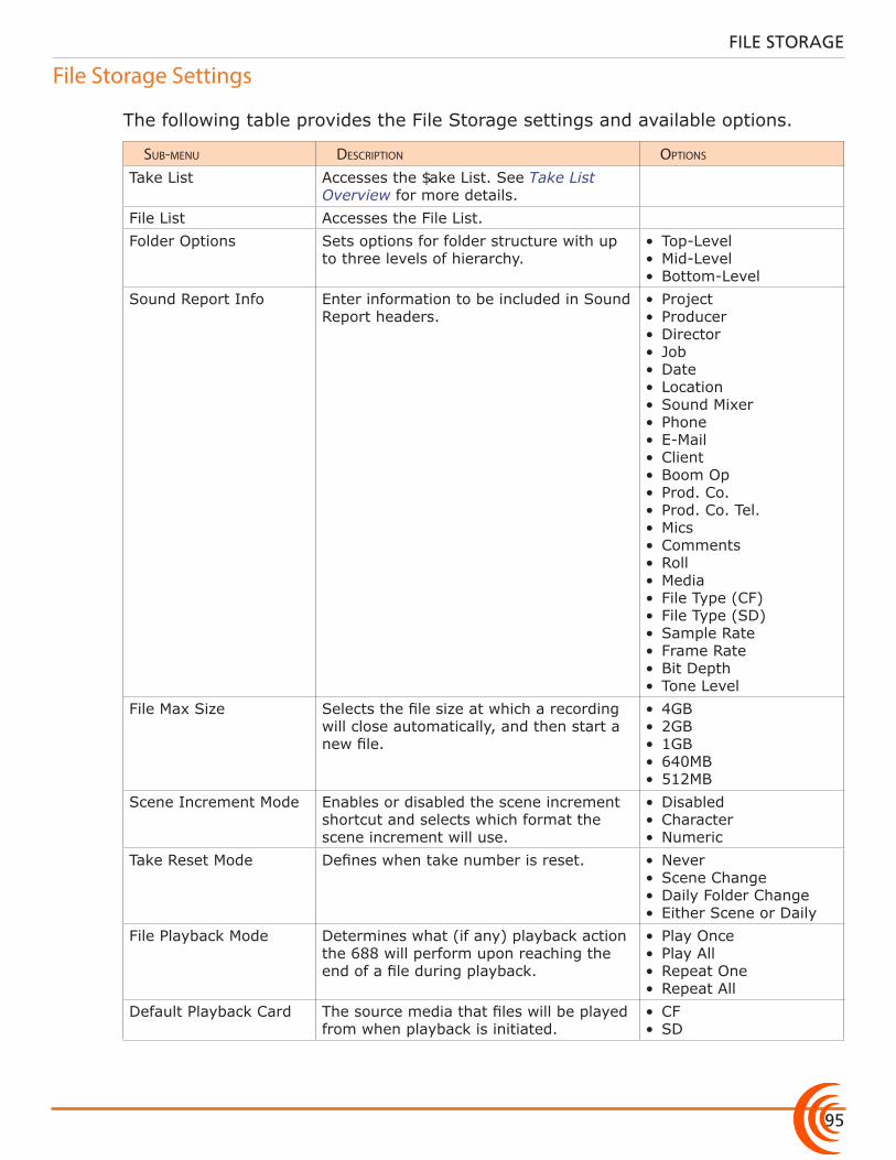
95
FILE STORAGE
File Storage Settings
The following table provides the File Storage settings and available options.
sub-menu Description options
Take List Accesses the Take List. See Take List Overview for more details.
File List Accesses the File List.Folder Options Sets options for folder structure with up
to three levels of hierarchy.• Top-Level• Mid-Level• Bottom-Level
Sound Report Info Enter information to be included in Sound Report headers.
• Project• Producer• Director• Job• Date• Location• Sound Mixer • Phone• E-Mail• Client• Boom Op• Prod. Co.• Prod. Co. Tel. • Mics• Comments• Roll• Media• File Type (CF)• File Type (SD)• Sample Rate• Frame Rate• Bit Depth• Tone Level
File Max Size Selects the file size at which a recording will close automatically, and then start a new file.
• 4GB• 2GB• 1GB• 640MB• 512MB
Scene Increment Mode Enables or disabled the scene increment shortcut and selects which format the scene increment will use.
• Disabled• Character• Numeric
Take Reset Mode Defines when take number is reset. • Never• Scene Change• Daily Folder Change• Either Scene or Daily
File Playback Mode Determines what (if any) playback action the 688 will perform upon reaching the end of a file during playback.
• Play Once• Play All• Repeat One• Repeat All
Default Playback Card The source media that files will be played from when playback is initiated.
• CF• SD
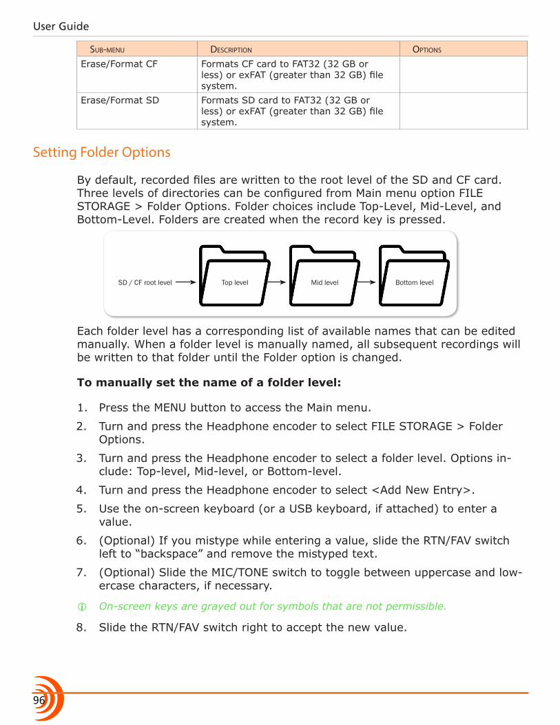
User Guide
96
sub-menu Description options
Erase/Format CF Formats CF card to FAT32 (32 GB or less) or exFAT (greater than 32 GB) file system.
Erase/Format SD Formats SD card to FAT32 (32 GB or less) or exFAT (greater than 32 GB) file system.
Setting Folder Options
By default, recorded files are written to the root level of the SD and CF card. Three levels of directories can be configured from Main menu option FILE STORAGE > Folder Options. Folder choices include Top-Level, Mid-Level, and Bottom-Level. Folders are created when the record key is pressed.
Bottom levelSD / CF root level Top level Mid level
Each folder level has a corresponding list of available names that can be edited manually. When a folder level is manually named, all subsequent recordings will be written to that folder until the Folder option is changed.
To manually set the name of a folder level:
1. Press the MENU button to access the Main menu.
2. Turn and press the Headphone encoder to select FILE STORAGE > Folder Options.
3. Turn and press the Headphone encoder to select a folder level. Options in-clude: Top-level, Mid-level, or Bottom-level.
4. Turn and press the Headphone encoder to select <Add New Entry>.
5. Use the on-screen keyboard (or a USB keyboard, if attached) to enter a value.
6. (Optional) If you mistype while entering a value, slide the RTN/FAV switch left to “backspace” and remove the mistyped text.
7. (Optional) Slide the MIC/TONE switch to toggle between uppercase and low-ercase characters, if necessary.
i On-screen keys are grayed out for symbols that are not permissible.
8. Slide the RTN/FAV switch right to accept the new value.
97
FILE STORAGE
In addition to custom entries, the Mid-level folder may be set to <Daily> and the Bottom-level folder may be set to <Scene>:• When the Mid-level folder is set to <Daily>, a folder will be created auto-
matically and named according to the date. Whenever a new day occurs, the 688 will prompt the user to confirm the creation of a new daily folder.
• When the Bottom-level folder is set to <Scene>, a new folder will be creat-ed each time the scene name is changed.
i The top level folder value is stored in the Project field of metadata. The mid level folder value is stored in the Roll (Tape) field of metadata.
Generating Sound Reports
The 688 can generate sound reports as a comma separated values (CSV) file. CSV files can be opened and edited by any common spreadsheet application such as Microsoft® Excel®, OpenOffice™ Calc, Apple® Numbers, Google Docs™, and many more. Ensure the spreadsheet application is set to delineate by com-ma.
i MP3 files are not included in sound reports.
To define headers for sound reports:
1. Press the MENU button.
2. Turn and press the Headphone encoder to select FILE STORAGE > Sound Report Info. A list of sound report headers appears.
3. Select a header to edit.
4. Do one of the following: X Use the Headphone encoder to select an existing item from the list. X Use the Headphone encoder to select <Add New Entry>. Then use the
on-screen keyboard to enter a new value.
i Other options include: <None>, <Current Selection>, and <System Date>.
Sound reports are generated by folder. All files in the folder are included in the sound report. Files located within sub-folders will not be included in the sound report. For example, if you have a Mid- and Bottom-level folder, you have to create a sound report on the bottom level where the files are located.
To generate a sound report:
1. Access the File List. See Accessing the File List for details.
2. Turn the Headphone encoder to highlight the folder in which you would like to generate a sound report.
3. Slide the RTN/FAV switch right to access the options menu for this folder.
User Guide
98
4. Turn and press the Headphone encoder to select Create a Sound Report. A .csv file will be created in the folder with a name of: [FOLDER NAME]_REPORT.CSV.
5. When prompted for confirmation, press the Headphone encoder to confirm.
i Sound reports may also be initiated from the Wingman app on mixers with the WM-Connect Bluetooth Smart USB accessory. For more information, see Wingman Integration: 6-Series.
Changing the Take Designator
The default take designator of file names is the capital letter T, but that may be changed to a hyphen or any letter of the alphabet.
To change the take designator:
1. Press MENU.
2. Select FILE STORAGE > Take Designator.
3. Select a new capital letter or a hyphen to be the take designator.
The change will apply to all future files; it does not affect existing files.
Defining File Max Size
By default, the maximum size of WAV files is 4GB. When the max file size is reached, the file is split and a new file is written automatically. This split is seamless and sample-accurate.
To set maximum file size:
1. Press the MENU button.
2. Turn and press the Headphone encoder to select FILE STORAGE > File Max Size.
3. Turn and press the Headphone encoder to set a maximum file size. Options include: 4 GB, 2 GB, 1 GB, 640 MB, and 512 MB.
If longer recording times with less splits are wanted, various options affect this:• Record mono WAV files rather than poly WAV files. See Setting File Type
and Media Track Assignment for details.• Lower the sample rate. See Setting the Sample Rate for details.• Lower the amount of armed tracks (poly only). See Arming or Disarming
Recording Tracks for details.
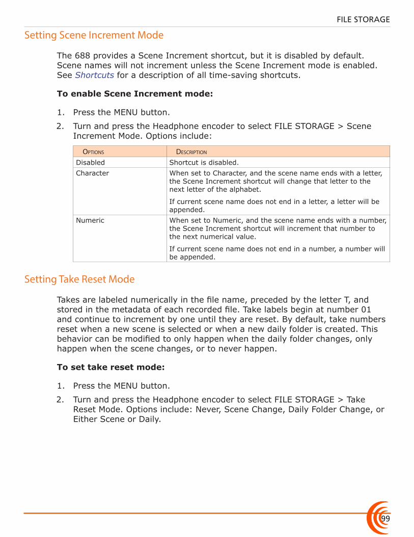
99
FILE STORAGE
Setting Scene Increment Mode
The 688 provides a Scene Increment shortcut, but it is disabled by default. Scene names will not increment unless the Scene Increment mode is enabled. See Shortcuts for a description of all time-saving shortcuts.
To enable Scene Increment mode:
1. Press the MENU button.
2. Turn and press the Headphone encoder to select FILE STORAGE > Scene Increment Mode. Options include:
options Description
Disabled Shortcut is disabled.Character When set to Character, and the scene name ends with a letter,
the Scene Increment shortcut will change that letter to the next letter of the alphabet.
If current scene name does not end in a letter, a letter will be appended.
Numeric When set to Numeric, and the scene name ends with a number, the Scene Increment shortcut will increment that number to the next numerical value.
If current scene name does not end in a number, a number will be appended.
Setting Take Reset Mode
Takes are labeled numerically in the file name, preceded by the letter T, and stored in the metadata of each recorded file. Take labels begin at number 01 and continue to increment by one until they are reset. By default, take numbers reset when a new scene is selected or when a new daily folder is created. This behavior can be modified to only happen when the daily folder changes, only happen when the scene changes, or to never happen.
To set take reset mode:
1. Press the MENU button.
2. Turn and press the Headphone encoder to select FILE STORAGE > Take Reset Mode. Options include: Never, Scene Change, Daily Folder Change, or Either Scene or Daily.
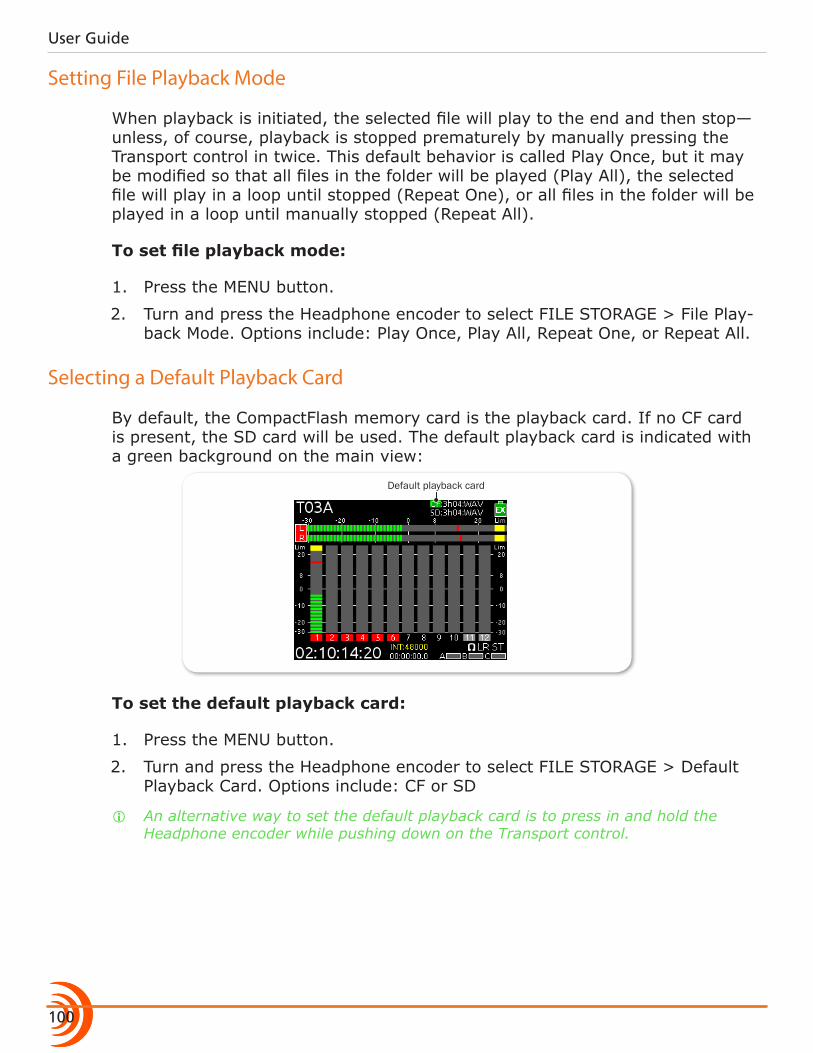
User Guide
100
Setting File Playback Mode
When playback is initiated, the selected file will play to the end and then stop—unless, of course, playback is stopped prematurely by manually pressing the Transport control in twice. This default behavior is called Play Once, but it may be modified so that all files in the folder will be played (Play All), the selected file will play in a loop until stopped (Repeat One), or all files in the folder will be played in a loop until manually stopped (Repeat All).
To set file playback mode:
1. Press the MENU button.
2. Turn and press the Headphone encoder to select FILE STORAGE > File Play-back Mode. Options include: Play Once, Play All, Repeat One, or Repeat All.
Selecting a Default Playback Card
By default, the CompactFlash memory card is the playback card. If no CF card is present, the SD card will be used. The default playback card is indicated with a green background on the main view:
Default playback card
To set the default playback card:
1. Press the MENU button.
2. Turn and press the Headphone encoder to select FILE STORAGE > Default Playback Card. Options include: CF or SD
i An alternative way to set the default playback card is to press in and hold the Headphone encoder while pushing down on the Transport control.
101
FILE STORAGE
Erasing / Formatting Media
Before recording to CF or SD media, cards must be formatted by the 688.
To format media:
1. Press the MENU button.
2. Turn and press the Headphone encoder to select FILE STORAGE.
3. Do either of the following: X Select Erase/Format CF to reformat a CompactFlash card. X Select Erase/Format SD to reformat an SD, SDHC, or SDXC card.
4. Press the Headphone encoder to begin the formatting process.
⚠ Formatting media will erase all data on the card.
5. Follow the message(s) that appear on screen and press the Headphone en-coder to continue.
6. Press the METERS button to return to the Main screen.
Cards with a capacity of 32 GB or less will be formatted with the FAT32 file sys-tem. Cards with a capacity greater than 32 GB will be formatted with the exFAT file system.
i The exFAT file system is not compatible with Windows XP or Mac OS X 10.6.4 or lower.

User Guide
102
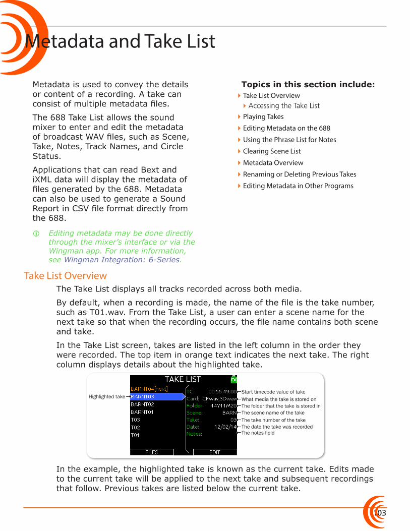
103
Topics in this section include:
Metadata and Take List
Take List Overview
Metadata is used to convey the details or content of a recording. A take can consist of multiple metadata files.
The 688 Take List allows the sound mixer to enter and edit the metadata of broadcast WAV files, such as Scene, Take, Notes, Track Names, and Circle Status.
Applications that can read Bext and iXML data will display the metadata of files generated by the 688. Metadata can also be used to generate a Sound Report in CSV file format directly from the 688.
i Editing metadata may be done directly through the mixer’s interface or via the Wingman app. For more information, see Wingman Integration: 6-Series.
The Take List displays all tracks recorded across both media.
By default, when a recording is made, the name of the file is the take number, such as T01.wav. From the Take List, a user can enter a scene name for the next take so that when the recording occurs, the file name contains both scene and take.
In the Take List screen, takes are listed in the left column in the order they were recorded. The top item in orange text indicates the next take. The right column displays details about the highlighted take.
Start timecode value of takeHighlighted take
The scene name of the take
What media the take is stored onThe folder that the take is stored in
The take number of the takeThe date the take was recordedThe notes field
In the example, the highlighted take is known as the current take. Edits made to the current take will be applied to the next take and subsequent recordings that follow. Previous takes are listed below the current take.
�Take List Overview �Accessing the Take List
�Playing Takes
�Editing Metadata on the 688
�Using the Phrase List for Notes
�Clearing Scene List
�Metadata Overview
�Renaming or Deleting Previous Takes
�Editing Metadata in Other Programs
User Guide
104
Accessing the Take List
There are two ways to access the Take List. One way is via the Main menu’s FILE STORAGE sub-menu. The other is provided in the following procedure.
To access the Take List:
1. MENU + HP: Press and hold the MENU button and Headphone encoder.
The Take List screen appears.
2. Turn the Headphone encoder to highlight takes and view details in the right column.
3. Press the METERS button to exit or close the Take List screen.
Playing Takes
Playback of a take may be initiated from the Take List.
To play a take from the Take List:
1. MENU + HP: Press in the MENU button and Headphone encoder together to view the Take List screen.
2. Turn the Headphone encoder to highlight a take to play.
3. Push down the Transport control to begin playback. The Main screen is dis-played, and playback begins.
Editing Metadata on the 688
Notes, Scene, Take, Circle Status, Folder (tape), Project, and all track names may be edited directly from the Take List for next or previous takes.
i The term “file” refers to a single file on one medium, but the term “take” refers to a recording which may consist of multiple files with identical content on different media. Editing a take in any way will affect all files associated with that take.
To edit metadata from the Take List:
1. MENU + HP: Press and hold the MENU button + Headphone encoder togeth-er to view the Take List screen.
2. Turn and press the Headphone encoder to choose a take to edit. A list of metadata parameters appears.
i Selecting the take at the top of the list (orange text and indicated by [NEXT]) will set metadata value for future takes. Selecting any other takes in the list will edit metadata for existing takes.
3. Turn and press the Headphone encoder to choose what metadata to edit.
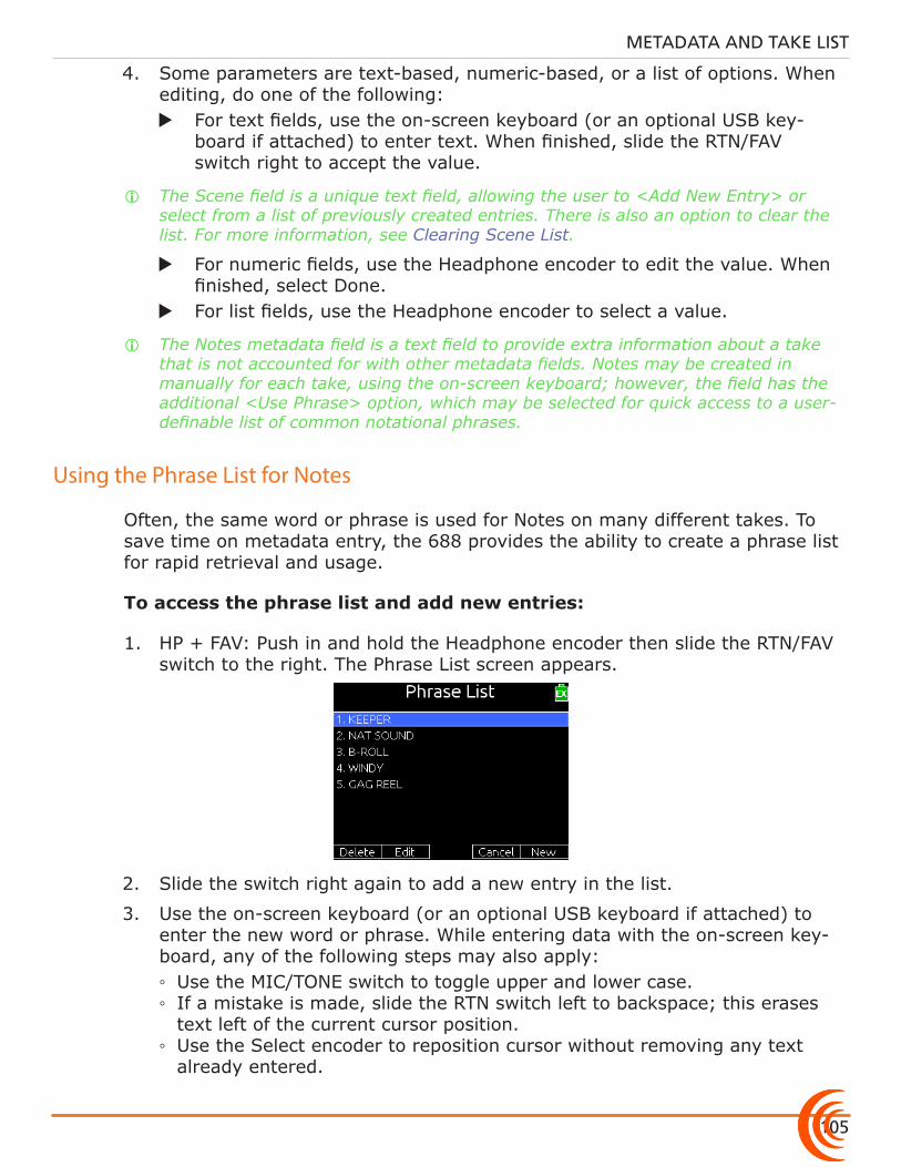
105
METADATA AND TAKE LIST
4. Some parameters are text-based, numeric-based, or a list of options. When editing, do one of the following:
X For text fields, use the on-screen keyboard (or an optional USB key-board if attached) to enter text. When finished, slide the RTN/FAV switch right to accept the value.
i The Scene field is a unique text field, allowing the user to <Add New Entry> or select from a list of previously created entries. There is also an option to clear the list. For more information, see Clearing Scene List.
X For numeric fields, use the Headphone encoder to edit the value. When finished, select Done.
X For list fields, use the Headphone encoder to select a value.
i The Notes metadata field is a text field to provide extra information about a take that is not accounted for with other metadata fields. Notes may be created in manually for each take, using the on-screen keyboard; however, the field has the additional <Use Phrase> option, which may be selected for quick access to a user-definable list of common notational phrases.
Using the Phrase List for Notes
Often, the same word or phrase is used for Notes on many different takes. To save time on metadata entry, the 688 provides the ability to create a phrase list for rapid retrieval and usage.
To access the phrase list and add new entries:
1. HP + FAV: Push in and hold the Headphone encoder then slide the RTN/FAV switch to the right. The Phrase List screen appears.
2. Slide the switch right again to add a new entry in the list.
3. Use the on-screen keyboard (or an optional USB keyboard if attached) to enter the new word or phrase. While entering data with the on-screen key-board, any of the following steps may also apply: ◦ Use the MIC/TONE switch to toggle upper and lower case. ◦ If a mistake is made, slide the RTN switch left to backspace; this erases text left of the current cursor position.
◦ Use the Select encoder to reposition cursor without removing any text already entered.
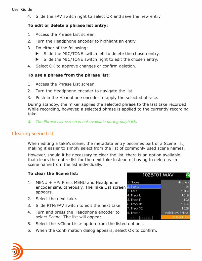
User Guide
106
4. Slide the FAV switch right to select OK and save the new entry.
To edit or delete a phrase list entry:
1. Access the Phrase List screen.
2. Turn the Headphone encoder to highlight an entry.
3. Do either of the following: X Slide the MIC/TONE switch left to delete the chosen entry. X Slide the MIC/TONE switch right to edit the chosen entry.
4. Select OK to approve changes or confirm deletion.
To use a phrase from the phrase list:
1. Access the Phrase List screen.
2. Turn the Headphone encoder to navigate the list.
3. Push in the Headphone encoder to apply the selected phrase.
During standby, the mixer applies the selected phrase to the last take recorded. While recording, however, a selected phrase is applied to the currently recording take.
i The Phrase List screen is not available during playback.
Clearing Scene List
When editing a take’s scene, the metadata entry becomes part of a Scene list, making it easier to simply select from the list of commonly used scene names.
However, should it be necessary to clear the list, there is an option available that clears the entire list for the next take instead of having to delete each scene name from the list individually.
To clear the Scene list:
1. MENU + HP: Press MENU and Headphone encoder simultaneously. The Take List screen appears.
2. Select the next take.
3. Slide RTN/FAV switch to edit the next take.
4. Turn and press the Headphone encoder to select Scene. The list will appear.
5. Select the <Clear List> option from the listed options.
6. When the Confirmation dialog appears, select OK to confirm.
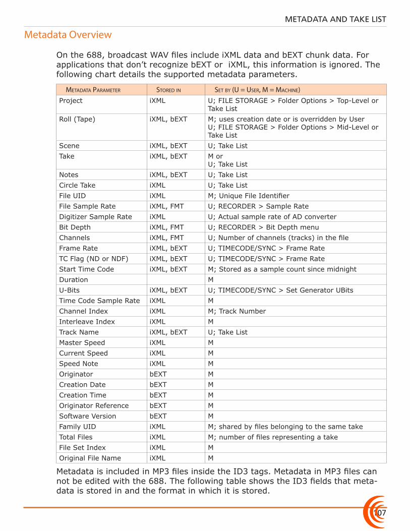
107
METADATA AND TAKE LIST
Metadata Overview
On the 688, broadcast WAV files include iXML data and bEXT chunk data. For applications that don’t recognize bEXT or iXML, this information is ignored. The following chart details the supported metadata parameters.
metaData parameter storeD in set by (u = user, m = macHine)Project iXML U; FILE STORAGE > Folder Options > Top-Level or
Take ListRoll (Tape) iXML, bEXT M; uses creation date or is overridden by User
U; FILE STORAGE > Folder Options > Mid-Level or Take List
Scene iXML, bEXT U; Take ListTake iXML, bEXT M or
U; Take ListNotes iXML, bEXT U; Take ListCircle Take iXML U; Take ListFile UID iXML M; Unique File IdentifierFile Sample Rate iXML, FMT U; RECORDER > Sample RateDigitizer Sample Rate iXML U; Actual sample rate of AD converterBit Depth iXML, FMT U; RECORDER > Bit Depth menuChannels iXML, FMT U; Number of channels (tracks) in the fileFrame Rate iXML, bEXT U; TIMECODE/SYNC > Frame RateTC Flag (ND or NDF) iXML, bEXT U; TIMECODE/SYNC > Frame RateStart Time Code iXML, bEXT M; Stored as a sample count since midnightDuration MU-Bits iXML, bEXT U; TIMECODE/SYNC > Set Generator UBitsTime Code Sample Rate iXML MChannel Index iXML M; Track NumberInterleave Index iXML MTrack Name iXML, bEXT U; Take ListMaster Speed iXML MCurrent Speed iXML MSpeed Note iXML MOriginator bEXT MCreation Date bEXT MCreation Time bEXT MOriginator Reference bEXT MSoftware Version bEXT MFamily UID iXML M; shared by files belonging to the same takeTotal Files iXML M; number of files representing a takeFile Set Index iXML MOriginal File Name iXML M
Metadata is included in MP3 files inside the ID3 tags. Metadata in MP3 files can not be edited with the 688. The following table shows the ID3 fields that meta-data is stored in and the format in which it is stored.
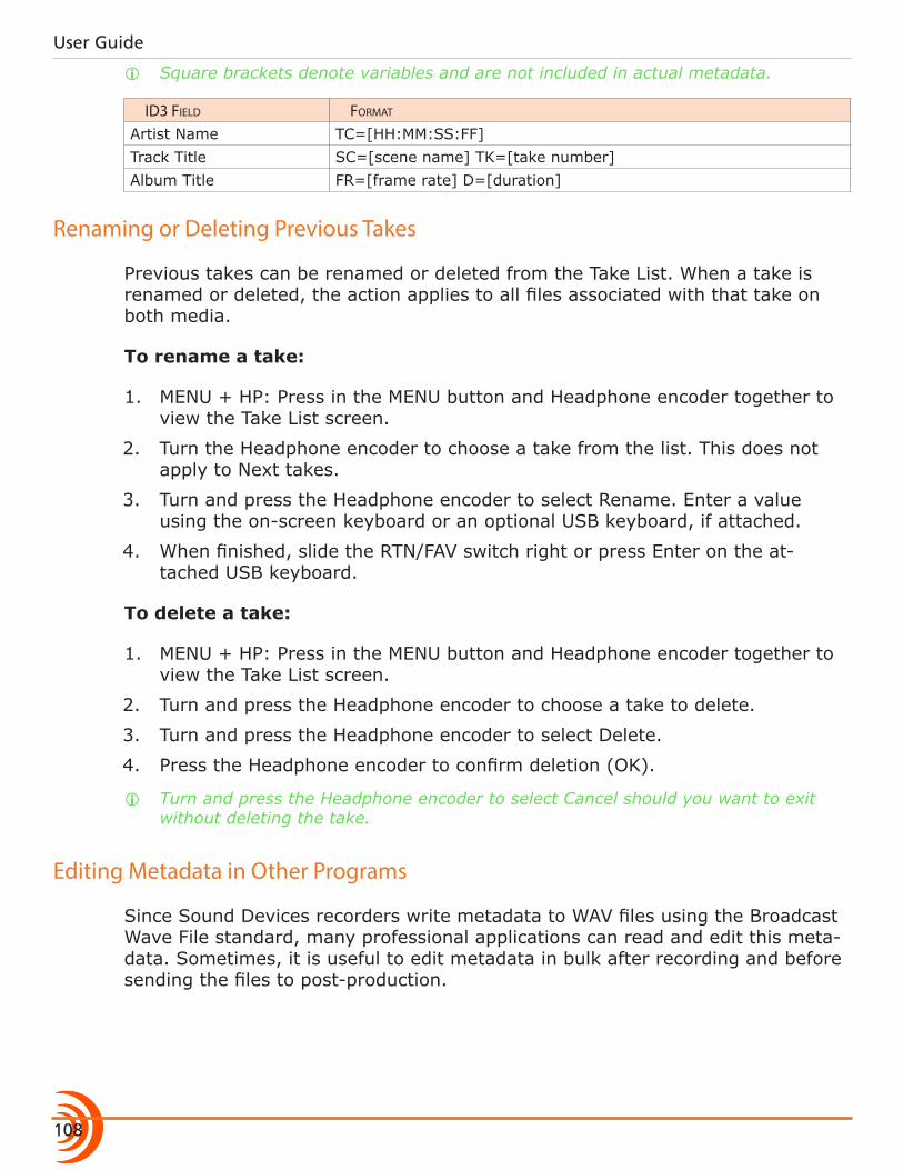
User Guide
108
i Square brackets denote variables and are not included in actual metadata.
iD3 FieLD Format
Artist Name TC=[HH:MM:SS:FF]Track Title SC=[scene name] TK=[take number]Album Title FR=[frame rate] D=[duration]
Renaming or Deleting Previous Takes
Previous takes can be renamed or deleted from the Take List. When a take is renamed or deleted, the action applies to all files associated with that take on both media.
To rename a take:
1. MENU + HP: Press in the MENU button and Headphone encoder together to view the Take List screen.
2. Turn the Headphone encoder to choose a take from the list. This does not apply to Next takes.
3. Turn and press the Headphone encoder to select Rename. Enter a value using the on-screen keyboard or an optional USB keyboard, if attached.
4. When finished, slide the RTN/FAV switch right or press Enter on the at-tached USB keyboard.
To delete a take:
1. MENU + HP: Press in the MENU button and Headphone encoder together to view the Take List screen.
2. Turn and press the Headphone encoder to choose a take to delete.
3. Turn and press the Headphone encoder to select Delete.
4. Press the Headphone encoder to confirm deletion (OK).
i Turn and press the Headphone encoder to select Cancel should you want to exit without deleting the take.
Editing Metadata in Other Programs
Since Sound Devices recorders write metadata to WAV files using the Broadcast Wave File standard, many professional applications can read and edit this meta-data. Sometimes, it is useful to edit metadata in bulk after recording and before sending the files to post-production.
109
Topics in this section include:
System
Setting up Tones and Bells
The 688 SYSTEM sub-menu allows for setup and control of various key system settings, such as tone or bell levels, date and time parameters, meter ballistics and more.
This sub-menu also provides access to viewing product version information and conducting firmware updates.
Some System settings, such as those related to headphones, Meter Views, or the LCD, are described in more detail in others sections of this guide where applicable. This section provides information for System settings not already covered elsewhere.
The 688’s internal tone oscillator, used for sending tone to outputs and tracks, has several settings to accommodate different workflows.
Activating tone is explained in more detail in the Sending Tone to Outputs sec-tion of this guide.
To define tone settings:
1. Press the MENU button.
2. Turn and press the Headphone encoder to select SYSTEM.
3. Configure the tone oscillator by modifying the following parameters.
�Setting up Tones and Bells �Configuring Record/Stop and Warning Bells
�Configuring the Meters �Setting Meter Ballistics and Peak Hold �Setting Peak Hold
�Setting up Date and Time Parameters
�Calibrating Faders & Pans
�Using a USB Keyboard
�Viewing Shortcut Information
�Viewing User Guide via QR Code
�Viewing Version Information
�Updating Firmware
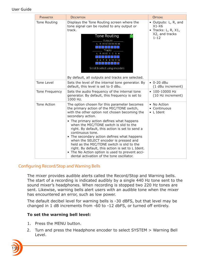
User Guide
110
parameter Description options
Tone Routing Displays the Tone Routing screen where the tone signal can be routed to any output or track.
By default, all outputs and tracks are selected.
• Outputs: L, R, and X1-X6
• Tracks: L, R, X1, X2, and tracks 1-12
Tone Level Sets the level of the internal tone generator. By default, this level is set to 0 dBu.
• 0-20 dBu (1 dBu increment)
Tone Frequency Sets the audio frequency of the internal tone generator. By default, this frequency is set to 1000 Hz.
• 100-10000 Hz (10 Hz increment)
Tone Action The option chosen for this parameter becomes the primary action of the MIC/TONE switch, with the other option not chosen becoming the secondary action.• The primary action defines what happens
when the MIC/TONE switch is slid to the right. By default, this action is set to send a continuous tone.
• The secondary action defines what happens when the SELECT encoder is pressed and held as the MIC/TONE switch is slid to the right. By default, this action is set to L Ident.
• The No Action option is used to prevent acci-dental activation of the tone oscillator.
• No Action• Continuous• L Ident
Configuring Record/Stop and Warning Bells
The mixer provides audible alerts called the Record/Stop and Warning bells. The start of a recording is indicated audibly by a single 440 Hz tone sent to the sound mixer’s headphones. When recording is stopped two 220 Hz tones are sent. Likewise, warning bells alert users with an audible tone when the mixer has encountered an error, such as low power.
The default decibel level for warning bells is -30 dBFS, but that level may be changed in 1 dB increments from -60 to -12 dbFS, or turned off entirely.
To set the warning bell level:
1. Press the MENU button.
2. Turn and press the Headphone encoder to select SYSTEM > Warning Bell Level.
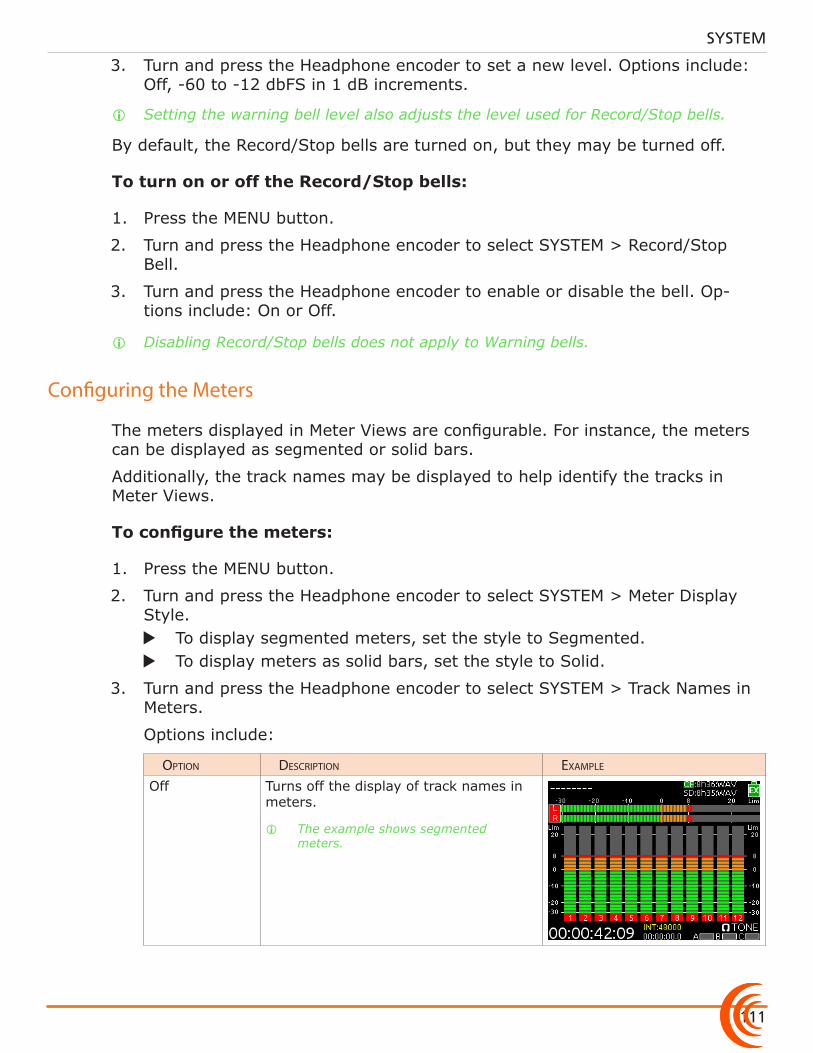
111
SYSTEM
3. Turn and press the Headphone encoder to set a new level. Options include: Off, -60 to -12 dbFS in 1 dB increments.
i Setting the warning bell level also adjusts the level used for Record/Stop bells.
By default, the Record/Stop bells are turned on, but they may be turned off.
To turn on or off the Record/Stop bells:
1. Press the MENU button.
2. Turn and press the Headphone encoder to select SYSTEM > Record/Stop Bell.
3. Turn and press the Headphone encoder to enable or disable the bell. Op-tions include: On or Off.
i Disabling Record/Stop bells does not apply to Warning bells.
Configuring the Meters
The meters displayed in Meter Views are configurable. For instance, the meters can be displayed as segmented or solid bars.
Additionally, the track names may be displayed to help identify the tracks in Meter Views.
To configure the meters:
1. Press the MENU button.
2. Turn and press the Headphone encoder to select SYSTEM > Meter Display Style.
X To display segmented meters, set the style to Segmented. X To display meters as solid bars, set the style to Solid.
3. Turn and press the Headphone encoder to select SYSTEM > Track Names in Meters.
Options include:
option Description exampLe
Off Turns off the display of track names in meters.
i The example shows segmented meters.
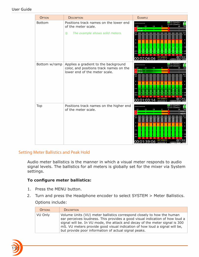
User Guide
112
option Description exampLe
Bottom Positions track names on the lower end of the meter scale.
i The example shows solid meters.
Bottom w/ramp Applies a gradient to the background color, and positions track names on the lower end of the meter scale.
Top Positions track names on the higher end of the meter scale.
Setting Meter Ballistics and Peak Hold
Audio meter ballistics is the manner in which a visual meter responds to audio signal levels. The ballistics for all meters is globally set for the mixer via System settings.
To configure meter ballistics:
1. Press the MENU button.
2. Turn and press the Headphone encoder to select SYSTEM > Meter Ballistics.
Options include:
options Description
VU Only Volume Units (VU) meter ballistics correspond closely to how the human ear perceives loudness. This provides a good visual indication of how loud a signal will be. In VU mode, the attack and decay of the meter signal is 300 mS. VU meters provide good visual indication of how loud a signal will be, but provide poor information of actual signal peaks.
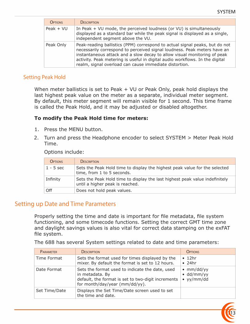
113
SYSTEM
options Description
Peak + VU In Peak + VU mode, the perceived loudness (or VU) is simultaneously displayed as a standard bar while the peak signal is displayed as a single, independent segment above the VU.
Peak Only Peak-reading ballistics (PPM) correspond to actual signal peaks, but do not necessarily correspond to perceived signal loudness. Peak meters have an instantaneous attack and a slow decay to allow visual monitoring of peak activity. Peak metering is useful in digital audio workflows. In the digital realm, signal overload can cause immediate distortion.
Setting Peak Hold
When meter ballistics is set to Peak + VU or Peak Only, peak hold displays the last highest peak value on the meter as a separate, individual meter segment. By default, this meter segment will remain visible for 1 second. This time frame is called the Peak Hold, and it may be adjusted or disabled altogether.
To modify the Peak Hold time for meters:
1. Press the MENU button.
2. Turn and press the Headphone encoder to select SYSTEM > Meter Peak Hold Time.
Options include:
options Description
1 - 5 sec Sets the Peak Hold time to display the highest peak value for the selected time, from 1 to 5 seconds.
Infinity Sets the Peak Hold time to display the last highest peak value indefinitely until a higher peak is reached.
Off Does not hold peak values.
Setting up Date and Time Parameters
Properly setting the time and date is important for file metadata, file system functioning, and some timecode functions. Setting the correct GMT time zone and daylight savings values is also vital for correct data stamping on the exFAT file system.
The 688 has several System settings related to date and time parameters:
parameter Description options
Time Format Sets the format used for times displayed by the mixer. By default the format is set to 12 hours.
• 12hr• 24hr
Date Format Sets the format used to indicate the date, used in metadata. By default, the format is set to two-digit increments for month/day/year (mm/dd/yy).
• mm/dd/yy• dd/mm/yy• yy/mm/dd
Set Time/Date Displays the Set Time/Date screen used to set the time and date.
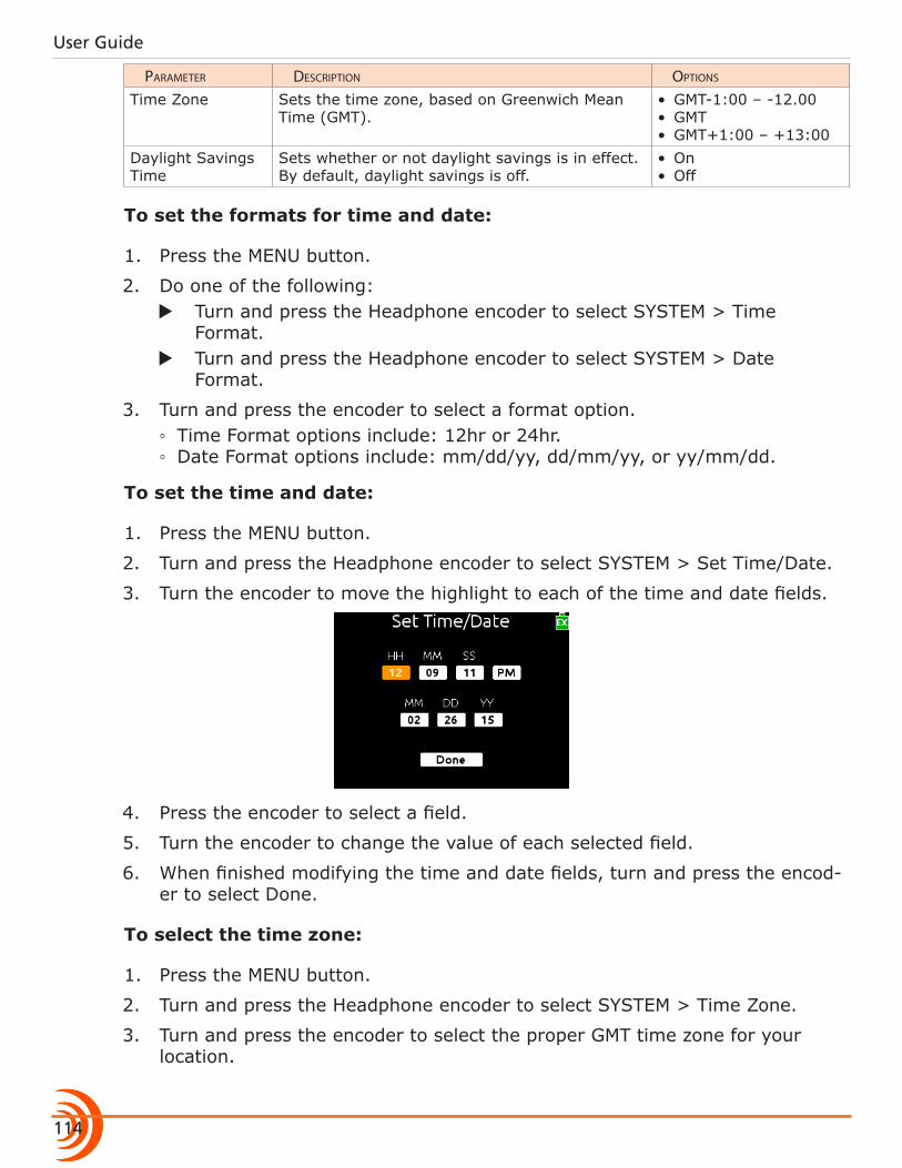
User Guide
114
parameter Description options
Time Zone Sets the time zone, based on Greenwich Mean Time (GMT).
• GMT-1:00 – -12.00• GMT• GMT+1:00 – +13:00
Daylight Savings Time
Sets whether or not daylight savings is in effect. By default, daylight savings is off.
• On• Off
To set the formats for time and date:
1. Press the MENU button.
2. Do one of the following: X Turn and press the Headphone encoder to select SYSTEM > Time
Format. X Turn and press the Headphone encoder to select SYSTEM > Date
Format.
3. Turn and press the encoder to select a format option. ◦ Time Format options include: 12hr or 24hr. ◦ Date Format options include: mm/dd/yy, dd/mm/yy, or yy/mm/dd.
To set the time and date:
1. Press the MENU button.
2. Turn and press the Headphone encoder to select SYSTEM > Set Time/Date.
3. Turn the encoder to move the highlight to each of the time and date fields.
4. Press the encoder to select a field.
5. Turn the encoder to change the value of each selected field.
6. When finished modifying the time and date fields, turn and press the encod-er to select Done.
To select the time zone:
1. Press the MENU button.
2. Turn and press the Headphone encoder to select SYSTEM > Time Zone.
3. Turn and press the encoder to select the proper GMT time zone for your location.
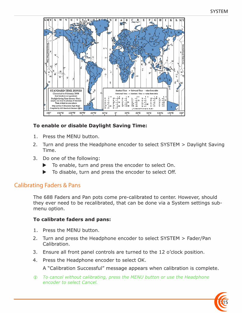
115
SYSTEM
To enable or disable Daylight Saving Time:
1. Press the MENU button.
2. Turn and press the Headphone encoder to select SYSTEM > Daylight Saving Time.
3. Do one of the following: X To enable, turn and press the encoder to select On. X To disable, turn and press the encoder to select Off.
Calibrating Faders & Pans
The 688 Faders and Pan pots come pre-calibrated to center. However, should they ever need to be recalibrated, that can be done via a System settings sub-menu option.
To calibrate faders and pans:
1. Press the MENU button.
2. Turn and press the Headphone encoder to select SYSTEM > Fader/Pan Calibration.
3. Ensure all front panel controls are turned to the 12 o’clock position.
4. Press the Headphone encoder to select OK.
A “Calibration Successful” message appears when calibration is complete.
i To cancel without calibrating, press the MENU button or use the Headphone encoder to select Cancel.
User Guide
116
Using a USB Keyboard
Included with the 688 is a USB 2.0 A (Female to Female) connector and a USB A to B cable, which may be used to connect a standard USB keyboard to the 688 mixer.
To use a USB keyboard with the 688:
1. Ensure SYSTEM > USB Port sub-menu is set to Keyboard.
i The USB Port is set to Keyboard by default; however, the alternative option is Factory Test, which is a setting reserved for the purposes of in-house quality assurance testing.
2. Connect the keyboard’s male USB A plug into the supplied USB A female adapter.
3. Connect the other end of the adapter to the USB A to B cable.
4. Plug the other end of the cable into the USB-B jack on the mixer’s right panel.
i Keyboards with an embedded USB hub are not compatible. Apple brand keyboards are not compatible. Additionally, some keyboards must be connected only after the mixer is turned on.
Keyboard shortcuts are provided in the Shortcuts section of this guide.
Viewing Shortcut Information
While this guide provides a section on the various shortcuts available with the 688, there is also an abbreviated list provided as a quick reference on the mixer itself.
To view shortcut information:
1. Press the MENU button.
2. Turn and press the Headphone encoder to select SYSTEM > Shortcut Info.
3. Turn the encoder to scroll down the list.
4. Press the encoder to select OK and exit the list.
Viewing User Guide via Smart Phone QR Code
The 688 provides QR codes on screen for smart phone access to product-related documentation, including this user guide, available online.
i Accessing documentation via a QR code requires the installation on your smart phone of a code reader application—many of which are available as free downloads from App stores.
117
SYSTEM
To access the 688 User Guide via QR code:
1. Press the MENU button.
2. Turn and press the Headphone encoder to select SYSTEM > User Guide link.
3. Using your phones code reader application, scan the QR code to view the guide (PDF format).
Viewing Version Information
Information regarding the product’s serial number, software and timecode versions, plus build numbers is provided on the mixer via a System settings sub-menu option.
To view version information:
1. Press the MENU button.
2. Turn and press the Headphone encoder to select SYSTEM > Version Info.
Updating Firmware
Periodically, Sound Devices releases firmware updates to improve system per-formance and expand the 688 feature set, which may be downloaded from the website and used to update the firmware on the mixer.
It is highly recommended that users update to the latest version of firmware available as soon as possible.
To update firmware:
1. Download the free firmware from the Sound Devices website to your computer.
2. Extract the ZIP file, which will contain a folder with a .prg file and related documentation.
3. Copy this .prg file to the root level of an approved SD or CF memory card. Do not place the file in any folder.
i Be sure to use a memory card already formatted in the mixer.
4. Insert the SD or CF card with the .prg file.
5. Power on the mixer if not already on.
⚠ Power the mixer from an external DC power source. Do not perform firm-ware updates with low batteries or unstable power sources.
6. Press the MENU button.
7. Turn and press the Headphone encoder to select SYSTEM > Update Firmware.
User Guide
118
8. Follow the on-screen instructions.
9. After the update is complete, the mixer power cycles.
When it reboots, the updated version number will appear briefly on the splash screen, and the mixer displays a message confirming the firmware update.
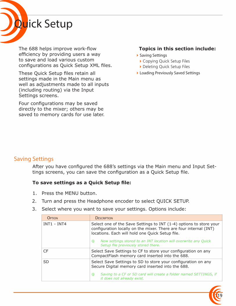
119
Topics in this section include:
Quick Setup
Saving Settings
The 688 helps improve work-flow efficiency by providing users a way to save and load various custom configurations as Quick Setup XML files.
These Quick Setup files retain all settings made in the Main menu as well as adjustments made to all inputs (including routing) via the Input Settings screens.
Four configurations may be saved directly to the mixer; others may be saved to memory cards for use later.
After you have configured the 688’s settings via the Main menu and Input Set-tings screens, you can save the configuration as a Quick Setup file.
To save settings as a Quick Setup file:
1. Press the MENU button.
2. Turn and press the Headphone encoder to select QUICK SETUP.
3. Select where you want to save your settings. Options include:
option Description
INT1 - INT4 Select one of the Save Settings to INT (1-4) options to store your configuration locally on the mixer. There are four internal (INT) locations. Each will hold one Quick Setup file.
i New settings stored to an INT location will overwrite any Quick Setup file previously stored there.
CF Select Save Settings to CF to store your configuration on any CompactFlash memory card inserted into the 688.
SD Select Save Settings to SD to store your configuration on any Secure Digital memory card inserted into the 688.
i Saving to a CF or SD card will create a folder named SETTINGS, if it does not already exist.
�Saving Settings �Copying Quick Setup Files �Deleting Quick Setup Files
�Loading Previously Saved Settings
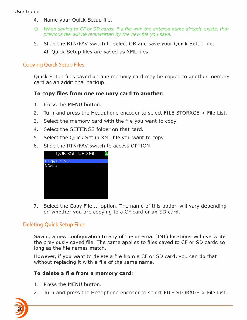
User Guide
120
4. Name your Quick Setup file.
i When saving to CF or SD cards, if a file with the entered name already exists, that previous file will be overwritten by the new file you save.
5. Slide the RTN/FAV switch to select OK and save your Quick Setup file.
All Quick Setup files are saved as XML files.
Copying Quick Setup Files
Quick Setup files saved on one memory card may be copied to another memory card as an additional backup.
To copy files from one memory card to another:
1. Press the MENU button.
2. Turn and press the Headphone encoder to select FILE STORAGE > File List.
3. Select the memory card with the file you want to copy.
4. Select the SETTINGS folder on that card.
5. Select the Quick Setup XML file you want to copy.
6. Slide the RTN/FAV switch to access OPTION.
7. Select the Copy File ... option. The name of this option will vary depending on whether you are copying to a CF card or an SD card.
Deleting Quick Setup Files
Saving a new configuration to any of the internal (INT) locations will overwrite the previously saved file. The same applies to files saved to CF or SD cards so long as the file names match.
However, if you want to delete a file from a CF or SD card, you can do that without replacing it with a file of the same name.
To delete a file from a memory card:
1. Press the MENU button.
2. Turn and press the Headphone encoder to select FILE STORAGE > File List.
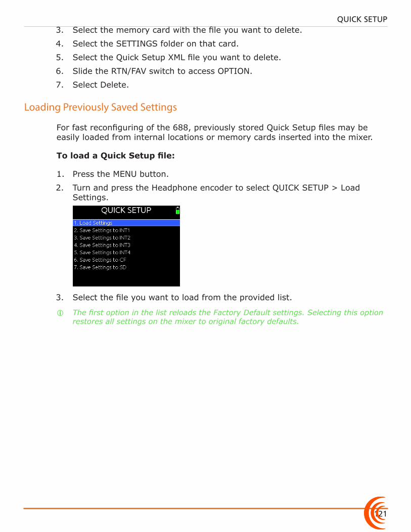
121
QUICK SETUP3. Select the memory card with the file you want to delete.
4. Select the SETTINGS folder on that card.
5. Select the Quick Setup XML file you want to delete.
6. Slide the RTN/FAV switch to access OPTION.
7. Select Delete.
Loading Previously Saved Settings
For fast reconfiguring of the 688, previously stored Quick Setup files may be easily loaded from internal locations or memory cards inserted into the mixer.
To load a Quick Setup file:
1. Press the MENU button.
2. Turn and press the Headphone encoder to select QUICK SETUP > Load Settings.
3. Select the file you want to load from the provided list.
i The first option in the list reloads the Factory Default settings. Selecting this option restores all settings on the mixer to original factory defaults.

User Guide
122
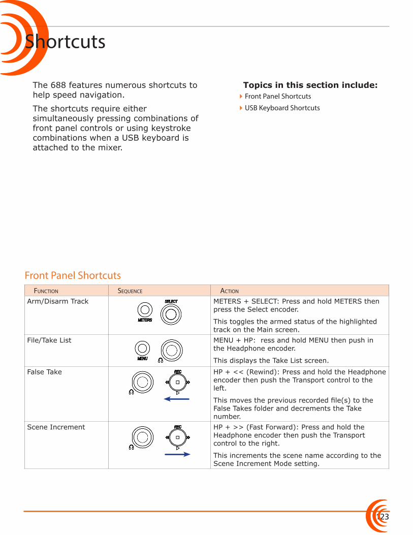
123
Topics in this section include:
Shortcuts
The 688 features numerous shortcuts to help speed navigation.
The shortcuts require either simultaneously pressing combinations of front panel controls or using keystroke combinations when a USB keyboard is attached to the mixer.
Function sequence action
Arm/Disarm Track METERS + SELECT: Press and hold METERS then press the Select encoder.
This toggles the armed status of the highlighted track on the Main screen.
File/Take List MENU + HP: Press and hold MENU then push in the Headphone encoder.
This displays the Take List screen.
False Take HP + << (Rewind): Press and hold the Headphone encoder then push the Transport control to the left.
This moves the previous recorded file(s) to the False Takes folder and decrements the Take number.
Scene Increment HP + >> (Fast Forward): Press and hold the Headphone encoder then push the Transport control to the right.
This increments the scene name according to the Scene Increment Mode setting.
�Front Panel Shortcuts
�USB Keyboard Shortcuts
Front Panel Shortcuts
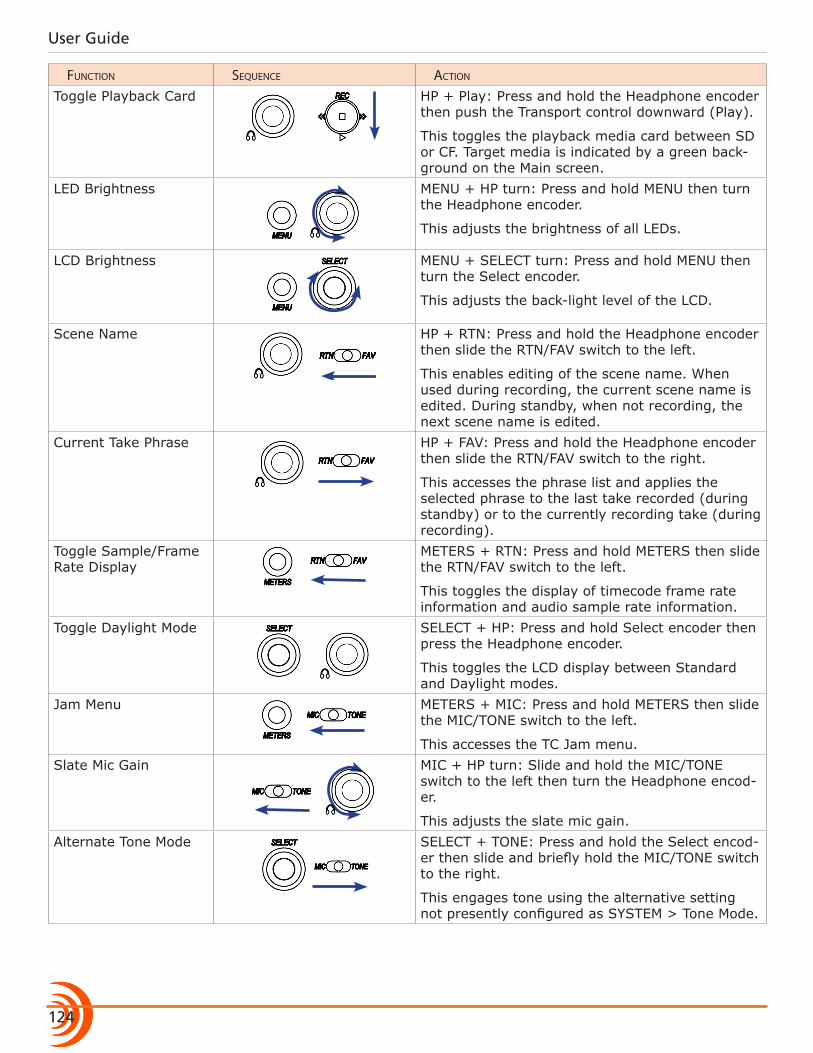
User Guide
124
Function sequence action
Toggle Playback Card HP + Play: Press and hold the Headphone encoder then push the Transport control downward (Play).
This toggles the playback media card between SD or CF. Target media is indicated by a green back-ground on the Main screen.
LED Brightness MENU + HP turn: Press and hold MENU then turn the Headphone encoder.
This adjusts the brightness of all LEDs.
LCD Brightness MENU + SELECT turn: Press and hold MENU then turn the Select encoder.
This adjusts the back-light level of the LCD.
Scene Name HP + RTN: Press and hold the Headphone encoder then slide the RTN/FAV switch to the left.
This enables editing of the scene name. When used during recording, the current scene name is edited. During standby, when not recording, the next scene name is edited.
Current Take Phrase HP + FAV: Press and hold the Headphone encoder then slide the RTN/FAV switch to the right.
This accesses the phrase list and applies the selected phrase to the last take recorded (during standby) or to the currently recording take (during recording).
Toggle Sample/Frame Rate Display
METERS + RTN: Press and hold METERS then slide the RTN/FAV switch to the left.
This toggles the display of timecode frame rate information and audio sample rate information.
Toggle Daylight Mode SELECT + HP: Press and hold Select encoder then press the Headphone encoder.
This toggles the LCD display between Standard and Daylight modes.
Jam Menu METERS + MIC: Press and hold METERS then slide the MIC/TONE switch to the left.
This accesses the TC Jam menu.Slate Mic Gain MIC + HP turn: Slide and hold the MIC/TONE
switch to the left then turn the Headphone encod-er.
This adjusts the slate mic gain.Alternate Tone Mode SELECT + TONE: Press and hold the Select encod-
er then slide and briefly hold the MIC/TONE switch to the right.
This engages tone using the alternative setting not presently configured as SYSTEM > Tone Mode.
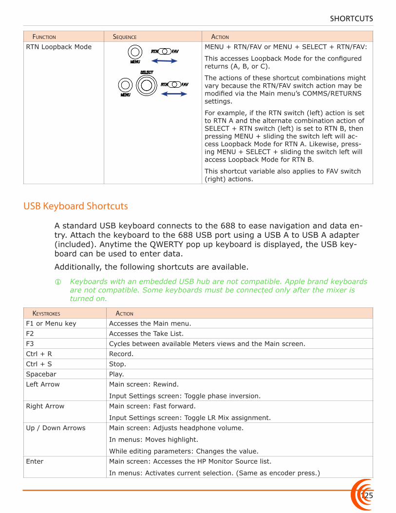
125
SHORTCUTS
Function sequence action
RTN Loopback Mode MENU + RTN/FAV or MENU + SELECT + RTN/FAV:
This accesses Loopback Mode for the configured returns (A, B, or C).
The actions of these shortcut combinations might vary because the RTN/FAV switch action may be modified via the Main menu’s COMMS/RETURNS settings.
For example, if the RTN switch (left) action is set to RTN A and the alternate combination action of SELECT + RTN switch (left) is set to RTN B, then pressing MENU + sliding the switch left will ac-cess Loopback Mode for RTN A. Likewise, press-ing MENU + SELECT + sliding the switch left will access Loopback Mode for RTN B.
This shortcut variable also applies to FAV switch (right) actions.
USB Keyboard Shortcuts
A standard USB keyboard connects to the 688 to ease navigation and data en-try. Attach the keyboard to the 688 USB port using a USB A to USB A adapter (included). Anytime the QWERTY pop up keyboard is displayed, the USB key-board can be used to enter data.
Additionally, the following shortcuts are available.
i Keyboards with an embedded USB hub are not compatible. Apple brand keyboards are not compatible. Some keyboards must be connected only after the mixer is turned on.
keystrokes action
F1 or Menu key Accesses the Main menu.F2 Accesses the Take List.F3 Cycles between available Meters views and the Main screen.Ctrl + R Record.Ctrl + S Stop.Spacebar Play.Left Arrow Main screen: Rewind.
Input Settings screen: Toggle phase inversion.Right Arrow Main screen: Fast forward.
Input Settings screen: Toggle LR Mix assignment.Up / Down Arrows Main screen: Adjusts headphone volume.
In menus: Moves highlight.
While editing parameters: Changes the value.Enter Main screen: Accesses the HP Monitor Source list.
In menus: Activates current selection. (Same as encoder press.)
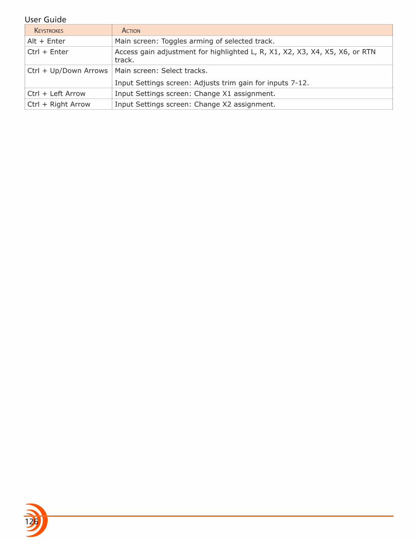
User Guide
126
keystrokes action
Alt + Enter Main screen: Toggles arming of selected track.Ctrl + Enter Access gain adjustment for highlighted L, R, X1, X2, X3, X4, X5, X6, or RTN
track.Ctrl + Up/Down Arrows Main screen: Select tracks.
Input Settings screen: Adjusts trim gain for inputs 7-12.Ctrl + Left Arrow Input Settings screen: Change X1 assignment.Ctrl + Right Arrow Input Settings screen: Change X2 assignment.

118
Topics in this section include:
Starting Wingman
Wingman is an iOS-based application that provides wireless remote control and monitoring of any 6-Series field production mixer/recorder—the 688, 664, or 633.
It may be downloaded from Apple’s App Store and installed on any iPad, iPhone, or iPod Touch mobile device, running iOS 8.0 or later.
The WM-Connect hardware accessory, a Bluetooth® Smart USB dongle for the 6-Series, is required for this integration.
i Instructions for installing WM-Connect and downloading the Wingman app are provided in the WM-Connect Quick Start Guide, shipped with the hardware and offered as a free PDF download from the Sound Devices website.
Before starting the application, ensure the WM-Connect hardware accessory (shown at right) is attached to your 6-Series mixer, that Bluetooth is turned on (on your mobile device), and the mixer is both powered on and running the latest firmware.
To start the Wingman App:
X Tap the Wingman icon.
Setting up Wingman Password
For added security, when using the Wingman App to monitor and control the recorder from a mobile device, set up the 6-Series mixer to require a password for remote access. The password may be up to 18 alpha-numeric characters. Punctuation other than a hyphen or an underscore is not permitted.
To set a remote password:
1. Press the MENU button.
2. Turn and press the Headphone encoder to select SYSTEM > Wingman Password > Enter Password.
�Starting Wingman
�User Interface
�Transport View �Connecting to a 6-Series Mixer �Using Transport Controls �Designating Circle and False Takes �Using Meter Views �Editing Track Names �Arming/Disarming Tracks
�Take List View �Editing a Take’s Metadata
�Reports View �Creating Sound Reports
�About View
�Track View on iPhone or iPod Touch
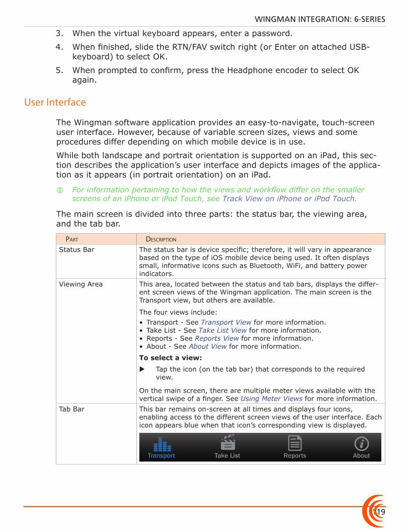
119
WINGMAN INTEGRATION: 6-SERIES
3. When the virtual keyboard appears, enter a password.
4. When finished, slide the RTN/FAV switch right (or Enter on attached USB-keyboard) to select OK.
5. When prompted to confirm, press the Headphone encoder to select OK again.
User Interface
The Wingman software application provides an easy-to-navigate, touch-screen user interface. However, because of variable screen sizes, views and some procedures differ depending on which mobile device is in use.
While both landscape and portrait orientation is supported on an iPad, this sec-tion describes the application’s user interface and depicts images of the applica-tion as it appears (in portrait orientation) on an iPad.
i For information pertaining to how the views and workflow differ on the smaller screens of an iPhone or iPod Touch, see Track View on iPhone or iPod Touch.
The main screen is divided into three parts: the status bar, the viewing area, and the tab bar.
part Description
Status Bar The status bar is device specific; therefore, it will vary in appearance based on the type of iOS mobile device being used. It often displays small, informative icons such as Bluetooth, WiFi, and battery power indicators.
Viewing Area This area, located between the status and tab bars, displays the differ-ent screen views of the Wingman application. The main screen is the Transport view, but others are available.
The four views include:• Transport - See Transport View for more information.• Take List - See Take List View for more information.• Reports - See Reports View for more information.• About - See About View for more information.
To select a view:
X Tap the icon (on the tab bar) that corresponds to the required view.
On the main screen, there are multiple meter views available with the vertical swipe of a finger. See Using Meter Views for more information.
Tab Bar This bar remains on-screen at all times and displays four icons, enabling access to the different screen views of the user interface. Each icon appears blue when that icon’s corresponding view is displayed.
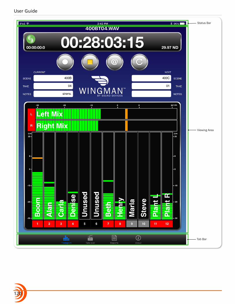
User Guide
120
Status Bar
Viewing Area
Tab Bar
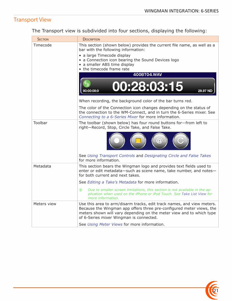
121
WINGMAN INTEGRATION: 6-SERIES
Transport View
The Transport view is subdivided into four sections, displaying the following:
section Description
Timecode This section (shown below) provides the current file name, as well as a bar with the following information:• a large Timecode display• a Connection icon bearing the Sound Devices logo• a smaller ABS time display• the timecode frame rate
When recording, the background color of the bar turns red.
The color of the Connection icon changes depending on the status of the connection to the WM-Connect, and in turn the 6-Series mixer. See Connecting to a 6-Series Mixer for more information.
Toolbar The toolbar (shown below) has four round buttons for—from left to right—Record, Stop, Circle Take, and False Take.
See Using Transport Controls and Designating Circle and False Takes for more information.
Metadata This section bears the Wingman logo and provides text fields used to enter or edit metadata—such as scene name, take number, and notes—for both current and next takes.
See Editing a Take’s Metadata for more information.
i Due to smaller screen limitations, this section is not available in the ap-plication when used on the iPhone or iPod Touch. See Take List View for more information.
Meters view Use this area to arm/disarm tracks, edit track names, and view meters. Because the Wingman app offers three pre-configured meter views, the meters shown will vary depending on the meter view and to which type of 6-Series mixer Wingman is connected.
See Using Meter Views for more information.
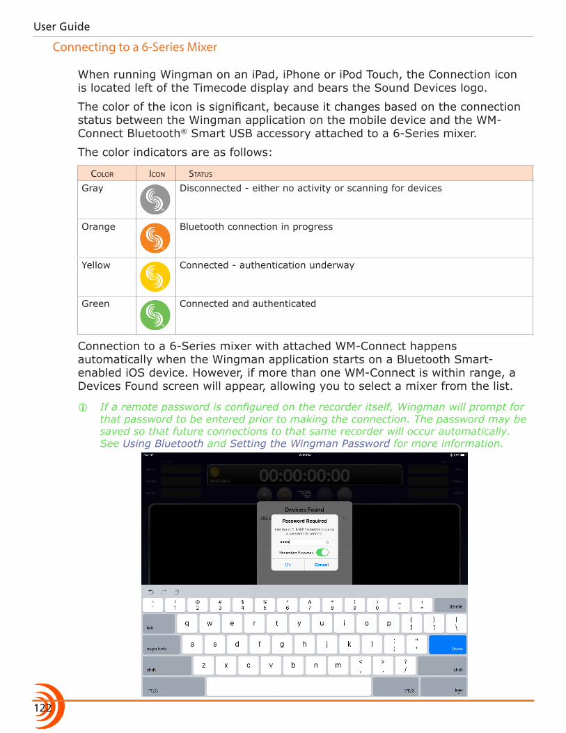
User Guide
122
Connecting to a 6-Series Mixer
When running Wingman on an iPad, iPhone or iPod Touch, the Connection icon is located left of the Timecode display and bears the Sound Devices logo.
The color of the icon is significant, because it changes based on the connection status between the Wingman application on the mobile device and the WM-Connect Bluetooth® Smart USB accessory attached to a 6-Series mixer.
The color indicators are as follows:
coLor icon status
Gray Disconnected - either no activity or scanning for devices
Orange Bluetooth connection in progress
Yellow Connected - authentication underway
Green Connected and authenticated
Connection to a 6-Series mixer with attached WM-Connect happens automatically when the Wingman application starts on a Bluetooth Smart-enabled iOS device. However, if more than one WM-Connect is within range, a Devices Found screen will appear, allowing you to select a mixer from the list.
i If a remote password is configured on the recorder itself, Wingman will prompt for that password to be entered prior to making the connection. The password may be saved so that future connections to that same recorder will occur automatically. See Using Bluetooth and Setting the Wingman Password for more information.
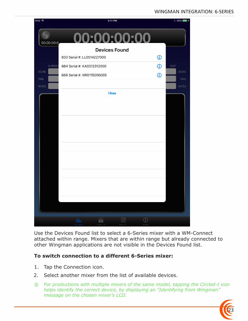
123
WINGMAN INTEGRATION: 6-SERIES
Use the Devices Found list to select a 6-Series mixer with a WM-Connect attached within range. Mixers that are within range but already connected to other Wingman applications are not visible in the Devices Found list.
To switch connection to a different 6-Series mixer:
1. Tap the Connection icon.
2. Select another mixer from the list of available devices.
i For productions with multiple mixers of the same model, tapping the Circled-I icon helps identify the correct device, by displaying an “Identifying from Wingman” message on the chosen mixer’s LCD.
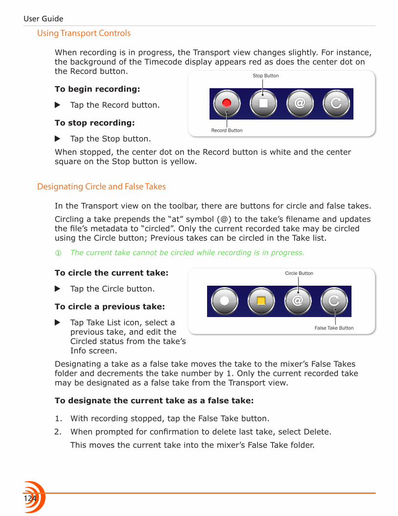
User Guide
124
Using Transport Controls
Record Button
Stop Button
When recording is in progress, the Transport view changes slightly. For instance, the background of the Timecode display appears red as does the center dot on the Record button.
To begin recording:
X Tap the Record button.
To stop recording:
X Tap the Stop button.
When stopped, the center dot on the Record button is white and the center square on the Stop button is yellow.
Designating Circle and False Takes
In the Transport view on the toolbar, there are buttons for circle and false takes.
Circling a take prepends the “at” symbol (@) to the take’s filename and updates the file’s metadata to “circled”. Only the current recorded take may be circled using the Circle button; Previous takes can be circled in the Take list.
i The current take cannot be circled while recording is in progress.
False Take Button
Circle ButtonTo circle the current take:
X Tap the Circle button.
To circle a previous take:
X Tap Take List icon, select a previous take, and edit the Circled status from the take’s Info screen.
Designating a take as a false take moves the take to the mixer’s False Takes folder and decrements the take number by 1. Only the current recorded take may be designated as a false take from the Transport view.
To designate the current take as a false take:
1. With recording stopped, tap the False Take button.
2. When prompted for confirmation to delete last take, select Delete.
This moves the current take into the mixer’s False Take folder.
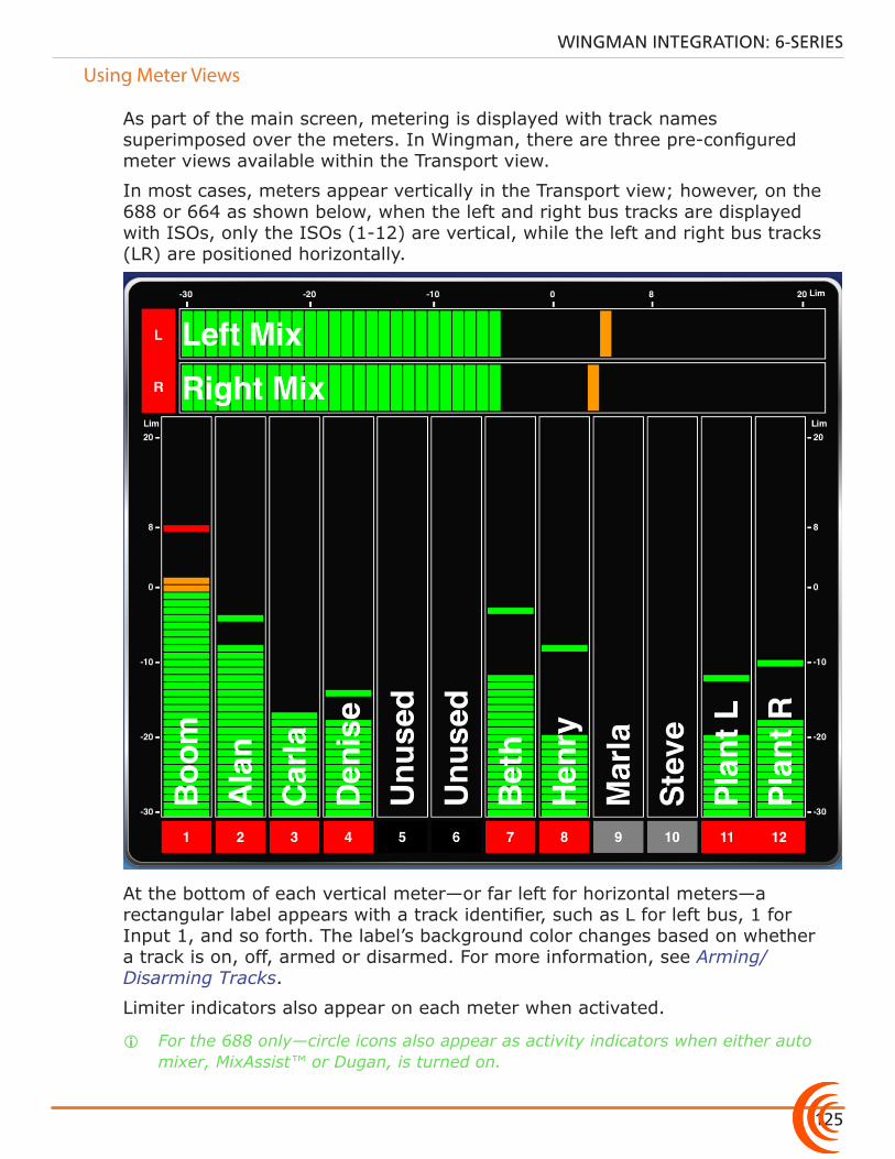
125
WINGMAN INTEGRATION: 6-SERIES
Using Meter Views
As part of the main screen, metering is displayed with track names superimposed over the meters. In Wingman, there are three pre-configured meter views available within the Transport view.
In most cases, meters appear vertically in the Transport view; however, on the 688 or 664 as shown below, when the left and right bus tracks are displayed with ISOs, only the ISOs (1-12) are vertical, while the left and right bus tracks (LR) are positioned horizontally.
At the bottom of each vertical meter—or far left for horizontal meters—a rectangular label appears with a track identifier, such as L for left bus, 1 for Input 1, and so forth. The label’s background color changes based on whether a track is on, off, armed or disarmed. For more information, see Arming/Disarming Tracks.
Limiter indicators also appear on each meter when activated.
i For the 688 only—circle icons also appear as activity indicators when either auto mixer, MixAssist™ or Dugan, is turned on.
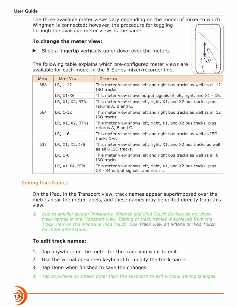
User Guide
126
The three available meter views vary depending on the model of mixer to which Wingman is connected; however, the procedure for toggling through the available meter views is the same.
To change the meter view:
X Slide a fingertip vertically up or down over the meters.
The following table explains which pre-configured meter views are available for each model in the 6-Series mixer/recorder line.
mixer meter View Description
688 LR, 1-12 This meter view shows left and right bus tracks as well as all 12 ISO tracks.
LR, X1-X6 This meter view shows output signals of left, right, and X1 - X6. LR, X1, X2, RTNs This meter view shows left, right, X1, and X2 bus tracks, plus
returns A, B and C.664 LR, 1-12 This meter view shows left and right bus tracks as well as all 12
ISO tracks.LR, X1, X2, RTNs This meter view shows left, right, X1, and X2 bus tracks, plus
returns A, B and C.LR, 1-6 This meter view shows left and right bus tracks as well as ISO
tracks 1-6.633 LR, X1, X2, 1-6 This meter view shows left, right, X1, and X2 bus tracks as well
as all 6 ISO tracks.LR, 1-6 This meter view shows left and right bus tracks as well as all 6
ISO tracks.LR, X1-X4, RTN This meter view shows left, right, X1, and X2 bus tracks, plus
X3 - X4 output signals, and return.
Editing Track Names
On the iPad, in the Transport view, track names appear superimposed over the meters near the meter labels, and these names may be edited directly from this view.
i Due to smaller screen limitations, iPhones and iPod Touch devices do not show track names in the Transport view. Editing of track names is achieved from the Track view on the iPhone or iPod Touch. See Track View on iPhone or iPod Touch for more information.
To edit track names:
1. Tap anywhere on the meter for the track you want to edit.
2. Use the virtual on-screen keyboard to modify the track name.
3. Tap Done when finished to save the changes.
i Tap anywhere on screen other than the keyboard to exit without saving changes.
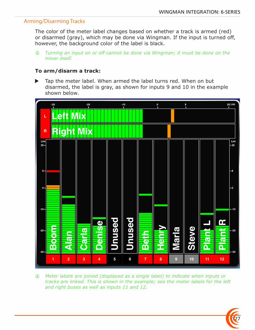
127
WINGMAN INTEGRATION: 6-SERIES
Arming/Disarming Tracks
The color of the meter label changes based on whether a track is armed (red) or disarmed (gray), which may be done via Wingman. If the input is turned off, however, the background color of the label is black.
i Turning an input on or off cannot be done via Wingman; it must be done on the mixer itself.
To arm/disarm a track:
X Tap the meter label. When armed the label turns red. When on but disarmed, the label is gray, as shown for inputs 9 and 10 in the example shown below.
i Meter labels are joined (displayed as a single label) to indicate when inputs or tracks are linked. This is shown in the example; see the meter labels for the left and right buses as well as inputs 11 and 12.
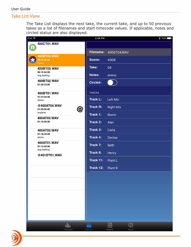
User Guide
128
Take List ViewThe Take List displays the next take, the current take, and up to 50 previous takes as a list of filenames and start timecode values. If applicable, notes and circled status are also displayed.
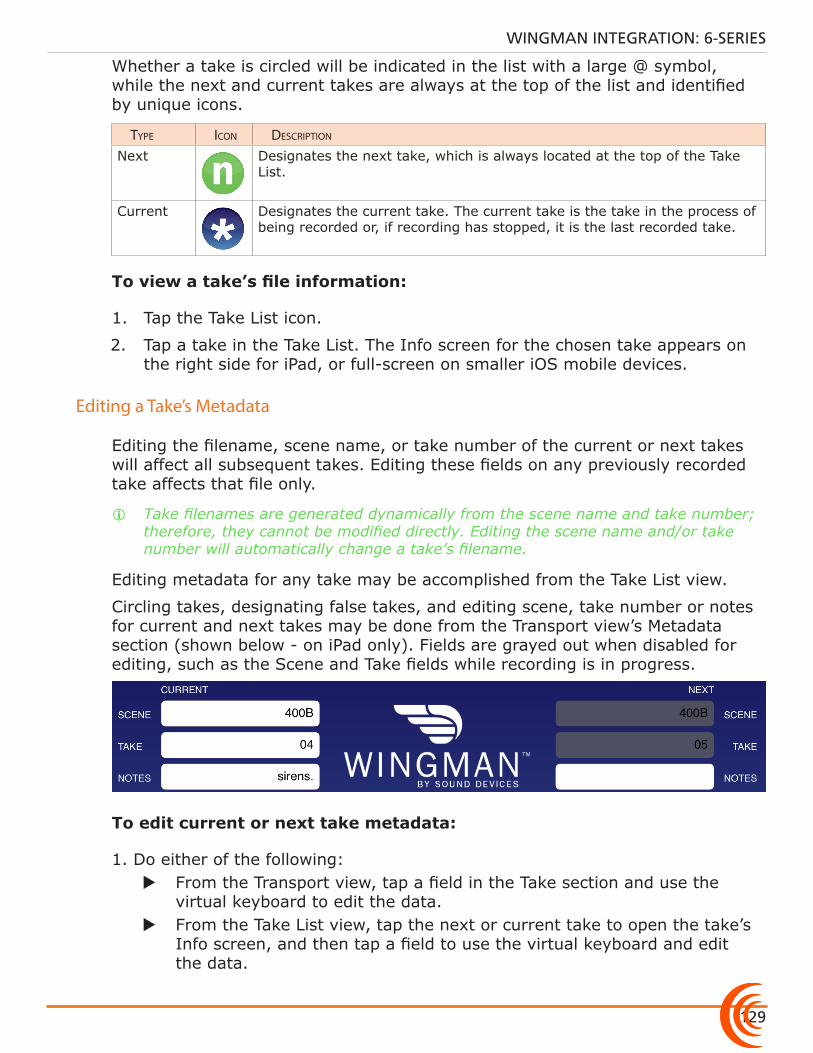
129
WINGMAN INTEGRATION: 6-SERIES
Whether a take is circled will be indicated in the list with a large @ symbol, while the next and current takes are always at the top of the list and identified by unique icons.
type icon Description
Next Designates the next take, which is always located at the top of the Take List.
Current Designates the current take. The current take is the take in the process of being recorded or, if recording has stopped, it is the last recorded take.
To view a take’s file information:
1. Tap the Take List icon.
2. Tap a take in the Take List. The Info screen for the chosen take appears on the right side for iPad, or full-screen on smaller iOS mobile devices.
Editing a Take’s Metadata
Editing the filename, scene name, or take number of the current or next takes will affect all subsequent takes. Editing these fields on any previously recorded take affects that file only.
i Take filenames are generated dynamically from the scene name and take number; therefore, they cannot be modified directly. Editing the scene name and/or take number will automatically change a take’s filename.
Editing metadata for any take may be accomplished from the Take List view.
Circling takes, designating false takes, and editing scene, take number or notes for current and next takes may be done from the Transport view’s Metadata section (shown below - on iPad only). Fields are grayed out when disabled for editing, such as the Scene and Take fields while recording is in progress.
To edit current or next take metadata:
1. Do either of the following: X From the Transport view, tap a field in the Take section and use the
virtual keyboard to edit the data. X From the Take List view, tap the next or current take to open the take’s
Info screen, and then tap a field to use the virtual keyboard and edit the data.
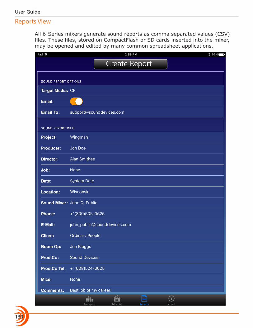
User Guide
130
Reports View
All 6-Series mixers generate sound reports as comma separated values (CSV) files. These files, stored on CompactFlash or SD cards inserted into the mixer, may be opened and edited by many common spreadsheet applications.
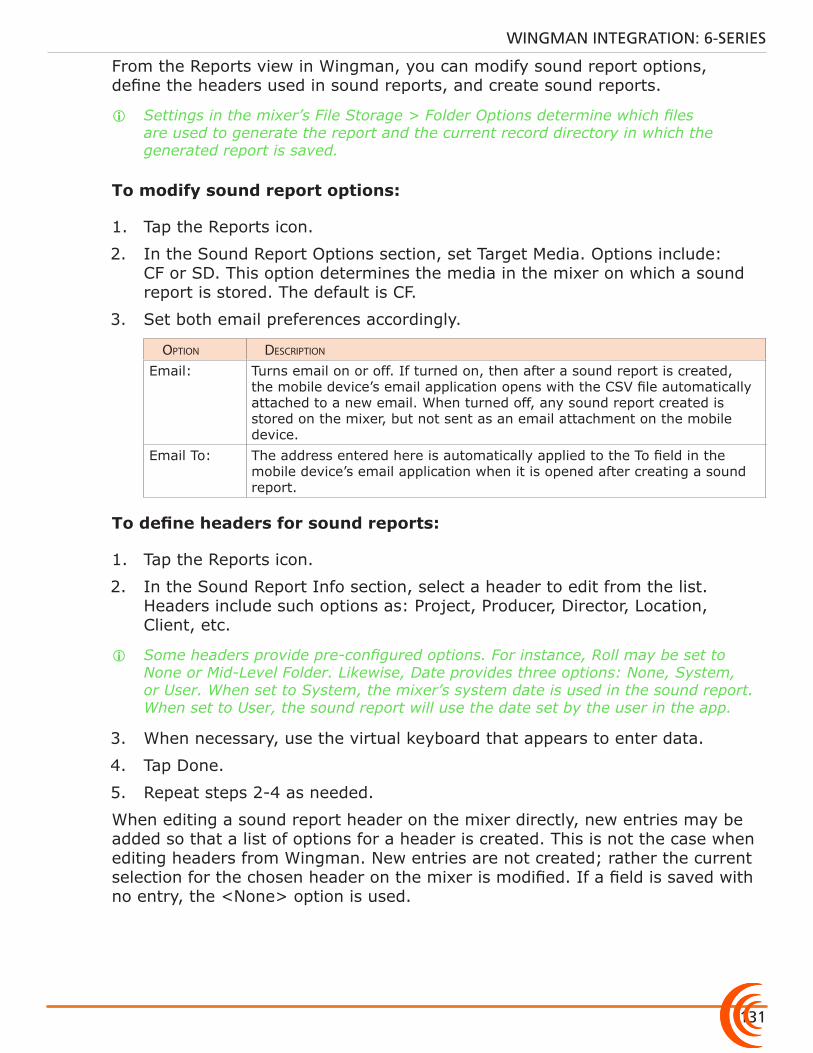
131
WINGMAN INTEGRATION: 6-SERIES
From the Reports view in Wingman, you can modify sound report options, define the headers used in sound reports, and create sound reports.
i Settings in the mixer’s File Storage > Folder Options determine which files are used to generate the report and the current record directory in which the generated report is saved.
To modify sound report options:
1. Tap the Reports icon.
2. In the Sound Report Options section, set Target Media. Options include: CF or SD. This option determines the media in the mixer on which a sound report is stored. The default is CF.
3. Set both email preferences accordingly.
option Description
Email: Turns email on or off. If turned on, then after a sound report is created, the mobile device’s email application opens with the CSV file automatically attached to a new email. When turned off, any sound report created is stored on the mixer, but not sent as an email attachment on the mobile device.
Email To: The address entered here is automatically applied to the To field in the mobile device’s email application when it is opened after creating a sound report.
To define headers for sound reports:
1. Tap the Reports icon.
2. In the Sound Report Info section, select a header to edit from the list. Headers include such options as: Project, Producer, Director, Location, Client, etc.
i Some headers provide pre-configured options. For instance, Roll may be set to None or Mid-Level Folder. Likewise, Date provides three options: None, System, or User. When set to System, the mixer’s system date is used in the sound report. When set to User, the sound report will use the date set by the user in the app.
3. When necessary, use the virtual keyboard that appears to enter data.
4. Tap Done.
5. Repeat steps 2-4 as needed.
When editing a sound report header on the mixer directly, new entries may be added so that a list of options for a header is created. This is not the case when editing headers from Wingman. New entries are not created; rather the current selection for the chosen header on the mixer is modified. If a field is saved with no entry, the <None> option is used.
User Guide
132
Creating Sound Reports
Sound reports created from Wingman are stored on the mixer and may be emailed from your iOS device.
To create a sound report:
1. Tap the Reports icon.
2. Tap the Create Report button at the top of the screen. ◦ If the Email option is turned on, the sound report (csv) file will appear as an attachment to an email that opens on screen.
◦ If the Email option is turned off, a message appears indicating the successful creation of the sound report, which is stored in the current directory on the target media (CF or SD) inserted into the mixer.
i Report creation is not allowed during recording.
About View
The About view displays important information and links related to the Wingman application and the 6-Series mixer to which it is connected.
Information available in the About view includes:• Wingman application version number• Build number• WM-Connect version number• 6-Series model number• 6-Series firmware version numberAlso included are interactive links to the following online resources:• The WM-Connect Quick Start Guide• The Wingman User Guide• The connected 6-Series mixer’s User Guide• Link to file a Support Query with Sound Devices Technical Support
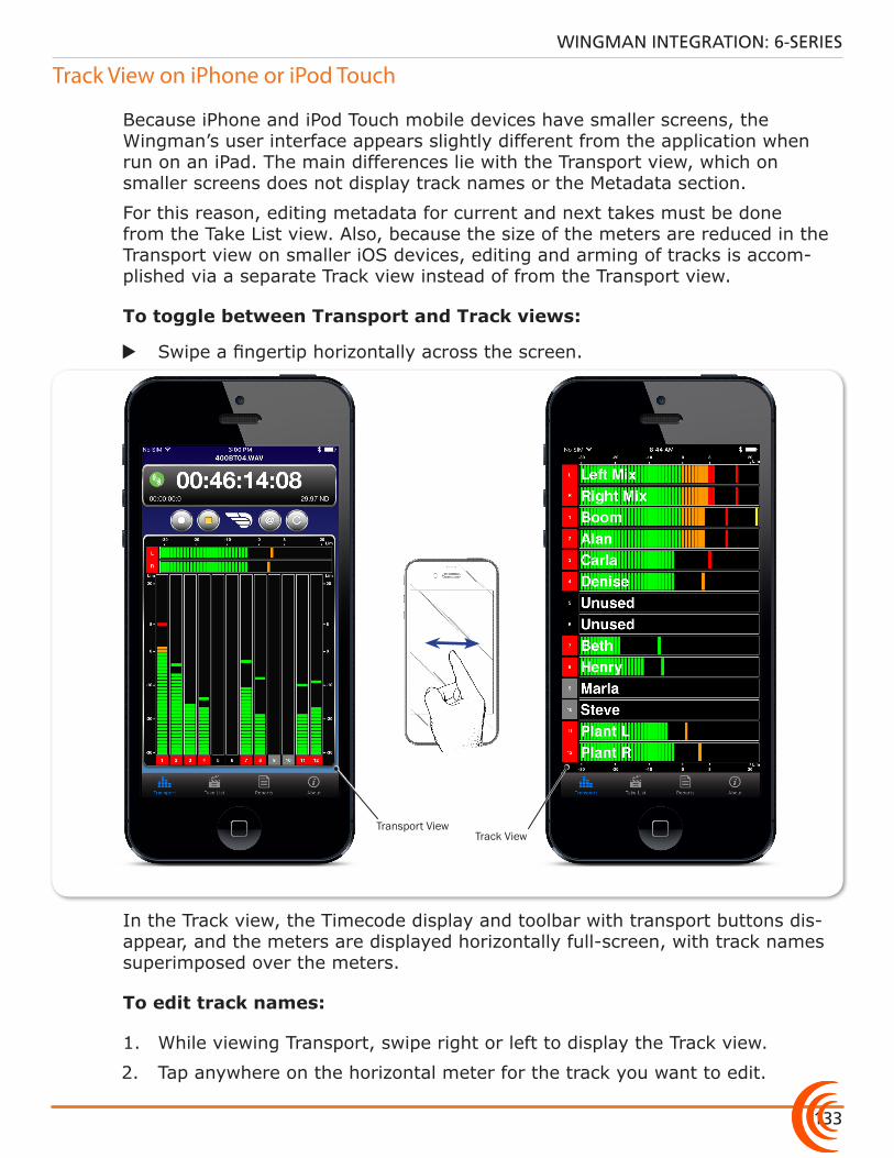
133
WINGMAN INTEGRATION: 6-SERIES
Track View on iPhone or iPod Touch
Because iPhone and iPod Touch mobile devices have smaller screens, the Wingman’s user interface appears slightly different from the application when run on an iPad. The main differences lie with the Transport view, which on smaller screens does not display track names or the Metadata section.
For this reason, editing metadata for current and next takes must be done from the Take List view. Also, because the size of the meters are reduced in the Transport view on smaller iOS devices, editing and arming of tracks is accom-plished via a separate Track view instead of from the Transport view.
To toggle between Transport and Track views:
X Swipe a fingertip horizontally across the screen.
Transport ViewTrack View
In the Track view, the Timecode display and toolbar with transport buttons dis-appear, and the meters are displayed horizontally full-screen, with track names superimposed over the meters.
To edit track names:
1. While viewing Transport, swipe right or left to display the Track view.
2. Tap anywhere on the horizontal meter for the track you want to edit.
User Guide
134
3. Use the virtual on-screen keyboard to modify the track name.
4. Tap Done when finished to save the changes.
i Tap anywhere on screen other than the keyboard to exit without saving changes.
To arm/disarm a track:
1. While viewing Transport, swipe left or right to display the Track view.
2. Tap the meter label, located left of the meter for the track you want to arm or disarm. The background color will change accordingly. When armed the label turns red. When on but disarmed, the label is gray.
i When input is off, the label appears black, and the input cannot be armed.
135
WINGMAN INTEGRATION: 6-SERIES
136
Topics in this section include:
Control in the Palm of Your Hand
Through collaboration with third-party companies— Ambient Recording, Lockit Network GmbH, PureBlend Software and Timecode Systems—Sound Devices offers wireless remote control of any 6-Series mixer (688, 664, and 633) via iOS and web-based mobile devices.
This section outlines the benefits and what is required for iOS and web-based wireless remote control integration. Please refer to your third-party manufacturer’s documentation for more details on setup and basic user information.
The ability to remotely control any 6-Series mixer/recorder with easy, wireless operation and larger touchscreen GUIs adds untethered freedom and flexibility on set and in the field. With wireless remote control, via iOS or web-based devices, Sound Mixers can:• Edit scene names, takes, and notes• Start and stop recording• Arm tracks and edit track names • Circle takes• Set false takes• Create sound reports
i Although these third-party wireless systems do not initiate sound reports on the actual mixers, they can create sound reports from their own applications’ databases. For more information regarding sound report creation on the mixer itself, see “Generating Sound Reports” in the File Storage chapter of this User Guide.
�Control in the Palm of Your Hand
�iOS Wireless Remote Control
�Web-based Wireless Remote Control
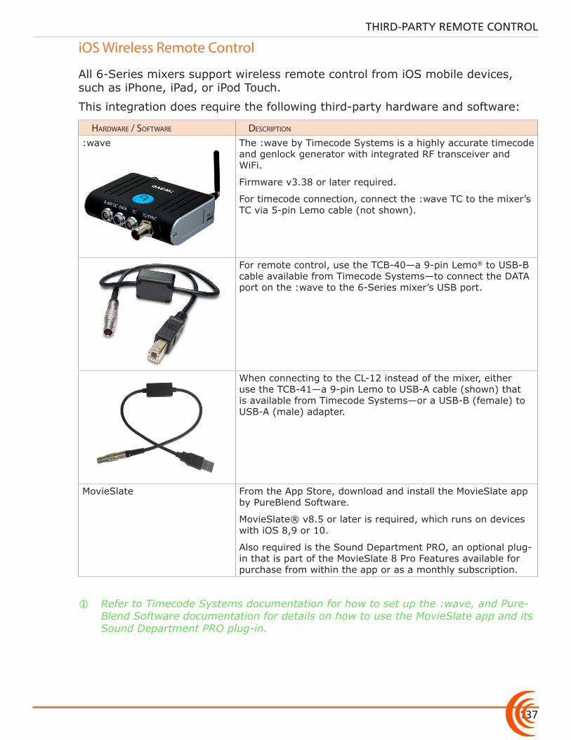
137
THIRD-PARTY REMOTE CONTROL
iOS Wireless Remote Control
All 6-Series mixers support wireless remote control from iOS mobile devices, such as iPhone, iPad, or iPod Touch.
This integration does require the following third-party hardware and software:
HarDware / soFtware Description
:wave The :wave by Timecode Systems is a highly accurate timecode and genlock generator with integrated RF transceiver and WiFi.
Firmware v3.38 or later required.
For timecode connection, connect the :wave TC to the mixer’s TC via 5-pin Lemo cable (not shown).
For remote control, use the TCB-40—a 9-pin Lemo® to USB-B cable available from Timecode Systems—to connect the DATA port on the :wave to the 6-Series mixer’s USB port.
When connecting to the CL-12 instead of the mixer, either use the TCB-41—a 9-pin Lemo to USB-A cable (shown) that is available from Timecode Systems—or a USB-B (female) to USB-A (male) adapter.
MovieSlate From the App Store, download and install the MovieSlate app by PureBlend Software.
MovieSlate® v8.5 or later is required, which runs on devices with iOS 8,9 or 10.
Also required is the Sound Department PRO, an optional plug-in that is part of the MovieSlate 8 Pro Features available for purchase from within the app or as a monthly subscription.
i Refer to Timecode Systems documentation for how to set up the :wave, and Pure-Blend Software documentation for details on how to use the MovieSlate app and its Sound Department PRO plug-in.
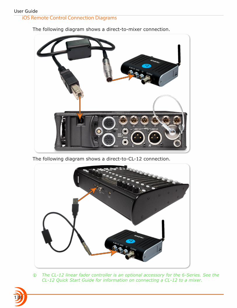
User Guide
138
iOS Remote Control Connection Diagrams
The following diagram shows a direct-to-mixer connection.
The following diagram shows a direct-to-CL-12 connection.
i The CL-12 linear fader controller is an optional accessory for the 6-Series. See the CL-12 Quick Start Guide for information on connecting a CL-12 to a mixer.
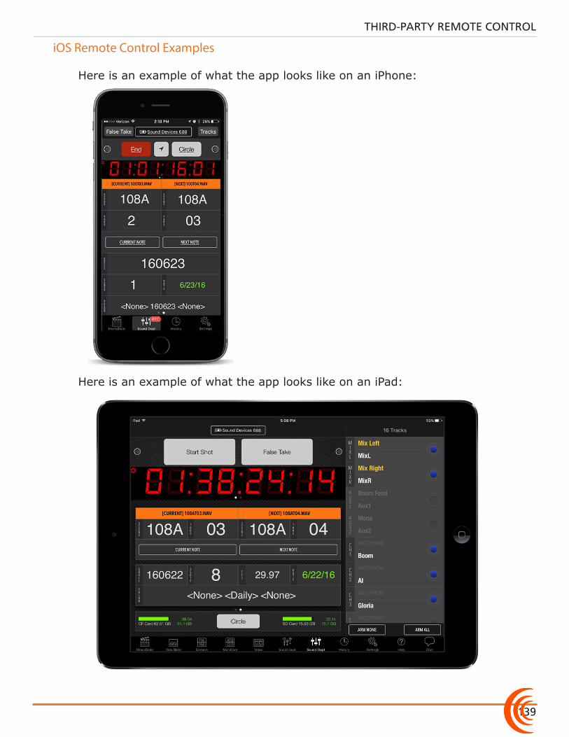
139
THIRD-PARTY REMOTE CONTROL
iOS Remote Control Examples
Here is an example of what the app looks like on an iPhone:
Here is an example of what the app looks like on an iPad:
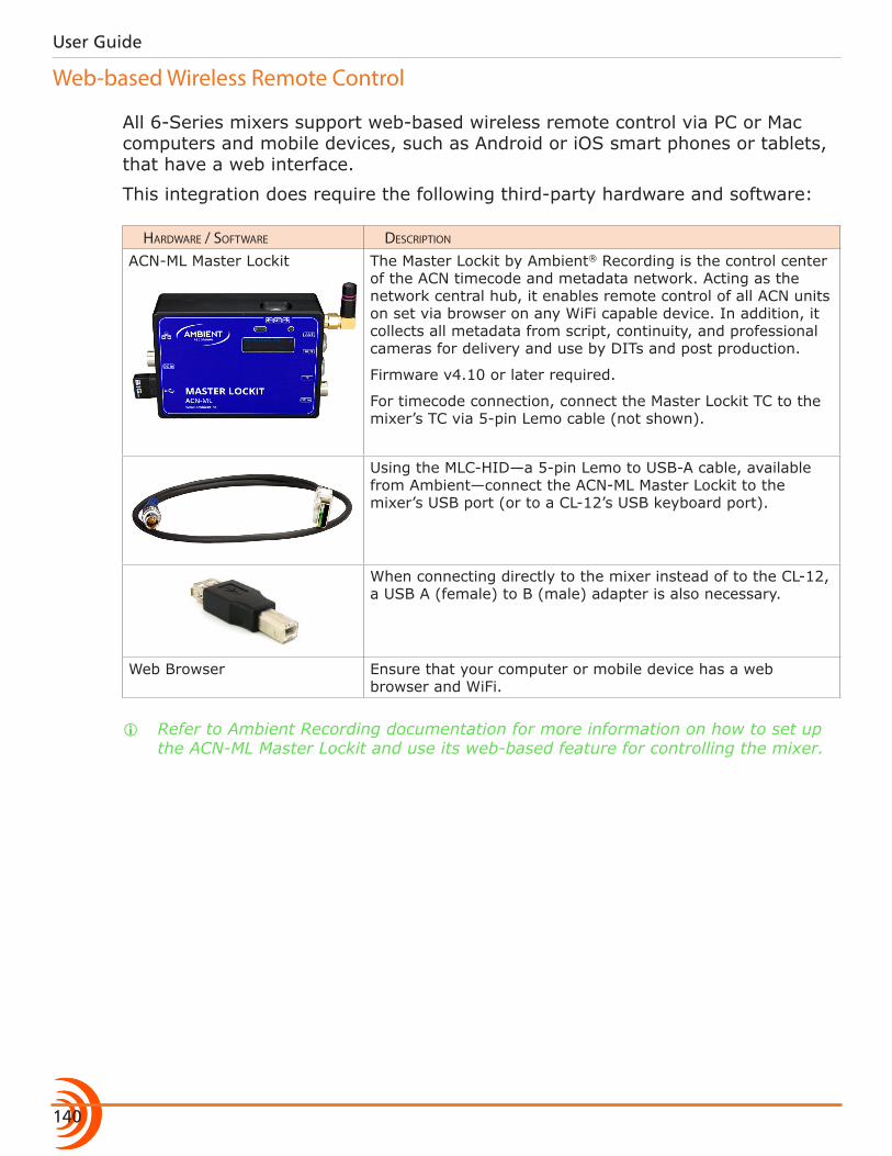
User Guide
140
Web-based Wireless Remote Control
All 6-Series mixers support web-based wireless remote control via PC or Mac computers and mobile devices, such as Android or iOS smart phones or tablets, that have a web interface.
This integration does require the following third-party hardware and software:
HarDware / soFtware Description
ACN-ML Master Lockit The Master Lockit by Ambient® Recording is the control center of the ACN timecode and metadata network. Acting as the network central hub, it enables remote control of all ACN units on set via browser on any WiFi capable device. In addition, it collects all metadata from script, continuity, and professional cameras for delivery and use by DITs and post production.
Firmware v4.10 or later required.
For timecode connection, connect the Master Lockit TC to the mixer’s TC via 5-pin Lemo cable (not shown).
Using the MLC-HID—a 5-pin Lemo to USB-A cable, available from Ambient—connect the ACN-ML Master Lockit to the mixer’s USB port (or to a CL-12’s USB keyboard port).
When connecting directly to the mixer instead of to the CL-12, a USB A (female) to B (male) adapter is also necessary.
Web Browser Ensure that your computer or mobile device has a web browser and WiFi.
i Refer to Ambient Recording documentation for more information on how to set up the ACN-ML Master Lockit and use its web-based feature for controlling the mixer.
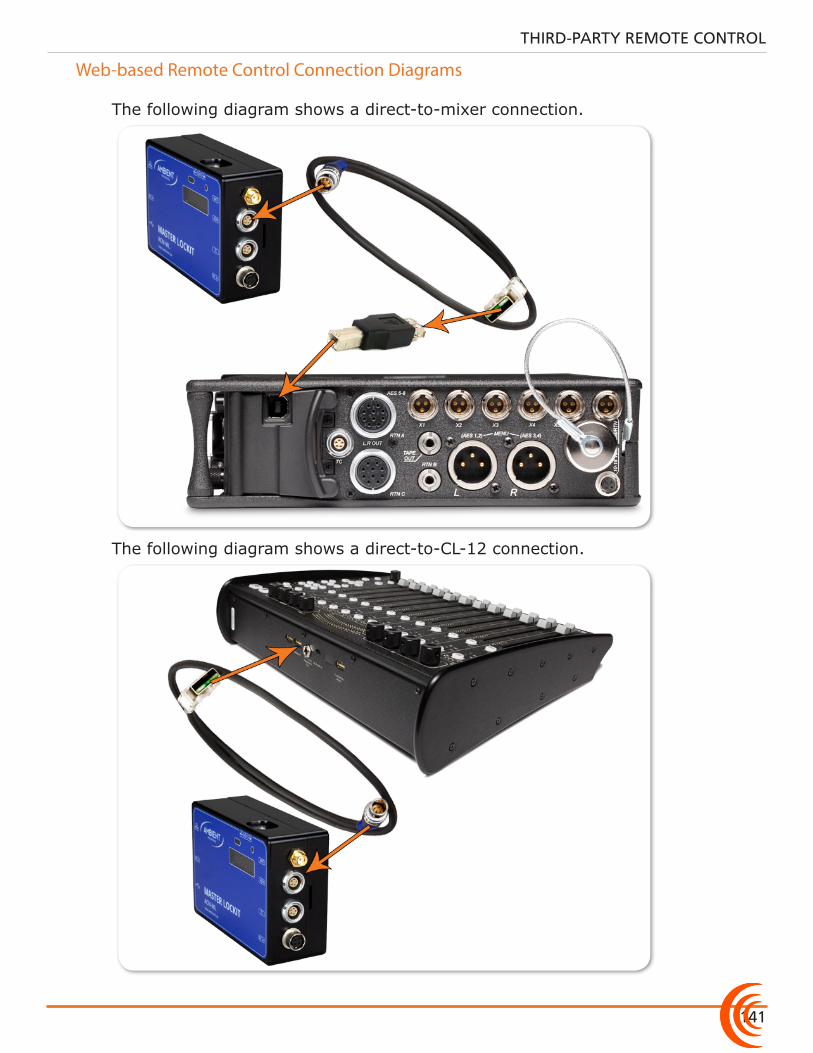
141
THIRD-PARTY REMOTE CONTROL
Web-based Remote Control Connection Diagrams
The following diagram shows a direct-to-mixer connection.
The following diagram shows a direct-to-CL-12 connection.
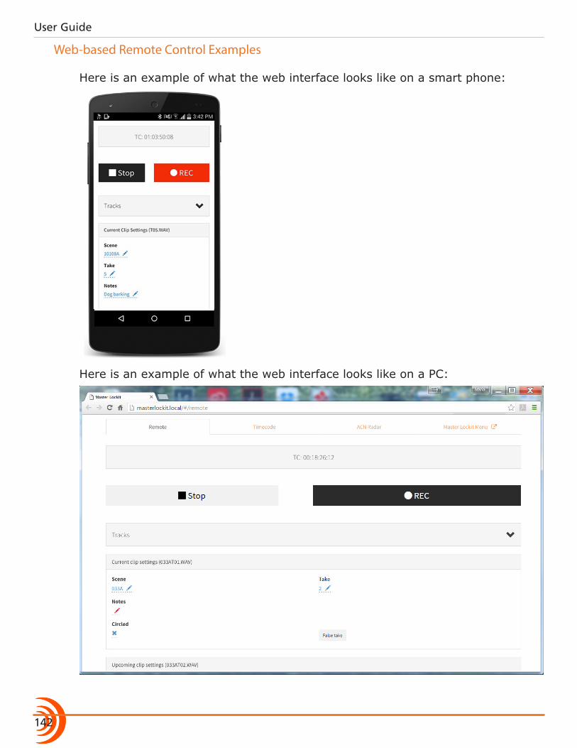
User Guide
142
Web-based Remote Control Examples
Here is an example of what the web interface looks like on a smart phone:
Here is an example of what the web interface looks like on a PC:

143
THIRD-PARTY REMOTE CONTROL
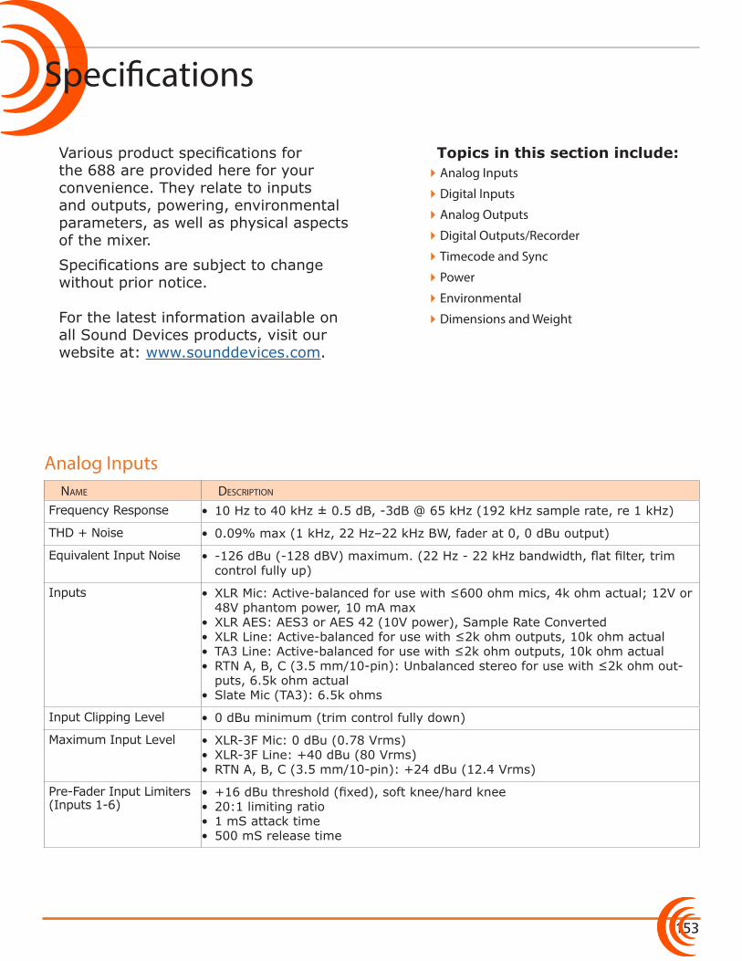
153
Topics in this section include:
Specifications
Various product specifications for the 688 are provided here for your convenience. They relate to inputs and outputs, powering, environmental parameters, as well as physical aspects of the mixer.
Specifications are subject to change without prior notice. For the latest information available on all Sound Devices products, visit our website at: www.sounddevices.com.
name Description
Frequency Response • 10 Hz to 40 kHz ± 0.5 dB, -3dB @ 65 kHz (192 kHz sample rate, re 1 kHz)
THD + Noise • 0.09% max (1 kHz, 22 Hz–22 kHz BW, fader at 0, 0 dBu output)
Equivalent Input Noise • -126 dBu (-128 dBV) maximum. (22 Hz - 22 kHz bandwidth, flat filter, trim control fully up)
Inputs • XLR Mic: Active-balanced for use with ≤600 ohm mics, 4k ohm actual; 12V or 48V phantom power, 10 mA max
• XLR AES: AES3 or AES 42 (10V power), Sample Rate Converted• XLR Line: Active-balanced for use with ≤2k ohm outputs, 10k ohm actual• TA3 Line: Active-balanced for use with ≤2k ohm outputs, 10k ohm actual• RTN A, B, C (3.5 mm/10-pin): Unbalanced stereo for use with ≤2k ohm out-
puts, 6.5k ohm actual• Slate Mic (TA3): 6.5k ohms
Input Clipping Level • 0 dBu minimum (trim control fully down)
Maximum Input Level • XLR-3F Mic: 0 dBu (0.78 Vrms)• XLR-3F Line: +40 dBu (80 Vrms)• RTN A, B, C (3.5 mm/10-pin): +24 dBu (12.4 Vrms)
Pre-Fader Input Limiters (Inputs 1-6)
• +16 dBu threshold (fixed), soft knee/hard knee• 20:1 limiting ratio• 1 mS attack time• 500 mS release time
�Analog Inputs
�Digital Inputs
�Analog Outputs
�Digital Outputs/Recorder
�Timecode and Sync
�Power
�Environmental
�Dimensions and Weight
Analog Inputs
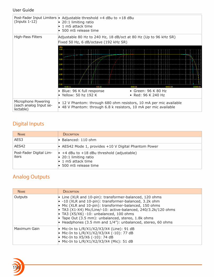
User Guide
154
Post-Fader Input Limiters (Inputs 1-12)
• Adjustable threshold +4 dBu to +18 dBu• 20:1 limiting ratio• 1 mS attack time• 500 mS release time
High-Pass Filters Adjustable 80 Hz to 240 Hz, 18 dB/oct at 80 Hz (Up to 96 kHz SR)Fixed 50 Hz, 6 dB/octave (192 kHz SR)
• Blue: 96 K full response• Yellow: 50 hz 192 K
• Green: 96 K 80 Hz• Red: 96 K 240 Hz
Microphone Powering (each analog Input se-lectable)
• 12 V Phantom: through 680 ohm resistors, 10 mA per mic available• 48 V Phantom: through 6.8 k resistors, 10 mA per mic available
Digital Inputs
name Description
AES3 • Balanced: 110 ohm
AES42 • AES42 Mode 1, provides +10 V Digital Phantom Power
Post-Fader Digital Lim-iters
• +4 dBu to +18 dBu threshold (adjustable)• 20:1 limiting ratio• 1 mS attack time• 500 mS release time
Analog Outputs
name Description
Outputs • Line (XLR and 10-pin): transformer-balanced, 120 ohms• -10 (XLR and 10-pin): transformer-balanced, 3.2k ohm• Mic (XLR and 10-pin): transformer-balanced, 150 ohms• TA3 (X1-X4) Mic/Line/-10: active-balanced, 240/3.2k/120 ohms• TA3 (X5/X6) -10: unbalanced, 100 ohms• Tape Out (3.5 mm): unbalanced, stereo, 1.8k ohms• Headphones (3.5 mm and 1/4”): unbalanced, stereo, 60 ohms
Maximum Gain • Mic-In to L/R/X1/X2/X3/X4 (Line): 91 dB• Mic-In to L/R/X1/X2/X3/X4 (-10): 77 dB• Mic-In to X5/X6 (-10): 74 dB• Mic-In to L/R/X1/X2/X3/X4 (Mic): 51 dB
155
SPECIFICATIONS
Headphone Max. Gain • 63 dB (Line 1-6 Input)• 44 dB (Line 7-12 Input)• 103 dB (Mic Input)
Line Output Clipping Level (1% THD) • 20 dBu minimum with 10k load
Output Limiters • L/R and X1/X2, adjustable threshold from +4 dBu to +18 dBu, soft knee/hard knee
• 20:1 limiting ratio• 1 mS attack time• 500 mS release time
Digital Outputs/Recorder
name Description
AES3 Output: • AES Out 1-4 on XLR-3M connectors• AES Out 5-8 on Hirose 10-pin connectors• 110 ohm, 2 V p-p, AES and S/PDIF compatible with RCA adapter
Sampling Frequency • 44.1 kHz• 47.952 kHz• 48 kHz• 48.048 kHz
• 88.2 kHz• 96 kHz• 192 kHz
A/D • 24 bit
A/D Dynamic Range • 114 dB, A-weighted, typical
Input Delay • Adjustable 0-30 mS for each input in 0.1 mS steps
Output Delay • Adjustable 0-417 mS (0-12.5 frames @ 30 fps) for each output in 1 mS steps
Media Type • Secure Digital Extended Capacity (SDXC)• Secure Digital High Capacity (SDHC)• Secure Digital (SD)• CompactFlash (CF)• FAT32 formatted (<32GB), exFAT for (>32GB), on-board memory card for-
matting
File Type • Record: WAV (Broadcast Wave File format), polyphonic or MP3• Playback: WAV (Broadcast Wave File format), polyphonic or MP3
Sampling Clock Accuracy • ± 0.2 ppm
Timecode and Sync
name Description
Modes Supported • Off• Rec Run
• Free Run• 24h Run
• External
Frame Rates • 23.976• 24• 25
• 29.97DF• 29.97ND
• 30DF• 30ND
User Guide
156
Accuracy • Ambient Generator: ±0.2ppm (0.5 frames per 24 hours)• Holds TC clock for two hours after main battery removal
Timecode Input • 20k ohm impedance• 0.3 V - 3.0 V p-p (–17 dBu - +3 dBu)
Timecode Output • Output: 1k ohm impedance• 3.0 V p-p (+12 dBu)
Wordclock • In/Out: Square wave; 10k/75 ohm, 1-5 V p-p input; 75 ohm, 5 V p-p output, at SR
• Termination: 75 ohm, Off
Power
name Description
External Power Supply • 10-18 V on locking 4-pin Hirose connector, pin-4 = (+), pin-1 = (-)• Mates with gold Hirose #HR10A-7P-4P (DigiKey# HR110-ND) or silver Hirose
#HR10-7P-4P (DigiKey# HR100-ND) locking connector
Internal Power Supply • Accepts 5 AA-sized (LR6) batteries, nominal (NiMH rechargeable recommend-ed)
PowerSafe • 10 second power reserve
Idle Current Draw • 680 mA at 12 V (8.16W) - Inputs 1-6 powered on, SD and CF inserted
Environmental
name Description
Operation and Storage • Operating: -20° C to 60° C• Storage: -40° C to 85° C• 0 to 90% relative humidity (non-condensing)
Dimensions and Weight
name Description
Size (H x W x D) • 2.1 in x 12.6 in x 7.8 in• 5.3 cm x 32 cm x 19.8 cm
Weight • 4 lbs 14 oz (unpackaged, without batteries)• 2.21 kg (unpackaged, without batteries)
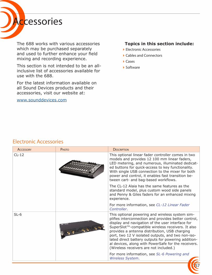
157
Topics in this section include:
Accessories
The 688 works with various accessories which may be purchased separately and used to further enhance your field mixing and recording experience.
This section is not intended to be an all-inclusive list of accessories available for use with the 688.
For the latest information available on all Sound Devices products and their accessories, visit our website at:
www.sounddevices.com
accessory pHoto Description
CL-12 This optional linear fader controller comes in two models and provides 12 100 mm linear faders, LED metering, and numerous, illuminated dedicat-ed buttons for quick-access to key functionality. With single USB connection to the mixer for both power and control, it enables fast transition be-tween cart- and bag-based workflows.
The CL-12 Alaia has the same features as the standard model, plus custom wood side panels and Penny & Giles faders for an enhanced mixing experience.
For more information, see CL-12 Linear Fader Controller.
SL-6 This optional powering and wireless system sim-plifies interconnection and provides better control, display and navigation of the user interface for SuperSlot™-compatible wireless receivers. It also provides a antenna distribution, USB charging port, two 12 V isolated outputs, and two non-iso-lated direct battery outputs for powering addition-al devices, along with PowerSafe for the receivers. (Wireless receivers are not included.)
For more information, see SL-6 Powering and Wireless System.
�Electronic Accessories
�Cables and Connectors
�Cases
�Software
Electronic Accessories
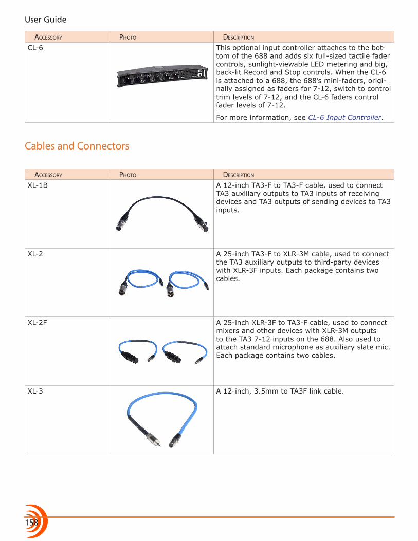
User Guide
158
accessory pHoto Description
CL-6 This optional input controller attaches to the bot-tom of the 688 and adds six full-sized tactile fader controls, sunlight-viewable LED metering and big, back-lit Record and Stop controls. When the CL-6 is attached to a 688, the 688’s mini-faders, origi-nally assigned as faders for 7-12, switch to control trim levels of 7-12, and the CL-6 faders control fader levels of 7-12.
For more information, see CL-6 Input Controller.
Cables and Connectors
accessory pHoto Description
XL-1B A 12-inch TA3-F to TA3-F cable, used to connect TA3 auxiliary outputs to TA3 inputs of receiving devices and TA3 outputs of sending devices to TA3 inputs.
XL-2 A 25-inch TA3-F to XLR-3M cable, used to connect the TA3 auxiliary outputs to third-party devices with XLR-3F inputs. Each package contains two cables.
XL-2F A 25-inch XLR-3F to TA3-F cable, used to connect mixers and other devices with XLR-3M outputs to the TA3 7-12 inputs on the 688. Also used to attach standard microphone as auxiliary slate mic. Each package contains two cables.
XL-3 A 12-inch, 3.5mm to TA3F link cable.
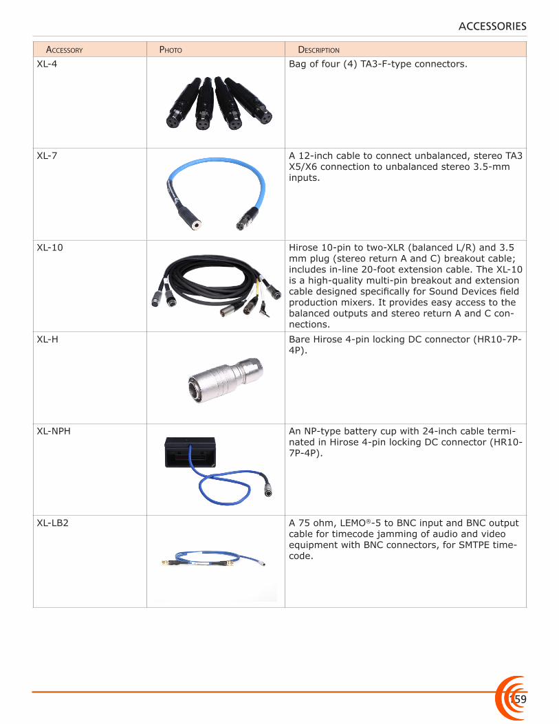
159
ACCESSORIES
accessory pHoto Description
XL-4 Bag of four (4) TA3-F-type connectors.
XL-7 A 12-inch cable to connect unbalanced, stereo TA3 X5/X6 connection to unbalanced stereo 3.5-mm inputs.
XL-10 Hirose 10-pin to two-XLR (balanced L/R) and 3.5 mm plug (stereo return A and C) breakout cable; includes in-line 20-foot extension cable. The XL-10 is a high-quality multi-pin breakout and extension cable designed specifically for Sound Devices field production mixers. It provides easy access to the balanced outputs and stereo return A and C con-nections.
XL-H Bare Hirose 4-pin locking DC connector (HR10-7P-4P).
XL-NPH An NP-type battery cup with 24-inch cable termi-nated in Hirose 4-pin locking DC connector (HR10-7P-4P).
XL-LB2 A 75 ohm, LEMO®-5 to BNC input and BNC output cable for timecode jamming of audio and video equipment with BNC connectors, for SMTPE time-code.
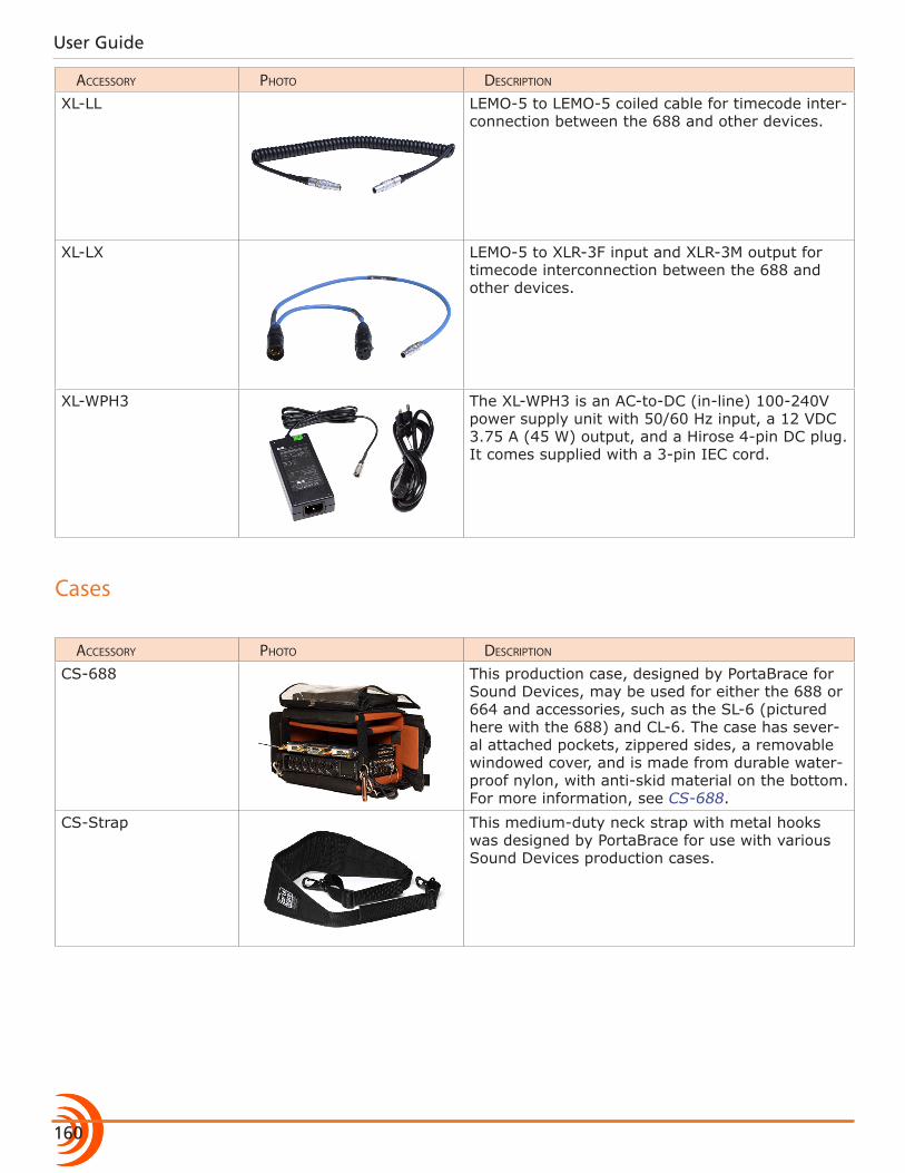
User Guide
160
accessory pHoto Description
XL-LL LEMO-5 to LEMO-5 coiled cable for timecode inter-connection between the 688 and other devices.
XL-LX LEMO-5 to XLR-3F input and XLR-3M output for timecode interconnection between the 688 and other devices.
XL-WPH3 The XL-WPH3 is an AC-to-DC (in-line) 100-240V power supply unit with 50/60 Hz input, a 12 VDC 3.75 A (45 W) output, and a Hirose 4-pin DC plug. It comes supplied with a 3-pin IEC cord.
Cases
accessory pHoto Description
CS-688 This production case, designed by PortaBrace for Sound Devices, may be used for either the 688 or 664 and accessories, such as the SL-6 (pictured here with the 688) and CL-6. The case has sever-al attached pockets, zippered sides, a removable windowed cover, and is made from durable water-proof nylon, with anti-skid material on the bottom. For more information, see CS-688.
CS-Strap This medium-duty neck strap with metal hooks was designed by PortaBrace for use with various Sound Devices production cases.
161
ACCESSORIES
Software
accessory pHoto Description
Wave Agent Sound Devices Wave Agent, a file librarian for computers, provides a comprehensive range of tools for preparing audio files for problem-free passage through complex production workflows.
For more a free download, visit: www.waveagent.com

User Guide
162
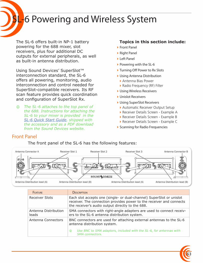
163
Topics in this section include:
Front Panel
The SL-6 offers built-in NP-1 battery powering for the 688 mixer, slot receivers, plus four additional DC outputs for external peripherals, as well as built-in antenna distribution. Using Sound Devices’ SuperSlot™ interconnection standard, the SL-6 offers all powering, monitoring, audio interconnection and control needed for SuperSlot-compatible receivers. Its RF scan feature provides quick coordination and configuration of SuperSlot Rx.
i The SL-6 attaches to the top panel of the 688. Instructions for attaching the SL-6 to your mixer is provided in the SL-6 Quick Start Guide, shipped with the accessory and as a PDF download from the Sound Devices website.
The front panel of the SL-6 has the following features:
Antenna Distribution lead (B) Antenna Distribution lead (A)Antenna Distribution lead (A)
Antenna Connector BReceiver Slot 2 Receiver Slot 3Receiver Slot 1Antenna Connector A
Antenna Distribution lead (B)
Feature Description
Receiver Slots Each slot accepts one (single- or dual-channel) SuperSlot or unislot receiver. The connection provides power to the receiver and connects the receiver’s audio output directly to the 688.
Antenna Distribution leads
SMA connectors with right-angle adapters are used to connect receiv-ers to the SL-6 antenna distribution system.
Antenna Connectors BNC connectors are used for attaching external antennas to the SL-6 antenna distribution system.
i Use BNC to SMA adapters, included with the SL-6, for antennas with SMA connectors.
�Front Panel
�Right Panel
�Left Panel
�Powering with the SL-6
�Turning Off Power to Rx Slots
�Using Antenna Distribution �Antenna Bias Power �Radio Frequency (RF) Filter
�Using Wireless Receivers
�Unislot Receivers
�Using SuperSlot Receivers �Automatic Receiver Output Setup �Receiver Details Screen - Example A �Receiver Details Screen - Example B �Receiver Details Screen - Example C
�Scanning for Radio Frequencies
SL-6 Powering and Wireless System
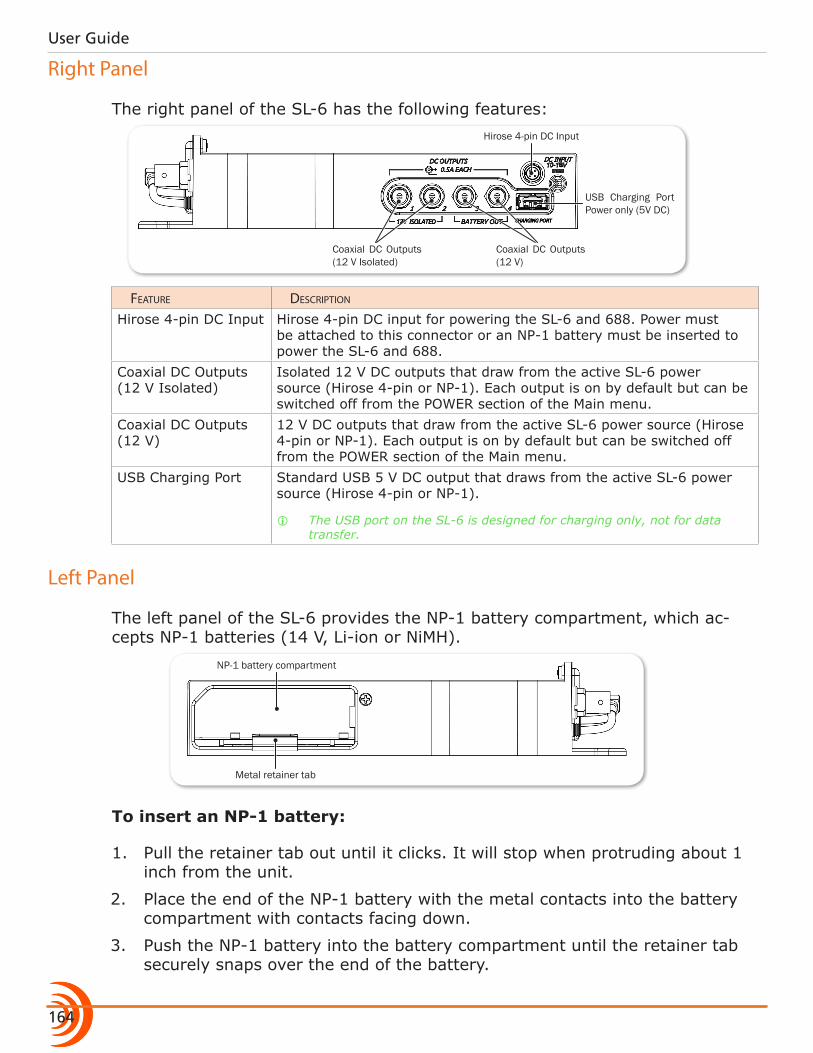
User Guide
164
Right Panel
The right panel of the SL-6 has the following features:
Coaxial DC Outputs (12 V)
Coaxial DC Outputs (12 V Isolated)
Hirose 4-pin DC Input
USB Charging Port Power only (5V DC)
Feature Description
Hirose 4-pin DC Input Hirose 4-pin DC input for powering the SL-6 and 688. Power must be attached to this connector or an NP-1 battery must be inserted to power the SL-6 and 688.
Coaxial DC Outputs (12 V Isolated)
Isolated 12 V DC outputs that draw from the active SL-6 power source (Hirose 4-pin or NP-1). Each output is on by default but can be switched off from the POWER section of the Main menu.
Coaxial DC Outputs (12 V)
12 V DC outputs that draw from the active SL-6 power source (Hirose 4-pin or NP-1). Each output is on by default but can be switched off from the POWER section of the Main menu.
USB Charging Port Standard USB 5 V DC output that draws from the active SL-6 power source (Hirose 4-pin or NP-1).
i The USB port on the SL-6 is designed for charging only, not for data transfer.
Left Panel
The left panel of the SL-6 provides the NP-1 battery compartment, which ac-cepts NP-1 batteries (14 V, Li-ion or NiMH).
NP-1 battery compartment
Metal retainer tab
To insert an NP-1 battery:
1. Pull the retainer tab out until it clicks. It will stop when protruding about 1 inch from the unit.
2. Place the end of the NP-1 battery with the metal contacts into the battery compartment with contacts facing down.
3. Push the NP-1 battery into the battery compartment until the retainer tab securely snaps over the end of the battery.
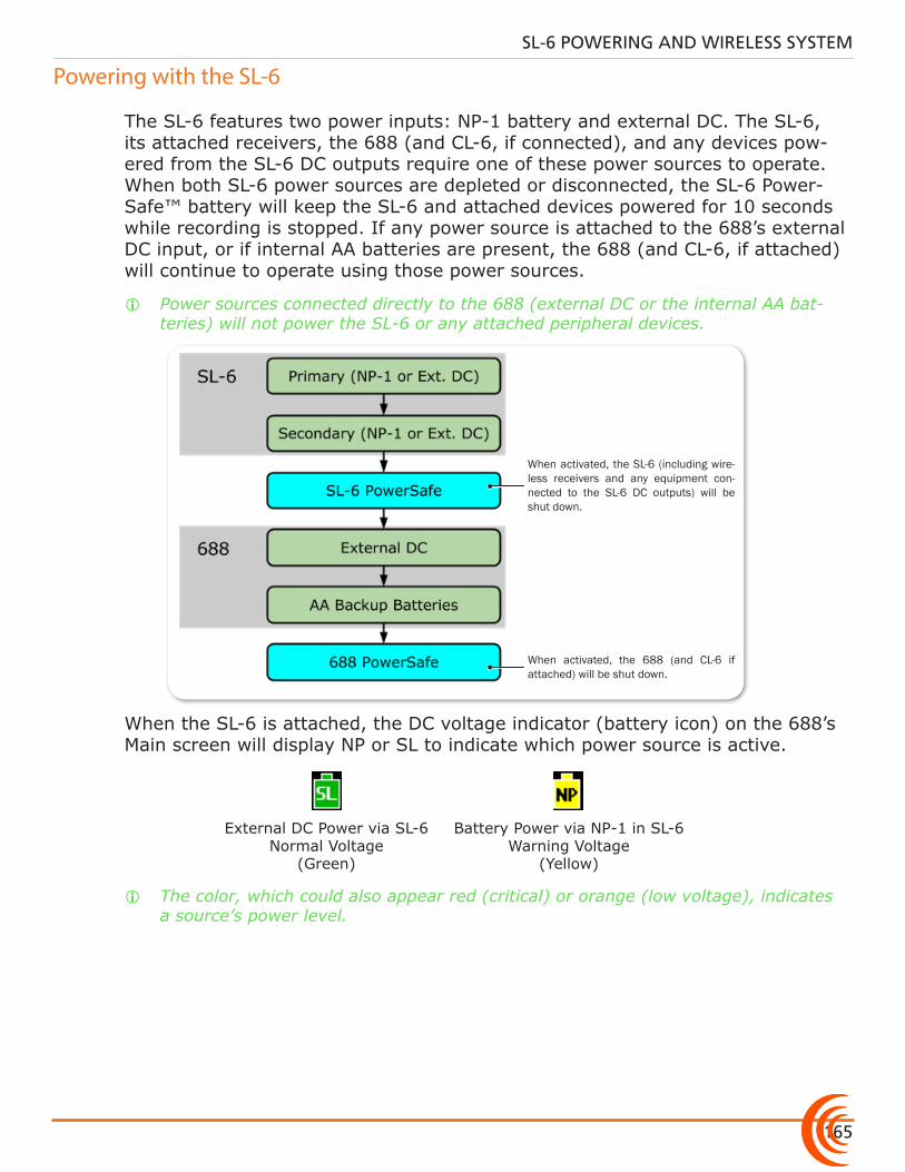
165
SL-6 POWERING AND WIRELESS SYSTEM
Powering with the SL-6
The SL-6 features two power inputs: NP-1 battery and external DC. The SL-6, its attached receivers, the 688 (and CL-6, if connected), and any devices pow-ered from the SL-6 DC outputs require one of these power sources to operate. When both SL-6 power sources are depleted or disconnected, the SL-6 Power-Safe™ battery will keep the SL-6 and attached devices powered for 10 seconds while recording is stopped. If any power source is attached to the 688’s external DC input, or if internal AA batteries are present, the 688 (and CL-6, if attached) will continue to operate using those power sources.
i Power sources connected directly to the 688 (external DC or the internal AA bat-teries) will not power the SL-6 or any attached peripheral devices.
When activated, the SL-6 (including wire-less receivers and any equipment con-nected to the SL-6 DC outputs) will be shut down.
When activated, the 688 (and CL-6 if attached) will be shut down.
When the SL-6 is attached, the DC voltage indicator (battery icon) on the 688’s Main screen will display NP or SL to indicate which power source is active.
External DC Power via SL-6 Normal Voltage
(Green)
Battery Power via NP-1 in SL-6 Warning Voltage
(Yellow)
i The color, which could also appear red (critical) or orange (low voltage), indicates a source’s power level.
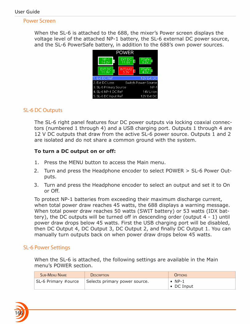
User Guide
166
Power Screen
When the SL-6 is attached to the 688, the mixer’s Power screen displays the voltage level of the attached NP-1 battery, the SL-6 external DC power source, and the SL-6 PowerSafe battery, in addition to the 688’s own power sources.
SL-6 DC Outputs
The SL-6 right panel features four DC power outputs via locking coaxial connec-tors (numbered 1 through 4) and a USB charging port. Outputs 1 through 4 are 12 V DC outputs that draw from the active SL-6 power source. Outputs 1 and 2 are isolated and do not share a common ground with the system.
To turn a DC output on or off:
1. Press the MENU button to access the Main menu.
2. Turn and press the Headphone encoder to select POWER > SL-6 Power Out-puts.
3. Turn and press the Headphone encoder to select an output and set it to On or Off.
To protect NP-1 batteries from exceeding their maximum discharge current, when total power draw reaches 45 watts, the 688 displays a warning message. When total power draw reaches 50 watts (SWIT battery) or 53 watts (IDX bat-tery), the DC outputs will be turned off in descending order (output 4 - 1) until power draw drops below 45 watts. First the USB charging port will be disabled, then DC Output 4, DC Output 3, DC Output 2, and finally DC Output 1. You can manually turn outputs back on when power draw drops below 45 watts.
SL-6 Power Settings
When the SL-6 is attached, the following settings are available in the Main menu’s POWER section.
sub-menu name Description options
SL-6 Primary Source Selects primary power source. • NP-1• DC Input
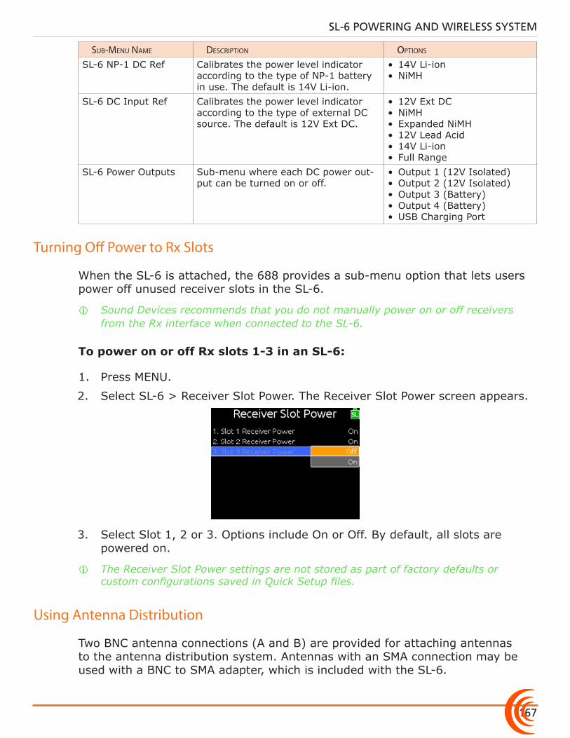
167
SL-6 POWERING AND WIRELESS SYSTEM
sub-menu name Description options
SL-6 NP-1 DC Ref Calibrates the power level indicator according to the type of NP-1 battery in use. The default is 14V Li-ion.
• 14V Li-ion• NiMH
SL-6 DC Input Ref Calibrates the power level indicator according to the type of external DC source. The default is 12V Ext DC.
• 12V Ext DC• NiMH• Expanded NiMH• 12V Lead Acid• 14V Li-ion• Full Range
SL-6 Power Outputs Sub-menu where each DC power out-put can be turned on or off.
• Output 1 (12V Isolated)• Output 2 (12V Isolated)• Output 3 (Battery)• Output 4 (Battery)• USB Charging Port
Turning Off Power to Rx Slots
When the SL-6 is attached, the 688 provides a sub-menu option that lets users power off unused receiver slots in the SL-6.
i Sound Devices recommends that you do not manually power on or off receivers from the Rx interface when connected to the SL-6.
To power on or off Rx slots 1-3 in an SL-6:
1. Press MENU.
2. Select SL-6 > Receiver Slot Power. The Receiver Slot Power screen appears.
3. Select Slot 1, 2 or 3. Options include On or Off. By default, all slots are powered on.
i The Receiver Slot Power settings are not stored as part of factory defaults or custom configurations saved in Quick Setup files.
Using Antenna Distribution
Two BNC antenna connections (A and B) are provided for attaching antennas to the antenna distribution system. Antennas with an SMA connection may be used with a BNC to SMA adapter, which is included with the SL-6.
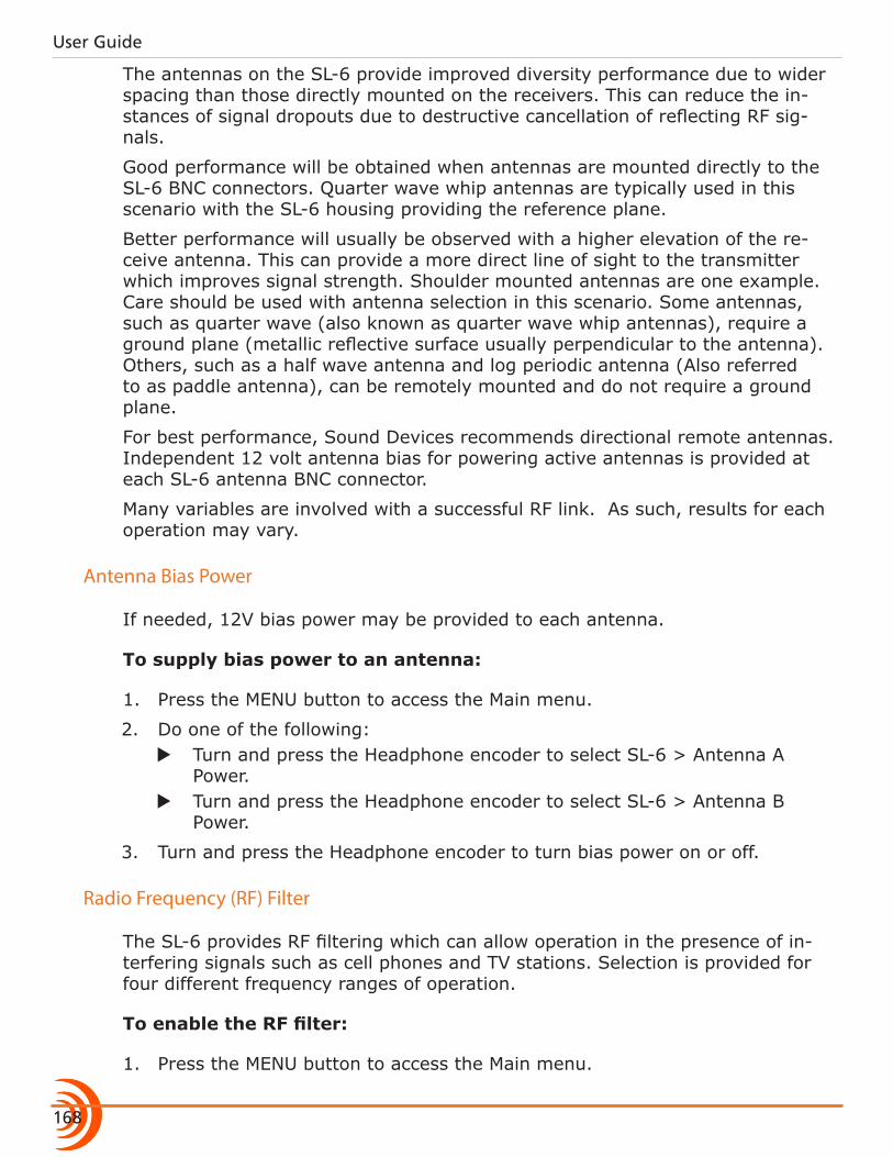
User Guide
168
The antennas on the SL-6 provide improved diversity performance due to wider spacing than those directly mounted on the receivers. This can reduce the in-stances of signal dropouts due to destructive cancellation of reflecting RF sig-nals.
Good performance will be obtained when antennas are mounted directly to the SL-6 BNC connectors. Quarter wave whip antennas are typically used in this scenario with the SL-6 housing providing the reference plane.
Better performance will usually be observed with a higher elevation of the re-ceive antenna. This can provide a more direct line of sight to the transmitter which improves signal strength. Shoulder mounted antennas are one example. Care should be used with antenna selection in this scenario. Some antennas, such as quarter wave (also known as quarter wave whip antennas), require a ground plane (metallic reflective surface usually perpendicular to the antenna). Others, such as a half wave antenna and log periodic antenna (Also referred to as paddle antenna), can be remotely mounted and do not require a ground plane.
For best performance, Sound Devices recommends directional remote antennas. Independent 12 volt antenna bias for powering active antennas is provided at each SL-6 antenna BNC connector.
Many variables are involved with a successful RF link. As such, results for each operation may vary.
Antenna Bias Power
If needed, 12V bias power may be provided to each antenna.
To supply bias power to an antenna:
1. Press the MENU button to access the Main menu.
2. Do one of the following: X Turn and press the Headphone encoder to select SL-6 > Antenna A
Power. X Turn and press the Headphone encoder to select SL-6 > Antenna B
Power.
3. Turn and press the Headphone encoder to turn bias power on or off.
Radio Frequency (RF) Filter
The SL-6 provides RF filtering which can allow operation in the presence of in-terfering signals such as cell phones and TV stations. Selection is provided for four different frequency ranges of operation.
To enable the RF filter:
1. Press the MENU button to access the Main menu.
169
SL-6 POWERING AND WIRELESS SYSTEM
2. Turn and press the Headphone encoder to select SL-6 > Antenna Filter.
3. Turn and press the Headphone encoder to select a filter range. Options include: Wideband, 470-700 MHz, 470-590 MHz, and 580-700 MHz.
Wideband represents the guaranteed range of operation of an SL-6. Signals above and below these frequencies may be usable. Filter selection depends on the presence and magnitude of interfering signals. Generally, the nar-rowest filter setting will give the best performance.
Using Wireless Receivers
The SL-6 supports SuperSlot and unislot receivers on a DB-25 connection. The SL-6 receiver slots provide power and audio connection to both types of receiv-ers. Additionally, SuperSlot receivers can be controlled from the 688 interface.
To connect antennas to the SL-6:
X Connect each antenna directly to each BNC Antenna Connector on the SL-6.
To connect a receiver to the SL-6:
i Mounting procedures for receiver models may vary. Refer to the receiver manufac-turer’s documentation for your receiver and follow the specific mounting instruc-tions.
⚠ Neither the Lectrosonics SRb5P nor SRc5P can be fitted into slot 1 of the SL-6. Using the blue spacer (provided with the receivers), both can be connected to slot 2 or 3.
1. Power off the 688.
2. The SL-6 ships with rubber slot protectors that hold the SMA antenna con-nectors with right-angle adapters secure during transport. These must be removed prior to use, so remove the connector, then pull the rubber cover off to expose the chosen slot.
i Do not discard protectors; Sound Devices recommends storing the connectors with their right-angle adapters in the rubber slot protectors when not in use.
3. Slide the receiver into slot on the SL-6. If necessary, use the provided spacer.
4. Screw the four mounting screws through the receiver and into the SL-6.
⚠ Use only the screws provided with the receiver. Longer screws can damage the SL-6.
5. Attach each antenna distribution lead to the receiver by screwing the SMA connector on both sides of the receiver.
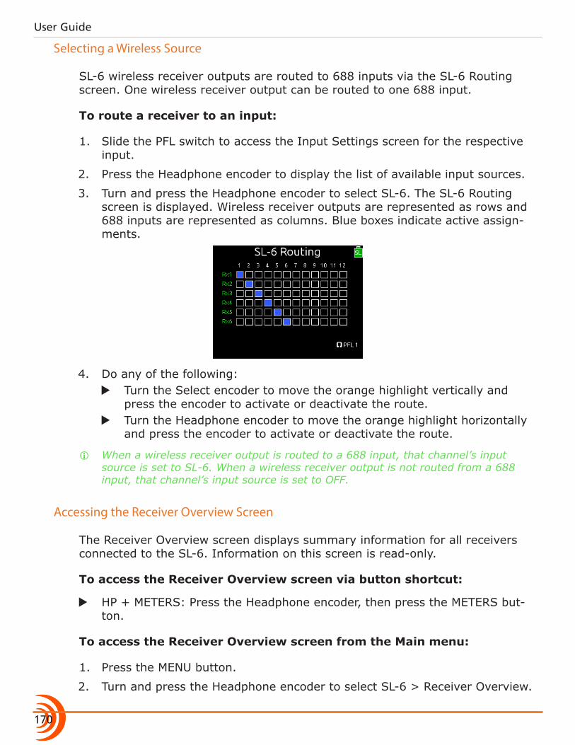
User Guide
170
Selecting a Wireless Source
SL-6 wireless receiver outputs are routed to 688 inputs via the SL-6 Routing screen. One wireless receiver output can be routed to one 688 input.
To route a receiver to an input:
1. Slide the PFL switch to access the Input Settings screen for the respective input.
2. Press the Headphone encoder to display the list of available input sources.
3. Turn and press the Headphone encoder to select SL-6. The SL-6 Routing screen is displayed. Wireless receiver outputs are represented as rows and 688 inputs are represented as columns. Blue boxes indicate active assign-ments.
4. Do any of the following: X Turn the Select encoder to move the orange highlight vertically and
press the encoder to activate or deactivate the route. X Turn the Headphone encoder to move the orange highlight horizontally
and press the encoder to activate or deactivate the route.
i When a wireless receiver output is routed to a 688 input, that channel’s input source is set to SL-6. When a wireless receiver output is not routed from a 688 input, that channel’s input source is set to OFF.
Accessing the Receiver Overview Screen
The Receiver Overview screen displays summary information for all receivers connected to the SL-6. Information on this screen is read-only.
To access the Receiver Overview screen via button shortcut:
X HP + METERS: Press the Headphone encoder, then press the METERS but-ton.
To access the Receiver Overview screen from the Main menu:
1. Press the MENU button.
2. Turn and press the Headphone encoder to select SL-6 > Receiver Overview.
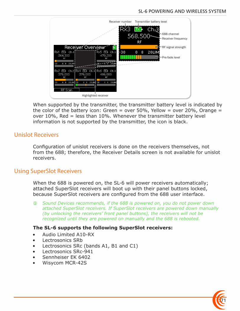
171
SL-6 POWERING AND WIRELESS SYSTEM
Highlighted receiver
688 channel
Receiver number Transmitter battery level
Receiver frequency
RF signal strength
Pre-fade level
When supported by the transmitter, the transmitter battery level is indicated by the color of the battery icon: Green = over 50%, Yellow = over 20%, Orange = over 10%, Red = less than 10%. Whenever the transmitter battery level information is not supported by the transmitter, the icon is black.
Unislot Receivers
Configuration of unislot receivers is done on the receivers themselves, not from the 688; therefore, the Receiver Details screen is not available for unislot receivers.
Using SuperSlot Receivers
When the 688 is powered on, the SL-6 will power receivers automatically; attached SuperSlot receivers will boot up with their panel buttons locked, because SuperSlot receivers are configured from the 688 user interface.
i Sound Devices recommends, if the 688 is powered on, you do not power down attached SuperSlot receivers. If SuperSlot receivers are powered down manually (by unlocking the receivers’ front panel buttons), the receivers will not be recognized until they are powered on manually and the 688 is rebooted.
The SL-6 supports the following SuperSlot receivers:• Audio Limited A10-RX• Lectrosonics SRb• Lectrosonics SRc (bands A1, B1 and C1) • Lectrosonics SRc-941• Sennheiser EK 6402• Wisycom MCR-42S
User Guide
172
Detailed information for each attached SuperSlot receiver is displayed on the 688 via a Receiver Details screen. Adjustments to SuperSlot receivers may be made from this screen, including RF scanning and frequency assignment. See Scanning for Radio Frequencies for more information.
The screen’s title will show the type or model of the receiver. Based on your receiver, information on screen could vary; refer to the receiver manufacturer’s documentation provided with your receiver(s) for more information.
To access Receiver Details screens from the Receiver Overview screen:
1. METERS + HP: Press the METERS button, then push in the Headphone en-coder to access the Receiver Overview screen.
2. Turn and press the Headphone encoder to select a receiver.
To directly access a specific Receiver Details screen:
X HP + PFL (1-6): Press and hold the Headphone encoder, and then slide the PFL switch that corresponds to the receiver number and channel you want to view—left for even channels and right for odd channels.
For instance, to view the Receiver Details screen for channel 1 on the first slotted receiver, slide PFL 1 to the left. Slide the same switch right for chan-nel 2 on the first slotted receiver.
i This HP + PFL (1-6) shortcut bypasses the Receiver Overview screen that shows data for all slotted receivers.
Receiver tuning is presented uniquely, based on each manufacturer’s receiver model. Current tuning values are displayed in outlined boxes on the Receiver Details screen.
To adjust a receiver’s tuning:
1. Access the Receiver Details screen.
2. Turn and press the Headphone encoder to enter editing mode for the select-ed field. The background color of the field will become blue to indicate edit-ing mode.
3. Turn the Headphone encoder to adjust the value.
4. Press the Headphone encoder to accept the value.
For more information regarding Receiver Details screens, see Receiver Details Screen - Example A, Receiver Details Screen - Example B, and Receiver Details Screen - Example C.
Automatic Receiver Output Setup
When using SuperSlot receivers with the SL-6, some receiver settings are auto-matically set by the mixer for optimized performance.
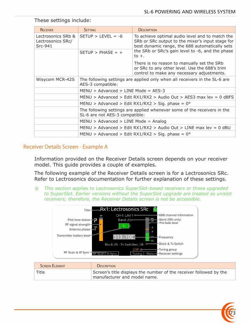
173
SL-6 POWERING AND WIRELESS SYSTEM
These settings include:
receiVer setting Description
Lectrosonics SRb & Lectrosonics SRc/Src-941
SETUP > LEVEL = -6 To achieve optimal audio level and to match the SRb or SRc output to the mixer’s input stage for best dynamic range, the 688 automatically sets the SRb or SRc’s gain level to -6, and the phase to +.
There is no reason to manually set the SRb or SRc to any other level. Use the 688’s trim control to make any necessary adjustments.
SETUP > PHASE = +
Wisycom MCR-42S The following settings are applied only when all receivers in the SL-6 are AES-3 compatible:MENU > Advanced > LINE Mode = AES-3MENU > Advanced > Edit RX1/RX2 > Audio Out > AES3 max lev = 0 dBFSMENU > Advanced > Edit RX1/RX2 > Sig. phase = 0°The following settings are applied whenever some of the receivers in the SL-6 are not AES-3 compatible:MENU > Advanced > LINE Mode = AnalogMENU > Advanced > Edit RX1/RX2 > Audio Out > LINE max lev = 0 dBUMENU > Advanced > Edit RX1/RX2 > Sig. phase = 0°
Receiver Details Screen - Example A
Information provided on the Receiver Details screen depends on your receiver model. This guide provides a couple of examples.
The following example of the Receiver Details screen is for a Lectrosonics SRc. Refer to Lectrosonics documentation for further explanation of these settings.
i This section applies to Lectrosonics SuperSlot-based receivers or those upgraded to SuperSlot. Earlier versions without the SuperSlot upgrade are treated as unislot receivers; therefore, the Receiver Details screen is not be accessible.
Pre-fade level
Frequency
Receiver settings
Transmitter battery level
RF signal strength
Title
Antenna phase
688 channel information
Block & Tx Switch
Tuning group
Pilot tone status
RF Scan & IR Sync
Band (SRc only)
screen eLement Description
Title Screen’s title displays the number of the receiver followed by the manufacturer and model name.
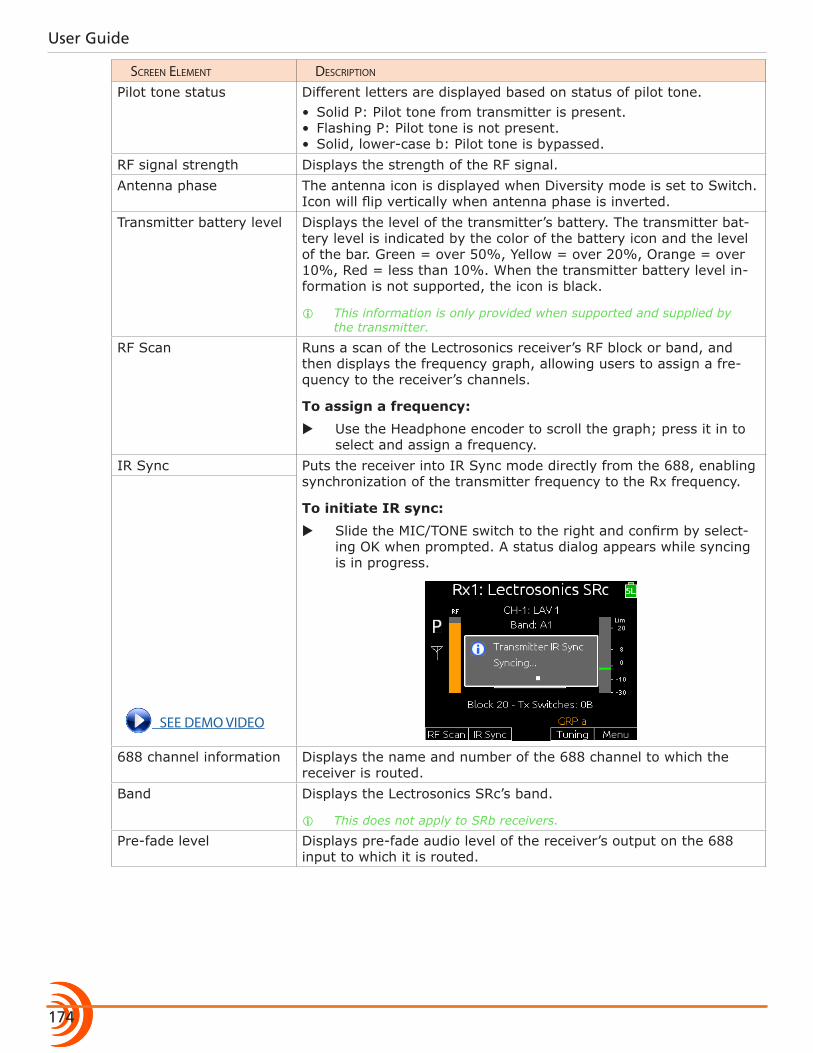
User Guide
174
screen eLement Description
Pilot tone status Different letters are displayed based on status of pilot tone.• Solid P: Pilot tone from transmitter is present.• Flashing P: Pilot tone is not present.• Solid, lower-case b: Pilot tone is bypassed.
RF signal strength Displays the strength of the RF signal.Antenna phase The antenna icon is displayed when Diversity mode is set to Switch.
Icon will flip vertically when antenna phase is inverted.Transmitter battery level Displays the level of the transmitter’s battery. The transmitter bat-
tery level is indicated by the color of the battery icon and the level of the bar. Green = over 50%, Yellow = over 20%, Orange = over 10%, Red = less than 10%. When the transmitter battery level in-formation is not supported, the icon is black.
i This information is only provided when supported and supplied by the transmitter.
RF Scan Runs a scan of the Lectrosonics receiver’s RF block or band, and then displays the frequency graph, allowing users to assign a fre-quency to the receiver’s channels.
To assign a frequency:
X Use the Headphone encoder to scroll the graph; press it in to select and assign a frequency.
IR Sync Puts the receiver into IR Sync mode directly from the 688, enabling synchronization of the transmitter frequency to the Rx frequency.
To initiate IR sync:
X Slide the MIC/TONE switch to the right and confirm by select-ing OK when prompted. A status dialog appears while syncing is in progress.
see Demo ViDeo
688 channel information Displays the name and number of the 688 channel to which the receiver is routed.
Band Displays the Lectrosonics SRc’s band.
i This does not apply to SRb receivers.
Pre-fade level Displays pre-fade audio level of the receiver’s output on the 688 input to which it is routed.
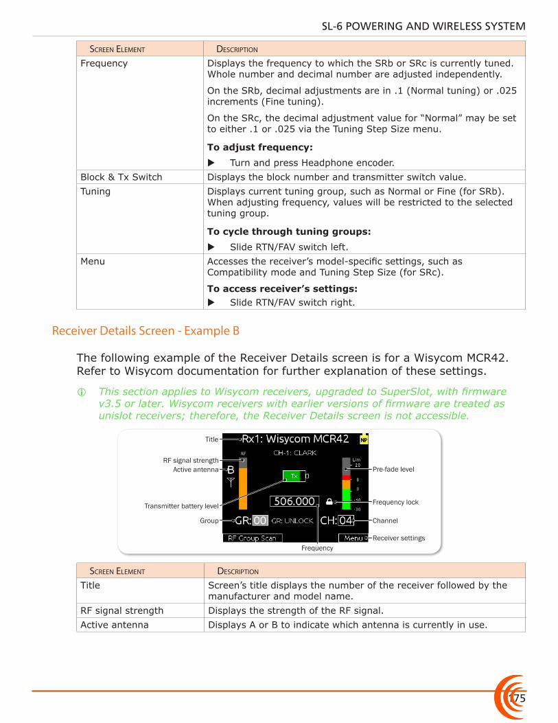
175
SL-6 POWERING AND WIRELESS SYSTEM
screen eLement Description
Frequency Displays the frequency to which the SRb or SRc is currently tuned. Whole number and decimal number are adjusted independently.
On the SRb, decimal adjustments are in .1 (Normal tuning) or .025 increments (Fine tuning).
On the SRc, the decimal adjustment value for “Normal” may be set to either .1 or .025 via the Tuning Step Size menu.
To adjust frequency:
X Turn and press Headphone encoder.Block & Tx Switch Displays the block number and transmitter switch value.Tuning Displays current tuning group, such as Normal or Fine (for SRb).
When adjusting frequency, values will be restricted to the selected tuning group.
To cycle through tuning groups:
X Slide RTN/FAV switch left.Menu Accesses the receiver’s model-specific settings, such as
Compatibility mode and Tuning Step Size (for SRc).
To access receiver’s settings: X Slide RTN/FAV switch right.
Receiver Details Screen - Example B
The following example of the Receiver Details screen is for a Wisycom MCR42. Refer to Wisycom documentation for further explanation of these settings.
i This section applies to Wisycom receivers, upgraded to SuperSlot, with firmware v3.5 or later. Wisycom receivers with earlier versions of firmware are treated as unislot receivers; therefore, the Receiver Details screen is not accessible.
Pre-fade level
FrequencyReceiver settings
Transmitter battery level
RF signal strength
Title
Channel
Frequency lock
Group
Active antenna
screen eLement Description
Title Screen’s title displays the number of the receiver followed by the manufacturer and model name.
RF signal strength Displays the strength of the RF signal.Active antenna Displays A or B to indicate which antenna is currently in use.
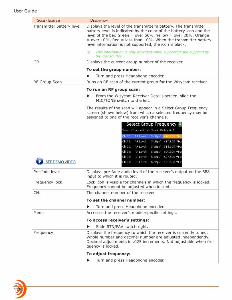
User Guide
176
screen eLement Description
Transmitter battery level Displays the level of the transmitter’s battery. The transmitter battery level is indicated by the color of the battery icon and the level of the bar. Green = over 50%, Yellow = over 20%, Orange = over 10%, Red = less than 10%. When the transmitter battery level information is not supported, the icon is black.
i This information is only provided when supported and supplied by the transmitter.
GR: Displays the current group number of the receiver.
To set the group number:
X Turn and press Headphone encoder.RF Group Scan Runs an RF scan of the current group for the Wisycom receiver.
To run an RF group scan:
X From the Wisycom Receiver Details screen, slide the MIC/TONE switch to the left.
The results of the scan will appear in a Select Group Frequency screen (shown below) from which a selected frequency may be assigned to one of the receiver’s channels.
see Demo ViDeo
Pre-fade level Displays pre-fade audio level of the receiver’s output on the 688 input to which it is routed.
Frequency lock Lock icon is visible for channels in which the frequency is locked. Frequency cannot be adjusted when locked.
CH: The channel number of the receiver.
To set the channel number:
X Turn and press Headphone encoder.Menu Accesses the receiver’s model-specific settings.
To access receiver’s settings:
X Slide RTN/FAV switch right.Frequency Displays the frequency to which the receiver is currently tuned.
Whole number and decimal number are adjusted independently. Decimal adjustments in .025 increments. Not adjustable when fre-quency is locked.
To adjust frequency:
X Turn and press Headphone encoder.
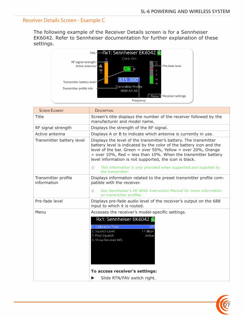
177
SL-6 POWERING AND WIRELESS SYSTEM
Receiver Details Screen - Example C
The following example of the Receiver Details screen is for a Sennheiser EK6042. Refer to Sennheiser documentation for further explanation of these settings.
Pre-fade level
FrequencyReceiver settings
Transmitter battery level
RF signal strength
Title
Transmitter profile info
Active antenna
screen eLement Description
Title Screen’s title displays the number of the receiver followed by the manufacturer and model name.
RF signal strength Displays the strength of the RF signal.Active antenna Displays A or B to indicate which antenna is currently in use.Transmitter battery level Displays the level of the transmitter’s battery. The transmitter
battery level is indicated by the color of the battery icon and the level of the bar. Green = over 50%, Yellow = over 20%, Orange = over 10%, Red = less than 10%. When the transmitter battery level information is not supported, the icon is black.
i This information is only provided when supported and supplied by the transmitter.
Transmitter profile information
Displays information related to the preset transmitter profile com-patible with the receiver.
i See Sennheiser’s EK 6042 Instruction Manual for more information on transmitter profiles.
Pre-fade level Displays pre-fade audio level of the receiver’s output on the 688 input to which it is routed.
Menu Accesses the receiver’s model-specific settings.
To access receiver’s settings:
X Slide RTN/FAV switch right.
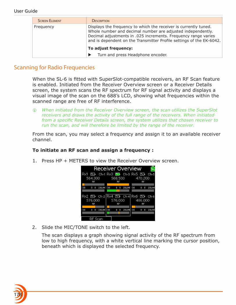
User Guide
178
screen eLement Description
Frequency Displays the frequency to which the receiver is currently tuned. Whole number and decimal number are adjusted independently. Decimal adjustments in .025 increments. Frequency range varies and is dependent on the Transmitter Profile settings of the EK-6042.
To adjust frequency:
X Turn and press Headphone encoder.
Scanning for Radio Frequencies
When the SL-6 is fitted with SuperSlot-compatible receivers, an RF Scan feature is enabled. Initiated from the Receiver Overview screen or a Receiver Details screen, the system scans the RF spectrum for RF signal activity and displays a visual image of the scan on the 688’s LCD, showing what frequencies within the scanned range are free of RF interference.
i When initiated from the Receiver Overview screen, the scan utilizes the SuperSlot receivers and draws the activity of the full range of the receivers. When initiated from a specific Receiver Details screen, the system utilizes that chosen receiver to run the scan, and will therefore be limited by the range of the receiver.
From the scan, you may select a frequency and assign it to an available receiver channel.
To initiate an RF scan and assign a frequency :
1. Press HP + METERS to view the Receiver Overview screen.
2. Slide the MIC/TONE switch to the left.
The scan displays a graph showing signal activity of the RF spectrum from low to high frequency, with a white vertical line marking the cursor position, beneath which is displayed the selected frequency.
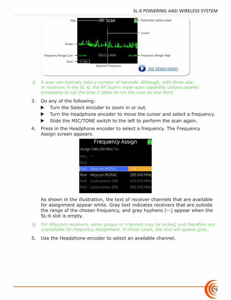
179
SL-6 POWERING AND WIRELESS SYSTEM
Cursor
Selected Frequency
Transmitter battery level
Frequency Range: Low
Title
Frequency Range: High
Scan
Graph
see Demo ViDeo
i A scan can typically take a number of seconds. Although, with three slot-in receivers in the SL-6, the RF Scan’s triple-scan capability utilizes parallel processing to cut the time it takes to run the scan by one-third.
3. Do any of the following: X Turn the Select encoder to zoom in or out. X Turn the Headphone encoder to move the cursor and select a frequency. X Slide the MIC/TONE switch to the left to perform the scan again.
4. Press in the Headphone encoder to select a frequency. The Frequency Assign screen appears.
As shown in the illustration, the text of receiver channels that are available for assignment appear white. Gray text indicates receivers that are outside the range of the chosen frequency, and gray hyphens (--) appear when the SL-6 slot is empty.
i For Wisycom receivers, some groups or channels may be locked, and therefore are unavailable for frequency assignment. In these cases, the text will appear gray.
5. Use the Headphone encoder to select an available channel.

User Guide
180
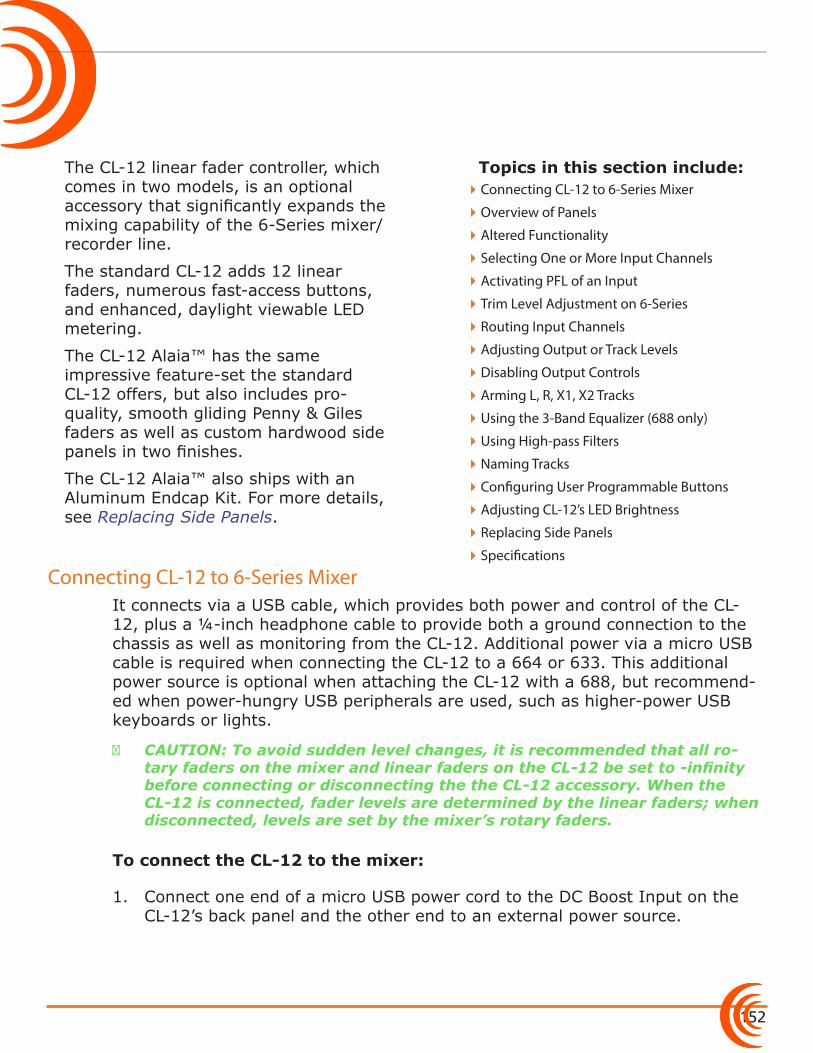
152
Topics in this section include:
Connecting CL-12 to 6-Series Mixer
The CL-12 linear fader controller, which comes in two models, is an optional accessory that significantly expands the mixing capability of the 6-Series mixer/recorder line.
The standard CL-12 adds 12 linear faders, numerous fast-access buttons, and enhanced, daylight viewable LED metering.
The CL-12 Alaia™ has the same impressive feature-set the standard CL-12 offers, but also includes pro-quality, smooth gliding Penny & Giles faders as well as custom hardwood side panels in two finishes.
The CL-12 Alaia™ also ships with an Aluminum Endcap Kit. For more details, see Replacing Side Panels.
It connects via a USB cable, which provides both power and control of the CL-12, plus a ¼-inch headphone cable to provide both a ground connection to the chassis as well as monitoring from the CL-12. Additional power via a micro USB cable is required when connecting the CL-12 to a 664 or 633. This additional power source is optional when attaching the CL-12 with a 688, but recommend-ed when power-hungry USB peripherals are used, such as higher-power USB keyboards or lights.
⚠ CAUTION: To avoid sudden level changes, it is recommended that all ro-tary faders on the mixer and linear faders on the CL-12 be set to -infinity before connecting or disconnecting the the CL-12 accessory. When the CL-12 is connected, fader levels are determined by the linear faders; when disconnected, levels are set by the mixer’s rotary faders.
To connect the CL-12 to the mixer:
1. Connect one end of a micro USB power cord to the DC Boost Input on the CL-12’s back panel and the other end to an external power source.
�Connecting CL-12 to 6-Series Mixer
�Overview of Panels
�Altered Functionality
�Selecting One or More Input Channels
�Activating PFL of an Input
�Trim Level Adjustment on 6-Series
�Routing Input Channels
�Adjusting Output or Track Levels
�Disabling Output Controls
�Arming L, R, X1, X2 Tracks
�Using the 3-Band Equalizer (688 only)
�Using High-pass Filters
�Naming Tracks
�Configuring User Programmable Buttons
�Adjusting CL-12’s LED Brightness
�Replacing Side Panels
�Specifications
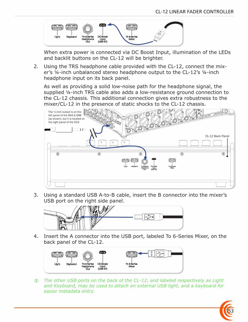
153
CL-12 LINEAR FADER CONTROLLER
When extra power is connected via DC Boost Input, illumination of the LEDs and backlit buttons on the CL-12 will be brighter.
2. Using the TRS headphone cable provided with the CL-12, connect the mix-er’s ¼-inch unbalanced stereo headphone output to the CL-12’s ¼-inch headphone input on its back panel.
As well as providing a solid low-noise path for the headphone signal, the supplied ¼-inch TRS cable also adds a low-resistance ground connection to the CL-12 chassis. This additional connection gives extra robustness to the mixer/CL-12 in the presence of static shocks to the CL-12 chassis.
CL-12 Back Panel
The ¼-inch output is on the left panel of the 664 & 688 (as shown), but it is located on the right panel of the 633.
3. Using a standard USB A-to-B cable, insert the B connector into the mixer’s USB port on the right side panel.
4. Insert the A connector into the USB port, labeled To 6-Series Mixer, on the back panel of the CL-12.
i The other USB ports on the back of the CL-12, and labeled respectively as Light and Keyboard, may be used to attach an external USB light, and a keyboard for easier metadata entry.
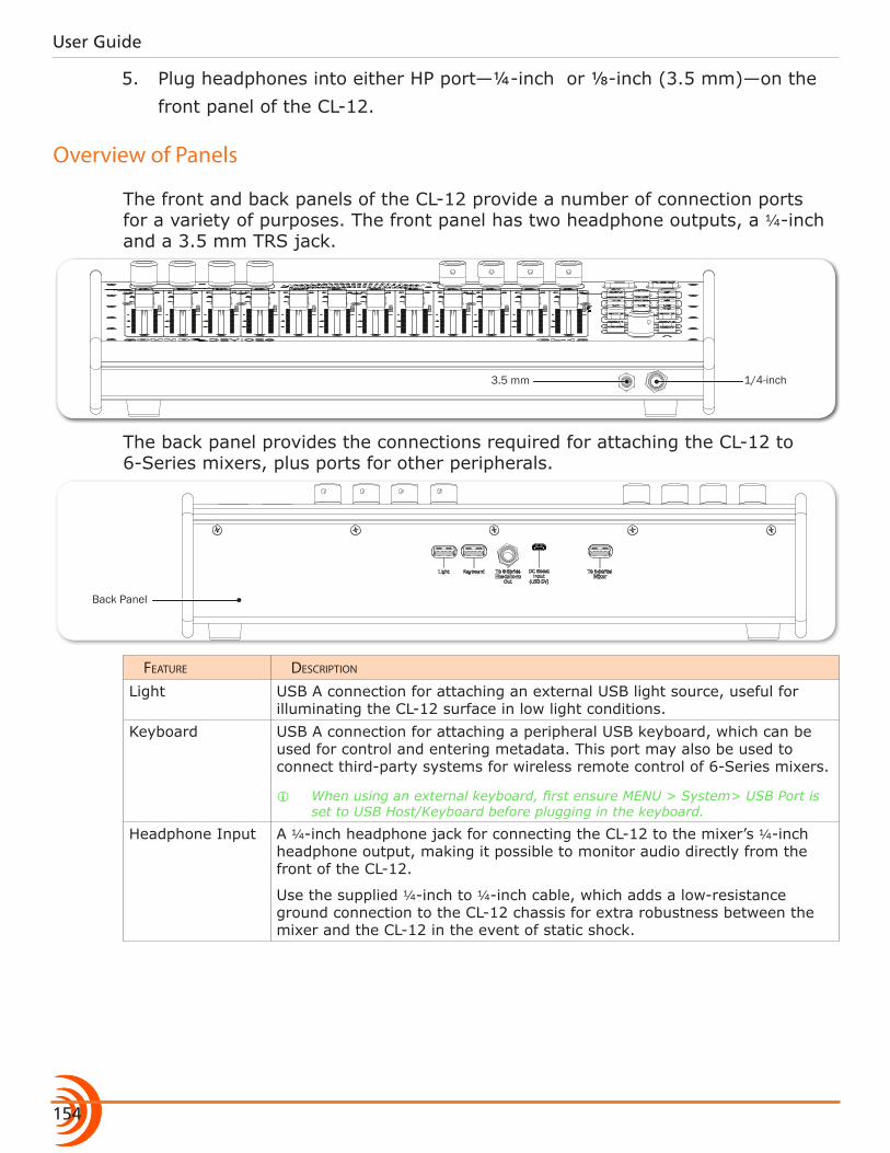
User Guide
154
5. Plug headphones into either HP port—¼-inch or ⅛-inch (3.5 mm)—on the front panel of the CL-12.
Overview of Panels
The front and back panels of the CL-12 provide a number of connection ports for a variety of purposes. The front panel has two headphone outputs, a ¼-inch and a 3.5 mm TRS jack.
1/4-inch3.5 mm
The back panel provides the connections required for attaching the CL-12 to 6-Series mixers, plus ports for other peripherals.
Back Panel
Feature Description
Light USB A connection for attaching an external USB light source, useful for illuminating the CL-12 surface in low light conditions.
Keyboard USB A connection for attaching a peripheral USB keyboard, which can be used for control and entering metadata. This port may also be used to connect third-party systems for wireless remote control of 6-Series mixers.
i When using an external keyboard, first ensure MENU > System> USB Port is set to USB Host/Keyboard before plugging in the keyboard.
Headphone Input A ¼-inch headphone jack for connecting the CL-12 to the mixer’s ¼-inch headphone output, making it possible to monitor audio directly from the front of the CL-12.
Use the supplied ¼-inch to ¼-inch cable, which adds a low-resistance ground connection to the CL-12 chassis for extra robustness between the mixer and the CL-12 in the event of static shock.
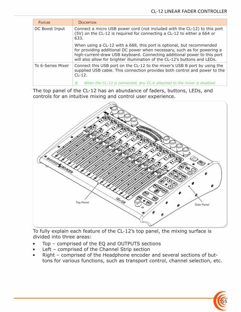
155
CL-12 LINEAR FADER CONTROLLER
Feature Description
DC Boost Input Connect a micro USB power cord (not included with the CL-12) to this port (5V) on the CL-12 is required for connecting a CL-12 to either a 664 or 633.
When using a CL-12 with a 688, this port is optional, but recommended for providing additional DC power when necessary, such as for powering a high-current-draw USB keyboard. Connecting additional power to this port will also allow for brighter illumination of the CL-12’s buttons and LEDs.
To 6-Series Mixer Connect this USB port on the CL-12 to the mixer’s USB B port by using the supplied USB cable. This connection provides both control and power to the CL-12.
i When the CL-12 is connected, any CL-6 attached to the mixer is disabled.
The top panel of the CL-12 has an abundance of faders, buttons, LEDs, and controls for an intuitive mixing and control user experience.
Top PanelSide Panel
To fully explain each feature of the CL-12’s top panel, the mixing surface is divided into three areas:• Top – comprised of the EQ and OUTPUTS sections• Left – comprised of the Channel Strip section• Right – comprised of the Headphone encoder and several sections of but-
tons for various functions, such as transport control, channel selection, etc.
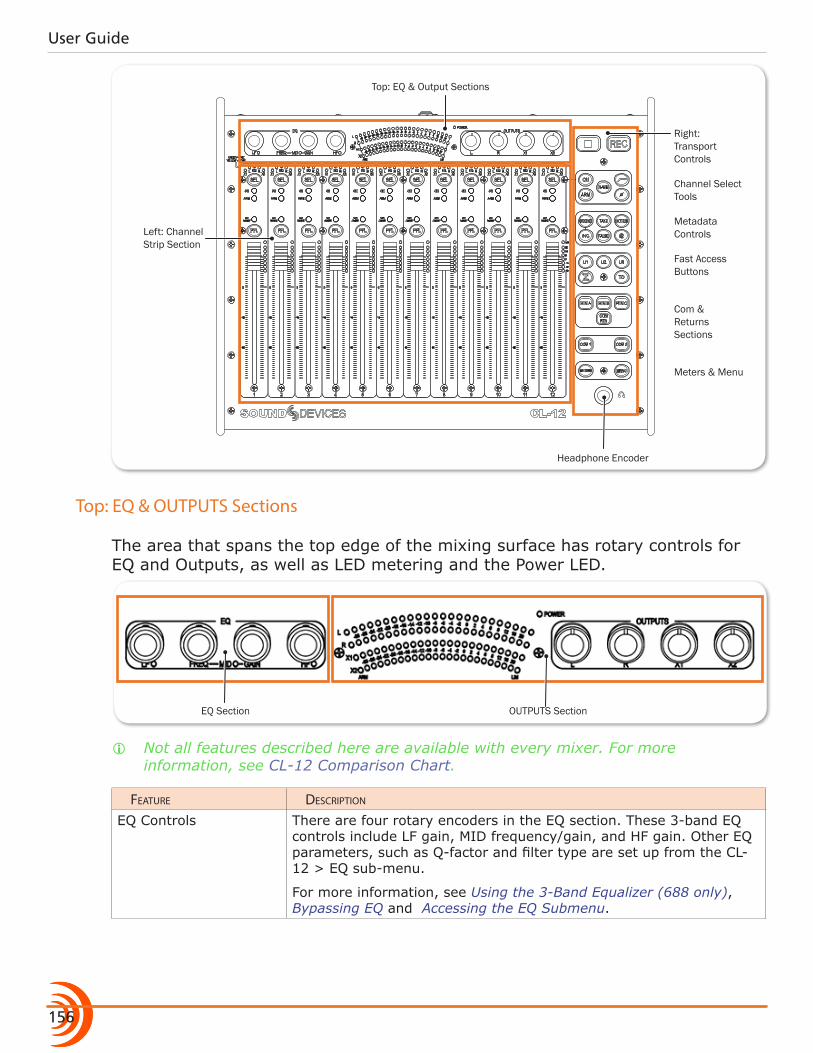
User Guide
156
Right: Transport Controls
Channel Select Tools
Metadata Controls
Fast Access Buttons
Com & Returns Sections
Meters & Menu
Left: Channel Strip Section
Top: EQ & Output Sections
Headphone Encoder
Top: EQ & OUTPUTS Sections
The area that spans the top edge of the mixing surface has rotary controls for EQ and Outputs, as well as LED metering and the Power LED.
EQ Section OUTPUTS Section
i Not all features described here are available with every mixer. For more information, see CL-12 Comparison Chart.
Feature Description
EQ Controls There are four rotary encoders in the EQ section. These 3-band EQ controls include LF gain, MID frequency/gain, and HF gain. Other EQ parameters, such as Q-factor and filter type are set up from the CL-12 > EQ sub-menu.
For more information, see Using the 3-Band Equalizer (688 only), Bypassing EQ and Accessing the EQ Submenu.
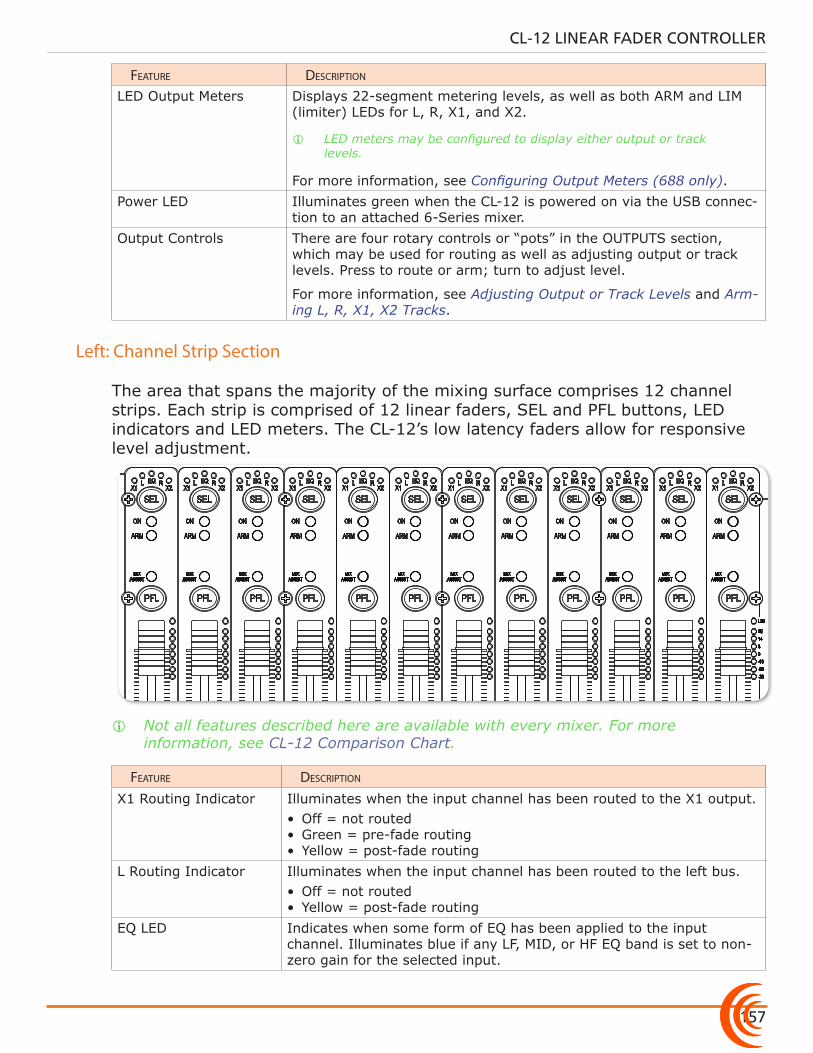
157
CL-12 LINEAR FADER CONTROLLER
Feature Description
LED Output Meters Displays 22-segment metering levels, as well as both ARM and LIM (limiter) LEDs for L, R, X1, and X2.
i LED meters may be configured to display either output or track levels.
For more information, see Configuring Output Meters (688 only).Power LED Illuminates green when the CL-12 is powered on via the USB connec-
tion to an attached 6-Series mixer.Output Controls There are four rotary controls or “pots” in the OUTPUTS section,
which may be used for routing as well as adjusting output or track levels. Press to route or arm; turn to adjust level.
For more information, see Adjusting Output or Track Levels and Arm-ing L, R, X1, X2 Tracks.
Left: Channel Strip Section
The area that spans the majority of the mixing surface comprises 12 channel strips. Each strip is comprised of 12 linear faders, SEL and PFL buttons, LED indicators and LED meters. The CL-12’s low latency faders allow for responsive level adjustment.
i Not all features described here are available with every mixer. For more information, see CL-12 Comparison Chart.
Feature Description
X1 Routing Indicator Illuminates when the input channel has been routed to the X1 output. • Off = not routed• Green = pre-fade routing• Yellow = post-fade routing
L Routing Indicator Illuminates when the input channel has been routed to the left bus.• Off = not routed• Yellow = post-fade routing
EQ LED Indicates when some form of EQ has been applied to the input channel. Illuminates blue if any LF, MID, or HF EQ band is set to non-zero gain for the selected input.
User Guide
158
Feature Description
R Routing Indicator Illuminates when the input channel has been routed to the right bus.• Off = not routed • Yellow = post-fade routing
X2 Routing Indicator Illuminates when the input channel has been routed to the X2 output. • Off = not routed • Green = pre-fade routing• Yellow = post-fade routing
SEL Button Selects or deselects an input channel, or multiple input channels for adjustment.
Each SEL button illuminates when a channel is selected.
While selected, an input channel may be routed to L, R, X1 or X2. It also may be turned on, armed, or named. Additionally, high-pass filtering, phase inversion, or EQ may be applied.
For more information, see Selecting One or More Input Channels. See also Setting SEL to follow PFL.
ON Indicator Illuminates yellow to indicate the input channel is on.ARM Indicator Illuminates red to indicate the corresponding isolated track (ISO) is
armed for recording.MIXASSIST Indicator Illuminates to indicate auto-mixing activity. When the input is open,
the LED is green. As the input closes, the LED is turned off.PFL Buttons (Pre-/Post-Fade Listen)
Activates or deactivates pre- or post-fade listen of inputs 1-12 to the headphone monitor.
For more information, see Activating PFL of an Input. See also Setting SEL to follow PFL.
Linear Faders 100 mm low latency linear controls for adjusting the fader levels of inputs 1-12. Ranges from Off, - 80 to +16 dB.
Each input’s linear fader gain is displayed on the mixer’s Input Settings screen. Calibrate linear faders to 0 dB via the mixer’s SYSTEM > Fader/Pan Calibration menu.
LED Meters Displays 7-segment pre- or post-fade metering, plus pre- and post-fade limiter LED indicator for input channels 1-12.
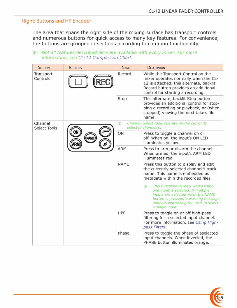
159
CL-12 LINEAR FADER CONTROLLER
Right: Buttons and HP Encoder
The area that spans the right side of the mixing surface has transport controls and numerous buttons for quick access to many key features. For convenience, the buttons are grouped in sections according to common functionality.
i Not all features described here are available with every mixer. For more information, see CL-12 Comparison Chart.
section buttons name Description
Transport Controls
Record While the Transport Control on the mixer operates normally when the CL-12 is attached, this alternate, backlit Record button provides an additional control for starting a recording.
Stop This alternate, backlit Stop button provides an additional control for stop-ping a recording or playback, or (when stopped) viewing the next take’s file name.
Channel Select Tools
i Channel Select tools operate on the currently selected channel(s).
ON Press to toggle a channel on or off. When on, the input’s ON LED illuminates yellow.
ARM Press to arm or disarm the channel. When armed, the input’s ARM LED illuminates red.
NAME Press this button to display and edit the currently selected channel’s track name. This name is embedded as metadata within the recorded files.
i This functionality only works when one input is selected. If multiple inputs are selected when the NAME button is pressed, a warning message appears instructing the user to select a single input.
HPF Press to toggle on or off high-pass filtering for a selected input channel. For more information, see Using High-pass Filters.
Phase Press to toggle the phase of aselected input channels. When inverted, the PHASE button illuminates orange.
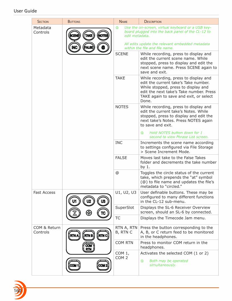
User Guide
160
section buttons name Description
Metadata Controls
i Use the on-screen, virtual keyboard or a USB key-board plugged into the back panel of the CL-12 to edit metadata. All edits update the relevant embedded metadata within the file and file name.
SCENE While recording, press to display and edit the current scene name. While stopped, press to display and edit the next scene name. Press SCENE again to save and exit.
TAKE While recording, press to display and edit the current take’s Take number. While stopped, press to display and edit the next take’s Take number. Press TAKE again to save and exit, or select Done.
NOTES While recording, press to display and edit the current take’s Notes. While stopped, press to display and edit the next take’s Notes. Press NOTES again to save and exit.
i Hold NOTES button down for 1 second to view Phrase List screen.
INC Increments the scene name according to settings configured via File Storage > Scene Increment Mode.
FALSE Moves last take to the False Takes folder and decrements the take number by 1.
@ Toggles the circle status of the current take, which prepends the “at” symbol (@) to file name and updates the file’s metadata to “circled.”
Fast Access U1, U2, U3 User definable buttons. These may be configured to many different functions in the CL-12 sub-menu.
SuperSlot Displays the SL-6 Receiver Overview screen, should an SL-6 by connected.
TC Displays the Timecode Jam menu.
COM & Return Controls
RTN A, RTN B, RTN C
Press the button corresponding to the A, B, or C return feed to be monitored in the headphones.
COM RTN Press to monitor COM return in the headphones.
COM 1, COM 2
Activates the selected COM (1 or 2)
i Both may be operated simultaneously.
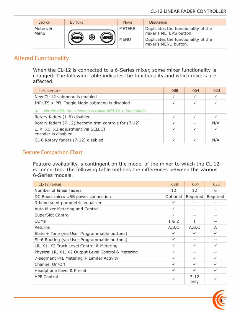
161
CL-12 LINEAR FADER CONTROLLER
section buttons name Description
Meters & Menu
METERS Duplicates the functionality of the mixer’s METERS button.
MENU Duplicates the functionality of the mixer’s MENU button.
Altered Functionality
When the CL-12 is connected to a 6-Series mixer, some mixer functionality is changed. The following table indicates the functionality and which mixers are affected.
FunctionaLity 688 664 633New CL-12 submenu is enabled
INPUTS > PFL Toggle Mode submenu is disabled
i On the 664, the submenu is called INPUTS > Input Mode.
Rotary faders (1-6) disabled
Rotary faders (7-12) become trim controls for (7-12) — N/AL, R, X1, X2 adjustment via SELECT encoder is disabled
CL-6 Rotary faders (7-12) disabled N/A
Feature Comparison Chart
Feature availability is contingent on the model of the mixer to which the CL-12 is connected. The following table outlines the differences between the various 6-Series models.
cL-12 Feature 688 664 633Number of linear faders 12 12 6DC Boost micro USB power connection Optional Required Required3-band semi-parametric equalizer — —Auto Mixer Metering and Control — —SuperSlot Control — —COMs 1 & 2 1 —Returns A,B,C A,B,C ASlate + Tone (via User Programmable buttons)
SL-6 Routing (via User Programmable buttons) — —LR, X1, X2 Track Level Control & Metering
Physical LR, X1, X2 Output Level Control & Metering — —7-segment PFL Metering + Limiter Activity
Channel On/Off
Headphone Level & Preset
HPF Control
7-12 only
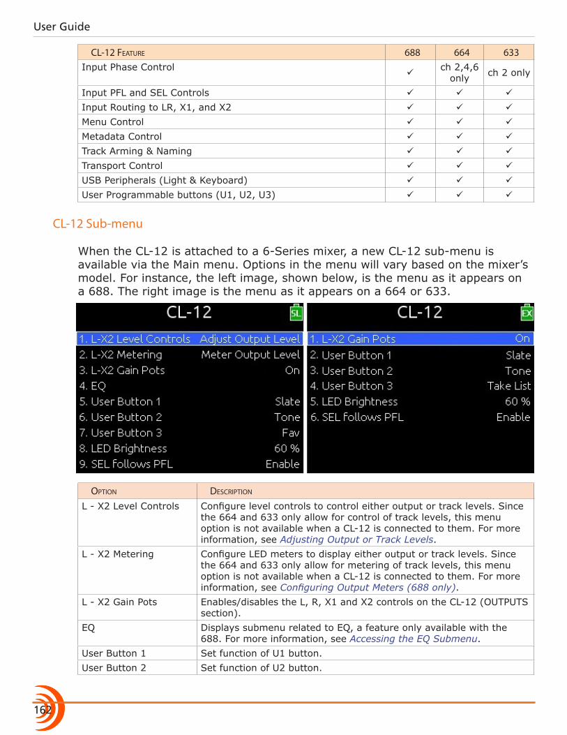
User Guide
162
cL-12 Feature 688 664 633Input Phase Control
ch 2,4,6
only ch 2 only
Input PFL and SEL Controls
Input Routing to LR, X1, and X2
Menu Control
Metadata Control
Track Arming & Naming
Transport Control
USB Peripherals (Light & Keyboard)
User Programmable buttons (U1, U2, U3)
CL-12 Sub-menu
When the CL-12 is attached to a 6-Series mixer, a new CL-12 sub-menu is available via the Main menu. Options in the menu will vary based on the mixer’s model. For instance, the left image, shown below, is the menu as it appears on a 688. The right image is the menu as it appears on a 664 or 633.
option Description
L - X2 Level Controls Configure level controls to control either output or track levels. Since the 664 and 633 only allow for control of track levels, this menu option is not available when a CL-12 is connected to them. For more information, see Adjusting Output or Track Levels.
L - X2 Metering Configure LED meters to display either output or track levels. Since the 664 and 633 only allow for metering of track levels, this menu option is not available when a CL-12 is connected to them. For more information, see Configuring Output Meters (688 only).
L - X2 Gain Pots Enables/disables the L, R, X1 and X2 controls on the CL-12 (OUTPUTS section).
EQ Displays submenu related to EQ, a feature only available with the 688. For more information, see Accessing the EQ Submenu.
User Button 1 Set function of U1 button. User Button 2 Set function of U2 button.
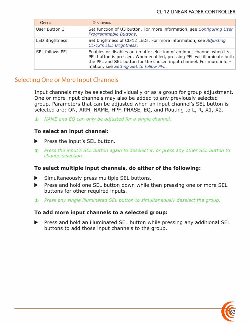
163
CL-12 LINEAR FADER CONTROLLER
option Description
User Button 3 Set function of U3 button. For more information, see Configuring User Programmable Buttons.
LED Brightness Set brightness of CL-12 LEDs. For more information, see Adjusting CL-12’s LED Brightness.
SEL follows PFL Enables or disables automatic selection of an input channel when its PFL button is pressed. When enabled, pressing PFL will illuminate both the PFL and SEL button for the chosen input channel. For more infor-mation, see Setting SEL to follow PFL.
Selecting One or More Input Channels
Input channels may be selected individually or as a group for group adjustment. One or more input channels may also be added to any previously selected group. Parameters that can be adjusted when an input channel’s SEL button is selected are: ON, ARM, NAME, HPF, PHASE, EQ, and Routing to L, R, X1, X2.
i NAME and EQ can only be adjusted for a single channel.
To select an input channel:
X Press the input’s SEL button.
i Press the input’s SEL button again to deselect it, or press any other SEL button to change selection.
To select multiple input channels, do either of the following:
X Simultaneously press multiple SEL buttons. X Press and hold one SEL button down while then pressing one or more SEL
buttons for other required inputs.
i Press any single illuminated SEL button to simultaneously deselect the group.
To add more input channels to a selected group:
X Press and hold an illuminated SEL button while pressing any additional SEL buttons to add those input channels to the group.
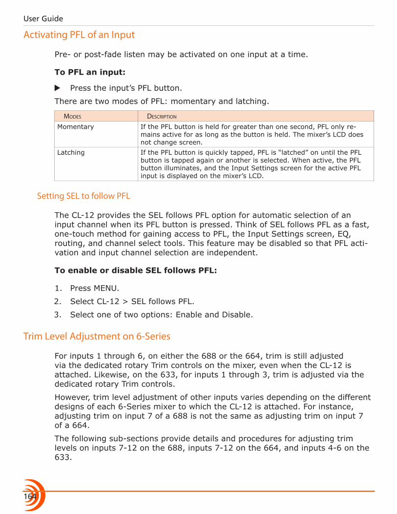
User Guide
164
Activating PFL of an Input
Pre- or post-fade listen may be activated on one input at a time.
To PFL an input:
X Press the input’s PFL button.
There are two modes of PFL: momentary and latching.
moDes Description
Momentary If the PFL button is held for greater than one second, PFL only re-mains active for as long as the button is held. The mixer’s LCD does not change screen.
Latching If the PFL button is quickly tapped, PFL is “latched” on until the PFL button is tapped again or another is selected. When active, the PFL button illuminates, and the Input Settings screen for the active PFL input is displayed on the mixer’s LCD.
Setting SEL to follow PFL
The CL-12 provides the SEL follows PFL option for automatic selection of an input channel when its PFL button is pressed. Think of SEL follows PFL as a fast, one-touch method for gaining access to PFL, the Input Settings screen, EQ, routing, and channel select tools. This feature may be disabled so that PFL acti-vation and input channel selection are independent.
To enable or disable SEL follows PFL:
1. Press MENU.
2. Select CL-12 > SEL follows PFL.
3. Select one of two options: Enable and Disable.
Trim Level Adjustment on 6-Series
For inputs 1 through 6, on either the 688 or the 664, trim is still adjusted via the dedicated rotary Trim controls on the mixer, even when the CL-12 is attached. Likewise, on the 633, for inputs 1 through 3, trim is adjusted via the dedicated rotary Trim controls.
However, trim level adjustment of other inputs varies depending on the different designs of each 6-Series mixer to which the CL-12 is attached. For instance, adjusting trim on input 7 of a 688 is not the same as adjusting trim on input 7 of a 664.
The following sub-sections provide details and procedures for adjusting trim levels on inputs 7-12 on the 688, inputs 7-12 on the 664, and inputs 4-6 on the 633.
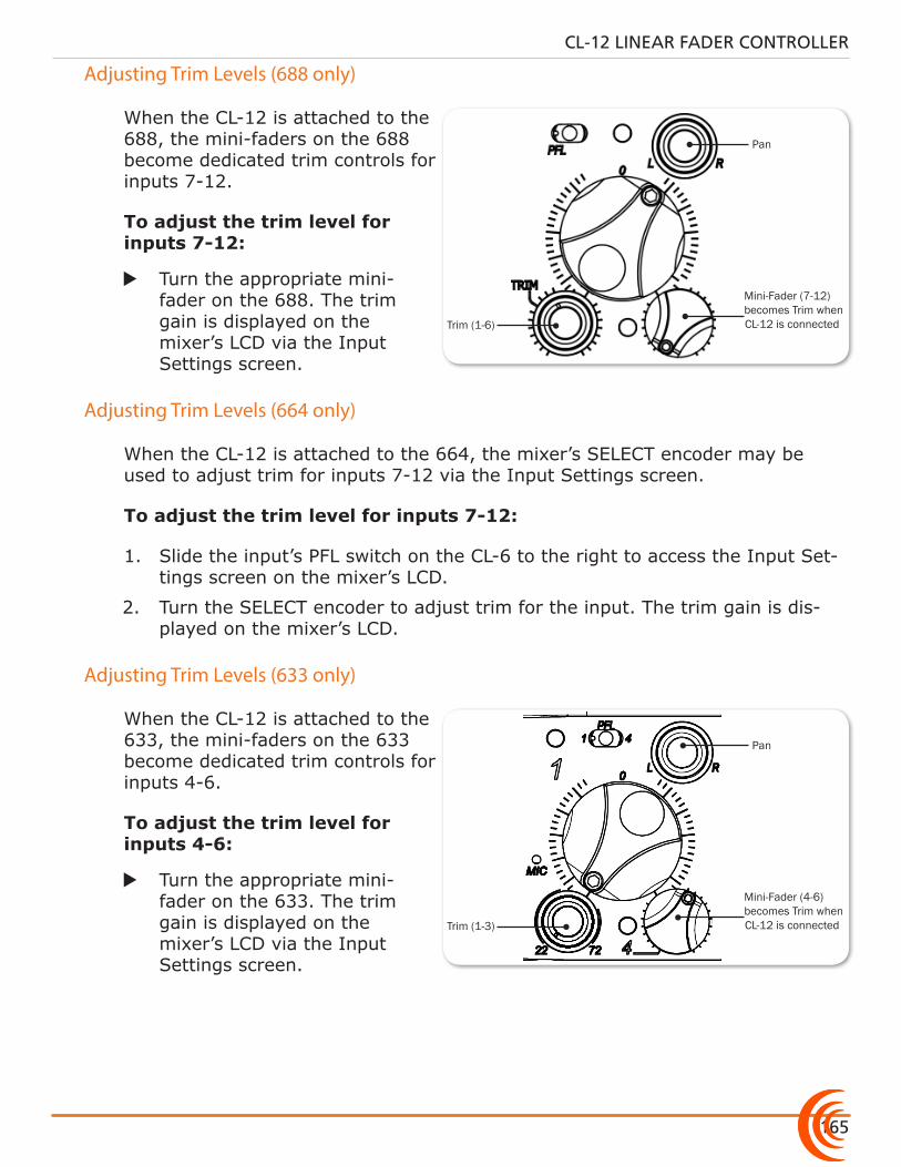
165
CL-12 LINEAR FADER CONTROLLER
Pan
Mini-Fader (7-12) becomes Trim when CL-12 is connectedTrim (1-6)
Adjusting Trim Levels (688 only)
When the CL-12 is attached to the 688, the mini-faders on the 688 become dedicated trim controls for inputs 7-12.
To adjust the trim level for inputs 7-12:
X Turn the appropriate mini-fader on the 688. The trim gain is displayed on the mixer’s LCD via the Input Settings screen.
Adjusting Trim Levels (664 only)
When the CL-12 is attached to the 664, the mixer’s SELECT encoder may be used to adjust trim for inputs 7-12 via the Input Settings screen.
To adjust the trim level for inputs 7-12:
1. Slide the input’s PFL switch on the CL-6 to the right to access the Input Set-tings screen on the mixer’s LCD.
2. Turn the SELECT encoder to adjust trim for the input. The trim gain is dis-played on the mixer’s LCD.
Pan
Mini-Fader (4-6) becomes Trim when CL-12 is connectedTrim (1-3)
Adjusting Trim Levels (633 only)
When the CL-12 is attached to the 633, the mini-faders on the 633 become dedicated trim controls for inputs 4-6.
To adjust the trim level for inputs 4-6:
X Turn the appropriate mini-fader on the 633. The trim gain is displayed on the mixer’s LCD via the Input Settings screen.
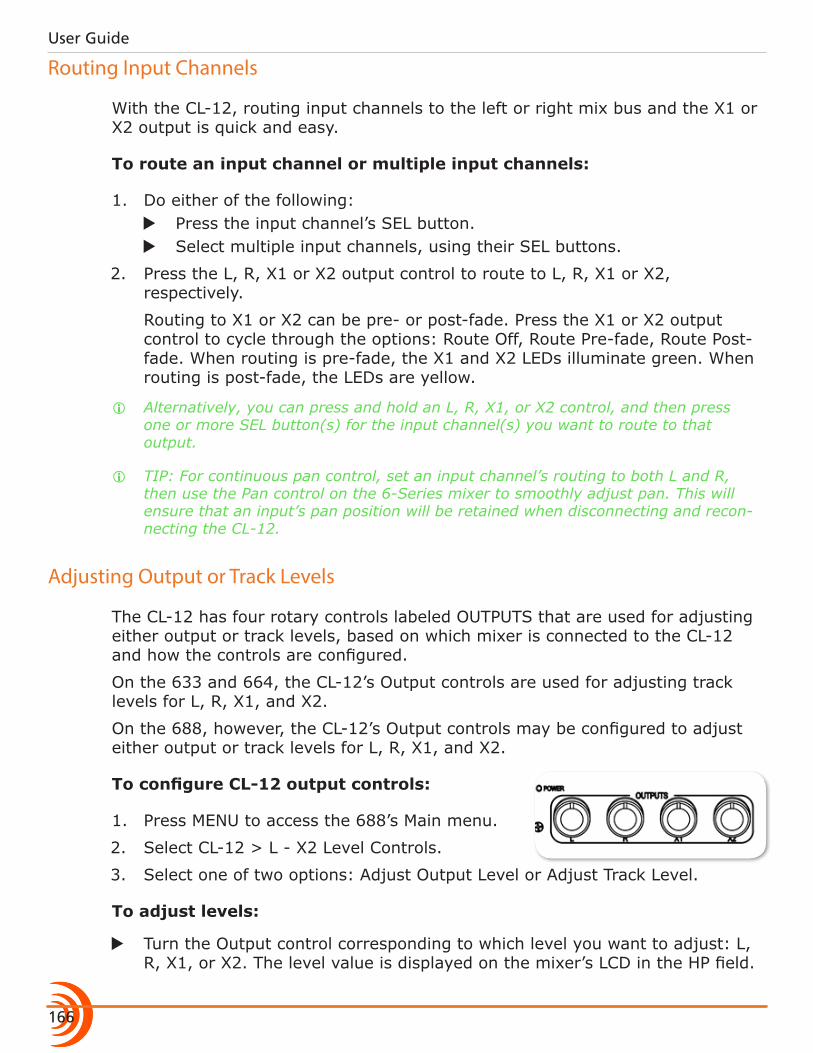
User Guide
166
Routing Input Channels
With the CL-12, routing input channels to the left or right mix bus and the X1 or X2 output is quick and easy.
To route an input channel or multiple input channels:
1. Do either of the following: X Press the input channel’s SEL button. X Select multiple input channels, using their SEL buttons.
2. Press the L, R, X1 or X2 output control to route to L, R, X1 or X2, respectively.
Routing to X1 or X2 can be pre- or post-fade. Press the X1 or X2 output control to cycle through the options: Route Off, Route Pre-fade, Route Post-fade. When routing is pre-fade, the X1 and X2 LEDs illuminate green. When routing is post-fade, the LEDs are yellow.
i Alternatively, you can press and hold an L, R, X1, or X2 control, and then press one or more SEL button(s) for the input channel(s) you want to route to that output.
i TIP: For continuous pan control, set an input channel’s routing to both L and R, then use the Pan control on the 6-Series mixer to smoothly adjust pan. This will ensure that an input’s pan position will be retained when disconnecting and recon-necting the CL-12.
Adjusting Output or Track Levels
The CL-12 has four rotary controls labeled OUTPUTS that are used for adjusting either output or track levels, based on which mixer is connected to the CL-12 and how the controls are configured.
On the 633 and 664, the CL-12’s Output controls are used for adjusting track levels for L, R, X1, and X2.
On the 688, however, the CL-12’s Output controls may be configured to adjust either output or track levels for L, R, X1, and X2.
To configure CL-12 output controls:
1. Press MENU to access the 688’s Main menu.
2. Select CL-12 > L - X2 Level Controls.
3. Select one of two options: Adjust Output Level or Adjust Track Level.
To adjust levels:
X Turn the Output control corresponding to which level you want to adjust: L, R, X1, or X2. The level value is displayed on the mixer’s LCD in the HP field.
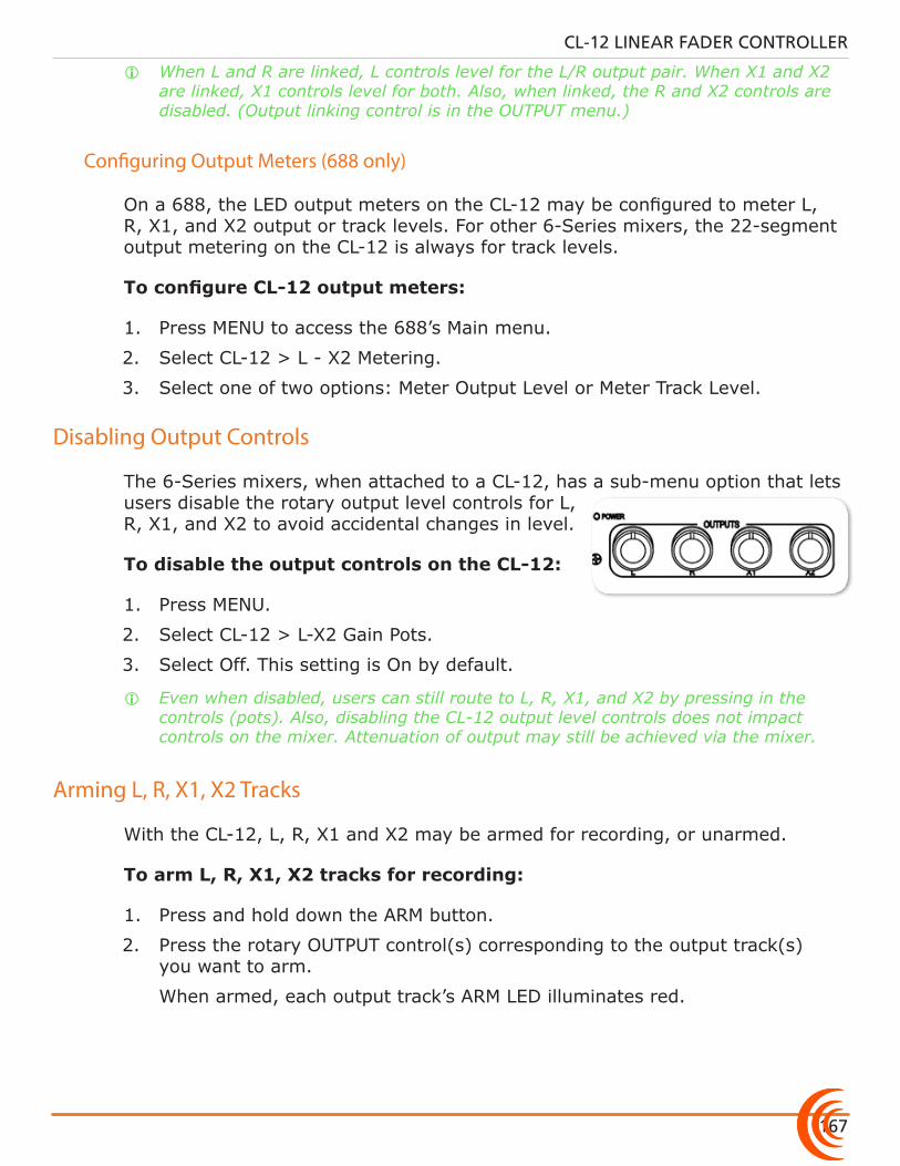
167
CL-12 LINEAR FADER CONTROLLER
i When L and R are linked, L controls level for the L/R output pair. When X1 and X2 are linked, X1 controls level for both. Also, when linked, the R and X2 controls are disabled. (Output linking control is in the OUTPUT menu.)
Configuring Output Meters (688 only)
On a 688, the LED output meters on the CL-12 may be configured to meter L, R, X1, and X2 output or track levels. For other 6-Series mixers, the 22-segment output metering on the CL-12 is always for track levels.
To configure CL-12 output meters:
1. Press MENU to access the 688’s Main menu.
2. Select CL-12 > L - X2 Metering.
3. Select one of two options: Meter Output Level or Meter Track Level.
Disabling Output Controls
The 6-Series mixers, when attached to a CL-12, has a sub-menu option that lets users disable the rotary output level controls for L, R, X1, and X2 to avoid accidental changes in level.
To disable the output controls on the CL-12:
1. Press MENU.
2. Select CL-12 > L-X2 Gain Pots.
3. Select Off. This setting is On by default.
i Even when disabled, users can still route to L, R, X1, and X2 by pressing in the controls (pots). Also, disabling the CL-12 output level controls does not impact controls on the mixer. Attenuation of output may still be achieved via the mixer.
Arming L, R, X1, X2 Tracks
With the CL-12, L, R, X1 and X2 may be armed for recording, or unarmed.
To arm L, R, X1, X2 tracks for recording:
1. Press and hold down the ARM button.
2. Press the rotary OUTPUT control(s) corresponding to the output track(s) you want to arm.
When armed, each output track’s ARM LED illuminates red.
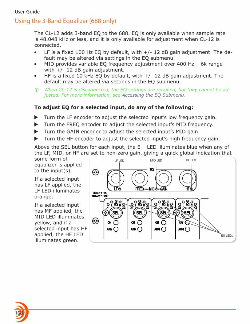
User Guide
168
Using the 3-Band Equalizer (688 only)
The CL-12 adds 3-band EQ to the 688. EQ is only available when sample rate is 48.048 kHz or less, and it is only available for adjustment when CL-12 is connected.• LF is a fixed 100 Hz EQ by default, with +/- 12 dB gain adjustment. The de-
fault may be altered via settings in the EQ submenu.• MID provides variable EQ frequency adjustment over 400 Hz – 6k range
with +/- 12 dB gain adjustment.• HF is a fixed 10 kHz EQ by default, with +/- 12 dB gain adjustment. The
default may be altered via settings in the EQ submenu. i When CL-12 is disconnected, the EQ settings are retained, but they cannot be ad-
justed. For more information, see Accessing the EQ Submenu.
To adjust EQ for a selected input, do any of the following:
X Turn the LF encoder to adjust the selected input’s low frequency gain. X Turn the FREQ encoder to adjust the selected input’s MID frequency. X Turn the GAIN encoder to adjust the selected input’s MID gain. X Turn the HF encoder to adjust the selected input’s high frequency gain.
HF LEDMID LEDLF LED
EQ LEDs
Above the SEL button for each input, the EQ LED illuminates blue when any of the LF, MID, or HF are set to non-zero gain, giving a quick global indication that some form of equalizer is applied to the input(s).
If a selected input has LF applied, the LF LED illuminates orange.
If a selected input has MF applied, the MID LED illuminates yellow, and if a selected input has HF applied, the HF LED illuminates green.
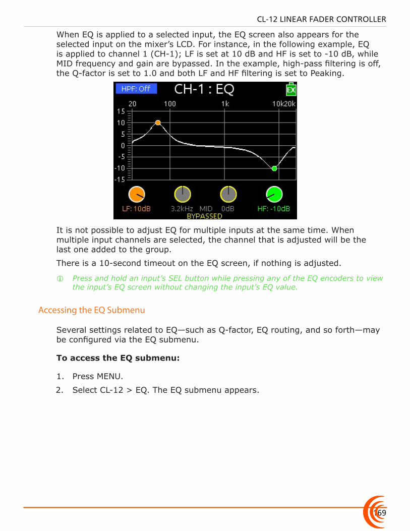
169
CL-12 LINEAR FADER CONTROLLER
When EQ is applied to a selected input, the EQ screen also appears for the selected input on the mixer’s LCD. For instance, in the following example, EQ is applied to channel 1 (CH-1); LF is set at 10 dB and HF is set to -10 dB, while MID frequency and gain are bypassed. In the example, high-pass filtering is off, the Q-factor is set to 1.0 and both LF and HF filtering is set to Peaking.
It is not possible to adjust EQ for multiple inputs at the same time. When multiple input channels are selected, the channel that is adjusted will be the last one added to the group.
There is a 10-second timeout on the EQ screen, if nothing is adjusted.
i Press and hold an input’s SEL button while pressing any of the EQ encoders to view the input’s EQ screen without changing the input’s EQ value.
Accessing the EQ Submenu
Several settings related to EQ—such as Q-factor, EQ routing, and so forth—may be configured via the EQ submenu.
To access the EQ submenu:
1. Press MENU.
2. Select CL-12 > EQ. The EQ submenu appears.
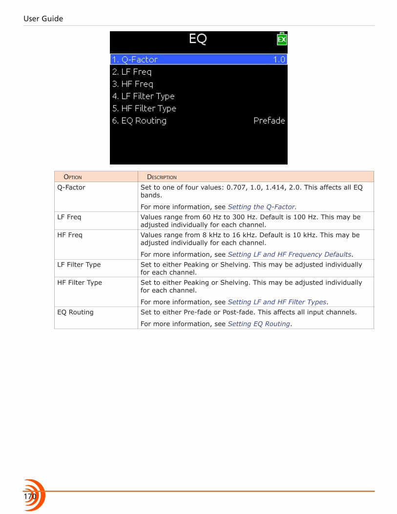
User Guide
170
option Description
Q-Factor Set to one of four values: 0.707, 1.0, 1.414, 2.0. This affects all EQ bands.
For more information, see Setting the Q-Factor.LF Freq Values range from 60 Hz to 300 Hz. Default is 100 Hz. This may be
adjusted individually for each channel.HF Freq Values range from 8 kHz to 16 kHz. Default is 10 kHz. This may be
adjusted individually for each channel.
For more information, see Setting LF and HF Frequency Defaults.LF Filter Type Set to either Peaking or Shelving. This may be adjusted individually
for each channel.HF Filter Type Set to either Peaking or Shelving. This may be adjusted individually
for each channel.
For more information, see Setting LF and HF Filter Types.EQ Routing Set to either Pre-fade or Post-fade. This affects all input channels.
For more information, see Setting EQ Routing.
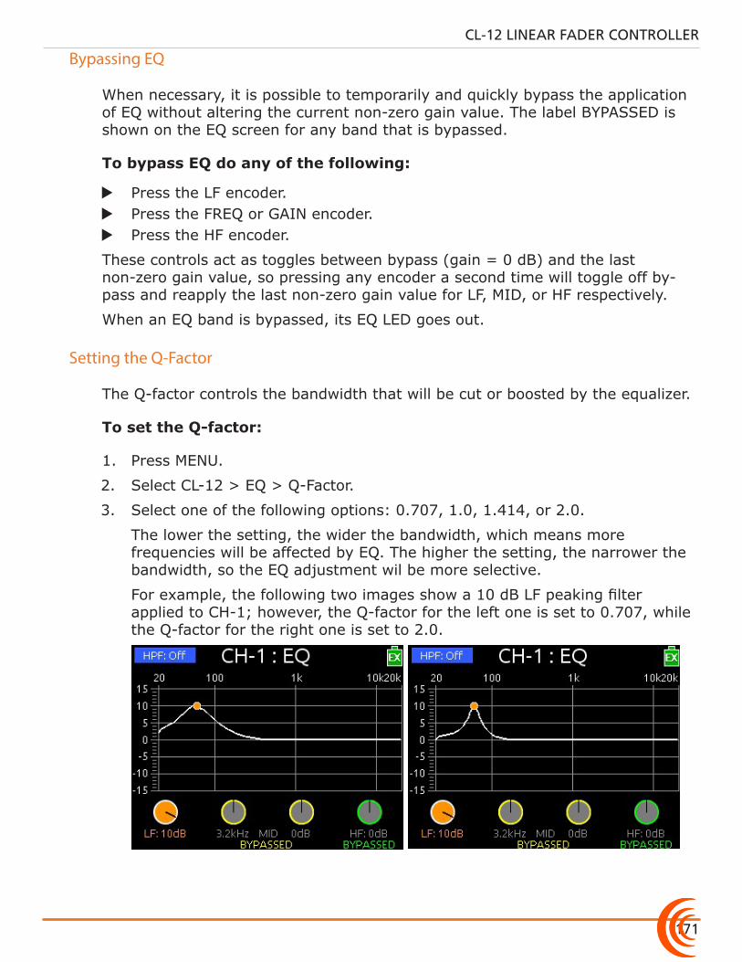
171
CL-12 LINEAR FADER CONTROLLER
Bypassing EQ
When necessary, it is possible to temporarily and quickly bypass the application of EQ without altering the current non-zero gain value. The label BYPASSED is shown on the EQ screen for any band that is bypassed.
To bypass EQ do any of the following:
X Press the LF encoder. X Press the FREQ or GAIN encoder. X Press the HF encoder.
These controls act as toggles between bypass (gain = 0 dB) and the last non-zero gain value, so pressing any encoder a second time will toggle off by-pass and reapply the last non-zero gain value for LF, MID, or HF respectively.
When an EQ band is bypassed, its EQ LED goes out.
Setting the Q-Factor
The Q-factor controls the bandwidth that will be cut or boosted by the equalizer.
To set the Q-factor:
1. Press MENU.
2. Select CL-12 > EQ > Q-Factor.
3. Select one of the following options: 0.707, 1.0, 1.414, or 2.0.
The lower the setting, the wider the bandwidth, which means more frequencies will be affected by EQ. The higher the setting, the narrower the bandwidth, so the EQ adjustment wil be more selective.
For example, the following two images show a 10 dB LF peaking filter applied to CH-1; however, the Q-factor for the left one is set to 0.707, while the Q-factor for the right one is set to 2.0.
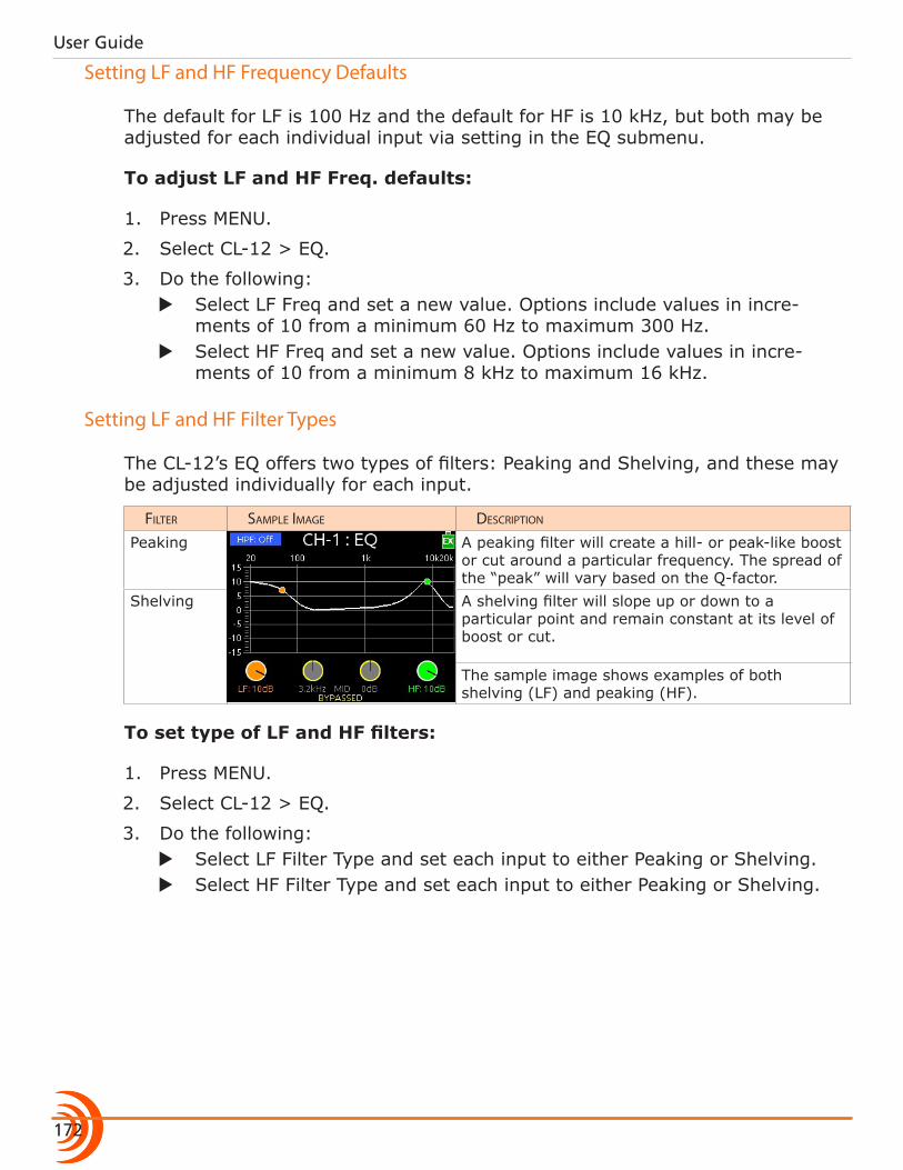
User Guide
172
Setting LF and HF Frequency Defaults
The default for LF is 100 Hz and the default for HF is 10 kHz, but both may be adjusted for each individual input via setting in the EQ submenu.
To adjust LF and HF Freq. defaults:
1. Press MENU.
2. Select CL-12 > EQ.
3. Do the following: X Select LF Freq and set a new value. Options include values in incre-
ments of 10 from a minimum 60 Hz to maximum 300 Hz. X Select HF Freq and set a new value. Options include values in incre-
ments of 10 from a minimum 8 kHz to maximum 16 kHz.
Setting LF and HF Filter Types
The CL-12’s EQ offers two types of filters: Peaking and Shelving, and these may be adjusted individually for each input.
FiLter sampLe image Description
Peaking A peaking filter will create a hill- or peak-like boost or cut around a particular frequency. The spread of the “peak” will vary based on the Q-factor.
Shelving A shelving filter will slope up or down to a particular point and remain constant at its level of boost or cut.
The sample image shows examples of both shelving (LF) and peaking (HF).
To set type of LF and HF filters:
1. Press MENU.
2. Select CL-12 > EQ.
3. Do the following: X Select LF Filter Type and set each input to either Peaking or Shelving. X Select HF Filter Type and set each input to either Peaking or Shelving.
173
CL-12 LINEAR FADER CONTROLLER
Setting EQ Routing
EQ may be applied either pre- or post-fade. This setting globally affects all in-puts.
To set EQ routing:
1. Press MENU.
2. Select CL-12 > EQ > EQ Routing. Options include: Pre-fade or Post-fade.
Using High-pass Filters
The High-pass Filter (HPF) button on the CL-12 is a toggle, which turns the high-pass filter off or on for the selected input.
On the 664, since inputs 1-6 are analog, the CL-12’s HPF button toggles on or off high-pass filtering for inputs 7-12 only at the fixed frequency of 150 Hz.
On the 688 and 633, the high-pass filter may be adjusted for all inputs to other frequencies.
To turn on and adjust an input’s high-pass filter:
1. Select an input, using the input’s SEL button.
2. Press the HPF button.
i If inputs 1-6 are selected on the 664 when the CL-12’s HPF button is pressed, a message will appear: “Use the low-cut control on the 664 front panel.”
The HPF button illuminates when high-pass filtering is on.
3. (633 & 688 only) Adjust the HPF value via the Input Settings screen.
When high-pass filtering is on, the HPF value is fixed at 150 Hz on the 664, but may be changed via in the Input Settings screen on the 633 or 688. Also, on the 688, the EQ screen appears on the mixer’s LCD. The Head-phone encoder may be used as an alternative way to adjust the HPF value displayed on the EQ screen.
i Press the HPF button again to turn off the high-pass filter.
User Guide
174
Naming Tracks
Since inputs are hard-wired to their respective tracks, the input name is the same as the track name. Naming functionality only applies to one selected input at a time. Attempting to do so with multiple inputs selected will result in a message instructing the user to select a single input before continuing.
While recording, the current take’s track name may be modified. Edits to the track name in the current take will also be applied to the next take and subsequent recordings that follow. The next take’s track name may be edited so long as recording is stopped.
To enter or edit track names:
1. With a single input selected, press the NAME button. The Track Name List appears over the Meters View.
2. Do any of the following: X Select Edit Entry to edit the current entry. X Select Add New Entry to enter a new track name. X Select a name from the list.
i TIP: Prepare a list of names to use for fast selection during production.
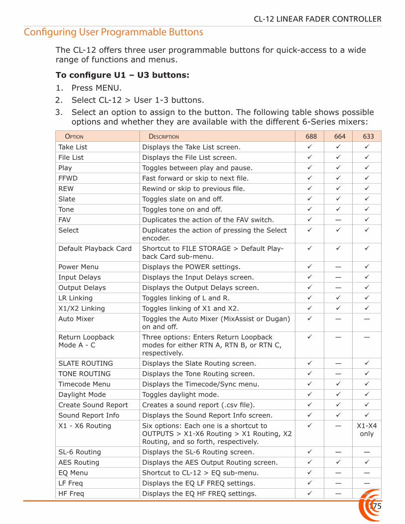
175
CL-12 LINEAR FADER CONTROLLER
Configuring User Programmable Buttons
The CL-12 offers three user programmable buttons for quick-access to a wide range of functions and menus.
To configure U1 – U3 buttons:1. Press MENU.2. Select CL-12 > User 1-3 buttons.3. Select an option to assign to the button. The following table shows possible
options and whether they are available with the different 6-Series mixers:
option Description 688 664 633Take List Displays the Take List screen.
File List Displays the File List screen.
Play Toggles between play and pause.
FFWD Fast forward or skip to next file.
REW Rewind or skip to previous file.
Slate Toggles slate on and off.
Tone Toggles tone on and off.
FAV Duplicates the action of the FAV switch. —
Select Duplicates the action of pressing the Select encoder.
Default Playback Card Shortcut to FILE STORAGE > Default Play-back Card sub-menu.
Power Menu Displays the POWER settings. —
Input Delays Displays the Input Delays screen. —
Output Delays Displays the Output Delays screen. —
LR Linking Toggles linking of L and R.
X1/X2 Linking Toggles linking of X1 and X2.
Auto Mixer Toggles the Auto Mixer (MixAssist or Dugan) on and off.
— —
Return Loopback Mode A - C
Three options: Enters Return Loopback modes for either RTN A, RTN B, or RTN C, respectively.
— —
SLATE ROUTING Displays the Slate Routing screen. —
TONE ROUTING Displays the Tone Routing screen. —
Timecode Menu Displays the Timecode/Sync menu.
Daylight Mode Toggles daylight mode.
Create Sound Report Creates a sound report (.csv file).
Sound Report Info Displays the Sound Report Info screen.
X1 - X6 Routing Six options: Each one is a shortcut to OUTPUTS > X1-X6 Routing > X1 Routing, X2 Routing, and so forth, respectively.
— X1-X4 only
SL-6 Routing Displays the SL-6 Routing screen. — —AES Routing Displays the AES Output Routing screen.
EQ Menu Shortcut to CL-12 > EQ sub-menu. — —LF Freq Displays the EQ LF FREQ settings. — —HF Freq Displays the EQ HF FREQ settings. — —

User Guide
176
Adjusting CL-12’s LED Brightness
Depending on the work environment, the brightness of the CL-12’s LED may require adjustment.
To adjust LED brightness:
1. Press MENU and scroll to CL-12.
2. Select LED Brightness.
3. Turn the Headphone encoder to adjust value up or down in 1% increments from a minimum of 5% up to 100%.
i TIP: LED brightness may be further boosted by connecting a USB 5 V source to the DC Boost Input port on the back panel of the CL-12.
Replacing Side Panels
The CL-12 Alaia comes equipped with custom, hand-crafted hardwood side pan-els; however, included with the CL-12 Alaia is the Aluminum Endcap Kit, which contains a set of black aluminum side panels like those on the standard CL-12 model.
To replace the wood with metal side panels:
1. Use the 1/16-inch hex L key, supplied with the kit, to remove the 9 but-ton-head screws and washers from each side of the CL-12 Alaia. The wood side panels will then come off.
2. Position each black aluminum side panel so that the holes in the panel are aligned with threaded holes in the CL-12 Alaia’s chassis.
3. Use the screws, supplied with the kit, to fasten the panels, and tighten with a Phillips-head screwdriver (not supplied).
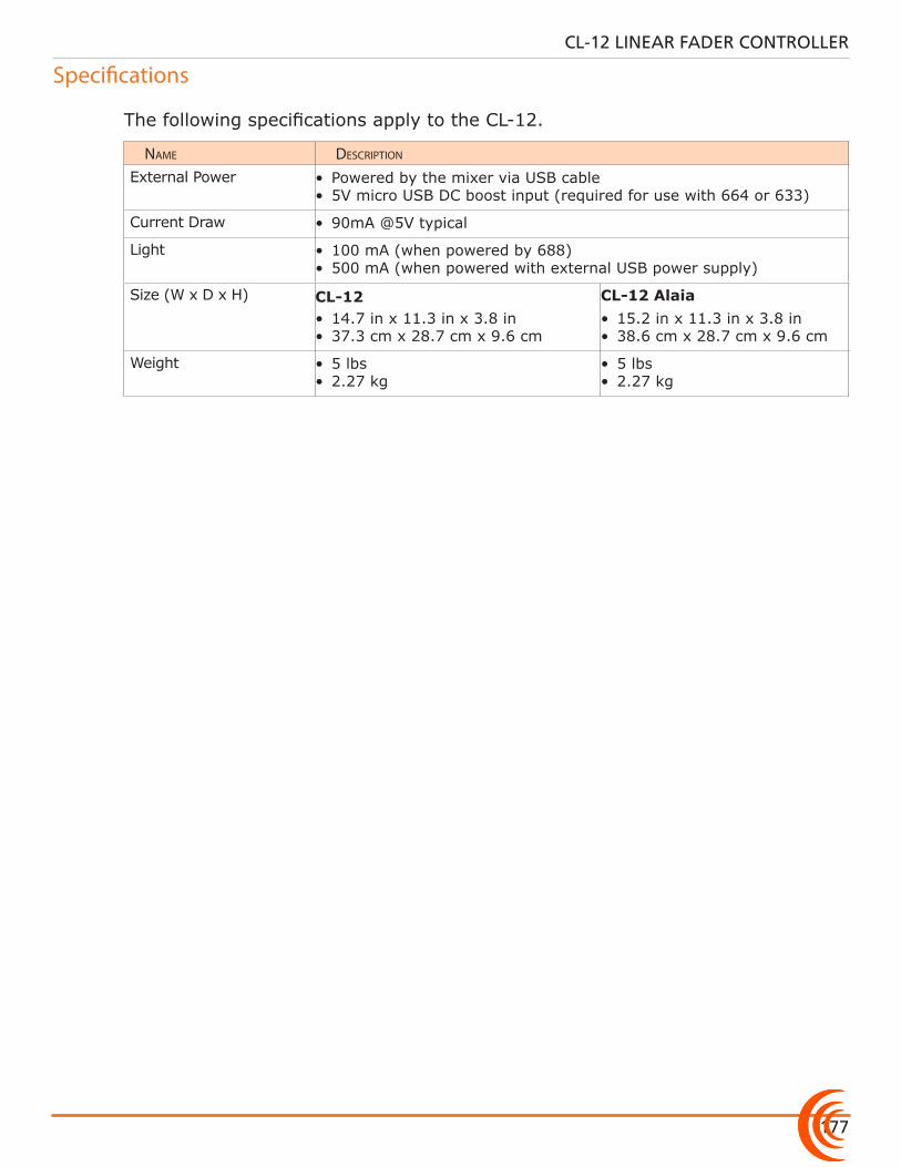
177
CL-12 LINEAR FADER CONTROLLER
Specifications
The following specifications apply to the CL-12.
name Description
External Power • Powered by the mixer via USB cable• 5V micro USB DC boost input (required for use with 664 or 633)
Current Draw • 90mA @5V typical
Light • 100 mA (when powered by 688)• 500 mA (when powered with external USB power supply)
Size (W x D x H) CL-12• 14.7 in x 11.3 in x 3.8 in • 37.3 cm x 28.7 cm x 9.6 cm
CL-12 Alaia• 15.2 in x 11.3 in x 3.8 in • 38.6 cm x 28.7 cm x 9.6 cm
Weight • 5 lbs • 2.27 kg
• 5 lbs • 2.27 kg
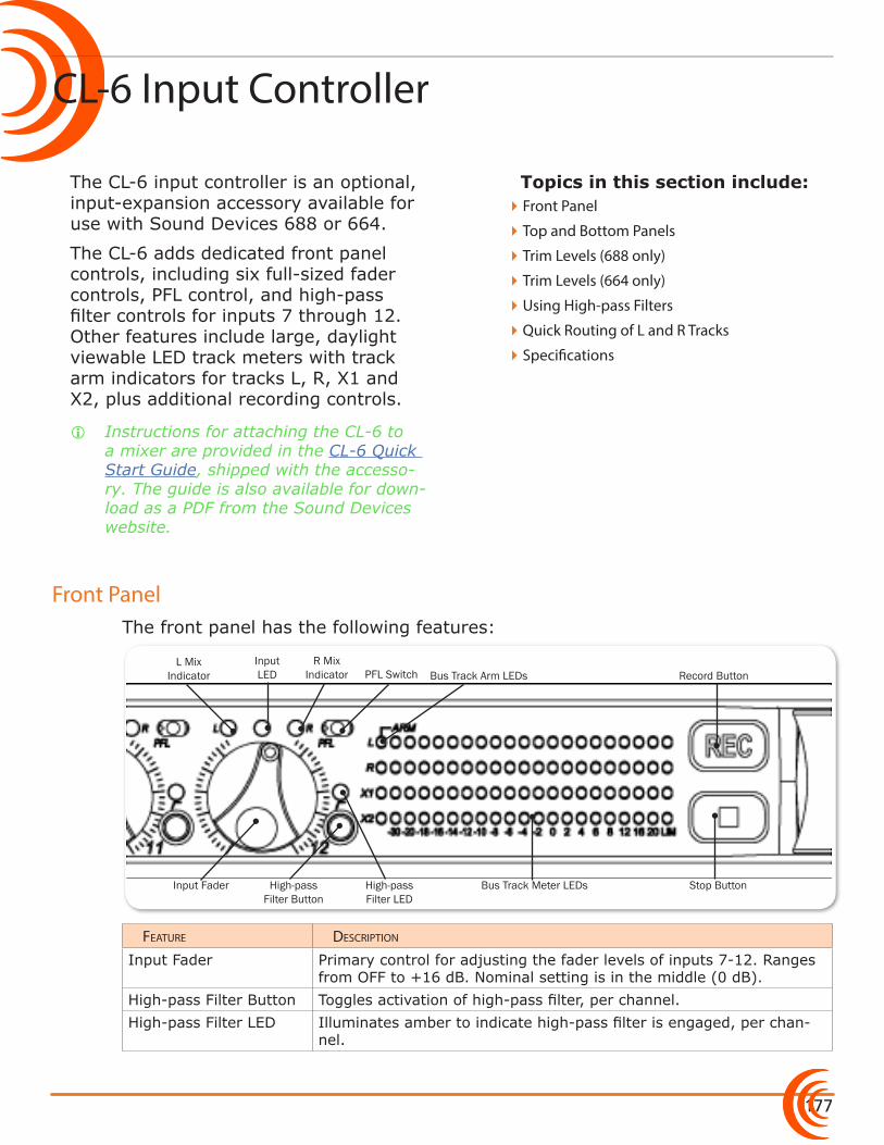
177
Topics in this section include:
CL-6 Input Controller
Front Panel
The CL-6 input controller is an optional, input-expansion accessory available for use with Sound Devices 688 or 664.
The CL-6 adds dedicated front panel controls, including six full-sized fader controls, PFL control, and high-pass filter controls for inputs 7 through 12. Other features include large, daylight viewable LED track meters with track arm indicators for tracks L, R, X1 and X2, plus additional recording controls.
i Instructions for attaching the CL-6 to a mixer are provided in the CL-6 Quick Start Guide, shipped with the accesso-ry. The guide is also available for down-load as a PDF from the Sound Devices website.
The front panel has the following features:
Input Fader
L Mix Indicator
Input LED PFL Switch
R Mix Indicator
High-pass Filter Button
High-pass Filter LED
Stop Button
Record ButtonBus Track Arm LEDs
Bus Track Meter LEDs
Feature Description
Input Fader Primary control for adjusting the fader levels of inputs 7-12. Ranges from OFF to +16 dB. Nominal setting is in the middle (0 dB).
High-pass Filter Button Toggles activation of high-pass filter, per channel.High-pass Filter LED Illuminates amber to indicate high-pass filter is engaged, per chan-
nel.
�Front Panel
�Top and Bottom Panels
�Trim Levels (688 only)
�Trim Levels (664 only)
�Using High-pass Filters
�Quick Routing of L and R Tracks
�Specifications
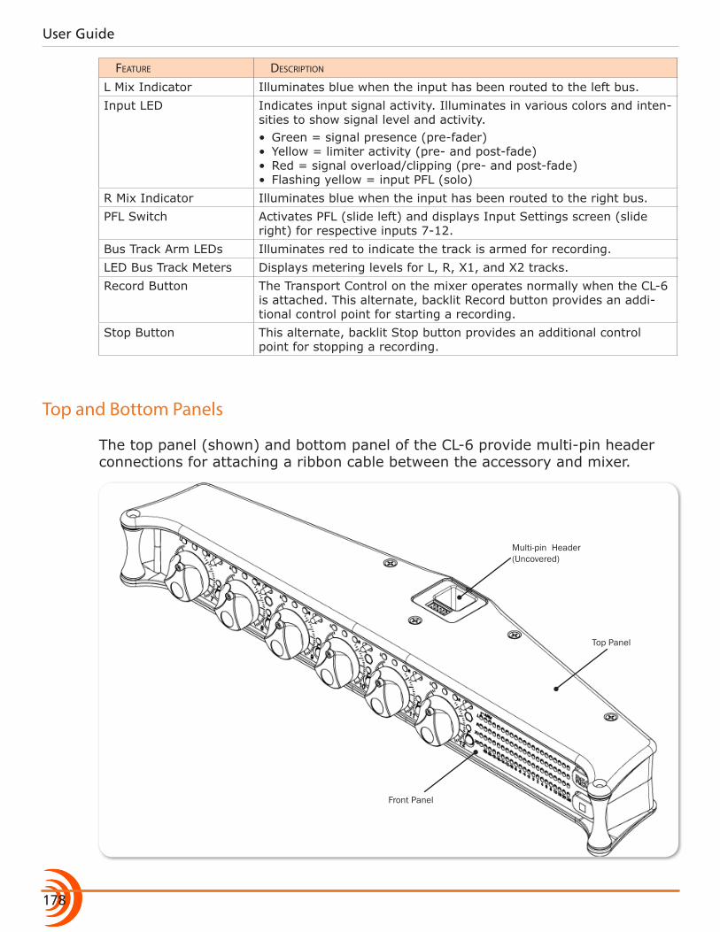
User Guide
178
Feature Description
L Mix Indicator Illuminates blue when the input has been routed to the left bus.Input LED Indicates input signal activity. Illuminates in various colors and inten-
sities to show signal level and activity. • Green = signal presence (pre-fader)• Yellow = limiter activity (pre- and post-fade)• Red = signal overload/clipping (pre- and post-fade)• Flashing yellow = input PFL (solo)
R Mix Indicator Illuminates blue when the input has been routed to the right bus.PFL Switch Activates PFL (slide left) and displays Input Settings screen (slide
right) for respective inputs 7-12.Bus Track Arm LEDs Illuminates red to indicate the track is armed for recording.LED Bus Track Meters Displays metering levels for L, R, X1, and X2 tracks. Record Button The Transport Control on the mixer operates normally when the CL-6
is attached. This alternate, backlit Record button provides an addi-tional control point for starting a recording.
Stop Button This alternate, backlit Stop button provides an additional control point for stopping a recording.
Top and Bottom Panels
The top panel (shown) and bottom panel of the CL-6 provide multi-pin header connections for attaching a ribbon cable between the accessory and mixer.
Multi-pin Header (Uncovered)
Top Panel
Front Panel
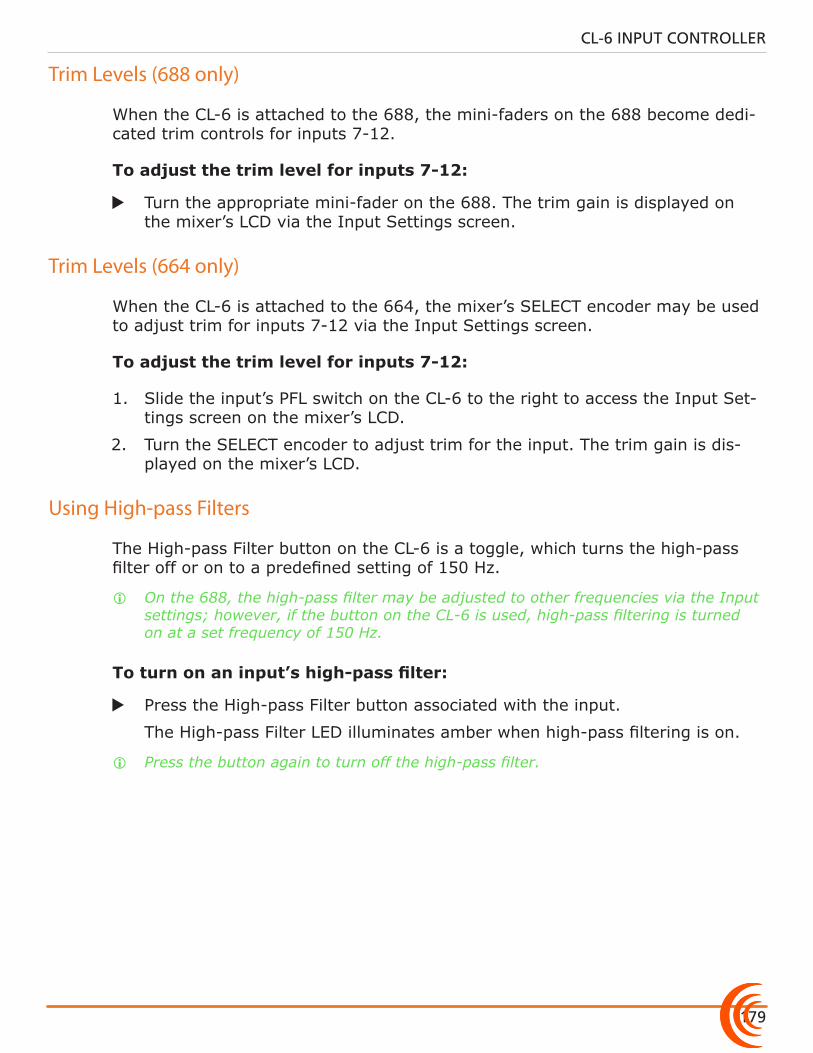
179
CL-6 INPUT CONTROLLER
Trim Levels (688 only)
When the CL-6 is attached to the 688, the mini-faders on the 688 become dedi-cated trim controls for inputs 7-12.
To adjust the trim level for inputs 7-12:
X Turn the appropriate mini-fader on the 688. The trim gain is displayed on the mixer’s LCD via the Input Settings screen.
Trim Levels (664 only)
When the CL-6 is attached to the 664, the mixer’s SELECT encoder may be used to adjust trim for inputs 7-12 via the Input Settings screen.
To adjust the trim level for inputs 7-12:
1. Slide the input’s PFL switch on the CL-6 to the right to access the Input Set-tings screen on the mixer’s LCD.
2. Turn the SELECT encoder to adjust trim for the input. The trim gain is dis-played on the mixer’s LCD.
Using High-pass Filters
The High-pass Filter button on the CL-6 is a toggle, which turns the high-pass filter off or on to a predefined setting of 150 Hz.
i On the 688, the high-pass filter may be adjusted to other frequencies via the Input settings; however, if the button on the CL-6 is used, high-pass filtering is turned on at a set frequency of 150 Hz.
To turn on an input’s high-pass filter:
X Press the High-pass Filter button associated with the input.
The High-pass Filter LED illuminates amber when high-pass filtering is on.
i Press the button again to turn off the high-pass filter.
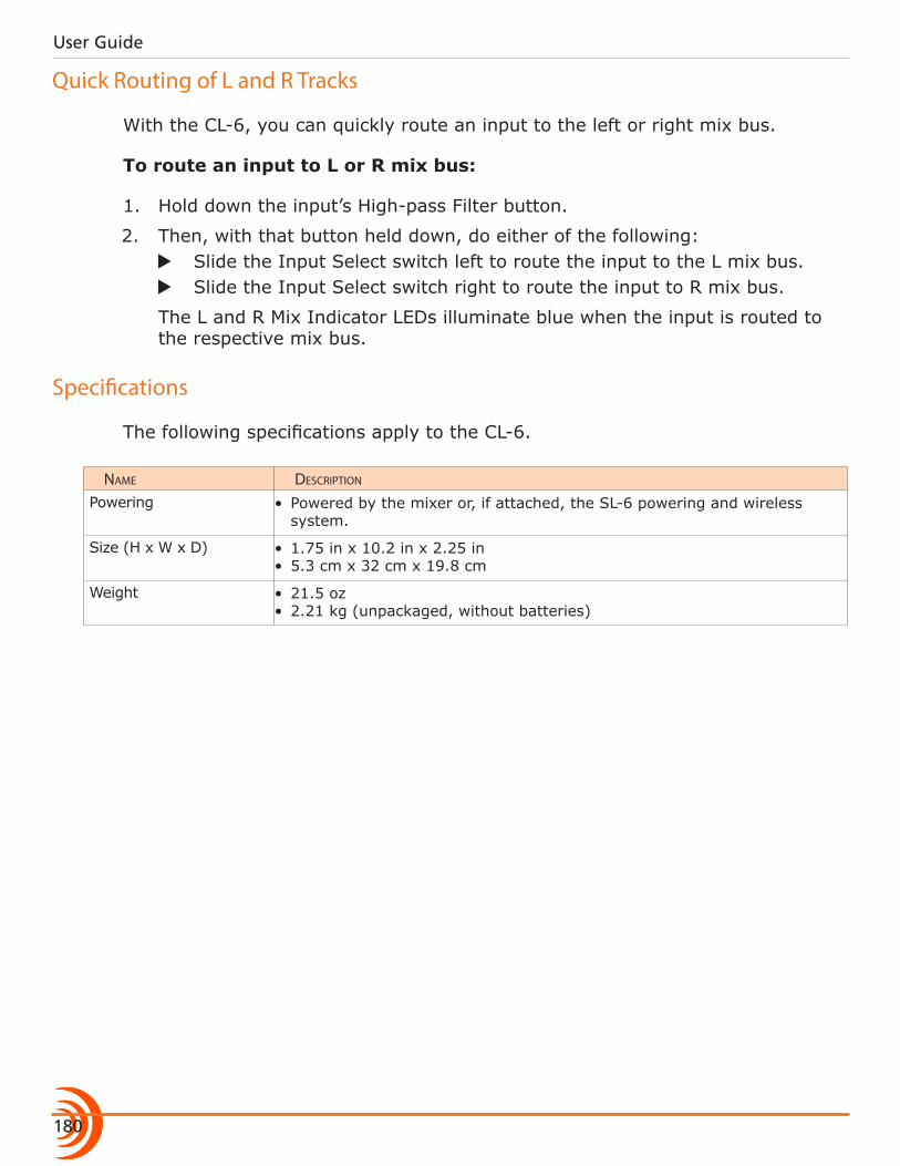
User Guide
180
Quick Routing of L and R Tracks
With the CL-6, you can quickly route an input to the left or right mix bus.
To route an input to L or R mix bus:
1. Hold down the input’s High-pass Filter button.
2. Then, with that button held down, do either of the following: X Slide the Input Select switch left to route the input to the L mix bus. X Slide the Input Select switch right to route the input to R mix bus.
The L and R Mix Indicator LEDs illuminate blue when the input is routed to the respective mix bus.
Specifications
The following specifications apply to the CL-6.
name Description
Powering • Powered by the mixer or, if attached, the SL-6 powering and wireless system.
Size (H x W x D) • 1.75 in x 10.2 in x 2.25 in • 5.3 cm x 32 cm x 19.8 cm
Weight • 21.5 oz • 2.21 kg (unpackaged, without batteries)

181
Included:
Copyright © 2019 • Sound Devices, LLC • All rights reserved.
• CS-688 Production Case • Detachable Windowed Cover• High-quality Shoulder Strap
Features
Manufactured by Portabrace for Sound Devices, this production case with included shoulder strap was designed for use with the 688 or 664 Field Production Mixers, as well as attachable accessories, such as the SL-6 powering and wireless system and the CL-6 input expansion controller.
The case is reversible, so the mixer may be positioned anywhere inside for easy access and versatility.
The production case is made from durable 1000 denier nylon and padded over rigid internal plastic framing for extra protection, shock resistance, durability, and temperature insulation. Other features include:
• Waterproof nylon exterior with layer of anti-skid material on bottom of case
• Adjustable dividers for main compartment and front pocket
• Pockets on each side for wireless transmitters and receivers
• Microphone power supply pocket• Quick zipper access to cable ports on
either side of case
Specifications
name Description
Dimensions (Interior) • 12.8 in x 6.5 in x 8.0 in• 32.4 cm x 16.5 cm x 20.3 cm
Weight • 4.6 lbs• 2.1 kg
CS-688 Production Case for 688 or 664
Published in Reedsburg, WI USA • www.sounddevices.com • Tel: (608) 524-0625 • Email: [email protected]

CS-688
182

180
Software License
End-user license agreement for Sound Devices 6-Series Software / Embedded Firmware
Important Read carefully: This Sound Devices, LLC end-user license agreement (“EULA”) is a legal agreement between you (either an individual or a single entity) and Sound Devices, LLC for the Sound Devices, LLC software product identified above, which includes computer software, embedded firmware, and may include associated media, printed materials, and “online” or electronic documentation (“SOFTWARE PRODUCT”). By using, installing, or copy-ing the SOFTWARE PRODUCT, you agree to be bound by the terms of this EULA. If you do not agree to the terms of this EULA, do not use or install the SOFTWARE PRODUCT.
Software Product License The SOFTWARE PRODUCT is protected by copyright laws and international copyright treaties, as well as other intellectual property laws and treaties. The SOFTWARE PRODUCT is licensed, not sold. Grant of license. This EULA grants you the following limited, non-exclusive rights: In consideration of payment of the licensee fee, Sound Devices, LLC, as licensor, grants to you, the licensee, a non-exclusive right to use this copy of a Sound Devices, LLC software program (hereinafter the “SOFTWARE”) on a single product and/or computer. All rights not expressly granted to licensee are reserved to Sound Devices, LLC. Software ownership. As the licensee, you own the hardware on which the SOFTWARE is recorded or fixed. Sound Devices, LLC shall retain full and complete title to the SOFTWARE and all subsequent copies of the SOFTWARE, regardless of the media or form on or in which the original copies may exist. The license is not a sale of the original SOFTWARE.
CopyrightAll rights, title, and copyrights in and to the SOFTWARE PRODUCT (including, but not limited to, any im-ages, photographs, animations, video, audio, music, text, and “applets” incorporated into the SOFTWARE PRODUCT) and any copies of the SOFTWARE PRODUCT are owned by Sound Devices, LLC or its suppliers. The SOFTWARE PRODUCT is protected by copyright laws and international treaty provisions. Therefore, you must treat the SOFTWARE PRODUCT like any other copyrighted material, except that you may make copies as only provided below. You may not copy the printed materials accompanying the SOFTWARE PRODUCT. Restrictions on use. Licensee may not distribute copies of the SOFTWARE or accompanying materials to others. Licensee may not modify, adapt, translate, reverse engineer, decompile, disassemble, or create de-rivative works based on the SOFTWARE or its accompanying printed or written materials. Transfer restrictions. Licensee shall not assign, rent, lease, sell, sublicense, or otherwise transfer the SOFT-WARE to another party without prior written consent of Sound Devices, LLC. Any party authorized by Sound Devices, LLC to receive the SOFTWARE must agree to be bound by the terms and conditions of this agree-ment.
TerminationWithout prejudice to any other rights, Sound Devices, LLC may terminate this EULA if you fail to comply with the terms and conditions of this EULA. In such event, you must destroy all copies of the SOFTWARE PRODUCT and all of its component parts.
Limited Warranty No warranties. Sound Devices, LLC expressly disclaims any warranty for the SOFTWARE PRODUCT. The SOFTWARE PRODUCT and any related documentation is provided “as is” without warranty or condition of any kind, either express or implied, including, without limitation, the implied warranties and conditions of merchantability, fitness for a particular purpose, or non-infringement. The entire risk arising out of use or performance of the SOFTWARE PRODUCT remains with you. No liability for damages. In no event shall Sound Devices, LLC or its suppliers be liable for any damages whatsoever (including, without limitation, damages for loss of business profits, business interruption, loss of business information, or any other pecuniary loss) arising out of the use of or inability to use this Sound

181
SOFTWARE LICENSE
Devices, LLC product, even if Sound Devices, LLC has been advised of the possibility of such damages. In any case, Sound Devices, LLC’s entire liability under any provision of this evaluation license shall be limited to the greater of the amount actually paid by you for the SOFTWARE PRODUCT or U.S. $5.00. Because some states/jurisdictions do not allow the exclusion or limitation of liability for consequential or incidental damag-es, the above limitation may not apply to you.
Governing Law This agreement and limited warranty are governed by the laws of the state of Wisconsin.
Sound Devices, LLCE7556 Road 23 and 33Reedsburg, Wisconsin 53959 USA
Phone: +1 (608) 524-0625Fax: +1 (608) 524-0655
Product InformationFor more information about products and accessories, visit us on the web at www.sounddevices.com.
Report Documentation ErrorEmail: [email protected]
Customer Support Toll Free: (800) 505-0625
Email: [email protected]://www.sounddevices.com/supporthttp://forum.sounddevices.com
®