SAFETY DEVICES
18
55 SAFETY DEVICES
-
Upload
khangminh22 -
Category
Documents
-
view
4 -
download
0
Transcript of SAFETY DEVICES
55
SAFETY DEVICES
56 www.castel.it
with the atmosphere. For this reason, duringrelief, a gas leak occurs through this orifice.Utilized material: EN 12420-CW617N brass.
Disc: obtained through bar machining andequipped with gasket, it ensures therequired sealing degree on the valve seat.The gasket is made in P.T.F.E.(Polytetrafluorethylene), a material that,during valve estimated service life,maintains a good strength and does notcause the disc to stick on the seat. The discis properly guided in the body and the guideaction can never fail; there are no glands orretaining rings that hamper the movementthereof.Utilized material: EN 12164-CW614N brass.
Spring: it opposes the pressure and thefluid dynamic actions and always ensuresvalve re-closing after pressure relief. Thespring coils, when the disc has reached thelift corresponding to the state of relief at fullflow rate, are spaced apart by at least halfthe wire diameter and, in any case, by notless than 2 mm. The disc is equipped with amechanic lock and when it attains it, thespring set does not exceed 85% of the totalset.Utilized material: DIN 17223-1 steel for springs.
Setting system: hexagonal head, threadedring nut to be screwed inside the body topby compressing the spring below. Onsetting completion, the position attained bythe ring nut is maintained unchanged laying,in the threaded coupling, a bonding agentwith high mechanic strength and lowviscosity features to make penetrationthereof easier. The setting system isprotected against subsequent unauthorizedinterventions by means of a cap nut that isscrewed outside the body and is sealedwith lead to it.
Valves series 3030 are safety devicesaccording to the definition given in Article 1,Point 2.1.3, 2nd dash of 97/23/EC Directiveand are the subject of Article 3, Point 1.4 ofaforesaid Directive.The valves above mentioned are standardtype, unbalanced, direct-loaded safetyvalves. Valve opening is produced by thethrust the fluid under pressure exerts on thedisc, when said thrust exceeds, undersetting conditions, the opposing force of thespring acting on the disc.
Valves are identified by means of:– a model number formed of an
alphanumerical coding that includes:– in the first part the family identification
(e.g. 3030/44C);– in the second part the setting pressure,
expressed in bars, multiplied by 10(e.g. 140);
– a progressive serial number.
Body: squared, obtained through dieforging and subsequent machining. Ithouses the following elements:– the nozzle with flat sealing seat;– the disc guide;– the setting spring holder;– the threaded seat of the setting adjusting
ring nut.
In the body, above the disc guide, a smallpressure relief hole is provided throughwhich the spring holder is put into contact
CONSTRUCTION
GENERAL DESCRIPTION
SAFETY VALVES 3030
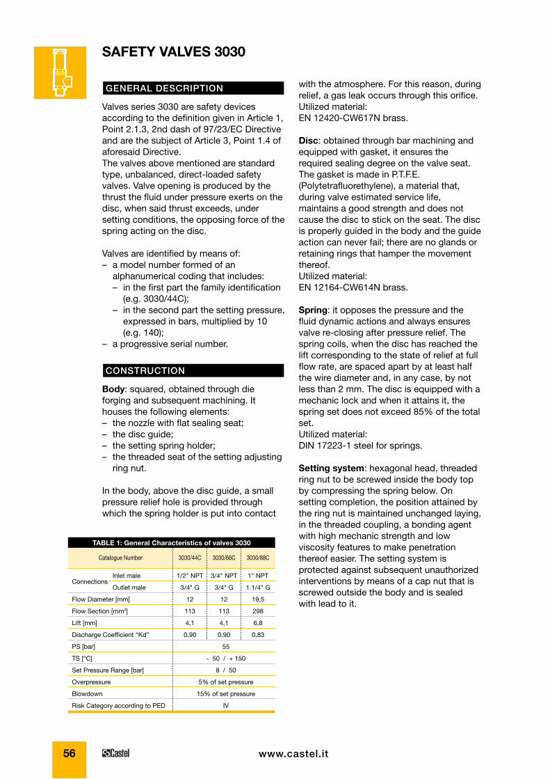
TABLE 1: General Characteristics of valves 3030
1/2" NPT
3/4" G
12
113
4,1
0,90
3/4" NPT
3/4" G
12
113
4,1
0,90
1" NPT
1.1/4" G
19,5
298
6,8
0,83
Catalogue Number 3030/44C 3030/66C 3030/88C
Connections
Flow Diameter [mm]
Flow Section [mm2]
Lift [mm]
Discharge Coefficient “Kd”
PS [bar]
TS [°C]
Set Pressure Range [bar]
Overpressure
Blowdown
Risk Category according to PED
55
- 50 / + 150
8 / 50
5% of set pressure
15% of set pressure
IV
Inlet male
Outlet male
57
SA
FET
Y D
EV
ICE
S
www.castel.it
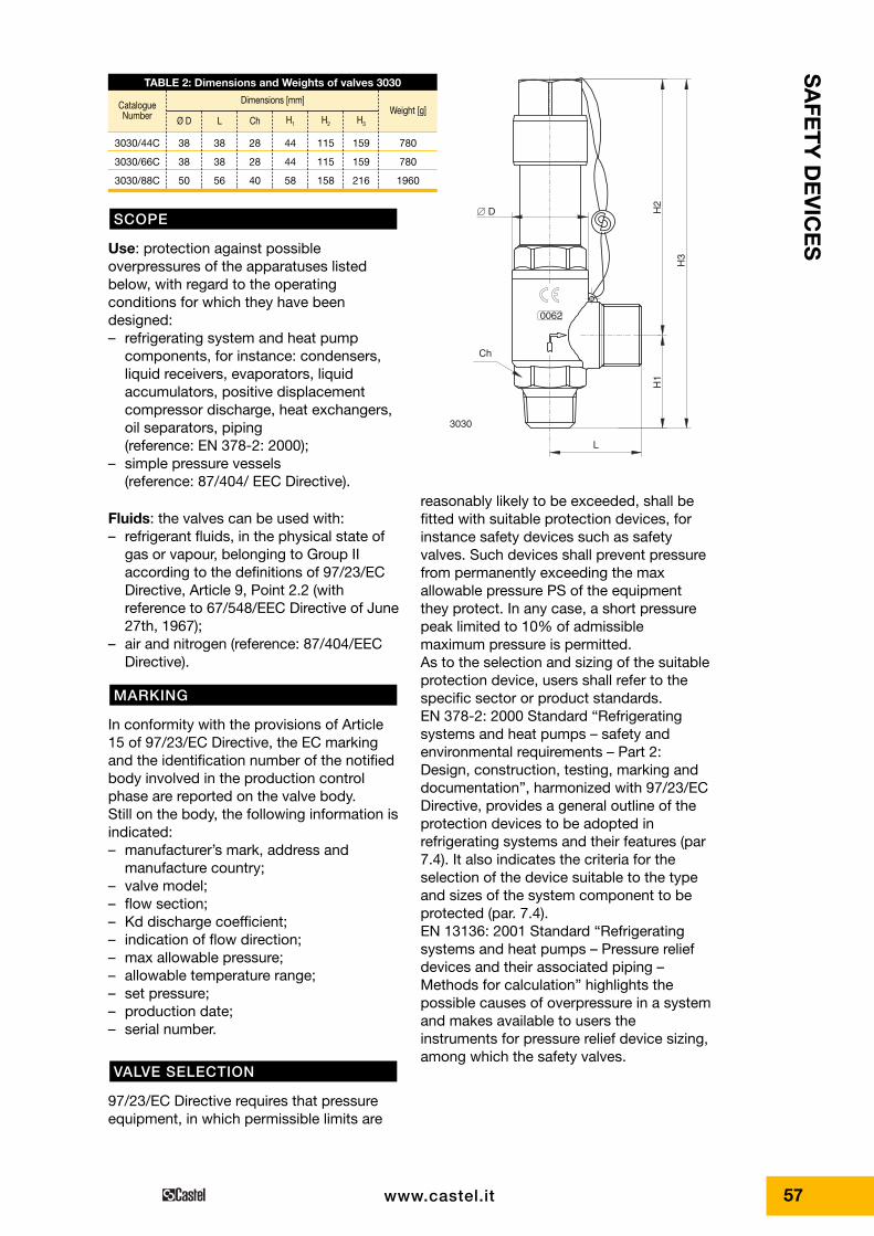
H3
H2
H1
L
� D
Ch
0062
3030
reasonably likely to be exceeded, shall befitted with suitable protection devices, forinstance safety devices such as safetyvalves. Such devices shall prevent pressurefrom permanently exceeding the maxallowable pressure PS of the equipmentthey protect. In any case, a short pressurepeak limited to 10% of admissiblemaximum pressure is permitted.As to the selection and sizing of the suitableprotection device, users shall refer to thespecific sector or product standards.EN 378-2: 2000 Standard “Refrigeratingsystems and heat pumps – safety andenvironmental requirements – Part 2:Design, construction, testing, marking anddocumentation”, harmonized with 97/23/ECDirective, provides a general outline of theprotection devices to be adopted inrefrigerating systems and their features (par7.4). It also indicates the criteria for theselection of the device suitable to the typeand sizes of the system component to beprotected (par. 7.4).EN 13136: 2001 Standard “Refrigeratingsystems and heat pumps – Pressure reliefdevices and their associated piping –Methods for calculation” highlights thepossible causes of overpressure in a systemand makes available to users theinstruments for pressure relief device sizing,among which the safety valves.
Use: protection against possibleoverpressures of the apparatuses listedbelow, with regard to the operatingconditions for which they have beendesigned:– refrigerating system and heat pump
components, for instance: condensers,liquid receivers, evaporators, liquidaccumulators, positive displacementcompressor discharge, heat exchangers,oil separators, piping(reference: EN 378-2: 2000);
– simple pressure vessels(reference: 87/404/ EEC Directive).
Fluids: the valves can be used with:– refrigerant fluids, in the physical state of
gas or vapour, belonging to Group IIaccording to the definitions of 97/23/ECDirective, Article 9, Point 2.2 (withreference to 67/548/EEC Directive of June27th, 1967);
– air and nitrogen (reference: 87/404/EECDirective).
In conformity with the provisions of Article15 of 97/23/EC Directive, the EC markingand the identification number of the notifiedbody involved in the production controlphase are reported on the valve body.Still on the body, the following information isindicated:– manufacturer’s mark, address and
manufacture country;– valve model;– flow section;– Kd discharge coefficient;– indication of flow direction;– max allowable pressure;– allowable temperature range;– set pressure;– production date;– serial number.
97/23/EC Directive requires that pressureequipment, in which permissible limits are
VALVE SELECTION
MARKING
SCOPE
TABLE 2: Dimensions and Weights of valves 3030
CatalogueNumber Weight [g]
Ø D L Ch H1 H2 H3
38
38
50
38
38
56
28
28
40
44
44
58
115
115
158
159
159
216
780
780
1960
Dimensions [mm]
3030/44C
3030/66C
3030/88C
58 www.castel.it
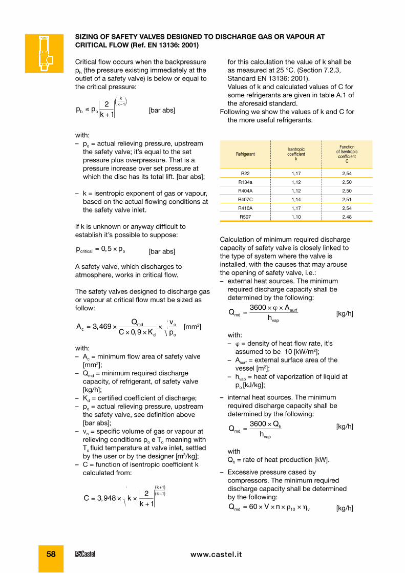
for this calculation the value of k shall beas measured at 25 °C. (Section 7.2.3,Standard EN 13136: 2001).Values of k and calculated values of C forsome refrigerants are given in table A.1 ofthe aforesaid standard.
Following we show the values of k and C forthe more useful refrigerants.
SIZING OF SAFETY VALVES DESIGNED TO DISCHARGE GAS OR VAPOUR ATCRITICAL FLOW (Ref. EN 13136: 2001)
Critical flow occurs when the backpressurepb (the pressure existing immediately at theoutlet of a safety valve) is below or equal tothe critical pressure:
[bar abs]
with:– po = actual relieving pressure, upstream
the safety valve; it’s equal to the setpressure plus overpressure. That is apressure increase over set pressure atwhich the disc has its total lift. [bar abs];
– k = isentropic exponent of gas or vapour,based on the actual flowing conditions atthe safety valve inlet.
If k is unknown or anyway difficult toestablish it’s possible to suppose:
[bar abs]
A safety valve, which discharges toatmosphere, works in critical flow.
The safety valves designed to discharge gasor vapour at critical flow must be sized asfollow:
[mm2]
with:– Ac = minimum flow area of safety valve
[mm2];– Qmd = minimum required discharge
capacity, of refrigerant, of safety valve[kg/h];
– Kd = certified coefficient of discharge;– po = actual relieving pressure, upstream
the safety valve, see definition above [bar abs];
– vo = specific volume of gas or vapour atrelieving conditions po e To meaning withTo fluid temperature at valve inlet, settledby the user or by the designer [m3/kg];
– C = function of isentropic coefficient kcalculated from:
C kk
k
k= × ×
+
+( )−( )
3 9482
1
1
1,
AQ
C Kvpc
md
d
o
o
= ×× ×
×3 4690 9
,,
p pcritical o= ×0 5,
p pkb o
kk
≤+
−⎛⎝⎜
⎞⎠⎟2
1
1
Calculation of minimum required dischargecapacity of safety valve is closely linked tothe type of system where the valve isinstalled, with the causes that may arousethe opening of safety valve, i.e.:– external heat sources. The minimum
required discharge capacity shall bedetermined by the following:
[kg/h]
with:– � = density of heat flow rate, it’s
assumed to be 10 [kW/m2];– Asurf = external surface area of the
vessel [m2];– hvap = heat of vaporization of liquid at
po [kJ/kg];
– internal heat sources. The minimumrequired discharge capacity shall bedetermined by the following:
[kg/h]
withQh = rate of heat production [kW].
– Excessive pressure cased bycompressors. The minimum requireddischarge capacity shall be determinedby the following:
[kg/h]Q V nmd v= × × × ×60 10ρ η
hmdh
vap
=×3600
QA
hmdsurf
vap
=× ×3600 ϕ
RefrigerantIsentropiccoefficient
k
Functionof Isentropiccoefficient
C
R22
R134a
R404A
R407C
R410A
R507
1,17
1,12
1,12
1,14
1,17
1,10
2,54
2,50
2,50
2,51
2,54
2,48
59
SA
FET
Y D
EV
ICE
S
www.castel.it
– ηv = volumetric efficiency estimated atsuction pressure and dischargepressure equivalent to the safety valvesetting.
with:– V = theoretical displacement of
compressor [m3]– n = rotational frequency of compressor
[min –1]– ρ10 = vapour density at refrigerant
saturation pressure / dew point at 10 °C [kg/m3]
Working conditions of compressorcorresponding to the relieving of safetyvalve:Condensing temperature:
+ 64 °C (27,25 bar abs)Evaporating temperature:
+ 10 °C (6,33 bar abs)
These conditions, settled in any case by thedesigner, are considered the mostunfavorable for the safety valve inconsequence of functional defects as:– move mistake;– non-working of automatic safety devices,
set to operate before safety valve.
It shall be excluded:– closeness the refrigerating system, the
presence of flammable substances in solarge quantities to be able to feed a fire.;
– inside the vessel, the presence of a heartsource.
Calculation of minimum dischargecapacityPrudentially leaving the vapour overheatingat the outlet of the liquid cooler out ofaccount, the volumetric efficiency ofcompressor is:
and so the minimum required dischargecapacity:
= 60x0,00224x1450x26,34x0,83=4260 [kg/h]
with ρ10 = 26,34 [kg/m3], vapour density ofR407C at saturation pressure / dew point at10 °C.
Q V nmd v= × × × × =60 10ρ η
ηvdisch e
suction
p
p= − = − =1 0 04 1 0 04
27 256 33
0 83, ,,
,,arg
System descriptionCompact refrigerating system designed tomake refrigerated water and consisting of:– open type reciprocating compressor;– water-cooled, shell-and-tube horizontally
condenser with lower section of shellused as receiver;
– shell-and-tube horizontally liquid coolerfed with a thermostatic valve;
– refrigerant fluid R407C.
Compressor data– Bore 82,5 mm– Stroke 69,8 mm– Cylinder number 6– Rotational frequency 1450 rpm– Clearance 4%The theoretical displacement of compressoris:
[m3]
Maximum allowable pressure of thecondenser, refrigerant side: PS = 25 bar.
Set pressure of the safety valve installed onthe upper shell section of condenser: pset = 25 bar
Actual relieving pressure of safety valve,choosing one valve type 3030 with anoverpressure of 5%:
[bar abs]p pset0 15
1001 27 25= × +⎛
⎝⎞⎠
+ = ,
V = × × × =π4
0 0825 0 0698 6 0 002242, , ,
EXAMPLE OF CALCULATION OF MINIMUM REQUIRED DISCHARGE CAPACITY Qmd ANDSIZING OF THE SAFETY VALVE FOR THE HIGH PRESSURE SIDE OF A REFRIGERATINGSYSTEM
60 www.castel.it
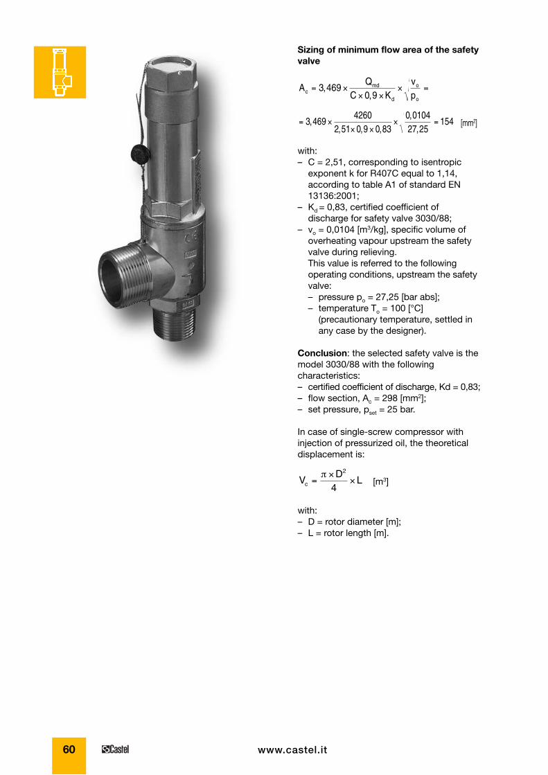
Sizing of minimum flow area of the safetyvalve
[mm2]
with:– C = 2,51, corresponding to isentropic
exponent k for R407C equal to 1,14,according to table A1 of standard EN13136:2001;
– Kd = 0,83, certified coefficient ofdischarge for safety valve 3030/88;
– vo = 0,0104 [m3/kg], specific volume ofoverheating vapour upstream the safetyvalve during relieving.This value is referred to the followingoperating conditions, upstream the safetyvalve:– pressure po = 27,25 [bar abs];– temperature To = 100 [°C]
(precautionary temperature, settled inany case by the designer).
Conclusion: the selected safety valve is themodel 3030/88 with the followingcharacteristics:– certified coefficient of discharge, Kd = 0,83;– flow section, Ac = 298 [mm2];– set pressure, pset = 25 bar.
In case of single-screw compressor withinjection of pressurized oil, the theoreticaldisplacement is:
[m3]
with:– D = rotor diameter [m];– L = rotor length [m].
VD
Lc =×
×π 2
4
= ×× ×
× =3 4694260
2 51 0 9 0 830 010427 25
154,, , ,
,,
AQ
C Kvpc
md
d
o
o
= ×× ×
× =3 4690 9
,,
61
SA
FET
Y D
EV
ICE
S
www.castel.it
with:– A = flow area of safety valve [mm2];– Ain = inside area of inlet tube to valve
[mm2];– Kdr = Kd x 0,9, derated coefficient of
discharge;– C = function of isentropic coefficient k;– ξ = addition of pressure loss coefficients
ξn of any component and piping;The coefficients ξn are relevant to:– pipe elements loss, as connections
and bends;– valves loss;– loss along the pipe and are listed in EN 13136:2001 standard,Table A.4.
Example: assume to install, on thecondenser of the previous example, a safetyvalve type 3030/88, set to 25 bar, using asteel union with the followingcharacteristics:– din = 28 [mm], inside diameter;– Ain = 616 [mm2], inside area;– L = 60 [mm], length;– flush connection to the shell of
condenser, with a broken edge.From table A.4 it’s possible to have thesedata:– ξ1 (inlet) = 0,25– ξ2 (length) = λ x L/ din = 0,02 x 60/28 = 0,043
with λ = 0,02 for steel tube– ξT = ξ1 + ξ2 = 0,25 + 0,043 = 0,293Between safety valve and union it’s installeda shut-off valve type 3033/88 (see page 46).The main characteristics of this valve are:– dR = 20 [mm], inside diameter;– AR = 314 [mm2], inside area;– kv = 20 [m3/h], kv factor.Pressure loss coefficient ξR of shut-off valveis given by:
The total pressure loss coefficient is: ξT + ξR
= 0,933
We remember the main characteristics ofsafety valve 3030/88 and of refrigerant fluidR407C:– A = 298 [mm2]– Kdr = 0,83 x 0,9 =0,747– C = 2,51
Pressure loss in the upstream line is:
∆pp
in
o
= × × ×⎡⎣⎢
⎤⎦⎥
× =0 032298616
2 51 0 747 0 933 0 02452
, , , , ,
ζR = × ⎡⎣⎢
⎤⎦⎥
× =−2 59231420
10 0 642
3, ,
VALVE INSTALLATIONAs far as the installation of safety reliefvalves is concerned, the fundamental pointslisted below shall be taken into account:• safety valves shall be installed near an
area of the system where vapours orgases are present and there is no fluidturbulence; the position shall be asupright as possible, with the inletconnector turned downwards;
• vessels, joined together with pipingrightly selected by the manufacturer andwithout any stop valve between them,may be considered as only one vessel forthe installation of a safety valve;
• the union between the valve and theequipment to be protected shall be asshort as possible. Furthermore, itspassage section shall not be narrowerthan the valve inlet section. In any case,EN 13136: 2001 standard states that thepressure loss between protected vesseland safety valve, at discharge capacity,shall not exceed 3% of the setting value,including any accessory mounted on theupstream line;
• in selecting the safety valve location, itshall be taken into account that valveoperation involves the discharge of therefrigerant fluid under pressure,sometimes even at high temperature.Where the risk exists to cause directinjuries to the persons nearby, an exhaustconveying piping shall be provided, whichshall be sized in such a way as not tocompromise valve operation. EN 13136: 2001 standard states that thispiping shall not generate, at dischargecapacity, a back pressure exceeding 10%of pressure po, for standard type valves,unbalanced.
To calculate the pressure loss either in theupstream line (between vessel and safetyvalve) or in the downstream line (betweensafety valve and atmosphere) refer to EN 13136: 2001 standard, Chapter 7.4.
Pressure loss in the upstream lineCalculation of pressure loss is given by:
∆pp
AA
C Kin
o indr= × × ×
⎡
⎣⎢
⎤
⎦⎥ ×0 032
2
, ζ
62 www.castel.it
Example: assume to install a discharge pipeon safety valve type 3030/88 of the previousexample, using a steel tube nominal size 2”with the following characteristics:– dout = 53 [mm], inside diameter;– Aout = 2206 [mm2], inside area;– L = 3000 [mm], ength;– pipe bend 90° with bending radius R
equal to three times external diameter oftube.
From table A.4 it’s possible to have thesedata:– ξ1 (bend) = 0,25;– ξ2 (length) = λ x L/ din = 0,02 x 3000/53 = 1,13
with λ = 0,02 for steel tube;– ξT = ξ1 + ξ2 = 0,25 + 1,13 = 1,38.
Pressure loss in the downstream line is:
The obtained value is admissible becauselower than the value of 0,10 forecast in EN 13136:2001. standard.
= =∆pp
out
o
0 075,
0 064 1 38298
22062 51 0 747 27 25
27 25
212
, , , , ,
,
× × × × ×⎛⎝
⎞⎠
⎡
⎣⎢
⎤
⎦⎥
=
The obtained value is admissible becauselower than the value of 0,03 forecast in EN 13136:2001. standard.
Pressure loss in the downstream lineCalculation of pressure loss is given by:
with:– A = flow area of safety valve [mm2]– Aout = inside area of outlet tube to valve
[mm2]– Kdr = Kd x 0,9, derated coefficient of
discharge– C = function of isentropic coefficient k– ξ = addition of pressure loss coefficients ξn
of pipingThe coefficients ξn are relevant to:– pipe elements loss, bends;– loss along the pipe and are listed in EN 13136:2001 standard,Table A.4.
∆pp
AA
C K p
pout
o
outdr o
o
=
× × × × ×⎛
⎝⎜
⎞
⎠⎟
⎡
⎣⎢⎢
⎤
⎦⎥⎥
0 0642
12
, ζ
63
SA
FET
Y D
EV
ICE
S
www.castel.it
Valves series 3060 are safety devicesaccording to the definition given in Article 1,Point 2.1.3, 2nd dash of 97/23/EC Directiveand are the subject of Article 3, Point 1.4 ofaforesaid Directive.The valves above mentioned are standardtype, unbalanced, direct-loaded safetyvalves. Valve opening is produced by thethrust the fluid under pressure exerts on thedisc, when said thrust exceeds, undersetting conditions, the opposing force of thespring acting on the disc.
Valves are identified by means of:– a model number formed of an
alphanumerical coding that includes:– in the first part the family identification
(e.g. 3060/45C);– in the second part the setting pressure,
expressed in bars, multiplied by 10(e.g. 140);
– a progressive serial number.
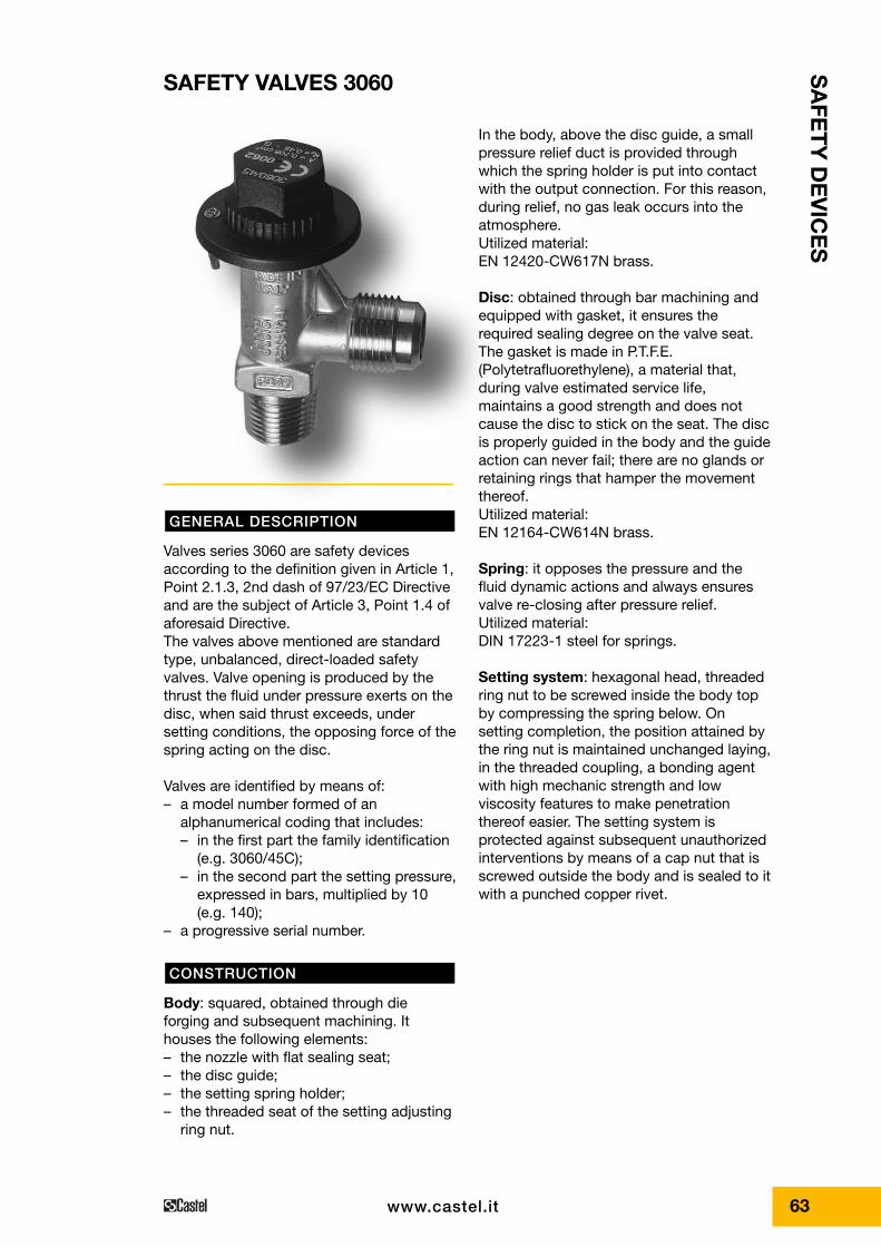
Body: squared, obtained through dieforging and subsequent machining. Ithouses the following elements:– the nozzle with flat sealing seat;– the disc guide;– the setting spring holder;– the threaded seat of the setting adjusting
ring nut.
CONSTRUCTION
GENERAL DESCRIPTION
In the body, above the disc guide, a smallpressure relief duct is provided throughwhich the spring holder is put into contactwith the output connection. For this reason,during relief, no gas leak occurs into theatmosphere.Utilized material: EN 12420-CW617N brass.
Disc: obtained through bar machining andequipped with gasket, it ensures therequired sealing degree on the valve seat.The gasket is made in P.T.F.E.(Polytetrafluorethylene), a material that,during valve estimated service life,maintains a good strength and does notcause the disc to stick on the seat. The discis properly guided in the body and the guideaction can never fail; there are no glands orretaining rings that hamper the movementthereof.Utilized material: EN 12164-CW614N brass.
Spring: it opposes the pressure and thefluid dynamic actions and always ensuresvalve re-closing after pressure relief.Utilized material: DIN 17223-1 steel for springs.
Setting system: hexagonal head, threadedring nut to be screwed inside the body topby compressing the spring below. Onsetting completion, the position attained bythe ring nut is maintained unchanged laying,in the threaded coupling, a bonding agentwith high mechanic strength and lowviscosity features to make penetrationthereof easier. The setting system isprotected against subsequent unauthorizedinterventions by means of a cap nut that isscrewed outside the body and is sealed to itwith a punched copper rivet.
SAFETY VALVES 3060
64 www.castel.it
• allowable temperature range;• production date;• serial number.
The following data are stamped on the cap:• EC marking and the identification number
of the notified body involved in theproduction control phase;
• valve model;• flow section;• Kd discharge coefficient.
97/23/EC Directive requires that pressureequipment, in which permissible limits arereasonably likely to be exceeded, shall befitted with suitable protection devices, forinstance safety devices such as safetyvalves. Such devices shall prevent pressurefrom permanently exceeding the maxallowable pressure PS of the equipmentthey protect. In any case, a short pressurepeak limited to 10% of admissiblemaximum pressure is permitted.As to the selection and sizing of the suitableprotection device, users shall refer to thespecific sector or product standards.EN 378-2: 2000 Standard “Refrigeratingsystems and heat pumps – safety andenvironmental requirements – Part 2:Design, construction, testing, marking anddocumentation”, harmonized with 97/23/ECDirective, provides a general outline of theprotection devices to be adopted inrefrigerating systems and their features (par7.4). It also indicates the criteria for the
VALVE SELECTION
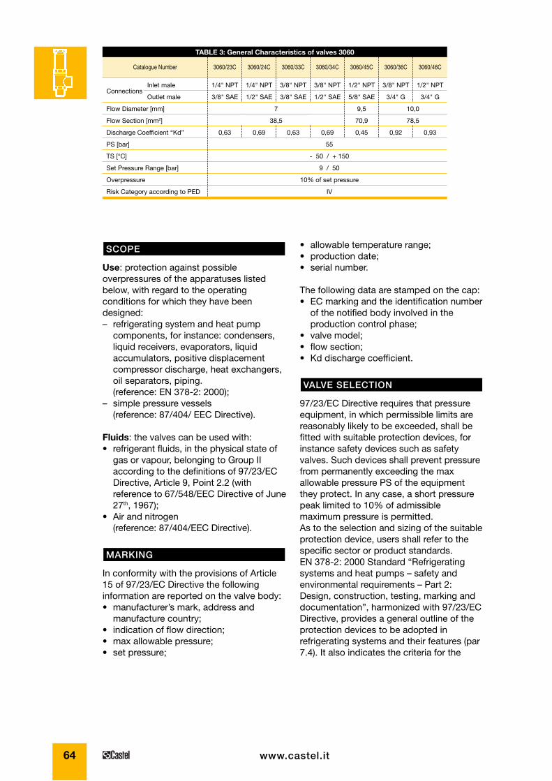
TABLE 3: General Characteristics of valves 3060
1/4" NPT
3/8" SAE
0,63
7
38,5
10,0
78,5
1/4" NPT
1/2" SAE
0,69
3/8" NPT
3/8" SAE
0,63
3/8" NPT
1/2" SAE
0,69
1/2" NPT
5/8" SAE
9,5
70,9
0,45
3/8" NPT
3/4" G
0,92
1/2" NPT
3/4" G
0,93
Catalogue Number 3060/23C 3060/24C 3060/33C 3060/34C 3060/45C 3060/36C 3060/46C
Connections
Flow Diameter [mm]
Flow Section [mm2]
Discharge Coefficient “Kd”
PS [bar]
TS [°C]
Set Pressure Range [bar]
Overpressure
Risk Category according to PED
55
- 50 / + 150
9 / 50
10% of set pressure
IV
Inlet male
Outlet male
Use: protection against possibleoverpressures of the apparatuses listedbelow, with regard to the operatingconditions for which they have beendesigned:– refrigerating system and heat pump
components, for instance: condensers,liquid receivers, evaporators, liquidaccumulators, positive displacementcompressor discharge, heat exchangers,oil separators, piping.(reference: EN 378-2: 2000);
– simple pressure vessels(reference: 87/404/ EEC Directive).
Fluids: the valves can be used with:• refrigerant fluids, in the physical state of
gas or vapour, belonging to Group IIaccording to the definitions of 97/23/ECDirective, Article 9, Point 2.2 (withreference to 67/548/EEC Directive of June27th, 1967);
• Air and nitrogen(reference: 87/404/EEC Directive).
In conformity with the provisions of Article15 of 97/23/EC Directive the followinginformation are reported on the valve body:• manufacturer’s mark, address and
manufacture country;• indication of flow direction;• max allowable pressure;• set pressure;
MARKING
SCOPE
65www.castel.it
� D
L
H1
H2
H3
Ch
3060
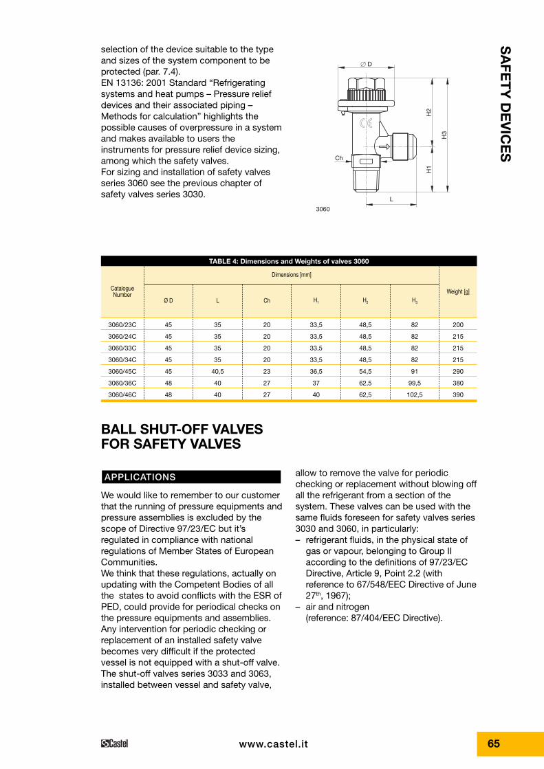
selection of the device suitable to the typeand sizes of the system component to beprotected (par. 7.4).EN 13136: 2001 Standard “Refrigeratingsystems and heat pumps – Pressure reliefdevices and their associated piping –Methods for calculation” highlights thepossible causes of overpressure in a systemand makes available to users theinstruments for pressure relief device sizing,among which the safety valves.For sizing and installation of safety valvesseries 3060 see the previous chapter ofsafety valves series 3030.
TABLE 4: Dimensions and Weights of valves 3060
CatalogueNumber Weight [g]
Ø D L Ch H1 H2 H3
45
45
45
45
45
48
48
35
35
35
35
40,5
40
40
20
20
20
20
23
27
27
33,5
33,5
33,5
33,5
36,5
37
40
48,5
48,5
48,5
48,5
54,5
62,5
62,5
82
82
82
82
91
99,5
102,5
200
215
215
215
290
380
390
Dimensions [mm]
3060/23C
3060/24C
3060/33C
3060/34C
3060/45C
3060/36C
3060/46C
BALL SHUT-OFF VALVES FOR SAFETY VALVES
allow to remove the valve for periodicchecking or replacement without blowing offall the refrigerant from a section of thesystem. These valves can be used with thesame fluids foreseen for safety valves series3030 and 3060, in particularly:– refrigerant fluids, in the physical state of
gas or vapour, belonging to Group IIaccording to the definitions of 97/23/ECDirective, Article 9, Point 2.2 (withreference to 67/548/EEC Directive of June27th, 1967);
– air and nitrogen(reference: 87/404/EEC Directive).
We would like to remember to our customerthat the running of pressure equipments andpressure assemblies is excluded by thescope of Directive 97/23/EC but it’sregulated in compliance with nationalregulations of Member States of EuropeanCommunities.We think that these regulations, actually onupdating with the Competent Bodies of allthe states to avoid conflicts with the ESR ofPED, could provide for periodical checks onthe pressure equipments and assemblies.Any intervention for periodic checking orreplacement of an installed safety valvebecomes very difficult if the protectedvessel is not equipped with a shut-off valve.The shut-off valves series 3033 and 3063,installed between vessel and safety valve,
APPLICATIONS
SA
FET
Y D
EV
ICE
S
66 www.castel.it
A
A
C
H2
H1
H3
L
� D
SEAL
BALL VALVE 3033/..
VALVE 3030/..
SEAL
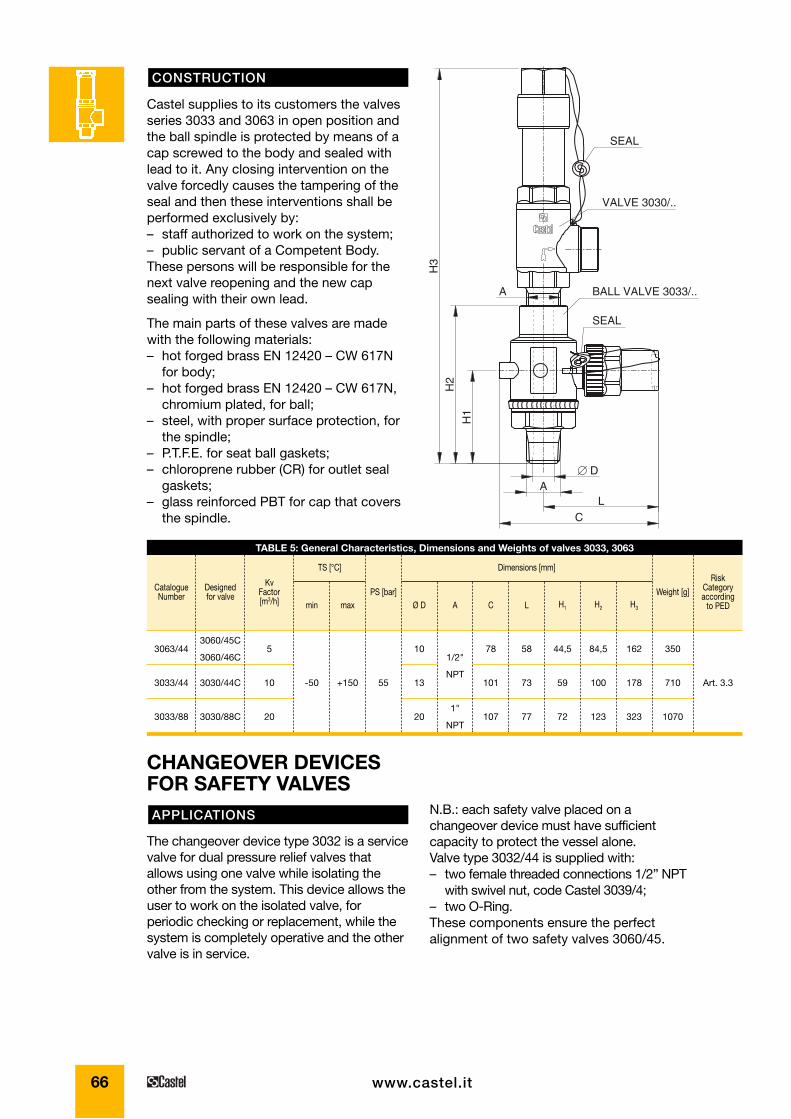
TABLE 5: General Characteristics, Dimensions and Weights of valves 3033, 3063
CatalogueNumber
Designed for valve
Kv Factor[m3/h]
Risk Categoryaccording
to PED
Weight [g]min max
PS [bar]Ø D A C L H1 H2 H3
Art. 3.3
Dimensions [mm]TS [°C]
3063/44
3033/44
3033/88
3060/45C
3060/46C
3030/44C
3030/88C
5
10
20
-50 +150 55
10
13
20
1/2"
NPT
1"
NPT
78
101
107
58
73
77
44,5
59
72
84,5
100
123
162
178
323
350
710
1070
Castel supplies to its customers the valvesseries 3033 and 3063 in open position andthe ball spindle is protected by means of acap screwed to the body and sealed withlead to it. Any closing intervention on thevalve forcedly causes the tampering of theseal and then these interventions shall beperformed exclusively by:– staff authorized to work on the system;– public servant of a Competent Body.These persons will be responsible for thenext valve reopening and the new capsealing with their own lead.
The main parts of these valves are madewith the following materials:– hot forged brass EN 12420 – CW 617N
for body;– hot forged brass EN 12420 – CW 617N,
chromium plated, for ball;– steel, with proper surface protection, for
the spindle;– P.T.F.E. for seat ball gaskets;– chloroprene rubber (CR) for outlet seal
gaskets;– glass reinforced PBT for cap that covers
the spindle.
CONSTRUCTION
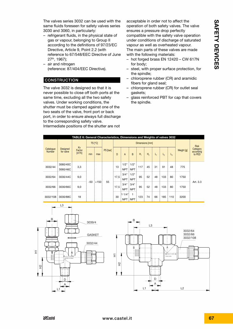
N.B.: each safety valve placed on achangeover device must have sufficientcapacity to protect the vessel alone.Valve type 3032/44 is supplied with:– two female threaded connections 1/2” NPT
with swivel nut, code Castel 3039/4;– two O-Ring.These components ensure the perfectalignment of two safety valves 3060/45.
The changeover device type 3032 is a servicevalve for dual pressure relief valves thatallows using one valve while isolating theother from the system. This device allows theuser to work on the isolated valve, forperiodic checking or replacement, while thesystem is completely operative and the othervalve is in service.
APPLICATIONS
CHANGEOVER DEVICES FOR SAFETY VALVES
67www.castel.it
L3
L2
H1
H1A
CHIUSO-CLOSED
H2
L1
BB A
L1
H2
L3
B
D
A
B
D
A
AB
B
CHIUSO-CLOSED
AB
A
3039/4
GASKET
3032/44
3032/663032/108
3032/64
acceptable in order not to affect theoperation of both safety valves. The valveensures a pressure drop perfectlycompatible with the safety valve operationunder conditions of discharge of saturatedvapour as well as overheated vapour.The main parts of these valves are madewith the following materials:– hot forged brass EN 12420 – CW 617N
for body;– steel, with proper surface protection, for
the spindle;– chloroprene rubber (CR) and aramidic
fibers for gland seal;– chloroprene rubber (CR) for outlet seal
gaskets;– glass reinforced PBT for cap that covers
the spindle.
The valves series 3032 can be used with thesame fluids foreseen for safety valves series3030 and 3060, in particularly:– refrigerant fluids, in the physical state of
gas or vapour, belonging to Group IIaccording to the definitions of 97/23/ECDirective, Article 9, Point 2.2 (withreference to 67/548/EEC Directive of June27th, 1967);
– air and nitrogen(reference: 87/404/EEC Directive).
The valve 3032 is designed so that it isnever possible to close off both ports at thesame time, excluding all the two safetyvalves. Under working conditions, theshutter must be clamped against one of thetwo seats of the valve, front port or backport, in order to ensure always full dischargeto the corresponding safety valve.Intermediate positions of the shutter are not
CONSTRUCTION
TABLE 6: General Characteristics, Dimensions and Weights of valves 3032
CatalogueNumber
Designed for valve
Kv Factor[m3/h]
Risk Categoryaccording
to PED
Weight [g]min max
PS [bar]L3L2L1H2H1
Art. 3.3
Dimensions [mm]TS [°C]
3032/44
3032/64
3032/66
3032/108
3060/45C
3060/46C
3030/44C
3030/66C
3030/88C
3,3
9,0
9,0
18
-50 +150 55
117
95
95
123
45
52
52
74
31
48
48
66
91
133
133
185
48
80
80
110
775
1750
1750
3200
B
1/2"
NPT
1/2"
NPT
3/4"
NPT
1
NPT
A
1/2"
NPT
3/4"
NPT
3/4"
NPT
1 1/4"
NPT
D
13
17,5
17,5
30
SA
FET
Y D
EV
ICE
S
68 www.castel.it
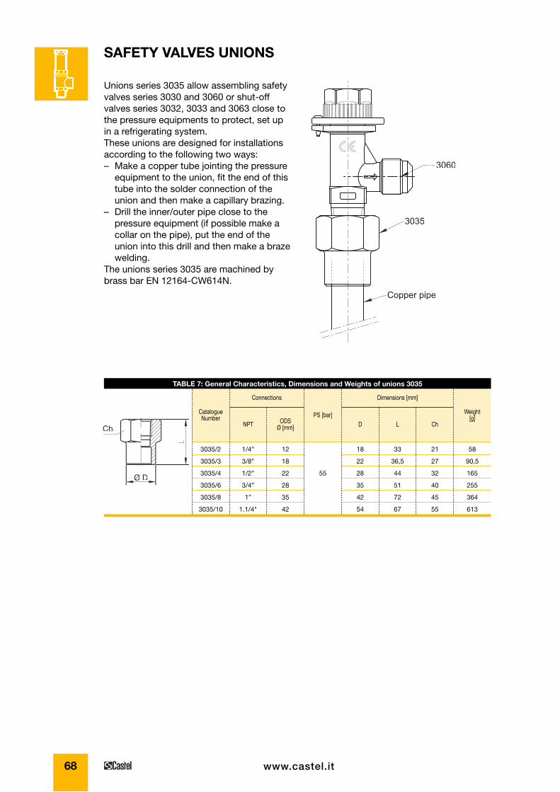
Unions series 3035 allow assembling safetyvalves series 3030 and 3060 or shut-offvalves series 3032, 3033 and 3063 close tothe pressure equipments to protect, set upin a refrigerating system.These unions are designed for installationsaccording to the following two ways:– Make a copper tube jointing the pressure
equipment to the union, fit the end of thistube into the solder connection of theunion and then make a capillary brazing.
– Drill the inner/outer pipe close to thepressure equipment (if possible make acollar on the pipe), put the end of theunion into this drill and then make a brazewelding.
The unions series 3035 are machined bybrass bar EN 12164-CW614N.
SAFETY VALVES UNIONS
Copper pipe
3060
3035
Ø D
L
Ch.
TABLE 7: General Characteristics, Dimensions and Weights of unions 3035
Catalogue Number ODS
Ø [mm]
PS [bar]D L Ch
Weight[g]
NPT
Connections Dimensions [mm]
3035/2
3035/3
3035/4
3035/6
3035/8
3035/10
1/4”
3/8”
1/2”
3/4”
1”
1.1/4"
12
18
22
28
35
42
55
18
22
28
35
42
54
33
36,5
44
51
72
67
21
27
32
40
45
55
58
90,5
165
255
364
613
69
SA
FET
Y D
EV
ICE
S
www.castel.it
In conformity with the provisions of Article15 of 97/23/EC Directive and of Point 7.3.3of EN 378-2 : 2000 Standard the followingdata are reported on the hexagonal nut:• EC marking;• Manufacturer's logo;• Max allowable pressure PS;• Melting point.
If a fusible plug is mounted on a pressurevessel or any other part which it protect itshall be placed in a section wheresuperheated refrigerant would not affect itscorrect function. Fusible plug shall not becovered by thermal insulation. Dischargefrom fusible plugs shall take place so thatpersons and property are not endangeredby the released refrigerant.EN 378-2 : 2000 Standard, harmonized withthe 97/23/EC Directive, establishes that afusible plug shall not be used as the solepressure relief device between a refrigerantcontaining component and the atmospherefor systems with a refrigerant charge largerthan:• 2,5 kg of group L1 refrigerant (ex. R22;
R134a; R404A; R407C; R410A; R507).• 1,5 kg of group L2 refrigerant.• 1,0 kg of group L3 refrigerant.
97/23/EC Directive requires that pressureequipment, in which permissible limits arereasonably likely to be exceeded, shall befitted with suitable protection devices, forinstance safety devices such as fusibleplugs. Such devices shall prevent pressurefrom permanently exceeding the maxallowable pressure PS of the equipmentthey protect. In any case, a short pressurepeak limited to 10% of admissiblemaximum pressure is permitted.As to the selection and sizing of the suitableprotection device, users shall refer to thespecific sector or product standards.EN 378-2 : 2000 Standard “Refrigeratingsystems and heat pumps – safety andenvironmental requirements – Part 2:Design, construction, testing, marking and
FUSIBLE PLUG SELECTION
INSTALLATION
MARKING
Fusible plugs series 3080/.C and 3082/.Care safety devices according to thedefinition given in Article 1, Point 2.1.3, 2nd
dash of 97/23/EC Directive and are thesubject of Article 3, Point 1.4 of aforesaidDirective.According to the definition given in Point3.6.4 of EN 378-1 : 2000 Standard, fusibleplug is a device containing material thatmelts at a predetermined temperature andthereby relieving the pressure.Castel has resolved to classify fusible plugsseries 3080/.C and 3082/.C in the Categoryof Risk I therefore fixing their use, asprotection devices, on specific pressureequipments, proper to the same Category ofRisk I, in compliance with Annex II, Point 2,of 97/23/EC Directive.In consequence of this choice, fusible plugsseries 3080/.C and 3082/.C cannot beused, as sole protection devices, onpressure equipments proper to Categoriesof Risk higher than first.
The body of the fusible plug is an NPT plugdrilled with a taper hole. A predeterminedquantity of fusible alloy, with checkedmelting point, is poured inside this hole.The parts of the fusible plugs are made withthe following materials:• Brass EN 12164 – CW 614N, hot tinned,
for the plug.• Eutectic alloy with several components,
cadmium and lead free, for the fusiblematerial.
Use: the fusible plugs are basically used toprotect the components in a refrigeratingsystem or heat pump against possibleoverpressures, with regard to the operatingconditions for which they have beendesigned, in case of an excessive externalheat source, such as fire.Fluids: the fusible plugs can be used withrefrigerant fluids belonging to Group 2according to the definitions of 97/23/ECDirective, Article 9, Point 2.2 (with referenceto 67/548/EEC Directive of June 27th, 1967).
SCOPE
CONSTRUCTION
GENERAL DESCRIPTION
FUSIBLE PLUGS
70 www.castel.it
– C = function of isentropic coefficient k (asmeasured at 25 °C , see Section 7.2.3 ,EN 13136 : 2001 Standard) calculatedfrom:
To find the values of k and C for the moreuseful refrigerants, see the chapter of safetyvalves series 3030Calculation of minimum required dischargecapacity of fusible plug is closely linked tothe main cause that may arouse the openingof fusible plug, which is the external heatsources.The minimum required discharge capacityshall be determined by the following:
[kg/h]
with– ϕ = density of heat flow rate, it’s assumed
to be 10 [kW/m2]– Asurf = external surface area of the vessel
[m2]– hvap = heat of vaporization of liquid at po
[kJ/kg]
EN 13136 : 2001 Standard also establishesthat the following values for Kdr shall be themaximum used depending on how the pipebetween the vessel and the fusible plug ismounted on the vessel:• flush or flared connection: Kdr = 0,70• inserted connection: Kdr = 0,55
Q
Ahmd
surf
vap
=× ×3600 ϕ
C k
k
k
k= × ×
+
+( )−( )
3 9482
1
1
1,
documentation” provides a general outlineof the protection devices to be adopted inrefrigerating systems and their features (par7.4). It also indicates the criteria for theselection of the device suitable to the typeand sizes of the system component to beprotected (par. 7.4).EN 13136 : 2001 Standard “ Refrigeratingsystems and heat pumps – Pressure reliefdevices and their associated piping –Methods for calculation”, harmonized with97/23/EC Directive, highlights the possiblecauses of overpressure in a system andmakes available to users the instruments forpressure relief device sizing, among whichthe fusible plugs.
As the fusible plugs discharge toatmosphere, they always work in criticalflow (to know the definition of critical flow,see the chapter of safety valves series3030).The fusible plugs must be sized as follow:
[mm2]
with:– Ac = minimum flow area of fusible plug
[mm2]– Qmd = minimum required discharge
capacity, of refrigerant, of fusible plug[kg/h]
– Kdr =derated coefficient of discharge offusible plug, equal to 0,9 x Kd
– po = pressure upstream the fusible plug,inside the equipment to be protected [barabs]
– vo = specific volume of gas or vapour atrelieving conditions po e To , [m3/kg] (To isthe fluid temperature at plug inlet, settledby the user or by the designer)
A
QC K
vpc
md
dr
o
o
= ××
×3 469,
SIZING OF FUSIBLE PLUGS (REF. EN 13136 : 2001)
71www.castel.it
SA
FET
Y D
EV
ICE
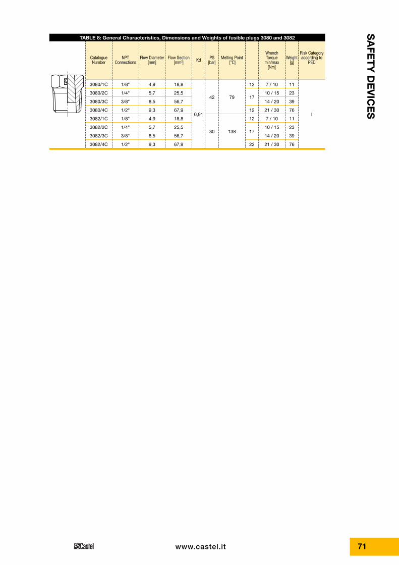
STABLE 8: General Characteristics, Dimensions and Weights of fusible plugs 3080 and 3082
CatalogueNumber
NPTConnections
Flow Diameter[mm]
Flow Section[mm2] Kd PS
[bar]Melting Point
[°C]
Wrench Torque
min/max [Nm]
Weight[g]
Risk Categoryaccording to
PED
3080/1C
3080/2C
3080/3C
3080/4C
3082/1C
3082/2C
3082/3C
3082/4C
1/8"
1/4"
3/8"
1/2"
1/8"
1/4"
3/8"
1/2"
4,9
5,7
8,5
9,3
4,9
5,7
8,5
9,3
18,8
25,5
56,7
67,9
18,8
25,5
56,7
67,9
0,91
42
30
79
138
12
17
12
12
17
22
7 / 10
10 / 15
14 / 20
21 / 30
7 / 10
10 / 15
14 / 20
21 / 30
11
23
39
76
11
23
39
76
I