
Topological triangle characterization with application to object detection from images
22
Topological Triangle Characterization with Application to Object Detection from Images L. G. Nonato, M. A. S. Lizier, J. Batista, M. C. F. de Oliveira and A. Castelo Instituto de Ciˆ encias Matem´ aticas e de Computa¸ c˜ ao Universidade de S˜ ao Paulo Av. Trabalhador S˜ ao-Carlense, 400, Cep: 13560-970 S˜ ao Carlos - SP, Brazil Abstract A novel mathematical framework inspired on Morse Theory for topological triangle characterization in 2D meshes is introduced that is useful for applications involving the creation of mesh models of objects whose geometry is not known a priori. The framework guarantees a precise control of topological changes introduced as a result of triangle insertion/removal operations and enables the definition of intuitive high- level operators for managing the mesh while keeping its topological integrity. An application is described in the implementation of an innovative approach for the detection of 2D objects from images that integrates the topological control enabled by Geometric Modeling with traditional image processing techniques. Object Detection, Object Modeling from Images, Topological Triangle Char- acterization, Morse Operators, 2D Triangular Meshes. 1 Introduction A theory of topology for digital spaces [10,21] is the basis of a range of tech- niques and tools for image segmentation, feature extraction and object detec- tion from images. In this context, topological pixel characterization, i.e., deter- mining the exact situations in which pixels may be removed or inserted from an object representation without changing its topology, plays a fundamental role. Topological tools are also common in Geometric Modeling, particularly in the construction of two – and three-dimensional mesh approximations of “real” objects. These piecewise linear approximations are typically described in terms of primitive cells (usually triangles in the 2D case, or tetrahedrons in Preprint submitted to Elsevier 11 June 2008
Transcript of Topological triangle characterization with application to object detection from images

Topological Triangle Characterization with
Application to Object Detection from Images
L. G. Nonato, M. A. S. Lizier, J. Batista, M. C. F. de Oliveira and A. Castelo
Instituto de Ciencias Matematicas e de ComputacaoUniversidade de Sao Paulo
Av. Trabalhador Sao-Carlense, 400,Cep: 13560-970
Sao Carlos - SP, Brazil
Abstract
A novel mathematical framework inspired on Morse Theory for topological trianglecharacterization in 2D meshes is introduced that is useful for applications involvingthe creation of mesh models of objects whose geometry is not known a priori. Theframework guarantees a precise control of topological changes introduced as a resultof triangle insertion/removal operations and enables the definition of intuitive high-level operators for managing the mesh while keeping its topological integrity. Anapplication is described in the implementation of an innovative approach for thedetection of 2D objects from images that integrates the topological control enabledby Geometric Modeling with traditional image processing techniques.
Object Detection, Object Modeling from Images, Topological Triangle Char-acterization, Morse Operators, 2D Triangular Meshes.
1 Introduction
A theory of topology for digital spaces [10,21] is the basis of a range of tech-niques and tools for image segmentation, feature extraction and object detec-tion from images. In this context, topological pixel characterization, i.e., deter-mining the exact situations in which pixels may be removed or inserted froman object representation without changing its topology, plays a fundamentalrole. Topological tools are also common in Geometric Modeling, particularlyin the construction of two – and three-dimensional mesh approximations of“real” objects. These piecewise linear approximations are typically describedin terms of primitive cells (usually triangles in the 2D case, or tetrahedrons in
Preprint submitted to Elsevier 11 June 2008

3D). Topological cell characterization is also essential in this context, becauseit provides – as in the digital case – the ability to control the topology of theobject being modeled.
Mesh models traditionally used in Geometric Modeling and numerical simula-tion might be employed to represent image features in terms of triangle prim-itives, rather than pixels [24]. Such an approach could, for example, enablealternative implementations of image processing operations such as morph-ing, warping, and detecting and modeling objects from images. An importantaspect in this latter case is that the topological control offered by the Geomet-ric Modeling representations allows more robust object modeling. As precisegeometric information about the target models is not easily obtainable fromthe image, the topological information available can assist in the generationof better approximation models.
The contribution of this work fits exactly into the above scenario: we describe atopological cell characterization that, as previously mentioned, is fundamentalto applications in both image segmentation and geometric modeling. Inspiredon Morse Theory [17], a novel framework for 2D mesh manipulation is derived.This framework guarantees a robust control of the mesh topology as trianglesare inserted/removed and enables the definition of intuitive high-level opera-tors for handling the mesh while keeping its topological integrity. Although weare particularly interested in the representation of image features – and thusrestrict ourselves to 2D triangular meshes in this work – the mathematicalbackground is useful to other applications involving mesh generation in whichprecise information on the geometry of the model to be created is not knowna priori.
The proposed framework is illustrated with an application to a typical imagesegmentation problem, the detection of 2D objects from images. We showhow the integration of techniques from geometric modeling, that operate onpiecewise linear object representations, with techniques from image processingoperating on digital spaces can improve the effectiveness of a simple proceduresuch as thresholding to extract meaningful information from images.
Section 2 presents some related works. In Section 3 we provide the basic con-cepts and notation required to follow the topological triangle characterizationintroduced in Section 4. From such a characterization, a set of operators isdefined that handle all the possible topological changes that may occur astriangles are inserted/removed into a 2D mesh. These operators are then usedto define topologically robust and intuitive high-level operations for trianglecutting and gluing. An implementation of the high-level operators, defined inSection 4, requires a suitable data structure for representing the mesh. Weintroduce such a data structure, called SHE (Singular Handle Edge) in Sec-tion 5. An application to object detection in gray scale image is described in
2

section 6. Final remarks are given in Section 7.
2 Related Work
To place in context the potential applicability of the mathematical frameworkintroduced in this paper we shall consider two classes of approaches adoptedby techniques targeted at processing, analysis and feature extraction from im-ages. The first class comprises techniques that make use of topology in digitalspaces, such as those originated from digital topology [10] and mathematicalmorphology [21]. Such techniques benefit from topological concepts “adapted”to digital spaces to solve important problems such as skeletonization [15], con-nectivity [8] and computation of invariant properties [7]. An important issuein this context is the topological characterization of the basic image elements,i.e., pixels. Solutions to the previous problems, and to many others, eitherexplicitly or implicitly employ such a characterization [18,14].
A second class of techniques for image manipulation exist whose conception,in contrast to the previous one, does not exploit topological concepts. To someof these, topology is not an ally but rather an obstacle to be overcome. A typ-ical example is snakes for image segmentation and shape extraction. Althoughhighly satisfactory results may be obtained with this technique, it faces severedifficulties when applied to objects with complex topology [12]. Another tech-nique that seeks for closed contours is shown in [1]. This edge-based segmen-tation process does not exhibit topology control, but ensures that a single,closed contour with no holes is obtained from an image. Traditional imageprocessing and segmentation techniques based on edges or regions [3,11,4,22];pattern recognition methods [23,5,13] and model-based such as MarkovianRandom Fields (MRF) and Fractals [6,25,19] do not exploit topological prop-erties either.
Handling topology in the representation of unstructured meshes is a commonproblem in Geometric Modeling that has deserved attention by several au-thors. Typically, the problem is tackled with the definition of a topologicaldata structure and a set of operators for manipulating such a structure. Sometopological data structures became popular in the context of two-dimensionalmesh generation and representation. The winged-edge by Baumgart [2], thehalf-edge by Mantyla [16], and the quad-edge by Guibas and Stolfi [9] are wellknown examples that rely on topological operators to maintain mesh consis-tency (incidence and adjacency) and topological control. To manipulate thequad-edge data structure Guibas and Stolfi [9] present basically a single topo-logical operator, the Splice. Baumgart [2] and Mantyla [16] utilize a set ofso-called Euler operators to modify the topological entities contained in thewinged-edge and half-edge data structures, respectively.
3

To implement such an approach we define a topological triangle characteriza-tion and a set of topological operators that manage a novel data structure,called SHE - Singular Handle Edge. SHE is similar to the topological datastructures described in the literature, except that it keeps an explicit repre-sentation of the object border components and explicitly represents singularvertices. The set of operators defined, named Morse operators, differ from ex-isting ones in that its users do not need to be aware of low-level manipulationsof vertices and edges, as operators were conceived to give users a high-levelview of their functionality in terms of triangle manipulation. Triangle cut andglue operations formalized in terms of the Morse operators support a topolog-ically robust management of the data structure and allow the generation of amesh directly from images, with no previous pre-processing step, as illustratedin Section 6. The concept of Morse operators has already been employed ingeometric modeling, however, without a rigorous theoretical framework as theone presented here.
3 Basic Concepts
This section introduces the basic concepts and terminology used in the re-mainder of the text. Definitions and results presented in this and the followingsections are restricted to two-dimensional Euclidean space.
A k-dimensional simplex or k-simplex in R2, 0 ≤ k ≤ 2, is the convex hull
of k+1 linearly independent points in R2 (a set of points x0, ..., xk are linearly
independent if so are the vectors x1 − x0, ..., xk − x0 ). A 0-simplex is calleda vertex, a 1-simplex is called an edge and a 2-simplex is called a triangle. Ifσ is a k-simplex, k = 1, 2, then any j-simplex, 0 ≤ j < k, contained in σ iscalled a face of σ. The interior of a simplex σ is the set of points in σ that donot belong to a face of σ.
A simplicial complex K is a finite collection of simplices satisfying:
(1) If σ ∈ K, then all faces of σ belong to K.(2) If σ, τ ∈ K, then eitherσ ∩ τ = ∅ or σ ∩ τ is a common face of σand τ .
The dimension of K, denoted dim K, is −1 if K = ∅, or the maximum valueamong the dimensions of the simplices for K 6= ∅.
A triangulation T in R2 (2D triangulation) is a simplicial complex of dimen-
sion 2 where all j-simplex in T , j = 0, 1, are contained in at least one 2-simplexof T . The definition of triangulation presented here is quite simple, but suffi-cient for the development of the work. The subset |T | =
⋃τ∈T τ is called the
underlying space of the triangulation T . A triangulation T is called con-
4
nected if for any two points x and y in |T |, there is a continuous curve in |T |connecting x to y. If T = T1 ∪ T2 ∪ ... ∪ Tm, where each Ti, i = 1, ..., m, is aconnected triangulation with Ti ∩ Tj = ∅, then T is said non-connected andeach Ti is called a connected component of T .
Each bounded and connected component of the subset R2 − |T | is called a
hole of the triangulation T . It is not difficult to see that the number of holesin a triangulation is finite (it may be zero), as the number of triangles is alsofinite and the subset R
2 − |T | has exactly one unbounded component.
An edge e (1-simplex) of a 2D triangulation T is an interior edge of T if e isshared by two triangles of T, otherwise, if e is contained in a single triangle ofT , it is called a boundary edge. Let P = (e1, ..., en) be a sequence of distinctboundary edges of T such that ei and ei+1, i = 1, ..., n, (en+1 = e1) have avertex in common. P is said to be a boundary curve of T if, as one “walks”from edge ei to ei+1, the triangles containing ei and ei+1 are always locatedto the left (or, alternatively, to the right) of ei and ei+1 for every i = 1, ..., n.A boundary curve P = (e1, ..., en) is an external boundary curve of T iffor each ei in P , there is a real number ǫ > 0 such that a disk centered inany interior point of ei with radius ǫ does not intersect any hole of T . If Pis a boundary curve and it bounds a hole of T then P is called an internalboundary curve of T .
The star of a vertex v in a triangulation T is the union of all simplices in Tthat contain v. The link of a vertex v is the union of all edges that do notcontain v and are in the triangles forming the star of v. A vertex is singularif its link is not homeomorphic to a circle or to a segment.
Let nv(T ), ne(T ), nt(T ), nc(T ), and nh(T ) be the number of vertices, edges,triangles, connected components, and holes of a triangulation T , respectively.The Euler characteristic of T is given by:
χ(T ) = nv(T ) − ne(T ) + nt(T ) = nc(T ) − nh(T ) (1)
The Euler characteristic is a topological invariant that plays an important rolein topology and has been extensively used in object classification [10].
4 Topological Triangle Characterization and Morse Operators
Let T be a triangulation in R2. A triangle τ is called adjacent to T if τ /∈ T
and τ ∩ T 6= ∅. A triangle τ adjacent to a triangulation T may be defined asa:
5

(1) (−1)-handle if all edges of τ are in T (figure 1(a))(2) 0-handle if either one vertex, or one edge, or two edges of τ are in T
(figure 1(b))(3) 1-handle if either two vertices, or one edge, and one vertex (opposite to
the edge) of τ are in T (figure 1(c))(4) 2-handle if three vertices of τ are in T (figure 1(d))
(a) (b)
(c) (d)
Fig. 1. (a)(−1)-handle; (b) 0-handle; (c) 1-handle; (d) 2-handle
Lemma 1 shows how the addition of a k-handle alters the Euler characteris-tic of a triangulation. The proof is offered in such a way as to illustrate howtopology can be controlled by the attachment of handles.
Lemma 1 Let τ be a k-handle of a triangulation T . Then
χ(T ∪ τ) = χ(T ) − k (2)
Proof.Let τv and τe be, respectively, the number of vertices and edges of τ that arenot in T .
(1) If τ is a (−1)-handle then χ(T ∪ τ) = χ(T ) + τv − τe + 1 = χ(T ) + 0 −0 + 1 = χ(T ) − (−1) = χ(T ) − k, as depicted in figure 2. Attachmentof a (−1)-handle always removes a hole from T , adding +1 to its Eulercharacteristic.
Fig. 2. Attaching a (−1)-handle to T
(2) If τ is a 0-handle then χ(T ∪τ) = χ(T )+τv−τe+1 = χ(T )+0 = χ(T )−kfor all possible kinds of 0-handles, as shown in figure 3. Thus, attachmentof a (0)-handle keeps the Euler characteristic of T unchanged.
(3) If τ is a 1-handle then two cases must be considered: the 1-handle is eitherattached to a single boundary component introducing a new hole in T
6

(a) (b) (c)
Fig. 3. Attaching a 0-handle to T . (a) by a vertex; (b) by one edge; (c) by two edges.
(figure 4 (a) and (b)), or it is attached to different boundaries components,joining two connected components (as shown in figure 4 (c) and (d)). Inboth cases the corresponding topological change is given by χ(T ∪ τ) =χ(T ) + τv − τe + 1 = χ(T ) − 1 = χ(T ) − k.
(a) (b)
(c) (c)
Fig. 4. (a) and (b) attaching a 1-handle and generating a hole; (c) and (d) attachinga 1-handle between two different boundary components.
(4) If τ is a 2-handle then three different types of attachment are possible,namely: a) the three vertices are in a single boundary component; b) twovertices are in a single boundary component and the third one is in adifferent connected component; c) each vertex is in a distinct connectedcomponent. In the first case addition of τ introduces two new holes inT (figure 5 (a)). In the second case, attaching τ introduces a new holeand removes a connected component from T (figure 5 (b)). In the lastcase, two connected components are removed (figure 5 (c)). In all suchcases the Euler characteristic changes according to the following equation:χ(T ∪ τ) = χ(T ) + τv − τe + 1 = χ(T ) − 2 = χ(T ) − k.
(a) (b)
(c)
Fig. 5. Attaching a 2-handle to (a) a single boundary component; (b) two differentboundary components; (c) three different boundary components
As lemma 1 contemplates all the topological changes that can be possiblyintroduced by the insertion of a new triangle to a triangulation, it allows a
7

complete characterization of triangles regarding the topological changes intro-duced by their insertion or removal. Morse operators are defined in a straight-forward manner based on the results of this lemma. They are grouped intofour different categories according to the topological change introduced in thetriangulation. The following symbols are used to describe the possible actionsof each operator over the topological entities they handle: M - make; K -kill; T - triangle; H - hole; S - singular vertex; E - edge identifying; and C -component. The four categories with their respective operators are:
• MO−1 = {MEEETKH};• MO0 = {MST ,MET ,MEET};• MO1 = {MTC,MSSTH ,MSETH ,MSSTKC,MSETKC};• MO2 = {MSSSTHH ,MSSSTHKC,MSSSTKCC}.
The symbols naming an operator provide a summary description of its actionon the triangulation. For example, the symbols MEET naming an operatorin MO0 indicate that this operator introduces (i.e., makes) two edge identify-ing and a triangle; the symbols MSSSTHKC in MO2 means that it makesthree singular vertices, a triangle and a hole, and kills a component; and thesymbol MSETKC in MO1 means that it makes a singular vertex, an edgeidentifying, and a triangle, and kills a component.
Each category groups operators that introduce similar changes in mesh topol-ogy: different handle types result in different topological changes, correspond-ing to the four possible situations treated in lemma 1. Thus, operators incategory MO−1 attach (−1)-handles to the existing triangulation, those inMO0 attach 0-handles, and so on. In general, operators in category MOk,k = −1, 0, 1, 2 add a k-handle to the triangulation, thus changing the mesh’sEuler characteristic by an order k, i.e., after applying an MOk operator themesh’s current Euler characteristic is changed from χ(T ) to χ(T ) − k.
The above operators are called direct operators, as they may be used to addtriangles to an existing mesh. Operators for removing triangles are describedin terms of their inverse operators, which may be obtained by replacing let-ters M with Ks (and vice-versa) in the above description. Inverse operatorsare also grouped into four categories according to the topological change theyintroduce. The four categories are:
• IMO−1 = {KTC,KSSTH ,KSETH ,KSSTMC,KSETMC};• IMO−2 ={KSSSTHH ,KSSSTHMC,KSSSTMCC};• IMO0 = {KST ,KET ,KEET};• IMO1 = {KEEETMH}.
Analogously to the direct operators, operators in category IMOk, k = −1,−2, 0, 1remove a k-handle from the triangulation, thus changing the mesh’s Euler
8

characteristic by an order k, i.e., after applying an IMOk operator the mesh’scurrent Euler characteristic is changed from χ(T ) to χ(T ) − k.
Theoretically, not all operators are required to generate a triangulation with aspecific topology. Actually, four of them are enough to generate triangulationsof arbitrary topologies, as shown by the proof of proposition 1 below. How-ever, to build an arbitrary triangulation with only four operators (and theirinverses) one must find an appropriate triangle insertion sequence, which maynot be an easy task if the triangles comprising the whole triangulation arenot known a priori, as it is common in several applications. Thus, the wholeset of operators becomes necessary to better handle arbitrary topologies andgeometries. Although it may not be useful from a practical point of view, thefollowing proposition does offer a theoretical guarantee that only four of theMorse operators are sufficient to generate triangulations.
Proposition 1 Only four Morse operators are enough to build any triangu-
lation in R2.
Proof.Let W be the subspace in R
5 generated by v − e + f − c + h = 0. Note thatany triangulation may be represented as a vector in W , the set of valid trian-gulations is a subset of W , and each Morse operator can also be described asa vector in W . For example, operator MSSTH may be represented by vector(1, 3, 1, 0, 1), meaning that it introduces one new vertex, three new edges, onenew triangle and one new hole in the triangulation.
Let x1 = (3, 3, 1, 1, 0), x2 = (1, 3, 1, 0, 1), x3 = (2, 3, 1, 0, 0), and x4 = (1, 2, 1, 0, 0)be the vector representations of operators MTC, MSSTH , MST , and MET ,respectively. A straightforward computation shows that x1, x2, x3 and x4 arein W and are linearly independent. So, MTC,MSSTH , MST , and METdefine a base to subspace W , thus generating any triangulation.
Note that other sets of four linearly independent operators could generatethe topological triangulation classes.
It is also worth pointing out that if singular vertices were not allowed, onlyfour Morse operators would enable the description of triangle cut and glue op-erations. But, as shown in proposition 2 bellow, singular vertices are requiredto handle general 2D meshes.
Proposition 2 . It is not possible to generate a triangulation with holes, by
gluing triangles, without adding singular vertices to the triangulation during
the process.
9

Proof.Suppose, without any loss of generality, that T is a connected triangulationwithout holes constructed by gluing triangles, for example, by using operatorsMTC, MET , and MEET . To generate a hole in T it is necessary to attacha 1-handle to it. The only operators capable of doing that are MSSTH andMSETH , and both introduce singular vertices. The same occurs if two holesare added to the triangulation by the operator MSSSTHH .
5 The Singular Handle-Edge Data Structure
The Singular Handle-Edge (SHE) data structure for representing two-dimensionalmeshes is tailored for manipulation by Morse Operators, as it can handle sin-gular vertices and includes an explicit representation of the boundary curvesof a triangulation. Although explicit representation of boundary curves is notcommon in topological data structures, it is essential for a correct implemen-tation of the Morse operators. Moreover, it simplifies storage of the contouringconditions that typically appear in numerical simulations. Another favorablefeature of the explicit representation of boundary curves is that it restricts thesearch for where to insert a triangle in a gluing operation, as new trianglesare always attached to boundary curves. SHE is organized in terms of eightexplicitly represented entities (or nodes), which are:
• SHE – Represents the whole mesh;• Mesh – Represents each connected component in the mesh;• Vertex – Represents the vertices in the mesh;• Half-edge – Represents an edge contained in a face;• Sing – Represents each singular component incident to a vertex;• Face – Represents the faces or cells in the mesh;• Boundary-curve – Represents the boundary curves in the mesh;• Boundary-edge – Represents the boundary edges.
The entities Half-edge, Sing and Boundary-edge are stored in circular dynamiclists, whilst the remaining entities are stored in non-circular lists. The rela-tionships amongst the entities are shown in figure 6. SHE points to the list ofMeshes and to the list of Vertices. Each Mesh points to the lists of its Faces andBoundary-curves (figure 6(a)). Each Vertex points to its Sing list (figure 6(b)).The Half-edge is always oriented and points to its tail vertex. The Half-edgenode also points to the Half-edge in its adjacent face if it is not in a boundary,otherwise it points to a Boundary-edge entity (figure 6(c)). Each Sing pointsto a Half-edge that “leaves” its associated vertex. If the vertex is a singularone then it has an associated Sing circular list, and each element in this listpoints to a Halfedge in the boundary of each component forming the singular-ity (figure 6(d)). Each Face node points to the circular list of Half-edges that
10

defines its orientation (figure 6(e)). The Boundary-curve points to a circularlist of its Boundary-edges. Each Boundary-edge points to the Boundary-curvein which it is contained and to the Half-edge it represents (figure 6(f)).
(a) (b) (c)
(d) (e) (f)
Fig. 6. Relationships amongst the entities constituting the SHE data structure.
5.1 Implementation
The data structure and a complete set of methods to access its stored infor-mation have been implemented in C++. Geometric data can also be modifiedthrough specific methods. Topological consistence is ensured with the use ofthe Morse operators to manipulate the structure, and the implementationenforces their use, so that mesh topology can only be manipulated throughthem. The operators were implemented as friend functions of the classes defin-ing the data structure. A mechanism called iterator is offered to traverse theelements of SHE, which allows scanning the lists with a simple FOR loop.Methods defined for each class are responsible for initializing and finishingthe iterator. For example, the following code could be employed to print thecoordinates of all vertices in the mesh by traversing its Vertex list:
Iterator<SHE_Vertex> iv;
for (iv = s->Begin_vertex(); iv.NotFinish(); ++iv)
cout << iv->Get_x() << iv->Get_y();
where s is a pointer to a SHE object. The main advantage of the iterator isthat it encapsulates the lists from the user and standardizes access to them.
11

5.2 Complexity
Due to the adjacency and incidence relations stored in SHE the time to obtainthe neighborhood of a given topological element is proportional to the numberof elements in that neighborhood. Such analysis is typically found in textsdescribing topological data structures [16]. In this section we focus on thecomplexity analysis of the Morse operators on SHE.
Surely the most expensive operation involving the Morse operators is locatingwhere to insert a new triangle. Without an auxiliary structure, the cost of at-taching a new triangle to the mesh is proportional to the time spent traversingthe boundary lists plus the time to modifying the structure in the neighbor-hood of the region where the triangle is to be inserted. If M is the number ofboundary edges and L is the cost of the structure’s local update, then the totalcost is O(M + L) for each new triangle to be inserted. As SHE offers efficientaccess to the neighborhood of the elements, complexity of the Morse operatorsis dominated by the search in the boundary curves. A geometrical search tree[20] can be employed to improve the search process, so that attachment of anew triangle can be executed in O(log(M) + L).
For example, let us consider the cost of the local update for attaching the high-lighted triangle to the mesh depicted in figure 7(a) with operator MSSTH .This operator will introduce a hole and a boundary curve to the triangulation.This new boundary curve can be constructed from the old one as follows: in-stanciate a new boundary curve, transfer the curve segment between the twosingular vertices from the current boundary curve to the new one, and closeboth curves with the appropriate edges of the new triangle. As the SHE datastructure keeps all the adjacency and incidence relationships, the transfer ofthe curve segment can be accomplished by straightforward pointer manip-ulation. The Sing entities associated to both singular vertices must also beupdated.
Fig. 7. Creating a new boundary curve.
12

6 Application to Object Detection in Gray Scale Images
We illustrate how the topological Morse operators and its associated SHE datastructure, which realize the topological characterization introduced in Section4, provide a powerful tool to detect target objects and segment regions of in-terest from images. We shall make our point using the MRI gray level imagein figure 8, which has intensity values in the range 0–255. This is handledwith a software that creates a mesh model from a given image according touser input parameters that define a mesh resolution and a target thresholdrange. The mesh resolution specifies the coarseness of an imaginary grid thatis superposed to the image, as depicted in figures 9(a) and 9(b). Resolutiondefines how many pixels are contained in a triangle, the primitive mesh ele-ment. In the grid depicted in figure 9(a), grid resolution is 48 pixels, implyingthat a triangle has an horizontal (vertical) edge length equal to 48 pixels. Infigure 9(b) grid resolution is 24 pixels. The threshold range selected providesan initial approximation of the region of interest in the image.
From these two inputs, a mesh may be derived as follows. From each triangle inthe imaginary grid it is determined whether one of its vertices corresponds to apixel value within the user-defined threshold. If so, the corresponding triangleis added to the mesh triangulation by the appropriate Morse operator. Thesoftware automatically chooses the correct operator based on the geometricintersection between the triangle being inserted and the mesh, evaluating howthis intersection relates with the topological entities. This is done for all gridtriangles. Using the Morse operators to construct the mesh ensures full controlover the mesh topology, i.e., one keeps track of the exact number of connectedcomponents and holes in the mesh after each triangle insertion. Thus, a usercan also specify a desired topology, establishing the desired number of compo-nents and holes in the resulting mesh. Undesired components and holes maybe removed using the appropriate operators. The software used to producethe examples below implements this approach operating over the SHE datastructure.
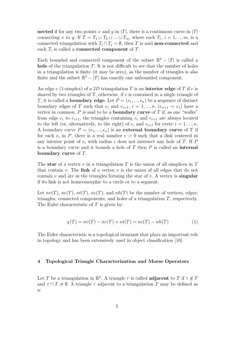
Let us assume a user wishes to extract the region corresponding to the brainand medullae from the image in figure 8, isolating it from the outer regionsthat correspond to other elements such as the nose and skull. The first taskfor the user is to search for a suitable threshold range that successfully coversthe target region. Figure 10(a) shows the shaded mesh model representation ofall the connected components detected in this image, for a threshold intervalgoing from 120 to 235, with a grid resolution of two pixels. Just to provide aview of the mesh model, figure 10(b) depicts a zoom of the mesh correspondingto the region delimited by the rectangle in figure 10(a).
The above threshold range detects the brain and medulla as desired, how-
13

Fig. 8. A sagittal MRI image of the head. Source:http://www.rrvr.net/images/AIRIS/brain.jpg.
ever, regions that clearly do not correspond to brain are also detected andincluded in the mesh model. In addition to components that do correspondto identifiable “objects” in the image (such as brain, skull bone and tissue,nose), noisy regions were also detected as isolated components, as it wouldbe expected from any threshold detecting technique. The resulting mesh hasa total of 88 distinct components – each component corresponds to a singleconnected region – and 155 holes. The advantage of our approach over othersegmentation techniques is that the underlying topological framework givesthe user full control over components and holes. Moreover, such a frameworkis completely transparent to the user.
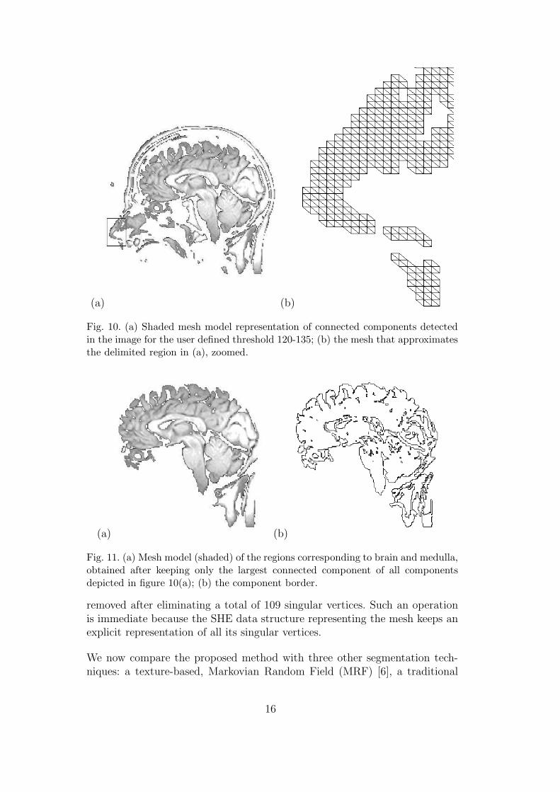
Now, the goal is to isolate the brain, which is known to consist of a singleconnected region with no holes. In this particular case, it is also clear thatthe region corresponding to the brain is the larger one in the image. The usermay set a parameter “number of components” to one, causing only the largestcomponent (the one with the highest number of triangles) to be kept, andthe other ones to be removed using the inverse Morse operators describedin Section 4. It is worth noting that criteria other than size could be usedto keep/remove components. This is just an implementation choice. Figure11(a) shows the resulting shaded mesh model, which provides a very goodapproximation model for the brain region contained in the original image.The border is depicted in figure 11(b).
The mesh now consists of a single component, which corresponds well to theregions of brain and medulla. However, the model still has “non-existing” (i.e.,
14

(a)
(b)
Fig. 9. Original image with superposed grid to generate approximation mesh. (a)grid resolution is 48 pixels (length of horizontal/vertical edges); (b) grid resolutionis 24 pixels.
in the “real” object) holes (117, in fact). Our framework allows these holes tobe removed by running the program with a parameter “number of holes” setto zero. Figures 12 (a) and (b) show the resulting mesh and its border, whenthe number of holes is set to zero.
Further processing may be applied. For example, if all mesh triangles thatinclude a singular vertex are removed, mesh regions that are loosely connectedmay be separated into different components. The effect of disconnecting theloosely connected components in the mesh from figure 12 is shown in figure13. Note that the region at the bottom right-hand corner of the image were
15
(a) (b)
Fig. 10. (a) Shaded mesh model representation of connected components detectedin the image for the user defined threshold 120-135; (b) the mesh that approximatesthe delimited region in (a), zoomed.
(a) (b)
Fig. 11. (a) Mesh model (shaded) of the regions corresponding to brain and medulla,obtained after keeping only the largest connected component of all componentsdepicted in figure 10(a); (b) the component border.
removed after eliminating a total of 109 singular vertices. Such an operationis immediate because the SHE data structure representing the mesh keeps anexplicit representation of all its singular vertices.
We now compare the proposed method with three other segmentation tech-niques: a texture-based, Markovian Random Field (MRF) [6], a traditional
16

(a) (b)
Fig. 12. (a) The same component from figure 11 after removing all holes; (b) thecomponent border.
Fig. 13. The brain model in figure 12 after disconnecting loosely connected regionsby removing singular vertices from the component. This produces two components,corresponding to the brain and the medullae (in the lower right region in figure 12),of which only the larger component (the brain) is shown here.
K-means clustering algorithm [23]and a border tracker [1]. Figures 14(a) and14(c) are the segmented images by the MRF and K-means clustering methods,respectively. Five distinct classes have been considered in both cases. Whilethe Markovian approach models textures within the image, the K-means clus-tering in this case has been performed with the pixel intensity as a singlefeature. Figures 14(b) and 14(d) show the boundaries extracted from their re-spective counterparts 14(a) and 14(c). The lack of topological control in bothtechniques yields a great amount of small contours, many of which are of noanatomical meaning. In order to obtain the same behaviour as the one pro-vided by the topological control, segmentation by region based techniques suchas MRF and K-means would require some post-processing, which, in general,is highly user dependent.
Figure 15 illustrates the detected object (15(a)) and its respective countor
17

(a) (b)
(c) (d)
Fig. 14. Segmentation by MRF and K-means clustering for 5 classes. (a) Segmentedimage by k-means clustering; (b) extracted boundaries; (c) Segmented image byMRF; (d) extracted boundaries
(15(b)) produced by the border tracker method. This result somehow resem-bles that shown in Figure 13, in which all holes and loosely connected regionshave been removed. The major difference is that while in the former the singleclosed contour is an inherent - an the only possible - outcome of the bordertracker approach (which always looks for contours of such nature), in the pro-posed method a single component is just one choice - out of many - madepossible by the topological control provided. Furthermore, the proposed topo-logical approach is less prone to noise and provides not only the contours butalso the content of the region.
The mesh models thus extracted may be used in applications that typicallyhandle geometric models. As an illustration, figure 16 shows an elastic defor-mation being applied to the brain model extracted from figure 8. This type
18

(a) (b)
Fig. 15. Image segmentation by border tracking: (a) single region with no holes; (b)component border
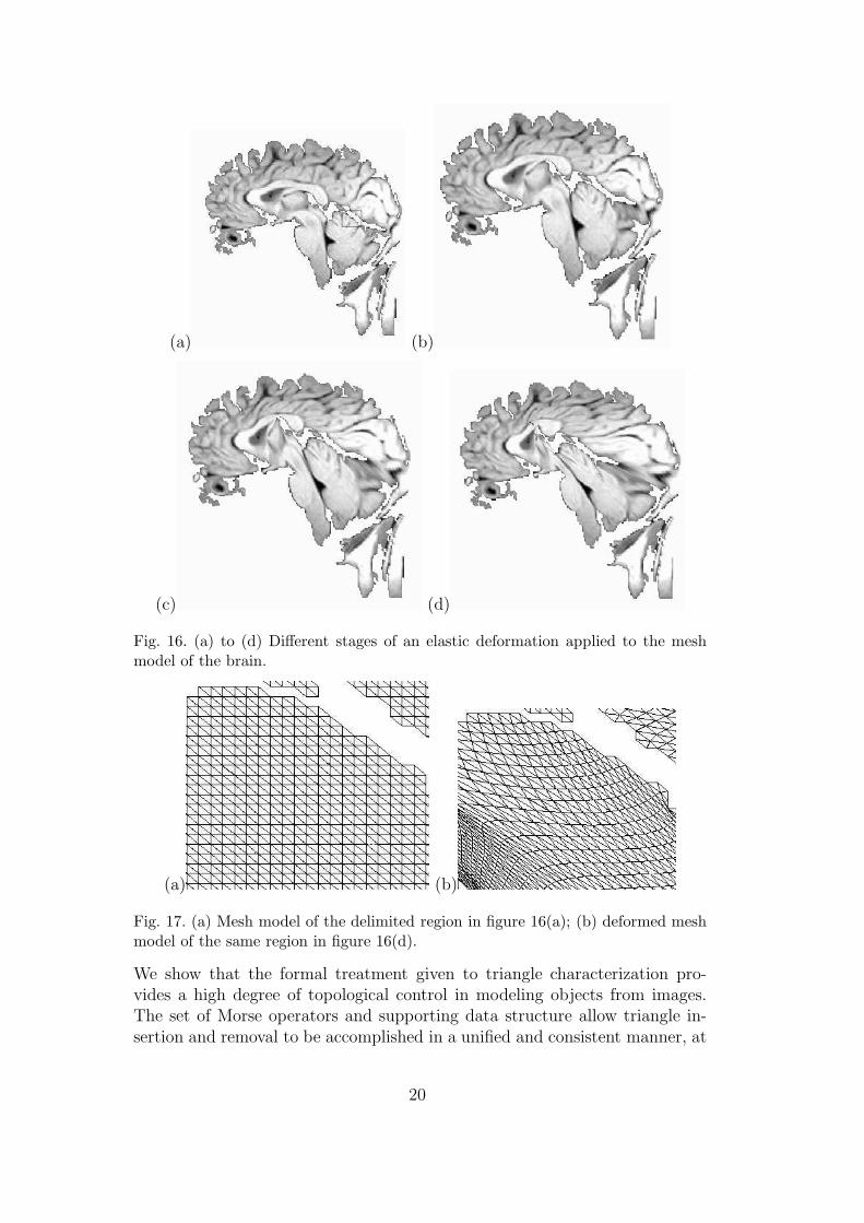
of deformation is widely used in problems in which a model must be adjustedto fit a second model, for example to assess how much two objects differ. Ameasure of the deformation required to fit the two models may be employedas an estimate measure of their differences. In figure 16(a) the brain modelwith a single hole introduced is shown. Different stages of the deformation,achieved by displacing the hole, are depicted in figures 16 (b) to (d). Figure17(a) shows the original mesh model (prior to deformation) of the region de-limited in figure 16(a). The deformed mesh corresponding to the same regionin figure 16(d) is depicted in figure 17(b).
7 Conclusions and Further Work
A robust topological framework for triangle characterization in two-dimensionalmeshes has been introduced and its application illustrated for the problem ofdetecting objects and constructing two-dimensional models from images. Com-parative results have shown that the topological control may, according to theapplication domain, be a usefull feature, as unimportant objects can be eas-ily removed by specifying a desired topololy. Traditional geometric modelingtechniques rely on available knowledge on object geometry and topology tobuild a model. However, when building models from images little or no geo-metrical information about the target objects is known a priori. Nevertheless,topological information is available, even though it is usually ignored by tra-ditional techniques that extract information from images, such as deformablemodels. The strength of our approach lies in the way it exploits topological in-formation to enable the creation of the desired models, combining techniquesfrom Geometric Modeling and Digital Image Processing.
19
(a) (b)
(c) (d)
Fig. 16. (a) to (d) Different stages of an elastic deformation applied to the meshmodel of the brain.
(a) (b)
Fig. 17. (a) Mesh model of the delimited region in figure 16(a); (b) deformed meshmodel of the same region in figure 16(d).
We show that the formal treatment given to triangle characterization pro-vides a high degree of topological control in modeling objects from images.The set of Morse operators and supporting data structure allow triangle in-sertion and removal to be accomplished in a unified and consistent manner, at
20

a suitable level of abstraction for the user and without taking into account thespecificities of different applications. The capability of precisely describing andtracking the topological changes introduced whenever a triangle is inserted orremoved from a given mesh is useful for a range of applications in differentfields. Another potential application not discussed here is in the implementa-tion of popular mesh generation procedures for numerical simulation.
Acknowledgements
The authors acknowledge the financial support of FAPESP – the State ofSao Paulo Research Funding Agency – and CNPq, – the Brazilian FederalResearch Funding Agency. They are also grateful to Igor Prata Soares for hiselastic deformation software, which was used to generate the deformed modelsin figures 16 and 17.
References
[1] J. Batista and R. Freitas. An adaptive gradient-based boundary detector formri images of brain. In Image Processing and its Applications 1999, number456, pages 440–445, jul 1999.
[2] B. G. Baumgart. A polyhedron representation for computer vision. AFIPSNational Computer Conference, 44:589–596, 1975.
[3] J. Canny. A computational approach to edge detection. In RCV87, pages184–203, 1987.
[4] M. Codrea and O. Nevalainen. Note: An algorithm for contour-based regionfilling. Computers and Graphics, 29(3):441–450, jun 2005.
[5] D. Comaniciu. Image segmentation using clustering with saddle point detection.In ICIP (3), pages 297–300, 2002.
[6] M. Commer and E. Delp. The {EM/MPM} algorithm for segmentation oftextured images: Analysis and further experimental results. IEEE Trans. ImageProcessing, 9(10):1731–1744, 2000.
[7] J. L. Dıaz de Leon and J. H. S. Azuela. On the computation of the euler numberof a binary object. Pattern Recognition, 29(3):471–476, 1996.
[8] S. B. Gray. Local properties of binary images in two dimensions. IEEETransactions on Computers, C-20:551–561, 1971.
[9] L. Guibas and J. Stolfi. Primitives for the manipulation of general subdivisionsand the computation of voronoi. ACM Trans. Graph., 4(2):74–123, 1985.
[10] G. T. Herman. Geometry of Digital Spaces. Birkhauser Boston, 1998.
21

[11] A. Huertas and G. G. Medioni. Detection of intensity changes with subpixelaccuracy using laplacian-gaussian masks. IEEE Trans. Pattern Analysis andMachine Intelligence, 8(5):651–664, sep 1986.
[12] L. Ji and H. Yan. Robust topology-adaptive snakes for image segmentation.Image Vision Comput., 20(2):147–164, 2002.
[13] S. Kollias and D. Kalogeras. A multiresolution probabilistic neural network forimage segmentation. In Proc. ICASSP ’94, pages 569–572, apr 1994.
[14] T. Y. Kong and A. Rosenfeld. Digital topology: introduction and survey.Comput. Vision Graph. Image Process., 48(3):357–393, 1989.
[15] G. Malandain and S. Fernandez-Vidal. Euclidean skeletons. Image VisionComput., 16(5):317–327, 1998.
[16] M. Mantyla. An introduction to solid modeling. Computer Science Press, Inc.,New York, NY, USA, 1987.
[17] J. W. Milnor. Morse Theory. Princeton University Press, 1963.
[18] L.G. Nonato, A. Castelo, R. Minghim, and J.E.S. Batista. Morse operatorsfor digital planar surfaces and their applications in image segmentation. IEEETrans. Image Processing, 13(2):216–227, 2004.
[19] S. Novianto, Y. Suzuki, and J. Maeda. Near optimum estimation of local fractaldimension for image segmentation. Pattern Recognition Letters, 24:365–374,2003.
[20] H. Samet. The design and analysis of spatial data structures. Addison-WesleyLongman Publishing Co., Inc., Boston, MA, USA, 1990.
[21] J. Serra. Image Analysis and Mathematical Morphology. Academic Press, Inc.,1983.
[22] Y. Sun and S. Ozawa. Efficient wavelet-based image retrieval using coarsesegmentation and fine region feature extraction. IEICE Transactions onInformation and Systems, e88-d(5):1021, may 2005.
[23] R. Wilson and M. Spann. A new approach to clustering. Pattern Recognition,23(12):1413–1425, 1990.
[24] Y. Yang, M. N. Wernick, and J. G. Brankov. A fast approach for accuratecontent-adaptive mesh generation. IEEE Transactions on Image Processing,12(8):866–881, 2003.
[25] H. Zhang, Z. Yuan, Z. Cai, and Z. Bian. Segmentation of {MRI} usinghierarchical markov random field. Journal of Software, 13(9):1779–1786, 2002.
22