TMD710 V4 Programmer Help - RT Systems
256
© 2013 RT Systems, Inc. TMD710 V4 Programmer Help
-
Upload
khangminh22 -
Category
Documents
-
view
1 -
download
0
Transcript of TMD710 V4 Programmer Help - RT Systems

© 2013 RT Systems, Inc.
TMD710 V4 Programmer Help

TMD710 V4 Programmer Help
by RT Systems, Inc.
The Programmer is designed to give you the ease andconvenience of programming the memories and options of theradio from your PC.
Using the Programmer, you can create separate files forunique applications such as travel, emergency activities, orspecial events. These files can contain different settings, suchas memories, power management features, and DTMFnumbers, for each purpose.
The Programmer also gives you the ability to read aconfiguration from the radio. The configuration would be storedin a file on your computer to be changed easily. Then, withminimal button pushing, you can send the altered file back toprogram the radio.

All rights reserved. No part of this work may be reproduced in any form or by any means - graphic, electronic, ormechanical, including photocopying, recording, taping, or information storage and retrieval systems for other thanyour own use - without the written permission of the publisher.
Products that are referred to in this document may be either trademarks and/or registered trademarks of therespective owners. The publisher and the author make no claim to these trademarks.
While every precaution has been taken in the preparation of this document, the publisher and the author assume noresponsibility for errors or omissions, or for damages resulting from the use of information contained in thisdocument or from the use of programs and source code that may accompany it. In no event shall the publisher andthe author be liable for any loss of profit or any other commercial damage caused or alleged to have been causeddirectly or indirectly by this document.
Printed: December 2013
TMD710 V4 Programmer Help
© 2013 RT Systems, Inc.

TMD710 V4 Programmer Help4
© 2013 RT Systems, Inc.
Table of ContentsForeword 10
Part I What Is the Radio Programmer 12
Part II Getting Started 14
Part III Using the Programmer - Overview 24
................................................................................................................................... 241 Working with Programming Files
................................................................................................................................... 242 Creating a New Programming File
................................................................................................................................... 253 Multiple Global Settings Files
................................................................................................................................... 264 Tying a Global Settings File to a Memory Channel File
Part IV Viewing and Changing Programming Files 29
Part V Easy Editing in the Grid 32
Part VI Screen Appearance and Default Options 54
Part VII Split Screen for Multiple Files 62
Part VIII Menu Item Cross Reference 65
................................................................................................................................... 661 Menu Items 000 - 400
................................................................................................................................... 702 Menu Items 500
................................................................................................................................... 733 Menu Items 600 (APRS)
................................................................................................................................... 814 Menu Items 700 - 900
Part IX Programming Memory Channels 84
................................................................................................................................... 851 Regular Memory Channels
.......................................................................................................................................................... 91Comment
.......................................................................................................................................................... 90CTCSS
.......................................................................................................................................................... 91DCS
.......................................................................................................................................................... 89Name
.......................................................................................................................................................... 87Non-Standard Offset
.......................................................................................................................................................... 88Offset Direction
.......................................................................................................................................................... 87Offset Frequency
.......................................................................................................................................................... 88Operating Mode
.......................................................................................................................................................... 86Receive Frequency
.......................................................................................................................................................... 90RX CTCSS
.......................................................................................................................................................... 85Simple Mode
.......................................................................................................................................................... 91Skip
.......................................................................................................................................................... 87Split Pair
.......................................................................................................................................................... 91Step
.......................................................................................................................................................... 89Tone Mode
.......................................................................................................................................................... 86Transmit Frequency

5Contents
5
© 2013 RT Systems, Inc.
.......................................................................................................................................................... 91Tx Step
................................................................................................................................... 922 Limit Memories
................................................................................................................................... 943 VFO - VFO 5 Memories
................................................................................................................................... 954 Home (Call) Channel
Part X Programming Other Set Menu Items 97
................................................................................................................................... 1011 Radio Menu Settings - Main
.......................................................................................................................................................... 10110 MHz Mode
.......................................................................................................................................................... 101Key Lock
.......................................................................................................................................................... 101Channel Display
.......................................................................................................................................................... 101Data Terminal
.......................................................................................................................................................... 101PR1 Pin Output Level
.......................................................................................................................................................... 102PR1 Pin Input Sensitivity
.......................................................................................................................................................... 102Repeater Operation
......................................................................................................................................................... 104Repeater Operations Details
.......................................................................................................................................................... 107Remote Control
......................................................................................................................................................... 109Remote Control Details
.......................................................................................................................................................... 113Password
.......................................................................................................................................................... 113Mic Sensitivity
.......................................................................................................................................................... 113EchoLink Rx Monitor
.......................................................................................................................................................... 113Memory Group Names
.......................................................................................................................................................... 114SQC Output Logic
.......................................................................................................................................................... 114Selected PM
.......................................................................................................................................................... 114Programmable Memory Name
................................................................................................................................... 1152 Radio Menu Settings - DTMF/Echolink/Weather
.......................................................................................................................................................... 115DTMF
.......................................................................................................................................................... 115Echolink
.......................................................................................................................................................... 116Weather Channels
................................................................................................................................... 1173 Programmable Memories (PM0 - PM5)
.......................................................................................................................................................... 119Menu Settings - Common
......................................................................................................................................................... 1191750 Hz Transmit Hold
......................................................................................................................................................... 122Announce (Voice Announce)
......................................................................................................................................................... 122Audio Settings
......................................................................................................................................................... 119Auto Brightness
......................................................................................................................................................... 119Auto PM Store
......................................................................................................................................................... 120Auto Pow er Off
......................................................................................................................................................... 120Auto Repeater Offset
......................................................................................................................................................... 120Backlight Color
......................................................................................................................................................... 123Continuous Recording (Voice/Message)
......................................................................................................................................................... 120Display Brightness
......................................................................................................................................................... 120Display Partition Bar
......................................................................................................................................................... 123External (& Internal) Speaker
......................................................................................................................................................... 121External Data Band
......................................................................................................................................................... 120External Data Speed
......................................................................................................................................................... 122Key Beep
......................................................................................................................................................... 123Language (Voice Announce)
......................................................................................................................................................... 122Memory Group Link
......................................................................................................................................................... 121Memory Recall Method
......................................................................................................................................................... 121Memory Settings
......................................................................................................................................................... 120Mic Key Lock
......................................................................................................................................................... 123Mic PF Keys
......................................................................................................................................................... 123Panel PF Keys

TMD710 V4 Programmer Help6
© 2013 RT Systems, Inc.
......................................................................................................................................................... 123Playback Interval (Voice/Message)
......................................................................................................................................................... 123Playback Repeat (Voice/Message)
......................................................................................................................................................... 120Pow er On Message
......................................................................................................................................................... 121Scan Resume
......................................................................................................................................................... 123Speed (Voice Announce)
......................................................................................................................................................... 121SQC Output Source
......................................................................................................................................................... 121Time Out Timer
......................................................................................................................................................... 122Voice Announce Settings
......................................................................................................................................................... 123Voice Storage
......................................................................................................................................................... 122Volume (Audio)
......................................................................................................................................................... 123Volume (Voice Announce)
.......................................................................................................................................................... 125Menu Settings - Tx / Rx / Repeater
......................................................................................................................................................... 127Band AIP
......................................................................................................................................................... 126Band Mask
......................................................................................................................................................... 125Band Select
......................................................................................................................................................... 127Beat Shift
......................................................................................................................................................... 128COM Port Speed
......................................................................................................................................................... 127Commander Callsign
......................................................................................................................................................... 128Display Contrast
......................................................................................................................................................... 128Display Reverse Mode
......................................................................................................................................................... 129Internal Data Band
......................................................................................................................................................... 127Mute
......................................................................................................................................................... 127Mute Hangup
......................................................................................................................................................... 127Receive Settings
......................................................................................................................................................... 125RF Pow er
......................................................................................................................................................... 127Sky Command II Settings
......................................................................................................................................................... 127S-Meter Squelch (A/B Bands)
......................................................................................................................................................... 127S-Meter Squelch Hangup
......................................................................................................................................................... 129Time Zone
......................................................................................................................................................... 128TM-D710 Settings
......................................................................................................................................................... 127Tone Frequency (Sky Command II)
......................................................................................................................................................... 127Transporter Callsign
......................................................................................................................................................... 129Visual Scan
......................................................................................................................................................... 126Weather Alert
.......................................................................................................................................................... 130Menu Settings - APRS 1
......................................................................................................................................................... 133Beacon Altitude
......................................................................................................................................................... 133Beacon Position Ambiguity
......................................................................................................................................................... 133Beacon Information Settings
......................................................................................................................................................... 133Beacon Speed
......................................................................................................................................................... 136Beacon Tx Algorithm Settings
......................................................................................................................................................... 136Beacon Tx Method
......................................................................................................................................................... 130Beacon Type
......................................................................................................................................................... 132COM Port Output
......................................................................................................................................................... 137CTCSS Frequency
......................................................................................................................................................... 130Data Band
......................................................................................................................................................... 131Data Speed
......................................................................................................................................................... 131DCD Sense
......................................................................................................................................................... 136Decay Algorithm
......................................................................................................................................................... 131GPS Baud Rate
......................................................................................................................................................... 131GPS Input
......................................................................................................................................................... 132GPS Output
......................................................................................................................................................... 131GPS Port Settings
......................................................................................................................................................... 136Initial Interval
......................................................................................................................................................... 130Internal TNC Settings

7Contents
7
© 2013 RT Systems, Inc.
......................................................................................................................................................... 130My Callsign
......................................................................................................................................................... 137Netw ork
......................................................................................................................................................... 134Packet Filter Type
......................................................................................................................................................... 134Packet Path Settings
......................................................................................................................................................... 134Packet Path Type
......................................................................................................................................................... 134Path is VIA:
......................................................................................................................................................... 132Position Comment
......................................................................................................................................................... 134Position Limit (Miles)
......................................................................................................................................................... 136Proportional Pathing
......................................................................................................................................................... 134Station Icon
......................................................................................................................................................... 134Total Hops (Packet Path)
......................................................................................................................................................... 131Tx Delay
......................................................................................................................................................... 136User Symbol
......................................................................................................................................................... 137Voice Alert
......................................................................................................................................................... 133Waypoint Format
......................................................................................................................................................... 133Waypoint Name
......................................................................................................................................................... 132Waypoint Output
......................................................................................................................................................... 133Waypoint Settings
.......................................................................................................................................................... 139Menu Settings - APRS 2
......................................................................................................................................................... 139APRS Voice
......................................................................................................................................................... 141Auto Message Reply
......................................................................................................................................................... 141Auto Message Reply To
......................................................................................................................................................... 141Auto Message Text
......................................................................................................................................................... 140DIGIPEAT
......................................................................................................................................................... 139Latitude
......................................................................................................................................................... 139Longitude
......................................................................................................................................................... 139My Position
......................................................................................................................................................... 139Rx Beep
......................................................................................................................................................... 139Sound Settings
......................................................................................................................................................... 140Special Call
......................................................................................................................................................... 139Status Text
......................................................................................................................................................... 139Status Tx Rate
......................................................................................................................................................... 140Tx Beep (Beacon)
......................................................................................................................................................... 140UICheck Time
......................................................................................................................................................... 140UIDIGI
......................................................................................................................................................... 140UIDIGI Aliases
......................................................................................................................................................... 141UIFLOOD
......................................................................................................................................................... 141UIFLOOD Alias
......................................................................................................................................................... 141UIFLOOD Substitution
......................................................................................................................................................... 141UITRACE
......................................................................................................................................................... 141UITRACE Alias
......................................................................................................................................................... 141Weather Station Settings
......................................................................................................................................................... 141Weather Station Tx
......................................................................................................................................................... 141Weather Tx Interval
.......................................................................................................................................................... 143Menu Settings - APRS 3
......................................................................................................................................................... 144Altitude,Rain (Display)
......................................................................................................................................................... 144Auto Brightness
......................................................................................................................................................... 144Bulletin Group Code
......................................................................................................................................................... 144Change Color
......................................................................................................................................................... 144Decay Algorithm Stopped (knots)
......................................................................................................................................................... 143Display Area
......................................................................................................................................................... 144Display Units Settings
......................................................................................................................................................... 144Grid Format (Display)
......................................................................................................................................................... 144Group Code

TMD710 V4 Programmer Help8
© 2013 RT Systems, Inc.
......................................................................................................................................................... 144Group Filtering Settings
......................................................................................................................................................... 143Interrupt Display Settings
......................................................................................................................................................... 144Message Group Code
......................................................................................................................................................... 144NAVITRA Group Mode
......................................................................................................................................................... 144NAVITRA Messages
......................................................................................................................................................... 144Position (Display)
......................................................................................................................................................... 144Proportional Pathing Moving (knots)
......................................................................................................................................................... 145Smart Beaconing
......................................................................................................................................................... 145Smart Beaconing Low /High Speed
......................................................................................................................................................... 145Smart Beaconing Slow /Fast Rate
......................................................................................................................................................... 145Smart Beaconing Turns (Angle, Slope, & Time)
......................................................................................................................................................... 144Speed,Distance (Display)
......................................................................................................................................................... 144Temperature (Display)
......................................................................................................................................................... 143User Phrases
Part XI Radio / Computer Data Transfer 148
................................................................................................................................... 1491 Communications | Get Data From
................................................................................................................................... 1522 Communications | Send Data To
................................................................................................................................... 1573 Radio to Computer Cabling
................................................................................................................................... 1584 Comport Setup
Part XII File Maintenance 160
................................................................................................................................... 1611 File | Exit
................................................................................................................................... 1622 File | New
................................................................................................................................... 1643 File | Open
.......................................................................................................................................................... 165Opening files from older programmers
.......................................................................................................................................................... 172Opening a V3 or V4 file from a different radio
.......................................................................................................................................................... 176Opening a V3 or V4 file
................................................................................................................................... 1794 File | Print
................................................................................................................................... 1805 File | Print Preview
................................................................................................................................... 1836 Saving Programming Files
.......................................................................................................................................................... 184File | Save
.......................................................................................................................................................... 186File | Save As
Part XIII ARRL TravelPlus* 188
................................................................................................................................... 1891 Creating a list in TravelPlus*
................................................................................................................................... 1912 Opening the list in the Programmer
................................................................................................................................... 1963 Using the TravelPlus* List with existing programmer file
Part XIV Copying From an Excel Spreadsheet 201
................................................................................................................................... 2021 Step 1
................................................................................................................................... 2042 Step 2
................................................................................................................................... 2053 Step 3
................................................................................................................................... 2064 Step 4
................................................................................................................................... 2075 Step 5
................................................................................................................................... 2106 Step 6
9Contents
9
© 2013 RT Systems, Inc.
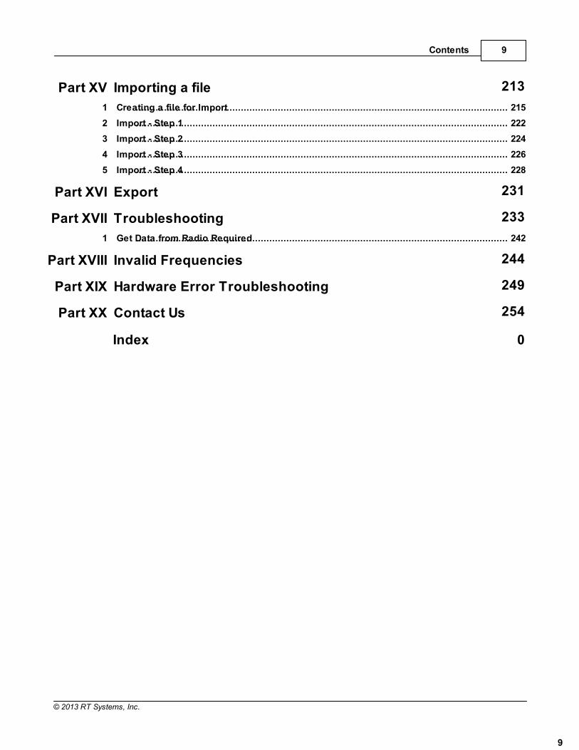
Part XV Importing a file 213
................................................................................................................................... 2151 Creating a file for Import
................................................................................................................................... 2222 Import - Step 1
................................................................................................................................... 2243 Import - Step 2
................................................................................................................................... 2264 Import - Step 3
................................................................................................................................... 2285 Import - Step 4
Part XVI Export 231
Part XVII Troubleshooting 233
................................................................................................................................... 2421 Get Data from Radio Required
Part XVIII Invalid Frequencies 244
Part XIX Hardware Error Troubleshooting 249
Part XX Contact Us 254
Index 0

Foreword
Foreword10
© 2013 RT Systems, Inc.
These help files are offered as reference for the features of the programmer and with some addedinformation about the features and functionality of the radio.
The final reference for a feature of the radio is the Users' Manual for that radio. Any error, omission ormisrepresentation of a radio's ability is unintentional.
The Programmer cannot make the radio do anything that it cannot do from the face of the unit. It makes iteasier to set options for the existing functions.

Part
I

TMD710 V4 Programmer Help12
© 2013 RT Systems, Inc.
1 What Is the Radio Programmer
The Programmer is designed to give you the ease and convenience of programmingthe memories and options of the radio from your PC.
Using the Programmer, you can create separate files for unique applications such astravel, emergency activities, or special events. These files can contain differentsettings, such as memories, power management features, and DTMF numbers, foreach purpose.
These files are saved separately to be sent to the radio at any time. One file can besent to the radio at any one time. Be sure to put everything you want into each file asyou build it.
The Programmer also gives you the ability to read a configuration from the radio. Theconfiguration would be stored in a file on your computer to be changed easily. Then,with minimal button pushing, you can send the altered file back to the radio.
Hardware Requirements
Hardware requirements for the Version 4 Programmers includeA PC running Microsoft Windows: XP, Vista (32 or 64 bit), Windows 7 (32or 64 bit) or Windows 8 (full version). The programmer will NOT work onWindows 98, ME, NT or 2000.
The correct RT Systems computer interface cable as shown in the Radio toComputer Cabling chapter under Radio / Computer Data Transfersection of this help.

Part
II

TMD710 V4 Programmer Help14
© 2013 RT Systems, Inc.
2 Getting Started
These are the basics for Gettings Started with the RT Systems radio programmersoftware. The details presented here are in generalities and while the programmer foryour radio will work in a similar manner, the details may vary for your particular modelas all radios are unique.
This section is presented as an overview for use of the programmer rather thanspecifics for one particular radio. Those details are covered in other parts of the helpfile.
Creating the file
The Programmer gives you an easy way to access details for memory channels andother settings of the radio.
Open the programmer by clicking on the icon that was created during installation. Theprogrammer opens to a default file.
Note: The default file contains memory channel information onseveral of the screens. This information is needed by the radio to "fillspaces in its little brain". You can change the default entries that yousee; but anything that is completed in the default file cannot be leftblank. The Programmer will help you with this. If information isrequired, it will warn you when it is missing.

Getting Started 15
© 2013 RT Systems, Inc.
Enter a receive frequency
In this example we'll enter 147.240 MHz with standard offset, a Name of Local, and atone of 100hz.
Type one four seven period two four zero into the receive frequencycolumn.
Press Enter.
The program completes much of the channel information with defaults. TheTransmit frequency, Offset frequency, Offset Direction and Operating Modeare completed. This satisfies the "Standard offset" requirement from theoriginal information.
Press tab or use your mouse to select the Name cell. Type LOCAL. Youchoose upper or lower case on many radios. On others, only upper case

TMD710 V4 Programmer Help16
© 2013 RT Systems, Inc.
letters are allowed. The programmer will help you. If a letter or symbol willnot work on the radio, you will not be able to enter it here.
Press tab to move to the Tone Mode cell. Setting up the tone of 100hzrequires TW steps (just as it would if you were doing this from the face ofthe radio). Turn on Tone Mode AND then set the 100hz tone.
Getting Started 17
© 2013 RT Systems, Inc.
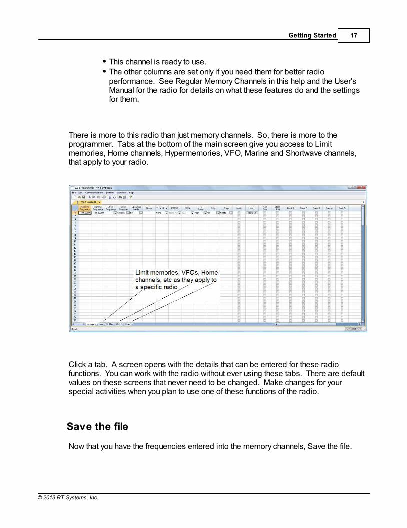
This channel is ready to use. The other columns are set only if you need them for better radioperformance. See Regular Memory Channels in this help and the User'sManual for the radio for details on what these features do and the settingsfor them.
There is more to this radio than just memory channels. So, there is more to theprogrammer. Tabs at the bottom of the main screen give you access to Limitmemories, Home channels, Hypermemories, VFO, Marine and Shortwave channels,that apply to your radio.
Click a tab. A screen opens with the details that can be entered for these radiofunctions. You can work with the radio without ever using these tabs. There are defaultvalues on these screens that never need to be changed. Make changes for yourspecial activities when you plan to use one of these functions of the radio.
Save the file
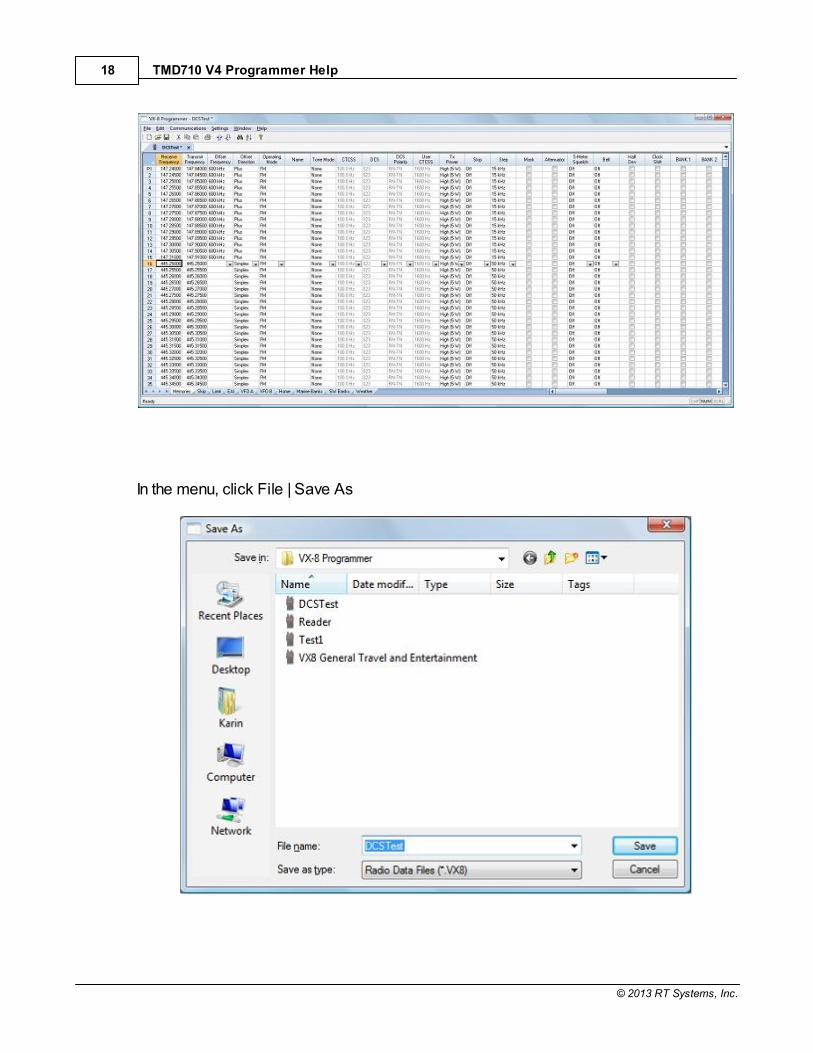
Now that you have the frequencies entered into the memory channels, Save the file.
TMD710 V4 Programmer Help18
© 2013 RT Systems, Inc.
In the menu, click File | Save As

Getting Started 19
© 2013 RT Systems, Inc.
Enter a filename. You can be as descriptive as you want. 256 characters includingspaces, upper and lower letters, and much more to describe this file. The programmerwill enter the extension so it can find the file later.
Once you complete this part of the process, the program will open the last file when itstarts up.
Even More Radio Functions
Today's radios can do so much. Many of the features are not a part of the details for amemory channel. These other options are set once for the radio to use no matter whatchannel you're operating on: memory channel, limit memory, VFO or Home channel.
These options may include, but are not limited to, Lock mode, ARTS details, displaybrightness and color, DTMF memories, scan resume options, and many others.
Select Settings | Radio Menu settings from the menu at the top of the main screen toaccess these options. The Settings screen opens to a page with check boxes, listboxes and edit fields. A sample Settings screen would look like this.
Set the options as you need them to get the performance you want from your radio. Thesettings shown for your radio will correspond to your radio's features.

TMD710 V4 Programmer Help20
© 2013 RT Systems, Inc.
Once you have the options like you want it, save this file. Yes, this is saved separatelyfrom the frequencies in the memory channels.
To save the file, select File | Save from the menu on the Settings page. Enter a namewhen the window opens. You will not have to set these options again when you start anew file of memory channels.
Once the file is saved, select File | Exit to return to the main screen of the programmer.
Sending the file(s) to the radio (programming the radio)
The new RT Systems' Version 4 programmers have no comport setup. Using the RTSystems' USB cable, you attach the cable, attach the radio, and get the programmingdone.
First: Communications | Get data from
Although you really want to put the details of your file into your new radio so you canuse it, doing Get data from with this new radio gets the process started and mayhelp prevent problems sending the file to the radio.
This process is REQUIRED if your radio has been modified totransmit outside the ham band.
From the menu at the top of the main window, select File | New. Open anew file to protect the file that you created.
Connect the RT Systems USB cable to a port on your computer. Wait untilthe New Hardware Found process completes.
With the radio off, connect the other end of the cable to the radio.
From the menu at the top of the main window, select Communications | Getdata from.
A screen will open with details about this process specificto your radio.
Follow these steps carefully until this process is complete.
Open the file that you created earlier. To open a file select File | Open fromthe menu at the top. Select your file from those in the list. Or with Version 4,your file may already be open in the other tab.

Getting Started 21
© 2013 RT Systems, Inc.
Second: Communications | Send data to
When your file is ready, select Communications | Send data to from themenu at the top of the main screen.
A screen will open with details about this process specific tothe radio.
Follow the steps carefully to complete this process and program the radio.Read the screen carefully. The steps are often different from those used toget data from the radio.
Turn off the power. Disconnect the programming cable from the radio.
Your radio may still be in VFO mode after it is programmed. This is anormal mode for the radio. Press the key on the face of the radio asdescribed in the User’s Manual for the radio to put the radio intoMemory mode and see what you programmed.
Hardware Requirements
Hardware requirements for the Version 4 Programmers include:A PC running Microsoft Windows XP, Vista, Windows 7 (32 or 64 bit), orWindows 8 (full version). The Version 4 RT Systems' software will not work

TMD710 V4 Programmer Help22
© 2013 RT Systems, Inc.
on Windows 98, 2000, ME, or NT.
Version 4 - An open USB port or the RTS-03 USB to serial adapter to workwith an original RT Systems 9-pin serial cable.
Note: The Version 4 programmers will not recognize any other cableor USB adapter. They will not work through a serial port. The correct RT Systems computer interface cable as shown in the Radio toComputer Cabling section of this help.

Part
III
TMD710 V4 Programmer Help24
© 2013 RT Systems, Inc.
3 Using the Programmer - Overview
The Programmer is designed to be used in conjunction with the manual for the radio.The Programmer provides easy feature configuration while the written manual providesan explanation of a feature and its use.
Working with Programming Files
The radio Programmer has the ability to work on more than one file at a time. Thesecan be files for the same radio or for different radios: even radios from differentmanufacturers. You can copy and paste frequencies from one file to another. This added featuremakes it even easier to create new files as you take pre-programmed memoryinformation from other files. The name of the file currently being edited is shown in the title bar at the top of thewindow. If the file has not yet been named, "Untitled #" appears. The "#" incrementswhen multiple new files are being worked on. Note: Untitled #, the default filename,should not be used for permanent file storage. Even if you work in this file, besure to enter a different filename when you save. The file being edited is referredto in this help as the current file.
Creating a New Programming File
Just like in any other editor, there are several ways to create a new cloning file.You can open an existing file, save it with a different filename.
You can use the File | New command as a starting point for a new "blank" file. This file begins with default information for the radio. The "default'information you see in the file is the same as what was in your radio whenyou bought it new.
Another way to create a data file is to upload the contents of the radio withthe Communications | Get data from menu command. After executing thiscommand, the current file will reflect the memory channels and featuresettings of the radio. Changes are easily made to these settings and thenew file saved.
Note: Not all the menu settings of the radio are associated with

Using the Programmer - Overview 25
© 2013 RT Systems, Inc.
memory channels. Many are "global" settings that affect the radioduring memory or VFO operations. These settings are handled in thefields found on the screen accessed under Settings | Radio MenuSettings.
The global settings will be read from the radio; however, by default, these settings arenot saved with the file. Select Settings | Radio Menu Settings to view, change and savethese settings. Once saved, these global settings will be sent to the radio every time itis programmed. If they are not saved, default settings will be sent to the radio with thememory programming.
To save these Global settingsSelect Settings | Radio Menu Settings in the menu on the main screen. TheSettings screen opens.
Verify that your settings are as you want them or make changes.
From the top of this screen, select File | Save. A Save dialog opens intowhich you enter a filename. Enter the name for this file and click Save.
Exit the Settings screen by selecting File | Exit.
This settings file is now available for use by any saved file that you send to your radio.
Creating and using multiple Global settings files
There may be global settings of the radio that you want configured differently fordifferent activities. You can make changes to your settings file and save it separately.
To select a settings file for use:Select Settings | Radio Menu Settings from the main page of theprogrammer.
From the Radio Menu Settings screen, select File | Open. A list of settingsfiles will be presented.
Select the file you want to use and click Open.
Verify that this is the settings file that you want to use. Check also that theproper filename appears in the bar at the top of the Menu Settings window.
Select File | Exit to close this screen. These settings will be sent to theradio with each memory channel file until you change this file selection

TMD710 V4 Programmer Help26
© 2013 RT Systems, Inc.
again.
Having multiple memory channel files and multiple global setting files gives you theability to mix and match the features of your radio to suit your needs. This makes it easyto customize the radio for a special event without disturbing the original programmingfiles. Then once the event is over, simply reprogram the radio with the memory channelinformation and settings that you use everyday.
Tying Global Settings to a Memory Channel File
The Version 3 and Version 4 programmers have the option of saving the globalsettings with the memory channel information. This new feature is not the default for theprogrammer; but may be valuable under certain programming circumstances (i.e.,programming many radios when you want to be absolutely certain that the settings andthe frequencies are properly set for a given activity). To contrast and compare the two Radio Menu Setting options:
Use Separate file for menu settings (default)
This is the default for the programmer.
This option is based on a "Set and Forget" plan. Once the globalsettings are configured to your liking and saved, you do not have torepeat this process. This configuration does not change with a newmemory channel file.
The last settings file saved is the one that will be used when a memoryfile is sent to the radio.
You can save several different settings files (i.e., one for your radioand a different one for your son’s radio). Then easily match thesettings to the radio being programmed without having to makechanges in the file repeatedly.
Keep menu settings and frequencies in a single file. (option)
This option is set on the Settings | Preferences screen.
With this option selected, the Radio Menu Settings as assigned on theSettings | Radio Menu Settings screen are assigned ONLY in this file.
With each new file created the Radio Menu Settings return to factorydefaults.
You have the ability to customize the global settings just as you

Using the Programmer - Overview 27
© 2013 RT Systems, Inc.
customize the memory channel file. This would be useful if you areprogramming each radio uniquely.
No guesswork about what the configuration of the global settings.Once they are set, they stay set in this file until you make a change tothem.

Part
IV

Viewing and Changing Programming Files 29
© 2013 RT Systems, Inc.
4 Viewing and Changing Programming Files
The Programmer begins in a screen displaying memory channel information for theradio. Default information found in a factory fresh radio is contained in the file. Anywherethis information is displayed it can be changed. Memory information is easily entered in a spreadsheet style layout. You can view,rearrange, eliminate, or edit these entries. Memory channel 1 must be programmed inmost radios. VFOs and Home channels must be programmed. Memory channel 1 andlimit memory channels. VFO and Call channels must each contain a frequencyappropriate for the band. The programmer checks for missing data when Send data tois executed. Columns not regularly used are easily hidden with the selections under Settings |Preferences (View | Preferences in earlier versions). Customize your screen for theinformation you use most often.
Radio Menu Settings
Global menu settings which in earlier programmers occupied the opening screen arenow entered on a Settings screen accessed under Settings | Radio Menu Settings(View | Settings in earlier versions). Here options are set for menu settings of the radiothat do not change with each memory channel. These settings affect the radio whether itis in memory mode or VFO mode. The Radio Menu Settings screens contain check boxes for single click settings andeasily filled blanks for personalized options. Once configured, these Settings are savedfor use by new files. There is no longer a need to reset the options in each new file or tobegin a file from an existing one.
Note: Radio Option Settings (including Lock, Beeps, etc) are readfrom the radio with the Get data from command. Be sure that settingsyou have customized are saved in the programmer. Access theSettings screen and use File | Save to make the options that weretaken from the radio permanent for programming the radio later. Once saved, the settings will be repeated with each new file ofmemory channel details.
The programmer has two options for these Settings. Multiple Settings files can becreated just as multiple frequency files. Then you can "mix and match" as needed toprogram a radio for a given situation. Alternately, you can opt to save the Settings aspart of an individual file. You can find more details on these two options under Using the Programmer -

TMD710 V4 Programmer Help30
© 2013 RT Systems, Inc.
Overview and Radio Menu Settings - General Overview in this help. Usingindividual and separate settings files is the default.

Part
V

TMD710 V4 Programmer Help32
© 2013 RT Systems, Inc.
5 Easy Editing in the Grid
Many new data management commands are available in the programming softwarefrom RT Systems. The commands listed here are available through a right click menu or from the list thatopens when you select Edit from the menu at the top of the screen. These commandscan be used on any of the spreadsheets in the program.
Right Click MenuSelect a row to be edited by clicking on the number to the left of that row. Youwill notice that the entire row is highlighted (not just the Receive Frequencycell). Release the left mouse button. You will notice that the row remainshighlighted until you left click someplace else on the screen of theprogrammer.
Note: You can select several rows at once (to copy, delete, etc) byclicking on the number to the left of the first of the selection thenwhile holding the left mouse button, drag the mouse across thenumber of each of the channels to be included. This must be acontinuous group.
With the mouse pointing at the highlighted area (anyplace as long as thepoint of the mouse pointer is within the highlighted area), press the rightmouse button. A menu opens with editing options. Release the right mousebutton once that menu opens.
Use the mouse to point at the desired command. Left click the mouse toexecute that command.
Edit MenuSelect a row to be edited by clicking on the number to the left of that row. Youwill notice that the entire row is highlighted (not just the Receive Frequencycell). Release the left mouse button. You will notice that the row remainshighlighted until you left click someplace else on the screen of theprogrammer.
Note: You can select several rows at once (to copy, delete, etc) byclicking on the number to the left of the first of the selection thenwhile holding the left mouse button, drag the mouse across thenumber of each of the channels to be included. This must be a

Easy Editing in the Grid 33
© 2013 RT Systems, Inc.
continuous group.
Holding neither of the mouse buttons, move the mouse pointer to Edit in themenu at the top of the screen. Press the left mouse button to select this menuoption.
Holding neither of the mouse buttons, use the mouse pointer to select one ofthe editing options shown in the menu. Click the left mouse button to executethis command.
Editing Commands
The examples here will use the programmers for the Yaesu FT-60 (ADMS-1J) and theIcom IC-91 (WCS-91). You will see by the screen shots that you can copy and pastebetween files: even files for radios from different manufacturers. The programmer willtake care of the similarities and differences.
Cut (Ctrl+X) - Removes the selected entry and leaves the memory channel blank.This feature is designed to work for deletion of all the data in a memory channel ratherthan data in a specific column.
Copy (Ctrl+C) - Copies the selected data.
You can copy two different ways: Copy all the details of a Memory Channel (one or several at once) or Copydetails within one column (from one cell to one or many at one time)
In most cases, data can be copied from one tab to another (as in leftand right memories). It can also be copied from one programmer to another (both filesVersion 3 or Version 4 or even between Version 3 and Version 4files). Data that is not appropriate for where it is to be pasted (i.e., a VHFfrequency into a UHF channel) will not be pasted.
Copying an entire memory channel or group of channels
Shown here are details for copying within a file. The same actions apply tocopy data to another tab of the file or to another programmer.
Open the file.

TMD710 V4 Programmer Help34
© 2013 RT Systems, Inc.
Select the data to be copied. To select an entire row, point your mouse at the number in the blue box atthe left of the row. Click and release the left mouse to select that row. Theentire row will be highlighted when it is selected.
To select multiple rows, point your mouse at the number in the blue box atthe left of the first row to be selected. Click and hold the left mouse button asyou drag the pointer over the next several channels that you want to copy. The channels must be sequential for multi channel copying. All the selectedchannels will be highlighted.
To select all rows, point your mouse at the number in the blue box at the leftof the first row. Left click the mouse. Release the mouse. Press Ctrl A toselect all. The entire page will be highlighted. Note: If you have a lot ofchannels to select, rather than trying to select them with the mouse,simply select the first one and press Ctrl A. The copy and pasteprocess does not care if blank channels are selected.

Easy Editing in the Grid 35
© 2013 RT Systems, Inc.
Copy Command
From the menu at the top of the screen, use your mouse to left click onEdit. From the menu that opens, use the mouse to left click on Copy.
You can also copy by pressing Ctrl C on the keyboard.
Or while pointing at the screen of the programmer, right click and selectCopy from the menu that opens.

TMD710 V4 Programmer Help36
© 2013 RT Systems, Inc.
It will appear that nothing has happened. The program in conjunction withbuilt in commands of the operating system of the computer has copied thedata. It is waiting for you to Paste it where you want it.
Paste (Ctrl+V) - Writes the selected data to the current position of the cursor overwritingthe data from that point.The Version 3 and Version 4 programmers have the ability tocopy and paste data in a single column as well as for an entire row.
Paste Complete Channels
Use the mouse to select the channel where you want the data to start. This can be in another file for the same radio or one for any radio forwhich you use an RT Systems Version 4 programmer.
Select the row that is the first into which the data is to be pasted. ThePaste process will begin in that location with the first copied channeland continue in each channel after that with the rest of the channelsthat were copied.

Easy Editing in the Grid 37
© 2013 RT Systems, Inc.
From the menu at the top of the screen, use your mouse to left click onEdit. From the menu that appears, use the mouse to left click onPaste.
You can also paste by pressing Ctrl V with the mouse pointing withinthe selected area (i.e., just look at where the mouse pointer is on thescreen. It must by within the black area on the screen of theprogrammer for this keystroke to have any effect.).
Or while pointing within the highlighted area, right click and selectPaste from the menu that opens.

TMD710 V4 Programmer Help38
© 2013 RT Systems, Inc.
The information is pasted into the selected channels.

Easy Editing in the Grid 39
© 2013 RT Systems, Inc.
You can make this process even easier by splitting the screen into two parts. SelectWindow New Vertical Tab Group for this result.
TMD710 V4 Programmer Help40
© 2013 RT Systems, Inc.
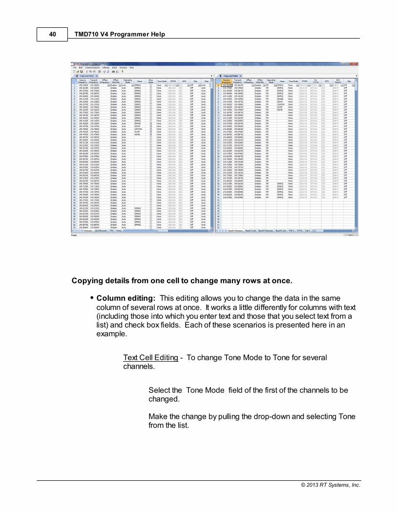
Copying details from one cell to change many rows at once.
Column editing: This editing allows you to change the data in the samecolumn of several rows at once. It works a little differently for columns with text(including those into which you enter text and those that you select text from alist) and check box fields. Each of these scenarios is presented here in anexample.
Text Cell Editing - To change Tone Mode to Tone for severalchannels.
Select the Tone Mode field of the first of the channels to bechanged. Make the change by pulling the drop-down and selecting Tonefrom the list.

Easy Editing in the Grid 41
© 2013 RT Systems, Inc.
Once the selection is made, the focus will move to the next field.Click back into the Tone Mode field that displays the correct value. When you move back into the field you can copy the information ifthe field is highlighted with a ring around its border or if the textwithin is shaded (indicating that it is selected).
Press Ctrl + C, select Edit | Copy from the menu at the top of thescreen, or right click and select Copy from the menu that appears.(Just as with row copying in the first example.) Select the first cell to be changed by pressing Down arrow untilthat cell is highlighted (the cell will be in the same column so usingthe Down Arrow key will easily move you to another nearby cell). Ifyou need to move quite a way in the file, move to the first cell to bechanged and click the mouse to select that cell.

TMD710 V4 Programmer Help42
© 2013 RT Systems, Inc.
If several consecutive rows are to be changed, select them all byholding the Shift Key while you Down Arrow through them or holdthe Left Mouse Key while you move your mouse over them (normalWindows selection processes). When they are selected, they willbe highlighted in a color based on the scheme of your computer. Press Ctrl + V, select Edit | Paste from the menu at the top of thescreen, or Right Click and select Paste from the options in themenu that opens. The copied value will appear in each of thefields.

Easy Editing in the Grid 43
© 2013 RT Systems, Inc.
Column editing will address a selection of consecutive cells all atonce or individual cells repeatedly. If the items to be changed arenot consecutive, you can select and paste repeatedly until all thecells are addresses. You do not have to copy again. Theprogrammer retains the copied value.
Check Box Cell Editing - If you want to put several channels into aBank, there is no reason to do this one row at a time.
This process varies from the other by how the cells are selected. Check box cells act differently than those that contain text. You cancopy from one check box column into another.
In this example, put channels several into Bank 1 without checking theBank 1 box for each channel.
First, select Settings from the menu at the top of the page. Fromthat menu, select Bank Settings. Several columns of the screen willbe hidden leaving only Receive Frequency, Name and Banks. This makes working on the screen easier since you no longer mustscroll through several columns that you are not using now.
For Channel 1, put a check in the box under Bank 1.

TMD710 V4 Programmer Help44
© 2013 RT Systems, Inc.
At this point you CANNOT copy this field. Press Tab or Enter to moveout of the field.
The process is more easily done now with the keyboard rather thanthe mouse.
Press Right Arrow to move focus back into the Bank 1 column. Noticethat there is now a black border on that cell. The cell is now ready tobe copied. Press Ctrl C or select Edit from the menu then copy fromthe list that opens to copy the cell.

Easy Editing in the Grid 45
© 2013 RT Systems, Inc.
Press and Hold the Shift key while pressing the Down Arrow key toselect the rows that will be set with this information.
Press Ctrl V to paste the selecting into the fields.

TMD710 V4 Programmer Help46
© 2013 RT Systems, Inc.
Simple Mode: Hides several of the columns for each memory channel. Thoseremaining are the ones that are most needed for any memory channel. Thoseremaining include:
Receive Frequency - A channel cannot be programmed without a receivefrequency. This is the frequency you listen to.
Transmit Frequency - The programmer will complete this automatically. The column is included in case you need to enter the value other than thedefault for the receive frequency based on the band plan (i.e., an odd splitpair).
Offset Direction - Again, the programmer will complete this automaticallybased on the band plan for the receive frequency. However, anoccasional repeater will differ from the band plan. Including this columngives you the ability to address that difference.
Name - This column is for personalized information to identify thechannel.
Tone Mode - The repeater operator controls this detail for the repeater. There is nothing standard that can be completed automatically. You need

Easy Editing in the Grid 47
© 2013 RT Systems, Inc.
to select the Tone Mode then assign the CTCSS frequency or DCS codeas needed for a particular repeater.
Skip - Use at your discretion to include or exclude a frequency duringmemory channel scanning.
Comment - Personalized notes up to 80 characters. This informationremains a part of the file and is not transferred to the radio.
Note: While in Simple Mode, you cannot access the Preferencesscreen (Settings | Preferences). The columns that are hidden inSimple mode are predetermined by the programmer.
All columns are visible on the screen when you are no longer inSimple Mode. If you want to hide other columns, you can do thatthrough individual selection on the Settings | Preferences page.
Find (Ctrl+F) - Finds specific text in a specified column. Once you select thiscommand or press Ctrl+F a screen opens into which you enter the text (or number)to be found.

TMD710 V4 Programmer Help48
© 2013 RT Systems, Inc.
Select the field to be searched (i.e., Receive frequency, Transmitfrequency, etc.)
Enter the text (or numbers) to be found.
Click OK to move to the first item found. The search always begins atthe top of the list and stops at the end.
Find Next (F3) - Use the F3 function key to repeat the specified find and move tothe next item. For example: You choose to search for 145 in the Receive Frequencycolumn in a file with 5 channels beginning with 145. OK in the Find box takes you tothe first one. F3 takes you to the second; then the third; then the fourth: and so onuntil you have stopped at each of those that match the criteria.
Goto Channel (Ctrl+G) - Moves to the indicated channel number. When thisoption is selected a screen opens into which you enter the channel number. Enterthe number and click OK to move to that memory channel (programmed or not).
Insert Channel (Shift+Ins) - Inserts a blank row without deleting informationpresent. The current information and all that follows is "pushed-down" to makeroom. The number of rows inserted will equal the number of rows selected. This is agreat way to slip channel information into a list of channels.
Easy Editing in the Grid 49
© 2013 RT Systems, Inc.
Note: Insertion of rows can result in the loss of data from the bottomof the list. You will be warned if there is danger of data loss and giventhe opportunity to cancel the process to prevent this loss.
Delete Channel (Shift+Del) - Removes the selected row. All the data following thedeleted row is "pulled-up" to eliminate the blank row. Beware!! Deleted data cannotbe recovered. Neither the Insert nor the Paste commands write the data to the grid.If you accidentally delete data, exit the Programmer WITHOUT saving. The file willbe restored to its condition when you last saved and the last deleted data will berestored. Multiple channels can be deleted by selecting them all at once andselecting delete.
Clear Channel - Removes the data from the selected channel without moving allthose that follow up to fill this space. Leaves the channel blank.
Move Up (Ctrl+U) - The ability to select a channel and have it "change places" withthe channel immediately preceding it. Repeat this command on a selected channelto "walk" it into place in your list. Sequential channels can be selected and moved atonce. The group will move up one channel at a time. The displaced memory channelwill move to the end of the group being moved.
Move Down (Ctrl+D) - The ability to select a channel and have it "change places"with the channel immediately following it. Repeat this command on a selectedchannel to "walk" it into place in your list. Sequential channels can be selected andmoved at once. The group will move down one channel at a time. The displacedmemory channel will move to the top of the group being moved.
Add Frequency Range - A convenient way to add lots of channels at once. This isgreat for setting up a radio for scanning a certain range of channels. When thisoption is selected you are presented with a window into which you enter the detailsof the channels to be entered.

TMD710 V4 Programmer Help50
© 2013 RT Systems, Inc.
Enter Starting Frequency: The value of the first frequency of the list to beentered. Any allowable frequency of the radio being programmed.
Number of channels - Enter the number of channels to be entered. Youcan insert as few as 1 to as many as 1000 channels at once. You are notwarned if you select more than the number of memory channels. Theprocess just inserts all that it can and ignores the rest.
Frequency Step - Enter the value that will separate each of thefrequencies in these channels. Select 5kHz to 200 kHz.
Click OK and watch the screen fill. Or Cancel to exit the process withoutchange to your file.
The channels are inserted beginning at the currently selected channel (i.e., ifyou have selected channel 40, the first channel will be added at channel 40).You are warned if a channel will be overwritten and given the ability to notoverwrite or to cancel the process. If you choose No to prevent loss of thecurrent channel information, the skipped frequency is entered into the nextavailable space and not lost.
Sort - Great for data management or to arrange your channels permanently for aspecial use. The version 3 and Version 4 programmers have the ability to Undo asort. You can now sort the list on a given parameter, touch-up a group of entries,then put the list back in its original order with the changes that you made. When thisoption is selected you are presented with a window for selection of the options.

Easy Editing in the Grid 51
© 2013 RT Systems, Inc.
Sort by - Select a column for the initial sort.
Then Sort By - Select a second column for a secondary sort.
Sort Mode - Ascending for lowest to highest. Descending for highestto lowest.
Channel Sort Selection - Selected Channels to sort only a group formthe file. All Channels to sort all the channels in the file.
If the result is not quite what you expected, select the Undo Sort option toreturn the list to the point you left it last. Always save your file before you sort. At the very worst you can exit the filewithout saving to return to the order of that last save. Blank memory channels are always sorted to the top of bottom of the listbased on the Ascending or Descending selection. Different fields sort differently. If a field is a text field in one programmer anda drop down list in another, the sort results will be different. It has to do withhow the computer interprets the values in these different types of fields.While this was present in the older programmers, it should not be a problemin the Version 3 or Version 4 programmers where the fields are consistentbetween the radio programmers.
Unsort - For use after sorting to return the list to the last saved order. Use Sortand Unsort to easily edit channels with the same info that needs to be changed. Sort to bring those channels together. Edit the details (see cell editing). Thenunsort to return the list to the last saved order with the edits in place.

TMD710 V4 Programmer Help52
© 2013 RT Systems, Inc.
Quick File Access Commands Ctrl 0 (Control zero) - Open existing file for same radio. Calls the Open dialog for
the programmer being used allowing you to select a file to be opened withouthaving to select the file type first. This is especially helpful when severalprogrammers are loaded on one system. (i.e., Lets you select another FT-7800file without having to select that file type first from the open box.)
Ctrl O (Control letter "O") - File | Open. Presents the box from which the file type isselected just as File | Open. Select the type of file to be opened. The programmerwill look in the location of that last file for that particular file type. (i.e., you can openan FT-60 file while working with the FT-7800 programmer as long as you have theVersion 3 or Version 4 module for the FT-60. With both open, you can copy andpaste between the files or send each to the proper radio without having to closeand reopen the Version 3 or Version 4 programmers separately.)
Ctrl M - Automatically create a new file for the programmer being used. Eliminateshaving to select the file type first.
Ctrl N - File | New. Presents the box from which the file type is selected just as in File |New in the menu. Select the file type for the programmer to create a new file forthat radio (the same as the one you're working with now or for a different radio forwhich you have the Version 3 or Version 4 module.)

Part
VI

TMD710 V4 Programmer Help54
© 2013 RT Systems, Inc.
6 Screen Appearance and Default Options
The screens of the programmer can be customized to make data entry that mucheasier. Many other controls for the program are found in the Preference section. Thechanges made here affect all the RT Systems programmers installed on this machine.
Options for screen appearance are accessed under Settings | Preferences from themenu on the main screen of the programmer. This screen appears when that option isselected:
Grid Display
Freeze Columns

Screen Appearance and Default Options 55
© 2013 RT Systems, Inc.
The option to "freeze" can be applied to any or all columns. Select thenumber of columns to remain on the screen at all times as you scroll to theright of the spreadsheet.
Having these columns always available for reference can be a great help foridentifying the memory channel being edited.
Hidden Columns (Mark the columns to hide)Selected columns can be marked as hidden which removes them from thescreen display. During editing, these fields are completed with defaultinformation for the radio. This option is a global setting and will affect everyfile, new or existing.
In an existing file the data in these columns is not lost: it is simply notdisplayed.
In a new file, a hidden column is filled with a default value.
Hidden column data is not printed. Columns can be marked as hidden tocustomize printed output and then restored for additional data management.
Note: Several columns are hidden and unhidden with the SimpleMode option found under Edit from the menu of the main screen. Simple mode hides all but the columns required for memory channeloperations. When you leave Simple Mode, all columns will again bevisible.
Alternate row colorsSelect a color for the text (Fore) and/or background (Back) for rows 2, 4, 6,etc. This can help the readability of the spreadsheet.
Use Combo for Check boxOn some systems the checkbox option does not work and you are not able tomake selections for banks, show name or other options with check boxes. The check boxes will be missing from the cell.
Select this option to change the cell to a Yes/No combo box rather than acheck box. Make your selections by setting the option to Yes where desired. Just are with the checkbox option, the combo box selection can be copiedand pasted to other cells in the column.
Language
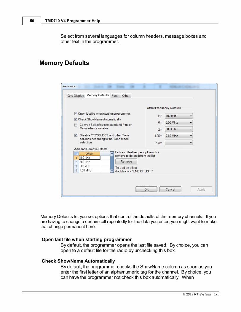
TMD710 V4 Programmer Help56
© 2013 RT Systems, Inc.
Select from several languages for column headers, message boxes andother text in the programmer.
Memory Defaults
Memory Defaults let you set options that control the defaults of the memory channels. If youare having to change a certain cell repeatedly for the data you enter, you might want to makethat change permanent here.
Open last file when starting programmerBy default, the programmer opens the last file saved. By choice, you canopen to a default file for the radio by unchecking this box.
Check ShowName AutomaticallyBy default, the programmer checks the ShowName column as soon as youenter the first letter of an alpha/numeric tag for the channel. By choice, youcan have the programmer not check this box automatically. When
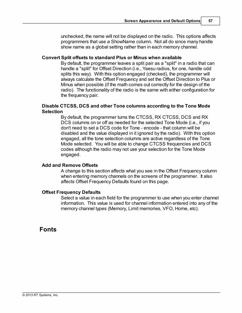
Screen Appearance and Default Options 57
© 2013 RT Systems, Inc.
unchecked, the name will not be displayed on the radio. This options affectsprogrammers that use a ShowName column. Not all do since many handleshow name as a global setting rather than in each memory channel.
Convert Split offsets to standard Plus or Minus when availableBy default, the programmer leaves a split pair as a "split" in a radio that canhandle a "split" for Offset Direction (i.e., Yaesu radios, for one, handle oddsplits this way). With this option engaged (checked), the programmer willalways calculate the Offset Frequency and set the Offset Direction to Plus orMinus when possible (if the math comes out correctly for the design of theradio). The functionality of the radio is the same with either configuration forthe frequency pair.
Disable CTCSS, DCS and other Tone columns according to the Tone ModeSelection
By default, the programmer turns the CTCSS, RX CTCSS, DCS and RXDCS columns on or off as needed for the selected Tone Mode (i.e., if youdon't need to set a DCS code for Tone - encode - that column will bedisabled and the value displayed in it ignored by the radio). With this optionengaged, all the tone selection columns are active regardless of the ToneMode selected. You will be able to change CTCSS frequencies and DCScodes although the radio may not use your selection for the Tone Modeengaged.
Add and Remove OffsetsA change to this section affects what you see in the Offset Frequency columnwhen entering memory channels on the screens of the programmer. It alsoaffects Offset Frequency Defaults found on this page.
Offset Frequency DefaultsSelect a value in each field for the programmer to use when you enter channelinformation. This value is used for channel information entered into any of thememory channel types (Memory, Limit memories, VFO, Home, etc).
Fonts

TMD710 V4 Programmer Help58
© 2013 RT Systems, Inc.
New to the Version 4.5 programmers is the selection of font and size tocontrol display of headers, messages and item identifiers in the programmer. Select any font and size available on your system to make the programmereasier to use.
Other
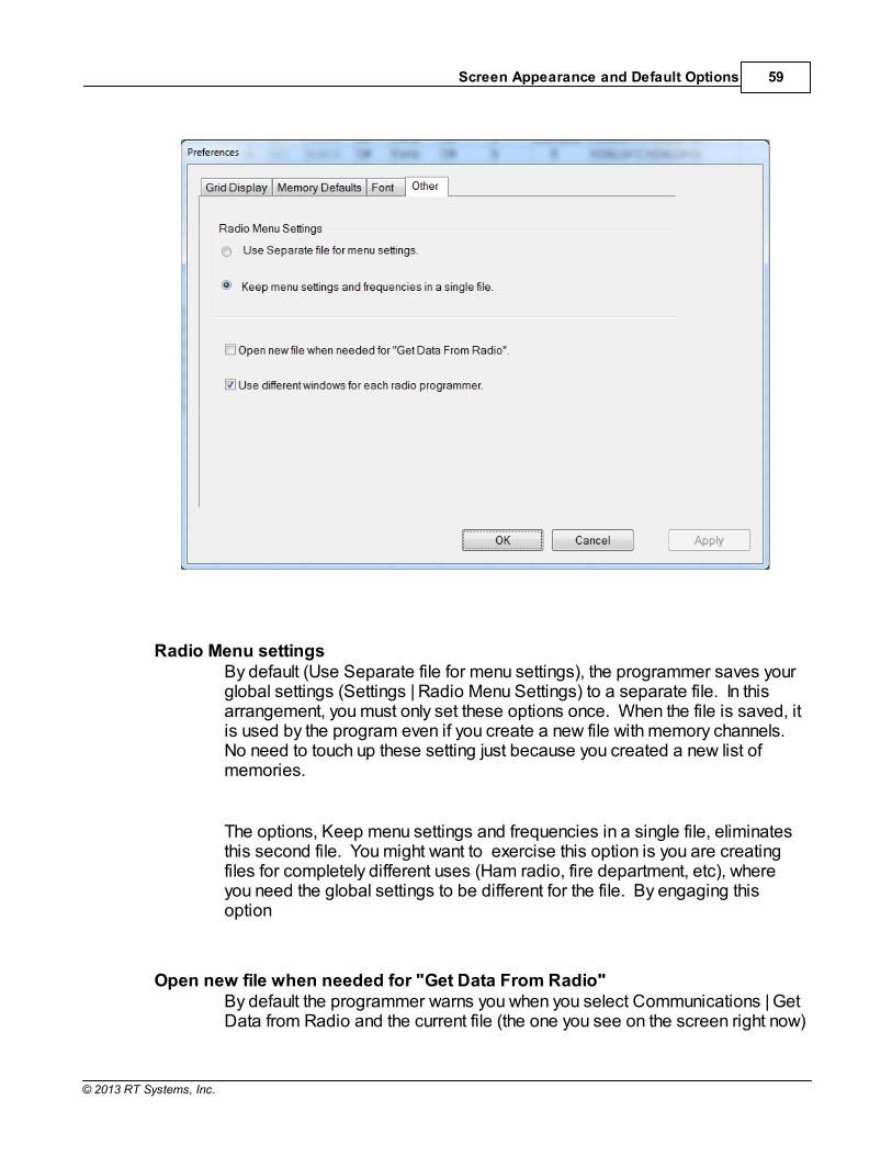
Screen Appearance and Default Options 59
© 2013 RT Systems, Inc.
Radio Menu settingsBy default (Use Separate file for menu settings), the programmer saves yourglobal settings (Settings | Radio Menu Settings) to a separate file. In thisarrangement, you must only set these options once. When the file is saved, itis used by the program even if you create a new file with memory channels. No need to touch up these setting just because you created a new list ofmemories.
The options, Keep menu settings and frequencies in a single file, eliminatesthis second file. You might want to exercise this option is you are creatingfiles for completely different uses (Ham radio, fire department, etc), whereyou need the global settings to be different for the file. By engaging thisoption
Open new file when needed for "Get Data From Radio" By default the programmer warns you when you select Communications | GetData from Radio and the current file (the one you see on the screen right now)

TMD710 V4 Programmer Help60
© 2013 RT Systems, Inc.
is not a blank, default file. The programmer is warning you that if you continueyou will lose all the work you have done by replacing the information on thescreen with that currently in the radio.
By selecting this option (checking the box), the programmer will automaticallyopen a blank, default file for you when Communications | Get data from Radiois selected. By completing the Get Data from Radio process into this defaultfile, you will not lose the work you have been doing in the current file.
Use different windows for each radio programmerBy default the programmer opens each of the programmers installed on thismachine (Version 4 or greater) in the same master window. Each fileoccupies a separate tab. The titlebar of the main window identifies theprogrammer associated with the file in a particular tab. If you name your filesas "the radio name" and then "any other identifying information... rememberyou have 256 characters... don't be cryptic" you can easily tell by theinformation on the tab which one is for which radio.
When this option is engaged (checking the box), each programmer will openin a separate "main window". Each tab that opens will be for that particularprogrammer. It will be as if the others don't exist unless you start them fromthe icon. Working between the files with copy and paste will still work even ifthe files are displayed in two separate windows. There is no loss offunctionality. Only a change in how the files are displayed.

Part
VII
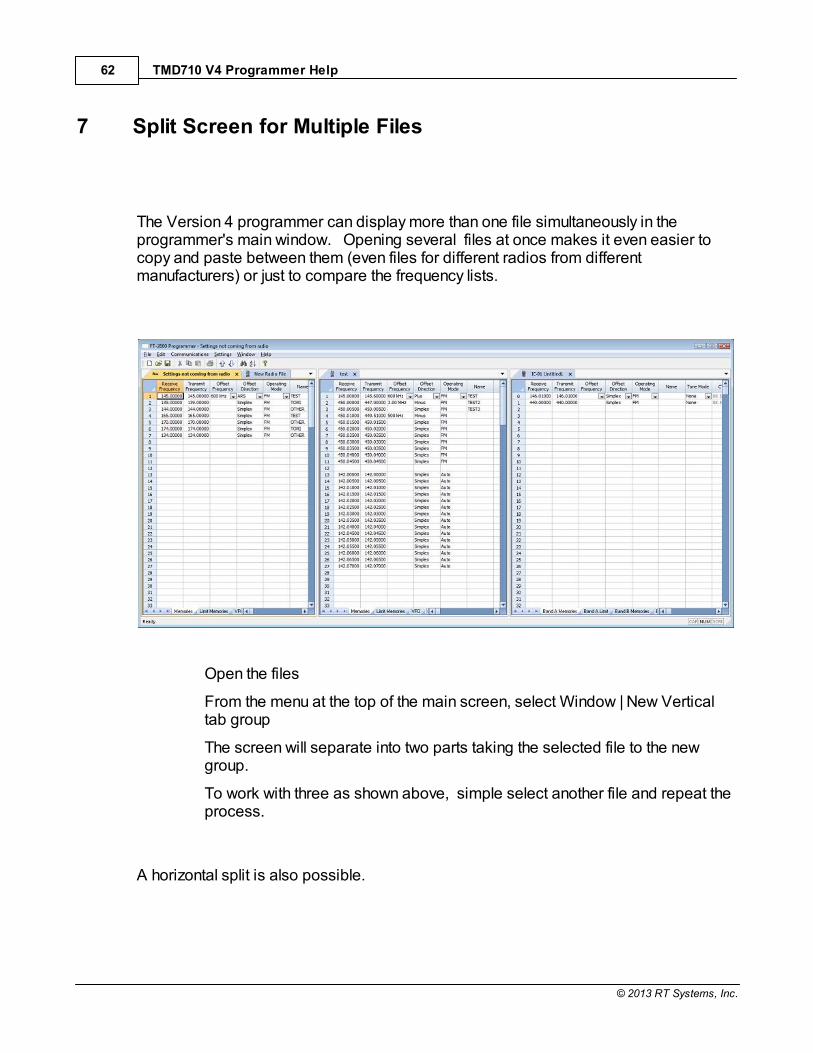
TMD710 V4 Programmer Help62
© 2013 RT Systems, Inc.
7 Split Screen for Multiple Files
The Version 4 programmer can display more than one file simultaneously in theprogrammer's main window. Opening several files at once makes it even easier tocopy and paste between them (even files for different radios from differentmanufacturers) or just to compare the frequency lists.
Open the files
From the menu at the top of the main screen, select Window | New Verticaltab group
The screen will separate into two parts taking the selected file to the newgroup.
To work with three as shown above, simple select another file and repeat theprocess.
A horizontal split is also possible.

Split Screen for Multiple Files 63
© 2013 RT Systems, Inc.
Open the files
From the menu at the top of the main screen, select Window | New Horizontaltab group
The screen will separate into two parts taking the selected file to the newgroup.
To work with three as shown above, simple select another file and repeat theprocess.
Note: Once you divide the screen horizontally or vertically, the otherseparation is not available. Selections for vertical and horizontalgroups will be enabled and disabled in the menu as necessary.

Part
VIII

Menu Item Cross Reference 65
© 2013 RT Systems, Inc.
8 Menu Item Cross Reference
The Programmer presents all the options for the radio in easy to use grid, check box,list and combo box formats. Most radios these days have so many options thatorganizing them in the Programmer can be a challenging task.
Organizing the menu item settings in the TM-D710 and TM-V71 was especiallychallenging since there are menu items that are universal to the radio and others thatcan be set differently in each Programmed Memory. In the Programmer these settingsare organized to make it easy for you to tell the difference as you customize thesettings.
Presented here is a cross reference list that details the item as presented in theoperating manual where you will find the setting for that item in the Programmer.
The location in the Programmer is described as a "path". For example.
Settings | Radio Menu Settings | Main Settings tab | Password
Click on Settings in the menu at the top of the screen
Select Radio Menu Settings from the menu that opens
Select the Main Settings tab
The option, Password, is on that screen
This section is presented in separate sections by menu item number to make the listsof menu items more manageable. Select the group from the contents at the left thenlook for the specific menu item you need to address.
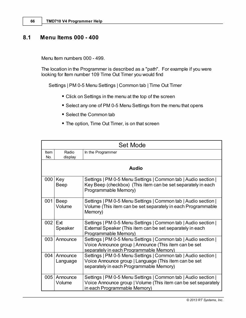
TMD710 V4 Programmer Help66
© 2013 RT Systems, Inc.
8.1 Menu Items 000 - 400
Menu Item numbers 000 - 499.
The location in the Programmer is described as a "path". For example if you werelooking for Item number 109 Time Out Timer you would find
Settings | PM 0-5 Menu Settings | Common tab | Time Out Timer
Click on Settings in the menu at the top of the screen
Select any one of PM 0-5 Menu Settings from the menu that opens
Select the Common tab
The option, Time Out Timer, is on that screen
Set ModeItemNo.
Radio display
In the Programmer
Audio
000 KeyBeep
Settings | PM 0-5 Menu Settings | Common tab | Audio section |Key Beep (checkbox) (This item can be set separately in eachProgrammable Memory)
001 BeepVolume
Settings | PM 0-5 Menu Settings | Common tab | Audio section |Volume (This item can be set separately in each ProgrammableMemory)
002 Ext Speaker
Settings | PM 0-5 Menu Settings | Common tab | Audio section |External Speaker (This item can be set separately in eachProgrammable Memory)
003 Announce Settings | PM 0-5 Menu Settings | Common tab | Audio section |Voice Announce group | Announce (This item can be setseparately in each Programmable Memory)
004 Announce Language
Settings | PM 0-5 Menu Settings | Common tab | Audio section |Voice Announce group | Language (This item can be setseparately in each Programmable Memory)
005 AnnounceVolume
Settings | PM 0-5 Menu Settings | Common tab | Audio section |Voice Announce group | Volume (This item can be set separatelyin each Programmable Memory)

Menu Item Cross Reference 67
© 2013 RT Systems, Inc.
006 AnnounceSpeed
Settings | PM 0-5 Menu Settings | Common tab | Audio section |Voice Announce group | Speed (This item can be set separatelyin each Programmable Memory)
007 PlaybackRepeat
Settings | PM 0-5 Menu Settings | Common tab | Audio section |Voice Storage group | Playback Repeat (checkbox) (This itemcan be set separately in each Programmable Memory)
008 PlaybackInterval
Settings | PM 0-5 Menu Settings | Common tab | Audio section |Voice Storage group | Playback Interval (secs) (This item can beset separately in each Programmable Memory)
009 ContinuousRecording
Settings | PM 0-5 Menu Settings | Common tab | Audio section |Voice Storage group | Continuous Recording (checkbox) (Thisitem can be set separately in each Programmable Memory)
Tx / Rx
100 ProgrammableVFO
Not addressed in the Programmer.
101 Step Main screen | Step - This item can be set independently for eachmemory channel.
102 Modulation Main screen | Operating Mode - This item can be setindependently for each memory channel.
103 VHF AIP Settings | PM 0-5 Menu Settings | TX/RX/Repeater tab | Receivesection | VHF Bank AIP (checkbox) (This item can be setseparately in each Programmable Memory)
104 UHF AIP Settings | PM 0-5 Menu Settings | TX/RX/Repeater tab | Receivesection | UHF Bank AIP (checkbox) (This item can be setseparately in each Programmable Memory)
105 S-Meter Squelch
Settings | PM 0-5 Menu Settings | TX/RX/Repeater tab | Receivesection | A-Band or B-Band S-Meter Sql (checkboxes). This itemcan be set independently for A-Band and B-Band operations. (This item can be set separately in each Programmable Memory)
106 S-MeterSQLHangupTime
Settings | PM 0-5 Menu Settings | TX/RX/Repeater tab | Receivesection | S-Meter Sql Hangup (This item can be set separately ineach Programmable Memory)
107 MuteHangup
Settings | PM 0-5 Menu Settings | TX/RX/Repeater tab | Receivesection | Mute Hangup (This item can be set separately in each

TMD710 V4 Programmer Help68
© 2013 RT Systems, Inc.
Time Programmable Memory)
108 Beat Shift Settings | PM 0-5 Menu Settings | TX/RX/Repeater tab | Receivesection | Beat Shift (checkbox)
109 TOT Settings | PM 0-5 Menu Settings | Common tab | Time Out Timer(This item can be set separately in each Programmable Memory)
110 WeatherAlert
Settings | PM 0-5 Menu Settings | TX/RX/Repeater tab | WeatherAlert section | A-Band and B-Band (checkboxes). This featurecan be engaged independently for A-Band and B-Bandoperations. (This item can be set separately in eachProgrammable Memory)
Memory
200 MemoryName
Main screen | Name - This item can be set independently for eachmemory channel
201 RecallMethod
Settings | PM 0-5 Menu Settings | Common tab | Memory section |Recall Method (This item can be set separately in eachProgrammable Memory)
202 Lockout Main screen | Skip - This item can be set independently for eachmemory channel
203 GroupLink
Settings | PM 0-5 Menu Settings | Common tab | Memory section |Group link (This item can be set separately in eachProgrammable Memory)
204 EchoLinkMemory
Settings | Radio Menu Settings | DTMF/Echolink/Weather tab |Echolink section | Name and Code
205 EchoLinkSpeed
Settings | Radio Menu Settings | DTMF/Echolink/Weather tab |Echolink speed
DTMF
300 DTMF Hold Settings | Radio Menu Settings | DTMF/Echolink/Weather tab |DTMF Hold (checkbox)
301 DTMFMemory
Settings | Radio Menu Settings | DTMF/Echolink/Weather tab |DTMF section | Name and Code
302 DTMFSpeed
Settings | Radio Menu Settings | DTMF/Echolink/Weather tab |DTMF Speed
303 DTMFPause
Settings | Radio Menu Settings | DTMF/Echolink/Weather tab |DTMF Delay

Menu Item Cross Reference 69
© 2013 RT Systems, Inc.
304 DTMF KeyLock
Settings | Radio Menu Settings | DTMF/Echolink/Weather tab |Echolink section | DTMF Mic Key Lock (checkbox)
Repeater
400 OffsetFrequency
Main Screen | Offset Frequency - This item can be setindependently for each memory channel.
401 AutoRepeaterOffset
Settings | PM 0-5 Menu Settings | Common tab | Auto RepeaterOffset (checkbox) (This item can be set separately in eachProgrammable Memory)
402 1750 TxHold
Settings | PM 0-5 Menu Settings | Common tab | 1750 HzTransmit Hold (checkbox) (This item can be set separately ineach Programmable Memory)
403 RepeaterMode
Settings | Radio Menu Settings | Main Settings tab | RepeaterOperation section | Mode
404 Repeater TXHold
Settings | Radio Menu Settings | Main Settings tab | RepeaterOperation section | TX Hold (500ms)
405 Repeater ID Settings | Radio Menu Settings | Main Settings tab | RepeaterOperation section | ID (edit field)
406 Repeater IDTX
Settings | Radio Menu Settings | Main Settings tab | RepeaterOperation section | ID Transmit

TMD710 V4 Programmer Help70
© 2013 RT Systems, Inc.
8.2 Menu Items 500
Menu Item numbers 500.
The location in the Programmer is described as a "path". For example if you werelooking for Item number 516 APO (Auto Power Off) you would find
Settings | PM 0-5 Menu Settings | Common tab | Auto Power Off
Click on Settings in the menu at the top of the screen
Select any one of PM 0-5 Menu Settings from the menu that opens
Select the Common tab
The option, Auto Power Off, is on that screen
Set ModeItemNo.
Radio display
In the Programmer
AUX
500 Power On Message
Settings | PM 0-5 Menu Settings | Common tab | Power OnMessage (This item can be set separately in eachProgrammable Memory)
501 Brightness Settings | PM 0-5 Menu Settings | Common tab | DisplayBrightness (This item can be set separately in eachProgrammable Memory)
502 AutoBrightness
Settings | PM 0-5 Menu Settings | Common tab | Auto Brightness(checkbox) (This item can be set separately in eachProgrammable Memory)
503 BacklightColor
Settings | PM 0-5 Menu Settings | Common tab | Backlight Color (This item can be set separately in each Programmable Memory)
504 Contrast Settings | PM 0-5 Menu Settings | TX/RX/Repeater tab | TM-D710section | Display Contrast (This item can be set separately ineach Programmable Memory)
505 DisplayReverseMode
Settings | PM 0-5 Menu Settings | TX/RX/Repeater tab | TM-D710section | Display Reverse Mode (This item can be set separatelyin each Programmable Memory)

Menu Item Cross Reference 71
© 2013 RT Systems, Inc.
507 Panel PF1 Settings | PM 0-5 Menu Settings | Common tab | Panel PF Keysection | PF1 (This item can be set separately in eachProgrammable Memory)
508 Panel PF2 Settings | PM 0-5 Menu Settings | Common tab | Panel PF Keysection | PF2 (This item can be set separately in eachProgrammable Memory)
509 Mic PF1(PF)
Settings | PM 0-5 Menu Settings | Common tab | Mic PF Keysection | PF1 (This item can be set separately in eachProgrammable Memory)
510 Mic PF2(MR)
Settings | PM 0-5 Menu Settings | Common tab | Mic PF Keysection | PF2 (This item can be set separately in eachProgrammable Memory)
511 Mic PF3(VFO)
Settings | PM 0-5 Menu Settings | Common tab | Mic PF Keysection | PF3 (This item can be set separately in eachProgrammable Memory)
512 Mic PF4(Call)
Settings | PM 0-5 Menu Settings | Common tab | Mic PF Keysection | PF4 (This item can be set separately in eachProgrammable Memory)
513 Mic KeyLock
Settings | PM 0-5 Menu Settings | Common tab | Mic Key Lock(checkbox) (This item can be set separately in eachProgrammable Memory)
514 ScanResume
Settings | PM 0-5 Menu Settings | Common tab | Scan resume (This item can be set separately in each Programmable Memory)
515 Visual Scan Settings | PM 0-5 Menu Settings | Tx/Rx/Repeater tab | TM-D710section | Visual Scan (This item can be set separately in eachProgrammable Memory)
516 APO Settings | PM 0-5 Menu Settings | Common tab | Auto Power Off (This item can be set separately in each Programmable Memory)
517 Ext DataBand
Settings | PM 0-5 Menu Settings | Common tab | External DataBand (This item can be set separately in each ProgrammableMemory)
518 Ext DataSpeed
Settings | PM 0-5 Menu Settings | Common tab | External DataSpeed (This item can be set separately in each ProgrammableMemory)
519 PC Port Baud Rate
Not addressed in the radio. A change to this option makes itimpossible to transfer data between the radio and the

TMD710 V4 Programmer Help72
© 2013 RT Systems, Inc.
computer. 520 SQC Source Settings | PM 0-5 Menu Settings | Common tab | SQC Output
Source (This item can be set separately in each ProgrammableMemory)
521 Auto PMStore
Settings | PM 0-5 Menu Settings | Common tab | Auto PM Store(checkbox) (This item can be set separately in eachProgrammable Memory)
522 Remote ID Settings | Radio Menu Settings | Main Settings tab | RemoteControl section | ID
523 RemoteAnswerBack
Settings | Radio Menu Settings | Main Settings tab | RemoteControl section | Answer Back
524 Date Not addressed in the Programmer.
525 Time Not addressed in the Programmer.
526 Time Zone Settings | PM 0-5 Menu Settings | TX/Rx/Repeater tab | TM-D710section | Time Zone (This item can be set separately in eachProgrammable Memory)
527 Display Partition Bar
Settings | PM 0-5 Menu Settings | Common tab | Display PartitionBar (checkbox) (This item can be set separately in eachProgrammable Memory)
528 ComportBaudrate
Settings | PM 0-5 Menu Settings | TX/Rx/Repeater tab | TM-D710section | COM Port Speed (This item can be set separately ineach Programmable Memory)
529 Int. DataBand(Packet)
Settings | PM 0-5 Menu Settings | TX/Rx/Repeater tab | TM-D710section | Internal Data Band (This item can be set separately ineach Programmable Memory)

Menu Item Cross Reference 73
© 2013 RT Systems, Inc.
8.3 Menu Items 600 (APRS)
Menu Item numbers 600.
The location in the Programmer is described as a "path". For example if you werelooking for Item number 607 Position Comment you would find
Settings | PM 0-5 Menu Settings | APRS 1 tab | Position Comment
Click on Settings in the menu at the top of the screen
Select any one of PM 0-5 Menu Settings from the menu that opens
Select the APRS 1 tab
The option, Position Comment, is on that screen
Set ModeItemNo.
Radio display
In the Programmer
Basic Settings
600
My Callsign Settings | PM 0-5 Menu Settings | APRS 1 tab | My Callsign(This item can be set separately in each ProgrammableMemory)
Beacon Type Settings | PM 0-5 Menu Settings | APRS 1 tab | BeaconType (This item can be set separately in eachProgrammable Memory)
Internal TNC
601
Data Band Settings | PM 0-5 Menu Settings | APRS 1 tab | Internal TNCsection | Data Band (This item can be set separately in eachProgrammable Memory)
Data Speed Settings | PM 0-5 Menu Settings | APRS 1 tab | Internal TNCsection | Data Speed (This item can be set separately ineach Programmable Memory)
DCD Sense Settings | PM 0-5 Menu Settings | APRS 1 tab | Internal TNCsection | DCD Sense (This item can be set separately in
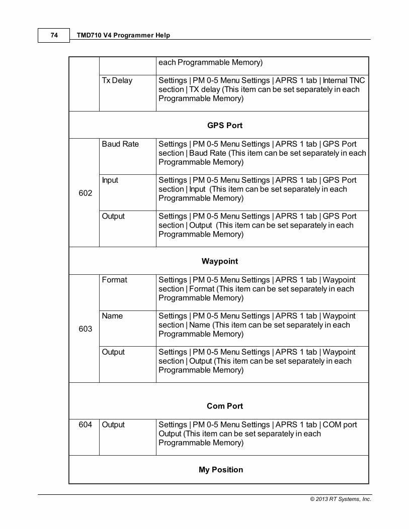
TMD710 V4 Programmer Help74
© 2013 RT Systems, Inc.
each Programmable Memory)
Tx Delay Settings | PM 0-5 Menu Settings | APRS 1 tab | Internal TNCsection | TX delay (This item can be set separately in eachProgrammable Memory)
GPS Port
602
Baud Rate Settings | PM 0-5 Menu Settings | APRS 1 tab | GPS Portsection | Baud Rate (This item can be set separately in eachProgrammable Memory)
Input Settings | PM 0-5 Menu Settings | APRS 1 tab | GPS Portsection | Input (This item can be set separately in eachProgrammable Memory)
Output Settings | PM 0-5 Menu Settings | APRS 1 tab | GPS Portsection | Output (This item can be set separately in eachProgrammable Memory)
Waypoint
603
Format Settings | PM 0-5 Menu Settings | APRS 1 tab | Waypointsection | Format (This item can be set separately in eachProgrammable Memory)
Name Settings | PM 0-5 Menu Settings | APRS 1 tab | Waypointsection | Name (This item can be set separately in eachProgrammable Memory)
Output Settings | PM 0-5 Menu Settings | APRS 1 tab | Waypointsection | Output (This item can be set separately in eachProgrammable Memory)
Com Port
604 Output Settings | PM 0-5 Menu Settings | APRS 1 tab | COM portOutput (This item can be set separately in eachProgrammable Memory)
My Position

Menu Item Cross Reference 75
© 2013 RT Systems, Inc.
605
Name Settings | PM 0-5 Menu Settings | APRS 2 tab | My Positionsection | Name (This item can be set separately in eachProgrammable Memory)
Latitude Settings | PM 0-5 Menu Settings | APRS 2 tab | My Positionsection | Latitude (This item can be set separately in eachProgrammable Memory)
Longitude Settings | PM 0-5 Menu Settings | APRS 2 tab | My Positionsection | Longitude (This item can be set separately in eachProgrammable Memory)
Beacon Information
606
Speed Settings | PM 0-5 Menu Settings | APRS 1 tab | BeaconInformation | Speed (This item can be set separately in eachProgrammable Memory)
Altitude Settings | PM 0-5 Menu Settings | APRS 1 tab | BeaconInformation | Altitude (This item can be set separately in eachProgrammable Memory)
PositionAmbiguity
Settings | PM 0-5 Menu Settings | APRS 1 tab | BeaconInformation | Position Ambiguity (This item can be setseparately in each Programmable Memory)
Position Comment
607 PositionComment
Settings | PM 0-5 Menu Settings | APRS 1 tab | PositionComment (This item can be set separately in eachProgrammable Memory)
Status Text
608
Text Settings | PM 0-5 Menu Settings | APRS 2 tab | Status Text |Name (This item can be set separately in eachProgrammable Memory)
Tx Rate Settings | PM 0-5 Menu Settings | APRS 2 tab | Status Text |Tx Rate (This item can be set separately in eachProgrammable Memory)
Packet Filter
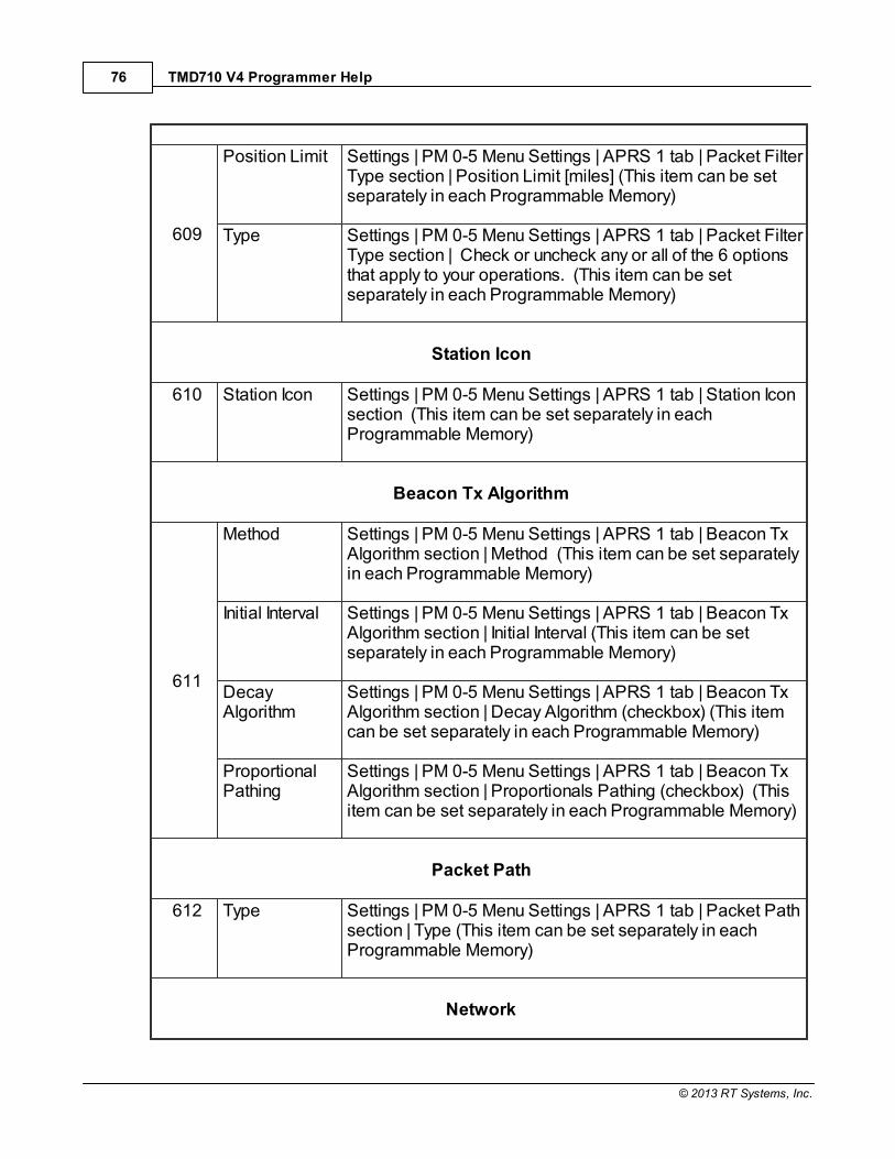
TMD710 V4 Programmer Help76
© 2013 RT Systems, Inc.
609
Position Limit Settings | PM 0-5 Menu Settings | APRS 1 tab | Packet FilterType section | Position Limit [miles] (This item can be setseparately in each Programmable Memory)
Type Settings | PM 0-5 Menu Settings | APRS 1 tab | Packet FilterType section | Check or uncheck any or all of the 6 optionsthat apply to your operations. (This item can be setseparately in each Programmable Memory)
Station Icon
610 Station Icon Settings | PM 0-5 Menu Settings | APRS 1 tab | Station Iconsection (This item can be set separately in eachProgrammable Memory)
Beacon Tx Algorithm
611
Method Settings | PM 0-5 Menu Settings | APRS 1 tab | Beacon TxAlgorithm section | Method (This item can be set separatelyin each Programmable Memory)
Initial Interval Settings | PM 0-5 Menu Settings | APRS 1 tab | Beacon TxAlgorithm section | Initial Interval (This item can be setseparately in each Programmable Memory)
DecayAlgorithm
Settings | PM 0-5 Menu Settings | APRS 1 tab | Beacon TxAlgorithm section | Decay Algorithm (checkbox) (This itemcan be set separately in each Programmable Memory)
ProportionalPathing
Settings | PM 0-5 Menu Settings | APRS 1 tab | Beacon TxAlgorithm section | Proportionals Pathing (checkbox) (Thisitem can be set separately in each Programmable Memory)
Packet Path
612 Type Settings | PM 0-5 Menu Settings | APRS 1 tab | Packet Pathsection | Type (This item can be set separately in eachProgrammable Memory)
Network
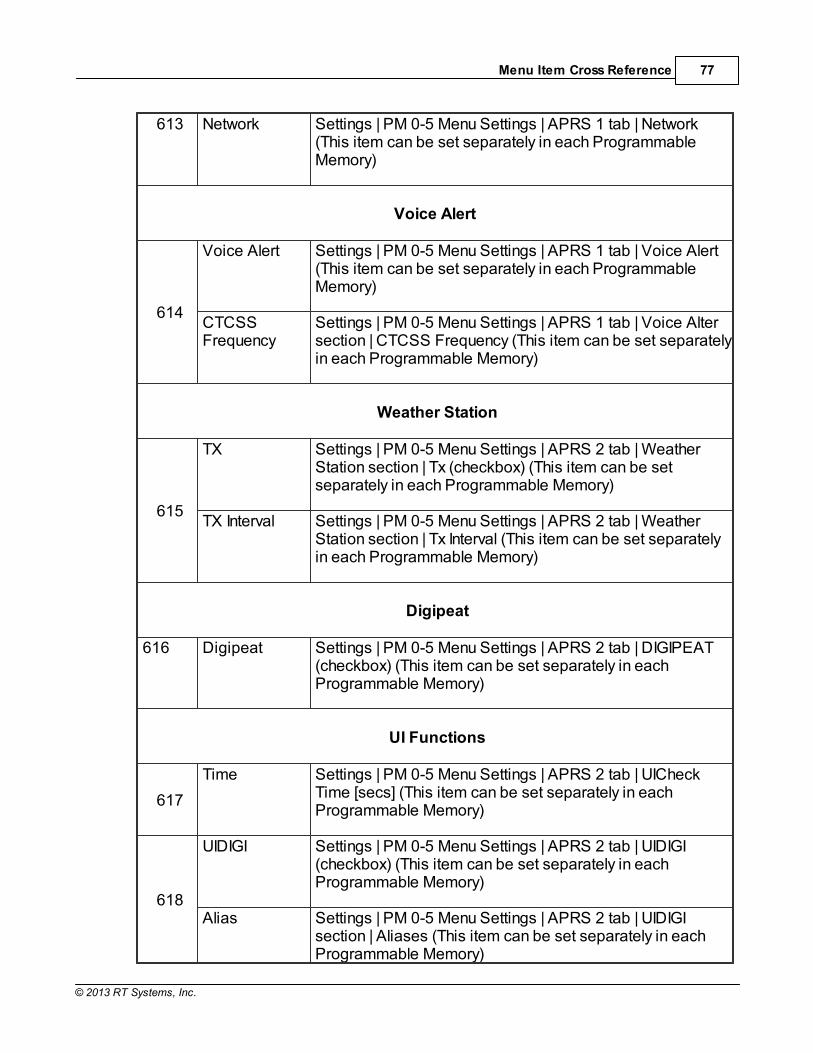
Menu Item Cross Reference 77
© 2013 RT Systems, Inc.
613 Network Settings | PM 0-5 Menu Settings | APRS 1 tab | Network (This item can be set separately in each ProgrammableMemory)
Voice Alert
614
Voice Alert Settings | PM 0-5 Menu Settings | APRS 1 tab | Voice Alert(This item can be set separately in each ProgrammableMemory)
CTCSSFrequency
Settings | PM 0-5 Menu Settings | APRS 1 tab | Voice Altersection | CTCSS Frequency (This item can be set separatelyin each Programmable Memory)
Weather Station
615
TX Settings | PM 0-5 Menu Settings | APRS 2 tab | WeatherStation section | Tx (checkbox) (This item can be setseparately in each Programmable Memory)
TX Interval Settings | PM 0-5 Menu Settings | APRS 2 tab | WeatherStation section | Tx Interval (This item can be set separatelyin each Programmable Memory)
Digipeat
616 Digipeat Settings | PM 0-5 Menu Settings | APRS 2 tab | DIGIPEAT(checkbox) (This item can be set separately in eachProgrammable Memory)
UI Functions
617
Time Settings | PM 0-5 Menu Settings | APRS 2 tab | UICheckTime [secs] (This item can be set separately in eachProgrammable Memory)
618
UIDIGI Settings | PM 0-5 Menu Settings | APRS 2 tab | UIDIGI(checkbox) (This item can be set separately in eachProgrammable Memory)
Alias Settings | PM 0-5 Menu Settings | APRS 2 tab | UIDIGIsection | Aliases (This item can be set separately in eachProgrammable Memory)
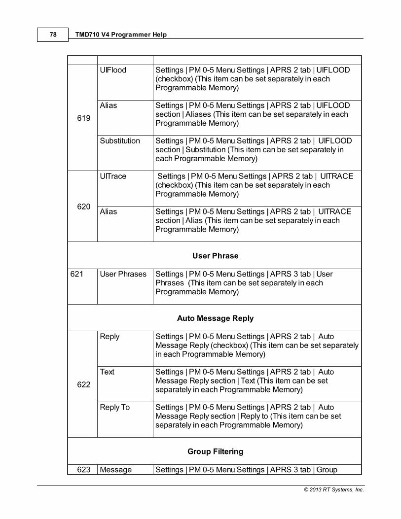
TMD710 V4 Programmer Help78
© 2013 RT Systems, Inc.
619
UIFlood Settings | PM 0-5 Menu Settings | APRS 2 tab | UIFLOOD(checkbox) (This item can be set separately in eachProgrammable Memory)
Alias Settings | PM 0-5 Menu Settings | APRS 2 tab | UIFLOOD section | Aliases (This item can be set separately in eachProgrammable Memory)
Substitution Settings | PM 0-5 Menu Settings | APRS 2 tab | UIFLOOD section | Substitution (This item can be set separately ineach Programmable Memory)
620
UITrace Settings | PM 0-5 Menu Settings | APRS 2 tab | UITRACE(checkbox) (This item can be set separately in eachProgrammable Memory)
Alias Settings | PM 0-5 Menu Settings | APRS 2 tab | UITRACE section | Alias (This item can be set separately in eachProgrammable Memory)
User Phrase
621 User Phrases Settings | PM 0-5 Menu Settings | APRS 3 tab | UserPhrases (This item can be set separately in eachProgrammable Memory)
Auto Message Reply
622
Reply Settings | PM 0-5 Menu Settings | APRS 2 tab | AutoMessage Reply (checkbox) (This item can be set separatelyin each Programmable Memory)
Text Settings | PM 0-5 Menu Settings | APRS 2 tab | AutoMessage Reply section | Text (This item can be setseparately in each Programmable Memory)
Reply To Settings | PM 0-5 Menu Settings | APRS 2 tab | AutoMessage Reply section | Reply to (This item can be setseparately in each Programmable Memory)
Group Filtering
623 Message Settings | PM 0-5 Menu Settings | APRS 3 tab | Group
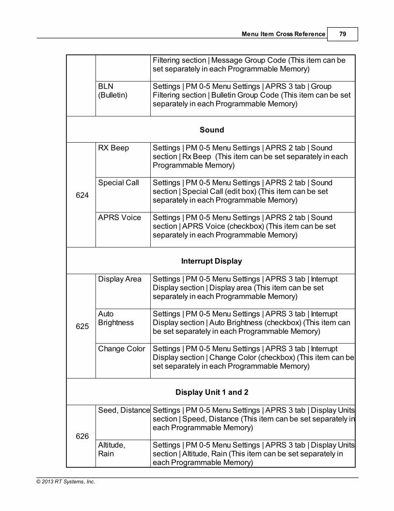
Menu Item Cross Reference 79
© 2013 RT Systems, Inc.
Filtering section | Message Group Code (This item can beset separately in each Programmable Memory)
BLN(Bulletin)
Settings | PM 0-5 Menu Settings | APRS 3 tab | GroupFiltering section | Bulletin Group Code (This item can be setseparately in each Programmable Memory)
Sound
624
RX Beep Settings | PM 0-5 Menu Settings | APRS 2 tab | Soundsection | Rx Beep (This item can be set separately in eachProgrammable Memory)
Special Call Settings | PM 0-5 Menu Settings | APRS 2 tab | Soundsection | Special Call (edit box) (This item can be setseparately in each Programmable Memory)
APRS Voice Settings | PM 0-5 Menu Settings | APRS 2 tab | Soundsection | APRS Voice (checkbox) (This item can be setseparately in each Programmable Memory)
Interrupt Display
625
Display Area Settings | PM 0-5 Menu Settings | APRS 3 tab | InterruptDisplay section | Display area (This item can be setseparately in each Programmable Memory)
AutoBrightness
Settings | PM 0-5 Menu Settings | APRS 3 tab | InterruptDisplay section | Auto Brightness (checkbox) (This item canbe set separately in each Programmable Memory)
Change Color Settings | PM 0-5 Menu Settings | APRS 3 tab | InterruptDisplay section | Change Color (checkbox) (This item can beset separately in each Programmable Memory)
Display Unit 1 and 2
626
Seed, Distance Settings | PM 0-5 Menu Settings | APRS 3 tab | Display Unitssection | Speed, Distance (This item can be set separately ineach Programmable Memory)
Altitude, Rain
Settings | PM 0-5 Menu Settings | APRS 3 tab | Display Unitssection | Altitude, Rain (This item can be set separately ineach Programmable Memory)

TMD710 V4 Programmer Help80
© 2013 RT Systems, Inc.
Temperature Settings | PM 0-5 Menu Settings | APRS 3 tab | Display Unitssection | Temperature (This item can be set separately ineach Programmable Memory)
627
Position Settings | PM 0-5 Menu Settings | APRS 3 tab | Display Unitssection | Position (This item can be set separately in eachProgrammable Memory)
Grid Format Settings | PM 0-5 Menu Settings | APRS 3 tab | Display Unitssection | Grid Format (This item can be set separately ineach Programmable Memory)
NAVITRA Functions
628
Group Mode Settings | PM 0-5 Menu Settings | APRS 3 tab | NAVITRAGroup Mode (checkbox) (This item can be set separately ineach Programmable Memory)
Group Code Settings | PM 0-5 Menu Settings | APRS 3 tab | NAVITRAGroup section | Group Code (This item can be set separatelyin each Programmable Memory)
629
Message Settings | PM 0-5 Menu Settings | APRS 3 tab | NAVITRAMessages (This item can be set separately in eachProgrammable Memory)
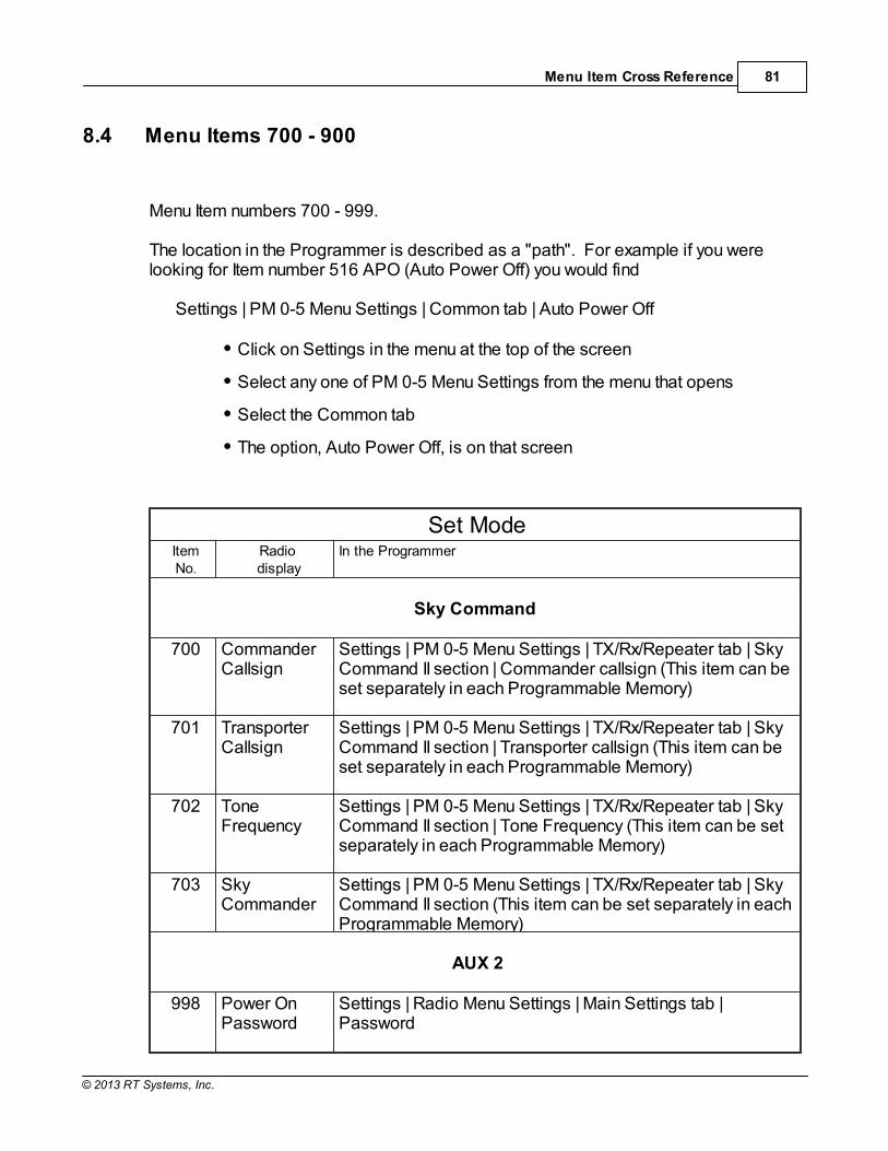
Menu Item Cross Reference 81
© 2013 RT Systems, Inc.
8.4 Menu Items 700 - 900
Menu Item numbers 700 - 999.
The location in the Programmer is described as a "path". For example if you werelooking for Item number 516 APO (Auto Power Off) you would find
Settings | PM 0-5 Menu Settings | Common tab | Auto Power Off
Click on Settings in the menu at the top of the screen
Select any one of PM 0-5 Menu Settings from the menu that opens
Select the Common tab
The option, Auto Power Off, is on that screen
Set ModeItemNo.
Radio display
In the Programmer
Sky Command
700 Commander Callsign
Settings | PM 0-5 Menu Settings | TX/Rx/Repeater tab | SkyCommand II section | Commander callsign (This item can beset separately in each Programmable Memory)
701 TransporterCallsign
Settings | PM 0-5 Menu Settings | TX/Rx/Repeater tab | SkyCommand II section | Transporter callsign (This item can beset separately in each Programmable Memory)
702 ToneFrequency
Settings | PM 0-5 Menu Settings | TX/Rx/Repeater tab | SkyCommand II section | Tone Frequency (This item can be setseparately in each Programmable Memory)
703 SkyCommander
Settings | PM 0-5 Menu Settings | TX/Rx/Repeater tab | SkyCommand II section (This item can be set separately in eachProgrammable Memory)
AUX 2
998 Power OnPassword
Settings | Radio Menu Settings | Main Settings tab |Password

TMD710 V4 Programmer Help82
© 2013 RT Systems, Inc.
999 Reset This item is not addressed from the Programmer.

Part
IX

TMD710 V4 Programmer Help84
© 2013 RT Systems, Inc.
9 Programming Memory Channels
The radio has lots of different types of memory channels. In the Programmer, these allprogram in a spreadsheet dedicated to that "type" of memory.
Use the links to access details for any one of these.
Regular Memory Channels - The several hundred all radios have these days. The ones you will use most often.
Home (Call) Channels - These are special memory channels that have onebutton access from the face of the radio. See the operating manual for theradio for details of how to access these memories from the face of the radio.
Limit Memories - These memory channels can be used as "regular"memories giving you that many more memory channels for individual use;however, these also control the top and bottom range of scanning when youbegin scanning on one of these.
VFO Memories - Settings for VFO operations when the file is first sent to theradio. This channel has no one button recall on the radio and will changewhen the tuning knob is used. To be able to recall settings at any time, usethe Regular Memory Channels.
Details on the special editing abilities of the Programmer are included in the EasyEditing in the Grid section of this Help. Review these details to make data entry eveneasier.

Programming Memory Channels 85
© 2013 RT Systems, Inc.
9.1 Regular Memory Channels
Enter the details for the memory channels on the screen of the program that first opens.
All details associated with the memory channels are programmed from thisscreen.
These are not all the functions of the radio. Other features are set once forthe radio to use no matter which memory channel you're on. These otheritems are set on the Settings screen accessed through Settings | RadioMenu Settings from the menu at the top of the screen.
Columns continue off the right side of the window. Use the bar at the bottomof the screen to move to these columns or press ENTER to step througheach column.
Make programming extra easy. Try Simple Mode in the software for evenless to enter. .

TMD710 V4 Programmer Help86
© 2013 RT Systems, Inc.
In Simple Mode the columns needed for the minimum information to set upthe channel are shown on the screen. Extra columns are hidden and filledwith default information.
To put the screen into Simple Mode, select Edit | Simple Mode from themenu. While in Simple Mode, you cannot access the Preferences screen. The Programmer controls what columns are hidden while in this mode
Details to be entered for Memory Channels
Receive Frequency: Enter a receive frequency for the memory channel. Acceptablefrequencies are detailed in the operating manual for the radio.
Unacceptable frequencies for the radio cannot be entered into theProgrammer.
The first memory channel must be programmed.
Note: When working in a default file you will find several channels(Call, VFO, etc) preprogrammed. While you can change theinformation in these channels, they cannot be blank. The radio musthave acceptable data in these memory locations.
Transmit Frequency: Enter a specific transmit frequency or let the Programmercalculate this frequency based on the offset. This field is always available; however thetransmit frequency for an "odd split" is the only value that must be entered manually.

Programming Memory Channels 87
© 2013 RT Systems, Inc.
Note: In the Programmer you can enter details for frequenciesoutside the transmission abilities of the radio. The software will notenable transmission on these frequencies. Transmission will bepossible only if the radio has been properly modified.
Entering a "Split" pair - When you are given information to program your radio, youmay be given a "pair" of frequencies (one for receive and a different one for transmit).
If the difference between the two frequencies is not divisible by 50, this pair isreferred to as a split.
If the difference is divisible by 50, the Programmer will automatically calculate theOffset frequency and set the Offset direction properly for working this repeater.
To enter the details for a "split pair":
First, enter the Receive Frequency into that column of the Programmer. This will be the frequency that you monitor when awaiting a call. This will bethe frequency of the repeater.
Press Enter. The Programmer will fill the remaining columns with defaultinformation which may or may not be right for your particular situation.
The Transmit field will be active as indicated by the dark border. Enter theTransmit Frequency from the information you have. (Note: Simply type thefirst number of that frequency. The field will change without having to erasewhat is there.)
Press Enter. Notice that the Offset Direction is set to Split. Note: TheProgrammer may set the Offset Direction to Plus or Minus. If it does andthe Receive and Transmit frequencies are what you entered, leave it as it isshown. This combination will give you the same performance on therepeater with more efficient workings of the radio.
You are finished with this entry unless you need to enter Name, Tone, or otherdetails for this memory channel.
Offset Frequency: Standard offsets include 100, 500, and 600 kHz and 5.0, 70.0, and1.0000 MHz. The most common standards are 600 kHz for the 2M band and 5.0 MHzfor the 440 MHz band.
Kenwood radios can use an Offset Frequency of any value in 50 kHz steps(i.e., any value ending in .x00 or .x50 where x is any digit from 0 to 9) with aPlus or Minus Offset Direction.

TMD710 V4 Programmer Help88
© 2013 RT Systems, Inc.
This gives you the ability to use the Reverse function of the radio althoughyour frequency pair is not separated by a standard offset value.
A non-standard Offset Frequency value is entered by typing it into the OffsetFrequency field after the Receive Frequency has been entered. Values areentered as an exact value including the decimal to denote kHz. Then selectPlus or Minus in the Offset Direction column and watch the Programmercalculate the Transmit Frequency.
For example, given the pair 146.650 and 147.300, the Offset Frequencyentered would be .650 (decimal - six - five - zero) with a Plus OffsetDirection. Without the decimal, an error is raised in the Programmer that avalid Offset Frequency should be entered.
As another example, given the pair 147.255 and 145.940 . This pair can notbe entered with an Offset Frequency and an Offset Direction. The resultingoffset for this pair us 1.315 MHz, which is not on a 50 kHz step. This pairrequires entry of both the Receive and Transmit frequency with the OffsetDirection set to Split.
Offset Direction
The programmer assigns an offset direction based on a generally accepted bandplan. This is not to say that every repeater aligns exactly with that plan. If thedetails for your repeater differ from the programmer's defaults, you are free tochange this field to any one of the options shown.
Simplex - Transmit and receive frequencies are the same. When set toSimplex, no value appears in the Offset Frequency column. The radio willtransmit and receive on the SAME frequency.
Minus -The Offset Frequency is subtracted from the receive frequencyyielding the frequency on which you will be transmitting.
Plus - The Offset Frequency is added to the receive frequency yielding thefrequency on which you will be transmitting.
Split - Used when a non-standard offset is required. The user enters both thereceive and transmit frequencies.
Operating Mode: Assign FM (+ 5 kHz), Narrow FM (+ 2.5 kHz), or AM as appropriatefor the frequency. This value can be set and stored independently for each memorychannel.

Programming Memory Channels 89
© 2013 RT Systems, Inc.
Name: Enter an Alpha/Numeric tag (up to 8 characters) for a memory channel toprovide an easy reminder of the function of a particular channel. The name is shownalong with the frequency on the display of the radio.
Tone Mode: The tone system of the radio has two functions.
It sends the sub-audible signal needed to gain access to a "toned" repeater(Tone / encode).
It uses a sub-audible tone to block signals into your radio (decode) ANDsends the sub-audible signal needed to gain access to the repeater(encode). Your radio remains silent until a signal with the same tone is heard. (T Sql = Tone Squelch)
Use of either of the tone systems requires two steps: Turning on the Tone Mode andSetting the CTCSS tone frequency or DCS code. The Programmer makes sure thatyou complete both by blocking access to the tones until a Tone Mode is selected. (Since the function will not work unless it is turned on... we make you turn it on first.)
The Tone Modes include:
None - No tone system activated. Even if the CTCSS, RX CTCSS. and DCSCode columns are set to a value, the radio will not open the repeater sincethe tone functionality is not engaged.
Tone - CTCSS tone generator is activated for transmission only Thismode is used for many if not most repeater operations.When this option isselected, the CTCSS column becomes available.
Select the tone frequency from those in the list. The value must be inthe list.
The values that appear in the RX CTCSS and DCS columns areignored by the radio when this option is being used for Tone Mode.
Tone is commonly used on repeaters not so much to limit access byradio operators; but to limit access from signals of nearby repeaters. Setting a Tone on a repeater helps keep out interference.
If the information you were given about a repeater does not specifyotherwise and you are given a CTCSS value along with other details,set Tone Mode to Tone. You will be right a majority of the time.
T Sql - CTCSS tone squelch is activated for both transmission andreception using one CTCSS tone for both. In this mode only signals set
TMD710 V4 Programmer Help90
© 2013 RT Systems, Inc.
up with the same tone will open the squelch. Your radio remains silentotherwise.
Select the tone frequency from those in the Rx CTCSS list. The valuemust be in the list.
The values that appear in the CTCSS and DCS columns are ignoredby the radio when this option is being used for Tone Mode.
Note: Be aware that many repeaters do not return tones with theoutput signal. If you can see activity as indicated by the signalstrength meter on the face of the radio but you cannot hear anythingeven when you adjust volume and squelch on with the knobs on theradio, you probably have Tone Mode set to TSql when it should beset to Tone. Or, you have an incorrect RX CTCSS value set.
TSql is being more widely used with today's amateur repeaters. Itremains, however, a lesser used option than Tone. Do not selectTSql unless the specific instructions for your activity tell you to doso.
DCS - Digital Coded Squelch mode is activated for transmission andreception using one DCS code for both. This mode is used in manycommercial systems; however, some amateur repeaters have begun to use italso. DCS is a digital code while Tone uses an analog value. When thisoption is selected, the DCS column becomes available. Select the codefrom those in the list. The value must be in the list.
The radio uses the DCS Code for both transmissions and reception. These work just like TSql functionality.
The values that appear in the CTCSS and Rx CTCSS columns areignored by the radio.
CTCSS: Select one of 42 tone frequencies to be used with Tone mode of "Tone". Thisfield is active only if Tone Mode is set to Tone. A value that appears in this field isignored if Tone Mode is set to TSql or DCS. This is the frequency that is sent to therepeater to allow access.
Rx CTCSS: Select one of 42 tone frequencies to be used with Tone mode of "TSql".This field is active only if Tone Mode is set to TSql. The tone squelch function uses atone to access the repeater AND block signals from being received by your radio. TheKenwood radio uses the one value in this field to do both functions. A value thatappears in this field is ignored if Tone Mode is set to Tone or DCS.

Programming Memory Channels 91
© 2013 RT Systems, Inc.
DCS Code: Select one of the 104 codes available for use when the radio is in DCSmode. The DCS codes correspond to digital signals sent subaudibly to the repeater toallow access. This value is set independently for each memory channel. This field isactive only when a Tone Mode for DCS is selected. A value that appears in this field isignored if one of the tone modes that uses DCS is not activated.
Note: Kenwood radios use a system of 42 CTCSS tones. Otherradios use as many as 50 tones. When you copy from another filethere may be a problem if the CTCSS value from the original datadoes not equal a value available in the Kenwood. Should thishappen, the program defaults to 67.0 for the CTCSS frequency. Afterusing copy and paste, check the CTCSS tones for 67.0Hz and verifythat this value is correct for that repeater.
Skip: Marks selected memory channel to be skipped during scanning (MemoryChannel Lockout). These channels remain available for manual selection by turningthe knob.
Unchecked - the channel is included when scanning memory channels.
Checked - the channel is omitted when scanning memory channels.
Step: The frequency that the radio is on changes by the value of the step when tuningmanually (in VFO). In VFO, this value could keep you from returning to your originalfrequency. The Programmer will help you with this value. An incorrect value will becorrected before the file is sent to the radio making the radio operate properly.
Tx Step: When saving a split pair, the Kenwood radio requires a step value for both thereceive frequency (step) and the transmit frequency (Tx step). The Programmer willhelp you with this value. An incorrect value will be corrected before the file is sent to theradio thus making the radio operate properly.
Comments: An identifying comment up to 80 characters. This information is nottransferred to the radio.

TMD710 V4 Programmer Help92
© 2013 RT Systems, Inc.
9.2 Limit Memories
This feature allows you to set sub-band limits for VFO scanning. Three conditions applyto the frequencies assigned to the lower and upper limit channels for a given pair must.
1) The lower limit channel must be a lower frequency than that of the upperlimit channel.
2) The two frequencies must be in the same band.
3) The step size must be the same in the two channels.
For example, you might wish to set up a limit (in North America) of 144.300 MHz to148.000 MHz so as to prevent encroachment into the SSB/CW "Weak Signal" portionof the band below 144.300 MHz. Then when you scan using this limit pair, you willbegin scanning at 144.300 and continue to scan up to 148.000 before returning to144.300 to begin the cycle again. The Limit Memory channels are entered on the Limit Memories page accessed throughthe tab of the same name at the bottom of the screen. The same information as thatentered for any memory channel is entered for these. See the Regular MemoryChannels section of this Help for the details about the information to be entered.
In the Limit Memory channels, Step becomes much more important since you plan tobegin scanning from one of these channels. Remember that scanning will incrementthe frequency by the value in the Step field. Choose your value to be sure you do notmiss channels in your range.
Note: If the step size differs between the lower limit and the upperlimit channels, the radio will perform a VFO scan rather than aProgram Scan (i.e., it will ignore the limits and scan the entire band).
The option for Scan Resume can be set from the Programmer. This item is found in theSetting file which is accessed by selecting Settings | PM 0 - 5 Menu Settings from themenu at the top of the screen. Scan Resume is found on the Common tab for eachProgrammable Memory. This option can be set independently in each of the sixProgrammable Memories.
To use Program scan once the limits are set, saved and sent to the radio,
Select the desired band
Press the [VFO] button

Programming Memory Channels 93
© 2013 RT Systems, Inc.
Rotate the Tuning control knob to select a frequency within your desiredrange.
Note: If the frequency is within more than one Program Scanrange, the range stored in the lower channel number will be used. Consider this carefully when setting up the ranges. If range 1 andrange 2 overlap, be sure to begin scanning range 2 on a frequencythat is within range 2 but outside of range 1 or the radio will scanrange 1.
Press the [VFO] button to start scanning at the current frequency.
To halt the scan, press [VFO] again
TMD710 V4 Programmer Help94
© 2013 RT Systems, Inc.
9.3 VFO - VFO 5 Memories
The TM-D710 has six sets of VFO channels. These VFO frequencies exist in each ofthe six Programmable Memory accessed through the PM key on the face of the radio.
The Programmable Memory (PM) channels store operating environments for quickrecall. These different VFOs would be available for immediate recall along with thecustomized settings when a Programmable Memory is recalled. The memory channelsare always available no matter which Programmable memory is operational.
The VFO memory provides "temporary" frequency storage for quick access. The VFOmemory is temporary since it is lost when the radio is tuned while in VFO mode.
Note: Remember, the VFO memory is temporary. The programmedfrequencies appear immediately after the file is sent to the radio. Whenthe radio is manually tuned in VFO mode, the programmed frequencycannot be recalled as a memory channel frequency will be.
Programming the VFO memory from the Programmer can be particularly helpful forreoccurring events for which the details of this channel are needed along with othermemory channels. Memories do not have to be programmed into VFO before being programmed into thememory channels when entering details in the Programmer. Memory channels areprogrammed directly into the spreadsheet that appears when the Programmer opens. To program the VFO memory, select the VFO(1-5) tab at the bottom of the screen.Enter a frequency that is appropriate for the band. The details that you enter willreplace the default of the radio. Simply type over the information shown to make thechanges.
Note: The VFOs must contain a frequency appropriate for the band. They CANNOT BE BLANK.
The information to be entered is the same as that for regular Memories except that theVFO’s do not have an alpha label available to be programmed. See the RegularMemory Channel in this Help for details of the fields.
In VFO mode, Step is important to ensure that you can tune manually to a certainfrequency. Pay careful attention to this column when programming the VFOs.

Programming Memory Channels 95
© 2013 RT Systems, Inc.
9.4 Home (Call) Channel
The Call channel memory provides convenient, one-touch access to your most oftenused frequency in the 2M and 440 MHz bands.
Call/Home channel memories are programmed on the Home tab of the Programmer. The information to be programmed for the Call Channels is the same as that for theregular Memories. See Regular Memory Channels for the details of each item to beprogrammed.
Call Scan
Use Call Scan to monitor both the Call channel for the active band and the currentlyselected VFO frequency or the currently selected Memory channel.
To use this functionSelect a Memory channel or VFO frequency.
Press CALL for 1 second to start Call scan. - The MHz decimal blinks toindicate the scan is in progress.
Press CALL again to quit scanning.
Note: If your radio seems to "run off" from the channel or frequencycheck that this feature is not engaged. You may have set itaccidentally by holding the CALL button a little too long.

Part
X
Programming Other Set Menu Items 97
© 2013 RT Systems, Inc.
10 Programming Other Set Menu Items
There is a lot more to this radio than just the memory channel.
Your radio has other menu items that are not associated with each memory channel. These menu items are "global" to the radio's functionality. The radio uses thesesettings no matter what memory channel you're on, what frequency of operation you'rein, if you're in VFO or memory.
If you radio "acts funny" once it is programmed with a file of memory channels, checkthe settings file to be sure things are set correctly. Then be sure to save the settings fileso your personal touches will go to the radio with every file. (File | Save from the menuon the Settings screen). The settings file then works in conjunction with the memorychannel file to program your radio.
Things like Beep, Squelch, Programmable keys and Locks, just to name a few, are setfor the radio to use whenever it is being operated...no matter the channel or mode(VFO or memory).
Radio Menu Settings are set from the Radio Menu Settings screens in theProgrammer. These screens are accessed by selecting Settings | Radio MenuSettings from the menu on the main screen. The Programmer offers three options for managing the global settings:
Set and forget - The Radio Menu Settings screens are there for you to useto easily customize your radio to suit your use. Once you make yourselections and save them, you don't have to do it again, even it you start anew frequency file.
Create and use multiple global settings files - This might be the best optionif you program the frequencies for several different people. You cancustomize the global functions for the individual without having to recreatethe frequency file.
Save the settings as part of the file with the memory information - This mightbe best if you are programming different frequencies AND different globalsettings for different groups. You might even want to use this option if youtravel. How you use your radio at home may differ from how it shouldfunction on the same frequency in another city. Then each time you travel,simply load the corresponding file into the radio to have frequency andglobal settings as you need them for where you're going.
The three options are discussed in detail below. Once you decide, set the Programmer

TMD710 V4 Programmer Help98
© 2013 RT Systems, Inc.
for the option that you want on the Preferences screen (Settings | Preferences) in theProgrammer.
Set and Forget
This is the default of the Programmer.
Not using the Radio Menu Settings (Settings | Radio Menu Settings) settings canresult in your radio "acting funny" every time you program it. That's becausesomething is getting reset in the radio by a setting in this file.
From the main screen of the Programmer, select Settings | Radio Menu Settings. Explore these screens. If you fear you have made changes you don't want, click the"X" at the upper right of the Settings screen. Answer No to the prompt to save. Thenclick the "X" again to close. The screen will close without saving anything you havedone.
Details for the options on this page are found on several pages of this Help. Eachpage contains the details for the options on that page. The information there can helpyou decide how best to customize a setting.
Once you complete your selections:
Click File | Save
If you are working in a default file (Untitled.rsf), you will be prompted for afilename.
Enter a name for this file. This can be the same as the name you're usingfor the memory channel information or it can be a name unique to thesesettings. If you're at a loss, use "Settings".
Click Save to close the Save dialog
Click File | Exit to close the Settings screen.
The Programmer will take it from here making sure these customized settings go tothe radio along with the memory channel information.
Creating and using multiple global settings files There may be global settings of the radio that you want configured differently fordifferent activities. You can make changes to your settings file and save it separately. Having multiple memory channel files (."radio name") and multiple global setting files

Programming Other Set Menu Items 99
© 2013 RT Systems, Inc.
(.rsf) gives you the ability to mix and match the features of your radio to suit yourneeds. This makes it easy to customize the radio for a special event without disturbingthe original programming files. Then once the event is over, simply reprogram theradio with the memory channel information and settings that you use everyday. When a new file is begun, the same settings used in the last settings file saved willbe used automatically. You need not re-enter the settings each time, nor are youforced to always begin a new file by renaming an existing file. You need only entermemory channel details. To select a settings file for use:
Select Settings | Radio Menu Settings from the main page of theProgrammer.
From the Radio Menu Settings screen, select File | Open. A list of settingsfiles will be presented. - Do not change the Files of Type selection at thebottom. The Programmer presents appropriate files to choose from.
Select the file you want to use and click Open.
Verify that this is the settings file that you want to use. Check also that theproper filename appears in the titlebar at the top of the Menu Settingswindow.
Click File | Save to reset the Programmer to use this file.
Select File | Exit to close this screen. These settings will be sent to theradio with the memory channel file until you change this file selection again.
Save the settings as part of the file with the memoryinformation
Beginning with the Version 3 Programmers, and continuing into the current version, isthe option of saving the global settings with the memory channel information.
This feature is good two ways. First, if you think that you'll always use only one file forprogramming and you are more comfortable knowing that EVERYTHING that is goingto the radio is in this one file, select this option. Second, if you are programmingsimilar, but not identical, memory channel information for people who use their radiosvery differently, keeping global menu settings in the file with the memory channelinformation would reduce the chance of programming a radio incorrectly. Keep menu settings and frequencies in a single file. (option)
From the main screen of the Programmer, select Settings | Preferences

TMD710 V4 Programmer Help100
© 2013 RT Systems, Inc.
Click OK to close this screen.
From the main screen of the Programmer, select Settings | Radio MenuSettings.
Make changes as needed.
Click Close | Apply changes and close (if you want to save) or Discard allchanges and close (if you think you're made mistakes and need to return tothe last time you saved this file).
Remember, with each new file created the Radio Menu Settings return to factorydefaults. You must set these option for EACH memory channel file created.
Another feature of this option is the ability to use the settings from a settings file thatyou already created.
From the Menu Settings screen, select External Setting Files
From that menu select Open
Select a settings file from the list presented. The settings file must be forthe same radio.
To set these to be used in this file, select Close | Apply changes and close.
The settings from the other file will be saved to this file and sent to the radio with thismemory channel programming.
Programming Other Set Menu Items 101
© 2013 RT Systems, Inc.
10.1 Radio Menu Settings - Main
Your radio has other menu items that are not associated with each memory channel. These menu items are "global" to the radio's functionality. The radio uses thesesettings no matter what memory channel you're on, what frequency of operation you'rein, if you're in VFO or memory.
If you radio "acts funny" once it is programmed with a file of memory channels, checkthe settings file to be sure things are set correctly. Then be sure to save the settings fileso your personal touches will go to the radio with every file. (File | Save from the menuon the Settings screen). The settings file then works in conjunction with the memorychannel file to program your radio.
10 MHz Mode - Enable to allow the VFO receive frequency to be tuned in 10 MHzsteps. This function can be set in software only. It cannot be enabled or disabled fromthe face of the radio.
Key Lock - Disable buttons of the radio other than [Power] and [PTT]. When engagedLOCK appears on the display of the radio. To disengage this feature from the face ofthe radio, press and hold the [F] key for one second (or until the LOCK indicationappears or disappears).
Channel Display - This function is more than just a change to the display on the faceof the radio. When engaged, ONLY Memory channels are accessible.
The display of the radio displays CH XXX (where XXX is a channel number)rather than a frequency.
To control this feature from the face of the radio, hold the [LOW] key duringpower On.
This feature cannot be engaged if there are no memory channels in the radio.Although the option can be checked in the Programmer, the setting will beignored by the radio.
When engaged, the radio cannot be reset.
Data Terminal
Set the PR1 Pin Output Level independently for Packet Mode and EcholinkSysop Mode.

TMD710 V4 Programmer Help102
© 2013 RT Systems, Inc.
Set the RKD Pin Input Sensitivity independently for Packet (1200 bps)Mode and Echolink Sysop Mode.
Repeater Operation - See details for this advanced feature of the radio in theRepeater Operations section of this Help. This is an advanced function of the radio foruse in special operations.
Remote Control - Control your mobile radio with a properly equipped HT throughproperly sent DTMF tones. See the section in the Help on Remote Control for moredetails on this feature. The options to be set in the Programmer for this functioninclude:
Password - Enter up to 5 letters and digits then check to enable passworded accessto your radio. This will be the first think that appears when the radio powers on. Thisoption cannot be enabled as blank to keep you from locking yourself out of your ownradio.
Note: Notice there is ONE password for this radio. The password isnot saved separately for each programmable memory.
Although there are six programmable memories that can becustomized for use by different people, there is only one password. Ifyour radio is being shared between several people, everyone with theright to use the radio will have to know the password.
Mic Sensitivity - Set to High, Medium, or Low to suit your voice.
EchoLink Rx Monitor - Configure the audio output while in Echolink Sysop Mode. Options include:
CTCSS/DCS - Audio is heard when a signal with a matching DCS orCTCSS tone is received.
Busy Only - Audio is heard whenever a signal is received.
Other options for Echolink are found on the DTMF / Echolink / Weather tab of theSettings file.
Memory Group Names - Memory channels are grouped by channel number into ten

Programming Other Set Menu Items 103
© 2013 RT Systems, Inc.
groups. Group 1 contains channels 0-99, Group 2 has channels 100 - 199, etc.,through Group 9 with channels 900 - 999
SQC Output Logic - Set the logic level from the SQC data terminal to High or Low.
Note: The other option for SQC operations, SQC Output Source, isfound at Settings | PM 0 - 5 Menu Settings | Common | SQC OutputSource.
These two items are separated in the Programmer since one canhave one value while the other can be set differently in each PM.
Selected PM - Set from 0 to 5 for the Programmable Memory to be used when theradio is programmed.
Programmable Memory Name - Enter a name of up to 16 characters to help identifythis PM.

TMD710 V4 Programmer Help104
© 2013 RT Systems, Inc.
10.1. .1 Repeater Operations Details
First and foremost, the repeater operations described here are NOT needed to simplyaccess your local repeater. These are advanced functions of the radio intended for useunder special, pre-determined circumstances with advanced setup.
For those of you who want to simply talk on and listen to local repeaters, do not activatethese functions. take care that you do not engage this function accidentally. It is notdisengaged even with a full reset on the radio. Further, you are unable to perform anytransceiver functions while in Repeater mode.
This feature can be engaged only from the face of the radio. You cannot accidentallyturn this on from the Programmer. To engage or disengage Repeater Operations,press and hold [TONE] while powering on the radio. When Repeater Operations isengaged, the PTT and LOCK icon blink on the display.
The TM-D710 is capable of functioning like a repeater by receiving a signal on oneband and retransmitting it on the other. This function is commonly know as Cross-bandrepeating. It is often used to give an HT the ability to access a distant repeater that itcan hear but cannot hit with 5 watts of power.
For example:
Given you want to use a 2 meter repeater. Set the HT to a simplex 440 MHzfrequency (listen for one that is not in use and use low power since the mobileradio and the HT are not far apart).
Set one side of the mobile radio to the same 440 Mhz frequency with offsetdirection set to Simplex. Set the other side to the details for the repeater(Receive frequency, offset and tone).
When you transmit with the HT on the 440 Mhz frequency, the mobile radiowill hear that signal and retransmit it on the 2 meter settings.
The signal returning from the repeater will be heard by the mobile radio andretransmitted to the HT on the 440 Mhz frequency.
The TM-D710 has three modes for Repeater Operations. After selection, turn thetransceiver power OFF; then press [TONE] + Power ON. When repeater mode is ON,the PTT and LOCK icons blink. To return to normal operation, turn the transceiver OFF,then press [TONE] + Power ON.
Cross Band - If a signal is being received on the TX band, the radioswitches the current RX band to the TX band. This is useful when joining a

Programming Other Set Menu Items 105
© 2013 RT Systems, Inc.
group talk. Plan ahead, participants in a group talk should set the Tx and Rxfrequencies on different bands and repeater operations to Cross Band tokeep from missing any of the conversation.
Locked TX (Band A or Band B) - The radio uses the same band to receiveor transmit a signal.
The options to be set in the Programmer for this function include:
Tx Hold (500 ms) - Check to set the radio to remain in transmit mode for500 ms after a signal drops (this gives the radio a "tail" just like that you hearfrom the repeater.)
Mode - Set to Cross Band or Single band operation.
ID Transmit - Set to Off, Voice, or Morse for callsign transmission every 10minutes as required by FCC rules for amateur transmissions.
Note: To use Voice, you must have the VGS-1 option installed. When using this option, the ID Transmit function will use channel 3as the callsign.
ID - Enter your callsign for repeater identification.
Note: If ID Transmit is set to Morse, the callsign will be transmitted at20 words per minute.

TMD710 V4 Programmer Help106
© 2013 RT Systems, Inc.
10.1.8 Remote Control
Your radio has other menu items that are not associated with each memory channel. These menu items are "global" to the radio's functionality. The radio uses thesesettings no matter what memory channel you're on, what frequency of operation you'rein, if you're in VFO or memory.
If you radio "acts funny" once it is programmed with a file of memory channels, checkthe settings file to be sure things are set correctly. Then be sure to save the settings fileso your personal touches will go to the radio with every file. (File | Save from the menuon the Settings screen). The settings file then works in conjunction with the memorychannel file to program your radio.
10 MHz Mode - Enable to allow the VFO receive frequency to be tuned in 10 MHzsteps. This function can be set in software only. It cannot be enabled or disabled fromthe face of the radio.
Key Lock - Disable buttons of the radio other than [Power] and [PTT]. When engagedLOCK appears on the display of the radio. To disengage this feature from the face ofthe radio, press and hold the [F] key for one second (or until the LOCK indicationappears or disappears).
Channel Display - This function is more than just a change to the display on the faceof the radio. When engaged, ONLY Memory channels are accessible.
The display of the radio displays CH XXX (where XXX is a channel number)rather than a frequency.
To control this feature from the face of the radio, hold the [LOW] key duringpower On.
This feature cannot be engaged if there are no memory channels in the radio.Although the option can be checked in the Programmer, the setting will beignored by the radio.
When engaged, the radio cannot be reset.
Data Terminal
Set the PR1 Pin Output Level independently for Packet Mode and EcholinkSysop Mode.

Programming Other Set Menu Items 107
© 2013 RT Systems, Inc.
Set the RKD Pin Input Sensitivity independently for Packet (1200 bps)Mode and Echolink Sysop Mode.
Repeater Operation - See details for this advanced feature of the radio in theRepeater Operations section of this Help. This is an advanced function of the radio foruse in special operations.
Remote Control - Control your mobile radio with a properly equipped HT throughproperly sent DTMF tones. See the section in the Help on Remote Control for moredetails on this feature. The options to be set in the Programmer for this functioninclude:
Password - Enter up to 5 letters and digits then check to enable passworded accessto your radio. This will be the first think that appears when the radio powers on. Thisoption cannot be enabled as blank to keep you from locking yourself out of your ownradio.
Note: Notice there is ONE password for this radio. The password isnot saved separately for each programmable memory.
Although there are six programmable memories that can becustomized for use by different people, there is only one password. Ifyour radio is being shared between several people, everyone with theright to use the radio will have to know the password.
Mic Sensitivity - Set to High, Medium, or Low to suit your voice.
EchoLink Rx Monitor - Configure the audio output while in Echolink Sysop Mode. Options include:
CTCSS/DCS - Audio is heard when a signal with a matching DCS orCTCSS tone is received.
Busy Only - Audio is heard whenever a signal is received.
Other options for Echolink are found on the DTMF / Echolink / Weather tab of theSettings file.
Memory Group Names - Memory channels are grouped by channel number into ten

TMD710 V4 Programmer Help108
© 2013 RT Systems, Inc.
groups. Group 1 contains channels 0-99, Group 2 has channels 100 - 199, etc.,through Group 9 with channels 900 - 999
SQC Output Logic - Set the logic level from the SQC data terminal to High or Low.
Note: The other option for SQC operations, SQC Output Source, isfound at Settings | PM 0 - 5 Menu Settings | Common | SQC OutputSource.
These two items are separated in the Programmer since one canhave one value while the other can be set differently in each PM.
Selected PM - Set from 0 to 5 for the Programmable Memory to be used when theradio is programmed.
Programmable Memory Name - Enter a name of up to 16 characters to help identifythis PM.

Programming Other Set Menu Items 109
© 2013 RT Systems, Inc.
10.1.8.1 Remote Control Details
An advanced feature of the radio allows you to control the TM-D710 with anappropriately equipped HT through DTMF tones. This function can be performed byany HT with DTMF functionality; however, if it lacks the remote control function, all toneswill be sent manually from the face of the HT.
Preparation on the HT includes:
Programming the same three digit ID to initiate remote control on the mobileradio
Setting up a UHF frequency for sending the tones to the mobile radio
Setting up a VHF frequency for receiving the Answer Back tones from themobile radio.
Note: This setup is a function of the HT and is not addressed in theProgrammer for the TM-D710. I
Two options are set in the Programmer for the mobile radio in preparation for remotecontrol operations:
Answer Back - Check to enable answer back from the mobile radio to theHT as confirmation that a signal was received. The three digit ID is sent bythe mobile radio as the Answer Back.
ID - To prevent control of the radio from an unauthorized source, this processis initiated through a three digit code established in the HT and the mobileradios. Enter this code in the ID field of the Remote Control section. Set thesame code in the HT or send the code manually if the HT does not haveremote control functionality.
Once setup is complete, engage remote control on the mobile radio by pressing the[REV] key while turning on the power. The CTRL and LOCK icons will appear on theface of the radio when this function is engaged.
While in Remote Control mode, the DTMF keys of the HT will function as shown in thetable below. The mobile radio will perform the specified function when the DTMF toneis received.
OperationDTMF
Command
Access your mobile via the remoteunit
A***#

TMD710 V4 Programmer Help110
© 2013 RT Systems, Inc.
OperationDTMF
Command
(where *** is your 3-digit secretnumber)
End access via the remote unit A #
DCS On 1
Tone On 2
CTCSS On 3
DCS Off (all signalling Off) 4
Tone Off (all signalling Off) 5
CTCSS Iff (all signalling Off) 6
Call mode On 7
VFO Mode On 8
Transmit Power (press to toggle between High,Medium and Low)
0
Frequency (VFO Mode) orMemory Channel (Memory Mode)direct entry
A XXXXXXX
DCS code (when DCS is on)Tone frequency (when Tone is on)orCTCSS frequency (when CTCSS ison) setup
B XXX(DCS code)
BA XXX(Tone / CTCSS
frequency)
Repeater Operation On (Cross-band or Locked-band)
C
Repeater Operation Off D
Step the frequency or Memorychannel down *Step the frequency or Memorychannel up
#

Programming Other Set Menu Items 111
© 2013 RT Systems, Inc.
Note: If you are using an HT that does not have a remote controlfunction, manually send "AXXX#YA#" where "XXX' is the pre-established 3-digit secret number programmed in the mobile radioand "Y" is a single digit control command as shown in the table.
If you do not send the "A#" at the end of the string you will not haveto send the "AXXX#" at the beginning of the next control command;however, the mobile radio will remain ready to receive commandsfrom any station capable of sending DTMF tones.
Unless you are working with a series of commands that will be sentone immediately following the next, it is best to End access with the"A#" suffix on each command and re-establish access with yoursecret code through the "AXXX#" prefix to prevent someone elsefrom making changes you don't expect.

TMD710 V4 Programmer Help112
© 2013 RT Systems, Inc.
10.1.9 Password
Your radio has other menu items that are not associated with each memory channel. These menu items are "global" to the radio's functionality. The radio uses thesesettings no matter what memory channel you're on, what frequency of operation you'rein, if you're in VFO or memory.
If you radio "acts funny" once it is programmed with a file of memory channels, checkthe settings file to be sure things are set correctly. Then be sure to save the settings fileso your personal touches will go to the radio with every file. (File | Save from the menuon the Settings screen). The settings file then works in conjunction with the memorychannel file to program your radio.
10 MHz Mode - Enable to allow the VFO receive frequency to be tuned in 10 MHzsteps. This function can be set in software only. It cannot be enabled or disabled fromthe face of the radio.
Key Lock - Disable buttons of the radio other than [Power] and [PTT]. When engagedLOCK appears on the display of the radio. To disengage this feature from the face ofthe radio, press and hold the [F] key for one second (or until the LOCK indicationappears or disappears).
Channel Display - This function is more than just a change to the display on the faceof the radio. When engaged, ONLY Memory channels are accessible.
The display of the radio displays CH XXX (where XXX is a channel number)rather than a frequency.
To control this feature from the face of the radio, hold the [LOW] key duringpower On.
This feature cannot be engaged if there are no memory channels in the radio.Although the option can be checked in the Programmer, the setting will beignored by the radio.
When engaged, the radio cannot be reset.
Data Terminal
Set the PR1 Pin Output Level independently for Packet Mode and EcholinkSysop Mode.

Programming Other Set Menu Items 113
© 2013 RT Systems, Inc.
Set the RKD Pin Input Sensitivity independently for Packet (1200 bps)Mode and Echolink Sysop Mode.
Repeater Operation - See details for this advanced feature of the radio in theRepeater Operations section of this Help. This is an advanced function of the radio foruse in special operations.
Remote Control - Control your mobile radio with a properly equipped HT throughproperly sent DTMF tones. See the section in the Help on Remote Control for moredetails on this feature. The options to be set in the Programmer for this functioninclude:
Password - Enter up to 5 letters and digits then check to enable passworded accessto your radio. This will be the first think that appears when the radio powers on. Thisoption cannot be enabled as blank to keep you from locking yourself out of your ownradio.
Note: Notice there is ONE password for this radio. The password isnot saved separately for each programmable memory.
Although there are six programmable memories that can becustomized for use by different people, there is only one password. Ifyour radio is being shared between several people, everyone with theright to use the radio will have to know the password.
Mic Sensitivity - Set to High, Medium, or Low to suit your voice.
EchoLink Rx Monitor - Configure the audio output while in Echolink Sysop Mode. Options include:
CTCSS/DCS - Audio is heard when a signal with a matching DCS orCTCSS tone is received.
Busy Only - Audio is heard whenever a signal is received.
Other options for Echolink are found on the DTMF / Echolink / Weather tab of theSettings file.
Memory Group Names - Memory channels are grouped by channel number into ten

TMD710 V4 Programmer Help114
© 2013 RT Systems, Inc.
groups. Group 1 contains channels 0-99, Group 2 has channels 100 - 199, etc.,through Group 9 with channels 900 - 999
SQC Output Logic - Set the logic level from the SQC data terminal to High or Low.
Note: The other option for SQC operations, SQC Output Source, isfound at Settings | PM 0 - 5 Menu Settings | Common | SQC OutputSource.
These two items are separated in the Programmer since one canhave one value while the other can be set differently in each PM.
Selected PM - Set from 0 to 5 for the Programmable Memory to be used when theradio is programmed.
Programmable Memory Name - Enter a name of up to 16 characters to help identifythis PM.

Programming Other Set Menu Items 115
© 2013 RT Systems, Inc.
10.2 Radio Menu Settings - DTMF/Echolink/Weather
DTMF - Dual Tone Multi-Frequency
The keys on the microphone keypad function to generate DTMF tones. These DTMFtones are used today for autodial functions (phone calls through amateur repeaters) orfor access to Internet functions. For more information about the availability of thesefunctions in your area, contact your local repeater operator.
The radio have 10 memories (automatic dialer) for storing a DTMF strings (Code) of upto 16 digits in each channel.
These memories can be labeled with an alpha/numeric strings (Name) for easieridentification.
The options to be set in the Programmer include:
Name - An identifying alpha/numeric string of up to 9 characters.
Code - The DTMF string. You can store up to 16 digits.
DTMF Hold - Activate this function to remain in transmit mode, afterbeginning to press keys when making a call.
DTMF Mic Key Lock - This function will lock the DTMF transmission keys sothat they will not transmit if they are accidently pressed. Check to inhibitDTMF transmission.
DTMF Delay - Adjust the delay between selection of a DTMF memory andtransmission of the tones.
DTMF Speed - Change the speed at which the tones are transmitted forimproved communication between the radio and the repeater. Somerepeaters may not respond correctly if at fast speed; if that happens, changethe speed to Slow.
Echolink - EchoLink®, a registered trademark of Synergenics, LLC, is a system thatlinks amateur radio stations together using the Internet and allows you to enjoy speechcommunication with other operations via the worldwide network, using VolP (voice-over-IP) technology.
There are many access points for EchoLink (called EchoLink nodes), such as repeaterstations and link stations that connect to the Internet.

TMD710 V4 Programmer Help116
© 2013 RT Systems, Inc.
Using DTMF codes transmitted from a transciever to access a nearby EchoLink node,it is possible to communication with amateur radio stations located at many places inthe world.
If the EchoLink software is installed on your personal computer, without using anytransceiver, it is possible to communicate as a single user directly via your personalcomputer. This is a major feature of EchoLink
In Sysop mode, EchoLink forms a gateway between the Internet and a local RFchannel, such as a simplex frequency or a nearby repeater. This allows other stationsin the system to communicate with mobile or portable users in your area.
For operation details, PC hardware requirements, and information about EchoLinknodes, visit the official site at www.echolink.org.
There are 10 EchoLink memory channels available. This function is used for accessingnearby relay stations using DTMF codes or by transmitting a control command.
Name - Enter an alpha/numeric string of up to 8 characters to identify thisEcholink memory.
Code - Enter the DTMF string of up to 8 characters needed for Echolinkaccess.
EchoLinkSpeed - Set the transmission speed for the tones to Fast or Slowfor improved communication between the radio and the repeater. Somerepeaters may not respond correctly if at fast speed; if that happens, changethe speed to Slow
Note: The radio cannot communicate with the Programmer if theEcholink Sysop Mode is on.
Weather Channel - you can program weather channels, if using a K-type (USA andCanada) transceiver model.
The radio comes preprogrammed with ten NOAA weather channel frequencies.
Rx Frequency - Appears only as reference for the other programmableinformation.
Rx Step - This value must be set appropriately for the frequency entered.
Name - Enter an alpha/numeric string of up to 8 characters to identify aWeather channel.
Programming Other Set Menu Items 117
© 2013 RT Systems, Inc.
10.3 Programmable Memories (PM0 - PM5)
The TM-D710 has settings that are associated with memory channels; others that areset only once in the radio; and others that can be set independently six different times:once for each programmable memory.
In the Programmer, these items are found in specific areas that help you easily setthem as they are designed to be used by the radio.
Memory Channel items are found in the spreadsheet on the main page ofthe Programmer.
Set Menu Items that can be set only once are found on the screens that openwhen you select Settings | Radio Menu Settings from the menu at the top ofthe screen.
Programmable Memory items, the ones that can be set independently foreach programmable memory, are found when you select Settings | PM0 -PM5 Menu Settings from the menu at the top of the screen. These screenscontain the same options. The radio will use the setting within theProgrammable Memory that is currently active on the radio.
Programmable Memories
Programmable Memories... maybe not the best name for these since they are NOTmemory channels for frequencies other than VFOs.
Programmable Memories (PM) are memories of a sense. They "remember" settingsfor many features of the radio. Your radio uses the same memory channels(frequencies) in all the PMs.
The TM-D710 has six Programmable Memories (PM). These contain menu itemsettings that can be configured not once but six different ways. PMs are useful inseveral scenarios.
If you share your radio with someone, each of you can configure many detailsof the radio as you want for optional performance.
Since display brightness and color are two of these options, you might wantto set your radio differently for your morning and evening commute to make itmore visible in changing light conditions.
ARPS settings are included in these options. With two button presses, youcan access different ARPS characteristics for a different activity.

TMD710 V4 Programmer Help118
© 2013 RT Systems, Inc.
The MIC and Panel PF key settings can be customized for differentactivities. Change to those differences without having to access the radio'smenu. Simply change to a different Programmable Memory to activate thosenew settings.
Set up different Memory Group Linking. While the radio accesses all thememory channels in each of the Programmable Memories, setting GroupLinking differently gives you control over what memory channels are includedwhen you scan. Set your amateur repeaters in one PM, your trainfrequencies in another, your fire and police frequencies in a third PM. Nowyou can scan for that specific activity without having to wait through the activityfrom the others.
These are just a few suggestions for using the Programmable Memories. Thecombinations are endless given how many features of the radio are included in theProgrammable Memory options.
With just a little thought and organization, your radio will operate six different ways withjust two button presses. How easy is that!!

Programming Other Set Menu Items 119
© 2013 RT Systems, Inc.
10.3.1 Menu Settings - Common
1750 Hz Transmit Hold - Check to enable transmission of the 1750 Hz toneautomatically when the PTT is pressed. This is different than transmitting the tonethrough a PF key and very useful when a repeater (usually in Europe) needs the tonewith each transmission.
Note: When engaged, the 1750 Hz tone is not transmitted continuallywhile the PTT is pressed. It is transmitted only at the beginning ofeach transmission.
Auto Brightness - check to enable. The display of the radio will light up every time akey is pressed.
Auto PM Store - If you are using Programmable Memories (PM), this is an option toconsider carefully.
Off (unchecked) - Any changes made to the radio options that can be setwithin a Programmable Memory will not be saved to the configuration of thatPM unless you use the steps to store it manually. With this option Off, whenyou leave then return to a PM, it will be just as you set it up from theProgrammer.
On (checked) - Any changes made to the radio options that can be set withina Programmable memory will be saved to the configuration of that PMautomatically. Be careful with your experimentation from the face of the radiois this option is set to On. You will not be able to return to the configurationyou established with the Programmer unless you send the file to the radioagain (or you remember how all the options were set.)
Note: This setting affects any of the options you see in theProgrammer on the PM0 - PM5 screens. Other settings of the radio(those found on the Radio Menu Settings screens) and savedmemory channels are retained by the radio no matter how this optionis set.
Remember, there are three "parts" of this radio...
1) Memory Channels that are available no matter which PM isactive.
2) Radio Menu Settings that are used by the radio no matter whichPM is active.

TMD710 V4 Programmer Help120
© 2013 RT Systems, Inc.
3) Programmable Memories (or menu items) that are setdifferently for each Programmable memory and make your radiofunction differently depending on the PM in use.
Auto Repeater Offset - When engaged, the radio automatically selects an offsetdirection, offset frequency (based on the offset frequency setting, Menu item 400, in theradio), and activates the Tone functions according to the frequency entered. Thisoption is useful when operating the radio in VFO mode. It does not affect the memorychannels since those values are stored in the radio when it is programmed.
This option does not affect how the Programmer sets the Offset Direction, OffsetFrequency and Tone Mode. The Programmer sets up the Offset Direction and OffsetFrequency based on a standard band plan. Tone Mode is left for you to configure sincethis information can vary widely based on the discretion of the repeater owner.
Display Partition Bar - Turn on or off the vertical line that separates the dual display ofthe radio.
Mic Key Lock - Check to lock the PF keys on the microphone.
Auto Power Off - A background function that monitors the radio for activity and turns itoff after the time set. Activities on the radio (transmissions, changes to set menu items,manual tuning) reset the timer to zero.
Note: Even with Beep volume set to off, the radio will beep and APOwill appear on the display one minute prior to power off.
Backlight Color - Set the color of the display to that most suitable for your activities.You may want one color while your spouse can see another more clearly.
Display Brightness - Set the brightness of the display to that most suitable for youractivities. You might need it brighter in the morning when the sun is up as compared toin the evening when you drive after dark.
Power On Message - Each time the transceiver is turned ON, the default word"HELLO" appears on display for approximately 2 seconds. A different message canbe programmed in place of the default message.
External Data Speed - Set to 1200 or 9600 bps for Packet data.

Programming Other Set Menu Items 121
© 2013 RT Systems, Inc.
External Data Band - Set the receive and transmit combination for A Band and BBand during Packet operations.
Scan Resume - Configure how the radio will respond when a signal is heard duringscanning.
Time - The radio remains on a signal for 5 seconds then resumes scanningeven if the signal is still active.
Carrier - The radio remains on a signal until it is lost for 2 seconds.
Seek - Scanning stops on a busy signal and does not resume automatically.
SQC Output Source - Set the condition for which the SQC output terminal becomesactive. SQC is the squelch control signal output to the computer function of Echolinkoperations. Set this option to:
Off - SQC Output remains inactive.
Busy - When a signal is received on the data band, the SQC output becomesactive.
SQL - When CTCSS/DCS is ON and a matching signal is received, the SQCoutput becomes active. When CTCSS/DCS is OFF, the SQC outputbecomes active when any signal is received.
Tx - While transmitting, the SQC output becomes active.
Busy or Tx - When the conditions of BUSY and TX (as described here) aremet, the SQC output becomes active.
SQL or Tx - Then the conditions of SQL and TX (as described here) are met,the SQC output becomes active.
Time Out Timer - Set the length of time the radio will transmit continually beforereturning automatically to receive mode.
Memory Settings
Recall Method - Set to Current or All Bands. Current allows you to recall only thosememory channels with frequencies within the current band. All Bands allows you torecall all programmed memory channels.

TMD710 V4 Programmer Help122
© 2013 RT Systems, Inc.
Note: AM channels cannot be recalled on the B Band.
Bands: 118 MHz: 118 ~ 135.995 MHz144 MHz 136 ~ 199.995 MHz
aka: 2 Meter Band or VHF Band220 MHz 200 ~ 299.995 MHz300 MHz 300 ~ 399.995 MHz430/440 MHz 400 ~ 523.995 MHz aka: 440 Ham Band or UHF Band1200 MHz 800 ~ 1299.990 MHz
aka: 1.2 GHz Ham Band (cellular blocked US version)
Group Link - The memory channels of the radio are preset into Groups (100channels per group: 0-99, 100-199, etc) based on channel number. Use thesegroups to your advantage as you separate memories into the groups by assigningthem to specific channels numbers. Neither the radio nor the Programmer care ifyou leave blank channel between programmed channels.
Group Link allows you to combine memory groups for scanning. Up to ten memorygroups can be linked. Group Link allows you to use Group Scan. If you plan to usethis scanning function, you must assign a group to Group Link.
Enter 0 through 9 separated by a space to combine groups. For example 1 3 7would cause the radio to scan groups 1, 3, and 7 when using Group Scanning.
Note: When combining groups for scanning, the same group can beincluded repeatedly. The radio will scan that group each time thegroup number appears giving it extra coverage.
You must set up a Group Link even if it is only one Memory Groupentered repeatedly to use Group Scan.
Audio Settings
Key Beep - Check to enable an audible tone when a key is pressed.
Volume - Set the volume for the tone that is heard when a key is pressed.
Voice Announce Settings - These options affect the performance of the radiowith the optional VGS-1 Voice unit.
Announce - Auto or Manual to control what functions are announced andwhether that announcement is triggered manually through a button press

Programming Other Set Menu Items 123
© 2013 RT Systems, Inc.
or automatically when a change is made from the face of the radio. When set to Manual, a PF key of the microphone must be set to Voice totrigger the announcement.
Volume - Adjust the volume for the announcement.
Speed - Adjust how fast or slow the announcement is made.
Language - Select from English or Japanese.
External Speaker - Configure internal/external speaker functions.
Voice Storage Settings - Another function of the optional VGS-1 Voice Unit. Theradio will ignore these settings if the VGS-1 is not installed.
Playback Interval - Set the time interval for how often the memo/message is played back.
Playback Repeat - Check to play back the memo/message repeatedly.
Continuous Recording - Check to engage continuous recording ofreceived signals on the control band. The last 30 seconds of recordedsignals are retained.
Mic / Panel PF Keys - Set a function from the menu items of the radio to be accessedwith a single key press.
Note: There are many functions of the radio that can be accessedonly through the Mic or Panel PF keys.
For example: When using the VGS-1 Voice Module, a PF key must be

TMD710 V4 Programmer Help124
© 2013 RT Systems, Inc.
programmed to [VGS] to access the functions of that option.
You manually transmit the 1750 Hz tone with a PF key.
To have direct entry for a frequency from the microphone, a PF keymust be set to [Enter].
The Weather Channels can be accessed only through a PF key. PF1on the front panel is programmed to access the Weather Channels bydefault.
There are others. Use the details in the operating manuals for theradio for more details on the option you plan to change.

Programming Other Set Menu Items 125
© 2013 RT Systems, Inc.
10.3.2 Menu Settings - Tx / Rx / Repeater
Included here are brief descriptions of the features to be controlled and how to set themin the Programmer. The operating manual of the radio should be used to provide anyother explanation of the feature and its use after programming.
A-Band / B-Band RF Power - Select the transmit power of the bands. Its generally agood idea to select lower power if the communications is clear. This lowers the risk ofinterfering with others on the band, and allows battery operation to last longer before arecharge is needed.
Band Select -
Transmit Band - Select either the A-Band or the B-Band
Control Band - Select the band to be controlled. This feature is useful if youhave a compatible transceiver (handheld) that can be used as a remotecontrol of your radio. This is handy when you want to control your radio fromanother location.
Note: While in Remote Control Mode, the DTMF keys of thehandheld will function as shown in the table below. Each time youpress the desired key, it will automatically send the correspondingcommand to the controlled band.
If using a band without a remote control function, manually send"AXXX#YA#" where "XXX" is a 3-digit secret number and "Y" is asingle-digit control command. If you do not add "A#" to the end, youcan skip sending "AXXX#" next time; however, the control band maybe accidently controlled by other operators.

TMD710 V4 Programmer Help126
© 2013 RT Systems, Inc.
Band Mask - If you have no plans to use specific bands, you can hide the frequencydisplay of the unused band(s). This saves power consumption and makes it simpler toread the information you need.
Weather Alert - Available only in the USA and Canada. When activated, this functionwill check for a received NOAA 1050 Hz tone. When tone is received, the weather alerttone will sound. Select the band for activating the weather alert.
Note: Whether or not the Weather Alert is activated, you can stillaccess the weather channels. The Weather Alert simply notifies youof activity on the weather channels.

Programming Other Set Menu Items 127
© 2013 RT Systems, Inc.
Receive Settings
A-Band / B-Band S-Meter Sql - S-Meter Squelch causes the squelch to openonly when a signal with the same or greater strength than the S-Meter setting isreceived. This function relieves you from constantly resetting the squelch whenreceiving weak signals/stations that you're not interested in.
Beat Shift - Enabling this function prevents interference when the transceiver'smicroprocessor and the CPU's clock's signals appear on the same spots of thereception frequencies.
Mute - Mutes the audio received on another band while receiving or transmitting onthe Tx band.
UHF / VHF Band AIP - Advanced Intercept Point helps eliminate interference(common in crowded urban areas) and reduce audio disortion. Can only be usedon the VHF/UHF bands.
Mute Hangup - Adjust the time interval between when you receive a signal andwhen the speaker is muted.
S-Meter Sql Hangup - Adjust the time interval between when the received signalsdrop and when the squelch closes.
Sky Command II Settings - allows remote control of specific transceivers;one transceiver operates as a control station called "Commander" and the othertransceiver is called "Transporter". This system functions as an interface between theCommander and the Transporter, and allows you to be portable instead of operatingfrom one specific location.
Note: Operation of SKY COMMAND SYSTEM II may not be permittedin certain countries. Check your local laws before operating.
Commander / Transporter Callsigns - Callsigns consisting of a maximum of 6characters plus an optional "-" followed by an SSID of 1 through 15 (up to 9 digitstotal).
Note: The built-in TNCs of the Commander and Transportercommunicate with each other; therefore, you must program differentcallsigns as the identifications of the TNCs.
Tone Frequency - Select the same VHF and UHF frequencies for both theCommander and Transporter.
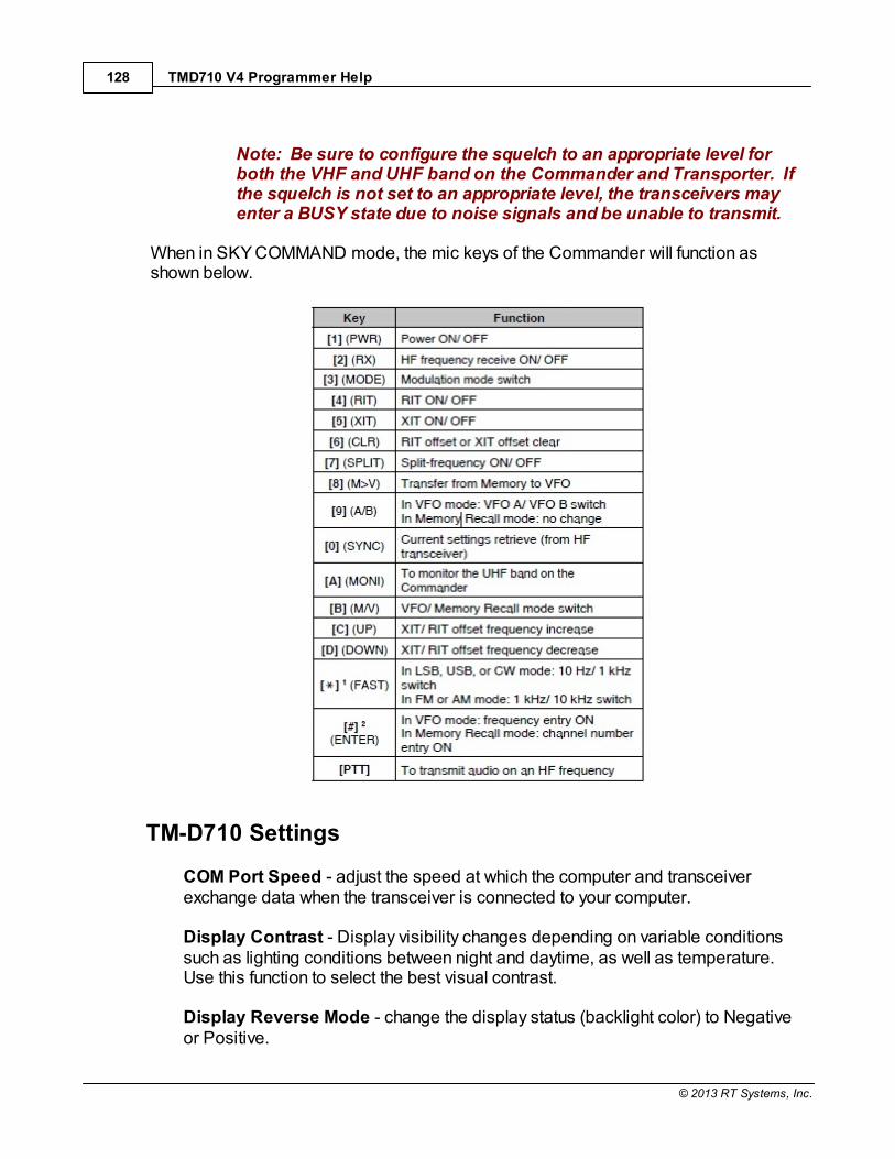
TMD710 V4 Programmer Help128
© 2013 RT Systems, Inc.
Note: Be sure to configure the squelch to an appropriate level forboth the VHF and UHF band on the Commander and Transporter. Ifthe squelch is not set to an appropriate level, the transceivers mayenter a BUSY state due to noise signals and be unable to transmit.
When in SKY COMMAND mode, the mic keys of the Commander will function asshown below.
TM-D710 Settings
COM Port Speed - adjust the speed at which the computer and transceiverexchange data when the transceiver is connected to your computer.
Display Contrast - Display visibility changes depending on variable conditionssuch as lighting conditions between night and daytime, as well as temperature. Use this function to select the best visual contrast.
Display Reverse Mode - change the display status (backlight color) to Negativeor Positive.

Programming Other Set Menu Items 129
© 2013 RT Systems, Inc.
Internal Data Band - select how data will be transmitted and received.
Time Zone - select your time zone.
Visual Scan - this feature graphically and simultaneously shows how allfrequencies in the selected range are busy. Select the center frequency and thenumber of channels.

TMD710 V4 Programmer Help130
© 2013 RT Systems, Inc.
10.3.3 Menu Settings - APRS 1
APRS Beacon - The Automatic Packet Reporting Systems was
designed to support rapid, reliable exchange of information for local, tactical real-timeinformation, events or nets. All relevant information is transmitted immediately toeveryone in the net and every station captures that information for consistent andstandard display to all participants. Since the primary objective is consistent exchangeof information between everyone, APRS established standard formats not only for thetransmission of POSITION, STATUS, MESSAGES, and QUERIES, it also establishesguidelines for display so that users of different systems will still see the same consistentinformation displayed in a consistent manner (independent of the particular display ormapping system in use).
Included here are brief descriptions of the features to be controlled and how to set themin the Programmer. The operating manual of the radio should be used to provide anyother explanation of the feature and its use after programming.
My Callsign - Program your callsign using a maximum of 9 alphanumeric characters. You may include SSID characters in the string. You cannot send any data usingNOCALL.
Note: Refer to the website for SSID: http://aprs.org/aprs11/SSIDs.txt
Beacon Type - select APRS data format (APRS or NAVITRA) for sending.
Internal TNC Settings - The TH-D72 has a built-in TNC (Terminal NodeController) modem in the transceiver for packet communication. The embeddedmicrocomputer supports not only the radio functions, but also data communicationapplication programs such as APRS.
Note: Close distance between the radio antenna and personalcomputer may cause interferences.
Data Band - select how data will be transmitted and received.
A-Band - A band receives and transmits
B-Band - B band receives and transmits
A:Tx B:Rx - A band transmits and B band receives
Programming Other Set Menu Items 131
© 2013 RT Systems, Inc.
A:Rx B:Tx - A band receives and B band transmits
Note: Select A:Tx B:Rx or A:Rx B:Tx if APRS networks which usetwo separate frequencies become available in the future.
Data Speed - select 1200 or 9600 bps for the data transfer rate, depending onTNC. The default setting of 1200 bps is standard among current APRS networks.
DCD Sense - select the method for inhibiting the built-in TNC from transmitting.
D or RxD Band - when the data band is no longer busy, the packet istransmitted.
Both Bands - when the bands are no longer busy, the packet is transmitted.
Ignore DCD - Transmission is not inhibited and the packet is transmittedimmediately.
Tx Delay - set the transmission delay time between transmitting the APRS dataand transmitting a flag code prior to the APRS data.
Note: When the other station has activated their Save Mode, set alonger delay time.
GPS Port Settings
Baud Rate - Set the communication speed of the external GPS or equipmentconnected to the GPS terminal. To set from the face of the radio, enter Menumode and access menu item 330.
Note: The speed is set to 4800 bps (NMEA) and 9600 bps (IPSformat: SONY) when a GPS receiver is connected.
It does not correspond to the Garmin - TXT format.
Input - Select APRS input.
Off - conduct APRS communications without using a GPS receiving orweather station.
GPS - conduct APRS communications using a GPS receiver. Verify yourposition data by pressing the [POS] key.

TMD710 V4 Programmer Help132
© 2013 RT Systems, Inc.
Weather (Davis) - conduct APRS communications using a Davis weatherstation. Verify your weather data by pressing the [WXI] (PF) key.
2011). See your operating manual for information & compatiblesoftware details.
Weather (Peet Bros.) - conduct APRS communications using a Peet Bros.weather station. Verify your weather data by pressing the [WXI] (PF) key.
Note: ULTIMETER® 2100 - operation verification model (as of April2011).
Output - Select APRS output.
Waypoint - the waypoint information is forwarded. Received callsign andpositioning data is displayed as the waypoint data through the deviceconnected to your GPS receiver or on the GPS receiver display.
DGPS - Differential GPS information is forwarded. Received differentialinformation is sent to the GPS receiver.
COM Port Output - outputs or verifies data from the PC (USB port) after receivingpacket and TNC command data from the ARPS data communications.
APRS Lock - prevents accidental frequency changes and/or transmissions whenenabled.
OFF - can transmit on internal data band by pressing [PTT]
ON - prevents frequency change. Also, prevents scan performance using the[VFO], [MR], [ENT], and [MHz] keys or the Tuning control.
ON & PTT - prevents frequency change, and transmissions are preventedwhen [PTT] key is pressed.
ON & TNC - prevents frequency change and, while in APRS mode, exiting themode is prevented when [TNC] key is pressed.
ON & PTT & TNC - prevents frequency change, and accidental pressing ofthe [PTT] AND [TNC] keys will not affect change.
Position Comment - select one of the 15 predetermined position comments.
Note: Never select EMERGENCY unless it is necessary. This causes
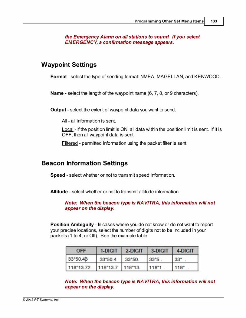
Programming Other Set Menu Items 133
© 2013 RT Systems, Inc.
the Emergency Alarm on all stations to sound. If you selectEMERGENCY, a confirmation message appears.
Waypoint Settings
Format - select the type of sending format: NMEA, MAGELLAN, and KENWOOD.
Name - select the length of the waypoint name (6, 7, 8, or 9 characters).
Output - select the extent of waypoint data you want to send.
All - all information is sent.
Local - If the position limit is ON, all data within the position limit is sent. If it isOFF, then all waypoint data is sent.
Filtered - permitted information using the packet filter is sent.
Beacon Information Settings
Speed - select whether or not to transmit speed information.
Altitude - select whether or not to transmit altitude information.
Note: When the beacon type is NAVITRA, this information will notappear on the display.
Position Ambiguity - In cases where you do not know or do not want to reportyour precise locations, select the number of digits not to be included in yourpackets (1 to 4, or Off). See the example table:
Note: When the beacon type is NAVITRA, this information will notappear on the display.

TMD710 V4 Programmer Help134
© 2013 RT Systems, Inc.
Packet Filter Type - check the type(s) you want to receive. Options include Weather,Mobile, NAVITRA, DIGI, Object, and Others. If all types are checked, you will receive alltypes of data.
Position Limit (Miles) - Specify a distance from your location to prevent receivingAPRS packets from others located outside the specified distance. This isespecially useful when too many APRS packets in the area disturbs your APRSactivities.
Packet Path Settings - a packet path is the digipeat route of the packet datasent from My station.
Type - select the packet path type:
New-N Paradigm - digipeat type commonly used in North America, but isalso now used worldwide.
RELAY Paradigm - digipeat type commonly used in Europe.
State/Section/Region - this method is used when packet is relayed within alimited area. Packet paths are specified by using abbreviations (forexample, in American, CA represents California, AZ represents Arizona, etc.)
Others - this method is used when the path is directly to a specific individual. A character string is needed for the data to be relayed.
WIDE 1-1 -
Total Hops - select the relay step number.
Path is VIA: - confirm the settings contents.
Station Icon - select an icon that will be displayed on the monitors of other stations asyour ID. Set an icon that represents your operational status (for example, setting anaircraft or balloon icon to a fixed station will cause confusion).
You can display and set the following icons:

Programming Other Set Menu Items 135
© 2013 RT Systems, Inc.
Note: APRS icon codes (symbols/tables) are sometimes updated. Please refer to the following official APRS websites (as of April 2011):http://www.aprs.org/symbols/symbolsX.txthttp://aprs.org/symbols/symbols-new.text

TMD710 V4 Programmer Help136
© 2013 RT Systems, Inc.
User Symbol -
Beacon Tx Algorithm Settings
Method - select the operation method for transmitting packets.
Manual - each press of the [BCON] key transmits your packet.
PTT - your packet transmits upon releasing the switch after you press/holdand speak into the microphone. To operate, press [BCON] to turn ON, thenpress and hold [PTT] and speak into microphone. Release [PTT] to transmitAPRS packet. To turn function off, press [BCON] again.
Note: You cannot retransmit packet until selected Initial Interval timeexpires. Wait until "BCON" is blinking on display panel to transmit.
Auto - packets are automatically transmitted at selected intervals periods. Press [BCON] to turn ON function; press [BCON] key again to turn OFF.
SmartBeaconing - after manually transmitting position one time, your positiondata is automatically transmitted using the time interval set under"SmartBeaconing" (Settings | Radio Menu Settings | APRS 3 tab | SmartBeaconing). Press [BCON] to turn ON function; press [BCON] key again toturn OFF.
Note: After setting Smart Beaconing, the Tx Interval Time, DecayAlgorithm, and Proportional pathing features will no longer operate.
Initial Interval - set the interval time for automatically transmitting APRS packets.
Note: While signals are present, an APRS packet does not transmitafter the set interval. Once the signals drop, then the transmitting isexecuted.
Decay Algorithm - if there is no change of information over a period of elapsedtime, the data is transmitted based on timed intervals of a Decay Algorithm (1minute, 2 minutes, 4 minutes, 8 minutes, 16 minutes, 32 minutes, 32 minutes, 32minutes, etc.).
Note: Should the position data change, the data transmissioninterval reverts back to the settings selected in the Initial Interval orProportional Pathing.
Proportional Pathing - after a period of elapsed time, the transmit packet pathchanges with each transmission. See your radio's operating manual for

Programming Other Set Menu Items 137
© 2013 RT Systems, Inc.
information and details of this function.
Note: When jointly used with the Decay Algorithm function, and thespeed is 1 knots or slower, the Decay Algorithm pattern is used;however if the speed is 3 knots or faster, the pattern changes toProportional Pathing.
Voice Alert - notifies other stations (that have the Voice Alert function ON), withmatching tone (CTCSS) frequencies, by emitting beacon tones, as to whether or notthey are within communication range.
Off - disabled
On - a CTCSS frequency is added to the transmitted packet (VA appearsabove displayed frequency)
Rx Only - a CTCSS frequency is not added to the transmitted packet (VARappears above displayed frequency)
Note: If built-in data band is set to Cross Band, the Voice Alertfunction will not operate.
Voice Alert takes precedence even when TONE, CTCSS, and DCS areset. When VA is ON, you cannot set/change the TONE, CTCSS, andDCS selections.
The TONE will disrupt the demodulation of the packet if the speed is9600 bps. It is recommended to set the packet speed at 1200 bps.
CTCSS Frequency - allows you to ignore (not hear) unwanted calls from others. Tohear calls from specific persons, select the same CTCSS tone frequencies tocommunicate or share information with each other.
Network - set the method in which packet data is transmitted without other stations ormaking a connection.
APRS - commonly set for normal use (default setting). When messages ormeteorological data is transmitted, "APK102" is added to the packet,following your callsign. There are no restrictions on received packets.
ALTNET - select for restrictions on received packets. When messages ormeteorological data is transmitted, your character string is added to thepacket, following your callsign.

TMD710 V4 Programmer Help138
© 2013 RT Systems, Inc.

Programming Other Set Menu Items 139
© 2013 RT Systems, Inc.
10.3.4 Menu Settings - APRS 2
APRS Beacon - The Automatic Packet Reporting Systems was
designed to support rapid, reliable exchange of information for local, tactical real-timeinformation, events or nets. All relevant information is transmitted immediately toeveryone in the net and every station captures that information for consistent andstandard display to all participants. Since the primary objective is consistent exchangeof information between everyone, APRS established standard formats not only for thetransmission of POSITION, STATUS, MESSAGES, and QUERIES, it also establishesguidelines for display so that users of different systems will still see the same consistentinformation displayed in a consistent manner (independent of the particular display ormapping system in use).
Included here are brief descriptions of the features to be controlled and how to set themin the Programmer. The operating manual of the radio should be used to provide anyother explanation of the feature and its use after programming.
Status Text - a desired comment, using a maximum of 42 alphanumeric characters, totransmit with your position data. There are 5 memory channels to preprogram.
Status Tx Rate - number of times on which to transmit. 1/X means the status textwill be transmitted X number of times. Options include OFF and 1/1 ~ 1/8 (APRSonly).
My Position - Five memory channels are available for storing/naming position data.
Select - select the memory number to program and store data.
Name - enter alphanumeric characters, plus special ASCII, characters up to 8digits.
Latitude - enter the north/south latitude.
Longitude - enter the east/west longitude.
Sound Settings
Rx Beep - sounds a beep each time an APRS packet is received. Select anoption:
TMD710 V4 Programmer Help140
© 2013 RT Systems, Inc.
All - beep sounds for all received messages, including duplicate and/orinvalid data.
All New - beep sounds when message and new packet data are received atyour station address.
Mine - beep sounds when a message is received at your station address andyour transmitted data is received by a digipeater.
Message Only - beep sounds only when message is received at your stationaddress.
Off - no beep sound.
Tx Beep (Beacon) - sounds a beep each time your position information istransmitted. Beep options are:
Off - No sound
On - sounds when beacon is automatically transmitted or when using the PTTswitch.
Note: Depending on the congestion level of the channel, the beepsound may be delayed when using the internal TNC DCD sensefunction.
APRS Voice - (requires the optional VGS-1 unit). Enable to allow announcementof the callsign of the sender each time a message is received.
Special Call - set callsigns of stations from which you want to receive a specialcall sound notification.
DIGIPEAT (My Callsign) - Enable or disable to use the TH-D72 as a digipeater.
If enabled as a digipeater, set your Callsign (Settings | PM 0-5 Menu Settings | APRS 1tab | My Callsign in the Programmer). The digipeat completion flag (*) is added to yourcallsign and will then process the relay.
UICheck Time [secs] -
UIDIGI - set whether or not a UI digipeat is run.

Programming Other Set Menu Items 141
© 2013 RT Systems, Inc.
Aliases -
UIFLOOD - set whether or not UIFLOOD digipeat runs.
Alias -
Substitution -
ID - your station's callsign is embedded. If there's already a callsign in therelayed UI frame, your station's callsign will replace it.
Noid - the callsign is not embedded or replaced.
First - If there's already a callsign in the relayed UI frame, it remains; however,if a callsign does not exist, your station's callsign is embedded.
UITRACE - set whether or not the UITRACE digipeat runs.
Alias -
Auto Message Reply - enable or disable programmed message that automaticallyresponds to a received message when you are unable to answer.
Text - Enter your reply message of alphanumberic characters, including special ASCIIcharacters.
Reply To - enter the specific callsign you would like your message to automaticallyreply to.
Weather Station Settings
Tx - enable or disable transmission of meteorological data obtained from theweather station.
Tx Interval - set the time period interval at which the meteorological data istransmitted. The interval can be set to 5, 10, or 30 minutes. Verify by viewing MYWEATHER STATION (press [F], [WXi]).

TMD710 V4 Programmer Help142
© 2013 RT Systems, Inc.
Note: This data is transmitted with the APRS standard format(altitude/longitude and time information)
Programming Other Set Menu Items 143
© 2013 RT Systems, Inc.
10.3.5 Menu Settings - APRS 3
APRS - The Automatic Packet Reporting Systems was designed to support
rapid, reliable exchange of information for local, tactical real-time information, events ornets. All relevant information is transmitted immediately to everyone in the net andevery station captures that information for consistent and standard display to allparticipants. Since the primary objective is consistent exchange of informationbetween everyone, APRS established standard formats not only for the transmission ofPOSITION, STATUS, MESSAGES, and QUERIES, it also establishes guidelines fordisplay so that users of different systems will still see the same consistent informationdisplayed in a consistent manner (independent of the particular display or mappingsystem in use).
Included here are brief descriptions of the features to be controlled and how to set themin the Programmer. The operating manual of the radio should be used to provide anyother explanation of the feature and its use after programming.
User Phrases - similar to a the computer function of a clipboard image which allowsyou to paste phrases into the message compilation mode. You can create up to 4phrases, each consisting of up to 32 characters.
Interrupt Display Settings
Display Area - select the display area:
Entire Always - the received new data, duplicate data, and station dataappear on the full display, while other data appears only at the top of thedisplay.
Entire - the received new data appears on full display, while other dataappears only at the top of the display.
Half - the received new data appears on the left half of the display only, whilethe other data appears only at the top of the display.
Off - the received new data appears only at the top of the display.
Note: When an emergency message or a message designated foryour station is received, the received data appears on the full display,even if the display method is set to HALF or OFF.
When a status message is received, it is displayed on half of thescreen.

TMD710 V4 Programmer Help144
© 2013 RT Systems, Inc.
Auto Brightness - Enables the blacklight to turn on when message is received.
Change Color - Enables the backlight color to change when message isreceived.
Group Filtering Settings
Message Group Code: - use this to exchange messages only among your groupmembers.
Bulletin Group Code: -
Display Units Settings
Speed,Distance - select to [mi/h, mile], [km/h, km], or [knots, nm].
Altitude,Rain - select to [feet, inch] or [m, mm].
Temperature - select to [°F] or [°C]
Grid Format - select to [Maidenhead Grid], [SAR Grid (CONV)], or [SAR Grid(CELL)]
Position - select to [dd°mm. mm'] or [dd°mm' ss.s"]
NAVITRA Group Mode - select to turn on Group mode.
Group Code: - Enter 0 to 9, A to Z.
NAVITRA Messages - create up to 5 phrases, each consisting of up to 20 characters.
Decay Algorithm Stopped (knots) -
Proportional Pathing Moving (knots) -

Programming Other Set Menu Items 145
© 2013 RT Systems, Inc.
Smart Beaconing - optimizes beacon transmission based on driving direction andspeed.
Low Speed - 2 ~ 30 mi/h, km/h, or knots. If lower than this, beacons aretransmitted at the time interval specified under SLOW RATE.
High Speed - 2 ~ 90 mi/h, km/h, or knots. If faster than this, beacons aretransmitted at the time interval specified under FAST RATE.
Slow Rate - 1 ~ 100 minutes
Fast Rate - 10 ~ 180 seconds
Turn Angle - driving direction change, minimum value setting (5 ~ 90 degrees)
Turn Slope - driving direction change, additional value setting (1 ~ 255 (10degrees/speed))
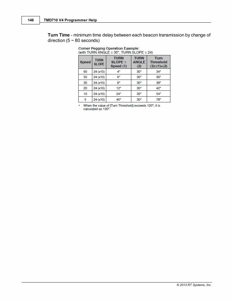
TMD710 V4 Programmer Help146
© 2013 RT Systems, Inc.
Turn Time - minimum time delay between each beacon transmission by change ofdirection (5 ~ 80 seconds)

Part
XI

TMD710 V4 Programmer Help148
© 2013 RT Systems, Inc.
11 Radio / Computer Data Transfer
Data flow two ways: from the computer to the radio or from the radio to the computer. Even when you are sending a file to the radio, some data must be sent from the radioto the computer to ensure that the two are "talking" before transfer of the file ever getsstarted.
In either case, be sure to follow the directions presented on the screen carefully. The wrong button press can result in a communications failure that could reset yourradio to factory defaults.
Details for this process are contained in these sections: Communications | Get Data From - Always the best place to start. Even ifthere is nothing in your radio. It gets the data "flowing" between the two.
Communications | Send Data To - This process programs the radio with thedetails of the file that is on the screen. If the file is blank, you will have a blankradio. Be sure you see your frequencies on the screen before you start thispart of the process.
Radio to Computer Cabling - Check the photos to be sure you are using thecorrect cabling for your radio.
Comport Setup - There is no comport setup in Version 4. The Programmerautomatically finds the RT Systems USB cable for you.
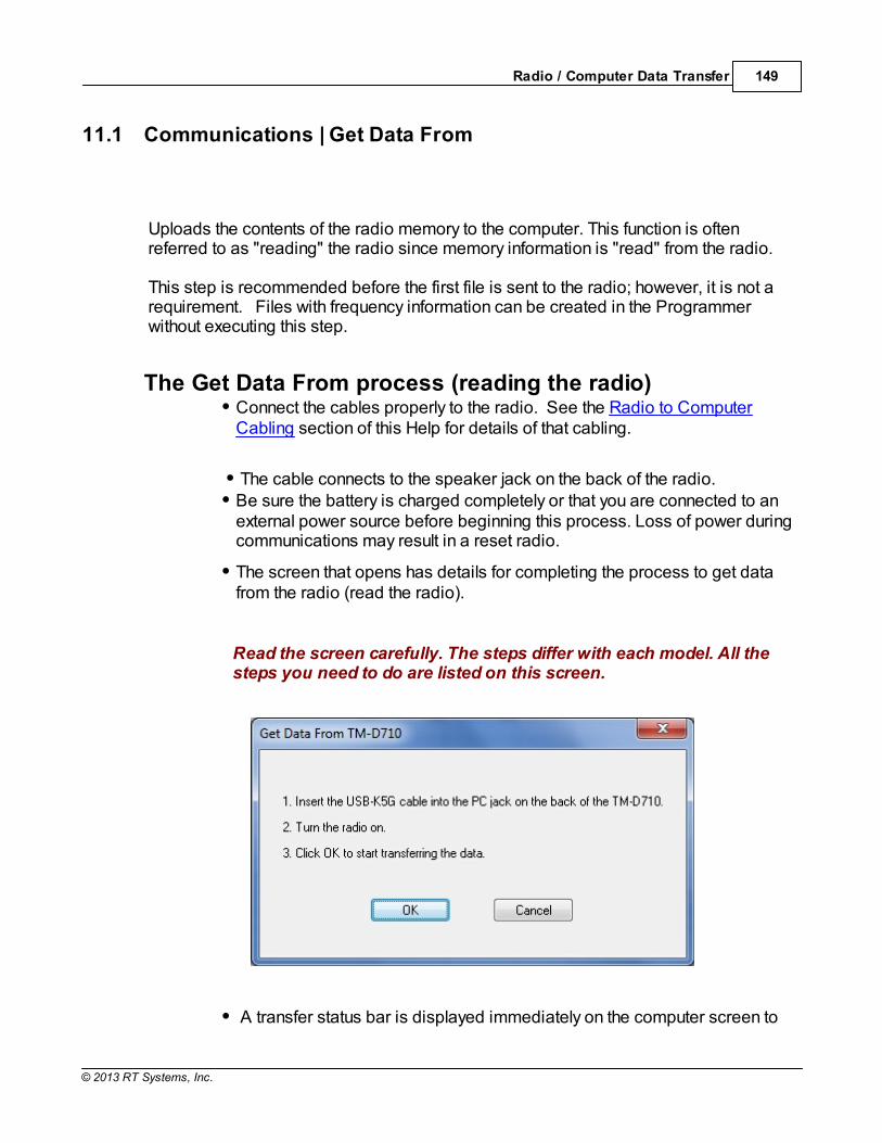
Radio / Computer Data Transfer 149
© 2013 RT Systems, Inc.
11.1 Communications | Get Data From
Uploads the contents of the radio memory to the computer. This function is oftenreferred to as "reading" the radio since memory information is "read" from the radio.
This step is recommended before the first file is sent to the radio; however, it is not arequirement. Files with frequency information can be created in the Programmerwithout executing this step.
The Get Data From process (reading the radio)Connect the cables properly to the radio. See the Radio to ComputerCabling section of this Help for details of that cabling.
The cable connects to the speaker jack on the back of the radio. Be sure the battery is charged completely or that you are connected to anexternal power source before beginning this process. Loss of power duringcommunications may result in a reset radio.
The screen that opens has details for completing the process to get datafrom the radio (read the radio).
Read the screen carefully. The steps differ with each model. All thesteps you need to do are listed on this screen.
A transfer status bar is displayed immediately on the computer screen to
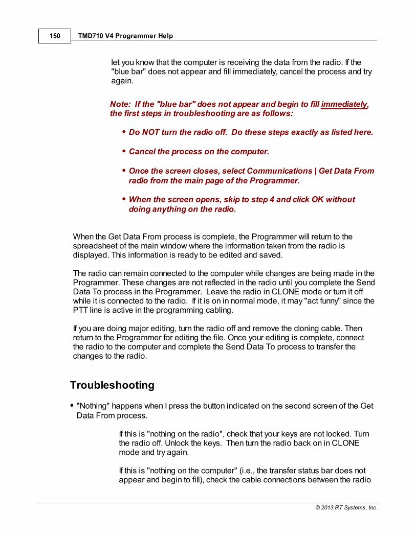
TMD710 V4 Programmer Help150
© 2013 RT Systems, Inc.
let you know that the computer is receiving the data from the radio. If the"blue bar" does not appear and fill immediately, cancel the process and tryagain.
Note: If the "blue bar" does not appear and begin to fill immediately,the first steps in troubleshooting are as follows:
Do NOT turn the radio off. Do these steps exactly as listed here.
Cancel the process on the computer.
Once the screen closes, select Communications | Get Data Fromradio from the main page of the Programmer.
When the screen opens, skip to step 4 and click OK withoutdoing anything on the radio.
When the Get Data From process is complete, the Programmer will return to thespreadsheet of the main window where the information taken from the radio isdisplayed. This information is ready to be edited and saved. The radio can remain connected to the computer while changes are being made in theProgrammer. These changes are not reflected in the radio until you complete the SendData To process in the Programmer. Leave the radio in CLONE mode or turn it offwhile it is connected to the radio. If it is on in normal mode, it may "act funny" since thePTT line is active in the programming cabling. If you are doing major editing, turn the radio off and remove the cloning cable. Thenreturn to the Programmer for editing the file. Once your editing is complete, connectthe radio to the computer and complete the Send Data To process to transfer thechanges to the radio.
Troubleshooting
"Nothing" happens when I press the button indicated on the second screen of the GetData From process.
If this is "nothing on the radio", check that your keys are not locked. Turnthe radio off. Unlock the keys. Then turn the radio back on in CLONEmode and try again. If this is "nothing on the computer" (i.e., the transfer status bar does notappear and begin to fill), check the cable connections between the radio

Radio / Computer Data Transfer 151
© 2013 RT Systems, Inc.
and the computer.
Other details for general troubleshooting can be found in the Troubleshootingsection of this Help.
Should the problem persist, contact RT Systems for personal assistance.

TMD710 V4 Programmer Help152
© 2013 RT Systems, Inc.
11.2 Communications | Send Data To
Sends the contents of the current file and the settings file to the radio.
Note: In the Version 3 or newer Programmers, you can have filesopen for several different radios at one time. The Programmer cansend a file only to the radio it is for. The title bar at the top of theProgrammer tells you which radio the file is for. You can open and send a file created for one radio to another;however, you must open that file as one for the receiving radio withthe Programmer specifically for that radio. See the File | Open sectionof this Help for details on this process.
Connect the radio to the computer
The USB-K5G cable connects to the PC jack on the radio.
Current File
The Programmer can work with several radio files at one time. There is no need toclose extra files before executing the Send Data To process. The current file will besent to the radio during the Send Data To process.
The current file is the one that appears in the main window of the Programmer.Basically, what you see on the screen is what is sent to the radio.
Settings File
Check your global menu settings under Settings | Radio Menu Settings to be surethe right information is being sent. The items on this screen are the radio settingsthat are not associated with a specific memory channel. These settings are set once to be sent to the radio with any frequency file that youcreate. Details on these settings can be found in the Programming Other Set Menu Items section of this Help. If the radio "acts funny" after it is programmed,
Check the Radio Menu Settings found under Settings | Radio MenuSettings. These are global settings that are not tied to any one memorychannel. When you program your radio with a file from the computer, these

Radio / Computer Data Transfer 153
© 2013 RT Systems, Inc.
settings go with the memory channel details.
Make changes to the settings as needed.
Save the settings file.
Do Communications | Send Data To with the same memory channel file. The menu settings will be sent with the memory channel information.
Completing the "Send Data To" Process When you execute the Communications | Send Data To command, you are presentedwith instruction for putting the radio into clone mode.
Read the screen carefully. The steps differ with each model. Pressingthe wrong button will result in no response or the wrong responsefor the process.
Follow the steps on this screen. When you click OK a progress bar appearsimmediately letting you know that the process is being completed. When the transfer is complete, the transfer status window disappears and theProgrammer returns to the Main Window. With the radio off, remove the cloning cable. The radio is ready to power-up and usewith the newly programmed settings.
Note: The radio may be in VFO mode even after it is programmed.This is a normal mode of the radio and the one you found it in the first

TMD710 V4 Programmer Help154
© 2013 RT Systems, Inc.
time you turned it on. Press the [M/Call] key to put the radio intomemory mode.
Troubleshooting
Communications | Get Data From Radio required first
The first time you attempt to send your file to the radio, this message may appear.
This indicates that you have not read the configuration of the radio into theProgrammer.
There are details that the Programmer can get only from the radio. Even if the radio isnot yet programmed, these "background" details are necessary for the Programmer tosend a file to your radio successfully.
To complete this process: 1) Select File | New from the menu at the top of the screen.
2) Turn off the radio.
3) Select Communication | Get Data From Radio from the menu at the top ofthe screen.
4) Complete the process detailed on the screen.
5) Once the process is complete, click the tab at the top of the screenshowing your filename. The file that you want to send to the radio will bedisplayed on the screen.
6) Select Communications | Send Data To Radio from the menu at the top ofthe screen.
7) Complete the process following each step carefully to program thesechannels into the radio.

Radio / Computer Data Transfer 155
© 2013 RT Systems, Inc.
Modified Radio
If your radio has been modified, you need to read from the radio (Get Data From) into anew file before you attempt to write data to the radio. When the Get Data From processis used, even if the radio is not yet programmed, the Programmer gets the data itneeds to know that the radio is modified.
When you use Get Data From for the sake of establishing communications, you need tosave the file ONLY if you want to save the memory data that is currently in the radio. TheProgrammer already has what it needs. The option to save is available should you wantto save the pre-programmed data.
The radio is not programmed after the process is complete
This could indicate several things. Most of those are specific to the radio. The mostgeneral error is not an error in programming; but the need to put the radio into Memorymode once programming is complete. Many of the radios return to VFO when they areprogrammed. Press the appropriate key on the radio (see the operating manual foryour specific model to identify the key press that changes the radio from VFO tomemory mode. It will be detailed there.) Once in memory mode the informationprogrammed will be available for use.
Several of the radios are not programmed when the download process is complete.These radios have encountered an error during the programming process. Try theprocess again. If it continues to fail, first, be sure you are using the latest version of theProgrammer by updating from the Check for Update link under Help in the menu of themain screen of the Programmer. If the problem persists, send the file that you areattempting to send to the radio. We will examine it for any problem that might exist inthe data.
Check the cabling between the radio and the computer by disconnecting andreconnecting at all connections. Try the process again.
If you have problems sending a certain file to the radio
Cancel the Send Data To process and execute Get Data From. Be sure to open a Newfile (File | New) into which the data will be read from the radio. This prevents loss ofdata in the file that you are sending to the radio. Getting data from the radio is a lesscritical process that can help get communications established.
The radio must be connected to the computer with the proper cables for that radio. See Radio to Computer Cabling in this Help for details and pictures. If necessary, contact RT Systems' tech support for assistance.

TMD710 V4 Programmer Help156
© 2013 RT Systems, Inc.

Radio / Computer Data Transfer 157
© 2013 RT Systems, Inc.
11.3 Radio to Computer Cabling
The radio must be connected to the computer with the proper cables for that radio.
The USB-K5G, a gray cable with an 8-pin mini din plug, is the correct cable for the TM-D710 radio. This cable is included in the KRS-D710 kit.

TMD710 V4 Programmer Help158
© 2013 RT Systems, Inc.
11.4 Comport Setup
In the Version 4 RT Systems' Programmers there is NO comport setup. The softwarefinds the USB cable automatically.
Troubleshooting
When I select Communications | Send Data To, I get the following error:
The only cable configurations that work with the Version 4 RT Systems' Programmersare
The RT Systems' USB cable; or
The RT Systems' original serial cable connected to the computer via theRTS-03 USB to serial adapter.
Be sure to give the computer enough time to do its internal setup once the cable isattached. On some machines this can take up to a minute (a long time in computertime). Once the cable is ready for use, the program will continue into the steps fortransferring data between the radio and the computer.
Follow the steps carefully. They are unique to each radio and different for the sameradio for Get Data From or Send Data To.

Part
XII

TMD710 V4 Programmer Help160
© 2013 RT Systems, Inc.
12 File Maintenance
Just as in a word process or other Windows based program, you will create files in theprogrammer for use in the radio. You can create as many files as the space on yourhard drive will allow.
Remember, with the exception of the Icom IC-7000, all other programmers eraseeverything in the radio and replace it with what is in the file. Be sure everything youwant in the radio is in the file that is sent. This is an "all or nothing" process.
From the File menu at the top of the main window, select:
New - Create a new file in any Version 3 programmer you have installed.
Open - Open an existing file in any of the Version 3 programmers you haveinstalled.
Open Travel Plus Link - Active only if a list is open in Travel Plus. Accessesthat Travel Plus list. Details on this functionality are available in the ARRLTravel Plus section of the help.
Close - Closes the current file.
Save - Saves the current file.
Save As - Saves the current file giving you the opportunity to enter a newname. This creates a copy of the file and saves it with the new name youentered.
Import - Advanced functionality that addresses data from a "flat" ASCII file.Details on this process are found in the Import and Export section of the help.
Export - Extracts data from the programmer file to a "flat" ASCII file. Detailson this process are found in the Import and Export section of the help.
Print Preview - Lets you see the formatted information on the screen before itprints.
Print - Prints the current file
Send File as E-mail - Sends the current file to RT Systems' tech support. This functionality is dependant on the e-mail program of your computer.
Files 1-4 - Up to four files that you last worked in and saved.
Exit - Closes the programmer.

File Maintenance 161
© 2013 RT Systems, Inc.
12.1 File | Exit
Exits the Programmer.
If files have been changed, you will be prompted to save or cancel the Exit command toavoid data loss in that file.
Yes - Exits the program saving the file.
No - Exits the program without saving any work done in the file since the lasttime you saved.
Cancel - Halts the Exit option. The program returns to the open file.

TMD710 V4 Programmer Help162
© 2013 RT Systems, Inc.
12.2 File | New
Use this command for setting up a "clean slate" into which you enter memoryfrequencies. A "clean slate" or default file will often have at least one channelprogrammed on the memory channel screen. This is a factory default that is in yourradio when it is new. The information for this channel can be changed; however, inmost radios, channel 1 must be programmed.
Use the quick key command of Ctrl M for easy access to a new file.
If you have been working to create a file with memory channels, use File | New beforeusing Communications | Get data from to prevent losing all the work you have done inthis file. The Get data from process will replace the information in the open file with whatis in the radio.
Other Radio Menu Settings and a New File
The radio is more than just memory channels. There are features that are controlledonce for the radio. They cannot be customized for each memory channel. Thesefeatures are address in the programmer under Settings | Radio Menu Settings.
The settings for these features that were last saved are use whenever a New file iscreated. There is no need to reset these features for each new file. If you have notsaved a settings file, factory these radio menu items are set to factory defaults( as ifyou reset your radio).
Note: If you radio "acts funny" after you download to it (i.e., keypadbeeps are different, squelch is open, Scan resume settings arechanged, etc.,) you have not yet set these options in the Settingsportion of the programmer. To make these option settingspermanent:
Select Settings | Radio Menu Settings from the menu at the topof the screen.Personalize your options just as you did on the radio.Select File | Save from the menu on the Settings screen. Enter a filename when prompted and click Save. Select File | Exit from the menu on the Settings screen. You will not have to change these again unless you want themto function differently.

File Maintenance 163
© 2013 RT Systems, Inc.
The settings file will change only if you read from the radio(Communications | Get data from) and send that file back to the radio(Communications | Send data to) without saving the memoryinformation that you retrieved. This is helpful if you are programminga friend’s radio in which he has all these options set up as he wantsthem.
The File|New command can be used to open several new files at once. Memorychannel information can be copied between these files (even from V3 to V4),regardless of which radio they are for.

TMD710 V4 Programmer Help164
© 2013 RT Systems, Inc.
12.3 File | Open
Just as in a word processor or other Windows programs, the command opens apreviously saved file.
You are not limited to one programming file for your radio. Make as many as you want.Then choose the one you want when you open the programmer.
Working with the programmers is a little different if you have one programmer orseveral programmers installed on this machine. Click the topic for details on
Opening a file with the Version 3 or Version 4 programmer (One Version 3 orVersion 4 programmer installed)
The Version 3 and higher programmers allow you to "share" Version 3 and higher filesfrom other radios...even radios from other manufacturers. Click the topic for details.
Opening ANY Version 3 file
There have been many RT Systems' programmers over the years. The Version 3 orhigher programmers can open and convert files from those older programmers. Clickto topic for details.
Opening existing programming files (*.rdf or *.icf files)

File Maintenance 165
© 2013 RT Systems, Inc.
12.3.1 Opening files from older programmers
Opening existing programming files (*.rdf or *.icf files)
The Version 3 or higher programmers can open a file created with an original RTSystems' ADMS or WCS programmer for the same radio. In this example, a file for the Yaesu FT-60 that was created in the original ADMS-1Jprogrammer (an .rdf file) will be opened in the Version 3 programmer for the FT-60. This process is the same in the Version 4 programmers although the screens will looka little different.
Directory selections may vary on your system depending on your choices in the originalprogrammer. This example is designed based on defaults from the originalprogrammers.
To open an existing file from the original programmer:
In the V3 Programmer, select File | Open.
If you have several Version 3 programmers installed, you will need to selectFT-60 Radio Data File from the list in box that opens next. This step is omittedif only one programmer is installed.

TMD710 V4 Programmer Help166
© 2013 RT Systems, Inc.
An Open Dialog appears
Since the Version 3 programmer is geared to look in its own directory, weneed to "find" the original file to be opened (We must change filing cabinetdrawers as the old analogy was described.) Use your mouse to left click thedown arrow to the right of the Look In box. A directory listing appears. Theone highlighted in the list simply indicates the "drawer" you are in now. Do notbe afraid. This is only a list from which we will make a selection. You cannothurt anything with these steps and actions.
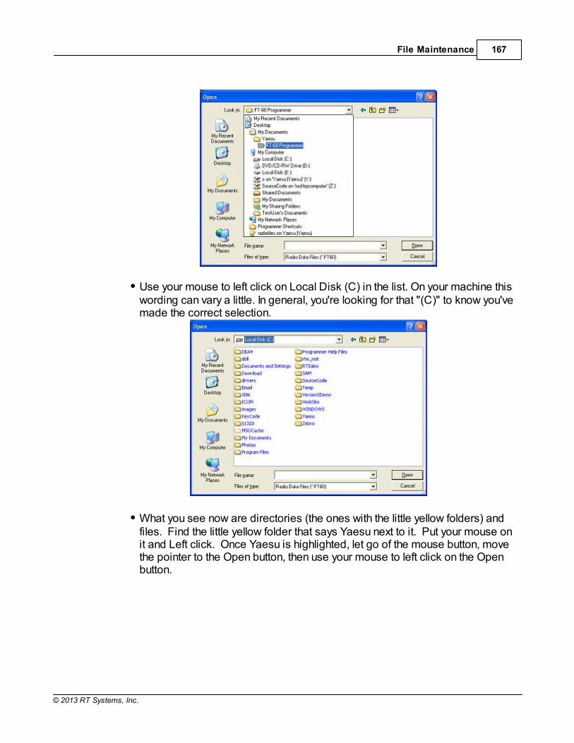
File Maintenance 167
© 2013 RT Systems, Inc.
Use your mouse to left click on Local Disk (C) in the list. On your machine thiswording can vary a little. In general, you're looking for that "(C)" to know you'vemade the correct selection.
What you see now are directories (the ones with the little yellow folders) andfiles. Find the little yellow folder that says Yaesu next to it. Put your mouse onit and Left click. Once Yaesu is highlighted, let go of the mouse button, movethe pointer to the Open button, then use your mouse to left click on the Openbutton.

TMD710 V4 Programmer Help168
© 2013 RT Systems, Inc.
After clicking Open, the contents of the Yaesu directory appear.
In this example, there are lots of directories (the ones with the little yellowfolders) since all the original programmers were installed on this machine. Inyour case, there is probably only one directory (little yellow folder). In eithercase, find the FT-60 directory (the one with the little yellow folder and thewords "FT-60" next to it. Find the FT-60 directory. Point at it with your mouse.Use the Left mouse button to click on it. Release the mouse button. Move thepointer to the Open button. Left click the mouse once on the Open button.

File Maintenance 169
© 2013 RT Systems, Inc.
Yes, a blank screen appears. This is normal. At the bottom of that screen,find the "Files of type" box. Use the left mouse button to click on the downarrow at the right of that box. Select Old Radio Files (*.rdf) from that list. Thenames of the available files will appear on the screen.
Use the mouse to point at the name of the file that you want to open. Click theleft mouse button once to select that file.

TMD710 V4 Programmer Help170
© 2013 RT Systems, Inc.
Release the left mouse button. Move the pointer to Open. Click the leftmouse button once to open the file.
All the data of the original file is converted into a new Version 3 file for the FT-60.
Now, save this new file so you don't have to do this again every time. Also,once saved as a new Version 3 file, you can use this data for other radiosonce you have the Version 3 programmer for them. (Advanced featureexplained below). From the menu, select File then Save as from the list. Usethe left mouse button to make this selection.

File Maintenance 171
© 2013 RT Systems, Inc.
Enter a filename in the File name field at the bottom of this screen. Use yourleft mouse button to click Save.
Note: Only files from the original ADMS-1J for the FT-60 Version 2programmer can be accessed with the FT-60 Version 3 programmer. Files ending in *.rdf for other Yaesu radios cannot be opened in theFT-60 Version 3 programmer.

TMD710 V4 Programmer Help172
© 2013 RT Systems, Inc.
12.3.2 Opening a V3 or V4 file from a different radio
The Version 3 programmers have the ability to "share" memory channel informationbetween radios. It makes o difference if the radios are from the same manufacturer ornot. As long as both files are from an RT Systems' Version 3 programmers, they canbe used by the Version 3 programmer for any other radio.
To open a Version 3 file from a different radio:
The steps detailed here are based on the directory structure of this machine. Makechanges to directories as needed to locate files that you want to open.
Files that you create in Version 3 can now be shared easily with anyone else who hasa Version 3 programmer. Simply post the Version 3 file for anyone to download.
In this example, a file for the Icom IC-T81 will be opened to be sent to the YaesuFT-60.
Open the FT-60 Version 3 programmer.
From the menu at the top of the screen, select File | Open. A box appearsfrom which you select the programmer for the radio to be programmed (inthis case, the FT-60).

File Maintenance 173
© 2013 RT Systems, Inc.
An Open Dialog box appears. By default it is looking in the FT-60 directorysince it is trying to help you find an FT-60 programming file. You will changedirectories to where the file is stored that you want to open. (Note: If youreceived the file via e-mail or from an Internet site, you chose where it wassaved. Personalize the steps here to move to that location.)
When the contents of that directory are displayed, it probably will be blankas shown. You have done nothing wrong. This is normal. The process isstill looking for an FT-60 file. From the Files of type field at the bottom of thescreen (the one highlighted blue in the figure above), select All files (*.*).

TMD710 V4 Programmer Help174
© 2013 RT Systems, Inc.
A listing will appear with more than just the file that you're looking for. Everything in that directory is listed. Your file will be in the list. Select thefile from the list.
Click Open in the lower right corner.
The resulting file contains frequencies that can be sent to the FT-60. Theblanks represent frequencies that were removed during the conversion. These frequencies would be invalid for the FT-60.

File Maintenance 175
© 2013 RT Systems, Inc.
Creation of this file did not disturb the original file. The memory channel informationwas not removed from the original. A copy was made by the programmer for theconversion. You can edit the file. In this case it needs to be edited to be sure that memory channel1 is programmed. You can remove the blank channels if you want. You can addothers. Alternately, you can send this file to the radio just as it is...other than channel 1 needingto be programmed with something allowable for the radio. Once you have used this to program the FT-60, you can save the file or close withoutsaving depending on your needs for the data.

TMD710 V4 Programmer Help176
© 2013 RT Systems, Inc.
12.3.3 Opening a V3 or V4 file
Opening a file with the Version 3 programmer (One Version3 programmer installed)
Select File|Open from the menu at the top of the screen.
A Windows Open dialog appears.

File Maintenance 177
© 2013 RT Systems, Inc.
Select the file that you want to open from the list presented. Click the Openbutton at the bottom right. This files opens in the programmer.
Opening a file with the Version 3 programmer (More thanone Version 3 programmer installed)
Select File|Open from the menu at the top of the screen.
A window opens listing the programmers installed on this machine. Selectthe radio from the list that will be programmed by this file being opened.

TMD710 V4 Programmer Help178
© 2013 RT Systems, Inc.
A Windows Open dialog appears with a list of the files for that radio.
Select the file that you want to open from the list presented. Click the Openbutton at the bottom right. This files opens in the programmer.

File Maintenance 179
© 2013 RT Systems, Inc.
12.4 File | Print
Prints the Memory channel information of the displayed page of the current file (i.e., ifyou are on the memories tab, the memory channel information is printed. Similarly, ifyou are on the VFO tab, the VFO channel information is printed. )
When this command is selected, a print dialog will give you the opportunityto setup your printer.
Hidden columns are not printed. A printout can be customized (includingincreasing type size) by deliberately hiding columns before printing. To hidecolumn, select Settings | Preferences from the menu of the programmer.
Only memory channels that are programmed are printed. Your printout willnot include the blank channels in the file.
Use Print Preview to see what your printout will look like and how manypages will be included before you send it to the printer. This new option willhelp save lots of wasted paper.

TMD710 V4 Programmer Help180
© 2013 RT Systems, Inc.
12.5 File | Print Preview
This new feature of the Version 3 programmers lets you preview the data to be printedbefore you waste paper sending it to the printer. With the file open that you want to print, select File | Print Preview.
You will notice first that the screen changes. It is filled with the data that willbe printed. This is just a temporary change. The order of your channels hasnot been changed in the file.
Then the screen opens to display the printed output you can expect.

File Maintenance 181
© 2013 RT Systems, Inc.
Notice at the top of the page you can see that your have "X of X pages". Making small changes can help reduce this number if it is not as you expect.
For example, reduce the size of the comment column since it is not beingused (or hide it completely). This move could save an additional page (orpages) by getting all the columns to fit on one page.
Under Printer setup, change the margins to print on as much of each page ofpaper as possible. Again, this can make it possible for all the columns to fiton one (or half the number of) page.
Use Zoom to read the data in the preview more easily. Click Zoom again toreturn to this view.

TMD710 V4 Programmer Help182
© 2013 RT Systems, Inc.

File Maintenance 183
© 2013 RT Systems, Inc.
12.6 Saving Programming Files
Many different files can be saved to your hard drive for permanent storage giving youthe ability to reprogram your radio quickly and easily to suit your current use.
Files are saved using the File | Save or File | Save As command.
When the window opens for the filename, enter any name up to 256characters (including spaces) but without a period at the end or anextension. The Programmer will enter that information for you automatically.

TMD710 V4 Programmer Help184
© 2013 RT Systems, Inc.
12.6.1 File | Save
Saves the current file to your computer hard drive.
If several files are open, the current file (the one on top: the one you are working in) isthe one that will be saved. Be sure to save the changes to each of the open files beforeclosing the Programmer.
It is recommended that you save the current file during data input and before sending itto the radio. Just as with a word processor, it’s an awful shame to lose everything ifsomething happens to the computer during either of these processes.
If the name of the current file is Untitled (in the main window title bar), you will bepresented with a save file dialog and should enter a new filename.
The filename can be any combination of characters and spaces including numbers andletters.
When saving a file, let the Programmer do the work. All you need to enter is the nameyou want for the file.

File Maintenance 185
© 2013 RT Systems, Inc.

TMD710 V4 Programmer Help186
© 2013 RT Systems, Inc.
12.6.2 File | Save As
Saves the current file under a new name. Used if you want to make a copy of the filethat you're working in to maintain the original without the changes you're making now.
If several files are open, the one that is active is the current file. This file willbe saved with the Save As command.
This is a good way to start another file for editing. Changes made to this filedo not affect the data in the original file.
When this command is selected, a save file dialog containing a list ofexisting files is presented. You can either select one of these to beoverwritten or enter a new filename. The Programmer will add the extensionso you should not enter an extension or a period at the end of the filename.
The title bar of the window changes to reflect the new filename.
When saving a file, let the Programmer do the work. All you need to enter isthe name you want for the file.

Part
XIII

TMD710 V4 Programmer Help188
© 2013 RT Systems, Inc.
13 ARRL TravelPlus*
RT Systems' Version 4 programmers have a feature that opens a TravelPlus list in theradio programmer. This makes the data available for creating files for programmingyour radio without the need to import the data from a file.
This Help file contains sections on creating the list in TravelPlus* and on getting that listready to program your radio. Takes only a few mouse clicks to have your radioprogrammed for that trip or other special event.
Creating a list in TravelPlus* - Brief details on this process. For moredetails, see the help file in TravelPlus*.
Opening the list in the radio Programmer - Details on opening the list in theradio programmer and the controls on that list.
Using the TravelPlus* list with an existing radio programming file -Sometimes you don't want all the repeaters found for an area by TravelPlus*...or you want to put what you found into a certain group of memory channels inthe radio programming file. This section details how to use the list selectivelyin the radio file.
*TravelPlus is a product of the American Amateur Radio League. Any images from TravelPlus included in this help are copyrighted to DHF Systems, LLC.

ARRL TravelPlus* 189
© 2013 RT Systems, Inc.
13.1 Creating a list in TravelPlus*
RT Systems' Version 4 programmers have a feature that opens a TravelPlus* list inthe radio programmer. This makes the data available for creating files forprogramming your radio without the need to import the data from a file. These instructions very briefly cover creation of the list from TravelPlus*. It is notintended to teach you to use that program. Detailed instructions are included in thishelp for using the information from that list in a file for programming your radio.
Open TravelPlus* from the link provided when that program was installed. Select alocation or create a route.
Once you have the area defined on the map, click the Create List button from the top ofthe screen. TravelPlus* displays the list of repeater frequencies found within yoursearch area.

TMD710 V4 Programmer Help190
© 2013 RT Systems, Inc.
Check the list. If you don't like the results, try again. Once you are satisfied with the list,you are finished with TravelPlus*. You can exit that program or leave it running whileyou access the RT Systems' radio programmer. Run the RT Systems programmer (Version 4 only). If the programmer is alreadyrunning, switch to it now to create a file from this list for programming the radio.
*TravelPlus is a product of the American Amateur Radio League. Any images from TravelPlus included in this help are copyrighted to DHF Systems, LLC.

ARRL TravelPlus* 191
© 2013 RT Systems, Inc.
13.2 Opening the list in the Programmer
Once you have created a list in TravelPlus* (Version 10.0 or higher), open any one ofthe Version 4 programmers installed on your machine. To access the list:
Select File from the menu at the top of the screen.
Select Open TravelPlus* list (this option was disabled until you created thelist)
The list appears in the window of the programmer

TMD710 V4 Programmer Help192
© 2013 RT Systems, Inc.
Customizing the list for the radio file:
Several selections appear at the bottom of the window that contains the list. Theseoptions control how the programmer will handle the data from the list in creating theradio programming file. These fields and their options are described below.
Selected Bands: Lists the bands of the frequencies in the list. All thebands are selected by default. Uncheck those that you don't want as part ofthe file for the radio.
If you are programming a 2 Meter radio with a file that contains 6 Meterrepeaters, you can choose to eliminate those frequencies in this step tobetter understand what will be contained in your resulting file. If you skipthis step, the programmer will omit these frequencies in the resulting radiofile since the radio does not operate on these frequencies.
If you do not eliminate the bands that cannot be used by your radio, theresulting radio file will contain blanks for each frequency the programmerremoves during file creation. Although the radio does not care, you maynot want all those blanks in your radio file.
If the TravelPlus* list contains too many frequencies for the radio, usingthe Selected Bands option would remove unused frequencies thus

ARRL TravelPlus* 193
© 2013 RT Systems, Inc.
lowering the number in the file and making it possible to create a radio filewith all those frequencies that you want. (i.e., Your TravelPlus* file has512 frequencies in the selected area. Your radio has 450 channels. YouSelect Bands and eliminate 6M, 10M and 220 Mhz Bands. The resultinglist now has 432 frequencies... few enough that they all will fit into the radiofile.)
Name: The TravelPlus* list contains information that does not "match" directly to acolumn in the radio programmer. One of the columns in the programmer accept datafrom these columns is the Name field.
Name in the programmer is the field that sets the alpha display on theradio. Generally, this display is limited to 5-8 characters dependingon the radio (other than the VX-8 that allows 16 characters).
By default, the programmer associates Callsign from the TravelPlus*list to Name in the programmer.
You can change that association by selecting another column fromthose listed.
Comment: The TravelPlus* list contains information that does not "match"directly to a column in the radio programmer.One of the columns in theprogrammer accept data from these columns is the Comment field.

TMD710 V4 Programmer Help194
© 2013 RT Systems, Inc.
Comment in the programmer is a field of information that helps youwhile you work with the programmer. This information does nottransfer to the radio. By default, the programmer associates City from the TravelPlus* listto Comment in the programmer. You can change that association by selecting another column fromthose listed.
Module: Select the radio for which you want to create a file.
The resulting file appears in its own tab.

ARRL TravelPlus* 195
© 2013 RT Systems, Inc.
The file is ready to be sent to the radio.
*TravelPlus is a product of the American Amateur Radio League. Any images from TravelPlus included in this help are copyrighted to DHF Systems, LLC.
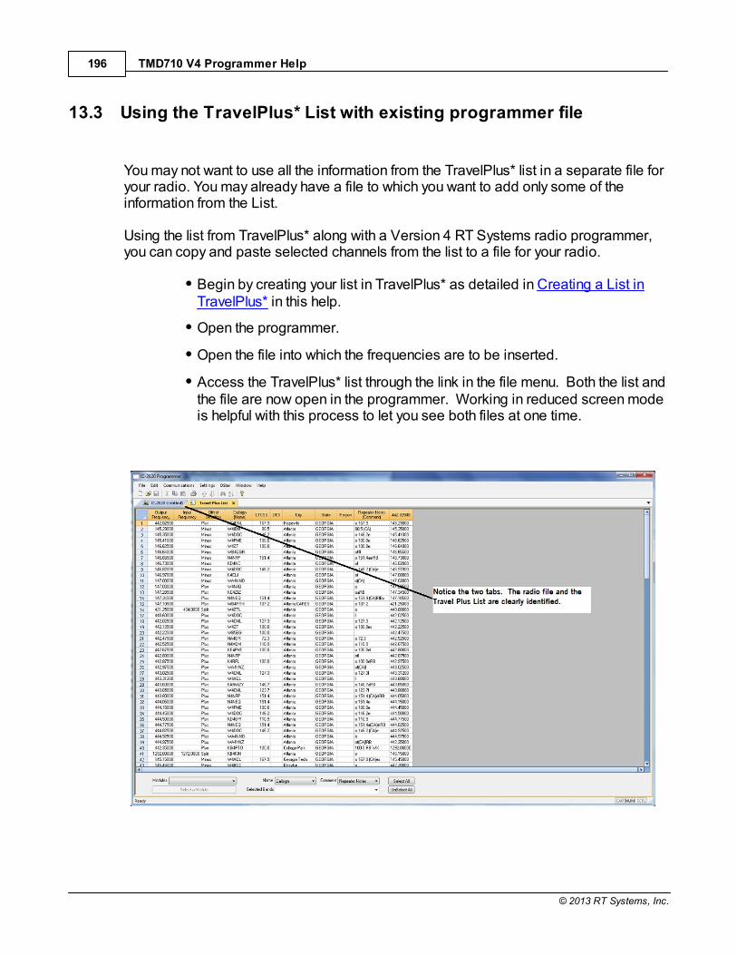
TMD710 V4 Programmer Help196
© 2013 RT Systems, Inc.
13.3 Using the TravelPlus* List with existing programmer file
You may not want to use all the information from the TravelPlus* list in a separate file foryour radio. You may already have a file to which you want to add only some of theinformation from the List. Using the list from TravelPlus* along with a Version 4 RT Systems radio programmer,you can copy and paste selected channels from the list to a file for your radio.
Begin by creating your list in TravelPlus* as detailed in Creating a List inTravelPlus* in this help.
Open the programmer.
Open the file into which the frequencies are to be inserted.
Access the TravelPlus* list through the link in the file menu. Both the list andthe file are now open in the programmer. Working in reduced screen modeis helpful with this process to let you see both files at one time.

ARRL TravelPlus* 197
© 2013 RT Systems, Inc.
Select a group of channels.
Point your mouse at the CHANNEL NUMBER (the grey shadedcolumn on the left) and left click. Don't let go of the left click button ifyou want more than one.
While holding the left mouse button, drag the mouse over theCHANNEL NUMBER of all the channels you want. If there are morethan those on the screen, just keep going at the bottom. The screenwill scroll to let you continue your selection.
Note: The entire row of a selected channel will turn behighlighted. If only the Receive Frequency is highlighted, thenONLY that information will be copied.
Copy the channels
With the mouse pointing at the highlighted channels right click andselect Copy from the menu that opens.
OR... with your mouse, left click to select Edit from the menu at the top

TMD710 V4 Programmer Help198
© 2013 RT Systems, Inc.
of the screen. From the menu that opens, select Copy.
It will appear that nothing has happened; however, Windows hascopied the information.
Use the mouse to click into the programmer file.
Note: If you are using the programmer in full screen mode, selectWindow from the menu then the programmer file name from thebottom of that list to switch between the two screens.
Alternately, you can select Window | Tile to have the programmerdisplay the two windows equally in the main window.
Select the first channel in the file into which the information is to be pasted.
Paste the information into the radio file
With the mouse pointing at the highlighted channels right click andselect Paste from the menu that opens.
OR... with your mouse, left click to select Edit from the menu at the topof the screen. From the menu that opens, select Paste.
View the results
The resulting file now contains only those selected pieces ofinformation from the TravelPlus* list along with all the originalinformation of that file.

ARRL TravelPlus* 199
© 2013 RT Systems, Inc.
Save the programmer file to make this change permanent.
Press Ctrl S or select File then Save from the menu that opens
With either process it will appear that nothing happens; however,Windows has made the change to the radio file permanent.
Send the file to your radio.
*TravelPlus is a product of the American Amateur Radio League. Any images from TravelPlus included in this help are copyrighted to DHF Systems, LLC.

Part
XIV

Copying From an Excel Spreadsheet 201
© 2013 RT Systems, Inc.
14 Copying From an Excel Spreadsheet
The Programmer can handle information copied from an Excel spreadsheet.
Although this process is very valid for transferring data between these programs, it isnot recommended for original file creation. It can be tedious getting all the informationinto the file to be copied. For example, why struggle to find information for the offsetfrequency and offset direction for your Excel list when the programmer will complete thisinformation automatically when frequencies are entered there.
Limitations for use of another commercial spreadsheet program include: The spreadsheet program will know none of the limitations of the radio. Itwill allow you to enter any value in any space. You will have to enter transmitand receive frequencies, CTCSS tones, and DCS codes carefully to besure they are imported correctly to the radio.
You will need to organize your data carefully. The Programmer will import allthe items from a single column as the same thing. This can cause an oddsplit to be entered as Simplex or a non-standard offset to be ignored if non-similar data is listed in the same column.
Let the Programmer help you as you create your original file with its defaults andautomatic settings. Once the file is created you could export the data for other uses.

TMD710 V4 Programmer Help202
© 2013 RT Systems, Inc.
14.1 Step 1
The Programmer makes no assumptions about the information being handed to it fromthe Excel file. You need to be familiar with the data in the file to the point you canidentify that data to the programmer during the copy process.
Step 1
Open the Excel file. Select and copy the information you want to put into theprogrammer.

Copying From an Excel Spreadsheet 203
© 2013 RT Systems, Inc.

TMD710 V4 Programmer Help204
© 2013 RT Systems, Inc.
14.2 Step 2
Open the Programmer to which the data is to be pasted.
It is recommend that you import into a new file to prevent loss of data from anexisting file. Channel information can be copied to an existing file, and put exactlywhere you want it, after the process of copying from Excel is complete.
Note: The FT-60 is used here as an example. The process works thesame for any RT Systems Version 4 programmer although columnnames may differ or not be available.

Copying From an Excel Spreadsheet 205
© 2013 RT Systems, Inc.
14.3 Step 3
Paste: Ctrl V or right click and select Paste or select Edit then Paste from themenu at the top of the screen.
A window opens to complete the process.

TMD710 V4 Programmer Help206
© 2013 RT Systems, Inc.
14.4 Step 4
On this screen, you may need to use the Text Qualifier to remove quotes from yourdata.
The data should be appear as it does in this image: without quotes and separatedinto columns.
Click Next to continue.

Copying From an Excel Spreadsheet 207
© 2013 RT Systems, Inc.
14.5 Step 5
In this step of the process, you identify the information in your spreadsheet for theprogrammer. The programmer attempts to identify the columns based on theheaders that you have for the columns.
The programmer makes no assumptions and will set any non-matched column to"Ignore". The data in an ignored column will not be used in this process.

TMD710 V4 Programmer Help208
© 2013 RT Systems, Inc.
The column header changes to show your selection. Be sure to identify each of thecolumns you want used. The data in an "ignored" column will be set to defaults inthe resulting file. Your specifics will not be used.

Copying From an Excel Spreadsheet 209
© 2013 RT Systems, Inc.
Click Next to continue.

TMD710 V4 Programmer Help210
© 2013 RT Systems, Inc.
14.6 Step 6
Complete the options on the final screen and click Finish.
The resulting file contains the data just as it was in the Excel spreadsheet.

Copying From an Excel Spreadsheet 211
© 2013 RT Systems, Inc.

Part
XV

Importing a file 213
© 2013 RT Systems, Inc.
15 Importing a file
The Programmer can Import data from delimited text files. These files can be createdusing the Export feature of the Programmer for another radio, Travel Plus for Repeatersby ARRL, commercial spreadsheet programs, or text editors. Limitations for use of another commercial spreadsheet program include:
The spreadsheet program will know none of the limitations of the radio. Itwill allow you to enter any value in any space. You will have to enter transmitand receive frequencies, CTCSS tones, and DCS codes carefully to besure they are imported correctly to the radio.
You will need to organize your data carefully. The Programmer will import allthe items from a single column as the same thing. This can cause an oddsplit to be entered as Simplex or a non-standard offset to be ignored.
The easiest way to begin a text file for your Programmer is to Export a file from theProgrammer first. In that exported file, you will see column headers for the details thatthe Programmer expects to import. You will also see the format of the information. Youcan edit or add to this file with any commercial spreadsheet program or text editor.
Note: The new features off the programmer include the ability toenter a series of channels by entering just a beginning frequency andthe number to be entered, column editing, copy and paste of one ormultiple rows of data, rearrangement of columns, hiding columns thatneed not be edited, and automatic completion of data based on banddefaults for a frequency entered. Given that the programmer isdesigned for the data of the radio, you might find editing in theprogrammer easier than using another spreadsheet program.
The file to be imported must contain at a minimum Receive frequency to define a validmemory channel. The programmer will fill the rest of the details for that channel withdefaults just as if that frequency had been entered. The Programmer makes no assumptions about the information available. If a piece ofinformation is omitted, the Programmer imports the memory as a simplex channel andfills other fields with defaults. Although this process is very valid for transferring data from one radio Programmer toanother and for using the data from other sources such as ARRL Travel Plus, it is notrecommended for original file creation. It can be tedious getting all the information intothe file to be imported just like the Programmer wants it. Let the Programmer help youas you create your original file with its defaults and automatic settings. Once the file is

TMD710 V4 Programmer Help214
© 2013 RT Systems, Inc.
created you could export the data for other uses.
Importing a file 215
© 2013 RT Systems, Inc.
15.1 Creating a file for Import
Checking a file to use with the Programmer
If you are given a file that you want to import into a programmer for use by your radioand are not sure if it is a "flat file", test the file by opening it with Windows notepad. If the Notepad display is full of strange characters with very little legible text, this file isnot ready to be imported by the programmer. The file may or may not be able to beused for import depending how it was created and saved. Try opening the file in Microsoft Excel or other commercial spreadsheet program. Ifeverything looks good there carefully save the file in as delimited text (this could becalled several different things in the program that you are using. If the first one you trydoes not produce the file format that you want, try selecting a different File Type duringthe save process. The details for this process are included below for Microsoft Excel. Open the file that you created during the save process in Notepad. As before, if thedisplay is legible data separated by commas you are well on your way. If, however, thedata appears in one very long line, you should return to the original source to extract thedata with line feed breaks at the end of each record. If the Notepad display has orderly lines of legible data separated by commas, it isready for use by the programmer. It is fine if you see two commas right together. Theprocess can handle a blank field.
Saving an Excel file for import If you work on a file in Excel for import to the programmer, that file must be saved as acomma delimited file before you leave Excel. The Programmer cannot import anExcel file with all its formatting codes. What it can work with is the "flat file" output ofthat file.
In Excel, select File|Save as
In the Save As window change the Save as Type to CSV (commadelimited) *.csv
Enter a file name for the output file. Pay attention to the drive and directoryto which the file is being saved. You will need to be able to find the file laterfor use during import.
TMD710 V4 Programmer Help216
© 2013 RT Systems, Inc.
Excel will raise a warning(s) about worksheets and formatting that will belost if the file is saved in this format. Answer to the affirmative (OK or Yes)to the message(s);eliminating the formatting is exactly what you want.
When you exit Excel, you will be asked again if you want to save the *.csvfile. If you have made no changes since you lost saved, answer No. If youhave made changes, answer Yes and proceed through the warnings againto save the file again.
Limitations for use of another commercial spreadsheet program include:
The spreadsheet program will know none of the limitations of the radio. Itwill allow you to enter any value in any space. You will have to enter transmitand receive frequencies, CTCSS tones, and DCS codes carefully to besure they are imported correctly to the radio.
You will need to organize your data carefully. The Programmer will import allthe items from a single column as the same thing. This can cause an oddsplit to be entered as Simplex or a non-standard offset to be ignored if thedata is not in a column labeled correctly or is mixed in with dissimilar data.
The Import File
The Import function is designed to assimilate some if not all of the following pieces ofinformation for use by the Programmer. As radio features vary, so will the informationto be imported (i.e., frequency ranges, the way offsets are handled, special optionssuch as mask, clock shift, etc.) Channel Number: If your file has channel numbers and you opt to use this columnduring import, your resulting file might not be what you expect.
If the "Overwrite existing channels" option is checked: The information willbe inserted into the specific channel no matter what is in the file at thatlocation now . While the channel numbers can help to organize theinformation being imported, it can result in data being overwritten in theprocess
If the "Overwrite existing channels" option is unchecked: The informationfrom the file being imported will be skipped if there is already information in

Importing a file 217
© 2013 RT Systems, Inc.
the channel. The data in the existing radio file will not be overwritten.
It is always recommended that you import into a new file to preventdata loss in an existing radio file. Once the information is in theprogrammer file, it can be copied into an existing file. With the copyprocess, you have more control of where the data is inserted into thefile.
Receive Frequency: The very least a file must have to be imported is the receivefrequency. This may be called the "output frequency" depending on whether you'rereferring to the radio or the repeater. If the column header is "Receive Frequency", theimport process will recognize this label and identify the information automatically.
Acceptable receive frequencies are detailed in the User's Manual for theradio. In the text file, the frequency should be entered in the format "MHzdecimal kHz" (i.e., 146.450) with up to five digits following the decimal.
Although, unacceptable frequencies can be entered into the text file, theywill not be imported into the Programmer. They will result in a blank memorychannel when import is completed.
Transmit Frequency: Enter a specific transmit frequency in the format "MHz decimalkHz" (i.e., 146.450) with up to five digits following the decimal.
This information can be omitted from the file. If you are importing repeater information where all the repeaters havestandard offsets (none operates on an "odd" split) the import process willcalculate the Transmit Frequency from other information in the file.
This information must be included in a separate column for an "oddsplit". The column cab be empty other than the specific information for those few"odd split" repeaters. The import process will calculate the TransmitFrequency from other information in the file for the other channels.
Acceptable transmit frequencies are detailed in the manual for your radio.
Note: In the Programmer you can enter details for frequenciesoutside the transmission abilities of the radio; however, the softwarewill not enable transmission on these frequencies. Transmission willbe possible only if the radio has been properly modified.
Offset Frequency: This is the amount that the Receive Frequency changes to

TMD710 V4 Programmer Help218
© 2013 RT Systems, Inc.
produce the Transmit Frequency. Standard offsets in the programmer include 100,500, and 600 kHz (0.1, 0.5 and 0.6 MHz) and 1.0, 1.6, 3.0, 5.0, and 7.6 MHz.
In Yaesu radios any value in 50 kHz increments can be used as an offset(i.e., .650, .550, .050)
In an Icom radio, there are no Splits. Everything must be entered with anexact Offset Frequency.
The Offset Frequency is used by the radio along with the Offset Direction tocalculate the Transmit Frequency. The Programmer does the same.
This is one place that the import process will make an assumption for you. Ituses 600 kHz for the offset for VHF and 5 MHz for the offset for UHF if noother offset is specified.
Non-Standard OffsetsThe Offset Frequency can be used in conjunction with Offset Direction for avalue in 5 kHz steps (i.e., any value ending in .xx5 where x is any digit from 0to 9). This gives you the ability to use the Reverse function of the radioalthough your frequency pair is not separated by a standard offset value. Thisis considered a non-standard offset.
To use a non-standard offset in your text file enter the Receive Frequency.Then the Offset Frequency as an exact value including the decimal to denotekHz. For example, given the pair 146.650 and 147.300, the Offset Frequencyentered would be .650 (decimal six five zero). And the Offset Direction asPlus or Minus. With these three pieces of information, the import process willsetup this memory channel correctly for use by the radio with the mostfunctionality.
Note: You may see this import with one of the standard OffsetFrequencies; however, once the file is saved, closed and reopened,the Plus or Minus and the Offset Frequency value as entered willappear.
Offset Direction: The Offset Direction lets the Import process know whether to add(plus) or subtract (minus) the Offset Frequency from the Receive Frequency whencalculating the Transmit Frequency for the memory channel.
Enter Plus, Minus, + or - for the process to recognize the command.
NOTE: Be sure to use Offset Direction if your file contains + and&endash; in this column. Using Offset Frequency for this column willresult in all channels being imported as simplex.
Operating Mode: Enter FM, AM, or WFM as appropriate for the frequency.
Importing a file 219
© 2013 RT Systems, Inc.
Name: Enter an Alpha/Numeric tag (up to 8 characters) for the memory channel toprovide an easy reminder of the function of a particular frequency. Not all radios havethis available for each memory channel. Consult your Users’ Manual for details. Tone Mode: Use of the tone systems of the radio allows for silent monitoring until acall is received with a corresponding tone. Tone mode also allows access torepeaters that are made private with a PL tone. Most radios offer CTCSS (ContinuousTone Coded Squelch System) or DCS (Digital Coded Squelch) to be tailored to yourparticular needs. Consult your Users’ Manual for details specific to your model.
Use of either of the tone systems requires two steps. Your import file will handlethese steps in THREE (3) columns.
Step 1: Turning on Tone ModeThere are now so many different tone modes and combinations of them, werecommend that you use the designation just as it appears in theProgrammer for your radio to identify the Tone Mode to be used. Exampleswould include but not be limited to:
None - Tone mode off
Tone - Encode
T Sql - Encode/Decode
DCS - DCS Tone
Others specific to your radio as detailed in the Tone Mode column of theprogrammer.
Step 2: Setting the tone frequency (CTCSS) or selecting the code for the tone(DCS).
Note: The CTCSS tone frequencies and the DCS tone codes shouldbe stored in TWO separate columns in your file to be imported. Theimport process does not separate. It will ignore incorrect valuesleaving the tone set incorrectly for the channel.
CTCSS Tone: Enter one of the 50 tone frequencies in the format MHzdecimal kHz with only one digit to the right of the decimal.
This value must be entered exactly as shown in the chart in the UsersManual. A value that is not in the table will result in an incorrect tonevalue setting in the resulting Programming file.
This value is set independently for each memory channel.

TMD710 V4 Programmer Help220
© 2013 RT Systems, Inc.
DCS Code: Enter one of the 104 codes in a three digit format (This willappear as two digits if you editor does not show leading zeroes. Twodigits are acceptable when the third is a leading zero).
This value must be entered exactly as shown in the chart in the UsersManual.
A value that is not in the table will result in an incorrect tone valuesetting.
This value can be set independently for each memory channel thatuses a DCS tone.
Skip: Marks selected memory channel to be skipped during scanning This fieldshould contain one of the following:
Scan, 0, or Stop to include the channel to be scanned
Skip or 1 to mark the channel to be skipped.
PScan or 2 to mark the channel as Preferential Scan
Step: The frequency being used by the radio changes by the value of the step whentuning manually. This value is used by the radio in Memory Tune mode. This value isnot critical in memory mode since the original memory channel frequency can beretrieved by exiting Memory Tune mode.
Enter 5/10/12.5/15/20/25/50 or 100 as needed.
Clock Shift: Shifts the internal reference frequency slightly to eliminate "birdies" thatinterfere on other channels.
Enter On or 1 / Off or 0
Tx Power: The output power can be set individually set for each memory channel toaddress the exact needs of each operation.
Enter High / Med / Low
Half Deviation: Enter On or Off as needed for the channel
Comments: Enter an identifying comment up to 80 characters.
You can see by the details here that creating a file for import can be a tedious process.Although this process is very valid for transferring data from one radio Programmer toanother and for using the data from other sources such as ARRL Travel Plus, it is notrecommended for original file creation.

Importing a file 221
© 2013 RT Systems, Inc.
Let the Programmer help you as you create your original file with its defaults andautomatic settings. Once the file is created you could export the data for other uses. The comma-delimited file can contain this information in any order. It must contain onlythe Receive frequency to be a valid memory channel. The Programmer makes noassumptions about the information available. If a piece of information is omitted, theProgrammer imports the memory as a simplex channel and fills other fields withdefaults.
This data can be entered in any order. You will identify the specifics to the Programmerduring the Import process. If you find after several entries that you need another columnfor additional information, simply add it at the end. The Programmer will correct theorder when it imports. Save the data in your file often to prevent loss. Be sure to save the file as text withdelimiters (separators) rather than as a worksheet of the program in which you areworking. The Programmer cannot use a worksheet created by the other program. To save as a text file, select File | Save (in the spreadsheet program). In the Save filewindow, select a different file type from the selection at the bottom of the screen.Acceptable formats are those that specify Text (i.e., .cvs, or .txt file extension). Exit the spreadsheet program. Your file is ready to be imported into the Programmer.Changes can be made within the Programmer after you import the data.
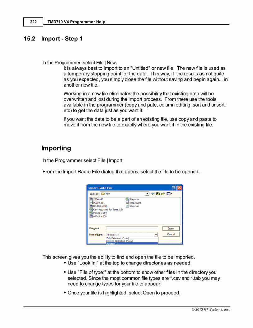
TMD710 V4 Programmer Help222
© 2013 RT Systems, Inc.
15.2 Import - Step 1
In the Programmer, select File | New. It is always best to import to an "Untitled" or new file. The new file is used asa temporary stopping point for the data. This way, if the results as not quiteas you expected, you simply close the file without saving and begin again... inanother new file.
Working in a new file eliminates the possibility that existing data will beoverwritten and lost during the import process. From there use the toolsavailable in the programmer (copy and pate, column editing, sort and unsort,etc) to get the data just as you want it.
If you want the data to be a part of an existing file, use copy and paste tomove it from the new file to exactly where you want it in the existing file.
Importing
In the Programmer select File | Import. From the Import Radio File dialog that opens, select the file to be opened.
This screen gives you the ability to find and open the file to be imported.
Use "Look in:" at the top to change directories as needed
Use "File of type:" at the bottom to show other files in the directory youselected. Since the most common file types are *.csv and *.tab you mayneed to change types for your file to appear.
Once your file is highlighted, select Open to proceed.

Importing a file 223
© 2013 RT Systems, Inc.
Import Step 1 of 4: Identify one or more of the first rows of data to be omitted
This screen was used originally to omit headers, columns without data, from the import.This is no longer necessary.
Actually, it is recommended that you leave the headers to help youmore easily identify the information in a later step.
This step remains useful for eliminating a number of memory channels from the importprocess. For example if your file contains more channels than are allowed by the radio.You could eliminate multiple channels here rather than later in the import process.
Click Next to continue.
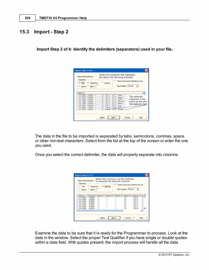
TMD710 V4 Programmer Help224
© 2013 RT Systems, Inc.
15.3 Import - Step 2
Import Step 2 of 4: Identify the delimiters (separators) used in your file.
The data in the file to be imported is separated by tabs, semicolons, commas, spaceor other non-text characters. Select from the list at the top of the screen or enter the oneyou used. Once you select the correct delimiter, the data will properly separate into columns.
Examine the data to be sure that it is ready for the Programmer to process. Look at thedata in the window. Select the proper Text Qualifier if you have single or double quoteswithin a data field. With quotes present, the import process will handle all the data
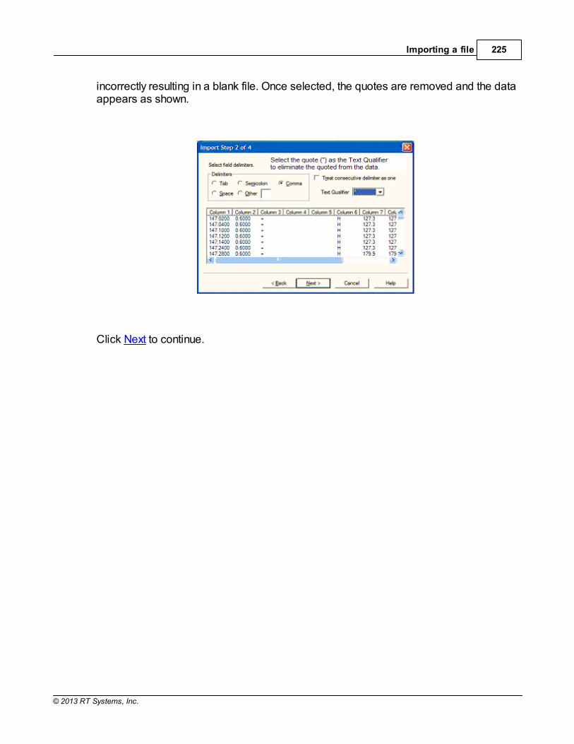
Importing a file 225
© 2013 RT Systems, Inc.
incorrectly resulting in a blank file. Once selected, the quotes are removed and the dataappears as shown.
Click Next to continue.

TMD710 V4 Programmer Help226
© 2013 RT Systems, Inc.
15.4 Import - Step 3
Import Step 3 of 4: Identify the data to the Programmer The Programmer will make an attempt to identify the information in your file. In this stepof the process, you can make corrections to the assignments the Programmer hasmade and identify other columns that you want imported.
For the columns to be imported, select the header of the column (the little grey box justabove the column) then select the proper identifier from the drop down list at the top ofthe screen
You need to identify only those columns to be imported.

Importing a file 227
© 2013 RT Systems, Inc.
Click Next to continue.

TMD710 V4 Programmer Help228
© 2013 RT Systems, Inc.
15.5 Import - Step 4
Import Step 4 of 4: Limit the channels that are imported by the Programmer
Again, you can make adjustments to the data to be imported without having to edit theoriginal file. Select all or any part of the list by checking the box at the left of the screen.
Since the data can be imported into an existing file, use the boxes at the top of thescreen to place the data in the file where you want it to appear.
Starting radio memory - Insert the channels into the file somewhere otherthan at the beginning (i.e., At the end of a list that has the last channel of21. Enter 22 in this box to begin with the next memory channel of that file).
Overwrite existing channels - Tells the process to replace data it finds in theexisting file or to skip that data and write in the next available channel. Forexample:
Unchecked - If you import into a file with memories in channel numbers 1-10, 12, 15 and 16 the process would write the imported channels in order to11, 13, 14, then 17 on to the end of the imported list.
Checked - If you import to a file with memories in channel numbers 1-10,12, 15 and 16 the process would write the imported channels in orderbeginning at channel 1and continue in order to the end of the imported list.The existing channel data of the file would be lost in the process as it isreplaced with that of the imported file.
Finish - Click to compete the process. The resulting file in this examplewould look like this:

Importing a file 229
© 2013 RT Systems, Inc.

Part
XVI

Export 231
© 2013 RT Systems, Inc.
16 Export
The programmer can export, "convert" , the data of a radio programming file to a flat filefor use in other programs. This will create the file that you need is someone asks youfor a "csv" or Excel file.
You control two parts of exportWhat is exported from the file
Where the exported file is saved on your hard drive.
What is exported from the file
The file created through export contains the data on the screen that is open whenthe process is begun.
If a radio has Right Memories and Left Memories, it will export the data of the RightMemories when you are viewing that screen when the process is begun and thedata from the Left memories if you are viewing that screen.
Each export should be directed to a separate file. If you use the same filename,you will replace the data from the first export with that of the next.
Where the exported file is saved on your hard drive
Select the section of the file to be exported.
Click File | Export
A Save dialog box opens. You have complete control of the filename and locationof the file on your hard drive in the options in that Save dialog box.
Pay close attention to the filename and directory designation of the resulting file. You want to be able to find it easily later.

Part
XVII

Troubleshooting 233
© 2013 RT Systems, Inc.
17 Troubleshooting
Technical support is available from RT Systems at the times and number shown in theContacting RT Systems of this help. As issues are addressed by Techsupport personnel, the issue and the result are oftendetailed on the FAQ page of www.rtsystemsinc.com Check there for additionalinformation that might pertain to the exact issue you’re seeing with your radio.
Detailed here are several of the more common problems that you may want to checkbefore you contact technical support.
"The data from the radio will overwrite this file. Continue?"
This message will be raised by the programmer when you select Communications | Getdata from radio with a file open that is not a new (default) file into which no entries havebeen made.
This message is warning you that you will replace any information you have enteredwith whatever is in the radio. The "whatever" could be all blank channels.
Answer "yes" if you want to lose all the information that appears on the screen. Answer"no" if you don't want to lose several hours of work spent creating the file on the screen. To prevent loss of information, first do File | New to open a new (default) file. Thenwhile looking at that file, do Communications | Get data from radio and complete thatprocess. Your file will drop to the background and be protected from during this part ofthe process.
Once you complete Communications | Get data from radio, return to your file a) selectthe tab at the top of the page; or b) select File | Open and open the file from the listpresented (if you closed it some time during the process.)
Program cannot find cable

TMD710 V4 Programmer Help234
© 2013 RT Systems, Inc.
This message can appear when you are attempting to get data from the radio or senddata to the radio. There can be several causes. The most common are:
The cable is not attached to the computer or you have the wrongprogramming cable attached. The cable for this radio is pictured in the Computer to radio cabling section of this help.
The communications process was accessed too quickly after the cable wasattached. It can take some computers a minute or more to recognize thecable properly. Give the computer a little more time and try again.
The problem may lie in the electronics of the cable. If this is the first time youhave attempted this process, contact RT Systems for assistance. This canbe corrected easily in just a few minutes with the computer and an Internetconnection.
Note: This can be corrected using a machine that has an Internetconnection that you don't plan to use for the programming software. Thesoftware for the radio does not have to be installed to complete thecorrection.
HotSync, the program for the Palm Pilot, is running on this computer. Hotsyncimmediately takes control of an available comport. Since the RT Systemsprogramming cable establishes a comport, Hotsync takes control before youhave a chance to use it. Look for the icon, red and blue arrows chasing eachother, in the tray at the right of the task bar. If found, right click and exit. Thatprogram will load again when you re-boot your computer. You will need todisable this software any time you program your radio.
Interference from other cables attached
The Programmer is designed to find the cable to be used by this radio forprogramming. This process is done through special identifying numbers programmedinto the electronics of the USB connector.
The process looks at each USB device attached. Other items attached, especially

Troubleshooting 235
© 2013 RT Systems, Inc.
other programming cables, may cause the programmer to wrongly identify the RTSystems cable it must use for a specific radio.
Two different errors can occur in this configuration. Either the programmer will reportthat the RT Systems cable is not attached to the USB port or the Communicationsprocess will not respond since the data being transferred from the radio (you did pressall the right buttons) is traveling along a cable other than that the programmer isconnected to.
Interference from other applications
Your radio is not the only device you attach to your computer for programming or datainterchange. I-Pads, I-Pods, Palm Pilots and other PDA devices, printers, camerasand others all install programs for their use. Unfortunately, many of these programs runconstantly looking to be used any time a cable is attached.
These programs take control of the cable even if it is not for their device. This rendersthe cable useless for its intended purpose.
You may not even be aware that these programs are running. You may have sold thedevice months ago; but unless you took steps to permanently disable the software for it,the problem remains. These programs run start whenever the computer is started orbrought back from hibernation then run in the background with little indication that theyare there.
Begin checking by hovering over each icon at the lower right of your screen. Those inthe taskbar. A name will appear as you pass over each. You may recognize the onethat needs to be disabled. Usually an option to Exit or Close will be available from aright click menu. Don't worry about exiting something you might need. The applicationwill begin again when you restart your computer.
After addressing a program, check in the programmer. You should be able to click OKon the Communications | Get Data from screen and have the process continue insteadof raising the error message.
Tech support at RT Systems will be glad to help you with this; but we are limited giventhis is an issue specific to the applications running on your machine. You are welcometo contact us for help with this issue.
Defective Cable
Cables from RT Systems are 100% tested prior to packaging. Even with this level ofcontrol, occasionally a cable fails in the field. Contact RT Systems tech support if to

TMD710 V4 Programmer Help236
© 2013 RT Systems, Inc.
determine if the cable is at fault and a replacement is needed.
A replacement can be initiated when you send a copy of your receipt as proof ofpurchase and the issue has been diagnosed with a tech support representative at RTSystems. In this case, a replacement will be sent immediately with a prepaid label forreturn of the defective item. The replacement will be sent to the address on thereceipt.
If the receipt is not available, return the original cable for replacement. A replacementcable will be sent immediately when the defective item is received at our location.
USB Driver Installation
On some systems running Windows 2000 or early versions of XP, the drivers for thecable will need to be installed manually. This is a normal thing in the USB world and iseasily done. We are RT Systems will be happy to help you through this process.
With the USB cable detached from the computer, start the New Hardware Wizard fromthe indication for the device in the Device Manager.
The drivers have been installed on your machine in the following directory.
C:\Program Files\Common Files\RT SystemsV4\RTDrivers\USBComDrivers\Drivers
Run the New Hardware Wizard twice. The first time use ftdibus.ini in that directory. Thesecond time use ftdiport.ini in that same directory.
Then attach the cable again. Check in Device Manager to be sure it is now listed underPorts (Com and Lpt) with a comport designation assigned.
Modified Radio

Troubleshooting 237
© 2013 RT Systems, Inc.
This error is raised when you attempt to send a file to a radio that is modified beforethe programmer is given that information.
If your radio has been modified, you must complete Communications | Get data fromradio into a new file before you attempt to write data to the radio. When the Get datafrom radio process is used, even if the radio is not yet programmed, the Programmergets the data it needs to know that the radio is modified. When you use Communications | Get data from for the sake of establishingcommunications, you need to save the file ONLY if you want to save the memory datathat is currently in the radio. The Programmer already has what it needs. The option tosave is available should you want to save the pre-programmed data.
Cabling to properly address the radio
The Version 4 RT Systems Programmers work only with the RT Systems' USB cables OR
Original RT Systems' serial cable with the RTS-03 USB to
serial adapter.
No other USB cable will be recognized by the programmer.
RT Systems' programmers address over 100 different radios. Of those, someprogram through the speaker jack, some through the mic jack, some through the datajack and some through the CAT port. These ports must be addressed by the correctRT Systems cable for communications to be successful.
Be sure to use the correct RT Systems cabling to address the radio beingprogrammed. Check the User’s Manual for the radio if you are not sure where the portis on the radio that is specified in the programmer. The cables for this particular radioare pictured in the Radio to Computer Cabling section of this help.

TMD710 V4 Programmer Help238
© 2013 RT Systems, Inc.
Specific to the FT-857/D and FT-897D: The cable used for programming is the USB-62 cable with the 8-pin mini din plug. This plug is attached to the CAT jack on the backof the radio. Forcing this connector into the data port will ruin the plug and coulddamage the radio. There have been cases where the power pin and the PTT wereconnected (since you never know which pin will go which way when you force them outof place) causing several hundred dollars in damage. Check to be sure you areconnecting the cable to the matching jack before forcing the pins into the holes.
At the time of this writing (2009), none of the Yaesu VHF/UHF mobile radios used theUSB-62 cable with its 8-pin plug. We have seen this tried. It will not work. The mobileradios that program through the data jack require a 6-pin mini din connection on thecable. Check the cabling specified in the help for the radio that you're programming tobe sure that you're using the right one to address the radio.
Icom specific issue for Clone mode
Other than the Icom IC-R10, at the time of this writing, Icom radios are NOT put intoCLONE mode for programming. CLONE mode is used only when you transfer datafrom one radio to another. The process for programming the radio from the computer is simple. When theinstructions say to "Turn the radio on", do just that, press the power button to turn it on. If pressing a key is needed as a part of this step, it will be included with the instructionson the Get data from screen.
Yaesu Radio does not go into Clone mode after initial menuselection
Many Yaesu radios, handheld and mobiles, access Clone mode from a startup menu.When you turn the radio on holding the specified key, you are in that menu with severaloptions of radio functions. Clone is only one of these options.
Once the Clone option is found in that menu, another key on the radio is pressed toactivate that mode. You know the options has been activated when the radio cycles offand back on. Only then is it in Clone mode and ready to program.
If the radio does not cycle off and back on when that next button is pressed, one of thefollowing may address the issue:
The keys on the face of the radio are locked. Turn the radio off and back on innormal mode to check for the Lock symbol on the screen. Unlock the keysand try again.

Troubleshooting 239
© 2013 RT Systems, Inc.
You have pressed the designated key too long or not long enough. Try againuntil you get the feel for the process.
Yaesu Radio does not change to Tx or Clone Out whenbutton is pressed
Many Yaesu radios have a key sequence that starts Clone mode without having toselect that option from a startup menu: the radio simply comes on in Clone mode.
With CLONE displayed on the face of the radio, a button is pressed to begincommunications.
If the radio comes on displaying CLONE; but then is unresponsive when the button ispressed to begin (i.e., the screen does not change from Clone) check these twocommon causes:
First, be sure you are using the correct cabling for the radio beingprogrammed. If an adapter was included with the kit, use it.
Check that the keys are not locked. To check, turn the radio off. Turn it backon in normal mode and check for the Lock symbol on the screen. Unlock thekeys from the face of the radio and try again.
Windows Version Compatibility
The Version 4 Programmer is designed to work with Windows XP, VISTA (32 or 64 bit)or Windows 7 (32 or 64 bit) and Windows 8 (full version).
RT Systems no longer supports use of the programmers on Windows 98, Windows98SE, Windows 2000, or Windows ME.
Note: If you plan to use an older computer for programming yourradio, you may experience problems with the program resulting fromfiles that are missing from the operating system. These files wouldhave been delivered through normal Windows updates to theoperating system.
If the machine has been out of service for several years, set it up withan Internet connection and Automatic Updates activated. Let it sit for

TMD710 V4 Programmer Help240
© 2013 RT Systems, Inc.
several days while it finds what it needs.
Once the updates are installed, you will have no other problemsrelated to the operating system relative to the programmer.
NACK/ACK Error
As ugly as this error appears. it actually is only a generic message saying theCommunication process failed. Try again after reading the hints here.
Do NOT turn the radio off. It may display Error. It is not terrible unhappy andis still in Clone Mode.
Cancel all Communications screens that are open in the programmer.
Open a new file ( File | Open form the menu at the top of the screen).
Select Communications | Get data from radio. Doing Get Data from oftengets the process going.
Skip the steps for putting the radio into Clone mode. It is already there.
Click OK
Press the key as instructed to begin the process (sometimes you need topress it twice... once to return to Clone mode... then again to begin theprocess.)
Once Get data from is successful, attempt Send data to. In this scenario, you can skipthe steps to put the radio into Clone mode since it usually remains in Clone mode afterGet data from is completed.

Troubleshooting 241
© 2013 RT Systems, Inc.
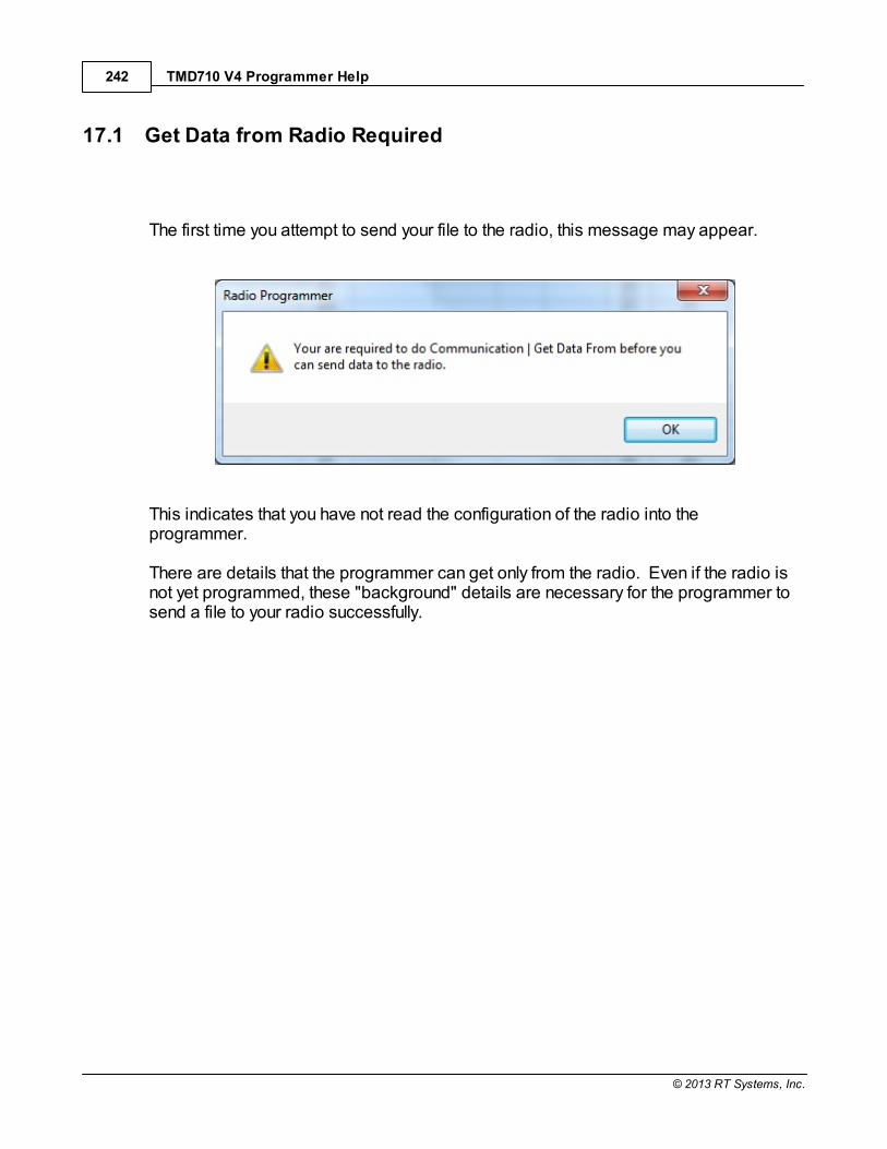
TMD710 V4 Programmer Help242
© 2013 RT Systems, Inc.
17.1 Get Data from Radio Required
The first time you attempt to send your file to the radio, this message may appear.
This indicates that you have not read the configuration of the radio into theprogrammer.
There are details that the programmer can get only from the radio. Even if the radio isnot yet programmed, these "background" details are necessary for the programmer tosend a file to your radio successfully.

Part
XVIII
TMD710 V4 Programmer Help244
© 2013 RT Systems, Inc.
18 Invalid Frequencies
This information is meant to address radio operators in the US. While many of thesedetails are true in other countries, some are not. Band plans, allowable frequencies,and other details differ around the world; but many of the functions of the radio remainthe same making this information useful to everyone.
This section is offered to help users understand why a frequency is rejected by anamateur radio. The Programmer will not allow you to enter a frequency that yourparticular radio cannot use.
Your radio is designed to work on all frequencies in the amateur bands. Problemsarise when frequencies from commercial operations are used on this amateurequipment. This explanation is offered to help you understand where the radios differ.
How Radios Work
A little here about how radios work. As for an allowable frequency, three factors areimportant: Reference Frequency, Reference Step and Step.
Reference Frequency - Based on its internal electronics, the radio uses a valuebased off the frequency you enter along with the Reference Frequency Oscillator togenerate the desired frequency.
Reference Step - The difference between any two Reference Frequencies. Thisvalue is set as a part of the internal workings of the radio. It cannot be changed.
Step - The difference between two frequencies displayed on the face of the radiowhen the tuning knob is turned while operating in VFO mode.
Reference step and Step work in conjunction with each other allowing or prohibitingyou from tuning to a given frequency.
Commercial radios have a Reference Step of 2.5 kHz.
Amateur radios are generally designed with Reference Steps of 5, 6.25, 12.5, 9 (onlyAM) and 8.333333 (air band only) kHz. While a few models have all these ReferenceSteps, many more remain with only Reference Steps of 5 and 12.5 kHz. These twoare sufficient for accessing any repeater in the Amateur Bands.
While in the mathematics of things there will be frequencies in the commercial bandsthat match the available Reference Steps of Amateur radios, the Step of the Amateurradio will not allow you to tune to the desired frequency.
Invalid Frequencies 245
© 2013 RT Systems, Inc.
It takes both working together to achieve a valid frequency.
Testing the validity of a frequency
The question of validity is seen with frequencies with four digits following the decimal(i.e., 154.03125 may be your local volunteer fire department frequency and while theircommercial radios can do this frequency, your amateur radio cannot... and it cannot bemade to do it with any software.)
Let's take 154.03125 and put it to the test.
Step 1:
The first and easiest test for the validity of a frequency is to attempt to dial to thatfrequency in VFO mode on the face of the radio. Remember in your attemptsthat it may be necessary to adjust the Step (see your Operator's Manual fordetails) to get to a certain frequency.
Turn on your radio.
Access VFO mode
Turn the tuning knob.
WIth the frequency changing by 5kHz steps, the frequency changesfrom 154.030 to 154.035 to 154.040 (oops... lost the 3 in the secondposition... let's try something else).
Change Step to 12.5 kHz (see Operator's Manual for your radio. Thisis generally done in the Set menu; however a shortcut key on the faceof the radio may give you easier access to this menu item.)
With the frequency changing by 12.5kHz steps, the frequency changesfrom 154.025, to 154.0375 (hey, at least I have the fourth digit now), to154.050... oops, missed the 154.03125 completely. Again, can't getthere tuning on the face of the radio.
Try other Step values until you're satisfied that the radio just cannot bemade to do that frequency.
Step 2:
Compare your frequency to this list. If you find it here, it will work. Note: "x'represents any number.

TMD710 V4 Programmer Help246
© 2013 RT Systems, Inc.
1. xxx.xx500 - Generally only 5 or 0 allowed in the third position with all0s after that. A few exceptions are shown below.
2. xxx.x12500 - Allowable for four digits after the decimal. The firstdigit after the decimal can be any from 0 to 9.
3. xxx.x375 - Allowable for four digits after the decimal. The first digitafter the decimal can be any from 0 to 9.
4. xxx.x625 - Allowable for four digits after the decimal. The first digitafter the decimal can be any from 0 to 9.
5. xxx.x875 - Allowable for four digits after the decimal. The first digitafter the decimal can be any from 0 to 9.
Comparing 154.03125:
There is a 1 in the third position after the decimal. By Rule 1, this isnot allowed for an amateur radio.
The frequency does not fit into any of the others that allow 4 digits afterthe decimal.
Step 3: Do the math.
Allowable frequencies (in Hz) must be evenly divisible by 5000 or 12500 or6250 Hz.
Convert your frequency to Hz:
154.03125 x 1,000,000 = 154031250
Divide that number by 5000
154031250 / 5000 = 30806.25
154031250 / 12500 = 12322.5
154031250 / 6250 = 24645
The 6250 Hz division was successful. There is a possibility that this frequencycan be used by an amateur radio.
As discussed earlier, both the Reference Step and the Step of the radio areused to determine a valid frequency. Models vary. While this frequency passed
Invalid Frequencies 247
© 2013 RT Systems, Inc.
the validity test for certain amateur radios, that in no way implies that it will workon your particular radio.
For this particular frequency to work in your particular radio, it is necessary thatthe radio have a 6.25 kHz step available in the Step option of the Set menu.

Part
XIX

Hardware Error Troubleshooting 249
© 2013 RT Systems, Inc.
19 Hardware Error Troubleshooting
"Well of course the information in the radio and the file do not match. I just madechanges to the file and I want the different information in the radio!!"
This is a common first reaction to this error. However, that is not the file informationinvolved in this error. There are several causes for this error. They include incorrect keystrokes on the radio, interference on the computer by another application or device, afaulty cable or the presence of a radio that has been modified for out of band use.
Below are various steps offered as corrections. At the end of each section try again totransfer data to the radio again.
Try this First
The error most likely indicates that "behind the scenes" information about the radiodoes not match that of a factory radio. This is most common when a radio hasbeen modified for our of band transmission.
1. Create a new file (press Ctrl M on the keyboard or select File | New fromthe menu at the top of the screen). This protects the file that you are tryingto send to the radio.
2. Select Communications | Get data from Radio from the menu at the top ofthe screen.
3. When this is completed successfully, return to your file (click to tab at thetop of the screen that displays the filename or select File | Open to reopenyour file.)
4. Select Communications | Send data to Radio. Be careful to follow these

TMD710 V4 Programmer Help250
© 2013 RT Systems, Inc.
steps shown on this screen. Generally, they are different from the Get Datafrom radio steps.
Radio Issues
"Error" is displayed on the radio.
"Behind the scenes" information about the radio does not match that of a factoryradio. This is most common when a radio has been modified.
1. Create a new file (Ctrl M or File|New)
2. Execute Communications | Get data from Radio. This is the only way this"behind the scenes" information can be obtained for your radio.
3. When this is completed successfully, return to your file.
4. Execute Communications | Send data to Radio begin careful to followthese steps since they are different from the Get Data from radio steps.
The radio does not change when "OK" clicked on the screen in theprogrammer (never indicates receive).
There is no communication between the radio and the computer. Check throughthe Cable issues to be sure you are using the right cable and that it is connectedproperly to the radio and to the computer.
The radio never goes to CLONE.
On many radios you hold buttons during power on to access a startup menu. Onceyou select the clone option of the menu (the radio is NOT YET IN CLONE MODE). You press a key to accept the CLONE option. When you press the button toaccess the startup menu option, the radio does not change.
1. The keys on the radio may be locked. Turn the radio off then back on innormal mode to check for a lock symbol on the screen. If the keys arelocked, unlock them. Once unlocked, power off the radio and begin theCommunications process again.
2. The key specified is "touchy" and responds if it is touched just the right way. This has been the case on several of the mobile radios. Try again with ashorter or longer touch on the button. When you get that touch just right, theradio will respond.

Hardware Error Troubleshooting 251
© 2013 RT Systems, Inc.
3. The wrong cable is being used. This is true for several of the hand heldradios that use the 4-pin plug. If you attempt this process with a stereo plug,the radio will not respond when you attempt the cloning process.
The radio never went into send (TX) mode (Get data from radio process).
Now that the radio is in Clone mode, one more button press is required to start thedata transfer (Get data from) or to make the radio ready to receive the data (Senddata to).
1. The wrong cable is being used. This is true for several of the hand heldradios that use the 4-pin plug. If you attempt this process with a stereo plug,the radio will not respond when you attempt to access the Clone option of thestartup menu.
2. The keys on the radio are locked. Turn the radio off then back on in normalmode to check for a lock symbol on the screen. Once the keys have beenunlocked, power off the radio and begin the Communications process again
Radio is not on at the time of data transfer.
This can get the process "out of sync". Cancel the Communications screen on thecomputer. Then access that screen again and start over with turning the radio on inClone mode. Be sure the battery is charged on your handheld radio or that you areconnected to external power to prevent an unexpected shutdown during thisprocess.
General Issue
Followed the Steps Incorrectly or executed the wrong process.
Get data from the radio:
1. Go to “Communications” in the top menu.
2. Click “Get Data from Radio”.
3. Read and follow each step. (Remember, the keystrokes are different for eachradio. They are detailed for a particular radio on the Get Data from radioscreen. The trick is to follow each step... one at a time.)
Send data to the radio:

TMD710 V4 Programmer Help252
© 2013 RT Systems, Inc.
1. Go to “Communications” in the top menu.
2. Click “Send Data to Radio”.
3. Read and follow each step. (Remember, the keystrokes are different for eachradio. They are even different for this process than they were for the Get Datafrom Radio process. They are detailed for a particular radio on the Get senddata to radio screen. The trick is to follow each step... one at a time.)
Cable Issues
Check that you are using the correct cable for this radio.
Many radios have jacks that will accommodate the programming cable from adifferent radio. Although the cable fits in the jack, the radio does not acceptprogramming through the wrong jack.
You can see the cables for each radio by clicking on Programming Cable Chart
Check that the cable is securely in the USB Port.
Be sure it has not pulled loose (this is easy to do with a USB). Also, the cableshould be plugged into a USB port on the computer rather than on a USB hub.
Check that the cable is plugged into the radio securely.
On cables with 6- or 8-pin round din plugs, you may want to check that the pins arenot bent in such a way that they are making a bad connection. Unplug the cablefrom the radio and check by looking at the pins in the plug.
On cables with 4, 6, or 8 pin modular plugs that address the mic jack, push thecable toward the connector to be sure the modular plug is plugged into the mic jackcompletely. There can be a good bit of play between the mic jack and the plug. Hold the cable securely until the process is complete.

Part
XX

TMD710 V4 Programmer Help254
© 2013 RT Systems, Inc.
20 Contact Us
RT Systems, Inc.510 Compton Street, Suite 105
Broomfield, CO 80020
Technicalsupport
303-586-6510
Fax
770-216-1836
TechnicalSupport Hours
Monday through Friday 10:30AM until 6:00 PM (Eastern Time) 9:30AM until 5:00 PM (Central Time) 8:30AM until 4:00 PM (Mountain Time) 7:30AM until 3:00 PM (Pacific Time)
Other times by appointment. Call or e-mail to makearrangements.
Web Page www.rtsystemsinc.com
Program updates
Answers to frequently asked questions can bereviewed under FAQs on our site.
Should you choose to send a message via e-mail, besure to include at the very least the following details:
The radio with which you use the Programmer
The version number of the Programming software

Contact Us 255
© 2013 RT Systems, Inc.
(found in the Programmer underHelp | About)
Based on the information given, we will respond asquickly as possible.
Be sure that rtsystemsinc.com is set as anacceptable address for your e-mail program. Orwatch for your response in your spam or junk mailfolder.

© 2013 RT Systems, Inc.