Timing analysis enhancement for synchronous program
10
Timing Analysis Enhancement for Synchronous Program * Pascal Raymond, Claire Maiza, Catherine Parent-Vigouroux and Fabienne Carrier Grenoble-Alpes University Verimag, centre équation 2 avenue de Vignate, 38610 Gières {firstname.lastname}@imag.fr ABSTRACT In real-time systems, an upper-bound on the execution time is mandatory to guarantee all timing constraints: a bound on the Worst-Case Execution Time (WCET). High-level syn- chronous approaches are usually used to design hard real- time systems and specifically critical ones. Timing analysis used for WCET estimates are based on the executable bi- nary program. Thus, a large part of semantic information, known at the design level, is lost due to the compilation scheme (typically organized in two stages, from high-level model to C, and then binary code). In this paper, we aim at improving the estimated WCET by taking benefit from high-level information. We integrate an existing verification tool to check the feasibility of the worst-case path. Based on a realistic example, we show that there is a large possible improvement for a reasonable analysis time overhead. Categories and Subject Descriptors C.3 [Computer Systems Organization]: Special- Purpose and Application-Based Systems—Real-time and embedded systems ; D.2.8 [Software Engineering]: Met- rics—Performance measures ; D.2.4 [Software Engineer- ing]: Software/Program Verification—Model checking General Terms Algorithms, Measurement, Verification Keywords WCET, Model-Based Design, Synchronous Languages, Model Checking, Traceability 1. INTRODUCTION Hard real-time systems are generally built using model- based design. Particularly, control engineering systems are * This work is supported by the french research fundation (ANR) as part of the W-SEPT project (ANR-12-INSE-0001) Permission to make digital or hard copies of all or part of this work for personal or classroom use is granted without fee provided that copies are not made or distributed for profit or commercial advantage and that copies bear this notice and the full citation on the first page. Copyrights for components of this work owned by others than the author(s) must be honored. Abstracting with credit is permitted. To copy otherwise, or republish, to post on servers or to redistribute to lists, requires prior specific permission and/or a fee. Request permissions from [email protected]. RTNS 2013 , October 16 - 18 2013, Sophia Antipolis, France Copyright 2013 ACM 978-1-4503-2058-0/13/10 ...$15.00. http://dx.doi.org/978-1-4503-2058-0/13/10. often generated from synchronous designs. In hard real- time systems any execution must fulfil timing constraints. To guarantee that these constraints are respected, a bound on the Worst-Case Execution Time is necessary. Static timing analyses aim at estimating this upper-bound on the WCET. They are based on abstractions of the hard- ware and the software. They generally suffer the necessary over-estimation due to abstraction. The source of this over- estimation is twofold: the hardware model may generate over-estimation when joining abstract states, the seman- tics of the program may generate over-estimation due to the fact that the execution path corresponding to the esti- mated WCET may be infeasible. In this paper, we aim at improving static WCET analysis when the program under analysis has been generated from a synchronous model. We improve the WCET estimation by reducing the set of infea- sible paths. We do not focus on the hardware analysis that we consider orthogonal. WCET analyses are derived on the binary level. When programs are generated from high-level design, they are first translated into an intermediate language (usually C or ADA) then compiled into binary. Due to this two-step compila- tion, it may appear that most of semantic information is lost: the WCET estimation should be enhanced by consid- ering this high-level semantic information. Two main issues must be solved to integrate these high-level semantic prop- erties: (i) how to extract interesting semantic properties at the high-level, (ii) how to transfer information from one level to the lower next level (traceability). This paper is structured as follows. First, we introduce the context: WCET analysis, synchronous model, and why synchronous model is a good candidate to enhance WCET estimation. Then, we show on a realistic example that the WCET estimation may be largely refined and we introduce our approach for programs generated from Lustre [5]. 2. CONTEXT 2.1 WCET/Timing Analysis In this paper we consider static timing analysis. Figure 1 shows the general timing analysis workflow that is used in a large part of WCET tools [15]. The analysis is based on the binary program. The Control Flow Graph (CFG) is first reconstructed from the binary. Then, a set of value analyses extracts memory addresses, loop bounds and simple infeasible paths. These analyses are mainly based on the binary or the C files (note that in case the C files are used some traceability analysis is necessary).
-
Upload
independent -
Category
Documents
-
view
0 -
download
0
Transcript of Timing analysis enhancement for synchronous program

Timing Analysis Enhancement for Synchronous Program∗
Pascal Raymond, Claire Maiza, Catherine Parent-Vigouroux and Fabienne CarrierGrenoble-Alpes UniversityVerimag, centre équation
2 avenue de Vignate, 38610 Gières{firstname.lastname}@imag.fr
ABSTRACTIn real-time systems, an upper-bound on the execution timeis mandatory to guarantee all timing constraints: a bound onthe Worst-Case Execution Time (WCET). High-level syn-chronous approaches are usually used to design hard real-time systems and specifically critical ones. Timing analysisused for WCET estimates are based on the executable bi-nary program. Thus, a large part of semantic information,known at the design level, is lost due to the compilationscheme (typically organized in two stages, from high-levelmodel to C, and then binary code). In this paper, we aimat improving the estimated WCET by taking benefit fromhigh-level information. We integrate an existing verificationtool to check the feasibility of the worst-case path. Basedon a realistic example, we show that there is a large possibleimprovement for a reasonable analysis time overhead.
Categories and Subject DescriptorsC.3 [Computer Systems Organization]: Special-Purpose and Application-Based Systems—Real-time andembedded systems; D.2.8 [Software Engineering]: Met-rics—Performance measures; D.2.4 [Software Engineer-ing]: Software/Program Verification—Model checking
General TermsAlgorithms, Measurement, Verification
KeywordsWCET, Model-Based Design, Synchronous Languages,Model Checking, Traceability
1. INTRODUCTIONHard real-time systems are generally built using model-
based design. Particularly, control engineering systems are
∗This work is supported by the french research fundation(ANR) as part of the W-SEPT project (ANR-12-INSE-0001)
Permission to make digital or hard copies of all or part of this work for personal orclassroom use is granted without fee provided that copies are not made or distributedfor profit or commercial advantage and that copies bear this notice and the full citationon the first page. Copyrights for components of this work owned by others than theauthor(s) must be honored. Abstracting with credit is permitted. To copy otherwise, orrepublish, to post on servers or to redistribute to lists, requires prior specific permissionand/or a fee. Request permissions from [email protected] 2013 , October 16 - 18 2013, Sophia Antipolis, FranceCopyright 2013 ACM 978-1-4503-2058-0/13/10 ...$15.00.http://dx.doi.org/978-1-4503-2058-0/13/10.
often generated from synchronous designs. In hard real-time systems any execution must fulfil timing constraints.To guarantee that these constraints are respected, a boundon the Worst-Case Execution Time is necessary.
Static timing analyses aim at estimating this upper-boundon the WCET. They are based on abstractions of the hard-ware and the software. They generally suffer the necessaryover-estimation due to abstraction. The source of this over-estimation is twofold: the hardware model may generateover-estimation when joining abstract states, the seman-tics of the program may generate over-estimation due tothe fact that the execution path corresponding to the esti-mated WCET may be infeasible. In this paper, we aim atimproving static WCET analysis when the program underanalysis has been generated from a synchronous model. Weimprove the WCET estimation by reducing the set of infea-sible paths. We do not focus on the hardware analysis thatwe consider orthogonal.
WCET analyses are derived on the binary level. Whenprograms are generated from high-level design, they are firsttranslated into an intermediate language (usually C or ADA)then compiled into binary. Due to this two-step compila-tion, it may appear that most of semantic information islost: the WCET estimation should be enhanced by consid-ering this high-level semantic information. Two main issuesmust be solved to integrate these high-level semantic prop-erties: (i) how to extract interesting semantic properties atthe high-level, (ii) how to transfer information from one levelto the lower next level (traceability).
This paper is structured as follows. First, we introducethe context: WCET analysis, synchronous model, and whysynchronous model is a good candidate to enhance WCETestimation. Then, we show on a realistic example that theWCET estimation may be largely refined and we introduceour approach for programs generated from Lustre [5].
2. CONTEXT
2.1 WCET/Timing AnalysisIn this paper we consider static timing analysis. Figure 1
shows the general timing analysis workflow that is used ina large part of WCET tools [15]. The analysis is basedon the binary program. The Control Flow Graph (CFG)is first reconstructed from the binary. Then, a set of valueanalyses extracts memory addresses, loop bounds and simpleinfeasible paths. These analyses are mainly based on thebinary or the C files (note that in case the C files are usedsome traceability analysis is necessary).

InputBinary
CFGRecon-
struction
Control-flow Graph
LoopBound
Analysis
ValueAnalysis
Control-flow
Analysis
AnnotatedCFG
Basic BlockTiming Info
Micro-architectural
Analysis
PathAnalysis
Legend:
Data
Phase
Figure 1: WCET analysis workflow
This semantic and address information is then helpful toproceed to the micro-architectural analysis. This analysismainly estimates the execution time of basic blocks takinginto account the whole architecture of the platform (pipeline,caches, buses,...). Note that, in this paper, we considermono-processor platforms. The last step of the analysis usesthe basic block execution time and semantic information tobuild the whole worst-case execution time.
In this paper we are contributing in this last step and thevalue/control-flow analysis. We extract semantic informa-tion from design-level (semantic analysis) and add them tothe path analysis. In the rest of this section, we detail themost popular path analysis: the implicit path enumerationtechnique. More information about previous steps or differ-ent path analyses may be found in state of the art papers [15,2].
Implicit Path Enumeration Technique. The implicit pathenumeration technique is based on integer linear program-ming (referred as ILP in the sequel). The main idea is toassociate to each block and each edge of the CFG, (1) an es-timation of their local execution time, (2) a numerical vari-able denoting their number of executions (block) or traversal(edge). The total execution time is then defined as the sumof these variables, weighted by their local execution time.
The system of constraints is a set of structural constraints:two constraints per block, one for entry edges, one for exitedges. For instance for block 9 of Figure 7 (right part):
x9 = edge7,9 + edge8,9 = edge9,21
where xi represents the number of executions of block i andedgei,j the number of executions of the edge from block ito block j. The estimated worst-case execution time is ob-tained by maximizing the following objective function thatcomputes the execution time of the program:∑
j∈B∑
i∈pred(j) ti,j ∗ edgei,j
where B is the set of all blocks in the CFG, pred(j) givesthe set of blocks in B that precede basic block j in the CFG,ti,j is the worst-case execution time of basic block j whenblock i is the previous executed block.
In this paper we use the tool OTAWA1. It gives us theCFG, all ti,j and the ILP set of constraints that describesthe CFG and contains the objective function. We nameilpcfg this initial set of constraints.
2.2 Synchronous programmingThe synchronous paradigm was proposed in the early 80’s
with the aim of making easier the development of safetycritical control systems. The main idea is to propose anidealized vision of time and concurrency that helps the pro-grammer to focus on functional concerns (does the programcompute right?), while abstracting away real-time concerns(does the system compute fast enough?). The goal of thissection is to list the characteristics of synchronous languagesthat are of interest for timing analysis. For a more generalpresentation see [8, 5].
Semantically, a synchronous program is a reactive statemachine: it reacts to its inputs by updating its internalstate (internal variables) and producing the correspondingoutputs. The sequence of reactions defines a global no-tion of (discrete) time, often called the basic clock of theprogram. Reactions are deterministic, which means thatthe semantics can be captured by a transition function(sk+1, ok) = F (sk, ik), meaning that at the reaction numberk, both the current outputs ok and the next state sk+1 arecompletely determined by the current inputs ik and state sk.Moreover, the program must be well initialized: the initialstate (s0) is also completely determined.
Practically, synchronous languages are providing featuresfor designing complex programs in a concise and structuredway. There are mainly two programming paradigms: indata-flow languages (e.g. Lustre, Scade2, Signal [7]), pro-grams are designed as networks of operators communicat-ing through explicit wires; in control-flow languages, pro-grams are designed as sets of automata communicating viaspecial variables, generally called signals (e.g. Esterel [5],SynchCharts3, Scade V62). The style may vary, but thelanguages are all based on the same principles:
Synchronous concurrency: all the components of a pro-gram communicate and react simultaneously;
Causality checking: since all communications occur atthe same “logical instant”, a causality analysis is nec-essary to check whether the whole behavior is deter-ministic or not, in which case the program is rejected.This analysis is based on data-dependency analysis andmay be more or less sophisticated depending on thelanguage/compiler;
Compilation into sequential code: the basic compila-tion scheme for all synchronous languages consists inproducing purely sequential code from the parallelsource design; this generation relies on the causalityanalysis, which, if it succeeds, guarantees that thereexists a computation order compatible with the datadependencies (this principle is often referred as staticscheduling).
1http://www.otawa.fr2http://www.esterel-technologies.com/products/scade-suite/3http://www.i3s.unice.fr/ map/WEBSPORTS/SyncCharts/

i o
s s′
F
H
H2
H1
H3
F
oi
G
mem
(a) hierarchical concurrent design (b) state machine code
Figure 2: Synchronous compilation.
To summarize, the compilation of synchronous programsimplements the semantics of the program as defined be-fore: it identifies and generates the memory and the tran-sition function of the program. Figure 2 illustrates thisprinciple for a data-flow design: the hierarchic concurrentdesign (a) is compiled into a simple state machine code(b); according to the data dependencies (arrows), a pos-sible sequential code for the function F is H();G(), whereH() = H1();H3();H2().
The synchronous compiler only produces the transitionfunction, that is, the function that performs a single step ofthe logical clock. The design of the main program, respon-sible of iterating the steps, is left to the user. As a matterof fact, this loop strongly depends on architectural choicesand on the underlying operating system. A typical choiceconsists in embedding the transition function into a periodictask activated on a real-time system clock.
Note that the principles presented in this section are validfor a large class of Model Based Design methods. As soonas a modeling language is equipped with an automatic codegenerator following the principles of Figure 2, it becomes a“de facto synchronous language”. For instance, it is the casefor the well-known Simulink/Stateflow4 environment, whichwas originally designed for simulation purpose, and has beencompleted with code generators.
2.3 Timing analysis of Synchronous pro-grams
The synchronous approach permits an orthogonal separa-tion of concerns between functional design and timing anal-ysis. The design and compilation method produces a code(transition function) which is intrinsically real-time, in thesense that it guarantees the existence of a WCET boundwhatever be the actual execution platform. This propertyis achieved because the languages are voluntary restricted inorder to forbid any source of unboundedness: no dynamicallocation, no recursion, no “while” loops. More precisely,the characteristics of a typical generated transition functionare the following:
• the flow graph is mainly sequential, made of basicstatements and nested conditionals (if, switch);
• synchronous languages allow to declare and manipu-late statically bounded arrays, that are naturally im-plemented using statically bounded for loops;
• the code generation may be modular, in which caseit contains function calls: the main transition functioncalls the transition functions of its sub-programs and so
4http://www.mathworks.fr/products/stateflow/
CodeGenerator(e.g.gcc)
High LevelDesign
(e.g. Lustre)
TransitionFunction(e.g. C)
SynchronousCompiler
(e.g.Lus2c)BinaryCode
(e.g. ARM7)
Figure 3: Typical 2-stage code generation in ModelBased Design
on; however this calling tree is bounded and staticallyknown.
Note that, besides these clean and appealing principles, syn-chronous languages also allow the user to import externalcode, in which case it becomes his/her responsibility to guar-antee the validity of the real-time property.
The role of timing analysis is then to estimate an actualWCET for a particular platform. Synchronous generatedcode is particularly favorable for WCET estimation, since itis free of complex features (no heap, complex aliasing, loops,nor recursion). The goal of this paper is to try to go further,by exploiting not only generic properties of synchronous pro-grams, but also functional properties. We start from thestatement that static analysis of high-level synchronous pro-grams has made important progress during the last decades:there exist checking tools (Model-checking, Abstract inter-pretation) able to discover or verify non-trivial functionalproperties, in particular invariants on the state-space of theprogram. This statement raises the following question: cansuch properties be exploited to enhance the timing analysis?Another statement is that such properties are hard or evenimpossible to discover at the binary level, and thus cannotbe handled by existing timing analysis tools.
More precisely, the binary code is obtained via a two-stagecompilation. Figure 3 illustrates this typical scheme, whichis valid for all synchronous languages, and more generallyfor most Model-Based Design methods: high-level design iscompiled into an “agnostic” general purpose language (C,most of the time), and then compiled for a specific binaryplatform. We give as example the languages and compilersthat are actually used in this work (Lustre and its compiler,C and gcc, and ARM7 as the target processor).
WCET estimation is performed at the binary level, andenhancing the estimation mainly consists in rejecting (prun-ing) execution paths on the binary. This process raises sev-eral problems:
Control structure. There must exist conditional branchesin the binary, otherwise there is nothing to prune. It sup-poses that the synchronous compiler actually generates acontrol structure, that will later be compiled into condi-tional branches. This fact strongly depends on the high-level language and its compiler. Control flow languages(Esterel, Scade 6) provide explicit control structures thatare likely to be mapped into C, and then binary controlstructures. In data-flow languages, the control structure isimplicit: conditional computation is expressed in terms ofclock-enable conditions, similarly to what happens in circuitdesign. The compiler must generate conditional statements,but the whole structure is likely to be less detailed than theone produced from a high level control-flow language. In thispaper, we focus on this less favorable case, by consideringexamples written in Lustre.
Non trivial functional properties. At the high level, wemust be able to discover and/or check properties that arehard to find at the binary level. For this purpose, stateinvariants are clearly good candidates: they are related tothe fact that the program state is initialized with a knownvalue, and that it is only modified by successive calls tothe transition function. All this information is indeed notavailable for the WCET analyser.
Traceability. Supposing that the compilation produces asuitable control structure, and that we can find interestingfunctional properties, there remains the technical problemof relating the properties with the binary code branches.This traceability problem is made more complex becauseof the two stage compilation: if we can expect a relativelysimple traceability between Lustre and C, this is not thecase between C and the binary code, in particular becauseof the code optimizations that may be rather intrusive.
All these problems and the proposed solutions are detailedin section 4.
3. RELATED WORKAs far as the authors know there is no previous work
specifically targeting the enhancement of timing analysis forsynchronous data-flow languages (SCADE/Lustre).
In [6] the AiT WCET tool5 is integrated in the SCADEsuite for analyzing the binary programs generated fromSCADE. This work pays attention to traceability but doesnot check the feasibility of estimated worst-case paths ac-cording to the high-level semantics.
Other related work focus specifically on the Esterel lan-guage. As explained in Section 2.3 and in [13], Esterel is acontrol-flow language; the timing analysis is easier than fordata-flow language due to the fact that the mapping of high-level control-flow graph and the C level is almost one-to-one. Thus, the analysis may be based on the high-level CFGthrough some graph traversal analysis and pattern match-ing [13, 10, 4]. The existing analyses of Matlab/simulinkprograms are also mainly based on the “control-flow” fea-tures of this language with some annotations about the ex-ecution modes [14, 11].
The analysis of synchronous programs may gain some se-mantic information by considering in the context of a stepthe state of the memory at the end of the previous step [9].This work is orthogonal to our approach. As a future work,we will extend our approach with this “memory” considera-tion.
Some related works use model-checking to analyseWCET [15]. Among them: in [1] PRET-C concurrent pro-grams are analysed; in [3] dynamic analysis is combined tomodel-checking to get timing and path information.
Finally, none of the cited work relies on optimization fromthe C level to binary level. They suppose that there is nooptimization and limit their path analysis at the C levelwhile we start from binary level.
4. PROOF-OF-CONCEPT ON A REALIS-TIC EXAMPLE
This section details the methods developed for this study,through the treatment of a typical example. We do not claim
5http://www.absint.com/
High-Levelcode
C code Binary code
TraceabilityAnalysis OTAWA
Initial ILPSystem
TraceabilityInformation
Infeasible Path Removal(Uses lpsolve and Lesar)
2 Algorithms
EnhancedWCET
Legend:
Data
Phase
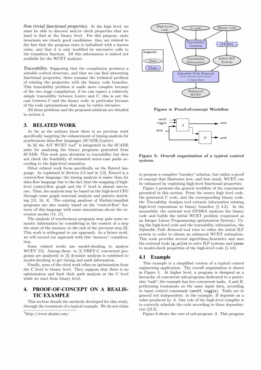
Figure 4: Proof-of-concept Workflow
data
A
B
onoff
outA
outB
toggle
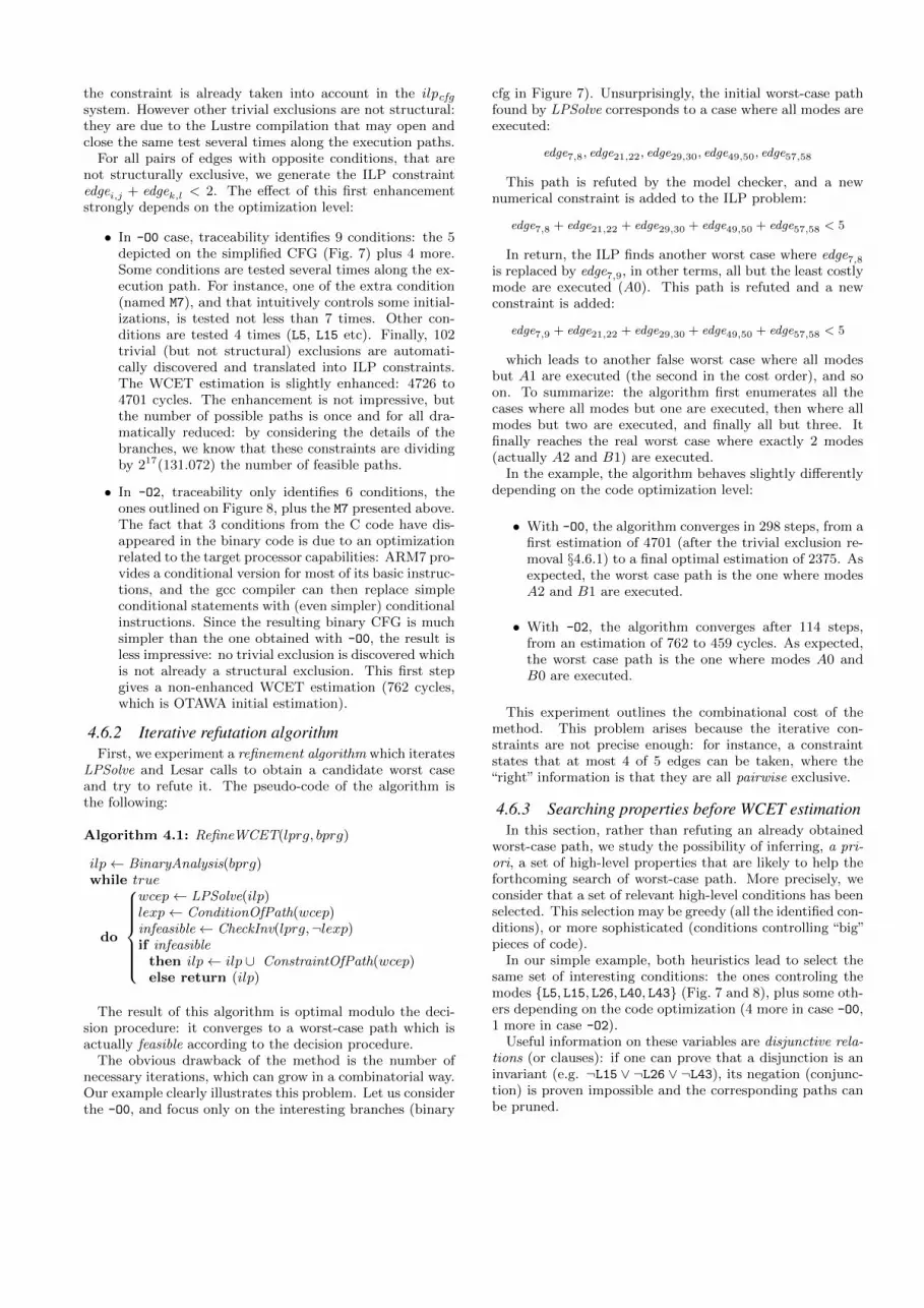
Figure 5: Overall organization of a typical controlsystem.
to propose a complete “turnkey” solution, but rather a proofof concept that illustrates how, and how much, WCET canbe enhanced by exploiting high-level functional properties.
Figure 4 presents the general workflow of the experimentpresented in this section. From the source high level code,the generated C code, and the corresponding binary code,the Traceability Analysis tool extracts information relatinghigh-level expressions to binary branches (§ 4.2). In themeanwhile, the external tool OTAWA analyses the binarycode and builds the initial WCET problem (expressed asan Integer Linear Programming optimization System). Us-ing the high-level code and the traceability information, theInfeasible Path Removal tool tries to refine the initial ILPsystem in order to obtain an enhanced WCET estimation.This tools provides several algorithms/heuristics and usesthe external tools lp_solve to solve ILP systems and Lesar
to model-check properties of the high-level code (§ 4.6).
4.1 ExampleThis example is a simplified version of a typical control
engineering application. The overall organisation is shownin Figure 5. At higher level, a program is designed as ahierarchy of concurrent sub-programs dedicated to a partic-ular “task”; the example has two concurrent tasks, A and B,performing treatments on the same input data, accordingto input control commands (onoff, toggle). Tasks are ingeneral not independent: in the example, B depends on avalue produced by A. One role of the high-level compiler isto correctly schedule the code according to these dependen-cies (§2.2).
Figure 6 shows the core of sub-program A. This program

high
low
idle
data out
A0
A1
A2
control
onoff
toggle
high
low
idle
Figure 6: Submodule A behaves according to 3 op-erating modes.
performs several treatments on its input data according toseveral operating modes. The data part is kept abstracted,but we gave meaningful names to the control part in orderto make their role clearer. The small arrow on the top of ablock behaves as a clock-enable: the block is activated (i.e.,executed) if and only if the clock is true. In the example,idle (resp. low and high), enables the computation of A0(resp. A1 and A2). The clocks are themselves computed bya control logic, according to the input commands onoff andtoggle. We don’t detail the code corresponding to control,but roughly, the command onoff switches between idle ornot, and, when not idle, toggle switches between low andhigh mode. What is really important for the sequel, is thatthe controller satisfies the following high-level requirement:if the inputs onoff and toggle are assumed exclusive, thenthe program guarantees that idle, low and high are also(pairwise) exclusive.
Sub-program B is similar to A except that it has only twooperating modes: when nom (nominal mode) it computes thefunction B0, and when degr (degraded mode) it computesB1. The control logic is also simple: the mode switches fromnominal to degraded (and conversely), whenever the inputcommand onoff is activated. This last point is importantsince it introduces a high-level property relating the modesof A and the modes of B: B must be in mode degr wheneverA is not in mode idle.
Finally, this example, while relatively simple, is a goodcandidate for experimenting since it satisfies high-level prop-erties that are likely to enhance the WCET estimation:
• whatever be the details of the compilation (from Lus-tre to C, and C to binary), high-level control vari-ables (clock-enables) will certainly be implemented bymeans of conditional statements,
• high-level relations between clock-enables (exclusivity)are likely to make some execution paths infeasible, andthen, the WCET estimation should be enhanced.
For this experiment, the example has been developed inLustre, in order to use the associated tool chain, mainly theLustre to C compiler lus2c6 and the Lustre model-checkerLesar[12].
6http://www-verimag.imag.fr/The-Lustre-Toolbox.html
Before considering the whole program, we analyse theWCET of the different modes, in order to foresee which com-bination of modes is likely to be the most costly. It appearsthat the cost of the combinations (A2 +B1) and (A0 +B0)are both very close, and much higher than any other possi-ble combination. Thus, the worst case is expected for oneof these cases.
The first problem (relating high-level variables to binarybranches) is addressed as the traceability problem in thefollowing. When binary branches are related to high-levelvariables, the next step consists in developing an automatedmethod for enhancing the WCET estimation (§ 4.6).
4.2 TraceabilityFor this experiment, we use a state of the art C compiler,
arm-elf-gcc 4.4.2, a widely used cross compiler for theARM7 platform.
First of all, we have to define precisely what the traceabil-ity problem is: for a given edge in the binary control flowgraph (e.g., basic block i to basic block j, noted edgei,j),find, if possible, a Boolean Lustre expression (e.g. toggle
and not onoff), such that the binary branch is taken iff theLustre expression is true. We have developed a prototypetool to solve this problem, for which we only present here hemain principles. Because of the two-stages compilation, theproblem requires to trace information at two levels: fromLustre to C, and then C to binary.
From Lustre to C. This problem is easily solved since wecontrol the development of the lus2c compiler. The com-piler has been adapted in such a way that all if statementsin the generated C code get the form if(Lk) where Lk is alocal C variable; moreover, a pragma is generated in orderto associate this variable to the source expression it comesfrom. We note E(Lk) this Lustre expression. The semanticsof such a pragma is: the value of the C variable at this partic-ular point of the C program is exactly the value of the Lus-tre expression. For a sake of simplicity, we no longer makea difference between the C variable and the correspondingexpression: we talk about the Lustre condition controllingthe C statement.
From C to binary. The problem, while mainly technical,can hardly been addressed here in a completely satisfactoryway: patching the gcc compiler to exactly add the informa-tion we need would require an amount of work which is outof the scope of this academic study. We have then chosen torely on the existing debugging features to relate binary codeto the C code. Indeed, code optimization may dramaticallyobfuscate the C control structure within the binary. Theretained solution is then not complete but safe: whenever abinary choice can be related, via the debugging information,to a corresponding if statement in the C code, we keep thisinformation. Otherwise the choice is simply ignored. Whilenaive, this solution resists to relatively intrusive optimiza-tions performed by gcc on the control structure.
4.2.1 Traceability without optimizationWithout optimization (-O0 option of gcc), as expected,
the binary control flow graph strictly maps the C controlflow graph.
Figure 7 shows the C CFG (left) and the binary CFG(right) of the example. Both graphs have been simplified

C code binary code
Figure 7: CFG traceability with -O0
in order to outline parts of interest (the actual graphs havemore than 70 nodes). Only the branches concerning thecalls of interest (A0, A1, etc) are depicted. Unsurprisingly,a one-to-one correspondence is automatically found by ourtool, based on the gcc debugging information.
4.2.2 Traceability with optimizationUsing optimizations raises problems in critical domains
submitted to certification process. For instance in avionics,the highest safety levels of the DO-178B document7 spec-ify that traceability is mandatory from requirements to allsource or executable code. Discussing whether some opti-mization is reasonable in critical domains is out of scopeof this paper: we only aim at experimenting how optimiza-tions may affect traceability, and thus, be an obstacle forenhancing WCET estimation.
Figure 8 shows the C CFG and the binary CFG obtainedwith gcc -O2. The most remarkable effect of the optimiza-tion concerns the first part (computation of A): the sourcesequence of 3 conditionals is implemented by a structureof interleaved jumps. In this graph, some branches of bi-nary code get no debugging information at all and thus,cannot be related to the source code (BB1 and BB10). Con-versely some source tests have been duplicated in the targetcode (e.g. BB4 and BB5 are attached to the same sourcetest). The goal of this kind of transformation is to give pri-ority (in average) to program-counter increment (sequence)over costly program-counter jump. Even relatively intrusive,
7http://www.rtca.org/store list.asp
C code binary code
Figure 8: CFG traceability with -O2
this transformation does not affect traceability: the binarychoice is related to its source C condition, but, indeed, sev-eral branches may refer to the same source.
4.3 From paths to predicatesAt this point, we suppose that traceability analysis has
been achieved. The result is a partial function from CFGedges to C literals (either Lk or not Lk), and then, to thecorresponding Lustre conditions (either E(Lk) or ¬E(Lk)).
We note condi,j the Lustre condition corresponding toedgei,j (if it exists). Note that if edgei,j and edgei,k are thetwo edges of a binary choice, if condi,j exists, then condi,k
exists too, and condi,j = ¬condi,k. Here are, for instance,some of the 16 traceability “facts” found on the optimizedcode of the example (see Figure 8):
cond4,7 = cond5,7 = E(L5)
cond4,6 = cond5,6 = ¬E(L5)
· · ·cond16,20 = E(L43)
cond16,19 = ¬E(L43)In the sequel, for the sake of simplicity, we extend the
traceability function by assigning the condition“true”to anyedge that is not related to a Lustre condition. For instance,in the example: condentry,1 = cond1,4 = cond1,5 = · · · =true.
4.4 Checking paths feasibilityA path (or more generally a set of paths) in the CFG
can be described by a set of edges. Consider the bi-nary CFG in the case -O2 (Fig. 8); the set of edges

{edge1,4, edge4,7, edge8,12} corresponds to the set of pathsthat passes by those 3 edges. In particular, for this set ofpaths, basic blocks 7 (A0) and 12 (A1) are both executed.For such a set {edgeik,jk}, one can build a Lustre logical ex-pression expressing the feasibility of the paths:
∧k condik,jk .
The idea is then to check whether this Boolean expres-sion is satisfiable according to the knowledge we have onthe program. In some cases the answer is trivial: when theexpression syntactically contains both a condition Lk andits negation ¬Lk, the corresponding edges are trivially ex-clusive. Some of these trivial exclusions are already takeninto account as structural constraints: this is obviously thecase for conditions guarding the two outcoming branches ofa same node (e.g. edgei,j and edgei,k). However, this is notalways the case: in the C code, the same condition may betested several times along the control graph, in which casethe logical exclusion is not “hard-coded” in the structure.
When infeasibility is not trivial, it is necessary to usea decision tool. More precisely, we build the predicateinfeasible = ¬(
∧k condik,jk ), and ask the model-checker
(Lesar) to prove that infeasible is an invariant of the pro-gram. The model-checker (just like any another automaticdesision tool) is partial; it may answer:
“yes”: in which case we know that infeasible remains truefor any execution of the program, and, thus the correspond-ing paths can be pruned out.
“inconclusive”: in which case infeasible may or may notbe an invariant.
In the example, the model-checker answers “yes” for theinfeasibility predicate ¬(cond4,7 ∧ cond8,12). As expectedfrom the program specification, it means that blocks 7 (callof A0) and 12 (call of A1) are never both executed.
One of the main argument for the proposed method is thatsuch property is almost impossible to discover at the binaryor C level: this is a relatively complex consequence of bothassumptions on inputs and dynamics of the underlying statemachine:
• inputs onoff and toggle are assumed exclusive,
• idle and low are initially exclusive (resp. true andfalse),
• whatever be an execution of the program satisfying theassumption, the computation of idle and low ensuresthat they remain exclusive in any reachable state.
The model-checker also covers simpler static logical prop-erties, for instance:
¬((X ⇒ Y ) ∧X ∧ ¬Y ),and even simple numerical properties8:
¬((X > 5) ∧ (3X ≤ 14))
4.5 From infeasibility to linear constraintsIn this case study, we limit the use of the discovered prop-
erties to the pruning of infeasible paths in the last stage ofthe WCET estimation, that is, at the ILP level. For ILPsolving, we use the tool lp_solve9.
Suppose that we have proved ¬(∧
k condik,jk ); it meansthat there exists no path passing by all the correspondingedges {edgeik,jk}.8More precisely, Lesar is equipped with a numerical solverthat handles Linear Algebra Theory.9http://lpsolve.sourceforge.net/
In the ILP system, each edge is associated to a numer-ical variable representing the number of times the edge istraversed during an execution; the same notation edgeik,jkis used for these numerical variables (context avoids mis-leading). This section presents how to translate the logicalexpression into a numerical constraint.
In the general case (programs with loops), translating theexclusivity of a set of edges {edgeik,jk} requires an extra in-formation: a structural max of the set. Intuitively, a struc-tural max is an upper bound of the number of executionsthat pass through at least one of the edges. Given suchstructural max µ, the exclusivity property can be translatedinto a numerical constraint:∑n
k=1 edgeik,jk < n× µ
The smallest is the bound, the most precise is the constraint.In the case of loop-free programs (which is the case for ourexample and, more generally, for any transition function notusing arrays), 1 is a structural max for any set of edges. Fora set of n edges, the ILP constraint is:∑n
k=1 edgeik,jk < n
For instance, the proven invariant ¬(cond4,7 ∧ cond8,12) istranslated into:
edge4,7 + edge8,12 < 2
4.6 Algorithms and strategiesWe have seen so far: how to use a model-checker to check
infeasibility properties, and how to translate such propertiesinto numerical constraints for the ILP solver. The problemis now to define a complete algorithm for the WCET esti-mation, that decides which properties to check and when tocheck them.
In the sequel, we use the following notations:
• “BinaryAnalysis(bprg)→ ilpcfg” is the abstraction forthe main OTAWA procedure that analyses a binaryprogram and returns a whole initial integer linear pro-gram (i.e., linear constraints + objective function), alinear constraint is noted ilc,
• CheckInv(lprg, lexp) → yes/no represents the call ofthe Lesar model-checker; it takes a Lustre program anda Lustre predicate, and returns yes if the predicate isa proven invariant of the program, no otherwise,
• LPSolve(ilp) → wcep represents the call of the ILPsolver; it returns the worst-case execution path,
• ConditionOfPath(wcep)→ lexp is the procedure thattraces back a binary path to the corresponding con-junction of Lustre literals, as explained in Section 4.4,
• ConstraintOfPath(wcep) → ilc is the procedure thattakes a binary path and produces the integer linearconstraint that will be used to state the infeasibility ofthe path, as explained in 4.5.
4.6.1 Removing trivial exclusionsA first step, which is almost free once the traceability step
has been done, consists in taking into account trivial exclu-sions of the form Ln and ¬Ln. As explained in Section 4.4,some of these trivial exclusions are also structural, and thus
the constraint is already taken into account in the ilpcfgsystem. However other trivial exclusions are not structural:they are due to the Lustre compilation that may open andclose the same test several times along the execution paths.
For all pairs of edges with opposite conditions, that arenot structurally exclusive, we generate the ILP constraintedgei,j + edgek,l < 2. The effect of this first enhancementstrongly depends on the optimization level:
• In -O0 case, traceability identifies 9 conditions: the 5depicted on the simplified CFG (Fig. 7) plus 4 more.Some conditions are tested several times along the ex-ecution path. For instance, one of the extra condition(named M7), and that intuitively controls some initial-izations, is tested not less than 7 times. Other con-ditions are tested 4 times (L5, L15 etc). Finally, 102trivial (but not structural) exclusions are automati-cally discovered and translated into ILP constraints.The WCET estimation is slightly enhanced: 4726 to4701 cycles. The enhancement is not impressive, butthe number of possible paths is once and for all dra-matically reduced: by considering the details of thebranches, we know that these constraints are dividingby 217(131.072) the number of feasible paths.
• In -O2, traceability only identifies 6 conditions, theones outlined on Figure 8, plus the M7 presented above.The fact that 3 conditions from the C code have dis-appeared in the binary code is due to an optimizationrelated to the target processor capabilities: ARM7 pro-vides a conditional version for most of its basic instruc-tions, and the gcc compiler can then replace simpleconditional statements with (even simpler) conditionalinstructions. Since the resulting binary CFG is muchsimpler than the one obtained with -O0, the result isless impressive: no trivial exclusion is discovered whichis not already a structural exclusion. This first stepgives a non-enhanced WCET estimation (762 cycles,which is OTAWA initial estimation).
4.6.2 Iterative refutation algorithmFirst, we experiment a refinement algorithm which iterates
LPSolve and Lesar calls to obtain a candidate worst caseand try to refute it. The pseudo-code of the algorithm isthe following:
Algorithm 4.1: RefineWCET(lprg, bprg)
ilp← BinaryAnalysis(bprg)while true
do
wcep← LPSolve(ilp)lexp← ConditionOfPath(wcep)infeasible← CheckInv(lprg,¬lexp)if infeasible
then ilp← ilp ∪ ConstraintOfPath(wcep)else return (ilp)
The result of this algorithm is optimal modulo the deci-sion procedure: it converges to a worst-case path which isactually feasible according to the decision procedure.
The obvious drawback of the method is the number ofnecessary iterations, which can grow in a combinatorial way.Our example clearly illustrates this problem. Let us considerthe -O0, and focus only on the interesting branches (binary
cfg in Figure 7). Unsurprisingly, the initial worst-case pathfound by LPSolve corresponds to a case where all modes areexecuted:
edge7,8, edge21,22, edge29,30, edge49,50, edge57,58
This path is refuted by the model checker, and a newnumerical constraint is added to the ILP problem:
edge7,8 + edge21,22 + edge29,30 + edge49,50 + edge57,58 < 5
In return, the ILP finds another worst case where edge7,8is replaced by edge7,9, in other terms, all but the least costlymode are executed (A0). This path is refuted and a newconstraint is added:
edge7,9 + edge21,22 + edge29,30 + edge49,50 + edge57,58 < 5
which leads to another false worst case where all modesbut A1 are executed (the second in the cost order), and soon. To summarize: the algorithm first enumerates all thecases where all modes but one are executed, then where allmodes but two are executed, and finally all but three. Itfinally reaches the real worst case where exactly 2 modes(actually A2 and B1) are executed.
In the example, the algorithm behaves slightly differentlydepending on the code optimization level:
• With -O0, the algorithm converges in 298 steps, from afirst estimation of 4701 (after the trivial exclusion re-moval §4.6.1) to a final optimal estimation of 2375. Asexpected, the worst case path is the one where modesA2 and B1 are executed.
• With -O2, the algorithm converges after 114 steps,from an estimation of 762 to 459 cycles. As expected,the worst case path is the one where modes A0 andB0 are executed.
This experiment outlines the combinational cost of themethod. This problem arises because the iterative con-straints are not precise enough: for instance, a constraintstates that at most 4 of 5 edges can be taken, where the“right” information is that they are all pairwise exclusive.
4.6.3 Searching properties before WCET estimationIn this section, rather than refuting an already obtained
worst-case path, we study the possibility of inferring, a pri-ori, a set of high-level properties that are likely to help theforthcoming search of worst-case path. More precisely, weconsider that a set of relevant high-level conditions has beenselected. This selection may be greedy (all the identified con-ditions), or more sophisticated (conditions controlling “big”pieces of code).
In our simple example, both heuristics lead to select thesame set of interesting conditions: the ones controling themodes {L5, L15, L26, L40, L43} (Fig. 7 and 8), plus some oth-ers depending on the code optimization (4 more in case -O0,1 more in case -O2).
Useful information on these variables are disjunctive rela-tions (or clauses): if one can prove that a disjunction is aninvariant (e.g. ¬L15 ∨ ¬L26 ∨ ¬L43), its negation (conjunc-tion) is proven impossible and the corresponding paths canbe pruned.

A virtual complete method. Using a model checker, it istheoretically possible to find an “optimal set of invariantclauses” over a set of conditions Lk (optimality is relativeto the decision procedure capabilities). The sketch of thealgorithm is the following:
• let lprg be the considered Lustre program, and s be itsstate variables; a model-checker can compute a formulaReach(s) denoting a superset of the reachable states ofthe program; in some cases (e.g. finite-state programs)the formula is exact, but in general (e.g. numericalvalues) the formula is a strict over-approximation;
• let Lk be the conditions of interest, and ek(s) = E(Lk)the corresponding Lustre expressions; these expres-sions are functions of the program state variables;
• consider the following formula over the state variablesand the conditions:
Reach(s)∧
k∈K(Lk = ek(s))
Quantifying existentially the state variables projectsthe formula on the Lk variables only, giving the set ofall possible configurations for the Lk variables:
Φ(Lk) = ∃s · Reach(s)∧
k∈K(Lk = ek(s))
• formula Φ(Lk) can be written in conjunctive normalform (i.e conjunction of clauses):
φ(Lk) =∧
i∈I Di(Lk)
involving a minimal number of minimal clauses (this isthe dual problem of finding a minimal prime implicantscover for disjunctive normal forms);
• each minimal clause can be translated into a minimalinfeasibility constraint as explained in Section 4.5.
This algorithm combines several well-known intractableproblems (reachability analysis, minimal clause cover) andremains largely virtual.
A pragmatic pairwise approach. We now focus on non-complete methods that may/may not find relevant rela-tions. From a pragmatic point of view, two-variable clauses(i.e., pairwise disjunctive relations) are good candidates: thenumber of pairs remains relatively reasonable (quadratic),and their analysis is likely to remain reasonable (since theyonly involve a small portion of the full program).
We detail the algorithm on the example, in the case -O2
(cf. Fig. 8). All the conditions identified by the traceabil-ity process are selected: the 5 emphasized in Fig. 8 (L5,L15, L26, L40, L43), plus an extra one, M7. Intuitively, thisvariable controls initializations; it has a strong influence onfunctionality, but not on the WCET. We build and check allthe possible pairwise disjunctive relations between these 6conditions, that is, 4× (6× 5)/2 = 60 predicates. The proofsucceeds for 14 relations, that reflect most of the propertieswe know from the program specification: exclusion betweenB0 and B1, pairwise exclusion for A0, A1 and A2, exclusionbetween B0 and either A1 and A2.
One property of the program is not reflected: the fact thatat least one of the modes A0, A1, A2 is executed. This prop-erty is induced by a 3-variable disjunction, and thus, cannot
be discovered by the method. However, this information isuseless, since the worst case certainly not occurs when noneof the modes are executed.
Another exclusion is discovered: ¬M7 ∨ ¬L26. Intuitively,this property means that mode A2 cannot be executed atthe very first reaction. This is an unexpected consequenceof the specifications10, which may have some influence onthe worst-case path.
Finally, the 14 properties are translated into 114 ILP con-straints (remember that the same condition may control sev-eral branches). With this additional constraints, lp_solvedirectly gives the same worst-case path and time obtainedwith the iterative algorithm. To summarize, this somehowbrute-force method gives the same result with only 60 rel-atively cheap calls to Lesar, and a single call to LPSolve,where the a priori smarter refutation method requires 114relatively costly calls to the model-checker and as many callsto LPSolve.
In case -O0, 9 atomic conditions are identified, leading to144 binary disjunctions to check; 21 are proven invariant byLesar, and translated into 396 ILP constraints. The finalestimation is 2376, which misses the optimal one for 1 cycle.The path obtained is still not feasible: this is the drawbackof the method which only consider pairwise properties andmay miss more complex relations. However, if and whenoptimality is the goal, the algorithm can be completed withone (or more) steps of the iterative method.
4.7 Results and discussionTable 1 gives some quantitative results on the experiment.
Each line corresponds to an algorithm (complete iterativemethod, or pairwise exclusion method) and an optimizationlevel of gcc.
The first 3 columns detail the WCET estimation (in cpucycles): the initial estimation is performed without any ad-ditional information (initial OTAWA WCET), the first (en-hanced) one is obtained by exploiting the trivial (syntac-tic) exclusions (§ 4.6.1), and the final estimation is obtainedby exploiting all the information, including those comingfrom Lesar. For the 3 main tools involved in the method,Lesar, lp solve and OTAWA, we give the number of nec-essary calls and their cost (total computation time). Notethat OTAWA is called once in any case (not given in thetable), and that the number of lp solve calls is always thenumber of Lesar calls plus 2 (initial and first estimations).A column describing the complexity of ILP constraints isalso given in order to better understand the influence of themethods on the ILP solver. For each case, we distinguish3 sets of constraints, for which we give both their numberand their arity (maximal number of variable appearing in aconstraint): structural constraints describe the binary CFG,they are produced once for all by OTAWA and only dependon the optimization level. Trivial constraints are those thatreflect simple exclusions and also depend only on the opti-mization level. At last, invariant constraints are those thatcome from the invariant properties checked by Lesar.
We can reasonably conclude, by comparing the cases -O2
and -O0, that the iterative algorithm is unlikely to scaleup for bigger codes. From the -O2 code to the -O0 code,the size grows roughly 3 times; in the same time, both thenumber of iterations and the total cost of Lesar seem to
10Since we assume that inputs are exclusives, it takes at leasttwo reactions to reach this particular mode.

Algo/optim Wcet estimation Lesar ILP Constraints LPSolve OTAWA Totalinitial first final calls cost struct. triv. inv. calls cost cost cost
iter./-O0 4726 4701 2375 298 2.8s 178 (2) 102 (2) 298 (30) 300 90s 64s 163siter/-O2 762 762 459 114 0.7s 60 (3) 6 (2) 114 (6) 116 1.5s 1s 4.5spair./-O0 4726 4701 2376 144 1.4s 178 (2) 102 (2) 396 (2) 3 0.1s 64s 67spair./-O2 762 762 459 60 0.6s 60 (3) 6 (2) 47 (2) 3 0.1s 1s 2.3s
Table 1: Experiment: quantitative results
grow linearly (factor between 2 and 3), but the total costof LPSolve dramatically explode (multiplied by 60). Morethan the increasing number of constraints, the increasingof their complexity explains this explosion (298 constraints,each involving 30 variables).
On the contrary, the pairwise exclusion method behaves ina very promising way: when considering only the overheaddue to our method, and not the cost of OTAWA, the costseems to grow linearly.
5. CONCLUSIONIn this paper, we introduced a method to improve timing
analysis of programs generated from high-level synchronousdesign. The main idea is to take benefit from semantic infor-mation that are known at the design level and may be lostby the compilation steps. For that purpose, we use existingverification tools that work on Lustre programs to check thefeasibility of paths. Furthermore, our approach may workon optimised code (from C to binary). We introduced theapproach on a realistic example and showed that there isa huge possible improvement, with a reasonable overheadcompared to the (unavoidable) cost of the binary code andarchitecture analyses.
As future work, we would like to extend our approach toother languages with a reacher set of high-level constructs(e.g. Scade V6), and to other code generators (e.g., Com-pcert11). The long term aim is to study the possibility of acomplete WCET-aware compilation chain.
6. REFERENCES[1] S. Andalam, P. Roop, and A. Girault. Pruning
Infeasible Paths for Tight WCRT Analysis ofSynchronous Programs. In DATE, 2011.
[2] M. Asavoae, C. Maiza, and P. Raymond. Programsemantics in model-based wcet analysis: A state of theart perspective. In WCET, pages 31–40, 2013.
[3] J.-L. Bechennec and F. Cassez. Computation of wcetusing program slicing and real-time model-checking.CoRR, abs/1105.1633, 2011.
[4] M. Boldt, C. Traulsen, and R. von Hanxleden. Worstcase reaction time analysis of concurrent reactiveprograms. ENTCS, 203(4):65–79, June 2008.
[5] P. Caspi, P. Raymond, and S. Tripakis. Synchronousprogramming. In I. Lee, J. Y.-T. Leung, and S. H.Son, editors, Handbook of Real-Time amd EmbeddedSystems, chapter 14. Chapman and Hall/CRC, 2007.
[6] C. Ferdinand, R. Heckmann, T. L. Sergent, D. Lopes,B. Martin, X. Fornari, and F. Martin. Combining ahigh-level design tool for safety-critical systems with a
11http://compcert.inria.fr
tool for WCET analysis on executables. In ERTS2,2008.
[7] T. Gauthier, P. L. Guernic, and L. Besnard. Signal, adeclarative language for synchronous programming ofreal-time systems. In Proc. 3rd. Conf. on FunctionalProgramming Languages and Computer Architecture.LNCS 274, Springer Verlag, 1987.
[8] N. Halbwachs. Synchronous programming of reactivesystems. Kluwer Academic Pub., 1993.
[9] L. Ju, B. K. Huynh, S. Chakraborty, andA. Roychoudhury. Context-sensitive timing analysis ofesterel programs. In DAC, pages 870–873, 2009.
[10] L. Ju, B. K. Huynh, A. Roychoudhury, andS. Chakraborty. Performance debugging of esterelspecifications. In CODES-ISSS, 2008.
[11] R. Kirner, R. Lang, G. Freiberger, and P. Puschner.Fully automatic worst-case execution time analysis forMatlab/Simulink models. In ECRTS, 2002.
[12] P. Raymond. Synchronous program verification withlustre/lesar. In S. Mertz and N. Navet, editors,Modeling and Verification of Real-Time Systems,chapter 6. ISTE/Wiley, 2008.
[13] T. Ringler. Static worst-case execution time analysisof synchronous programs. In Ada-Europe, pages 56–68,2000.
[14] L. Tan, B. Wachter, P. Lucas, and R. Wilhelm.Improving timing analysis for MatlabSimulink/Stateflow. In ACES-MB, 2009.
[15] R. Wilhelm, J. Engblom, A. Ermedahl, N. Holsti,S. Thesing, D. Whalley, G. Bernat, C. Ferdinand,R. Heckmann, T. Mitra, F. Mueller, I. Puaut,P. Puschner, J. Staschulat, and P. Stenstrom. Theworst-case execution-time problem - overview ofmethods and survey of tools. ACM Trans. EmbeddedComput. Syst. (TECS), 7(3), 2008.