Three Dimensional Transient Multifield Analysis of a Piezoelectric Micropump for Drug Delivery...
16
ORIGINAL PAPER Three Dimensional Transient Multifield Analysis of a Piezoelectric Micropump for Drug Delivery System for Treatment of Hemodynamic Dysfunctions Asim Nisar Æ Nitin Afzulpurkar Æ Adisorn Tuantranont Æ Banchong Mahaisavariya Published online: 22 November 2008 Ó Springer Science+Business Media, LLC 2008 Abstract In this paper, we present design of a transder- mal drug delivery system for treatment of cardiovascular or hemodynamic disorders such as hypertension. The system comprises of integrated control electronics and micro- electromechanical system devices such as micropump, micro blood pressure sensor and microneedle array. The objective is to overcome the limitations of oral therapy such as variable absorption profile and the need for fre- quent dosing, by fabricating a safe, reliable and cost effective transdermal drug delivery system to dispense various pharmacological agents through the skin for treat- ment of hemodynamic dysfunction such as hypertension. Moreover, design optimization of a piezoelectrically actu- ated valveless micropump is presented for the drug delivery system. Because of the complexity in analysis of piezoelectric micropump, which involves structural and fluid field couplings in a complicated geometrical arrangement, finite element (FE) numerical simulation rather than an analytical system has been used. The behavior of the piezoelectric actuator with biocompatible polydimethylsiloxane membrane is first studied by con- ducting piezoelectric analysis. Then the performance of the valveless micropump is analyzed by building a three dimensional electric-solid-fluid model of the micropump. The effect of geometrical dimensions on micropump characteristics and efficiency of nozzle/diffuser elements of a valveless micropump is investigated in the transient analysis using multiple code coupling method. The defor- mation results of the membrane using multifield code coupling analysis are in good agreement with analytical as well as results of single code coupling analysis of a pie- zoelectric micropump. The analysis predicts that to enhance the performance of the micropump, diffuser geo- metrical dimensions such as diffuser length, diffuser neck width and diffuser angle need to be optimized. Micropump flow rate is not strongly affected at low excitation fre- quencies from 10 to 200 Hz. The excitation voltage is the more dominant factor that affects the flow rate of the mi- cropump as compared with the excitation frequency. However, at extremely high excitation frequencies beyond 8,000 Hz, the flow rate drops as the membrane exhibits multiple bending peaks which is not desirable for fluid flow. Following the extensive numerical analysis, actual fabrication and performance characterization of the micropump is presented. The performance of the micro- pump is characterized in terms of piezoelectric actuator deflection and micropump flow rate at different operational parameters. The set of multifield simulations and experi- mental measurement of deflection and flow rate at varying voltage and excitation frequency is a significant advance in the study of the electric-solid-fluid coupled field effects as it allows transient, three dimensional piezoelectric and fluid analysis of the micropump thereby facilitating a more realistic multifield analysis. The results of the present study will also help to conduct relevant strength duration tests of integrated drug delivery device with micropump and microneedle array in future. A. Nisar (&) N. Afzulpurkar School of Engineering and Technology, Asian Institute of Technology (AIT), Pathum Thani, Thailand e-mail: [email protected] A. Tuantranont Nanoelectronics and MEMS Lab, National Electronics and Computer Technology Center, Bangkok, Thailand B. Mahaisavariya Siriraj Hospital, Faculty of Graduate Studies, Mahidol University, Nakhon Pathom, Thailand 123 Cardiovasc Eng (2008) 8:203–218 DOI 10.1007/s10558-008-9060-1
Transcript of Three Dimensional Transient Multifield Analysis of a Piezoelectric Micropump for Drug Delivery...

ORIGINAL PAPER
Three Dimensional Transient Multifield Analysis of a Piezoelectric
Micropump for Drug Delivery System for Treatment
of Hemodynamic Dysfunctions
Asim Nisar Æ Nitin Afzulpurkar Æ Adisorn Tuantranont Æ
Banchong Mahaisavariya
Published online: 22 November 2008
� Springer Science+Business Media, LLC 2008
Abstract In this paper, we present design of a transder-
mal drug delivery system for treatment of cardiovascular or
hemodynamic disorders such as hypertension. The system
comprises of integrated control electronics and micro-
electromechanical system devices such as micropump,
micro blood pressure sensor and microneedle array. The
objective is to overcome the limitations of oral therapy
such as variable absorption profile and the need for fre-
quent dosing, by fabricating a safe, reliable and cost
effective transdermal drug delivery system to dispense
various pharmacological agents through the skin for treat-
ment of hemodynamic dysfunction such as hypertension.
Moreover, design optimization of a piezoelectrically actu-
ated valveless micropump is presented for the drug
delivery system. Because of the complexity in analysis of
piezoelectric micropump, which involves structural and
fluid field couplings in a complicated geometrical
arrangement, finite element (FE) numerical simulation
rather than an analytical system has been used. The
behavior of the piezoelectric actuator with biocompatible
polydimethylsiloxane membrane is first studied by con-
ducting piezoelectric analysis. Then the performance of the
valveless micropump is analyzed by building a three
dimensional electric-solid-fluid model of the micropump.
The effect of geometrical dimensions on micropump
characteristics and efficiency of nozzle/diffuser elements of
a valveless micropump is investigated in the transient
analysis using multiple code coupling method. The defor-
mation results of the membrane using multifield code
coupling analysis are in good agreement with analytical as
well as results of single code coupling analysis of a pie-
zoelectric micropump. The analysis predicts that to
enhance the performance of the micropump, diffuser geo-
metrical dimensions such as diffuser length, diffuser neck
width and diffuser angle need to be optimized. Micropump
flow rate is not strongly affected at low excitation fre-
quencies from 10 to 200 Hz. The excitation voltage is the
more dominant factor that affects the flow rate of the mi-
cropump as compared with the excitation frequency.
However, at extremely high excitation frequencies beyond
8,000 Hz, the flow rate drops as the membrane exhibits
multiple bending peaks which is not desirable for fluid
flow. Following the extensive numerical analysis, actual
fabrication and performance characterization of the
micropump is presented. The performance of the micro-
pump is characterized in terms of piezoelectric actuator
deflection and micropump flow rate at different operational
parameters. The set of multifield simulations and experi-
mental measurement of deflection and flow rate at varying
voltage and excitation frequency is a significant advance in
the study of the electric-solid-fluid coupled field effects as
it allows transient, three dimensional piezoelectric and
fluid analysis of the micropump thereby facilitating a more
realistic multifield analysis. The results of the present study
will also help to conduct relevant strength duration tests of
integrated drug delivery device with micropump and
microneedle array in future.
A. Nisar (&) � N. AfzulpurkarSchool of Engineering and Technology, Asian Institute
of Technology (AIT), Pathum Thani, Thailand
e-mail: [email protected]
A. Tuantranont
Nanoelectronics and MEMS Lab, National Electronics
and Computer Technology Center, Bangkok, Thailand
B. Mahaisavariya
Siriraj Hospital, Faculty of Graduate Studies, Mahidol
University, Nakhon Pathom, Thailand
123
Cardiovasc Eng (2008) 8:203–218
DOI 10.1007/s10558-008-9060-1
Keywords Cardiovascular � CFD � Drug delivery �MEMS � Multiple code coupling � PDMS � Piezoelectric �
Valveless micropump
Introduction
Drug delivery devices using Micro and Nano Electrome-
chanical Systems (MEMS or NEMS) technology are
increasingly being developed for drug delivery applications.
Conventional drug delivery methods such as oral tablets or
injections are not effective to deliver the drug effectively
within their therapeutic range. MEMS technologies have
made it possible to fabricate small size and high perfor-
mance biomedical devices to meet critical medical needs
such as site specific drug delivery, reduced side effects,
increased bioavailability and increased therapeutic effec-
tiveness. MEMS based drug delivery devices in general
include microneedles based transdermal devices, osmosis
based devices, micropump based devices, microreservoir
based devices and biodegradable MEMS devices. An inte-
grated transdermal drug delivery system (DDS) consists of a
drug reservoir, micropumps, valves, microsensors, micro-
channels, microneedles and necessary related circuits. The
major advantage of the MEMS based drug delivery system
is the ease of mass fabrication of small feature sizes at low
cost thereby making such systems desirable for commercial
applications. A typical micropump is a fundamental part of a
drug delivery system which provides the actuation source to
effectively transfer the accurate amount of fluid (drug) from
the drug reservoir to the body (tissue or blood vessel). A
number of micropump based drug delivery systems for
chemotherapy for cancer patients, insulin delivery for dia-
betic patients and so on have been developed (Nisar et al.
2008). However, the commercialization of micropumps
based drug delivery systems for biomedical application is
still in its beginning. Although a lot of technical information
is available for a number of design concepts for micropump
based drug delivery systems however, little focus has been
paid to design and analysis of the drug delivery systems.
Furthermore, many of the novel concepts of micropumps
reported in literature for drug delivery and other biomedical
applications still need to be incorporated into practical and
commercially viable devices.
Research and development on micropumps initially
started using microfabrication technology in 1980s and
shifted towards MEMS technologies in 1990s. Since then,
there is a growing trend to incorporate novel MEMS based
micropumps in micro drug delivery and other biomedical
systems. A comprehensive review of MEMS based mi-
cropumps and their biomedical application was presented
by the present authors in the previous study (Nisar et al.
2008). In general, micropumps can be classified as either
mechanical or non-mechanical micropumps (Tay 2002).
The micropumps that have moving mechanical parts such
as pumping diaphragm and check valves are referred to as
mechanical micropumps where as those involving no
mechanical moving parts are referred to as non-mechanical
micropumps.
In this work, we design a controlled drug delivery sys-
tem for treatment of cardiovascular or hemodynamic
disorders such as hypertension, etc. The conventional
devices or methods available for treatment of cardiovas-
cular or hemodynamic disorders such as hypertension have
the limitation of accurately controlling and monitoring the
release profile of the drug to be delivered to the patient.
Hence there is an emerging need for development of a
controlled drug delivery system for treatment of hyper-
tension and other cardiovascular or hemodynamic
disorders. The proposed drug delivery system will incor-
porate many MEMS devices such as micropump, channels,
microsensor, blood pressure sensors, etc. A piezoelectri-
cally actuated valveless micropump for the drug delivery
system is proposed. Valveless micropumps are able to
conduct particles and sensitive materials because of their
open flow structures. More over, the design and fabrication
is simple because of the absence of any moving mechanical
parts such as check valves or active valves.
The analysis of piezoelectric micropump is complex as
it involves electromechanical coupling of the piezoelectric
actuator and the fluid-solid coupling between the working
fluid and the micropump membrane. Piezoelectric actua-
tion in a valveless micropump generates transverse or
radial strains in the membrane attached to the piezoelectric
disc. As a result, the membrane expands and contracts and
the reciprocating motion of the piezoelectric actuator and
membrane drives the working fluid from inlet to the outlet.
The working fluid provides resistance to the reciprocating
motion of the pump membrane. Therefore, membrane
motion and fluid flow are coupled. As micropump design
and simulation involves complex multiphysics analysis
with various field couplings, many research studies have
been conducted to optimize piezoelectrically actuated
valveless micropump design. Mu et al. (1999) conducted
numerical studies for design optimization of a piezoelectric
micropump using silicon, aluminum and copper as mem-
brane materials for piezoelectric actuator. Cao et al. (2001)
used numerical modeling to predict deflection in silicon
membrane glued to the piezoelectric actuator with a
bonding layer for different actuator and membrane
dimensions. Wang et al. (2006) conducted modal analysis
of the piezoelectric actuator with brass membrane. Olsson
and Stemme (2000) utilized numerical modeling to conduct
pressure drop analysis of nozzle diffuser elements of single
and double chamber micropumps. Numerical modeling of
electromechanical fluid coupling in a valveless micropump
204 Cardiovasc Eng (2008) 8:203–218
123

has also been investigated by many researchers (Pan et al.
2001; Fan et al. 2005). Cui et al. (2006, 2007) conducted
coupled field design studies of valveless micropump to
characterize the behavior of piezoelectrically actuated
membrane made of silicon, silicon-di-oxide and steel.
However the coupled field simulations by Cui et al. (2007)
were conducted on two dimensional models of the micro-
pump using multifield single code coupling method. Li
et al. (2007) performed preliminary two dimensional
analysis of a valveless micropump with light weight
piezocomposite actuator using commercial finite element
analysis software COMSOL Multiphysics 3.2a.
Biocompatibility of MEMS based micropumps is
becoming increasingly important and is regarded as a key
requirement for drug delivery systems. Silicon as substrate
material has been used extensively as a good biocompatible
material. However in view of the increased use of MEMS
based micropumps in implantable drug delivery systems
and emphasis on lowering the manufacturing costs, silicon
is now being replaced with polymer based materials. The
use of polymer based materials is rapidly growing because
of their good biocompatibility, excellent physical and
mechanical properties, low cost and simple and fast fab-
rication. Most of the piezoelectric micropumps with
diffuser and nozzle elements previously presented have
been made with membrane made of silicon or other
materials (Wang et al. 2006; Cui et al. 2007). The present
study is motivated by the goal to make micropumps out of
biodegradable polymers such as polydimethylsiloxane
(PDMS) using mold-based fabrication methods that lend
themselves to inexpensive and robust mass production. In
this paper, an in-depth numerical analysis of the piezo-
electrically actuated valveless micropump is presented.
Because of the complexity of the process, which involves
various field couplings in a complicated geometrical
arrangement, finite element (FE) numerical simulation
using CoventorWare and ANSYS rather than an analytical
system has been used in multifield analysis. The simulation
involving modal and harmonic analysis is first conducted to
determine the natural frequencies of the actuator and
PDMS membrane assembly. Then transient multifield
analysis using multiple code coupling method is conducted
on three dimensional model of the micropump. The mul-
tiple code coupling method involves sequential simulations
consisting of piezoelectric analysis of piezoelectric actua-
tor and computation fluid dynamics (CFD) analysis of fluid
flow in a MEMS micropump. Therefore, multiple code
coupling method for multifield analysis can simulate more
physically complex and larger three dimensional models
than the single code coupling method used previously (Cui
et al. 2006, 2007). The effect of several critical design
parameters on micropump performance is investigated in
the transient electro-fluid-solid coupled field analysis.
Following the extensive numerical analysis, actual fabri-
cation and performance characterization of the micropump
is presented. The experimental measurements of piezo-
electric actuator deflection and micropump flow rates are
compared with numerically predicted results. The analysis
is helpful to predict the possible outcome of a variation in
critical design parameters of the valveless micropump, to
facilitate an optimized design before fabrication within the
constraints given by material properties and micro fabri-
cation limitations. The study will also provide a valuable
benchmark and prediction data to conduct strength duration
tests in future with integrated drug delivery device with
micropump and microneedle array.
Description of the Drug Delivery System
The aim of this project is to design a microfluidic drug
delivery device for medical application such as drug
delivery systems for treatment of cardiovascular disorders
such as hypertension, etc. The major components of our
system are drug reservoir, a flow control device such as a
micropump, monitoring devices such as blood pressure and
flow sensor and electronic control circuitry. The block
diagram of the drug delivery system is shown in Fig. 1. In
the proposed drug delivery system, microneedles provide
an interface between the drug delivery system and the
patients’ body for releasing the drug. The use of micro-
needles is advantageous by eliminating pain and
inconvenient intravenous injections. Micropump driven by
piezoelectric actuator is used to generate moderate pressure
and drive the drug into patients’ bodies. Another important
feature of the drug delivery system is to incorporate a
pressure sensor which provides information about the flow
Fig. 1 Block diagram of the drug delivery system
Cardiovasc Eng (2008) 8:203–218 205
123
rate and measures static and dynamic pressure appearing in
the system. Secondly, real time sensing of the released
volume is accomplished by the flow sensor to ensure the
safety of the patient. The blood pressure sensor in the
system monitors patient’s blood pressure. Based on the
result from the blood pressure sensor, the drug delivery
system automatically injects the desired drug dose through
microneedle arrays into the patient’s body. During the drug
delivery, the flow is monitored by the flow sensors to
prevent the large fluctuation of flow rate. Potential
advantages of the proposed new controlled drug delivery
system include reduced drug administration frequency,
stable drug concentrations, uniform drug effect, decreased
cost and decreased daily dosage.
Design and Fabrication of the Micropump
As mentioned above, a micropump is a key component of a
drug delivery system and its performance has a crucial
impact on the overall behavior of the drug delivery system.
In this section, we design and evaluate the performance of
the valveless micropump driven by piezoelectric actuator.
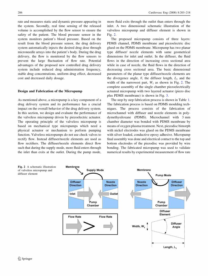
The operating principle of the valveless micropump is
based on mechanical type micropumps which need a
physical actuator or mechanism to perform pumping
function. Valveless micropumps do not use check valves to
rectify flow. Instead diffuser/nozzle elements are used as
flow rectifiers. The diffuser/nozzle elements direct flow
such that during the supply mode, more fluid enters through
the inlet than exits at the outlet. During the pump mode,
more fluid exits through the outlet than enters through the
inlet. A two dimensional schematic illustration of the
valveless micropump and diffuser element is shown in
Fig. 2.
The proposed micropump consists of three layers:
PDMS channel, PDMS membrane and piezoelectric disc
glued on the PDMS membrane. Micropump has two planar
type diffuser/ nozzle elements with same geometrical
dimensions for inlet and outlet. In the diffuser, the fluid
flows in the direction of increasing cross sectional area
while in case of nozzle, the fluid flows in the direction of
decreasing cross sectional area. The basic dimensional
parameters of the planar type diffuser/nozzle elements are
the divergence angle, h, the diffuser length, L1 and the
width of the narrowest part, W1 as shown in Fig. 2. The
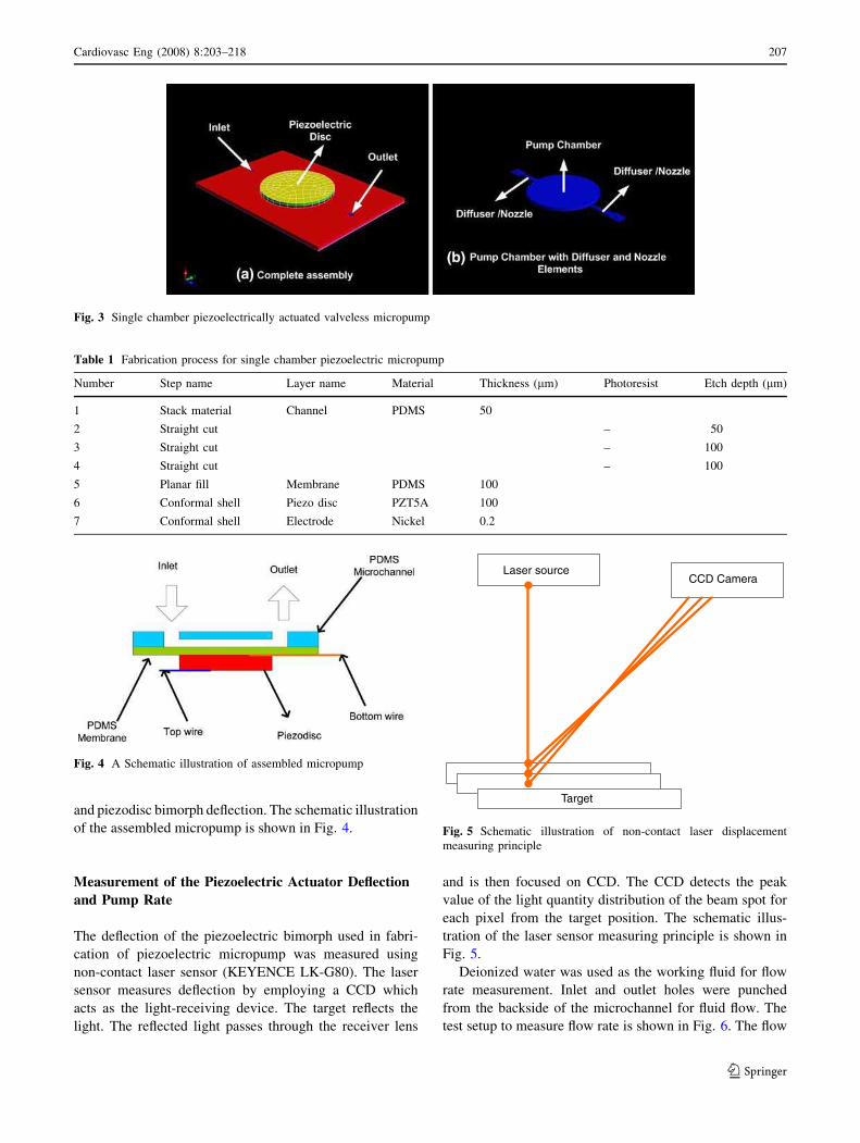
complete assembly of the single chamber piezoelectrically
actuated micropump with two layered actuator (piezo disc
plus PDMS membrane) is shown in Fig. 3.
The step by step fabrication process is shown in Table 1.
The fabrication process is based on PDMS moulding tech-
niques. The process consists of the fabrication of
microchannel with diffuser and nozzle elements in poly-
dymethysiloxane (PDMS). Microchannel with 3 mm
chamber diameter was bonded with PDMS membrane by
means of oxygen plasma treatment. Next, piezodisc bimorph
with nickel electrodes was glued on the PDMS membrane
with silver loaded, conductive epoxy adhesive. Micropump
final assembly was done and electrical contact to the top and
bottom electrodes of the piezodisc was provided by wire
bonding. The fabricated micropump was used to validate
numerical results by experimental measurement of flow rate
Fig. 2 A schematic illustration
of valveless micropump and
diffuser element
206 Cardiovasc Eng (2008) 8:203–218
123
and piezodisc bimorph deflection. The schematic illustration
of the assembled micropump is shown in Fig. 4.
Measurement of the Piezoelectric Actuator Deflection
and Pump Rate
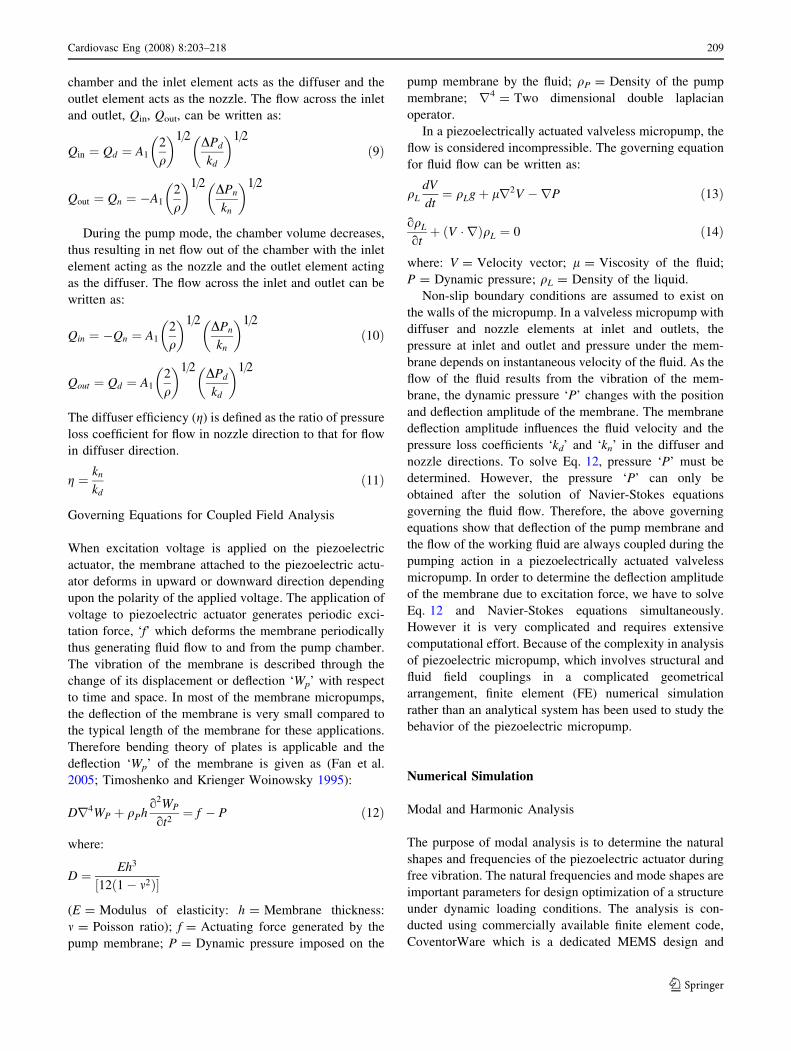
The deflection of the piezoelectric bimorph used in fabri-
cation of piezoelectric micropump was measured using
non-contact laser sensor (KEYENCE LK-G80). The laser
sensor measures deflection by employing a CCD which
acts as the light-receiving device. The target reflects the
light. The reflected light passes through the receiver lens
and is then focused on CCD. The CCD detects the peak
value of the light quantity distribution of the beam spot for
each pixel from the target position. The schematic illus-
tration of the laser sensor measuring principle is shown in
Fig. 5.
Deionized water was used as the working fluid for flow
rate measurement. Inlet and outlet holes were punched
from the backside of the microchannel for fluid flow. The
test setup to measure flow rate is shown in Fig. 6. The flow
Fig. 3 Single chamber piezoelectrically actuated valveless micropump
Table 1 Fabrication process for single chamber piezoelectric micropump
Number Step name Layer name Material Thickness (lm) Photoresist Etch depth (lm)
1 Stack material Channel PDMS 50
2 Straight cut – 50
3 Straight cut – 100
4 Straight cut – 100
5 Planar fill Membrane PDMS 100
6 Conformal shell Piezo disc PZT5A 100
7 Conformal shell Electrode Nickel 0.2
Fig. 4 A Schematic illustration of assembled micropump
Laser sourceCCD Camera
Target
Fig. 5 Schematic illustration of non-contact laser displacement
measuring principle
Cardiovasc Eng (2008) 8:203–218 207
123

rate was measured under the constant pressure difference
between the inlet and outlet. A sinusoidal voltage was
applied to the piezodisc and the flow rate was measured by
the fluid displacement variation of the outlet tube.
Theoretical Analysis
Piezoelectric Analysis
Piezoelectric analysis involves coupling of structural and
electric fields. When a voltage is applied to the piezo-
electric material, the piezoelectric material exhibits
deformation and conversely a vibrating piezoelectric
material generates voltage. The matrix form of the simul-
taneous full coupling applicable to piezoelectric actuators
is:
K11½ � K12½ �K21½ � K22½ �
� �
X1f gX2f g
� �
¼F1f gF2f g
� �
ð1Þ
where [Kij]; i, j = 1, 2 are the stiffness submatrices; [Fi];
i = 1, 2 are force vectors; [Xi]; i = 1, 2 are two types of
degrees of freedom.
The off-diagonal submatrices [K12] and [K21] account
for the coupling effect. The equations of elasticity are
coupled to the charge equation of electrostatics by means
of piezoelectric constants in linear piezoelectric analysis
ANSI/IEEE Std 176 (1987):
T½ �
D½ �
( )
¼c½ �E e½ �
e½ �T e½ �
" #
S½ �
�E½ �
( )
ð2Þ
where [T] = Stress vector; [D] = Electric flux density
vector; [S] = Strain vector; [E] = Electric field vector;
[c]E = Elasticity matrix evaluated at constant electric field;
[e] = Piezoelectric stress matrix; [e]S = Dielectric Matrix
at constant strain.
Diffuser Efficiency
Performance of the valveless micropump depends upon
characteristics of the diffuser/nozzle elements (Singhal
et al. 2004). Micropump net flow rate through diffuser/
nozzle elements can be evaluated from pressure loss
coefficients. Pressure loss coefficients in diffuser/nozzle
directions as shown in Fig. 2 are defined as follows:
kd ¼DPd
1=2qV2th;d
ð3Þ
kn ¼DPd
1=2qV2th;n
ð4Þ
where DPd = Pressure difference between inlet and outlet;
kd, kn = Pressure loss coefficients in the diffuser and
nozzle directions respectively (White 1986); q = Fluid
density; Vth,d, Vth,n = Velocity at throat of diffuser and
nozzle element respectively.
The pressure loss coefficients across the diffuser and
nozzle element are the sum of pressure drops in three
regions: first, the sudden contraction at the entrance; sec-
ond, the gradual expansion or contraction along the length
of diffuser and nozzle element and third, the sudden
expansion at the exit. Hence the pressure loss coefficients
kd and kn across the diffuser and nozzle direction are
(Olsson et al. 1996):
kd ¼ kd;en þ kd;l þ kd;exA1
A2
� �2
ð5Þ
kn ¼ kn;ex þ ðkn;l þ kn;enÞA1
A2
� �2
ð6Þ
where kd,en, kd,ex are pressure loss coefficients of diffuser
element at entrance and exit. kd,l, kn,l are pressure loss
coefficients along the length of diffuser and nozzle ele-
ment. kn,en, kn,ex are the pressure loss coefficients of nozzle
element at entrance and exit. A1, A2 is the narrowest and
largest area of the diffuser/nozzle element respectively.
The flows across diffuser and nozzle directions, Qd, Qn
are respectively expressed as:
Qd ¼ A1
2
q
� �1=2DPd
kd
� �1=2
ð7Þ
Qn ¼ A1
2
q
� �1=2DPn
kn
� �1=2
ð8Þ
During the supply phase of the micropump, the chamber
volume increases thus resulting in net flow into the pump
Silicon
Tubing
Deionized
water
Inlet
Outlet
Power Supply
piezoelectric
actuator
Fig. 6 A schematic illustration of micropump flow rate measurement
set up
208 Cardiovasc Eng (2008) 8:203–218
123
chamber and the inlet element acts as the diffuser and the
outlet element acts as the nozzle. The flow across the inlet
and outlet, Qin, Qout, can be written as:
Qin ¼ Qd ¼ A1
2
q
� �1=2DPd
kd
� �1=2
ð9Þ
Qout ¼ Qn ¼ �A1
2
q
� �1=2DPn
kn
� �1=2
During the pump mode, the chamber volume decreases,
thus resulting in net flow out of the chamber with the inlet
element acting as the nozzle and the outlet element acting
as the diffuser. The flow across the inlet and outlet can be
written as:
Qin ¼ �Qn ¼ A1
2
q
� �1=2DPn
kn
� �1=2
ð10Þ
Qout ¼ Qd ¼ A1
2
q
� �1=2DPd
kd
� �1=2
The diffuser efficiency (g) is defined as the ratio of pressure
loss coefficient for flow in nozzle direction to that for flow
in diffuser direction.
g ¼kn
kdð11Þ
Governing Equations for Coupled Field Analysis
When excitation voltage is applied on the piezoelectric
actuator, the membrane attached to the piezoelectric actu-
ator deforms in upward or downward direction depending
upon the polarity of the applied voltage. The application of
voltage to piezoelectric actuator generates periodic exci-
tation force, ‘f’ which deforms the membrane periodically
thus generating fluid flow to and from the pump chamber.
The vibration of the membrane is described through the
change of its displacement or deflection ‘Wp’ with respect
to time and space. In most of the membrane micropumps,
the deflection of the membrane is very small compared to
the typical length of the membrane for these applications.
Therefore bending theory of plates is applicable and the
deflection ‘Wp’ of the membrane is given as (Fan et al.
2005; Timoshenko and Krienger Woinowsky 1995):
Dr4WP þ qPho2WP
ot2¼ f � P ð12Þ
where:
D ¼Eh3
12 1� m2ð Þ½ �
(E = Modulus of elasticity: h = Membrane thickness:
m = Poisson ratio); f = Actuating force generated by the
pump membrane; P = Dynamic pressure imposed on the
pump membrane by the fluid; qP = Density of the pump
membrane; r4= Two dimensional double laplacian
operator.
In a piezoelectrically actuated valveless micropump, the
flow is considered incompressible. The governing equation
for fluid flow can be written as:
qLdV
dt¼ qLgþ lr2V �rP ð13Þ
oqLot
þ V � rð ÞqL ¼ 0 ð14Þ
where: V = Velocity vector; l = Viscosity of the fluid;
P = Dynamic pressure; qL = Density of the liquid.
Non-slip boundary conditions are assumed to exist on
the walls of the micropump. In a valveless micropump with
diffuser and nozzle elements at inlet and outlets, the
pressure at inlet and outlet and pressure under the mem-
brane depends on instantaneous velocity of the fluid. As the
flow of the fluid results from the vibration of the mem-
brane, the dynamic pressure ‘P’ changes with the position
and deflection amplitude of the membrane. The membrane
deflection amplitude influences the fluid velocity and the
pressure loss coefficients ‘kd’ and ‘kn’ in the diffuser and
nozzle directions. To solve Eq. 12, pressure ‘P’ must be
determined. However, the pressure ‘P’ can only be
obtained after the solution of Navier-Stokes equations
governing the fluid flow. Therefore, the above governing
equations show that deflection of the pump membrane and
the flow of the working fluid are always coupled during the
pumping action in a piezoelectrically actuated valveless
micropump. In order to determine the deflection amplitude
of the membrane due to excitation force, we have to solve
Eq. 12 and Navier-Stokes equations simultaneously.
However it is very complicated and requires extensive
computational effort. Because of the complexity in analysis
of piezoelectric micropump, which involves structural and
fluid field couplings in a complicated geometrical
arrangement, finite element (FE) numerical simulation
rather than an analytical system has been used to study the
behavior of the piezoelectric micropump.
Numerical Simulation
Modal and Harmonic Analysis
The purpose of modal analysis is to determine the natural
shapes and frequencies of the piezoelectric actuator during
free vibration. The natural frequencies and mode shapes are
important parameters for design optimization of a structure
under dynamic loading conditions. The analysis is con-
ducted using commercially available finite element code,
CoventorWare which is a dedicated MEMS design and
Cardiovasc Eng (2008) 8:203–218 209
123
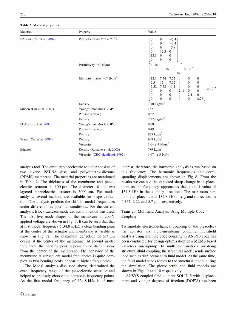
analysis tool. The circular piezoelectric actuator consists of
two layers: PZT-5A disc, and polydimethylsiloxane
(PDMS) membrane. The material properties are mentioned
in Table 2. The thickness of the membrane and piezo-
electric actuator is 100 lm. The diameter of the two
layered piezoelectric actuator is 3000 lm. For modal
analysis, several methods are available for shape extrac-
tion. The analysis predicts the shift in modal frequencies
under different bias potential conditions. For the current
analysis, Block Lanczos mode extraction method was used.
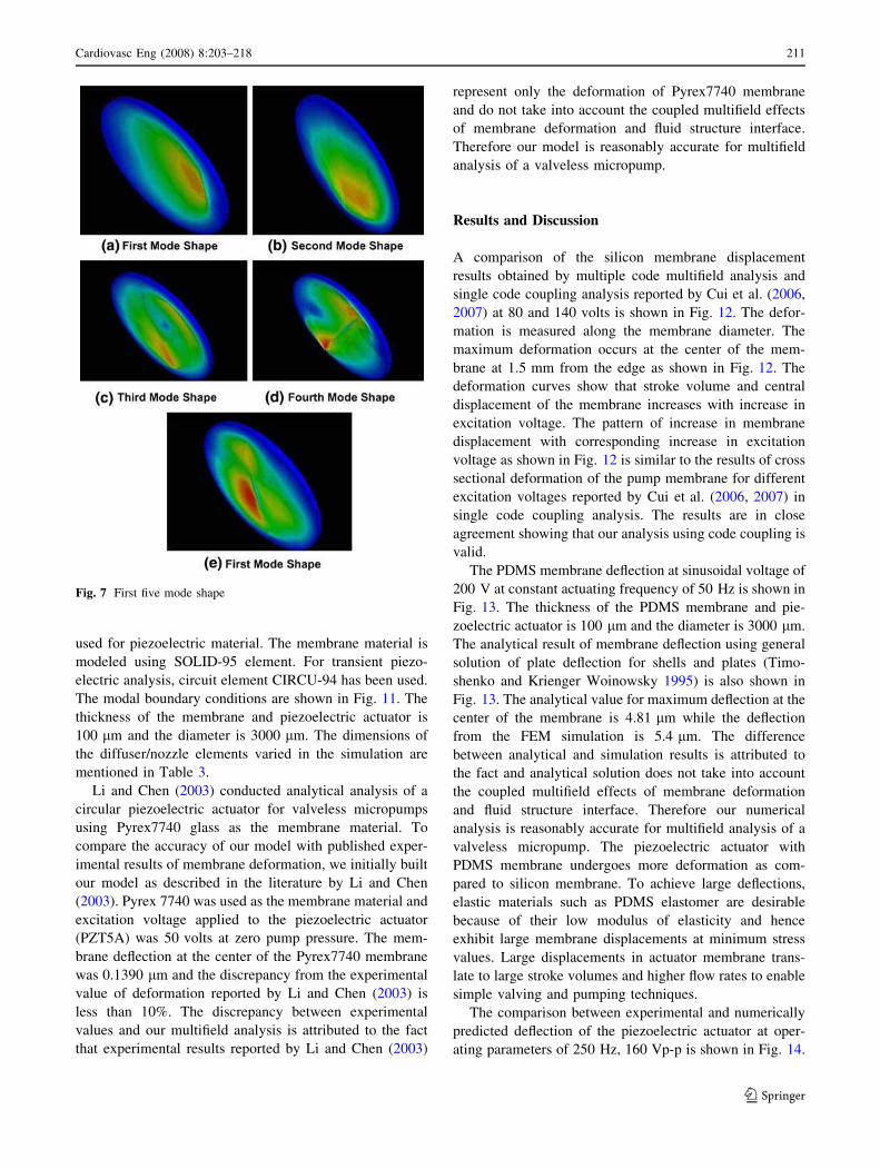
The first five mode shapes of the membrane at 200 V
applied voltage are shown in Fig. 7. It can be seen that that
at first modal frequency (134.8 kHz), a clear bending peak
at the center of the actuator and membrane is visible as
shown in Fig. 7a. The maximum deflection of 5.7 lm
occurs at the center of the membrane. At second modal
frequency, the bending peak appears to be drifted away
from the center of the membrane. The behavior of the
membrane at subsequent modal frequencies is quite com-
plex as two bending peaks appear at higher frequencies.
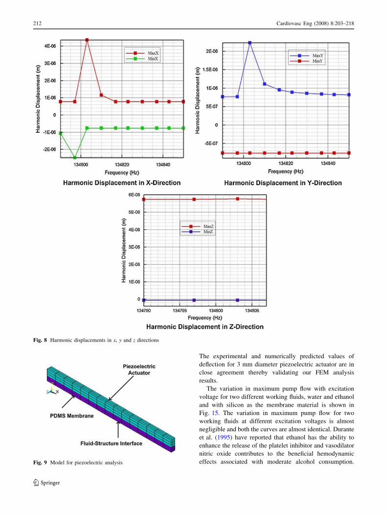
The Modal analysis discussed above, determined the
exact frequency range of the piezoelectric actuator and
helped to precisely choose the harmonic frequency points.
As the first modal frequency of 134.8 kHz is of most
interest, therefore, the harmonic analysis is run based on
this frequency. The harmonic frequencies and corre-
sponding displacements are shown in Fig. 8. From the
results we can see the expected sharp change in displace-
ment as the frequency approaches the mode 1 value of
134.8 kHz in the x and y directions. The maximum har-
monic displacement at 134.8 kHz in x, y and z directions is
4.352, 2.22 and 5.7 lm, respectively.
Transient Multifield Analysis Using Multiple Code
Coupling
To simulate electromechanical coupling of the piezoelec-
tric actuator and fluid-membrane coupling, multifield
analysis using multiple code coupling in ANSYS code has
been conducted for design optimization of a MEMS based
valveless micropump. In multifield analysis involving
structural-fluid coupling, the structural model sends surface
load such as displacement to fluid model. At the same time,
the fluid model sends forces to the structural model during
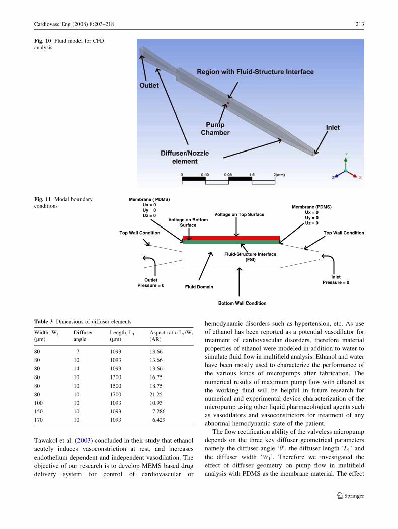
the simulation. The piezoelectric and fluid models are
shown in Figs. 9 and 10 respectively.
ANSYS coupled field element SOLID-5 with displace-
ment and voltage degrees of freedom (DOF’S) has been
Table 2 Material properties
Material Property Value
PZT-5A (Cui et al. 2007) Piezoelectricity ‘‘e’’ (C/m2) 0 0 �5:40 0 �5:40 0 15:80 12:3 0
12:3 0 0
0 0 0
2
6
6
6
6
6
6
4
3
7
7
7
7
7
7
5
Permittivity ‘‘e’’ (F/m) 8:107 0 0
0 8:107 0
0 0 8:107
2
4
3
5� 10�9
Elasticity matrix ‘‘c’’ (N/m2) 12:1 7:54 7:52 0 0 0
7:54 12:1 7:52 0 0 0
7:52 7:52 11:1 0 0 0
0 0 0 2:11 0 0
0 0 0 0 2:11 0
0 0 0 0 0 2:26
2
6
6
6
6
6
6
4
3
7
7
7
7
7
7
5
� 1010
Density 7,700 kg/m3
Silicon (Cui et al. 2007) Young’s modulus E (GPa) 162
Poisson’s ratio c 0.22
Density 2,329 kg/m3
PDMS (Li et al. 2005) Young’s modulus E (GPa) 0.003
Poisson’s ratio c 0.49
Density 965 kg/m3
Water (Cui et al. 2007) Density 998 kg/m3
Viscosity 1.04 e-3 Ns/m2
Ethanol Density (Romano et al. 2003) 789 kg/m3
Viscosity (CRC Handbook 1992) 1.074 e-3 Ns/m2
210 Cardiovasc Eng (2008) 8:203–218
123
used for piezoelectric material. The membrane material is
modeled using SOLID-95 element. For transient piezo-
electric analysis, circuit element CIRCU-94 has been used.
The modal boundary conditions are shown in Fig. 11. The
thickness of the membrane and piezoelectric actuator is
100 lm and the diameter is 3000 lm. The dimensions of
the diffuser/nozzle elements varied in the simulation are
mentioned in Table 3.
Li and Chen (2003) conducted analytical analysis of a
circular piezoelectric actuator for valveless micropumps
using Pyrex7740 glass as the membrane material. To
compare the accuracy of our model with published exper-
imental results of membrane deformation, we initially built
our model as described in the literature by Li and Chen
(2003). Pyrex 7740 was used as the membrane material and
excitation voltage applied to the piezoelectric actuator
(PZT5A) was 50 volts at zero pump pressure. The mem-
brane deflection at the center of the Pyrex7740 membrane
was 0.1390 lm and the discrepancy from the experimental
value of deformation reported by Li and Chen (2003) is
less than 10%. The discrepancy between experimental
values and our multifield analysis is attributed to the fact
that experimental results reported by Li and Chen (2003)
represent only the deformation of Pyrex7740 membrane
and do not take into account the coupled multifield effects
of membrane deformation and fluid structure interface.
Therefore our model is reasonably accurate for multifield
analysis of a valveless micropump.
Results and Discussion
A comparison of the silicon membrane displacement
results obtained by multiple code multifield analysis and
single code coupling analysis reported by Cui et al. (2006,
2007) at 80 and 140 volts is shown in Fig. 12. The defor-
mation is measured along the membrane diameter. The
maximum deformation occurs at the center of the mem-
brane at 1.5 mm from the edge as shown in Fig. 12. The
deformation curves show that stroke volume and central
displacement of the membrane increases with increase in
excitation voltage. The pattern of increase in membrane
displacement with corresponding increase in excitation
voltage as shown in Fig. 12 is similar to the results of cross
sectional deformation of the pump membrane for different
excitation voltages reported by Cui et al. (2006, 2007) in
single code coupling analysis. The results are in close
agreement showing that our analysis using code coupling is
valid.
The PDMS membrane deflection at sinusoidal voltage of
200 V at constant actuating frequency of 50 Hz is shown in
Fig. 13. The thickness of the PDMS membrane and pie-
zoelectric actuator is 100 lm and the diameter is 3000 lm.
The analytical result of membrane deflection using general
solution of plate deflection for shells and plates (Timo-
shenko and Krienger Woinowsky 1995) is also shown in
Fig. 13. The analytical value for maximum deflection at the
center of the membrane is 4.81 lm while the deflection
from the FEM simulation is 5.4 lm. The difference
between analytical and simulation results is attributed to
the fact and analytical solution does not take into account
the coupled multifield effects of membrane deformation
and fluid structure interface. Therefore our numerical
analysis is reasonably accurate for multifield analysis of a
valveless micropump. The piezoelectric actuator with
PDMS membrane undergoes more deformation as com-
pared to silicon membrane. To achieve large deflections,
elastic materials such as PDMS elastomer are desirable
because of their low modulus of elasticity and hence
exhibit large membrane displacements at minimum stress
values. Large displacements in actuator membrane trans-
late to large stroke volumes and higher flow rates to enable
simple valving and pumping techniques.
The comparison between experimental and numerically
predicted deflection of the piezoelectric actuator at oper-
ating parameters of 250 Hz, 160 Vp-p is shown in Fig. 14.
Fig. 7 First five mode shape
Cardiovasc Eng (2008) 8:203–218 211
123
The experimental and numerically predicted values of
deflection for 3 mm diameter piezoelectric actuator are in
close agreement thereby validating our FEM analysis
results.
The variation in maximum pump flow with excitation
voltage for two different working fluids, water and ethanol
and with silicon as the membrane material is shown in
Fig. 15. The variation in maximum pump flow for two
working fluids at different excitation voltages is almost
negligible and both the curves are almost identical. Durante
et al. (1995) have reported that ethanol has the ability to
enhance the release of the platelet inhibitor and vasodilator
nitric oxide contributes to the beneficial hemodynamic
effects associated with moderate alcohol consumption.
Fig. 8 Harmonic displacements in x, y and z directions
Fig. 9 Model for piezoelectric analysis
212 Cardiovasc Eng (2008) 8:203–218
123
Tawakol et al. (2003) concluded in their study that ethanol
acutely induces vasoconstriction at rest, and increases
endothelium dependent and independent vasodilation. The
objective of our research is to develop MEMS based drug
delivery system for control of cardiovascular or
hemodynamic disorders such as hypertension, etc. As use
of ethanol has been reported as a potential vasodilator for
treatment of cardiovascular disorders, therefore material
properties of ethanol were modeled in addition to water to
simulate fluid flow in multifield analysis. Ethanol and water
have been mostly used to characterize the performance of
the various kinds of micropumps after fabrication. The
numerical results of maximum pump flow with ethanol as
the working fluid will be helpful in future research for
numerical and experimental device characterization of the
micropump using other liquid pharmacological agents such
as vasodilators and vasoconstrictors for treatment of any
abnormal hemodynamic state of the patient.
The flow rectification ability of the valveless micropump
depends on the three key diffuser geometrical parameters
namely the diffuser angle ‘h’, the diffuser length ‘L1’ and
the diffuser width ‘W1’. Therefore we investigated the
effect of diffuser geometry on pump flow in multifield
analysis with PDMS as the membrane material. The effect
Fig. 10 Fluid model for CFD
analysis
Bottom Wall Condition
Fluid Domain
Top Wall Condition
Inlet
Pressure = 0
Membrane (PDMS)
Ux = 0
Uy = 0
Uz = 0
Voltage on Top Surface
Voltage on Bottom
Surface
Fluid-Structure Interface
(FSI)
Membrane ( PDMS)
Ux = 0
Uy = 0
Uz = 0
Outlet
Pressure = 0
Top Wall Condition
Fig. 11 Modal boundary
conditions
Table 3 Dimensions of diffuser elements
Width, W1
(lm)
Diffuser
angle
Length, L1
(lm)
Aspect ratio L1/W1
(AR)
80 7 1093 13.66
80 10 1093 13.66
80 14 1093 13.66
80 10 1300 16.75
80 10 1500 18.75
80 10 1700 21.25
100 10 1093 10.93
150 10 1093 7.286
170 10 1093 6.429
Cardiovasc Eng (2008) 8:203–218 213
123

of diffuser angle on flow rate during supply and pump
modes is shown in Figs. 16 and 17 respectively. As shown
in Fig. 16, more fluid enters through the inlet than it exits
the outlet during the supply phase. Maximum flow of
10.68 ll/min is achieved through the inlet at a diffuser
angle of 10� at sinusoidal voltage of 200 V at constant
actuating frequency of 50 Hz. The variation in diffuser
angle does not seem to have significant effect on flow rate
through the inlet during the supply phase. At higher dif-
fuser angles, the flow rate through the outlet reduces during
the supply phase. Thus diffuser angles higher than 7� are
desirable for outlet during the supply phase. The effect of
diffuser angle on flow rate during the pump phase is shown
in Fig. 17. The flow rate out of the pump during the pump
phase increases with increase in diffuser angle. Thus higher
diffuser angles ([7�) are desirable to achieve higher flow
rates during the pump phase.
The comparison between experimental and numerically
predicted micropump flow rate for 3 mm pump chamber
diameter is shown in Fig. 18. The maximum experimen-
tally measured flow rate of the micropump is
approximately 8.9 ll/min at 160Vp-p at 250 Hz excitation
frequency. The experimental and numerically predicted
values of flow rate are in close agreement thereby vali-
dating our multifield analysis. The relation between applied
voltage and micropump flow rate is linear and flow rate
increases with increase in applied voltage due to increase in
deflection of the piezoelectric actuator.
The effect of diffuser angle on diffuser efficiency at
constant PDMS membrane thickness of 0.1 mm and
varying piezoelectric layer thickness is shown in Fig. 19.
The aspect ratio is also kept constant at 13.66. The diffuser
efficiency is analytically determined by calculating pres-
sure loss coefficients in diffuser and nozzle directions. It
can be seen from Fig. 19 that diffuser efficiency increases
by increasing diffuser angle at constant aspect ratios for
PDMS membranes. Jiang et al. (1998) found from exper-
iments that diffuser efficiency increases with increasing
diffuser angle and the same phenomenon was observed in
the simulated results shown in Fig. 19. However at higher
0
0.005
0.01
0.015
0.02
0.025
0.03
0.035
0.04
0.045
0 20 40 60
Flo
w R
ate
(µ
l/m
in)
Voltage (V)
Silicon Membrane
Flow Rate (µl/min) (Water)
Flow Rate (µl/min) (Ethanol)
Fig. 15 Maximum pump flow for different working fluids
0
0.1
0.2
0.3
0.4
0.5
0.6
0 0.5 1 1.5
Membrane Position (mm)
Me
mb
ran
e D
isp
lac
em
en
t (µ
m)
80 V (Multiple code coupling results)
80 V (Single code coupling results) Cui et al. 2007
140 V (Multiple code coupling results)
140 V (Single code coupling results) Cui et al. 2007
Fig. 12 Comparison of membrane displacement results of single
code (Cui et al. 2007) and multiple code coupling analysis
0.00
1.00
2.00
3.00
4.00
5.00
6.00
0 1 2 3
Membrane Position (mm)
Mem
bra
ne D
isp
lacem
en
t (µ
m)
Total Mesh Displacement (µm) FEM
Total Mesh Displacement (µm) Analytical
Fig. 13 Membrane deflection from FEM and analytical solution
Frequency 250 Hz
0
0.5
1
1.5
2
2.5
3
3.5
4
4.5
5
0 50 100 150 200
Voltage (V)
Defl
ecti
on
(µ
m)
Deflection (µm) Experimental
Deflection (µm) FEM
Fig. 14 Comparison between experimental and numerically pre-
dicted deflection of the piezoelectric actuator
214 Cardiovasc Eng (2008) 8:203–218
123
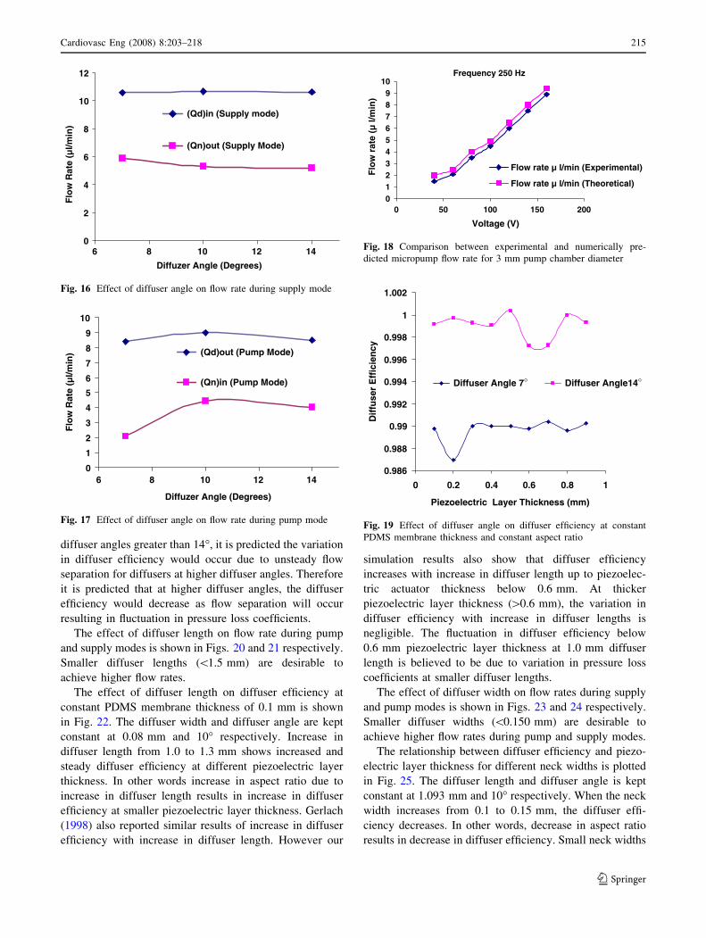
diffuser angles greater than 14�, it is predicted the variation
in diffuser efficiency would occur due to unsteady flow
separation for diffusers at higher diffuser angles. Therefore
it is predicted that at higher diffuser angles, the diffuser
efficiency would decrease as flow separation will occur
resulting in fluctuation in pressure loss coefficients.
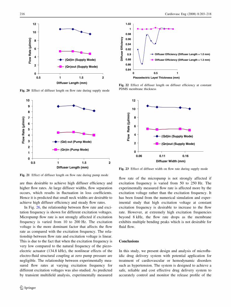
The effect of diffuser length on flow rate during pump
and supply modes is shown in Figs. 20 and 21 respectively.
Smaller diffuser lengths (\1.5 mm) are desirable to
achieve higher flow rates.
The effect of diffuser length on diffuser efficiency at
constant PDMS membrane thickness of 0.1 mm is shown
in Fig. 22. The diffuser width and diffuser angle are kept
constant at 0.08 mm and 10� respectively. Increase in
diffuser length from 1.0 to 1.3 mm shows increased and
steady diffuser efficiency at different piezoelectric layer
thickness. In other words increase in aspect ratio due to
increase in diffuser length results in increase in diffuser
efficiency at smaller piezoelectric layer thickness. Gerlach
(1998) also reported similar results of increase in diffuser
efficiency with increase in diffuser length. However our
simulation results also show that diffuser efficiency
increases with increase in diffuser length up to piezoelec-
tric actuator thickness below 0.6 mm. At thicker
piezoelectric layer thickness ([0.6 mm), the variation in
diffuser efficiency with increase in diffuser lengths is
negligible. The fluctuation in diffuser efficiency below
0.6 mm piezoelectric layer thickness at 1.0 mm diffuser
length is believed to be due to variation in pressure loss
coefficients at smaller diffuser lengths.
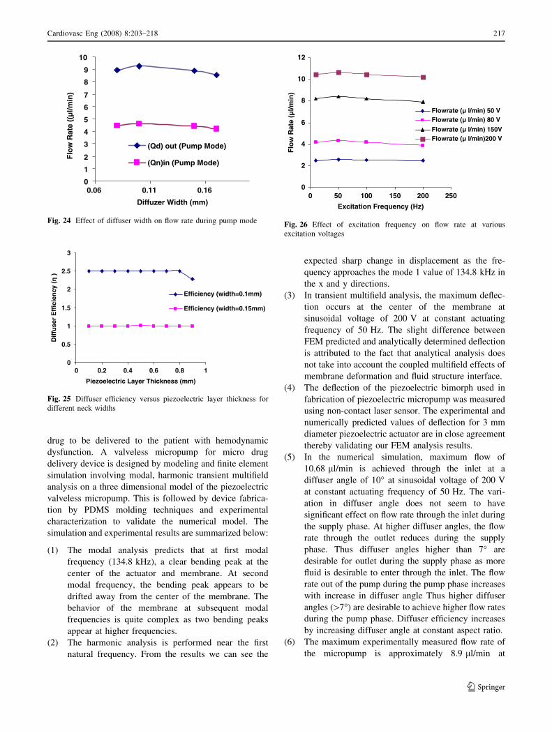
The effect of diffuser width on flow rates during supply
and pump modes is shown in Figs. 23 and 24 respectively.
Smaller diffuser widths (\0.150 mm) are desirable to
achieve higher flow rates during pump and supply modes.
The relationship between diffuser efficiency and piezo-
electric layer thickness for different neck widths is plotted
in Fig. 25. The diffuser length and diffuser angle is kept
constant at 1.093 mm and 10� respectively. When the neck
width increases from 0.1 to 0.15 mm, the diffuser effi-
ciency decreases. In other words, decrease in aspect ratio
results in decrease in diffuser efficiency. Small neck widths
0
2
4
6
8
10
12
6 8 10 12 14
Diffuzer Angle (Degrees)
Flo
w R
ate
(µ
l/m
in)
(Qd)in (Supply mode)
(Qn)out (Supply Mode)
Fig. 16 Effect of diffuser angle on flow rate during supply mode
0
1
2
3
4
5
6
7
8
9
10
6 8 10 12 14
Diffuzer Angle (Degrees)
Flo
w R
ate
(µ
l/m
in) (Qd)out (Pump Mode)
(Qn)in (Pump Mode)
Fig. 17 Effect of diffuser angle on flow rate during pump mode
Frequency 250 Hz
0
1
2
3
4
5
6
7
8
9
10
0 50 100 150 200
Voltage (V)
Flo
w r
ate
(µ
l/m
in)
Flow rate µ l/min (Experimental)
Flow rate µ l/min (Theoretical)
Fig. 18 Comparison between experimental and numerically pre-
dicted micropump flow rate for 3 mm pump chamber diameter
0.986
0.988
0.99
0.992
0.994
0.996
0.998
1
1.002
0 0.2 0.4 0.6 0.8 1
Piezoelectric Layer Thickness (mm)
Dif
fus
er
Eff
icie
nc
y
Diffuser Angle 7° Diffuser Angle14°
Fig. 19 Effect of diffuser angle on diffuser efficiency at constant
PDMS membrane thickness and constant aspect ratio
Cardiovasc Eng (2008) 8:203–218 215
123
are thus desirable to achieve high diffuser efficiency and
higher flow rates. At large diffuser widths, flow separation
occurs, which results in fluctuation in loss coefficients.
Hence it is predicted that small neck widths are desirable to
achieve high diffuser efficiency and steady flow rates.
In Fig. 26, the relationship between flow rate and exci-
tation frequency is shown for different excitation voltages.
Micropump flow rate is not strongly affected if excitation
frequency is varied from 10 to 200 Hz. The excitation
voltage is the more dominant factor that affects the flow
rate as compared with the excitation frequency. The rela-
tionship between flow rate and excitation voltage is linear.
This is due to the fact that when the excitation frequency is
very low compared to the natural frequency of the piezo-
electric actuator (134.8 kHz), the nonlinear effects of the
electro-fluid structural coupling at zero pump pressure are
negligible. The relationship between experimentally mea-
sured flow rates at varying excitation frequency for
different excitation voltages was also studied. As predicted
by transient multifield analysis, experimentally measured
flow rate of the micropump is not strongly affected if
excitation frequency is varied from 50 to 250 Hz. The
experimentally measured flow rate is affected more by the
excitation voltage rather than the excitation frequency. It
has been found from the numerical simulation and exper-
imental study that high excitation voltage at constant
excitation frequency is desirable to increase to the flow
rate. However, at extremely high excitation frequencies
beyond 8 kHz, the flow rate drops as the membrane
exhibits multiple bending peaks which is not desirable for
fluid flow.
Conclusions
In this study, we present design and analysis of microflu-
idic drug delivery system with potential application for
treatment of cardiovascular or hemodynamic disorders
such as hypertension. The system is designed to achieve a
safe, reliable and cost effective drug delivery system to
accurately control and monitor the release profile of the
0
2
4
6
8
10
12
0.5 1 1.5 2
Diffuser Length (mm)
Flo
w R
ate
(µ
l/m
in)
(Qd)in (Supply Mode)
(Qn)out (Supply Mode)
Fig. 20 Effect of diffuser length on flow rate during supply mode
0
1
1
2
3
4
5
6
7
8
9
10
0.5 1.5 2
Diffuser Length (mm)
Flo
w R
ate
(µ
l/m
in)
(Qd) out (Pump Mode)
(Qn)in (Pump Mode)
Fig. 21 Effect of diffuser length on flow rate during pump mode
0.84
0.86
0.88
0.9
0.92
0.94
0.96
0.98
1
1.02
0 0.5 1
Dif
fus
er
Eff
icie
nc
y
Piezoelectric Layet Thickness (mm)
Diffuser Efficiency (Diffuser Length = 1.0 mm)
Diffuser Efficiency (Diffuser Length = 1.3 mm)
Fig. 22 Effect of diffuser length on diffuser efficiency at constant
PDMS membrane thickness
0
2
4
6
8
10
12
0.06 0.11 0.16
Diffuzer Width (mm)
Flo
w
Ra
te (
(µl/
min
)
(Qd)in (Supply Mode)
(Qn)out (Supply Mode)
Fig. 23 Effect of diffuser width on flow rate during supply mode
216 Cardiovasc Eng (2008) 8:203–218
123
drug to be delivered to the patient with hemodynamic
dysfunction. A valveless micropump for micro drug
delivery device is designed by modeling and finite element
simulation involving modal, harmonic transient multifield
analysis on a three dimensional model of the piezoelectric
valveless micropump. This is followed by device fabrica-
tion by PDMS molding techniques and experimental
characterization to validate the numerical model. The
simulation and experimental results are summarized below:
(1) The modal analysis predicts that at first modal
frequency (134.8 kHz), a clear bending peak at the
center of the actuator and membrane. At second
modal frequency, the bending peak appears to be
drifted away from the center of the membrane. The
behavior of the membrane at subsequent modal
frequencies is quite complex as two bending peaks
appear at higher frequencies.
(2) The harmonic analysis is performed near the first
natural frequency. From the results we can see the
expected sharp change in displacement as the fre-
quency approaches the mode 1 value of 134.8 kHz in
the x and y directions.
(3) In transient multifield analysis, the maximum deflec-
tion occurs at the center of the membrane at
sinusoidal voltage of 200 V at constant actuating
frequency of 50 Hz. The slight difference between
FEM predicted and analytically determined deflection
is attributed to the fact that analytical analysis does
not take into account the coupled multifield effects of
membrane deformation and fluid structure interface.
(4) The deflection of the piezoelectric bimorph used in
fabrication of piezoelectric micropump was measured
using non-contact laser sensor. The experimental and
numerically predicted values of deflection for 3 mm
diameter piezoelectric actuator are in close agreement
thereby validating our FEM analysis results.
(5) In the numerical simulation, maximum flow of
10.68 ll/min is achieved through the inlet at a
diffuser angle of 10� at sinusoidal voltage of 200 V
at constant actuating frequency of 50 Hz. The vari-
ation in diffuser angle does not seem to have
significant effect on flow rate through the inlet during
the supply phase. At higher diffuser angles, the flow
rate through the outlet reduces during the supply
phase. Thus diffuser angles higher than 7� are
desirable for outlet during the supply phase as more
fluid is desirable to enter through the inlet. The flow
rate out of the pump during the pump phase increases
with increase in diffuser angle Thus higher diffuser
angles ([7�) are desirable to achieve higher flow rates
during the pump phase. Diffuser efficiency increases
by increasing diffuser angle at constant aspect ratio.
(6) The maximum experimentally measured flow rate of
the micropump is approximately 8.9 ll/min at
0
0.5
1
1.5
2
2.5
3
0 0.2 0.4 0.6 0.8 1
Piezoelectric Layer Thickness (mm)
Dif
fuser
Eff
icie
ncy (η
)
Efficiency (width=0.1mm)
Efficiency (width=0.15mm)
Fig. 25 Diffuser efficiency versus piezoelectric layer thickness for
different neck widths
0
2
4
6
8
10
12
0 50 100 150 200 250
Excitation Frequency (Hz)
Flo
w R
ate
(µ
l/m
in)
Flowrate (µ l/min) 50 V
Flowrate (µ l/min) 80 V
Flowrate (µ l/min) 150V
Flowrate (µ l/min)200 V
Fig. 26 Effect of excitation frequency on flow rate at various
excitation voltages
0
1
2
3
4
5
6
7
8
9
10
0.06 0.11 0.16
Diffuzer Width (mm)
Flo
w R
ate
((µ
l/m
in)
(Qd) out (Pump Mode)
(Qn)in (Pump Mode)
Fig. 24 Effect of diffuser width on flow rate during pump mode
Cardiovasc Eng (2008) 8:203–218 217
123

160Vp-p at 250 Hz excitation frequency. The exper-
imental and numerically predicted values of flow rate
are in close agreement thereby validating our multi-
field analysis. The relation between applied voltage
and micropump flow rate is linear and flow rate
increases with increase in applied voltage due to
increase in deflection of the piezoelectric actuator.
(7) Diffuser lengths less than 1.5 mm are desirable to
achieve higher flow rates during pump and supply
phase. Increase in aspect ratio due to increase in
diffuser length from 1.0 to 1.3 mm results in increase
in diffuser efficiency at smaller piezoelectric layer
thickness. At thicker piezoelectric layer thickness
([0.6 mm), the variation in diffuser efficiency with
increase in diffuser lengths is negligible.
(8) Smaller diffuser widths (\0.150 mm) are desirable to
achieve higher flow rates during pump and supply
modes. Decrease in aspect ratio due to decrease in
diffuser widths results in decrease in diffuser effi-
ciency. Small neck widths are thus desirable to
achieve high diffuser efficiency and higher flow rates.
(9) The flow rate is affected more by the excitation
voltage rather than the excitation frequency. High
excitation voltage at constant excitation frequency is
desirable to increase to the flow rate. However, at
extremely high excitation frequencies beyond 8 kHz,
the flow rate drops as the membrane exhibits
multiple bending peaks which is not desirable for
fluid flow.
Due to the complexities associated with modeling of
piezoelectric micropump, a numerical technique has been
employed to optimize the design of the piezoelectric
valveless micropump before fabrication. In the simulation,
a three dimensional model with coupled field effects is
considered in a non-linear sequential piezoelectric and fluid
analysis, thereby facilitating a more realistic multifield
analysis. The analysis is helpful to predict micropump
performance characteristics by varying critical design
parameters of the valveless micropump. In future work,
integrated drug delivery device with micropump and
microneedle array will be fabricated and the set of multi-
field simulations and experimental measurement of
deflection and flow rate at varying voltage and excitation
frequency presented in the present study will be utilized to
conduct more realistic experimental strength duration tests
of the drug delivery device.
Acknowledgements The authors would like to thank and
acknowledge National Electronics and Computer Technology Center,
(NECTEC), Thailand for providing the grant under the MEMS pro-
ject. The contribution of anonymous reviewers is also acknowledged
for providing valuable feedback and suggestions to improve the
article.
References
ANSI/IEEE Std 176. IEEE standard on piezoelectricity. IEEE; 1987.
http://standards.ieee.org/reading/ieee/std_public/description/ultr
asonics/176-1987_desc.html.
Cao L, Mantell Susan, Polla Dennis. Design and simulation of an
implantable medical drug delivery system using microelectro-
mechanical systems technology. Sens Actuators A Phys.
2001;94:117–25.
Cui Q, Liu C, Xuan F. Simulation and optimization of a piezoelectric
micropump for medical applications. Int J Adv Manuf Technol.
2006; doi:10.1007/s00170-006-0867-x.
Cui Q, Liu C, Xuan F. Study on a piezoelectric micropump for the
controlled drug delivery system. Microfluid Nanofluidics.
2007;3(4):377–90.
David R Lide. CRC Handbook of Chemistry and Physics. 73rd ed.
CRC Press; 1992–1993.
Durante W, Cheng K, Sunaharat RK, Schafer A. Ethanol potentiates
interleukin-1 fl-stimulated inducible nitric oxide synthase in
cultured vascular smooth muscle cells. Biochem J. 1995;
308:231–6.
Fan B, Song G, Hussain F. Simulation of piezoelectrically actuated
valveless micropump. J Smart Mater Struct. 2005;14:400–5.
Gerlach T. Microdiffusers as dynamic passive valves for micropump
applications. Sens Actuators A Phys. 1998;69:181–91.
Jiang XN, Zhou ZY, Huang XY, Li Y, Yang Y, Liu CY. Micronozzle/
diffuser flow and its application in micro valveless pumps. Sens
Actuators A Phys. 1998;70:81–7.
Li G, Nam SG, Byun D. Electro-fluid-structural interaction simulation
of valveless micropump. Proc SPIE. 2007;6528:65280S.
Li S, et al. Disposable polydimethylsiloxane/silicon hybrid chips for
protein detection. Biosens Bioelectron. 2005;21:574–80.
Li S, Chen S. Analytical analysis of a circular PZT actuator for
valveless micropumps. Sens Actuators A Phys. 2003;104:151–61.
Mu YH, Hung NP, Ngoi KA. Optimization design of a piezoelectric
micropump. Int JAdv Manuf Technol. 1999;15:573–6.
Nisar A, Afzulpurkar N, Mahaisavariya B, Tuantranont A. MEMS
based micropumps in drug delivery and biomedical applications.
Sens Actuators B. 2008;130:917–42.
Olsson A, Stemme E. Numerical and experimental studies of flat
walled diffuser elements for valveless micropumps. Sens Actu-
ators A Phys. 2000;84:165–75.
Olsson A, Stemme E, StemmeG. Diffuser element design investigation
for valveless pumps. Sens Actuators A Phys. 1996;57:137–43.
Pan L, Nguyen T, Liu GR, Lam KY, Jiang T. Analytical solutions for
the dynamic analysis of a valveless micropump: a membrane-
fluid coupling study. Sens Actuators A Phys. 2001;93:173–81.
Romano E, Trenzado JL, Gonzalez E, Matos JS, Segade L, Jimenez
E. Thermophysical properties of four binary dimethyl carbonate
?1-alcohol systems at 288.15–313.15 K. Fluid Phase Equilib.
2003;211:219–40.
Singhal V, Garimella S, Murthy JY. Low Reynolds number flow
through nozzle-diffuser elements in valveless micropumps. Sens
Actuators A Phys. 2004;113:226–35.
Tawakol A, Omland T, Creager MA. The direct effect of ethanol on
human vascular function. Am J Physiol Heart Circ Physiol.
2004. doi:10.1152/ajpheart.01207.2003.
Tay F. Microfluidics and BioMEMS applications. 1st ed. Springer, ISBN:
1402072376, Boston: Kluwer Academic Publishers; 2002. p. 3–24.
Timoshenko S, Krienger Woinowsky S. Theory of plates and shells.
2nd ed. New York: McGraw-Hill; 1995.
Wang B, Chu X, Li E, Li L. Simulations and analysis of a
piezoelectric micropump. Ultrasonics. 2006;44:643–6.
White FM. Fluid mechanics. New York: McGraw-Hill; 1986. p. 332–
9, 345–71.
218 Cardiovasc Eng (2008) 8:203–218
123