Pulmonary membrane diffusing capacity and capillary blood volume in tropical eosinophilia
Upload
independentCategory
view
1download
0
©B
RA
ND
X P
ICT
UR
ES
SOME CONGENITAL CARDIOPATHIESrequire “Fontan” pulmonary circula-tion. In this article, a special deviceto increase the flow and pressure inpulmonary arteries is presented. Thesystem is formed by a dc motor plusa helix (generating a radial flow) and
a stator, which converts the radial flow into alongitudinal flow. The main innovation of thisdevice is the transmission between the motorand the helix. This is the critical point, since it isnecessary to insulate the motor (to preventshort circuits) and it is also necessary to imple-ment an adequate motor-helix transmissionpath. In other words, the challenge is to imple-ment an axial pump that is going to operate sub-merged in blood.
OverviewIn certain cardiopathies, the heart does notpump the blood with enough pressure. In thesesituations it is therefore necessary to increasethe blood pressure [1], [2]. There are cases inwhich it is impossible to accomplish this withdrugs. For these cases, it is necessary to includea prosthesis that helps increase the blood pres-sure. These kinds of systems (Figure 1) are usu-ally comprised of the following components:
■ An impeller system, which is responsiblefor pumping the blood when it is necessary.It is constituted by an electric motor. The
JUAN DÍAZ , JUAN MANUEL LOPERA,ALBERTO M. PERNÍA, FERNANDO NUÑO,JUAN A. MARTÍNEZ, JUAN V. COMAS, andLORENZO GALLETTI
0278-0046/07/$25.00©2007IEEE SPRING 2007 ■ IEEE INDUSTRIAL ELECTRONICS MAGAZINE 39
40 IEEE INDUSTRIAL ELECTRONICS MAGAZINE ■ SPRING 2007
transmission to the helix is aproblem, since it must be fullyencapsulated.
■ A complete energy supply system(batteries and a battery chargingsystem). It is necessary to ensure aproper charge and long life cycle forthe batteries.
■ A control circuit for the entire sys-tem. This will regulate the impellersystem and control the battery
charge. Obviously, for power con-sumption and size, the lower/smaller,the better.These systems usually require a
large set of batteries, since the powerlevels needed are high. This is due totwo reasons: 1) in adults, the bloodpressure is relatively high and theelectrical power needed is also high;2) the motors used are based on stepmotors. A typical motor is shown in
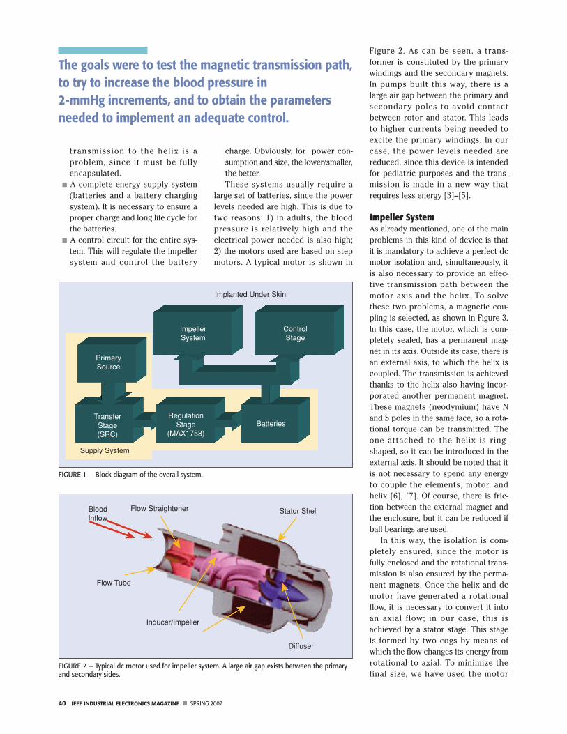
Figure 2. As can be seen, a trans-former is constituted by the primarywindings and the secondary magnets.In pumps built this way, there is alarge air gap between the primary andsecondary poles to avoid contactbetween rotor and stator. This leadsto higher currents being needed toexcite the primary windings. In ourcase, the power levels needed arereduced, since this device is intendedfor pediatric purposes and the trans-mission is made in a new way thatrequires less energy [3]–[5].
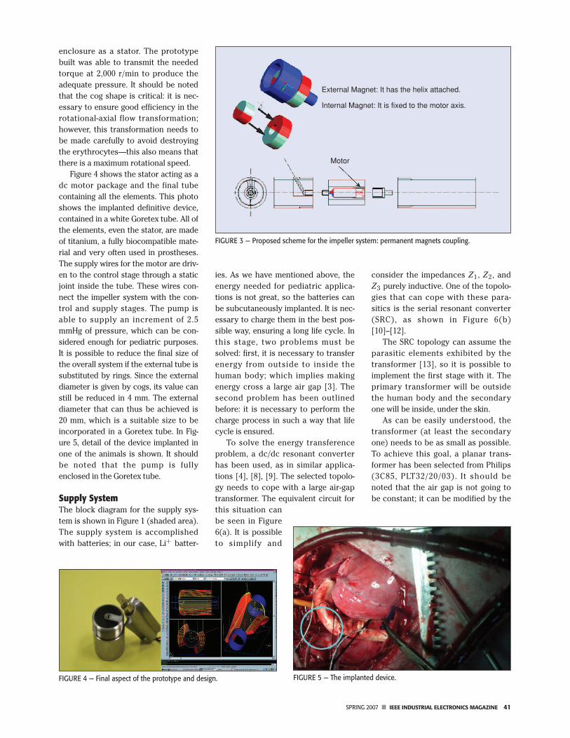
Impeller SystemAs already mentioned, one of the mainproblems in this kind of device is thatit is mandatory to achieve a perfect dcmotor isolation and, simultaneously, itis also necessary to provide an effec-tive transmission path between themotor axis and the helix. To solvethese two problems, a magnetic cou-pling is selected, as shown in Figure 3.In this case, the motor, which is com-pletely sealed, has a permanent mag-net in its axis. Outside its case, there isan external axis, to which the helix iscoupled. The transmission is achievedthanks to the helix also having incor-porated another permanent magnet.These magnets (neodymium) have Nand S poles in the same face, so a rota-tional torque can be transmitted. Theone attached to the helix is ring-shaped, so it can be introduced in theexternal axis. It should be noted that itis not necessary to spend any energyto couple the elements, motor, andhelix [6], [7]. Of course, there is fric-tion between the external magnet andthe enclosure, but it can be reduced ifball bearings are used.
In this way, the isolation is com-pletely ensured, since the motor isfully enclosed and the rotational trans-mission is also ensured by the perma-nent magnets. Once the helix and dcmotor have generated a rotationalflow, it is necessary to convert it intoan axial flow; in our case, this isachieved by a stator stage. This stageis formed by two cogs by means ofwhich the flow changes its energy fromrotational to axial. To minimize thefinal size, we have used the motor
FIGURE 1 — Block diagram of the overall system.
Implanted Under Skin
ControlStage
ImpellerSystem
BatteriesRegulation
Stage(MAX1758)
TransferStage(SRC)
Supply System
PrimarySource
FIGURE 2 — Typical dc motor used for impeller system. A large air gap exists between the primaryand secondary sides.
Flow Straightener Stator Shell
Diffuser
Inducer/Impeller
Flow Tube
BloodInflow
The goals were to test the magnetic transmission path,to try to increase the blood pressure in2-mmHg increments, and to obtain the parametersneeded to implement an adequate control.
SPRING 2007 ■ IEEE INDUSTRIAL ELECTRONICS MAGAZINE 41
enclosure as a stator. The prototypebuilt was able to transmit the neededtorque at 2,000 r/min to produce theadequate pressure. It should be notedthat the cog shape is critical: it is nec-essary to ensure good efficiency in therotational-axial flow transformation;however, this transformation needs tobe made carefully to avoid destroyingthe erythrocytes—this also means thatthere is a maximum rotational speed.
Figure 4 shows the stator acting as adc motor package and the final tubecontaining all the elements. This photoshows the implanted definitive device,contained in a white Goretex tube. All ofthe elements, even the stator, are madeof titanium, a fully biocompatible mate-rial and very often used in prostheses.The supply wires for the motor are driv-en to the control stage through a staticjoint inside the tube. These wires con-nect the impeller system with the con-trol and supply stages. The pump isable to supply an increment of 2.5mmHg of pressure, which can be con-sidered enough for pediatric purposes.It is possible to reduce the final size ofthe overall system if the external tube issubstituted by rings. Since the externaldiameter is given by cogs, its value canstill be reduced in 4 mm. The externaldiameter that can thus be achieved is20 mm, which is a suitable size to beincorporated in a Goretex tube. In Fig-ure 5, detail of the device implanted inone of the animals is shown. It shouldbe noted that the pump is fullyenclosed in the Goretex tube.
Supply SystemThe block diagram for the supply sys-tem is shown in Figure 1 (shaded area).The supply system is accomplishedwith batteries; in our case, Li+ batter-
ies. As we have mentioned above, theenergy needed for pediatric applica-tions is not great, so the batteries canbe subcutaneously implanted. It is nec-essary to charge them in the best pos-sible way, ensuring a long life cycle. Inthis stage, two problems must besolved: first, it is necessary to transferenergy from outside to inside thehuman body; which implies makingenergy cross a large air gap [3]. Thesecond problem has been outlinedbefore: it is necessary to perform thecharge process in such a way that lifecycle is ensured.
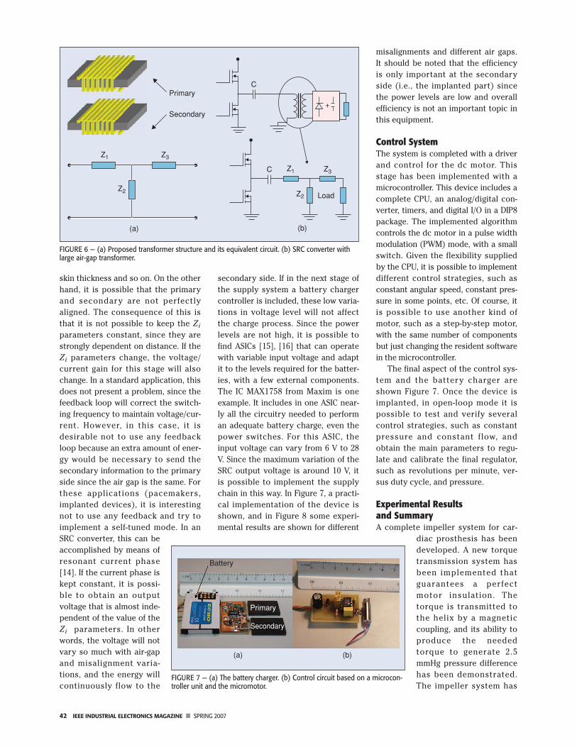
To solve the energy transferenceproblem, a dc/dc resonant converterhas been used, as in similar applica-tions [4], [8], [9]. The selected topolo-gy needs to cope with a large air-gaptransformer. The equivalent circuit forthis situation canbe seen in Figure6(a). It is possibleto simplify and
consider the impedances Z1, Z2, andZ3 purely inductive. One of the topolo-gies that can cope with these para-sitics is the serial resonant converter(SRC), as shown in Figure 6(b)[10]–[12].
The SRC topology can assume theparasitic elements exhibited by thetransformer [13], so it is possible toimplement the first stage with it. Theprimary transformer will be outsidethe human body and the secondaryone will be inside, under the skin.
As can be easily understood, thetransformer (at least the secondaryone) needs to be as small as possible.To achieve this goal, a planar trans-former has been selected from Philips(3C85, PLT32/20/03). It should benoted that the air gap is not going tobe constant; it can be modified by the
FIGURE 3 — Proposed scheme for the impeller system: permanent magnets coupling.
External Magnet: It has the helix attached.
Internal Magnet: It is fixed to the motor axis.
Motor
FIGURE 5 — The implanted device.FIGURE 4 — Final aspect of the prototype and design.
42 IEEE INDUSTRIAL ELECTRONICS MAGAZINE ■ SPRING 2007
skin thickness and so on. On the otherhand, it is possible that the primaryand secondary are not perfectlyaligned. The consequence of this isthat it is not possible to keep the Zi
parameters constant, since they arestrongly dependent on distance. If theZi parameters change, the voltage/current gain for this stage will alsochange. In a standard application, thisdoes not present a problem, since thefeedback loop will correct the switch-ing frequency to maintain voltage/cur-rent. However, in this case, it isdesirable not to use any feedbackloop because an extra amount of ener-gy would be necessary to send thesecondary information to the primaryside since the air gap is the same. Forthese applications (pacemakers,implanted devices), it is interestingnot to use any feedback and try toimplement a self-tuned mode. In anSRC converter, this can beaccomplished by means ofresonant current phase[14]. If the current phase iskept constant, it is possi-ble to obtain an outputvoltage that is almost inde-pendent of the value of theZi parameters. In otherwords, the voltage will notvary so much with air-gapand misalignment varia-tions, and the energy willcontinuously flow to the
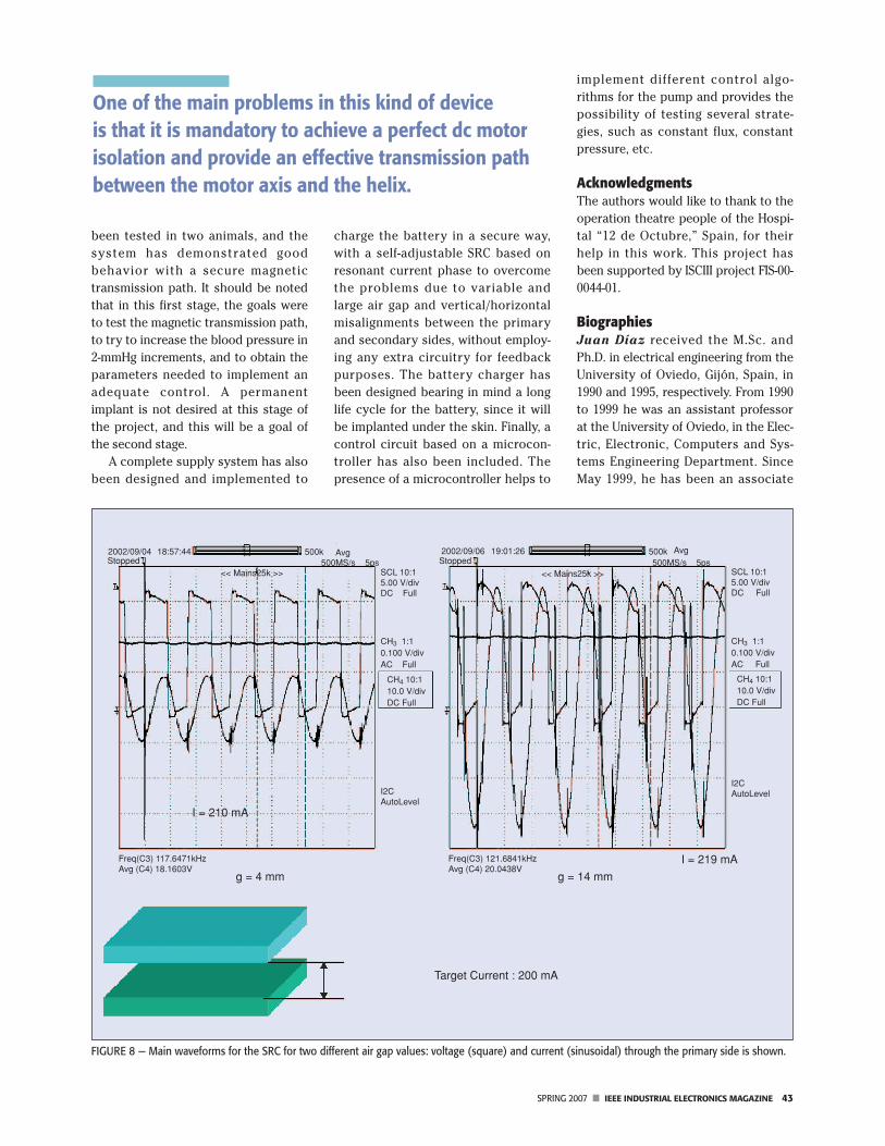
secondary side. If in the next stage ofthe supply system a battery chargercontroller is included, these low varia-tions in voltage level will not affectthe charge process. Since the powerlevels are not high, it is possible tofind ASICs [15], [16] that can operatewith variable input voltage and adaptit to the levels required for the batter-ies, with a few external components.The IC MAX1758 from Maxim is oneexample. It includes in one ASIC near-ly all the circuitry needed to performan adequate battery charge, even thepower switches. For this ASIC, theinput voltage can vary from 6 V to 28V. Since the maximum variation of theSRC output voltage is around 10 V, itis possible to implement the supplychain in this way. In Figure 7, a practi-cal implementation of the device isshown, and in Figure 8 some experi-mental results are shown for different
misalignments and different air gaps.It should be noted that the efficiencyis only important at the secondaryside (i.e., the implanted part) sincethe power levels are low and overallefficiency is not an important topic inthis equipment.
Control SystemThe system is completed with a driverand control for the dc motor. Thisstage has been implemented with amicrocontroller. This device includes acomplete CPU, an analog/digital con-verter, timers, and digital I/O in a DIP8package. The implemented algorithmcontrols the dc motor in a pulse widthmodulation (PWM) mode, with a smallswitch. Given the flexibility suppliedby the CPU, it is possible to implementdifferent control strategies, such asconstant angular speed, constant pres-sure in some points, etc. Of course, itis possible to use another kind ofmotor, such as a step-by-step motor,with the same number of componentsbut just changing the resident softwarein the microcontroller.
The final aspect of the control sys-tem and the battery charger areshown Figure 7. Once the device isimplanted, in open-loop mode it ispossible to test and verify severalcontrol strategies, such as constantpressure and constant flow, andobtain the main parameters to regu-late and calibrate the final regulator,such as revolutions per minute, ver-sus duty cycle, and pressure.
Experimental Results and SummaryA complete impeller system for car-
diac prosthesis has beendeveloped. A new torquetransmission system hasbeen implemented thatguarantees a perfectmotor insulation. Thetorque is transmitted tothe helix by a magneticcoupling, and its ability toproduce the neededtorque to generate 2.5mmHg pressure differencehas been demonstrated.The impeller system has
FIGURE 6 — (a) Proposed transformer structure and its equivalent circuit. (b) SRC converter withlarge air-gap transformer.
(a) (b)
Load
Primary
Secondary
Z1 Z3
Z2
Z1C
C
Z2
Z3
FIGURE 7 — (a) The battery charger. (b) Control circuit based on a microcon-troller unit and the micromotor.
Battery
Primary
Secondary
(a) (b)
SPRING 2007 ■ IEEE INDUSTRIAL ELECTRONICS MAGAZINE 43
been tested in two animals, and thesystem has demonstrated goodbehavior with a secure magnetictransmission path. It should be notedthat in this first stage, the goals wereto test the magnetic transmission path,to try to increase the blood pressure in2-mmHg increments, and to obtain theparameters needed to implement anadequate control. A permanentimplant is not desired at this stage ofthe project, and this will be a goal ofthe second stage.
A complete supply system has alsobeen designed and implemented to
charge the battery in a secure way,with a self-adjustable SRC based onresonant current phase to overcomethe problems due to variable andlarge air gap and vertical/horizontalmisalignments between the primaryand secondary sides, without employ-ing any extra circuitry for feedbackpurposes. The battery charger hasbeen designed bearing in mind a longlife cycle for the battery, since it willbe implanted under the skin. Finally, acontrol circuit based on a microcon-troller has also been included. Thepresence of a microcontroller helps to
implement different control algo-rithms for the pump and provides thepossibility of testing several strate-gies, such as constant flux, constantpressure, etc.
AcknowledgmentsThe authors would like to thank to theoperation theatre people of the Hospi-tal “12 de Octubre,” Spain, for theirhelp in this work. This project hasbeen supported by ISCIII project FIS-00-0044-01.
BiographiesJuan Díaz received the M.Sc. andPh.D. in electrical engineering from theUniversity of Oviedo, Gijón, Spain, in1990 and 1995, respectively. From 1990to 1999 he was an assistant professorat the University of Oviedo, in the Elec-tric, Electronic, Computers and Sys-tems Engineering Department. SinceMay 1999, he has been an associate
FIGURE 8 — Main waveforms for the SRC for two different air gap values: voltage (square) and current (sinusoidal) through the primary side is shown.
2002/09/04Stopped
Avg Avg5ps
2002/09/06 19:01:26Stopped
<< Mains25k >><< Mains25k >>
500k500k500MS/s 500MS/s 5ps
SCL 10:15.00 V/divDC Full
SCL 10:15.00 V/divDC Full
CH3 1:10.100 V/divAC Full
CH4 10:110.0 V/divDC Full
CH3 1:10.100 V/divAC Full
CH4 10:110.0 V/divDC Full
I2CAutoLevelI2C
AutoLevel
I = 219 mA
g = 14 mmg = 4 mm
I = 210 mA
Freq(C3) 121.6841kHzAvg (C4) 20.0438V
Freq(C3) 117.6471kHzAvg (C4) 18.1603V
18:57:44
Target Current : 200 mA
One of the main problems in this kind of device is that it is mandatory to achieve a perfect dc motorisolation and provide an effective transmission pathbetween the motor axis and the helix.
44 IEEE INDUSTRIAL ELECTRONICS MAGAZINE ■ SPRING 2007
professor at the University of Oviedo.His research interests include switch-ing-mode power supplies, resonantpower conversion, piezoelectrics, dchigh-voltage applications, and designof systems based on microcontrollers.He is a Member of the IEEE.
Juan Manuel Lopera receivedthe M.Sc. and Ph.D. in electrical engi-neering from the Universidad deOviedo, Gijón, Spain, in 1990 and1994, respectively. He is currently anassociate professor at the Universi-dad de Oviedo. His research interestsare high-frequency, high-densitypower converters; electronic ballasts’modeling of magnetic elements; andmagnetic sensors. He is a Member ofthe IEEE.
Alberto M. Pernía received the M.S.and Ph.D. degrees in electrical engi-neering from the University of Oviedoin 1991 and 1996, respectively. Since1992, he has been working as associateprofessor at the Electronic TechnologyArea of the University of Oviedo. Hehas worked on different topics relatedwith the power electronics and espe-cially on high-frequency power supplysystems. He has contributed severalpapers to international electronics con-ferences and international journalsrelated to magnetic component integra-tion and high-power-density dc/dc con-verters. Currently, his work andresearch are oriented toward voltageregulator modules, high-output voltageconverters, and the modeling of mag-netic structures.
Fernando Nuño received theM.Sc. and Ph.D. degrees in electricalengineering from the University ofOviedo, Gijón, Spain, in 1988 and 1991,respectively. From 1988 to 1993 hewas an assistant professor at the Uni-versity of Oviedo. Since May 1993, hehas been an associate professor at theUniversity of Oviedo. His researchinterests include switching-modepower supplies, resonant power con-
version, modeling and design of mag-netic devices, high-power-factor recti-fiers and design of systems based onmicrocontrollers. He is a Member ofthe IEEE.
Juan A. Martínez received theM.Sc. and Ph.D. in electrical engineer-ing from the University of Oviedo,Gijón, Spain, in 1988 and 1991, respec-tively. From 1988 to 1993 he was anassistant professor at the Universityof Oviedo. Since May 1993, he hasbeen an associate professor at theUniversity of Oviedo. His researchinterests include switching-modepower supplies, resonant power con-version, and high-power-factor recti-fiers. He is a Member of the IEEE.
Juan V. Comas received the Ph.D.in congenital cardiac physiology fromBarcelona University, Spain, in 1994. Heis strongly dedicated to the treatmentof congenital heart disease, taking fel-lowships in thoracic and cardiovascu-lar surgery for adults and pediatrics inBarcelona, Paris, London, and Australia(1984–1995). Since 1997 he has beenthe director of surgery at the PediatricHeart Institute at the Hospital “12 deOctubre,” in Madrid. His researchinterests are Fontan circulation, tissuevalve engineering, and neurologicaloutcomes of congenital heart diseases.
Lorenzo Galletti received the“graduation” in medicine and surgeryfrom the University of Pisa, Italy, in1986, the National Board in cardiotho-racic surgery in 1992, and Ph.D. in sur-gical pathophysiology (1993), fromthe University of Rome. Since 1991 hehas been strongly dedicated to thetreatment of congenital heart disease,taking fellowship at Bambino GesùHospital (Rome), Marie LannelongueHospital (Paris), and the Aldo Cas-tañeda Institute (Genolier). Since 1997he has been a staff surgeon at thePediatric Heart Institute at the Hospi-tal “12 de Octubre,” in Madrid. Hisresearch interests are Fontan circula-
tion, tissue valve engineering, andneurological outcomes of congenitalheart diseases.
References[1] Fontan Operation Homepage [Online]. Available:
http://www.fontanoperation.com/fontan.htm[2] http://heart.healthcentersonline.com/pediatric-
heartsurgery/ [3] A. Don, G. Pedder, et al., “A contactless electrical
energy transmission system,” IEEE Trans. Ind.Electron., vol. 46, pp. 23–30, Feb. 1999.
[4] R. Mecke, “High frequency inverter for contact-less energy transmission,” in Proc. PCIM 2001,Nurnberg, Germany, June 2001 [CD-ROM].
[5] T.H. Nishimura, M. Saito, L. Lorenz, and B.Baulemente, “An energy conversion system for animplantable artificial heart using sirets,” in Proc.Euro. Conf. Power Electronics, 1989, pp. 755–760.
[6] J. Díaz, J.M. Lopera, J.V. Comas, and L. Galletti,“Pulmonary blood flow regulation with contact-less energy transmission system,” in Proc. EMBS-BMES, 2002, pp. 1538–1539.
[7] W.H. Moore, D.P. Holschneider, T.K. Givrad, and J.-M. Maarek, “Transcutaneous RF-poweredimplantable minipump driven by a class-E trans-mitter,” IEEE Trans. Biomed. Eng., vol. 53, pp. 1705–1708, Aug. 2006.
[8] B. Cho, J. Nho, H. Cha, T. Ahn, and S. Choi,“Design and implementation of low-profile con-tactless battery charger using planar printed cir-cuit board windings as energy transfer device,”IEEE Trans. Ind. Electron., vol. 51, pp. 140–147,Feb. 2004.
[9] C.-S. Wang, O.H. Stielau, and G.A. Covic, “Designconsiderations for a contactless electric vehiclebattery charger,” IEEE Trans. Ind. Electron., vol. 52,pp. 1308–1314, Oct. 2005.
[10] A. Ghahary and B.H. Cho, “Design of transcuta-neous energy transmission system using a seriesresonant converter,” in Proc. Power ElectronicsSpecialist Conf., 1990, pp. 1–8.
[11] T.H. Nishimura, K. Hirachi, Y. Maejima, K.Kuwana, and M. Sito, “Characteristics of a novelenergy transmission for a rechargeable cardiacpacemaker by using a resonant converter,” inProc. Conf. Industrial Electronic Soc., 1993, pp.875–880.
[12] R.L. Steigerwald, “A comparison of half-bridgeresonant converter topologies,” IEEE Trans. Ind.Electron., vol. 3, pp. 181–191, Apr. 1988.
[13] T. Hiro, T. Rguchi, K. Hirachi, Y. Maejima, K.Kuwana, and M. Saito, “A large air gap flat trans-former for a transcutaneouus energy transmis-sion system,” in Proc. Power Electronics SpecialistConf., 1994, pp. 1323–1329.
[14] J. Díaz, J.M. Lopera, J.A. Martín, A. Martín, andJ.A. Esteban, “Transcutaneous battery chargerusing a half bridge SRC controlled by resonantcurrent phase,” in Proc. Conf. Industrial ElectronicSoc., Sevilla, Spain, 2002 [CD-ROM].
[15] Maxim Datasheets [Online]. Available:http://www.maxim-ic.com
[16] J.A. Martín, “Intelligent and universal fast charg-er for Ni-Cd and Ni-MH batteries in portable appli-cations,” in Proc. Eur. Conf. Power Electronics,Lausanne, 1999 [CD-ROM].
An earlier version of this work waspresented at the 24th Annual Interna-tional Conference of the IEEE Engineer-ing in Medicine and Biology Society/Annual Fall Meeting of the BiomedicalEngineering Society, 23–26 October2002, Houston, Texas.
Once the device is implanted, in open-loop mode it ispossible to test and verify several control strategies.
Copyright © 2022 FDOKUMEN