thesis.pdf - Munin
128
1/128 INF INF INF INF-39 39 39 3996 96 96 96 Master of Science Master of Science Master of Science Master of Science Thesis Thesis Thesis Thesis in in in in Telemedicine and e Telemedicine and e Telemedicine and e Telemedicine and e-Health Health Health Health A SENSOR DEVICE AND ITS APPLICATION IN E-HEALTH Odd-Arne Olsen June, 2007 FACULTY OF SCIENCE Department of Computer Science University of Tromsø Number of pages (including this): 128
-
Upload
khangminh22 -
Category
Documents
-
view
0 -
download
0
Transcript of thesis.pdf - Munin

1/128
I N FINFINFINF ---- 3 939393996969696
Ma s t e r o f S c i en c eMas t e r o f S c i en c eMas t e r o f S c i en c eMas t e r o f S c i en c e Th e s i sTh e s i sTh e s i sTh e s i s i n i n i n i n
T e l emed i c i n e and eTe l emed i c i n e and eTe l emed i c i n e and eTe l emed i c i n e and e ---- H e a l t hHea l t hHea l t hHea l t h
A SENSOR DEVICE AND ITS APPLICATION IN E-HEALTH
Odd-Arne Olsen
June, 2007
FACULTY OF SCIENCE Department of Computer Science
University of Tromsø
Number of pages (including this): 128

INF-3996 A Sensor Device And Its Application in eHealth Odd-Arne Olsen
2/128
INF-3996 A Sensor Device And Its Application in eHealth Odd-Arne Olsen
3/128
Preface
The assignment described in this thesis is a tiny part of a long running project at the Norwegian Centre for Telemedicine (NST). The project is focused on self-help and health motivational devices. This part concentrates on the debugging phase of a ready made wireless step-counter prototype.
I had hoped to get more work done on the device. However events beyond my control laid some obstacles in my way.
I would like to thank my supervisors, Weihai Yu and Eirik Årsand, for immense amounts of patience, help, advice and inspiration. Further on I would also like thank Willy Mortensen at Sensotek and Harry Jensen at Faculty of Medicine, University of Tromsø.
Finally I have to thank my wife Chun-Lan and our three daughters for helping me through this.

INF-3996 A Sensor Device And Its Application in eHealth Odd-Arne Olsen
4/128
INF-3996 A Sensor Device And Its Application in eHealth Odd-Arne Olsen
5/128
Contents
PREFACE ............................................................................................................................................... 3
CONTENTS ............................................................................................................................................ 5
SUMMARY............................................................................................................................................. 7
1. INTRODUCTION......................................................................................................................... 9
2. BACKGROUND ......................................................................................................................... 11 2.1. E-HEALTH ............................................................................................................................ 11 2.2. SELF-MONITORING SYSTEM - THE NST PROJECT.................................................................. 11 2.3. WEARABLE HEALTH MONITORING SYSTEMS......................................................................... 13 2.4. THE MICROCONTROLLER ...................................................................................................... 13
2.4.1. Microcontrollers ............................................................................................................. 13 2.4.2. The AVR Architecture ..................................................................................................... 18 2.4.3. The ATmega164P microcontroller ................................................................................. 18
2.5. PROGRAMMING ENVIRONMENTS .......................................................................................... 20 2.5.1. IAR Embedded Workbench ............................................................................................. 21 2.5.2. CodeVisionAVR .............................................................................................................. 21 2.5.3. WinAVR (GNU GCC) ..................................................................................................... 22 2.5.4. ImageCraft v7 C compiler and Crossworks for AVR...................................................... 22
2.6. AVR ASSEMBLY PROGRAMMING ......................................................................................... 23 2.6.1. The registers ................................................................................................................... 23
2.7. WIRELESS COMMUNICATION ................................................................................................ 24 2.8. SENSORS .............................................................................................................................. 25
3. METHODS .................................................................................................................................. 27
3.1. SENSORS MEASUREMENTS.................................................................................................... 27 3.2. PROGRAM DEVELOPMENT AND TESTING............................................................................... 28
3.2.1. The STK-500 starter kit .................................................................................................. 28 The Atmel AVR JTAGICE mkII emulator...................................................................................... 29
4. REQUIREMENT SPECIFICATION ....................................................................................... 31
4.1. ERGONOMICS, POWER CONSUMPTION AND USABILITY ......................................................... 31 4.2. PERSONAL ADAPTATION AND CONTEXT AWARENESS ........................................................... 31 4.3. RELIABILITY AND INFORMATION SECURITY.......................................................................... 32
5. DESIGN AND IMPLEMENTATION....................................................................................... 33
5.1. THE STEP-COUNTER PROTOTYPES......................................................................................... 33 5.2. STEP-COUNTER FUNCTIONALITY .......................................................................................... 35 5.3. BLUETOOTH MODULE SETUP ................................................................................................ 35 5.4. BLUETOOTH – UART INTERFACING ..................................................................................... 36
5.4.1. Data format..................................................................................................................... 36 5.4.2. Hardware flow control ................................................................................................... 37 5.4.3. Choosing baud rate......................................................................................................... 37 5.4.4. Connecting microcontroller with the Bluetooth module................................................. 39 5.4.5. Some alternatives............................................................................................................ 39
5.5. POWER SUPPLY..................................................................................................................... 41 5.6. THE STEP COUNTER SOFTWARE............................................................................................ 42
5.6.1. Program overview .......................................................................................................... 42 5.6.2. Initialization “inite_reg.asm” ........................................................................................ 43 5.6.3. Main routine ”main.asm” .............................................................................................. 44 5.6.4. Interrupt service routine for step counting “isr_count.asm” ......................................... 44 5.6.5. Interrupt service routine for user initiated data transmission “isr_mtransm.asm” ....... 44 5.6.6. Interrupt service routine for real time clock update “isr_timer.asm”............................ 44 5.6.7. Control routine for transmitting step-counter data “transmit_bt.asm” ......................... 45

INF-3996 A Sensor Device And Its Application in eHealth Odd-Arne Olsen
6/128
5.6.8. The low level UART servicing routines .......................................................................... 45
6. RESULTS .................................................................................................................................... 47
6.1. MOVEMENT SENSORS ........................................................................................................... 47 6.1.1. Sensor design and testing ............................................................................................... 47 6.1.2. The inclinometer test....................................................................................................... 48 6.1.3. The sub miniature micro switch test ............................................................................... 48 6.1.4. Tilt and vibration sensors ............................................................................................... 49 6.1.5. Accelerometers ............................................................................................................... 50
6.2. POWER CONSUMPTION.......................................................................................................... 52 6.3. DATA SECURITY ................................................................................................................... 52 6.4. MICROCONTROLLER SOFTWARE........................................................................................... 53
6.4.1. The initialization file, “inite_reg.asm”........................................................................... 53 6.4.2. The communication and time control routines ............................................................... 54 6.4.3. Retransmission of lost data............................................................................................. 59 6.4.4. DTR timeout.................................................................................................................... 61 6.4.5. The final changes............................................................................................................ 62
7. DISCUSSION .............................................................................................................................. 63
7.1. SENSORS .............................................................................................................................. 63 7.2. WIRELESS COMMUNICATION ................................................................................................ 64 7.3. MICROCONTROLLER............................................................................................................. 64 7.4. POWER SAVING .................................................................................................................... 64 7.5. MICROCONTROLLER SOFTWARE........................................................................................... 65 7.6. THE STEP-COUNTER.............................................................................................................. 65
8. FUTURE WORK ........................................................................................................................ 67
8.1. THE TIME SET FUNCTION ...................................................................................................... 67 8.2. ALTERNATIVE POWER SUPPLY.............................................................................................. 67 8.3. REMOTE PROGRAMMING ...................................................................................................... 68
9. CONCLUSION ........................................................................................................................... 71
REFERENCES ..................................................................................................................................... 73
APPENDIX A: THE PROJECT GROUP’S BLOCK DIAGRAM .................................................. 77
APPENDIX B: MY BLOCK DIAGRAM........................................................................................... 85
APPENDIX C: THE UNMODIFIED PROGRAM ........................................................................... 91
APPENDIX D: THE MODIFIED PROGRAM ............................................................................... 107
APPENDIX E: BLUETOOTH MODULE SETUP ......................................................................... 123
APPENDIX F: THE SENSOR TESTS ............................................................................................. 125
INF-3996 A Sensor Device And Its Application in eHealth Odd-Arne Olsen
7/128
Summary
The projects Self-help through a mobile ICT tool and The ICT Lifestyle and Health
Motivation Project at the Norwegian Centre for Telemedicine (NST) have designed and built a prototype smart sensor system. Just days before the hand-in of this thesis, the second version of the prototype was ready for testing.
Central for this thesis is the hardware and software debugging process of this first prototype. The result of this process is a number of suggestions for changes in the microcontroller’s software and the hardware generally. The suggestion for changes does not introduce any new features, but rather tries to direct the functionality towards the project group’s intention. The main suggestions involve how to avoid loss of data, and also let the user take charge over when the step-counter should report to the mobile base.
The thesis starts with an introduction to the main project and a revision of similar projects. The direction then changes towards the theory and tools necessary to perform the intended task are presented.
A somewhat large part is devoted to design of movement sensors. As a part of this there were done some tests. The results of some of these plus suggestions for some new are presented.
As wireless communication carrier the project group has chosen Bluetooth. The thesis gives a revision of the module chosen plus some alternatives. In addition there is also some suggestions regarding the setup of the module.

INF-3996 A Sensor Device And Its Application in eHealth Odd-Arne Olsen
8/128
INF-3996 A Sensor Device And Its Application in eHealth Odd-Arne Olsen
9/128
1. Introduction The aim of this project is to test and further develop a prototyped smart sensor
system. This system is designed and built by the Norwegian Centre for Telemedicine (NST) and SensoTek – as part of the projects Self-help through a mobile ICT tool and The Lifestyle Project. The smart sensor system is at the moment implemented as a step counter able to wirelessly report its accumulated measurement results to a mobile base. The smart sensor’s main building blocks are the Atmel ATmega164P 8-bit RISC microcontroller and the connectBlue OEMSPA311i-04 Bluetooth adapter. As mobile base the research group has chosen two smart phones; the HTC “Trinity” P3600 and the HTC “MTeoR”. Both are running the Windows Mobile 5.0 operating system.
At present the user has to initiate the wireless transmission by pressing a button positioned on the smart sensor or wait for an automatic transfer every 24th hour. A startup initiated at the mobile base is possible but concerns for the smart sensors’ power budget has caused this feature to be put on hold.
The difference between this and a “normal” informatics thesis is the real-world aspect this project involves. As such this project embraces some basic measuring technique essentials as well as short-range communication aspects for data transfer and eHealth/Telemedicine considerations on the sensor system.
In order to perform construction or debugging at this level detailed component knowledge is vital. This goes for both hardware and software in order to be able too give a valid numeric interpretation of the involved sensors output. The fact that the system is programmed in AVR assembler intensifies this statement.
A large part of this thesis is devoted to the description of the debugging process, and since electronics is part of the project it will be mentioned but not described in detail.
Here however a short definition list follows. Hexadecimal numbers are marked with the prefix “0x” Binary numbers are marked with the prefix “0b” Decimal numbers have no prefix Brown block diagram boxes illustrates parts of the original program Blue block diagram boxes illustrate a suggested change In this thesis the abbreviation ISP means in-system programming
The rest of the report has the following outline:
Chapter 2 gives a brief introduction to eHealth and the use of smart-sensors in eHealth, for then to slide into descriptions devices used for this project
Chapter 3 describes the equipment and its usage Chapter 4 presents the project requirements and some of the immediate
technical implications they have Chapter 5 presents the step-counter and its software Chapter 6 describes changes and additions made in addition to making
suggestions for further development Chapter 7 discussion Chapter 8 presents some possibilities for future work Chapter 9 conclusion

INF-3996 A Sensor Device And Its Application in eHealth Odd-Arne Olsen
10/128

INF-3996 A Sensor Device And Its Application in eHealth Odd-Arne Olsen
11/128
2. Background
2.1. e-Health
Trying to find plain e-Health definition is difficult. It seems as though every
involved party has coined their own meaning satisfying their own needs. The Norwegian Center for Telemedicine has adopted the definition quoted below:
eHealth means applying new low-cost technologies, such as "web-enabled"
transactions, advanced networks and new design approaches, to healthcare delivery.
In practice, it implies not only the application of new technologies, but also a
fundamental rethinking of healthcare processes based on using electronic
communication and computer-based support at all levels and for all functions, both
within the healthcare service itself and in its dealings with outside suppliers. eHealth
is a term which implies a way of working rather than a specific technology of
application [1, 2].
How can a step-counter be considered an eHealth device? The definition above is
so broad that it embraces a wide range of services bordering to both healthcare and information technology. As such this involves both self-help systems for people suffering from diseases as well as for instance activity monitoring of healthy persons for the cause of disease prevention [3].
The step-counter is at present only capable of registering a persons walking activity. But by combining this data with his/her weight and average step length, data like walking distance and caloric consumption can be found. These parameters would be a useful tool for persons in need of a balanced diet. Examples of such users’ could be people with lifestyle related or chronic diseases.
Being made available for the person’s physician these data could also form the basis for adjustments of medical dosage levels. With reference to the definition of telemedicine adopted by NST, the step-counter could also be categorized as a telemedical device.
Telemedicine is the investigation, monitoring and management of patients and the
education of patients and staff using systems which allow ready access to expert
advice and patient information no matter where the patient or relevant information is
located [4].
The collected and processed data are available at the person’s mobile phone and as
such the data could be made available to the physician, irrelevant to the involved persons’ individual geographical position.
2.2. Self-monitoring system - The NST project
NST’s lifestyle research team is trying to develop a self-help system for patients
suffering from chronic or lifestyle related diseases. The motivation for doing this was
INF-3996 A Sensor Device And Its Application in eHealth Odd-Arne Olsen
12/128
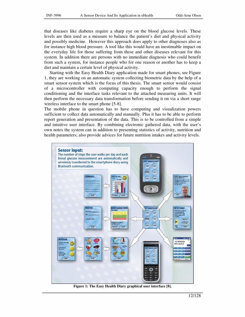
that diseases like diabetes require a sharp eye on the blood glucose levels. These levels are then used as a measure to balance the patient’s diet and physical activity and possibly medicine. However this approach does apply to other diagnoses also as for instance high blood pressure. A tool like this would have an inestimable impact on the everyday life for those suffering from these and other diseases relevant for this system. In addition there are persons with no immediate diagnosis who could benefit from such a system, for instance people who for one reason or another has to keep a diet and maintain a certain level of physical activity.
Starting with the Easy Health Diary application made for smart phones, see Figure 1, they are working on an automatic system collecting biometric data by the help of a smart sensor system which is the focus of this thesis. The smart sensor would consist of a microcontroller with computing capacity enough to perform the signal conditioning and the interface tasks relevant to the attached measuring units. It will then perform the necessary data transformation before sending it on via a short range wireless interface to the smart phone [5-8]. The mobile phone in question has to have computing and visualization powers sufficient to collect data automatically and manually. Plus it has to be able to perform report generation and presentation of the data. This is to be controlled from a simple and intuitive user interface. By combining electronic gathered data, with the user’s own notes the system can in addition to presenting statistics of activity, nutrition and health parameters; also provide advices for future nutrition intakes and activity levels.
Figure 1: The Easy Health Diary graphical user interface [8].
INF-3996 A Sensor Device And Its Application in eHealth Odd-Arne Olsen
13/128
Here the glucose measurements are used as example of biometric data but other
alternatives could be a pulse-counter, a blood pressure monitor etc. The reports generated from such a system could be forwarded to other receivers
approved by the patient at hand. For instance to an electronic health record, or in the case of infants; the parents [5-8].
2.3. Wearable health monitoring systems
The NST project is however one among many others in the field. Closest when it
comes to the technology chosen is the as Harvard University’s “Code Blue” [9] and the “WHMS- Wearable Health Monitoring System” from The University of Alabama [10]. They base their smart sensor system on the Telos sensor node platform. Telos is module made at Berkley University for the purpose of research and experimentation. It uses Zigbee as its communication carrier [11].
Common for these two projects is that they are emphasizing on wireless body area networks, and the use smart sensors for professional medical purposes. The areas involved are continuous monitoring as a part of a diagnostic procedure, observation and counseling of patients with chronic conditions, supervised convalescence or multiple patient observations at hospitals or in disaster areas [9, 12].
There are many other projects which are based on non-invasive measurements. One of the smallest and handy ones seems to be the AMON. It is a wrist worn device designed for continuous medical monitoring [13]. Its similarity with the NST project is the harvesting of biometric data for the purpose of wireless transfer to a base station for further handling. Current status of this project is unknown as the project is terminated.
A problem with biometric measurements is the correct placement of sensors. This is especially true if the patient is supposed to perform the task by him/herself. For devices as the AMON and the step-counter this is not a problem.
But to register parameters such as ECG, EEG, heart sound, lung sound, etc – sensors has to be placed on the torso. This could be a problem for a patient. A solution to this might be smart clothing where sensors are woven into the textiles. An example of this is the WHEALTHY project. Here the sensors and necessary wiring is woven or knitted into the fabric. The sensors are controlled by a hip worn patient unit taking care of signal conditioning, preprocessing and transmission of data [14]. A project similar was the VTAM t-shirt [15]. They both use GSM/GPRS as information carrier.
2.4. The microcontroller
2.4.1. Microcontrollers
A microcontroller is, in contrast to a microprocessor, designed for standalone
operation. A short list of the microcontroller’s main features is low performance, low

INF-3996 A Sensor Device And Its Application in eHealth Odd-Arne Olsen
14/128
cost and high strength I/O drivers. This makes the microcontroller the ideal choice for any electronic or electrical device in need of some intelligence or decision power.
Three fundamental elements are however common for both the microprocessor and the microcontroller: a register set, an arithmetic logic unit (ALU) and a control unit. The register set is a combination of special-purpose and general-purpose registers. Type and variety of these registers differs with architecture, type and brand. Special-purpose registers maintains tasks specific to the central processing unit (CPU). Examples here can be the program counter and the instruction register. In order for a microcontroller or a microprocessor to perform arithmetic, logical and shift operations the CPU needs an ALU. And finally the control unit’s purpose is to fetch, decode and execute the program instructions [16].
Traditionally this would have been a complete description of a microprocessor – modern units though have had a tendency to grow richer on features. Anyhow this would only form the basis of a microcontroller. A significant property with the microcontroller is that it is designed to interface with a great number of devices requiring a minimal number of external components. The situation described in Figure 2 could be a good example for this.
Figure 2: A microcontroller interfacing with external devices with a minimum of extra
components [17].
With Figure 2 as basis one could conclude that a reasonably well equipped
microcontroller could in addition to the CPU contain: Program memory. Could be of type EEPROM, EPROM, Flash, Mask
ROM or PROM RAM (data memory) Clock oscillator Digital I/O Analog I/O Reset and brownout detector circuitry Serial port Timer Real Time Clock
INF-3996 A Sensor Device And Its Application in eHealth Odd-Arne Olsen
15/128
Watchdog timer etc.
2.4.1.1. Architectures
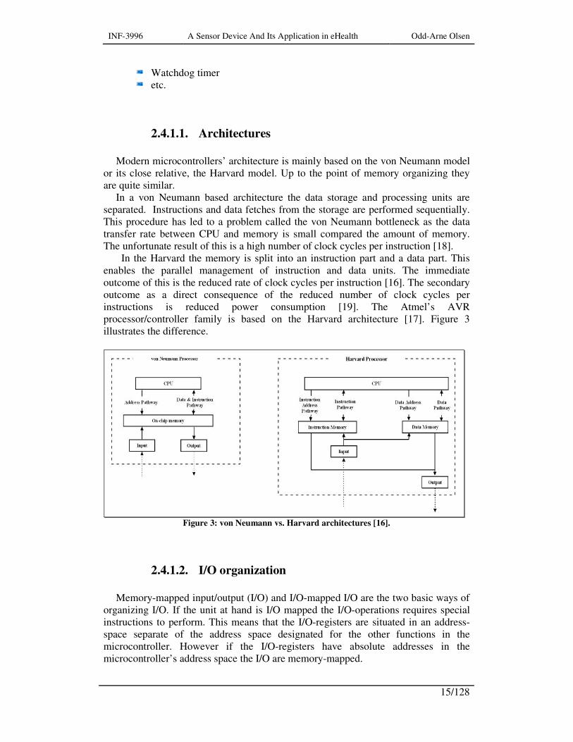
Modern microcontrollers’ architecture is mainly based on the von Neumann model
or its close relative, the Harvard model. Up to the point of memory organizing they are quite similar.
In a von Neumann based architecture the data storage and processing units are separated. Instructions and data fetches from the storage are performed sequentially. This procedure has led to a problem called the von Neumann bottleneck as the data transfer rate between CPU and memory is small compared the amount of memory. The unfortunate result of this is a high number of clock cycles per instruction [18].
In the Harvard the memory is split into an instruction part and a data part. This enables the parallel management of instruction and data units. The immediate outcome of this is the reduced rate of clock cycles per instruction [16]. The secondary outcome as a direct consequence of the reduced number of clock cycles per instructions is reduced power consumption [19]. The Atmel’s AVR processor/controller family is based on the Harvard architecture [17]. Figure 3 illustrates the difference.
Figure 3: von Neumann vs. Harvard architectures [16].
2.4.1.2. I/O organization
Memory-mapped input/output (I/O) and I/O-mapped I/O are the two basic ways of
organizing I/O. If the unit at hand is I/O mapped the I/O-operations requires special instructions to perform. This means that the I/O-registers are situated in an address-space separate of the address space designated for the other functions in the microcontroller. However if the I/O-registers have absolute addresses in the microcontroller’s address space the I/O are memory-mapped.

INF-3996 A Sensor Device And Its Application in eHealth Odd-Arne Olsen
16/128
The separation of the memory address space and the I/O address space is the main advantage with I/O-mapping. Because the whole memory address space can be used for program and data purposes without any restrictions. Whereas as the requirement for an extra instruction is its downside.
Not needing an extra instructions for read and write operations is the memory-mapped I/O’s main advantage. However the occupation of memory locations is its main disadvantage [18].
In order to carry out I/O-operations there are only three possibilities: polling, interrupt driven I/O and DMA. During polling the status of the register in question is checked at intervals in order to find out if it has received or produced data.
When in need of servicing the I/O unit in question raises a CPU flag. Given the interrupts designated priority the microcontroller will initiate the assigned interrupt service routine at once or when its current task is finished.
DMA is not relevant here as it is not available in the chosen microcontroller. However it was traditionally used to increase performance but in low-power embedded systems it helps servicing interrupts allowing the microcontroller core to remain in sleep mode longer.
2.4.1.3. Pipelining
By observing that during execution of instructions a large part of the
microprocessor was not used, someone found out that the instruction cycle could be broken down into a sequence of steps. Each of these steps would only use a small portion of the time needed to complete the whole instruction. Having a pipeline with multiple stages, each of these steps is assigned to an exclusive stage. The instructions enter the pipeline at one end, and steps finished exit at the other end. When a subtask result leaves a stage, this stage is ready to take on results from the previous stage. New instructions are accepted although the prior one is not completely finished. The main goal of this is to keep the pipeline fully utilized and this is true when the input rate matches the output rate [20].
The stages of a pipeline work in parallel each executing an instruction step. But no matter how many steps the pipeline has the instruction needs the same amount of time to complete. However an n-step pipeline can process n instructions at the same time. Given an ideal pipeline the completed instruction rate would be n times higher than without a pipeline [20].
2.4.1.4. Serial communication
There are two main classes of serial communication – synchronous and
asynchronous. A synchronous bus transfers a separate clock signal in addition to the data communication lines. As every bit is clocked over, there is no need for start and stop bits to mark the borders of a data byte. However in an asynchronous bus these bits are needed. Since no external clock signal is transferred this has to be extracted from the transferred data. Here the start and stop bits plays an important role. The start bit is of opposite polarity from the data-lines idle state whereas the stop bit has the
INF-3996 A Sensor Device And Its Application in eHealth Odd-Arne Olsen
17/128
same polarity as the idle state [21]. There is a third class – the semi-synchronous bus, which also is a clocked transfer but with one or more clock periods per transfer. It is however not of interest for this project.
In addition to the data lines there might be several handshake lines in order to mark the start and stop of data transfers. Examples of this can be the Request To Send (RTS), Clear To Send (CTS), Data Terminal Ready (DTR) and Data Set Ready (DSR) signals, found among other places in the asynchronous RS-232 data bus [21]. The use of these lines is however not mandatory and they can as such be deactivated when the service they provide are not needed.
The abbreviation UART will frequently be mentioned in the following. UART expands to universal asynchronous receiver/transmitter. This is a unit found also in microcontrollers’. Here its task is to convert the internal parallel communication into serial start – stop bit framed data bytes. Atmel calls their device for USART (Universal Synchronous/Asynchronous Receiver/Transmitter). The units bearing this description can also perform the duties of a synchronous interface.
2.4.1.5. JTAG
The IEEE standard 1149.1-1990 JTAG (Joint Test Action Group) is a synchronous
serial interface that was originally standardized as a means for testing printed circuit boards. The standard specifies four signals: Test Clock (TCK), Test Mode Select (TMS), Test Data Input (TDI) and Test Data Output (TDO) [22]. In addition the Test Reset (TRST) signal plus ground and a reference voltage is supplied. The TRST signal ensures that a reset is synchronized on both sides of the bus. Among many other uses it is nowadays also used as a debugging tool for embedded systems.
Although a standard there seem to exist many versions of the JTAG bus. The version of interest here is the one that Atmel uses as communication between their ATmega microcontrollers’ and the AVR JTAGICE mkII emulator.
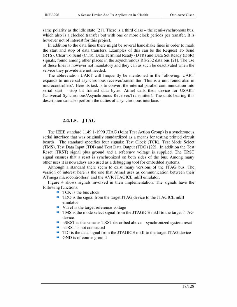
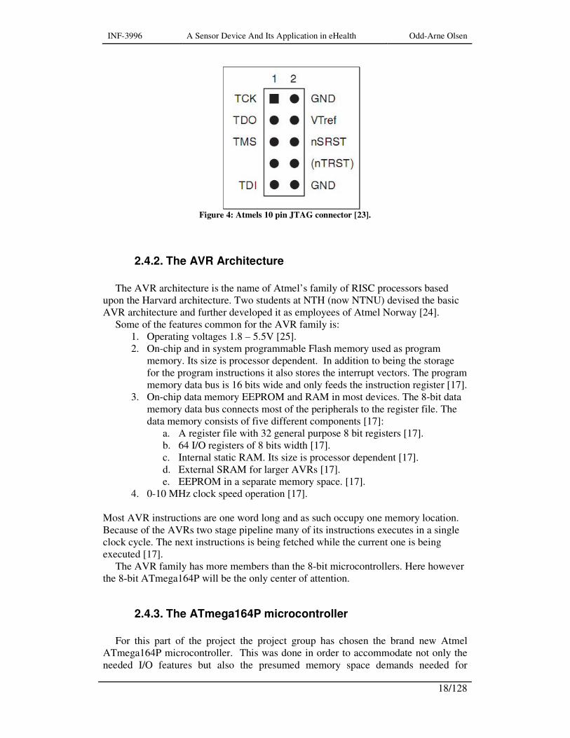
Figure 4 shows signals involved in their implementation. The signals have the following functions:
TCK is the bus clock TDO is the signal from the target JTAG device to the JTAGICE mkII
emulator VTref is the target reference voltage TMS is the mode select signal from the JTAGICE mkII to the target JTAG
device nSRST is the same as TRST described above – synchronized system reset nTRST is not connected TDI is the data signal from the JTAGICE mkII to the target JTAG device GND is of course ground
INF-3996 A Sensor Device And Its Application in eHealth Odd-Arne Olsen
18/128
Figure 4: Atmels 10 pin JTAG connector [23].
2.4.2. The AVR Architecture
The AVR architecture is the name of Atmel’s family of RISC processors based
upon the Harvard architecture. Two students at NTH (now NTNU) devised the basic AVR architecture and further developed it as employees of Atmel Norway [24].
Some of the features common for the AVR family is: 1. Operating voltages 1.8 – 5.5V [25]. 2. On-chip and in system programmable Flash memory used as program
memory. Its size is processor dependent. In addition to being the storage for the program instructions it also stores the interrupt vectors. The program memory data bus is 16 bits wide and only feeds the instruction register [17].
3. On-chip data memory EEPROM and RAM in most devices. The 8-bit data memory data bus connects most of the peripherals to the register file. The data memory consists of five different components [17]:
a. A register file with 32 general purpose 8 bit registers [17]. b. 64 I/O registers of 8 bits width [17]. c. Internal static RAM. Its size is processor dependent [17]. d. External SRAM for larger AVRs [17]. e. EEPROM in a separate memory space. [17].
4. 0-10 MHz clock speed operation [17]. Most AVR instructions are one word long and as such occupy one memory location. Because of the AVRs two stage pipeline many of its instructions executes in a single clock cycle. The next instructions is being fetched while the current one is being executed [17].
The AVR family has more members than the 8-bit microcontrollers. Here however the 8-bit ATmega164P will be the only center of attention.
2.4.3. The ATmega164P microcontroller
For this part of the project the project group has chosen the brand new Atmel
ATmega164P microcontroller. This was done in order to accommodate not only the needed I/O features but also the presumed memory space demands needed for
INF-3996 A Sensor Device And Its Application in eHealth Odd-Arne Olsen
19/128
program and data. The ATmega164P is memory wise the smallest member of an AVR subfamily consisting of totally three otherwise nearly identical members. The three members have respectively 16Kb, 32Kb and 64Kb of flash program memory [25]. In addition there are some differences in the sizes of EEPROM and RAM memories. However the pin outs of these three are identical. Judging by this a transition from ATmega164P to one of its larger relatives should be a painless process with just minor software changes needed. Such a transition would of course be caused by the demands for more program memory. The reason why the research group started with the smallest member was that it was the only one that was available at the time, in addition to it having some however minor advantages in terms of power consumption.
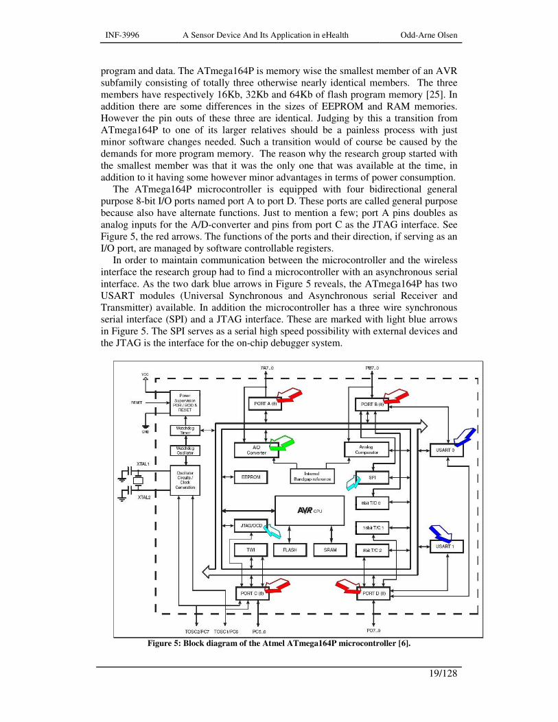
The ATmega164P microcontroller is equipped with four bidirectional general purpose 8-bit I/O ports named port A to port D. These ports are called general purpose because also have alternate functions. Just to mention a few; port A pins doubles as analog inputs for the A/D-converter and pins from port C as the JTAG interface. See Figure 5, the red arrows. The functions of the ports and their direction, if serving as an I/O port, are managed by software controllable registers.
In order to maintain communication between the microcontroller and the wireless interface the research group had to find a microcontroller with an asynchronous serial interface. As the two dark blue arrows in Figure 5 reveals, the ATmega164P has two USART modules (Universal Synchronous and Asynchronous serial Receiver and Transmitter) available. In addition the microcontroller has a three wire synchronous serial interface (SPI) and a JTAG interface. These are marked with light blue arrows in Figure 5. The SPI serves as a serial high speed possibility with external devices and the JTAG is the interface for the on-chip debugger system.
Figure 5: Block diagram of the Atmel ATmega164P microcontroller [6].
INF-3996 A Sensor Device And Its Application in eHealth Odd-Arne Olsen
20/128
2.5. Programming environments
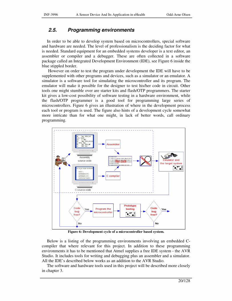
In order to be able to develop system based on microcontrollers, special software
and hardware are needed. The level of professionalism is the deciding factor for what is needed. Standard equipment for an embedded systems developer is a text editor, an assembler or compiler and a debugger. These are often collected in a software package called an Integrated Development Environment (IDE), see Figure 6 inside the blue stippled border.
However on order to test the program under development the IDE will have to be supplemented with other programs and devices, such as a simulator or an emulator. A simulator is a software tool for simulating the microcontroller and its program. The emulator will make it possible for the designer to test his/her code in circuit. Other tools one might stumble over are starter kits and flash/OTP programmers. The starter kit gives a low-cost possibility of software testing in a hardware environment, while the flash/OTP programmer is a good tool for programming large series of microcontrollers. Figure 6 gives an illustration of where in the development process each tool or program is used. The figure also hints of a development cycle somewhat more intricate than for what one might, in lack of better words, call ordinary programming.
Figure 6: Development cycle of a microcontroller based system.
Below is a listing of the programming environments involving an embedded C-
compiler that where relevant for this project. In addition to these programming environments it has to be mentioned that Atmel supplies a free IDE system - the AVR Studio. It includes tools for writing and debugging plus an assembler and a simulator. All the IDE’s described below works as an addition to the AVR Studio.
The software and hardware tools used in this project will be described more closely in chapter 3.

INF-3996 A Sensor Device And Its Application in eHealth Odd-Arne Olsen
21/128
2.5.1. IAR Embedded Workbench
IAR Embedded Workbench is a complete IDE consisting of among other things a
text editor, a C compiler, AVR assembler and the C-SPY debugger. As the system is developed and maintained in co-operation with Atmel Norway
they more or less guarantee having the most recent additions and changes. This is undoubtedly the most streamlined and professional product available. The pricelist below obtained on the 8th of February 2007 from Norsys AS, might be considered to reveal one of its major downsides.
Standard version kr. 22.500,- Light version kr. 17.000,- Embedded C++ kr. 29.500,-
All prices are for one license. The difference between the standard version and the
light version is that the light version does not include the C-SPY debugger. However it can use the features available in the Atmel AVR Studio.
Embedded C++ is according to Norsys AS rarely used for 8-bit microcontrollers. By paying 25% extra a floating license can be obtained. Here any computer
attached to the network can use the program. However if only one license is bought only one computer can use it at a time. Another possibility is to buy an USB dongle for 500kr. Only the computer with this dongle attached can run the program.
The prices gives one year of updates, additional update beyond the first year is obtainable at a cost of 20% of the full license fee.
All prices are exclusive value added tax and freight charges. More information to be found in reference [26].
2.5.2. CodeVisionAVR
CodeVisionAVR is an IDE and C-compiler. It does not contain a debugger but is
designed to work with Atmel’s AVR Studio Debugger. This is a cheap alternative compared to the IAR Embedded Workbench. The downside is a lower rate of updates and a system not as streamlined and well integrated as the IAR system.
However users seem to be very pleased with its features and level of usability. It is undoubtedly a good alternative when price and available documentation is taken into the consideration.
There are two versions available, however only the standard version is relevant for this project. The reason for this is that the light version does not support the ATmega line of microcontrollers.
The prize for the standard version is €150/$180 plus value added tax. This includes a one year subscription of updates and e-mail tech support. The yearly updates costs at the time of writing $90/€75.
The ordering procedure is somewhat complex. First the commercial version of the compiler has to be downloaded. Then an order including the buyer’s address details and name of product has to be sent via e-mail to the chosen vendor. The vendor

INF-3996 A Sensor Device And Its Application in eHealth Odd-Arne Olsen
22/128
responds with a password for the downloaded zip-archive. This is however not the end of it. After the installation the program supplies the user with a serial number which he/she has to send to the program author. Following this HP InfoTech, which is the program maker/author, will send a license file and installation instructions for it.
At the moment it is not clear what has to be done in order to move the program from one computer to another. But a fairly good guess would be that it involves some e-mail exchange with the program author.
In addition to a 200-page user manual there are also books available covering AVR software development using the CodeVisionAVR software. An example being recommended by many is “Embedded C Programming And The Atmel AVR” 2nd edition, by Richard H. Barnett, Sarah Cox, Larry O'Cull (ISBN-10: 1418039594 / ISBN-13: 978-1418039592). More information found via reference [27].
2.5.3. WinAVR (GNU GCC)
This is an open-source collection of development tools. The collection contains all
the tools needed as compiler (avr-gcc), programmer (avrdude), debugger (avr-gdb), simulator (simulavr) and more. It is developed and maintained by volunteers and independent groups. A result of this is that a somewhat higher entry level is to be expected in addition to an even lower update rate than for instance CodeVisionAVR. A quick search for literature reveals many possibilities though few in understandable languages (Norwegian, English). Worth to mention is a tutorial [28] and a slightly aged user manual [29]. In addition there is also a book available “C Programming for Microcontrollers Featuring Atmel’s AVR Butterfly and the free WinAVR Compiler” by John Pardue (ISBN-10: 0976682206 / ISBN-13: 978-0976682202). The AVR Butterfly is a $20 evaluation card containing the ATmega169 processor plus display and sensors.
2.5.4. ImageCraft v7 C compiler and Crossworks for AVR
These two software packages are also often mentioned along with the others. Why
these have not gotten more room here is mostly because of their license restrictions and advertised device support.
According to their current web pages Crossworks does not yet support the mega164 microcontroller [30]. This of course may only be caused by slow working web masters. More serious is their license policy. There are three possibilities commercial, educational and personal. However in order to achieve the commercial freedom presumed desired by the research group only the commercial version to $950 would suffice.
This is not a problem with the ImageCraft system as its license levels only limits the number of features supplied.
A common feature which seems to disqualify them both is that they presumably only support their own line of emulators and programmers [30, 31].
INF-3996 A Sensor Device And Its Application in eHealth Odd-Arne Olsen
23/128
2.6. AVR Assembly programming
2.6.1. The registers
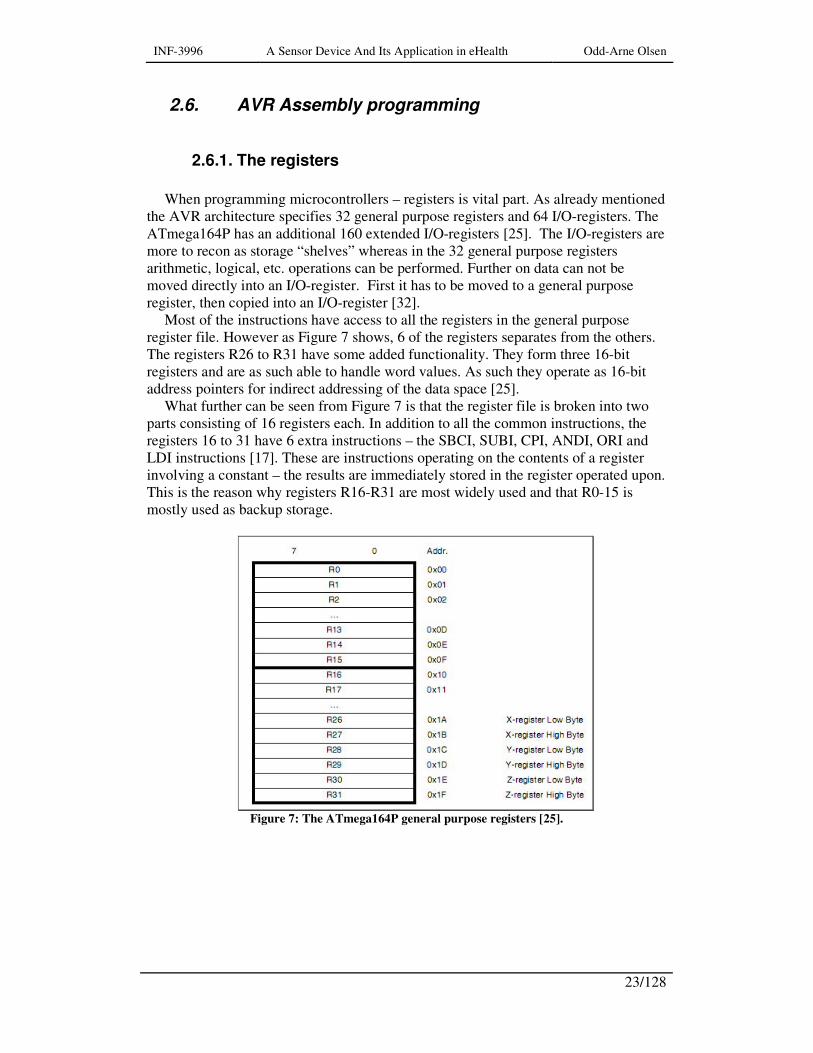
When programming microcontrollers – registers is vital part. As already mentioned
the AVR architecture specifies 32 general purpose registers and 64 I/O-registers. The ATmega164P has an additional 160 extended I/O-registers [25]. The I/O-registers are more to recon as storage “shelves” whereas in the 32 general purpose registers arithmetic, logical, etc. operations can be performed. Further on data can not be moved directly into an I/O-register. First it has to be moved to a general purpose register, then copied into an I/O-register [32].
Most of the instructions have access to all the registers in the general purpose register file. However as Figure 7 shows, 6 of the registers separates from the others. The registers R26 to R31 have some added functionality. They form three 16-bit registers and are as such able to handle word values. As such they operate as 16-bit address pointers for indirect addressing of the data space [25].
What further can be seen from Figure 7 is that the register file is broken into two parts consisting of 16 registers each. In addition to all the common instructions, the registers 16 to 31 have 6 extra instructions – the SBCI, SUBI, CPI, ANDI, ORI and LDI instructions [17]. These are instructions operating on the contents of a register involving a constant – the results are immediately stored in the register operated upon. This is the reason why registers R16-R31 are most widely used and that R0-15 is mostly used as backup storage.
Figure 7: The ATmega164P general purpose registers [25].
INF-3996 A Sensor Device And Its Application in eHealth Odd-Arne Olsen
24/128
2.7. Wireless communication
Bluetooth is at present the only short-range communication protocol which is
commercially available and most important it is a standard feature in many mobile phones. Compared to other wireless technologies of equal accessibility it scores high because of usability, small size and low-cost. In addition it is a true world-wide standard as any Bluetooth based system can communicate with any Bluetooth unit in any country [33, 34]. Bluetooth uses the industrial, scientific and medical (ISM) radio bands at 2.4GHz. Here it works among 79 channels. Jumps between channels occur approximately 1600 times per second. Which channel it jumps too is decided by whether it is vacant or not. This technique is called adaptive frequency hopping (AFH) [35].
A competitor to Bluetooth is Zigbee - it is more power efficient and simpler, but although commercially available it is at the time of writing not implemented in any mobile phones. Another technology often mentioned is Wibree, however it is not been put out on the market yet. Wibree might be the biggest competitor to Bluetooth in the future for this project as Nokia has announced its implementation in mobile phones.
The research group has chosen the connectBlue OEMSPA311i-04 module as its Bluetooth interface. This 16mm by 36mm module is a class 1 device with a transmitting range of 10 to 150 meters depending on the attached antenna. There are three Bluetooth power classes. Class 1 has a range of around 100 meters; class 2 around 10 meters and class 3 have a range of around 1 meter [33]. However there seems to be no class 3 devices available commercially. If such a short range is desired, many manufacturers have added a power limiting feature to their class 1 or class 2 devices. This enables the user to set the output power on the module to a level giving the range which satisfies his/her needs [36].
The range values mentioned here for the power classes should not be regarded as absolute truths as these numbers varies according to which data sheet or book you read. These ranges vary from producer to producer, and also between identical modules with different antennas attached. I addition these data are given for devices tested with an unobstructed line of sight connection, and with no structures in the vicinity giving signal reflections which could jam the main transmission [36].
In addition to being locally available the chosen module is relatively small and compact. It is equipped with an internal antenna and as such it is ideal for this purpose. The setup is taken care by a set of AT-commands enabling the user to configure the module optimally in relation to his/her needs. In order to accommodate this, the module has two operational modes; transparent data mode and AT mode [37].

INF-3996 A Sensor Device And Its Application in eHealth Odd-Arne Olsen
25/128
2.8. Sensors
The main purpose of a sensor is to give an environmental variable a numerical
representation. There are most likely a number of approaches available for every measurable entity – some more successful than others.
An example of a sensor is the thermocouple sensor. Two different types of metal wires are joined together in a small contact point. Over this junction point there will be an electrical potential depending on the type of metals used and the junctions temperature. There are many types available depending on area of usage, accuracy and cost. The potential difference over a modern thermocouple could be between 1 µV/°C to approximately 70 µV/°C [38]. This is an example of an analog sensor which would need an amplification of its output signal and an A/D converter in order to get a readable representation of its data into the microcontroller. However this is also an example of a sensor which would need software correction due to non linearity in addition to value look up tables or a polynomial interpolation formula in order to present the correct measured temperature.
In order to record a number of recurring events for instance the number of a special movement a device which produces a pulse each time the situation occurs is needed. Such a pulse can be fed directly to one of the microcontroller’s digital input without any signal conditioning. Here there are many possibilities also, but in it simplest form it can just be a switch.

INF-3996 A Sensor Device And Its Application in eHealth Odd-Arne Olsen
26/128

INF-3996 A Sensor Device And Its Application in eHealth Odd-Arne Olsen
27/128
3. Methods
3.1. Sensors measurements
For testing out possible movement sensors two circuits where used. This might
seem redundant, but the circuit shown in Figure 8 B was the one I used before the project group supplied me with the initial hardware specifications.
The components in Figure 8 A were chosen with sharp eye power consumption. This is however a delicate trade-off as a too high resistance circuit will give noise problems while a too low resistance circuit might cause a premature drainage of the power source.
Figure 8: Sensor test circuits. A) Implemented in the step-counter. B) Only used for test
purposes.
As power source an Oltronic B202 laboratory power supply were used. The
measurements were performed with a Picoscope 2105 virtual oscilloscope. It is a pen shaped probe with an USB interface combined with computer software for viewing a graphical interpretation of the signals measured upon. The probe is powered via the computers USB interface and it can measure frequencies up to 25MHz. The system can directly store or print out data if so desired [39].

INF-3996 A Sensor Device And Its Application in eHealth Odd-Arne Olsen
28/128
3.2. Program development and testing
3.2.1. The STK-500 starter kit
In order to get acquainted with the ATmega164P microcontroller and the AVR
assembly language the AVR STK500 starter kit was used. Starter kits are easy and low-cost systems designed for testing the software in a hardware environment. It consists of a hardware board and an in-system programmer bundled with software component needed. Often this software is just evaluation versions of a complete IDE or its separate components. Atmel however delivers a complete IDE with assembler, editor, and simulator – the AVR Studio. The starter kits are mostly or almost exclusively only available for flash controllers. This is because the flash memory allows the microcontroller at hand to – well – emulate itself as the in-system programmer downloads the code into the flash and executes it. To be able to perform debugging the starter kit downloads a short monitor code along with the developed code. The monitor code allows the developer to examine the memory and insert break points in the code. In order to be able to do this the monitor code has to use some of the microcontroller resources as interrupts, stack-, code- and data-memory. These kits are just for small scale and hobby use, and do of course not offer the debugging force of simulators and high-end emulators. But their main advantage is the real time operability and easy testing of I/O-functionality that they offer.
Figure 9 shows a picture of the STK500. As can be seen it provides a number of switches and light emitting diodes (LED) for the purpose of testing programmed input/output functions. The kit is also equipped with a number of IC sockets in order to provide support for all the different AVR microcontrollers intended.
Figure 9: The Atmel AVR STK500 starter kit.

INF-3996 A Sensor Device And Its Application in eHealth Odd-Arne Olsen
29/128
The Atmel AVR JTAGICE mkII emulator
An emulator is a hardware device designed to behave as identical as possible to
what the real microcontroller would have. The emulator is connected to the developers PC via parallel, RS-232 or an USB connection.
The JTAGICE mkII performs its duty, as the name might imply – via the JTAG interface. This requires that the circuit designer equips the circuit board the ten pin JTAG header as this emulator requires. This emulator further requires that the microcontroller is placed on the circuit board. Figure 10 reveals the rather dull exterior of the emulator; however on the left side of the picture the 10-pin JTAG header is clearly visible.
Figure 10: Atmel AVR JTAGICE mkII in-circuit emulator [23].
The emulator was used to test and edit the step-counter software on the prototype
printed circuit boards.

INF-3996 A Sensor Device And Its Application in eHealth Odd-Arne Olsen
30/128

INF-3996 A Sensor Device And Its Application in eHealth Odd-Arne Olsen
31/128
4. Requirement Specification
4.1. Ergonomics, power consumption and usability
There are many factors why a user might chose not to continue using an e-health
device acquired during a sudden urge for health and fitness. However the only factors possible to concentrate on here are of course device related issues like size, weight and usability.
As such this calls for a step-counter which is both light in weight and small in physical size. The ideal situation is a system which when properly mounted is more or less unnoticeable for the user during his/her daily activity.
Unfortunately these desires are at current in directly conflict with the wish for a long life span of the device. A long life span is synonymous with large battery capacity. A large battery capacity is in turn equal to increased size and weight. Therefore keeping the current consumption at a minimum is vital.
Usability calls for a device with as few buttons and user controllable functions as possible. Ideally the only thing the user should have to do is to attach the unit at a suitable place on his/her body and think nothing more of it. The planned wireless interface is a major leap towards this, in lack of better words, device-unawareness. It removes the need for any display, and nearly all buttons. The ultimate goal should be no buttons as there should be no need for any user initiated setups or features being controlled at the step-counter device. Ideally everything should be controlled from the mobile base.
4.2. Personal adaptation and context awareness
Although at current only equipped with a movement sensor, there should be
possibilities of getting more data than just the number of movements within the given timeframe. For instance how many of these movements where caused by, walking, jogging or running.
This device is supposed to serve any type of person – active as passive, tall as short. What might be running for one person might for the next one hardly pass as jogging. The device will as such have to be able to handle individual setups of how the data is going to be interpreted.
Further on possibilities of context awareness should be investigated. For instance is the person moving inside or outside? Is he/she climbing stairs or walking on a horizontal surface. Such data would help the system into giving more accurate values of for instance caloric consumption.

INF-3996 A Sensor Device And Its Application in eHealth Odd-Arne Olsen
32/128
4.3. Reliability and information security
It is quite impossible to secure every corner considering the technical reliability of
such a device. This is however no excuse for not trying. The most obvious danger is the loss of data due to power failure or communicational errors. As such pre-emptive measures to reduce these risks should be taken.
Further on is the step-counter’s ability to produce reliable data. Here its noise susceptibility is a vital keyword. This however can only be controlled to a certain degree by careful circuit board and hardware design - plus shielding.
Information security might be an issue for the later versions of this device. However considering the small amount of data being transmitted and the infrequent transmissions, the danger seems not to be imminent. Another matter will be the introduction of other sensors measuring biometric data with a higher degree of sensitivity than the number of steps within the last 24 hours. As such data encryption in addition to identification of the mobile base and appurtenant step-counter would eventually have to be addressed. Not just for reasons of security but with scalability in mind.
INF-3996 A Sensor Device And Its Application in eHealth Odd-Arne Olsen
33/128
5. Design and implementation
5.1. The step-counter prototypes
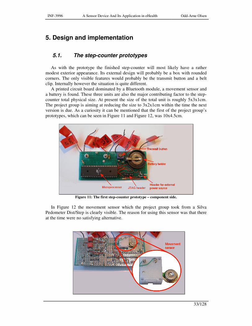
As with the prototype the finished step-counter will most likely have a rather
modest exterior appearance. Its external design will probably be a box with rounded corners. The only visible features would probably be the transmit button and a belt clip. Internally however the situation is quite different.
A printed circuit board dominated by a Bluetooth module, a movement sensor and a battery is found. These three units are also the major contributing factor to the step-counter total physical size. At present the size of the total unit is roughly 5x3x1cm. The project group is aiming at reducing the size to 3x2x1cm within the time the next version is due. As a curiosity it can be mentioned that the first of the project group’s prototypes, which can be seen in Figure 11 and Figure 12, was 10x4.5cm.
Figure 11: The first step-counter prototype – component side.
In Figure 12 the movement sensor which the project group took from a Silva
Pedometer Dist/Step is clearly visible. The reason for using this sensor was that there at the time were no satisfying alternative.

INF-3996 A Sensor Device And Its Application in eHealth Odd-Arne Olsen
34/128
Figure 12: The first step-counter prototype – solder side.
Figure 13 and Figure 14 shows pictures of the second step-counter prototype with
its main features marked.
Figure 13: The second step counter prototype, side 1.
Figure 14: The second step-counter prototype, side 2.
INF-3996 A Sensor Device And Its Application in eHealth Odd-Arne Olsen
35/128
5.2. Step-counter functionality
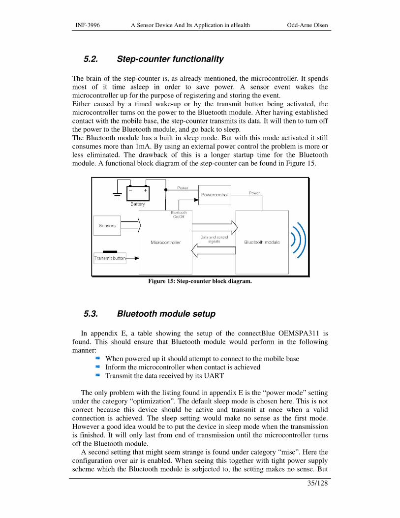
The brain of the step-counter is, as already mentioned, the microcontroller. It spends most of it time asleep in order to save power. A sensor event wakes the microcontroller up for the purpose of registering and storing the event. Either caused by a timed wake-up or by the transmit button being activated, the microcontroller turns on the power to the Bluetooth module. After having established contact with the mobile base, the step-counter transmits its data. It will then to turn off the power to the Bluetooth module, and go back to sleep. The Bluetooth module has a built in sleep mode. But with this mode activated it still consumes more than 1mA. By using an external power control the problem is more or less eliminated. The drawback of this is a longer startup time for the Bluetooth module. A functional block diagram of the step-counter can be found in Figure 15.
Figure 15: Step-counter block diagram.
5.3. Bluetooth module setup
In appendix E, a table showing the setup of the connectBlue OEMSPA311 is
found. This should ensure that Bluetooth module would perform in the following manner:
When powered up it should attempt to connect to the mobile base Inform the microcontroller when contact is achieved Transmit the data received by its UART
The only problem with the listing found in appendix E is the “power mode” setting
under the category “optimization”. The default sleep mode is chosen here. This is not correct because this device should be active and transmit at once when a valid connection is achieved. The sleep setting would make no sense as the first mode. However a good idea would be to put the device in sleep mode when the transmission is finished. It will only last from end of transmission until the microcontroller turns off the Bluetooth module.
A second setting that might seem strange is found under category “misc”. Here the configuration over air is enabled. When seeing this together with tight power supply scheme which the Bluetooth module is subjected to, the setting makes no sense. But
INF-3996 A Sensor Device And Its Application in eHealth Odd-Arne Olsen
36/128
actually this will be the only way to change the setup module when mounted into the step-counter. This will of course require external powering of the module.
For later to-way versions a more active use of the sleep mode, maybe in combination with sniff mode should be tested out. When in sniff mode the module is only up and listens for a short time at intervals, for instance 5mS for every 100mS. This mode is available in the OEMSPA311 through link policies 6-8 [37]. Sniff modes should only be used after thorough tests as connectBlue warns of possible traffic dependent link/data loss [37].
5.4. Bluetooth – UART interfacing
5.4.1. Data format
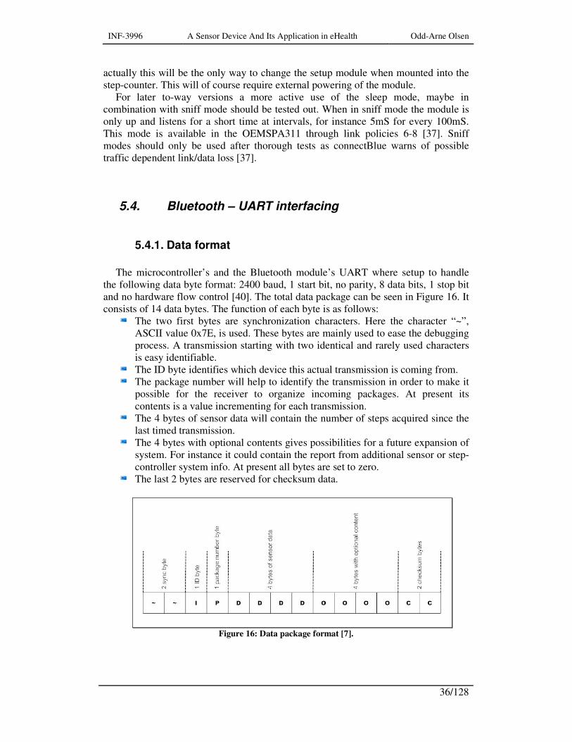
The microcontroller’s and the Bluetooth module’s UART where setup to handle
the following data byte format: 2400 baud, 1 start bit, no parity, 8 data bits, 1 stop bit and no hardware flow control [40]. The total data package can be seen in Figure 16. It consists of 14 data bytes. The function of each byte is as follows:
The two first bytes are synchronization characters. Here the character “~”, ASCII value 0x7E, is used. These bytes are mainly used to ease the debugging process. A transmission starting with two identical and rarely used characters is easy identifiable.
The ID byte identifies which device this actual transmission is coming from. The package number will help to identify the transmission in order to make it
possible for the receiver to organize incoming packages. At present its contents is a value incrementing for each transmission.
The 4 bytes of sensor data will contain the number of steps acquired since the last timed transmission.
The 4 bytes with optional contents gives possibilities for a future expansion of system. For instance it could contain the report from additional sensor or step-controller system info. At present all bytes are set to zero.
The last 2 bytes are reserved for checksum data.
Figure 16: Data package format [7].
INF-3996 A Sensor Device And Its Application in eHealth Odd-Arne Olsen
37/128
5.4.2. Hardware flow control
In order for the microcontroller to know whether the Bluetooth module was active
or not, there was some uncertainty whether the flow control was needed or not. I suggested the use of the DTR (Data Terminal Ready) line available on the Bluetooth module. For RS-232 communication a unit can check whether a receiving unit is active and ready to operate by checking the status of the DTR line.
However it was not clear whether the active status of the Bluetooth module’s DTR line was determined by flow control settings or not. After some searching I found that the DTR and DSR (Data Set Ready) lines where controlled by a separate AT command. As a direct consequence of this the hardware flow control could be disabled.
The AT command “AT*AMDS=” gave two functional possibilities for the DTR line. The DTR line could be activated when the module started or when there was an active Bluetooth connection present [37]. The latter was chosen since it meant an easy and foolproof method of checking not only the Bluetooth module’s status but also whether there was an approved mobile base ready to receive the transmission.
An active flow control would have required two additional control lines - the CTS and RTS, in addition to software routines handling them.
5.4.3. Choosing baud rate
Initially the baud rate was set to 9600 baud. But with the chosen clock source the
microcontroller could not deliver the needed level of accuracy in the generated baud rate
The reason for this was that the step counter microcontroller is using its internal oscillator which is running at 1MHz. The microcontroller’s baud rate generator derives the baud rate directly from the oscillator frequency. The Atmega164P has two possibilities of generating the baud rate clock signal in asynchronous mode, as it does in synchronous mode. Here however only asynchronous mode is relevant and therefore the only center of attention.
The baud rate generator is controlled by the oscillator frequency. The signal is fed to a down counter which is loaded with the contents of the USART Baud Rate Register (UBRR) every time it reaches zero. The output frequency is
)1( +=
UBRRnfosc and depending on modes chosen, the output baud rate at is a half,
an eighth or a sixteenth part of this frequency [25]. The same network also generates a clock signal for the clock recovery logic. The clock recovery logic synchronizes this clock signal with the incoming data bytes at the receive pin (Rx) [25].
As such, with the chosen oscillator frequency this network will produce a baud rate which at its best will be 7% below the wanted 9600 baud. The receiving end of the OEMSPA311 Bluetooth adapter’s UART tolerates an error of only 2% deviation from the predestined baud rate [37]. While the microcontroller’s UART receiver has an error margin of ±1.5% for a 9-bit data frame [25]. These are not absolute values as higher error ratings can be acceptable. But the system will have less noise resistance, and have increased sensitivity for the deviations in the internal RC oscillator’s frequency.
INF-3996 A Sensor Device And Its Application in eHealth Odd-Arne Olsen
38/128
In asynchronous mode the transfer rate can be doubled. This is done by setting the U2Xn bit high. This should have no effect on the transmitting side. However for the receiver this halves the number of samples taken in the data reading and clock recovery procedures. Having an accurate baud rate setting and a stable system clock this should not produce any problems [25].
During the first testing the microcontroller UART baud rate was set to 9600 baud with the U2Xn bit high. According to the microcontroller documentation this should only give an error rate of 0.2%. But measurements done showed an error of around 8% slower on the produced data frames. This could of course be caused by errors and inaccuracies in the measurement process.
But no matter the cause of this error, it was obvious that a baud rate of 9600 baud could not be maintained with an oscillator frequency of 1MHz with the internal RC oscillator as its source.
The easiest solution was to clear the U2Xn bit and reduce the baud rate to 2400 baud. For the current system this should cause no problem as the data package to be transferred consisted of only 14 9-bit frames. With the help of an oscilloscope I found that the error was within ±1.2%, and therefore acceptable.
It should be noted though that an oscilloscope is not the best instrument to perform such measurements with. The accuracy of such a measurement will largely depend on the visual estimate of person reading the instrument.
5.4.3.1. Strategies for achieving a 9600 baud rate
For later versions of the system one might aim for 9600 baud. This can be caused
by demands from different Bluetooth modules or other modules external to the microcontroller. One solution can be to use the Atmega164P’s low power external oscillator and increasing the oscillator frequency to 1.8432MHz.
The project group was very reluctant to this idea because the use of this oscillator in addition to the higher clock frequency would most likely cause a higher power consumption. This should however be tested out in case such a change is forced through due to external technical needs. Such a need could be the interfacing between the step-counter and a glucose meter.
The low power crystal oscillator is only capable of driving the microcontroller clock and it can be susceptible for noise. However it will create a more stable clock than the internal RC oscillator. The major downside is the need for three extra components – two capacitors and a clock crystal. The capacitors are negligible in size but a 1.8432 MHz crystal is quite visible. A further increase in oscillator frequency to the next frequency causing a minimal division error, 3.6864 MHz, gives higher power consumption but the crystals are smaller in size. One possibility that should be looked into is a dynamically run-time change of clock frequency or clock source.

INF-3996 A Sensor Device And Its Application in eHealth Odd-Arne Olsen
39/128
5.4.4. Connecting microcontroller with the Bluetooth module
Having made sure that the microcontroller produced data frames of acceptable
quality, see Figure 17, it was attached to the Bluetooth module. The module was set up and tested beforehand by the project group in the manner indicated above on a starter kit. For initial testing all security and bonding features were disabled.
When hooking the Bluetooth module to 3.3V power, ground and signal from the microcontroller no contact with the test base was achieved. The step-counter was visible from other Bluetooth devices but it would not connect or be connected to. Confirming with the manual that there should be no reason why this minimal connection scheme shouldn’t work the imminent conclusion was that the Bluetooth module’s setup had to be revised [41].
The project group‘s revision resulted in a successful connection between the step-counter and a test base. However when toggling the power on the step-counter it did not try to connect. The reason for this was that the connection was initiated by the test base. When fully operative the step-counter should attempt to connect to the paired base at every Bluetooth module power-up. If the connectBlue module is not able to perform in this manner it has to be replace with one who does.
Figure 17: Oscilloscope picture of the output from the microcontroller's UART.
5.4.5. Some alternatives
One weakness of the OEMSPA311’s became apparent when the project group found another module with a physical size over four times smaller. However this module, the KCWirefree’s KC-22, needs an external antenna [42]
INF-3996 A Sensor Device And Its Application in eHealth Odd-Arne Olsen
40/128
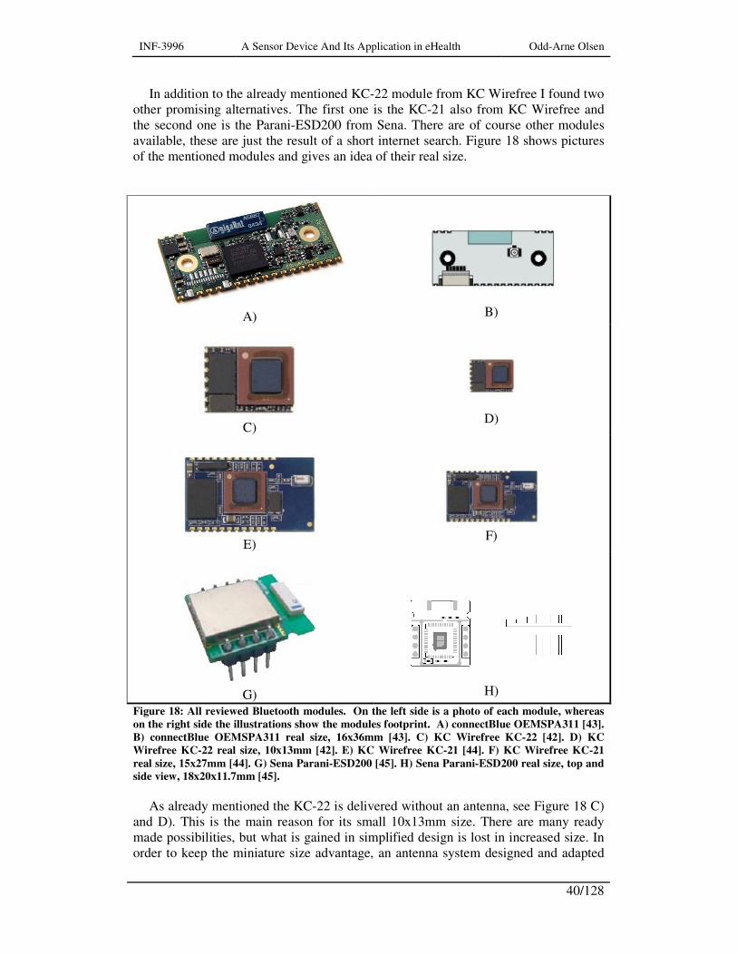
In addition to the already mentioned KC-22 module from KC Wirefree I found two other promising alternatives. The first one is the KC-21 also from KC Wirefree and the second one is the Parani-ESD200 from Sena. There are of course other modules available, these are just the result of a short internet search. Figure 18 shows pictures of the mentioned modules and gives an idea of their real size.
A)
B)
C)
D)
E)
F)
G)
H)
Figure 18: All reviewed Bluetooth modules. On the left side is a photo of each module, whereas
on the right side the illustrations show the modules footprint. A) connectBlue OEMSPA311 [43].
B) connectBlue OEMSPA311 real size, 16x36mm [43]. C) KC Wirefree KC-22 [42]. D) KC
Wirefree KC-22 real size, 10x13mm [42]. E) KC Wirefree KC-21 [44]. F) KC Wirefree KC-21
real size, 15x27mm [44]. G) Sena Parani-ESD200 [45]. H) Sena Parani-ESD200 real size, top and
side view, 18x20x11.7mm [45].
As already mentioned the KC-22 is delivered without an antenna, see Figure 18 C)
and D). This is the main reason for its small 10x13mm size. There are many ready made possibilities, but what is gained in simplified design is lost in increased size. In order to keep the miniature size advantage, an antenna system designed and adapted
INF-3996 A Sensor Device And Its Application in eHealth Odd-Arne Olsen
41/128
for the step counter would be preferable. Another short search revealed a number of possibilities where the Fractus® Compact Reach Xtend™ chip antenna [46] seemed the most promising when size and efficiency were considered. In addition, when compared to similar chip antennas the Fractus required a somewhat simpler circuit board layout [47]. Here however the simplicity seems to end; in order for the system to perform optimally the signal line between the antenna the module has to possess certain characteristics. Going further with the printed circuit boards mentioned above the easiest solution is a microstrip line. A microstrip line is a transmission line geometry with a single conductor trace on one side of a dielectric substrate and a single ground plane on the other [48, 49]. The properties of a microstrip line are given by its physical measurements and the substrate’s electrical abilities. At 2.4GHz this is vital in order to obtain an adapted and reflection free connection with correct impedance. A well designed and well tuned antenna system will ensure that as much as possible of the power produced by the Bluetooth module is transmitted.
If there however does not exist any special needs in terms of the positioning of the antenna, for instance mechanical design or noise considerations, the other alternative KC-21 is basically the same module but with an antenna.
Anyhow, reading through the data of each module – the reason for choosing any of the other modules than the connectBlue OEMSPA311 has to be smaller sizes. In terms on features and power consumption they offer roughly the same.
Both connectBlue and Parani has Norwegian representation but KC Wirefree has dealerships in England and Germany. A foreign dealer is not necessarily a weakness as both KC-Wirefree’s and connectBlue’s delivered their respective devices well within a working week in contrast to what many Norwegian representatives are able to do.
In the project group there has been a lot of talk about a manufacturer named Cambridge Silicon Radio Limited (CSR). But as far as I could tell they only manufacture Bluetooth chips, not modules [50]. Because of this they are not of interest in the current stage of the project, however for later step-counter versions the chips can be well worth looking into.
5.5. Power supply
As power source the project groups has chosen the CR2477, which is a Lithium
manganese dioxide primary battery (CR). A primary battery is not rechargeable. The CR2477 is a button shaped battery of size 24x7.7mm and weighs 10 grams.
The CR lithium batteries has high cell voltage, high energy density, a stable discharge voltage, good energy flow rates at low temperatures (down to -60°C) and good capacity for storage [51]. It is easy accessible and it is the most common type occupying around 80% of the lithium market. It is suitable for long life and low cost applications in need of high pulse currents. But how long this battery will function in the step-counter is not known as there has not been performed a power consumption analysis of the system yet.
The lithium battery is undoubtedly the best commercially available battery. However therein lays the flaw considering this project. Its flat discharge curve is a great advantage as it simplifies the system design. This because supply voltage stays fairly constant through the whole discharge cycle [52]. But it causes problems for

INF-3996 A Sensor Device And Its Application in eHealth Odd-Arne Olsen
42/128
using voltage measurements to determine of the battery’s state of charge. The voltage drops so late that it might not be power enough left to send a warning message.
5.6. The Step counter software
5.6.1. Program overview
After having reviewed the basic program code of the step counter’s
microcontroller, I started breaking it down into a block diagram. My diagram is found in appendix B whereas the project team’s diagram (handed me later) are found in appendix A. Furthermore in appendix C a listing of the complete program prior to my proposed changes is found and consequently in appendix D the program listing subjected to my modification suggestions are to be found.
The purpose of the examination was both to gain detailed knowledge about the program and its functionality, and to propose improvements and new functionalities. The first task however was to discover errors in writing, form or logic and to suggest corrections.
Figure 19 gives a general overview of the different modules in the step-counter software. The black arrows indicate a standard procedure call, whereas the red arrows indicate an interrupt initiated procedure call. The software consists of seven modules. These modules are tied together as include files in the main program “ped164.asm”, see Table 1. Somewhat confusingly both the main program and a routine are described as main. However the complete step-counter software is called the main program, whereas the main routine, “main.asm”, mentioned below is just a small part of the total program, see chapter 5.6.3.
Table 1: The "ped164.asm" main program.
;******* main program .nolist .include "m164pdef.inc" .list .include "inite_reg.asm" ; initialize the registers for start/reset .include "isr_count.asm" ; interrupt service routine for step counting .include "isr_timer.asm" ; interrupt service routine for RTC .include "isr_mtransm.asm" ; interrupt service routine for user initiated
transmit .include "uart0.asm" ; low level routins for UART handling .include "transmit_bt.asm" ; data transmit routine .include "main.asm" ; main function
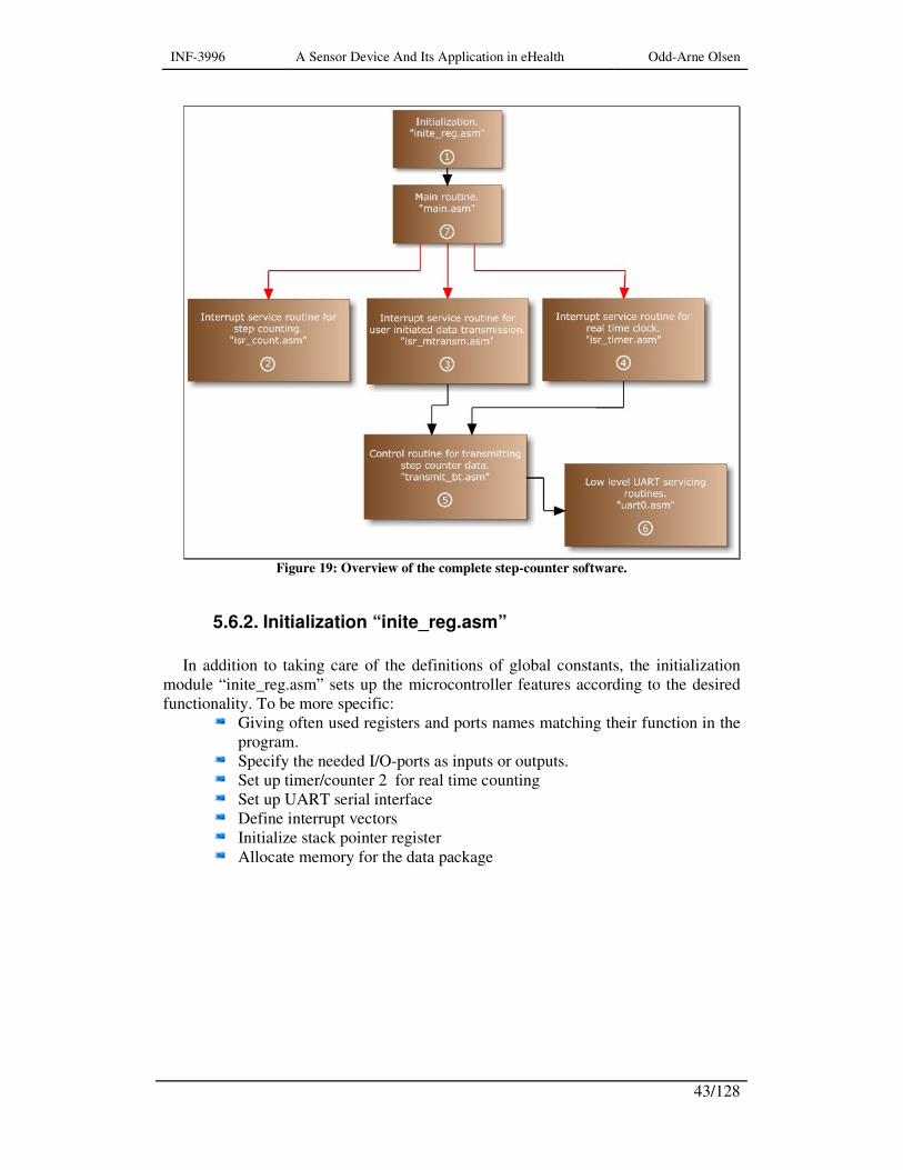
INF-3996 A Sensor Device And Its Application in eHealth Odd-Arne Olsen
43/128
Figure 19: Overview of the complete step-counter software.
5.6.2. Initialization “inite_reg.asm”
In addition to taking care of the definitions of global constants, the initialization
module “inite_reg.asm” sets up the microcontroller features according to the desired functionality. To be more specific:
Giving often used registers and ports names matching their function in the program.
Specify the needed I/O-ports as inputs or outputs. Set up timer/counter 2 for real time counting Set up UART serial interface Define interrupt vectors Initialize stack pointer register Allocate memory for the data package
INF-3996 A Sensor Device And Its Application in eHealth Odd-Arne Olsen
44/128
5.6.3. Main routine ”main.asm”
The function of the main routine is just to activate the global interrupts and then
perform an endless loop activating the sleep modus. An interrupt call will wake up the microcontroller. The loop ensures that the microcontroller goes back to the power save mode after having returned from the interrupt service routine.
5.6.4. Interrupt service routine for step counting “isr_count.asm”
The interrupt service routine for step counting is called every time the external
interrupt pin int0 detects a falling edge, i.e. a transition from logic high to a logic low level. This transition is caused by a movement activating the movement sensor. The routine performs a loop as long as the level at int0 still is low. This is done in order to filter out noise. After a logic high level is detected at int0, the routine updates the step counter value and returns to the main routine.
5.6.5. Interrupt service routine for user initiated data transmission “isr_mtransm.asm”
The interrupt service routine for user initiated data transmission
“isr_mtransm.asm” is activated by a transition from logical high to logical low level an the external interrupt pin int1. This transition is caused by the user pressing the send button on the step counter. The routine loops until the send button is released. After the button is released, the routine calls the Bluetooth transmit routine. After completion of the transmit routine, the microcontroller returns to the main routine.
5.6.6. Interrupt service routine for real time clock update “isr_timer.asm”
The interrupt service routine for the real time clock is called every eight second.
This routine counts the amount of eight second sequences. When this amount equals to 24 hours the Bluetooth transmit routine is called. One interesting thing with this routine is that this real time clock value has to be stored in a different set of registers than the registers used for the updating. The reason for this is that it is only possible to perform additions on a 16 bit value in a limited number of the general purpose registers. However this register also has alternate functions and as such a back up storage is needed.

INF-3996 A Sensor Device And Its Application in eHealth Odd-Arne Olsen
45/128
5.6.7. Control routine for transmitting step-counter data “transmit_bt.asm”
The control routine for transmitting step-counter data “transmit_bt.asm”, or the
Bluetooth transmit routine as it also has been called, retrieves the step counter data from its storage and inserts into the data package. After having turned on the power to the Bluetooth module the routine checks the DTR input line whether it has made contact with the mobile base and is ready to transmit. When this is the case the routine sends the data package, frame by frame to the UART service routine in charge of transferring the data to the Bluetooth module. Before returning to its caller the routine turns off the Bluetooth power, resets the step-counter value and presets the 24 hour real time counter value.
5.6.8. The low level UART servicing routines
The two low level UART servicing routines handle the transmission at frame level.
Making sure a new frame is not put in the buffer before the old one has been transmitted. The other routine forwards the incoming data from the receive buffer to the subsequent handling routines. These handling routines are however not implemented here.

INF-3996 A Sensor Device And Its Application in eHealth Odd-Arne Olsen
46/128

INF-3996 A Sensor Device And Its Application in eHealth Odd-Arne Olsen
47/128
6. Results
6.1. Movement sensors
6.1.1. Sensor design and testing
Registering or counting movements is not as straight forward as one might think.
Finding a sensor that has the right degree of sensitivity and delivers a signal with as little noise as possible is difficult. What complicates matters is that the movement to be analyzed varies in both speed and force for different users and activity levels.
No movement sensor will be able to present an output as perfect as can be seen in Figure 20 a) where one movement causes a clean and well defined pulse on the sensor output. Figure 20 b) is somewhat closer to the truth. Here in this example one movement might be read as seven. This is especially the case for mechanical sensors.
Figure 20: Illustrations of output from a movement sensor (Vl indicates the border between a
logical high and a logical low level). a) The ideal situation – one movement one pulse. b) A
situation closer to the truth – one movement and a lot of ripple.
The reason for using mechanical sensor is that there is no need for a quiescent
current or indeed no extra power at all. However the ripple needs some extra attention. A low pass filter made out of passive components letting the movement signals through and blocking the fast ripple could solve some of the problems. This works to a certain extent. The mechanical sensor must of course be able to perform well at the intended movement frequency range, if not; no filter can save the signal. In Figure 24 an example of this can be seen.
Further signal conditioning can of course be done by adding extra external components as for instance a monostable multivibrator or a Smith trigger. A possibly
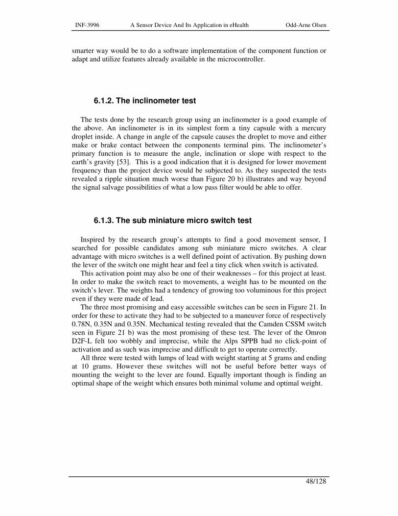
INF-3996 A Sensor Device And Its Application in eHealth Odd-Arne Olsen
48/128
smarter way would be to do a software implementation of the component function or adapt and utilize features already available in the microcontroller.
6.1.2. The inclinometer test
The tests done by the research group using an inclinometer is a good example of
the above. An inclinometer is in its simplest form a tiny capsule with a mercury droplet inside. A change in angle of the capsule causes the droplet to move and either make or brake contact between the components terminal pins. The inclinometer’s primary function is to measure the angle, inclination or slope with respect to the earth’s gravity [53]. This is a good indication that it is designed for lower movement frequency than the project device would be subjected to. As they suspected the tests revealed a ripple situation much worse than Figure 20 b) illustrates and way beyond the signal salvage possibilities of what a low pass filter would be able to offer.
6.1.3. The sub miniature micro switch test
Inspired by the research group’s attempts to find a good movement sensor, I
searched for possible candidates among sub miniature micro switches. A clear advantage with micro switches is a well defined point of activation. By pushing down the lever of the switch one might hear and feel a tiny click when switch is activated.
This activation point may also be one of their weaknesses – for this project at least. In order to make the switch react to movements, a weight has to be mounted on the switch’s lever. The weights had a tendency of growing too voluminous for this project even if they were made of lead.
The three most promising and easy accessible switches can be seen in Figure 21. In order for these to activate they had to be subjected to a maneuver force of respectively 0.78N, 0.35N and 0.35N. Mechanical testing revealed that the Camden CSSM switch seen in Figure 21 b) was the most promising of these test. The lever of the Omron D2F-L felt too wobbly and imprecise, while the Alps SPPB had no click-point of activation and as such was imprecise and difficult to get to operate correctly.
All three were tested with lumps of lead with weight starting at 5 grams and ending at 10 grams. However these switches will not be useful before better ways of mounting the weight to the lever are found. Equally important though is finding an optimal shape of the weight which ensures both minimal volume and optimal weight.
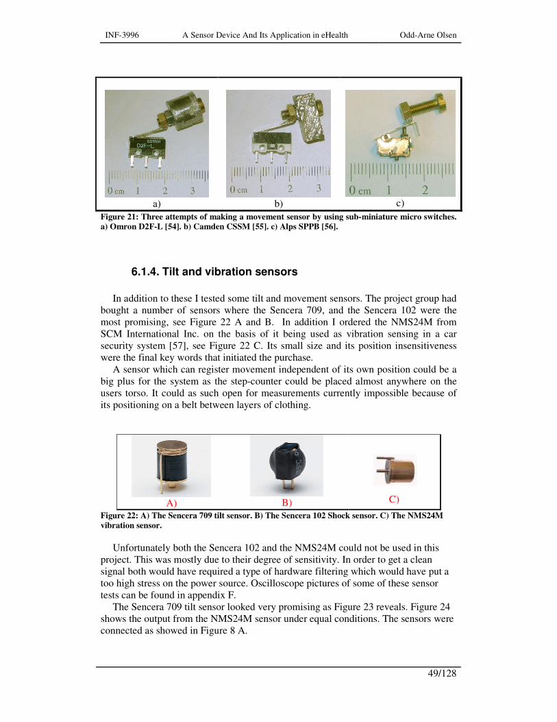
INF-3996 A Sensor Device And Its Application in eHealth Odd-Arne Olsen
49/128
a)
b)
c)
Figure 21: Three attempts of making a movement sensor by using sub-miniature micro switches.
a) Omron D2F-L [54]. b) Camden CSSM [55]. c) Alps SPPB [56].
6.1.4. Tilt and vibration sensors
In addition to these I tested some tilt and movement sensors. The project group had
bought a number of sensors where the Sencera 709, and the Sencera 102 were the most promising, see Figure 22 A and B. In addition I ordered the NMS24M from SCM International Inc. on the basis of it being used as vibration sensing in a car security system [57], see Figure 22 C. Its small size and its position insensitiveness were the final key words that initiated the purchase.
A sensor which can register movement independent of its own position could be a big plus for the system as the step-counter could be placed almost anywhere on the users torso. It could as such open for measurements currently impossible because of its positioning on a belt between layers of clothing.
A)
B)
C)
Figure 22: A) The Sencera 709 tilt sensor. B) The Sencera 102 Shock sensor. C) The NMS24M
vibration sensor.
Unfortunately both the Sencera 102 and the NMS24M could not be used in this
project. This was mostly due to their degree of sensitivity. In order to get a clean signal both would have required a type of hardware filtering which would have put a too high stress on the power source. Oscilloscope pictures of some of these sensor tests can be found in appendix F.
The Sencera 709 tilt sensor looked very promising as Figure 23 reveals. Figure 24 shows the output from the NMS24M sensor under equal conditions. The sensors were connected as showed in Figure 8 A.
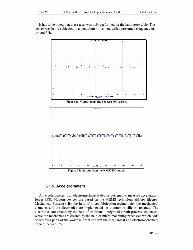
INF-3996 A Sensor Device And Its Application in eHealth Odd-Arne Olsen
50/128
It has to be noted that these tests was only performed on the laboratory table. The sensor was being subjected to a pendulum movement with a presumed frequency of around 3Hz.
Figure 23: Output from the Sencera 709 sensor.
Figure 24: Output from the NMS24M sensor.
6.1.5. Accelerometers
An accelerometer is an electromechanical device designed to measure acceleration
forces [58]. Modern devices are based on the MEMS technology (Micro–Electro-Mechanical-Systems). By the help of micro fabrication technologies the mechanical elements and the electronics are implemented on a common silicon substrate. The electronics are created by the help of traditional integrated circuit process sequences, while the mechanics are created by the help of micro machining processes which adds or removes parts of the wafer in order to form the mechanical and electromechanical devices needed [59].
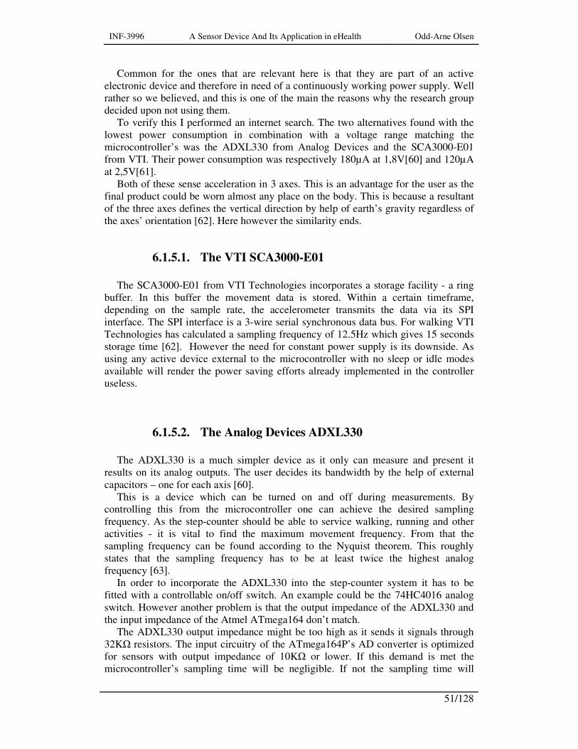
INF-3996 A Sensor Device And Its Application in eHealth Odd-Arne Olsen
51/128
Common for the ones that are relevant here is that they are part of an active electronic device and therefore in need of a continuously working power supply. Well rather so we believed, and this is one of the main the reasons why the research group decided upon not using them.
To verify this I performed an internet search. The two alternatives found with the lowest power consumption in combination with a voltage range matching the microcontroller’s was the ADXL330 from Analog Devices and the SCA3000-E01 from VTI. Their power consumption was respectively 180µA at 1,8V[60] and 120µA at 2,5V[61].
Both of these sense acceleration in 3 axes. This is an advantage for the user as the final product could be worn almost any place on the body. This is because a resultant of the three axes defines the vertical direction by help of earth’s gravity regardless of the axes’ orientation [62]. Here however the similarity ends.
6.1.5.1. The VTI SCA3000-E01
The SCA3000-E01 from VTI Technologies incorporates a storage facility - a ring
buffer. In this buffer the movement data is stored. Within a certain timeframe, depending on the sample rate, the accelerometer transmits the data via its SPI interface. The SPI interface is a 3-wire serial synchronous data bus. For walking VTI Technologies has calculated a sampling frequency of 12.5Hz which gives 15 seconds storage time [62]. However the need for constant power supply is its downside. As using any active device external to the microcontroller with no sleep or idle modes available will render the power saving efforts already implemented in the controller useless.
6.1.5.2. The Analog Devices ADXL330
The ADXL330 is a much simpler device as it only can measure and present it
results on its analog outputs. The user decides its bandwidth by the help of external capacitors – one for each axis [60].
This is a device which can be turned on and off during measurements. By controlling this from the microcontroller one can achieve the desired sampling frequency. As the step-counter should be able to service walking, running and other activities - it is vital to find the maximum movement frequency. From that the sampling frequency can be found according to the Nyquist theorem. This roughly states that the sampling frequency has to be at least twice the highest analog frequency [63].
In order to incorporate the ADXL330 into the step-counter system it has to be fitted with a controllable on/off switch. An example could be the 74HC4016 analog switch. However another problem is that the output impedance of the ADXL330 and the input impedance of the Atmel ATmega164 don’t match.
The ADXL330 output impedance might be too high as it sends it signals through 32KΩ resistors. The input circuitry of the ATmega164P’s AD converter is optimized for sensors with output impedance of 10KΩ or lower. If this demand is met the microcontroller’s sampling time will be negligible. If not the sampling time will

INF-3996 A Sensor Device And Its Application in eHealth Odd-Arne Olsen
52/128
depend on how fast the microcontroller’s sample and hold capacitor is able to charge [25].
6.2. Power consumption
At this stage of the project it is quite limited what can be done in order to reduce
the power consumption. Much has already been done in order to reduce the idle power consumption, but more can be achieved by reducing the active power and active time [64].
The easiest place to start is the reduction of the output power of the Bluetooth modules. When exchanging data it is a high probability that the step-counter and mobile base is close vicinity to each other. There should then be no need to run the connectBlue OEMSPA311 full power – its maximum range is 150 meters [43].
The minimum range is 10 meters. The maximum output power is the default value of the Bluetooth module. By the help of the “AT*AMMP=” command and an integer value between 0 and 255 the output power can be set to a more suitable level [37]. My guess is that a range of 10 meters is more than sufficient; however this has to be tested out.
Another way of reducing power consumption is to vary the microcontroller’s clock frequency at run time [64]. The system could be working with two clock sources. In normal mode when just sleeping or reading sensor data the system could work with an even lower clock frequency than now (1MHz) and still continue to use the internal RC oscillator as source. When servicing the Bluetooth module the microcontroller could switch over to the low power crystal oscillator. As such the project group would be freer to choose a baud rate more suitable for their intentions concerning the system.
6.3. Data security
The Bluetooth module is already equipped security support. When in this mode the
authentication of communicating devices plus encryption of data is activated. If one of the devices engaged in the data exchange has security enabled – security will be used [37].
The communication between security enabled devices can only be performed if they are bonded. The bonding procedure creates a link key only valid between these two Bluetooth units [37].
Whether this is sufficient or not will be trade-off between the data’s level of sensitivity, the amount of information transmitted and the cost involved in implementing further security. As such the project group’s intentions for the future of this system will also have to be taken into account. However here at this stage of the project I assume that the security available is adequate.

INF-3996 A Sensor Device And Its Application in eHealth Odd-Arne Olsen
53/128
6.4. Microcontroller software
6.4.1. The initialization file, “inite_reg.asm”
The initial hardware setup had to be changed due to a possible conflict with
features needed for future step-counter version. As can be seen in the program listing found in appendix C, the Bluetooth control lines was initially designed to connect to I/O port A. On my request this was changed due to the fact that port A also doubles as interface for the A/D-converter. As such the interface lines were moved to port D. Figure 25 shows the final layout of port D. Pin number 13-15 represents the changes.
Figure 25: Port D layout. Pin numbering refers to the TQFP/QFN and MLF packages.
These changes did however just represent changes in the declarations and port
setup. The changes and additions regarding this are listed in Table 2.
Table 2: Additions and changes to constant, pin and port definitions.
;******* global pin and constant definitions .equ Bt_DTR = 4 ; data terminal ready, from Bluetooth .equ Bt_RESET= 5 ; Bluetooth RESET .equ Bt_power = 6 ; Bluetooth power on/off ;****** initialize Bluetooth control lines. cbi DDRD,Bt_DTR ; set Bluetooth DTR line direction in sbi DDRD,Bt_RESET ; set Bluetooth RESET line, direction out sbi PORTD,Bt_RESET ; Set RESET line high (inactive) sbi DDRD,Bt_power ; set Bluetooth power line direction out cbi PORTD,Bt_power ; turn Bluetooth power off
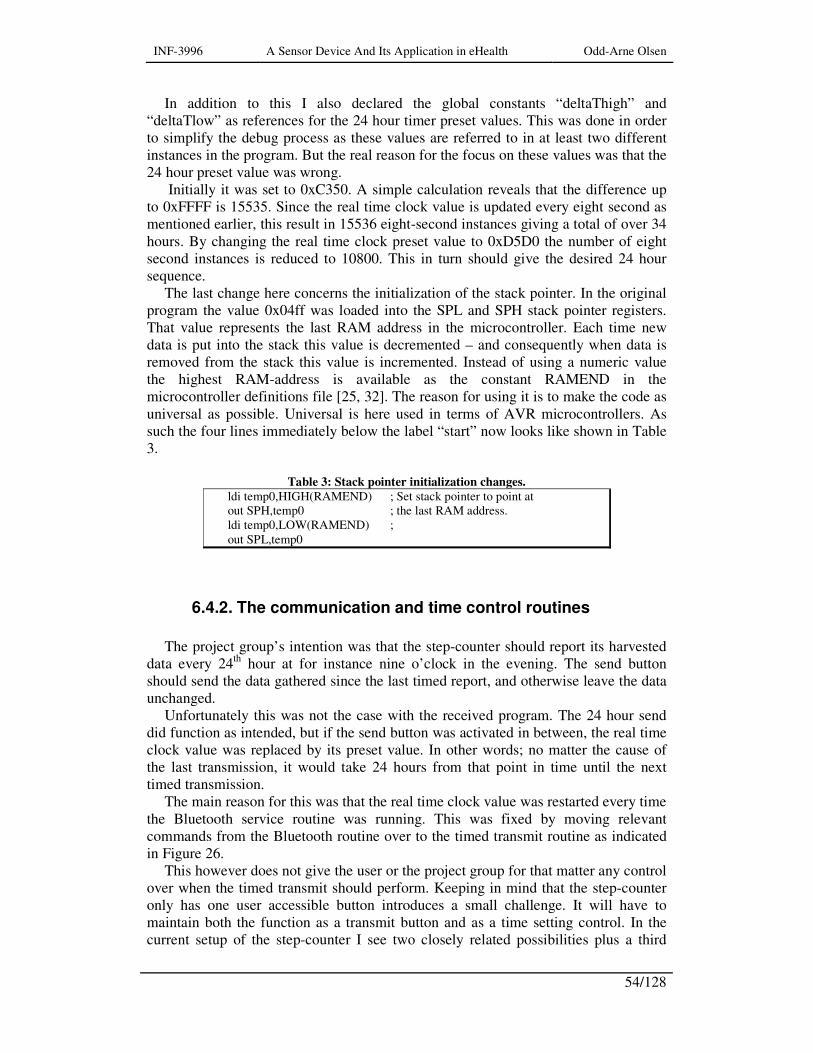
INF-3996 A Sensor Device And Its Application in eHealth Odd-Arne Olsen
54/128
In addition to this I also declared the global constants “deltaThigh” and “deltaTlow” as references for the 24 hour timer preset values. This was done in order to simplify the debug process as these values are referred to in at least two different instances in the program. But the real reason for the focus on these values was that the 24 hour preset value was wrong.
Initially it was set to 0xC350. A simple calculation reveals that the difference up to 0xFFFF is 15535. Since the real time clock value is updated every eight second as mentioned earlier, this result in 15536 eight-second instances giving a total of over 34 hours. By changing the real time clock preset value to 0xD5D0 the number of eight second instances is reduced to 10800. This in turn should give the desired 24 hour sequence.
The last change here concerns the initialization of the stack pointer. In the original program the value 0x04ff was loaded into the SPL and SPH stack pointer registers. That value represents the last RAM address in the microcontroller. Each time new data is put into the stack this value is decremented – and consequently when data is removed from the stack this value is incremented. Instead of using a numeric value the highest RAM-address is available as the constant RAMEND in the microcontroller definitions file [25, 32]. The reason for using it is to make the code as universal as possible. Universal is here used in terms of AVR microcontrollers. As such the four lines immediately below the label “start” now looks like shown in Table 3.
Table 3: Stack pointer initialization changes.
ldi temp0,HIGH(RAMEND) ; Set stack pointer to point at out SPH,temp0 ; the last RAM address. ldi temp0,LOW(RAMEND) ; out SPL,temp0
6.4.2. The communication and time control routines
The project group’s intention was that the step-counter should report its harvested
data every 24th hour at for instance nine o’clock in the evening. The send button should send the data gathered since the last timed report, and otherwise leave the data unchanged.
Unfortunately this was not the case with the received program. The 24 hour send did function as intended, but if the send button was activated in between, the real time clock value was replaced by its preset value. In other words; no matter the cause of the last transmission, it would take 24 hours from that point in time until the next timed transmission.
The main reason for this was that the real time clock value was restarted every time the Bluetooth service routine was running. This was fixed by moving relevant commands from the Bluetooth routine over to the timed transmit routine as indicated in Figure 26.
This however does not give the user or the project group for that matter any control over when the timed transmit should perform. Keeping in mind that the step-counter only has one user accessible button introduces a small challenge. It will have to maintain both the function as a transmit button and as a time setting control. In the current setup of the step-counter I see two closely related possibilities plus a third
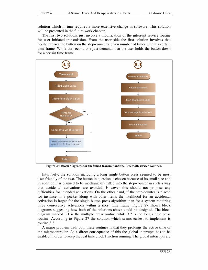
INF-3996 A Sensor Device And Its Application in eHealth Odd-Arne Olsen
55/128
solution which in turn requires a more extensive change in software. This solution will be presented in the future work chapter.
The first two solutions just involve a modification of the interrupt service routine for user initiated transmission. From the user side the first solution involves that he/she presses the button on the step-counter a given number of times within a certain time frame. While the second one just demands that the user holds the button down for a certain time frame.
Figure 26: Block diagrams for the timed transmit and the Bluetooth service routines.
Intuitively, the solution including a long single button press seemed to be most
user-friendly of the two. The button in question is chosen because of its small size and in addition it is planned to be mechanically fitted into the step-counter in such a way that accidental activations are avoided. However this should not propose any difficulties for intended activations. On the other hand, if the step-counter is placed for instance in a pocket along with other items the likelihood for an accidental activation is larger for the single button press algorithm than for a system requiring three consecutive activations within a short time frame. Figure 27 shows block diagrams suggesting how both of the solutions above could be designed. The block diagram marked 3.1 is the multiple press routine while 3.2 is the long single press routine. According to Figure 27 the solution which seems easiest to implement is routine 3.2.
A major problem with both these routines is that they prolongs the active time of the microcontroller. As a direct consequence of this the global interrupts has to be enabled in order to keep the real time clock function running. The global interrupts are

INF-3996 A Sensor Device And Its Application in eHealth Odd-Arne Olsen
56/128
automatically disabled during an interrupt call [25]. The global interrupt must however be disabled again before the call of the Bluetooth control routine.
What is more serious is the increased current consumption these routines represent. The running time of these routines will have to be a trade-off between keeping it short for the sake of minimal current consumption and keeping it long enough to reduce the number of errors.
Figure 27: Two alternatives for a dual function transmission and report-time set switch. 3.1) The
multiple button press routine. 3.2) The long single press routine.
But having to choose between these two the long single press routine seems to be
the best one. As already mentioned it seems more user-friendly and easier to implement. In addition - since the global interrupts are enabled multiple button activations might cause trouble. The routine might be restarted instead of continuing in its task. This however is just a presumption and has to be tested if the 3.1 routine is to be used.
But having this in mind, plus that the 3.2 routine seemed shorter and easier to implement it became the chosen one. It is basically a routine that every 50th mS polls the int1 input to check whether the button has been released. A counter keeps track of

INF-3996 A Sensor Device And Its Application in eHealth Odd-Arne Olsen
57/128
every poll. When this has performed a hundred times or more, the button has been pressed for over 5 seconds. If this is the case the 24 hour real time clock is initialized with its preset values. However if not, the routine performs as originally and transmits data. In Table 4 the new user-send routine is listed.

INF-3996 A Sensor Device And Its Application in eHealth Odd-Arne Olsen
58/128
Table 4: The new user initiated send routine 3.2.
isr_mtransm: sei ldi count,0x00 ;----------------------------- ; delaying 49995 cycles (nearly 50mS at 1MHz) int1_loop: ldi temp0, 101 loop0: ldi temp1, 164 loop1: dec temp1 brne loop1 dec temp0 brne loop0 ; ----------------------------- ; check if switch is released in temp0,PinD andi temp0,0x08 cpi temp0,0x08 breq time1 jmp int1_loop ;------------------------------ ; If button has been pressed down for 5 seconds or more ; reset the 24 hour counter values. time1: cli ;Disable global interrupt cpi count,100 brlt out1 ldi rtcH,deltaThigh ldi rtcL,deltaTlow movw r3:r2,rtcH:rtcL reti ;------------------------------- out1: rcall transmit_bt sei reti ; =============================
The only really new code here is the 50mS delay sequence. Given an oscillator
frequency of 1MHz, 50mS equals 50000 clock cycles. This is a standard piece of code which pops up nearly everywhere. With reference to the listings above; at label loop1 the routine should waste a predestined number of clock cycles, hereafter named z. This is to be performed the number of times decided by the value y loaded into the temp1 register at label loop0. All this is to be performed x times decided by the value loaded into temp0 at label int1_loop. In addition will each decrement and a true branch command combination count for 3 clock cycles [65]. And as such this loop can be represented by the following formula: ( )( )33__ ++= zyxcyclesclockDelay
As probably can be seen from the code in Table 4; z=0, y=164 and x =101 for this instance. This loop is 5 clock cycles away from the desired 50000 goal. However the andi, cpi, breq uses each one clock cycle to perform and the jmp instruction takes three clock cycles. This still not totals to exactly 50000 clock cycles, but for the use intended the accuracy is more than sufficient. The calculations of these loop constants x, y, and z can be done by the help of a spreadsheet or a self made program.
A direct consequence of the global interrupt being activated is that the 4.1 isr_timer routine has to be changed. The 3.2 routine might be interrupted at any time. Therefore
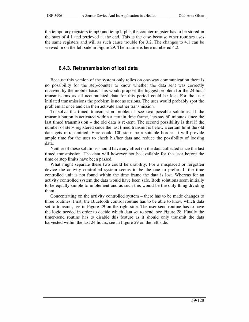
INF-3996 A Sensor Device And Its Application in eHealth Odd-Arne Olsen
59/128
the temporary registers temp0 and temp1, plus the counter register has to be stored in the start of 4.1 and retrieved at the end. This is the case because other routines uses the same registers and will as such cause trouble for 3.2. The changes to 4.1 can be viewed in on the left side in Figure 29. The routine is here numbered 4.2.
6.4.3. Retransmission of lost data
Because this version of the system only relies on one-way communication there is
no possibility for the step-counter to know whether the data sent was correctly received by the mobile base. This would propose the biggest problem for the 24 hour transmissions as all accumulated data for this period could be lost. For the user initiated transmissions the problem is not as serious. The user would probably spot the problem at once and can then activate another transmission.
To solve the timed transmission problem I see two possible solutions. If the transmit button is activated within a certain time frame, lets say 60 minutes since the last timed transmission – the old data is re-sent. The second possibility is that if the number of steps registered since the last timed transmit is below a certain limit the old data gets retransmitted. Here could 100 steps be a suitable border. It will provide ample time for the user to check his/her data and reduce the possibility of loosing data.
Neither of these solutions should have any effect on the data collected since the last timed transmission. The data will however not be available for the user before the time or step limits have been passed.
What might separate these two could be usability. For a misplaced or forgotten device the activity controlled system seems to be the one to prefer. If the time controlled unit is not found within the time frame the data is lost. Whereas for an activity controlled system the data would have been safe. Both solutions seem initially to be equally simple to implement and as such this would be the only thing dividing them.
Concentrating on the activity controlled system – there has to be made changes to three routines. First, the Bluetooth control routine has to be able to know which data set to transmit, see in Figure 29 on the right side. The user-send routine has to have the logic needed in order to decide which data set to send, see Figure 28. Finally the timer-send routine has to disable this feature as it should only transmit the data harvested within the last 24 hours, see in Figure 29 on the left side.

INF-3996 A Sensor Device And Its Application in eHealth Odd-Arne Olsen
60/128
Figure 28: The final prototype version of the user-send routine.
Since the retransmit order is captured by the user-send routine, it has to use a
temporary register as a messenger. In the timer-send routine this temporary register has to contain a message disabling this feature in the Bluetooth routine as it should only be available from the user-send routine. For this I chose to use the register named as temp0. For the system to retransmit old data temp0 has to contain the number 0xAA – or in binary format 0b10101010.
INF-3996 A Sensor Device And Its Application in eHealth Odd-Arne Olsen
61/128
Figure 29: Final prototype versions of the timer-send and the Bluetooth controller routines.
6.4.4. DTR timeout
A more serious flaw in the given microcontroller software was the lack of timeout
when waiting for the DTR signal from the Bluetooth module. If the step-counter was waiting to transmit its data and were for some reason not able to connect with the mobile base – the system would continue in an endless loop waiting for an active DTR signal.
This was a relatively easy thing to fix; the main problem was to choose the length of the timeout. It had to be long enough for the system to be able to connect, but it has to have an upper limit in order to avoid extra strains on the already limited power budget.
But what happens if it is the 24 hour report that can’t be transmitted? After a 100 new steps the data would be lost according to chapter 6.4.3. However, the user has
INF-3996 A Sensor Device And Its Application in eHealth Odd-Arne Olsen
62/128
chosen the report time himself/herself, and presumably will he/she check the mobile base for incoming data. The user would as such be aware of a problem like this and would be able to perform the necessary steps to correct the situation.
It is possible to make the step-counter transmit two messages in such situations. First the 24 hour report, then the steps registered since the report time. However I chose to have faith in the user and believe that the 100 step limit will suffice as security limit. In addition it will be to the benefit of the power budget.
The software solution is based around the same delay loop as is used in Table 4 under the label “int1_loop”. In appendix D, file “transmit_bt.asm” under label “Bt-ready” is my suggestion listed.
6.4.5. The final changes
What remained after this in order to get a fully working prototype program was to
remove all debug and test code. In addition the DTR line check and Bluetooth power on/off function had to be activated.
During the hardware debug phase it was decided that the Bluetooth reset function should be incorporated. This was suggested because the module would not connect to the mobile base and the idea was that it might need a delayed start up after the power had been turned on. However the connection problem had other reasons – it was not correctly set up.
In this program version the Bluetooth reset line is kept at the inactive level all the time. The main reason for this is to reduce the power-up time for the Bluetooth module in order save battery power. In addition the module is equipped with power-on-reset making this feature superfluous.

INF-3996 A Sensor Device And Its Application in eHealth Odd-Arne Olsen
63/128
7. Discussion
7.1. Sensors
It might be considered a bit daring starting off building a step-counter without
having found the proper movement sensing element, and as such ending up with a device relying a component from a factory made device. But my tests with the sensors already acquired by the project group or me have produced one possible alternative – the Sencera 709 tilt sensor. An immediate drawback with this sensor is its position sensitivity. In other words it has to be mounted in a predestined position on order to perform as intended. The consequence for the user is that the step-counter has to be hip worn. The consequence for the project group is the limitations in measurement possibilities this involves. This limitation also holds for the sensor taken from the Silva Pedometer Dist/Step.
The strict demand on power consumption makes it difficult to introduce a more active hardware filtration scheme. As such the mechanical movement sensing element has to have the correct level of inertia. It should only change state when a motion is detected and it should do so with the minimum amount of ripple.
The Silva Pedometer Dist/Step uses custom-built micro switch with a balanced weight attached to its lever see Figure 12. The tests performed here with commercially available sub-miniature micro switches were not successful. There are many reasons for this, but first of all there should have been performed more accurate calculations concerning the mechanics and physics involved. Secondly, although using lead as weight material, the weight turned out quite voluminous compared to the desired system size. Last but not least the assembly of such a unit requires a certain skill in precision mechanics, and as Figure 21 reveals this is not one of my strong sides.
But back to the filtering which is the last concern for the existing setup in this section. As can be seen in Figure 8A it is a very high resistance filter circuitry which has been implemented. In addition one might discuss how much filtering a 10nF capacitor will provide. Figure 23 and Figure 24 reveals that because of this the high level output from sensor barely crosses the border of a logical high level. In total this leaves the system quite vulnerable for noise. But only real life testing will reveal the seriousness of this. On the other hand – lowering the resistance and/or increasing the capacitance will put extra strains on an already stressed power budget.
Measurement wise the project would have gotten better results if it would have been possible to use an accelerometer as a movement sensor. The ADXL330 will, with a bit extra electronics and some movement measurements/analysis, possibly be able to fulfill the task.

INF-3996 A Sensor Device And Its Application in eHealth Odd-Arne Olsen
64/128
7.2. Wireless communication
Although techniques using less power than Bluetooth exist, there is at current no
real available alternative. Zigbee is not available in mobile phones and Wibree has not been made available on the market yet. Actually for Zigbee’s sake this is not the end of the story as the abbreviation Z-SIM has often been mentioned lately. Z-SIM is a complete Zigbee node integrated in a SIM card [66]. When it will be available is at current uncertain, even more uncertain is when it will be available in Norway.
But having chosen Bluetooth there are many manufacturers producing modules with quite similar electrical characteristics. The project group has chosen the connectBlue OEMSPA311. The experience so far has proved it to be robust and reliable. Its wealth of features might however cause problems for a developer although nothing more than what can be solved by the help of the user manual or the connectBlue support service.
The project group is however looking for ways to shrink the size of the step-counter, and as such modules like the KC Wirefree KC-21 or the Sena Parani-ESD200 could be worth taking a closer look at. However in order to move further both in terms of lower power consumption and smaller physical size the solution might be to move a step back and start to construct a Bluetooth system at chip level. Here the solutions from Cambridge Silicon Radio Limited could be a good place to start.
7.3. Microcontroller
The microcontroller chosen by the project group, Atmel ATmega164P, became
available on the market in the end of 2006. It is the smallest one in a series of three quite similar microcontrollers. They differ only in terms of memory sizes. The immediate advantage of this is if future software demands calls for a larger memory size. This can be achieved with minimal effort and practically no change of hardware, except for the microcontroller of course. The amount of available I/O-features should make this a good start for the sensor platform which the project group hopes to make.
7.4. Power saving
A feature available in many Bluetooth modules is the possibility to reduce the
output power. Since the communication between the step-counter and the mobile base most likely will be performed over short distances a good power saving effort would be to reduce the step-counter’s transmit-range to 10m.
As long as only one way communication is implemented there are no other real possibilities of reducing the power consumption for the Bluetooth module. Sleep or sniff modes will have no effect as the module’s only duty is to transmit the data after the connection is made. After this it is turned off.
For the microcontroller however there is one possibility that should be checked out. That is the task dependent run-time change of clock frequency. By reducing the
INF-3996 A Sensor Device And Its Application in eHealth Odd-Arne Olsen
65/128
clock frequency as low as possible for the handling of the sensors and their data, and turning it up for Bluetooth interfacing there will be some profits in terms of reduced power consumption. One certain gain of using two clock frequencies/sources would be a more flexible system. For instance will the project group stand more freely in choice of Bluetooth modules and the same microcontroller hardware setup could be used for other purposes too. For instance the system could also serve as Bluetooth interface for glucose meters - requiring only minimal hardware changes, if any.
Although the increased clock frequency causes higher power consumption, this increase could be regained by the shorter transmission period. It this is holds for the 14-byte data package implemented here is another matter, but it will undoubtedly be valid for larger data packages.
Anyhow in order to be able to know much to gain by these restrictive power measures there should be made a power consumption analysis of the current situation.
7.5. Microcontroller software
Although the software following the first step-counter prototype wasn’t complete
and flawless it fulfilled its purpose. It made it possible to test the total system, and to discover its strengths, weaknesses and possibilities.
But in order to obtain a well functioning system there were several things that had to be changed or rewritten. The most serious problems were the report time settings, the retransmission of lost data and the DTR timeout. My suggestions has not been properly tested yet, but if working as intended they would take care of these problems.
Although trying to take every measure in order to avoid loss of data, one can never say for sure that you are 100% covered. But combining the efforts suggested here with for instance a warning, audible or visual, on the mobile base when a transmission is missing would most like reduce the problem drastically. In addition combining this with an active user this problem would probably be minimal.
7.6. The step-counter
Combining a functioning and well tested software with a lightweight and
physically small hardware covered by a smooth and user friendly exterior is the ideal. This project is well on the way to achieve this.
There are still possibilities to explore on order to reduce size and weight. Smaller Bluetooth modules, different powering schemes and more suitable sensors are some examples of this. At current the components limits the possibilities for the step-counter. As such the movement sensor is the biggest sinner. Its position sensitivity forces the step-counter to be nothing more that a hip worn device. The result of this is the major restrictions introduced for other types of measurements.

INF-3996 A Sensor Device And Its Application in eHealth Odd-Arne Olsen
66/128
INF-3996 A Sensor Device And Its Application in eHealth Odd-Arne Olsen
67/128
8. Future work
8.1. The time set function
As already mentioned for the routines suggested and implemented, they have
serious weaknesses when thinking of the current consumption. The routine chosen keeps the step-counter awake for at least 5 seconds just to set the watch. In addition it introduces a secondary function for the transmit switch. This might complicate matters for a user, and it may introduce an extra error source.
The third alternative has the immediate consequence that the user-send routine can more or less be changed back to its original state. In other words, from 3.3 back to 3, see appendixes A, B and C. In addition the timer-send routine can return to version 4.1, see Figure 26.
However for the third alternative to work, two-way communication between the mobile phone and the step-counter has to be introduced. As a part of a receipt message the mobile phone can transmit the number of eight second sequences between now and the 24 hour report time.
On the mobile phone the user can set up which time he/she wants the timed transmit to perform. The user can check and/or change the time anytime he/she chooses to.
When receiving a step-counter report the software in the mobile phone has to translate current time into this eight second scheme and transmit it along with the receipt. All the step-counter has to do is to store this value. It may have to take in account latency time; however this will most likely be well within 8 seconds.
When to-way communication is implemented the changes and additions on the step-counter side would be relatively small. The receiving routine has to extract the time data and store it. On the mobile phone side this solution will probably put a little bit harder challenge on the programmer.
In addition to usability the most important thing gained with this solution is the reduced active time of the step-counter. But let’s not forget the removal of an error source. An erroneous activation of the transmit/time set button might cause loss of data.
8.2. Alternative power supply
In order to make the step-counter more flexible and to extend its duty cycle the
possibility of using a rechargeable battery system should be looked into. This change would require many new components, but the need for battery
capacity would be reduced. The direct consequence of this would be a smaller and lighter battery. A wired recharging system is of course a possibility. But the wires and headers involved would most likely be looked upon as a step backwards in terms of usability.
There is however the possibility of wireless charging or inductive charging as it is called. It is a relatively low cost space economic solution [67]. As the smart card

INF-3996 A Sensor Device And Its Application in eHealth Odd-Arne Olsen
68/128
applications constructed at Fraunhofer IIS is a good example of [68], se also Figure 30.
Figure 30: Smart-card with a wireless battery charge system [69].
The main difference between a wired and a wireless charger is that in the wireless
system the transformer is split in two. The two halves functions respectively as a transmitter and a receiver antenna. In addition in wired systems most of the charging electronic is placed inside the stationary power module. Whereas in the wireless system this is situated in the wearable unit, see Figure 31.
Whether this is a possible solution for the step-counter will only tests reveal. The main challenge would be the co-existence of a Bluetooth module and the wireless charge antenna in the same enclosure.
Figure 31: Block diagram of a wireless charge system [69].
8.3. Remote programming
In order to make a fully flexible system the possibilities of remote programming
the step-counter from the smart phone should be investigated. This feature might not be open for the user, but more as a means for system setups or updates. Maybe it even could be an opportunity for the system operator without physical access to the system to perform remote service. The only condition would be that the smart phone is in an area of mobile network coverage with the step-counter in its vicinity. The system suggested below might seem a bit extravagant. However, if in need of a total reprogramming this might be worth looking into. But if only smaller parts of the program need updating, the ATmega164P is capable of handling this on its own [25]. But in order for any of these to function the system has to be supplemented with for instance a CRC checksum routine in order to intercept transmission errors.
The solution described here requires an extra microcontroller, not necessarily of the same type as the first one. The requirement for the second one has to be that its SRAM or data EEPROM is large enough to store the whole contents of the first ones
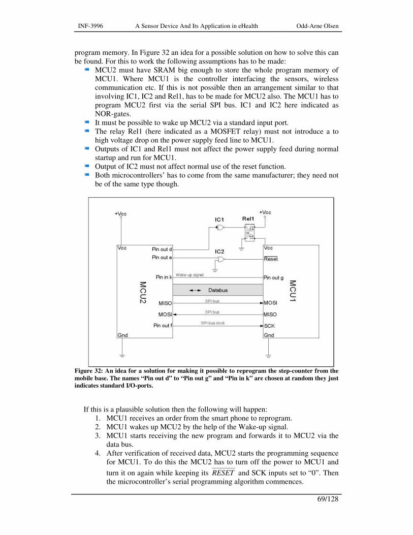
INF-3996 A Sensor Device And Its Application in eHealth Odd-Arne Olsen
69/128
program memory. In Figure 32 an idea for a possible solution on how to solve this can be found. For this to work the following assumptions has to be made:
MCU2 must have SRAM big enough to store the whole program memory of MCU1. Where MCU1 is the controller interfacing the sensors, wireless communication etc. If this is not possible then an arrangement similar to that involving IC1, IC2 and Rel1, has to be made for MCU2 also. The MCU1 has to program MCU2 first via the serial SPI bus. IC1 and IC2 here indicated as NOR-gates.
It must be possible to wake up MCU2 via a standard input port. The relay Rel1 (here indicated as a MOSFET relay) must not introduce a to
high voltage drop on the power supply feed line to MCU1. Outputs of IC1 and Rel1 must not affect the power supply feed during normal
startup and run for MCU1. Output of IC2 must not affect normal use of the reset function. Both microcontrollers’ has to come from the same manufacturer; they need not
be of the same type though.
Figure 32: An idea for a solution for making it possible to reprogram the step-counter from the
mobile base. The names “Pin out d” to “Pin out g” and “Pin in k” are chosen at random they just
indicates standard I/O-ports.
If this is a plausible solution then the following will happen:
1. MCU1 receives an order from the smart phone to reprogram. 2. MCU1 wakes up MCU2 by the help of the Wake-up signal. 3. MCU1 starts receiving the new program and forwards it to MCU2 via the
data bus. 4. After verification of received data, MCU2 starts the programming sequence
for MCU1. To do this the MCU2 has to turn off the power to MCU1 and
turn it on again while keeping its RESET and SCK inputs set to “0”. Then the microcontroller’s serial programming algorithm commences.
INF-3996 A Sensor Device And Its Application in eHealth Odd-Arne Olsen
70/128
5. After programming the RESET is set high for normal operation of MCU1 and MCU2 goes back to sleep.
The most obvious danger, in addition to communication problems, with this
solution is if there occurs some sort of power failure during this operation. The solution indicated earlier where MCU1 first programs MCU2’s data EEPROM could solve this but with the downside of introducing more components. Although should the suggestion in Figure 32 be very close to the truth – the EEPROM solution would at best only need another MOSFET relay as the NOR-gates comes in a package of four.
When it comes to downsides - all these extra components imposes extra strain on the power budget. It has to be emphasized that this is just a rough idea, and one would not know if this works before a proper design has been made and it has been tested.
INF-3996 A Sensor Device And Its Application in eHealth Odd-Arne Olsen
71/128
9. Conclusion This is a multifaceted project involving sensors and signal conditioning, serial
communication, Bluetooth, battery-power economization and not to forget the Atmel ATmega164P microcontroller and AVR assembly programming.
As programming goes an assembly program might not look that impressive. But in clear distinction to programming in a computer environment, no matter type of programming language, embedded system programming is often a result of trial and error due influence from uncontrollable external factors. Examples of this could be non-linear components, inaccurate component values or minor flaws in external components. In addition a wearable device has to be able too function as intended despite temperature changes and electrically noisy environments.
Many of the problems which has with a varying degree of success been dealt here, has its basis in the attempts of using components initially specified for other purposes to the benefit this project. A good example is the movement sensor tests. Anyhow these tests revealed one good possibility, namely the Sencera 709 tilt sensor. But these tests were only performed in the laboratory. To find out if it really is usable, field tests has to be done.

INF-3996 A Sensor Device And Its Application in eHealth Odd-Arne Olsen
72/128

INF-3996 A Sensor Device And Its Application in eHealth Odd-Arne Olsen
73/128
References [1] NST. More Definitions of Telemedicine. [cited April 2007]; Available from:
http://www.telemed.no/index.php?id=44355. [2] Silicon_Bridge_Research_Limited, Understanding the market for eHealth.
2001, Silicon Bridge Research Limited: Basingstoke, UK. [3] Lymberis A and De Rossi DE, Wearable ehealth systems for personalised
health management elektronisk ressurs : state of the art and future challenges. Studies in health technology and informatics ; v. 108. 2004, Amsterdam Washington, DC: IOS Press. xii, 354 s.
[4] NST. What do we mean by “telemedicine”? [cited April 2007]; Available from: http://www.telemed.no/index.php?cat=4636.
[5] Årsand E, Andersson N, and Hartvigsen G, No-touch wireless transfer of
blood glucose data from patient operated blood glucose monitors. 2006, NST. [6] Årsand E and Hartvigsen G. A wearable eHealth system for people with Type
2 diabetes. in Scandinavian Conference on Health Informatics 2005. 2005. Aalborg, Denmark: Aalborg University.
[7] Årsand E and Hartvigsen G, Reprogrammable Hardware used in future
Patient-Centric eHealth Tools, in TTeC 06. 2006, NST: Tromsø. [8] Årsand E, Wangberg SC, and Hartvigsen G. Capturing and presenting patient-
data through a smartphone; designing a self-help tool. . in Tromsø
Telemedicine and eHealth Conference. 2006. Tromsø, Norway: NST Norwegian Centre for Telemedicine. (Poster).
[9] Welsh M. CodeBlue: Wireless Sensor Networks for Medical Care. 2006 [cited January 2007; Available from: http://www.eecs.harvard.edu/~mdw/proj/codeblue/.
[10] Jovanov E and Milenković A. WHMS - Wearable Health Monitoring Systems. Huntsville 2006 [cited January 2007; Available from: http://www.ece.uah.edu/~jovanov/whrms/.
[11] Polastre J, Szewczyk R, and Culler D. Telos: enabling ultra-low power
wireless research. 2005. [12] Jovanov E, et al., A wireless body area network of intelligent motion sensors
for computer assisted physical rehabilitation. Journal of NeuroEngineering and Rehabilitation, 2005. 2(1): p. 6.
[13] Fabrice A, et al., Flexible technologies and smart clothing for citizen
medicine, home healthcare, and disease prevention. Information Technology in Biomedicine, IEEE Transactions on, 2005. 9(3): p. 325-336.
[14] Paradiso R, Loriga G, and Taccini N, Wearable System for Vital Signs
Monitoring, in Wearable eHealth Systems for Personalised Health
Management - State of the Art and Future Challenges, Lymberis A and Rossi Dd, Editors. 2004, IOS Press: Amsterdam, Netherland. p. 253-259.
[15] Weber J-L, et al., Telemonitoring of Vital Parameters with Newly Designed
Biomedical Clothing, in Wearable eHealth Systems for Personalised Health
Management - State of the Art and Future Challenges, Lymberis A and Rossi Dd, Editors. 2004, IOS Press: Amsterdam, Netherland. p. 260-265.
[16] Noergaard T, Embedded systems architecture : a comprehensive guide for
engineers and programmers. Embedded technology series. 2005, Amsterdam: Elsevier. XIV, 640 s.

INF-3996 A Sensor Device And Its Application in eHealth Odd-Arne Olsen
74/128
[17] Gadre DV, Programming and customizing the AVR microcontroller
elektronisk ressurs. 2001, New York London: McGraw-Hill. xxi, 339s. [18] Abd-El-Barr M and El-Rewini H, Fundamentals of computer organization and
architecture. Wiley series on parallel and distributed computing. 2005, Hoboken, N.J.: Wiley. xiv, 273 s.
[19] Piguet C, History of Low-Power Electronics, in Low-power electronics design, Piguet C, Editor. 2005, CRC Press: Boca Raton. p. 1-1 - 1-15.
[20] Alexandridis NA, Design of microprocessor-based systems. 1993, Englewood Cliffs, N.J.: Prentice Hall. XVI, 541 s.
[21] Stone HS, Microcomputer interfacing. 1982, Reading, Mass.: Addison-Wesley. XV,383 s.
[22] Davis L. JTAG Bus Description. Integrated Circuit Buses 2007 [cited; Available from: http://www.interfacebus.com/Design_Connector_JTAG_Bus.html.
[23] Atmel. JTAGICE mkII Quick Start Guide. 2006 [cited February 2007]; Available from: http://www.atmel.com/.
[24] Atmel AVR. 2007 [cited January 2007]; Available from: http://en.wikipedia.org/wiki/Atmel_AVR.
[25] Atmel. ATmega164P/V, ATmega324P/V, ATmega644P/V Preliminary. 8 bit AVR Microcontroller with 16/32/64KBytes In-System Programmable Flash 2006 February 2007 [cited February 2007]; Available from: http://www.atmel.com/dyn/products/product_card.asp?part_id=3887.
[26] IAR_Systems. C/C++ compiler and debugger tools for Atmel AVR - IAR
Embedded Workbench V4.21 for Atmel AVR. [cited February 2007]; Available from: http://www.iar.com/ewavr.
[27] Haiduc P. CodeVisionAVR - Standard & Light. [cited February 2007]; Available from: http://www.hpinfotech.ro/html/cvavr.htm.
[28] WinAVR. WinAVR tutorial. [cited February 2007]; Available from: http://winavr.scienceprog.com/avr-gcc-tutorial/.
[29] Weddington EB. WinAVR User Manual - 20050214. [cited Sourceforge.net February 2007]; Available from: http://winavr.sourceforge.net/WinAVR-user-manual.html.
[30] Rowley_Associates. Crossworks for AVR - Professional Tools for AVR
Developers. [cited February 2007]; Available from: http://www.rowley.co.uk/avr/index.htm.
[31] Atmel. AVR development tools - Version 7 C Compiler Tools with Windows
IDE for Atmel AVR Microcontrollers. [cited February 2007]; Available from: http://www.imagecraft.com/.
[32] Morton J, AVR : an introductory course. 2002, Oxford: Newnes. 6 bl., 241 s. [33] Bluetooth_SIG. Bluetooth Basics. Learn 2007 [cited; Available from:
http://www.bluetooth.com/Bluetooth/Learn/Basics/. [34] Bluetooth_SIG. Bluetooth Technology Benefits. Learn 2007 [cited; Available
from: http://www.bluetooth.com/Bluetooth/Learn/Basics/. [35] Bluetooth_SIG. How Bluetooth Technology Works. Learn 2007 [cited;
Available from: http://www.bluetooth.com/Bluetooth/Learn/Basics/. [36] Blankenbeckler D. An Introduction to Bluetooth. The Bluetooth Channel 2000
[cited March 2007]; Available from: http://www.wirelessdevnet.com/channels/bluetooth/features/bluetooth.html.
[37] connectBlue. Serial Port Adapter™ Version 2 and 3 AT Commands. INDUSTRIAL BLUETOOTH™ 2006 October [cited February 2007];

INF-3996 A Sensor Device And Its Application in eHealth Odd-Arne Olsen
75/128
3.10:[Available from: http://www.connectblue.se/produkts/bluetooth-products/oem-modules/oemspa311331/downloads/.
[38] Guide to Thermocouple and Resistance Thermometry. http://www.tc.co.uk/: TC Ltd.
[39] Pico. Picoscope 2104 & 2105 PC Oscilloscopes - User Guide. 2006 [cited February 2007]; PS2100044-1.0:[Available from: http://www.picotech.com/document/pdf/ps2100044.pdf.
[40] Varmedal R and Eriksen HØ, Mobile to Sensor Interface Requirement
Document (IRD). 2007, Tromsø Telemedicine Laboratory. [41] connectBlue. OEM Serial Port Adapter™ cB-0901 Electical and Mechanical
Datasheet. INDUSTRIAL BLUETOOTH™ 2006 September [cited February 2007]; 1.7.3:[Available from: http://www.connectblue.se/produkts/bluetooth-products/oem-modules/oemspa311331/downloads/.
[42] KCWirefree. KC-22 Datasheet Bluetooth OEM Micro Module. 2007 [cited March 2007]; KC-22.4:[Available from: http://www.kcwirefree.com/documents.html.
[43] connectBlue. Product Brief OEMSPA311/331. INDUSTRIAL BLUETOOTH™ 2006 October [cited February 2007]; 1.3:[Available from: http://www.connectblue.se/produkts/bluetooth-products/oem-modules/oemspa311331/downloads/.
[44] KCWirefree. KC-21 Datasheet Bluetooth OEM Module. 2007 [cited March 2007]; KC-21.3:[Available from: http://www.kcwirefree.com/documents.html.
[45] Sena. OEM Bluetooth Serial Module, Parani-ESD100/110/200/210. 2006 [cited March 2007]; Available from: http://www.sena.com.
[46] Fractus. Small SMD chip antenna for headset, compact flash, secure digital
and small PCB devices - Fractus® Compact Reach Xtend™ Chip Antenna
P/N: FR05-S1-N-0-102. Data sheet - short range wireless 2006 [cited; Available from: http://www.fractus.com/sales_documents/FR05-S1-N-0-102/DS_FR05-S1-N-0-102.pdf.
[47] Fractus. User Manual - Fractus® Compact Reach Xtend™ Bluetooth ,
802.11b/g WLAN Chip Antenna 2006 [cited March 2007]. [48] Maloratsky LG, Reviewing the basics of microstrip lines. Microwaves & RF,
2000. 39(3): p. 79-88. [49] Pozar DM, Microwave engineering. 1990, Reading, Mass.: Addison-Wesley.
XVII, 726 s. [50] CSR. Bluetooth ICs (Bluecore). 2007 [cited May 2007]; Available from:
http://www.csr.com/home.php. [51] Holdø L, Batteriet - Den moderne Strømkilde. Batteriskolen. 1995, Oslo,
Norway: Teknisk Presse AS. [52] mpower. Performance Characteristics. How To Specify Batteries 2005 [cited
April 2007]; Available from: http://www.mpoweruk.com/soc.htm. [53] Wikipedia. Inclinometer. [cited February 2007]; Available from:
http://en.wikipedia.org/wiki/Clinometer. [54] Omron. Ultra Subminiature Basic Switch - D2F. [cited February 2007];
Available from: http://www.omroncomponents.eu/home/products/Switches/Microswitches/Unsealed/default.asp.
[55] Camden. Ultra Miniature Microswitch. Miniature switches - CSSM [cited February 2007]; Available from: http://www.camdenelec.com/electronics/product-

INF-3996 A Sensor Device And Its Application in eHealth Odd-Arne Olsen
76/128
subcategory.asp?Category=MINIATURE%20SWITCHES&Sub=V4%20Type.
[56] Alps. Alps - Compact Type Detector Switch - SPPB Series. [cited February 2007]; Available from: http://www3.alps.co.jp/cgi-bin/WebObjects/catalog.woa/wa/varietyList?language=english&country=com&top_mode=2003&productId=3&varietyId=8.
[57] Jeng JI, Electronic circuit system named mobile safety communication (MSC)
device embedded in the rearview/side mirror of a vehicle. 2004: United States. [58] Dimension_Engineering. A beginner’s guide to accelerometers. [cited
February 2007]; Available from: http://www.dimensionengineering.com/accelerometers.htm.
[59] Weinberg H. MEMS (Micro Electro-Mechanical Systems) Technology. How they work [cited March 2007]; Available from: http://www.sensorland.com.
[60] Analog_Devices. ADXL330. Small, Low Power, 3-Axis ±3 g iMEMS® Accelerometer [cited February 2007]; Available from: http://www.analog.com/en/prod/0,2877,ADXL330,00.html.
[61] VTI. SCA3000-E01 3-AXIS ULTRA LOW POWER ACCELEROMETER WITH
DIGITAL SPI INTERFACE. [cited February 2007]; Available from: http://www.vti.fi/en/products-solutions/products/accelerometers/sca3000-accelerometers/.
[62] VTI. SCA3000 Accelerometer in Speed, Distance and Energy Measurement. [cited February 2007]; Application Note 50:[Available from: http://www.vti.fi/en/products-solutions/products/accelerometers/sca3000-accelerometers/.
[63] Weinberg H. Minimizing Power Consumption of iMEMS® Accelerometers. Application Note 2002 [cited March 2007]; AN-601:[Available from: http://www.analog.com/en/cList/0,2880,764%255F800%255F43,00.html.
[64] Bertozzi D and Benini L, Battery Lifetime Optimization for Energy-Aware
Circuits, in Low-power electronics design, Piguet C, Editor. 2005, CRC Press: Boca Raton. p. 43-1 - 43-21.
[65] Covington MA. An Atmel AVR Notebook. August 2006 [cited April 2007]; Available from: http://www.ai.uga.edu/mc.
[66] Turolla M and Alessio E. ZSIM enabling innovative services to improve
quality of life. 2006 [cited May 2007]; Available from: http://www.zigbee.org/en/events/documents/Mar2006_Open_House_Presentations/OpenHouseFinale7.pdf.
[67] Spies P. Energy Systems. Power and Battery Management 2006 [cited April 2007]; Available from: http://www.iis.fraunhofer.de/fhg/Images/energy_systems_info_tcm97-73296.pdf.
[68] Arbinger F-X, Spies P, and Rohmer G. Wireless Battery Charger Chip for
Smart-Card Applications. [cited February 2007]; Available from: http://www.iis.fraunhofer.de/.
[69] Spies P. Inductive Charge Regulator. Power and Battery Management 2006 [cited April 2007]; Available from: http://www.iis.fraunhofer.de/fhg/Images/inductive_charging_info_tcm278-73295.pdf.
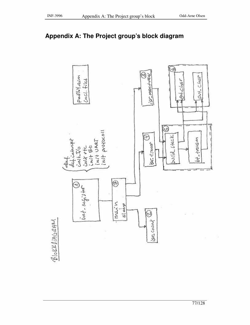
INF-3996 Appendix A: The Project group’s block diagram
Odd-Arne Olsen
77/128
Appendix A: The Project group’s block diagram

INF-3996 Appendix A: The Project group’s block diagram
Odd-Arne Olsen
78/128
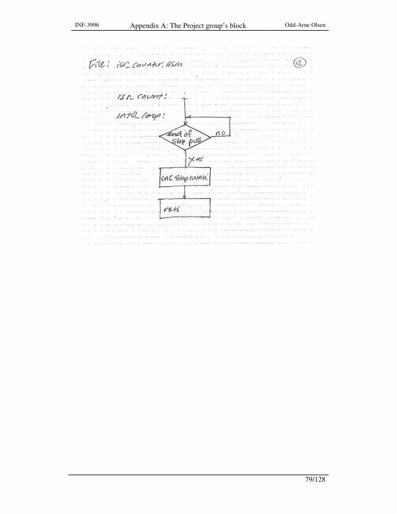
INF-3996 Appendix A: The Project group’s block diagram
Odd-Arne Olsen
79/128
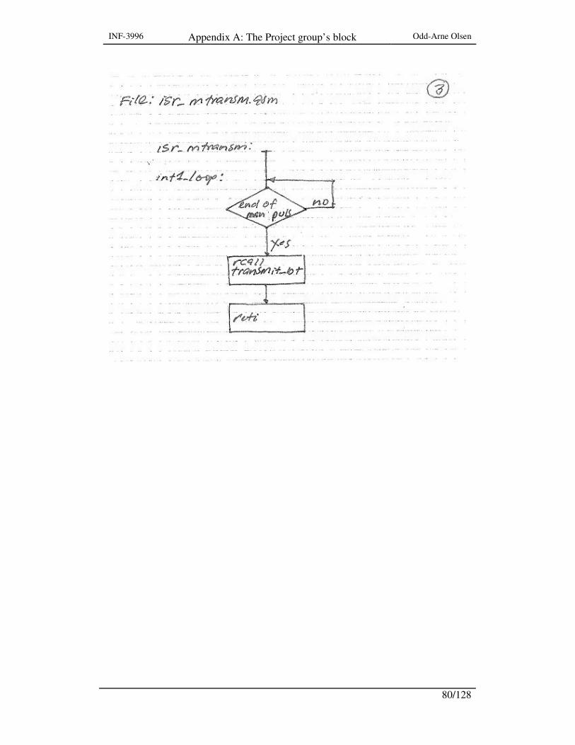
INF-3996 Appendix A: The Project group’s block diagram
Odd-Arne Olsen
80/128
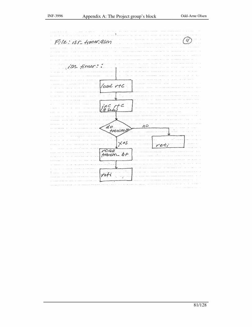
INF-3996 Appendix A: The Project group’s block diagram
Odd-Arne Olsen
81/128
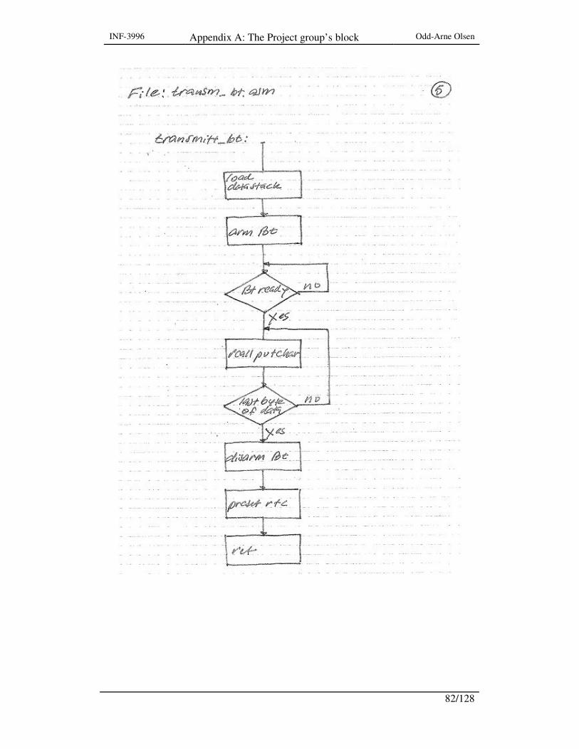
INF-3996 Appendix A: The Project group’s block diagram
Odd-Arne Olsen
82/128

INF-3996 Appendix A: The Project group’s block diagram
Odd-Arne Olsen
83/128

INF-3996 Appendix A: The Project group’s block diagram
Odd-Arne Olsen
84/128
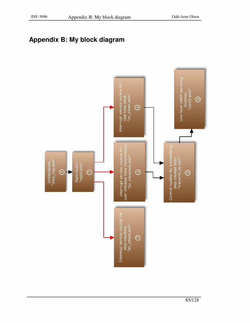
INF-3996 Appendix B: My block diagram Odd-Arne Olsen
85/128
Appendix B: My block diagram

INF-3996 Appendix B: My block diagram Odd-Arne Olsen
86/128
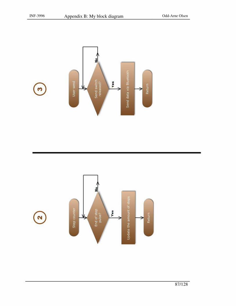
INF-3996 Appendix B: My block diagram Odd-Arne Olsen
87/128
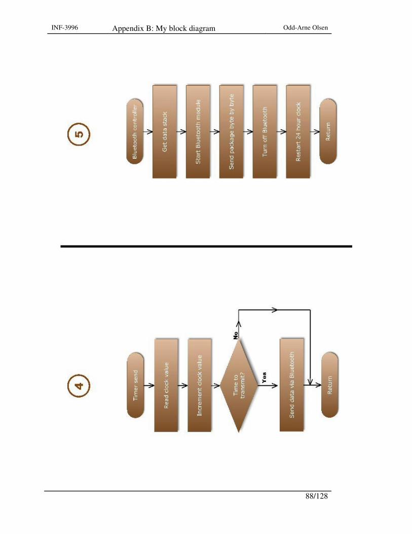
INF-3996 Appendix B: My block diagram Odd-Arne Olsen
88/128

INF-3996 Appendix B: My block diagram Odd-Arne Olsen
89/128

INF-3996 Appendix B: My block diagram Odd-Arne Olsen
90/128

INF-3996 Appendix C: The unmodified program Odd-Arne Olsen
91/128
Appendix C: The unmodified program ; ;************************************************************* ;* ;* Title: Pedometer for Telemedesin ;* ;* Filnamn: ped164.asm ;* ;* Versjon: 1.0(BETA) ;* ;* Last uppdated: 07.03.22 ;* ;* Target: ATmega164p ;* ;* Description: Main of included files ;* ;************************************************************* ;******* main program ; .LIST .include "m164pdef.inc" .include "inite_reg.asm" ; initier the registers for start/reset .include "isr_count.asm" ; interupt service routine for step counting .include "isr_timer.asm" ; interupt service routine for RTC .include "isr_mtransm.asm" ; interupt service routine for manuell data .include "uart0.asm" ; low level routins for .include "transmit_bt.asm" ; transmiterings routin .include "main.asm" ; main function
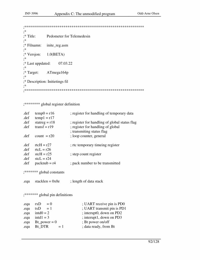
INF-3996 Appendix C: The unmodified program Odd-Arne Olsen
92/128
;************************************************************* ;* ;* Title: Pedometer for Telemedesin ;* ;* Filnamn: inite_reg.asm ;* ;* Versjon: 1.0(BETA) ;* ;* Last uppdated: 07.03.22 ;* ;* Target: ATmega164p ;* ;* Description: Initietings fil ;* ;************************************************************* ;******** global register definition .def temp0 = r16 ; register for handling of temporary data .def temp1 = r17 .def statreg = r18 ; register for handling of global status flag .def transf = r19 ; register for handling of global ; transmiting status flag .def count = r20 ; loop counter, general .def rtcH = r27 ; rtc temporary timeing register .def rtcL = r26 .def stcH = r25 ; step count register .def stcL = r24 .def packnub = r4 ; pack number to be transmitted ;******* global constants .equ stacklen = 0x0e ; length of data stack ;******* global pin definitions .equ rxD = 0 ; UART receive pin is PD0 .equ txD = 1 ; UART transmit pin is PD1 .equ intd0 = 2 ; interupt0, down on PD2 .equ intd1 = 3 ; interupt1, down on PD3 .equ Bt_power = 0 ; Bt power on/off .equ Bt_DTR = 1 ; data ready, from Bt

INF-3996 Appendix C: The unmodified program Odd-Arne Olsen
93/128
;******** global defenition .CSEG .org 0x00000 ;****** def. interupt vektors, init. jmp start ; reset handler .org INT0addr ; step interupt, service routine jmp isr_count .org INT1addr ; manualt transmitt of data, service routine jmp isr_mtransm .org OVF2addr ; rtc overflov, service routine, timer2 jmp isr_timer ;****** MCU register init. start: ; start register initiering ldi temp0,0x04 ; load SPH out SPH,temp0 ldi temp0,0xff ; load SPL out SPL,temp0 ; ldi temp0,0xc3 ; preset rtc for counting up NB ***** ldi temp0,0xff mov r3,temp0 ; ldi temp0,0x50 ldi temp0,0xfb mov r2,temp0 ldi temp0,0x0A ; load EICRA, ext.interupt controll register A sts EICRA,temp0 ; "falling edge" sense on INT0 and INT1 ldi temp0, 0x03 ; load ext. interupt mask register out EIMSK, temp0 cbi DDRD,intd0 ; initier port direction INT0

INF-3996 Appendix C: The unmodified program Odd-Arne Olsen
94/128
cbi DDRD,intd1 ; initier port direction INT1 ldi temp0,0x00 ; load MCUCR, controllregister out MCUCR,temp0 ldi temp0,0x07 ; load sleep mode and power-save out SMCR,temp0 ;****** initier rtc registers ldi temp0,0x01 ; load T/C2 overflow interupt mask register sts TIMSK2,temp0 ldi temp0,0x07 ; load T/C2 controll register, set prescaler sts TCCR2B,temp0 ; divided by 1024 ldi temp0,0x01 ; reset T/C2 interupt flagg register out TIFR2,temp0 ldi temp0,0x20 ; set assyncron clock from crystall,T/C2 sts ASSR,temp0 ; counting. ;****** initier Bt power sbi DDRA,Bt_power ; set Bt. power bus direction out cbi PORTA,Bt_power ; disarm Bt. power off cbi DDRA,Bt_DTR ; set Bt. DTR bus direction in ;******initier uart sbi PORTD, txD ; initier USART port transmit sbi DDRD, txD cbi PORTD, rxD ; initier USART port receieve cbi DDRD, rxD ldi temp0, 0x00 ; set double the USART transm. speed sts UCSR0A, temp0 ldi temp0, 0x18 ; enable receive and transmit sts UCSR0B, temp0 ldi temp0, 0x06 ; setframe format: asyacronous, 8data bits, 1stop bits,

INF-3996 Appendix C: The unmodified program Odd-Arne Olsen
95/128
sts UCSR0C, temp0 ; no parity bit. ldi temp0, 0x00 ; set baud rate, 1MHz/2400 bps sts UBRR0H, temp0 ldi temp0, 0x19 sts UBRR0L, temp0 ;****** initiering protokoll stack ldi ZL,0x00 ; set data stack pointer ldi ZH,0x02 ldi count,stacklen ; initier start loop countet cldstack: ldi temp0,0x00 ; clear data stack st Z+,temp0 dec count brne cldstack ; branch if not last byte ldi ZL,0x00 ; set data stack pointer ldi ZH,0x02 ldi temp0,0x7f ; set frame sync, tilde. std Z+0x00,temp0 std Z+0x01,temp0 ldi temp0,0x55 ; set protocol ID = 0x55 std Z+0x02,temp0 ; stor ID value ldi temp0,0xe6 std Z+0x0c,temp0 ; set crc bytes std Z+0x0d,temp0 end_init: rjmp main
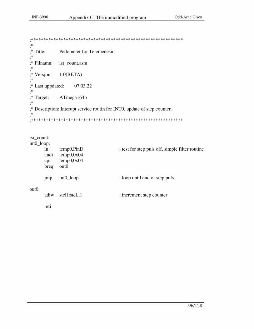
INF-3996 Appendix C: The unmodified program Odd-Arne Olsen
96/128
;************************************************************* ;* ;* Title: Pedometer for Telemedesin ;* ;* Filnamn: isr_count.asm ;* ;* Versjon: 1.0(BETA) ;* ;* Last uppdated: 07.03.22 ;* ;* Target: ATmega164p ;* ;* Description: Interupt service routin for INT0, update of step counter. ;* ;************************************************************* isr_count: int0_loop: in temp0,PinD ; test for step puls off, simple filter routine andi temp0,0x04 cpi temp0,0x04 breq out0 jmp int0_loop ; loop until end of step puls out0: adiw stcH:stcL,1 ; increment step counter reti
INF-3996 Appendix C: The unmodified program Odd-Arne Olsen
97/128
;************************************************************* ;* ;* Title: Pedometer for Telemedesin ;* ;* Filnamn: isr_timer.asm ;* ;* Versjon: 1.0(BETA) ;* ;* Last uppdated: 07.03.22 ;* ;* Target: ATmega164p ;* ;* Description: Interupt service routine for TIMER2_OVF, and ;* test of 24 houer limit. day end flagg. ;* ;************************************************************* isr_timer: movw rtcH:rtcL,r3:r2 ; load rtc value adiw rtcH:rtcL,0x01 ; increment rtc counter movw r3:r2,rtcH:rtcL ; save rtc value brcs carry_set ; do transmitt if 24 hours reti carry_set: rcall transmit_bt ; do transmitt 24 hours reti

INF-3996 Appendix C: The unmodified program Odd-Arne Olsen
98/128
;************************************************************* ;* ;* Title: Pedometer for Telemedesin ;* ;* Filnamn: isr_mtransm.asm ;* ;* Versjon: 1.0(BETA) ;* ;* Last uppdated: 07.03.22 ;* ;* Target: ATmega164p ;* ;* Description: Interupt service routine for INT1, do manuell ;* data transmission. ;* ;************************************************************* isr_mtransm: int1_loop: in temp0,PinD ; test for manual interupt puls off andi temp0,0x08 cpi temp0,0x08 breq out1 jmp int1_loop ; loop until end of transm. puls out1: rcall transmit_bt ; do the transmiting manual reti
INF-3996 Appendix C: The unmodified program Odd-Arne Olsen
99/128
;********************************************************** ;* ;* Title : Read/Write through USART ;* ;* Filname : uartcom.asm ;* ;* Versjon : 1.0(BETA) ;* ;* Last updated: 07.03.22 ;* ;* Target : ATmega164p ; ;* Description: ;* ;********************************************************** ;********************************************************** ;* ;* Function: putchar ;* ;* Description: Puts out one character ;* ;* Usage: ;* ;* Return: None ;* ;* Note: Parameter to be transmitted in temp1 ;* ;********************************************************** putchar: USART_transmit: lds temp0,UCSR0A ; wait for emty transmit buffer sbrs temp0,UDRE0 rjmp USART_transmit sts UDR0,temp1 ; put data in to buffer ret

INF-3996 Appendix C: The unmodified program Odd-Arne Olsen
100/128
;********************************************************** ;* ;* Function: getchat ;* ;* Description: Get one character ;* ;* Usage: ;* ;* Return: Yes ;* ;* Note: Return to be transmitted in temp1 ;* ;********************************************************** getchar: USART_receive: lds temp0,UCSR0A ; wait for data to be received sbrs temp0,RXC0 rjmp USART_receive lds temp1,UDR0 ; get and return recieved data from buffer ret

INF-3996 Appendix C: The unmodified program Odd-Arne Olsen
101/128
;************************************************************* ;* ;* Title: Pedometer for Telemedesin ;* ;* Filnamn: transmit_bt.asm ;* ;* Versjon: 1.0(BETA) ;* ;* Last uppdated: 07.03.24 ;* ;* Target: ATmega164p ;* ;* Description: Service routine for transmitting step counter data. ;* ;************************************************************* transmit_bt: ldi ZL,0x00 ; set data stack pointer to start ldi ZH,0x02 ldi count,stacklen ; initier loop counter mov temp0,packnub ; update pack number inc temp0 mov packnub,temp0 std Z+0x03,packnub ; stor packed number std Z+0x06,stcH ; step counter higher byte to data stack std Z+0x07,stcL ; step counter lower byte to data stack sbi PORTA,Bt_power ; arm Bt power,and wait for DTR high level Bt_ready: in temp0,PINA ; test Bt ready ; sbrs temp0,Bt_DTR ; NB ********** ; rjmp Bt_ready ; loop until BT ready transm: ld temp1,Z+ ; Load data from data stack rcall putchar dec count brne transm ; branch if not last byte

INF-3996 Appendix C: The unmodified program Odd-Arne Olsen
102/128
untilempty: lds temp0,UCSR0A ; wait for last byte in UART to be transmitted sbrs temp0,UDRE0 rjmp untilempty cbi PORTA,BT_power ; disarm Bt power ldi stcH,0x00 ;reset step counter, stc ldi stcL,0x00 ; ldi rtcH,0xc3 ; preset teal time counter, rtc NB *********** ; ldi rtcL,0x50 ldi rtcH,0xff ; preset teal time counter, rtc ldi rtcL,0xfb movw r3:r2,rtcH:rtcL ; save preset value endtransm: ret
INF-3996 Appendix C: The unmodified program Odd-Arne Olsen
103/128
;************************************************************* ;* ;* Title: Pedometer for Telemedesin ;* ;* Filnamn: main.asm ;* ;* Versjon: 1.0(BETA) ;* ;* Last uppdated: 07.03.22 ;* ;* Target: ATmega164p ;* ;* Description: Main function ;* ;************************************************************* main: sei ; set global interupt main_loop: ; sleep ; set sleep mode, Power-save ; rcall start_sync ;********************************** ; rcall transmit_bt nop nop rjmp main_loop ;-------------------------------------------------------- ;TEST OF RUN start_test: ldi temp0,0x01 out PORTA,temp0 out DDRA,temp0 ldi temp1,0x01 test_loop1: add temp0,temp1 brcs go1

INF-3996 Appendix C: The unmodified program Odd-Arne Olsen
104/128
jmp test_loop1 go1: ldi temp0,0x00 out PORTA,temp0 ldi temp1,0x01 test_loop2: add temp0,temp1 brcs go2 jmp test_loop2 go2: ; rjmp venteloop ; loop until next inerupt ;----------------------------------------------------------- ; synkpuls for UART test start_sync: sbi PORTA,0x00 sbi DDRA,0x00 ldi r21,0x7f ldi r22,0x01 loop_sync: add r21,r22 brcs loop_out jmp loop_sync loop_out: cbi PORTA,0x00 ret ;------------------------------------------------------------- start_syncx: ldi temp0,0x01 out PORTA,temp0 out DDRA,temp0 ldi r21,0x00 ldi r22,0x01
INF-3996 Appendix C: The unmodified program Odd-Arne Olsen
105/128
loop_syncx: ; rcall indre add r21,r22 brcs loop_out jmp loop_syncx loop_outx: cbi PORTA,0x00 ret ;------------------------------------------------------------- indre: ldi r23,0x00 ldi r24,0x08 loop_syn: add r23,r24 brcs loop_out jmp loop_syn ret

INF-3996 Appendix C: The unmodified program Odd-Arne Olsen
106/128

INF-3996 Appendix D: The modified program Odd-Arne Olsen
107/128
Appendix D: The modified program ; ;************************************************************* ;* ;* Title: Pedometer for Telemedisin ;* ;* Filename: ped164.asm ;* ;* Versjon: 1.1 OA(BETA) ;* ;* Last updated: 2007.04.18 ;* ;* Target: ATmega164p ;* ;* Description: Main include file ;* ;* Designed by: Willy Mortensen ;* ;* Modified by: Odd-Arne Olsen ;* ;************************************************************* ;******* main program .nolist .include "m164pdef.inc" .list .include "inite_reg.asm" ; initialize the registers for start/reset .include "isr_count.asm" ; interrupt service routine for step counting .include "isr_timer.asm" ; interrupt service routine for RTC .include "isr_mtransm.asm" ; interrupt service routine for user initiated transmit .include "uart0.asm" ; low level routins for UART handling .include "transmit_bt.asm" ; data transmit routine .include "main.asm" ; main function

INF-3996 Appendix D: The modified program Odd-Arne Olsen
108/128
;************************************************************* ;* ;* Title: Pedometer for Telemedisin ;* ;* Filename: inite_reg.asm ;* ;* Block diagram 1 ;* ;* Versjon: 1.1 OA(BETA) ;* ;* Last updated: 2007.04.19 ;* ;* Target: ATmega164p ;* ;* Description: Initialization file ;* ;* Designed by: Willy Mortensen ;* ;* Modified by: Odd-Arne Olsen ;* ;************************************************************* ;******** global register definition .def temp0 = r16 ; register for temporary data handling .def temp1 = r17 ; register for temporary data handling .def statreg = r18 ; register for global status flag handling .def transf = r19 ; register for global transmit status flag .def count = r20 ; loop counter, general .def rtcH = r27 ; RTC temporary timing register high 8 bits .def rtcL = r26 ; RTC temporary timing register low 8 bits .def stcH = r25 ; step count register high 8 bits .def stcL = r24 ; step count register low 8 bits .def packnub = r4 ; package number to be transmitted ;******* global constants .equ stacklen = 0x0e ; length of data package stack ;******* global pin and constant definitions .equ rxD = 0 ; UART receive pin is PD0
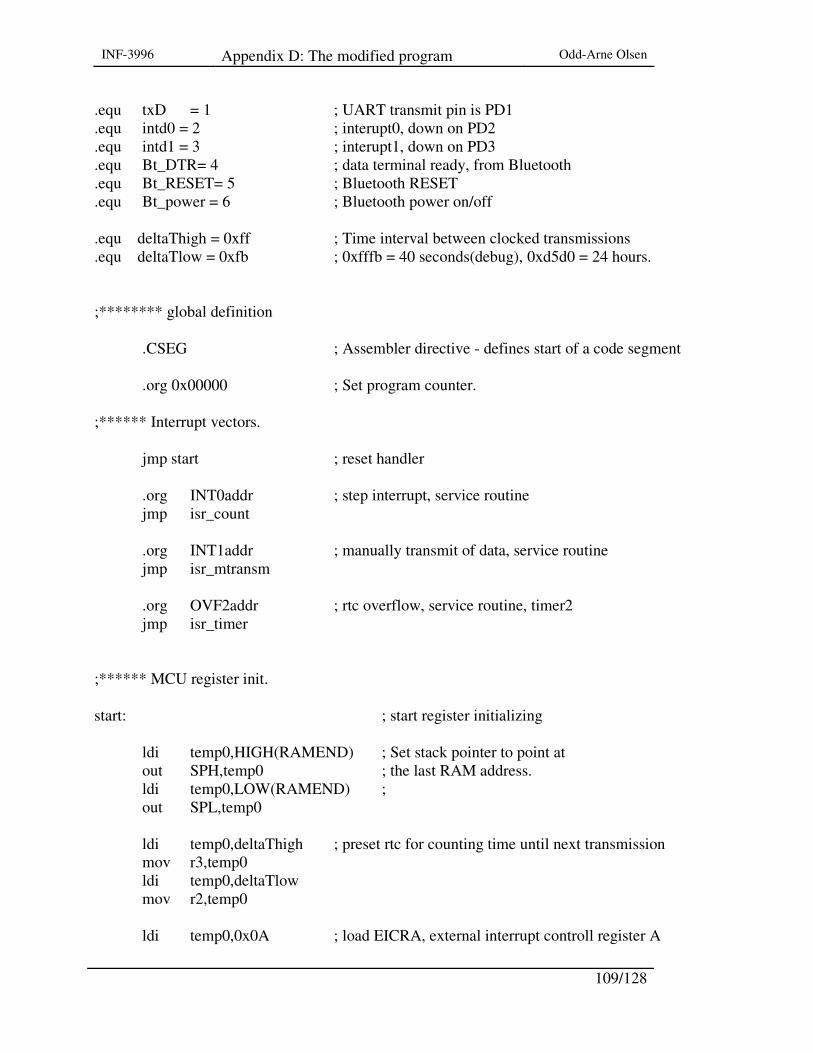
INF-3996 Appendix D: The modified program Odd-Arne Olsen
109/128
.equ txD = 1 ; UART transmit pin is PD1
.equ intd0 = 2 ; interupt0, down on PD2
.equ intd1 = 3 ; interupt1, down on PD3
.equ Bt_DTR= 4 ; data terminal ready, from Bluetooth
.equ Bt_RESET= 5 ; Bluetooth RESET
.equ Bt_power = 6 ; Bluetooth power on/off .equ deltaThigh = 0xff ; Time interval between clocked transmissions .equ deltaTlow = 0xfb ; 0xfffb = 40 seconds(debug), 0xd5d0 = 24 hours. ;******** global definition .CSEG ; Assembler directive - defines start of a code segment .org 0x00000 ; Set program counter. ;****** Interrupt vectors. jmp start ; reset handler .org INT0addr ; step interrupt, service routine jmp isr_count .org INT1addr ; manually transmit of data, service routine jmp isr_mtransm .org OVF2addr ; rtc overflow, service routine, timer2 jmp isr_timer ;****** MCU register init. start: ; start register initializing
ldi temp0,HIGH(RAMEND) ; Set stack pointer to point at out SPH,temp0 ; the last RAM address. ldi temp0,LOW(RAMEND) ; out SPL,temp0 ldi temp0,deltaThigh ; preset rtc for counting time until next transmission mov r3,temp0 ldi temp0,deltaTlow mov r2,temp0 ldi temp0,0x0A ; load EICRA, external interrupt controll register A
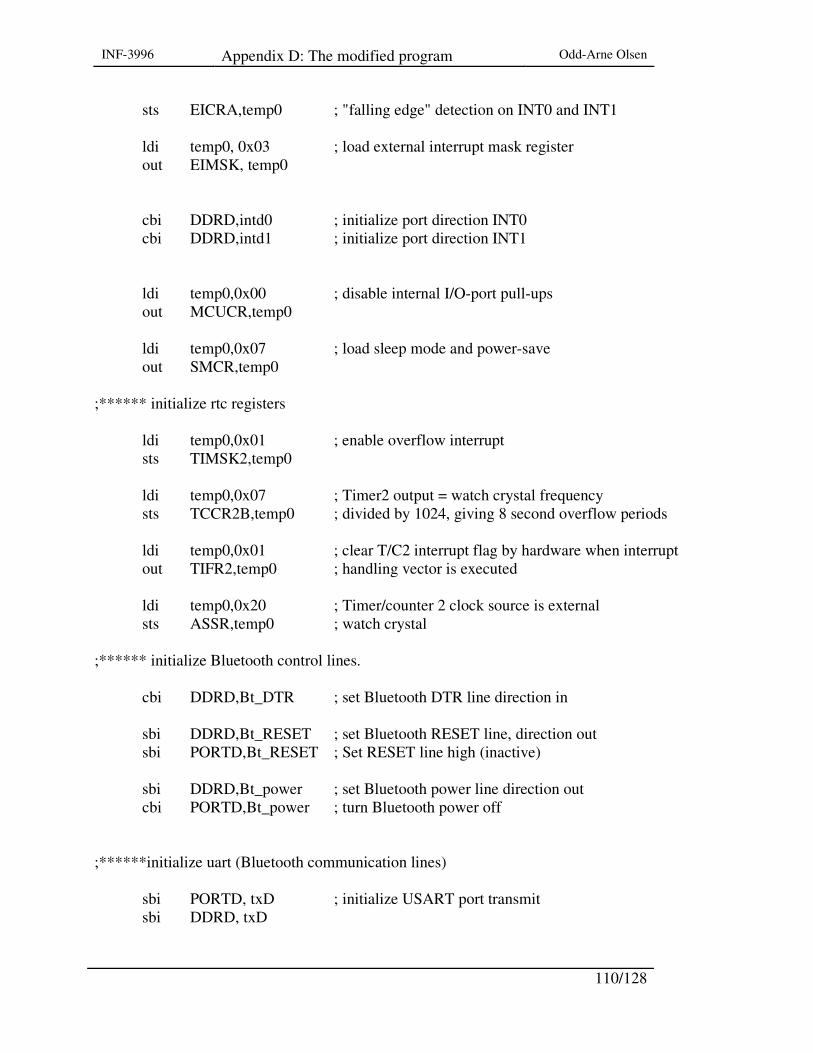
INF-3996 Appendix D: The modified program Odd-Arne Olsen
110/128
sts EICRA,temp0 ; "falling edge" detection on INT0 and INT1 ldi temp0, 0x03 ; load external interrupt mask register out EIMSK, temp0 cbi DDRD,intd0 ; initialize port direction INT0 cbi DDRD,intd1 ; initialize port direction INT1 ldi temp0,0x00 ; disable internal I/O-port pull-ups out MCUCR,temp0 ldi temp0,0x07 ; load sleep mode and power-save out SMCR,temp0 ;****** initialize rtc registers ldi temp0,0x01 ; enable overflow interrupt sts TIMSK2,temp0 ldi temp0,0x07 ; Timer2 output = watch crystal frequency sts TCCR2B,temp0 ; divided by 1024, giving 8 second overflow periods ldi temp0,0x01 ; clear T/C2 interrupt flag by hardware when interrupt out TIFR2,temp0 ; handling vector is executed ldi temp0,0x20 ; Timer/counter 2 clock source is external sts ASSR,temp0 ; watch crystal ;****** initialize Bluetooth control lines. cbi DDRD,Bt_DTR ; set Bluetooth DTR line direction in sbi DDRD,Bt_RESET ; set Bluetooth RESET line, direction out sbi PORTD,Bt_RESET ; Set RESET line high (inactive) sbi DDRD,Bt_power ; set Bluetooth power line direction out cbi PORTD,Bt_power ; turn Bluetooth power off ;******initialize uart (Bluetooth communication lines) sbi PORTD, txD ; initialize USART port transmit sbi DDRD, txD

INF-3996 Appendix D: The modified program Odd-Arne Olsen
111/128
cbi PORTD, rxD ; initialize USART port recieve cbi DDRD, rxD ldi temp0, 0x00 ; set single USART transm. speed sts UCSR0A, temp0 ldi temp0, 0x18 ; enable receive and transmit sts UCSR0B, temp0 ldi temp0, 0x06 ; set frame format: asynchronous, 8 data bits, 1 stop bits, sts UCSR0C, temp0 ; no parity bit. ldi temp0, 0x00 ; set baud rate, 1MHz/2400 bps sts UBRR0H, temp0 ldi temp0, 0x19 sts UBRR0L, temp0 ;****** initialization of data package protocol stack ldi ZL,0x00 ; set data stack pointer ldi ZH,0x02 ldi count,stacklen ; initialize start loop counter clrdstack: ldi temp0,0x00 ; clear data stack st Z+,temp0 dec count brne clrdstack ; branch if not last byte ldi ZL,0x00 ; set data stack pointer ldi ZH,0x02 ldi temp0,0x7e ; set frame sync, tilde. std Z+0x00,temp0 std Z+0x01,temp0 ldi temp0,0x55 ; set protocol ID = 0x55 std Z+0x02,temp0 ; stor ID value ldi temp0,0xe6 std Z+0x0c,temp0 ; set crc bytes std Z+0x0d,temp0 end_init: rjmp main
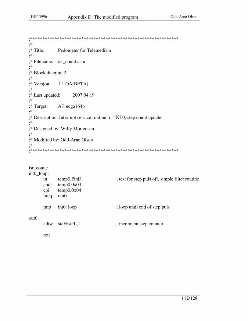
INF-3996 Appendix D: The modified program Odd-Arne Olsen
112/128
;************************************************************* ;* ;* Title: Pedometer for Telemedisin ;* ;* Filename: isr_count.asm ;* ;* Block diagram 2 ;* ;* Versjon: 1.1 OA(BETA) ;* ;* Last updated: 2007.04.19 ;* ;* Target: ATmega164p ;* ;* Description: Interrupt service routine for INT0, step count update. ;* ;* Designed by: Willy Mortensen ;* ;* Modified by: Odd-Arne Olsen ;* ;************************************************************* isr_count: int0_loop: in temp0,PinD ; test for step puls off, simple filter routine andi temp0,0x04 cpi temp0,0x04 breq out0 jmp int0_loop ; loop until end of step puls out0: adiw stcH:stcL,1 ; increment step counter reti

INF-3996 Appendix D: The modified program Odd-Arne Olsen
113/128
;************************************************************* ;* ;* Title: Pedometer for Telemedisin ;* ;* Filename: isr_timer.asm ;* ;* Block diagram 4.2 ;* ;* Versjon: 1.2 OA(BETA) ;* ;* Last updated: 2007.04.28 ;* ;* Target: ATmega164p ;* ;* Description: Interrupt service routine for TIMER2_OVF, and ;* test of the 24 hour limit. day end flagg. ;* ;* Designed by: Willy Mortensen ;* ;* Modified by: Odd-Arne Olsen ;* ;************************************************************* isr_timer: mov r4, temp0 mov r5, temp1 movw rtcH:rtcL,r3:r2 ; load rtc value adiw rtcH:rtcL,0x01 ; increment the rtc counter movw r3:r2,rtcH:rtcL ; save rtc value brcs carry_set ; 24 hours since last transmit? jmp oldvalue carry_set: ldi temp0, 0x00 rcall transmit_bt ; transmit data ldi stcH,0x00 ; reset step counter, stc ldi stcL,0x00

INF-3996 Appendix D: The modified program Odd-Arne Olsen
114/128
ldi rtcH,deltaThigh ; preset real time counter, rtc ldi rtcL,deltaTlow movw r3:r2,rtcH:rtcL ; save preset value oldvalue: mov temp0, r4 mov temp1, r5 reti
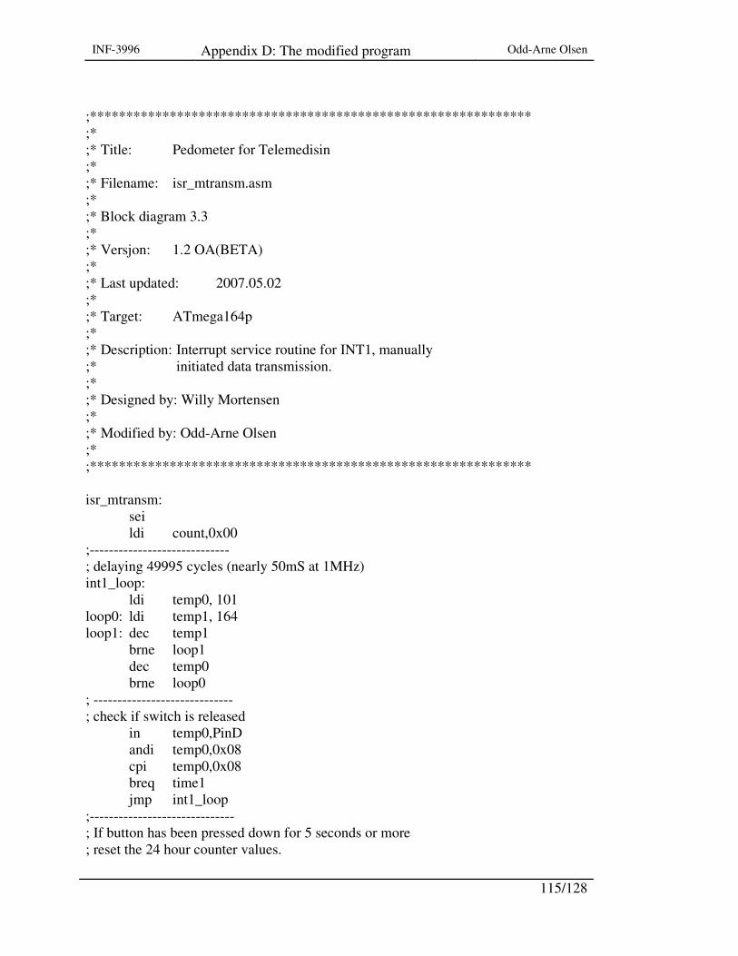
INF-3996 Appendix D: The modified program Odd-Arne Olsen
115/128
;************************************************************* ;* ;* Title: Pedometer for Telemedisin ;* ;* Filename: isr_mtransm.asm ;* ;* Block diagram 3.3 ;* ;* Versjon: 1.2 OA(BETA) ;* ;* Last updated: 2007.05.02 ;* ;* Target: ATmega164p ;* ;* Description: Interrupt service routine for INT1, manually ;* initiated data transmission. ;* ;* Designed by: Willy Mortensen ;* ;* Modified by: Odd-Arne Olsen ;* ;************************************************************* isr_mtransm: sei ldi count,0x00 ;----------------------------- ; delaying 49995 cycles (nearly 50mS at 1MHz) int1_loop: ldi temp0, 101 loop0: ldi temp1, 164 loop1: dec temp1 brne loop1 dec temp0 brne loop0 ; ----------------------------- ; check if switch is released in temp0,PinD andi temp0,0x08 cpi temp0,0x08 breq time1 jmp int1_loop ;------------------------------ ; If button has been pressed down for 5 seconds or more ; reset the 24 hour counter values.

INF-3996 Appendix D: The modified program Odd-Arne Olsen
116/128
time1: cpi count,100 brlt hundredstep ldi rtcH,deltaThigh ldi rtcL,deltaTlow movw r3:r2,rtcH:rtcL reti ;------------------------------- hundredstep: cpi stcH, 0x00 brne newdata cpi stcL, 101 brlt olddata newdata: ldi temp0, 0x00 jmp out1 olddata: ldi temp0, 0xAA out1: cli rcall transmit_bt reti ; =============================
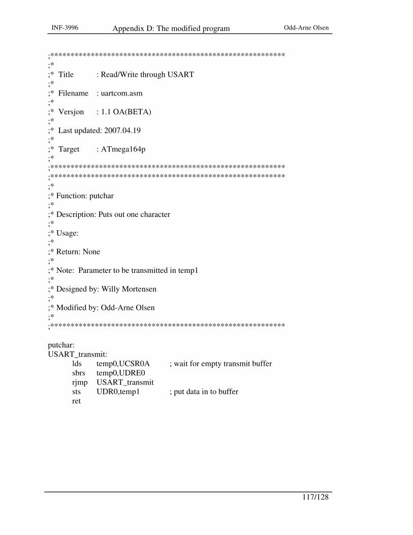
INF-3996 Appendix D: The modified program Odd-Arne Olsen
117/128
;********************************************************** ;* ;* Title : Read/Write through USART ;* ;* Filename : uartcom.asm ;* ;* Versjon : 1.1 OA(BETA) ;* ;* Last updated: 2007.04.19 ;* ;* Target : ATmega164p ;* ;********************************************************** ;********************************************************** ;* ;* Function: putchar ;* ;* Description: Puts out one character ;* ;* Usage: ;* ;* Return: None ;* ;* Note: Parameter to be transmitted in temp1 ;* ;* Designed by: Willy Mortensen ;* ;* Modified by: Odd-Arne Olsen ;* ;********************************************************** putchar: USART_transmit: lds temp0,UCSR0A ; wait for empty transmit buffer sbrs temp0,UDRE0 rjmp USART_transmit sts UDR0,temp1 ; put data in to buffer ret

INF-3996 Appendix D: The modified program Odd-Arne Olsen
118/128
;********************************************************** ;* ;* Function: getchat ;* ;* Description: Get one character ;* ;* Usage: ;* ;* Return: Yes ;* ;* Note: Return to be transmitted in temp1 ;* ;********************************************************** getchar: USART_receive: lds temp0,UCSR0A ; wait for data to be received sbrs temp0,RXC0 rjmp USART_receive lds temp1,UDR0 ; get and return recieved data from buffer ret
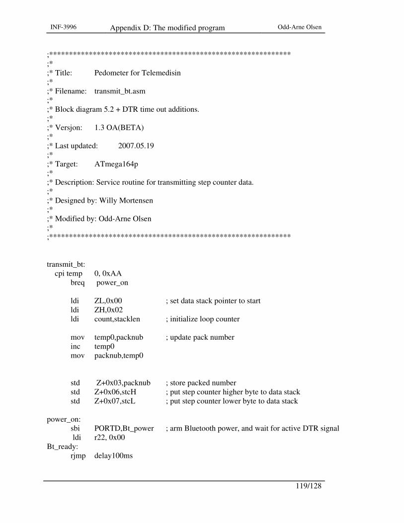
INF-3996 Appendix D: The modified program Odd-Arne Olsen
119/128
;************************************************************* ;* ;* Title: Pedometer for Telemedisin ;* ;* Filename: transmit_bt.asm ;* ;* Block diagram 5.2 + DTR time out additions. ;* ;* Versjon: 1.3 OA(BETA) ;* ;* Last updated: 2007.05.19 ;* ;* Target: ATmega164p ;* ;* Description: Service routine for transmitting step counter data. ;* ;* Designed by: Willy Mortensen ;* ;* Modified by: Odd-Arne Olsen ;* ;************************************************************* transmit_bt: cpi temp 0, 0xAA breq power_on ldi ZL,0x00 ; set data stack pointer to start ldi ZH,0x02 ldi count,stacklen ; initialize loop counter mov temp0,packnub ; update pack number inc temp0 mov packnub,temp0 std Z+0x03,packnub ; store packed number std Z+0x06,stcH ; put step counter higher byte to data stack std Z+0x07,stcL ; put step counter lower byte to data stack power_on: sbi PORTD,Bt_power ; arm Bluetooth power, and wait for active DTR signal ldi r22, 0x00 Bt_ready: rjmp delay100ms
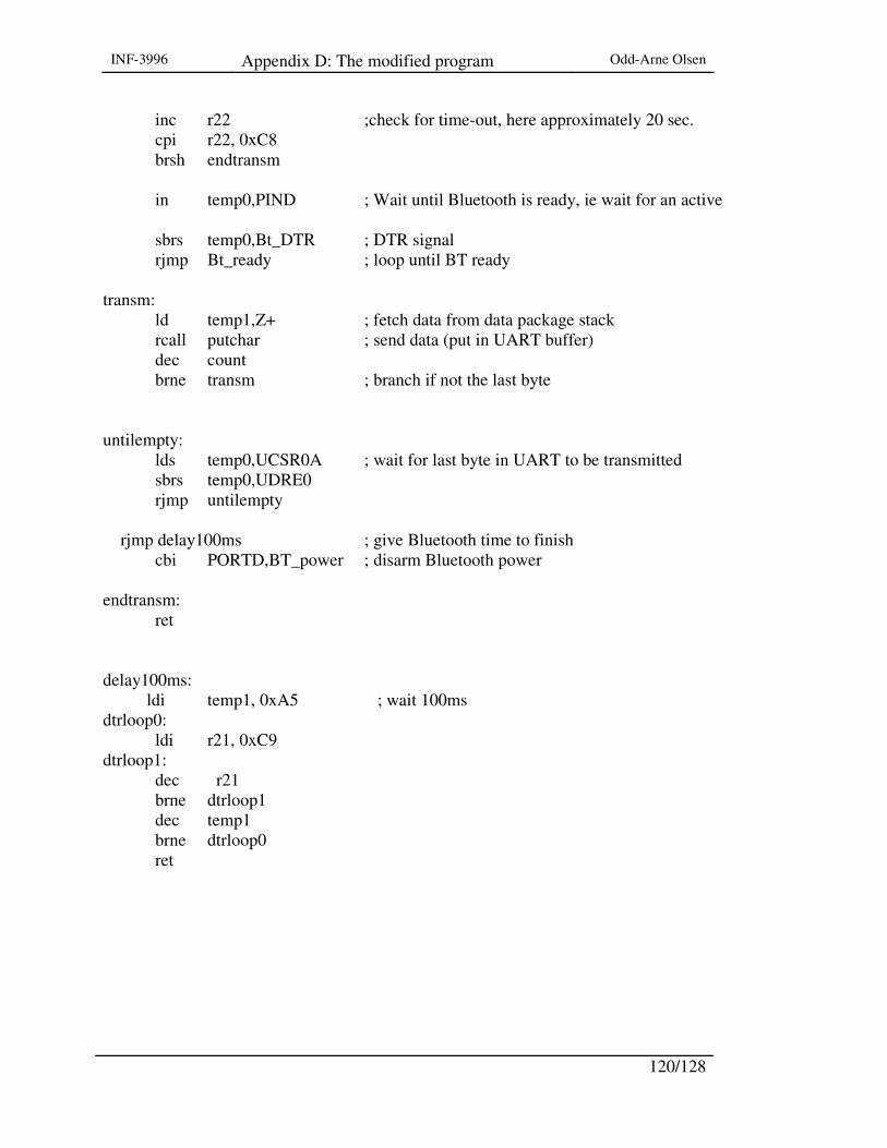
INF-3996 Appendix D: The modified program Odd-Arne Olsen
120/128
inc r22 ;check for time-out, here approximately 20 sec. cpi r22, 0xC8 brsh endtransm in temp0,PIND ; Wait until Bluetooth is ready, ie wait for an active sbrs temp0,Bt_DTR ; DTR signal rjmp Bt_ready ; loop until BT ready transm: ld temp1,Z+ ; fetch data from data package stack rcall putchar ; send data (put in UART buffer) dec count brne transm ; branch if not the last byte untilempty: lds temp0,UCSR0A ; wait for last byte in UART to be transmitted sbrs temp0,UDRE0 rjmp untilempty rjmp delay100ms ; give Bluetooth time to finish cbi PORTD,BT_power ; disarm Bluetooth power endtransm: ret delay100ms: ldi temp1, 0xA5 ; wait 100ms dtrloop0:
ldi r21, 0xC9 dtrloop1:
dec r21 brne dtrloop1 dec temp1 brne dtrloop0
ret

INF-3996 Appendix D: The modified program Odd-Arne Olsen
121/128
;************************************************************* ;* ;* Title: Pedometer for Telemedisin ;* ;* Filename: main.asm ;* ;* Block diagram 7 ;* ;* Versjon: 1.1 OA(BETA) ;* ;* Last updated: 2007.05.02 ;* ;* Target: ATmega164p ;* ;* Description: Main function ;* ;* Designed by: Willy Mortensen ;* ;* Modified by: Odd-Arne Olsen ;* ;************************************************************* main: sei ; set global interrupt main_loop: sleep ; set sleep mode, Power-save rjmp main_loop

INF-3996 Appendix D: The modified program Odd-Arne Olsen
122/128
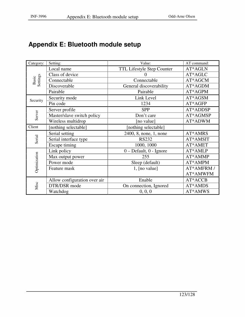
INF-3996 Appendix E: Bluetooth module setup Odd-Arne Olsen
123/128
Appendix E: Bluetooth module setup Category: Setting: Value: AT command:
Local name TTL Lifestyle Step Counter AT*AGLN Class of device 0 AT*AGLC Connectable Connectable AT*AGCM Discoverable General discoverability AT*AGDM
Bas
ic
Setti
ngs
Pairable Pairable AT*AGPM Security mode Link Level AT*AGSM Security Pin code 1234 AT*AGFP Server profile SPP AT*ADDSP Master/slave switch policy Don’t care AT*AGMSP
Serv
er
Wireless multidrop [no value] AT*ADWM Client [nothing selectable] [nothing selectable]
Serial setting 2400, 8, none, 1, none AT*AMRS Serial interface type RS232 AT*AMSIT
Seri
al
Escape timing 1000, 1000 AT*AMET Link policy 0 – Default, 0 - Ignore AT*AMLP Max output power 255 AT*AMMP Power mode Sleep (default) AT*AMPM
Opt
imiz
atio
n
Feature mask 1, [no value] AT*AMFRM / AT*AMWFM
Allow configuration over air Enable AT*ACCB DTR/DSR mode On connection, Ignored AT*AMDS
Mis
c
Watchdog 0, 0, 0 AT*AMWS

INF-3996 Appendix E: Bluetooth module setup Odd-Arne Olsen
124/128

INF-3996 Appendix A: The Project group’s block diagram
Odd-Arne Olsen
125/128
Appendix F: The sensor tests
Figure I: Test cicuit used.
Figure II: Output from Cambden CSSM sub-miniature micro switch. Test circuit seen in Figure
I B.
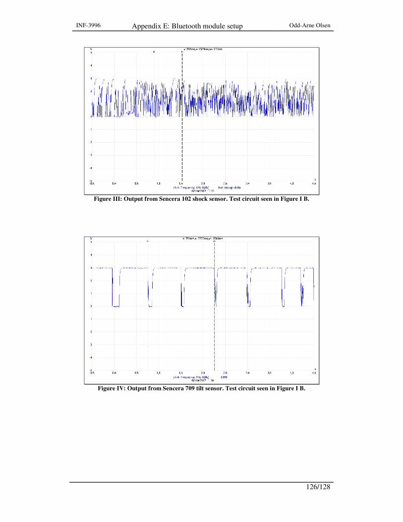
INF-3996 Appendix E: Bluetooth module setup Odd-Arne Olsen
126/128
Figure III: Output from Sencera 102 shock sensor. Test circuit seen in Figure I B.
Figure IV: Output from Sencera 709 tilt sensor. Test circuit seen in Figure I B.
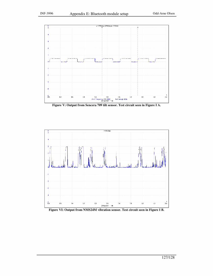
INF-3996 Appendix E: Bluetooth module setup Odd-Arne Olsen
127/128
Figure V: Output from Sencera 709 tilt sensor. Test circuit seen in Figure I A.
Figure VI: Output from NMS24M vibration sensor. Test circuit seen in Figure I B.

INF-3996 Appendix E: Bluetooth module setup Odd-Arne Olsen
128/128
Figure VII: Output from NMS24M vibration sensor. Test circuit seen in Figure I A.