Pt100 Input Module User's Manual (Hardware) - inverter & Plc
Upload
khangminh22Category
view
5download
0
User’s Manual(Hardware)
AJ65SBT2B-64TDThank you for purchasing the programmable controller.
© 2009 MITSUBISHI ELECTRIC CORPORATION
Thermocouple InputModule
Prior to use, please read this and relevant manuals thoroughly to fully understand the product.
MODEL AJ65S-64TD-U-HW
MODELCODE
13JY76
IB(NA)-0800419-F(1612)MEE

SAFETY PRECAUTIONS(Read these precautions before using this product.)
Before using this product, please read this manual and the relevant manuals carefully and pay full attention to safety to handle the product correctly.These precautions apply only to this equipment. Refer to the user's manual of the CPU module to use for a description of the programmable controller system safetyprecautions.
In this manual, the safety precautions are classified into two levels: " WARNING" and " CAUTION".
Under some circumstances, failure to observe the precautions given under " CAUTION" may lead to serious consequences.Observe the precautions of both levels because they are important for personal and system safety.
Make sure that the end users read this manual and then keep the manual in a safe place for future reference.
WARNINGIndicates that incorrect handling may cause
hazardous conditions, resulting in death or severe
injury.
Indicates that incorrect handling may cause
hazardous conditions, resulting in minor or moderate
injury or property damage.CAUTION
A-1

[Design Precautions]
[Installation Precautions]
WARNINGIn the case of a communication failure in the network, data in the master module are held.Check the communication status information (SB, SW) and configure an interlock circuit in the sequence program to ensure that the entire system will operate safely.
CAUTIONDo not install the control lines or communication cables together with the main circuit lines or power cables.Keep a distance of 100mm (3.94 inches) or more between them.Failure to do so may result in malfunction due to noise.
CAUTIONUse the programmable controller in an environment that meets the general specifications in this manual.Failure to do so may result in electric shock, fire, malfunction, or damage to or deterioration of the product.
For protection of the switches, do not remove the cushioning material before installation.
Securely fix the module with a DIN rail or mounting screws. Tighten the screws within the specified torque range.Undertightening can cause drop of the screw, short circuit or malfunction.Overtightening can damage the screw and/or module, resulting in drop, short circuit, or malfunction.
Do not directly touch any conductive part of the module.Doing so can cause malfunction or failure of the module.
A-2
[Wiring Precautions]
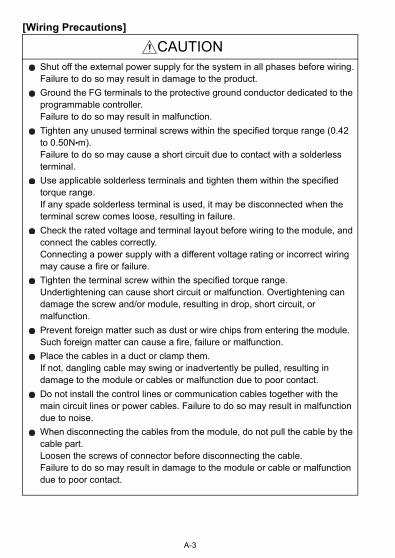
CAUTIONShut off the external power supply for the system in all phases before wiring.Failure to do so may result in damage to the product.
Ground the FG terminals to the protective ground conductor dedicated to the programmable controller.Failure to do so may result in malfunction.
Tighten any unused terminal screws within the specified torque range (0.42 to 0.50N•m).Failure to do so may cause a short circuit due to contact with a solderless terminal.
Use applicable solderless terminals and tighten them within the specified torque range.If any spade solderless terminal is used, it may be disconnected when the terminal screw comes loose, resulting in failure.
Check the rated voltage and terminal layout before wiring to the module, and connect the cables correctly.Connecting a power supply with a different voltage rating or incorrect wiring may cause a fire or failure.
Tighten the terminal screw within the specified torque range.Undertightening can cause short circuit or malfunction. Overtightening can damage the screw and/or module, resulting in drop, short circuit, or malfunction.
Prevent foreign matter such as dust or wire chips from entering the module.Such foreign matter can cause a fire, failure or malfunction.
Place the cables in a duct or clamp them.If not, dangling cable may swing or inadvertently be pulled, resulting in damage to the module or cables or malfunction due to poor contact.
Do not install the control lines or communication cables together with the main circuit lines or power cables. Failure to do so may result in malfunction due to noise.
When disconnecting the cables from the module, do not pull the cable by the cable part.Loosen the screws of connector before disconnecting the cable.Failure to do so may result in damage to the module or cable or malfunction due to poor contact.
A-3
[Startup/Maintenance Precautions]
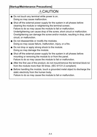
CAUTIONDo not touch any terminal while power is on.Doing so may cause malfunction.
Shut off the external power supply for the system in all phases before cleaning the module or retightening the terminal screws .Failure to do so may cause the module to fail or malfunction.Undertightening can cause drop of the screw, short circuit or malfunction.Overtightening can damage the screw and/or module, resulting in drop, short circuit, or malfunction.
Do not disassemble or modify the modules.Doing so may cause failure, malfunction, injury, or a fire.
Do not drop or apply strong shock to the module. Doing so may damage the module.
Shut off the external power supply for the system in all phases before mounting or removing the module to or from the panel.Failure to do so may cause the module to fail or malfunction.
After the first use of the product, do not mount/remove the terminal block to/from the module more than 50 times. (IEC 61131-2 compliant)
Before handling the module, touch a grounded metal object to discharge the static electricity from the human body.
Failure to do so may cause the module to fail or malfunction.
A-4
[Disposal Precautions]
CAUTIONWhen disposing of this product, treat it as industrial waste.
A-5
PRÉCAUTIONS DE SÉCURITÉ(Lire ces précautions avant toute utilisation du produit.)
Before using this product, please read this manual and the relevant manuals carefully and pay full attention to safety to handle the product correctly.Ces précautions ne concernent que cet équipement. Dans le manuel de l'utilisateur du module CPU correspondant, voir l'exposé des précautions de sécurité concernant le système de l'automate programmable.
Dans ce manuel, les précautions de sécurité sont classées en deux niveaux, à savoir : " AVERTISSEMENT" et " ATTENTION"
Dans certaines circonstances, le non-respect d'une précaution de sécurité introduite sous le titre " ATTENTION"peut avoir des conséquences graves.Les précautions de ces deux niveaux doivent être observées dans leur intégralité car elles ont trait à la sécurité des personnes et aussi du système.
Veiller à ce que les utilisateurs finaux lisent ce manuel qui doit être conservé dans un endroit sûr pour s'y référer en cas de besoin.
AVERTISSEMENT Attire l'attention sur le fait qu'une négligence peut créer une situation de danger avec risque de mort ou de blessures graves.Attire l'attention sur le fait qu'une négligence peut créer une situation de danger avec risque de blessures légères ou de gravité moyennes ou risque de dégâts matériels.
ATTENTION
A-6
[Précautions lors de la conception]
[Précautions d'installation]
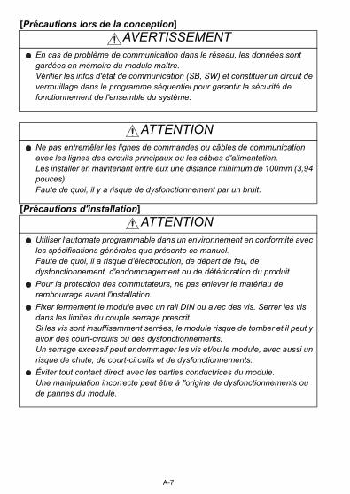
AVERTISSEMENTEn cas de problème de communication dans le réseau, les données sont gardées en mémoire du module maître.Vérifier les infos d'état de communication (SB, SW) et constituer un circuit de verrouillage dans le programme séquentiel pour garantir la sécurité de fonctionnement de l'ensemble du système.
ATTENTIONNe pas entremêler les lignes de commandes ou câbles de communication avec les lignes des circuits principaux ou les câbles d'alimentation.Les installer en maintenant entre eux une distance minimum de 100mm (3,94 pouces).Faute de quoi, il y a risque de dysfonctionnement par un bruit.
ATTENTIONUtiliser l'automate programmable dans un environnement en conformité avec les spécifications générales que présente ce manuel.Faute de quoi, il a risque d'électrocution, de départ de feu, de dysfonctionnement, d'endommagement ou de détérioration du produit.
Pour la protection des commutateurs, ne pas enlever le matériau de rembourrage avant l'installation.
Fixer fermement le module avec un rail DIN ou avec des vis. Serrer les vis dans les limites du couple serrage prescrit.Si les vis sont insuffisamment serrées, le module risque de tomber et il peut y avoir des court-circuits ou des dysfonctionnements.Un serrage excessif peut endommager les vis et/ou le module, avec aussi un risque de chute, de court-circuits et de dysfonctionnements.
Éviter tout contact direct avec les parties conductrices du module.Une manipulation incorrecte peut être à l'origine de dysfonctionnements ou de pannes du module.
A-7
[Pécautions de câblage]
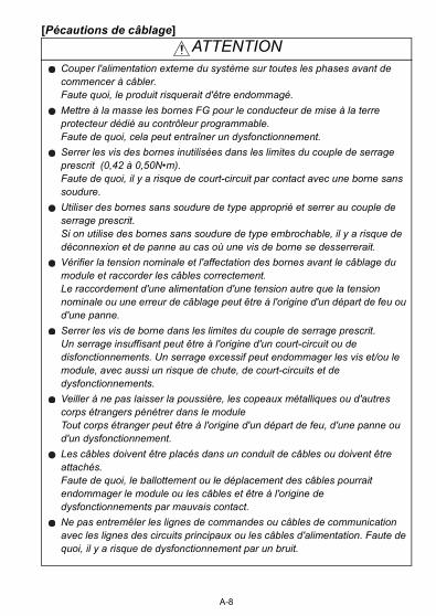
ATTENTIONCouper l'alimentation externe du système sur toutes les phases avant de commencer à câbler.Faute quoi, le produit risquerait d'être endommagé.
Mettre à la masse les bornes FG pour le conducteur de mise à la terre protecteur dédié au contrôleur programmable.Faute de quoi, cela peut entraîner un dysfonctionnement.
Serrer les vis des bornes inutilisées dans les limites du couple de serrage prescrit (0,42 à 0,50N•m).Faute de quoi, il y a risque de court-circuit par contact avec une borne sans soudure.
Utiliser des bornes sans soudure de type approprié et serrer au couple de serrage prescrit.Si on utilise des bornes sans soudure de type embrochable, il y a risque de déconnexion et de panne au cas où une vis de borne se desserrerait.
Vérifier la tension nominale et l'affectation des bornes avant le câblage du module et raccorder les câbles correctement.Le raccordement d'une alimentation d'une tension autre que la tension nominale ou une erreur de câblage peut être à l'origine d'un départ de feu ou d'une panne.
Serrer les vis de borne dans les limites du couple de serrage prescrit.Un serrage insuffisant peut être à l'origine d'un court-circuit ou de disfonctionnements. Un serrage excessif peut endommager les vis et/ou le module, avec aussi un risque de chute, de court-circuits et de dysfonctionnements.
Veiller à ne pas laisser la poussière, les copeaux métalliques ou d'autres corps étrangers pénétrer dans le moduleTout corps étranger peut être à l'origine d'un départ de feu, d'une panne ou d'un dysfonctionnement.
Les câbles doivent être placés dans un conduit de câbles ou doivent être attachés.Faute de quoi, le ballottement ou le déplacement des câbles pourrait endommager le module ou les câbles et être à l'origine de dysfonctionnements par mauvais contact.
Ne pas entremêler les lignes de commandes ou câbles de communication avec les lignes des circuits principaux ou les câbles d'alimentation. Faute de quoi, il y a risque de dysfonctionnement par un bruit.
A-8

[Pécautions de câblage]
[Mise en service/Précautions de maintenance]
ATTENTIONPour débrancher les câbles du module, ne pas tirer sur le câble lui-même.Desserrer les vis du connecteur avant de débrancher le câble.Faute de quoi, il y a risque d'endommagement du module ou du câble ou un mauvais contact pourrait être à l'origine de dysfonctionnements.
ATTENTIONNe toucher à aucun des bornes quand le système est sous tension.Cela pourrait être à l'origine de dysfonctionnements.
Avant de nettoyer le module ou de resserrer les vis de borne, couper l'alimentation externe du système sur toutes les phases.Le non-respect de cette précaution peut être à l'origine de pannes ou de dysfonctionnements du module.Si les vis sont insuffisamment serrées, le module risque de tomber et il peut y avoir des court-circuits ou des dysfonctionnements.Un serrage excessif peut endommager les vis et/ou le module, avec aussi un risque de chute, de court-circuits et de dysfonctionnements.
Ne pas démonter ni modifier les modules.Cela pourrait entraîner des pannes ou dysfonctionnements et être à l'origine de blessures ou de départs de feu.
Ne pas faire tomber le module et ne pas le soumettre à des chocs. Cela risquerait d'endommager le module.
Avant d'installer ou retirer le module du tableau, couper l'alimentation externe du système sur toutes les phases.Le non-respect de cette précaution peut être à l'origine de pannes ou de dysfonctionnements du module.
Après la première utilisation du produit, le nombre maximum admissible d'opérations de pose/retrait du bornier sur le module est de 50. (selon IEC 61131-2)
Avant de manipuler un module, se débarrasser de la charge électrostatique qu'accumule le corps humain en touchant un objet métallique raccordé à la terre.
Le non-respect de cette précaution peut être à l'origine de pannes ou de dysfonctionnements du module.
A-9

[Pécautions de mise au rebut]
ATTENTIONLors de sa mise au rebut, ce produit doit être traité comme un déchet industriel.
A-10

CONDITIONS OF USE FOR THE PRODUCT
(1) Mitsubishi programmable controller ("the PRODUCT") shall be used in conditions;i) where any problem, fault or failure occurring in the PRODUCT, if any, shall not lead to any major or serious accident; and ii) where the backup and fail-safe function are systematically or automatically provided outside of the PRODUCT for the case of any problem, fault or failure occurring in the PRODUCT.
(2) The PRODUCT has been designed and manufactured for the purpose of being used in general industries.MITSUBISHI SHALL HAVE NO RESPONSIBILITY OR LIABILITY (INCLUDING, BUT NOT LIMITED TO ANY AND ALL RESPONSIBILITY OR LIABILITY BASED ON CONTRACT, WARRANTY, TORT, PRODUCT LIABILITY) FOR ANY INJURY OR DEATH TO PERSONS OR LOSS OR DAMAGE TO PROPERTY CAUSED BY the PRODUCT THAT ARE OPERATED OR USED IN APPLICATION NOT INTENDED OR EXCLUDED BY INSTRUCTIONS, PRECAUTIONS, OR WARNING CONTAINED IN MITSUBISHI'S USER, INSTRUCTION AND/OR SAFETY MANUALS, TECHNICAL BULLETINS AND GUIDELINES FOR the PRODUCT.("Prohibited Application")Prohibited Applications include, but not limited to, the use of the PRODUCT in;• Nuclear Power Plants and any other power plants operated by Power
companies, and/or any other cases in which the public could be affected if any problem or fault occurs in the PRODUCT.
• Railway companies or Public service purposes, and/or any other cases in which establishment of a special quality assurance system is required by the Purchaser or End User.
• Aircraft or Aerospace, Medical applications, Train equipment, transport equipment such as Elevator and Escalator, Incineration and Fuel devices, Vehicles, Manned transportation, Equipment for Recreation and Amusement, and Safety devices, handling of Nuclear or Hazardous Materials or Chemicals, Mining and Drilling, and/or other applications where there is a significant risk of injury to the public or property.
A-11

Notwithstanding the above, restrictions Mitsubishi may in its sole discretion, authorize use of the PRODUCT in one or more of the Prohibited Applications, provided that the usage of the PRODUCT is limited only for the specific applications agreed to by Mitsubishi and provided further that no special quality assurance or fail-safe, redundant or other safety features which exceed the general specifications of the PRODUCTs are required. For details, please contact the Mitsubishi representative in your region.
A-12

REVISIONS* The manual number is given on the bottom right of the cover.
© 2009 MITSUBISHI ELECTRIC CORPORATION
Print date *Manual number RevisionJun., 2009 IB(NA)-0800419-A First editionDec., 2009 IB(NA)-0800419-B
CONDITIONS OF USE FOR THE PRODUCT
SAFETY PRECAUTIONS, ABOUT MANUAL, CHAPTER 1, Section 2.1, 2.2, Section 3.1, Section 4.1, Section 5.2, 5.3, Section 6.1, 6.2, CHAPTER 7
Apr., 2010 IB(NA)-0800419-CBack cover
Dec., 2010 IB(NA)-0800419-DCONDITIONS OF USE FOR THE PRODUCT, SAFETY PRECAUTIONS, ABOUT MANUAL, Section 2.1
Dec., 2011 IB(NA)-0800419-ESAFETY PRECAUTIONS(Chinese)
Section 2.1, 4.1Dec., 2016 IB(NA)-0800419-F
SAFETY PRECAUTIONS(French)
Section 2.2, Chapter 3, 7
This manual confers no industrial property rights or any rights of any other kind, nor does it confer any patent licenses. Mitsubishi Electric Corporation cannot be held responsible for any problems involving industrial property rights which may occur as a result of using the contents noted in this manual.
Adittion
Partial correction
Partial correction
Partial correction
Adittion
Partial correction
Adittion
Partial correction
A-13
A-14
CONTENTS
1. OVERVIEW.....................................................................................................1
2. SPECIFICATIONS ..........................................................................................2
2.1 General Specifications..............................................................................2
2.2 Performance Specifications......................................................................4
3. PART NAMES AND SETTINGS .....................................................................8
3.1 Part Names...............................................................................................8
4. LOADING AND INSTALLATION................................................................... 12
4.1 Handling Precautions ............................................................................. 12
5. DATA LINK CABLE WIRING ........................................................................ 14
5.1 Wiring Precautions ................................................................................. 14
5.2 CC-Link Dedicated Cable Connection Method....................................... 14
5.3 Connection of Terminating Resistor ....................................................... 15
6. WIRING......................................................................................................... 16
6.1 Wiring Precautions ................................................................................. 16
6.2 Wiring with Thermocouple ...................................................................... 16
7. EXTERNAL DIMENSIONS ........................................................................... 17
A-15
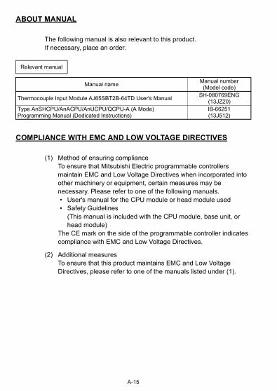
ABOUT MANUAL
The following manual is also relevant to this product.If necessary, place an order.
COMPLIANCE WITH EMC AND LOW VOLTAGE DIRECTIVES
(1) Method of ensuring complianceTo ensure that Mitsubishi Electric programmable controllers maintain EMC and Low Voltage Directives when incorporated into other machinery or equipment, certain measures may be necessary. Please refer to one of the following manuals. • User's manual for the CPU module or head module used • Safety Guidelines
(This manual is included with the CPU module, base unit, or head module)
The CE mark on the side of the programmable controller indicatescompliance with EMC and Low Voltage Directives.
(2) Additional measuresTo ensure that this product maintains EMC and Low Voltage Directives, please refer to one of the manuals listed under (1).
Relevant manual
Manual nameManual number
(Model code)
Thermocouple Input Module AJ65SBT2B-64TD User's ManualSH-080769ENG
(13JZ20)Type AnSHCPU/AnACPU/AnUCPU/QCPU-A (A Mode) Programming Manual (Dedicated Instructions)
IB-66251(13J512)

1. OVERVIEW
This user's manual explains the specifications, names of the components and wiring for the AJ65SBT2B-64TD Thermocouple Input Module (hereafter AJ65SBT2B-64TD) which are used as a remote device station in a CC-Link system.
1

2. SPECIFICATIONS
2.1 General Specifications
The general specifications of the AJ65SBT2B-64TD are shown in the following table.
Table 2.1 General specifications
Item SpecificationOperating ambient temperatureTempérature ambiante de fonctionnement
0 to 550 à 55
Storage ambient temperature
-20 to 75
Operating ambient humidity
10 to 90%RH, non-condensingStorage ambient humidity
Vibration resistance
Compliant with JIS B 3502 and
IEC 61131-2
FrequencyConstant
accelerationHalf
amplitudeSweep count
Under intermitte
nt vibration
5 to 8.4Hz - 3.5mm10 times
each in X, Y, Z
directions8.4 to150Hz 9.8m/s2 -
Under continuous vibration
5 to 8.4Hz - 1.75mm-
8.4 to150Hz 4.9m/s2 -
Shock resistance
Compliant with JIS B 3502 and IEC 61131-2(147 m/s2, 3 times each in 3 directions X, Y, Z)
Operating atmosphere
No corrosive gases
Operating altitude *1 0 to 2000m
Installation location
Inside a control panel
Overvoltage category *2 II or less
Pollution degree *3 2 or less
2

*1 Do not use or store the programmable controller under pressure higher than
the atmospheric pressure of altitude 0m. Doing so may cause malfunction.
When using the programmable controller under pressure, please consult
your local Mitsubishi Electric representative.
*2 This indicates the section of the power supply to which the equipment is
assumed to be connected between the public electrical power distribution
network and the machinery within premises.
Category II applies to equipment for which electrical power is supplied from
fixed facilities. The surge voltage withstand level for up to the rated voltage of
300V is 2500V.
*3 This index indicates the degree to which conductive material is generated in
terms of the environment in which the equipment is used.
Pollution level 2 is when only non-conductive pollution occurs. A temporary
conductivity caused by condensing must be expected occasionally.
3

2.2 Performance Specifications
The performance specifications for the AJ65SBT2B-64TD are shown in the following table.
Table 2.2 Performance specifications
Item AJ65SBT2B-64TDTemperature sensor input -270 to 1820
Measured temperature value16-bit signed binary (-2700 to 18200: value rounded to one
decimal place 10)Applicable thermocouple and measured temperature range accuracy*1
Refer to Table 2.3 Applicable thermocouples and conversion accuracies
Cold junction compensation accuracy(Operating ambient temperature 25 10 )*1*2
1.0
Overall accuracy*1 See the calculation formula in *3.Maximum resolution B, R, S, N: 0.3 K, E, J, T: 0.1Conversion speed*4 640ms/4 channelsSampling cycle*5 160ms/4 channelsAbsolute maximum input 5VNumber of analog input points 4 channels + Pt100 connection channel 2Built-in terminating resistor Available (110 )Number of writes to Flash memory
Up to 10,000 times
CC-Link station type Remote device stationNumber of occupied stations 1 station (RX/RY: 32 points each, RWr/RWw: 4 points each)Connection cable CC-LInk dedicated cable
Withstand voltage
Between all power supply systems and all communication systems and cold junction compensation channels
Between thermocouple input and all communication systems and cold junction compensation channels
Between thermocouple input channels
500VAC for one minute
4

*1 Except when noise is applied. To meet the accuracy, a warm-up (power
distribution) period of 30 minutes is required.
*2 When the module is mounted vertically and the ambient temperature for use
is from 0 to 15 or from 35 to 55 , the cold junction temperature
compensation accuracy is 1.5 .
*3 Calculate the overall accuracy by the following method.
(Overall accuracy) = (Conversion accuracy) + (Temperature characteristics)
(Operating ambient temperature variation)
Isolation method
Between all power supply systems and all communication systems and cold junction compensation channels
Between thermocouple input and all communication systems and cold junction compensation channels
Between thermocouple inputchannels
Transformer isolation
Noise immunityTested by a noise simulator with noise voltage of 500Vp-p,
noise width of 1 s, and noise frequency of 25 to 60Hz.Disconnection detection Available (for each channel)
External connection system
Communication part, module power supply part
7-point, 2-piece terminal blockM3 5.2 Tightening torque: 0.59 to 0.88N•m
Number of applicable solderless terminals: maximum 2
I/O part18-point, 2-piece terminal block
M3 5.2 Tightening torque: 0.59 to 0.88N•mNumber of applicable solderless terminals: maximum 2
Applicable wire size 0.3 to 2.0mm2
Applicable solderless terminal
• RAV1.25-3 (JIS C 2805 compliant)[Applicable wire size: 0.3 to 1.25mm2]
• V2-MS3, RAP2-3SL, TGV2-3N[Applicable wire size: 1.25 to 2.0mm2]
Module mounting screwM4 0.7mm 16mm or more screw
(tightening torque range: 0.78 to 1.08N•m)The module can also be mounted with a DIN rail.
Applicable DIN rail TH35-7.5Fe, TH35-7.5AI (IEC 60715 compliant)
External power supply
24VDC (ripple ratio: within 5%)(allowable voltage range 20.4 to 28.8VDC)
Inrush current: 1.5A 1.3msCurrent consumption: 0.12A (24VDC)
Weight 0.3kg
Table 2.2 Performance specifications
Item AJ65SBT2B-64TD
5
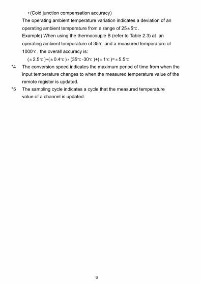
+(Cold junction compensation accuracy)
The operating ambient temperature variation indicates a deviation of an
operating ambient temperature from a range of 25 5 .
Example) When using the thermocouple B (refer to Table 2.3) at an
operating ambient temperature of 35 and a measured temperature of
1000 , the overall accuracy is:
( 2.5 )+( 0.4 ) (35 -30 )+( 1 )= 5.5
*4 The conversion speed indicates the maximum period of time from when the
input temperature changes to when the measured temperature value of the
remote register is updated.
*5 The sampling cycle indicates a cycle that the measured temperature
value of a channel is updated.
6
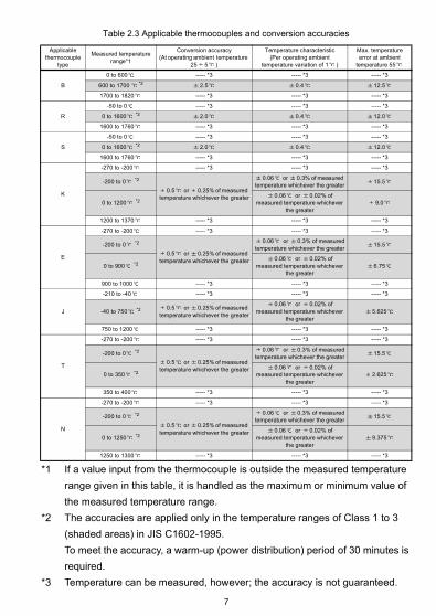
*1 If a value input from the thermocouple is outside the measured temperature
range given in this table, it is handled as the maximum or minimum value of
the measured temperature range.
*2 The accuracies are applied only in the temperature ranges of Class 1 to 3
(shaded areas) in JIS C1602-1995.
To meet the accuracy, a warm-up (power distribution) period of 30 minutes is
required.
*3 Temperature can be measured, however; the accuracy is not guaranteed.
Table 2.3 Applicable thermocouples and conversion accuracies
Applicable thermocouple
type
Measured temperature range*1
Conversion accuracy(At operating ambient temperature
25 5 )
Temperature characteristic(Per operating ambient
temperature variation of 1 )
Max. temperature error at ambient
temperature 55
B
0 to 600 ----- *3 ----- *3 ----- *3
600 to 1700 *2 2.5 0.4 12.5
1700 to 1820 ----- *3 ----- *3 ----- *3
R
-50 to 0 ----- *3 ----- *3 ----- *3
0 to 1600 *2 2.0 0.4 12.0
1600 to 1760 ----- *3 ----- *3 ----- *3
S
-50 to 0 ----- *3 ----- *3 ----- *3
0 to 1600 *2 2.0 0.4 12.0
1600 to 1760 ----- *3 ----- *3 ----- *3
K
-270 to -200 ----- *3 ----- *3 ----- *3
-200 to 0 *2
0.5 or 0.25% of measured temperature whichever the greater
0.06 or 0.3% of measured temperature whichever the greater
15.5
0 to 1200 *20.06 or 0.02% of
measured temperature whichever the greater
9.0
1200 to 1370 ----- *3 ----- *3 ----- *3
E
-270 to -200 ----- *3 ----- *3 ----- *3
-200 to 0 *2
0.5 or 0.25% of measured temperature whichever the greater
0.06 or 0.3% of measuredtemperature whichever the greater
15.5
0 to 900 *20.06 or 0.02% of
measured temperature whichever the greater
6.75
900 to 1000 ----- *3 ----- *3 ----- *3
J
-210 to -40 ----- *3 ----- *3 ----- *3
-40 to 750 *2 0.5 or 0.25% of measured temperature whichever the greater
0.06 or 0.02% of measured temperature whichever
the greater5.625
750 to 1200 ----- *3 ----- *3 ----- *3
T
-270 to -200 ----- *3 ----- *3 ----- *3
-200 to 0 *2
0.5 or 0.25% of measured temperature whichever the greater
0.06 or 0.3% of measuredtemperature whichever the greater
15.5
0 to 350 *20.06 or 0.02% of
measured temperature whichever the greater
2.625
350 to 400 ----- *3 ----- *3 ----- *3
N
-270 to -200 ----- *3 ----- *3 ----- *3
-200 to 0 *2
0.5 or 0.25% of measured temperature whichever the greater
0.06 or 0.3% of measuredtemperature whichever the greater
15.5
0 to 1250 *20.06 or 0.02% of
measured temperature whichever the greater
9.375
1250 to 1300 ----- *3 ----- *3 ----- *3
7
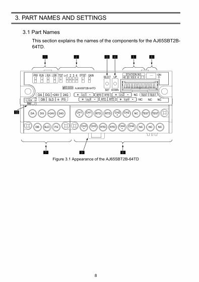
3. PART NAMES AND SETTINGS
3.1 Part Names
This section explains the names of the components for the AJ65SBT2B-64TD.
Figure 3.1 Appearance of the AJ65SBT2B-64TD
DA DG +24V 24G
DB SLD FG
CH1+
CH1- RTD NCRTD CH2
+CH2- TEST TEST
CH3+
CH3- RTDRTD CH4
+ NCCH4- NC NC
8

Table 3.1 Part names
No. Name Description
Operating status indication LED
PW LEDOn: Power supply onOff: Power supply off
RUN LED
Normal mode
On: Flashing:
Off:
Normal operationIndicates that out of average processing setting range error or faulty hardware, or RTD Pt100 is disconnected, or user range read error.Indicates that 24VDC power supply interrupted, watchdog timer error occurred.
Test mode
On:
Flashing:
Off:
Indicates that the SELECT/SET switch is in the SET position.Indicates that the offset value or the gain value is out of the setting range,or the gain value is less than 10 greater than the offset value,or faulty hardware, or RTD Pt100 is disconnected, or write error for Flash memory.Indicates that the SELECT/SET switch is in the SELECT or center position.
L RUN LED
On: Normal communicationOff: Communication cutoff (time expiration error)
L ERR.LED
On:
Flashing regularly:
Flashing irregularly:
Off:
Indicates that station number setting is outside the range.Indicates that station number setting was changed from that at power-on.Indicates that the terminating register is not connected. The module or CC-Link dedicated cable is affected by noise.Indicates normal communication.
Offset/gain adjusting LEDs
TESTCHOFFSETGAIN
Normal mode
Always off.
Test mode
Turns on when the TEST terminal is short-circuited.The LEDs lit change every time the SELECT/SET switch is moved to SELECT.
SELECT/SET switch
When the switch is moved to SELECT during the test mode, the offset value or gain value of the specified channel can be adjusted.Moving the switch to SET determines the offset value or gain value.
UP/DOWN switch
Used to adjust the offset value and gain value of the channel specified by the SELECT/SET switch.
1
2
3
4
9

Station number setting switches
Use the switches in STATION NO. "10", "20" and "40" to set the tens place of the station number.Use the switches in STATION NO. "1", "2", "4" and "8" to set the ones place of the station number.The switches are all factory-set to off.Set the station number within the range from 1 to 64.Setting any other number than 1 to 64 will result in an error, with the "L ERR." LED on.The switches cannot set the same station number to two or more stations.
(Example) To set the station number to "32", set the switches as indicated below.
Use prohibited
Do not use.
Terminal block for transmission and module power supply
Terminal block for transmission and module power supply
Table 3.1 Part names
No. Name Description
5
Station number
Tens place Ones place40 20 10 8 4 2 1
1 OFF OFF OFF OFF OFF OFF ON2 OFF OFF OFF OFF OFF ON OFF3 OFF OFF OFF OFF OFF ON ON4 OFF OFF OFF OFF ON OFF OFF
10 OFF OFF ON OFF OFF OFF OFF11 OFF OFF ON OFF OFF OFF ON
64 ON ON OFF OFF ON OFF OFF
Station number
Tens place Ones place40 20 10 8 4 2 1
32 OFF ON ON OFF OFF ON OFF
6
7
Terminal Description
DA
Connection terminal for CC-Link dedicated cableDB
DG
SLD
FG
Connection terminal for grounding to the protective conductor
*SLD and FG terminals are connected inside of the module.
+24VConnection terminal for extermal power supply
24G
10
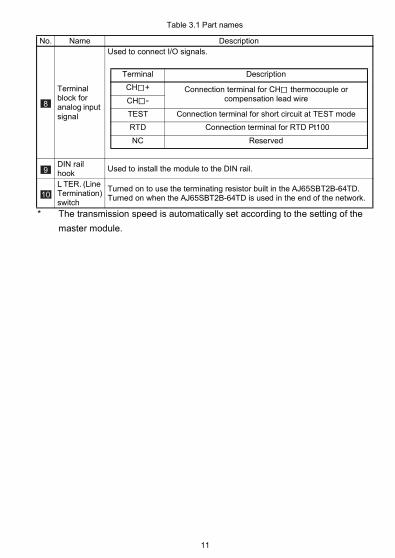
* The transmission speed is automatically set according to the setting of the
master module.
Terminal block for analog input signal
Used to connect I/O signals.
DIN rail hook
Used to install the module to the DIN rail.
L TER. (Line Termination) switch
Turned on to use the terminating resistor built in the AJ65SBT2B-64TD.Turned on when the AJ65SBT2B-64TD is used in the end of the network.
Table 3.1 Part names
No. Name Description
8
Terminal Description
CH + Connection terminal for CH thermocouple or compensation lead wireCH -
TEST Connection terminal for short circuit at TEST mode
RTD Connection terminal for RTD Pt100
NC Reserved
9
10
11
4. LOADING AND INSTALLATION
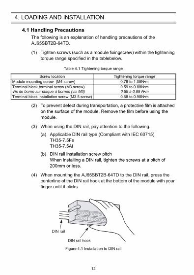
4.1 Handling PrecautionsThe following is an explanation of handling precautions of the AJ65SBT2B-64TD.
(1) Tighten screws (such as a module fixingscrew) within the tightening torque range specified in the tablebelow.
(2) To prevent defect during transportation, a protective film is attached on the surface of the module. Remove the film before using the module.
(3) When using the DIN rail, pay attention to the following.
(a) Applicable DIN rail type (Compliant with IEC 60715)TH35-7.5FeTH35-7.5Al
(b) DIN rail installation screw pitchWhen installing a DIN rail, tighten the screws at a pitch of 200mm or less.
(4) When mounting the AJ65SBT2B-64TD to the DIN rail, press the centerline of the DIN rail hook at the bottom of the module with your finger until it clicks.
Figure 4.1 Installation to DIN rail
Table 4.1 Tightening torque range
Screw location Tightening torque rangeModule mounting screw (M4 screw) 0.78 to 1.08N•mTerminal block terminal screw (M3 screw)Vis de borne sur plaque à bornes (vis M3)
0.59 to 0.88N•m0,59 à 0,88 N•m
Terminal block installation screw (M3.5 screw) 0.68 to 0.98N•m
DIN rail
DIN rail hook
12

(5) For the use with the AJ65SBT2B-64TD, refer to the master module user's manual for the name, specification, and manufacturer of applicable cables.
(6) Do not touch the RTD Pt100 with a driver or the like when mounting and removing the module, and when wiring, because the RTD Pt100 is precision part.
13
5. DATA LINK CABLE WIRING
5.1 Wiring Precautions
When using existing CC-Link dedicated cables, rewire the system using communication terminal block for the AJ65SBT2B-64TD.
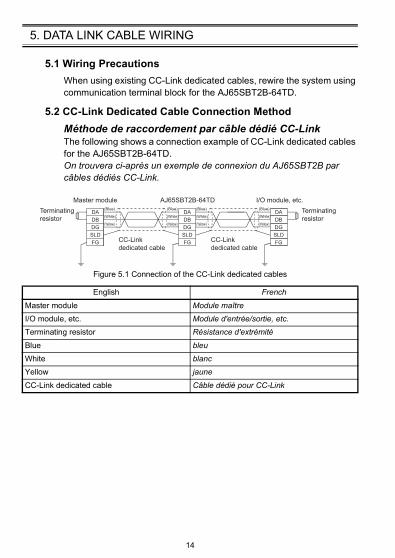
5.2 CC-Link Dedicated Cable Connection Method
Méthode de raccordement par câble dédié CC-LinkThe following shows a connection example of CC-Link dedicated cables for the AJ65SBT2B-64TD.On trouvera ci-après un exemple de connexion du AJ65SBT2B par câbles dédiés CC-Link.
Figure 5.1 Connection of the CC-Link dedicated cables
English French
Master module Module maître
I/O module, etc. Module d'entrée/sortie, etc.
Terminating resistor Résistance d'extrémité
Blue bleu
White blanc
Yellow jaune
CC-Link dedicated cable Câble dédié pour CC-Link
Terminating
resistor
Terminating
resistor
Master module I/O module, etc.
CC-Link
dedicated cable
CC-Link
dedicated cable
AJ65SBT2B-64TD
(Blue)
(White)
(Yellow)
(Blue)
(White)
(Yellow)
(Blue)
(White)
(Yellow)
(Blue)
(White)
(Yellow)
DA
DB
DG
SLD
FG
DA
DB
DG
SLD
FG
DA
DB
DG
SLD
FG
14
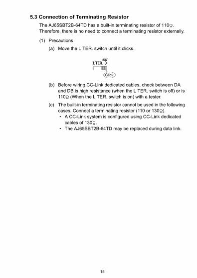
5.3 Connection of Terminating Resistor
The AJ65SBT2B-64TD has a built-in terminating resistor of 110 . Therefore, there is no need to connect a terminating resistor externally.
(1) Precautions
(a) Move the L TER. switch until it clicks.
(b) Before wiring CC-Link dedicated cables, check between DA and DB is high resistance (when the L TER. switch is off) or is 110 (When the L TER. switch is on) with a tester.
(c) The built-in terminating resistor cannot be used in the following cases. Connect a terminating resistor (110 or 130 ). • A CC-Link system is configured using CC-Link dedicated
cables of 130 . • The AJ65SBT2B-64TD may be replaced during data link.
Click
15
6. WIRING
6.1 Wiring Precautions
External wiring that is susceptible to noise is required as a highly reliable system and making full use of functions of the AJ65SBT2B-64TD.The precautions when performing external wiring are as follows:
(1) Use separate cables for the AC control circuit and the AJ65SBT2B-64TD signals output externally to avoid the influence of the AC side surges and inductions.
(2) Place the thermocouple at least 10cm away from the main circuit cables and AC control circuit lines. Keep it away from high-voltage cables and circuits, which include high frequency waves, such as an inverter's load circuit. Not doing so will cause the module more susceptible to noises, surges and inductions.
(3) The shield wire or the shield of the shielded cable must be grounded at one end. However, grounding outside may be suitable depending on the noise.
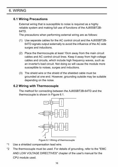
6.2 Wiring with Thermocouple
The method for connecting between the AJ65SBT2B-64TD and the thermocouple is shown in Figure 6.1.
Figure 6.1 Wiring of thermocouple
*1 Use a shielded compensation lead wire.
*2 The thermocouple must be used. For details of grounding, refer to the "EMC
AND LOW VOLTAGE DIRECTIVES" chapter of the user's manual for the
CPU module used.
Pt100
RTD
+
–
CH1
+
–
CH4
*1
*2
Input am
plif
ier
Input am
plif
ier
Input am
plif
ier
Filt
er
Tra
nsfo
rmer
Filt
er
Tra
nsfo
rmer
16
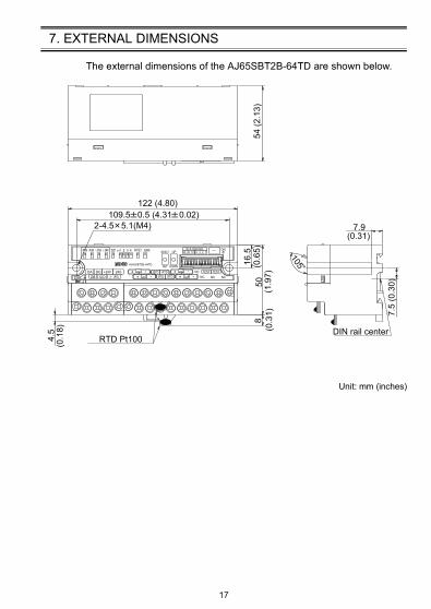
7. EXTERNAL DIMENSIONS
The external dimensions of the AJ65SBT2B-64TD are shown below.
Unit: mm (inches)
RTD Pt100DIN rail center
2-4.5 5.1(M4)
105
54 (2
.13)
5016
.5(0
.65)
4.5
(0.1
8)
122 (4.80)
7.5
(0.3
0)
7.9(0.31)
109.5 0.5 (4.31 0.02)
8(1
.97)
(0.3
1)
17

WARRANTYMitsubishi will not be held liable for damage caused by factors found not to be the cause of Mitsubishi; machine damage or lost profits caused by faults in the Mitsubishi products; damage, secondary damage, accident compensation caused by special factors unpredictable by Mitsubishi; damages to products other than Mitsubishi products; and to other duties.
Specifications subject to change without notice.
HEAD OFFICE : TOKYO BUILDING, 2-7-3 MARUNOUCHI, CHIYODA-KU, TOKYO 100-8310, JAPANNAGOYA WORKS : 1-14, YADA-MINAMI 5-CHOME, HIGASHI-KU, NAGOYA, JAPAN
When exported from Japan, this manual does not require application to the Ministry of Economy, Trade and Industry for service transaction permission.
MITSUBISHI ELECTRIC TURKEY A.Ş Ümraniye Branch Serifali Mahallesi Nutuk Sokak No:5, TR-34775 Umraniye/Istanbul, TurkeyTel : +90-216-526-3990MITSUBISHI ELECTRIC EUROPE B.V. Dubai Branch Dubai Silicon Oasis, P.O.BOX 341241, Dubai, U.A.E.Tel : +971-4-3724716ADROIT TECHNOLOGIES 20 Waterford Office Park, 189 Witkoppen Road, Fourways, South AfricaTel : +27-11-658-8100
MITSUBISHI ELECTRIC AUTOMATION (CHINA) LTD. No.1386 Hongqiao Road, Mitsubishi Electric Automation Center, Shanghai, ChinaTel : +86-21-2322-3030SETSUYO ENTERPRISE CO., LTD. 6F, No.105, Wugong 3rd Road, Wugu District, New Taipei City 24889, TaiwanTel : +886-2-2299-2499MITSUBISHI ELECTRIC AUTOMATION KOREA CO., LTD. 7F-9F, Gangseo Hangang Xi-tower A, 401, Yangcheon-ro, Gangseo-Gu, Seoul 07528, KoreaTel : +82-2-3660-9530MITSUBISHI ELECTRIC ASIA PTE. LTD. 307, Alexandra Road, Mitsubishi Electric Building, Singapore 159943Tel : +65-6473-2308
MITSUBISHI ELECTRIC FACTORY AUTOMATION (THAILAND) CO., LTD. 12th Floor, SV.City Building, Office Tower 1, No. 896/19 and 20 Rama 3 Road, Kwaeng Bangpongpang, Khet Yannawa, Bangkok 10120, ThailandTel : +66-2682-6522MITSUBISHI ELECTRIC VIETNAM COMPANY LIMITED Hanoi Branch 6th Floor, Detech Tower, 8 Ton That Thuyet Street, My Dinh 2 Ward, Nam Tu Liem District, Hanoi, VietnamTel : +84-4-3937-8075PT. MITSUBISHI ELECTRIC INDONESIAGedung Jaya 11th Floor, JL. MH. Thamrin No.12, Jakarta Pusat 10340, IndonesiaTel : +62-21-3192-6461
MITSUBISHI ELECTRIC INDIA PVT. LTD. Pune Branch Emerald House, EL-3, J Block, M.I.D.C., Bhosari, Pune-411026, Maharashtra, IndiaTel : +91-20-2710-2000
USA MITSUBISHI ELECTRIC AUTOMATION, INC. 500 Corporate Woods Parkway, Vernon Hills, IL 60061, U.S.A.Tel : +1-847-478-2100
Turkey
Sales office/Tel
Country/Region
Sales office/Tel
Country/Region
Mexico MITSUBISHI ELECTRIC AUTOMATION, INC. Mexico Branch Mariano Escobedo #69, Col. Zona Industrial, Tlalnepantla Edo. Mexico, C.P.54030Tel : +52-55-3067-7500
UAE
Brazil MITSUBISHI ELECTRIC DO BRASIL COMÉRCIO E SERVIÇOS LTDA. Avenida Adelino Cardana, 293, 21 andar, Bethaville, Barueri SP, BrazilTel : +55-11-4689-3000
South Africa
Germany MITSUBISHI ELECTRIC EUROPE B.V. German Branch Mitsubishi-Electric-Platz 1, 40882 Ratingen, GermanyTel : +49-2102-486-0
China
UK MITSUBISHI ELECTRIC EUROPE B.V. UK Branch Travellers Lane, Hatfield, Hertfordshire, AL10 8XB, U.K.Tel : +44-1707-28-8780
Taiwan
Ireland MITSUBISHI ELECTRIC EUROPE B.V. Irish Branch Westgate Business Park, Ballymount, Dublin 24, IrelandTel : +353-1-4198800
Korea
Italy MITSUBISHI ELECTRIC EUROPE B.V. Italian Branch Centro Direzionale Colleoni-Palazzo Sirio Viale Colleoni 7, 20864 Agrate Brianza(Milano) ItalyTel : +39-039-60531
Singapore
Spain MITSUBISHI ELECTRIC EUROPE, B.V. Spanish Branch Carretera de Rubí, 76-80-Apdo. 420, 08190 Sant Cugat del Vallés (Barcelona), SpainTel : +34-935-65-3131
Thailand
France MITSUBISHI ELECTRIC EUROPE B.V. French Branch 25, Boulevard des Bouvets, 92741 Nanterre Cedex, FranceTel : +33-1-55-68-55-68
Vietnam
Czech Republic
MITSUBISHI ELECTRIC EUROPE B.V. Czech Branch Avenir Business Park, Radlicka 751/113e, 158 00 Praha5, Czech RepublicTel : +420-251-551-470
Indonesia
Poland MITSUBISHI ELECTRIC EUROPE B.V. Polish Branch ul. Krakowska 50, 32-083 Balice, PolandTel : +48-12-347-65-00
India
Sweden MITSUBISHI ELECTRIC EUROPE B.V. (Scandinavia) Fjelievägen 8, SE-22736 Lund, SwedenTel : +46-8-625-10-00
Russia MITSUBISHI ELECTRIC (RUSSIA) LLC St. Petersburg Branch Piskarevsky pr. 2, bld 2, lit “Sch”, BC “Benua”, office 720; 195027 St. Petersburg, RussiaTel : +7-812-633-3497
Australia MITSUBISHI ELECTRIC AUSTRALIA PTY. LTD.348 Victoria Road, P.O. Box 11, Rydalmere, N.S.W 2116, AustraliaTel : +61-2-9684-7777
Copyright © 2022 FDOKUMEN