SYSMAC CP Series CP2E CPU Unit Hardware USER'S ...
326
USER’S MANUAL Cat. No. W613-E1-01 SYSMAC CP Series CP2E-E D - CP2E-S D - CP2E-N D - CP2E CPU Unit Hardware
-
Upload
khangminh22 -
Category
Documents
-
view
0 -
download
0
Transcript of SYSMAC CP Series CP2E CPU Unit Hardware USER'S ...

USER’S MANUAL
Cat. No. W613-E1-01
SYSMAC CP SeriesCP2E-E D -CP2E-S D -CP2E-N D -
CP2E CPU Unit Hardware
Copyrights
Microsoft product screen shots reprinted with permission from Microsoft Corporation.
All rights reserved. No part of this publication may be reproduced, stored in a retrieval system, or transmitted, in
any form, or by any means, mechanical, electronic, photocopying, recording, or otherwise, without the prior
written permission of OMRON.
No patent liability is assumed with respect to the use of the information contained herein. Moreover, because
OMRON is constantly striving to improve its high-quality products, the information contained in this manual is
subject to change without notice. Every precaution has been taken in the preparation of this manual. Neverthe-
less, OMRON assumes no responsibility for errors or omissions. Neither is any liability assumed for damages
resulting from the use of the information contained in this publication.
NOTE
• Microsoft, Windows are either registered trademarks or trademarks of Microsoft Corporation in the United States
and other countries.
Other company names and product names in this document are the trademarks or registered trademarks of their
respective companies.
Trademarks


SYSMAC CP SeriesCP2E-E D -CP2E-S D -CP2E-N D -CP2E CPU Unit HardwareUser’s ManualProduced September 2019

1CP2E CPU Unit Hardware User’s Manual(W613)
Introduction
Thank you for purchasing a SYSMAC CP-series CP2E Programmable Controller.
This manual contains information required to use the CP2E. Read this manual completely and be sureyou understand the contents before attempting to use the CP2E.
This manual is intended for the following personnel, who must also have knowledge of electrical sys-tems (an electrical engineer or the equivalent).
• Personnel in charge of installing FA systems
• Personnel in charge of designing FA systems
• Personnel in charge of managing FA systems and facilities
CP-series CP2E CPU Units• Essential Model CP2E-E D -
A model of CPU Unit that supports connections to Programmable Terminals and basic controlapplications using instructions such as basic, movement, arithmetic, and comparison instructions.
• Standard Model CP2E-S D -A model of CPU Unit that supports connections to inverters and servo drives.
• Network Model CP2E-N D -A model of CPU Unit that supports Ethernet connection and enhanced positioning functions suchas 4-axis linear interpolation and pulse.
The CP Series is centered around the CP1H, CP1L, CP1E and CP2E CPU Units and is designedwith the same basic architecture as the CS and CJ Series.
Always use CP-series Expansion Units and CP-series Expansion I/O Units when expanding I/Ocapacity.
Intended Audience
Applicable Products

2 CP2E CPU Unit Hardware User’s Manual(W613)
CP2E CPU Unit Manuals
Information on the CP2E CPU Units is provided in the following manuals.
Refer to the appropriate manual for the information that is required.
Mounting and Setting Hardware1
2
3
4
5
6
7
Wiring
Connecting Online to the PLC
Software Setup
Creating the Program
Checking and Debugging Operation
Maintenance and Troubleshooting
CP2E CPU Unit Hardware User’s Manual(Cat. No. W613)
CP2E CPU Unit Software User’s Manual(Cat. No. W614)
This Manual
· Wiring methods for the power supply· Wiring methods between external I/O devices and Expansion I/O Units or Expansion Units
Connecting Cables for CX-Programmer Support Software
Error codes and remedies if a problem occurs
Procedures for connecting the CX-Programmer Support Software
Software setting methods for the CPU Units (PLC Setup)
· Checking I/O wiring, setting the Auxiliary Area settings, and performing trial operation
· Monitoring and debugging with the CX-Programmer
· Program types and basic information· CPU Unit operation· Internal memory· Built-in CPU functions· Settings
· Names and specifications of the parts of all Units· Basic system configuration for each CPU Unit· Connection methods for Expansion I/O Units and Expansion Units
CP1E/CP2E CPU Unit Instructions Reference Manual(Cat. No. W483)
Detailed information on programming instructions

3CP2E CPU Unit Hardware User’s Manual(W613)
The CP2E CPU manuals are organized in the sections listed in the following tables. Refer to the appro-priate section in the manuals as required.
Manual Configuration
CP2E CPU Unit Hardware User’s Manual (Cat. No. W613) (This Manual)
Section Contents
Section 1 Overview and Specifica-tions
This section gives an overview of the CP2E, describes its features, and provides its specifications.
Section 2 Basic System Configura-tion and Devices
This section describes the basic system configuration and unit models of the CP2E.
Section 3 Part Names and Functions This section describes the part names and functions of the CPU Unit, Expansion I/O Units, and Expansion Units in a CP2E PLC .
Section 4 Programming Device This section describes the features of the CX-Programmer used for pro-gramming and debugging PLCs, as well as how to connect the PLC with the Programming Device by USB, Ethernet and serial port.
Section 5 Installation and Wiring This section describes how to install and wire CP2E Units.
Section 6 Troubleshooting This section describes how to troubleshoot problems that may occur with a CP2E PLC, including the error indications provided by the CP2E Units.
Section 7 Maintenance and Inspec-tion
This section describes periodic inspections, the service life of the Bat-tery, and how to replace the Battery.
Section 8 Using Expansion Units and Expansion I/O Units
This section describes application methods for Expansion Units.
Appendices The appendices provide information on dimensions, wiring diagrams, wiring serial communications, network installation for the CP2E, and comparison between CP1E and CP2E.
CP2E CPU Unit Software User’s Manual (Cat. No. W614)
Section Contents
Section 1 Overview This section gives an overview of the CP2E, describes its application procedures.
Section 2 CPU Unit Memory This section describes the types of internal memory in a CP2E CPU Unit and the data that is stored.
Section 3 CPU Unit Operation This section describes the operation of a CP2E CPU Unit.
Section 4 Programming Concepts This section provides basic information on designing ladder programs for a CP2E CPU Unit.
Section 5 I/O Memory This section describes the types of I/O memory areas in a CP2E CPU Unit and the details.
Section 6 I/O Allocation This section describes I/O allocation used to exchange data between the CP2E CPU Unit and other units.
Section 7 PLC Setup This section describes the PLC Setup, which are used to perform basic settings for a CP2E CPU Unit.
Section 8 Overview and Allocation of Built-in Functions
This section lists the built-in functions and describes the overall applica-tion flow and the allocation of the functions.
Section 9 Quick-response Inputs This section describes the quick-response inputs that can be used to read signals that are shorter than the cycle time.

4 CP2E CPU Unit Hardware User’s Manual(W613)
Section 10 Interrupts This section describes the interrupts that can be used with CP2E PLCs, including input interrupts and scheduled interrupts.
Section 11 High-speed Counters This section describes the high-speed counter inputs, high-speed counter interrupts, and the frequency measurement function.
Section 12 Pulse Outputs This section describes positioning functions such as trapezoidal control, jogging, and origin searches.
Section 13 PWM Outputs This section describes the variable-duty-factor pulse (PWM) outputs.
Section 14 Serial Communications This section describes communications with Programmable Terminals (PTs) without using communications programming, no-protocol commu-nications with general components, and connections with a Modbus-RTU Easy Master, Serial PLC Link, host computer and Modbus-RTU Slave.
Section 15 Built-in Ethernet This section gives an outline of the built-in Ethernet function, explains its specification and how to make the settings required for operation.
Section 16 Other Functions This section describes PID temperature control, clock functions, DM backup functions, security functions.
Section 17 Analog Option Board This section describes an overview of the Analog Option Board, describes its installation and setting methods, memory allocations, star-tup operation, refresh time, troubleshooting and how to use the Analog Option Board.
Section 18 Operating the Program-ming Device
This section describes basic functions of the CX-Programmer, such as using the CX-Programmer to write ladder programs to control the CP2E CPU Unit, to transfer the programs to the CP2E CPU Unit, and to debug the programs.
Appendices The appendices provide lists of programming instructions, the Auxiliary Area, cycle time response performance, PLC performance at power interruption, memory map and Ethernet functions.
CP1E/CP2E CPU Unit Instructions Reference Manual (Cat. No. W483)
Section Contents
Section 1 Summary of Instructions This section provides a summary of instructions used with a CP1E/CP2E CPU Unit.
Section 2 Instruction This section describes the functions, operands and sample programs of the instructions that are supported by a CP1E/CP2E CPU Unit.
Section 3 Instruction Execution Times and Number of Steps
This section provides the execution times for all instructions used with a CP1E/CP2E CPU Unit.
Section 4 Monitoring and Comput-ing the Cycle Time
This section describes how to monitor and calculate the cycle time of a CP1E/CP2E CPU Unit that can be used in the programs.
Appendices The appendices provide a list of instructions by Mnemonic and ASCII code table for the CP1E/CP2E CPU Unit.
Section Contents

5CP2E CPU Unit Hardware User’s Manual(W613)
Manual Structure
The following page structure and icons are used in this manual.
Special information in this manual is classified as follows:
Page Structure and Icons
Special Information
5 - 3
5 Installation and wiring
CP2E CPU Unit Hardware User’s Manual(W613)
5
5-2 Installation
5-2-1 Installation Location
DIN Track Installation
1
2Release
DIN Track mounting pins
3
DIN Track
DIN Track mounting pins
Precautions for Correct Use
Tighten terminal block screws and cable screws to the following torques.M4: 1.2 N·mM3: 0.5 N·m
Use a screwdriver to pull down the DIN Track mounting pins from the back of the Units to release them, and mount the Units to the DIN Track.
Fit the back of the Units onto the DIN Track by catching the top of the Units on the Track and then pressing in at the bottom of the Units, as shown below.
Press in all of the DIN Track mounting pins to securely lock the Units in place.
5-2 Installatio
n5-2-1 Installation Location
Level 1 headingLevel 2 headingLevel 3 headingLevel 2 heading
Step in a procedure
Manual name
Special Information (See below.)
Level 3 heading
Page tab
Gives the current headings.
Indicates a step in a procedure.
Gives the number of the section.
This illustration is provided only as a sample and may not literally appear in this manual.
Icons are used to indicate precautions and additional information.
Precautions for Safe UsePrecautions on what to do and what not to do to ensure using the product safely.
Precautions for Correct UsePrecautions on what to do and what not to do to ensure proper operation and performance.
Additional InformationAdditional information to increase understanding or make operation easier.

6 CP2E CPU Unit Hardware User’s Manual(W613)
Terminology and Notation
Term Description
E-type CPU Unit An essential model of CPU Unit that supports connections to Programmable Terminals and basic control applications using instructions such as basic, movement, arithmetic, and comparison instructions.
Essential models of CPU Units are called “E -type CPU Units” or “E14/20 CPU Units” in this manual.
The models of E -type CPU Units are shown below.
CP2E-E D -
S-type CPU Unit A standard model of CPU Unit that supports connections to inverters and servo drives.
Standard models of CPU Units are called “S -type CPU Units” or “S30/40/60 CPU Units” in this manual.
The models of S -type CPU Units are shown below.
CP2E-S D -
N-type CPU Unit A network model of CPU Unit that supports Ethernet connection and enhanced position-ing functions such as 4-axis linear interpolation and pulse.
Network models of CPU Units are called “N -type CPU Units” or “N30/40/60 CPU Units” in this manual.
The models of N -type CPU Units are shown below.
CP2E-N D -
CX-OneCX-Programmer
A programming device that applies for programming and debugging PLCs.
CP2E CPU Units are supported by CX-One version 4.51 or higher and CX-Programmer version 9.72 or higher.

7CP2E CPU Unit Hardware User’s Manual(W613)
Sections in this Manual
1
2
3
4
5
6
7
8
A
1
5
6
7
2
3
4
8
A
Overview and Specifications
Troubleshooting
Maintenance and Inspection
Basic System Configuration and Devices
Part Names and Functions
Programming Device
Installation and Wiring
Using Expansion Units and Expansion I/O Units
Appendices

8 CP2E CPU Unit Hardware User’s Manual(W613)
CONTENTS
Introduction ...............................................................................................................1
CP2E CPU Unit Manuals ...........................................................................................2
Manual Structure .......................................................................................................5
Terms and Conditions Agreement.........................................................................11
Safety Precautions..................................................................................................13
Precautions for Safe Use........................................................................................17
Operating Environment Precautions.....................................................................21
Regulations and Standards....................................................................................22
Software Licenses and Copyrights .......................................................................23
Related Manuals ......................................................................................................24
Section 1 Overview and Specifications
1-1 CP2E Overview ........................................................................................................................ 1-21-1-1 Overview of Features .................................................................................................................. 1-21-1-2 Features ...................................................................................................................................... 1-3
1-2 Basic Operating Procedure .................................................................................................. 1-10
1-3 Specifications ........................................................................................................................ 1-111-3-1 General Specifications .............................................................................................................. 1-111-3-2 Characteristics .......................................................................................................................... 1-121-3-3 Functional Specifications .......................................................................................................... 1-15
Section 2 Basic System Configuration and Devices
2-1 Basic System Configuration................................................................................................... 2-22-1-1 Basic System Configuration Using an E/S -type CPU Unit.................................................... 2-22-1-2 Basic System Configuration Using an N -type CPU Unit....................................................... 2-3
2-2 CPU Units ................................................................................................................................. 2-42-2-1 CPU Unit Models ........................................................................................................................ 2-42-2-2 Optional Products........................................................................................................................ 2-82-2-3 Unit Versions of CPU Units ....................................................................................................... 2-10
2-3 Expansion I/O Unit or Expansion Unit ................................................................................. 2-112-3-1 Expandable CPU Units ............................................................................................................. 2-112-3-2 Connection Methods ................................................................................................................. 2-112-3-3 Maximum Number of I/O Points for an Expansion I/O Unit or Expansion Unit ......................... 2-112-3-4 Expansion I/O Units and Expansion Units ................................................................................ 2-122-3-5 Restrictions on System Configuration ....................................................................................... 2-14
2-4 Unit Current Consumption and External Power Supply Capacity .................................... 2-162-4-1 External Power Supply Capacity When Expansion I/O Units or
Expansion Units are Connected................................................................................................ 2-162-4-2 Current Consumption ................................................................................................................ 2-17

9CP2E CPU Unit Hardware User’s Manual(W613)
Section 3 Part Names and Functions
3-1 CPU Units ................................................................................................................................. 3-23-1-1 E14/20 or N14/20 CPU Units .................................................................................................... 3-23-1-2 E30/40/60, S30/40/60 or N30/40/60 CPU Units.......................................................................... 3-63-1-3 Common I/O Specifications....................................................................................................... 3-123-1-4 Serial Communication Port ....................................................................................................... 3-173-1-5 Analog Option Board for N -type CPU Units........................................................................ 3-24
3-2 Expansion I/O Units............................................................................................................... 3-283-2-1 Expansion Input Unit ................................................................................................................. 3-283-2-2 Expansion Output Units ............................................................................................................ 3-293-2-3 Expansion I/O Units .................................................................................................................. 3-313-2-4 I/O Specifications ...................................................................................................................... 3-33
Section 4 Programming Device
4-1 Applicable Programming Devices for CP2E.......................................................................... 4-2
4-2 Connecting by USB ................................................................................................................. 4-4
4-3 Connection Method with an Ethernet Port ............................................................................ 4-6
4-4 Connection Method with a Serial Port ................................................................................. 4-15
Section 5 Installation and Wiring
5-1 Fail-safe Circuits ...................................................................................................................... 5-2
5-2 Installation................................................................................................................................ 5-35-2-1 Installation Location .................................................................................................................... 5-35-2-2 Unit Arrangement ........................................................................................................................ 5-65-2-3 Installation ................................................................................................................................... 5-75-2-4 Connecting Expansion I/O Units and Expansion Units ............................................................. 5-12
5-3 Wiring ..................................................................................................................................... 5-145-3-1 Wiring Procedure ...................................................................................................................... 5-145-3-2 Wiring Power Supply and Ground Lines ................................................................................... 5-145-3-3 I/O Wiring .................................................................................................................................. 5-175-3-4 Wiring Safety and Noise Controls ............................................................................................. 5-215-3-5 Relay Output Noise Reduction Methods ................................................................................... 5-22
Section 6 Troubleshooting
6-1 Troubleshooting CPU Unit Errors .......................................................................................... 6-26-1-1 Errors and Remedies .................................................................................................................. 6-26-1-2 Checking Errors .......................................................................................................................... 6-26-1-3 Checking Detailed Status............................................................................................................ 6-36-1-4 Reading Error Log Information.................................................................................................... 6-36-1-5 Types of Errors ............................................................................................................................ 6-56-1-6 Error Processing Flowchart......................................................................................................... 6-76-1-7 No Operation When Power is Supplied ....................................................................................... 6-76-1-8 Fatal Errors ................................................................................................................................. 6-86-1-9 CPU Errors................................................................................................................................ 6-146-1-10 Non-fatal Errors......................................................................................................................... 6-156-1-11 Other Errors .............................................................................................................................. 6-19
6-2 Troubleshooting Unit Errors ................................................................................................. 6-216-2-1 Inputs ........................................................................................................................................ 6-216-2-2 Outputs...................................................................................................................................... 6-226-2-3 CX-Programmer Connection..................................................................................................... 6-23

10 CP2E CPU Unit Hardware User’s Manual(W613)
Section 7 Maintenance and Inspection
7-1 Periodic Maintenance and Inspection ................................................................................... 7-27-1-1 Tools Required for Inspections.................................................................................................... 7-27-1-2 Periodic Inspection...................................................................................................................... 7-27-1-3 Inspection and Maintenance ....................................................................................................... 7-37-1-4 Unit Replacement Precautions.................................................................................................... 7-4
7-2 Replacing the Battery in N/S -type CPU Units................................................................. 7-5
Section 8 Using Expansion Units and Expansion I/O Units
8-1 Analog Input Units................................................................................................................... 8-28-1-1 Overview ..................................................................................................................................... 8-28-1-2 Part Names and Functions.......................................................................................................... 8-28-1-3 Specifications .............................................................................................................................. 8-38-1-4 Flow of Operation........................................................................................................................ 8-7
8-2 Analog Output Units.............................................................................................................. 8-158-2-1 Overview ................................................................................................................................... 8-158-2-2 Part Names and Functions........................................................................................................ 8-158-2-3 Specifications ............................................................................................................................ 8-168-2-4 Flow of Operation...................................................................................................................... 8-20
8-3 Analog I/O Units..................................................................................................................... 8-278-3-1 CP1W-MAD11 Analog I/O Units ............................................................................................... 8-278-3-2 CP1W-MAD42/CP1W-MAD44 Analog I/O Units ....................................................................... 8-40
8-4 Temperature Sensor Units .................................................................................................... 8-568-4-1 CP1W-TS 1/TS 2 Temperature Sensor Units ....................................................................... 8-568-4-2 CP1W-TS003 Temperature Sensor Units ................................................................................. 8-718-4-3 TS004 Temperature Sensor Units............................................................................................. 8-81
Section A Appendices
A-1 Dimensions .............................................................................................................................A-2A-1-1 CPU Units ...................................................................................................................................A-2A-1-2 Option Boards .............................................................................................................................A-5A-1-3 Expansion I/O Units ....................................................................................................................A-8A-1-4 Expansion Units ........................................................................................................................A-10
A-2 Wiring Diagrams ....................................................................................................................A-12A-2-1 CPU Units .................................................................................................................................A-12A-2-2 Expansion I/O Units ..................................................................................................................A-18A-2-3 Expansion Units ........................................................................................................................A-25A-2-4 Serial Communications .............................................................................................................A-36
A-3 Wiring for Serial Communications .......................................................................................A-41A-3-1 Recommended RS-232C Wiring...............................................................................................A-41A-3-2 Recommended RS-422A/485 Wiring ........................................................................................A-46A-3-3 Reducing Electrical Noise for External Wiring ..........................................................................A-49
A-4 Network Installation...............................................................................................................A-50
A-5 Comparison between CP1E and CP2E ................................................................................A-53
Index .................................................................................................................................. Index-1
Revision History ................................................................................Revision-1

11CP2E CPU Unit Hardware User’s Manual(W613)
Terms and Conditions Agreement
Exclusive WarrantyOmron’s exclusive warranty is that the Products will be free from defects in materials and workman-ship for a period of twelve months from the date of sale by Omron (or such other period expressed in writing by Omron). Omron disclaims all other warranties, express or implied.
LimitationsOMRON MAKES NO WARRANTY OR REPRESENTATION, EXPRESS OR IMPLIED, ABOUT NON-INFRINGEMENT, MERCHANTABILITY OR FITNESS FOR A PARTICULAR PURPOSE OF THE PRODUCTS. BUYER ACKNOWLEDGES THAT IT ALONE HAS DETERMINED THAT THE PRODUCTS WILL SUITABLY MEET THE REQUIREMENTS OF THEIR INTENDED USE.
Omron further disclaims all warranties and responsibility of any type for claims or expenses based on infringement by the Products or otherwise of any intellectual property right.
Buyer RemedyOmron’s sole obligation hereunder shall be, at Omron’s election, to (i) replace (in the form originally shipped with Buyer responsible for labor charges for removal or replacement thereof) the non-com-plying Product, (ii) repair the non-complying Product, or (iii) repay or credit Buyer an amount equal to the purchase price of the non-complying Product; provided that in no event shall Omron be responsible for warranty, repair, indemnity or any other claims or expenses regarding the Products unless Omron’s analysis confirms that the Products were properly handled, stored, installed and maintained and not subject to contamination, abuse, misuse or inappropriate modification. Return of any Products by Buyer must be approved in writing by Omron before shipment. Omron Companies shall not be liable for the suitability or unsuitability or the results from the use of Products in combi-nation with any electrical or electronic components, circuits, system assemblies or any other materi-als or substances or environments. Any advice, recommendations or information given orally or in writing, are not to be construed as an amendment or addition to the above warranty.
See http://www.omron.com/global/ or contact your Omron representative for published information.
OMRON COMPANIES SHALL NOT BE LIABLE FOR SPECIAL, INDIRECT, INCIDENTAL, OR CON-SEQUENTIAL DAMAGES, LOSS OF PROFITS OR PRODUCTION OR COMMERCIAL LOSS IN ANY WAY CONNECTED WITH THE PRODUCTS, WHETHER SUCH CLAIM IS BASED IN CONTRACT, WARRANTY, NEGLIGENCE OR STRICT LIABILITY.
Further, in no event shall liability of Omron Companies exceed the individual price of the Product on which liability is asserted.
Warranty, Limitations of Liability
Warranties
Limitation on Liability; Etc

12 CP2E CPU Unit Hardware User’s Manual(W613)
Omron Companies shall not be responsible for conformity with any standards, codes or regulations which apply to the combination of the Product in the Buyer’s application or use of the Product. At Buyer’s request, Omron will provide applicable third party certification documents identifying ratings and limitations of use which apply to the Product. This information by itself is not sufficient for a com-plete determination of the suitability of the Product in combination with the end product, machine, sys-tem, or other application or use. Buyer shall be solely responsible for determining appropriateness of the particular Product with respect to Buyer’s application, product or system. Buyer shall take applica-tion responsibility in all cases.
NEVER USE THE PRODUCT FOR AN APPLICATION INVOLVING SERIOUS RISK TO LIFE OR PROPERTY OR IN LARGE QUANTITIES WITHOUT ENSURING THAT THE SYSTEM AS A WHOLE HAS BEEN DESIGNED TO ADDRESS THE RISKS, AND THAT THE OMRON PRODUCT(S) IS PROPERLY RATED AND INSTALLED FOR THE INTENDED USE WITHIN THE OVERALL EQUIP-MENT OR SYSTEM.
Omron Companies shall not be responsible for the user’s programming of a programmable Product, or any consequence thereof.
Data presented in Omron Company websites, catalogs and other materials is provided as a guide for the user in determining suitability and does not constitute a warranty. It may represent the result of Omron’s test conditions, and the user must correlate it to actual application requirements. Actual perfor-mance is subject to the Omron’s Warranty and Limitations of Liability.
Product specifications and accessories may be changed at any time based on improvements and other reasons. It is our practice to change part numbers when published ratings or features are changed, or when significant construction changes are made. However, some specifications of the Product may be changed without any notice. When in doubt, special part numbers may be assigned to fix or establish key specifications for your application. Please consult with your Omron’s representative at any time to confirm actual specifications of purchased Product.
Information presented by Omron Companies has been checked and is believed to be accurate; how-ever, no responsibility is assumed for clerical, typographical or proofreading errors or omissions.
Application Considerations
Suitability of Use
Programmable Products
Disclaimers
Performance Data
Change in Specifications
Errors and Omissions

13CP2E CPU Unit Hardware User’s Manual(W613)
Safety Precautions
The following notation is used in this manual to provide precautions required to ensure safe usage of aCP-series PLC. The safety precautions that are provided are extremely important to safety. Always readand heed the information provided in all safety precautions.
Definition of Precautionary Information
Symbols
The triangle symbol indicates precautions (includingwarnings). The specific operation is shown in the triangleand explained in text. This example indicates a precau-tion for electric shock.
The circle and slash symbol indicates operations that youmust not do. The specific operation is shown in the circleand explained in text.
The filled circle symbol indicates operations that youmust do. The specific operation is shown in the circle andexplained in text. This example shows a general precau-tion for something that you must do.
The triangle symbol indicates precautions (includingwarnings). The specific operation is shown in the triangleand explained in text. This example indicates a generalprecaution.
The triangle symbol indicates precautions (includingwarnings). The specific operation is shown in the triangleand explained in text. This example indicates a precau-tion for hot surfaces.
WARNING
Caution
Indicates an imminently hazardous situation which, if not avoided, will result in death or serious injury. Additionally, there may be severe property damage.
Indicates a potentially hazardous situation which, if not avoided, may result in minor or moderate injury, or property damage.
Precautions for Safe UseIndicates precautions on what to do and what not to do to ensure using the product safely.
Precautions for Correct UseIndicates precautions on what to do and what not to do to ensure proper operation and performance.

14 CP2E CPU Unit Hardware User’s Manual(W613)
Do not attempt to take any Unit apart while the power is being supplied.
Doing so may result in electric shock.
Do not touch any of the terminals or terminal blocks while the power is being supplied.
Doing so may result in electric shock.
Provide safety measures in external circuits (i.e., not in the Programmable Con-troller), including the following items, to ensure safety in the system if an abnormality occurs due to malfunction of the PLC or another external factor affecting the PLC operation.
Not doing so may result in serious accidents.
• Emergency stop circuits, interlock circuits, limit circuits, and similar safety mea-sures must be provided in external control circuits.
• The PLC will turn OFF all outputs when its self-diagnosis function detects any error or when a severe failure alarm (FALS) instruction is executed. Unexpected opera-tion, however, may still occur for errors in the I/O control section, errors in I/O mem-ory, and errors that cannot be detected by the self-diagnosis function. As a countermeasure for all these errors, external safety measures must be provided to ensure safety in the system.
• The PLC outputs may remain ON or OFF due to deposition or burning of the output relays or destruction of the output transistors. As a countermeasure for such prob-lems, external safety measures must be provided to ensure safety in the system.
• When the 24-VDC output (service power supply to the PLC) is overloaded or short-circuited, the voltage may drop and result in the outputs being turned OFF. As a countermeasure for such problems, external safety measures must be provided to ensure safety in the system.
Fail-safe measures must be taken by the customer to ensure safety in the event of incorrect, missing, or abnormal signals caused by broken signal lines, momentary power interruptions, or other causes.
Serious accidents may result from abnormal operation if proper measures are not provided.
Do not apply the voltage/current outside the specified range to this unit.
It may cause a malfunction or fire.
WARNING

15CP2E CPU Unit Hardware User’s Manual(W613)
Be sure to sufficiently confirm the safety at the destination when you transfer the program or I/O memory or perform procedures to change the I/O memory.
Devices connected to PLC outputs may incorrectly operate regardless of the operat-ing mode of the CPU Unit.
Execute online edit only after confirming that no adverse effects will be caused by extending the cycle time.
Otherwise, the input signals may not be readable.
Tighten the screws on the terminal block of the AC power supply section to the torque specified in the user’s manual.
The loose screws may result in burning or malfunction.
Do not touch the power supply section and I/O terminal blocks when power is being supplied or immediately after the power supply is turned OFF.
The power supply section and I/O terminal blocks will be hot and you may be burned.
Pay careful attention to the polarities (+/-) when wiring the DC power supply.
A wrong connection may cause malfunction of the system.
When connecting the PLC to a computer or other peripheral device, either ground the 0-V side of the external power supply or do not ground the external power supply at all.
Otherwise the external power supply may be shorted depending on the connection methods of the peripheral device. DO NOT ground the 24 V-side of the external power supply, as shown in the following diagram.
CautionCaution
24V
0V 0V 0V
FGFG FG
FG
Non-insulated DCpower supply
CPU Unit
USB cable or other communications cable
Peripheral device(e.g., personal computer)

16 CP2E CPU Unit Hardware User’s Manual(W613)
Sufficiently check safety if I/O bit status or present values are monitored in the Ladder Section Pane or present values are monitored in the Watch Pane.
If bits are set, reset, force-set, or force-reset by inadvertently pressing a shortcut key, devices connected to PLC outputs may operate incorrectly regardless of the operat-ing mode.
Program so that the memory area of the start address is not exceeded when using a word address or symbol for the offset.
For example, write the program so that processing is executed only when the indirect specification does not cause the final address to exceed the memory area by using an input comparison instruction or other instruction.If an indirect specification causes the address to exceed the area of the start address, the system will access data in other area, and unexpected operation may occur.
Set the temperature range according to the type of temperature sensor con-nected to the Unit.
Temperature data will not be converted correctly if the temperature range does not match the sensor.
Do not set the temperature range to any values other than those for which tem-perature ranges are given in the following table.
An incorrect setting may cause operating errors.
Caution

17CP2E CPU Unit Hardware User’s Manual(W613)
Precautions for Safe Use
Observe the following precautions when using a CP-series PLC.
Power Supply• Always use the power supply voltages specified in the user’s manuals. An incorrect voltage may
result in malfunction or burning.
• Take appropriate measures to ensure that the specified power with the rated voltage and fre-quency is supplied. Be particularly careful in places where the power supply is unstable. An incor-rect power supply may result in malfunction.
• Double-check all wiring and switch settings before turning ON the power supply. Incorrect wiringmay result in burning.
• Always turn OFF the power supply to the PLC before attempting any of the following. Not turningOFF the power supply may result in malfunction or electric shock.
• Mounting or dismounting Expansion Units or Expansion I/O Units
• Mounting or dismounting Option Boards
• Setting DIP switches or rotary switches
• Connecting cables or wiring the system
• Connecting or disconnecting the connectors
Installation• Before touching a Unit, be sure to first touch a grounded metallic object in order to discharge any
static build-up. Not doing so may result in malfunction or damage.
• Install the Unit properly as specified in the operation manual. Improper installation of the Unit mayresult in malfunction.
• Be sure that the terminal blocks, connectors, Option Boards, and other items with locking devicesare properly mounted and locked into place. Improper locking may result in malfunction.
Wiring• Wire correctly according to specified procedures in this manual.
• Keep the wire cuttings out of the Unit when wiring.
• Always use the following size wire when connecting I/O terminals: AWG22 to AWG18 (0.32 to
0.82 mm2).
• When unpacking the Unit, check carefully for any external scratches or other damages. Also,shake the Unit gently and check for any abnormal sound.
• Install external breakers and take other safety measures against short-circuiting in external wiring.Insufficient safety measures against short-circuiting may result in burning.
• Always connect to a ground of 100 Ω or less when installing the Units. Not connecting to a groundof 100 Ω or less may result in electric shock.
• Keep foreign substances, such as wiring chips, from entering into the Units. It may cause a fire,failure or malfunction. Take protective measures especially at the time of construction.
• Use crimp terminals for wiring. Do not connect bare stranded wires directly to terminals. Connec-tion of bare stranded wires may result in burning.
• Do not apply voltages to the input terminals in excess of the rated input voltage. Excess voltagesmay result in burning.
• Do not apply voltages or connect loads to the output terminals in excess of the maximum switch-ing capacity. Excess voltage or loads may result in burning.
• Disconnect the functional ground terminal when performing withstand voltage tests. Not discon-necting the functional ground terminal may result in burning.

18 CP2E CPU Unit Hardware User’s Manual(W613)
• Be sure that all the PLC terminal screws and cable connector screws are tightened to the torquespecified in the relevant manuals. The tightening torque for the terminals on the CP1W-CIF11/CIF12-V1 terminal block is 0.23 N·m Incorrect tightening torque may result in malfunction.
• The NV3W-M 20L Programmable Terminal can be connected to pin 6 (+5V) on the built-in RS-232C port on the CPU Unit or the RS-232C Option Board (CP1W-CIF01) mounted to the CPUUnit. Do not connect pin 6 to any other device.
• Use the cables that are specified in the manual for each device. External devices or the CPU Unitmay be damaged if a commercially available RS-232C computer cable is used.
• Do not pull on the cables or bend the cables beyond their natural limit. Doing either of these maybreak the cables.
• Do not place objects on top of the cables or other wiring lines. Doing so may break the cables.
Handling• Set the Unit properly as specified in the operation manual. Improper setting of the Unit may result
in malfunction.
• Check that the DIP switches and data memory (DM) are properly set before starting operation.
• To initialize the DM Area, back up the initial contents for the DM Area to the Flash Memory usingone of the following methods.
• Set the number of words of the DM Area to be backed up starting with D0 in the Number of CHof DM for backup Box in the Startup Data Read Area.
• Include programming to back up specified words in the DM Area to the built-in Flash Memoryby turning ON A751.15 (DM Backup Save Start Bit).
• Check the ladder program for proper execution before actually running it on the Unit. Not checkingthe program may result in an unexpected operation.
• Transfer a routing table to the CPU Unit only after confirming that no adverse effects will becaused by restarting CPU Bus Units, which is automatically done to make the new tables effec-tive.
• The ladder program and parameter area data in the CP2E CPU Units are backed up in the built-inFlash Memory. The BKUP indicator will light on the front of the CPU Unit when the backup opera-tion is in progress. Do not turn OFF the power supply to the CPU Unit when the BKUP indicator islit. The data will not be backed up if power is turned OFF and a memory error will occur the nexttime the power supply is turned ON.
• With a CP2E CPU Unit, data memory can be backed up to the built-in Flash Memory. The BKUPindicator will light on the front of the CPU Unit when backup is in progress. Do not turn OFF thepower supply to the CPU Unit when the BKUP indicator is lit. If the power is turned OFF during abackup, the data will not be backed up and will not be transferred to the DM Area in RAM the nexttime the power supply is turned ON.
• Do not turn OFF the power supply to the PLC for a long time after the battery is attached. Other-wise the battery life may be shortened.
• Install a battery (sold separately), if you are using clock data for the program. If the battery is notinstalled, the clock data will be initialized when the power is turned off, and the program maycause malfunction.
• When using a battery, set it to “Detect Low Battery” in PLC settings. If the setting is not changed,a program that uses clock data may cause malfunction, when the battery is exhausted.
• Before replacing the battery, supply power to the CPU Unit for at least 30 minutes and then com-plete battery replacement within 5 minutes. Clock data may be corrupted if this precaution is notobserved.
• The equipment may operate unexpectedly if inappropriate parameters are set. Even if the appro-priate parameters are set, confirm that equipment will not be adversely affected before transfer-ring the parameters or routing tables to the CPU Unit.
• After replacing the CPU Unit, make sure that the required data for the DM Area, Holding Area, andother memory areas has been transferred to the new CPU Unit before restarting operation.
• Do not attempt to disassemble, repair, or modify any Units. Any attempt to do so may result in mal-function, fire, or electric shock.

19CP2E CPU Unit Hardware User’s Manual(W613)
• Do not drop the Unit or subject the Unit to unusual vibration and shock. Do so may result in failureor fire.
• Confirm that no adverse effect will occur in the system before attempting any of the following. Notdoing so may result in an unexpected operation.
• Changing the operating mode of the PLC (including the setting of the startup operating mode).
• Force-setting/force-resetting any bit in memory.
• Changing the present value of any word or any set value in memory.
• When replacing parts, be sure to confirm that the rating of a new part is correct. Not doing so mayresult in malfunction or burning.
• Do not touch the Expansion I/O Unit Connecting Cable while the power is being supplied in orderto prevent malfunction due to static electricity.
• Do not turn OFF the power supply to the Unit while data is being transferred.
• When transporting or storing Units or Board, static electricity can destroy LSIs or ICs. Cover thePCBs with a conductive material and maintain the specified storage temperature.
• Do not touch circuit boards or the components mounted to them with your bare hands. There aresharp leads and other parts on the boards that may cause injury if handled improperly.
• Double-check the pin numbers when assembling and wiring the connectors.
• Never short-circuit the positive and negative terminals of a battery or charge, disassemble, heat,or incinerate the battery. Do not subject the battery to strong shocks or deform the battery byapplying pressure. Doing any of these may result in leakage, rupture, heat generation, or ignitionof the battery. Dispose of any battery that has been dropped on the floor or otherwise subjected toexcessive shock. Batteries that have been subjected to shock may leak if they are used.
• Dispose of the product and batteries according to local ordinances as they apply.
• UL standards require that only an experienced engineer can replace the battery. Make sure thatan experienced engineer is in charge of battery replacement. Follow the procedure for batteryreplacement given in this manual.
• The following precaution must be displayed on all products that contain a lithium primary battery(containing at least 6 ppb of perchlorate) and that will be exported to or transported through theState of California in the USA.Perchlorate Material - special handling may apply. Seehttp://www.dtsc.ca.gov/hazardouswaste/perchlorateA CP2W-BAT02 lithium primary battery (containing at least 6 ppb of perchlorate) can be mountedin a CP2E-N/S D - CPU Unit. Display the precaution given above on your product’s packag-ing box or shipping box if the product contains a CP2W-BAT02 Battery and is exported to orthrough the State of California in the USA.
• This product is EMC compliant when assembled in a complete PLC system. Refer to the applica-ble manual for grounding, cable selection, and any other conditions for EMC compliance.
• This is a Class A product for use in industrial environments. In residential environments it maycause radio interference, in which case the user may be required to take adequate measures toreduce interference.
External Circuits• Always configure the external circuits to turn ON power to the PLC before turning ON power to the
control system. If the PLC power supply is turned ON after the control power supply, temporaryerrors may result in control system signals because the output terminals on DC Output Units andother Units will momentarily turn ON when power is turned ON to the PLC.
• Fail-safe measures must be taken by the customer to ensure safety in the event that outputs fromoutput terminals remain ON as a result of internal circuit failures, which can occur in relays, tran-sistors, and other elements.

20 CP2E CPU Unit Hardware User’s Manual(W613)
• If the I/O Hold Bit is turned ON, the outputs from the PLC will not be turned OFF and will maintaintheir previous status when the PLC is switched from RUN or MONITOR mode to PROGRAMmode. Make sure that the external loads will not produce dangerous conditions when this occurs.(When operation stops for a fatal error, including those produced with the FALS instruction, all out-puts from PLC will be turned OFF and only the internal output status in the CPU Unit will be main-tained.)

21CP2E CPU Unit Hardware User’s Manual(W613)
Operating Environment Precautions
Perform installation following the instructions in this manualFollow the instructions in this manual to correctly perform installation.
Do not operate the control system in the following locations• Locations subject to direct sunlight
• Locations subject to temperatures or humidity outside the range specified in the specifications
• Locations subject to condensation as the result of severe changes in temperature
• Locations subject to corrosive or flammable gases
• Locations subject to dust (especially iron dust) or salts
• Locations subject to exposure to water, oil, or chemicals
• Locations subject to shock or vibration
• Locations subject to direct rain fall
• Locations subject to direct strong UV
Take countermeasures in the following locations• Locations subject to static electricity or other forms of noise
• Locations subject to strong electromagnetic fields
• Locations subject to possible exposure to radioactivity
• Locations close to power supplies

22 CP2E CPU Unit Hardware User’s Manual(W613)
Regulations and Standards
• EMC Directives
• Low Voltage Directive
EMC DirectivesOMRON devices are electrical components that are designed to be built into equipment and manu-facturing systems. OMRON devices that comply with EMC Directives also conform to the relatedEMC standards*, so that they can be more easily built into other devices or the overall machine.Whether the products conform to the standards in the system used by the customer, however, mustbe checked by the customer.
EMC-related performance of the OMRON devices that comply with EC Directives will vary depend-ing on the configuration, wiring, and other conditions of the equipment or control panel on which theOMRON devices are installed. The customer must, therefore, perform the final check to confirm thatdevices and the overall machine conform to EMC standards.
* The applicable EMC (Electromagnetic Compatibility) standard is EN61131-2.
Low Voltage DirectiveAlways ensure that devices operating at voltages of 50 to 1,000 VAC and 75 to 1,500 VDC meet therequired safety standards for the PLC (EN 61131-2).
Conformance to EC DirectivesThe CP2E PLCs comply with EC Directives. To ensure that the machine or device in which theCP2E PLC is used complies with EC Directives, the PLC must be installed as follows:
• The CP-series PLC must be installed within a control panel.
• CP-series PLCs complying with EC Directives also conform to EN61131-2. Radiated emissioncharacteristics (10-m regulations) may vary depending on the configuration of the control panelused, other devices connected to the control panel, wiring, and other conditions. You must there-fore confirm that the overall machine or equipment complies with EC Directives.
• A SYSMAC CP-series PLC is a class A product (for an industrial environment). In residentialareas it may cause radio interference, in which case the user may be required to take adequatemeasures to reduce interference.
SYSMAC is a registered trademark for Programmable Controllers made by OMRON Corporation.
CX-One is a registered trademark for Programming Software made by OMRON Corporation.
Windows is a registered trademark of Microsoft Corporation.
Other system names and product names in this document are the trademarks or registered trademarksof their respective companies.
Conformance to EC Directives
Applicable Directives
Concepts
Trademarks

23CP2E CPU Unit Hardware User’s Manual(W613)
Software Licenses and Copyrights
This product incorporates certain third party software. The license and copyright information associatedwith this software is shown at the following.
Copyright (c) 2001-2004 Swedish Institute of Computer Science.
All rights reserved.
Redistribution and use in source and binary forms, with or without modification, are permitted providedthat the following conditions are met:
1. Redistributions of source code must retain the above copyright notice, this list of conditions and thefollowing disclaimer.
2. Redistributions in binary form must reproduce the above copyright notice, this list of conditions andthe following disclaimer in the documentation and / or other materials provided with the distribution.
3. The name of the author may not be used to endorse or promote products derived from this softwarewithout specific prior written permission.
THIS SOFTWARE IS PROVIDED BY THE AUTHOR "AS IS" AND ANY EXPRESS OR IMPLIEDWAR-RANTIES, INCLUDING, BUT NOT LIMITED TO, THE IMPLIED WARRANTIES OF MERCHANTABIL-ITY AND FITNESS FOR A PARTICULAR PURPOSE ARE DISCLAIMED. IN NO EVENT SHALL THEAUTHOR BE LIABLE FOR ANY DIRECT, INDIRECT, INCIDENTAL, SPECIAL, EXEMPLARY, ORCONSEQUENTIAL DAMAGES (INCLUDING, BUT NOT LIMITED TO, PROCUREMENT OF SUBSTI-TUTE GOODS OR SERVICES; LOSS OF USE, DATA, OR PROFITS; OR BUSINESS INTERRUP-TION) HOWEVER CAUSED AND ON ANY THEORY OF LIABILITY, WHETHER IN CONTRACT,STRICT LIABILITY, OR TORT (INCLUDING NEGLIGENCE OR OTHERWISE) ARISING IN ANY WAYOUT OF THE USE OF THIS SOFTWARE, EVEN IF ADVISED OF THE POSSIBILITY OF SUCH DAM-AGE.

24 CP2E CPU Unit Hardware User’s Manual(W613)
Related Manuals
The following manuals are related to the CP2E. Use them together with this manual.
Manual name Cat. No. Model numbers Application Contents
SYSMAC CP Series CP2E CPU Unit Hard-ware User’s Manual (this manual)
W613 CP2E-E D -
CP2E-S D -
CP2E-N D -
To learn the hard-ware specifications of the CP2E PLCs
Describes the following information for CP2E PLCs.
• Overview and features
• Basic system configuration
• Part names and functions
• Installation and settings
• Troubleshooting
Use this manual together with the CP2E CPU Unit Software User’s Manual (Cat. No. W614) and Instructions Reference Manual (Cat. No. W483).
SYSMAC CP Series CP2E CPU Unit Soft-ware User’s Manual
W614 CP2E-E D -
CP2E-S D -
CP2E-N D -
To learn the software specifications of the CP2E PLCs
Describes the following information for CP2E PLCs.
• CPU Unit operation
• Internal memory
• Programming
• Settings
• CPU Unit built-in functions
• Interrupts
• High-speed counter inputs
• Pulse outputs
• Serial communications
• Ethernet
• Other functions
Use this manual together with the CP2E CPU Unit Hardware User’s Manual (Cat. No. W613) and Instructions Reference Manual (Cat. No. W483).
SYSMAC CP Series CP1E/CP2E CPU Unit Instructions Reference Manual
W483 CP1E-E D -
CP1E-N D -
CP1E-NA D -
CP2E-E D -
CP2E-S D -
CP2E-N D -
To learn program-ming instructions in detail
Describes each programming instruction in detail.
When programming, use this manual together with the CP2E CPU Unit Software User’s Man-ual (Cat. No. W614).
CS/CJ/CP/NSJ Series Communications Com-mands Reference Man-ual
W342 CS1G/H-CPU H
CS1G/H-CPU -V1
CS1D-CPU H
CS1D-CPU S
CS1W-SCU -V1
CS1W-SCB -V1
CJ1G/H-CPU H
CJ1G-CPU P
CJ1M-CPU
CJ1G-CPU
CJ1W-SCU -V1
To learn communica-tions commands for CS/CJ/CP/NSJ-series Controllers in detail
Describes
1) C-mode commands and2) FINS commands in detail.
Read this manual for details on C-mode and FINS commands addressed to CPU Units.
Note This manual describes commands addressed to CPU Units. Itdoes not cover commands addressed to other Units or ports (e.g.,serial communications ports on CPU Units, communications portson Serial Communications Units/Boards, and other Communica-tions Units).
CX-One FA Integrated Tool Package Setup Manual
W463 CXONE-AL D-V4 To install the soft-ware provided in the CX-One
Describes the overview of the CX-One FA Inte-grated Tool Package, and how to install and uninstall the CX-One.
CX-Programmer Operation Manual
W446 To learn the opera-tion procedures for the CX-Program-mer, the Program-ming Device for Windows computers
Describes the operation procedures for the CX-Programmer.
CX-Programmer Operation Manual (Function Blocks/ Structured Text)
W447
CX-Simulator Operation Manual
W366 To learn the opera-tion procedures for the CX-Simulator, the Simulation Device for Windows computers
Describes the operation procedures for the CX-Simulator.
CX-Integrator Operation Manual
W464 To set up and moni-tor networks
Describes the operation procedures for the CX-Integrator.

1-1
1
CP2E CPU Unit Hardware User’s Manual(W613)
1\
This section gives an overview of the CP2E, describes its features, and provides itsspecifications.
1-1 CP2E Overview . . . . . . . . . . . . . . . . . . . . . . . . . . . . . . . . . . . . . . . . . . . . . . . . 1-21-1-1 Overview of Features . . . . . . . . . . . . . . . . . . . . . . . . . . . . . . . . . . . . . . . . . . . . 1-2
1-1-2 Features . . . . . . . . . . . . . . . . . . . . . . . . . . . . . . . . . . . . . . . . . . . . . . . . . . . . . . 1-3
1-2 Basic Operating Procedure . . . . . . . . . . . . . . . . . . . . . . . . . . . . . . . . . . . . . 1-10
1-3 Specifications . . . . . . . . . . . . . . . . . . . . . . . . . . . . . . . . . . . . . . . . . . . . . . . . 1-111-3-1 General Specifications . . . . . . . . . . . . . . . . . . . . . . . . . . . . . . . . . . . . . . . . . . 1-11
1-3-2 Characteristics . . . . . . . . . . . . . . . . . . . . . . . . . . . . . . . . . . . . . . . . . . . . . . . . 1-12
1-3-3 Functional Specifications . . . . . . . . . . . . . . . . . . . . . . . . . . . . . . . . . . . . . . . . 1-15
Overview and Specifications

1 Overview and Specifications
1-2 CP2E CPU Unit Hardware User’s Manual(W613)
1-1 CP2E Overview
The SYSMAC CP2E Programmable Controller is a package-type PLC made by OMRON that is designedfor easy application. The CP2E includes E -type CPU Units (essential models) that support connec-tions to Programmable Terminals and basic control applications using basic, movement, arithmetic, andcomparison instructions, S -type CPU Units (standard models) that support connections to Invertersand Servo Drives and N -type CPU Units (network models) that support Ethernet connection andenhanced positioning functions such as 4-axis linear interpolation and pulse.
1-1-1 Overview of Features
Essential Models Standard Models Network Models
E -type CPU Units S -type CPU Units N -type CPU Units
CPU Unit with 14, 20 I/O Points
CPU Unit with 30, 40 or 60 I/O Points
CPU Unit with 30, 40 or 60 I/O Points
CPU Unit with 14, 20 I/O Points
CPU Unit with 30, 40 or 60 I/O Points
Appearance
I/O points 14/20 30/40/60 30/40/60 14/20 30/40/60
Program capacity 4K steps 8K steps 10K steps
FB capacity 4K steps 8K steps 10K steps
DM Area capacity 4K wordsOf these 1,500 words can be written to the built-in Flash Memory.
8K wordsOf these 7,000 words can be written to the built-in Flash Memory.
16K wordsOf these 15,000 words can be written to the built-in Flash Memory.
Mounting Expansion I/O Units and Expan-sion Units
Not supported. 3 Units maximum 3 Units maximum Not supported. 3 Units maximum
Model with transis-tor outputs
Not supported. Available
Pulse outputs (Models with transis-tor outputs only)
Not supported. 2 axes supported. 2 axes supported.
(Linear interpolationsupported)
4 axes supported.
(Linear interpolationsupported)
Built-in serial com-munications port
RS-232C port provided. RS-232C/RS-485 port provided.
Not provided.
Expand to up to two ports by a Option Board.
Not provided.
Expand to up to three ports by Option Boards.
Option Board Not supported. 1 slot 2 slots
Built-in Ethernet port No provided. 1 port 2 ports (Switch function)
Connection port for Programming Device
USB port Ethernet port
Clock Not supported. Supported
Using a Battery Not supported. Supported (CP2W-BAT02 sold separately)
Battery-free opera-tion
Always battery-free operation.Data in I/O Memory is retained even if no battery is attached.

1-3
1 Overview and Specifications
CP2E CPU Unit Hardware User’s Manual(W613)
1-1 CP
2E O
verview
1
1-1-2 Features
System ConfigurationNetwork Model
Essential/Standard Model
1-1-2 Features
Commercially availableEthernet cable
One RS-232C port One RS-422A/485 port
CX-Programmer
Ethernetport
CP2E CPU Unit (An N��-type CPU Unit with 40 I/O Points is shown here.)
Power supply and input terminals
Expansion Units (Can be mounted to N30/40/60 CPU Units)
Option Board
Output terminal block
IN CH
CH
OUT
00 01 02 03
08 09 10 11
04 05 06 07
00 01 02 03 04 05 06 07CH
CH EXP
COM 01 03 05 07 09 11NC 00 02 04 06 08 10
NC 00 01 02 04 05 07NC COM COM COM 03 COM 06
IN CH
CH
OUT
00 01 02 03
08 09 10 11
04 05 06 07
00 01 02 03 04 05 06 07CH
CH EXP
COM 01 03 05 07 09 11NC 00 02 04 06 08 10
NC 00 01 02 04 05 07NC COM COM COM 03 COM 06
IN CH
CH
OUT
00 01 02 03
08 09 10 11
04 05 06 07
00 01 02 03 04 05 06 07CH
CH EXP
COM 01 03 05 07 09 11NC 00 02 04 06 08 10
NC 00 01 02 04 05 07NC COM COM COM 03 COM 06
Ethernet port
CP2W-BAT02 Battery (sold separately)
Two Option Board Slots
RS-232C Option Board CP1W-CIF01
RS-422A/485 Option Board CP1W-CIF11/CIF12-V1
Analog Option Board
CP1W-ADB21/DAB21V/MAB221
Two RS-232C ports
RS-232C&RS-232C Option Board CP2W-CIFD1
One RS-232C port andone RS-485 portRS-232C&RS-485 Option Board CP2W-CIFD2
Two RS-485 ports
RS-485&RS-485 Option Board CP2W-CIFD3
Note 1. Maximum one Analog Option Board can be mounted on an N��-type CPU Unit. 2. CP2W-CIFD1/2/3 can only be mounted on option slot 1. 3. The following Option Boards cannot be used. · CP1W-DAM01 LCD Option Board · CP1W-CIF41 Ethernet Option Board
CX-One
Commerciallyavailable USBcable
CX-Programmer
USB port
CP2E CPU Unit (An S -type CPU Unit with 40 I/O Points is shown here.)
CP2W-BAT02 Battery (sold separately)(Can be mounted only to S -type CPU Units.)
Power supply and input terminals
Expansion Units (Can be mounted to E30/40/60 or S30/40/60 CPU Units)
Output terminal block
IN CH
CH
OUT
00 01 02 03
08 09 10 11
04 05 06 07
00 01 02 03 04 05 06 07CH
CH EXP
COM 01 03 05 07 09 11NC 00 02 04 06 08 10
NC 00 01 02 04 05 07NC COM COM COM 03 COM 06
IN CH
CH
OUT
00 01 02 03
08 09 10 11
04 05 06 07
00 01 02 03 04 05 06 07CH
CH EXP
COM 01 03 05 07 09 11NC 00 02 04 06 08 10
NC 00 01 02 04 05 07NC COM COM COM 03 COM 06
IN CH
CH
OUT
00 01 02 03
08 09 10 11
04 05 06 07
00 01 02 03 04 05 06 07CH
CH EXP
COM 01 03 05 07 09 11NC 00 02 04 06 08 10
NC 00 01 02 04 05 07NC COM COM COM 03 COM 06
CX-One
Peripheral USB port
Built-in RS-232C port
Built-in RS-485 port

1 Overview and Specifications
1-4 CP2E CPU Unit Hardware User’s Manual(W613)
The CX-Programmer is used as the Programming Device for the CP2E.
The CX-Programmer is connected using a commercially available USB/Ethernet cable between thecomputer’s USB/Ethernet port and the built-in USB/Ethernet port of the CP2E.
A total of up to three of the following Expansion I/O Units can be connected to an E30/40/60, S30/40/60or N30/40/60 CPU Unit. (The total of three Units must also include Expansion Units.)
24-input/16-output Unit, 32-output Unit, 12-input/8-output Unit, 16-output Unit, 8-input Unit, or 8-out-put Unit
With an E30/40/60, S30/40/60 or N30/40/60 CPU Unit, a total of up to three of the following ExpansionUnits can be connected. (The total of three Units must also include Expansion I/O Units.)
Analog I/O Unit, Analog Input Unit, Analog Output Unit, Temperature Sensor Units
Data Memory Area (D), Holding Area (H), Counter Area (C) and Auxiliary Area (A) will be retained evenif power is turned OFF with no battery installed.
Programming, Setting, and Monitoring with the CX-Programmer
Easy Connection with Computers Using Commercially Available USB/Ethernet Cables
With E30/40/60, S30/40/60 or N30/40/60 CPU Units, Add I/O by Connecting Expansion I/O Units
With E30/40/60, S30/40/60 or N30/40/60 CPU Units, Add Analog I/O or Temperature Inputs by Connecting Expansion Units
Batteryless Data Backup

1-5
1 Overview and Specifications
CP2E CPU Unit Hardware User’s Manual(W613)
1-1 CP
2E O
verview
1
1-1-2 Features
By setting a built-in input to quick-response input operation, inputs with signal widths as small as 50 µscan be read with certainty regardless of the cycle time.
Up to eight quick-response inputs can be used.
Note The user setting in the PLC Setup determines if each input is a quick-response input, normal input, interruptinput, or high-speed counter input.
An interrupt task can be started when a built-in input turns ON or turns OFF . Up to eight interrupt inputs can be used.
Note The user setting in the PLC Setup determines if each input is a quick-response input, normal input, interruptinput, or high-speed counter input.
Quick-response Inputs
Input Interrupts
Quick-response signal tophotomicrosensor or other device
Built-in input
Cycle timeCan read ON signals shorter than this time.
Cycle time
Input bit
Input bitON for one scan in the next cycle
I/O refresh
END
Interrupt occurs
Built-in input
Interrupt input
Interrupt task
Ladder program

1 Overview and Specifications
1-6 CP2E CPU Unit Hardware User’s Manual(W613)
A high-speed counter input can be used by connecting a rotary encoder to a built-in input. A CP2E CPUUnit is equipped with more than one high-speed counter input, making it possible to control devices formultiple axes with a single PLC.
Note The user setting in the PLC Setup determines if each input is a quick-response input, normal input, interruptinput, or high-speed counter input.
• High-speed counters can be used for high-speed processing, using either target value comparison orrange comparison with the counter’s PV to create interrupts.An interrupt task can be started when the count reaches a specified value or falls within a specifiedrange.
• High-speed counter input frequency (speed) can be measured.The input pulse frequency can be measured using the PRV instruction (counter 0 only).
Complete High-speed Counter Functionality
Encoder
Built-in Inputs(Functions can be assigned.)
High-speed Counter Inputs
E/S��-type CPU Units:Increment pulse inputs: 10kHz × 4 counters, 100kHz × 2 counters Up/down pulse inputs: 10kHz × 1 counter, 100kHz × 1 counter Pulse + direction inputs: 100kHz × 2 countersDifferential phase inputs : 5kHz × 1 counter, 50kHz × 1 counter N14/20 CPU Units:Increment pulse inputs: 10kHz × 4 counters, 100kHz × 2 counters Up/down pulse inputs: 10kHz × 1 counter, 100kHz × 1 counter Pulse + direction inputs: 100kHz × 2 countersDifferential phase inputs : 5kHz × 1 counter, 50kHz × 1 counter
N30/40/60 CPU Units:Increment pulse inputs: 10kHz × 3 counters, 100kHz × 3 counters Up/down pulse inputs: 100kHz × 2 counters Pulse + direction inputs: 100kHz × 2 countersDifferential phase inputs : 50kHz × 2 counters

1-7
1 Overview and Specifications
CP2E CPU Unit Hardware User’s Manual(W613)
1-1 CP
2E O
verview
1
1-1-2 Features
Fixed duty ratio pulse outputs can be output from the CPU Unit’s built-in outputs and used to performpositioning or speed control with a servomotor or a stepping motor that accepts pulse inputs.
Up to four pulse outputs at 100 kHz are provided as standard features.
Note The instruction used to control each output determines whether it is used as a normal output, pulse output,or PWM output.
Positioning is possible with Trapezoidal Acceleration and DecelerationTrapezoidal acceleration and deceleration can be used for positioning using the PULSE OUTPUT(PLS2) instruction.
Jogging can be PerformedJogging can be performed by executing the SPED or ACC instruction.
Origin Searches and Origin Returns can be Performed Using the ORIGIN SEARCH InstructionAn accurate origin search combining all I/O signals can be executed with a single instruction. It isalso possible to move directly to an established origin using the ORIGIN SEARCH (ORG) instruc-tion.
Linear Interpolation OperationUp to one linear interpolation can be used for an N14/20 CPU Unit, and up to two linear interpola-tions can be used for an N30/40/60 CPU Unit. Linear interpolation operation can be performed byexecuting the LINEAR INTERPOLATION (ITPL) instruction.
Easy Interrupt FeedingAn interrupt input can be used as a trigger to switch from speed control to position control and out-put the specified number of pulses, then decelerate to a stop using the INTERRUPT FEEDING(IFEED) instruction.
Lighting and power control can be performed by outputting variable duty ratio pulse (PWM) output sig-nals from the CPU Unit’s built-in outputs.
Versatile Pulse Control for Transistor Output CPU Units
PWM Outputs for Transistor Output CPU Units
Stepping MotorServomotor
16 Built-in Outputs (Functions can be assigned.) (See note.)
Four pulse outputs100 kHz

1 Overview and Specifications
1-8 CP2E CPU Unit Hardware User’s Manual(W613)
The E/S -type CPU Units have one built-in RS-232C port as a standard feature.
The S -type CPU Units have one built-in RS-485 port as a standard feature.
UP to two Serial Communications Option Boards can be added to an N -type CPU Unit. With theserial communications port, it is easy to connect to general components, such as barcode readers, andother components such as PTs, other CP-series PLCs, and Inverters.
Note Serial Option Boards cannot be mounted to the E/S -type CPU Unit.
Built-in RS-232C Port for E/S -type CPU Units
Built-in RS-485 Port for S -type CPU Units
Mounting Serial Option Boards to N -type CPU Units
RS-232C
NB-series PT, Barcode Reader, etc.
Example: Inverter
RS-422A
Modbus-RTU Easy Master Function
Serial PLC Links
CP2E, CP1E, CP1H CP1L, CJ2M
RS-232C Option Board
RS-422A/485 Option Board

1-9
1 Overview and Specifications
CP2E CPU Unit Hardware User’s Manual(W613)
1-1 CP
2E O
verview
1
1-1-2 Features
With the built-in Ethernet port, it is possible to connect the CX-Programmer to PLCs and exchange databetween OMRON PLCs using Ethernet. It can also create an original communication procedure usingTCP/IP or UDP/IP for the host application or communicate with PLCs from another manufacturer.
Built-in Ethernet Port for Various Ethernet Application for N -type CPU Units
(1) Connecting the CX-Programmer to the PLCs online via Ethernet
CX-Programmer
FINS
IP routerInternet
Intranet
(3) Configuring an independent communications protocol for the host application using TCP/IP (UDP/IP)
FirewallServer Room
DNS serverSNTP server
RouterEthernet
Office Floor
CX-Programmer
Ethernet
Independent user application
UDP/TCP socket
Router
(Factory line)
Writingcommands Ethernet
NB-series PT
FINS
CX-Programmer
FINS
FINS message communications
CP2E-N D -CP2E-N D -
(2) Sending and receiving data via Ethernetbetween OMRON PLCs
FINS message communications
(1) Connecting the CX-Programmer to PLCs online via Ethernet
(5) Auto IP(4) Automatically adjusting the PLC's internal clockperiodically
FINS

1 Overview and Specifications
1-10 CP2E CPU Unit Hardware User’s Manual(W613)
1-2 Basic Operating Procedure
In general, use the following procedure.
1. Setting Devices and Hardware
2. Wiring
3. Connecting Online to the PLC
4. I/O Allocations
5. Software Setup
6. Writing the Programs
8. Basic Program Operation
Connect the CPU Unit, Expansion I/O Units, and Expansion Units.Set the DIP switches on the Option Board and Expansion Units as required.
Wire the power supply, I/O, and communications.
Connect the personal computer online to the PLC.
Allocations for built-in I/O on the CPU Unit are predetermined and memory is allocated automatically to Expansion I/O Units and Expansion Units, so the user does not have to do anything.
Make the PLC settings using the CX-Programmer.
Write the programs using the CX-Programmer.
Check the I/O wiring and the Auxiliary Area settings, and perform trial operation.The CX-Programmer can be used for monitoring and debugging.
7. Checking Operation
Set the operating mode to RUN mode to start operation.
Refer to Section 3 Part Names and Functions and Section 5 Installation and Wiring in the CP2E CPU Unit Hardware User’s Manual (Cat. No. W613).
Refer to Section 5 Installation and Wiring in the CP2E CPU Unit Hardware User’s Manual (Cat. No. W613).
Refer to Section 4 Programming Device in the CP2E CPU Unit Hardware User’s Manual (Cat. No. W613).
Refer to Section 6 I/O Allocation in the CP2E CPU Unit Software User’s Manual (Cat. No. W614).
Refer to Section 7 PLC Setup in the CP2E CPU Unit Software User’s Manual (Cat. No. W614).
Refer to Section 4 Programming Concepts in the CP2E CPU Unit Software User’s Manual (Cat. No. W614).
Refer to Section 8 Overview and Allocation of Built-in Functions in the CP2E CPU Unit Software User’s Manual (Cat. No. W614).

1-11
1 Overview and Specifications
CP2E CPU Unit Hardware User’s Manual(W613)
1-3 Sp
ecification
s
1
1-3-1 General S
pecifications
1-3 Specifications
The following table lists the general specifications of CP2E CPU Units.
*1 Total of 110 mm with mounting brackets.
*2 Excluding cables.*3 Use the external power supply to power input devices. Do not use it to drive output devices.
*4 This is the rated value for the maximum system configuration. Use the following formula to calculate power consumption for CPU Units with DC power.Formula: DC power consumption = (5V current consumption × 5 V/70% (internal power efficiency) + 24V current consumption) × 1.1(current fluctuation factor)The above calculation results show that a DC power supply with a greater capacity is required.
*5 The Expansion I/O Units and Expansion Units work under the same conditions as the CPU Units unless otherwise specified.
1-3-1 General Specifications
Item AC power supply DC power supplyModel CP2E- D -A CP2E- D -D
Enclosure Mounted in a panel
Dimensions (H × D × W) CPU Unit with 14 or 20 I/O points (CP2E- 14/20D - ): 90mm*1 ×80mm*2 × 86mmCPU Unit with 30 I/O points (CP2E- 30D - ): 90mm*1 × 80mm*2 × 130mmCPU Unit with 40 I/O points (CP2E- 40D - ): 90mm*1 × 80mm*2 × 150mmCPU Unit with 60 I/O points (CP2E- 60D - ): 90mm*1 × 80mm*2 × 195mm
Weight CPU Unit with 14 I/O points (CP2E- 14D - ): 335g max.CPU Unit with 20 I/O points (CP2E- 20D - ): 340g max.CPU Unit with 30 I/O points (CP2E- 30D - ): 580g max.CPU Unit with 40 I/O points (CP2E- 40D - ): 640g max.CPU Unit with 60 I/O points (CP2E- 60D - ): 780g max.
Electri-cal spec-ifications
Supply voltage 100 to 240 VAC 50/60 Hz 24 VDC
Operating voltage range 85 to 264 VAC 20.4 to 26.4 VDC
Power consumption 15 VA/100 VAC max.25 VA/240 VAC max. (CP2E- 14/20D -A) 13W max. (CP2E- 14/20D -D)
50 VA/100 VAC max.70 VA/240 VAC max. (CP2E- 30/40/60D -A) 20W max. (CP2E- 30/40/60D -D) *4
Inrush current 120 VAC, 20 A for 8 ms max. for cold start at roomtemperature240 VAC, 40 A for 8 ms max. for cold start at roomtemperature
24 VDC, 30A for 20 ms max. for cold start at roomtemperature
External power supply *3 Not provided. (CP2E- 14/20D -A)24 VDC, 300 mA (CP2E- 30/40/60D -A)
Not provided.
Insulation resistance 20 MΩ min. (at 500 VDC) between the external AC ter-minals and GR terminals
No insulation between primary and secondary DC power supplies
Dielectric strength 2,300 VAC 50/60Hz for 1 min between AC external andGR terminalsLeakage current: 5 mA max.
No insulation between primary and secondary DC power supplies
Power interrupt time 10 ms min. 2 ms min.
Applica-tion envi-ronment
Ambient operating temper-ature
-20 to 60°C
Ambient humidity 10% to 90%
Atmosphere No corrosive gas.
Ambient storage temperature -20 to 75°C (excluding battery)
Altitude 2,000 m max.
Pollution degree 2 or less: Conforms to IEC61010-2-201.
Noise resistance 2 kV on power supply line (Conforms to IEC61000-4-4.)
Overvoltage category Category II: Conforms to IEC61010-2-201.
EMC immunity level Zone B
Vibration resistance Conforms to JIS 60068-2-6.5 to 8.4 Hz with 3.5-mm amplitude, 8.4 to 150 HzAcceleration of 9.8 m/s2 for 100 min in X, Y, and Z directions (10 sweeps of 10 min each = 100 min total)
Shock resistance Conforms to JIS 60068-2-27.147 m/s2, 3 times in X, Y, and Z directions
Terminal block Fixed (not removable)
Terminal screw size M3
Applicable standards Conforms to EC Directives.
Grounding method Ground to 100Ω or less.

1 Overview and Specifications
1-12 CP2E CPU Unit Hardware User’s Manual(W613)
The following table gives the characteristics of CP2E CPU Units.
1-3-2 Characteristics
Item CP2E-E D - CP2E-S D - CP2E-N D -Program capacity 4K steps 8K steps 10K stepsFB capacity 4K steps 8K steps 10K stepsControl method Stored program methodI/O control method Cyclic scan with immediate refreshingProgram language Ladder diagramFunction blocks Maximum number of function block definitions: 64
Maximum number of instances: 128Languages usable in function block definitions: Ladder diagrams, structured text (ST)
Instructions Approximately 220Processing speed
Overhead processing time 0.1ms 0.15ms 0.2msInstruction execution times LD 0.23µs
MOV 1.76µsNumber of CP1W-series Expansion I/OUnits and Expansion Units connected
CP2E- 14/20D - : NoneCP2E- 30/40/60D - : 3units
Maximum number of I/O points CP2E- 14D - : 14CP2E- 20D - : 20CP2E- 30D - : 150 (30 built in, 40 × 3 expansion)CP2E- 40D - : 160 (40 built in, 40 × 3 expansion)CP2E- 60D - : 180 (60 built in, 40 × 3 expansion)
Built-in input function
High-speed counters
High-speed counter mode/maximum frequency
Incremental Pulse Inputs100 kHz: 2 counters10 kHz: 4 countersUp/Down Inputs100 kHz: 1 counter10 kHz: 1 counterPulse + Direction Inputs100 kHz: 2 countersDifferential Phase Inputs (4x)50 kHz: 1 counter5 kHz: 1 counter
N14/20D -Incremental Pulse Inputs100 kHz: 2 counters10 kHz: 4 countersUp/Down Inputs100 kHz: 1 counter10 kHz: 1 counterPulse + Direction Inputs100 kHz: 2 countersDifferential Phase Inputs 50 kHz: 1 counter5 kHz: 1 counter
N30/40/60D -Incremental Pulse Inputs100 kHz: 3 counters10 kHz: 3 countersUp/Down Inputs100 kHz: 2 counters,Pulse + Direction Inputs100 kHz: 2 countersDifferential Phase Inputs 50 kHz: 2 counters
Counting mode • Linear mode• Ring mode
Count value 32 bitsCounter reset modes
• Phase Z and software reset(excluding increment pulse input)• Software reset
Control method • Target matching• Range comparison
Input interrupts 6 inputs 8 inputs(6 inputs only for 14 I/O points)
Interrupt input pulse width: 50 µs min.Quick-response inputs 6 inputs 8 inputs
(6 inputs only for 14 I/O points)Input pulse width: 50 µs min.
Normal input Input constants Delays can be set in the PLC setup (0 to 32 ms, default: 8 ms).Set values: 0, 1, 2, 4, 8, 16, or 32 ms
Built-in output function
Pulse outputs (Models with transistor out-puts only)
Pulse output Pulse output function not included
Pulse+Direction ModeFrequency 1 Hz to 100kHz : 2 outputs N14/20D -
1 Hz to 100kHz: 2 outputsN30/40/60D - 1 Hz to 100kHz: 4 outputs
Output mode • Continuous mode (for speed control)• Independent mode (for position control)
Number of out-put pulses
• Relative coordinates: 0000 0000 to 7FFF FFFF hex(0 to 2147483647)
• Absolute coordinates: 8000 0000 to 7FFF FFFF hex(-2147483647 to 2147483647)
Acceleration/ deceleration curves
Trapezoidal acceleration and deceleration (Cannot perform S-curve acceleration and deceleration).
Changing SVs during instruc-tion execution
Only target position can be changed.
Origin searches IncludedLinear interpo-lation
None N14/20D - 2 axes max.N30/40/60D - 4 axes max.

1-13
1 Overview and Specifications
CP2E CPU Unit Hardware User’s Manual(W613)
1-3 Sp
ecification
s
1
1-3-2 Characteristics
Built-in output function
PWM outputs (Models with transistor out-puts only)
Frequency PWM output function not included
2.0 to 6,553.5 Hz (in increments of 0.1 Hz) with 1 output or 2 Hz to 32,000 Hz (in increments of 1 Hz) with 1 output
Duty factor 0.0% to 100.0% (in increments of 0.1%) Accuracy: +1%/-0% at 2 Hz to 10,000 Hz and +5%/-0% at 10,000 Hz to 32,000 kHz
Output mode Continuous ModeCommunica-tions
Peripheral USB port Conforming to USB 2.0 B-type conntor NoneTransmission distance
5m max.
Built-in RS232C port Interface: Conforming to EIA RS-232C NoneTransmission distance
15m max.
Communica-tions method
Half duplex
Synchronization Start-stopBaud rate 1.2, 2.4, 4.8, 9.6, 19.2, 38.4, 57.6, or 115.2 kbpsSupported pro-tocol
• Host Link• 1:N NT Link• No-protocol mode• Serial PLC Links (master, slave)• Modbus-RTU Easy Master• Modbus-RTU Slave
Built-in RS485 port(not isolated)
None Interface: Conforming to EIA RS-485
None
Transmission distance
50m max.
Communica-tions method
Half duplex
Synchronization Start-stopBaud rate 1.2, 2.4, 4.8, 9.6, 19.2, 38.4,
57.6, or 115.2 kbpsSupported pro-tocol
• Host Link• 1:N NT Link• No-protocol mode• Serial PLC Links (master,
slave)• Modbus-RTU Easy Master• Modbus-RTU Slave
Serial Option port
Number of Option Boards
None N14/20D - 1 Option BoardN30/40/60D - 2 Option Boards
Number of serial communi-cations
N14/20D - 2 ports max.N30/40/60D - 3 ports max.
Communica-tions method
Depends on Option Board
Synchronization Depends on Option BoardBaud rate 1.2, 2.4, 4.8, 9.6, 19.2, 38.4,
57.6, or 115.2 kbpsMountable Option Boards
Serial Communication Option Board with one port• One RS-232C port:
CP1W-CIF01 (Start-stop)• One RS-422A/485 port (not
isolated):CP1W-CIF11 (Start-stop)
• One RS-422A/485 port (iso-lated):CP1W-CIF12-V1 (Start-stop)
Serial Communication Option Board with two ports*1• Two RS-232C ports:
CP2W-CIFD1 (Start-stop)• One RS-232C port and one
RS-485 port (isolated):CP2W-CIFD2 (Start-stop)
• Two RS-485 ports (isolated):CP2W-CIFD3 (Start-stop)
Analog Option Board*2CP1W-MAB221/ADB21/DAB21V*1 CP2W-CIFD can only be
mounted on option slot 1.*2 Maximum one Analog Option
Board can be mounted on an N -type CPU Unit.
Compatible pro-tocols
• Host Link*• 1:N NT Link*• No-protocol mode• Serial PLC Links (master,
slave)• Modbus-RTU Easy Master• Modbus-RTU Slave* PORT1(EX) is not supported.
Item CP2E-E D - CP2E-S D - CP2E-N D -

1 Overview and Specifications
1-14 CP2E CPU Unit Hardware User’s Manual(W613)
Communica-tions
Ethernet Physical layer None 100/10BASE-TX (Auto-MDIX)Media access methiod
CSMA/CD
Modulation BasebandBaud rate 100BASE-TX: 100Mbit/s
10BASE-T: 10Mbit/s• Half/full auto-negotiation for
each port• Link speed auto-sensing for
each portTransmission media
100BASE-TX• Unshielded twisted-pair
(UDP) cable Categories: 5, 5e
• Shielded twisted-pair (STP) cable Categories: 100Ω at 5, 5e
10BASE-T• Unshielded twisted-pair
(UDP) cable Categories: 3, 4, 5, 5e
• Shielded twisted-pair (STP) cable Categories: 100Ω at 3, 4, 5, 5e
Transmission distance
100 m (distance between switch and node)
Protocol TCP, UDP, ARP, ICMP (ping only), SNTP, DNS
Applications FINS, Socket, SNTP, DNS (Cli-ent)
Switching hub function
Layer 2 switch* N14/20 is not supported.
Number of tasks 17• 1 cyclic task• 16 interrupt tasks
Scheduled interrupt task: Interrupt task 1 (fixed)Built-in input interrupt task: Interrupt task 2 to 9 (IN8 and IN9 can only be used in N20/30/40/60 CPU Units)High-speed counter interrupt task: Interrupt task 1 to 16
Maximum subroutine number 128Maximum jump number 128Scheduled interrupt tasks 1 interrupt taskBattery service life*With CP2W-BAT02 Battery (optional)
Battery cannot be mounted. CP2W-BAT02 can be mounted.Maximum battery service life: 5 yearsGuaranteed LifetimeAmbient temperature is 60°C: 13,000 hours (approx. 1.5 years)Ambient temperature is 25°C: 43,000 hours (approx. 5 years)
Clock None Supported.Accuracy (monthly deviation): -4.5 min to -0.5 min (ambient temperature: 60°C),-2.0 min to +2.0 min (ambient temperature: 25°C),-2.5 min to +1.5 min (ambient temperature: -20°C)
Memory backup Built-in Flash Memory Ladder programs and parameters are automatically saved to built-in Flash Memory.A section of the Data Memory Area can be saved to the built-in Flash Memory.
Built-in non-volatile memory Data Memory Area (D), Holding Area (H), Counter Area (C) and Auxiliary Area (A) areautomatically saved to the built-in non-volatile memory.
CIO Area Input Bits 1,600 bits (100 words): CIO 0.00 to CIO 99.15 (CIO 00 to CIO 99)Output Bits 1,600 bits (100 words): CIO 100.00 to CIO 199.15 (CIO 100 to CIO 199)Serial PLC Link Words 1,440 bits (90 words): CIO 200.00 to CIO 289.15 (CIO 200 to CIO 289)
Work Area (W) 2,048 bits (128 words): W0.00 to W127.15 (W0 to W127)Holding Area (H) 2,048 bits (128 words): H0.00 to H127.15 (H0 to 127)
Words H512 to H1535: These words can be used only for function blocks.Auxiliary Area (A) Read-only: 7,168 bits (448 words): A0.00 to A447.15 (A0 to A447)
Read/write: 8,192 bits (512 words): A448.00 to A959.15 (A448 to A959)Temporary Area (TR) 16 bits: TR0 to TR15Timer Area (T) 256 timer numbers (T0 to T255 (separate from counters))
Words T256 to T511: These words can be used only for function blocks. Counter Area (C) 256 counter numbers (C0 to C255 (separate from timers))
Words C256 to C511: These words can be used only for function blocks. Data Memory Area (D) 4 K words: D0 to D4095
DM backup: 1,500 words (D0 to D1499)
8 K words: D0 to D8191DM backup : 7,000 words (D0 to D6999)
16 K words: D0 to D16383DM backup : 15,000 words (D0 to D14999)
Index Registers (IR) 16 registers: IR0 to IR15Data Registers (DR) 16 registers: DR0 to DR15Operating modes PROGRAM Mode:Program execution is stopped.
Preparations can be executed prior to program execution in this mode.MONITOR Mode: Programs are executed.
Some operations, such as online editing, and changes to present values in I/O memory, are enabled in this mode.
RUN Mode: Programs are executed. This is the normal operating mode.
Item CP2E-E D - CP2E-S D - CP2E-N D -

1-15
1 Overview and Specifications
CP2E CPU Unit Hardware User’s Manual(W613)
1-3 Specifications
1
The following table gives the functional specifications of CP2E CPU Units.
1-3-3 Functional Specifications
Function Description
Cycle time manage-ment
Minimum cycle time Makes the cycle time consistent.
Cycle time monitoring Monitors the cycle time.
CPU Unit built-in functions
Inputs High-speed countersinputs
High-speed pulse inputs
High-speed pulses from devices such as a rotary encoder are counted. The counted values are stored in the Auxiliary Area.Interrupt tasks can be executed when target is reached or by range comparison.
Input pulse fre-quency measurement
The frequency of pulses input by the PRV instruction is measured.
Interrupt inputs Relevant interrupt tasks are executed during the cycle when the CPU Unit built-in inputs turn ON or turn OFF.
Quick-response inputs Inputs can be read without being affected by cycle time.Use the quick-response inputs to read signals shorter than the cycle time.
Normal inputs
I/O refreshing
Cyclic refreshing
The CPU Unit’s built-in I/O are cyclically refreshed.
Immediate refreshing
I/O refreshing by immediate refreshing instructions.
Input response times Input constants can be set for built-in CPU inputs.The response time can be increased to reduce the effects of chattering and noise at input contacts. The response time can be decreased to enable detect-ing shorter input pulses.
Outputs Pulse out-puts (Mod-els with transistor outputs only )
Pulse control A pulse signal is output and positioning or speed control is performed with a servo driver that accepts a pulse input.Continuous mode for speed control or independent mode for position control can be used. There are functions for changing to positioning during speed con-trol and for changing the target value during positioning.
Linear interpolation Up to 2 linear interpolations can be executed by the ITPL instrnction.
Origin positioning Origin searches and origin returns.
PWM outputs (Models with transis-tor outputs only )
Pulses for which the duty ratio (ratio between ON time and OFF time during one pulse cycle) can be set are output.
Normal outputs
Load OFF function All of the outputs on the CPU Unit’s I/O are turned OFF when an error occurs in RUN or MONITOR mode.
Expansion I/O Units and Expansion Units
Functions sup-ported by both Expansion I/O Unit and Expansion Unit
I/O refresh-ing
Cyclic refreshing The Expansion I/O Units and Expansion Units are cyclically refreshed.
Refreshing by IORF I/O refreshing by IORF instruction.
Load OFF function All of the outputs on Expansion I/O Units and Expansion Units are turned OFF (0000 hex) when an error occurs in RUN or MONITOR mode.
Expansion I/O Units Input response times The response time can be increased to reduce the effects of chattering and noise at input contacts.The response time can be decreased to enable detecting shorter input pulses.
Expansion Units Unit error detection Errors in Expansion Units are detected. The CPU Unit is notified that the Expansion Unit stopped due to an error.
Memory manage-ment func-tions
Holding I/O memory when changing operating modes The status of I/O memory can be held when the operating mode is changed. The forced-set/reset status can be held when the operating mode is changed .
Automatic backup to the backup memory (built-in Flash Memory)
Automatic backup of ladder programs and parameter area to the backup mem-ory (built-in Flash Memory).
Batteryless I/O Memory backup Data Memory Area (D), Holding Area (H), Counter Area (C) and Auxiliary Area (A) be retained when the power is interrupted.
Communi-cations
Peripheral USB port Peripheral bus (toolbus) For communications with programming device (CX-Programmer).
Ethernet port For communications with programming device (CX-Programmer).Data can be transferred with devices such as PTs, computers or PLCs via Ethernet port.
Serial port Host Link (SYSWAY) communica-tions
Host Link commands can be sent from a PT or a computer to read/write I/O memory, and perform other operations for PLC.
No-protocol communications I/O instructions for communications ports (TXD/RXD instructions) can be used for data transfer with peripheral devices such as bar code readers.
NT Link communications I/O memory in the PLC can be allocated and directly linked to various PT func-tions, including status control areas, status notification areas, touch switches, lamps, memory tables, and other objects.
Serial PLC Links Up to 10 words of data per Unit can be shared between up to nine CPU Units (one polling unit and eight polled units).
* A PT cannot be connected.
Modbus-RTU Easy Master function Modbus-RTU commands are sent by the Modbus-RTU Master function. Mod-bus slaves, such as inverters, can be easily controlled with serial communica-tions.
Modbus-RTU Slave function Communications with Modbus-RTU Master.Data can be transferred by commands from Modbus-RTU Master.
Interrupt Scheduled interrupts Tasks can be executed at a specified interval (1.0 ms min., Unit: 0.1 ms).
Input interrupts Interrupt tasks are processed when the built-in input turns ON or OFF.
High-speed counter interrupts This function counts input pulses with the CPU Unit’s built-in high-speed counter and executes an interrupt task when the count reaches the preset value or falls within a preset range (target value or zone comparison).

1 Overview and Specifications
1-16 CP2E CPU Unit Hardware User’s Manual(W613)
Function Description
Power sup-ply man-agement
Memory protection Holding Area data, DM Area data, Counter Completion Flags, Counter Present Values and Auxiliary Area data are held even when power is turned OFF.Data is retained without battery even if the power supply is interrupted.
Number of power interruptions counter The number of times power has been interrupted is counted.
Debugging Online editing The program can be changed during operation in MONITOR mode or PRO-GRAM mode.
Force-set/reset Specified bits can be set or reset.
Differentiate monitoring ON/OFF changes in specified bits can be monitored.
Storing the stop position at errors The location and task number where execution stopped for a program error is recorded.
Program check The programs can be checked for items such as no END instruction and FALS/FAL errors at startup.
Self-diag-nosis and restoration
Error Log Details and the time of occurance of error codes predefined by the CPU Unit are stored.
CPU error detection CPU Unit WDT errors are detected.
User-defined failure diagnosis Errors can be generated for user-specified conditions:Non-fatal errors (FAL) and fatal errors (FALS).
Load OFF function The built-in outputs, Expansion I/O Unit outputs, and Expansion Unit outputs are turned OFF.
Non-fatal error detection
System FAL error detection(User-defined non-fatal error)
This function generates a non-fatal (FAL) error when the user-defined condi-tions are met in program.
Backup memory error detection This function detects when data in the backup memory that stores the ladder program is corrupted.
PLC Setup error detection This function detects setting errors in the PLC Setup.
Option Board errors This function detects when the Option Board is malfunctioning or discon-nected.
Battery error detection(N/S -type CPU Units only)
This function detects when the battery voltage is low or the battery is discon-nected.* This function is valid only when a battery is mounted and the Do not detect
battery error Check Box is cleared in the PLC Setup.Built-in Ethernet error(N -type CPU Units only)
This function detects errors in Ethernet connection and setup.
Ethernet setting table error(N -type CPU Units only)
This function detects logic errors that occur in routing tables or Ethernet address tables.
Fatal Error Detec-tion
Memory error detection This function detects errors that occur in memory of the CPU Unit.
I/O bus error detection This function detects errors that occur during data transfer between the CPU Unit and another Unit.
Detection of too many I/O points This function detects when more than the maximum number of CP1W Expan-sion I/O Units and Expansion Units are connected to the PLC.
Built-in Ethernet stop error(N -type CPU Units only)
This function detects that Ethernet stops working because of sum value of MAC address error or controller error.
Program error detection This function detects when there is an error in the program. See the following for details.
Instruction processing error detection
This function detects an error when the given data value is invalid when exe-cuting an instruction, or execution of instruction between tasks was attempted.
Indirect DM addressing BCD error
This function detects an error when an indirect DM/EM address in BCD mode is not BCD.
Illegal area access error detec-tion
This function detects an error when an attempt is made to access an illegal area with an instruction operand.
No END error detection This function detects an error when there is no END instruction at the end of the program.
Task error detection The execution condition for an interrupt task was met but there is no interrupt task with the specified number.
Differentiation overflow error detection
This function detects an error when too many differentiated instructions are entered or deleted during online editing (131,072 times or more).
Invalid instruction error detec-tion
This function detects an error when an attempt is made to execute an instruc-tion that is not defined in the system.
User program area overflow error detection
This function detects an error when instruction data is stored after the last address in user program area.
Cycle time exceeded error detec-tion
This function monitors the cycle time (10 to 1,000 ms) and stops the operation when the set value is exceeded.
System FALS error detection (user-defined fatal error)
This function generates a fatal (FALS) error when the user-defined conditions are met in program.
Mainte-nance
Automatic online connection via network This function enables automatically connecting to the PLC online when the CX-Programmer is directly connected by a communication port (peripheral USB port or Ethernet port).
Security functions
Read protection using password This function protects reading and displaying programs using passwords.Read protection: Set a password using the CX-Programmer.
* Overwrite protection function not included.

2-1
2
CP2E CPU Unit Hardware User’s Manual(W613)
2
Ü
This section describes the basic system configuration and device models of the CP2E.
2-1 Basic System Configuration . . . . . . . . . . . . . . . . . . . . . . . . . . . . . . . . . . . . . 2-22-1-1 Basic System Configuration Using an E (S)-type CPU Unit . . . . . . . . . . . . 2-2
2-1-2 Basic System Configuration Using an N/NA (S )-type CPU Unit . . . . . . . 2-3
2-2 CPU Units . . . . . . . . . . . . . . . . . . . . . . . . . . . . . . . . . . . . . . . . . . . . . . . . . . . . 2-42-2-1 CPU Unit Models . . . . . . . . . . . . . . . . . . . . . . . . . . . . . . . . . . . . . . . . . . . . . . . 2-4
2-2-2 Optional Products . . . . . . . . . . . . . . . . . . . . . . . . . . . . . . . . . . . . . . . . . . . . . . 2-8
2-2-3 Unit Versions of CPU Units . . . . . . . . . . . . . . . . . . . . . . . . . . . . . . . . . . . . . . 2-10
2-3 Expansion I/O Unit or Expansion Unit . . . . . . . . . . . . . . . . . . . . . . . . . . . . 2-112-3-1 Expandable CPU Units . . . . . . . . . . . . . . . . . . . . . . . . . . . . . . . . . . . . . . . . . 2-11
2-3-2 Connection Methods . . . . . . . . . . . . . . . . . . . . . . . . . . . . . . . . . . . . . . . . . . . 2-11
2-3-3 Maximum Number of I/O Points for an Expansion I/O Unit or Expansion Unit . . . . . . . . . . . . . . . . . . . . . . . . . . . . . . . . . . . . . . . . . . . . . . . . 2-11
2-3-4 Expansion I/O Units and Expansion Units . . . . . . . . . . . . . . . . . . . . . . . . . . . 2-12
2-3-5 Restrictions on System Configuration . . . . . . . . . . . . . . . . . . . . . . . . . . . . . . 2-14
2-4 Unit Current Consumption and External Power Supply Capacity . . . . . . 2-162-4-1 External Power Supply Capacity When Expansion I/O Units or
Expansion Units are Connected . . . . . . . . . . . . . . . . . . . . . . . . . . . . . . . . . . 2-16
2-4-2 Current Consumption . . . . . . . . . . . . . . . . . . . . . . . . . . . . . . . . . . . . . . . . . . . 2-17
Basic System Configuration and Devices

2 Basic System Configuration and Devices
2-2 CP2E CPU Unit Hardware User’s Manual(W613)
2-1 Basic System Configuration
This section describes the system configurations using CP2E CPU Units.
The system configuration when using a CP2E E/S -type CPU Unit is shown below.
2-1-1 Basic System Configuration Using an E/S -type CPU Unit
Personal computerSupport Software CX-One
CP2E CPU Unit Expansion I/O Units Expansion Units
20 or 40 I/O Points
8 inputs
8 outputs
16 outputs
32 outputs
Up to 3 Units can be connected
CP1W-CN811
CP2E CPU UnitExpansion Units and Expansion I/O Units
I/O Connecting Cable
�When a two level layout is created by expansion and distance is required
DIN Track
Analog I/O
Analog inputs
Analog outputs
Temperature sensors
CP2E-E30DR-ACP2E-E40DR-ACP2E-E60DR-ACP2E-S30D�-�CP2E-S40D�-�CP2E-S60D�-�
RS-485 port
RS-232C port
CP2E-E14DR-ACP2E-E20DR-A
Battery
Serial port
CP2W-BAT02(S��-type only)
(NT Link/Host Link)
General component
(No-protocol mode)(Modbus-RTU)
CP-series PLC or CJ2M PLC
(Serial PLC Link)
Host computer
(Host Link)
Programmable Terminal (PT)
Inverter

2-3
2 Basic System Configuration and Devices
CP2E CPU Unit Hardware User’s Manual(W613)
2-1 Basic S
ystem C
on
figu
ration
2
2-1-2 Basic S
ystem C
onfiguration Using an N
/NA
(S)-type C
PU
Unit
The system configuration when using a CP2E N -type CPU Unit is shown below.
2-1-2 Basic System Configuration Using an N -type CPU Unit
CP2E-N14D�-�CP2E-N20D�-�
Note 1. Maximum one Analog Option Board can be mounted on an N��-type CPU Unit. 2. CP2W-CIFD� can only be mounted on option slot 1.
LINK/ACT
CP2E-N30D�-�CP2E-N40D�-�CP2E-N60D�-�
CP2E CPU Unit Expansion I/O Units Expansion Units
8 inputs
8 outputs
16 outputs
32 outputs
Analog I/O
Analog inputs
Analog outputs
Temperature sensors
Up to 3 Units can be connected
DIN Track
CP1W-CN811
CP2E CPU UnitExpansion Units and Expansion I/O Units I/O Connecting Cable
Personal computerSupport Software CX-One
COMM
RS-232COption Board
CP1W-CIF01
COMM
RS-422A/485Option Board
CP1W-CIF11CP1W-CIF12-V1
Or
AnalogOption Board
CP1W-ADB21CP1W-DAB21VCP1W-MAB221
Or
Battery
CP2W-BAT02
�When a two level layout is created by expansion and distance is required
(NT Link/Host Link)
General component
(No-protocol mode)(Modbus-RTU)
CP-series PLC or CJ2M PLC
(Serial PLC Link)
Host computer
(Host Link)
Programmable Terminal (PT)
Inverter
20 or 40 I/O Points
RS-232C & RS-232COption Board
CP2W-CIFD1
RS-232C & RS-485Option Board
CP2W-CIFD2Or
RS-485 & RS-485Option Board
CP2W-CIFD3Or
Serial port

2 Basic System Configuration and Devices
2-4 CP2E CPU Unit Hardware User’s Manual(W613)
2-2 CPU Units
This section describes the models of CP2E CPU Units.
The CP2E CPU Unit model numbers are configured as shown below.
2-2-1 CPU Unit Models
CP2E-���D�-�
Power supplyA: AC power supplyD: DC power supply
Output typeR: Relay outputsT: Transistor outputs, sinkingT1: Transistor outputs, sourcing
Input typeD: DC inputs
Unit typeE: Essential modelS: Standard modelN: Network model
I/O capacity14: 14 I/O points (8 inputs, 6 outputs)
30: 30 I/O points (18 inputs, 12 outputs)20: 20 I/O points (12 inputs, 8 outputs)
40: 40 I/O points (24 inputs, 16 outputs)60: 60 I/O points (36 inputs, 24 outputs)

2-5
2 Basic System Configuration and Devices
CP2E CPU Unit Hardware User’s Manual(W613)
2-2 CP
U U
nits
2
2-2-1 CP
U U
nit Models
The following is a list of available CP2E CPU Unit models.
E -type CPU Units
Name and appearance Model number
Number of built-in I/O points Power
supply specifica-
tions
Output typeProgram capacity
DM Area capacity
Current consumption
WeightTotal
Numberof
inputs
Numberof
outputs5 VDC 24 VDC
CPU Unit with 14 I/O Points CP2E-E14DR-A 14 8 6 AC power supply 100 to 240 VAC
Relays 4K steps (FB capacity: 4K steps)
4K words 0.06A 0.04A 320g max.
CPU Unit with 20 I/O Points CP2E-E20DR-A 20 12 8 0.08A 0.06A 325g max.
CPU Unit with 30 I/O Points CP2E-E30DR-A 30 18 12 0.12A 0.07A 550g max.
CPU Unit with 40 I/O Points CP2E-E40DR-A 40 24 16 0.13A 0.09A 610g max.
CPU Unit with 60 I/O Points CP2E-E60DR-A 60 36 24 0.16A 0.13A 750g max.
Note A battery cannot be mounted to an E-type CPU Unit.

2 Basic System Configuration and Devices
2-6 CP2E CPU Unit Hardware User’s Manual(W613)
S -type CPU Units
Name and appearance Model number
Number of built-in I/O points Power
supply specifica-
tions
Output typeProgram capacity
DM Area capacity
Current consumption
WeightTotal
Number of
inputs
Number of
outputs5 VDC 24 VDC
CPU Unit with 30 I/O Points CP2E-S30DR-A 30 18 12 AC power supply 100 to 240 VAC
Relays 8K steps (FB capacity: 8K steps)
8K words 0.12A 0.07A 560g max.
CP2E-S30DT-D DC power
supply
24VDC
Sinkingtransistor
0.28A 0.02A 430g max.
CP2E-S30DT1-D Sourcing transistor
CPU Unit with 40 I/O Points CP2E-S40DR-A 40 24 16 AC power supply 100 to 240 VAC
Relays 0.13A 0.09A 610g max.
CP2E-S40DT-D DC power
supply
24VDC
Sinkingtransistor
0.34A 0.02A 480g max.
CP2E-S40DT1-D Sourcing transistor
CPU Unit with 60 I/O Points CP2E-S60DR-A 60 36 24 AC power supply 100 to 240 VAC
Relays 0.16A 0.13A 760g max.
CP2E-S60DT-D DC power
supply
24VDC
Sinkingtransistor
0.48A 0.02A 590g max.
CP2E-S60DT1-D Sourcing transistor

2-7
2 Basic System Configuration and Devices
CP2E CPU Unit Hardware User’s Manual(W613)
2-2 CP
U U
nits
2
2-2-1 CP
U U
nit Models
N -type CPU Units
Name and appearance Model number
Number of built-in I/O points Power
supply specifica-
tions
Output typeProgram capacity
DM Area capacity
Currentconsumption
Weight
TotalNumber
ofinputs
Number of
outputs5 VDC 24 VDC
CPU Unit with 14 I/O Points CP2E-N14DR-A 14 8 6 AC power supply 100 to 240 VAC
Relays 10K steps (FB capacity: 10K steps)
16K words
0.15A 0.05A 335g max.
CP2E-N14DT-A Sinkingtransistor
0.21A 0.02A 320g max.
CP2E-N14DR-D DC power supply 24VDC
Relays 0.15A 0.05A 325g max.
CP2E-N14DT-D Sinkingtransistor
0.21A 0.02A 305g max.
CP2E-N14DT1-D Sourcing transistor
0.22A 0.02A 305g max.
CPU Unit with 20 I/O Points CP2E-N20DR-A 20 12 8 AC power supply 100 to 240 VAC
Relays 0.17A 0.06A 340g max.
CP2E-N20DT-A Sinkingtransistors
0.27A 0.02A 330g max.
CP2E-N20DR-D DC power
supply
24VDC
Relays 0.17A 0.06A 320g max.
CP2E-N20DT-D Sinkingtransistors
0.27A 0.02A 310g max.
CP2E-N20DT1-D Sourcing transistors
0.26A 0.02A 310g max.
CPU Unit with 30 I/O Points CP2E-N30DR-A 30 18 12 AC power supply 100 to 240 VAC
Relays 0.41A 0.07A 580g max.
CP2E-N30DT-A Sinkingtransistors
0.52A 0.03A 550g max.
CP2E-N30DR-D DC power
supply
24VDC
Relays 0.37A 0.07A 470g max.
CP2E-N30DT-D Sinkingtransistors
0.51A 0.03A 450g max.
CP2E-N30DT1-D Sourcing transistors
0.51A 0.03A 450g max.
CPU Unit with 40 I/O Points CP2E-N40DR-A 40 24 16 AC power supply 100 to 240 VAC
Relays 0.39A 0.09A 640g max.
CP2E-N40DT-A Sinkingtransistors
0.59A 0.03A 600g max.
CP2E-N40DR-D DC power
supply
24VDC
Relays 0.39A 0.09A 540g max.
CP2E-N40DT-D Sinkingtransistors
0.59A 0.03A 500g max.
CP2E-N40DT1-D Sourcing transistors
0.59A 0.03A 500g max.
CPU Unit with 60 I/O Points CP2E-N60DR-A 60 36 24 AC power supply 100 to 240 VAC
Relays 0.44A 0.13A 780g max.
CP2E-N60DT-A Sinkingtransistor
0.71A 0.03A 720g max.
CP2E-N60DR-D DC power supply 24VDC
Relays 0.41A 0.13A 670g max.
CP2E-N60DT-D Sinkingtransistor
0.71A 0.03A 620g max.
CP2E-N60DT1-D Sourcing transistor
0.71A 0.03A 620g max.

2 Basic System Configuration and Devices
2-8 CP2E CPU Unit Hardware User’s Manual(W613)
2-2-2 Optional Products
Optional Products for CPU Units
Name and appearance Model number ApplicationsCurrent
consumption Weight5 VDC 24 VDC
RS-232C Option Board CP1W-CIF01 Mounted in the option slot of an N -type CPU Unit and can be used as an RS-232C port.Maximum transmission distance: 15 m
0.04A − 20g
Non-isolated RS-422A/485 Option Board
CP1W-CIF11 Mounted in the option slot of an N -type CPU Unit and can be used as an RS-422A/485 port.Maximum transmission distance: 50 m
0.04A − 15g
Isolated RS-422A/485 Option Board
CP1W-CIF12-V1
Mounted in the option slot of an N -type CPU Unit and can be used as an RS-422A/485 port.Maximum transmission distance: 500 m
0.04A − 15g
RS-232C&RS-232C Option Board
CP2W-CIFD1 Mounted in the option slot 1 of an N -type CPU Unit and can be used as two RS-232C ports.Maximum transmission distance: 15 m
0.04A − 25g
RS-232C&RS-485 Option Board
CP2W-CIFD2 Mounted in the option slot 1 of an N -type CPU Unit and can be used as one RS-232C port and one isolated RS-485 port.Maximum transmission distance: 15 m (RS-232C)500 m (RS-485)
0.06A − 25g
RS-485&RS-485 Option Board
CP2W-CIFD3 Mounted in the option slot 1 of an N -type CPU Unit and can be used as two isolated RS-485 ports.Maximum transmission distance: 500 m
0.08A − 25g
Analog Input Option Board CP1W-ADB21 Mounted in the option slot of an N -type CPU Unit and can be used as an analog input module.
• 2 analog inputs0 to 10 V (Resolution: 1/4000)0 to 20 mA (Resolution: 1/2000)
0.02A − 25g
Analog Output Option Board CP1W-DAB21V Mounted in the option slot of an N -type CPU Unit and can be used as an analog out-put module.• 2 analog outputs
0 to 10 V (Resolution: 1/4000)
0.06A − 25g
Analog Input/Output Option Board
CP1W-MAB221 Mounted in the option slot of an N -type CPU Unit and can be used as an analog input/output module.• 2 analog inputs
0 to 10 V (Resolution: 1/4000)0 to 20 mA (Resolution: 1/2000)
• 2 analog outputs0 to 10 V (Resolution: 1/4000)
0.08A − 25g
COMM
COMM
COMM

2-9
2 Basic System Configuration and Devices
CP2E CPU Unit Hardware User’s Manual(W613)
2-2 CP
U U
nits
2
2-2-2 Optional P
roducts
Note 1 Maximum one Analog Option Board can be mounted on an N -type CPU Unit.
2 The CP1W-ME05M Memory Cassette, CP1W-DAM01 LCD Option Board, and CP1W-CIF41 Ethernet Option Boardcannot be used with the CP2E CPU Unit.
3 Serial Option Boards cannot be used with the E/S -type CPU Unit.
Battery CP2W-BAT02 Mounted in an N/S -type CPU Unit.Mount the Battery when using the clock function.A Battery cannot be mounted to an E -type CPU Unit.
− − −
Installation and Wiring Products
Name and appearance Model number Specifications and application
DIN Track PFP-50N Track length: 50 cm, Height: 7.3 mm
PFP-100N Track length: 1 m, Height: 7.3 mm
PFP-100N2 Track length: 1 m, Height: 16 mm
End Plate PFP-M Stopper to prevent Units from moving on the DIN Track.
I/O Connecting Cable CP1W-CN811 Length: 800 mm
This cable is used if the connecting cable for the Expansion I/O Unit or Expansion Unit is not long enough or for a vertical configu-ration.
Only one I/O Connecting Cable can be used in each PLC.
Name and appearance Model number ApplicationsCurrent
consumption Weight5 VDC 24 VDC

2 Basic System Configuration and Devices
2-10 CP2E CPU Unit Hardware User’s Manual(W613)
A “unit version” has been introduced to manage CPU Units in the CP Series according to differences infunctionality accompanying Unit upgrades.
Notation of Unit Versions on Products The unit version is given to the right of the lot number on the nameplate of the products for whichunit versions are being managed, as shown below.
Confirming Unit Versions with Support SoftwareCX-Programmer can be used to confirm the unit version of the CP2E CPU Units.
Refer to 4-1 Applicable Programming Devices for CP2E for details on the CX-Programmer.
The CX-Programmer can be used to confirm the unit version using one of the following methods.
• Using the PLC Information
• Using the Unit Manufacturing Information
Unit Versions
2-2-3 Unit Versions of CPU Units
Unit Versions
Type Model numbers Unit version
CP2E CPU Units CP2E-E D -
CP2E-S D -
CP2E-N D -
Unit version 1.
Lot No.
CP2E-N40DR-A
CPU UNIT
Lot No. 01819M Ver.1.0
OMRON Corporation MADE IN CHINA
Product nameplate
Unit version (example for unit version 1.0)
CP2E CPU Unit

2-11
2 Basic System Configuration and Devices
CP2E CPU Unit Hardware User’s Manual(W613)
2-3 Exp
ansio
n I/O
Un
it or E
xpan
sion
Un
it
2
2-3-1 Expandable C
PU
Units
2-3 Expansion I/O Unit or Expansion Unit
This section describes the connection of Expansion I/O Units or Expansion Units to a CP2E CPU Unit.
• Expansion I/O Units and Expansion Units cannot be connected to E14/20 or N14/20 CPU Units.
• A total of up to three Expansion I/O Units and Expansion Units can be connected to an E30/40/60,S30/40/60 or N30/40/60 CPU Unit.
CP2E E14/20 or N14/20 CPU Unit
CP2E E30/40/60, S30/40/60 or N30/40/60 CPU Unit
Connection cables for the Expansion I/O Units and Expansion Units are used to connect the Units. The length can be extended by using a CP1W-CN811 I/O Connecting Cable (length: 800 mm).Leave approximately 10mm of space between the CPU Unit and the Exapansion I/O Units or Expan-sion Units.
2-3-1 Expandable CPU Units
2-3-2 Connection Methods
2-3-3 Maximum Number of I/O Points for an Expansion I/O Unit or Expansion Unit
CPU UnitBuilt-in I/O on CPU Unit Total number of Expansion
I/O Units and Expansion Units that can be con-
nected
Number of inputs: 24Number of outputs: 16
Total number of I/O points when three CP1W-40ED Expansion
I/O Units are connected
Total Number of inputs
Number of outputs Total Number
of inputsNumber
of outputs
CP2E- 14D - 14 8 6 Not possible. 14 8 6
CP2E- 20D - 20 12 8 20 12 8
CP2E- 30D - 30 18 12 3 Units maximum 150 90 60
CP2E- 40D - 40 24 16 160 96 64
CP2E- 60D - 60 36 24 180 108 72
CP-series Expansion Units and Expansion I/OUnits cannot be connected.
A total of up to three CP-series Expansion I/O Units and Expansion Units can be connected.
CH
NCNC
NC
NCNC
NCCOM
COM COM COM COM COM COM03 06 01 03 06
00 02 04 06 08 10
00 01 02 04 05 07 00 02 04 05 07
00 02 04 06 08 1001 03 05 07 09 11 01 03 05 07 09 11
IN
40EDROUT
CH CH
CH CH EXP
CH
CH
CH
111009080706050403020100
111009080706050403020100
0706050403020100
0706050403020100
CH
NCNC
NC
NCNC
NCCOM
COM COM COM COM COM COM03 06 01 03 06
00 02 04 06 08 10
00 01 02 04 05 07 00 02 04 05 07
00 02 04 06 08 1001 03 05 07 09 11 01 03 05 07 09 11
IN
40EDROUT
CH CH
CH CH EXP
CH
CH
CH
111009080706050403020100
111009080706050403020100
0706050403020100
0706050403020100
CH
NCNC
NC
NCNC
NCCOM
COM COM COM COM COM COM03 06 01 03 06
00 02 04 06 08 10
00 01 02 04 05 07 00 02 04 05 07
00 02 04 06 08 1001 03 05 07 09 11 01 03 05 07 09 11
IN
40EDROUT
CH CH
CH CH EXP
CH
CH
CH
111009080706050403020100
111009080706050403020100
0706050403020100
0706050403020100

2 Basic System Configuration and Devices
2-12 CP2E CPU Unit Hardware User’s Manual(W613)
2-3-4 Expansion I/O Units and Expansion Units
Expansion I/O Units
Name and appearance Model numberSpecifications
Current consumption Weight
Outputs Inputs 5V 24V
8-point Input Unit CP1W-8ED Not provided. 8 inputs, 24 VDC 0.018A − 200g
8-point Output Unit CP1W-8ER 8 relay outputs Not provided. 0.026A 0.044A 250g
CP1W-8ET 8 transistor outputs, sinking
0.075A − 250g
CP1W-8ET1 8 transistor outputs, sourcing
0.075A − 250g
16-point Output Unit CP1W-16ER 16 relay outputs Not provided. 0.042A 0.090A 280g
CP1W-16ET 16 transistor outputs, sinking
0.076A − 225g
CP1W-16ET1 16 transistor outputs, sourcing
0.076A − 225g
20-point I/O Unit CP1W-20EDR1 8 relay outputs 12 inputs, 24 VDC 0.103A 0.044A 300g
CP1W-20EDT 8 transistor outputs, sinking
0.130A − 300g
CP1W-20EDT1 8 transistor outputs, sourcing
0.130A − 300g
32-point Output Unit CP1W-32ER 32 relay outputs Not provided. 0.049A 0.131A 465g
CP1W-32ET 32 transistor outputs, sinking
0.113A − 325g
CP1W-32ET1 32 transistor outputs, sourcing
0.113A − 325g
40-point I/O Unit CP1W-40EDR 16 relay outputs 24 inputs, 24 VDC 0.080A 0.090A 380g
CP1W-40EDT 16 transistor outputs, sinking
0.160A − 320g
CP1W-40EDT1 16 transistor outputs, sourcing
0.160A − 320g
OUT
00
CH
CH
01 02 03 05 07
OUT
COMNC COM COM 04 06 COM
COM 01 03 COM 06 NC00 02 04 05 07 NC
00 01 02 03 04 05 06 07
16ER
CH 00 01 02 03 04 05 06 07
NC
NCNC
CH EXP

2-13
2 Basic System Configuration and Devices
CP2E CPU Unit Hardware User’s Manual(W613)
2-3 Exp
ansio
n I/O
Un
it or E
xpan
sion
Un
it
2
2-3-4 Expansion I/O
Units and E
xpansion Units
Expansion Units
Name and appearance Model number SpecificationsCurrent
consumption Weight5V 24V
Analog I/O Unit CP1W-MAD11 2 analog inputs0 to 5 V, 1 to 5 V, 0 to 10 V, -10 to 10 V, 0 to 20 mA, and 4 to 20 mA 1 analog output1 to 5 V, 0 to 10 V, -10 to 10 V, 0 to 20 mA, 4 to 20 mA Resolution: 1/6,000
0.083A 0.110A 250g
CP1W-MAD42 4 analog inputs0 to 5 V, 1 to 5 V, 0 to 10 V, -10 to 10 V, 0 to 20 mA, and 4 to 20 mA2 analog outputs1 to 5 V, 0 to 10 V, -10 to 10 V, 0 to 20 mA, 4 to 20 mAResolution: 1/12,000
0.120A 0.120A 260g
CP1W-MAD44 4 analog inputs0 to 5 V, 1 to 5 V, 0 to 10 V, -10 to 10 V, 0 to 20 mA, and 4 to 20 mA4 analog outputs1 to 5 V, 0 to 10 V, -10 to 10 V, 0 to 20 mA, 4 to 20 mAResolution: 1/12,000
0.120A 0.170A 260g
Analog Input Unit CP1W-AD041 4 analog inputs0 to 5 V, 1 to 5 V, 0 to 10 V, -10 to 10 V, 0 to 20 mA, and 4 to 20 mAResolution: 1/6,000
0.100A 0.090A 200g
CP1W-AD042 4 analog inputs0 to 5 V, 1 to 5 V, 0 to 10 V, -10 to 10 V, 0 to 20 mA, and 4 to 20 mAResolution: 1/12,000
0.100A 0.050A 200g
Analog Output Unit CP1W-DA021 2 analog outputs1 to 5 V, 0 to 10 V, -10 to 10 V, 0 to 20 mA, and 4 to 20 mA Resolution: 1/6,000
0.040A 0.095A 200g
CP1W-DA041 4 analog outputs1 to 5 V, 0 to 10 V, -10 to 10 V, 0 to 20 mA, and 4 to 20 mA Resolution: 1/6,000
0.080A 0.124A 200g
CP1W-DA042 4 analog outputs1 to 5 V, 0 to 10 V, -10 to 10 V, 0 to 20 mA, and 4 to 20 mAResolution: 1/12,000
0.070A 0.160A 200g
Temperature Sensor Unit CP1W-TS001 Thermocouple inputs K or J, 2 inputs 0.040A 0.059A 250g
CP1W-TS002 Thermocouple inputs K or J, 4 inputs 0.040A 0.059A 250g
CP1W-TS003 Thermocouple inputs K or J, 4 inputs or 2 analog inputs0 to 10 V, 1 to 5 V, 4 to 20 mAResolution: 1/12,000
0.070A 0.030A 225g
CP1W-TS101 Platinum resistance thermometer inputs Pt100 or JPt100, 2 inputs
0.054A 0.073A 250g
CP1W-TS102 Platinum resistance thermometer inputs Pt100 or JPt100, 4 inputs
0.054A 0.073A 250g
NC NC
CHI IN1 I IN3
I IN2VIN1VIN2
VIN3COM1COM2
I IN4VIN4 COM4
NCAG
COM3
IN
CHI OUT1 I OUT3
I OUT2VOUT1VOUT2
VOUT3COM1COM2
I OUT4VOUT4 COM4
NCAG
COM3
OUT

2 Basic System Configuration and Devices
2-14 CP2E CPU Unit Hardware User’s Manual(W613)
The following restrictions apply to the CP-series Expansion Units and CP-series Expansion I/O Unitsthat can be connected to CP2E CPU Units.
A total of up to three Expansion Units and Expansion I/O Units can be connected to an E30/40/60,S30/40/60 or N30/40/60 CPU Unit. Expansion Units and Expansion I/O Units cannot be connected toE14/20 or N14/20 CPU Units.
Refer to 2-4-1 External Power Supply Capacity When Expansion I/O Units or Expansion Units areConnected for power consumption calculation method to ensure it is sufficient when Expansion Units,Expansion I/O Units and Option Board Units are connected.
Each N -type CPU Unit can connect one device to pin 6 (+5V power supply) of the CP1W-CIF01.
The following restrictions apply when using the CPU Unit’s external power supply.
AC-power-supply E30/40/60, S30/40/60 or N30/40/60 CPU UnitThe power supply capacity is restricted for AC-power-supply E30/40/60, S30/40/60 or N30/40/60CPU Units. It may not be possible to use the full 300 mA of the external power supply, though a CPUUnit can connect any CP-series Expansion I/O Unit or Expansion Unit.
The entire 300 mA from the external power supply can be used if Expansion Units and ExpansionI/O Units are not connected.
Refer to 2-4-1 External Power Supply Capacity When Expansion I/O Units or Expansion Units areConnected for details.
AC-power-supply E14/20, N14/20 CPU Unit or DC-power-supply CPU UnitThere is no external power supply.
Temperature Sensor Unit CP1W-TS004 Thermocouple inputs K or J, 12 inputs 0.080A 0.050A 380g
2-3-5 Restrictions on System Configuration
Restriction on the Number of Connected Units
Restrictions on External Power Supply Capacity
Name and appearance Model number SpecificationsCurrent
consumption Weight5V 24V

2-15
2 Basic System Configuration and Devices
CP2E CPU Unit Hardware User’s Manual(W613)
2-3 Exp
ansio
n I/O
Un
it or E
xpan
sion
Un
it
2
2-3-5 Restrictions on S
ystem C
onfiguration
According to the ambient temperature, there are restrictions on power supply voltage and outputload current for the DC-power-supply CPU Units.
Refer to Output Specifications for Relay Outputs in 3-2-4 I/O Specifications for details.
Use CP1W-32ER/ET/ET1 32-point Output Units with the number of simultaneously ON less than 24points (75%).
When connecting CP-series Expansion Units or Expansion I/O Units to a CPU Unit with AC power,provide a space of approximately 10 mm between the CPU Unit and the first Expansion Unit orExpansion I/O Unit.
If sufficient space cannot be provided between the CPU Unit and the first Expansion Unit or Expan-sion I/O Unit, use the PLC in an ambient temperature of -20 to 50°C.
Restrictions by ambient temperature
Restrictions on the Number of Simultaneously ON Points
Mounting Restriction
10 mm
CP2E CPU Unit Expansion I/O Units or Expansion Units
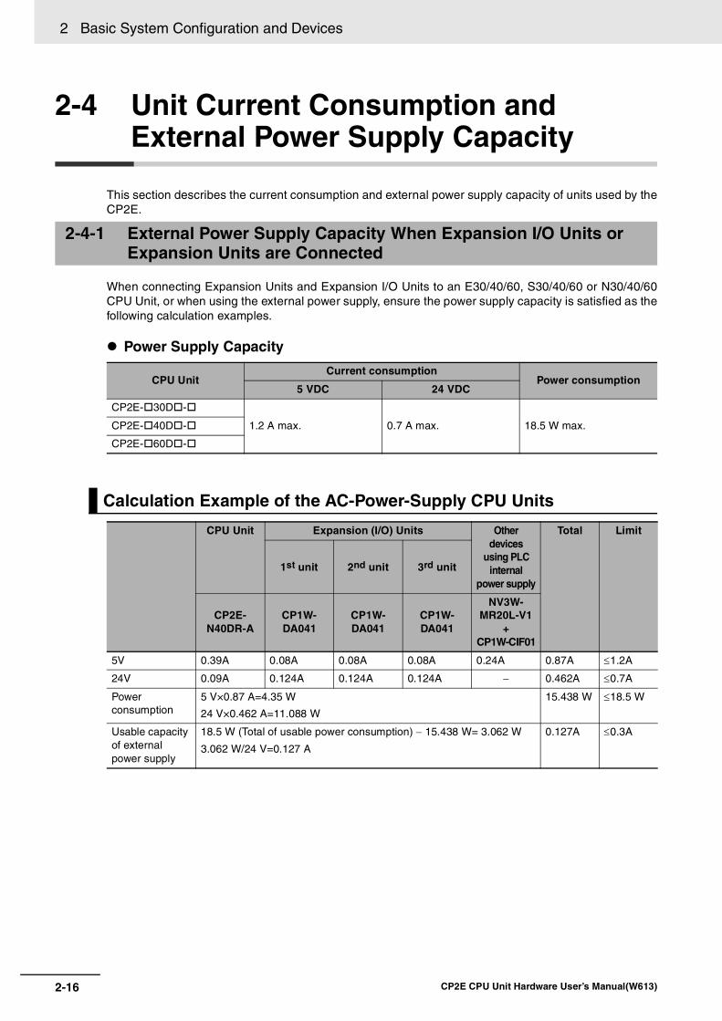
2 Basic System Configuration and Devices
2-16 CP2E CPU Unit Hardware User’s Manual(W613)
2-4 Unit Current Consumption and External Power Supply Capacity
This section describes the current consumption and external power supply capacity of units used by theCP2E.
When connecting Expansion Units and Expansion I/O Units to an E30/40/60, S30/40/60 or N30/40/60CPU Unit, or when using the external power supply, ensure the power supply capacity is satisfied as thefollowing calculation examples.
Power Supply Capacity
2-4-1 External Power Supply Capacity When Expansion I/O Units or Expansion Units are Connected
CPU UnitCurrent consumption
Power consumption5 VDC 24 VDC
CP2E- 30D -
1.2 A max. 0.7 A max. 18.5 W max.CP2E- 40D -
CP2E- 60D -
Calculation Example of the AC-Power-Supply CPU Units
CPU Unit Expansion (I/O) Units Other devices
using PLC internal
power supply
Total Limit
1st unit 2nd unit 3rd unit
CP2E-N40DR-A
CP1W-DA041
CP1W-DA041
CP1W-DA041
NV3W-MR20L-V1
+CP1W-CIF01
5V 0.39A 0.08A 0.08A 0.08A 0.24A 0.87A ≤1.2A
24V 0.09A 0.124A 0.124A 0.124A − 0.462A ≤0.7A
Power consumption
5 V×0.87 A=4.35 W
24 V×0.462 A=11.088 W
15.438 W ≤18.5 W
Usable capacity of external power supply
18.5 W (Total of usable power consumption) − 15.438 W= 3.062 W
3.062 W/24 V=0.127 A
0.127A ≤0.3A

2-17
2 Basic System Configuration and Devices
CP2E CPU Unit Hardware User’s Manual(W613)
2-4 Un
it Cu
rrent C
on
sum
ptio
n an
d E
xternal
Po
wer S
up
ply C
apacity
2
2-4-2 Current C
onsumption
Note DC-Power-Supply CPU Units have no external power supply.
CPU Units
E -type CPU Units
S -type CPU Units
Calculation Example of the DC-Power-Supply CPU Units
CPU Unit Expansion (I/O) Units Other devices
using PLC internal
power supply
Total Limit
1st unit 2nd unit 3rd unit
CP2E-N60DT-D
CP1W-40EDT
CP1W-TS003
CP1W-DA041
CP1W-CIF01
5V 0.71A 0.16A 0.07A 0.12A 0.08A 1.14A ≤1.2A
24V 0.03A − 0.03A 0.17A − 0.23A ≤0.7A
Power consumption
5 V×1.14 A=5.7 W
24 V×0.23 A=5.52 W
11.22 W ≤18.5 W
2-4-2 Current Consumption
I/O capacity Model numberCurrent consumption5 VDC 24 VDC
14 I/O points CP2E-E14DR-A 0.06A 0.04A
20 I/O points CP2E-E20DR-A 0.08A 0.06A
30 I/O points CP2E-E30DR-A 0.12A 0.07A
40 I/O points CP2E-E40DR-A 0.13A 0.09A
60 I/O points CP2E-E60DR-A 0.16A 0.13A
I/O capacity Model numberCurrent consumption5 VDC 24 VDC
30 I/O points CP2E-S30DR-A 0.12A 0.07A
CP2E-S30DT-D 0.28A 0.02A
CP2E-S30DT1-D
40 I/O points CP2E-S40DR-A 0.13A 0.09A
CP2E-S40DT-D 0.34A 0.02A
CP2E-S40DT1-D
60 I/O points CP2E-S60DR-A 0.16A 0.13A
CP2E-S60DT-D 0.48A 0.02A
CP2E-S60DT1-D

2 Basic System Configuration and Devices
2-18 CP2E CPU Unit Hardware User’s Manual(W613)
N -type CPU Units
Note The current consumptions given in the following table must be added to the current consumption of the CPUUnit if an Expansion Unit, Expansion I/O Unit or Option Board Unit is connected.
I/O capacity Model numberCurrent consumption5 VDC 24 VDC
14 I/O points CP2E-N14DR-A 0.15A 0.05A
CP2E-N14DT-A 0.21A 0.02A
CP2E-N14DR-D 0.15A 0.05A
CP2E-N14DT-D 0.21A 0.02A
CP2E-N14DT1-D 0.22A 0.02A
20 I/O points CP2E-N20DR-A 0.17A 0.06A
CP2E-N20DT-A 0.27A 0.02A
CP2E-N20DR-D 0.17A 0.06A
CP2E-N20DT-D 0.27A 0.02A
CP2E-N20DT1-D 0.26A 0.02A
30 I/O points CP2E-N30DR-A 0.41A 0.07A
CP2E-N30DT-A 0.52A 0.03A
CP2E-N30DR-D 0.37A 0.07A
CP2E-N30DT-D 0.51A 0.03A
CP2E-N30DT1-D 0.51A 0.03A
40 I/O points CP2E-N40DR-A 0.39A 0.09A
CP2E-N40DT-A 0.59A 0.03A
CP2E-N40DR-D 0.39A 0.09A
CP2E-N40DT-D 0.59A 0.03A
CP2E-N40DT1-D 0.59A 0.03A
60 I/O points CP2E-N60DR-A 0.44A 0.13A
CP2E-N60DT-A 0.71A 0.03A
CP2E-N60DR-D 0.41A 0.13A
CP2E-N60DT-D 0.71A 0.03A
CP2E-N60DT1-D 0.71A 0.03A

2-19
2 Basic System Configuration and Devices
CP2E CPU Unit Hardware User’s Manual(W613)
2-4 Un
it Cu
rrent C
on
sum
ptio
n an
d E
xternal
Po
wer S
up
ply C
apacity
2
2-4-2 Current C
onsumption
Expansion I/O Units, Expansion Units and Option Board Units
Other Devices Using PLC Internal Power Supply
Unit name Model numberCurrent consumption5 VDC 24 VDC
Expansion I/O Units 8 inputs CP1W-8ED 0.018A −8 outputs CP1W-8ER 0.026A 0.044A
CP1W-8ET 0.075A −CP1W-8ET1
16 outputs CP1W-16ER 0.042A 0.090ACP1W-16ET 0.076A −CP1W-16ET1
20 I/O points12 inputs8 outputs
CP1W-20EDR1 0.103A 0.044ACP1W-20EDT 0.130A −CP1W-20EDT1
32 outputs CP1W-32ER 0.049A 0.131ACP1W-32ET 0.113A −CP1W-32ET1
40 I/O points24 inputs16 outputs
CP1W-40EDR 0.080A 0.090ACP1W-40EDT 0.160A −CP1W-40EDT1
Expa-nsion Units
Analog Input Unit
4 inputs CP1W-AD041 0.100A 0.090ACP1W-AD042 0.100A 0.050A
Analog Output Unit
2 outputs CP1W-DA021 0.040A 0.095A4 outputs CP1W-DA041 0.080A 0.124A
CP1W-DA042 0.070A 0.160AAnalog I/O Unit Analog inputs: 2
Analog outputs: 1 CP1W-MAD11 0.083A 0.110A
Analog inputs: 4Analog outputs: 2
CP1W-MAD42 0.120A 0.120A
Analog inputs: 4Analog outputs: 4
CP1W-MAD44 0.120A 0.170A
Temperature Sensor Units
K or J thermocouples CP1W-TS001 0.040A 0.059ACP1W-TS002CP1W-TS004 0.080A 0.050A
K, J thermocouples or analog inputs
CP1W-TS003 0.070A 0.030A
Pt or JPt platinum resistance thermometers
CP1W-TS101 0.054A 0.073ACP1W-TS102
Option Board Units One RS-232C port CP1W-CIF01 0.04A −One RS-422A/485 port CP1W-CIF11 0.04A −
CP1W-CIF12-V1 0.04A −Two RS-232C ports CP2W-CIFD1 0.04A −One RS-232C port and One RS-485 port
CP2W-CIFD2 0.06A −
Two RS-485 ports CP2W-CIFD3 0.08A −Analog input CP1W-ADB21 0.02A −Analog output CP1W-DAB21V 0.06A −Analog I/O CP1W-MAB221 0.08A −
Unit name Model numberCurrent consumption5 VDC 24 VDC
Programmable Terminal
Backlight Green/Orange/Red NV3W-MG20L-V1 0.2A −Backlight White/Pink/Red NV3W-MR20L-V1 0.2A −

2 Basic System Configuration and Devices
2-20 CP2E CPU Unit Hardware User’s Manual(W613)

3-1
3
CP2E CPU Unit Hardware User’s Manual(W613)
3
This section describes the part names, function specifications and terminal arrange-ments of the CP2E CPU Unit and other Units.
3-1 CPU Units . . . . . . . . . . . . . . . . . . . . . . . . . . . . . . . . . . . . . . . . . . . . . . . . . . . . 3-23-1-1 E14/20 or N14/20 CPU Units . . . . . . . . . . . . . . . . . . . . . . . . . . . . . . . . . . . . . . 3-2
3-1-2 E30/40/60, S30/40/60 or N30/40/60 CPU Units . . . . . . . . . . . . . . . . . . . . . . . 3-6
3-1-3 Common I/O Specifications . . . . . . . . . . . . . . . . . . . . . . . . . . . . . . . . . . . . . . 3-12
3-1-4 Serial Communication Port . . . . . . . . . . . . . . . . . . . . . . . . . . . . . . . . . . . . . . 3-17
3-1-5 Analog Option Board for N -type CPU Units . . . . . . . . . . . . . . . . . . . . . . 3-24
3-2 Expansion I/O Units . . . . . . . . . . . . . . . . . . . . . . . . . . . . . . . . . . . . . . . . . . . 3-283-2-1 Expansion Input Unit . . . . . . . . . . . . . . . . . . . . . . . . . . . . . . . . . . . . . . . . . . . 3-28
3-2-2 Expansion Output Units . . . . . . . . . . . . . . . . . . . . . . . . . . . . . . . . . . . . . . . . . 3-29
3-2-3 Expansion I/O Units . . . . . . . . . . . . . . . . . . . . . . . . . . . . . . . . . . . . . . . . . . . . 3-31
3-2-4 I/O Specifications . . . . . . . . . . . . . . . . . . . . . . . . . . . . . . . . . . . . . . . . . . . . . . 3-33
Part Names and Functions

3 Part Names and Functions
3-2 CP2E CPU Unit Hardware User’s Manual(W613)
3-1 CPU Units
This section describes the names of the CPU Unit parts and provides the I/O specifications and termi-nal arrangements. Refer to A-1 Dimensions for the dimensions, A-2 Wiring Diagrams for the wiring dia-grams.
3-1-1 E14/20 or N14/20 CPU Units
Part Names and Functions
E-type CPU UnitCP2E-E14/20DR-A
N-type CPU UnitCP2E-N14/20D -
(1) Input terminal block
(6) Power supply input terminals
(2) Input indicators
(3) Peripheral USB port
(7) Ground terminal
(8) Input terminals
(9) Output indicators
(10) Output terminal block
(5) Operation indicators
(11) Output terminals
(13) Built-in RS-232C port
(12) Battery holder
(4) Option Board slot
(14) Built-in Ethernet port

3-3
3 Part Names and Functions
CP2E CPU Unit Hardware User’s Manual(W613)
3-1 CP
U U
nits
3
3-1-1 E14/20 or N
14/20 CP
U U
nits
Number Name Function
(1) Input terminal block (not removable)
This is the terminal block for inputs such as the power supply input and 24 VDC inputs.
(2) Input indicators (yellow) Input status is displayed. An indicator will be ON when the input is ON.
(3) Peripheral USB port Used to connect to a personal computer for programming and monitoring by the CX-Programmer for CP2E.
(4) Option Board slot for N -type CPU Units
An Option Board can be connected to the slot.
• CP1W-CIF01 RS-232C Option Board
• CP1W-CIF11 RS-422A/485 Option Board (Maximum transmission dis-tance: 50 m)
• CP1W-CIF12-V1 RS-422A/485 Option Board (Maximum transmission distance: 500 m)
• CP1W-MAB221/ADB21/DAB21V Analog Option Board
• CP2W-CIFD1 Option Board with two RS-232C ports
• CP2W-CIFD2 Option Board with one RS-232C port and one RS-485 port (isolated)
• CP2W-CIFD3 Option Board with two RS-485 ports (isolated)
(5) Operation indicators The CPU Unit’s operating status can be confirmed with this indicator.
Refer to CPU Unit Status Indicators (Page 3-4).
(6) Power supply input terminals
Power of 100 to 240 VAC or 24 VDC can be supplied.
(7) Ground terminal Protective ground ( ): To prevent electric shock, ground to 100 Ω or less.
(8) Input terminals Input devices such as switches and sensors can be connected.
(9) Output indicators (yellow) Output status is displayed. An indicator will be ON when the output is ON.
(10) Output terminal block (not removable)
This is the terminal block for outputs such as relay outputs and transistor outputs.
(11) Output terminals Loads such as lamps, contactors, and solenoid valves can be connected.
(12) Battery holder for N -type CPU Units
A Battery can be installed by opening the cover. (The Battery is optional.)
(13) Built-in RS-232C port for E -type CPU Units
By connecting a PT, the controlled system can be monitored and data can be collected.
(14) Built-in Ethernet port for N -type CPU Units
Used to connect to a personal computer for programming and monitoring by the CX-Programmer for CP2E, or connect to other OMRON PLCs for data exchange.

3 Part Names and Functions
3-4 CP2E CPU Unit Hardware User’s Manual(W613)
: Not lit : Flashing : Lit
Precautions for Safe Use
Do not turn OFF the power supply to the PLC when the BKUP indicator is lit. It indicates thatdata is being written to the built-in Flash Memory.
If the power is turned OFF during backup, the data will not be backed up and transferred to theDM Area in RAM next time the power supply is turned ON.
CPU Unit Status Indicators
Name Color Function Description
POWER Green
Lit
When PLC power is ON.
Not litWhen PLC power is OFF.
RUN Green
Lit
When PLC is executing a program under RUN or MONITOR mode.
Not litOperation is stopped in PROGRAM mode or due to a fatal error.
ERR/ALM Red
Lit
A fatal error (including FALS execution) or a hardware error (WDT error) has occurred. PLC operation will stop and all outputs will be turned OFF.
FlashingA non-fatal error has occurred (including FAL execution).PLC operation will continue.
Not litOperation is normal.
INH Yellow
Lit
All outputs has been turned OFF.
Output OFF bit (A500.15) has been turned OFF.
Not litOperation is normal.
PRPHL(E -type only)
YellowFlashing
Communications (either sending or receiving) are in progress through the peripheral USB port.
Not litOther than the above.
BKUP YellowLit
A user program, parameters, or Data Memory is being written to the built-in Flash Memory.
Not litOther than the above.
RS-232C(E -type only)
YellowFlashing
Communications (either sending or receiving) are in progress through the RS-232C port.
Not litOther than the above.
LINK/ACT(N -type only)
Yellow
Lit
A valid link is detected.
FlashingCommunications (either sending or receiving) are in progress through the Ethernet port.
Not litOther than the above.
POWER
PRPHL
RUN
ERR/ALM
INH
BKUP
RS-232C
E��-type
POWER
BKUP
RUN
ERR/ALM
INH
LINK/ACT
N��-type

3-5
3 Part Names and Functions
CP2E CPU Unit Hardware User’s Manual(W613)
3-1 CP
U U
nits
3
3-1-1 E14/20 or N
14/20 CP
U U
nits
Input Arrangement
AC Power Supply
DC Power Supply
Output Arrangement
AC Power Supply and DC Power Supply
Terminal Arrangements
CIO 0
CP2E- 14D -A
L1 L2/N COM 01 03 05 07 NC NC
00 02 04 06 NC NCNC
L1,L2/N : Power supply terminal : Protective ground terminalCOM : Common terminal00 to 07 : Input terminalNC : No connection
CIO 0
CP2E- 20D -A
L1 L2/N COM 01 03 05 07 09 11
00 02 04 06 08 10NC
L1,L2/N : Power supply terminal : Protective ground terminalCOM : Common terminal00 to 11 : Input terminalNC : No connection
+ - COM 01 03 05 07 NC NC
00 02 04 06 NC NCNC
CIO 0
CP2E-N14D -D
+,- : Power supply terminal : Protective ground terminalCOM : Common terminal00 to 07 : Input terminalNC : No connection
+ - COM 01 03 05 07 09 11
00 02 04 06 08 10NC
CIO 0
CP2E-N20D -D
+,- : Power supply terminal : Protective ground terminalCOM : Common terminal00 to 11 : Input terminalNC : No connection
00 01 02 03
COM COM NC COM
04 05 NC
NCCOMNC
CIO 100
CP2E- 14D -
COM : Common terminal00 to 05 : Output terminalNC : No connection
00 01 02 03
COM COM NC COM
04 05 07
06COMNC
CIO 100
CP2E- 20D -
COM : Common terminal00 to 07 : Output terminalNC : No connection

3 Part Names and Functions
3-6 CP2E CPU Unit Hardware User’s Manual(W613)
3-1-2 E30/40/60, S30/40/60 or N30/40/60 CPU Units
Part Names and Functions
E/S-type CPU UnitCP2E-E30/40/60DR-ACP2E-S30/40/60D -
N-type CPU UnitCP2E-N30/40/60D -
(12) Output terminals
(1) Input terminal block
(6) Power supply input terminals
(8) Ground terminal
(9) Expansion I/O Unit connector
(10) Output indicators
(11) Output terminal block
(13) External power supply input terminals
(7) Input terminals
(2) Input indicators
(3) Peripheral USB port
(5) Operation indicators
(16) Built-in RS-232C port
(17) Built-in RS-485 port
L1L1 L2/NL2/N
(14) Battery holder
(18) External supply terminals
(15) Built-in Ethernet port
(4) Option Board slots
(Bottom View)
PORT1A PORT1B

3-7
3 Part Names and Functions
CP2E CPU Unit Hardware User’s Manual(W613)
3-1 CP
U U
nits
3
3-1-2 E30/40/60, S
30/40/60 or N30/40/60 C
PU
Units
Number Name Function(1) Input terminal block
(not removable)This is the terminal block for inputs such as the power supply input and 24 VDC inputs.
(2) Input indicators (yellow) Input status is displayed. An indicator will be ON when the input is ON.(3) Peripheral USB port Used to connect to a personal computer for programming and monitoring
by the CX-Programmer for CP2E.(4) Option Board slots for
N -type CPU UnitsOption Boards can be connected to the slots.
• CP1W-CIF01 RS-232C Option Board
• CP1W-CIF11 RS-422A/485 Option Board (Maximum transmission dis-tance: 50 m)
• CP1W-CIF12-V1 RS-422A/485 Option Board (Maximum transmission distance: 500 m)
• CP1W-MAB221/ADB21/DAB21V Analog Option Board
• CP2W-CIFD1 Option Board with two RS-232C ports
• CP2W-CIFD2 Option Board with one RS-232C port and one RS-485 port (isolated)
• CP2W-CIFD3 Option Board with two RS-485 ports (isolated)(5) Operation indicators The CPU Unit’s operating status can be confirmed with this indicator.
Refer to CPU Unit Status Indicators (Page 3-8).(6) Power supply input termi-
nalsPower of 100 to 240 VAC or 24 VDC can be supplied.
(7) Input terminals Input devices such as switches and sensors can be connected.(8) Ground terminal Protective ground ( ): To prevent electric shock, ground to 100 Ω or
less.
Functional ground ( ): If noise is a significant source of errors or if
electrical shock is a problem, connect to the protective ground terminal and ground both with a ground of 100Ω or less (AC power supply only).
(9) Expansion I/O Unit connector
CP-series Expansion I/O Units or Expansion Units such as Analog I/O Units, and Temperature Sensors can be connected.
Refer to 5-2-4 Connecting Expansion I/O Units and Expansion Units.(10) Output indicators (yellow) Output status is displayed. An indicator will be ON when the output is ON.(11) Output terminal block
(not removable)This is the terminal block for outputs such as relay outputs, transistor out-puts, and the external power supply output.
(12) Output terminals Loads such as lamps, contactors, and solenoid valves can be connected.(13) External power supply
input terminals for S -type CPU Units
Power of 20.4V to 26.4 VDC can be supplied to CIO 100.00 and CIO 100.01.
(14) Battery holder for N/S -type CPU Units
A Battery can be installed by opening the cover. (Battery is optional.)
(15) Built-in Ethernet port for N -type CPU Units
Used to connect to a personal computer for programming and monitoring by the CX-Programmer for CP2E, or connect to other OMRON PLCs for data exchange.
(16) Built-in RS-232C port for E/S -type CPU Units
By connecting a PT, the controlled system can be monitored and data can be collected.
(17) Built-in RS-485 port for S -type CPU Units
Communications are possible between an inverter and a PLC by using Modbus-RTU and Serial PLC Links.
(18) External supply terminals
The external supply terminals output up to 300 mA max at 24 VDC.They can be used as a service power supply for input devices (AC power supply only).

3 Part Names and Functions
3-8 CP2E CPU Unit Hardware User’s Manual(W613)
: Not lit : Flashing : Lit
CPU Unit Status Indicators
Name Color Function Description
POWER GreenLit
When PLC power is ON.
Not litWhen PLC power is OFF.
RUN GreenLit
When PLC is executing a program under RUN or MONITOR mode.
Not litOperation is stopped in PROGRAM mode or due to a fatal error.
ERR/ALM RedLit
A fatal error (including FALS execution) or a hardware error (WDT error) has occurred. PLC operation will stop and all outputs will be turned OFF.
FlashingA non-fatal error has occurred (including FAL execution).PLC operation will continue.
Not litOperation is normal.
INH YellowLit
All outputs has been turned OFF.
Output OFF bit (A500.15) has been turned OFF.
Not litOperation is normal.
PRPHL(E/S -type only)
YellowFlashing
Communications (either sending or receiving) are in progress through the peripheral USB port.
Not litOther than the above.
BKUP YellowLit
A user program, parameters, or Data Memory is being written to the bulit-in Flash Memory.
Not litOther than the above.
RS232C(E/S -type only)
YellowFlashing
Communications (either sending or receiving) are in progress through the RS-232C port.
Not litOther than the above.
RS485(S -type only)
YellowFlashing
Communications (either sending or receiving) are in progress through the RS-485 port.
Not litOther than the above.
PORT1ALINK/ACT(N -type only)
YellowLit
A valid link is detected.
FlashingCommunications (either sending or receiving) are in progress through the Ethernet port (Left: PORT1A).
Not litOther than the above.
PORT1BLINK/ACT(N -type only)
YellowLit
A valid link is detected.
FlashingCommunications (either sending or receiving) are in progress through the Ethernet port (Right: PORT1B).
Not litOther than the above.
POWER
E/S��-type
PRPHL
RUN
ERR/ALM
INH
BKUP
RS-232C
RS-485
POWER
N��-type
BKUP
RUN
ERR/ALM
INH
PORT1A LINK/ACT
PORT1B LINK/ACT

3-9
3 Part Names and Functions
CP2E CPU Unit Hardware User’s Manual(W613)
3-1 CP
U U
nits
3
3-1-2 E30/40/60(S
), N30/40/60(S
) or NA
20 CP
U U
nits
Precautions for Safe Use
Do not turn OFF the power supply to the PLC when the BKUP indicator is lit. It indicates thatdata is being written to the built-in Flash Memory.
If the power is turned OFF during backup, the data will not be backed up and transferred to theDM Area in RAM next time the power supply is turned ON.
Input Arrangement
Terminal Arrangements
AC Power SupplyCP2E- 30D -A
CP2E- 40D -A
CP2E- 60D -A
DC Power SupplyCP2E- 30D -D
CP2E- 40D -D
CP2E- 60D -D
CIO 0 CIO 1
L1 L2/N COM
NC
01 03 05 07 09 11
00 02 04 06 08 10
01 03 05
00 02 04
L1, L2/N : Power supply terminalCOM : Common terminal00 to 11 : Input terminal : Functional ground terminal : Protective ground terminalNC : No connection
CIO 0 CIO 1
L1 L2/N COM 01 03 05
00 02 04
07 09 11
06 08 10
01 03 05
00 02 04
07 09 11
06 08 10
CIO 0 CIO 1 CIO 2
L1 L2/N COM 01 03 05
00 02 04
07 09 11
06 08 10
01 03 05
00 02 04
07 09 11
06 08 10
01 03 05
00 02 04
07 09 11
06 08 10
CIO 0 CIO 1
+ - COM
NCNC
01 03 05 07 09 11
00 02 04 06 08 10
01 03 05
00 02 04
+, - : Power supply terminalCOM : Common terminal00 to 11 : Input terminalNC : No connection : Protective ground terminal
CIO 0 CIO 1
01 03 05 07 09 11
04 08
01 03 05 07 09 11
0000 02 04 06 08 10NC
+ -
02
COM
06 10
CIO 0 CIO 1 CIO 2
01 03 05 07 09 11
04 08
01 03 05 07 09 11
00 0000 02 04 06 08 10
01 03 05 07 09 11
02 04 06 08 10NC
+ -
02
COM
06 10

3 Part Names and Functions
3-10 CP2E CPU Unit Hardware User’s Manual(W613)
Output Arrangement
AC Power SupplyCP2E- 30D -A
CP2E- 40D -A
CP2E- 60D -A
DC Power SupplyCP2E-N30D -D
CP2E-N40D -D
CP2E-N60D -D
CIO 100 CIO 101
00 01 02 04 05 07 00
03 06
02
01 03
+
- COM COMCOM COM COM
+,- : External supply terminalCOM : Common terminal00 to 07 : Output terminal
CIO 100 CIO 101
+ 00 01
07
02 03 04 06 00 01
COM COM 05 07 COM
03 04 06
02 05COMCOMCOM-
00 01 02 04 05 07 00 02 04 05 07 00 02 04 05 07
COM COM COM 03 COM 06 COM 01 03 COM 06 COM 01 03 COM 06
CIO 100 CIO 101 CIO 102
+
−
CIO 100 CIO 101
0201 04 05 07 00 02
03
00
COM COM COM COM COMNC
NC
03 06 01
NC : No connectionCOM : Common terminal00 to 07 : Output terminal
CIO 100 CIO 101
0201 03 04 06 00 01 03 04 06
02
00
NC COM COM COMCOM 07 COM
NC
05 05 07COM
01 02 04 05 07 00 02 04 05 07 00 02 04 05 07
COM COM 03 COM 06 COM 01 03 COM 06 COM 01 03 COM 06
CIO 100 CIO 101 CIO 102
00
COM
NC
NC

3-11
3 Part Names and Functions
CP2E CPU Unit Hardware User’s Manual(W613)
3-1 CP
U U
nits
3
3-1-2 E30/40/60(S
), N30/40/60(S
) or NA
20 CP
U U
nits
CP2E-S30DT-D
Note COM(V-) has been connected with V- in an inner circuit.
CP2E-S30DT1-D
Note COM(V+) has been connected with V+ in an inner circuit.
CP2E-S40DT-D
Note COM(V-) has been connected with V- in an inner circuit.
CP2E-S40DT1-D
Note COM(V+) has been connected with V+ in an inner circuit.
CP2E-S60DT-D
Note COM(V-) has been connected with V- in an inner circuit.
CP2E-S60DT1-D
Note COM(V+) has been connected with V+ in an inner circuit.
CIO 100 CIO 101
00 01 02 04 05 07 00
03 06
02
01 03
V+
V- COM(V-) COM COM COM
CIO 100 CIO 101
0201 04 05 07 00 02
03
00
COM(V+) COM COM COMV-
V+
03 06 01
CIO 100 CIO 101
V+ 00 01
07
02 03 04 06 00 01
COM 05 07 COM
03 04 06
02 05COMCOMCOM(V-)V-
COM :Common terminal
00~07 :Output terminal
V+ :External power supply input terminal for CIO 100.00/01 (DC24V)
V- :External power supply input terminal for CIO 100.00/01 (0V)
CIO 100 CIO 101
0201 03 04 06 00 01 03 04 06
02
00
V- COM(V+) COMCOM 07 COM
V+
05 05 07COM
00 01 02 04 05 07 00 02 04 05 07 00 02 04 05 07
COM(V-) COM 03 COM 06 COM 01 03 COM 06 COM 01 03 COM 06
CIO 100 CIO 101 CIO 102
V+
V-
01 02 04 05 07 00 02 04 05 07 00 02 04 05 07
COM 03 COM 06 COM 01 03 COM 06 COM 01 03 COM 06
CIO 100 CIO 101 CIO 102
00
COM(V+)
V+
V-

3 Part Names and Functions
3-12 CP2E CPU Unit Hardware User’s Manual(W613)
The following table gives the specifications that apply to the built-in I/O on a CP2E CPU Unit.
*1 The bits that can be used depend on the model of CPU Unit.
*2 The response time is the delay caused by hardware. The delay set in the PLC Setup (0 to 32 ms, default: 8 ms)for a normal input must be added to this value.
3-1-3 Common I/O Specifications
SpecificationsItem Specification
Input type High-speed counter inputs or normal inputs
High-speed counter inputs, interrupt inputs,
quick-response inputs or normal inputs
Normal inputs
Input bits
E/S -type and N14 CPU Units
CIO 0.00 and CIO 0.01 CIO 0.02 to CIO 0.07CIO 0.08 to CIO 0.11,
CIO 1.00 to CIO 1.11 and CIO 2.00 to CIO 2.11 *1
N20 CPU Units CIO 0.00 and CIO 0.01 CIO 0.02 to CIO 0.09 CIO 0.10 to CIO 0.11
N30/40/60 CPU Units CIO 0.00 to CIO 0.03 CIO 0.04 to CIO 0.09
CIO 0.10, CIO 0.11, CIO 1.00 to CIO 1.11 and CIO 2.00 to CIO 2.11 *1
Applicable inputs 2-wire and 3-wire sensors
Input voltage 24 VDC, +10% / -15%
Input impedance 3.3 kΩ 3.3 kΩ 4.8 kΩ
Input current 7.5 mA (typical) 7.5 mA (typical) 5 mA (typical)
ON voltage/current 17.0 VDC min. / 3 mA min. 17.0 VDC min. / 3 mA min. 14.4 VDC min. / 3 mA min.
OFF voltage/current 5.0 VDC max. / 1 mA max. 5.0 VDC max. / 1 mA max. 5.0 VDC max. / 1 mA max.
ON response time*2 2.5 μs min. 50 μs max. 1 ms max.
OFF response time*2 2.5 μs min. 50 μs max. 1 ms max.
Circuit configurationInput indicator
IN
IN
COM
Internalcircuits
Isolationcircuits

3-13
3 Part Names and Functions
CP2E CPU Unit Hardware User’s Manual(W613)
3-1 CP
U U
nits
3
3-1-3 Com
mon I/O
Specifications
CP2E- DR-
Output Specifications for Relay Outputs
Item Specification
Maximum switching capacity 2 A 250 VAC (cosφ= 1)
2 A 24 VDC (4 A/common)
Minimum switching capacity 10 mA 5 VDC
Service life of relay
Electrical Resistive load
200,000 operations (24 VDC)
Inductive load
70,000 operations (250 VAC, cosφ = 0.4)
Mechanical 20,000,000 operations
ON response time 15 ms max.
OFF response time 15 ms max.
Circuit configuration
ON
OFF
ON
OFF
ON
OFFT1 T2 T3 T4
T1, T2, T3, T4: 2.5 µs min.
90%50%10%
90%50%10%
90%50%10%
2.5µs min.
2.5µs min.
20.0µs min. 10.0µs min.
Up/down input mode Differential phase mode
Pulse plus direction input modeIncrement mode
E/S��-type: 0.00/0.01N14/20-type: 0.00/0.01N30/40/60-type: 0.00 to 0.02
E/S��-type: 0.00/0.01N14/20-type: 0.00/0.01N30/40/60-type: 0.00 to 0.03
ON
OFF
ON
OFF
ON
OFFT1 T2 T3 T4
T1, T2, T3, T4: 50 µs min.
90%50%10%
90%50%10%
90%50%10%
50µs min.
50µs min.
200µs min. 100µs min.
E/S��-type: 0.02 to 0.07 N14-type: 0.02 to 0.07N20-type: 0.02 to 0.09N30/40/60-type: 0.04 to 0.09
E/S��-type: 0.02/0.03N14/20-type: 0.02/0.03
Interrupt input mode
Output indicator
Internalcircuits
COM
OUT
OUT
250 VAC, 2A,24 VDC, 2 Amax.

3 Part Names and Functions
3-14 CP2E CPU Unit Hardware User’s Manual(W613)
Estimating the Service Life of RelaysUnder normal conditions, the service life of output contacts is as shown above. The service life ofrelays is as shown in the following diagram as a guideline.
CP2E- DR-
30-VDC/250-VAC resistive load
125-VAC resistive load
125 VAC cosφ= 0.4
250 VAC cosφ= 0.4/ 30 VDC, τ = 7ms
Contact current (A)
Life
(x
104 )
300
500700
1000
200
100
5070
3020
57
32
1
10
0.1 0.2 0.3 0.5 0.7 1 2 3 5 7 10

3-15
3 Part Names and Functions
CP2E CPU Unit Hardware User’s Manual(W613)
3-1 CP
U U
nits
3
3-1-3 Com
mon I/O
Specifications
CP2E- N14/20/30/40/60DT(1)- , CP2E-S30/40/60DT(1)-
Normal Outputs
*1 Also do not exceed 0.9 A for the total of CIO 100.00 to CIO 100.03, which are different common.
Output Specifications for Transistor Outputs (Sinking or Sourcing)
Item
Specification
S -type: CIO 100.00 and CIO 100.01N -type: CIO 100.00, CIO 100.01,
CIO 101.00 and CIO 101.01
S -type: CIO 100.02 to CIO 102.07 *2N -type: CIO 100.02 to CIO 100.07,
CIO 101.02 to CIO 102.07 *2
Maximum switching capacity
0.3 A/output, 0.9 A/common*14.5 to 30 VDCCP2E-N14D - : 1.5 A/Unit CP2E-S/N40D - : 3.6 A/UnitCP2E-N20D - : 1.8 A/Unit CP2E-S/N60D - : 5.4 A/UnitCP2E-S/N30D - : 2.7 A/Unit
Minimum switching capacity
1 mA 4.5 to 30 VDC
Leakage current
0.1mA max.
Residual voltage
0.6 V max. 1.5V max.
ON response time
0.1 ms max. 0.1 ms max.
OFF response time
0.1 ms max. 1 ms max.
Fuse Not provided.
External power supply
20.4 to 26.4VDC 30mA max.(N -type is not needed)
Not needed
Circuit configuration
• S -type CPU Unit Sinking output model
Sourcing output model
• N -type CPU Unit Sinking output model
Sourcing output model
Sinking output model
Sourcing output model
Internalcircuits
Internalcircuits
OUT
OUT
V+
V-
4.5 to 30VDC
20.4 to 26.4VDC
COM(V-)
L
L
~
OUT
OUT
COM(V+)
L
L
V+
V-
Internalcircuits
Internalcircuits
4.5 to 30VDC
20.4 to 26.4VDC
~
OUT
OUT ~
COM(–)
L
L
Internalcircuits
Internalcircuits
24 VDC,4.5 to 30VDC
Internalcircuits
OUT
OUT
L
L
COM(+)
Internalcircuits
24 VDC,4.5 to 30VDC
~
OUT
OUT
COM(–)
L
L24 VDC,4.5 to 30VDC
Internalcircuits
~
OUT
OUT
COM(+)
L
L
24 VDC,4.5 to 30VDC
Internalcircuits
~

3 Part Names and Functions
3-16 CP2E CPU Unit Hardware User’s Manual(W613)
*2 The bits that can be used depend on the model of CPU Unit.
Precautions for Correct UsePrecautions for Correct Use
Do not connect a load to an output terminal or apply a voltage in excess of the maximum switch-ing capacity.
Pulse Outputs
Additional Information
• The load for the above values is assumed to be the resistive load, and does not take intoaccount the impedance for the connecting cable to the load.
• Due to distortions in pulse waveforms resulting from connecting cable impedance, the pulsewidths in actual operation may be smaller than the values shown above.
PWM Output (CIO 100.01)
ItemSpecification
S -type: CIO 100.00 and CIO 100.01N -type: CIO 100.00, CIO 100.01, CIO 101.00 and CIO 101.01
Maximum switching capacity 100 mA 4.5 to 26.4 VDC
Minimum switching capacity 7 mA 4.5 to 26.4 VDC
Maximum output frequency 100 kHz
Output waveform
The OFF and ON refer to the output transistor. The output transistor is ON at level “L”.
Item Specification
Maximum switching capacity 30 mA 4.5 to 26.4 VDC
Maximum output frequency 32 kHz
PWM output accuracy For ON duty +1%, -0%:10 kHz output
For ON duty +5%, -0%: 0 to 32 kHz output
Output waveform
The OFF and ON refer to the output transistor. The output transistor is ON at level “L”.
4μs min. 2μs min.
OFF 90%
ON 10%
T
ON duty= × 100%T
tON tON
OFF
ON

3-17
3 Part Names and Functions
CP2E CPU Unit Hardware User’s Manual(W613)
3-1 CP
U U
nits
3
3-1-4 Serial C
omm
unication Port
The Serial Communication Port can be used for a CP2E CPU Unit.
RS-485 Terminal Block
DIP Switch for Terminating Resistance Settings
3-1-4 Serial Communication Port
E/S -type CPU Units
Built-in RS-232C Port for E/S -type CPU Units
Pin Abbr. Signal Name Signal direction
1 SD(TXD) Send data Output
2 RD(RXD) Receive data Input
3 RS(RTS) Request to send Output
4 CS(CTS) Clear to send Input
5 SG(0V) Signal ground −
6 FG Frame ground −
Built-in RS-485 Port (2-wire) for S -type CPU Units
Pin Abbr. Signal Name Signal direction
1 A- Send/Receive data - −
2 B+ Send/Receive data + −
3 FG Frame ground −
Setting
ON ON (both ends) Terminating resistance selection
Resistance value: 220Ω typical
OFF OFF
CP2E S30/40/60CPU Unit
Built-in RS-232C port
Built-in RS-485 port(S��-type CPU Unit only)
FGSD RDRS CS SG
A- B+ FG
ON

3 Part Names and Functions
3-18 CP2E CPU Unit Hardware User’s Manual(W613)
Note CP2W-CIFD can only be mounted on option slot 1.
Serial Communication Option Board
How to Mount a Serial Option BoardWhen mounting an Option Board, first remove the slot cover.
Press the up/down lock-levers on both sides of the Option Board slot cover at the same time tounlock the cover, and then pull the cover out.
Check the alignment to make the corner cut of the Option Board fit in the Option Board slot, andfirmly press the Option Board in until it snaps into place.
Precautions for Correct UsePrecautions for Correct Use
Always turn OFF the power supply to the PLC before mounting or removing an Option Board.
N -type CPU Units
Model numbers PortMaximum
transmission distance
Connection method
CP1W-CIF01 One RS-232C port 15m Connector (D-sub, 9 pin female)
CP1W-CIF11 One RS-422A/485 port (not isolated) 50m Terminal block (using ferrules)
CP1W-CIF12-V1 One RS-422A/485 port (isolated) 500m Terminal block (using ferrules)
CP2W-CIFD1 Two RS-232C Ports 15m Terminal block (using ferrules)
CP2W-CIFD2One RS-232C port and one RS-485 port (isolated)
15m (RS-232C)
500m (RS-485)
Terminal block (using ferrules)
CP2W-CIFD3 Two RS-485 ports (isolated) 500m Terminal block (using ferrules)
CP2E N��-type CPU Unit
CP1W-CIF11/12-V1RS-422A/485Option Board
CP2W-CIFD1RS-232C&RS-232COption Board
CP2W-CIFD2RS-232C&RS-485Option Board
CP2W-CIFD3RS-485&RS-485Option Board
CP1W-CIF01RS-232COption Board
Slot 2
Slot 1
CP1W-CIF11/12-V1RS-422A/485Option Board
CP1W-CIF01RS-232COption Board

3-19
3 Part Names and Functions
CP2E CPU Unit Hardware User’s Manual(W613)
3-1 CP
U U
nits
3
3-1-4 Optional S
erial Com
munications P
ort for N/N
A(S
)-type CP
U U
nits
RS-232C Connector
Note The NV3W-M 20L-V1 Programmable Terminal can be connected to pin 6 (+5V) on the RS-232C OptionBoard (CP1W-CIF01) mounted to the CPU Unit. Do not connect pin 6 to any other device.
CP1W-CIF01 RS-232C Option Board
Pin Abbr. Signal Signal direction
1 FG Frame ground −
2 SD(TXD) Send data Output
3 RD(RXD) Receive data Input
4 RS(RTS) Request to send Output
5 CS(CTS) Clear to send Input
6 5V Power −
7 DR(DSR) Data set ready Input
8 ER(DTR) Data terminal ready Output
9 SG(0V) Signal ground −
Connector hood FG Frame ground −
COMM
Front Rear
Communications status indicator
RS-232C connector
CPU Unit connector
5
6
1
9

3 Part Names and Functions
3-20 CP2E CPU Unit Hardware User’s Manual(W613)
RS-422A/485 Terminal Block
DIP Switch for Operation Settings
CP1W-CIF11 or CP1W-CIF12-V1 RS-422A/485 Option Board
CP1W-CIF11 CP1W-CIF12-V1Setting
Pin Pin
SW 1 SW1 1 ON ON (both ends) Terminating resistance selection
Resistance value: 220Ω typicalOFF OFF
2 2 ON 2-wire connections 2-wire or 4-wire selection*1
OFF 4-wire connections
3 3 ON 2-wire connections 2-wire or 4-wire selection*1
OFF 4-wire connections
4 4 − − Not used.
5 SW2 1 ON RS control enabled RS control selection for RD*2
OFF RS control disabled (Data always received.)
6 2 ON RS control enabled RS control selection for SD*3
OFF RS control disabled (Data always sent.)
*1 Set both pins 2 and 3 to either ON (2-wire) or OFF (4-wire).
*2 To disable the echo-back function, set pin 5 to ON (RS control enabled).
*3 When connecting to a device on the N side in a 1: N connection with the 4-wire method, set pin 6 to ON (RScontrol enabled).Also, when connecting by the 2-wire method, set pin 6 to ON (RS control enabled).
Front Rear
Communications status indicator
COMM
RDA- RDB+ SDA- SDB+ FG
RS-422A/485 terminal block
CPU Unit connector
DIP switch for operationsettings
RDB+
RDA-
SDA- SDB+
FG
Tighten screws on the terminalblock to 0.28 N.m.
1 2 3 4 5 6
O N
1 2 3 4
O N1 2
O N

3-21
3 Part Names and Functions
CP2E CPU Unit Hardware User’s Manual(W613)
3-1 CP
U U
nits
3
3-1-4 Optional S
erial Com
munications P
ort for N/N
A(S
)-type CP
U U
nits
RS-232C&RS-232C Terminal Block
CP2W-CIFD1 RS-232C&RS-232C Option Board
Port Pin Abbr. Signal Name Signal direction
PORT 1 SD(TXD) Send data Output
2 RD(RXD) Receive data Input
3 SG(0V) Signal ground −
4 FG Frame ground −
PORT (EX) 5 SD(TXD) Send data Output
6 RD(RXD) Receive data Input
7 SG(0V) Signal ground −
8 FG Frame ground −
Note CP2W-CIFD1 can only be mounted on option slot 1.PORT is supported by serial port 1 and PORT (EX) is supported by serial port 1(EX).
Front Rear
Communications status indicator
RS-232C&RS-232C terminal block
CPU Unit connector

3 Part Names and Functions
3-22 CP2E CPU Unit Hardware User’s Manual(W613)
RS-232C&RS-485 Terminal Block
DIP Switch for Terminating Resistance Settings
CP2W-CIFD2 RS-232C&RS-485 Option Board
Port Pin Abbr. Signal Name Signal direction
PORT 1 SD(TXD) Send data Output
2 RD(RXD) Receive data Input
3 SG(0V) Signal ground −
4 FG Frame ground −
PORT (EX) 5 A- Send/Receive data - −
6 B+ Send/Receive data + −
7 FG Frame ground −
8 NC NC −
Note CP2W-CIFD2 can only be mounted on option slot 1.PORT is supported by serial port 1 and PORT (EX) is supported by serial port 1(EX).
Setting
ON ON (both ends) Terminating resistance selection
Resistance value: 220Ω typicalOFF OFF
Front Rear
Communications status indicator
RS-232C&RS-485terminal block
CPU Unit connector
DIP switch

3-23
3 Part Names and Functions
CP2E CPU Unit Hardware User’s Manual(W613)
3-1 CP
U U
nits
3
3-1-4 Optional S
erial Com
munications P
ort for N/N
A(S
)-type CP
U U
nits
RS-485&RS-485 Terminal Block
DIP Switch for Terminating Resistance Settings
CP2W-CIFD3 RS-485&RS-485 Option Board
Port Pin Abbr. Signal Name Signal direction
PORT 1 A- Send/Receive data - −
2 B+ Send/Receive data + −
3 FG Frame ground −
4 NC NC −
PORT (EX) 5 A- Send/Receive data - −
6 B+ Send/Receive data + −
7 FG Frame ground −
8 NC NC −
Note CP2W-CIFD3 can only be mounted on option slot 1.PORT is supported by serial port 1 and PORT (EX) is supported by serial port 1(EX).
Pin Setting
1ON ON (both ends) Terminating resistance selection
Resistance value: 220Ω typicalOFF OFF
2 − − Not used.
3 − − Not used.
4ON ON (both ends) Terminating resistance selection
Resistance value: 220Ω typicalOFF OFF
Front Rear
Communications status indicator
RS-485&RS-485terminal block
CPU Unit connector
DIP switch

3 Part Names and Functions
3-24 CP2E CPU Unit Hardware User’s Manual(W613)
The Analog Option Board can be used for a CP2E N -type CPU Unit.
Note Maximum one Analog Option Board can be mounted on an N -type CPU Unit.If two Analog Option Boards are mounted, an option board error will occur and both Analog Option Boardsdo not work.
Analog Option BoardAnalog option board units are non-isolated analog units which allow you to easily realize analoginput/output function for CP2E N -type CPU Unit.
How to Mount an Analog Option BoardWhen mounting an Option Board, first remove the slot cover.
Press the up/down lock-levers on both sides of the Option Board slot cover at the same time tounlock the cover, and then pull the cover out.
Check the alignment to make the corner cut of the Option Board fit in the Option Board slot, andfirmly press the Option Board in until it snaps into place.
Precautions for Correct UsePrecautions for Correct Use
Always turn OFF the power supply to the PLC before mounting or removing an Option Board.
Not doing so may result in an unexpected operation.
3-1-5 Analog Option Board for N -type CPU Units
N -type CPU Units
Analog Option Board
Voltage Input0V~10V
(Resolution:1/4000)
Current Input0mA~20mA(Resolution:
1/2000)
Voltage Output0V~10V
(Resolution:1/4000)
Analog I/O Option Board CP1W-MAB221 2CH 2CH
Analog Input Option Board CP1W-ADB21 2CH ---
Analog Output Option Board CP1W-DAB21V --- 2CH
CP2E N��-typeCPU Unit
CP1W-DAB21VAnalog OutputOption Board
CP1W-MAB221Analog Input/OutputOption Board
CP1W-ADB21Analog Input Option Board

3-25
3 Part Names and Functions
CP2E CPU Unit Hardware User’s Manual(W613)
3-1 CP
U U
nits
3
3-1-5 Analog O
ption Board for N
-type CP
U U
nits
Analog Input Terminal Arrangement
Note When using current inputs, voltage input terminals must be short-circuited with current input terminals.
Main Specifications
Analog Input Option Board
ItemSpecifications
Voltage Input Current Input
Input signal range 0 V to 10 V 0 mA to 20 mA
Max. rated input 0 V to 15 V 0 mA to 30 mA
External input impedance 200 kΩ min. Approx. 250 Ω
Resolution 1/4000 (full scale) 1/2000 (full scale)
Overall accuracy 25°C ±0.5% (full scale) ±0.6% (full scale)
0 to 60°C ±1.0% (full scale) ±1.2% (full scale)
-20 to 0°C ±1.3% (full scale) ±1.5% (full scale)
A/D conversion data 0000 to 0FA0 hex 0000 to 07D0 hex
Averaging function Not supported
Conversion time Inner sample time 2ms/pointRefresh time refers to 17-9 Analog Option Board Refresh Time in the CP2E CPU Unit Software User’s Manual (Cat. No. W614)
Isolation method None
Current consumption 5 VDC: 20 mA max.
VI1 Voltage Input 1
Current Input 1
Voltage Input 2
Current Input 2
II1
VI2
II2
COM Input Common

3 Part Names and Functions
3-26 CP2E CPU Unit Hardware User’s Manual(W613)
Analog Output Terminal Arrangement
Main Specifications
Analog Output Option Board
ItemSpecifications
Voltage Output Current Output
Output signal range 0 V to 10 V ---
External output allowable load resistance 2 kΩ min. ---
External output impedance 0.5 Ω max. ---
Resolution 1/4,000 (full scale) ---
Overall accuracy 25°C ±0.5% (full scale) ---
0 to 60°C ±1.0% (full scale) ---
-20 to 0°C ±1.3% (full scale) ---
D/A conversion data 0000 to 0FA0 hex ---
Conversion time Inner conversion time 2ms/pointRefresh time refers to 17-9 Analog Option Board Refresh Time in the CP2E CPU Unit Software User’s Manual (Cat. No. W614)
Isolation method None
Current consumption 5 VDC: 60 mA max.
VO1 Voltage Output 1
VO2 Voltage Output 2
COM Output Common

3-27
3 Part Names and Functions
CP2E CPU Unit Hardware User’s Manual(W613)
3-1 CP
U U
nits
3
3-1-5 Analog O
ption Board for N
-type CP
U U
nits
Analog I/O Terminal Arrangement
Note When using current inputs, voltage input terminals must be short-circuited with current input terminals.
Main Specifications
Analog I/O Option Board
ItemSpecifications
Voltage I/O Current I/O
Analog Input Section
Input signal range 0 V to 10 V 0 mA to 20 mA
Max. rated input 0 V to 15 V 0 mA to 30 mA
External input impedance 200 kΩ min. Approx. 250 Ω
Resolution 1/4,000 (full scale) 1/2,000 (full scale)
Overall accuracy 25°C ±0.5% (full scale) ±0.6% (full scale)
0 to 60°C ±1.0% (full scale) ±1.2% (full scale)
-20 to 0°C ±1.3% (full scale) ±1.5% (full scale)
A/D conversion data 0000 to 0FA0 hex 0000 to 07D0 hex
Averaging function Not supported
Analog Output Section
Output signal range 0 V to 10 V ---
External output allowable load resistance
2 kΩ min. ---
External output impedance 0.5 Ω max. ---
Resolution 1/4,000 (full scale) ---
Overall accuracy 25°C ±0.5% (full scale) ---
0 to 60°C ±1.0% (full scale) ---
-20 to 0°C ±1.3% (full scale) ---
D/A conversion data 0000 to 0FA0 hex ---
Conversion time Inner conversion time 6ms (4CH total)Refresh time refers to 17-9 Analog Option Board Refresh Time in the CP2E CPU Unit Software User’s Manual (Cat. No. W614)
Isolation method None
Current consumption 5 VDC: 80 mA max.
VI1 Voltage Input 1
II1 Current Input 1
VI2 Voltage Input 2
II2 Current Input 2
COM Analog I/O Common
VO1 Voltage Output 1
VO2 Voltage Output 2
COM Analog I/O Common

3 Part Names and Functions
3-28 CP2E CPU Unit Hardware User’s Manual(W613)
3-2 Expansion I/O Units
This section describes the names of the Expansion I/O Unit parts and provides the input specificationsand terminal arrangement. Refer to A-1 Dimensions for the dimensions, A-2 Wiring Diagrams for thewiring diagrams.
8-point Input Units (CP1W-8ED)
The first word of input words allocated to the Expansion Input Unit is indicated by CIO m.
Input Terminal Arrangement
Note COM terminals are connected inside.
3-2-1 Expansion Input Unit
Part Names and Functions
Number Name Function
(1) Input terminals(not removable)
Used to connect input devices.
(2) Expansion I/O connecting cable
This is a connection cable to connect the adjacent CPU Unit, Expansion I/O Unit, or Expansion Unit. For extended connections or vertical arrange-ments, use the CP1W-CN811 I/O Connecting Cable (length: 800 mm).
(3) Input indicators Input status is displayed. An indicator will be ON when the input is ON.
(4) Expansion connector CP-series Expansion I/O Units or Expansion Units can be connected.
Refer to 5-2-4 Connecting Expansion I/O Units and Expansion Units.
Terminal Arrangements
Input terminals(1)
Input indicators(3)
Input indicators(3)
Expansion connector(4)
Input terminals(1)
Expansion I/Oconnecting cable
(2)
CIO m
COM
00 02 COM 05
04 06
07
01 03
Unit Upper Terminal Block Unit Lower Terminal Block

3-29
3 Part Names and Functions
CP2E CPU Unit Hardware User’s Manual(W613)
3-2 Exp
ansio
n I/O
Un
its
3
3-2-2 Expansion O
utput Units
3-2-2 Expansion Output Units
Part Names and Functions
Number Name Function
(1) Output terminals(not removable)
Used to connect output devices.
(2) Expansion I/O con-necting cable
This is a connection cable to connect the adjacent CPU Unit, Expansion I/O Unit, or Expansion Unit. For extended connections or vertical arrangements, use the CP1W-CN811 I/O Connecting Cable (length: 800 mm).
(3) Output indicators Output status is displayed. An indicator will be ON when output is ON.
(4) Expansion connector CP-series Expansion I/O Units or Expansion Units can be connected.
Refer to 5-2-4 Connecting Expansion I/O Units and Expansion Units.
8-point Output UnitsCP1W-8ER/8ET/8ET1
16-point Output UnitsCP1W-16ER/ET/ET1
Output terminals(1)
Output indicators(3)
Output indicators(3)
Expansion connector(4)
Expansion I/Oconnecting cable
(2)
Output terminals(1)
OUT
00
CH
CH
01 02 03 05 07
OUT
COMNC COM COM 04 06 COM
COM 01 03 COM 06 NC00 02 04 05 07 NC
00 01 02 03 04 05 06 07
16ER
CH 00 01 02 03 04 05 06 07
NC
NCNC
CH EXP
Output terminals(1)
Output indicators(3)
Output indicators(3)Expansion connector(4)
Expansion I/Oconnecting cable
(2)
Output terminals(1)
32-point Output UnitsCP1W-32ER/ET/ET1
Output terminals(1)
Output terminals(1)
Output indicators(3)
Expansion connector(4)
Expansion I/Oconnecting cable
(2)

3 Part Names and Functions
3-30 CP2E CPU Unit Hardware User’s Manual(W613)
The first word of output words allocated to the Expansion Output Unit is indicated by CIO n.
8-point Output Units (CP1W-8E )
16-point Output Units (CP1W-16E )
Units with 32 Output Points (CP1W-32E )
Terminal Arrangements
Unit Upper Terminal Block
Unit Lower Terminal Block
COM : Common terminal
00 to 07 : Output terminal
CIO n
COM 01 03
00 02
04 06
COM 05 07
Unit Upper Terminal Block Unit Lower Terminal Block
COM : Common terminal
00 to 07 : Output terminal
NC : No connection
CIO n+1CIO n
NC
NC
COM COM COM COM04 06
00 01 02 03 05 07
NC
NC NC
NC
COM COM
00 02 04 05 07
01 03 06
Unit Upper Terminal Block Unit Lower Terminal Block
NC COM COM COM COM 05 07 COM 02 COM 05 07 NC NC NC
00 01 02 03 04 06 00 01 03 04 06 NC NC NC
CIO n
CIO n
CIO n+1
CIO n+1
COM : Common terminal
00 to 07 : Output terminal
NC : No connection
NC COM COM COM COM 05 07 COM 02 COM 05 07
CIO n+2 CIO n+3
CIO n+3
02 03 06 00 01 03 04 06 NC00 01 04
CIO n+2

3-31
3 Part Names and Functions
CP2E CPU Unit Hardware User’s Manual(W613)
3-2 Exp
ansio
n I/O
Un
its
3
3-2-3 Expansion I/O
Units
3-2-3 Expansion I/O Units
Part Names and Functions
Units with 20 I/O PointsCP1W-20EDR1/EDT/EDT1
Units with 40 I/O PointsCP1W-40 EDR/EDT/EDT1
Number Name Function
(1) Input terminals(not removable)
Used to connect input devices.
(2) Expansion I/O connecting cable
This is a connection cable to connect the adjacent CPU Unit, Expansion I/O Unit, or Expansion Unit. For extended connections or vertical arrangements, use the CP1W-CN811 I/O Connecting Cable (length: 800 mm).
(3) Output terminals(not removable)
Used to connect output devices.
(4) Input indicators Input status is displayed. An indicator will be ON when the input is ON.
(5) Expansion connector CP-series Expansion I/O Units or Expansion Units can be connected.
Refer to 5-2-4 Connecting Expansion I/O Units and Expansion Units.
(6) Output indicators Output status is displayed. An indicator will be ON when the output is ON.
Expansion connector
Input terminals(1)
Input indicators(4)
Output indicators(6)
Output terminals(3)
Expansion I/Oconnecting cable
(2)
(5)
Input terminals(1)
Input indicators(4)
Output indicators(6)
Expansion connector
(5)
Expansion I/Oconnecting cable
(2)
Output terminals(3)

3 Part Names and Functions
3-32 CP2E CPU Unit Hardware User’s Manual(W613)
The first word of input words allocated to the Expansion I/O Unit is indicated by CIO m and the first wordof the output words by CIO n.
20-point I/O Units (CP1W-20ED )
40-point I/O Units (CP1W-40ED )
Terminal Arrangements
• Input (Unit Upper Terminal Block)
• Output (Unit Lower Terminal Block)
• Input (Unit Upper Terminal Block)
• Output (Unit Lower Terminal Block)
COM : Common terminal
00 to 11 : Input terminal
NC : No connection
COM 01 03 05 07 09 11
NC 00 02 04 06 08 10
CIO m
COM : Common terminal
00 to 07 : Output terminal00 01 02 04 05 07
COMCOM COM 03 COM 06
CIO n
COM : Common terminal
00 to 11 : Input terminal
NC : No connection
NC NC COM 01 03 05 07 09 11 01 03 05 07 09 11
NC NC 00 02 04 06 08 10 00 02 04 06 08 10
CIO m
CIO m
CIO m+1
CIO m+1
COM : Common terminal
00 to 07 : Output terminal
NC : No connection
NC 00 01 02 04 05 07 00 02 04 05 07
NC COM COM COM 03 COM 06 COM 01 03 COM 06
CIO n
CIO n
CIO n+1
CIO n+1

3-33
3 Part Names and Functions
CP2E CPU Unit Hardware User’s Manual(W613)
3-2 Exp
ansio
n I/O
Un
its
3
3-2-4 I/O S
pecifications
This section describes the I/O specifications common to all Expansion I/O Units.
Input Specifications (CP1W-8ED/20EDR1/20EDT/20EDT1/40EDR/40EDT/40EDT1)
* The response time is the delay caused by hardware. The delay set in the PLC Setup (0 to 32 ms, default: 8 ms)must be added to this value. For the CP1W-40EDR/EDT/EDT1, a fixed value of 16 ms must be added.
Precautions for Safe Use
Do not apply voltage in excess of the rated voltage to the input terminal.
3-2-4 I/O Specifications
I/O Specifications
Item Specification
Input voltage 24 VDC, +10% / -15%
Input impedance 4.7 kΩ
Input current 5 mA typical
ON voltage / current 14.4 VDC min. / 3mA min.
OFF voltage / current 5.0 VDC max. / 1mA max.
ON response time 1 ms max.*
OFF response time 1 ms max.*
Circuit configurationInput indicator
IN
IN
COM
Internalcircuits
Isolationcircuits

3 Part Names and Functions
3-34 CP2E CPU Unit Hardware User’s Manual(W613)
Output Specifications for Relay Outputs (CP1W-8ER/16ER/20EDR1/32ER/40EDR)
• Estimating the Service Life of RelaysThe service life of output contacts is as shown in the following diagram.
• Restrictions of CP1W-16ER/32ERLimit the output load current to satisfy the following derating curve.
Item Specification
Maximum switching capacity 2 A 250 VAC (cosφ = 1), 2 A 24 VDC (4 A/common)
Minimum switching capacity 10 mA 5 VDC
Service life of relay
Electrical Resistive load
150,000 operations (24 VDC)
Inductive load
100,000 operations (240 VAC, cosφ = 0.4)
Mechanical 20,000,000 operations
ON response time 15 ms max.
OFF response time 15 ms max.
Circuit configuration
CP1W-16ER/32ER
COM
OUT
OUT
Output indicator
Internal circuits
250 VAC, 2A, 24 VDC, 2 A max.
Contact current (A)
300
200
100
50
30
20
5
3
2
10
0.1 0.2 0.3 0.5 0.7 1 3 5
120-VAC resistive load24 VDC, τ = 7 ms
120 VAC COSφ = 0.4240 VAC COSφ = 0.4
24-VDC/240-VAC resistive load
Life
(×
104 )
Switching frequency: 1,800 operations/hour
2
50
100
5543 60Ambient temperature (˚C)
Output load current(%)
Power voltage: 21.6 VDC
Power voltage: 20.4 VDC

3-35
3 Part Names and Functions
CP2E CPU Unit Hardware User’s Manual(W613)
3-2 Exp
ansio
n I/O
Un
its
3
3-2-4 I/O S
pecifications
• CP1W-32ER’s maximum number of simultaneously ON output points is 24 (75%).
According to the ambient temperature, there are restrictions on power supply voltage and output loadcurrent for the CPU Units connected with the Expansion I/O Units (CP1W-8ER/16ER/20EDR1/32ER/40EDR). Use the PLC in the range of the power supply voltage and output load current as showbelow.
• The ambient temperature is restricted for the CPU Units.Derating curve of the output load current for Expansion I/O Units (CP1W-8ER/16ER/20EDR1/32ER/40EDR).
Relation between Number of ON Outputs and Ambient Temperature (CP1W-32ER)
Connected to CP2E-N30DR-D
Connected to CP2E-N40DR-D
Connected to CP2E- 30DT -D
Connected to CP2E- 40DT -D
Connected toCP2E-N60DR-D
CP2E- 60DT -D
0
75
60Ambient temperature (˚C)
Number of inputs ON simultaneously (%)
50%
100%
60°C45350%
Power voltage:21.6 VDC
Power voltage:20.4 VDC
Ambient temperature
50%
100%
60°C
300%
Power voltage:21.6 VDC
Power voltage:20.4 VDC
Ambient temperature45
50%
100%
60°C45350%
Power voltage:21.6 VDC
Power voltage:20.4 VDC
Ambient temperature
50%
100%
60°C45350%
Power voltage:21.6 VDC
Power voltage:20.4 VDC
Ambient temperature
100%
50%
0%40 45 60˚C
Power voltage:
20.4VDC
Power voltage:
21.6VDC
Ambient temperature

3 Part Names and Functions
3-36 CP2E CPU Unit Hardware User’s Manual(W613)
Output Specifications for Transistor Outputs (Sinking or Sourcing)
*1 If the ambient temperature is maintained below 50ºC, up to 0.9 A/common can be used.
*2 The fuse cannot be replaced by the user. Replace the Unit if the fuse breaks due to an short-circuit or overcur-rent.
Precautions for Safe Use
Do not connect a load to an output terminal or apply a voltage in excess of the maximum switch-ing capacity.
ItemSpecification
CP1W-40EDTCP1W-40EDT1
CP1W-32ETCP1W-32ET1
CP1W-20EDTCP1W-20EDT1
CP1W-16ETCP1W-16ET1
CP1W-8ETCP1W-8ET1
Maximum switching capacity*1
4.5 to 30 VDC
0.3 A/output
0.9 A/common 3.6 A/Unit
4.5 to 30 VDC
0.3 A/output
0.9 A/common7.2 A/Unit
24 VDC +10%/-5%
0.3 A/output
0.9 A/common 1.8 A/Unit
4.5 to 30 VDC
0.3 A/output
0.9 A/common 3.6 A/Unit
4.5 to 30 VDC
0.3 A/output
0.9 A/common 1.8 A/Unit
Leakage current
0.1 mA max. 0.1 mA max. 0.1 mA max. 0.1 mA max. 0.1 mA max.
Residual voltage
1.5 V max. 1.5 V max. 1.5 V max. 1.5 V max. 1.5 V max.
ON response time
0.1 ms max. 0.1 ms max. 0.1 ms 0.1 ms max. 0.1 ms max.
OFF response time
1 ms max.
At 24 VDC +10%/-5%, 5 to 300 mA
1 ms max.
At 24 VDC +10%/-5%, 5 to 300 mA
1 ms max.
At 24 VDC +10%/-5%, 5 to 300 mA
1 ms max.
At 24 VDC +10%/-5%, 5 to 300 mA
1 ms max.
At 24 VDC +10%/-5%, 5 to 300 mA
Maximum number of simultaneously ON outputs
16 points(100% load)
24 points (100% load)
8 points (100% load)
16 points (100% load)
8 points (100% load)
Fuse*2 1 fuse/common
Circuit configuration
L
LInternalcircuits
COM(–)
OUT
OUT
Sinking
Output indicator
24 VDC/4.5 to 30 VDC
L
L
Output indicator
Internalcircuits
COM(+)
OUT
OUT
Sourcing
24 VDC/4.5 to 30 VDC
0.9
0.7
(A)
0 50 60 (°C)
Tot
al c
urre
nt p
er c
omm
on
Ambient temperature

4-1
4
CP2E CPU Unit Hardware User’s Manual(W613)
4
This section describes the features of the CX-Programmer used for programming anddebugging PLCs, as well as how to connect the PLC with the Programming Device.
4-1 Applicable Programming Devices for CP2E . . . . . . . . . . . . . . . . . . . . . . . . 4-2
4-2 Connecting by USB . . . . . . . . . . . . . . . . . . . . . . . . . . . . . . . . . . . . . . . . . . . . 4-4
4-3 Connection Method with an Ethernet Port . . . . . . . . . . . . . . . . . . . . . . . . . 4-6
4-4 Connection Method with a Serial Port . . . . . . . . . . . . . . . . . . . . . . . . . . . . 4-15
Programming Device

4 Programming Device
4-2 CP2E CPU Unit Hardware User’s Manual(W613)
4-1 Applicable Programming Devices for CP2E
A programming device is a software application for initializing, programming, monitoring, and debug-ging PLCs. This section describes the programming device used by CP2E.
The programming devices in the following table are used to program and monitor the CP2E Unit.
CP2E CPU Units are supported by CX-One version 4.51 or higher and CX-Programmer version 9.72 orhigher.
Applicable Programming Devices
Application CX-One Software Description
ProgrammingCX-Programmer Basic software for creating and debugging PLC programs.
SwitchBox Utility Utility software to support PLC debugging operations.
Network settings CX-IntegratorSoftware for starting and setting FA networks, such as Controller Link, DeviceNet, CompoWay/F, Ethernet, and CompoNet. Includes routing table com-ponents, data link components, and DeviceNet Configurator functions.
Simulation CX-SimulatorSoftware for simulating PLC operations on a personal computer and debugging programs without requiring a CPU Unit.
CP2E CPU Unit
CX-One
Sopport Software• CX-Programmer• CX-Simulator• CX-Integrator• Switch Box Utility

4-3
4 Programming Device
CP2E CPU Unit Hardware User’s Manual(W613)
4-1 Ap
plicab
le Pro
gram
min
g D
evices for C
P2E
4
The CX-Programmer is a basic software application for creating and debugging PLC programs.
The CX-Integrator is a software application for setting up Ethernet.
CX-Programmer
CX-Integrator
Programming functions
CX-Programmer
FBs
ST language
PLC Setup
Debugging and maintenance functions
CPU Unit parameters
Programming
Simulation
Monitoring
Ladder language
Ladder language
General network settings and monitoring
CX-Integrator
Routing table settings
Network configurationreading
Network testing

4 Programming Device
4-4 CP2E CPU Unit Hardware User’s Manual(W613)
4-2 Connecting by USB
This section describes how to connect the CX-Programmer with the CP2E E/S -type CPU Unit.
In order to connect the PLC to a personal computer by USB, a USB driver must be installed in the per-sonal computer. When installing the CX-One, the installer automatically stores the USB driver for USB connections in the following directory on the OS disc drive:C:\ProgramFiles\OMRON\CX-Server\USB
When the personal computer is connected to the PLC by USB cable, the personal computer automati-cally recognizes the device and the USB driver installation is started. For details on how to install the USB driver, refer to CX-Programmer’s manual.
Using commercially available USB cable, connect the CX-Programmer to the peripheral USB port onthe CPU Unit.
Use the following cable to connect the CP2E CPU Unit to the CX-Programmer.
Preparations for Connection
Connection Methods
Port at UnitPort at
computerNetwork type
(communications mode) Model numbers Length
Peripheral USB port (Conforming to USB 2.0, B connector)
USB port USB 2.0 (or 1.1) Commercially available USB cable (A connector - B con-nector)
5m max.
ComputerCX-Programmer
Commercially available USB cable*
Peripheral USB port (Conforming to USB 2.0, B connector)
A connector B connector CP2E CPU Unit
* Commercially available USB cable: 5 m max., for USB 2.0.
USB port

4-5
4 Programming Device
CP2E CPU Unit Hardware User’s Manual(W613)
4-2 Co
nn
ecting
by US
B
4
The following restrictions apply to the connection of the CP2E to a computer due to the USB specifica-tions. Keep these restrictions in mind when using the USB port.
• Only one CP2E CPU Unit can be connected by USB to a single personal computer. It is not possibleto connect multiple CP2E CPU Units simultaneously.
• Do not remove the USB cable while connected online. The application must be offline before thecable is removed. The CX-Programmer will not go online simply by reinserting the USB cable. Placethe CX-Programmer offline before reinserting the USB cable, then place it online again.
• If the cycle time is too long, it may result the communication failure when CX-Programmer tries towork online. In this case, click the Settings button on the right side of Network Type in the ChangePLC dialog box and increase the value in Response Timeout(s).
Restrictions on Connecting by USB

4 Programming Device
4-6 CP2E CPU Unit Hardware User’s Manual(W613)
4-3 Connection Method with an Ethernet Port
This section describes how to connect the CX-Programmer with the CP2E N -type CPU Unit.
Using commercially available Ethernet cable, connect the CX-Programmer to the built-in Ethernet port.
Use the following cable to connect the CP2E CPU Unit to the CX-Programmer.
• Twisted-pair cable
UTP (Unshielded): Category 5, 5e
STP (Shielded): Category 5, 5e
CX-Programmer supports two methods for connecting online to the target PLC, which are auto onlineand normal online.
Auto Online You can automatically and easily connect online to a PLC when PC and target PLC are in samelocal network by using auto online function.
1 Connect the Ethernet port to the computer via a twisted-pair cable or hub according to the con-
nection type (Refer to A-5 Network Installation).
Connection Method
Connection Procedure
Ethernet cable
ComputerCX-Programmer
Built-in Ethernet port
Note·Either PORT1A or PORT1B of the CP2E N��-type CPU
Unit can be connected.·Connect the computer to the CP2E built-in Ethernet port by
an Ethernet cable.

4-7
4 Programming Device
CP2E CPU Unit Hardware User’s Manual(W613)
4-3 Co
nn
ection
Meth
od
with
an E
thern
et Po
rt
4
2 Select DirectEthernetUtility from the Menu as follow.
3 Select a target network card to connect with.
4 Open the CX-Programmer and click the PLC button as follow.

4 Programming Device
4-8 CP2E CPU Unit Hardware User’s Manual(W613)
5 Select the CP1/CP2 Ethernet Online item. The user can also click the button in the Tool-
bars.
6 Select a connection type
Direct connection is possible only when a PLC and a computer are connected 1:1. In other cir-cumstances, select HUB connection.
a. Choose the Direct Connection item and click the Connect button. Then connection online iscompleted.

4-9
4 Programming Device
CP2E CPU Unit Hardware User’s Manual(W613)
4-3 Co
nn
ection
Meth
od
with
an E
thern
et Po
rt
4
b. Choose the Hub Connection item and click Browse button to select the PLC which userwants to connect.

4 Programming Device
4-10 CP2E CPU Unit Hardware User’s Manual(W613)
Click the Connect button to connect and then connection online is completed.

4-11
4 Programming Device
CP2E CPU Unit Hardware User’s Manual(W613)
4-3 Co
nn
ection
Meth
od
with
an E
thern
et Po
rt
4
Normal OnlineTo connect with a PLC via Ethernet, there are two types of hardware connections that can be used(Refer to A-6 Network Installation). These are described in the following table.
Network Type
Ethernet - Direct ConnectionWhen the Ethernet port on the computer is connected directly to the Ethernet port on the PLC with atwisted-pair cable, this mode can be selected as the connection method.In this mode, user need not change the IP setting in PC side.
1 Select the PLC type as CP2E-N in Device Type in the CX-Programmer’s Change PLC Dialog
Box.
Connection Type Ethernet - Direct connection Ethernet - HUB connection
Connection diagram
Description The Ethernet port on the computer is connected directly to the Ethernet port on the PLC with a twisted-pair cable.
The Ethernet port on the computer is connected to a hub and then the CX-Programmer is placed online with a PLC through the Ethernet network.
Network Type Ethernet (FINS/TCP) Ethernet or Ethernet (FINS/TCP)
Destination PLC IP setting No need Need
PC IP setting No need Need
Network Type Ethernet Ethernet (FINS/TCP)
Protocol FINS/UDP FINS/TCP
Features A standard protocol for host computers with HUB connection only.
A standard protocol for host computers with either Direct connection or HUB connection.

4 Programming Device
4-12 CP2E CPU Unit Hardware User’s Manual(W613)
2 Set Ethernet (FINS/TCP) in Network Type.
3 Click the Settings button on the right side of Network Type. The settings in the Network Tab
and in the Driver are as follow dialogue boxes.

4-13
4 Programming Device
CP2E CPU Unit Hardware User’s Manual(W613)
4-3 Co
nn
ection
Meth
od
with
an E
thern
et Po
rt
4
4 Click the OK button and finish the settings of the direct connection.
5 Then connect to the CP2E by executing the CX-Programmer’s online connection command.
Ethernet - HUB connectionWhen the Ethernet port on the computer is connected to a hub and then the CX-Programmer isplaced online with a PLC through the Ethernet network, this mode can be selected as the connec-tion method.
In this mode, user should change the IP setting in PC side in a same subnet as PLC.
1 The settings of PLC type and CPU type are the same as Ethernet - Direct connection.
2 Set Network Type. Both Ethernet and Ethernet (FINS/TCP) are supported. In the following we
will use Ethernet (FINS/TCP) as the sample.The settings of Network Tab in Network Settings are also the same as those in the Ethernet -Direct connection.

4 Programming Device
4-14 CP2E CPU Unit Hardware User’s Manual(W613)
3 Set the connection type as Ethernet - HUB connection in Driver Tab.
4 Set the target PLC’s IP Address.
If do not know the target PLC’s IP address, user can click the Browse button on the right side ofIP Address and it will show a dialogue box as follow. The CX-Programmer will automaticallysearch CP2E series PLCs under the same segment in the local area. All PLC found by CX-Pro-grammer will be listed with the IP address, PLC’s type and MAC ID in the Select Target IPAddress dialogue box. Choose a target PLC to be connected and click the OK button.
5 Change the IP setting in PC side to an IP address in same subnet as the target PLC.
6 Click the OK button in the Network Settings dialogue box and finish the settings.
7 Then connect to the CP2E by executing the CX-Programmer’s online connection command.

4-15
4 Programming Device
CP2E CPU Unit Hardware User’s Manual(W613)
4-4 Co
nn
ection
Meth
od
with
a Serial P
ort
4
4-4 Connection Method with a Serial Port
This section describes how to connect the CX-Programmer with the CP2E CPU Unit.
Connect the CX-Programmer to the serial communication port.
Connect the Programming Device using the Connecting Cable that is appropriate for the serial commu-nications mode of the computer and CPU Unit.
Connection Method
Computer Connecting Cable CP2E CPU Unit
Connector Model Length Connector Serial communications mode
D-Sub 9 pin, male XW2Z-200S-CV 2m D-Sub 9 pin, female (With a CP1W-CIF01 mounted in option board slot)
Host Link(SYSWAY)XW2Z-500S-CV 5m
Refer to the cable mentioned in A-3
Terminal Block (With a built-in RS-232C port or a CP2W-CIFD mounted in option board slot)
D-Sub connector(9-pin, female)
CP2E N��-type CPU Unit
D-Sub connector(9-pin, male)
Recommended cablefor CP1W-CIF01XW2Z-200S-CV (2 m) orXW2Z-500S-CV (5 m)
ComputerCX-Programmer

4 Programming Device
4-16 CP2E CPU Unit Hardware User’s Manual(W613)

5-1
5
CP2E CPU Unit Hardware User’s Manual(W613)
5
This section describes how to install and wire CP2E Units.
5-1 Fail-safe Circuits . . . . . . . . . . . . . . . . . . . . . . . . . . . . . . . . . . . . . . . . . . . . . . 5-2
5-2 Installation . . . . . . . . . . . . . . . . . . . . . . . . . . . . . . . . . . . . . . . . . . . . . . . . . . . 5-35-2-1 Installation Location . . . . . . . . . . . . . . . . . . . . . . . . . . . . . . . . . . . . . . . . . . . . . 5-3
5-2-2 Unit Arrangement . . . . . . . . . . . . . . . . . . . . . . . . . . . . . . . . . . . . . . . . . . . . . . . 5-6
5-2-3 Installation . . . . . . . . . . . . . . . . . . . . . . . . . . . . . . . . . . . . . . . . . . . . . . . . . . . . 5-7
5-2-4 Connecting Expansion I/O Units and Expansion Units . . . . . . . . . . . . . . . . . 5-12
5-3 Wiring . . . . . . . . . . . . . . . . . . . . . . . . . . . . . . . . . . . . . . . . . . . . . . . . . . . . . . 5-145-3-1 Wiring Procedure . . . . . . . . . . . . . . . . . . . . . . . . . . . . . . . . . . . . . . . . . . . . . . 5-14
5-3-2 Wiring Power Supply and Ground Lines . . . . . . . . . . . . . . . . . . . . . . . . . . . . 5-14
5-3-3 I/O Wiring . . . . . . . . . . . . . . . . . . . . . . . . . . . . . . . . . . . . . . . . . . . . . . . . . . . . 5-17
5-3-4 Wiring Safety and Noise Controls . . . . . . . . . . . . . . . . . . . . . . . . . . . . . . . . . 5-21
5-3-5 Relay Output Noise Reduction Methods . . . . . . . . . . . . . . . . . . . . . . . . . . . . 5-22
Installation and Wiring

5 Installation and Wiring
5-2 CP2E CPU Unit Hardware User’s Manual(W613)
5-1 Fail-safe Circuits
This section describes the fail-safe circuits that must be set up outside the CP2E.
Always set up safety circuits outside of the PLC to prevent dangerous conditions in the event of errors inthe CP2E CPU Unit or external power supply.
In particular, be careful of the following points.
If the PLC’s power supply is turned ON after the controlled system’s power supply, outputs in Units such as DC Output Units may momentarily not function properly.
To prevent any malfunction, add an external circuit that prevents the power supply to the controlled sys-tem from going ON before the power supply to the PLC itself.
When any of the following errors occur, PLC operation (program execution) will stop and all outputsfrom the Units will be turned OFF.
• A CPU error (watchdog timer error) or CPU on standby
• A fatal error (memory error, I/O bus error, too many I/O points error, program error, cycle timeexceeded error, FALS error or built-in Ethernet stop error)
Be sure to add any circuits necessary outside of the PLC to ensure the safety of the system in the eventof an error that stops PLC operation.
It is possible for an output to remain ON due to a malfunction in the internal circuitry of the Output Unit,such as a relay or transistor malfunction. Always add any circuits necessary outside of the PLC toensure the safety of the system in the event that an output fails to go OFF.
When the PLC controls operation such as the clockwise and counterclockwise operation of a motor andif there is any possibility of an accident or mechanical damage due to faulty PLC operation, provide anexternal interlock such as the one shown below to prevent both the forward and reverse outputs fromturning ON at the same time.
Example:
Timing of Supplying Power to the PLC and the Controlled System
Safety Circuit for Errors (Outputs Turned OFF)
Safety Circuit after a Malfunction (When an Output Remains ON)
External Interlock Circuits
A circuit like the one shown in the dia-gram on the left is required to prevent outputs MC1 and MC2 from both being ON at the same time even if both PLC outputs CIO 100.00 and CIO 100.01 are both ON.
CP2E
Interlock Circuits
MC2100.00
MC1100.01
MC1
MC2
Motor clockwise operation
Motor counterclock wise operation

5-3
5 Installation and Wiring
CP2E CPU Unit Hardware User’s Manual(W613)
5-2 Installatio
n
5
5-2-1 Installation Location
5-2 Installation
This section describes the environmental factors that must be considered and the installation location ofeach Unit.
Do not install the Unit in the following locations.
• Locations subject to ambient temperatures lower than -20ºC or higher than 60ºC.
• Locations subject to drastic temperature changes or condensation.
• Locations subject to ambient humidity lower than 10% or higher than 90%.
• Locations subject to corrosive or flammable gases.
• Locations subject to excessive dust, salt, or metal filings.
• Locations that would subject the PLC to direct shock or vibration.
• Locations exposed to direct sunlight.
• Locations that would subject the PLC to water, oil, or chemical reagents.
Always enclose or protect the PLC sufficiently in the following locations.
• Locations subject to static electricity or other forms of noise.
• Locations subject to strong electromagnetic fields.
• Locations subject to possible exposure to radioactivity.
• Locations close to power lines.
When the CP2E is being installed in a cabinet or control panel, be sure to provide proper ambient con-ditions as well as access for operation and maintenance.
Installation OrientationWhen installing the CP2E in a control panel, it must be installed with the side with indicators andcommunications ports facing the front to ensure proper heat dissipation.
5-2-1 Installation Location
Installation Environment
Installation in Cabinets or Control Panels
OK

5 Installation and Wiring
5-4 CP2E CPU Unit Hardware User’s Manual(W613)
Accessibility for Operation and Maintenance• To ensure safe access for operation and maintenance, separate the PLC as much as possible
from high-voltage equipment and moving machinery.
• The PLC will be easiest to install and operate if it is mounted at a height of 1.0 to 1.6 m above thefloor.
Precautions for Correct UsePrecautions for Correct Use
After the power supply has been turned OFF, wait until the PLC has sufficiently cooled beforetouching it.
Do not touch the power supply or the area around the I/O terminals while power is being supplied or immediately after power has been turned OFF. Doing so may result in burns.
Not possible
WARNING

5-5
5 Installation and Wiring
CP2E CPU Unit Hardware User’s Manual(W613)
5-2 Installatio
n
5
5-2-1 Installation Location
Improving Noise ResistanceLeave space between the CP2E and control panel or other devices to allow adequate dissipation ofheat generated by the power supply.
• Do not mount the PLC in a control panel containing high-voltage equipment.
• Install the PLC at least 200 mm (6.5 feet) from power lines.
• Ground the mounting plate between the PLC and the mounting surface.
Temperature ControlThe ambient operating temperature around the CP2E must be between -20 and 60ºC. Observe thefollowing precautions.
• Provide enough space for good air flow.
• Do not install the PLC above equipment that generates a large amount of heat such as heaters,transformers, or high-capacity resistors.
• If the ambient temperature exceeds 60ºC, install a cooling fan or air conditioner.
SYSMAC CP2E
200 mm min.
200 mm min.
Power Line
SYSMACCP2E
FanControl panel
Louver

5 Installation and Wiring
5-6 CP2E CPU Unit Hardware User’s Manual(W613)
This section describes how to arrange the CP2E Units.
As shown in the following diagrams, Units can be arranged in one or two rows when Expansion I/OUnits or Expansion Units are used.
Expansion I/O Units and Expansion Units can be installed in a side-by-side arrangement.
Precautions for Correct UsePrecautions for Correct Use
When connecting CP-series Expansion Units or Expansion I/O Units to a CPU Unit with ACpower, provide a space of approximately 10 mm between the CPU Unit and the first ExpansionUnit or Expansion I/O Unit.If sufficient space cannot be provided between the CPU Unit and the first Expansion Unit orExpansion I/O Unit, use the PLC in an ambient temperature of -20 to 50°C.
The Units can be arranged in two rows using the CP1W-CN811 I/O Connecting Cable (800 mm).
Precautions for Correct UsePrecautions for Correct Use
I/O Connecting Cable can be used in one place only in each CP2E PLC. It cannot be used inmore than one place in the same CP2E PLC.
5-2-2 Unit Arrangement
Arrangement in One Row
Arrangement in Two Rows
CP-series Expansion Units and Expansion I/O Units
CP2E CPU Unit
CP1W-CN811 I/O Connecting Cable

5-7
5 Installation and Wiring
CP2E CPU Unit Hardware User’s Manual(W613)
5-2 Installatio
n
5
5-2-3 Installation
This section describes how to install the CP2E.
Dimensions• E/S -type CPU Units
• N -type CPU Units
Installation HeightThe installation height is approximately 90 mm.
When a cable is connected to an Option Board, however, the additional height must be included.Always allow for the additional height when considering the depth of the control panel in which thePLC is to be mounted.
5-2-3 Installation
Dimensions and Installation Height
Model number W1 W2
CP2E- 14D - 86 76
CP2E- 20D - 86 76
CP2E- 30D - 130 120
CP2E- 40D - 150 140
CP2E- 60D - 195 185
W1
W2
80
8
110 100 90
4-φ4.5
W1
W2
80
8
110 100 90
4-φ4.5

5 Installation and Wiring
5-8 CP2E CPU Unit Hardware User’s Manual(W613)
There are two installation methods.
DIN Track Installation• Units can be mounted to PEP-50N (50 cm) or PEP-100N/100N2 (100 cm) DIN Tracks.
• Units can be moved and removed easily.
• The installation height in the control panel will be increased depending on the type of DIN tracksused.
Surface InstallationUnits can be directly mounted in the control panel using M4 screws.
DIN Track InstallationSecure the DIN Track with screws in at least three places.
Surface InstallationA CP2E CPU Unit and CP-series Expansion I/O Units and Expansion Units can be mounted usingM4 screws. For restrictions on the number of Expansion I/O Units and Expansion Units that can beconnected, refer to 2-3 Expansion I/O Unit or Expansion Unit.
1 Use a screwdriver to pull down the DIN Track mounting pins from the back of the Units to
release them, and mount the Units to the DIN Track.
Installation Methods
Installation Example
DIN Track Installation
DIN Track
Secure with screws
Release
DIN Track mounting pins

5-9
5 Installation and Wiring
CP2E CPU Unit Hardware User’s Manual(W613)
5-2 Installatio
n
5
5-2-3 Installation
2 Fit the back of the Units onto the DIN Track by catching (1) the top of the Units on the Track and
then pressing (2) in at the bottom of the Units, as shown below.
3 Press in all of the DIN Track mounting pins to securely lock the Units in place.
DIN TrackSecure the DIN Track to the control panel using M4 screws at interval of 210 mm or less (6 holes orfewer). The tightening torque is 1.2 N·m.
Mounting Brackets
DIN Track(1)(1)(1)
(2)(2)(2)
DIN Track mounting pins
1510
4.5
25 25 2510
25 151000
1000(500)*
PFP-100N2
PFP-100N/50N
1510
4.5
25 25 2510
25 15(5)* 1
16
1.51
29.2zz27
28-25 × 4.5 long holes
30±0.3
7.3±0.15
35±0.3 27±0.15
*PFP-50N dimensions are given in parentheses.

5 Installation and Wiring
5-10 CP2E CPU Unit Hardware User’s Manual(W613)
End PlateUse the PFP-M End Plates to secure the Units so that they do not move towards one end or theother of the DIN Track.
Surface Installation• Create the mounting holes in the mounting surface as shown in the dimensions diagrams.
• Align the CP2E CPU Unit with the mounting holes and secure it in place with M4 screws.
Surface Installation Mounting Hole Pitch• CP2E CPU Units, Expansion Units or Expansion I/O Units
Surface Installation
UnitMounting hole pitch A (mm)
CP2E CPU Units Unit with 14 I/O points 76±0.5
Unit with 20 I/O points 76±0.5
Unit with 30 I/O points 120±0.5
Unit with 40 I/O points 140±0.5
Unit with 60 I/O points 185±0.5
Expansion I/O Units Unit with 8 input points 56±0.2
Unit with 8 output points
56±0.2
Unit with 16 output points
76±0.2
Unit with 20 I/O points 76±0.2
Unit with 32 I/O points 140±0.2
Unit with 40 I/O points 140±0.2
Analog I/O Units Analog I/O
Analog input
Analog output
76±0.2
Temperature Sen-sor Units
Except CP1W-TS004 76±0.2
CP1W-TS004 140±0.2
100mm
8mm
A
CP2E CPU Unit,Expansion Unit or Expansion I/O Unit

5-11
5 Installation and Wiring
CP2E CPU Unit Hardware User’s Manual(W613)
5-2 Installatio
n
5
5-2-3 Installation
Whenever possible, route I/O wiring through wiring ducts. Install the ducts so that it is easy to wire theI/O Units through the ducts. It is handy to have the ducts at the same height as the Racks. Use mount-ing bases if necessary to adjust the heights.
Precautions for Correct UsePrecautions for Correct Use
Tighten terminal block screws and cable screws to the following torques.M4: 1.2 N·mM3: 0.5 N·m
Routing Wiring Ducts Install the wiring ducts at least 20 mm between the tops of the Racks and any other objects, (e.g.,ceiling, wiring ducts, structural supports, devices, etc.) to provide enough space for air circulationand replacement of Units.
Using Wiring Ducts
40mm
30mm30mm
81.6~89.0mm
CPURack
Mounting bracket
Duct
Duct
Duct
Unit
20mm min.
20mm min.
DIN Track
Input duct Output duct Power duct
200 mm min.
CP2E
BreakerFuse
Power equipment,such as transformers and magnetic relays
Terminal blocks for power equipment
Terminal blocks for PLC
Fuses, timers, relays, etc. (Not heat-generating equipment or power equipment.)

5 Installation and Wiring
5-12 CP2E CPU Unit Hardware User’s Manual(W613)
This section describes how to connect Expansion I/O Units and Expansion Units.
1 Remove the cover from the CPU Unit’s or the Expansion I/O Unit’s expansion connector. Use a
flat-head screwdriver to remove the cover from the Expansion I/O Connector.
2 Insert the Expansion I/O Unit’s connecting cable into the CPU Unit’s or the Expansion I/O Unit’s
expansion connector.
3 Attach the cover to the CPU Unit’s or the Expansion I/O Unit’s expansion connector.
5-2-4 Connecting Expansion I/O Units and Expansion Units
Connection Methods
(1) Remove
Expansion Connector Cover
(2) Insert
IN
OUT
(3) Attach
IN
OUT

5-13
5 Installation and Wiring
CP2E CPU Unit Hardware User’s Manual(W613)
5-2 Installatio
n
5
5-2-4 Connecting E
xpansion I/O U
nits and Expansion U
nits
The following restrictions apply to the CP-series Expansion Units and Expansion I/O Units that can beconnected to CP2E CPU Units.
Maximum Number of Connectable UnitsWith an E30/40/60, S30/40/60 or N30/40/60 CPU Unit, a total of up to three Expansion I/O Units andExpansion Units can be connected to one CPU Unit. It is not possible to connect Expansion I/OUnits and Expansion Units to E14/20 or N14/20 CPU Units.
Precautions on Connecting Units

5 Installation and Wiring
5-14 CP2E CPU Unit Hardware User’s Manual(W613)
5-3 Wiring
This section describes wiring methods for the CPU Unit.
Make sure that the power supply is OFF before beginning wiring.
• Wire a separate circuit for the power supply circuit so that there is no voltage drop from the inrushcurrent or startup current that flows when other equipment is turned ON.
• When several CP2E PLCs are being used, it is recommended to wire the PLCs on separate cir-cuits to prevent a voltage drop from the inrush current or incorrect operation of the circuit breaker.
5-3-1 Wiring Procedure
1. Prepare the parts required for wiring. Prepare crimp terminals and cables for wiring.
−
2. Connect the power supply terminals. Connect power supply to power supply terminals L1 and L2/N.
Refer to 5-3-2 Wiring Power Supply and Ground Lines.
3. Ground the ground terminal( ).Ground to 100 Ω or less. Refer to 5-3-2 Wiring Power Supply
and Ground Lines.
4. Connect the input terminals. Connect sensors and switches to the terminals.
Refer to 5-3-3 I/O Wiring.
5. Connect the output terminals. Connect loads to the terminals. Refer to 5-3-3 I/O Wiring.
5-3-2 Wiring Power Supply and Ground Lines
Wiring AC Power Supply and Ground
MCCB
Ground to 100 Ω or less
Upper Terminal Block
SR
GR: Protective ground terminalLG: Functional ground terminal
L2/N COM 01 03 09 0105 07 11 03 05 07 09 11L1
00 02 04 06 08 10 00 02 04 06 08 10
100 to 240 VAC, 50/60 Hz

5-15
5 Installation and Wiring
CP2E CPU Unit Hardware User’s Manual(W613)
5-3 Wirin
g
5
5-3-2 Wiring P
ower S
upply and Ground Lines
AC Power Supply Wiring• Use twisted-pair power supply cables to prevent noise from the power supply lines.
Adding a 1:1 isolating transformer reduces electrical noise even further.
• Consider the possibility of voltage drops and the allowable current, and always use thick powerlines.
• Use round crimp terminals for AC power supply wiring.
• Use a power supply within the allowable voltage fluctuation range (85 to 264 VAC).
Grounding• Always ground the ground terminal to 100 Ω or less to protect against electric shock and incorrect
operation from electrical noise.
• If one phase of the power supply is grounded, connect the grounded phase to the L2/N terminal.
• The GR terminal is a ground terminal. To prevent electrical shock, use a dedicated ground line (2mm2 min.) of 100 Ω or less.
• The line ground terminal (LG) is a noise-filtered neutral terminal. If noise is a significant source oferrors or if electrical shocks are a problem, connect the line ground terminal (LG) to the groundterminal (GR) and ground both with a ground resistance of 100 Ω or less.
• To prevent electrical shock when short-circuiting between the LG and GR terminals, always use aground of 100 Ω or less.
• Do not connect ground lines to other devices or to the frame of a building. Doing so will reversethe effectiveness of the ground and instead have a bad influence.
Isolation TransformerThe PLC’s internal noise isolation circuits are sufficient to control typical noise in power supply lines.Ground noise can be further reduced by providing the power supply through a 1:1 isolating trans-former. Do not ground the secondary coil of the transformer.
Precautions for Correct UsePrecautions for Correct Use
The power supply terminals are located at the top of the Unit. Do not connect a power supply tothe 24-VDC external supply terminals on the bottom of the Unit. Internal circuits may be dam-aged if power is supplied to these terminals.
Tighten the AC power supply terminal screws to a torque of 0.5 N·m.
Loose screws may result in fire or malfunction.
6.2 mm max.
WARNING

5 Installation and Wiring
5-16 CP2E CPU Unit Hardware User’s Manual(W613)
• Wire a separate circuit for the power supply circuit so that there is no voltage drop from the inrushcurrent or startup current that flows when other equipment is turned ON.
• When several CP2E PLCs are being used, it is recommended to wire the PLCs on separate cir-cuits to prevent a voltage drop from the inrush current or incorrect operation of the circuit breaker.
DC Power Supply Wiring• Use crimp terminals or solid wire for power supply wiring. Do not connect bare stranded wires
directly to terminals.
• M3 self-rising terminal screws are used. Tighten the terminal block screws to the torque of 0.5N·m.
• Use a power supply within the allowable voltage fluctuation range (20.4 to 26.4 VDC).
• The maximum power consumption is 20 W for E30/40/60, S30/40/60 or N30/40/60 CPU Units, 13 Wfor E14/20 or N14/20 CPU Units.
• There will be a inrush current of about five times that level when the power is turned ON.
Grounding• Always ground the ground terminal to 100Ω or less to protect against electric shock and incorrect
operation from electrical noise.
• The GR terminal is a ground terminal. To prevent electrical shock, use a dedicated ground line(2mm2 min.) of 100Ω or less.
• Do not connect ground lines to other devices or to the frame of a building. Doing so will reversethe effectiveness of the ground and instead have a bad influence.
Precautions for Safe Use
• Be sure not to reverse the positive and negative leads when wiring the power supply termi-nals.
• Supply power to all of the Power Supply Units from the same source.
• Use reinforced insulation or double insulation for the DC power supplies connected to DCPower Supply Units to comply with EC (Low Voltage Directive) Directives.
Wiring DC Power Supply and Ground
24VDC -+
COM 01 03 09 0105 07 11 03 05 07 09 11
00 02 04 06 08 10 00 02 04 06 08 10
+ -
NC
GR:Protective ground terminal
MCCB
Upper Terminal Block
Ground to 100Ω or less
6.2mm max. 6.2mm max.

5-17
5 Installation and Wiring
CP2E CPU Unit Hardware User’s Manual(W613)
5-3 Wirin
g
5
5-3-3 I/O W
iring
Precautions for Safe Use
• Never apply a voltage that exceeds the input voltage for Input Units or the maximum switchingcapacity for Output Units.
• When the power supply has positive and negative terminals, always wire them correctly.
• Do not bend the I/O Connecting cable past its natural bending radius or pull in it with excessiveforce. Doing so will damage the cable.
Wire Sizes
• AWG22 to AWG18 (0.32 to 0.82 mm2) power lines are recommended.
• The current capacity of electric wire depends on factors such as the ambient temperature andinsulation thickness, as well as the gauge of the wire.
Crimp Terminals• M3 self-rising terminal screws are used.
• Use crimp terminals or solid wire for wiring.
• Do not connect bare stranded wires directly to terminals.
• Tighten the terminal block screws to the torque of 0.5 N·m.
• Use crimp terminals (M3) having the dimensions shown below.
Wiring• Wire the Units so that they can be easily replaced.
• Make sure that the I/O indicators are not covered by the wiring.
• Do not place the I/O wiring in the same conduits or ducts as high-voltage or power lines. Inductivenoise can cause errors or damage.
• Tighten the terminal screws to the torque of 0.5 N·m.
5-3-3 I/O Wiring
I/O Wiring
Unit type Terminal width Terminal pitchCPU Units 6.4mm 7.6mm
Expansion I/O Units40ED /32E /20EDT
6.4mm 7.7mm
Expansion I/O UnitsAD04 /DA0 /MAD /TS 0 /20EDR1/16E /8E
6.8mm 8.4mm
6.2 mm max. 6.2 mm max.
Terminalwidth
Terminalpitch

5 Installation and Wiring
5-18 CP2E CPU Unit Hardware User’s Manual(W613)
Use the following information for reference when selecting or connecting input devices.
DC Input UnitsConnectable DC Input Devices (for DC Output Models)
Example of Input Device Connections
IN
COM
CP2EOutputs
Outputs
Outputs
Outputs
Outputs
5mA/7.5mA0V
+
IN CP2E
5mA/7.5mA0V
+
COM+
IN
COM
CP2E
5mA/7.5mA0V
+
Two-wire, DC outputs
NPN open-collector outputs
CP2E
COM
IN
Contact outputs
NPN current outputs
Voltage outputs
IN CP2E
0V
+
COM
IN
COM
CP2E
0V
+
IN
COM
CP2E
+Sensor power supply
Sensor power supply
The circuit below should NOT be used for I/O devices having a voltage output.
Sensor power supply
Sensor power supply
Sensor power supply
Current regulator
Sensor power supply
PNP current outputs
2
2
2
2
1
1

5-19
5 Installation and Wiring
CP2E CPU Unit Hardware User’s Manual(W613)
5-3 Wirin
g
5
5-3-3 I/O W
iring
When using a two-wire sensor with a 24-VDC input device, check that the following conditions havebeen met. Failure to meet these conditions may result in operating errors.
(1) Relation between voltage when the PLC is ON and the sensor residual voltage:
VON≤VCC −VR
(2) Relation between current when the PLC is ON and sensor control output (load cur-rent):
IOUT(min)≤ION≤IOUT(max)
ION=(VCC −VR −1.5[PLC internal residual voltage]*)/RIN
When ION is smaller than IOUT (min), connect a bleeder resistor R.
The bleeder resistor constant can be calculated as follows:
R≤(VCC −VR)/(IOUT(min) −ION)
Power W≥(VCC −VR)2/R × 4(allowable margin)
(3) Relation between current when the PLC is OFF and sensor leakage current:
IOFF≥Ileak
Connect a bleeder resistor if Ileak is greater than IOFF.
Use the following equation to calculate the bleeder resistance constant.
R≤RIN × VOFF/(Ileak×RIN −VOFF)
Power W≥(VCC − VR)2/R × 4(allowable margin)
(4) Precautions on Sensor Inrush Current
An incorrect input may occur due to sensor inrush current if a sensor is turned ON after thePLC has started up to the point where inputs are possible.
Determine the time required for sensor operation to stabilize after the sensor is turned ONand take appropriate measures, such as inserting into the program a timer delay after turn-ing ON the sensor.
Precautions When Connecting a Two-wire DC Sensor
Vcc: Power voltage
Vr: Sensor output residual voltage
Von: PLC ON voltage
Iout: Sensor control current (load current)
Voff: PLC OFF voltage
Ion: PLC ON current
Ileak: Sensor leakage current
Ioff: PLC OFF current
R: Bleeder resistance
Rin: PLC input impedance
DC Input Unit
RVR
VCC
Two-wire sensor RIN

5 Installation and Wiring
5-20 CP2E CPU Unit Hardware User’s Manual(W613)
Programming Example In this example, the sensor’s power supply voltage is used as the input to CIO 0.00.
A 100-ms timer delay (the time required for an OMRON Proximity Sensor to stabilize) is created inthe program.
After the Completion Flag for the timer turns ON, the sensor input on input bit CIO 0.01 will causeoutput bit CIO 100.00 to turn ON.
Protective Circuit for Load Short-circuitsIf a load connected to the output terminals is short-circuited, output components and the printed cir-cuit boards may be damaged. To guard against this, incorporate a fuse in the external circuit. Use afuse with a capacity of about twice the rated output.
Connecting to a TTL Circuit A TTL circuit cannot be connected directly to a transistor output because of the transistor’s residualvoltage. Connect a TTL Unit through a CMOS-IC. It is necessary to connect a pull-up resistor for atransistor output.
Precautions on Inrush CurrentWhen connecting a transistor or triac output to a load having a high inrush current (such as anincandescent lamp), steps must be taken to avoid damage to the transistor or triac. Use either of thefollowing methods to reduce the inrush current.
Output Wiring
TIM
100
#0001
0.00
100.00
0.01 T100
OUT
R
COM
L+
[Method1]
SYSMAC CP2E
Providing a dark current of approx. one-third of the rated value through an incandescent lamp
OUTR
COM
L+
[Method2]
Installing a limiting resistor
SYSMAC CP2E

5-21
5 Installation and Wiring
CP2E CPU Unit Hardware User’s Manual(W613)
5-3 Wirin
g
5
5-3-4 Wiring S
afety and Noise C
ontrols
Whenever possible, place I/O signal lines and power lines in separate ducts or conduits both inside andoutside of the control panel.
When wiring in the same duct, use shielded cables and connect the shields to the GR terminal toreduce noise.
When an inductive load is connected to an I/O Unit, connect a surge protector or diode in parallel withthe load as shown below.
Precautions for Correct UsePrecautions for Correct Use
Use surge protectors and diodes with the following specifications.
5-3-4 Wiring Safety and Noise Controls
I/O Signal Wiring
Inductive Loads
(1)
Suspended ducts
Floor ducts Conduit
(2)
(1) (2)(1) (2)
(1):I/O cables
(2):Power lines
L
IN
COM
DC inputSurge protector
OUT
COM
Diode
OUT
COM
Relay output
Relay output
Transistor output
L
+
Diode
Surge protector
ResistanceCapacitorVoltage
: 50Ω: 0.47μF: 200V
Diode
Breakdown voltageMean rectification current
: 3 times load voltage: 1 A

5 Installation and Wiring
5-22 CP2E CPU Unit Hardware User’s Manual(W613)
Take the following points into account when externally wiring I/O, power supply, and power lines.
• When multi-conductor signal cable is being used, do not combine I/O wires and other control wires inthe same cable.
• If wiring racks are parallel, allow at least 300 mm between them.
• If the I/O wiring and power cables must be placed in the same duct, they must be shielded from eachother using grounded steel sheet metal.
The CP2E PLCs conforms to the Common Emission Standards (EN61131-2) of the EMC Directives.However, noise generated by relay output switching may not satisfy these Standards.
In such a case, a surge protector must be connected to the load side or other appropriate countermea-sures must be provided outside the PLC. Countermeasures taken to satisfy the standards vary depend-ing on the devices on the load side, wiring, configuration of machines, etc.
Following are examples of countermeasures for reducing the generated noise.
Countermeasures (Refer to EN 61131-2 for details.)• Countermeasures are not required if the frequency of load switching for the whole system with the
PLC included is less than 5 times per minute.
• Countermeasures are required if the frequency of load switching for the whole system with thePLC included is more than 5 times per minute.
Reducing Electrical Noise for External Wiring
5-3-5 Relay Output Noise Reduction Methods
Power lines
Control cables
Power cables
PLC I/O wiring
Ground to 100 Ω or less.
300 mm min.
300 mm min.
PLC power supply General control circuit wiring
Low-current cables
Power linesPLC I/O wiring
Ground to 100 Ω or less.
200 mm min.
Steel metal
PLC power supplyGeneral control circuit wiring

5-23
5 Installation and Wiring
CP2E CPU Unit Hardware User’s Manual(W613)
5-3 Wirin
g
5
5-3-5 Relay O
utput Noise R
eduction Methods
Countermeasure Examples• When switching an inductive load, connect a surge protector, diodes, etc., in parallel with the load
or contact as shown below.
• When switching a load with a high inrush current such as an incandescent lamp, suppress theinrush current as shown below.
CircuitCurrent
Characteristic Required elementAC DC
CR method
OK OK
If the load is a relay or solenoid, there is a time lag between the moment the cir-cuit is opened and the moment the load is reset.
If the supply voltage is 24 or 48 V, insert the arc killer in parallel with the load. If the supply voltage is 100 to 200V, insert the arc killer between the contacts.
The capacitance of the capacitor must be 1 to 0.5 μF per contact current of 1 A and resistance of the resistor must be 0.5 to 1 Ω per contact voltage of 1 V.
These values, however, vary with the load and the characteristics of the relay.
Decide these values from experiments, and take into consideration that the capacitance suppresses spark discharge when the contacts are separated and the resistance limits the current that flows into the load when the circuit is closed again.
The dielectric strength of the capacitor must be 200 to 300 V. If the circuit is an AC circuit, use a capacitor with no polarity.
Diode method
--- OK
The diode connected in parallel with the load changes energy accumulated by the coil into a current, which then flows into the coil so that the current will be converted into Joule heat by the resis-tance of the inductive load.
This time lag, between the moment the circuit is opened and the moment the load is reset, caused by this method is longer than that caused by the CR method.
The reversed dielectric strength value of the diode must be at least 10 times as large as the circuit voltage value. The for-ward current of the diode must be the same as or larger than the load current.
The reversed dielectric strength value of the diode may be two to three times larger than the supply voltage if the surge pro-tector is applied to electronic circuits with low circuit voltages.
Varistor method
OK OK
The varistor method prevents the impo-sition of high voltage between the con-tacts by using the constant voltage characteristic of the varistor. There is time lag between the moment the circuit is opened and the moment the load is reset.
If the supply voltage is 24 or 48 V, insert the varistor in parallel with the load. If the supply voltage is 100 to 200 V, insert the varistor between the contacts.
−
Power C
R
Indu
ctiv
e lo
ad
Power
Indu
ctiv
e lo
ad
Power
Indu
ctiv
e lo
ad
OUT
R
COM
L
+
OUTR
COM
L
+
[Method 1]
Providing a limiting resistorProviding a dark current of approx. one-third of the rated value through an incandescent lamp
[Method 2]

5 Installation and Wiring
5-24 CP2E CPU Unit Hardware User’s Manual(W613)
Conditions for Meeting EMC Directives when Using CP-series Relay Expansion I/O UnitsEN61131-2 immunity testing conditions when using the CP1W-40EDR, CP1W-32ER, or CP1W-16ER with a CP1W-CN811 I/O Connecting Cable are given below.
• Recommended Ferrite Core
Ferrite Core (Data Line Filter): 0443-164151 manufactured by Nisshin Electric
Minimum impedance: 90 Ω at 25 MHz, 160 Ω at 100 MHz
• Recommended Connection Method
(1) Cable Connection Method
(2) Connection Method
As shown below, connect a ferrite core to each end of the CP1W-CN811 I/O Connecting Cable.
30
32 33

6-1
6
CP2E CPU Unit Hardware User’s Manual(W613)
6
This section describes how to troubleshoot problems that may occur with a CP2E PLC.
6-1 Troubleshooting CPU Unit Errors . . . . . . . . . . . . . . . . . . . . . . . . . . . . . . . . . 6-26-1-1 Errors and Remedies . . . . . . . . . . . . . . . . . . . . . . . . . . . . . . . . . . . . . . . . . . . . 6-2
6-1-2 Checking Errors . . . . . . . . . . . . . . . . . . . . . . . . . . . . . . . . . . . . . . . . . . . . . . . . 6-2
6-1-3 Checking Detailed Status . . . . . . . . . . . . . . . . . . . . . . . . . . . . . . . . . . . . . . . . 6-3
6-1-4 Reading Error Log Information . . . . . . . . . . . . . . . . . . . . . . . . . . . . . . . . . . . . 6-3
6-1-5 Types of Errors . . . . . . . . . . . . . . . . . . . . . . . . . . . . . . . . . . . . . . . . . . . . . . . . . 6-5
6-1-6 Error Processing Flowchart . . . . . . . . . . . . . . . . . . . . . . . . . . . . . . . . . . . . . . . 6-7
6-1-7 No Operation When Power is Supplied . . . . . . . . . . . . . . . . . . . . . . . . . . . . . . 6-7
6-1-8 Fatal Errors . . . . . . . . . . . . . . . . . . . . . . . . . . . . . . . . . . . . . . . . . . . . . . . . . . . 6-8
6-1-9 CPU Errors . . . . . . . . . . . . . . . . . . . . . . . . . . . . . . . . . . . . . . . . . . . . . . . . . . 6-14
6-1-10 Non-fatal Errors . . . . . . . . . . . . . . . . . . . . . . . . . . . . . . . . . . . . . . . . . . . . . . . 6-15
6-1-11 Other Errors . . . . . . . . . . . . . . . . . . . . . . . . . . . . . . . . . . . . . . . . . . . . . . . . . . 6-19
6-2 Troubleshooting Unit Errors . . . . . . . . . . . . . . . . . . . . . . . . . . . . . . . . . . . . 6-216-2-1 Inputs . . . . . . . . . . . . . . . . . . . . . . . . . . . . . . . . . . . . . . . . . . . . . . . . . . . . . . . 6-21
6-2-2 Outputs . . . . . . . . . . . . . . . . . . . . . . . . . . . . . . . . . . . . . . . . . . . . . . . . . . . . . 6-22
6-2-3 CX-Programmer Connection . . . . . . . . . . . . . . . . . . . . . . . . . . . . . . . . . . . . . 6-23
Troubleshooting

6 Troubleshooting
6-2 CP2E CPU Unit Hardware User’s Manual(W613)
6-1 Troubleshooting CPU Unit Errors
This section describes how to troubleshoot errors that occur in the CP2E CPU Units.
Use the following procedure when an error occurs.
The type of error that occurred can be determined by checking the indicators on the front of the CPUUnit or by using the CX-Programmer.
Refer to 6-1-5 Types of Errors for details on the types of error status.
: Not lit : Flashing : Lit
6-1-1 Errors and Remedies
6-1-2 Checking Errors
Checking the Indicators
· · ·
· · ·
· · ·
Check the indicators
End
Error occurs
Implement countermeasures
Identify the error
Take measures to eliminate the error that occurred and to prevent it from occurring again.
Identify the error from the indicators(refer to 6-1-5 Types of Errors) or use the CX-Programmer to read the error status.
Check the indicators on the front of the CPU Unit or use the CX-Programmer to read the error status.
POWER: Power supply Green
Green
ERR/ALM: Shows the results of self-diagnosis. Red
INH: Outputs OFF Yellow
PRPHL: Peripheral USB port communications Yellow
BKUP: Writing to backup memoryYellow
Yellow
Yellow
Yellow
Yellow
Status Normal operation
RUN: RUN or MONITOR mode
Operation is stopped in PROGRAM mode
A non-fatal error has occurred
A fatal error has occurred
— — — —
— — — —
— — — —
RS-232C: Built-in RS-232C port communications
RS-485: Built-in RS-485 port communications (S30/40/60 CPU Unit only)
PORT1B Built-in EthernetLINK/ACT: communications (N30/40/60 CPU Unit only)
LINK/ACT: Built-in Ethernet communications (N14/20 CPU Unit only)PORT1A Built-in EthernetLINK/ACT: communications (N30/40/60 CPU Unit only)
— — — —
— — — —
Yellow — — — —
POWER
PRPHL
RUN
ERR/ALM
INH
BKUP
RS-232C
RS-485
POWER
BKUP
RUN
ERR/ALM
INH
LINK/ACT
PORT1ALINK/ACT
PORT1BLINK/ACT
N�� E/S��
— — — —
— — — —

6-3
6 Troubleshooting
CP2E CPU Unit Hardware User’s Manual(W613)
6-1 Trou
blesh
oo
ting
CP
U U
nit E
rrors
6
6-1-3 Checking D
etailed Status
Use the following procedure to read the error status.
You can check detailed error status using information registered in the Auxiliary Area.
The following error details are registered.
If the error status could not be checked when the error occurred, it can be checked by reading error logdata.
The following information is stored in the error log.
• Error code (This is the same error code as is stored in word A400.)
• Error contents
• Time of occurrence
Checking Error Status with the CX-Programmer
1 Place the CX-Programmer online with the CPU Unit.
2 Double-click Error Log in the project tree in the main window.
The PLC Errors Window will be displayed. Click the Errors Tab. The current errors will be dis-played on the Errors Tab Page.
6-1-3 Checking Detailed Status
Area Description
Error flags The Auxiliary Area contains flags that indicate the type of error.
Error information is provided for various types of error.
Error information The Auxiliary Area contains words that provide detailed information on current errors.
Error information is provided for various types of error.
Error code The Auxiliary Area contain a word that provides a code that describes the error that has occurred.
The error code is stored in A400 for all errors.
If two or more errors occur at the same time, the highest (most serious) error code will be stored in A400.
6-1-4 Reading Error Log Information

6 Troubleshooting
6-4 CP2E CPU Unit Hardware User’s Manual(W613)
A maximum of 20 error records will be stored in the error log.
If more than 20 errors occur, the oldest error record (in A100 to A104) will be deleted and the 19records stored in A105 to A199 will be shifted by one, with the newest record being stored in A195 toA199.
Note The E -type CPU Units do not support the clock function, so the time of occurrence cannot be confirmed.The display is always 01-01-01 01:01:01 Sunday.When the clock in the N/S -type CPU Units stops, the display is also 01-01-01 01:01:01 Sunday.
The following methods can be used to check error log information with the CX-Programmer.
CX-Programmer PLC Error WindowCheck the error log by clicking the Error Log Tab in the PLC Errors Window of the CX-Programmer.
The example above shows that a memory error has occurred.
• Error code 80F1 → Memory error
• Error contents (A403) → 0001 → A403.00 is ON → A checksum error has occurred in the program.
Error Log Information
Checking Error Log Information
A100 4 1 0 2
0 0 9 D
0 0 F 7
A101A102A103A104A105A106A107A108A109
A195A196A197A198A199
Error code
Error code
Error code
Order of occurrence
Error Log Area
Error Log Pointer
Error contents
Error contents
Minutes, secondsTime of occurrence
Time of occurrence
Time of occurrence
Day, hourYear, month
Minutes, secondsDay, hourYear, month
Error codeError contentsMinutes, secondsDay, hourYear, month
4102
00F7
009D
1
2
20
A300
The error code is displayed here.

6-5
6 Troubleshooting
CP2E CPU Unit Hardware User’s Manual(W613)
6-1 Trou
blesh
oo
ting
CP
U U
nit E
rrors
6
6-1-5 Types of Errors
Directly Monitoring the Area where Error Log Information is Stored
1 Connect the CX-Programmer online.
2 Read words A100 to A199.
3 Check the error status from the registered data.
The type of error that has occurred can be identified by checking the indicators on the front of the CPUUnit, or by using the CX-Programmer to check the error status.
The errors detected by the CPU Unit are listed in the following table.
Refer to 6-2 Troubleshooting Unit Errors for errors not detected by the CPU Unit.
: Not lit : Flashing : Lit
6-1-5 Types of Errors
• Error code storage word: The error code is stored in A400 when an error occurs.
• Error flags: Flags that indicate the type of error are allocated in the Auxiliary Area.
• Error information: There are words in the Auxiliary Area that provide specific informationon the meaning of error flags and information on the error location anderror details.
Error
Indicator Error code
(A400)
Error flag
Error information Operation
statusPOWER RUN ERR/
ALM INH PRPHL BKUP LINK/ACT
RS-232CRS-485 Error Word
Power supply error
Not lit Not lit Not lit Not lit Not lit−
Not lit Not lit− − − −
Operation stops.
CPU error (WDT error)*1 Lit Not lit Lit
− − − − − − − − −Operation stops.
Peripheral USB port communications error
Lit Lit Not lit−
Not lit− − − − − − −
Operation continues.
Built-in RS-232C/ RS-485 port communi-cations error Lit Lit Not lit
− − − −Not lit
− − − −Operation continues.
Fatal errors*1*2
Memory error
Lit Not lit Lit
− − − − − 0x80F1 A401.15 Memory Error Location
A403 Operation stops.
I/O bus error 0x80CA A401.14 Always 0x0A0A
A404
Too many I/O points error
0x80E1 A401.11 Always 0x4000
A407
Program error 0x80F0 A401.09 Program Error Details
A294 to A299
Cycle time exceeded error
0x809F A401.08 − −
FALS error 0xC101 to 0xC2FF
A401.06 − −
Built-inEthernet stop error
0x80F6 A401.04 Built-in Ethernet Stop Error Detaits
A313

6 Troubleshooting
6-6 CP2E CPU Unit Hardware User’s Manual(W613)
*1 The indicator status is the same for CPU errors and fatal errors, but they can be distinguished because a ProgrammingDevice can be connected when a fatal error occurs, but not when a CPU error occurs.
*2 Refer to 6-1-8 Fatal Errors and 6-1-10 Non-fatal Errors for details on fatal and non-fatal errors.
Note The indicator status shows the status of the errors that have occurred in RUN or MONITOR mode.
: Not lit : Flashing : Lit
Error
Indicator Error code
(A400)
Error flag
Error information Operation
statusPOWER RUN ERR/
ALM INH PRPHL BKUP LINK/ACT
RS-232CRS-485 Error Word
Non-fatal errors*2
FAL instruction executed
Lit Lit Flash-ing
− − − − − 0x4101 to 0x42FF
A402.15 Executed FAL Number
A360 to A391
Operation continues.
Backup mem-ory error
0x00F1 A315.15 − −
PLC setup error
0x009B A402.10 − −
Option Board error(N -type only)
0x00D10x00D2
A315.13 Error Option Board Number
A424
Battery error 0x00F7 A402.04 − −
Ethernet setting table error
0x021A A315.11 Routing tables error or Ethernet address tables error
A313
FINS/TCP connection setup error
0x03C0 A315.10 An error in TCP connection setup including FINS/TCP connection setup.
Ethernet server setup error
0x03C1 An error in server setup, including DNS server and SNTP server.
Ethernet serverconnection error
0x03C4 An error in connecting with server, including DNS server and SNTP server.

6-7
6 Troubleshooting
CP2E CPU Unit Hardware User’s Manual(W613)
6-1 Trou
blesh
oo
ting
CP
U U
nit E
rrors
6
6-1-6 Error P
rocessing Flow
chart
Confirm the error category by referring to the status of the CPU Unit indicators, investigate the cause forthe error in the error tables, and take corrective actions.
First confirm that the POWER indicator (green) is lit.
POWER Indicator Not LitThe power supply may not match the Unit rating, wiring may not be correct, or the Unit may be faulty.
• Confirm the Unit rating (i.e., is it 24 VDC or 100 to 240 VAC?) and see if the supply powermatches the rating.
• Check the wiring to see if it is correct and that nothing is disconnected.
• Check the voltage at the power supply terminals. If the voltage is normal and the POWER indica-tor is not lit, the Unit may be faulty. In that case, replace the Unit.
POWER Indicator FlashingThere may be fluctuations in the power supply voltage, disconnected wiring, or poor contacts. Checkthe power supply system and wiring.
POWER Indicator Lit but No OperationCheck the RUN indicator if the POWER indicator is lit but the CPU Unit does not operate.
The CPU Unit may be on standby if the RUN indicator is not lit.
6-1-6 Error Processing Flowchart
6-1-7 No Operation When Power is Supplied
Lit
Not lit
Not lit
Flashing
Lit
Not lit
Lit
ERR/ALM indicator lit?Not lit
Problem?
POWER indicator lit?
RUN indicator lit?
ERR/ALM indicator lit?
A non-fatal error has occurred.Refer to 6-1-10.
There is no error in the CP2E. Check for other causes. Refer to 6-2.
A fatal error has occurred.Refer to 6-1-8.
Check the power supply. Refer to 6-1-7 and 6-2.
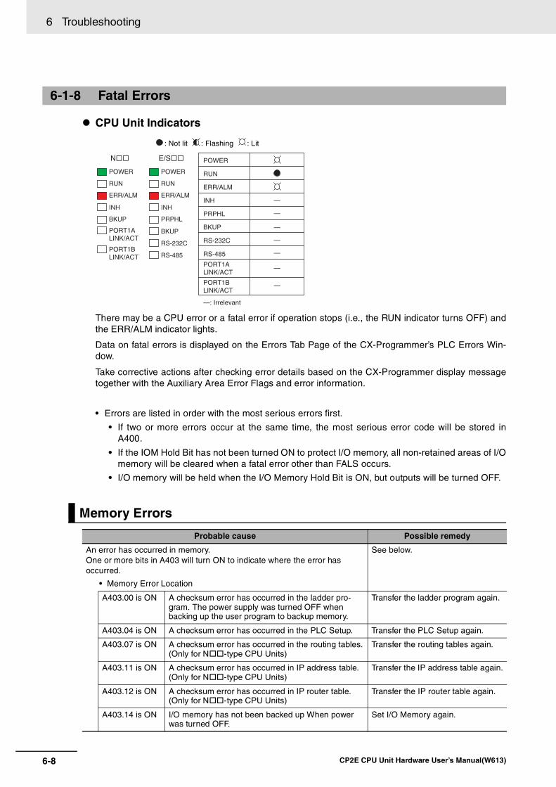
6 Troubleshooting
6-8 CP2E CPU Unit Hardware User’s Manual(W613)
CPU Unit Indicators
: Not lit : Flashing : Lit
There may be a CPU error or a fatal error if operation stops (i.e., the RUN indicator turns OFF) andthe ERR/ALM indicator lights.
Data on fatal errors is displayed on the Errors Tab Page of the CX-Programmer’s PLC Errors Win-dow.
Take corrective actions after checking error details based on the CX-Programmer display messagetogether with the Auxiliary Area Error Flags and error information.
• Errors are listed in order with the most serious errors first.
• If two or more errors occur at the same time, the most serious error code will be stored inA400.
• If the IOM Hold Bit has not been turned ON to protect I/O memory, all non-retained areas of I/Omemory will be cleared when a fatal error other than FALS occurs.
• I/O memory will be held when the I/O Memory Hold Bit is ON, but outputs will be turned OFF.
6-1-8 Fatal Errors
Memory Errors
Probable cause Possible remedy
An error has occurred in memory. One or more bits in A403 will turn ON to indicate where the error has occurred.
• Memory Error Location
See below.
A403.00 is ON A checksum error has occurred in the ladder pro-gram. The power supply was turned OFF when backing up the user program to backup memory.
Transfer the ladder program again.
A403.04 is ON A checksum error has occurred in the PLC Setup. Transfer the PLC Setup again.
A403.07 is ON A checksum error has occurred in the routing tables.(Only for N -type CPU Units)
Transfer the routing tables again.
A403.11 is ON A checksum error has occurred in IP address table.(Only for N -type CPU Units)
Transfer the IP address table again.
A403.12 is ON A checksum error has occurred in IP router table.(Only for N -type CPU Units)
Transfer the IP router table again.
A403.14 is ON I/O memory has not been backed up When power was turned OFF.
Set I/O Memory again.
POWER
RUN
ERR/ALM
INH
PRPHL
BKUP
RS-232C
RS-485
PORT1ALINK/ACT
PORT1BLINK/ACT
—: Irrelevant
—
—
—
—
—
—
—
POWER
PRPHL
RUN
ERR/ALM
INH
BKUP
RS-232C
RS-485
POWER
BKUP
RUN
ERR/ALM
INH
PORT1ALINK/ACT
PORT1BLINK/ACT
N�� E/S��

6-9
6 Troubleshooting
CP2E CPU Unit Hardware User’s Manual(W613)
6-1 Trou
blesh
oo
ting
CP
U U
nit E
rrors
6
6-1-8 Fatal Errors
Reference Information
Precautions for Correct UsePrecautions for Correct Use
As a memory error cannot be backed up in time due to Power OFF, it will be detected at the nextPower ON. If the power supply is turned OFF after the memory error occurs, the program willexecute with damaged memory data.
For applications that need to maintain DM, HR, CNT and other data during Power OFF, it is nec-essary to prevent the device from being powered on next time by inserting a ladder program (forexample, using the I/O Memory Backup Error Flag to turn ON the Load Cutoff Flag).
If the ladder program is running without I/O memory, the device may malfunction.
A583.00 I/O Memory Backup Error Flag
The flag will be ON when the I/O memory is not held at power ON.
It will still be ON until the memory area is cleared or the flag is turned OFF manually.
An I/O bus error has occurred in data transfer between the CPU Units and Units connected to the I/Obus.
Cycle the power supply. If operation is not restored when the power supply has been cycled, turn OFFthe power supply and check that connections are proper and that there is no damage.
Reference Information
Error flag Memory Error Flag, A401.15
Error code (A400) 80F1
Error information Memory Error Location, A403
I/O Bus Error
Probable cause Possible remedy
An error occurred in data transfer between the CPU Unit and an Expansion Unit or Expansion I/O Unit.
(A value of 0A0A hex will be stored in A404.)
• Cycle the power supply.
• If the problem persists, turn OFF the power supply and check the Connecting Cables between the Units to see if they are connected properly.
• Check the Unit connections to be sure they are ok (e.g., that there is no damage).
• After correcting the problem, turn ON the power to the Units again.
Error flag I/O Bus Error Flag, A401.14
Error code (A400) 80CA
Error information I/O Bus Error Details, A404
A500.15(Output OFF Bit)A583.00

6 Troubleshooting
6-10 CP2E CPU Unit Hardware User’s Manual(W613)
The number of CP-series Expansion Units and Expansion I/O Units connected exceeds the restrictionfor the number of Units or words for the system configuration.
Turn OFF the power supply and reconfigure the system within the restrictions.
Reference Information
A program error indicates a problem with the user program. Refer to the error information, check theprogram, and correct the mistakes.
Clear the error once the problem has been corrected.
Too Many I/O Points Error
Probable cause Possible remedy
The number of CP-series Expansion Units and Expansion I/O Units exceeds the restriction.
(A value of 4000 hex will be stored in A407.)
Connect a maximum of three Expansion Units or Expan-sion I/O Units to CPU Units with 30,40 or 60 I/O points.
Error flag Too Many I/O Points Flag, A401.11
Error code (A400) 80E1
Error information Too Many I/O Points Details, A407
Program Errors
Probable cause Possible remedy
Instruction Processing Error (A295.08 turns ON)
The instruction could not be executed because of incorrect operand data, and the ER Flag was turned ON. (Only when the Stop CPU on Instruction Error parameter in the PLC Setup is set to Stop.)
• Refer to A298 and A299 (instruction program address when the program fails), check the specifications for the relevant instruction, and set the correct operand data.
• Set the PLC Setup to not stop operation for an instruc-tion error.
Indirect DM Addressing BCD Error (A295.09 turns ON)
The operand of indirect DM Area addressing in BCD Mode did not contain a BCD value when the instruc-tion was executed, and the AER Flag was turned ON. (Only when the Stop CPU on Instruction Error parameter in the PLC Setup is set to Stop.)
• Refer to A298 and A299 (instruction program address when the program fails), and correctly set the content for the indirectly addressed DM operand (BCD mode) to BCD or change the specified destination. Alterna-tively, change the indirect addressing to binary mode.
• Set the PLC Setup to not stop operation for an instruc-tion error.
Illegal Area Access Error (A295.10 turns ON)
The AER flag is ON because an illegal area was specified for access when executing the instruction. (Only when the Stop CPU on Instruction Error parameter in the PLC Setup is set to Stop.)
The following operations are considered illegal access:
• Reading/writing the parameter area
• Writing to an area without memory installed
• Writing to a write-protected area
• Indirect DM addressing BCD error
• Refer to A298 and A299 (instruction program address when the program fails) and take corrective actions so that illegal area access errors will not occur.
• Set the PLC Setup to not stop operation for an instruc-tion error.
No END Error (A295.11 turns ON)
This error occurs when there is not an END instruc-tion in the program.
Insert an END instruction at the end of the program allo-cated to the task stored in A294 (task number when the program fails).

6-11
6 Troubleshooting
CP2E CPU Unit Hardware User’s Manual(W613)
6-1 Trou
blesh
oo
ting
CP
U U
nit E
rrors
6
6-1-8 Fatal Errors
Reference Information
Task Error (A295.12 turns ON)
There is no specified interrupt task when an interrupt is generated (input interrupt, high-speed counter interrupt or scheduled interrupt.)
Create a task for the number stored in A294 (task number when the program fails).
Differentiation Overflow Error(A295.13 turns ON)
Differentiation instructions were repeatedly inserted or deleted using the online editor and the system restriction was exceeded.
Change the operating mode to PROGRAM mode and then return to MONITOR mode.
Illegal Instruction Errors (A295.14 turns ON)
Execution of an unexecutable instruction was attempted.
Transfer the program again using the CX-Programmer.
UM Overflow Error (A295.15 turns ON)
An attempt was made to execute a program that exceeds the user program capacity.
Transfer the program again using the CX-Programmer.
Error flag Program Error Flag, A401.09
Error code (A400) 80F0
Error information Program Error Details, A294 to A299
Probable cause Possible remedy

6 Troubleshooting
6-12 CP2E CPU Unit Hardware User’s Manual(W613)
Note Clicking Ctrl+G in the tasks and function blocks of the CX-Programmer, it is possible to search the instruc-tions of the corresponding addresses.
Error information Contents
Task Number When Program Stopped
A294
This word contains the task number of the task that was being executed when program execution was stopped because of a program error.
Cyclic tasks: 0000 hex
Interrupt tasks: 8000 to 800F hex (task 0 to 15)
Program Stop Error Identification Information
A297
This word contains FFFF hex when the stop position is in the program except the function block.
This word contains the data other than FFFF hex when the stop position is in the function block.
Program Address Where Program Stopped
A298 to A299
These words contain the program address of the instruction where pro-gram execution was stopped due to a program error.
Confirm the Program Error When A295.08 to A295.10 Turn ON
Program Error295.08 to A295.10 turn ON
Check the task number in A294
The program error occurs in the program of the task whose program address is stored in A298 or A299 and task number in A294 where program execution stopped.
The program error occurs in the function block which is used by the task number in A294.* If more than two FBs are used, it cannot be
specified which FB fails.
Check and correct the program (function block) whose address is stored in A298 or A299 where program execution stopped.* Confirm all the FB instructions used by the
corresponding task number.
Correct the corresponding instruction.
Check A297Except FFFF hex
FFFF hex

6-13
6 Troubleshooting
CP2E CPU Unit Hardware User’s Manual(W613)
6-1 Trou
blesh
oo
ting
CP
U U
nit E
rrors
6
6-1-8 Fatal Errors
Reference Information
Reference Information
Reference Information
Cycle Time Exceeded Error
Probable cause Possible remedy
This error occurs when the cycle time PV exceeds the maximum cycle time set in the PLC Setup.
• Change the program to reduce the cycle time.
• Change the maximum cycle time setting.
• Refer to the Maximum Interrupt Task Processing Time (A440) and study the maximum cycle time.For example, use the JUMP instruction to skip sections that are not executed to shorten the cycle time.
• The cycle time exceeded error may occur during the following situa-tion in the use of high-speed counter. Please check the input signal of high-speed counter.
• The Z-signal is input at high-frequency.
• Change the direction of signal at high-frequency.
• Change the direction of target matching at high-frequency.
• The input interrupt (IN2 to IN9) signal is input at high-frequency.
Error flag Cycle Time Too Long Error, A401.08
Error code (A400) 809F
Error information −
Errors Created with FALS Instructions
Probable cause Possible remedy
FALS instruction executed (fatal error) in the program.
C100 hex will be added to the FALS number (001 to 1FF hex) and the result will be stored in A400 as the error code (C100 to C2FF hex).
Check the conditions for executing FALS instructions and remove any causes for the user-defined error.
Error flag FALS Error Flag, A401.06
Error code (A400) C101 to C2FF
Error information −
Built-in Ethernet Stop Error (Only for N -type CPU Units)
Probable cause Possible remedy
ON when the built-in Ethernet stops working because of sum value of MAC address error or controller error.
Cycle the power supply. The Unit may be faulty. Consult your OMRON representative.
Error flag Built-in Ethernet Stop Error, A401.04
Error code (A400) 80F6
Error information −

6 Troubleshooting
6-14 CP2E CPU Unit Hardware User’s Manual(W613)
CPU Unit Indicators
: Not lit : Flashing : Lit
A CPU error or fatal error may have occurred if the ERR/ALM indicator lights during operation (RUNmode or MONITOR mode), the RUN indicator turns OFF, and operation stops.
Reference Information
Note Just as when a CPU error occurs, the RUN indicator will turn OFF and the ERR/ALM indicator willlight when a fatal error occurs. Connecting the CX-Programmer, however, is possible for fatalerrors but not for CPU errors.
If the CX-Programmer cannot be connected (online), a CPU error has probably occurred.
6-1-9 CPU Errors
CPU Unit Errors
Probable cause Possible remedy
A WDT (watchdog) error occurred in the CPU Unit.
(This does not occur in normal use.)
Cycle the power supply.
The Unit may be faulty. Consult your OMRON representative.
Error flag −
Error code (A400) −
Error information −
POWER
PRPHL
RUN
ERR/ALM
INH
BKUP
RS-232C
RS-485
POWER
BKUP
RUN
ERR/ALM
INH
PORT1ALINK/ACT
PORT1BLINK/ACT
N�� E/S�� POWER
RUN
ERR/ALM
INH
PRPHL
BKUP
RS-232C
RS-485
PORT1ALINK/ACT
PORT1BLINK/ACT
—: Irrelevant
—
—
—
—
—
—
—

6-15
6 Troubleshooting
CP2E CPU Unit Hardware User’s Manual(W613)
6-1 Trou
blesh
oo
ting
CP
U U
nit E
rrors
6
6-1-10 Non-fatal E
rrors
A non-fatal error has occurred if both the RUN indicator is lit and the ERR/ALM indicator is flashingduring operation (i.e., in RUN or MONITOR mode).
CPU Unit Indicators
: Not lit : Flashing : Lit
Information on the non-fatal errors can be obtained from the Errors Tab Page of the CX-Program-mer’s PLC Errors Window.
Take corrective actions after checking error details using the display messages and the AuxiliaryArea Error Flags and error information.
• Errors are listed in order with the most serious errors first.
• If two or more errors occur at the same time, the most serious error code will be stored in A400.
Reference Information
6-1-10 Non-fatal Errors
Errors Created with FAL Instructions
Probable cause Possible remedy
A FAL instruction was executed in the program to create a non-fatal error.(The executed FAL number 001 to 511 will be stored in A360 to A391. The number 4 will be added to the front of 101 to 2FF (which correspond to executed FAL numbers 001 to 511) and the result will be stored in A400 as error code 4101 to 42FF. )
Check the conditions for executing FAL instructions and remove any causes of the user-defined error.
Error flag FAL Error Flag, A402.15
Error code (A400) 4101 to 42FF
Error information −
Backup Memory Error
Probable cause Possible remedyWriting to the backup memory fails. (A315.15 will turn ON. )
The Flash Memory in which the user data is backed up has failed.The users data may be lost when the power supply is turned OFF.Save the user data (program, parameter and backup DM) before the power supply is turned OFF and then replace the CPU Unit.
POWER
PRPHL
RUN
ERR/ALM
INH
BKUP
RS-232C
RS-485
POWER
BKUP
RUN
ERR/ALM
INH
PORT1ALINK/ACT
PORT1BLINK/ACT
N�� E/S�� POWER
RUN
ERR/ALM
INH
PRPHL
BKUP
RS-232C
RS-485
PORT1ALINK/ACT
PORT1BLINK/ACT
—: Irrelevant
—
—
—
—
—
—
—

6 Troubleshooting
6-16 CP2E CPU Unit Hardware User’s Manual(W613)
Reference Information
Reference Information
Reference Information
Reference Information
Error flag Backup Memory Error Flag, A315.15
Error code (A400) 00F1
Error information −
PLC Setup Errors
Probable cause Possible remedy
A set value error occurred in the PLC Setup. Correct the PLC Setup with correct values.
Error flag PLC Setup Error Flag, A402.10
Error code (A400) 009B
Error information −
Option Board Errors (Only for N -type CPU Units)
Probable cause Possible remedy
The Option Board is removed while the power is being supplied. (A315.13 will turn ON.)
Turn OFF the power supply and then install the Option Board again.
The Option Board is not supported by the CPU Unit.(A315.13 will turn ON.)
Turn OFF the power supply and then remove the Option Board.
The CP1W-CIF41 or CP1W-DAM01 cannot be used on CP2E CPU Unit.
Two Analog Option Boards are mounted.(A315.13 will turn ON.)
Install one Aralog Option Board.
Error flag Option Board Error Flag, A315.13
Other Non-fatal Error Flag, A402.00
Error code (A400)00D1: Option slot 1
00D2: Option slot 2
Error information −
Battery Errors (Only for N/S -type CPU Units)
Probable cause Possible remedy
If the PLC Setup is set to detect battery errors, this error will occur when there is an error in the battery in the CPU Unit (i.e., the voltage is low or a battery is not mounted).
Check the battery connections.
Select the Do not detect battery error Check Box in the PLC Setup setting if battery-free operation is being used.
Error flag Battery Error Flag, A402.04
Error code (A400) 00F7
Error information −

6-17
6 Troubleshooting
CP2E CPU Unit Hardware User’s Manual(W613)
6-1 Trou
blesh
oo
ting
CP
U U
nit E
rrors
6
6-1-10 Non-fatal E
rrors
Reference Information
Ethernet Setting Table Error (Only for N -type CPU Units)
Probable cause Possible remedy
An error occurs in routing table. Set the routing table again by the CX-Integrator.
An error occurs in IP address table or IP router table.
Confirm the IP Router Table on the Built-in Ethernet Tab in the PLC Setup or the IP Address Table in the FINS/UDP Setup, and then transfer again.
Error flag Setting Table Logic Error Flag, A315.11
Other Non-fatal Flag, A402.00
Error code (A400) 021A
Error information (A313) Error in IP address tables or IP router tables 0003
Error in Ethernet address tables 0004
FINS/TCP Connection Setup Error, Ethernet Server Setup Error, Ethernet Server Connection Error (Only for N -type CPU Units)
Probable cause Possible remedy
A Built-in Ethernet error has occurred. A315.10 will turn ON to indicate where the error has occurred. See below for details.
• Error Information
See below.
A315.10 is ON
Error code (A400): 03C0
FINS/TCP Connection Setup Error
When there is an error in TCP connec-tion setup including FINS/TCP con-nection setup, the error occurs.
Confirm the FINS/TCP Setting on the Built-in Ethernet Tab in the PLC Setup and transfer again.
A315.10 is ON
Error code (A400): 03C1
Server Setup Error
When there is an error in server setup, including DNS server and SNTP server, the error occurs.
Confirm the DNS and Clock Auto Adjustment Settings on the Built-in Ethernet Tab in the PLC Setup and transfer again.
A315.10 is ON
Error code (A400): 03C4
Server Connection Error
When there is an error in connecting with server, including DNS server and SNTP server, the error occurs.
Click the DNS Setting and the Clock Auto Adjustment on the Built-in Ethernet Tab in the PLC Setup and confirm the DNS and SNTP Server Settings.

6 Troubleshooting
6-18 CP2E CPU Unit Hardware User’s Manual(W613)
Reference Information
Error flag Built-in Ethernet Error Flag, A315.10
Other Non-fatal Flag, A402.00
Error code (A400) 03C0: FINS/TCP connection setup error
03C1: Ethernet server setup error
03C4: Ethernet server connection error
Error information (A313)
03C0 Leftmost byte: FINS/TCP connection number
01: FINS/TCP connection No.1
02: FINS/TCP connection No.2
03: FINS/TCP connection No.3
Rightmost byte: Error causes
01: Automatic allocation of FINS node address error
02: Target IP address error
03: Target FINS/TCP Port No. error
03C1 Leftmost byte: Server type
00: DNS server
01: SNTP server
Rightmost byte: Error causes
01: IP address setting error
02: Host name error
03: Port No. error
04: Other setting error
03C4 Leftmost byte: Server type
00: DNS server
01: SNTP server
Rightmost byte: Error causes
01: Specified host does not existed
02: No service at specified host
03: Time out error
04: Closed unilaterally by host error
05: Cannot connect because account information does not match
06: Host name resolution error
07: Transmission error
08: Reception error

6-19
6 Troubleshooting
CP2E CPU Unit Hardware User’s Manual(W613)
6-1 Trou
blesh
oo
ting
CP
U U
nit E
rrors
6
6-1-11 Other E
rrors
CPU Unit Indicators
: Not lit : Flashing : Lit
6-1-11 Other Errors
Communications Errors
Probable cause Possible remedy
An error has occurred in the communications between the Ethernet port and connected device.
• Check the cable wiring.
• Check the Ethernet cable and replace it if necessary.
An error has occurred in the communications between the peripheral USB port and connected device.
• Check the cable wiring.
• Check the USB cable and replace it if necessary.
An error has occurred in the communications between the serial port and connected device.
• Confirm that the Built-in RS-232C Port, Built-in RS-485 Port or Serial Port Tab settings in the PLC Setup are cor-rect.
• Check the cable wiring.
• If a host computer is connected, check the serial port settings and program in the host computer.
An error will be occurred if the cycle time is too long.
• Start the CX-Programmer. Select Change Model from the PLC Menu. The Change PLC Dialog Box will be dis-played.
• Click the Settings Button on the right side of Network Type. The Network Settings [USB] Dialog Box will be displayed.
• Click the Network Tab and increase the value in Response Timeout(s).
POWER
PRPHL
RUN
ERR/ALM
INH
BKUP
RS-232C
RS-485
POWER
BKUP
RUN
ERR/ALM
INH
PORT1ALINK/ACT
PORT1BLINK/ACT
N�� E/S�� POWER
RUN
ERR/ALM
INH
PRPHL
BKUP
RS-232C
RS-485
PORT1ALINK/ACT
PORT1BLINK/ACT
—: Irrelevant
—
—
—
—
—
—
—

6 Troubleshooting
6-20 CP2E CPU Unit Hardware User’s Manual(W613)
When Ethernet Communication Error occurs during FINS communication service by built-in Ether-net port, the error code, error contents and error’s time will be stored in A40 to A44.
The detail information of error code and error contents show as the following table.
Ethernet Communication Error
Error code (Hex)
Error contentDetailed information
1st byte 2nd byte
0105 Node address setting error (send failed) FINS CommandsBit 15: OFFBits 08 to 14: Source network addressBits 00 to 07: Source node addressFINS ResponsesBit 15: ONBits 08 to 14: Destination network addressBits 00 to 07: Destination node address
0107 Remote node not in network (send failed)
0108 No unit with specified unit address (send failed)
010D Destination address not in routing tables (send failed)
010E No routing table entry (send failed)
010F Routing table error (send failed)
0111 Command too long (send failed)
0112 Header error (send failed)
0117 Internal buffers full; packet discarded
0118 Illegal packet discarded
0119 Local node busy (send failed)
0120 Unexpected routing error
0121 No setting in IP address table; packet discarded
03C3 FINS/UDP packet discarded 01 to FE: Source node address
03C2 FINS/TCP packet discarded 01 to 03: Connection number
02: Reopened because remote node closed03: Reopened because of reception error04: Reopened because of transmission error05: Reopened because RST received from remote node06: Reopened because of no keep-alive response07: Illegal FINS/TCP pro-cedure08: Insufficient memory during server pro-cessing09: Insufficient memory during client process-ing0A: Insufficient memory during node switching
03C6 Clock data write error 0001: Clock data cannot be refreshed because of a CPU Unit error.0002: Clock data cannot be refreshed because the current CPU mode do not support opera-tion.

6-21
6 Troubleshooting
CP2E CPU Unit Hardware User’s Manual(W613)
6-2 Trou
blesh
oo
ting
Un
it Erro
rs
6
6-2-1 Inputs
6-2 Troubleshooting Unit Errors
This section describes how to troubleshoot errors that occur in devices other than the CP2E CPUUnit.
6-2-1 Inputs
No. Symptom Probable cause Possible remedy
1 Not all inputs turn ON or indicators are not lit.
1. External power is not supplied for the input.
Supply power.
2. Supply voltage is low. Adjust supply voltage to within rated range.
3. Terminal block screws are loose. Tighten screws.
2 Not all inputs turn ON even though the indicator is lit.
Input circuit is faulty. (There is a short at the load or something else that caused an overcurrent to flow.)
Replace Unit.
3 Not all inputs turn OFF. Input circuit is faulty. Replace Unit.
4 Specific input bit does not turn ON.
1. Input device is faulty. Replace input devices.
2. Input wiring disconnected. Check input wiring
3. Terminal block screws are loose. Tighten screws.
4. Too short ON time of external input. Adjust input device.
5. Input circuit is faulty. Replace Unit.
6. Input bit number is used for output instruction.
Correct the ladder program.
5 Specific input bit does not turn OFF.
1. Input circuit is faulty. Replace Unit.
2. Input bit number is used for output instruction.
Correct the ladder program.
6 Input irregularly turns ON/OFF.
1. External input voltage is low or unsta-ble.
Adjust external input voltage to within rated range.
2. Malfunction due to noise. Take protective measures against noise, such as:
• Install surge suppressor.
• Install insulation transformer.
• Install shielded cables between the Input Unit and the loads.
3. Terminal block screws are loose. Tighten screws.
7 Error occurs in units of 8 points or 16 points, i.e., for the same common
1. Common terminal screws are loose. Tighten screws.
2. Faulty data bus Replace Unit.
3. Faulty CPU Replace CPU Unit.
8 Input indicator is not lit in normal operation.
Faulty indicator or indicator circuit. Replace Unit.

6 Troubleshooting
6-22 CP2E CPU Unit Hardware User’s Manual(W613)
6-2-2 Outputs
No. Symptom Probable cause Possible remedy
1 Not all outputs turn ON 1. Load is not supplied with power. Supply power.
2. Load voltage is low. Adjust voltage to within rated range.
3. Terminal block screws are loose. Tighten screws.
4. Unit failure caused by an overcurrent (possibly caused by a short at the load).
Replace Unit.
5. Faulty I/O bus connector contact. Replace Unit.
6. Faulty output circuit. Replace Unit.
7. If the INH indicator is lit, the Output OFF Bit (A500.15) is ON.
Turn A500.15 OFF.
2 Not all outputs turn OFF Output circuit is faulty. Replace Unit.
3 Output of a specific bit number does not turn ON and indicator is not lit
1. Output ON time is too short because of a mistake in programming.
Correct program to increase the time that the output is ON.
2. Bit status controlled by multiple instruc-tions in a ladder program.
Correct program so that each output bit is controlled by only one instruction.
3. Faulty output circuit. Replace Unit.
4 Output of a specific bit number does not turn ON (indicator lit).
1. Faulty output device. Replace output device.
2. Break in output wiring. Check output wiring.
3. Loose terminal block screws. Tighten screws.
4. Faulty output bit (relay output only). Replace Unit.
5. Faulty output circuit. Replace Unit.
5 Output of a specific bit number does not turn OFF (indicator is not lit).
1. Faulty output bit (relay output only). Replace Unit.
2. Bit does not turn OFF due to leakage current or residual voltage.
Replace external load or add dummy resistor.
6 Output of a specific bit number does not turn OFF (indicator lit).
1. Bit status controlled by multiple instruc-tions in ladder program.
Correct the ladder program.
2. Faulty output circuit. Replace Unit.
7 Output irregularly turns ON/OFF.
1. Low or unstable load voltage. Adjust load voltage to within rated range.
2. Bit status controlled by multiple instruc-tions in ladder program.
Correct program so that each output bit is controlled by only one instruction.
3. Malfunction due to noise. Take protective measures against noise, such as:
• Install surge protector.
• Install insulation transformer.
• Use shielded cables between the output terminal and the load.
4. Terminal block screws are loose. Tighten screws.
8 Error occurs in units of 8 points or 16 points, i.e., for the same common.
1. Common terminal screws are loose. Tighten screws.
2. An overcurrent (possibly caused by a short at the load) resulted in a blown fuse for the output.
Replace Unit.
3. Faulty data bus Replace Unit.
4. Faulty CPU Replace CPU Unit.
9 Output indicator does not light during normal opera-tion.
Faulty indicator. Replace Unit.

6-23
6 Troubleshooting
CP2E CPU Unit Hardware User’s Manual(W613)
6-2 Trou
blesh
oo
ting
Un
it Erro
rs
6
6-2-3 CX
-Program
mer C
onnection
Use the following procedure if the CX-Programmer cannot connect to the PLC.
If the cycle time is too long, it may result the communication failure when CX-Programmer tries to workonline. In this case, click the Settings button on the right side of Network Type in the Change PLC dia-log box and increase the value in Response Timeout(s).
6-2-3 CX-Programmer Connection
Connecting via the Peripheral USB Port
Yes
Yes
No
No
YesNo
No Yes
The CX-Programmer cannot connect.
Is the USB cable securely connected?
Is the CX-Programmer network type set to USB?
Replace the USB cable.
Insert the cable all the way in at both the personal computer and at the CPU Unit.
Set the CX-Programmer network type to USB.
Can the CX-Programmer be connected online?
Can the CX-Programmer be connected online?
End

6 Troubleshooting
6-24 CP2E CPU Unit Hardware User’s Manual(W613)
Connecting via the Ethernet Port
The CX-Programmer cannot connect.
Is the Ethernet cable securely connected?
At the personal computer (or the Ethernet switch) and the CPU Unit, firmly insert the cable until the connector locks. Confirm that the LINK/ACT indicator lights at the personal computer (or Ethernet switch).
Use the PING command from the personal computer to confirm that the communications to the PLC have been established. For details, refer to 15-4-4 Communications Test in the CP2E CPU Unit Software User’s Manual(Cat. No. W614).
Can the CX-Programmer be connected online?
Are unique IP addresses used for the personal computer and the CPU Unit, and are they set for the same
domain?
Set the IP address for the personal computer. Either use the default IP address for the CPU Unit or else connect the CX-Programmer and set another IP address.
Use the PING command from the personal computer to confirm that the communications to the PLC has been established. For details, refer to 15-4-4 Communications Test in the CP2E CPU Unit Software User’s Manual(Cat. No. W614).
Can the CX-Programmer be connected online?
Is the CX-Programmer
network type set to Ethernet?
Set the CX-Programmer network type to Ethernet.
Can the CX-Programmer be connected online?
Replace the Ethernet cable and the Ethernet switch.
No
Yes
End Yes
Yes
Yes
No
No
No
No Yes
No
Yes

7-1
7
CP2E CPU Unit Hardware User’s Manual(W613)
7
This section describes periodic inspections, the service life of the Battery, and how toreplace the Battery.
7-1 Periodic Maintenance and Inspection . . . . . . . . . . . . . . . . . . . . . . . . . . . . . 7-27-1-1 Tools Required for Inspections . . . . . . . . . . . . . . . . . . . . . . . . . . . . . . . . . . . . 7-2
7-1-2 Periodic Inspection . . . . . . . . . . . . . . . . . . . . . . . . . . . . . . . . . . . . . . . . . . . . . 7-2
7-1-3 Inspection and Maintenance . . . . . . . . . . . . . . . . . . . . . . . . . . . . . . . . . . . . . . 7-3
7-1-4 Unit Replacement Precautions . . . . . . . . . . . . . . . . . . . . . . . . . . . . . . . . . . . . 7-4
7-2 Replacing the Battery in N/S -type CPU Units. . . . . . . . . . . . . . . . . . . . . 7-5
Maintenance and Inspection

7 Maintenance and Inspection
7-2 CP2E CPU Unit Hardware User’s Manual(W613)
7-1 Periodic Maintenance and Inspection
This section describes periodic inspections and maintenance of CP2E PLCs.
Daily or periodic inspections are required in order to maintain the PLC’s functions in peak operatingcondition.
Required Tools• Phillips screwdrivers
• Voltage tester or digital voltmeter
• Industrial alcohol and clean cotton cloth
Tools Required Occasionally• Synchroscope
• Oscilloscope with pen plotter
• Thermometer and hygrometer (humidity meter)
Although the major components in CP-series PLCs have an extremely long life time, they can deterio-rate under improper environmental conditions. Periodic inspections are thus required to ensure that therequired conditions are being kept.
Inspection is recommended at least once every six months to a year, but more frequent inspections willbe necessary in adverse environments.
Take immediate steps to correct the situation if any of the conditions in the following table are not met.
Battery
7-1-1 Tools Required for Inspections
7-1-2 Periodic Inspection
Item Life Remedy
Check whether the Battery has reached its service life (CP2W-BAT02 Battery).
Service life expectancy is 5 years at 25ºC, less at higher temperatures.
(From 1.5 to 5 years depending on model and ambient temperature.)
Replace the Battery when its service life has passed even if a Battery error has not occurred. The service life depends on the model and ambient temperature.
Refer to 7-2 Replacing the Battery in N/S -type CPU Units.

7-3
7 Maintenance and Inspection
CP2E CPU Unit Hardware User’s Manual(W613)
7-1 Perio
dic M
ainten
ance an
d In
spectio
n
7
7-1-3 Inspection and Maintenance
7-1-3 Inspection and Maintenance
No.Inspection
pointsInspection Criteria Remedy
1 Power sup-ply voltage
Check for voltage fluctuations at the power supply terminals.
Allowable voltage range AC power supply:85 to 264 VACDC power supply: 20.4 to 26.4 VDC
Use a voltage tester to check the power supply at the terminals. Take necessary steps to bring voltage fluc-tuations within limits.
2 I/O power supply
Check for voltage fluctuations at the I/O terminals.
Voltages must be within I/O specifica-tions for each Unit.
Use a voltage tester to check the power supply at the terminals. Take necessary steps to bring voltage fluc-tuations within limits.
3 Ambient environment
Check the ambient tempera-ture. (Inside the control panel if the PLC is in a control panel.)
-20 to 60°C Use a thermometer to check the tem-perature and make sure that the ambient temperature remains within the allowed range of -20 to 60ºC.
Check the ambient humidity (inside the control panel if the PLC is in a control panel).
Relative humidity must be 10% to 90% with no con-densation.
Use a hygrometer to check the opera-tion humidity and ensure that the ambient humidity remains between 10% and 90%.
Make sure that condensation does not occur due to rapid changes in temperature.
Check that the PLC is not in direct sunlight.
Not in direct sun-light
Protect the PLC if necessary.
Check for accumulation of dirt, dust, salt, metal filings, etc.
No significant accu-mulation
Clean and protect the PLC if neces-sary.
Check for water, oil, or chemi-cal spray.
No spray on the PLC
Clean and protect the PLC if neces-sary.
Check for corrosive or flam-mable gases in the area of the PLC.
No corrosive or flammable gases
Check by smell or use a sensor.
Check the level of vibration or shock.
Vibration and shock must be within specifications.
Install cushioning or shock absorbing equipment if necessary.
Check for noise sources near the PLC.
No significant noise sources
Either separate the PLC and noise source or protect the PLC.
Check that the PLC is not in direct UV.
Not in direct UV Protect the PLC if necessary.
4 Installation and wiring
Check that the Option Boards and cable connectors are fully inserted and locked.
No looseness Correct any improperly installed con-nectors.
Check for loose screws in external wiring.
No looseness Tighten loose screws with a Phillips screwdriver.
Check crimp connectors in external wiring.
Adequate spacing between connec-tors
Check visually and adjust if neces-sary.
Check for damaged external wiring cables.
No damage Check visually and replace cables if necessary.

7 Maintenance and Inspection
7-4 CP2E CPU Unit Hardware User’s Manual(W613)
Check the following when replacing any faulty Units discovered during inspections.
• Do not replace a Unit until the power is turned OFF.
• Check the new Unit to make sure that there are no errors.
• If a faulty Unit is being returned for repair, describe the problem in as much detail as possible,enclose this description with the Unit, and return the Unit to your OMRON representative.
• For poor contact, take a clean cotton cloth, soak the cloth in industrial alcohol, and carefully wipe thecontacts clean. Be sure to remove any lint prior to remounting the Unit.
Precautions for Correct Use
When replacing a CPU Unit, be sure that not only the user program but also all other datarequired for operation is transferred to or set in the new CPU Unit before starting operation,including DM Area and HR Area settings.
If data area and other data are not correct for the user program, unexpected accidents mayoccur.
7-1-4 Unit Replacement Precautions

7-5
7 Maintenance and Inspection
CP2E CPU Unit Hardware User’s Manual(W613)
7-2 Rep
lacing
the B
attery in N
/NA
(S)-typ
e CP
U U
nits
7
7-2 Replacing the Battery in N/S -type CPU Units
For CP2E N/S -type CPU Units, the clock will stop when the power is turned OFF.Mount the CP2W-BAT02 Battery (sold separately) to an N/S -type CPU Unit when using the clockfunction.
A Battery cannot be mounted to an E -type CPU Unit.
The procedure to replace the Battery on an N/S -type CPU Unit is given below.
At 25°C, the maximum service life for the Battery is five years whether or not power is supplied to theCPU Unit while the Battery is installed.
The Battery’s lifetime will be shorter when it is used at higher temperatures.
The following table shows the approximate minimum lifetimes and typical lifetimes for the backup Bat-tery (total time with power not supplied).
* The minimum lifetime is the memory backup time at an ambient temperature of 60°C.The typical lifetime is the memory backup time at an ambient temperature of 25°C.
Battery Service Life and Replacement Period
Model numberApprox. maximum
lifetimeApprox. minimum
lifetime*Typical lifetime*
CP2E-N D -CP2E-S D -
5 years 13,000 hours (1.5 years)
43,000 hours(5 years)
1 year
2 years
3 years
4 years
5 years
25°C 40°C 60°C
Memory Backup Time
Ambient temperature
* This graphic is for reference only.
CP2E N/S��-type CPU Unit

7 Maintenance and Inspection
7-6 CP2E CPU Unit Hardware User’s Manual(W613)
The ERR/ALM indicator on the front of the CPU Unit will flash when the Battery is nearly discharged.
When the ERR/ALM indicator flashes, connect the CX-Programmer and read the error messages.If a low Battery message appears on the CX-Programmer or the Battery Error Flag (A402.04) is ON,first check whether the Battery is properly connected to the CPU.If the Battery is properly connected, replace the Battery as soon as possible.
Once a low battery error has been detected, it will take 5 days (at an ambient temperature of 25°C)before the Battery fails assuming that power has been supplied at least once a day.You can prevent the clock from stopping by ensuring that the CPU Unit power is not turned OFF untilthe Battery is replaced.
Precautions for Correct Use
• The low battery message will appear on the CX-Programmer and the Battery Error Flag(A402.04) will turn ON only if the Detect Low Battery parameter in the PLC Setup has been setto detect a low-Battery error. If this setting has not been made, Battery errors will not be detected.
• The Battery will discharge faster at higher temperatures, e.g., 4 days at 40°C and 2 days at60°C.
Replacement BatteryName: Battery Unit
Model: CP2W-BAT02
Precautions for Correct Use
Be sure to install a replacement Battery within two years of the production date. shown on theBattery’s label.
How to read production date.
Low Battery Indications
Flashing
Production Date 1st character: the rightmost digit of year 2nd character: month (0: Oct., Y: Nov., Z:Dec.)For example, “8Z” indicates the Battery ismanufactured in December 2018.
CR2032
+
8Z

7-7
7 Maintenance and Inspection
CP2E CPU Unit Hardware User’s Manual(W613)
7-2 Rep
lacing
the B
attery in N
/NA
(S)-typ
e CP
U U
nits
7
Use the following procedure to replace the Battery when the previous Battery has become completelydischarged.
Precautions for Safe Use
We recommend replacing the Battery with the power OFF to prevent the CPU Unit’s sensitiveinternal components from being damaged by static electricity. The Battery can be replaced with-out turning OFF the power supply. To do so, always touch a grounded piece of metal to dischargestatic electricity from your body before starting the procedure.
After replacing the Battery, connect a Programming Device and clear the Battery error.
1 Turn OFF the power supply to the N/S -type CPU Unit.
If the CPU Unit has not been ON, turn it ON for at least 30 minutes and then turn it OFF.
Additional Information
There is a capacitor inside the N/S -type CPU Unit that keeps the clock working when theBattery is removed. If the power is not turned ON for at least 30 minutes before replacing theBattery, the capacitor will not be fully charged and the clock data may be reset to 2001-01-0101:01:01 before the new Battery is inserted.
2 Open the Battery holder on the CPU Unit and draw out the Battery. Put the new Battery into the
Battery holder and close it.
Replacing the Battery

7 Maintenance and Inspection
7-8 CP2E CPU Unit Hardware User’s Manual(W613)
Precautions for Safe Use
• You must complete this procedure within 5 minutes after turning OFF the power to the CPUUnit to ensure memory backup.If the Battery is removed for more than 5 minutes, the time will be reset to 2001-01-01 01:01:01.
• Never short-circuit the Battery terminals; never charge the Battery; never disassemble the Bat-tery; and never heat or incinerate the Battery. Doing any of these may cause the Battery toleak, heat, burn, or rupture, resulting in injury, fire, and possible loss of property.Also, never use a Battery that has been dropped on the floor or otherwise subject to shock. Itmay leak.UL standards require that batteries be replaced by experienced technicians. Always place anexperienced technician in charge of Battery replacement.
• Turn ON the power after replacing the Battery for a CPU Unit that has been unused for a longtime. Leaving the CPU Unit unused again without turning ON the power even once after the Batteryis replaced may result in a shorter Battery life.
Additional Information
The Battery error will be cleared automatically the next time the CPU Unit is turned ON afterreplacing the Battery.

8-1
8
CP2E CPU Unit Hardware User’s Manual(W613)
8
This section describes the Analog Input Unit, Analog Output Unit, Temperature SensorUnits, CompoBus/S I/O Link Unit, and Expansion I/O Units.
8-1 Analog Input Units . . . . . . . . . . . . . . . . . . . . . . . . . . . . . . . . . . . . . . . . . . . . . 8-28-1-1 Overview . . . . . . . . . . . . . . . . . . . . . . . . . . . . . . . . . . . . . . . . . . . . . . . . . . . . . 8-2
8-1-2 Part Names and Functions . . . . . . . . . . . . . . . . . . . . . . . . . . . . . . . . . . . . . . . 8-2
8-1-3 Specifications . . . . . . . . . . . . . . . . . . . . . . . . . . . . . . . . . . . . . . . . . . . . . . . . . . 8-3
8-1-4 Flow of Operation . . . . . . . . . . . . . . . . . . . . . . . . . . . . . . . . . . . . . . . . . . . . . . 8-7
8-2 Analog Output Units . . . . . . . . . . . . . . . . . . . . . . . . . . . . . . . . . . . . . . . . . . 8-158-2-1 Overview . . . . . . . . . . . . . . . . . . . . . . . . . . . . . . . . . . . . . . . . . . . . . . . . . . . . 8-15
8-2-2 Part Names and Functions . . . . . . . . . . . . . . . . . . . . . . . . . . . . . . . . . . . . . . 8-15
8-2-3 Specifications . . . . . . . . . . . . . . . . . . . . . . . . . . . . . . . . . . . . . . . . . . . . . . . . . 8-16
8-2-4 Flow of Operation . . . . . . . . . . . . . . . . . . . . . . . . . . . . . . . . . . . . . . . . . . . . . 8-20
8-3 Analog I/O Units . . . . . . . . . . . . . . . . . . . . . . . . . . . . . . . . . . . . . . . . . . . . . . 8-278-3-1 CP1W-MAD11 Analog I/O Units . . . . . . . . . . . . . . . . . . . . . . . . . . . . . . . . . . 8-27
8-3-2 CP1W-MAD42/CP1W-MAD44 Analog I/O Units . . . . . . . . . . . . . . . . . . . . . . 8-40
8-4 Temperature Sensor Units . . . . . . . . . . . . . . . . . . . . . . . . . . . . . . . . . . . . . 8-568-4-1 CP1W-TS 1/TS 2 Temperature Sensor Units . . . . . . . . . . . . . . . . . . . . . . . 8-56
8-4-2 CP1W-TS003 Temperature Sensor Units . . . . . . . . . . . . . . . . . . . . . . . . . . . 8-71
8-4-3 TS004 Temperature Sensor Units . . . . . . . . . . . . . . . . . . . . . . . . . . . . . . . . . 8-81
Using Expansion Units and Expansion I/O Units

8 Using Expansion Units and Expansion I/O Units
8-2 CP2E CPU Unit Hardware User’s Manual(W613)
8-1 Analog Input Units
Each CP1W-AD041/CP1W-AD042 Analog Input Unit provides four analog inputs.
• The analog input signal ranges are 0 to 5 V, 1 to 5 V, 0 to 10 V, -10 to +10 V, 0 to 20 mA, and 4 to 20 mA. The resolution of CP1W-AD041 is 1/6,000.The resolution of CP1W-AD042 is 1/12,000. The open-circuit detection function is activated in the ranges of 1 to 5 V and 4 to 20 mA.
• The Analog Input Unit uses four input words and two output words.
CP1W-AD041/CP1W-AD042
(1)Analog Input TerminalsConnected to analog output devices.
• Input Terminal Arrangement
Note When using current inputs, voltage input terminals must be short-circuited with current input terminals.
(2)Expansion I/O Connecting Cable Connected to the CPU Unit or Expansion Unit expansion connector. The cable is attached to theAnalog Input Unit and cannot be removed.
8-1-1 Overview
8-1-2 Part Names and Functions
V IN1 Voltage input 1
I IN1 Current input 1
COM1 Input common 1
V IN2 Voltage input 2
I IN2 Current input 2
COM2 Input common 2
V IN3 Voltage input 3
I IN3 Current input 3
COM3 Input common 3
V IN4 Voltage input 4
I IN4 Current input 4
COM4 Input common 4
CHI IN1 I IN3
I IN2VIN1VIN2
VIN3COM1COM2
I IN4VIN4 COM4
NCAG
COM3
IN
(3) Expansion connector
(2) Expansion I/O connecting cable (1) Analog input terminals
CHI IN1 I IN3
I IN2VIN1VIN2
VIN3COM1COM2
I IN4VIN4 COM4
NCAG
COM3
IN
I IN1 I IN3I IN2VIN1
VIN2VIN3COM1
COM2I IN4
VIN4 COM4NC
AGCOM3

8-3
8 Using Expansion Units and Expansion I/O Units
CP2E CPU Unit Hardware User’s Manual(W613)
8-1 An
alog
Inp
ut U
nits
8
8-1-3 Specifications
Precautions for Safe Use
Do not touch the cables during operation. Static electricity may cause operating errors.
(3)Expansion ConnectorConnected to the next Expansion Unit or Expansion I/O Unit to enable expansion.
CP1W-AD041/AD042 Analog Input Units are connected to a CP2E CPU Unit.
8-1-3 Specifications
Model CP1W-AD041 CP1W-AD042
Item Voltage input Current input Voltage input Current input
Number of analog inputs 4 inputs (4 words allocated)
Input signal range 0 to 5 V, 1 to 5 V,0 to 10 V, or -10 to 10 V
0 to 20 mA or 4 to 20 mA
0 to 5 VDC,1 to 5 VDC,0 to 10 VDC,or -10 to 10 VDC
0 to 20 mA or 4 to 20 mA
Max. rated input ±15 V ±30 mA ±15 V ±30 mA
External input impedance 1 MΩ min. Approx. 250 Ω 1 MΩ min. Approx. 250 Ω
Resolution 1/6000 (full scale) 1/12000 (full scale)
Overall accuracy
25°C 0.3% full scale 0.4% full scale 0.2% full scale 0.3% full scale
0 to 55°C 0.6% full scale 0.8% full scale 0.5% full scale 0.7% full scale
55 to 60°C 0.7% full scale 0.8% full scale 0.5% full scale 0.7% full scale
-20 to 0°C 0.8% full scale 1% full scale 0.7% full scale 0.9% full scale
A/D conversion data 16-bit binary (4-digit hexadecimal)
Full scale for -10 to 10 V: F448 to 0BB8 hex
Full scale for other ranges: 0000 to 1770 hex
16-bit binary (4-digit hexadecimal)
Full scale for -10 to 10 V: E890 to 1770 hex
Full scale for other ranges: 0000 to 2EE0 hex
Averaging function Supported (Set in output words n+1 and n+2.)
Open-circuit detection function Supported
Conversion time 2 ms/point (8 ms/all points) 1 ms/point (4 ms/all points)
Isolation method Photocoupler isolation between analog input terminals and internal circuits. No isolation between analog I/O signals.
Current consumption 5 VDC: 100 mA max.; 24 VDC: 90 mA max.
5 VDC: 100 mA max.; 24 VDC: 50 mA max.
IN
00
C H
C H
02 04 06 08 10
OUT
01C OM 03 05 07 09 11
C OM CO M C OM 03 CO M 0600 01 02 04 05 07
00 01 02 03 04 05 06 07
08 09 10 11
20EDR1
C H 00 01 02 03 04 05 06 07
N C
N CN C
C H E X P
IN
00 0201C OM 03
C OM 05 0704 06
C H 00 01 02 03
08 09 10 11
8ED
E X P CHI IN1 I IN3
I IN2VIN1VIN2
VIN3COM1COM2
I IN4VIN4 COM4
COM3
IN
NCAG
CP1W-20EDR1Expansion I/O Unit
CP2E CPU Unit CP1W-8EDExpansion I/O Unit
CP1W-AD041CP1W-AD042 Analog Input Unit
4 analog inputs

8 Using Expansion Units and Expansion I/O Units
8-4 CP2E CPU Unit Hardware User’s Manual(W613)
Analog Input Signal RangesAnalog input data is digitally converted according to the input signal range as shown below.
Additional Information
When the input exceeds the specified range, the A/D conversion data will be fixed at either thelower limit or upper limit.
-10 to 10 V Inputs When the resolution is 1/6,000, the -10 to 10 V range correspond to hexadecimal values F448 to 0BB8 (-3,000 to 3,000). The range of data that can be converted is F31C to 0CE4 hex (-3,300 to 3,300). A negative voltage is expressed as a two’s complement.
When the resolution is 1/12,000, the -10 to 10 V range correspond to hexadecimal values E890 to 1770 (-6,000 to 6,000). The entire data range is E638 to 19C8 hex (-6,600 to 6,600). A negative voltage is expressed as a two's complement.
0 to 10 V InputsWhen the resolution is 1/6,000, the 0 to 10 V range correspond to hexadecimal values 0000 to 1770 (0 to 6,000). The range of data that can be converted is FED4 to 189C hex (-300 to 6,300). A negative voltage is expressed as a two’s complement.
0 V 10 V 11 V
−11 V −10 V
Converted dataHexadecimal (Decimal)
0CE4 (3300)0BB8 (3000)
0000 (0)
F448 (−3000)F31C (−3300)
0V 10V 11V
−11V −10V
E890 (−6000)
E638 (−6600)
19C8 (6600)
1770 (6000)
0000 (0)
Converted DataHexadecimal (Decimal)
0 V 10 V 10.5 V
−0.5 V
Converted dataHexadecimal (Decimal)
189C (6300)1770 (6000)
0000 (0)
FED4 (−300)

8-5
8 Using Expansion Units and Expansion I/O Units
CP2E CPU Unit Hardware User’s Manual(W613)
8-1 An
alog
Inp
ut U
nits
8
8-1-3 Specifications
When the resolution is 1/12,000, the 0 to 10 V range correspond to hexadecimal values 0000 to 2EE0 (0 to 12,000). The entire data range is FDA8 to 3138 hex (-600 to 12,600). A negative voltage is expressed as a two's complement.
0 to 5 V InputsWhen the resolution is 1/6,000, the 0 to 5 V range correspond to hexadecimal values 0000 to 1770 (0 to 6,000). The range of data that can be converted is FED4 to 189C hex (-300 to 6,300). A negative voltage is expressed as a two’s complement.
When the resolution is 1/12,000, the 0 to 5 V range correspond to hexadecimal values 0000 to 2EE0 (0 to 12,000). The entire data range is FDA8 to 3138 hex (-600 to 12,600). A negative voltage is expressed as a two’s complement.
1 to 5 V InputsWhen the resolution is 1/6,000, the 1 to 5 V range correspond to hexadecimal values 0000 to 1770 (0 to 6,000). The range of data that can be converted is FED4 to 189C hex (-300 to 6,300).Voltage in the range of 0.8 to 1 V is expressed as a two’s comple-ment.
If an input is below the range (i.e., less than 0.8 V), the open-circuit detection function is activated and the data becomes 8,000.
When the resolution is 1/12,000, the 1 to 5 V range correspond to hexadecimal values 0000 to 2EE0 (0 to 12,000). The entire data range is FDA8 to 3138 hex (-600 to 12,600). Voltage in the range of 0.8 to 1 V is expressed as two's complement.
If an input is below the range (i.e., less than 0.8 V), the open-circuit detection function is activated and the data becomes 8,000.
0 V 10 V 10.5 V
−0.5 V
FDA8 (−600)
3138 (12600)
2EE0 (12000)
0000 (0)
Converted DataHexadecimal (Decimal)
0 V 5 V 5.25 V
−0.25V
Converted dataHexadecimal (Decimal)
189C (6300)1770 (6000)
0000 (0)
FED4 (−300)
0 V 5 V 5.25 V
−0.25 V
FDA8 (−600)
3138 (12600)
2EE0 (12000)
0000 (0)
Converted DataHexadecimal (Decimal)
1 V 5 V 5.2 V
0.8 V
Converted dataHexadecimal (Decimal)
189C (6300)1770 (6000)
0000 (0)
FED4 (−300)
1 V 5 V 5.2 V
0.8 V
FDA8 (−600)
3138 (12600)2EE0 (12000)
0000 (0)
Converted DataHexadecimal (Decimal)

8 Using Expansion Units and Expansion I/O Units
8-6 CP2E CPU Unit Hardware User’s Manual(W613)
Averaging Function For analog inputs, the averaging function operates when the averaging bit is set to 1. The averagingfunction outputs the average (a moving average) of the last eight input values as the converted value.
Use this function to smooth inputs that vary at a short interval.
Open-circuit Detection The open-circuit detection function is activated when the input range is set to 1 to 5 V and the volt-age drops below 0.8 V, or when the input range is set to 4 to 20 mA and the current drops below 3.2 mA.
When the open-circuit detection function is activated, the converted data will be set to 8,000.
The time for enabling or clearing the open-circuit detection function is the same as the time for con-verting the data. If the input returns to the convertible range, the open-circuit detection is clearedautomatically and the output returns to the normal range.
0 to 20 mA InputsWhen the resolution is 1/6,000, the 0 to 20 mA range correspond to hexadecimal values 0000 to 1770 (0 to 6,000). The range of data that can be converted is FED4 to 189C hex (-300 to 6,300). A negative current is expressed as a two’s comple-ment.
When the resolution is 1/12,000, the 0 to 20 mA range correspond to hexadecimal values 0000 to 2EE0 (0 to 12,000). The entire data range is FDA8 to 3138 hex (-600 to 12,600). A negative voltage is expressed as a two’s complement.
4 to 20 mA InputsWhen the resolution is 1/6,000, the 4 to 20 mA range correspond to hexadecimal values 0000 to 1770 (0 to 6,000). The range of data that can be con-verted is FED4 to 189C hex (-300 to 6,300). Current in the range of 3.2 to 4 mA is expressed as a two’s complement.
If an input is below the range (i.e., less than 3.2 mA), the open-circuit detection function is activated and the data becomes 8,000.
When the resolution is 1/12,000, the 4 to 20mA range correspond to hexadecimal values 0000 to 2EE0 (0 to 12,000). The entire data range is FDA8 to 3138 hex (-600 to 12,600). Current in the range of 3.2 to 4 mA is expressed as two's complement.
If an input is below the range (i.e., less than 3.2 mA), the open-circuit detection function is activated and the data becomes 8,000.
0 mA 20 mA 21 mA
−1 mA
Converted dataHexadecimal (Decimal)
189C (6300)1770 (6000)
0000 (0)
FED4 (−300)
0 mA 20 mA 21 mA
−1 mA
FDA8 (−600)
3138 (12600)
2EE0 (12000)
0000 (0)
Converted DataHexadecimal (Decimal)
Converted dataHexadecimal (Decimal)
189C (6300)1770 (6000)
0000 (0)
FED4 (−300)
4 mA 20 mA 20.8 mA
3.2 mA0 mA
4 mA 20 mA 20.8 mA
3.2 mA
FDA8 (−600)
3138 (12600)
2EE0 (12000)
0000 (0)
0 mA
Converted DataHexadecimal (Decimal)

8-7
8 Using Expansion Units and Expansion I/O Units
CP2E CPU Unit Hardware User’s Manual(W613)
8-1 An
alog
Inp
ut U
nits
8
8-1-4 Flow
of Operation
Writing Set Data and Reading A/D Converted Values
1 Connect the Analog Input Unit to the CPU Unit.
8-1-4 Flow of Operation
1 • Connect Analog Input Units.
• Wire to analog output devices.
2 • Write set data to output words (n+1, n+2).
• Set use of inputs.
• Select input signals using range codes.
• Set use of averaging.
• Read A/D converted values from input words (m+1 to m+4).
• For current inputs, confirm that there is no open circuit.
Connect and wire Units.
Create a ladder program.
• Temperature sensor• Pressure sensor• Speed sensor• Flow sensor• Voltage/current meter• Other devices
CPU Unit
MOV
Set data (inputs 1, 2)
Set data (inputs 3, 4)
Analog input 3 converted value
Analog input 4 converted value
Analog Input Unit
Ladder program
Analog input 1 converted value
Analog input 2 converted valueAnalog devices
Writes the set data. Reads the converted value.
“m” is the last input word and “n” is the last output word allocated to the CPU Unit or previous Expansion Unit or Expansion I/O Unit.
Word (n+1)
Word (n+2)
Word (m+1)
Word (m+2)
Word (m+3)
Word (m+4)
CHIIN1 IIN3
IIN2VIN1VIN2
VIN3COM1COM2
IIN4VIN4 COM4
COM3
IN
NCAG
CP1W-AD041/AD042Analog Input Unit
CP2E CPU Unit

8 Using Expansion Units and Expansion I/O Units
8-8 CP2E CPU Unit Hardware User’s Manual(W613)
2 Wire to analog output devices.
(1) Wiring internal circuits of the CPU Unit
(2) Wiring analog output devices to the Analog Input Unit
Precautions for Correct UsePrecautions for Correct Use
• Do not connect the shield when using shielded twisted-pair cables.
• When an input is not being used, short V IN and I IN to COM terminals.
• Separate wiring from power lines (AC power supply lines, high-voltage lines, etc.)
• When there is noise in the power supply line, install a noise filter on the input section and thepower supply.
AG
Analog input 4
Analog ground COM1(−)
I IN1
V IN1
COM4(−)
I IN4
V IN4
510 kΩ
510 kΩ
510 kΩ
510 kΩ
250 Ω
250 ΩInte
rnal
circ
uits
Analog input 1
toto
V IN
COM
I IN
V IN
COM
I INAnalog device with voltage output
Analog Input Unit
+
−
+
−
Analog device with current output
Analog Input Unit
2-core shieldedtwisted-pair cable
2-core shieldedtwisted-pair cable
FG FG

8-9
8 Using Expansion Units and Expansion I/O Units
CP2E CPU Unit Hardware User’s Manual(W613)
8-1 An
alog
Inp
ut U
nits
8
8-1-4 Flow
of Operation
Additional Information
Refer to the following information on open circuits when using voltage inputs.
For example, if connected device 2 is outputting 5 V and the same power supply is being used for bothdevices as shown above, approximately 1/3, or 1.6 V, will be applied to the input for input device 1.
If a wiring disconnection occurs when voltage input is being used, the situation described below willresult. Either separate the power supplies for the connected devices, or use an isolator for eachinput.
• If the same power supply is being used by the connected devices and a disconnection occurs atpoints A or B in the above diagram, an unwanted circuit path will occur as shown along the dottedline in the diagram. If that occurs, a voltage of approximately 1/3 to 1/2 of the output voltage of theother connected device will be generated.
• If that voltage is generated while the setting is for 1 to 5 V, open-circuit detection may not be pos-sible.
• If a disconnection occurs at point C in the diagram, the negative (-) side will be used for bothdevices and open-circuit detection will not be possible.
This problem will not occur for current inputs even if the same power supply is used.
A
CB
Analog output device 1
Analog output device 2
24 VDC

8 Using Expansion Units and Expansion I/O Units
8-10 CP2E CPU Unit Hardware User’s Manual(W613)
3 Create the ladder program.
(1) Allocating I/O Words
Four input words and two output words are allocated from the next words following the lastI/O words allocated to the CPU Unit or an existing Expansion Unit or Expansion I/O Unit.
(2) Writing Set Data
Write the settings for input use, averaging use, and range codes for words n+1 and n+2.When the set data is transferred from the CPU Unit to the Analog Input Unit, the A/D con-version will be started.
• Set Data
• The Analog Input Unit will not start converting analog input values until the set data hasbeen written. The conversion data will be 0000 until the range code is written.
• Once the settings have been made, it is not possible to be changed while power is beingsupplied to the CPU Unit. To change the range code or other settings, turn the CPU UnitOFF then ON again.
(3) Averaging
Set whether averaging is to be used for set data. When the averaging bit is set to 1, theaverage (moving average) for the past eight inputs is output as conversion data.
Words (m+1) to (m+4)
Analog Input Unit
Words (n+1), (n+2)
15 0
1 0 0 0 0 0 0
8 7 6 5 4 3 2 1
15 0
1 0 0 0 0 0 0
8 7 6 5 4 3 2 1
0
0
Wd (n+1)
Wd (n+2)
Analog input 1Analog input 2
Analog input 3Analog input 4
Even if analog inputs are not used, bits 15 in words n+1 and n+2 must be set to 1.
Even if analog inputs are not used, bits 15 in words n+1 and n+2 must be set to 1.
Averaging01
NoYes
Input use0 No1 Yes
Range code Analog input range−10 to 10 V0 to 10 V
1 to 5 V or 4 to 20 mA0 to 5 V or 0 to 20 mA
00011011

8-11
8 Using Expansion Units and Expansion I/O Units
CP2E CPU Unit Hardware User’s Manual(W613)
8-1 An
alog
Inp
ut U
nits
8
8-1-4 Flow
of Operation
(4) Reading Analog Input Conversion Values
The ladder program can be used to read the memory area words where the converted val-ues are stored.
With word m as the last input word allocated to the CPU Unit or an already-connectedExpansion Unit, the A/D conversion data will be output to the following words m+1 to m+4.
(5) Startup Operation
After the power is turned ON, it will require two cycle times plus approximately 50 ms beforethe first conversion data is stored in the input words. Therefore, create a program as shownbelow, so that the ladder can start to operate with valid conversion data in input words.
The analog input data will be 0000 until the first conversion data is stored in the inputwords.
(6) Handling Unit Errors
• When an error occurs in an Analog Input Unit, the analog input conversion databecomes 0000.
• Expansion Unit errors are output to bits 0 to 5 of word A436 for Units 1 to 3. The bits areallocated from A436.00 in order starting with the Unit nearest the CPU Unit. CP1W-AD041 is allocated two bits each. Use these flags in the program when it is necessary todetect errors.
MOV
2
D0
TIM
0005
#0002
T0005
Always ON FlagP_On
TIM0005 is started when the power is turnedON. After 0.2 s (200 ms) elapses, the TIM0005contact turns ON and the analog input 1 con-version data stored in CIO 2 is transferred toD0.
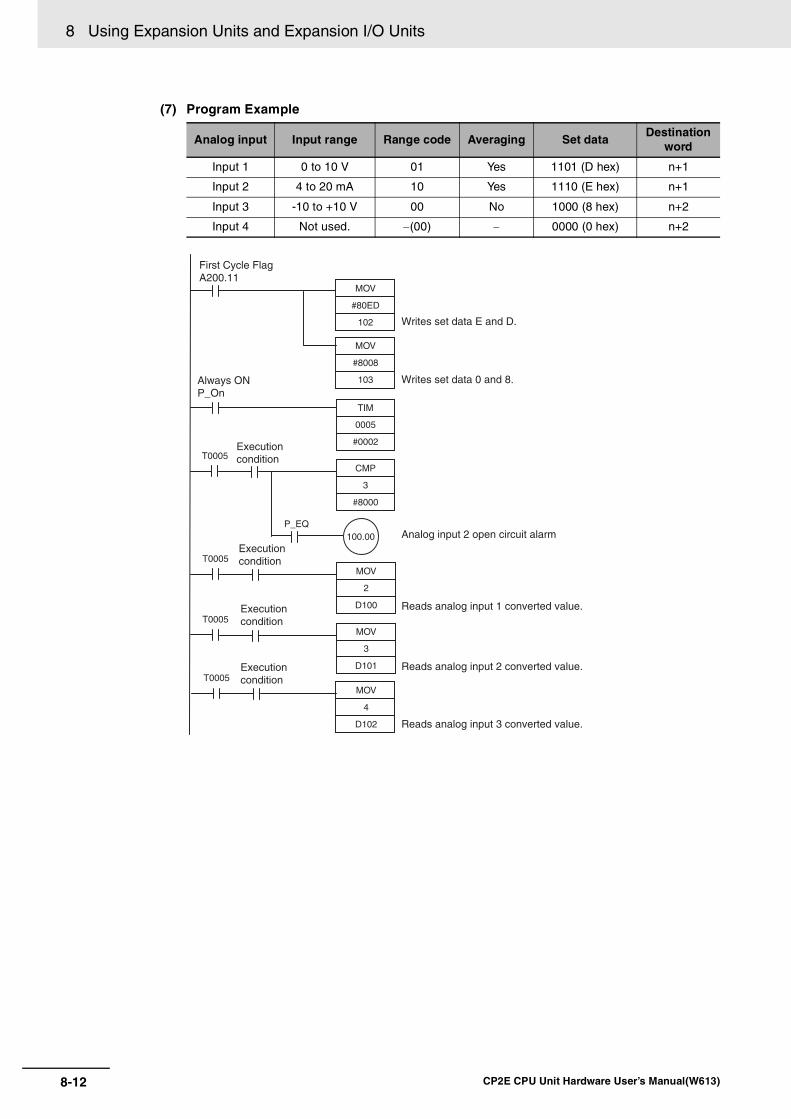
8 Using Expansion Units and Expansion I/O Units
8-12 CP2E CPU Unit Hardware User’s Manual(W613)
(7) Program Example
Analog input Input range Range code Averaging Set dataDestination
word
Input 1 0 to 10 V 01 Yes 1101 (D hex) n+1
Input 2 4 to 20 mA 10 Yes 1110 (E hex) n+1
Input 3 -10 to +10 V 00 No 1000 (8 hex) n+2
Input 4 Not used. −(00) − 0000 (0 hex) n+2
MOV
#80ED
102
TIM
0005
#0002
2
D100
T0005MOV
4
D102
T0005MOV
Analog input 2 open circuit alarmP_EQ
100.00
3
#8000
T0005CMP
MOV
#8008
103
3
D101
T0005MOV
Execution condition
Execution condition
Execution condition
Execution condition
Reads analog input 1 converted value.
Reads analog input 3 converted value.
Reads analog input 2 converted value.
Writes set data E and D.
Writes set data 0 and 8.Always ON P_On
First Cycle Flag A200.11

8-13
8 Using Expansion Units and Expansion I/O Units
CP2E CPU Unit Hardware User’s Manual(W613)
8-1 An
alog
Inp
ut U
nits
8
8-1-4 Flow
of Operation
• Example: Scaling analog input values
When a 0 to 10V voltage is input to the analog input word (CIO 3) of CP1W-AD042 as 0 to 12,000,convert the value into a value between 0 and 24,000 and output the result to D200.
Data Memory Settings
Ladder Program
Descriptions of APR Instruction
Setting Address Data
Control word D100 #0800
Unscaled minimum value (0) D101 &0
Scaled minimum value (0) D102 &0
Unscaled maximum value (12,000) D103 &12,000
Scaled maximum value (24,000) D104 &24,000
12,000(10V)
0 (0V)
24,000
Data input to Analog Input Unit (Unscaled: 0 to 12,000)
Scaled value (0 to
24,000)
(Data in CIO3)
(D200)
0
Always ON Flag P_On
Use APR instruction for scaling.APR(069)
D100
D200
3
APR
C
D
S
C:Control word
D:Result word
S:Source word
X1X0
Y1
Unscaled data
Scaleddata
SInput data
DScaledresult
Y0

8 Using Expansion Units and Expansion I/O Units
8-14 CP2E CPU Unit Hardware User’s Manual(W613)
C: Control word
Set for “Signed Integer Data (Binary)”.
Control word setting
#0800: Binary numeral (0000 1000 0000 0000)
S: Source data
Specify the word address of the input data before scaling.
R: Result word
Specify the word address where the data will be output after scaling.
Setting Address Data
Control word C #0800
Unscaled minimum value (X0) C+1 X0
Scaled minimum value (Y0) C+2 Y0
Unscaled maximum value (Xm = X1) C+3 X1
Scaled maximum value (Ym = Y1) C+4 Y1
C
15
0 0 0 0 1 0
8 7 6 5 4 3 2 1 0
0
Number of coordinates minus one (m+1), 00 to FF hex (1 m 256)
14 13 12 11 10 9
Data length specification for S and D0: 16-bit signed binary data 1: 32-bit signed binary data
Floating-point specification for S and D0: Integer data
Signed data specification for S and D1: Signed binary data
The number of coordinates is 1 (m=1), soset bit 0 to 7 to “0” (=m-1).

8-15
8 Using Expansion Units and Expansion I/O Units
CP2E CPU Unit Hardware User’s Manual(W613)
8-2 An
alog
Ou
tpu
t Un
its
8
8-2-1 Overview
8-2 Analog Output Units
Each CP1W-DA021 Analog Output Unit provides two analog outputs.
Each CP1W-DA041/CP1W-DA042 Analog Output Unit provides four analog outputs.
• The analog output signal ranges are 1 to 5 V, 0 to 10 V, -10 to +10 V, 0 to 20 mA, and 4 to 20 mA. The resolution of CP1W-DA021/DA041 is 1/6,000.The resolution of CP1W-DA042 is 1/12,000.
• CP1W-DA021 uses two output words and CP1W-DA041/DA042 uses four output words.
CP1W-DA021/CP1W-DA041/CP1W-DA042
(1)Analog Output Terminals Connected to analog input devices.
• I/O Terminal Arrangement for CP1W-DA021
8-2-1 Overview
8-2-2 Part Names and Functions
V OUT1 Voltage output 1
I OUT1 Current output 1
COM1 Output common 1
V OUT2 Voltage output 2
I OUT2 Current output 2
COM2 Output common 2
CHI OUT1 I OUT3
I OUT2VOUT1VOUT2
VOUT3COM1COM2
I OUT4VOUT4 COM4
NCNC
COM3
OUT
(3) Expansion connector
(1) Analog output terminals(2) Expansion I/O connecting cable
CHI OUT1 NC
I OUT2VOUT1VOUT2
NCCOM1COM2
NCNC NC
NCNC
NC
I OUT1 NCI OUT2VOUT1
VOUT2NCCOM1
COM2NC
NC NCNC
NCNC
OUT

8 Using Expansion Units and Expansion I/O Units
8-16 CP2E CPU Unit Hardware User’s Manual(W613)
• I/O Terminal Arrangement for CP1W-DA041/DA042
(2)Expansion I/O Connecting Cable Connected to the expansion connector on the CPU Unit or previous Expansion Unit. The cable isprovided with the Unit and cannot be removed.
Precautions for Safe Use
Do not touch the cables during operation. Static electricity may cause operating errors.
(3)Expansion ConnectorConnected to the next Expansion Unit or Expansion I/O Unit.
CP1W-DA021/DA041/DA042 Analog Output Units are connected to a CP2E CPU Unit.
V OUT1 Voltage output 1
I OUT1 Current output 1
COM1 Output common 1
V OUT2 Voltage output 2
I OUT2 Current output 2
COM2 Output common 2
V OUT3 Voltage output 3
I OUT3 Current output 3
COM3 Output common 3
V OUT4 Voltage output 4
I OUT4 Current output 4
COM4 Output common 4
8-2-3 Specifications
CHI OUT1 I OUT3
I OUT2VOUT1VOUT2
VOUT3COM1COM2
I OUT4VOUT4 COM4
NCNC
COM3
I OUT1 I OUT3I OUT2VOUT1
VOUT2VOUT3COM1
COM2I OUT4
VOUT4 COM4NC
NCCOM3
OUT
IN
00
C H
C H
02 04 06 08 10
OUT
01C OM 03 05 07 09 11
C OM CO M C OM 03 CO M 0600 01 02 04 05 07
00 01 02 03 04 05 06 07
08 09 10 11
20EDR1
C H 00 01 02 03 04 05 06 07
N C
N CN C
C H E X P
IN
00 0201C OM 03
C OM 05 0704 06
C H 00 01 02 03
08 09 10 11
8ED
E X P CHI OUT1 I OUT3
I OUT2VOUT1VOUT2
VOUT3COM1COM2
I OUT4VOUT4 COM4
NCAG
COM3
OUT
CP2E CPU Unit
CP1W-DA021: 2 analog outputsCP1W-DA041: 4 analog outputsCP1W-DA042: 4 analog outputs
CP1W-20EDR1Expansion I/O Unit
CP1W-8EDExpansion I/O Unit
CP1W-DA021/DA041 CP1W-DA042Analog Output Unit

8-17
8 Using Expansion Units and Expansion I/O Units
CP2E CPU Unit Hardware User’s Manual(W613)
8-2 An
alog
Ou
tpu
t Un
its
8
8-2-3 Specifications
Analog Output Signal Ranges
The output data is converted to analog according to the output signal range, as shown below.
Additional Information
When the output exceeds the specified range, the output signal will be fixed at either the lowerlimit or upper limit.
Model CP1W-DA021/CP1W-DA041 CP1W-DA042
Item Voltage output Current output Voltage output Current output
Analog output section
Number of analog out-puts
CP1W-DA021:2 outputs (2 words allocated)
CP1W-DA041: 4 outputs (4 words allocated)
4 outputs (4 words allocated)
Output signal range 1 to 5 V, 0 to 10 V, or -10 to 10 V
0 to 20 mA or 4 to 20 mA
1 to 5 V, 0 to 10 V, or -10 to 10 V
0 to 20 mA or 4 to 20 mA
External output allow-able load resistance
2 kΩ min. 350 Ω max. 2 kΩ min. 350 Ω max.
External output imped-ance
0.5 Ω max. − 0.5 Ω max. −
Resolution 1/6000 (full scale) 1/12000 (full scale)
Overall accuracy
25°C 0.4% full scale 0.3% full scale
0 to 60°C 0.8% full scale 0.7% full scale
-20 to 0°C 1% full scale 0.9% full scale
D/A conversion data 16-bit binary (4-digit hexadecimal)
Full scale for -10 to 10 V: F448 to 0BB8 hex
Full scale for other ranges: 0000 to 1770 hex
16-bit binary (4-digit hexadecimal)
Full scale for -10 to 10 V: E890 to 1770 hex
Full scale for other ranges: 0000 to 2EE0 hex
Conversion time CP1W-DA021: 2 ms/point (4 ms/all points)
CP1W-DA041: 2 ms/point (8 ms/all points)
1 ms/point (4 ms/all points)
Isolation method Photocoupler isolation between analog I/O terminals and internal circuits. No isolation between analog I/O signals.
Current consumption CP1W-DA021: 5 VDC 40 mA max.; 24 VDC 95 mA max.
CP1W-DA041: 5 VDC 80 mA max.; 24 VDC 124 mA max.
5 VDC: 70 mA max.; 24 VDC: 160 mA max.

8 Using Expansion Units and Expansion I/O Units
8-18 CP2E CPU Unit Hardware User’s Manual(W613)
-10 to 10 V When the resolution is 1/6,000, the hexadecimal values F448 to 0BB8 (-3000 to 3000) correspond toan analog voltage range of -10 to 10 V. The entire output range is -11 to 11 V. Specify the DA conversion data as the two’s complement if it is a negative value.
When the resolution is 1/12,000, the hexadecimal values E890 to 1770 (-6000 to 6000) correspondto an analog voltage range of -10 to 10 V.The entire output range is -11 to 11 V.Specify the DA conversion data as the two's complement if it is a negative value.
0 to 10 VWhen the resolution is 1/6,000, the hexadecimal values 0000 to 1770 (0 to 6000) correspond to ananalog voltage range of 0 to 10 V. The entire output range is -0.5 to 10.5 V. Specify the DA conversion data as the two’s complement if it is a negative value.
0 V
10 V
11 V
−11 V
−10 V
F448 (-3000)
F31C (-3300)
0CE4(3300)
0BB8(3000)
8000
7FFF
0000 (0) Conversion Data Hexadecimal (Decimal)
0 V
10 V
11 V
−11 V
−10 V
E890(−6000)
E638(−6600)
19C8(6600)
1770(6000)
0000 (0)8000
7FFF
Conversion DataHexadecimal (Decimal)
0 V
10 V
10.5 V
−0.5 V
FED4(−300)
189C(6300)
1770(6000)
8000
7FFF
0000 (0) Conversion Data Hexadecimal (Decimal)

8-19
8 Using Expansion Units and Expansion I/O Units
CP2E CPU Unit Hardware User’s Manual(W613)
8-2 An
alog
Ou
tpu
t Un
its
8
8-2-3 Specifications
When the resolution is 1/12,000, the hexadecimal values 0000 to 2EE0 (0 to 12000) correspond toan analog voltage range of 0 to 10 V.The entire output range is -0.5 to 10.5 V.Specify the DA conversion data as the two's complement if it is a negative value.
1 to 5 VWhen the resolution is 1/6,000, the hexadecimal values 0000 to 1770 (0 to 6000) correspond to ananalog voltage range of 1 to 5 V. The entire output range is 0.8 to 5.2 V.
When the resolution is 1/12,000, the hexadecimal values 0000 to 2EE0 (0 to 12000) correspond toan analog voltage range of 1 to 5 V.The entire output range is 0.8 to 5.2 V.
0 to 20 mAWhen the resolution is 1/6,000, the hexadecimal values 0000 to 1770 (0 to 6000) correspond to ananalog current range of 0 to 20 mA. The entire output range is 0 to 21 mA.
0 V
10 V
10.5 V
−0.5 V
FDA8 (−600)
3138(12600)
2EE0(12000)
0000 (0)8000
7FFFConversion DataHexadecimal (Decimal)
1 V
5 V
5.2 V
0.8 V
189C(6300)
1770(6000)
0 V 7FFFFED4(−300)
8000
Conversion Data Hexadecimal (Decimal)
1 V
5 V
5.2 V
0.8 V
3138(12600)
2EE0(12000)
0 V 7FFFFDA8(−600)
8000Conversion DataHexadecimal (Decimal)
Conversion Data Hexadecimal (Decimal)
0 mA
20 mA
21 mA
189C(6300)
1770(6000)
7FFF
8000 0000 (0)

8 Using Expansion Units and Expansion I/O Units
8-20 CP2E CPU Unit Hardware User’s Manual(W613)
When the resolution is 1/12,000, the hexadecimal values 0000 to 2EE0 (0 to 12000) correspond toan analog voltage range of 0 to 20 mA.The entire output range is 0 to 21 mA.
4 to 20 mAWhen the resolution is 1/6,000, the hexadecimal values 0000 to 1770 (0 to 6000) correspond to ananalog current range of 4 to 20 mA. The entire output range is 3.2 to 20.8 mA.
When the resolution is 1/12,000, the hexadecimal values 0000 to 2EE0 (0 to 12000) correspond toan analog voltage range of 4 to 20 mA.The entire output range is 3.2 to 20.8 mA.
8-2-4 Flow of Operation
1 • Connect Analog Output Units.
• Wire to analog input devices.
2 • Write range code to output wordsCP1W-DA021: Word n+1CP1W-DA041/DA042: Words n+1, n+2
• Set use of outputs.
• Select output signals using range codes.
• Write D/A conversion values to output wordsCP1W-DA021: Words n+1, n+2CP1W-DA041/DA042: Words n+1 to n+4
0 mA
20 mA
21 mA
0000 (0)
3138(12600)
2EE0(12000)
7FFF
8000Conversion DataHexadecimal (Decimal)
Conversion Data Hexadecimal (Decimal)
4 mA
20 mA
20.8 mA
3.2 mA
189C(6300)
1770(6000)
0 mA 7FFFFED4(−300)
8000
4 mA
20 mA
20.8 mA
3.2 mA
3138(12600)
2EE0(12000)
0 mA 7FFFFDA8(−600)
8000Conversion DataHexadecimal (Decimal)
Connect and wire Units.
Create a ladder program.

8-21
8 Using Expansion Units and Expansion I/O Units
CP2E CPU Unit Hardware User’s Manual(W613)
8-2 An
alog
Ou
tpu
t Un
its
8
8-2-4 Flow
of Operation
Writing Set Data and Writing D/A Conversion Data
CP1W-DA021
CP1W-DA041/CP1W-DA042
1 Connect the Analog Output Unit to the CPU Unit.
MOV
Word (n+1) Set data (outputs 1, 2)
Word (n+1)
Word (n+2) Analog output 2 conversion value
CPU Unit Analog Output Unit
Ladder program
Writes the set data.Writes the conversion values.
Analog output 1 conversion value
Where “n” is the last output word allocated to the CPU Unit, or previous Expansion Unit or Expansion I/O Unit.
Analog devices
• Adjustment equipment• Servo Controller• Variable speed device• Recorder• Other
MOV
Word (n+1) Set data (outputs 1, 2)
Word (n+2) Set data (outputs 3, 4)
Word (n+1)
Word (n+2) Analog output 2 conversion value
Word (n+3) Analog output 3 conversion value
Word (n+4) Analog output 4 conversion value
CPU Unit Analog Output Unit
Ladder program
Writes the set data.Writes the conversion values.
Analog output 1 conversion value
Where “n” is the last output word allocated to the CPU Unit, or previous Expansion Unit or Expansion I/O Unit.
Analog devices
• Adjustment equipment• Servo Controller• Variable speed device• Recorder• Other
CP1W-DA021/DA041CP1W-DA042Analog Output Unit
CHI OUT1 I OUT3
I OUT2VOUT1VOUT2
VOUT3COM1COM2
I OUT4VOUT4 COM4
NCAG
COM3
OUT
CP2E CPU Unit

8 Using Expansion Units and Expansion I/O Units
8-22 CP2E CPU Unit Hardware User’s Manual(W613)
2 Wire to analog input devices.
(1) Wiring internal circuits of the CPU Unit
The following diagram shows the internal circuit using CP1W-DA041/DA042 as an example,which wires analog outputs 1 to 4. In the case of CP1W-DA021, analog outputs 1 to 2 canbe used.
(2) Wiring analog input devices to the Analog Output Unit
Precautions for Correct UsePrecautions for Correct Use
• Do not connect the shield when using shielded twisted-pair cables.
• Separate wiring from power lines (AC power supply lines, high-voltage lines, etc.)
• When there is noise in the power supply line, install a noise filter on the input section and thepower supply.
Additional Information
When external power is supplied (when setting the range code), or when there is a power inter-ruption, a pulse-form analog output may be generated.
If this causes problems with operation, take countermeasures such as those suggested below.
(1) Countermeasure 1
• Turn ON the power supply for the CP2E CPU Unit first, confirm correct operation, andthen turn ON the power supply for the load.
• Turn OFF the power supply for the load before turning OFF the power supply for theCP2E CPU Unit.
(2) Countermeasure 2
• Control the machine not only by analog output but also by other signals (additionalstart/stop control signal for machine).
Analog output 1
Analog ground NC
I OUT1
COM1 (−)
V OUT1
I OUT4
COM4 (−)
V OUT4
Analog output 4
Inte
rnal
circ
uits
toto
+V OUT
COM
I OUT
−
+V OUT
COM
I OUT
−
Analog output unit
Analog device with voltage input
Analog output unit
Analog device with current input
2-core shielded twisted-pair cable
2-core shielded twisted-pair cable
FGFG

8-23
8 Using Expansion Units and Expansion I/O Units
CP2E CPU Unit Hardware User’s Manual(W613)
8-2 An
alog
Ou
tpu
t Un
its
8
8-2-4 Flow
of Operation
3 Create the ladder program.
(1) Allocating Output Words
Four output words (n+1 to n+4) are allocated to the Analog Output Unit starting from thenext word following the last word allocated to the CPU Unit or previous Expansion Unit orExpansion I/O Unit. For CP1W-DA021, two output words (n+1, n+2) are allocated.
(2) Writing Set Data
Write the output use and the range code to words n+1 and n+2. For CP1W-DA021, onlyword n+1 can be used. The D/A conversion will start when the set data is transferred fromthe CPU Unit to the Analog Output Unit.
• Set Data
• The Analog Output Unit will not start converting analog output values until the set datahas been written.
• Before the range code is written, 0 V or 0 mA will be output for the 0 to 10V, -10 to 10V,or 0 to 20 mA ranges, and 1 V or 4 mA will be output for the 1 to 5V and 4 to 20 mAranges.
• Once the range code has been set, it is not possible to be changed while power is beingsupplied to the CPU Unit. To change the range code, turn the CPU Unit OFF then ONagain.
Words n+1 to n+4
CP1W-DA041/DA042Analog Output Unit
15
1 0 0 0 0 0 0
8 7 6 5 4 3 2 1 0
Wd n+1
15
1 0 0 0 0 0 0
8 7 6 5 4 3 2 1 0
0
0
Analog output 2 Analog output 1
Analog output 4 Analog output 3
Wd n+2
Even if analog outputs are not used, bits 15 in words n+1 and n+2 must be set to 1.
Even if analog outputs are not used, bits 15 in words n+1 and n+2 must be set to 1.
01
Range code Analog output range
−10 to 10 V
0 to 10 V
1 to 5 V
0 to 20 mA
4 to 20 mA
000
001
010
011
100
Output use
NoYes

8 Using Expansion Units and Expansion I/O Units
8-24 CP2E CPU Unit Hardware User’s Manual(W613)
(3) Writing Analog Output Conversion Values
The ladder program can be used to write conversion data to the output words.
When “n” is the last output word allocated to the CPU Unit, or previous Expansion Unit orExpansion I/O Unit, the output words will be n+1 to n+2 for CP1W-DA021 and n+1 to n+4for CP1W-DA041/DA042.
(4) Startup Operation
After power is turned ON, it will require two cycle times plus approximately 50 ms before thefirst conversion data is output.
The following table shows the output status after the initial processing is completed.
Therefore, create a program as shown below, so that when operation begins simulta-neously with startup it will wait for valid set data.
(5) Handling Unit Errors
• When an error occurs at the Analog Output Unit, the analog output will be 0 V or 0 mA. If a CPU error or an I/O bus error (fatal errors) occurs at the CPU Unit and the analogoutput is set to 1 to 5 V or 4 to 20 mA, 0 V or 0 mA will be output. For any other fatalerrors at the CPU Unit, 1 V or 4 mA will be output.
• Expansion Unit and Expansion I/O Unit errors are output to bits 0 to 5 of word A436 forunits 1 to 3. The bits are allocated from A436.00 in order starting from the Unit nearestthe CPU Unit. CP1W-DA041/DA042 is allocated two bits each and CP1W-DA021 is allo-cated one bit each. Use these flags in the probgram when it is necessary to detecterrors.
Output type Voltage output Current output
Output range 0 to 10 V,-10 to +10 V
1 to 5 V 0 to 20 mA 4 to 20 mA
Before range code is written
0V 0mA
After range code is written
0V 1V 0mA 4mA
P_On
MOV
D100
102
TIM
0005
#0002
T0005
Always ON Flag TIM0005 is started when the power is turnedON. After 0.2 s (200 ms) elapses, the TIM0005contact turns ON and the data stored in D100will be moved to CIO 102 as the conversiondata for analog output 1.

8-25
8 Using Expansion Units and Expansion I/O Units
CP2E CPU Unit Hardware User’s Manual(W613)
8-2 An
alog
Ou
tpu
t Un
its
8
8-2-4 Flow
of Operation
(6) Program Example (CP1W-DA041/DA042)
Analog output Output range Range code Set data Destination word
Output 1 0 to 10 V 001 1001 (9 hex) n+1
Output 2 4 to 20 mA 100 1100 (C hex) n+1
Output 3 -10 to 10 V 000 1000 (8 hex) n+2
Output 4 Not used. −(000) 0000 (0 hex) n+2
P_On
T0005
T0005
T0005
MOV
#80C9
102
TIM
0005
#0002
D200
102
MOV
D202
104
MOV
MOV
#8008
103
D201
103
MOV
Always ON Flag
Execution condition
Execution condition
Execution condition
First Cycle Flag A200.11
Writes set data C and 9.
Writes set data 0 and 8.
Writes analog output 1 conversion data.
Writes analog output 2 conversion data.
Writes analog output 3 conversion data.

8 Using Expansion Units and Expansion I/O Units
8-26 CP2E CPU Unit Hardware User’s Manual(W613)
• Example: Scaling analog output values
Convert a value between 200 and 500 in D300 into 2 to 5 V to output the voltage from the analogoutput word (CIO 102) of CP1W-DA042.
Data memory settings
Ladder program
Refer to 8-1 Example: Scaling analog input values for the descriptions of APR instruction.
Setting Address Data
Control word D110 #0800
Unscaled minimum value (200) D111 &200
Scaled minimum value (3,000) D112 &3,000
Unscaled maximum value (500) D113 &500
Scaled maximum value (12,000) D114 &12,000
12,000(5V)
3,000(2V)
500
200
Value output to Analog Output Unit(Scaled: 3,000 to 12,000)
Unscaleddata
(200 to500)
(Data in CIO102)
(D300)
Always ON Flag P_On
APR(069) Use APR instruction for scaling.
D110
102
D300

8-27
8 Using Expansion Units and Expansion I/O Units
CP2E CPU Unit Hardware User’s Manual(W613)
8-3 An
alog
I/O U
nits
8
8-3-1 CP
1W-M
AD
11 Analog I/O
Units
8-3 Analog I/O Units
Each CP1W-MAD11 Analog I/O Unit provides 2 analog inputs and 1 analog output.
• The analog input range can be set to 0 to 5 V, 1 to 5 V, 0 to 10 V, -10 to 10 V, 0 to 20 mA, or 4 to 20mA. The inputs have a resolution of 1/6000. An open-circuit detection function is activated in theranges of 1 to 5 V and 4 to 20 mA.
• The analog output range can be set to 1 to 5 V, 0 to 10 V, -10 to 10 V, 0 to 20 mA, or 4 to 20 mA. Theoutputs have a resolution of 1/6000.
CP1W-MAD11
(1)Analog I/O Terminals Connected to analog I/O devices.
• I/O Terminal Arrangements
Note For current inputs, short V IN0 to I IN0 and V IN1 to I IN1.
(2)Expansion I/O Connecting Cable Connected to the expansion connector of a CPU Unit or an Expansion Unit or Expansion I/O Unit.The cable is provided with the Analog I/O Unit and cannot be removed.
8-3-1 CP1W-MAD11 Analog I/O Units
Overview
Part Names and Functions
V OUT Voltage output
I OUT Current output
COM Output common
V IN0 Voltage input 0
I IN0 Current input 0
COM0 Input common 0
V IN1 Voltage input 1
I IN1 Current input 1
COM1 Input common 1
NC NC
(3) Expansion connector
(2) Expansion I/O connecting cable(1) Analog I/O terminals
(4) DIP switch
I OUT V IN0 COM0
V OUT COM I IN0
I IN1
V IN1 COM1N C N C
AGN C N C

8 Using Expansion Units and Expansion I/O Units
8-28 CP2E CPU Unit Hardware User’s Manual(W613)
Precautions for Safe Use
Do not touch the cables during operation. Static electricity may cause operating errors.
(3)Expansion Connector Used for connecting Expansion Units or Expansion I/O Units.
(4)DIP SwitchUsed to enable or disable averaging.
CP1W-MAD11 Analog I/O Units are connected to the CP2E CPU Unit.
Pin 1: Average processing for analog input 0
(OFF: Average processing not performed; ON: Average processing performed)
Pin 2: Average processing for analog input 1
(OFF: Average processing not performed; ON: Average processing performed)
Specifications
CP1W-20EDR1
Expansion I/O Unit
CP1W-8ED
Expansion I/O Unit
CP1W-MAD11
Analog I/O Unit
1 analog output 2 analog inputs
IN
00
C H
C H
02 04 06 08 10
OUT
01C OM 03 05 07 09 11
C OM CO M C OM 03 CO M 0600 01 02 04 05 07
00 01 02 03 04 05 06 07
08 09 10 11
20EDR1
C H 00 01 02 03 04 05 06 07
N C
N CN C
C H E X P
IN
00 0201C OM 03
C OM 05 0704 06
C H 00 01 02 03
08 09 10 11
8ED
E X PNC NC
CP2E CPU Unit

8-29
8 Using Expansion Units and Expansion I/O Units
CP2E CPU Unit Hardware User’s Manual(W613)
8-3 An
alog
I/O U
nits
8
8-3-1 CP
1W-M
AD
11 Analog I/O
Units
Analog I/O Signal RangesAnalog I/O data is digitally converted according to the analog I/O signal range as shown below.
Additional Information
When the input/output exceeds the specified range, the AD/DA converted data will be fixed ateither the lower limit or upper limit.
Model CP1W-MAD11
Item Voltage I/O Current I/O
Analog Input Section
Number of analog inputs 2 inputs (2 words allocated)
Input signal range 0 to 5 V, 1 to 5 V, 0 to 10 V, or -10 to 10 V
0 to 20 mA or 4 to 20 mA
Max. rated input ±15 V ±30 mA
External input impedance 1 MΩ min. Approx. 250 Ω
Resolution 1/6000 (full scale)
Overall accuracy
25°C 0.3% full scale 0.4% full scale
0 to 60°C 0.6% full scale 0.8% full scale
-20 to 0°C 0.8% full scale 1% full scale
A/D conversion data 16-bit binary (4-digit hexadecimal)
Full scale for -10 to 10 V: F448 to 0BB8 hex
Full scale for other ranges: 0000 to 1770 hex
Averaging function Supported (Settable for individual inputs via DIP switch)
Open-circuit detection func-tion
Supported
AnalogOutputSection
Number of outputs 1 output (1 word allocated)
Output signal range 1 to 5 VDC, 0 to 10 VDC, or -10 to 10 VDC
0 to 20 mA or 4 to 20 mA
Allowable external output load resistance
1 kΩ min. 600 Ω max.
External output impedance 0.5 Ω max. −
Resolution 1/6000 (full scale)
Overall accuracy
25°C 0.4% full scale
0 to 60°C 0.8% full scale
-20 to 0°C 1% full scale
Set data (D/A conversion) 16-bit binary (4-digit hexadecimal)
Full scale for -10 to 10 V: F448 to 0BB8 hex
Full scale for other ranges: 0000 to 1770 hex
Conversion time 2 ms/point (6 ms/all points)
Isolation method Photocoupler isolation between analog I/O terminals and internal cir-cuits.
No isolation between analog I/O signals.
Current consumption 5 VDC: 83 mA max., 24 VDC: 110 mA max.

8 Using Expansion Units and Expansion I/O Units
8-30 CP2E CPU Unit Hardware User’s Manual(W613)
Analog Input Signal Ranges
-10 to 10 VVoltages in the -10 to 10 V range corre-spond to hexadecimal values F448 to 0BB8 (-3,000 to 3,000). The range of data that can be converted is F31C to 0CE4 hex (-3,300 to 3,300). A negative voltage is expressed as a two’s complement.
0 to 10 VVoltages in the 0 to 10 V range correspond to hexadecimal values 0000 to 1770 (0 to 6,000). The range of data that can be con-verted is FED4 to 189C hex (-300 to 6,300).
A negative voltage is expressed as a two’s complement.
0 to 5 VVoltages in the 0 to 5 V range correspond to hexadecimal values 0000 to 1770 (0 to 6,000). The range of data that can be con-verted is FED4 to 189C hex (-300 to 6,300).
A negative voltage is expressed as a two’s complement.
0 V 10 V 11 V
−11V −10V
F448 (−3000)F31C (−3300)
0BB8 (3000)
0000 (0)
Converted DataHexadecimal (Decimal)
0CE4 (3300)
0 V 10 V 10.5 V−0.5 V 0000 (0)
FED4 (−300)
189C (6300)1770 (6000)
Converted DataHexadecimal (Decimal)
0 V 5 V 5.25 V
−0.25 V 0000 (0)
FED4 (−300)
189C (6300)1770 (6000)
Converted DataHexadecimal (Decimal)

8-31
8 Using Expansion Units and Expansion I/O Units
CP2E CPU Unit Hardware User’s Manual(W613)
8-3 An
alog
I/O U
nits
8
8-3-1 CP
1W-M
AD
11 Analog I/O
Units
1 to 5 VVoltages in the 1 to 5 V range correspond to hexadecimal values 0000 to 1770 (0 to 6,000). The range of data that can be con-verted is FED4 to 189C hex (-300 to 6,300).
Voltage in the range of 0.8 to 1 V is expressed as a two’s complement.
If an input is below the range (i.e., less than 0.8 V), the open-circuit detection function is activated and the data becomes 8,000.
0 to 20 mACurrents in the 0 to 20 mA range corre-spond to hexadecimal values 0000 to 1770 (0 to 6,000). The range of data that can be converted is FED4 to 189C hex (-300 to 6,300). A negative current is expressed as a two’s complement.
4 to 20 mACurrents in the 4 to 20 mA range corre-spond to hexadecimal values 0000 to 1770 (0 to 6,000). The range of data that can be converted is FED4 to 189C hex (-300 to 6,300). Current in the range of 3.2 to 4 mA is expressed as a two’s complement. If an input is below the range (i.e., less than 3.2 mA), the open-circuit detection function is activated and the data becomes 8,000.
1 V 5 V 5.2 V0.8 V
FED4 (−300)
189C (6300)1770 (6000)
0000 (0)
Converted DataHexadecimal (Decimal)
0 mA 20 mA 21 mA−1 mA 0000 (0)
FED4 (−300)
189C (6300)1770 (6000)
Converted DataHexadecimal (Decimal)
4 mA 20 mA 20.8 mA3.2 mA
FED4 (−300)
189C (6300)1770 (6000)
0000 (0)0 mA
Converted DataHexadecimal (Decimal)

8 Using Expansion Units and Expansion I/O Units
8-32 CP2E CPU Unit Hardware User’s Manual(W613)
Analog Output Signal Ranges
-10 to 10 V
The hexadecimal values F448 to 0BB8 (-3000 to 3000) correspond to an analog voltage range of-10 to 10 V.The entire output range is -11 to 11V. Specify the DA conversion data as the two’s complement if it is a negative value.
0 to 10 V
The hexadecimal values 0000 to 1770 (0 to 6000) correspond to an analog voltage range of 0 to 10 V. The entire output range is -0.5 to 10.5 V. Specify the DA conversion data as the two’s complement if it is a negative value.
1 to 5 V
The hexadecimal values 0000 to 1770 (0 to 6000) correspond to an analog voltage range of 1 to 5 V. The entire output range is 0.8 to 5.2 V.
0 V
10 V11 V
−11 V−10 V
F448(−3000)
F31C(−3300)
0CE4 (3300)
0BB8(3000)
0000 (0)8000
7FFFConversion DataHexadecimal (Decimal)
0 V
10 V10.5 V
−0.5 V
FED4 (−300)
189C(6300)
1770(6000)
0000 (0)8000
7FFFConversion DataHexadecimal (Decimal)
1 V
5 V5.2 V
0.8 V
189C(6300)
1770(6000)
0 V 7FFFFED4(−300)
8000 Conversion DataHexadecimal (Decimal)

8-33
8 Using Expansion Units and Expansion I/O Units
CP2E CPU Unit Hardware User’s Manual(W613)
8-3 An
alog
I/O U
nits
8
8-3-1 CP
1W-M
AD
11 Analog I/O
Units
0 to 20 mA
The hexadecimal values 0000 to 1770 (0 to 6000) correspond to an analog current range of 0 to 20 mA. The entire output range is 0 to 21 mA.
4 to 20 mA
The hexadecimal values 0000 to 1770 (0 to 6000) correspond to an analog current range of 4 to 20 mA. The entire output range is 3.2 to 20.8 mA.
Averaging Function for Analog Inputs The averaging function can be enabled for inputs using the DIP switch. The averaging function out-puts the average (a moving average) of the last eight input values as the converted value.
Use this function to smooth inputs that vary at a short interval.
Open-circuit Detection Function for Analog Inputs The open-circuit detection function is activated when the input range is set to 1 to 5 V and the volt-age drops below 0.8 V, or when the input range is set to 4 to 20 mA and the current drops below 3.2 mA.
When the open-circuit detection function is activated, the converted data will be set to 8,000.
The time for enabling or clearing the open-circuit detection function is the same as the time for con-verting the data.
If the input returns to the convertible range, the open-circuit detection is cleared automatically andthe output returns to the normal range.
0 mA
20 mA21 mA
0000 (0)189C(6300)
1770(6000)
7FFF
8000Conversion DataHexadecimal (Decimal)
4 mA
20 mA20.8 mA
3.2 mA
189C(6300)
1770(6000)
0 mA 7FFFFED4(−300)
8000Conversion DataHexadecimal (Decimal)

8 Using Expansion Units and Expansion I/O Units
8-34 CP2E CPU Unit Hardware User’s Manual(W613)
Writing Set Data and Reading A/D Converted Values
Writing D/A Conversion Data
* Word (n+1) can be used for either the set data or the analog output conversion value.
Flow of Operation
1 • Connect the Analog I/O Unit.
• Set analog inputs as voltage or current inputs and set the averag-ing function.
2 • Connect analog I/O devices.
3 • Write the range code.
• Analog inputs: Read converted values.
• Analog output: Write set data.
Connect the Unit.
Create a ladder program.
Wire the analog I/O.
MOV
Ladder programSet dataWord (n+1)
Word (m+1)
Word (m+2)
CPU Unit Analog I/O Unit
• Writes the set data.• Reads the converted values.
Analog input 0 converted valueAnalog input 1 converted value
“m” is the last input word and “n” is the last output word allocated to the CPU Unit or previous Expansion Unit or Expansion I/O Unit.
Analog devices• Temperature sensor• Pressure sensor• Speed sensor• Flow sensor• Voltage/current meter• Other
MOV
Ladder program
Word (n+1)
CPU Unit Analog I/O Unit
(*)
Writes the conversion values.
Analog output conversion value
“n” is the last output word allocated to the CPU Unit or previous Expansion Unit or Expansion I/O Unit.
Analog devices• Adjustment equipment• Servo Controller• Variable speed device• Recorder• Other

8-35
8 Using Expansion Units and Expansion I/O Units
CP2E CPU Unit Hardware User’s Manual(W613)
8-3 An
alog
I/O U
nits
8
8-3-1 CP
1W-M
AD
11 Analog I/O
Units
1 Connect the Analog I/O Unit to the CPU Unit.
• Setting the Averaging Function DIP switch pins 1 and 2 are used to set the averaging function. When averaging is enabled, amoving average of the last eight input values is output as the converted value. The averagingfunction can be set separately for analog inputs 0 and 1.
2 Wire to analog I/O devices.
(1) Wiring internal circuits of the CPU Unit
(2) Wiring analog output devices to the Analog I/O Unit
DIP switch pin Function Setting Default
1 Averaging Analog input 0OFF: Disabled; ON: Enabled
OFF
2 Analog input 1OFF: Disabled; ON: Enabled
OFF
CP2E CPU UnitCP1W-MAD11Analog I/O Unit
NC NC
• Analog Inputs • Analog Outputs
Analog ground
Input 0
Input 1
Analog ground
Output
Inte
rnal
circ
uits
510 kΩ
510 kΩ
510 kΩ
510 kΩ
250 Ω
250 Ω
COM0 (−)
V IN0
V IN1
COM1 (−) Inte
rnal
circ
uits COM (−)
V OUT
I OUT
AGNC
NC
I IN0
I IN1
V IN
COM
I IN
V IN
COM
I IN
Analog device with voltage output
+
−
+
−
Analog Input Unit
Analog device with current output
Analog Input Unit
2-core shielded twisted-pair cable
FG
2-core shielded twisted-pair cable
FG

8 Using Expansion Units and Expansion I/O Units
8-36 CP2E CPU Unit Hardware User’s Manual(W613)
(3) Wiring analog input devices to the Analog I/O Unit
Precautions for Correct UsePrecautions for Correct Use
• Do not connect the shield when using shielded twisted-pair cables.
• When an input is not being used, short V IN and I IN to COM terminals.
• Separate wiring from power lines (AC power supply lines, high-voltage lines, etc.)
• When there is noise in the power supply line, install a noise filter on the input section and thepower supply terminals.
Additional Information
Refer to the following information on open circuits when using voltage inputs.
Example: If connected device 2 is outputting 5 V and the same power supply is being used for bothdevices as shown above, approximately 1/3, or 1.6 V, will be applied to the input for input device 1.
If a wiring disconnection occurs when voltage input is being used, the situation described below willresult. Either separate the power supplies for the connected devices, or use an isolator for each input.
FG FG
V OUT
COM
I OUT
V OUT
COM
I OUT
Analog device with voltage input
+
−
+
−
Analog Output Unit
Analog device with current input
Analog Output Unit
2-core shielded twisted-pair cable
2-core shielded twisted-pair cable
24 VDC
A
CB
Analog output device 1
Analog output device 2
Internal circuits

8-37
8 Using Expansion Units and Expansion I/O Units
CP2E CPU Unit Hardware User’s Manual(W613)
8-3 An
alog
I/O U
nits
8
8-3-1 CP
1W-M
AD
11 Analog I/O
Units
• If the same power supply is being used by the connected devices and a disconnection occurs atpoints A or B in the above diagram, an unwanted circuit path will occur as shown along the dotted linein the diagram. If that occurs, a voltage of approximately 1/3 to 1/2 of the output voltage of the otherconnected device will be generated.
• If that voltage is generated while the setting is for 1 to 5 V, open-circuit detection may not be possible.
• If a disconnection occurs at point C in the diagram, the negative (-) side will be used for both devicesand open-circuit detection will not be possible.
This problem will not occur for current inputs even if the same power supply is used.
Additional Information
When external power is supplied (when setting the range code), or when there is a power inter-ruption, a pulse-form analog output may be generated. If this causes problems with operation, take countermeasures such as those suggested below.
(1) Countermeasure 1
• Turn ON the power supply for the CP2E CPU Unit first, confirm correct operation, andthen turn ON the power supply for the load.
• Turn OFF the power supply for the load before turning OFF the power supply for theCP2E CPU Unit.
(2) Countermeasure 2
• Control the machine not only by analog output but also by other signals (additionalstart/stop control signal for machine).
3 Create the ladder program.
(1) Allocating I/O Words
Two input words and one output word are allocated to the Analog I/O Unit starting from thenext word following the last word allocated to the CPU Unit or previous Expansion Unit orExpansion I/O Unit.
(2) Writing the Set Data
Write the set data to word n+1. A/D or D/A conversion begins when the set data is trans-ferred from the CPU Unit to the Analog I/O Unit. There are five range codes, 000 to 100,that combine the analog input 0 and 1 and analog output ranges, as shown below.
Range code Analog input 0 range Analog input 1 range Analog output range
000 -10 to 10 V -10 to 10 V -10 to 10 V
001 0 to 10 V 0 to 10 V 0 to 10 V
010 1 to 5 V/4 to 20 mA 1 to 5 V/4 to 20 mA 1 to 5 V
011 0 to 5 V/0 to 20 mA 0 to 5 V/0 to 20 mA 0 to 20 mA
100 − − 4 to 20 mA
Analog I/O Unit
Word m+1Word m+2
32 inputs16 outputs
Word n+1

8 Using Expansion Units and Expansion I/O Units
8-38 CP2E CPU Unit Hardware User’s Manual(W613)
• The Analog I/O Unit will not start converting analog I/O values until the range code hasbeen written. Inputs will be 0000, and 0 V or 0 mA will be output.
• After the range code has been set, 0 V or 0 mA will be output for the 0 to 10V, -10 to 10V,or 0 to 20mA ranges, and 1 V or 4 mA will be output for the 1 to 5V and 4 to 20mAranges until a convertible value has been written to the output word.
• Once the range code has been set, it is not possible to change the setting while power isbeing supplied to the CPU Unit. To change the I/O range, turn the CPU Unit OFF thenON again.
(3) Reading Analog Input Converted Values
The ladder program can be used to read the memory area words where the converted val-ues are stored.
Values are output to the next two words (m + 1, m + 2) following the last input word (m) allo-cated to the CPU Unit or previous Expansion Unit or Expansion I/O Unit.
(4) Writing Analog Output Converted Values
The ladder program can be used to write data to the memory area where the set value isstored.
The output word will be “n+1”, where “n” is the last output word allocated to the CPU Unit orprevious Expansion Unit or Expansion I/O Unit.
(5) Startup Operation
After the power is turned ON, it will require two cycle times plus approximately 50 ms beforethe first conversion data is stored in the input words. Therefore, create a program as shownbelow, so that when operation begins simultaneously with startup it will wait for valid conver-sion data.
Analog input data will be 0000 until initial processing is completed. Analog output data willbe 0 V or 0 mA until the range code has been written. After the range code has been writ-ten, the analog output data will be 0 V or 0 mA if the range is 0 to 10 V, -10 to 10 V, or 0 to20 mA, or it will be 1 V or 4 mA if the range is 1 to 5 V or 4 to 20 mA.
word n+1
15
1 0 0 0 0 0 0
8 7 6 5 4 3 2 1 0
Analog output
Analog input 1
Analog input 0
MOV
#800A
n+1
First Cycle FlagA200.11
Analog input 0: 4 to 20 mAAnalog input 1: 0 to 10 VAnalog output: -10 to 10 V
Example: The following instructions set analog input 0 to 4 to 20 mA, analog input 1 to 0 to 10 V,and the analog output to -10 to 10 V.
MOV
2
D0
Always ON FlagP_On
TIM
0005
#0002
T0005
TIM0005 is started when the power is turnedON. After 0.2 s (200 ms) elapses, the TIM0005contact turns ON and the converted data fromanalog input 0 that is stored in CIO 2 will betransferred to D0.

8-39
8 Using Expansion Units and Expansion I/O Units
CP2E CPU Unit Hardware User’s Manual(W613)
8-3 An
alog
I/O U
nits
8
8-3-1 CP
1W-M
AD
11 Analog I/O
Units
(6) Handling Unit Errors
• When an error occurs in the Analog I/O Unit, analog input data will be 0000 and 0 V or 0mA will be output as the analog output. If a CPU error or an I/O bus error (fatal errors) occurs at the CPU Unit and the analogoutput is set to 1 to 5 V or 4 to 20 mA, 0 V or 0 mA will be output. For any other fatalerrors at the CPU Unit, 1 V or 4 mA will be output.
• Expansion Unit and Expansion I/O Unit errors are output to bits 0 to 5 of word A436. Thebits are allocated from A436.00 in order starting from the Unit nearest the CPU Unit. Usethese flags in the program when it is necessary to detect errors.
(7) Programming Example
Analog input 0: 0 to 10 V
Analog input 1: 4 to 20 mA
Analog output : 0 to 10 V
MOV
#8051
102
First Cycle FlagA200.11
TIM
0005
#0002
Always ON FlagP_On
2
D0
T0005MOV
P_EQ100.00
3
D1
T0005MOV
D10
102
T0005MOV
3
#8000
T0005CMP
Execution condition
Execution condition
Execution condition
Execution condition
Writes the range code (8051) to the Unit.
Reads analog input 0’s converted value.
Reads analog input 1’s converted value.
The content of D10 is written to the output word as the analog output set value.
Open-circuit alarm

8 Using Expansion Units and Expansion I/O Units
8-40 CP2E CPU Unit Hardware User’s Manual(W613)
Each CP1W-MAD42 Analog I/O Unit provides 4 analog inputs and 2 analog outputs.
Each CP1W-MAD44 Analog I/O Unit provides 4 analog inputs and 4 analog outputs.
• The analog input range can be set to 0 to 5 VDC, 1 to 5 VDC, 0 to 10 VDC, −10 to 10 VDC, 0 to 20mA, or 4 to 20 mA. The inputs have a resolution of 1/12000.An open-circuit detection function is activated in the ranges of 1 to 5 VDC and 4 to 20 mA.
• The analog output range can be set to 1 to 5 VDC, 0 to 10 VDC, −10 to 10 VDC, 0 to 20 mA, or 4 to20 mA. The outputs have a resolution of 1/12000.
CP1W-MAD42/CP1W-MAD44
(1)Analog Input TerminalsConnected to analog output devices.
• Input Terminal Arrangement for CP1W-MAD42/MAD44
Note When using current inputs, voltage input terminals must be short-circuited with current input terminals.
(2)Analog Output TerminalsConnected to analog input devices.
8-3-2 CP1W-MAD42/CP1W-MAD44 Analog I/O Units
Overview
Part Names and Functions
V IN1 Voltage input 1
I IN1 Current input 1
COM1 Input common 1
V IN2 Voltage input 2
I IN2 Current input 2
COM2 Input common 2
V IN3 Voltage input 3
I IN3 Current input 3
COM3 Input common 3
V IN4 Voltage input 4
I IN4 Current input 4
COM4 Input common 4
(4) Expansion connector
(3) Expansion I/O connecting cable (2) Analog Output terminals
(1) Analog Input terminals

8-41
8 Using Expansion Units and Expansion I/O Units
CP2E CPU Unit Hardware User’s Manual(W613)
8-3 An
alog
I/O U
nits
8
8-3-2 CP
1W-M
AD
42/CP
1W-M
AD
44 Analog I/O
U
nits
• Output Terminal Arrangement for CP1W-MAD42
• Output Terminal Arrangement for CP1W-MAD44
(3)Expansion I/O Connecting CableConnected to the expansion connector of a CPU Unit or an Expansion Unit or Expansion I/O Unit.The cable is provided with the Analog I/O Unit and cannot be removed.
Precautions for Safe Use
Do not touch the cables during operation. Static electricity may cause operating errors.
(4)Expansion ConnectorUsed for connecting Expansion Units or Expansion I/O Units.
CP1W-MAD42/MAD44 Analog I/O Units are connected to the CP2E CPU Unit.
V OUT1 Voltage output 1 I OUT1 Current output 1 COM1 Output common 1 V OUT2 Voltage output 2 I OUT2 Current output 2 COM2 Output common 2
V OUT1 Voltage output 1 I OUT1 Current output 1 COM1 Output common 1 V OUT2 Voltage output 2 I OUT2 Current output 2 COM2 Output common 2 V OUT3 Voltage output 3 I OUT3 Current output 3 COM3 Output common 3 V OUT4 Voltage output 4 I OUT4 Current output 4 COM4 Output common 4
Specifications
CP2E CPU Unit
IN
00
C H
C H
02 04 06 08 10
OUT
01C OM 03 05 07 09 11
C OM CO M C OM 03 CO M 0600 01 02 04 05 07
00 01 02 03 04 05 06 07
08 09 10 11
20EDR1
C H 00 01 02 03 04 05 06 07
N C
N CN C
C H E X P
IN
00 0201C OM 03
C OM 05 0704 06
C H 00 01 02 03
08 09 10 11
8ED
E X P
CP1W-20EDR1Expansion I/O Unit
CP1W-8EDExpansion I/O Unit
CP1W-MAD42/MAD44 Analog I/O Unit
CP1W-MAD42: 2 analog outputsCP1W-MAD44: 4 analog outputs
4 analog inputs

8 Using Expansion Units and Expansion I/O Units
8-42 CP2E CPU Unit Hardware User’s Manual(W613)
Analog I/O Signal RangesAnalog I/O data is digitally converted according to the analog I/O signal range as shown below.
Additional Information
When the input/output exceeds the specified range, the AD/DA converted data will be fixed ateither the lower limit or upper limit.
Model CP1W-MAD42/CP1W-MAD44
Item Voltage I/O Current I/O
Analog Input Section
Number of inputs 4 inputs (4 words allocated)
Input signal range 0 to 5 VDC, 1 to 5 VDC,0 to 10 VDC, or −10 to 10 VDC
0 to 20 mA or 4 to 20 mA
Max. rated input ±15 V ±30 mA
External input impedance 1 MΩ min. Approx. 250 Ω
Resolution 1/12000 (full scale)
Overall accuracy
25°C 0.2% full scale 0.3% full scale
0 to 60°C 0.5% full scale 0.7% full scale
-20 to 0°C 0.7% full scale 0.9% full scale
A/D conversion data 16-bit binary (4-digit hexadecimal)
Full scale for −10 to 10 V: E890 to 1770 hexFull scale for other ranges: 0000 to 2EE0 hex
Averaging function Supported
Open-circuit detection func-tion
Supported
Analog Output Section
Number of outputs CP1W-MAD42: 2 outputs (2 words allocated)
CP1W-MAD44: 4 outputs (4 words allocated)
Output signal range 1 to 5 VDC, 0 to 10 VDC, or −10 to 10 VDC
0 to 20 mA or 4 to 20 mA
Allowable external output load resistance
2 kΩ min. 350 Ω max.
External output impedance 0.5 Ω max.
Resolution 1/12000 (full scale)
Overall accuracy
25°C 0.3% full scale
0 to 60°C 0.7% full scale
-20 to 0°C 0.9% full scale
Set data (D/A conversion) 16-bit binary (4-digit hexadecimal)
Full scale for −10 to 10 V: E890 to 1770 hexFull scale for other ranges: 0000 to 2EE0 hex
Conversion time CP1W-MAD42: 1 ms/point (6 ms/all points)
CP1W-MAD44: 1 ms/point (8 ms/all points)
Isolation method Photocoupler isolation between analog I/O terminals and internal circuits.No isolation between analog I/O signals.
Current consumption CP1W-MAD42: 5 VDC: 120 mA max., 24 VDC: 120 mA max.
CP1W-MAD44: 5 VDC: 120 mA max., 24 VDC: 170 mA max.

8-43
8 Using Expansion Units and Expansion I/O Units
CP2E CPU Unit Hardware User’s Manual(W613)
8-3 An
alog
I/O U
nits
8
8-3-2 CP
1W-M
AD
42/CP
1W-M
AD
44 Analog I/O
U
nits
Analog Input Signal Ranges
−10 to 10 V
The −10 to 10 V range corresponds to the hexadecimal values E890 to 1770 (−6000 to 6000). Theentire data range is E638 to 19C8 (−6600 to 6600). A negative voltage is expressed as a two’s complement.
0 to 10 V
The 0 to 10 V range corresponds to the hexadecimal values 0000 to 2EE0 (0 to 12000). The entiredata range is FDA8 to 3138 (−600 to 12600). A negative voltage is expressed as a two’s comple-ment.
0 to 5 V
The 0 to 5 V range corresponds to the hexadecimal values 0000 to 2EE0 (0 to 12000). The entiredata range is FDA8 to 3138 (−600 to 12600). A negative voltage is expressed as a two’s comple-ment.
0 V 10 V 11 V
−11V −10V
E890 (−6000)E638 (−6600)
19C8 (6600)1770 (6000)
0000 (0)
Converted DataHexadecimal (Decimal)
0 V 10 V 10.5 V−0.5 V
FDA8 (−600)
3138 (12600)2EE0 (12000)
0000 (0)
Converted DataHexadecimal (Decimal)
0 V 5 V 5.25 V−0.25 V
FDA8 (−600)
3138 (12600)2EE0 (12000)
0000 (0)
Converted DataHexadecimal (Decimal)

8 Using Expansion Units and Expansion I/O Units
8-44 CP2E CPU Unit Hardware User’s Manual(W613)
1 to 5 V
The 1 to 5 V range corresponds to the hexadecimal values 0000 to 2EE0 (0 to 12000). The entiredata range is FDA8 to 3138 (−600 to 12600). Inputs between 0.8 and 1 V are expressed as two’scomplements. If the input falls below 0.8 V, open-circuit detection will activate and converted datawill be 8000.
0 to 20 mA
The 0 to 20 mA range corresponds to the hexadecimal values 0000 to 2EE0 (0 to 12000). The entiredata range is FDA8 to 3138 (−600 to 12600). A negative current is expressed as a two’s comple-ment.
4 to 20 mA
The 4 to 20 mA range corresponds to the hexadecimal values 0000 to 2EE0 (0 to 12000). The entiredata range is FDA8 to 3138 (−600 to 12600). Inputs between 3.2 and 4 mA are expressed as two’scomplements. If the input falls below 3.2 mA, open-circuit detection will activate and converted datawill be 8000.
1 V 5 V 5.2 V0.8 V
FDA8 (−600)
3138 (12600)2EE0 (12000)
0000 (0)
Converted DataHexadecimal (Decimal)
0 mA 20 mA 21 mA−1 mA
FDA8 (−600)
3138 (12600)2EE0 (12000)
0000 (0)
Converted DataHexadecimal (Decimal)
4 mA 20 mA 20.8 mA3.2 mA
FDA8 (−600)
3138 (12600)2EE0 (12000)
0000 (0)0 mA
Converted DataHexadecimal (Decimal)

8-45
8 Using Expansion Units and Expansion I/O Units
CP2E CPU Unit Hardware User’s Manual(W613)
8-3 An
alog
I/O U
nits
8
8-3-2 CP
1W-M
AD
42/CP
1W-M
AD
44 Analog I/O
U
nits
Analog Output Signal Ranges
−10 to 10 V
The hexadecimal values E890 to 1770 (−6000 to 6000) correspond to an analog voltage range of −10to 10 V. The entire output range is −11 to 11 V. Specify a negative voltage as a two’s complement.
0 to 10 V
The hexadecimal values 0000 to 2EE0 (0 to 12000) correspond to an analog voltage range of 0 to10 V. The entire output range is −0.5 to 10.5 V. Specify a negative voltage as a two’s complement.
1 to 5 V
The hexadecimal values 0000 to 2EE0 (0 to 12000) correspond to an analog voltage range of 1 to 5 V. The entire output range is 0.8 to 5.2 V.
0 V
10 V11 V
−11 V−10 V
E890(−6000)
E638(−6600)
19C8 (6600)
1770(6000)
0000 (0)8000
7FFFConversion DataHexadecimal (Decimal)
0 V
10 V10.5 V
−0.5 V
FDA8 (−600)
3138(12600)
2EE0(12000)
0000 (0)8000
7FFFConversion DataHexadecimal (Decimal)
1 V
5 V5.2 V
0.8 V
3138(12600)
2EE0(12000)
0 V 7FFFFDA8(−600)
8000 Conversion DataHexadecimal (Decimal)

8 Using Expansion Units and Expansion I/O Units
8-46 CP2E CPU Unit Hardware User’s Manual(W613)
0 to 20 mA
The hexadecimal values 0000 to 2EE0 (0 to 12000) correspond to an analog current range of 0 to 20 mA. The entire output range is 0 to 21 mA.
4 to 20 mA
The hexadecimal values 0000 to 2EE0 (0 to 12000) correspond to an analog current range of 4 to 20 mA. The entire output range is 3.2 to 20.8 mA.
Averaging Function for Analog InputsFor analog inputs, the averaging function operates when the averaging bit is set to 1. The averagingfunction outputs the average (a moving average) of the last eight input values as the convertedvalue. If there is only a slight variation in inputs, it is handled by the averaging function as a smoothinput.
The averaging function stores the average (a moving average) of the last eight input values as theconverted value. Use this function to smooth inputs that vary at a short interval.
Open-circuit Detection Function for Analog InputsThe open-circuit detection function is activated when the input range is set to 1 to 5 V and the voltagedrops below 0.8 V, or when the input range is set to 4 to 20 mA and the current drops below 3.2 mA.When the open-circuit detection function is activated, the converted data will be set to 8,000.
The time for enabling or clearing the open-circuit detection function is the same as the time for con-verting the data. If the input returns to the convertible range, the open-circuit detection is clearedautomatically and the output returns to the normal range.
0 mA
20 mA21 mA
0000 (0)3138(12600)
2EE0(12000)
7FFF
8000Conversion DataHexadecimal (Decimal)
4 mA
20 mA20.8 mA
3.2 mA
3138(12600)
2EE0(12000)
0 mA 7FFFFDA8(−600)
8000Conversion DataHexadecimal (Decimal)

8-47
8 Using Expansion Units and Expansion I/O Units
CP2E CPU Unit Hardware User’s Manual(W613)
8-3 An
alog
I/O U
nits
8
8-3-2 CP
1W-M
AD
42/CP
1W-M
AD
44 Analog I/O
U
nits
Writing Set Data and Reading A/D Converted Data
Flow of Operation
1 • Connect the Analog I/O Unit.
• Set analog inputs as voltage or current inputs and set the averag-ing function.
2 • Connect analog I/O devices.
3 • Write the range code.
• Analog inputs: Read converted values.
• Analog output: Write set data.
Connect the Unit.
Create a ladder program.
Wire the analog I/O.
MOV
Ladder programWord (n+2)
Word (n+1)
Word (m+1)
Word (m+2)
CPU Unit CP1W-MAD42
• Writes the set data.• Reads the converted values.
Analog input 1 converted value
Set data (input 1, 2 and output 1)Set data (input 3, 4 and output 2)
Analog input 2 converted value
Word (m+3)Analog input 3 converted value
Word (m+4) Analog input 4 converted value
“m” is the last input word and “n” is the last output word allocated to the CPU Unit or previous Expansion Unit or Expansion I/O Unit.
Analog devices• Temperature sensor• Pressure sensor• Speed sensor• Flow sensor• Voltage/current meter• Other
MOV
Ladder program
Word (n+4)
Word (n+3)
Word (n+2)
Word (n+1)
Word (m+1)
Word (m+2)
CPU Unit CP1W-MAD44
• Writes the set data.• Reads the converted values.
Analog input 1 converted value
Set data (input 1, 2)Set data (input 3, 4)Set data (output 1, 2)Set data (output 3, 4)
Analog input 2 converted value
Word (m+3)Analog input 3 converted value
Word (m+4) Analog input 4 converted value
“m” is the last input word and “n” is the last output word allocated to the CPU Unit or previous Expansion Unit or Expansion I/O Unit.
Analog devices• Temperature sensor• Pressure sensor• Speed sensor• Flow sensor• Voltage/current meter• Other

8 Using Expansion Units and Expansion I/O Units
8-48 CP2E CPU Unit Hardware User’s Manual(W613)
Writing D/A Conversion Data
* Words (n+1, n+2) can be used for either the set data or the analog output conversion value.
* Words (n+1 to n+4) can be used for either the set data or the analog output conversion value.
1 Connect the Analog I/O Unit to the CPU Unit.
MOV
Ladder program
CPU Unit CP1W-MAD42
(*)
Writes the conversion values.
Word (n+2)
“n” is the last output word allocated to the CPU Unit or previous Expansion Unit or Expansion I/O Unit.
Analog devices• Adjustment equipment• Servo Controller• Variable speed device• Recorder• Other
Word (n+1)Analog output 1 conversion valueAnalog output 2 conversion value
MOV
Ladder program
CPU Unit CP1W-MAD44
(*)Analog output 1 conversion valueAnalog output 2 conversion valueAnalog output 3 conversion valueAnalog output 4 conversion value
“n” is the last output word allocated to the CPU Unit or previous Expansion Unit or Expansion I/O Unit.
Analog devices• Adjustment equipment• Servo Controller• Variable speed device• Recorder• Other
Word (n+4)
Word (n+3)
Word (n+2)
Word (n+1)
Writes the conversion values.
CP2E CPU UnitCP1W-MAD42/44Analog I/O Unit

8-49
8 Using Expansion Units and Expansion I/O Units
CP2E CPU Unit Hardware User’s Manual(W613)
8-3 An
alog
I/O U
nits
8
8-3-2 CP
1W-M
AD
42/CP
1W-M
AD
44 Analog I/O
U
nits
2 Wire to analog I/O devices.
(1) Wiring internal circuits of the CPU Unit
(2) Wiring analog output devices to the Analog I/O Unit
(3) Wiring analog input devices to the Analog I/O Unit
Analog Inputs
Analog Outputs (CP1W-MAD42)
Analog ground
Analog input 1
toto
Analog input 4
Analog ground
Inte
rnal
circ
uits
510 kΩ
510 kΩ
510 kΩ
510 kΩ
250 Ω
250 Ω
COM1 (−)
V IN1
V IN4
COM4 (−)
Inte
rnal
circ
uits
COM1 (−)
V OUT1
I OUT1
AG
NC
NC
I IN1
I IN4
Analog Outputs (CP1W-MAD44)
Analog ground
Inte
rnal
circ
uits
COM1 (−)
V OUT1
I OUT1
COM2 (−)
V OUT2
I OUT2
COM4 (−)
V OUT4
I OUT4
NC
NC
Analog output 1
tototo
Analog output 4
Analog output 1
to
Analog output 2
V IN
COM
I IN
V IN
COM
I IN
Analog device with voltage output
+
−
+
−
Analog Input Unit
Analog device with current output
Analog Input Unit
2-core shielded twisted-pair cable
FG
2-core shielded twisted-pair cable
FG
FG FG
V OUT
COM
I OUT
V OUT
COM
I OUT
Analog device with voltage input
+
−
+
−
Analog Output Unit
Analog device with current input
Analog Output Unit
2-core shielded twisted-pair cable
2-core shielded twisted-pair cable

8 Using Expansion Units and Expansion I/O Units
8-50 CP2E CPU Unit Hardware User’s Manual(W613)
Precautions for Correct UsePrecautions for Correct Use
• Do not connect the shield when using shielded twisted-pair cables.
• When an input is not being used, short V IN and I IN to COM terminals.
• Separate wiring from power lines (AC power supply lines, high-voltage lines, etc.)
• When there is noise in the power supply line, install a noise filter on the input section and thepower supply terminals.
Additional Information
Refer to the following information on open circuits when using voltage inputs.
Example: If connected device 2 is outputting 5 V and the same power supply is being used for bothdevices as shown above, approximately 1/3, or 1.6 V, will be applied to the input for input device 1.
If a wiring disconnection occurs when voltage input is being used, the situation described below willresult. Either separate the power supplies for the connected devices, or use an isolator for each input.
• If the same power supply is being used by the connected devices and a disconnection occurs atpoints A or B in the above diagram, an unwanted circuit path will occur as shown along the dotted linein the diagram. If that occurs, a voltage of approximately 1/3 to 1/2 of the output voltage of the otherconnected device will be generated.
• If that voltage is generated while the setting is for 1 to 5 V, open-circuit detection may not be possible.
• If a disconnection occurs at point C in the diagram, the negative (-) side will be used for both devicesand open-circuit detection will not be possible.
This problem will not occur for current inputs even if the same power supply is used.
24 VDC
A
CB
Analog output device 1
Analog output device 2
Internal circuits

8-51
8 Using Expansion Units and Expansion I/O Units
CP2E CPU Unit Hardware User’s Manual(W613)
8-3 An
alog
I/O U
nits
8
8-3-2 CP
1W-M
AD
42/CP
1W-M
AD
44 Analog I/O
U
nits
Additional Information
When external power is supplied (when setting the range code), or when there is a power inter-ruption, a pulse-form analog output may be generated. If this causes problems with operation, take countermeasures such as those suggested below.
(1) Countermeasure 1
• Turn ON the power supply for the CP2E CPU Unit first, confirm correct operation, andthen turn ON the power supply for the load.
• Turn OFF the power supply for the load before turning OFF the power supply for theCP2E CPU Unit.
(2) Countermeasure 2
• Control the machine not only by analog output but also by other signals (additionalstart/stop control signal for machine).
3 Create the ladder program.
(1) Allocating I/O Words
Four input words and two output words are allocated to the CP1W-MAD42, starting fromthe next word following the last word allocated to the CPU Unit or previous Expansion Unitor Expansion I/O Unit.
Four input words and four output words are allocated to the CP1W-MAD44, starting fromthe next word following the last word allocated to the CPU Unit or previous Expansion Unitor Expansion I/O Unit.
(2) Writing the Range Code
(a) CP1W-MAD42
Write the set data to words (n+1 to n+2). A/D or D/A conversion begins when the setdata is transferred from the CPU Unit to the Analog I/O Unit. Setting contents areshown as the following table.
Word (n+1) 15 14 13 12 11 10 9 8 7 6 5 4 3 2 1 0
Value 1 0 0 0 Analog output 1 Analog input 2 Analog input 1
Word (n+2) 15 14 13 12 11 10 9 8 7 6 5 4 3 2 1 0
Value 1 0 0 0 Analog output 2 Analog input 4 Analog input 3
CP1W-MAD42
Word m+1Word m+2Word m+3Word m+4
Word n+1
CP1W-MAD44
Word m+1Word m+2Word m+3Word m+4
Word n+1Word n+2 Word n+2
Word n+3Word n+4

8 Using Expansion Units and Expansion I/O Units
8-52 CP2E CPU Unit Hardware User’s Manual(W613)
(b) CP1W-MAD44
Write the set data to words (n+1 to n+4). A/D or D/A conversion begins when the setdata is transferred from the CPU Unit to the Analog I/O Unit. Setting contents areshown as the following table.
Even if analog inputs are not used, bit 15 in word (n+1) and (n+2) must be set to 1.
• Set Data of Analog Inputs
• Set Data of Analog Outputs
• The Analog I/O Unit will not start converting analog I/O values until the set data hasbeen written.
• Before range code is written, 0 V or 0 mA will be output in the 0 to 10 V, −10 to +10 V,and 0 to 20 mA ranges, and 1 V or 4 mA will be output in the 1 to 5 V and 4 to 20 mAranges.
• Once the range code has been set, it is not possible to be changed while power is beingsupplied to the CPU Unit. To change the code range, turn the CPU Unit OFF then ONagain.
Word (n+1) 15 14 13 12 11 10 9 8 7 6 5 4 3 2 1 0
Value 1 0 0 0 0 0 0 0 Analog input 2 Analog input 1
Word (n+2) 15 14 13 12 11 10 9 8 7 6 5 4 3 2 1 0
Value 1 0 0 0 0 0 0 0 Analog input 4 Analog input 3
Word (n+3) 15 14 13 12 11 10 9 8 7 6 5 4 3 2 1 0
Value 1 0 0 0 0 0 0 0 Analog output 2 Analog output 1
Word (n+4) 15 14 13 12 11 10 9 8 7 6 5 4 3 2 1 0
Value 1 0 0 0 0 0 0 0 Analog output 4 Analog output 3
Range Code Analog input range
00 −10 to 10 V
01 0 to 10 V
10 1 to 5 V (4 to 20 mA)
11 0 to 5 V (0 to 20 mA)
Range Code Analog output range
000 −10 to 10 V
001 0 to 10 V
010 1 to 5 V
011 0 to 20 mA
100 4 to 20 mA
Value Enable
Enable Bit0 : Disable channel1 : Enable channel
Average Bit0 : Disable1 : Enable
7 6 012345
Average AD Range Code Enable Average AD Range Code
AD Range Code00 : −10 to 10V01 : 0 to 10V10 : 1 to 5V (4 to 20mA)11 : 0 to 5V (0 to 20mA)
Value Enable
Enable Bit0 : Disable channel1 : Enable channel
7 6 012345
DA Range Enable DA Range
DA Range000 : -10 to 10001 : 0 to 10V010 : 1 to 5V011 : 0 to 20m100 : 4 to 20m

8-53
8 Using Expansion Units and Expansion I/O Units
CP2E CPU Unit Hardware User’s Manual(W613)
8-3 An
alog
I/O U
nits
8
8-3-2 CP
1W-M
AD
42/CP
1W-M
AD
44 Analog I/O
U
nits
(3) Averaging
Set whether averaging is to be used for set data. When the averaging bit is set to 1, theaverage (moving average) for the past eight inputs is output as conversion data.
(4) Reading Analog Input Converted Values
Read the conversion value storage area with the ladder program. With word m as the lastinput word allocated to the CPU Unit or an already-connected Expansion Unit, the A/D con-version data will be output to the following words m+1 to m+4.
(5) Writing Analog Output Converted Values
The ladder program can be used to write conversion data to the output words. The outputword start from “n+1” where “n” is the last output word allocated to the CPU Unit, or previ-ous Expansion Unit or Expansion I/O Unit.
(6) Startup Operation
After power is turned ON, it will require two cycle times plus approximately 50ms before thefirst conversion data is output.
Analog input data will be 0000 until the first conversion data is stored in the input words.
The following table shows the output status after the initial processing is completed.
Therefore, create a program as shown below, so that the ladder can start to operate withvalid conversion data in input words.
(7) Handling Unit Errors
When an error occurs in the Analog I/O Unit, analog input data will be 0000 and 0 V or 0 mAwill be output as the analog output.If a CPU error or an I/O bus error (fatal errors) occurs at the CPU Unit and the analog out-put is set to 1 to 5 V or 4 to 20 mA, 0 V or 0 mA will be output. For any other errors at theCPU Unit, 1 V or 4 mA will be output.
(8) Programming Example
Output type Voltage output Current output
Output range 0 to 10 V,-10 to +10 V
1 to 5 V 0 to 20 mA 4 to 20 mA
Before range code is written
0V 0mA
After range code is written
0V 1V 0mA 4mA
MOV
2
D0
Always ON FlagP_On
0005
TIM
#0002T0005
TIM0005 is started when the power is turnedON. After 0.2 s (200 ms) elapses, the TIM0005contact turns ON and the converted data fromanalog input 0 that is stored in CIO 2 will betransferred to D0.
CP2E
Input word addresses
Output word addresses
CIO 0CIO 1
CIO 100CIO 101
CP1W-MAD42
CIO 102CIO 103
CIO 2 CIO 3 CIO 4 CIO 5
CIO 6 CIO 7 CIO 8 CIO 9
CIO 104 CIO 105 CIO 106 CIO 107
CP1W-MAD44

8 Using Expansion Units and Expansion I/O Units
8-54 CP2E CPU Unit Hardware User’s Manual(W613)
This programming example uses these ranges:
(a) CP1W-MAD42
(a) CP1W-MAD44
Analog input
Input range
Range code
Averaging Set data Destinationword
Input 1 4 to 20 mA 10 Yes 1110 (E hex) n+1
Input 2 0 to 10 V 01 Yes 1101 (D hex) n+1
Input 3 0 to 5 V 11 Yes 1111 (F hex) n+2
Input 4 -10 to 10 V 00 Yes 1100 (C hex) n+2
Output 1 -10 to 10 V 000 − 1000 (8 hex) n+1
Output 2 4 to 20 mA 100 − 1100 (C hex) n+2
Analog input
Input range
Range code
Averaging Set data Destinationword
Input 1 4 to 20 mA 10 Yes 1110 (E hex) n+1
Input 2 0 to 10 V 01 No 1001 (9 hex) n+1
Input 3 0 to 5 V 11 Yes 1111 (F hex) n+2
Input 4 -10 to 10 V 00 Yes 1100 (C hex) n+2
Output 1 -10 to 10 V 000 − 1000 (8 hex) n+3
Output 2 4 to 20 mA 100 − 1100 (C hex) n+3
Output 3 0 to 10 V 001 − 1001 (9 hex) n+4
Output 4 Not use − − 0000 (0 hex) n+4
MOV
#88DE
102
First Cycle FlagA200.11
A200.11
A200.11
A200.11
A200.11
A200.11
#8CCF
MOV
103
#809E
104
MOV
#80CF
105
MOV
#80C8
106
MOV
#8009
107
MOV
← Writes the range code of CP1W-MAD42 to the Unit.
← Writes the range code of CP1W-MAD44 to the Unit.

8-55
8 Using Expansion Units and Expansion I/O Units
CP2E CPU Unit Hardware User’s Manual(W613)
8-3 An
alog
I/O U
nits
8
8-3-2 CP
1W-M
AD
42/CP
1W-M
AD
44 Analog I/O
U
nits
0005
TIM
#0002
Always ON FlagP_On
2
D0
T0005MOV
(P_EQ)100.00
3
D1
T0005MOV
D10
102
T0005MOV
2
#8000
T0005CMP
Execution condition
Execution condition
Execution condition
Execution condition
← Reads analog input 1’s of CP1W-MAD42 converted value.
← Reads analog input 2’s of CP1W-MAD42 converted value.
6
D4
T0005MOV
7
D5
T0005MOV
Execution condition
Execution condition
← Reads analog input 1’s of CP1W-MAD44 converted value.
← Reads analog input 2’s of CP1W-MAD44 converted value.
← The content of D10 is written to the output word as the analog output conversion value.
Open-circuit alarm
Open-circuit detection (4 to 20 mA)
Open-circuit detection (4 to 20 mA)
(P_EQ)100.01
D12
104
T0005MOV
6
#8000
T0005CMP
Execution condition
Execution condition
← The content of D10 is written to the output word as the analog output conversion value.
Open-circuit alarm

8 Using Expansion Units and Expansion I/O Units
8-56 CP2E CPU Unit Hardware User’s Manual(W613)
8-4 Temperature Sensor Units
CP1W-TS002/TS102 Temperature Sensor Units each provide up to four input points, and CP1W-TS001/TS101 Temperature Sensor Units each provide up to two input points. The inputs can be fromthermocouples or platinum resistance thermometers.
CP1W-TS002/TS102 Temperature Sensor Units are each allocated four input words.
Temperature Sensor Units: CP1W-TS001/002/101/102
(1)Temperature Sensor Input Terminals Used to connect temperature sensors such as thermocouples or platinum resistance thermome-ters.
(2)DIP SwitchUsed to set the temperature unit (°C or °F) and the number of decimal places used.
(3)Rotary SwitchUsed to set the temperature input range. Make the setting according to the specifications of thetemperature sensors that are connected.
(4)Expansion I/O Connecting Cable Connected to the expansion connector of a CP2E CPU Unit or an Expansion Unit or ExpansionI/O Unit. The cable is included with the Temperature Sensor Unit and cannot be removed.
Precautions for Safe Use
Do not touch the cables during operation. Static electricity may cause operating errors.
(5)Expansion ConnectorUsed for connecting Expansion Units or Expansion I/O Units.
8-4-1 CP1W-TS 1/TS 2 Temperature Sensor Units
Overview
Part Names and Functions
(5) Expansion Connector
(1) Temperature Sensor Input Terminals(4) Expansion I/O
Connecting Cable
(3) Rotary Switch(2) DIP Switch

8-57
8 Using Expansion Units and Expansion I/O Units
CP2E CPU Unit Hardware User’s Manual(W613)
8-4 Temp
erature S
enso
r Un
its
8
8-4-1 CP
1W-T
S1/T
S2 Tem
perature Sensor
Units
A CP1W-TS 01/TS 02 Temperature Sensor Unit can be connected to a CP2E CPU Unit.
* Accuracy for a K-type sensor at -100°C or less is ±4°C ±1 digit max.
Specifications
Model CP1W-TS001 CP1W-TS002 CP1W-TS101 CP1W-TS102
Temperature sensors Thermocouples Platinum resistance thermometer
Switchable between K and J, but same type must be used for all inputs.
Switchable between Pt100 and JPt100, but same type must be used for all inputs.
Number of inputs 2 4 2 4
Allocated input words 2 4 2 4
Accuracy 25°C (The larger of ±0.5% of converted value or ±2°C) ±1 digit max. *
(The larger of ±0.5% of converted value or ±1°C) ±1 digit max.
0 to 60°C (The larger of ±1% of converted value or ±4°C) ±1 digit max. *
(The larger of ±1% of converted value or ±2°C) ±1 digit max.
-20 to 0°C (The larger of ±1.3% of converted value or ±5°C) ±1 digit max.
(The larger of ±1.3% of converted value or ±3°C) ±1 digit max.
Conversion time 250 ms for 2 or 4 input points
Converted temperature data 16-bit binary data (4-digit hexadecimal)
Isolation Photocouplers between all temperature input signals
Current consumption 5 VDC: 40 mA max.,
24 VDC: 59 mA max.
5 VDC: 54 mA max.,
24 VDC: 73 mA max.
IN
00
C H
C H
02 04 06 08 10
OUT
01C OM 03 05 07 09 11
C OM CO M C OM 03 CO M 0600 01 02 04 05 07
00 01 02 03 04 05 06 07
08 09 10 11
20EDR1
C H 00 01 02 03 04 05 06 07
N C
N CN C
C H EXP
IN
00 0201C OM 03
C OM 05 0704 06
C H 00 01 02 03
08 09 10 11
8ED
EXP
CP1W-20EDR1Expansion I/O Unit
CP1W-8EDExpansion I/O Unit
CP1W-TS �01/TS �02Temperature Sensor Unit
Thermocouples or platinum resistance thermometers
Temperature inputs
CP2E CPU Unit

8 Using Expansion Units and Expansion I/O Units
8-58 CP2E CPU Unit Hardware User’s Manual(W613)
1 Connect the Temperature Sensor Unit to the CPU Unit.
2 Set temperature ranges.
With the Temperature Sensor Unit’s DIP switch and rotary switch, set the temperature unit, thenumber of decimal places, and the temperature input range.
Precautions for Safe Use
Do not touch the DIP switch or rotary switch while power is being supplied. Static electricity maycause operating errors.
Flow of Operation
1 • Connect the Temperature Sensor Units to the CPU Unit.
2 • Set the temperature unit, 2-decimal-place mode if required, and set the temperature input range.
3 • Connect temperature sensors.
4 • Read temperature data stored in the input words.
Set the temperature ranges.
Connect the temperature sensors.
Connect the Temperature Sensor Units.
Operation in the ladder program.
IN
00
CH
CH
02 04 06 08 10
OUT
01COM 030 5 07 09 11
COM COM COM 03C O M 0600 01 02 04 05 07
00 01 02 03 04 05 06 07
08 09 10 11
20EDR1
CH 00 01 02 03 04 05 06 07
NC
NCNC
CH EXP
IN
00 0201COM 03
COM 050 704 06
CH 00 01 02 03
08 09 10 11
8ED
EXP
CP1W-20EDR1Expansion I/O Unit
CP1W-8EDExpansion I/O Unit
CP1W-TS001/101Temperature Sensor Unit
CP2E CPU Unit

8-59
8 Using Expansion Units and Expansion I/O Units
CP2E CPU Unit Hardware User’s Manual(W613)
8-4 Temp
erature S
enso
r Un
its
8
8-4-1 CP
1W-T
S1/T
S2 Tem
perature Sensor
Units
Precautions for Correct UsePrecautions for Correct Use
Always turn OFF the power supply before setting the temperature range.
(1) DIP Switch Settings
The DIP switch is used to set the temperature unit (°C or °F) and the number of decimalplaces.
* For details on 2-decimal-place Mode, refer to Two-decimal-place Mode in Function Descriptions.
(2) Rotary Switch Setting
The rotary switch is used to set the temperature range.
SW Setting
1 Temperature unit OFF °C
ON °F
2 Number of deci-mal places*
OFF Normal (0 or 1 digit after the decimal point, depending on the input range)
ON 2-decimal-place Mode
Set the temperature range according to the type of temperature sensorconnected to the Unit. Temperature data will not be converted correctly if the temperature rangedoes not match the sensor.
Do not set the temperature range to any values other than those forwhich temperature ranges are given in the following table. An incorrect setting may cause operating errors.
Set-ting
CP1W-TS001/TS002 CP1W-TS101/TS102
Input type
Range (°C) Range (°F) Input type
Range (°C) Range (°F)
0 K -200 to 1,300 -300 to 2,300 Pt100 -200.0 to 650.0
-300.0 to 1,200.0
1 0.0 to 500.0 0.0 to 900.0 JPt100 -200.0 to 650.0
-300.0 to 1,200.0
2 J -100 to 850 -100 to 1,500 − Cannot be set.
3 0.0 to 400.0 0.0 to 750.0 −
4 to F − Cannot be set. −
Temperature input terminals
DIP SwitchUsed to set the temperature unit and the number of decimal places used.
Rotary SwitchUsed to set the temperature input range.
ON
1 2
Caution

8 Using Expansion Units and Expansion I/O Units
8-60 CP2E CPU Unit Hardware User’s Manual(W613)
3 Connect Temperature Sensors.
(1) Thermocouples
(a) CP1W-TS001
Either K or J thermocouples can be connected to the CP1W-TS001, but boththermocouples must be the same type and the same input range.
(b) CP1W-TS002
Up to four K or J thermocouples can be connected to the CP1W-TS002, but all fourthermocouples must be the same type and the same input range.
Precautions for Correct UsePrecautions for Correct Use
When connecting a thermocouple input, observe the following precautions:
• Do not remove the cold junction compensator attached at the time of delivery. If the cold junc-tion compensator is removed, the Unit will not be able to measure temperatures correctly.
• Each of the input circuits is calibrated with the cold junction compensator attached to the Unit.If the Unit is used with the cold junction compensator from other Units, the Unit will not be ableto measure temperatures correctly.
• Do not touch the cold junction compensator. Doing so may result in incorrect temperaturemeasurement.
Input 0−
Input 0+
NCInput 1−
Input 1+
NC NC NC NC
NC NC NC
Temperature input 0
Temperature input 1
Cold junction compensator
Temperature input 0
Input 0−
Input 0+
NCInput 1−
Input 1+
NC NC
NC
Temperature input 1
Temperature input 2
Temperature input 3
Input 2+
Input 3+
Input 2−
Input 3−
Cold junction compensator

8-61
8 Using Expansion Units and Expansion I/O Units
CP2E CPU Unit Hardware User’s Manual(W613)
8-4 Temp
erature S
enso
r Un
its
8
8-4-1 CP
1W-T
S1/T
S2 Tem
perature Sensor
Units
(2) Platinum Resistance Thermometers
(a) CP1W-TS101
One or two Pt or JPt platinum resistance thermometers can be connected to theCP1W-TS101, but both of the thermometers must be of the same type and the sameinput range must be used for each.
(b) CP1W-TS102
Up to four Pt100 or JPt100 platinum resistance thermometers can be connected to theCP1W-TS102, but all four of the thermometers must be of the same type and the sameinput range must be used for each.
Precautions for Correct UsePrecautions for Correct Use
Do not connect anything to terminals not used for inputs.
Temperature input 0
Pt
Input 0B
Input 0A
Input 0B
Input 1B
NC NC NC NC
NC NC NCInput 1A
Input 1B
NC
Temperature input 1
Pt
Pt
Input 0B
Input 0A
Input 0B
Input 1B
NC
Input 1A
Input 1B
NC
Pt
Input 2B
Input 2A
Input 2B
Input 3B
Input 3A
Input 3B
Pt Pt
Temperature input 0
Temperature input 1
Temperature input 2
Temperature input 3

8 Using Expansion Units and Expansion I/O Units
8-62 CP2E CPU Unit Hardware User’s Manual(W613)
4 Create the ladder program.
(1) Words Allocation
Temperature Sensor Units are allocated words in the same way as other CP-series Expan-sion Units or Expansion I/O Units, i.e., in order of connection. A Temperature Sensor Unit isallocated the next input words following the input words of the CPU Unit or previous Expan-sion Unit or Expansion I/O Unit. Two input words are allocated to the 2-input CP1W-TS001or CP1W-TS101 and four input words are allocated to the 4-input CP1W-TS002 or CP1W-TS102. No output words are allocated.
• Example 1 (E30/40/60, S30/40/60 or N30/40/60 CPU Unit)
• Example 2 (E30/40/60, S30/40/60 or N30/40/60 CPU Unit)
(2) Reading Temperature Data
The temperature data will be stored in the input words allocated to the Temperature SensorUnit in 4-digit hexadecimal.
“m” is the last input word allocated to the CPU Unit, Expansion I/O Unit, or Expansion Unitconnected immediately before the Temperature Sensor Unit.
CP1W-TS002/TS102 CP1W-TS001/TS101
m+1 Converted temperature data from input 0
m+1 Converted temperature data from input 0
m+2 Converted temperature data from input 1
m+2 Converted temperature data from input 1
m+3 Converted temperature data from input 2
m+4 Converted temperature data from input 3
None
CP1W-TS001/101 Temperature Sensor Unit
CPU Unit
Input word addresses
Output word addresses
CIO 0CIO 1
CIO 100CIO 101
CIO 2 CIO 3
None
CP1W-TS002/102Temperature Sensor Unit
CPU Unit
Input word addresses
Output word addresses
CIO 0CIO 1
CIO 100CIO 101
CIO 2 CIO 3 CIO 4 CIO 5

8-63
8 Using Expansion Units and Expansion I/O Units
CP2E CPU Unit Hardware User’s Manual(W613)
8-4 Temp
erature S
enso
r Un
its
8
8-4-1 CP
1W-T
S1/T
S2 Tem
perature Sensor
Units
• If the converted value is a negative value, it will be stored as its two’s complements.
• Data for range codes that include one digit after the decimal point are stored as binarywithout the decimal point, i.e., 10 times the actual value is stored.
• If the input temperature exceeds the maximum or minimum value in the temperatureinput range that has been set by ±20°C or ±20°F, the displayed value will be held.
• If the circuit is disconnected, the open-circuit detection function will operate and the con-verted temperature data will be set to 7FFF.
• The open-circuit detection function will be automatically cleared and normal input tem-perature conversion will begin automatically when the input temperature returns to theconvertible range.
(3) Startup Operation
After power is turned ON, approximately 1 s is required for the first conversion data to bestored in the input word. During that period, the data will be 7FFE. Therefore, create a pro-gram as shown below, so that when operation begins simultaneously with startup it will waitfor valid conversion data.
(4) Handling Unit Errors
• Expansion Unit and Expansion I/O Unit errors are output to bits 0 to 5 of word A436. Thebits are allocated from A436.00 in order starting from the Unit nearest the CPU Unit.CP1W-TS002 and CP1W-TS102 Temperature Sensor Units are allocated two bits each.Use these flags in the program when it is necessary to detect Expansion Unit/ExpansionI/O Unit errors.
• When an error occurs, the Temperature Sensor Unit data becomes 7FFF hex (the sameas for an open-circuit detection). With an open-circuit detection, it is not reflected in wordA436.
(5) Programming Example (E30/40/60, S30/40/60 or N30/40/60 CPU Unit)
(a) The following programming example shows how to convert the input data from 2temperature sensor inputs to BCD and store the result in D0 and D1.
Input Data conversion examples
Unit: 1°C K, J 850°C→0352 hex
-200°C→FF38 hex
Unit: 0.1°C Pt, JPt, K, J ×10 500.0°C→5000→1388 hex
-20.0°C→-200→FF38 hex
-200.0°C→-2000→F830 hex
Temperature unit 0 (°C)
Number of decimal places 0 (normal)
Input range setting 1 (K: 0.0 to 500.0°C)
Input 0 CIO 2
Input 1 CIO 3
P_EQ
W0.00
2
#7FFE
P_OnCMP
Always ON
Temperature input data output word
Initialization Completed Flag
CP2E CPU Unit CP1W-TS001/101 Temperature Sensor Unit
Inputs
Outputs
CIO 0CIO 1
CIO 100CIO 101
CIO 2CIO 3
None
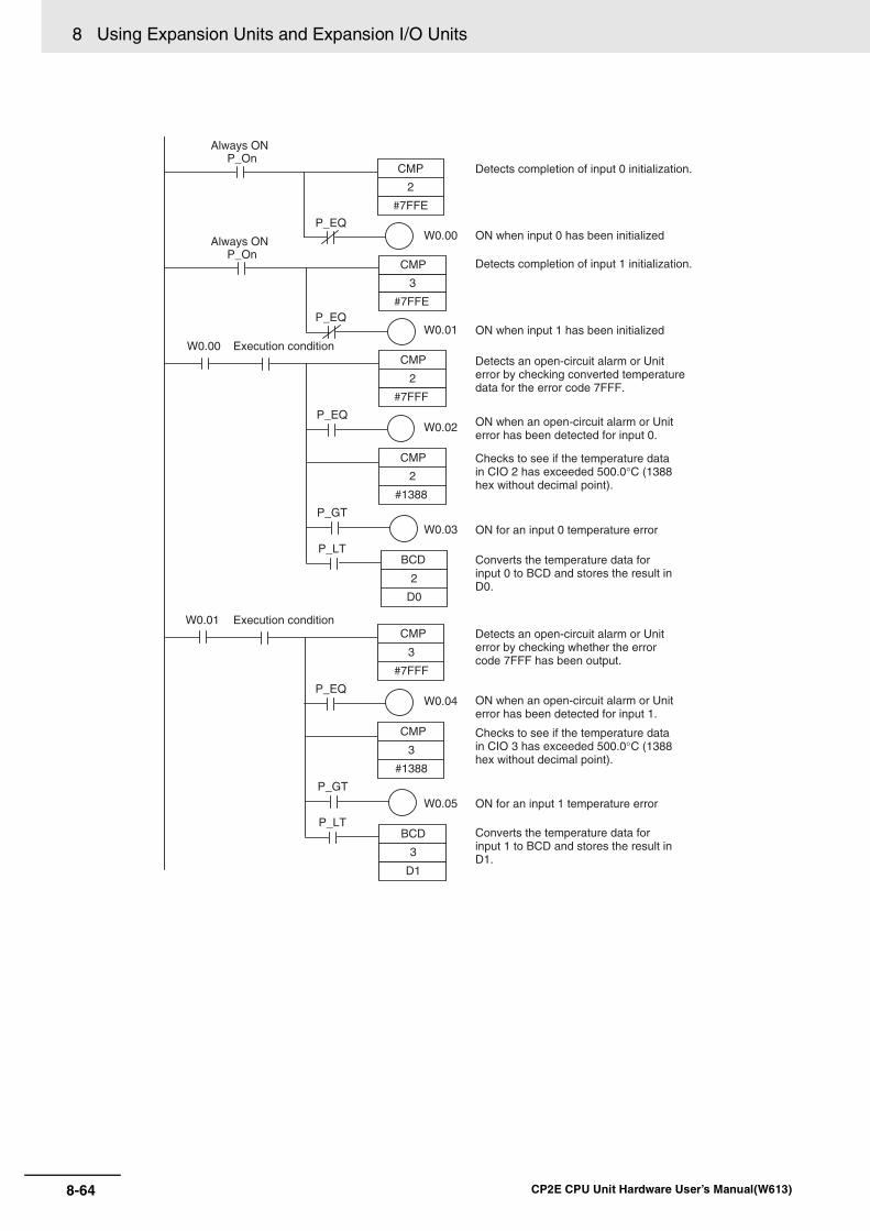
8 Using Expansion Units and Expansion I/O Units
8-64 CP2E CPU Unit Hardware User’s Manual(W613)
2
#7FFF
W0.00CMP
P_EQW0.00
2
#7FFE
Always ONP_On
CMP
P_EQW0.01
3
#7FFE
Always ONP_On
CMP Detects completion of input 1 initialization.
P_EQW0.02
2
#1388
CMP
P_GT
W0.03
P_LT
2
D0
BCD
3
#7FFF
W0.01 CMP
P_EQW0.04
3
#1388
CMP
P_GT
W0.05
P_LT
3
D1
BCD
Detects completion of input 0 initialization.
ON when input 0 has been initialized
ON when input 1 has been initializedExecution condition
Detects an open-circuit alarm or Unit error by checking converted temperature data for the error code 7FFF.
ON when an open-circuit alarm or Unit error has been detected for input 0.
Checks to see if the temperature data in CIO 2 has exceeded 500.0°C (1388 hex without decimal point).
ON for an input 0 temperature error
Converts the temperature data for input 0 to BCD and stores the result in D0.
Execution conditionDetects an open-circuit alarm or Unit error by checking whether the error code 7FFF has been output.
ON when an open-circuit alarm or Unit error has been detected for input 1.
Checks to see if the temperature data in CIO 3 has exceeded 500.0°C (1388 hex without decimal point).
ON for an input 1 temperature error
Converts the temperature data for input 1 to BCD and stores the result in D1.

8-65
8 Using Expansion Units and Expansion I/O Units
CP2E CPU Unit Hardware User’s Manual(W613)
8-4 Temp
erature S
enso
r Un
its
8
8-4-1 CP
1W-T
S1/T
S2 Tem
perature Sensor
Units
(b) The following programming example shows how to convert the data for tempera-ture input 0 to BCD and store the result in D0 and D1. “#0001” is stored in D1when the input data is a negative value. The following system configuration isused.
(6) Programming with BCD Instruction
Temperature unit setting 0 (°C)
Two-decimal-place mode
0 (normal)
Input range setting 1 (Pt100: -200.0 to 650.0°C)
Input 0 CIO 2
CP2E CPU Unit CP1W-TS001/101 Temperature Sensor Unit
Inputs
Outputs
CIO 0CIO 1
CIO 100CIO 101
CIO 2CIO 3
None
2
#7FFF
W0.00 CMP
W0.00
2
#7FFE
Always ONP_On
CMP Detects completion of input 0 initialization.
P_EQW0.01
2
D0
BCD
2.15
#0000
2
-(410)
P_EQ 2.15
#0000
D1
MOV
D0
D0
D0
BCD
#0001
D1
MOV
Execution condition
ON when input 0 has been initialized
Detects an open-circuit alarm or Unit error by checking whether the error code 7FFF has been output
ON when an open-circuit alarm or Unit error has been detected for input 0.
Stores positive BCD data in D0.
Stores #0000 in D1.
When input 0 converted value is negative (#0000 minus two’s complement = actual value)
Stores negative BCD data in D0.
Stores #0001 in D1 to indicate a negative number.
P_EQ

8 Using Expansion Units and Expansion I/O Units
8-66 CP2E CPU Unit Hardware User’s Manual(W613)
(7) Programming with SCL2 Instruction
• Operation
Two-decimal-place ModeIf pin 2 on the DIP switch is turned ON, values are stored to two decimal places. In this case, tem-perature data is stored as 6-digit signed hexadecimal (binary) data with 4 digits in the integer portionand 2 digits after the decimal point. The actual data stored in memory is 100 times the actual value,i.e., the decimal point is not indicated. Methods for handling this data are described in this section.
Additional Information
When set to store values to two decimal places, temperature data as far as two digits after thedecimal point is converted to 6-digit binary data, but the actual resolution is not 0.01°C (°F). Forthis reason, there may be skipping and inaccuracies in the first digit after the decimal point 0.1°C(°F). Treat any resolution above that specified for the normal data format as reference data.
Function Descriptions
2
#7FFF
W0.00 CMP
W0.00
2
#7FFE
Always ONP_On
CMP
P_EQ
P_EQ
W0.01
P_CY
P_EQ
#0000
D1
MOV
2
D10
SCL2
D0
P_CY
#0001
D1
MOV
ON when initialization complete.Execution condition
ON when an open-circuit alarm has been detected.
Parameter settings for data conversion:
When the converted value is non-negative, stores #0000 in D1.
When the converted value is negative, stores #0001 in D1.
Detects completion of input 0 initialization.
Detects an open-circuit alarm or Unit error by checking whether the error code 7FFF has been output
CIO 2
D1
1: Negative, 0: Non-negative
163 162 161 160
0 0 0 1/0 1/0D0
CY (when using SCL2 instruction)
Binary to BCD conversion
103 102 101 100
0: If data non-negative, “0000” stored in D1.1: If data negative, “0001” stored in D1.

8-67
8 Using Expansion Units and Expansion I/O Units
CP2E CPU Unit Hardware User’s Manual(W613)
8-4 Temp
erature S
enso
r Un
its
8
8-4-1 CP
1W-T
S1/T
S2 Tem
perature Sensor
Units
Temperature Data Partitioning and Structure
Data Conversion Examples
Example 1
Temperature: 1,130.25°C×100: 113025Temperature Data: 01B981 (hexadecimal for 113025)
Leftmost 3 Digits and Flags
015 347811121314
Rightmost 3 Digits and Flags
0 4 378
Not used.
Always 0
Temperature data
Temperature data
@ @ @ @ @ @
Leftmost/Rightmost Flag
Temperature Unit Flag
Open-circuit Flag
0: Leftmost1: Rightmost
0: °C1: °F
0: Normal1: Error
×165 ×163×164
×162 ×160×161
15 11121314
Leftmost/Rightmost Flag
0: Leftmost1: Rightmost
Temperature Unit Flag
0: °C1: °F
Open-circuit Flag
0: Normal1: Error
Not used.
Always 0
Leftmost/Rightmost Flag: Indicates whether the leftmost or rightmost 3 digits are provided.Temperature Unit Flag: Indicates whether the temperature is in °C or °F.Open-circuit Flag: Turns ON (1) when an open-circuit is detected. The temperature
data will be 7FF FFF if this flag is ON.
Temperature Data (Actual Temperature x 100 Binary)
Leftmost 3 Digits and Flags
Flags
Bits
Data
15
0
14
0
13
0
12
0
11 to 08
0
07 to 04
1
03 to 00
B 0 0 1 B
Flags
Rightmost 3 Digits and Flags
Flags
Bits
Data
15 14 13 12 11 to 08 07 to 04 0
1 0 0 0 9 8 1 8 9 8 1
Flags
Normal°C
Leftmost
Normal
Rightmost
×165 ×164 ×163
×162 ×161 ×160
°C
Temperature data
Temperature data

8 Using Expansion Units and Expansion I/O Units
8-68 CP2E CPU Unit Hardware User’s Manual(W613)
Example 2
Temperature: -100.12°C×100: -10012Temperature Data: FFD8E4 (hexadecimal for -10012)
Example 3
Temperature: -200.12°F×100: -20012Temperature Data: FFB1D4 (hexadecimal for -20012)
Example 4
Temperature: Open circuit (°F)Temperature Data: 7FFFFF
Leftmost 3 Digits and Flags
Flags
Bits
Data
15
0
14
0
13
0
12
0
11 to 08
F
07 to 04
F
03 to 00
D 0 F F D
Flags
Rightmost 3 Digits and Flags
Flags
Bits
Data
15
1
14
0
13
0
12
0
11 to 08
8
07 to 04
E
03 to 00
4 8 8 E 4
Flags
Normal°C
Leftmost
Normal°C
Rightmost
×165 ×164 ×163
×162 ×161 ×160
Temperature data
Temperature data
Leftmost 3 Digits and Flags
Flags
Bits
Data
15
0
14
1
13
0
12
0
11 to 08
F
07 to 04
F
03 to 00
B 4 F F B
Flags
Rightmost 3 Digits and Flags
Flags
Bits
Data
15
1
14
1
13
0
12
0
11 to 08
1
07 to 04
D
03 to 00
4 C 1 D 4
Flags
Normal°F
Leftmost
Normal°F
Rightmost
×165 ×164 ×163
×162 ×161 ×160
Temperature data
Temperature data
Leftmost 3 Digits and Flags
Flags
Bits
Data
15
0
14
1
13
1
12
0
11 to 08
7
07 to 04
F
03 to 00
F 6 7 F F
Flags
Rightmost 3 Digits and Flags
Flags
Bits
Data
15
1
14
1
13
1
12
0
11 to 08
F
07 to 04
F
03 to 00
F E F F F
Flags
Error°F
Leftmost
Error°F
Rightmost
×165 ×164 ×163
×162 ×161 ×160
Temperature data
Temperature data

8-69
8 Using Expansion Units and Expansion I/O Units
CP2E CPU Unit Hardware User’s Manual(W613)
8-4 Temp
erature S
enso
r Un
its
8
8-4-1 CP
1W-T
S1/T
S2 Tem
perature Sensor
Units
Additional Information
• Leftmost digits are stored in the lower memory addresses. Treat the data in the lower memoryaddress as the leftmost digits when programming.
• Be sure that the data is read at least once every 125 ms to allow for the CPU Unit’s cycle timeand communications time. Correct data may not be obtained if the read cycle is greater than125 ms.
Programming Example The following programming example shows how to use 2-decimal-place Mode for the following PLCconfiguration.
In this example, 100 times the temperature data for temperature input 0 (input to CIO 002) is storedin binary form in D100 to D102.
CPU Unit
InputsCIO 0CIO 1
OutputsCIO 100CIO 101
InputsCIO 2CIO 3
OutputsNone
CP1W-TS001 Temperature Sensor Unit
Temperature unit setting:0 (°C)
Two-decimal-place Mode:1 (2 digits after decimal point stored)
Temperature Unit Flag (0: °C, 1: °F)
Open-circuit Flag (0: Normal, 1: Error)
Bit
D100
D101
D102
15 14 13 12
Always 0
11 10 8 7 5 3 1
Always 0 Always 0 0 0
Temperature input 0 CIO 2 Leftmost data
Rightmost data
W100
9 6 4 2 0
×165 ×164
×163 ×162 ×161 ×160
×167 ×166

8 Using Expansion Units and Expansion I/O Units
8-70 CP2E CPU Unit Hardware User’s Manual(W613)
W0.02
#0000
D102
A200.11 (First Scan Flag)MOV
2#0020
MOVD
W101
#0100D103
2
#7FFE
CMP
W0.00
P_On (Always ON Flag)
P_EQ
W0.01
SET W0.02
2
W100
W0.00 2.13 (open-circuit detected)
2.15 (leftmost digits)
2.15 (leftmost digits)
2.15 (rightmost digits)
2000#0300
W101
2000#0011
W102
SET W0.03
RSET W0.02
MOV
(1)Sets D103 and D102 to #0100 and #0000, respectively.
Detects completion of input 0 initialization.
ON when input 0 has been initialized.
Open-circuit alarm output
MOV (2)Leftmost digits moved to W100.
(3)
(4)
(5)
Leftmost and rightmost digits rearranged and moved to W102 and W101.
MOVD
MOVD
Data rearrangement completed.
W101
D100
BCDL
D102
W101
-L(411)
D100
BCDL
#0008
#0300
MOVD
D101
REST W0.03
W0.03 W102.7 (non-negative data)
W102.7 (negative data)
H0
H0
(6)If the temperature data is non-negative, the binary data in W102 and W101 is converted to BCD and placed in D101 and D100.
(7)If the temperature data is negative, the 2’s complement data in W102 and W101 is converted to binary data representing the absolute value of the temperature input and placed in H1 and H0.
(8)The binary data in H1 and H0 is converted to BCD and placed in D101 and D100.
(9)“1” is written to the bit in D101 indicating negative data.

8-71
8 Using Expansion Units and Expansion I/O Units
CP2E CPU Unit Hardware User’s Manual(W613)
8-4 Temp
erature S
enso
r Un
its
8
8-4-2 CP
1W-T
S003 Tem
perature Sensor U
nits
Description of Operation
CP1W-TS003 Temperature Sensor Unit provides up to four input points. The inputs can be from ther-mocouples or analog inputs.
CP1W-TS003 Temperature Sensor Unit is allocated four input words, so no more than three Units canbe connected.
Temperature Sensor Units: CP1W-TS003
(1)Temperature Sensor Input TerminalsUsed to connect temperature sensors such as thermocouples or analog inputs.
(2)DIP SwitchUsed to set the input type (temperature or analog input), the input thermocouple type (K or J) andthe temperature unit (°C or °F). Make the setting according to the specifications of the tempera-ture sensors or analog inputs that are connected.
8-4-2 CP1W-TS003 Temperature Sensor Units
Overview
Part Names and Functions
W100
W102
CIO 2: Leftmost 3 digits of temperature data
0 165 164 163
0 0 165 164 W101 164 163 161 160
0 165 164 163
CIO 2: Rightmost 3 digits of temperature data
1 162 161 161
(2)
(1)
(9) If temperature data is negative, “8” is written here.
(3)
D101 0/8 106 105 104
D103 0 1 0 0
#0100
W102− 2’s complement data
D100 103 102 101 100
H1 0 0 165 164 H0 163 162 161 160
(5)(4)
(1)
D102 0 0 0 0
#0000
W101 2’s complement data
(6)If the temperature data is non-negative, binary data is converted to BCD data.
(8)If the temperature data is negative, binary data is converted to BCD data.
(7)Binary subtraction
(4) Expansion Connector
(1) Temperature Sensor or Analog Input Terminals (Terminal block is not removable)
(3) Expansion I/O Connector Cable
(2) DIP Switch

8 Using Expansion Units and Expansion I/O Units
8-72 CP2E CPU Unit Hardware User’s Manual(W613)
(3)Expansion I/O Connecting CableConnected to the expansion connector of a CP2E CPU Unit or an Expansion Unit or ExpansionI/O Unit.The cable is included with the Temperature Sensor Unit and cannot be removed.
Precautions for Safe Use
Do not touch the cables during operation. Static electricity may cause operating errors.
(4)Expansion ConnectorUsed for connecting Expansion Units or Expansion I/O Units.
*1 Only last two channels can be used as analog input.
*2 Accuracy for a K-type sensor at −100°C or less is ±4°C ±1 digit max.
*3 Accuracy for a K-type sensor at −100°C or less is ±10°C ±1 digit max.
Specifications
Item CP1W-TS003Temperature sensors Thermocouples or analog input *1
Switchable between K and J, but same type must be used for all inputs.
Number of inputs 4Allocated input words 4Max. number of Units 3Accuracy 25°C Thermocouple inputs (The larger of ±0.5% of converted value or ±2°C) ±1 digit max. *2
Analog voltage inputs 0.5% full scaleAnalog current inputs 0.6% full scale
0 to 60 °C Thermocouple inputs (The larger of ±1% of converted value or ±4°C) ±1 digit max. *3Analog voltage inputs 1.0% full scaleAnalog current inputs 1.2% full scale
-20 to 0 °C Thermocouple inputs (The larger of ±1.3% of converted value or ±5°C) ±1 digit max. *3Analog voltage inputs 1.2% full scaleAnalog current inputs 1.5% full scale
Input signal range Thermocouple inputs K: -200.0 to 1300.0°C or -300.0 to 2300.0°F
J: -100.0 to 850.0°C or -100.0 to 1500.0°FAnalog voltage inputs 0 to 10V, 1 to 5VAnalog current inputs 4 to 20mA
Resolution Thermocouple inputs 0.1°C or 0.1°FAnalog inputs 1/12000 (full scale)
Max. rated input Analog voltage inputs ±15VAnalog current inputs ±30mA
External input impedance
Analog voltage inputs 1MΩ min.Analog current inputs 250 Ω
Open-circuit detection function SupportedAveraging function UnsupportedConversion time 250 ms for 4 input pointsConverted temperature data 16-bit binary data (4-digit hexadecimal)
2-decimal-place mode is not supportedConverted AD data 16-bit binary data (4-digit hexadecimal)Isolation Photocouplers between any two input signalsCurrent consumption 5 VDC: 70 mA max., 24 VDC: 30 mA max.

8-73
8 Using Expansion Units and Expansion I/O Units
CP2E CPU Unit Hardware User’s Manual(W613)
8-4 Temp
erature S
enso
r Un
its
8
8-4-2 CP
1W-T
S003 Tem
perature Sensor U
nits
Analog Input Signal RangesAnalog input data is digitally converted according to the input signal range as shown below.
Additional Information
When the input exceeds the specified range, the A/D conversion data will be fixed at either thelower limit or upper limit.
0 to 10 VThe 0 to 10 V range corresponds to the hexadecimal values 0000 to 2EE0 (0 to 12000). The entiredata range is FDA8 to 3138 (−600 to 12600). A negative voltage is expressed as a two’s comple-ment.
1 to 5 VThe 1 to 5 V range corresponds to the hexadecimal values 0000 to 2EE0 (0 to 12000). The entiredata range is FDA8 to 3138 (−600 to 12600). Inputs between 0.8 and 1 V are expressed as two’scomplements. If the input falls below 0.8 V, open-circuit detection will activate and converted datawill be 8000.
0 V 10 V 10.5 V−0.5 V
FDA8 (−600)
3138 (12600)2EE0 (12000)
0000 (0)
Converted DataHexadecimal (Decimal)
1 V 5 V 5.2 V0.8 V
FDA8 (−600)
3138 (12600)2EE0 (12000)
0000 (0)
Converted DataHexadecimal (Decimal)

8 Using Expansion Units and Expansion I/O Units
8-74 CP2E CPU Unit Hardware User’s Manual(W613)
4 to 20 mAThe 4 to 20 mA range corresponds to the hexadecimal values 0000 to 2EE0 (0 to 12000). The entiredata range is FDA8 to 3138 (−600 to 12600). Inputs between 3.2 and 4 mA are expressed as two’scomplements. If the input falls below 3.2 mA, open-circuit detection will activate and converted datawill be 8000.
Open-circuit Detection Function for TemperatureIf the circuit is disconnected, the open-circuit detection function will operate and the converted tem-perature data will be set to 7FFF.
Open-circuit Detection Function for Analog InputsThe open-circuit detection function is activated when the input range is set to 1 to 5 V and the volt-age drops below 0.8 V, or when the input range is set to 4 to 20 mA and the current drops below 3.2mA. When the open-circuit detection function is activated, the converted data will be set to 8,000.
The time for enabling or clearing the open-circuit detection function is the same as the time for con-verting the data. If the input returns to the convertible range, the open-circuit detection is clearedautomatically and the output returns to the normal range.
Flow of Operation
1 • Connect the Temperature Sensor Units to the CPU Unit.
2 • Set the input type (temperature or analog input), the input thermo-couple type (K or J) and the temperature unit (°C or °F).
3 • Connect temperature sensors or analog devices.
4 • Read converted data stored in the input words.
4 mA 20 mA 20.8 mA3.2 mA
FDA8 (−600)
3138 (12600)2EE0 (12000)
0000 (0)0 mA
Converted DataHexadecimal (Decimal)
Set the temperature or analog ranges.
Connect the temperature sensors or analog devices.
Operation in the ladder program.
Connect the Temperature Sensor Units.

8-75
8 Using Expansion Units and Expansion I/O Units
CP2E CPU Unit Hardware User’s Manual(W613)
8-4 Temp
erature S
enso
r Un
its
8
8-4-2 CP
1W-T
S003 Tem
perature Sensor U
nits
1 Connect the Temperature Sensor Unit to the CPU Unit.
2 Set temperature or analog ranges.
Precautions for Safe Use
Do not touch the DIP switch while power is being supplied. Static electricity may cause operatingerrors.
Precautions for Correct UsePrecautions for Correct Use
Always turn OFF the power supply before setting the temperature range.
Set the temperature range according to the type of temperature sensorconnected to the Unit. Temperature data will not be converted correctly if the temperature rangedoes not match the sensor.
Do not set the temperature range to any values other than those forwhich temperature ranges are given in the following table. An incorrect setting may cause operating errors.
CP2E CPU Unit
IN
00
C H
C H
02 04 06 08 10
OUT
01C O M
C O M C O M C O M C O M 0600 01 02 04 05 07
00 01 02 03 04 05 06 07
03 05 07
08 09 10 11
09 11
20EDR1
C H 00 01 02 03
03
04 05 06 07
N C
N CN C
C H EXP
IN
00 0201C O M 03
C O M 070504 06
C H 00 01 02 03
08 09 10 11
8ED
EXP
CP1W-20EDR1Expansion I/O Unit
CP1W-8EDExpansion I/O Unit
CP1W-TS003Temperature Sensor Unit
Caution

8 Using Expansion Units and Expansion I/O Units
8-76 CP2E CPU Unit Hardware User’s Manual(W613)
With the Temperature Sensor Unit’s DIP switch, set the input type (temperature or analog input),the input thermocouple type (K or J) and the temperature unit (°C or °F).
Additional Information
Fahrenheit temperature uses the following equation to convert the temperature unit from Celsius,but the temperature input range is different between Fahrenheit and Celsius. Fahrenheit temperature (°F) = Celsius temperature (°C) x 1.8 + 32
3 Connect Temperature Sensors.
(1) Thermocouples
Either K or J thermocouples can be connected, but all four thermocouples must be thesame type and the same input range. Only last two channels can be used as analog inputs.
SW Setting1 Thermocouple type of
temperature sensorON J
OFF K
2 Temperature unit ON °F
OFF °C
3 NC
4 Input type selection for the third input (Input 2)
ON Analog input
OFF Thermocouple
5 Input type selection for the fourth input (Input 3)
ON Analog input
OFF Thermocouple
6 Analog input signal range
ON 1 to 5V/4 to 20mA
OFF 0 to 10V
Temperature input Analog inputInput type Range (°C) Range (°F) Input type Range
K -200.0 to 1300.0 -300.0 to 2300.0 Voltage 0 to 10V/1 to 5V
J -100.0 to 850.0 -100.0 to 1500.0 Current 4 to 20mA
SW 1 2 3 4 5 6
ON
OFF
Temperature input 0
LOOP0−
LOOP0+
NCLOOP1−
LOOP1+
NC I IN2
I IN3
Temperature input 1
Temperature input 2
Temperature input 3
LOOP2+V IN2
LOOP3+V IN3
LOOP2−COM2
LOOP3−COM3
Cold junction compensator

8-77
8 Using Expansion Units and Expansion I/O Units
CP2E CPU Unit Hardware User’s Manual(W613)
8-4 Temp
erature S
enso
r Un
its
8
8-4-2 CP
1W-T
S003 Tem
perature Sensor U
nits
Precautions for Correct UsePrecautions for Correct Use
When connecting a thermocouple input, observe the following precautions:
• Do not remove the cold junction compensator attached at the time of delivery. If the cold junc-tion compensator is removed, the Unit will not be able to measure temperatures correctly.
• Each of the input circuits is calibrated with the cold junction compensator attached to the Unit.If the Unit is used with the cold junction compensator from other Units, the Unit will not be ableto measure temperatures correctly.
• Do not touch the cold junction compensator. Doing so may result in incorrect temperaturemeasurement.
(2) Analog Inputs
Last two channels can be used as analog inputs, but two of the analog inputs must be thesame range.
• Wiring for Analog Inputs
Precautions for Correct UsePrecautions for Correct Use
• When an input is not being used, short the + and – terminals.
• Separate wiring from power lines (AC power supply lines, high-voltage lines, etc.)
• When there is noise in the power supply line, install a noise filter on the input section and thepower supply.
Temperature input 0
LOOP0−
LOOP0+
NCLOOP1−
LOOP1+
NC I IN2
I IN3
Temperature input 1
LOOP2+V IN2
LOOP3+V IN3
LOOP2−COM2
LOOP3−COM3
Cold junction compensator
Analog device with voltage output
Analog input 2
Analog input 3
Analog device with current output
V IN
COM
I IN
V IN
COM
I IN Analog device with voltage output
Analog input 2,3
+
−
+
−
Analog device with current output
Analog input 2,3
FG
2-core shieldedtwisted-pair cable
FG
2-core shieldedtwisted-pair cable

8 Using Expansion Units and Expansion I/O Units
8-78 CP2E CPU Unit Hardware User’s Manual(W613)
4 Create the ladder program.
(1) Word Allocations
Temperature Sensor Units are allocated words in the same way as other CP-series Expan-sion Units or Expansion I/O Units, in order of connection. A Temperature Sensor Unit isallocated the next input words following the input words of the CPU Unit or previous Expan-sion Unit or Expansion I/O Unit. Four input words are allocated to CP1W-TS003.
• Example
(2) Reading Temperature or Analog Data
The temperature or analog data will be stored in the input words allocated to the Tempera-ture Sensor Unit in 4-digit hexadecimal.
“m” is the last input word allocated to the CPU Unit, Expansion I/O Unit, or Expansion Unitconnected immediately before the Temperature Sensor Unit.
• Negative values are stored as 2’s complements.
• Data for range codes that include one digit after the decimal point are stored without thedecimal point, i.e., 10 times the actual value is stored.
• If the input temperature exceeds the maximum or minimum value in the temperatureinput range that has been set by ±20°C or ±20°F, the displayed value will be held.
• If the circuit is disconnected, the open-circuit detection function will operate and the con-verted temperature data will be set to 7FFF.
• The open-circuit detection function will be automatically cleared and normal input tem-perature conversion will begin automatically when the input temperature returns to theconvertible range.
(3) Startup Operation
After power is turned ON, approximately 1 s is required for the first conversion data to bestored in the input word. During that period, the data will be 7FFE. Therefore, create a pro-gram as shown below, so that the ladder can start to operate with valid conversion data ininput words.
Reading Temperature Data Reading Analog Datam+1 Converted temperature data from input 0 m+3 Converted analog data from input 2
m+2 Converted temperature data from input 1 m+4 Converted analog data from input 3
m+3 Converted temperature data from input 2
m+4 Converted temperature data from input 3
Input Data conversion examples
Unit: 0.1°C K or J ×10 500.0°C → 5000 → 1388 hex−20.0°C → −200 → FF38 hex−200.0°C → −2000 → F830 hex
None
CP1W-TS003 Temperature Sensor Unit
CP2E
Input word addresses
Output word addresses
CIO 0CIO 1
CIO 100CIO 101
CIO 2 CIO 3 CIO 4 CIO 5
(P_EQ)
W0.00
2
#7FFE
P_OnCMP
Always ON
Temperature input data output word
Initialization Completed Flag

8-79
8 Using Expansion Units and Expansion I/O Units
CP2E CPU Unit Hardware User’s Manual(W613)
8-4 Temp
erature S
enso
r Un
its
8
8-4-2 CP
1W-T
S003 Tem
perature Sensor U
nits
(4) Programming Example
The following programming example shows how to store the input data of CP1W-TS003 (4inputs) in D0 to D3, and W10.00 to W10.03 turn ON at the time of open-circuit detection.
• DIP Switch Setting
• Wiring Diagram
SW1 OFF K
SW2 OFF °C
SW3 NC
SW4 OFF Thermocouple
SW5 ON Analog
SW6 ON 1 to 5V/4 to 20mA
None
CP1W-TS003 Temperature Sensor Unit
Temperature unit setting: OFF(ºC)Input range settingInput 0: Thermocouple K(CIO2)Input 1: Thermocouple K(CIO3)Input 2: Thermocouple K(CIO4)Input 3: Analog input 1 to 5V(CIO5)
CP2E
Input word addresses
Output word addresses
CIO 0CIO 1
CIO 100CIO 101
CIO 2 CIO 3 CIO 4 CIO 5
Temperature input 0
LOOP0−
LOOP0+
NCLOOP1−
LOOP1+
NC I IN2
I IN3
Temperature input 1
Temperature input 2
LOOP2+V IN2
LOOP3+V IN3
LOOP2−COM2
LOOP3−COM3
Cold junction compensator
Analog device with voltage output
Analog input 3 (1 to 5 V)

8 Using Expansion Units and Expansion I/O Units
8-80 CP2E CPU Unit Hardware User’s Manual(W613)
W10.00
2
D0
MOV(021)
#7FFF
2
=(300)
#7FFE
2
<>(305)
W10.01
3
D1
MOV(021)
#7FFF
3
=(300)
#7FFE
3
<>(305)
W10.02
4
D2
MOV(021)
#7FFF
4
=(300)
#7FFE
4
<>(305)
W10.03
5
D3
MOV(021)
#8000
5
=(300)
#7FFE
5
<>(305)
Detects initialization complete
Stores input 0’s data in D0.
Stores input 1’s data in D1.
Stores input 2’s data in D2.
Stores input 3’s data in D3.
ON when an open-circuit alarm has been detected for thermocouples input 2.
ON when an open-circuit alarm has been detected for thermocouples input 2.
ON when an open-circuit alarm has been detected for thermocouples input 2.
ON when an open-circuit alarm has been detected for analog input 3.

8-81
8 Using Expansion Units and Expansion I/O Units
CP2E CPU Unit Hardware User’s Manual(W613)
8-4 Temp
erature S
enso
r Un
its
8
8-4-3 TS
004 Temperature S
ensor Units
CP1W-TS004 Temperature Sensor Unit provide up to twelve input points. The inputs can be fromthermocouples.
CP1W-TS004 Temperature Sensor Unit is allocated two input words and one output word, so nomore than seven Units can be connected.
Temperature Sensor Units: CP1W-TS004
(1)Temperature Sensor Input TerminalsUsed to connect temperature sensors such as thermocouples.
(2)DIP SwitchUsed to set the temperature unit (°C or °F) and the temperature input range. Make the settingaccording to the specifications of the temperature sensors that are connected.
(3)Expansion I/O Connecting CableConnected to the expansion connector of a CP2E CPU Unit or an Expansion Unit or Expan-sion I/O Unit. The cable is included with the Temperature Sensor Unit and cannot beremoved.
Precautions for Safe Use
Do not touch the cables during operation. Static electricity may cause operating errors.
(4)Expansion ConnectorUsed for connecting Expansion Units or Expansion I/O Units.
8-4-3 TS004 Temperature Sensor Units
Overview
Part Names and Functions
(4) Expansion Connector
(1) Temperature Sensor Input Terminals(3) Expansion I/O
Connector Cable
(2) DIP Switch

8 Using Expansion Units and Expansion I/O Units
8-82 CP2E CPU Unit Hardware User’s Manual(W613)
*1 Accuracy for a K-type sensor at −100°C or less is ±4°C ±1 digit max.
*2 Accuracy for a K-type sensor at −100°C or less is ±10°C ±1 digit max.
Open-circuit Detection Function for TemperatureIf the circuit is disconnected, the open-circuit detection function will operate and the converted tem-perature data will be set to 7FFF.
1 Connect the Temperature Sensor Unit to the CPU Unit.
Specifications
Item CP1W-TS004
Temperature sensors Thermocouples
Switchable between K and J, but same type must be used for all inputs.
Number of inputs 12
Allocated input words 2
Allocated output words 1
Accuracy 25°C (The larger of ±0.5% of converted value or ±2°C) ±1 digit max. *1
0 to 60°C (The larger of ±1% of converted value or ±4°C) ±1 digit max. *2
-20 to 0°C (The larger of ±1.3% of converted value or ±5°C) ±1 digit max. *2
Conversion time 500 ms for 12 input points
Converted temperature data 16-bit binary data (4-digit hexadecimal)
2-decimal-place mode is not supported
Isolation Photocouplers between any two input signals
Current consumption 5 VDC: 80 mA max., 24 VDC: 50 mA max.
Flow of Operation
1 • Connect the Temperature Sensor Units to the CPU Unit.
2 • Set the temperature unit and set the temperature input range.
3 • Connect temperature sensors.
4 • Read converted data stored in the input words.
Set the temperature ranges.
Connect the temperature sensors.
Connect the Temperature Sensor Units.
Operation in the ladder program.
CP2E CPU Unit
IN
00
C H
C H
02 04 06 08 10
OUT
01C OM 03 05 07 09 11
C OM CO M C OM 03 CO M 0600 01 02 04 05 07
00 01 02 03 04 05 06 07
08 09 10 11
20EDR1
C H 00 01 02 03 04 05 06 07
N C
N CN C
C H EXP
IN
00 0201C OM 03
C OM 05 0704 06
C H 00 01 02 03
08 09 10 11
8ED
EXP
CP1W-20EDR1Expansion I/O Unit
CP1W-8EDExpansion I/O Unit
CP1W-TS004Temperature Sensor Unit

8-83
8 Using Expansion Units and Expansion I/O Units
CP2E CPU Unit Hardware User’s Manual(W613)
8-4 Temp
erature S
enso
r Un
its
8
8-4-3 TS
004 Temperature S
ensor Units
2 Set temperature ranges.
Precautions for Safe Use
Do not touch the DIP switch while power is being supplied. Static electricity may cause operatingerrors.
Precautions for Correct UsePrecautions for Correct Use
Always turn OFF the power supply before setting the temperature range.
With the Temperature Sensor Unit’s DIP switch, set the temperature unit and the temperatureinput range.
Additional Information
Fahrenheit temperature uses the following equation to convert the temperature unit from Celsius,but the temperature input range is different between Fahrenheit and Celsius. Fahrenheit temperature (°F) = Celsius temperature (°C) × 1.8 + 32
Set the temperature range according to the type of temperature sensorconnected to the Unit. Temperature data will not be converted correctly if the temperature rangedoes not match the sensor.
Do not set the temperature range to any values other than those forwhich temperature ranges are given in the following table. An incorrect setting may cause operating errors.
SW Setting
1 Input type ON J
OFF K
2 Temperature unit ON °F
OFF °C
Temperature input
Input type Range (°C) Range (°F)
K -200.0 to 1300.0 -300.0 to 2300.0
J -100.0 to 850.0 -100.0 to 1500.0
Caution
SW
1
ON
OFF
SW
2

8 Using Expansion Units and Expansion I/O Units
8-84 CP2E CPU Unit Hardware User’s Manual(W613)
3 Connecte Temperature Sensors.
(1) Thermocouples
Either K or J thermocouples can be connected, but all twelve thermocouples must be thesame type and the same input range.
Precautions for Correct UsePrecautions for Correct Use
When connecting a thermocouple input, observe the following precautions:
• Do not remove the cold junction compensator attached at the time of delivery. If the cold junc-tion compensator is removed, the Unit will not be able to measure temperatures correctly.
• Each of the input circuits is calibrated with the cold junction compensator attached to the Unit.If the Unit is used with the cold junction compensator from other Units, the Unit will not be ableto measure temperatures correctly.
• Do not touch the cold junction compensator. Doing so may result in incorrect temperaturemeasurement.
• Use the thermocouple with metallic shield and connect the shield to ground.
4 Create the ladder program.
(1) Word Allocations
Temperature Sensor Units are allocated words in the same way as other CP-series Expan-sion Units or Expansion I/O Units, in order of connection. A Temperature Sensor Unit isallocated the next input words following the input words of the CPU Unit or previous Expan-sion Unit or Expansion I/O Unit. Two input words and one output word are allocated toCP1W-TS004.
• Example
Temperature input 0
Temperature input 1
Temperature input 11Cold junction compensator
CIO 102
CP2E
Input word addresses
Output word addresses
CIO 0CIO 1
CIO 100CIO 101
CIO 2 CIO 3
CP1W-TS004Temperature Sensor Unit

8-85
8 Using Expansion Units and Expansion I/O Units
CP2E CPU Unit Hardware User’s Manual(W613)
8-4 Temp
erature S
enso
r Un
its
8
8-4-3 TS
004 Temperature S
ensor Units
(2) Reading Temperature Data
There are 12 temperature input data to be read, but only two input words are allocated toCP1W-TS004. The operation is shown as the following.
• Input Word
• Output Word
• Read/Response Command and Temperature Data
• Negative values are stored as 2’s complements.
• The converted temperature data CIO m+2 is stored in 16-bit binary data (4-digit hexa-decimal).
• Data for range codes that include one digit after the decimal point are stored without thedecimal point, i.e., 10 times the actual value is stored.
• IIf the input temperature exceeds the maximum or minimum value in the temperatureinput range that has been set by ±20×C or ±20×F, the displayed value will be held.
• If the circuit is disconnected, the open-circuit detection function will operrate and theconverted temperature data will be set to 7FFF.
• The open-circuit detection function will be automatically cleared and normal input tem-perature conversion will begin automatically when the input temperature returns to theconvertible range.
m+1 Response. Input words stored in CIO m+2
m+2 Temperature data of the specified input word
n+1 Read command data (input word specified)
Command
Output Word Input Word
n+1 m+1 m+2
Read command
Response command
Temperature data(4-digit hexadecimal)
Read temperature data from input 0 #9901 9901 Input 0 temperature data
Read temperature data from input 1 #9902 9902 Input 1 temperature data
Read temperature data from input 2 #9903 9903 Input 2 temperature data
Read temperature data from input 3 #9904 9904 Input 3 temperature data
Read temperature data from input 4 #9905 9905 Input 4 temperature data
Read temperature data from input 5 #9906 9906 Input 5 temperature data
Read temperature data from input 6 #9907 9907 Input 6 temperature data
Read temperature data from input 7 #9908 9908 Input 7 temperature data
Read temperature data from input 8 #9909 9909 Input 8 temperature data
Read temperature data from input 9 #990A 990A Input 9 temperature data
Read temperature data from input 10 #990B 990B Input 10 temperature data
Read temperature data from input 11 #990C 990C Input 11 temperature data
Others Others No response for other commands
Input Data conversion examples
Unit: 0.1°C K or J ×10 500.0°C → 5000 → 1388 hex-20.0°C → -200 → FF38 hex-200.0°C → -2000 → F830 hex

8 Using Expansion Units and Expansion I/O Units
8-86 CP2E CPU Unit Hardware User’s Manual(W613)
(3) Creating Ladder Program
(1) Write temperature data commandWrite temperature data command which read temperature data from input word to CIOn+1.
(2) Response confirmationAfter CP1W-TS004 receives CIO n+1 read command and CP1W-TS004’s internallyspecified input temperature data is ready, the value which is the same as the read com-mand will be stored in CIO m+1. The temperature data will be stored in CIO m+2 at thesame time.
(3) Read temperature dataStore the temperature data from CIO m+2 in DM area.
Note 1 It takes about 2ms maximum until it is reflected to CIO m+1 and m+2 from writing the read command toCIO n+1.
2 It takes about 1s after the power is turned ON, till a read command initial processing of CP1W-TS004 iscompleted, so a response to the read command after power ON takes only about 1s. After the power isturned ON, create a ladder program 1s later due to its control by temperature data.
3 When writing a command other than that specified in the temperature data read command, CIO m+1 andm+2 hold the previous value.
The power is ON
CIO m+2 (3) Read temperature data
Store in DM area
CIO n+1 (1) Write temperature data
command
Read command matches response
CIO m+1(2) Response confirmation
Read command and response are unmatched
Response CIO m+1
#9902
Temperature data CIO m+2
Input 2 temperature data
2ms max. from writing read command, response, to reading temperature data
Approx. 1s Approx. 2ms
Read commandCIO n+1
0000 #9901 #9902 #9903
Power ON Write input 1 temperature data command
Write input 2 temperature data command
7FFE
7FFE #9901
Input 1 temperature data

8-87
8 Using Expansion Units and Expansion I/O Units
CP2E CPU Unit Hardware User’s Manual(W613)
8-4 Temp
erature S
enso
r Un
its
8
8-4-3 TS
004 Temperature S
ensor Units
(4) Programming Example
The temperature data of CP1W-TS004 (12 inputs, input type is J type and temperature unitis °C) is stored in D0 to D11.
When it occurs open-circuit alarm, W10.00 to W10.11 is ON.
• Temperature Data Storage Address
Input word Read command CIO n+1
Temperature data storage address
Open-circuit alarm
Input 0 #9901 D0 W0.00
Input 1 #9902 D1 W0.01
Input 2 #9903 D2 W0.02
Input 3 #9904 D3 W0.03
Input 4 #9905 D4 W0.04
Input 5 #9906 D5 W0.05
Input 6 #9907 D6 W0.06
Input 7 #9908 D7 W0.07
Input 8 #9909 D8 W0.08
Input 9 #990A D9 W0.09
Input 10 #990B D10 W0.10
Input 11 #990C D11 W0.11
CIO 102
CP2E
Input word addresses Input range
J: SW1 OFF
Temperature unit
°C: SW2 ONOutput word addresses
CIO 0CIO 1
CIO 100CIO 101
CIO 2 CIO 3
CP1W-TS004Temperature Sensor Unit

8 Using Expansion Units and Expansion I/O Units
8-88 CP2E CPU Unit Hardware User’s Manual(W613)
2
SET
W0.00
SET
W0.01
3
D0
MOV(021)
W0.00
RSET
W0.00
102
MOV(021)
#9901
#9901
=(300)
2
SET
W0.02
3
D1
MOV(021)
W0.01
RSET
W0.01
102
MOV(021)
#9902
#9902
=(300)
2
SET
W0.03
3
D2
MOV(021)
W0.02
RSET
W0.02
102
MOV(021)
#9903
#9903
=(300)
First Cycle ON Flag
Start to read temperature data.
W10.02
#7FFF
3
=(300)
W10.01
#7FFF
3
=(300)
W10.00
#7FFF
3
=(300)
Write input 0’s read command (#9901) to CIO 102 (CIO n+1).
W10.00 turns ONat the time of open-circuit detection (7FFF).
Read Input 0’s temperature data
Read Input 1’s temperature data
Read Input 2’s temperature data
If CIO 2 (CIO m+1) and read command are matched, store the temperature data (CIO m+2) to D0.

8-89
8 Using Expansion Units and Expansion I/O Units
CP2E CPU Unit Hardware User’s Manual(W613)
8-4 Temp
erature S
enso
r Un
its
8
8-4-3 TS
004 Temperature S
ensor Units
2
SET
W0.05
3
D4
MOV(021)
W0.04
RSET
W0.04
102
MOV(021)
#9905
#9905
=(300)
2
SET
W0.06
3
D5
MOV(021)
W0.05
RSET
W0.05
102
MOV(021)
#9906
#9906
=(300)
2
SET
W0.04
3
D3
MOV(021)
W0.03
RSET
W0.03
102
MOV(021)
#9904
#9904
=(300)
W10.03
#7FFF
3
=(300)
W10.04
#7FFF
3
=(300)
W10.05
#7FFF
3
=(300)
Read Input 3’s temperature data
Read Input 4’s temperature data
Read Input 5’s temperature data

8 Using Expansion Units and Expansion I/O Units
8-90 CP2E CPU Unit Hardware User’s Manual(W613)
2
SET
W0.07
3
D6
MOV(021)
W0.06
RSET
W0.06
102
MOV(021)
#9907
#9907
=(300)
2
SET
W0.08
3
D7
MOV(021)
W0.07
RSET
W0.07
102
MOV(021)
#9908
#9908
=(300)
W10.06
#7FFF
3
=(300)
W10.07
#7FFF
3
=(300)
2
SET
W0.09
3
D8
MOV(021)
W0.08
RSET
W0.08
102
MOV(021)
#9909
#9909
=(300)
W10.08
#7FFF
3
=(300)
Read Input 6’s temperature data
Read Input 7’s temperature data
Read Input 8’s temperature data

8-91
8 Using Expansion Units and Expansion I/O Units
CP2E CPU Unit Hardware User’s Manual(W613)
8-4 Temp
erature S
enso
r Un
its
8
8-4-3 TS
004 Temperature S
ensor Units
2
SET
W0.10
3
D9
MOV(021)
W0.09
RSET
W0.09
102
MOV(021)
#990A
#990A
=(300)
2
SET
W0.11
3
D10
MOV(021)
W0.10
RSET
W0.10
102
MOV(021)
#990B
#990B
=(300)
2
3
D11
MOV(021)
W0.11
SET
W0.00
RSET
W0.11
102
MOV(021)
#990C
#990C
=(300)
W10.09
#7FFF
3
=(300)
W10.10
#7FFF
3
=(300)
W10.11
#7FFF
3
=(300)
Read Input 9’s temperature data
Read Input 10’s temperature data
Read Input 11’s temperature data

8 Using Expansion Units and Expansion I/O Units
8-92 CP2E CPU Unit Hardware User’s Manual(W613)

A-1
App
CP2E CPU Unit Hardware User’s Manual(W613)
Ap
p
A-1 Dimensions . . . . . . . . . . . . . . . . . . . . . . . . . . . . . . . . . . . . . . . . . . . . . . . . . . A-2A-1-1 CPU Units . . . . . . . . . . . . . . . . . . . . . . . . . . . . . . . . . . . . . . . . . . . . . . . . . . . . A-2
A-1-2 Option Boards . . . . . . . . . . . . . . . . . . . . . . . . . . . . . . . . . . . . . . . . . . . . . . . . . A-5
A-1-3 Expansion I/O Units . . . . . . . . . . . . . . . . . . . . . . . . . . . . . . . . . . . . . . . . . . . . . A-8
A-1-4 Expansion Units . . . . . . . . . . . . . . . . . . . . . . . . . . . . . . . . . . . . . . . . . . . . . . . A-10
A-2 Wiring Diagrams . . . . . . . . . . . . . . . . . . . . . . . . . . . . . . . . . . . . . . . . . . . . . . A-12A-2-1 CPU Units . . . . . . . . . . . . . . . . . . . . . . . . . . . . . . . . . . . . . . . . . . . . . . . . . . . A-12
A-2-2 Expansion I/O Units . . . . . . . . . . . . . . . . . . . . . . . . . . . . . . . . . . . . . . . . . . . . A-18
A-2-3 Expansion Units . . . . . . . . . . . . . . . . . . . . . . . . . . . . . . . . . . . . . . . . . . . . . . . A-25
A-2-4 Serial Communications . . . . . . . . . . . . . . . . . . . . . . . . . . . . . . . . . . . . . . . . . A-36
A-3 Wiring for Serial Communications . . . . . . . . . . . . . . . . . . . . . . . . . . . . . . . A-41A-3-1 Recommended RS-232C Wiring . . . . . . . . . . . . . . . . . . . . . . . . . . . . . . . . . . A-41
A-3-2 Recommended RS-422A/485 Wiring . . . . . . . . . . . . . . . . . . . . . . . . . . . . . . . A-46
A-3-3 Reducing Electrical Noise for External Wiring . . . . . . . . . . . . . . . . . . . . . . . . A-49
A-4 Network Installation . . . . . . . . . . . . . . . . . . . . . . . . . . . . . . . . . . . . . . . . . . . A-50
A-5 Comparison between CP1E and CP2E . . . . . . . . . . . . . . . . . . . . . . . . . . . . A-53
Appendices

Appendices
A-2 CP2E CPU Unit Hardware User’s Manual(W613)
A-1 Dimensions
CP2E-N14/20D -Unit: mm
CP2E-E14/20D -Unit: mm
A-1-1 CPU Units
CPU Units with 14 or 20 I/O Points
76
100
110
90
86
2-φ4.5
808
76
100
110
90
86
2-φ4.5
808

A-3
Appendices
CP2E CPU Unit Hardware User’s Manual(W613)
A-1 D
imen
sion
s A
pp
A-1-1 C
PU
Units
CP2E-N30D -Unit: mm
CP2E-E30D - , CP2E-S30D -Unit: mm
CP2E-N40D -Unit: mm
CPU Units with 30 I/O Points
CPU Units with 40 I/O Points
120
110
100
90
1308
80
120130
90100
110
808
140
90
150
100
110
4-φ4.5
808

Appendices
A-4 CP2E CPU Unit Hardware User’s Manual(W613)
CP2E-E40D - , CP2E-S40D -Unit: mm
CP2E-N60D -Unit: mm
CP2E-E60D - , CP2E-S60D -Unit: mm
CPU Units with 60 I/O Points
14090
15010
011
0
4-φ4.5
808
185195
4-φ4.5
100
90110
880
185195
4-φ4.5
100
90110
880
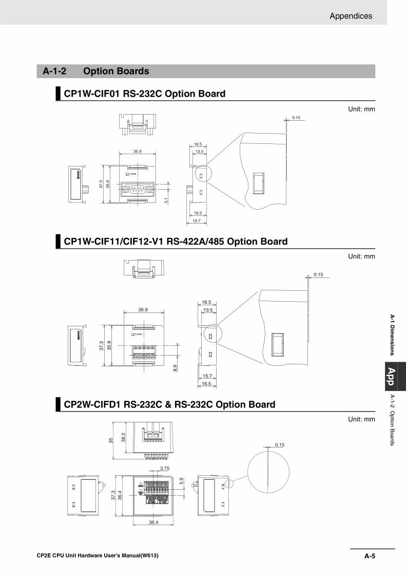
A-5
Appendices
CP2E CPU Unit Hardware User’s Manual(W613)
A-1 D
imen
sion
s A
pp
A-1-2 O
ption Boards
Unit: mm
Unit: mm
Unit: mm
A-1-2 Option Boards
CP1W-CIF01 RS-232C Option Board
CP1W-CIF11/CIF12-V1 RS-422A/485 Option Board
CP2W-CIFD1 RS-232C & RS-232C Option Board
35.9
37.3
35.9
5.1
16.5
16.5
0.15
13.5
19.7
35.9
37.3
35.9
8.9
15.7
16.5
0.15
13.5
16.5
0.15
5.9
36.4
36.4
37.3
3.75
35 38.2

Appendices
A-6 CP2E CPU Unit Hardware User’s Manual(W613)
Unit: mm
Unit: mm
Unit: mm
CP2W-CIFD2 RS-232C & RS485 Option Board
CP2W-CIFD3 RS-485 & RS-485 Option Board
CP1W-MAB221 Analog Input/Output Option Board
5.9
36.4
36.4
37.3
28.2
35
3.75
0.15
0.15
5.9
36.4
36.4
37.3
3.75
35 38.2
28.2 35
36.4
36.4 7.
3
37.3
8
0.15

A-7
Appendices
CP2E CPU Unit Hardware User’s Manual(W613)
A-1 D
imen
sion
s A
pp
A-1-2 O
ption Boards
Unit: mm
Unit: mm
CP1W-ADB21 Analog Input Option Board
CP1W-DAB21V Analog Output Option Board
28.2
36.4
36.4
37.3
35
7.3
8
0.15
28.2
36.4
36.4
37.3
35
7.3
3
0.15

Appendices
A-8 CP2E CPU Unit Hardware User’s Manual(W613)
Unit: mm
Unit: mm
Unit: mm
A-1-3 Expansion I/O Units
CP1W-8ED Expansion I/O Unit with 8 Input Points
CP1W-8E Expansion I/O Units with 8 Output Points
CP1W-16E Expansion I/O Units with 16 Output Points
50
8
2-φ4.5
90 100±0.2
5
556±0.2
66
50
8
2-φ4.5
90 100±0.2
5
556±0.2
66
50
82-φ4.5
90 100±0.2
5
576±0.2
86

A-9
Appendices
CP2E CPU Unit Hardware User’s Manual(W613)
A-1 D
imen
sion
s A
pp
A-1-3 E
xpansion I/O U
nits
Unit: mm
Unit: mm
Unit: mm
CP1W-32ER/ET/ET1 Expansion I/O Units with 32 Output Points
CP1W-20ED Expansion I/O Units with 20 I/O Points
CP1W-40ED Expansion I/O Units with 40 I/O Points
50
8 4-φ4.5
110 100 90
140
150
50
82-φ4.5
90 100±0.2
5
576±0.2
86
50
8 4-φ4.5
110 100 90
140
150

Appendices
A-10 CP2E CPU Unit Hardware User’s Manual(W613)
Unit: mm
Unit: mm
Unit: mm
A-1-4 Expansion Units
CP1W-MAD11/MAD42/MAD44 Analog I/O Units
CP1W-AD041/AD042 Analog Input Unit
CP1W-DA021/DA041/DA042 Analog Output Unit
50
8
2-φ4.5
90 100±0.2
576±0.2
86
5
50
876±0.2
86 2-φ4.5
5
90 100±0.2
5
5
50
82-φ4.5
76±0.2
86
90 100±0.2
5

A-11
Appendices
CP2E CPU Unit Hardware User’s Manual(W613)
A-1 D
imen
sion
s A
pp
A-1-4 E
xpansion Units
Unit: mm
Unit: mm
CP1W-TS 1/2/3 Temperature Sensor Units
CP1W-TS004 Temperature Sensor Units
90
5
5
86 50
876±0.2
100±0.2
508
5
50
5
5
90
Two,4.5 dia.holes
140±0.2150
5
90 100±0.2
140±0.2150

Appendices
A-12 CP2E CPU Unit Hardware User’s Manual(W613)
A-2 Wiring Diagrams
A-2-1 CPU Units
CPU Unit with 14 I/O Points (Terminal Block is not removable)
Input Wiring Diagram Output Wiring Diagram
All ModelsAC Power Supply
CP2E-E14DR-A
CP2E-N14D -A
DC Power Supply
CP2E-N14D -D
Relay OutputsCP2E-E14DR-A
CP2E-N14DR-
Transistor Outputs (Sinking)CP2E-N14DT-
Transistor Outputs (Sourcing)CP2E-N14DT1-D
24V DC
CIO 0
+
-+
-
NC
L1 L2/N COM 01 03 05 07 NC NC
00 02 04 06 NC NC
CIO 0
COM+ -
NC
DC Power Supply
N14D��-D
00 01 02 03 04 05 NC
COM COM NC COM NC COM NC
CIO 100
L L L L LL
CIO 100
CIO 100
CIO 100
L L L L LL
00 01 02 03 04 05 NC
COM COM NC COM NC COM NC
CIO 100
CIO 100
L L L L LL
00 01 02 03 04 05 NC
COM COM NC COM NC COM NC

A-13
Appendices
CP2E CPU Unit Hardware User’s Manual(W613)
A-2 W
iring
Diag
rams
Ap
pA
-2-1 CP
U U
nits
CPU Unit with 20 I/O Points (Terminal Block is not removable)
Input Wiring Diagram Output Wiring Diagram
All ModelsAC Power Supply
CP2E-E20DR-A
CP2E-N20D -A
DC Power Supply
CP2E-N20D -D
Relay OutputsCP2E-E20DR-A
CP2E-N20DR-
Transistor Outputs (Sinking)CP2E-N20DT-
Transistor Outputs (Sourcing)CP2E-N20DT1-D
24V DC
CIO 0
+
-+
-
NC
L1 L2/N COM 01 03 05 07 09 11
00 02 04 06 08 10
CIO 0
COM+ -
NC
DC Power Supply
N20D��-D
00 01 02 03 04 05 07
COM COM NC COM NC COM 06
CIO 100
L L L L L L
L
L
CIO 100
CIO 100
CIO 100
L L L L L L
L
L
00 01 02 03 04 05 07
COM COM NC COM NC COM 06
CIO 100
CIO 100
L L L L L L
L
L
00 01 02 03 04 05 07
COM COM NC COM NC COM 06

Appendices
A-14 CP2E CPU Unit Hardware User’s Manual(W613)
CPU Units with 30 I/O Points (Terminal Block is not removable)
Input Wiring Diagram Output Wiring Diagram
All ModelsAC Power SupplyCP2E-E30DR-A, CP2E-S30DR-A, CP2E-N30D -ADC Power Supply
CP2E-S30D -D, CP2E-N30D -D
Relay OutputsCP2E-E30DR-A, CP2E-S30DR-A, CP2E-N30DR-
Transistor Outputs (Sinking)CP2E-S30DT-D CP2E-N30DT-
Transistor Outputs (Sourcing)CP2E-S30DT1-D CP2E-N30DT1-D
24V DC+
-
CIO 0
+
-
L1 L2/N COM 01 03 05 07 09 11 01 03 05
00 02 04 06 08 10 00 02 04
CIO 1
CIO 0 CIO 1
COM+ -
NC
DC Power Supply
N/S30D��-D
CIO 100
CIO 101CIO 100
CIO 101
L L L L L L LL
L LLL
00+ 01 02 04 05 07 00 02
COM COM COM 03 COM 06- COM 01 03
NC
NC COM
N30DR-D
DC Power Supply
L L L L L LLL
L
L L
L
CIO 100
CIO 101CIO 100
CIO 101
00V+ 01 02 04 05 07 00 02
COM(-) COM 03 COM 06V- COM 01 03
L L L L L LLL
L
L L
L
CIO 100
CIO 101CIO 100
CIO 101
00+ 01 02 04 05 07 00 02
COM COM COM 03 COM 06- COM 01 03
NC
NC COM
N30DT-D
DC Power Supply
L L L L L LLL
L
L L
L
CIO 100
CIO 101CIO 100
CIO 101
00 01 02 04 05 07 00 02
COM 03 COM 06 COM 01 03
V+
COM(+)V-
L L L L L LLL
L
L L
L
CIO 100
CIO 101CIO 100
CIO 101
00NC 01 02 04 05 07 00 02
COM COM COM 03 COM 06NC COM 01 03

A-15
Appendices
CP2E CPU Unit Hardware User’s Manual(W613)
A-2 W
iring
Diag
rams
Ap
pA
-2-1 CP
U U
nits
CPU Units with 40 I/O Points (Terminal Block is not removable)
Input Wiring Diagram Output Wiring Diagram
All ModelsAC Power SupplyCP2E-E40DR-A, CP2E-S40DR-A, CP2E-N40D -ADC Power SupplyCP2E-S40D -D, CP2E-N40D -D
Relay OutputsCP2E-E40DR-A, CP2E-S40DR-A, CP2E-N40DR-
Transistor Outputs (Sinking)CP2E-S40DT-D CP2E-N40DT-
Transistor Outputs (Sourcing)CP2E-S40DT1-D CP2E-N40DT1-D
CIO 1CIO 0
24V DC+
-
CIO 1CIO 0
+
-
L1 L2/N COM 01 03 05 07 09 11 01 03 05 07 09 11
00 02 04 06 08 10 00 02 04 06 08 10
COM+ -
NC
DC Power Supply
N/S40D��-D
L L L L L L LLLLL
L L L L L
00+ 01 02 03 04 06 00 01 03 04 06
- COM COM COM COM 05 07 COM 02 COM 05 07
00NC
NC
CIO 100
CIO 100 CIO 101
CIO 101
N40DR-D
DC Power Supply
L L L L L L LLLLL
LLLLL
00V+ 01 02 03 04 06 00 01 03 04 06
V- COM(-) COM COM 05 07 COM 02 COM 05 07
CIO 100
CIO 101CIO 100
CIO 101
L L L L L L LLLLL
LLLLL
00+ 01 02 03 04 06 00 01 03 04 06
- COM COM COM COM 05 07 COM 02 COM 05 07
CIO 100
CIO 101CIO 100
CIO 101
N40DT-D
DC Power Supply
00NC
NC
L L L L L L LLLLL
LLLLL
00V+ 01 02 03 04 06 00 01 03 04 06
V- COM(+) COM COM 05 07 COM 02 COM 05 07
CIO 100
CIO 101CIO 100
CIO 101
L L L L L L LLLLL
LLLLL
00NC 01 02 03 04 06 00 01 03 04 06
NC COM COM COM COM 05 07 COM 02 COM 05 07
CIO 100
CIO 101CIO 100
CIO 101

Appendices
A-16 CP2E CPU Unit Hardware User’s Manual(W613)
CPU Units with 60 I/O Points (Terminal Block is not removable)
Input Wiring Diagram Output Wiring Diagram
All ModelsAC Power Supply
CP2E-E60DR-A, CP2E-S60DR-A,
CP2E-N60D -A
DC Power Supply
CP2E-S60D -D, CP2E-N60D -D
Relay OutputsCP2E-E60DR-A, CP2E-S60DR-A, CP2E-N60DR-
Transistor Outputs (Sinking)CP2E-S60DT-D CP2E-N60DT-
Transistor Outputs (Sourcing)CP2E-S60DT1-D CP2E-N60DT1-D
24 V DC +
-
CIO 1 CIO 0
+
-
CIO 1 CIO 0 CIO 2
CIO 2
L2/NL1 COM 01 03 05 07 09 11
00 02 04 06 08 10
01 03 05 07 09 11
00 02 04 06 08 10
01 03 05 07 09 11
00 02 04 06 08 10
N/S60D��-D
DC Power Supply
-+ COM
NC
DC Power Supply
N60DR-D
NC
NC COM
L L L
CIO 101 CIO 100 CIO 102
+ 00 01 02 04 05 07 00 02 04 05 07 00 02 04 05 07
- COM COM COM 03 COM 06 COM 01 03 COM 06 COM 01 03 COM 06
L L L L L L L L L L L L L L L L
L L L L L
CIO 100 CIO 101 CIO 102
L LL
V+ 00 02 04 05 07 04 05 07 02 05 07
COM(-) COM COM03 COM06 COM COM 03 COM
L LLLLLLLLLL L L L L L
L L L L L
CIO 100 CIO 101 CIO 102
CIO 100 CIO 101 CIO 102
L LL
L LLLLLLLLLL L L L L L
L L L L L
01 03 06 01 06
0400020001
V-
L LL
CIO 101 CIO 100 CIO 102
+ 00 01 02 04 05 07 00 02 04 05 07 00 02 04 05 07
- COM COM COM 03 COM 06 COM 01 03 COM 06 COM 01 03 COM 06
L LLLLLLLLLL L L L L L
L L L L L
CIO 100 CIO 101 CIO 102
L LL
CIO 101 CIO 100 CIO 102
+ 00 01 02 04 05 07 00 02 04 05 07 00 02 04 05 07
- COM COM COM 03 COM 06 COM 01 03 COM 06 COM 01 03 COM 06
L LLLLLLLLLL L L L L L
L L L L L
CIO 100 CIO 101 CIO 102
DC Power Supply
N60DT-D
NC
NC COM
L L L
V+
V- COM(+)
L L L L L LLLLLLLLLLL
L L L L L
CIO 100 CIO 101 CIO 102
CIO 100 CIO 101 CIO 102
00 02 04 05 07 04 05 07 02 05 07
COM COM03 COM06 COM COM 03 COM01 03 06 01 06
0400020001
L L L
CIO 101 CIO 100 CIO 102
NC 00 01 02 04 05 07 00 02 04 05 07 00 02 04 05 07
NC COM COM COM 03 COM 06 COM 01 03 COM 06 COM 01 03 COM 06
L L L L L LLLLLLLLLLL
L L L L L
CIO 100 CIO 101 CIO 102

A-17
Appendices
CP2E CPU Unit Hardware User’s Manual(W613)
A-2 W
iring
Diag
rams
Ap
pA
-2-1 CP
U U
nits
AC-power-supply CPU Units with 30, 40 or 60 I/O points have an external power supply (DC24V 0.3A),and can be used as a service power supply for input devices.
DC-power-supply CPU Units with 14 or 20 I/O points have no external power supply.
Wiring Example: AC-power-supply CPU Units with 40 I/O Points
Input Wiring Example When Using External Power Supply
L2/NL1 COM 01 03 05 07 09 11 01 03 05 07 09 11
00 02 04 06 08 10 00 02 04 06 08 10
+ 0100 02 03 04 06 00 01 03 04 06
- COMCOM COM COM 05 07 COM 02 COM 05 07
Input device
Input device
24VDC 0.3AOUTPUT
Input terminal
Output terminal

Appendices
A-18 CP2E CPU Unit Hardware User’s Manual(W613)
The first input word allocated to the Expansion I/O Unit is shown as CIO m and the first output word isshown as CIO n.
A-2-2 Expansion I/O Units
8-point Input Unit (Terminal Block is not removable)
Input Wiring Diagram Output Wiring Diagram
Outputs not provided.
8-point Output Units (Terminal Block is not removable)
Input Wiring Diagram Output Wiring Diagram
Inputs not provided. Relay Outputs CP1W-8ER
24V DC
24V DC
- +
+ -
- +
+ -
CIO m
COM 01 03
00 02 COM 05 07
04 06
The COM terminals on the upper terminal block and the COM terminals on the lower terminal block are internally connected, but they must also be wired externally.
Unit Upper Terminal Block Unit Lower Terminal Block
L L
L L
L L
L L
CIO n
Unit Lower Terminal Block
24V DC
24V DC
Unit Upper Terminal Block
COM 01 03
00 02 COM 05 07
04 06

A-19
Appendices
CP2E CPU Unit Hardware User’s Manual(W613)
A-2 W
iring
Diag
rams
Ap
pA
-2-2 Expansion I/O
Units
Inputs not provided. Transistor Outputs (Sinking)CP1W-8ET
Transistor Outputs (Sourcing)CP1W-8ET1
16-point Output Units (Terminal Block is not removable)
Input Wiring Diagram Output Wiring Diagram
Inputs not provided. Relay OutputsCP1W-16ER
Input Wiring Diagram Output Wiring Diagram
L L
L L
L L
L L
-
+
-
+
Unit Lower Terminal BlockUnit Upper Terminal Block
COM 05 07
04 06COM 01 03
00 02
4.5 to 30 VDC
4.5 to 30 VDC
CIO n
L L
L L
L L
L L
-
+
-
+
COM 05 07
04 06COM 01 03
00 02
4.5 to 30 VDC
4.5 to 30 VDC
CIO n
Unit Lower Terminal BlockUnit Upper Terminal Block
L L LL L L
L L
CIO n
Unit Upper Terminal Block
NC COM COM COM 04 06 COM
NC 00 01 02 03 05 07

Appendices
A-20 CP2E CPU Unit Hardware User’s Manual(W613)
Inputs not provided.
Transistor Outputs (Sinking)CP1W-16ET
Transistor Outputs (Sourcing)CP1W-16ET1
Input Wiring Diagram Output Wiring Diagram
NC 00 02 04 05 07 NC
NC COM 01 03 COM 06 NC
L L L
L L L L L
CIO n+1
Unit Lower Terminal Block
L L L
NC COM COM COM 04 06 COM
NC 00 01 02 03 05 07
L L L
L L
NC 00 02 04 05 07 NC
NC COM 01 03 COM 06 NC
L L L
L L L L L
Unit Lower Terminal Block
Unit Upper Terminal Block
CIO n
CIO n+1
L L L
NC COM COM COM 04 06 COM
NC 00 01 02 03 05 07
L L L
L L
Unit Upper Terminal Block
CIO n

A-21
Appendices
CP2E CPU Unit Hardware User’s Manual(W613)
A-2 W
iring
Diag
rams
Ap
pA
-2-2 Expansion I/O
Units
Inputs not provided.
32-point Output Units (Terminal Block is not removable)
Input Wiring Diagram Output Wiring Diagram
Inputs not provided. Relay OutputsCP1W-32ER
Unit Upper Terminal Block
Unit Lower Terminal Block
Input Wiring Diagram Output Wiring Diagram
NC
NC
00 02 04 05 07 NC
COM 01 03 COM 06 NC
L L L
L L L L L
CIO n+1
Unit Lower Terminal Block
NC COM COM COM 05 07 COM 02 COM 05 07 NC NC NC
00 02 03 04 06 00 01 03 04 06
L L L L L L L LL
L LL L
CIO n+1CIO n
L
LL
COM
NCNCNC01
CIO n+1CIO n
L L L
LL L L L
L L L LLLLL
00 02 03 04 06 00 01 03 04 06
NC COM COM COM 05 07 COM 02 COM 05 07COM
NC01
CIO n+2
CIO n+2
CIO n+3
CIO n+3

Appendices
A-22 CP2E CPU Unit Hardware User’s Manual(W613)
Inputs not provided. Transistor Outputs (Sinking)CP1W-32ET
Unit Upper Terminal Block
Unit Lower Terminal Block
Transistor Outputs (Sourcing) CP1W-32ET1
Unit Upper Terminal Block
Input Wiring Diagram Output Wiring Diagram
NC COM COM COM COM 05 07 COM 02 COM 05 07 NC NC NC
00 01 02 03 04 06 00 01 03 04 06 NC NC NC
L L L L L L L LL
L LL LL
LL
CIO n
CIO n CIO n+1
CIO n+1
L L L
LL L L L
L L L LLLLL
00 01 02 03 04 06 00 01 03 04 06 NC
NC COM COM COM 05 07 COM 02 COM 05 07COM
CIO n+2
CIO n+2 CIO n+3
CIO n+3
NC COM COM COM COM 05 07 COM 02 COM 05 07 NC NC NC
00 01 03 04 06 00 01 03 04 06 NC NC NC
L L L L L L L LL
L LL LL
LL
02
CIO n
CIO n CIO n+1
CIO n+1

A-23
Appendices
CP2E CPU Unit Hardware User’s Manual(W613)
A-2 W
iring
Diag
rams
Ap
pA
-2-2 Expansion I/O
Units
Inputs not provided. Unit Lower Terminal Block
20-point I/O Units (Terminal Block is not removable)
Input Wiring Diagram Output Wiring Diagram
All Models Relay OutputsCP1W-20EDR1
Transistor Outputs (Sinking)CP1W-20EDT
Input Wiring Diagram Output Wiring Diagram
L L L
LL L L L
L L L LLLLL
00 01 02 03 04 06 00 01 03 04 06
NC COM COM COM 05 07 COM 02 COM 05 07COM
NC
CIO n+3
CIO n+3
CIO n+2
CIO n+2
COM 01 03 05 07 09 11
NC 00 02 04 06 08 10
- +
-+
CIO m
CIO m
24V DC
00 01 02 04 05 07
COM COM COM 03 COM 06
L L
L LLLLL
CIO n
L L L L L L
L L
COM COM COM COM03 06
00 01 02 04 05 07CIO n

Appendices
A-24 CP2E CPU Unit Hardware User’s Manual(W613)
Transistor Outputs (Sourcing)CP1W-20EDT1
40-point I/O Units (Terminal Block is not removable)
Input Wiring Diagram Output Wiring Diagram
All Models Relay OutputsCP1W-40EDR
Transistor Outputs (Sinking)CP1W-40EDT
Transistor Outputs (Sourcing)CP1W-40EDT1
Input Wiring Diagram Output Wiring Diagram
L L L L L L
L L
COM COM COM COM03 06
00 01 02 04 05 07CIO n
+
-
-
+
NC NC
NCNC
COM 01 03 05 07 09 11 01 03 05 07 09 11
00 02 04 06 08 10 00 02 04 06 08 10
24V DC
CIO m
CIO m
CIO m+1
CIO m+1
L L L
L L L L L
L L L LLLLL
NC 00 01 02 04 05 07 00 02 04 05 07
NC COM COM COM 03 COM 06 COM 01 03 COM 06
CIO n CIO n+1
CIO n+1CIO n
LLL L
L L L LL L L L L L L
L
CIO n
CIO n CIO n+1
CIO n+1
NC 00 01 02 04 05 07 00 02 04 05 07
NC COM COM COM 03 COM 06 COM 01 03 COM 06
LLL L
L L L LL L L L L L L
L
CIO n
CIO n CIO n+1
CIO n+1
NC 00 01 02 04 05 07 00 02 04 05 07
NC COM COM COM 03 COM 06 COM 01 03 COM 06

A-25
Appendices
CP2E CPU Unit Hardware User’s Manual(W613)
A-2 W
iring
Diag
rams
Ap
pA
-2-3 Expansion U
nits
A-2-3 Expansion Units
CP1W-AD041/AD042 Analog Input Unit (Terminal Block is not removable)
Wiring Diagrams
Input Terminal Arrangement
Note For current inputs, short V IN1 to I IN1, V IN2 to I IN2, V IN3 to I IN3, and V IN4 to I IN4.
Wiring Methods
Example:
CHI IN1 I IN3
I IN2VIN1VIN2
VIN3COM1COM2
I IN4VIN4 COM4
NCAG
COM3
IN
V IN1 Voltage input 1
I IN1 Current input 1
COM1 Input common 1
V IN2 Voltage input 2
I IN2 Current input 2
COM2 Input common 2
V IN3 Voltage input 3
I IN3 Current input 3
COM3 Input common 3
V IN4 Voltage input 4
I IN4 Current input 4
COM4 Input common 4
V IN
COM
I IN
V IN
COM
I INAnalog device with voltage output
Analog Input Unit
+
−
+
−
Analog device with current output
Analog Input Unit
2-core shieldedtwisted-pair cable
2-core shieldedtwisted-pair cable
FGFG
�
������
������
�
I IN1 VIN2 COM2 I IN3 VIN4 COM4 AG
VIN1 COM1 I IN2 VIN3 COM3 I IN4 NC
+
–
–
Connection toinput 1 forvoltage input
Connection toinput 2 forcurrent input
Voltageoutput
Current output
+

Appendices
A-26 CP2E CPU Unit Hardware User’s Manual(W613)
CP1W-DA021 Analog Output Unit (Terminal Block is not removable)
Wiring Diagrams
Output Terminal Arrangement
Wiring Methods
Example:
CHI OUT1
I OUT2VOUT1VOUT2
COM1COM2
NCNC
NCNC
NCNC
NCNC
OUT
V OUT1 Voltage output 1
I OUT1 Current output 1
COM1 Output common 1
V OUT2 Voltage output 2
I OUT2 Current output 2
COM2 Output common 2
V OUT
COM
I OUT
V OUT
COM
I OUT
Analog device with voltage input
+
−
+
−
Analog output Unit
Analog device with current input
2-core shielded twisted-pair cable
2-core shielded twisted-pair cable
Analog output Unit
FG FG
IOUT1 VOUT2 COM2 NC
VOUT1 COM1 IOUT2 NC
NC
NC
NC
NC
NC
NC
Connection tooutput 1 forvoltage output
VoltageInput
Current Input
Connection tooutput 2 forcurrent output
�������
+
–
+
–
�������

A-27
Appendices
CP2E CPU Unit Hardware User’s Manual(W613)
A-2 W
iring
Diag
rams
Ap
pA
-2-3 Expansion U
nits
CP1W-DA041/DA042 Analog Output Unit (Terminal Block is not removable)
Wiring Diagrams
Output Terminal Arrangement
Wiring Methods
Example:
CHI OUT1 I OUT3
I OUT2VOUT1VOUT2
VOUT3COM1COM2
I OUT4VOUT4 COM4
NCNC
COM3
OUT
V OUT1 Voltage output 1
I OUT1 Current output 1
COM1 Output common 1
V OUT2 Voltage output 2
I OUT2 Current output 2
COM2 Output common 2
V OUT3 Voltage output 3
I OUT3 Current output 3
COM3 Output common 3
V OUT4 Voltage output 4
I OUT4 Current output 4
COM4 Output common 4
V OUT
COM
I OUT
V OUT
COM
I OUT
Analog device with voltage input
+
−
+
−
Analog output Unit
Analog device with current input
2-core shielded twisted-pair cable
2-core shielded twisted-pair cable
Analog output Unit
FG FG
IOUT1 VOUT2 COM2 IOUT3 VOUT4 COM4 NC
VOUT1 COM1 IOUT2 VOUT3 COM3 IOUT4 NC
Connection tooutput 1 forvoltage output
VoltageInput
Current Input
Connection tooutput 2 forcurrent output
�������
+
–
+
–
�������

Appendices
A-28 CP2E CPU Unit Hardware User’s Manual(W613)
CP1W-MAD11 Analog I/O Unit (Terminal Block is not removable)
Wiring Diagrams
I/O Terminal Arrangement
Note For current inputs, short V IN0 to I IN0 and V IN1 to I IN1.
Wiring Methods• Wiring Analog Inputs
• Wiring Analog Outputs
V OUT Voltage output
I OUT Current output
COM Output common
V IN0 Voltage input 0
I IN0 Current input 0
COM0 Input common 0
V IN1 Voltage input 1
I IN1 Current input 1
COM1 Input common 1
V IN
COM
I IN
V IN
COM
I IN
Analog device with voltage output
+
−
+
−
Analog I/O Unit
Analog device with current output
Analog I/O Unit
2-core shielded twisted-pair cable
FG
2-core shielded twisted-pair cable
FG
FG FG
V OUT
COM
I OUT
V OUT
COM
I OUT
Analog device with voltage input
+
−
+
−
Analog I/O Unit
Analog device with current input
Analog I/O Unit
2-core shielded twisted-pair cable
2-core shielded twisted-pair cable

A-29
Appendices
CP2E CPU Unit Hardware User’s Manual(W613)
A-2 W
iring
Diag
rams
Ap
pA
-2-3 Expansion U
nits
Example:
Wiring Diagrams
I OUT NC NC V IN0 COM0 IIN1 AG
VOUT COM NC NC I IN0 V IN1 COM1
Connection toinput forvoltage output
Connection toinput 0 forvoltage input
Connection toinput 1 forcurrent input
Voltage output
Current output
Voltage input
�������
�������
+
–
+
+
–
–

Appendices
A-30 CP2E CPU Unit Hardware User’s Manual(W613)
CP1W-MAD42 Analog I/O Unit (Terminal Block is not removable)
Wiring Diagrams
I/O Terminal Arrangement• Input Terminal Arrangement
Note For current inputs, short V IN1 to I IN1, V IN2 to I IN2, V IN3 to I IN3, and V IN4 to I IN4.
• Output Terminal Arrangement
Wiring Methods• Wiring Analog Inputs
• Wiring Analog Outputs
V IN1 Voltage input 1
I IN1 Current input 1
COM1 Input common 1
V IN2 Voltage input 2
I IN2 Current input 2
COM2 Input common 2
V IN3 Voltage input 3
I IN3 Current input 3
COM3 Input common 3
V IN4 Voltage input 4
I IN4 Current input 4
COM4 Input common 4
V OUT1 Voltage output 1
I OUT1 Current output 1
COM1 Output common 1
V OUT2 Voltage output 2
I OUT2 Current output 2
COM2 Output common 2
V IN
COM
I IN
V IN
COM
I IN
Analog device with voltage output
+
−
+
−
Analog I/O Unit
Analog device with current output
Analog I/O Unit
2-core shielded twisted-pair cable
FG
2-core shielded twisted-pair cable
FG
FG FG
V OUT
COM
I OUT
V OUT
COM
I OUT
Analog device with voltage input
+
−
+
−
Analog I/O Unit
Analog device with current input
Analog I/O Unit
2-core shielded twisted-pair cable
2-core shielded twisted-pair cable

A-31
Appendices
CP2E CPU Unit Hardware User’s Manual(W613)
A-2 W
iring
Diag
rams
Ap
pA
-2-3 Expansion U
nits
CP1W-MAD44 Analog I/O Unit (Terminal Block is not removable)
Wiring Diagrams
I/O Terminal Arrangement• Input Terminal Arrangement
Note For current inputs, short V IN1 to I IN1, V IN2 to I IN2, V IN3 to I IN3, and V IN4 to I IN4.
• Output Terminal Arrangement
Wiring Methods• Wiring Analog Inputs
• Wiring Analog Outputs
V IN1 Voltage input 1
I IN1 Current input 1
COM1 Input common 1
V IN2 Voltage input 2
I IN2 Current input 2
COM2 Input common 2
V IN3 Voltage input 3
I IN3 Current input 3
COM3 Input common 3
V IN4 Voltage input 4
I IN4 Current input 4
COM4 Input common 4
V OUT1 Voltage output 1
I OUT1 Current output 1
COM1 Output common 1
V OUT2 Voltage output 2
I OUT2 Current output 2
COM2 Output common 2
V OUT3 Voltage output 3
I OUT3 Current output 3
COM3 Output common 3
V OUT4 Voltage output 4
I OUT4 Current output 4
COM4 Output common 4
V IN
COM
I IN
V IN
COM
I IN
Analog device with voltage output
+
−
+
−
Analog I/O Unit
Analog device with current output
Analog I/O Unit
2-core shielded twisted-pair cable
FG
2-core shielded twisted-pair cable
FG
FG FG
V OUT
COM
I OUT
V OUT
COM
I OUT
Analog device with voltage input
+
−
+
−
Analog I/O Unit
Analog device with current input
Analog I/O Unit
2-core shielded twisted-pair cable
2-core shielded twisted-pair cable

Appendices
A-32 CP2E CPU Unit Hardware User’s Manual(W613)
CP1W-TS001/TS002/TS101/TS102 Temperature Sensor Units(Terminal Block is not removable)
Wiring Diagrams
Connecting a Thermocouple• CP1W-TS001
One or two K or J thermocouples can be connected to the CP1W-TS001. Both of the thermocouples must be of the same type and the same input range must be used foreach. Example:
• CP1W-TS002One to four K or J thermocouples can be connected to the CP1W-TS002. All of the thermocouples must be of the same type and the same input range must be used foreach.Example:
Input 0−
Input 0+
NCInput 1−
Input 1+
NC NC NC NC
NC NC NC
Temperature input 0
Temperature input 1
Cold junction compensator
Temperature input 0
Input 0
Input 0+
NCInput 1
Input 1+
NC NC
NC
Temperature input 1
Temperature input 2
Temperature input 3
Input 2+
Input 3+
Input 2−
Input 3−− −
Cold junction compensator

A-33
Appendices
CP2E CPU Unit Hardware User’s Manual(W613)
A-2 W
iring
Diag
rams
Ap
pA
-2-3 Expansion U
nits
Connecting a Platinum Resistance Thermometer• CP1W-TS101
One or two Pt or JPt platinum resistance thermometers can be connected to the CP1W-TS101.Both of the thermometers must be of the same type and the same input range must be used foreach.Example:
• CP1W-TS102One to four Pt or JPt platinum resistance thermometers can be connected to the CP1W-TS102.All of the thermometers must be of the same type and the same input range must be used foreach. Example:
Wiring Diagrams
Temperature input 0
Pt
Input 0B
Input 0A
Input 0B
Input 1B
NC NC NC NC
NC NC NCInput 1A
Input 1B
NC
Temperature input 1
Pt
Pt
Input 0B
Input 0A
Input 0B
Input 1B
NC
Input 1A
Input 1B
NC
Pt
Input 2B
Input 2A
Input 2B
Input 3B
Input 3A
Input 3B
Pt Pt
Temperature input 0
Temperature input 1
Temperature input 2
Temperature input 3

Appendices
A-34 CP2E CPU Unit Hardware User’s Manual(W613)
CP1W-TS003 Temperature Sensor Units(Terminal Block is not removable)
Wiring Diagrams
Connecting a ThermocoupleEither K or J thermocouples can be connected, but all four of the thermocouples must be of thesame type and the same input range must be used for each. Only last two channels can be used asanalog inputs.Example:
Connecting Analog InputsOnly last two channels can be used as analog inputs.
Temperature input 0
LOOP0−
LOOP0+
NCLOOP1−
LOOP1+
NC I IN2
I IN3
Temperature input 1
Temperature input 2
Temperature input 3
LOOP2+V IN2
LOOP3+V IN3
LOOP2−COM2
LOOP3−COM3
Cold junction compensator
Temperature input 0
LOOP0−
LOOP0+
NCLOOP1−
LOOP1+
NC I IN2
I IN3
Temperature input 1
LOOP2+V IN2
LOOP3+V IN3
LOOP2−COM2
LOOP3−COM3
Cold junction compensator
Analog device with voltage output
Analog input 2
Analog input 3
Analog device with current output

A-35
Appendices
CP2E CPU Unit Hardware User’s Manual(W613)
A-2 W
iring
Diag
rams
Ap
pA
-2-3 Expansion U
nits
CP1W-TS004 Temperature Sensor Units(Terminal Block is not removable)
Wiring Diagrams
Connecting a ThermocoupleEither K or J thermocouples can be connected, but all twelve of the thermocouples must be of thesame type and the same input range must be used for each. Example:
Temperature input 0
Temperature input 1
Temperature input 11Cold junction compensator

Appendices
A-36 CP2E CPU Unit Hardware User’s Manual(W613)
Connecting a PT and a PLC 1:1 with RS-232C Ports• Communications Mode: Host Link
A-2-4 Serial Communications
Wiring Examples for PTs Using Host LinkCP2E CPU Unit NB-series PT
Connecting the built-inserial port of the NB-series PT
Host Link
FG
–
SD
RD
RS
CS
5V
–
–
SG
FG
FG
SD
RD
RS
CS
5V
DR
ER
SG
NB-Series PT
1
2
3
4
5
6
7
8
9
1
2
3
4
5
6
7
8
9
CP2E N��-type CPU Unit
Signal SignalPin Pin
Hood Hood
RS-232C Option Board CP1W-CIF01
D-sub, 9-pin connector (male) D-sub, 9-pin connector (male)
RS-232C interface
FG
–
SD
RD
RS
CS
5V
–
–
SG
FG
SD
RD
RS
CS
SG
NB-Series PT
1
2
3
4
5
1
2
3
4
5
6
7
8
9
CP2E E/S��-type CPU Unit
Signal SignalPin Pin
6 HoodBuilt-in RS-232C Port
D-sub, 9-pin connector (male)
RS-232C interface
FG
–
SD
RD
RS
CS
5V
–
–
SG
FG
SD
RD
SG
FG
SD
NB-Series PT
1
2
3
8
5
RD
SG
6
7
1
2
3
4
5
6
7
8
9
CP2E N��-type CPU Unit
SignalPort
PORT�
PORT�(EX)
SignalPin Pin
4 Hood
CP2W-CIFD1CP2W-CIFD2
D-sub, 9-pin connector (male)
RS-232C interface
* PORT1(EX) does not support Host Link.

A-37
Appendices
CP2E CPU Unit Hardware User’s Manual(W613)
A-2 W
iring
Diag
rams
Ap
pA
-2-4 Serial C
omm
unications
Connecting a PT and a PLC with RS-422A/485 Ports Using 4-wire, RS-422A Communications• Communication mode: Host Link
SDB+
SD(TXD)
RD(RXD)
TRM
TRM
RDB+
SDA-
RDA-
SG
FG
RDA-
RDB+
SDA-
SDB+
FG
1
2
3
4
5
6
7
8
9
CP2E N -type CPU UnitDIP SW SW1: ON (with terminating resistance) SW2: OFF (4-wire connection) SW3: OFF (4-wire connection) SW4: OFF SW5: OFF (no control) SW6: OFF (no control)
Signal SignalPin Pin
1
2
3
4
5
Hood
RS-422A/485 Option BoardCP1W-CIF11CP1W-CIF12-V1 Built-in
serial port
NB-Series PT

Appendices
A-38 CP2E CPU Unit Hardware User’s Manual(W613)
• Communications Mode: No-protocol
Connecting RS-232C Ports 1:1
* DR and ER signals are not supported by the E/S -type CPU Unit.
Connecting RS-422A/485 Ports 1:1 with 2-wire Connections
Connecting RS-422A/485 Ports 1:1 with 4-wire Connections
No-protocol Communications
FG
SD
RD
RS
CS
DR*
ER*
SG
SD RS-232CinterfaceRS-232C
Option BoardCP1W-CIF01
RD
SG
1
2
3
4
5
7
8
9
S/E -type built-in RS-232C portor Option Board CP1W-CIF01
Signal
Signal
PinRS-232C
shielded cable
D-sub, 9-pin connector (male)
Device supportingRS-232C communications
34125
SDA-SDB+RDA-RDB+
FG
A(-)B(+)
CP2E N��-type CPU Unit
RS-422A/485 Option BoardCP1W-CIF11CP1W-CIF12-V1
Signal
Signal
SignalPin
Terminal block
Terminal block
Device supportingRS-422A/485 communications (2-wire)
RS-422A/485 interface
A(-)B(+)
Signal
Device supportingRS-422A/485 communications (2-wire)
RS-422A/485 interfaceA-
B+FG
S��-type built-in RS-485 port
or Option Board CP2W-CIFD2/D3
RS-485 Port
34125
SDA-SDB+RDA-RDB+
FG
RDA
RDB
SDA
SDB
CP2E N��-type CPU Unit
RS-422A/485 Option BoardCP1W-CIF11CP1W-CIF12-V1
Signal Pin
Terminal block4-wireTerminating resistance: ON
Signal
Device supporting RS-422A/485 communications
RS-422A/485 interface

A-39
Appendices
CP2E CPU Unit Hardware User’s Manual(W613)
A-2 W
iring
Diag
rams
Ap
pA
-2-4 Serial C
omm
unications
• Communications mode: Modbus-RTU Easy Master
• Communications mode: Modbus-RTU Slave
• Communications mode: Serial PLC Link (Master) or Serial PLC Link (Slave)
Connecting RS-232C PortsRS-232C connection is also possible when using a Serial PLC Link to connect two CP2E CPU Units.
* DR and ER signals are not supported by the E/S -type CPU Unit.
Modbus-RTU Easy Master Function
Modbus-RTU Slave Function
Serial PLC Links
CP1W-CIF11CP1W-CIF12-V1
2-wire
Signal
RS-422A/485 Option BoardCP1W-CIF11CP1W-CIF12-V1
Control circuit terminal block (communications terminals)
RS485
3G3MX2-V1CP2E N��-type CPU Unit
CP1W-CIF11CP1W-CIF12-V1
CP1W-CIF11CP1W-CIF12-V1
2-wire
RS485
RS-422A/485 Option BoardCP1W-CIF11CP1W-CIF12-V1
RS-422A/485 Option BoardCP1W-CIF11CP1W-CIF12-V1
CP2E N��-type CPU Unit CP2E N��-type CPU Unit
Signal Pin SignalPin
1
2
3
4
5
6
7
8
9
1
2
3
4
5
6
7
8
9
FG
SD
RD
RS
CS
5V
DR*
ER*
SG
FG
SD
RD
RS
CS
5V
DR*
ER*
SG
CP2E N -type CPU Unit CP2E N -type CPU Unit
RS-232COption BoardCP1W-CIF01
RS-232COption BoardCP1W-CIF01

Appendices
A-40 CP2E CPU Unit Hardware User’s Manual(W613)
Connecting RS-422A/485 Ports with RS-422A, 4-wire Connections
Connecting RS-422A/485 Ports with RS-485, 2-wire Connections
1 2 3 4 5
DIP SWSW1: SW2: SW3: SW4: SW5: SW6:
SW1: SW2: SW3: SW4: SW5: SW6:
SW1: SW2: SW3: SW4: SW5: SW6:
DIP SW DIP SW
RD
A–
RD
B+
SD
A–
SD
B+
FG
RD
A–
RD
B+
SD
A–
SD
B+
FG
RD
A–
RD
B+
SD
A–
SD
B+
FG
1 2 3 4 5 1 2 3 4 5
CP2E N��-type CPU UnitCP1W-CIF11 RS-422A/485 Option Board
ON (with terminating resistance)OFF (4-wire connection)OFF (4-wire connection)OFFOFF (no RS control for RD)ON (no RS control for SD)
RS-422A/485 interface RS-422A/485 interface
Sig
nal n
ame
PinS
igna
l nam
ePin
RS-422A/485 interface
Sig
nal n
ame
Pin
CP2E N��-type CPU Unit (Polled Unit No. 0)CP1W-CIF11 RS-422A/485 Option Board
OFF (no terminating resistance)OFF (4-wire connection)OFF (4-wire connection)OFFOFF (no RS control for RD)ON (with RS control for SD)
CP2E N��-type CPU Unit (Polled Unit No. 1)CP1W-CIF11 RS-422A/485 Option Board
ON (with terminating resistance)OFF (4-wire connection)OFF (4-wire connection)OFFOFF (no RS control for RD)ON (with RS control for SD)
Shield
Pin
RS-485 port
Sig
nal n
ame
A-
B+ FG
1 2 3 4 5
Sig
nal n
ame
RD
A-
RD
B+
SD
A-
SD
B+
FG
CP2E N□□-type CPU UnitCP2W-CIFD2/3 RS-485 port
DIP SWTerminating resistance:ON
CP2E S -type CPU Unit (Polled Unit No. 0)Built-in RS-485 port
DIP SWTerminating resistance:OFF
RS-485 port
Sig
nal n
ame
A-
B+ FG
RS-422A/485 interface
CP1L CPU Unit (Polled Unit No. 1)
CP1W-CIF11 RS-422A/485 port
DIP SWSW1: SW2: SW3: SW4: SW5: SW6:
ON (with terminating resistance)ON (2-wire connection)ON (2-wire connection)OFFOFF (no RS control for RD)ON (with RS control for SD)
Shield

A-41
Appendices
CP2E CPU Unit Hardware User’s Manual(W613)
A-3 W
iring
for S
erial Co
mm
un
ication
sA
pp
A-3-1 R
ecomm
ended RS
-232C W
iring
A-3 Wiring for Serial Communications
We recommend the following wiring method for the RS-232C, especially in environments prone tonoise.
1 Use shielded twisted-pair cables for the communications cables.
• Recommended RS-232C Cables
2 Combine a signal wire and SG (signal ground) wire in a twisted-pair cable.
At the same time, bundle the SG wires at the connectors on Option Board and the remotedevice.
3 Connect the shield of the communications cable to the hood (FG) of the RS-232C connector on
the Option Board.
At the same time, ground the ground terminal (GR) of the CPU Unit to 100 Ω or less.
Connection ExampleExample: Twisted-pair Cable Connecting SD-SG, and RD-SG Terminals in Host Link Mode
A-3-1 Recommended RS-232C Wiring
Recommended RS-232C Wiring
Model numbers Manufacturer
UL2464 AWG28x5P IFS-RVV-SB (UL product)
AWG28x5P IFVV-SB (non-UL product)
Fujikura Ltd.
UL2464-SB (MA) 5Px28AWG (7/0.127) (UL product)
CO-MA-VV-SB 5Px28AWG (7/0.127) (non-UL product)
Hitachi Cable, Ltd.
SG signal wires
Bundle the SG wires
Aluminum foil
XM2S-0911-E

Appendices
A-42 CP2E CPU Unit Hardware User’s Manual(W613)
*1 PORT1(EX) does not support Host Link.
*2 The hood (FG) is internally connected to the ground terminal (GR) on the CPU Unit.Therefore, the FG is grounded by grounding the power supply ground terminal (GR). Although there is conduc-tivity between the hood (FG) and pin 1 (FG), connect the shield to both the hood and pin 1 to reduce the con-tact resistance between the shield and FG and thus provide better noise resistance.
123456789
CDRDSDERSGDRRSCSCI
612435
FGSDRDCSRSSG
CP2E E/S��-type CPU Unit IBM PC/AT or compatible
Signal SignalPin Pin
Built-inRS-232C Port
RS-232C interface
D-sub, 9-pin connector (female)
123456789
CDRDSDERSGDRRSCSCI
41238567
FGSDRDSGFGSDRDSG
CP2E N��-type CPU Unit IBM PC/AT or compatible
SignalPort
PORT�
PORT�(EX)*1
SignalPin Pin
CP2W-CIFD1
RS-232C interface
D-sub, 9-pin connector (female)
123456789
CDRDSDERSGDRRSCSCI
123456789
FG*2
SDRDRSCS5VDRERSG
CP2E N -type CPU Unit IBM PC/AT or compatible
Signal SignalPin Pin
RS-232C Option BoardCP1W-CIF01
RS-232C interface
D-sub, 9-pin connector (male) D-sub, 9-pin connector (female)
Serial Communication Option Board
Ground to 100Ω or less
: Power supply ground terminal

A-43
Appendices
CP2E CPU Unit Hardware User’s Manual(W613)
A-3 W
iring
for S
erial Co
mm
un
ication
sA
pp
A-3-1 R
ecomm
ended RS
-232C W
iring
Use the following steps to wire connectors.
See the following diagrams for the length of the cable portion to be cut in each step.
Shield Connected to Hood (FG)
1 Cut the cable to the required length.
2 Remove the specified length of the sheath from the cable using a knife.
Be careful not to scratch the braided shield.
3 Trim off the braided shield using scissors.
4 Remove the insulation from each conductor using a stripper.
5 Fold back the braided shield.
6 Wrap aluminum foil tape around the folded shield.
CP1W-CIF01 Wiring
25mm (RS-422A)40mm(RS-232C)
10mm
5mm
Aluminum foil tape

Appendices
A-44 CP2E CPU Unit Hardware User’s Manual(W613)
Shield Not Connected to Hood (FG)
1 Cut the cable to the required length.
2 Remove the specified length of the sheath from the cable using a knife.
Be careful not to scratch the braided shield.
3 Trim off all the braided shield using scissors.
4 Remove the insulation from each conductor using a stripper.
5 Wrap adhesive tape around the conductor from which the braided shield was removed.
Soldering
1 Place a heat-shrinking tube on each conductor.
2 Temporarily solder each conductor to the corresponding connector terminals.
3 Completely solder each conductor.
4 Return the heat-shrinking tube to the soldered portion, then heat the tube to shrink it in place.
25mm (RS-422A)40mm(RS-232C)
5mm
Adhesive tape
Soldering iron
Heat-shrinking tubeInside diameter: 1.5 mm, l = 10
1 mm

A-45
Appendices
CP2E CPU Unit Hardware User’s Manual(W613)
A-3 W
iring
for S
erial Co
mm
un
ication
sA
pp
A-3-1 R
ecomm
ended RS
-232C W
iring
Assembling Connector HoodAssemble the connector hood as shown below.
When wiring the RS-232C terminal block, treat either solid or stranded wires directly.
• To make the connection, press the release button in with a small flat blade screwdriver and pushthe line in while the lock is released. Remove the screwdriver and lock it inside.
• To disconnect the wiring, press the release button in with a small flat blade screwdriver and pullthe line out while the lock is released.
Note 1 Note 1 Ferrules with/without plastic sleeve cannot be used.
2 When using stranded wire, twist the core so that the barbed wires cannot protrude.
3 Do not solder-plate the end of cable.
The screwdriver shown below is recommended for wiring.
Built-in RS-232C (CP2E-E/S D- ) or CP2W-CIFD1/2 RS-232C Wiring
Model numbers Manufacturer
SZS 0.4×2.5 Phoenix Contact
Heat-shrinking tube
End connected to FGAluminum foil tape
Grounding plate
End not connected to FG
Release button
2-conductor shielded twisted-pair cable
0.4mm
Side Front
2.5mm

Appendices
A-46 CP2E CPU Unit Hardware User’s Manual(W613)
Use the following wiring methods for RS-422A/485 to maintain transmission quality.
1 Always use shielded twisted-pair cables as communications cables.
• Recommended RS-422A/485 Cables
2 Connect the shield of the communications cable to the FG terminal on the RS-422A/485 Option
Board. At the same time, ground the ground terminal (GR) of the CPU Unit to 100 Ω or less.
Applicable CablesSolid wire or ferrules can be used.
• Recommended RS-485 Cables
• Recommended ferrules
Note Do not connect bare stranded wires directly to terminals.
Terminal WiringWhen wiring the RS-485 terminal block, treat either solid or stranded wires directly.
• To make the connection, press the release button in with a small flat blade screwdriver and pushthe line in while the lock is released. Remove the screwdriver and lock it inside.
• To disconnect the wiring, press the release button in with a small flat blade screwdriver and pullthe line out while the lock is released.
Note 1 Note 1 Ferrules with/without plastic sleeve cannot be used.
2 When using stranded wire, twist the core so that the barbed wires cannot protrude.
3 Do not solder-plate the end of cable.
A-3-2 Recommended RS-422A/485 Wiring
CP1W-CIF11/CIF12-V1 RS-422A/485 Wiring
Model numbers Manufacturer
CO-HC-ESV-3P×7/0.2 Hirakawa Hewtech Corp.
Built-in RS-485 (CP2E-S D - ) or CP2W-CIFD2/3 RS-485 wiring
Model numbers Manufacturer
CO-HC-ESV-3P×7/0.2 Hirakawa Hewtech Corp.
Manufacturer Model numbers Applicable wire
Phoenix Contact AI-0.25-12 AWG24
Release button
2-conductor shielded twisted-pair cable

A-47
Appendices
CP2E CPU Unit Hardware User’s Manual(W613)
A-3 W
iring
for S
erial Co
mm
un
ication
sA
pp
A-3-2 R
ecomm
ended RS
-422A/485 W
iring
The screwdriver shown below is recommended for wiring.
Precautions for Correct UsePrecautions for Correct Use
Using the Built-in RS-485 Port or CP1W-CIF11 RS-422A/485 Option Board (Not Isolated)
Use the Built-in RS-485 Port or CP1W-CIF11 only when there is no difference in electrical poten-tial between devices. Connect the shield on the communications cable at both ends to the FGterminals on the RS-422A/485 terminal blocks to ground it. Do not allow the communications dis-tance to exceed 50m.
Using the CP1W-CIF12-V1 RS-422A/485 Option Board or CP2W-CIFD2/3 RS-485 Option Board(Isolated)
Use the CP1W-CIF12-V1 or CP2W-CIFD2/3 if there is a difference in electrical potential betweendevices or for long distance communications (500 m max.).
Connect the shield on the communications cable only at the Option Board to ground it. If theshield is connected at both ends of the cable when there is a difference in electrical potential, thedevices may be damaged.
2-Wire and 4-Wire Transmission CircuitsThe transmission circuits for 2-wire and 4-wire connections are different, as shown in the followingdiagram.
• CP1W-CIF11/CIF12-V1
Model numbers Manufacturer
SZS 0.4×2.5 Phoenix Contact
Connection Examples
0.4mm
Side Front
2.5mm
Example of 4-Wire Connections Example of 2-Wire Connections
2/4-wire switch (DPDT)
Option Board
2/4-wire switch (DPDT)
Option Board Not connectedOther Unit Other UnitOther UnitOther Unit

Appendices
A-48 CP2E CPU Unit Hardware User’s Manual(W613)
• Built-in RS-485 port (CP2E-S D - ) or CP2W-CIFD2/3
Precautions for Correct UsePrecautions for Correct Use
Use the same type of transmission circuit (2-wire or 4-wire) for all nodes.Do not use 4-wire connections when the 2/4-wire switch on the Board is set to 2-wire.
Wiring Example: 1:1 Connections• Two-wire Connections
• Four-wire Connections
Example of 2-Wire Connections
2-wire switch (DPDT)
Built-in RS-485 PortCP2W-CIFD2/3 Option Board
Other UnitOther Unit
SDA-SDB+RDA-RDB+
FG
34125
FG
A(–)B(+)
FG
A(–)B(+)
CP2E N��-type CPU UnitCP1W-CIF11/CIF12-V1 Option Board
CP2E S��-type CPU UnitBuilt-in RS-485 Port
CP2E N��-type CPU UnitCP2W-CIFD2/3 Option Board
Pin Signal
Signal
Signal
Shield
Shield
Remote device
Signal
Remote device
Ground the shield at one end when using CP1W-CIF12-V1.
A-B+FG
SDA-SDB+RDA-RDB+
FG
34125
RDARDBSDASDBFG
CP2E N��-type CPU UnitCP1W-CIF11/CIF12-V1 Option Board
Pin Signal Signal
Shield
Remote device
Ground the shield at one end when using CP1W-CIF12-V1.

A-49
Appendices
CP2E CPU Unit Hardware User’s Manual(W613)
A-3 W
iring
for S
erial Co
mm
un
ication
sA
pp
A-3-3 R
educing Electrical N
oise for External
Wiring
Observe the following precautions when wiring communications cables.
• When multi-conductor signal cable is being used, avoid combining I/O wires and other control wiresin the same cable.
• If wiring racks are parallel, allow at least 300 mm between them.
• If the I/O wiring and power cables must be placed in the same duct, they must be shielded from eachother using grounded steel sheet metal.
A-3-3 Reducing Electrical Noise for External Wiring
Communications cables
Low-current cables
PLC power supply and general control circuit wiring
Power lines
300 mm min.
Ground to 100 Ω or less.
Control cables
Power cables300 mm min.
Communications cables
PLC power supply and general control circuit wiring Power lines
200 mm min.
Ground to 100 Ω or less.
Steel sheet metal

Appendices
A-50 CP2E CPU Unit Hardware User’s Manual(W613)
A-4 Network Installation
• Take the greatest care when installing the Ethernet System, being sure to follow ISO 802-3 specifica-tions. You must obtain a copy of these specifications and be sure you understand them beforeattempting to install an Ethernet System. Unless you are already experienced in installing communi-cations systems, we strongly recommend that you employ a professional to install your system.
• Do not install Ethernet equipment near sources of noise. If noise-prone environments are unavoid-able, be sure to take adequate measures against noise interference, such as installing network com-ponents in grounded metal cases, using optical links in the system, etc.
The following products are recommended for use with the CP2E series PLC.
Basic Installation Precautions
Recommended products
Part Maker Model number Specifications Inquires
Hub 100BASE-TX
OMRON W4S1-03B 10/100 Mbit/s 3-port hub
OMRON W4S1-05B(C)
10/100 Mbit/s 5-port hub
PHOENIX CONTACT
SWITCH 5TX 10/100 Mbit/s 5-port hub
10BASE-T
Allied Telesis MR820TLX 9-port hub with 10Base-5 back-bone port
Allied Telesis
(0120) 86-0442(in Japan only)
Twisted-pair cable 100BASE-TX
Fujikura F-LINK-E 0.5mm x 4P
STP (shielded twisted-pair) cable: Category 5, 5e
Note: Impedance is limited to 100 Ω.
---
Fujikura CTP-LAN5 0.5mm x 4P
UTP (unshielded twisted-pair) cable: Category 5, 5e
10BASE-T
Fujikura F-LINK-E 0.5mm x 4P
STP (shielded twisted-pair) cable: Category 3, 4, 5, 5e
Note: Impedance is limited to 100 Ω.
Fujikura CTP-LAN5 0.5mm x 4P
UTP (unshielded twisted-pair) cable: Category 3, 4, 5, 5e
Connectors (Modular plug)
STP Plug
Panduit Corp MPS588 ---
UTP Plug
Panduit Corp MP588-C ---

A-51
Appendices
CP2E CPU Unit Hardware User’s Manual(W613)
A-4 N
etwo
rk Installatio
nA
pp
A-3-3 R
educing Electrical N
oise for External
Wiring
Basic Precautions • Press the cable connector in firmly until it locks into place at both the hub and the PLC.• After laying the twisted-pair cable, check the connection with a 10Base-T cable tester.
Environment Precautions• The UTP cable is not shielded, and the hub is designed for use in OA environments. In environ-
ments subject to noise, construct a system with shielded twisted-pair (STP) cable and hubs suit-able for an FA environment.
• Do not lay the twisted-pair cable together with high-voltage lines.• Do not lay the twisted-pair cable near devices that generate noise.• Do not lay the twisted-pair cable in locations subject to high temperature or high humidity.• Do not lay the twisted-pair cable in locations subject to excessive dirt and dust or to oil mist or
other contaminants.
Hub Installation Environment Precautions• Do not install the hub near devices that generate noise.• Do not install the hub in locations subject to high temperature or high humidity.• Do not install the hub in locations subject to excessive dirt and dust or to oil mist or other contam-
inants.
Hub Connection MethodsIf more hub ports are required, they can be added by connecting more than one hub. There are twopossible connection methods for hubs: Cascade and stacked.
The following standards and specifications apply to the connectors for the Ethernet twisted-pair cable.
• Electrical specifications: Conforming to IEEE802.3 standards
• Connector structure: RJ45 8-pin Modular Connector
(conforming to ISO8877)
Precautions on Laying Twisted-pair Cable
Ethernet Connectors
Connector Pin Signal Name Abbr. Signal Direction
1 Transmission data + TD+ Output
2 Transmission data - TD- Output
3 Reception data + RD+ Input
4 Not used --- ---
5 Not used --- ---
6 Reception data - RD- Input
7 Not used --- ---
8 Not used --- ---
Hood Frame ground FG ---

Appendices
A-52 CP2E CPU Unit Hardware User’s Manual(W613)
Precautions for Safe Use
Turn OFF the PLC’s power supply before connection or disconnecting twisted-pair cable.
Allow enough space for the bending radius of the twisted-pair cable.
1 Lay the twisted-pair cable.
2 Connect the cable to the hub. Be sure to press in the cable until it locks into place.
Request cable installation from a qualified professional.
3 Connect the cable to the connector on the PLC. Be sure to press in the cable until it locks into
place.
When installing the Ethernet System between the CP2E N30/40/60 CPU Unit and swtiching hub, donot connect the two ports at the same time. Otherwise Ethernet communications may not be estab-lished.
Connecting the Cable
Precautions on Installing Ethernet System
PORT1A PORT1B
Switching hub
CP2E N30/40/60 CPU Unit

A-53
Appendices
CP2E CPU Unit Hardware User’s Manual(W613)
A-5 C
om
pariso
n b
etween
CP
1E an
d C
P2E
Ap
pA
-3-3 Reducing E
lectrical Noise for E
xternal W
iring
A-5 Comparison between CP1E and CP2E
Functional Specifications
Item CP1E E/N S-type CPU Units CP2E E/S -type CPU Units CP1E N -type CPU Units CP2E N -type CPU Units
Power supply AC power supply 100 to 240 VACDC power supply 24VDC
Operation temperature 0°C~55°C -20°C~60°C 0°C~55°C -20°C~60°C
Power supply to external devices (service power)
Only AC power supplyN30/40/60S CPU Unit: 300mA
Only AC power supply30/40/60 CPU Unit: 300mA
E14/20 CPU Unit: None
Only AC power supplyN30/40/60 CPU Unit: 300mAN14/20 CPU Unit: None
Only AC power supplyN30/40/60 CPU Unit: 300mAN14/20 CPU Unit: None
High-speed counter inputs E S-type:Up/down or pulse plusdirection inputs:10kHz × 2 countersOrDifferential phases (4x):5kHz × 2 countersOrIncrement inputs:10kHz × 6 counters10kHz × 5 counters (Only for 10 I/O Points)
N S-type:Up/down inputs:100kHz × 1 counter10kHz × 1 counterOr Pulse plus direction inputs:100 kHz × 2 countersOrDifferential phase inputs (4x)50 kHz × 1 counter5 kHz × 1 counterOrIncremental pulse inputs100 kHz × 2 counters10 kHz × 4 counters
Up/down inputs:100kHz × 1 counter10kHz × 1 counterOr Pulse plus direction inputs:100 kHz × 2 countersOrDifferential phase inputs (4x)50 kHz × 1 counter5 kHz × 1 counterOrIncremental pulse inputs100 kHz × 2 counters10 kHz × 4 counters
Up/down inputs:100kHz × 1 counter10kHz × 1 counterOr Pulse plus direction inputs:100 kHz × 2 countersOrDifferential phase inputs (4x)50 kHz × 1 counter5 kHz × 1 counterOrIncremental pulse inputs100 kHz × 2 counters10 kHz × 4 counters
N14/20 CPU Unit:Up/down inputs:100kHz × 1 counter10kHz × 1 counterOr Pulse plus direction inputs:100 kHz × 2 countersOrDifferential phase inputs 50 kHz × 1 counter5 kHz × 1 counterOrIncremental pulse inputs100 kHz × 2 counters10 kHz × 4 counters
N30/40/60 CPU Unit:Up/down or pulse plusdirection inputs:100 kHz × 2 counters,OrDifferential phase inputs 50 kHz × 2 countersOrIncremental pulse inputs100 kHz × 3 counters10 kHz × 3 counters
Quick-response /Interrupt inputs
6 inputs 6 inputs 6 inputs 8 inputs(6 inputs only for 14 I/O points)
Pulseoutputs(Models with transistor outputs only)
Pulse output method
E S-type: Not supportedN S-type: Pulse plus direction only
E -type: Not supportedS -type: Pulse plus direction only, 2 axes max.
Pulse plus direction only2 axes max.
Pulse plus direction only4 axes max.
Speed control E S-type: Not supportedN S-type: Supported
E -type: Not supportedS -type: Supported
Supported Supported
Positioning E S-type: Not supportedN S-type: Supported
E -type: Not supportedS -type: Supported
Supported Supported
Origin searches E S-type: Not supportedN S-type: Supported
E -type: Not supportedS -type: Supported
Supported Supported
PWM outputs (Models with transistor outputs only)
E S-type: Not supportedN S-type: 1 output
E -type: Not supportedS -type: 1 output
1 output 1 output
Analog I/O Not supported Not supported Supported (Only for NA20) Not supported
Analog volume Not supported Not supported Supported Not supported
USB port Provided.USB2.0 Full-speed (12M)
Not provided
Ethernet port Not provided ProvidedWith switch function* N14/20 is not supported.
Built-in serialcommunication port
E S-type: Not providedN S-type: RS-232CN S1-type: RS-232C and RS-485
Provided.E -type: RS-232CS -type: RS-232C and RS-485
Provided.N -type: RS-232C
Not providedProvided by installing Option Board.
Serial option port Not provided N14/20 CPU Unit: NoneN30/40/60 CPU Unit: 1 port
N14/20 CPU Unit: 2 portsN30/40/60 CPU Unit: 3 ports
Serial communication protocols
Baud rate 1200/2400/4800/9600/19.2k/38.4k/57.6k/115.2k
Supported protocol
• Host Link• 1:N NT Link• No-protocol mode• Serial PLC Links (master, slave)• Modbus-RTU easy master
• Host Link• 1:N NT Link• No-protocol mode• Serial PLC Links (master, slave)• Modbus-RTU Easy Master• Modbus-RTU Slave
• Host Link• 1:N NT Link• No-protocol mode• Serial PLC Links (master, slave)• Modbus-RTU easy master
• Host Link*• 1:N NT Link*• No-protocol mode• Serial PLC Links (master, slave)• Modbus-RTU Easy Master• Modbus-RTU Slave* PORT1(EX) is not supported.

Appendices
A-54 CP2E CPU Unit Hardware User’s Manual(W613)
Option Boards that can be mounted
Cannot be mounted. • RS232C Option BoardCP1W-CIF01• RS422A/485 Option BoardCP1W-CIF11/CIF12-V1• Ethernet Option BoardCP1W-CIF41• Analog Option BoardCP1W-MAB221/ADB21/DAB21V
Serial Communication Option Board with one port• RS232C Option BoardCP1W-CIF01• RS-422A/485 Option BoardCP1W-CIF11/CIF12-V1Serial Communication Option Board with two ports*1• RS232C Option BoardCP2W-CIFD1• RS232C & RS-485 Option Board CP2W-CIFD2• RS-485 Option BoardCP2W-CIFD3Analog Option BoardCP1W-MAB221/ADB21/DAB21V*1 CP2W-CIFD can only be mounted on option slot 1.*2 Maximum one Analog Option Board can be mounted on an N -type CPU Unit.
Memory backup Built-in EEPROM:Contains the user programs, parameters, DM Area initial values and comment files
Built-in SRAM (Battery backup):DM/HR/CNT/AR Data memory area
Built-in Flash Memory:Contains the user programs, parameters, DM Area initial values and comment files
Built-in non-volatile memory (Batteryless backup):DM/HR/CNT/AR Data memory area
Built-in EEPROM:Contains the user programs, parameters, DM Area initial values and comment files
Built-in SRAM (Battery backup):DM/HR/CNT/AR Data memory area
Built-in Flash Memory:Contains the user programs, parameters, DM Area initial values and comment files
Built-in non-volatile memory (Batteryless backup):DM/HR/CNT/AR Data memory area
Clock E S-type: Not supportedN S-type: Supported
E -type: Not supportedS -type: Supported
Supported Supported
Item CP1E CPU Units CP2E CPU Units
Program capacity E -type: 2K stepsN -type: 8K steps
E -type: 4K stepsS -type: 8K stepsN -type: 10K steps
FB capacity Not provided E -type: 4K stepsS -type: 8K stepsN -type: 10K steps
Program language Ladder diagram Ladder diagram
Function blocks Not provided Maximum number of function block definitions: 64Maximum number of instances: 128Languages usable in function block definitions: Ladder diagrams, structured text (ST)
Instructions Approximately 200 Approximately 220
Instruction execution times LD: 1.19μsMOV: 7.9μs
LD: 0.23μsMOV: 1.76μs
Number of tasks 17• 1 cyclic task• 16 interrupt tasks
17• 1 cyclic task• 16 interrupt tasks
Maximum subroutine number 128 128
Maximum jump number 128 128
Scheduled interrupt tasks 1 1
CIO Area 4,640 bits (290 words) CIO 0.00 to CIO 289.15 (CIO 0 to CIO 289)
4,640 bits (290 words) CIO 0.00 to CIO 289.15 (CIO 0 to CIO 289)
Work Area (W) 1,600 bits (100 words)W0.00 to W99.15 (W0 to W99)
2,048 bits (128 words)W0.00 to W127.15 (W0 to W127)
Holding Area (H) 800 bits (50 words)H0.00 to H49.15 (H0 to H49CH)
2048 bits (128 words)H0.00 to H127.15 (H0 to H127CH)
Auxiliary Area (A) Read-only: 7,168 bits (448 words)A0.00 to A447.15 (A0 to A447)
Read/write: 4,896 bits (306 words)A448.00 to A753.15 (A448 to A753)
Read-only: 7,168 bits (448 words)A0.00 to A447.15 (A0 to A447)
Read/write: 8,192 bits (512 words)A448.00 to A959.15 (A448 to A959)
Temporary Area (TR) 16 bits: TR0 to TR15 16 bits: TR0 to TR15
Counter Area (C) 256 timer numbers: T0 to T255 256 timer numbers: T0 to T255
Timer Area (T) 256 counter numbers: C0 to C255 256 counter numbers: C0 to C255
Data Memory Area (D) E -type: 2K words D0 to D2047N -type: 8K words D0 to D8191
E -type: 4K words D0 to D4095S -type: 8K words D0 to D8191N -type: 16K words D0 to D16383
Data Registers (DR) Not provided 16 registers: DR0 to DR15
Index Registers (IR) Not provided 16 registers: IR0 to IR15
Item CP1E E/N S-type CPU Units CP2E E/S -type CPU Units CP1E N -type CPU Units CP2E N -type CPU Units

Index-1CP2E CPU Unit Hardware User’s Manual(W613)
Index
AAnalog adjuster .......................................................3-3, 3-7Analog I/O Unit....................................................2-13, 8-27
Dimensions ........................................................... A-10DIP Switch settings ................................................8-35Wiring ...............................8-35, 8-49, A-28, A-30, A-31Words allocation............................................8-37, 8-51
Analog Input Unit ..................................................2-13, 8-2Dimensions ........................................................... A-10Part names and functions ........................................8-2Specifications ...........................................................8-3Wiring ............................................................. 8-8, A-25Words allocation.....................................................8-10
Analog Output Unit..............................................2-13, 8-15Dimensions ........................................................... A-10Part names and functions ......................................8-15Specifications .........................................................8-16Wiring ..................................................8-22, A-26, A-27Words allocation............................................8-22, 8-23
BBackup memory error ...........................................6-6, 6-15Battery ....................................................................2-9, 7-2
Replacing ................................................................. 7-7Service life................................................................ 7-5
Battery error..........................................................6-6, 6-16Built-in Ethernet port ...............................................3-3, 3-7Built-in RS-232C port .................................... 3-3, 3-7, 3-17Built-in RS-485 Port ..............................................3-7, 3-17
CChecking errors.............................................................. 6-2Communications error
Built-in RS-232C port ............................................... 6-5Peripheral USB port ................................................. 6-5
CompoBus/S I/O Link UnitDimensions ........................................................... A-11
Connecting Expansion (I/O) Units................................ 5-12connectors
recommended models........................................... A-50CPU error..............................................................6-5, 6-14CPU Unit
Common I/O specifications .................................... 3-12Dimensions ............................................................. A-2E14/20 or N14/20 CPU Units ................................... 3-2E30/40, S30/40/60 or N30/40/60 CPU Units ............ 3-6Model numbers......................................................... 2-4Models...................................................................... 2-4Part names and functions .................................3-2, 3-6Terminal arrangements .....................................3-5, 3-9Unit version ............................................................ 2-10Wiring .................................................................... A-12
Current consumptionAnalog I/O Unit .......................................................8-29Analog Input Unit......................................................8-3Analog Output Unit .................................................8-17CPU Unit .......................................... 2-5, 2-6, 2-7, 2-18Expansion I/O Unit ................................................. 2-19Expansion Unit ....................................................... 2-19Temperature Sensor Unit .......................................8-57
CX-Programmer .............................................................4-2CX-Programmer connection error ................................6-23Cycle time exceeded error ....................................6-5, 6-12
DDimensions ....................................................................5-7
CPU Unit ................................................................. A-2Expansion I/O Unit .................................................. A-8Expansion Unit ...................................................... A-10Option Boards ......................................................... A-5
DIN Track ................................................................2-9, 5-9DIN Track installation .....................................................5-8DIP switch
Analog I/O Units .....................................................8-35RS-422A/485 Option Board...........................3-17, 3-20Temperature Sensor Unit .......................................8-59
DM Area capacity............................................ 2-5, 2-6, 2-7
EEMC Directive ................................................................ -22End Plate ..............................................................2-9, 5-10Error log information ......................................................6-3Error processing flowchart .............................................6-7E-type CPU Unit
Basic system configuration.......................................2-2E14/20 or N14/20 CPU Units ...................................3-2E30/40, S30/40/60 or N30/40/60 CPU Units ............3-6Maximum number of I/O Points ..............................2-11
Expansion I/O Unit ..............................................3-28, 3-31Common I/O specifications ....................................3-33Dimensions.............................................................. A-8Models....................................................................2-12Part names and functions.......................................3-31Terminal arrangements...........................................3-32Wiring .................................................................... A-18
Expansion Input UnitPart names and functions.......................................3-28Terminal arrangements...........................................3-28
Expansion Output UnitPart names and functions.......................................3-29Terminal arrangements...........................................3-30
Expansion system configuration ..................................2-11Expansion Unit
Dimensions............................................................ A-10Models....................................................................2-13Wiring .................................................................... A-25
External power supply capacity ..........................2-14, 2-16
FFail-safe circuits .............................................................5-2FAL error ...............................................................6-6, 6-15FALS error.............................................................6-5, 6-13Fatal errors
Cycle time exceeded error ..............................6-5, 6-12FALS error .......................................................6-5, 6-13I/O bus error ......................................................6-5, 6-9Memory error.....................................................6-5, 6-8Program error ..................................................6-5, 6-10Too many I/O points error................................6-5, 6-10

Index-2 CP2E CPU Unit Hardware User’s Manual(W613)
GGrounding........................................................... 5-15, 5-16
HHigh-speed counter ..................................................... 3-12
II/O bus error ........................................................... 6-5, 6-9I/O Connecting Cable .................................................... 2-9I/O wiring ..................................................................... 5-17Indicator.................................................................. 3-4, 3-8
Checking errors ....................................................... 6-2Communications errors.......................................... 6-19CPU errors............................................................. 6-14Errors ....................................................................... 6-5Fatal errors .............................................................. 6-8Non-fatal errors...................................................... 6-15
Inductive loads ............................................................ 5-21Input errors .................................................................. 6-21Inspection and maintenance ......................................... 7-3Installation and Wiring Products
Models ..................................................................... 2-9Installation height .......................................................... 5-7Interrupt inputs ............................................................ 3-12
LLow Voltage Directive .................................................... -22
MMaximum number of I/O Points ................................... 2-11Memory error.......................................................... 6-5, 6-8Modbus-RTU Easy Master function............................. A-39Modbus-RTU Slave Function....................................... A-39Model numbers.............................................................. 2-4Models
CPU Unit.................................................................. 2-4Expansion I/O Unit................................................. 2-12Expansion Unit ...................................................... 2-13Installation and Wiring Products .............................. 2-9Optional Products .................................................... 2-8
Mounting hole pitch ..................................................... 5-10
NN/NA-type CPU Unit
Basic system configuration ...................................... 2-3E14/20 or N14/20 CPU Units................................... 3-2E30/40, S30/40/60 or N30/40/60 CPU Units ........... 3-6Models ..................................................................... 2-7
Noise control ............................................................... 5-21External wiring ..............................................5-22, A-49Relay output........................................................... 5-22
Non-fatal errorsBackup memory error ..................................... 6-6, 6-15Battery error.................................................... 6-6, 6-16FAL error......................................................... 6-6, 6-15Option Board error .......................................... 6-6, 6-16PLC Setup error.............................................. 6-6, 6-16
No-protocol communications....................................... A-38Normal inputs .............................................................. 3-12Normal Outputs ........................................................... 3-15NT Link ........................................................................A-36Number of connected Units......................................... 5-13Number of Expansion (I/O)
Units connected...................................... 2-11, 2-14, 5-13
Number of simultaneously ON points .......................... 2-15
OOption Board ............................................................... 3-18Option Board error................................................ 6-6, 6-16Option Boards
Dimensions .............................................................. A-5Optional Products
Models ..................................................................... 2-8Output errors ............................................................... 6-22Output wiring ............................................................... 5-20
PPart names and functions
Analog Input Unit ..................................................... 8-2Analog Output Unit ................................................ 8-15E14/20 or N14/20 CPU Units................................... 3-2E30/40, S30/40/60 or N30/40/60 CPU Units ........... 3-6Expansion I/O Unit................................................. 3-31Expansion Input Unit.............................................. 3-28Expansion Output Unit........................................... 3-29
Periodic inspection ........................................................ 7-2Peripheral USB port ............ 3-3, 3-7, 4-4, 6-12, 6-23, 6-24PLC Setup error ................................................... 6-6, 6-16Power consumption ..................................................... 1-11Power supply error ........................................................ 6-5Precautions
Precautions on Connecting Units .......................... 5-13Precautions when connecting a
two-wire DC sensor............................................. 5-19Restrictions of CPU Unit with 16 or 32 I/O Points.. 3-34Restrictions on system configuration ..................... 2-14Unit replacement precautions .................................. 7-4
Program capacity ............................................ 2-5, 2-6, 2-7Program error ....................................................... 6-5, 6-10Pulse outputs............................................................... 3-16PWM output................................................................. 3-16
RRotary switch............................................................... 8-59RS-232C Option Board ........................................ 2-8, 3-19
Dimensions .............................................................. A-5RS-232C&RS-232C Option Board ....................... 2-8, 3-21
Dimensions .............................................................. A-5RS-232C&RS-485 Option Board .......................... 2-8, 3-22
Dimensions .............................................................. A-6RS-422A/485 Option Board.................................. 2-8, 3-20
Dimensions ...................................................... A-5, A-6RS-485&RS-485 Option Board ............................ 2-8, 3-23
Dimensions .............................................................. A-6
SSerial communications ................................................A-36Serial Communications Port ............................... 3-17, 3-24Serial PLC Links.......................................................... A-39Service life of relays
CPU Unit................................................................ 3-14Expansion I/O Unit................................................. 3-34
SpecificationsAnalog Input Unit ..................................................... 8-3Analog Output Unit ................................................ 8-16Characteristics ....................................................... 1-12Functional specifications........................................ 1-15General specifications ........................................... 1-11
Surface installation ........................................................ 5-8

Index-3CP2E CPU Unit Hardware User’s Manual(W613)
System configurationE/S-type CPU Unit ................................................... 2-2Expansion system configuration............................. 2-11N-type CPU Unit....................................................... 2-3Restrictions on system configuration ..................... 2-14
TTemperature Sensor Unit .......................... 2-13, 2-14, 8-56
Dimensions ........................................................... A-11DIP Switch Settings................................................8-59Rotary Switch Setting.............................................8-59Wiring ................................................. A-32, A-34, A-35Words allocation.....................................................8-62
Terminal arrangementsE14/20 or N14/20 CPU Units ................................... 3-2E30/40, S30/40/60 or N30/40/60 CPU Units ............ 3-6Expansion I/O Unit ................................................. 3-32Expansion Input Unit .............................................. 3-28Expansion Output Unit ........................................... 3-30
Too many I/O points error .....................................6-5, 6-10twisted-pair cables
recommended models........................................... A-50Two-decimal-place Mode .............................................8-66Types of errors ............................................................... 6-5
UUnit replacement............................................................ 7-4Unit version .................................................................. 2-10
WWDT error ...................................................................... 6-5Weight
CPU Unit .......................................... 1-11, 2-5, 2-6, 2-7Expansion I/O Unit ................................................. 2-12Expansion Unit ....................................................... 2-13
WiringAC Power Supply ................................................... 5-14Analog I/O Unit ..............................................8-35, 8-49Analog Input Unit......................................................8-8Analog Output Unit .................................................8-22CPU Unit ............................................................... A-12DC Power Supply ................................................... 5-16Expansion I/O Unit ................................................ A-18Expansion Unit ...................................................... A-25Ground lines ..................................................5-15, 5-16I/O .......................................................................... 5-17Noise control ......................................................... A-49Output .................................................................... 5-20Serial communications .................................A-36, A-41Wiring connectors ........................................A-43, A-45
Wiring Diagrams ......................................................... A-12Wiring ducts ................................................................. 5-11Wiring for PTs ............................................................. A-36Wiring power supply............................................5-14, 5-16

Index-4 CP2E CPU Unit Hardware User’s Manual(W613)

Revision-1CP2E CPU Unit Hardware User’s Manual(W613)
Revision History
A manual revision code appears as a suffix to the catalog number on the front cover of the manual.
Revision code Date Revised content01 September 2019 Original production
Cat. No. W613-E1-01
Revision code

Revision-2 CP2E CPU Unit Hardware User’s Manual(W613)


Authorized Distributor:
In the interest of product improvement, specifications are subject to change without notice.
Cat. No. W613-E1-01
© OMRON Corporation 2019 All Rights Reserved.
0919
OMRON Corporation Industrial Automation Company
OMRON ELECTRONICS LLC2895 Greenspoint Parkway, Suite 200 Hoffman Estates, IL 60169 U.S.A.Tel: (1) 847-843-7900/Fax: (1) 847-843-7787
Regional HeadquartersOMRON EUROPE B.V.Wegalaan 67-69, 2132 JD HoofddorpThe NetherlandsTel: (31)2356-81-300/Fax: (31)2356-81-388
Contact: www.ia.omron.com Kyoto, JAPAN
OMRON ASIA PACIFIC PTE. LTD. No. 438A Alexandra Road # 05-05/08 (Lobby 2), Alexandra Technopark, Singapore 119967 Tel: (65) 6835-3011/Fax: (65) 6835-2711
OMRON (CHINA) CO., LTD. Room 2211, Bank of China Tower, 200 Yin Cheng Zhong Road, PuDong New Area, Shanghai, 200120, China Tel: (86) 21-5037-2222/Fax: (86) 21-5037-2200