Thermal Processing of Materials: From Basic ... - CiteSeerX
30
1 Copyright © 2003 by ASME THERMAL PROCESSING OF MATERIALS: FROM BASIC RESEARCH TO ENGINEERING Yogesh Jaluria Department of Mechanical and Aerospace Engineering Rutgers, the State University of New Jersey New Brunswick, NJ 08903 Email: [email protected] ABSTRACT This paper reviews the active and growing field of thermal processing of materials, with a particular emphasis on the linking of basic research with engineering aspects. In order to meet the challenges posed by new applications arising in electronics, telecommunications, aerospace, transportation, and other areas, extensive work has been done on the development of new materials and processing techniques in recent years. Among the materials that have seen intense interest and research activity over the last two decades are semiconductor and optical materials, composites, ceramics, biomaterials, advanced polymers, and specialized alloys. New processing techniques have been developed to improve product quality, reduce cost, and control material properties. However, it is necessary to couple research efforts directed at the fundamental mechanisms that govern materials processing with engineering issues that arise in the process, such as system design, control and optimization, process feasibility and selection of operating conditions to achieve desired product characteristics. Many traditional and emerging materials processing applications involve thermal transport, which plays a critical role in the determination of the quality and characteristics of the final product and in the operation, control, and design of the system. This review is directed at the heat and mass transfer phenomena underlying a wide variety of materials processing operations, such as optical fiber manufacture, crystal growth for semiconductor fabrication, casting, thin film manufacture, and polymer processing, and at the engineering aspects that arise in actual practical systems. The review outlines the basic and applied considerations in thermal materials processing, available solution techniques, and the effect of the transport on the process, the product and the system. The complexities that are inherent in materials processing, such as large material property changes, complicated and multiple regions, combined heat and mass transfer mechanisms, and complex boundary conditions are discussed. The governing equations and boundary conditions for typical processes, along with important parameters, common simplifications and specialized methods employed to study these processes are outlined. The field of thermal materials processing is quite extensive and only a few important techniques employed for materials processing are considered in detail. Among the processes discussed here are polymer extrusion, optical fiber drawing, casting, continuous processing, and chemical vapor deposition for the fabrication of thin films. The effect of heat and mass transfer on the final product, the nature of the basic problems involved, solution strategies, and engineering issues involved in the area are brought out. The current status and future trends are discussed, along with critical research needs in the area. The coupling between the research on the basic aspects of materials processing and the engineering concerns involved with practical processes and systems is discussed in detail. NOMENCLATURE b temperature coefficient of viscosity, Eq. (17) Bi Biot number, Bi = hL/k s c m species concentration C p specific heat at constant pressure - e unit vector in the direction of gravitational force E activation energy Ec Eckert number, Eq. (15) f l liquid mass fraction - F body force vector g magnitude of gravitational acceleration Gr Grashof number, Eq. (15) h convective heat transfer coefficient H enthalpy H o enthalpy at 0 K - i unit vector in x-direction k thermal conductivity, K bulk viscosity, reaction rate Proceedings of HT2003 ASME Summer Heat Transfer Conference July 21-23, 2003, Las Vegas, Nevada, USA HT2003-47 600 Downloaded From: https://proceedings.asmedigitalcollection.asme.org on 06/29/2019 Terms of Use: http://www.asme.org/about-asme/terms-of-use
-
Upload
khangminh22 -
Category
Documents
-
view
0 -
download
0
Transcript of Thermal Processing of Materials: From Basic ... - CiteSeerX

Downloaded From: https://proceedings.asmed
Proceedings of2003 ASME Summer Heat Transfer Conference
July 21-23, 2003, Las Vegas, Nevada, USA
HT2003-47600
THERMAL PROCESSING OF MATERIALS:FROM BASIC RESEARCH TO ENGINEERING
Yogesh JaluriaDepartment of Mechanical and Aerospace Engineering
Rutgers, the State University of New JerseyNew Brunswick, NJ 08903
Email: [email protected]
Proceedings of HT2003 ASME Summer Heat Transfer Conference
July 21-23, 2003, Las Vegas, Nevada, USA
HT 200 3-47 600
ABSTRACTThis paper reviews the active and growing field of thermal
processing of materials, with a particular emphasis on thelinking of basic research with engineering aspects. In order tomeet the challenges posed by new applications arising inelectronics, telecommunications, aerospace, transportation, andother areas, extensive work has been done on the development ofnew materials and processing techniques in recent years. Amongthe materials that have seen intense interest and research activityover the last two decades are semiconductor and optical materials,composites, ceramics, biomaterials, advanced polymers, andspecialized alloys. New processing techniques have beendeveloped to improve product quality, reduce cost, and controlmaterial properties. However, it is necessary to couple researchefforts directed at the fundamental mechanisms that governmaterials processing with engineering issues that arise in theprocess, such as system design, control and optimization,process feasibility and selection of operating conditions toachieve desired product characteristics.
Many traditional and emerging materials processingapplications involve thermal transport, which plays a critical rolein the determination of the quality and characteristics of the finalproduct and in the operation, control, and design of the system.This review is directed at the heat and mass transfer phenomenaunderlying a wide variety of materials processing operations,such as optical fiber manufacture, crystal growth forsemiconductor fabrication, casting, thin film manufacture, andpolymer processing, and at the engineering aspects that arise inactual practical systems. The review outlines the basic andapplied considerations in thermal materials processing, availablesolution techniques, and the effect of the transport on theprocess, the product and the system. The complexities that areinherent in materials processing, such as large material propertychanges, complicated and multiple regions, combined heat andmass transfer mechanisms, and complex boundary conditions arediscussed. The governing equations and boundary conditions fortypical processes, along with important parameters, common
1
igitalcollection.asme.org on 06/29/2019 Terms of Us
simplifications and specialized methods employed to study theseprocesses are outlined.
The field of thermal materials processing is quite extensiveand only a few important techniques employed for materialsprocessing are considered in detail. Among the processesdiscussed here are polymer extrusion, optical fiber drawing,casting, continuous processing, and chemical vapor depositionfor the fabrication of thin films. The effect of heat and masstransfer on the final product, the nature of the basic problemsinvolved, solution strategies, and engineering issues involved inthe area are brought out. The current status and future trends arediscussed, along with critical research needs in the area. Thecoupling between the research on the basic aspects of materialsprocessing and the engineering concerns involved with practicalprocesses and systems is discussed in detail.
NOMENCLATUREb temperature coefficient of viscosity, Eq. (17)Bi Biot number, Bi = hL/kscm species concentrationCp specific heat at constant pressure-e unit vector in the direction of gravitational
forceE activation energyEc Eckert number, Eq. (15)fl liquid mass fraction-F body force vectorg magnitude of gravitational accelerationGr Grashof number, Eq. (15)h convective heat transfer coefficientH enthalpyHo enthalpy at 0 K-i unit vector in x-directionk thermal conductivity,K bulk viscosity, reaction rate
Copyright © 2003 by ASME
e: http://www.asme.org/about-asme/terms-of-use
GUEST
1

Down
Kc consistency index for non-Newtonian fluid, Eq.(16)
L characteristic lengthLh latent heat of fusion.m mass flow raten power-law fluid indexN speed in revolutions/min (rpm)p local pressurepa hydrostatic pressure
pd dynamic pressure due to fluid motion
Pr Prandtl number, Eq. (15)q heat fluxqv dimensionless volume flow rate in a polymer
extruder.Q volumetric heat sourceR universal gas constant; radiusRe Reynolds number, Eq. (15)Sr Strouhal number, Eq. (15)t timeT temperatureu, v, w velocity components in x, y and z directions,
respectivelyU, Us speed of a moving solid or source-V velocity vector-x position vectorx,y,z coordinate distancesX, Y, Z dimensionless coordinate distancesGreek Symbolsα thermal diffusivityβ coefficient of thermal expansion.γ strain rateδ location of interface between solid and liquidε surface emissivityλ second viscosity coefficientµ dynamic viscosity of fluidν kinematic viscosityΦ viscous dissipation functionρ densityθ dimensionless temperatureτ shear stressSubscriptsa ambientb barrel; walli initial; inletl liquidm melting pointo references solid, surface
INTRODUCTIONMaterials processing is one of the most important and active
areas of research in heat transfer today. With growinginternational competition, it is has become crucial to optimizethe present processing techniques and improve the quality of the
2
loaded From: https://proceedings.asmedigitalcollection.asme.org on 06/29/2019 Terms of Use
final product. Also, new materials and processing methods areneeded to meet the growing demand for special materialproperties in new and emerging applications related to diversefields such as environment, energy, bioengineering,transportation, communications, and computers. It is also criticalto use the fundamental understanding of materials processing inthe design and optimization of the relevant systems.
Heat transfer is extremely important in a wide range ofmaterials processing techniques such as crystal growing, casting,glass fiber drawing, chemical vapor deposition, spray coating,soldering, welding, polymer extrusion, injection molding, andcomposite materials fabrication. The flows that arise in themolten material in crystal growing due to temperature andconcentration differences, for instance, can affect the quality ofthe crystal and, thus, of the semiconductors fabricated from thecrystal. Therefore, it is important to understand these flows anddevelop methods to minimize or control their effects. Similarly,the profile of the neck-down region in an optical fiber drawingprocess is largely governed by the viscous flow of molten glass,which is in turn determined by the thermal field in the glass. Thebuoyancy-driven flows generated in the liquid melt in castingprocesses strongly influence the microstructure of the casting andthe shape, movement and other characteristics of the solid-liquidinterface. In chemical vapor deposition, the heat and masstransfer processes determine the deposition rate and uniformity,and thus the quality of the thin film produced. The transport infurnaces and ovens used for heat treatment strongly influence thequality of the product.
As a consequence of the importance of heat and mass transferin materials processing, extensive work is presently beingdirected at this area. But what is often lacking is the link betweenthe basic mechanisms that govern diverse processing techniquesand the thermal systems needed to achieve the given process. Onthe one hand, considerable effort has been directed at specificmanufacturing systems, problems and circumstances in order todevelop new products, reduce costs and optimize the process.Much of this effort has been based on expensive and time-consuming experimentation on practical systems. On the otherhand, detailed research has been carried out to extract the mainunderlying features of the processes, develop new solutionmethods to simulate complex transport circumstances that arise,and to obtain a much better understanding of the governingmechanisms. However, quantitative information on thedependence of product quality, process control and optimizationon the thermal transport is often unavailable The couplingbetween practical engineering systems and the basic transportmechanisms is a very important aspect that should be considered,so that the current and future research on thermal materialsprocessing has a strong impact on the design, control andoptimization of the relevant thermal systems. For instance, anunderstanding of the microscale mechanisms that determinematerial characteristics is important, but these must be linkedwith the boundary conditions that are usually imposed at themacroscale level in the thermal processing system.
This review paper is directed at these important issues,focusing on the heat and mass transfer involved with materialsprocessing and linking these with the characteristics of theproduct and with the system . A range of processes is considered
Copyright © 2003 by ASME
: http://www.asme.org/about-asme/terms-of-use
GUEST
2

Downloa
in order to discuss the basic aspects that arise and their effect onthe processed material and on the system. Thus, the two mainaspects that are considered in this paper are:1. Basic heat and mass transfer phenomena underlying materials
processing, including non-Newtonian, free surface, andsurface tension driven flows, moving surfaces, transportwith phase change and chemical reactions, transport insprays, heat transfer under microgravity conditions, and otherbasic transport mechanisms that are of particular interest inthis field.
2. Engineering aspects of materials processing, including theinfluence of thermal transport on the characteristics of thefinal product, in terms of consistency, uniformity, andquality, the rate of fabrication, and on the design andoptimization of the system for the fabrication of traditionaland advanced materials.
It must be noted that the concerns, questions andconsiderations presented in this paper are not unique to the fieldof materials processing. Other traditional and emerging areas likethose concerned with safety, cooling of electronic systems,automobile and aircraft systems, space, and energy also involveresearch on the basic transport processes and these need to belinked with engineering issues to develop, modify and improvesystems to achieve desired goals, preferably under optimumconditions such as minimum cost.
THERMAL PROCESSING OF MATERIALSThermal processing of materials refers to manufacturing and
material fabrication techniques that are strongly dependent on thethermal transport mechanisms. With the substantial growth innew and advanced materials like composites, ceramics, differenttypes of polymers and glass, coatings, specialized alloys andsemiconductor materials, thermal processing has becomeparticularly important since the properties and characteristics ofthe product, as well as the operation of the system, are largelydetermined by heat transfer mechanisms. The choice of anappropriate material for a given application is a very importantconsideration in the design and optimization of processes andsystems, as discussed by Jaluria [1]. Thus, new techniques havebeen developed and are used along with the classical techniques ofmaterials processing, such as heat treatment, forming andcasting, to obtain the desired properties in the chosen material.
A few important materials processing techniques in whichheat transfer plays a very important role are listed in Table 1.
TABLE 1Different types of thermal materials processing
operations, along withexamples of common techniques
1. PROCESSES WITH PHASE CHANGEcasting, continuous casting, crystal growing, drying
2. HEAT TREATMENTannealing, hardening, tempering, surface treatment, curing,baking
3. FORMING OPERATIONShot rolling, wire drawing, metal forming, extrusion, forging
3
ded From: https://proceedings.asmedigitalcollection.asme.org on 06/29/2019 Terms of Us
4. CUTTINGlaser and gas cutting, fluid jet cutting, grinding, machining
5. BONDING PROCESSESsoldering, welding, explosive bonding, chemical bonding
6. POLYMER PROCESSINGextrusion, injection molding, thermoforming
7. REACTIVE PROCESSING chemical vapor deposition, food processing8. POWDER PROCESSING powder metallurgy, sintering, sputtering, processing of nano-powders and ceramics9. GLASS PROCESSING
optical fiber drawing, glass blowing, annealing10. COATING
thermal spray coating, polymer coating11. OTHER PROCESSES
composite materials processing, microgravity materials processing, rapid prototyping
This list contains both traditional processes and new oremerging methods. In the former category, we can includewelding, metal forming, polymer extrusion, casting, heattreatment and drying. Similarly, in the latter category, we caninclude crystal growing, chemical vapor deposition and other thinfilm manufacturing techniques, thermal sprays, fabrication ofcomposite materials, processing of nano-powders to fabricatesystem components, optical fiber drawing and coating,microgravity materials processing, laser machining and reactiveextrusion.
A few of these processes, in which heat transfer is ofparticular importance, are also sketched in Fig. 1. These includethe optical glass fiber drawing process in which a speciallyfabricated glass preform is heated and drawn into a fiber, thinfilm fabrication by chemical vapor deposition (CVD),Czochralski crystal growing in which molten material such assilicon is allowed to solidify across an interface as a seed crystalis withdrawn, and screw extrusion in which materials such asplastics are melted and forced through a die to obtain specificdimensions and shape. In all these processes, the quality andcharacteristics of the final product and the rate of fabrication arestrong functions of the underlying thermal transport processes.
Many books are available in the area of manufacturing andmaterials processing. However, most of these discuss importantpractical considerations and manufacturing systems relevant tothe various processes, without a detailed consideration of theunderlying thermal transport and fluid flow. See, for instance, thebooks by Schey [2] and Kalpakjian [3]. A few books do focus onthe fundamental transport mechanisms in materials processing,for instance, the books by Szekely [4] and by Ghosh and Mallik[5]. The former considers fluid flow in metals processing andpresents both the fundamental and applied aspects in this area.Specific manufacturing processes, as considered from afundamental standpoint, are also presented in a few books, forinstance, those by Altan et al. [6] and by Fenner [7]. In addition,there are several review articles and edited books on fluid flowand thermal transport in materials processing. Examples of theseare the books edited by Hughel and Bolling [8], Kuhn and
Copyright © 2003 by ASME
e: http://www.asme.org/about-asme/terms-of-use
GUEST
3

Down
Lawley [9], Chen et al. [10], Li [11], and Poulikakos [12], andthe review article by Viskanta [13].
BASIC RESEARCH VERSUS ENGINEERINGResearch in thermal materials processing is largely directed
at the basic processes and underlying mechanisms, physicalunderstanding, effect of different transport mechanisms, dominantconsiderations, effect of physical parameters, general behaviorand characteristics, and the thermal process undergone by thematerial. It is usually a long-term effort, which leads to a betterquantitative understanding and information on the process underconsideration. However, it can also provide inputs, which can beused for design and development.
Engineering studies in materials processing, on the otherhand, are concerned with the design of the process and therelevant thermal system, optimization, product control anddevelopment, system control, choice of operating conditions,improving product quality, reduction in costs, process feasibility,enhanced productivity, repeatability, and dependability.
Figure 2 shows a schematic of the different steps that aretypically involved in the design and optimization of a system.The iterative process to obtain an acceptable design by varyingthe design variables is indicated by the feedback loop connectingsimulation, design evaluation and acceptable design. There is afeedback between simulation and modeling as well, in order toimprove the model representation of the physical system on thebasis of observed behavior and characteristics of the system, asobtained from simulation. Optimization of the system isundertaken after acceptable designs have been obtained.Automation and control are important for the satisfactory andsafe performance of the given system. The results from thedetailed design and optimization process are finallycommunicated to groups involved with the fabrication, sales andmarketing. Several of these aspects, such as modeling,simulation and optimization, are discussed in greater detail laterin this paper.
Basic Transport Considerations. Many important considerationsarise when dealing with the thermal transport in the processingof materials, as given in Table 2.
TABLE 2Some of the important considerations in heat
transfer associated withthermal materials processing
1. COUPLING OF TRANSPORT WITH MATERIAL CHARACTERISTICS
different materials, properties, behavior, material structure
2. VARIABLE MATERIAL PROPERTIES strong variation with temperature, pressure and
concentration3. COMPLEX GEOMETRIES complicated domains, multiple regions4. COMPLICATED BOUNDARY CONDITIONS conjugate conditions, combined modes5. INTERACTION BETWEEN DIFFERENT MECHANISMS
4
loaded From: https://proceedings.asmedigitalcollection.asme.org on 06/29/2019 Terms of U
surface tension, heat and mass transfer, chemical reactions, phase change
6. MICRO-MACRO COUPLING micro-structure changes, mechanisms operating at different length and time scales7. COMPLEX FLOWS non-Newtonian flows, free surface flows, powder and
particle transport8. INVERSE PROBLEMS non-unique multiple solutions, iterative solution9. DIFFERENT ENERGY SOURCES
laser, chemical, electrical, gas, fluid jet, heat10. SYSTEM OPTIMIZATION AND CONTROL link between heat transfer and manufacturing system
All these considerations make the mathematical andnumerical modeling of the process and the associated system formaterials processing very involved and challenging. Specialprocedures and techniques are generally needed to satisfactorilysimulate the relevant boundary conditions and material propertyvariations. The results from the simulation provide inputs for thedesign and optimization of the relevant system, as well as for thechoice of the appropriate operating conditions. Experimentaltechniques and results are also closely linked with themathematical modeling in order to simplify the experiments andobtain useful results in terms of important dimensionlessparameters. Also, experimental results are of critical value invalidating mathematical and numerical models, as well inproviding the physical insight needed for model development.
It must be noted that it is necessary for heat transferresearchers to thoroughly understand the concerns, intricacies andbasic considerations that characterize materials processing inorder to make a significant impact on the field. The dependenceof the characteristics of the final product on the heat transfermust be properly understood and characterized so that analysis orexperimentation can be used to design processes to achievedesired product characteristics and production rates. This is theonly way that research on heat transfer can stay at the cuttingedge of technology in materials processing and significantlyaffect the future developments in this field.
MATHEMATICAL MODELINGModeling is one of the most crucial elements in the design
and optimization of thermal materials processing systems.Practical processes and systems are generally very complicatedand must be simplified through idealizations and approximationsto make the problem solvable. This process of simplifying agiven problem so that it may be represented in terms of a systemof equations, for analysis, or a physical arrangement, forexperimentation, is termed modeling. Once a model is obtained,it is subjected to a variety of operating conditions and designvariations. If the model is a good representation of the actualsystem under consideration, the outputs obtained from the modelcharacterize the behavior of the given system. This informationis used in the design process as well as in obtaining andcomparing alternative designs by predicting the performance ofeach design, ultimately leading to an optimal design.
Copyright © 2003 by ASME
se: http://www.asme.org/about-asme/terms-of-use
GUEST
4

Dow
i i / / i i / //.,,x,.- " i ~ f ~ llant~
l i / / / I / / / - r " l ~ l l a , al~
C ~ a n .
coo levi walls
hni s u s c c p t l ~ r
- / 7 " -
~ eaaaal n=t~fal
D i l ¢ ~ la=ll~
li~.--~ Dram
l i - l i mcadnl ~.c~.l,a~
t 2
t I, D '1
Fig. 1 Sketches of a few common manufacturing processes that involve thermal transport in the material being processed.
(a) Optical fiber drawing (b) Chemical vapor deposition (c) Czochralski crystal growing (d) Plastic screw extrusion
a i H o p p e r Hea ted Barrel
L ! ' - - t
C
Funy deve loped Isothermal Flow at the In let
oppe~n,et) Isotheh1=a Barr=~ at T, O~e(ouUet)
~ v . . v . , o , . // I ' [~ ~ : . . , 0 ~..,,/gy = 0
z.w .~atabaac rx~ew
i i t ,
H I I process or Modeling Simulation , Design system evaluation
o f design and control design ( design
Fig. 2. Various steps involved in the design and optimization of a thermal system and in the implementation of the design.
T.
E x t r u s i o n d i e
[ (=1
(h i
Fig. 3 (a) Sketch of the extrusion process for a heated material, (b) Moving material at different time intervals.
a
~ Fluids with a yield stress and a nonlinear flow curve Bingham plastic
~ i " * j Pseudoplastlc I Thix~ropic f / ( s h e a r thinning) I ~ R h e o p e c t i c ~ N e w t o n i a n ~ ' / / ~ J
Dilatant I / / ~..,¢" / (shear thickening) o V / ~ .
~hear rate du/dy b o du/dy
Fig. 5 Plots of shear stress versus shear rate for viscoinelastic non- Newtonian fluids. (a) Time-independent, and (b) time-dependent fluids.
s ~
i-- &OE1 ~tOEl
7 ~
2.~E(
s 6 2 4 6
Fig. 6 Dependence of (a) hemispherical spectral emissivity on optical thickness and (b) absorption coefficient on wavelength for a two-band spectral model for silica glass.
Fig. 4 Screw channel and simplified computational domain for a single- screw extruder.
5 Copyright © 2003 by ASME
nloaded From: https://proceedings.asmedigitalcollection.asme.org on 06/29/2019 Terms of Use: http://www.asme.org/about-asme/terms-of-use

Downlo
The model may be descriptive or predictive, the former beingused to describe and explain various physical phenomena.Predictive models can be used to predict the performance of agiven system and are of particular interest in engineering design.There are four main types of predictive models that are of interestin the design and optimization of thermal systems. These are:1. Analog models2. Mathematical models3. Physical models4. Numerical models
Analog models use available results from another area tosolve the problem at hand by using the analogy between the two,such as the analogy between heat and mass transfer. Amathematical model is one that represents the performance andbehavior of a given system in terms of mathematical equations.These models are the most important ones in the design ofthermal systems, since they provide considerable flexibility andversatility in obtaining quantitative results that are needed asinputs for design. Mathematical models form the basis forsimulation, so that the behavior and characteristics of the systemmay be investigated without actually fabricating a prototype. Inaddition, the simplifications and approximations that lead to amathematical model also indicate the dominant variables in aproblem. This helps in developing efficient experimental models,if needed. A physical model is one that resembles the actualsystem and is generally used to obtain experimental results onthe behavior of the system.
Numerical models are based on the mathematical model andallow one to obtain, using a computer, quantitative results onthe system behavior for different operating conditions and designparameters. Only very simple cases can usually be solved byanalytical procedures and numerical techniques are needed formost practical systems. Numerical modeling refers to therestructuring and discretization of the governing equations inorder to solve them on a computer.
Governing EquationsGeneral Equations. The governing equations for convective heattransfer in materials processing are derived from the basic con-servation principles for mass, momentum and energy. For a pureviscous fluid, these equations may be written as
DρDt
+ ρ ∇ . -V = 0 (1)
ρ D
-V
Dt =
-F + ∇ .
=τ (2)
ρ Cp DTDt
= ∇.( k ∇ T ) + .Q + β T
DpDt
+ µ Φ (3)
Here, D/Dt is the substantial or particle derivative, given interms of the local derivatives in the flow field by D/Dt = ∂/∂t +-V .∇. The other variables are defined in the Nomenclature.
For a solid, the energy equation is written as
ρ Cp DTDt
= ∂T∂t
+ -V .∇ T = ∇.( k ∇ T ) +
.Q (4)
where the specific heats at constant pressure and at constantvolume are essentially the same for an incompressible fluid. Ifthe solid is stationary, the convection term drops out and the
aded From: https://proceedings.asmedigitalcollection.asme.org on 06/29/2019 Terms of Us
particle derivative is replaced by the transient term ∂/∂t, resultingin the conduction equation. In a deforming solid, as in wiredrawing, extrusion or fiber drawing, the material is treated as afluid, with an appropriate constitutive equation, and theadditional terms due to pressure work and viscous heating aregenerally included. In the preceding equations, the material istaken as isotropic, with the properties, which are taken asvariable, assumed to be the same in all directions. For certainmaterials such as composites, the nonisotropic behavior must betaken into account.
The stress tensor in Eq. (2) can be written in terms of the
velocity -V if the material characteristics are known. For
instance, if µ is taken as constant for a Newtonian fluid, therelationship between the shear stresses and the shear rates, givenby Stokes, are employed to yield
ρ D
-V
Dt =
-F - ∇p + µ ∇2
-V +
µ3
∇ (∇ . -V ) (5)
Here, the bulk viscosity K = λ + (2/3)µ is taken as zero. For an
incompressible fluid, ρ is constant, which gives ∇ . -V = 0
from Eq. (1). Then, the last term in Eq. (5) drops out.
Buoyancy Effects. The body force -F is also important in many
manufacturing processes, such as crystal growing and castingwhere it gives rise to the thermal or solutal buoyancy term. Thegoverning momentum equation is obtained from Eq. (5), whenthermal buoyancy is included, as
ρ D
-V
Dt = -
-e g ρ β ( T - Ta ) - ∇pd + µ ∇2
-V (6)
where pd is the dynamic pressure, obtained after subtracting out
the hydrostatic pressure pa. Therefore, pd is the component due
to fluid motion, as discussed by Jaluria [14] and Gebhart et al.[15]. Boussinesq approximations, that neglect the effect of thedensity variation in the continuity equation and assume a linearvariation of density with temperature, are employed here.However, in many practical cases, these approximations can notbe used and the solution is more involved. The governingequations are coupled because of the buoyancy term in Eq. (6)and must be solved simultaneously [16].
Viscous Dissipation. The viscous dissipation term µΦ in Eq. (3)represents the irreversible part of the energy transfer due to theshear stress. Therefore, viscous dissipation gives rise to athermal source in the flow and is always positive. For aCartesian coordinate system, Φ is given by the expression
Φ = 2 [ (∂u∂x
)2 + (∂v∂y
)2 + (∂w∂z
)2] + (∂v∂x
+ ∂u∂y
)2
+(∂w∂y
+ ∂v∂z
)2 + (∂u∂z
+ ∂w∂x
)2 - 23 (∇.
-V) 2 (7)
Similarly, expressions for other coordinate systems may beobtained. This term becomes important for very viscous fluidsand at high speeds. The former circumstance is of particularinterest in the processing of glass, plastics, food, and otherpolymeric materials.
Copyright © 2003 by ASME
e: http://www.asme.org/about-asme/terms-of-use
GUEST
6

Downlo
Processes with Phase Change. Many material processingtechniques, such as crystal growing, casting, and welding,involve a phase change. Two main approaches have been used forthe numerical simulation of these problems. The first one treatsthe two phases as separate, with their own properties andcharacteristics. The interface between the two phases must bedetermined so that conservation principles may be applied thereand appropriate discretization of the two regions may be carriedout [12, 17]. This becomes fairly involved since the interfacelocation and shape must be determined for each time step oriteration. The governing equations are the same as those givenearlier for the solid and the liquid.
In the second approach, the conservation of energy isconsidered in terms of the enthalpy H, yielding the governingenergy equation as
ρ DHDt
= ρ ∂H∂t
+ ρ -V .∇ H = ∇.( k ∇ T ) (8)
where each of the phase enthalpies Hi is defined as
Hi = ∫0
T
Ci dT + Hoi (9)
Ci being the corresponding specific heat and H oi the enthalpy at
0K. Then, the solid and liquid enthalpies are given by,respectively,
Hs = Cs T Hl = Cl T + [ ( Cs - Cl ) Tm + Lh ] (10)where Lh is the latent heat of fusion and Tm the melting point.The continuum enthalpy and thermal conductivity are given,respectively, as
H = Hs + fl ( Hl - Hs ) k = ks + fl ( k l - ks ) (11)
where fl is the liquid mass fraction, obtained from equilibrium
thermodynamic considerations. The dynamic viscosity µ isexpressed as the harmonic mean of the phase viscosities,employing the limit µs -> ∞, i.e., µ = µ l / fl. This model
smears out the discrete phase transition in a pure material. Butthe numerical modeling is much simpler since the sameequations are employed over the entire computational domain andthere is no need to keep track of the interface between the twophases [18-20]. In addition, impure materials, mixtures andalloys can be treated very easily by this approach.
Chemically Reactive Flows. Combined thermal and masstransport mechanisms are important in many materialsprocessing circumstances, such as chemical vapor deposition andprocessing of food, reactive polymers, and several other materialswith multiple species. Chemical reactions occurring in foodmaterials and other chemically reactive materials substantiallyalter the structure and characteristics of the product [21, 22].
A simple approach to model the chemical conversionprocess in reactive materials, such as food, is based on thegoverning equation for chemical conversion, given as [23]
ddt
[(1 - ~X )] = - K (1 -
~X )m (12)
where ~X is the degree of conversion, defined as,
~X =
Mi - MtM i - Mf
(13)
aded From: https://proceedings.asmedigitalcollection.asme.org on 06/29/2019 Terms of Us
Here Mi is the initial amount of unconverted material, taken asstarch here in [23], Mf is the final amount of unconverted starchand Mt is the amount of unconverted starch at time t. The orderof the reaction is m and K is the reaction rate, these generallybeing determined experimentally. Similarly, chemical kineticsplay a critical role in the deposition of material from the gasphase in chemical vapor deposition systems [24, 25]. Theconcentrations of the chemical species in the reactor affect thechemical kinetics, which in turn affect the deposition.
Idealizations and SimplificationsIn order to develop an appropriate mathematical model for a
given materials processing system, several idealizations andsimplifications are made to make the problem amenable to ananalytical or numerical solution. Some of these have beenmentioned in the preceding section. A general procedure may beadopted to obtain the usual simplifications in analysis [1]. Theseinclude considerations of transient versus steady-state transport,number of spatial dimensions needed, possible lumped massapproximation, simplification of boundary conditions, neglectingrelatively small effects, idealizations such as isothermal oruniform heat flux conditions, characterization of materialproperties and use of the relevant conservation laws.
Boundary Conditions. Many of the boundary and initialconditions used in materials processing are the usual no-slipconditions for velocity and the appropriate thermal or masstransfer conditions at the boundaries. Similarly, the normalgradients are taken as zero at an axis or plane of symmetry,temperature and heat flux continuity is maintained in going fromone homogeneous region to another, and initial conditions areoften taken as the no-flow circumstance at the ambienttemperature, representing the situation before the onset of theprocess. For periodic processes, the initial conditions arearbitrary. However, a few special considerations arise for certainmaterials processing techniques. Some of these are discussedhere.
At a free surface, the shear stress is often specified as zero,
yielding a Neumann condition of the form ∂-V /∂n = 0, if
negligible shear is applied on the surface. If the shear stressexerted by the ambient fluid is significant, it replaces the zero inthis equation. Basically, a balance of all the forces acting at thesurface is used to obtain the interface. As considered in detail byRoy Choudhury et al. [26] and as presented later, the free surfacemay be determined numerically by iterating from an initialprofile and using the imbalance of the forces for correcting theprofile at intermediate steps, finally yielding a converged profile.
In a stationary ambient medium, far from the solid
boundaries, the velocity and temperature may be given as -V -->
0, T --> Ta as n --> ∞. However, frequently the condition ∂-V /∂n
--> 0 is used, instead, in order to allow for entrainment into theflow. The use of this gradient, or Neumann, condition generallyallows the use of a much smaller computational domain, thanthat needed for a given value, or Dirichlet condition, imposed on
the velocity -V [27]. The gradient conditions allow the flow to
adjust to ambient conditions more easily, without forcing it to
Copyright © 2003 by ASME
e: http://www.asme.org/about-asme/terms-of-use
GUEST
7

Downlo
take on the imposed values at a chosen boundary. Thisconsideration is important for simulating openings in enclosures,commonly encountered in furnaces and ovens.
If a change of phase occurs at the boundary, the energyabsorbed or released due to the change of phase must be takeninto account. Thus, the boundary conditions at the movinginterface between the two phases must be given if a two-zonemodel is being used. This is not needed in the enthalpy modelmentioned earlier. For one-dimensional solidification, thisboundary condition is given by the equation
ks ∂Ts∂y
- kl ∂Tl∂y
= ρ Lh dδdt
(14)
where y = δ is the location of the interface. This implies that theenergy released due to solidification is conveyed by conduction inthe two regions. Similarly, the boundary condition may bewritten for two- or three-dimensional solidification [17]. For astationary interface, as is the case in crystal growing shown inFig. 1(c) and for continuous casting, the appropriate boundarycondition has been given by Siegel [28, 29].
Other Simplifications. In the case of material flow in a movingcylindrical rod or plate for extrusion or hot rolling, as sketched inFig. 3, the temperature T is a function of time and location if aLagrangian approach is used to follow a material element.However, by placing the coordinate system outside the movingmaterial, a steady problem is obtained if the edge of the rod is farfrom the inlet, x = 0, i.e., for large time, and if the boundaryconditions are steady. Transient problems arise for small lengthsof the rod at a short time following the onset of the process, andfor boundary conditions varying with time [30, 31].
Similarly, coordinate transformations can be employed toconvert transient problems to steady state ones in othercircumstances. For instance, a moving thermal source at thesurface of an extensive material gives rise to a transientcircumstance if the coordinate system is fixed to the material.However, a steady state situation is obtained by fixing the originof the coordinate system at the source. If x is measured in thedirection of the source movement from a coordinate system fixedon the material surface and U is the velocity of the point source,the transformation used is ξ = x-Ut, which yields steady transportin many practical circumstances, such as welding and lasercutting.
In the case of a single-screw extruder, shown in Fig. 4, thecoordinate system is generally fixed to the rotating screw and thechannel straightened out mathematically, ignoring the effects ofcurvature. Then the complicated flow in the extruder is replacedby a pressure and shear driven channel flow, with shear arisingdue to the barrel moving at the pitch angle over a stationaryscrew. This is similar to the shear and pressure driven channelflow available in the literature. Therefore, this approximationsubstantially simplifies the mathematical/numerical model.
The basic nature of the underlying physical processes and thesimplifications that may be obtained under various circumstancescan be best understood in terms of dimensionless variables thatarise when the governing equations and the boundary conditionsare nondimensionalized. The commonly encountered governingdimensionless parameters are the Strouhal number Sr, the
aded From: https://proceedings.asmedigitalcollection.asme.org on 06/29/2019 Terms of Use
Reynolds number Re, the Grashof number Gr, the Prandtlnumber Pr and the Eckert number Ec. These are defined as
Sr = L
Vc tc , Re =
Vc Lν
, Gr = g β (Ts - Ta) L3
ν ,
Pr = να
, Ec = V
2c
Cp (Ts - Ta) (15)
where Vc is a characteristic speed, L a characteristic dimension,and tc a characteristic time. It is often convenient to applydifferent nondimensionalization to the solid and fluid regions.The dimensionless equations may be used to determine thevarious regimes over which certain simplifications can be made.For instance, highly viscous flow usually gives rise to verysmall Reynolds numbers, for which the creeping flowapproximation is often employed. The Reynolds number Re isgenerally much smaller than 1.0 for plastic and food flow in asingle screw extruder and the inertia terms are usually dropped.At large Re, boundary layer approximations can be made tosimplify the problem. At very small Prandtl number Pr, thethermal diffusion terms are relatively large and yield theconduction-dominated circumstance, which is often applied to theflow of liquid metals in casting, soldering and welding. A smallvalue of Gr/Re2 implies negligible buoyancy effects, forinstance, in continuous casting where the effect of buoyancy onthe transport in the melt region may be neglected. A small valueof the Eckert number Ec similarly implies negligible pressurework effects and a small value of Ec/Re can be used to neglectviscous dissipation. Therefore, the expected range of thegoverning parameters such as Re, Gr, Pr, Sr, and Ec can beemployed to determine the relative importance of variousphysical mechanisms underlying the transport process. Thisinformation can then be used to simplify the relevant governingequations and the corresponding modeling.
MATERIAL CONSIDERATIONSVariable Properties
The properties of the material undergoing thermal processingare very important in the modeling of the process, in theinterpretation of experimental results and in the determination ofthe characteristics of the final product. The ranges of pressure,concentration and temperature are usually large enough to makeit necessary to consider material property variations. Usually, thedependence of the properties on temperature T is the mostimportant effect. This leads to nonlinearity in the governingequations and couples the flow with the energy transport. Thusthe solution of the equations and the interpretation ofexperimental results become more involved than for constantproperty circumstances. Average constant property values atdifferent reference conditions are frequently employed to simplifythe solution [32, 33]. Similar approaches are used to interpretand characterize experimental data. However, such an approach issatisfactory only for small ranges of the process variables. Mostmanufacturing processes require the solution of the full variable-property problem for accurate predictions of the resultingtransport.
The variation of dynamic viscosity µ requires specialconsideration for materials such as plastics, polymers, food
Copyright © 2003 by ASME
: http://www.asme.org/about-asme/terms-of-use
GUEST
8

Downlo
materials several oils and rubber, that are of interest in a varietyof manufacturing processes. Most of these materials are non-Newtonian in behavior, implying that the shear stress is notproportional to the shear rate. Thus, the viscosity µ is a functionof the shear rate and, therefore, of the velocity field. Figure 5shows the variation of the shear stress τyx with the shear ratedu/dy for a shear flow such as the flow between two parallelplates with one plate moving at a given speed and the other heldstationary. The viscosity is independent of the shear rate forNewtonian fluids like air and water, but increases or decreaseswith the shear rate for shear thickening or thinning fluids,respectively. These are viscoinelastic (purely viscous) fluids,which may be time-independent or time-dependent, the shear ratebeing a function of both the magnitude and the duration of shearin the latter case. Viscoelastic fluids show partial elastic recoveryon the removal of a deforming shear stress. Food materials areoften viscoelastic in nature.
Various models are employed to represent the viscous orrheological behavior of fluids of practical interest. Frequently,the fluid is treated as a Generalized Newtonian Fluid (GNF) withthe non-Newtonian viscosity function given in terms of the shearrate, which is related to the second invariant of the rate of straintensor. For instance, time-independent viscoinelastic fluidswithout a yield stress are often represented by the power-lawmodel, given by [34]
τyx = Kc | dudy
| n-1
dudy
(16)
where Kc is the consistency index and n the power law fluidindex. Note that n = 1 represents a Newtonian fluid. For n < 1,the behavior is pseudoplastic (shear thinning) and for n > 1, it isdilatant (shear thickening). Then the viscosity variation may bewritten as [34]
µ = µo (
.γ.γo
)n-1
e -b(T - To)
(17)
where.γ = [ (
∂u∂y
) 2 + (∂w∂y
)2 ]1/2
with τyx = µ ∂u∂y
, τyz = µ ∂w∂y
(18)
for a two-dimensional flow, with u and w varying only with y.Similarly, expressions for other two- and three-dimensional
flows may be written. Here .γ is the shear strain rate, the
subscript o denotes reference conditions and b is the temperaturecoefficient of viscosity. Other expressions for the viscosity maybe used to consider other reactive and non-reactive polymericmaterials. For food materials, the viscosity is also a strongfunction of the moisture concentration cm. In addition, chemicalchanges, that typically occur at the microscale level in thematerial, affect the viscosity and other properties. Other models,besides the power-law model, are also employed to representdifferent materials [35-37].
Glass is another very important, though complicated,material. It is a supercooled liquid at room temperature. Theviscosity varies almost exponentially with temperature. Inoptical fiber drawing, for instance, the viscosity changes throughseveral orders of magnitude in a relatively short distance. Even a
aded From: https://proceedings.asmedigitalcollection.asme.org on 06/29/2019 Terms of Use
change of a few degrees in temperature in the vicinity of thesoftening point, Tm, which is around 1600 oC for fused silica,can cause substantial changes in viscosity and thus in the flowfield and the neck-down profile. This can lead to a significanteffect on defect generation in the fiber and thus on fiber quality[26, 38, 39]. An equation based on the curve fit of available datafor kinematic viscosity ν is written for silica, in S.I. units, as
ν = 4545.45 exp [ 32 (TmT
- 1) ] (19)
indicating the strong, exponential, variation of ν withtemperature. The other properties vary much more gradually withtemperature.
In glass, the heat transfer is further complicated by the factthat it is a participating medium for thermal radiation. Theabsorption coefficient is a strong function of the wavelength λand the radiation is absorbed and emitted over the volume of thematerial. A two-band spectral absorption model, as shown inFig. 6, has been used extensively for studying the thermaltransport in the neck-down region of a furnace-drawn optical fiber[40, 41]. Since the process and the quality of the optical fiber arestrongly influenced by the heat transfer and the temperaturedistributions in the material, it is critical to obtain accurateabsorption coefficient data and use these in the modeling.
There are several other important considerations related tomaterial properties. Constraints on the temperature level in thematerial, as well as on the spatial and temporal gradients, arisedue to the characteristics of the material. In thermoforming, forinstance, the material has to be raised to a given temperaturelevel, above a minimum value Tmin, for material flow to occurin order for the process to be carried out. However, the maximumtemperature Tmax must not be exceeded to avoid damage to thematerial. In polymeric materials, Tmax - Tmin is relativelysmall and the thermal conductivity k is also small, making itdifficult to design a process, which restricts the temperature toTmax while raising the entire material to above Tmin formaterial structural changes to occur. An example of this processis the manufacturing of plastic-insulated wires, as considered byJaluria [42]. Similarly, constraints arise due to thermal stressesin the material undergoing thermal processing. Such constraintsare particularly critical for brittle materials such as glass andceramics. The design of the manufacturing system is thengoverned by the material constraints.
Link Between Transport Processes and MaterialCharacteristics
The preceding discussion brings out the importance ofmaterial properties in a satisfactory mathematical and numericalmodeling of thermal manufacturing processes, as well as foraccurate interpretation of experimental results. The properties ofthe material undergoing thermal processing must be known andappropriately modeled to accurately predict the resulting flow andtransport, as well as the characteristics of the final product.However, this latter aspect is an area in which there is acute lackof data and critical work is needed in the future.
Numerical and experimental investigation can lead to theprediction of the thermal history of the material as it undergoes agiven thermal process. Similarly, the pressure, stress, masstransfer, and chemical reactions can be determined. The next and
Copyright © 2003 by ASME
: http://www.asme.org/about-asme/terms-of-use
GUEST
9

Down
particularly critical step is to determine the changes in thestructure or composition of the material as it goes through thesystem. Thus a study of the transport processes can, in principle,lead to a determination of the physical and chemical properties ofthe final product. But this requires a detailed information onmaterial behavior and how structural or chemical changes occurin the material as a consequence of the temperature, pressure andother conditions to which it is subjected. Additional diagnosticsmay also be undertaken to link important properties likestrength, porosity, defects, and ductility of the product with thethermal transport.
Nano-, Micro- and Macro-Scale Coupling. The characteristics andquality of the material being processed are generally determinedby the transport processes occurring at the micro- or nano-meterscale in the material, for instance at the solid-liquid interface incasting, over molecules involved in a chemical reaction inchemical vapor deposition and reactive extrusion, or at siteswhere defects are formed in an optical fiber. However,engineering aspects are generally concerned with the macroscale,involving practical dimensions, typical physical geometries andappropriate boundaries. It is crucial to link the two approaches sothat the appropriate boundary conditions for a desired micro- ornano-structure can be imposed in a physically realistic system. Aconsiderable interest exists today in this aspect of materialsprocessing. For instance, interest lies in understandingmicroscopic phenomena associated with solidification and intensecurrent research work has been directed at this problem. Thesolidification front can be divided into various morphologicalforms such as planar, cellular and dendritic. Various models havebeen proposed and experiments carried out to characterize suchstructures and growth [43, 44]. For instance, Fig. 7 showsequiaxed and columnar denritic crystals. Averaging volumes anddendrite envelopes that may be used for modeling of themicroscopic phenomena are shown.
Similarly, detailed experimental work on the chemicalconversion of starches has been carried out [23]. The order of thereaction m in Eq. (12) has been shown to be zero for starches andthe rate of the reaction K given as a combination of thermal (T)and shear (S) driven conversion as
K = KT + KS (20)where
KT = KTo exp ( - ET / RT ) KS = KSo exp ( - ES /τ η ) (21)
Here, τ is the shear stress, and η is a constant, which is obtainedexperimentally for the material, along with other constants in theequation. A simple approximation may be applied to model thedegree of conversion defined in Eq. (12), as given by [45, 46]
w d
~X
dz = K (22)
Here, w is the velocity in the down-channel direction z in anextruder. Thus, numerical results on conversion in the channelare obtained by integrating this equation.
Another area in which the changes at the molecular level areconsidered is that of generation of defects in optical fiberdrawing. The differential equation for the time dependence of theE' defect concentration was formulated by Hanafusa et al. [47]based on the theory of the thermodynamics of lattice vacancies in
loaded From: https://proceedings.asmedigitalcollection.asme.org on 06/29/2019 Terms of Us
crystals. It was assumed that the E' defects are generated throughbreaking of the Si-O band, and, at the same time, part of thedefects recombine to form Si-O again. The net concentration ofthe E' defects is the difference between the generation and therecombination. If the concentration and activation energy of theE' defects are represented by nd and Ed, and those of theprecursors by np and Ep, the differential equation is given by
dnddt
= np ν∗ exp (- Ep~kT
) - nd ν∗ exp (- Ed~kT
) (23)
where, ν∗ is the frequency factor for this reaction and ~k theBoltzmann constant. The first term on the right hand side of thisequation expresses the generation of the defects while the secondterm expresses the recombination. The values of Ep, Ed, ν∗ andnp(0) are all given by [47, 48] and may be used to calculate thedistribution of these defects in the fiber [49].
Inverse Problems. Material behavior can often be employed todetermine the thermal cycle that a given material must undergoin order to achieve desired characteristics. Metallurgicalconsiderations for steel, for instance, indicate the thermal processneeded for annealing, which is an important process employed forrelieving the stresses in the material and restoring the ductilityfor further machining and forming operations. The thermalprocessing involves heating of the material to the annealingtemperature of around 723 oC for common sheet steel,maintaining the temperature at this value for a given time knownas soaking period so that this temperature level is attainedeverywhere in the material and the internal stresses are relieved,initial slow cooling to allow the microstructure to settle down,and final rapid cooling to reduce processing time [50, 51]. Thetypical temperature cycle undergone by a material is shown inFig. 8.
Since our interest lies in determining the conditions thatwould yield the desired temperature variation in the material, thisis an inverse problem. Analysis only yields the outputs onsystem behavior for given inputs, rather than solve the inverseproblem of yielding the inputs needed for a desired behavior. Thisis a fairly difficult problem, which has to be solved in order toselect the design variables. The solution is not unique and effortshave to be made to narrow the domain over which designparameters and operating conditions are to be chosen. Iteration isgenerally necessary to obtain a satisfactory design. By generatingextensive simulation results, an attempt is often made to solvethe inverse problem by correlating the outputs with the inputs.An interesting inverse problem was solved by Issa et al. [52] todetermine the furnace wall temperature distribution in an opticalfiber drawing furnace, which would yield a measured temperaturedistribution in a glass or graphite rod in the furnace. Anoptimization strategy was used to obtain a solution that was in avery narrow range of the variables and could thus be taken asessentially unique.
SOLUTION TECHNIQUES AND SIMULATIONAnalytical
Due to the complexity of the governing equations and theboundary conditions, analytical methods can be used in very few
Copyright © 2003 by ASME
e: http://www.asme.org/about-asme/terms-of-use
GUEST
10

D
(ill
Fig. 7 Schematic illustration of the averaging volume and the dendrite envelopes for (a) equiaxed growth, and (b) columnar growth [43].
BARREL ( T ~ ISCVELOCITY UN~ fo~-
It I 02
'k+ 'k '%1
= , . = .
ISOTtI~&dS q IIARR]~, ( T = Tb)
~d t - i ;°" ) ") ? - ~ ~ - ' l ") "'
tit t l..: N 1
l w ii
Fig. 9 Calculated velocity and temperature fields in the channel of a single screw extruder at n = 0.5 and dimensionless throughput qv = 0.3, for typica! operating conditions.
0.0060 I ~ ~ $~eamf.scdon • ~ A 0-4J4~45 0.006
o.oo5o I-1 \\~ t 0-4m09 I - - - ~ - ~ - ~ , , \ ~ , ~m1+ ~ooo5 0 0040 F ~ ' ~ \ ' ~ 1 03i1111
,~ " ~ " x " ~ + o - r a m ~, o.om
0 0030 I- " ~ \ \ ~ , S o.lz~:zn ~ 0.003
0.0020 3 0-136163 "°+ o.oolo ;~'I~, o.ool
0 "~'~ n
~r~:EIIATt/PJ~ 1 • / " <;''>~-/~"//'"- ~ - - - - " ~ " , , , A ~ Z ' - ~
" \ ~ N ~ N...~vczoln¢ or - ~
Fig. 8 Typical temperature cycle of the annealing process.
Tnms~on ~
Scnm Root
B,tuma W~ co,ot=aml
Fig. 10 Schematic diagram of the cross-section of a tangential twin screw extruder, showing the translation (T) and intermeshing, or mixing (M), regions.
L I ~ u.v Vtloaly R~I w Velod~ ~
Vorticity
9 0.0171316 P
-0.00212911 7 ,0.012(FJ01
,0.G420525 -0,0G20142
4 -0.01119719 32 -0.101918
-0.121199 ,0d4 I161
0.05 0.10 0.15 0.20 0.25 0,30 Axial distance (m)
0 0.05 0.10 0.15 0.20 0.25 0,30 a Axial distance (m) b
Viscous Dissipation
II 2.995916 A 0.005 9 0-996S~ o . 0 o l o 1 =.62t4~ . ~ t o.9ozsss
=o a 2a46916 8 0.004 1 0- .0m ¢:: 6 0.11699 0,0008 $ 1.172416
"--~ 4 1.4979F16 0.003 $ O.6213O'/ __~ 0.0006 3 J.123416 "~ 4 0-$3~2J. ~ 0.0004 2 741974 "~ 0.00~ 3 0.431442
I 3744117 CE 2 0.14426 0.0002 0.00~ ~ l o.~1o77
'r ~ ,-U,, : ~ . , 00.15 0.20 0.25 0,30 0.05 0.10 0.15 0.20 Q . 2 5 0,30
Axial distance (m) d Axial distance (m)
Fig. 12 Calculated (a) slaearrffunction, (b) vorticity, (c) viscous dissipation, and (d) temperature contours in the optical fiber drawing process for typical drawing conditions.
XXX Temperldum C<xltotml ~mkr R~ Conlou.I Press.urn Conlom3
X X X Fig. 11 Mesh discretization for the mixing region in a co-rotating tangential twin screw extruder, along with typical computed results for low density polyethylene (LDPE) at n = 0.48, Tb = 320 °C, T i = 220 °C, N = 60 rpm, qv = 0.3.
11 Copyright © 2003 by ASME ownloaded From: https://proceedings.asmedigitalcollection.asme.org on 06/29/2019 Terms of Use: http://www.asme.org/about-asme/terms-of-use

Downlo
practical circumstances and numerical approaches are generallyneeded to obtain the solution. However, analytical solutions arevery valuable since they provide results that can be used forvalidating the numerical model, physical insight into the basicmechanisms and expected trends, and results for limiting orasymptotic conditions. In addition, certain simple componentscan be idealized to obtain quantitative results by analysis.
Consider, for example, the complex flow in a screwextruder, as shown in Fig. 1 (d). This flow can be simplified andtransformed to a shear and pressure driven flow in a channel, asdiscussed earlier and as seen in Fig. 4. If a fully developed flow,for which the velocity field remains unchanged downstream, isassumed, analytical solutions can be obtained for Newtonianfluids. If the pressure gradient is zero, the flow is known asdrag, or shear-driven, flow and arises only due to the viscouseffect of the wall moving at velocity Us. For Newtonian fluids,the velocity profile is linear and the dimensionless flow rate, orthroughput, qv, which is the flow rate divided by the product ofwall speed and cross-sectional area, is simply 0.5. For afavorable pressure gradient, i.e., pressure decreasing downstream,the throughput exceeds 0.5 and for an adverse pressure gradient itis smaller than 0.5. Similarly, the fully developed flow in a diemay be analyzed. The relationship between the pressure drop ∆p,across a cylindrical region of length L and radius R, and the mass
flow rate .m was obtained by Kwon et al. [53] for a power-law
non-Newtonian fluid as
∆p = 2 LR
^C (T) [
3n + 14 n
4
.m
ρ π R3 ]n
(24)
where µ = ^C (T) (
.γ)1-n and
^C (T) is a temperature dependent
coefficient. This expression can be used for several common diesand it also applies, without significant error, for relatively longcylindrical regions in practical dies [54]. Expressions for aconical die and for an orifice were also given by Kwon et al.[53].
NumericalThe numerical solution of the governing equations is based
on the extensive literature on computational heat transfer [16,55], with the most commonly employed technique being theSIMPLER algorithm, given by Patankar [56], and the severalvariations of this approach. This method employs the finitevolume formulation with a staggered grid and solves for theprimitive variables, such as velocity, pressure, concentration andtemperature. For two-dimensional and axisymmetric problems,the governing equations are often cast in terms of the vorticityand streamfunction by eliminating the pressure from the twocomponents of the momentum equation and by defining astreamfunction to take care of the continuity equation [16]. Thisreduces the number of equations by one and eliminates pressureas a variable, though it can be calculated after the solution isobtained. This approach is generally advantageous, as comparedto the primitive variable approach, for two-dimensional andaxisymmetric flows. The latter approach is more appropriate forthree-dimensional circumstances.
In materials processing, both transient and steady statesolutions are of interest, depending on the process under
aded From: https://proceedings.asmedigitalcollection.asme.org on 06/29/2019 Terms of Us
consideration. In the former case, time marching is used withconvergence at each time step to obtain the time-dependentvariation of the transport. For steady problems also, timemarching may be used to obtain steady-state results at large time.The problem can also be solved by iteration or by using falsetransients with large time steps [57]. Though central differencesare desirable for all the approximations, numerical instabilitywith the convection terms is often avoided by the use of upwind,exponential or power-law differencing schemes [56]. Because ofthe inaccuracy due to false diffusion, second-order upwinddifferencing and third-order QUICK schemes have become quitepopular for discretizing the convection terms [58]. Under-relaxation is generally needed for convergence due to the strongnonlinearities that arise in these equations mainly due to propertyvariations.
As mentioned earlier, major difficulties arise in materialprocessing simulations due to the complexity of thecomputational domain as well as that of the boundary conditions.Finite element and boundary element methods have been usedadvantageously to simulate a wide variety of material processingsystems. Finite difference and finite volume methods have alsobeen used, often with coordinate transformations to convert thecomplex domains into much simpler forms so that thediscretization is simplified.
ExperimentalExperimental work is particularly important in a study of
thermal processing of materials. This is needed for enhancing thebasic understanding of the underlying transport processes,providing physical insight that can be used in the development ofmathematical and numerical models, determining importantaspects and variables, providing results for validation ofmathematical and numerical models, and yielding quantitativeresults that can be used to characterize processes and componentsin the absence of accurate and dependable models.
Though validation of mathematical and numerical models isoften considered as the main reason for experimentation, there aremany complex transport processes where experimental results areneeded to guide the development of the model and also generatequantitative data that can be used as empirical inputs if accuratemodeling is not possible. Also, there are many circumstanceswhere experimentation is either the most convenient or the mostdependable and accurate approach. This is particularly true forcharacterizing the material, determining the product quality,obtaining the characteristics of components like heat exchangers,pumps and blowers, and obtaining transport rates from complexbodies and surfaces.
TYPICAL RESULTS FROM NUMERICALSIMULATIONThe numerical results obtained for a few important processes arepresented here to illustrate the basic characteristics of thermalprocessing of materials and some of the relevant considerations.Even though extensive results have been obtained in variousstudies, only a few typical results are presented.
Polymer Extrusion
Copyright © 2003 by ASME
e: http://www.asme.org/about-asme/terms-of-use
GUEST
12

Downlo
This is an important manufacturing process, which has beenmentioned earlier and is sketched in Figs. 1(d) and 4. The basicproblem is complicated because of the strong variation of theviscosity with the temperature and the shear rate, complexgeometry, large viscous dissipation, and the coupling betweenthe momentum and energy equations. Interest lies in the controland prediction of the heat transfer and flow in order to predict,improve and modify physical and chemical changes undergone bythe material as it moves down the extruder channel.
Figure 9 shows typical computed velocity and temperaturefields in an extruder channel for a single-screw extruder. Largetemperature differences arise across the channel height because ofthe relatively small thermal conductivity of plastics. There islittle bulk mixing, due to the high viscosity, which is typicallymore than a million times that of water at room temperature.Reverse screw elements, sudden changes in the screwconfiguration and other such sharp changes in the channel areoften used to disrupt the well-layered flow and promote mixing.The extruded material temperature rises beyond the imposedbarrel temperature due to viscous dissipation. Additional resultsand trends are presented in several papers [34, 35] .
The residence time distribution (RTD) is an importantconsideration in the extrusion process. The residence time is theamount of time spent by a fluid particle in the extruder from theinlet to the die. An excessive residence time can lead to over-processing or degradation. Similarly, a short residence time canresult in under-processing. The final product is, therefore,strongly affected by the residence time distribution sincestructural changes due to thermal processing and chemicalreactions are usually time-dependent. The residence timedistribution is a function of the flow field and can be numericallysimulated by particle tracking. Several results are given in theliterature on RTD for different extruders [22, 35, 59]. It isexperimentally obtained by releasing a fixed amount of color dyeor tracer in the material at the inlet or hopper and measuring theflow rate of the dye material as it emerges from the extruder atthe other end.
More recently, the use of twin-screw extruders for theprocessing of polymeric materials has increased substantially.The main advantages of twin-screw extruders, over single-screwextruders, are better stability, control and mixing characteristics.In twin screw extruders, two screws are positioned adjacent toeach other in a barrel casing whose cross section is in a figure ofeight pattern, see Fig. 10. Twin-screw extruders are of manytypes, such as, intermeshing, non-intermeshing, co-rotating,counter-rotating, to name a few.
The flow domain of a twin-screw extruder is a complicatedone and the simulation of the entire region is very involved [60].A major simplification in the numerical simulation is obtainedby diving the flow into two regions: the translation, or T region,and the mixing, or M region, as sketched in Fig. 10. This figureschematically shows sections taken normal to the screw axes oftangential twin screw extruders. Due to geometric similarity, theflow in the translation region is analyzed in a manner identical tothat for a single screw extruder. The intermeshing, or mixing,region is represented by the geometrically complex portion of theextruder between the two screws. A hypothetical boundary isused to numerically separate the two regions. For further details
aded From: https://proceedings.asmedigitalcollection.asme.org on 06/29/2019 Terms of Us
on this model for the twin screw extruder and on the numericalscheme, see [60-62]. The finite-element method is particularlywell suited for the modeling of the complex domain in a twin-screw extruder. Figure 11 shows the finite element mesh usedand some typical results on the transport in the mixing or nipregion of the extruder. Large gradients arise in pressure, velocityand shear rate in the nip region, resulting in substantial fluidmixing, unlike the small recirculation in single-screw extruders.Similarly, other approximations and results on twin-screwextruders have been presented in the literature [63, 64]
Optical Fiber DrawingThe optical fiber drawing process has become critical for
advancements in telecommunications and networking. Asmentioned earlier, the viscosity of glass, which is a supercooledliquid, is a very strong function of temperature. At its softeningpoint, the viscosity is still quite high, being of the same order asthat of polymer melts considered previously. Thus, viscousdissipation is important and the momentum and energy equationsare coupled. However, glass flow may be treated as Newtonian attypical draw speeds.
In this process, as sketched in Fig. 1(a), a cylindrical rod,which is known as a preform and which is specially fabricated toobtain a desired refractive index variation, is heated in a furnaceand drawn into a fiber. Its diameter changes substantially, from2-10 cm to around 125 µm in a distance of only a fewcentimeters. This places stringent demands on the analysis andthe numerical simulation. The radiative transport within theglass, which is a participating medium, is determined using theoptically thick medium approximation or improved models suchas the zonal method [65]. Interest lies in obtaining high qualityoptical fibers, as indicated by low concentration of process-induced defects, diameter uniformity, desired refractive indexvariation, low tension, strength, and other important measures,at high draw speeds.
Typical computed results in the neck-down region, for aspecified profile, are shown in Fig. 12 in terms of thestreamfunction, vorticity, viscous dissipation and temperaturecontours. The flow is seen to be smooth and well layered becauseof the high viscosity. Typical temperature differences of 50-100oC arise across the fiber for preform diameters of around 2.0 cm.Larger temperature differences arise for a larger preform diameter[49]. Viscous dissipation, though relatively small, is mainlyconcentrated near the end of the neck-down, in the small diameterregion, and plays an important role in maintaining thetemperatures above the softening point. Further details on thisproblem may be obtained from [38, 39, 66].
The determination of the neck-down profile of the glasspreform as it is drawn into a fiber is a particularly difficultproblem, since it involves modeling the free surface flow ofglass under large variations in temperature, viscosity and cross-sectional area. Relatively simple models had been employed inthe past to study the flow in this region [66]. More recently, acombined analytical and numerical approach, based on thetransport processes and the surface force balance, was developedfor the calculation of the neck-down profile [26]. Axisymmetric,laminar flows were assumed in the glass and in the circulatinginert gases. The transport equations were solved by finite
Copyright © 2003 by ASME
e: http://www.asme.org/about-asme/terms-of-use
GUEST
13

Downloa
difference methods. A correction scheme was obtained for theneck-down profile using the radially lumped axial velocity, thenormal force balance and the vertical momentum equations. Theprofile was then determined numerically by iterating from aninitial profile and using this scheme for correcting the profile atintermediate steps, finally yielding a converged profile.
A typical example of the numerical generation of neck-downprofile with a cosinusoidal starting profile is shown in Fig. 13(a). It is seen that, for the first few iterations, the neck-downprofile is quite unrealistic, with a flat region and an abruptchange in radius near the end of neck down. But after a fewiterations, the shape becomes quite smooth and monotonicallydecreasing, eventually reaching a steady, converged, profile, asindicated by the invariance of the profile with further iterations.For convergent cases, perturbations to the initial profile anddifferent starting shapes lead to the converged neck-down profile,as seen in Fig. 13 (b), indicating the robustness of the numericalscheme and the stability of the drawing process. The forcebalance conditions were also closely satisfied if convergence wasachieved. However, convergence does not occur in every case,leading to infeasible drawing conditions, as discussed later. It wasfound that viscous and gravitational forces are the dominantmechanisms in the determination of the profile. Surface tensioneffects are small. The external shear and inertial effects are small,as expected. Later papers obtained the profile at higher drawspeeds and for larger preform diameters [49, 67, 68].
There are several other processes involved in a typical opticalfiber manufacturing process, as shown in Fig. 1 (a). The fiber iscooled as it moves away from the furnace and is then coated witha jacketing material for protection against abrasion, to reducestress induced microbending losses, and for increased strength.The temperature of the fiber entering the coating section islimited by the properties of the coating material used, beingaround 150 °C for commonly used curable acrylates. The wetcoating is then cured by ultra-violet radiation as it passes throughthe curing station, and finally the fiber is spooled around a take-up drum at the base of the draw tower. All these processes havealso been investigated in several studies with respect to providingadequate distance for cooling and controlling the thickness,quality and the concentricity of the coating layer [69-72].
CastingCasting is an important manufacturing process, which
involves solidification and melting. Several other materialsprocessing techniques, such as crystal growing, welding, andpolymer injection molding, involve phase change processes and,therefore, solidification and melting have been studiedextensively, considering pure materials as well as mixtures suchas alloys [73-75]. The buoyancy-driven flow due to temperatureand concentration differences in the liquid or melt region iscoupled with the conduction in the solid, though earlier studiesneglected the convection effects. For casting in an enclosedregion, the interface between the liquid and the solid moves awayfrom the cooled walls for solidification till the entire material issolidified. However, the time-dependent location of this interfaceis not known and must be obtained from the solution. Acoordinate transformation, such as the Landau transformation,may be employed to simplify the computational domains [17,
ded From: https://proceedings.asmedigitalcollection.asme.org on 06/29/2019 Terms of U
19, 76]. Several other techniques have been developed to treatsuch moving boundary problems and the complicated domainsthat arise. In continuous casting and crystal growing, as shownin Fig. 1(c), the interface between the solid and the liquid isessentially stationary, but it is not known apriori and an iterativeprocedure may be adopted to determine its shape and location.Transformations and body fitted coordinates may be employed toapproximate the irregular shaped computational domains. If theenthalpy model is employed, the entire region is treated as one,considerably simplifying the computational procedure [19, 77].From an engineering standpoint, interest lies in obtaining highquality castings, with few voids and defects, good grain structureand low stresses, at high production rates.
The coupled conduction in the walls of the mold is animportant consideration in these problems [78]. The effect of theimposed conditions at the outer surface of the mold on thesolidification process can be obtained by solving this conjugateproblem, which yields the temperature distribution in the moldas well as that in the solid and the liquid. Banaszek et al. [79]carried out numerical simulations and appropriately designedexperiments to demonstrate the importance of conduction in thewall, as shown in Fig. 14. Such numerical and experimentalstudies can be used to determine the movement of thesolidification front with time and thus monitor the generation ofvoids and other defects in the casting. Experimental studies havebeen relatively few because of the complexity of the process.Detailed accurate experimental results are needed to criticallyevaluate the various models employed for simulation as well asto provide information on the characteristics of the interface forthe development of microscale models.
Recent work on this problem has led to a much betterunderstanding of the solidification process than before. Thebuoyancy-induced flow affects the heat and mass transferprocesses, which in turn influence the characteristics of the melt-solid interface and the rate of melting/solidification. Thetransport also affects the quality of the product because ofundesirable oscillations, generation of voids, and distribution ofimpurities. There has been a growing interest in thesolidification of mixtures, particularly alloys [75]. Similarly,solidification in polymers is of interest in various processes [80].For instance, in injection molding, the molten polymer isinjected under pressure into a mold and, after the mold is filled,the material is allowed to cool and thus solidify. Solidification inextrusion dies and in channels leading to a mold must be avoidedsince it affects the polymer flow and the pressure due to theresulting blockage. Combined heat and mass transfer processesarise in these cases and significantly affect the thermal transportand the product quality.
Continuous ProcessingContinuously moving materials undergoing thermal
processing are frequently encountered in manufacturing processeslike hot rolling, wire drawing and extrusion. The cooling of amoving optical fiber before coating is an example of suchprocessing. If the location of the moving surface is known, as isthe case for the circumstance of Fig. 3 (b), the continuousmovement of the edge may be replaced by discrete steps, so thatthe length L is held constant over a time increment ∆t, with the
Copyright © 2003 by ASME
se: http://www.asme.org/about-asme/terms-of-use
GUEST
14

FdL
Dow
r •
LO
O.5
~N~ ~ =taalng pmnle
. . . . ~:,, . . . . . ~ = ~ - ~ o . -
0,5 1.0
Z*
polynomial IxoFJe
. . . . . ~arat,,~ p=~e
r • 0,5 .~ \ -...
o..o0 0.S I~ Z~
ig. 13 Iterative convergence of the neck-down profile in optical fiber rawing. Here, r* = r/R and z* = z/L, where R is the preform radius and the furnace length.
S'rREAMLI NES i
~ Us
(a)
TLC tracers
Evaluated velocity
Temperatme field /l'l Calculated veioctty and temperature
Fig. 14 Experimental and numerical results for water solidification driven by convection and conduction [79].
~ 4
i
o.o £0 ;.o ;.o ;.o ~.o Y
Fig. 15 (a) Flow in the ambient fluid due to a continuously moving material; (b) Dimensionless velocity (u/Us) distribution in the fluid due to a vertically moving heated plate with aiding buoyancy effects.
(4)
(b)
0.6
~;, 1 . . . . present - reference / ~ ', ] • experimental (Evereteyn et aL) I ~P, J--- ...... numerical(Mahajan &Wei) I
-~ 04 ~, ~,*....... l- . . . . n u m e d e a l ( C h i u & J a l u d a ) I \ :%4.
..c 0.2
0.0 . . . . . . . . . . ~ . . . . . . . . . ~ . . . . . . . . . ~ . . . . . . . . . ~ . . . . . . . . . t . . . . . . , , - 0.0 0.1 0.2 0.3
Pos i t ion a l o n g t h e S u s c e p t o r , x ' [m]
Fig. 16 Comparisons between the numerical results on predicted filmgrowth rate and the experimental data of [87].
Inside of BmTel Wall /
1116" Tube / . Plugseal
Washer ~ Plug
Spdng ' ! ~ '~ o ~ P i s t o n
Capscrew ~ ~ _ D n v e c a m
a b
Fig. 18 (a) Cam-driven thermocouple for temperature measurements in the screw channel; (b) representation of the loci of points where temperature data are collected. [107, 108].
Fig. 17 Comparison between experimental observations and numerical predictions of streamlines at Re = 9.48 and Re = 29.7 for a ceramic susceptor. 15 Copyright © 2003 by ASME
nloaded From: https://proceedings.asmedigitalcollection.asme.org on 06/29/2019 Terms of Use: http://www.asme.org/about-asme/terms-of-use

Downlo
transient conduction problem being solved over this interval. Thelength L is then taken at the increased value for the next timeinterval, with the additional finite region adjacent to the basetaken at temperature To, and the computation is carried out overthis interval. The procedure is carried out until results areobtained over a specified time or until the steady statecircumstance is obtained [27]. Then, the corresponding initial andboundary conditions are obtained as:
t = 0: L(t) = 0
t > 0: at x = 0, T = To; at x = L(t), -k ∂T∂x
= hL(T-Ta)
(25)where hL is the heat transfer coefficient at the edge of the
moving rod. The problem may be solved analytically [31] ornumerically, the latter approach being more appropriate for two-and three-dimensional problems and for practical circumstances.The length of the rod L increases with time and the temperatureat the end decreases. At large time for steady ambient conditions,a steady temperature distribution arises over the rod and thetemperature at the moving end reaches the ambient temperature.The problem may then also be solved as a steady, continuouslymoving, infinite rod.
In most practical circumstances, conjugate conditions ariseat the surface and the convective transport in the fluid must besolved in conjunction with conduction in the moving solid [81].The region close to the point of emergence of the materialusually has large axial gradients and requires the solution of thefull equations. However, far downstream, the axial diffusionterms are small and boundary layer approximations may be made.In practical systems, interest lies in controlling the localprocessing of the material in order to obtain uniformity, desiredproduct characteristics and high productivity.
Figure 15 shows the typical calculated streamlines for a flatplate moving in a quiescent medium. The ambient fluid is drawntoward the moving surface because of large pressure gradientsdirected towards the origin. This effect decays downstream and theflow approaches the characteristics of a boundary-layer flow. Theboundary-layer thickness increases in the direction of motion. Ifbuoyancy effects due to the temperature differences are included,the maximum velocity in the flow is larger than the plate speedUs, for an upward moving heated plate, as shown in the figure.This flow increases the heat transfer from the plate. Similarly,other orientations, the time-dependent flow at the initial stages ofthe process, addition of externally induced flow for enhancedcooling, and other important aspects have been investigated.
Chemical Vapor DepositionChemical vapor deposition involves the deposition of thin
films from a gas phase on to a solid substrate by means of achemical reaction that takes place during the deposition process.The activation energy needed for the chemical reactions isprovided by an external heat source, see Fig. 1 (b). The productsof the reactions form a solid crystalline or amorphous layer onthe substrate. This technique has become quite important inmaterials processing and is used in a wide range of applications,such as those in the fabrication of microelectronic circuits,optical and magnetic devices, high performance cutting and
aded From: https://proceedings.asmedigitalcollection.asme.org on 06/29/2019 Terms of Us
grinding tools, and solar cells. The quality of the deposited filmis characterized in terms of its purity, composition, thickness,adhesion, surface morphology and crystalline structure. The levelof quality needed depends on the application, with electronic andoptical materials imposing the most stringent demands. Much ofthe initial effort on this problem was directed at silicondeposition because of its importance in the semiconductorindustry. However, recent efforts have been directed at thedeposition of materials such as titanium nitride, silicon carbide,diamond, and metals like titanium, tungsten, aluminum, andcopper.
Many different types of CVD reactors have been developedand applied for different applications. The quality, uniformity,and rate of deposition are dependent on the heat and mass transfer,and on the chemical reactions that are themselves stronglyinfluenced by temperature and concentration levels [25, 82, 83].The flow, heat transfer and chemical reactions in CVD reactorshave been investigated by several researchers [82-86]. Sometypical results obtained for silicon deposition are shown in Fig.16, indicating a comparison between numerical and experimentalresults from [87]. A fairly good agreement is observed, given theuncertainty with material property data and with the chemicalkinetics. The two results from [86] refer to two different valuesof the diffusion coefficient, the one labeled as the reference caseemploys the same values as those in [88].
Conjugate transport at the heated surface is also animportant consideration, since in actual practice thermal energyis supplied to the susceptor, often at a constant rate, and thetemperature distribution at the surface depends on the transportprocesses that arise. An experimental and numerical study wascarried out by Chiu et al. [89] on the heat transfer in a horizontalchannel with a finite heated region to approximate the susceptor.Figure 17 shows the typical results obtained, indicating goodagreement between the experimental and numerical results. Thecharacteristics of the flow, ranging from steady laminar tooscillatory and turbulent flow, were investigated and linked to theuniformity of the deposition.
Additional ProcessesOnly a few thermal processing techniques have been
presented in the preceding section. There are many otherprocesses in which the thermal transport is of crucial importanceand which have been of particular interest in recent years. Amongthese are crystal growing, microgravity materials processing andthermal sprays.
Crystal growing is a very important area since mostsemiconductor devices are fabricated from single crystals grownfrom the vapor phase or from the melt. The former processgenerally involves sublimation and chemical transport in a sealedenclosure [90] and the latter was mentioned earlier, with theCzochralski process shown in Fig. 1(c). Several other crystalgrowth techniques, including Bridgman crystal growing in whichthe furnace has an upper zone at temperature above the meltingpoint and a lower zone at temperature below the melting point,have been developed [91, 92]. The Czochralski method hasdominated the production of single crystals for microelectronicsand has been the subject of considerable research interest overmore than three decades [91, 93, 94]. The transport phenomena
Copyright © 2003 by ASME
e: http://www.asme.org/about-asme/terms-of-use
GUEST
16

Down
involves buoyancy-driven convection in the liquid due totemperature and concentration differences, forced and mixedconvection because of moving solid surfaces, thermocapillaryflows because of surface tension gradients, phase change, andheat and mass transfer processes. The basic concerns are similarto those in casting and other phase-change processes. Thetransport processes affect the quality of the crystal throughoscillations, instability, and distribution of impurities. Siliconcrystals have been of particular interest in the fabrication ofelectronic devices. However, there has been growing interest inmaterials like GaAs, InP and other compounds because of theiruse in various electro-optic applications.
In the recent years, there has been considerable interest inthermal materials processing under microgravity conditions.Such an environment is obtained, for instance, in laboratoriesorbiting in space, where the processing of materials can becarried out with reduced effects of the terrestrial gravitationalfield. Gravity determines the buoyancy-driven flows in the meltof a crystal growing system and thus affects the quality andcharacteristics of the crystal. Similarly, gravity plays animportant role in determining the shape of the meniscus in thefiber coating process and of the neck-down profile in optical fiberdrawing. Thus, by controlling the gravitational force, theresulting transport processes and the final product can beimproved [95, 96]. Many papers have focused their attention oncrystal growing processes and additional aspects, such as bubblemigration, film deposition and deforming interfaces, have alsobeen investigated [97, 98]. Such efforts are in progress and areexpected to lead to a much better understanding of materialsprocessing under microgravity conditions.
Another area, which has received considerable attention, isthat of thermal sprays for the manufacture of near-net shapestructured materials. Sprays containing droplets of the desireddeposition material are directed at a specified substrate and thematerial is deposited by rapid solidification. Due to theelimination of several traditional processing steps, the process isfast and rapid solidification eliminates macro-segregation, whichweakens traditionally cast materials [99]. Superior propertiesassociated with fine-grained microstructures and non-equilibriumphases are usually obtained. Several materials, such asaluminum, tin, and different alloys have been employed in thedroplet-based manufacturing process. The process involvesgenerating the droplets, convective flow in the spray, dropletimpact and deformation, and rapid solidification [100-102].Plasmas are used for fabricating ceramics, particularlynanostructured ceramics [103].
VALIDATIONA very important consideration in modeling and simulation
is that of validation of the models. This is particularly critical inthermal materials processing because of simplifications andidealizations usually needed to make the problem amenable to asolution, lack of accurate material property data, uncertainly inmaterial characterization, combined mechanisms that affect thetransport and the product, and other complexities in the process.As discussed earlier, modeling is needed for a basic understandingof the processes involved, as well as for providing accurateinputs for system design, control and optimization. However, it
loaded From: https://proceedings.asmedigitalcollection.asme.org on 06/29/2019 Terms of Us
is important to ensure that the numerical code performssatisfactorily for the chosen method and that the model is anaccurate representation of the physical problem. These aspects aresometimes referred to as verification and validation, respectively,or simply as validation of the numerical model employed. Unlessthe models are satisfactorily validated and the accuracy of thepredictions established, the models cannot be used as a basis fordesign and for choosing operating conditions for desired productcharacteristics. Validation of the models is based on aconsideration of the physical behavior of the results obtained,elimination of the effect of arbitrary parameters like grid and timestep, comparisons with available analytical results for simplerconfigurations, comparisons with numerical results in theliterature, and comparisons with experimental results on theprocess and on a prototype, if available [104]. Severalinternational symposia have been devoted to the validation ofnumerical models [105]. Specific problems, such as buoyancy-induced flow in an enclosure and shear-driven cavity flow, havealso been chosen as benchmark exercises and computationalsolutions obtained by different researchers on these problemshave been compared to establish benchmark results. In severalcases, it is necessary to design and carry out suitable experimentsin order to validate the mathematical and numerical modeling ofthe given thermal material processing method. A few examplesare presented here on experimental validation.
Polymer Extrusion. Measurements on the temperature andvelocity distributions in an extruder channel is very complicatedbecause of the complex domain, rotating screw and generallyopaque nature of the typical materials. However, the overallcharacteristics of the extrusion process, in terms of pressure andtemperature at the die inlet, residence time distribution, total heatinput, characteristics of the extrudate, total torque exerted on thescrew, and flow rate, are available in the literature [21, 34, 106].These can be used to validate the main predictions of the modelsfor the polymer extrusion process. However, detailedtemperature, velocity and pressure distributions are needed todetermine the accuracy, validity and predictability of the localbehavior. Sernas and co-workers [107, 108] have carried outinnovative, well-designed, well-controlled, and accurate,experiments on single-screw extruders.
A specially designed single screw extruder was used for theseexperiments. A Plexiglas window was fitted at the measuringports to provide optical access to the flow to observe if the screwchannel was completely filled with the extrudate. The barrel wassubdivided into three sections, which were maintained at differentuniform temperatures. The pressure and temperature weremeasured at several down-channel locations. The measurement ofthe temperature profile in the screw channel is complicatedbecause of the rotating screw. A cam-driven thermocouplesystem, as shown in Fig. 18 (a), was installed on the extruder inorder to allow the thermocouple probe to travel in and out of thechannel in a synchronized motion linked to the screw rotation.The probe moved a preset distance into the channel as the flightstraverse due to screw rotation. The loci of points where data weretaken are sketched in Fig. 18 (b). A considerable amount of effortand care was involved in extracting the appropriate data for thetemperature profiles.
Copyright © 2003 by ASME
e: http://www.asme.org/about-asme/terms-of-use
GUEST
17

Downlo
A few experimental results for Viscasil-300M, which is anon-Newtonian fluid, are shown in Fig. 19, along withnumerical results from two-dimensional finite volume and three-dimensional finite element calculations [37, 109]. The effect offluid recirculation in the screw channel is seen as the temperaturenear the screw root being closer to the barrel temperature, thanthat predicted by the two-dimensional model, which does notconsider this recirculation. A three-dimensional model is neededto simulate this recirculation and the results are close to theexperimental data. A good agreement between the experimentaland predicted pressure and temperature at the die was alsoobtained, providing strong support to the model.
Similarly, experiments have been carried to validate modelsfor twin-screw extrusion, particularly the approach of combiningalternating translation and intermeshing regions, as sketched inFig. 10 and discussed earlier. An experimental study was carriedout to investigate the characteristics of the flow and the basicfeatures of the mixing process in the intermeshing, or mixing,region [110]. Experimentally and numerically obtainedstreamlines in the region between two rotating cylinders,approximating a twin-screw, are shown in Fig. 20, indicatinggood agreement. Some of the fluid flowing adjacent to the leftcylinder continues to flow along its surface, while the remainingflows over to the other cylinder. A flow division ratio xf, definedas the fraction of the mass flow that crosses over from onechannel to the other, is taken as a measure of mixing and isdetermined by using the dividing streamline that separates thetwo fluid streams. A comparison between experimental andnumerical results is shown, indicating good agreement at thetypically small Reynolds numbers encountered in extruders. Asmall difference, between numerical and experimental results,arises as Reynolds numbers increase beyond 1.0, because ofsignificant inertia effects, which are neglected in themathematical model.
Measurement of the velocity distribution in the channel isalso very involved because of the complex geometry and rotatingscrews. Karwe and co-workers [111, 112] have carried outvelocity measurements for heavy corn syrup, which istransparent. Employing a Plexiglas window, a two-componentLaser Doppler Anemometer (LDA) in the backscatter mode wasused to measure the local velocities in the extruder, as shown inFig. 21 (a). The complicated, three-dimensional, flow field wasstudied and a comparison of the tangential velocity distributionin the translation region with the numerical predictions is shownin Fig. 21 (b). A fairly good agreement is observed, lendingsupport to the model. Similarly, different velocity componentswere measured in the intermeshing region and compared withnumerical predictions, yielding good agreement. Various othercomparisons between experimental data and numericalpredictions, particularly on pressure and RTD, can also be usedto validate the model [113].
Optical Fiber Drawing. Very little experimental work has beendone on the thermal transport in the optical fiber drawing processbecause of the high temperatures encountered, high draw speeds,complex geometry, and difficult accessibility into the furnace[52, 66]. Most efforts have been directed at the practical issue offiber characteristics for different operating conditions such as
aded From: https://proceedings.asmedigitalcollection.asme.org on 06/29/2019 Terms of Use
furnace wall temperature, draw speed and applied tension. Only afew results are available that may be used for quantitativecomparisons with numerical predictions. Paek and Runk [114]experimentally determined the neck-down profile. Using the heattransfer coefficient values given by them and an appropriateparabolic furnace temperature distribution to obtain theexperimental conditions, the neck-down profile was calculated in[26] and compared with the experimental results, as shown inFig. 22 (a). The analytical results obtained by Paek et al. [115]showed that the draw tension plotted on a logarithmic scalevaries linearly with the inverse of the furnace temperature. Acomparison between the computed results and the experimentaldata show good agreement, as seen in Fig. 22 (b). Similarly,other comparisons have been made on the profile and the drawtension. These comparisons with experimental results lendstrong support to the mathematical and numerical model.
Casting. As mentioned earlier, very few detailed experimentalresults are available on the solidification process that can be usedfor validating the models. Some numerical and experimentalresults were shown earlier for solidification of water, indicatinggood qualitative agreement. A benchmark problem, in whichmelting in a rectangular enclosed region is initiated by stepchanges in the temperatures at the left and right boundaries, theleft being held at a temperature higher than the melting point andthe right at a temperature lower than the melting point, has beenused for validating the models. Figure 23 shows the experimentalresults and corresponding numerical predictions on the liquid-solid interface location, for melting of pure tin, using theenthalpy model [116, 117]. Though these results are found toagree quite well, further detailed comparisons are needed toimprove existing models.
Similarly, experimental validation of mathematical andnumerical models for thermal processing of materials has beenundertaken for various other manufacturing methods, such aschemical vapor deposition, continuous processing, heat treatmentand coating. Even though validation is an expensive and time-consuming process, it is a critical step in the overall simulationand design process to improve existing processes, develop newtechniques, and control product characteristics.
SYSTEM SIMULATIONIn the preceding sections, we have discussed modeling and
simulation of various processes and components that are ofinterest in the thermal processing of materials. However, there isanother very important aspect that must be considered and thatrelates to the numerical simulation of the overall thermal sys-tem, which usually consists of several components, since theprocess undergone by the material results from the energyexchange with the various components of the system. Thenumerical simulation of the system refers to the use of numericalmodeling to obtain quantitative information on behavior andcharacteristics of the thermal materials processing system forgiven design parameters and set of operating conditions, as wellas and for changes in these quantities.
Consider, for instance, a typical electrical furnace, whichconsists of the heater, walls, insulation, enclosed gases and the
Copyright © 2003 by ASME
: http://www.asme.org/about-asme/terms-of-use
GUEST
18

/
• • . v , ,
o ' ~ o m n 4 ~
i " " t
d "r~-.---. tl'q
% ,;
a. !
\
c 1.0 -.,
. i : ]
~o.0~----~- I I i ~ ~`°~a--~-~' - . e~p~mnL__~__ - - : N u n ~ I c a l ;
0 .00 0 .06 0 .16 0 .24 0,,32 0 .40
R e , m o l d s Numbe, .
Fig. 20 Streamlines in the region between two rotating cylinders for CMC solution at 16 rpm. (a) Experimental results; (b) Numerical predictions for flow entering the region over one cylinder; (c) T~,.,=lmrcl T ~ r , l : ?
Fig. 19 Comparisons between numerical and experimental results on temperature profiles for Viscasil-300M, with (a) and (c) from the 3D (FEM) model and (b) and (d) from the 2D (FDM) model. For (a) and (b): Ti = 20.3 oc, Tb = 12.2 oc, N = 20. For (c) and (d): T i = 18.8 oc, Tb = 22.3 oc, N = 35. L0
i " ', ~ . . . . . . . . ~ ~ l
- r
( a ) ~*
I .o
0.5
0.0
.! ' [ . . . . - t . O
r • 0.,5
( b )
Fig. 21 (a) Experimental arrangement for velocity measurements in the flow of corn syrup a twin-screw extruder; (b) comparison between calculated and measured tangential velocity U x profiles f o r . isothermal heavy corn syrup at 26.5 °C, with mass flow rate of 6 kg/hr and screw speed of 30 rpm.
Comparison of flow division ratio xf obtained from experimental and numerical results [57].
b
A
101
~ n u m e d c a l re,.,u(ts .
~ ) " l ~q~ l l ' b l~n la~ m s u n s (F)ael... S t i l l . o S i e r ~ d Kulk~.al.~, 1 ~ )
% = 3 n V s
- - - ~ - - - e x l x ~ t a l ( P a e k ~ : l R u n k ) 1~ " " ' ' . . . . . . ' ' ~ , , , , , r 0 . 410 0..420 0 .430 0 .440 0.4.50 0 .460 ~
Reeiproaeal of furnace temperature, (I/T~)* 1000 (I/K)
Fig. 22 Comparison of the numerical predictions of . . . . . . ~ . . . . (a) the neck-down profile and (b) the draw tension
o~ ' with experimental results from [114, 115]. Z*
/ Hater r/H/HH,'~.~.(HJ~', /
H e a t l o s s ~ Q ~ : a ] 7
Ambient ' \ ' Material
(n)
o! a ! I al ! a'
o ! o! *I *l
, /
"/4 *,.*i - f ! • . , 7 " / a ! ~ ~ T ime Io A n o t ,or . / , ~ . . . . .
• o ~ I I ! .ol2h o - - - -
! 2 ~ 4 5 6 77 8 9
x (cn,~
DOlL ~ T imn( Id o ~ - - 0 0 7 7 0 ~ o 0.16.5
v 1.696
0 I 2 3 4
.A
0.
Q
Ambient Co)
Fig. 24 (a) Sketch of an electric furnace; (b) Information-flow diagram (a) Co) showing the coupling between different parts of the system.
Fig. 23 Comparison between measured and predicted interface locations during (a) melting, and (b) soldification of pure tin from a vertical surface [116, 117].
16 Copyright © 2003 by ASME Downloaded From: https://proceedings.asmedigitalcollection.asme.org on 06/29/2019 Terms of Use: http://www.asme.org/about-asme/terms-of-use
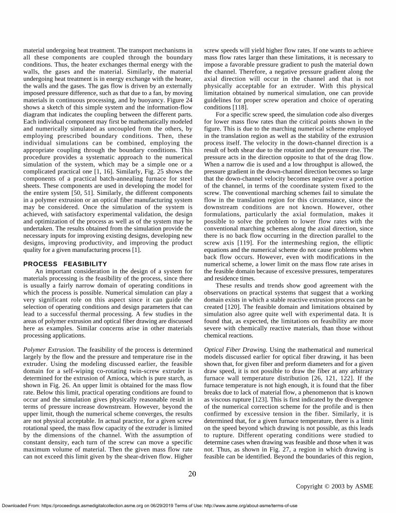
Downlo
material undergoing heat treatment. The transport mechanisms inall these components are coupled through the boundaryconditions. Thus, the heater exchanges thermal energy with thewalls, the gases and the material. Similarly, the materialundergoing heat treatment is in energy exchange with the heater,the walls and the gases. The gas flow is driven by an externallyimposed pressure difference, such as that due to a fan, by movingmaterials in continuous processing, and by buoyancy. Figure 24shows a sketch of this simple system and the information-flowdiagram that indicates the coupling between the different parts.Each individual component may first be mathematically modeledand numerically simulated as uncoupled from the others, byemploying prescribed boundary conditions. Then, theseindividual simulations can be combined, employing theappropriate coupling through the boundary conditions. Thisprocedure provides a systematic approach to the numericalsimulation of the system, which may be a simple one or acomplicated practical one [1, 16]. Similarly, Fig. 25 shows thecomponents of a practical batch-annealing furnace for steelsheets. These components are used in developing the model forthe entire system [50, 51]. Similarly, the different componentsin a polymer extrusion or an optical fiber manufacturing systemmay be considered. Once the simulation of the system isachieved, with satisfactory experimental validation, the designand optimization of the process as well as of the system may beundertaken. The results obtained from the simulation provide thenecessary inputs for improving existing designs, developing newdesigns, improving productivity, and improving the productquality for a given manufacturing process [1].
PROCESS FEASIBILITYAn important consideration in the design of a system for
materials processing is the feasibility of the process, since thereis usually a fairly narrow domain of operating conditions inwhich the process is possible. Numerical simulation can play avery significant role on this aspect since it can guide theselection of operating conditions and design parameters that canlead to a successful thermal processing. A few studies in theareas of polymer extrusion and optical fiber drawing are discussedhere as examples. Similar concerns arise in other materialsprocessing applications.
Polymer Extrusion. The feasibility of the process is determinedlargely by the flow and the pressure and temperature rise in theextruder. Using the modeling discussed earlier, the feasibledomain for a self-wiping co-rotating twin-screw extruder isdetermined for the extrusion of Amioca, which is pure starch, asshown in Fig. 26. An upper limit is obtained for the mass flowrate. Below this limit, practical operating conditions are found tooccur and the simulation gives physically reasonable result interms of pressure increase downstream. However, beyond theupper limit, though the numerical scheme converges, the resultsare not physical acceptable. In actual practice, for a given screwrotational speed, the mass flow capacity of the extruder is limitedby the dimensions of the channel. With the assumption ofconstant density, each turn of the screw can move a specificmaximum volume of material. Then the given mass flow ratecan not exceed this limit given by the shear-driven flow. Higher
aded From: https://proceedings.asmedigitalcollection.asme.org on 06/29/2019 Terms of Us
screw speeds will yield higher flow rates. If one wants to achievemass flow rates larger than these limitations, it is necessary toimpose a favorable pressure gradient to push the material downthe channel. Therefore, a negative pressure gradient along theaxial direction will occur in the channel and that is notphysically acceptable for an extruder. With this physicallimitation obtained by numerical simulation, one can provideguidelines for proper screw operation and choice of operatingconditions [118].
For a specific screw speed, the simulation code also divergesfor lower mass flow rates than the critical points shown in thefigure. This is due to the marching numerical scheme employedin the translation region as well as the stability of the extrusionprocess itself. The velocity in the down-channel direction is aresult of both shear due to the rotation and the pressure rise. Thepressure acts in the direction opposite to that of the drag flow.When a narrow die is used and a low throughput is allowed, thepressure gradient in the down-channel direction becomes so largethat the down-channel velocity becomes negative over a portionof the channel, in terms of the coordinate system fixed to thescrew. The conventional marching schemes fail to simulate theflow in the translation region for this circumstance, since thedownstream conditions are not known. However, otherformulations, particularly the axial formulation, makes itpossible to solve the problem to lower flow rates with theconventional marching schemes along the axial direction, sincethere is no back flow occurring in the direction parallel to thescrew axis [119]. For the intermeshing region, the ellipticequations and the numerical scheme do not cause problems whenback flow occurs. However, even with modifications in thenumerical scheme, a lower limit on the mass flow rate arises inthe feasible domain because of excessive pressures, temperaturesand residence times.
These results and trends show good agreement with theobservations on practical systems that suggest that a workingdomain exists in which a stable reactive extrusion process can becreated [120]. The feasible domain and limitations obtained bysimulation also agree quite well with experimental data. It isfound that, as expected, the limitations on feasibility are moresevere with chemically reactive materials, than those withoutchemical reactions.
Optical Fiber Drawing. Using the mathematical and numericalmodels discussed earlier for optical fiber drawing, it has beenshown that, for given fiber and preform diameters and for a givendraw speed, it is not possible to draw the fiber at any arbitraryfurnace wall temperature distribution [26, 121, 122]. If thefurnace temperature is not high enough, it is found that the fiberbreaks due to lack of material flow, a phenomenon that is knownas viscous rupture [123]. This is first indicated by the divergenceof the numerical correction scheme for the profile and is thenconfirmed by excessive tension in the fiber. Similarly, it isdetermined that, for a given furnace temperature, there is a limiton the speed beyond which drawing is not possible, as this leadsto rupture. Different operating conditions were studied todetermine cases when drawing was feasible and those when it wasnot. Thus, as shown in Fig. 27, a region in which drawing isfeasible can be identified. Beyond the boundaries of this region,
Copyright © 2003 by ASME
e: http://www.asme.org/about-asme/terms-of-use
GUEST
20

Do
Wall "I". (r. z)
At time T
"~(~. d
Sub,=or~p~.s:
c : Protccdv¢ cover f : Flue pses ~ : Inert g~ca m: Coil maleahM p : C~avector plate r~: Fumnee w~ls
Fig. 25 Sketch of the different components of a batch annealing furnace for steel sheets, used for d e v e l o p i n g a m a t h e m a t i c a l model of the complete system.
U O
I O O
o
o o
o o
o o
24O0 250O
15
2OOO 2100 2200 2300 r ~ , c e tunpera~.Ke. Tf (Iq
(a)
z s l - -
= I
. I ° | 1 I I • • •
| . ;
: : i = m "1 ]
em m ,m so mlv. m m *o m .o
Fig. 26 Feasible domain for twin-screw extrusion of starch.
14 • l, lo ¢~dng po,l~Ible ~ m l b t ~ UW ¢zaled k1*
/
f
2900 2100 2200 2300 224Q0 2500 Furnace ~ , J m . T , ~
V~ (m~) T.(K)
(=) @)
.H=
z 3 1 i 6 1 s • io S=p Num~':r
5 0 @
4 5 •
!
g ss •
3 0 •
2 5 - ,~ 2 0 O 0
(c)
- -e-- - boundary point • draw Imposslble o draw p o s s i b l e
¢~ o o o o o o o o
\
\ @ \ 0 0 0 0 0 0 0 0
\
• k 0 0 0 0 0 0 0
\
• • @\ ~0 0 0 0 O 0
• 9 @ • ~ 0 0 0 0
2 2 0 0 2 4 0 0 2 6 0 0 2 8 0 0 3 0 0 0
d r a w temperature ( K )
draw speed : 15 m/s
Fig. 27 Results obtained from a feasibility study of the fiber drawing process : (a) different cases studied, showing both feasible and infeasible cOmbinations of parameters; (b) "iso-tension" contours for the feasible range of fiber drawing; (c) feasible domain at a draw speed of 15 m/s in terms of furnace length and temperature.
U
Staaing , )
x x
( a ) ( b )
/
)
Fig. 28 Steepest ascent method, shown in terms of the climb towards the peak of a hill and also in terms of constant U contours.
Fig. 29 Variation of the objective function U with (a) inlet velocity and (b) susceptor temperature. Also shown in (c) is the change in the value of the objective function with each step in the steepest descent method.
21 Copyright © 2003 by ASME wnloaded From: https://proceedings.asmedigitalcollection.asme.org on 06/29/2019 Terms of Use: http://www.asme.org/about-asme/terms-of-use

Downloa
drawing is not possible. For the domain in which the drawingprocess is feasible, the draw tension is calculated. The "iso-tension'' contours are also shown in the figure. As expected, thedraw tension is small at higher temperatures and lower speeds,which explains the positive slope of the iso-tension contours. Similarly, different combinations of other physical andprocess variables, such as the inert gas flow velocity, flowconfiguration, furnace wall temperature distribution, furnacelength and diameter, and preform and fiber diameters, may beconsidered to determine the feasibility of the process. Figure 27(c) shows the results when the furnace length and temperature areconsidered as the two main parameters. Clearly, the maximumdraw speed at a given furnace temperature could be restricted bythe heating-zone length due to the requirement that thetemperature in the neck-down region must exceed the softeningtemperature. In all such cases, the feasibility of the process islargely determined by viscous rupture, which is a direct result ofhigh draw tension. It is seen that either a higher draw temperatureor a longer residence time in the furnace, as regulated by itslength, is needed to make fiber drawing possible at higher drawspeeds. These results are very important for a realistic fiber-drawing operation, since the parameters in a fiber drawing systemcan be determined so that a fiber of desired diameter can be drawn.
It must be pointed out that, in actual practice, fiber drawingmay never reach the boundaries of the feasible domain due tounacceptably high draw tension. The numerical convergence, aswell as the transport characteristics near the boundaries have beeninvestigated to understand viscous rupture and other effects thatarise. Also, there are other considerations that need to be takeninto account to determine feasible and optimum drawingconditions. For example, a very high furnace temperature alongwith a small draw speed would result in a small draw tension dueto the small value of viscosity. The fiber could break into dropsbecause of the very mobile state of glass and the correspondingcapillary instability [123]. Under these conditions, the processalso becomes very sensitive to disturbances that are caused byvariations in the drawing parameters. Similarly, theconcentrations of various process-induced defects could be high athigh draw temperatures, leading to unsatisfactory optical fibers.From these considerations, very high draw speeds or very highdraw temperatures are not very desirable, even when drawing isfeasible in terms of the transport process.
ADDITIONAL ENGINEERING ASPECTSSeveral important considerations in the design and operation
of practical thermal materials processing systems were discussedin the preceding sections. These included issues like rate offabrication, quality of the product, and feasibility of the process.However, there are obviously many other aspects that need to beconsidered in the design and optimization of the system and forthe selection of the operating conditions. Some of these areoutlined here.
An important consideration in polymer extrusion is themixing inside the screw channel since it determines thehomogeneity of the processed material. Some results on mixing,as given by the flow division ratio for flow between two rotatingcylinders, were given earlier. The downstream motion of materialparticles may also be considered for a better understanding of the
ded From: https://proceedings.asmedigitalcollection.asme.org on 06/29/2019 Terms of Us
mixing process. Using the calculated three-dimensional velocityfield in the extruder, one can consider specific particles inside thescrew channel and follow their movement along the channel[124]. The particles undergo complicated spiral movements,except those near the barrel and screw surfaces. The spiralmovement of the particles inside the screw channel promotesmixing within the single screw extruder. Similarly, thedistributive mixing inside the channel may be considered interms of mixing between two different types of materials, witheach initially occupying one half of the channel. These materialsare followed with time as the fluid moves down the channel. Theprocess is a slow one, though the materials are eventually mixedwith each other. Several other measures of mixing have beenconsidered in the literature. Substantial work has also been doneon mixing in twin-screw extruders, including the use of chaosintroduced by changes in the geometry and the boundaryconditions [125, 126]. Similarly, melting and solidification ofthe material, leakage across screw flights, instability in the flow,unfilled screw channels, and conjugate transport due toconduction in the barrel are other important engineering issues inpolymer extrusion. Transient effects are also important, both forthe start-up of the process and for changes in the operatingconditions.
In optical fiber manufacture, the fiber has to be cooledrapidly in order to reach appropriate temperature levels beforecoating is applied. A lot of work has been done on this problem,because the height of the draw tower is significantly affected bythe cooling process [66, 127]. The inert gases in the draw furnaceplay an important part in the thermal transport in the furnace.The convective flow is a strong function of the geometry,particularly of the locations of the inlet/outlet channels, and ofthe flow rate. The local transport rates affect the fiber quality aswell as the draw process. The concentration of defects in the fiberis another important consideration, because it affect the quality ofsignal transmission and the distance one could go withoutenhancing the signal. Several defects are generated by the thermalprocess, and enhanced cooling could affect the distribution andretention of these defects. The glass flow also affects thedistribution of these defects.
Similarly, in other thermal materials processing systems,important aspects that are particularly relevant to the processunder consideration arise and must be taken into account by themodeling and simulation in order to provide the appropriateinputs for system design and optimization. These relate toengineering issues like durability, maintenance and availabilityof different materials and components, as well as the convenienceand practical range of operating conditions.
OPTIMIZATIONWe have so far largely considered workable or acceptable
design of a system. Such a design satisfies the requirements forthe given application, without violating any imposedconstraints. However, the design would generally not be the bestor optimal design, as judged on the basis of cost, performance,efficiency, or the best quality or performance per unit cost, withacceptable environmental effects. The need to optimize is veryimportant in the design of the materials processing system and
Copyright © 2003 by ASME
e: http://www.asme.org/about-asme/terms-of-use
GUEST
22

Downl
has become particularly crucial in the recent times due togrowing global competition.
Any optimization process requires the specification of aquantity or function U, known as the objective function andwhich is to be minimized or maximized. The generalmathematical formulation for the optimization of a system maybe written as
U ( x1, x2, x3, . . . , xn ) ----> Uopt (26)with, Gi ( x1, x2, x3, . . . , xn ) = 0, for i = 1, 2, 3, . . . , m
(27)and, Hi ( x1, x2, x3, . . . , xn ) ≤ or ≥ Ci, for i = 1, 2, 3, . . , l
(28)where xi represent the design variables and operating conditions,Gi represent equality constraints and Hi inequality constraints. Ifthe number of equality constraints m is equal to the number ofindependent variables n, the constraint equations may simply besolved to obtain the variables and there is no optimizationproblem. If m > n, the problem is over constrained and a uniquesolution is not possible since some constraints have to bediscarded to make m ≤ n. If m < n, an optimization problem isobtained.
For thermal materials processing, the objective function Ucould be taken as the number of items produced per unit cost,product quality, or the amount of material processed, such as thelength of fiber drawn. The constraints are often given on thetemperature and pressure due to material limitations.Conservation principles and equipment limitations restrict theflow rates, cutting speed, draw speed, and other variables. Thesecond law of thermodynamics and entropy generation can alsobe used to optimize systems so that exergy, which is a measureof the availability of energy from a thermal system, can bemaximized [128, 129].
Search methods constitute the most important optimizationstrategy for thermal systems. Many different approaches havebeen developed and are particularly appropriate for specificproblems. The underlying idea is to generate a number ofdesigns, which are also called trials or iterations, and to select thebest among these. Effort is made to keep the number of trialssmall, often going to the next iteration only if necessary. This isan important consideration with respect to thermal materialsprocessing systems since each trial may take a considerableamount of computational or experimental effort. The steepestascent/descent method is an important search method formultivariable optimization and is widely used for a variety ofapplications including thermal systems. It is a hill-climbingtechnique in that it attempts to move towards the peak, formaximizing the objective function, or towards the valley, forminimizing the objective function, over the shortest possiblepath. At each step, starting with the initial trial point, thedirection in which the objective function changes at the greatestrate is chosen for moving the location of the point whichrepresents the design on the multivariable space. Figure 28shows this movement schematically on a hill as well as on atwo-variable contour plot, the direction of the gradient vector ∇Ubeing the direction in which U changes at the greatest rate. Sincethe search always moves in the direction of greatest rate ofchange of U, the number of trial runs needed to reach theoptimum is expected to be small. However, it does require the
oaded From: https://proceedings.asmedigitalcollection.asme.org on 06/29/2019 Terms of Use
evaluation of gradients in order to determine the appropriatedirection of motion, limiting the application of the method toproblems where the gradients can be obtained accurately andeasily. Numerical differentiation may be used if an algebraicexpression is not available for the objective function, which isoften the case for thermal materials processing. Several othersuch gradient-based methods have been developed foroptimization and are used for a variety of thermal processes [1,130-132]. Genetic optimization algorithms, that are based onfunction evaluations instead of gradients, have also beendeveloped and used, though these methods are often less efficientthan gradient-based methods.
The objective function is among the most critical anddifficult aspects to be decided in the optimization of thermalmaterials processing systems, since the optimal design is astrong function of the chosen criterion for optimization.Frequently, optimization is carried out for different criteria andthe final design is chosen by comparison and combination ofresults for different criteria. For illustration, let us consider aCVD system for deposition of TiN. As discussed in detail byChiu et al. [133], the main qualities of interest include productquality, production rate, and operating cost. These three may beincorporated into one possible objective function, as given by
U = (Product Quality Deficiency) x (Operating Cost)
Production Rate (29)
where U is to be minimized. Here, the product quality is definedin terms of uniformity of film thickness and other properties,which quantify the desired attributes. Since the objectivefunction is minimized, maximum production rate is achieved byplacing it in the denominator. The objective function representsequal weighting for each design quality. Chiu et al. [133] usedtwo measurements of product quality, namely film uniformityand film resistivity. Film uniformity was defined as themaximum variation in film thickness across the susceptorsurface. Thus, a minimum value of U implies greater filmthickness uniformity. Similarly, operating costs were representedby heat input and gas flow rate. The production rate wasexpressed in terms of the deposition rate.
Obviously, the objective function may assume manypossible forms. The preceding form is chosen because themagnitude of each aspect does not play a role in locating theoptimal solution. It may be factored out as a constant during theminimization process. The change of each aspect in the objectivefunction is of greater interest, since terms which exhibitsignificantly larger variations relative to others will drive theoptimization. When a design incorporates effects with differentsensitivities to the process variables, this problem may becircumvented by expressing the objective function as a sum ofthe log of the qualities. Another common form of the objectivefunction expresses the effects as a sum or as the square root ofthe squared sums of the affects. All the aforementionedpossibilities are possible forms for an objective function, but theproper form will strongly depend on the desired performance of aparticular system.
A detailed study of the design space was carried out by Chiuet al. [133] to determine the domain of acceptable designs and theeffects of various parameters on the objective function. Using thesteepest ascent method, the optimal design was obtained
Copyright © 2003 by ASME
: http://www.asme.org/about-asme/terms-of-use
GUEST
23

Downlo
considering different combinations of parameters. Some typicalresults are shown in Fig. 29, indicating the variations of theobjective function with the inlet velocity Vinlet and thesusceptor temperature Tsus and also with each iteration step fortwo different starting points. The variation of U with thedifferent parameters can also be employed for univariate search,which involves optimizing with respect to one variable at a timeand alternating the variables [1, 132].
A similar detailed study was carried out by Cheng [134] onthe optical fiber drawing process, considering the numericalsimulation of the draw furnace. The objective function couldagain be taken as the general form given by Eq. (29). Because ofthe complexity of the process and lack of information onoperating costs, the effort was directed at the fiber quality, takingthe tension, defect concentration and velocity difference across thefiber, all these being scaled to obtain similar ranges of variation,as the main considerations. The objective function U was takenas the square root of the sum of the squares of these threequantities and was minimized. Several search methods, such asgolden-section for single variable and univariate for multivariablecases, were employed. Figure 30 shows typical results fromgolden-section search for the optimal draw temperature and drawspeed. The results from the first search are used in the secondsearch, following the univariate search strategy, to obtainoptimal design in terms of these two variables. Several otherresults were obtained on this complicated problem, particularlyon furnace dimensions and operating conditions to achieveoptimal drawing.
KNOWLEDGE BASEAn important consideration in the design of systems for the
thermal processing of materials is the use of the availableknowledge base on the process to guide the design and operationof the system. The knowledge base typically includes relevantinformation on existing systems and processes, current practice,knowledge of an expert in the particular area, material propertydata, and empirical data on equipment and transport, such as heattransfer correlations. It is obviously important to use thisknowledge base in developing acceptable and optimal designs,and in the selection of operating conditions for given productcharacteristics. Some effort has been directed in recent years atstreamlining the design process, improving the designmethodology, automating the use of existing information anddeveloping strategies for rapid convergence to the final design[135]. The basic concept behind knowledge-based systems is thestorage and use of this knowledge to take logical decisions forselection, diagnostics and design [136]. Empirical data, heuristicarguments and rules for making decisions are all part of thisknowledge-based methodology. The expert knowledge isobviously specific to a given application and represents theknowledge and experience acquired by the expert over a longperiod of work in the area of interest.
A very important element in the development and use ofknowledge-based methodology is object-oriented programming.All the information needed to use an object are stored in theobject itself. The methods embedded or encapsulated in each ofthe objects are unique to that object. Therefore, encapsulationmakes different objects reusable and reduces duplication within a
aded From: https://proceedings.asmedigitalcollection.asme.org on 06/29/2019 Terms of Us
program. Inheritance gives each object access to the features ofthe methods from the class above it on a tree structure. Thisaspect allows any system to be easily modified by adding anobject, or subroutine, without affecting any other object. Withthe use of these features of object-oriented programming, it iseasy to store and retrieve expert knowledge. A couple ofexamples are discussed here to illustrate the use of theknowledge-based strategy for design.
Knowledge-based design methodology is particularly usefulin selecting an initial design for a polymer extrusion die. Diedesign is an important consideration in plastic extrusion sincethe operation of the extruder system and the quality of the finalproduct are strongly influenced by the die. Even though a die isoften treated as a component of the extruder, practical dies areusually subsystems consisting of different parts, such asentrance, flow channel and exit regions, which are attached toeach other through couplings and screws, and the heating/coolingarrangement to maintain a desired temperature [34, 35, 106,137]. Two strategies may be used for generating an initialdesign. The first is based on a library of designs built usinginformation from earlier design efforts and from existingsystems. The design closest to the given problem may beselected by comparing the designs in the library with the desiredspecifications. The second approach is based on expert rules fordie design. Employing knowledge and experience used by anexpert, rules may be set down to generate a design for the givenrequirements and constraints [138]. Preliminary evaluations andestimates are used to develop a possible design that is used asinitial design. Of course, the user can always enter his/her owninitial design if the output from the library or the expert rules isnot satisfactory. Figure 31 shows a sketch of the initial designmodule giving these different strategies.
The knowledge base is also used in the redesign module toevaluate a given design and, if this is not satisfactory, to generatea new design. Expert rules are written on the basis of earlierexperience and knowledge from an expert. These establish therelationship between a design variable and the objective function.Several efficient strategies can be developed for selecting thedesign variables to go from one design to the next. The selectionof design variables for the new design are guided by expert rulesas well as the results of the design process up to the giveninstant. Thus, the efficiency of the iterative process issubstantially improved. Figure 32 shows the advantage ofselective search which avoids local minima that are physicallyunacceptable, as compared to an exhaustive one, in the drivetoward the optimum given by a minimum value of the objectivefunction.
Another problem that may be considered is the casting of amaterial in an enclosed region. The need for design andoptimization of the system arises because of the desire to reducethe solidification time and improve the product quality. A largenumber of design parameters arise in this problem, such asmaterials, initial melt pour temperature, cooling fluid and itsflow rate, and dimensions. The quality of the casting isdetermined by grain size, composition, directional strength,concentration of defects, voids, thermal stresses, etc. It isnecessary to carry out a thermal analysis of the solidification
Copyright © 2003 by ASME
e: http://www.asme.org/about-asme/terms-of-use
GUEST
24

Fs
Fp
Do
i 2 g
I I I I I I ~0.0 .0 2400 .0 2600 .0 .0
¢baw temperatme T~ (K)
2.0
1.0
0.5
o.o , ~'.o ' 1o.o' ' ,~.o' ' ~ . o ' ~ . o ' ~ ' .o
draw spe~:S V, (re's)
ig. 30 Evaluation of optimal draw temperature at a draw speed of 15 m/s and the optimal draw peed at a draw temperature of 2489.78 K by using the golden-section search method.
.
~l~t specifications
Expe.n ml~
~m . . . . .
=,, :
Solution Extemal ~arces
Fig. 31 Initial design module using knowledge-based methodology [138].
i i i i
" Exhaustive Rdcsign rules I /
1.6 . . . . . . . . . . . . . S¢lecdve redesign rules
1 . 4
>
i 1.0
!°-' f 0 . 6
0 . 4
o~ I \ 0 . 0
I i I / !
0 5 10 15 20 Redesign itemioa mmaber
ig. 32 Comparison of redesign strategies for a 1 cm circular die for extruding low density olyethylene (LDPE) at 400 kg/hr [1381.
T.,
(a) Co)
r~3u3 seth3
~ Interface posldon (m) 0.135 ss ./
/• J ~ /
0" I 0~ I a~sS:I/f " ~ " 0.0~I
o.o54 I / Mold mmcrid ~ d ~ IJddd d ~ - - I ~ p c d
Y Tvour 1895 K ..... Increase h, W--lumped
0.027 Mold initial temp. 304 K ...... Switch to ID PDE
°°°°0.0 2so.o 5~0.0 84o.o i no.o 14oo.o
Fig. 34 Results for design of an ingot casting system, showing solid-!iquid, interface movement with time and switching to a more complex model after many design trials.
(c) x
Fig. 33 Different mathematical models for ingot casting. (a) Chvorinov model; (b) lumped mold model; (c) semi-infinite model.
25 Copyright © 2003 by ASME
wnloaded From: https://proceedings.asmedigitalcollection.asme.org on 06/29/2019 Terms of Use: http://www.asme.org/about-asme/terms-of-use

Downlo
process, using modeling and simulation, to obtain inputs fordesign and to evaluate the nature of the casting.
Viswanath [139] and Viswanath and Jaluria [140] consideredthis problem, using knowledge-based methodology for design.Several models are available for the study of solidification. Thesemay be listed as:
1. Steady conduction in solid model: Melt is taken at freezingtemperature, mold at fixed temperature and steady conductionin the solid is assumed.
2. Chvorinov model: Entire thermal resistance is assumed to bedue to the mold and energy balance is used.
3. Lumped mold model: Temperature in the mold is assumed tobe uniform and time-dependent, melt is taken at freezingtemperature and steady conduction in the solid is assumed.
4. One-dimensional conduction model: Transient 1D temperaturedistribution is assumed in the mold, solid and melt.
5. Two- and three-dimensional models: Natural convection flowin the melt is included.
6. More sophisticated models: Needed for alloys, generation ofvoids and defects, complicated geometries, etc.
Three models among these are sketched in Fig. 33. Eachmodel has its own level of accuracy and validity. Differentmodels may be chosen, depending on the application andmaterials involved. Expert knowledge plays a major role here.For instance, if an insulating material such as ceramic or sand isused for the mold, the Chvorinov model may yield good resultssince most of the thermal resistance is in the mold. One-dimensional models are adequate for solidification near theboundaries. Sophisticated models are needed for alloysolidification and for considering the microstructure in thecasting.
The optimal design may be obtained with solidification timefor a given casting being chosen as the objective function andemploying constraints from the expert knowledge to avoidunacceptable thermal stresses and defects in the casting. We canstart with relatively simple models and move to morecomplicated models if the desired details are not obtained. Wemay also start with the simplest model and keep on moving tomodels with greater complexity till the results remain essentiallyunchanged from one model to the next. Thus, models may beautomatically selected using decision-making based on accuracyconsiderations. In a typical design session, the coolingparameters are first varied to reduce the solidification time. If thesolidification time does not reach the desired value, the pourtemperature of the melt may be varied. If even this does notsatisfy the requirements, the thickness of the mold wall may bechanged. The material of the wall may also be varied, if needed.Thus, by first varying the operating conditions and then thedimensions and materials, the solidification time may beminimized or brought below a desired value. Figures 34 showsome a typical run for the design of the given system, indicatingmodel change as the design proceeds. Each successful design maybe stored for help in future designs. This is the process ofimproving the system through learning from past experiences.
Clearly, the use of the available knowledge base on theprocess is important in the design, optimization and operation of
aded From: https://proceedings.asmedigitalcollection.asme.org on 06/29/2019 Terms of Use
the system, as well as in choosing the operating conditions for adesired product. In actual practice, this knowledge, which maysimply be called experience, is used all the time by engineers andworkers involved with materials processing. Decisions are oftenmade on the basis of what is known about existing processes,past trials and other similar systems. Therefore, it is desirable tobuild this knowledge base into the design, control and operationof the system.
CONCLUSIONS AND FUTURE RESEARCHNEEDS
This paper presents a review of the current status of theimportant field of thermal processing of materials. It focuses onthe link between basic research on the underlying transportmechanisms and the engineering aspects associated with theprocess and the system. Several important processing techniques,such as optical fiber drawing, polymer extrusion and chemicalvapor deposition, are discussed in particular detail to bring outthe basic and applied issues in materials processing. Theseinclude modeling, validation, system simulation, processfeasibility, and the design and optimization of the system.Important solution techniques, typical results in thermalmaterials processing and the implications for practical systemsare discussed.
Our understanding of thermal processing of materials hasgrown significantly over the last three decades. Many new andimproved techniques have been developed, along with newmaterials, new processing systems and better control on productquality and production costs. However, there are still many areasthat need detailed further work. Among the most important onesare material properties and characteristics, experimental results,and coupling of micro- or nano-scales where materials processingoccurs and the macro-scale of interest in engineering. Themeasurement and availability of accurate material properties arecrucial to a study in this area. Also, experimental results arestrongly needed for validation of models and for providing inputsand insight for future model development.
In addition, work is needed on several other topics. Some ofthe main ones are transport in complex materials such aspowders, particulates, and granules, characteristics of free surfacesand interfaces, accurate numerical modeling of combinedmechanisms, multiple domains, and multiphase transport, andtransport instability mechanisms. Experimental techniques areneeded for practical materials which are often opaque and formeasurements under high temperature and pressure. Similarly,numerical techniques are needed for large material propertychanges and for coupling the transport equations with thechemical kinetics which may involve several different reactions,with different reaction rates, activation energy, and otherconstants. Further development of new products, processes andsystems on the basis of underlying thermal transport is needed.The design, control and optimization of the systems, as well asthe selection of operating conditions, in order to achieve thedesired thermal processing needs further work.
ACKNOWLEDGEMENTSThe author appreciates the honor and opportunity provided tohim by the Max Jakob Memorial Award Committee to prepare
Copyright © 2003 by ASME
: http://www.asme.org/about-asme/terms-of-use
GUEST
26

Down
this review. He acknowledges the support of the NationalScience Foundation, of the industry, and of the New JerseyCommission on Science and Technology, through variousCenters, for much of the work reported here and for thepreparation of this paper. The author also acknowledges the workdone by several students, as referenced here, that made it possibleto present this review.
REFERENCES[1] Jaluria, Y., 1998, Design and Optimization of Thermal
Systems, McGraw-Hill, New York.[2] Schey, J.A., 1987, Introduction to Manufacturing Processes,
2nd Ed., McGraw-Hill, New York.[3] Kalpakjian, S., 1989, Manufacturing Engineering and
Technology, Addison-Wesley, Reading, MA.[4] Szekely, J., 1979, Fluid Flow Phenomena in Metals
Processing, Academic Press, New York.[5] Ghosh, A. and Mallik, A.K.,1986, Manufacturing Science,
Ellis Horwood, Chichester, U.K.[6] Altan, T., Oh, S.I. and Gegel, H.L., 1971, Metal Forming:
Fundamentals and Applications, Amer. Soc. Metals, MetalsPark, OH.
[7] Fenner, R.T., 1979, Principles of Polymer Processing,Chemical Publishing, New York.
[8] Hughel, T.J. and Bolling, G.F., Eds., 1971, Solidification,Amer. Soc. Metals, Metals Park, OH.
[9] Kuhn, H.A. and Lawley, A., Eds., 1978, Powder MetallurgyProcessing, New Techniques and Analysis, Academic Press,New York.
[10] Chen, M.M., Mazumder, J. and Tucker, C.L., Eds., 1983,Transport Phenomena in Materials Processing, HTD vol.29, Amer. Soc. Mech. Engrs., New York.
[11] Li, T., Ed., 1985, Optical Fiber Communications, Vol. 1:Fiber Fabrication, Academic Press, New York.
[12] Poulikakos, D., Ed., 1996, “Transport Phenomena inMaterials Processing,” Adv. Heat Transfer, 18.
[13] Viskanta, R., 1988, “Heat Transfer During Melting andSolidification of Metals,” J. Heat Transfer, 110, pp. 1205-1219.
[14] Jaluria, Y., 1980, Natural Convection Heat and MassTransfer, Pergamon Press, Oxford, UK.
[15] Gebhart, B., Jaluria, Y., Mahajan, R.L. and Sammakia, B.,1988, Buoyancy-Induced Flows and Transport, Taylor andFrancis, Philadelphia, PA.
[16] Jaluria, Y. and Torrance, K.E., 2003, Computational HeatTransfer, 2nd. Ed., Taylor and Francis, New York, NY.
[17] Ramachandran, N., Gupta, J.P. and Jaluria, Y., 1982,“Thermal and Fluid Flow Effects During Solidification in aRectangular Enclosure,” Int. J. Heat Mass Transfer, 25, pp.187-194.
[18] Bennon, W.D. and Incropera, F.P., 1988, “DevelopingLaminar Mixed Convection with Solidification in a VerticalChannel,” J. Heat Transfer, 110, pp. 410-415.
[19] Viswanath, R. and Jaluria, Y., 1993, “A Comparison ofDifferent Solution Methodologies for Melting andSolidification Problems in Enclosures,” Numerical HeatTransfer, 24B, pp. 77-105.
loaded From: https://proceedings.asmedigitalcollection.asme.org on 06/29/2019 Terms of Use
[20] Prescott, P.J. and Incropera, F.P., 1996, “Convection Heatand Mass Transfer in Alloy Solidification,” Adv. HeatTransfer, 28, pp. 231-338.
[21] Harper, J.M., 1981, Extrusion of Foods: Volume I, CRDPress, Boca Raton, FL.
[22] Kokini, J.L., Ho, C.-T. and Karwe, M.V., Eds., 1992,Food Extrusion Science and Technology, Marcel Dekker,New York.
[23] Wang, S.S., Chiang, C.C., Yeh, A.I., Zhao, B. and Kim,I.H., 1989, “Kinetics of Phase Transition of Waxy CornStarch at Extrusion Temperatures and Moisture Contents,”J. Food Sci., 54, pp. 1298-1301.
[24] Jensen, K. F., E. O. Einset, and D. I. Fotiadis, 1991,“Flow Phenomena in Chemical Vapor Deposition of ThinFilms,” Ann. Rev. Fluid Mechanics, 23, pp. 197-232.
[25] Mahajan, R.L., 1996, “Transport Phenomena in ChemicalVapor-Deposition Systems,” Adv. Heat Transfer, 28, pp.339-425.
[26] Roy Choudhury, S., Jaluria, Y. and Lee, S.H.-K., 1999,"Generation of neck-down profile for furnace drawing ofoptical fiber," Numerical Heat Transfer, 35, pp. 1-24.
[27] Jaluria, Y., 1992, “Transport from Continuously MovingMaterials Undergoing Thermal Processing,” Ann. Rev. HeatTransfer, 4, pp. 187-245.
[28] Siegel, R., 1978, “Shape of Two-DimensionalSolidification Interface During Directional Solidification byContinuous Casting,” J. Heat Transfer, 100, pp. 3-10.
[29] Siegel, R., 1984, “Two-Region Analysis of Interface Shapein Continuous Casting with Superheated Liquid,” J. HeatTransfer, 106, pp. 506-511.
[30] Jaluria, Y. and Singh, A.P., 1983, “TemperatureDistribution in a Moving Material Subjected to SurfaceEnergy Transfer,” Comp. Meth. Appl. Mech. and Engg.,41, pp. 145-157.
[31] Roy Choudhury, S. and Jaluria, Y., 1994, “AnalyticalSolution for the Transient Temperature Distribution in aMoving Rod or Plate of Finite Length with Surface HeatTransfer,” Int. J. Heat Mass Transfer, 37, pp. 1193-1205.
[32] Chiu, W. K.-S., Jaluria, Y., and N.C. Glumac, 2000,"Numerical Simulation of Chemical Vapor DepositionProcesses Under Variable and Constant PropertyApproximations," Numerical Heat Transfer, 37, pp. 113-132.
[33] Wang, Q., Yoo, H., and Jaluria, Y., "Convection in aHorizontal Duct Under Constant and Variable PropertyFormulations," Int. J. Heat Mass Transfer, Vol. 46, pp.297-310, 2003.
[34] Tadmor, Z. and Gogos, C., 1979, Principles of PolymerProcessing, Wiley, New York.
[35] Jaluria, Y., 1996, “Heat and Mass Transfer in the Extrusionof Non-Newtonian Materials,” Adv. Heat Transfer, 28, pp.145-230.
[36] Pearson, J.R.A. and Richardson, S.M., Eds., 1983,Computational Analysis of Polymer Processing, Appl. Sci.Pub., London, UK.
[37] Karwe, M.V. and Jaluria, Y., 1990, “Numerical Simulationof Fluid Flow and Heat Transfer in a Single-Screw Extruder
Copyright © 2003 by ASME
: http://www.asme.org/about-asme/terms-of-use
GUEST
27

Down
for Non-Newtonian Fluids,” Numerical Heat Transfer, 17,pp. 167-190.
[38] Lee, S.H.-K. and Jaluria, Y., 1996, “Effect of VariableProperties and Viscous Dissipation During Optical FiberDrawing,” J. Heat Transfer, 118, pp. 350-358.
[39] Lee, S.H.-K. and Jaluria, Y., 1996, “Simulation of theTransport Processes in the Neck-Down Region of a FurnaceDrawn Optical Fiber,” Int. J. Heat Mass Transfer, 40, pp.843-856.
[40] Sayles, R. and Caswell, B., 1984, "A Finite ElementAnalysis of the Upper Jet Region of a Fiber Drawing FlowField, Int. J. Heat Mass Transfer, 27, pp. 57-67.
[41] Myers, M.R., 1989, "A Model for Unsteady Analysis ofPreform Drawing, AIChE Journal, 35, pp. 592-602.
[42] Jaluria, Y. ,1976, “Temperature Regulation of a Plastic-Insulated Wire in Radiant Heating,” J. Heat Transfer, 98,pp. 678-680.
[43] Beckermann, C. and Wang, C.Y., 1995, “Multiphase/-ScaleModeling of Alloy Solidification,” Ann. Rev. Heat Transfer,6, pp. 115-198.
[44] Wang, C.Y. and Beckermann, C., 1993, “A unified SoluteDiffusion Model for Columnar and Equiaxed Dendritic AlloySolidification,” Mater. Sci. Eng., A171, pp. 199-211.
[45] Abib, A.H., Jaluria, Y. and Chiruvella, R.V., 1993,“Thermal Processing of Food Materials in a Single ScrewExtruder,” in Heat Transfer in Food Processing, ASME HeatTransfer Div., 254, pp. 57-67, ASME, New York.
[46] Chiruvella, R.V., Jaluria, Y. and Karwe, M.V., 1996,“Numerical Simulation of Extrusion Cooking of StarchyMaterials,” J. Food Engg., 30, pp. 449-467.
[47] Hanafusa, H., Hibino, Y. and Yamamoto, F., 1985,"Formation Mechanism of Drawing-Induced E' Centers inSilica Optical Fibers," J. Applied Physics, Vol. 58, No. 3,pp. 1356-1361.
[48] Hibino, Y., Hanafusa, H., and Sakaguchi, S., 1985,"Formation of Drawing-Induced E' Centers in Silica OpticalFibers," Jap. J. Applied Physics, Vol. 24, No. 9, pp. 1117-1121.
[49] Yin, Z. and Jaluria, Y., 2000, “Neck Down and ThermallyInduced Defects in High Speed Optical Fiber Drawing,”ASME J. Heat Transfer, 122, pp. 351-362.
[50] Jaluria, Y., 1984, "Numerical Study of the ThermalProcesses in a Furnace," Numerical Heat Transfer, 7, pp.211-224.
[51] Jaluria, Y., 1988, “Numerical Simulation of the TransportProcesses in a Heat Treatment Furnace,” Int. J. Num. Meth.Engg., 25, pp. 387-399.
[52] Issa, J., Yin, Z., Polymeropoulos, C.E. and Jaluria, Y.,1996, “Temperature Distribution in an Optical Fiber DrawTower Furnace,” J. Mater. Proc. Mfg. Sci., 4, pp. 221-232.
[53] Kwon, T.H., Shen, S.F., and Wang, K.K., 1986, “PressureDrop of Polymeric Melts in Conical Converging Flow:Experiments and Predictions,” Polymer Engg. Sci., Vol. 28,pp. 214-224.
[54] Lin, P. and Jaluria, Y., 1997, “Conjugate Transport inPolymer Melt Flow Through Extrusion Dies,” PolymerEngg. Sci., 37, pp. 1582-1596.
loaded From: https://proceedings.asmedigitalcollection.asme.org on 06/29/2019 Terms of Us
[55] Minkowycz, W.J. and Sparrow, E.M., Eds., 1997,Advances in Numerical Heat Transfer, , 1 , Taylor &Francis, Philadelphia, PA.
[56] Patankar, S.V., 1980, Numerical Heat Transfer and FluidFlow, Taylor and Francis, Philadelphia, PA.
[57] Mallinson, G.D. and de Vahl Davis, G., 1973, “he Methodof False Transient for the Solution of Coupled EllipticEquations,” J. Comput. Phys., 12, pp. 435-461.
[58] Leonard, B.P., 1997, “Bounded Higher-Order UpwindMultidimensional Finite-Volume Convection-DiffusionAlgorithms,” in Advances in Numerical Heat Transfer,Minkowycz, W.J. and Sparrow, E.M., Eds., Vol. 1, Taylor& Francis, Philadelphia, PA, pp. 1-57.
[59] Zhu, W. and Jaluria, Y., 2001, "Residence Time andConversion in the Extrusion of Chemically ReactiveMaterials," Polymer Engg. Sci., 41, pp. 1280-1291.
[60] Wang, Y. and White, J.L., 1989, “Non-Newtonian FlowModeling in the Screw Region of an Intermeshing Co-rotating Twin Screw Extruder,” J. Non-Newtonian FluidMech., 32, pp. 19-38.
[61] Kwon, G.H., Jaluria, Y., Karwe, M.V. and Sastrohartono,T., 1991, “Numerical Simulation of the Transport Processesin a Twin screw Polymer Extruder,” in Prog. ModelingPolymer Processing, Ed. A.I. Isayev, Ch. 4, pp. 77-115,Hanser Pub., New York.
[62] Sastrohartono, T., Jaluria, Y. and Karwe, M.V., 1994,“Numerical Coupling of Multiple Region Simulations toStudy Transport in a Twin Screw Extruder,” Numerical HeatTransfer, 25, pp. 541-557.
[63] Kalyon, D.M., Gotsis, A.D., Yilmazer, U., Gogos, C.,Sangani, H., Aral, B. and Tsenoglou, C., 1988,“Development of Experimental Techniques and SimulationMethods to Analyze Mixing in Co-Rotating Twin ScrewExtrusion,” Adv. Polymer Techno., 8, pp. 337-353.
[64] Chiruvella, R.V., Jaluria, Y., Karwe, M.V. and Sernas, V.,1996, “Transport in a Twin-Screw Extruder for theProcessing of Polymers,” Polymer Engg. Sci., 36, pp.1531-1540.
[65] Yin, Z. and Jaluria, Y., 1997, “Zonal Method to ModelRadiative Transport in an Optical Fiber Drawing Furnace,”J. Heat Transfer, 119, pp. 597-603.
[66] Paek, U.C., 1999, “Free Drawing and Polymer Coating ofSilica Glass Optical Fibers,” J. Heat Transfer, 121, pp.775-788.
[67] Cheng, X. and Jaluria, Y., 2002, "Effect of Draw FurnaceGeometry on High-Speed Optical Fiber Manufacturing,"Numerical heat Transfer, 41, pp. 757-781.
[68] Cheng, X. and Jaluria, Y., "Thermal Design of Draw
Furnace in Optical Fiber Manufacturing," Proc. 12th
Int.Heat Transfer Conf., Grenoble, France, August 2002.
[69] Blyler, L. L. and DiMarcello, F. V., 1980, “Fiber Drawing,Coating and Jacketing,” Proc. IEEE, 68, pp. 1194-1198.
[70] Paek, U. C., 1986, “High Speed High Strength FiberCoating,” J. Lightwave Tech., LT-4, pp. 1048-1059.
[71] Ravinutala, S., Rattan, K., Polymeropoulos, C. and Jaluria,Y., 2000, “Dynamic Menisci in a Pressurized FiberApplicator,” Proc. 49th Int. Wire Cable Symp., AtlanticCity, NJ.
Copyright © 2003 by ASME
e: http://www.asme.org/about-asme/terms-of-use
GUEST
28

Downlo
[72] Vaskopulos, T., Polymeropoulos, C.E. and Zebib, A.,1995, “Cooling of Optical Fibers in Aiding and OpposingForced Gas Flow,” Int. J. Heat Mass Transfer, 18, pp.1933-1944.
[73] Flemings, M.C., 1974, Solidification Processing, McGraw-Hill, New York.
[74] Viskanta, R., 1985, “Natural Convection in Melting andSolidification,” in Natural Convection: Fundamentals andApplications, S. Kakac, W. Aung and R. Viskanta, Eds.,Hemisphere Pub. Co., Washington, DC, pp. 845-877.
[75] Bennon, W.D. and Incropera, F.P., 1987, “A ContinuumModel for Momentum, Heat and Species Transport inBinary Solid-Liquid Phase Change Systems. I. ModelFormulation,” Int. J. Heat Mass Transfer, 30, pp. 2161-2170.
[76] Sparrow, E.M., Patankar, S.V. and Ramadhyani, S, 1977,“Analysis of Melting in the Presence of Natural Convectionin the Melt Region,” J. Heat Transfer, 99, pp. 520-526.
[77] Voller, V.R, 1997, “An Overview of Numerical Methodsfor Solving Phase Change Problems,” in Advances inNumerical Heat Transfer, Minkowycz, W.J. and Sparrow,E.M., Eds., Vol. 1, Taylor & Francis, Philadelphia, PA,pp. 341-380.
[78] Viswanath, R. and Jaluria, Y., 1995, “Numerical Study ofConjugate Transient Solidification in an Enclosed Region,”Numerical Heat Transfer, 27, pp. 519-536.
[79] Banaszek, J., Jaluria, Y., Kowalewski, T.A., and Rebow,M., 1999, “Semi-implicit FEM Analysis of NaturalConvection in Freezing Water,” Numerical Heat Transfer,36, pp. 449-472.
[80] Lin, P. and Jaluria, Y., 1997, “Heat Transfer andSolidification of Polymer Melt Flow in a Channel,”Polymer Engg. Sci., 37, pp. 1247-1258.
[81] Kang, B.H., Jaluria, Y. and Karwe, M.V., 1991,“Numerical Simulation of Conjugate Transport from aContinuous Moving Plate in Materials Processing,”Numerical Heat Transfer, 19, pp. 151-176.
[82] Jensen, K.F. and Graves, D.B., 1983, “Modeling andAnalysis of Low Pressure CVD Reactors,” J. Electrochem.Soc., 130, pp. 1950-1957.
[83] Fotiadis, D. I., Boekholt, M., Jensen, K.F. and W. Richter,1990, “Flow and Heat Transfer in CVD Reactors:Comparison of Raman Temperature Measurements andFinite Element Model Predictions,” J. Crystal Growth,100, pp. 577-599.
[84] Evans, G. and R. Greif, 1987, A Numerical Model of theFlow and Heat Transfer in a Rotating Disk Chemical VaporDeposition Reactor, J. Heat Transfer, 109, pp. 928-935.
[85] Chiu, W.K.S. and Jaluria, Y., 2000, “Continuous chemicalvapor deposition processing with a moving finite thicknesssusceptor,” J. Mater. Res., 15, pp. 317-328.
[86] Yoo, H. and Jaluria, Y., 2002, "Thermal Aspects in TheContinuous Chemical Vapor Deposition of Silicon," J.Heat Transfer, 124, pp. 938-946.
[87] Eversteyn, F. C., Severin, P. J. W., Brekel, C. H. J., andPeek, H. L., 1970, “A Stagnant Layer Model for theEpitaxial Growth of Silicon from Silane in a HorizontalReactor,” J. Electrochem. Soc., 117, pp. 925-931.
aded From: https://proceedings.asmedigitalcollection.asme.org on 06/29/2019 Terms of Use
[88] Mahajan, R.L. and Wei, C., 1991, "Buoyancy, Soret,Dufour and Variable Property Effects in Silicon Epitaxy," J.Heat Transfer, 113, pp. 688-695.
[89] Chiu, W.K.S., Richards, C.J., and Jaluria, Y., 2001,"Experimental and numerical study of conjugate heat transferin a horizontal channel heated from below," J. Heat Transfer,123, pp. 688-697.
[90] Rosenberger, F., 1980, “Fluid Dynamics in Crystal Growthfrom Vapors,” Physicochemical Hydrodynamics, 1, pp. 3-26.
[91] Ostrach, S., 1983, “Fluid Mechanics in Crystal Growth -The 1982 Freeman Scholar Lecture,” J. Fluids Engg., 105,pp. 5-20.
[92] Kou, S., 1996, Transport Phenomena and MaterialsProcessing, Wiley, New York.
[93] Prasad, V., Zhang, H. and Anselmo, A.P., 1997, “TransportPhenomena in Czochralski Crystal Growth Processes,” Adv.Heat Transfer, 30, pp. 313-435.
[94] Brown, R.A., 1988, “ Theory of Transport Processes inSingle Crystal Growth from the Melt,” AIChE J., 43, pp.881-911.
[95] Ostrach, S., 1982, "Low-Gravity Fluid Flows," Ann. Rev.Fluid Mech., 14, pp. 313-345.
[96] Guyene, T.D. and Hunt, J., Eds., 1983, "Materials SciencesUnder Microgravity," European Space Agency, Rep. ESA-SP-191.
[97] Balasubramaniam, R. and Lavery, J.E., 1989, "NumericalSimulation of Thermocapillary bubble Migration UnderMicrogravity for Large Reynolds and Marangoni Numbers,"Numerical Heat Transfer, 16, pp. 175-187.
[98] Mundrane, M., Xu, J. and Zebib, A., 1995,"Thermocapillary Convection in a Rectangular Cavity witha Deformable Interface," Adv. Space Res., 16, pp. 41-53.
[99] Wang, G.X. and Prasad, V., 2000, “Rapid Solidification:Fundamentals and Modeling,” Ann. Rev. Heat Transfer, 11,pp. 207-297.
[100] Delplanque, J.P. and Rangel, R.H., 1998, "A Comparisonof Models, Numerical Simulation, and Experimental Resultsin Droplet Deposition Processes," Acta Mater., 46, pp.4925-4933.
[101] Pasandideh-Fard, M., Bhola, R., Chandra, S., andMostaghimi, J., 1998, "Deposition of Tin Droplets on aSteel Plate: Simulations and Experiments," Int. J. HeatMass Transfer, 41, pp. 2929-2945.
[102] Delplanque, J.P., Cal, W.D., Rangel, R.H., and Lavernia,E.J., 1997, "Spray Atomization and Deposition of TantalumAlloys," Acta Mater., 45, pp. 5233-5243.
[103] Ahmed, I. and Bergman, T.L., 1999, "Thermal Modelingof Plasma Spray Deposition of Nanostructured Ceramics,” J.Thermal Spray Technology, 8, pp. 315-322.
[104] Roache, P.J., 1998,Verification and Validation inComputational Science and Engineering, HermosaPublishers, Albuquerque, New Mexico.
[105] De Vahl Davis, G. and Leonardi, E., Eds., 2001, Advancesin Computational Heat Transfer II, Begell House Pub., NewYork, NY.
[106] Rauwendaal, C., 1986, Polymer Extrusion, Hanser Pub.,New York.
Copyright © 2003 by ASME
: http://www.asme.org/about-asme/terms-of-use
GUEST
29

Down
[107] Esseghir, M. and Sernas, V., 1991, “A Cam-Driven Probefor Measurement of the Temperature Distribution in anExtruder Channel,” SPE ANTEC Tech. Papers, 37, pp. 54-57.
[108] Esseghir, M. and Sernas, V., 1992, “Experiments on aSingle Screw Extruder with a Deep and Highly CurvedScrew Channel,” in Food Extrusion Science andTechnology, Eds. J.L. Kokini, C.T. Ho and M.V. Karwe,Marcel Dekker, New York, pp. 21-40.
[109] Sastrohartono, T., Jaluria, Y., Esseghir, M. and Sernas,V., 1995, “A Numerical and Experimental Study of Three-Dimensional Transport in the Channel of an Extruder forPolymeric Materials,” Int. J. Heat Mass Transfer, 38, pp.1957-1973.
[110] Sastrohartono, T., Esseghir, M., Kwon, T.H. and Sernas,V., 1990. “Numerical and Experimental Studies of the Flowin the Nip Region of a Partially Intermeshing Co-RotatingTwin Screw Extruder, Polymer Engg. Sci., 30, pp. 1382-1398.
[111] Karwe, M.V. and Sernas, V., 1996, “Application of LaserDoppler Anemometry to Measure Velocity DistributionInside the Screw Channel of a Twin Screw Extruder,” J.Food Process Engg., 19, pp. 135-152.
[112] Bakalis, S. and Karwe, M.V., 1997, “Velocity Field in aTwin Screw Extruder,” Int.J. Food Sci. Tech., 32, pp. 241-253.
[113] Jaluria, Y., 2002, "Validation of Twin-Screw PolymerExtruder Modeling," Proc. Int. Mech. Engg. Cong. &Expo., New Orleans, LA, 2002.
[114] Paek, U.C. and Runk, R.B., 1978, “Physical Behavior ofthe Neck-down Region during Furnace Drawing of SilicaFibers,” J. Applied Physics, 49, pp. 4417-4422.
[115] Paek, U.C., Schroeder, C.M. and Kurkjian, C.R., 1988,“Determination of the Viscosity of High Silica GlassesDuring Fibre Drawing,” Glass Technology, 29 (6).
[116] Wolff, F. and Viskanta, R., 1987, “Melting of a PureMetal from a Vertical Wall,”Experimental Heat Transfer, 1,pp. 17-30.
[117] Wolff, F. and Viskanta, R., 1988, “Solidification of a PureMetal at a Vertical Wall in the Presence of LiquidSuperheat,” Int. J. Heat Mass Transfer, 31, pp. 1735-1744.
[118] Zhu, W. and Jaluria, Y., 2001, "Transport Processes andFeasible Operating Domain in a Twin-Screw PolymerExtruder," Polymer Engg. Sci., 41, pp. 107-117.
[119] Chiruvella, R.V., Jaluria, Y., Esseghir, M. and Sernas,V., 1996, "Extrusion of Non-Newtonian Fluids in a Single-Screw Extruder with Pressure Back Flow," Polymer Engg.Sci., 36, pp. 358-367.
[120] Jongbloed, H.A., Kiewiet, J.A., Van Dijk, J.H. andJanssen, L.P.B.M., 1995, The Self-Wiping Co-RotatingTwin-Screw Extruder as a Polymerization Reactor forMethacrylates, Polymer Engg. Sci., 35, pp.1569-1579.
[121] Roy Choudhury, S. and Jaluria, Y., 1998, PracticalAspects in the Thermal Transport During Optical FiberDrawing, J. Mater. Res., 13, pp. 483-493.
[122] Cheng, X. and Jaluria, Y., 2003, "Feasible Domain ofHigh Speed Optical Fiber Drawing," Proc. ASME-JSMEThermal Engg. Jt. Conf., Hawaii.
loaded From: https://proceedings.asmedigitalcollection.asme.org on 06/29/2019 Terms of Use
[123] Dianov, E.M., Kashin, V.V., Perminov, S.M.,Perminova, V.N., Rusanov, S.Y. and Sysoev, V.K., 1988,“The Effect of Different Conditions on the Drawing ofFibers from Preforms,” Glass Technology, 29, No. 6, pp.258-262.
[124] Sastrohartono, T. and Kwon, T.H., 1990, “Finite ElementAnalysis of Mixing Phenomena in Tangential Twin ScrewExtruders for Non-Newtonian Fluids, Int. J. Num. Meth.Engg., 30, pp. 1369-1383.
[125] Ottino, J.M., 1997, "The Kinematics of Mixing:Stretching, Chaos, and Transport," Cambridge UniversityPress, Cambridge, England.
[126] Kwon, T.H., Joo, J.W. and Kim, S.J., 1994, “Kinematicsand Deformation Characteristics as a Mixing Measure in theScrew Extrusion Process, Polymer Engg. Sci., 34, pp. 174-189.
[127] Roy Choudhury, S., Jaluria, Y., Vaskopoulos, T. andPolymeropoulos, C.E., 1994, "Forced Convective Coolingof Optical Fiber During Drawing Process," ASME J. HeatTransfer, 116, pp. 790-794.
[128] Bejan, A., 1995, Entropy Generation Minimization, CRCPress, Boca Raton, Florida.
[129] Bejan, A., Tsatsaronis, G. and Moran, M., 1996, ThermalDesign and Optimization, Wiley, New York.
[130] Haug, E.J. and Arora, J.S., 1979, Applied OptimalDesign, Wiley, New York.
[131] Arora, J.S., 1989, Introduction to Optimum Design,McGraw-Hill, New York.
[132] Stoecker, W.F., 1989, Design of Thermal Systems, 3rdEd., McGraw-Hill, New York.
[133] Chiu, W.K.S., Jaluria, Y. and Glumac, N.G., 2002,"Control of Thin Film Growth in Chemical VaporDeposition Manufacturing Systems," ASME J. Mfg. Sci.Engg., 124, pp. 715-724.
[134] Cheng, X., 2002, "Design and Optimization of the DrawFurnace for High Speed Optical Fiber Drawing," Ph.D.Thesis, Rutgers Univ., New Brunswick, NJ.
[135] Suh, N.P., 1990, The Principles of Design, Oxford Univ.Press, New York.
[136] Jaluria, Y. and Lombardi, D., 1991, "Use of ExpertSystems in the Design of Thermal Equipment andProcesses," Res. Eng. Des., 2, pp. 239-253.
[137] Michaeli, W., 1984, Extrusion Dies, Macmillan Pub.,New York.
[138] Jamalabad, V.R., Langrana, N.A. and Jaluria, Y., 1994,"Rule-Based Design of a Materials Processing Component,"Engg. with Computers, 10, pp. 81-94.
[139] Viswanath, R., 1993, "Modeling, Simulation and Designof Solidification Systems," Ph.D. Thesis, Rutgers Univ.,New Brunswick, NJ. .
[140] Viswanath, R. and Jaluria, Y., 1991, "Knowledge-BasedSystem for the Computer Aided Design of Ingot CastingProcesses," Engg. with Computers, 7, pp. 109-120.
Copyright © 2003 by ASME
: http://www.asme.org/about-asme/terms-of-use
GUEST
30