Simultaneous determination of porosity, tortuosity, viscous and thermal characteristic lengths of...
6
Simultaneous determination of porosity, tortuosity, viscous and thermal characteristic lengths of rigid porous materials Z. E. A. Fellah, M. Sadouki, M. Fellah, F. G. Mitri, E. Ogam et al. Citation: J. Appl. Phys. 114, 204902 (2013); doi: 10.1063/1.4833546 View online: http://dx.doi.org/10.1063/1.4833546 View Table of Contents: http://jap.aip.org/resource/1/JAPIAU/v114/i20 Published by the AIP Publishing LLC. Additional information on J. Appl. Phys. Journal Homepage: http://jap.aip.org/ Journal Information: http://jap.aip.org/about/about_the_journal Top downloads: http://jap.aip.org/features/most_downloaded Information for Authors: http://jap.aip.org/authors
-
Upload
independent -
Category
Documents
-
view
3 -
download
0
Transcript of Simultaneous determination of porosity, tortuosity, viscous and thermal characteristic lengths of...

Simultaneous determination of porosity, tortuosity, viscous and thermalcharacteristic lengths of rigid porous materialsZ. E. A. Fellah, M. Sadouki, M. Fellah, F. G. Mitri, E. Ogam et al. Citation: J. Appl. Phys. 114, 204902 (2013); doi: 10.1063/1.4833546 View online: http://dx.doi.org/10.1063/1.4833546 View Table of Contents: http://jap.aip.org/resource/1/JAPIAU/v114/i20 Published by the AIP Publishing LLC. Additional information on J. Appl. Phys.Journal Homepage: http://jap.aip.org/ Journal Information: http://jap.aip.org/about/about_the_journal Top downloads: http://jap.aip.org/features/most_downloaded Information for Authors: http://jap.aip.org/authors

Simultaneous determination of porosity, tortuosity, viscous and thermalcharacteristic lengths of rigid porous materials
Z. E. A. Fellah,1 M. Sadouki,2 M. Fellah,3 F. G. Mitri,4 E. Ogam,1 and C. Depollier5
1LMA, CNRS, UPR 7051, Aix-Marseille University, Centrale Marseille, F-13402 Marseille Cedex 20, France2Facult�e des Sciences et Technique, Universit�e de Khemis Miliana, Ain Defla 44225, Algerie3Laboratoire de Physique Th�eorique, Facult�e de Physique, USTHB, BP 32 El Alia, Bab Ezzouar 16111,Algerie4Chevron, Area 52 - ETC, 5 Bisbee Ct., Santa Fe, New Mexico 87508, USA5LUNAM, Laboratoire d’Acoustique de l’Universite du Maine, UMR CNRS 6613, UFR STS,Universite du Maine, Avenue O. Messiaen, 72085 Le Mans Cedex 09, France
(Received 26 July 2013; accepted 11 November 2013; published online 22 November 2013)
We present an improved method for the characterization of air-saturated porous materials by
simultaneous measurement of porosity, tortuosity, viscous, and thermal characteristic lengths via
ultrasonic transmission only. The proposed method is based on a temporal model of the direct and
inverse scattering problem for the transient ultrasonic waves in a homogeneous isotropic slab of
rigid porous material. The advantage of the proposed method is that the four parameters are
determined simultaneously using just transmitted experimental waves from a porous material
saturated by one gas (air). In addition, no relationship is assumed between the two characteristic
lengths. VC 2013 AIP Publishing LLC. [http://dx.doi.org/10.1063/1.4833546]
I. INTRODUCTION
Acoustic damping in air-saturated porous materials is
described by the inertial, viscous, and thermal interactions
between the fluid and the structure.1–3 These materials are
mainly used to reduce noise and vibration pollution. The
physical parameters1–4 describing the ultrasonic propagation
in these media are porosity, tortuosity, viscous, and thermal
characteristic lengths. These parameters play an important
role in the attenuation and dispersion of acoustic waves in a
porous medium at the high frequencies.4 The high frequency
domain4 corresponds to the range of frequencies such that
the viscous boundary layer thickness d ¼ ð2g=xqÞ1=2is
smaller than the radius r of the pores (g and q are, respec-
tively, the viscosity and density of the saturating fluid and xrepresents the pulsation frequency).
The transmitted waves5–9 are often used for the ultra-
sonic characterization of air-saturated porous materials in the
frequency5–7 and time8,9 domains. When the structure of the
porous materials is rigid, two independent parameters are
generally measured in transmitted mode using ultrasonic
waves; the tortuosity and the viscous characteristic length.
The thermal characteristic length is deduced from a fixed ra-
tio with the viscous characteristic length. When the porous
medium is subsequently saturated by two gases (air and he-
lium), the determination of the thermal characteristic length
independently of the viscous length is possible.5 In the case
of a porous material having a structure which vibrates,10,11
the ultrasonic transmitted waves allow measurement of the
porosity, and mechanical parameters.
The reflected waves by the first interface12,13 of a slab of
rigid porous material permit the measurement of the tortuosity
and porosity. When the reflected wave by the second interface
is detected experimentally, the determination of the
characteristic lengths becomes possible.14 The use of both
transmitted and reflected waves simultaneously15,16 gives a
good estimation of porosity, tortuosity, viscous, and thermal
characteristic lengths. Other methods,17–21 not using ultra-
sonic waves, have been developed for the characterization of
rigid porous materials, measuring some parameters mentioned
above.
In this work, we introduce an improved method to mea-
sure the porosity, tortuosity, the viscous, and thermal charac-
teristic lengths simultaneously, by solving the inverse
problem in the time domain, without the use of reflected
waves. Experimental data are used in the inversion process
from waves transmitted by the porous material in the high
frequency range. No relationship is assumed between the
characteristic lengths such that both lengths are determined
independently. This work shows that it is now possible to
measure the porosity using ultrasonic transmitted waves
only. In addition, the thermal characteristic length can be
obtained regardless of the viscous length, without saturating
the porous medium by another gas, or the use data reflected
wave. Thus, the method is reliable, rapid, and presents
advantages over the classic techniques used to date. These
results open perspectives yet to be explored for the ultrasonic
characterization techniques of air-saturated porous materials.
II. MODEL
In the acoustics of porous materials, one distinguishes
two situations according to whether the frame is moving or
not. In the initial case, the dynamics of the waves due to the
coupling between the solid skeleton and the fluid is well
described by the Biot theory.22 In air-saturated porous media,
the vibrations of the solid frame can often be neglected in ab-
sence of direct contact with the sound source, so that the
0021-8979/2013/114(20)/204902/5/$30.00 VC 2013 AIP Publishing LLC114, 204902-1
JOURNAL OF APPLIED PHYSICS 114, 204902 (2013)

waves can be considered to propagate only in fluid. This
case is described by the equivalent-fluid model, which is a
particular case of the Biot model, in which fluid-structure
interactions are taken into account by two frequency
response factors: dynamic tortuosity of the medium aðxÞgiven by Johnson et al.4 and the dynamic compressibility of
the air in the porous material bðxÞ given by Allard and
Atalla.1 In the frequency domain, these factors multiply the
density of the fluid and its compressibility, respectively, and
represent the deviation from the behavior of the fluid in free
space as the frequency increases. Consider a homogeneous
porous material that occupies the region 0 � x � L. A sound
pulse impinges normally on its surface. It generates an
acoustic pressure field p and an acoustic velocity field vwithin the material. The acoustic fields satisfy the following
equivalent-fluid macroscopic equations (along the x-axis):1
qaðxÞjxv ¼ @p
@x;
bðxÞKa
jxp ¼ @v@x; (1)
where, j2¼ –1, q is the fluid density, and Ka is the compressi-
bility modulus of the fluid. In the high frequency domain, the
viscous effects are concentrated in a small volume near the
frame and the compression/dilatation cycle is faster than the
heat transfer between the air and the structure, and it is a good
approximation to consider that the compression is adiabatic.
The high-frequency approximation of the responses factors
aðxÞ and bðxÞ when x!1 are given by the relations
aðxÞ ¼ a1 1þ 2
K
ffiffiffiffiffiffiffiffig
jxq
r !;
bðxÞ ¼ 1þ 2ðc� 1ÞK0
ffiffiffiffiffiffiffiffiffiffiffiffiffig
jxPrq
r;
(2)
where j2 ¼ �1; a1 is the tortuosity, K is the viscous charac-
teristic length, K0 is the thermal characteristic length, g is the
fluid viscosity, c is the adiabatic constant, and Pr is the
Prandtl number. The expression, in frequency domain, of the
transmission coefficient TðxÞ of a slab of porous material is
given by
TðxÞ ¼ 2YðxÞ2YðxÞcosh jkðxÞL½ � þ 1þ Y2ðxÞ
� �sinh jkðxÞL½ �
;
(3)
where
YðxÞ ¼ /
ffiffiffiffiffiffiffiffiffiffibðxÞaðxÞ
s; and kðxÞ ¼ x
ffiffiffiffiffiffiffiffiffiffiffiffiffiffiffiffiffiffiffiffiffiffiffiqaðxÞbðxÞ
Ka
s;
/ is the porosity of the material. In the time domain, aðxÞand bðxÞ act as operators and in the high frequency approxi-
mation, their expressions are given by Ref. 23
~aðtÞ ¼ a1 dðtÞ þ 2
Kgpq
� �1=2
t�1=2
!;
~bðtÞ ¼ dðtÞ þ 2ðc� 1ÞK0
gpPrq
� �1=2
t�1=2
!;
(4)
in these equations, dðtÞ is the Dirac function. In this model,
the time convolution of t–1=2 with a function is interpreted as
a semi derivative operator following the definition of the
fractional derivative of order � given in Samko et al.24
D�½xðtÞ� ¼ 1
Cð��Þ
ðt
0
ðt� uÞ���1xðuÞdu; (5)
where CðxÞ is the gamma function. Using Eqs. (1) and (4) in
the time domain, it follows the fractional propagation
equation
@2p
@x2� a1
c20
� �@2p
@t2� B
@3=2p
@t3=2� C
@p
@t¼ 0; (6)
where the coefficients c0, B, and C are constants, respec-
tively, given by
c0 ¼ffiffiffiffiffiffiKa
q
s; B ¼ 2a1
Ka
ffiffiffiffiffiffiqgp
r1
Kþ c� 1ffiffiffiffiffi
Prp
K0
� �;
C ¼ 4a1ðc� 1ÞgKaKK0
ffiffiffiffiffiPrp : (7)
The incident piðtÞ and transmitted ptðtÞ fields are related in
time domain by the transmission scattering operator9 T
ptðx; tÞ ¼ðt
0
~TðsÞpi t� s� ðx� LÞc0
� �ds; where :
~TðtÞ ¼ 4/ffiffiffiffiffiffia1p
ð/þ ffiffiffiffiffiffia1p Þ2
G tþ L
c;L
c
� �: (8)
As in most porous materials saturated by air, the multiple
reflections are negligible because of the high attenuation of
the sound wave, the expression of the transmission operator~T takes into account only the reflections at interfaces x¼ 0
and x¼ L. The parameter G is the Green function of the me-
dium given by25
Gðt; kÞ ¼
0 if 0 � t � k;
b0
4ffiffiffipp k
ðt� kÞ3=2exp � b02k2
16ðt� kÞ
!þ D
ðt�k
0
hðt; nÞdn if t � k;
8>>><>>>:
(9)
204902-2 Fellah et al. J. Appl. Phys. 114, 204902 (2013)
where hðn; sÞ ¼ � 14p3=2
1ffiffiffiffiffiffiffiffiffiffiffiffiffiffiffiffiðs�nÞ2�k2p 1
n3=2
Ð 1
�1exp � vðl;s;nÞ
2
� �ðvðl; s; nÞ � 1Þ ldlffiffiffiffiffiffiffiffi
1�l2p ; and vðl; s; nÞ ¼
�Dl
ffiffiffiffiffiffiffiffiffiffiffiffiffiffiffiffiffiffiffiffiffiffiffiffiffiffiðs� nÞ2 � k2
qþ b0ðs� nÞ
�2
=8n; b0 ¼ Bc20
ffiffiffipp
; c0 ¼ C:c20; D2 ¼ b02� 4c0:
III. INVERSION OF EXPERIMENTAL DATA
The inverse problem is to find the parameters a1; /, K,
and K0, which minimize numerically the discrepancy function
Uða1; /;K;K0Þ ¼Pi¼N
i¼1 ðptexpðx; tiÞ � ptðx; tiÞÞ2; wherein
ptexpðx; tiÞi¼1;2;:::n is the discrete set of values of the experi-
mental transmitted signal and ptðx; tiÞi¼1;2;:::n the discrete set
of values of the simulated transmitted signal predicted from
Eq. (8). The inverse problem is solved numerically by the
least-square method. For its iterative solution, we used the
simplex search method (Nedler Mead),26 which does not
require numerical or analytic gradients. Experiments are per-
formed in air using a broadband Ultran NCT202 transducer
with a central frequency of 190 kHz in air and a bandwidth of
6 dB extending from 150 to 230 kHz. Pulses of 400 V are pro-
vided by a 5058PR Panametrics pulser/receiver. The received
signals are filtered above 1 MHz to avoid high-frequency
noise. Electronic interference is eliminated by 1000 acquisi-
tion averages. The experimental setup is shown in Fig. 1.
Consider a sample of plastic polyurethane foam M1, of
thicknesses 0.8 6 0.01 cm. Sample M1 was characterized
using classic methods3,6,9,12,13,27 and gave the following
physical parameters: / ¼ 0:85 6 0:05; a1 ¼ 1:45 6 0:05;K ¼ ð30 6 1Þlm; K0 ¼ ð60 6 3Þlm. The porosity is meas-
ured by the direct27 and ultrasonic methods,12–14 giving the
same results. Tortuosity is related to the formation factor28
used to describe the electrical conductivity of a porous solid
saturated with conducting fluid. The direct method for the
measurement of tortuosity is based on the measurement of
formation factor. For air-saturated plastic foams,1–3 it is not
possible to saturate the material by a conducting fluid. The ul-
trasonic methods3,5,6,9,12–14 are best suited for the measure-
ment of tortuosity. The standard methods used for measuring
the viscous and thermal characteristic lengths of the porous
sample are the ultrasonic method.4–6
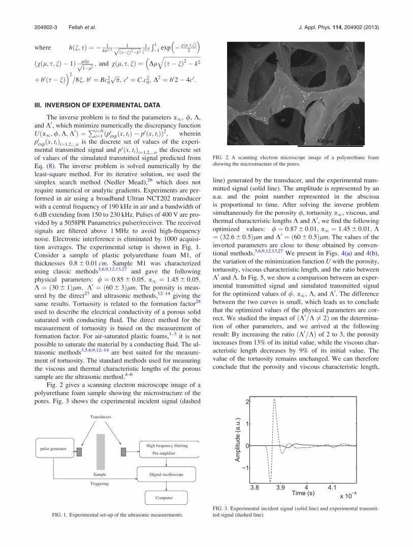
Fig. 2 gives a scanning electron microscope image of a
polyurethane foam sample showing the microstructure of the
pores. Fig. 3 shows the experimental incident signal (dashed
line) generated by the transducer, and the experimental trans-
mitted signal (solid line). The amplitude is represented by an
a.u. and the point number represented in the abscissa
is proportional to time. After solving the inverse problem
simultaneously for the porosity /, tortuosity a1, viscous, and
thermal characteristic lengths K and K0, we find the following
optimized values: / ¼ 0:87 6 0:01; a1 ¼ 1:45 6 0:01; K¼ ð32:6 6 0:5Þlm and K0 ¼ ð60 6 0:5Þlm. The values of the
inverted parameters are close to those obtained by conven-
tional methods.3,6,9,12,13,27 We present in Figs. 4(a) and 4(b),
the variation of the minimization function U with the porosity,
tortuosity, viscous characteristic length, and the ratio between
K0 and K. In Fig. 5, we show a comparison between an exper-
imental transmitted signal and simulated transmitted signal
for the optimized values of /; a1, K, and K0. The difference
between the two curves is small, which leads us to conclude
that the optimized values of the physical parameters are cor-
rect. We studied the impact of ðK0=K 6¼ 2Þ on the determina-
tion of other parameters, and we arrived at the following
result: By increasing the ratio ðK0=KÞ of 2 to 3, the porosity
increases from 13% of its initial value, while the viscous char-
acteristic length decreases by 9% of its initial value. The
value of the tortuosity remains unchanged. We can therefore
conclude that the porosity and viscous characteristic length,
FIG. 1. Experimental set-up of the ultrasonic measurements.
FIG. 2. A scanning electron microscope image of a polyurethane foam
showing the microstructure of the pores.
FIG. 3. Experimental incident signal (solid line) and experimental transmit-
ted signal (dashed line).
204902-3 Fellah et al. J. Appl. Phys. 114, 204902 (2013)

are the parameters that were most affected by the change in
the ratio between K0 and K.
The use of the expression of the transmission operator in
the time domain (Eq. (8)), or that the transmission coefficient
in the frequency domain (Eq. (3)), then taking the inverse
transform numerically, gives exactly the same result for the
inversion process. The time and frequency approaches are
complementary. For transient signals in very short time, the
temporal model is best suited. However, for signals with a
wide temporal content (narrow frequency content), the fre-
quency approach is preferred. For the experimental signals
used in this work, the two approaches are equivalent and
give the same results.
Given the low sensitivity of the porosity and the thermal
length, relative to that of the tortuosity and the viscous length
of the transmitted waves, we thought9,12,13 it was not possi-
ble to solve the inverse problem with respect to porosity and
thermal length. However, this study came to contradict this
earlier conclusion. The measurement of these two quantities
(/ and K0) is now possible using only the transmitted ultra-
sonic waves. This promising result, open horizons yet to be
explored for the ultrasonic characterization of porous materi-
als, thus limiting the experimental data. We recall that until
now, the measurement of porosity and thermal characteristic
length required the combination of data in transmission and
reflection. The alternative ultrasonic method5 for measuring
K0 using only the transmitted waves, is to saturate the porous
material by another gas, which is not always easy to do
experimentally, without damaging the internal structure of
the material porous. The proposed method has the advantage
of being simple, without any intervention on the fluid satu-
rating the porous material. Increasingly limiting the experi-
mental data to the transmitted signals, the inversion is faster
to perform. Solving the inverse problem in the time domain
for transient signals has the advantage of treating the full in-
formation of the experimental signal, acting simultaneously
on speed, attenuation, and dispersion of the ultrasonic wave.
IV. CONCLUSION
An inverse scattering estimate of the porosity, tortuosity,
viscous, and thermal characteristic lengths was given by solv-
ing the inverse problem in time domain for waves transmitted
by a slab of air-saturated porous material. The inverse prob-
lem is solved numerically by the least-square method. The
reconstructed values of these parameters are in agreement
with those obtained using classical methods. The proposed
experimental method has the advantage of being simple,
rapid, and efficient for estimating those parameters and fur-
ther characterizing porous materials. This study shows that it
is not necessary to use the reflected waves for a complete ul-
trasonic characterization of air-saturated porous material.
1J. F. Allard and N. Atalla, Propagation of Sound in Porous Media:Modeling Sound Absorbing Materials (Wiley, Chichester, UK, 2009).
2K. Attenborough, J. Acoust. Soc. Am 81, 93 (1987).3P. B. Nagy, L. Adler, and B. P. Bonner, Appl. Phys. Lett. 56, 2504 (1990).4D. L. Johnson, J. Koplik, and R. Dashen, J. Fluid Mech. 176, 379 (1987).5P. Leclaire, L. Kelders, W. Lauriks, N. R. Brown, M. Melon, and B.
Castagnede, J. Appl. Phys. 80, 2009 (1996).6P. Leclaire, L. Kelders, W. Lauriks, C. Glorieux, and J. Thoen, J. Acoust.
Soc. Am. 99, 1944 (1996).7C. Ayrault, A. Moussatov, B. Castagnede, and D. Lafarge, Appl. Phys.
Lett. 74, 3224 (1999).8Z. E. A. Fellah, C. Depollier, and M. Fellah, J. Sound Vib. 244, 359
(2001).9Z. E. A. Fellah, M. Fellah, W. Lauriks, and C. Depollier, J. Acoust. Soc.
Am. 113, 61 (2003).10N. Sebaa, Z. E. A. Fellah, M. Fellah, E. Ogam, A. Wirgin, F. G. Mitri, C.
Depollier, and W. Lauriks, J. Acoust. Soc. Am. 120, 1816 (2006).
FIG. 4. (a) Variation of the minimization function U with porosity and tortu-
osity. (b) Variation of the cost function U with the viscous characteristic
length K and the ratio K0=K.
FIG. 5. Comparison between the experimental transmitted signal (black
dashed line) and the simulated transmitted signals (red line) using the recon-
structed values of /; a1, K, and K0.
204902-4 Fellah et al. J. Appl. Phys. 114, 204902 (2013)

11E. Ogam, Z. E. A. Fellah, N. Sebaa, and J. P. Groby, J. Sound Vib. 330,
1074 (2011).12Z. E. A. Fellah, S. Berger, W. Lauriks, C. Depollier, C. Aristegui, and J.
Y. Chapelon, J. Acoust. Soc. Am. 113(5), 2424 (2003).13Z. E. A. Fellah, F. G. Mitri, C. Depollier, S. Berger, W. Lauriks, and J. Y.
Chapelon, J. Appl. Phys. 94, 7914 (2003).14Z. E. A. Fellah, C. Depollier, S. Berger, W. Lauriks, P. Trompette, and J.
Y. Chapelon, J. Acoust. Soc. Am. 114(5), 2561 (2003).15J. P. Groby, E. Ogam, L. Deryck, N. Sebaa, and W. Lauriks, J. Acoust.
Soc. Am. 127, 764 (2010).16Z. E. A. Fellah, F. G. Mitri, M. Fellah, E. Ogam, and C. Depollier,
J. Sound Vib. 302, 746 (2007).17R. Panneton and X. Olny, J. Acoust. Soc. Am. 119, 2027 (2006).18X. Olny and R. Panneton, J. Acoust. Soc. Am. 123, 814 (2008).19O. Doutres, Y. Salissou, N. Atalla, and R. Panneton, Appl. Acoust. 71, 506
(2010).
20M. Henry, P. Lemarinier, J. F. Allard, J. L. Bonardet, and A. Gedeon,
J. Appl. Phys. 77, 17 (1995).21P. Leclaire, M. J. Swift, and K. V. Horoshenkov, J. Appl. Phys. 84, 6886
(1998).22M. A. Biot, J. Acoust. Soc. Am. 28, 179 (1956).23Z. E. A. Fellah and C. Depollier, J. Acoust. Soc. Am. 107, 683 (2000).24S. G. Samko, A. A. Kilbas, and O. I. Marichev, Fractional Integrals and
Derivatives: Theory and Applications (Gordon and Breach Science
Publishers, Amsterdam, 1993).25Z. E. A. Fellah, M. Fellah, W. Lauriks, C. Depollier, J. Y. Chapelon, and
Y. C. Angel, Wave Motion 38, 151 (2003).26J. C. Lagarias, J. A. Reeds, M. H. Wright, and P. E. Wright, SIAM J.
Optim. 9, 112 (1998).27Y. Champoux, M. R. Stinson, and G. A. Daigle, J. Acoust. Soc. Am. 89,
910 (1991).28R. J. S. Brown, Geophysics 45, 1269 (1980).
204902-5 Fellah et al. J. Appl. Phys. 114, 204902 (2013)