Thermal Decomposition of Lower-GWP Refrigerants - CiteSeerX
11
Purdue University Purdue e-Pubs International Refrigeration and Air Conditioning Conference School of Mechanical Engineering 2014 ermal Decomposition of Lower-GWP Refrigerants Makoto Ito e University of Tokyo, Japan, [email protected] Chaobin Dang e University of Tokyo, Japan, [email protected] Eiji Hihara e University of Tokyo, Japan, [email protected] Follow this and additional works at: hp://docs.lib.purdue.edu/iracc is document has been made available through Purdue e-Pubs, a service of the Purdue University Libraries. Please contact [email protected] for additional information. Complete proceedings may be acquired in print and on CD-ROM directly from the Ray W. Herrick Laboratories at hps://engineering.purdue.edu/ Herrick/Events/orderlit.html Ito, Makoto; Dang, Chaobin; and Hihara, Eiji, "ermal Decomposition of Lower-GWP Refrigerants" (2014). International Reigeration and Air Conditioning Conference. Paper 1538. hp://docs.lib.purdue.edu/iracc/1538
-
Upload
khangminh22 -
Category
Documents
-
view
1 -
download
0
Transcript of Thermal Decomposition of Lower-GWP Refrigerants - CiteSeerX
Purdue UniversityPurdue e-PubsInternational Refrigeration and Air ConditioningConference School of Mechanical Engineering
2014
Thermal Decomposition of Lower-GWPRefrigerantsMakoto ItoThe University of Tokyo, Japan, [email protected]
Chaobin DangThe University of Tokyo, Japan, [email protected]
Eiji HiharaThe University of Tokyo, Japan, [email protected]
Follow this and additional works at: http://docs.lib.purdue.edu/iracc
This document has been made available through Purdue e-Pubs, a service of the Purdue University Libraries. Please contact [email protected] foradditional information.Complete proceedings may be acquired in print and on CD-ROM directly from the Ray W. Herrick Laboratories at https://engineering.purdue.edu/Herrick/Events/orderlit.html
Ito, Makoto; Dang, Chaobin; and Hihara, Eiji, "Thermal Decomposition of Lower-GWP Refrigerants" (2014). InternationalRefrigeration and Air Conditioning Conference. Paper 1538.http://docs.lib.purdue.edu/iracc/1538
2591, Page 1
15th International Refrigeration and Air Conditioning Conference at Purdue, July 14-17, 2014
Thermal decomposition of lower-GWP refrigerants
Makoto Ito*, Chaobin Dang, Eiji Hihara
Department of Human and Engineered Environmental Studies, Graduate school of frontier sciences,
The University of Tokyo Kashiwa, Chiba, Japan
+81-4-7136-4630, [email protected]
ABSTRACT The use of chlorofluorocarbons (CFCs) and hydrochlorofluorocarbons (HCFCs) has been widely restricted. They have been replaced with hydrofluorocarbons (HFCs) in order to protect the ozone layer. However, the leakage of refrigerant into air from active or end-of-life air conditioners has been a serious environmental issue owing to the high global warming potential (GWP) of HFCs. It has therefore been widely recognized that the replacement of HFCs with lower-GWP refrigerants is a reasonable solution of the problem. In Japan, the lower-GWP refrigerants such as R1234yf, R1234ze, and R32 are considered as candidate alternatives for conventional HFC refrigerants. However, these lower-GWP refrigerants are often chemically unstable. To assess the risks when lower-GWP refrigerants are exposed to high-temperature solid surface, it is necessary to clarify their decomposabilities and products. However, the high reactivities of products like hydrogen fluoride (HF) make this quantification difficult. Moreover, in case of combustion, some researchers proposed that the reactivity of a molecule with more fluorine atoms than hydrogen atoms, like R1234yf, is affected by humidity. Thus, its flammability limits and product composition are influenced by temperature and humidity. In this study, to discuss on the effects of temperature and humidity in thermal decomposition, mixtures of refrigerants and air were decomposed in heated tube and the products were analyzed with FT-IR to quantify decomposed refrigerants and hydrogen fluoride which was the main toxic product. The tested refrigerants were R1234yf, R32 and R134a. The temperature of the heated tube and humidity in the mixture were systematically changed. Because the concentration of hydrogen fluoride was influenced by the tube material due to the chemical reaction between hydrogen fluoride and the tube material, several kinds of heated tubes, made with ceramics or Inconel alloy, were used. The thermal decomposition characteristics of lower-GWP refrigerants were compared with those of conventional non-flammable refrigerants.
1. INTRODUCTION To analyze the risks of using lower-GWP refrigerants, it is necessary to clarify their decomposability and products. However, the high reactivities of products such as hydrogen fluoride (HF) make this quantification difficult. Moreover, Takizawa et al. (2011) has suggested that the reactivity of a molecule with more fluorine atoms than hydrogen atoms, such as R1234yf, is affected by humidity. Thus, its flammability limits and product composition depend on the relative humidity of the surrounding air. The experiment described in this section was carried out to quantify HF, the main toxic product, and to analyze other products in the thermal decomposition of refrigerants.
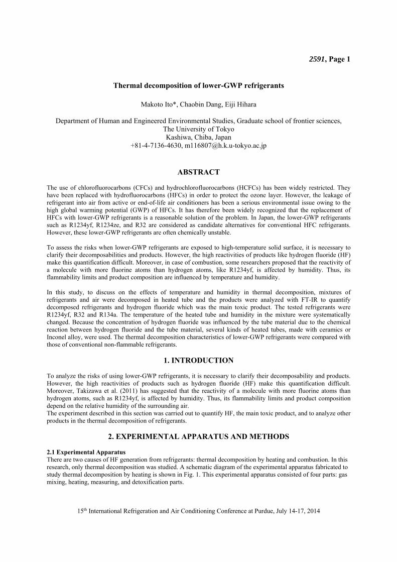
2. EXPERIMENTAL APPARATUS AND METHODS 2.1 Experimental Apparatus There are two causes of HF generation from refrigerants: thermal decomposition by heating and combustion. In this research, only thermal decomposition was studied. A schematic diagram of the experimental apparatus fabricated to study thermal decomposition by heating is shown in Fig. 1. This experimental apparatus consisted of four parts: gas mixing, heating, measuring, and detoxification parts.
2591, Page 2
15th International Refrigeration and Air Conditioning Conference at Purdue, July 14-17, 2014
The gas mixing part was used to mix refrigerant and air at a specified concentration and humidity. The concentration was controlled by mass flow controllers, and the humidity was controlled by a dehumidifier and humidifier. The heating part was used to heat a gas sample and make it react in a straight Inconel 600 pipe (inner diameter 10.7 mm) or mullite (3AlO3·2SiO2) pipe (inner diameter 11 mm), and included a 550-mm-long electric furnace around the pipe. Three thermocouples were set on the outside wall, and for the mullite tube, three additional thermocouples were set on the inside wall of the pipe. To prevent these thermocouples from corroding, the inside ones were mounted in a mullite protection tube with an outer diameter of 6 mm. The gas sample flowed in the gap, 2.5 mm wide, with a cross-sectional area of 0.67 cm2, between the two tubes. The measuring part consisted of gas cells for Fourier transform infrared spectroscopy (FT-IR). To broaden the concentration measurement range, two cells with different path lengths were used. The detoxification part consisted of an absorbance tube that exhausted into a fume hood.
Fig. 1 Schematic diagram of experimental apparatus
2.2 Materials Tested The materials tested were mixtures of refrigerants (R32, R1234yf, and R134a) and air. 2.3 Measuring Instruments An FT/IR-4200 (by JASCO), gas cell (temperature-controlled, 10-cm path length, by Harrick), and CaF2 windows were used to measure the concentrations of the refrigerants and products. To avoid instrument corrosion caused by the HF, FT-IR was conducted using a detector that was not exposed to the sample gas. 2.4 Quantifying Method Each molecule was quantified by absorption in particular wavenumbers. For refrigerants, criteria were established from measurements taken while the electric furnace was off and was at room temperature. For HF and COF2, data from Northwest-Infrared (PNNL, 2012) were used as criteria. 2.5 Experimental Conditions The following parameters were used as the experimental conditions. 1) Temperature of the heater: up to 700°C 2) Concentration of the refrigerant: four points under its LFL (Lower flammable limit) 3) Total flow rate: 100–200 ml/min. 4) Humidity: up to 60% RH
3. RESULTS AND DISCUSSION 3.1 Results for the Inconel Tube The concentrations of refrigerant, HF, and COF2 after heating versus the heater temperature are shown below for each refrigerant. The variable parameter is absolute humidity [g/m3], and the fixed parameters are the refrigerant concentration (2.5 vol. %) and the total flow rate (200 ml/min.).
FT‐IR: Fourier transform infrared spectroscopyMFC: mass flow controller
heating tube
air
MFC
gascylinder
compressor
MFC
humidifier
dehumidifier
refrigerants
FT‐IRgas cell(12m)
exhaust
FT‐IRgas cell(10cm)
2591, Page 3
15th International Refrigeration and Air Conditioning Conference at Purdue, July 14-17, 2014
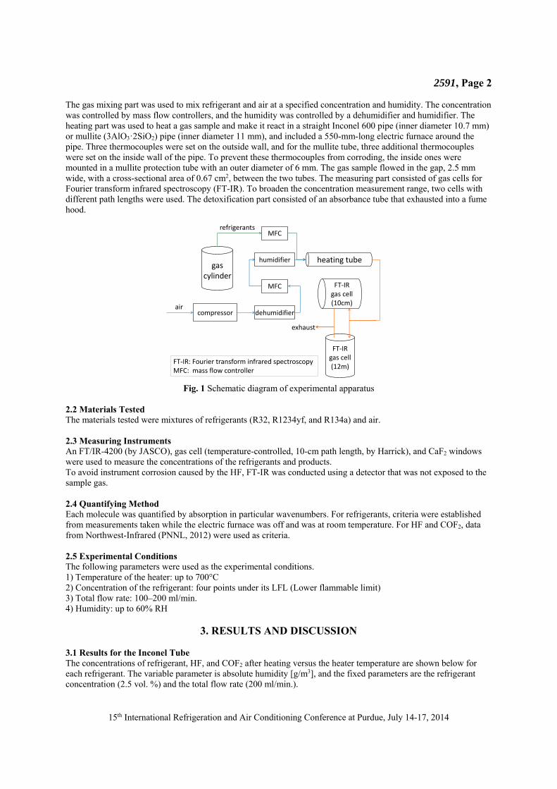
3.1.1 R32 The concentrations of R32 and HF in the case of R32 testing are shown in Figs. 2 to 7. In both case of 2.5 and 5.0 vol. % concentrations of R32, a decrease in the R32 concentration and an increase in the HF concentration began when the heater temperature was in the range of 570–590°C. In addition, the decrease in the R32 concentration was not affected by the humidity. Moreover, in case of 5vol. %, the amount of COF2 generated was highest in 600~650°C and less in higher and lower temperature.
Fig. 2 Concentration of R32 and heater temperature
(Total 200ml/min, 2.5vol. % with air)
Fig.4 Concentration of R32 and heater temperature
(Total 200ml/min, 2.5vol. % R32 with air)
Fig.6 Concentration of COF2 and heater temperature
(Total 200ml/min, 2.5vol. % R32 with air)
‐1
0
1
2
3
400 500 600 700
concentration of R32 [vol.%
]
Temperature of heater [°C]
‐0.5
0
0.5
1
1.5
400 500 600 700concentration of HF [vol.%
]
Temperature of heater [°C]
0
0.0025
0.005
0.0075
0.01
0.0125
0.015
400 500 600 700concentration of COF 2
[vol.%
]
Temperature of heater [°C]
2591, Page 4
15th International Refrigeration and Air Conditioning Conference at Purdue, July 14-17, 2014
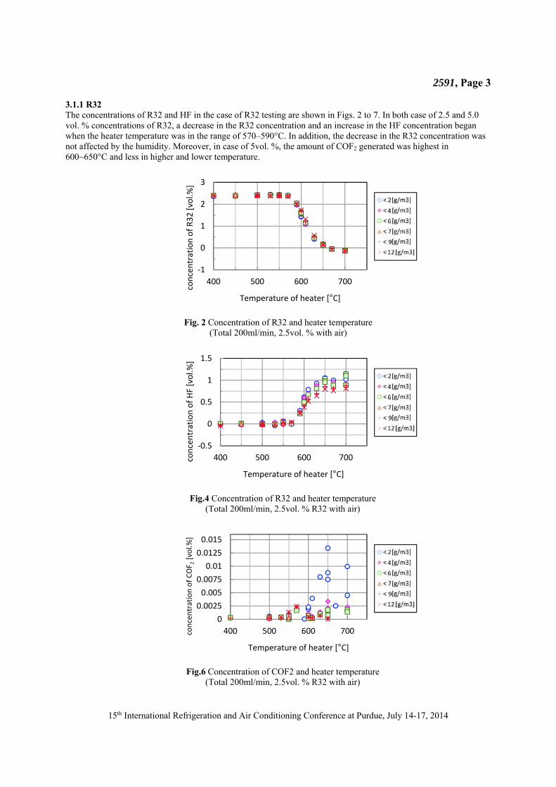
Fig.3 Concentration of HF and heater temperature
(Total 200ml/min, 5.0vol. % with air)
Fig.5 Concentration of HF and heater temperature
(Total 200ml/min, 5.0vol. % R32 with air)
Fig.7 Concentration of COF2 and heater temperature
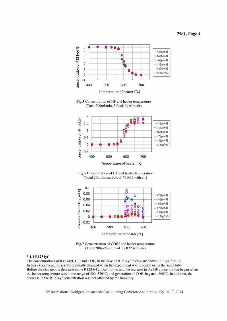
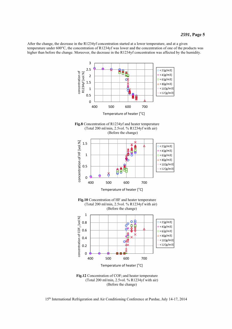
(Total 200ml/min, 5vol. % R32 with air) 3.1.2 R1234yf The concentrations of R1234yf, HF, and COF2 in the case of R1234yf testing are shown in Figs. 8 to 13. In this experiment, the results gradually changed when the experiment was repeated using the same tube. Before the change, the decrease in the R1234yf concentration and the increase in the HF concentration began when the heater temperature was in the range of 500–570°C, and generation of COF2 began at 600°C. In addition, the decrease in the R1234yf concentration was not affected by the humidity.
‐1
0
1
2
3
4
5
400 500 600 700
concentration of R32 [vol.%
]
Temperature of heater [°C]
‐0.5
0
0.5
1
1.5
2
400 500 600 700concentration of HF [vol.%
]
Temperature of heater [°C]
‐0.02
0
0.02
0.04
0.06
0.08
0.1
400 500 600 700concentration of COF 2
[vol.%
]
Temperature of heater [°C]
2591, Page 5
15th International Refrigeration and Air Conditioning Conference at Purdue, July 14-17, 2014
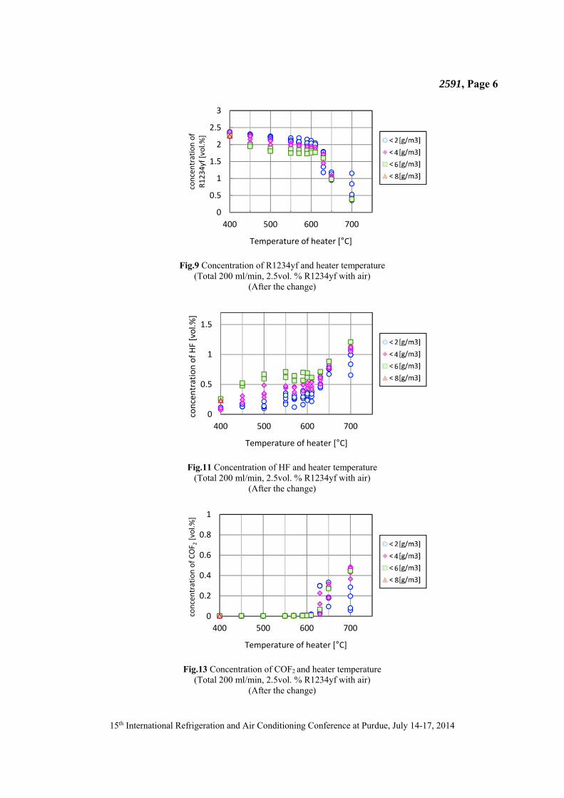
After the change, the decrease in the R1234yf concentration started at a lower temperature, and at a given temperature under 600°C, the concentration of R1234yf was lower and the concentration of one of the products was higher than before the change. Moreover, the decrease in the R1234yf concentration was affected by the humidity.
Fig.8 Concentration of R1234yf and heater temperature
(Total 200 ml/min, 2.5vol. % R1234yf with air) (Before the change)
Fig.10 Concentration of HF and heater temperature
(Total 200 ml/min, 2.5vol. % R1234yf with air) (Before the change)
Fig.12 Concentration of COF2 and heater temperature
(Total 200 ml/min, 2.5vol. % R1234yf with air) (Before the change)
0
0.5
1
1.5
2
2.5
3
400 500 600 700
concentration of
R1234yf [vol.%
]
Temperature of heater [°C]
0
0.5
1
1.5
400 500 600 700concentration of HF [vol.%
]
Temperature of heater [°C]
0
0.2
0.4
0.6
0.8
1
400 500 600 700
concentration of COF 2
[vol.%
]
Temperature of heater [°C]
2591, Page 6
15th International Refrigeration and Air Conditioning Conference at Purdue, July 14-17, 2014
Fig.9 Concentration of R1234yf and heater temperature
(Total 200 ml/min, 2.5vol. % R1234yf with air) (After the change)
Fig.11 Concentration of HF and heater temperature
(Total 200 ml/min, 2.5vol. % R1234yf with air) (After the change)
Fig.13 Concentration of COF2 and heater temperature
(Total 200 ml/min, 2.5vol. % R1234yf with air) (After the change)
0
0.5
1
1.5
2
2.5
3
400 500 600 700
concentration of
R1234yf [vol.%
]
Temperature of heater [°C]
0
0.5
1
1.5
400 500 600 700
concentration of HF [vol.%
]
Temperature of heater [°C]
0
0.2
0.4
0.6
0.8
1
400 500 600 700
concentration of COF 2
[vol.%
]
Temperature of heater [°C]
2591, Page 7
15th International Refrigeration and Air Conditioning Conference at Purdue, July 14-17, 2014
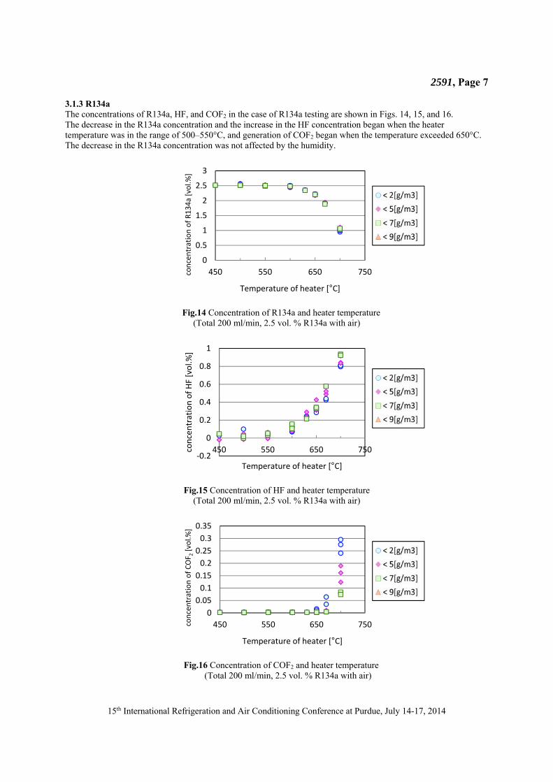
3.1.3 R134a The concentrations of R134a, HF, and COF2 in the case of R134a testing are shown in Figs. 14, 15, and 16. The decrease in the R134a concentration and the increase in the HF concentration began when the heater temperature was in the range of 500–550°C, and generation of COF2 began when the temperature exceeded 650°C. The decrease in the R134a concentration was not affected by the humidity.
Fig.14 Concentration of R134a and heater temperature
(Total 200 ml/min, 2.5 vol. % R134a with air)
Fig.15 Concentration of HF and heater temperature
(Total 200 ml/min, 2.5 vol. % R134a with air)
Fig.16 Concentration of COF2 and heater temperature
(Total 200 ml/min, 2.5 vol. % R134a with air)
0
0.5
1
1.5
2
2.5
3
450 550 650 750concentration of R134a [vol.%
]
Temperature of heater [°C]
‐0.2
0
0.2
0.4
0.6
0.8
1
450 550 650 750concentration of HF [vol.%
]
Temperature of heater [°C]
0
0.05
0.1
0.15
0.2
0.25
0.3
0.35
450 550 650 750concentration of COF 2
[vol.%
]
Temperature of heater [°C]
2591, Page 8
15th International Refrigeration and Air Conditioning Conference at Purdue, July 14-17, 2014
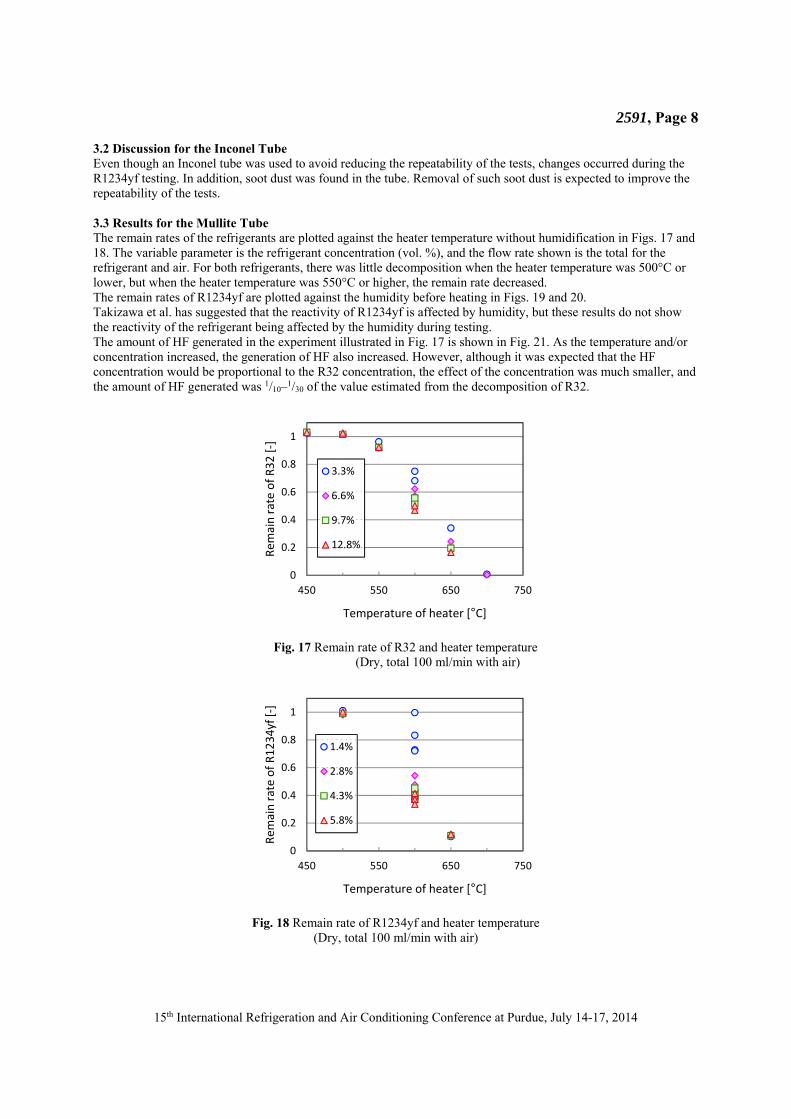
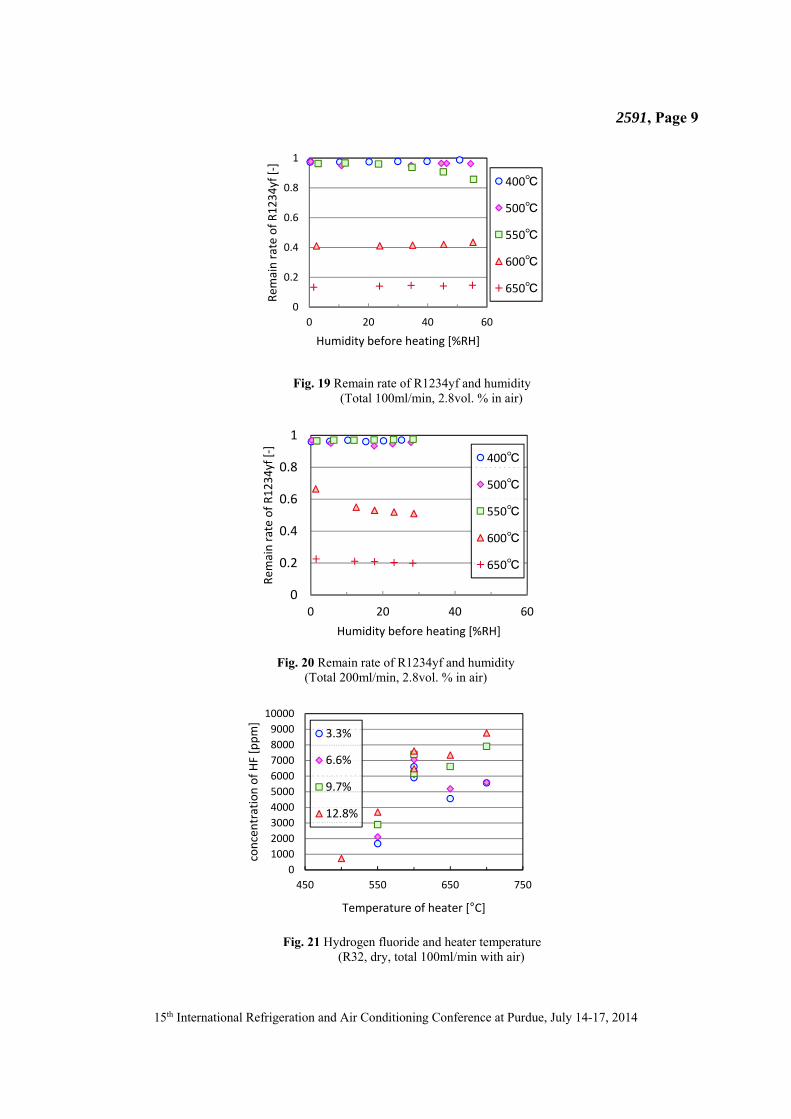
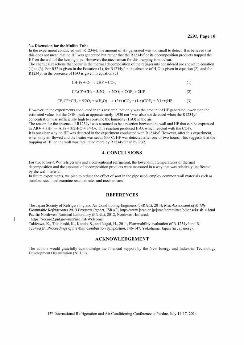
3.2 Discussion for the Inconel Tube Even though an Inconel tube was used to avoid reducing the repeatability of the tests, changes occurred during the R1234yf testing. In addition, soot dust was found in the tube. Removal of such soot dust is expected to improve the repeatability of the tests. 3.3 Results for the Mullite Tube The remain rates of the refrigerants are plotted against the heater temperature without humidification in Figs. 17 and 18. The variable parameter is the refrigerant concentration (vol. %), and the flow rate shown is the total for the refrigerant and air. For both refrigerants, there was little decomposition when the heater temperature was 500°C or lower, but when the heater temperature was 550°C or higher, the remain rate decreased. The remain rates of R1234yf are plotted against the humidity before heating in Figs. 19 and 20. Takizawa et al. has suggested that the reactivity of R1234yf is affected by humidity, but these results do not show the reactivity of the refrigerant being affected by the humidity during testing. The amount of HF generated in the experiment illustrated in Fig. 17 is shown in Fig. 21. As the temperature and/or concentration increased, the generation of HF also increased. However, although it was expected that the HF concentration would be proportional to the R32 concentration, the effect of the concentration was much smaller, and the amount of HF generated was 1/10–1/30 of the value estimated from the decomposition of R32.
Fig. 17 Remain rate of R32 and heater temperature
(Dry, total 100 ml/min with air)
Fig. 18 Remain rate of R1234yf and heater temperature
(Dry, total 100 ml/min with air)
0
0.2
0.4
0.6
0.8
1
450 550 650 750
Remain rate of R32 [‐]
Temperature of heater [°C]
3.3%
6.6%
9.7%
12.8%
0
0.2
0.4
0.6
0.8
1
450 550 650 750
Remain rate of R1234yf [‐]
Temperature of heater [°C]
1.4%
2.8%
4.3%
5.8%
2591, Page 9
15th International Refrigeration and Air Conditioning Conference at Purdue, July 14-17, 2014
Fig. 19 Remain rate of R1234yf and humidity
(Total 100ml/min, 2.8vol. % in air)
Fig. 20 Remain rate of R1234yf and humidity
(Total 200ml/min, 2.8vol. % in air)
Fig. 21 Hydrogen fluoride and heater temperature
(R32, dry, total 100ml/min with air)
0
0.2
0.4
0.6
0.8
1
0 20 40 60
Rem
ain rate of R1234yf [‐]
Humidity before heating [%RH]
400℃
500℃
550℃
600℃
650℃
0
0.2
0.4
0.6
0.8
1
0 20 40 60
Rem
ain rate of R1234yf [‐]
Humidity before heating [%RH]
400℃
500℃
550℃
600℃
650℃
0
1000
2000
3000
4000
5000
6000
7000
8000
9000
10000
450 550 650 750
concentration of HF [ppm]
Temperature of heater [°C]
3.3%
6.6%
9.7%
12.8%
2591, Page 10
15th International Refrigeration and Air Conditioning Conference at Purdue, July 14-17, 2014
3.4 Discussion for the Mullite Tube In the experiment conducted with R1234yf, the amount of HF generated was too small to detect. It is believed that this does not mean that no HF was generated but rather that the R1234yf or its decomposition products trapped the HF on the wall of the heating pipe. However, the mechanism for this trapping is not clear. The chemical reactions that occur in the thermal decomposition of the refrigerants considered are shown in equation (1) to (3). For R32 is given in the Equation (1), for R1234yf in the absence of H2O is given in equation (2), and for R1234yf in the presence of H2O is given in equation (3)
CH2F2 + O2 → 2HF + CO2, (1)
CF3CF=CH2 + 5/2O2 → 2CO2 + COF2 + 2HF (2)
CF3CF=CH2 + 5/2O2 + x(H2O) → (2+x)CO2 + (1-x)COF2 + 2(1+x)HF (3)
However, in the experiments conducted in this research, not only was the amount of HF generated lower than the estimated value, but the COF2 peak at approximately 1,930 cm-1 was also not detected when the R1234yf concentration was sufficiently high to consume the humidity (H2O) in the air. The reason for the absence of R1234yf was assumed to be a reaction between the wall and HF that can be expressed as AlO3 + 3HF → AlF3 + 3/2H2O + 3/4O2. This reaction produced H2O, which reacted with the COF2. It is not clear why no HF was detected in the experiment conducted with R1234yf. However, after this experiment, when only air flowed and the heater was set at 600°C, HF was detected after one or two hours. This suggests that the trapping of HF on the wall was facilitated more by R1234yf than by R32.
4. CONCLUSIONS For two lower-GWP refrigerants and a conventional refrigerant, the lower-limit temperatures of thermal decomposition and the amounts of decomposition products were measured in a way that was relatively unaffected by the wall material. In future experiments, we plan to reduce the effect of soot in the pipe used, employ common wall materials such as stainless steel, and examine reaction rates and mechanisms.
REFERENCES The Japan Society of Refrigerating and Air Conditioning Engineers (JSRAE), 2014, Risk Assessment of Mildly Flammable Refrigerants 2013 Progress Report, JSRAE, http://www.jsrae.or.jp/jsrae/committee/binensei/risk_e.html Pacific Northwest National Laboratory (PNNL), 2012, Northwest-Infrared, https://secure2.pnl.gov/nsd/nsd.nsf/Welcome.
Takizawa, K., Tokuhashi, K., Kondo, S., and Nagai, H., 2011, Flammability evaluation of R-1234yf and R-1234ze(E), Proceedings of the 49th Combustion Symposium, 146-147, Yokohama, Japan (in Japanese).
ACKNOWLEDGEMENT The authors would gratefully acknowledge the financial support by the New Energy and Industrial Technology Development Organization (NEDO).