Annual Quality Assurance Report Multani Mal Modi College ...
B D P E n v i r o n m E n t D E s i g n g u i D E May 2006 • Des 4 • Summary
Thermal Mass in Building DesignDavid Baggs & Neal MortensenThis paper was originally published in August 1995. It has now been fully reviewed by the authors and republished to reflect updates to the topic since original publication.
Summary of
Actions towards Sustainable OutcomesEnvironmental Issues/Principal Impacts• Materials with properly incorporated thermal mass enhance thermal comfort in residential and low use-intensity commercial
buildings, particularly low-rise, when combined with passive solar design.• Proper incorporation means that the volume of mass in a building is balanced with the area, aspect and shading of windows.
The level of insulation in both walls and roof/ceiling is relevant to the climate.• Enhanced comfort means the minimisation of greenhouse gas emissions from fuel-based heating and cooling in buildings.• The use of mass is the only way (apart from natural ventilation) that buildings can be passively cooled without expenditure of
energy.• The thermal effect of mass is measured mainly by three parallel factors: R-value, thermal diffusivity and time lag (decrement)
effect.• Mass improperly employed can amplify the unpleasant aspect of a climate.
Basic StrategiesIn many design situations, boundaries and constraints limit the application of cutting EDGe actions. In these circumstances, designers should at least consider the following:• Where possible, build on slab-on-ground. Where this is not possible, use slabs or timber floors with minimum under-floor
ventilation to maximise earth-coupling effect• In lightweight structures, consider use of lightweight steel framed concrete floors or isolated mass walls, supported by beams,
to introduce mass• Wherever possible, insulate mass walls externally or in the cavity
Cutting EDGe Strategies• Use second generation NatHERS software tools such as AccuRate to test the amount of mass needed for each design and
climate, and to ensure a balance between glass, mass and insulation levels, and effects• Provide summer night-time ventilation/flushing (night purging) – either manual or automated, particularly in commercial
buildings to recharge the thermal mass for the following day• Heat/cool storage in water tanks or hollow concrete floor planks; heating from active solar heat systems in winter and cooling
from night-sky radiation losses in summer• Use ‘Green Roofs’, (vegetated roofs) and earth integrated or insulated earth wall structures. Specify low embodied energy,
high mass materials such as concrete made with cement extenders (cements made with supplementary cementitious materials e.g. fly ash, slag), rammed earth, mud-bricks, and re-cycled clay bricks. Use recycled mass products such as recycled bricks or concrete gravel to increase the ecological value of mass elements.
Synergies and References• BDP Environment Design Guide, Volume 1: Gen 12, Tec 2 and 6; Volume 2: Des 2, 20 and 23; Volume 3: Pro 8 and 12 • Hastings, SR, 1999, Solar Air Systems, Built Examples International Energy Agency, James and James, London• Sunaga, N, 1999, A Bioclimatic Design for Tropical Climates, PLEA 99 Sustaining the Future. Energy/Ecology/Architecture,
Volume 2, Passive and Low Energy Architecture Conference, PLEA International with University of Queensland, Brisbane• Zeiher, L, 1996, the Ecology of Architecture, Whitney Library of Design, New York

B D P E n v i r o n m E n t D E s i g n g u i D E May 2006 • Des 4 • Page �
The BDP Environment Design Guide is published by The Royal Australian Institute of Architects
Thermal Mass in Building DesignDavid Baggs & Neal MortensenThis paper was originally published in August 1995. It has now been fully reviewed by the authors and republished to reflect updates to the topic since original publication. Thermal mass can be effectively employed in buildings to increase occupants’ thermal comfort conditions. This paper seeks to clarify the ways in which this can be achieved and specifically investigates how, why, where, when and in what way thermal mass will have the most beneficial impact.
�.0 IntroductionThe introduction of thermal mass elements into buildings in most climate zones assists in the reduction of energy consumed in heating and cooling, can significantly reduce the ecological impacts of burning fossil fuels for energy production, as well as reduce costs, improve comfort and reduce or eliminate the need for air conditioning. During warm months, introducing thermal mass into lightweight structures is the only way to passively cool a structure down once the external temperatures exceed comfort levels and ventilation and insulation fail to provide comfort. Likewise, in cooler months, using thermal mass in lightweight structures is the only way daytime temperatures can be stored to keep buildings warm in the evening without introducing external energy sources. The use of thermal mass to achieve these ends has, to date, been the domain of the concept known as ‘Passive Solar Design’.However, with the introduction of the second generation National Home Energy Rating Scheme (NatHERS) software tools such as AccuRate, First Rate and NABERS Pro, the sometimes seemingly rigid precepts of passive solar design become more like guiding principles to stimulate design where ideas can be tested, simulated more accurately and endlessly finessed. However there are still some realms where even these sophisticated thermal modelling tools lack depth. This note seeks to explain thermal mass, its benefits and limitations to enhance an understanding of mass and its uses in ordinary buildings; and provide guidance in areas where even the sophisticated second generation thermal modelling tools do not deal adequately with the thermodynamics of more innovative means such as vegetated high mass structures (e.g. green roof, earth covered, earth integrated or green wall).
�.� Low Energy ComfortHistory has shown that some indigenous communities have managed to provide themselves with thermally comfortable dwellings while expending minimum amounts of additional energy. For example, the adobe Taos Pueblo in New Mexico has been in continuous occupation for over 1000 years, harnessing the diurnal temperature swing to stay comfortable throughout the year with comparatively minimal additional energy requirements, even in winter. In the 1930s, North American architects began experimenting with the
‘greenhouse’ effect as a means of house heating, with the Crystal House, at the 1933 Chicago World’s Fair, an early example (AIA Research Corporation 1976). Since then, millions of dollars have been spent on research into solar orientated buildings in an attempt to understand how to balance the amounts of glass, thermal mass, insulation and insolation (solar access) required to produce low energy use comfortable environments.
�.2 Mass and ComfortWhile the ‘greenhouse’ effect can trap large amounts of heat during the day, this heat can also be quickly lost unless materials that act as a storage medium for the heat – or thermal mass – are used. Thermal mass influences comfort by radiant exchanges with the skin. In fact radiant exchange with high mass surfaces is singularly the most efficient way of maintaining comfort compared with another technique as the body is more than twice as sensitive to radiant losses and gains than all other pathways combined (conduction, convection, respiration, evaporation) and more than four times as sensitive as any other single pathway.In summer, the thermal mass effect is the most important of only three commonly possible means of passively cooling a structure without the use of externally sourced (active) energy or fuel. The others are ventilation and evaporation. As noted above, in many climatic conditions, thermal mass effects are the only means of cooling a building. In winter, mass storage effects can create comfort by harnessing large amounts of excess solar energy to initially store and later reradiate low level radiant heat via a ‘thermal flywheel’ effect. In doing so, thermal comfort of occupants can be maintained while achieving energy savings of up to 100% in heating and cooling loads (in some building types). This effect is dependent on the amount of mass introduced and the balance and composition of a number of key building parameters such as glass area and protection, insulation, orientation, ventilation and building usage. However, it is important to realise that history has shown that mass must be carefully employed as it is possible to amplify the unwanted aspects of a climate by inappropriate use. Hence it is important that, from the outset and where possible, architects work with at least second generation NatHERS software tools to optimise the design effectiveness and integration
Page 2 • Des 4 • May 2006 B D P E n v i r o n m E n t D E s i g n g u i D E
of thermal mass components. With very high mass buildings or ‘added mass systems’ such as sub-floor gravel bed or phase change systems, the use of specialised building services engineers who are knowledgeable in passive/active systems and use simulation software capable of modelling them (or consultants experienced in vegetated earth temperature simulation for green roofs or earth integrated buildings), to design systems in an integrated way and maximise simulation accuracy is wise.
2.0 Thermal Mass and Personal Comfort
2.� Storage of HeatThermal mass is the ability of a material to store heat and is a function of its specific heat (kJ/kg.K) – the amount of heat required to increase 1 kg of material by 1°K – and its density. The thermal mass or storage capacity of a material can be measured by its volumetric heat capacity (kJ/m³.K) – the amount of energy stored in a unit volume of material (m³) for a 1°K rise in temperature. Materials suitable for thermal mass are heavy (or dense) materials with the ability to store large amounts of heat energy to provide warmth in winter and coolth (the opposite of warmth) in summer, within a relatively small volume (see Table 1).
2.2 Thermal ComfortThermal comfort exists when a body’s heat loss equals its heat gain or vice versa. The body exchanges 62% of this heat via radiation, 15% by evaporation, 10% by convection, 10% by respiration and 3% by conduction. Hence, when considering normal comfort conditions inside a building the radiative effect of surrounding surfaces is at least as important as air temperature. Relatively small changes in mean radiant temperature have a far greater effect than similar changes in air temperatures (Ballinger 1992, p 39). This gives rise to the importance of recognising the overall Environmental Temperature [T(env)], as opposed to the dry bulb temperature. T(env) = 2/3 Mean radiant surface temperature + 1/3 Air temperature
Thermal mass influences bodily comfort by providing heat source and heat sink surfaces primarily for the radiative heat exchange processes. Thermal comfort is explored in more detail in Des 12: Perceived Comfort (BDP Environment Design Guide, Volume 2)
3.0 Thermal Mass and Internal Air TemperatureThermal mass affects the temperature within a building by stabilising internal temperatures in three ways:• stabilising internal temperatures by providing
heat source and heat sink surfaces for radiative, conductive and convective heat exchange processes
• providing a time-lag in the equalisation of external and internal temperatures
• providing a temperature reduction across an external wall (the decrement factor).
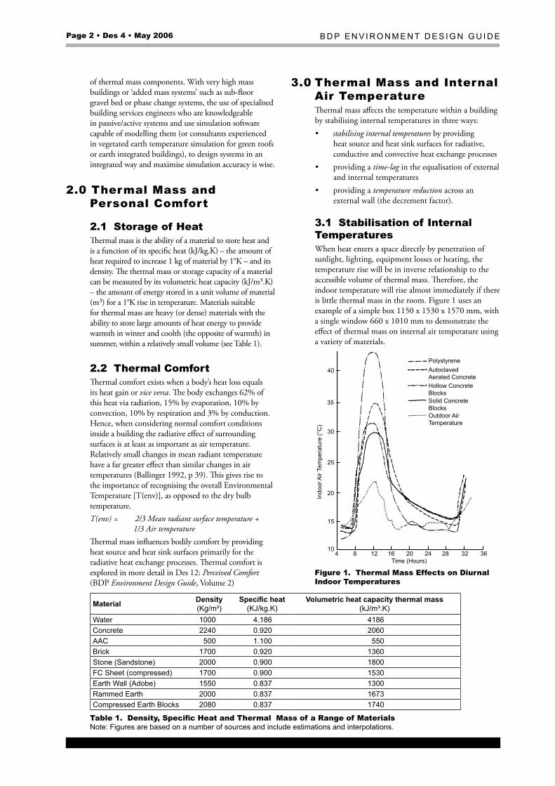
3.� Stabilisation of Internal TemperaturesWhen heat enters a space directly by penetration of sunlight, lighting, equipment losses or heating, the temperature rise will be in inverse relationship to the accessible volume of thermal mass. Therefore, the indoor temperature will rise almost immediately if there is little thermal mass in the room. Figure 1 uses an example of a simple box 1150 x 1530 x 1570 mm, with a single window 660 x 1010 mm to demonstrate the effect of thermal mass on internal air temperature using a variety of materials.
Polystyrene
Hollow ConcreteBlocksSolid ConcreteBlocksOutdoor AirTemperature
AutoclavedAerated Concrete
Time (Hours)
Indo
or A
ir Te
mpe
ratu
re (°
C)
410
15
20
25
35
30
40
8 12 16 20 24 28 32 36
Figure �. Thermal Mass Effects on Diurnal Indoor Temperatures
Material Density (Kg/m³)
Specific heat (KJ/kg.K)
Volumetric heat capacity thermal mass (kJ/m³.K)
Water 1000 4.186 4186Concrete 2240 0.920 2060AAC 500 1.100 550Brick 1700 0.920 1360stone (sandstone) 2000 0.900 1800FC sheet (compressed) 1700 0.900 1530Earth Wall (Adobe) 1550 0.837 1300rammed Earth 2000 0.837 1673Compressed Earth Blocks 2080 0.837 1740
Table 1. Density, Specific Heat and Thermal Mass of a Range of Materialsnote: Figures are based on a number of sources and include estimations and interpolations.
B D P E n v i r o n m E n t D E s i g n g u i D E May 2006 • Des 4 • Page 3
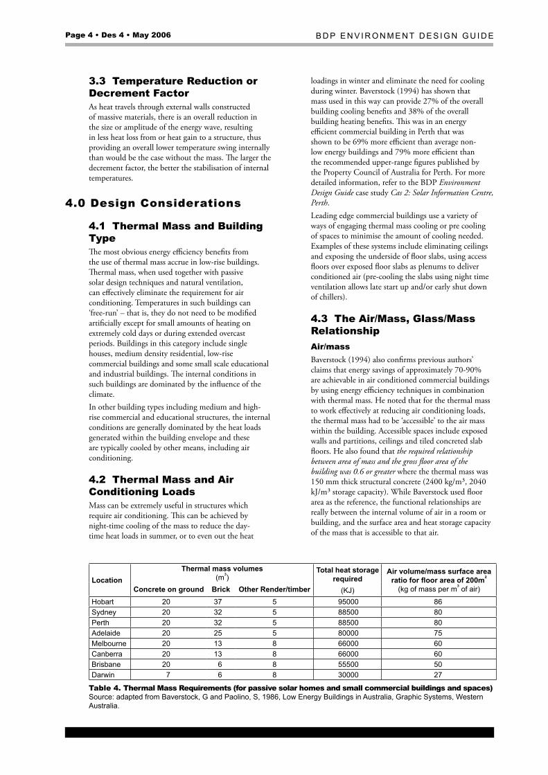
In situations of high thermal resistance and low levels of thermal mass, rapid heating and cooling will occur. Conversely, low levels of thermal resistance and high thermal mass significantly reduce the necessity for heating and cooling (Givoni 1981, p 144). This effect is also demonstrated in Figure 2, which compares two houses, one of lightweight construction (brick veneer, uninsulated walls, timber floor) and the other of heavyweight construction (double brick, insulated, slab on ground).The mass effect can be enhanced with the use of insulation external to the mass and insulation of the glazed areas. In summer, thermal mass can be used in conjunction with passive solar design strategies to inhibit heat build up. In areas where there is a significant diurnal temperature range, night ventilation will cool the building by convection, leaving it ready to absorb the heat build up during the next day. Table 2 describes user shading and ventilation strategies for summer thermal comfort.
Summer Winter Device day night day nightWindows, doors closed open closed closedBlinds (external) closed open open closedCurtains (internal) closed open open closed
Table 2. User Control of Shading and Ventilation DevicesIn winter, thermal mass will increase thermal comfort in a building when solar heat stored in the materials during the day is released as internal temperatures fall. Heat loss from the building after the sun has left the glazing can be prevented by drawing insulating curtains over the windows, or by using double glazing permanently in place. Table 2 describes user shading and ventilation strategies for winter thermal comfort.
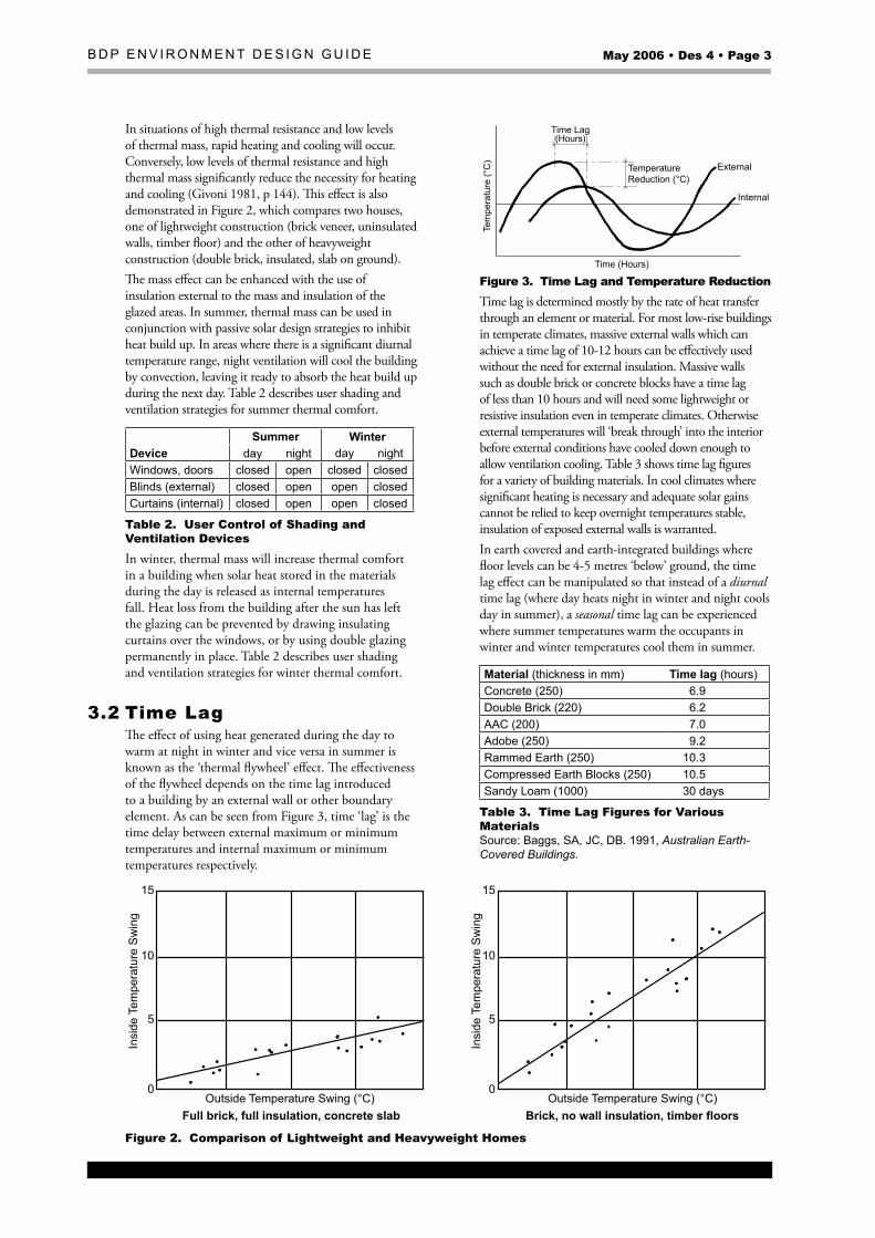
3.2 Time LagThe effect of using heat generated during the day to warm at night in winter and vice versa in summer is known as the ‘thermal flywheel’ effect. The effectiveness of the flywheel depends on the time lag introduced to a building by an external wall or other boundary element. As can be seen from Figure 3, time ‘lag’ is the time delay between external maximum or minimum temperatures and internal maximum or minimum temperatures respectively.
Time (Hours)
Internal
External
Time Lag(Hours)
TemperatureReduction (°C)
Tem
pera
ture
(°C
)
Figure 3. Time Lag and Temperature ReductionTime lag is determined mostly by the rate of heat transfer through an element or material. For most low-rise buildings in temperate climates, massive external walls which can achieve a time lag of 10-12 hours can be effectively used without the need for external insulation. Massive walls such as double brick or concrete blocks have a time lag of less than 10 hours and will need some lightweight or resistive insulation even in temperate climates. Otherwise external temperatures will ‘break through’ into the interior before external conditions have cooled down enough to allow ventilation cooling. Table 3 shows time lag figures for a variety of building materials. In cool climates where significant heating is necessary and adequate solar gains cannot be relied to keep overnight temperatures stable, insulation of exposed external walls is warranted.In earth covered and earth-integrated buildings where floor levels can be 4-5 metres ‘below’ ground, the time lag effect can be manipulated so that instead of a diurnal time lag (where day heats night in winter and night cools day in summer), a seasonal time lag can be experienced where summer temperatures warm the occupants in winter and winter temperatures cool them in summer.
Material (thickness in mm) Time lag (hours)Concrete (250) 6.9Double Brick (220) 6.2AAC (200) 7.0Adobe (250) 9.2rammed Earth (250) 10.3Compressed Earth Blocks (250) 10.5sandy Loam (1000) 30 days
Table 3. Time Lag Figures for Various Materials source: Baggs, sA, JC, DB. 1991, Australian Earth-Covered Buildings.
Outside Temperature Swing (°C)
15
10
5
0Outside Temperature Swing (°C)
15
10
5
0
Full brick, full insulation, concrete slab Brick, no wall insulation, timber floors
Insi
de T
empe
ratu
re S
win
g
Insi
de T
empe
ratu
re S
win
g
Figure 2. Comparison of Lightweight and Heavyweight Homes
Page 4 • Des 4 • May 2006 B D P E n v i r o n m E n t D E s i g n g u i D E
3.3 Temperature Reduction or Decrement FactorAs heat travels through external walls constructed of massive materials, there is an overall reduction in the size or amplitude of the energy wave, resulting in less heat loss from or heat gain to a structure, thus providing an overall lower temperature swing internally than would be the case without the mass. The larger the decrement factor, the better the stabilisation of internal temperatures.
4.0 Design Considerations
4.� Thermal Mass and Building TypeThe most obvious energy efficiency benefits from the use of thermal mass accrue in low-rise buildings. Thermal mass, when used together with passive solar design techniques and natural ventilation, can effectively eliminate the requirement for air conditioning. Temperatures in such buildings can ‘free-run’ – that is, they do not need to be modified artificially except for small amounts of heating on extremely cold days or during extended overcast periods. Buildings in this category include single houses, medium density residential, low-rise commercial buildings and some small scale educational and industrial buildings. The internal conditions in such buildings are dominated by the influence of the climate.In other building types including medium and high-rise commercial and educational structures, the internal conditions are generally dominated by the heat loads generated within the building envelope and these are typically cooled by other means, including air conditioning.
4.2 Thermal Mass and Air Conditioning LoadsMass can be extremely useful in structures which require air conditioning. This can be achieved by night-time cooling of the mass to reduce the day-time heat loads in summer, or to even out the heat
loadings in winter and eliminate the need for cooling during winter. Baverstock (1994) has shown that mass used in this way can provide 27% of the overall building cooling benefits and 38% of the overall building heating benefits. This was in an energy efficient commercial building in Perth that was shown to be 69% more efficient than average non-low energy buildings and 79% more efficient than the recommended upper-range figures published by the Property Council of Australia for Perth. For more detailed information, refer to the BDP Environment Design Guide case study Cas 2: Solar Information Centre, Perth.Leading edge commercial buildings use a variety of ways of engaging thermal mass cooling or pre cooling of spaces to minimise the amount of cooling needed. Examples of these systems include eliminating ceilings and exposing the underside of floor slabs, using access floors over exposed floor slabs as plenums to deliver conditioned air (pre-cooling the slabs using night time ventilation allows late start up and/or early shut down of chillers).
4.3 The Air/Mass, Glass/Mass RelationshipAir/massBaverstock (1994) also confirms previous authors’ claims that energy savings of approximately 70-90% are achievable in air conditioned commercial buildings by using energy efficiency techniques in combination with thermal mass. He noted that for the thermal mass to work effectively at reducing air conditioning loads, the thermal mass had to be ‘accessible’ to the air mass within the building. Accessible spaces include exposed walls and partitions, ceilings and tiled concreted slab floors. He also found that the required relationship between area of mass and the gross floor area of the building was 0.6 or greater where the thermal mass was 150 mm thick structural concrete (2400 kg/m³, 2040 kJ/m³ storage capacity). While Baverstock used floor area as the reference, the functional relationships are really between the internal volume of air in a room or building, and the surface area and heat storage capacity of the mass that is accessible to that air.
LocationThermal mass volumes
(m³)Total heat storage
required(KJ)
Air volume/mass surface area ratio for floor area of 200m²
(kg of mass per m³ of air)Concrete on ground Brick Other Render/timberHobart 20 37 5 95000 86sydney 20 32 5 88500 80Perth 20 32 5 88500 80Adelaide 20 25 5 80000 75melbourne 20 13 8 66000 60Canberra 20 13 8 66000 60Brisbane 20 6 8 55500 50Darwin 7 6 8 30000 27
Table 4. Thermal Mass Requirements (for passive solar homes and small commercial buildings and spaces) source: adapted from Baverstock, g and Paolino, s, 1986, Low Energy Buildings in Australia, graphic systems, Western Australia.
B D P E n v i r o n m E n t D E s i g n g u i D E May 2006 • Des 4 • Page �
Assuming an average commercial building ceiling height of 2.7 metres, this provides an air volume/thermal mass requirement of 1 m² of 150 mm thick concrete (or equivalent) for every 4.5 m³ of air, or in other terms, (for Perth and similar climates such as Adelaide &and Sydney i.e., BCA climate zone 5): The optimum air volume/mass ratio = 80 kg of mass
per cubic metre of air (concrete at 2400 kg/m³, 2040 kJ/m³ storage
capacity and 150 mm thick). In a building with this minimum exposed mass provided, Baverstock showed savings of up to $24/m² pa (at 18 c/kWh) over conventional, inefficient buildings in Perth. Savings possible in other cities can be interpolated from other figures provided by Baverstock and Paolino by comparing the thermal mass requirement of Perth with other cities, as summarised in Table 4. These figures have been generated by the TECTO Simulation Program.The total heat storage requirements shown in the table below are based on the volumetric heat capacity figures for various materials shown in Table 1. Furthermore, for each climate represented by the capital cities shown in Table 1, there are corresponding glass area and insulation values that need to be applied for optimum energy efficiency.
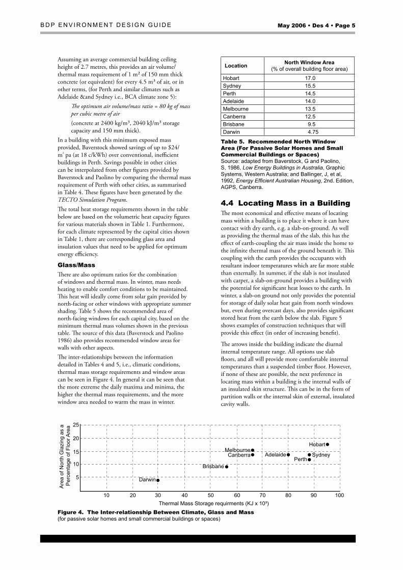
Glass/MassThere are also optimum ratios for the combination of windows and thermal mass. In winter, mass needs heating to enable comfort conditions to be maintained. This heat will ideally come from solar gain provided by north-facing or other windows with appropriate summer shading. Table 5 shows the recommended area of north-facing windows for each capital city, based on the minimum thermal mass volumes shown in the previous table. The source of this data (Baverstock and Paolino 1986) also provides recommended window areas for walls with other aspects. The inter-relationships between the information detailed in Tables 4 and 5, i.e., climatic conditions, thermal mass storage requirements and window areas can be seen in Figure 4. In general it can be seen that the more extreme the daily maxima and minima, the higher the thermal mass requirements, and the more window area needed to warm the mass in winter.
10
5
10
15
20
25
Thermal Mass Storage requirments (KJ x 10³)
Are
a of
Nor
th G
lazi
ng a
s a
Per
cent
age
of F
loor
Are
a
20 30 40 50 60 70 80 90 100
Darwin
Brisbane
CanberraMelbourne
SydneyAdelaidePerth
Hobart
Figure 4. The Inter-relationship Between Climate, Glass and Mass (for passive solar homes and small commercial buildings or spaces)
Location North Window Area (% of overall building floor area)
Hobart 17.0sydney 15.5Perth 14.5Adelaide 14.0melbourne 13.5Canberra 12.5Brisbane 9.5Darwin 4.75
Table �. Recommended North Window Area (For Passive Solar Homes and Small Commercial Buildings or Spaces) source: adapted from Baverstock, g and Paolino, s, 1986, Low Energy Buildings in Australia, graphic systems, Western Australia; and Ballinger, J, et al, 1992, Energy Efficient Australian Housing, 2nd. Edition, AgPs, Canberra.
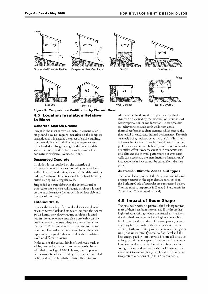
4.4 Locating Mass in a BuildingThe most economical and effective means of locating mass within a building is to place it where it can have contact with dry earth, e.g. a slab-on-ground. As well as providing the thermal mass of the slab, this has the effect of earth-coupling the air mass inside the home to the infinite thermal mass of the ground beneath it. This coupling with the earth provides the occupants with resultant indoor temperatures which are far more stable than externally. In summer, if the slab is not insulated with carpet, a slab-on-ground provides a building with the potential for significant heat losses to the earth. In winter, a slab-on ground not only provides the potential for storage of daily solar heat gain from north windows but, even during overcast days, also provides significant stored heat from the earth below the slab. Figure 5 shows examples of construction techniques that will provide this effect (in order of increasing benefit).
The arrows inside the building indicate the diurnal internal temperature range. All options use slab floors, and all will provide more comfortable internal temperatures than a suspended timber floor. However, if none of these are possible, the next preference in locating mass within a building is the internal walls of an insulated skin structure. This can be in the form of partition walls or the internal skin of external, insulated cavity walls.
Page 6 • Des 4 • May 2006 B D P E n v i r o n m E n t D E s i g n g u i D E
Least
Most
Suspended Free Ventilation Suspended Non-Ventilated On-Fill On-Ground
BermedStepped Wall-Contact Earth-Covered
Figure 5. Temperature Modification by Thermal Mass
4.� Locating Insulation Relative to MassConcrete Slab-On-GroundExcept in the most extreme climates, a concrete slab-on-ground does not require insulation on the complete underside, as this negates the effect of earth coupling. In extremely hot or cold climates polystyrene sheet foam insulation along the edge of the concrete slab and extending as a ‘skirt’ for 1.2 metres around the perimeter is preferred (Watanabe 1986).
Suspended ConcreteInsulation is not required on the underside of suspended concrete slabs supported by fully enclosed walls. However, as the air space under the slab provides indirect ‘earth-coupling’, it should be isolated from the outside air by insulating the walls.Suspended concrete slabs with the external surface exposed to the elements will require insulation located on the outside surface (i.e. underside of floor slab and top side of roof slab).
External WallsBecause the time lag of external walls such as double brick, concrete block and stone are less than the desired 10-12 hours, they always require insulation located within the cavity where possible or preferably on the outside surface to ensure adequate thermal isolation. Current BCA ‘Deemed to Satisfy’ provisions require minimum levels of added insulation for all these wall types and are a good indicator of desirable insulation levels on different climates.In the case of the various kinds of earth walls such as adobe, rammed earth and compressed earth blocks, with their time lags of 10-11+ hours, their apparent performance is enhanced if they are either left unsealed or finished with a ‘breathable’ paint. This is to take
advantage of the thermal energy which can also be absorbed or released by the processes of latent heat of water vaporisation or condensation. These processes are believed to provide earth walls with actual thermal performance characteristics which exceed the theoretical or calculated thermal performance. Research currently being undertaken at the Cra’ Terre’ Institute of France has indicated that favourable winter thermal performances seem to rely heavily on this yet to be fully quantified effect. Nonetheless in cold temperate and cold climates the thermal performance of even earth walls can necessitate the introduction of insulation if inadequate solar heat cannot be stored from daytime gains.
Australian Climate Zones and TypesThe main characteristics of the Australian capital cities or major centres in the eight climate zones cited in the Building Code of Australia are summarised below. Thermal mass is important in Zones 3-8 and useful in Zones 1 and 2 when used correctly.
4.6 Impact of Room ShapeThe mass walls within a passive solar building receive most of their heat from internal air. If the house has high cathedral ceilings, when the heated air stratifies, the absorbed heat is located too high up the walls to be effective for the comfort of the occupants (the use of ceiling fans can reduce this stratification to some extent). With horizontal plaster or concrete ceilings the rising hot air will stratify closer to floor level and the heat energy passing into the walls is more effective due to its proximity to occupants. In rooms with the same floor areas and solar access but with different ceiling configurations, and without additional heating or air movement techniques being employed, environmental temperature variations of up to 3-4°C can occur.
B D P E n v i r o n m E n t D E s i g n g u i D E May 2006 • Des 4 • Page �
Zone Climate Type Characteristics Examples1 tropical Hot humid summer, warm winter nt: Darwin, Katherine;
WA: Broome, Karratha;Qld: Cairns, townsville
2 sub-tropical Warm humid summer, mild winter Qld: mackay, rockhampton, Brisbane;nsW: Byron Bay, Coffs Harbour
3 Hot Arid Hot dry summer, warm winter WA: shark Bay, Halls Creeknt: tennant Creek, Alice springsQld: mount isa, Birdsville, Charleville
4 Hot Dry Hot dry summer, cool winter WA: meekatharra, KalgooriesA: oodnadatta, tarcoola, WhyallansW: Bourke, tamworth, Dubbovic: mildura, swan Hill
5 Warm temperate Warm summer, cool winter WA: Perth, geraldton, EsperancensW: sydney, Wollongong, newcastle
6 mild temperate mild to warm summer, cool winter
vic: melbourne, orbost, WarnamboolsA: mt gambierWA: Albany, Pemberton
7 Cool temperate mild to warm summer, cold winter ACt: CanberransW: Coomatas: Hobart, Launceston
8 Alpine Warm summer, cold to very cold winters nsW: thredbovic: mt Hothamtas: Breona
Table 6. Australian Climate Zones and Types (source: Australian Building Codes Board)
4.� Impact of Mass on Ventilation Heat LossFrom a health point of view, it is desirable to provide some ventilation to internal spaces to remove internal pollutants. Off-gassing of hazardous chemicals such as formaldehyde, plasticisers and radon gas ordinarily tend to build up in the indoor environment if left unchecked. The polluted internal air requires replacement with outdoor air by flush ventilation (short sharp flushes are recommended). While the period of ventilation can be short, it is important (particularly in the case of radon) that a significant volume of air is exchanged. The provision of thermal mass to a space allows this ventilation to occur with the loss of only a small amount of stored heat energy or ‘coolth’, compared to a lightweight structure, which would lose the majority of its stored heat under these conditions.
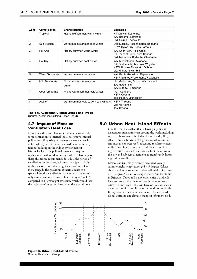
�.0 Urban Heat Island Effects One thermal mass effect that is having significant deleterious impacts in cities around the world including Australia is known as the Urban Heat Island (UHI) effect. This is a function of high mass surfaces in the city such as concrete roofs, roads and to a lesser extent walls, absorbing daytime heat and re-radiating it at night. This re-radiated heat forms a heat ‘halo’ around the city and subjects all residents to significantly hotter night time conditions. Melbourne University recently measured average summer night temperatures 3.4-4.5 degrees Celsius above the long term mean and on still nights, increases of 10 degrees Celsius were experienced. Similar studies in Brisbane, Tokyo and many other cities worldwide have confirmed this phenomenon is common to all cities to some extent. This will have obvious impacts in decreased comfort and increase air conditioning loads. It may also have serious consequences for increased global warming and climate change if left unchecked.
92°F
Rur
al
Com
mer
cial
Urb
anR
esid
entia
l
Sub
urba
nR
esid
entia
l
Sub
urba
nR
esid
entia
l
Dow
ntow
n
Par
k
Rur
alFa
rmla
nd
°C
33
32
31
30
Late
Afte
rnoo
n Te
mpe
ratu
re
92
Figure 6. Urban Heat-Island Profile source: Heat island group

Page � • Des 4 • May 2006 B D P E n v i r o n m E n t D E s i g n g u i D E
6.0 ‘Green Roof ’ RevolutionUrban heat islands have become such a phenomenon worldwide that vegetated green roofs on conventional buildings offices now account for 20% of the new roofs in Germany. In Tokyo it has been mandated on all new commercial buildings over 1000m² and massive projects are appearing throughout the United States, such as the 40,000 square metre green roof on the Ford Motor Company’s Detroit manufacturing plant.Green roofs provide significant energy savings via insulation, thermal mass, evaporation and evapotranspiration pathways as well as major water and visual quality outcomes. They are being promoted for use in Australia also and were recently the subject of a book by NSW Government Architect Chris Johnson entitled Greening Sydney. Green roofs are one form of earth integrated buildings that are the subject of the author’s book Australian Earth Covered Buildings (see references at the end of this paper). Both of these books set out the benefits of earth integration and show that thermal mass effects combined with evapotranspiration and vegetative shade create thermal comfort, energy efficiency and other synergistic benefits well beyond the potential of ordinary structures (see references for further benefits).
�.0 Limitations of Software ToolsThe second generation NatHERS tools such as AccuRate, First Rate and BERS Pro are significant improvements over first generation tools and they are effective at providing simulations of ordinary buildings. However they still have limitations that impact on their ability to accurately simulate (or in some cases simulate at all) certain building types, features and climates such as:• Passive/Active add on systems;• Inner city areas impacted by Urban Heat Island
effects that are not included in the temperature data (normally taken at airports away from inner urban areas)
• Earth wall structures where the full thermal effects of these structures is still not fully understood and practical experience indicates that conventional understanding is inadequate to explain the full thermal effects of earth structures
• Vegetated green roofs and earth covered buildings where software that simulates shade cover, evapotranspiration and moisture dependent thermal diffusivity of soil is required.
More sophisticated commercial modelling tools such as DOE2, TAS and IES Virtual Environment are required to undertake these types of assessments in combination with specialised vegetated earth temperature simulation programs such as TCAL (see references).
�.0 Embodied EnergyThere is a tendency to design high mass buildings with much reinforced concrete and clay fired bricks which tend to be high in embodied energy. This is particularly the case with deep earth covered buildings where in the past deep section in-situ concrete has been the preferred structure. However, in today’s greenhouse gas emission (GGE) aware world, the GGE of the energy embodied in the structure needs to be compared against the savings due from the building’s energy efficiency and the ‘payback’ analysed as to whether it is ‘worthwhile’. If a structure takes 50 years to pay back its GGE of construction does this warrant the initiative even if the structure lasts 500 years? Given the imminence of global warming, probably not, so structures that use low embodied energy materials to provide access to mass need to be employed wherever possible e.g. any technique that provides access to the free mass of the earth by coupling either directly or indirectly as in Figure 5 where sketches 2-8 are easily made GGE efficient. Structures represented in sketches 9-11 need to be carefully considered to ensure low GGE profile structures and systems are used to minimise the ‘payback’ period. Obviously impacts such as urban heat island effect minimisation need to be taken into account in this process. There are options available in some locations and markets to introduce low-embodied energy cement into some concrete products. Up to a fifty percent or higher embodied energy saving can be achieved by specifying cement blended with cement extenders (supplementary cementitious materials) such as fly-ash and granulated blast furnace slag. These products are commonly available and with larger projects and more complex concrete structures have the added advantage of resulting in a higher strength (MPa) concrete (albeit with longer setting times). Also, Tec-eco in Tasmania is researching and developing a magnesium based cement (and some products are already available from pilot projects) which actually absorb CO2 during production.
9.0 ConclusionMass is an essential aspect of energy efficient design. However, mass alone will not create a thermally comfortable building. The inclusion of thermal mass has to form part of an integrated approach to the thermal design of buildings, incorporating correct orientation, appropriate areas and treatment of windows, insulation (when required), site integration considerations, appropriate use of natural and/or mechanical ventilation and appropriate back-up heating or cooling sources. It is important that designers consider energy efficiency techniques such as thermal mass as an inherent part of design and architectural expression and that they be included conceptually from the outset.
B D P E n v i r o n m E n t D E s i g n g u i D E May 2006 • Des 4 • Page 9
References and Further ReadingAccuRate, Building Simulation Software, http://www.hearne.com.auAIA Research Corporation May, 1976, Solar Dwelling Design Concepts, Washington DCBaggs, SA, JC and DW, 1991, Australian Earth-Covered Buildings, Dual Harmony Publishers (1300 88 55 78)Ballinger, J, et al, 1992, Energy Efficient Australian Housing, 2nd Edition, AGPS, CanberraBaverstock, G and Paolino, S, 1986, Low Energy Buildings in Australia, Graphic Systems, Western Australia (+61 8 9386-3888)BERS Pro, Building Simulation Software, http://www.solarlogic.com.auGivoni, B, 1981, Man, Climate and Architecture, Van Nostrand Reinhold, New YorkIES Virtual Environment, Building Simulation Software, http://www.iesve.comMortensen, N, The Natural Airconditioned House, http://www.dab.uts.edu.au/ebrf/index.htmlTCAL, Earth Temperature Simulation Software; Natural Integrated Living Pty Ltd, Brisbane (1300 88 55 78)TAS, Building Simulation Software, http://www.edsl.netWatanabe, T, et al, 1986, Case Study on Thermal Insulation Systems for the Earth-Contact Floor, Report on the International Symposium on Earth Architecture, Kyushu, Japan
BiographyDavid Baggs, BArch (Hons), CA, FRAIA, ABSA, MRSAS, is an award winning architect and ESD consultant and educator. His practice, Natural Integrated Living Pty Ltd, specialises in ecological sustainability, particularly green roof, earth wall and earth integrated buildings, energy efficiency, eco-materials and commercial and residential building sustainability assessment and rating. He wrote the Building Thermal Performance Assessors (Residential) Course for the Australian Greenhouse Office and ABSA and has been responsible for the design of over 400 earth wall, green roof and ESD buildings. He is co-developer and Technical Director of Ecospecifier.org an industry database of eco and health preferable products and co-author of Australian Earth Covered Buildings, The Healthy House Book (2nd Edition) and A Sustainability Primer for Designers. He was chair of the RAIA committee originally responsible for the development and implementation of the RAIA Environment Policy and the BDP Environment Design Guide.Neal Mortensen, BArch, ARAIA, is also an award winning architect and his practice, Environmental Architecture, specialises in ecologically sustainable design. He was a member of the Energy and Ecology Group (formerly the Natural Environment and Energy Group), the RAIA committee originally responsible for the development and implementation of the RAIA Environment Policy and BDP Environment Design Guide Notes.
The views expressed in this Note are the views of the author(s) only and not necessarily those of the Australian Council of Building Design Professions Ltd (BDP), The Royal Australian Institute of Architects (RAIA) or any other person or entity.This Note is published by the RAIA for BDP and provides information regarding the subject matter covered only, without the assumption of a duty of care by BDP, the RAIA or any other person or entity.This Note is not intended to be, nor should be, relied upon as a substitute for specific professional advice.Copyright in this Note is owned by The Royal Australian Institute of Architects.

Copyright © 2022 FDOKUMEN