thePassa P360-221 DALI UP online_307 421 01_EN.indd
16
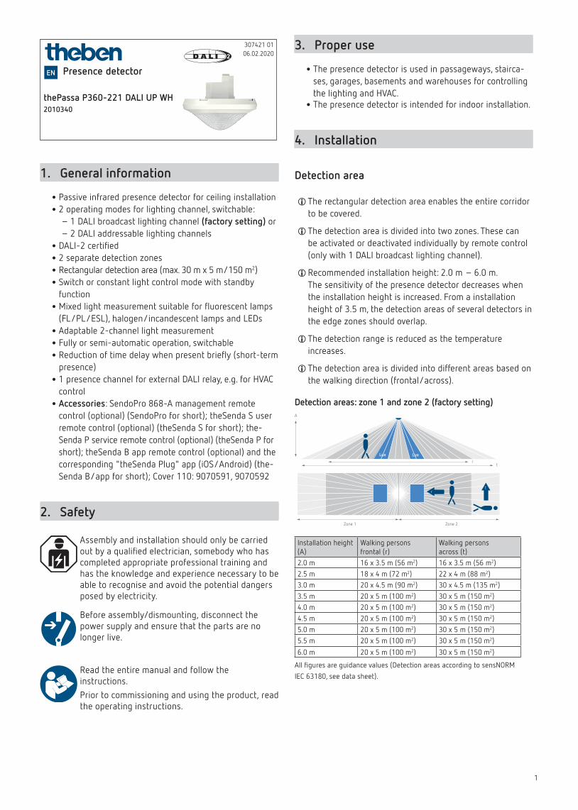
1 thePassa P360-221 DALI UP WH 2010340 307421 01 06.02.2020 Presence detector EN 1. General information • Passive infrared presence detector for ceiling installation • 2 operating modes for lighting channel, switchable: – 1 DALI broadcast lighting channel (factory setting) or – 2 DALI addressable lighting channels • DALI-2 certified • 2 separate detection zones • Rectangular detection area (max. 30 m x 5 m/150 m 2 ) • Switch or constant light control mode with standby function • Mixed light measurement suitable for fluorescent lamps (FL/PL/ESL), halogen/incandescent lamps and LEDs • Adaptable 2-channel light measurement • Fully or semi-automatic operation, switchable • Reduction of time delay when present briefly (short-term presence) • 1 presence channel for external DALI relay, e.g. for HVAC control • Accessories: SendoPro 868-A management remote control (optional) (SendoPro for short); theSenda S user remote control (optional) (theSenda S for short); the- Senda P service remote control (optional) (theSenda P for short); theSenda B app remote control (optional) and the corresponding "theSenda Plug" app (iOS/Android) (the- Senda B/app for short); Cover 110: 9070591, 9070592 2. Safety Assembly and installation should only be carried out by a qualified electrician, somebody who has completed appropriate professional training and has the knowledge and experience necessary to be able to recognise and avoid the potential dangers posed by electricity. Before assembly/dismounting, disconnect the power supply and ensure that the parts are no longer live. Read the entire manual and follow the instructions. Prior to commissioning and using the product, read the operating instructions. 3. Proper use • The presence detector is used in passageways, stairca- ses, garages, basements and warehouses for controlling the lighting and HVAC. • The presence detector is intended for indoor installation. 4. Installation Detection area L The rectangular detection area enables the entire corridor to be covered. L The detection area is divided into two zones. These can be activated or deactivated individually by remote control (only with 1 DALI broadcast lighting channel). L Recommended installation height: 2.0 m – 6.0 m. The sensitivity of the presence detector decreases when the installation height is increased. From a installation height of 3.5 m, the detection areas of several detectors in the edge zones should overlap. L The detection range is reduced as the temperature increases. L The detection area is divided into different areas based on the walking direction (frontal/across). Detection areas: zone 1 and zone 2 (factory setting) A r t r t Zone 1 Zone 2 Installation height (A) Walking persons frontal (r) Walking persons across (t) 2.0 m 16 x 3.5 m (56 m 2 ) 16 x 3.5 m (56 m 2 ) 2.5 m 18 x 4 m (72 m 2 ) 22 x 4 m (88 m 2 ) 3.0 m 20 x 4.5 m (90 m 2 ) 30 x 4.5 m (135 m 2 ) 3.5 m 20 x 5 m (100 m 2 ) 30 x 5 m (150 m 2 ) 4.0 m 20 x 5 m (100 m 2 ) 30 x 5 m (150 m 2 ) 4.5 m 20 x 5 m (100 m 2 ) 30 x 5 m (150 m 2 ) 5.0 m 20 x 5 m (100 m 2 ) 30 x 5 m (150 m 2 ) 5.5 m 20 x 5 m (100 m 2 ) 30 x 5 m (150 m 2 ) 6.0 m 20 x 5 m (100 m 2 ) 30 x 5 m (150 m 2 ) All figures are guidance values (Detection areas according to sensNORM IEC 63180, see data sheet).
-
Upload
khangminh22 -
Category
Documents
-
view
0 -
download
0
Transcript of thePassa P360-221 DALI UP online_307 421 01_EN.indd
1
thePassa P360-221 DALI UP WH2010340
307421 0106.02.2020
Presence detectorEN
1. General information
•Passive infrared presence detector for ceiling installation
•2 operating modes for lighting channel, switchable: – 1 DALI broadcast lighting channel (factory setting) or – 2 DALI addressable lighting channels
•DALI-2 certified
•2 separate detection zones
•Rectangular detection area (max. 30 m x 5 m/150 m2)
•Switch or constant light control mode with standby function
•Mixed light measurement suitable for fluorescent lamps (FL/PL/ESL), halogen/incandescent lamps and LEDs
•Adaptable 2-channel light measurement
•Fully or semi-automatic operation, switchable
•Reduction of time delay when present briefly (short-term presence)
•1 presence channel for external DALI relay, e.g. for HVAC control
•Accessories: SendoPro 868-A management remote control (optional) (SendoPro for short); theSenda S user remote control (optional) (theSenda S for short); the-Senda P service remote control (optional) (theSenda P for short); theSenda B app remote control (optional) and the corresponding "theSenda Plug" app (iOS/Android) (the-Senda B/app for short); Cover 110: 9070591, 9070592
2. Safety
Assembly and installation should only be carried out by a qualified electrician, somebody who has completed appropriate professional training and has the knowledge and experience necessary to be able to recognise and avoid the potential dangers posed by electricity.
Before assembly/dismounting, disconnect the power supply and ensure that the parts are no longer live.
Read the entire manual and follow the instructions.Prior to commissioning and using the product, read the operating instructions.
3. Proper use
•The presence detector is used in passageways, stairca-ses, garages, basements and warehouses for controlling the lighting and HVAC. •The presence detector is intended for indoor installation.
4. Installation
Detection area
LThe rectangular detection area enables the entire corridor to be covered.
LThe detection area is divided into two zones. These can be activated or deactivated individually by remote control (only with 1 DALI broadcast lighting channel).
LRecommended installation height: 2.0 m – 6.0 m. The sensitivity of the presence detector decreases when the installation height is increased. From a installation height of 3.5 m, the detection areas of several detectors in the edge zones should overlap.
LThe detection range is reduced as the temperature increases.
LThe detection area is divided into different areas based on the walking direction (frontal/across).
Detection areas: zone 1 and zone 2 (factory setting)A
rt
rt
Zone 1 Zone 2
Installation height (A)
Walking persons frontal (r)
Walking persons across (t)
2.0 m 16 x 3.5 m (56 m2) 16 x 3.5 m (56 m2)2.5 m 18 x 4 m (72 m2) 22 x 4 m (88 m2)3.0 m 20 x 4.5 m (90 m2) 30 x 4.5 m (135 m2)3.5 m 20 x 5 m (100 m2) 30 x 5 m (150 m2)4.0 m 20 x 5 m (100 m2) 30 x 5 m (150 m2)4.5 m 20 x 5 m (100 m2) 30 x 5 m (150 m2)5.0 m 20 x 5 m (100 m2) 30 x 5 m (150 m2)5.5 m 20 x 5 m (100 m2) 30 x 5 m (150 m2)
6.0 m 20 x 5 m (100 m2) 30 x 5 m (150 m2)
All figures are guidance values (Detection areas according to sensNORM IEC 63180, see data sheet).

2
Detection areas: zone 1 or zone 2
A
rt
rt
Zone 1 Zone 2
A
rt
rt
Zone 1 Zone 2
A
rt
rt
Zone 1 Zone 2
A
rt
rt
Zone 1 Zone 2
Installation height (A)
Walking personsfrontal (r)
Walking personsacross (t)
2.0 m 8 x 3.5 m (28 m2) 8 x 3.5 m (28 m2)2.5 m 9 x 4 m (36 m2) 11 x 4 m (44 m2)3.0 m 10 x 4.5 m (45 m2) 15 x 4.5 m (68 m2)3.5 m 10 x 5 m (50 m2) 15 x 5 m (75 m2)4.0 m 10 x 5 m (50 m2) 15 x 5 m (75 m2)4.5 m 10 x 5 m (50 m2) 15 x 5 m (75 m2)5.0 m 10 x 5 m (50 m2) 15 x 5 m (75 m2)5.5 m 10 x 5 m (50 m2) 15 x 5 m (75 m2)
6.0 m 10 x 5 m (50 m2) 15 x 5 m (75 m2)
All fi gures are guidance values (Detection areas according to sensNORM IEC 63180, see data sheet).
Brightness measurement
The presence detector measures artifi cial light and daylight by means of two directed light measurements. Light measu-rement Z1 measures the brightness in zone 1. In zone 2, light measurement Z2 measures the brightness. The alignment of both brightness measurements has to be taken into account during installation. The installation location is the reference point for the lighting level. The brightness measurement can be adapted to the conditions in a room with the room correc-tion factor.
2 m 2 m
Z1 Z2
Each light measurement zone maps a rectangle of about 2 x 4 m on the fl oor. Depending on the operating mode and the selected detection zone, the light measurements are assigned as follows:
1-channel (broadcast):Selection of detec-tion zone
Lighting channel Light measuring zone
Only zone 1 Channel C1 - light Zone 1
Only zone 2 Channel C1 - light Zone 2
Zone 1 + zone 2 Channel C1 - light Ø from zone 1 + zone 2
2-channel (addressable):Lighting channel Light measuring zone
Channel C1 - light Zone 1
Channel C2 - light Zone 2
LThe alignment of both zone 1/zone 2 brightness measu-rements must be taken into account!
LDirect light infl uences the light measurement. Avoid pla-cing fl oor lamps or suspended lighting directly under the detector.
Constant light controlThe detector must be positioned in such a way that it only detects artifi cial light that it controls itself. Artifi cial light controlled by other detectors (or manually switched working lights) will affect the brightness measurement of the detector.
Switching modeIf the brightness measurement is deactivated, the lighting only switches based on the presence detection function (brightness setpoint value is set to «Measurement off» via the remote control).
Flush-mounted installation
with standard fl ush-mounting box, size 1
Ceiling installation
with ceiling installation box 73A (9070917), for installation diameter 72 mm (Ø 73 mm)

3
Surface-mounted installation
with back box 110A (9070912, 7070913)
5. Connection
!Use the same external conductor for all detectors and buttons.
LSeveral buttons can be connected to one control input.
L Illuminated buttons can only be used with a neutral con-ductor connection.
LUp to 50 DALI operating devices can be connected to each master device. Distribute the DALI operating devices evenly over the 3 external conductors.
L In the addressable operating mode, lighting channels C1 and C2 can be assigned to the required button inputs S1 and S2 via the remote control.
Individual switching
•As master, the presence detector detects presence and brightness and controls lighting.
Master
DALI
DA+ DA–S1 S2EVG
P
*
NL
N
L
EVG
*Only for the "addressable" operating mode
Master/slave parallel switching
•If the detection area of a single presence detector is insuffi cient (spacious rooms), a maximum of 10 detec-tors can be connected in parallel by connecting the P terminals.
•Presence is detected collectively by all the detectors.
•The master measures the brightness, processes the button information and controls the lighting.
•The other detectors (slaves) merely provide presence information (e.g. thePassa P360 Slave UP).
Master
DALI
DA+ DA–S1 S2
PNL
Slave
PNL
N
L
EVG
*
*Only for the "addressable" operating mode
Master/master parallel switching
•Several masters can be used. Every master controls its lighting groups according to its own brightness measurement.
•Time delays and brightness setpoint values are set indi-vidually on each master.
•Presence is detected collectively by all the detectors.
•Switch up to 10 detectors in parallel.
Master
DALI DALI
DA+ DA–S1 S2
PNL
N
L
EVG MasterDA+ DA–S1 S2
PNL
EVG
* *
*Only for the "addressable" operating mode
Integrating an external DALI relay
•No more than 1 external DALI relay can be connected on one single DALI line. The Dali relay must comply with Standard IEC 62386-208 (device type 7).
•The detector automatically detects the DALI relay.
•Switch-on delay and time delay can be set using the remote control.
Master
DALI RMr
DALI
DA+ DA–S1 S2EVG
PNL
N
L
EVG
*
*Only for the "addressable" operating mode

4
6. Start-up
Initial operation of thePassa P360-111 DALI (broadcast) → factory setting
LAfter the start-up phase (30 s), the detector is ready for operation.
Initial operation of thePassa P360-221 DALI (addressable), unconfigured system
� The operating mode can be switched from broadcast to addressable with the SendoPro remote control or the the-Senda B/app:� Select the <thePassa P360-111 DALI> parameter as the detector type.� Open the DALI configuration ("Control commands" menu in the SendoPro).� Send the <Change over to addressable operating mode> parameter to the detector.� After the changeover, select <thePassa P360-221> as the detector type for further parameterization.
After the first changeover to the addressable operating mode (thePassa P360-221 DALI), the detector restarts, identifies all connected DALI lights, assigns short addresses and manages them in a list.
▻ Depending on the system size, the LED on the detector flashes (5 x ON briefly every 3 s) for up to 3 min.
If no DALI EBs are connected to the detector or a DALI line is interrupted
▻ the LED flashes (LED is switched on and flashes 2 x OFF briefly every 3 s).
If the system is functioning, the detector switches to confi-guration mode and waits for the configuration of the lighting groups.
▻ The LED flashes (2 x ON briefly every 3 s).
As long as the configuration has not been carried out, the system is in the following operating state:
•Detector is in broadcast mode.
•Function is in switching mode (only presence detection, no light measurement).
•All lights are controlled with 100% switch-on dimming value.
•The operating mode is fully automatic device.
•All connected buttons are active. Switching on and off as well as dimming are possible.
•Time delay: 10 min.
Configuring the lighting groups with
•SendoPro
•theSenda B/app
•Buttons or theSenda S
Configuring the lighting groups with SendoPro
Right function button
Right button
Up button
Down button
Left function button
� Select "thePassa P360-221 DALI" as the type in the SendoPro.� Select "Menu" (right function button) then "Control com-mands" (left function button).� Open "DALI configuration" with "Open" (right function button).
For the DALI configuration, there are 3 options available:y "Group assignment (unaddress.)": only DALI EBs without a group address are processed.y "Group assignment (all)": all connected DALI EBs are con-figured. NOTE: All existing group assignments with group number 1 or 2 are deleted.y "Change group assignment": the next existing EB is searched for and selected.
� Use the Up or Down button to select the required group assignment and press "Send" (right function button) to start the configuration.
LThe remote control must be directed to the detector! The LED is switched off.
▻ A DALI light starts to pulse (random order).� Select the required C1 or C2 channel with the button and assign it to the DALI EB by pressing "Send" (right function button).
▻ As confirmation, the light dims to 20%. ▻ The next DALI light starts to pulse. One after the other, the lighting groups are assigned to all the lights.
•For group assignment (unaddress.) or (all): if all DALI EBs are assigned to a lighting group, the detector terminates the configuration process and restarts (startup phase of 30 s). The detector then switches to the normal opera-ting mode and the configuration is completed.
L If necessary, the configuration process can be ended by pressing "End" (left function button).
▻ In this case, the system is not ready for operation.
•If "Change group assignment" has been selected, use the right ">" button to switch to the next DALI EB without changing the lighting group.
� When all required changes have been made, end the confi-guration process by pressing "End" (left function button).
Configuring the lighting groups with the theSenda B/app� Connect the theSenda B with the corresponding "theSenda Plug" app.� Place the theSenda B under the detector (direct the remote control towards the detector).� Select "thePassa P360-221 DALI" as the type in the "the-Senda Plug" app.� In the "DALI configuration" menu, select the required group assignment.

5
For the DALI configuration, there are 3 options available:y "Group assignment (unaddress.)": only DALI EBs without a group address are processed.y "Group assignment (all)": all connected DALI EBs are con-figured. NOTE: All existing group assignments with group number 1 or 2 are deleted.y "Change group assignment": the next existing EB is searched for and selected.
▻ After selecting the required group assignment, the detector is in the programming mode. ▻ A DALI light starts to pulse (random order).
� Use to assign the required C1 or C2 channel to the DALI EB. � For further steps, see "Configuring the lighting groups with SendoPro".
Configuring the lighting groups using buttons� Set the <Configuration button/RC> parameter to "Enabled". All connected buttons can be used for the configuration.� Press any button 5 times briefly (< 0.4 s) and press and hold once (> 15 s).
▻ The LED is switched off. ▻ A DALI light starts to pulse (random order). ▻ The lighting group is assigned by pressing the approp-riate button:y 1 x short button press = channel C1y 2 x short button press = channel C2
▻ As confirmation, the light dims to 20% (3 s after the last button press). ▻ The next DALI light starts to pulse. One after the other, the lighting groups are assigned to all the lights.
•If all DALI EBs are assigned to a lighting group, the detector terminates the configuration process and restarts (startup phase of 30 s). ▻ The detector switches to the normal operating mode and the configuration is completed.
L If required, the configuration process can be ended by pressing and holding any button for longer than 15 s. The detector restarts.
▻ In this case, the system is not ready for operation.
L Instead of using the button, the configuration can also be carried out with the ON/OFF buttons on the theSenda B/S.
Checking the configurationThe assignment of the lighting groups can be checked by switching the individual lighting groups on or off using but-tons, the SendoPro remote control or the theSenda B/app (for SendoPro/theSenda B (app), select the "Control commands" menu).
LChanging the lighting group for DALI EBs: use the Sendo-Pro or the theSenda B/app to change the DALI configura-tion via the "Change group assignment" command.
LWith the button: the whole DALI configuration must be re-executed.
LA video on configuring the lighting groups can be found at https://www.youtube.com/user/TheThebenAG
Switch-on response (configured system)
If voltage is applied, the presence detector goes through two phases which are indicated by the LED:
1. Start-up phase (30 s)
•The red LED flashes in one-second intervals; the lighting is switched on with the switch on dimming value.
•The detector does not react to button commands or to the theSenda B/S.
•If absent, the lighting is switched off after 30 s.
2. Operation
•The red LED is off. The constant light control or switching mode are started. ▻ The detector is ready for operation.
7. Functions
Z1 Z2
Mixed light measurement Presence detection Artificial light Button for manual lighting control Incident daylight
Lighting channel C1 (broadcast) Lighting channel C1, C2 (addressable)
The lighting is controlled by presence and brightness. In case of little daylight and presence, the artificial light is switched on via the DALI interface and regulated to a constant bright-ness level.In case of sufficient daylight or absence, the lighting is swit-ched off via the DALI interface.
Constant light control
•It compensates for daylight fluctuations by controlling the lighting.
•The total brightness is kept constant at the required brightness level.
•The lighting is switched on with the switch on dimming value and regulated to the set brightness setpoint value.
•Depending on the "school" or "office" configuration type, the presence detector responds as follows after manual dimming using the buttons: "School" configuration type (in school and conference rooms):y Manual dimming stops the constant light control.y When someone is present, the lighting remains at the dimmed value (no brightness influence).y Switching off and on again leads to control mode.

6
•"Office" configuration type (in single and open-plan offices):y After manual dimming, the constant light control remains temporarily active with the current brightness value as the new brightness setpoint value.y The new brightness setpoint value only applies while some-one is present.y After the lighting time delay, the set brightness setpoint value is restored.
Switching mode
•The switching response is controlled by presence and brightness.
•The lighting channel switches on in darkness and when someone is present. The lighting switches off if there is sufficient brightness or during periods of absence after the set lighting time delay.
•The light is switched on with the switch-on dimming value.
•The button can be used to change the intensity of the artificial light when someone is present. If the lighting is switched on with the button, it remains switched on for at least 30 min. If people have left the room (before), the lighting switches off after the set time delay.
Standby (orientation light)
•After the lighting time delay, the lighting is set to the standby dimming value (1–25% of the lamp output).
•The standby time can be set between 0 s and 60 min or permanently.
•If the room brightness is above the brightness setpoint value, the lighting switches off. If the room brightness is below the brightness setpoint value, the lighting swit-ches to the standby brightness. If someone reenters the room, the detector switches back automatically (fully automatic device) or after pressing the button (semi-automatic device) to the set brightness setpoint value.
Lighting time delay
•The minimum time delay (10 s – 60 min) is adjustable and can increase to max. 30 min or decrease back to the set minimum time.
•With settings ≤ 2 min or ≥ 30 min, the time delay remains unchanged at the set value. If someone briefly enters and leaves an unoccupied room within 30 s, the lighting switches off early after 2 min (short-term presence).
Button control
•The lighting can be switched or dimmed manually via a button.
•A short button press switches the light on or off; a long button press dims the light (brighter or darker).
•If the lighting is switched off manually, it remains switched off as long as people are present. The lighting switches on again after the time delay has elapsed.
Fully or semi-automatic device
•Fully automatic device: the lighting is switched on and off automatically.
•Semi-automatic device: the lighting must be switched on manually. It is switched off automatically.
Staircase light function
•If the staircase light function is activated, the detector is used as a staircase automatic device. It is not possible to switch the lighting off manually.
•If the staircase light function is deactivated, the lighting can be switched on and off manually.
eco and eco plusSettings for ideal switching response and maximum energy savings.
8. Settings
The thePassa P360-221 DALI presence detector features two different operating modes:
•Broadcast (factory setting)
•AddressableBoth operating modes can be selected with the SendoPro or the theSenda B/app.
Parameter Selection
Type thePassa P360-111 DALI (broadcast)
thePassa P360-221 DALI (addressable)
•The presence detectors are supplied with basic settings ready for operation.
•With SendoPro and the theSenda B/app, parameters can be checked, adjusted and optimised during start-up.
•With the theSenda P, parameters can only be adjusted.
Broadcast <thePassa P360-111 DALI>
Teach-in via button
� Press the button for > 15 s ▻ The currently measured brightness value is adopted as the brightness setpoint value.
LThe teach-in function via the button can be disabled using the SendoPro or the theSenda B/app remote controls when the "Configuration button/RC" parameter is set to "disabled".
Parameters via remote control
The following parameters can be checked or changed via the remote control for support during start-up as well as servicing:
Parameter Description Can be checked by Sendo-Pro/the-Senda B (app)
Can be changed by Sen-doPro/theSenda B (app)
Can be changed by the-Senda P
Detection zone Selection: Z1 / Z2 / Z1+Z2 x x
Function C1 Selection: switching/control x x

7
Parameter Description Can be checked by Sendo-Pro/the-Senda B (app)
Can be changed by Sen-doPro/theSenda B (app)
Can be changed by the-Senda P
Brightness set-point value C1
Value range in lux/measurement off x x x
Brightness actual value C1
Check brightness actual value x
Room correction factor C1
Room correction factor x x
Brightness measurement value C1
Lux meter bright-ness value in lux x
Detection sensi-tivity (PIR)
Value range in increments x x x
Lighting time delay
Value range in seconds/minutes x x
Short-term presence
Short-term pre-sence: ON/OFF x x
Energy saving mode
Selection: eco/eco plus x x
Presence switch-on delay
Value range in seconds/minutes x
Presence time delay
Value range in seconds/minutes x x
Switch on dim-ming value C1 Value range in % x
Configuration type C1 Selection: Auto/Man x x x
Control speed Selection: standard/average/fast x
Minimum dim-ming value Value range in % x
Maximum dim-ming value Value range in % x
Switch off brightness
Value range in minutes/hours/never off
x
Staircase light function Selection: ON/OFF x x
Dimming speed: man. dimming
Selection: standard/fast x
Response after man. dimming
Selection: school/office x
Standby timeValue range in seconds/minutesPermanently on
x
Standby dim-ming value Value range in % x
IR group address C1
Selection: all/I/II/III (app to VIII) x
Scene 1 C1 Value range in % x
Scene 2 C1 Value range in % xConfiguration button/RC
Selection: Enabled/Disabled x
LED motion display OFF/ON x
LThe selection of parameters is limited with the theSenda P.
Checking the set values:With the SendoPro and the theSenda B/app, parameters can be checked by gradually sending the values to the detector. If the sent value is below the set parameter, the LED lights up briefly. If the sent value is equal to or above the set parameter, the LED lights flickers for 2 s.
Detection zone
The detection area is divided into two independent detec-tion zones (see 4. Installation, detection area). For a maxi-mum range, zone 1 and zone 2 are activated. If a limitation of the detection area is required, zone 1 or zone 2 can be deactivated.
Value range
Adjustable values from SendoPro/theSenda/app
Z1, Z2, Z1 and Z2
Function C1
The lighting channel C1 can be operated in switching mode or in the constant light control function. The function is set via the <Function C1> parameter.
Value range (with SendoPro/theSenda B/app)
Switching Lighting channel C1 is in the switching mode function
Control Lighting channel C1 is in the constant light control function
Brightness setpoint value C1
The brightness setpoint value defines the minimum required brightness. The current brightness is measured below the presence detector. If the brightness is below the setpoint value and presence is detected, the light is switched on (for the fully automatic device configuration type).
Value range
Adjustable values from SendoPro/theSenda B/app 10–3000 lux
Adjustable values from theSenda P 10, 15, 300, 500, 800 lux
Deactivation of brightness measurement (brightness measurement has no effect)The lighting channels only switch according to presence and absence.
SendoPro/theSenda B/app Measurement off
theSenda P button
Brightness actual value C1
The brightness actual value can be checked for monitoring purposes. To check, see the "Parameters via remote control" table.
Room correction factor C1, brightness measurement value C1
The room correction factor is a measure of the different brightness measurements at the ceiling and on the work surface (the brightness value depends on the ambient conditions).

8
2,5 m 2,5 m
Z1 Z2theSenda B oder Luxmeter
theSenda B or lux meter
Room correction factor = Brightness value at the ceiling Brightness value on the floor
The brightness measurement value at the ceiling is influenced by the installation location, incidence of light, position of the sun, weather conditions, the reflection properties of the room, and the furniture. In order to be able to adhere to the requi-red lux value in the desired area, a comparison of the bright-ness measurements is necessary.The measured lux meter value below the presence detector is sent to the detector via the remote control.When sending the brightness measurement value, the room correction factor of the corresponding lighting channel is automatically adjusted to the conditions inside the room.Two different procedures can be selected for the comparison.
SendoPro and lux meter� Dim all lights to maximum power. If possible, lower the blinds. � Place the lux meter on the work surface under the sensor. The measured lux value is entered via the <Brightness measurement value C1> SendoPro parameter.� During lux measurements, observe the distances shown in the diagram. Carry out all measurements on the floor. � Using only zone 1: place the lux meter during the bright-ness measurement in zone 1 (approx. 2.5 m away from the detector).� Using only zone 2: place the lux meter during the bright-ness measurement in zone 2.� Using zones 1+2: place the lux meter in the middle.
•The room correction factor is calculated from this. Values between 0.05 and 2.0 are permitted. Calculated or ente-red values outside the permitted range are automatically set to the appropriate limit value.
•The calculated room correction factor is adopted. The room correction factor can be checked via the <Room correction factor C1> parameter for monitoring purposes. The default value is 0.3.
theSenda B and the "theSenda Plug" app� Connect the theSenda B with the corresponding theSenda Plug app.� Select the appropriate detector type and load the parame-ter set.� Select the <Brightness measurement value C1> parameter.
Using the theSenda B remote control� Set up the theSenda B according to the drawing, and move a few steps away from the measurement location, so the lux measurement will not be influenced.� Press OK.
▻ A new window with the measured brightness measu-rement value is shown. If you would like to apply this value,
� Press OK.� Important: Press the send button ( ). After this, the brightness measurement is calibrated.
Using the lux meter� Set up or align the lux meter according to the drawing, and read the lux value.� Press "Enter" in the app.
▻ A new window opens. � Enter the lux value and press OK.
▻ The brightness measurement value appears in the display.
� Important: Press the send button ( ). After this, the brightness measurement is calibrated.
•For the room correction factor, see SendoPro and the lux meter...
Switch on dimming value C1
In switching mode and in the constant light control function, the lighting is switched on with the switch-on dimming value.
Value range (with SendoPro/theSenda B/app)Switch on dimming value C1 30–100%
Configuration type C1
Fully automatic device: the lighting is switched on and off automatically (based on presence, absence and brightness).
SendoPro/theSenda B/app auto
theSenda P Button A
Semi-automatic device: the lighting must always be switched on manually. It is switched off automatically by the presence detector (based on absence or brightness)
SendoPro/theSenda B/app man
theSenda P button
IR group address C1
This parameter is applied when using the theSenda S or theSenda B.A group address can be assigned to lighting channel C1. The group addresses in the detector can be programmed with the SendoPro, theSenda B/app or theSenda S.
Value range
Adjustable values from SendoPro I, II, III, all
Adjustable values from theSenda B I, II, III
Adjustable values from theSenda Plug I–VIII, all
Adjustable values from theSenda S I, II
With the theSenda S, the group address can be assigned as follows:
Press the and buttons at the same time for at least 5 s
I
Press the and buttons at the same time for at least 5 s
II
With the theSenda B, the group address can be assigned without the app as follows:
Press the and buttons at the same time for at least 5 s
I

9
Press button A and the button at the same time for at least 5 s
II
Press the and buttons at the same time for at least 5 s
III
Scene 1 C1/Scene 2 C1
The required dimming value for lighting channel C1 can be assigned to scene 1 and scene 2.
Value range (with SendoPro/theSenda B/app)
Adjustable values 0–100%
With the theSenda S or the theSenda B, the lighting is set to a required brightness and saved as follows:
Press the button for at least 3 s. Scene 1 has been saved
Press the button for at least 3 s. Scene 2 has been saved
The scene can be opened by briefly pressing the button.
Control commands via remote control
The following control commands can be triggered with the remote control:
Control command
Description Can be triggered by Sen-doPro/theSenda B (app)
Can be trigge-red by the-Senda P
DALI configuration
Configuration of the operating mode/DALI components
Change over to "addressa-ble" operating mode
Changeover from "broadcast" to "addressable". After the changeo-ver, <thePassa P360-221 DALI> must be selected as the type.
x
Reset DALI EBs All connected DALI EBs are reset to the factory setting. x
Reset DALI relay
The connected DALI relay is reset to the factory setting. x
Switching light The lighting group can be switched on and off. x x
Teach-in C1 Activation x xPresence test OFF/ON x xLight test OFF/ON xRestart Restart the detector x xFactory settings
Set all parameters and settings to the factory setting. x
Changing over to "addressable" operating mode
In factory setting, the detector is in the broadcast operating mode (<thePassa P360-111 DALI> type). Use the control command to change over to the <thePassa P360-221 DALI> detector type which owns 2 addressable lighting groups.
LAfter changing over to the addressable mode, the detector is in the emergency mode. For programming the lighting groups, see chapter 6 "Start-up".
Teach-in C1
During the teach-in process, the currently measured bright-ness value is adopted as brightness setpoint value C1. Values outside the permitted range are automatically set to the appropriate limit value.The teach-in control command can be executed with the SendoPro, the theSenda B/app or with the theSenda P (via the button).
Factory settings
The presence detector is supplied with the following parame-ter values: thePassa P360-111 DALI
Parameter Value
Detection zone Z1+Z2
Function C1 Control
Brightness setpoint value C1 200 luxRoom correction factor C1 0.3Detection sensitivity (PIR) Increment 3Lighting time delay 5 minShort-term presence ONEnergy saving mode ecoPresence switch-on delay 0 sPresence time delay 10 minSwitch on dimming value C1 50%Configuration type autoControl speed StandardMinimum dimming value 10%Maximum dimming value 100%Switch off brightness 10 minStaircase light function OFFDimming speed: man. dimming StandardResponse after man. dimming SchoolStandby time 0 sStandby dimming value 10%IR group address C1 I
Scene 1 C1 30%
Scene 2 C1 70%
Configuration button/RC Enabled
LED motion display OFF
LThe parameters can only be reset to the factory setting with the SendoPro or the theSenda B.
Addressable <thePassa P360-221 DALI>
Setting the teach-in function via button
� Press the button for > 15 s ▻ The currently measured brightness value is adopted as the brightness setpoint value.
LThe teach-in function via the button can be disabled using the SendoPro or the theSenda B/app remote controls when the "Configuration button/RC" parameter is set to "disabled".

10
Parameters via remote control
The following parameters can be checked or changed via the remote control for support during start-up as well as servicing:
Parameter Description Can be checked by Sendo-Pro/the-Senda B (app)
Can be changed by Sen-doPro/theSenda B (app)
Can be changed by the-Senda P
Function C1/C2 Selection: switching/control x x
Terminal S1 assignment, terminal S2 assignment
Selection: C1/C2/C1+C2 x
Brightness setpoint value C1, C2
Value range in lux/measurement off x x x
Brightness actual value C1, C2
Check brightness actual value x
Room correction factor C1, C2
Room correction factor x x
Brightness mea-surement value C1, C2
Lux meter bright-ness value in lux x
Detection sensi-tivity (PIR)
Value range in increments x x x
Lighting time delay
Value range in seconds/minutes x x
Short-term presence
Short-term pre-sence: ON/OFF x x
Energy saving mode
Selection: eco/eco plus x x
Presence switch-on delay
Value range in seconds/minutes x
Presence time delay
Value range in seconds/minutes x x
Switch on dimming value C1, C2
Value range in % x
Configuration type C1/C2 Selection: Auto/Man x x x
Control speed Selection: standard/average/fast x
Minimum dim-ming value Value range in % x
Maximum dim-ming value Value range in % x
Switch off brightness
Value range in minutes/hours/never off
x
Staircase light function Selection: ON/OFF x x
Dimming speed: man. dimming
Selection: standard/fast x
Response after man. dimming
Selection: school/office x
Standby timeValue range in seconds/minutesPermanently on
x
Standby dim-ming value Value range in % x
IR group address C1, C2
Selection: all/I/II/III (app to VIII) x
Scene 1 C1, scene 2 C1
Scene for lighting channel C1 value range in %
x
Scene 1 C2, scene 2 C2
Scene for lighting channel C2 value range in %
x
Parameter Description Can be checked by Sendo-Pro/the-Senda B (app)
Can be changed by Sen-doPro/theSenda B (app)
Can be changed by the-Senda P
Configuration button/RC
Selection: Enabled/Disabled x
LED motion display OFF/ON x
LThe selection of parameters is limited with the theSenda P.
Checking the set values:With the SendoPro and the theSenda B/app, parameters can be checked by gradually sending the values to the detector. If the sent value is below the set parameter, the LED lights up briefly. If the sent value is equal to or above the set parameter, the LED lights flickers for 2 s.
Function C1, C2
Lighting channels C1 and C2 can be operated together in switching mode or in the constant light control function. The function is set via the <Function C1, C2> parameter.
Value range (with SendoPro/theSenda B/app)
Switching Lighting channels C1 and C2 are in the switching mode function
Control Lighting channels C1 and C2 are in the constant light control function
Terminal S1 assignment, terminal S2 assignment
Terminals S1 and S2 for the buttons can be assigned to the required lighting channel at any time without rewiring.
Value range (with SendoPro/theSenda B/app)
Parameter Lighting channel
Terminal S1 assignment
C1 C2 C1+C2
Terminal S2 assignment
C1 C2 C1+C2
Brightness setpoint value C1, C2
The brightness setpoint value defines the minimum required brightness. The current brightness is measured below the presence detector. If the brightness is below the setpoint value and presence is detected, the light is switched on (for the fully automatic device configuration type).A separate brightness setpoint value is available for each lighting channel C1, C2.
Value range
Adjustable values from SendoPro/theSenda B/app 10–3000 lux
Adjustable values from theSenda P 10, 15, 300, 500, 800 lux
Deactivation of brightness measurement (brightness measurement has no effect)The lighting channels only switch according to presence and absence.
SendoPro/theSenda B/app Measurement off
theSenda P button

11
Brightness actual value C1, C2
Both brightness actual values can be checked for monitoring purposes. To check, see the "Parameters via remote control" table.
Room correction factor C1, C2, brightness measure-ment value C1, C2
The room correction factor is a measure of the different brightness measurements at the ceiling and on the work surface (the brightness value depends on the ambient conditions).
2,5 m 2,5 m
Z1 Z2theSenda B oder Luxmeter
theSenda B or lux meter
Room correction factor = Brightness value at the ceiling Brightness value on the floor
The brightness measurement value at the ceiling is influenced by the installation location, incidence of light, position of the sun, weather conditions, the reflection properties of the room, and the furniture. In order to be able to adhere to the requi-red lux value in the desired area, a comparison of the bright-ness measurements is necessary.The measured lux meter value below the presence detector is sent to the detector via the remote control. When sending the brightness measurement value, the room correction factor of the corresponding lighting channel is automatically adjusted to the conditions inside the room.Two different procedures can be selected for the comparison.
SendoPro and lux meter� Dim all lights to maximum power. If possible, lower the blinds. � Place the lux meter on the work surface under the sensor. The measured lux value is entered via the <Brightness measurement value C1, C2> SendoPro parameter.� During lux measurements, observe the distances shown in the diagram. Carry out all measurements on the floor. � Using only zone 1: place the lux meter during the bright-ness measurement in zone 1 (approx. 2.5 m away from the detector).� Using only zone 2: place the lux meter during the bright-ness measurement in zone 2. (approx. 2.5 m away from the detector).� Using zones 1+2: place the lux meter in the middle.
•The room correction factor is calculated from this. Values between 0.05 and 2.0 are permitted. Calculated or ente-red values outside the permitted range are automatically set to the appropriate limit value.
•The calculated room correction factor is adopted. The room correction factor can be checked via the <Room correction factor C1,C2> parameter for monitoring pur-poses. The default value is 0.3.
theSenda B and the "theSenda Plug" app� Connect the theSenda B with the corresponding theSenda Plug app.� Select the appropriate detector type and load the parame-ter set.� Select the <Brightness measurement value C1, C2> parameter.
Using the theSenda B remote control� Set up the theSenda B according to the drawing, and move a few steps away from the measurement location, so the lux measurement will not be influenced.� Press OK.
▻ A new window with the measured brightness measu-rement value is shown. If you would like to apply this value,
� Press OK.� Important: Press the send button ( ). After this, the brightness measurement is calibrated.
Using the lux meter� Set up or align the lux meter according to the drawing, and read the lux value.� Press "Enter" in the app.
▻ A new window opens. � Enter the lux value and press OK.
▻ The brightness measurement value appears in the display.
� Important: Press the send button ( ). After this, the brightness measurement is calibrated.
•For the room correction factor, see SendoPro and the lux meter...
Switch on dimming value C1, C2
In switching mode and in the constant light control function, the lighting is switched on with the switch-on dimming value.
Value range (with SendoPro/theSenda B/app)Switch on dimming value C1, C2 30–100%
Configuration type C1/C2
Fully automatic device: the lighting is switched on and off automatically (based on presence, absence and brightness).
SendoPro/theSenda B/app auto
theSenda P Button A
Semi-automatic device: the lighting must always be switched on manually. It is switched off automatically by the presence detector (based on absence or brightness).
SendoPro/theSenda B/app man
theSenda P button
IR group address C1, C2
This parameter is applied when using the theSenda S or theSenda B.A group address can be assigned to lighting channels C1 and C2. The group addresses in the detector can be programmed with the SendoPro, theSenda B/app or theSenda S.

12
Value range
Adjustable values from SendoPro I, II, III, all
Adjustable values from theSenda B I, II, III
Adjustable values from the theSenda Plug app I–VIII, all
Adjustable values from theSenda S I, II
With the theSenda S, the group address can be assigned as follows:
For IR group address C1:
Press the and buttons at the same time for at least 5 s
I
Press the and buttons at the same time for at least 5 s
II
For IR group address C2:
Press the and 2 buttons at the same time for at least 5 s
I
Press the and 2 buttons at the same time for at least 5 s
II
With the theSenda B, the group address can be assigned without the app as follows:
For IR group address C1:
Press the and buttons at the same time for at least 5 s
I
Press button A and the button at the same time for at least 5 s
II
Press the and buttons at the same time for at least 5 s
III
For IR group address C2:
Press the and 2 buttons at the same time for at least 5 s
I
Press button A and the 2 button at the same time for at least 5 s
II
Press the and 2 buttons at the same time for at least 5 s
III
Scene 1 C1, C2/scene 2 C1, C2
The required dimming value for each lighting group can be assigned to scene 1 and scene 2.
Value range (with SendoPro/theSenda B/app)
Adjustable values 0–100%
With the theSenda S or the theSenda B, the lighting is set to a required brightness and saved as follows:Press the button for at least 3 s. Scene 1 has been
saved
Press the button for at least 3 s. Scene 2 has been saved
The scene can be opened by briefly pressing the button.
Control commands via remote control
The following control commands can be triggered with the remote control:
Control command Description Can be triggered by Sen-doPro/theSenda B app
Can be triggered by the-Senda P/theSenda B app
DALI configurationConfiguration of the lighting group operating mode/DALI components
Group assignment (unaddress.)
Configuration of the unaddressed lighting groups x
Group assignment (all)
Configuration of all lighting groups x
Change group assignment
Change configuration of the lighting groups x
End group assignment
End configuration of the lighting groups x
Change over to broadcast opera-ting mode
Changeover from "addres-sable" to "broadcast". After the changeover, <thePassa P360-111 DALI> must be selected as the type.
x
Reset DALI EBs All connected DALI EBs are reset to the factory settings x
Reset DALI relay The connected DALI relay is reset to the factory setting. x
Switching light C1 Lighting group C1 can be switched on and off. x x
Switching light C2 Lighting group C2 can be switched on and off. x x
Switching light (all) All lighting groups can be switched on and off together x x
Teach-in C1 Execute for lighting channel C1 x x
Teach-in C2 Execute for lighting channel C2 x x
Teach-in C1 + C2 Activate for all lighting chan-nels C1, C2 x
Presence test ON/OFF x xLight test ON/OFF x
Restart Restart the detector x x
Factory settings
Set all parameters and settings to the factory set-ting; the DALI configuration remains unchanged.
x
Teach-in C1, C2
During the teach-in process, the currently measured bright-ness value is adopted as brightness setpoint value. Values outside the permitted range are set to the appropriate limit value.The teach-in control command can be executed with the SendoPro, theSenda B/app or theSenda P.With the theSenda P, the teach-in process is saved as follows:
Teach-in channel C1 Press the button and then the button within 10 s
Teach-in channel C2 Press the 2 button and then the button within 10 s
Teach-in channel C1 + C2 Press the button
Factory settings
After resetting, the presence detector is preset via the <Fac-tory settings> parameter with the following parameter values: thePassa P360-221 DALI

13
Parameter Value
Function C1/C2 Control
Terminal S1 assignment C1
Terminal S2 assignment C2
Brightness setpoint value C1 200 lux
Brightness setpoint value C2 200 luxRoom correction factor C1 0.3Room correction factor C2 0.3Detection sensitivity (PIR) Increment 3Lighting time delay 5 minShort-term presence ONEnergy saving mode ecoPresence switch-on delay 0 sPresence time delay 10 minSwitch on dimming value C1 50%Switch on dimming value C2 50%Configuration type C1/C2 autoControl speed StandardMinimum dimming value 10%Maximum dimming value 100%Switch off brightness 10 minStaircase light function OFFDimming speed: man. dimming StandardResponse after man. dimming SchoolStandby time 0 sStandby dimming value 10%IR group address C1 IIR group address C2 II
Scene 1 C1 30%
Scene 2 C1 70%
Scene 1 C2 30%
Scene 2 C2 70%
Configuration button/RC Enabled
LED motion display OFF
LThe parameters can only be reset to the factory setting with the SendoPro or the theSenda B.
General settings of
Broadcast <thePassa P360-111 DALI>
Addressable <thePassa P360-221 DALI>
Detection sensitivity
The detector has 5 sensitivity increments. The basic setting is the middle increment (3). Increments 1 to 5 can be selected and sent to the detector with the SendoPro and the theSenda B/app. With the theSenda P, the sensitivity can be reduced
by one increment by pressing the -
button, or raised by
pressing the button.
Value range
Incre-ment
Sensitivity
1 Very insensitive
2 Insensitive
3 Standard
4 Sensitive
5 Very sensitive
LBy selecting the presence test mode, the set sensitivity increment is not changed.
Lighting time delay
Value range
Adjustable values from SendoPro/theSenda B/app 10 s – 60 min
Adjustable values from theSenda P 10 s ( button), 30 s, 60 s, 2 min, 10 min, 20 min, 60 min ( button)
Short-term presence
If someone enters an unoccupied room only briefly and leaves within 30 s, the lighting is switched off early after 2 min (short-term presence). Short-term presence can be used for the fully automatic device and semi-automatic device confi-guration type.
Value range (with SendoPro/theSenda B/app)
The time delay is applied according to the set time delay. OFF
Short-term presence is active. ON
Energy saving mode: eco/eco plus
The "eco" selection stands for an ideal switching response, while "eco plus" stands for maximum energy savings.
Value range (with SendoPro/theSenda B/app)
eco The time delay adapts to the user behaviour. The time delay does not fall below the set value.
eco plus The set time delay remains unchanged (no self-learning effect). Faster response to brightness detection than with the eco mode.

14
Presence switch-on delay
The contact of the external DALI relay closes when some-one is present regardless of the brightness and after the set switch-on delay has elapsed. Buttons and the configuration type (fully automatic device/semi-automatic device) do not affect the relay contact.
Value range (with SendoPro/theSenda B/app)
No switch-on delay 0 s
Switch-on delay 10 s – 30 min
Presence time delay
The relay contact of the external DALI relay only opens once the set time delay has elapsed in periods of absence.
Value range
Adjustable values from Sendo-Pro/theSenda B/app
10 s – 120 min
Adjustable values from theSenda P
10 s, 30 s, 60 s, 2 min, 10 min, 20 min, 120 min
Control speed
In the "Control" function, the speed of the constant light con-trol can be set using the <Control speed> parameter.
Value range (with SendoPro/theSenda B/app)
The response is set ideally. The control function is slow and barely perceptible.
Standard
The control function is a little faster. Average
The control function is fast. Fast
Minimum/maximum dimming value
The lower and upper limits of the lighting channel output values can be set using the <Minimum dimming value> and <Maximum dimming value> parameters.
Value range (with SendoPro/theSenda B/app)
Minimum dimming value 1% – 25%
Maximum dimming value 50% – 100%
Switch off brightness
In the Constant light control function, the lighting can be switched off if the brightness is sufficient. If the lighting is switched down to the lower limit of the control, the lighting is switched off after the time set in the <Switch off brightness> parameter. If the "Never off" option is selected, the lighting is never switched off (only as long as there are people present).
Value range (with SendoPro/theSenda B/app)
Switch off the lighting after the set time. 5 min – 9 h
The lighting is never switched off. Never off
Staircase light function
Value range (with SendoPro/theSenda B/app)
The lighting can be switched on and off manually. OFF
The lighting can be switched on, but not switched off manually. It only switches off after the set time delay.
ON
Dimming speed for manual dimming
Value range (with SendoPro/theSenda B/app)
Dimming speed when dimming with buttons or the remote control - theSenda S - theSenda B/App
Standard
Fast
Response after man. dimming
With the constant light control function, the response after manual dimming can be selected using the <Response after man. dimming> parameter.
Value range (with SendoPro/theSenda B/app)
After manual dimming, the constant light control remains temporarily active with the current brightness value as the new brightness setpoint value. After the lighting time delay, the set setpoint value is restored.
Office
Constant light control is temporarily interrupted by manual dim-ming. The setpoint remains unchanged.
School
Standby time/standby dimming value
When the standby time is activated, the lighting is not swit-ched off after the lighting time delay has elapsed, but remains set to the standby dimming value as an orientation light.
Value range (with SendoPro/theSenda B/app)
Standby time 30 s – 60 min
Standby function (orientation light) is inactive 0 s
Standby function (orientation light) is switched on permanently
ON
Standby dimming value 1–25%
Configuration button/RC
The teach-in function and the configuration of lighting groups via the button or the theSenda B/S can be enabled or disab-led with the <configuration button/RC> parameter.
Value range (with SendoPro/theSenda B/app)
Teach-in and configuration can be executed via the buttons/remote controls.
Enabled
Teach-in and configuration via the buttons/remote controls id disabled.
Disabled

15
LED display motion
Motion detection can be displayed using the LED.
Value range (with SendoPro/theSenda B/app)
No display of motion detection. OFF
The LED is switched on when motion is detected, otherwise it remains off.
ON
Presence test
The presence test mode checks the presence detection and wiring. The presence test mode can be activated with the SendoPro, the theSenda B/app or with the theSenda P ( button). When the test mode is set, the detector switches directly to test mode:
•Every movement is indicated by the LED.
•The lighting is switched on where there is movement.
•If there is no movement, the lighting is switched off after 10 s.
•The brightness measurement is deactivated, the detector does not respond to brightness.
•Constant light control is deactivated (switching mode).
•The standby function is deactivated.
•The detector responds as in the "fully automatic device" configuration type – even if "semi-automatic device" is set.
•Teach-in cannot be activated in test mode.
•The test mode ends after 10 min. The detector restarts (see "Switch-on response").
Light test
The light test mode checks the brightness threshold and the constant light control. The light test mode can be activa-ted with the SendoPro or the theSenda B/app. When the test mode is set, the detector switches directly to test mode:
•The LED shows the light test mode (5 seconds ON, 0.3 seconds OFF).
•The presence detector responds as in the normal operating mode; it only responds faster to brightness/darkness.
•To simulate the response, either actuate the blinds or illuminate the area under the presence detector.
•The test mode ends after 10 min. The detector restarts (see "Switch-on response").
LNote: Do not use a torch to trigger the presence detector to switch! The adaptive light switching thresholds are falsified!
Resetting the DALI EBs/DALI relays
The connected DALI EBs/DALI relays are reset to the factory settings.
9. Technical data
Operating voltage 110 – 230 V AC, +10%/-15%
Frequency 50–60 Hz
Upstream protection device: 16 A
Power consumption (without DALI EB) < 0.4 W
Type of installation Ceiling installation; flush/surface mounted or ceiling installation
Recommended installation height 2.0–6.0 m/max. 15 m
Minimum height > 1.7 m
Detection area horizontal 360°
Maximum range 20 x 5 m (IH 3.5 m)/100 m2 moving radially30 x 5 m (IH 3.5 m)/150 m2 moving tangentially
Setting range of brightness setpoint value
10–3000 lux
Lighting time delay 10 s – 60 min
Presence switch-on delay 0 s – 30 min
Presence time delay 10 s – 120 min
Lighting standby time 0 s – 60 min/permanently on
Standby dimming value 1–25%
Lighting control output 100 mA guaranteed, max. 250 mA, max. 64 DALI operating devices, basic insulation
Connection type Screw terminals
Max. cable cross-section max. 2 x 2.5 mm²
Flush-mounted box size Size 1, Ø 55 mm (NIS, PMI)
Protection rating IP 20 (IP 54 when installed)
Ambient temperature –15 °C ... +50 °C
CE Declaration of Conformity This device conforms to the safety regulations of the EMC Directive 2014/30/EU and of Directive 2014/35/EU.
Dali conformity IEC 62386-101, IEC 62386-103
Troubleshooting Fault CauseLight does not switch on or off if presence is detected and in darkness
Brightness setpoint value is set too low; detector is set to semi-automatic device; light was switched off manually using buttons or the theSenda B/S; person is not in the detection area; obstacle(s) disrupt detection; time delay is too short
Light stays on with detection of presence despite sufficient brightness
Brightness setpoint value is set too high; the light was switched on manually a short while ago using buttons or the theSenda B/S (wait 30 min during switching mode); detector is in test mode
Light does not switch off, or light switches on spontaneously when no one is present
Wait for time delay (self-learning);thermal sources of interference in detection area; fan heaters, light bulb/halogen spotlight, moving objects (e.g. curtains in front of open windows)
Button does not work Device still in the start-up phase; illuminated button was used without neutral conductor; button not connected to master.
Light cannot be switched off with the button
Button is not connected to the detector. Check the button wiring.
Lighting does not respond
Short circuit or interruption on DALI bus. Overvol-tage on DALI bus: disconnect the detector from the mains for 1 minute (thermal fuse).
Error flashing (4 x per second)
Error in self-test; device not functional!
LED is switched on and flashes 2 x OFF briefly every 3 s
The detector has not detected any DALI EBs. Check DALI connections. At least 1 DALI EB must be con-nected to the detector. Short circuit on DALI bus.
Master/slave, master/master parallel swit-ching is not working
The detector and button are not connected to the same external conductor.

16
Cleaning and service
� Only use a dry, soft cloth to clean the device surface.� Do not use any cleaning agents and solvents.
Disposal
� Dispose of device in environmentally sound manner
10. Dimensions diagrams
8646
25
40
11. Contact
Theben AGHohenbergstr. 3272401 HaigerlochGERMANYPhone +49 7474 692-0Fax +49 7474 692-150
HotlinePhone +49 7474 [email protected], telephone numbers, etc. www.theben.de