ee 221 lcircuit ii - laboratory 1: dc circuits & ltspice - Electrical ...
15
DEPARTMENT OF ELECTRICAL AND COMPUTER ENGINEERING 1 EE 221 L CIRCUIT II LABORATORY 1: DC CIRCUITS & LTSPICE DEPARTMENT OF ELECTRICAL AND COMPUTER ENGINEERING UNIVERSITY OF NEVADA, LAS VEGAS OBJECTIVE Better understand circuit laws, theorems and analysis approaches, e.g. KCL, KVL, node & mesh analysis, superposition, Thevenin’s Theorem & Norton’s Theorem, Δ-Y convertion, etc. Learn to use LTspice for circuit simulations, measuring voltage at each node and current through each component. COMPONENTS & EQUIPMENT Computer with Windows OS LTspice software BACKGROUND SPICE (Simulation Program with Integrated Circuit Emphasis) is a general-purpose, open source analog electronic circuit simulator. It is a program used in integrated circuit and board-level design to check the integrity of circuit designs and to predict circuit behavior. LTspice is a high-performance SPICE simulator, schematic capture and waveform viewer with enhancements and models for easing the simulation of various circuits. Current version included in this download are LTspice, Macro Models for majority of Linear Technology's switching regulators, over 200 op amp models, as well as resistors, transistors and MOSFET models. Kirchhoff's circuit laws are two equalities that deal with the current (KCL) and potential difference (commonly known as voltage, KVL) in the lumped element model of electrical circuits. “±” can be used to represent the directions of currents and voltages.
-
Upload
khangminh22 -
Category
Documents
-
view
1 -
download
0
Transcript of ee 221 lcircuit ii - laboratory 1: dc circuits & ltspice - Electrical ...

DEPARTMENT OF ELECTRICAL AND COMPUTER ENGINEERING 1
EE 221 L CIRCUIT II
LABORATORY 1: DC CIRCUITS & LTSPICE
DEPARTMENT OF ELECTRICAL AND COMPUTER ENGINEERING
UNIVERSITY OF NEVADA, LAS VEGAS
OBJECTIVE
Better understand circuit laws, theorems and analysis approaches, e.g. KCL, KVL, node &
mesh analysis, superposition, Thevenin’s Theorem & Norton’s Theorem, Δ-Y convertion, etc.
Learn to use LTspice for circuit simulations, measuring voltage at each node and current
through each component.
COMPONENTS & EQUIPMENT
Computer with Windows OS
LTspice software
BACKGROUND
SPICE (Simulation Program with Integrated Circuit Emphasis) is a general-purpose, open
source analog electronic circuit simulator. It is a program used in integrated circuit and board-level
design to check the integrity of circuit designs and to predict circuit behavior.
LTspice is a high-performance SPICE simulator, schematic capture and waveform viewer with
enhancements and models for easing the simulation of various circuits. Current version included
in this download are LTspice, Macro Models for majority of Linear Technology's switching
regulators, over 200 op amp models, as well as resistors, transistors and MOSFET models.
Kirchhoff's circuit laws are two equalities that deal with the current (KCL) and potential
difference (commonly known as voltage, KVL) in the lumped element model of electrical
circuits. “±” can be used to represent the directions of currents and voltages.

EE 221L CIRCUITS II
DEPARTMENT OF ELECTRICAL AND COMPUTER ENGINEERING 2
DC is the unidirectional flow of electric charge. The DC solution of an electric circuit is the
solution where all voltages and currents are constant, zero-frequency, or slowly varying local mean
value of a voltage or current. A battery is a good example of a DC power supply. Some power
adapter (e.g. your laptop power adapter, desktop power supply, etc.) can convert AC power, which
will be examined in future labs, into DC power.
Electrical Circuit Rules &
Elements
Graphic Description (I-V Plot)
KCL
I1
I2
I3
I4
I5
KVL
Ideal DC Voltage Supply
𝑉 = 𝑉0
𝐴 ∈ 𝑅

EE 221L CIRCUITS II
DEPARTMENT OF ELECTRICAL AND COMPUTER ENGINEERING 3
Ideal DC Current Supply
𝐴 = 𝐴0
𝑉 ∈ 𝑅
Non-Ideal DC Voltage and
Current Supply
Resistor
𝑉 = 𝐼𝑅
EE 221L CIRCUITS II
DEPARTMENT OF ELECTRICAL AND COMPUTER ENGINEERING 4
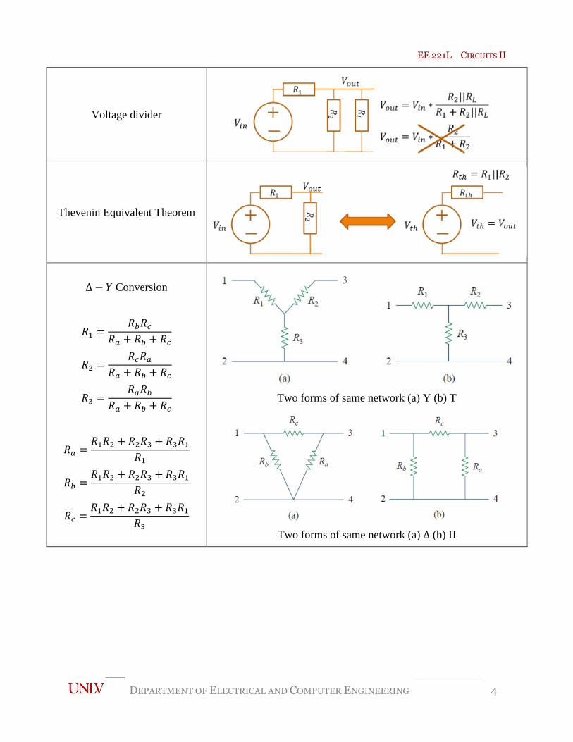
Voltage divider
Thevenin Equivalent Theorem
Δ − 𝑌 Conversion
𝑅1 =𝑅𝑏𝑅𝑐
𝑅𝑎 + 𝑅𝑏 + 𝑅𝑐
𝑅2 =𝑅𝑐𝑅𝑎
𝑅𝑎 + 𝑅𝑏 + 𝑅𝑐
𝑅3 =𝑅𝑎𝑅𝑏
𝑅𝑎 + 𝑅𝑏 + 𝑅𝑐
𝑅𝑎 =𝑅1𝑅2 + 𝑅2𝑅3 + 𝑅3𝑅1
𝑅1
𝑅𝑏 =𝑅1𝑅2 + 𝑅2𝑅3 + 𝑅3𝑅1
𝑅2
𝑅𝑐 =𝑅1𝑅2 + 𝑅2𝑅3 + 𝑅3𝑅1
𝑅3
Two forms of same network (a) Y (b) T
Two forms of same network (a) Δ (b) Π

EE 221L CIRCUITS II
DEPARTMENT OF ELECTRICAL AND COMPUTER ENGINEERING 5
LAB DELIVERIES
PRELAB:
1. Read:
https://en.wikipedia.org/wiki/Electronic_circuit_simulation
https://en.wikipedia.org/wiki/SPICE
2. Go through “Simulations Step-by-Step with Schematic Files” starting from Page 9
of this manual.
LAB EXPERIMENTS:
1. Simulate the following Circuit 1 (1) and (2) for 1ms, respectively, and measure the
output voltage and current through each resistor.
• Fill in the table, and show your hand calculation process.
• Compare the hand calculation and LTspice simulation, do they meet KCL and KVL?
• Compare Circuit 1 (1) and (2), what can you conclude with Thevenin’s/Norton’s Theorem?
Circuit 1 (1) Circuit 1 (2)
𝑉𝑜𝑢𝑡 (V) 𝑖𝑅1 (mA) 𝑖𝑅2 (mA) 𝑖𝑅3 (mA)
Circuit 1 (1) Hand Calculation
LTspice Simulation
Circuit 1 (2) Hand Calculation
LTspice Simulation

EE 221L CIRCUITS II
DEPARTMENT OF ELECTRICAL AND COMPUTER ENGINEERING 6
2. Simulate the following circuit for 1ms.
• Does it include one or more Δ or Y circuit? Why?
• Hand calculate 𝑅𝑒𝑞, and compare 10/𝑖0 − 5, where 𝑖0 is measured by LTspice.
Circuit 2
3. Simulate the following circuit for 1ms, and write down 𝑰𝟎.
• Use Δ − 𝑌 conversion to hand calculate 𝑅𝑒𝑞. Show process.
• Run LTspice simulation, and compare 12/𝐼0 with the 𝑅𝑒𝑞 that you have calculated.
Circuit 3

EE 221L CIRCUITS II
DEPARTMENT OF ELECTRICAL AND COMPUTER ENGINEERING 7
4. Simulate the following circuit for 1ms, and write down the voltage at each node and
the current through each resistor.
• Hand calculate the voltages at each node and current through each resistor. Show the process.
• Compare the results if
1) only applying voltage source, i.e. no current source
2) only applying current source, i.e. no voltage source
3) applying both current and voltage sources.
• What can you conclude regarding superposition law?
Circuit 4
Circuit 4 V1 (V) V2 (V) I (R1) (mA) I (R2) (mA) I (R3) (mA) I (R4) (mA)
1) Calculation
LTspice
2) Calculation
LTspice
3) Calculation
LTspice

EE 221L CIRCUITS II
DEPARTMENT OF ELECTRICAL AND COMPUTER ENGINEERING 8
POSTLAB REPORT:
Include the following elements in the report document: Section Element
1 Theory of operation Include a brief description of every element and phenomenon that appear during the experiments.
2 Prelab report
None
3
Results of the experiments
Experiments Experiment Results
1 Screenshots of LTspice demo, as required in Prelab
2 Experiment 1 simulation results and hand calculation process.
3 Experiment 2 simulation results and hand calculation process.
4 Experiment 3 simulation results and hand calculation process.
5 Experiment 4 simulation results and hand calculation process.
4
Answer the questions
Questions Questions
1 Why do we use SPICE for simulations before implementing real circuits?
2 Answer questions in Experiment 1~4 marked in red.
5 Conclusions Write down your conclusions, things learned, problems encountered during the lab and how they were
solved, etc.
6
Images Paste images (e.g. scratches, drafts, screenshots, photos, etc.) in Postlab report document (only .docx,
.doc or .pdf format is accepted). If the sizes of images are too large, convert them to jpg/jpeg format
first, and then paste them in the document.
Attachments (If needed) Zip your projects. Send through WebCampus as attachments, or provide link to the zip file on Google
Drive / Dropbox, etc.
REFERENCES & ACKNOWLEDGEMENT
1. C. K. Alexander and M. Sadiku, “Fundamentals of Electric Circuits”, 4th Ed。
2. http://www.linear.com/designtools/software/
I appreciate the help from faculty members and TAs during the composing of this instruction
manual. I would also thank students who provide valuable feedback so that we can offer better
high education to the students.

EE 221L CIRCUITS II
DEPARTMENT OF ELECTRICAL AND COMPUTER ENGINEERING 9
Simulation Step-by-Step with Schematic Files
LTspice can run simulations on either schematic files or coded netlist files. Both methods are quite
similar, and only simulations with schematic files are introduced in detail here.
Step 1: Install LTspice and open the software (Click No if requested update).
Current version: LTspice XVII.
Step 2: Create a new schematic, or open an existing schematic file.

EE 221L CIRCUITS II
DEPARTMENT OF ELECTRICAL AND COMPUTER ENGINEERING 10
Step 3: Add/Modify/Delete electrical components into the schematic.
• Shortcut keys and buttons; zoom in/out or rotate components if needed. Also available to view in
“Control Panel”.
EE 221L CIRCUITS II
DEPARTMENT OF ELECTRICAL AND COMPUTER ENGINEERING 11
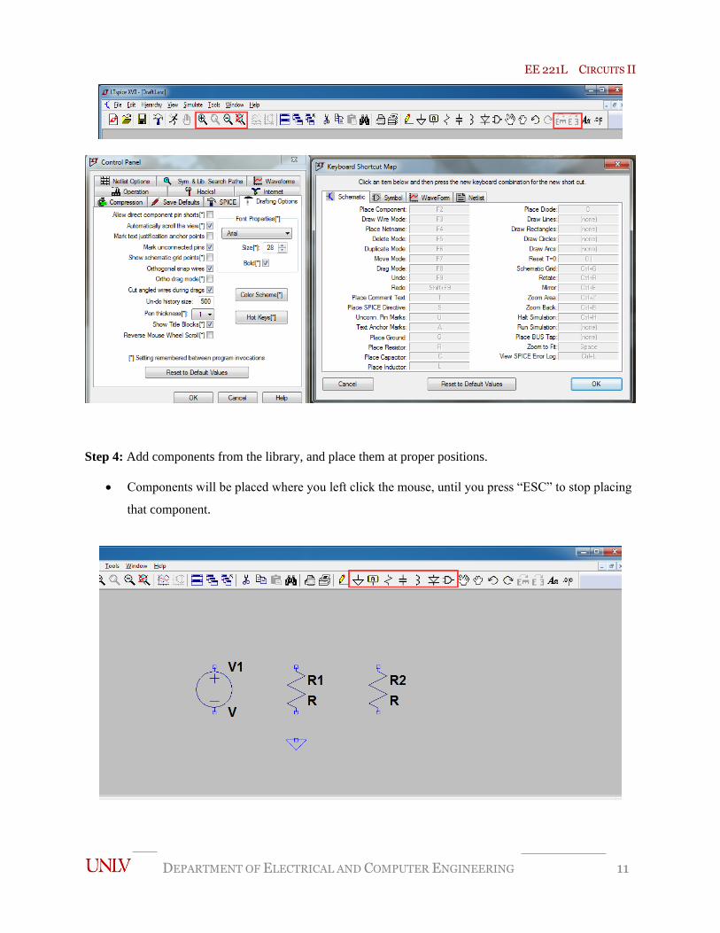
Step 4: Add components from the library, and place them at proper positions.
• Components will be placed where you left click the mouse, until you press “ESC” to stop placing
that component.
EE 221L CIRCUITS II
DEPARTMENT OF ELECTRICAL AND COMPUTER ENGINEERING 12
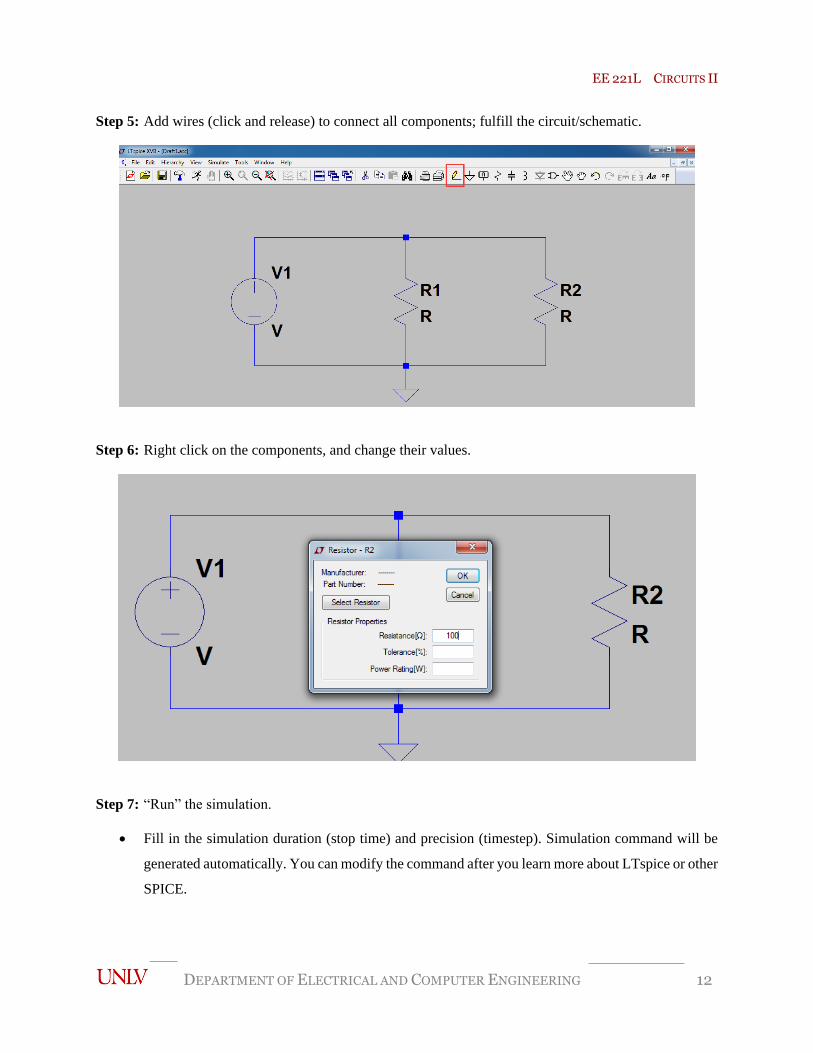
Step 5: Add wires (click and release) to connect all components; fulfill the circuit/schematic.
Step 6: Right click on the components, and change their values.
Step 7: “Run” the simulation.
• Fill in the simulation duration (stop time) and precision (timestep). Simulation command will be
generated automatically. You can modify the command after you learn more about LTspice or other
SPICE.

EE 221L CIRCUITS II
DEPARTMENT OF ELECTRICAL AND COMPUTER ENGINEERING 13
• Click “OK” to run. The window arrangement of the trace panel (Draft1.raw) and the schematic
panel (Draft1.asc) can be adjusted.

EE 221L CIRCUITS II
DEPARTMENT OF ELECTRICAL AND COMPUTER ENGINEERING 14
• Color of trace panel can be adjusted in “Tools”, “Color Panels”, “WaveForm” tab, “background”
in pulldown menu.
Step 8: View the output
1) Left click to activate (bring front) the schematic panel. Place the cursor on the node/wire (voltage)
or the element (current), and left click to probe and display the measured values.

EE 221L CIRCUITS II
DEPARTMENT OF ELECTRICAL AND COMPUTER ENGINEERING 15
2) Right click on the trace panel, select “Add Traces”, and left click on the signals you want to see.
Click “OK” to display.


![EE]I!' - DunDraCon](https://static.fdokumen.com/doc/165x107/63170fc39076d1dcf80ba715/eei-dundracon.jpg)