The Technique of Intracerebral Microdialysis
7
METHODS 23, 3–9 (2001) doi:10.1006/meth.2000.1101, available online at http://www.idealibrary.com on The Technique of Intracerebral Microdialysis Shah-Naz H. Khan* and Ashfaq Shuaib² *Saskatchewan Stroke Research Centre, University of Saskatchewan, Saskatoon, Saskatchewan, Canada; and ²Department of Medicine, Division of Neurology, Walter Mackenzie Health Science Centre, University of Alberta, Edmonton, Alberta T6G 2B7, Canada separated by a semipermeable microdialysis mem- Intracerebral microdialysis is an increasingly popular experimental brane. In the case of injection of a pharmacological technique. A brief description of the principles of microdialysis is pre- or other agents into the brain, the direction of move- sented and the terms relevant to the procedure are defined. The meth- ment down the gradient is reversed. odology involved in conducting intracerebral microdialysis is described In vivo microdialysis has been used to monitor in detail. Factors influencing the outcome of analysis such as external stimuli, perfusion fluid, perfusion rate, temperature, probe placement, basal levels of drug-induced changes in neurotrans- membrane characteristics, and timing of sample collection are dis- mitters; monitor free extracellular concentrations of cussed. The importance of maintaining the uniformity of the above- endogenous compounds; administer drugs and toxins mentioned factors is stressed. q 2001 Academic Press into the extracellular space in discrete brain regions; modify local concentrations of ions via the dialysate; monitor levels of drugs and their metabolites; corre- late behavioral changes and neurotransmission; and The era of intracerebral microdialysis was ushered monitor neurochemical events in the extracellular in with the technique reported by Bito et al. (1), space (9). whereby a dialysis sac containing dialysis fluid com- At this point, the following terms need clarifica- posed of 6% dextran in saline was implanted into the tion: brain tissue. Since then, considerable strides have been made in constructing various types of progres- 1. Recovery: the ratio between the concentration sively sophisticated microdialysis probes (2–7). With of a particular substance in the perfusate compared diversity of probe designs came the utilization of dif- to its concentration in the medium outside the mi- ferent solutions as perfusion fluids, e.g., 0.9% saline, crodialysis probe (6). Ringer’s solution, modified Ringer’s solution (MRS), 2. Relative recovery: recovery is expressed in con- and artificial cerebrospinal fluid (CSF) (8). These centrations per volume and is inversely dependent fluids have progressively come closer to the electro- on the flow rate (10). lyte composition of the internal brain milieu. 3. Absolute Recovery: the amount of compound in At present, there are multiple techniques available the dialysate per unit of time (9). It is positively for in vivo intracranial substance analysis (Table 1). correlated to flow rate, until it reaches a plateau at This review focuses upon intracranial microdialysis. rates allowing maximum diffusion flux. For a clear conception of the technique, it is im- portant to understand the principles of microdialysis. Finally, before embarking upon a description of Suffice it to say, it is the simple diffusion of low- methodology, it needs to be clarified that as anatomi- molecular-weight substances down a concentration cal and experimental considerations do not allow gradient from the extracellular fluid (ECF) compart- 100% recovery of compounds (10), several mathemat- ment to the dialysis fluid compartment within the microdialysis probe. These two compartments are ical models have been proposed for quantifying 1046-2023/01 $35.00 3 Copyright q 2001 by Academic Press All rights of reproduction in any form reserved.
-
Upload
independent -
Category
Documents
-
view
1 -
download
0
Transcript of The Technique of Intracerebral Microdialysis

METHODS 23, 3–9 (2001)doi:10.1006/meth.2000.1101, available online at http://www.idealibrary.com on
The Technique of Intracerebral Microdialysis
Shah-Naz H. Khan* and Ashfaq Shuaib†
*Saskatchewan Stroke Research Centre, University of Saskatchewan, Saskatoon, Saskatchewan, Canada;and †Department of Medicine, Division of Neurology, Walter Mackenzie Health Science Centre,University of Alberta, Edmonton, Alberta T6G 2B7, Canada
Intracerebral microdialysis is an increasingly popular experimentaltechnique. A brief description of the principles of microdialysis is pre-sented and the terms relevant to the procedure are defined. The meth-odology involved in conducting intracerebral microdialysis is describedin detail. Factors influencing the outcome of analysis such as externalstimuli, perfusion fluid, perfusion rate, temperature, probe placement,membrane characteristics, and timing of sample collection are dis-cussed. The importance of maintaining the uniformity of the above-mentioned factors is stressed. q 2001 Academic Press
The era of intracerebral microdialysis was usheredin with the technique reported by Bito et al. (1),whereby a dialysis sac containing dialysis fluid com-posed of 6% dextran in saline was implanted into thebrain tissue. Since then, considerable strides havebeen made in constructing various types of progres-sively sophisticated microdialysis probes (2–7). Withdiversity of probe designs came the utilization of dif-ferent solutions as perfusion fluids, e.g., 0.9% saline,Ringer’s solution, modified Ringer’s solution (MRS),and artificial cerebrospinal fluid (CSF) (8). Thesefluids have progressively come closer to the electro-lyte composition of the internal brain milieu.
At present, there are multiple techniques availablefor in vivo intracranial substance analysis (Table 1).This review focuses upon intracranial microdialysis.For a clear conception of the technique, it is im-portant to understand the principles of microdialysis.Suffice it to say, it is the simple diffusion of low-molecular-weight substances down a concentrationgradient from the extracellular fluid (ECF) compart-ment to the dialysis fluid compartment within themicrodialysis probe. These two compartments are
1046-2023/01 $35.00Copyright q 2001 by Academic PressAll rights of reproduction in any form reserved.
separated by a semipermeable microdialysis mem-brane. In the case of injection of a pharmacologicalor other agents into the brain, the direction of move-ment down the gradient is reversed.
In vivo microdialysis has been used to monitorbasal levels of drug-induced changes in neurotrans-mitters; monitor free extracellular concentrations ofendogenous compounds; administer drugs and toxinsinto the extracellular space in discrete brain regions;modify local concentrations of ions via the dialysate;monitor levels of drugs and their metabolites; corre-late behavioral changes and neurotransmission; andmonitor neurochemical events in the extracellularspace (9).
At this point, the following terms need clarifica-tion:
1. Recovery: the ratio between the concentrationof a particular substance in the perfusate comparedto its concentration in the medium outside the mi-crodialysis probe (6).
2. Relative recovery: recovery is expressed in con-centrations per volume and is inversely dependenton the flow rate (10).
3. Absolute Recovery: the amount of compound inthe dialysate per unit of time (9). It is positivelycorrelated to flow rate, until it reaches a plateau atrates allowing maximum diffusion flux.
Finally, before embarking upon a description ofmethodology, it needs to be clarified that as anatomi-cal and experimental considerations do not allow100% recovery of compounds (10), several mathemat-ical models have been proposed for quantifying
3

KHAN AND SHUAIB4
microdialysis (6, 8, 11–26). Some of these modelsare based on testing a dialysis probe in vitro. Theinformation thus obtained is used to calculate theactual extracellular concentrations in vivo, relyingon the assumption that the concentration outside thedevice is proportional to the concentration in theperfusion medium and that such a recovery can bedetermined for a particular compound, dialysisprobe, and conditions of the experiment (27). Otherexperiments calculate such values in vivo by fluctu-ating the perfusion flow rate or substance concentra-tion. Using a computer-assisted nonlinear regressionmodel, the values are extrapolated back to zero flow(11–13). Still others rely on systemic, local, or endog-enous markers as a reference for calculating extra-cellular concentrations of drugs or endogenous com-pounds (10).
DESCRIPTION OF METHOD
The following procedure is practiced in our labora-tory for intracerebral microdialysis: After inducingand maintaining general anesthesia, a hole is drilledfor stereotactic placement of a guide cannula (CMA-12, CMA/Microdialysis AB, Stockholm, Sweden) inthe animal’s right CA1 hippocampal region. The fol-lowing coordinates are used with bregma as refer-ence: posterior 0.24, lateral 0.25, and depth 0.35 mm.A second hole is drilled anteriorly in the frontal bonefor an anchoring screw (CMA/Microdialysis AB), tak-ing care not to penetrate the inner table of the skull.The cannula and screw are rigidly secured by ce-menting with Orthocryl powder (Stratford-CooksonCompany, West Hempstead, NY) and methyl methac-rylate (DENTSPLY International Inc., York, PA).
A long and a short length of FEP tubing (CMA/Microdialysis AB) and the attached microdialysisprobe (CMA-12, CMA/Microdialysis AB) are consecu-tively primed thrice each with the following solu-tions: 70% ethanol, nanogram-pure water, and MRS(145 mM NaCl, 2.7 mM KCl, 1.2 mM CaCl2, 1.2 mMMgCl2, pH 7.4). This priming may be done by fillinga 1000-ml syringe (Type 1, CMA/Microdialysis AB)with the requisite solution and using a microinjectionpump (CMA/100, CMA/Microdialysis AB). The con-nections between the system are made as follows:Using tubing adapters (CMA/Microdialysis AB), oneend of the long tube is connected to the syringe loadedin the microinjection pump, and the other end isattached to the inlet of the microdialysis probe. Theshorter tube, which is no more than 6 in. in length,is connected to the outlet of the probe. After comple-tion of priming, the syringe is filled with MRS. At thispoint, with the aid of a probe clip (CMA/MicrodialysisAB) the microdialysis probe is positioned such thatits tip and distal shaft are immersed in MRS con-tained in a polypropylene microcentrifuge tube(VWR, Canlab) up to 1.5 ml in volume. The microcen-trifuge tube itself is held in vitro in a stand (CMA/130, CMA/Microdialysis AB) which has two addi-tional slots (Fig. 1). These slots are utilized for hold-ing ultrapure water and standard solution, whichare required toward the end of the experiment.
The microinjection pump is adjusted to a volumeof 1 ml and a rate of 2 ml/min. Prior to commencingmicrodialysis, the pump is switched on to verify thatthe system is adequately primed, without air bubbles
TABLE 1
Techniques of in Vivo Intracranial Substance Analysis
Method Examples
Perfusion Push–pull cannulaCortical cupIntracranial microdialysis
Voltammetry ChronoamperometryLinear potential sweep voltammetryDifferential pulse voltammetry (DPV)Differential normal pulse voltammetry
(DNPV)
FIG. 1. Components of microdialysis unit. The microdialysis sy-ringe is in position in the pump. The longer tubing runs betweenthe syringe and the microdialysis probe. The probe is resting inthe middle microcentrifuge tube of the in vitro stand. The tip ofthe outlet tubing is within the conical insert in the glass vial,which in turn is lying in a container filled with crushed ice.

TECHNIQUE OF INTRACEREBRAL MICRODIALYSIS 5
and with a smooth, uninterrupted flow. Each conicalinsert (Chromatographic Specialties, Inc., PE Coni-cal, 250 ml) for collecting the dialysate is placed in aspring coil (SB200778, Chromatographic Specialties,Inc.) contained within a 4.0-ml screw top glass vial(Chromatographic Specialties, Inc.). All vials arenumbered.
Maintaining anesthesia, the animal is placed su-pine on a modified operating table granting accessto the anterior cervical region, as well as the crownaccommodating the guide cannula. All four limbs aresecurely taped down and a rectal probe (Model 402,Yellow Springs Instrument Co. Inc., Yellow Springs,OH) attached to a telethermometer (Model 2100, Yel-low Springs Instrument Co. Inc.) is inserted, meticu-lously ensuring not to cause any trauma. For main-taining a uniform temperature of 378C (60.58C), ahydraulic heating pad and pump (GAYMAR, ModelTP 250, Orchard Park, NY) are used. If cerebral isch-emia induction by clamping the carotid arteries isintended during the experiment, surgery is under-taken in the anterior cervical region to isolate thearteries bilaterally by passing a suture around eachartery (Fig. 2). Such procedures are completed priorto commencing microdialysis. The operating table isturned on its side such that the surgeon is facing theguide cannula. After ensuring that the microdialysispump is turned on and stabilizing the microdialysiscannula with a forceps in one hand, the cannulaguide is withdrawn and replaced with the microdia-lysis probe (Fig. 3). Meticulous care is taken not todamage the membrane at the tip of the probe duringthis maneuver. The operating table is then returned
to its original position. It is verified that dialysateis returning appropriately through the short outlettube and sample gathering is commenced by placingthe tip of the outlet tube into the conical insert rest-ing within the spring coil and glass vial. During sam-ple collection, the vial lies within a container filledwith crushed ice (Fig. 4). Samples are collected for10 min each and the first six samples are discarded.After obtaining a sample, the vial is firmly closedwith a polypropylene cap containing a Teflon/siliconseptum (Chromatographic Specialties, Inc.) andshaken down a couple of times to remove any airbubbles within the sample. The vial is then trans-ferred to a larger container with crushed ice.
At least 1 h prior to the completion of microdialysis,a standard solution comprising known concentra-tions of the amino acids being measured is removedfrom the freezer (2708C) and placed in a refrigerator(48C), allowing it to thaw. After the microdialysis iscomplete, the probe is withdrawn from the brain andreplaced with the cannula guide. The probe is placedfor 10 min each in 1 nanogram-pure water, MRS,and standard solution. Then a final sample is col-lected while the probe rests in standard solution.This sample is for the purpose of in vitro calibrationof the microdialysis membrane against the stan-dard solution.
The surgical wound is sutured and the animal isallowed to recover and returned to its pen. All sam-ples are removed from crushed ice and stored at
FIG. 2. Incision site, anterior cervical region. The sutures looparound the carotid artery on either side and isolate the artery,enabling easy access when arterial clamping is undertaken.
FIG. 3. The microdialysis probe about to be inserted into theguide cannula. The cannula guide has already been removed fromwithin the cannula. The operating table has been turned on itsside so that the surgeon is facing the crown. As may be detected,our operating table is made from a disposable cardboard glovebox with a small portion of the base cut out to provide access tothe crown.
KHAN AND SHUAIB6
2708C until analyzed. During the entire procedure,the animal is shielded from any external stimuli.
PRACTICAL CONSIDERATIONS
Exogenous StimuliExternal stimuli such as moving the subject under-
going dialysis, noxious manipulation (including guttrauma from a temperature probe), and fluctuatingtemperature influence the dialysis results and areto be avoided. All the above-mentioned stimuli maymanifest a glutamate spike.
PrimingIt is important that both the inlet and the outlet
tubing are primed. Priming may be done manuallyor by using the microinjection pump. We find thelatter more efficient. However, to protect the dialysismembrane, the rate during priming should be main-tained below 20 ml/min. Upon completion, the systemshould be free of air bubbles and the tubing shouldcontain only the perfusate when dialysis is com-menced. The rationale underlying cleaning of tubeswith 70% ethanol is twofold: in case of reusing thetubes, it contributes to ridding of organisms thatmight otherwise be introduced into the animal’sbrain. It also dissolves the glycerol off the dialysismembrane, enabling effective diffusion (28). Due tothe neurotoxic effects of ethanol, it is important that
all ethanol is washed out of the system when primingis complete.
Perfusion RateThe perfusion flow rate is inversely related to rela-
tive recovery (15).The absolute recovery increaseswith increasing rate, until it reaches a plateau. Suchhigh rates are not used because of the risk of exces-sive draining of compounds from the brain ECF, lead-ing to physiological disequilibrium. Still further in-creases in flow rates decrease absolute recovery dueto increased resistance at the probe outlet. The in-creased resistance in turn causes a positive hydro-static pressure gradient across the dialysis mem-brane (10), which may be deleterious to local braintissue. At higher flow rates convectional forces,which are not a consideration at lower rates, alsocome into play. Hence, optimum and constant flowrate is imperative. Usually rates below 2.5 ml/minare selected. Conversely, Flow rates of 1 ml/min orless are impractical due to the resultant prolongedsampling time. Our laboratory routinely employs aconstant flow rate of 2 ml/min.
TemperatureAn increase in temperature increases the recovery
rate by 1–2%/8C (29, 30). To prevent fluctuation indiffusion, uniform temperature maintenance at 378C(60.58C) is recommended (31).
After samples have been collected, for the sake ofaccuracy they should be analyzed as soon as possible.In the interim, they are stored at 2708C to preventbreakdown of compounds in the perfusate. For thesame reason, the glass vials rest in crushed ice dur-ing sample collection.
Deferred SamplingThe relative recovery of a substance continuously
diminishes with time. Initially, this decrement ishigh, and any samples obtained soon after probe im-plantation will render erroneous results. One hourafter commencement of microdialysis, the decline inrelative recovery becomes a negligible ,1% (15). Thissituation demands that sample collection be delayedfor at least 1 h following probe insertion.
With respect to the blood–brain barrier (BBB), itis intact within 30 min of probe insertion (4, 32, 33).However, the BBB is not reestablished at ,10 minafter probe insertion (34).
Dialysis MembraneAn increase in the microdialysis membrane sur-
face area results in increased recovery rate (4, 27,
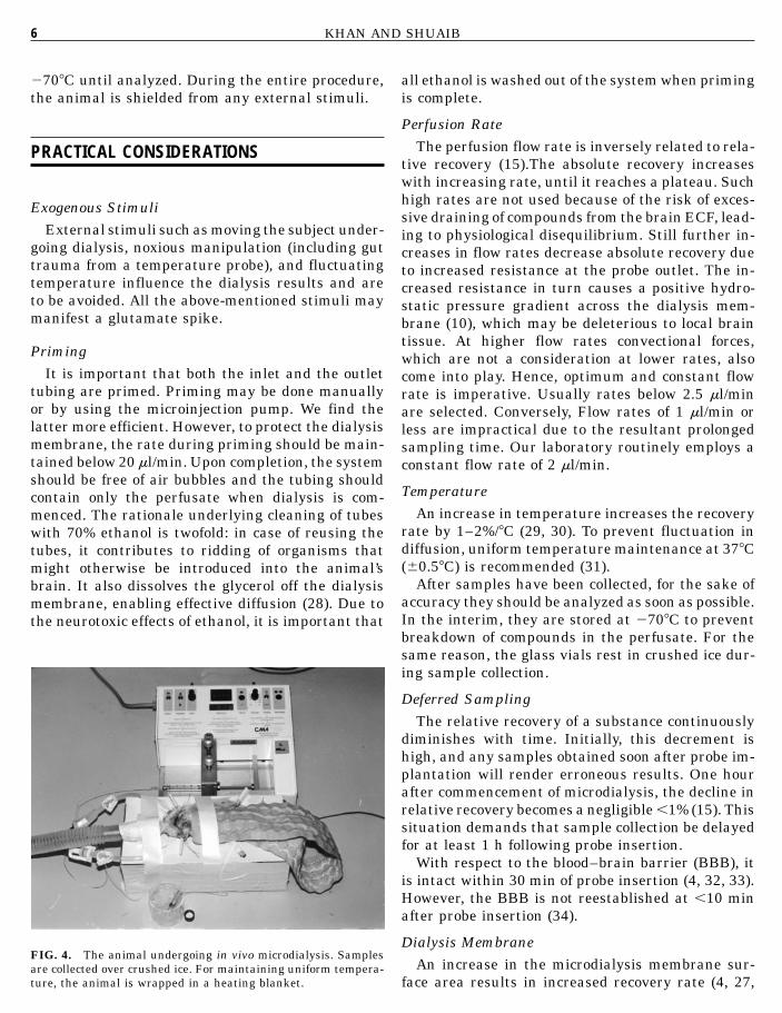
FIG. 4. The animal undergoing in vivo microdialysis. Samplesare collected over crushed ice. For maintaining uniform tempera-ture, the animal is wrapped in a heating blanket.

TECHNIQUE OF INTRACEREBRAL MICRODIALYSIS 7
35) and vice versa. The above consideration makesmembrane length and geometry important (10). Thislaboratory routinely employs probes with membranelength of 2 mm.
Once the protective glycerol layer is removed, themembrane should not be unnecessarily exposed toair, since it will dry out and disintegrate. If storedin distilled water, the probe can be reused. Somehave safely reused a single probe more than threetimes (36), but our practice is to use a probe no morethan twice.
There are known interactions between the dialysismembrane and the transported material, resultingin a higher recovery of some substances, e.g., acidmetabolites, than of other substances with similardiffusion coefficients (27). The mechanisms underly-ing such interactions are unknown. However, it issafe to say that the properties of the chemical com-pound being recovered influence its diffusion acrossthe membrane. For accuracy of analysis, the mem-brane should preferably be biocompatible and inert(28).
Probe CheckThe probe check is performed following completion
of microdialysis in order that the samples collectedmay be corrected for percent probe recovery. We havenot found a significant difference between checksperformed at room ('218C) and body (378C) tempera-tures (unpublished data). Hence, in our laboratoryprobe checks are routinely performed at room tem-perature (30, 37, 38). Some investigators prefer per-forming the calibration at 378C (39–42). Another fac-tor to bear in mind is that, during in vitro calibration,the membrane is exposed to a homogeneous solution,with simple diffusion being the primary active force.In vivo, the membrane is exposed to much smallervolumes of brain ECF, allowing less substance to beexposed to a given amount of membrane surface area.Furthermore, during in vivo diffusion the substancemust negotiate tortuous paths of ECF, rather thana direct one as in open homogeneous fluid (43).
Perfusion FluidA variety of fluids, which are usually isotonic to
blood, have been used for perfusion in microdialysis(8). However, it is advisable that such fluids are rou-tinely consistent with CSF or brain ECF electrolytecomposition, since the normal brain homeostaticmechanisms (44, 45) are bypassed. For example, aperfusion fluid devoid of calcium will cause depletionof calcium in the ECF surrounding the probe and
impair synaptic transmission (46, 47). Similar to itscomposition, the pH of the fluid influences the recov-ery of interstitial compound concentrations (9,45–50).
Our laboratory employs MRS for animals (30, 38,51, 52) and Ringer’s solution in humans (36, 54–56).
Sample ProtectionThe possible rapid degradation of collected sam-
ples must be taken into consideration. This may oc-cur due to a slow perfusion rate, resulting in slowersample collection, as well as a long outlet tubingcausing the perfusate to remain in tubing for a longertime. To circumvent this problem, the length of theoutlet tubing is kept short (,6 in.). The tubing itselfshould consist of inert material to prevent any inter-actions with the perfusate. Finally, all samples arecollected in tubes on crushed ice. If analysis is de-ferred, the samples must be stored expeditiously at2708C.
Special Considerations during AnalysisCertain compounds may require a particularly
long time or a longer dialysis membrane for adequatecollection. For recovery of a neurotransmitter likeacetylcholine which is readily metabolized, it is nec-essary to add inhibitor (acetylcholinesterase in thecase of acetylcholine) to the perfusate (27).
Acute vs Chronic DialysisThis is a consideration due to the histological and
biochemical changes manifest at the site of probeimplantation. During the initial 48 h following im-plantation, the neuropil essentially appears mini-mally damaged (54, 58). The biochemical changesin the immediate vicinity of implantation involvingincreased glucose metabolism and decreased bloodflow normalize after 24 h (58). Based on these obser-vations, the optimal time for commencing microdia-lysis has been determined to be 24–48 h (57). How-ever, due to practical considerations microdialysis isusually initiated 1–4 h after probe implantation.
By the third day of probe insertion, astrocytic hy-pertrophy and axonal damage with anterograde andretrograde degeneration are obvious. Following 2weeks, there is a gradual replacement of astrocytesby connective tissue (54, 58). The influence of thesechanges on chronic microdialysis (after 2–3 days) isa matter of debate. A steady increase in the restingrelease of several amino acids as well as a fluctuationin response to electroconvulsive shock and concen-trated potassium infusions has been documented

KHAN AND SHUAIB8
(39). Conversely, near-constant chronic concentra-tions of certain amino acids have also been noted(60). Hence, the factors that may affect chronic mi-crodialysis include possible biochemical alterationsdue to the histological changes; coating of the probewith inflammatory cells and connective tissue,changing diffusion characteristics of the probe andtissue; and the unestablished integrity of the BBBin chronic cases (15). Due to all these unresolvedissues, the accuracy of chronic microdialysis remainsin question.
Placement VerificationFollowing the completion of the experiment, probe
placement should be verified microscopically. In ourlaboratory, this is done with coronal sections that aresubjected to hematoxylin and eosin staining, as wellas silver staining for concomitant histological evalu-ation of brain tissue.
CONCLUDING REMARKS
Intracerebral microdialysis is an increasingly pop-ular experimental technique. To ensure accuracy,factors influencing microdialysis such as tempera-ture, external stimuli, perfusion fluid and rate, probetype, membrane characteristics, duration of sam-pling, and technique should be taken into consider-ation and consistently maintained uniform. Whereasit is established that the results of microdialysis per-formed over a short duration are reflective of thebrain ECF, reliability of chronic microdialysis re-mains in question.
REFERENCES
1. Bito, D. H., Levin, E., Murray, M., and Snider, N. (1966) J.Neurochem 13, 1057–1067.
2. Delgado, J. M. R., DeFeudis, F. V., Roth, R. H., Ryugo, D. K.,and Mitruka, B. M. (1972) Arch. Int. Pharmacodyn. 198, 9–21.
3. Ungerstedt, U., and Pycock, C. H. (1974) Bull. Schweiz. Akad.Med. Wiss. 30, 44–55.
4. Tossman, U., and Ungerstedt, U. (1981) Neurosci. Lett.
5. Johnson, R. D., and Justice, J. B. (1983) Med. Res. Bull.10, 567–571.
6. Ungerstedt, U., Herrera-Marschitz, M., Jungnelius, U., Sthle,L., Tossman, U., and Zetterstrom, T. (1982) in Advances inDopamine Research (Kotisaka, M., Ed.), pp. 219–231, Perga-mon, New York.
7. Westerink, B. H. C., Damsma, G., De Vries, J. B., and Horn,A. S. (1987) Life Sci. 41, 1763–1776.
8. Benveniste, H., and Huttemeier, P. C. (1990) Prog. Neuobiol.35, 195–215.
9. Herregodts, P. (1991) Neurochemical Studies of Monoaminer-gic Neurotransmitters in the Central Nervous System, pp.219–231, VUB Press, Brussels.
10. Kehr, J. (1993) J. Neurosci. Methods 48, 251–261.11. Jacobson, I., Sandberg, M., and Hamberger, A. (1985) J. Neu-
rosci. Methods 15, 263–268.12. Lerma, J., Herranz, A. S., Herreras, O., Abraira, V., and Mar-
tin Del Rio, R. (1986) Brain Res. 384, 145–155.13. L auonnroth, P., Jansson, P. A., and Smith, U (1987) A microdi-
alysis method allowing characterization of intracellular waterspace in humans. Am. J. Physiol. 253: E228–E231.
14. Alexander, G. M., Grothusen, J. R., and Schwartzman, R. J.(1988) Life Sci. 43, 595–601.
15. Benveniste, H. (1989) J. Neurochem. 52, 1667–1679.16. Lindefors, N., Amberg, G., and Ungerstedt, U. (1989) J. Phar-
macol. Methods 22, 141–156.17. Bungay, P. M., Morrison, P. F., and Dedrick, R. L. (1990) Life
Sci. 46, 105–119.18. Kurosawa, M., Hallstrom, A., and Ungerstedt, U. (1991) Neu-
rosci. Lett. 49, 73–78.19. Morrison, P. F., Bungay, P. M., Hsiao, J. K., Mefford, I. N.,
Dykstra, K. H., and Dedrick, R. L. (1991) in Microdialysis inthe Neurosciences, Techniques in the Behavioral and NeuralSciences (Robinson, T. E., and Justice, J. B., Jr., Eds.), pp47–80, Elsevier, Amsterdam.
20. Ekblom, M., G anrdmark, M., and Mammarlund-Udenaes, M.(1992) Life Sci. 51, 449–460.
21. Fink-Jensen, A., Judge, M. E., and Hansen, A. J. (1992) Curr.Sep. 10, 82–83.
22. Sjoberg, P., Olofsson, I. M., and Lundqvist, T. (1992) Pharm.Res. 9, 1592–1598.
23. Terasaki, T., Deguchi, Y., Kasama, Y., Pardridge, W. M., andTsuji, A. (1992) Int. J. Pharm. 81, 143–152.
24. Wong, S. L., Wang, Y. F., and Sawchuk, R. J. (1992) Pharm.Res. 9, 332–338.
25. Yokel, R. A., Allen, D. D., Burgio, D. E., and McNamara, P.J. (1992) J. Pharmacol. Toxicol. Methods. 27, 135–142.
26. Merlo Pich, E., Lorang, M., Parsons, L., and Weiss, F. (1993)Curr. 66–67.
27. Ungerstedt, U. (1984) in Measurement of NeurotransmitterRelease In Vivo (Marsden, C. A., Ed.), pp. 81–107, Wiley,New York.
28. Ungerstedt, U. (1991) in Microdialysis in the Neurosciences(Robinson, T. E., and Justice, J. B., Jr., Eds.), pp. 3–22, Elsev-ier, Amsterdam.
29. Bard, A. G., and Faulkner, L. R. (1980) Electrochemical Meth-ods, p. 153, Wiley, New York.
30. Wages, S. A., Church, W. H., and Justice, J. B., Jr. (1986)Anal. Chem. 58, 1649–1655.
31. Shuaib, A., Mahmood, R. A., Wishart, T., Kanthan, R., Mo-hamed, A. M., Ijaz, S., Miyashita, H., and Howlett, W. (1995)Brain. Res. 702, 199–206.
32. Blasberg, R. G., Fenstermacher, J. D., and Patlak, C. S. (1983)J. Cereb. Blood Flow Metab. 3, 8–32.
33. Tossman, U., and Ungerstedt, U. (1986) Acta Physiol. Scand.128, 9–14.
34. Benveniste, H., Drejer, J., Schousboe, A., and Diemer, N. H.(1984) J. Neurochem. 43, 1369–1374.

TECHNIQUE OF INTRACE
35. Hamberger, A., Berthold, C. H., Karlsson, B., Lehmann, A.,and Nystrom, B. (1983) in Glutamine, Glutamate and GABAin the Central Nervous System (Hertz, L., Kvamme, E.,McGeer, R. G., and Schousboe, A., Eds.), pp 473–492, A. R.Liss, New York.
36. Kendrick, K. M. (1991) in Microdialysis in the Neurosciences(Robinson, T. E., and Justice, J. B., Jr., Eds.), pp. 327–348,Elsevier, Amsterdam.
37. Kanthan, R., Shuaib, A., Goplen, G., and Miyashita, H. (1995)J. Neurosci. Methods 60, 151–155.
38. Owen, A. J., Ijaz, S., Miyashita, H., Wishart, T., Howlett, W.,and Shuaib, A. (1997) Brain. Res. 770, 115–122.
39. Zetterstrom, T., Vernet L., Ungerstedt, U., Tossman, U., Jon-zon, B., and Fredholm B. B. (1982) Neurosci. Lett. 29, 111–115.
40. Korf, J., and Venema, K. (1985) J. Neurochem. 45, 1341–1348.41. Van Wylen, D. G. L., Park, T. S., Rubio, R., and Berne, R. M.
(1986) J. Cereb. Blood Flow Metab. 6, 522–528.
42. Young, A. M. J., and Bradford, H. F. (1986) J. Neurochem.47, 1399–1404.
43. Justice, J. B., Jr. (1993) J. Neurosci. Methods 48, 263–278.
44. Bradbury, M. W. B. (1979) The Concept of a Blood–BrainBarrier, Wiley, London.
45. Hansen, A. J. (1985) Physiol. Rev. 65, 101–148.
46. Imperato, A., and Di Chiara, G. (1984) J. Neurosci. 4, 966–977.
47. Westerink, B. H. C., and Di Vries, J. B. (1988) J. Neurochem.51, 683–687.
48. Solis, J. M., Herranz, A. S., Herreras, O., Munoz, M. D.,
REBRAL MICRODIALYSIS 9
Martin Del Rio, R., and Lerma, J. (1986) Neurosci. Lett. 66,263–268.
49. Vezzani, A., Wu, H. W., Angelico, P., Stasi, M. A., and Samanin,R. (1988) Brain Res. 454, 289–297.
50. Moghaddum, B., and Bunney, B. S., (1989) J. Neurochem.53, 652–654.
51. Shuaib, A., Ijaz, S., Miyashita, H., Mainprize, T., and Kan-than, R. (1994) Brain Res. 666, 99–103.
52. Shuaib, A., Ijaz, S., Hemmings, S., Galazka, P., Ishaqzay R,Liu, L. Ravindran, J., and Miyashita, H. (1994) Exp. Neurol.128, 260–265.
53. Shuaib, A., Ijaz, M. S., Hussain, S., and Kanthan, R. (1997)Exp. Neurol. 147, 311–315.
54. Kanthan, R., Shuaib, A., Griebel, R., El-Alazounni, H., Miyas-hita, H., and Kalra, J. (1996) Neurochem. Res. 21, 563–566.
55. Shuaib, A., Kanthan, R., Goplen, G., Griebel, G., El-Azzouni,H., Miyashita, H., and Hogan, T. (1996) Acta Neurochir. 67,53–58.
56. Kanthan, R., Shuaib, A., Griebel, R., Miyashita, H., and Kalra,J. (1996) Neurosci. Lett. 209, 207–209.
57. Benveniste, H., and Diemer, N. H. (1988) J Cereb. Blood FlowMetab. 8, 713–719.
58. Shuaib, A., Xu, K., Crain, B., Sirn, A.-L., Feuerstein, G., Hal-lenbeck, J., and Davis, J. N. (1990) Neurosci. Lett. 112, 149–154.
59. Benveniste, H., Drejer, J., Schousboe, A., and Diemer, N. H.(1987) J. Neurochem. 49, 729–734.
60. Delgado, J. M. R., Lerma, J., Martin del Rio, R., and Solis,J. M. (1984) J. Neurochem. 42, 1218–1228.