The Near-Infrared Camera and Multi-Object Spectrometer Ultra Deep Field: Observations, Data...
12
THE NEAR-INFRARED CAMERA AND MULTI-OBJECT SPECTROMETER ULTRA DEEP FIELD: OBSERVATIONS, DATA REDUCTION, AND GALAXY PHOTOMETRY Rodger I. Thompson Steward Observatory, University of Arizona, 933 North Cherry Avenue, Tucson, AZ 85721 Garth Illingworth and Rychard Bouwens Astronomy Department, University of California, Santa Cruz, CA 95064 Mark Dickinson National Optical Astronomy Observatory, Tucson, AZ 85719 Daniel Eisenstein and Xiaohui Fan Steward Observatory, University of Arizona, 933 North Cherry Avenue, Tucson, AZ 85721 Marijn Franx Leiden Observatory, Postbus 9513, 2300 RA Leiden, Netherlands Adam Riess Space Telescope Science Institute, Baltimore, MD 21218 Marcia J. Rieke, Glenn Schneider, and Elizabeth Stobie Steward Observatory, University of Arizona, 933 North Cherry Avenue, Tucson, AZ 85721 and Sune Toft and Pieter van Dokkum Department of Astronomy, Yale University, New Haven, CT 06520 Received 2004 December 14; accepted 2005 March 22 ABSTRACT This paper describes the observations and data reduction techniques for the version 2.0 images and catalog of the Near-Infrared Camera and Multi-Object Spectrometer Ultra Deep Field (NICMOS UDF) Treasury program. All sources discussed in this paper are based on detections in the combined NICMOS F110W and F160W bands only. The NICMOS images are drizzled to 0B09 pixel 1 and aligned to the Advanced Camera for Surveys UDF F850LP image, which was rebinned to the same pixel scale. These form the NICMOS version 2.0 UDF images. The catalog sources are chosen with a conservative detection limit to avoid the inclusion of numerous spurious sources. The catalog contains 1293 objects in the 144 00 ; 144 00 NICMOS subfield of the UDF. The 5 ' signal-to-noise ratio level is an average 0B6 diameter aperture AB magnitude of 27.7 at 1.1 and 1.6 "m. The catalog sources, listed in order of right ascension, satisfy a minimum signal-to-noise ratio criterion of 1.4 ' in at least seven contiguous pixels of the combined F110W and F160W image. Key words: cosmology: observations — galaxies: fundamental parameters — galaxies: photometry Online material: machine-readable table 1. INTRODUCTION The Near-Infrared Camera and Multi-Object Spectrometer Ultra Deep Field ( NICMOS UDF) Treasury observations were designed to complement and enhance the Advanced Camera for Surveys (ACS) optical UDF observations. They provide an ex- tension in wavelength to 1.6 "m and two additional bands that extend the rest-band energy and morphology measurements to longer wavelengths. They also provide the potential for viewing objects at redshifts beyond 7.5, where Lyman lines and contin- uum absorption quench the flux in the ACS bands. The addi- tional wavelength coverage also helps distinguish between the influences of age, metallicity, and extinction. As with previous deep-field catalog publications ( Williams et al. 1996; Thompson et al. 1999; S. V. W. Beckwith 2005, in preparation), this paper is intended primarily as a description of the observations, data anal- ysis, and source photometric properties rather than a scientific evaluation of the implications of the observations. Due to the relatively small field of the NICMOS camera 3 used in this program (51 00 ; 51 00 ), only a subsection (144 00 ; 144 00 ) of the optical UDF was covered. This was done with a 3 ; 3 til- ing of the NICMOS images. The NICMOS images extend a few arcseconds beyond this subsection but at a significantly decreased signal-to-noise ratio. All the individual processed NICMOS im- ages are available in the Hubble Space Telescope (HST ) Trea- sury archive (MAST), 1 as are the raw images in the main HST archive. The primary purpose of this paper is to provide a very de- tailed account of the data reduction steps used to produce the Treasury images and catalog stored in MAST so that users are aware of the pedigree of the data and can reproduce the analysis if they wish. Other users may wish to alter the reduction steps if they prefer choices other than the ones made here. Finally, we wish to convey the attributes and limitations of the catalog of sources. In particular, users who wish to extract the faint- est sources from the data will want to use more aggressive 1 See http://archive.stsci.edu / prepds/udf / udf _ hlsp.html. A 1 The Astronomical Journal, 130:1–12, 2005 July # 2005. The American Astronomical Society. All rights reserved. Printed in U.S.A.
-
Upload
independent -
Category
Documents
-
view
2 -
download
0
Transcript of The Near-Infrared Camera and Multi-Object Spectrometer Ultra Deep Field: Observations, Data...

THE NEAR-INFRARED CAMERA AND MULTI-OBJECT SPECTROMETER ULTRA DEEP FIELD:OBSERVATIONS, DATA REDUCTION, AND GALAXY PHOTOMETRY
Rodger I. Thompson
Steward Observatory, University of Arizona, 933 North Cherry Avenue, Tucson, AZ 85721
Garth Illingworth and Rychard Bouwens
Astronomy Department, University of California, Santa Cruz, CA 95064
Mark Dickinson
National Optical Astronomy Observatory, Tucson, AZ 85719
Daniel Eisenstein and Xiaohui Fan
Steward Observatory, University of Arizona, 933 North Cherry Avenue, Tucson, AZ 85721
Marijn Franx
Leiden Observatory, Postbus 9513, 2300 RA Leiden, Netherlands
Adam Riess
Space Telescope Science Institute, Baltimore, MD 21218
Marcia J. Rieke, Glenn Schneider, and Elizabeth Stobie
Steward Observatory, University of Arizona, 933 North Cherry Avenue, Tucson, AZ 85721
and
Sune Toft and Pieter van Dokkum
Department of Astronomy, Yale University, New Haven, CT 06520
Received 2004 December 14; accepted 2005 March 22
ABSTRACT
This paper describes the observations and data reduction techniques for the version 2.0 images and catalog of theNear-Infrared Camera and Multi-Object Spectrometer Ultra Deep Field (NICMOS UDF) Treasury program. Allsources discussed in this paper are based on detections in the combined NICMOS F110Wand F160W bands only.The NICMOS images are drizzled to 0B09 pixel�1 and aligned to the Advanced Camera for Surveys UDF F850LPimage, which was rebinned to the same pixel scale. These form the NICMOS version 2.0 UDF images. The catalogsources are chosen with a conservative detection limit to avoid the inclusion of numerous spurious sources. Thecatalog contains 1293 objects in the 14400 ; 14400 NICMOS subfield of the UDF. The 5 � signal-to-noise ratio levelis an average 0B6 diameter aperture AB magnitude of 27.7 at 1.1 and 1.6 �m. The catalog sources, listed in order ofright ascension, satisfy a minimum signal-to-noise ratio criterion of 1.4 � in at least seven contiguous pixels of thecombined F110W and F160W image.
Key words: cosmology: observations — galaxies: fundamental parameters — galaxies: photometry
Online material: machine-readable table
1. INTRODUCTION
The Near-Infrared Camera and Multi-Object SpectrometerUltra Deep Field (NICMOS UDF) Treasury observations weredesigned to complement and enhance the Advanced Camera forSurveys (ACS) optical UDF observations. They provide an ex-tension in wavelength to 1.6 �m and two additional bands thatextend the rest-band energy and morphology measurements tolonger wavelengths. They also provide the potential for viewingobjects at redshifts beyond 7.5, where Lyman lines and contin-uum absorption quench the flux in the ACS bands. The addi-tional wavelength coverage also helps distinguish between theinfluences of age, metallicity, and extinction. As with previousdeep-field catalog publications (Williams et al. 1996; Thompsonet al. 1999; S. V.W. Beckwith 2005, in preparation), this paper isintended primarily as a description of the observations, data anal-ysis, and source photometric properties rather than a scientificevaluation of the implications of the observations.
Due to the relatively small field of the NICMOS camera 3used in this program (5100 ; 5100 ), only a subsection (14400 ;14400 )
of the optical UDF was covered. This was done with a 3 ; 3 til-ing of the NICMOS images. The NICMOS images extend a fewarcseconds beyond this subsection but at a significantly decreasedsignal-to-noise ratio. All the individual processed NICMOS im-ages are available in the Hubble Space Telescope (HST ) Trea-sury archive (MAST),1 as are the raw images in the main HSTarchive.
The primary purpose of this paper is to provide a very de-tailed account of the data reduction steps used to produce theTreasury images and catalog stored in MAST so that users areaware of the pedigree of the data and can reproduce the analysisif they wish. Other users may wish to alter the reduction stepsif they prefer choices other than the ones made here. Finally,we wish to convey the attributes and limitations of the catalogof sources. In particular, users who wish to extract the faint-est sources from the data will want to use more aggressive
1 See http://archive.stsci.edu/prepds/udf /udf_hlsp.html.
A
1
The Astronomical Journal, 130:1–12, 2005 July
# 2005. The American Astronomical Society. All rights reserved. Printed in U.S.A.

extraction techniques than we have used in producing the Trea-sury catalog.
2. OBSERVATIONS
The NICMOS observations in the UDF (HST GO/9803) arecentered on the position 3h32m39.s0, �27�47029B1 (J2000.0) atapproximately the center of the ACS UDF observations.2 Theimages lie in a 3 ; 3 grid with centers separated by 4500. The gridcenters are dithered by 500 in a 4 ; 4 square pattern tilted at 22N5to the x-axis of the images to reduce the effect of intrapixel sen-sitivity variations. The tilt of the pattern also produces dithers thathave fractional pixel offsets in the detector array.
The NICMOS UDF program consists of 144 orbits brokeninto two epochs: (1) 2003 August 30–September 14 and (2) 2003November 2–November 27. The scheduled start of observationsin 2003 mid-August was delayed by a safing of the NICMOSCooling System (NCS) just prior to the beginning of observa-tions. All reference files, such as flats and darks, were obtainedsubsequent to the safing event. The epochs are separated to en-able the detection of Type Ia supernova candidates and to pro-vide enough South Atlantic Anomaly (SAA) crossing-free orbitsfor high sensitivity. The images in the two epochs are rotated by90� to accommodate the roll restrictions of the spacecraft. In thefirst epoch the y-axis of the NICMOS camera 3 was oriented40N925 east of north, and in the second epoch it was oriented130N925 east of north. These orientations are the same as the twoACS orientations in an effort to align the NICMOS and ACSimages without the need for a rotation. The drizzled ACS imagesin MAST, however, were produced with the standard north-up,east-left orientation. The version 2NICMOSTreasury images sup-plied toMASTare also oriented with north up, unlike the version 1NICMOS image. The NICMOS version 2 images have beenaligned with the ACS version 1 image so that researchers can usethe complete set of ACS and NICMOS images without realign-ment or rotation (see x 3.7).
Each orbit contains an F110W and F160W band SPARS64,NSAMP = 24, 1344 s integration. Figure 1 shows the total re-sponse of the two bands, including the detector quantum effi-ciency. The F110W integration always precedes the F160Wintegration. Three orbits comprise a single visit with the loca-tion of the image specified by a POSTARG from the central ref-erence position. It is possible that the F160W images from thefirst orbit of a visit may have received a small amount of earth-shine in the last readout of the NSAMP = 24 readout sequence.This is due to the guide star acquisition time on the first orbit ofthe visit, which takes longer than the guide star reacquisition inthe subsequent two orbits of the visit. No correction has beenmade in the Treasury images for this effect. The 3 ; 3 grid wascompleted in three visits, with each visit representing a three-image strip stepped in the detector x-direction. The visits wereordered to finish each 3 ; 3 grid before starting another andalways in the same order. This was done to maximize the timecoverage for a supernova event, should one occur. After theinitial delay due to the NCS safing, all the visits occurred in theirexpected order.Subsequent analysis of the images indicated that the second-
epoch images were not an exact repeat of the first-epoch im-ages. In the second epoch, three of the visits replaced a centerimage with an image on the right-hand side of the three-imagestrip. Tables 1 and 2 list the visits, with T, C, and B indicatingtop, center, and bottom for the first-epoch visits and L, C, and Rindicating left, center, and right for the second-epoch visits.These refer to the left, right, top, and bottom of the NICMOSimages in their standard x- and y-orientations.
3. DATA REDUCTION
Previous papers (Thompson et al. 1999, 2001; Thompson2003) described details of the data reduction procedures fordeep-field NICMOS observations. Some of the procedures re-quired revision for post-NCS installation data. These changesand the provision of the reduced images as public Treasuryprogram data products warrants a detailed description of the datareduction procedures even though some aspects have been cov-ered in the publications cited above. All the procedures use thecommercial Interactive Data Language (IDL)3 software and theIDL-based Fits List Calculator (FLC; Lytle et al. 1999) software.These procedures were developed primarily by R. I. T. and E. S.for previous NICMOS observations.
3.1. Basic Reduction
The initial steps in the data reduction take advantage of thenondestructive readout capability of the NICMOS detectors.NICMOS detectors are read out at specified intervals withouterasing or altering the image. This ability allows several data re-duction advantages not shared by CCD detectors. The SPARS64read pattern with 24 samples provides readouts evenly spaced by63.998 s after the first two samples, which are spaced by 0.303 s.All the images in the NICMOS UDF observations were taken in
Fig. 1.—Total response functions for the NICMOS F160W and F110Wfilters. On this plot 100% response is equal to 1.0.
TABLE 1
First-Epoch Image Positions by Visit
1 2 3 4 5 6 7 8 9 10 11 12 13 14 15 16 17 18 19 20 21 22 23 24
B C T B C T B C T B C T B C T B C T B C T B C T
2 See image at http://www.stsci.edu/hst /udf /parameters/#Pointing.
3 IDL is a registered trademark of Research Systems Incorporated, a Kodakcompany.
THOMPSON ET AL.2 Vol. 130

this mode. The steps described in this section are done automat-ically in batch processing with no interaction. This is roughlyequivalent to the Space Telescope Science Institute (STScI) pipe-line processing.
3.1.1. First Read Subtraction
The first step in the data reduction is the subtraction of theimage obtained in the first read from all subsequent reads. Thisstep eliminates the kTC noise that is present in each of the individ-ual photodiodes at the beginning of an integration. The number ofreads carried through in the final processing is then 23 reads ratherthan 24 after this step.
3.1.2. Dark Current Subtraction
After the first read subtraction, the dark current image is sub-tracted from each of the reads. This is a very important step, asthe NICMOS detectors have dark current images with very sig-nificant structure. This structure is larger in magnitude than thesignal from most of the galaxies in the image. The dark imagesare constructed from integrations in exactly the same modeas the observations but with the cold blank filter in place. Thisstep differs from the STScI pipeline that uses ‘‘synthetic darks’’calculated from parameters developed during the operation ofNICMOS (Mobasher et al. 2004).
3.1.3. The NICMOS UDF Dark
The NICMOS UDF dark is a median dark image obtainedfrom dark integrations taken during the Earth occultation periodin each of the orbits assigned to the NICMOS UDF program.Operational constraints prevented dark integrations on two orbits,but the remaining 142 dark integrations were used to construct themedian images. There is a median dark image for each read con-structed from the medians of all the dark images for that particularread.
Between visit 34 and visit 35 of the 48 visits in the NICMOSUDF program, the temperature set point on the NCS was reducedby 0.1 K to compensate for the warmer conditions encounteredduring the period when the Earth’s orbit is closest to the Sun.There was concern that this set point change would alter the na-ture of the NICMOS darks, since it is known that the darks aretemperature-sensitive. Comparison of a median of the darks takenbefore the set point change with the median darks taken after theset point change did not reveal any differences above the noiselevel in the observations. The NICMOS UDF dark was thereforeconstructed from the median of all the darks before and after theset point change.
3.1.4. Warm Pixels
In the NCS era the NICMOS detectors operate at a signifi-cantly warmer temperature than in the previous operation withsolid nitrogen cryogen. There are several advantages to thewarmer detector temperature, but a disadvantage is an increase inthe number of ‘‘hot’’ and ‘‘warm’’ pixels. Hot pixels are pixelswith a dark current high enough to reach the nonlinear responseregion in a 1000 s integration. These pixels are included in thelist of bad pixels described in x 3.1.9. More difficult cases are
the warm pixels that have elevated dark current but not elevatedenough to become nonlinear in a normal integration. These pixelscan be corrected through the dark image subtraction for mosttypes of integrations. The degree of elevation, however, is verytemperature-dependent and will vary over the normal range oftemperature variations inherent in the NCS operations. The ele-vated dark current is in many cases much larger than the signalencountered in faint galaxies.
The warm pixels contribute noise in two ways. The firstway is the normal Poisson statistics inherent in a steady dark cur-rent, and the second way is incomplete removal when the darkcurrent varies from the median dark current measured by theNICMOS UDF dark. The presence of these varying warm pixelsaltered the previous data reductions in two ways. The first was theintroduction of a more aggressive bad pixel list for the UDF ob-servations, and the second was the introduction of postprocess-ing procedures to detect the presence of warm pixel signals andseparate them from true sources. These procedures are describedin x 3.6.
3.1.5. Linearity Correction
During thermal vacuum testing prior to launch and in cycle 7,the linearity of each pixel was measured. The point at whichnonlinearity set in and coefficients for a polynomial fit after thatpoint were determined for every pixel. In the linearity correc-tion stage the signal of every pixel is checked to see if it is in thenonlinear range. If it is above the linear range, its signal iscorrected using the determined coefficients of the polynomialfit. If it is in the signal range that is deemed uncorrectable, it ismarked as saturated, and only the reads occurring before satura-tion are used in the analysis. New coefficients are being deter-mined for post-NCS operation. However, none of the galaxiesin the UDF reached signal levels requiring correction; there-fore, linearity is not an issue in this analysis.
3.1.6. Cosmic-Ray Removal
A cosmic-ray event produces a sharp jump in signal intensityin the first readout after the event. Most events do not saturatethe pixel, and subsequent readouts continue to monitor the in-cident flux. At this point in the analysis the readouts are storedas delta signal levels between each readout. The signal ‘‘ramp’’is reconstructed by adding the delta together. The first step incosmic-ray detection is a linear fit to the signal ramp, whichwill be a poor fit to the data if there is a cosmic-ray jump. Theresiduals to the fit will be increasingly negative with a sharptransition to positive after the event. The cosmic-ray detectionprocedure looks for the negative-to-positive transition as a sig-nature of a cosmic-ray hit. If it detects a residual transitionabove the level expected from noise, it removes the delta signalbetween the two readouts before and after the event, recalcu-lates the signal ramp, and fits a new linear solution.
The cosmic-ray procedure rechecks the ramp to see if therewas another cosmic-ray hit and removes the proper delta signalif one is detected. If there is still a detectable cosmic-ray signa-ture after the second refit, the pixel is marked as bad, and nofurther correction attempt is made. If the signal is saturated after
TABLE 2
Second-Epoch Image Positions by Visit
25 26 27 28 29 30 31 32 33 34 35 36 37 38 39 40 41 42 43 44 45 46 47 48
R C L R R L R C L R C L R C L R L C L R R L R R
NICMOS ULTRA DEEP FIELD 3No. 1, 2005
the cosmic-ray hit, only the signal obtained before the event isused in the analysis. The final recorded signal is the value of theslope of the linear fit to the signal ramp in ADUs per second.Cosmic-ray hits that occur in the 0.3 s between the first andsecond read are detected as fits that do not intercept zero, re-calling that the first read is subtracted from the second so thatthe second read is the first point in the ramp. These hits do notaffect the calculated slope but are marked as cosmic-ray hits inthe data-quality array discussed later.
3.1.7. Quadrant Bias Correction
Each quadrant of the NICMOS detectors has a separateoutput amplifier to transmit the analog signal to an analog-to-digital converter. This was done to prevent the loss of an entiredetector array if there was a failure of an output amplifier. As aside effect of this design decision a small DC bias offset can oc-cur between the four detector quadrants. Although the offset issmall, the effect is significant relative to the faint galaxy signalsin the UDF and can cause unreliable outputs during the drizzleprocess. Since there is significant sky background from the zo-diacal light, it is difficult to determine the offset amount from asimple inspection of the image.
The quadrant bias is removed via a procedure based on thebias removal procedure developed by M. Dickinson as part ofthe STScI NICMOS team (Mobasher et al. 2004). The proce-dure uses the flat-field imprint produced on the DC signal by theflat-field correction process. Any flat DC bias will be modulatedby the variations in the flat field. The process successively
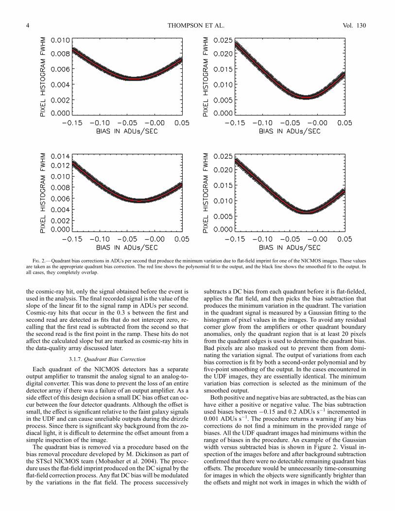
subtracts a DC bias from each quadrant before it is flat-fielded,applies the flat field, and then picks the bias subtraction thatproduces the minimum variation in the quadrant. The variationin the quadrant signal is measured by a Gaussian fitting to thehistogram of pixel values in the images. To avoid any residualcorner glow from the amplifiers or other quadrant boundaryanomalies, only the quadrant region that is at least 20 pixelsfrom the quadrant edges is used to determine the quadrant bias.Bad pixels are also masked out to prevent them from domi-nating the variation signal. The output of variations from eachbias correction is fit by both a second-order polynomial and byfive-point smoothing of the output. In the cases encountered inthe UDF images, they are essentially identical. The minimumvariation bias correction is selected as the minimum of thesmoothed output.Both positive and negative bias are subtracted, as the bias can
have either a positive or negative value. The bias subtractionused biases between �0.15 and 0.2 ADUs s�1 incremented in0.001 ADUs s�1. The procedure returns a warning if any biascorrections do not find a minimum in the provided range ofbiases. All the UDF quadrant images had minimums within therange of biases in the procedure. An example of the Gaussianwidth versus subtracted bias is shown in Figure 2. Visual in-spection of the images before and after background subtractionconfirmed that there were no detectable remaining quadrant biasoffsets. The procedure would be unnecessarily time-consumingfor images in which the objects were significantly brighter thanthe offsets and might not work in images in which the width of
Fig. 2.—Quadrant bias corrections in ADUs per second that produce the minimum variation due to flat-field imprint for one of the NICMOS images. These valuesare taken as the appropriate quadrant bias correction. The red line shows the polynomial fit to the output, and the black line shows the smoothed fit to the output. Inall cases, they completely overlap.
THOMPSON ET AL.4 Vol. 130

the pixel signal histograms is dominated by source variationsrather than noise. Neither is the case for the UDF. In reality theIDL code for this procedure actually performs both the flat-fielding and bad-pixel correction. These procedures, however,are discussed individually in the following sections.
3.1.8. Flat-Fielding
NICMOS flat fields are created internally. The ‘‘beam steeringmirror’’ internal to the instrument lies at an optical pupil and isused to correct the spherical aberration of theHST primary. It canbe illuminated from behind, and the reflective coating of themirror was adjusted to be about 0.01% transmissive, producingan illuminated pupil for flat-fielding. Flat fields are produced atregular intervals during operation in all filters of each camera.We used F110W and F160W camera 3 flat-field observationscreated on 2003 September 9 from proposal 9640. The flat fieldsare analyzed in the identical manner as described in the pre-ceding steps. The STScI reference flat fields were not used in thisanalysis because theywere based on flat fields observed previousto the NCS safing event.
One of the effects that the flat field corrects is a slight vi-gnetting along the lower edge of camera 3. For two reasons thiscorrection was not effective in the UDF fields. First, the net ef-fect has two components, vignetting of the incoming astronom-ical flux and emission from the vignetting component, which isthought to be the edge of the mount for the field division mirrorfor camera 3. For bright sources the vignetting is the dominanteffect, and the flat field properly corrects the field. For very faintimages, such as the UDF, emission can be a significant com-ponent that varies due to the natural temperature variations inthe aft shroud. Second, variations in geometry due to temper-ature changes can affect the degree of vignetting. Again, theeffect is slight for bright sources but can be significant for theUDF signal levels. For these reasons the lower 20 rows of allUDF images were masked off in the drizzle procedure describedin x 3.7.
3.1.9. Bad Pixel Correction
Bad pixels are defined as pixels with quantum efficiencies(QEs) of less than 10% of the average QE or with dark currentshigh enough to reach nonlinear signal levels in 1000 s or less.In the post-NCS era the list of bad pixels has increased overthe cycle 7 listing due to the higher temperature of the detectorcreating more high dark current pixels. Pixels that satisfy nei-ther criterion but are highly variable in their dark current werealso added to the list. All bad pixel signals are replaced with themedian of the 8 pixels surrounding them. In the case of adjacentbad pixels, that number is reduced by the number of adjoiningbad pixels. All bad pixels are listed in the data-quality array,which is an extension of the image or science array. Table 3gives the decimal codes for each of the steps described above.They are each a single, different, binary bit, so each combina-tion of actions performed on a pixel has a unique output code.Note that only a few of the 16 bits available for pixel actions areused in this analysis. A full set of data-quality codes can befound in the NICMOS Handbook, but only the ones listed hereare used in the NICMOSUDF Treasury data. Even for the codesused, they may in many cases differ from the codes returned bythe STScI pipeline analysis. As an example, the lists of badpixels differ between the pipeline analysis and the analysisdescribed here. Note that the data-quality extensions only existfor the individual NICMOS UDF images. The drizzle proce-dure does not preserve these codes, since many input pixelscontribute to a single drizzled output pixel.
3.2. SAA Persistence Correction
The program planners at STScI were careful to schedule theNICMOSUDF observations in orbits that were not impacted bySAA passages. None of the NICMOSUDF images required anycorrection to remove SAA persistence.
3.3. Earthshine Detection
As mentioned in x 2, the last read of the first orbit in a visitmay have encountered increased earthshine due to the longerperiod of delay in a guide star acquisition than in a reacquisi-tion. This would only affect the F160W images, as the readoutsequence was always F110W and then F160W. We tested forthis effect by plotting the median of the delta increase in theF160W images as a function of readout. In a few cases we saw adetectable rise in the last readout of the first orbit in a visit. Theeffect appeared minor enough that no correction was attempted.
3.4. Background Subtraction
The primary background source in the UDF is zodiacalemission, which is relatively uniform across the small UDFfield of view. A median image of all the images in the F110Wfilter and in the F160W filter determines the background forthat filter. The background is simply subtracted from each im-age in the proper filter. The median image is extremely smooth,with no indication of any residual source structure. This is similarto the results in theHubbleDeep Field-North (HDF-N; Thompsonet al. 1999), in which the spacing between images was muchsmaller than in the UDF. Since the zodiacal backgrounds can betime-dependent, the first-epoch and second-epoch backgroundsubtractions were done independently.
3.5. Residual Bias Correction
The removal of quadrant biases and the background sub-traction should result in an image that has a median value ofnearly zero, since most of the pixels in the image are not insources that are above the noise level. The minimums of thequadrant bias curves in Figure 2, however, are rather broad. Tocompensate for this, each quadrant of every image was set tozero bias. The bias was determined from the median of the por-tion of the quadrants that is 40 rows and columns away from theedge to avoid any contamination from residual corner glow oruncorrected vignetting. Any detected bias was subtracted fromthe entire quadrant to produce a zero-bias image. Inspection byeye of the zero-bias images did not find any detectable quadrantoffsets.
3.6. Warm Pixel Correction
A new effect encountered in the NICMOS UDF images iswarm pixel variation. At the higher operating temperature of theNCS, the NICMOS detectors have more warm pixels than dur-ing the cycle 7 operation with solid nitrogen cryogen. A warmpixel is defined as a pixel with an elevated dark current that isnot high enough to be declared a bad pixel by the criteria definedin x 3.1.9. For most applications warm pixels are adequately
TABLE 3
Data-Quality Codes
Bit or Number Bad Pixel Cosmic Ray Nonlinear Saturated
Bit......................... 8 9 12 13
Number................. 256 512 4096 8192
NICMOS ULTRA DEEP FIELD 5No. 1, 2005

corrected by dark subtraction, but for the UDF they presenttwo problems. The first problem is that their dark current istemperature-sensitive, and the NCS has slight temperature varia-tions within an orbital cycle and within a 24 hr day due to powercycles in HST operation. The variation is small but significantrelative to faint UDF sources. The second problem is that thePoisson noise of the signal at the end of an integration is alsosignificant relative to a UDF source. The individual images havesingle or sometimes double pixels with signal levels of eitherpositive or negative high contrast relative to the surroundingpixels from the warm pixel effect.
Warm pixels are identified by their contrast with neighboringpixels. The point-spread function (PSF) of a point source cen-tered on a pixel provides a maximum contrast for a real source.Pixels with contrasts significantly greater than this are due towarm pixels. The contrast was computed for each pixel com-pared to the 8 pixels adjacent to it. A pixel is set equal to themedian of the 8 pixels if three conditions are met: (1) its value ishigher than the 3 � noise value in the image, (2) its value ishigher relative to the median of the adjacent pixels than a presetcontrast value, and (3) the value of the surrounding median isless than a preset number of standard deviations. The last condi-tion prevents peak clipping on point objects. The contrast val-ues were set to 6.0 for the F160W image and 8.0 for the F110Wimage, which has a narrower PSF. The standard deviation limitswere set to 2.5 for the F160W images and 2.0 for the F110Wimages. Any corrected pixel has the bad pixel flag set in thedata-quality image extension so it can be identified.
3.7. Drizzle Procedure
The Treasury mosaic images were produced using the drizzleprocedure with context images (Fruchter & Hook 2002). Theoffsets for the NICMOS images were determined by registeringthe NICMOS F110W images onto the ACS F850LP UDF im-age in the HST archive, which has a north-up orientation and0B03 pixel scale. The significant overlap between the two filtersgreatly reduces any errors due to color-dependent morphology;however, see x 3.7.3 for an assessment of the accuracy of thealignment. The NICMOS F160W images, which always im-mediately followed the F110W images in an orbit, were as-sumed to have the same offset as the F110W images precedingthem. The ACS image was reduced to 0B09 pixels by a simple3 ; 3 pixel2 addition of the image. Individual NICMOS F110Wimages were then produced with a drizzle PIXFRAC parameterof 0.6 and a SCALE parameter of 0.09/0.202863 to produce0B09 output pixels. The denominator in the scale factor is thepixel size of the distortion-corrected NICMOS pixel. The geo-metric distortion coefficients (L. Bergeron 2004, private com-munication) are given in Table 4. These coefficients are theconstants for a cubic distortion correction of the form
xdist ¼ a1 þ a2xþ a3yþ a5xyþ a6 y2 þ a7x
3 þ a8x2yþ a9xy
3
ð1Þ
and an identical equation in b coefficients for the y position thatgoverns the placement of the pixels. Compared to other HST
instruments the correction is relatively small. The main com-ponent is the difference in plate scale between the x- andy-directions due to a slight tilt in the camera 3 focal plane rel-ative to the plane of the detector. The tilt is due to the curvatureof the focal plane. Each 0B09 NICMOS image was rotated to anorth-up orientation using the ORIENTAT value in the imageheader.A three-step process provided the positions of each F110W
image relative to the ACS F850LP image. The first step was toshift the NICMOS images to the positions indicated by theirworld coordinate system positions in the headers. The secondstep was a noninteractive �2 minimization of the differences be-tween the bright objects in the NICMOS image and the nearestcorresponding bright ACS object. The ACS positions were de-termined with the source extraction program SExtractor (SE) inthe ABSOLUTE mode with the threshold set at 0.03 ADU s�1.Positions in the NICMOS images were also determined with SEin ABSOLUTE mode with the threshold set at 0.01 ADU s�1.Both of these thresholds are quite bright in order to ensure a lowsource count per area. This made the likelihood of wrongobject-matching low. The shifts were limited to �10 pixels inthe x- and y-directions in single-pixel steps. The average posi-tion shift in this step was on the order of 2–3 0B09 pixels. Thefinal shifts were determined by a similar �2 minimization ofinteractively selected NICMOS objects. Usually three objectswere selected on the basis of compact size and sufficient signal-to-noise ratio. Whenever fully visible in a NICMOS image, thestar near the center of the image was used as one of the objects.The more eastern star image appears to have contamination dueto a faint nearby object visible in the ACS images. Shifts in thisstep were limited to �1 pixel in 0.1 pixel steps. The averageposition adjustment in this third and final stage was 0.2–0.30B09 pixels. These final positions were then used as the input tothe drizzle procedure.
3.7.1. Individual Image Masking
The F110W and F160W images each have a general maskused in the drizzle process. These mask out the bottom 20 rowsof the image to eliminate the partially vignetted region at thebottom of camera 3. They also mask out a portion of the upperright-hand corner of camera 3 where there is an area of rapidlychanging QE. In addition, they also mask out the known badpixels and areas in which some particles, termed ‘‘grot,’’ coverdetector pixels. The large number of dithered images greatly re-duces the impact of the masked areas. The masks are availablein the STScI NICMOS UDF Treasury version 2.0 archive inMAST. Several of the images had artifacts, such as satellite pas-sage streaks, that required masking. Individual masks weremade for 20 F110W images and 31 F160W images. Table 5 liststhe masked images. The masks are contained in the NICMOSversion 2.0 Treasury submission.
3.7.2. Cosmic-Ray Persistence
A few of the masks remove spurious objects created bycosmic-ray persistence. If a cosmic-ray hit before the start of anintegration produces a shower of particles, cosmic-ray persistence
TABLE 4
NICMOS Camera 3 Distortion Coefficients
x or y 1 2 3 4 5 6 7 8 9 10
x.................................. 0.0 1.0014705 0.0 8.0317971E�6 1.3219373E�5 5.8285553E�6 0.0 0.0 0.0 0.0
y.................................. 0.0 �8.9368516E�4 0.99853067 �1.8073393E�5 0.59911861E�7 �1.1582927E�5 0.0 0.0 0.0 0.0
THOMPSON ET AL.6 Vol. 130

can give a resolved source that appears in the first F110W imageafter the hit and more weakly in the following F160W image.This exactly mimics a high-redshift galaxy. The ACS image hasno signal, and the F110W-F160W color is blue. The signature ofthis spurious event is that the source only appears in one set ofF110W and F160W images. All the NICMOS sources that didnot have ACS counterparts were inspected in each image. Twospurious cosmic-ray persistence sources were found and maskedout (see also x 7.4).
3.7.3. Point-Spread Functions
Unlike the deep NICMOS observations in the HDF-N, theHST secondary mirror was not adjusted to bring the camera 3images into sharp focus. The photometric gain was not con-
sidered high enough to request the adjustment, which wouldhave put the parallel ACS images significantly out of focus. ThePSF at the focal plane of camera 3 is therefore broader than thediffraction-limited PSF observed by NICMOS cameras 1 and 2.To determine the PSFs of the UDF images, two measurementswere performed. The first was to measure the PSF of the brightstar at x ¼ 1897:26; y ¼ 1610:34 with Gaussian fitting. Thesecond bright star at x ¼ 1246:12; y ¼ 1420:42 appears to bedouble with a faint companion. The second measurement in-volved 42 camera 3 images in F110W and F160W of the pho-tometric calibration star P330-E taken after the NCS safingevent. These were part of the proposal 9995 calibration programof M. Dickinson. These images were drizzled in the samemanner as the UDF images. The PSFs of the drizzled F110Wand F160W images were measured by the same Gaussian fittingas for the UDF stellar images. The results are listed in Table 6,which gives the measured major- and minor-axis FWHM val-ues. Table 6 also gives the results of performing the same ex-ercise on synthetic images produced with the Tiny Tim software(Krist & Hook 2004)4 for the camera 3 focus used in the UDFobservations. The Tiny Tim and calibration star PSFs agreequite well, but the measured UDF stellar values are between0B06 and 0B1 wider. This may reflect the accuracy of the mosaicposition calculations. The widths measured in an independentlyreduced image (see x 7.4) are very similar to our UDF imagewidths. Any researcher that requires extremely accurate objectshapes, such as for weak lensing, may wish to go to the origi-nal single images for size and shape measurements. Thoseresearchers should apply the geometric distortion correctionslisted in Table 4.
4. IMAGE SIZE AND WEIGHT
The full drizzled image does not have a uniform integrationtime over the image. In particular, the edges of the image haveonly one integration, as opposed to the average 16 integrationsfor the interior of the image. The full drizzled image has a sizeof 3500 ; 3500 pixels, the same size and orientation as the ACSimages reduced to 0B09 pixels. Experience with the HDF-Nimages indicated that source extraction in regions with less thanhalf of the average integration time was not profitable, except inspecial cases in which a particular object near the edge of thetotal image required analysis. Users of the Treasury imageshould be aware that the edges of the image have a roughly
ffiffiffi
2p
lower signal-to-noise ratio than the central regions. The exactweight for all pixels is given by the weight images included inthe Treasury archive. There are some regions in which the im-ages overlap that have much higher integration times. Users who
TABLE 5
Images with Special Masks
F110W F160W
01bl 01ct
08me 03jy
09tf 03kj
13ap 06et
18c3 07ka
20j6 13au
27es 14d1
28im 14dn
29jr 16ve
30wj 17b8
32xe 20jb
33fh 25c4
34m8 26cm
34mq 27f0
35nt 28jc
36ot 28l1
38zd 29l1
40qs 31vp
44js 32xl
45qg 34my
. . . 35ny
. . . 36nx
. . . 36p0
. . . 38zk
. . . 39pe
. . . 40pw
. . . 42ht
. . . 43i7
. . . 44jz
. . . 45rl
. . . 48az
Note.—The numbers and let-ters are the unique sections ofthe file names.
TABLE 6
Observed PSF Parameters
UDF Star (arcsec) UDF Stara (arcsec) P330-E (arcsec) Tiny Tim (arcsec)
Parameter F110W F160W F110W F160W F110W F160W F110W F160W
FWHM major......................... 0.36 0.39 0.38 0.38 0.29 0.30 0.29 0.27
FWHM minor ........................ 0.32 0.36 0.35 0.35 0.26 0.26 0.25 0.24
Note.—The observed PSF parameters are given for the star in the NICMOS UDF images at (x, y) (819.2, 597.3), a calibration star P330-Edrizzled in the same way as the UDF images, and a synthetic Tiny Tim image at the camera 3 focal position used in the UDF.
a These values were measured for the images kindly supplied by M. Stiavelli, B. Mobasher, and L. Bergeron. See x 7.4.
4 The Tiny Tim software and manual are available at http://www.stsci.edu/software/tinytim.
NICMOS ULTRA DEEP FIELD 7No. 1, 2005

need a uniform selection criterion for analysis should be aware ofthese differences in weight.
5. SOURCE EXTRACTION
Source extraction in the science image was performed withSE version 2.3 (Bertin & Arnout 1996) in the dual image andrms image modes. The source extraction included the four ACSUDF images, as well as the NICMOS images. The ACS ex-tractions provided the source reality check described in x 7.3and are included in the Treasury catalog.
5.1. Noise
Figure 3 shows the histograms of all the pixel values in theF110Wand F160W images. The majority of the pixels are wellfit with a Gaussian centered on zero. The offsets from zero are7 ; 10�5 ADU s�1 for both images. The positive tail deviatingfrom a Gaussian is the contribution from the true sources in thefield. The width of the Gaussian fit is an indicator of the noise.The Gaussian fit gives noise levels of 3:5 ;10�4 ADU s�1 forthe F110W image and 3:7 ;10�4 ADU s�1 for the F160Wimage. This corresponds to 0.55 and 0.58 nJy, respectively. Thisis an underestimate of the true noise, as is partially indicated bythe excess over the Gaussian on the negative side of the fit. Thedrizzle procedure is known to introduce correlation to the noise(Fruchter & Hook 2002). Fruchter & Hook (2002) give anexpression for the noise increase factor that gives a factor of 1.8for the drizzle PIXFRAC and SCALE parameters used in theimages. This yields 1 � noise values of 1.0 and 1.2 nJy pixel�1.
Figure 4 shows the histograms of the signals in a denselypacked grid of apertures of the same diameter as the threeapertures (6, 11, and 17 pixels) used in the source extraction.The 175 ; 175 grid is regularly spaced on 20 pixel centers toprovide 30,625 apertures. Most of these do not contain sources,but the positive tail in Figure 4 indicates apertures with positivesource flux. The large number of apertures that fall off the
NICMOS image are not included in the analysis. The histo-grams are roughly Gaussian-shaped, but only the 6 pixel ap-erture histogram has an easily measurable FWHM. The 1 �noise derived from the FWHM is 3:7 ; 10�3 ADUs s�1 for theF110W image. Similar results were obtained for the F160Wimage. The expected noise from the individual pixel noise de-scribed above, including the factor of 1.8, is 3:5 ; 10�3, whichis comparable to the measured value. To the degree that theaperture noises are truly Gaussian-distributed, this indicatesthat a factor of 1.8 is a reasonable figure to account for thecorrelated noise and that the aperture noise is approximatelyequal to the square root of the number of pixels in the aperturetimes the individual pixel noise. The measured aperture noise injanskys from the histogram is 5:8 ;10�9, which is equivalentto an AB magnitude of 29.5 for the 0B54 diameter aperture. The
Fig. 3.—Histograms of the pixel values in the F110W (left) and F160W (right) images. The deviation from the Gaussian fit on the positive side is due to thecontribution of sources. The width of the Gaussian is an indication of the noise in the images. See x 5.1 for a discussion of the pixel noise.
Fig. 4.—Histograms of the flux in a densely packed grid of aperturescovering the UDF F110W image. The three apertures are 6, 11, and 17 pixelswide. See x 5.1 for a discussion of the aperture noise.
THOMPSON ET AL.8 Vol. 130

5 �ABmagnitude is 27.7, which we take as the appropriate valueindependent of source noise. In observations of the HDF-S,Labbe et al. (2003), with the Infrared Spectrometer and ArrayCamera on theVLT, found 1 � aperture noises of 28.6 and 28.1 forthe J and H bands with a 0B7 diameter aperture, which gives 5 �values of 26.7 and 26.2. The minimum number of contiguouspixels for a real source is set to seven in the extraction procedure.The 5 � noise for a point-source detection is then the noise in the7 pixel aperture, which gives AB magnitudes of 30.35 and 30.15for the F110W and F160W filters, respectively.
5.2. Detection Image
In the two-image mode SE uses a detection image to deter-mine the position and extent of sources. The individual imagesource extraction is then performed on exactly the same posi-tions and regions determined from the detection image. The SEparameters regarding source geometry such as area and ellip-ticity are determined by the detection image. The detection im-age for the Treasury catalog is the simple sum of the F110WandF160W science images. Even though it is the sum of two im-ages, the detection image has a significantly lower signal-to-noise ratio than any of the ACS UDF images, except for sourcesthat are extremely red. Users that are interested in the NICMOSlimits on faint ACS UDF sources should use the ACS images asthe detection images to perform the source extraction on theNICMOS images. On the other hand, very red sources mayappear only in the NICMOS images. Since we wish to providean infrared catalog, we choose to use the NICMOS images forextraction. Note that by combining the two NICMOS imagesthere is a bias against the very reddest sources that might onlyappear in the F160W image.
5.3. rms Image
SE uses an rms image to determine the detection limit of apixel signal when operating in the rms mode used in the Trea-sury version 2.0 catalog. The drizzle procedure produces anobservation time weight map that measures the total integrationtime for every pixel, but the weight map does not take intoaccount the large variations in QE over the face of the NICMOSdetector array. To account for the QE variations, the F110WandF160W flat-field images were drizzled in exactly the same wayas the UDF images, using identical masks. Note that the flat-field images are the multiplicative flats used in the normal im-age reductions. As such, they are high where the signal is lowand vice versa. All subsequent postdrizzle procedures that wereapplied to the science images were also applied to the drizzledflat images. Next the median of the drizzled flat images was setto one and multiplied by the standard deviation determined inx 5.1, adjusted by the correlation parameter of 1.8. These im-ages were then added together as the square root of the sum ofthe squares to form the rms image for the detection imagesupplied to SE. This rms image properly represents the differ-ences in QE across the detector and the mapping of the differ-ences onto the final science image. The individual F110W andF160W rms images were retained for use in the source extrac-tion described below. The ACS rms images were assumed to beuniform and equal to the standard deviations found in x 5.1 forthe individual ACS images. The individual filter rms imagesform the basis of the magnitude and flux errors returned by SE.
5.3.1. rms Image Adjustments
Visual inspection of the detection image and the individualNICMOS drizzled images revealed small areas in which there
were clearly higher regions of noise or residual spurious arti-facts. These are usually regions of ‘‘cross-hatched’’ noise orsmall irregular regions of a few pixels with boundaries toosharp to be real sources. Even though areas such as these weremasked in the original images, the drizzle process can produceadditional areas due to the rebinning process. Rather than re-moving these regions from the images, the rms images wereadjusted to guarantee that they were not used in the sourceextraction. The pixel regions with adjusted rms values are givenin a table supplied with the version 2 submission to MAST.These regions can also be identified in the rms images themselves,where they have been set to 9.999. This procedure preserves theignored areas in the images so that they can be evaluated by otherresearchers if they wish, just as the individual images, beforemasking, can be retrieved from the archive. Areas outside of theobserved regions were set to very high rms values on the orderof 500–800.
5.4. Extraction Parameters
SE’s source extraction process is controlled by a configura-tion file that gives the parameters for source extraction. Some ofthe configuration parameters used in the version 2.0 Treasurysource extraction are given in Table 7. The full configurationfiles used in the extraction are included in the Treasury NICMOSUDF version 2.0 submission toMAST. The parameters include adetection threshold of 1.4 � and the minimum number of con-tiguous pixels for a true source set to seven. Note that theseparameters discriminate against faint point sources.
Although not evident from the documentation, SE runs in adual rms image mode. In this mode two rms images are suppliedin the WEIGHT_IMAGE parameter. The first image is the rmsimage for the detection image; the second is the rms image forthe extraction image, which is the UDF image in each of theindividual filters. The second rms image does not influence thesource selection but determines the error values returned by SE.
The photometric zero points in AB magnitude are 23.41(F110W) and 23.22 (F160W). The extraction parameters wereadjusted to produce a clean extraction of sources with a goal ofno erroneous detections in the high signal-to-noise ratio regionsof the image. This produces a relatively conservative catalog
TABLE 7
Source Extraction Parameters Used in the NICMOS
Treasury Version 2.0 Catalog
Parameter Value
THRESH_TYPE........................................ RELATIVE
ANALYSIS_THRESH............................... 1.4
DEBLEND_NTHRESH ............................ 32
CLEAN_PARAM...................................... 5
WEIGHT_TYPE........................................ RMS_WEIGHT
DETECT_MINAREA ............................... 7
FILTER ...................................................... Y
DEBLEND_MINCONT ............................ 0.001
MASK_TYPE............................................ CORRECT
PHOT_APERTURES ................................ 6, 11, 17
DETECT_THRESH................................... 1.4
FILTER_NAME........................................ detec.conv
CLEAN ...................................................... Y
WEIGHT_IMAGE..................................... rms_combfix.fit, rmsfilter.fit
PHOT_AUTOPARAMS............................ 2.5, 3.5
Notes.—Obvious parameters such as DETECT_TYPE = CCD have not beenentered. The full configuration files are part of the ver. 2.0 Treasury archive inMAST. rmsfilter.fit refers to the rms image for a given filter, such as rmsF160W.fit.
NICMOS ULTRA DEEP FIELD 9No. 1, 2005

given the range of weighting over the image. Visual inspectionof the image indicates that there are real sources that have beenmissed by the extraction process. More aggressive extractionparameters pick up these sources but also begin to find sourcesof doubtful reality (see x 7). Users who wish to have a moreaggressive extraction can use our parameters as a starting pointand adjust them to produce the required level of extraction. Ourparameters produced 1293 extracted sources.
6. CATALOG CONSTRUCTION
All the output values listed in the Treasury catalog are outputsfrom SEwith no editing. The source order has been rearranged tobe in order of increasing right ascension. To maintain correspon-dence with the segmentation images that were returned by SE,the original source identification numbers assigned by SE aregiven in the catalog. Ten of the sources detected by SE are notincluded in the catalog as described in x 7.3, leaving 1283 of the1293 detected sources.
Each source has 90 entries; therefore, we do not include thetable in this paper. The catalog is available at the STScI MASTWeb site containing the NICMOS version 2.0 high-level sci-ence products. That catalog is a comma-separated text file.Columns (1) and (2) contain the identification number and theidentification number of the associated source in the version 1I-band-based ACS UDF catalog. The associated ACS sourceis the closest source to the catalog source. If there is no ACSsource within 0.3 s of the NICMOS source, a ‘‘0’’ entry is madein column (2). Column (3) gives the distance to the associatedsource in arcseconds, and column (4) gives the identificationnumber of the source in the SE-produced segmentation image,which is also provided in the MAST archive. If a version 2catalog of ACS sources is produced, we will attempt to providea version 2.1 catalog with the new ACS source identificationsincluded.
Columns (5) and (6) give the x- and y-positions in pixels ofthe source in the version 2.0 Treasury image. Columns (7) and(8) are the right ascension and declination positions in degrees,while columns (9) and (10) are the right ascension and decli-nation positions in traditional nomenclature. Columns (11)–(28) give the aperture AB magnitudes of the source. The threeaperture magnitudes of the ACS F445W band are listed first,followed by the remaining ACS and NICMOS bands in order ofwavelength. Columns (29)–(34) list the isophotal magnitudes,and columns (35)–(40) list auto magnitudes returned by SE inthe same order.
Column (41) lists the number of pixels associated with thesource in the SE segmentation image. Columns (42)–(47) listthe FWHM in each band. Column (48) lists the position angle ofthe source returned by SE. Column (49) lists the flag valuereturned by SE. No sources have been removed from the catalogon the basis of the value of the SE error flag. Columns (50)–(55)list the XPEAK, YPEAK, XMIN, YMIN, XMAX, and YMAXvalues returned by SE. The source is contained in a box definedby the minimum and maximum x- and y-values. Columns (56)and (57) give the ellipticity and elongation of the source re-turned by SE. Column (58) contains the 0B6 diameter apertureAB magnitude of the F160W band.Columns (59)–(76) contain the aperture fluxes in the same
order as the aperture magnitudes. The fluxes are in ADUs persecond. The NICMOS gain is 6.5 electrons per ADU. Col-umns (77)–(82) list the isophotal fluxes, and columns (83)–(88)list auto fluxes returned by SE. Columns (89) and (90) are theISOAREA and ISOFAREA values returned by SE.
6.1. Minicatalog
To be consistent with the ACS UDF submissions, we havealso constructed a minicatalog of the sources, part of which isincluded in the printed version of this paper. The whole catalogis available in the electronic version of this paper. The catalogappears in Table 8. There are some differences relative to theACS catalog available in MAST. First, the catalog is ordered inright ascension with the associated ACS source identificationand the segmentation identification in columns (2) and (3). Thex- and y-positions followed by the right ascension and declina-tion in degrees are in columns (4)–(7). Next are the positionangle, ellipticity, half-radius, FWHM, and stellarity in col-umns (8)–(12). These are followed by the isophotal magnitude,isophotal magnitude error, and signal-to-noise ratio for the fourACS and two NICMOS bands, starting with the ACS F435Wand ending with the NICMOS F160W band. The signal-to-noiseratio is the ratio of the isophotal flux to the isophotal flux errorreturned by SE. The last column in the table is the value of theerror flag returned by SE. As in the larger table there has been noeffort to remove sources based on the SE error flag. Due to spaceconstraints, only the first few columns of the table are present inthe printed version.
7. SOURCE RELIABILITY
Although the extraction parameters were adjusted conser-vatively, independent assessments of the source reliability are
TABLE 8
A Minicatalog of Source Parameters
ID
(1)
ACS
(2)
Seg.
(3)
x
(4)
y
(5)
R.A.
(6)
Decl.
(7)
P.A.
(8)
Ellipticity
(9)
Rh
(10)
FWHM
(11)
Stellarity
(12)
1............................. 4394 605 2877.54 1797.00 53.13059235 �27.79026222 0.0000 0.8470 2.9450 4.3800 0.840
2............................. 5109 631 2789.20 1766.72 53.13309097 �27.79101944 �23.9000 0.1540 2.0870 7.1800 0.890
3............................. 5010 636 2764.20 1762.93 53.13379669 �27.79111481 78.0000 0.5340 4.0370 8.7800 0.910
4............................. 4638 702 2750.66 1709.68 53.13417816 �27.79244423 �45.3000 0.4250 2.8050 5.6200 0.700
5............................. 3460 926 2697.05 1500.98 53.13569260 �27.79766273 45.3000 0.4080 3.3700 4.1400 0.730
6............................. 5115 627 2685.79 1769.54 53.13601303 �27.79094887 27.4000 0.3890 2.9230 7.2000 0.920
7............................. 3871 842 2673.44 1586.07 53.13636017 �27.79553413 68.7000 0.4570 3.9490 9.2400 0.520
8............................. 4350 774 2671.81 1643.54 53.13640594 �27.79409790 �21.0000 0.0550 2.8130 5.1000 0.980
9............................. 3938 867 2666.78 1572.05 53.13655090 �27.79588509 17.7000 0.0380 2.5200 4.1100 0.940
10........................... 4370 792 2661.00 1637.50 53.13671112 �27.79424858 89.8000 0.1730 2.7700 4.6100 0.430
Notes.—Table 8 is published in its entirety in the electronic edition of The Astronomical Journal. A portion is shown here for guidance regarding its form andcontent. See x 6.1 for a description of the parameters.
THOMPSON ET AL.10 Vol. 130

required. The following analyses and tests were performed tojudge the reality of the catalog sources.
7.1. Signal-to-Noise Ratio Values
The source extraction program, SE, returns flux errors as wellas fluxes. Figure 5 shows the measured signal-to-noise ratiovalues for the faint end of the catalog. The ratio of the isophotalflux to isophotal flux error is plotted versus isophotal magni-tude. There is significant scatter in the values, as expected. Theaverage magnitude for a signal-to-noise ratio of 5 appears to bearound an isophotal magnitude of 28.4, significantly fainterthan the aperture test value of 27.7 found in x 5.1. The details ofhow SE computes its flux errors are not immediately obvious,so the value of 27.7 is used. The rms images supplied to SEweremultiplied by 1.8 for the expected correlation due to drizzling,so that should not be an explanation for the difference.
7.2. Negative Image
As a check on noise-induced sources, we ran the identicalextraction procedure on the negative of the original source de-tection image. The procedure produced no detections from thenegative image. This indicates that the number of sources pro-duced by noise is very low.
7.3. Comparison with the ACS Images
The presence of the much higher signal-to-noise ratio ACSimages provided a second test of source reliability. We checkedfor catalog sources that had ACS F850LP 0B6 aperture diameterAB magnitudes fainter than 29.5. The smallest aperture waschosen to minimize flux from overlapping sources. We identi-fied 22 sources out of the total 1293 sources that matched thatcriterion. Two of these sources are in the high-redshift sourcelist of five sources described by Bouwens et al. (2004) in whichthe Lyman break occurs to the red of the ACS cutoff. Bouwenset al. (2004) used a more aggressive source extraction, whichaccounts for the extra three sources in their analysis. The re-maining 20 sources fell into three categories. The first categoryis legitimate sources with ACS F850LP flux below the limit butclearly there under visual inspection. There are 10 sources inthis category. The second category is sources with clear flux inonly the F160W band. There are two sources in this category.
The remaining eight were sources that appear to be noise arti-facts by a subjective visual analysis. The 10 objects in the lasttwo categories do not appear in the catalog even though the twosources with only F160W flux may be real.
7.4. Comparison with an Independently Generated Image
The NICMOS UDF images were independently reduced atSTScI by M. Stiavelli, B. Mobasher, and L. Bergeron. Theyvery graciously provided these images for comparison with ourreductions. Inspection of these images revealed two objects inour images that were the result of cosmic-ray persistence (seex 3.7.2). These objects were masked out in the individual imagethey appeared in for the final drizzle run. One NICMOS objectthat does not have an ACS counterpart, object 937 (UDF 818-886; Bouwens et al. 2004), does not appear in the image fromStiavelli, Mobasher, and Bergeron. Inspection of our individualimages indicates that no single image contributed the majorityof the flux, as would be expected for a cosmic-ray persistenceevent. The object appears faintly in several of our individualimages in both filters. To date we have not been able to resolvewhy this discrepancy exists. Users of the catalog should beaware of this discrepancy, particularly because this sourcesatisfies the criteria for a galaxy at a redshift greater than 7.
8. CONCLUSIONS
Although this is a description of the data and techniques usedin constructing the NICMOS UDF Treasury version 2.0 cata-log, it has been traditional (Williams et al. 1996; Thompsonet al. 1999) to show a number-magnitude diagram from thedata. Figure 6 displays the number-magnitude diagram in ABmagnitudes for the NICMOS F160W sources in the Ultra DeepField. The vertical error bars are calculated from number sta-tistics only. Other errors, such as incompleteness, source noise,and large-scale structure, are not included. The falloff at ABmagnitudes greater than 27 is certainly due to incompleteness,partially due to the conservative source extraction parametersused in the construction of the Treasury catalog. Note that themagnitudes are aperture magnitudes in the smallest, 0B6, aperture.For comparison, the F814Wdata from theHDF-N (Williams et al.1996) are also plotted. The agreement is good, with the F160W
Fig. 5.—Faint end of the isophotal F110WAB magnitude versus signal-to-noise ratio plot, where the signal-to-noise ratio is calculated from the isophotalflux and isophotal flux error returned by SE. Each source is marked by anasterisk. In general, the flux error returned by SE is smaller than that calcu-lated by other means. See the discussion in x 7.1.
Fig. 6.—H-band (F160W) number-magnitude diagram for the UDF. Theerror bars are strictly due to number statistics and do not reflect completenessor systematic errors. For comparison, the HDF-N F814W and F160W data areoverplotted. The falloff at AB magnitudes greater than 27 is partially due tothe conservative nature of the source extraction used for the Treasury ver. 2.0catalog.
NICMOS ULTRA DEEP FIELD 11No. 1, 2005

plot possibly having a slightly steeper slope, opposite of what wasobserved in the HDF-N (Thompson 2003).
We are extremely grateful to Massimo Stiavelli, BahramMobasher, and Louis Bergeron for pointing out objects in ourreduction that did not appear in their independent reduction ofthe same data and for providing one of us (R. I. T.) with theimages for detailed comparison. We are grateful to all the per-sonnel at the Space Telescope Science Institute (STScI), in
particular Beth Perriello, who worked very hard to make theNICMOS UDF observations a success. This task was madeeven more difficult by the NCS safing that delayed the beginningof the observations. This article is based on data fromobservationswith theNASA/ESAHubble Space Telescope, obtained at STScI,which is operated by the Association of Universities for Re-search in Astronomy, Inc., under NASA contract NAS 5-26555.The individual researchers are funded in part by NASA grantHST-GO-09803.01-A-G from STScI. S. T. received supportfrom the Danish Natural Research Council.
REFERENCES
Bertin, E., & Arnouts, S. 1996, A&AS, 117, 393Bouwens, R. J., et al. 2004, ApJ, 616, L79Fruchter, A. S., & Hook, R. N. 2002, PASP, 114, 144Krist, J., & Hook, R. 2004, Tiny Tim User’s Guide, version 6.2 (Baltimore:STScI)
Labbe, I., et al. 2003, AJ, 125, 1107Lytle, D., Stobie, E., Ferro, A., & Barg, I. 1999, in ASP Conf. Ser. 172,Astronomical Data Analysis Software and Systems VIII, ed. D. Mehringer,R. Plante, & D. Roberts (San Francisco: ASP), 445
Mobasher, B., et al. 2004, HST Data Handbook for NICMOS, version 6.0(Baltimore: STScI), chaps. 4.1.2 and 4.1.3, http://www.stsci.edu/hst /nicmos/documents/handbooks/DataHandbookv6
Thompson, R. I. 2003, ApJ, 596, 748Thompson, R. I., Storrie-Lombardi, L. J., Weymann, R. J., Rieke, M. J.,Schneider, G., Stobie, E., & Lytle, D. 1999, AJ, 117, 17
Thompson, R. I., Weymann, R. J., & Storrie-Lombardi, L. J. 2001, ApJ, 546,694
Williams, R. E., et al. 1996, AJ, 112, 1335
THOMPSON ET AL.12