Applying intraoral scanner to residual ridge in edentulous ...
Upload
khangminh22Category
view
0download
0
THE INTRAORAL TELEVISION
MICROMEASUREMENT OF
CAVITY MARGIN DETERIORATION
. by
Burton Allan Horwitz
Submitted to the Faculty of the Graduate School
in partial fulfillment of the requirements for
the degree of Master of Science of Dentistry,
Indiana University, School of Dentistry, 1966.
ACKNOWLEDGMENTS

The author wishes to express his gratitude
to Dr. Ralph E. McDonald for his guidance and
inspiration during the author's pedodontic
graduate program.
The author wishes to express his sincere
gratitude to Dr. Arthur I. Klein. Without his
patience, understanding, and wise counsel, the
preparation and completion of this thesis
would have been impossible.
The author wishes to thank Dr. Paul Starkey
for his interest and stimulation during the
author's graduate program.
The author wishes to thank Mr. Dwight
MacPherson for his assistance in the technical
procedures of the television microscope. His
devotion to this project is gratefully acknow
ledged.
The author wishes to thank Miss Rosemary
Rocap for her assistance in the administration
of this research project. Her friendship and
devotion will always be held in the highest
esteem by the author.
The author wishes to thank Mr. Richard Scott
for his assistance in compiling the photographic
portions of this thesis.
The author wishes to take this opportunity
to thank his parents for their continued in
spiration and faith throughout his academic
career.
The author wishes to thank his wife, Michele,
for her assistance in the typing of this thesis.
He also wishes to express his gratitude for her
faith, inspiration and encouragement during the
authorts pedodontic graduate program.

TABLE OF CONTENTS
/
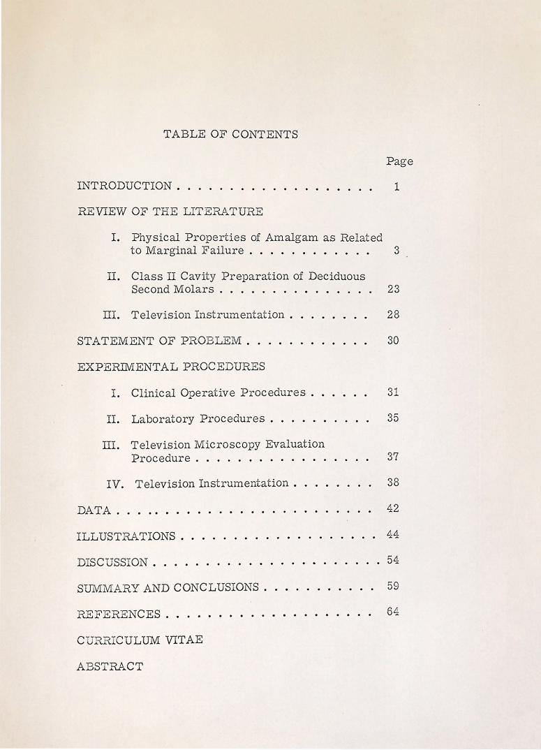
TABLE OF CONTENTS
Page
INTRODUCTION . . . . . . . . . . . . . . . . . . . 1
REVIEW OF THE LITERATURE
I. Physical Properties of Amalgam as Related to M:arginal Failure . . . . . . . . . . . . 3
II. Class II Cavity Preparation of Deciduous Second Molars . . . . . . . . . . . . . . . 23
III. Television Instrumentation . 28
STATEMENT OF PROBLEM. . . 30
EXPERllv'IENTAL PROCEDURES
I. Clinical Operative Procedures . 31
II. Laboratory Procedures . . . . . . 35
III. Television Microscopy Evaluation Procedure . . . . . . . . . . • . . 37
IV. Television Instrumentation • . 38
DATA . . . . . . . . . . . . . . . . · · 42
ILLUSTRATIONS • . . . . . • . . . . . . . . . • . . 44
DISCUSS-ON . . . . . . . . . . . . . . . • . • . . . . 54
SUMMARY AND CONCLUSIONS . . . . . . . . . . . 59
REFERENCES ....• . . . . . . . . . . . . . . . 64
C RR ... CULUM VITAE
ABSTRA.CT
LIST OF ILLUSTRATIONS

LIST OF ILLUSTRA.TIONS
Page
Figure 1. The clinical and laboratory procedure for the te evision microscope . . . . . . 44
Figure 2. A cast gold overlay with viewing holes . 45
Figure 3. Serial television gingival micromeasurement photographs indicating the line of measurement . . . . . . . . . . . . . . . 46
Figure 4. A block diagram of the intraoral microscope system . . . . . . . . 47
Figure 5. A labeled pho.Logra of the intraoral microscope assembly . . . . . . . . 48
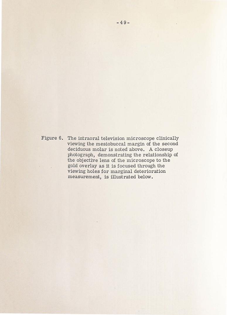
Figure 6. The intraoral elevision microscope clinically viewing the mesiobuccal margin of a second deciduous molar . . 49
A closeup p otograph demonstrating the relationship of .Lhe objective lens of the microscope to the gold overlay . 49
Figure 7. An overall viev; of the television laboratory . . . . . . . . . . . . . 50
Figure 8. A graph show· g the average marginal deterioration for the occlusal and gin-gival areas . . . . . . . . . . . . . . . . 5
Figure 9. A bar graph emonstrating the average micron and percent marginal deteriora-tion . . . . . . . . . . . . . . . . . . 52
Figure 10. Serial televis ·on micromeasurement photographs indicating an area of pro-gressive marginal deterioration . . . . . 53
INTRODUCTION
-1-
Most clinical dental research of the oral
c a v it y i s co n duct e d w it h t h e n a k e d e y e , o r at
best, a few times magnification with the aid of
binocular loops. Higher magnification is im
possible due to the bulkiness of the equipment
and the necessity for observing at the low light
levels found in the oral cavity of the human and
experimental animal. The television micro
scope eliminates this problem by obtaining
clinically high magnifications and accurate
measurements utilizing electronically con
trolled lightness, brightr:-ess, and scanning
measurement techniques.
A great deal has been said and written
about the cavosurface margins where amalgam
is being used. The profession has long realized
that it is at this point where many of the res
toration failures take place. It has been as
sumed that these failures are due to faulty
cavity preparation and restorative manipulation.
In addition, little is known concerning the ex t ent,
the character, and tl:le nature of cavosurface
failures of amalgam restorations. Since this
cavosurface junction is critical, relative to
cavity preparation, filling manipulati~n, and
the permanence of the restoration, more
critical methods for the accurate evaluation of
these procedures should be developed.
-2-
A study was designed to measure the marginal
deterioration of alloy restorations in deciduous
teeth, utilizing the television microscope for
precise intraoral micromeasure1nents. This
study was intended to demonstrate the clinical
application of the television microscope in
dental research and the nature and extent of
proximal marginal deterioration of alloy res
torations in deciduous teeth.
REVIEW OF THE LITERATURE
- 3-
The review of the literature is divided
into three subheadings relative to the s·ubject
of marginal deterioration of amalgam res
torations. These topics are Physical Prop
erties of Amalgam as Related to Marginal
Failure, Class II Cavity Preparation of
Deciduous Molars, and the Television Instru
mentation.
Physical Properties of Amalgam as Related to Marginal Failure
Black1
was one of the first investigators
to recognize the importance of studying the
influence of manipulative variables on the
properties of amalgam as it related to mar-
g in a 1 ad a p it at i o n . H e rna d e o b s e r v at i o n s of
the influence of residual mercury on the re
sistance of the material to crushing stresses.
However, Black was hampered by inaccurate
instruments with which to demonstrate the
relationship of these two factors.
The relationship of residua l mercury to
the physical properties and clinical behavior
of amalgam has occupied the interest of nu-2 3
m e r o u s in v e s t i g at o r s in the p a s t . G r a y , '
in 1919, made important observations on the
relation between residual mercury and the
physical properties of amalgam. He stressed
-4-
the importance of maintaining an accurate
mercury/alloy ratio. However, he noted that
a sound condensation technique lessened the
significance of the mercury/alloy ratio factor.
Phillips and Boyd 4 investigated the im
portance of the mercury/alloy ratio to the
amalgam filling. They found that the percent
of residu?-1 mercury increased proportionately
as the mercury/alloy ratio increased. Excess
mercury used in trituration increased the
flow and decreased the resistance of the alloy
to tarnish and corrosion. Furthermore, as
the mercury/alloy ratio was increased, the
crushing strength decreased for both one
hour and 24-hour tests. Phillips and Swartz 5
c o n t i n u e d t o i. n v e s t i g at e t h e e f f e c t s of r e s -
idual mercury in amalgam restorations and
found that the average mercury content of 100
alloys was 45.4 percent, with extremes of
28.6 percent and 61.0 percent. They con
cluded that the amount of mercury remaining
in the amalgam should be minimized to assure
maximum strength and resistance to tarnish.
Nadal, Phillips, and Swartz6
' 7
' 8
con
ducted a clinical investigation of the relation
of mercury to the amalgam restoration. They
placed 257 amalgam restorations in stand
ardized preparations. Using three different
techniques, they produced restorations of
three widely different mercury contents and,
therefore three different sets of physical '

- 5-
properties. They found no failures due to flow
or dimensional change. A definite relation
between marginal deterioration and mercury
content was discovered; the number and se
verity of marginal failures increased as the
mercury content increased. Surface roughness
and general degradation were manifested by
many of the restorations containing 58 percent
mercury, and this roughness and degradation
increased even more in the group containing
62 percent mercury.
Swartz and Phillips 9 also studied the
residual mercury content of amalgam restora
tions as related to its influence on compressive
strength. They stated that the residual mer
cury content was dependent on two factors,
the original mercury/a l loy ratio and the
condensing pressure. No correlation between
strength and residual mercury was observed
when the residual merc u ry content was 45 to
53 percent. A direct relationship was found
between compressive strength and residual
mercury content when 55 percent residual
mercury or more was obtained; the strength
of the amalgam decreased sharply when 55
percent residual mercury was reached. They
found that it was quite common to find the
marginal areas exceeding 55 percent when the
average residual 1nercury content for the
entire restoration was less that 55 percent.
Wilson, Phillips, and Norman 10 found that
-6-
regardless of the method of condensation or
the dryness of the alloy increments, the mar
ginal areas of the amalgam contained a higher
percentage of mercury than did the bulk of
the alloy.
Wolcott 11 examined the effect of increasing
the mercury/alloy ratio. He found that this
increased the residual mercury, thereby re
ducing the strength, increasing the flow,
and increasing the susceptibility to tarnish
and corrosion. He further found that a se
rious loss in strength occurred when the re
sidual mercury exceeded 55 percent. These
findings corroborated the results of previous
investigations by Swartz and Phillips. 9
One can conclude from these studies
co n cern in g .residua 1 mercury in alloy restor a
tions that a reduction in strength, and an
increase in flow, and an increase in suscep
tibility to tarnish and corrosion is effected
when the residual mercury content of an al l oy
reaches 55 percent. Furthermore, one can
conclude that the marginal areas of an amalgam
contain a higher percentage of residual mercury
t han the bulk of the alloy. An increased re
sidual mercury content, however, seems to
have little affect on flow or dimensional
c h an g e a s r e l at e d t o f a i 1 u r e s i n a m a·l g a m r e s -
torations. The effect of residual mercury
appears to be far more pronounced in the mar
ginal areas where surface roughness and n1ar-
-7-
ginal deterioration was far more prevalent as
the residual mercury content approached 58
percent.
Compressive strength appears to be a
property of amalgam that has prompted some
investigations as to its nature. Ward 12
first noted the influence of the rate of load
application on the strength values of alloy
restorations. He proved that the faster the
load application, the higher the strength value
b e c am e . T h i s p r in c i p l e 1 e d t o t h e o b s e .r v a
tion that the strength properties of amalgam
were influenced not only by the type of stress
but also by the length of time that the res
toration was subjected to the stress.
Phillips 13 studied six alloys to determine
their compressive strength as related to time.
He found that the alloy was very weak in the
first few hours after insertion. It gained
strength rapidly and reached approximately
85 percent of its maximum strength by the
end of the first eight hours. The compressive
strength continued to increase gradually up
t o t h e s i x - m o n t h f in a 1 t e s t . H e co n c 1 u d e d
that equilibrium in amalgam is not reached
for an indefinite period of time. Taylor and
others14 agreed with Phillips and recommended
that no stress be applied to amalgam less than
one hour old and further sugg·ested that any
mastication on an amalgam less than six hours
old would cause damage.
- 8-
Crowell and Phillips 15 determined the
relationship between the surface area of alloy
particles and compressive strength. They
found that the compressive strength increased
as the surface area of the alloy chips increased
for both one-hour tests and 24-hour tests . . The property of flow has been considered
by 1nany to be of extreme clinical importance.
Ward and Scott16 found that amalgam exhibited
63 times more flow than gold. They concluded
that it took only a small force to cause the
proximal portions of alloy restorations in
'molars and bicuspids to move. Further in
vestigations by Skinner 17 led him to conclude
that neither method nor time of trituration
greatly affected the property of flow.
Sweeney 18 , 19 conducted comparative
studies on the effect of manual and mechanical
condensation techniques on the physical prop-
e r t i e s of am a 1 g a 1n . H e c on c 1 u d e d t h at t h e
pneumatic condenser permitted the operat or
to condense amalgam in a less plastic state.
The pneumatic condenser made adaptation
possible without excess mercury being present
in the original mix. Distortion of mechanically
condensed restorations appeared to be less than
in those restorations packed by uncontrolled
hand methods. The most important contribution
made by Sweeney in his studies was that he
found no clinical evidence of flow even though
alloys of high flow values were used. He

-9-
concluded that flow was not an important cause
of failure. Delayed expansion or contraction
appeared to be far more important in assessing
the clinical failure of amalgam restorations.
Nadal, Phillips, and Swartz 6 ' 7 ' 8 corroborated
these con c 1 us ions on the c 1 in i c a 1 significance
of flow many years later.
Phillips, Boyd, Healey, and Crawford 20 ' 21
conducted a clinical study on 130 restorations
placed in both adults and children. These res
torations were placed by three different tech
niques. Approxi1nately one-third were under
amalgamated, one-third were mixed according
t o fn s t r u c t i o n s , and o n e - t h i r d w e r e t r it u r at e d
for three minutes. Clinically, there was not
much difference between the three techniques.
Based on clinical examinations, the three
minute mix exhibited less tarnish and corro
sion, closer adaptation to the cavity walls,
and a slight contraction. I n contrast, the
undertriturated amalgam exhibited more expan
sion and tarnished easily. No clinical evid.ence
of flow was enc ·ountered regardless of the tech-
nique used.
Jarabak 22 continue d investigations of the
effect of alloy particle size on the dimensional
change of amalgam. He found that expansion
decreased as the particle size of the alloy
became smaller. Furthermore, it was found
that as the particle size became smaller, the
e f f e c t s of fr it u r at i o n t i m e an d c o n d e n s at i on
-10-
o n d i 1n e n s i o n a l c h an g e b e c am e l e .s s a p p a r en t .
In contrast to previous investigators, Jarabak
found no difference between mechanical con-
d e n s at i o n and h an d co n d e n s at i o n on d i m e n s i o n a 1
change.
Phillip~, 23 in 1944, compared the influence
of the mechanical amalgamator and the pneumatic
condenser on the physical properties of amalgam.
He concluded that the mechanical amalgamator
produced more thorough mixing, caused a
slight contraction and more flow, but increased
the one-hour and 24-hour compressive strengths
of _the amalgam. The pneumatic condenser, how
ever, had little effect on dimensional change or
flow. This fact confirmed Jarabak's conclusions
on the relationship of mechanical condensation
to dimensional change.
Sweeney 24 analyzed several aspects of ·
amalgam manipulation and proposed some ma
nipulative c.oncepts. H e stressed complete
amalgamation, removal of excess mercury prior
to condensation, and condensation of small
increm·ents of amalgam to activate excess mer
cury to the surface of each layer. These three
principles will provide an amalgam of low mer
cury content, thus effecting a decrease in flow
and an increase in compressive strength.
H omogep.eity throughout the restoration was pro
p osed by Sweeney as an essential principle for
resistance to corrosion.
Ryge and others 25 compared the effects of
-11-
three mechanical condensers and three hand
packing techniques on compressive strength,
dimensional change, mercury content, and
microstructure. They found that mechanical
condensation caused higher compressive
strengths and slight contraction. H owever '
no relationship was found between mercury
content and the compressive strength, the
dimensional change,- or the microstructure
of amalgam.
Crawford and Larson 26 refuted Ryge and
found that there was no difference in corn
pr _essive strength when using ei t her hand con
densation or mechanical condensation tech
niques. They also found that longer mec h anical
trituration times resulted in an increase in
strength and a decrease in expansion. T h ey
confirmed that within certa i n limits mercury
content alone could not be used to predic t
strength, nor was there any correlation
between mercury content and strength or di
mensional change of the alloy.
Swartz and Phillips 27 found no correla-
tion between the physical properties of ama l gam
or residual mercury content with any specific
method of cond~nsation. They stressed t hat if
a sound technique for removing mercury from
individual increments was employed with a
carefully standardized condensation procedure,
no differences in the physical properties of
the alloy would be found. This lends credence

-12-
to earlier statements by Sweeney 28 in which
h e s t r o n g l y c on d e 1n n e d t h e u s e of s m a 11 p 1 u g g e r s
for condensation and burnishing inside the
cavity. He stated that small pluggers merely
push the amalgam from one place to another '
thus not realizing proper condensation. He
also concluded that burnishing caused weak
amalgam to be deposited in the sharp angles of
the restoration where the strongest alloy is
desired.
M o s t of t h e t e c h n i q u e s e 1n p 1 o y e d in t r i t u r a
tion and condensation of amalgam stress the
"i11creasing dryness" technique. However,
there are now many advocates of a t echnique
whereby amalgam of the same consis t ency is
condensed throughout the cavity preparation.
S t r ad e r 2 9 f i r s t r e c o m m e n d e d .c o n d e n s in g
amalgam of the same plasticity from the bottom
to the top of the restoration in order to mini
mize or eliminate unequal expansion and flow.
Mosteller30 advocated a dry mix of amalgam
from start to finish of condensation to m i ni
mize expansion.
Eames31, 32 proposed that a well-co n densed
amalgam should contain less than 50 percent
residual mercu:rY· He showed that an am a lga1n
m a s s c o u 1 d b e t r it u r at e d c o n t a'i n in g a n e a r -
optimum ratio of less that 50 percent mercury.
Eames maintained, after a four-year study,
that this amalgam exhibited more desirable
clinical properties in condensation and
-13-
manipulation, since mulling and removing
excess mercury with instru1nents is. virtually
eliminated. Further1nore, this technique
provided early strength values considerably
higher than those usually expected. Wolcott,
Jendresen, and Ryge33, 34 investigated the
strength, dimensional change, and adaptation
of amalgam prepared with a 1:1 ratio of mer
cury to alloy. They found that successful
amalgam with a low mercury content and high
strength could be produced by this techni q ue.
No difference in adaptation was noted, nor was
a slight contraction due to increased tritura
tion time considered clinically significant.
Expansion and contraction of dental amalgam
has been a subject of repeated investigation.
Schoonover, Souder, and Beall35 investigated
expansion and contraction of dental ama l gam.
They stated:
Expansion may cause extension of the restoration beyond the tooth margins
Contraction causes the separat ion of the restoration from the retaining walls of the tooth, resulting in leakage and thus inviting recurrent decay.
They concluded that excessive expansion d oes
n o t o c c u r u n 1 e s· s t h e a 11 o y i s c o n t am i n a t e d by
moisture. Miller36, 37,38 formulated several clinical
p r in c i p 1 e s an d p r o c e d u r e s t o m in i 1n i z e f a i 1 u r e of
amalgam restorations. He stated that the pre
requisites to a successful amalgam included the

-14-
use of an accepted alloy, correct cavity prep-
·aration, the use of the rubber dam during the
condensation and carving procedures, the ap
plication of an unyielding matrix band, and
intelligent 1nanagement of amalgam. Miller
concluded that moisture contamination should
be avoided at all times, thus emphasizing the
n e e d f o r t h e r u b b e r d a 1n . H e s t r e s s e d the
importance of maintaining exact mercury/
a 11 o y ratios, complete t r it u ration, and uniform
filling material from the floor of the cavity
to the occlusal surface. Romnes 39 further
defined the effect of moisture contamination
on amalgam. He stated that saliva or moisture
interfered with cohesion. Marginal leakage
occurred due to the dissolution of salivary
salts. Moisture contamination also caused
a decrease in crushing strength, delayed ex
pansion, and a decrease in resistance to
corrosion.
Phillips 40 referred to the A. D. A. speci-
fication that amalgam should expand between
three and 13 microns per centimeter 24 hours
postoperatively. He stated, however, that
moisture contamination sometimes caused
several hundred 1nicrons expansion for the same
time period. This led to an investigation on
the effects of contracting alloy restorations.
M cDonald and Phillips 41 placed 60 contracting
alloy restorations in children to determine the
clinical significance of open margins or re
current caries and concluded that contraction

-15-
resulting from slight overtrituration is not
clinically observable. Mosteller42 confirmed
this observation by stating that slight con
traction is of no clinical importance, whereas
excessive expansion of the alloy will result in
failure of the restoration.
Many investigators have attempted to define
and categorize the reason for failure of amalgam
restorations. Ottolengui 4 3 stated, in 1925,
that the greatest percentage of failures occur
on the proximal surfaces due to the difficulty
of properly inserting and polishing the res-.14 I
to ration. Byrnes... agreed and stated that
there were two main reasons for proxima l
occlusal alloy restoration fa:ilure: 1. faulty
adaptation to the cavity wall, which was at
tributed to the lack of the development of a
matrix which would adequately withstand th e
forces of condensation, and 2. the poor edge
strength of amalgam.
Schoonover and Sou de r 45 found a definite
relationship between corrosion of dental alloys
and the extent to which the alloys sealed the
cavity preparations. They examined 50 freshly
extracted teeth containing amalgam restora
tions. Corrosion was observed at the base of
all amalgam restorations in which the fillings
evidently failed to seal the cavity. Thorough
amalgamation, accurate condensing procedures,
and careful polishing were considered essential
to prevent or minimize corrosion of alloy
-16-
restorations.
An important study on the causes and pre
vention of amalgam failures was conducted by
Easton, 46 in 1941. He exa1nined 415 alloys to
·d e termine the causes of failure .. One or both
proximal surfaces were cariously involved in
274 of these failures. In only one-third of
the failures was the causative defect limited
to the occlusal surface only. A V-shaped
fracture of the alloy at the buccal and lingual
margins of the proxi1nal walls from gingival
to occlusal was found in 23 percent of these
failures. It was difficult to determine the
causes of this fracture with accuracy. How
ever, the outline form was observed to be
faulty to the extent that the fracture could
have been attributed to a weakness of the alloy
at the margins. This substantiated Tingley 4 7
who said:
We ought not to lose sight of the fact that enamel is very friable m at e r i a l and t h at e n a 1n e l c a v o s u r -face margins on occasions do fracture. Discrepancies resulting from breakage of either the enamel or the amalgam serve to cause the failure of our restoration.
Predicated on the fact that enamel was very
friable and that enamel cavosurface margins oc
casionally fracture because of this friability,
Kornfeld48 recommended that cavity walls
follow the direction of the enamel rods of the
tooth for maximum strength and prevention of
-17-
am a l g a m an d e n am :e l f r a c t u r e s at t h e m a r g in s .
Healey and Phillips 49 examined 1521 de
fective amalgam restorations to determine
the causes of failure. They found that the
main causes of failure were recurrent caries,
fracture, dimensional change, and pulp or
periodontal invo l vement. I mproper cavity
preparation accounted for 56 percent of all
failures. Faulty manipulation of amalgam or
its contamination at the time of insertion ac
counted for 40 percent of all failures. I m
proper cavity preparation and failure of the
material itself were contributing factors to
recurrent caries. Fracture of the amalgam
accounted for 26.2 percent of the failures.
Faulty manipulation of th e alloy, improper
mercury/alloy ratios, and improper cavity
p ·reparations. were contributing factors to
fractures of the amalgam. These fractures
included serious marginal breakdown i n the
proximal f l are and occlusal areas. D imen
sional changes, 16.6 percent of all fai l ures,
were caused primarily by moisture contamina
tion during condensation.
rnhe most frequent causes of failure of
ama l gam restorations have since been co r
roborated by many investigators. Moss 50 in
vestigated amalgam fai l ure in the United
States Armed Forces and found that 83.8 per
cent of all failures were caused by incorrect
cavity preparation. Ingraham51 stated that

-18-
underextended margins was a 1najor cause of
marginal failure. Kr-oll, 52 Richardson, 53
Hailey, 54 and Wiggins 55 confirmed the factors
of improper cavity preparation and faulty
manipulation as the major causes of amalgam
failure. They emphasized the contributing
manipulative errors of undertrituration, ex
cessive mercury, improper condensation, and
moisture contamination. Wilson and Ryge56
observed 500 restorations for six, twelve, and
eighteen months and found that the effects of
manipulative variables, matrix stability, and
finishing procedures were far more pronounced
t h a·n d iff ere n c e s due to zinc content or particle
size of the alloy. Deschenes 57 further de
fined the specific errors in cavity preparation
to include incomplete caries removal, insuf
ficient extension, faulty retentive form, lack
of cavity depth, and fragility of the cava
peripheral angle. He also corroborated the
manipulative errors previously discussed.
Castaldi 5 8 studied 1, 009 proximal oc
clusal amalgam restorat ions in deciduous
teeth and found that proximal margin defects
occurred frequently, particularly on the disto
buccal margins of mandibular primary first
molars. He altered the cavity design by
capping the distobuccal cusp, and the incidence
of proximal margin defects decreased from
29.04 percent to five percent. Fritz, 59
S i m on, 6 0 M ark 1 e y ,6 1 M i 11 e r , 6 2 and And e r s on 6 3
-19-
stressed the fact that amalgam has no edge
strength. Most investigators consider edge
strength to be indicative of the ability of
fine margins to resist fracture or abrasion.
It i s co n s i d e r e d a c r it i c a I p r o p e r t y of am a 1-
gam and must be compensated by preparing the
proximc:tl surfaces so that they are parallel
to the enamel rods and form a:. ninety degree
cavosurface angle.
MacRae, Zacherl, and Castaldi 64 con
ducted a four-year study of defects in Class II
amalgam restorations in deciduous molars.
They examined 1, 009 restorations and found
thal proximal margin defects occurred more
frequently than any other type of defect. It
was found that failure of the amalgam itself
was responsible for more marginal defects
than breakdown of the enamel. In almost all
cases, these defects occurred between six and
twelve months postoperatively. They sug
gested that these findings indicated the need
for a better filling materia l or alternative
methods for restoring these tee t h.
Marginal adaptation to the cavity walls
is of primary concern to investigators studying
marginal failures of amalgam restorations.
Bjorndal and Sahs 65 conducted a comparative
photomicrographic study of marginal adapta
tion of gold inlays and amalgams. These
teeth were extracted and magnified 60 times.
Amalgam restorations were found to have far
-20-
better adaptation properties than gold inlays,
but it is evident from the photomicrographs
that there are many irregularities and voids
in the cavosurface r.nargins of the amalgam
restorations.
Hatt6 6 studied the effect on amalgam
ad apt at ion to the cavity wall as influenced by
the following factors: l. varying the amount
of n1 e r cur y expelled i m mediately after t r it u r a
tion and prior to condensation, 2. varying
the condensation method, and 3. varying the
condensation pressure. He made 194 specimens
by ~ondensing into an artificial cavity designed
to si1nulate the proximal aspect of Black 1 s
Class II cavity. A Talysurf surface analyser
was used to assess the quality of adaptation.
T h e a v e r a g e r e s i d u a 1·· m. e r c u r y co n t e n t w a s 4 8 . 9
percent. Hatt found that the amount of mercury
expelled had no effect on adaptation as long as
the amount of mercury eliminated was between
20 and 25 percent for hand condensation and be
tween 25 and 30 percent for mechanical con
densation. The ideal hand coadensing pressure
was found to be 2800 pounds per square inch.
Using a condenser point whose outline gained
access to the line angles, the average size of
the space between the amalgam and the cavity
v1all was 60 micro-inches and 76 micro-inches
along the cavosurface angle. Using a cir-
cular condensing point, the average size of
the spaces was 66 and 140 micro-inches for
-21-
the cavity wall and the cavosurface angle,
respectively. Using a mechanical condenser,
the space was 25 and 38 micro-inches for the
cavity wall and the cavosurface angle, thus
indicating better adaptation using a mechan
ical condenser.
Nelsen, Wolcott, and Paffenbarger 67
studied fluid exchanges at the margin.s of dental
restorations and found that temperature changes
in the mouth cause d a fluid exchange between
the teeth and amalgam restorations_ This
marginal percolation is caused oy a difference
in the coefficient of thermal expansion of the
tooth and the restoration and by thermal ex
pansion of the fluid occu p ying the crevice be
tween the tooth and the restoration. Armstrong
and Simon 68 and Phillips 69 investigated the
penetration of radioac ti ve isotopes at the
margins of filling materials and found le ss
penetration at the margins of amalgams than
with other material s. Furthermore, Phillips
found that marginal penetration of ama l gams
decreased with the age of the restora t ion ..
Weinstock 70 investigated the ability of
amalgam to seal a prepared cavity and found
that it exhibited 100 percent seepage to b ac
teria and fluid at the margins within eig ht days
postoperatively. Phillips, Gilmore, Sw rtz,
and Schenker 71 found, with the use of Ca 4 5,
that the margins of amalgam were readily pene
trated by the isotope initially. This leakage
-22-
d i 1n in i s h e d a s t h e r e s t o r at i o n a g e d . T h e s e
findings were confirmed by Brannstrom and
Soremark72 using Na 22 ions. They also found
that penetration was greater around amalgams
that were not insulated with a varnish.
Baumgartner, Bustard, and Fei erabend73 con
ducted si1nilar studies using 1131 ions and
found similar results.
J o r g e n s e n 7 4 ' 7 5 co n d u c t e d an i m p o r t ant
study of the mechanism leading to fracture of
the 1nargins of an amalgam restoration. The
most essential reason for slits or voids oc
curring between the amalgam margin and the
cavity wall is corrosion with resulting
"mercuroscopic" expansion. The amalgam
surface facing the cavi t y wall functions as
an anode in a concentration cell element where
the cathode is the free surface of the filling.
Due to the anodic corrosion, metallic mercury
is set free; the mercury d iffuses into the
amalgam from the cavity side and causes a
unilateral expansion of t he wedge-shaped
amalgam margin which b ends away from the
supporting ename l wall. Ot her reasons for
deformation of slits are de l ayed expansion,
condensing failures, flow, marginal excess,
enamel fractures, and caries. Jorgensen74, 75
further outlined some factors that he believes
are significant in "mercuroscopic" marginal
d e f 1 e c t i o n • 0 m i s s i on of t h e e 1 e c t r o 1 y t e f ro m
the interface between amalgam and tooth
-23-
structure is important. This omission can
be obtained only by the greatest possible
adaptability, the smallest possible setting
expansion or contracti'on, a certain degree
of roughness of the cavity wall, parallel'ism
between the cavity wall, and omission of
delayed expansion. The greatest possible
strength of amalgam may al$o improve the
stability between tooth and filling. Jorgen
sen74, 75 also stated that the reduction of
the mercury content in the margins to a
minimum and to the same value as the bulk of
the fillings was very important in "mercuro
scopic" marginal deflection.
Class II Cavity Preparation of Deciduous Second Molars
The importance of correct cavity prepara
tion on the success or failure of any amalgam
restoration is undisputed. Gabel 76 stated:
Due to the inherent characteristic of amalgam and certain peculiarities of the deciduous molars failures of the amalgam restoration are more frequent than any other type.
Ireland, 77 in 1947, outlines the most common
errors in cavity preparation of Class II de
ciduous molars. He stated that the most common
errors were too ·narrow b u c co 1 in g u a 1 prep a r a-
ti on s at t h e o c c 1 u s a 1 i s t h m u s , in ad e q u at e p r e p -
aration of the occlusal step, and extreme

-24-
tapering toward the buccal and lingual of the
proximal walls.
The occlusal P.ortion of Class I I cavity
preparations in deciduous molars has occupied
the interest of many inves t igators& Brown 78,79
offered a mechanical basis for the prepara-
tion of Class II cavity preparations in deciduous
molars. He stated that the occlusal dovetail
should be shallow and broad, with rounded
contours. The floor of the occlusal step
should be flat and form the base of a tr uncated
cone. Sweet 8 0 stated that cavity prepara-
tions in deciduous teeth should be governed
by the morphology of the teeth, the t ype of
filling material to be used, esthetics, and
economics. He also advocated a wide occ-usal
isthmus that was slight l y undercut. Th e
buccal and lingual wal l s of the occl u sal step
should be parallel to the external bucca l and
lingual surfaces.
Noonan, 81 in 1949, conducted a s ' udy
applying photoelasticity to researc h on cavity
preparations. He concluded that a flat floor
with rounded line angles and rounded retention
points permitted. less stress concen tra ion
than sharp angles and s ha rp retenLion points.
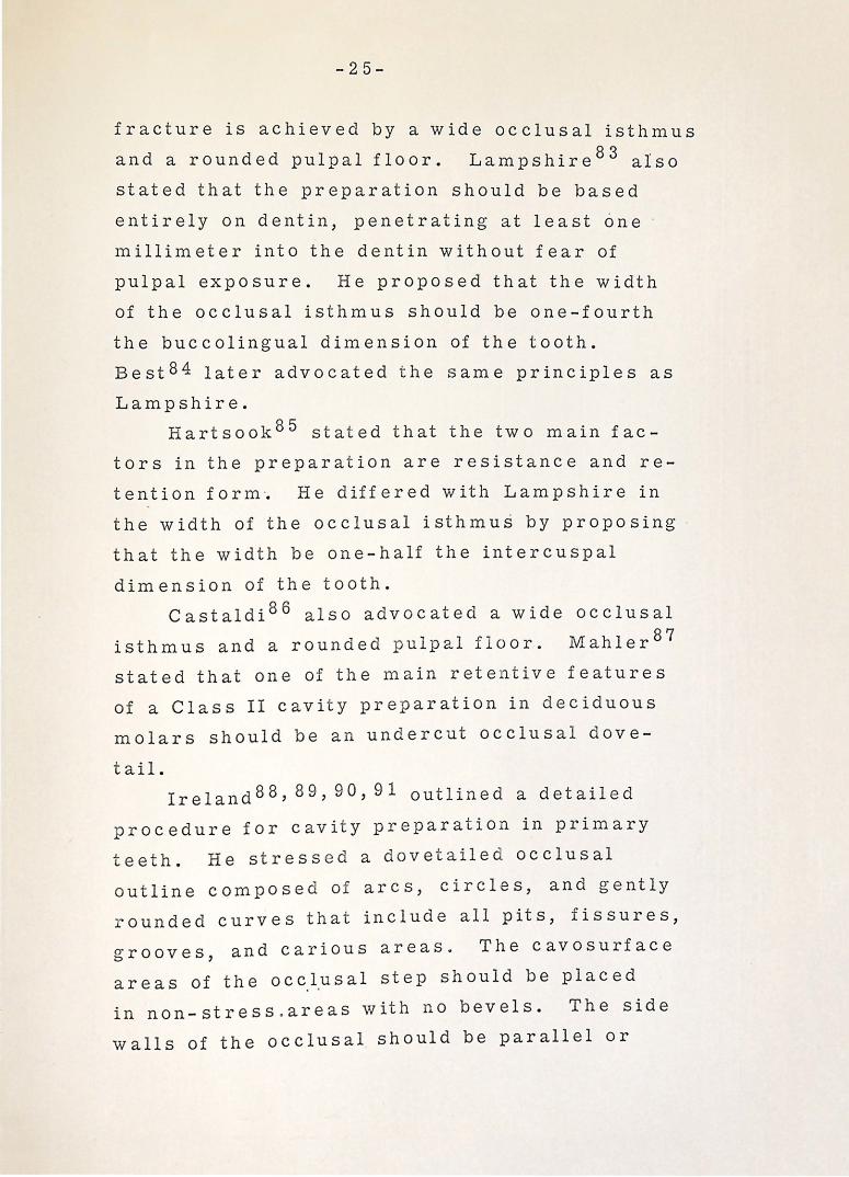
Lampshire, 82 in 1950, conduc ted an in
vestigation to test and evaluate various Class II
cavity forms to determine the most b eneficial
prinicples of cavity preparation. His results
indicated that the greatest resistance to
-25-
fracture is achieved by a wide occlusal isthmus
and a rounded pulpal floor. Lampshire 8 3 also
stated that the preparation should be based
entirely on dentin, penetrating at least one
millimeter into the dentin without fear of
pulpal exposure. He proposed that the width
of the occlusal isthmus should be one-fourth
the buccolingual dimension of the tooth.
Best84 later advocated the same principles as
Lamp shire.
Hartsook8 5 stated that the two main fac
tors in the preparation are resistance and re
tention form ·. He differed with Lampshire in
the width of the occlusal isthmus by proposing
that the width be one-half the intercuspal
dimension of the tooth.
Castaldi86 also advocated a wide occlusal
isthmus and a rounded pulpal floor. Mahler87
stated that one of the main retentive features
of a Class II cavity preparation in deciduous
molars should be an undercut occlusal dove-
tail. Ireland88, 89, 90,91 outlined a detailed
procedure for cavity preparation in primary
teeth. He stressed a dovetailed occlusal
outline composed of arcs, circles, and gently
rounded curves that include all pits, fissures,
grooves, and carious areas~ The cavosurface
a r e a s of t h e o c c.l.u s a l s t e p s h o u 1 d b e p l a c e d
in non-stress . areas with no bevels. The side
walls of the occlusal should be parallel or

-26-
converge slightly as they approach the cava
surface margin.
McDonald92 discussed some basic prin
ciples in the preparation of cavities in de
ciduous teeth. He stated that the cavity
preparation should extend into all pits and
fissures and should include all areas of
carious involvement. McDonald advocated a
wide occlusal isthmus buccolingually, the
optimum average width being approximately
one-half the intercuspal dimension of the
tooth. The occlusal floor should be flat . '
and the depth should be approximately one-
half millimeter pulpally from the dentino
enamel junction. He also stated that the
internal line angles should be rounded to
reduce stress concentration and permit more
complete condensation in these areas.
The proximal portion of Class II cavity
preparations in deciduous molars has fre
quently been designated as a major area of
restorative failures. As stated previously,
Ireland77 proposed that extreme tapering
toward the buccal and lingual of the proximal
walls was a common error in cavity prepara
t ion. Brown7 8 , 79 stressed a triangular
shaped proximal box whose base was the gin
gival floor. He stated that the gingival
proximal line angles should be gently rounded.
The proximal walls should be parallel with
some flaring for extension into free-cleansing

-27-
a r e a s . S w e e t 8 0 r ' e c o m m e n d e d t h at t h e b u c c a 1
and lingual walls of the proximal box be par
allel to the external buccal and lingual sur-
f a c e s· . K e 1 s t e n 9 3 s t r e s s e d t h e i m p o r t an c e
of preparing the proximal walls so that they
were perpendicular to the enamel rods.
Lampshire, 82, 83 Best, 84 Castaldi, 86 Ire
land, 88, 89, 90,91 and McDonald9 2 agreed with
the previous investigators by advocating th.at
the buccal and lingual walls of the proximal
box should flare enough to carry the margins
into free-cleansing areas and should reach a
cavosurface angle of 90 degrees.
- As stated previously, Noonan 8 1 concluded
in his studies that rounded line angles and
rounded retention points permit t.e d 1 e s s stress
concentration than sharp angles and sharp
retention points. Based largely on Noonan's
work, other investigators78-80, 82-86,88-95
have advocated rounded p u 1 p o ax i a 1 1 in e an g 1 e s
an d r o u n d e d b u c c o gin gi v a 1 and 1 in g u o g in g i v a 1
line angles. The reasons for rounding all
line angles are to permit less stress con
centration and more facilitation in conden-
sation. Ireland94, 95 advocated aU-shaped groove
at the gingivoaxial line angle as an aid in re
tention of the amalgam restoration. Other . t· t 78, 79, 86,87' 92,93 advocated 1nves 1ga ors
side retention grooves in the buccoaxial and
linguoaxial line angles. These grooves should
-28-
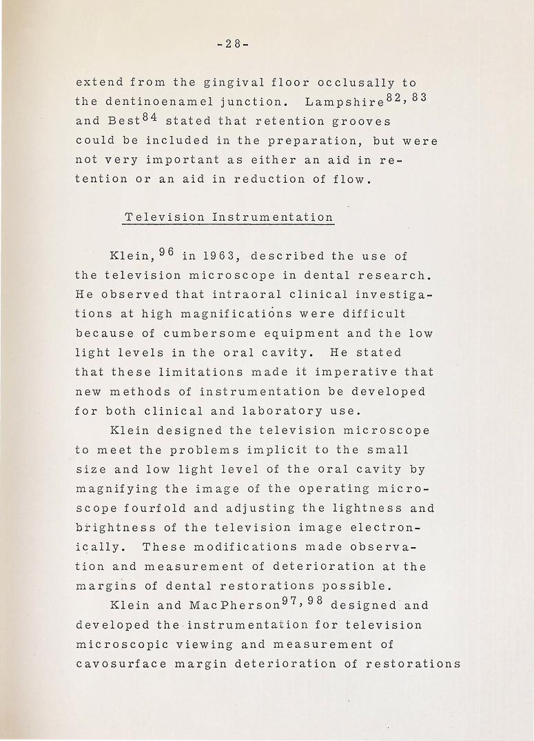
extend from the gingival floor occlusally to
the dentinoenamel junction. Lampshire82, 83
and Best84 stated that retention grooves
could be included in the preparation, but were
not v.ery important as either an aid in re
tention or an aid in reduction of flow.
Television Instrumentation
Klein, 96 in 1963, described the use of
the television microscope in dental research.
He observed that intraoral clinical investiga
tions at high magnifications were difficult
because of cumbersome equipment and the low
light levels in the oral cavity. He stated
that these limitations made it imperative that
new methods of instrumentation be developed
for both clinical and laboratory use.
Klein designed the television microscope
to meet the problems implicit to the small
size and low light level of the oral cavity by
magnifying the image of the operating micro
scope fourfold and adjusting the lightness and
brightness of the television image electron
i~ally. These modifications 1nade observa
tion and measurement of deterioration at the
margins of dental restorations possible.
Klein and MacPherson 97 , 98 designed . and
developed the -instrumentat ion for television
microscopic viewing and measurement of
cavosurface margin deterioration of restorations

-29-
in primary teeth. This instrumentation was
achieved by coupling a petrographic microscope
to a two-camera closed circuit television
syste1n through scan line measurement cir
cuitry. A one millimeter area of the cave
surface margin can be serially viewed at 250X
magnification with linear measurement changes
as small as two microns being noted.

STATEMENT OF PROBLEM

-30-
The purpose of this study was to demonstrate
the clinical application of the television micro
scope for direct intraoral micromeasuremen t
of cavity margin deterioration. This was ac
complished by measuring the marginal dete
rioration of proximal occlusal alloy restorations
in deciduous second molars. The margins were
evaluated on the basis of the character, the
extent, and the nature of the margin deteriora
tion.

EXPER.IM:ENTAL PROCEDURES

-31-
The experimental procedures section of
this thesis has been divided into four parts,
as follows:
l. Clinical operative procedures: The
criteria for selection of teeth, cavity prep
aration, base and restorative materials
utilized, restoration placement, and impres
sion technique for the gold overlay,
2. Laboratory procedures: A descrip
tion of the fabrication and design of the
proximal occlusal gold overlay,
3. Television microscopy evaluation:
The procedures for postoperative polishing
and the television microscopy evaluation at
one week, two weeks, four weeks, 12 weeks,
24 weeks,. and 36 weeks after insertion, and
4. Television instrumentation: The
design and development as des~ribed by Klein
and MacPherson. 97 , 98
Clinical Operative Procedures
The teeth selected for this study were from
c h i l d r e n in t h e m i x e d d e n t it i o n s t ag e s e l e c t e d
from the patients receiving treatment in the
Pedodontic Department at Indiana University
School of Dentistry. The sample was . li1nited
to the maxillary arch because of greater
-32-
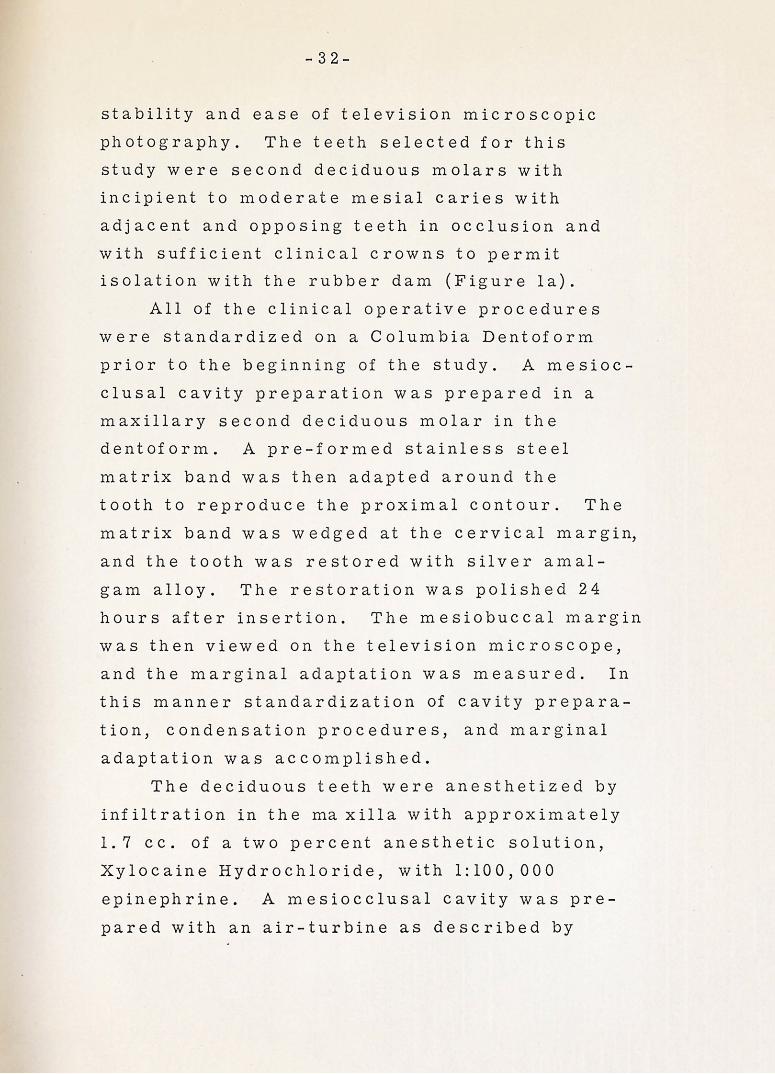
stability and ease of television microscopic
photography. The teeth selected for this
study were second deciduous molars with
incipient to moderate mesial caries with
adjacent and opposing teeth in occlusion and
with sufficient clinical crowns to permit
isolation with the rubber dam (Figure la).
All of the clinical operative procedures
were standardized on a Colu1nbia Dentoform
prior to the beginning of the study. A mesioc
clusal cavity preparation was prepared in a
maxillary second deciduous molar in the
dentoform. A pre-formed stainless steel
matrix band was then adapted around the
tooth to reproduce the proximal contour. The
matrix band was wedged at the cervical margin,
and the tooth was restored with silver amal
gam alloy. The restoration was polished 24
hours after insertion. The mesiobuccal margin
was then viewed on the television microscope,
and the marginal adaptation was measured. In
this manner standardization of cavity prepara
tion, condensation procedures, and marginal
adaptation was accomplished.
The deciduous teeth were anesthetized by
infiltration in the rna xilla with approximately
1. 7 cc. of a two percent anesthetic solution,
Xylocaine Hydrochloride, with 1:100,000
epinephrine. A mesiocclusal cavity was pre
pared with an air-turbine as described by

-33-
McDonald. 92 A number 557 carbide bur was
used to outline the occlusal step. The cavity
preparation was extended pulpally to a depth
of approximately one-half millimeter below
the dentinoenamel junction. It was extended
on the occlusal to include all pits and fissures.
The heavy, transverse ridge of the maxillary
second deciduous molar was not crossed unless
undermined by caries. The pulpal floor was
f 1 at, but the an g 1 e formed by the p u 1 p a 1 f 1 o or
and the axial walls was gently rounded to
reduce stress concentration. The buccolingual
width of the occlusal isthmus was approximately
one-half the intercuspal dimension of the
tooth. An occlusal dovetail was pre pared so
that its buccolingual width was slightly greater
than the isthmus width. The bur was used in
a pendulum-swinging action to prepare the
proximal box and to establish the depth of the
gingival seat. The gingival seat was estab
lished just beneath the free margin of the
gingiva 1 tissue. The ax i a 1 w a 11 was extended
just beneath the dentinoenamel junction. The
buccal and lingual proximal walls converged
slightly toward the occlusal and extended
into a free-cleansing area. The mesiobuccal
p roximal wall was extended just beyond min
imal extensions to provide adequate access
for television viewing (Figure lb). A pl.asti.c
model, duplicating the exact width of the tele
vision microscope light beam, was then
-34-
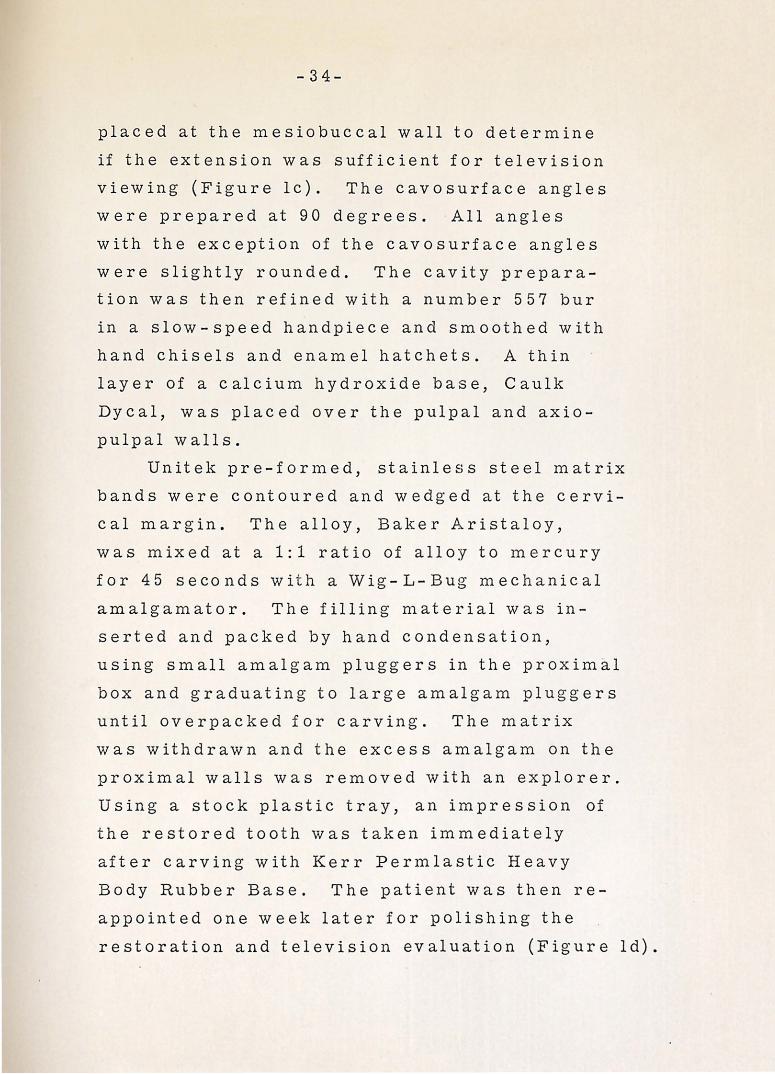
placed at the mesiobuccal wall to determine
if the extension was sufficient for television
viewing (Figure lc). The cavosurface angles
were prepared at 90 degrees. All angles
with the exception of the cavosurface angles
were slightly rounded. The cavity prepara
tion was then refined with a number 557 bur
in a slow-speed handpiece and smoothed with
hand chisels and enamel hatchets. A thin
layer of a calcium hydroxide base, Caulk
Dycal, was placed over the pulpal and axio
pulpal walls.
Unitek pre-for1ned, stainless steel matrix
bands were contoured and wedged at the cervi
cal margin. The alloy, Baker Aristaloy,
was mixed at a 1:1 ratio of alloy to mercury
for 45 seconds with a Wig-L-Bug mechanical
amalgamator. The filling material was in
serted and packed by hand condensation,
using small amalgam pluggers in the proximal
box and graduating to large amalgam pluggers
until overpacked for carving. The matrix
was withdrawn and the excess amalgam on the
proximal walls was removed with an explorer.
Using a stock plastic tray, an impression of
the restored tooth was taken immediately
after carving with Kerr Permlastic Heavy
Body Rubber Base. The patient was then re
appointed one week later for polishing the
restoration and television evaluation (Figure ld).

-35-
Laboratory Procedures
The rubber base impression was boxed
with yellow beeswax and poured with Cristobalite
inlay investment material with a water/powder
ratio of 19 cc. :50 gm. The impression was
poured a second time using yellow stone which
served as a finishing model for the overlay.
The invest1nent model was allowed to dry and
the mesiobuccal proximal margin of the res
toration was carefully outlined with a sharp
pencil. The model was placed on a Ney sur
veyor so that the marking arm was perpen
dicular to the mesiobuccal margin of the res
toration (Figure le). A piece of thin trans
parent, 22 gauge Kinco adhesive casting wax
was adapted over the mesial half of the oc
clusal portion of the restored tooth and over
the distal half of the occlusal portion of the
adjacent tooth, with an extension over the
interproximal portions of the restoration and
the adjacent tooth from buccal to lingual -.
The outlines mesiobuccal margin of the res
toration could be seen through the wax
(Figure lf).
A plastic model, duplicating the exact
w i d t h of t h e t e 1 e v i s i on 1 i g h t b e a 1n , w a s f a b -
ricated with a hole through its longitudinal
center to replace the surveyor arm. A piece
of . 060 stainless steel tubing was fabricated
with an internal soldered spring that held a
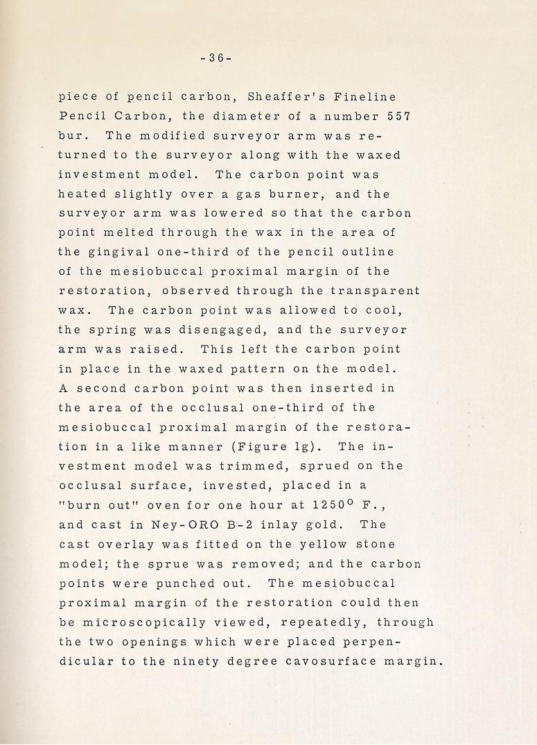
-36-
piece of pencil carbon, Sheaffer's Fineline
Pencil Carbon, the diameter of a number 557
bur. The modified surveyor arm was re-
turned to the surveyor along with the waxed
investment model. The carbon point was
heated slightly over a gas burner, and the
surveyor arm was lowered so that the carbon
point melted through the wax in the area of
the gingival one-third of the pencil outline
of the mesiobuccal proximal margin of the
restoration, observed through the transparent
wax. The carbon point was allowed to cool,
the spring was disengaged, and the surveyor
arm was raised. This left the carbon pQint
in place in the waxed pattern on the model.
A second carbon point was then inserted in
the area of the occlusal one-third of the
mesiobuccal proximal margin of the restora-
tion in a like manner (Figure lg). The in
vestment model was trimmed, sprued on the
occlusal surface, invested, placed in a
"burn out" oven for one hour at 1250° F.,
and cast in Ney-ORO B-2 inlay gold. The
cast overlay was fitted on the yellow stone
model; the sprue was removed; and the carbon
points were punched out. The mesiobuccal
proximal margin of the restoration could then
be microscopically viewed, repeatedly, through
the two openings which were placed perpen
dicular to the ninety degree cavosurface margin.

-37-
Television Microscopy Evaluation Procedure
One week after the insertion of the res
toration, the tooth was isolated with a rubber
dam, the proximal surfaces were finished
with an extrafine sandpaper disc, and the oc
clusal surface was refined with dull, round
finishing burs. The restoration was polished
with moist flour of pumice, using a rubber
cup, followed by a tin oxide agent. The cast
overlay was then placed over the restor e·d
tooth for television evaluation of the res
toration (Figure lh).
The mesiobuccal proximal margin of the
restoration was observed by the television
microscope through the occlusal and gingival
marginal observation holes at 250X magnifi
cation (Figure 2). The image that appears
on the storage master monitor was made up
of 525 lines of scan. An oscilloscope intro-
duced into the circuit made it possible to
select any one line of scan for measurement.
A micron dot scale was then electronically
placed on the scan line, and the area of mar
ginal deterioration was measured and recorded.
Two measurements of marginal deterioration
were noted at each appointment. One measure
ment was made through the hole in the occlusal
one-third of the overlay and one through the
hole in the gingival one-third. A photograph,
for recording purposes, was then made of

-38-
each of the images from the master monitor.
These measurements were taken at one week,
two weeks, four weeks, 12 weeks, 24 weeks,
and 36 weeks after insertion of the amalgam
restoration (Figure 3). The areas to be
measured were oriented by the holes in the
cast overlay and by visual identification of
landmarks on the tooth and restoration as
seen on the television monitor.
Television Instrumentation
The television microscope instrumenta
tion was designed and developed by Klein and
MacPherson. 97 , 98 The following is a brief
explanation of the design of the instrumenta
tion as described and illustrated in their
papers. A schematic block diagram of the
instrumentation is noted in Figure 4.
Microscopic System. The optical system was
a Leitz petrographic microscope consisting of
a monocular tube mounted on a detachable
microscope limb with dual rack and pinion and
micrometer fine focusing. The objective
system housed a fixed ring mirror and an
interchangeable objective with an adjustable
ring condenser. The ring condenser surrounded
the objective concentrically and guided the
light reflected from the ring mirror to the
object. The objective had a free working
distance of 16 mm. This working distance

. -3 9-
made it possible to examine and measure
·deeper margins of the specimen which wou ld
not be possible with standard micro-objectives.
The eyepiece, a H uygens6X, was mounted in
an attachment that consisted of a lateral
focusing telescope (lOX) that 'indicated the
area being viewed. The eyepiece and tele
scope were couple d to t he television viewing
ca1nera through a l ight- t igh t adapter tube.
A self-wi n ding ce nt ral f l ash synchronized
shutter was opera t e d a t a 1 / 1 25 secon d set
ting t o activate the p er m ac h o n s t orage camera.
A release for activating t h e prism an d the
shutter was driven, in correc t se q uence, by
an ele :ctro- solenoid unit that was energized b y
a foot control swi t ch a t t h e time of exposure
(Figure 5).
L ig ht System D es ign. A light h ous i ng was
desi'gned which combi ned the light requ ir ements
of the vi d icon pic k u p tub e, u s e d f or f oc u s i ng
and o b servation, a n d th e per m a c h o n sto ra ge
tu b e. .A. 1 00-watt me r c ur y a r c lamp , wi th a
force d air cooli n g system, serve d the vi d icon
o b servation system t hrough a ligh t beam
s pl it t er that ut i lize d a d ichroic coa t ing whic h
r e fl ec t ed 4600 l\ l ig h t, f or m aximum res p onse
o.c h e permac h o n s t orage t u b e. A n e l ec tr onic
f ash power suppl y with varia bl e ligh t outpu t
was used because of variations of l ight ·e
fl ectance and a b so r pt i o n from t ooth to t oot h .
me l evision Came ra . J. ... c a me r a chain with a
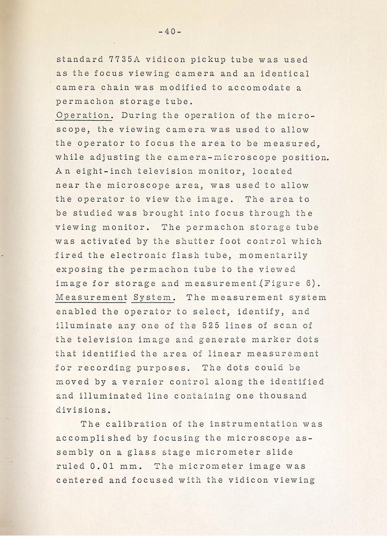
-40-
standard 7735 A vi di con pickup tube was used
as th e focus viewing camera and an identical
camera chain was modified to accomodate a
permachon storage tube.
0 per at ion. During the operation of the m i c r o
scope, the viewing camera was used to allow
the operator to focus the area to be measured,
w hi 1 e adjusting the camera- m · c r o scope position.
An eight- inch television monitor, l ocate d
near the microscope area, was used to a ll ow
the operator to view the image. The area to
be stu died was brought ·nt o focus through th e
viewing monitor. he perma chon s t o rage tube
was activafed by the s hu-'-t er foot co ntra which
fired the electron ic flas h tube , mome ntaril y
exposing the permachon tube to the v iewe
image for storage and measuremen.J. ~~igu - e 6).
lVI easurement Sys tem . The measurement sys t em
enabled the opera t o r to se le ct, identify, and
i l luminate any o ne of t~ e 525 lines of sc an o f
the television image a.- generate marker d o t s
.t.hat identified the area of inear measurement
for recording purposes. The dots cou -d be
moved by a vernier conJ-r o· along the ide ntifie d
and illuminated lin e co n.t.aining one thousand
divisions.
The calibrati on of th e ins.L.rumentation was
accompli shed by focusing the microscope as
sembly on a glass stage micrometer slide
ruled 0.01 mm. he micrometer image was
centered and focused w it .. the vidicon viewing
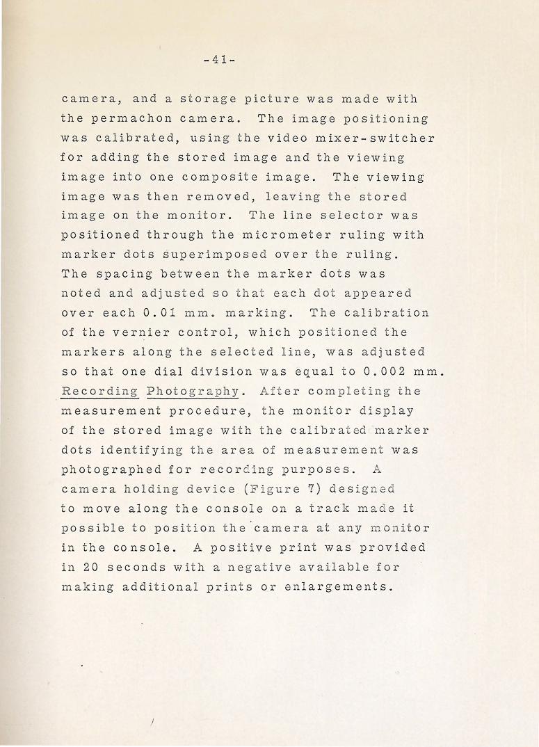
-41-
camera, and a storage picture was made with
the permachon camera. The image positioning
w a s c a 1 i b r at e d , u s in g t h e v i d e o m i x e r - s w it c h e. r
for adding the stored image and the viewing
image into one composite image. The viewing
image was then removed, leaving the stored
image on the monitor. The line selector was
positioned through the micrometer ruling with
marker dots superimposed over the ru l ing ..
The spacing between the marker dots was
noted and adjusted so tha"" each dot appeared
over each 0. 0 1 mm. marking. ':'he calibration
of the vernier control, which positioned the
markers along the selected line, was adjusted
so that one dial division was equal to 0. 002 mm.
Recording Photography .. A J er comp letin g the
measurement procedure, the monitor di splay
of t h e stored image with the c a 1 i bra J ed marker
dots identifying the area of measurement was
photographed for recor ·ng purposes. P,;.
camera holding dev-=ce ( igur e 7) desig _ed
to move along the conso e on a track made it
possible to position the 'camera at any monitor
in the console. A positive print was provided
in 20 seconds with a negative available for
making additiona l prints or enlargements.
J

DATA
i
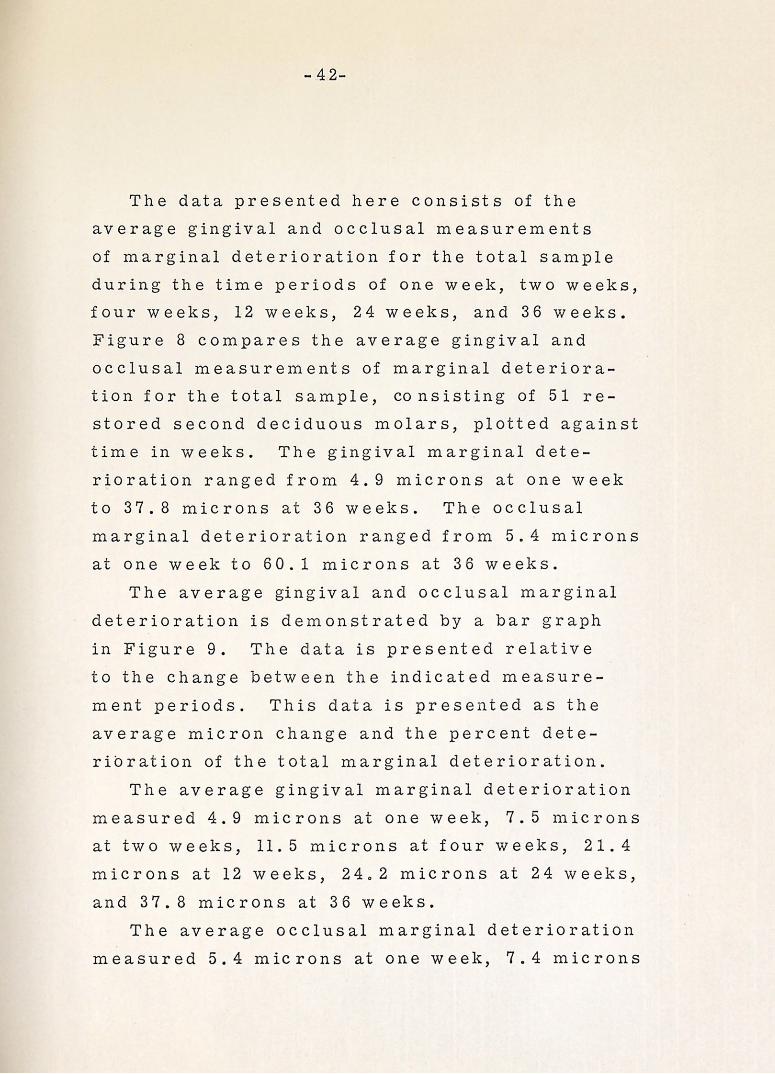
-42-
The data presented here consists of the
average gingival and occlusal measurements
of marginal deterioration for the total sample
during the time periods of one week, two weeks,
four weeks, 12 weeks, 24 weeks, and 36 weeks.
Figure 8 compares the average gingival and
occlusal measurements of marginal deteriora
tion f o r t h e t o t a 1 sam p 1 e , co n s is tin g of 5 1 r e
stored second deciduous molars, plotted against
time in weeks. The gingival marginal dete
rioration ranged from 4. 9 microns at one week
to 37.8 microns at 36 weeks. The occlusal
marginal deterioration ranged from 5. 4 microns
at one week to 60.1 microns at 36 weeks.
The average gingival and occlusal mar gin al
deterioration is demonstrated by a bar graph
in Figure 9. The data is presented relative
to the change between the indicated measure
ment periods. This data is presented as the
average micron change and the percent dete
rioration of the total marginal deterioration.
The average gingival marginal deterioration
measured 4. 9 microns at one week, 7. 5 1nicrons
at two weeks, 11.5 microns at four weeks, 21.4
microns at 12 weeks, 24o 2 microns at 24 weeks,
and 37.8 microns at 36 weeks.
The average occlusal marginal deterioration
measured 5. 4 microns at one week, 7. 4 microns
-43-
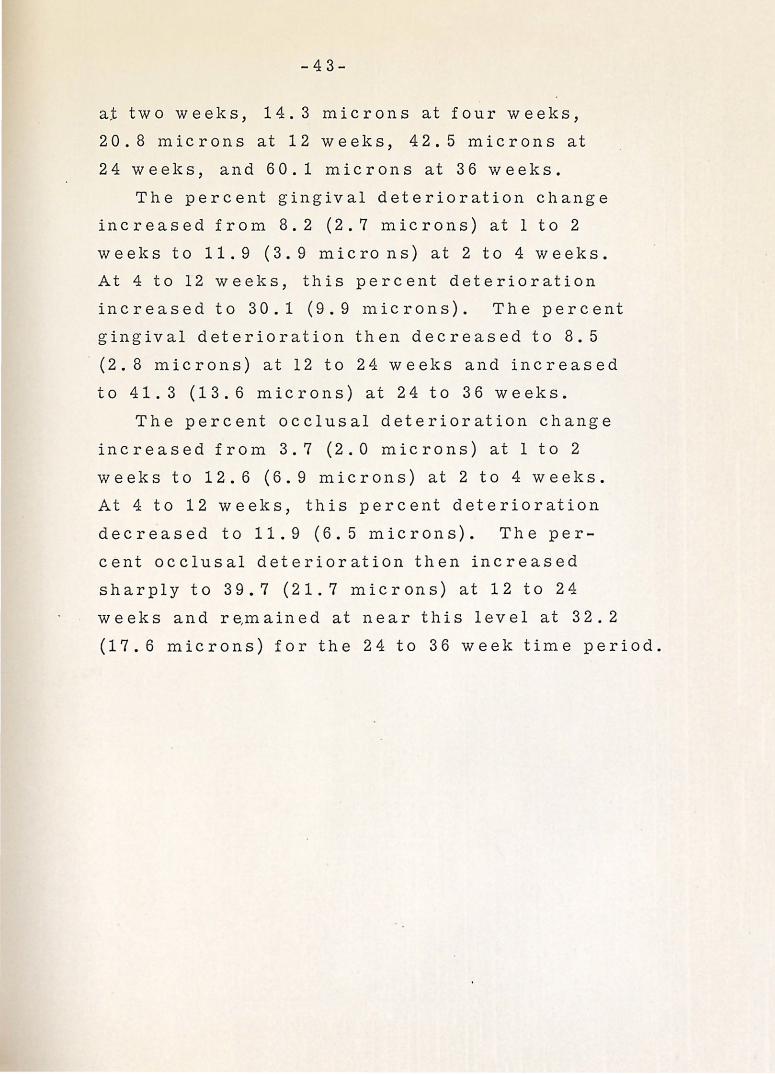
at two weeks, 1 4. 3 microns at four weeks,
20.8 microns at 12 weeks, 42.5 microns at
24 weeks, and 60.1 microns at 36 weeks.
The percent gingival deterioration change
increased from 8. 2 (2. 7 microns) at l to 2
weeks to 11.9 (3. 9 microns) at 2 to 4 weeks.
At 4 to 12 weeks, this percent deterioration
increased to 3 0. 1 ( 9. 9 microns). The percent
gingival deterioration then decreased to 8. 5
· (2. 8 microns) at 12 to 24 weeks and increased
to 41.3 (13. 6 microns) at 24 to 36 weeks.
The percent occlusal deterioration change
increased from 3. 7 (2. 0 microns) at 1 to 2
weeks to 12.6 (6. 9 microns) at 2 to 4 weeks.
At 4 to 12 weeks, this percent deterioration
decreased to 11.9 (6. 5 microns). The per
cent occlusal deterioration then increased
sharply to 39.7 (21. 7 microns) at 12 to 24
w e e k s an d r e, m a in e d at n e a r t h i s 1 e v e 1 at 3 2 . 2
(17. 6 microns) for the 24 to 36 week time period.

ILLUSTRATIONS
-44-
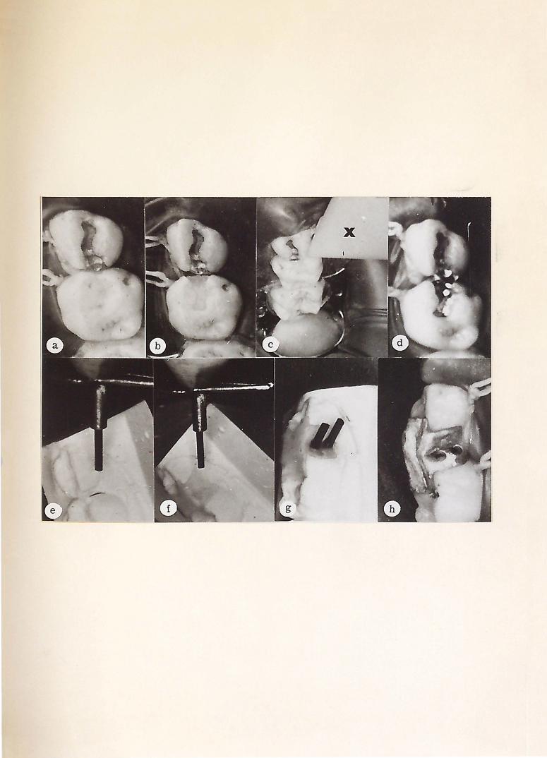
Figure 1. Clinical and laboratory procedure for the television microscope. A preoperative view of a maxillary second deciduous molar selected for this study (a) with typical preparation at (b). A plastic model (x) duplicating the three dimensions of the television micro-scope light beam at (c) was utilized to determine the mesiobuccal 1nargin extension suitable for television viewing. (d) The complete polished restoration. (e) The investment model of the restored tooth, in a modified dental surveyor, with the mesiobuccal outlined. (f) Waxup of the gold overlay and placement of the carbon points perpendicular to the 1nargin in the wax pattern. (g) Completed waxup with carbon pomts for the preparation of the gingival and occlusal viewing hole. (h) The cast gold overlay seated in the mouth with the gingival and occlusal viewing holes overlying and perpendicular to the mesiobuccal proximal margin of the restoration. Through these holes this margin can be repeatedly viewed and measured, at 250 times ·magnification, by the intraoral television microscope.

-45-
Figure 2. Cast gold overlay. The photograph demonstrates the cast gold overlay· with viewing holes at (A).


-46-
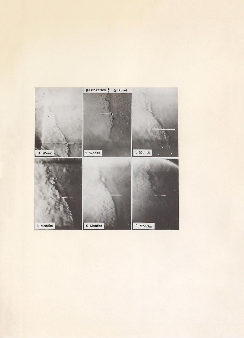
Figure 3. The serial television gingival micromeasurement (original magnification 250X) photographs indicate the line of measurement as a series of Q.ots, calibrated to be ten microns apart.
-47-
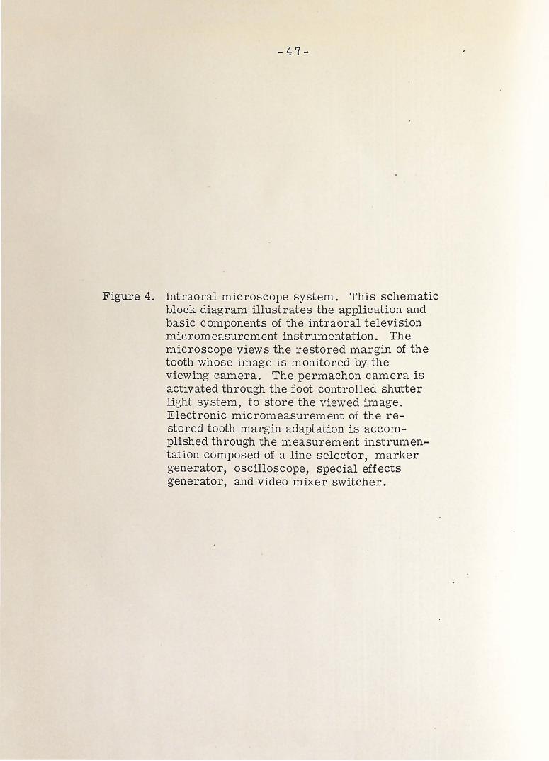
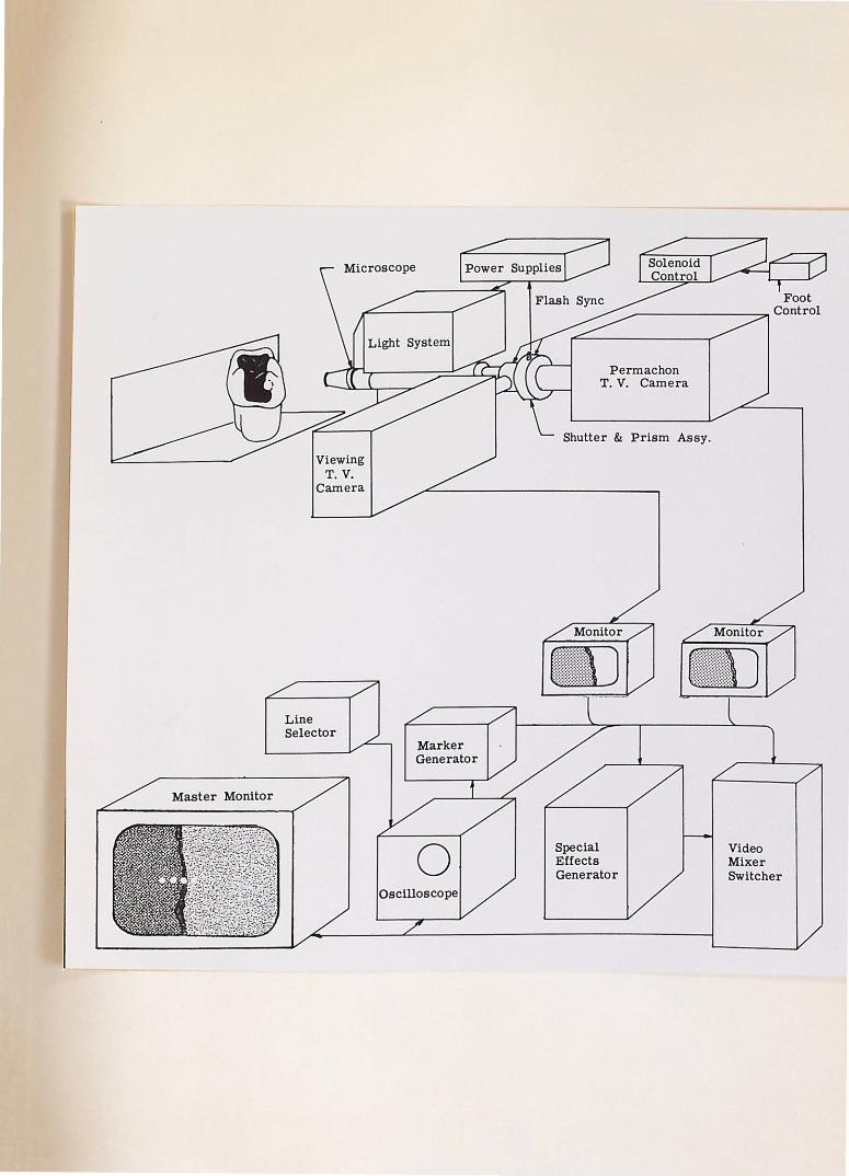
Figure 4. Intraoral microscope system. This schematic block diagram illustrates the application and basic components of the intraoral television micromeasurement instrumentation. The microscope views the restored margin of the tooth whose image is monitored by the viewing camera. The permachon camera is activated through the foot controlled shutter light system, to store the viewed image. Electronic micro1neasurement of the restored tooth margin adaptation is accomplished through the measurement instrumentation composed of a line selector, marker generator, oscilloscope, special effects generator, and video mixer switcher.
Line Selector
Permachon T.V. Camera
Shutter & Prism Assy.
Special Effects Generator
Video Mixer Switcher
-48-
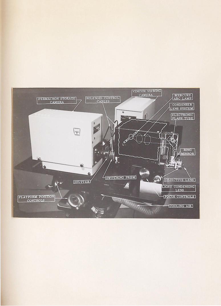
Figure 5. A labeled detail photograph of the intraoral microscope assembly.
-49-
Figure 6. The intraoral television microscope clinically vie\ving the mesiobuccal margin of the second deciduous molar is noted above. A closeup photograph, demonstrating the relationship of the objective lens of the microscope to the gold overlay as it is focused through the viewing holes for marginal deterioration measurement, is illustrated below.


-50-
Figure 7. An overall view of the laboratory with intraoral microscope at (A) and the camera holding device at (B).


.............
::l ...........
z 9 E-4 < ~ 0 E:! 35 ~ E-4 ~ ~
~
~ a ~ 25
20
15
10
5
4 8
-51-
AVERAGE MARGINAL DETERIORATION
GINGIVAL OCCLUSAL
12 16 20
TIME (Weeks)
FIGURE 8

z g E-t
~ 0 ~ rx1 E-t rx1 ~
..:I g ~
~ ~ E-t z rx1 0 ~ rx1 p..
45
40
35
30
25
20
15
10
5
AVERAGE MICRON & PERCENT MARGINAL DETERIORATION
GINGIVAL OCCLUSAL
GINGIVAL OCCLUSAL
1-2
TOTAL CHANGE TOTAL CHANGE
f~;.r?-Jl.:!~~{~-;~-r.::;:r.:~{J
Y/ll/1//01
32. 9 Jl 54. 7 Jl
4-12
TIME (Weeks)
FIGURE 9 .
12-24 13.6
24-36
-53-
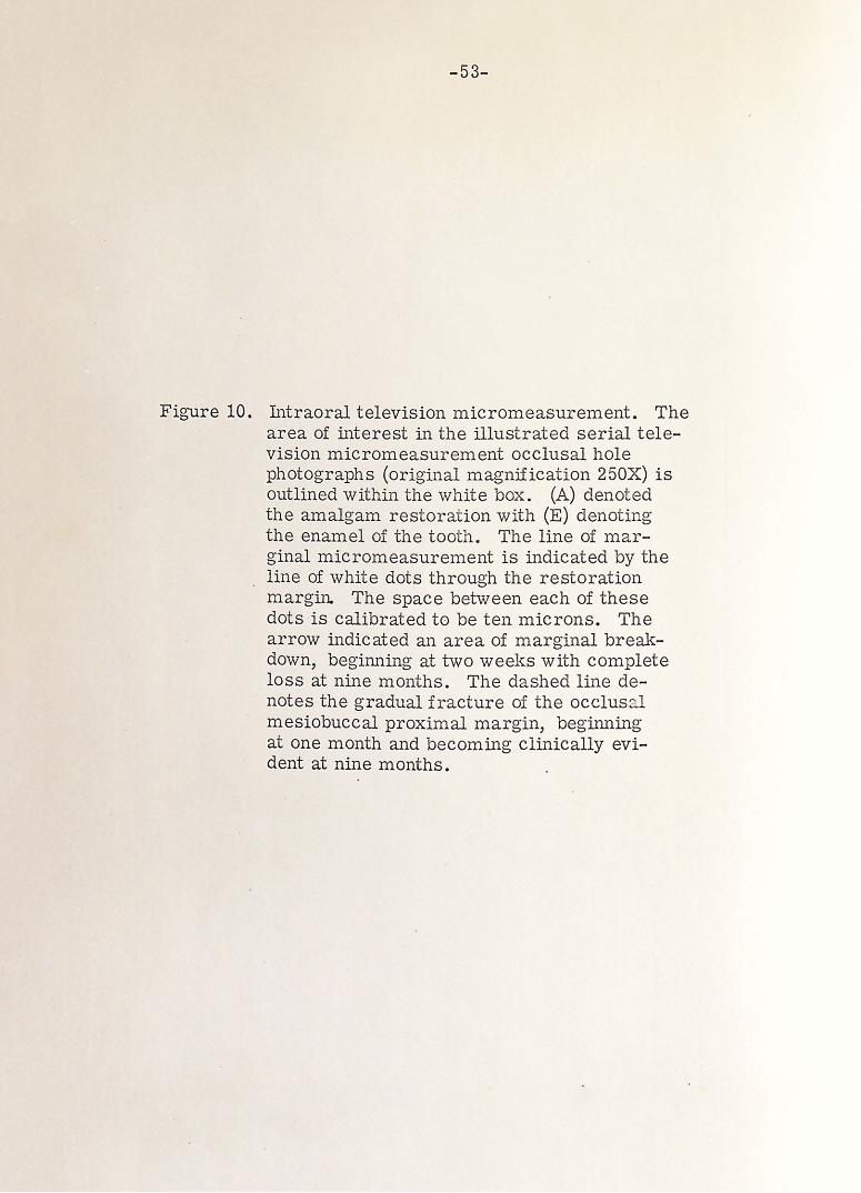
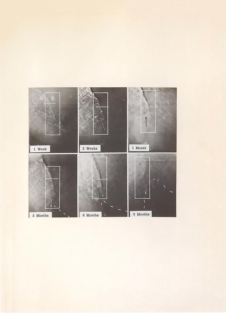
Figure 10. Intraoral television micromeasurement. The area of interest in the illustrated serial television micromeasurement occlusal hole photographs (original magnificat ion 250X) is outlined within the white box. (A) denoted the amalgam restorat ion with (E) denoting the enamel of the tooth. The line of marginal micromeasurement is indicated by the line of white dots through the restoration margin. The space between each of these dots is calibrated to be ten microns. The arrow indicated an area of marginal breakdown, beginning at two weeks with complete loss at nine months. The dashed line denotes the gradual fracture of the occlusal mesiobuccal proximal margin, beginning at one month and becoming clinically evi-dent at nine months.

DISCUSSION
-54-
The objectives of this study were to
demonstrate the clinical upe of the television
m ·i c r o s c o p e a s a t o o 1 f o r d e n t a l r e s e a r c h a n d
to measure and assess the marginal deteriora
tion of proximal occlusal alloy restorations
in deciduous second molars.
The proximal margin was observed through
the television microscope at intervals of one
week, two weeks, four weeks, 12 weeks, 24 weeks,
and 36 weeks postoperatively. This margin
was observed in two areas, the gingival one-
third and the occlusal one-third. The proximal
margin was chosen because this is the area
where previous investigators have frequently
observed marginal deterioration on a clinical basis. 9, 49-51,56-58,62,64,74 It was found
that the mesiobuccal margin provided readily
available access for viewing with the tele-
vision microscope; therefore, only mesioc-
clusal alloy restorations were chosen for this
study. The extent of the decay governed the
extent of the preparation. Incipient to moderate
decay was selected so that the ·possibilities of
pulp therapy and large alloy restorations were
eliminated as variable factors in the study.
Two random sample areas of the proximal
margin were chosen for observation, one area
·midway in the gingival one-third of the proximal

-55-
margin and another area midway in the occlusal
one-third.
The gingival area of the proximal margin
deteriorated at a faster rate during the first
12 weeks than the occlusal area. The gin
gival deterioration for the total sample was
50. 2% of the total gingival 1narginal deteriora
tion during the first 12 weeks. The occlusal
marginal deterioration data demonstrated
that 71.9% of the total occlusal deterioration
occurred in the last 24 weeks of th e study.
During the evaluation of the serial photo
graphic records, it was noted that in all
probability the measured marginal deteriora
tion in the gingival area was initiated by
microscopic alloy flash. This flash initially
broke or chipped away, leaving microscopic
areas of unsupported enamel which eventually
broke do·wn an additional amount probably due
to occlusal and masticatory forces, leaving
areas of unsupported marginal alloy. The
process of the alloy chipping followed by sub
sequent enamel breakdown created a repetitive
cycle of continuing deterioration. An evalua
tion of the serial photographic records indicated
that marginal alloy flash appeared mo r e fre
quently in the gingival portion of the pr oximal
margin tha~ in the occlusal portion (F-igure 10).
This fact could account for the greater p " -
centage of marginal deterioration during the
first three months than in the occlusal portion.
-56-
There are two possible explanations for
the increased microscopic alloy flash in the
gingival one-third of the proximal margin.
It is more difficult to prepare, condense,
and finish proximal occlusal alloy restora
tions in the gingival one-third of the proximal
margin than in the occlusal one-third. This
fact is related to problems of operator and
instrument access in this area. Restricted
access promotes uneven margins, incomplete
condensation, and inadequate polishing of the
restoration. A second possible explanation
for increased flash is that excess amalgam on
the proximal margin was re1noved with an
explorer; therefore, a burnishing effect could
h ave taken place, producing a mercury-rich
margin. This margin would,- therefore, be
more vulnerable to fracture and corrosion.
More excess amalgam may have been present
in the gingival area of the proximal margin
than in the occlusal area because of inadequate
adaptation of the matrix band in this area and
failure of · the matrix band to adequately resist
forces of condensation.
The following factors could introduce some
error in the study. The entire proximal
margin was not evaluated and measured, but
rather two specific are as were chosen in
order to be able to make serial measurements.
Intraoral instrumentation is being developed
-57-
which will allow the investigator to study and
measure the entire margin serially. Plaque
and debris formation sometimes made measure
ments difficult, as the patients were not
instructed in oral hygiene procedures. This
decision was made so that a clear representa
tion of what happened to an alloy restoration
under the usual conditions observed in most
childrents mouths could be ascertained. In
addition, no rotary instruments were ever
applied to the proximal margins after the
initial polishing procedure for fear of changing
the character of the deteriorating proximal
margin. The existing plaque and debris,
therefore, sometimes tended to partially ob
scure the margin and accounted for some
degree of error in reorientation and inter
pretation. It would be interesting to deter
mine the effect of oral hygiene on marginal
deterioration. The microscopic expansion
an d c o n t r a c t i o n of t h e all o y r e s t o r •a t i o n s o m e -
times produced a shadow in the marginal area
w h i c h m a d e it d iff i c u l t t o d e t e r 1n in e a s t o w h at
was shadow or marginal deterioration. Here
again, instrumentation is being developed to
overcome this problem. These sources of
error tended to exist in equal degree -in both
the gingival and occlusal areas of measurement,
therefore balancing each other out.
The results of this study indicate the need
for a reevaluation of the Class II deciduous
-58-
cavity preparation design. The i nf 1 u en c e
of masticatory and occlusal stresses on the
total marginal deterioration point to the need
for a critical evaluation of both the cavity
design and the restorative material used.
The significance of this study lies in the
demonstration of the us e of the television
microscope for clinical dental research. It
would be beneficial if the results of this
study were correlated with the ultimate fate
of the restorations. This would require
continued observation and micromeasurement
of the restorations until such time as they
failed or the teeth were exfoliated.
SUMMARY AND CONCLUSIONS

-59-
T h i s s t u d y w a s d e s i g n e d t o d e 1n o n s t r at e
a clinical application of the television micro
scope in dental research and to measure and
assess the marginal deterioration of Class II
silv.er amalgam alloy restorations in deciduous
teeth.
The teeth included in this study were from
children in the mixed dentition stage selected
from the patients receiving treatment in the
Pedodontic Department a t Indiana University
School of Dentistry. The observation teeth
were limited to the maxillary arch because
of greater ease in standardization and du
plication of the television microscopic photo
graphy.
The teeth selected for this study were
second deciduous molars with incipient mesial
carious lesions with adjacent and opposing
teeth in o c c 1 us ion and with s uf f i c i en t intact
clinical crown to permit isolation with the
rubber dam.
P ... ll of the clinical operative procedures
were standardized on a Columbia entoform
prior to the beginning of the study. A mesioc
clusal cavity preparation was prepared in a
maxillary second deciduous molar in the
dentoform. A pre-formed stainless steel
matrix band was then adapted around the
-60-
tooth to reproduce the proximal contour. The
matrix band was wedged at the cervical margin,
and the tooth was restored with silver amalgam
alloy. The restoration was polished 24 hours
after insertion. The me s i o bucca 1 margin was
then viewed on the television microscope,
and the marginal adaptation was measured.
In this manner standardization of cavity prep
aration, condensation procedures, and mar
ginal adaptation was accomp l ished.
Mesial occlusa l ama l gam al l oy restora-
tions were placed in 51 deciduous secon d molars.
The teeth were anesthe t ized by i nfil t ra ti on in
the m·axilla with approximately 1. 7 cc. of a
two percent anest h e t ic so l u ti on, Xy l oc ain e
Hydrochloride, wi th 1:- 0 0, 00 epi n e phrine ..
The teeth were isolate d under a ru bb e r d am;
t h e c a v it y p re p a r at i o n s w e r e p r e p a r e d w it h an
air-turbine denta l handpiec e using a nu m b er 557
carbide bur. The cavi t y pr e p aration consis t ed
of an occlusal step that inc l u d ed all p i t s,
fissures, and car i ous areas; the occ l usa l
isthmus was approximately one-ha l f the i nt er
cuspal dimension of the t oo h. The cavi t y
preparation was extended pul p ally to a dep th
of approximately one-ha l f m i li 1ne t er b elow th e
dentinoenamel junc t ion; the pupal floor was
fla t , but the angle formed by t he pulpa l f l oor
and the axial wall was gently rounded to reduce
stress concentration. T he gingival seat of
the proximal box was estab l ished just beneath
-61-
the dentinoenamel junction. The buccal and
lingual walls converged slightly toward the
occlusal and extended into a free-cleansing
area. The mesiobuccal proximal wall was
ext e n d e d j u s t b e y o n d m in i m a 1 ext 'e n s i o n s t o
provide adequate access for television viewing.
A pre-formed stainless steel matrix band was
adapted around the prepared tooth so that the
proximal contour of the tooth was reproduced.
The matrix band was then wedged at the
cervical margin, and the tooth was restored
with silver amalgam alloy.
A cast gold overlay was prepared for
each restoration with observation holes placed
in two areas of the mesiobuccal margin, one
in the gingival one-third and one in the occlusal
one-third. One week after the insertion of
the restoration the alloy was polished, and
the cast gold overlay was placed over the
restored tooth for microscopic television ob
servation. The mesiobuccal margin of the
restoration was observed through the occlusal
and gingival observation holes at a magnifica
tion of 250X. The teeth were observed at
one week, two weeks, four \veeks, 12 weeks,
24 weeks, and 36 weeks postoperatively. The
marginal deterioration was measured elec
tronically at each observation appointment.
The average gingival marginal deteriora
tion measured 4. 9 microns at one week, 7. 5
microns at two weeks, 11. 5 microns at four

-62-
weeks, 21.4 microns at 12 weeks, 24.2 microns
at 24 weeks, and 37.8 microns at 36 weeks.
The average occlusal marginal deteriora
tion measured 5. 4 microns at one week, 7. 4
microns at two weeks, 14.3 microns at four
weeks, 20.8 microns at 12 weeks, 42.5 microns
at 24 weeks, and 60.1 microns at 36 weeks.
The data indicated that the gingival area
of the proximal margin deteriorated at a
faster rate during the first 12 weeks post
operatively than the occlusal area. The per
cent of the total gingival marginal deteriora
tion during the first 12 weeks was 50. 2.
During the last 24 weeks, the occlusal area
deteriorated faster, the percent of the total
occlusal marginal deterioration being 71.9.
Microscopic alloy flash was more fre
quently observed in the gingival area of the
proximal margin as compared to the occlusal
area. This fact could account for the ac
celerated marginal deterioration of the gin
gival area during the first 1 2 weeks of the
study as compared to the occlusal marginal
deterioration. Occlusal and masticatory
forces could account for the occlusal mar
ginal deterioration during the last 24 weeks
of the study.
Additional re ·search is needed in order
to correlate the findings of this study with
the ultimate fate of the restored teeth. The
influence of oral hygiene on marginal deteriora-

-63-
tion of amalgam alloys is an area of research
that should be thoroughly investigated.
The results of this study indicated the
need for a re-evaluation of the Class II
deciduous cavity preparation design which
would make it pos.sible to more adequately
restore and finish the gingival portion of the
proximal margin.
This study successfully demonstrated the
application of the television microscope in
clinical dental research. More refined in
strumentation is currently being developed
to overcome the difficulties encountered
with respect to shadow. In addition, intra
oral instrumentation is also being developed
that will enable investigators to view entire
margins rather than random areas.
REFERENCES

-64-
1. Black, G. V.: The physical properties of the silver-tin amalgams. Dental Cosmos. 38:882, 1886.
2. Gray, A. W.: Metallographic phenomena observed in amalgams. J. Amer. Dent. Ass. 6:513, 1919.
3. Gray, A. W.: Metallographic phenomena observed in amalgams. J. Amer. Dent. Ass. 6:909, 1919.
4. Phillips, R. W. and Boyd, D. A.: Importance of the mercury alloy ratio to the amalgam filling. J. Amer. Dent. Ass. 34:451, 1947.
5. Phillips, R. W. and Swartz, M. L.: Mercury analysis of one hundred amalgam restorations. J. Dent. Res. 28:569, 1949.
6. Nadal, Rafael, Phillips, R. W., and Swartz, M. L.: Clinical investigation on the relation of merc\lrY to the amalgam restoration; I. J. Amer. Dent .. Ass. 63:24, 1961.
7. Nadal, Rafael, Phillips, R. W., and Swartz, M. L.: Clinical investigation on the relation of mercury to the amalgam restoration: II. J. Amer. Dent. Ass. 63:488, 1961.
8 • N ad a 1, R af a e 1: Am a 1 gam restoration: cavity preparation, condensing, and finishing. J. Amer. Dent. Ass. 65:66, 1962.
9. Swartz, M. L. and Phillips, R. W.: Residual mercury content of amalgan1 restorations and its influence on compressive strength. J. Dent. Res. 35:458, 1956.
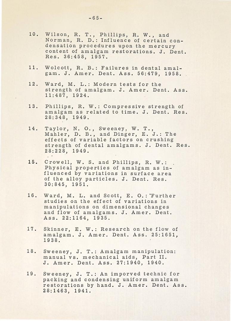
-65-
10. Wilson, R. T., Phillips, R. W., and Nor1nan, R. D.: Influence of certain condensation procedures upon the mercury content of amalgam restorations. J. Dent. Res. 36:458, 1957.
11. Wolcott, R. B.: Failures in dental amalgam. J. Amer. Dent. Ass. 56:479, 1958.
12. Ward, M. L.: Modern tests for the strength of amalgam. J. Amer. Dent. Ass. 11:487, 1924.
13. Phillips, R. W.: Compressive strength of amalgam as related to time. J. Dent. Res. 28:348, 1949.
14. Taylor, N. 0., Sweeney, W. T., Mahler, D. B., and Dinger, E. J.: The effects of variable factors on crushing strength of dental amalgams. J. Dent. Res. 28:228, 1949.
15. Crowell, W. S. and Phillips, R. W.: Physical properties of amalgam as influenced by variations in surface area of the alloy particles. J. Dent. Res. 30:845, 1951.
1 6 . W a r d , M . L . and S c ott , E . 0 . : ·F u r t h e r studies on the effect of variations in manipulations on dimensional changes and flow of amalgams. J. Amer. Dent. Ass. 22:1164, 1935.
17. Skinner, E. W.: Research on the flow of amalgam. J. Amer. Dent. Ass. 25:1651, 1938.
18. Sweeney, J. T.: Amalgam manipulation: manual vs. mechanical aids, Part II. J. Amer. Dent. Ass. 27:1940, 1940.
19. Sweeney, J. T.: An imporved technic for packing and condensing uniform a1nalgam restorations by hand. J. Amer. Dent. Ass. 28:1463, 1941.

-66":"
20. Phillips, R. W., Boyd, D. A., Healey, H. J., and Crawford, W. H.: Clinical observa-tion on amalgams with known physical properties. J. Dent. Res. 22:167, 1943.
21. Phillips, R. W., Boyd, D. A., Healey, H. J., and C r a w f o r d, W . H . : C l in i c a l o b s e r v a -tions on amalgams with known physical properties, final report. J. Amer. Dent. Ass. 32:325, 1945.
22. Jarabak, J. R.: The effect of particle s i z e o n d i m e n s i o n a l ch an g e in d e .n t a l amalgams. J. Amer. Dent. Ass. 29:593, 1942.
23. Phillips, R. W.: Physical properties of amalgam as influenced by the mechanical amalgamator and pneumatic condenser. J. Amer. Dent. Ass. 31:1308, 1944.
24. Miller, C. E.: Construction of the amalgam restoration. J. Canad. Dent. Ass .. 18:119, 1952.
25. Ryge, Gunnar, Dickson, George, Smith, D. L., and Schoonover, I. C.: Dental amalgam: the effect of mechanical condensation on some physical properties. J. Amer. Dent. Ass. 45:269, 1952.
26. Crawford, W. H. and Larson, J ·. H.: Dental restorative materials: amalgams, acrylics. J. Dent. Res. 33:414, 1954.
27. Swartz, M. L. and Phillips, R. W.: A study of amalgam condensation procedures with emphasis on the residual mercury content of the increments. J. Dent. Res. 33:12, 1954.
2 8. Sweeney, J. T.: Manipulation of amalgam to prevent distortion and corrosion. J. Amer. Dent. Ass. 31:375, 1944.
-67-
29. Strader, K. H.: Amalgam alloy: its heat treatment, flow, mercury content and distribution of dimensional change. J. Amer. Dent. Ass. 38:602, 1949.
30. Mosteller, J. H.: The principles of condensation of amalgam, J. Georgia Dent. Ass. 24:10, 1950 . .
31. Eames, W. B.: Amalgam with a low ~ercury-alloy ratio. J. Amer. Dent. Ass. 58:78, 1959.
32. Eames, W. B.: Effect of mercury/alloy ratio, condensation, and other variables on the adaptation of dental amalgam. J. Dent. Res. 43:922, 1964. (Abst.)
33. Wolcott, R. B., Jendresen, M. D., and Ryge, Gunnar: Strength, dimensional change and adaptation of amalgam prepared with 1:1 ratio. Intern. Ass. Dent. Res. 41st General Meeting. 40:95, 1962.
34. Wolcott, R. B., Jendresen, M. D., and Ryge, Gunnar: Strength, dimensional change, and adaptation of amalgam prepared with 1:1 ratio. J. Amer. Dent. Ass. 67:375, 1963.
35. Schoonover, I. C., Souder, Wilmer, and Beall, J. R.: Excessive expansion of dental amalgam. J. Amer. Dent. Ass. 29:1825, 1942.
36. Miller, E. C.: Amalgam inconsistencies in its use in restorations. J. Amer. Dent. Ass. 33:349, 1946.
37. Miller, E. C.: Clinical factors in the use of amalgam. J. Amer. Dent. Ass. 34:820, 1947.
38. Miller, E. C.: Clinical procedures which effect amalgam restorations. Northwest Dent. 27:173, 1948.

-68-
39. Romnes, A. ~.: Amalgam restorations: a critical survey of present day practice. Int. Dent. J. 4:1, 1953.
40. Phillips, R. W.: Amalgam--its properties and manipulation. New York J. Dent. 23:105, 1953.
41. McDonald, R .. E. and Phillips, R. W.: Clinical observations on a contracting amalgam alloy. J. Dent. Res. 29:482, 19 50.
42. Mosteller, J. H.: An evaluation of the A. D. A. specification for amalgam alloy in relation to particle size. Ann. Dent. 12:19, 1953.
43. Ottolengui, R.: The failures with amalgam as commonly used. Dental Cosmos. 67:998, 1925.
44. Byrnes, R. R.: Why fillings fail. J. Amer. Dent. Ass. 21:2149, 1934.
45. Schoonover, I. C. and Souder, Wilmer: Corrosion of dental alloys. J. Amer. Dent. Ass. 28:1278, 1941.
46. Easton, G. S.: Causes and prevention of amalgam failures. J. Amer. Dent. Ass. 28:392, 1941.
4 7. Tin g I e y, V. H. E . : The clinical use of amalgam. D. Items Interest. 62:608, 1940.
48. Kornfeld, B.: Amalgam and silicate r e s t o r at i o n s • D e n t . 0 u t 1 o o k . 2 9 : .2 8 3 , 1942.
49. Healey, H. J. and Phillips, R. W.: A clinical study of amalga1n failures. J. Dent. Res. 28:439, 1949.
50. Moss, R. P.: Amalgam failures. U.S. Armed Forces Med ~ J. 4:735, 1953.
-69-
51. Ingraham, Rex: The application of sound biochemical principles in the design of inlay, amalgam and gold foil restorations. J. Amer. Dent. Ass. 40:402, 1950.
52. Kroll, Abraham: New Look at an old friend--silver amalgam. New York J. Dent. - 30:376, 1960. (Abst.)
53.· Richardson, D. E.: Some considerations in preventing amalgam failures. S. Carolina Dent. J. 18:19, 1960.
54. Hailey, Ray, Jr.: Why do amalgam restorations fail? Fortn. Rev. Chicago Dent. Soc. 41:17, 1961.
55. Wiggins, E. T.: Amalgam failure and its prevention. Dent. Stud. Mag. 41:399, 1963.
56. Wilson, C. J. and Ryge, Gunnar: Progress report on clinical study of amalgam fillings. J. Dent. Res. 40:773, 1961. (Abst.)
57. Deschenes, G. H.: Reasons for amalgam filling failures. J. Canad. Dent. Ass. 28:667, 1962. (Fr.)
58. Castaldi, C. R.: The management of some common paedodontic problems. J. Canad. Dent. Ass. 28:80, 1962.
59. Fritz, J. W.: Etiology and prevention of ·fractures of amalgam restorations. J. Philipp. Dent. Ass. 14:21, 1961.
60 .. Simon, W. J.: Amalgam restorations, part I. J. Tenn. Dent. Ass. 29:7, 1949. ·
61. Markley, M. R.: Restorations of silver amalgam. J. Amer. Dent. Ass. 43:133, 1951.
-70-
62. Miller, E. C.: Modern technic for building amalgam restorations. J. Wisconsin Dent. Soc. 28:199, 1952.
63. · Anderson, J. N.: Dental an1algam. Dent .. Pract. (Bristol) 13:526, 1963.
64. MacRae, P. D., Zacherl, W., and Castaldi, C. R.: Study of defects in Class I I dental amalgam restorations in d e c i d u o u s m o I a r s . ·J • C an ad . D e n t . Ass. 28:491, 1961.
65. Bjorndal, A. M. and Sahs, E. A.: Comparative microphotographic study of marginal adaptation of amalgam and gold inlay restoration. Iowa Dent. J. 46:12, 19 6 0.
66. Hatt, S. D.: Relationship of amalgam to cavity wall. Dent. Pract. (Bristol) 10:76, 1959.
67. Nelsen, R. J ., Wolcott, R. B., and Paffenbarger, G. C.: Fluid exchange at the margins of dental restorations. J. Amer. Dent. Ass. 44:288, 1952.
68. Armstrong, W. D. and Simon, W. J.: Penetration of a radio-calcium at margins of filling materials: a preliminary report. J. Amer. Dent. Ass. 43: 684, 1951.
69. Phillips. R. W.: Research on dental amalgam and its application in practice. J. Amer. Dent. Ass. 54:309, 1957.
70. Weinstock, Alfred: Biophysical properties of silver amalgam--its use and abuse. J. Canad. Dent. Ass. 26:210, 1960.
71. Phillips, R. W., Gilmore, W. H., Swartz, M. L., and Schenker, S. I.: Adaptation of restorations in vivo as assessed by ca45. J. Amer. Dent. Ass. 62:9, 1961.

7 2.
7 3.
74.
7 5.
76.
77.
7 8.
7 9 •
80.
81.
8 2.
-71-
Brannstrom, M~rtin and Soremark, Rune: Penetration of 2 Na ions around amalgam restorations with and without cavity varnish. Odont. Rev. 13:331 No. 4, 1962.
Baumgartner, W. J., Bustard, R. E., and Feierabend, R. F.: Marginal leakage of amalgam restorations. J. Prosth. Dent. 13:346, 1963.
Jorgensen, K. D.: Marginal fracture of amalgam fillings. Tandlaegebladet. 68:475, 19 6 4. (Dan. )
Jorgensen, K. D.: Adaptability of dep.tal amalgams~ Tandlaegebladet. 68:378, 1964. (Dan. )
Gabel, A. B.: The a.malgam proximocclusal r e s t o r at i o n in t h e d e c i duO· u s m o l a r . J . Dent. Child. 11:52, 2nd quarter, 1944.
Ireland, Ro L.: Preservation of the primary teeth. J. Amer. Dent. Ass. 34:383, 1947.
Brown, S. C.: Accepted operative procedures for deciduous and young permanent teeth. D. Items Interest. 71:579, 1949.
Brown, W. E.: Am echani_cal basis for the . preparation of Class II cavities for amalgam fillings in deciduous molars . J .. Am e r. Dent. Ass. 38:417, 1949.
Sweet, C. A.: Cavity preparation in deciduous teeth. J. Amer. Dent. Ass. 38:423, 1949.
Noonan, M. A.: The use of photoelasticity in a study of cavity preparations. J. Dent. Child. 16:24, 1949.
Lampshire, E. L.: Relation of cavity form t o f a i 1 u r e of s i 1 v e r am a l g a 1n r e s t o r at i o n s in primary molar teeth. M. S. Thesis, University of Nebraska, 1950.
-72-
83. Lampshire, E. L.: An evaluation of cavity preparations in primary molars. J. Dent. Child. 22:3, 1955.
84. Best, B. C.: Class II cavity preparation in primary teeth. J. Nebraska Dent. Ass. 38:6, 1962.
85. Hartsook, J. T.: Principles involved in preparing proximocclusal cavities in deciduous teeth. J. Amer. Dent. Ass. 51:649, 1955.
86. Castaldi, C. R.: Analysis of some operative procedures being used in paedodontics. J. Canad. Dent. Ass. 23:377, 19 57.
87. Mahler, D. B.: An analysis of stresses in a dental amalgam restoration. J. Dent. Res. 37:516, 1958.
88. Ireland, R. L.: Cavity preparation and restoration for primary teeth. J. Tenn. Dent. Ass. 40:161, 1960.
89. Ireland, R. L.: Class II cavity preparation for primary teeth and its restoration with silver amalgam. Dent. Pract. (Bristol) 11:208, 1961.
90. Ireland, R. L.: Operative procedures for children. J. Amer. Dent. Ass. 67:340, 1963.
91. Ireland, R. L.: Operative procedures for children. J. Amer. Dent. Ass. 67:340, 1963.
92. Me Donald, R. E.: Pedodontics. St. Louis, C. V. Mosby Co., 1963, p. 243.
93. Kelsten, L. B.: Amalgam restorations for the primary dentition. J. New Jersey Dent. Soc. 23:33, 1952.
-73-
94. Ireland, R. L.: Operative technics for the tooth and the child. J. Amer. Dent. Ass. 32:1083, 1945.
95. Ireland, R. L.: The management of cavities in the primary teeth. J. New Jersey Dent. Soc. 18:5, 1947.
96. Klein, A. I.: The television microscope in dental research. Dental Progress. 3:274, 1963.
97. Klein, A. I. and MacPherson, Dwight: Intra-oral television micromeasurement instrumentation. Unpublished manuscript, Indiana University Dental School.
98. Klein, A. I. and MacPherson, Dwight: Television measurement pulse generatormixed. Unpublished manuscript, Indiana University Dental School. ·
CURRICULUM V1TAE
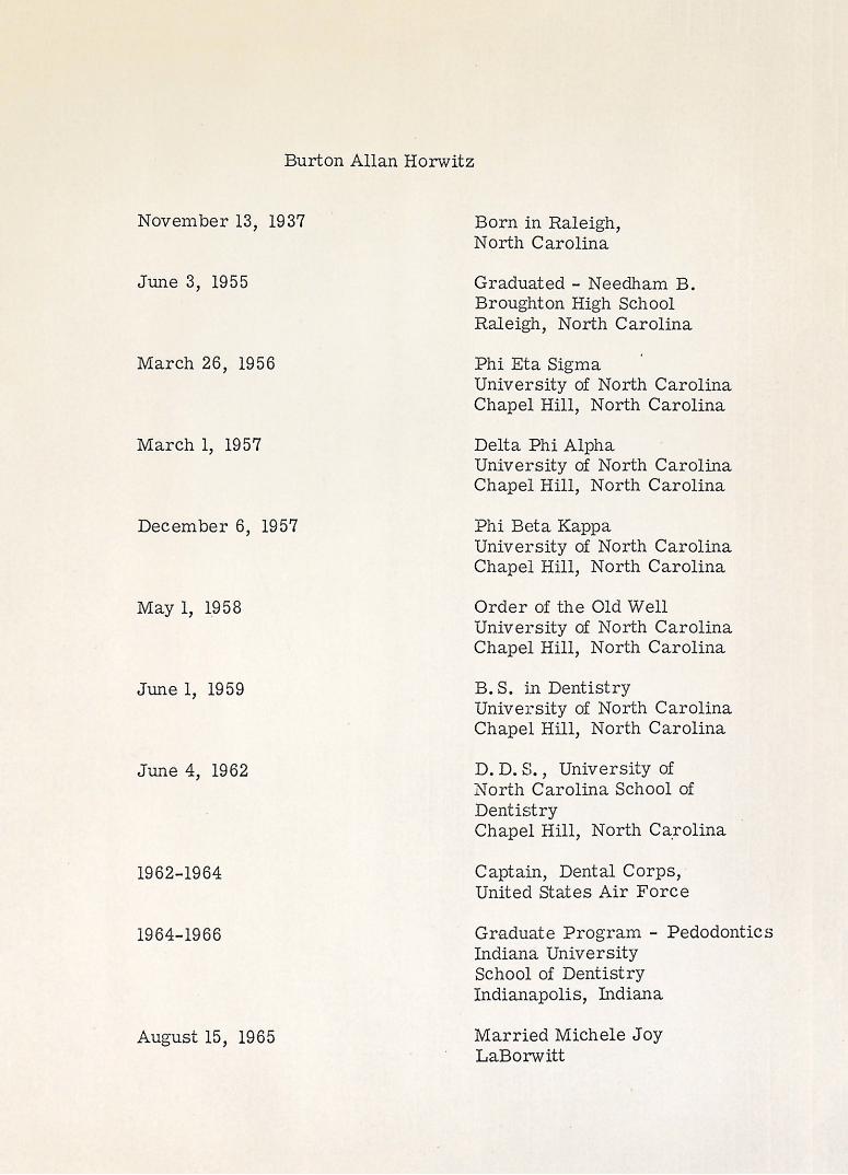
Burton Allan Horwitz
November 13, 1937
June 3, 1955
March 26, 1956
March I, 1957
December 6, 1957
May I, 1958
June I, 1959
June 4, 1962
1962-1964
1964-1966
Born in Raleigh, North Carolina
Graduated - Needham B. Broughton High School Raleigh, North Carolina
Phi Eta Sigma University of North Carolina Chapel Hill, North Carolina
Delta Phi Alpha University of North Carolina Chapel Hill, North Carolina
Phi Beta Kappa University of North Carolina Chapel Hill, North Carolina
Order of the Old Well University of North Carolina Chapel Hill, North Carolina
B.S. jn Dentistry University of North Carolina Chapel Hill, North Carolina
D. D. S. , University of North Carolina School of Dentistry Chapel Hill, North Ca.rolina
Captain, Dental Corps, United States Air Force
Graduate Program - Pedodontics Indiana University School of Dentistry Indianapolis, Indiana
August 15, 1965 Married Michele Joy LaBorwitt
Professional Societies:
The American Dental Association
The American Society of Dentistry for Children
Alpha Omega Professional Dental Fraternity

ABSTRACT
THE INTRAORAL TELEVISION MICROMEASUREMENT OF CAVITY MARGIN DETERIORATION by Burton Allan Horwitz
The purpose of this study was to demonstrate
the clinical application of the television micro
scope for direct intraoral micromeasurement of
cavity margin deterioration. Mesiocclusal alloy
restorations were placed in fif t y-one maxillary
second deciduous molars. A cas t gold overlay
with two proximal 1nargin o b servation holes, one
hole in the occlusal one-third and one hole in the
gingival one-third, was fabricated for each re
stored tooth. The mesiobuccal proxima l margins
of the restorations were observed by th e t elevision
microscope, and the marginal deterioration was
electronically measured at intervals of one week,
two weeks, four weeks, 12 weeks, 24 weeks, and
36 weeks postopera t ively. The average gingival
marginal deteriora t ion ranged fr o m 4. 9 mi crons at
one week to 37. 8 microns at 36 weeks; th e average
occlusal marginal deterioration ranged from 5. 4
microns at one week to 60.1 microns at 36 weeks.
The data indica t ed t ha t t he gingival area of t he
proximal margin d eteriorated at a faster r a t e
d u r in g t h e f i r s t 1 2 w e e k s p o s t o· p e r at i v e l y , and t h e
occlusal area of the gingival margin deteriora t ed at
a faster rate during the last 24 weeks. Greater
marginal alloy flash in the gingival area was
believed to be responsible for the initial
gingival deterioration, and repeated masticat ory
stresses was believed to be major causative factor
for the occlusal deterioration during the last
2 4 w e e k s of, t h e s t u d y 0
Copyright © 2022 FDOKUMEN