Antennas for Intraoral Tongue Drive System at 2.4 GHz - IEEE ...
11
1 Antennas for Intraoral Tongue Drive System at 2.4 GHz: Design, Characterization, and Comparison Fanpeng Kong, student member, IEEE, Cheng Qi, Hoseon Lee, Gregory D. Durgin, Senior Member, IEEE, and Maysam Ghovanloo, Senior Member, IEEE Abstract—The intraoral Tongue Drive System (iTDS), is a tongue-controlled wireless assistive technology (AT), operated by a number of user-defined voluntary tongue gestures to issue control commands. In this paper we present a new arch-shaped iTDS, occupying the buccal shelf space in the mouth, without limiting the available space for tongue motions. We describe the design, characterization, and comparison between three types of 2.4 GHz antennas for this system: patch, dipole, and planar inverted-F in terms of gain, directivity, bandwidth, and data communication performance to achieve a robust RF link despite mouth motions. The antennas are designed and simulated in a simple human mouth model and measured in the mouth. Based on simulation and measurement results, using an iTDS prototype made of commercial off-the-shelf components, the patch antenna has the highest gain in both closed- and open-mouth states, at -10.6 dBi and -9 dBi, respectively. We also measured the propagation loss between the iTDS intraoral antenna and out- of-mouth receiver in a real user-case scenario and evaluated the link quality by measuring the package error rate between the transmitter and receiver. The presented antennas have larger bandwidth, smaller area, and higher gain compared to prior work on implantable antennas in the literature, resulting in a robust wireless link for the iTDS application. Index Terms— Assistive technology, intraoral antennas, industrial-scientific-medical (ISM) band, package error rate, propagation link, Tongue Drive System. I. I NTRODUCTION A CROSS the United Sates, nearly 1 in 5 people live with paralysis during their lifetime, of which 29% is caused by stroke, 23% by spinal cord injury (SCI), and 17% by multiple sclerosis [1]. To improve the quality of life of these and other people with severe physical disabilities and enhance their independence, engineers have developed various assistive technologies (ATs) [2]-[7]. ATs help those with disabilities to regain some level of mobility and physical function. However, the choices are quite limited as many ATs do not provide suf- ficient flexibility for the patients or they require frequent care- givers’ assistance. Others are not sufficiently robust, intuitive, or compatible with various environments. For example, the EEG-based brain-computer interfaces (BCIs) are suitable for people who have severe paralysis [8], but they are difficult to Manuscript received xxx, 2017; revised .... This work was supported by the National Science Foundation under Awards 1264624. Fanpeng Kong and Maysam Ghovanloo ∗ are with the GT-Bionics lab, School of Electrical and Computer Engineering at the Georgia Institute of Technology, Atlanta, GA 30308, USA ( ∗ corresponding author: phone: 404- 385-7048; fax: 404-894-4701, email: [email protected]) Hoseon Lee is with Department of Electrical Engineering at Kennesaw State University, Kennesaw, GA, 30144. Cheng Qi and Gregory D. Durgin are with the School of Electrical and Computer Engineering at the Georgia Institute of Technology, Atlanta, GA 30332, USA. wear and setup [9] and susceptible to motion artifacts, making them inappropriate for outdoor environments. Another group of ATs operate with electromyography (EMG) signals. The EMG-controlled switches provide users with computer access [4], [10], but they are limited by the number of commands and muscle fatigue in long-term operation [11]. The speech recognition system is a popular AT now presenting on almost every computer and smartphone. Even though people with disabilities can issue simple commands and type efficiently using this technology in a quiet environment [12], it cannot provide efficient cursor control and it is not reliable enough for wheelchair navigation because of being sensitive to noise and not operating well in outdoor environments [13], [14]. To address these problems, we have developed the Tongue Drive System (TDS) to tap into the inherent abilities of the human tongue together with added system robustness, simplicity, and high flexibility through customized tongue command definition [15], [16]. TDS allows users to employ a set of unique tongue gestures to issue a set of user-defined commands for accessing computers, navigating wheelchairs, and controlling their environment. A small permanent mag- netic tracer, the size of a lentil, is affixed near the tip of the tongue, via tissue adhesives, implantation, or tongue piercing, to generate a magnetic field pattern for each tongue gesture [17]. This magnetic signature is recorded by an array of magnetic sensors inside the mouth or near the cheeks on the outside and wirelessly delivered to a processing unit that runs a real-time pattern recognition algorithm to infer the user’s intended command [18]. Tongue and oral muscles have a strong representation in the human motor cortex, which results in sophisticated motor control needed for speech and ingestion with many degrees of freedom [19]. The tongue is directly connected to the brain through the hypoglossal nerve, which often escapes SCIs and major neurological diseases [20]. Therefore, a tongue-operated AT can offer broad coverage among people with severe physical disabilities, who can move their tongues without difficulty. In addition, unlike the brain, the tongue is easily accessible without any surgical procedure, and being hidden inside the mouth offers the end users an intraoral AT with a certain degree of privacy [21]. Several versions of the TDS have been developed, including external TDS (eTDS) [15], multi-model TDS (mTDS) [22], and intraoral TDS (iTDS) [23], [24]. The eTDS has even been evaluated clinically, with the results presented in [16]. The iTDS has no externally worn component, such as a headset, and provides its users the highest level of mechanical stability and privacy [25]. However, like most dental retainers, Digital Object Identifier: 10.1109/TMTT.2018.2787118 1557-9670 c 2018 IEEE. Personal use is permitted, but republication/redistribution requires IEEE permission. See http://www.ieee.org/publications standards/publications/rights/index.html for more information.
-
Upload
khangminh22 -
Category
Documents
-
view
0 -
download
0
Transcript of Antennas for Intraoral Tongue Drive System at 2.4 GHz - IEEE ...

1
Antennas for Intraoral Tongue Drive System at 2.4
GHz: Design, Characterization, and ComparisonFanpeng Kong, student member, IEEE, Cheng Qi, Hoseon Lee, Gregory D. Durgin, Senior Member, IEEE, and
Maysam Ghovanloo, Senior Member, IEEE
Abstract— The intraoral Tongue Drive System (iTDS), is atongue-controlled wireless assistive technology (AT), operated bya number of user-defined voluntary tongue gestures to issuecontrol commands. In this paper we present a new arch-shapediTDS, occupying the buccal shelf space in the mouth, withoutlimiting the available space for tongue motions. We describe thedesign, characterization, and comparison between three types of2.4 GHz antennas for this system: patch, dipole, and planarinverted-F in terms of gain, directivity, bandwidth, and datacommunication performance to achieve a robust RF link despitemouth motions. The antennas are designed and simulated in asimple human mouth model and measured in the mouth. Basedon simulation and measurement results, using an iTDS prototypemade of commercial off-the-shelf components, the patch antennahas the highest gain in both closed- and open-mouth states,at −10.6 dBi and −9 dBi, respectively. We also measured thepropagation loss between the iTDS intraoral antenna and out-of-mouth receiver in a real user-case scenario and evaluated thelink quality by measuring the package error rate between thetransmitter and receiver. The presented antennas have largerbandwidth, smaller area, and higher gain compared to priorwork on implantable antennas in the literature, resulting in arobust wireless link for the iTDS application.
Index Terms— Assistive technology, intraoral antennas,industrial-scientific-medical (ISM) band, package error rate,propagation link, Tongue Drive System.
I. INTRODUCTION
ACROSS the United Sates, nearly 1 in 5 people live with
paralysis during their lifetime, of which 29% is caused
by stroke, 23% by spinal cord injury (SCI), and 17% by
multiple sclerosis [1]. To improve the quality of life of these
and other people with severe physical disabilities and enhance
their independence, engineers have developed various assistive
technologies (ATs) [2]-[7]. ATs help those with disabilities to
regain some level of mobility and physical function. However,
the choices are quite limited as many ATs do not provide suf-
ficient flexibility for the patients or they require frequent care-
givers’ assistance. Others are not sufficiently robust, intuitive,
or compatible with various environments. For example, the
EEG-based brain-computer interfaces (BCIs) are suitable for
people who have severe paralysis [8], but they are difficult to
Manuscript received xxx, 2017; revised . . .. This work was supported bythe National Science Foundation under Awards 1264624.
Fanpeng Kong and Maysam Ghovanloo∗ are with the GT-Bionics lab,School of Electrical and Computer Engineering at the Georgia Institute ofTechnology, Atlanta, GA 30308, USA (∗corresponding author: phone: 404-385-7048; fax: 404-894-4701, email: [email protected])
Hoseon Lee is with Department of Electrical Engineering at Kennesaw StateUniversity, Kennesaw, GA, 30144.
Cheng Qi and Gregory D. Durgin are with the School of Electrical andComputer Engineering at the Georgia Institute of Technology, Atlanta, GA30332, USA.
wear and setup [9] and susceptible to motion artifacts, making
them inappropriate for outdoor environments. Another group
of ATs operate with electromyography (EMG) signals. The
EMG-controlled switches provide users with computer access
[4], [10], but they are limited by the number of commands
and muscle fatigue in long-term operation [11]. The speech
recognition system is a popular AT now presenting on almost
every computer and smartphone. Even though people with
disabilities can issue simple commands and type efficiently
using this technology in a quiet environment [12], it cannot
provide efficient cursor control and it is not reliable enough
for wheelchair navigation because of being sensitive to noise
and not operating well in outdoor environments [13], [14].
To address these problems, we have developed the Tongue
Drive System (TDS) to tap into the inherent abilities of
the human tongue together with added system robustness,
simplicity, and high flexibility through customized tongue
command definition [15], [16]. TDS allows users to employ
a set of unique tongue gestures to issue a set of user-defined
commands for accessing computers, navigating wheelchairs,
and controlling their environment. A small permanent mag-
netic tracer, the size of a lentil, is affixed near the tip of the
tongue, via tissue adhesives, implantation, or tongue piercing,
to generate a magnetic field pattern for each tongue gesture
[17]. This magnetic signature is recorded by an array of
magnetic sensors inside the mouth or near the cheeks on the
outside and wirelessly delivered to a processing unit that runs
a real-time pattern recognition algorithm to infer the user’s
intended command [18].
Tongue and oral muscles have a strong representation in
the human motor cortex, which results in sophisticated motor
control needed for speech and ingestion with many degrees of
freedom [19]. The tongue is directly connected to the brain
through the hypoglossal nerve, which often escapes SCIs and
major neurological diseases [20]. Therefore, a tongue-operated
AT can offer broad coverage among people with severe
physical disabilities, who can move their tongues without
difficulty. In addition, unlike the brain, the tongue is easily
accessible without any surgical procedure, and being hidden
inside the mouth offers the end users an intraoral AT with a
certain degree of privacy [21].
Several versions of the TDS have been developed, including
external TDS (eTDS) [15], multi-model TDS (mTDS) [22],
and intraoral TDS (iTDS) [23], [24]. The eTDS has even
been evaluated clinically, with the results presented in [16].
The iTDS has no externally worn component, such as a
headset, and provides its users the highest level of mechanical
stability and privacy [25]. However, like most dental retainers,
Digital Object Identifier: 10.1109/TMTT.2018.2787118
1557-9670 c© 2018 IEEE. Personal use is permitted, but republication/redistribution requires IEEE permission.See http://www.ieee.org/publications standards/publications/rights/index.html for more information.

2
Fig. 1. Two versions of the iTDS: (a) iTDS-p, located at the palate place;and (b) iTDS-a, located at the buccal shelf place.
it should be customized based on the user’s oral anatomy
for maximum comfort level. Two different shapes have been
considered for the iTDS so far; the iTDS-p in the form of a
palatal retainer (Fig. 1a) [23], and the iTDS-a in the form of
an arch-shaped retainer (Fig. 1b) [24]. Even though iTDS-p
is simpler to construct, has been adopted for prior intraoral
ATs [26], [27], and offers more space for the electronics
and battery, iTDS-a has the advantage of not occupying the
intraoral space, where the tongue moves, thus providing the
user more freedom to issue tongue commands. Therefore,
iTDS-a is our preferred shape for which we have designed and
analyzed antennas in this study. The new iTDS-a prototype is
built using commercial off-the-shelf components (COTS) that
are located in the buccal shelf space of the mouth.
The intraoral device presented in [27] uses wires to send
information which are inconvenient and unattractive to users.
Therefore, one of the important design considerations for the
iTDS is wireless communication from inside the mouth to
the outside receiver (Rx). However, the design of wireless
communication for intraoral devices is challenging because
the mouth absorbs power in the high radio frequency (RF)
range, de-tunes antennas, and has a dynamically changing
environment because of the varying jaw and tongue positions.
Normally, basic wireless communication methods for intraoral
devices can be adopted from wearable and implantable medical
devices (IMD), such as short-range RF and body channel
communication (BCC) [28]. Because BCC requires special
operating conditions that have been discussed in [28], and is
not as reliable, RF communication is the preferred method for
the iTDS. Since most the intraoral devices use commercialized
transceivers that operate at 2.4 GHz, a critical component
is the antenna, which needs to be small and also address
the changing environment of the mouth with additional loss
imposed by the surrounding tissue.
In [29] and [30] the authors have presented a dipole antenna
for intraoral devices and discussed its propagation characteris-
tics, respectively. However, their discussions are devoid of any
system implementation. Furthermore, several studies include
wireless intraoral devices [31]-[35], but none of them provide
detailed antenna designs or evaluate the wireless communi-
Fig. 2. System block diagram of the iTDS, including the printed circuitboards and the universal user interface
Fig. 3. iTDS system prototype with a control board, a supply board, and aUSB dongle.
cation aspect of the systems. In particular, communication
robustness and radiative performance are unclear. A number
of articles focus on implantable antenna design [36]-[39].
However, the gain of most implantable antennas is small and
insufficient for intraoral applications.
Previously, we studied the performance of COTS antennas
in three operating frequencies, 27 MHz, 432 MHz, and 2.48
GHz for the iTDS-p [28]. Those antennas were not designed
for intraoral application and suffered from impedance mis-
match and small gain. Furthermore, we designed a planar
inverted-F antenna (PIFA) that works at 432 MHz for an earlier
version of iTDS-a [24]. However, the antenna was not fully
characterized and had a low radiation efficiency.
In this paper, to ensure robust wireless communication for
iTDS-a, we have designed three types of 2.4 GHz antennas: a
patch antenna, a dipole antenna, and a PIFA with proper size
for operation inside the mouth. We have characterized these
antennas and tested their robustness within an actual iTDS-a
prototype. Section II describes the implementation of iTDS-a,
including the transmitter (Tx) and receiver (Rx). Section III
presents the three antenna designs using a simple human tissue
model. Section IV illustrates the antenna measurement set up
and the results of antenna measurements inside the mouth.
Section V shows the radiation performance of the system with
3
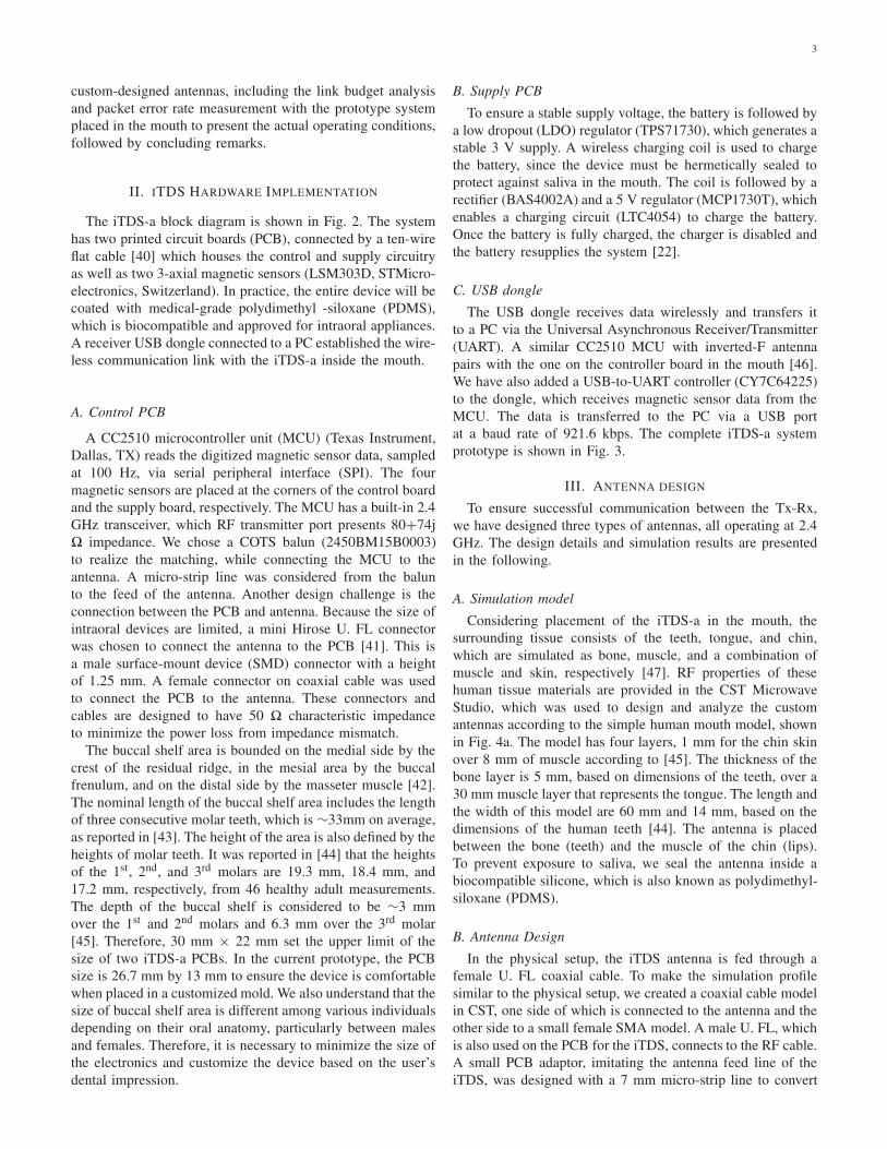
custom-designed antennas, including the link budget analysis
and packet error rate measurement with the prototype system
placed in the mouth to present the actual operating conditions,
followed by concluding remarks.
II. ITDS HARDWARE IMPLEMENTATION
The iTDS-a block diagram is shown in Fig. 2. The system
has two printed circuit boards (PCB), connected by a ten-wire
flat cable [40] which houses the control and supply circuitry
as well as two 3-axial magnetic sensors (LSM303D, STMicro-
electronics, Switzerland). In practice, the entire device will be
coated with medical-grade polydimethyl -siloxane (PDMS),
which is biocompatible and approved for intraoral appliances.
A receiver USB dongle connected to a PC established the wire-
less communication link with the iTDS-a inside the mouth.
A. Control PCB
A CC2510 microcontroller unit (MCU) (Texas Instrument,
Dallas, TX) reads the digitized magnetic sensor data, sampled
at 100 Hz, via serial peripheral interface (SPI). The four
magnetic sensors are placed at the corners of the control board
and the supply board, respectively. The MCU has a built-in 2.4
GHz transceiver, which RF transmitter port presents 80+74j
� impedance. We chose a COTS balun (2450BM15B0003)
to realize the matching, while connecting the MCU to the
antenna. A micro-strip line was considered from the balun
to the feed of the antenna. Another design challenge is the
connection between the PCB and antenna. Because the size of
intraoral devices are limited, a mini Hirose U. FL connector
was chosen to connect the antenna to the PCB [41]. This is
a male surface-mount device (SMD) connector with a height
of 1.25 mm. A female connector on coaxial cable was used
to connect the PCB to the antenna. These connectors and
cables are designed to have 50 � characteristic impedance
to minimize the power loss from impedance mismatch.
The buccal shelf area is bounded on the medial side by the
crest of the residual ridge, in the mesial area by the buccal
frenulum, and on the distal side by the masseter muscle [42].
The nominal length of the buccal shelf area includes the length
of three consecutive molar teeth, which is ∼33mm on average,
as reported in [43]. The height of the area is also defined by the
heights of molar teeth. It was reported in [44] that the heights
of the 1st, 2nd, and 3rd molars are 19.3 mm, 18.4 mm, and
17.2 mm, respectively, from 46 healthy adult measurements.
The depth of the buccal shelf is considered to be ∼3 mm
over the 1st and 2nd molars and 6.3 mm over the 3rd molar
[45]. Therefore, 30 mm × 22 mm set the upper limit of the
size of two iTDS-a PCBs. In the current prototype, the PCB
size is 26.7 mm by 13 mm to ensure the device is comfortable
when placed in a customized mold. We also understand that the
size of buccal shelf area is different among various individuals
depending on their oral anatomy, particularly between males
and females. Therefore, it is necessary to minimize the size of
the electronics and customize the device based on the user’s
dental impression.
B. Supply PCB
To ensure a stable supply voltage, the battery is followed by
a low dropout (LDO) regulator (TPS71730), which generates a
stable 3 V supply. A wireless charging coil is used to charge
the battery, since the device must be hermetically sealed to
protect against saliva in the mouth. The coil is followed by a
rectifier (BAS4002A) and a 5 V regulator (MCP1730T), which
enables a charging circuit (LTC4054) to charge the battery.
Once the battery is fully charged, the charger is disabled and
the battery resupplies the system [22].
C. USB dongle
The USB dongle receives data wirelessly and transfers it
to a PC via the Universal Asynchronous Receiver/Transmitter
(UART). A similar CC2510 MCU with inverted-F antenna
pairs with the one on the controller board in the mouth [46].
We have also added a USB-to-UART controller (CY7C64225)
to the dongle, which receives magnetic sensor data from the
MCU. The data is transferred to the PC via a USB port
at a baud rate of 921.6 kbps. The complete iTDS-a system
prototype is shown in Fig. 3.
III. ANTENNA DESIGN
To ensure successful communication between the Tx-Rx,
we have designed three types of antennas, all operating at 2.4
GHz. The design details and simulation results are presented
in the following.
A. Simulation model
Considering placement of the iTDS-a in the mouth, the
surrounding tissue consists of the teeth, tongue, and chin,
which are simulated as bone, muscle, and a combination of
muscle and skin, respectively [47]. RF properties of these
human tissue materials are provided in the CST Microwave
Studio, which was used to design and analyze the custom
antennas according to the simple human mouth model, shown
in Fig. 4a. The model has four layers, 1 mm for the chin skin
over 8 mm of muscle according to [45]. The thickness of the
bone layer is 5 mm, based on dimensions of the teeth, over a
30 mm muscle layer that represents the tongue. The length and
the width of this model are 60 mm and 14 mm, based on the
dimensions of the human teeth [44]. The antenna is placed
between the bone (teeth) and the muscle of the chin (lips).
To prevent exposure to saliva, we seal the antenna inside a
biocompatible silicone, which is also known as polydimethyl-
siloxane (PDMS).
B. Antenna Design
In the physical setup, the iTDS antenna is fed through a
female U. FL coaxial cable. To make the simulation profile
similar to the physical setup, we created a coaxial cable model
in CST, one side of which is connected to the antenna and the
other side to a small female SMA model. A male U. FL, which
is also used on the PCB for the iTDS, connects to the RF cable.
A small PCB adaptor, imitating the antenna feed line of the
iTDS, was designed with a 7 mm micro-strip line to convert

4
Fig. 4. (a) Simple four-layer geometry of the human closed mouth modelfor the antenna design. (b) Simple four-layer geometry of the human openmouth model of the antenna design. (c) Simulation components used in CST.
the male U. FL to a regular SMA connector, which connects to
the Vector Network Analyzer (VNA) for measurements. The
micro- strip line in the PCB adaptor is also modeled in the
CST PCB studio to ensure that it has 50 � impedance at 2.4
GHz. All of these structures are included in the model, as
shown in Fig. 4c, and simulated in CST.
The design procedure has three steps: 1) the antenna is
optimized in the air for 2.4 GHz with the feed components,
which are a coaxial cable, SMA, and adaptor PCB. 2) PDMS
material is added on the coaxial cable and antennas in the
model, and the antenna is re-tuned to resonate at 2.4 GHz. 3)
the antenna with PDMS coating is placed within the mouth
model in Fig. 4a and re-optimized at 2.4 GHz. Finally, we
compare the simulation and measurement results.
We used Roger 3003 (Rogers Corporation, Rogers, CT),
which has electrical permittivity of εr = 3.0, as a flexible
substrate material with 0.75 mm thickness [48]. The width
of the antenna needs to be less than 19 mm, and the length
is defined according to oral anatomy. The backside of the
substrate was used as a ground plane for the patch antenna.
The antenna was placed in the center of the substrate to
reduce the coupling effect between the antenna and the ground
plane. The geometry of the patch antenna on the top layer
of the substrate is shown in Fig 5a. A feed line at the
center is inserted into the antenna. The antenna impedance
is controlled by the width and depth of the feed line. Due to
the space limitation in the retainer, a traditional patch antenna
cannot easily fit inside the mouth. Instead, an alongated patch
Fig. 5. Top view of the three types of antennas: (a) the patch antenna, (b)PIFA, and (c) the dipole antenna.
TABLE I
KEY PARAMETERS OF THREE CUSTOM-DESIGNED ANTENNAS
antenna has been designed based on [49], [50]. The operating
frequency, f of a patch antenna in a homogeneous medium can
be found from [51]. However, the antenna is surrounded by
high-permittivity, conductive human tissue, which decreases
the effective length of the antenna. Therefore, the actual
resonance frequency differs from the one predicted in [51]. To
design the patch antenna in human tissue, we first optimized
the length of the antenna to reach the desired frequency. Then,
the width and the depth of the feed line into the antenna
needed to be optimized. By changing these parameters, the
antenna with S11 parameter less than −10 dB at 2.4 GHz was
designed. Table I summarizes the dimensions of the patch and
other antennas.
The PIFA antenna has a structure similar to the patch
antenna on the same substrate material, with a smaller size
as it is operating at a quarter wavelength. The geometry of
the PIFA antenna is presented in Fig. 5b, which is achieved
by following a design procedure similar to that of the patch
antenna. However, we directly use a probe to feed the PIFA
antenna instead of a feed line. Another component of the
PIFA is the shorting pin, which is placed on the corner of the
antenna, with 0.5 mm in diameter. Compared to the length
and width of the PIFA antenna, the size of the shorting pin is
negligible. Therefore, the resonant frequency depends on the
width and the length of the antenna, which are optimized to
operate at 2.4 GHz. The impedance of the PIFA is controlled
5
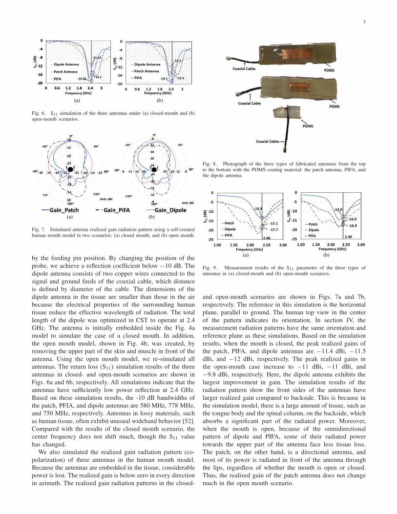
Fig. 6. S11 simulation of the three antennas under (a) closed-mouth and (b)open-mouth scenarios.
Fig. 7. Simulated antenna realized gain radiation pattern using a self-createdhuman mouth model in two scenarios: (a) closed mouth, and (b) open mouth.
by the feeding pin position. By changing the position of the
probe, we achieve a reflection coefficient below −10 dB. The
dipole antenna consists of two copper wires connected to the
signal and ground feeds of the coaxial cable, which distance
is defined by diameter of the cable. The dimensions of the
dipole antenna in the tissue are smaller than those in the air
because the electrical properties of the surrounding human
tissue reduce the effective wavelength of radiation. The total
length of the dipole was optimized in CST to operate at 2.4
GHz. The antenna is initially embedded inside the Fig. 4a
model to simulate the case of a closed mouth. In addition,
the open mouth model, shown in Fig. 4b, was created, by
removing the upper part of the skin and muscle in front of the
antenna. Using the open mouth model, we re-simulated all
antennas. The return loss (S11) simulation results of the three
antennas in closed- and open-mouth scenarios are shown in
Figs. 6a and 6b, respectively. All simulations indicate that the
antennas have sufficiently low power reflection at 2.4 GHz.
Based on these simulation results, the -10 dB bandwidths of
the patch, PFIA, and dipole antennas are 580 MHz, 778 MHz,
and 750 MHz, respectively. Antennas in lossy materials, such
as human tissue, often exhibit unusual wideband behavior [52].
Compared with the results of the closed mouth scenario, the
center frequency does not shift much, though the S11 value
has changed.
We also simulated the realized gain radiation pattern (co-
polarization) of three antennas in the human mouth model.
Because the antennas are embedded in the tissue, considerable
power is lost. The realized gain is below zero in every direction
in azimuth. The realized gain radiation patterns in the closed-
Fig. 8. Photograph of the three types of fabricated antennas from the topto the bottom with the PDMS coating material: the patch antenna, PIFA, andthe dipole antenna.
Fig. 9. Measurement results of the S11 parameter of the three types ofantennas in (a) closed-mouth and (b) open-mouth scenarios.
and open-mouth scenarios are shown in Figs. 7a and 7b,
respectively. The reference in this simulation is the horizontal
plane, parallel to ground. The human top view in the center
of the pattern indicates its orientation. In section IV, the
measurement radiation patterns have the same orientation and
reference plane as these simulations. Based on the simulation
results, when the mouth is closed, the peak realized gains of
the patch, PIFA, and dipole antennas are −11.4 dBi, −11.5
dBi, and −12 dBi, respectively. The peak realized gains in
the open-mouth case increase to −11 dBi, −11 dBi, and
−9.8 dBi, respectively. Here, the dipole antenna exhibits the
largest improvement in gain. The simulation results of the
radiation pattern show the front sides of the antennas have
larger realized gain compared to backside. This is because in
the simulation model, there is a large amount of tissue, such as
the tongue body and the spinal column, on the backside, which
absorbs a significant part of the radiated power. Moreover,
when the mouth is open, because of the omnidirectional
pattern of dipole and PIFA, some of their radiated power
towards the upper part of the antenna face less tissue loss.
The patch, on the other hand, is a directional antenna, and
most of its power is radiated in front of the antenna through
the lips, regardless of whether the mouth is open or closed.
Thus, the realized gain of the patch antenna does not change
much in the open mouth scenario.
6
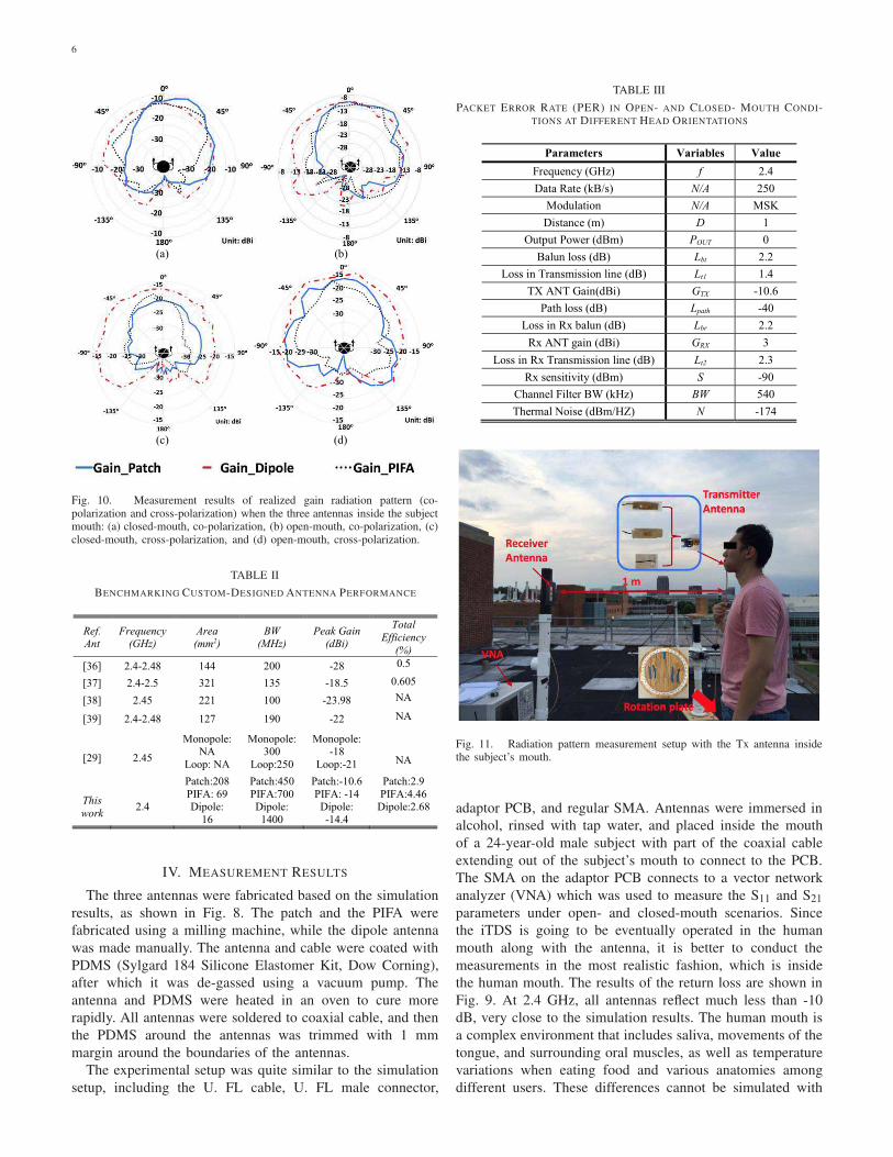
Fig. 10. Measurement results of realized gain radiation pattern (co-polarization and cross-polarization) when the three antennas inside the subjectmouth: (a) closed-mouth, co-polarization, (b) open-mouth, co-polarization, (c)closed-mouth, cross-polarization, and (d) open-mouth, cross-polarization.
TABLE II
BENCHMARKING CUSTOM-DESIGNED ANTENNA PERFORMANCE
IV. MEASUREMENT RESULTS
The three antennas were fabricated based on the simulation
results, as shown in Fig. 8. The patch and the PIFA were
fabricated using a milling machine, while the dipole antenna
was made manually. The antenna and cable were coated with
PDMS (Sylgard 184 Silicone Elastomer Kit, Dow Corning),
after which it was de-gassed using a vacuum pump. The
antenna and PDMS were heated in an oven to cure more
rapidly. All antennas were soldered to coaxial cable, and then
the PDMS around the antennas was trimmed with 1 mm
margin around the boundaries of the antennas.
The experimental setup was quite similar to the simulation
setup, including the U. FL cable, U. FL male connector,
TABLE III
PACKET ERROR RATE (PER) IN OPEN- AND CLOSED- MOUTH CONDI-TIONS AT DIFFERENT HEAD ORIENTATIONS
Fig. 11. Radiation pattern measurement setup with the Tx antenna insidethe subject’s mouth.
adaptor PCB, and regular SMA. Antennas were immersed in
alcohol, rinsed with tap water, and placed inside the mouth
of a 24-year-old male subject with part of the coaxial cable
extending out of the subject’s mouth to connect to the PCB.
The SMA on the adaptor PCB connects to a vector network
analyzer (VNA) which was used to measure the S11 and S21
parameters under open- and closed-mouth scenarios. Since
the iTDS is going to be eventually operated in the human
mouth along with the antenna, it is better to conduct the
measurements in the most realistic fashion, which is inside
the human mouth. The results of the return loss are shown in
Fig. 9. At 2.4 GHz, all antennas reflect much less than -10
dB, very close to the simulation results. The human mouth is
a complex environment that includes saliva, movements of the
tongue, and surrounding oral muscles, as well as temperature
variations when eating food and various anatomies among
different users. These differences cannot be simulated with

7
high accuracy in a software model. It can be seen that in the
measurements, the center resonance frequencies have slightly
shifted to lower frequencies compared to the simulations.
To measure the radiation pattern and realized gain of these
antennas, the subject stood on a rotating plate, with the Tx
antenna in his mouth. The Rx antenna was an E-shape patch
antenna, described in [52]. At 2.4 GHz, the E-patch antenna
has 6 dBi gain and relatively large bandwidth. Moreover, it has
been well-characterized at 2.4 GHz, similar to other reference
antennas in the laboratory environment. The Rx antenna was
placed in front of the subject, 1 m away from the Tx. The Tx
and Rx antennas were connected to VNA ports, and the subject
was rotated 10° at a time, while S21 measurements were
recorded manually for a complete 360° rotation. To eliminate
multi-path effects, which are caused by the indoor subjects
that can absorb or reflect radio waves, the experiment was con-
ducted in a calibrated rooftop antenna range. If present, multi-
path effects will cause multipath fading, resulting in reduced
signal strength and antenna measurement errors. However, in
our application, the multi-path effects cannot be eliminated.
To overcome the possibility of the reduction of the signal
strength, resulting from the multi-path effects, we can adjust
the output power from the microcontroller accordingly. The
gain was solved using the Friis formula [51],
Pr = Pt + Gt + Gr − Ppath, (1)
where Pr and Pt represent the power received by the Rx
antenna and the power transmitter from the Tx antenna in
dB, respectively. Gr and Gt are the gains of the Rx and Tx
antennas, respectively. Ppath is the path loss in the free space,
which can be calculated from,
Ppath = 20 log10(d) + 20 log10( f ) + 20 log10(4π
c), (2)
where d is the distance, f represents the carrier frequency,
and c is the speed of light in vacuum. The VNA transmitted
power was fixed at 0 dBm. The Rx antenna gain is known, and
the received power, which is the S21 parameter, is measured
by the VNA. Therefore, the gain of the Tx antenna can be
found from (1).
We conducted realized gain radiation pattern (co-
polarization and cross-polarization) measurements under
closed- and open-mouth scenarios, with results shown in
Fig. 10, using the experimental setup in Fig. 11. In the co-
polarization scenario, the peak realized gains of the patch,
PIFA, and dipole antennas are -10.6 dBi, −14 dBi, and −14.4
dBi, respectively when the mouth is closed, and −9 dBi,
−11.1 dBi, and −9.8 dBi, when the mouth is open. In the
cross-polarization scenario, the peak realized gains of the
patch, PIFA, and dipole antennas are −21.6 dBi, −19.1 dBi,
and −16.2 dBi, respectively, when the mouth is closed, and
−17.1 dBi, −16.9 dBi and −15.2 dBi, when the mouth is
open. Based on the measurement results, the dipole antenna
experiences more de-polarization compared to patch antenna
and PIFA. This is likely because there is no ground plane
shielding the de-polarizing scattering structures in the head.
In the measurement, all of the proposed antennas show a
directional pattern because a large portion of muscle is at the
Fig. 12. Measurement setup for measuring the radiation pattern of theantennas with the iTDS inside the mouth.
backside of the antennas, which shields the antennas radiated
power. In Table II, these three antennas are compared with
other implantable and intraoral antennas in the literature. The
most important finding is that the patch antenna displays
the highest realized gain among these designs in the co-
polarization scenario. The PIFA and patch antennas employ
the same type of substrate, resulting in the similar εeff in both
antennas. However, the patch antenna has larger physical area
compared to PIFA, which contributes to its higher gain.
V. SYSTEM LEVEL EVALUATION OF THE ANTENNAS
The radiation pattern was measured at the system level
to realistically evaluate the antenna performance within the
iTDS-a. The measurement setup in Fig. 12 is similar to the
antenna radiation pattern measurement setup, but the antenna
is now embedded within the iTDS-a prototype and placed
inside the subject’s mouth. According to the antenna mea-
surement results, the proposed antennas are linearly polarized
in the mouth, therefore in this system, the Rx [46] and Tx
antennas are maintained in the same polarization. The Rx,
located 1 m away in front of the subject, was the USB dongle,
discussed in Section II. Both iTDS-a (Tx) and USB dongle
(Rx) were connected to a PC, running SmartRF Studio 7 (TI,
Dallas, TX) [54], via two CC debuggers (TI, Dallas, TX) [55].
On the SmartRF Studio 7, the transmission power, operating
frequency, data rate, and modulation scheme were set to 0
dBm, 2.4 GHz, 250 kpbs, and minimum-shift keying (MSK),
respectively. The subject was rotated 360° , 10o at a time.
The received power on the Rx side was recorded after the
power reading on SmartRF was stabilized. Sometimes the
received power reading had small fluctuations, in which case,
the average received power was recorded. The experiment was
repeated with both closed- and open-mouth conditions.
The antenna characterization section showed the realized
gain value in the radiation pattern of the antenna. The iTDS-

8
Fig. 13. Measured radiation patterns in closed- and open-mouth scenarios ofthe three antennas connected with the system inside the mouth: (a) the patchantenna, (b) the dipole antenna, and (c) PIFA.
a system radiation patterns, shown in Fig. 13, exhibit the
power received at the Rx. The shapes of the system level
radiation patterns are similar to those with antennas only.
Measurement results show that the USB dongle received more
power when the subject opened his mouth because of higher
antenna gain. Compared to the S21 measurements by VNA
when the antennas were characterized, the Rx received less
power because both Rx and Tx PCBs have power loss. In
particular, the Tx PCB is coated with PDMS and surrounded
by tissue, which also contribute to power loss. The antenna that
has a high gain in the front side of the mouth ensures enough
power can be delivered to the Rx, resulting in a high SNR and
low bit error rate (BER). The iTDS is meant to allow users
to issue commands to control their environment. Therefore,
reliability in safety critical tasks such as driving a powered
wheelchair is paramount, and we need to ensure system
robustness by maintaining a high SNR and very low BER.
Based on these results, the patch antenna in the system has
the highest gain in both closed- and open-mouth conditions.
TABLE IV
LINK BUDGET ANALYSIS FOR ITDS WITH PATCH ANTENNA (CLOSED
MOUTH)
Moreover, the radiation patterns in Fig. 13 show similar power
received by the dongle at 1 m Tx-Rx separation, compared to
[28] in which the Tx-Rx distance is only 22 cm. In addition,
a link budget analysis is also provided in the table IV.
We also measured the package error rate (PER) in SmartRF
Studio 7 at three different angles: 00, +900, and −900, for each
antenna, as an indicator of the system robustness. Random
packets, each containing 30 bytes, were generated by SmartRF
Studio 7 and transmitted to the Rx, where the SmartRF Studio
7 reads the incoming packets in real time, compares them with
the transmitted packets, and calculates the PER. We used the
same setup as in system radiation pattern measurement. In
addition, at every angle, the subject was asked to open and
close his mouth. 50,000 packets (1.2×107 bits) [28] were sent
and the PERs were recorded for every scenario. The results
are listed in the Table III, where the PER of the three antennas
are presented at three angles. These results show that the patch
antenna has the lowest PER among these three antennas, and
results in the most robust link for the iTDS-a, because of its
high gain.
The last step of the experiment was to test the complete
iTDS-a wireless data transmission functionality in a setup
similar to [28]. The subject placed the iTDS-a inside the
mouth, running a firmware that packetized the raw magnetic
sensor data from four 3-axial magnetic sensors in the CC2510
MCU, and send those packets to the USB dongle, connected
to a PC. The distance between the Rx dongle and iTDS-a
inside the mouth was 1 m, similar to the other measurements.
A custom user interface in LabVIEW was able to display the
raw data on the computer similar to the eTDS headset without
any noticeable data loss [22].
VI. CONCLUSION
We designed three types of antennas (patch, PIFA, and
dipole) at 2.4 GHz to establish a wireless link between an
iTDS-a inside the mouth and an external receiver implemented
as a USB dongle. The antenna performance was compered for
establishing the most robust connection. The antennas were
designed in CST using a simple human mouth model, and
fabricated on Roger substrate. Simulation and measurements
were conducted in similar conditions by placing the prototypes
inside a subject’s mouth. Measurement results showed that
the patch antenna has the highest gain in both closed- and
open-mouth conditions, with -10.6 dBi and -9 dBi received
9
power at 1 m Tx-Rx separation, respectively when it is co-
polarized. The dipole antenna, on the other hand, demonstrated
the widest bandwidth and best performance in the cross-
polarization scenario. To match the impedance of the antennas
where they connect to the PCB, mini-SMA and thin coaxial
cable were used with careful design of the RF traces on the
PCB. All custom-designed antennas were also tested within
the iTDS-a system in a realistic measurement setup, where
the transmitter antennas and receiver antenna maintain the
same polarization and the superiority of the patch antenna was
further confirmed by demonstrating the lowest PER measured
in the SmartRF Studio 7 environment.
We are plan to use the iTDS and its custom-designed
antenna in an able-bodied human subject trial to evaluate
the performance of the entire system before testing it by the
potential end users. Since the proposed antennas are linearly
polarized, a dual polarized Rx antenna will be considered for
the iTDS to improve the reliability of the system. Moreover,
an application-specific integrated circuit (ASIC) Tx [56] has
been designed to provide dynamic matching to compensate
part of the antenna mismatch that results from the movements
of the jaw and tongue. In addition, a procedure for fine-tune
the antennas for different users’ oral anatomies will be devised
and evaluated.
REFERENCES
[1] Model System Knowledge Translation Center, “SCI factsheetbooklet edition 3 final,” [Online document], 2016. Available:http://www.msktc.org/lib/docs/Booklet.
[2] R. Barea, L. Boquete, and M. Mazo, “System for assisted mobility usingeye movements based on electrooculography,” IEEE Trans. Neural Syst
Rehabil Eng., vol. 10, no. 4, pp. 209-218, Dec. 2002.[3] J. R. Wolpaw, N. Birbaumer, D. J. McFarland, G. Pfurtscheller, and T. M.
Vaughan, “Brain-computer interfaces for communication and control,”Clin. Neurophysiol, vol. 113, pp. 767–791, Jun. 2002.
[4] M. R.Williams and R. F. Kirsch, “Evaluation of head orientation andneck muscle EMG signals as command inputs to a human-computerinterface for individuals with high tetraplegia,” IEEE Trans. Neural Syst.
Rehabil. Eng., vol. 16, no. 5, pp. 485–496, Oct. 2008[5] Adaptive Switch Labs, Inc. [Online]. Available: http://www.asl-inc.
com/catalog.[6] NaturalPoint, Inc. [Online]. Available: http://www.naturalpoint.com/
smartnav.[7] Origin Instrument: Sip/Puff Switch [Online]. Available: http://www.
orin.com/access/sip_puff/index.htm[8] L. R. Hochberg et al., “Neuronal ensemble control of prosthetic devices
by a human with tetraplegia,” Nature, vol. 442, no. 7099, pp. 164–171,Jul. 2006.
[9] J. Donoghue, “Bridging the brain to the world: A perspective on neuralinterface systems,” Neuron, vol. 60, no. 3, pp. 511–521, Jul. 2008.
[10] C. Choi, S. Micera, J. Carpaneto, and J. Kim, “Development andquantitative performance evaluation of a noninvasive EMG computerinterface,” IEEE Trans. Biomed. Eng., vol. 56, no. 1, pp. 188–191, Jan.2009.
[11] M. R. Ahsan, M. I. Ibrahimy, and O. O. Khalifa, “EMG signal classi-fication for human computer interaction: A review,” Eur. J. Sci. Res.,vol. 33, no. 3, pp. 480–501, 2009.
[12] C. M. Karat, C. Halverson, D. Horn, and J. Karat, “Patterns of entry andcorrection in large vocabulary continuous speech recognition systems,”in Proc. SIGCHI Conf. Human Factors Comput. Syst., pp. 568–575,1999.
[13] S. Harada, J. A. Landay, J. Malkin, X. Li, and J. A. Bilmes, “The vocaljoystick: Evaluation of voice-based cursor control techniques,” in Proc.
Int. ACM SIGACCESS Conf. Comput. Accessibil., pp. 197–204, Oct.2006
[14] A. Acero, L. Deng, T. T. Kristjansson, and J. Zhang, “HMM adaptationusing vector Taylor series for noisy speech recognition,” in Proc.
INTERSPEECH, pp. 869–872, Oct. 2000.
[15] X. Huo, M. Ghovanloo, "Tongue Drive: a wireless tongue-operatedmeans for people with severe disabilities to communicate their inten-tions," IEEE Comm Mag, vol. 50, no. 10, pp. 128-135, Oct. 2012.
[16] J. Kim, H. Park, et al., “Tongue enables computer and wheelchair accessfor the people with high-level disabilities,” Sci Translat. Med, vol. 5,no.21 3, pp. 213ra166, Nov. 2013
[17] A. Laumann, J. Holbrook, J. Minocha, D. Rowles, B. Nardone, D. West,J. Kim, J. Bruce, E.J. Roth, and M. Ghovanloo, “Safety and efficacy ofmedically performed tongue piercing in people with tetraplegia for usewith tongue-operated assistive technology,” Topics in Spinal Cord Injury
Rehabilitation, vol. 21, no. 1, pp. 61-76, Feb. 2015.
[18] Y. Behnaz, X. Huo, and M. Ghovanloo. "Preliminary assessment ofTongue Drive System in medium term usage for computer access andwheelchair control." in Proc. IEEE 33rd Conf. Eng. Med. Biol. Soc., pp.5766–5769, Aug. 2011.
[19] E. R. Kandel, J. H. Schwartz, and T. M. Jessell, Principles of Neural
Science, 4th ed. New York: McGraw-Hill Medical, 2000.
[20] M. Liancai, and I. Sanders. "Human tongue neuroanatomy: nerve supplyand motor endplates." Clinical Anatomy, vol. 23, no. 7, pp. 777-791, Oct.2010.
[21] M. Ghovanloo, M.N. Sahadat, Z. Zhang, F. Kong, and N. Sebkhi,“Tapping into tongue motion to substitute of augment upper limbs,” inSPIE Defense+Security. International Society for Optics and Photonics,pp. 1019413-1019413, May. 2017.
[22] M. N. Sahadat, A. Alreja, P. Srikrishnan, and M. Ghovanloo, “A mul-timodal human computer interface combining head movement, speechand tongue motion for people with severe disabilities.” IEEE Biomed.
Circ. Sys. Conf., pp.1-4, Oct. 2015.
[23] H. Park, et al., "A wireless magnetoresistive sensing system for anintraoral tongue-computer interface." IEEE Trans. Biomed. Circuits
Syst., vol. 6, no. 6, pp. 571-585, Dec.2012.
[24] H. Park, and M. Ghovanloo. "An arch-shaped intraoral Tongue DriveSystem with built-in tongue-computer interfacing SoC." Sensors, vol14, no. 11, pp 21565-21587, Nov. 2014.
[25] T. J. Forlizzi, J. Goetz, J. Stroback, and C. Kurtz, “The ELDer project:Social and emotional factors in the design of eldercare technologies,” inProc. ACM Conf. Univ. Usability, pp. 72–79, Nov. 2000.
[26] M. Giraldi. "Independence day: Tongue-touch controls give Ben a moresatisfying self-sufficient lifestyle." Teamrehab Rep. Mag, pp. 1417, 1997.
[27] J. Daniel, C. Cipriani, D. B. Popovic, and L. N. S. A. Struijk "Control ofa robotic hand using a tongue control system-a prosthesis application."IEEE Trans. Biomed Eng., vol 63, no. 7, pp. 1368-1376, July 2016.
[28] H. Park, and M. Ghovanloo. "Wireless communication of intraoraldevices and its optimal frequency selection." IEEE Trans. Microw.
Theory Techn, vol. 62, no. 12, pp. 3205-3215, Dec. 2014.
[29] R. Chandra and A. J. Johansson, “In-mouth antenna for tongue con-trolled wireless devices: Characteristics and link-loss,” in Proc. IEEE
33rd Conf. Eng. Med. Biol. Soc., pp. 5598–5601, Aug. 2011.
[30] R. Chandra and A. J. Johansson. "Antennas and propagation for in-mouth tongue-controlled devices in wireless body area networks." IEEE
Antennas and Wireless Propag. Lett. vol. 14, pp. 1518-1521, Oct. 2014.
[31] Q. Peng and T. F. Budinger, “ZigBee-based wireless intra-oral controlsystem for quadriplegic patients,” in Proc. Int. Conf. Eng. Med. Bio.
Soc., pp. 1647–1650, Aug. 2007.
[32] C. Lau and S. O’Leary, “Comparison of computer interface devices forpersons with severe physical disabilities,” Amer. J. Occupat. Therapy,vol. 47, pp. 1022–1030, Nov. 1993.
[33] M. Kuribayashi, Y. Kitasako, K. Matin, A. Sadr, K. Shida, and J. Tagami,“Intraoral pH measurement of carious lesions with qPCR of cariogenicbacteria to differentiate caries activity,” J. Dentistry, vol. 40, pp. 222–228, Dec. 2011.
[34] L. N. S. A. Struijk, E. R. Lontisand, B. Bentsen, H. V. Christensen, H. A.Caltenco, and M. E. Lund, “Fully integrated wireless inductive tonguecomputer interface for disabled people,” in Proc. IEEE 31st Conf. Eng.
Med. Biol. Soc., pp. 547–550, Sep. 2009,
[35] H. Park, J. Kim, and M. Ghovanloo, “Development and preliminaryevaluation of an intraoral Tongue Drive System,” in Proc. IEEE 34th
Conf. Eng. Med. Biol. Soc., pp. 1157–1160, Aug. 2012.
[36] Z. Yang and S. Xiao. "A single-fed miniaturized circularly polarizedimplantable antenna for ISM band biomedical application." in Proc.
IEEE MTT-S int. Microw. Workshop., Oct. 2016
[37] M. Francesco, L. Bolomey, and J. Zurcher, "Design, realization andmeasurements of a miniature antenna for implantable wireless commu-nication systems." IEEE Trans. Antenna Propag. vol 59, no. 10, pp.3544-3555, Oct. 2011.
10
[38] F. Merli, L. Bolomey, E. Meurville, and A. K. Skrivervik, “Implantedantenna for biomedical applications,” in IEEE Antennas Propag. Soc.
Int. Symp., pp. 1–4, 2008.[39] C. Liu, Y. Guo, and S. Xiao. "Capacitively loaded circularly polarized
implantable patch antenna for ISM band biomedical applications." IEEE
Trans. Antenna Propag. vol. 62, no. 5, pp. 2407-2417, May. 2014.[40] Molex, “Product specifications of the 0.5 mm center FFC jumper cable,”
FFC Jumper Cable datasheet, Sept. 2010 [Revised April 2014].[41] Hirose Electric, “Ultra small surface mount coaxial connectors”, U.FL-
R-SMT-1 datasheet, Feb. 2008.[42] A. O. Rahn, J. R. Ivanhoe, and K. D. Plummer, “Textbook of complete
dentures”, 6th ed. Shelton, Connecticut, People’s Medical PublishingHouse. 2009.
[43] S. A. Fernandes, F. Vellini-Ferreira, H. Scavone-Junior, and R. I. Fer-reira, “Crown dimensions and proximal enamel thickness of mandibularsecond bicuspids”, Braz. Oral Res, vol. 25, pp.324-440, July, 2011.
[44] T. Miyabara, “An anthropological study of the masticatory system in theJapanese: The teeth”. Dent. Cosmo vol. 58, pp. 739–749, July, 1916.
[45] J. He, T. Chou, H. Chang, J. Chen, Y. Yang, and D. Moore, "Predictablereproduction of the buccal shelf area in mandibular dentures." Int. J.
Prosthodont. Vol. 20, pp. 535-537, Sept. 2007.[46] A. Andersen, April. 2008, Application Note AN043: Small size 2.4 GHz
PCB antenna.[47] B.M. Zide. "The mentalis muscle: an essential component of chin and
lower lip position." Plastic and reconstructive surgery, vol. 105, no. 3,pp. 1213-1215, March, 2000.
[48] Rogers Corporation, “RO3000® Series Circuit Materials”, RO3000Laminate datasheet, 2015.
[49] A. K. Bhattacharyya, “Long rectangular patch antenna with a singlefeed.” IEEE Trans. Antenna Propag. vol 38, no. 7, pp. 987-993, July1990.
[50] J. Liu, and Q. Xue, “Broadband long rectangular patch antenna withhigh gain and vertical polarization” IEEE Trans. Antenna Propag. vol61, no. 2, pp. 539-546, Oct. 2012.
[51] C. A. Balanis, “Antenna theory: analysis and design.” 4th ed. Hoboken,New Jersey, John Wiley & Sons. 2016.
[52] F. Merli, L. Bolomey, J. Zürcher, G. Corradini, E. Meurville, and A.K. Skrivervik, “Design, realization and measurements of a miniatureantenna for implantable wireless communication systems,” IEEE Trans.
Antennas Propag, vol. 59, no. 10, pp. 3544-3555, Oct. 2011.[53] C. Qi, and G.D. Durgin, “Analysis of E-patch antenna performance over
various dielectric materials at 2.4 GHz.” IEEE APS 2016, pp. 1807-1808,June 2016.
[54] Texas Instruments, “SmartRF Studio 7 Overview”, [Online], 2010.Available: http:\\ www.ti.com/lit/ug/swru195b
[55] Texas Instruments, “CC debugger User’s Guide,” [Online], 2014. Avail-able: http:\\ www.ti.com/lit/ug/swru197h.
[56] F. Kong, S. A. Mirbozorgi, B. Lee, and M. Ghonvanloo, “Towards arobust data link for intraoral Tongue Drive System using triple bandsand adaptive matching,” Proc. of IEEE Int. Midwest Symp. Circuits Syst.,pp. 491-494, Aug. 2017.
Fanpeng Kong received the B.Sc. degree in micro-electronics engineering from University of Elec-tronic Science and Technology of China, Chengdu,China, in 2014, and the M.S. degree in electrical andcomputer engineering from the Rutgers University,Piscataway, NJ, in 2015. Currently, he is pursingthe Ph.D. degree at GT-Bionics with the schoolof electrical and computer engineering at GeorgiaInstitute of Technology, Atlanta, GA. His researchinterests include analog/digital/mixed-mode circuitsdesign for biomedical applications, and system inte-
gration and interface circuits design for biomedical system.
Cheng Qi received B.S.E.E. degree from TianjinUniversity in 2014, and received M.S.E.E degreefrom Georgia Institute of Technology in 2015. Heis currently working toward the Ph.D. degree at thePropagation Group at Georgia Institute of Technol-ogy.
He began his research career as an undergraduatedeveloping brain-computer interfaces and functionalelectrical stimulation systems for the Neural Engi-neering & Rehabilitation Lab at Tianjin University.Since 2015, he has been a graduate research assistant
at the Propagation Group, where his research focuses on antenna design, RF-based environment monitoring technology, and RFID localization technology.As a student, he has published five technical papers and received sixscholarships.
Hoseon Lee (M’13) was born in Suwon, SouthKorea in 1979. He received the B.S., M.S., Ph.D.degrees in electrical and computer engineering fromthe Georgia Institute of Technology, in 2002, 2005,and 2013, respectively. From 2006 to 2009, he wasa full-time lecturer at the Naval Academy in SouthKorea. He is currently an Assistant Professor withthe Department of Electrical Engineering at Kenne-saw State University. His research interests includeantennas, wireless sensors, and bio applications.
Gregory D. Durgin joined the faculty of GeorgiaTech’s School of Electrical and Computer Engi-neering in Fall 2003 where he serves as a profes-sor. He received the BSEE (96), MSEE (98), andPhD (00) degrees from Virginia Polytechnic Insti-tute and State University. In 2001 he was awardedthe Japanese Society for the Promotion of Science(JSPS) Post-doctoral Fellowship and spent one yearas a visiting researcher with Morinaga Laboratoryat Osaka University. He has received best paperawards for articles coauthored in the IEEE Trans-
actions on Communications (1998 Stephen O. Rice prize), IEEE Microwave
Magazine (2014), and IEEE RFID Conference (2016). Prof. Durgin alsoauthored Space-Time Wireless Channels, the first textbook in the field ofspace-time channel modeling. Prof. Durgin founded the Propagation Group(http://www.propagation.gatech.edu) at Georgia Tech, a research group thatstudies radiolocation, channel sounding, backscatter radio, RFID, and appliedelectromagnetics. He is a winner of the NSF CAREER award as wellas numerous teaching awards, including the Class of 1940 Howard EctorOutstanding Classroom Teacher Award at Georgia Tech (2007). He has servedas an editor for IEEE RFID Virtual Journal, IEEE Transactions on Wireless
Communications, and IEEE Journal on RFID. He also serves on the advisorycommittee on the IEEE Council for RFID (ComSoc Liaison). He is a frequentconsultant to industry, having advised many multinational corporations onwireless technology.

11
Maysam Ghovanloo (S’00–M’04–SM’10) receivedthe B.S. degree in electrical engineering from theUniversity of Tehran, and the M.S. degree in bio-medical engineering from the Amirkabir Univer-sity of Technology, Tehran, Iran in 1997. He alsoreceived the M.S. and Ph.D. degrees in electricalengineering from the University of Michigan, AnnArbor, in 2003 and 2004.
From 2004 to 2007 he was an Assistant Professorin the Department of ECE at the North CarolinaState University, Raleigh, NC. Since 2007 he has
been with the Georgia Institute of Technology, School of Electrical andComputer Engineering, where he is a Professor and the founding director ofthe GT-Bionics Lab. He has 5 issued patents and authored or coauthored morethan 200 peer-reviewed conference and journal publications on implantablemicroelectronic devices, integrated circuits and micro-systems for IMD appli-cations, and modern assistive technologies.
Dr. Ghovanloo is an Associate Editor of the IEEE Transactions on Biomed-
ical Engineering and IEEE Transactions on Biomedical Circuits and Systems.He was the general chair of the IEEE Biomedical Circuits and Systems (Bio-CAS 2015) in Atlanta, GA in Oct. 2015. He served as an Associate Editorof IEEE Transactions on Circuits and Systems, Part II (2008-2011), as wellas a Guest Editor for the IEEE Journal of Solid-State Circuits and IEEE
Transactions on Neural Systems and Rehabilitation Engineering. He hasreceived the National Science Foundation CAREER Award, the Tommy NobisBarrier Breaker Award for Innovation, and Distinguished Young ScholarAward from the Association of Professors and Scholars of Iranian Heritage.