
The Inertial Reticle Technology (IRT) Applied to a .50-cal. M2 ...
69
ARMY RESEARCH LABORATORY The Inertial Reticle Technology (IRT) Applied to a .50-cal. M2 Heavy-Barrel Machine Gun Firing From a High-Mobility Multipurpose Wheeled Vehicle (HMMWV) by Timothy L. Brosseau, Mark D. Kregel, Bailey T. Haug, and John T. McLaughlin ARL-TR-2210 April 2000 Approved for public release; distribution is unlimited. DTIC QUALITY INSPECTED 2 20000511 032
-
Upload
khangminh22 -
Category
Documents
-
view
3 -
download
0
Transcript of The Inertial Reticle Technology (IRT) Applied to a .50-cal. M2 ...
ARMY RESEARCH LABORATORY
The Inertial Reticle Technology (IRT) Applied to a .50-cal. M2
Heavy-Barrel Machine Gun Firing From a High-Mobility
Multipurpose Wheeled Vehicle (HMMWV)
by Timothy L. Brosseau, Mark D. Kregel, Bailey T. Haug, and John T. McLaughlin
ARL-TR-2210 April 2000
Approved for public release; distribution is unlimited.
DTIC QUALITY INSPECTED 2 20000511 032

The findings in this report are not to be construed as an official Department of the Army position unless so designated by other authorized documents.
Citation of manufacturer's or trade names does not constitute an official endorsement or approval of the use thereof.
Destroy this report when it is no longer needed. Do not return it to the originator.
Army Research Laboratory Aberdeen Proving Ground, MD 21005-5066
ARL-TR-2210 April 2000
The Inertial Reticle Technology (IRT) Applied to a .50-cal. M2 Heavy-Barrel Machine Gun Firing From a High-Mobility Multipurpose Wheeled Vehicle (HMMWV)
Timothy L. Brosseau, Mark D. Kregel, Bailey T. Haug, and John T. McLaughlin Weapons and Materials Research Directorate, ARL
Approved for public release; distribution is unlimited.
Abstract
Motion of the muzzle of a weapon fired from a moving vehicle occurs during firing because of many factors, such as vibrations caused by the vehicle's wheels or the terrain. This motion can have adverse effects on the capabilities of the weapon to hit a target, because the shooter is unable to accurately position the muzzle of the weapon onto the target as the projectile exits the barrel. Large, heavy vehicles, such as the Abrams tank, the Bradley Fighting Vehicle, and the costly Apache helicopter, have very expensive gun turrets that are controlled by very expensive, fully stabilized gun sights to accurately position the muzzle of the weapon onto the target. However, small and lightweight vehicles, such as a small helicopter, a fast attack vehicle, or a high-mobility multipurpose wheeled vehicle (HMMWV), cannot justify such expensive gun turrets and fully stabilized sights. Therefore, to improve the accuracy of a weapon firing from a small, lightweight vehicle, the U.S. Army Research Laboratory (ARL) has developed the Inertial Reticle Technology (IRT).
This report presents the complete details of how the IRT was applied to a .50-cal. M2 heavy-barrel machine gun firing from a HMMWV, along with an analysis of stationary and moving vehicle live fire test data. Also presented are analyses of moving vehicle live fire test data from a .50-cal. M2 heavy-barrel machine gun firing from the swivel turret of a standard HMMWV, without the IRT.
n

Table of Contents
Page
List of Figures v
List of Tables v
1. Introduction 1
2. The IRT Applied to a Weapon Firing From a Lightweight Vehicle 1
3. The IRT Applied to a .50-cal. M2 Heavy-Barrel Machine Gun Firing From aHMMWV 3
4. Indoor Testing of the IRT Applied to a .50-cal. M2 Heavy-Barrel Machine Gun 7
5. Initial Long-Range Outdoor Testing of the IRT Applied to a .50-cal. M2 Heavy-Barrel Machine Gun Firing From a HMMWV 7
6. Final Long-Range Outdoor Testing of the IRT Applied to a .50-cal. M2 Heavy-Barrel Machine Gun Firing From a HMMWV 10
7. Long-Range Outdoor Testing of a .50-cal. M2 Heavy-Barrel Machine Gun Firing From a HMMWV 13
8. Results 13
9. Conclusions 13
Appendix: Computer Program 17
Distribution List 57
Report Documentation Page 59
in

INTENTIONALLY LEFT BLANK.
IV

List of Figures
Figure Page
1. The IRT Applied to a .50-cal. M2 Heavy-Barrel Machine Gun Firing From a HMMWV (Right Side View) 4
2. The IRT Applied to a .50-cal. M2 Heavy-Barrel Machine Gun Firing From a HMMWV (Left Side View) 4
3. Remote Control Panel (Rests on Gunner's Lap) 8
4. Video Image of a 20.3-cm Target at 452 m (Monitor in Remote Control Panel) 8
5. Angular Displacement vs. Time for a Three-Round Burst Fired With the IRT 12
List of Tables
Table Page
1. Summary of Results 14

INTENTIONALLY LEFT BLANK.
VI
1. Introduction
Motion of the muzzle of a weapon fired from a moving vehicle occurs during firing because
of many factors, such as vibrations caused by the vehicle's wheels or the terrain. This motion
can have adverse effects on the capabilities of the weapon to hit a target because the shooter is
unable to accurately position the muzzle of the weapon onto the target as the projectile exits the
barrel. Large, heavy vehicles, such as the Abrams tank, the Bradley Fighting Vehicle, and the
costly Apache helicopter, have very expensive gun turrets that are controlled by very expensive,
fully stabilized gun sights to accurately position the muzzle of the weapon onto the target.
However, small and lightweight vehicles, such as a small helicopter, a fast attack vehicle, or a
high-mobility multipurpose wheeled vehicle (HMMWV), cannot justify such expensive gun
turrets and fully stabilized sights. Therefore, to improve the accuracy of a weapon firing from a
small, lightweight vehicle, the U.S. Army Research Laboratory (ARL) has developed the Inertial
Reticle Technology (IRT).
2. The IRT Applied to a Weapon Firing From a Lightweight Vehicle
Two test beds were built as part of the IRT program, which was an Army Science and
Technology Objective culminating in December 1998. The initial test bed was a fast attack
vehicle on which the IRT was integrated with a 5.56-mm M16A2 rifle. The second test bed was
a HMMWV on which the IRT was integrated with a .50-cal. M2 heavy-barrel machine gun.
This section discusses the common aspects of the design, and the rest of this report focuses on
the HMMWV test bed.
The IRT replaces the conventional sight or scope on the weapon fired from a lightweight
vehicle with a video camera that is mounted to the weapon and a video display mounted in a
remote control panel that rests on the gunner's lap inside the vehicle. The IRT also replaces the
weapon mount on the lightweight vehicle with a remotely operated, lightweight, and inexpensive
weapon positioner or turret.
1
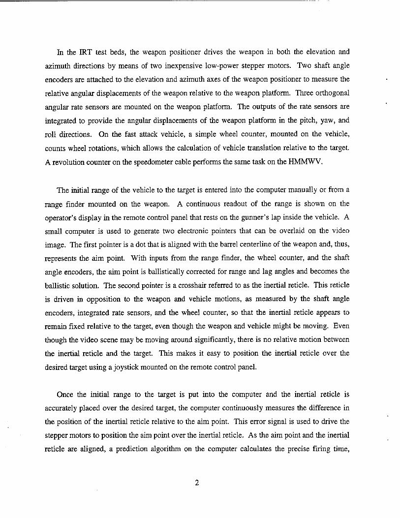
In the IRT test beds, the weapon positioner drives the weapon in both the elevation and
azimuth directions by means of two inexpensive low-power stepper motors. Two shaft angle
encoders are attached to the elevation and azimuth axes of the weapon positioner to measure the
relative angular displacements of the weapon relative to the weapon platform. Three orthogonal
angular rate sensors are mounted on the weapon platform. The outputs of the rate sensors are
integrated to provide the angular displacements of the weapon platform in the pitch, yaw, and
roll directions. On the fast attack vehicle, a simple wheel counter, mounted on the vehicle,
counts wheel rotations, which allows the calculation of vehicle translation relative to the target.
A revolution counter on the speedometer cable performs the same task on the HMMWV.
The initial range of the vehicle to the target is entered into the computer manually or from a
range finder mounted on the weapon. A continuous readout of the range is shown on the
operator's display in the remote control panel that rests on the gunner's lap inside the vehicle. A
small computer is used to generate two electronic pointers that can be overlaid on the video
image. The first pointer is a dot that is aligned with the barrel centerline of the weapon and, thus,
represents the aim point. With inputs from the range finder, the wheel counter, and the shaft
angle encoders, the aim point is ballistically corrected for range and lag angles and becomes the
ballistic solution. The second pointer is a crosshair referred to as the inertial reticle. This reticle
is driven in opposition to the weapon and vehicle motions, as measured by the shaft angle
encoders, integrated rate sensors, and the wheel counter, so that the inertial reticle appears to
remain fixed relative to the target, even though the weapon and vehicle might be moving. Even
though the video scene may be moving around significantly, there is no relative motion between
the inertial reticle and the target. This makes it easy to position the inertial reticle over the
desired target using a joystick mounted on the remote control panel.
Once the initial range to the target is put into the computer and the inertial reticle is
accurately placed over the desired target, the computer continuously measures the difference in
the position of the inertial reticle relative to the aim point. This error signal is used to drive the
stepper motors to position the aim point over the inertial reticle. As the aim point and the inertial
reticle are aligned, a prediction algorithm on the computer calculates the precise firing time,
ensuring that the projectile exits the muzzle as the ballistic solution is aligned with the inertial
reticle. Assuming that the gunner has enabled the system to fire, the precise firing is
accomplished by means of an electric solenoid that is attached to the trigger of the weapon. To
simplify the display for the gunner, the ballistic solution is typically not displayed and the
gunner's tasks are to select the target, enter the range, and keep the inertial reticle on target.
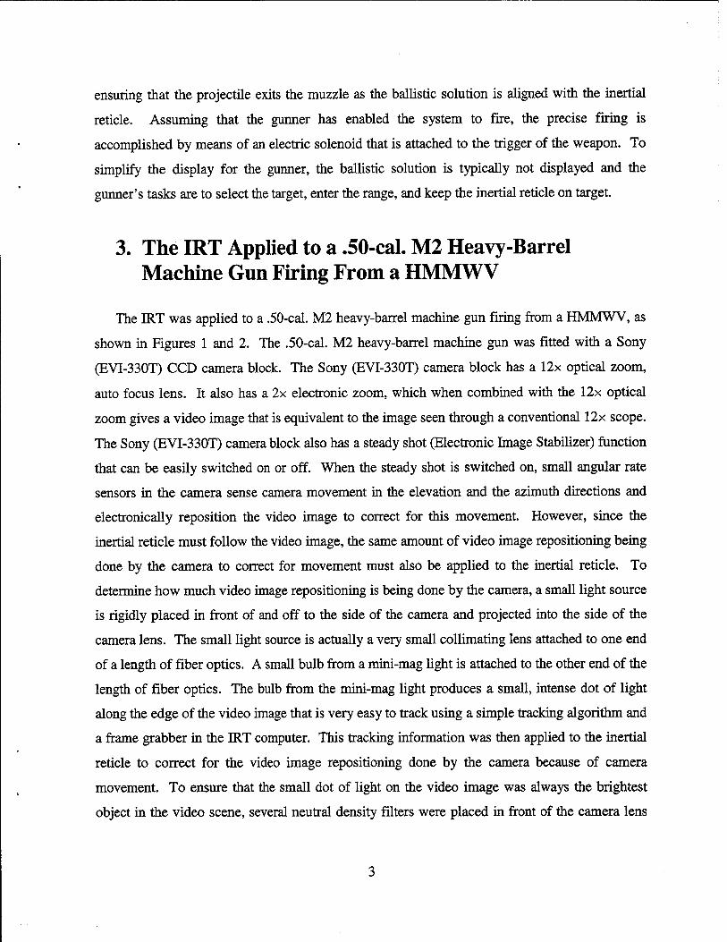
3. The IRT Applied to a .50-cal. M2 Heavy-Barrel Machine Gun Firing From a HMMWV
The IRT was applied to a .50-cal. M2 heavy-barrel machine gun firing from a HMMWV, as
shown in Figures 1 and 2. The .50-cal. M2 heavy-barrel machine gun was fitted with a Sony
(EVI-330T) CCD camera block. The Sony (EVI-330T) camera block has a 12x optical zoom,
auto focus lens. It also has a 2x electronic zoom, which when combined with the 12x optical
zoom gives a video image that is equivalent to the image seen through a conventional 12x scope.
The Sony (EVI-330T) camera block also has a steady shot (Electronic Image Stabilizer) function
that can be easily switched on or off. When the steady shot is switched on, small angular rate
sensors in the camera sense camera movement in the elevation and the azimuth directions and
electronically reposition the video image to correct for this movement. However, since the
inertial reticle must follow the video image, the same amount of video image repositioning being
done by the camera to correct for movement must also be applied to the inertial reticle. To
determine how much video image repositioning is being done by the camera, a small light source
is rigidly placed in front of and off to the side of the camera and projected into the side of the
camera lens. The small light source is actually a very small collimating lens attached to one end
of a length of fiber optics. A small bulb from a mini-mag light is attached to the other end of the
length of fiber optics. The bulb from the mini-mag light produces a small, intense dot of light
along the edge of the video image that is very easy to track using a simple tracking algorithm and
a frame grabber in the IRT computer. This tracking information was then applied to the inertial
reticle to correct for the video image repositioning done by the camera because of camera
movement. To ensure that the small dot of light on the video image was always the brightest
object in the video scene, several neutral density filters were placed in front of the camera lens
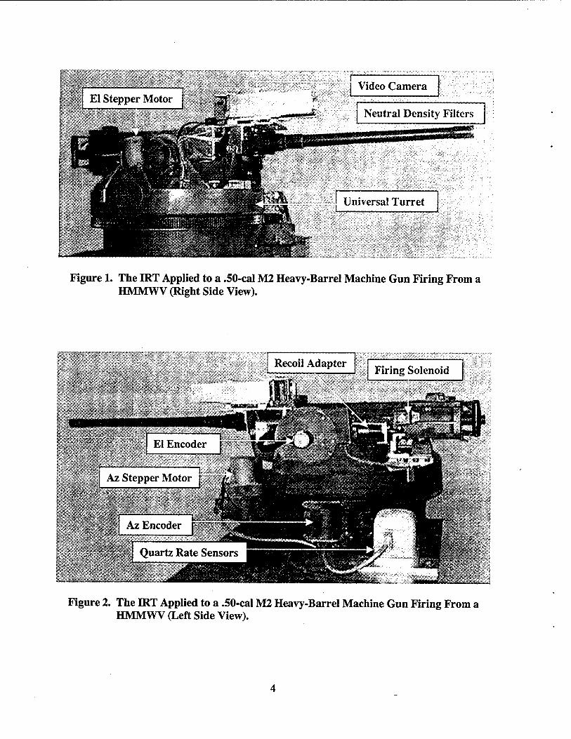
Figure 1. The IRT Applied to a .50-cal M2 Heavy-Barrel Machine Gun Firing From a HMMWV (Right Side View).
Figure 2. The IRT Applied to a .50-cal M2 Heavy-Barrel Machine Gun Firing From a HMMWV (Left Side View).
and the small collimating lens. This also forced the aperture of the camera lens to remain open
even in bright sunlight so that the small dot of light off to the side of the lens was not occluded
by the aperture of the camera lens in bright sunlight. The box in front of the camera shown in
Figure 1 houses the neutral density filters and keeps stray light out of the camera lens. The video
image from the camera block is viewed by the gunner on a Sony flat-panel display monitor
(FMD-402A) mounted in the remote control panel.
The .50-cal. M2 heavy-barrel machine gun is mounted in a recoil mount that is attached to a
Universal turret from a Cobra helicopter. The recoil mount was designed and built by ARL to
reduce the recoil force to the turret, the video camera, the shaft angle encoders, and the quartz
rate sensors during firing. The recoil mount allows the receiver of the weapon to recoil about
2 cm during firing of the round and returns the receiver to the full forward position in about
65 ms, which is well before the second round in the burst is fired. The recoil spring adapters for
the recoil mount can be seen in Figure 2.
Both the elevation and the azimuth drive motors on the Universal turret were replaced by
Superior Electric (M092-FD08) low-power stepper motors that are powered by Industrial
Devices (SA Drive) microstepping motor controllers. Two Itek LSI Micro Series (|iS/16/23K)
shaft angle encoders measure the relative angular displacements between the weapons and the
weapon platform in azimuth and elevation. The shaft angle encoders are mounted to the turret,
and their output shafts are attached to the elevation and the azimuth axis of the weapon platform.
Three Systran Donner quartz rate sensors (QRS-11-0010-101) mounted to the weapon platform
measure the angular displacements of the weapon platform in elevation, azimuth, and roll. A
quartz revolution counter mounted to the speedomenter cable of the HMMWV measures the
vehicle translation.
The initial range of the vehicle to the target is put into the computer manually from inside the
vehicle by switches on the remote control panel. Once the initial range to the target is put into
the computer and the inertial reticle accurately placed over the desired target, the target
designator switch on the gunner's control panel is momentarily engaged. At this time, the initial
position of the target relative to the inertial reticle is determined in inertial coordinates.
Theoretically, once the inertial reticle is positioned accurately over the target, it should stay there
indefinitely. However, due to random walk in the quartz rate sensors, the inertial reticle will
drift off from the target after several seconds. The inertial reticle can be easily repositioned over
the target by slight movements of the joystick. If the drift becomes large enough to get outside
of the range of the joystick correction, a switch on the gunner's control panel can be turned on,
switching the joystick operation from the displacement mode to the velocity mode and giving it
an endless correction range. A second switch on the gunner's control panel can also be engaged
when the joystick is in velocity mode to cause the stepper motors of the turret to move at a much
faster rate, which facilitates getting the target in the field of view.
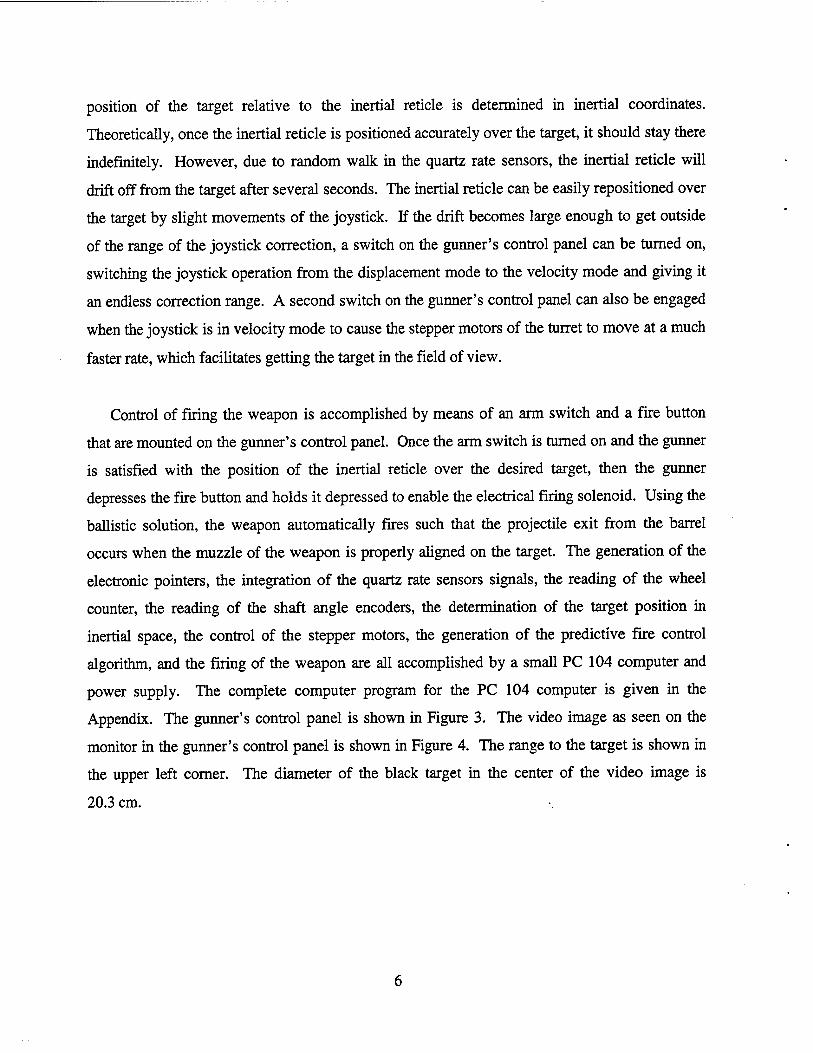
Control of firing the weapon is accomplished by means of an arm switch and a fire button
that are mounted on the gunner's control panel. Once the arm switch is turned on and the gunner
is satisfied with the position of the inertial reticle over the desired target, then the gunner
depresses the fire button and holds it depressed to enable the electrical firing solenoid. Using the
ballistic solution, the weapon automatically fires such that the projectile exit from the barrel
occurs when the muzzle of the weapon is properly aligned on the target. The generation of the
electronic pointers, the integration of the quartz rate sensors signals, the reading of the wheel
counter, the reading of the shaft angle encoders, the determination of the target position in
inertial space, the control of the stepper motors, the generation of the predictive fire control
algorithm, and the firing of the weapon are all accomplished by a small PC 104 computer and
power supply. The complete computer program for the PC 104 computer is given in the
Appendix. The gunner's control panel is shown in Figure 3. The video image as seen on the
monitor in the gunner's control panel is shown in Figure 4. The range to the target is shown in
the upper left corner. The diameter of the black target in the center of the video image is
20.3 cm.
4. Indoor Testing of the IRT Applied to a .50-cal. M2 Heavy-Barrel Machine Gun
Prior to any long-range testing of the IRT applied to a .50-cal. M2 heavy-barrel machine gun
firing from a HMMWV, extensive short-range testing was done in the indoor range in building
390 at ARL. Over 100 rounds of M33 ammunition were fired from the weapon with the turret
mounted to a rigid plate to determine if the turret, the video camera, the shaft angle encoders, and
the quartz rate sensors could withstand the shock from firing. Accuracy measurements were also
taken during the initial testing for each round fired. Several rounds of M33 ammunition were
also fired with the weapon mounted directly to the rigid plate. The average standard deviations
in the elevation and the azimuth directions for several 10-round groups fired from the weapon
while it was mounted directly to the rigid plate were .67 mil and .65 mil, respectively. The
average standard deviations in the elevation and the azimuth directions for several 10-round
groups fired from the weapon with the turret mounted to a rigid plate were .69 mil and .66 mil,
respectively. These experiments showed similar results with the weapon mounted in the turret,
which was mounted to a fixed plate, and the weapon mounted directly to the plate. It was felt
that the IRT integrated with the .50-cal. M2 heavy-barrel machine gun performed substantially as
well as a fixed rigid mount, and no more short-range indoor experiments were performed. There
was no damage to the turret, the video camera, the shaft angle encoders, or the quartz rate
sensors after firing over 100 rounds.
5. Initial Long-Range Outdoor Testing of the IRT Applied to a .50-cal. M2 Heavy-Barrel Machine Gun Firing From a HMMWV
After the indoor testing was completed, the .50-cal M2 IRT test bed was mounted on a
HMMWV and initial long-range outdoor firing experiments were done at the U.S. Army
Aberdeen Test Center (ATC) H-Field test facility at the Edgewood Area of Aberdeen Proving
Ground. The HMMWV selected had been previously used in unrelated experiments and was
equipped with a generator, equipment racks, and a platform designed to support this turret. This

Figure 3. Remote Control Panel (Rests on Gunner's Lap).
Figure 4. Video Image of a 20.3-cm Target at 452 m (Monitor in Remote Control Panel).
greatly facilitated the ability to experiment with and demonstrate IRT concepts without having to
spend limited resources to adapt electronics to a tactical vehicle. There are no technical barriers
envisioned in reducing the hardware to a tactical vehicle.
Before any firings from a moving vehicle were done, firings from a stationary vehicle were
made at a 400-m target. The average standard deviations in the elevation and the azimuth
directions for several 10-round groups of M33 ammunition fired semiautomatically by the
gunner from inside the stationary vehicle were .71 mil and .68 mil, respectively. These results,
obtained with a gunner inside the stationary vehicle, compared favorably with previous indoor
firings. Since mounting the M2 integrated with the IRT on the HMMWV did not result in
increased dispersion, it was felt that no further stationary experiments were required, and firing-
on-the-move experiments were initiated.
After completing the stationary vehicle firings at the 400-m target, the firings were repeated
from a moving vehicle. The initial firing-on-the-move experiments were conducted with the
gunner firing from inside the vehicle while the vehicle was moving away from the target.
Ten-round groups were fired semiautomatically by the gunner at about 1-s intervals while the
vehicle was traveling at 16 kph down a gravel road away from a 400-m target. The average
standard deviations in the elevation and the azimuth directions for several 10-round groups of
M33 ammunition fired semiautomatically by the gunner from inside the moving vehicle were
.74 mil and .70 mil, respectively. Since the average standard deviations were only slightly
higher than those for the previous firings from the stationary vehicle, it was felt that the IRT was
achieving its maximum accuracy performance for these conditions, and no more semiautomatic
firings moving away from the target were made.
Once the firings from the moving vehicle while driving away from the 400-m target were
completed, the target was placed 400-m off to the side of the vehicle. The firing experiments
were repeated with the gunner firing from inside the moving vehicle and the weapon pointing
over the right and left sides of the vehicle while it traversed at 16 kph parallel to the target along
a gravel road. The IRT held the inertia! reticle on the target and put in the correct amount of lag
angle so that the projectiles hit on target. The average standard deviations for the elevation and
the azimuth directions for several 10-round groups of M33 ammunition fired semiautomatically
by the gunner from inside the moving vehicle were .75 mil and .73 mil, respectively. The
average standard deviations were essentially the same as those for the previous firings for the
vehicle traveling straight away from the target.
The next experiment was to determine if the IRT could accurately hit a moving target if the
computer was given the target velocity. The first firing tests of firing at a 400-m target while the
vehicle was traveling at 16 kph along a gravel road away from the target were repeated. Again
the vehicle was driven away from the target at 16 kph from an initial range of 400 m. However,
this time during the experiment the target was moving left to right at 16 kph. Ten-round groups
were fired semiautomatically by the gunner from inside the vehicle at about 1-s intervals while
the vehicle was moving down the gravel road away from the 400-m target. The IRT held the
inertial reticle on the target and put in the correct amount of lead angle so that the projectiles hit
on target. The average standard deviations in the elevation and the azimuth directions for several
10-round groups of M33 ammunition fired semiautomatically by the gunner from inside the
moving vehicle were .77 mil and .79 mil, respectively. These average standard deviations were
essentially the same as those for the previous firing for the vehicle traveling straight away from
the target.
6. Final Long-Range Outdoor Testing of the IRT Applied to a .50-cal. M2 Heavy-Barrel Machine Gun Firing From a HMMWV
After the initial long-range outdoor testing was completed, a review of the videotape of the
inertial reticle taken during the firing tests from the moving vehicle showed that the weapon
platform was oscillating at a frequency of about 8 Hz as a result of firing each round of
ammunition. The time interval from the fire pulse to projectile exit from the barrel is 28 ms for
the hammer-fired .50-cal. M2 heavy-barrel machine gun. This in-bore time is short enough that
it was felt the firing predictor should predict well enough at 8 Hz to allow the weapon to be fired
10

in a burst mode. If the hammer could be re-seared soon enough after firing the first round in the
burst, then at 8 Hz, the firing predictor should give a firing pulse every 200 ms, which converts
to a rate of fire of 300 rd/rnin. The sear spring of the weapon was replaced with a much stiffer
one and it was determined that with the stiffer sear spring the hammer in the weapon could be
easily re-seared in 200 ms. Even though the video scene was blurred for almost 1 s after firing a
round, it was felt that the inertial reticle would not drift off from the target a significant amount
during the firing of a 3- or 4-round burst.
A final long-range outdoor experiment with the .50-cal. M2 heavy-barrel machine gun IRT
test bed firing from a HMMWV was done at the H-Field test facility at the Edgewood Area of
Aberdeen Proving Ground. The firing experiments from a moving vehicle done in the initial
long-range outdoor testing of the IRT were repeated on the same firing range. However in these
experiments, 12 rounds were fired in 3- or 4-round bursts by the gunner from inside the vehicle
with about a 1-s interval between each burst while the vehicle was moving at 16 kph down the
same gravel road away from the 400-m target. The average standard deviations in the elevation
and the azimuth directions for several 12-round groups of M33 ammunition were .83 mil and
.80 mil, respectively. In reviewing the videotape of the inertial reticle and the analog tape of the
displacements of the weapon taken during the firing tests from the moving vehicle, it was
determined that the weapon platform was oscillating at a frequency of about 8 Hz. A check of
the firing time data also taken during the firing tests showed that there were no instances when
the muzzle of the weapon was not pointing at the target when the projectile exited the gun barrel.
Samples of the angular displacements of the weapon taken during the firing of a 3-round burst
are shown in Figure 5 along with the firing times for each round in the burst. The average rate of
fire of the 3- or 4-round bursts was about 300 rd/min. Since the average standard deviations for
the 3- or 4-round burst firings were only slightly higher than the average standard deviations for
the semiautomatic firings from the previous final long-range outdoor tests fired from a moving
vehicle, it was felt that the IRT applied to a .50-cal. M2 heavy-barrel machine gun firing from a
HMMWV was achieving its optimum performance in accuracy for this scenario.
11

H
u i Ul £
s> h s «! b. s «
0 a o si
H 88 U
a a •
w
<M a u E V u M O.
«j s M B
Vt
2
E
(Sliui) lN3W30VldSia HVinONV
12
7. Long-Range Outdoor Testing of a .50-cal. M2 Heavy-Barrel Machine Gun Firing From a HMMWV
After completing the burst firing experiments, the same experiments were repeated on the
same firing range with a .50-cal. M2 heavy-barrel machine gun from a standard swivel mount on
a HMMWV. However, in these tests, 20 rounds were fired in 3- or 4-round bursts at about
450 rd/min by a U.S. Army Aberdeen Test Center (ATC) gunner standing behind the weapon
with about a 1-s interval between each burst while the vehicle was moving at 16 kph down the
same gravel road away from the 400-m target. The average standard deviations in the elevation
and the azimuth directions for several 20-round groups of M33 ammunition fired in this
experiment were 8.60 mils and 4.50 mils, respectively. In reality, the average standard
deviations were actually larger because on the average only 11 of the 20 rounds fired in each
group hit the 8-m x 8-m target.
8. Results
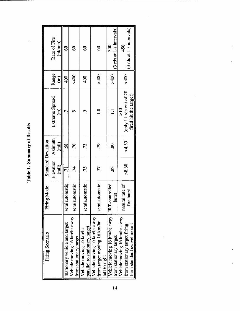
The results of the experiments conducted with the .50-cal. M2 heavy-barrel machine gun are
summarized in Table 1.
9. Conclusions
As can be seen from Table 1, with the IRT fire control, the engineer was able to shoot .8-m
groups, centered on the target, in semiautomatic mode moving away from the target. This was
repeated with .9-m groups, centered on target, while the vehicle was traveling a path parallel to
the target, again in semiautomatic mode. Although the IRT currently has no means to track the
target, by feeding information about target velocity to the computer, the engineer was able to
achieve similar results with a crossing target moving at 16 kph.
13
"3 en
es
« E E S
co CO
CS CS
s & £ <u <u •4-» ■4-»
E o
c e
=0 © VO
o VO
o • VO
O VO
G
8*? ,G
■*-» i-, ■4~J -4-> cS CS CS « CO
en
CO
"2 en
<L>
c es ? o
3 o
A
o 9
O
A
o
A
o
A
O CN 0
t3 «4—1 t> cs O 60 8 OH
A "O *-•
on
E ? C-; 00 ON ©
^ 8 ZU S
■4-»
>»"S PJ
^—^
.G O 1 00 o CO ON O
o CO E vq t^; t-; r-; 00 Tf
• i—c N N—' A > <
1 G o ^^ o
c CS
es >
*73 —H rf m t— en VO
E, r^ r^ i> r-; 00 00 ■4-4 u A co w
o _o o o "O ttH <u "G 'G *-> 'G (L> o
T3 CO CS CS CS ^^ <U to 2 g
o o s
o e o s o
8 - •C co -4-4 *3 •4-* ■*-» G hj , JD
00 s 3 3 3 o S 2 8 c CS cs es cs o X> "C s £ E 6
1
CS
c E CO CO CO co ß
>» >-. >» >1
cS CS es es ■4-4
60
CS
CS 4-» es es g) e v-i .5 3 hi
43 43 00 ^ J J3 o
• *-H
•4-*
G •*-> C CS "S: ^> G -4-4 ^S e
cd c M o
"* G
^2 i™H i< u VO E? > c CO vo £? vo go VO g? o ~* 3 ^H C - 3
•E fe T3 > 2 G o S ß E-2-g
co
c
o oß O G 'S > 3 > E
°0 s^ G C^
11 •c UH
> U O M
E o o *■> ■>-> a <o 43 c w so
CS i> 3 <u — « cs 'C u .5 <u 5 3 c o 73 M o -a .O ~ O o M •£ co co
'^ 2 £ S s 43 c w 2 E 2 E E 3 CO
d> o > OH
<u o C <L> O <U O O > £ > 4= JJ > cG > cG *
14

With careful timing, the IRT can control the M2 at a rate of fire of 300 rds/min, approaching
the full natural rate of fire and achieve accuracies far in excess of what can be achieved with a
conventional weapon under similar conditions. This allows the direction of suppressive fire with
deadly accuracy.
The IRT, when integrated with a crew-served weapon, on a lightweight platform, such as a
HMMWV or fast attack vehicle, has clearly demonstrated the ability to dramatically improve the
accuracy of the weapon system. By demonstrating the ability to fire at high rates of fire, the fire
suppressive capability is enhanced with the ability to deliver this type of fire accurately at ranges
in excess of 400 m. This technology offers not only the opportunity to achieve accurate fire from
a moving platform but to enhance the survivability of the operator by putting the gunner down in
the vehicle, reducing his exposure.
15

INTENTIONALLY LEFT BLANK.
16

Appendix:
Computer Program"
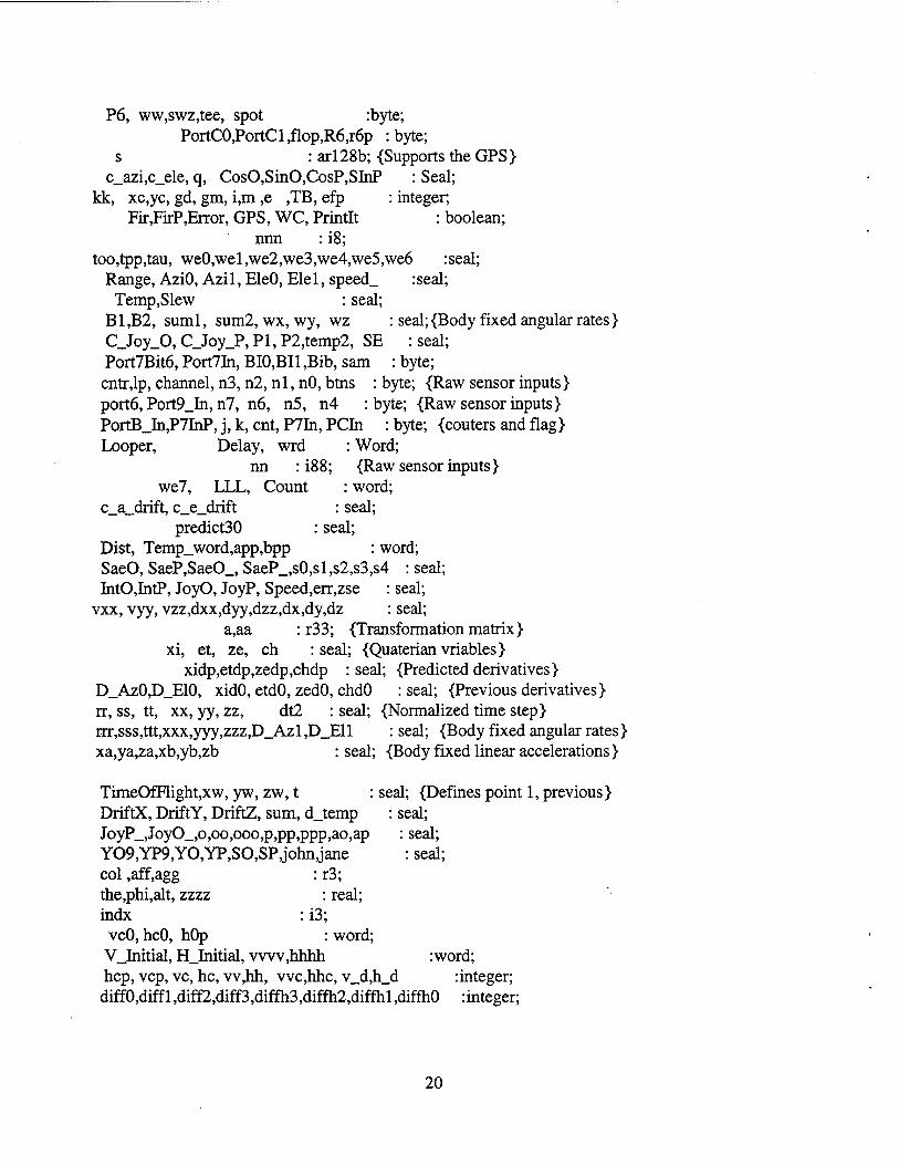
Program B0804a is the computer program for the PC 104 computer.
17

INTENTIONALLY LEFT BLANK.
18
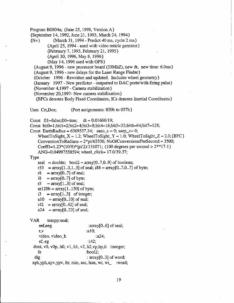
Program B0804a; {June 25,1998, Version A} {September 14,1992, June 21,1993, March 24,1994} {N+> {March 31,1994 - Predict 40 ms, cycle 2 ms}
{April 25,1994 - used with video reticle genrator} {February 7,1995, February 21,1995} {April 30,1996, May 8,1996} {May 14,1996 used with GPS}
{August 9,1996 - new processor board (33MhZ), new dt, new time: 6.0ms} {August 9,1996 - new delays for the Laser Range Finder} {October 1996 - Rewritten and updated. Includes wheel geometry} {January 1997 - New predictor - outputted to DAC ports/with firing pulse} {November 4,1997 - Camera stabilization} {November 20,1997- New camera stabilization}
{BFCs denotes Body Fixed Coordinates, ICs denotes Inertial Coordinates}
Uses Crt,Dos; {Port assignments: 050h to 057h}
Const fll=false;fl0=true; dt = 0.01666/19; Const bit0= 1 ;bit 1 =2;bit2=4;bit3=8;bit4= 16;bit5=32;bit6=64;bit7=128; Const EarthRadius = 6369537.34; saeo_c - 0; saep_c= 0;
WheelToSight_X = 1.2; WheelToSight_Y = 1.0; WheelToSight.Z = 2.0; {BFC} ConversionToRadians = 2*pi/65536; NoOfConversionsPerSecond = 3500; Coeffl=1.23*(10/9)*(pi/2)/131071; {100 degrees per second > 2**17-1} ANG=0.04997558594; wheel_click= 17.0/39.37;
Type seal = double; bool2 = array[0..7,0..9] of boolean; r33 = array[l ..3,1 ..3] of seal; 188 = array[0..7,0..7] of byte; r8 = array[0. .7] of seal; i8 =array[0..7]ofbyte; r3 = arrayfl ..3] of seal; arl28b = array[1..150] of byte; i3 =array[1..3] of integer; alO = array[0..10] of seal; i42 = array[0..42] of seal; a24 = array[0..23] of seal;
VAR tempp:seal; eef,eeg :array[0..6] of seal; r,v :al0; video, video_h :a24; ef,eg :i42;
dont, vO, vOp, hO, vl, hi, v2, h2,vp,hp,ii :integer; fe :bool2;
dig : array[0..3] of word; xph,yph,xpv,ypv, hr, min, sec, hun, wi, wi_ :word;
19
P6, ww,swz,tee, spot :byte; PortC0,PortCl,flop,R6,r6p : byte;
s : ar 128b; {Supports the GPS } c_azi,c_ele, q, CosO,SinO,CosP,SInP ; Seal;
kk, xc,yc, gd, gm, i,m ,e ,TB, efp : integer; Fir,FirP,Error, GPS, WC, Printlt : boolean;
nnn : i8; too,tpp,tau, we0,wel,we2,we3,we4,we5,we6 :seal;
Range, AziO, Azi 1, EleO, Elel, speed_ :seal; Temp,Slew : seal;
B1JB2, suml, sum2, wx, wy, wz : seal;{Body fixed angular rates} C_Joy_0, C_Joy_P,Pl,P2,temp2, SE : seal; Port7Bit6, Port7In, BI0,BI1 ,Bib, sam : byte; cntr,lp, channel, n3, n2, nl, nO, btns : byte; {Raw sensor inputs} portö, Port9_In, n7, n6, n5, n4 : byte; {Raw sensor inputs} PortB_In,P7InP, j, k, cnt, P7In, PCIn : byte; {couters and flag} Looper, Delay, wrd : Word;
nn : i88; {Raw sensor inputs} we7, LLL, Count : word;
c_a_drift, c_e_drift : seal; predict30 : seal;
Dist, Temp_word,app,bpp : word; SaeO, SaeP,SaeO_, SaeP_,sO,sl,s2,s3,s4 : seal; IntO,IntP, JoyO, JoyP, Speed,err,zse : seal;
vxx, vyy, vzz,dxx,dyy,dzz,dx,dy,dz : seal; a,aa : r33; {Transformation matrix}
xi, et, ze, ch : seal; {Quaterian vriables} xidp,etdp,zedp,chdp : seal; {Predicted derivatives}
D_AzO,D_E10, xidO, etdO, zedO, chdO : seal; {Previous derivatives} rr, ss, tt, xx, yy, zz, dt2 : seal; {Normalized time step} rrr,sss,ttt,xxx,yyy,zzz,D_Azl,D_Ell : seal; {Body fixed angular rates} xa,ya,za,xb,yb,zb : seal; {Body fixed linear accelerations}
TimeOfFlight,xw, yw, zw, t : seal; {Defines point 1, previous} DriftX, DriftY, DriftZ, sum, d_temp : seal; JoyP_,JoyO_,o,oo,ooo,p,pp,ppp,ao,ap : seal; Y09,YP9,YO,YP,SO,SP,john,jane : seal; col ,aff,agg : r3; the,phi,alt, zzzz : real; indx : i3;
vcO, hcO, hOp : word; V_Initial, H_Initial, vwv,hhhh :word; hep, vcp, vc, he, vv,hh, vvc,hhc, v_d,h_d : integer;
diffO,diff 1 ,diff2,diff3,diffh3,diffh2,diffhl ,diffhO :integer;
20

Procedure PutP3( var A:Byte); begin asm mov dx,233h; les bx, A; mov al,es:[bx]; out dx,al end end; Procedure PutP6( var A:Byte); begin asm mov dx,236h; les bx, A; mov al.es:[bx]; out dx.al end end;
Procedure Put6(B:byte;Var A:byte); begin a: =b; asm mov dx,236h; les bx, A; mov al.es: [bx]; outdx.al endend;
Procedure Put2(B:byte;Var A:byte); begina:=b;asm movdx,232h; lesbx, A;moval,es:[bx]; outdx.al endend;
Procedure Put4(B:byte;Var A:byte); begin a:=b;asm mov dx,234h; lesbx, A; mov al,es:[bx]; outdx,al endend;
Procedure Put3(B:byte;Var A:byte); begin a: =b; asm mov dx,233h; lesbx, A; mov al.es: [bx]; outdx,al endend;
Procedure D;var i:word; begin
for i:=0 to 1 do begin end; end;
Procedure ConfigA(var z:byte);{J3} begin asm mov dx,0303h; {Configuration A>les bx,z;mov al,es:[bx];out dx.al end end;
Procedure ConfigB(var z:byte);{J4} begin asm mov dx,0307h; {Configuration B}les bx,z;mov al.es: [bx];out dx.al end end;
Procedure ConfigC(var z:byte); {J3 } begin asm mov dx,0333h;{Configuration C}les bx,z;mov al.es:[bx];out dx,al end end;
Procedure ConfigD(var z:byte);{J4} begin asm movdx,0337h;{ConfigurationD}lesbx,z;mov al.es:[bx];outdx.al endend;
Procedure Set_Pix(var V,H,M:word;var N:word);{M offset, N number} begin asm {N:0 OOOcccc nnnn nnnn} {M=l next pixel next column over, M=512 next pixel next row down} les bx,H
21
mov cx,es:[bx] {ex: 0 0 0 0 0 0 0 b8 b7 b6 b5 b4 b3 b2 bl bO, H} les bx,V mov dx,es:[bx] {dx: 0 0 0 0 0 0 0 a8 a7 a6 a5 a4 a3 a2 al aO, V} rol dx,l {dx: 0 0 0 0 0 0 a8 a7 a6 a5 a4 a3 a2 al aO 0} xoral,al {ax: xxxx xxxx 0000 000 0}
movah,dl {ax:a6a5a4a3a2ala0 0 0000 000 0} add cx,ax {cx:a6 a5 a4 a3 a2 al aO b8 b7 b6 b5 b4 b3 b2 bl bO} mov al,dh {ax:a6 a5 a4 a3 a2 al aO 0 0 0 0 0 0 0 a8 a7} andal,03h {ax:a6a5a4a3 a2 al aO 0 0 0 0 0 0 0a8a7} push ax
mov dx,236h out dx,al {Output to PO, program the two "page" bits, P0.1, P0.0}
les bx,M; mov dx,es:[bx]; {[M] -> dx, ex dx reserved} les bx,N; mov bx,es:[bx]; {[N] -> bx, ex dx bx reserved}
{bx: 0000 cccc nnnn nnnn} movax,0a000h {ax: 1101 0000 0000 000 0} mov es,ax {es: 11010000 0000 000 0}
{dx: offset, ex dx bl es reserved}
mov ax,bx {ax: color and number, ex dx al es reserved} mov bx,cx {bx:a6 a5 a4 a3 a2 al aO b8 b7 b6 b5 b4 b3 b2 bl bO} movcx.ax {ex: color number}
pop ax {ax:a6 a5 a4 a3 a2 al aO 0 0 0 0 0 0 0 a8 a7}
@ 1: mov es: [bx] ,ch {Move print code to video memory} add bx,dx; jb @4; {Jump if CY=1 or Z=l}
@5: deccl jnz@l jmp@6
@4: inc al . push dx mov dx,0236h out dx,al pop dx mov ah, 1; @7: decah;jnz@7; {Delay awhile} jmp@5
@6:
22
end end;
Procedure LineV( xO, yO,n:word; colonboolean); varm :word; begin
M:=512; if not color then N:=N+$0f00; Set_Pix(xO,yO,M,N);
end;
Procedure LineH( xO, yO,n:word; color:boolean); vax m :word; begin M:=l;
if not color then N:=N+$0f00; Set_Pix(xO,yO,M,N);
end;
Procedure Put_Digit(var r:seal; var cnt:byte); var y:word; i:byte;a,b,c:word; const dx=36; dy=25; dx2=dx div 2; x=60; {x component - downM/} begin c:=1000; b:=trunc(abs(r)); for i := 0 to 3 do begin
a:= b div c; if ((i=(cnt and 03)) {and (dig[i]oa)>) then begin
y:= i*4O+60 ; {Y component - over ->} LineH(x , y , dy, fe[0,a]); LineH(x+dx2, y , dy, fe[l,a]); LineH(x+dx , y , dy, fe[2,a]);
LineV(x , y , dx2, fe[3,a]); LineV(x , y+dy, dx2, fe[4,a]); LineV(x+dx2, y , dx2, fe[5,a]); LineV(x+dx2, y+dy, dx2, fe[6,a]); dig[i]:=a;
end; b:= b - a*c; c:= c div 10;
end; inc(cnt);
23
end;
Procedure G_Init; var i,h,m,n:word; begin ww:=$80;ConfigA(ww); ww:=$82;ConfigB(ww); ww:=$9b;ConfigC(ww); ww:=$99;ConfigD(ww); fe[0,0]:-fll ;fe[l ,0]:=fl0;fe[2,0]:=fll ;fe[3,0]:=fll ;fe[4,0] :=fll ;fe[5,0]:=fll ;fe[6,0]:=fll fe[0,l]:=flO;fe[l,l]:=flO;fe[2,l]:=flO;fe[3,l]:=flO;fe[4,l]:=fll;fe[5,l]:=flO;fe[6,l]:=fll fe[0,2]:=fll;fe[l,2]:=fll;fe[2,2]:=fll;fe[3,2]:=fl0;fe[4,2]:=fll;fe[5,2]:=fll;fe[6,2]:=fl0 fe[0,3]:=fll;fe[l,3]:=fll;fe[2,3]:=fll;fe[3,3]:=fl0;fe[4,3]:=fll;fe[5,3]:=fl0;fe[6,3]:=fll fe[0,4]:=fl0;fe[l,4]:=fll;fe[2,4]:=fl0;fe[3,4]:=fll;fe[4,4]:=fll;fe[5,4]:=fl0;fe[6,4]:=fll fe[0,5]:=fll;fe[l,5]:=fll;fe[2,5]:=fll;fe[3,5]:=fll;fe[4,5]:=fl0;fe[5,5]:=fl0;fe[6,5]:=fll fe[0,6]:=fl0;fe[l,6]:=fll;fe[2,6]:=fll;fe[3,6]:=fll;fe[4,6]:=fl0;fe[5,6]:=fll;fe[6,6]:=fll fe[0,7]:=fll;fe[l,7]:=fl0;fe[2,7]:=fl0;fe[3,7]:=fl0;fe[4,7]:=fll;fe[5,7]:=fl0;fe[6,7]:=fll fe[0,8]:=fll;fe[l,8]:=fll;fe[2,8]:=fll;fe[3,8]:=fll;fe[43]:=fll;fe[53]:=fll;fe[6,8]:=fir fe[0,9]:=fll;fe[l,9]:=fll;fe[2,9]:=fll;fe[3,9]:=fll;fe[4,9]:=fll;fe[5,9]:=fl0;fe[6,9]:=fll end;
Procedure G_Set( x,y,xp,yp:word); Const dx=20; dy=30; dx2=dx div 2; dy2=dy div 2; Var ymdy2,xmdx2:word; begin
xmdx2:=x-dx2; ymdy2:=y-dy2; LineV(xpv, ypv, dx, true); LineV(xmdx2, y, dx, false); xpv:=xmdx2; ypv:=y;
LineH(xph, yph, dy, true); LineH(x, ymdy2, dy, false); xph:=x; yph:=ymdy2
end;
PROCEDURE LuDcmp( n rinteger; VAR a: r33; VAR indx :i3; VAR d :seal); CONST tiny=1.0e-20;
VAR k,j,imax,i: integer; sum,dum,big: seal;
vv:r3; BEGIN
d:=1.0 ;
24
FORi:=lTOnDOBEGIN big:=0.0; FOR j:= 1 TO n DO IF (abs(a[ij]) > big) THEN big:=abs(a[i,j]); IF (big-0.0) THEN BEGIN END; {if} w[i]:=1.0/big;
END; {for i}
FOR j:= 1 TO n DO BEGIN IF (j>l) THEN BEGIN FORi:=lTOj-lDOBEGIN
sum:=a[i,j]; IF (i>l) THEN BEGIN
FORk:= 1 TO i-1 DO sum :=sum-a[i,k]*a[k,j]; a[i,j] := sum; END {if i}
END {for i} END; {if j}
big:=0.0; FOR i:=j TO n DO BEGIN
sum:= a[i,j]; IF (j>l) THEN BEGIN
FORk:=l TO j-1 DO sum:=sum-a[i,k]*a[k,j]; a[i,j]:= sum; END; {if j}
dum:= vv[i]*abs(sum); IF (dum>big) THEN BEGIN big:=dum; imax :=i END {if dum}
END; {for i}
IF (jo imax) THEN BEGIN
FORk:=lTOnDOBEGTN dum:=a[imax,k]; a[imax,k]:=a[j,k]; a[j,k]:=dum;
END; {fork} d:=-d; w[imax]:=w[j]; END; {if j}
indx[j]:= imax; IF(jon) THEN
BEGIN IF(a[j,j]=0.0) THEN a[j,j]:=tiny; dum :=1.0/a[j,j]; FOR i := j+1 TO n DO a[i,j]:=a[i,j]*dum;
END {if j} END; {for j}
IF(a[n,n] =0.0) THEN a[n,n] := tiny;
25
END; {proc}
Procedure LuBkSb(n :integer; VAR indx :i3; VAR b :r3; VAR a :r33); VAR j,ip,ii>k integer;
sum: seal; BEGIN
ii:=0; FOR i:=l TO n DO BEGIN
ip:=indx[i]; sum:=b[ip]; b[ip]:=b[i]; EF(ii <> 0)THEN
BEGIN FOR j:= ii TO i-1 DO sum:=sum-a[i,j]*b[j];
END{ifii} ELSE IF (sumo 0.0) THEN H:= i; b[i]:=sum;
END; {for i> FOR i:= n DOWNTO 1 DO BEGIN
sum := b[i]; IF (i<n) THEN FOR j:=i+l TO n DO sum := sum -a[i,j]*b[j]; b[i]:= sum/a[i,i];
END {for i} END; {procedure}
Procedure Mat_Inv(var a,y:r33); {Generates the inverse matrix of A in Y} var i,j,n:integer; d:seal; {The matrix A is destroyed} begin n:=3; LuDcmp(n,a,indx,d); forj := 1 ton do begin
for i := 1 to n do col[i]:=0 ; col|j]:-1.0; LuBkSb(n,indx,col,a); fori:= 1 ton do y[i,j]:=col[i];
end; end;
Procedure MATMAT (var c:r33; a, b:r33); vari ,j,k:word; sum:seal; begin for i :=1 to 3 do for k := 1 to 3 do
26
begin sum:=0;for j:=l to 3 do sum:=sum+a[i,j]*b[j,k]; c[i,k] := sum end; end;
Procedure MATMUL(var a,b:r3;var c:r33); var ijrword; sum:seal; begin for i:= 1 to 3 do begin sum := 0;
for j := 1 to 3 do sum := sum + b[j]*c[i,j]; a[i] := sum end end;
Procedure MATMULInv(var a,b:r3;var c:r33); var i,j:word; sum:seal; begin for i:= 1 to 3 do begin sum := 0; for j := 1 to 3 do sum := sum + b[j]*c[j,i]; a[i] := sum end end;
Procedure VDIF(var a,b,c:r3); var i:word;begin for i:=l to 3 do a[i]:=b[i]-c[i] end;
Procedure CMULT( var a,b,c:r3); begin a[l]:=b[2]*c[3]-b[3]*c[2]; a[2]:=b[3]*c[l]-b[l]*c[3];
a[3]:=b[l]*c[2]-b[2]*c[l] end;
Procedure Norm(var a:r3); var temp:seal; i :word;
begin temp := 0; for i := 1 to 3 do temp := temp + sqr(a[i]); temp := sqrt(temp); for i := 1 to 3 do a[i]:=a[i]/temp end;
Procedure DotProd(var r:seal;a,b:r3); begin r := a[l]*b[l]+a[2]*b[2]+a[3]*b[3]; end;
Function ATan (y,x:real):real; var u:real; begin if ((x=0) and (y=0)) then atan:=0.0 else
27

begin if (abs(x) < abs(y)) then begin {abs(x) < abs(y)}
u:=arctan(abs(x/y)); if x<0 then begin {x<0} if y>0 then atan:=pi/2+u else atan:=-pi/2-u end else begin {x>0} if y>0 then atan:=pi/2-u else atan:=-pi/2+u end
end else begin {abs(x) >= abs(y)}
u:= arctan(abs(y/x)); if x<0 then begin {x<0} if y>0 then atan:=pi -u else atan:= -pi +u end else begin {x>0} if y>0 then atan := u else atan:= -u end
end end
end;
Procedure Mat(var xi,et,ze,ch:seal; var a:r33); var ze2, et2, xi2, ch2, ze_et, ze_xi, ze_ch, xi_et, et_ch, xi_ch:seal; begin {calculates elements of the transformation matrix}
ze2 := ze*ze; xi2 := xi*xi; et2 := et*et; ch2 := ch*ch; et_ch:=et*ch; ze_et:=ze*et; ze_xi:=ze*xi; ze_ch:=ze*ch; xi_et:=et*xi; xi_ch:=xi*ch;
a[l,l]:=xi2-et2-ze2+ch2;a[l,2]:=2*(xi_et+ze_ch);a[l,3]:=2*(ze_xi-et_ch); a[2,l]:=2*(xi_et-ze_ch);a[2,2]:=-xi2+et2-ze2+ch2;a[2,3]:=2*(ze_et+xi_ch); a[3,l]:=2*(ze_xi+et_ch);a[3,2]:=2*(ze_et-xi_ch);a[3,3]:=-xi2-et2+ze2+ch2
end; {procedure}
Procedure Mat_Der(var xi, et, ze, ch, wl, w2, w3, xi_, et_, ze_, ch_:seal); begin xi_:=( ch*wl - ze*w2 + et*w3)/2; et_:=( ze*wl + ch*w2 - xi*w3)/2;
ze_:=(-et*wl + xi*w2 + ch*w3)/2; ch_:=(-xi*wl - et*w2 - ze*w3)/2 end;
Procedure ICsToBFCs(var x, y, z, x_, y_, z_ :seal); begin x:=x_*a[l,l]+y_*a[l,2]+z_*a[l,3];
y:=x_*a[2,l]+y_*a[2,2]+z_*a[2,3]; z:=x_*a[3,l]+y_*a[3,2]+z_*a[3,3]; end;
Procedure BFCsToICs (var x_,y_,z_:seal; x,y,z:seal); begin x_:=x * a[l,l] + y * a[2,l] + z * a[3,l];
y_:=x * a[l,2] + y * a[2,2] + z * a[3,2];
28
z_:=x * a[l,3] + y * a[2,3] + z * a[3,3] end;
Procedure Initialize_Q (var xi, et, ze, ch :seal); begin xi:=0; et:=0; ze:=0; ch:=l; end;
Procedure Integrate(var a,b,c,d, uO.ul, vO.vl, wO.wl, xO,xl:seal); begin a:=a+(u0+ul)*dt2;b:=b+(v0+vl)*dt2;c:=c+(w0+wl)*dt2;d:=d+(x0+xl)*dt2
end;
Procedure Up_Date(var a,b,c,d,e,f,g,h:seal);begin a:=b;c:=d;e:=f;g:=h end;
Procedure Normalize(var a,b,c,d:seal); var sum:seal; begin {Normalize the Quaterion coefficients}
sum:= sqrt( sqr(a) + sqr(b) + sqr(c) + sqr(d)); a:=a/sum; b:=b/sum; c:=c/sum; d:=d/sum end;
Procedure Step(var value:word); begin
asm {sccccddddddddddd} mov dx,0300h; lesbx,value; mov ax,es:[bx]; <ah:dddd dddd, al:dddddddd} outdx,al; {dddd dddd} {Bits 0 - 7 > 300h} mov dx,0302h; {302h > dx } mov al,ah out dx,al
end; end;
Procedure Stepper_Driver( Channehbyte; var WP,D:seal; W,S:seal); const kappa = 100; {Defines the maximum angular acceleration} var zz,z:seal; var sign:boolean; wrdrword; a,b,dw:seal; begin if channel = 1 then z:=2.4 else z:= 1.2; {channel 1 is azimuth} if ((P7In and 1)=0) then w:=0; w:=w*z*8.0e5; {One degree error translates to maximum slew rate (w:=l)}
dw:=w-wp;
29
if dw > kappa then w:=wp+kappa; if dw < -kappa then w:=wp-kappa; if w > 16383 then w:= 16383 else if w <-16383 then w:=-16383; wp:=w; if w<0 then sign:=false else sign:=true; w:=abs(w); zz:=3.0; if (w < 1) then a:= 16383 else a:= 16383/w; if a<zz then a:=zz; b:=trunc(a+d+0.5); d:=d+a-b; wrd := trunc(b);
if channel = 0 then wrd := wrd + 32768; if sign = true then wrd := wrd + 16384; Step (Wrd);
end;
Procedure GetPort7( var A:Byte); begin asm mov dx,0331h; in al,dx; les bx, A; mov es:[bx],al end end;
Procedure GetPort6( var A:Byte); begin asm mov dx,0301h; in al,dx; les bx, A; mov es:[bx],al end end;
(* Procedure GetPortC( var A:Byte); begin asm mov dx,019Ch; in al,dx; les bx, A; mov es:[bx],al end end;
*) Procedure GetPortB( var A:Byte); {Switches} begin asm mov dx,0331h; in al,dx; les bx, A; mov es:[bx],al end end;
Procedure SetPort6_l( var A:Byte); {Fire Pulse} begin asm movdx,0301h; lesbx, A; moval,es:[bx]; {(A)>al>
oraLbitl; moves:[bx],al; out dx,al end end;
Procedure ResetPort6_l( var A:Byte); {Fire Pulse} begin asm mov dx,0301h; les bx, A; mov al,es:[bx];
and al,255-bitl; mov es:[bx],al; out dx,al end end;
30

Procedure SetPort6_7( var A:Byte); {A/D Board} begin asm mov dx,0335h; les bx,A; mov al,es:[bx];
or al,bit7; mov es:[bx],al; out dx, al end end;
Procedure ResetPort6_7( var A:Byte); begin asm mov dx,0335h; les bx,A; mov al,es:[bx];
and al,255-bit7; mov es:[bx],al; out dx,al end end;
Procedure SetPort6_0(var A:Byte); begin asm mov dx,0301h; les bx,A; mov al,es:[bx]; { (A) > al}
or al,bitO; mov es:[bx],al; out dx,al end end;
Procedure ResetPort6_0(var A:Byte); {Timing Pulse} begin asm mov dx,0301h; les bx, A; mov al,es:[bx];
and al,255 - bitO; mov es:[bx],al; out dx,al end end;
Procedure Convert(var srreal; var nn:i8); begin {real:s:l f:39 e:8. v :=(-l)**s*2**(e-129)*(l.f). if e=0thenv:=0} { b47 b46-b8 b7-b0 }
asm {MSByte ah, al, ch, cl LSByte}
les bx,nn moval,es:[bx+4] { al: s.inm.2m.l m.O x x b25 b24} andal,3 { al: 0 0 0 0 0 0 b25 b24}
movdl,es:[bx+5] { dh: s.inm.2m.l m.O x x b27 b26} anddl,3 { dh: 0 0 0 0 0 0b27 b26} rol dl,2 oral,dl { al: 0 0 0 0 b27 b26 b25 b24}
movdl,es:[bx+6] { dl: s.inm.2m.l m.O x x b29 b28} and dl,3 rol dl,4 or al,dl
movdl,es:[bx+7] { dl: s.inm.2m.l m.O x x b31 b30} and dl,3 rol dl,6
31
or al,dl {al: b31 b30 b29 b28 b27 b26 b25 b24}
mov cl,es:[bx+2] {cl: b23 b22 b21 b20 bl9 bl8 bl7 bl6} mov dh,es:[bx+l] {dh: bl5 bl4 bl3 bl2 bl 1 blO b9 b8} mov dl.es:[bx+0] {dl: b7 b6 b5 b4 b3 b2 bl bO} movch,0 {ch: 0000000 0} testal,128 {al: b31 0 0 0 0 0 0 0} jz @ 00 {Jump if negative }
{sign:l, al:8, cl:8, dh:8, dl:8,00:8, ah:8} xor al,255 {b31 b30 b29 b28 b27 b26 b25 b24} xorcl,255 {b23b22b21 b20bl9bl8M7bl6} xordh,255 {bl5bl4bl3 bl2bll bl0b09b08} xor dl,255 {b07 b06 b05 b04 b03 b02 bOl bOO} adddl,l; adcdh,0; adccl,0; adcal,0; mov ch, 128
@00:mov ah,128+32 {sign:l, al:8, cl:8, dh:8, dl:8,00:8, ah:8} test al,255; {Check for all zeros } jnz @3
mov al,cl; mov cl,dh; mov dh,dl; mov dl,0; mov ah, 128+8+8+8 test al,255; jnz @3
mov al,cl; mov cl,dh ; mov dh,00 ; testal,255;jnz@3
mov ah, 128+8+8
mov al,cl; mov cl,00; test al,255; jnz @3
mov ah, 128+8
mov al,00; jmp @57
; mov ah,0
@3: dec dec dec dec dec dec dec
rcl @51: @52: @53: @54:
{Finished}
testal,128; test al,64: test al,32 test al, 16 test al,8 test al,4 test al,2
ah; ah; ah; ah; ah; ah; ah
{al, cl, dh, dl, 00, ah} dl,l; rcl dh,l; rcl cl,l; rcl al,l
jnz @57 jnz @56 jnz @55 jnz@54 jnz @53 jnz @52 jnz@51
rcl dl,l; rcl dh,l; rcl cl,l rcl dl,l; rcl dh,l; rcl cl,l rcl dl,l; rcl dh,l; rcl cl,l rcldl,l;rcldh,l;rclcl,l
rcl al,l rcl al,l rcl al,l rcl al,l
32
@55: rcl dl,l; rcl dh,l; rcl cl,l; rcl all @56: rcl dl,l; rcl dh,l; rcl cl,l; rcl al,l @57: and al,127; or al,ch; les bx,s; mov es:[bx+5],al
mov es: [bx+4],cl; mov es: [bx+3],dh; mov es: [bx+2],dl xor al,al; mov es: [bx+1 ] ,al; mov es: [bx+0] ,ah
end; {Asm} end; {Proc Convert}
Procedure Ack_Lo(var CNT:byte); begin asm mov dx,0334h; mov ah,0
@0: dec ah; jz @ 1; in al,dx; test al,l28 {bit7}; jnz @0 @ 1: les bx,CNT; mov es: [bx] ,ah end end;
Procedure Ack_Hi(var CNT:byte); begin asm mov dx,0334h; mov ah,0
@0: dec ah; jz @1; in al,dx; test al,128 {bit7}; jz @0 @ 1: les bx,CNT; mov es: [bx],ah end end;
Procedure Get_Result(var al,aO:byte); begin asm mov dx,0336h; les bx,aO; inal,dx; moves:[bx],al movdx,0334h; lesbx,al; inal,dx; moves:[bx],alendend;
Procedure Ext_Sign_Bit(var aO:byte); begin asm lesbx,aO; moval,es:[bx]; and al,15; test al,8; jz @0; or al, 240
@0: mov es:[bx],al end end;
Procedure Int(var n2:byte; var n4,n3:byte); begin asm lesbx,n2; mov al,es:[bx];movah,al; and al,112 {Mask channel };ror al,4; les bx,n4; mov es:[bx],al;mov al,ah; and al, 12 {Mask set}; ror al,2; les bx,n3; mov es:[bx],al end end;
Procedure C16(var count: word; var nO,nl:byte);
33
begin asm les bx,nO; mov al,es:[bx]; les bx,nl; mov ah,es:[bx] les bx,count; mov es:[bx],ax end end;
Procedure get(var nO:byte); begin asm mov dx,0336h;in al,dx;les bx,nO;mov es:[bx],al end end;
Procedure GetReading (var nn:I88; var Count:Word; var n4,n5 :Byte); var jJc,n3,n2,nl,nO,CNT :Byte; begin {11 > error := false; j:=0; n5:=0; n2 := 0; while (j<7)do begin {j2}
inc(n5);
k:=0; n4 := 0; while (k<3) do
begin {k3} inc (n4); if ((n2 and 128) = 0) then
begin {0 4} setport6_7(Port6); ack_hi(CNT); {Wait for ack to go high }
{ if(CNT=0)then exit;} getjresult (n2,n0); int(n2,j,k); nn[j,k+4] := n2; nn[jX ] := n0
end {0 4} else
begin {1 4} resetPort6_7(Port6); ack_lo(CNT); {Wait for ack to go low }
{ if (CNT =0) then exit; } get_result(n2,nl); int(n2,j,k); nn[j,k+4] := n2; nn[j,k ] := nl;
end; {1 4}
34
end; {k3}
{if n4 <> 4 then error := true;}
end; (j 2} setPort6_7(Port6); {*} resetPort6_7(Port6);
if n5 <> 8 then error := true;
cl 6(count,nn[6,3] ,nn[7,3]);
end;
Procedure ReadShaftEncoder_Azi (var S:seal;var P:byte; var T_Word:word); var a,b:byte; begin asm {Do not change bits P. 1 and P.O } les bx,P; mov ah,es:[bx]; and ah, 03h {ah:0000 OOnn}
mov dx,301h; mov al,ah; or al,bit2; out dx,al {al:0000 Olnn} {Set Update Command}
{Delay for 1 us} nop;nop;nop;nop;nop;nop;nop;nop;nop;nop;nop;nop;nop;nop;nop; nop;nop;nop;nop;nop;nop;nop;nop;nop;nop;nop;nop;nop;nop;nop; nop;nop;nop;nop;nop;nop;nop;nop;nop;nop;nop;nop;nop;nop;nop; nop;nop;nop;nop;nop;nop;nop;nop;nop;nop;nop;nop;nop;nop;nop; nop;nop;nop;nop;nop;nop;nop;nop;nop;nop;nop;nop;nop;nop;nop; nop;nop;nop;nop;nop;nop;nop;nop;nop;nop;nop;nop;nop;nop;nop; nop;nop;nop;nop;nop;nop;nop;nop;nop;nop;nop;nop;nop;nop;nop; nop;nop;nop;nop;nop;nop;nop;nop;nop;nop;nop;nop;nop;nop;nop;
les bx,t_word; mov al,ah; out dx,al {al:0000 OOnn} {Reset Update Command}
mov dx,331h @0: in al,dx ; and al, bit6 ; jz @0; {Wait for update complete}
mov dx,301 h {Set address 0 } mov al,ah ; or al, bit4 ;out dx,al {al:0001 OOnn}
{Delay for 1 us} nop;nop;nop;nop;nop;nop;nop;nop;nop;nop;nop;nop;nop;nop;nop; nop;nop;nop;nop;nop;nop;nop;nop;nop;nop;nop;nop;nop;nop;nop;
35
nop;nop;nop;nop;nop;nop;nop;nop;nop;nop;nop;nop;nop;nop;nop; nop;nop;nop;nop;nop;nop;nop;nop;nop;nop;nop;nop;nop;nop;nop; nop;nop;nop;nop;nop;nop;nop;nop;nop;nop;nop;nop;nop;nop;nop; nop;nop;nop;nop;nop;nop;nop;nop;nop;nop;nop;nop;nop;nop;nop; nop;nop;nop;nop;nop;nop;nop;nop;nop;nop;nop;nop;nop;nop;nop; nop;nop;nop;nop;nop;nop;nop;nop;nop;nop;nop;nop;nop;nop;nop; movdx,332h ; inal,dx; moves:[bx],al; {ReadLSByte }
mov dx, 301h {ReSet address 0} moval,ah ;outdx,al {al:0000 OOnn}
{Set address 1} oral,bit3 ; out dx,al <al: 0000 10nn}
{Delay for 1 us} nop;nop;nop;nop;nop;nop;nop;nop;nop;nop;nop;nop;nop;nop;nop; nop;nop;nop;nop;nop;nop;nop;nop;nop;nop;nop;nop;nop;nop;nop; nop;nop;nop;nop;nop;nop;nop;nop;nop;nop;nop;nop;nop;nop;nop; nop;nop;nop;nop;nop;nop;nop;nop;nop;nop;nop;nop;nop;nop;nop; nop;nop;nop;nop;nop;nop;nop;nop;nop;nop;nop;nop;nop;nop;nop; nop;nop;nop;nop;nop;nop;nop;nop;nop;nop;nop;nop;nop;nop;nop; nop;nop;nop;nop;nop;nop;nop;nop;nop;nop;nop;nop;nop;nop;nop; nop;nop;nop;nop;nop;nop;nop;nop;nop;nop;nop;nop;nop;nop;nop; mov dx,332h ; in al,dx ; mov es:[bx+l], al; {Read MSByte }
mov dx, 301h {Reset Address 1} moval,ah ; outdx,al {ahOOOO OOnn}
end; {asm} { a:=(t_word div 256); b:= (t_word-256*a); writeln('azi' ,t_word:12,a:12,b:12);
} S:=t_word; end; {procedure}
Procedure ReadShaftEncoder_Ele (var S:seal;var P:byte; var T_Word:word); var a,b:byte; begin asm {Do not change bits P. 1 and P.O } les bx,P ; mov ah,es:[bx]; and ah, 03h {ah:0000 OOnn}
mov dx,301h; mov al,ah; or al,bit5; out dx,al {alrOOlO OOnn} {Set Update Command}
{Delay for 1 us} nop;nop;nop;nop;nop;nop;nop;nop;nop;nop;nop;nop;nop;nop;nop; nop;nop;nop;nop;nop;nop;nop;nop;nop;nop;nop;nop;nop;nop;nop;
36
nop;nop;nop;nop;nop;nop;nop;nop;nop;nop;nop;nop;nop;nop;nop; nop;nop;nop;nop;nop;nop;nop;nop;nop;nop;nop;nop;nop;nop;nop; nop;nop;nop;nop;nop;nop;nop;nop;nop;nop;nop;nop;nop;nop;nop; nop;nop;nop;nop;nop;nop;nop;nop;nop;nop;nop;nop;nop;nop;nop; nop;nop;nop;nop;nop;nop;nop;nop;nop;nop;nop;nop;nop;nop;nop; nop;nop;nop;nop;nop;nop;nop;nop;nop;nop;nop;nop;nop;nop;nop; les bx,t_word; mov al,ah; out dx,al {al:0000 OOnn} {Reset Update Command}
movdx,331h @0:inal,dx ; andal,bit7; jz@0; {Wait for update complete}
movdx,301h {Set address 0} moval,ah ; oral,bit7 ; out dx,al {al: 1000 OOnn}
{Delay for 1 us} nop;nop;nop;nop;nop;nop;nop;nop;nop;nop;nop;nop;nop;nop;nop; nop;nop;nop;nop;nop;nop;nop;nop;nop;nop;nop;nop;nop;nop;nop; nop;nop;nop;nop;nop;nop;nop;nop;nop;nop;nop;nop;nop;nop;nop; nop;nop;nop;nop;nop;nop;nop;nop;nop;nop;nop;nop;nop;nop;nop; nop;nop;nop;nop;nop;nop;nop;nop;nop;nop;nop;nop;nop;nop;nop; nop;nop;nop;nop;nop;nop;nop;nop;nop;nop;nop;nop;nop;nop;nop; nop;nop;nop;nop;nop;nop;nop;nop;nop;nop;nop;nop;nop;nop;nop; nop;nop;nop;nop;nop;nop;nop;nop;nop;nop;nop;nop;nop;nop;nop; movdx,330h ; inal,dx; moves:[bx],al; {ReadLSByte}
i
mov dx, 301h {ReSet address 0 } moval.ah ; outdx.al {al: 0000 OOnn}
{Set address 1} oral,bit6 ; outdx,al {al:0100 OOnn}
{Delay for 1 us} nop;nop;nop;nop;nop;nop;nop;nop;nop;nop;nop;nop;nop;nop;nop; nop;nop;nop;nop;nop;nop;nop;nop;nop;nop;nop;nop;nop;nop;nop; nop;nop;nop;nop;nop;nop;nop;nop;nop;nop;nop;nop;nop;nop;nop; nop;nop;nop;nop;nop;nop;nop;nop;nop;nop;nop;nop;nop;nop;nop; nop;nop;nop;nop;nop;nop;nop;nop;nop;nop;nop;nop;nop;nop;nop; nop;nop;nop;nop;nop;nop;nop;nop;nop;nop;nop;nop;nop;nop;nop; nop;nop;nop;nop;nop;nop;nop;nop;nop;nop;nop;nop;nop;nop;nop; nop;nop;nop;nop;nop;nop;nop;nop;nop;nop;nop;nop;nop;nop;nop; movdx,330h ; inal,dx; mov es:[bx+l],al; {Read MSByte}
mov dx, 30 lh {Reset Address 1} moval,ah ; outdx,al {al: 0000 OOnn}
37
end; {asm} { a:=(t_word div 256); b:= (t_word-256*a);
} S := t_word;
end; {procedure}
Procedure Wheel_Pulse; begin asm mov dx,0306h;
mov al,0; out dx,al; mov al,bitO; out dx,al end end;
Procedure Wheel_Read(var Port9_In:Byte); begin asm les bx,Port9_In; mov dx,0305h;
in al,dx; mov es:[bx],al end end;
Procedure Sensors (var wy,wz,wx,joy_p,joy_o, c_azi, c_ele :seal; var Count: word);
varjjcbyte; begin
GetReading ( nn, Count, n4,n5 ); j := 3; if (error=false) then begin for k := 0 to 7 do nnn[k] := nn[jjk]; Convert(zzzz,nnn) end;wy:=- zzzz;
j := 7;if (error=false) then begin for k := 0 to 7 do nnn[k] := nn[j,k]; Convert(zzzz,nnn) end;wz:= - zzzz;
j := 6; if (error=false) then begin for k := 0 to 7 do nnn[k] := nn[j,k]; Convert(zzzz,nnn) end;wx:= zzzz;
j := 2; if (error=false) then begin for k:=0 to 7 do nnn[k]:=nn[j,k]; Convert(zzzz,nnn) end;joy_P :=-zzzz;
j := 4; if (error=false) then begin for k:=0 to 7 do nnn[k]:=nn[j,k]; Convert(zzzz,nnn) end;c_azi := zzzz;
38
j := 0; if (error=false) then begin for k:=0 to 7 do nnn[k]:=nn[j,k]; Convert(zzzz,nnn) end;c_ele := zzzz;
j := 5;if (error=false) then begin for k:=0 to 7 do nnn[k]:=nn[j,k]; Convert(zzzz,nnn) end;joy_0 :=-zzzz;
end;
Procedure Draw (a,b: integer; var d,e: integer); var c:boolean; begin a:=d; b:=e;
{a,b Corner reference, 0 to 511} if a<20 then a:=20; if b<20 then b:=20; if a>480 then a: =480; if b>480 then b:=480;
G_Set(a,b,App,Bpp); ApP := a; BpP:= b;
end;
Procedure Fit(var ZZZ,ZZ,Z,YZ,SZ:seal); var Y9:seal; begin YZ :=(5*z+zz+zz-zzz)/6; y9 := (z+zz+zzz)/3; SZ := (YZ - Y9) end;
(* Procedure GetPort77(var a,b:byte); begin a:=0; b:=255; while aob do begin asm mov dx,0331h; les bx,b; in al,dx; mov es:[bx],al;
les bx,a; in al,dx; mov es:[bx],al end end end;
*)
Procedure Encoders(var SaeO, SaeP:Seal); begin ReadShaftEncoder_Ele( SaeO, Port6,temp_word); {0 <= SaeO <= 65535} ReadShaftEncoder_Azi( SaeP, Port6,temp_word); {0 <= SaeP <= 65535} saeo:= saeo + saeo_c; saep := saep + saep_c; if saeO>32767 then saeo:=saeo-65535; if saep>32767 then saep:=saep-65535;
39

SaeO := SaeO*ConversionToRadians; SaeP := SaeP*ConversionToRadians ; {gotoxy(l,l); writeln('saeo saep ',saeo*180/pi:12:3,saep*180/pi:12:3)};
end;
(* Procedure GetPortD(var value,sam:byte); begin sam:=0;value:=255;while sam <> value do begin asm mov dx,019dh; les bx,value;in al,dx; mov es:[bx],al;les bx,sam;in al,dx; mov es:[bx],al end end end;
*)
(* Procedure PutPortC(nnnn:byte;var value:byte); begin value:=nnnn; asm mov dx,019ch; les bx,value; mov al,es:[bx]; out dx,al end; end;
*)
(* Procedure BitGet(var a,b:byte); begin asm les bx,B; mov al, es:[bx]; and al,40h; add al,al; mov ah,al les bx,A; mov al, es:[bx]; oral,ah; moves:[bx],alend; end;
*)
Procedure SerialToReal(var s:arl28b;var vrreal); begin asm lesbx,S;movch,es:[bx ]; movcl,es:[bx+l]; mov dh,es:[bx+2]; mov dl,es:[bx+3]; mov ah,es:[bx+4];mov al,es:[bx+5]; les bx,V; mov es:[bx ],ch; mov es:[bx+l],cl; mov es:[bx+2],dh; mov es:[bx+3],dl; mov es:[bx+4],ah;mov es:[bx+5],al;end; end;
Procedure ConvertSing(n:word; var s:arl28b; var x:real); varm,k:word; t:arl28b; begin m:=l; for k := n to n+1 do begin t[m]:=sDc+k-l];inc(m);t[m]:=s[k+k]; inc(m); end; t[6]:=t[4];t[5]:=t[3]; t[4]:=t[2];t[3]:=0; t[2]:=0; SerialToReal(t,x); end;
Procedure ConvertReal(n:word; var s:arl28b;var x:real); var mJc:word; t:arl28b; begin m:= 1; for k := n to n+2 do
begin t[m] := s[k+k-l]; inc(m); t[m] := s[k+k]; inc(m); end; serialToReal(t,x)
40
end;
Procedure PutPort6(var a:byte); begin asm mov dx,0301h;les bx,a; mov al,es:[bx]; out dx,al; end end;
Procedure SuperElevation(var Range, Angle: Seal); {Units are meters and radians} begin
Angle := -1.00358e-4 + range*(7.34523e-6 + range*(-3.81355e-10 + range*2.49212e-12)) end;
(*
Procedure LaserRangeFinder; begin
begin Port6 := Port6 and (255-32); PutPort6(Port6); Delay_(200); Port6 := Port6 or 32; PutPort6(Port6);
Port7Bit6 :=0; while Port7Bit6 = 0 do
begin GetPort7(Port7In); Port7Bit6 := Port7In and 64; if keypressed=true then Port7Bit6:=l;
end; GetPortC(PortCO); portö := portö and 255 - 8; PutPort6( Port6); delay_(400); GetPortC(PortCl); Port6 := portö or 8; dist := 0; if portcO and 128 > 0 then dist:= dist + 200; if portcO and 64 > 0 then dist:= dist + 2000 if portcO and 32 > 0 then dist:= dist + 4000 if portcO and 16 > 0 then dist:= dist + 8000 if portcO and 4 > 0 then dist:= dist + 400; if portcO and 2 > 0 then dist:= dist + 800; if portcO and 1 > 0 then dist:= dist +1000;
41
if portcl and 64 > 0 then dist:= dist + 20 if portcl and 32 > 0 then dist:= dist + 40 if portcl and 16 > 0 then dist:= dist + 80 if portcl and 8 > 0 then dist:= dist + 100; if portcl and 2 > 0 then dist:= dist + 5; if portcl and 1 > 0 then dist:= dist + 10; range := dist+ 0.1; if range < 5 then range := 5;
end; {Reading the Laser Range Finder} end;
*)
Procedure Time_Of_Flight(var a, b: seal); begin a:= -7.002e-3 + b*(1.1388303e-3 + b*(2.23335e-7 + b*1.4562e-10)) end; {b denotes the
range}
Procedure Matrixintegrate; begin Mat_Der( xi, et, ze, ch, wx, wy, wz, xidp, etdp, zedp, chdp); lhtegrate(xi,et,ze,ch, xid0,xidp, etd0,etdp, zed0,zedp, chd0,chdp); Up_Date(xid0, xidp, etdO, etdp, zedO, zedp, chdO, chdp); Normalize(xi, et, ze, ch); {Assures orthonormality} if WC then Wheel_Pulse; {Allows time for the embedded controller} Mat( xi, et, ze, ch, A); {Defines the A transformation matrix} end;
Procedure DriftCorrection; begin wx := Coeffl * (wx/count - DriftX); wy:=Coeffl*(wy/count - DriftY); wz := Coeffl * (wz/count - DriftZ); end;
Procedure DAC00(var xxrinteger); CONST PORT = $00; BASE = $0f3c0; begin asm
les bx,xx; mov ax,es: [bx]; {RUBY-MM, Port = 00h } xor ah,8h; mov dx,BASE + 08h; out dx, al; {LS8Bs -> BASE + 08h, same for all} mov dx,BASE +PORT; mov al,ah; out dx, al; {MS4Bs -> BASE + Port}
end
end;
Procedure DAC01(var xx:integer); CONST PORT = $01; BASE = $0f3c0; begin asm
42
les bx,xx; mov ax,es:[bx]; {RUBY-MM, Port = 00h} xor ah,8h; mov dx,BASE + 08h; outdx, al; {LS8Bs -> BASE + 08h, same for all} mov dx,BASE +PORT; mov al,ah; out dx, al; {MS4Bs -> BASE + Port}
end
end;
Procedure DAC02(var xx:integer); CONST PORT= $02; BASE = $0f3c0; begin asm
les bx,xx; mov ax,es: [bx]; {RUBY-MM, Port = 00h} xor ah,8h; mov dx,BASE + 08h; outdx, al; {LS8Bs -> BASE + 08h, same for all} mov dx,BASE +PORT; mov al,ah; out dx, al; {MS4Bs -> BASE + Port}
end
end;
Procedure DAC03(var xx:integer); CONST PORT= $03; BASE = $0f3c0; begin asm
les bx,xx; mov ax,es:[bx]; {RUBY-MM, Port = 00h} xor ah,8h; mov dx,BASE + 08h; outdx, al; {LS8Bs-> BASE+ 08h, same for all} mov dx,BASE +PORT; mov al,ah; out dx, al; {MS4Bs -> BASE + Port}
end
end;
Procedure DACJUPDATE; CONST BASE = $0f3c0; begin asm
mov dx,BASE + 09h; in al,dx; {Update all 8 channels simultaneously} end end;
Procedure GetR6(Var R6:byte); begin asm mov dx,0236h; les bx,R6; in al,dx; mov es:[bx],al end end;
Procedure Vertical_Blank(var R6P,R6:byte); begin
while not ((R6 = Bit3) and (R6P=0)) do begin R6P := R6; GetR6(R6); R6 := R6 and Bit3 end; {Synchronization}
end;
43
Procedure CLR( a:byte); begin putp6(a); end; Procedure STT( a:byte); var b:byte; begin b:=a+l; putp6(b); end;
Procedure DELAYS (time: word); var hrO,minO,secO,hunO,i:word; begin
GetTime(hr,min,sec,hun); hunO:=hun; while hunO=hun do GetTime(hr,min,sec,hun); for i:=l to time do begin hunO:=hun; while hunO=hun do GetTime(hr,min,sec,hun); end;end;
Procedure RESET_CX; const IN_LUT_ENABLE=$14; OUT_LUT_ENABLE=$24; BEGIN
asm mov dx,0236h; in al,dx; {Read port 6 to wake the board up} end; Delays(l); clr(IN_LUT_ENABLE); clr(OUT_LUT_ENABLE); P6:= $59; PutP3(P6); P6:=$15; PutP6(P6); P6:=$2f; PutP6(P6);{Reboot} Delays(l); {Delay 55 to 100 ms to finish} P6:=$47; PutP3(P6); {Put board in the CX100 mode} Delays(l); {Delay 55 to 100 ms to finish}
END;
Procedure RAM_ON; begin Put6($lb,P6) end;
Procedure RAM_OFF; begin Put6($la,P6) end;
Procedure Frame; var n,h,i:word; begin
m:=0; n:=$00ff; 111:—1; {high order byte of "n" denotes color} fori:=0to511 do begin h:=0; set_pix(i,h,lll,n); h:=255; set_pix(i,h,lll,n); end;
end;
Procedure Bright( vv,hh:word; var v0,h0,vl,h 1:integer; var bl:byte); Const Size=78 ; SizeR=511-size; Size2=Size div 2; Size3 = Size div 3;
begin vO := vv - size2; hO := hh - size2; {Convert vO and hO to edge reference}
44
if vO>SizeR then vO:=SizeR; if hO>SizeR then hO:=SizeR;
asm cli lesbx,HO {hO,Oto511} mov cx,es:[bx] {ex: 0 0 0 0 0 0 0 b8 b7 b6 b5 b4 b3 b2 bl bO, H} lesbx,VO {vO,Oto511} mov dx,es:[bx] {dx: 0 0 0 0 0 0 0 a8 a7 a6 a5 a4 a3 a2 al aO, V} rol dx,l {dx: 0 0 0 0 0 0 a8 a7 a6 a5 a4 a3 a2 al aO 0} xoral,al {ax: x x x x x x x x 0 0 0 0 0 0 0 0} mov ah,dl {ax:a6 a5 a4 a3 a2 al aO 0 0 0 0 0 0 0 0 0} add cx,ax {cx:a6 a5 a4 a3 a2 al aO b8 b7 b6 b5 b4 b3 b2 bl bO,cx} mov bx,cx {bx:a6 a5 a4 a3 a2 al aO b8 b7 b6 b5 b4 b3 b2 bl bO,bx} mov al,dh {ax:a6 a5 a4 a3 a2 al aO 0 0 0 0 0 0 0 a8 a7,ax} and al,03h {ax:a6 a5 a4 a3 a2 al aO 0 0 0 0 0 0 0 a8 a7,ax> movdx,236h {dx:0000 0010 0011 Oil 0,dx} out dx,al {ax:a6 a5 a4 a3 a2 al aO 0 0 0 0 0 0 0 a8 a7,ax} mov dx,0a000h {dx: 11010000 0000 000 0,dx} mov es,dx {es: 11010000 0000 000 0,es} xorah,ah {ax: 0000 0000 0000 0 0 a8 a7,ax} mov di,ax {di: 0000 0000 0000 0 0 a8 a7,di} mov dh,size3; {dx:0001 0100 0000 000 0,dx} pushdx
@2: pop dx emp dh,0; je@10 decdh pushdx mov dl,size3;
@3: { mov dh,255;
moves:[bx],dh;
} movdh, es:[bx] addah,128;adddh,128 emp ah,dh jg @4 {Jump if ah >= video ram}
{Get here if video ram > ah} {Vertical Horizontal} @5: add dh,128; add ah,128
mov cx,bx {cx:a6 a5 a4 a3 a2 al aO b8 b7 b6 b5 b4 b3 b2 bl bO,cx} mov ah,dh {ax:v7 v6 v5 v4 v3 v2 vl vO 0 0 0 0 0 0 a8 a7,ah} mov di,ax {di:nnnn nnnn 0000 00 a8 a7,di}
45
addah,128;adddh,128
@4: add ah,128; add dh,128 add bx,3 decdl jnz@3
@6:addbx, 3* 512-size ; jnc@2 incal pushdx mov dx, 236h out dx,al {Update page select bits} popdx jmp@2
@10:movax,di <ax:v7v6v5v4 v3v2vlv0 0 0 0 0 0 0a8a7,ax} {cx:a6 a5 a4 a3 a2 al aO b8 b7 b6 b5 b4 b3 b2 bl bO,cx}
mov dx,cx ; and dx,01ffh; les bx,hl ; mov es:[bx],dx les bx,bl ; mov es:[bx],ah ; {brightness to bl} movah,al {ax: 0 0 0 0 0 0a8a7 0 0 0 0 0 0a8a7}
{cx:a6 a5 a4 a3 a2 al aO b8 b7 b6 b5 b4 b3 b2 bl bO} mov al,ch {ax: 0 0 0 0 0 0 a8 a7 a6 a5 a4 a3 a2 al aO b8} clc ; {Clear the carry flag.} rcr ax,l {ax: 0 0 0 0 0 0 0 a8 a7 a6 a5 a4 a3 a2 al aO} les bx,vl; mov es:[bx], ax sti end; {asm} {vl and hi 0 to 511, edge reference} end;
{ The origin for the Body Fixed Coordinates (BFCs) is the sight aligned with the orientation of the buggy. xx, yy and zz define the location of the sight in Inertial Coordinates (ICs). xw, yx and zw define the location of the counter wheel in ICs. xb, yb and zb define the location of the target wrt the BFCs. xa, ya and za define the location of the target wrt the ICs.}
(* MAIN const IN_LUT_ENABLE=$14; OUT_LUT_ENABLE=$24; DISPLAY_RAM=$08;RAM_ENABLE=$ 1 A;
46
BEGIN {main} clrscr;
R6p := 0; R6:=BIT3;
RESET.CX;
RAM_On;
Vertical_Blank(R6P,R6); {Wait for vertical blank}
{ Disp_Ovl} P6:=$27; PutP6(P6); d; { $27 overlay, $26 no overlay}
{ Ovr_Ena} P6:=$28; PutP6(P6); d; { $28 video ram, $29 overlay ram}
{Interrupt Enable} P6:=$10; PutP6(P6); d;
{Trigger Enable} Put6($12,P6); d; { High_Res } P6:=$0a; PutP6(P6); d;
{ Display_Ram} P6:=$09; PutP6(P6); d; { $08 live, $09 ram} clr(Out_LUT_Enable);d;
{Blank Display} Put6($16,P6); d; { $16 display $17 blank}
{Acquire Request} Put6($06,P6); d;
RAM_ON; d;
{Overlay Ram Select} P6:=$29; PutP6(P6);d; { $29 } Frame; {Rewrites the overlay ram, all pixels }
{Video Ram Select} P6:=$28; PutP6(P6);d; { $28}
Put6($08,P6); Frame; {Rewrites the video ram, all pixels }
R6P := R6; while not ((R6 = Bit3) and (R6P=0)) do begin R6P := R6; GetR6(R6); R6 := R6 and Bit3 end; {Synchronization}
P6 := $27; PutP6(P6); { $27 Overlay on} d; P6 := $29; PutP6(P6); { $29 Select the overlay memory} d; vc:=256; hc:=256; {Edge coordinates}
Draw (vvvv,hhhh,vc,hc);
47
P6 := $28; PutP6(P6); { $28 Select the video memory) d;
R6p := R6; while not ((R6 = Bit3) and (R6P=0)) do begin R6P := R6; GetR6(R6); R6 := R6 and Bit3 end; {Synchronization} GetR6(P6);P6:=P6 and Bit3;
G_Init; {Initializes the video display board}
app:=0;bpp:=0; {Initializes the graphics} Port6 :=125; ResetPort6_l(Port6); GetPort7(P7In);
{while true do begin setport6_7(port6); d; resetport6_7(port6); d; end;} GPS:=FALSE; WC:=true;{ if((P7In and 4)=0) then GPS := TRUE else WC := TRUE;}
ao := 0; ap := 0; {Dummy variables used by the stepper procedure}
JoyO_:=0; JoyP_:=0; {Used in the joystick integration mode}
C_Joy_0:=pi/(l80* 131072);C_Joy_P:=pi/(l80* 131072);{Joy stick sensitivity}
Hop:=l; SaeO_:= 0; SaeP_ := 0; OO:=0; O:=0; PP:=0; P:=0;
sensors(wy,wz,wx,joyp,joyo,c_azi, c_ele, Count); {Done for synchronization}
c_a_drift := c_azi/count; c_e_drift := c_ele/count;
get_result (n2,n0);
AckJLo(CNT); {Test slave's output - low normal state} if(CNT = 0)then begin
writeln( 'Slave in wrong state. Press any key'); halt;
end; { writeln('sensors');}
suml := 0; sum2 := 0; Bl := 0; B2 := 0;
{ ResetPort6_0(Port6);} Fir := False; LLL:=0;
xc:=0; dt2:=dt/2; xid0:=0; etd0:=0; zed0:=0; chd0:=0; Speed:=0; speed_:=0; wi:=65535; {used in calculating vehicle speed}
48
Range := 100; {Center of Screen (COS) Sight to Target distance} {xb, yb, zb define the target in Body Fixed Coordinates (BFCs)} Encoders (SaeO,SaeP); {Center of the Screen} {O elevation, P azimuth} CosP := cos(SaeP); SinP := sin(SaeP);CosO := cos(SaeO); SinO := sin(SaeO); xb:=CosO*CosP*Range; yb:=CosO*SinP*Range; zb:=SinO*Range;{COS, wrt BFCs, BFCs}
if WC then begin Wheel_Pulse; {Initializes wheel pulse counter} xx:=0;yy:=0;zz:=0; {xx yy zz:location of the origin of the BFCs, ICs}
end;
Initialize_Q(xi,et,ze,ch); {0,0,0,1} Mat( xi, et, ze, ch, A); {Defines the A transformation matrix, A=[l]}
{Initial position of the Reference Wheel, ICs} {A=[l]} xw:=xx - WheelToSight_X; yw:=yy - WheelToSight_Y; zw:=zz-WheelToSight_Z; {xw yw zw: the Reference Wheel wrt BFCs, ICs}
SuperElevation(Range, SE); {SE defines the super elevation angle} ZSE := SE*Range; {ZSE becomes the apparent z offset of the target}
BFCsToICs(xa,ya,za,xb,yb,zb); {Target's Position, COS, wrt BFCs, ICs} xxx:=xa+xx; yyy:=ya+yy; zzz:=za+zz; {COS&Range, wrt ICs,ICs} IntP:=0; IntO:=0; yo:=0; yp:=0; so:=0; sp:=0;
writeln('xx yy zz', xx:12:2, yy:12:2, zz:12:2); writeln('xb yb zb', xb:12:2, yb:12:2, zb:12:2); writeln('xa ya za', xa:12:2, ya:12:2, za:12:2); writeln('xxx yyy zzz ', xxx:12:2, yyy:12:2, zzz:12:2); Looper := 0; {Used by the wheel counter to automatically go to drift mode} writeln('Entering master loop');
(* forhT:=lto40do begin
sensors(wy,wz,wx,joyp,joyo,c_ele, c_azi, Count); {Done for synchronization} c_a_drift := c_azi/count; c_e_drift:= c_ele/count; driftx:=wx/count; drifty:=wy/count; driftz:=wz/count; c_a_drift := c_a_drift + (c_azi - c_a_drift)*0.001; c_e_drift := c_e_drift + (c_ele - c_e_drift)*0.001; driftx:=driftx+(wx-driftx)*0.001;
49
drifty:=drifty+(wy-drifty)*0.001; driftz:=driftz+(wz-driftz)*0.001;
end;
*) sensors(wy,wz,wx,joyp,joyo,c_ele, c_azi, Count); {Done for synchronization} driftx:= wx/count; drifty:=wy/count; driftz:=wz/count; c_azi:=c_azi/count; c_ele:=c_ele/count;
driftx:=160.0; drifty: =257.0; driftz:=-377.0; c_a_drift:=2157; c_e_drift:=574;
vxx := 0; vyy := 0; vzz:=0; {Speed of the target in BFCs.}
t:=0; lp :=0; {byte, Loop Counter}
too:=0;tpp:=0; {Used in stepper driver} v_d:=0; h_d:=0; clrscr; V_Initial:=339; H_Initial:=355; vc:=V_Initial; hc:=H_Initial;
fori:=0to 6dobegineeg[i]:=0; eef[i]:=0 end; for efp:= 0 to 42 do begin eg[efp]:=0; ef[efp]:=0 end; efp := 0; {Error File Pointer} s0:=0; sl:=0; s2:=0; s3:=0; s4:=0; for i := 0 to 6 do
begin s0:=s0+l; q:=i; sl:-sl + q; q:=q*i; s2:=s2 + q; q:=q*i; s3:=s3 + q; q:=q*i; s4:=s4 + q end;
aa[l,l]:=s2; aa[l,2]:=sl; aa[l,3]:=s2; aa[2,l]:=sl; aa[2,2]:=s0; aa[2,3]:=sl; aa[3,l]:=s2; aa[3,2]:=sl; aa[3,3]:=s0;
{ writeln(aa[l,l]:20:8,aa[l,2]:20:8,aa[l,3]:20:8); writeln(aa[2,l]:20:8,aa[2,2]:20:8,aa[2,3]:20:8); writeln(aa[3,l]:20:8,aa[3,2]:20:8,aa[3,3]:20:8);
} LuDcmp(2,aa,indx, d_temp); {writeln(aa[l,l]:20:8,aa[l,2]:20:8,aa[l,3]:20:8); writeln(aa[2,l]:20:8,aa[2,2]:20:8,aa[2,3]:20:8); writeln(aa[3,l]:20:8,aa[3,2]:20:8,aa[3,3]:20:8); }
tempp:=0; writelnCb0810b'); printit:=false;
(* Master Loop *)
while true do
50
begin if keypressed=true then
begin writeln(driftx: 16:6,drifty: 16:6,driftz: 16:6, c_a_drift:16:6,c_e_drift:16:6); halt end;
GetPort7(P7In);
Sensors(wy, wz,wx, JoyP, JoyO, c_ele, c_azi, Count);
{if printit then writeCSensors^wx/countiTiZ.wy/countT^^z/countT^JoyP/countT^JoyO/countT^^ount^);
}
c_azi := c_azi/count; c_ele := c_ele/count; c_azi := c_azi - c_a_drift; c_ele := c_ele - c_e_drift;
DriftCorrection; {Cancels out static drift in wx, wy and wz} {wx:=0;wy:=0;wz:=0; > ; {Looper is used to turn on and off the drift corection }
{and is based on when the last wheel pulse was detected.}
if ((Looper=0) and (P7In and 1 = 0)) then begin if wx < 0 then driftx := driftx - 0.2 else driftx := driftx + 0.2; if wy < 0 then drifty := drifty - 0.2 else drifty := drifty + 0.2; if wz < 0 then driftz := driftz - 0.2 else driftz := driftz + 0.2; end; if c_azi<0 then c_a_drift := c_a_drift -1.2 else c_a_drift := c_a_drift + 1.2; if c_ele<0 then c_e_drift := c_e_drift -1.2 else c_e_drift := c_e_drift + 1.2;
Matrixintegrate; {Update Quaterions based on angular rates}
if WC then begin
if wi<65535 then inc(wi) else speed :=0; Wheel_Read(Port9_In); {Number of pulses since last update} if(Port9_In = 0)then
begin if wi > wi_ then speed_ := - wheel_click/(wi*dt) end else
begin speed_:= - wheel_click/(wi*dt); wi_:=wi; wi:=0 end; { speed_:= - 6.7056;} {15mph in meters per second} Speed:= 0.99*Speed + 0.01*speed_; temp := speed*dt; {Speed is negative for rear firing}
51
BFCsToICs(xx,yy,zz,WheelToSight_X,WheelToSIght_Y,WheelToSight_Z); xw := xw + Temp*a[l,l];xx:= xx + xw; {xw: Ref. Wheel's position, ICs} yw := yw + Temp*a[l,2];yy:= yy + yw; {xx: Scope's position, ICs} zw := zw + Temp*a[l ,3];zz:= zz + zw; {xw, yw and zw: the Reference Wheel's position in IC} {xx, yy and zz: the location of the sight (origin of BFCs) in ICs} if Port9_In > 0 then looper:=1815 else if looper>0 then dec(looper);
end;
if printit then write(' P9_In ', port9_In:4,''); if printit then write(' wi_ ',wi_:4,'');
Encoders (SaeO.SaeP); {Center of the Screen} {O elevation, P azimuth} CosP := cos(SaeP); SinP > sin(SaeP);CosO := cos(SaeO); SinO := sin(SaeO);
if Printit then write('saeo saep ',saeo:8:4,saep:8:4);
{Routine for setting the Range} GetPortB(PortB_In);
If (PortBJn and 4=0) then begin {manual ranging and Target Position (BFCs) update}
IntO:=C_Joy_0*JoyO/count; IntP :=-C_Joy_P*JoyP/count; xw:=0; yw:=0; zw:=0; If ((PortBJn and 8) = 0) then Range := Range + 0.1; If ((PortBJn and 16) - 0) then Range := Range - 0.1; if range < 5 then range := 5; xb:= CosO*CosP*Range; yb := CosO*SinP*Range; zb := SinO*Range; initialize_Q(xi,et,ze,ch); mat(xi,et,ze,ch,a); BFCsToICs(xa,ya,za,xb,yb,zb);{Center of Screen (COS) & Range, wrt BFCs} xxx:=xa+xx;yyy:=ya+yy;zzz:=za+zz;{COS&Range, wrt ICs,ICs} t:=0;
end;
{Target Acquire}
if{((PortB_In and 4>0) and} (PortB_In and 16=0) then vyy:=4.47; {10 mph}
52
{ begin LaserRangeFinder; if range <10 then range:=100; IntO:= C_Joy_0*JoyO/count; IntP := -C_Joy_P*JoyP/count; xw:=0; yw:=0; zw:=0; xb := CosO*CosP*Range; yb := CosO*SinP*Range; zb := SinO*Range; BFCsToICs(xa,ya,za,xb,yb,zb); xxx:=xa+xx; yyy:=ya+yy; zzz:=za+zz;{COS&Range, wrt ICsJCs} { sensors(we0,wel,we2,we3,we4,we5,we6, we7);
t:=0; end; }
{t:=t + dt;} if (PortBJn and 8=0) then vyy:=0;
xxx := xxx + vxx*dt; yyy := yyy+vyy*dt; zzz := zzz+ vzz*dt;
<gotoxy(l,l); writeln(t: 12:2,xxx: 12:2, yyy: 12:2,zzz: 12:2); >
RRR:=XXX - XX; SSS:=YYY - YY; TTT:=ZZZ - ZZ; {COS&Range, wrt BFCs, ICs} Range:=sqrt(sqr(RRR) + sqr(SSS) + sqr(TTT)); {COS distance}
Time_Of_Hight(TimeOfHight,Range); {TimeOfFlight is an approximation neglecting the speed of the vehicle}
ICsToBFCs(rr,ss,tt,rrr,sss,ttt);{COS&Range+Gravity, wrt BFCs (BFCs&ICs)} aziO := atan(SS,RR); eleO :=atan(TT,sqrt(sqr(RR)+sqr(SS))); {COS}
SuperElevation(Range, SE); {SE defines the super elevation angle} ZSE := SE*Range; {ZSE becomes the apparent z offset of the target}
dxx:=vxx*TimeOfFlight; dyy:= vyy*TimeOfFlight; dzz:=vzz*TimeOfFlight;
ICsToBFCs(dx,dy,dz,dxx,dyy,dzz);
RR:=RR + Speed*TimeOfFlight - DX; {RR SS TT: hit point, wrt BFCs, BFCs } SS := SS - DY; TT:=TT - ZSE - DZ; {Gravity Drop of the Projectile} {COS&Range+Gravity, Lead Angle, wrt BFCs} azil:=atan(SS,RR){+0.238/range}; elel :=atan(TT,sqrt(sqr(RR)+sqr(SS)));
Slew := 0.002; if ((PortBJn and 8)=0) then slew := 0.007; JoyP := CJoyJP*JoyP/count; if ((P7in and 2)=0) then IntP := IntP + JoyP*slew;
53
JoyP_ := JoyP + IntP;
Slew := 0.002; if ((PortBJn and 8)=0) then slew := 0.002; JoyO := - C_Joy_0*JoyO/count; if ((P7in and 2)=0) then IntO:=IntO + JoyO * slew {else t:=0}; JoyO_ := JoyO + MO;
if printit then write(' azi ',azil:8:4,' speed \speed:8:2);
SaeO := SaeO + JoyO_; {Elevation} Saep := Saep + JoyP_; {Azimuth} D_E10 :=(SaeO - EleO); D_Az0 := (SaeP - AziO); D_E11 :=(SaeO - Elel); D_Azl := (SaeP - Azil); {Elevation, O, Azimuth, P}
OOO := 00; 00:=0; O :=-D_E10; PPP :« PP; PP:=P; P := D_AzO; Y09:=YO; Fit(000,00,0,YO,SO); {Generates YO,SO} YP9 := YP; Fit(PPP,PP,P,YP,SP); {Generates YP,SP} {00} Stepper_Driver(0,AO,TOO,YO,SO);
{gotoxy(l,l);}
ef[efp]:=D_E10; eg[efp]:=D_AzO; { ef[efp]:=tempp; eg[efp]:=tempp; tempp:=tempp+l;}
ii:= efp; eef[0]:=ef[ii]; for i :=1 to 6 do
begin ii:=ii - 7; if ii<0 then ii := ii+43; eef[i]:=ef[ii] end;
ii := efp; eeg[0]:=eg[ii]; for i:=l to 6 do begin ii:=ii-7;if ii<0 then ii:=ii+43; eeg[i]:=eg[ii] end;
aff[l ] :=0;aff[2] :=0;aff[3] :=0; for i := 0 to 6 do begin
temp:=eef[i]; aff[2]:=aff[2] + temp; temp:=temp*i; aff[l]:=aff[l] + temp; temp:=temp*i; aff[3]:=aff[3] + temp end;
agg[l]:=0;agg[2]:=0;agg[3]:=0; for i := 0 to 6 do begin
temp:=eeg[i]; agg[2]:=agg[2] + temp; temp:=temp*i; agg[l]:=agg[l] + temp; temp:=temp*i; agg[3]:=agg[3] + temp end;
54
LuBkSb(2,indx,aff,aa); LuBkSb(2,indx,agg,aa);
temp := -4.8; {Prediction interval to 30 milliseconds} john := aff[2] + temp*aff[l]; jane := agg[2] + temp*agg[l];
inc(erp); if efp >42 then efp :=0; { writeln(jane: 12:6,john: 12:6,efp: 12);}
FirP := Fir; If ((P7In and 32=0) and (Fir=False)) then begin err:=sqrt(sqr(john)+sqr(Jane)); if err<0.0002 then Fir:=True end; if ((Fir = True) and (FirP = False)) then SetPort6_l(Port6); if (Fir = True) then inc(LLL); if (LLL= 40)thenResetPort6_l(Port6); if (LLL= 700) then begin Fir:=False;ResetPort6_l(Port6);LLL:=0; end;
if fir then john := john+ 0.002;
if fir then jane := jane + 0.002;
if (o > ANG) then xc:=$7ff else if (o < -0.05/3) then xc:=$800 else xc := trunc (o*40960*3); DACOO(xc);
if (p > ANG) then xc:=$7ff else if (p < -0.05/3) then xc:=$800 else xc := trunc (p*40960*3); DACOl(xc);
if (john > ANG) then xc:=$7ff else if (john < -0.05/3) then xc:=$800 else xc := - trunc(john*40960*3); DAC02(xc);
if (jane > ANG) then xc:=$7ff else if (jane < -0.05/3) then xc:=$800 else xc:- trunc(jane*40960*3); DAC03(xc);
GetPort7(P7In); P7MP := P7In;
{OP} Stepper_Driver(l,AP,TPP,YP,SP);
setPort6_0(Port6);
video[lp]:=D_EH;
55
video_H[lp]:=D_Azl; if printit then writeln;
inc(lp); {Increment the Loop Counter} if lp= 19 then
begin lp:=0; SetPort6_0(Port6); GetR6(R6); while (R6 and Bit3) = 0 do GetR6(R6); {Synchronization}
Bright(vc,hc,vv,hh,vvc,hhc,btns); {vcp and hep define the spot's location} { VVC:=v_iNITIAL;HHC:=h_iNrnAL;}
spot := (19*vvc) div 511;
vc:=vvc; hc:=hhc; v_d:= V_Initial - vvc; h_d := H_Initial - hhc;
{ gotoxy(l,l);writeln(vvc:10,hhc:10,v_d:10,h_d:10); }
v_d:=trunc((v_d)* 1.1); if btns<255 then begin vc:=V_Initial; hc:=H_Initial end; vO:=vOp; hO:=hOp; vOp := -trunc(video[spot]*23800); hOp:= -trunc(video_H[spot]* 18800); diff3:=diff2;diff2:=diffl;diffl:=diff0;diff0:=v0 - h_d; diffh3:=diffh2 ; diffh2:=diffhl; diffhl:=diffhO; diffh0:=h0 - h_d;
vcp:=(5*diffO+2*diffl-diff2) div 6 + 256; hep := (5*diffh0+2*diffhl-diffh2) div 6 + 256; vcp:=-trunc(D_EH*23800) + 256; hcp:=-trunc(D_Azl* 18800) + 256; P6:=$29; PutP6(P6); Draw(vwv,hhhh,vcp,hcp); Put_Digit(range,cntr); P6:=$28; PutP6(P6);
if printit then begin gotoxy(l,l) ;writeln; end; end;
ReSetPort6_0(Port6); DACJJPDATE;
end; end. {main}
56

NO. OF COPIES ORGANIZATION
DEFENSE TECHNICAL INFORMATION CENTER DTIC DDA 8725 JOHN J KINGMAN RD STE 0944 FT BELVOIR VA 22060-6218
HQDA DAMO FDQ D SCHMIDT 400 ARMY PENTAGON WASHINGTON DC 20310-0460
OSD OUSD(A&T)/ODDDR&E(R) RJTREW THE PENTAGON WASHINGTON DC 20301-7100
DPTYCGFORRDA US ARMY MATERIEL CMD AMCRDA 5001 EISENHOWER AVE ALEXANDRIA VA 22333-0001
NO. OF COPIES
1
ORGANIZATION
DIRECTOR US ARMY RESEARCH LAB AMSRLDD 2800 POWDER MILL RD ADELPHI MD 20783-1197
DIRECTOR US ARMY RESEARCH LAB AMSRL CS AS (RECORDS MGMT) 2800 POWDER MILL RD ADELPHI MD 20783-1145
DIRECTOR US ARMY RESEARCH LAB AMSRL CILL 2800 POWDER MILL RD ADELPHI MD 20783-1145
ABERDEEN PROVING GROUND
DIRUSARL AMSRL CI LP (BLDG 305)
INST FOR ADVNCD TCHNLGY THE UNIV OF TEXAS AT AUSTIN PO BOX 202797 AUSTIN TX 78720-2797
DARPA B KASPAR 3701 N FAIRFAX DR ARLINGTON VA 22203-1714
NAVAL SURFACE WARFARE CTR CODE B07 J PENNELLA 17320 DAHLGRENRD BLDG 1470 RM 1101 DAHLGREN VA 22448-5100
US MILITARY ACADEMY MATH SCI CTR OF EXCELLENCE DEPT OF MATHEMATICAL SCI MADN MATH THAYERHALL WEST POINT NY 10996-1786
57

NO. OF COPIES ORGANIZATION
NO. OF COPIES ORGANIZATION
CDR USASOC DSCR AOHRIMSI E BROWN SOST COORDINATOR FORT BRAGG NC 28307
CDR USASOCOM SOSTT W WILLIAMS BLDG 102 MACDILL AFB FL 33621-5316
OFFICE OF SPECIAL TECH G SHOCK 10530 RIVERVIEW RD FT WASHINGTON MD 20744
CDR US ARMY ARDEC AMSTA CCJ S SMALL PICATINNY ARSENAL NJ 07806-5000
ABERDEEN PROVING GROUND
DIR USATC STEACAECA
P MCCALL D GRIFFIN STEACFCM AROSE G NIEWENHOUS G BREWER
DIRUSARL AMSRLWMBA
WD'AMICO TBROSSEAU BHAUG M KREGEL J MCLAUGHLIN
AMSRLWMMB R KASTE L BURTON
CDR US ARMY ARDEC AMSTA DSA SA J UNTERKOFLER MDOWNES PICATINNY ARSENAL NJ 07806-5000
58

REPORT DOCUMENTATION PAGE Form Approved OUB No. 0704-0188
Public raporting bur Jan tor till» cokcUon ol UonmUon It eanmaU to avaraga \ hour par raaponaa. Indu Jng Via dm. (or nrnwig "wnraww. Public reporting burden lorWicöledion ol inlonmoon It aannulM »tvertga l nour par ranpona.. inquging T. .... '>»■•""■";« ;,,""~"':i~^^5S5«S^rf*ta gathering«* remainingthedata naadad. and eomplalingand revtowtngthecoMcUonof Information. Sand «""^•S"?*^*'*?"»^ eeleciiori of Information, Inducing euggeedone for radudng thia bunten, to Wtehlngton Headquanare 8f^^»J^»»5l^n^^""""d
lSS^^1!n * **"?"
1. AGENCY USE ONLY (Leave blank)
April 2000 Final, 4. TITLE AND SUBTITLE
The Inertial Reticle Technology (IRT) Applied to a .50-cal. M2 Heavy-Barrel Machine Gun Firing From a High-Mobility Multipurpose Wheeled Vehicle (HMMWV) 6. AUTHOR(S)
Timothy L. Brosseau, Mark D. Kregel, Bailey T. Haug, and John T. McLaughlin
7. PERFORMING ORGANIZATION NAME(S) AND ADDRESSES)
U.S. Army Research Laboratory ATTN: AMSRL-WM-BA Aberdeen Proving Ground, MD 21005-5066
9. SPONSORING/MONITORING AGENCY NAMES(S) AND ADDRESSES)
11. SUPPLEMENTARY NOTES
. FUNDING NUMBERS
1L162618AH80
8. PERFORMING ORGANIZATION REPORT NUMBER
ARL-TR-2210
10.SPONSORING/MONITORING AGENCY REPORT NUMBER
12a. DISTRIBUTION/AVAILABILITY STATEMENT
Approved for public release; distribution is unlimited.
12b. DISTRIBUTION CODE
13. ABSTRACT (Maximum 200 words)
Motion of the muzzle of a weapon fired from a moving vehicle occurs during firing because of many factors, such as vibrations caused by the vehicle's wheels or the terrain. This motion can have adverse effects on the capabilities of the weapon to hit a target, because the shooter is unable to accurately position the muzzle of the weapon onto the target as the projectile exits the barrel. Large, heavy vehicles, such as the Abrams tank, the Bradley Fighting Vehicle, and the costly Apache helicopter, have very expensive gun turrets that are controlled by very expensive, fully stabilized gun sights to accurately position the muzzle of the weapon onto the target. However, small and lightweight vehicles, such as a small helicopter, a fast attack vehicle, or a high-mobility multipurpose wheeled vehicle (HMMWV), cannot justify such expensive gun turrets and fully stabilized sights. Therefore, to improve the accuracy of a weapon firing from a small, lightweight vehicle, the U.S. Army Research Laboratory (ARL) has developed the Inertial Reticle Technology (IRT).
This report presents the complete details of how the IRT was applied to a .50-cal. M2 heavy-barrel machine gun firing from a HMMWV, along with an analysis of stationary and moving vehicle live fire test data. Also presented are analyses of moving vehicle live fire test data from a .50-cal. M2 heavy-barrel machine gun firing from the swivel turret of a standard HMMWV, without the IRT. 14. SUBJECT TERMS
Inertial Reticle Technology, .50-cal. M2 machine gun, HMMWV, M33 ammunition, video camera, flat display monitor, quartz rate sensors, shaft angle encoders, firing solenoid
18. SECURITY CLASSIFICATION 17. SECURITY CLASSIFICATION OF REPORT
UNCLASSIFIED NSN 7540-01-280-5500
OF THIS PAGE
UNCLASSIFIED
19. SECURITY CLASSIFICATION OF ABSTRACT
UNCLASSIFIED
15. NUMBER OF PAGES
62 16. PRICE CODE
20. LIMITATION OF ABSTRACT
UL
59 Standard Form 298 (Rev. 2-89) Prescribed by ANSI Std. 239-18 298-102

INTENTIONALLY LEFT BLANK.
60

USER EVALUATION SHEET/CHANGE OF ADDRESS
This Laboratory undertakes a continuing effort to improve the quality of the reports it publishes. Your comments/answers to the items/questions below will aid us in our efforts.
1. ARL Report Number/Author ARL-TR-2210 (Brosseau) Date of Report April 2000
2. Date Report Received
3. Does this report satisfy a need? (Comment on purpose, related project, or other area of interest for which the report will be
used.)
4. Specifically, how is the report being used? (Information source, design data, procedure, source of ideas, etc.).
5. Has the information in this report led to any quantitative savings as far as man-hours or dollars saved, operating costs
avoided, or efficiencies achieved, etc? If so, please elaborate ___________
6. General Comments. What do you think should be changed to improve future reports? (Indicate changes to organization,
technical content, format, etc.)
Organization
CURRENT Name E-mail Name ADDRESS
Street or P.O. Box No.
City, State, Zip Code
7. If indicating a Change of Address or Address Correction, please provide the Current or Correct address above and the Old
or Incorrect address below.
Organization
OLD Name ADDRESS
Street or P.O. Box No.
Gty, State, Zip Code
(Remove this sheet, fold as indicated, tape closed, and mail.) (DO NOT STAPLE)