M2 Conveyor manual - City of Winnipeg
144
The City of Winnipeg Appendix B Bid Opportunity No. 461-2016 Page 1 of 1 Template Version: S220150806 - S B SO 2. APPENDIX B - BIOSOLIDS COMPOSTING FACILITY OPERATING AND MAINTENANCE MANUAL SPECIFICATION SECTION 14454 - CONVEYORS
-
Upload
khangminh22 -
Category
Documents
-
view
0 -
download
0
Transcript of M2 Conveyor manual - City of Winnipeg

The City of Winnipeg Appendix B Bid Opportunity No. 461-2016 Page 1 of 1
Template Version: S220150806 - S B SO
2. APPENDIX B - BIOSOLIDS COMPOSTING FACILITY OPERATING AND MAINTENANCE MANUAL SPECIFICATION SECTION 14454 - CONVEYORS

!!!
!"#$%&'()%*#+,&-,./#!
"#$%!&'!(#))#*+,!-./0%!10!"&2*&3$!4/5#6#$%!
!!!!!!!!
0-11.2(3#4)/#!
178!9)0:3$.#/6!7/#)$+)/)5+!;<!=>?@<!>$A!BC+!BDD&$3'&.0E!-F"F!
GH1!@I?!


Pulleys:Diameter Face Hub Lagging
Drive 16.0 51.0 HE35 .375 HBG
Tail 14.0 51.0 HE30
Bearings:Bearing Size SCM LHl Type E LiD TAF Li0
Drive 3.4375 316826 500000 500000
Tail 2.9375 500000 500000 500000
_. - . -. - - -- - -- - -
The Belt-Drive is based on the following:Motor Frame: 254
Reference Number:1500000000205099
Inputs:Identification
Design Capacity (TPH)
Conveyor Uft (FT)
Material Repose Angle
(DEG)
Design Belt Speed (FPM)
Skirtboard Length (FT)
Material Group
Conveyor Profile
Design:Required H.P.
Starting Torque (LB-FT)
Tight Side Tension (LB)
Tail Belt Tension (LB)
Max Bearing Centers (IN)
Volumetric Capacity (TPH)
Design Belt Speed (FPM)
Idler Angle (DEG)
Min. Reducer Sheave:
Reducer Mechanical
Rating:
Reducer Thermal Rating:
Actual Service Factor:
Selection:Name:
M2 Conveyor Number M2
198 Conveyor Lef\9th (FT) 50
7 Material Density (LB!FT3) 40
35 Idler Angle (DEG) 20
350 Design Belt Width (IN) 48
Number of Belt Scrapers
40 Skirtboard Height (IN) 6
Group 3 - Lumpy
1 - Manual Takeup
13.9 Motor H.P. (1750 RPM) 15
79.5 Conveyor Incline (DEG) 8
2546 Slack Side Belt Tension 1131
(LB)
1052 Max Running Tension 53(PIW)
64.0 Drive Pulley Speed (RPM) 78
598 System Capacity (TPH) 198
350 Design Belt Width (IN) 48
20 Idler Spacing for 2% SAG 4.5
(FT)
Shaft Diameter Est Length
3.4375 89
2.9375 71
S2000 Li0
500000
500000
ISAF Li0
500000
500000
USAF L10
500000
500000
Minimum Motor Sheave: 4.4 in
25.4 to 29.4 in
570.43 Ibs5.4 in Belt Center Distance:
Net Weight for Above:30.8 HP
23.8 HP
2.05
Net Weight for Qty 1: 570.43 Ibs
-
Reducer
Description:
TXT515CT,CTV TAPER BUSH REDUCER
2 15/16 TOTS TAPERED BUSH ASSY
Part Number:245551
245112Bushing
Motor Mount
Electric Motor
TA5M MOTOR MOUNT ASSY 245391
15HP,1765RPM,3PH,60HZ,254T,0944M,TEFC,F EM2333T

M2 Conveyor Parts List
Item No. Quantity DescriptionEM3774T 1 15Hp 1760 TEFC 254T 575 Volt MotorDrive package 1 Reducer TXT315 x 2 3/16, C/W Motor mountDrive package 1 Backstop bearing BS 315 for Reducer
Head pulley BearingsHead Shaft 1 Special Head shaft 3-7/16" Dia Machined per
DrawingHead Shaft 2 Dodge P2BS2307R, 2 bolt Spherical Bearings Pillow Block bearingsV-belt drive 1 2B74, SK x 1 5/8, 2B110, SKx1 15/16
2 of B80 V beltHead pulley 1 Drum 16' dia x 51" face x 3 7/16 Bushed
c/w LaggingTail Pulley 1 Wing 14" dia x 51" Face x 2 15/16 bushedTail Shaft 2 Dodge P2BS2215R - 2 bolt Spherical Bearings Pillow block bearingsTail shaft take 2 ATU215-18"up frameTail Shaft 1 Special Tail Shaft 2-15/16 Dia Machined per
DrawingTail Shaft 1 Wirligig mount, M300 sensor adaptorSensorTrough roller 5 C20-48 - 20 deg Troughing idlerReturn Roller 2 CR-48 - 5" x 51" Return roller c/w drop bracketsBelt Cleaner 1 Mini Sabre Belt Cleaner for 48" belt
c/w Frame mount.Skirt Rubber 50ft 1/2 x 6 Skirt RubberSafety Pull 1 2-Schneider Electric XY2 CE Pull Hardware,
Tension adjustmentSystem 50 ft Red PVC Cable
Gear box oil Shell Omala 220
Belting 2Ply-220-48 100ft belting c/w SS Lacing

Quality control sheetM2 Conveyor
Sections Quantity CheckFrame Section
All welding completed on frame xAll assembly Bolts tightened xEmergency switches 2 xemergency switch cable 2 xEmergency switch cable guides 12 xSkirting 4 xTrough rollers 12 xReturn rollers 4 xLift lugs 12 x
Roof Section (3 sections)
Welding completed xHinges completed 26 xLift Handles 13 xLatches 13 xRoof Cladding 13 xBolts and washers supplied xLift lugs 4 x
Legs and Cross bracing
Legs 8 xCross bracing 16 xBolts, nuts and washers xPainted x
Head Assembly
Motor 1 xGear box 1 xSheaves 2 xBelts 2 xMounting hardware 1 xCover 1 xBearings 2 xBelt Scraper 1 xHead pulley 1 xAll bolts tightened x
Tail Assembly
tail pulley 1 xBearings 2 xBelt Take up 2 xAll bolts tightened xZero Speed switch 1 x

TYPICAL CONFIGURATION
a-1 <ID~I-ti I T
1~'~<ID~ T1~I'ullswitch Eyelet
PSE 100
Pigtail Pullwire
PTPYC4 - 4" I'WPYCO - Orange
PTI'YC6 - 6" I'WPYCR - Red
PST IOOOC
ACCESSORIES
c-1 \
if.
\r--;',,'~ 0,3~- ~.
I~~? -1'-Jr id>4 '. 5 /4
1. Red Pull Wire & Pigtail2. Collar / Clip3. Eyelet for Pull Wire4. "0" Shackle5. PVC Coated Pigtail 4"6. Tensioner7. Anchor Spring (Optional)
Not Shown-Orange Pull WireFlag Indicator
~~
t: -_.~ 1" ..-., ~_.~.,,,-,,-_ ..~."
7 -~I!!I
TECHNICAL SPECIFICATIONSPullswitch - Conveyor Pull Cord Safety Stop Switch
Tensioner
IYIA 100
"0" Shackle CoUar Enclosed
Sllring
PAS 100
I'I)S 100 I'GSC 100
CONTACT ARRANGEMENTComacts slKhm in nOIlJNtI opeIiIting conrlitioas.
IIII
: ,4J
CIf I
1l,H.mtSlOII
LJ
1c_
~~4i~~~~~;'~(~_~_Pullswitch-PST1000C---------------.-Enclosure: Polycarbonate and Stainless Steel PlatedWeight: 4 Ibs. (1.8 Kgs)Dimensions: 4" x 8" x 5" (100 x 200 x 125 mm)Contacts: 10 Amps (120 VAC)Conduit Entries: Two 1/2" NPTMechanism: Double Ended Taut WireOperating Temperature: -130 F to 1580 F (_25°C to 70° C)Protection: IP65/ NEMA 4, 4)(, 9Approvals: Class 2 Division 1 Groups E, F & G
CH2-.-----..- ..-R.H. nNSION
CH2'.-------...- ...LOCf(OUT
CH2.--:"-"jL.H. 7ENs.oN !
j
CHI CHI,;.:r~F-5~ ,~ 7W ~ 'O@z~
I11iil..'1 II~ I N
LJI- '
....-4-'-"
t Q91------I ~~T•.':.==~tnDOMI4-r~~r rJ2 +
Y I CONTACJOR
MO"'"CONTACTOIt
Inside View of Contactsand Motor Contactor
)<::
Please refer to instruction manual for correct installation.Information subject to change or correction, July 2009.
48 COMPONENTSLIMITED 729SabrinaDrive,East Peoria, IL 61611USATel: 309-698-5611 Fax: 309-698-5615 Email:[email protected] www.go4b.com

SPECIFICATIONDOe6E®
5-2000
INCH
DODGE Spherical Bearings, including S-2000 bearings,are general purpose, high-capacity, double-row sphericalroller bearings. All are mounted in single piece precisionmachined housings. Bearings are mounted to shafts bymeans of set screw collars, with 65 degree set screwspacing for maximum clamping force.
ASTM A48 Class 30 cast iron is the standard materialused in S-2000 housings. A-27 Grade 70-36 Class 1Steel is the standard material used in Steel S2000-HD
housings. Housing designs are available for survival inextreme harsh environments, through the use of specialfinishes and stainless hardware.
Housings are available in a variety of standardconfigurations, including pillow blocks, flanges, pilotedflanges and take-up bearings. TRIDENT triple lip contactseal and Labyrinth seals are available onS-2000 bearings.
HOW TO ORDERThere are two ways to specify DODGE Bearings. Most ofthe product offerings have part numbers with listings shownthroughout this catalog. Use of part numbers ensures accurateorder processing.
When part numbers are not shown, the product may bespecified by description or part name. This method is usedwhen ordering units that include modifications or options.To order by description, use the nomenclature key shown onpage B12-5 and add any special instructions to the end of thedescription for options not covered by the nomenclature.
DODGE Spherical Bearings are factory adjusted andpre-Iubricated. For applications where extreme ambienttemperatures, high speeds, or high loads are expected, a varietyof specialty lubricants is available. Standard grease provided islithium complex base Mobilgrease XHP222. High temperature
greases available include Mobil HTS #2. Other special lubricantsare available upon request. Special lubricant options usuallyinvolve set-up charges, minimum quantities and list pricepremiums. To order, specify type of lubricant required at the endof the product name or after the standard part number.
Example: 070320 except with Mobil HTS #2 greaseor
P2BS21 08l except with Mobil HTS #2 grease
For applications requiring modifications not listed, we encourageyou to contact our Application Engineering Department forBearings at 864-284-5700.
FEATUREs/SENEFITSPAGE S12·2
HOW TO ORDERlNOMENCLATUREPAGE S12-4
DIMENSIONSPAGE S12-14
SELEcnONPAGE S12-7
B12-4

1
WARNINGTO ENSURE THAT DRIVE IS NOT UNEXPECTEDLY STARTED, TURN OFF AND LOCK OUT OR TAG POWER SOURCE BEFORE PROCEEDING. FAILURE TO OBSERVE THESE PRECAUTIONS MAY RESULT IN BODILY INJURY.
INSTALLATION:
GENERAL INFORMATION
DODGE S-2000 Spherical Roller Bearing mounted units incorporate a unique way of sealing the internal components of the bearing while still allowing a full + or - 1 degree of misalignment. The patented sealing system (Pat. #5,908,249) has proven effective, due to its constant contact pressure, in protecting the internal bearing components under maximum allowable misaligned conditions.
NON-EXPANSION BEARING
1. Clean shaft and bore of bearing. The shaft should be straight, free of burrs and nicks, and correct size (see shaft tolerance table). If used shafting is utilized, then the bearing should be mounted on unworn section of shafting.
2. Lubricate shaft and bearing bore with grease or oil to facilitate assembly. Slip bearing into position. When light press !t is required, press against the end of the inner ring of bearing. Do not strike or exert pressure on the housing or seals.
3. Bolt bearing to support, using shims where necessary to align bearing so inner ring does not rub on seal carrier. Use full shims which extend across the entire housing base.
4. Determine !nal shaft position and tighten setscrews in the locking collar(s) of non-expansion bearing to recommended torque while the other bearings remain free. Rotate the shaft slowly under load, if possible, to properly center the rolling elements with respect to the raceways. Then tighten setscrews into the locking collar of the remaining bearings to the recommended torque.
5. Check rotation. If there is any strain, irregular rotational torque or vibration, it could be due to incorrect alignment, bent shaft or bent supports. Installation should be rechecked and correction made where necessary.
WARNING: Because of the possible danger to persons(s) or property from accidents which may result from the improper use of products, it is important that correct procedures be followed: Products must be used in accordance with the engineering information specified in the catalog. Proper installation, maintenance and operation procedures must be observed. The instructions in the instruction manuals must be followed. Inspections should be made as necessary to assure safe operation under prevailing conditions. Proper guards and other suitable safety devices or procedures as may be desirable or as may be specified in safety codes should be provided, and are neither provided by Baldor Electric Company nor are the responsibility of Baldor Electric Company. This unit and its associated equipment must be installed, adjusted and maintained by qualified personnel who are familiar with the construction and operation of all equipment in the system and the potential hazards involved. When risk to persons or property may be involved, a holding device must be an integral part of the driven equipment beyond the speed reducer output shaft.
INSTRUCTION MANUAL FOR DODGE®S-2000 SPHERICAL ROLLER BEARINGS
These instructions must be read thoroughly before installing or operating this product.
EXPANSION BEARING
Steps (1, 2, 3) Same as Non-Expansion Bearing.4. Position expansion bearing in the housing. For normal
expansion conditions, the bearing insert should be positioned in the center of the housing. To center bearing insert in housing, move bearing insert to extreme position and mark shaft. Then using bearing maximum total expansion table, move bearing insert in opposite direction one-half the total expansion to center bearing in the housing. If maximum expansion is required, move bearing insert to the extreme position in the housing to permit full movement in direction of expansion. After expansion bearing has been positioned in the housing, tighten the setscrews in the locking collar to the recommended torque.
5. Same as Non-Expansion Bearing.
FIELD CONVERSION (RE-OP) OF A NON-EXPANSIONBEARING INTO AN EXPANSION BEARING
All non-expansion bearing sizes can be re-oped to become expansion bearings. To re-op a non-expansion to an expansion bearing follow these steps:
1. Move the snap ring, opposite from the collar side of bearing, to the outermost snap ring groove.
2. Install bearing per Expansion Bearing instructions listed above.
NOTE: Bearing nameplate has a non-expansion Part Number. When bearing is re-oped the bearing should be marked as expansion for future reference.
BEARING MAXIMUM TOTAL EXPANSION TABLE
Shaft Size Total Expansion
in. in.
1 3/8 – 1 1/2 3/16
1 11/16 – 3 7/16 1/14
3 15/16 5/16
4 7/16 – 4 15/16 3/8

2
LUBRICATION INSTRUCTIONS
OPERATION IN PRESENCE OF DUST, WATER OR CORROSION VAPORS
This bearing is factory lubricated with No. 2 consistency lithium complex base grease which is suitable for most applications. However, extra protection is necessary if bearing is subjected to excessive moisture, dust, or corrosive vapor. In these cases, bearing should contain as much grease as speed will permit (a full bearing with consequent slight leakage through the seal is the best protection against contaminant entry).
In extremely dirty environments, the bearing should be purged daily to !ush out contaminants. For added protection, it is advisable to shroud the bearing from falling material.
HIGH SPEED OPERATION
At higher operation speeds, too much grease may cause overheating. In these cases, the amount of lubrication can only be determined by experience. If excess grease causes overheating, remove grease "ttings and run for ten minutes. This will allow excess grease to escape. Then wipe off excess grease and replace grease "ttings.
In higher speed applications, a small amount of grease at frequent intervals is preferable to a large amount at infrequent intervals. However, the proper volume and interval of lubrication can best be determined by experience.
AVERAGE OPERATIONS
The following table is a general guide for normal operating conditions. However, some situations may require a change in lubricating periods as dictated by experience. If the bearing is exposed to unusual operating conditions, consult a reputable grease manufacturer.
LUBRICATION GUIDE
READ PRECEDING PARAGRAPHS BEFORE ESTABLISHING LUBRICATION SCHEDULE
Suggested Lubrication Period in Weeks
Hours run per
day
1 to 250 rpm
251 to 500 rpm
501 to 750 rpm
751 to 1500rpm
1001 to
2000 rpm
1501 to
2000 rpm
2001 to
2500 rpm
2501 to
3000 rpm
8 12 12 10 7 5 4 3 2
16 12 7 5 4 2 2 2 1
24 10 5 3 2 1 1 1 1
Set Screw Torque Table
Shaft Size Socket Set Screw Size Tightening Torque
1-3/8 – 1-3/4 in. 5/16 in. 165 Inch Pounds
11-15/16 – 2-7/16 in. 3/8 in. 290 Inch Pounds
12-11/16 – 3-7/16 in. 1/2 in. 620 Inch Pounds
13-15/16 – 4-15/16 in. 5/8 in. 1325 Inch Pounds
Recommended Shaft Tolerance Table
Normal Shaft Size Low to Normal Equlvalent Load and Catalog Speed*
Up to 1-1/2 in. +.000 in. –.0005 in.
Over 1-1/2 to 2-1/2 in. +.000 in. –.001 in.
Over 2-1/2 to 4 in. +.000 in. –.001 in.
Over 4 to 5 in. +.000 in –.0015 in.
OPERATING TEMPERATURE
Abnormal bearing temperatures may indicate insuf"cient lubrication. If the housing is too hot to touch for more than a few seconds, check the temperature by applying a thermometer at the top of the pillow block with the thermometer tip surrounded by putty.
Because the thermometer reading will be approximately 10°F lower than the actual bearing temperature, add ten degrees to the reading and compare to the temperature rating of your grease. If the bearing temperature reading is consistent and operating within the recommended limits of your grease, the bearing is operating satisfactorily. The recommended maximum operating temperature for S-2000 Spherical Roller Bearings is 200 °F.
STORAGE OR SPECIAL SHUT DOWN
If equipment will be idle for some time, before shutting down, add grease to the bearing until grease purges from the seals. This will ensure protection of the bearing, particularly when exposed to severe environmental conditions. After storage or idle period, add fresh grease to the bearing before starting.
On severe applications and where dynamic balance and minimum runout are important, a snug to light press "t may be required to obtain optimum bearing performance. Consult factory.
*Normal equivalent load .08C to .18C.

3

World Headquarters
P.O. Box 2400, Fort Smith, AR 72902-2400 U.S.A., Ph: (1) 479.646.4711, Fax (1) 479.648.5792, International Fax (1) 479.648.5895
Dodge Product Support
6040 Ponders Court, Greenville, SC 29615-4617 U.S.A., Ph: (1) 864.297.4800, Fax: (1) 864.281.2433
www.baldor.com
© Baldor Electric CompanyMN3033 (Replaces 499330)
All Rights Reserved. Printed in USA.1/09 TCP 20,000*3033-0110*
COMPONENT PART NUMBERS (1 3/8” - 4 15/16”)
ITEM 1 1A 2 3 4 5
Shaft SizeBearing Insert
Assembly (R) SealBearing Inert
Assembly (L) Seal*Collar *Set Screw Snap Ring **Grease Fitting
1 3/8 070000 070016 040050 400058 069276 405015
1 7/16 070001 070017 040050 400058 069276 405015
1 1/2 070002 070018 040050 400058 069276 405015
1 11/16 070003 070019 040051 400058 069277 405015
1 3/4 070004 070020 040051 400058 069277 405015
1 15/16 070005 070021 070587 400094 069278 405015
2 070006 070022 070587 400094 069278 405015
2 3/16 070007 070023 070588 400094 069279 405015
2 7/16 070008 070024 040054 400094 069280 405015
2 11/16 070009 070025 070589 400150 069281 405015
2 15/16 070010 070026 070589 400150 069281 405015
3 070011 070027 070589 400150 069281 405015
3 7/16 070012 070028 040056 400154 069282 405015
3 15/16 070013 070029 060946 400186 069283 405015
4 7/16 070014 070030 * 060947 * 400186 069284 405015
4 15/16 070015 070031 * 040059 * 400190 069285 405015
QTY/PER 1 1 1 2 1 1
*Shaft sizes 4 7/16” - 4 15/16” have two collars a** WSTU and TPHU TU take a 405016 grease fitting.

NOMENCLATUREDO$6E®
S-2000
s g P2B - S2 - 207 - B g
I ~ ~
"E" prefixdenotes TypeE dimensionedhousingwith S2000spherical rollerbearing insert •
"S" prefixdenotes caststeel housing
HOUSINGSTYLE
P2B = Pillow Block2-Bolt Base,Cast Iron
BEARINGTYPE
SIZEI
SEAL
R= TRIDENT Triple lE =Lip Rubbing Seal
P4B= Pillow Block4-Bolt Base,Cast Iron
S2 = S-2000 I Inches and 16th
L= LabyrinthMetallic Seal
F3R = Flange Bearing3-Bolt,Cast Iron,Round
F4S = Flange Bearing4-Bolt,Cast Iron,Square
F4R = Flange Bearing4-Bolt,Cast Iron,Round
2 = 2"07 = 7/16"207 = 2-7/16"
* Available in two or four bolt pillow blocks, four bolt square flanges and piloted flanges
FC = PilotedFlanged(FlangedCartridge)
WSTU = Wide SlotTake-UpBearing ForUse In Center-Pull Frames
TPHU = TPHU Take-upBearing ForUse In TPHUOr Top AngleTake-Up Frames
OTHER DATA
ExpansionType Bearing- If "E" DoesNot Appear,Bearing Is NonExpansion Type
FEATURES/BENEFITSPAGE B12-2
SPECIFICATIONPAGE B12-4
SELECTIONPAGE B12-7
OIMENSIONSPAGE B12-14
612-5

DIMENSIONSDO$6E®
.• 5-2000 Pillow Block2-BOLT BASE - INCH
F BOLT DIA.
NOTE: All sizes use a1/8-27 NPT hydraulicgrease fitting
J
!II 11• D MIN .1 I
• DM~ ~• B
x
1 'I: I t=t=',,,: 1 ..••..-
1 , i ,.1L -':"1 "' ,- I
:IIIIIIIIII
I~ c ~
EXPANSION
•
1
I---c ~
NON-EXPANSION
FEATURES/BENEFITSPAGE B12-2
SPECIFICATIONPAGE B12-4
SELECTIONSPAGE B12-7
HOW TO ORDER/NOMENCLATUREPAGE B12-4
812-14

FEATURES/BENEFITSPAGE B12-2
SPECIFICATIONPAGE B12-4
HOW TO ORDER/NOMENCLATUREPAGE B12-4
SELECTIONSPAGE B12-7
DIMENSIONSDO))6E@
8-2000 Pillow Block2-BOLT BASE - INCH
.-7'
~.
Shaft TRIDENT Seal Labyrinth Seal
Bearing Size Non-Expansion Expansion Non-Expansion ExpansionInch Part No. Part Name Part No. Part Name Part No. Part Name Part No. Part Name1-3/8 070272 P2B-S2-106R 070295 P2B-S2-106RE 070318 P2B-S2-106l 070341 P2B-S2-106lE
22208 1-7/16 070273 P2B-S2-107R 070296 P2B-S2-107RE 070319 P2B-S2-107l 070342 P2B-S2-107lE1-1/2 070274 P2B-S2-108R 070297 P2B-S2-108RE 070320 P2B-S2-108l 070343 P2B-S2-108lE
222091-11116 070276 P2B-S2-111R 070299 P2B-S2-111RE 070322 P2B-S2-111 l 070345 P2B-S2-111 lE1-3/4 070277 P2B-S2-112R 070300 P2B-S2-112RE 070323 P2B-S2-112l 070346 P2B-S2-112lE
222101-15/16 070278 P2B-S2-115R 070301 P2B-S2-115RE 070324 P2B-S2-115l 070347 P2B-S2-115lE2 070279 P2B-S2-200R 070302 P2B-S2-200RE 070325 P2B-S2-200l 070348 P2B-S2-200lE
22211 2-3/16 070280 P2B-S2-203R 070303 P2B-S2-203RE 070326 P2B-S2-203l 070349 P2B-S2-203lE22213 2-7/16 070282 P2B-S2-207R 070305 P2B-S2-207RE 070328 P2B-S2-207l 070351 P2B-S2-207lE
2-11/16 070284 P2B-S2-211 R 070307 P2B-S2-211RE 070330 P2B-S2-211 l 070353 P2B-S2-211 lE22215 2-15/16 070285 P2B-S2-215R 070308 P2B-S2-215RE 070331 P2B-S2-215l 070354 P2B-S2-215lE
3 070286 P28-S2-300R 070309 P2B-S2-300RE 070332 P2B-S2-300L 070355 P2B-S2-300lE22218 3-7/16 070288 P2B-S2-307R 070311 P2B-S2-307RE 070334 P2B-S2-307l 070357 P2B-S2-307lE22220 3-15/16 070290 P2B-S2-315R 070313 P2B-S2-315RE 070336 P2B-S2-315l 070359 P2B-S2-315lE
Shaft D F X
SizeA B C Bolt G H J L M R S Total Y Z
Min Max Dia. Exp.
1-3/81-7/16 2.53 6.88 1.95 4.81 5.20 1/2 0.81 1.13 3.88 2.75 1.88 0.88 1.66 3/16 0.020 1.801-1/2
1-111162.67 7.38 2.06 5.31 5.70 1/2 0.81 1.25 4.27 3.19 2.13 0.81 1.86 1/4 0.020 208
1-3/41-15/16
2.84 8.38 2.50 6.06 6.44 5/8 1.31 4.56 3.44 2.25 0.86 1.98 1/4 0.020 2.302
0.95
2-3/16 2.94 8.88 2.63 6.56 6.94 5/8 0.95 1.50 5.00 3.75 2.50 0.91 2.03 1/4 0.025 2.602-7/16 3.20 9.25 2.81 6.94 7.31 5/8 0.95 1.63 5.59 4.06 2.75 1.13 2.08 1/4 0.025 2.952-11/162-15/16 3.59 10.44 3.08 7.94 8.31 3/4 1.06 1.88 6.38 4.70 3.25 1.14 2.45 1/4 0.025 3.473
3-7/16 4.02 13.00 3.42 9.38 10.63 7/8 1.63 2.25 7.50 5.50 3.75 1.41 2.61 1/4 0.025 4.053-15/16 4.47 15.25 3.94 10.63 12.88 1 2.25 2.44 8.38 6.00 4.25 1.56 2.91 5/16 0.025 4.50
(Y\\ - ~~ '1?>i:::-""Y\-P--lN~S r;LB~2.3C'1-R (O~O;2..~g)
Y\~ 1 - TJ\-tl- V P;LB~~l~tZ ( CJ10;;tSS)
M2- l~ v P2(?~?~a'i-l2. ( (Y1-0'2Ei)
M'1-- T4JL ./ f:.-t6 ~~\<s ~ (c'1-0~RS)
612-15

Product Information Packet
EM2333T-5 15HP,1760RPM,3PH,60HZ,254T,0942M,TEFC,F1
Copyright © All product information within this document is subject to Baldor Electric Company copyright © protection, unless otherwise noted.

Page 2 of 9
Product Information Packet: EM2333T-5 - 15HP,1760RPM,3PH,60HZ,254T,0942M,TEFC,F1
Part DetailRevision: A Status: PRD/A Change #: Proprietary: No
Type: AC Prod. Type: 0942M Elec. Spec: 09WGX130 CD Diagram:
Enclosure: TEFC Mfg Plant: Mech. Spec: 09P11 Layout:
Frame: 254T Mounting: F1 Poles: 04 Created Date: 02-21-2013
Base: RG Rotation: R Insulation: F Eff. Date: 07-03-2013
Leads: 3#12 Literature: Elec. Diagram: Replaced By:
Nameplate NP1259LCAT.NO. EM2333T-5
SPEC. 09P011X130
HP 15
VOLTS 575
AMP 14.5
RPM 1760
FRAME 254T HZ 60 PH 3
SER.F. 1.15 CODE H DES B CL F
NEMA-NOM-EFF 92.4 PF 84
RATING 40C AMB-CONT
CC 010A USABLE AT 208V
DE 6309 ODE 6208
ENCL TEFC SN

Page 3 of 9
Product Information Packet: EM2333T-5 - 15HP,1760RPM,3PH,60HZ,254T,0942M,TEFC,F1
Parts ListPart Number Description QuantitySA259175 SA 09P011X130 1.000 EARA245936 RA 09P011X130 1.000 EA37FN3002A02 EXFN, PLASTIC, 9.00 OD, 1.503 ID 1.000 EAS/P107-000-005 SUPER-E PROC'S(254/6 FR.) ZK PLANT - POL 1.000 EAHW1002A63 WASHER, 5/8 HI-COLLAR SPRLCKWASHER 1.000 EA09CB3002SP CB W/1.38 LEAD HOLE FOR 37, 39, 307 & 30 1.000 EA09GS1000SP GASKET-CONDUIT BOX, 1/16 THICK LEXIDE 1.000 EA10XN2520K12 1/4-20 X.75 GRD 5 2.000 EAHW1001A25 LOCKWASHER 1/4, ZINC PLT .493 OD, .255 I 2.000 EAWD1000B17 T&B CX35TN TERMINAL 1.000 EA11XW1032G06 10-32 X .38, TAPTITE II, HEX WSHR SLTD U 1.000 EA09EP1100A194 ENDPLATE, MACH 1.000 EAXY3816A12 3/8-16 FINISHED NUT 4.000 EAHW1001A38 LOCKWASHER 3/8, ZINC PLT .688 OD, .382 I 4.000 EAHW5100A08 W3118-035 WVY WSHR (WB) 1.000 EA10XN2520K28 1/4-20 X 1.75" HX HD SCRWGRADE 5, ZINC P 2.000 EAHW1001A25 LOCKWASHER 1/4, ZINC PLT .493 OD, .255 I 2.000 EA09EP1101A136 PU ENDPLATE, MACH 1.000 EAHW4600B44SP V-RING SLINGER 1.500 X 2.290 X 0.280 1.000 EA10XN2520K36 1/4-20 X 2.25" HX HD SCRWGRADE 5, ZINC P 4.000 EAHW1001A25 LOCKWASHER 1/4, ZINC PLT .493 OD, .255 I 4.000 EAHA3113A02 THRUBOLT 3/8-16 X 16.750 4.000 EAHW1001A38 LOCKWASHER 3/8, ZINC PLT .688 OD, .382 I 4.000 EA09FH4000SP FAN COVER, STAMPED 1.000 EA

Page 4 of 9
Product Information Packet: EM2333T-5 - 15HP,1760RPM,3PH,60HZ,254T,0942M,TEFC,F1
Parts List (continued)Part Number Description QuantityHA2081A05 SPACER TUBE, 309 FAN HSG, 2.00 LONG 4.000 EAXY3816A12 3/8-16 FINISHED NUT 4.000 EAHW1001A38 LOCKWASHER 3/8, ZINC PLT .688 OD, .382 I 4.000 EA09CB3501SP CONDUIT BOX LID FOR 09CB3001 & 09CB3002 1.000 EA09GS1013SP 09 GS FOR 09CB3501 LID - LEXIDE 1.000 EA51XW2520A12 .25-20 X .75, TAPTITE II, HEX WSHR SLTD 2.000 EAHW2501G25 KEY, 3/8 SQ X 2.875 1.000 EALB1115 LABEL,LIFTING DEVICE 1.000 EALB5040 INSTRUCTION TAG, AC & DC 1.000 EAHA4051A00 PLASTIC CAP FOR GREASE FITTING 1.000 EAHW4500A05 1669B ALEM/UNIV860 GR FTG X 1.000 EAHW4500A17 317400 ALEMITE GREASE RELIEF 1.000 EAHA4066A01 PUSH IN T-DRAIN FITTING (BLACK) 1.000 EAMJ1000A75 GREASE, POLYREX EM EXXON 0.080 LBHA4051A00 PLASTIC CAP FOR GREASE FITTING 1.000 EAHW4500A03 GREASE FITTING, .125 NPT 1610(ALEMITE) 8 1.000 EAHW4500A17 317400 ALEMITE GREASE RELIEF 1.000 EAHA4066A01 PUSH IN T-DRAIN FITTING (BLACK) 1.000 EAHW2500A25 WOODRUFF KEY USA #1008 #BLOW CARBON STEE 1.000 EA51XB1214A20 12-14X1.25 HXWSSLD SERTYB 1.000 EAMG1000Y03 WILKO 689.710 GOLD PAINT SUPER E 0.050 GA85XU0407A04 #4-7 X 1/4 DRIVE PIN 2.000 EALB1119 WARNING LABEL 1.000 EALB1125C02 SUPER-E (STOCK CTN LABEL SUPER-E WITH FL 4.000 EA

Page 5 of 9
Product Information Packet: EM2333T-5 - 15HP,1760RPM,3PH,60HZ,254T,0942M,TEFC,F1
Parts List (continued)Part Number Description QuantityLC0006 CONNECTION LABEL 1.000 EANP1259L ALUM SUPER-E UL CSA-EEV CC NEMA PREMIUM 1.000 EA09PA1000 PACKAGING GROUP COMBINED PRINT 1.000 EA

Page 6 of 9
Product Information Packet: EM2333T-5 - 15HP,1760RPM,3PH,60HZ,254T,0942M,TEFC,F1
Performance Data at 575V, 60Hz, 15.0HP (Typical performance - Not guaranteed values)General Characteristics
Full Load Torque: 45.0 LB-FT Start Configuration: DOL
No-Load Current: 5.56 Amps Break-Down Torque: 143.0 LB-FT
Line-line Res. @ 25°C.: 0.908 Ohms A Ph / 0.0 Ohms B Ph Pull-Up Torque: 75.0 LB-FT
Temp. Rise @ Rated Load: 47 C Locked-Rotor Torque: 88.0 LB-FT
Temp. Rise @ S.F. Load: 56 C Starting Current: 100.0 Amps
Load Characteristics
% of Rated Load 25 50 75 100 125 150 S.F.
Power Factor: 49.0 71.0 81.0 86.0 88.0 89.0 87.0
Efficiency: 87.9 92.1 93.0 92.8 92.3 91.5 92.5
Speed: 1792.0 1784.0 1776.0 1766.0 1759.0 1750.0 1762.0
Line Amperes: 6.32 8.42 10.9 14.5 16.8 20.0 15.6

Page 7 of 9
Product Information Packet: EM2333T-5 - 15HP,1760RPM,3PH,60HZ,254T,0942M,TEFC,F1
Performance Graph at 575V, 60Hz, 15.0HP Typical performance - Not guaranteed values

Page 8 of 9
Product Information Packet: EM2333T-5 - 15HP,1760RPM,3PH,60HZ,254T,0942M,TEFC,F1

Page 9 of 9
Product Information Packet: EM2333T-5 - 15HP,1760RPM,3PH,60HZ,254T,0942M,TEFC,F1

Savona Equipment LtdP.O. Box 176, Savona, BC Canada V0K 2J0!"#$ %(250) 373-2424 % &'($ (250) 373-2323)))*savonaequip*+,-%%%%%%sales.savonaequip*+,-%
!"#$%&"'(
!"#$%&'()%*+#,-./#).01*
23*0-*45*6(,7*
5-(87*8#'"*+-08*9:;<**=.="*)(,.1>*
?#/6.1"'*/-0@17*
A(B/#1.C"'*B#>>.1>*
9&9:D<*"1'*'.7/7*01*@.1>7*
EB#)*0-*-0(1'*,#-*@.1>**'"7.>17*#$#.B#,B"*
F:G<*#1'*9:;<*"1'*'.7/7*01*'-(87*
)*#+,#-,"((.+#/"$"&'*
9;<*
9D<*
9H<*
9G<*
)*#+,#-,"((0+1$2'(
;H<*
F;<*
FG<*
DD<*
I9<*
3$2"&((456'+1"&#$+56'(!"#$%&'()$*+,&,-.))$
/'-'0,1$!),2$3'0)4$
5667.8)748)16$9,&.4$
:,.'"-#'2)$2'4.&';+.'"-$
5-)$<),&$=)91,()0)-.$$>,&&,-.?*
!"#$%*5()%*J01$"%0-*K(BB"%7*
LJJ*=(BB"%7*0++"-*#1*"M/"=).01#B*/08,.1#).01*0+*-"B.#,.B.)%N*O(#B&.)%N*#1'*$#B("*.1*#1*0++&)6"&76"B+*/01$"%0-*=(BB"%7P*Q7.1>*01"*=."/"*)(,"7*+0-*6"#'*=(BB"%7N*#1'*6"#$%*'()%*+#,-./#)"'*)#.B*=(B&B"%7N*)6"7"*=(BB"%7*#-"*.'"#B*+0-*8"'.(8*'()%*#>>-">#)"*#==B.&/#).017P**36"*=(BB"%7*(7"*"1>.1""-"'*"1'*'.7/7*#1'*7)#1'#-'*23*7)%B"*,(76.1>7*+0-*#))#/68"1)*01*76#+).1>P*36"*=(BB"%7*#-"*#$#.B#,B"*.1*#*@.'"*-#1>"*0+*7)#1'#-'*7.C"7*P**RBB*LJJ*=(BB"%7*/08"*@.)6*#*7)#1'#-'*01"&%"#-*@#--#1)%P*S.)6*)6"*,"7)*=-./.1>*.1*)6"*.1'(7)-%N*#1'*0++&)6"&76"B+*#$#.B#,.B.)%N*)6"7"*=(BB"%7*#-"*.'"#B*+0-*)0'#%T7*/08=").).$"*"1$.-018"1)P***E0-*/08801N*0++&)6"*76"B+*=(BB"%*-"O(.-"8"1)7N*)6"*=0=(B#-*7.C"7*)6#)*/08=-.7"*)6"*B.1"*#-"*.1)"1'"'*)0*,"/08"*#*-"B.#,B"*#B)"-1#).$"*)0*"M.7).1>*70(-/"7P**36"*/08=01"1)7*#-"*7)0/U"'*.1*B0/#).017*#/-077*)6"*/0(1)-%N*#1'*#-"*0+)"1*#$#.B#,B"*+0-*'"B.$"-%*@.)6*8.1.8#B*B"#'*).8"*#1'*+-".>6)P*

!"#$%&%'( )"*&+( ,-.( )%"/+&(!"# "$# "%# !""#!"# &"# "%# !'$#!"# &(# "%# !)"#!'# "$# "%# !'*#!'# &"# "%# !))#!'# &(# "%# "+)#!'# &"# &+# !(+#!'# &(# &+# "!+#!'# ''# &+# "'!#!$# "$# &+# !(+#!$# &"# &+# "!&#!$# &(# &%# "'$#!$# ''# &%# "))#!$# %!# &%# &!*#!(# &"# &%# "%+#!(# &(# &%# "(%#!(# ''# &%# &"%#!(# %!# &%# &$)#
,%#*0!'-$(1-22%34(
,-./0102# 3-415# 678# 30-951#!"# "$# "%# !""#!"# &"# "%# !%&#!"# &(# "%# !)*#!'# "$# "%# !$+#!'# &"# "%# !**#!'# &(# "%# "'&#!'# &"# &+# !*$#!'# &(# &+# "&'#!'# ''# &+# ")!#!$# "$# &+# !(%#!$# &"# &+# ""(#!$# &(# &%# "$$#!$# ''# &%# &!)#!$# %!# &%# &$!#!(# &(# &%# &!+#!(# ''# &%# &%$#!(# %!# '+# '!!#
)"5/06#"2(1-22%34(
!"#$%&'()%&*+,$"%+-&.(//"%0&

Operating Instructions July 2009
ZSSmilltronics

!
© "#$%$&'!(#))*+,&#-'!.+,-$''!/&'*+0%$&*'!/&-1!!2334
!
Safety Guidelines: 56+&#&7!&,*#-$'!%0'*!8$!,8'$+9$:!*,!$&'0+$!;$+',&6)!'6<$*=!6'!>$))!6'!*?6*!,<!,*?$+'@!6&:!*,!;+,*$-*!*?$!;+,:0-*!6&:!*?$!-,&&$-*$:!$A0#;%$&*1!B?$'$!>6+&#&7!&,*#-$'!6+$!6--,%;6&#$:!8=!6!-)6+#<#-6*#,&!,<!*?$!)$9$)!,<!-60*#,&!*,!8$!,8'$+9$:1!
Qualified Personnel: B?#'!:$9#-$C'='*$%!%6=!,&)=!8$!'$*!0;!6&:!,;$+6*$:!#&!-,&D0&-*#,&!>#*?!*?#'!%6&06)1!E06)#<#$:!;$+',&&$)!6+$!,&)=!60*?,+#F$:!*,!#&'*6))!6&:!,;$+6*$!*?#'!$A0#;%$&*!#&!6--,+:6&-$!>#*?!$'*68)#'?$:!'6<$*=!;+6-*#-$'!6&:!'*6&:6+:'1!
Unit Repair and Excluded Liability:
B?$!0'$+!#'!+$';,&'#8)$!<,+!6))!-?6&7$'!6&:!+$;6#+'!%6:$!*,!*?$!:$9#-$!8=!*?$!0'$+!,+!*?$!0'$+G'!67$&*1!!
H))!&$>!-,%;,&$&*'!6+$!*,!8$!;+,9#:$:!8=!"#$%$&'!(#))*+,&#-'!.+,-$''!/&'*+0%$&*'!/&-1!! I$'*+#-*!+$;6#+!*,!<60)*=!-,%;,&$&*'!,&)=1!! J,!&,*!+$0'$!<60)*=!-,%;,&$&*'1!!
Warning: K6+:8,6+:!'?#;;#&7!;6-L67$!;+,9#:$'!)#%#*$:!?0%#:#*=!6&:!%,#'*0+$!;+,*$-*#,&1!B?#'!;+,:0-*!-6&!,&)=!<0&-*#,&!;+,;$+)=!6&:!'6<$)=!#<!#*!#'!-,++$-*)=!*+6&';,+*$:@!'*,+$:@!#&'*6))$:@!'$*!0;@!,;$+6*$:@!6&:!%6#&*6#&$:1!B?#'!;+,:0-*!#'!#&*$&:$:!<,+!0'$!#&!#&:0'*+#6)!6+$6'1!M;$+6*#,&!,<!*?#'!$A0#;%$&*!#&!6!+$'#:$&*#6)!6+$6!%6=!-60'$!#&*$+<$+$&-$!*,!'$9$+6)!<+$A0$&-=!86'$:!-,%%0&#-6*#,&'1
!
Note: H)>6='!0'$!;+,:0-*!#&!6--,+:6&-$!>#*?!';$-#<#-6*#,&'1!
Copyright Siemens Milltronics Process Instruments Inc. 2009. All Rights Reserved!
Disclaimer of Liability!
B?#'!:,-0%$&*!#'!696#)68)$!#&!8,0&:!9$+'#,&!6&:!#&!$)$-*+,&#-!9$+'#,&1!5$!$&-,0+67$!0'$+'!*,!;0+-?6'$!60*?,+#F$:!8,0&:!%6&06)'@!,+!*,!9#$>!$)$-*+,&#-!9$+'#,&'!6'!:$'#7&$:!6&:!60*?,+$:!8=!"#$%$&'!(#))*+,&#-'!.+,-$''!/&'*+0%$&*'!/&-1!"#$%$&'!(#))*+,&#-'!.+,-$''!/&'*+0%$&*'!/&-1!>#))!&,*!8$!+$';,&'#8)$!<,+!*?$!-,&*$&*'!,<!;6+*#6)!,+!>?,)$!+$;+,:0-*#,&'!,<!$#*?$+!8,0&:!,+!$)$-*+,&#-!9$+'#,&'1!
5?#)$!>$!?69$!9$+#<#$:!*?$!-,&*$&*'!,<!*?#'!%6&06)!<,+!67+$$%$&*!>#*?!*?$!#&'*+0%$&*6*#,&!:$'-+#8$:@!96+#6*#,&'!+$%6#&!;,''#8)$1!B?0'!>$!-6&&,*!706+6&*$$!<0))!67+$$%$&*1!!B?$!-,&*$&*'!,<!*?#'!%6&06)!6+$!+$70)6+)=!+$9#$>$:!6&:!-,++$-*#,&'!6+$!#&-)0:$:!#&!'08'$A0$&*!$:#*#,&'1!.)$6'$!-?$-L!*?$!>$8'#*$!'?,>&!8$),>!<,+!*?$!)6*$'*!%6&06)!+$9#'#,&'1!5$!>$)-,%$!6))!'077$'*#,&'!<,+!#%;+,9$%$&*1!!!B$-?&#-6)!:6*6!'08D$-*!*,!-?6&7$1!
!(/NNBIMO/K"P#'!6!+$7#'*$+$:!*+6:$%6+L!,<!"#$%$&'!(#))*+,&#-'!.+,-$''!/&'*+0%$&*'!/&-1! Contact SMPI Technical Publications European Authorized Representative at the following address:!B$-?&#-6)!.08)#-6*#,&'! ! ! ! "#$%$&'!HQ!"#$%$&'!(#))*+,&#-'!.+,-$''!/&'*+0%$&*'!/&-1! ! /&:0'*+=!"$-*,+!R4ST!B$-?&,),7=!J+#9$@!.1M1!U,V!T22S! ! WXRYR!Z6+)'+0?$!.$*$+8,+,07?@!M&*6+#,@!K6&6:6@!!Z4[!WUR! ! J$0*'-?)6&:!\%6#)]!*$-?;08'1'%;#^'#$%$&'1-,%!! _,+!6!'$)$-*#,&!,<!"#$%$&'!(#))*+,&#-'!)$9$)!%$6'0+$%$&*!%6&06)'@!7,!*,]!!
www. siemens.com/processautomation1!`&:$+!.+,-$''!/&'*+0%$&*6*#,&@!'$)$-*!N$9$)!($6'0+$%$&*!!6&:!*?$&!7,!*,!*?$!%6&06)!6+-?#9$!)#'*$:!0&:$+!*?$!;+,:0-*!<6%#)=1!
_,+!6!'$)$-*#,&!,<!"#$%$&'!(#))*+,&#-'!>$#7?#&7!%6&06)'@!7,!*,]!!www. siemens.com/processautomation1!`&:$+!5$#7?#&7!B$-?&,),7=@!'$)$-*!K,&*#&0,0'!5$#7?#&7!"='*$%'!6&:!*?$&!7,!*,!*?$!%6&06)!6+-?#9$!)#'*$:!0&:$+!*?$!;+,:0-*!<6%#)=1!

!
Table of Contents
Milltronics ZSS Motion Sensing Switch ........................................................................ 1"#$%&'()*&%+(,,,,,,,,,,,,,,,,,,,,,,,,,,,,,,,,,,,,,,,,,,,,,,,,,,,,,,,,,,,,,,,,,,,,,,,,,,,,,,,,,,,,,,,,,,,,,,,,,,,,,,,,,,,,,,,,,,,,,,,,,,,,,,,,,,,,,,,,,,,,,-
"#$%&'(.#/0!12(+'.3*4+( ,,,,,,,,,,,,,,,,,,,,,,,,,,,,,,,,,,,,,,,,,,,,,,,,,,,,,,,,,,,,,,,,,,,,,,,,,,,,,,,,,,,,,,,,,,,,,,,,,,,,,,,,,,,,,,-56%(7#18#4(,,,,,,,,,,,,,,,,,,,,,,,,,,,,,,,,,,,,,,,,,,,,,,,,,,,,,,,,,,,,,,,,,,,,,,,,,,,,,,,,,,,,,,,,,,,,,,,,,,,,,,,,,,,,,,,,,,,,,,,,,,,,,,,,,,,,,,,,,,,,,,,9
Specifications ...................................................................................................................... 3
Installation .......................................................................................................................... 4:1;!/*1.%1&(,,,,,,,,,,,,,,,,,,,,,,,,,,,,,,,,,,,,,,,,,,,,,,,,,,,,,,,,,,,,,,,,,,,,,,,,,,,,,,,,,,,,,,,,,,,,,,,,,,,,,,,,,,,,,,,,,,,,,,,,,,,,,,,,,,,,,,,,,,,,,,<
ZSS Circuit Card .................................................................................................................. 5
ZSS Connection ...................................................................................................................6
ZSS Typical Wiring ............................................................................................................. 7
Operation .............................................................................................................................. 85'=!>#4(?%/$*/.#1>%( ,,,,,,,,,,,,,,,,,,,,,,,,,,,,,,,,,,,,,,,,,,,,,,,,,,,,,,,,,,,,,,,,,,,,,,,,,,,,,,,,,,,,,,,,,,,,,,,,,,,,,,,,,,,,,,,,,,,,,@?%/$*/.#1>%(:A#.=4%+(,,,,,,,,,,,,,,,,,,,,,,,,,,,,,,,,,,,,,,,,,,,,,,,,,,,,,,,,,,,,,,,,,,,,,,,,,,,,,,,,,,,,,,,,,,,,,,,,,,,,,,,,,,,,,,,,B
Dimensions ........................................................................................................................ 10
Maintenance ...................................................................................................................... 10

!"#$%%&'()*+ ",--./01,234566474896:;<=:8>94"?9<?# @ABC4$
Milltronics ZSS Motion Sensing Switch
",--./01,2345664D0.,0143C13,1B43E,.2F4,34A4FCAGHIJK.H4LC/043MCCJ4A-A/DN48.4,34K3CJ4.04JC.C2.4.FC4AO3C12C40/4M/C3C12C40P4D0.,0140P4/0.A.,1BQ4/C2,M/02A.,1BQ40/4201GCH,1B4CRK,MDC1.N4:FC45664FA34A42,/2K,.42A/J4A1J4A4DAB1C.,24A33CDO-H4M0..CJ4,14.FC4M/0OC4O0JHN4:FC45664,34M0EC/CJ4P/0D4.FC4-,1C4G0-.ABC4A1J4M/0G,JC34A43C.40P4J/H4/C-AH4201.A2.34.04,1J,2A.C4D0.,014EFC14.FC4PC//0K34.A/BC.340P4.FC4DA2F,1C/H4OC,1B4D01,.0/CJ4MA334,14P/01.40P4.FC4M/0OCN
Safety Notes1
6MC2,A-4A..C1.,014DK3.4OC4MA,J4.04EA/1,1B34A1J410.C34F,BF-,BF.CJ4P/0D4.FC4/C3.40P4.FC4.CS.4OH4B/CH4O0SC3N
Safety marking symbols
$N :F,343HDO0-4,34K3CJ4EFC14.FC/C4,3410420//C3M01J,1B42AK.,0143HDO0-4014.FC4M/0JK2.N
WARNING: relates to a caution symbol on the product, and means that failure to observe the necessary precautions can result in death, serious injury, and/or considerable material damage.WARNING!: means that failure to observe the necessary precautions can result in death, serious injury, and/or considerable material damage.
CAUTION: means that failure to observe the necessary precautions can result in considerable material damage.Note: DCA134,DM0/.A1.4,1P0/DA.,014AO0K.4.FC4M/0JK2.40/4.FA.4MA/.40P4.FC40MC/A.,1B4DA1KA-N
In manual On Product Description
=AK.,01T4/CPC/4.04A220DMA1H,1B4J02KDC1.34UDA1KA-V4P0/4JC.A,-3N
@/0.C2.,GC4=01JK2.0/4:C/D,1A-

!"#$%& '())*+,-(./%011%2%34156785394%':47:; <';=>>?@ABC&
The Manual
5D(/%(-/*+E.*(,-%F"-E")%.,G$+/%*D$%(-/*"))"*(,-H%,I$+"*(,-%"-J%F"(-*$-"-.$%,K%*D$%
'())*+,-(./%011L%3*%(/%$//$-*(")%*D"*%*D(/%F"-E")%M$%+$K$++$J%*,%K,+%I+,I$+%(-/*"))"*(,-%"-J%
,I$+"*(,-%,K%N,E+%E-(*L%:JD$+(-#%*,%*D$%(-/*"))"*(,-%"-J%,I$+"*(-#%I+,.$JE+$/%O())%$-/E+$%"%
PE(.QH%*+,EM)$%K+$$%(-/*"))"*(,-%"-J%")),O%K,+%*D$%F"R(FEF%"..E+".N%"-J%+$)("M()(*N%,K%N,E+%
F,*(,-%/$-/(-#%I+,M$L%
3K%N,E%D"G$%"-N%PE$/*(,-/H%.,FF$-*/H%,+%/E##$/*(,-/%"M,E*%*D$%F"-E")%.,-*$-*/H%I)$"/$%
$F"()%E/%"*%*$.DIEM/L/FI(S/($F$-/L.,FL
B,+%*D$%.,FI)$*$%)(M+"+N%,K%1($F$-/%F"-E")/H%#,%*,%
OOOL/($F$-/L.,FTI+,.$//"E*,F"*(,-L
Notes: U 5D$%'())*+,-(./%011%I+,JE.*%(/%*,%M$%E/$J%,-)N%(-%*D$%F"--$+%,E*)(-$J%(-%*D(/%
(-/*+E.*(,-%F"-E")L
U 5D(/%I+,JE.*%(/%(-*$-J$J%K,+%E/$%(-%(-JE/*+(")%"+$"/L%9I$+"*(,-%,K%*D(/%$PE(IF$-*%
(-%"%+$/(J$-*(")%"+$"%F"N%."E/$%(-*$+K$+$-.$%*,%/$G$+")%K+$PE$-.N%M"/$J%
.,FFE-(."*(,-/L

!"#$%%&'()*+ ",--./01,234566474896:;<=:8>94"?9<?# @ABC4D
Specifications
Power E $$'4F4?=G4'*HI*4JKG4!4F?0/
E +D*4F4?=G4'*HI*4JKG4!4F?4E !$*L40M4/A.CN4O0-.ABC4
Output E $4M0/P4=4Q6@(:R4N/S4/C-AS4201.A2.3G4/A.CN4'4?4A.4+'*4F4?=4101T,1NU2.,OCG4MA,-T3AMC4
0VC/A.,014E .,PC4NC-AS4W4
E 3.A/.4UV4W4$*4.04$X43C201N34Q0/4'4.04!43C201N34Y,.Z4'43C2H$+4@@"4[UPVC/4,13.A--CNR
E KC/043VCCN4W4'43C201N3!!$!QP,1,PUP43VCCN4$*4.04$'4VVPR$40/4$*43C201N3!!+!QP,1,PUP43VCCN4'4.04!\'4VVPR$
E #](4,1N,2A.C34NC.C2.,0140M42ZA1BC34,14PAB1C.,24M,C-N4Q/C3C.34KC/043VCCN4.,PC/R
Operating Temperature E 74X*4.04^I*4_=4Q74X*4.04^$X*4_)R
EnvironmentalE -02A.,01W4,1N00/H0U.N00/E A-.,.UNCW4+***4P4QI'I+4M.\R4PA`\E APa,C1.4.CPVC/A.U/CW4TX*4.04^I*_=4QTX*4.04^$X*_)RE /C-A.,OC4ZUP,N,.SW43U,.Aa-C4M0/40U.N00/4Q:SVC4X4H49]"?4XG4:SVC4Xb4H49]"?4XbG4:SVC4I4H9]"?4IG48@I!R
E ,13.A--A.,0142A.CB0/SW488E V0--U.,014NCB/CCW4X
Dynamic RangeE P,1,PUP4I40/4$+4VU-3C34VC/4P,1U.C$4E PA`,PUP4D***4VU-3C34VC/4P,1U.C4
Shipping Weight E +4cB4QX\X4-a3\R4
ApprovalsE =6?4E =]
$\ 6C-C2.CN4O,A4A420PP014[UPVC/\4;CMC/4.04>VC/A.,01\4

!"#$%& '())*+,-(./%011%2%34156785394%':47:; <';=>>?@ABCD
Installation
Environment5E$%011%FG/*%H$%F,G-*$I%(-%"-%"+$"%*E"*%(/%-,-JE"K"+I,G/L%M(*E(-%*E$%"FH($-*%*$FN$+"*G+$%+"-#$%"-I%-,-J.,++,/(O$%*,%*E$%F"*$+(")/%,P%.,-/*+G.*(,-Q%6$P$+%*,%A(F$-/(,-/%P,+%F"*$+(")/%,P%.,-/*+G.*(,-Q%
5E$%N+,H$%/E,G)I%H$%F,G-*$I%G/(-#%*E$%/GNN)($I%F,G-*(-#%P)"-#$L%,-*,%"%O(H+"*(,-%P+$$%/*+G.*G+$Q%5E$%#"N%H$*M$$-%*E$%N+,H$%"-I%*E$%*"+#$*%/E,G)I%H$%/GPP(.($-*%/G.E%*E"*%*E$+$%(/%-,%I"-#$+%,P%*E$%*"+#$*%I"F"#(-#%*E$%N+,H$Q%5E$%F"R(FGF%")),M"H)$%#"N%+"-#$/%P+,F%DC%FF%*,%,O$+%=CC%FF%P+,F%*E$%P".$%,P%*E$%*"+#$*%*,%*E$%P".$%,P%*E$%N+,H$Q%5E$%+"-#$%(/%I$N$-I$-*%,-%*E$%*"+#$*%*SN$%"-I%+"-#$%,P%/N$$I%$RN$.*$IQ%1$$%*SN(.")%N$+P,+F"-.$%#+"NE/%,-%N"#$ >%P,+%$R"FN)$/Q%
WARNING: The probe face is magnetic. Keep it away from magnetosensitive materials such as computer discs and audio or video tapes. WARNING: All field wiring must have insulation suitable for at least 250 V and the maximum ambient temperature of +60°C (+140 °F).
Notes:T 5E$%!+,*$.*(O$%U"+*E%5$+F(-")%(-I(."*$I%HS%V W%FG/*%H$%.,--$.*$I%*,%+$)("H)$%
#+,G-IQT :))%M(+(-#%FG/*%H$%I,-$%HS%XG")(P($I%N$+/,--$)%(-%"..,+I"-.$%M(*E%"))%#,O$+-(-#%
+$#G)"*(,-/QT 5E$%$XG(NF$-*%FG/*%H$%N+,*$.*$I%HS%"%=@%:%PG/$%,+%.(+.G(*%H+$"Y$+%(-%*E$%HG()I(-#%
(-/*"))"*(,-QT :%.(+.G(*%H+$"Y$+%,+%/M(*.E%(-%*E$%HG()I(-#%(-/*"))"*(,-L%F"+Y$I%"/%"%I(/.,--$.*%
/M(*.EL%/E"))%H$%(-%.),/$%N+,R(F(*S%*,%*E$%$XG(NF$-*%"-I%M(*E(-%$"/S%+$".E%,P%*E$%,N$+"*,+Q
T 6$)"S%.,-*".*%*$+F(-")/%"+$%P,+%G/$%M(*E%$XG(NF$-*%ME(.E%E"/%-,%"..$//(H)$%)(O$%N"+*/%"-I%M(+(-#%ME(.E%E"/%(-/G)"*(,-%/G(*"H)$%P,+%"*%)$"/*%D@C%ZQ
!"#"$%&'(()##*'+,-.,/-(0---012
GN%*,%=CC%FF%V&[W%F"R(FGF%#"N

!"#$%%&'()*+ ",--./01,234566474896:;<=:8>94"?9<?# @ABC4'
:DC45664,343C13,.,EC4.04-A.C/A-4F,3.G/HA12C34.04,.34IAB1C.,24J,C-FK48J4.DC45664,34/C3L01F,1B4.04I0.,014J/0I4A14,1.C/JC/,1B4.A/BC.M4I0EC4.DC456640/4,13.A--4A4JC//0G34L-A.C4N3.CC-4O4A34A43D,C-F4HC.PCC14.DC45664A1F4.DC4,1.C/JC/,1B4.A/BC.K4
QDC/C4L033,H-CM4.DC4L/0HC43D0G-F4HC4I0G1.CF4304.DC4201FG,.4C1./R4,34L0,1.,1B4F0P14.04AE0,F4A22GIG-A.,0140J4201FC13A.,014,14.DC42A3,1BK4=011C2.,0140J4.DC4L/0HC43D0G-F4HC4IAFC4E,A4J-CS,H-C4201FG,.4J0/4CA3,C/4/CI0EA-40/4AFTG3.IC1.40J4.DC4L/0HCK
ZSS Circuit Card
Note:48142-,IA.C34PDC/C4F,/C2.43G1-,BD.4IAR42AG3C4.DC4",--./01,2345664.CILC/A.G/C4.04/,3C4AH0EC4.DC43LC2,J,CF4-,I,.M43DAFC4.DC4G1,.4HR4,13.A--,1B4A43G143D,C-FK
WARNING: Disconnect power before opening top cover.
Note:4=DC2U41AICL-A.C4J0/4L/0LC/40LC/A.,014E0-.ABC4N$$'4V4?=40/4+W*4V4?=OK
.C/I,1A-4H-02U4J0/42G3.0IC/42011C2.,01
FC.C2.,014,1F,2A.0/4#X(
B/0G1F4.C/I,1A-4J0/42G3.0IC/42011C2.,01

!"#$%& '())*+,-(./%011%2%34156785394%':47:; <';=>>?@ABCD
ZSS Connection
Notes:=E A+F%.,-*".*/%/G,H-%(-%I$J$-$+#(K$I%L")"+M%,+%/G$)NO%/*"*$E%DE 011%(/%M"-PN".*P+$I%N,+%$(*G$+%==@%,+%DQC%R%:8%,S$+"*(,-E%8G$.T%011%
-"M$S)"*$%N,+%"SS)(."U)$%V,)*"#$E%8,++$.*%V,)*"#$%MP/*%U$%/PSS)($IE%R,)*"#$/%),H$+%*G"-%/S$.(N($I%H())%+$/P)*%(-%"-%(-,S$+"*(V$%.,-I(*(,-E%R,)*"#$/%G(#G$+%*G"-%/S$.(N($I%H())%/$V$+$)F%I"M"#$%P-(*E%
QE B,+%@%/$.,-I%*(M$%I$)"F%"-I%M(-(MPM%=D%SSM%+"-#$W%.,--$.*%XPMS$+%".+,//%*$+M(-")/%<%"-I%?E%Y(*G,P*%"%XPMS$+W%*G$%I$N"P)*%(/%=C%/$.,-I%*(M$%I$)"F%"-I%M(-(MPM%&%SSM%+"-#$E
*$+M(-")%.(+.P(*%."+I

!"#$%%&'()*+ ",--./01,234566474896:;<=:8>94"?9<?# @ABC4!
ZSS Typical Wiring
6D0E-F4.DC4.,GC4FC-AH4ICA.E/C40143.A/.4EJ410.4KC4/CLE,/CFM4J0NC/43D0E-F4KC4AJJ-,CF4
201.,1E0E3-H4I/0G4A43CJA/A.C430E/2CO4:HJ,2A--H4.D,34N0E-F4KC4FC3,/AK-C4I0/4AE.0GA.,24EJP
3./CAG43.A/.4EJ40I4201QCH,1B4FCQ,2C34AI.C/4F0N143./CAG4F/,QC4DA34/CA2DCF4,.340JC/A.,014
3JCCFO4
Notes:$O 81.C/-02R34A1F43AIC.H4JE--43N,.2DC34A/C410.43D0N1O4
+O 8I4S6:?;:T4,34,1,.,A.CF4KH4J/0B/AGGAK-C4-0B,24201./0--C/M42-03E/C4.,GC4GAH4
KC40I4,13EII,2,C1.4FE/A.,014.04A--0N45664201.A2.4.04-A.2DO48143E2D4A42A3CM4
J/0B/AG4A4.,GC/4201.A2.4,1.042,/2E,.O4
UO =6?4/CLE,/C34A4U4?40/4-C334IE3C4.04J/0.C2.4201.A2.3O4)0/4+V*4W4?=M4J/0.C2.4
201.A2.34N,.D4A4$'**4W?4./A13I0/GC/4A34NC--O4
$$'X+U*4W4?=4'*XY*4Z[
10.C4U
6.0J6.A/.
=01.A2.0/
10.C4+
$4+
$:\4 "$
566
#+X9#$
566
=01.A2.0/
D0-F4E1.,-4EJ4.043JCCF
$4+
6.0J
10.C4U$:\4 "$
6.A/.

!"#$%& '())*+,-(./%011%2%34156785394%':47:; <';=>>&?@ABC
Operation
DE$-%F,G$+%(/%(-(*("))H%"FF)($I%*,%*E$%011J%*E$%")"+K%+$)"H%(/%$-$+#(L$I%"-I%E$)I%"+*(M(.("))H%NH%*E$%*(K(-#%.(+.O(*P%5E(/%G())%/(KO)"*$%*E$%-,+K")%,F$+"*(,-%,M%*E$%011%M,+%"%/*"+*%OF%I$)"H%,M%Q=B%/$.,-I/%R,+%Q?%/$.,-I/%(M%"%SOKF$+%(/%G(+$I%".+,//%*$+K(-")/%<%"-I%&TP%
:/%"%M$++,K"#-$*(.%,NS$.*%F"//$/%*E+,O#E%*E$%F+,N$U/%F$+K"-$-*%K"#-$*%M($)IJ%*E$%I(/*,+*(,-%,M%*E$%M)OV%(/%/$-/$I%NH%*E$%K"#-$*(.%I$*$.*(,-%.(+.O(*P%3M%*E$%I(/*,+*(,-%(/%,M%/O(*"N)$%K"#-(*OI$J%"%/E,+*%FO)/$%(/%#$-$+"*$I%*,%+$/$*%*E$%*(K(-#%.(+.O(*J%W(/(N)$%*,%*E$%O/$+%NH%*E$%;X@%/E,G-%(-%*E$%)(I%G(-I,GP%5E(/%".*(,-%Y$$F/%*E$%")"+K%+$)"H%$-$+#(L$I%F+,W(I(-#%M"()Z/"M$%,F$+"*(,-%,M%*E$%.,-*".*/P%
3M%-,%.E"-#$%(-%M)OV%R*"+#$*%K,*(,-T%(/%/$-/$I%M,+%"%F$+(,I%,M%=B%/$.,-I/%R,+%?%/$.,-I/%(M%"%SOKF$+%(/%G(+$I%".+,//%*$+K(-")/%<%"-I%&TJ%*E$%*(K(-#%.(+.O(*%G())%-,*%N$%+$/$*P%5E(/%G())%."O/$%*E$%")"+K%+$)"H%*,%I$Z$-$+#(L$%"-I%*E$%.,-*".*/%*,%.E"-#$%/*"*$P%
5EO/%*E$%011%."--,*%I$*$.*%*E$%K,*(,-%,M%O-(M,+K%M$++,K"#-$*(.%K"//$/%/O.E%"/%"%+,*"*(-#%FO))$H%,+%"%Y$H)$//%/E"M*P%
DE$-%"ISO/*(-#%*E$%011%K,O-*(-#%F,/(*(,-J%(*%K"H%*"Y$%OF%*,%=B%/$.,-I/%M,+%*E$%I$*$.*(,-%.(+.O(*%*,%"ISO/*%*,%*E$%-$G%"KN($-*%K"#-$*(.%$-W(+,-K$-*P%@O+(-#%*E(/%"ISO/*K$-*%F$+(,IJ%*E$%;X@%K"H%M"()%*,%M)"/E%M,+%"-%,*E$+G(/$%-,+K"))H%I$*$.*"N)$%K,W(-#%*"+#$*P%
Typical Performance5E$%K"V(KOK%"(+%#"F%M,+%GE(.E%*E$%011%G())%+$)("N)H%I$*$.*%*E$%K,W(-#%M$++,O/%*"+#$*%W"+($/%"..,+I(-#%*,%*E$%*"+#$*[/%/(L$J%/E"F$J%,+($-*"*(,-%"-I%I(+$.*(,-%,M%K,*(,-J%"/%G$))%"/%*E$%K"*$+(")%*,%GE(.E%*E$%*"+#$*%(/%"**".E$IP
:-%$V"KF)$%/E,G-%N$),G%.,KF"+$/%*HF(.")%+$/O)*/%M+,K%/*$$)%N),.Y/%O/$I%"/%*"+#$*/%,-%"%GE$$)%R$(*E$+%M$++,O/%,+%-,-ZM$++,O/TP%:/%/E,G-J%"%)"+#$+%I$*$.*(,-%+"-#$%."-%*HF(."))H%N$%".E($W$I%GE$-%*E$+$%(/%"%M$++,O/%,NS$.*%N$E(-I%*E$%*"+#$*P%5E$%011%F+,W(I$/%$V.$))$-*%I$*$.*(,-%,M%"%+$)"*(W$)H%/K"))%*"+#$*J%/O.E%"/%"%\]=^_%R`?%KKT%/E"M*%Y$H%(-/*"))$I%(-%"%?]&_%R`=^%KKT%K,*,+%/E"M*%G(*E%a%BP=C?_%R`\%KKT%,M%*E$%Y$H%F+,*+OI(-#%N$H,-I%*E$%/E"M*%$-W$),F$P
5,%$-/O+$%F+,F$+%,F$+"*(,-%(-%"-H%/$*OFJ%O/$%*E$%;X@%(-I(."*,+%*,%.,-M(+K%.,-/(/*$-*%I$*$.*(,-%,M%*E$%*"+#$*%,W$+%*E$%MO))%+"-#$%,M%$VF$.*$I%,F$+"*(,-")%/F$$I/P%4,*$%*E"*%I$*$.*(,-%+"-#$%K"H%W"+H%/)(#E*)H%G(*E%W,)*"#$%/OFF)H%"-I%*$KF$+"*O+$J%/,%(*%(/%+$.,KK$-I$I%*,%O/$%*E$%K(-(KOK%"(+%#"F%*E"*%(/%FEH/(."))H%/"M$%*,%(KF)$K$-*P

!"#$%%&'()*+ ",--./01,234566474896:;<=:8>94"?9<?# @ABC4%
Performance Examples
!"#$%&'$(")$*+,$-)../
!
"!
#!
$!
%!
&!
'!
(!
)!
*!
!+!"! !+"!! "+!!! "!+!!!
-)../$012+3
!"#,$%&'$(")$0113
,-./012,-./013,-./014,-./015
4
6C.DE4?F45664G,.H4.G04$IJ+IJ+I43.CC-4.A/BC.34K0D1.CL40143.CC-4GHCC-
6C.DE4MF45664G,.H4.G04$IJ+IJ$I43.CC-4.A/BC.34K0D1.CL40143.CC-4GHCC-
6C.DE4=F45664G,.H4.G04$IJ+IJ+I43.CC-4.A/BC.34K0D1.CL4014101NOC//0D34GHCC-
6C.DE4(F45664G,.H4.G04$IJ+IJ$I43.CC-4.A/BC.34K0D1.CL4014101NOC//0D34GHCC-
6C.DE4PF4(=4K0.0/4G,.H4'Q&I4L/,RC43HAO.4A1L4SQ$TI43UDA/C4VCW
$IX4J4+IY4J4+I(43.CC-4Z-02V
3.CC-4GHCC-
566
$IX4J4+IY4J4$I(3.CC-4Z-02V
3.CC-4GHCC-
566
$IX4J4+IY4J4+I(3.CC-4Z-02V
566
101NOC//0D34GHCC-
$IX4J4+IY4J4$I(43.CC-4Z-02V
566
101NOC//0D34GHCC-
(=4K0.0/
SQ$TI43U[4VCW
'Q&I43HAO.566
XHCC-4(/,RC14PJAKE-C3
6HAO.4(/,RC14PJAKE-C
90.CF4$4KQ34\4+**4O.QK,1]4+'4KK4\4$[*I
!454'$-6"75$8&56$-9:"'.$;.<$=$%&'$(")$*+,$>?!
!
#!
%!
'!
)!
"!!
"#!
"%!
"! "!! "!!! "!!!!
>?!
%&'$(")$0113

!"#$%&' ()**+,-.)/0%122%3%452678964:5%(;58;< =(<&>>?@AB'C
Dimensions
Maintenance
6D$%1$,-%2E$$F%2G)+/D%/".%H$%/*$".$F%HI%G)E).#%+D$%$./*-0J,$%$K+$,)-,%G)+D%"%F"LE%/*-+DM%5-%NJ,+D$,%L").+$."./$%)0%,$OJ),$F%N-,%+D$%F$P)/$M
&'QRC%0/,$GST%E*"/$0
RUTV%5!6/-.FJ)+%$.+,"./$
CCW%LLX?M>VY &C=%LL
X@VY
L-J.+).#%N*".#$S%0$$%F$+")*%;
CV%5!2<"*JL).JL%E,-H$%H-FI
W'%LLXCMR?VY
*-/Z.J+S%E*"+$F/"0).#%#"0Z$+S%.$-E,$.$
/"0).#S%"*JL).JL
&>=%LLX=M=@VY
/"E%#"0Z$+S.$-E,$.$
/"ES"*JL).JL
A$+")*%; (-J.+).#>@%LL%XRM=@VY%F)"ME,-H$%/*$","./$%D-*$
W%LL%X'MC@VY%F)"M%D-*$N-,%&UT%Q%C'%H-*+-,%F,)**%".F%+"E-.%&&T%LL%XTM@VY%[9AST%E*"/$0
W%LL%X'MC@Y%F)"M%D-*$N-,%&UT%Q%C'%H-*+%-.&&T%LL%XTM@VY%[A9S
T%E*"/$0
:MAM&RR%LLX@MC@VY
C@%LLX&M'VY
CV%5!2<
/),/J)+%H-",F
+$,L)."*%H*-/Z0
<\A

CONVEYOR
EFFICIENCY
SPECIALISTS
P.O. Box 1760 5929 Benton Road Paducah, KY 42002-1760 1-800-553-4567 / 270-898-6821 Fax: 1-800-230-9462 / 270-898-8061
http://www.aeec.com
Gordon Belt Cleaning Systems • Tri-Return Training Idler • Wyatt Alignment Disks • Simplicity Access Doors • Gordon “At-Last-A-Seal” Skirt Rubber Flexiskirt Sealing System • Gordon Dust Seal • Simplicity Slider System • Dust Shark Dust Suppression System • Simplicity Chute Liner • Fogger Sy stem
Simplicity Impact System • Conveyor Controls & Belt Protection Equipment • ArchWeigh Belt Scales • Metasearch Metal Detector

Arch Environmental Equipment, Inc. GORDON "MINI"
SABER BLADE BELT CLEANER
INSTALLATION INSTRUCTIONS
THE INSTALLATION OF THE GORDON "MINI" SABER BELT CLEANER IS VERY SIMPLE. IT ONLY REQUIRES A FEW TOOLS AND A SHORT AMOUNT OF TIME.
THE TOOLS & RESOURCES REQUIRED ARE:
1. STRAIGHT EDGE 5. WELDING EQUIPMENT 2. LEVEL 6. CHALK 3. TAPE MEASURE 7. ADJUSTABLE WRENCH 4. CUTTING TORCH
SHUT DOWN AND LOCKOUT CONVEYOR BEFORE PERFORMING ANY MAINTENANCE
STEP 1 Determine the diameter of the head pulley and the thickness of the conveyor belt. Example: head pulley diameter = 24" (609.6mm), belt thickness = 3/4" (19.05mm). Take one half of the head pulley measurement ( in this case 12" (304.8mm) and add the belt thickness. This will give an effective radius of 12 3/4" (325.85mm). To this number add 2 3/8" (60.375mm) (See FIG 1- dimension A). This will give the "Z" dimension. (SEE FIG. 1 – Dimension Z)
STEP 2 Using the “Z” dimension, as described in step 1, draw an arc or radius to define the area for cutting the mounting holes on the chute wall.
Fig. 1

STEP 3 From the centerline of the head pulley, measure down 6 1/2" (165.1mm). (SEE FIG.1-dimension B). This is the highest point that the cleaner should be mounted. It can be mounted anywhere along the radius that was marked off in step 2. The limiting factor is the restriction of a dribble chute or lack of a dribble chute at the point where the belt leaves the head pulley on the return side. STEP 4 After you have located the correct position to mount the cleaner, mark two holes approximately 1 7/8" (47.62mm) x 2 7/8" (73.02mm) size. These should now be torched or cut out. You can use the urethane installation rings included with the cleaner to verify the correct location (see Step 6 below). NOTE: DO NOT USE EXISTING HOLES FROM ANOTHER BRAND OF CLEANER.
STEP 5 Disassemble the cleaner ( FIG. 2 ). This is done by removing the pin ( item 6 – FIG.2 ) at the end of the tensioner hub. Remove the tensioner ( item 4 - FIG. 2 ) from the tensioner pipe. You will notice that when the tensioner is removed, there is an extra hub ( item 7- FIG. 2 ) behind it. This is the weld collar for the opposite side. You should also find there are two urethane rings included in the packaging materials included with the cleaner. The installation rings are used to verify the “Z" dimension. Loosen the set screws (item 9 - FIG. 2) on the mainframe. CAUTION! Loosen them only enough to allow both pipes (items 2 and 5 - FIG. 2) to be removed from the cleaner mainframe ( item 3 - FIG. 2).
Fig. 2

STEP 6 Put the cleaner ( items 1 & 3 - FIG. 2 ) inside the chute, and slide the support and tensioner pipes (items 2 and 5 - FIG. 2 ) through the slots previously cut. Then slide the weld collar (item 7 - FIG. 2) and the tensioner ( item 4 - FIG. 2 ) onto the support and tensioner pipes. Next, level the cleaner in relation to the head pulley. Verify the "Z" dimension by slipping the installation rings onto the support and tensioner pipe. Then the installation rings should be placed against the belt. Tack weld the weld collar and tensioner into place. Set the cleaner blade against the belt and insert the pin (item 6 - FIG. 2) into the tensioner hub. Tighten the sets crews on the mainframe. Now, complete welding on the hubs (3 - 1" (25.4mm) welds on each hub is enough). Pull the pin again to check if the cleaner rotates freely in the hubs; if it doesn't, realign the hubs until it rotates freely.
STEP 7 Finally, pull the pin ( item 6 - FIG. 2 ) and rotate the tensioner away from the head pulley, until the next hole shows ( SEE FIG. 4 ) in the tensioner hub. Reinstall the pin. THATS IT!!
Fig. 4
Fig. 3

1
INSTALLATION:1. Use lifting bracket where applicable to lift reducer.2. Determine the running positions of the reducer. (See Fig. 1)
Note that the reducer is supplied with six plugs; four around the sides for horizontal installations and one on each face for vertical installations. These plugs must be arranged relative to the running positions as follows:
Horizontal Installations - Install the magnetic drain plug in the hole closest to the bottom of the reducer. Install the ! lter/ventilation plug in topmost hole. Of the two remaining plugs on the sides of the reducer, the lowest plug is the minimum oil level plug.
Vertical Installations - Install the ! lter/ventilation plug in the hole provided in the upper face of the reducer housing. If space is restricted on the upper face, install the vent in the highest hole on the side of the reducer per Figure 1 using the optional vertical vent kit. Install a plug in the hole in the bottom face of the reducer. Do not use this hole for the magnetic drain plug. Install the magnetic drain plug in the lowest hole on the sides of the reducer. Of the remaining holes on the sides of the reducer, use the plug in the upper housing half for the minimum oil level plug,
Figure 1 - Mounting Positions
WARNING Because of the possible danger to persons(s) or property from accidents which may result from the improper use of products, it is important that correct procedures be followed. Products must be used in accordance with the engineering information specifi ed in the catalog. Proper installation, maintenance and operation procedures must be observed. The instructions in the instruction manuals must be followed. Inspections should be made as necessary to assure safe operation under prevailing conditions. Proper guards and other suitable safety devices or procedures as may be desirable or as may be specifi ed in safety codes should be provided, and are neither provided by Baldor Electric Company nor are the responsibility of Baldor Electric Company. This unit and its associated equipment must be installed, adjusted and maintained by qualifi ed personnel who are familiar with the construction and operation of all equipment in the system and the potential hazards involved. When risk to persons or property may be involved, a holding device must be an integral part of the driven equipment beyond the speed reducer output shaft.
Installation and Parts Replacement Manual for DODGE® Torque-Arm™ TXT Double Reduction
Taper Bushed and Straight Bore Speed ReducersTXT/HXT 1ATXT/HXT 2ATXT/HXT 3BTXT/HXT 4B
TXT/HXT 5CTXT/HXT 6ATXT/HXT 7A
TXT 8ATXT 9ATXT 10A
Includes Char-Lynn 6B Hydroil ReducersHXT 3B – 6BHXT 4B – 6B
HXT 5C – 6BHXT 6A – 6B
HXT 7A – 6B
These instructions must be read thoroughly before installation or operation.
Below 15 RPM output speed, oil level must be adjusted to reach the highest oil level plug. If reducer position is to vary from those shown in Figure 1, either more or less oil may be required. Consult Dodge.
The running position of the reducer in a horizontal application is not limited to the four positions shown in Fig. 1. However, if running position is over 20° in position “B” & “D” or 5° in position“A” & “C”, either way from sketches, the oil level plug cannot be used safely to check the oil level, unless during the checking, the torque arm is disconnected and the reducer is swung to within 20° for position “B” & “D” or 5° for position “A” & “C” of the positions shown in Fig. 1. Because of the many possible positions of the reducer, it may be necessary or desirable to make special adaptations using the lubrication ! lling holes furnished along with other standard pipe ! ttings, stand pipes and oil level gauges as required.
3. Mount reducer on driven shaft as follows:
WARNING: To ensure that drive is not unexpectedly started, turn off and lock out or tag power source before proceeding. Remove all external loads from drive before removing or servicing drive or accessories. Failure to observe these precautions could result in bodily injury.
For Taper Bushed Reducer: Mount the reducer on the driven shaft per instruction sheet for the tapered bushing kit.
4. Install sheave on input shaft as close to reducer as practical.(See Fig. 2)
5. If not using a Dodge Torque-Arm motor mount, install motor and V-belt drive so belt will approximately be at right angles to the centerline between driven and input shaft. (See Fig. 3) This will permit tightening the V-belt with the torque arm.
6. Install torque arm and adapter plates using the long reducer bolts. The adapter plates may be installed in any position around the input end of the reducer.
7. Install torque arm fulcrum on a " at and rigid support so that the torque arm will be approximately at right angles to the centerline through the driven shaft and the torque arm anchor screw. (See Fig. 4) Make sure that there is suf! cient take-up in the turnbuckle for belt tension adjustment when using V-belt drive.
CAUTION: Unit is shipped without oil. Add proper amount ofrecommended lubricant before operating. Failure to observethis precaution could result in damage to or destruction of the equipment.
8. Fill gear reducer with the recommended volume of lubricant.

2
Figure 2 - Reducer and Sheave Installation
Figure 3 - Angle of V-Drive
Figure 4 - Angle of Torque Arm
TXT TAPERED BUSHING INSTALLATION
WARNING: To ensure that drive is not unexpectedly started, turn off and lock out or tag power source before proceeding. Remove all external loads from drive before removing or servicing drive or accessories. Failure to observe these precautions could result in bodily injury.
Taper Bore Bushings:
1. One bushing assembly is required to mount the reducer on the driven shaft. An assembly consists of two tapered bushings, bushing screws and washers, and necessary shaft keys or key.
The driven shaft must extend through the full length of the reducer. The minimum shaft length, as measured from the end of the shaft to the outer edge of the bushing ! ange (see Figure 5), is given in Table 1. This dimension does not include dimension “A”. Dimension “A” should be added to the minimum shaft length to allow for the removal of the bushings at disassembly.
2. Place one bushing, ! ange end " rst, onto the driven shaft and position per dimension “A”, as shown in Table 1. This will allow the bolts to be threaded into the bushing and for future bushing and reducer removal. If the reducer must be positioned closer to the equipment than dimension “A”, place the screws, with washers installed, into the unthreaded holes of the bushing ! ange prior to placing the bushing on the shaft and position as required.
3. Insert the output key in the shaft and bushing. For ease of installation, rotate the driven shaft so that the shaft keyseat is at the top position.
4. Mount the reducer on the driven shaft and align the shaft key with the reducer hub keyway. Maintain the recommended minimum distance “A” from the shaft bearing.
5. Insert the screws, with washers installed, in the unthreaded holes in the bushing ! ange and align with the threaded holes in the bushing backup plate. If necessary, rotate the bushing backup plate to align with the bushing screws. Tighten the screws lightly. If the reducer must be positioned closer than dimension “A”, place the screws with washers installed, in the unthreaded holes in the bushing before positioning reducer making sure to maintain at least 1/8” between the screw heads and the bearing.
6. Place the second tapered bushing in position on the shaft and align the bushing keyway with the shaft key. Align the unthreaded holes in the bushing with the threaded holes in the bushing backup plate. If necessary, rotate the bushing backup plate to align with the bushing holes. Insert bushing screws, with washers installed in the unthreaded holes in the bushing. Tighten screws lightly.
7. Alternately and evenly tighten the screws in the bushing nearest the equipment to the recommended torque given in Table 1. Repeat procedure on outer bushing.
A
MINIMUM SHAFT LENGTH
Figure 5 - Minimum Recommended Dimensions
Table 1 - Minimum Mounting Dimensions and Bolt Torques
Minimum Required Shaft Length
Reducer Size Taper Bushing Straight Bushing
TXT1A 6-1/2 5-5/8
TXT2A 6-3/4 5-13/16
TXT3B 8-9/16 7-11/16
TXT4B 9-5/16 8-1/4
TXT5C 9-3/4 8-11/16
TXT6A 10-3/4 9-5/8
TXT7A 11-15/16 10-3/4
TXT8A 13-1/8 11-3/8
TXT9A 13-0 11-3/8
TXT10A 14-3/16 12-3/8
Bushing Screw Information and Minimum Clearance for Removal
Reducer Size Fastener Size Torque in In.-Lbs. Dim. “A”
TXT1A 5/16-18 200 1-1/4
TXT2A 5/16-18 200 1-1/4
TXT3B 3/8-16 200 1-1/2
TXT4B 3/8-16 360 1-3/4
TXT5C 3/8-16 360 1-13/16
TXT6A 1/2-13 360 1-13/16
TXT7A 1/2-13 800 2-1/16
TXT8A 1/2-13 800 2-1/16
TXT9A 1/2-13 900 2-7/16
TXT10A 5/8-11 900 2-7/16
3
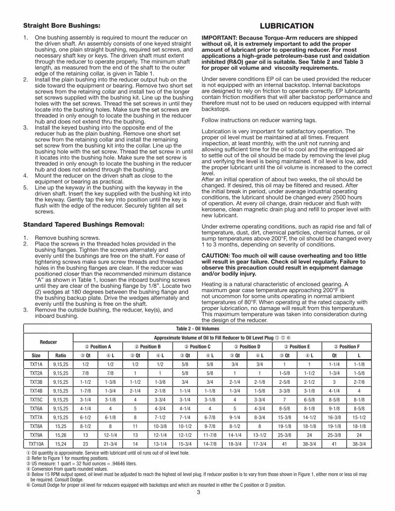
Straight Bore Bushings:
1. One bushing assembly is required to mount the reducer on the driven shaft. An assembly consists of one keyed straight bushing, one plain straight bushing, required set screws, and necessary shaft key or keys. The driven shaft must extent through the reducer to operate properly. The minimum shaft length, as measured from the end of the shaft to the outer edge of the retaining collar, is given in Table 1.
2. Install the plain bushing into the reducer output hub on the side toward the equipment or bearing. Remove two short set screws from the retaining collar and install two of the longer set screws supplied with the bushing kit. Line up the bushing holes with the set screws. Thread the set screws in until they locate into the bushing holes. Make sure the set screws are threaded in only enough to locate the bushing in the reducer hub and does not extend thru the bushing.
3. Install the keyed bushing into the opposite end of the reducer hub as the plain bushing. Remove one short set screw from the retaining collar and install the remaining set screw from the bushing kit into the collar. Line up the bushing hole with the set screw. Thread the set screw in until it locates into the bushing hole. Make sure the set screw is threaded in only enough to locate the bushing in the reducer hub and does not extend through the bushing.
4. Mount the reducer on the driven shaft as close to the equipment or bearing as practical.
5. Line up the keyway in the bushing with the keyway in the driven shaft. Insert the key supplied with the bushing kit into the keyway. Gently tap the key into position until the key is ! ush with the edge of the reducer. Securely tighten all set screws.
Standard Tapered Bushings Removal:
1. Remove bushing screws.2. Place the screws in the threaded holes provided in the
bushing ! anges. Tighten the screws alternately and evenly until the bushings are free on the shaft. For ease of tightening screws make sure screw threads and threaded holes in the bushing ! anges are clean. If the reducer was positioned closer than the recommended minimum distance “A” as shown in Table 1, loosen the inboard bushing screws until they are clear of the bushing ! ange by 1/8”. Locate two (2) wedges at 180 degrees between the bushing ! ange and the bushing backup plate. Drive the wedges alternately and evenly until the bushing is free on the shaft.
3. Remove the outside bushing, the reducer, key(s), and inboard bushing.
LUBRICATIONIMPORTANT: Because Torque-Arm reducers are shipped without oil, it is extremely important to add the proper amount of lubricant prior to operating reducer. For most applications a high-grade petroleum-base rust and oxidation inhibited (R&O) gear oil is suitable. See Table 2 and Table 3 for proper oil volume and viscosity requirements.
Under severe conditions EP oil can be used provided the reducer is not equipped with an internal backstop. Internal backstops are designed to rely on friction to operate correctly. EP lubricants contain friction modi" ers that will alter backstop performance and therefore must not to be used on reducers equipped with internal backstops.
Follow instructions on reducer warning tags.
Lubrication is very important for satisfactory operation. The proper oil level must be maintained at all times. Frequent inspection, at least monthly, with the unit not running and allowing suf" cient time for the oil to cool and the entrapped air to settle out of the oil should be made by removing the level plug and verifying the level is being maintained. If oil level is low, add the proper lubricant until the oil volume is increased to the correct level.After an initial operation of about two weeks, the oil should be changed. If desired, this oil may be " ltered and reused. After the initial break in period, under average industrial operating conditions, the lubricant should be changed every 2500 hours of operation. At every oil change, drain reducer and ! ush with kerosene, clean magnetic drain plug and re" ll to proper level with new lubricant.
Under extreme operating conditions, such as rapid rise and fall of temperature, dust, dirt, chemical particles, chemical fumes, or oil sump temperatures above 200°F, the oil should be changed every 1 to 3 months, depending on severity of conditions.
CAUTION: Too much oil will cause overheating and too little will result in gear failure. Check oil level regularly. Failure to observe this precaution could result in equipment damage and/or bodily injury.
Heating is a natural characteristic of enclosed gearing. A maximum gear case temperature approaching 200°F is not uncommon for some units operating in normal ambient temperatures of 80°F. When operating at the rated capacity with proper lubrication, no damage will result from this temperature. This maximum temperature was taken into consideration during the design of the reducer.
Table 2 - Oil Volumes
ReducerApproximate Volume of Oil to Fill Reducer to Oil Level Plug !
" Position A " Position B " Position C " Position D " Position E " Position F
Size Ratio # Qt $ L # Qt $ L # Qt $ L # Qt $ L # Qt $ L Qt L
TXT1A 9,15,25 1/2 1/2 1/2 1/2 5/8 5/8 3/4 3/4 1 1 1-1/4 1-1/8
TXT2A 9,15,25 7/8 7/8 1 1 5/8 5/8 1 1 1-5/8 1-1/2 1-3/4 1-5/8
TXT3B 9,15,25 1-1/2 1-3/8 1-1/2 1-3/8 3/4 3/4 2-1/4 2-1/8 2-5/8 2-1/2 3 2-7/8
TXT4B 9,15,25 1-7/8 1-3/4 2-1/4 2-1/8 1-1/4 1-1/8 1-3/4 1-5/8 3-3/8 3-1/8 4-1/4 4
TXT5C 9,15,25 3-1/4 3-1/8 4 3-3/4 3-1/4 3-1/8 4 3-3/4 7 6-5/8 8-5/8 8-1/8
TXT6A 9,15,25 4-1/4 4 5 4-3/4 4-1/4 4 5 4-3/4 8-5/8 8-1/8 9-1/8 8-5/8
TXT7A 9,15,25 6-1/2 6-1/8 8 7-1/2 7-1/4 6-7/8 9-1/4 8-3/4 15-3/8 14-1/2 16-3/8 15-1/2
TXT8A 15,25 8-1/2 8 11 10-3/8 10-1/2 9-7/8 8-1/2 8 19-1/8 18-1/8 19-1/8 18-1/8
TXT9A 15,26 13 12-1/4 13 12-1/4 12-1/2 11-7/8 14-1/4 13-1/2 25-3/8 24 25-3/8 24
TXT10A 15,24 23 21-3/4 14 13-1/4 15-3/4 14-7/8 18-3/4 17-3/4 41 38-3/4 41 38-3/4
% Oil quantity is approximate. Service with lubricant until oil runs out of oil level hole." Refer to Figure 1 for mounting positions.# US measure: 1 quart = 32 fl uid ounces = .94646 liters.$ Conversion from quarts rounded values.& Below 15 RPM output speed, oil level must be adjusted to reach the highest oil level plug. If reducer position is to vary from those shown in Figure 1, either more or less oil may
be required. Consult Dodge.! Consult Dodge for proper oil level for reducers equipped with backstops and which are mounted in either the C position or D position.

4
Table 3 - Oil Recommendations
ISO Grades For Ambient Temperatures of 50°F to 125°F (Refer to Notes below)
OutputRPM
Torque-Arm Reducer Size
TXT1A TXT2A TXT3B TXT4B TXT5C TXT6A TXT7A TXT8A TXT9A TXT10A
301 – 400 320 320 220 220 220 220 220 220 220 220
201 – 300 320 320 220 220 220 220 220 220 220 220
151 – 200 320 320 220 220 220 220 220 220 220 220
126 – 150 320 320 320 220 220 220 220 220 220 220
101 – 125 320 320 320 320 220 220 220 220 220 220
81 – 100 320 320 320 320 320 220 220 220 220 220
41 – 80 320 320 320 320 320 220 220 220 220 220
11 – 40 320 320 320 320 320 320 320 320 320 320
1 – 10 320 320 320 320 320 320 320 320 320 320
ISO Grades For Ambient Temperatures of 15°F to 60°F (Refer to Notes below)
OutputRPM
Torque-Arm Reducer Size
TXT1A TXT2A TXT3B TXT4B TXT5C TXT6A TXT7A TXT8A TXT9A TXT10A
301 – 400 220 220 150 150 150 150 150 150 150 150
201 – 300 220 220 150 150 150 150 150 150 150 150
151 – 200 220 220 150 150 150 150 150 150 150 150
126 – 150 220 220 220 150 150 150 150 150 150 150
101 – 125 220 220 220 220 150 150 150 150 150 150
81 – 100 220 220 220 220 220 150 150 150 150 150
41 – 80 220 220 220 220 220 150 150 150 150 150
11 – 40 220 220 220 220 220 220 220 220 220 220
1 – 10 220 220 220 220 220 220 220 220 220 220
Notes:1. Assumes auxiliary cooling where recommended in the catalog.2. Pour point of lubricant selected should be at least 10°F lower than expected minimum ambient starting temperature.3. Extreme pressure (EP) lubricants are not necessary for average operating conditions. TORQUE-ARM internal backstops are not suitable for use with EP lubricants.4. Special lubricants may be required for food and drug industry applications where contact with the product being manufactured may occur. Consult a lubrication
manufacturer’s representative for his recommendations .5. For reducers operating in ambient temperatures between -22°F (-30°C) and 20°F (–6.6°C) use a synthetic hydrocarbon lubricant, 100 ISO grade or AGMA 3 grade (for
example, Mobil SHC627) . Above 125°F (51°C), consult DODGE Gear Application Engineering (864) 284-5700 for lubrication recommendation .6. Mobil SHC630 Series oil is recommended for high ambient temperatures.

5
OIL VISCOSITY EQUIVALENCY CHART
2000
1000
800
600
500
400
300
200
100
80
60
50
40
30
20
10
8
6
5
4
3
2
70
60
50
40
30
20
10
8
5
4
9
7
6
1500
1000
680
460
320
220
150
100
68
8A
8
7
6
5
4
3
2
85W
250
140
90
80W
46
32
22
15
10
7
5
175W
3
2
300
200
150
100
80
70
60
50
40
35
32
400
500
600
800
1000
1500
2000
3000
4000
50006000
8000
10,000
cSt/40˚ C 100˚ C
cSt/ ISOVG
AGMAGRADES
GRADESGEAR OILS
SUS/100˚F
SUS/210˚F
SAE
KINEMATICVISCOSITIES
SAYBOLTVISCOSITIES
200
300
100
90
80
70
60
55
50
45
40VISCOSITIES CAN BERELATED HORIZONTALLYONLY.VISCOSITIES BASED ON96 VI SINGLE GRADEOILS.ISO ARE SPECIFIED AT40˚C.AGMA ARE SPECIFIED AT40˚C.SAE 75W, 80W, AND 85WSPECIFIED AT LOWTEMPERATURE. EQUIVALENTVISCOSITIES FOR 100˚FAND 200˚ F ARE SHOWN.SAE 90 TO 250 SPECIFIEDAT 100˚C.

6
GUIDELINES FOR TXT REDUCER LONG-TERM STORAGEDuring periods of long storage, or when waiting for delivery or installation of other equipment, special care should be taken to protect a gear reducer to have it ready to be in the best condition when placed into service.
By taking special precautions, problems such as seal leakage and reducer failure due to lack of lubrication, improper lubrication quantity, or contamination can be avoided. The following precautions will protect gear reducers during periods of extended storage:
Preparation:
1. Drain oil from the unit. Add a vapor phase corrosion inhibiting oil (VCI-105 oil by Daubert Chemical Co.) in accordance with Table 4.
2. Seal the unit airtight. Replace the vent plug with a standard pipe plug and wire the vent to the unit.
3. Cover all unpainted exterior parts with a waxy rust preventative compound that will keep oxygen away from the bare metal. (Non-Rust X-110 by Daubert Chemical Co. or equivalent)
4. The instruction manuals and lubrication tags are paper and must be kept dry. Either remove these documents and store them inside, or cover the unit with a durable waterproof cover which can keep moisture away.
5. Protect reducer from dust, moisture, and other contaminants by storing the unit in a dry area.
6. In damp environments, the reducer should be packed inside a moisture-proof container or an envelope of polyethylene containing a desiccant material. If the reducer is to be stored outdoors, cover the entire exterior with a rust preventative.
When placing the reducer into service:
1. Fill the unit to the proper oil level using a recommended lubricant. The VCI oil will not affect the new lubricant.
2. Clean the shaft extensions with petroleum solvents.3. Assemble the vent plug into the proper hole.
Follow the installation instructions provided in this manual.
Table 4 - Quantities of VCI #105 Oil
Reducer Size Quantity (Ounces / Mililiter)
TXT1A 1 / 30
TXT2A 1 / 30
TXT3B 1 / 30
TXT4B 1 / 30
TXT5C 1 / 30
TXT6A 2 / 59
TXT7A 2 / 59
TXT8A 3 / 89
TXT9A 4 / 118
TXT10A 6 / 177
VCI #105 and #10 are interchangeable.VCI #105 is more readily available.
Motor Mounts
Figure 6 - Motor Mounts
Warning: Belt guard removed for illustration purposes. Do not operate if belt guard is not in place.
Motor Mount Installation:
The TA motor mount is designed to be installed on the output end of the reducer as shown in Figure 6. If bottom mounting is desired, use the optional TAB style.
TA1M thru TA7M Motor Mount:
Remove the required housing bolts on the output end of the reducer. Place the motor mount brackets in position and install the longer housing bolts supplied with the motor mount assembly. Do not fully tighten the housing bolts at this time.
Install the bottom plate to the motor mount brackets and tighten with the hardware provided. Next, tighten the housing bolts to the torque values listed in Table 6.
Install the four adjusting studs to the bottom plate using the jam nuts provided and securely tighten. These nuts will not require any further adjustment. Add one additional jam nut to each stud and thread approximately to the middle of the stud. Install the top motor plate on top of the jam nuts. Assemble the remaining jam nuts on studs to secure top motor plate. Do not fully tighten these nuts yet.
Mount motor, drive and driven sheaves, and v-belts.
Note: Mount driven sheave as close to the reducer housing as practical.
Adjust v-belts to the proper tension by adjusting the jam nuts and securely tighten.
Check all bolts to insure that they are securely tightened.
TA8 thru TA10 Motor Mount:
Remove the required housing bolts on the output end of the reducer. Place the motor mount brackets in position and install the longer housing bolts supplied with the motor mount assembly. Do not fully tighten the housing bolts at this time.
Install the four adjusting studs to the top plate as shown using the jam nuts provided and securely tighten. Add one additional

7
jam nut to each stud and thread approximately to the middle of the stud. Install this assembly to the motor mount brackets and install the remaining jam nuts onto the studs to secure the top plate to the brackets. Tighten the housing bolts to the torque values listed in Table 6.
Loosely install the front motor rail to the top plate. Measure the distance between the front and rear mounting holes on the motor and position the rear motor rail at this distance and loosely bolt to the top plate.
Center the motor on the motor rails and securely bolt the motor to the motor rails.
Install the motor sheave and reducer sheave on their shafts. Mount the reducer sheave as close to the housings as practical. Install the v-belts and adjust the motor rails to permit proper alignment of the v-belts to the sheaves. Securely tighten the motor rails to the mounting plate.
Adjust the v-belts to the proper tension and securely tighten the adjusting nuts.
Check all bolts to see that they are securely tightened.
WARNING: To ensure that drive is not unexpectedly started, turn off and lock out or tag power source before proceeding. Remove all external loads from drive before removing or servicing drive or accessories. Failure to observe these precautions could result in bodily injury.
REPLACEMENT OF PARTSNOTE: Using tools normally found in a maintenance department, a Dodge Torque-Arm speed reducer can be disassembled and reassembled by careful attention to the instructions following.
Cleanliness is very important to prevent the introduction of dirt into the bearings and other parts of the reducer. A tank of clean solvent, an arbor press, and equipment for heating bearings and gears (for shrinking these parts on shafts) should be available.
The oil seals are designed with a contact lip. Considerable care should be used during disassembly and reassembly to avoid damage to the surface on which the seals rub.
The keyseat in the input shaft, as well as any sharp edges on the output hub should be covered with tape or paper before disassembly or reassembly. Also, be careful to remove any burrs or nicks on surfaces of the input shaft or output hub before disassembly or reassembly.
Ordering Parts:
When ordering parts for a Dodge Torque Arm reducer, specify reducer part number, part name, and quantity required.
It is strongly recommended that, when a pinion or gear is replaced, the mating pinion or gear is replaced also.
If the large gear on the output hub must be replaced, it is recommended that an output hub assembly consisting of a gear assembled on a hub be ordered to ensure undamaged surfaces on the output hub where the output seals rub. However, if it is desired to use the old output hub, press the gear and bearing off and examine the rubbing surface under the oil seal carefully for possible scratching or other damage resulting from the pressing operation. To prevent oil leakage at the shaft oil seals, the smooth surface of the output hub must not be damaged.
If any parts must be pressed from a shaft or from the output hub, this should be done before ordering parts to make sure that none of the bearings or other parts are damaged in removal. Do not press against rollers or cage of any bearing. Because old shaft oil seals may be damaged in disassembly, it is advisable to order replacements for these parts.
Removing Reducer from Shaft:
WARNING: To ensure that drive is not unexpectedly started, turn off and lock out or tag power source before proceeding. Remove all external loads from drive before removing or servicing drive or accessories. Failure to observe these precautions could result in bodily injury.
Taper Bushed Reducer:
1. Disconnect and remove belt guard, v-drive, and motor mount as required. Disconnect torque arm rod from reducer adapter.
2. Remove bushing screws.3. Place the screws in the threaded holes provided in the
bushing ! anges. Tighten the screws alternately and evenly until the bushings are free on the shaft. For ease of tightening screws, make sure screw threads and threaded holes in bushing ! anges are clean. A tap can be used to clean out the threads. Use caution to use the proper size tap to prevent damage to the threads.
4. Remove the outside bushing, the reducer, and then the inboard bushing.
Straight Bore Reducer:
1. Disconnect and remove belt guard, v-drive, and motor mount as required. Disconnect torque arm rod from reducer adapter.
2. Loosen and remove the set screws in both output hub collars.
3. Remove the collar from the output hub closest to the end of the shaft. This will expose three puller holes in the output hub to permit the use of a three prong puller. In removing the reducer from the shaft, use care not to damage the reducer output hub.
Disassembly:
1. Drain all oil from the reducer.2. Remove all locking collars, retaining rings, and bushing
backup plated as required. Position the reducer on its side and remove all housing bolts. Using the three pry slots around the periphery of the ! ange, gently separate the housing halves and open evenly to prevent damage to the parts inside. Remove the two dowel pins.
3. Lift input shaft, all gear assemblies, and bearing assemblies from housing.
4. Remove seals from housing.5. Remove bearings from shafts and hubs. Be careful not to
scratch or damage any assembly or seal area during bearing removal. The hub assembly can be disassembled for gear replacement but if scratching or grooving occurs on the hub, seal leakage will occur and the hub will need to be replaced.
TXT Reassembly:
1. Output Hub Assembly: Heat gear to 325°F to 350°F to shrink onto hub. Heat bearings to 270°F to 290°F to shrink onto hub. Any damage to the hub surfaces where the oil seals rub will cause leakage, making it necessary to replace the hub.
2. Countershaft Assembly: Heat gear to 325°F to 350°F and bearings to 270°F to 290°F to shrink onto shaft.
3. Input Shaft Assembly: Heat bearings 270°F to 290°F to shrink onto shaft. Press bearings on shaft.
4. Drive the two dowel pins into place in the right-hand housing half (backstop side).
5. Place R.H. housing half on blocks to allow for protruding end of output hub.
6. Install all bearing cups on TXT3B thru TXT10A in right-hand housing half, making sure they are properly seated. TXT1A and TXT2A reducers use ball bearings on all shafts and do not incorporate bearing cups.
7. Mesh output hub gear and small countershaft gear together and set in place in housing. Set input shaft assembly in

8
place in the housing. Make sure bearing rollers (cones) are properly seated in their cups.
8. Make sure both housing halves are clean. Apply a continuous 1/8” diameter bead of Dow Corning RTV732 sealant on the ! ange surface of the R.H. housing (make sure RTV is placed around all bolt holes). Set the left-hand housing half into position onto the dowel pins and gently tap with a soft hammer (rawhide, not lead hammer) until housing bolts can be used to draw housing halves together. Make sure reducer shafts do not bind while tightening housing bolts. Torque housing bolts per torque values listed in Table 6.
9. On TXT1A and TXT2A reducers, skip to step number 12.10. Place the output bearing cup into the housing and tap into
place. Install the output seal carrier and draw down with two bolts 180° apart to 50 inch pounds of torque. Loosen both bolts then retighten " nger tight only. Measure the clearance between the housing and carrier ! ange at each bolt and average the two values. Add 0.010” to the average reading and make up shim pack. Install shim pack between the carrier ! ange and the reducer housing. Torque the bolts to the value shown in Table 6. Using a magnetic base and dial indicator, check the axial end play. Add or remove shims until the axial endplay reading of the output hub is per Table 5.
11. Repeat step 9 above for installing and adjusting the countershaft and input bearings. Adjust the axial endplay per Table 5.
12. Install input and output seals. Lightly coat the seal lips with Mobilith AW2 All-Purpose grease or equivalent. The possibility of damage and consequent oil leakage can be decreased by covering all sharp edges with tape prior to seal installation. Seals should be pressed or tapped with a soft hammer evenly into place in the reducer housing, applying pressure only on the outer edge of the seals. Extreme care should be used when installing seals to avoid damage due to contact with sharp edges on the input shaft or output hub. A slight oil leak at the seals may be evident during initial running, but should disappear unless seals have been damaged.
13. Install bushing backup plates and snap rings on Taper Bushed reducers or hub collars on straight bore reducers and install backstop cover. Make sure all bolts are tightened to the correct torque values listed in Table 6.
Table 5 - Bearing Adjustment Tolerances
Reducer SizeBearing Endplay Values
Input Countershaft Ouput
TXT1A N / A N / A N / A
TXT2A N / A N / A N / A
TXT3B .002-.004 Loose .0005-.003 Loose .0005-.003 Loose
TXT4B .002-.004 Loose .0005-.003 Loose .0005-.003 Loose
TXT5C .002-.004 Loose .0005-.003 Loose .0005-.003 Loose
TXT6A .002-.004 Loose .0005-.003 Loose .0005-.003 Loose
TXT7A .002-.004 Loose .0005-.003 Loose .0005-.003 Loose
TXT8A .002-.004 Loose .0005-.003 Loose .0005-.003 Loose
TXT9A .002-.004 Loose .0005-.003 Loose .0005-.003 Loose
TXT10A .002-.004 Loose .0005-.003 Loose .0005-.003 Loose
Table 6 - Recommended Bolt Torque Values
Recommended Torque Values (lbs.-ft.)
Reducer Size
Housing Bolts
Output Seal Carrier
C/S Bearing Cover
Input Seal Carrier
TXT1A 30 - 27 N/A N/A N/A
TXT2A 30 - 27 N/A N/A N/A
TXT3B 50 - 45 17 – 15 17 – 15 17 – 15
TXT4B 50 - 45 30 – 27 30 – 27 30 – 27
TXT5C 75 - 68 30 – 27 30 – 27 30 – 27
TXT6A 75 - 68 30 – 27 30 – 27 30 – 27
TXT7A 150 - 135 30 – 27 50 - 45 50 - 45
TXT8A 150 - 135 30 – 27 30 – 27 30 – 27
TXT9A 150 - 135 30 – 27 30 – 27 30 – 27
TXT10A 150 - 135 30 – 27 30 – 27 30 – 27
Backstop Cover Bolt Recommended Torque Values
Reducer Size Fastener Size Torque in Ft.-Lbs.
TXT1A 10 - 24 x 3/8 5 – 4
TXT2A 10 - 24 x 3/8 5 – 4
TXT3B 10 - 24 x 3/8 5 – 4
TXT4B ! - 20 x " 8 – 7
TXT5C ! - 20 x " 8 – 7
TXT6A ! - 20 x " 8 – 7
TXT7A ! - 20 x " 8 – 7
TXT8A ! - 20 x " 8 – 7
TXT9A ! - 20 x " 8 – 7
TXT10A ! - 20 x " 8 – 7

9
Replacement Part and Kit Numbers
Table 7 – Part Numbers for ReplacementBearings, Double Reduction Reducers
ReducerSize
Output Hub Bearing – LH and RH Sides
Part Number Manufacturer's Part Number
TXT1A 424020 6011NR
TXT2A 424022 6013NR
TXT3B 402272 / 403127 LM814849 / LM814810
TXT4B 402268 / 403163 498 / 492A
TXT5C 402193 / 403016 42381 / 42584
TXT6A 402050 / 403140 JM822049 / JM822010
TXT7A 402058 / 403111 48290 / 48220
TXT8A 402147 / 403105 36690 / 36620
TXT9A 402160 / 403110 46790 / 46720
TXT10A 402168 / 403116 67790 / 67720
ReducerSize
Countershaft Bearing – LH Input Side
Part Number Manufacturer's Part Number
TXT1A 424006 6304NR
TXT2A 424000 305NR
TXT3B 402273 / 403094 15102 / 15245
TXT4B 402000 / 403000 M86649 / M86610
TXT5C 402203 / 403027 2789 / 2720
TXT6A 402054 / 403159 HM807040 / HM807010
TXT7A 402256 / 403053 JHM807045 / JHM807012
TXT8A 402057 / 403143 JH211749 / JH211710
TXT9A 402109 / 403078 655 / 652A
TXT10A 402232 / 402231 JH415647 / JH415610
ReducerSize
Countershaft Bearing – RH Backstop Side
Part Number Manufacturer's Part Number
TXT1A 424006 6304NR
TXT2A 424000 305NR
TXT3B 402273 / 403094 15102 / 15245
TXT4B 402000 / 403000 M86649 / M86610
TXT5C 402203 / 403027 2789 / 2720
TXT6A 402052 / 403142 HM803149 / HM803110
TXT7A 402256 / 403053 JHM807045 / JHM807012
TXT8A 402148 / 403106 39585 / 39520
TXT9A 402109 / 403078 655 / 652A
TXT10A 402232/402231 JH415647 / JH415610
ReducerSize
Input Shaft Bearing – LH Input Side
Part Number Manufacturer's Part Number
TXT1A 424112 6205NR
TXT2A 424019 206NR
TXT3B 402204 / 403139 LM48548A / LM48510
TXT4B 402280 / 403027 2788 / 2720
TXT5C 402144 / 403104 28579 / 28521
TXT6A 402196 / 403091 395A / 3920
TXT7A 402150 / 403106 39590 / 39520
TXT8A 402098 / 403072 566 / 563
TXT9A 402114 / 403080 745A / 742
TXT10A 402114 / 403080 745A / 742
ReducerSize
Input Shaft Bearing – RH Backstop Side
Part Number Manufacturer's Part Number
TXT1A 424111 6204NR
TXT2A 424090 6305NR
TXT3B 402273 / 403094 15102 / 15245
TXT4B 402142 / 403102 26118 / 26283
TXT5C 402266 / 403073 350A / 352
TXT6A 402197 / 403091 396 / 3920
TXT7A 402088 / 403047 455 / 452
TXT8A 402097 / 403072 565 / 563
TXT9A 402107 / 403076 639 / 633
TXT10A 402112 / 403080 745S / 742
Note: Bearing part numbers refer to Cup/Cone combinations, respectively, and apply to all ratios unless otherwise specifi ed. For actual reducer ratios, refer to Table 9.

10
Table 8 - Replacement Parts Kit Numbers
Reducer Size Ratio Seal KitOutput Hub Assembly Countershaft
Assembly Bearing Kit(s)Taper Hub Straight Hub
TXT1A
9:1
392119 390878 390151
392100
389905 All15:1 392090
25:1 392091
TXT2A
9:01
392120 392111 392110
392101
389906 All15:1 392092
25:1 392093
TXT3B
9:1
389720 389703 389702
389729
392345 All15:1 389700
25:1 389701
TXT4B
9:1
389721 389710 389709
389730
392347 All15:1 389707
25:1 389708
TXT5C
9:1
389722 389717 389716
389731
392350 All15:1 389714
25:1 389715
TXT6A
9:1
246340 390935 390988
392140
335368 All15:1 391171
25:1 391186
TXT7A
9:1
247345 390941 390990
392141
392353 All15:1 391196
25:1 391197
TXT8A15:1
248340 390944 390993391184
392355 All25:1 391185
TXT9A15:1
249340 390949 390159390124
392357 All26:1 390139
TXT10A15:1
272460 390954 390160390983
392359 All24:1 390998
Notes:Seal Kit consists of Input Seal, Output Seals, Backstop Cover Gasket and RTV Sealant.Output Hub Assembly consists of Output Hub, Output Gear and Gear Key.Countershaft Assembly consists of Countershaft Pinion, Countershaft Gear and Gear Key.Bearing Kit consists of LH and RH Output Bearing Cup/Cone, LH and RH Countershaft Bearing Cup/Cone (double reduction only) and LH and RH Input Bearing Cup/Cone.

11
Parts for TXT/HXT 1A & 2A Straight and Tapered Bushed Double Reduction Reducers

12
Parts for TXT/HXT 1A & 2A Straight and Tapered Bushed Double Reduction Reducers
Ref. Description Qty. TXT/HXT 1A TXT/HXT 2A
1212
3!!16182022!!253438
Backstop AssemblyHousing-LHHousing-RHHousing-RH, Flange Mount DrilledHousing-Hydroil LHRTV Sealant, TubeAir VentHousing BoltHousing Bolt-AdapterLock-WasherHex NutDowel PinMagnetic Oil PlugOil PlugBackstop Shaft CoverBackstop Cover Screw
1111111"2##21414
242101241358241359241387241064465044900287411418411420419011407087420145430060430031242221415022
252101242353242354242393242067465044900287411418411420419011407087420145430060430031243221415022
364278
Seal Kit $Backstop Cover Gasket %Input Oil Seal %Output Hub Oil Seal %
1112
392119242220241457241210
392120243220242211242210
40
130
Input Pinion9:1 Ratio &15:1 Ratio &25:1 Ratio &Hydroil Input Pinion15:1 Ratio &25:1 Ratio &
111
11
241481241302241200
241455241449
242481242186242187
242188242189
41 Input Pinion Key 1 443008 443014
44465480
Bearing Replacement Kit $Input Pinion Bearing-LH, Input Side %Input Pinion Bearing-RH, Backstop Side %Countershaft Pinion Bearing %Output Hub Bearings %
11122
389905424112424111424006424020
389906424019424090424000424022
4850
52
Countershaft Pinion Assembly $9:1 Ratio &15:1 Ratio &25:1 Ratio &Countershaft Pinion %First Reduction Gear %9:1 Ratio &15:1 Ratio &25:1 Ratio &Countershaft to First Gear Key %
1111
1111
392100392090392091241216
241482241170241171241309
392101392092392093242185
242482242008242005242218
Taper Bore Output Hub Assembly $ 1 390878 392111
Straight Bore Output Hub Assembly ' 1 390151 392110
60
62645961
Output HubStraight Bore (Taper Bore %
Output Gear % (Output Gear Key % (Output Hub Snap Ring %Straight Bore Output Hub Key (
111122
241208241265241007241217421013241296
242208242134242181443399421017242296
68707274
Straight Bore Output Hub CollarStraight Bore Output Hub Collar ScrewTaper Bore Bushing Backup PlateBushing Backup Plate Retaining Ring
2422
241209400062241266421111
242209400094242137421112
84 Taper Bore Bushing Assembly $Bushing %1” Bore1-1/16” Bore1-1/8” Bore1-3/16” Bore1-1/4” Bore1-5/16” Bore1-3/8” Bore1-7/16” Bore1-11/16” Bore1-1/2” Bore1-5/8” Bore1-3/4” Bore1-15/16” Bore
1111111111111
241278241280241282241286241288241290241294241292
N/AN/AN/AN/AN/A
N/AN/A
242146242148242150242152242154242156242164242158242162242166242168

13
Parts for TXT/HXT 1A & 2A Straight and Tapered Bushed Double Reduction Reducers
Ref. Description Qty. TXT/HXT 1A TXT/HXT 2A
86 Bushing Screw ! 6 411405 411390
88 Lock Washer ! 6 419010 419010
90 Key, Taper Bore Bushing to Shaft !1” Bore1-1/8” Bore1-3/16” Bore1-1/4” Bore1-5/16” Bore1-3/8” Bore1-7/16” Bore1-1/2” Bore1-5/8” Bore1-11/16”1-3/4” Bore1-15/16” Bore
111111111111
443274443271241308241307241306241310241305
N/AN/AN/AN/AN/A
N/A443281443281443281443264443280443282443282424172242171242170443283
" Key, Bushing to Output Hub !1” Bore1-1/8” Bore1-1/8” to 1-1/2” Bore
111
443272443273
N/A
N/AN/A
443284
949698100102104106110
Torque-Arm Assembly #Torque-Arm Rod End !RH Nut !Torque-Arm Turnbuckle !Torque-Arm Extension !LH Nut !Torque-Arm Fulcrum !Fulcrum Screw !Hex Nut !
111111111
241097241245407093241246241247407242241249411456407091
243097243245407095243246243247407244243249411484407093
112114116118120122
Adapter Assembly #RH Torque-Arm Adapter Bracket !LH Torque-Arm Adapter Bracket !Adapter Bushing !Adapter Bolt !Lock Washer !Hex Nut !
1111111
259151241242241241242243411412419011407087
259152242136242135243243411437419012407089
124126128111""
Hydraulic Motor AdapterAdapter ScrewLockwasherInput Pinion Seal, HydroilMotor to Adapter ScrewMotor to Adapter Lock Washer
166122
241454417081419046241457411408419011
242454417081419046242457411408419011
Notes:" Not shown on Drawing.# Includes Parts Listed Immediately Below$ Includes Parts Listed Immediately Below! Makes up Assembly Under Which it is Listed.% Makes up Assembly Under Which it is Listed.& See Table 9 for Actual Ratio.' 4 Required on TXT1A and 5 Required on TXT2A( 6 Required on TXT1A and 7 Required on TXT2A

14
Parts for TXT3B thru TXT5C Straight and Tapered Bushed Double Reduction Reducers

15
Parts for TXT3B thru TXT5C Straight and Tapered Bushed Double Reduction Reducer
Ref. Description Qty. TXT3BHXT3B
TXT4BHXT4B
TXT5CHXT5C
1212
!!16182022!!2528303233343839
Backstop AssemblyHousing - TXT and Hydroil LHHousing-RHHousing-RH, Flange Mount DrilledRTV Sealant, TubeAir VentHousing BoltHousing Bolt-AdapterLock-WasherHex NutDowel PinMagnetic Oil PlugOil PlugInput Shaft Seal CarrierInput Shaft Bearing Shim PackInput Seal Carrier ScrewLock WasherBackstop CoverBackstop Shaft CoverBackstop Cover Screw
11111162882141"##144
243106243228243229243384465044900287411440411442419012407089420146430060430031243543389704411390419010243560416524
N/A
244106244365244366244387465044900287411442411444419012407089420146430060430031244577389711411407419011244493411035
N/A
245154245369245370245373465044904287411464411466419013407091420147430062430033245597389732411407419011245226411394419009
364278
Seal Kit $Backstop Cover Gasket %Input Pinion Shaft Seal %Output Hub Oil Seal %
1112
389720243561243558243578
389721244593244524244673
389722245220355011245545
40
130
Input Pinion9:1 Ratio &15:1 Ratio &25:1 Ratio &15:1 Ratio Hydroil Pinion &25:1 Ratio Hydroil Pinion &15:1 Ratio Hydroil 6-B Pinion & 25:1 Ratio Hydroil 6-B Pinion &
1111111
243549243550243551243553243554
N/A243498
244579244580244581244583244584244586244587
245599245600245601245603245604
N/A245641
41 Input Pinion Shaft Key 1 443032 443082 443096
44454647
Input Bearing Kit $Input Shaft Bearing Cone, Input Side %Input Shaft Bearing Cup, Input Side %Input Shaft Bearing Cone, Backstop Side %Input Shaft Bearing Cup, Backstop Side %
11111
389587402204403139402273403094
389590402280403027402142403102
389594402144403104402266403073
4850
52
Countershaft Pinion Assembly $9:1 Ratio &15:1 Ratio &25:1 Ratio &Countershaft Pinion %First Reduction Gear %9:1 Ratio &15:1 Ratio &25:1 Ratio &First Stage Gear Key %
1111111111
389729389700389701243555
243237243238243239D8242
389730389707389708244590
244482244214244212D8243
389731389714389715245596
245482245214245212D8243
545556575859
Countershaft Bearing Kit $Countershaft Bearing Cone, Input Side %Countershaft Bearing Cup, Input Side %Countershaft Bearing Cone, Backstop Side %Countershaft Bearing Cup, Backstop Side %Countershaft Bearing Cover, Input Side %Countershaft Bearing Shim Pack
111111"
389588402273403094402273403094243545389705
389591402000403000402000403000244578389712
389595402203403027402203403027245594389718
60 6264
Taper Bore Output Hub Assembly $Straight Bore Output Hub Assembly 'Output HubStraight Bore (Taper Bore %Output Gear % (Output Gear Key % (
11 1111
389703389702
243557243556243570243216
389710389709
244589244588244188354087
389717389716
245591245590245186355064
68707274
Output Hub Collar, Straight BoreOutput Hub Collar ScrewBushing Backup Plate, Taper BoreBushing Backup Plate Retaining Ring
2422
243572400098243308421109
244658400150244099421108
245598400154245114421107
76 808182
Output Hub Seal Carrier, Input SideOutput Hub Bearing Kit Output Hub Bearing, Cone %Output Hub Bearing, Cup %Output Hub Bearing Shim Kit
1122"
243547389589402272403127389706
244591389592402268403163389713
245592389596402193403016389719

16
Parts for TXT3B thru TXT5C Straight and Tapered Bushed Double Reduction Reducer, continued
Ref. Description Qty. TXT3BHXT3B
TXT4BHXT4B
TXT5CHXT5C
84
8688
Taper Bore Bushing Assembly !Bushing "1-5/16” Bore1-3/8” Bore1-7/16” Bore1-1/2” Bore1-5/8” Bore1-11/16” Bore1-3/4” Bore1-7/8” Bore1-15/16” Bore2” Bore2-1/8” Bore2-3/16” Bore2-1/4” Bore2-7/16” Bore2-1/2” Bore2-11/16” Bore2-15/16” BoreTaper Bushing Screw "Taper Bushing Lockwasher "
1111111111111111166
243282243284243260243262243264243268243266243270243272243274
N/A243276
N/AN/AN/AN/AN/A
411407419011
N/AN/A
244079244081244083244085244087244089244093244095244109244111244113244115
N/AN/AN/A
411408419011
N/AN/AN/AN/AN/AN/AN/A
245084245086245088
N/A245090245092245094245099245110245112411435419012
90 Key, Bushing to Shaft "1-5/16” Bore1-3/8” Bore1-7/16” Bore1-1/2” Bore1-5/8” Bore1-11/16” Bore1-3/4” Bore1-7/8” Bore1-15/16” Bore2” Bore2-1/8” Bore2-3/16” Bore2-1/4” Bore2-7/16” Bore2-1/2” Bore2-11/16” Bore2-15/16” Bore
11111111111111111
443264443264443265443265443265443266443266443267443269443268
N/A443270
N/AN/AN/AN/AN/A
N/AN/A
443254443254443254443254443254443255443255443255443258443259443260443261
N/AN/AN/A
N/AN/AN/AN/AN/AN/AN/A
443251443251443251
N/A443251443251443243443244443245443250
# Key, Bushing to Output Hub "1-3/4” thru 1-15/16” Bore Bushing1-7/16” thru 2-1/4” Bore Bushing2-3/16” thru 2-15/16” Bore Bushing
111
443262N/AN/A
N/AN/A
443257
N/A443202
N/A
949698100102104106110
Torque-Arm Rod Kit !Torque-Arm Rod End "RH Nut "Torque-Arm Turnbuckle "Torque-Arm Extension "LH Nut "Fulcrum "Fulcrum Screw "Hex Nut "
111111111
243097243245407095243246243247407244243249411484407093
245097243245407095243246243247407246243249411484407093
245097243245407095243246243247407246243249411484407093
112114116118120122
Adapter Assembly !RH Adapter Plate "LH Adapter Plate "Adapter Bushing "Adapter Bolt "Lockwasher "Hex Nut "
1111111
259153243242243241243243411437419012407089
259154244244244243245243411460419013407091
259155245242245241245243411460419013407091
124
126128
Hydroil Motor Adapter15:1 Ratio Motor Adapter25:1 Ratio Motor AdapterHydroil 6-B Motor Adapter, 15:1 and 25:1 RatioAdapter ScrewLockwasherMotor to Adapter ScrewMotor to Adapter Lock Washer
111$$
243539243541243467417081419046
244572244572244573417108419047
245606245607245643415023419047
Notes: Not shown on drawing.
! Includes parts listed immediately below % Includes parts listed immediately below" Makes up assembly under which it is listed.& Makes up assembly under which it is listed.' See Table 9 for actual ratio.$ 4 required on TXT3B and TXT4B, 5 required on TXT5C( Two sets recommended.

17
Parts for TXT6A thru TXT10A Straight and Tapered Bushed double Reduction Reducers

18
Parts for TXT6A thru TXT10A Straight and Tapered Bushed double Reduction Reducers
Ref. Description Qty. TXT6AHXT6A
TXT7AHXT7A
TXT8A TXT9A TXT10A
1212
!!16182022!25!2830323334353839
Backstop AssemblyHousing-TXT and Hydroil LHHousing-RHHousing-RH, Flange Mount DrilledRTV Sealant, TubeAir VentHousing BoltHousing Bolt-AdapterLock-WasherHex NutDowel PinMagnetic Oil PlugOil PlugInput Shaft Seal CarrierInput Shaft Bearing Shim PackCarrier and Cover ScrewLock WasherBackstop CoverBackstop Retaining RingBackstop Cover ScrewBackstop Cover Lock Washer
11111122142141"##1$66
246092246358246359
465044904287411466411468419013407091420147430062430033246184391164411408419011246226421029411394419009
247260247358247359
465044904287411498411499419016407095420148430064430035247320390420411433419012246226421029411394419009
249260248358248359
465044904287411499411502419016407095420148430064430035258023390038411408419011248226421034411394419009
249260249358249359
465044904287411500411502419016407095420148430064430035249211390168 411408419011248226421034411394419009
250260250358250359
465044904287411502411506419016407095420148430064430035249211390168411408419011248226421034411394419009
364278
Seal Kit %Backstop Cover Gasket &Input Pinion Shaft Seal &Output Hub Oil Seal &
1112
246340246220242210246310
247345246220242210247310
248340248220248211258019
249340248220248211249210
272460248220248211250010
40
130
Input Pinion9:1 Ratio '15:1 Ratio '25:1 Ratio ' (15:1 Ratio Hydroil Pinion '25:1 Ratio Hydroil Pinion '15:1 Ratio 6B Hydroil Pinion '25:1 Ratio 6B Hydroil Pinion '
1111111
246481246290246291246230246286
N/A246521
247479247370247371247463247462
N/A247521
N/A
248370248371
N/AN/AN/AN/A
N/A
272074272106
N/AN/AN/AN/A
N/A
250300250004
N/AN/AN/AN/A
41 Input Pinion Shaft Key 1 443113 443127 443133 443123 443123
44454647
Input BearingsInput Shaft Bearing Cone, Input SideInput Shaft Bearing Cup, Input SideInput Shaft Bearing Cone, Backstop SideInput Shaft Bearing Cup, Backstop Side
1111
402196403091402197403091
402150403106402088403047
402098403072402097403072
402114403080402107403076
402114403080402112403080
4850
52
Countershaft Pinion Assembly %9:1 Ratio '15:1 Ratio '25:1 Ratio ' (Countershaft Pinion &First Reduction Gear &9:1 Ratio '15:1 Ratio '25:1 Ratio ' (First Stage Gear Key &
1111 1111
392140391171391186246294
246482246492246293245218
392141391196391197247002
247478247008247005247218
N/A391184391185248002
N/A248213248214248218
N/A390124390139249006
N/A249008249005248218
N/A390983390998272249
N/A250301250005248218
545556575859
Countershaft BearingsCountershaft Bearing Cone, Input SideCountershaft Bearing Cup, Input SideCountershaft Bearing Cone, Backstop SideCountershaft Bearing Cup, Backstop SideCountershaft Bearing Cover, Input SideCountershaft Bearing Shim Pack
11111"
402054403159402052403142246185391165
402256403053402256403053247194390429
402057403143402148403106248223391182
402109403078402109403078249225390168
402232402231402232402231272251390575
60
6264
Taper Bore Output Hub Assembly %Straight Bore Output Hub Assembly )Straight Bore Hub *Taper Bore Hub &Output Gear & *Output Gear Key & *
111112
390935390988246338246269246295245217
390941390990247338272137247215245217
390944390993248332272036248215248217
390949390159250090249140021764443413
390954390160250008272241250007250017
6870
Output Hub Collar, Straight Bore Output Hub Collar Screw
24
246309 400154
247309 400190
248209 400190
249209 400194
250009400194
727476
Bushing Backup Plate, Taper BoreOutput Hub Retaining RingOutput Hub Seal Carrier, Input Side
221
246270421055 246187
272138421099 247315
272037421098 258021
272082421097 249221
272242421069250011
808182
Output Hub Bearing Kit 1Output Hub Bearing, ConeOutput Hub Bearing, CupOutput Hub Bearing Shim Kit
122"
402050403140391187
402058403111390044
402147403105390048
402160403110390171
402168403116390172

19
Parts for TXT6A thru TXT10A Straight and Tapered Bushed double Reduction ReducersRef. Description Qty. TXT6A TXT7A TXT8A TXT9A TXT10A
84
8688
Taper Bore Bushing Assembly !Bushing "2-3/16” Bore2-1/4” Bore2-7/16” Bore 2-1/2” Bore2-11/16” Bore2-13/16” Bore2-7/8” Bore2-15/16” Bore3” Bore3-3/16” Bore3-7/16” Bore3-15/16” Bore4-3/16” Bore4-7/16” Bore4-15/16” Bore5-7/16” BoreTaper Bushing Screw "Taper Bushing Lockwasher "
111111111111111166
246261 246262246263 246264246265
N/A246266246267246283
N/A246268
N/AN/AN/AN/AN/A
411435419012
N/AN/A
272125N/A
272147272130272131272132272133272134272135272136
N/AN/AN/AN/A
411456419013
N/AN/AN/A N/AN/A N/AN/A
272048N/AN/A
272032272033272034272035
N/AN/A
411457419013
N/AN/AN/A N/AN/AN/AN/AN/AN/AN/A
N/A272056272077
N/A272079272080
N/A411484419014
N/AN/AN/AN/AN/AN/AN/AN/AN/AN/AN/A
272214N/A
272238272239272240411484419014
90 Key, Bushing to Shaft "2-3/16” Bore2-1/4” Bore2-7/16” Bore 2-1/2” Bore2-11/16” Bore2-13/16” Bore2-7/8” Bore2-15/16” Bore3” Bore3-3/16” Bore3-7/16” Bore3-15/16” Bore4-3/16” Bore4-7/16” Bore4-15/16” Bore5-7/16” Bore
11111111111111111
443211443211443214443214443238
N/A443236443237443252
N/A443213
N/AN/AN/AN/AN/AN/A
N/AN/A
443248N/A
443248443199443199443199443199443216443235443217443218
N/AN/AN/AN/A
N/AN/AN/AN/AN/AN/AN/AN/A
443247N/AN/A
443171443173443174443196
N/AN/A
N/AN/AN/AN/AN/AN/AN/AN/AN/AN/AN/A
443249272119
N/A272066443161
N/A
N/AN/AN/AN/AN/AN/AN/AN/AN/AN/AN/AN/A
443192N/A
443193443194443195
# Key, Bushing to Output Hub "2-3/16” thru 2-1/2” Bore Bushing2-7/16” thru 3” Bore Bushing2-3/16” thru 2-15/16” Bore Bushing2-15/16” thru 3-7/16” Bore Bushing3-7/16” thru 4-3/16” Bore Bushing3-15/16” thru 4-7/16” Bore Bushing
111111
443212N/AN/AN/AN/AN/A
N/A443198
N/AN/AN/AN/A
N/AN/AN/A
443162N/AN/A
N/AN/AN/AN/A
443121N/A
N/AN/AN/AN/AN/A
443191
949698100102104106108110
Torque-Arm Rod Kit !Torque-Arm Rod End "RH Nut "Torque-Arm Turnbuckle "Torque-Arm Extension "LH Nut "Fulcrum "Fulcrum Screw "Lockwasher "Hex Nut "
1111111111
246097245245407097245246245247407246247248411489419014407093
247098247239407099247246247240407248247248411489419014407093
390129271050407104271051271052407250271054411516419020407099
390129271050407104271051271052407250271054411516419020407099
390129271050407104271051271052407250271054411516419020407099
112114116118120122
Adapter Assembly !RH Adapter Plate "LH Adapter Plate "Adapter Bushing "Adapter Bolt "Lockwasher "Hex Nut "
1111111
259156246242246241245243411460419013407091
259157247242247241247244411489419014407093
248110272053272053271046411510419020407099
249110249241249241271046411512419020407099
250110250041250041211046411512419020407099
124
126128##
Hydroil Motor AdapterHydroil 6B Motor AdapterHydroil Adapter ScrewLockwasherMotor to Adapter ScrewMotor to Adapter Lock Washer
1166
246465246522417108906406
247464247522417141907406
N/AN/AN/AN/A
N/AN/AN/AN/A
N/AN/AN/AN/A
Notes:# Not shown on drawing! Includes parts listed immediately below " Makes up assembly under which it is listed$ Includes parts listed immediately below marked % Makes up assembly under which it is listed& See Table 9 for actual ratio' Required only with optional backstop, 1 required on TXT6A and TXT7A, 2 required on TXT8A, TXT9A, & TXT10A.( 2 sets recommended) 18 Required on TXT6A, 20 Required on TXT7A, and 24 Required on TXT8A, TXT9A, & TXT10A* Nominal Ratio on TXT6A, TXT7A, and TXT8A is 25:1, Nominal Ratio on TXT9A is 26:1, and Nominal Ratio on TXT10A is 24:1

P.O. Box 2400, Fort Smith, AR 72902-2400 U.S.A., Ph: (1) 479.646.4711, Fax (1) 479.648.5792, International Fax (1) 479.648.5895
Dodge Product Support
6040 Ponders Court, Greenville, SC 29615-4617 U.S.A., Ph: (1) 864.297.4800, Fax: (1) 864.281.2433
www.baldor.com
© Baldor Electric CompanyMN1610 (Replaces 499304)
All Rights Reserved. Printed in USA. TCP 25,000!"#"$%$&""!
ACTUAL RATIOS
Table 9 – Actual Ratios
Reducer SizeNominal Ratios
9:1 15:1 25:1*
TXT1A 9.44 15.35 25.64
TXT2A 9.25 14.10 23.46
TXT3B 8.91 14.88 24.71
TXT4B 9.67 15.13 24.38
TXT5C 8.95 15.40 25.56
TXT6A 9.20 15.33 25.13
TXT7A 9.61 15.23 24.59
TXT8A N/A 15.08 24.62
TXT9A N/A 15.12 25.66
TXT10A N/A 15.16 24.30
* TXT9A is 26:1 Nominal Ratio and TXT10A is 24:1 Nominal Ratio

!"#$%&"'()%*+(,#-"'./+,"#(-"'(.0(!
"# $%&!&''&()*+&!(,-+&.,/!0&1)!)&-2*,-!*2!$*3%)!2*4&!5!6789!102!
:1;(<!:*4&!5!""="!102!
!
6# >,-+&.,/!0&1)!?@!*2!"7!=# A;B*CDC!(,-+&.,/!0&1)!D-*)!2)/&22E!@FG!
H 7=!@FG!
4. !I!5!"J!0&;/*-3!1*'&!',/!%&;4E!);*1!;-4!2-D0!KD11&.2!*2!7JJJJJ!%/2 5. :%;')!:K&(*'*(;)*,-2


!!!
!"#$%&'()%*#+,&-,./#!
"#$%!&'!(#))#*+,!-./0%!10!"&2*&3$!4/5#6#$%!
!!!!!!!!
0-11.2(3#4)/#!
178!9)0:3$.#/6!7/#)$+)/)5+!;<!=>?@<!>$A!BC+!BDD&$3'&.0E!-F"F!
GH1!@I?!


Reference Number:1500000000205096
Inputs:
Identification
Design Capacity (TPH)
Conveyor Lift (FT)
Material Repose Angle
(DEG)
Design Belt Speed (FPM)
Skirtboard Length (FT)
Material Group
Conveyor Profile
Design:
Required H.P.
Starting Torque (LB-FT)
Tight Side Tension (LB)
Tail Belt Tension (LB)
Max Bearing Centers (IN)
Volumetric Capacity (TPH)
Design Belt Speed (FPM)
Idler Angle .(DEG)
Pulleys:
Diameter
Drive 12.0
10.0Tail
Bearings:
Bearing Size
Drive 3.4375
2.9375Tail
-- _ ..•• -03 _. - ---;:'."
M1 Conveyor Number M1
198 Conveyor Length (FT) 22
7 Material Density (LB/FT3) 40
35 Idler Angle (DEG) 20
350 Design Belt Width (IN) 48
Number of Belt Scrapers
13 Skirtboard Height (IN) 6
Group 3 - Lumpy
1 - Manual Takeup
8.4 Motor H.P. (1750 RPM) 10
46.5 Conveyor Incline (DEG) 19
1957 Slack Side Belt Tension 1014
(LB)
924 Max Running Tension 41
(PIW)
64.0 Drive Pulley Speed (RPM) 101
598 System Capacity (TPH) 198
350 Design Belt Width (IN) 48
20 Idler Spacing for 2% SAG 4.5
(FT)
Face Hub
51.0
51.0
HE35
HE30
SCM LiD
450459
500000
Type E L10
500000
500000
Torque-Arm Shaft Mount Reducer
The Belt-Drive is based on the following:
Motor Frame: 215
Min. Reducer Sheave:
Reducer Mechanical
Rating:
Reducer Thermal Rating:
Actual Service Factor:
Selection:
Name:
4.0 in
15.89 HP
15.89 HP
1.59
Description:
TX'f315BT,BTV TAPER BUSHED REDR
2 3/16 TDT3 TAPERED BUSH ASSY
TA3M MOTOR MOUNT ASSY
Reducer
Lagging
.375 HBG
Shaft Diameter Est Length
3.4375
2.9375
88
71
TAF L10
500000
500000
S2000 L10
500000
500000
ISAF L10
500000
500000
USAF L10
500000
500000
Minimum Motor Sheave:
Belt Center Distance:
3.8 in
22.0 to 25.3 in
328.27 IbsNet Weight for Above:
Net Weight for Qty 1: 328.27 Ibs
Part Number:
243501
243276
243391
Bushing
Motor Mount
Electric Motor 10HP,1760RPM,3PH,60HZ,215T,0748M,TEFC,F EM3774T

M1 ConveyorParts list
Item No. Quantity DescriptionEM3774T 1 10Hp 1750 TEFC 215T 575 Volt MotorDrive package 1 Reducer TXT315 x 2 3/16, C/W Motor mountDrive package 1 Backstop bearing BS 315 for Reducer
Head pulley BearingsHead Shaft 1 Special Head shaft 3-7/16" Dia Machined per
DrawingHead Shaft 2 Dodge P2BS2307R, 2 bolt Spherical Bearings Pillow Block bearingsV-belt drive 1 2B60, sdsx x 1 3/8, 2B70, SKx1 7/16
2 of B65 V beltHead pulley 1 Drum 16' dia x 51" face x 3 7/16 Bushed
c/w LaggingTail Pulley 1 Wing 14" dia x 51" Face x 2 15/16 bushedTail Shaft 1 Special Tail Shaft 2-15/16 Dia Machined per
DrawingTail Shaft 2 Dodge P2BS2215R 2bolt Spherical Bearings Pillow block bearingsTail shaft take 2 ATU215-12"up frameTail Shaft 1 Wirligig mount, M300 sensor adaptorSensorTrough roller 5 C20-48 - 20 deg Troughing idlerReturn Roller 2 CR-48 - 5" x 51" Return roller c/w drop bracketsBelt Cleaner 1 Mini Sabre Belt Cleaner for 48" belt
c/w Frame mount.Skirt Rubber 50ft 1/2 x 6 Skirt RubberSafety Pull 1 2-Schneider Electirc XY2 CE Pull Hardware,
Tension adjustmentSystem 50 ft Red PVC Cable
Gear box oil Shell Omala 220
Belting 2Ply-220-48 42ft belting c/w SS Lacing

Quality control sheetM1 Conveyor
Sections Quantity CheckFrame Section
All welding completed on frame xAll assembly Bolts tightened xEmergency switches 2 xemergency switch cable 2 xEmergency switch cable guides 4 xSkirting 2 xTrough rollers 5 xReturn rollers 2 xLift lugs 4 x
Roof Section (3 sections)
Welding completed xChute xBolts and washers supplied xLift lugs 4 x
Legs and Cross bracing
Legs 4 xCross bracing 8 xBolts, nuts and washers x
Head Assembly
Motor 1 xGear box 1 xSheaves 2 xBelts 2 xMounting hardware 1 xCover 1 xBearings 2 xBelt Scraper 1 xHead pulley 1 xAll bolts tightened
Tail Assembly
tail pulley 1 xBearings 2 xBelt Take up 2 xAll bolts tightened xZero Speed switch 1 x

TYPICAL CONFIGURATION
a-1 <ID~I-ti I T
1~'~<ID~ T1~I'ullswitch Eyelet
PSE 100
Pigtail Pullwire
PTPYC4 - 4" I'WPYCO - Orange
PTI'YC6 - 6" I'WPYCR - Red
PST IOOOC
ACCESSORIES
c-1 \
if.
\r--;',,'~ 0,3~- ~.
I~~? -1'-Jr id>4 '. 5 /4
1. Red Pull Wire & Pigtail2. Collar / Clip3. Eyelet for Pull Wire4. "0" Shackle5. PVC Coated Pigtail 4"6. Tensioner7. Anchor Spring (Optional)
Not Shown-Orange Pull WireFlag Indicator
~~
t: -_.~ 1" ..-., ~_.~.,,,-,,-_ ..~."
7 -~I!!I
TECHNICAL SPECIFICATIONSPullswitch - Conveyor Pull Cord Safety Stop Switch
Tensioner
IYIA 100
"0" Shackle CoUar Enclosed
Sllring
PAS 100
I'I)S 100 I'GSC 100
CONTACT ARRANGEMENTComacts slKhm in nOIlJNtI opeIiIting conrlitioas.
IIII
: ,4J
CIf I
1l,H.mtSlOII
LJ
1c_
~~4i~~~~~;'~(~_~_Pullswitch-PST1000C---------------.-Enclosure: Polycarbonate and Stainless Steel PlatedWeight: 4 Ibs. (1.8 Kgs)Dimensions: 4" x 8" x 5" (100 x 200 x 125 mm)Contacts: 10 Amps (120 VAC)Conduit Entries: Two 1/2" NPTMechanism: Double Ended Taut WireOperating Temperature: -130 F to 1580 F (_25°C to 70° C)Protection: IP65/ NEMA 4, 4)(, 9Approvals: Class 2 Division 1 Groups E, F & G
CH2-.-----..- ..-R.H. nNSION
CH2'.-------...- ...LOCf(OUT
CH2.--:"-"jL.H. 7ENs.oN !
j
CHI CHI,;.:r~F-5~ ,~ 7W ~ 'O@z~
I11iil..'1 II~ I N
LJI- '
....-4-'-"
t Q91------I ~~T•.':.==~tnDOMI4-r~~r rJ2 +
Y I CONTACJOR
MO"'"CONTACTOIt
Inside View of Contactsand Motor Contactor
)<::
Please refer to instruction manual for correct installation.Information subject to change or correction, July 2009.
48 COMPONENTSLIMITED 729SabrinaDrive,East Peoria, IL 61611USATel: 309-698-5611 Fax: 309-698-5615 Email:[email protected] www.go4b.com

SPECIFICATIONDOe6E®
5-2000
INCH
DODGE Spherical Bearings, including S-2000 bearings,are general purpose, high-capacity, double-row sphericalroller bearings. All are mounted in single piece precisionmachined housings. Bearings are mounted to shafts bymeans of set screw collars, with 65 degree set screwspacing for maximum clamping force.
ASTM A48 Class 30 cast iron is the standard materialused in S-2000 housings. A-27 Grade 70-36 Class 1Steel is the standard material used in Steel S2000-HD
housings. Housing designs are available for survival inextreme harsh environments, through the use of specialfinishes and stainless hardware.
Housings are available in a variety of standardconfigurations, including pillow blocks, flanges, pilotedflanges and take-up bearings. TRIDENT triple lip contactseal and Labyrinth seals are available onS-2000 bearings.
HOW TO ORDERThere are two ways to specify DODGE Bearings. Most ofthe product offerings have part numbers with listings shownthroughout this catalog. Use of part numbers ensures accurateorder processing.
When part numbers are not shown, the product may bespecified by description or part name. This method is usedwhen ordering units that include modifications or options.To order by description, use the nomenclature key shown onpage B12-5 and add any special instructions to the end of thedescription for options not covered by the nomenclature.
DODGE Spherical Bearings are factory adjusted andpre-Iubricated. For applications where extreme ambienttemperatures, high speeds, or high loads are expected, a varietyof specialty lubricants is available. Standard grease provided islithium complex base Mobilgrease XHP222. High temperature
greases available include Mobil HTS #2. Other special lubricantsare available upon request. Special lubricant options usuallyinvolve set-up charges, minimum quantities and list pricepremiums. To order, specify type of lubricant required at the endof the product name or after the standard part number.
Example: 070320 except with Mobil HTS #2 greaseor
P2BS21 08l except with Mobil HTS #2 grease
For applications requiring modifications not listed, we encourageyou to contact our Application Engineering Department forBearings at 864-284-5700.
FEATUREs/SENEFITSPAGE S12·2
HOW TO ORDERlNOMENCLATUREPAGE S12-4
DIMENSIONSPAGE S12-14
SELEcnONPAGE S12-7
B12-4
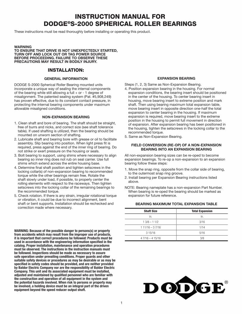
1
WARNINGTO ENSURE THAT DRIVE IS NOT UNEXPECTEDLY STARTED, TURN OFF AND LOCK OUT OR TAG POWER SOURCE BEFORE PROCEEDING. FAILURE TO OBSERVE THESE PRECAUTIONS MAY RESULT IN BODILY INJURY.
INSTALLATION:
GENERAL INFORMATION
DODGE S-2000 Spherical Roller Bearing mounted units incorporate a unique way of sealing the internal components of the bearing while still allowing a full + or - 1 degree of misalignment. The patented sealing system (Pat. #5,908,249) has proven effective, due to its constant contact pressure, in protecting the internal bearing components under maximum allowable misaligned conditions.
NON-EXPANSION BEARING
1. Clean shaft and bore of bearing. The shaft should be straight, free of burrs and nicks, and correct size (see shaft tolerance table). If used shafting is utilized, then the bearing should be mounted on unworn section of shafting.
2. Lubricate shaft and bearing bore with grease or oil to facilitate assembly. Slip bearing into position. When light press !t is required, press against the end of the inner ring of bearing. Do not strike or exert pressure on the housing or seals.
3. Bolt bearing to support, using shims where necessary to align bearing so inner ring does not rub on seal carrier. Use full shims which extend across the entire housing base.
4. Determine !nal shaft position and tighten setscrews in the locking collar(s) of non-expansion bearing to recommended torque while the other bearings remain free. Rotate the shaft slowly under load, if possible, to properly center the rolling elements with respect to the raceways. Then tighten setscrews into the locking collar of the remaining bearings to the recommended torque.
5. Check rotation. If there is any strain, irregular rotational torque or vibration, it could be due to incorrect alignment, bent shaft or bent supports. Installation should be rechecked and correction made where necessary.
WARNING: Because of the possible danger to persons(s) or property from accidents which may result from the improper use of products, it is important that correct procedures be followed: Products must be used in accordance with the engineering information specified in the catalog. Proper installation, maintenance and operation procedures must be observed. The instructions in the instruction manuals must be followed. Inspections should be made as necessary to assure safe operation under prevailing conditions. Proper guards and other suitable safety devices or procedures as may be desirable or as may be specified in safety codes should be provided, and are neither provided by Baldor Electric Company nor are the responsibility of Baldor Electric Company. This unit and its associated equipment must be installed, adjusted and maintained by qualified personnel who are familiar with the construction and operation of all equipment in the system and the potential hazards involved. When risk to persons or property may be involved, a holding device must be an integral part of the driven equipment beyond the speed reducer output shaft.
INSTRUCTION MANUAL FOR DODGE®S-2000 SPHERICAL ROLLER BEARINGS
These instructions must be read thoroughly before installing or operating this product.
EXPANSION BEARING
Steps (1, 2, 3) Same as Non-Expansion Bearing.4. Position expansion bearing in the housing. For normal
expansion conditions, the bearing insert should be positioned in the center of the housing. To center bearing insert in housing, move bearing insert to extreme position and mark shaft. Then using bearing maximum total expansion table, move bearing insert in opposite direction one-half the total expansion to center bearing in the housing. If maximum expansion is required, move bearing insert to the extreme position in the housing to permit full movement in direction of expansion. After expansion bearing has been positioned in the housing, tighten the setscrews in the locking collar to the recommended torque.
5. Same as Non-Expansion Bearing.
FIELD CONVERSION (RE-OP) OF A NON-EXPANSIONBEARING INTO AN EXPANSION BEARING
All non-expansion bearing sizes can be re-oped to become expansion bearings. To re-op a non-expansion to an expansion bearing follow these steps:
1. Move the snap ring, opposite from the collar side of bearing, to the outermost snap ring groove.
2. Install bearing per Expansion Bearing instructions listed above.
NOTE: Bearing nameplate has a non-expansion Part Number. When bearing is re-oped the bearing should be marked as expansion for future reference.
BEARING MAXIMUM TOTAL EXPANSION TABLE
Shaft Size Total Expansion
in. in.
1 3/8 – 1 1/2 3/16
1 11/16 – 3 7/16 1/14
3 15/16 5/16
4 7/16 – 4 15/16 3/8

2
LUBRICATION INSTRUCTIONS
OPERATION IN PRESENCE OF DUST, WATER OR CORROSION VAPORS
This bearing is factory lubricated with No. 2 consistency lithium complex base grease which is suitable for most applications. However, extra protection is necessary if bearing is subjected to excessive moisture, dust, or corrosive vapor. In these cases, bearing should contain as much grease as speed will permit (a full bearing with consequent slight leakage through the seal is the best protection against contaminant entry).
In extremely dirty environments, the bearing should be purged daily to !ush out contaminants. For added protection, it is advisable to shroud the bearing from falling material.
HIGH SPEED OPERATION
At higher operation speeds, too much grease may cause overheating. In these cases, the amount of lubrication can only be determined by experience. If excess grease causes overheating, remove grease "ttings and run for ten minutes. This will allow excess grease to escape. Then wipe off excess grease and replace grease "ttings.
In higher speed applications, a small amount of grease at frequent intervals is preferable to a large amount at infrequent intervals. However, the proper volume and interval of lubrication can best be determined by experience.
AVERAGE OPERATIONS
The following table is a general guide for normal operating conditions. However, some situations may require a change in lubricating periods as dictated by experience. If the bearing is exposed to unusual operating conditions, consult a reputable grease manufacturer.
LUBRICATION GUIDE
READ PRECEDING PARAGRAPHS BEFORE ESTABLISHING LUBRICATION SCHEDULE
Suggested Lubrication Period in Weeks
Hours run per
day
1 to 250 rpm
251 to 500 rpm
501 to 750 rpm
751 to 1500rpm
1001 to
2000 rpm
1501 to
2000 rpm
2001 to
2500 rpm
2501 to
3000 rpm
8 12 12 10 7 5 4 3 2
16 12 7 5 4 2 2 2 1
24 10 5 3 2 1 1 1 1
Set Screw Torque Table
Shaft Size Socket Set Screw Size Tightening Torque
1-3/8 – 1-3/4 in. 5/16 in. 165 Inch Pounds
11-15/16 – 2-7/16 in. 3/8 in. 290 Inch Pounds
12-11/16 – 3-7/16 in. 1/2 in. 620 Inch Pounds
13-15/16 – 4-15/16 in. 5/8 in. 1325 Inch Pounds
Recommended Shaft Tolerance Table
Normal Shaft Size Low to Normal Equlvalent Load and Catalog Speed*
Up to 1-1/2 in. +.000 in. –.0005 in.
Over 1-1/2 to 2-1/2 in. +.000 in. –.001 in.
Over 2-1/2 to 4 in. +.000 in. –.001 in.
Over 4 to 5 in. +.000 in –.0015 in.
OPERATING TEMPERATURE
Abnormal bearing temperatures may indicate insuf"cient lubrication. If the housing is too hot to touch for more than a few seconds, check the temperature by applying a thermometer at the top of the pillow block with the thermometer tip surrounded by putty.
Because the thermometer reading will be approximately 10°F lower than the actual bearing temperature, add ten degrees to the reading and compare to the temperature rating of your grease. If the bearing temperature reading is consistent and operating within the recommended limits of your grease, the bearing is operating satisfactorily. The recommended maximum operating temperature for S-2000 Spherical Roller Bearings is 200 °F.
STORAGE OR SPECIAL SHUT DOWN
If equipment will be idle for some time, before shutting down, add grease to the bearing until grease purges from the seals. This will ensure protection of the bearing, particularly when exposed to severe environmental conditions. After storage or idle period, add fresh grease to the bearing before starting.
On severe applications and where dynamic balance and minimum runout are important, a snug to light press "t may be required to obtain optimum bearing performance. Consult factory.
*Normal equivalent load .08C to .18C.

3

World Headquarters
P.O. Box 2400, Fort Smith, AR 72902-2400 U.S.A., Ph: (1) 479.646.4711, Fax (1) 479.648.5792, International Fax (1) 479.648.5895
Dodge Product Support
6040 Ponders Court, Greenville, SC 29615-4617 U.S.A., Ph: (1) 864.297.4800, Fax: (1) 864.281.2433
www.baldor.com
© Baldor Electric CompanyMN3033 (Replaces 499330)
All Rights Reserved. Printed in USA.1/09 TCP 20,000*3033-0110*
COMPONENT PART NUMBERS (1 3/8” - 4 15/16”)
ITEM 1 1A 2 3 4 5
Shaft SizeBearing Insert
Assembly (R) SealBearing Inert
Assembly (L) Seal*Collar *Set Screw Snap Ring **Grease Fitting
1 3/8 070000 070016 040050 400058 069276 405015
1 7/16 070001 070017 040050 400058 069276 405015
1 1/2 070002 070018 040050 400058 069276 405015
1 11/16 070003 070019 040051 400058 069277 405015
1 3/4 070004 070020 040051 400058 069277 405015
1 15/16 070005 070021 070587 400094 069278 405015
2 070006 070022 070587 400094 069278 405015
2 3/16 070007 070023 070588 400094 069279 405015
2 7/16 070008 070024 040054 400094 069280 405015
2 11/16 070009 070025 070589 400150 069281 405015
2 15/16 070010 070026 070589 400150 069281 405015
3 070011 070027 070589 400150 069281 405015
3 7/16 070012 070028 040056 400154 069282 405015
3 15/16 070013 070029 060946 400186 069283 405015
4 7/16 070014 070030 * 060947 * 400186 069284 405015
4 15/16 070015 070031 * 040059 * 400190 069285 405015
QTY/PER 1 1 1 2 1 1
*Shaft sizes 4 7/16” - 4 15/16” have two collars a** WSTU and TPHU TU take a 405016 grease fitting.
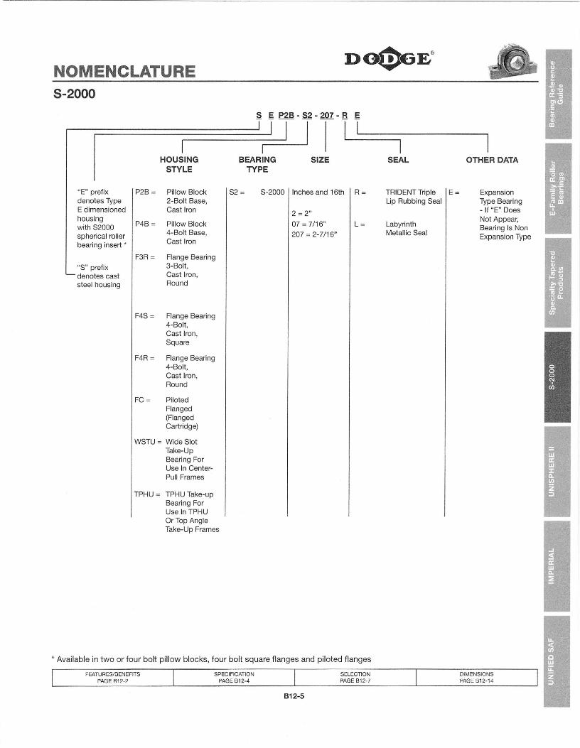
NOMENCLATUREDO$6E®
S-2000
s g P2B - S2 - 207 - B g
I ~ ~
"E" prefixdenotes TypeE dimensionedhousingwith S2000spherical rollerbearing insert •
"S" prefixdenotes caststeel housing
HOUSINGSTYLE
P2B = Pillow Block2-Bolt Base,Cast Iron
BEARINGTYPE
SIZEI
SEAL
R= TRIDENT Triple lE =Lip Rubbing Seal
P4B= Pillow Block4-Bolt Base,Cast Iron
S2 = S-2000 I Inches and 16th
L= LabyrinthMetallic Seal
F3R = Flange Bearing3-Bolt,Cast Iron,Round
F4S = Flange Bearing4-Bolt,Cast Iron,Square
F4R = Flange Bearing4-Bolt,Cast Iron,Round
2 = 2"07 = 7/16"207 = 2-7/16"
* Available in two or four bolt pillow blocks, four bolt square flanges and piloted flanges
FC = PilotedFlanged(FlangedCartridge)
WSTU = Wide SlotTake-UpBearing ForUse In Center-Pull Frames
TPHU = TPHU Take-upBearing ForUse In TPHUOr Top AngleTake-Up Frames
OTHER DATA
ExpansionType Bearing- If "E" DoesNot Appear,Bearing Is NonExpansion Type
FEATURES/BENEFITSPAGE B12-2
SPECIFICATIONPAGE B12-4
SELECTIONPAGE B12-7
OIMENSIONSPAGE B12-14
612-5

DIMENSIONSDO$6E®
.• 5-2000 Pillow Block2-BOLT BASE - INCH
F BOLT DIA.
NOTE: All sizes use a1/8-27 NPT hydraulicgrease fitting
J
!II 11• D MIN .1 I
• DM~ ~• B
x
1 'I: I t=t=',,,: 1 ..••..-
1 , i ,.1L -':"1 "' ,- I
:IIIIIIIIII
I~ c ~
EXPANSION
•
1
I---c ~
NON-EXPANSION
FEATURES/BENEFITSPAGE B12-2
SPECIFICATIONPAGE B12-4
SELECTIONSPAGE B12-7
HOW TO ORDER/NOMENCLATUREPAGE B12-4
812-14

FEATURES/BENEFITSPAGE B12-2
SPECIFICATIONPAGE B12-4
HOW TO ORDER/NOMENCLATUREPAGE B12-4
SELECTIONSPAGE B12-7
DIMENSIONSDO))6E@
8-2000 Pillow Block2-BOLT BASE - INCH
.-7'
~.
Shaft TRIDENT Seal Labyrinth Seal
Bearing Size Non-Expansion Expansion Non-Expansion ExpansionInch Part No. Part Name Part No. Part Name Part No. Part Name Part No. Part Name1-3/8 070272 P2B-S2-106R 070295 P2B-S2-106RE 070318 P2B-S2-106l 070341 P2B-S2-106lE
22208 1-7/16 070273 P2B-S2-107R 070296 P2B-S2-107RE 070319 P2B-S2-107l 070342 P2B-S2-107lE1-1/2 070274 P2B-S2-108R 070297 P2B-S2-108RE 070320 P2B-S2-108l 070343 P2B-S2-108lE
222091-11116 070276 P2B-S2-111R 070299 P2B-S2-111RE 070322 P2B-S2-111 l 070345 P2B-S2-111 lE1-3/4 070277 P2B-S2-112R 070300 P2B-S2-112RE 070323 P2B-S2-112l 070346 P2B-S2-112lE
222101-15/16 070278 P2B-S2-115R 070301 P2B-S2-115RE 070324 P2B-S2-115l 070347 P2B-S2-115lE2 070279 P2B-S2-200R 070302 P2B-S2-200RE 070325 P2B-S2-200l 070348 P2B-S2-200lE
22211 2-3/16 070280 P2B-S2-203R 070303 P2B-S2-203RE 070326 P2B-S2-203l 070349 P2B-S2-203lE22213 2-7/16 070282 P2B-S2-207R 070305 P2B-S2-207RE 070328 P2B-S2-207l 070351 P2B-S2-207lE
2-11/16 070284 P2B-S2-211 R 070307 P2B-S2-211RE 070330 P2B-S2-211 l 070353 P2B-S2-211 lE22215 2-15/16 070285 P2B-S2-215R 070308 P2B-S2-215RE 070331 P2B-S2-215l 070354 P2B-S2-215lE
3 070286 P28-S2-300R 070309 P2B-S2-300RE 070332 P2B-S2-300L 070355 P2B-S2-300lE22218 3-7/16 070288 P2B-S2-307R 070311 P2B-S2-307RE 070334 P2B-S2-307l 070357 P2B-S2-307lE22220 3-15/16 070290 P2B-S2-315R 070313 P2B-S2-315RE 070336 P2B-S2-315l 070359 P2B-S2-315lE
Shaft D F X
SizeA B C Bolt G H J L M R S Total Y Z
Min Max Dia. Exp.
1-3/81-7/16 2.53 6.88 1.95 4.81 5.20 1/2 0.81 1.13 3.88 2.75 1.88 0.88 1.66 3/16 0.020 1.801-1/2
1-111162.67 7.38 2.06 5.31 5.70 1/2 0.81 1.25 4.27 3.19 2.13 0.81 1.86 1/4 0.020 208
1-3/41-15/16
2.84 8.38 2.50 6.06 6.44 5/8 1.31 4.56 3.44 2.25 0.86 1.98 1/4 0.020 2.302
0.95
2-3/16 2.94 8.88 2.63 6.56 6.94 5/8 0.95 1.50 5.00 3.75 2.50 0.91 2.03 1/4 0.025 2.602-7/16 3.20 9.25 2.81 6.94 7.31 5/8 0.95 1.63 5.59 4.06 2.75 1.13 2.08 1/4 0.025 2.952-11/162-15/16 3.59 10.44 3.08 7.94 8.31 3/4 1.06 1.88 6.38 4.70 3.25 1.14 2.45 1/4 0.025 3.473
3-7/16 4.02 13.00 3.42 9.38 10.63 7/8 1.63 2.25 7.50 5.50 3.75 1.41 2.61 1/4 0.025 4.053-15/16 4.47 15.25 3.94 10.63 12.88 1 2.25 2.44 8.38 6.00 4.25 1.56 2.91 5/16 0.025 4.50
(Y\\ - ~~ '1?>i:::-""Y\-P--lN~S r;LB~2.3C'1-R (O~O;2..~g)
Y\~ 1 - TJ\-tl- V P;LB~~l~tZ ( CJ10;;tSS)
M2- l~ v P2(?~?~a'i-l2. ( (Y1-0'2Ei)
M'1-- T4JL ./ f:.-t6 ~~\<s ~ (c'1-0~RS)
612-15

Product Information Packet
ECP3774T-5 10HP,1760RPM,3PH,60HZ,215T,0748M,TEFC,F1
Copyright © All product information within this document is subject to Baldor Electric Company copyright © protection, unless otherwise noted.

Page 2 of 10
Product Information Packet: ECP3774T-5 - 10HP,1760RPM,3PH,60HZ,215T,0748M,TEFC,F1
Part DetailRevision: G Status: PRD/A Change #: Proprietary: No
Type: AC Prod. Type: 0748M Elec. Spec: 07WGX493 CD Diagram:
Enclosure: TEFC Mfg Plant: Mech. Spec: 07K374 Layout:
Frame: 215T Mounting: F1 Poles: 04 Created Date: 03-19-2009
Base: RG Rotation: R Insulation: F Eff. Date: 07-31-2013
Leads: 3#14 Literature: Elec. Diagram: Replaced By:
Nameplate NP1260ECAT.NO. ECP3774T-5
SPEC. 07K374X493
HP 10
VOLTS 575
AMP 10
RPM 1760
FRAME 215T HZ 60 PH 3
SER.F. 1.15 CODE H DES A CL F
NEMA-NOM-EFF 92.4 PF 81
RATING 40C AMB-CONT
CC 010A USABLE AT 208V
DE 6307 ODE 6307
ENCL TEFC SN

Page 3 of 10
Product Information Packet: ECP3774T-5 - 10HP,1760RPM,3PH,60HZ,215T,0748M,TEFC,F1
Parts ListPart Number Description QuantitySA180527 SA 07K374X493 1.000 EARA168488 RA 07K374X493 1.000 EA37FN3002C01 EXFN, PLASTIC, 6.00 OD, 1.155 ID 1.000 EAS/P107-000-001 SUPER E PROC'S-FS & WS PLTS-POLYREX EM G 1.000 EAHW3201A05 3/8-16 EYEBOLT 1.000 EA09CB1001A03G CONDUIT BOX, MACH GRAY 1.000 EARM1017 LEAD SEPERATOR GASKET MODEL 307 1/8" THK 1.000 EA51XW2520A12 .25-20 X .75, TAPTITE II, HEX WSHR SLTD 2.000 EA11XW1032G06 10-32 X .38, TAPTITE II, HEX WSHR SLTD U 1.000 EAHW3001B01 003SS CUP WASHER, FOR #8 SCREW 1.000 EA10XN2520S06 1/4 20X3/8 HX HD CAP S.S. 2.000 EAWD1000B16 T&B CX70TN TERMINAL 2.000 EA37EP1101C43G TEFC 307 BRG, GRSR,RELIEF,.25-20 FH TAPS 1.000 EAHW4500A01 1641B(ALEMITE)400 UNIV, GREASE FITT 1.000 EAHA4051A00 PLASTIC CAP FOR GREASE FITTING 1.000 EAHW4500A17 317400 ALEMITE GREASE RELIEF 1.000 EAHA4054 SHORT T-DRAIN FITTING, .125" N.P.T. 1.000 EAHW5100A08 W3118-035 WVY WSHR (WB) 1.000 EA37EP1101A32G PU ENDPLATE MACH 1.000 EAHW4500A01 1641B(ALEMITE)400 UNIV, GREASE FITT 1.000 EAHA4051A00 PLASTIC CAP FOR GREASE FITTING 1.000 EAHW4500A17 317400 ALEMITE GREASE RELIEF 1.000 EAHA4054 SHORT T-DRAIN FITTING, .125" N.P.T. 1.000 EAXY3118A12 5/16-18 HEX NUT DIRECTIONAL SERRATION 4.000 EA

Page 4 of 10
Product Information Packet: ECP3774T-5 - 10HP,1760RPM,3PH,60HZ,215T,0748M,TEFC,F1
Parts List (continued)Part Number Description Quantity51XB1214A20 12-14X1.25 HXWSSLD SERTYB 1.000 EA07FH1001A01G SPL FAN HOUSING, 307, W/GREASER, GRAY EP 1.000 EA10XN2520A16 1/4-20 X 1 HEX HEAD CAP SCR, ZINC PLATED 3.000 EAWD4100A02 DP-1000 HEYCO PLUG OR 62MP1000 MICRO PL 1.000 EA09CB1504A01G LIPPED CONDUIT BOX LID, MACH GRAY EPOXY 1.000 EA09GS1001A01SP GASKET, BOX LID, 1/8 THICK BLACK NEOPREN 1.000 EA10XN2520A12 O1/4-20X 3/4 HEX HEAD CAP 2.000 EAHW1001A25 LOCKWASHER 1/4, ZINC PLT .493 OD, .255 I 2.000 EAHA1005A07SP SLINGER, OD 2.25, ID 1.344, 307 BRG 1.000 EAHW4600B33 V-RING SLINGER 1.375 X 1.890 X 0.350 1.000 EAHW2501F21 KEY, 5/16 SQ X 2.375 1.000 EAHA7000A02 KEY RETAINER RING, 1 1/8 DIA, 1 3/8 DIA 1.000 EAMJ5001A01 46-665 RED SEALER 0.001 QT85XU0407S04 4X1/4 U DRIVE PIN STAINLESS 2.000 EALB1115 LABEL,LIFTING DEVICE 1.000 EALB1002 LABEL,MARINE DUTY (ON ROLLS) 1.000 EAMJ1000A75 GREASE, POLYREX EM EXXON 0.050 LBHA3104A32 THRUBOLT- 5/16-18 X12.750 4.000 EAMG1025Z20 ACTIVATOR WILKOFAST 060.32 0.010 GAMG1025G29 PAINT 789.205 DARK GRAY METALLIC (USE W/ 0.036 GALB1119 WARNING LABEL 1.000 EALB1125C02 SUPER-E (STOCK CTN LABEL SUPER-E WITH FL 1.000 EALC0006 CONNECTION LABEL 1.000 EANP1260E SS CP SUPER-E UL CSA CC 1.000 EA

Page 5 of 10
Product Information Packet: ECP3774T-5 - 10HP,1760RPM,3PH,60HZ,215T,0748M,TEFC,F1
Parts List (continued)Part Number Description Quantity07PA1011 PKG GRP, 07 CAST IRON PK1181 1.000 EA

Page 6 of 10
Product Information Packet: ECP3774T-5 - 10HP,1760RPM,3PH,60HZ,215T,0748M,TEFC,F1
AccessoriesPart Number Description Multiplier37-1304 C FACE KIT A8

Page 7 of 10
Product Information Packet: ECP3774T-5 - 10HP,1760RPM,3PH,60HZ,215T,0748M,TEFC,F1
Performance Data at 575V, 60Hz, 10.0HP (Typical performance - Not guaranteed values)General Characteristics
Full Load Torque: 29.7 LB-FT Start Configuration: DOL
No-Load Current: 4.1 Amps Break-Down Torque: 87.4 LB-FT
Line-line Res. @ 25°C.: 1.44 Ohms A Ph / 0.0 Ohms B Ph Pull-Up Torque: 52.1 LB-FT
Temp. Rise @ Rated Load: 59 C Locked-Rotor Torque: 57.7 LB-FT
Temp. Rise @ S.F. Load: 73 C Starting Current: 70.9 Amps
Load Characteristics
% of Rated Load 25 50 75 100 125 150 S.F.
Power Factor: 44.0 67.0 78.0 83.0 84.0 85.0 84.0
Efficiency: 89.7 92.9 92.9 92.1 91.4 90.2 91.7
Speed: 1790.0 1781.0 1771.0 1762.0 1750.0 1739.0 1755.0
Line Amperes: 4.67 6.02 7.8 9.82 12.2 14.6 11.2

Page 8 of 10
Product Information Packet: ECP3774T-5 - 10HP,1760RPM,3PH,60HZ,215T,0748M,TEFC,F1
Performance Graph at 575V, 60Hz, 10.0HP Typical performance - Not guaranteed values

Page 9 of 10
Product Information Packet: ECP3774T-5 - 10HP,1760RPM,3PH,60HZ,215T,0748M,TEFC,F1

Page 10 of 10
Product Information Packet: ECP3774T-5 - 10HP,1760RPM,3PH,60HZ,215T,0748M,TEFC,F1

Savona Equipment LtdP.O. Box 176, Savona, BC Canada V0K 2J0!"#$ %(250) 373-2424 % &'($ (250) 373-2323)))*savonaequip*+,-%%%%%%sales.savonaequip*+,-%
!"#$%&"'(
!"#$%&'()%*+#,-./#).01*
23*0-*45*6(,7*
5-(87*8#'"*+-08*9:;<**=.="*)(,.1>*
?#/6.1"'*/-0@17*
A(B/#1.C"'*B#>>.1>*
9&9:D<*"1'*'.7/7*01*@.1>7*
EB#)*0-*-0(1'*,#-*@.1>**'"7.>17*#$#.B#,B"*
F:G<*#1'*9:;<*"1'*'.7/7*01*'-(87*
)*#+,#-,"((.+#/"$"&'*
9;<*
9D<*
9H<*
9G<*
)*#+,#-,"((0+1$2'(
;H<*
F;<*
FG<*
DD<*
I9<*
3$2"&((456'+1"&#$+56'(!"#$%&'()$*+,&,-.))$
/'-'0,1$!),2$3'0)4$
5667.8)748)16$9,&.4$
:,.'"-#'2)$2'4.&';+.'"-$
5-)$<),&$=)91,()0)-.$$>,&&,-.?*
!"#$%*5()%*J01$"%0-*K(BB"%7*
LJJ*=(BB"%7*0++"-*#1*"M/"=).01#B*/08,.1#).01*0+*-"B.#,.B.)%N*O(#B&.)%N*#1'*$#B("*.1*#1*0++&)6"&76"B+*/01$"%0-*=(BB"%7P*Q7.1>*01"*=."/"*)(,"7*+0-*6"#'*=(BB"%7N*#1'*6"#$%*'()%*+#,-./#)"'*)#.B*=(B&B"%7N*)6"7"*=(BB"%7*#-"*.'"#B*+0-*8"'.(8*'()%*#>>-">#)"*#==B.&/#).017P**36"*=(BB"%7*(7"*"1>.1""-"'*"1'*'.7/7*#1'*7)#1'#-'*23*7)%B"*,(76.1>7*+0-*#))#/68"1)*01*76#+).1>P*36"*=(BB"%7*#-"*#$#.B#,B"*.1*#*@.'"*-#1>"*0+*7)#1'#-'*7.C"7*P**RBB*LJJ*=(BB"%7*/08"*@.)6*#*7)#1'#-'*01"&%"#-*@#--#1)%P*S.)6*)6"*,"7)*=-./.1>*.1*)6"*.1'(7)-%N*#1'*0++&)6"&76"B+*#$#.B#,.B.)%N*)6"7"*=(BB"%7*#-"*.'"#B*+0-*)0'#%T7*/08=").).$"*"1$.-018"1)P***E0-*/08801N*0++&)6"*76"B+*=(BB"%*-"O(.-"8"1)7N*)6"*=0=(B#-*7.C"7*)6#)*/08=-.7"*)6"*B.1"*#-"*.1)"1'"'*)0*,"/08"*#*-"B.#,B"*#B)"-1#).$"*)0*"M.7).1>*70(-/"7P**36"*/08=01"1)7*#-"*7)0/U"'*.1*B0/#).017*#/-077*)6"*/0(1)-%N*#1'*#-"*0+)"1*#$#.B#,B"*+0-*'"B.$"-%*@.)6*8.1.8#B*B"#'*).8"*#1'*+-".>6)P*

!"#$%&%'( )"*&+( ,-.( )%"/+&(!"# "$# "%# !""#!"# &"# "%# !'$#!"# &(# "%# !)"#!'# "$# "%# !'*#!'# &"# "%# !))#!'# &(# "%# "+)#!'# &"# &+# !(+#!'# &(# &+# "!+#!'# ''# &+# "'!#!$# "$# &+# !(+#!$# &"# &+# "!&#!$# &(# &%# "'$#!$# ''# &%# "))#!$# %!# &%# &!*#!(# &"# &%# "%+#!(# &(# &%# "(%#!(# ''# &%# &"%#!(# %!# &%# &$)#
,%#*0!'-$(1-22%34(
,-./0102# 3-415# 678# 30-951#!"# "$# "%# !""#!"# &"# "%# !%&#!"# &(# "%# !)*#!'# "$# "%# !$+#!'# &"# "%# !**#!'# &(# "%# "'&#!'# &"# &+# !*$#!'# &(# &+# "&'#!'# ''# &+# ")!#!$# "$# &+# !(%#!$# &"# &+# ""(#!$# &(# &%# "$$#!$# ''# &%# &!)#!$# %!# &%# &$!#!(# &(# &%# &!+#!(# ''# &%# &%$#!(# %!# '+# '!!#
)"5/06#"2(1-22%34(
!"#$%&'()%&*+,$"%+-&.(//"%0&

Operating Instructions July 2009
ZSSmilltronics

!
© "#$%$&'!(#))*+,&#-'!.+,-$''!/&'*+0%$&*'!/&-1!!2334
!
Safety Guidelines: 56+&#&7!&,*#-$'!%0'*!8$!,8'$+9$:!*,!$&'0+$!;$+',&6)!'6<$*=!6'!>$))!6'!*?6*!,<!,*?$+'@!6&:!*,!;+,*$-*!*?$!;+,:0-*!6&:!*?$!-,&&$-*$:!$A0#;%$&*1!B?$'$!>6+&#&7!&,*#-$'!6+$!6--,%;6&#$:!8=!6!-)6+#<#-6*#,&!,<!*?$!)$9$)!,<!-60*#,&!*,!8$!,8'$+9$:1!
Qualified Personnel: B?#'!:$9#-$C'='*$%!%6=!,&)=!8$!'$*!0;!6&:!,;$+6*$:!#&!-,&D0&-*#,&!>#*?!*?#'!%6&06)1!E06)#<#$:!;$+',&&$)!6+$!,&)=!60*?,+#F$:!*,!#&'*6))!6&:!,;$+6*$!*?#'!$A0#;%$&*!#&!6--,+:6&-$!>#*?!$'*68)#'?$:!'6<$*=!;+6-*#-$'!6&:!'*6&:6+:'1!
Unit Repair and Excluded Liability:
B?$!0'$+!#'!+$';,&'#8)$!<,+!6))!-?6&7$'!6&:!+$;6#+'!%6:$!*,!*?$!:$9#-$!8=!*?$!0'$+!,+!*?$!0'$+G'!67$&*1!!
H))!&$>!-,%;,&$&*'!6+$!*,!8$!;+,9#:$:!8=!"#$%$&'!(#))*+,&#-'!.+,-$''!/&'*+0%$&*'!/&-1!! I$'*+#-*!+$;6#+!*,!<60)*=!-,%;,&$&*'!,&)=1!! J,!&,*!+$0'$!<60)*=!-,%;,&$&*'1!!
Warning: K6+:8,6+:!'?#;;#&7!;6-L67$!;+,9#:$'!)#%#*$:!?0%#:#*=!6&:!%,#'*0+$!;+,*$-*#,&1!B?#'!;+,:0-*!-6&!,&)=!<0&-*#,&!;+,;$+)=!6&:!'6<$)=!#<!#*!#'!-,++$-*)=!*+6&';,+*$:@!'*,+$:@!#&'*6))$:@!'$*!0;@!,;$+6*$:@!6&:!%6#&*6#&$:1!B?#'!;+,:0-*!#'!#&*$&:$:!<,+!0'$!#&!#&:0'*+#6)!6+$6'1!M;$+6*#,&!,<!*?#'!$A0#;%$&*!#&!6!+$'#:$&*#6)!6+$6!%6=!-60'$!#&*$+<$+$&-$!*,!'$9$+6)!<+$A0$&-=!86'$:!-,%%0&#-6*#,&'1
!
Note: H)>6='!0'$!;+,:0-*!#&!6--,+:6&-$!>#*?!';$-#<#-6*#,&'1!
Copyright Siemens Milltronics Process Instruments Inc. 2009. All Rights Reserved!
Disclaimer of Liability!
B?#'!:,-0%$&*!#'!696#)68)$!#&!8,0&:!9$+'#,&!6&:!#&!$)$-*+,&#-!9$+'#,&1!5$!$&-,0+67$!0'$+'!*,!;0+-?6'$!60*?,+#F$:!8,0&:!%6&06)'@!,+!*,!9#$>!$)$-*+,&#-!9$+'#,&'!6'!:$'#7&$:!6&:!60*?,+$:!8=!"#$%$&'!(#))*+,&#-'!.+,-$''!/&'*+0%$&*'!/&-1!"#$%$&'!(#))*+,&#-'!.+,-$''!/&'*+0%$&*'!/&-1!>#))!&,*!8$!+$';,&'#8)$!<,+!*?$!-,&*$&*'!,<!;6+*#6)!,+!>?,)$!+$;+,:0-*#,&'!,<!$#*?$+!8,0&:!,+!$)$-*+,&#-!9$+'#,&'1!
5?#)$!>$!?69$!9$+#<#$:!*?$!-,&*$&*'!,<!*?#'!%6&06)!<,+!67+$$%$&*!>#*?!*?$!#&'*+0%$&*6*#,&!:$'-+#8$:@!96+#6*#,&'!+$%6#&!;,''#8)$1!B?0'!>$!-6&&,*!706+6&*$$!<0))!67+$$%$&*1!!B?$!-,&*$&*'!,<!*?#'!%6&06)!6+$!+$70)6+)=!+$9#$>$:!6&:!-,++$-*#,&'!6+$!#&-)0:$:!#&!'08'$A0$&*!$:#*#,&'1!.)$6'$!-?$-L!*?$!>$8'#*$!'?,>&!8$),>!<,+!*?$!)6*$'*!%6&06)!+$9#'#,&'1!5$!>$)-,%$!6))!'077$'*#,&'!<,+!#%;+,9$%$&*1!!!B$-?&#-6)!:6*6!'08D$-*!*,!-?6&7$1!
!(/NNBIMO/K"P#'!6!+$7#'*$+$:!*+6:$%6+L!,<!"#$%$&'!(#))*+,&#-'!.+,-$''!/&'*+0%$&*'!/&-1! Contact SMPI Technical Publications European Authorized Representative at the following address:!B$-?&#-6)!.08)#-6*#,&'! ! ! ! "#$%$&'!HQ!"#$%$&'!(#))*+,&#-'!.+,-$''!/&'*+0%$&*'!/&-1! ! /&:0'*+=!"$-*,+!R4ST!B$-?&,),7=!J+#9$@!.1M1!U,V!T22S! ! WXRYR!Z6+)'+0?$!.$*$+8,+,07?@!M&*6+#,@!K6&6:6@!!Z4[!WUR! ! J$0*'-?)6&:!\%6#)]!*$-?;08'1'%;#^'#$%$&'1-,%!! _,+!6!'$)$-*#,&!,<!"#$%$&'!(#))*+,&#-'!)$9$)!%$6'0+$%$&*!%6&06)'@!7,!*,]!!
www. siemens.com/processautomation1!`&:$+!.+,-$''!/&'*+0%$&*6*#,&@!'$)$-*!N$9$)!($6'0+$%$&*!!6&:!*?$&!7,!*,!*?$!%6&06)!6+-?#9$!)#'*$:!0&:$+!*?$!;+,:0-*!<6%#)=1!
_,+!6!'$)$-*#,&!,<!"#$%$&'!(#))*+,&#-'!>$#7?#&7!%6&06)'@!7,!*,]!!www. siemens.com/processautomation1!`&:$+!5$#7?#&7!B$-?&,),7=@!'$)$-*!K,&*#&0,0'!5$#7?#&7!"='*$%'!6&:!*?$&!7,!*,!*?$!%6&06)!6+-?#9$!)#'*$:!0&:$+!*?$!;+,:0-*!<6%#)=1!

!
Table of Contents
Milltronics ZSS Motion Sensing Switch ........................................................................ 1"#$%&'()*&%+(,,,,,,,,,,,,,,,,,,,,,,,,,,,,,,,,,,,,,,,,,,,,,,,,,,,,,,,,,,,,,,,,,,,,,,,,,,,,,,,,,,,,,,,,,,,,,,,,,,,,,,,,,,,,,,,,,,,,,,,,,,,,,,,,,,,,,,,,,,,,,-
"#$%&'(.#/0!12(+'.3*4+( ,,,,,,,,,,,,,,,,,,,,,,,,,,,,,,,,,,,,,,,,,,,,,,,,,,,,,,,,,,,,,,,,,,,,,,,,,,,,,,,,,,,,,,,,,,,,,,,,,,,,,,,,,,,,,,-56%(7#18#4(,,,,,,,,,,,,,,,,,,,,,,,,,,,,,,,,,,,,,,,,,,,,,,,,,,,,,,,,,,,,,,,,,,,,,,,,,,,,,,,,,,,,,,,,,,,,,,,,,,,,,,,,,,,,,,,,,,,,,,,,,,,,,,,,,,,,,,,,,,,,,,,9
Specifications ...................................................................................................................... 3
Installation .......................................................................................................................... 4:1;!/*1.%1&(,,,,,,,,,,,,,,,,,,,,,,,,,,,,,,,,,,,,,,,,,,,,,,,,,,,,,,,,,,,,,,,,,,,,,,,,,,,,,,,,,,,,,,,,,,,,,,,,,,,,,,,,,,,,,,,,,,,,,,,,,,,,,,,,,,,,,,,,,,,,,,<
ZSS Circuit Card .................................................................................................................. 5
ZSS Connection ...................................................................................................................6
ZSS Typical Wiring ............................................................................................................. 7
Operation .............................................................................................................................. 85'=!>#4(?%/$*/.#1>%( ,,,,,,,,,,,,,,,,,,,,,,,,,,,,,,,,,,,,,,,,,,,,,,,,,,,,,,,,,,,,,,,,,,,,,,,,,,,,,,,,,,,,,,,,,,,,,,,,,,,,,,,,,,,,,,,,,,,,,@?%/$*/.#1>%(:A#.=4%+(,,,,,,,,,,,,,,,,,,,,,,,,,,,,,,,,,,,,,,,,,,,,,,,,,,,,,,,,,,,,,,,,,,,,,,,,,,,,,,,,,,,,,,,,,,,,,,,,,,,,,,,,,,,,,,,,B
Dimensions ........................................................................................................................ 10
Maintenance ...................................................................................................................... 10

!"#$%%&'()*+ ",--./01,234566474896:;<=:8>94"?9<?# @ABC4$
Milltronics ZSS Motion Sensing Switch
",--./01,2345664D0.,0143C13,1B43E,.2F4,34A4FCAGHIJK.H4LC/043MCCJ4A-A/DN48.4,34K3CJ4.04JC.C2.4.FC4AO3C12C40/4M/C3C12C40P4D0.,0140P4/0.A.,1BQ4/C2,M/02A.,1BQ40/4201GCH,1B4CRK,MDC1.N4:FC45664FA34A42,/2K,.42A/J4A1J4A4DAB1C.,24A33CDO-H4M0..CJ4,14.FC4M/0OC4O0JHN4:FC45664,34M0EC/CJ4P/0D4.FC4-,1C4G0-.ABC4A1J4M/0G,JC34A43C.40P4J/H4/C-AH4201.A2.34.04,1J,2A.C4D0.,014EFC14.FC4PC//0K34.A/BC.340P4.FC4DA2F,1C/H4OC,1B4D01,.0/CJ4MA334,14P/01.40P4.FC4M/0OCN
Safety Notes1
6MC2,A-4A..C1.,014DK3.4OC4MA,J4.04EA/1,1B34A1J410.C34F,BF-,BF.CJ4P/0D4.FC4/C3.40P4.FC4.CS.4OH4B/CH4O0SC3N
Safety marking symbols
$N :F,343HDO0-4,34K3CJ4EFC14.FC/C4,3410420//C3M01J,1B42AK.,0143HDO0-4014.FC4M/0JK2.N
WARNING: relates to a caution symbol on the product, and means that failure to observe the necessary precautions can result in death, serious injury, and/or considerable material damage.WARNING!: means that failure to observe the necessary precautions can result in death, serious injury, and/or considerable material damage.
CAUTION: means that failure to observe the necessary precautions can result in considerable material damage.Note: DCA134,DM0/.A1.4,1P0/DA.,014AO0K.4.FC4M/0JK2.40/4.FA.4MA/.40P4.FC40MC/A.,1B4DA1KA-N
In manual On Product Description
=AK.,01T4/CPC/4.04A220DMA1H,1B4J02KDC1.34UDA1KA-V4P0/4JC.A,-3N
@/0.C2.,GC4=01JK2.0/4:C/D,1A-

!"#$%& '())*+,-(./%011%2%34156785394%':47:; <';=>>?@ABC&
The Manual
5D(/%(-/*+E.*(,-%F"-E")%.,G$+/%*D$%(-/*"))"*(,-H%,I$+"*(,-%"-J%F"(-*$-"-.$%,K%*D$%
'())*+,-(./%011L%3*%(/%$//$-*(")%*D"*%*D(/%F"-E")%M$%+$K$++$J%*,%K,+%I+,I$+%(-/*"))"*(,-%"-J%
,I$+"*(,-%,K%N,E+%E-(*L%:JD$+(-#%*,%*D$%(-/*"))"*(,-%"-J%,I$+"*(-#%I+,.$JE+$/%O())%$-/E+$%"%
PE(.QH%*+,EM)$%K+$$%(-/*"))"*(,-%"-J%")),O%K,+%*D$%F"R(FEF%"..E+".N%"-J%+$)("M()(*N%,K%N,E+%
F,*(,-%/$-/(-#%I+,M$L%
3K%N,E%D"G$%"-N%PE$/*(,-/H%.,FF$-*/H%,+%/E##$/*(,-/%"M,E*%*D$%F"-E")%.,-*$-*/H%I)$"/$%
$F"()%E/%"*%*$.DIEM/L/FI(S/($F$-/L.,FL
B,+%*D$%.,FI)$*$%)(M+"+N%,K%1($F$-/%F"-E")/H%#,%*,%
OOOL/($F$-/L.,FTI+,.$//"E*,F"*(,-L
Notes: U 5D$%'())*+,-(./%011%I+,JE.*%(/%*,%M$%E/$J%,-)N%(-%*D$%F"--$+%,E*)(-$J%(-%*D(/%
(-/*+E.*(,-%F"-E")L
U 5D(/%I+,JE.*%(/%(-*$-J$J%K,+%E/$%(-%(-JE/*+(")%"+$"/L%9I$+"*(,-%,K%*D(/%$PE(IF$-*%
(-%"%+$/(J$-*(")%"+$"%F"N%."E/$%(-*$+K$+$-.$%*,%/$G$+")%K+$PE$-.N%M"/$J%
.,FFE-(."*(,-/L
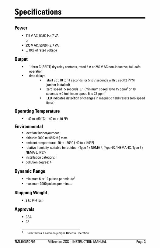
!"#$%%&'()*+ ",--./01,234566474896:;<=:8>94"?9<?# @ABC4D
Specifications
Power E $$'4F4?=G4'*HI*4JKG4!4F?0/
E +D*4F4?=G4'*HI*4JKG4!4F?4E !$*L40M4/A.CN4O0-.ABC4
Output E $4M0/P4=4Q6@(:R4N/S4/C-AS4201.A2.3G4/A.CN4'4?4A.4+'*4F4?=4101T,1NU2.,OCG4MA,-T3AMC4
0VC/A.,014E .,PC4NC-AS4W4
E 3.A/.4UV4W4$*4.04$X43C201N34Q0/4'4.04!43C201N34Y,.Z4'43C2H$+4@@"4[UPVC/4,13.A--CNR
E KC/043VCCN4W4'43C201N3!!$!QP,1,PUP43VCCN4$*4.04$'4VVPR$40/4$*43C201N3!!+!QP,1,PUP43VCCN4'4.04!\'4VVPR$
E #](4,1N,2A.C34NC.C2.,0140M42ZA1BC34,14PAB1C.,24M,C-N4Q/C3C.34KC/043VCCN4.,PC/R
Operating Temperature E 74X*4.04^I*4_=4Q74X*4.04^$X*4_)R
EnvironmentalE -02A.,01W4,1N00/H0U.N00/E A-.,.UNCW4+***4P4QI'I+4M.\R4PA`\E APa,C1.4.CPVC/A.U/CW4TX*4.04^I*_=4QTX*4.04^$X*_)RE /C-A.,OC4ZUP,N,.SW43U,.Aa-C4M0/40U.N00/4Q:SVC4X4H49]"?4XG4:SVC4Xb4H49]"?4XbG4:SVC4I4H9]"?4IG48@I!R
E ,13.A--A.,0142A.CB0/SW488E V0--U.,014NCB/CCW4X
Dynamic RangeE P,1,PUP4I40/4$+4VU-3C34VC/4P,1U.C$4E PA`,PUP4D***4VU-3C34VC/4P,1U.C4
Shipping Weight E +4cB4QX\X4-a3\R4
ApprovalsE =6?4E =]
$\ 6C-C2.CN4O,A4A420PP014[UPVC/\4;CMC/4.04>VC/A.,01\4

!"#$%& '())*+,-(./%011%2%34156785394%':47:; <';=>>?@ABCD
Installation
Environment5E$%011%FG/*%H$%F,G-*$I%(-%"-%"+$"%*E"*%(/%-,-JE"K"+I,G/L%M(*E(-%*E$%"FH($-*%*$FN$+"*G+$%+"-#$%"-I%-,-J.,++,/(O$%*,%*E$%F"*$+(")/%,P%.,-/*+G.*(,-Q%6$P$+%*,%A(F$-/(,-/%P,+%F"*$+(")/%,P%.,-/*+G.*(,-Q%
5E$%N+,H$%/E,G)I%H$%F,G-*$I%G/(-#%*E$%/GNN)($I%F,G-*(-#%P)"-#$L%,-*,%"%O(H+"*(,-%P+$$%/*+G.*G+$Q%5E$%#"N%H$*M$$-%*E$%N+,H$%"-I%*E$%*"+#$*%/E,G)I%H$%/GPP(.($-*%/G.E%*E"*%*E$+$%(/%-,%I"-#$+%,P%*E$%*"+#$*%I"F"#(-#%*E$%N+,H$Q%5E$%F"R(FGF%")),M"H)$%#"N%+"-#$/%P+,F%DC%FF%*,%,O$+%=CC%FF%P+,F%*E$%P".$%,P%*E$%*"+#$*%*,%*E$%P".$%,P%*E$%N+,H$Q%5E$%+"-#$%(/%I$N$-I$-*%,-%*E$%*"+#$*%*SN$%"-I%+"-#$%,P%/N$$I%$RN$.*$IQ%1$$%*SN(.")%N$+P,+F"-.$%#+"NE/%,-%N"#$ >%P,+%$R"FN)$/Q%
WARNING: The probe face is magnetic. Keep it away from magnetosensitive materials such as computer discs and audio or video tapes. WARNING: All field wiring must have insulation suitable for at least 250 V and the maximum ambient temperature of +60°C (+140 °F).
Notes:T 5E$%!+,*$.*(O$%U"+*E%5$+F(-")%(-I(."*$I%HS%V W%FG/*%H$%.,--$.*$I%*,%+$)("H)$%
#+,G-IQT :))%M(+(-#%FG/*%H$%I,-$%HS%XG")(P($I%N$+/,--$)%(-%"..,+I"-.$%M(*E%"))%#,O$+-(-#%
+$#G)"*(,-/QT 5E$%$XG(NF$-*%FG/*%H$%N+,*$.*$I%HS%"%=@%:%PG/$%,+%.(+.G(*%H+$"Y$+%(-%*E$%HG()I(-#%
(-/*"))"*(,-QT :%.(+.G(*%H+$"Y$+%,+%/M(*.E%(-%*E$%HG()I(-#%(-/*"))"*(,-L%F"+Y$I%"/%"%I(/.,--$.*%
/M(*.EL%/E"))%H$%(-%.),/$%N+,R(F(*S%*,%*E$%$XG(NF$-*%"-I%M(*E(-%$"/S%+$".E%,P%*E$%,N$+"*,+Q
T 6$)"S%.,-*".*%*$+F(-")/%"+$%P,+%G/$%M(*E%$XG(NF$-*%ME(.E%E"/%-,%"..$//(H)$%)(O$%N"+*/%"-I%M(+(-#%ME(.E%E"/%(-/G)"*(,-%/G(*"H)$%P,+%"*%)$"/*%D@C%ZQ
!"#"$%&'(()##*'+,-.,/-(0---012
GN%*,%=CC%FF%V&[W%F"R(FGF%#"N

!"#$%%&'()*+ ",--./01,234566474896:;<=:8>94"?9<?# @ABC4'
:DC45664,343C13,.,EC4.04-A.C/A-4F,3.G/HA12C34.04,.34IAB1C.,24J,C-FK48J4.DC45664,34/C3L01F,1B4.04I0.,014J/0I4A14,1.C/JC/,1B4.A/BC.M4I0EC4.DC456640/4,13.A--4A4JC//0G34L-A.C4N3.CC-4O4A34A43D,C-F4HC.PCC14.DC45664A1F4.DC4,1.C/JC/,1B4.A/BC.K4
QDC/C4L033,H-CM4.DC4L/0HC43D0G-F4HC4I0G1.CF4304.DC4201FG,.4C1./R4,34L0,1.,1B4F0P14.04AE0,F4A22GIG-A.,0140J4201FC13A.,014,14.DC42A3,1BK4=011C2.,0140J4.DC4L/0HC43D0G-F4HC4IAFC4E,A4J-CS,H-C4201FG,.4J0/4CA3,C/4/CI0EA-40/4AFTG3.IC1.40J4.DC4L/0HCK
ZSS Circuit Card
Note:48142-,IA.C34PDC/C4F,/C2.43G1-,BD.4IAR42AG3C4.DC4",--./01,2345664.CILC/A.G/C4.04/,3C4AH0EC4.DC43LC2,J,CF4-,I,.M43DAFC4.DC4G1,.4HR4,13.A--,1B4A43G143D,C-FK
WARNING: Disconnect power before opening top cover.
Note:4=DC2U41AICL-A.C4J0/4L/0LC/40LC/A.,014E0-.ABC4N$$'4V4?=40/4+W*4V4?=OK
.C/I,1A-4H-02U4J0/42G3.0IC/42011C2.,01
FC.C2.,014,1F,2A.0/4#X(
B/0G1F4.C/I,1A-4J0/42G3.0IC/42011C2.,01

!"#$%& '())*+,-(./%011%2%34156785394%':47:; <';=>>?@ABCD
ZSS Connection
Notes:=E A+F%.,-*".*/%/G,H-%(-%I$J$-$+#(K$I%L")"+M%,+%/G$)NO%/*"*$E%DE 011%(/%M"-PN".*P+$I%N,+%$(*G$+%==@%,+%DQC%R%:8%,S$+"*(,-E%8G$.T%011%
-"M$S)"*$%N,+%"SS)(."U)$%V,)*"#$E%8,++$.*%V,)*"#$%MP/*%U$%/PSS)($IE%R,)*"#$/%),H$+%*G"-%/S$.(N($I%H())%+$/P)*%(-%"-%(-,S$+"*(V$%.,-I(*(,-E%R,)*"#$/%G(#G$+%*G"-%/S$.(N($I%H())%/$V$+$)F%I"M"#$%P-(*E%
QE B,+%@%/$.,-I%*(M$%I$)"F%"-I%M(-(MPM%=D%SSM%+"-#$W%.,--$.*%XPMS$+%".+,//%*$+M(-")/%<%"-I%?E%Y(*G,P*%"%XPMS$+W%*G$%I$N"P)*%(/%=C%/$.,-I%*(M$%I$)"F%"-I%M(-(MPM%&%SSM%+"-#$E
*$+M(-")%.(+.P(*%."+I

!"#$%%&'()*+ ",--./01,234566474896:;<=:8>94"?9<?# @ABC4!
ZSS Typical Wiring
6D0E-F4.DC4.,GC4FC-AH4ICA.E/C40143.A/.4EJ410.4KC4/CLE,/CFM4J0NC/43D0E-F4KC4AJJ-,CF4
201.,1E0E3-H4I/0G4A43CJA/A.C430E/2CO4:HJ,2A--H4.D,34N0E-F4KC4FC3,/AK-C4I0/4AE.0GA.,24EJP
3./CAG43.A/.4EJ40I4201QCH,1B4FCQ,2C34AI.C/4F0N143./CAG4F/,QC4DA34/CA2DCF4,.340JC/A.,014
3JCCFO4
Notes:$O 81.C/-02R34A1F43AIC.H4JE--43N,.2DC34A/C410.43D0N1O4
+O 8I4S6:?;:T4,34,1,.,A.CF4KH4J/0B/AGGAK-C4-0B,24201./0--C/M42-03E/C4.,GC4GAH4
KC40I4,13EII,2,C1.4FE/A.,014.04A--0N45664201.A2.4.04-A.2DO48143E2D4A42A3CM4
J/0B/AG4A4.,GC/4201.A2.4,1.042,/2E,.O4
UO =6?4/CLE,/C34A4U4?40/4-C334IE3C4.04J/0.C2.4201.A2.3O4)0/4+V*4W4?=M4J/0.C2.4
201.A2.34N,.D4A4$'**4W?4./A13I0/GC/4A34NC--O4
$$'X+U*4W4?=4'*XY*4Z[
10.C4U
6.0J6.A/.
=01.A2.0/
10.C4+
$4+
$:\4 "$
566
#+X9#$
566
=01.A2.0/
D0-F4E1.,-4EJ4.043JCCF
$4+
6.0J
10.C4U$:\4 "$
6.A/.

!"#$%& '())*+,-(./%011%2%34156785394%':47:; <';=>>&?@ABC
Operation
DE$-%F,G$+%(/%(-(*("))H%"FF)($I%*,%*E$%011J%*E$%")"+K%+$)"H%(/%$-$+#(L$I%"-I%E$)I%"+*(M(.("))H%NH%*E$%*(K(-#%.(+.O(*P%5E(/%G())%/(KO)"*$%*E$%-,+K")%,F$+"*(,-%,M%*E$%011%M,+%"%/*"+*%OF%I$)"H%,M%Q=B%/$.,-I/%R,+%Q?%/$.,-I/%(M%"%SOKF$+%(/%G(+$I%".+,//%*$+K(-")/%<%"-I%&TP%
:/%"%M$++,K"#-$*(.%,NS$.*%F"//$/%*E+,O#E%*E$%F+,N$U/%F$+K"-$-*%K"#-$*%M($)IJ%*E$%I(/*,+*(,-%,M%*E$%M)OV%(/%/$-/$I%NH%*E$%K"#-$*(.%I$*$.*(,-%.(+.O(*P%3M%*E$%I(/*,+*(,-%(/%,M%/O(*"N)$%K"#-(*OI$J%"%/E,+*%FO)/$%(/%#$-$+"*$I%*,%+$/$*%*E$%*(K(-#%.(+.O(*J%W(/(N)$%*,%*E$%O/$+%NH%*E$%;X@%/E,G-%(-%*E$%)(I%G(-I,GP%5E(/%".*(,-%Y$$F/%*E$%")"+K%+$)"H%$-$+#(L$I%F+,W(I(-#%M"()Z/"M$%,F$+"*(,-%,M%*E$%.,-*".*/P%
3M%-,%.E"-#$%(-%M)OV%R*"+#$*%K,*(,-T%(/%/$-/$I%M,+%"%F$+(,I%,M%=B%/$.,-I/%R,+%?%/$.,-I/%(M%"%SOKF$+%(/%G(+$I%".+,//%*$+K(-")/%<%"-I%&TJ%*E$%*(K(-#%.(+.O(*%G())%-,*%N$%+$/$*P%5E(/%G())%."O/$%*E$%")"+K%+$)"H%*,%I$Z$-$+#(L$%"-I%*E$%.,-*".*/%*,%.E"-#$%/*"*$P%
5EO/%*E$%011%."--,*%I$*$.*%*E$%K,*(,-%,M%O-(M,+K%M$++,K"#-$*(.%K"//$/%/O.E%"/%"%+,*"*(-#%FO))$H%,+%"%Y$H)$//%/E"M*P%
DE$-%"ISO/*(-#%*E$%011%K,O-*(-#%F,/(*(,-J%(*%K"H%*"Y$%OF%*,%=B%/$.,-I/%M,+%*E$%I$*$.*(,-%.(+.O(*%*,%"ISO/*%*,%*E$%-$G%"KN($-*%K"#-$*(.%$-W(+,-K$-*P%@O+(-#%*E(/%"ISO/*K$-*%F$+(,IJ%*E$%;X@%K"H%M"()%*,%M)"/E%M,+%"-%,*E$+G(/$%-,+K"))H%I$*$.*"N)$%K,W(-#%*"+#$*P%
Typical Performance5E$%K"V(KOK%"(+%#"F%M,+%GE(.E%*E$%011%G())%+$)("N)H%I$*$.*%*E$%K,W(-#%M$++,O/%*"+#$*%W"+($/%"..,+I(-#%*,%*E$%*"+#$*[/%/(L$J%/E"F$J%,+($-*"*(,-%"-I%I(+$.*(,-%,M%K,*(,-J%"/%G$))%"/%*E$%K"*$+(")%*,%GE(.E%*E$%*"+#$*%(/%"**".E$IP
:-%$V"KF)$%/E,G-%N$),G%.,KF"+$/%*HF(.")%+$/O)*/%M+,K%/*$$)%N),.Y/%O/$I%"/%*"+#$*/%,-%"%GE$$)%R$(*E$+%M$++,O/%,+%-,-ZM$++,O/TP%:/%/E,G-J%"%)"+#$+%I$*$.*(,-%+"-#$%."-%*HF(."))H%N$%".E($W$I%GE$-%*E$+$%(/%"%M$++,O/%,NS$.*%N$E(-I%*E$%*"+#$*P%5E$%011%F+,W(I$/%$V.$))$-*%I$*$.*(,-%,M%"%+$)"*(W$)H%/K"))%*"+#$*J%/O.E%"/%"%\]=^_%R`?%KKT%/E"M*%Y$H%(-/*"))$I%(-%"%?]&_%R`=^%KKT%K,*,+%/E"M*%G(*E%a%BP=C?_%R`\%KKT%,M%*E$%Y$H%F+,*+OI(-#%N$H,-I%*E$%/E"M*%$-W$),F$P
5,%$-/O+$%F+,F$+%,F$+"*(,-%(-%"-H%/$*OFJ%O/$%*E$%;X@%(-I(."*,+%*,%.,-M(+K%.,-/(/*$-*%I$*$.*(,-%,M%*E$%*"+#$*%,W$+%*E$%MO))%+"-#$%,M%$VF$.*$I%,F$+"*(,-")%/F$$I/P%4,*$%*E"*%I$*$.*(,-%+"-#$%K"H%W"+H%/)(#E*)H%G(*E%W,)*"#$%/OFF)H%"-I%*$KF$+"*O+$J%/,%(*%(/%+$.,KK$-I$I%*,%O/$%*E$%K(-(KOK%"(+%#"F%*E"*%(/%FEH/(."))H%/"M$%*,%(KF)$K$-*P

!"#$%%&'()*+ ",--./01,234566474896:;<=:8>94"?9<?# @ABC4%
Performance Examples
!"#$%&'$(")$*+,$-)../
!
"!
#!
$!
%!
&!
'!
(!
)!
*!
!+!"! !+"!! "+!!! "!+!!!
-)../$012+3
!"#,$%&'$(")$0113
,-./012,-./013,-./014,-./015
4
6C.DE4?F45664G,.H4.G04$IJ+IJ+I43.CC-4.A/BC.34K0D1.CL40143.CC-4GHCC-
6C.DE4MF45664G,.H4.G04$IJ+IJ$I43.CC-4.A/BC.34K0D1.CL40143.CC-4GHCC-
6C.DE4=F45664G,.H4.G04$IJ+IJ+I43.CC-4.A/BC.34K0D1.CL4014101NOC//0D34GHCC-
6C.DE4(F45664G,.H4.G04$IJ+IJ$I43.CC-4.A/BC.34K0D1.CL4014101NOC//0D34GHCC-
6C.DE4PF4(=4K0.0/4G,.H4'Q&I4L/,RC43HAO.4A1L4SQ$TI43UDA/C4VCW
$IX4J4+IY4J4+I(43.CC-4Z-02V
3.CC-4GHCC-
566
$IX4J4+IY4J4$I(3.CC-4Z-02V
3.CC-4GHCC-
566
$IX4J4+IY4J4+I(3.CC-4Z-02V
566
101NOC//0D34GHCC-
$IX4J4+IY4J4$I(43.CC-4Z-02V
566
101NOC//0D34GHCC-
(=4K0.0/
SQ$TI43U[4VCW
'Q&I43HAO.566
XHCC-4(/,RC14PJAKE-C3
6HAO.4(/,RC14PJAKE-C
90.CF4$4KQ34\4+**4O.QK,1]4+'4KK4\4$[*I
!454'$-6"75$8&56$-9:"'.$;.<$=$%&'$(")$*+,$>?!
!
#!
%!
'!
)!
"!!
"#!
"%!
"! "!! "!!! "!!!!
>?!
%&'$(")$0113

!"#$%&' ()**+,-.)/0%122%3%452678964:5%(;58;< =(<&>>?@AB'C
Dimensions
Maintenance
6D$%1$,-%2E$$F%2G)+/D%/".%H$%/*$".$F%HI%G)E).#%+D$%$./*-0J,$%$K+$,)-,%G)+D%"%F"LE%/*-+DM%5-%NJ,+D$,%L").+$."./$%)0%,$OJ),$F%N-,%+D$%F$P)/$M
&'QRC%0/,$GST%E*"/$0
RUTV%5!6/-.FJ)+%$.+,"./$
CCW%LLX?M>VY &C=%LL
X@VY
L-J.+).#%N*".#$S%0$$%F$+")*%;
CV%5!2<"*JL).JL%E,-H$%H-FI
W'%LLXCMR?VY
*-/Z.J+S%E*"+$F/"0).#%#"0Z$+S%.$-E,$.$
/"0).#S%"*JL).JL
&>=%LLX=M=@VY
/"E%#"0Z$+S.$-E,$.$
/"ES"*JL).JL
A$+")*%; (-J.+).#>@%LL%XRM=@VY%F)"ME,-H$%/*$","./$%D-*$
W%LL%X'MC@VY%F)"M%D-*$N-,%&UT%Q%C'%H-*+-,%F,)**%".F%+"E-.%&&T%LL%XTM@VY%[9AST%E*"/$0
W%LL%X'MC@Y%F)"M%D-*$N-,%&UT%Q%C'%H-*+%-.&&T%LL%XTM@VY%[A9S
T%E*"/$0
:MAM&RR%LLX@MC@VY
C@%LLX&M'VY
CV%5!2<
/),/J)+%H-",F
+$,L)."*%H*-/Z0
<\A

CONVEYOR
EFFICIENCY
SPECIALISTS
P.O. Box 1760 5929 Benton Road Paducah, KY 42002-1760 1-800-553-4567 / 270-898-6821 Fax: 1-800-230-9462 / 270-898-8061
http://www.aeec.com
Gordon Belt Cleaning Systems • Tri-Return Training Idler • Wyatt Alignment Disks • Simplicity Access Doors • Gordon “At-Last-A-Seal” Skirt Rubber Flexiskirt Sealing System • Gordon Dust Seal • Simplicity Slider System • Dust Shark Dust Suppression System • Simplicity Chute Liner • Fogger Sy stem
Simplicity Impact System • Conveyor Controls & Belt Protection Equipment • ArchWeigh Belt Scales • Metasearch Metal Detector

Arch Environmental Equipment, Inc. GORDON "MINI"
SABER BLADE BELT CLEANER
INSTALLATION INSTRUCTIONS
THE INSTALLATION OF THE GORDON "MINI" SABER BELT CLEANER IS VERY SIMPLE. IT ONLY REQUIRES A FEW TOOLS AND A SHORT AMOUNT OF TIME.
THE TOOLS & RESOURCES REQUIRED ARE:
1. STRAIGHT EDGE 5. WELDING EQUIPMENT 2. LEVEL 6. CHALK 3. TAPE MEASURE 7. ADJUSTABLE WRENCH 4. CUTTING TORCH
SHUT DOWN AND LOCKOUT CONVEYOR BEFORE PERFORMING ANY MAINTENANCE
STEP 1 Determine the diameter of the head pulley and the thickness of the conveyor belt. Example: head pulley diameter = 24" (609.6mm), belt thickness = 3/4" (19.05mm). Take one half of the head pulley measurement ( in this case 12" (304.8mm) and add the belt thickness. This will give an effective radius of 12 3/4" (325.85mm). To this number add 2 3/8" (60.375mm) (See FIG 1- dimension A). This will give the "Z" dimension. (SEE FIG. 1 – Dimension Z)
STEP 2 Using the “Z” dimension, as described in step 1, draw an arc or radius to define the area for cutting the mounting holes on the chute wall.
Fig. 1
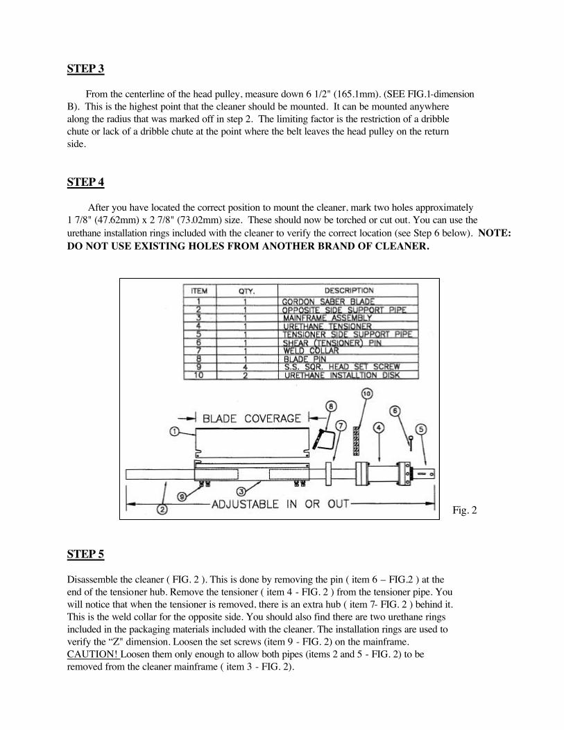
STEP 3 From the centerline of the head pulley, measure down 6 1/2" (165.1mm). (SEE FIG.1-dimension B). This is the highest point that the cleaner should be mounted. It can be mounted anywhere along the radius that was marked off in step 2. The limiting factor is the restriction of a dribble chute or lack of a dribble chute at the point where the belt leaves the head pulley on the return side. STEP 4 After you have located the correct position to mount the cleaner, mark two holes approximately 1 7/8" (47.62mm) x 2 7/8" (73.02mm) size. These should now be torched or cut out. You can use the urethane installation rings included with the cleaner to verify the correct location (see Step 6 below). NOTE: DO NOT USE EXISTING HOLES FROM ANOTHER BRAND OF CLEANER.
STEP 5 Disassemble the cleaner ( FIG. 2 ). This is done by removing the pin ( item 6 – FIG.2 ) at the end of the tensioner hub. Remove the tensioner ( item 4 - FIG. 2 ) from the tensioner pipe. You will notice that when the tensioner is removed, there is an extra hub ( item 7- FIG. 2 ) behind it. This is the weld collar for the opposite side. You should also find there are two urethane rings included in the packaging materials included with the cleaner. The installation rings are used to verify the “Z" dimension. Loosen the set screws (item 9 - FIG. 2) on the mainframe. CAUTION! Loosen them only enough to allow both pipes (items 2 and 5 - FIG. 2) to be removed from the cleaner mainframe ( item 3 - FIG. 2).
Fig. 2

STEP 6 Put the cleaner ( items 1 & 3 - FIG. 2 ) inside the chute, and slide the support and tensioner pipes (items 2 and 5 - FIG. 2 ) through the slots previously cut. Then slide the weld collar (item 7 - FIG. 2) and the tensioner ( item 4 - FIG. 2 ) onto the support and tensioner pipes. Next, level the cleaner in relation to the head pulley. Verify the "Z" dimension by slipping the installation rings onto the support and tensioner pipe. Then the installation rings should be placed against the belt. Tack weld the weld collar and tensioner into place. Set the cleaner blade against the belt and insert the pin (item 6 - FIG. 2) into the tensioner hub. Tighten the sets crews on the mainframe. Now, complete welding on the hubs (3 - 1" (25.4mm) welds on each hub is enough). Pull the pin again to check if the cleaner rotates freely in the hubs; if it doesn't, realign the hubs until it rotates freely.
STEP 7 Finally, pull the pin ( item 6 - FIG. 2 ) and rotate the tensioner away from the head pulley, until the next hole shows ( SEE FIG. 4 ) in the tensioner hub. Reinstall the pin. THATS IT!!
Fig. 4
Fig. 3

1
INSTALLATION:1. Use lifting bracket where applicable to lift reducer.2. Determine the running positions of the reducer. (See Fig. 1)
Note that the reducer is supplied with six plugs; four around the sides for horizontal installations and one on each face for vertical installations. These plugs must be arranged relative to the running positions as follows:
Horizontal Installations - Install the magnetic drain plug in the hole closest to the bottom of the reducer. Install the ! lter/ventilation plug in topmost hole. Of the two remaining plugs on the sides of the reducer, the lowest plug is the minimum oil level plug.
Vertical Installations - Install the ! lter/ventilation plug in the hole provided in the upper face of the reducer housing. If space is restricted on the upper face, install the vent in the highest hole on the side of the reducer per Figure 1 using the optional vertical vent kit. Install a plug in the hole in the bottom face of the reducer. Do not use this hole for the magnetic drain plug. Install the magnetic drain plug in the lowest hole on the sides of the reducer. Of the remaining holes on the sides of the reducer, use the plug in the upper housing half for the minimum oil level plug,
Figure 1 - Mounting Positions
WARNING Because of the possible danger to persons(s) or property from accidents which may result from the improper use of products, it is important that correct procedures be followed. Products must be used in accordance with the engineering information specifi ed in the catalog. Proper installation, maintenance and operation procedures must be observed. The instructions in the instruction manuals must be followed. Inspections should be made as necessary to assure safe operation under prevailing conditions. Proper guards and other suitable safety devices or procedures as may be desirable or as may be specifi ed in safety codes should be provided, and are neither provided by Baldor Electric Company nor are the responsibility of Baldor Electric Company. This unit and its associated equipment must be installed, adjusted and maintained by qualifi ed personnel who are familiar with the construction and operation of all equipment in the system and the potential hazards involved. When risk to persons or property may be involved, a holding device must be an integral part of the driven equipment beyond the speed reducer output shaft.
Installation and Parts Replacement Manual for DODGE® Torque-Arm™ TXT Double Reduction
Taper Bushed and Straight Bore Speed ReducersTXT/HXT 1ATXT/HXT 2ATXT/HXT 3BTXT/HXT 4B
TXT/HXT 5CTXT/HXT 6ATXT/HXT 7A
TXT 8ATXT 9ATXT 10A
Includes Char-Lynn 6B Hydroil ReducersHXT 3B – 6BHXT 4B – 6B
HXT 5C – 6BHXT 6A – 6B
HXT 7A – 6B
These instructions must be read thoroughly before installation or operation.
Below 15 RPM output speed, oil level must be adjusted to reach the highest oil level plug. If reducer position is to vary from those shown in Figure 1, either more or less oil may be required. Consult Dodge.
The running position of the reducer in a horizontal application is not limited to the four positions shown in Fig. 1. However, if running position is over 20° in position “B” & “D” or 5° in position“A” & “C”, either way from sketches, the oil level plug cannot be used safely to check the oil level, unless during the checking, the torque arm is disconnected and the reducer is swung to within 20° for position “B” & “D” or 5° for position “A” & “C” of the positions shown in Fig. 1. Because of the many possible positions of the reducer, it may be necessary or desirable to make special adaptations using the lubrication ! lling holes furnished along with other standard pipe ! ttings, stand pipes and oil level gauges as required.
3. Mount reducer on driven shaft as follows:
WARNING: To ensure that drive is not unexpectedly started, turn off and lock out or tag power source before proceeding. Remove all external loads from drive before removing or servicing drive or accessories. Failure to observe these precautions could result in bodily injury.
For Taper Bushed Reducer: Mount the reducer on the driven shaft per instruction sheet for the tapered bushing kit.
4. Install sheave on input shaft as close to reducer as practical.(See Fig. 2)
5. If not using a Dodge Torque-Arm motor mount, install motor and V-belt drive so belt will approximately be at right angles to the centerline between driven and input shaft. (See Fig. 3) This will permit tightening the V-belt with the torque arm.
6. Install torque arm and adapter plates using the long reducer bolts. The adapter plates may be installed in any position around the input end of the reducer.
7. Install torque arm fulcrum on a " at and rigid support so that the torque arm will be approximately at right angles to the centerline through the driven shaft and the torque arm anchor screw. (See Fig. 4) Make sure that there is suf! cient take-up in the turnbuckle for belt tension adjustment when using V-belt drive.
CAUTION: Unit is shipped without oil. Add proper amount ofrecommended lubricant before operating. Failure to observethis precaution could result in damage to or destruction of the equipment.
8. Fill gear reducer with the recommended volume of lubricant.

2
Figure 2 - Reducer and Sheave Installation
Figure 3 - Angle of V-Drive
Figure 4 - Angle of Torque Arm
TXT TAPERED BUSHING INSTALLATION
WARNING: To ensure that drive is not unexpectedly started, turn off and lock out or tag power source before proceeding. Remove all external loads from drive before removing or servicing drive or accessories. Failure to observe these precautions could result in bodily injury.
Taper Bore Bushings:
1. One bushing assembly is required to mount the reducer on the driven shaft. An assembly consists of two tapered bushings, bushing screws and washers, and necessary shaft keys or key.
The driven shaft must extend through the full length of the reducer. The minimum shaft length, as measured from the end of the shaft to the outer edge of the bushing ! ange (see Figure 5), is given in Table 1. This dimension does not include dimension “A”. Dimension “A” should be added to the minimum shaft length to allow for the removal of the bushings at disassembly.
2. Place one bushing, ! ange end " rst, onto the driven shaft and position per dimension “A”, as shown in Table 1. This will allow the bolts to be threaded into the bushing and for future bushing and reducer removal. If the reducer must be positioned closer to the equipment than dimension “A”, place the screws, with washers installed, into the unthreaded holes of the bushing ! ange prior to placing the bushing on the shaft and position as required.
3. Insert the output key in the shaft and bushing. For ease of installation, rotate the driven shaft so that the shaft keyseat is at the top position.
4. Mount the reducer on the driven shaft and align the shaft key with the reducer hub keyway. Maintain the recommended minimum distance “A” from the shaft bearing.
5. Insert the screws, with washers installed, in the unthreaded holes in the bushing ! ange and align with the threaded holes in the bushing backup plate. If necessary, rotate the bushing backup plate to align with the bushing screws. Tighten the screws lightly. If the reducer must be positioned closer than dimension “A”, place the screws with washers installed, in the unthreaded holes in the bushing before positioning reducer making sure to maintain at least 1/8” between the screw heads and the bearing.
6. Place the second tapered bushing in position on the shaft and align the bushing keyway with the shaft key. Align the unthreaded holes in the bushing with the threaded holes in the bushing backup plate. If necessary, rotate the bushing backup plate to align with the bushing holes. Insert bushing screws, with washers installed in the unthreaded holes in the bushing. Tighten screws lightly.
7. Alternately and evenly tighten the screws in the bushing nearest the equipment to the recommended torque given in Table 1. Repeat procedure on outer bushing.
A
MINIMUM SHAFT LENGTH
Figure 5 - Minimum Recommended Dimensions
Table 1 - Minimum Mounting Dimensions and Bolt Torques
Minimum Required Shaft Length
Reducer Size Taper Bushing Straight Bushing
TXT1A 6-1/2 5-5/8
TXT2A 6-3/4 5-13/16
TXT3B 8-9/16 7-11/16
TXT4B 9-5/16 8-1/4
TXT5C 9-3/4 8-11/16
TXT6A 10-3/4 9-5/8
TXT7A 11-15/16 10-3/4
TXT8A 13-1/8 11-3/8
TXT9A 13-0 11-3/8
TXT10A 14-3/16 12-3/8
Bushing Screw Information and Minimum Clearance for Removal
Reducer Size Fastener Size Torque in In.-Lbs. Dim. “A”
TXT1A 5/16-18 200 1-1/4
TXT2A 5/16-18 200 1-1/4
TXT3B 3/8-16 200 1-1/2
TXT4B 3/8-16 360 1-3/4
TXT5C 3/8-16 360 1-13/16
TXT6A 1/2-13 360 1-13/16
TXT7A 1/2-13 800 2-1/16
TXT8A 1/2-13 800 2-1/16
TXT9A 1/2-13 900 2-7/16
TXT10A 5/8-11 900 2-7/16

3
Straight Bore Bushings:
1. One bushing assembly is required to mount the reducer on the driven shaft. An assembly consists of one keyed straight bushing, one plain straight bushing, required set screws, and necessary shaft key or keys. The driven shaft must extent through the reducer to operate properly. The minimum shaft length, as measured from the end of the shaft to the outer edge of the retaining collar, is given in Table 1.
2. Install the plain bushing into the reducer output hub on the side toward the equipment or bearing. Remove two short set screws from the retaining collar and install two of the longer set screws supplied with the bushing kit. Line up the bushing holes with the set screws. Thread the set screws in until they locate into the bushing holes. Make sure the set screws are threaded in only enough to locate the bushing in the reducer hub and does not extend thru the bushing.
3. Install the keyed bushing into the opposite end of the reducer hub as the plain bushing. Remove one short set screw from the retaining collar and install the remaining set screw from the bushing kit into the collar. Line up the bushing hole with the set screw. Thread the set screw in until it locates into the bushing hole. Make sure the set screw is threaded in only enough to locate the bushing in the reducer hub and does not extend through the bushing.
4. Mount the reducer on the driven shaft as close to the equipment or bearing as practical.
5. Line up the keyway in the bushing with the keyway in the driven shaft. Insert the key supplied with the bushing kit into the keyway. Gently tap the key into position until the key is ! ush with the edge of the reducer. Securely tighten all set screws.
Standard Tapered Bushings Removal:
1. Remove bushing screws.2. Place the screws in the threaded holes provided in the
bushing ! anges. Tighten the screws alternately and evenly until the bushings are free on the shaft. For ease of tightening screws make sure screw threads and threaded holes in the bushing ! anges are clean. If the reducer was positioned closer than the recommended minimum distance “A” as shown in Table 1, loosen the inboard bushing screws until they are clear of the bushing ! ange by 1/8”. Locate two (2) wedges at 180 degrees between the bushing ! ange and the bushing backup plate. Drive the wedges alternately and evenly until the bushing is free on the shaft.
3. Remove the outside bushing, the reducer, key(s), and inboard bushing.
LUBRICATIONIMPORTANT: Because Torque-Arm reducers are shipped without oil, it is extremely important to add the proper amount of lubricant prior to operating reducer. For most applications a high-grade petroleum-base rust and oxidation inhibited (R&O) gear oil is suitable. See Table 2 and Table 3 for proper oil volume and viscosity requirements.
Under severe conditions EP oil can be used provided the reducer is not equipped with an internal backstop. Internal backstops are designed to rely on friction to operate correctly. EP lubricants contain friction modi" ers that will alter backstop performance and therefore must not to be used on reducers equipped with internal backstops.
Follow instructions on reducer warning tags.
Lubrication is very important for satisfactory operation. The proper oil level must be maintained at all times. Frequent inspection, at least monthly, with the unit not running and allowing suf" cient time for the oil to cool and the entrapped air to settle out of the oil should be made by removing the level plug and verifying the level is being maintained. If oil level is low, add the proper lubricant until the oil volume is increased to the correct level.After an initial operation of about two weeks, the oil should be changed. If desired, this oil may be " ltered and reused. After the initial break in period, under average industrial operating conditions, the lubricant should be changed every 2500 hours of operation. At every oil change, drain reducer and ! ush with kerosene, clean magnetic drain plug and re" ll to proper level with new lubricant.
Under extreme operating conditions, such as rapid rise and fall of temperature, dust, dirt, chemical particles, chemical fumes, or oil sump temperatures above 200°F, the oil should be changed every 1 to 3 months, depending on severity of conditions.
CAUTION: Too much oil will cause overheating and too little will result in gear failure. Check oil level regularly. Failure to observe this precaution could result in equipment damage and/or bodily injury.
Heating is a natural characteristic of enclosed gearing. A maximum gear case temperature approaching 200°F is not uncommon for some units operating in normal ambient temperatures of 80°F. When operating at the rated capacity with proper lubrication, no damage will result from this temperature. This maximum temperature was taken into consideration during the design of the reducer.
Table 2 - Oil Volumes
ReducerApproximate Volume of Oil to Fill Reducer to Oil Level Plug !
" Position A " Position B " Position C " Position D " Position E " Position F
Size Ratio # Qt $ L # Qt $ L # Qt $ L # Qt $ L # Qt $ L Qt L
TXT1A 9,15,25 1/2 1/2 1/2 1/2 5/8 5/8 3/4 3/4 1 1 1-1/4 1-1/8
TXT2A 9,15,25 7/8 7/8 1 1 5/8 5/8 1 1 1-5/8 1-1/2 1-3/4 1-5/8
TXT3B 9,15,25 1-1/2 1-3/8 1-1/2 1-3/8 3/4 3/4 2-1/4 2-1/8 2-5/8 2-1/2 3 2-7/8
TXT4B 9,15,25 1-7/8 1-3/4 2-1/4 2-1/8 1-1/4 1-1/8 1-3/4 1-5/8 3-3/8 3-1/8 4-1/4 4
TXT5C 9,15,25 3-1/4 3-1/8 4 3-3/4 3-1/4 3-1/8 4 3-3/4 7 6-5/8 8-5/8 8-1/8
TXT6A 9,15,25 4-1/4 4 5 4-3/4 4-1/4 4 5 4-3/4 8-5/8 8-1/8 9-1/8 8-5/8
TXT7A 9,15,25 6-1/2 6-1/8 8 7-1/2 7-1/4 6-7/8 9-1/4 8-3/4 15-3/8 14-1/2 16-3/8 15-1/2
TXT8A 15,25 8-1/2 8 11 10-3/8 10-1/2 9-7/8 8-1/2 8 19-1/8 18-1/8 19-1/8 18-1/8
TXT9A 15,26 13 12-1/4 13 12-1/4 12-1/2 11-7/8 14-1/4 13-1/2 25-3/8 24 25-3/8 24
TXT10A 15,24 23 21-3/4 14 13-1/4 15-3/4 14-7/8 18-3/4 17-3/4 41 38-3/4 41 38-3/4
% Oil quantity is approximate. Service with lubricant until oil runs out of oil level hole." Refer to Figure 1 for mounting positions.# US measure: 1 quart = 32 fl uid ounces = .94646 liters.$ Conversion from quarts rounded values.& Below 15 RPM output speed, oil level must be adjusted to reach the highest oil level plug. If reducer position is to vary from those shown in Figure 1, either more or less oil may
be required. Consult Dodge.! Consult Dodge for proper oil level for reducers equipped with backstops and which are mounted in either the C position or D position.

4
Table 3 - Oil Recommendations
ISO Grades For Ambient Temperatures of 50°F to 125°F (Refer to Notes below)
OutputRPM
Torque-Arm Reducer Size
TXT1A TXT2A TXT3B TXT4B TXT5C TXT6A TXT7A TXT8A TXT9A TXT10A
301 – 400 320 320 220 220 220 220 220 220 220 220
201 – 300 320 320 220 220 220 220 220 220 220 220
151 – 200 320 320 220 220 220 220 220 220 220 220
126 – 150 320 320 320 220 220 220 220 220 220 220
101 – 125 320 320 320 320 220 220 220 220 220 220
81 – 100 320 320 320 320 320 220 220 220 220 220
41 – 80 320 320 320 320 320 220 220 220 220 220
11 – 40 320 320 320 320 320 320 320 320 320 320
1 – 10 320 320 320 320 320 320 320 320 320 320
ISO Grades For Ambient Temperatures of 15°F to 60°F (Refer to Notes below)
OutputRPM
Torque-Arm Reducer Size
TXT1A TXT2A TXT3B TXT4B TXT5C TXT6A TXT7A TXT8A TXT9A TXT10A
301 – 400 220 220 150 150 150 150 150 150 150 150
201 – 300 220 220 150 150 150 150 150 150 150 150
151 – 200 220 220 150 150 150 150 150 150 150 150
126 – 150 220 220 220 150 150 150 150 150 150 150
101 – 125 220 220 220 220 150 150 150 150 150 150
81 – 100 220 220 220 220 220 150 150 150 150 150
41 – 80 220 220 220 220 220 150 150 150 150 150
11 – 40 220 220 220 220 220 220 220 220 220 220
1 – 10 220 220 220 220 220 220 220 220 220 220
Notes:1. Assumes auxiliary cooling where recommended in the catalog.2. Pour point of lubricant selected should be at least 10°F lower than expected minimum ambient starting temperature.3. Extreme pressure (EP) lubricants are not necessary for average operating conditions. TORQUE-ARM internal backstops are not suitable for use with EP lubricants.4. Special lubricants may be required for food and drug industry applications where contact with the product being manufactured may occur. Consult a lubrication
manufacturer’s representative for his recommendations .5. For reducers operating in ambient temperatures between -22°F (-30°C) and 20°F (–6.6°C) use a synthetic hydrocarbon lubricant, 100 ISO grade or AGMA 3 grade (for
example, Mobil SHC627) . Above 125°F (51°C), consult DODGE Gear Application Engineering (864) 284-5700 for lubrication recommendation .6. Mobil SHC630 Series oil is recommended for high ambient temperatures.

5
OIL VISCOSITY EQUIVALENCY CHART
2000
1000
800
600
500
400
300
200
100
80
60
50
40
30
20
10
8
6
5
4
3
2
70
60
50
40
30
20
10
8
5
4
9
7
6
1500
1000
680
460
320
220
150
100
68
8A
8
7
6
5
4
3
2
85W
250
140
90
80W
46
32
22
15
10
7
5
175W
3
2
300
200
150
100
80
70
60
50
40
35
32
400
500
600
800
1000
1500
2000
3000
4000
50006000
8000
10,000
cSt/40˚ C 100˚ C
cSt/ ISOVG
AGMAGRADES
GRADESGEAR OILS
SUS/100˚F
SUS/210˚F
SAE
KINEMATICVISCOSITIES
SAYBOLTVISCOSITIES
200
300
100
90
80
70
60
55
50
45
40VISCOSITIES CAN BERELATED HORIZONTALLYONLY.VISCOSITIES BASED ON96 VI SINGLE GRADEOILS.ISO ARE SPECIFIED AT40˚C.AGMA ARE SPECIFIED AT40˚C.SAE 75W, 80W, AND 85WSPECIFIED AT LOWTEMPERATURE. EQUIVALENTVISCOSITIES FOR 100˚FAND 200˚ F ARE SHOWN.SAE 90 TO 250 SPECIFIEDAT 100˚C.

6
GUIDELINES FOR TXT REDUCER LONG-TERM STORAGEDuring periods of long storage, or when waiting for delivery or installation of other equipment, special care should be taken to protect a gear reducer to have it ready to be in the best condition when placed into service.
By taking special precautions, problems such as seal leakage and reducer failure due to lack of lubrication, improper lubrication quantity, or contamination can be avoided. The following precautions will protect gear reducers during periods of extended storage:
Preparation:
1. Drain oil from the unit. Add a vapor phase corrosion inhibiting oil (VCI-105 oil by Daubert Chemical Co.) in accordance with Table 4.
2. Seal the unit airtight. Replace the vent plug with a standard pipe plug and wire the vent to the unit.
3. Cover all unpainted exterior parts with a waxy rust preventative compound that will keep oxygen away from the bare metal. (Non-Rust X-110 by Daubert Chemical Co. or equivalent)
4. The instruction manuals and lubrication tags are paper and must be kept dry. Either remove these documents and store them inside, or cover the unit with a durable waterproof cover which can keep moisture away.
5. Protect reducer from dust, moisture, and other contaminants by storing the unit in a dry area.
6. In damp environments, the reducer should be packed inside a moisture-proof container or an envelope of polyethylene containing a desiccant material. If the reducer is to be stored outdoors, cover the entire exterior with a rust preventative.
When placing the reducer into service:
1. Fill the unit to the proper oil level using a recommended lubricant. The VCI oil will not affect the new lubricant.
2. Clean the shaft extensions with petroleum solvents.3. Assemble the vent plug into the proper hole.
Follow the installation instructions provided in this manual.
Table 4 - Quantities of VCI #105 Oil
Reducer Size Quantity (Ounces / Mililiter)
TXT1A 1 / 30
TXT2A 1 / 30
TXT3B 1 / 30
TXT4B 1 / 30
TXT5C 1 / 30
TXT6A 2 / 59
TXT7A 2 / 59
TXT8A 3 / 89
TXT9A 4 / 118
TXT10A 6 / 177
VCI #105 and #10 are interchangeable.VCI #105 is more readily available.
Motor Mounts
Figure 6 - Motor Mounts
Warning: Belt guard removed for illustration purposes. Do not operate if belt guard is not in place.
Motor Mount Installation:
The TA motor mount is designed to be installed on the output end of the reducer as shown in Figure 6. If bottom mounting is desired, use the optional TAB style.
TA1M thru TA7M Motor Mount:
Remove the required housing bolts on the output end of the reducer. Place the motor mount brackets in position and install the longer housing bolts supplied with the motor mount assembly. Do not fully tighten the housing bolts at this time.
Install the bottom plate to the motor mount brackets and tighten with the hardware provided. Next, tighten the housing bolts to the torque values listed in Table 6.
Install the four adjusting studs to the bottom plate using the jam nuts provided and securely tighten. These nuts will not require any further adjustment. Add one additional jam nut to each stud and thread approximately to the middle of the stud. Install the top motor plate on top of the jam nuts. Assemble the remaining jam nuts on studs to secure top motor plate. Do not fully tighten these nuts yet.
Mount motor, drive and driven sheaves, and v-belts.
Note: Mount driven sheave as close to the reducer housing as practical.
Adjust v-belts to the proper tension by adjusting the jam nuts and securely tighten.
Check all bolts to insure that they are securely tightened.
TA8 thru TA10 Motor Mount:
Remove the required housing bolts on the output end of the reducer. Place the motor mount brackets in position and install the longer housing bolts supplied with the motor mount assembly. Do not fully tighten the housing bolts at this time.
Install the four adjusting studs to the top plate as shown using the jam nuts provided and securely tighten. Add one additional

7
jam nut to each stud and thread approximately to the middle of the stud. Install this assembly to the motor mount brackets and install the remaining jam nuts onto the studs to secure the top plate to the brackets. Tighten the housing bolts to the torque values listed in Table 6.
Loosely install the front motor rail to the top plate. Measure the distance between the front and rear mounting holes on the motor and position the rear motor rail at this distance and loosely bolt to the top plate.
Center the motor on the motor rails and securely bolt the motor to the motor rails.
Install the motor sheave and reducer sheave on their shafts. Mount the reducer sheave as close to the housings as practical. Install the v-belts and adjust the motor rails to permit proper alignment of the v-belts to the sheaves. Securely tighten the motor rails to the mounting plate.
Adjust the v-belts to the proper tension and securely tighten the adjusting nuts.
Check all bolts to see that they are securely tightened.
WARNING: To ensure that drive is not unexpectedly started, turn off and lock out or tag power source before proceeding. Remove all external loads from drive before removing or servicing drive or accessories. Failure to observe these precautions could result in bodily injury.
REPLACEMENT OF PARTSNOTE: Using tools normally found in a maintenance department, a Dodge Torque-Arm speed reducer can be disassembled and reassembled by careful attention to the instructions following.
Cleanliness is very important to prevent the introduction of dirt into the bearings and other parts of the reducer. A tank of clean solvent, an arbor press, and equipment for heating bearings and gears (for shrinking these parts on shafts) should be available.
The oil seals are designed with a contact lip. Considerable care should be used during disassembly and reassembly to avoid damage to the surface on which the seals rub.
The keyseat in the input shaft, as well as any sharp edges on the output hub should be covered with tape or paper before disassembly or reassembly. Also, be careful to remove any burrs or nicks on surfaces of the input shaft or output hub before disassembly or reassembly.
Ordering Parts:
When ordering parts for a Dodge Torque Arm reducer, specify reducer part number, part name, and quantity required.
It is strongly recommended that, when a pinion or gear is replaced, the mating pinion or gear is replaced also.
If the large gear on the output hub must be replaced, it is recommended that an output hub assembly consisting of a gear assembled on a hub be ordered to ensure undamaged surfaces on the output hub where the output seals rub. However, if it is desired to use the old output hub, press the gear and bearing off and examine the rubbing surface under the oil seal carefully for possible scratching or other damage resulting from the pressing operation. To prevent oil leakage at the shaft oil seals, the smooth surface of the output hub must not be damaged.
If any parts must be pressed from a shaft or from the output hub, this should be done before ordering parts to make sure that none of the bearings or other parts are damaged in removal. Do not press against rollers or cage of any bearing. Because old shaft oil seals may be damaged in disassembly, it is advisable to order replacements for these parts.
Removing Reducer from Shaft:
WARNING: To ensure that drive is not unexpectedly started, turn off and lock out or tag power source before proceeding. Remove all external loads from drive before removing or servicing drive or accessories. Failure to observe these precautions could result in bodily injury.
Taper Bushed Reducer:
1. Disconnect and remove belt guard, v-drive, and motor mount as required. Disconnect torque arm rod from reducer adapter.
2. Remove bushing screws.3. Place the screws in the threaded holes provided in the
bushing ! anges. Tighten the screws alternately and evenly until the bushings are free on the shaft. For ease of tightening screws, make sure screw threads and threaded holes in bushing ! anges are clean. A tap can be used to clean out the threads. Use caution to use the proper size tap to prevent damage to the threads.
4. Remove the outside bushing, the reducer, and then the inboard bushing.
Straight Bore Reducer:
1. Disconnect and remove belt guard, v-drive, and motor mount as required. Disconnect torque arm rod from reducer adapter.
2. Loosen and remove the set screws in both output hub collars.
3. Remove the collar from the output hub closest to the end of the shaft. This will expose three puller holes in the output hub to permit the use of a three prong puller. In removing the reducer from the shaft, use care not to damage the reducer output hub.
Disassembly:
1. Drain all oil from the reducer.2. Remove all locking collars, retaining rings, and bushing
backup plated as required. Position the reducer on its side and remove all housing bolts. Using the three pry slots around the periphery of the ! ange, gently separate the housing halves and open evenly to prevent damage to the parts inside. Remove the two dowel pins.
3. Lift input shaft, all gear assemblies, and bearing assemblies from housing.
4. Remove seals from housing.5. Remove bearings from shafts and hubs. Be careful not to
scratch or damage any assembly or seal area during bearing removal. The hub assembly can be disassembled for gear replacement but if scratching or grooving occurs on the hub, seal leakage will occur and the hub will need to be replaced.
TXT Reassembly:
1. Output Hub Assembly: Heat gear to 325°F to 350°F to shrink onto hub. Heat bearings to 270°F to 290°F to shrink onto hub. Any damage to the hub surfaces where the oil seals rub will cause leakage, making it necessary to replace the hub.
2. Countershaft Assembly: Heat gear to 325°F to 350°F and bearings to 270°F to 290°F to shrink onto shaft.
3. Input Shaft Assembly: Heat bearings 270°F to 290°F to shrink onto shaft. Press bearings on shaft.
4. Drive the two dowel pins into place in the right-hand housing half (backstop side).
5. Place R.H. housing half on blocks to allow for protruding end of output hub.
6. Install all bearing cups on TXT3B thru TXT10A in right-hand housing half, making sure they are properly seated. TXT1A and TXT2A reducers use ball bearings on all shafts and do not incorporate bearing cups.
7. Mesh output hub gear and small countershaft gear together and set in place in housing. Set input shaft assembly in

8
place in the housing. Make sure bearing rollers (cones) are properly seated in their cups.
8. Make sure both housing halves are clean. Apply a continuous 1/8” diameter bead of Dow Corning RTV732 sealant on the ! ange surface of the R.H. housing (make sure RTV is placed around all bolt holes). Set the left-hand housing half into position onto the dowel pins and gently tap with a soft hammer (rawhide, not lead hammer) until housing bolts can be used to draw housing halves together. Make sure reducer shafts do not bind while tightening housing bolts. Torque housing bolts per torque values listed in Table 6.
9. On TXT1A and TXT2A reducers, skip to step number 12.10. Place the output bearing cup into the housing and tap into
place. Install the output seal carrier and draw down with two bolts 180° apart to 50 inch pounds of torque. Loosen both bolts then retighten " nger tight only. Measure the clearance between the housing and carrier ! ange at each bolt and average the two values. Add 0.010” to the average reading and make up shim pack. Install shim pack between the carrier ! ange and the reducer housing. Torque the bolts to the value shown in Table 6. Using a magnetic base and dial indicator, check the axial end play. Add or remove shims until the axial endplay reading of the output hub is per Table 5.
11. Repeat step 9 above for installing and adjusting the countershaft and input bearings. Adjust the axial endplay per Table 5.
12. Install input and output seals. Lightly coat the seal lips with Mobilith AW2 All-Purpose grease or equivalent. The possibility of damage and consequent oil leakage can be decreased by covering all sharp edges with tape prior to seal installation. Seals should be pressed or tapped with a soft hammer evenly into place in the reducer housing, applying pressure only on the outer edge of the seals. Extreme care should be used when installing seals to avoid damage due to contact with sharp edges on the input shaft or output hub. A slight oil leak at the seals may be evident during initial running, but should disappear unless seals have been damaged.
13. Install bushing backup plates and snap rings on Taper Bushed reducers or hub collars on straight bore reducers and install backstop cover. Make sure all bolts are tightened to the correct torque values listed in Table 6.
Table 5 - Bearing Adjustment Tolerances
Reducer SizeBearing Endplay Values
Input Countershaft Ouput
TXT1A N / A N / A N / A
TXT2A N / A N / A N / A
TXT3B .002-.004 Loose .0005-.003 Loose .0005-.003 Loose
TXT4B .002-.004 Loose .0005-.003 Loose .0005-.003 Loose
TXT5C .002-.004 Loose .0005-.003 Loose .0005-.003 Loose
TXT6A .002-.004 Loose .0005-.003 Loose .0005-.003 Loose
TXT7A .002-.004 Loose .0005-.003 Loose .0005-.003 Loose
TXT8A .002-.004 Loose .0005-.003 Loose .0005-.003 Loose
TXT9A .002-.004 Loose .0005-.003 Loose .0005-.003 Loose
TXT10A .002-.004 Loose .0005-.003 Loose .0005-.003 Loose
Table 6 - Recommended Bolt Torque Values
Recommended Torque Values (lbs.-ft.)
Reducer Size
Housing Bolts
Output Seal Carrier
C/S Bearing Cover
Input Seal Carrier
TXT1A 30 - 27 N/A N/A N/A
TXT2A 30 - 27 N/A N/A N/A
TXT3B 50 - 45 17 – 15 17 – 15 17 – 15
TXT4B 50 - 45 30 – 27 30 – 27 30 – 27
TXT5C 75 - 68 30 – 27 30 – 27 30 – 27
TXT6A 75 - 68 30 – 27 30 – 27 30 – 27
TXT7A 150 - 135 30 – 27 50 - 45 50 - 45
TXT8A 150 - 135 30 – 27 30 – 27 30 – 27
TXT9A 150 - 135 30 – 27 30 – 27 30 – 27
TXT10A 150 - 135 30 – 27 30 – 27 30 – 27
Backstop Cover Bolt Recommended Torque Values
Reducer Size Fastener Size Torque in Ft.-Lbs.
TXT1A 10 - 24 x 3/8 5 – 4
TXT2A 10 - 24 x 3/8 5 – 4
TXT3B 10 - 24 x 3/8 5 – 4
TXT4B ! - 20 x " 8 – 7
TXT5C ! - 20 x " 8 – 7
TXT6A ! - 20 x " 8 – 7
TXT7A ! - 20 x " 8 – 7
TXT8A ! - 20 x " 8 – 7
TXT9A ! - 20 x " 8 – 7
TXT10A ! - 20 x " 8 – 7

9
Replacement Part and Kit Numbers
Table 7 – Part Numbers for ReplacementBearings, Double Reduction Reducers
ReducerSize
Output Hub Bearing – LH and RH Sides
Part Number Manufacturer's Part Number
TXT1A 424020 6011NR
TXT2A 424022 6013NR
TXT3B 402272 / 403127 LM814849 / LM814810
TXT4B 402268 / 403163 498 / 492A
TXT5C 402193 / 403016 42381 / 42584
TXT6A 402050 / 403140 JM822049 / JM822010
TXT7A 402058 / 403111 48290 / 48220
TXT8A 402147 / 403105 36690 / 36620
TXT9A 402160 / 403110 46790 / 46720
TXT10A 402168 / 403116 67790 / 67720
ReducerSize
Countershaft Bearing – LH Input Side
Part Number Manufacturer's Part Number
TXT1A 424006 6304NR
TXT2A 424000 305NR
TXT3B 402273 / 403094 15102 / 15245
TXT4B 402000 / 403000 M86649 / M86610
TXT5C 402203 / 403027 2789 / 2720
TXT6A 402054 / 403159 HM807040 / HM807010
TXT7A 402256 / 403053 JHM807045 / JHM807012
TXT8A 402057 / 403143 JH211749 / JH211710
TXT9A 402109 / 403078 655 / 652A
TXT10A 402232 / 402231 JH415647 / JH415610
ReducerSize
Countershaft Bearing – RH Backstop Side
Part Number Manufacturer's Part Number
TXT1A 424006 6304NR
TXT2A 424000 305NR
TXT3B 402273 / 403094 15102 / 15245
TXT4B 402000 / 403000 M86649 / M86610
TXT5C 402203 / 403027 2789 / 2720
TXT6A 402052 / 403142 HM803149 / HM803110
TXT7A 402256 / 403053 JHM807045 / JHM807012
TXT8A 402148 / 403106 39585 / 39520
TXT9A 402109 / 403078 655 / 652A
TXT10A 402232/402231 JH415647 / JH415610
ReducerSize
Input Shaft Bearing – LH Input Side
Part Number Manufacturer's Part Number
TXT1A 424112 6205NR
TXT2A 424019 206NR
TXT3B 402204 / 403139 LM48548A / LM48510
TXT4B 402280 / 403027 2788 / 2720
TXT5C 402144 / 403104 28579 / 28521
TXT6A 402196 / 403091 395A / 3920
TXT7A 402150 / 403106 39590 / 39520
TXT8A 402098 / 403072 566 / 563
TXT9A 402114 / 403080 745A / 742
TXT10A 402114 / 403080 745A / 742
ReducerSize
Input Shaft Bearing – RH Backstop Side
Part Number Manufacturer's Part Number
TXT1A 424111 6204NR
TXT2A 424090 6305NR
TXT3B 402273 / 403094 15102 / 15245
TXT4B 402142 / 403102 26118 / 26283
TXT5C 402266 / 403073 350A / 352
TXT6A 402197 / 403091 396 / 3920
TXT7A 402088 / 403047 455 / 452
TXT8A 402097 / 403072 565 / 563
TXT9A 402107 / 403076 639 / 633
TXT10A 402112 / 403080 745S / 742
Note: Bearing part numbers refer to Cup/Cone combinations, respectively, and apply to all ratios unless otherwise specifi ed. For actual reducer ratios, refer to Table 9.

10
Table 8 - Replacement Parts Kit Numbers
Reducer Size Ratio Seal KitOutput Hub Assembly Countershaft
Assembly Bearing Kit(s)Taper Hub Straight Hub
TXT1A
9:1
392119 390878 390151
392100
389905 All15:1 392090
25:1 392091
TXT2A
9:01
392120 392111 392110
392101
389906 All15:1 392092
25:1 392093
TXT3B
9:1
389720 389703 389702
389729
392345 All15:1 389700
25:1 389701
TXT4B
9:1
389721 389710 389709
389730
392347 All15:1 389707
25:1 389708
TXT5C
9:1
389722 389717 389716
389731
392350 All15:1 389714
25:1 389715
TXT6A
9:1
246340 390935 390988
392140
335368 All15:1 391171
25:1 391186
TXT7A
9:1
247345 390941 390990
392141
392353 All15:1 391196
25:1 391197
TXT8A15:1
248340 390944 390993391184
392355 All25:1 391185
TXT9A15:1
249340 390949 390159390124
392357 All26:1 390139
TXT10A15:1
272460 390954 390160390983
392359 All24:1 390998
Notes:Seal Kit consists of Input Seal, Output Seals, Backstop Cover Gasket and RTV Sealant.Output Hub Assembly consists of Output Hub, Output Gear and Gear Key.Countershaft Assembly consists of Countershaft Pinion, Countershaft Gear and Gear Key.Bearing Kit consists of LH and RH Output Bearing Cup/Cone, LH and RH Countershaft Bearing Cup/Cone (double reduction only) and LH and RH Input Bearing Cup/Cone.

11
Parts for TXT/HXT 1A & 2A Straight and Tapered Bushed Double Reduction Reducers

12
Parts for TXT/HXT 1A & 2A Straight and Tapered Bushed Double Reduction Reducers
Ref. Description Qty. TXT/HXT 1A TXT/HXT 2A
1212
3!!16182022!!253438
Backstop AssemblyHousing-LHHousing-RHHousing-RH, Flange Mount DrilledHousing-Hydroil LHRTV Sealant, TubeAir VentHousing BoltHousing Bolt-AdapterLock-WasherHex NutDowel PinMagnetic Oil PlugOil PlugBackstop Shaft CoverBackstop Cover Screw
1111111"2##21414
242101241358241359241387241064465044900287411418411420419011407087420145430060430031242221415022
252101242353242354242393242067465044900287411418411420419011407087420145430060430031243221415022
364278
Seal Kit $Backstop Cover Gasket %Input Oil Seal %Output Hub Oil Seal %
1112
392119242220241457241210
392120243220242211242210
40
130
Input Pinion9:1 Ratio &15:1 Ratio &25:1 Ratio &Hydroil Input Pinion15:1 Ratio &25:1 Ratio &
111
11
241481241302241200
241455241449
242481242186242187
242188242189
41 Input Pinion Key 1 443008 443014
44465480
Bearing Replacement Kit $Input Pinion Bearing-LH, Input Side %Input Pinion Bearing-RH, Backstop Side %Countershaft Pinion Bearing %Output Hub Bearings %
11122
389905424112424111424006424020
389906424019424090424000424022
4850
52
Countershaft Pinion Assembly $9:1 Ratio &15:1 Ratio &25:1 Ratio &Countershaft Pinion %First Reduction Gear %9:1 Ratio &15:1 Ratio &25:1 Ratio &Countershaft to First Gear Key %
1111
1111
392100392090392091241216
241482241170241171241309
392101392092392093242185
242482242008242005242218
Taper Bore Output Hub Assembly $ 1 390878 392111
Straight Bore Output Hub Assembly ' 1 390151 392110
60
62645961
Output HubStraight Bore (Taper Bore %
Output Gear % (Output Gear Key % (Output Hub Snap Ring %Straight Bore Output Hub Key (
111122
241208241265241007241217421013241296
242208242134242181443399421017242296
68707274
Straight Bore Output Hub CollarStraight Bore Output Hub Collar ScrewTaper Bore Bushing Backup PlateBushing Backup Plate Retaining Ring
2422
241209400062241266421111
242209400094242137421112
84 Taper Bore Bushing Assembly $Bushing %1” Bore1-1/16” Bore1-1/8” Bore1-3/16” Bore1-1/4” Bore1-5/16” Bore1-3/8” Bore1-7/16” Bore1-11/16” Bore1-1/2” Bore1-5/8” Bore1-3/4” Bore1-15/16” Bore
1111111111111
241278241280241282241286241288241290241294241292
N/AN/AN/AN/AN/A
N/AN/A
242146242148242150242152242154242156242164242158242162242166242168

13
Parts for TXT/HXT 1A & 2A Straight and Tapered Bushed Double Reduction Reducers
Ref. Description Qty. TXT/HXT 1A TXT/HXT 2A
86 Bushing Screw ! 6 411405 411390
88 Lock Washer ! 6 419010 419010
90 Key, Taper Bore Bushing to Shaft !1” Bore1-1/8” Bore1-3/16” Bore1-1/4” Bore1-5/16” Bore1-3/8” Bore1-7/16” Bore1-1/2” Bore1-5/8” Bore1-11/16”1-3/4” Bore1-15/16” Bore
111111111111
443274443271241308241307241306241310241305
N/AN/AN/AN/AN/A
N/A443281443281443281443264443280443282443282424172242171242170443283
" Key, Bushing to Output Hub !1” Bore1-1/8” Bore1-1/8” to 1-1/2” Bore
111
443272443273
N/A
N/AN/A
443284
949698100102104106110
Torque-Arm Assembly #Torque-Arm Rod End !RH Nut !Torque-Arm Turnbuckle !Torque-Arm Extension !LH Nut !Torque-Arm Fulcrum !Fulcrum Screw !Hex Nut !
111111111
241097241245407093241246241247407242241249411456407091
243097243245407095243246243247407244243249411484407093
112114116118120122
Adapter Assembly #RH Torque-Arm Adapter Bracket !LH Torque-Arm Adapter Bracket !Adapter Bushing !Adapter Bolt !Lock Washer !Hex Nut !
1111111
259151241242241241242243411412419011407087
259152242136242135243243411437419012407089
124126128111""
Hydraulic Motor AdapterAdapter ScrewLockwasherInput Pinion Seal, HydroilMotor to Adapter ScrewMotor to Adapter Lock Washer
166122
241454417081419046241457411408419011
242454417081419046242457411408419011
Notes:" Not shown on Drawing.# Includes Parts Listed Immediately Below$ Includes Parts Listed Immediately Below! Makes up Assembly Under Which it is Listed.% Makes up Assembly Under Which it is Listed.& See Table 9 for Actual Ratio.' 4 Required on TXT1A and 5 Required on TXT2A( 6 Required on TXT1A and 7 Required on TXT2A

14
Parts for TXT3B thru TXT5C Straight and Tapered Bushed Double Reduction Reducers

15
Parts for TXT3B thru TXT5C Straight and Tapered Bushed Double Reduction Reducer
Ref. Description Qty. TXT3BHXT3B
TXT4BHXT4B
TXT5CHXT5C
1212
!!16182022!!2528303233343839
Backstop AssemblyHousing - TXT and Hydroil LHHousing-RHHousing-RH, Flange Mount DrilledRTV Sealant, TubeAir VentHousing BoltHousing Bolt-AdapterLock-WasherHex NutDowel PinMagnetic Oil PlugOil PlugInput Shaft Seal CarrierInput Shaft Bearing Shim PackInput Seal Carrier ScrewLock WasherBackstop CoverBackstop Shaft CoverBackstop Cover Screw
11111162882141"##144
243106243228243229243384465044900287411440411442419012407089420146430060430031243543389704411390419010243560416524
N/A
244106244365244366244387465044900287411442411444419012407089420146430060430031244577389711411407419011244493411035
N/A
245154245369245370245373465044904287411464411466419013407091420147430062430033245597389732411407419011245226411394419009
364278
Seal Kit $Backstop Cover Gasket %Input Pinion Shaft Seal %Output Hub Oil Seal %
1112
389720243561243558243578
389721244593244524244673
389722245220355011245545
40
130
Input Pinion9:1 Ratio &15:1 Ratio &25:1 Ratio &15:1 Ratio Hydroil Pinion &25:1 Ratio Hydroil Pinion &15:1 Ratio Hydroil 6-B Pinion & 25:1 Ratio Hydroil 6-B Pinion &
1111111
243549243550243551243553243554
N/A243498
244579244580244581244583244584244586244587
245599245600245601245603245604
N/A245641
41 Input Pinion Shaft Key 1 443032 443082 443096
44454647
Input Bearing Kit $Input Shaft Bearing Cone, Input Side %Input Shaft Bearing Cup, Input Side %Input Shaft Bearing Cone, Backstop Side %Input Shaft Bearing Cup, Backstop Side %
11111
389587402204403139402273403094
389590402280403027402142403102
389594402144403104402266403073
4850
52
Countershaft Pinion Assembly $9:1 Ratio &15:1 Ratio &25:1 Ratio &Countershaft Pinion %First Reduction Gear %9:1 Ratio &15:1 Ratio &25:1 Ratio &First Stage Gear Key %
1111111111
389729389700389701243555
243237243238243239D8242
389730389707389708244590
244482244214244212D8243
389731389714389715245596
245482245214245212D8243
545556575859
Countershaft Bearing Kit $Countershaft Bearing Cone, Input Side %Countershaft Bearing Cup, Input Side %Countershaft Bearing Cone, Backstop Side %Countershaft Bearing Cup, Backstop Side %Countershaft Bearing Cover, Input Side %Countershaft Bearing Shim Pack
111111"
389588402273403094402273403094243545389705
389591402000403000402000403000244578389712
389595402203403027402203403027245594389718
60 6264
Taper Bore Output Hub Assembly $Straight Bore Output Hub Assembly 'Output HubStraight Bore (Taper Bore %Output Gear % (Output Gear Key % (
11 1111
389703389702
243557243556243570243216
389710389709
244589244588244188354087
389717389716
245591245590245186355064
68707274
Output Hub Collar, Straight BoreOutput Hub Collar ScrewBushing Backup Plate, Taper BoreBushing Backup Plate Retaining Ring
2422
243572400098243308421109
244658400150244099421108
245598400154245114421107
76 808182
Output Hub Seal Carrier, Input SideOutput Hub Bearing Kit Output Hub Bearing, Cone %Output Hub Bearing, Cup %Output Hub Bearing Shim Kit
1122"
243547389589402272403127389706
244591389592402268403163389713
245592389596402193403016389719

16
Parts for TXT3B thru TXT5C Straight and Tapered Bushed Double Reduction Reducer, continued
Ref. Description Qty. TXT3BHXT3B
TXT4BHXT4B
TXT5CHXT5C
84
8688
Taper Bore Bushing Assembly !Bushing "1-5/16” Bore1-3/8” Bore1-7/16” Bore1-1/2” Bore1-5/8” Bore1-11/16” Bore1-3/4” Bore1-7/8” Bore1-15/16” Bore2” Bore2-1/8” Bore2-3/16” Bore2-1/4” Bore2-7/16” Bore2-1/2” Bore2-11/16” Bore2-15/16” BoreTaper Bushing Screw "Taper Bushing Lockwasher "
1111111111111111166
243282243284243260243262243264243268243266243270243272243274
N/A243276
N/AN/AN/AN/AN/A
411407419011
N/AN/A
244079244081244083244085244087244089244093244095244109244111244113244115
N/AN/AN/A
411408419011
N/AN/AN/AN/AN/AN/AN/A
245084245086245088
N/A245090245092245094245099245110245112411435419012
90 Key, Bushing to Shaft "1-5/16” Bore1-3/8” Bore1-7/16” Bore1-1/2” Bore1-5/8” Bore1-11/16” Bore1-3/4” Bore1-7/8” Bore1-15/16” Bore2” Bore2-1/8” Bore2-3/16” Bore2-1/4” Bore2-7/16” Bore2-1/2” Bore2-11/16” Bore2-15/16” Bore
11111111111111111
443264443264443265443265443265443266443266443267443269443268
N/A443270
N/AN/AN/AN/AN/A
N/AN/A
443254443254443254443254443254443255443255443255443258443259443260443261
N/AN/AN/A
N/AN/AN/AN/AN/AN/AN/A
443251443251443251
N/A443251443251443243443244443245443250
# Key, Bushing to Output Hub "1-3/4” thru 1-15/16” Bore Bushing1-7/16” thru 2-1/4” Bore Bushing2-3/16” thru 2-15/16” Bore Bushing
111
443262N/AN/A
N/AN/A
443257
N/A443202
N/A
949698100102104106110
Torque-Arm Rod Kit !Torque-Arm Rod End "RH Nut "Torque-Arm Turnbuckle "Torque-Arm Extension "LH Nut "Fulcrum "Fulcrum Screw "Hex Nut "
111111111
243097243245407095243246243247407244243249411484407093
245097243245407095243246243247407246243249411484407093
245097243245407095243246243247407246243249411484407093
112114116118120122
Adapter Assembly !RH Adapter Plate "LH Adapter Plate "Adapter Bushing "Adapter Bolt "Lockwasher "Hex Nut "
1111111
259153243242243241243243411437419012407089
259154244244244243245243411460419013407091
259155245242245241245243411460419013407091
124
126128
Hydroil Motor Adapter15:1 Ratio Motor Adapter25:1 Ratio Motor AdapterHydroil 6-B Motor Adapter, 15:1 and 25:1 RatioAdapter ScrewLockwasherMotor to Adapter ScrewMotor to Adapter Lock Washer
111$$
243539243541243467417081419046
244572244572244573417108419047
245606245607245643415023419047
Notes: Not shown on drawing.
! Includes parts listed immediately below % Includes parts listed immediately below" Makes up assembly under which it is listed.& Makes up assembly under which it is listed.' See Table 9 for actual ratio.$ 4 required on TXT3B and TXT4B, 5 required on TXT5C( Two sets recommended.

17
Parts for TXT6A thru TXT10A Straight and Tapered Bushed double Reduction Reducers

18
Parts for TXT6A thru TXT10A Straight and Tapered Bushed double Reduction Reducers
Ref. Description Qty. TXT6AHXT6A
TXT7AHXT7A
TXT8A TXT9A TXT10A
1212
!!16182022!25!2830323334353839
Backstop AssemblyHousing-TXT and Hydroil LHHousing-RHHousing-RH, Flange Mount DrilledRTV Sealant, TubeAir VentHousing BoltHousing Bolt-AdapterLock-WasherHex NutDowel PinMagnetic Oil PlugOil PlugInput Shaft Seal CarrierInput Shaft Bearing Shim PackCarrier and Cover ScrewLock WasherBackstop CoverBackstop Retaining RingBackstop Cover ScrewBackstop Cover Lock Washer
11111122142141"##1$66
246092246358246359
465044904287411466411468419013407091420147430062430033246184391164411408419011246226421029411394419009
247260247358247359
465044904287411498411499419016407095420148430064430035247320390420411433419012246226421029411394419009
249260248358248359
465044904287411499411502419016407095420148430064430035258023390038411408419011248226421034411394419009
249260249358249359
465044904287411500411502419016407095420148430064430035249211390168 411408419011248226421034411394419009
250260250358250359
465044904287411502411506419016407095420148430064430035249211390168411408419011248226421034411394419009
364278
Seal Kit %Backstop Cover Gasket &Input Pinion Shaft Seal &Output Hub Oil Seal &
1112
246340246220242210246310
247345246220242210247310
248340248220248211258019
249340248220248211249210
272460248220248211250010
40
130
Input Pinion9:1 Ratio '15:1 Ratio '25:1 Ratio ' (15:1 Ratio Hydroil Pinion '25:1 Ratio Hydroil Pinion '15:1 Ratio 6B Hydroil Pinion '25:1 Ratio 6B Hydroil Pinion '
1111111
246481246290246291246230246286
N/A246521
247479247370247371247463247462
N/A247521
N/A
248370248371
N/AN/AN/AN/A
N/A
272074272106
N/AN/AN/AN/A
N/A
250300250004
N/AN/AN/AN/A
41 Input Pinion Shaft Key 1 443113 443127 443133 443123 443123
44454647
Input BearingsInput Shaft Bearing Cone, Input SideInput Shaft Bearing Cup, Input SideInput Shaft Bearing Cone, Backstop SideInput Shaft Bearing Cup, Backstop Side
1111
402196403091402197403091
402150403106402088403047
402098403072402097403072
402114403080402107403076
402114403080402112403080
4850
52
Countershaft Pinion Assembly %9:1 Ratio '15:1 Ratio '25:1 Ratio ' (Countershaft Pinion &First Reduction Gear &9:1 Ratio '15:1 Ratio '25:1 Ratio ' (First Stage Gear Key &
1111 1111
392140391171391186246294
246482246492246293245218
392141391196391197247002
247478247008247005247218
N/A391184391185248002
N/A248213248214248218
N/A390124390139249006
N/A249008249005248218
N/A390983390998272249
N/A250301250005248218
545556575859
Countershaft BearingsCountershaft Bearing Cone, Input SideCountershaft Bearing Cup, Input SideCountershaft Bearing Cone, Backstop SideCountershaft Bearing Cup, Backstop SideCountershaft Bearing Cover, Input SideCountershaft Bearing Shim Pack
11111"
402054403159402052403142246185391165
402256403053402256403053247194390429
402057403143402148403106248223391182
402109403078402109403078249225390168
402232402231402232402231272251390575
60
6264
Taper Bore Output Hub Assembly %Straight Bore Output Hub Assembly )Straight Bore Hub *Taper Bore Hub &Output Gear & *Output Gear Key & *
111112
390935390988246338246269246295245217
390941390990247338272137247215245217
390944390993248332272036248215248217
390949390159250090249140021764443413
390954390160250008272241250007250017
6870
Output Hub Collar, Straight Bore Output Hub Collar Screw
24
246309 400154
247309 400190
248209 400190
249209 400194
250009400194
727476
Bushing Backup Plate, Taper BoreOutput Hub Retaining RingOutput Hub Seal Carrier, Input Side
221
246270421055 246187
272138421099 247315
272037421098 258021
272082421097 249221
272242421069250011
808182
Output Hub Bearing Kit 1Output Hub Bearing, ConeOutput Hub Bearing, CupOutput Hub Bearing Shim Kit
122"
402050403140391187
402058403111390044
402147403105390048
402160403110390171
402168403116390172

19
Parts for TXT6A thru TXT10A Straight and Tapered Bushed double Reduction ReducersRef. Description Qty. TXT6A TXT7A TXT8A TXT9A TXT10A
84
8688
Taper Bore Bushing Assembly !Bushing "2-3/16” Bore2-1/4” Bore2-7/16” Bore 2-1/2” Bore2-11/16” Bore2-13/16” Bore2-7/8” Bore2-15/16” Bore3” Bore3-3/16” Bore3-7/16” Bore3-15/16” Bore4-3/16” Bore4-7/16” Bore4-15/16” Bore5-7/16” BoreTaper Bushing Screw "Taper Bushing Lockwasher "
111111111111111166
246261 246262246263 246264246265
N/A246266246267246283
N/A246268
N/AN/AN/AN/AN/A
411435419012
N/AN/A
272125N/A
272147272130272131272132272133272134272135272136
N/AN/AN/AN/A
411456419013
N/AN/AN/A N/AN/A N/AN/A
272048N/AN/A
272032272033272034272035
N/AN/A
411457419013
N/AN/AN/A N/AN/AN/AN/AN/AN/AN/A
N/A272056272077
N/A272079272080
N/A411484419014
N/AN/AN/AN/AN/AN/AN/AN/AN/AN/AN/A
272214N/A
272238272239272240411484419014
90 Key, Bushing to Shaft "2-3/16” Bore2-1/4” Bore2-7/16” Bore 2-1/2” Bore2-11/16” Bore2-13/16” Bore2-7/8” Bore2-15/16” Bore3” Bore3-3/16” Bore3-7/16” Bore3-15/16” Bore4-3/16” Bore4-7/16” Bore4-15/16” Bore5-7/16” Bore
11111111111111111
443211443211443214443214443238
N/A443236443237443252
N/A443213
N/AN/AN/AN/AN/AN/A
N/AN/A
443248N/A
443248443199443199443199443199443216443235443217443218
N/AN/AN/AN/A
N/AN/AN/AN/AN/AN/AN/AN/A
443247N/AN/A
443171443173443174443196
N/AN/A
N/AN/AN/AN/AN/AN/AN/AN/AN/AN/AN/A
443249272119
N/A272066443161
N/A
N/AN/AN/AN/AN/AN/AN/AN/AN/AN/AN/AN/A
443192N/A
443193443194443195
# Key, Bushing to Output Hub "2-3/16” thru 2-1/2” Bore Bushing2-7/16” thru 3” Bore Bushing2-3/16” thru 2-15/16” Bore Bushing2-15/16” thru 3-7/16” Bore Bushing3-7/16” thru 4-3/16” Bore Bushing3-15/16” thru 4-7/16” Bore Bushing
111111
443212N/AN/AN/AN/AN/A
N/A443198
N/AN/AN/AN/A
N/AN/AN/A
443162N/AN/A
N/AN/AN/AN/A
443121N/A
N/AN/AN/AN/AN/A
443191
949698100102104106108110
Torque-Arm Rod Kit !Torque-Arm Rod End "RH Nut "Torque-Arm Turnbuckle "Torque-Arm Extension "LH Nut "Fulcrum "Fulcrum Screw "Lockwasher "Hex Nut "
1111111111
246097245245407097245246245247407246247248411489419014407093
247098247239407099247246247240407248247248411489419014407093
390129271050407104271051271052407250271054411516419020407099
390129271050407104271051271052407250271054411516419020407099
390129271050407104271051271052407250271054411516419020407099
112114116118120122
Adapter Assembly !RH Adapter Plate "LH Adapter Plate "Adapter Bushing "Adapter Bolt "Lockwasher "Hex Nut "
1111111
259156246242246241245243411460419013407091
259157247242247241247244411489419014407093
248110272053272053271046411510419020407099
249110249241249241271046411512419020407099
250110250041250041211046411512419020407099
124
126128##
Hydroil Motor AdapterHydroil 6B Motor AdapterHydroil Adapter ScrewLockwasherMotor to Adapter ScrewMotor to Adapter Lock Washer
1166
246465246522417108906406
247464247522417141907406
N/AN/AN/AN/A
N/AN/AN/AN/A
N/AN/AN/AN/A
Notes:# Not shown on drawing! Includes parts listed immediately below " Makes up assembly under which it is listed$ Includes parts listed immediately below marked % Makes up assembly under which it is listed& See Table 9 for actual ratio' Required only with optional backstop, 1 required on TXT6A and TXT7A, 2 required on TXT8A, TXT9A, & TXT10A.( 2 sets recommended) 18 Required on TXT6A, 20 Required on TXT7A, and 24 Required on TXT8A, TXT9A, & TXT10A* Nominal Ratio on TXT6A, TXT7A, and TXT8A is 25:1, Nominal Ratio on TXT9A is 26:1, and Nominal Ratio on TXT10A is 24:1

P.O. Box 2400, Fort Smith, AR 72902-2400 U.S.A., Ph: (1) 479.646.4711, Fax (1) 479.648.5792, International Fax (1) 479.648.5895
Dodge Product Support
6040 Ponders Court, Greenville, SC 29615-4617 U.S.A., Ph: (1) 864.297.4800, Fax: (1) 864.281.2433
www.baldor.com
© Baldor Electric CompanyMN1610 (Replaces 499304)
All Rights Reserved. Printed in USA. TCP 25,000!"#"$%$&""!
ACTUAL RATIOS
Table 9 – Actual Ratios
Reducer SizeNominal Ratios
9:1 15:1 25:1*
TXT1A 9.44 15.35 25.64
TXT2A 9.25 14.10 23.46
TXT3B 8.91 14.88 24.71
TXT4B 9.67 15.13 24.38
TXT5C 8.95 15.40 25.56
TXT6A 9.20 15.33 25.13
TXT7A 9.61 15.23 24.59
TXT8A N/A 15.08 24.62
TXT9A N/A 15.12 25.66
TXT10A N/A 15.16 24.30
* TXT9A is 26:1 Nominal Ratio and TXT10A is 24:1 Nominal Ratio

!"#$%&"'()%*+(,#-"'./+,"#(-"'(.0(!
"# $%&!&''&()*+&!(,-+&.,/!0&1)!)&-2*,-!*2!$*3%)!2*4&!5!"678!102!91:(;!9*4&!5!"<"=!102!
!># ?,-+&.,/!0&1)!@A!*2!"<!B# C:D*EFE!(,-+&.,/!0&1)!F-*)!2)/&22G!AHI!
J ="!AHI!4. !K!5!"<!0&:/*-3!1*'&!',/!%&:4G!):*1!:-4!2-F0!LF11&.2!*2!7<<<<<!%/2 5. 9%:')!9L&(*'*(:)*,-2


gga eeaEaffiqagg =lEnlil Hual llett; 1
']rlzzlzigaaa g i*alai IEggggElafi Ez+F A=NI4gI;EA EEEH=d FUE;fiEEE E
e; sE=e;etEcE t-;4=iu ) a
6S*FEEB= H€ -3 6 :9,EEg =eg5ss 2 ,828 d j t 65 0
6sg,flg5gEE€€=EgAf;gFH fo -B= w r - i
$e x
E$+{EFaEgc.5Edgsx a*- ( 4 i 5 6
] s E '
o
=.
@l\)
N)A
6
o)s
N)
@
N)A(,N)
Bom
€
m
Al\)
N)
-Y
qotl n c a 0'a.f
R
$tit j I\ t l i
\I
i$l=i='
G)trItl0)o
_-
-(oN
o!rnvtz=
zcl-
==ntro6
I
!
nzot,=o
Ir-E-
I
--€o
I
5@
N=o
I
5@
I
F=o
a5(D
I
o
{{€(b-o5Ioo3
€J
sa_a @9 oo )
9E8z*=
REg : '< x- :
-io=
z@cPrt--t
6zza-{vco{
k

g+#flreEdi P a tr P ddPA'qfEP38
ciga l gg i n Ei$ *:E+Es$ sEe=i 5fi$F+Egg iFlgEg iia H,fi+gF i$iE$s [$Et H g$igggf€ FEiigi E gE $ fi i'H$ EFFf,EF giFFi $ g$FsggFi F$*g+a- gr g g i gi ggg+ig *ig#
l'igg;*gg gigi;eqil+iEi5gs$5ggggn[6g$fl$$$g$ggE$5FSEE$FFii$iFF5igF$
I -
g =a E d -
gA . op
o
=.f
oN
N)
s(D
c
BomN
€
nmOAN
N_
HigEfrE ;gE83+g =* 5$s; fi++EEi ** 4i*FiFEEn;'***'s lglgig 'igggiigggg ll +gigiig+lgi+E a*; * ;
*Eii$ggagg+Egfii$gcilgg*tFF+gauui$F:gi+Es ssasatii#3E;sEi$;; $Hai:iigs-'- E- g*lie s?iiFga$tga Hg
FF$FFF3FF:Fi59; fl€gggqF geEf€EsF
5iHEE F95Ei fr $Elrn+,3+ i ssss-igF;i-s*s ++riE ' c$rfr$lfsg ; +Ei$*3$e{Cig$* $$a== '
clr 3g$g* **r.a# d
o
=:_
o
N)
5@
BomCD
=o
m
5
N

E RSEx t =d@ o + YE. - 5a
\ = @ , F , 9 ,L + : i - - =
L d5 ; *I qs <EI 6 r N df +F cEa ==697
" I E 'R
* q E + -
:+q1+5 d d,E: 8-o €
? 3 ' = -a ' .V
i ResEas s=S=Ho Y Y x 9 *
b ' 9 " s B - 6 9#+*dffi E HF Hd'HF- * = 3 d
R d - : Ei ' " e Oa Q 6 1a , ' = = ' 6= * - @ €
g E Sga \ a ; ?= ' o - X
P : 4 5' 6 = a
d 9 < =o = o o- = =* o 5 5
uH rao = o. 5
5 ' \
3\.
< 9 =
;a=a R.=@ \ u - '
8g$m o == = =O = ' <s4e6 b 6o < *2 g 6= . o ) +
x$96 a as€ I! = ! Dr x ) lX = . \<
de go s Ag Z do o or € lo F 5X = ' ) a;4q9 g E= . = ' Y3 @ i ;
€x H. ^ Y A- a
d '
8 d a 'u i f 0 )
6_d
,EgA go i l( i o<6=g-- o-
EE=6 6 = .x m6 'u r * @ 'o r u 6 )
FES* H"<9 El=:lr =. +5 5 -
=.
oN)
N)s@
U J
o
-.1
ol - ,Y' --0)
o
U)o= r =o i
q ) oo U ,
( n pd ai 5 {6 i =
g5
mF
=U J
ilm
FN)
N)
o
=.(of
oN)
N)5w
c r----l---?
[ .n
€=.=6'
=(Dcxo
moID
=.f
@
m
oU)oo
(t{J
sm
T-o
€o
vm
5N)
N
!
6o@
-l
a
0)x.33aoo
I
X
€oo
@No
--l
dq)
U)No
(Do:.
@
0)o=.9T
a0)
gt
N5
=cU'
ao=i
(tl
d'u
ctlN)
cz
@o6-
@
='6-(t@
@
o
ll
=o:fo
U'
='oa@C/'
o
x
,'iF\l\\j,l/
./o o o ( E
a
N

! , | 9 D N : ' q B
a$f9e +a E E$ Er;
EE[giiEEgE-EEEEggg+f*iEiEa€gaa*agffigffig*rrF*cigii,eEe.3s€ sH e: Hs*11sEg+p*
r ( 9
N
cz
o
act)=o
Io '
do
ooooo
P -8*>84V
o . v
fo=.oao
sdE331
rf rf pg=9s; ' 9 f r E i lE 3 9 . n 6 ' i i- . ^ 9 - n d t a
6 ' H F # - X ;9 L 5 q o
a 9 E! d x
6;d
=.(o
o19
N)s@
d
(Do@oi
do
P+5 V
'Tla ;
o
z--.{m
N
czost
o
CDJo
zo
oco
=cq..f
o
of
0@lo=,oo-ao
6'
Bm
@
Bom\
€o
Am
5N)
G
€
vm
5N)o)
l\)
o
=.f
oN)
N5@
oc
l1$ o: J -o -3893o
E = '
tso^odcn -.o o
8e"l=< 9 .=qFYr oXe i i5Eb qo Y5 o
@
(n
N
€TE
€a5(D
@
=o5@s
€
A@N
=L J
i5(D
@
oo
0)ao
t
c/)oo
U)E.f
og0)=
o)=J
o '==oo
o
oi
o=
f=o
4
EI
oo.ag)oo@0)-o
U'
o
€-'
,A'g
=.
l,
ito -
il
o
€=f(E'
@E.f
5-o
6a
Is
o
a0):A)
(D
o.of
€='(o.q€5N)
!cao
do
€==(E'@E.f
(!lo--lo
o
=!,GIoo:t
oo5ooo
=*= 8B;v = + = ' 0 - 6 '
='"+ a,E gtrFg afrHO. n O --.< E: .Y E e .n 6
iar g;i< F ( d 6 6-
$$"=g'=.o@
c(t-uDo
r+to1^o.5N
n
5
1l
l\)
-u
5
T(t
N)
-o@
A-Tl
o
-U@
N
.Tl
o'Tt -Tl
@
o
-u
xo)=.f
zT
zllz!
n
-U
dx(n=.
t
n
xU)=.f
z1lztlz1l
-u
1loxU)=.of
ll
zllz!z!
n
n
dxa=.f
@oa=.J
a
o=.=
=o
Lo=.f
N
=o
@
troU'ooo-
5.J