The HYbrid metric maps (HYMMs): a novel map representation for DenseSLAM
6
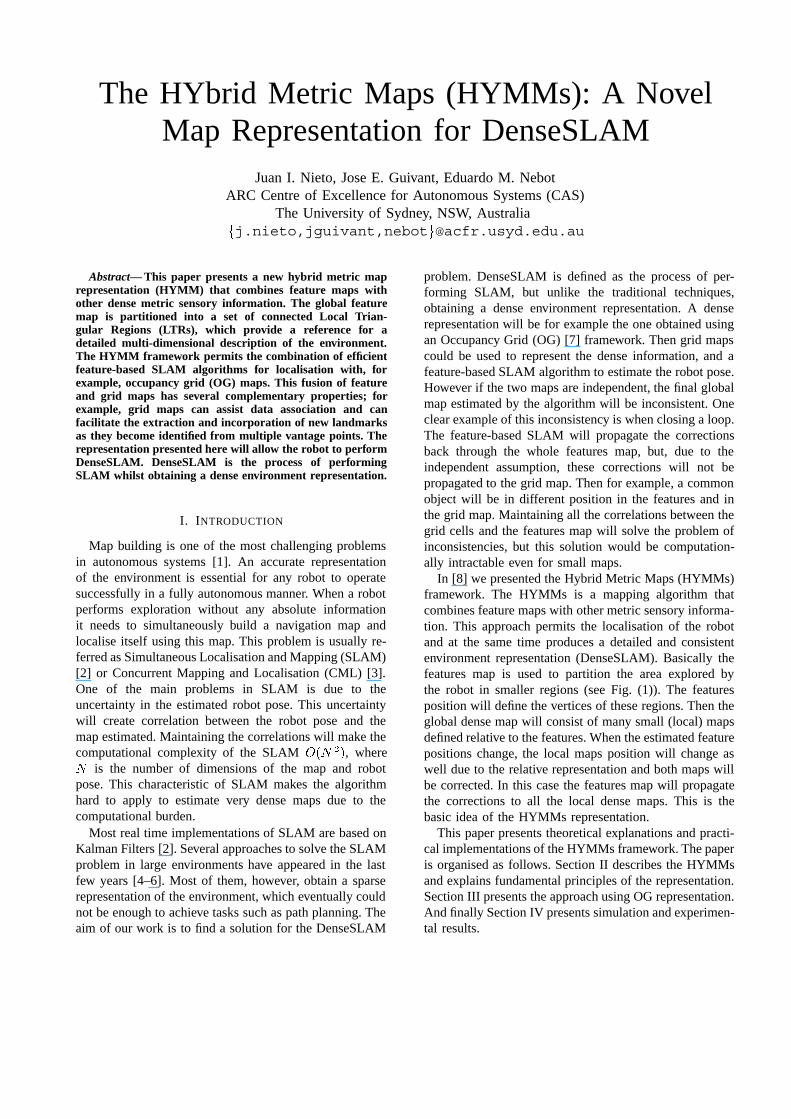
The HYbrid Metric Maps (HYMMs): A Novel Map Representation for DenseSLAM Juan I. Nieto, Jose E. Guivant, Eduardo M. Nebot ARC Centre of Excellence for Autonomous Systems (CAS) The University of Sydney, NSW, Australia j.nieto,jguivant,nebot @acfr.usyd.edu.au Abstract— This paper presents a new hybrid metric map representation (HYMM) that combines feature maps with other dense metric sensory information. The global feature map is partitioned into a set of connected Local Trian- gular Regions (LTRs), which provide a reference for a detailed multi-dimensional description of the environment. The HYMM framework permits the combination of efficient feature-based SLAM algorithms for localisation with, for example, occupancy grid (OG) maps. This fusion of feature and grid maps has several complementary properties; for example, grid maps can assist data association and can facilitate the extraction and incorporation of new landmarks as they become identified from multiple vantage points. The representation presented here will allow the robot to perform DenseSLAM. DenseSLAM is the process of performing SLAM whilst obtaining a dense environment representation. I. I NTRODUCTION Map building is one of the most challenging problems in autonomous systems [1]. An accurate representation of the environment is essential for any robot to operate successfully in a fully autonomous manner. When a robot performs exploration without any absolute information it needs to simultaneously build a navigation map and localise itself using this map. This problem is usually re- ferred as Simultaneous Localisation and Mapping (SLAM) [2] or Concurrent Mapping and Localisation (CML) [3]. One of the main problems in SLAM is due to the uncertainty in the estimated robot pose. This uncertainty will create correlation between the robot pose and the map estimated. Maintaining the correlations will make the computational complexity of the SLAM , where is the number of dimensions of the map and robot pose. This characteristic of SLAM makes the algorithm hard to apply to estimate very dense maps due to the computational burden. Most real time implementations of SLAM are based on Kalman Filters [2]. Several approaches to solve the SLAM problem in large environments have appeared in the last few years [4–6]. Most of them, however, obtain a sparse representation of the environment, which eventually could not be enough to achieve tasks such as path planning. The aim of our work is to find a solution for the DenseSLAM problem. DenseSLAM is defined as the process of per- forming SLAM, but unlike the traditional techniques, obtaining a dense environment representation. A dense representation will be for example the one obtained using an Occupancy Grid (OG) [7] framework. Then grid maps could be used to represent the dense information, and a feature-based SLAM algorithm to estimate the robot pose. However if the two maps are independent, the final global map estimated by the algorithm will be inconsistent. One clear example of this inconsistency is when closing a loop. The feature-based SLAM will propagate the corrections back through the whole features map, but, due to the independent assumption, these corrections will not be propagated to the grid map. Then for example, a common object will be in different position in the features and in the grid map. Maintaining all the correlations between the grid cells and the features map will solve the problem of inconsistencies, but this solution would be computation- ally intractable even for small maps. In [8] we presented the Hybrid Metric Maps (HYMMs) framework. The HYMMs is a mapping algorithm that combines feature maps with other metric sensory informa- tion. This approach permits the localisation of the robot and at the same time produces a detailed and consistent environment representation (DenseSLAM). Basically the features map is used to partition the area explored by the robot in smaller regions (see Fig. (1)). The features position will define the vertices of these regions. Then the global dense map will consist of many small (local) maps defined relative to the features. When the estimated feature positions change, the local maps position will change as well due to the relative representation and both maps will be corrected. In this case the features map will propagate the corrections to all the local dense maps. This is the basic idea of the HYMMs representation. This paper presents theoretical explanations and practi- cal implementations of the HYMMs framework. The paper is organised as follows. Section II describes the HYMMs and explains fundamental principles of the representation. Section III presents the approach using OG representation. And finally Section IV presents simulation and experimen- tal results.
Transcript of The HYbrid metric maps (HYMMs): a novel map representation for DenseSLAM
The HYbrid Metric Maps (HYMMs): A NovelMap Representation for DenseSLAM
Juan I. Nieto, Jose E. Guivant, Eduardo M. NebotARC Centre of Excellence for Autonomous Systems (CAS)
The University of Sydney, NSW, Australia�j.nieto,jguivant,nebot�@acfr.usyd.edu.au
Abstract— This paper presents a new hybrid metric maprepresentation (HYMM) that combines feature maps withother dense metric sensory information. The global featuremap is partitioned into a set of connected Local Trian-gular Regions (LTRs), which provide a reference for adetailed multi-dimensional description of the environment.The HYMM framework permits the combination of efficientfeature-based SLAM algorithms for localisation with, forexample, occupancy grid (OG) maps. This fusion of featureand grid maps has several complementary properties; forexample, grid maps can assist data association and canfacilitate the extraction and incorporation of new landmarksas they become identified from multiple vantage points. Therepresentation presented here will allow the robot to performDenseSLAM. DenseSLAM is the process of performingSLAM whilst obtaining a dense environment representation.
I. INTRODUCTION
Map building is one of the most challenging problemsin autonomous systems [1]. An accurate representationof the environment is essential for any robot to operatesuccessfully in a fully autonomous manner. When a robotperforms exploration without any absolute informationit needs to simultaneously build a navigation map andlocalise itself using this map. This problem is usually re-ferred as Simultaneous Localisation and Mapping (SLAM)[2] or Concurrent Mapping and Localisation (CML) [3].One of the main problems in SLAM is due to theuncertainty in the estimated robot pose. This uncertaintywill create correlation between the robot pose and themap estimated. Maintaining the correlations will make thecomputational complexity of the SLAM ��� ��, where� is the number of dimensions of the map and robotpose. This characteristic of SLAM makes the algorithmhard to apply to estimate very dense maps due to thecomputational burden.
Most real time implementations of SLAM are based onKalman Filters [2]. Several approaches to solve the SLAMproblem in large environments have appeared in the lastfew years [4–6]. Most of them, however, obtain a sparserepresentation of the environment, which eventually couldnot be enough to achieve tasks such as path planning. Theaim of our work is to find a solution for the DenseSLAM
problem. DenseSLAM is defined as the process of per-forming SLAM, but unlike the traditional techniques,obtaining a dense environment representation. A denserepresentation will be for example the one obtained usingan Occupancy Grid (OG) [7] framework. Then grid mapscould be used to represent the dense information, and afeature-based SLAM algorithm to estimate the robot pose.However if the two maps are independent, the final globalmap estimated by the algorithm will be inconsistent. Oneclear example of this inconsistency is when closing a loop.The feature-based SLAM will propagate the correctionsback through the whole features map, but, due to theindependent assumption, these corrections will not bepropagated to the grid map. Then for example, a commonobject will be in different position in the features and inthe grid map. Maintaining all the correlations between thegrid cells and the features map will solve the problem ofinconsistencies, but this solution would be computation-ally intractable even for small maps.
In [8] we presented the Hybrid Metric Maps (HYMMs)framework. The HYMMs is a mapping algorithm thatcombines feature maps with other metric sensory informa-tion. This approach permits the localisation of the robotand at the same time produces a detailed and consistentenvironment representation (DenseSLAM). Basically thefeatures map is used to partition the area explored bythe robot in smaller regions (see Fig. (1)). The featuresposition will define the vertices of these regions. Then theglobal dense map will consist of many small (local) mapsdefined relative to the features. When the estimated featurepositions change, the local maps position will change aswell due to the relative representation and both maps willbe corrected. In this case the features map will propagatethe corrections to all the local dense maps. This is thebasic idea of the HYMMs representation.
This paper presents theoretical explanations and practi-cal implementations of the HYMMs framework. The paperis organised as follows. Section II describes the HYMMsand explains fundamental principles of the representation.Section III presents the approach using OG representation.And finally Section IV presents simulation and experimen-tal results.
II. HYBRID METRIC MAPS (HYMMS)
This section describes the Hybrid Metric Maps(HYMMs) approach. The HYMMs combine feature mapswith other metric information to obtain a dense representa-tion of the robot’s surroundings. This novel representationenables the propagation of the corrections from the fea-tures map to the dense metric map, building one consistentdense map.
A. HYMMs Overview
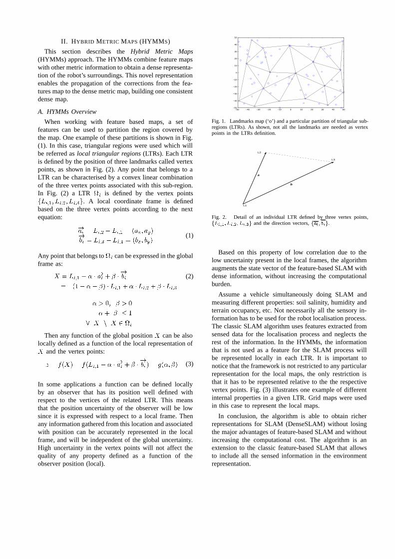
When working with feature based maps, a set offeatures can be used to partition the region covered bythe map. One example of these partitions is shown in Fig.(1). In this case, triangular regions were used which willbe referred as local triangular regions (LTRs). Each LTRis defined by the position of three landmarks called vertexpoints, as shown in Fig. (2). Any point that belongs to aLTR can be characterised by a convex linear combinationof the three vertex points associated with this sub-region.In Fig. (2) a LTR �� is defined by the vertex points������ ����� �����. A local coordinate frame is definedbased on the three vertex points according to the nextequation:
���� � ���� � ���� � ���� ������� � ���� � ���� � ���� ���
(1)
Any point that belongs to �� can be expressed in the globalframe as:
� � ���� � � � ���� � ����� (2)
� ��� �� � � ���� � � � ���� � � ����
� �� �
�� � �
� � � � ��
Then any function of the global position � can be alsolocally defined as a function of the local representation of� and the vertex points:
� � ���� � ������ � � � ���� � ����� � � ��� � (3)
In some applications a function can be defined locallyby an observer that has its position well defined withrespect to the vertices of the related LTR. This meansthat the position uncertainty of the observer will be lowsince it is expressed with respect to a local frame. Thenany information gathered from this location and associatedwith position can be accurately represented in the localframe, and will be independent of the global uncertainty.High uncertainty in the vertex points will not affect thequality of any property defined as a function of theobserver position (local).
−50 −40 −30 −20 −10 0 10 20 30 40 50−50
−40
−30
−20
−10
0
10
20
30
40
50
Fig. 1. Landmarks map (‘o’) and a particular partition of triangular sub-regions (LTRs). As shown, not all the landmarks are needed as vertexpoints in the LTRs definition.
L1
L3
a
b
L2
Fig. 2. Detail of an individual LTR defined by three vertex points,������ ����� ����� and the direction vectors, ���� ���.
Based on this property of low correlation due to thelow uncertainty present in the local frames, the algorithmaugments the state vector of the feature-based SLAM withdense information, without increasing the computationalburden.
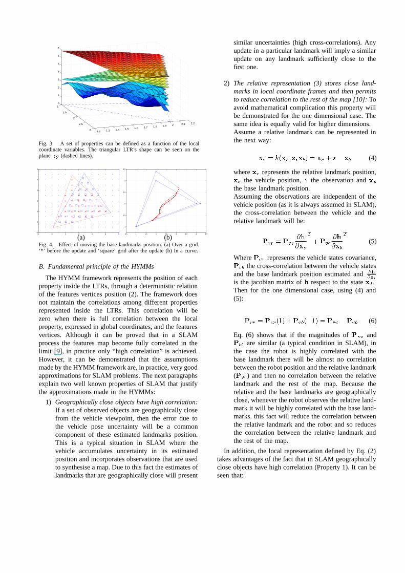
Assume a vehicle simultaneously doing SLAM andmeasuring different properties: soil salinity, humidity andterrain occupancy, etc. Not necessarily all the sensory in-formation has to be used for the robot localisation process.The classic SLAM algorithm uses features extracted fromsensed data for the localisation process and neglects therest of the information. In the HYMMs, the informationthat is not used as a feature for the SLAM process willbe represented locally in each LTR. It is important tonotice that the framework is not restricted to any particularrepresentation for the local maps, the only restriction isthat it has to be represented relative to the the respectivevertex points. Fig. (3) illustrates one example of differentinternal properties in a given LTR. Grid maps were usedin this case to represent the local maps.
In conclusion, the algorithm is able to obtain richerrepresentations for SLAM (DenseSLAM) without losingthe major advantages of feature-based SLAM and withoutincreasing the computational cost. The algorithm is anextension to the classic feature-based SLAM that allowsto include all the sensed information in the environmentrepresentation.
1
1.5
2
2.5
31.2 1.3 1.4 1.5 1.6 1.7 1.8 1.9 2 2.1 2.2
0
1
2
3
4
5
6
7
Fig. 3. A set of properties can be defined as a function of the localcoordinate variables. The triangular LTR’s shape can be seen on theplane �� (dashed lines).
−1 0 1 2 3 4 5−1
0
1
2
3
4
5
0.5 1 1.5 2 2.5 3 3.5 4 4.5
1
1.5
2
2.5
3
3.5
(a) (b)Fig. 4. Effect of moving the base landmarks position. (a) Over a grid.‘*’ before the update and ‘square’ grid after the update (b) In a curve.
B. Fundamental principle of the HYMMs
The HYMM framework represents the position of eachproperty inside the LTRs, through a deterministic relationof the features vertices position (2). The framework doesnot maintain the correlations among different propertiesrepresented inside the LTRs. This correlation will bezero when there is full correlation between the localproperty, expressed in global coordinates, and the featuresvertices. Although it can be proved that in a SLAMprocess the features map become fully correlated in thelimit [9], in practice only “high correlation” is achieved.However, it can be demonstrated that the assumptionsmade by the HYMM framework are, in practice, very goodapproximations for SLAM problems. The next paragraphsexplain two well known properties of SLAM that justifythe approximations made in the HYMMs:
1) Geographically close objects have high correlation:If a set of observed objects are geographically closefrom the vehicle viewpoint, then the error due tothe vehicle pose uncertainty will be a commoncomponent of these estimated landmarks position.This is a typical situation in SLAM where thevehicle accumulates uncertainty in its estimatedposition and incorporates observations that are usedto synthesise a map. Due to this fact the estimates oflandmarks that are geographically close will present
similar uncertainties (high cross-correlations). Anyupdate in a particular landmark will imply a similarupdate on any landmark sufficiently close to thefirst one.
2) The relative representation (3) stores close land-marks in local coordinate frames and then permitsto reduce correlation to the rest of the map [10]: Toavoid mathematical complication this property willbe demonstrated for the one dimensional case. Thesame idea is equally valid for higher dimensions.Assume a relative landmark can be represented inthe next way:
�� � ���� � ����� � �� � �� �� (4)
where �� represents the relative landmark position,�� the vehicle position, � the observation and ��
the base landmark position.Assuming the observations are independent of thevehicle position (as it is always assumed in SLAM),the cross-correlation between the vehicle and therelative landmark will be:
��� � ���
��
���
�
����
��
���
�
(5)
Where ��� represents the vehicle states covariance,��� the cross-correlation between the vehicle statesand the base landmark position estimated and �
��
is the jacobian matrix of � respect to the state ��.Then for the one dimensional case, using (4) and(5):
��� � ������ �������� � ��� ���� (6)
Eq. (6) shows that if the magnitudes of ��� and��� are similar (a typical condition in SLAM), inthe case the robot is highly correlated with thebase landmark there will be almost no correlationbetween the robot position and the relative landmark(���) and then no correlation between the relativelandmark and the rest of the map. Because therelative and the base landmarks are geographicallyclose, whenever the robot observes the relative land-mark it will be highly correlated with the base land-marks. this fact will reduce the correlation betweenthe relative landmark and the robot and so reducesthe correlation between the relative landmark andthe rest of the map.
In addition, the local representation defined by Eq. (2)takes advantages of the fact that in SLAM geographicallyclose objects have high correlation (Property 1). It can beseen that:
� � ���� �� �� � �� ��� �� �� �� � ���� �� �� � �� ��� �� �� �� � ���� �� �� � �� ��� �� �� �
This means that if a relative estimated point � is closeto ���� and the estimation process generates changes inthe base landmarks ����� ���� but no change is introducedin ���� then a very small change will be made over theestimate of � . Fig. (4) shows the effects of changingthe position of the base landmarks in a LTR. In (a) theconcept is illustrated in a grid, and in (b) in a curve. It isevident that there are small changes in the points close tothe static landmarks, and large changes in the points closeto the landmarks that moved. This result is consistent withProperty 1.
III. HYMMS USING OCCUPANCY GRIDS
The Occupancy Grid mapping technique (OG) [7] rep-resents the environment with a grid of fixed resolution.The OG is a multidimensional grid that maintains stochas-tic estimates of the occupancy state of each cell. Asmentioned before, one of the main problems with OGmaps is that they do not take into account the correlationbetween cells that exists due to the robot pose uncertainty.The technique assumes that the state variables of each cellare independent, an assumption that is not true speciallywhen working in large areas where the robot pose canpotentially accumulate significant errors. As stated in [11]it is of fundamental importance to have a representation ofthe robot pose and sensor uncertainty and their correlationto achieve convergence of the SLAM process. This isnot possible using only OG techniques. In general OGtechniques provide very rich representations of the envi-ronment, however they do not provide consistent globalmap estimates when working in large environments.
Using the HYMM representation is possible to ob-tain consistent OG maps. The HYMM uses the featuresincluded in the stochastic map to define the triangularboundaries of a local grid map. The representation cancombine feature based maps with OG. The approach usesthe best of both worlds, the consistency of the featuremaps, that will enable the robot to localise itself andthe rich representation that can be obtained with gridmaps. The next section presents experimental results usingthe HYMMs, combining features based maps with OGrepresentation.
IV. EXPERIMENTAL RESULTS
This section presents simulation and experimental re-sults of the HYMMs using OGs. The importance of thesimulation results in this case is in the possibility tocompare the actual objects position with the estimated by
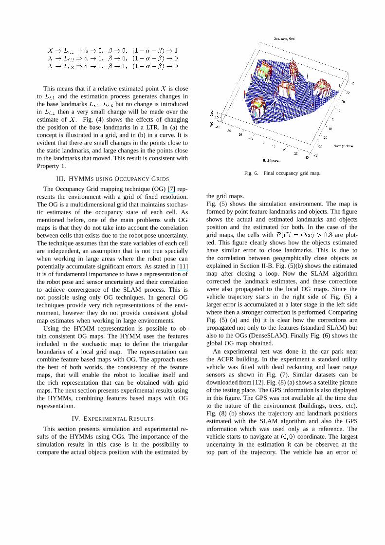
Fig. 6. Final occupancy grid map.
the grid maps.Fig. (5) shows the simulation environment. The map isformed by point feature landmarks and objects. The figureshows the actual and estimated landmarks and objectsposition and the estimated for both. In the case of thegrid maps, the cells with � ��� � ���� ��� are plot-ted. This figure clearly shows how the objects estimatedhave similar error to close landmarks. This is due tothe correlation between geographically close objects asexplained in Section II-B. Fig. (5)(b) shows the estimatedmap after closing a loop. Now the SLAM algorithmcorrected the landmark estimates, and these correctionswere also propagated to the local OG maps. Since thevehicle trajectory starts in the right side of Fig. (5) alarger error is accumulated at a later stage in the left sidewhere then a stronger correction is performed. ComparingFig. (5) (a) and (b) it is clear how the corrections arepropagated not only to the features (standard SLAM) butalso to the OGs (DenseSLAM). Finally Fig. (6) shows theglobal OG map obtained.
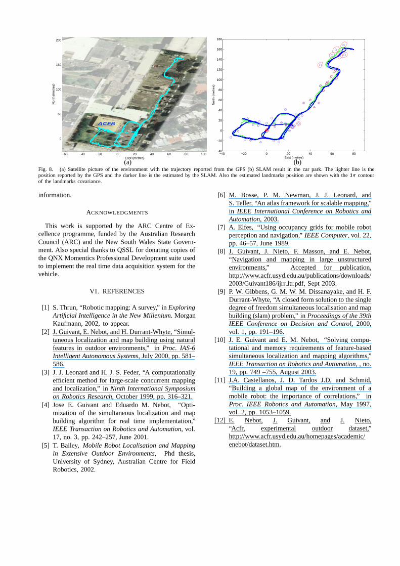
An experimental test was done in the car park nearthe ACFR building. In the experiment a standard utilityvehicle was fitted with dead reckoning and laser rangesensors as shown in Fig. (7). Similar datasets can bedownloaded from [12]. Fig. (8) (a) shows a satellite pictureof the testing place. The GPS information is also displayedin this figure. The GPS was not available all the time dueto the nature of the environment (buildings, trees, etc).Fig. (8) (b) shows the trajectory and landmark positionsestimated with the SLAM algorithm and also the GPSinformation which was used only as a reference. Thevehicle starts to navigate at ��� �� coordinate. The largestuncertainty in the estimation it can be observed at thetop part of the trajectory. The vehicle has an error of
−60 −40 −20 0 20 40 60
−40
−30
−20
−10
0
10
20
30
40
East (metres)
Nor
th (
met
res)
−60 −40 −20 0 20 40 60
−40
−30
−20
−10
0
10
20
30
40
East (metres)
Nor
th (
met
res)
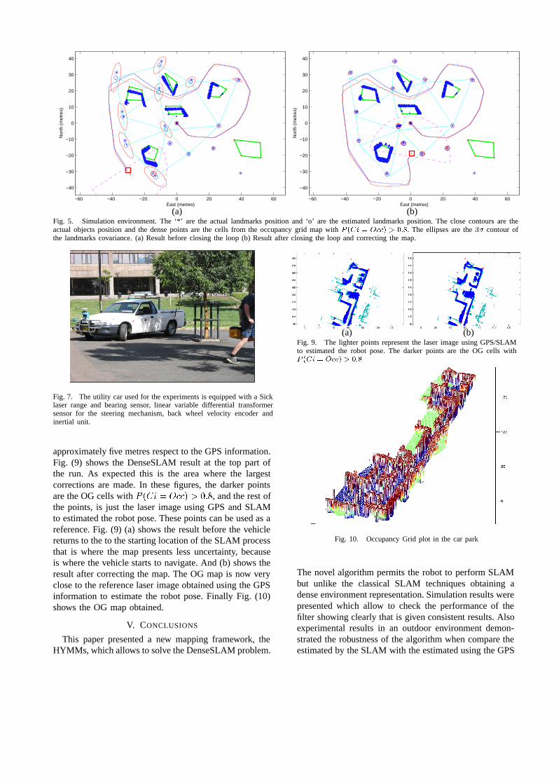
(a) (b)Fig. 5. Simulation environment. The ‘*’ are the actual landmarks position and ‘o’ are the estimated landmarks position. The close contours are theactual objects position and the dense points are the cells from the occupancy grid map with � �� � ��� � � �. The ellipses are the �� contour ofthe landmarks covariance. (a) Result before closing the loop (b) Result after closing the loop and correcting the map.
Fig. 7. The utility car used for the experiments is equipped with a Sicklaser range and bearing sensor, linear variable differential transformersensor for the steering mechanism, back wheel velocity encoder andinertial unit.
approximately five metres respect to the GPS information.Fig. (9) shows the DenseSLAM result at the top part ofthe run. As expected this is the area where the largestcorrections are made. In these figures, the darker pointsare the OG cells with � ��� � ���� ���, and the rest ofthe points, is just the laser image using GPS and SLAMto estimated the robot pose. These points can be used as areference. Fig. (9) (a) shows the result before the vehiclereturns to the to the starting location of the SLAM processthat is where the map presents less uncertainty, becauseis where the vehicle starts to navigate. And (b) shows theresult after correcting the map. The OG map is now veryclose to the reference laser image obtained using the GPSinformation to estimate the robot pose. Finally Fig. (10)shows the OG map obtained.
V. CONCLUSIONS
This paper presented a new mapping framework, theHYMMs, which allows to solve the DenseSLAM problem.
(a) (b)Fig. 9. The lighter points represent the laser image using GPS/SLAMto estimated the robot pose. The darker points are the OG cells with� �� � ��� � � �
Fig. 10. Occupancy Grid plot in the car park
The novel algorithm permits the robot to perform SLAMbut unlike the classical SLAM techniques obtaining adense environment representation. Simulation results werepresented which allow to check the performance of thefilter showing clearly that is given consistent results. Alsoexperimental results in an outdoor environment demon-strated the robustness of the algorithm when compare theestimated by the SLAM with the estimated using the GPS
−60 −40 −20 0 20 40 60 80 100
0
50
100
150
200
East (metres)
Nor
th (
met
res)
−40 −20 0 20 40 60 80−40
−20
0
20
40
60
80
100
120
140
160
180
East (metres)
Nor
th (
met
res)
(a) (b)Fig. 8. (a) Satellite picture of the environment with the trajectory reported from the GPS (b) SLAM result in the car park. The lighter line is theposition reported by the GPS and the darker line is the estimated by the SLAM. Also the estimated landmarks position are shown with the �� contourof the landmarks covariance.
information.
ACKNOWLEDGMENTS
This work is supported by the ARC Centre of Ex-cellence programme, funded by the Australian ResearchCouncil (ARC) and the New South Wales State Govern-ment. Also special thanks to QSSL for donating copies ofthe QNX Momentics Professional Development suite usedto implement the real time data acquisition system for thevehicle.
VI. REFERENCES
[1] S. Thrun, “Robotic mapping: A survey,” in ExploringArtificial Intelligence in the New Millenium. MorganKaufmann, 2002, to appear.
[2] J. Guivant, E. Nebot, and H. Durrant-Whyte, “Simul-taneous localization and map building using naturalfeatures in outdoor environments,” in Proc. IAS-6Intelligent Autonomous Systems, July 2000, pp. 581–586.
[3] J. J. Leonard and H. J. S. Feder, “A computationallyefficient method for large-scale concurrent mappingand localization,” in Ninth International Symposiumon Robotics Research, October 1999, pp. 316–321.
[4] Jose E. Guivant and Eduardo M. Nebot, “Opti-mization of the simultaneous localization and mapbuilding algorithm for real time implementation,”IEEE Transaction on Robotics and Automation, vol.17, no. 3, pp. 242–257, June 2001.
[5] T. Bailey, Mobile Robot Localisation and Mappingin Extensive Outdoor Environments, Phd thesis,University of Sydney, Australian Centre for FieldRobotics, 2002.
[6] M. Bosse, P. M. Newman, J. J. Leonard, andS. Teller, “An atlas framework for scalable mapping,”in IEEE International Conference on Robotics andAutomation, 2003.
[7] A. Elfes, “Using occupancy grids for mobile robotperception and navigation,” IEEE Computer, vol. 22,pp. 46–57, June 1989.
[8] J. Guivant, J. Nieto, F. Masson, and E. Nebot,“Navigation and mapping in large unstructuredenvironments,” Accepted for publication,http://www.acfr.usyd.edu.au/publications/downloads/2003/Guivant186/ijrr ltr.pdf, Sept 2003.
[9] P. W. Gibbens, G. M. W. M. Dissanayake, and H. F.Durrant-Whyte, “A closed form solution to the singledegree of freedom simultaneous localisation and mapbuilding (slam) problem,” in Proceedings of the 39thIEEE Conference on Decision and Control, 2000,vol. 1, pp. 191–196.
[10] J. E. Guivant and E. M. Nebot, “Solving compu-tational and memory requirements of feature-basedsimultaneous localization and mapping algorithms,”IEEE Transaction on Robotics and Automation, , no.19, pp. 749 –755, August 2003.
[11] J.A. Castellanos, J. D. Tardos J.D, and Schmid,“Building a global map of the environment of amobile robot: the importance of correlations,” inProc. IEEE Robotics and Automation, May 1997,vol. 2, pp. 1053–1059.
[12] E. Nebot, J. Guivant, and J. Nieto,“Acfr, experimental outdoor dataset,”http://www.acfr.usyd.edu.au/homepages/academic/enebot/dataset.htm.