The effect of temperature on the large amplitude vibrations of curved beams
15
JOURNAL OF SOUND AND VIBRATION Journal of Sound and Vibration 285 (2005) 1093–1107 The effect of temperature on the large amplitude vibrations of curved beams Pedro Ribeiro a, , Emil Manoach b a IDMEC/DEMEGI, Faculdade de Engenharia, Universidade do Porto, Rua Dr. Roberto Frias, 4200-465 Porto, Portugal b Institute of Mechanics, Bulgarian Academy of Sciences, Acad G. Bonchev Street, Block 4, 1113 Sofia, Bulgaria Received 7 November 2003; received in revised form 6 September 2004; accepted 15 September 2004 Available online 2 December 2004 Abstract The thermoelastic, geometrically nonlinear vibrations of isotropic, straight and curved beams are studied using p-version, hierarchical finite elements. First-order shear deformation theory is followed, and both the longitudinal displacements and inertia are taken into account. The nonlinear equations of motion are solved in the time domain by Newmark’s method. The influence of parameters like the temperature variation, the thickness and the ratio of curvature on the beams nonlinear dynamics is studied. Periodic and non-periodic motions are found. r 2004 Elsevier Ltd. All rights reserved. 1. Introduction Large amplitude vibrations introduce a geometrical type of nonlinearity that influences the dynamic behaviour of a structure. In fact, the structure’s stiffness, and consequently the resonance frequencies and mode shapes, are amplitude dependent [1]. It is also well known that temperature variations from a reference temperature may cause quite significant changes in the dynamic behaviour of a structure, as temperature fields introduce stresses due to thermal expansion or contraction, and can cause buckling of structures with fixed ends [2]. Therefore, the problem of ARTICLE IN PRESS www.elsevier.com/locate/jsvi 0022-460X/$ - see front matter r 2004 Elsevier Ltd. All rights reserved. doi:10.1016/j.jsv.2004.09.010 Corresponding author. Tel: +351 22 508 17 13; Fax: +351 22 508 14 45. E-mail address: [email protected] (P. Ribeiro).
Transcript of The effect of temperature on the large amplitude vibrations of curved beams

ARTICLE IN PRESS
JOURNAL OFSOUND ANDVIBRATION
Journal of Sound and Vibration 285 (2005) 1093–1107
0022-460X/$ -
doi:10.1016/j.
�CorresponE-mail add
www.elsevier.com/locate/jsvi
The effect of temperature on the large amplitudevibrations of curved beams
Pedro Ribeiroa,�, Emil Manoachb
aIDMEC/DEMEGI, Faculdade de Engenharia, Universidade do Porto, Rua Dr. Roberto Frias, 4200-465 Porto, PortugalbInstitute of Mechanics, Bulgarian Academy of Sciences, Acad G. Bonchev Street, Block 4, 1113 Sofia, Bulgaria
Received 7 November 2003; received in revised form 6 September 2004; accepted 15 September 2004
Available online 2 December 2004
Abstract
The thermoelastic, geometrically nonlinear vibrations of isotropic, straight and curved beams are studiedusing p-version, hierarchical finite elements. First-order shear deformation theory is followed, and both thelongitudinal displacements and inertia are taken into account. The nonlinear equations of motion aresolved in the time domain by Newmark’s method. The influence of parameters like the temperaturevariation, the thickness and the ratio of curvature on the beams nonlinear dynamics is studied. Periodic andnon-periodic motions are found.r 2004 Elsevier Ltd. All rights reserved.
1. Introduction
Large amplitude vibrations introduce a geometrical type of nonlinearity that influences thedynamic behaviour of a structure. In fact, the structure’s stiffness, and consequently the resonancefrequencies and mode shapes, are amplitude dependent [1]. It is also well known that temperaturevariations from a reference temperature may cause quite significant changes in the dynamicbehaviour of a structure, as temperature fields introduce stresses due to thermal expansion orcontraction, and can cause buckling of structures with fixed ends [2]. Therefore, the problem of
see front matter r 2004 Elsevier Ltd. All rights reserved.
jsv.2004.09.010
ding author. Tel: +351 22 508 17 13; Fax: +351 22 508 14 45.
ress: [email protected] (P. Ribeiro).

ARTICLE IN PRESS
P. Ribeiro, E. Manoach / Journal of Sound and Vibration 285 (2005) 1093–11071094
geometrically nonlinear vibration with temperature effects is an interesting one, with wideapplicability in engineering.Beams, straight or curved, are fundamental elements in machines and structures, and one can
find several publications devoted to the study of their linear and nonlinear vibrations. As far asthe linear vibrations of curved beams are concerned, one of the main motives of research is thealleviation of the shear locking phenomenon in finite elements [3,4]. The nonlinear vibration ofcurved beams is a particularly interesting problem, which has been investigated, for example, inRefs. [5–7]. In the first Ref. [5], a two-mode model was applied, which has the advantage of beingsmall, but might not be accurate enough for some investigations. In Ref. [6], nonlinear steady-state vibration of beams, frames and shallow arches were analysed in the frequency domain, usinga h-version straight beam finite element. Undamped, free vibrations of curved Timoshenko beamswere analysed in [7] by the Galerkin method, which was applied both in the space and timedomains. In these references the temperature effects were not considered.Although the temperature and elastic behaviours are in fact coupled [2,8], for thin structures—
beams, plates or shells—it is often reasonable to assume that the temperature distribution isindependent from the deformation of the structure. This gives rise to uncoupled problems, whichwere investigated, for example, in [9–15]. Chang et al. [9] performed an analytical analysis ofheated plates using one term Galerkin approximation and Berger’s simplified theory. Locke [10]studied the large deflection of thin, in the Kirchhoff sense, laminated composite plates subjectedto static, temperature and acoustic loads. A single mode Galerkin approximation was followed. In[11] a finite element method (FEM) for large amplitude oscillation of panels with the influence oftemperature is presented. In [12] a FEM time domain modal formulation for the nonlinear flutterof panels at elevated temperatures is introduced. Limit-cycle and chaotic oscillations are found. Apreliminary given distribution of the temperature field is accepted as well in [13], wheregeometrically nonlinear vibrations of thermally buckled slender panels are investigated using a FEmodel. In [14] governing equations for geometrically nonlinear vibrations of shells under linearand parabolic temperature distributions are derived. The equations are solved assuming that thedeflection is given by one term and applying Galerkin’s method. In [15], a formulation based onthe FEM and modal analysis is applied to analyse thermal post-buckling of thin simply supportedplates.In the p-version of the FEM, the accuracy of the approximation is improved by increasing the
number of shape functions over the elements. Several works demonstrate that, in general, the p-version of the FEM gives accurate results with fewer degrees of freedom than the h-version, whichis a big advantage in nonlinear analysis [1,16,17]. Moreover, p-elements are not prone to shearlocking [17] and, if orthogonal shape functions are chosen, the linear matrices are diagonal. A p-version of the FEM where the set of functions corresponding to an approximation of lower orderp, constitutes a subset of the set of functions corresponding to the approximation of order p+1, iscalled the ‘‘hierarchical finite element method’’ (HFEM) [16]. This has additional advantages, likethe fact that linear matrices of different orders of approximation are embedded.An analysis of the current state of the art in thermoelastic geometrically nonlinear vibrations of
structures reveals that the highly efficient p-version, hierarchical FEM has not been used to studythis problem. In the following pages, a p-version, hierarchical finite element for isotropic, linearelastic, curved beams is applied to study thermoelastic geometrically nonlinear vibrations. First-order shear deformation theory is followed; the longitudinal displacements and the longitudinal

ARTICLE IN PRESS
P. Ribeiro, E. Manoach / Journal of Sound and Vibration 285 (2005) 1093–1107 1095
inertia are not neglected. The nonlinear equations of motion are solved in the time domain. Theinfluence on the beam nonlinear dynamics of parameters like the temperature variation, thethickness and the ratio of curvature are investigated.
2. Finite element model
A curved beam of thickness h, whose undeformed geometry is defined from a reference straightline by introducing a curvature radius R, is considered. Therefore, the centroidal axis is initiallylocated at a distance from the x-axis given by
wiðxÞ ¼ �1
2
x2
R
� �: (1)
The axial displacement, u, is a function of the longitudinal displacement along the centroidalaxis u0 and of the rotation about the y-axis, which is denoted by y0y: The superscript ‘‘0’’ representsthe centroidal axis and the rotations follow the right-hand rule. Using a first-order sheardeformation model, the displacements are given by
uðx; z; tÞ ¼ u0ðx; tÞ þ zy0yðx; tÞ; (2)
wðx; z; tÞ ¼ w0ðx; tÞ þ wiðxÞ; (3)
where w is the displacement along the z direction and w0 is the deformation in relation to theinitial configuration. The longitudinal strains of curved beams are given by
�x ¼ 1 z� � �p
0
�b0
( )þ
�I
0
� �þ
�pL
0
( ) !; (4)
where the linear longitudinal and bending strains, �p0 and �b
0; and the geometrically nonlinearlongitudinal strain, �p
L; are defined as
�p0 ¼ u0
;x; �b0 ¼ y0y;x; �p
L ¼ðw0
;xÞ2
2: (5)
The following strain is due to the initial curvature of the arch and to the transverse displacement:
�I ¼w0
R: (6)
The transverse shear strain is
g0zx ¼ w0;x þ y0y: (7)
The other strains are zero. Naturally, the strains and displacements in Eqs. (4)–(7) depend on theposition x and on time t, but in order to simplify the notation �xðx; tÞ is represented as �x; etc.When a beam is heated and the temperature distribution is uniform, its dimensions tend to
change due to a thermal deformation that can be expressed as �T ¼ aðT � T ref Þ ¼ aDT : The letterT represents the actual temperature, and Tref is a reference temperature for zero thermal strain. Ifthe beam is constrained by boundary conditions that do not allow an axial deformation to occur,

ARTICLE IN PRESS
P. Ribeiro, E. Manoach / Journal of Sound and Vibration 285 (2005) 1093–11071096
then an axial compressive stress will result and the following stress–strain relation holds:
sx ¼ Eð�p0 þ �p
L þ �I � �T � zkxÞ: (8)
The relation between the average shear stress and the shear strain is the usual
txz ¼ lGgxz: (9)
In the former equations, E represents the modulus of elasticity and G is the shear modulus ofelasticity, given by E=ð2ð1þ nÞÞ; where n is the Poisson ratio. The shear correction factor, l,depends on the beam’s cross-section, and different values have been suggested. According to [18],the expression l ¼ ð5þ 5nÞ=ð6þ 5nÞ; which will be used in this paper, gives an appropriate valuefor rectangular beams. Material properties, like E, G and a; may vary appreciably when thetemperature changes a few hundred degrees [2], but in this work the temperature changes will bemoderate, and constant material properties will be assumed.In the FEM, the middle surface elemental displacements are expressed in the form:
u0
w0
y0y
8>><>>:
9>>=>>; ¼
Nuf gT 0 0
0 Nwf gT 0
0 0 Nyy� �T
2664
3775
qu
qw
qyy
8><>:
9>=>;; (10)
where fqug is the vector of generalised longitudinal displacements, fqwg is the vector of generalisedtransverse displacements, and fqyy
g is the vector of generalised rotations. The complete matrix ofshape functions is constituted by the row vectors of longitudinal, transverse and rotational shapefunctions, which are, respectively, fNugT; fNwgT and fNyygT: In the HFEM the number of shapefunctions can vary as deemed necessary by the user. The sets of shape functions used here aregiven in [1].The stress and couple resultants and the shear stress resultant per unit length are, respectively,
defined by Tx ¼R h=2�h=2 sx dz; M ¼
R h=2�h=2 sx zdz and Qz ¼
R h=2�h=2 txz dz: Substituting the stresses by
their relations with the strains, Eqs. (8) and (9), one arrives at the thermoelastic constitutiverelations of the curved beam. Because beams of symmetric cross section are considered, there areno coupling terms between extension and bending and the following relation holds:
T
M
� �¼
A 0
0 D
� � �p0
�b0
( )þ
�pL
0
( )þ
�I
0
� ��
�T
0
� � !; (11)
Qx ¼ lGhgxz (12)
with
A ¼ Eh; D ¼Eh3
12:
ARTICLE IN PRESS
P. Ribeiro, E. Manoach / Journal of Sound and Vibration 285 (2005) 1093–1107 1097
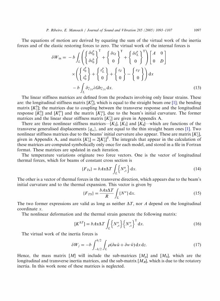
The equations of motion are derived by equating the sum of the virtual work of the inertiaforces and of the elastic restoring forces to zero. The virtual work of the internal forces is
dW in ¼ � b
ZL
d�p0
d�b0
( )T
þd�I
0
( )T
þd�p
L
0
( )T0@
1A A 0
0 D
" #
��p0
�b0
( )þ
�pL
0
( )þ
�I
0
( )�
�T
0
( ) !dx
� b
ZL
dgzxlGhgzx dx: ð13Þ
The linear stiffness matrices are defined from the products involving only linear strains. Theseare: the longitudinal stiffness matrix ½K
p1; which is equal to the straight beam one [1]; the bending
matrix ½Kb1; the matrices due to coupling between the transverse response and the longitudinal
response ½Kb1 and ½K
ps1 and the matrix ½Kss
1 ; due to the beam’s initial curvature. The formermatrices and the linear shear stiffness matrix ½K
g1 are given in Appendix A.
There are three nonlinear stiffness matrices—[K2], [K3] and [K4]—which are functions of thetransverse generalised displacements {qw}, and are equal to the thin straight beam ones [1]. Twononlinear stiffness matrices due to the beams’ initial curvature also appear. These are matrix ½Ks
2;given in Appendix A, and matrix ½Ks
3 ¼ 2½Ks2T: The integrals that appear in the calculation of
these matrices are computed symbolically only once for each model, and stored in a file in Fortranformat. These matrices are updated in each iteration.The temperature variations originate two force vectors. One is the vector of longitudinal
thermal forces, which for beams of constant cross section is
FTuf g ¼ bAaDT
ZL
Nu;x
n odx: (14)
The other is a vector of thermal forces in the transverse direction, which appears due to the beam’sinitial curvature and to the thermal expansion. This vector is given by
FTSf g ¼bAaDT
R
ZL
fNwgdx: (15)
The two former expressions are valid as long as neither DT ; nor A depend on the longitudinalcoordinate x.The nonlinear deformation and the thermal strain generate the following matrix:
½KDT ¼ bAaDT
ZL
Nw;x
n oNw
;x
n oT
dx: (16)
The virtual work of the inertia forces is
dW j ¼ �b
Z h=2
�h=2
ZL
rðdu €u þ dw €wÞdxdz: (17)
Hence, the mass matrix [M] will include the sub-matrices [Mp] and [Mb], which are thelongitudinal and transverse inertia matrices, and the sub-matrix [MR], which is due to the rotatoryinertia. In this work none of these matrices is neglected.

ARTICLE IN PRESS
P. Ribeiro, E. Manoach / Journal of Sound and Vibration 285 (2005) 1093–11071098
The principle of the virtual work is applied to compute the vector of generalised forces due toexternal mechanical actions. Considering as an example the point load, Pw
j ðtÞ; and the distributedtransverse load, Pw
d ðx; tÞ; the following expression applies:
dW ex ¼
ZL
Pwj ðtÞdðx � xjÞ þ Pw
d
h idwðx; tÞdL
3 dW ex ¼ 0 dqw 0n oT
0
FEw
0
8>><>>:
9>>=>>;; ð18Þ
where dðx � xjÞ represents a spatial Dirac delta function. A similar procedure is followed to obtainthe vectors of generalised externally applied longitudinal forces FE
u
� �and moments ME
� �:
For simplicity’s sake, stiffness proportional damping will be assumed, and the following timedomain equations of motion in generalised coordinates are obtained:
Mp
� �0 0
0 Mb½ 0
0 0 MR½
2664
3775
€qu
€qw
€qyy
8>><>>:
9>>=>>;þ
Kp1
� �K
ps1
� �0
Ksp1
� �Kss
1
� �þ K
g111
h iK
g121
h i0 K
g211
h iKb
1
� �þ K
g221
h i
2666664
3777775
qu
qw
qyy
8>><>>:
9>>=>>;
þ c
Kp1
� �K
ps1
� �0
Ksp1
� �Kss
1
� �þ K
g111
h iK
g121
h i0 K
g211
h iKb
1
� �þ K
g221
h i
2666664
3777775
_qu
_qw
_qyy
8>><>>:
9>>=>>;
þ
0 K2½ 0
K3½ K4½ þ Ks2
� �þ Ks
3
� �� KDT� �
0
0 0 0
2664
3775
qu
qw
qyy
8>><>>:
9>>=>>; ¼
FTu
FTS
0
8>><>>:
9>>=>>;þ
FEu
FEw
ME
8>><>>:
9>>=>>;: ð19Þ
3. Numerical studies and discussions
All beams analysed are in aluminium with elasticity modulus E ¼ 7� 1010 N=m2; mass densityr ¼ 2778kg=m3; and Poisson coefficient n ¼ 0:34: The thermal expansion coefficient is a ¼
23:90� 10�6=K and the shear correction factor is, as already stated, l ¼ ð5þ 5nÞ=ð6þ 5nÞ: In thefirst series of examples it will be assumed that the damping coefficient is c ¼ 10�3; afterwards, thevalue c ¼ 10�4 will be employed. Only one hierarchical finite element is used to model each beam.The boundaries are clamped–clamped.First, a straight beam with the following geometric properties is analysed: b ¼ 0:02m;
h=0.002m, L=0.5m. Using a finite element with 9 transverse shape functions, 9 longitudinal

ARTICLE IN PRESS
P. Ribeiro, E. Manoach / Journal of Sound and Vibration 285 (2005) 1093–1107 1099
shape functions and 9 rotational shape functions, that is, 27 dof, the values calculated for the firstfour natural frequencies (rad/s) are: 259.338, 714.774, 1401.00, 2315.64. These agree with theanalytical results [19].In Fig. 1, the displacements of the beam’s middle point are displayed. The beam is excited at its
first natural frequency by a harmonic excitation with 1N, applied transversely at midspan anddifferent variations in temperature are implemented. When negative variations of temperature areconsidered, one verifies, as expected, that a straight beam becomes stiffer, and that, therefore, thedisplacements amplitudes are smaller. On the other hand, as the temperature increases the beamsoftens, and its vibration amplitudes increase.With DT equal to �5, 0 or 1K the motions are periodic and symmetric around the
corresponding equilibrium position, which is the original straight configuration. For DT equal orhigher than 4K, the beam oscillates again with periodic motions, but around a new, buckled,equilibrium configuration.With this 1N point excitation, a very interesting motion occurs DT ¼ 3K; as the time, phase
and Poincare plots in Fig. 2 demonstrate. In this far from periodic motion, the beam movesaround three equilibrium positions, one unstable and two stable. The two buckled equilibriumpositions appear because the critical buckling temperature—determined as approximately DT ¼
2:2K; employing a Bernoulli–Euler model [2]—was passed. The Poincare plots, represented in thisand in the following pictures, were constructed by sampling the velocity and displacements atperiods of the excitation force [20].In Fig. 3, the time history of the displacement and the phase plot of the middle point of
the same straight beam is portrayed, but when DT ¼ 5K and the excitation amplitude is 5N. Thetemperature is larger than the critical buckling temperature and the force is quite large, so that thebeam should pass through its three equilibrium positions. It is thus interesting to find out thatthe motion became periodic again.From this simple examination, we verify that the dynamic behaviour of thin beams suffers
important changes with temperature. This brings some difficulties when one carries outexperimental analyses of beams with fixed boundaries, in a laboratory without a rigoroustemperature control [21].
-1.5
-1
-0.5
0
0.5
1
1.5
-3
-2
-1
0
1
2
3
w/h
w/h
0 0.1 0.2
t (s) t (s)
∆T=1 K ∆T=0 K ∆T=-5 K ∆T=5 K ∆T=10 K ∆T=4 K
∆T=3 K
0 0.1 0.2 0.3
Fig. 1. Time histories of thin straight beam at different temperatures.

ARTICLE IN PRESS
-2.5 -2
-1.5 -1
-0.5 0
0.5 1
1.5 2
2.5 3
0.89 0.91 0.93 0.95 0.97 0.99
-2
-1.5
-1
-0.50
0.5
1
1.5
2
-2.5 -1.5 -0.5 0.5 1.5 2.5
hw t(s)
hw
w(m
/s)
(a) (b)
Fig. 3. Time (a) and phase (b) plots representing motion of middle point of straight beam, when DT ¼ 5K:
-1.5
-1
-0.5
0
0.5
1
1.5
3 3.2 3.4 3.6 3.8 4 4.2 4.4 4.6 4.8 5
-0.4
-0.2
0
0.2
0.4-0.75 -0.25 0.25 0.75
-0.35
-0.3
-0.25
-0.2
-0.15-0.00175 -0.00125 -0.00075 -0.00025 0.00025
w. .
(m /s)
w/h
t (s)
w (m) w/h
w (m/s)
Fig. 2. Time, phase and Poincare plots of motion of middle point of straight beam, when DT ¼ 3K:
P. Ribeiro, E. Manoach / Journal of Sound and Vibration 285 (2005) 1093–11071100
Now, let us study the effects of the beam’s thickness by analysing straight beams with theproperties previously defined, except the thickness, which will be varied. Two finite elements areapplied: the previously used 27 dof element and a hierarchical finite element with 7 shapefunctions of each type, i.e., 21 dof in total. Compared with the 27 dof element, the 21 dof still

ARTICLE IN PRESS
P. Ribeiro, E. Manoach / Journal of Sound and Vibration 285 (2005) 1093–1107 1101
provides very accurate results—if the 5th mode is not important in the motion’s definition—withcomputational time savings. With this 21 dof element, the fourth linear natural frequency iscomputed with a relative error lower than 0.63%.Fig. 4 shows the time plots of responses when the excitation frequency is the first natural
frequency of the beam under analysis, the temperature variation is either 0K or 10K, and theforce is distributed with amplitude 50(h/h1)
3N/m, where h1 is the thickness of the thinner beam(h1 ¼ 0:002m). The other beams thicknesses are h2 ¼ 0:01m and h3 ¼ 0:02m; that is h2=L ¼ 0:02and h3=L ¼ 0:04:In spite of the increasing force amplitude, the amplitude of the displacements decreased
significantly as the thickness of the beam augmented. Also, as confirmed by the 0K examples, thethin beam response changes dramatically with the temperature variation, whilst for the mediumbeam the effects of the temperature are smaller and the thicker beam has a similar response atboth temperatures. In fact, at 10K, the dynamic response to a harmonic excitation changed froma not periodic motion, in the thinner beam case, to a harmonic one in the thicker beams.By analysing the deformed shapes of the thin beam, it was verified that its motion is affected by
higher order modes, in both temperature cases. Nevertheless, these higher modes are much moreimportant when DT ¼ 10K; where the motion is not at all periodic, as the phase and Poincareplots—Figs. 5 and 6—demonstrate. In this case of non-periodic motions, and because high order
-4
-3
-2
-1
0
1
2
3
4
0.6 0.65 0.7 0.75 0.8 0.85 0.9 0.95 1
-0.7
-0.5
-0.3
-0.1
0.1
0.3
0.5
0.7
0 0.02 0.04 0.06 -0.25
-0.15
-0.05
0.05
0.15
0.25
0 0.01 0.02 0.03 0.04
t(s)
t(s) t(s)
hw hw
hw
(a)
(b) (c)
Fig. 4. Time histories of straight beams with different thicknesses. Grey, DT ¼ 0K; black DT ¼ 10K; and (a) h=L ¼
0:002; (b) h=L ¼ 0:03; and (c) h=L ¼ 0:04:

ARTICLE IN PRESS
-2.25
-1.25
-0.5
0.25
1.25
2.25
-1.5
-0.25
0.5 1.5
-4-3-2-1012 4
-2 0 2
w/h w/h (a) (b)
w. (m/s
)
w. (m/s
)
Fig. 5. Phase plots of straight thin beam when DT ¼ 0K (a) and DT ¼ 10K (b).
0.05
0.1
0.15
0.2
0.25
0.3
-0.002 -0.0015 -0.001 -0.0005
0.35
0
0.5
1
1.5
2
-0.0045 -0.004 -0.0035 -0.003
w (m) w (m)
w. (m
/s)
w. (m
/s)
(a) (b)
Fig. 6. Poincare maps of straight thin beam when (a) DT ¼ 0K and (b) DT ¼ 10K:
-1
-0.5
0
0.5
1
1.5
0.05 0.1
0.2
0
0.4
0.6
0.8
1
0 0.05 0.10
0.1
0.2
0.3
0.4
0.5
0.6
0.7
0 0.05 0.1
0
0.2
0.4
0.6
0.8
1
1.2
1.4
t(s) t(s)
t(s) t(s)
0.05 0.10
(a) (b)
(c) (d)
hw hwhwhw
Fig. 7. Time plots for different curved beams (DT ¼ 100K): (a) R ¼ 1; (b) L=R ¼ 0:1; (c) L=R ¼ 0:2; and (d) L=R ¼
0:3:
P. Ribeiro, E. Manoach / Journal of Sound and Vibration 285 (2005) 1093–11071102

ARTICLE IN PRESS
P. Ribeiro, E. Manoach / Journal of Sound and Vibration 285 (2005) 1093–1107 1103
nonlinear modes are present in the response, slightly different time, Poincare and phase plots wereobtained with the 21 dof and with the 27 dof models. Thus, the results from the more accurate 27dof model are the ones shown.In the following examples the thermoelastic vibrations of curved beams, with length L ¼ 0:5m
and square cross-section, being b ¼ h ¼ 0:02m; are analysed. The 21 dof finite element is used forthis purpose.Let us start by changing the beams’ curvature radius, analysing beams where R obeys one of the
following relations: R1 ¼ 1; L=R2 ¼ 0:1; L=R3 ¼ 0:2 and L=R4 ¼ 0:3: The responses of thesebeams to distributed harmonic excitations with frequency equal to their first natural frequency,and with amplitude 10 kN/m, were computed. The results when the temperature variation is 100Kare shown in Fig. 7.As the initial curvature radius decreases, the beam becomes stiffer; consequently, the vibration
amplitude decreases as L/R increases. However, the transverse thermal force—given byexpression (15)—also increases with the curvature of the beam, and, unlike straight beams prior
-0.6
-0.4
-0.2
0
0.10 0.01 0.02 0.03 0.04
-0.4
-0.2
0
0.20 0.01 0.02 0.03 0.04
-0.3
-0.2
-0.1
0
0.1
0.2
0.3
0.40 0.01 0.02 0.03 0.04
-0.2
-0.1
0
0.1
0.2
0.3
0.4
0.5
0 0.01 0.02 0.03 0.04 0
0.1
0.2
0.3
0.4
0.5
0.6
0 0.01 0.02 0.03 0.04
-1
-0.8
-0.6
-0.4
-0.2
00 0.01 0.02 0.03 0.04
t(s) t(s)
t(s)
hw hwhw
hw
t(s)
hwhw
t(s) t(s)
(a)
(c) (d)
(e) (f)
(b)
Fig. 8. Time plots for a curved beam under 10 kN/m and different temperature variations: DT ¼ �100K (a), DT ¼
�50K (b), DT ¼ �25K (c), DT ¼ 0K (d), DT ¼ 25K (e), and DT ¼ 50K (f).

ARTICLE IN PRESS
P. Ribeiro, E. Manoach / Journal of Sound and Vibration 285 (2005) 1093–11071104
to buckling, curved beams always vibrate around an equilibrium position which is displacedrelatively to the one of the unheated beam.Fig. 8 displays the responses of the beam where L=R ¼ 0:2; with a mechanical excitation due to
a distributed harmonic load with 10 kN/m, but with different temperature changes. In this case, allthe motions are periodic, but the temperature variation DT alters the equilibrium configuration.For negative temperature variations, the curvature of the beam decreases, and the opposite occursfor positive DT :So far the damping parameter has always been c ¼ 0:001: Now, to attain very large amplitude
vibrations, this will be reduced to c ¼ 0:0001 and the distributed force increased to 40 kN/m. Ourgoal here is to shown the importance of the curvature in the very large displacement, hightemperature, elastic vibrations. One sees in Figs. 9 and 10 that, for this larger excitation force, themotions at the different temperature variations are periodic and do not vary so strongly with thetemperature as in other cases. Nevertheless, the amplitudes of vibration and the phase plots
-5
-4
-3
-2
-1
0
1
2
3
0 0.01 0.02 0.03 0.04-5
-4
-3
-2
-1
0
1
2
3
0 0.01 0.02 0.03 0.04
-5
-4
-3
-2
-1
0
1
2
3
0 0.01 0.02 0.03 0.04-5
-4
-3
-2
-1
0
1
2
3
0 0.01 0.02 0.03 0.04
-5
-4
-3
-2
-1
0
1
2
3
0 0.01 0.02 0.03 0.04 -5
-4
-3
-2
-1
0
1
2
3
0 0.01 0.02 0.03 0.04
t (s) t (s)
t (s) t (s)
t (s) t (s)
w/h w/h
w/h
w/h
w/h
w/h
(a) (b)
(c) (d)
(e) (f)
Fig. 9. Time plots for a curved beam under 40 kN/m and different temperature variations: DT ¼ �100K (a), DT ¼
�25K (b), DT ¼ 0K (c), DT ¼ 25K (d), DT ¼ 50K (e), and DT ¼ 100K (f).
ARTICLE IN PRESS
-40
10
60
-3.5 -1.5 0.5 2.5
-40
10
60
110
-2 0 2
-90
-40
10
60
110
-2 0 2
-40
10
60
110
-4 -2 0 2
w/h
w (
m/s
) w
(m
/s)
w. (m
/s)
w. (m
/s)
w/h
w/h w/h
(a) (b)
(c) (d)
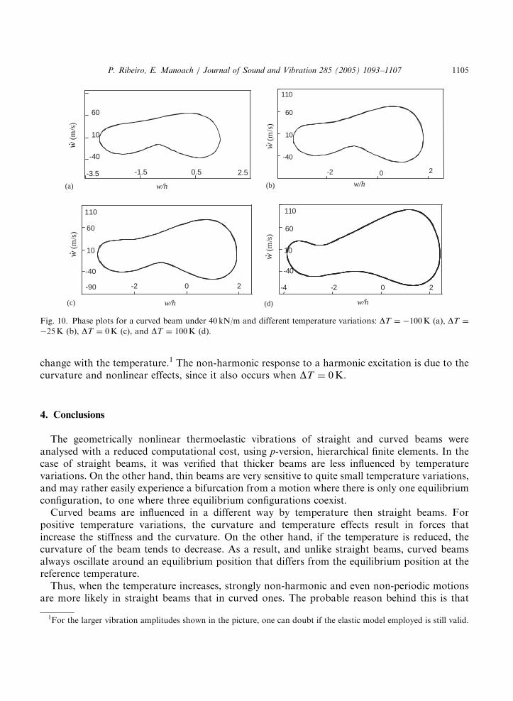
Fig. 10. Phase plots for a curved beam under 40 kN/m and different temperature variations: DT ¼ �100K (a), DT ¼
�25K (b), DT ¼ 0K (c), and DT ¼ 100K (d).
P. Ribeiro, E. Manoach / Journal of Sound and Vibration 285 (2005) 1093–1107 1105
change with the temperature.1 The non-harmonic response to a harmonic excitation is due to thecurvature and nonlinear effects, since it also occurs when DT ¼ 0K:
4. Conclusions
The geometrically nonlinear thermoelastic vibrations of straight and curved beams wereanalysed with a reduced computational cost, using p-version, hierarchical finite elements. In thecase of straight beams, it was verified that thicker beams are less influenced by temperaturevariations. On the other hand, thin beams are very sensitive to quite small temperature variations,and may rather easily experience a bifurcation from a motion where there is only one equilibriumconfiguration, to one where three equilibrium configurations coexist.Curved beams are influenced in a different way by temperature then straight beams. For
positive temperature variations, the curvature and temperature effects result in forces thatincrease the stiffness and the curvature. On the other hand, if the temperature is reduced, thecurvature of the beam tends to decrease. As a result, and unlike straight beams, curved beamsalways oscillate around an equilibrium position that differs from the equilibrium position at thereference temperature.Thus, when the temperature increases, strongly non-harmonic and even non-periodic motions
are more likely in straight beams that in curved ones. The probable reason behind this is that
1For the larger vibration amplitudes shown in the picture, one can doubt if the elastic model employed is still valid.

ARTICLE IN PRESS
P. Ribeiro, E. Manoach / Journal of Sound and Vibration 285 (2005) 1093–11071106
straight beams with fixed ends easily buckle when they are heated, and therefore they will haveone unstable and two stable equilibrium positions. If the mechanical excitation has a large enoughamplitude to force the beam to oscillate around these three positions, a rich dynamic behaviour isexpected. On the other hand, a heated curved beam will expand and become more curved, andtherefore has even more tendency to oscillate around only one equilibrium position. To make thisheated curved beam buckle, a larger mechanical external force is required.
Acknowledgments
The authors wish to thank the support of ICCTI/GRICES, Portugal trough the NATO Sciencefellowship program, as well as the support of the Science and Technology Foundation, Portugal,through grant FEDER POCTI/EME/32641/2000 and of the Bulgarian Research Fund troughgrant TH 1103/01.
Appendix A. Stiffness and mass matrices
½Kb1 ¼ bD
ZL
Nyy;x
n oNyy
;x
n oT
dx; (A.1)
½Kps1 ¼
bA
R
ZL
Nu;x
n oNwf g
T dx; (A.2)
½Ksp1 ¼ ½K
ps1
T; (A.3)
½Kss1 ¼
bA
R2
ZL
Nwf g Nwf gT dx; (A.4)
Kg111 K
g121
Kg211 K
g221
" #¼ bGlh
ZL
Nw;x
n oNw
;x
n oT
Nw;x
n oNyy� �T
Nyy� �
Nw;x
n oT
Nyy� �
Nyy� �T
2664
3775dx; (A.5)
½Ks2 ¼
bA
2R
ZL
Nwf g Nw;x
n oT
w0;x dL; (A.6)
½Mp 0 0
0 ½Mb 0
0 0 ½MR
264
375 ¼ rh
bR
LfNugfNugT dx 0 0
0 bR
LfNwgfNwgT dx 0
0 0 112
bh3RO Nyy� �
Nyy� �T
dx
2664
3775:
(A.7)

ARTICLE IN PRESS
P. Ribeiro, E. Manoach / Journal of Sound and Vibration 285 (2005) 1093–1107 1107
References
[1] P. Ribeiro, M. Petyt, Non-linear vibration of beams with internal resonance by the hierarchical finite element
method, Journal of Sound and Vibration 224 (1999) 591–624.
[2] E.A. Thorton, Thermal Structures for Aerospace Applications, AIAA Education Series, Reston, VA, 1996.
[3] S.S. Lee, J.S. Koo, J.M. Choi, Development of a new curved beam element with shear effect, Engineering
Computations 13 (1996) 9–25.
[4] P. Raveendranath, G. Singh, G.V. Rao, A three-noded shear-flexible curved beam element based on coupled
displacement field interpolations, International Journal for Numerical Methods in Engineering 51 (2001) 85–101.
[5] Q. Bi, H.H. Dai, Analysis of non-linear dynamics and bifurcations of a shallow arch subjected to periodic
excitation with internal resonance, Journal of Sound and Vibration 233 (2000) 557–571.
[6] S.H. Chen, Y.K. Cheung, H.X. Xing, Nonlinear vibration of plane structures by finite element and incremental
harmonic balance method, Nonlinear Dynamics 26 (2001) 87–104.
[7] J. Luczko, Bifurcations and internal resonances in space-curved rods, Computer Methods in Applied Mechanics and
Engineering 191 (2002) 3271–3296.
[8] D. Karagiozova, E. Manoach, Coupling effects in an elastic–plastic beam subjected to heat impact, Nuclear
Engineering and Design 135 (1992) 267–276.
[9] W.P. Chang, S.C. Jen, Nonlinear free vibrations of heated orthotropic rectangular plates, International Journal of
Solids and Structures 22 (1986) 267–282.
[10] J. Locke, Nonlinear random response of angle-ply laminates with static and thermal preloads, AIAA Journal 29
(1991) 1480–1487.
[11] D.Y. Xue, C. Mei, Finite element nonlinear panel flutter with arbitrary temperatures in supersonic flow, AIAA
Journal 31 (1993) 154–162.
[12] R.C. Zhou, Y. Xue, C. Mei, Finite element time domain-modal formulation for nonlinear flutter of composite
panels, AIAA Journal 32 (1994) 2044–2052.
[13] R. Udrescu, Nonlinear vibrations of thermally buckled panels, Proceedings of Seventh International Conference
Recent Advances in Structural Dynamics, ISVR, Southampton, 2000, pp. 757–768.
[14] U.K. Mandal, P. Biswas, Nonlinear thermal vibrations on elastic shallow spherical shell under linear and parabolic
temperature distributions, Journal of Applied Mechanics 66 (1999) 814–815.
[15] Y. Shi, R.Y.Y. Lee, C. Mei, Thermal postbuckling of composite plates using the finite element modal coordinate
method, Journal of Thermal Stresses 22 (1999) 595–614.
[16] L. Meirovitch, H. Baruh, On the inclusion principle for the hierarchical finite element method, International
Journal for Numerical Methods in Engineering 19 (1983) 281–291.
[17] P. Ribeiro, A p-version finite element for non-linear vibration of moderately thick laminated plates, Proceedings of
the 44th AIAA/ASME/ASCE/AHS/ASC Structures, Structural Dynamics, and Materials Conference & Exhibit,
7–10 April 2003, Norfolk, VA, Paper nr. AIAA 2003-1711.
[18] J.R. Hutchinson, Shear coefficients for Timoshenko beam theory, Journal of Applied Mechanics 68 (2001) 87–92.
[19] C.M. Harris, Shock and Vibration Handbook, 3rd ed., McGraw-Hill, New York, 1988.
[20] A.H. Nayfeh, B. Balachandran, Applied Nonlinear Dynamics: Analytical, Computational, and Experimental
Methods, Wiley, New York, 1995.
[21] P. Ribeiro, R. Carneiro, Experimental detection of modal interaction in the non-linear vibration of a
hinged–hinged beam, Journal of Sound and Vibration 277 (2004) 943–954.