
The design and safety features of the IRIS reactor
17
Nuclear Engineering and Design 230 (2004) 151–167 The design and safety features of the IRIS reactor Mario D. Carelli a,∗ , L.E. Conway a , L. Oriani a , B. Petrovi´ c a , C.V. Lombardi b , M.E. Ricotti b , A.C.O. Barroso c , J.M. Collado d , L. Cinotti e , N.E. Todreas f , D. Grgi´ c g , M.M. Moraes h , R.D. Boroughs i , H. Ninokata j , D.T. Ingersoll k , F. Oriolo l a Science and Technology Department, Westinghouse Electric Company, 1344 Beulah Road, Pittsburgh, PA 15235, USA b Politecnico di Milano, Italy c Comissão Nacional de Energia Nuclear (CNEN), Brazil d Equipos Nucleares S.A. (ENSA), Spain e Ansaldo Energia, Italy f Massachusetts Institute of Technology (MIT), USA g University of Zagreb, Croatia h Nuclebras Equipamentos Pesados S/A (NUCLEP), Brazil i Tennessee Valley Authority (TVA), USA j Tokyo Institute of Technology, Japan k Oak Ridge National Laboratory (ORNL), USA l Università di Pisa, Italy Received 8 May 2003; received in revised form 2 October 2003; accepted 13 November 2003 Abstract Salient features of the International Reactor Innovative and Secure (IRIS) are presented here. IRIS, an integral, modular, medium size (335 MWe) PWR, has been under development since the turn of the century by an international consortium led by Westinghouse and including over 20 organizations from nine countries. Described here are the features of the integral design which includes steam generators, pumps and pressurizer inside the vessel, together with the core, control rods, and neutron reflector/shield. A brief summary is provided of the IRIS approach to extended maintenance over a 48-month schedule. The unique IRIS safety-by-design approach is discussed, which, by eliminating accidents, at the design stage, or decreasing their consequences/probabilities when outright elimination is not possible, provides a very powerful first level of defense in depth. The safety-by-design allows a significant reduction and simplification of the passive safety systems, which are presented here, together with an assessment of the IRIS response to transients and postulated accidents. © 2004 Elsevier B.V. All rights reserved. 1. Introduction The IRIS plant conceptual design was completed in 2001 and the preliminary design is currently under- ∗ Corresponding author. Tel.: +1-412-256-1042; fax: +1-412-256-2444. E-mail address: [email protected] (M.D. Carelli). way. The pre-application licensing process with NRC started in October 2002 and IRIS is one of the de- signs considered by US utilities as part of the Early Site Permit (ESP) process. Details of the IRIS design and supporting analyses have been previously reported and the reader is direc- ted to the listed references. Purpose of this article is to provide an overall review of the IRIS characteristics. 0029-5493/$ – see front matter © 2004 Elsevier B.V. All rights reserved. doi:10.1016/j.nucengdes.2003.11.022
-
Upload
independent -
Category
Documents
-
view
3 -
download
0
Transcript of The design and safety features of the IRIS reactor
Nuclear Engineering and Design 230 (2004) 151–167
The design and safety features of the IRIS reactor
Mario D. Carellia,∗, L.E. Conwaya, L. Oriania, B. Petrovica, C.V. Lombardib,M.E. Ricottib, A.C.O. Barrosoc, J.M. Colladod, L. Cinottie, N.E. Todreasf, D. Grgicg,
M.M. Moraesh, R.D. Boroughsi, H. Ninokataj, D.T. Ingersollk, F. Oriolol
a Science and Technology Department, Westinghouse Electric Company,1344 Beulah Road, Pittsburgh, PA 15235, USA
b Politecnico di Milano, Italyc Comissão Nacional de Energia Nuclear (CNEN), Brazil
d Equipos Nucleares S.A. (ENSA), Spaine Ansaldo Energia, Italy
f Massachusetts Institute of Technology (MIT), USAg University of Zagreb, Croatia
h Nuclebras Equipamentos Pesados S/A (NUCLEP), Brazili Tennessee Valley Authority (TVA), USA
j Tokyo Institute of Technology, Japank Oak Ridge National Laboratory (ORNL), USA
l Università di Pisa, Italy
Received 8 May 2003; received in revised form 2 October 2003; accepted 13 November 2003
Abstract
Salient features of the International Reactor Innovative and Secure (IRIS) are presented here. IRIS, an integral, modular,medium size (335 MWe) PWR, has been under development since the turn of the century by an international consortium led byWestinghouse and including over 20 organizations from nine countries. Described here are the features of the integral designwhich includes steam generators, pumps and pressurizer inside the vessel, together with the core, control rods, and neutronreflector/shield. A brief summary is provided of the IRIS approach to extended maintenance over a 48-month schedule. Theunique IRIS safety-by-design approach is discussed, which, by eliminating accidents, at the design stage, or decreasing theirconsequences/probabilities when outright elimination is not possible, provides a very powerful first level of defense in depth.The safety-by-design allows a significant reduction and simplification of the passive safety systems, which are presented here,together with an assessment of the IRIS response to transients and postulated accidents.© 2004 Elsevier B.V. All rights reserved.
1. Introduction
The IRIS plant conceptual design was completed in2001 and the preliminary design is currently under-
∗ Corresponding author. Tel.:+1-412-256-1042;fax: +1-412-256-2444.
E-mail address:[email protected] (M.D. Carelli).
way. The pre-application licensing process with NRCstarted in October 2002 and IRIS is one of the de-signs considered by US utilities as part of the EarlySite Permit (ESP) process.
Details of the IRIS design and supporting analyseshave been previously reported and the reader is direc-ted to the listed references. Purpose of this article is toprovide an overall review of the IRIS characteristics.
0029-5493/$ – see front matter © 2004 Elsevier B.V. All rights reserved.doi:10.1016/j.nucengdes.2003.11.022
152 M.D. Carelli et al. / Nuclear Engineering and Design 230 (2004) 151–167
Acronyms
ADS automatic depressurization systemATWS anticipated transient without scramCRDM control rod drive mechanismCV containment vesselDID defense in depthDOE Department of EnergyDVI direct vessel injectionEBT emergency boration tankEHRS emergency heat removal systemIRIS International Reactor Innovative
and SecureLOCA loss of coolant accidentMIT Massachusetts Institute of TechnologyNERI Nuclear Energy Research InitiativeNRC Nuclear Regulatory CommissionO&M operation and maintenancePBMR pebble bed modular reactorPRA probabilistic risk assessmentPSS pressure suppression systemPWR pressurized water reactorRCCA rod control cluster assemblyRCP reactor coolant pumpRCS reactor coolant systemRV reactor vesselRWST refueling water storage tankSG steam generator
IRIS is a pressurized water reactor that utilizesan integral reactor coolant system layout. The IRISreactor vessel houses not only the nuclear fuel andcontrol rods, but also all the major reactor coolantsystem components including pumps, steam genera-tors, pressurizer, control rod drive mechanisms andneutron reflector. The IRIS integral vessel is largerthan a traditional PWR pressure vessel, but the sizeof the IRIS containment is a fraction of the size ofcorresponding loop reactors, resulting in a significantreduction in the overall size of the reactor plant.
IRIS has been primarily focused on achieving de-sign with innovative safety characteristics. The firstline of defense in IRIS is to eliminate event initiatorsthat could potentially lead to core damage. In IRIS,this concept is implemented through the “safety-by-design” approach, which can be simply describedas “design the plant in such a way as to eliminate
accidents from occurring, rather than coping withtheir consequences.” If it is not possible to eliminatecertain accidents altogether, then the design inher-ently reduces their consequences and/or decreasestheir probability of occurring. The key difference inthe IRIS “safety-by-design” approach from previouspractice is that the integral reactor design is conduciveto eliminating accidents, to a degree impossible inconventional loop-type reactors. The elimination ofthe large LOCAs, since no large primary penetrationsof the reactor vessel or large loop piping exist, is onlythe most easily visible of the safety potential charac-teristics of integral reactors. Many others are possible,but they must be carefully exploited through a de-sign process that is kept focused on selecting designcharacteristics that are most amenable to eliminateaccident initiating events.
The IRIS design builds on the proven technol-ogy provided by over 40 years of operating PWRexperience, and on the established use of passivesafety features pioneered by Westinghouse in theNRC certified AP600 plant design. The use of pas-sive safety systems provides improvements in plantsimplification, safety, reliability, and investment pro-tection over conventional plant designs. Because ofthe safety-by-design approach, the number and com-plexity of these passive safety systems and requiredoperator actions are further minimized in IRIS. Thenet result is a design with significantly reduced com-plexity and improved operability, and extensive plantsimplifications to reduce construction time.
2. The IRIS approach and the IRIS consortium
When Westinghouse started the conceptual designof a new reactor in answer to the DOE solicitation, theoverriding objective was to develop a commerciallyviable concept and thus avoid producing just one morepaper reactor like so many of its predecessors. It wasevident that the era of a single company, or even a sin-gle nation, developing and deploying a nuclear planthad past. Also, it was apparent that many utilities, aswell as developing nations, are interested in cappingtheir capital investment in a power plant project toonly a few hundred million dollars, thus driving themto concentrate on smaller capacity additions. Largerplants, however, have economy of scale and a new

M.D. Carelli et al. / Nuclear Engineering and Design 230 (2004) 151–167 153
dimension has to appear for smaller plants to becomemore economical and true market competitors.
Smaller, modular gas cooled reactors had alreadybeen proposed as commercial market entries, thePBMR (Nicholls, 2001) and the gas turbine-modularhelium reactor (GT-MHR) (LaBar, 2002). For thePBMR, Exelon had made a strong case of the in-herent advantage of small plants in introducing newpower to the grid in limited increments, thus finelytailoring supply and demand and limiting the utilities’financial exposure. The same considerations apply toIRIS. Also common to the modular reactors is thefact that, in addition to being simpler to construct andoperate, these smaller plants have to be fabricated inseries. Thus, it is readily apparent that to fabricateand deploy an economically large enough number of
Table 1Member organizations of the IRIS consortium
IndustryWestinghouse USA Overall coordination, core design, licensingBNFL UK Fuel and fuel cycleAnsaldo Energia Italy Steam generators designAnsaldo Camozzi Italy Steam generators, CRDMs fabricationENSA Spain Pressure vessel and internalsNUCLEP Brazil Containment, pressurizerBechtel USA BOP, AEOKBM Russia Testing, desalination
LaboratoriesORNL USA I&C, PRA, shielding, pressurizer, core analysesCNEN Brazil Pressurizer design, transient and safety analyses, desalinationININ Mexico PRA supportLEI Lithuania Safety analyses, PRA, district heating co-gen
UniversitiesPolytechnic of Milan Italy Safety analyses, shielding, thermal hydraulics, steam
generators design, internal CRDMs, desalinationMIT USA Advanced cores, maintenanceTokyo Institute of Technology Japan Advanced cores, PRAUniversity of Zagreb Croatia Neutronics, safety analysesUniversity of Pisa Italy Containment analysesPolytechnic of Turin Italy Human factors, reliability availability maintainability supportUniversity of Rome Italy Radwaste system, occupational doses
Power producersTVA USA Maintenance, utility perspectiveEletronuclear Brazil Developing country utility perspective
Associated US universities (NERI Programs)University of California Berkeley USA Neutronics, advanced coresUniversity of Tennessee USA Modularization, I&COhio State University USA In-core power monitor, advanced diagnosticsIowa State University (& Ames Lab) USA On-line monitoringUniversity of Michigan (& Sandia Labs) USA Monitoring and control
multiple, identical modules, the market has to be oneglobal, international arena.
Once it was established that this new reactor was tobe deployed world-wide, it followed that to be read-ily accepted internationally, it had to be developedinternationally, i.e., it had to address international re-quirements, needs and even cultures. Hence, the IRISapproach, as emphasized by the first letter (Interna-tional) of its acronym: from the very beginning, IRISwas going to be designed and subsequently fabricated,deployed and serviced by an international partner-ship, where all team members were stakeholders inthe project.
This approach immediately found a positive res-onance, as the IRIS team kept growing in its first 3years from the initial 4 members and 2 countries to the
154 M.D. Carelli et al. / Nuclear Engineering and Design 230 (2004) 151–167
present over 20 members from 10 countries. The origi-nal team of Westinghouse, two American universities(University of California Berkeley and MIT) and oneItalian university (Polytechnic of Milan) was joined byother reactor designers and component manufacturers,fuel and fuel cycle vendors, architect engineers, powerproducers, universities, and laboratories.Table 1pro-vides a summary of the IRIS team partnership withthe areas of responsibility of each team member. As-sociate members are US universities and laboratoriescurrently working on DOE funded NERI projects,which, while of general interest, use IRIS as the exam-ple application of the technology being investigated.
While associated members are DOE funded viaNERI, all other IRIS consortium members (includinginternational universities) are currently self-fundedand provide to the project both design effort and pre-vious know-how. Currently, approximately 100 peo-ple across the IRIS consortium are contributing to theproject.
The contribution of the universities to the IRISprogram cannot be emphasized enough. Innovativedesign solutions have been proposed and developedby universities, and IRIS is perhaps the first and onlycommercial reactor project where academia and indus-try are in a partnership equally co-responsible for thedesign. The partnership with universities (and labora-tories) has also a potentially very important long-termeffect, in making IRIS a “living and contemporary”design. In fact, once the IRIS preliminary design iscompleted, its implementation becomes essentiallythe responsibility of the industrial partners, while theuniversities and laboratories will shift to work on fu-ture improved designs incorporating the most recenttechnological advancements. As they are readied, in-dustry can then implement them in a new series ofIRIS modules. A key reason that this can conceivablybe done and accepted by the market is that the size ofan IRIS module is only about one-third to one-fourthof today’s large light water reactors (LWRs) and thusthe financial exposure is much more limited.
3. The integral reactor coolant system
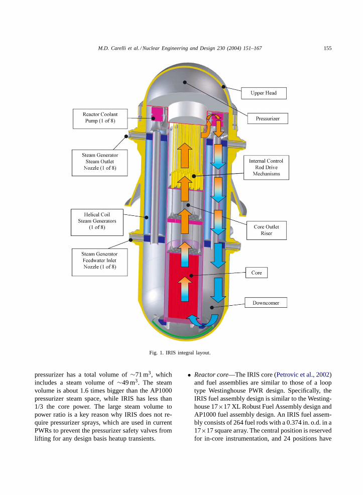
The IRIS reactor vessel (Collado, 2003) houses notonly the nuclear fuel and control rods, but also all themajor reactor coolant system components (seeFig. 1):
eight small, spool type, reactor coolant pumps; eightmodular, helical coil, once through steam generators;a pressurizer located in the RV upper head; the con-trol rod drive mechanisms; and, a steel reflector whichsurrounds the core and improves neutron economy,as well as it provides additional internal shielding.This integral RV arrangement eliminates the individ-ual component pressure vessels and large connectingloop piping between them, resulting in a more com-pact configuration and in the elimination of the largeloss-of-coolant accident as a design basis event. Be-cause the IRIS integral vessel contains all the RCScomponents, it is larger than the RV of a traditionalloop-type PWR. It has an i.d. of 6.21 m and an over-all height of 22.2 m including the closure head. Waterflows upwards through the core and then through theriser region (defined by the extended core barrel). Atthe top of the riser, the coolant is directed into the up-per part of the annular plenum between the extendedcore barrel and the RV inside wall, where the suctionof the reactor coolant pumps is located. Eight coolantpumps are employed, and the flow from each pump isdirected downward through its associated helical coilsteam generator module. The primary flow path con-tinues down through the annular downcomer regionoutside the core to the lower plenum and then back tothe core completing the circuit.
The major in-vessel components are described be-low:
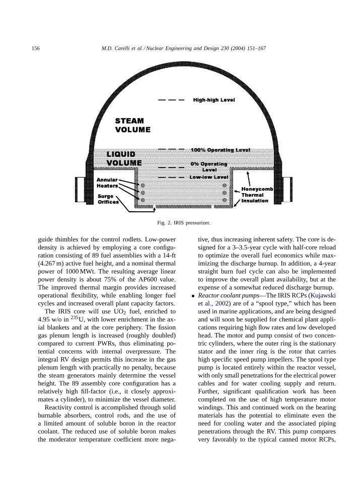
• Pressurizer—The IRIS pressurizer (Barroso et al.,2003) is integrated into the upper head of the reactorvessel (seeFig. 2). The pressurizer region is definedby an insulated, inverted top-hat structure that di-vides the circulating reactor coolant flow path fromthe saturated pressurizer water. This structure in-cludes a closed cell insulation to minimize the heattransfer between the hotter pressurizer fluid and thesubcooled primary water. Annular heater rods arelocated in the bottom portion of the inverted top-hatwhich contains holes to allow water insurge and out-surge to/from the pressurizer region. These surgeholes are located just below the heater rods so thatinsurge fluid flows up along the heater elements.
By utilizing the upper head region of the reactorvessel, the IRIS pressurizer provides a very largewater and steam volume, as compared to plants witha traditional, separate, pressurizer vessel. The IRIS
M.D. Carelli et al. / Nuclear Engineering and Design 230 (2004) 151–167 155
Fig. 1. IRIS integral layout.
pressurizer has a total volume of∼71 m3, whichincludes a steam volume of∼49 m3. The steamvolume is about 1.6 times bigger than the AP1000pressurizer steam space, while IRIS has less than1/3 the core power. The large steam volume topower ratio is a key reason why IRIS does not re-quire pressurizer sprays, which are used in currentPWRs to prevent the pressurizer safety valves fromlifting for any design basis heatup transients.
• Reactor core—The IRIS core (Petrovic et al., 2002)and fuel assemblies are similar to those of a looptype Westinghouse PWR design. Specifically, theIRIS fuel assembly design is similar to the Westing-house 17×17 XL Robust Fuel Assembly design andAP1000 fuel assembly design. An IRIS fuel assem-bly consists of 264 fuel rods with a 0.374 in. o.d. in a17×17 square array. The central position is reservedfor in-core instrumentation, and 24 positions have
156 M.D. Carelli et al. / Nuclear Engineering and Design 230 (2004) 151–167
Fig. 2. IRIS pressurizer.
guide thimbles for the control rodlets. Low-powerdensity is achieved by employing a core configu-ration consisting of 89 fuel assemblies with a 14-ft(4.267 m) active fuel height, and a nominal thermalpower of 1000 MWt. The resulting average linearpower density is about 75% of the AP600 value.The improved thermal margin provides increasedoperational flexibility, while enabling longer fuelcycles and increased overall plant capacity factors.
The IRIS core will use UO2 fuel, enriched to4.95 w/o in235U, with lower enrichment in the ax-ial blankets and at the core periphery. The fissiongas plenum length is increased (roughly doubled)compared to current PWRs, thus eliminating po-tential concerns with internal overpressure. Theintegral RV design permits this increase in the gasplenum length with practically no penalty, becausethe steam generators mainly determine the vesselheight. The 89 assembly core configuration has arelatively high fill-factor (i.e., it closely approxi-mates a cylinder), to minimize the vessel diameter.
Reactivity control is accomplished through solidburnable absorbers, control rods, and the use ofa limited amount of soluble boron in the reactorcoolant. The reduced use of soluble boron makesthe moderator temperature coefficient more nega-
tive, thus increasing inherent safety. The core is de-signed for a 3–3.5-year cycle with half-core reloadto optimize the overall fuel economics while max-imizing the discharge burnup. In addition, a 4-yearstraight burn fuel cycle can also be implementedto improve the overall plant availability, but at theexpense of a somewhat reduced discharge burnup.
• Reactor coolant pumps—The IRIS RCPs (Kujawskiet al., 2002) are of a “spool type,” which has beenused in marine applications, and are being designedand will soon be supplied for chemical plant appli-cations requiring high flow rates and low developedhead. The motor and pump consist of two concen-tric cylinders, where the outer ring is the stationarystator and the inner ring is the rotor that carrieshigh specific speed pump impellers. The spool typepump is located entirely within the reactor vessel,with only small penetrations for the electrical powercables and for water cooling supply and return.Further, significant qualification work has beencompleted on the use of high temperature motorwindings. This and continued work on the bearingmaterials has the potential to eliminate even theneed for cooling water and the associated pipingpenetrations through the RV. This pump comparesvery favorably to the typical canned motor RCPs,
M.D. Carelli et al. / Nuclear Engineering and Design 230 (2004) 151–167 157
which have the pump/impeller extending througha large opening in the pressure boundary with themotor outside the RV. Consequently, the cannedpump motor casing becomes part of the pressureboundary and is typically flanged and seal weldedto the mating RV pressure boundary surface. All ofthis is eliminated in IRIS. In addition to the aboveadvantages derived from its integral location, thespool pump geometric configuration maximizes therotating inertia and these pumps have a high run-outflow capability. Both these attributes mitigate theconsequences of LOFAs. Because of their lowdeveloped head, spool pumps have never been can-didates for nuclear applications. However, the IRISintegral RV configuration and low primary coolantpressure drop can accommodate these pumps andtogether with the assembly design conditions cantake full advantage of their unique characteristics.
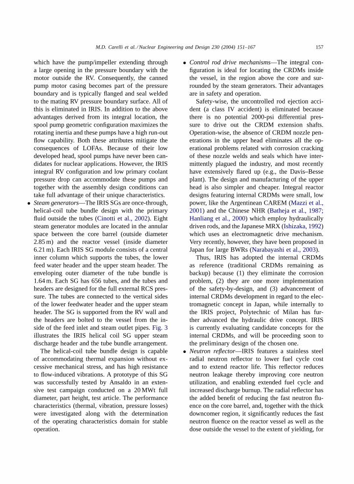
• Steam generators—The IRIS SGs are once-through,helical-coil tube bundle design with the primaryfluid outside the tubes (Cinotti et al., 2002). Eightsteam generator modules are located in the annularspace between the core barrel (outside diameter2.85 m) and the reactor vessel (inside diameter6.21 m). Each IRIS SG module consists of a centralinner column which supports the tubes, the lowerfeed water header and the upper steam header. Theenveloping outer diameter of the tube bundle is1.64 m. Each SG has 656 tubes, and the tubes andheaders are designed for the full external RCS pres-sure. The tubes are connected to the vertical sidesof the lower feedwater header and the upper steamheader. The SG is supported from the RV wall andthe headers are bolted to the vessel from the in-side of the feed inlet and steam outlet pipes.Fig. 3illustrates the IRIS helical coil SG upper steamdischarge header and the tube bundle arrangement.
The helical-coil tube bundle design is capableof accommodating thermal expansion without ex-cessive mechanical stress, and has high resistanceto flow-induced vibrations. A prototype of this SGwas successfully tested by Ansaldo in an exten-sive test campaign conducted on a 20 MWt fulldiameter, part height, test article. The performancecharacteristics (thermal, vibration, pressure losses)were investigated along with the determinationof the operating characteristics domain for stableoperation.
• Control rod drive mechanisms—The integral con-figuration is ideal for locating the CRDMs insidethe vessel, in the region above the core and sur-rounded by the steam generators. Their advantagesare in safety and operation.
Safety-wise, the uncontrolled rod ejection acci-dent (a class IV accident) is eliminated becausethere is no potential 2000-psi differential pres-sure to drive out the CRDM extension shafts.Operation-wise, the absence of CRDM nozzle pen-etrations in the upper head eliminates all the op-erational problems related with corrosion crackingof these nozzle welds and seals which have inter-mittently plagued the industry, and most recentlyhave extensively flared up (e.g., the Davis–Besseplant). The design and manufacturing of the upperhead is also simpler and cheaper. Integral reactordesigns featuring internal CRDMs were small, lowpower, like the Argentinean CAREM (Mazzi et al.,2001) and the Chinese NHR (Batheja et al., 1987;Hanliang et al., 2000) which employ hydraulicallydriven rods, and the Japanese MRX (Ishizaka, 1992)which uses an electromagnetic drive mechanism.Very recently, however, they have been proposed inJapan for large BWRs (Narabayashi et al., 2003).
Thus, IRIS has adopted the internal CRDMsas reference (traditional CRDMs remaining asbackup) because (1) they eliminate the corrosionproblem, (2) they are one more implementationof the safety-by-design, and (3) advancement ofinternal CRDMs development in regard to the elec-tromagnetic concept in Japan, while internally tothe IRIS project, Polytechnic of Milan has fur-ther advanced the hydraulic drive concept. IRISis currently evaluating candidate concepts for theinternal CRDMs, and will be proceeding soon tothe preliminary design of the chosen one.
• Neutron reflector—IRIS features a stainless steelradial neutron reflector to lower fuel cycle costand to extend reactor life. This reflector reducesneutron leakage thereby improving core neutronutilization, and enabling extended fuel cycle andincreased discharge burnup. The radial reflector hasthe added benefit of reducing the fast neutron flu-ence on the core barrel, and, together with the thickdowncomer region, it significantly reduces the fastneutron fluence on the reactor vessel as well as thedose outside the vessel to the extent of yielding, for
158 M.D. Carelli et al. / Nuclear Engineering and Design 230 (2004) 151–167
Fig. 3. IRIS helical coil steam generator.
any practical purposes, a “cold” vessel. This hasobvious beneficial impacts on costs (very long lifevessel, no need for the embrittlement surveillanceprogram, reduced biological shield), operationaldoses, and decommissioning.
4. Extended maintenance
As mentioned, a distinguishing characteristic ofIRIS is its capability of operating with long cy-
cles. Even though the reference design features atwo-batch, 3-year fuel cycle, selected on the basis ofease of licensing and US utilities preference, IRIS iscapable of eventually operating in straight burn with acore lifetime of up to 8 years. However, the significantadvantages connected with a long refueling period inreducing O&M costs are lost if the reactor still has tobe shut down on a 18–24-month interval for routinemaintenance and inspection. Thus, first and foremost,the IRIS primary system components are designed tohave very high reliability to decrease the incidence
M.D. Carelli et al. / Nuclear Engineering and Design 230 (2004) 151–167 159
of equipment failures and reduce the frequency of re-quired inspections or repairs. Next, IRIS has been de-signed to extend the need for scheduled maintenanceoutages to at least 48 months. The basis of the designhas been a study (McHenry et al., 1997) performedearlier by MIT for an operating PWR to identify re-quired actions for extending the maintenance periodfrom 18 to 48 months. The strategy was to either ex-tend the maintenance/testing items to 48 months or toperform maintenance/testing on line. MIT identified3743 maintenance items, 2537 of them off-line andthe remaining 1206 on-line. It was also confirmed that1858 of the off-line items could be extended from 18to 48 months, while 625 could be recategorized fromoff-line to on-line. Further, out of the 1858 itemsthere were 1499, which were electrical surveillancesand had a strong potential for also being performedon-line. This left only 54 items which still needed tobe performed off-line on a schedule shorter than 48months. Starting from this MIT study and factoring in
Fig. 4. IRIS spherical steel containment arrangement.
the specific IRIS conditions (for example, there is noneed to change the RCP oil lubricant, since the spooltype pumps are lubricated by the reactor coolant),only seven items were left as obstacles to a 48-monthcycle (Galvin et al., 2003). These items have beenaddressed and either have been resolved or a plan ofaction has been identified (Boroughs et al., 2003).
Because of the 4-year maintenance cycle capability,the capacity factor of IRIS is expected to comfortablysatisfy and exceed the 95% target, and personnel re-quirements are expected to be significantly reduced.Both considerations will result in decreased O&Mcosts.
Uninterrupted operation for 48 months requiresreliable advanced diagnostics. The IRIS project iscurrently investigating various technologies, eitheralready proven or in advanced phase of development,to monitor the behavior of the in-vessel components.Promising, but more distant technologies, are beingpursued by associated universities.
160 M.D. Carelli et al. / Nuclear Engineering and Design 230 (2004) 151–167
5. Containment system
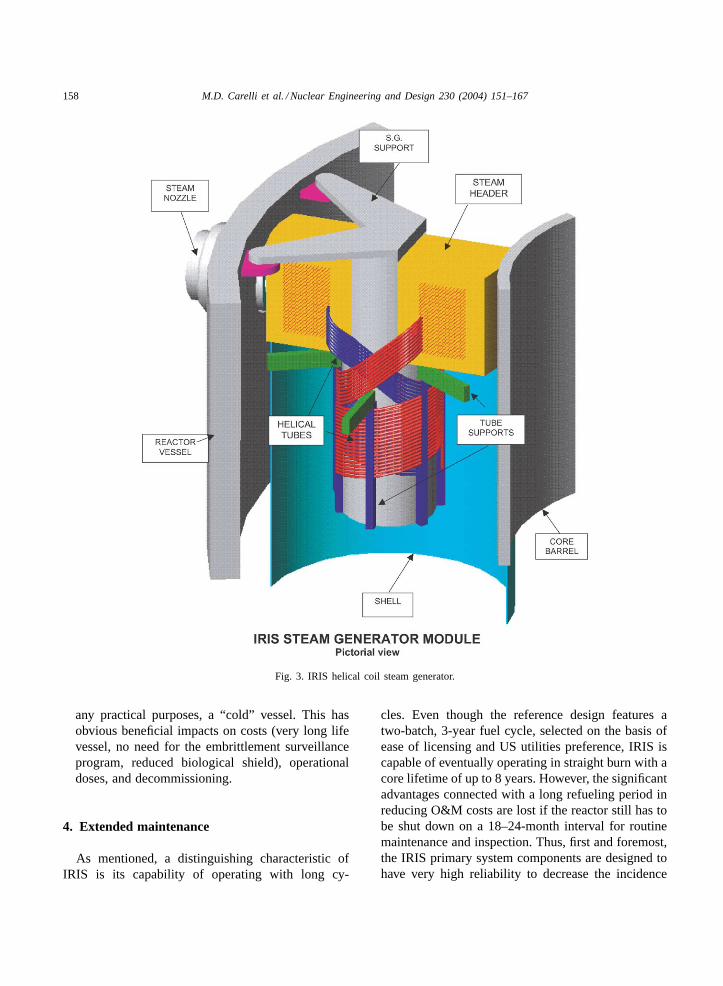
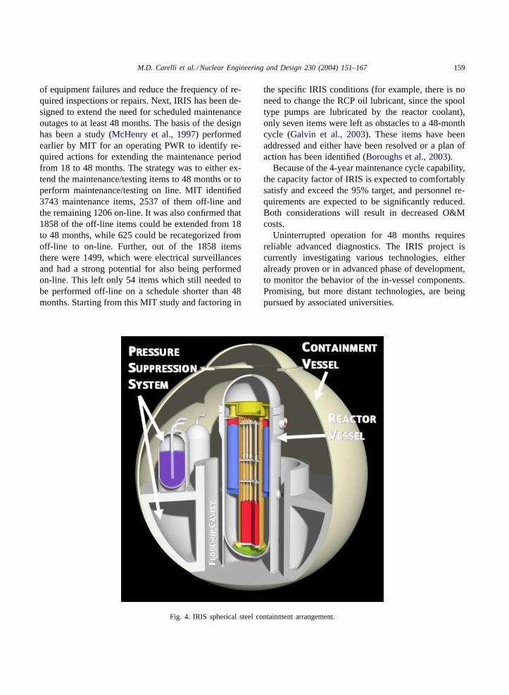
Because the IRIS integral RV configuration elim-inates the loop piping and the externally locatedsteam generators, pumps and pressurizer with theirindividual vessels, the footprint of the patent-pendingIRIS containment system is greatly reduced. Thissize reduction, combined with the spherical geometry,results in a design pressure capability at least threetimes higher than a typical loop reactor cylindricalcontainment, assuming the same metal thickness andstress level in the shell. The current layout features aspherical, steel containment vessel that is 25 m (82 ft.)in diameter (seeFig. 4). The CV is constructed of1 − 3/4 in. steel plate and has a design pressure ca-pability of 1.4 MPa (∼190 psig). The containmentvessel has a bolted and flanged closure head at thetop that provides access to the RV upper head flangeand bolting. Refueling of the reactor is accomplishedby removing the containment vessel closure head, in-stalling a sealing collar between the CV and RV, andremoving the RV head. The refueling cavity abovethe containment and RV is then flooded, and the RVinternals are removed and stored in the refueling cav-ity. Fuel assemblies are vertically lifted from the RVdirectly into a fuel handling and storage area, usinga refueling machine located directly above the CV.Thus, no refueling equipment is required inside con-tainment and the single refueling machine is used forall fuel movement activities.
Fig. 4also shows the pressure suppression pool thatlimits the containment peak pressure to well belowthe CV design pressure. The suppression pool wateris elevated such that it provides a potential source ofelevated gravity driven makeup water to the RV. Alsoshown is the RV flood-up cavity formed by the con-tainment internal structure. The flood-up level is 9 mand ensures that the lower section of the RV, wherethe core is located, is surrounded by water followingany postulated accident. The water flood-up heightis sufficient to provide long-term gravity makeup, sothat the RV water inventory is maintained above thecore for an indefinite period of time. It also providessufficient heat removal from the external RV surfaceto prevent any vessel failure following beyond designbasis scenarios.
Almost half of the IRIS containment vessel is lo-cated below ground, thus leaving only about 15 m
above the ground (i.e., several times less than the con-tainment of a large LWR). This very low profile makesIRIS an extremely difficult target for aircraft flying ter-rorists; in addition, the IRIS containment is inconspic-uously housed in and protected by the reactor building.The cost of putting the entire reactor underground wasevaluated; it was judged to be prohibitive for a compet-itive entry to the power market and unnecessary sincethe IRIS design characteristics are such to offer both aneconomic and very effective approach to this problem.
6. The IRIS safety-by-design approach
The IRIS design provides for multiple levels ofdefense for accident mitigation (defense in depth),resulting in extremely low core damage probabili-ties. In addition to the traditional DID levels (bar-riers, redundancy, diversity, etc.) IRIS introduces avery basic level of DID, i.e., elimination by designof accident initiators or reduction of their conse-quences/probability. This is implemented throughthe “safety-by-design” approach, which was brieflypresented in the introduction.
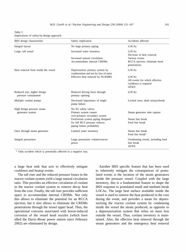
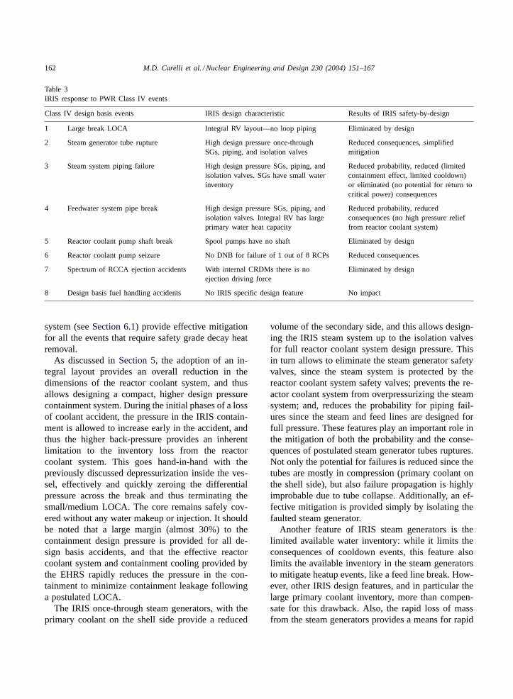
Several features of the design form the basis ofthe safety-by-design approach. These features aresummarized inTable 2and are discussed in the fol-lowing. Table 3 provides an overview of how thesafety-by-design features listed inTable 2will impactthe typical design basis events.
The adoption of an integral reactor coolant systemeliminates the large loop piping required for other de-signs, and thus the potential for postulated large lossof coolant accidents is eliminated by design. The elim-ination of large break LOCAs is only the most evidentsafety-by-design feature of IRIS; others are presentedhere as they are a fundamental part of the IRIS defensein depth.
The adoption of an integral layout requires the de-sign of a large vessel compared to other PWRs, witha tall riser above the core to allow sufficient space forthe placements of the steam generators and reactorcoolant pumps in the pressure vessel. This providesa large coolant inventory in the reactor coolant sys-tem, that is the basis of the IRIS response to smalland medium break LOCAs, i.e., to rely on “maintain-ing water inventory” rather than “providing coolantinjection.” Also, the large coolant inventory provides
M.D. Carelli et al. / Nuclear Engineering and Design 230 (2004) 151–167 161
Table 2Implications of safety-by-design approach
IRIS design characteristic Safety implication Accidents affected
Integral layout No large primary piping LOCAs
Large, tall vessel Increased water inventory LOCAsDecrease in heat removal
Increased natural circulation Various eventsAccommodates internal CRDMs RCCA ejection, eliminate head
penetrations
Heat removal from inside the vessel Depressurizes primary system bycondensation and not by loss of mass
LOCAs
Effective heat removal by SG/EHRS LOCAsAll events for which effectivecooldown is requiredATWS
Reduced size, higher designpressure containment
Reduced driving force throughprimary opening
LOCAs
Multiple coolant pumps Decreased importance of singlepump failure
Locked rotor, shaft seizure/break
High design pressure steamgenerator system
No SG safety valvesPrimary system cannotover-pressure secondary system
Steam generator tube rupture
Feed/steam system piping designedfor full RCS pressure reducespiping failure probability
Steam line breakFeed line break
Once through steam generator Limited water inventory Steam line breakFeed line breaka
Integral pressurizer Large pressurizer volume/reactorpower
Overheating events, including feedline breakATWS
a Only accident which is potentially affected in a negative way.
a large heat sink that acts to effectively mitigatecooldown and heatup events.
The tall riser and the reduced pressure losses in thereactor coolant system yield a large natural circulationratio. This provides an effective circulation of coolantin the reactor coolant system to remove decay heatfrom the core. Finally, the tall riser provides sufficientspace to accommodate internal CRDMs. Not onlythis allows to eliminate the potential for an RCCAejection, but it also allows to eliminate the CRDMspenetrations through the vessel upper head. Thus, theoperational concerns associated with boron-inducedcorrosion of the vessel head nozzles (which haveidled the Davis–Besse power station since February2002) are eliminated by design.
Another IRIS specific feature that has been usedto inherently mitigate the consequences of postu-lated events is the location of the steam generatorsinside the pressure vessel. Coupled with the largeinventory, this is a fundamental feature to shape theIRIS response to postulated small and medium breakLOCAs. The large heat surface available inside thevessel is used to remove the heat produced in the coreduring the event, and provides a mean for depres-surizing the reactor coolant system by condensinginside the vessel the steam produced, as opposite toa depressurization system that relies on mass lossoutside the vessel. Thus, coolant inventory is main-tained. Also, the effective heat removal through thesteam generators and the emergency heat removal
162 M.D. Carelli et al. / Nuclear Engineering and Design 230 (2004) 151–167
Table 3IRIS response to PWR Class IV events
Class IV design basis events IRIS design characteristic Results of IRIS safety-by-design
1 Large break LOCA Integral RV layout—no loop piping Eliminated by design
2 Steam generator tube rupture High design pressure once-throughSGs, piping, and isolation valves
Reduced consequences, simplifiedmitigation
3 Steam system piping failure High design pressure SGs, piping, andisolation valves. SGs have small waterinventory
Reduced probability, reduced (limitedcontainment effect, limited cooldown)or eliminated (no potential for return tocritical power) consequences
4 Feedwater system pipe break High design pressure SGs, piping, andisolation valves. Integral RV has largeprimary water heat capacity
Reduced probability, reducedconsequences (no high pressure relieffrom reactor coolant system)
5 Reactor coolant pump shaft break Spool pumps have no shaft Eliminated by design
6 Reactor coolant pump seizure No DNB for failure of 1 out of 8 RCPs Reduced consequences
7 Spectrum of RCCA ejection accidents With internal CRDMs there is noejection driving force
Eliminated by design
8 Design basis fuel handling accidents No IRIS specific design feature No impact
system (seeSection 6.1) provide effective mitigationfor all the events that require safety grade decay heatremoval.
As discussed inSection 5, the adoption of an in-tegral layout provides an overall reduction in thedimensions of the reactor coolant system, and thusallows designing a compact, higher design pressurecontainment system. During the initial phases of a lossof coolant accident, the pressure in the IRIS contain-ment is allowed to increase early in the accident, andthus the higher back-pressure provides an inherentlimitation to the inventory loss from the reactorcoolant system. This goes hand-in-hand with thepreviously discussed depressurization inside the ves-sel, effectively and quickly zeroing the differentialpressure across the break and thus terminating thesmall/medium LOCA. The core remains safely cov-ered without any water makeup or injection. It shouldbe noted that a large margin (almost 30%) to thecontainment design pressure is provided for all de-sign basis accidents, and that the effective reactorcoolant system and containment cooling provided bythe EHRS rapidly reduces the pressure in the con-tainment to minimize containment leakage followinga postulated LOCA.
The IRIS once-through steam generators, with theprimary coolant on the shell side provide a reduced
volume of the secondary side, and this allows design-ing the IRIS steam system up to the isolation valvesfor full reactor coolant system design pressure. Thisin turn allows to eliminate the steam generator safetyvalves, since the steam system is protected by thereactor coolant system safety valves; prevents the re-actor coolant system from overpressurizing the steamsystem; and, reduces the probability for piping fail-ures since the steam and feed lines are designed forfull pressure. These features play an important role inthe mitigation of both the probability and the conse-quences of postulated steam generator tubes ruptures.Not only the potential for failures is reduced since thetubes are mostly in compression (primary coolant onthe shell side), but also failure propagation is highlyimprobable due to tube collapse. Additionally, an ef-fective mitigation is provided simply by isolating thefaulted steam generator.
Another feature of IRIS steam generators is thelimited available water inventory: while it limits theconsequences of cooldown events, this feature alsolimits the available inventory in the steam generatorsto mitigate heatup events, like a feed line break. How-ever, other IRIS design features, and in particular thelarge primary coolant inventory, more than compen-sate for this drawback. Also, the rapid loss of massfrom the steam generators provides a means for rapid

M.D. Carelli et al. / Nuclear Engineering and Design 230 (2004) 151–167 163
Fig. 5. IRIS passive safety system schematic.
detection of the fault and thus for a rapid actuation ofthe safety features.
An effective means for mitigating the consequencesof heatup events is provided by another IRIS designcharacteristic of the integral layout. A large volume isavailable in the reactor vessel head for the pressurizer,which is thus designed with a large steam volume,to provide an inherent mitigation to events causing apressurization of the reactor coolant system. Not onlythis allows to simplify the design (IRIS does not fea-ture a spray system nor automatic power-operated re-lief valves), but it also provides an inherent protectionagainst reactor coolant system overpressurization.
6.1. IRIS safety features
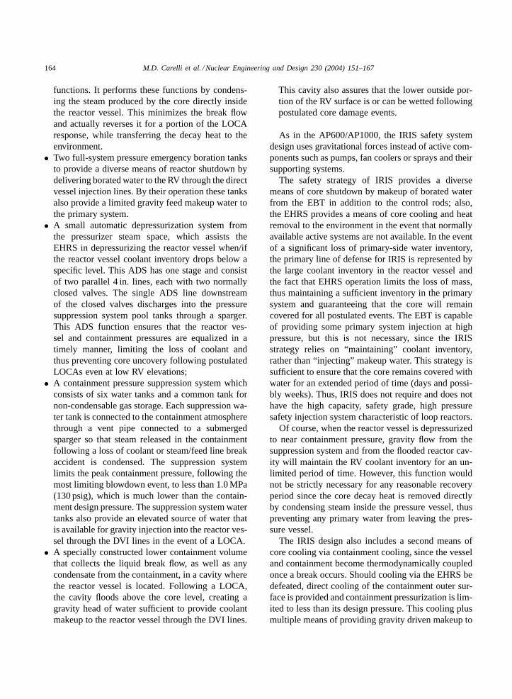
To complement its safety-by-design, IRIS featureslimited and simplified passive systems as shown inFig. 5. They include:
• A passive emergency heat removal system made offour independent subsystems, each of which has ahorizontal, U-tube heat exchanger connected to aseparate SG feed/steam line. These heat exchangersare immersed in the refueling water storage tank lo-cated outside the containment structure. The RWSTwater provides the heat sink to the environment forthe EHRS heat exchangers. The EHRS is sized sothat a single subsystem can provide core decay heatremoval in the case of a loss of secondary systemheat removal capability. The EHRS operates in natu-ral circulation, removing heat from the primary sys-tem through the steam generators heat transfer sur-face, condensing the steam produced in the EHRSheat exchanger, transferring the heat to the RWSTwater, and returning the condensate back to theSG. The EHRS provides both the main post-LOCAdepressurization (depressurization without loss ofmass) of the primary system and the core cooling
164 M.D. Carelli et al. / Nuclear Engineering and Design 230 (2004) 151–167
functions. It performs these functions by condens-ing the steam produced by the core directly insidethe reactor vessel. This minimizes the break flowand actually reverses it for a portion of the LOCAresponse, while transferring the decay heat to theenvironment.
• Two full-system pressure emergency boration tanksto provide a diverse means of reactor shutdown bydelivering borated water to the RV through the directvessel injection lines. By their operation these tanksalso provide a limited gravity feed makeup water tothe primary system.
• A small automatic depressurization system fromthe pressurizer steam space, which assists theEHRS in depressurizing the reactor vessel when/ifthe reactor vessel coolant inventory drops below aspecific level. This ADS has one stage and consistof two parallel 4 in. lines, each with two normallyclosed valves. The single ADS line downstreamof the closed valves discharges into the pressuresuppression system pool tanks through a sparger.This ADS function ensures that the reactor ves-sel and containment pressures are equalized in atimely manner, limiting the loss of coolant andthus preventing core uncovery following postulatedLOCAs even at low RV elevations;
• A containment pressure suppression system whichconsists of six water tanks and a common tank fornon-condensable gas storage. Each suppression wa-ter tank is connected to the containment atmospherethrough a vent pipe connected to a submergedsparger so that steam released in the containmentfollowing a loss of coolant or steam/feed line breakaccident is condensed. The suppression systemlimits the peak containment pressure, following themost limiting blowdown event, to less than 1.0 MPa(130 psig), which is much lower than the contain-ment design pressure. The suppression system watertanks also provide an elevated source of water thatis available for gravity injection into the reactor ves-sel through the DVI lines in the event of a LOCA.
• A specially constructed lower containment volumethat collects the liquid break flow, as well as anycondensate from the containment, in a cavity wherethe reactor vessel is located. Following a LOCA,the cavity floods above the core level, creating agravity head of water sufficient to provide coolantmakeup to the reactor vessel through the DVI lines.
This cavity also assures that the lower outside por-tion of the RV surface is or can be wetted followingpostulated core damage events.
As in the AP600/AP1000, the IRIS safety systemdesign uses gravitational forces instead of active com-ponents such as pumps, fan coolers or sprays and theirsupporting systems.
The safety strategy of IRIS provides a diversemeans of core shutdown by makeup of borated waterfrom the EBT in addition to the control rods; also,the EHRS provides a means of core cooling and heatremoval to the environment in the event that normallyavailable active systems are not available. In the eventof a significant loss of primary-side water inventory,the primary line of defense for IRIS is represented bythe large coolant inventory in the reactor vessel andthe fact that EHRS operation limits the loss of mass,thus maintaining a sufficient inventory in the primarysystem and guaranteeing that the core will remaincovered for all postulated events. The EBT is capableof providing some primary system injection at highpressure, but this is not necessary, since the IRISstrategy relies on “maintaining” coolant inventory,rather than “injecting” makeup water. This strategy issufficient to ensure that the core remains covered withwater for an extended period of time (days and possi-bly weeks). Thus, IRIS does not require and does nothave the high capacity, safety grade, high pressuresafety injection system characteristic of loop reactors.
Of course, when the reactor vessel is depressurizedto near containment pressure, gravity flow from thesuppression system and from the flooded reactor cav-ity will maintain the RV coolant inventory for an un-limited period of time. However, this function wouldnot be strictly necessary for any reasonable recoveryperiod since the core decay heat is removed directlyby condensing steam inside the pressure vessel, thuspreventing any primary water from leaving the pres-sure vessel.
The IRIS design also includes a second means ofcore cooling via containment cooling, since the vesseland containment become thermodynamically coupledonce a break occurs. Should cooling via the EHRS bedefeated, direct cooling of the containment outer sur-face is provided and containment pressurization is lim-ited to less than its design pressure. This cooling plusmultiple means of providing gravity driven makeup to
M.D. Carelli et al. / Nuclear Engineering and Design 230 (2004) 151–167 165
the core provides a means of preventing core damageand ensuring containment integrity and heat removalto the environment that is diverse from the EHRS op-eration.
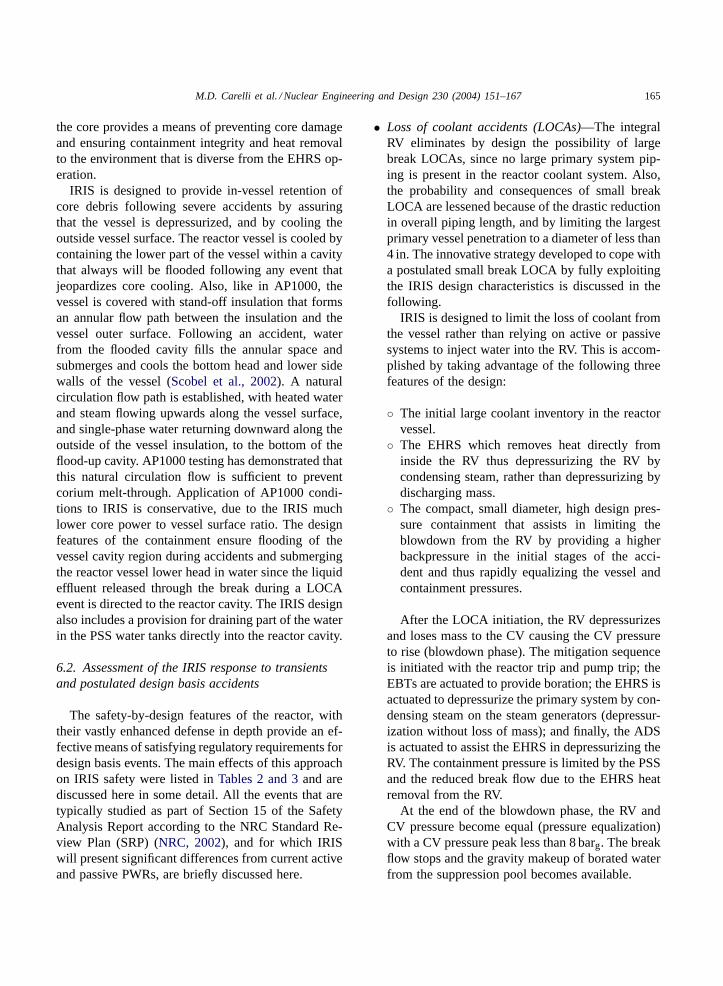
IRIS is designed to provide in-vessel retention ofcore debris following severe accidents by assuringthat the vessel is depressurized, and by cooling theoutside vessel surface. The reactor vessel is cooled bycontaining the lower part of the vessel within a cavitythat always will be flooded following any event thatjeopardizes core cooling. Also, like in AP1000, thevessel is covered with stand-off insulation that formsan annular flow path between the insulation and thevessel outer surface. Following an accident, waterfrom the flooded cavity fills the annular space andsubmerges and cools the bottom head and lower sidewalls of the vessel (Scobel et al., 2002). A naturalcirculation flow path is established, with heated waterand steam flowing upwards along the vessel surface,and single-phase water returning downward along theoutside of the vessel insulation, to the bottom of theflood-up cavity. AP1000 testing has demonstrated thatthis natural circulation flow is sufficient to preventcorium melt-through. Application of AP1000 condi-tions to IRIS is conservative, due to the IRIS muchlower core power to vessel surface ratio. The designfeatures of the containment ensure flooding of thevessel cavity region during accidents and submergingthe reactor vessel lower head in water since the liquideffluent released through the break during a LOCAevent is directed to the reactor cavity. The IRIS designalso includes a provision for draining part of the waterin the PSS water tanks directly into the reactor cavity.
6.2. Assessment of the IRIS response to transientsand postulated design basis accidents
The safety-by-design features of the reactor, withtheir vastly enhanced defense in depth provide an ef-fective means of satisfying regulatory requirements fordesign basis events. The main effects of this approachon IRIS safety were listed inTables 2 and 3and arediscussed here in some detail. All the events that aretypically studied as part of Section 15 of the SafetyAnalysis Report according to the NRC Standard Re-view Plan (SRP) (NRC, 2002), and for which IRISwill present significant differences from current activeand passive PWRs, are briefly discussed here.
• Loss of coolant accidents (LOCAs)—The integralRV eliminates by design the possibility of largebreak LOCAs, since no large primary system pip-ing is present in the reactor coolant system. Also,the probability and consequences of small breakLOCA are lessened because of the drastic reductionin overall piping length, and by limiting the largestprimary vessel penetration to a diameter of less than4 in. The innovative strategy developed to cope witha postulated small break LOCA by fully exploitingthe IRIS design characteristics is discussed in thefollowing.
IRIS is designed to limit the loss of coolant fromthe vessel rather than relying on active or passivesystems to inject water into the RV. This is accom-plished by taking advantage of the following threefeatures of the design:
◦ The initial large coolant inventory in the reactorvessel.
◦ The EHRS which removes heat directly frominside the RV thus depressurizing the RV bycondensing steam, rather than depressurizing bydischarging mass.
◦ The compact, small diameter, high design pres-sure containment that assists in limiting theblowdown from the RV by providing a higherbackpressure in the initial stages of the acci-dent and thus rapidly equalizing the vessel andcontainment pressures.
After the LOCA initiation, the RV depressurizesand loses mass to the CV causing the CV pressureto rise (blowdown phase). The mitigation sequenceis initiated with the reactor trip and pump trip; theEBTs are actuated to provide boration; the EHRS isactuated to depressurize the primary system by con-densing steam on the steam generators (depressur-ization without loss of mass); and finally, the ADSis actuated to assist the EHRS in depressurizing theRV. The containment pressure is limited by the PSSand the reduced break flow due to the EHRS heatremoval from the RV.
At the end of the blowdown phase, the RV andCV pressure become equal (pressure equalization)with a CV pressure peak less than 8 barg. The breakflow stops and the gravity makeup of borated waterfrom the suppression pool becomes available.
166 M.D. Carelli et al. / Nuclear Engineering and Design 230 (2004) 151–167
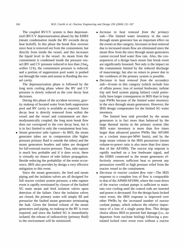
The coupled RV/CV system is then depressur-ized (RV/CV depressurization phase) by the EHRS(steam condensation inside the RV exceeds decayheat boiloff). In this phase the break flow reversessince heat is removed not from the containment, butdirectly from inside the vessel, and this increasesthe liquid level in the vessel. As steam from thecontainment is condensed inside the pressure ves-sel (RV and CV pressure reduced to less than 2 bargwithin 12 h), the containment pressure is reduced,and a portion of suppression pool water is pushedout through the vents and assists in flooding the ves-sel cavity.
The depressurization phase is followed by thelong term cooling phase where the RV and CVpressure is slowly reduced as the core decay heatdecreases.
During this phase of the accident recovery, grav-ity makeup of borated water from both suppressionpool and RV cavity is available as required. Sincedecay heat is directly removed from within thevessel and the vessel and containment are ther-modynamically coupled, the long term break flowdoes not correspond to the core decay heat, but itis in fact limited to only the containment heat loss.
• Steam generator tube rupture—In IRIS, the steamgenerator tubes are in compression (the higherpressure primary fluid is outside the tubes) and thesteam generators headers and tubes are designedfor full external reactor pressure. Thus, tube ruptureis much less probable and if it does occur, thereis virtually no chance of tube failure propagation.Beside reducing the probability of the event occur-rence, IRIS also provides by design a very effectivemitigation to this event.
Since the steam generators, the feed and steampiping and the isolation valves are all designed forfull reactor coolant system pressure, a tube ruptureevent is rapidly terminated by closure of the faultedSG main steam and feed isolation valves upondetection of the failure. Once the isolation valvesare closed, the primary water will simply fill andpressurize the faulted steam generator terminatingthe leak. Given the limited volume of the steamgenerators and piping, no makeup to the RV is evenrequired; and since the faulted SG is immediatelyisolated, the release of radioactivity (primary fluid)to the environment will be minimized.
• Increase in heat removal from the primaryside—The limited water inventory in the oncethrough steam generator has an important effect onthe events in this category. Increases in heat removaldue to increased steam flow are eliminated since thesteam flow from the once through steam generatorscannot exceed feed water flow rate. Also, the con-sequences of a design basis steam line break eventare significantly lessened. Not only is the impact onthe containment limited by the reduced dischargeof mass/energy, but also no return to power due tothe cooldown of the primary system is possible.
• Decrease in heat removal from the secondaryside—Events in this category (which include lossof offsite power, loss of normal feedwater, turbinetrip and feed system piping failure) could poten-tially have larger consequences in IRIS than in looptype PWRs because of the limited water inventoryin the once through steam generators. However, theIRIS design compensates for the limited SG waterinventory.
The limited heat sink provided by the steamgenerators is in fact more than balanced by thelarge thermal inertia in the primary system (theIRIS water inventory is more than five timeslarger than advanced passive PWRs like AP1000on a coolant mass-per-MWt basis), and by thelarge steam volume in the IRIS pressurizer (steamvolume-to-power ratio is also more than five timesthat of the AP1000). The reactor trip setpoint israpidly reached on a low feedwater signal, andthe EHRS connected to the steam generators ef-fectively removes sufficient heat to prevent anypressurizer overfill or high pressure relief from thereactor vessel to the containment.
• Decrease in reactor coolant flow rate—The IRISresponse to a complete loss of flow is comparableto that of the AP600/AP1000, where the coast downof the reactor coolant pumps is sufficient to main-tain core cooling until the control rods are insertedand power is decreased. For the design basis lockedrotor event, the IRIS response is improved overother PWRs by the increased number of reactorcoolant pumps, which reduces the relative impor-tance of a loss of a single pump flow. This designchoice allows IRIS to prevent fuel damage (i.e., nodeparture from nucleate boiling) following a pos-tulated locked rotor event even without a reactor
M.D. Carelli et al. / Nuclear Engineering and Design 230 (2004) 151–167 167
trip. Of course a shaft break accident cannot occur,because spool pumps do not have shafts.
• Spectrum of postulated rod ejection accidents—Locating the CRDMs internally to the reactor ves-sel eliminates by design the rod ejection accidentsince there is no significant driving differentialpressure over the driveline.
• Increase in reactor coolant inventory—This cate-gory of events is eliminated in IRIS since IRIS doesnot utilize high pressure coolant injection followinga LOCA. The inadvertent actuation of the smallemergency boration tanks can be accommodated bythe large pressurizer volume with no overpressureor overfill of the RV.
7. Conclusions
An overview of the status of the IRIS design hasbeen provided, with particular emphasis on the inte-gral layout of the reactor coolant system and on theinnovative IRIS approach to safety.
The integral layout offers very significantadvantages in terms of performance, simplicity, andcompactness. It has been demonstrated that it has anextremely positive impact on the overall reactor safetyresponse to postulated accidents. It is also expected tohave a positive economic impact and work has beeninitiated for its verification.
Because of the safety-by-design approach, the num-ber and complexity of the safety systems and requiredoperator actions are minimized in IRIS. The net resultis a design with significantly reduced complexity, im-proved operability, and extensive plant simplifications.
References
Barroso, A.C.O., Baptista, B.D., Arone, F.I.D., Macedo, L.A.,Sampaio, P.A.B., Moraes, M., 2003. IRIS pressurizer design.In: Proceedings of the International Congress on Advances inNuclear Power Plants ICAPP’03, Cordoba, Spain, 4–7 May2003.
Batheja, P., et al., 1987. Design and testing of the reactor-internalhydraulic control rod drive in the nuclear heating reactor. Nucl.Technol. 79, 186–195.
Boroughs, R., Wilson, J., Eberly, W., McClanahan, J., Boles, G.,2003. Enabling 48-month maintenance intervals in IRIS. In:Proceedings of the GENES4/ANP2003, Kyoto, Japan, 15–19September 2003.
Cinotti, L., Bruzzone, M., Meda, N., Corsini, G., Conway, L.E.,Lombardi, C., Ricotti, M.E., 2002. Steam generator of theInternational Reactor Innovative and Secure. In: Proceedingsof the 10th International Conference on Nuclear EngineeringICONE-10, Arlington, VA, USA, 14–18 April 2002.
Collado, J.M., 2003. Design of the reactor pressure vessel andinternals of the IRIS integrated nuclear system. In: Proceedingsof the International Congress on Advances in Nuclear PowerPlants ICAPP’03, Cordoba, Spain, 4–7 May 2003.
Galvin, M., Todreas, N.E., Conway, L.E., 2003. Maintenance cycleextension in the IRIS advanced light water reactor plant design.Nucl. Technol. 143, 270–280.
Hanliang, B., et al., 2000. Studies on the performance of thehydraulic control rod drive for the NHR-200. Nucl. Eng. Des.195, 117–121.
Ishizaka, Y., 1992. Development of a built-in type control rod drivemechanism for advanced marine reactor MRX. In: Proceedingsof the International Conference on Design and Safety ofAdvanced Nuclear Power Plants (ANP’92), Tokyo, Japan,25–29 October 1992.
Kujawski, J.M., Kitch, D.M., Conway, L.E., 2002. The IRISspool-type reactor coolant pump. In: Proceedings of the 10thInternational Conference on Nuclear Engineering ICONE-10,Arlington, VA, USA, 14–18 April 2002.
LaBar, M.P., 2002. The gas turbine-modular reactor: a promisingoption for near term deployment. In: Proceedings of theInternational Congress on Advanced Nuclear Power PlantsICAPP’02, Hollywood, FL, USA, 9–13 June 2002.
Mazzi, R., et al., 2001. CAREM project development activities. In:Proceedings of the IAEA International Seminar on Status andProspects for Small and Medium Size Reactors, Cairo, Egypt,May 2001.
McHenry, R.S., Moore, T.J., Maurer, J.H., Todreas, N.E., 1997.Surveillance strategy for an extended operating cycle incommercial nuclear reactors. In: Proceedings of the 5thInternational Topical Meeting on Nuclear Thermal Hydraulics,Operations and Safety NUTHOS-5, Beijing, China, April 1997.
Narabayashi, T., Yamamoto, T., Sato, M., Kobayashi, N., Kameda,T., Tokumasu, T., Kawano, S., Hagiwara, T., Mori, M., Ohmori,S., Terai, T., Madarame, H., Morimoto, Y., 2003. Developmentof internal CRD for next generation BWR. In: Proceedings ofthe GENES4/ANP2003, Kyoto, Japan, 15–19 September 2003.
Nicholls, D., 2001. The pebble bed modular reactor. Nucl. News44, 35–40.
NRC, 2002. Standard Review Plan for the Review of SafetyAnalysis Reports for Nuclear Power Plants. Regulatory GuideNUREG-0800, Rev. 02/2002.
Petrovic, B., Carelli, M., Greenspan, E., Milosevic, M., Vujic, J.,Padovani, E., Ganda, F., 2002. First core and refueling optionsfor IRIS. In: Proceedings of the 10th International Conferenceon Nuclear Engineering ICONE-10, Arlington, VA, USA, 14–18April 2002.
Scobel, J.E., Theofanous, T.G., Conway, L.E., 2002. In-vesselretention of molten core debris in the Westinghouse AP1000advanced passive PWR. In: Proceedings of the InternationalCongress on Advanced Nuclear Power Plants ICAPP’02,Hollywood, FL, USA, 9–13 June 2002.