The costs and benefits of combining different IP mobility standards
34
The costs and benefits of combining different IP mobility standards Antonio de la Oliva a , Ignacio Soto b,* , Maria Calderon a , Carlos J. Bernardos a , M. Isabel Sanchez a,c a Departamento de Ingenier´ ıa Telem´ atica, Universidad Carlos III de Madrid b Departamento de Ingenier´ ıa de Sistemas Telem´ aticos, Universidad Polit´ ecnica de Madrid c Institute IMDEA Networks Abstract Triggered by the demand of ubiquitous Internet connectivity and the availability of different wireless technologies, several IP mobility support protocols have been standardized in the past. Each solution provides a specific functionality (e.g., host or network mobility) and/or requires operations of particular nodes (e.g., client or network based). The current trend is towards the co-existence of these solutions, though the impact of doing so has not been yet fully understood. This article briefly reviews key standards for providing IP mobility support, identifying sce- narios where combining them is necessary. We analyze the functionality offered by each combination and its performance cost in terms of protocol overhead and handover latency, highlighting the associated benefits and costs. This analysis is complemented by an experimental evaluation that supports our findings. The con- clusions of our study indicate that combining different mobility mechanisms has a non-negligible impact on both the communication overhead and handover latency. This highlights the need for developing techniques to alleviate the costs of the combination. The recently proposed Distributed Mobility Management scheme exhibits some interesting properties that may help solving some of the identified combination shortcomings, as analyzed in this paper. Keywords: IP Mobility, Network-based Localized Mobility, Host Mobility, Network Mobility, Distributed Mobility Management * Corresponding author. Tel: +34 915495700 ext. 3057; fax: +34 913367333 Email addresses: [email protected] (Antonio de la Oliva), [email protected] (Ignacio Soto), [email protected] (Maria Calderon), [email protected] (Carlos J. Bernardos), [email protected] (M. Isabel Sanchez) Preprint submitted to Computer Standards & Interfaces February 27, 2014
-
Upload
independent -
Category
Documents
-
view
1 -
download
0
Transcript of The costs and benefits of combining different IP mobility standards
The costs and benefits of combining different IPmobility standards
Antonio de la Olivaa, Ignacio Sotob,∗, Maria Calderona, Carlos J. Bernardosa, M.Isabel Sancheza,c
aDepartamento de Ingenierıa Telematica, Universidad Carlos III de MadridbDepartamento de Ingenierıa de Sistemas Telematicos, Universidad Politecnica de Madrid
cInstitute IMDEA Networks
Abstract
Triggered by the demand of ubiquitous Internet connectivity and the availabilityof different wireless technologies, several IP mobility support protocols have beenstandardized in the past. Each solution provides a specific functionality (e.g., hostor network mobility) and/or requires operations of particular nodes (e.g., client ornetwork based). The current trend is towards the co-existence of these solutions,though the impact of doing so has not been yet fully understood. This articlebriefly reviews key standards for providing IP mobility support, identifying sce-narios where combining them is necessary. We analyze the functionality offeredby each combination and its performance cost in terms of protocol overhead andhandover latency, highlighting the associated benefits and costs. This analysis iscomplemented by an experimental evaluation that supports our findings. The con-clusions of our study indicate that combining different mobility mechanisms has anon-negligible impact on both the communication overhead and handover latency.This highlights the need for developing techniques to alleviate the costs of thecombination. The recently proposed Distributed Mobility Management schemeexhibits some interesting properties that may help solving some of the identifiedcombination shortcomings, as analyzed in this paper.
Keywords: IP Mobility, Network-based Localized Mobility, Host Mobility,Network Mobility, Distributed Mobility Management
∗Corresponding author. Tel: +34 915495700 ext. 3057; fax: +34 913367333Email addresses: [email protected] (Antonio de la Oliva), [email protected]
(Ignacio Soto), [email protected] (Maria Calderon), [email protected] (Carlos J.Bernardos), [email protected] (M. Isabel Sanchez)
Preprint submitted to Computer Standards & Interfaces February 27, 2014
1. Introduction
Users demand Internet access everywhere and anytime. Current smart-phonesand hand-held devices are equipped with multiple technologies – e.g., 3G andIEEE 802.11 Wireless LAN (WLAN) – as a solution to provide ubiquitous In-ternet access. The Internet Protocol (IP) constitutes the common building blockfor the provision of voice and data services, independent of the access technol-ogy. Users’ mobility has triggered the need for new IP mobility mechanisms thatenable terminals to move and change their point of attachment without affectingto their connectivity or the applications’ behavior. Driven by the requirementsposed by the different scenarios where connectivity is demanded, the Internet En-gineering Task Force (IETF)1 has standardized several IP mobility solutions. Ini-tially, global mobility protocols were designed to allow seamless roaming (keep-ing global reachability and session continuity) within the whole Internet, bothfor single mobile hosts (e.g., Mobile IPv6 [1]) and moving networks (e.g., Net-work Mobility Basic Support [2]). More recently there has been an increasinginterest in solutions that provide mobility support within a part of the network bymeans of functionality residing only on the network infrastructure, what is callednetwork-based localized mobility. Proxy Mobile IPv6 [3] enables a mobile hostto roam within a local domain without changing its IP address. Another exampleis N-PMIPv6 [4], a proposal that enhances Proxy Mobile IPv6 to better integratemobile networks, by fully supporting terminals to roam between fixed and mobileaccess routers.
All these IP mobility protocols (which are briefly explained in Section 2) aregoing to co-exist because each of them addresses different requirements. For ex-ample, the 3GPP2 specification [5] deals with the integration in its mobile archi-tecture of access networks not based on 3GPP technologies. To support the mobil-ity of a terminal, this specification considers the possibility of choosing betweentwo types of IP mobility protocols: network-based or with mobility functionalityin the terminal. The decision is taken depending on the capabilities of the networkand the terminal. Selecting the most suitable mobility protocol among those avail-able is the goal of the defined mechanisms in current 3GPP specifications, but anext step going beyond that may be required, as these protocols (and others men-
1http://www.ietf.org/2http://www.3gpp.org/
2
tioned above related with network mobility) could also be used simultaneously incertain scenarios to maximize the overall performance or provide additional func-tionality. So it is interesting not only to choose among mobility protocols, as in the3GPP specification, but also to be able to decide to combine them. To enable this,we need to study the different aspects involved in the combinations of IP mobilityprotocols. This article studies these combinations, highlighting the functionalitythey provide, the scenarios in which their deployment make sense, and the supportrequired from the network and the user terminal (Section 3). We also analyticallycharacterize the associated costs of the combinations – in terms of protocol over-head and handover latency (Section 4). In order to validate the theoretical results,we have performed also an experimental evaluation (Section 5). From this analy-sis we conclude that the combination of different mobility solutions has a cost thatmust be considered when designing mobility solutions that combine different pro-tocols. Finally the article outlines an approach to solve the problem of efficientlycombining different mobility support mechanisms in a general way (Section 6).This approach is based on generalizing the characteristics of a particular instanti-ation of the Distributed Mobility Management concept, a recent trend to managemobility that is under study by the IETF.
2. Overview of IP Mobility Protocols
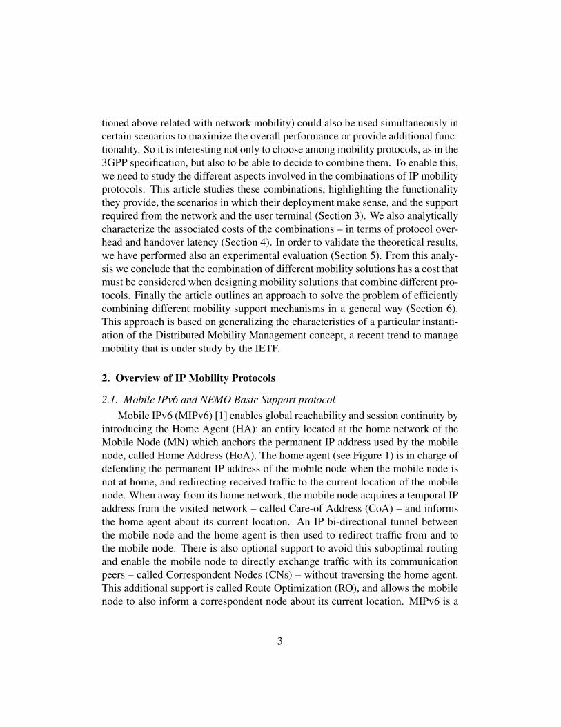
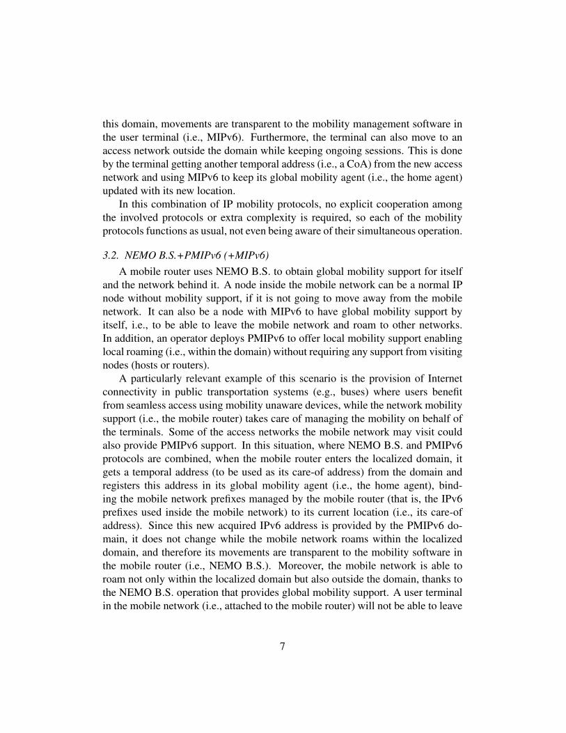
2.1. Mobile IPv6 and NEMO Basic Support protocolMobile IPv6 (MIPv6) [1] enables global reachability and session continuity by
introducing the Home Agent (HA): an entity located at the home network of theMobile Node (MN) which anchors the permanent IP address used by the mobilenode, called Home Address (HoA). The home agent (see Figure 1) is in charge ofdefending the permanent IP address of the mobile node when the mobile node isnot at home, and redirecting received traffic to the current location of the mobilenode. When away from its home network, the mobile node acquires a temporal IPaddress from the visited network – called Care-of Address (CoA) – and informsthe home agent about its current location. An IP bi-directional tunnel betweenthe mobile node and the home agent is then used to redirect traffic from and tothe mobile node. There is also optional support to avoid this suboptimal routingand enable the mobile node to directly exchange traffic with its communicationpeers – called Correspondent Nodes (CNs) – without traversing the home agent.This additional support is called Route Optimization (RO), and allows the mobilenode to also inform a correspondent node about its current location. MIPv6 is a
3
client-based solution because the mobile node is required to perform specific IPprocedures to support its own mobility.
The Network Mobility Basic Support (NEMO B.S.) protocol [2] extends MIPv6to support the movement of a whole network (also referred to as a NEMO or mo-bile network), by the router of the network – called Mobile Router (MR) – takingcare of the mobility management (i.e., mobility signaling and tunnel setup) of thenetwork on behalf of the nodes of the network, called Mobile Network Nodes(MNNs). The IP addresses of these nodes belong to the Mobile Network Prefix(MNP) of the NEMO that is anchored at the home agent of the mobile router.There is no route optimization support standardized for NEMO B.S. Regardingmobility, the NEMO B.S. is a client-based solution as well, because it is alsobased on mobility functionality in the mobile node, a router in this case.
2.2. Proxy Mobile IPv6Proxy Mobile IPv6 (PMIPv6) [3] is a network-based localized mobility man-
agement protocol. This means that user terminals are provided with mobility sup-port without their involvement in the mobility management and signaling, as therequired functionality is relocated from the mobile node to the network. In partic-ular, movement detection and signaling operations are performed by a new func-tional entity – called Mobile Access Gateway (MAG) – which usually resides onthe Access Router (AR) for the terminal (see Figure 1). In a Localized MobilityDomain (LMD), which is the area where the network provides mobility support,there are multiple MAGs. A MAG learns through standard terminal operations(such as router and neighbor discovery) or by means of link-layer support aboutthe movement of a mobile node and coordinates routing state updates without anyIP mobility support from the terminal.
Terminals are assigned a particular IP prefix in the localized domain, whichremains to be the same even when they connect to a different MAG, so a termi-nal does not change address while visiting the domain. The IP prefixes used bythe terminals are anchored at an entity called the Local Mobility Anchor (LMA),which plays the role of a local home agent, although required signaling exchangesare performed with MAGs, instead of with the user terminals. Inside the localizeddomain, the traffic of terminals is transferred using bi-directional tunnels betweenthe LMA and the MAGs, so terminals can keep the same IP address without af-fecting the routing of their traffic. Proxy Mobile IPv6 is based on an extension ofthe Mobile IPv6 signaling.
4
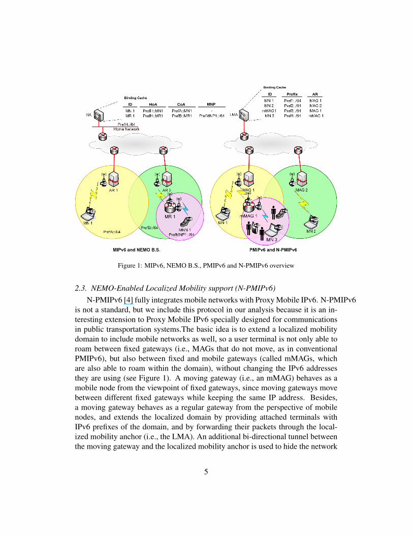
Figure 1: MIPv6, NEMO B.S., PMIPv6 and N-PMIPv6 overview
2.3. NEMO-Enabled Localized Mobility support (N-PMIPv6)N-PMIPv6 [4] fully integrates mobile networks with Proxy Mobile IPv6. N-PMIPv6
is not a standard, but we include this protocol in our analysis because it is an in-teresting extension to Proxy Mobile IPv6 specially designed for communicationsin public transportation systems.The basic idea is to extend a localized mobilitydomain to include mobile networks as well, so a user terminal is not only able toroam between fixed gateways (i.e., MAGs that do not move, as in conventionalPMIPv6), but also between fixed and mobile gateways (called mMAGs, whichare also able to roam within the domain), without changing the IPv6 addressesthey are using (see Figure 1). A moving gateway (i.e., an mMAG) behaves as amobile node from the viewpoint of fixed gateways, since moving gateways movebetween different fixed gateways while keeping the same IP address. Besides,a moving gateway behaves as a regular gateway from the perspective of mobilenodes, and extends the localized domain by providing attached terminals withIPv6 prefixes of the domain, and by forwarding their packets through the local-ized mobility anchor (i.e., the LMA). An additional bi-directional tunnel betweenthe moving gateway and the localized mobility anchor is used to hide the network
5
topology, and avoid changing the particular prefix assigned to a terminal whileroaming within the same domain. The target scenarios are public transportationsystems, in which fixed MAGs are deployed in stations and moving MAGs invehicles (buses, trains, for example).
3. Combining IP Mobility Protocols
Each of the mobility support protocols described in the previous section aredesigned to be used independently. However there are circumstances in whichtwo or more of them can be combined. In most cases the combination is theresult of individual actions of the different actors –users, operators– involved inthe scenario, with each of them deploying a solution to fulfill their own require-ments. For example a client-based solution can be set up by a user requiringglobal mobility, but then the user’s MN could visit a network where the operatorhas deployed a network-based solution to provide mobility support to its visitingnodes. On the other hand, the combination can also be planned to get together dif-ferent functionalities, for example network mobility and host mobility. The basiccombinations do not require modifying the individual protocols. Although theyare used together, they are not aware of each other and they do not have explicitmechanisms to cooperate, so there is no increased complexity because there is nonew functionality implemented in the involved nodes. We next describe and an-alyze different combinations of IP mobility protocols, explaining the motivationfor each combination, the functionality resulting from that combination, and theadditional complexity, if any, that each of the particular combinations brings.
3.1. MIPv6+PMIPv6A mobile node uses MIPv6 to obtain global mobility support (i.e., it can roam
to any visited network while keeping global reachability and session continuity).On the other hand, an operator deploys PMIPv6 to offer local mobility supportenabling local roaming (i.e., within the domain) without requiring any supportfrom the user terminals. In this scenario, a MIPv6 node may visit the PMIPv6domain.
The operation of MIPv6 in the mobile node when visiting a PMIPv6 accessnetwork is the same as when visiting any other foreign network: initially, afterattaching to the domain, the mobile node gets an IP address (i.e., to be used as itscare-of address), and registers it in its global mobility agent (i.e., the home agent),to bind this temporal address to its permanent address (i.e., home address). Sincethe IP address used in the PMIPv6 domain remains the same while roaming within
6
this domain, movements are transparent to the mobility management software inthe user terminal (i.e., MIPv6). Furthermore, the terminal can also move to anaccess network outside the domain while keeping ongoing sessions. This is doneby the terminal getting another temporal address (i.e., a CoA) from the new accessnetwork and using MIPv6 to keep its global mobility agent (i.e., the home agent)updated with its new location.
In this combination of IP mobility protocols, no explicit cooperation amongthe involved protocols or extra complexity is required, so each of the mobilityprotocols functions as usual, not even being aware of their simultaneous operation.
3.2. NEMO B.S.+PMIPv6 (+MIPv6)A mobile router uses NEMO B.S. to obtain global mobility support for itself
and the network behind it. A node inside the mobile network can be a normal IPnode without mobility support, if it is not going to move away from the mobilenetwork. It can also be a node with MIPv6 to have global mobility support byitself, i.e., to be able to leave the mobile network and roam to other networks.In addition, an operator deploys PMIPv6 to offer local mobility support enablinglocal roaming (i.e., within the domain) without requiring any support from visitingnodes (hosts or routers).
A particularly relevant example of this scenario is the provision of Internetconnectivity in public transportation systems (e.g., buses) where users benefitfrom seamless access using mobility unaware devices, while the network mobilitysupport (i.e., the mobile router) takes care of managing the mobility on behalf ofthe terminals. Some of the access networks the mobile network may visit couldalso provide PMIPv6 support. In this situation, where NEMO B.S. and PMIPv6protocols are combined, when the mobile router enters the localized domain, itgets a temporal address (to be used as its care-of address) from the domain andregisters this address in its global mobility agent (i.e., the home agent), bind-ing the mobile network prefixes managed by the mobile router (that is, the IPv6prefixes used inside the mobile network) to its current location (i.e., its care-ofaddress). Since this new acquired IPv6 address is provided by the PMIPv6 do-main, it does not change while the mobile network roams within the localizeddomain, and therefore its movements are transparent to the mobility software inthe mobile router (i.e., NEMO B.S.). Moreover, the mobile network is able toroam not only within the localized domain but also outside the domain, thanks tothe NEMO B.S. operation that provides global mobility support. A user terminalin the mobile network (i.e., attached to the mobile router) will not be able to leave
7
the mobile network without breaking its ongoing sessions unless this terminal hasMIPv6 support.
As in the previous case, in this combination of IP mobility protocols, no ex-plicit cooperation among the involved protocols or extra complexity is required,so each of the mobility protocols functions as usual, not even being aware of theirsimultaneous operation.
3.3. MIPv6+N-PMIPv6This combination is very similar to the first one (MIPv6+PMIPv6). A mobile
node uses MIPv6 to obtain global mobility support (i.e., it can roam to any visitednetwork while keeping global reachability and session continuity). In addition anoperator deploys N-PMIPv6 to offer local mobility support enabling local roam-ing (i.e., within the domain) without requiring any support from user terminals.With N-PMIPv6 this local mobility domain is composed of fix and moving accessgateways. In this scenario, a MIPv6 terminal may visit the N-PMIPv6 domain.
In this scenario a user terminal can both move within a localized domain –without changing its IP address (which is used as care-of address) – and can alsoleave the domain without breaking any ongoing communications, by acquiring anew temporal address (i.e., a care-of address) from the new access network andusing MIPv6 to register this temporal address in its global mobility agent. The dif-ference with the first combination is that here the localized domain integrates bothfixed gateways (MAGs) and moving gateways (mMAGs), so that a user terminalis able to roam between fixed and mobile access infrastructure within the domainwithout involving/requiring any IP mobility support in the terminal (thanks to theuse of N-PMIPv6 protocol). Whenever the terminal changes its location within thedomain, the new access gateway (i.e., fixed or mobile) will update the terminal’slocation in the mobility anchor (i.e., LMA).
An example of this scenario could also be a public transportation system,where mobility unaware devices would not only get Internet access while mov-ing (e.g., in a bus or train) or while waiting at the station platforms, but also whileroaming between fixed and mobile access infrastructure (e.g., getting on or get-ting off a bus). Additionally, the use of MIPv6 would also enable a mobile nodeto roam outside the localized domain, for example, when leaving the public trans-portation environment.
As in the previous case, in this combination of IP mobility protocols, no ex-plicit cooperation among the involved protocols or extra complexity is required,so each of the mobility protocols functions as usual, not even being aware of theirsimultaneous operation.
8
3.4. NEMO B.S.+N-PMIPv6 (+MIPv6)In this combination, as in the previous one, an operator deploys N-PMIPv6
to offer local mobility support enabling local roaming (i.e., within the domain)without requiring any support from the user terminals. But, in addition, the oper-ator also deploys NEMO B.S. mobile router capabilities in the moving gateways,which enable the corresponding mobile networks to be able to move outside thelocalized domain while keeping ongoing sessions. This could be a common con-figuration if the mobile network needs to move out of a domain (e.g., a bus leavesthe N-PMIPv6 localized domain deployed in a city and connects to another net-work operator). In this combination, thanks to the use of the N-PMIPv6 protocol,the localized domain integrates both fixed gateways (MAGs) and moving gate-ways (mMAGs), so that a user terminal is able to roam between fixed and mobileaccess infrastructure within the domain without changing its IP address. The ter-minal can also be connected to a mMAG that moves outside the localized domainand, thanks to the use of NEMO B.S. functionality, this movement will be trans-parent to terminals in the mobile network, i.e., they will not need to change theirIP addresses. The terminal can also use MIPv6 to obtain global mobility, i.e., tobe able to roam outside the access infrastructure provided by the operator throughN-PMIPv6 and the mobile networks created by using NEMO B.S.
The most efficient way of deploying this scenario is by co-locating the globalmobility agent of the mobile router functionality (i.e., the home agent) and thelocal mobility anchor of the moving gateway (i.e., the LMA) in the same node,so they share the range of addresses to be used (i.e., the mobile network prefixesof the NEMO are part of the IPv6 address space of the localized domain and,therefore, they are topologically anchored at the LMA). With this configuration,the localized domain becomes also the home network of the global mobility sup-port (i.e., home domain). Therefore, when the mobile network is at the homedomain, packets addressed to a user terminal attached to this mobile network areforwarded as in the N-PMIPv6 simple case (i.e., through the localized mobilityanchor – LMA). This means that when the mobile network is away from its homedomain, a bi-directional tunnel is created between the mobile router – after ob-taining a new care of address from the visited network – and its home agent, usedto forward all the traffic from or to terminals connected to the mobile network.Note that in case the mobile network moves out of its home domain, the mobilerouter (also with moving gateway functionality) cannot act anymore as a movinggateway (either because the visited domain is not an N-PMIPv6 localized domainor because the moving gateway lacks the appropriate security associations withthe localized mobility anchor of the visited domain). When the mobile network
9
is not at its home domain, a user terminal moving away from the mobile networkwould need to change its IP address, thus breaking ongoing sessions unless themobile node has its own MIPv6 support.
In this combination a node in the network has to combine LMA (N-PMIPv6)and HA (NEMO B.S.) functionality. Additionally, the moving access gatewayshave to combine mMAG (N-PMIPv6) and MR (NEMO B.S.) functionality. [6]documents the issues that might arise from the interactions between PMIPv6 andMIPv6 when the LMA and the HA are co-located, being some of their recom-mendations applicable to the NEMO B.S. + N-PMIPv6 combination addressed inthis section. The implementations of N-PMIPv6 and NEMO B.S. can work inde-pendently (actually, [6] recommends to avoid the LMA and HA entities sharingtheir binding cache). Nevertheless we have to guarantee the compatibility of theaddressing assigned by both protocols to the same nodes. This can be done byusing static pre-assignments of IP prefixes to be used by each mMAG/MR. In themMAG/MR node, mobile router functionality can be triggered for example bychanges in the used IP prefix in the outgoing interface, and moving MAG func-tionality can be triggered by detecting the advertisement of an IP prefix in theoutgoing interface that belongs to the mMAG’s home network. Other means oftriggering the protocols are also possible, such as using hints from the authenti-cation mechanism in the access network. When the mMAG/MR enters a visitednetwork away from its home domain, it has to register the IP prefixes used insidethe mobile network in the HA. When the mMAG/MR enters the home domain ithas to register itself in the LMA and also it has to register the identities of thenodes attached to the mMAG. In the LMA/HA, each implementation processesits own signaling and behaves accordingly, without affecting the other one. Wecould make some optimizations by enabling cooperation between both protocols.For example, in the LMA/HA both implementations could share a database withinformation about prefixes and the identities of nodes using them. The databasewould be updated dynamically by both implementations. Therefore, for mak-ing this combination work, we need to combine the implementation of differentprotocols in the same nodes (LMA/HA and mMAG/MR) and the correspondingconfiguration. This means some added complexity in both the LMA/HA and themMAG/MR. But the added complexity is not much compared with the indepen-dent implementation of the mMAG and the MR functionalities, and the operatorgains the ability to offer transparent connectivity service to nodes roaming in itsdomain or connected to its mobile networks even when they move to other do-mains, and that without depending on functionality or configuration in the mobilenodes themselves. The possible use of MIPv6 in a mobile node to achieve global
10
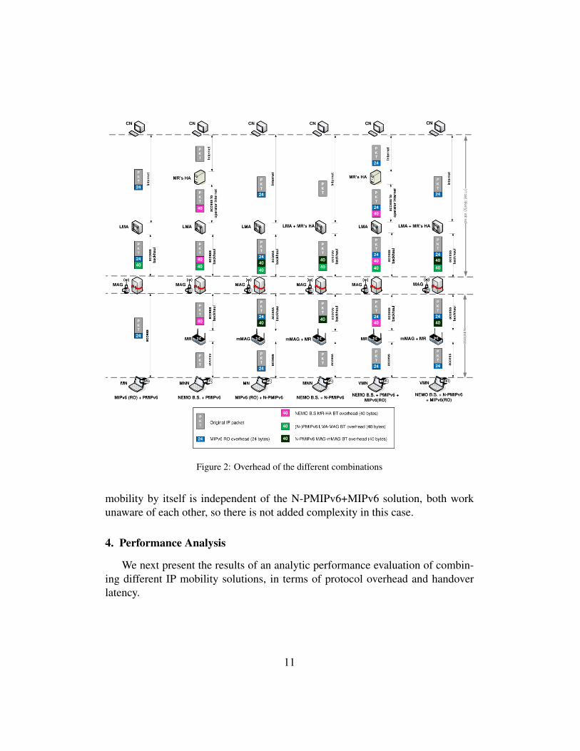
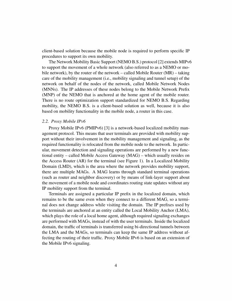
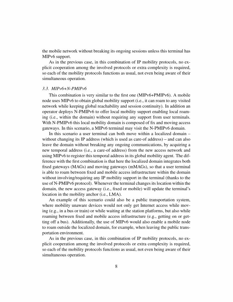
Figure 2: Overhead of the different combinations
mobility by itself is independent of the N-PMIPv6+MIPv6 solution, both workunaware of each other, so there is not added complexity in this case.
4. Performance Analysis
We next present the results of an analytic performance evaluation of combin-ing different IP mobility solutions, in terms of protocol overhead and handoverlatency.
11
4.1. OverheadIn this section we analyze the overhead – in terms of control headers (tunnels)
– of each combination. In this analysis we focus not only on the amount of addedpacket overhead, but also on which segments of the network suffer from this extraoverhead, as the impact is more important if the additional control informationappears on segments of the network where the transmission media is wireless. Inorder to simplify this exercise, we limit the analysis of the MIPv6 overhead to thecase where Route Optimization (RO) is enabled. The difference between usingRO mode or bi-directional tunneling (BT) mode is basically the following: in BTmode, the overhead is higher (40 bytes, instead of 24), but it only appears betweenthe terminal and its home agent, while in route optimized mode the overhead ispresent along the complete path (i.e., between the terminal and the correspondentnode).
4.1.1. MIPv6 + PMIPv6In this case, 24 bytes of additional overhead are added in the whole path be-
tween the mobile node and the correspondent node, due to the use of Mobile IPv6(in RO mode), plus an IPv6 tunnel (40 bytes) between the localized mobility an-chor and the gateway (MAG) where the mobile node is attached to (due to the useof Proxy Mobile IPv6). It is important to note that, out of the overall overhead,only the 24 bytes added by Mobile IPv6 are present in the wireless access.
4.1.2. NEMO B.S. + PMIPv6 (+ MIPv6)Two different tunnels are involved to enable the communications of the mobile
network: one between the mobile router and its home agent (due to the use ofNEMO B.S.), and another between the localized mobility anchor and the gatewayserving the mobile router (due to the use of Proxy Mobile IPv6). Thus, there areup to 80 additional bytes of overhead in some wired segments of the path (whenboth tunnels are present), and up to 40 bytes in the wireless access (due to theuse of NEMO B.S.), though not in the last wireless hop between the user terminal(i.e., the MNN) and its access router (i.e., the MR). Note that this last wirelesshop is where the effect on battery consumption and bandwidth waste is likely tobe more significant. A third overhead component (24 bytes in route optimizedmode) is required if the terminal attached to the mobile network is itself a MIPv6mobile node outside its home network.
12
4.1.3. MIPv6 + N-PMIPv6In this case, where a mobile node is attached to a moving gateway, three over-
head components are required: one (24 bytes) between the mobile and the cor-respondent node (due to the use of Mobile IPv6 in route optimized mode), anIPv6 tunnel (40 bytes) between the localized mobility anchor and the fixed gate-way where the moving gateway is attached to, and a second tunnel between thelocalized mobility anchor and the moving gateway.
4.1.4. NEMO B.S. + N-PMIPv6 (+ MIPv6)When a mobile network is attached to a moving MAG (which is at its home
N-PMIPv6 domain), and assuming a deployment scenario in which the localizedmobility anchor and the home agent of the mobile router are co-located (see Sec-tion 2.2), two IPv6 tunnels are required: one between the localized mobility an-chor and the fixed gateway serving the moving gateway, and a second betweenthe localized mobility anchor and the moving gateway. If the user terminal that isgetting access through the mobile network is a mobile node running Mobile IPv6(which is outside its home network), an additional overhead component (24 bytes)is required (due to the use of Mobile IPv6 in route optimized mode).
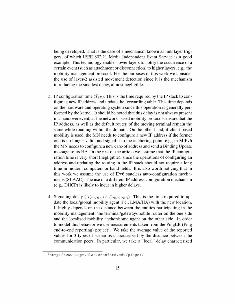
Figure 2 shows the overhead of all the analyzed combinations over the differ-ent network segments. Depending on the combination under consideration, wecan have up to three extra headers in the wired access network backhaul, up totwo in the wireless access backhaul (i.e., between the fixed access network andthe moving MAG/mobile router), and up to one in the last wireless hop to theterminal.
In order to gain understanding on the effect of the mobility overhead with usertraffic, we have taken data from a real access network deployment offering Inter-net access during a conference (ACM CoNEXT 2008 [7]). The average packetsize for UDP or TCP traffic is 710 bytes (including all headers). For the case ofthree additional overhead components (104 bytes), the extra headers account fora waste of 14.6% of the bandwidth. If two extra headers are required, the wasteis between 9% and 11.26% (for the cases of 64 and 80 bytes of overhead, respec-tively). Finally, if only one overhead component is needed, the bandwidth wasteis between 3.38% and 5.6% (for the cases of 24 and 40 bytes). Nevertheless, notethat these figures just represent a mixture of user traffic – composed mostly ofHTTP data – in a conference. In mobile scenarios the overhead penalty will tendto be worse, for example with the expected increase of VoIP traffic. It is worthhighlighting that the extra headers – in addition to the bandwidth waste – alsoinvolve the extra energy consumption required to transmit them, which is signifi-
13
cant in wireless environments. Moreover, it is commonly argued that the problemis not so important in the access network backhaul, because it is usually wiredand bandwidth is not severely limited, but wireless multi-hop access networks arebecoming increasingly popular, which weakens this reasoning.
4.2. Handover latency of IP mobility protocolsThe handover delay of mobility protocols can be expressed as a combination
of independent factors such as the layer-2 handover time, the movement detectiontime, the IP configuration time, and the specific mobility signaling delay. Webriefly describe first each of these independent factors.
1. Layer-2 handover time (T hoL2). It is defined as the time required by layer-2
technology to perform a handover (i.e., disconnecting from its current pointof attachment and connecting to a new one). In the case of an IEEE 802.11-based layer-2 technology, this time usually involves the channel scanningfor candidate Access Points (APs), plus the time required for re-association.As presented in [8], this delay can be modeled with a Beta probability dis-tribution function. In [9] it is shown how its mean value can be reduced upto 50 ms by appropriately selecting the number of channels being scanned.For the handover delay analysis we conduct later, we take this last numberas the mean value of the Beta distribution, while the standard deviation ofthe resulting distribution is of 3.66 ms.
2. Movement detection time (TMD). This delay corresponds to the time re-quired by the terminal to detect that it has moved to a different layer-3point of attachment. This detection can be performed by functionality atthe IP layer or assisted by layer-2 mechanisms. If we focus on IPv6 mech-anisms, movement detection can be done in different ways. The most sim-ple (and the most widely supported) consists in using Routing Advertise-ment (RA) messages. An access router periodically multicasts unsolicitedRA messages. Typically, the time interval between these advertisementsfollows a uniform distribution: whenever a router advertisement is sentfrom an access router, a timer is set to a uniformly distributed randomvalue [10] between the configured MinRtrAdvInterval (Rm) and MaxRtrAd-vInterval (RM ). Although IPv6-based movement detection mechanisms arewell known and supported, new optimized mechanisms to detect the con-nection of a terminal to a new point of attachment have been and are still
14
being developed. That is the case of a mechanism known as link layer trig-gers, of which IEEE 802.21 Media Independent Event Service is a goodexample. This technology enables lower layers to notify the occurrence of acertain event (such as attachment or disconnection) to higher layers, e.g., themobility management protocol. For the purposes of this work we considerthe use of layer-2 assisted movement detection since it is the mechanismintroducing the smallest delay, almost negligible.
3. IP configuration time (TIP ). This is the time required by the IP stack to con-figure a new IP address and update the forwarding table. This time dependson the hardware and operating system since this operation is generally per-formed by the kernel. It should be noted that this delay is not always presentin a handover event, as the network-based mobility protocols ensure that theIP address, as well as the default router, of the moving terminal remain thesame while roaming within the domain. On the other hand, if client-basedmobility is used, the MN needs to configure a new IP address if the formerone is no longer valid, and signal it to the anchoring point, e.g., in MIPv6the MN needs to configure a new care-of address and send a Binding Updatemessage to its HA. In the rest of the article we assume that the IP configu-ration time is very short (negligible), since the operations of configuring anaddress and updating the routing in the IP stack should not require a longtime in modern computers or hand-helds. It is also worth noticing that inthis work we assume the use of IPv6 stateless auto-configuration mecha-nisms (SLAAC). The use of a different IP address configuration mechanism(e.g., DHCP) is likely to incur in higher delays.
4. Signaling delay ( TBU/BA or TPBU/PBA). This is the time required to up-date the local/global mobility agent (i.e., LMA/HA) with the new location.It highly depends on the distance between the entities participating in themobility management: the terminal/gateway/mobile router on the one sideand the localized mobility anchor/home agent on the other side. In orderto model this behavior we use measurements taken from the PingER (Pingend-to-end reporting) project3. We take the average value of the reportedvalues for 3 types of scenarios characterized by the distance between thecommunication peers. In particular, we take a ”local” delay characterized
3http://www-iepm.slac.stanford.edu/pinger/
15
by an average value of 5.37 ms, a ”regional” delay of 18.32 ms and a ”con-tinental” delay of 138.79 ms. To characterize the delay in an Internet path,these values are used as the mean of a Weibull distribution with varianceprovided by Hurst parameters of 0.8, 0.65 and 0.5 for local, regional andcontinental delays respectively [11] [12].
After explaining the different independent factors that are common to the han-dover time for all mobility solutions, we focus in the following on understandingthe handover delay for the different IP mobility management protocols (MobileIPv6, NEMO B.S., Proxy Mobile IPv6 and N-PMIPv6).
1. MIPv6/NEMO B.S. The delay incurred by a Mobile IPv6 terminal perform-ing a handover (in bi-directional tunnel mode) or by a mobile router, can beexpressed as:
T (MIPv6 BT/NEMO) = T hoL2 + TMD + TIP +RTT (MN/MR,HA),
(1)
where RTT(MN/MR,HA) represents the round trip time between the mobilenode (or router), and the corresponding home agent.In case route optimization mode is used in Mobile IPv6, we assume themobile node is performing optimistic registration [13], which means thatthe route optimization related signaling is performed in parallel with theregistration signaling with the home agent. For this case, an additionalRTT (CN,HA) component should be added to the delay shown in Eq. (1).
2. PMIPv6. If Proxy Mobile IPv6 is used to manage the mobility of the userterminal, the handover delay can be expressed as:
T (PMIPv6) = T hoL2 + TMD +RTT (MAG,LMA) (2)
In this case, in addition to the time required for the layer-2 handover, move-ment detection and authentication, we also add the signaling delay betweenthe gateway and the localized mobility anchor. In case the MN is enteringthe localized domain for the first time, an additional TIP component shouldbe added to the delay shown in Eq. (2).
16
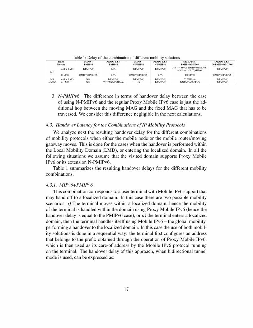
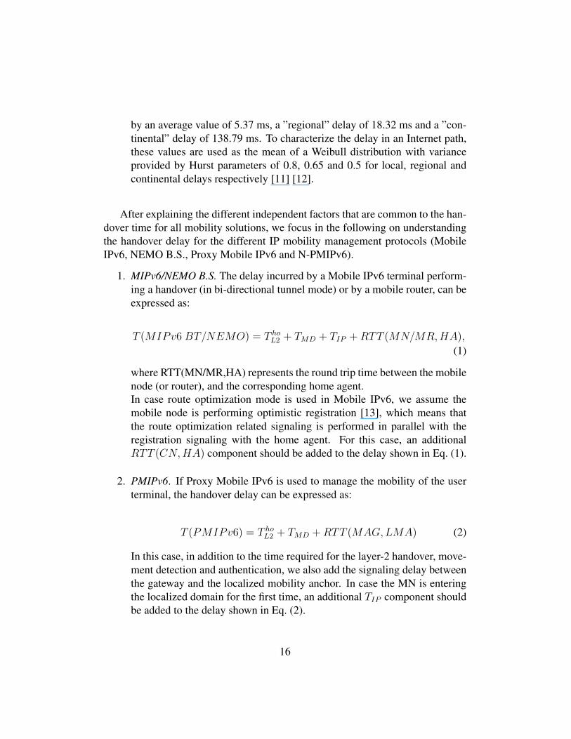
Table 1: Delay of the combination of different mobility solutionsEntity MIPv6+ NEMO B.S.+ MIPv6+ NEMO B.S.+ NEMO B.S.+ NEMO B.S.+
Moving PMIPv6 PMIPv6 N-PMIPv6 N-PMIPv6 PMIPv6+MIPv6 N-PMIPv6+MIPv6
MNwithin LMD T(PMIPv6) N/A T(PMIPv6) T(PMIPv6) MR → MAG: T(MIPv6+PMIPv6) T(PMIPv6)MAG → MR: T(MIPv6)
to LMD T(MIPv6+PMIPv6) N/A T(MIPv6+PMIPv6) N/A T(MIPv6) T(MIPv6+PMIPv6)
MR within LMD N/A T(PMIPv6) T(PMIPv6) T(PMIPv6) T(PMIPv6) T(PMIPv6)mMAG to LMD N/A T(NEMO+PMIPv6) NA T(PMIPv6) T(NEMO+PMIPv6) T(PMIPv6)
3. N-PMIPv6. The difference in terms of handover delay between the caseof using N-PMIPv6 and the regular Proxy Mobile IPv6 case is just the ad-ditional hop between the moving MAG and the fixed MAG that has to betraversed. We consider this difference negligible in the next calculations.
4.3. Handover Latency for the Combinations of IP Mobility ProtocolsWe analyze next the resulting handover delay for the different combinations
of mobility protocols when either the mobile node or the mobile router/movinggateway moves. This is done for the cases when the handover is performed withinthe Local Mobility Domain (LMD), or entering the localized domain. In all thefollowing situations we assume that the visited domain supports Proxy MobileIPv6 or its extension N-PMIPv6.
Table 1 summarizes the resulting handover delays for the different mobilitycombinations.
4.3.1. MIPv6+PMIPv6This combination corresponds to a user terminal with Mobile IPv6 support that
may hand off to a localized domain. In this case there are two possible mobilityscenarios: i) The terminal moves within a localized domain, hence the mobilityof the terminal is handled within the domain using Proxy Mobile IPv6 (hence thehandover delay is equal to the PMIPv6 case), or ii) the terminal enters a localizeddomain, then the terminal handles itself using Mobile IPv6 – the global mobility,performing a handover to the localized domain. In this case the use of both mobil-ity solutions is done in a sequential way: the terminal first configures an addressthat belongs to the prefix obtained through the operation of Proxy Mobile IPv6,which is then used as its care-of address by the Mobile IPv6 protocol runningon the terminal. The handover delay of this approach, when bidirectional tunnelmode is used, can be expressed as:
17
T (MIPv6 + PMIPv6) = T hoL2 + TMD + TIP +RTT (MAG,LMA)
+RTT (MN,HA)
= T hoL2 + TMD + TIP +RTT (MAG,LMA)
+RTT (MN,LMA) +RTT (LMA,HA)
' T hoL2 + 2 ∗RTT (MAG,LMA)
+RTT (LMA,HA).
(3)
We separate the RTT between the MN and the HA in two parts: the RTTbetween the MN and the LMA, and the RTT between the LMA and the HA.This is because when the MN is in a PMIPv6 domain, its traffic, including theMIPv6 signaling, has to go through the LMA. Separating the RTT in two partsallows us to consider the influence of the distance between the LMA and theHA. Additionally, the RTT between the MN and the LMA is equal to the RTTbetween the MAG and the LMA plus the delay in the hop MAG-MN that weconsider negligible.
In the case of optimistic route optimization mode, an additional RTT (CN,HA)component should be added to the delay shown in Eq. (3).
4.3.2. NEMO B.S.+PMIPv6In this combination, instead of a user terminal running Mobile IPv6, the entity
moving is a mobile router running the NEMO B.S. protocol. As in the previoussection, two situations may arise: i) the mobile router moves within a localizedmobility domain, hence the mobility of the router within the domain is handledusing Proxy Mobile IPv6, or ii) the mobile router enters a localized domain, sothe router handles the macro-mobility (using the NEMO B.S. protocol). This caseis similar to the MIPv6+PMIPv6 without route optimization, being Eq. (3) alsoapplicable in this scenario (considering a mobile router instead of a mobile node).
T (NEMO + PMIPv6) = T hoL2 + TMD + TIP +RTT (MAG,LMA)
+RTT (MR,LMA) +RTT (LMA,HA)
' T hoL2 + 2 ∗RTT (MAG,LMA)
+RTT (LMA,HA).
(4)
18
4.3.3. MIPv6+N-PMIPv6This scenario considers a user terminal with Mobile IPv6 support that may
move to a localized mobility domain where gateways are able to move (mMAGs),hence there are two mobile entities: the mobile node and the moving gateway.In case the terminal attaches to a moving gateway, as shown in the delay ex-planation for the N-PMIPv6 solution (see Section 4.2), the difference in delaybetween the Proxy Mobile IPv6 case and N-PMIPv6 case is the one due to anadditional hop in the local network. Taking this fact into account, the com-bined solution of MIPv6+N-PMIPv6 presents a slightly increase in the delay:RTT (mMAG,MAG) – which we consider negligible – compared to MIPv6 +PMIPv6.
If the entity moving is a moving gateway, it can move either within the local-ized mobility domain or from outside to the domain.
N-PMIPv6 protocol allows the moving gateway to roam within the domain(using the Proxy Mobile IPv6 protocol). Hence, in the case the moving gatewayroams within the domain, the handover delay is equal to the one obtained in ProxyMobile IPv6. The case where the moving gateway moves to a different localizedmobility domain is not considered here, since there is no mobile router function-ality in the moving gateway and, therefore, mobility cannot be granted.
4.3.4. NEMO B.S.+N-PMIPv6This combination considers user terminals without Mobile IPv6 support and
moving MAGs that also incorporate NEMO B.S. functionality, so they can handoff outside the localized mobility domain. As in the previous section, in thisscenario two entities are able to move, the user terminal and the moving gateway.In case the terminal moves, it can attach to another access router belonging tothe same domain and the mobility is handled by the network-based signaling (N-PMIPv6).
The case where the terminal hands off from outside to the domain is not appli-cable since the terminal does not have mobility support in this case and, hence, itcannot hand off from outside the localized mobility domain. If the entity movingis the moving gateway, it can move i) within the domain, using the N-PMIPv6protocol that allows the moving gateway to roam within the domain, or ii) to thedomain from the outside (in this case the moving gateway is outside the domainand it performs a handover to it). As the moving gateway is part of the domain,the prefix used by its mobile router functionality belongs to the localized domain.Therefore it only requires performing a Proxy Mobile IPv6 registration in order tohand off to the domain.
19

4.3.5. NEMO B.S.+PMIPv6+MIPv6This scenario encompasses a user terminal supporting Mobile IPv6, and a lo-
calized mobility domain where there is a mobile router attached. The terminal canmove within the domain or can move to it from the outside. In case the terminalis attached to the domain, it can be anchored to a gateway or to the mobile router.For the scenario where the terminal is attached to the mobile router and handsoff to a gateway, the terminal uses both Mobile IPv6 and Proxy Mobile IPv6 toreconnect to the domain, i.e., it is equivalent to the MIPv6+PMIPv6 scenario. Onthe other hand, if the terminal is attached to a gateway and hands off to the mobilerouter, it must use Mobile IPv6 to regain connectivity, since the address providedby the mobile router does not belong to the domain, but to the home network ofthe router.
The case where the terminal is moving to the domain from the outside is equiv-alent to the MIPv6+PMIPv6 case. In this mobility combination scenario the mo-bile router can also move, being this case equivalent to the NEMO B.S.+PMIPv6scenario.
4.3.6. NEMO B.S.+N-PMIPv6+MIPv6This scenario considers a terminal with Mobile IPv6 support and a localized
mobility domain where there are moving gateways (mMAGs) with mobile router(NEMO B.S.) functionality. This scenario can be analyzed as a combination of theprevious scenarios. The case where the terminal moves to the domain, is equiv-alent to the combination MIPv6+N-PMIPv6, while the case where the mobilerouter moves is equivalent to the NEMO B.S.+N-PMIPv6 combination.
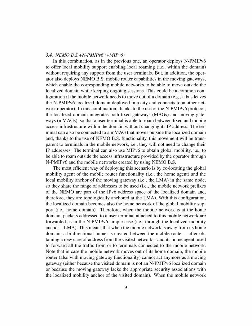
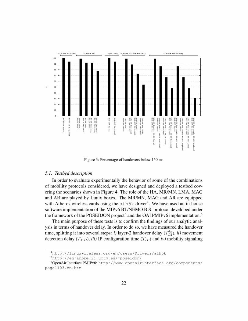
4.4. Delay performance analysisFigure 3 allows us to gain some insight about the impact of the combination
of different mobility solutions on the delay experienced during handovers. It rep-resents, for different mobility solutions and different topologies, the percentage ofhandovers with a delay below a particular threshold, namely 150 ms. This valueis a reasonable disruption time for most applications, assuming the use of somebuffering function to minimize packet loss during the interruption caused by thehandover in the communication [9]. The first two bars on the left of the figureare the percentage of handovers whose delay is below 150 ms for NEMO B.S.or MIPv6 in bi-directional tunneling mode (BT), depending on the distance be-tween the Home Agent and the Mobile Node/Router. Using global mobility theMN/MR can move everywhere. Additionally, the visiting network may providelocal mobility support. This allows better efficiency in handovers inside the local
20
domain (see the bars referring to PMIPv6 in Figure 3) but at the cost of a longerhandover delay to move into the local domain, as shown in the bars referring tothe MIPv6 BT/NEMO B.S.+PMIPv6 combination. This cost increases with thedistance between the Mobile Anchor Gateway and the Localized Mobility An-chor. For example, a MIPv6 terminal that is not using Route Optimization andit is at regional distance from its HA has a probability close to 95% of having adelay below 150 ms when executing a handover to an access network without lo-cal mobility support; but when the access network has local mobility support theprobability is reduced to the 55-90% range depending on the distance between theMAG and the LMA in the local domain and the distance between the LMA andthe HA. It is also worth noticing that the effect of the delay MAG-LMA is greaterthan the effect of the delay LMA-HA. This is because the path MAG-LMA istraversed both for the PMIPv6 and for the MIPv6 signaling while the path LMA-HA is only traversed by the MIPv6 signaling – see Eq. (3). Figure 3 also showsthe performance of the handovers of MIPv6 terminals with Route Optimization,and of the handovers of MIPv6 terminals with Route Optimization moving to aPMIPv6 domain.
To fully understand the importance of these results we need to consider twoaspects. First, when evaluating handover performance we need to focus on thelongest handover that the terminal can suffer in any type of handover, becausethat will determine the performance and the needed mechanisms (e.g., buffering)to avoid interruptions in the terminals communications. The second aspect isthe frequency of the handovers: if some type of handover was very unusual, wecould accept having a worse performance in that type of handover. The frequencyof the type of handovers depends on the scenario, but we argue that the trendin mobile communications networks is towards very dynamic mobility scenariosin which nodes will change of access network very frequently according to theaccess network availability and the terminal requirements, so probably every typeof handover will become usual.
5. Experimental analysis
We next complement the findings of our analytic study, by performing an ex-perimental evaluation using Linux-based implementations of IP mobility proto-cols and conducting several experiments under different scenarios.
21
0
10
20
30
40
50
60
70
80
90
100
MN/MR-HA Local
MN/MR-HA Regional
MN-HA Local
HA-CN Local
MN-HA Local
HA-CN Regional
MN-HA Regional
HA-CN Local
MN-HA Regional
HA-CN Regional
MAG-LMA Local
MAG-LMA Regional
LMA-HA Local
MAG-LMA Local
LMA-HA Regional
MAG-LMA Local
LMA-HA Local
MAG-LMA Regional
LMA-HA Regional
MAG-LMA Regional
LMA-HA Local; HA-CN Local
MAG-LMA Local
LMA-HA Local; HA-CN Regional
MAG-LMA Local
LMA-HA Local; HA-CN Local
MAG-LMA Regional
LMA-HA Local; HA-CN Regional
MAG-LMA Regional
LMA-HA Regional; HA-CN Local
MAG-LMA Local
LMA-HA Regional; HA-CN Regional
MAG-LMA Local
LMA-HA Regional; HA-CN Local
MAG-LMA Regional
LMA-HA Regional; HA-CN Regional
MAG-LMA Regional
%
T(MIPv6 BT/NEMO) T(MIPv6 RO) T(PMIPv6) T(MIPv6 BT/NEMO+PMIPv6) T(MIPv6 RO+PMIPv6)
Figure 3: Percentage of handovers below 150 ms
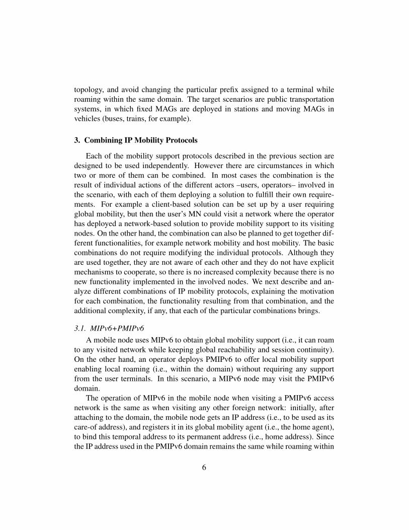
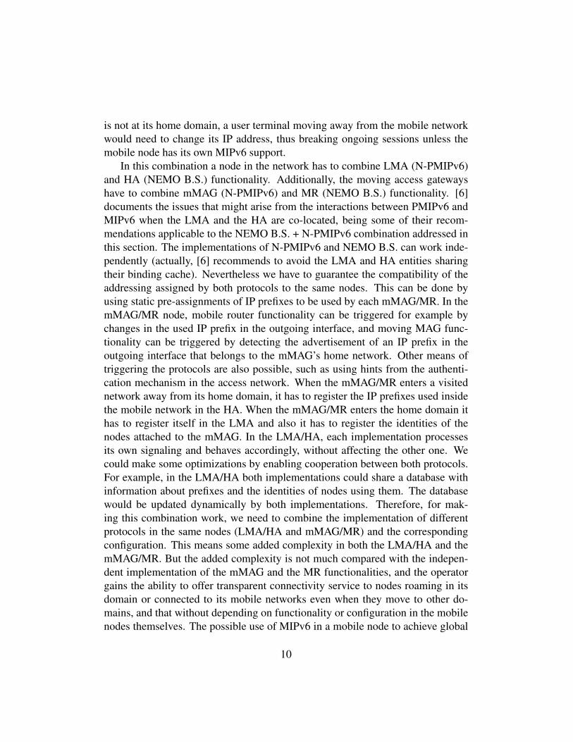
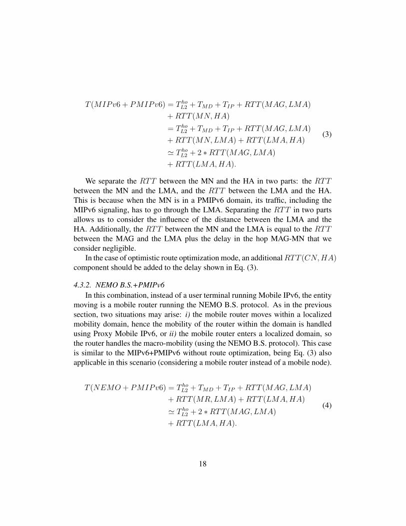
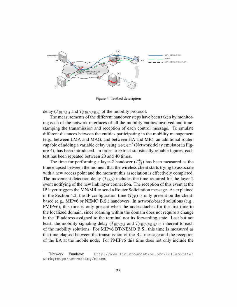
5.1. Testbed descriptionIn order to evaluate experimentally the behavior of some of the combinations
of mobility protocols considered, we have designed and deployed a testbed cov-ering the scenarios shown in Figure 4. The role of the HA, MR/MN, LMA, MAGand AR are played by Linux boxes. The MR/MN, MAG and AR are equippedwith Atheros wireless cards using the ath5k driver4. We have used an in-housesoftware implementation of the MIPv6 BT/NEMO B.S. protocol developed underthe framework of the POSEIDON project5 and the OAI PMIPv6 implementation.6
The main purpose of these tests is to confirm the findings of our analytic anal-ysis in terms of handover delay. In order to do so, we have measured the handovertime, splitting it into several steps: i) layer-2 handover delay (T ho
L2), ii) movementdetection delay (TMD), iii) IP configuration time (TIP ) and iv) mobility signaling
4http://linuxwireless.org/en/users/Drivers/ath5k5http://enjambre.it.uc3m.es/˜poseidon/6OpenAir Interface PMIPv6: http://www.openairinterface.org/components/
page1103.en.htm
22
AR
LMA
NETWORK DELAY
EMULATOR
MNHA
Home Network
MAG
MIPv6 BT/NEMO B.S.
PMIPv6
MIPv6 BT/NEMO B.S.+PMIPv6
Figure 4: Testbed description
delay (TBU/BA and TPBU/PBA) of the mobility protocol.The measurements of the different handover steps have been taken by monitor-
ing each of the network interfaces of all the mobility entities involved and time-stamping the transmission and reception of each control message. To emulatedifferent distances between the entities participating in the mobility management(e.g., between LMA and MAG, and between HA and MR), an additional router,capable of adding a variable delay using netem7 (Network delay emulator in Fig-ure 4), has been introduced. In order to extract statistically reliable figures, eachtest has been repeated between 20 and 40 times.
The time for performing a layer-2 handover (T hoL2) has been measured as the
time elapsed between the moment that the wireless client starts trying to associatewith a new access point and the moment this association is effectively completed.The movement detection delay (TMD) includes the time required for the layer-2event notifying of the new link layer connection. The reception of this event at theIP layer triggers the MN/MR to send a Router Solicitation message. As explainedin the Section 4.2, the IP configuration time (TIP ) is only present on the client-based (e.g., MIPv6 or NEMO B.S.) handovers. In network-based solutions (e.g.,PMIPv6), this time is only present when the node attaches for the first time tothe localized domain, since roaming within the domain does not require a changein the IP address assigned to the terminal nor its forwarding state. Last but notleast, the mobility signaling delay (TBU/BA and TPBU/PBA) is inherent to eachof the mobility solutions. For MIPv6 BT/NEMO B.S., this time is measured asthe time elapsed between the transmission of the BU message and the receptionof the BA at the mobile node. For PMIPv6 this time does not only include the
7Network Emulator: http://www.linuxfoundation.org/collaborate/workgroups/networking/netem
23
0
0.05
0.1
0.15
0.2
0.25
0.3
MN
/MR
-HA
Local
MN
/MR
-HA
Reg
ional
MA
G-L
MA
Local
MA
G-L
MA
Reg
ional
LM
A-H
A L
ocal
MA
G-L
MA
Local
LM
A-H
A R
egio
nal
MA
G-L
MA
Local
LM
A-H
A R
egio
nal
MA
G-L
MA
Reg
ional
LM
A-H
A L
ocal
MA
G-L
MA
Reg
ional
Han
dover
del
ay (
seco
nds)
T(MIPv6 BT/NEMO B.S.) T(PMIPv6) T(MIPv6 BT/NEMO B.S.+PMIPv6)
TL2
TMD
TIP
TBU/BA
TPBU/PBA
Figure 5: Experimental delay analysis
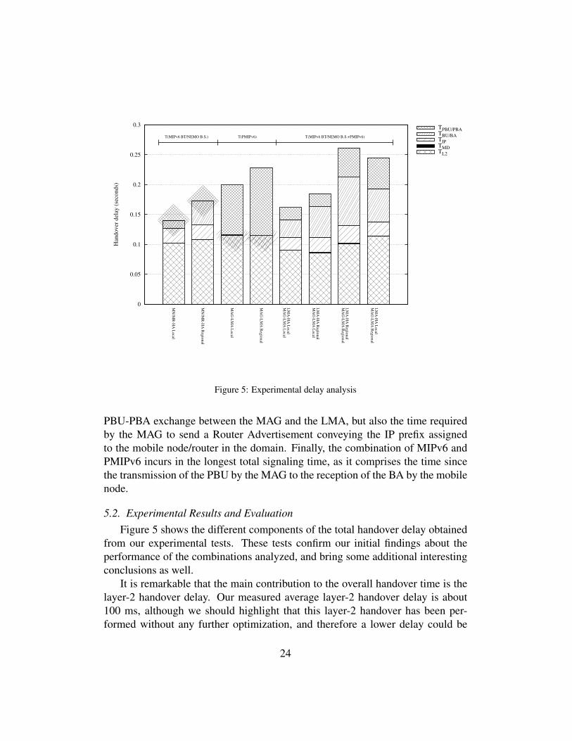
PBU-PBA exchange between the MAG and the LMA, but also the time requiredby the MAG to send a Router Advertisement conveying the IP prefix assignedto the mobile node/router in the domain. Finally, the combination of MIPv6 andPMIPv6 incurs in the longest total signaling time, as it comprises the time sincethe transmission of the PBU by the MAG to the reception of the BA by the mobilenode.
5.2. Experimental Results and EvaluationFigure 5 shows the different components of the total handover delay obtained
from our experimental tests. These tests confirm our initial findings about theperformance of the combinations analyzed, and bring some additional interestingconclusions as well.
It is remarkable that the main contribution to the overall handover time is thelayer-2 handover delay. Our measured average layer-2 handover delay is about100 ms, although we should highlight that this layer-2 handover has been per-formed without any further optimization, and therefore a lower delay could be
24
obtained by, for example, appropriately configuring the channels to scan and finetuning the layer-2 mechanisms involved in the association process.
The movement detection time is confirmed to be negligible, with an averagemeasured time of less than a millisecond.
On the other hand, the experimentation has shown that the process of config-uration and management of the IP addresses and routes is very time consuming.While these procedures are not present for the case of PMIPv6, the IP configura-tion time becomes relevant in the case of MIPv6 BT/NEMO B.S. and the com-bination MIPv6 BT/NEMO B.S+PMIPv6, as the mobile node/router cannot sendthe Binding Update message until the egress interface is configured properly withthe IP addresses assigned by the access router. In fact, our experiments show thatthe configuration of an IP address in the terminal requires an average of 20 ms8,which seems to be an implementation-specific aspect that can be improved.
The signaling time of the mobility protocols depends strongly on the distancebetween the entities involved in the mobility management (i.e., MAG and LMA,or HA and MR and their combinations). When the distance is local, practicallyall the handovers require less than 150 ms to be completed. When the delayis regional, the percentage of handovers requiring less than 150 ms decreases.The fact of combining protocols also has an impact, being the distance betweenthe MAG and LMA the most significant factor. A longer delay between thesetwo elements impacts significantly in the overall performance of the combination,as reflected by the comparison of the LMA-HA Local MAG-LMA Local with theLMA-HA Local MAG-LMA Regional cases in Figure 5.
If we look at the mobility signaling delay (TPBU/PBA and TBU/BA), it is worth-while mentioning that our experimental results show that, besides the delay dueto the RTT between the involved mobility entities, there is also a non negligibledelay caused by the processing time of the software implementation of the mobil-ity protocols. Note that the implementations used in our experiments are researchsoftware, with code not optimized for performance.
This results in a measured signaling time noticeably higher in our experimentsthan the one considered in our theoretical analysis. One particularly unfortunatecase is the PMIPv6 signaling delay resulting from the used implementation, asit requires the LMA to remove the tunnel that was being used before doing anyfurther processing of a received PBU. This is a bug of the implementation that
8Note that Duplicate Address Detection (DAD) was disabled in our tests. Had it been enabled,it would have added an average of 1 second to the IP configuration time.
25
introduces a considerable additional delay9. If we compare the handover delaysof PMIPv6 and MIPv6 BT/NEMO B.S.+PMIPv6 in Figure 5, we can see that thePMIPv6 signaling delay TPBU/PBA of the latter is considerably lower because, inthat case, the MN/MR just arrives to the localized domain, so no previous tunnelhas to be removed. Based on this, although we have included the results of thePMIPv6 case for completeness, we do not consider them representative of the realperformance of the protocol, for the reasons explained above.
If we compare the results of the handover delay of our theoretical analysis per-formed in Section 4.4 with the experimental results here, we can see that measuredvalues from the conducted tests are higher than the ones resulting from the analyticevaluation. This is due mainly to higher layer-2 handover delays and some pro-cessing times not considered in the theoretical analysis (most are implementation-specific, therefore not invalidating our analysis). Nevertheless, our general findingthat combining IP mobility protocols tends to increase the overall handover delayis confirmed as can be seen by comparing the MIPv6 BT/NEMO B.S. results withthe MIPv6 BT/NEMO B.S.+PMIPv6 results in Figure 5.
6. Facing the shortcomings of combining IP mobility solutions
We have identified, described and analyzed different combinations of IP mo-bility protocols standardized by the IETF and the functionality that they provide.An important result of the analysis is that, although the combination is needed tobe able to obtain a mix of the properties of the different protocols, it also involvesa cost, both from the point of view of additional overhead and from the point ofview of handover delay.
Regarding handover delay, combining different mobility solutions has an im-pact on the performance, even when some of the steps required by each of the mo-bility protocols – such as movement detection – are shared, resulting in a longerhandover interruption. We have also showed that this performance penalty can besignificant in certain cases.
These results raise the need to develop mechanisms to alleviate the costs ofcombining different mobility solutions, while keeping the advantages brought bythe combination. The experience teaches us that we cannot expect a single mo-bility solution with all the functionalities to be universally adopted. Instead weadvocate for solutions that include in their design the flexibility to activate and de-activate the use of their supported mobility functionalities (as already supported
9This bug has already been reported to the software developers.
26
in a very limited way by the latest 3GPP specifications [5]). For example, it wouldbe interesting to design a mechanism so that the mobile nodes and the network cannegotiate about the mobility support functions required in a particular situation,choosing a particular set of functions from those available as required. This im-plies placing a very active role in the mobile nodes regarding the use of mobilitysolutions. This is in contradiction with part of the motivation for the network-based mobility approach that has been favored by some operators. However, infact, the heterogeneity of access networks and the current trend towards environ-ments with several options for network access from different operators make un-avoidable to place more responsibility in the mobile nodes regarding the mobilitysolutions to use, at least if they want to enjoy an optimized performance adaptedto their needs but compatible with network requirements.
Recently there has been an interest in mobility solutions that push the mo-bility anchors to the network edges (closer to the mobile nodes), what is calledDistributed Mobility Management (DMM) [14]. This work is being carried outat the IETF, and at this stage, is first properly scoping the problem of DMM aswell as analyzing how current standardized protocols could be used to achieve aDMM-alike behavior. The reasons for this approach are distributing the function-ality to avoid bottlenecks and single points of failure, keeping mobility signalingclose to the MN, improving handover efficiency because mobility signaling is lo-cal (and therefore faster), and optimizing data path routing (the anchor is close tothe MN so, in general, long diversions through a far-off anchor are avoided). But,interestingly from our point of view, the DMM approach also assumes a moreactive role in the MN, that chooses how to use mobility support functionality ona per-communication basis. We are going to use a particular instantiation of thisapproach to show how building this flexibility in mobility mechanisms can helpin minimizing the negative effects of combining different IP mobility schemes.
6.1. Distributed Mobility ManagementThe mobility management approaches described in Section 2 have in common
the use of a centralized anchor point in charge of defending the MN’s address andforwarding the packets addressed to the mobile node towards its current destina-tion. The use of this central anchor point has several drawbacks, such as longer(sub-optimal) routing paths, scalability issues or longer handover latencies. Ad-ditionally, not every IP application requires IP address continuity (i.e., to keep theIP address across movements), and therefore it is preferable to enable mobility ona per-application basis. These are the issues that have motivated the development
27
of the Distributed Mobility Management (DMM) approach. As part of this effort,needs for new mechanisms and protocols are being identified.
Although the DMM paradigm is relatively new, there have been already pro-posals for distributed mobility management solutions. These can be classified intotwo main groups: those that aim at making client IP mobility approaches (such asMIPv6) work in a distributed way [15], and those that aim at doing that for proxynetwork-based mobility (like PMIPv6) [16]. Both approaches follow the samebasic principle: access routers (i.e., the first-hop router the mobile node attachesto) perform two main functionalities: i) provide attaching terminals with valid IPaddresses that are topologically valid at the access router, and ii) anchor these ad-dresses and keep their reachability even when the mobile node moves. In orderto do so, the access router may also have to implement the HA or MAG/LMAfunctionality (depending on the approach followed) for certain IP addresses. Itis important to note that the activation of the IP address mobility management isperformed on demand on an IP address basis, depending on the requirements ofthe applications running on the user terminal that are using that given IP address.We provide next an example: an MN attaches to an access router (AR1), and ob-tains an IP address/prefix topologically correct (ip1) at that location. If the MNstarts any applications, they will make use of ip1 as source IP address for the newcommunications, thus benefiting from direct (optimal) routing to the correspon-dent node. We consider next the situation in which the MN moves to a new accessrouter (AR2): after attaching, the MN obtains a new valid address/prefix (ip2),which is used by any new connections. Besides, in case the MN requires IP ad-dress continuity (e.g., because it has ongoing communications using ip1 that can-not survive an IP address change), the previous access router (AR1) implementsHA/LMA functionality, and keeps defending the IP address ip1, and forwardingpackets addressed to the new location of the MN.
6.2. Combining IP mobility protocols in a dynamic and distributed fashionIn order to clarify the requirements and operation of the new DMM paradigm,
this section presents a DMM example. In [17] a particular DMM solution isproposed, which is being developed within the context of the EU MEDIEVALproject10. This solution, as any DMM solution, allows mobile nodes to choosewhen to use, or not, mobility support for each of their applications. But, addition-ally, it also offers two different types of mobility support solutions: a global and
10http://www.ict-medieval.eu/
28
a local one. The mobile node can choose to use one solution, the other or none,for each of their applications, which provides the advantages of both solutionswithout incurring in the inefficiencies identified in Section 4.
We are going to give a brief description of the solution described in [17]. Notethat a detailed description is out of the scope of this article, we are just goingto highlight the properties in this solution that enable an efficient combination ofdifferent mobility mechanisms, in this case a global and a local mobility solution.
The MEDIEVAL mobility architecture leverages on the concept of DistributedMobility Management [18], for the development of both network-based and client-based mobility management. The access network is organized in Localized Mobil-ity Domains in which the network-based scheme inspired by [16] is applied. Usersare expected to be most of the time roaming within a single LMD, but, for thosecases where this is not possible (e.g., roaming to a network owned by a differentoperator or running a different mobility support scheme), a client-based DMMapproach is followed (e.g., based on [15]). In order to integrate both approaches,so a mobile node can simultaneously have sessions managed by a network-based(“PMIPv6 alike”) approach and a client-based (“MIPv6 alike”) approach, a novelarchitectural element called Mobile Access Router (MAR) is introduced. TheMAR is a network entity implementing all the functionalities of its counterpartsin the standard mobility protocols (MIPv6 and PMIPv6), so it is able to play therole of plain access router, home agent, local mobility anchor and mobile accessgateway on a per address basis.
A mobile node obtains a locally anchored IP address every time it attachesto a MAR. While moving between MARs of the same LMD, the reachability ofthese addresses is maintained – if needed by an application – by using a PMIPv6based DMM mode of operation. Note that in this mode, and for each IP address,the anchoring MAR plays the role of LMA, and the currently serving MAR playsthe role of MAG. On the other hand, if the MN moves out of an LMD, it enablesits MIPv6 stack, obtains a new care-of address and signals its current location tothe relevant MARs (i.e., those that anchor IP addresses which reachability shouldbe maintained). Note that in this case, these MARs play the role of HA for thoseaddresses.
We are not arguing here that DMM (or the MEDIEVAL DMM approach) isthe perfect mobility solution. In many scenarios it has the advantage of reducingthe distance between the MN and its anchor point in use, which improves effi-ciency. But it may also have drawbacks. It pushes functionality/complexity to theedge of the network. It can also be very inefficient for MNs moving and open-ing several long-term communications, because that can result in tunnels from the
29
MN to several network nodes, tunnels that can become quite long with time, asthe MN moves away from its initial position. These long tunnels mean losing theperformance advantage of the DMM solution.
The interesting point for us is that we can identify key elements in the ME-DIEVAL architecture that enable an efficient combination of mobility mecha-nisms:
• In MEDIEVAL mobile nodes are provided with the ability to choose, foreach of their applications, the mobility mechanisms that are used to sup-port their mobility. This is a feasible feature for client-based mobility ap-proaches, but it is usually not present in other situations such as network-based mobility approaches or for hosts connected to mobile networks.
• An information system based on IEEE 802.21 [19] is defined so networknodes and mobile nodes can exchange information about the mobility sup-port requirements of the mobile node, and to request the activation or de-activation of certain functions in the network, such as the network mobilitysupport for a particular prefix.
• Mobile nodes not aware of the MEDIEVAL approach (e.g., unable to com-municate with the network through IEEE 802.21) still receive, transparentlyfor them, a default mobility support service based on PMIPv6 in this case.
Generalizing from this example, to achieve an efficient coexistence of mobil-ity approaches that offers the advantages of their different functionalities withouthaving performance penalties, we need the following:
• Flexibility for activating/deactivating particular mobility functionalities.
• A system for exchanging the required information among the mobile nodesand the network.
• A default behavior to provide mobility support to legacy nodes.
Ideally, the flexibility to activate/deactivate functions should be a built-in char-acteristic in any (new) mobility solution developed, and the information systemshould be standardized independently of the mobility solutions. Legacy nodes inthis context means nodes that cannot exchange information and negotiate with thenetwork the mobility support mechanisms to be activated. These legacy nodesmust be able to benefit from a default mobility support functionality, even if it
30
is with some inefficiencies. The default mobility support functionality will de-pend on the situation, examples are a MIPv6 service, a PMIPv6 service, or aMIPv6+PMIPv6 combination. The important point is that being unaware of theinformation system should not make a mobile node unable to use the basic mobil-ity functionality, even if it is with some inefficiencies.
7. Conclusions
Many IP mobility support protocols have been and still are being developedby several standardization bodies and, in particular, by the IETF. Each protocolprovides a different functionality (terminal mobility or network mobility, for ex-ample) and/or require operations in different nodes (mobility support based on theterminal or on the network). The current trend in the evolution of mobile com-munication networks is towards terminals with several network interfaces (theseare already a market reality) that get ubiquitous Internet access by dynamicallychanging access network to the most appropriate one. Handovers between differ-ent access networks are going to be usual. In this situation the different mobilitysolutions developed by the IETF are going to co-exist. There is no winner solutionbecause each of them addresses different requirements.
In some scenarios we need a combination of different mobility solutions be-cause a mix of some of their properties is required. This article has analyzed thedifferent combinations and the functionality that they provide. But the combina-tions also have a cost. The article evaluates this cost for the different combinationsof mobility solutions, both from the point of view of the overhead and from thepoint of view of the handover delay. The conclusion is that the combination ofsolutions may have an important impact on the overhead and handover delay ofthe communications, leading to performance penalties which can be significantin certain cases. A first contribution of this paper is an analytic study of thesepenalties so designers of mobility solutions can consider them when addressingan scenario that requires a combination of different mobility protocols. The find-ings of this analytic study have been confirmed, for the case of the handover delay,by an experimental evaluation conducted in a Linux-based testbed.
The second contribution of this article is giving an outline of how future mo-bility protocols can be designed, or previous ones adapted, to facilitate the combi-nation of different mobility protocols. The key properties required are: flexibilityto allow the activation and deactivation of mobility functionalities according tomobile and network requirements, the existence of a system so the network andthe mobile nodes can exchange the information needed to support that activation
31
and deactivation, and the provision of a default mobility support service for legacyterminals. We have briefly summarized in this article a solution that integrates aPMIPv6-based with an MIPv6-based distributed mobility management solutionusing this approach.
Future work includes the definition of the information system in an indepen-dent way from the mobility solutions. The proposed behavior –mobile nodes ne-gotiating with the network which mobility support functionalities to use– has to beachieved in an automatic way. It would be completely unrealistic to have users in-volved in choosing mobility mechanisms, but their preferences must be taken intoaccount. We intend to explore the use of cognitive networks approaches, such uspattern-based agreement techniques, to implement this automatic negotiation.
Acknowledgments
We want to thank the anonymous reviewers for their useful comments whichhave helped to improve this article.
The research leading to these results has received funding from the EuropeanCommunity’s Seventh Framework Programme (FP7-ICT-2009-5) under grant agree-ment n. 258053 (MEDIEVAL project) and also from the Spanish MICINN throughthe I-MOVING project (TEC2010-18907).
[1] C. Perkins, D. Johnson, J. Arkko, Mobility Support in IPv6, RFC 6275,2011.
[2] V. Devarapalli, R. Wakikawa, A. Petrescu, P. Thubert, Network Mobility(NEMO) Basic Support Protocol, RFC 3963, 2005.
[3] S. Gundavelli, K. Leung, V. Devarapalli, K. Chowdhury, B. Patil, ProxyMobile IPv6, RFC 5213, 2008.
[4] I. Soto, C. J. Bernardos, M. Calderon, A. Banchs, A. Azcorra, NEMO-enabled localized mobility support for internet access in automotive scenar-ios, IEEE Communications Magazine 47 (2009) 152–159.
[5] 3GPP, Architecture enhancements for non-3GPP accesses, TS 23.402,v11.2.0, 3rd Generation Partnership Project (3GPP), 2012.
[6] G. Giaretta, Interactions between Proxy Mobile IPv6 (PMIPv6) and MobileIPv6 (MIPv6): Scenarios and Related Issues, RFC 6612 (Informational),2012.
32
[7] P. Serrano, A. de la Oliva, C. J. Bernardos, I. Soto, A. Banchs, A. Azcorra,A CARMEN mesh experience: deployment and results, in: IEEE Workshopon Hot Topics in Mesh Networking, HotMESH’09.
[8] T. Pagtzis, Advanced IPv6 mobility management for next generation wire-less access networks, Ph.D. thesis, University College London, 2005.
[9] R. Aguiar, A. Banchs, C. J. Bernardos, M. Calderon, M. Liebsch, T. Melia,P. Pacyna, S. Sargento, I. Soto, Scalable QoS-aware Mobility for FutureMobile Operators, IEEE Communications Magazine 44 (2006) 95 – 102.
[10] Y. Han, J. Choi, S. H. Hwang, Reactive handover optimization in IPv6-basedmobile networks, IEEE Journal on Selected Areas in Communications 24(2006) 1758–1772.
[11] R. G. Clegg, A practical guide to measuring the Hurst parameter, Arxivpreprint math/0610756 (2006).
[12] J. A. Hernandez, I. W. Phillips, Weibull mixture model to charac-terise end-to-end Internet delay at coarse time-scales, IEE Proceedings-Communications 153 (2006) 295–304.
[13] C. Vogt, M. Zitterbart, Efficient and scalable, end-to-end mobility supportfor reactive and proactive handoffs in IPv6, Communications Magazine 44(2006) 74 – 82.
[14] R. Kuntz, D. Sudhakar, R. Wakikawa, L. Zhang, A Summary of DistributedMobility Management, Internet-Draft (work in progress), draft-kuntz-dmm-summary-00, 2011.
[15] F. Giust, A. de la Oliva, C. J. Bernardos, Flat Access and Mobility Archi-tecture: an IPv6 Distributed Client Mobility Management Solution, in: 3rdIEEE International Workshop on Mobility Management in the Networks ofthe Future World (Mobiworld 2011), in conjunction with The 30th IEEEInternational Conference on Computer Communications (IEEE INFOCOM2011).
[16] P. Seite, Dynamic Mobility Anchoring, Internet-Draft (work in progress),draft-seite-netext-dma-00.txt, 2010.
33
[17] F. Giust, C. J. Bernardos, S. Figueiredo, P. Neves, T. Melia, A Hybrid MIPv6and PMIPv6 Distributed Mobility Management: the MEDIEVAL approach,in: Sixth Workshop on multiMedia Applications over Wireless Networks.
[18] H. Chan, Problem statement for distributed and dynamic mobility manage-ment, Internet-Draft (work in progress), draft-chan-distributed-mobility-ps-02.txt, 2011.
[19] A. de la Oliva, A. Banchs, I. Soto, T. Melia, A. Vidal., An Overview of IEEE802.21: Media-Independent Handover Services, IEEE Wireless Communi-cations 15 (2008) 96 – 103.
34