The ALPHATRAP experiment
67
Eur. Phys. J. Special Topics 227, 1425–1491 (2019) c The Author(s) 2019 https://doi.org/10.1140/epjst/e2018-800225-2 THE E UROPEAN PHYSICAL J OURNAL SPECIAL TOPICS Regular Article The ALPHATRAP experiment ? Sven Sturm a , Ioanna Arapoglou, Alexander Egl, Martin H¨ ocker, Sandro Kraemer, Tim Sailer, Bingsheng Tu, Andreas Weigel, Robert Wolf b , Jos´ e Crespo L´ opez-Urrutia, and Klaus Blaum Max-Planck-Institut f¨ ur Kernphysik, Saupfercheckweg 1, 69117 Heidelberg, Germany Received 11 December 2018 Published online 11 February 2019 Abstract. The Alphatrap experiment at the Max-Planck Institute for Nuclear Physics in Heidelberg aims at probing the validity of quan- tum electrodynamics in extremely strong electromagnetic fields. To this end, Alphatrap will determine the value of the magnetic moment, or the g-factor, of the electron bound in highly charged ions. Quantum electrodynamics predicts this value with extraordinary precision. As the bound electron in highly charged ions is exposed to the strongest fields available for high-precision spectroscopy in the laboratory, reach- ing up to 10 16 V/cm in hydrogenlike lead 208 Pb 81+ , a comparison of the theoretical prediction with a measured value can yield the most stringent test of the Standard Model in strong fields. The targeted precision of eleven digits or more can be achieved by storing single highly charged ions in a cryogenic Penning trap, where its eigenfre- quencies can be determined with ultra-sensitive electronics to highest precision. Additionally, the spin state can be non-destructively deter- mined using the continuous Stern–Gerlach effect, allowing spectroscopy of the Larmor precession. Alphatrap is constructed to enable the injection and the storage of externally produced ions. The coupling to the Heidelberg EBIT gives access to even the heaviest highly charged ions and thus extends the available field strength by more than two orders of magnitude compared to previous experiments. This article describes the technical architecture and the performance of Alphatrap and summarises the experimental measurement possibilities. 1 Introduction The Standard Model (SM) of physics describes the interactions of particles via the four fundamental forces – electromagnetic, weak and strong interaction as well as gravitation. The former three interactions are represented by quantum field theo- ries, whereas gravitation up to now has resisted attempts to be treated in such a framework. Quantum electrodynamics (QED), the interaction of electrically charged particles via the exchange of photons, has been the first of these quantum field theories ? This article comprises parts of the thesis work of I.A., A.E. T.S. and A.W. a e-mail: [email protected] b Present address: ARC Centre of Excellence for Engineered Quantum Systems, School of Physics, The University of Sydney, NSW, Australia.
-
Upload
khangminh22 -
Category
Documents
-
view
2 -
download
0
Transcript of The ALPHATRAP experiment

Eur. Phys. J. Special Topics 227, 1425–1491 (2019)c© The Author(s) 2019
https://doi.org/10.1140/epjst/e2018-800225-2
THE EUROPEANPHYSICAL JOURNALSPECIAL TOPICS
Regular Article
The ALPHATRAP experiment?
Sven Sturma, Ioanna Arapoglou, Alexander Egl, Martin Hocker,Sandro Kraemer, Tim Sailer, Bingsheng Tu, Andreas Weigel, Robert Wolfb,Jose Crespo Lopez-Urrutia, and Klaus Blaum
Max-Planck-Institut fur Kernphysik, Saupfercheckweg 1, 69117 Heidelberg, Germany
Received 11 December 2018Published online 11 February 2019
Abstract. The Alphatrap experiment at the Max-Planck Institutefor Nuclear Physics in Heidelberg aims at probing the validity of quan-tum electrodynamics in extremely strong electromagnetic fields. To thisend, Alphatrap will determine the value of the magnetic moment, orthe g-factor, of the electron bound in highly charged ions. Quantumelectrodynamics predicts this value with extraordinary precision. Asthe bound electron in highly charged ions is exposed to the strongestfields available for high-precision spectroscopy in the laboratory, reach-ing up to 1016 V/cm in hydrogenlike lead 208Pb81+, a comparison ofthe theoretical prediction with a measured value can yield the moststringent test of the Standard Model in strong fields. The targetedprecision of eleven digits or more can be achieved by storing singlehighly charged ions in a cryogenic Penning trap, where its eigenfre-quencies can be determined with ultra-sensitive electronics to highestprecision. Additionally, the spin state can be non-destructively deter-mined using the continuous Stern–Gerlach effect, allowing spectroscopyof the Larmor precession. Alphatrap is constructed to enable theinjection and the storage of externally produced ions. The coupling tothe Heidelberg EBIT gives access to even the heaviest highly chargedions and thus extends the available field strength by more than twoorders of magnitude compared to previous experiments. This articledescribes the technical architecture and the performance of Alphatrapand summarises the experimental measurement possibilities.
1 Introduction
The Standard Model (SM) of physics describes the interactions of particles via thefour fundamental forces – electromagnetic, weak and strong interaction as well asgravitation. The former three interactions are represented by quantum field theo-ries, whereas gravitation up to now has resisted attempts to be treated in such aframework. Quantum electrodynamics (QED), the interaction of electrically chargedparticles via the exchange of photons, has been the first of these quantum field theories
? This article comprises parts of the thesis work of I.A., A.E. T.S. and A.W.a e-mail: [email protected] Present address: ARC Centre of Excellence for Engineered Quantum Systems, School of Physics,
The University of Sydney, NSW, Australia.

1426 The European Physical Journal Special Topics
and served as a blueprint for the development of the other theories. Accordingly, theexperimental verification of this theory is of major importance and interest. Indeed,QED is today considered to be the best tested theory of the SM. The magneticmoment associated with the spin of the electron can be calculated within the frame-work of QED and has thus served for experimental tests of the theory. Probablythe most intriguing of these experiments is the g − 2 experiment of the free electron[1], which has determined the gyromagnetic ratio, or g-factor, of the electron up tothe 13th decimal. This unique agreement of the experiment with the prediction bythe SM is a far-reaching confirmation of the validity of the theory. However, in thisexperiment, except for the weak magnetic trapping field, the electron couples only tothe vacuum field, so that non-linear effects in the field strength might go unnoticed.
In order to specifically address such interactions, for example a hypothetical pho-ton self-interaction or any other strong-field deviation of the known interactions, testsat the strongest possible electromagnetic field are desirable. Externally applied staticfields are limited in strength to about 50 T for static or 300 T for pulsed magneticfields, or to about 1600 kV/cm in vacuum gaps [2] in case of electrostatic fields.These limitations can be overcome in intense laser fields. However, typically the localintensity in the laser beam is transient in time and space, as well as only poorlycontrollable, hindering high-precision experiments.
By binding a single electron to a heavy nucleus, this electron is exposed to itsextremely strong Coulomb field. Expectation values reach up to about 1016 V/cmin the ground state of such hydrogen like heavy ions. Such field strengths are manyorders of magnitude higher than achievable in current state-of-the-art laser fields. Theproperties of these systems are inherently well defined. QED allows for an extraor-dinarily precise calculation of electronic transition frequencies in few-electron ions.The strong binding reduces the effect of external perturbations, such as electromag-netic fields originating from the trap. Simultaneously, transition frequencies from theelectronic ground state to an excited state scale strongly with the nuclear charge Z.Orbital transition energies increase with Z2, transitions between hyperfine-structurelevels with Z3 and fine-structure transitions with Z4 [3,4]. These scalings make mostorbital transitions in heavy highly charged ions (HCI) inaccessible for optical lasers,which hinders high-precision experiments. Despite this, a series of experiments in theexperimental storage ring (ESR) at the GSI Helmholtz Center for Heavy Ion Researchhave successfully determined the ground-state Lamb shift of HCI up to hydrogenlikeuranium [5]. Here, the relevant transitions are well within the X-ray regime, suchthat a resonant excitation is not feasible. The experiment measures the energy ofphotons from spontaneous decays of excited ions. The Lamb shift, which amounts toonly 460.2 eV, can be extracted from the difference of two transition frequencies [4].
A particularly suitable observable for a strong field test of the SM is the magneticmoment of the bound electron in heavy HCI. The ultra-precise measurement of thisquantity, which is the main goal of Alphatrap, and the comparison with the pre-diction of the SM enables a stringent test of the validity of the SM in the yet largelyunexplored regime of extremely strong electromagnetic fields. While the presence ofthe strong binding field of the nucleus largely influences the magnetic moment, itsabsolute value does not change critically over the complete chart of nuclides. Over thepast years the g-factor experiment for HCI at the Johannes Gutenberg-University inMainz, Germany has performed a series of measurements on different elements andcharge states with 11 digits precision. The g-factor determination in hydrogenlike sil-icon 28Si13+ [6,7] has provided the most stringent test of QED in strong fields to date.By measuring suitable combinations, such as the isotopic difference of the g-factorsof lithiumlike 40,48Ca17+ [8], it was possible to test the relativistic recoil effect onthe nucleus. Finally, an ultra-precise measurement of the g-factor of 12C5+ allowedto determine the value of the atomic mass of the electron, a fundamental constantof the SM, with world-leading precision [9]. Eventually, the Mainz experiment was

The Alphatrap Experiment 1427
hindered by the achievable ionisation energies from measuring even heavier systemsand thus to test QED in extremely strong fields. Here, Alphatrap ’s key advan-tage lies in the possibility of injecting ions from external ion sources, such as theHeidelberg EBIT [10]. In combination with the versatile spin-state detection via thecontinuous Stern–Gerlach effect (CSGE, see Sect. 3.6) Alphatrap will be able toexplore an extensive range of interesting measurement candidates. In absence of aneffective nuclear spin, the theoretical prediction is not influenced by the distribu-tion of the magnetic moment inside the nucleus, the Bohr–Weisskopf effect (BWE).Although the finite size of the nucleus does indeed alter the Coulomb interaction, thetheoretical prediction is significantly more precise than in the case of the hyperfinestructure. In fact, by measuring the magnetic moment in different charge states ofone isotope, it becomes possible to largely cancel the influence of the nucleus andthus to compare the measurement with the most precise quantum-electrodynamicalcalculations [11]. This will yield a unique opportunity to perform the most sensitivetest of the validity of the SM in extremely strong electromagnetic fields.
While in general most electronic ground-state transitions are inaccessible for opti-cal lasers in heavy HCI, in specific systems there are exceptions to this rule. The finestructure (FS) and hyperfine structure (HFS) of the ground state, which leads to asmall splitting of the spectroscopic lines in the range of microwave frequencies forhydrogen, evolves into the regime of optical frequencies for medium heavy or heavyions, respectively. This opens the possibility to perform laser spectroscopy of theHFS in these ions. The magnetic field produced by the nuclear magnetic momentat the position of the electron can reach values up to 10 000 T, making these testsespecially interesting. However, since the HFS is sensitive specifically to small dis-tances, it is also strongly influenced by the spatial distribution of the spin insidethe nucleus, which leads to the BWE. Since there is only very limited knowledge ofthis distribution, the BWE causes a severe limitation on the precision of the theo-retical prediction. By making use of the dependence of the BWE on the electronicstate, it is possible to eliminate the BWE from the measurement by considering spe-cific differences of the hyperfine splittings in different charge-states. Recently, theLIBELLE collaboration measured the HFS in lithiumlike and hydrogenlike bismuthions in the ESR storage ring [12,13]. Both systems have an unpaired electron in ans-state, such that their overlap with the nucleus is similar up to a scaling factor. Byusing literature values for the magnetic moment of the bare nucleus, it is possible topredict the weighted difference of the HFS in these systems to a relative precisionof about 10 ppm. The experimental result differed from that prediction by sevenstandard deviations at the time of the publication, raising the question of the valid-ity of the Bound-State Quantum Electrodynamics (BS-QED) calculations in theseheavy systems. After the publication, a nuclear magnetic resonance measurement[14] yielded a new value for the nuclear magnetic moment of bismuth, which recov-ered consistency with theory, however at the cost of a larger uncertainty. This yields afurther strong motivation to not only further investigate the HFS in heavy HCI withhigher precision, but also to perform direct measurements of the nuclear magneticmoments, which would eliminate the major source of uncertainty from the BS-QEDtest. Only a very limited number of systems are accessible to such measurements, asthe transitions in both charge-states need to be in the optical regime. In the bismuthsystem, the long life-time of the transitions severely complicates the measurement.In Section 6.3 we propose a novel method to measure FS and HFS transitions inHCI. With this technique, the Alphatrap experiment will address FS and HFStransitions in heavy HCI and independently determine nuclear magnetic momentswith high accuracy. Finally, as will be detailed in Section 6.5, it might eventuallybecome possible to extract a value of the electromagnetic fine-structure constant αwith Alphatrap by making use of the dependence of the g-factor on relativistic wavefunctions in the bound state (see Sect. 2.1). An independent value with competitive

1428 The European Physical Journal Special Topics
precision is an important contribution for other precision tests of the SM withatomic systems.
2 Theory
2.1 The g-factor of a bound electron
After the seminal experiments by Stern and Gerlach [15] and their interpretation byUhlenbeck [16] it became clear that the electron has an intrinsic angular moment, theso-called spin, which is associated with a magnetic moment µs. With the formulationof his relativistic quantum theory in 1928 [17], Paul Dirac not only explained theobserved two-fold separation in the Stern–Gerlach experiment, but also enabled thecalculation of the strength of the magnetic moment in units of the Bohr magnetonµB:
µs = −gsµB~s
~. (1)
The g-factor, which appears as the unitless proportionality constant, has served as awork-horse along the development of the SM. Since it can be measured with extraor-dinary precision, a comparison with the theoretical prediction immediately yields astringent test of the validity of the theory. The Dirac theory predicts the g-factor ofthe electron propagating freely in space to be exactly g = 2. As the g-factor describesthe interaction of the electron’s magnetic moment with a magnetic field, it appearsas parameter for observables in atomic physics, such as the hydrogen spectrum withits HFS. Only with the high-precision measurements by Kusch and Foley [18] itbecame apparent that gs deviates slightly but significantly from Dirac’s prediction.This discovery led to the development of modern QED, which allows for the emis-sion and absorption of real and virtual photons by the electron. The leading-orderterms (see Fig. 1) have been calculated by Schwinger [19], yielding gs = 2(1 + α
2π ),
where α ≡ e2
4πε0~c ≈1
137 is the fine-structure constant, which parametrises the cou-pling strength of the electron to photons. Here, ε0 is the vacuum permittivity and cthe speed of light in vacuum.
Since this advent of QED, the calculations have been dramatically refined. Today,the g-factor of a free electron, or equivalently the anomaly ae ≡ gs−2
2 , is calculatedin a QED series expansion:
ae =∞∑n=1
C2n
(απ
)2n
. (2)
Using this terminology, the Schwinger term C2 = 12 . Today, the coefficients up to
C10 have been calculated [20,21], yielding more than sufficient precision to comparewith the experimental value of gs − 2, which has been measured in 2008 at Harvarduniversity in the Gabrielse group [1]. In order to use this result to test QED, anindependent determination of the fine-structure constant is required. On the currentlevel of precision, this can be obtained from experiments that measure the photonrecoil momentum on atoms. A recent experiment on cesium atoms [22] was able todetermine α to 0.2 parts-per-billion (ppb) precision. By inserting this value into theQED series expansion and comparing with the gs − 2 experiment results in a 2.5σtension. Though this is clearly not enough to claim a discovery, it might be interpretedas a hint to new physics.

The Alphatrap Experiment 1429
Fig. 1. Feynman diagram for the one photon-loop correction for the free electron (Schwingerterm). Prior to the interaction with the external magnetic field, denoted here by a triangle,the electron emits a virtual photon, which it reabsorbs later in order to conserve totalenergy. This next-to-leading order contribution changes the g-factor by about one permillerelatively.
When the electron is not propagating freely, but is bound in the Coulomb potentialof a hydrogen like ion, it is no longer described by a plane wave solution in the Diracequation but rather by the hydrogen wave functions. Accordingly, also the g-factor(in the 1s state) is no longer g = 2 even in lowest order. Breit was the first to calculatethe solution to the Dirac equation [23], which was named after him:
g1s = 21 + 2
√1− (Zα)
2
3. (3)
While g1s is similar to the free space solution for light ions, in the heavy ion regime,where the nuclear charge Z is such that Zα ≈ 1, the dependence on α becomes size-able. For hydrogenlike lead the deviation amounts to about 13% and a measurementof g1s can potentially be used to determine the precise value of the fine-structureconstant. Additionally to this purely relativistic effect, also the QED contributionschange compared to the free electron case. The main goal of Alphatrap is to explorewhether QED stays valid in such strong fields by comparing experimental measure-ments with predictions by QED (the field strength experienced by a 1s electron isplotted in Fig. 2). The corresponding BS-QED theory can be calculated in two fun-damentally different ways: Either the QED interactions with the magnetic field areevaluated for a freely propagating particle and the interaction with the Coulombpotential is accounted for by separate QED interactions, leading to a second seriesexpansion in orders of Zα. Alternatively all Feynman diagrams are evaluated usingthe hydrogen solutions in the QED propagator, yielding a solution in all orders of Zα.In the low-Z regime, where the Coulomb field is relatively weak, the Zα expansionconverges fast and can yield extremely precise values. In the high-Z regime how-ever, where the field is extremely strong and Zα ≈ 1, the QED interactions with theCoulomb field become strongly coupled and a series expansion does not converge sat-isfyingly anymore. This strong coupling opens the possibility to probe a new regimeof physics in extremely strong fields. To exploit this possibility it is mandatory tocalculate all relevant Feynman diagrams, which are summarised and grouped in thefollowing.
2.2 Radiative corrections
The interactions with the magnetic field are structured according to the number ofphoton loops. As every photon loop effectively contributes a factor of α, higher loop

1430 The European Physical Journal Special Topics
Fig. 2. Relativistic expectation value 〈|Ens|〉 of the electric field strength in the 1s (hydro-genlike) and 2s (lithiumlike) states. 〈|E1s|〉 surpasses the values achievable in the brightestlaser sources today already in the medium-Z regime. In the high-Z regime the bound elec-tron is exposed to the strongest field available in the laboratory for precision experimentson stable systems. Systems that have been measured already at the Mainz HCI experimentand their respective field strength regime are displayed for reference, as well as hydrogenlikelead 208Pb81+, the heaviest system to be targeted by Alphatrap. (*) The Schwinger limitshown here corresponds to the homogenous field case, the microscopic volume of the ionprevents the spontaneous breakup of the vacuum by creation of electron-positron pairs inthe range of nuclear charges displayed here.
orders contribute accordingly less. The six diagrams of the first loop order, whichare shown in Figure 4, are calculated to all orders of Zα within the Furry picture[25], where the nucleus is accounted for by a fixed, stationary Coulomb potential.In second order, there are already 50 Feynman diagrams. At present these diagramshave not yet been evaluated in all orders of Zα but in an expansion up to (Zα)5.When combined with the higher order diagrams of unbound QED (order αn(Zα)0
[21]) these results are extremely precise in the low-Z regime and thus allow notonly for tests of QED but also to extract fundamental constants from the respectivemeasurements (see Sect. 6.2). However, in order to also reach a similar precision inthe high-Z regime it is mandatory to derive results in all orders of Zα, a large effortwhich is currently being pursued in several groups worldwide.
2.3 Contributions from the nucleus
In reality, the binding potential, which is originating from the nucleus, is not a trueCoulomb potential. Instead, the finite size and internal structure of the nucleus causessignificant deviations from a pure Coulomb potential close to the nucleus. Whenmaking use of charge radii which have been measured in independent experiments it

The Alphatrap Experiment 1431
Fig. 3. Contributions to the g-factor of the bound electron in hydrogenlike ions. Theprojected relative experimental precision of the Alphatrap experiment is about 10parts-per-trillion (ppt) and thus enables an exquisite test of BS-QED in the strongestelectromagnetic fields. It can be seen that most contributions increase in size with thenuclear charge. Especially the contributions of the nuclear charge distribution (finite size)and nuclear structure (susceptibility) become sizeable in the heaviest elements, but eventhere, compared to other observables such as the HFS, the interesting QED contributionsare clearly resolvable and can be stringently tested [24].
becomes possible to allow for the more accurate potential shape in the calculationsand derive respective corrections. These correction are called the finite size effect.For small nuclei also the finite size effect is relatively small and can be accounted forto very good precision. For heavy ions however, the finite size effect is approaching0.1% in the heaviest systems (see Fig. 3) and the available literature values of thecharge radius is implying severe limits on the achievable precision of the theoreticalcalculations [26]. On even higher precision also effects beyond the charge radius,originating from nuclear structure and susceptibility become relevant [27]. While thedependence of the g-factor on these effects can be used for determining very precisevalues of nuclear structure parameters from the experiments, in order to perform themost stringent QED test it is possible to cancel the impact of the nuclear effectsby making use of the specific difference of g-factors in different charge states (seeSect. 6.1).
Additionally to the effect of the finite nuclear size, also the mass of the nucleus isnot infinitely large. Accordingly, the interaction of the electron with the nucleus leadsto a recoil of the nucleus which alters the observed g-factor [28]. Interestingly, whilefor electronic transitions the recoil effect can be calculated in good approximationin the reduced mass system where the center of mass of nucleus and electron standsstill, only relativistic recoil effects contribute to the g-factor. As a result, the g-factorrequires a non-trivial solution to the Dirac equation with two motile particles and thusprovides an immediate access to physics beyond the Furry picture [8]. By comparingthe g-factor of the same element and charge state but in different isotopes, mostelectronic QED contributions drop out and thus need not be calculated to all orders.This way, the isotopic effect allows us to specifically test the interesting yet smallcontributions of the nucleus.

1432 The European Physical Journal Special Topics
Fig. 4. The six Feynman diagrams of first order in the bound-state framework. Here, thedouble line indicates the bound-state propagator. Instead of considering the electron to be“free” in between interaction vertices, the Coulomb potential of the nucleus is accounted forby using the hydrogen solution of the Dirac equation as the basis for the propagator. Cor-respondingly, the diagram can be calculated in all orders of Zα and is thus applicable evento the heaviest HCI. (a) Corresponds to the Schwinger term, while the remaining diagramsrepresent self-energy and vacuum-polarization corrections to the g-factor, which are for thefree electron not appearing explicitly but are accounted for by the renormalizations.
2.4 Many-electron effects
When considering systems with more than a single electron, also interactions betweenthe individual electrons will contribute to the g-factor, which adds significant com-plexity. In Figure 5 a choice of Feynman diagrams is shown. It is possible to distinguishbetween diagrams that involve only photon exchanges in between electrons, which aresummarised as interelectronic interactions, and those diagrams that involve closedphoton loops in addition to the interelectronic photon exchange, which are calledscreened QED. Specifically the interelectronic interactions are interesting since theynecessarily involve the negative energy states in the calculation. At present, theuncertainty of the interelectronic contributions dominate the uncertainty budget inthe low- and medium-Z regime. For the medium- to high-Z regime Volotka et al.have recently provided rigorous QED solutions in all orders of Zα that significantlyimproved the precision compared to previous results [29,30]. For boronlike systems,the situation is even more complex due to the additional electrons. Here, similarrigourous calculations are still pending.
3 Experimental principle
Alphatrap is an ultra-high precision Penning-trap experiment dedicated to themeasurement of ground-state properties of highly charged ions. A pivotal elementis the detection of the spin-state of a single HCI via the continuous Stern–Gerlacheffect, which was developed by Dehmelt et al. around the 1980s [31]. When combinedwith highly sensitive image current detectors, it becomes possible to determine the

The Alphatrap Experiment 1433
Fig. 5. Examples for Feynman diagrams in a few-electron system. (a) Represents interelec-tronic interaction, while (b) is assigned to the screened-QED contributions, where the QEDinteraction (here the vacuum polarization) of the active electron is altered by the presenceof a second electron.
Larmor spin-precession frequency1
νL =1
2π
g
2
e
meB0, (4)
which depends on the electron’s charge e, mass me and the sought after gyromagnetic“g-factor”, as well as the cyclotron frequency
νc =1
2π
q
mB0 (5)
of the ion with mass m and charge q in the magnetic field B0 of the Penning trap.From these two frequencies, it is possible to determine the g-factor of the HCI:
g = 2νL
νc
me
m
q
e, (6)
which then can be compared to theoretical predictions. Today, state-of-the-artQED calculations consider two-loop contributions and even three-loop diagrams arestarting to become relevant [11,32,33].
In the following, the techniques and challenges that are relevant for Alphatrapand its goal to ultimately achieve measurement precisions in the 10 parts-per-trillionregime and beyond are described.
3.1 The Penning trap
The Penning trap is the central tool for Alphatrap. Over the last decades, thePenning trap has proven its worth for the precise determination of a multitudeof ground-state properties of charged particles. It consists of a superposition of a
homogeneous magnetic field−→B = B0
−→ez , which confines the particle in the plane
1In this work, we use frequency units for measurement observables wherever possible. In somecases however, the equivalent angular frequencies ωi = 2πνi with identical indices are used to preventthe appearance of 2π factors.

1434 The European Physical Journal Special Topics
perpendicular to the field lines (“radial”) due to the magnetic Lorentz force. A har-monic electrostatic potential prevents loss of the ion along the field lines (“axial”).The mathematically idealised trapping potential
Videal(ρ, z) = V0C2
2d(z2 − ρ2/2), (7)
which is characterised by a characteristic trap “length” d and a field parameter C2,would be produced from infinitely large, hyperbolically shaped electrodes. In high-precision Penning traps, this ideal potential is carefully approximated by a set ofelectrodes, which are in the case of Alphatrap of cylindrical shape. In such traps,the potential around the trap origin can be expressed in terms of a series expansion:
Vreal(ρ, θ, z) =V0
2d
∞∑n=0
CnρnPn(cos θ), (8)
where Pn denotes the Legendre polynomials. The axial frequency νz for ions withnegligible mode energies is given by the term of second order in z, which coincideswith Videal:
νz =1
2π
√qV0C2
md2. (9)
The even terms in equation (8) lead to typically unwanted shifts of νz as a functionof the mode energies. A suitable geometric design of the trap electrodes, including so-called correction electrodes [34], allows nulling the dominant terms, typically at leastC4 and C6. Such a trap is called compensated [35]. In the case of the Alphatraptrap, even higher orders up to C10 are nulled. The odd terms are typically very weakdue to the axial symmetry of the trap and are neglected because in leading orderthey produce no secular effect on the eigenfrequencies. While the magnetic field doesnot influence the axial motion, in the plane perpendicular to the magnetic field thetrajectory of the ion is controlled by both the magnetic and the electric field. Thehomogeneous magnetic field alone would force the ion on cyclotron orbits with thefree-space cyclotron frequency νc. Combined with the electrostatic quadrupole fieldthis is modified to a system of two independent harmonic eigenmotions: the fastmodified cyclotron motion with frequency ν+ and the slow magnetron drift aroundthe electrostatic center of the trap with frequency ν−. These frequencies are relatedto the free-space cyclotron frequency νc via
ν± =νc2± 1
2
√ν2c − 2ν2
z . (10)
All three trap eigenfrequencies obey a typical hierarchy:
ν− < νz ν+ < νc. (11)
As its name suggests, ν+ is mainly defined by the magnetic field and amounts toabout 25 MHz for highly charged ions in the case of Alphatrap with B0 ≈ 4.02 T,while νz (for a given ion) depends solely on the electric field and is adjusted by suitablechoice of voltages to about 650 kHz. The magnetron frequency ν−, which is to firstapproximation mass independent, amounts to about 10 kHz. Since the eigenmotionsare uncoupled in an ideal trap, the corresponding mode energies are conserved andcan be easily calculated from the sum of kinetic and potential energy associated with

The Alphatrap Experiment 1435
the respective motion. The magnetron motion is special as it has relatively low kineticenergy due to the low frequency of the motion, and its energy is dominated by thenegative potential energy:
E− =1
2m
(ω2− −
ω2z
2
)ρ2− ≈ −
1
4mω2
zρ2−. (12)
For the g-factor experiment, all three eigenfrequencies have to be measured. Thedetermined values can then be used to calculate the free-space cyclotron frequencyvia the so-called invariance theorem [36,37]:
νc =√ν2
+ + ν2z + ν2
−. (13)
Considering the hierarchy in equation (11), the individual frequencies have to be mea-sured with different relative precisions. The highest precision is required for ν+. Theinvariance theorem (13) is robust against lowest-order imperfections of the trappingfields, especially a tilt of the magnetic and electric field axis and an elliptic distortionof the electrostatic field. Since such imperfections cannot be fully avoided even incarefully manufactured and aligned traps, this robustness is the key to performingultra-high precision experiments in Penning traps.
3.2 Image current detection
For the g-factor measurements it is mandatory to detect the motion of the singleion non-destructively, i.e. without losing the ion. This can be achieved by a mea-surement of the ion’s image current, see Figure 6. The charged ion induces so-calledmirror-charges into the conductive trap electrodes. When the ion oscillates with itseigenfrequencies between the electrodes, so do the mirror-charges. The current flowingin and out of the electrodes thus contains the desired frequency information of one ormore of the eigenfrequencies, depending on the geometry of the electrodes. However,the small magnitude of this current, typically in the femtoampere regime, necessi-tates sophisticated cryogenic and superconducting electronics, which is detailed inSection 4.6. The induced charge on one trap electrode is given to first order by
qind = qz
Deff, (14)
where Deff is the effective electrode distance, which depends on the electrode chosento be connected to the detection circuit. It can be computed numerically for anyspecific trap electrode geometry. Thus, a current of magnitude
iind = qz
Deff(15)
flows across the connected superconducting tank circuit. Due to the large impedanceof the tank circuit, when the ion is tuned into resonance, a measurable voltage dropsacross the resonator. The Fourier-transformed spectrum provides the sought after fre-quency. A typical signal is shown in Figure 7. The induced current causes dissipationin the tank circuit, leading to an effective cooling of the ion’s motion with a coolingtime constant
τ =mD2
eff
q2Re(Z(ω)), (16)

1436 The European Physical Journal Special Topics
Fig. 6. Equivalent circuit of the image current detection system. The ion induces the currentiind into the tank circuit. Accordingly, a voltage drops across the circuit, which is detectedby the cryogenic amplifier. The ion dissipates its energy into the resistance rt, which con-denses all losses of the superconducting tank circuit. Eventually, the ion comes into thermalequilibrium with the Johnson thermal noise of the tank circuit, typically at 4.2 K.
Fig. 7. A typical Fourier-transformed spectrum of a hot single 12C5+-ion signal in a Penningtrap. The axial frequency offset here is 651 400 Hz. The spectral width of the ion’s peak isdefined by the effective cooling time constant τ(ω), which has been increased in this caseby slightly detuning the ion from the resonator.
where Z(ω) denotes the frequency dependent impedance of the tank circuit. For HCI,typical values of τ are in the range of 10 ms. Consequently, the ion’s spectral signalis a Lorentzian to first order, with a significant finite width Γ = 1/τ .
3.3 Noise dip
After cooling for several time constants, the ion eventually comes into thermal equi-librium with the tank circuit. Now, the excitation of the ion due to the thermalJohnson noise of the tank circuit exactly cancels the cooling effect. If the system isshielded against noise from external and internal sources, the ion finally adopts thetemperature of the environment, typically 4.2 K. The ion’s signal does not simply

The Alphatrap Experiment 1437
Fig. 8. (Left) The ion in resonance with the tank circuit can be represented by a seriesresonant circuit with parameters Lion and Cion depending on the ion’s charge and mass.(Right) The cryogenic amplifiers records the thermal noise density of the tank circuit, whichfeatures a narrow dip at the ion’s axial frequency. The width of this feature is proportionalto q2/m and amounts to typically a few Hz. If a second or even more ions of the samespecies are present in the harmonic region of the trap they couple their axial frequenciesand the center of mass motion consequently acts as one ion with respectively higher chargeand mass. This way, the dip width can be used to measure the number of ions in the trap.
disappear within the resonators noise, but rather forms a prominent dip in the spec-trum (see Figs. 8 and 29) [38]. This is because in thermal equilibrium, the ion takesa trajectory such that its induced current exactly cancels the Johnson noise at theion’s frequency. From the equations of motion we can see that the ion inside the trap
is equivalent to a series resonant circuit with effective inductance Lion =mD2
eff
q2 and
capacitance Cion = q2
mD2eff
1ω2z, connected in parallel to the tank circuit. Assuming that
the tank circuit is the only dissipation mechanism for the ion and the ion’s oscillationfrequency is constant in time, the effective resonator has no series resistance, andthe noise spectrum drops to zero exactly at the ion’s frequency. However, since thetank circuit and the ion form a system of coupled resonators, the spectrum addi-tionally shows a maximum if the ion’s frequency is detuned with respect to the tankcircuit. While the noise minimum occurs at the ion’s frequency, the location of themaximum depends on the parameters of both the ion and the tank circuit and isthus subject to frequency pulling and pushing [39]. The spectral noise density can becalculated by considering the real component of the complex circuit impedance. Theresulting expression can then be used to fit the measured noise spectrum and extractthe undisturbed axial frequency of the ion. While the obtained precision dependson many parameters, such as the detectors signal-to-noise ratio, the measurementtime and the ion type, a dip fit typically allows for a precision in the order of a few10 mHz [6].
3.4 Radiofrequency coupling
The image current detector allows us to directly measure the axial frequency. How-ever, the modified cyclotron and the magnetron mode do not couple to the axial tankcircuit due to field geometry and frequency mismatch. In certain cases it is possibleto detect also the modified cyclotron motion with the help of a dedicated tank circuit,

1438 The European Physical Journal Special Topics
which then has to be tuned exactly to one specific charge-to-mass ratio. Such a detec-tion is not possible for the magnetron motion, since any dissipation at the magnetronfrequency would lead to a fast radial loss of ions due to the negative mode energy ofthe magnetron motion as can be seen from equation (12). It is therefore advantageousto be able to determine the radial frequencies via a coupling to the axial frequency[40]. To this end, some of the trap’s electrodes are split, which allows for a numberof radiofrequency excitations. The dipolar excitation, which is characterised by itsposition invariant form
EDz = − UDzDeff,z
cos(ωrft+ ϕrf)
(001
)(17)
for the axial motion, or respectively rotated for the radial modes, can resonantly drivethe modes at their eigenfrequencies ωz, ω+ and ω−, respectively. Here, UDz is the peakvoltage applied to the electrode, and Deff,z is an effective distance for the specific trapand excitation geometry. For an initially cold ion, its radius then increases linearlyin time and the ion’s phase lags exactly 90 degrees behind the drive’s phase ϕrf. Thisallows for initializing the ion’s phase for the phase-sensitive measurement schemes,e.g. PnP and PnA, which will be discussed later (see Sect. 3.5). Generally, if the ionhas a non-negligible initial radius, the final phase after excitation will be defined byboth the initial state and the drive pulse. Consequently, in order to achieve a goodcontrol over the ion’s phase, it has to be cooled to the lowest temperature possibleand the excitation pulse has to be sufficiently strong to reach a radius that overcomesthe thermal distribution.
The second type of frequently used excitation geometry is the quadrupolar excita-tion. Here, the excitation field strength depends explicitly on the position. The mostfrequently used geometry is the Qxz multipole moment with a field of the form:
EQxz =UQxzD2
eff,xz
cos(ωrft+ ϕrf)
(z0x
). (18)
Again, UQxz is the peak voltage applied to the electrode, and Deff,xz is the effectivedistance now for the Qxz geometry. Such a field is generated by a half-split electrode,which is axially offset from the trap center. In Alphatrap, this is a split correctionelectrode. A Qxz excitation at any of the four sidebands ω+ ± ωz and ωz ± ω− cancouple the two respective eigenmodes. At the red sidebands (ω+ − ωz and ωz + ω−),such a coupling leads to Rabi-like oscillations of the action between the coupledmodes. The coupling is adiabatic, but not energy conserving (for the ion). Rather,the peak energies of the oscillations are related by the respective frequencies:
E±,max = ±Ez,maxω±ωz
. (19)
Consequently, when the axial motion is in thermal equilibrium with the 4.2 Ktank circuit, the coupling allows cooling of the radial modes to about T+ ≈ 160 K andT− ≈ 52 mK. In contrast, if the ion was coupled to a cyclotron tank circuit, sidebandcoupling would allow cooling the axial mode to 110 mK, however this is technicallymuch more challenging due to the typically weak coupling to the cyclotron tankcircuit. In addition to the possibility to cool the radial modes, the sideband couplingalso allows us to transfer phase and amplitude information between the radial andthe axial mode. While the coupling is on, the axial (and radial) amplitude undergoesRabi oscillations. Since the image current detector only sees the axial oscillation, this

The Alphatrap Experiment 1439
(carrier-free) amplitude modulation yields two sidebands, each offset by one Rabifrequency from the uncoupled axial frequency. The frequencies νl, νr of this double-peak (or double-dip) show an avoided crossing with respect to the drive frequency (seeFig. 33), such that from a measurement of the double-dip spectrum and an uncoupledsingle-dip spectrum one can deduce the radial frequencies with similar precision asthe axial frequency:
ν± = νrf ± (νl + νr)∓ νz. (20)
For most HCI, this method allows for a relative precision of typically parts-per-billion per shot, which can be averaged to a few 10−10. Even better precisionbecomes accessible by using advanced phase-sensitive detection methods as discussedin Section 3.5, which allow for reaching 10 parts-per-trillion precision and beyond[9,41].
3.5 Phase-sensitive frequency measurements
The noise dip described in Section 3.3 is used as a very robust tool to detect theion’s motion. One of it’s main advantages lies in the fact that the ion is in thermalequilibrium with the detection circuit during the measurement. This way, systematicshifts due to the kinetic energy of the ion are typically negligible. However, since theion is driven by the thermal noise, its motion is necessarily incoherent. Correspond-ingly, the statistical precision of the fitted frequencies scales unfavorably slow withthe averaging time T : δνz
νz∝ 1√
T. In addition, though the lineshape of the noise dip
is well established, it depends on the transfer function and the technical parametersof the detection system, which are not known to arbitrary precision. Depending onthe ion and the detector parameters, this can set stringent limits to the achievableaccuracy. These disadvantages can be overcome by using a coherent, phase sensitivedetection. Here, the ion is initially prepared in a coherent state with well-definedphase φ0. This can be readily achieved by using a resonant, dipolar rf-excitation (seeSect. 3.4) on one of its eigenfrequencies. Afterwards, the ion is left undisturbed andcan be completely decoupled from the detector for a variable phase evolution timeTevol. Finally, the ion’s final phase φ1 is measured using the complex Fourier trans-form of a short transient of the ion, recorded after bringing the detector into contactwith the ion again. Now, the frequency ν of the ion’s free evolution can be determinedby assuming
φ1 = 2πνTevol + φ0. (21)
Consequently, ν can be deduced with a precision of
δν
ν=
√δφ2
0 + δφ21
2πν
1
Tevol. (22)
For the axial frequency this scheme can be directly applied and has been routinelyutilised in the predecessor experiment of Alphatrap in Mainz in order to determinethe small shift in the axial frequency due to a spin-state change via the continuousStern–Gerlach effect, which will be introduced in Section 3.6. Here, systematic shiftsarising from the relatively large amplitudes required to detect the phase with suffi-cient resolution are of minor concern. For the precise determination of the cyclotronfrequency however, such shifts can be unacceptably large. Furthermore, a direct detec-tion of the cyclotron phase requires a tank circuit in resonance with the cyclotron

1440 The European Physical Journal Special Topics
Fig. 9. Sketch of a PnA cycle. The ion is initially cooled in axial and cyclotron modes (a).Then the ion is excited by a dipolar excitation pulse, which initialises the ion’s cyclotronphase ϕ+. The required amplitude is determined only by the cold ion’s energy distribu-tion and can be generally smaller than the threshold energy of the detector. (b) In thephase evolution period, the ion is entirely decoupled from all detection circuitry. The phaseϕ+ (t) = ω+t accumulates (c). Finally, the cyclotron phase is imprinted onto the axialmotion via a radiofrequency coupling at the “blue” cyclotron-axial sideband. There, it canbe read-out with good signal-to-noise ratio using the image-current detector (d).
frequency of the specific ion. Such a tank circuit however would lead to systematicfrequency shifts on its own via frequency pulling effects. Correspondingly, a technique([42], see Fig. 9) has been developed that allows us to transfer the cyclotron phaseinformation onto the axial motion, such that it can be read out on the axial tank cir-cuit. For PnA, at the end of the evolution time the cyclotron motion is coupled to theaxial one via a quadrupole excitation on the “blue” sideband νdrive = ν+ + νz. Thisway, not only the phase information is transferred, but simultaneously the axial andcyclotron motions are resonantly amplified to virtually arbitrary amplitudes, that canbe read out with good signal-to-noise ratio, even if the initial motional amplitude isbelow the detection threshold of the image current detector. Consequently, systematicshifts due to the excitation amplitude can be extremely low if the ion is initially cold.Since the measured phase directly corresponds to the cyclotron frequency, the impactof uncertainties of the axial frequency, e.g. due to voltage fluctuations or imperfec-tions of the lineshape model, is drastically reduced by a factor νz
ν+≈ 1/50. This is a
key factor for achieving uncertainties exceeding about 0.1 parts per billion (ppb) forthe g-factor measurement.
3.6 The continuous Stern–Gerlach effect
The introduced methods allow for the precise measurement of the trap eigenfrequen-cies, and thus, via the invariance relation (13), for the determination of the free-spacecyclotron frequency νc. For a g-factor measurement however, also the Larmor pre-cession frequency of the spin has to be determined. Since the spin precession is notaccompanied by a charge oscillation, it cannot be seen by the image current detector.

The Alphatrap Experiment 1441
Rather, it is determined by performing spin-flip spectroscopy on the Zeeman tran-sition. A millimeter-wave excitation at the Larmor frequency can resonantly inducequantum jumps between the two spin eigenstates. Such transitions of a single spincan then be detected using the continuous Stern–Gerlach method. Here, a quadraticmagnetic inhomogeneity of the form
Bz(z, ρ) = B0 +B2
(z2 − ρ2
2
)(23)
is superimposed to the trap’s homogeneous magnetic field, which causes a smalladditional harmonic axial force due to the magnetic moment of the spin
Fz = ±µz∂zBz. (24)
Combined with the electrostatic trapping field, the additional force of this magneticbottle causes a slight, but detectable frequency change depending on the magneticmoment projection on the trap axis µz:
∆νz =B2
(2π)2mνzµz. (25)
From equation (25) one can see that the frequency shift scales linearly with thestrength of the magnetic bottle B2 and inversely with the ion’s mass m. In order tobe able to determine the spin state even of heavy HCI it is thus mandatory to achievea sufficiently strong bottle. In the Alphatrap experiment we have manufactured thecentral ring electrode of the analysis trap (AT, see Sect. 3.7), which is dedicated tothe spin state detection, from a ferromagnetic cobalt-iron alloy (VACOFLUX50 [43]),which yields a magnetic bottle of B2 ≈ 44 kT/m2. This is significantly stronger than inprevious experiments on highly charged ions, but a spin-flip still only causes an axialfrequency jump of 2∆νz ∼= 154 mHz for the heavy, hydrogenlike lead 208Pb81+. Whilethis would be easily resolvable in a normal precision Penning trap, the strong magneticbottle not only causes axial frequency changes due to the spin state, but the radialmotions of the ion, magnetron and specifically modified cyclotron motion, also inducean axial magnetic moment projection. Thus, the axial frequency in the magneticbottle is strongly dependent on the cyclotron mode energy, leading to significantdrifts if the cyclotron energy is not kept perfectly constant in time:
∆νz =B2
(2π)2mνz
(gmzµB +
E+
B0− E−B0
), (26)
where mz denotes the quantum number of the spin projection onto the axis defined bythe magnetic field. Any kind of spurious noise on the electrodes will cause a randomwalk of the cyclotron energy, and must thus be categorically avoided by using suitablefiltering techniques on all voltage and signal lines.
A special challenge is imposed by measurements of boronlike ions. Since theground-state of these ions is a p1/2-state, their Lande g-factor is about a factor of3 smaller than for a comparable hydrogenlike or lithiumlike ion. This translates inthe extreme case of boronlike lead 208Pb77+ into a frequency jump of only 53 mHz,which can only be reliably detected by using special phase-sensitive measurementtechniques.
An important advantage of the spin-state detection via the continuous Stern–Gerlach effect is that virtually any ion with arbitrary charge q and mass m canbe measured. Unlike in the case of laser-based double-resonance techniques [44], no

1442 The European Physical Journal Special Topics
optically accessible transition with suitable lifetime is required. Furthermore, anysingle transition can be detected, virtually independent of the lifetime of the excitedstate, if only the transition changes the axial spin projection. This is an importantprerequisite for performing ultra-high precision laser spectroscopy of highly chargedions at Alphatrap, as will be discussed in Section 6.3.
3.7 The double-trap technique
The large magnetic bottle in the analysis trap, which is required to make the spin-state visible, causes strong, undesired shifts of all trap eigenfrequencies. This imposesa significant limitation for the achievable precision. For example, the thermal axialmotion at 4.2 K would broaden the Larmor resonance inside the magnetic bottleto a relative width of several parts-per-million [45], depending on the mass of theion. To solve this problem [6,46], the measurement is distributed into two specialisedtraps: While the analysis trap features the strong magnetic bottle, which enablesspin-state detection, all precision spectroscopy is performed on the same ion insidethe so-called precision trap (PT). This trap is spatially separated from the analysistrap and has a drastically lower inhomogeneity. At Alphatrap, we have additionallyplaced ferromagnetic material such that it exactly compensates the inhomogeneityin the precision trap originating from the magnetic bottle in the analysis trap. Theresidual inhomogeneity in the precision trap then is almost 6 orders of magnitudelower than in the analysis trap (see Sect. 4.5), allowing for extremely high-precisionspectroscopy. The measurement process then starts in the analysis trap, where theion’s spin state is determined. Subsequently, the ion is transported into the precisiontrap by adiabatically shifting the electrostatic trap center with a stack of transportelectrodes and adequate voltages. In the precision trap, the eigenfrequencies are mea-sured and simultaneously a millimeter-wave excitation is irradiated into the trap.If this excitation is sufficiently close to the ion’s Larmor frequency, the spin statecan be changed resonantly. After transporting the ion back to the analysis trap, thespin state is read out and compared to the initial state. One measurement cycle thusgives the cyclotron frequency of the ion and the randomly chosen frequency of thesimultaneously irradiated millimeter-wave excitation, together with the informationwhether or not a spin-flip has occurred. The ratio of the two frequencies in measure-ment step i is typically termed Γi. In combination with the spin-flip information, anymeasurement cycle is self-contained and does not depend explicitly on the magneticfield or on fluctuations of the field between successive cycles. Finally, the spin-flipprobability (or fraction) can be plotted as function of Γ ≡ νMW
νc, which reveals (after
small corrections for systematic shifts) a resonance maximum at Γ0 ≡ νLνc
, from whichthe g-factor can be calculated.
In order to being able to apply the double-trap technique, it is mandatory to havean unambiguous spin-state detection. One important milestone is therefore to pushspurious frequency fluctuations δνz in the analysis trap below a threshold of aboutδνz ∆νz, or about 100 mHz in the case of 208Pb81+. Apart from efficient filtering ofnoise, also the radial (specifically cyclotron) temperatures have to be kept as low aspossible, as the effective axial frequency fluctuations depend linearly on the cyclotronenergy [47,48].
3.8 Laser cooling
One of the limitations of previous measurements performed in Penning traps havebeen systematic frequency shifts and uncertainties which depend on the ion’s energy

The Alphatrap Experiment 1443
and amplitude [42], see Section 4.5. We would like to reduce these shifts by utiliz-ing laser cooling techniques. Further cooling would mean a reduction of the ion’senergy and motional amplitudes, up to the point the ions are arranging themselvesin a Coulomb crystal. This leads to two positive effects: the smaller the coordinatespace the fewer anharmonicities of the trapping field are seen by the ions, which isespecially interesting for a configuration with more than one ion in the trap, and alsothe reduction of momentum space leads to a reduction of velocity-depended shiftsdue to second-order Doppler effect and relativistic mass increase. The formation of aCoulomb crystal opens up new measurement schemes (see Sect. 6) and enables spa-tial control for two or more ions. In general, laser cooling is only applicable to suchions in which a suitable transition is addressable for a laser. Since the HCI whichare envisaged to be used in Alphatrap generally do not have strong optical tran-sitions, sympathetic cooling of the HCI by another laser cooled ion has to be used.The final temperature of the HCI should become close to that of the directly lasercooled light ion, in case there are no further heating mechanisms present. Sympatheticlaser cooling in a Penning trap between two different ion species was first shown in1986 for 198Hg+ ions sympathetically cooled by 9Be+ ions [49]. Laser cooling relieson the momentum transfer by light onto massive particles upon photon absorptionand emission. The interaction with the laser light of frequency ωLaser respectivelywavelength λ can be described by scattering events. If the detuning of the laser com-pensate for the Doppler shift experienced by the ion moving towards the laser beam,the ion can absorb a resonant photon upon which its momentum gets reduced by~k, where k is the angular wave number k = 2π
λ of the incident radiation. Sincethe spontaneous reemission is isotropic, the recoil momentum over a large numberof emission cycles averages to zero, so the net effect over many cycles results in areduction of the momentum and thus for the axial and cyclotron mode also of themotional amplitudes.
Even though the average recoil momentum over a large number of emission cyclesis zero, the mean squared momentum is not. The cooling limit can be derived byusing rate equations for parametrizing the interaction into damping and fluctuatingforces. The steady state is reached when these cooling and heating forces are equaland one obtains the well-known Doppler cooling limit at a temperature TD
TD =~γ2kB
. (27)
For 9Be+ the usable cooling transition between the 2P3/2,mJ = 3/2 and 2S1/2,mJ =1/2 states has a lifetime of τ = 8.1(4) ns and a line width of γ = 1/τ = 19.6 MHz[50] and thus the Doppler cooling limit TD is about 0.5 mK. This temperature istwo orders of magnitude lower than achieved so far by using feedback cooling [51].Even if the concept of a temperature in the sense of an ensemble average definedoften in thermodynamics might not be suitable for a single ion in a Penning trap,the temperature of an ion’s motional mode can be defined via the time averagedexpectation value of the energy within the meaning of the ergodic hypothesis as
Tz,+,− =〈Ez,+,−〉kB
, (28)
which also over several measurements will sample a thermal Boltzmann distribution.For laser cooling in a Penning trap some special peculiarities occur and have to
be accounted for, e.g. see [52]. Since the motional frequencies of the three eigenmo-tions are independent either they would need to be cooled individually or a couplingbetween the modes for an energy transfer has to be established while at least one mode

1444 The European Physical Journal Special Topics
is laser cooled (compare Sect. 3.4). In the Alphatrap experiment only axial accessfor the laser is possible and such a scheme for mode coupling has to be employed.Care has to be taken for the magnetron mode, in which the radius increases forlower total magnetron energy and thus becomes unstable. As a result of the har-monic motion of the ion with relatively large oscillation frequencies, laser cooling ina Penning trap can also be extended to resolved sideband cooling [53,54] in the socalled Lamb-Dicke regime. In the case the cooled ion has a motional amplitude belowthe wavelength of the cooling laser and the used cooling transition has a line widthmuch smaller than the motional frequency of the cooled mode (Γ νz), the spec-trum of the ion shows a strong central carrier frequency at νo with equally spacedsidebands and frequency offset by the motional frequency of a mode, e.g. νz. In thiscase, by driving the “red” sideband at νred = νo − νz, individual motional quantacan be removed and eventually the ion can be cooled into the motional groundstate [55].
At Alphatrap 9Be+ was chosen as laser cooled ion since it provides good opticalaccess and a comparably simple cooling cycle. Due to the strong magnetic field theZeeman splitting is given by the Paschen-Back effect: The fine structure and hyperfinelevels are strongly split in the order of several tens of GHz [56,57]. This splitting of theoptical transitions is larger than either the Doppler or natural broadening so the laserhas to be tuned to a specific transition between two hyperfine manifolds. In the caseof 9Be+ a suitable transition is between the 2P3/2,mJ = 3/2 and 2S1/2,mJ = 1/2levels, which is in the presence of the strong axial magnetic field a circular polarisedtransition and in the UV range at a wavelength of about 313 nm.
4 Experimental setup
4.1 Overview of the ALPHATRAP apparatus
The main goal of Alphatrap is performing high-precision measurements of the g-factor of heavy, highly charged ions. While large parts of the apparatus are based onthe g-factor experiment on highly charged ions at the Johannes Gutenberg-Universityin Mainz, Germany, the production of heavy HCI with ionization energies of upto 100 keV necessitates a dedicated production facility outside of the Penning-trapchamber. Today, only few such facilities exist world-wide. Among these are the exper-imental storage ring (ESR) at the GSI in Darmstadt, Germany, where large numbersof heavy HCI are routinely produced by stripping stored ions in a target foil at kineticenergies of order 400 MeV/u. However, the resulting HCI do still have a large kineticenergy and energy spread and have to be cooled in the dedicated HITRAP [58] facility,which is currently under development. On the other end, there are large electron-beamion traps (EBITs), where electron beam energies in excess of the required 102 keVfor 208Pb81+ (or even 132 keV for 238U91+) are feasible. Here, the HCI are producednominally at rest, albeit still at a temperature in the order of a few eV × q. Whilethis energy spread is still too large for high-precision experiments, such ions can beextracted from the EBIT and recaptured in a Penning trap, where they are subse-quently resistively cooled to 4 K. One such EBIT is the cryogenic Heidelberg EBITat the MPIK. To deliver HCI from the Heidelberg EBIT to the Alphatrap Penningtraps, a room-temperature electrostatic beamline was built that allows injecting ionbunches. Alternatively, the beamline can also be used to inject HCI from a smaller,room-temperature Heidelberg Compact Electron Beam Ion Trap (HC-EBIT) [59],which allows “offline” production of medium heavy HCI, as well as from a laser ionsource (LIS) which can deliver singly-charged 9Be+ ions for sympathetic laser coolingof HCI. A schematic top-view of the facility is shown in Figure 10.

The Alphatrap Experiment 1445
Fig. 10. Overview of the experimental setup. Heavy HCI are produced in the HeidelbergEBIT (HD-EBIT) and transported electrostatically to either the PENTATRAP mass spec-trometer [60,61], which has recently started taking data, or the Alphatrap g-factorexperiment. Alphatrap additionally is equipped with a room-temperature HC-EBIT,which can deliver medium charged ions and a laser ion source (LIS), which is dedicatedto the production of 9Be+ ions for laser cooling.
4.2 Cryostat and magnet
The Penning traps of the Alphatrap setup are located inside a superconductingmagnet which provides the homogeneous and temporally stable magnetic field. Here,we reuse an Oxford 200/130 NMR vertical bore magnet, which has previously beenused in the SMILETRAP experiment [62]. It is capable of providing up to 4.7 T,but has been charged to only 4 T. This choice brings the Larmor and cyclotron fre-quencies into a convenient regime. The superconducting magnet has a self-shieldingfactor of only 14.3 and is therefore supplemented by a superconducting self-shieldingcoil around the trap chamber, which helps to strongly suppress the effect of externalmagnetic field fluctuations in the trap. The homogeneity of the bare-magnet field isshimmed to about 2 × 10⁻⁷ based on the lineshape of a 1.5 cm3 cylindrical NMRprobe. The superconducting magnet is of warm-bore type, such that the experimentneeds an additional, independent liquid helium cryostat. Despite the additional com-plexity, this has a number of practical advantages: Firstly, the trap vacuum chamberis surrounded by an insulation vacuum, which significantly softens the requirementson the leak-tightness. Secondly, the superconducting electronics can be inserted intothe magnetic field above the critical temperature and cooled within the field. Themagnet is supported on a table which rests on rails. This allows us to move themagnet and apparatus to the side of the beam-line and remove the 4 K insert for
1446 The European Physical Journal Special Topics
maintenance and modifications without the need to vent the UHV beam-line, whichenables cycling the experiment on time scales of about one week, or even shorter ifrequired.
4.2.1 Cryostat
Since the use of closed-cycle coolers is unfavorable due to unavoidable vibrations,which affect the frequency stability, we have designed a liquid helium cryostat specif-ically for Alphatrap. Its design is sketched in Figure 11. On top of the magnet,supported by spring-loaded posts, sits the liquid nitrogen (LN2) tank which con-tains 55 l of LN2, sufficient to keep the experiment cold for about 5 days. A coppershield tube extends into the superconducting magnet’s bore and provides the thermalshielding of the inner 4 K insert, which hangs vertically on three Vespel SP1 rods forminimum heat conductance. All other connections to the 4 K section, including thebeamtube and the filling ports, are flexible to prevent varying stress due to thermalshrinking.
While the 4 K part can be easily removed by a crane, the 77 K cryostat is per-manently mounted. To provide optimal radiation shielding, the LN2 cryostat iscompleted by a piece of copper shield, which is mounted on the 4 K insert. It isattached by copper braids and copper-beryllium springs to the LN2 cryostat justbefore the final lowering of the 4 K insert. The complete 77 K stage is insulated byvacuum and multi-layer insulation (MLI). The 4 K stage, which is mainly subjected toconductive load via the electric cabling, is radiation-shielded by a high-conductivity,single layer metal foil, which minimises absorption of heat radiation from the 77 Kstage. The overall load on the 4 K stage, including dissipated power in the cryogenicamplifiers, is below 100 mW, resulting in a hold-time of about 5 days with 14 l ofLHe.
To achieve maximum frequency stability, the cryostat has been optimised forminimal susceptibility to external influences. The top flange of the cryostat, called the“hat”, which holds the electric feedthroughs for the cryogenic electronics and whichsupports the 4 K insert, is constructed such that metrological pressure variationshave minimal impact on the relative position of trap and magnet coils. If required,further stabilization can be achieved in the future via piezoelectric elements, whichare installed in the support structure and which allow moving the 4 K insert verticallyby up to 20µm.
4.2.2 Beamtube and cryovalve
The externally produced ions are injected into the cryogenic trap chamber via abeamtube. After the last steering lens on top of the cryostat there are no further ionoptical elements inside this tube other than the magnetic field of the superconductingmagnet which guides the ions into the trap. Since the trap vacuum is connected to theroom-temperature beamline, there are severe requirements on the vacuum quality. Inorder to being able to store heavy HCI for extended time periods in excess of hours, avacuum better than 10−16 mbar should be achieved. This is only possible due to thecryogenic freeze-out of almost all gases, with the important exceptions of helium andhydrogen. These two gases have a sizeable vapor pressure even at 4.2 K, but they canbe adsorbed on other, particularly metallic, surfaces in single or few atomic layers.Consequently, if the amount of those gases inside the trap chamber can be limitedbelow a complete monolayer coverage, a virtually complete rest-gas freeze-out occurs.However, the room-temperature beamline continuously feeds particularly hydrogenmolecules, which diffuse from the bulk of the stainless steel walls, even though all

The Alphatrap Experiment 1447
Fig. 11. The Alphatrap cryostat. The 4 K (pink) insert with the trap chamber and thecryogenic electronics is supported via low-conductance rods from the so-called hat (green).Here, all electric connections enter the insulation vacuum via multi-pin feedthroughs. The77 K shield (blue) is completed by a top piece which is lifted out of the magnet togetherwith the 4 K insert.

1448 The European Physical Journal Special Topics
beamline parts have been vacuum-fired to minimise the amount of dissolved hydrogen.By considering the vacuum conductance of the cryogenic part of the beamline even theachieved rest-gas pressure in the room-temperature beamline of typically 10−11 mbar,leads to a limited operation time of the experiment. After the trap chamber hasaccumulated enough gas to form a monolayer, the vacuum would degrade drastically.In order to maximise this time and to become less vulnerable to temporary vacuumproblems in the room-temperature section, a cryogenically operated valve has beendesigned and installed at Alphatrap. When closed, this valve, which is cooled to4.2 K, provides a virtually complete blockage of gas flux into the trap chamber, andthus eliminates also the direct flux of gas from the room-temperature section tothe ions. Only in the short intervals while ions are injected gas can enter the trapchamber. This way, a virtually unlimited operation can be achieved, a key requirementfor the envisaged experiments with heavy HCI. The valve is operated manually viaa rotational feedthrough at the hat, which is coupled on demand (to minimise heatconductivity while not operating the valve) via a hex-key to a gearbox mountedon the LHe tank. The gearbox operates a flap inside the valve housing via a linearfeedthrough realised with a membrane bellow. The successful routine operation of thisvalve has been demonstrated in the 2017 commissioning run and a vacuum in excessof 10−17 mbar has been demonstrated by storing a single 40Ar13+ ion over more than 2months without any charge exchange. Alphatrap is the first experiment world-wideto demonstrate virtually infinite storage time of arbitrary, externally injected HCI.
4.2.3 Superconducting self-shielding coil
Measurements envisioned in Alphatrap take place on different timescales overwhich a stable magnetic field is desirable. On short timescales of seconds to min-utes individual frequency measurements are performed whereas a whole measurementcampaign can take up to several weeks, therefore temporal magnetic field stabilityis essential for the experiment. Activities in the facilities around the measurementsetup are sources for external magnetic field perturbations and fluctuations and causetemporal deviations of the ion’s frequencies. In order to mitigate homogenous axialmagnetic field fluctuations a self-shielding superconducting solenoid [63] is woundaround the cylindrical trap chamber body. The aspect ratio and positioning of thesolenoid is optimised to maximise shielding from external field fluctuations at theposition of the ion inside the precision trap. The solenoid itself is wound from singlestranded and formvar insulated niobium-titanium (NbTi) wire. The two ends of thecoils are welded together and wrapped around a heating resistor, which can be usedto quench a persistent shielding coil current. The shielding of the magnet can beestimated from the shift to be expected knowing the strength of the applied externalmagnetic field and is ≈14.3. Measurements show that external field fluctuations arereduced by the additional self-shielding coil by an additional factor of ≈6.7. Figure 12shows the frequency shift in the modified cyclotron frequency ν+ in dependence of theexternally applied magnetic field. This value is well below values one estimate accord-ing to [63]. The reason for this is currently under investigation and could be due toslightly intolerances in the alignment or the mutual inductances between the shield-ing coil and coils of the magnet, namely the main field coil and especially gradientshimming coils.
4.3 The ALPHATRAP beamline
The production of heavy HCI up to hydrogenlike lead 208Pb81+ in the cryogenicPenning-trap structure itself is technically very challenging due to the high voltages

The Alphatrap Experiment 1449
Fig. 12. Determination of the shielding factor of the superconducting solenoid. Via adouble-dip (see Sect. 5.3) measurement the modified cyclotron frequency was measured.The magnetic field was produced by a pair of solenoid coils around the magnet. The coilswere used in a Helmholtz configuration to apply a homogenous magnetic field perturbationwirth known strength at the center of the trap. The homogeneity δBz/Bz along the trapand magnet center axis is estimated to be better than 1× 10⁻⁴ over the length of the super-conducting self-shielding coil and 1× 10⁻² over the estimated length of the main coils ofthe superconducting magnet. On the right hand side, a sketch of the Helmholtz configura-tion setup around the magnet is shown. The pink cross indicates the position of the ion inthe center of the precision trap. The two coils are arranged concentric around the magnetwith an axial spacing identical to their radius R = 90 cm symmetrically with respect to thenominal precision-trap center. Each coil has around 600 windings and the pair generates amagnetic field of 0.6 µT
A[64].
necessary to reach the high electron energies. Therefore, the production of theseions is performed in a dedicated external ion source. The Heidelberg EBIT [59] isdesigned to reach electron energies of up to 150 keV. To transfer the HCI from theHeidelberg EBIT and inject them into the Alphatrap setup, an ultra-high vacuum(UHV) beamline has been designed and set up. The beamline opens the possibility toconnect further ion sources such as the HC-EBIT, which is used for the production oflow and medium mass HCI as well as the commissioning of the ion injection system.Furthermore, a laser ablation ion source has been developed to provide singly chargedberyllium ions for sympathetic laser cooling of HCI into Alphatrap. All externalion sources will be described in more detail in the next sections.
The foreseen experiments with single HCI require extremely low background gaspressure to reduce the probability of ion loss due to charge-exchange reactions withneutral rest gas particles. Such vacuum conditions have been successfully achieved inseveral “hermetically closed” cryogenic systems [6,9,41,65–67], i.e. systems which onlyconsist of an evacuated, cryogenic experimental zone or systems in which this zone isseparated from the main room temperature adjacent parts by a well-isolating barrier,as for example a pinched-off connection or a sealed foil. In the case of Alphatrap, nopermanent barrier can be used to effectively transmit HCI of several 10 keV kineticenergy from the ion source to the Penning trap while blocking neutral gas particles.Rather, the cryogenic valve (see Sect. 4.2.2) developed and installed at Alphatrapprevents a continuous stream of background gas particles from the room temperaturebeamline into the cryogenic trap chamber. However, to also prevent excessive particleflux during the opening periods of the valve, the beamline itself has to provide a

1450 The European Physical Journal Special Topics
background gas pressure in the order of 10−11 mbar at room temperature. To matchthese requirements on the background gas pressure in the vertical section of theAlphatrap beamline, see Figure 13, the following design and construction strategyhas been pursued:
– All vacuum components have to be in situ bakeable to 300 C. This reduces thesuitable materials to UHV compatible metals, ceramics and synthetics with lowvapor pressure at elevated temperatures.
– The major background gas partial pressure in the UHV regime results fromhydrogen outgassing of stainless steel components. This can be reduced by vac-uum firing (950 C at 10−5 mbar or better for at least 1.5 h) after the finalmachining, which also decreases the permeability of e.g. welds of stainless steelwhich becomes necessary in the vicinity of the superconducting magnet. Usually,it is recommended to only use conflat (CF) flange components made from mate-rial 1.4429ESU for vacuum firing to preserve the stability of the sealing formingknife. In-vacuum ion optical components were made mainly from 1.4429ESUor 1.4435 stainless steel and vacuum fired as well. Insulators are made fromhigh-purity alumina or Macor. Further materials used in small quantities arephosphor bronze, aluminum and beryllium copper and have been vacuum firedbefore installation at suitable temperatures. After this treatment, the surfaceof the components is basically free from organic components, reducing the riskof contaminating the vacuum.
– Prior to the final installation all parts are cleaned in acetone and isopropanol,this also accounts for vacuum components that could not be vacuum-fired afterfinal machining such as membrane bellows or parts with glass- or ceramic-metaljoints.
– In-vacuum cabling has been performed with blank copper wire supported byalumina shells at critical positions to avoid the usage of polyimide-coated wires,which are known for their moisture sorption.
To evacuate the beamline, several turbomolecular pumps (TMP), ion-getterpumps (IGP) and non-evaporative getter (NEG) pumps are used, as illustarted inFigure 14. To eliminate the risk of vacuum contamination with organic compoundsdue to outgassing and backflow in case of TMP failure, all TMPs used (except TMPHC-EBIT) are fully magnetically levitated (Edwards STP603) and therefore lubricantfree. The pre-vacuum is generated with oil-free scroll pumps (Edwards nXDS series).To improve the pre-vacuum and therefore also the overall effective compression ratiofor H2, a 80 l/s TMP is installed in the pre-vacuum system (Oerlikon Leybold Tur-bovac SL80). In the vertical beamline, where a low background gas pressure is mostcritical due to the close proximity to the Penning trap and the clear line of sight intothe center of the trap while the cryogenic valve is open, an ion getter pump (IGP,Agilent VacIon Plus 500 Starcell), a non-evaporative getter pump (NEG 1, SAESCapacitorr-D 2000/150 MK5) and an IGP-NEG combination (NEG 2, SAES NEX-Torr D 2000-10) are installed additionally. After evacuation for several weeks withonly TMPs, the background gas pressure settled at around 10−10 mbar (air equiva-lent) or better in most parts of the beamline, measured with several Penning gauges(Pfeiffer Vacuum IKR270) along the beamline. This has been achieved without an insitu bakeout and activation and/or conditioning of the IGP and NEG pumps and hasbeen considered as sufficient so far. It is believed that the background gas pressurewill be further reduced by an in situ bakeout and activation of these pumps, howeverthis has not yet been performed.
For ion beam and pulse diagnosis, several microchannel plate (MCP) detectors(Photonis USA APD 2 PS 18/12/10/5 I 40:1 P43 or El-Mul Technologies C033VP43)

The Alphatrap Experiment 1451
Fig. 13. Cut-open view of the Alphatrap electrostatic beamline. Ions are arriving in shortpulses from either the room-temperature HC-EBIT, the superconducting HD-EBIT (fromthe right) or the Laser ablation source at transfer potentials of a few keV × q in the groundfloor. Two electrostatic quadrupole benders deflect the beam first into the plane of thevertical beamline if necessary and then down into the basement, where the main laboratorywhich houses the magnet is located. A pulsed drift-tube allows us to remove most of thekinetic transfer energy. The ions are exiting the pulsed drift tube with about 100 eV × q.Electrostatic lenses and steerers allow refocussing the beam into the Alphatrap cryostatand magnet. Here, they pass the cryogenic vacuum valve and are eventually recaptured inthe trap tower. The arrival of the bunches can be monitored using the cryogenic faraday-cupdetector (see Fig. 24).
are installed along the beamline, while all except MCP2 are mounted on a motionfeedthrough to retract them from the ion optical axis. The detectors are equippedwith a phosphor screen and an in-vacuum highly polished aluminum disc mounted45 tilted to the normal of the phosphor screen and a triggerable CCD camera (Allied

1452 The European Physical Journal Special Topics
Fig. 14. Schematic overview of the Alphatrap room-temperature beamline. Ions are pro-duced in either the HD-EBIT, the HC-EBIT or the laser ion source (LIS) and transferredvia various ion optics from the EBIT hall level to the Penning-trap setup in the basement.The positions of turbomolecular pumps (TMP), an ion getter pump (IGP), non-evaporativegetter (NEG) pumps, microchannel plate (MCP) detectors and quadrupole benders (QPB)are indicated as well. For further details see text.
Vision Prosilica GC655) outside the vacuum chamber to record the position of the ionbeam. In addition, the electronic signal of the MCP following an ion impact is ampli-fied (FAST Comtec TA2000B-3 or Ortec VT120A) and recorded with a fast multiscaler (Stanford Research Systems SR430 or FAST ComTec MCS6A2) to acquire thepulse shape and timing information.
To inject ions into the Penning-trap system inside the superconducting magnet(see cut-open view in Fig. 13), the ions have to pass an 8 mm inner diameter bellowtube of about 29 mm length before they are entering the magnetic field gradient.Further downstream in the high-field region close to the trap entrance, a tubularaperture of 3 mm diameter and 5.9 mm length is installed and acts as a pumpingbarrier as well as Faraday cup for ions on large radial positions. To pass the bellowand the aperture, the ion pulses have to be steered and focused precisely, which isaccomplished by a combination of three x-y segmented einzel lenses in the verticalsection of the beamline, see Figure 13. Ion pulses are typically extracted from EBIT

The Alphatrap Experiment 1453
electrodes biased to potentials of several kilovolts with respect to ground. To capturethe ions at almost rest in the Penning trap, identical electric potentials would haveto be applied and switched in the electrode structure of the Penning trap. Since thisis technically very challenging, the ions are slowed down via a pulsed drift-tube inthe vertical section of the room temperature beamline to a low kinetic energy ofabout 100 eV × q, such that the final deceleration in the Penning-trap structure onlyrequires voltages of about 100 V. To estimate the transfer efficiency, the ion beamcurrent from the HC-EBIT has been measured directly by using the Faraday cup afterthe Wien filter. An ion count of about 14 500 16O5+ can be extracted by pulsing thecenter drift tube of the HC-EBIT. After lowering the energy of the ions to around100 eV × q, about 410 ions can be detected in the croygenic Faraday cup at thebottom of the Penning trap. This results in a transfer efficiency of approximately 3%.
4.4 The ALPHATRAP ion sources
The Alphatrap setup contains several ion sources to produce heavy HCI as theHeidelberg EBIT, medium and low mass HCI as the HC-EBIT and singly chargedions as the laser ablation ion source. These ion sources will be described in detail inthe following.
4.4.1 Heidelberg EBIT
The Heidelberg EBIT will be the main ion source for Alphatrap. It is designed toallow the electron gun to generate a beam with up to 150 keV energy and a currentin excess of 500 mA. Such parameters also require suitable shielding for X-rays. TheEBIT main magnetic field is generated by a superconducting magnet, which reachesup to 9 T in the central beam compression region. Here, beam densities in the orderof 15 000 A
cm2 are achieved. To minimise charge-exchange processes with the HCI, theEBIT electrode structures are cooled to liquid helium temperature, which enablesvery good vacuum conditions. Combined with the injection of a light cooler gas,which is expelled from the trapping region after gaining energy from collisions withthe heavy HCI and thus cools them, the EBIT in principle can produce even thehighest charge states of heavy ions, including hydrogenlike lead 208Pb81+. Currently,the EBIT is being re-commissioned to achieve the design electron energies, but alreadythe current performance of up to 70 keV gives access to a multitude of interestingcandidates for g-factor measurements in a previously inaccessible regime, such aslithiumlike bismuth 209Bi80+ and hydrogenlike ions up to 132Xe53+. The high transferefficiencies achieved with the Alphatrap beamline and the virtually infinite storagetimes in the cryogenic Penning trap allow to work even with very low productionyields. After the charge breeding process, which can take up to minutes dependingon the addressed charge state, the HCI are ejected in bunches from the EBIT. Thetransfer energy is adjustable, but typically of the order 10 keV × q. The ions of interestcan be selected by a dipole magnet. After focussing and steering elements, the beampasses straight through a selector magnet and enters the Alphatrap beamline, fromwhere it is finally guided into the trap section. In Alphatrap, the ion bunch is keptin the storage trap, from where HCI can be extracted at wish. This way, the EBITcan be used for other experiments or even switched off after the trap has been loaded.
4.4.2 Heidelberg compact electron beam ion trap
The Heidelberg compact electron beam ion trap (HC-EBIT) is a room-temperature,permanent magnet EBIT developed at the Max Planck Institute for Nuclear Physics.

1454 The European Physical Journal Special Topics
Alphatrap uses a prototype while several follow-up versions are already in use atother experiments [59].
The magnetic structure consists of eight arrays of each six NdFeB cylinder mag-nets (45 mm diameter, 30 mm height). Soft iron is used as a yoke to concentrate themagnetic flux and to achieve about 0.74 T in the 19 mm wide magnetic gap in thecenter of the structure. Later versions with nine cylinder magnets per array achieveeven 0.87 T in the center. Flux return rods on the outside close the magnetic circuit.Regions of almost zero magnetic field are formed on the axis at about 90 mm dis-tance from the center, ideally used as electron emitting and collecting locations. A3.4 mm-diameter thermionic barium impregnated tungsten-dispenser cathode with aconcave spherical radius of 8.2 mm is used in a Pierce-type electron gun incorporat-ing a focusing and anode electrode to control the electric field strength and shape atthe cathode. Stable and constant electron emission currents of several milliamperecan be achieved at vacuum levels on the order of 1× 10⁻⁹ mbar. The electron col-lector on the opposite side of the magnetic center consists of a copper tube held atground potential and a focusing electrode at negative potential to focus the ions.The electron transmission, i.e., the ratio of the emitted electron current from thecathode and the electron current on the collector is about 93%. The electron beam iscompressed by the high magnetic field in the center of the structure, yielding therethe highest ionization rates. Here, an electrode structure is located to capture andstore the ions. The cathode is typically at potential of −1 kV to −1.5 kV with respectto ground while the inner electrodes are at potentials of about +2 kV, resulting inelectron energies of up to 3.5 keV in the center of the structure.
In the case of the HC-EBIT, the electrostatic structure consists of five cylindricalelectrodes where the innermost electrode is held at a lower positive potential thanthe outer electrodes to capture ions axially. The radial confinement is achieved bythe Lorentz force due to the magnetic field and the electric field due to the spacecharge potential of the electron beam and the electrodes. Gas-phase atoms such asnoble gasses, e.g. argon or xenon, are introduced by means of a needle valve. For opti-mal ionization, the gas pressure ranges from 1× 10⁻⁹ mbar to about 3× 10⁻⁹ mbar,measured above the central region of the structure. HCI up to 40Ar16+ and 129Xe37+
have been produced in a pulsed ejection mode [59]. Ions of different specific charge arespatially separated with a Wien filter, and only the species of interest is transferredon the optical axis of the system to the Penning trap, while all other species are lostin the transfer process.
4.4.3 In-trap EBIS
An in-trap Electron Beam Ion Source (EBIS) [68] has been used for the first com-missioning stages of our experiment. This ion source consists of a field-emission point(FEP), an acceleration electrode, a carbon target and a set of electrodes which areused to reflect the electron beam at the capture-trap section as shown in Figure 15.
The electrons are extracted from the tip of the field emission point by applyinga voltage difference between the cathode and the acceleration electrodes. Since theelectron beam is reflected several times the current density continuously increasesuntil the space charge of the electrons cause the beam to hit the target, which hasa 0.8 mm hole. As a result, a number of atoms are evaporated from the target’ssurface and fills the trap volume. Due to further collisions with the electron beamthese atoms can be ionised and trapped in the precision-trap region (see Fig. 15 andSect. 4.5). The resulting ion cloud consists of several species with ions in differentcharge-to-mass ratios.
The in-trap EBIS allowed for testing different parts of our complicated setup indi-vidually. By calibrating the trap tower using carbon ions, from the in-trap source, we

The Alphatrap Experiment 1455
Fig. 15. In-trap Electron Beam Ion Source that was temporarily attached at the bottom ofthe trap tower. A field emission point (FEP) emits an electron beam that is reflected withinthe trap via the reflection electrodes, before the electron beam hits the target and sputtersatoms. Those atoms are subsequently ionized and can be captured in one of the traps. Therest of the trap tower is shown here as transparent. For details see text.
were able to separate the optimization of the external ion injection and the ion trap-ping and detection, an important advantage. Eventually, the electron gun has beenremoved from the trap tower to allow the injection of miliimeter and laser excitations.
4.4.4 Laser ion source
In our laser ion source (LIS) [69], atoms are ablated or vaporised from solid targetmaterials. This is done using a high intensity laser pulse, produced by a frequencydoubled Nd:YAG laser system (Litron Nano S) with a maximum pulse energy of35 mJ and a pulse length of 6 ns to 8 ns at 532 nm. If the applied power densityexceeds 1× 10⁸ W/cm2, a plasma can be produced by the same laser pulse. Suchconditions are achieved by focusing the laser down to a spot diameter of less than250µm. The higher thermal velocity of the electrons compared to the ions leadsto a faster diffusion of the electrons as well as a higher probability of them hittingsurrounding electrodes. This results in an overall net of positively charged ions, whichcan be extracted by applying a constant electric field.
The LIS consists of two double vacuum crosses to house the ablation chamber, theacceleration stages, and a set of three einzel lenses as shown in Figure 16. The laseris introduced through a 45 tilted view-port. The acceleration stage is split into threeparts which allows the selection of the distance of the time-focal-point according to[70]. The set of three einzel lenses, including two 4-way split electrodes in betweenfacilitates beam focusing and steering, as well as a changing of the lateral position ofthe beam.
The motorised x-y translation stage can be used to manipulate the target posi-tion. By moving the target to a specific position, a hole in the target holder willallow the laser to pass through the setup and to be monitored and adjusted throughthe upper view-port. With different materials mounted on the target holder this alsoenables a selection of the target material giving access to different ion species. Thishas been successfully tested using carbon, aluminum and aluminum-beryllium com-pound targets, the latter being used for the production of beryllium ions. The linearfeedthrough (z translation) allows the precise positioning of the target close to theacceleration stage.
Measurements of the ion beam current showed a production of up to 2.6× 10⁷
9Be+ ions per laser pulse. This is expected to allow a sufficient amount of berylliumions to be transferred and trapped to facilitate laser cooling.
4.5 Trap tower
The Alphatrap trap tower consists of a double Penning-trap system and a set ofcapture electrodes (see Fig. 17). The capture trap is used for capturing externally

1456 The European Physical Journal Special Topics
Fig. 16. Simplified schematic of the laser ion source (LIS): A frequency doubled Nd:YAGlaser at 532 nm enters the vacuum chamber with 45 angle. The laser hits the target material,vaporises it and ignites a plasma. From this, ions are extracted by applying a high voltageto the acceleration electrodes. The extracted ions are then steered into the beamline andguided towards the trap.
Fig. 17. The Alphatrap trap tower. The precision trap is used for high-precision spec-troscopy and the analysis trap is used for the spin-state determination via the continuousStern–Gerlach effect. The ions enter via the ion injection diaphragm before they are cap-tured within the capture trap. For commissioning purposes, an electron gun was implemented(Sect. 4.4.3) for in situ ion production.
injected ions by fast switching of the potential of this set of electrodes. The doublePenning-trap system involves the so called “precision trap” and “analysis trap”, whichare the tools necessary for the g-factor determination via the double-trap method (seeSect. 3.7). During the first commissioning stage of our experiment, an electron gunattached to the bottom of the trap tower was used. It can be seen in Figure 17, andis described in Section 4.4.3.
The capture trap, the precision trap and the analysis trap are separated by a seriesof transport electrodes that allow adiabatic ion transport from one trap to another.The externally injected ions have to travel through the ion injection diaphragm with3 mm inner diameter that was planned to be used also as a Faraday Cup during thefirst attempts of external ion injection. Between the diaphragm and the capture trap amicrowave damping cone made from carbon nanotube filled peek (TECAPEEK ELSnanoblack [71]) is installed, which has a specific volume resistance within the rangeof 103 Ω cm to 105 Ω cm. Every electrode is isolated from its neighboring electrodesby sapphire or quartz insulators.2
2Both the sapphire and the quartz-glass insulators were manufactured with tolerances down to3µm for the critical surfaces.

The Alphatrap Experiment 1457
Fig. 18. Illustration of a typical potential curve applied to the capture electrodes during theinjection of ions with an average energy of 100 eV × q. The capture section consists of sixindividually controlled electrodes of which the first three are switchable within 1µs. Afterslowing down (by the blue curve) the ion bunch is captured in a potential well (blue andyellow curve). The switching process is illustrated by the green dashed curves.
4.5.1 Capture trap
The HCI from the different ion sources are all decelerated by the pulsed drift tubeand focused by the electronic optical lens and guided towards the Penning trap. Afterpassing through the 3-mm diaphragm, the ion bunch enters the capture section whichconsists of six individually controlled electrodes. To capture the ions, the first threeelectrodes of the capture trap can be switched by a maximum of ±200 V within 1µs.By adjusting the capture potential according to the energy distribution of the ionbunch the capture efficiency can be optimised. A typical potential configuration isshown in Figure 18. In a first step the ion bunch is slowed down and spatially com-pressed. Subsequently, it is captured in a potential well by applying a fast switchingpulse to the C1-C3 electrodes when the bunch is at its motional reversal point. Thus,the remaining axial energy is mainly determined by the initial energy dispersion ofthe ion bunch. For HCI injected from the HC-EBIT the axial energy dispersion istypically on the order of 5 eV × q to 10 eV × q. After a successful injection the cap-ture section is used as a battery buffered reservoir. From this reservoir, ions can beextracted by applying suitable voltages to the center electrode of this trap well, whichsplits the trap and the cloud in two parts. This allows for continuous operation largelyindependently of the external ion sources.
4.5.2 Precision trap
In order to allow for high-precision experiments with both low and highly chargedions, the precision trap has to meet a number of special requirements. For this reason,the Alphatrap precision trap is larger than predecessor high-precision Penningtraps and features an exceptionally harmonic electrostatic potential. In Figure 19

1458 The European Physical Journal Special Topics
the precision-trap electrodes are depicted. The trap features some non-standardcharacteristics.
(1) Large radius
All electrodes of the precision trap have a radius of 9 mm predominantly to reducesystematic uncertainties that are caused by the image charge shift [51,72] of the ion’sfree cyclotron frequency, which scales with ∝ 1
ρ3 :
δνc
νc∝ m
8πε0ρ3B20
, (29)
with m being the mass of the ion, ρ the trap radius and B0 the magnetic field strength.Since the relative image charge shift scales linearly with the ion’s mass, it would bedominant for heavy ions such as 208Pb81+. With the optimised trap geometry withρ = 9 mm, the image charge shift is reduced by more than an order of magnitudecompared to predecessor experiments using only ρ = 3.5 mm. Additionally, the effectof patch potentials on the electrode surfaces on the ion’s motion are also reducedwith a large trap radius. Such patch potentials can occur due to variations of thework function of the gold layer or accumulation of charges on the electrodes duringion loading.
(2) 7-electrode configuration
Higher electric field harmonicity allows excitation to larger amplitudes without theeffect of systematic shifts that would arise otherwise, an advantageous configurationfor detecting even low charged ions. Cylindrical traps can be made harmonic by suit-able electrode geometries or by proper tuning of the applied voltages (see Sect. 5.2)in order to correct for the unavoidable deviation from the ideal trap case. Most cylin-drical Penning traps are composed of a stack of 5 electrodes, namely a ring electrode,two correction electrodes positioned symmetrically around the ring electrode on theaxial direction and a set of endcap electrodes that are typically grounded. Introducingan extra set of correction electrodes (see Fig. 19), allows for compensating of higherorder field components via two degrees of freedom, leading to much better harmonic-ity. That way excitations of the ion’s motion to larger radii are enabled, an essentialfeature for high-precision measurement techniques like PnA [42,51].
To prevent undesired effects due to paramagnetic oxygen contaminations, whichwould lead to sizeable fluctuations of the magnetic field at cryogenic temperatures,all electrodes are made out of Oxygen Free High Conductivity (OFHC) copper andhave been machined with a tolerance of 10µm. After manufacturing, in order toavoid oxidation, all electrodes were subjected to gold-plating, where a uniform layerof 10µm of gold was deposited on the electrodes’ surfaces via galvanic deposition. A2µm silver layer acts as a diffusion barrier between copper and gold.
The Alphatrap precision trap consists of a ring electrode, two sets of correc-tion electrodes and endcap electrodes (see Fig. 19). The ideally very long endcapelectrodes have been split in shorter sections. That way the ion can be adiabati-cally transported to and from the precision trap. The dimensions of our precisiontrap, which is designed similarly to the precision trap of the Light Ion Trap (LION-TRAP) [41,73], a high-precision mass spectrometer for light ions in Mainz, are listedin Table 1 and have been calculated analytically during the optimisation process andindependently verified numerically as well as analytically [34]. In this 7-electrode con-figuration, five parameters can vary towards the optimum geometry for the highest

The Alphatrap Experiment 1459
Fig. 19. The precision trap of Alphatrap is shown. It consists of a ring electrode (RE),two sets of correction electrodes – upper correction 1 (UC1), lower correction 1 (LC1) andupper correction 2 (UC2), lower correction 2 (LC2) – and four endcap electrodes (UE1, LE1,UE2 and LE2). The sapphire and glass insulators are shown in grey. The ring electrode aswell as the upper and lower correction electrode 1 are half-split while the upper correctionelectrode 2 is quarter split. For details see text.
Table 1. Precision-trap electrode’s optimum dimensions. The manufacturing tolerance was10µm. This seven-electrode trap consists of a ring electrode, two sets of correction electrodesand two sets of endcap electrodes rather than one set of double-in-length endcap electrodes.Functionally, the endcaps (together with the rest of the trap tower), act together to definethe ground potential reference. For details see text.
Electrode Abbreviation Length (mm)
Ring RE 1.993Correction 1 LC 1/UC 1 3.705Correction 2 LC 2/UC 2 6.146Endcap LE1,2/UE1,2 8.996
electric field harmonicity. For a fixed trap radius and gap between adjacent elec-trodes, these parameters are the length of the ring and of the correction 1 andcorrection 2 electrodes as well as the voltages applied to the correction electrodes(lr, lc1, lc2, Vc1, Vc2). The potential in the gap between electrodes has been modeledeither as a linear potential or as a 5th order polynomial [74,75]. It should be notedthat in our calculations we found good agreement between the calculations mentionedabove.
Assuming an empty trap and cylindrical as well as axial mirror symmetrywith respect to the trap centre, the electrostatic potential inside the trap followsequation (8) where the Cn coefficients are dimensionless expansion parameters,V0 is the voltage difference between the ring and the endcap electrodes, d =√
12 (z2
0 + ρ2
2 ) = 9.156 mm is a characteristic length of the trap and z0 is defined as
z0 = lr/2 + lg + lc1 + lg + lc2 + lg. The optimisation parameters (lr, lc1, lc2, Vc1, Vc2)

1460 The European Physical Journal Special Topics
have been chosen such that C4 = C6 = C8 = C10 = 0 as well as Dcomb2 = 0 where
C2,eff = C2 +Dcomb2 , (30)
Dcomb2 ≡ D21 · TR1 +D22 · TR2, (31)
and
TR1,2 =Vc1,2Vr
. (32)
Here, the so-called tuning ratios TR1 and TR2 are defined which are the ratiosbetween the voltages applied to the respective correction electrode and the voltageapplied to the ring electrode. By optimising both tuning ratios in situ, it is possible tocompletely null at least C4 and C6 simultaneously even in the presence of unavoidablemachining imperfections. In this case the robustness of our trap design typicallycauses C8 to remain small as well. The remaining anharmonicities lead to frequencyshifts that are typically negligible even for high-precision measurements.
To be able to practically operate the trap, it is important that the orthogonalitycriterion is fulfilled. That is, the axial frequency νz ∝
√C2 (see Eq. (9)), remains
unaffected while changing the applied tuning ratio. Since double orthogonality (D21 =D22 = 0) is not possible in this kind of configuration, the trap is orthogonalisedby imposing the “combined orthogonality” criterion of equation (31). On the innercylinder surface all electrodes have a distance of lg = 140µm from their adjacentelectrodes, a distance maintained by means of sapphire or quartz-glass ring insulators.As can be seen in Figure 19, the insulators between the ring and correction electrodesare T-shaped. They are made out of quartz glass and have been machined to at leastthe same precision as the electrodes. Since the shrinking coefficient of sapphire issignificantly smaller than the one of copper, the electrodes shrink onto the insulatorsin a controlled fashion. For this reason the T-shaped design has been employed, whichallows for a well-defined final position of the electrodes when cooling down from roomtemperature to 4 K. The same distance of 140µm separates the segmented electrodes.The ring electrode as well as the set of first correction electrodes are half split allowingdipole excitation for driving the modes and quadrupole excitation that is used forcoupling the radial modes to the axial one via sideband coupling (see Sect. 3.4). Theupper correction electrode 2 is quarter split permitting radial mode coupling. All splitelectrodes in the precision trap are insulated via sapphire plates, which are invisiblein Figures 17 or 19.
(3) Magnetic field homogeneity
Similarly to the electric field, the magnetic field can be expanded in a series ofLegendre polynomials. When considering only the axial component of the magneticfield the series expansion is further simplified:
Bz(z) =∞∑i=0
Bizi. (33)
The shift due to the leading order correction, the quadratic magnetic bottle ∼ B2z2,
has been derived in [36] and reads:

The Alphatrap Experiment 1461
Table 2. Exemplary expected axial frequency jumps induced by a spinflip in the anal-ysis trap of Alphatrap with B2 = 44.35(84) kT/m2 (see Sect. 5.4), B0 ' 3.8 T andνz ' 334 kHz.
12C5+ 28Si13+ 40Ar13+ 132Xe53+ 208Pb81+ 208Pb77+
∆νz 3.1 Hz 1.3 Hz 312 mHz 269 mHz 156 mHz 54 mHz
(δν+/ν+
δνz/νzδν−/ν−
)=
B2
B0m(2πνz)2
−(νz/ν+)2 1 21 0 −12 −1 −2
·(E+
EzE−
). (34)
For high-precision determinations of the ion’s free cyclotron frequency, not onlyelectric field homogeneity is necessary but also homogeneity of the magnetic field isessential. Due to the shimming procedure, the magnetic field of our superconductingmagnet is very homogenous without the trap tower setup. When the double-trapsetup (see Sect. 3.7) is inserted inside the bore of the magnet, the dominant mag-netic field inhomogeneity contribution in the precision-trap region is the residualB2 due to the magnetic bottle configuration. For this reason, a ring that is alsomade out of the same ferromagnetic material VACOFLUX50 [43] was designed andpositioned appropriately so that it compensates for magnetic field inhomogeneitiesnotably, about one order of magnitude. The resulting B2 in the precision trap wasmeasured to be B2 = 0.0643(32) T/m2 and the linear field gradient of our setup isB1 = 2.638(24) mT/m.
4.5.3 Analysis trap
The analysis trap is dedicated to the determination of the ion’s spin state via thecontinuous Stern–Gerlach effect [31] (see Sect. 3.6). There, in contrast to the precisiontrap, a very strong magnetic inhomogeneity is required in order to allow for detectableaxial frequency jumps caused by spin flips. This trap differs from the precision trapin a few important aspects: it acquires a ferromagnetic ring electrode, it is smaller indimensions and it is a 5-electrode trap.
(1) Magnetic bottle
The ring electrode of this trap is made out of VACOFLUX50 [43], which has a veryhigh saturation magnetisation corresponding to about 2.35 T and can locally generatethe strong magnetic bottle configuration that is necessary for the spin flip detection(for details see Sect. 3.6). The material choice and the geometry have been optimisedso that a magnetic bottle of strength B2 ≈ 44 kT/m2 is achieved. Inducing a changein the spin projection translates into a jump of the axial frequency of the ion inthe analysis trap according to equation (25). The expected frequency shifts for somelight and heavy HCI in our setup are given in Table 2. These depend primarily onthe strength of the magnetic bottle and the mass of the ion.
(2) 5-electrode configuration
The analysis trap, shown in Figure 20, is much smaller than the precision trap.With a radius of ρAT = 3 mm the necessary strong magnetic bottle configurationis enabled. The lower limit for the radius of the analysis trap was set by the spintransition frequency of boronlike lead 208Pb77+, as a smaller radius would not support

1462 The European Physical Journal Special Topics
Fig. 20. The analysis trap of Alphatrap consists of a ring electrode (RE), a set of cor-rection electrodes (upper correction (UC) and lower correction electrodes (LC)) and twosets of endcap electrodes (upper endcap 1 and 2 (UE1 and UE2) and lower endcap 1 and2 (LE1 and LE2)). The ferromagnetic ring electrode (RE), that is depicted here in blackfor demonstrative purposes, is also gold-plated in reality. The half-split electrode (UE2) forQxz excitation is shown. The electrodes are insulated via sapphire rings (grey).
transmission of the mm-waves required to induce a spin flip. The dimensions of theanalysis-trap electrodes are given in Table 3.
The analysis trap is a five-electrode trap with only a single set of correctionelectrodes (see Fig. 20 and Tab. 3). Just like in the case of the precision trap, theanalysis trap includes two sets of short endcap electrodes instead of one set of longendcap electrodes to enable adiabatic ion transport. Similarly to the precision trap,the electrodes are made out of OFHC copper and gold plated with the same galvanicprocess that is mentioned in Section 4.5.2. Owing to the small radius of this trap,and therefore the larger impact of the image charge shift and patch potentials onthe surface of the electrodes, the inner surface of the analysis-trap electrodes hasbeen plasma polished to ensure a smoother surface. Unlike the T-shaped insulatorsthat are used in the precision trap for controlled positioning of the electrodes at atemperature of 4 K, here the sapphire insulators keep the same distance between theelectrodes, a distance of 140µm whilst the two halves of the split electrode of thetrap are kept in distance by spherical quartz glass insulators.
(3) Axial frequency stability
For unambiguous spin flip determination in the analysis trap, disturbances of theaxial frequency need to be minimised since unwanted noise would compromise thestability of the axial frequency. Due to the strong magnetic field inhomogeneity,energy fluctuations of the modified cyclotron mode E+ would inhibit measurable axialfrequency fluctuations. Within this configuration, the influence of the trap voltage islow (due to the low axial frequency) compared to the desirable large influence of thespin state and the influence of E+ on the axial frequency stability.
The significance of the axial frequency stability in the analysis trap becomesapparent when considering the relative frequency changes (see Tab. 2) that need tobe resolved for spin flip detection. In the case of a boronlike argon ion the expected

The Alphatrap Experiment 1463
Table 3. Electrode dimensions of the analysis trap. This five-electrode trap includes twosets of endcap electrodes instead of one set of double in length endcap electrodes, to enableadiabatic ion transport. For details see text.
Electrode Abbreviation Length (mm)
Ring RE 0.823Correction LC/UC 2.304Endcap LE1,2/UE1,2 2.996
Fig. 21. (Left) Axial frequency stability in the analysis trap over time. Consecutive axialfrequency measurements over the course of 14 h where each data point is obtained every80 second. The strong drift during the first 3 hours of the measurement shown in the left plotis due to thermalisation of the voltage source, and is plotted for demonstration purposes.(Right) The Allan deviation is plotted with respect to measurement time, excluding thethermalisation data.
frequency jump is 312 mHz. To detect a shift of 312 mHz out of the 335 kHz of theion’s axial frequency with high fidelity, we impose the requirement of at least 75 mHzstability. That means that the applied voltage needs to be stable at a 4.5× 10⁻⁷ level.This level of stability is provided by a UM1-14 voltage source [76] (for details seeSect. 4.6) and as can be seen in Figure 21 the axial frequency stability requirement ismet for 40Ar13+, permitting explicit spin flip detection. Measuring the axial frequencyconsecutively over the course of several hours, the obtained jitter was found to beabout 55 mHz. In the same figure, the strong drift that occurred during the first 3 his due to thermalisation of the voltage source with the environmental conditions ofthe lab.
4.6 Trap electronics
4.6.1 Axial detectors
The underlying principle of all measurement schemes performed at Alphatrap is theimage charge detection technique which was discussed in Section 3.2. The main work-ing horse of this technique is the resonant detection circuit. It consists of a parallel

1464 The European Physical Journal Special Topics
RLC tank circuit (resonator) with resonance frequency ωres ≈ 1√LC
and impedance
Z(ω) =
(1
Rp+ i
(ω
Lω2res
− Cω2res
ω
))−1
, (35)
followed by an ultra-low-noise cryogenic amplifier. Here Rp = Z(ωres) denotes theequivalent parallel resistance which is a figure of merit for a high signal-to-noise ratioand thus an efficient and fast ion detection. Rp can be directly determined from thequality factor
Q =ωres∆ω
=Rp
ωresL, (36)
where ∆ω is the −3 dB bandwidth of the resonator. Electrically Rp represents thecombined component losses of the detection circuit and can be expressed in termsof the capacitor’s equivalent series resistance (ESR) and the inductor’s equivalentwinding resistance RL at the respective frequency:
Rp ≈L
C(ESR +RL). (37)
According to this relation, Rp can be increased by minimizing the circuit parametersC, RL and ESR and maximizing L. Typically, these quantities are not indepen-dent and are also partly restricted by the boundary conditions of the experiment. Inorder to reach maximal detection efficiency all detection circuits are therefore highlyoptimised in terms of their geometry and material selection resulting in unloadedQ-values of up to 324 000 [77], which corresponds to an equivalent parallel resistanceof Rp ≈ 6.5 GΩ.
At Alphatrap, the analysis trap and precision trap are both equipped with theirown purpose built axial detector circuit. The resonators are realised as helical induc-tors wound on cylindrical PTFE coil formers and screened by cylindrical housingsfrom external influences. Shield and wire are made from the type-II superconductorNbTi, allowing for minimal conductive losses [77] when operated below its criticaltemperature. The resonators are positioned in a magnetic field of B ≈ 2 T whichcorresponds to a critical temperature of Tc ≈ 8 K.
The basic construction of the Alphatrap resonators is shown in Figure 22. Thecircuit parameters of all resonators are summarised in Table 4. The analysis-trap andprecision-trap resonator have an identical housing geometry and only differ by the coildimension and the number of windings. These are chosen such that in combinationwith parasitic wire capacitance and the respective trap capacitance the final resonancefrequency of the precision-trap detection circuit is 651.4 kHz. It allows for detectionof ions with q/m > 1/4 e/u, limited by the currently maximal accessible trappingvoltage of −100 V.
For the non-coherent dip detection, which is used during the axial frequencymeasurement in the precision trap, a high signal-to-noise ratio and therefore a highRp is of great importance since it significantly reduces the necessary measurementtime. On the other hand the statistical precision is limited by the line width of thedip signal δν = 1
2πτ which scales linearly with Rp · q2 (see Eq. (16)). To counteractthis limitation the precision-trap detector is equipped with a dedicated Q-switch (seeFig. 22). In high-Q mode the complete precision-trap detector features a signal-to-noise ratio of 24 dB at a final Q-value of 40 000 (Rp ∼344 MΩ). In combination withan effective electrode distance of 29.3 mm this translates into a dip width of ∼4.1 Hzfor a single 40Ar13+ ion.

The Alphatrap Experiment 1465
Fig. 22. (Left) All Alphatrap resonators have a similar housing geometry. They are12.8 cm long and 4 cm in outer diameter, limited by spatial constraints of the experiment.The NbTi wire is arranged in a so-called interleaved winding which features a small parasiticwinding capacitance. All insulating parts including coil former and wire insulation are madefrom PTFE due to its small permittivity (εr = 2.1 Fm−1) and low loss angle (tanδ < 10−4).(Right) Layout of the precision-trap axial amplifier and Q-switch. In low-Q mode the Q-switch is open and the effective parallel resistance is limited by the parallel impedance ofthe snubber (damping) circuit. In high-Q mode the switch is closed and shorts the dampingresistor to ground.
Table 4. The circuit parameters of all Alphatrap resonators, where N denotes the windingnumber, L the effective inductance, C the effective capacitance. Q loaded and Rp loadeddenote the final cryogenic values of the complete detector circuits (connected to the trapand the amplifiers) inside the magnetic field.
Precision-trap axial Analysis-trap axial Precision-trap cyclotron
N 684 1912 10L 2.1 mH 10.5 mH 1.3µHC 5.1 pF 6.3 pF 4 pFQ loaded 40 000 7000 1800Rp loaded 344 MΩ 155 MΩ 0.37 MΩ
Figure 23 shows the effect of the Q-switch on the noise resonance of the precision-trap detector and the dip width of a single 40Ar13+ ion. The Q-switch is also switchedto low-Q mode during particle production and sideband cooling. It also increases thecooling time constant and enables an extension of the evolution time during phaseresolved detection.
Compared to the precision-trap the analysis-trap detection circuit is designed fora lower detection frequency of approximately 335.1 kHz. This can be attributed to thefact that the spin flip induced axial frequency jump in the analysis trap scales with1/νz. However, if the detection frequency would be chosen too small this could impairthe trap harmonicity due to an increased influence of patch potentials compared tothe relatively small trapping voltage. The chosen detector frequency is also the lowerfrequency limit without sacrificing the signal-to-noise ratio due to the amplifiers 1/fnoise.

1466 The European Physical Journal Special Topics
Fig. 23. Noise resonance of the precision-trap detection circuit in high Q (blue) and low Q(orange) mode. In low Q mode Rp and therefore also the width of the visible 40Ar13+ iondip is reduced by a factor of ∼5. The parasitic capacitance of the active Q-switch shifts thedetector’s resonance frequency by about 31 Hz. The inset is a zoom of the dip position.
Each axial resonator is connected to its own cryogenic amplifier which are iden-tical in design (see Fig. 22). They are based on GaAs MESFETs which feature ahigh-input impedance and low-noise characteristics at liquid helium temperatures.Care is taken in order to keep the amplifier’s parasitic influence on the resonator assmall as possible. The input stage is therefore designed in a discrete common-sourcecascode configuration. It significantly reduces the amplifier’s back-action on the res-onator’s quality factor caused by the parasitic Miller capacitance. A source followerin the output stage provides impedance matching to the coaxial lines which are usedfor signal transport. Compared to the unloaded resonator the axial amplifiers havea relatively small effective input resistance of about 22 MΩ at their operation fre-quencies. It would constitute a major limitation if the amplifier input was directlyconnected to the resonator which would correspond to a coupling factor of κ = 1.For this reason the Alphatrap axial amplifiers is decoupled from the resonatorby tapping the resonator coil according to an autotransformer with winding ratioNS/NP ≈ 1/10. Here NS denotes the secondary winding number and NP the primaryor total winding number.
4.6.2 Cyclotron detector
In principle, by utilizing sideband coupling, one axial detector per trap is sufficientfor the determination of all eigenfrequencies. However, a dedicated cyclotron detectoris useful for the direct detection and an efficient bolometric cooling of the modifiedcyclotron motion. Therefore, the precision trap is also equipped with a cyclotrondetector circuit.

The Alphatrap Experiment 1467
Compared to the axial detectors the cyclotron detector circuit is optimised formuch higher operation frequencies in the order of 20 MHz to 30 MHz depending onthe ion’s charge-to-mass ratio (Eq. (5)). Just as the axial resonators the cyclotronresonator also features a helical coil geometry and is built into a similar NbTi housing.The coil is made from multistranded NbTi wire. Using multiple thin insulated wiresinstead of a single thick wire reduces conduction losses caused by the skin effect.Since at 300 K NbTi has a considerable specific resistance of ρs ≈ 0.7 µΩ cm [78],this measure ensures a normal conducting quality factor of Q ≈ 80 and allows foreasier frequency adjustment during maintenance at room temperature. The cyclotronamplifier is based on a design discussed in [79].
For later in situ frequency tuning the cyclotron detector is equipped with a capac-itively decoupled varactor diode. It allows for a compensation of typical frequencyshifts on the order of ∼0.5 MHz caused by thermal contraction processes during thecooldown and thermalisation of the experiment. It also enables an adjustment of thecooling time constant during phase resolved detection of the modified cyclotron fre-quency. During a precision measurement, the varactor allows us to detune the detectorfrom the ion, this way reducing the adverse effect of frequency pulling, which shiftsthe ion’s cyclotron frequency as a result of the interaction with the cyclotron detector.
4.6.3 Charge amplifiers
Efficient dynamic capturing of externally produced HCI in the capture section (seeSect. 4.5.1) requires precise information on the energy and arrival time of the ionbunch in the order of microseconds. For this reason Alphatrap is equipped withtwo cryogenic charge sensitive detectors. They include two charge amplifiers eachconnected to a Faraday cup (FC) situated at the upper and lower end of the traptower. Figure 24 shows the post-amplified averaged signal of the two charge sensitivedetectors during the injection of Ar9+ bunches. The dispersive signal picked up byFC1 indicates that the ion bunch is sufficiently compressed in radial direction in orderto pass the 3 mm hole of the diaphragm without significant ion loss.
The signal on the second detector shows an Ar9+ bunch impinging on the targetof the in-trap EBIS which was used as the second FC at that time. Besides anadditional discharge resistor at the input the charge amplifiers do not differ from theaxial amplifier layout. At a gain of 14 dB and a Faraday cup capacitance of about12 pF the output charge sensitivity of each detector amounts 418 mV/pC or 67 nVper elementary charge.
4.6.4 DC-biasing
For the DC-biasing of the trap electrodes and cryogenic electronics Alphatrap isequipped with four different types of voltage sources. The ring and correction elec-trodes of the precision trap are individually supplied with up to −100 V from fiveultra-stable channels of a StaReP (Stable Reference for Penning-trap experiments)voltage source developed in house [80]. The voltage resolution of each channel isdefined by two 16bit DACs (digital-to-analog converter), one for the coarse and onefor the fine-voltage setting. The relative voltage stability is in the order of 10−8 for atypical time scale of 10 minutes.
The analysis-trap ring and correction electrodes are connected to three 25-bitprecision channels of a UM1-14 voltage source from Stahl Electronics, which showsrelative fluctuation on a 10−7 level. Additionally the UM1-14 includes ten 16-bit fastmode channels that are used for the analysis-trap endcaps and for controlling thesolid state excitation line switches. The remaining transport electrodes as well as

1468 The European Physical Journal Special Topics
Fig. 24. Typical averaged signals of slow (100 eV) Ar9+ bunches visible on the two chargesensitive detectors installed at the entrance and exit of the trap tower. The signal amplitudecorresponds to ≥ 1400 Ar9+ ions. The bunches arrive at FC2 about 0.6 ms after the ejectionfrom the HC-EBIT. The signal rise time corresponds to an ejection pulse time (temporalbunch length) of ∼3µs.
the cryogenic amplifiers are supplied by two bipolar LoCepps (Low Current enabledprecision power supply) sources which have been developed in our group and aredescribed in [81]. The high positive blocking voltages that are required in the capturesection during the injection of ions are delivered by a bipolar HV 200-8 supply fromStahl Electronics.
On their way to the trap electrodes and the cryogenic electronics, the DC linesrun through three RC lowpass filter stages located at 300 K, 77 K and 4.2 K (compareFig. 25). The serial connection of the three successive filter stages corresponds to aneffective cutoff frequency of 28 Hz and an effective filter time constant of 6.8 ms. Thehigh voltages needed in the capture section are filtered by dedicated HV filters ona separate HV board. The filters of the switchable capture electrodes are bypassedwith antiparallel diode pairs. This way, a fast switching (∼1µs) of voltages exceedingthe diode threshold voltage becomes possible, while typical noise amplitudes are stillefficiently filtered by the RC filter.
4.6.5 AC-excitations
Figure 25 shows a simplified circuit diagram of the precision trap. For the excitationand coupling of the individual particle eigenmodes, the Alphatrap experiment isequipped with 5 excitation lines, including two quadrupolar and two dipolar excita-tions. Additionally, electronic feedback can be applied through a shared line which iscapacitively coupled to the inputs of all detector circuits.
The excitations as well as the amplifier output signals are transported via cryo-genic coaxial cables made from stainless steel. Despite the relatively low thermalconductivity of stainless steel, due to the rather large cable dimensions, the addi-tional thermal load introduced by the coaxial lines amounts to about 20% of thetotal heatload on the LHe cryostat. All excitation lines are connected to the trap

The Alphatrap Experiment 1469
Fig. 25. Simplified wiring diagram of the precision trap. The detector circuits as well as theexcitation switches include the DC biasing of the respective electrodes. RF block resistorsprotect the excitation signal from AC shorts to ground. To increase the cyclotron signal thesplit ring and correction electrodes are capacitively interconnected within the trap chamber.For reasons of clarity, not all bias connection are shown here.
electrodes via cryogenic solid-state switches. In “on” state, i.e. during the applicationof an excitation the switches are high ohmic and the signal can pass. However, whilethe excitation lines are not in use the switches act as AC short to ground. This allowsreducing parasitic radiofrequency noise which enters through the excitation lines. At25 MHz the signal and therefore also the noise attenuation difference between on andoff state amounts to more than 40 dB.
4.7 The millimeter-wave setup and laser access
As mentioned in Section 3.6 the spin flip spectroscopy method employed inAlphatrap requires the possibility to irradiate the ion with a suitable millimeter-wave radiation. In the magnetic field of the superconducting magnet of about 4 Tthe Zeeman splitting for the s-ground state of hydrogenlike ions amounts to about112 GHz, however for a p1/2-ground state as e.g. in boronlike ion systems it onlyamounts to one third of this value to about 37.3 GHz. These frequencies are gen-erated by a microwave synthesizer (Anritsu MG3694C) directly up to 40 GHz. Forfrequencies corresponding to electronic s-states, the fundamental frequency output ofthe synthesizer is multiplied by an active multiplier chain (OML S10MS). The synthe-sizer is referenced to a 10 MHz signal from a rubidium frequency standard (StanfordResearch Systems, FS725).
In order to couple these microwaves into the Penning-trap tower, waveguides areused (see Fig. 26). In the design for the waveguides care was taken to allow opera-tion for both frequency bands with a minimum of change necessary when changingfrequency band [82]. Since waveguides for 37 GHz would not allow for a single modeoperation at 112 GHz, a tapered transition at the end of the waveguide acts as a mode

1470 The European Physical Journal Special Topics
Fig. 26. Cross sectional view of the microwave injection system. The different regions ofthe temperature shields are color coded (blue: liquid nitrogen at 77 K, pink: liquid heliumat ∼4 K). In cyan the path of the incoupled laser light is shown. The figure has been rotatedby 90 degrees.
cleaner, which has to be exchanged with a straight section when switching betweenthe two frequency bands.
The microwaves are coupled into the trap from below the magnet verticallyupwards into the magnet bore. On the way the microwaves propagate through threedifferent pressure regions, from atmospheric pressure into the insulation vacuum ofthe cryostat into the cryogenically pumped extremely high vacuum of the trap cham-ber. This can be accomplished by horn to horn transitions, as shown in Figure 26.The horns are thermally anchored at the 77 K shield and at the trap chamber at 4 K,respectively. Between two horns a wedged window made of UV fused silica is placed,which has very good transmission for both the microwaves as well as light over abroad spectral range from visual down to near ultraviolet. These windows allow thepossibility to simultaneously insert also a laser beam which can then be used for e.g.Doppler laser cooling as described in Section 3.8 or laser spectroscopy of HCI, seeSection 6.3. The laser light for Doppler laser cooling and spectroscopy are producedby different laser sources in a dedicated laser laboratory adjacent to the magnetroom. From there the beam can be transported to the area below the superconduc-ing magnet via a free beam or in a fiber. It arrives on an optical breadboard whichcan house different optics for beam preparation and steering for alignment purposes.To this end, the millimeter waves are bent by 90, while the laser beam propagatesstraight. Whereas for the lower frequency respectively long wavelength a small pin-hole for the laser light can be drilled into a waveguide bend without compromisingthe transmission, this is not directly applicable for shorter wavelengths. Thereforea self-designed waveguide bend is used, which allows for an acceptable microwavetransmission and at the same time features a moderate sized aperture for the laserbeam. Simulations done with the RF Module of COMSOL Multiphysics predict amicrowave power transmission in the desired frequency around 112 GHz of more than75 %, which would allow to couple in enough microwave power for inducing a spinflip on time scales of few milliseconds.
4.8 The cooling laser system
For sympathetic laser cooling of the HCI under investigation, at least one furtherion with a suitable electronic structure is necessary. Only very few elements exhibit

The Alphatrap Experiment 1471
in their ionic states a suitable transition in the range accessible by lasers. A smallcharge-to-mass ratio q/m, similar to the value for highly charged ions (e.g. q/m ≈0.39 e/u for 208Pb81+), is desirable to keep differences in trap frequencies as small aspossible. The single ionised charge state of 9Be has a charge-to-mass ratio of q/m ≈0.11 e/u. 9Be+ exhibits a suitable electronic transition between the 2S1/2 and 2P3/2
states with a zero-field wavelength of 313.132 922(44) nm [56]. The lifetime of theexcited state is 8.1(4) ns [50] resulting in a natural line width of the excited state of∆νnat = 19.7(10) MHz. The saturation intensity of this transition is 836(42) W/m2.To illuminate the trap at this intensity with a beam of 0.95 mm diameter, correspond-ing to the diameter of the smallest used millimeter waveguide, less than 0.6 mW arenecessary.
A precise frequency control of the laser system is required for laser cooling. This isachieved by locking the laser to a frequency reference. Contrary to most experimentsusing the fluorescence light emitted by the laser-cooled ion for wavelength locking,the requirements on the electric field homogeneity and the possible coverage of solidangle do not allow the use of photodiodes in the current Alphatrap trap tower. Anexternal frequency measurement with sufficient accuracy connected to a regulationloop will be used instead. It is characterised by a frequency accuracy of 2 MHz anda sample time of the stabilization control loop of 100 ms. Fluctuations occurringon timescales below the stabilization sampling time contribute to the line widthmeasured with an corresponding integration time. To ensure reliable Doppler coolingand avoid heating through frequency fluctuations into the blue detuned side of theelectronic transition, the laser system’s line width should be significantly smaller than∆νnat.
The system consists of a commercial TA-FHG pro system manufactured byToptica Photonics, an accurate HighFinesse Angstrom WS Ultimate 2 wavelengthmeter and an LJSC-3-11 frequency reference laser developed by Lasertex [83–85].This laser system uses a diode laser with small linewidth and fourth harmonic gen-eration to produce the light for the cooling of the 9Be+ ions. Via viewports in theroom temperature and cryogenic section of the cryostat the light can be injected intothe trap tower, see Figure 26. An External Cavity Diode Laser (ECDL) in Littrowconfiguration emits the fundamental light at 1252 nm. The extended length of theresonator as well as the small bandwidth of the grating allow single-mode operationwith a narrow line width compared to other common types of laser systems [86]. Ithas been measured with a 3µs integration resulting in a line width below 7 kHz. Apiezo allows adjusting the length of the cavity in order to stabilise the wavelength. ATapered Amplifier (TA) active medium amplifies the typical output power of 85 mWof the fundamental light to 1.8 W, retaining the spectral characteristics of the ECDL.Frequency conversion takes consecutively place in two cavities equipped with birefrin-gent crystals. The stabilization of the length of the cavity uses a Pound-Drever-Halllock. The second harmonic generating cavity (SHG) delivers 800 mW of light at awavelength of 626 nm while 300 mW are available after fourth harmonic generation(FHG). Figure 27 shows a schematic drawing of the complete laser system. Thisallows easily to reach and surpass the saturation intensity and can compensate forlarge beam transport losses. At integration time scale of 100 ms under laboratory con-ditions, the laser light at 313 nm exhibits a linewidth of 191(3) kHz [57]. On largertimescales, the wavelength is actively stabilised to the desired value. The output of awavelength meter using a set of Fizeau-type interferometers is used as process vari-able for a Proportional-Integral-Derivative controller acting on the piezo-adjustmentof the ECDL cavity. The wavelength meter is characterised by a measurement reso-lution of 500 kHz and an absolute accuracy of 2 MHz inside 10 nm around calibrationpoint. In order to assure this accuracy, every 2 min recalibration of the wavelengthmeter with a stable reference is necessary [84]. The Helium-Neon-laser system servesas calibration light source. Intra-cavity spectroscopy locks the laser system to one
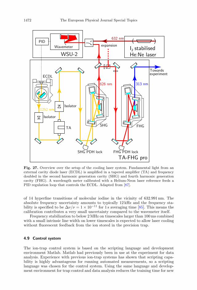
1472 The European Physical Journal Special Topics
Fig. 27. Overview over the setup of the cooling laser system. Fundamental light from anexternal cavity diode laser (ECDL) is amplified in a tapered amplifier (TA) and frequencydoubled in the second harmonic generation cavity (SHG) and fourth harmonic generationcavity (FHG). A wavelength meter calibrated with a Helium-Neon laser reference feeds aPID regulation loop that controls the ECDL. Adapted from [87].
of 14 hyperfine transitions of molecular iodine in the vicinity of 632.991 nm. Theabsolute frequency uncertainty amounts to typically 12 kHz and the frequency sta-bility is specified to be ∆ν/ν = 1× 10⁻¹¹ for 1 s averaging time [85]. This means thecalibration contributes a very small uncertainty compared to the wavemeter itself.
Frequency stabilization to below 2 MHz on timescales larger than 100 ms combinedwith a small intrinsic line width on lower timescales is expected to allow laser coolingwithout fluorescent feedback from the ion stored in the precision trap.
4.9 Control system
The ion-trap control system is based on the scripting language and developmentenvironment Matlab. Matlab had previously been in use at the experiment for dataanalysis. Experience with previous ion-trap systems has shown that scripting capa-bility is highly advantageous for running automated measurements, so a scriptinglanguage was chosen for the control system. Using the same language and develop-ment environment for trap control and data analysis reduces the training time for new
The Alphatrap Experiment 1473
students and enables tight interaction between data analysis and data taking. Matlabscripts do not need to be compiled and can be modified at run-time, which enablesfast iteration, and the text-based nature of the files is advantageous for working withversion-control software.
In order for the code to be self-documenting, the experiment hardware is describedin a single “trap define.m” script, which assigns names to all function generators,voltages sources, electrodes, detectors, and electrodes, and defines the relationshipsbetween them. Each physical device is represented as an object derived from the“handle class” to ensure the state of the software object always corresponds to thestate of the hardware.3 All this information is collected into a single object called“trap”, which is passed to all helper functions. Measurements are performed by writ-ing scripts that calls the appropriate helper functions. These measurement scripts andthe “trap define.m” script are committed into a version-control system, which helpsto document the evolution of the experiment alongside the current measurements.
Instrument communication is based on the VISA-library for most commercialdevices (requires the “Instrument Control Toolbox”), and on serial communicationand TCP sockets for custom-built equipment. This way, the control system structureis kept generic to allow porting the system to a different scripting language, such asPython, if the need arises.
5 Commissioning of the trap system
5.1 Cleaning and preparation of a single ion
After ion production, several species in different abundances are potentially presentin the trap. In Figure 28 a typical mass scan can be seen. This particular ion cloud hasbeen taken after operating the mini Electron Beam Ion Source (see Sect. 4.4.3) for in-trap ion production. After 15 seconds of breeding time the electron gun is turned off.The following ring voltage scan allows ion identification via the different frequenciesof the axial oscillation for the different charge-to-mass ratios present in the trap. Hotions generate a large signal when the axial frequency passes by the resonator, whichis plotted versus the ring voltage in Figure 28.
Having an ion bunch in the precision trap which was either internally producedusing the in-trap EBIS (see Sect. 4.4.3) or externally produced, injected and captured(see Sect. 4.5.1), different techniques exist for reducing the ion cloud population downto a single ion. Axial cleaning was implemented where strong rf-excitation sweeps areapplied on all frequencies except the axial frequency of the ion of interest. Thatway, unwanted species are excited to large amplitudes before the applied confiningpotential is shortly relaxed, so that the energetic ions are no longer axially confined.This technique is effective towards impurities with q/m different to the ion of interest,in this case 12C5+, as shown in Figure 29.
Another possibility to reduce the ion population down to the one of interest, is byaddressing the magnetron mode. With this technique, a wideband excitation in theform of noise close to the magnetron frequency is applied. Only the magnetron motionof the ion of interest is simultaneously cooled using the axial-magnetron sideband,in order to cancel the effect of the applied noise. This way all unwanted species areeventually lost radially to the walls of the trap, leaving the ion(s) of interest confinedinside the trap.
Since the width of the noise dip scales linearly with the number of ions resonantwith the detection system (see exemplary measurement in Fig. 30), we can extract
3In Matlab, all objects are passed-by value, except for objects derived from a fundamental pointer-like object, the “handle” class.

1474 The European Physical Journal Special Topics
Fig. 28. Example mass spectrum after in situ ion production in the precision trap using thein-trap EBIS. Predominantly, ions of carbon, the target material, and oxygen in differentcharge states as contaminant can be identified.
Fig. 29. A single 12C5+ ion on resonance with the detection system (yellow line). The fitof this signal is also shown with the dashed red line. Five ions of the same species on theresonator (blue line) and the signal’s fit (green dashed line).
the number of ions inside the trap from a fit to the dip. When the remainder trappedion cloud consists only of ions of the same charge-to-mass ratio, then by applyinga cyclotron burst excitation on the modified cyclotron frequency of the ion species,all existing ions are excited to slightly different amplitudes. Consequently, each ionappears as an individual peak on the cyclotron resonator (see Sect. 4.6). In thisconfiguration it is possible to address individual ions by individual chirped cyclotronexcitations. Finally, the hot ions can be removed from the trap either by exciting thenow individually shifted axial frequencies or by simply lowering the trap potentialand waiting for collisions of the hot ions. A good signature for the success of thecleaning procedure is shown in Figure 29, where the dip width of the signal shown inthe yellow spectrum corresponds to a single ion. Especially in the analysis trap, thestability of the axial frequency is a good indicator for remaining contaminants as any

The Alphatrap Experiment 1475
Fig. 30. The number of trapped 12C5+ ions in the precision trap versus the width of thedetected dip. The width of the dip generated by the common motion of the ions is alwaysan integer multiple of the width of a single ion, about 2.2 Hz in the case of 12C5+.
interactions between different ions would inevitably lead to frequency fluctuations inthe strong magnetic bottle.
5.2 Electric field optimisation
After the preparation of a single ion, the trap’s electrostatic potential has to beoptimised. Due to the finite machining precision and unavoidable variations of thepotential on the electrode surfaces, the potential will differ slightly from the calculatedone. This optimisation is essential for all following measurements.
As mentioned in Section 3.1 the Cn coefficients (Eq. (8)) that characterise theleading order unharmonicities of the electric field (C4, C6, C8 and C10 in the caseof Alphatrap ) can be minimised by applying suitable correction voltages. To dothat, the ion’s axial frequency was monitored while the radius of the ion’s magnetronmotion was altered. In the presence of electric field imperfections, the axial frequencyshift by the dominant C4 contribution is given by [88]:
∆νzνz
=C4
C2
3
4d2(z2 − 2ρ2
+ − 2ρ2−) (38)
in first order. Since the precision trap is a 7-electrode trap, which requires a set of twoindependent correction voltages, it needs to be dynamically compensated. In otherwords, the trap is not orthogonal4 with respect to the individual correction voltages.When adjusting the voltages that are applied to the first set of correction electrodesalso the voltage applied to the second set has to be changed in order to keep the axialfrequency invariant. Specifically, the trap was designed such that it is orthogonalwhen changing both tuning ratios TR1,2 by the same factor. Therefore, during theoptimisation configuration for each magnetron radius the correction voltage of bothcorrection electrodes is multiplied by a factor called here “TRcomb”. In first order,the axial frequency shifts quadratically with the magnetron excitation strength:
∆νz ≈ −C4
C2
3
2d2νz · κ2 · U2
exc +C6
C2
45
16d4νz · κ4 · U4
exc (39)
where κ is the magnetron radius calibration factor. Assuming the ion is originallycooled to negligible amplitudes, κ relates the magnetron radius to the excitation
4In an orthogonal trap, the ion’s axial frequency is independent of the correction voltages.

1476 The European Physical Journal Special Topics
Fig. 31. (Left) Axial frequency shift for different tuning ratios at different radii of themagnetron mode, ρ−. The plotted axial frequency shift is the difference between the axialfrequency when the magnetron mode is pulsed and thermalised (νhotz − νcoldz ). (Right) Poly-nomial fit parameters P1(∝ C4) as a function of the combined tuning-ratio factor TRcomb.From the linear fit the optimum value TRopt
comb is obtained for P1 = 0.
burst as:
ρ− = κ · Uexc. (40)
With optimal settings, the axial frequency is essentially independent on the oscillationamplitude, demonstrating excellent harmonicity.
From the electrostatic simulation, optimal values of TR1 = 0.9636 and TR2 =0.8156 have been determined. By changing the ions magnetron radius for differentTRcomb settings we can map the harmonicity of the trap as can be seen in Figure 31.There, during the tuning-ratio optimization, the strength of the applied excitationwas varied via the pulse length whilst the excitation pulse amplitude was fixed to0.1 Vpp. The obtained data from all individual excitation pulse strength scans for
each tuning ratio is fitted using equation (39). We define P1 ≡ −C4
C2
32d2 νz · κ
2 and
P2 ≡ C6
C2
4516d4 νz · κ
4. Considering the linear dependence of the C4 coefficient with
respect to the applied tuning ratio (Fig. 31 (right)), the optimum combined tuningratio can be obtained. Note that this is in fact the factor that the calculated tuningratios TR1 and TR2 need to be multiplied by for a highly harmonic electric field inthe centre of the precision trap.
In order to minimise the C4 coefficient we chose the tuning ratio factor TRcomb
that corresponds to the zero crossing in Figure 31 (right), which is TRoptcomb =
1.0004872(50). This value deviates from the expected calculated value less than onepart per thousand which shows a good performance of our experimental setup withrespect to the theoretical predictions. From the slope α of the fit in Figure 31 (right)and from equation (39) we obtain the calibration constant κ:
κ =
√−2
3
aC2d2
Dcomb4 2πνz
= 140(1)µm/(V ·ms), (41)
where C2 = −0.590325, Dcomb4 is calculated to be Dcomb
4 = −0.590325, d =9.156 470 mm is the characteristic trap size and α is given by the slope in

The Alphatrap Experiment 1477
Fig. 32. Sideband coupling at νrf = ν+ − νz. In red, the typical axial dip with νz of the ionwhen no coupling is applied is shown. In blue the double dip is plotted, with the frequenciesof the left (νl) and right (νr) dips indicated in the figure. The width of each dip of the doubledip is half the width of the single axial dip.
Figure 31 (right) as α =−1917(14) Hz/(msVpp)2. The applied excitation pulses of
the magnetron mode were dipole rf drives on the Dx electrode. It can be observedfrom Figure 31 (left), that even for large radii up to 1 mm (compared to the thermalradius of about 1µm), the axial frequency shifts by significantly less than 1 Hz.
5.3 Double-dip measurement
The determination of the g-factor requires determining the free cyclotron frequencyof the ion (see Sects. 1 and 3), for which three eigenfrequencies need to be mea-sured. The axial mode is measured directly with a detection system that is inresonance with the ion’s axial frequency. To measure the other two radial modes, theso called “double-dip technique” is utilised. It is essentially a quadrupole Qxz cou-pling, as explained in detail in Section 3.4, on the red sideband νrf = ν+ − νz. Whenthis rf field is coupled to the ion’s motion not only the radial modified cyclotronmode ν+ is resistively cooled via the axial detection system, but also ν+ can bemeasured.
Considering the relatively long time constants (∼ min) of the direct cooling viathe cyclotron resonator, the sideband cooling technique via the axial resonator allowsfor typically much faster cooling, in the order of 100 ms for HCI.
While the modes are coupled, the energy transfer between the modes occurs withthe Rabi frequency Ω0 which depends on the rf amplitude and the detuning. After afew cooling time constants, when both modes are thermalised with the axial resonator,the modified cyclotron frequency can be deduced. In Figure 32 the axial dip andthe corresponding double-dip splitting after sideband coupling with νrf = ν+ − νz isshown.
The frequencies of the left and right dips are given by νl = νz − ∆0 andνr = νz + ∆0, respectively. Assuming a non-perfectly resonant coupling rf drive, the

1478 The European Physical Journal Special Topics
Fig. 33. Avoided crossing of the left and right dips due to coupling of the axial and modifiedcyclotron modes using the the sideband ν+ − νz. The axial frequency νz is independentlymeasured after each sideband coupling measurement. The fit (red line) is according toequation (42) in [40].
double-dip splitting is no longer symmetric around the axial single dip. Rather, thetwo dips show an avoided crossing behavior, which can be seen in Figure 33. There,the left, right and non-coupled axial dip are shown. The frequency of each dip isrecorded for different coupling frequencies νrf within a frequency range of ±20 Hz.
The avoided crossing data in Figure 33 are fit using the equation given in [40] aftera rigorous calculation. For a small detuning δ around the coupling frequency suchthat νrf = ν+−νz + δ, the ion oscillates at the axial mode with frequency components
ν = νz −δ
2±√δ2 + ∆2
0. (42)
The modified cyclotron frequency can thus be deduced from the relation:
ν+ = νr + νl − νz + νrf, (43)
which is exact within the rotating wave approximation. Here, the axial frequency νzis measured independently when the rf drive is off.
After thermalisation of all modes, the effective temperature of the axial detectioncircuit can be determined via equation (19). These measurements are discussed inSection 5.6.
5.4 Determination of B2 in the analysis trap
The strength of the magnetic bottle is determined by measuring the B2 coeffi-cient within the trap. According to equation (44), an axial frequency change can

The Alphatrap Experiment 1479
Fig. 34. Strength of the magnetic bottle present in the analysis trap caused by the ferro-magnetic ring. The axial frequency shift in the analysis trap is plotted for different modifiedcyclotron radii of the ion. For details see text.
be observed when the ion’s modified cyclotron radius ρ+ is altered:
δνzνz
=B2
4B0
ν+ + ν−ν−
ρ2+. (44)
After having verified that there is no increase of the ion’s cyclotron energy dur-ing ion transport between precision and analysis trap, the strength of the magneticbottle in the analysis trap was measured as follows: Initially the cold ion is in theanalysis trap where the axial frequency νz is measured before the ion is adiabaticallytransported to the precision trap. There, the modified cyclotron radius ρ+ of the ionis pulsed to a well-defined value and the ion is transported back to the analysis trap.The magnetic bottle shifts the axial frequency of the ion accordingly and the axialfrequency dip of the ion is measured anew. Then the ion is transported once againto the precision trap where the ion’s modified cyclotron mode is sideband coupledto the axial mode, therefore the modified cyclotron energy of the previously appliedexcitation is dumped on the axial resonator and the ion is cooled back via resistivecooling. The modified cyclotron mode radius calibration was obtained independentlyprior to this measurement and was used here in order to translate the excitation pulsestrength into modified cyclotron radius ρ+.
The shift of the axial frequency with respect to ρ+ can be seen in Figure 34. Thismeasurement allows mapping the strength of the magnetic bottle in the analysis trap.The value that was deduced during this measurement was B2 = 44.35(84) kT/m2.
5.5 Ion transport
In order to measure the g-factor, the ion has to be transported several times fromthe precision trap to the analysis trap and back. To prevent changes in the spinstate or energy of the ion, it is transported adiabatically between a set of electrodesthat are located between the two traps. During this process the potential on these

1480 The European Physical Journal Special Topics
electrodes is consecutively altered so that the potential trap is “moved” from oneelectrode to the other. This change has to happen slow enough so that the ion’sentropy remains unchanged. This is a restriction mainly for the slow magnetron mode.In order to guarantee a sufficiently high magnetron frequency at any moment of thetransport, it is important to have short electrodes, which enables a sufficiently strongquadrupole potential to all positions along the transport path, despite unavoidablepatch potentials on the electrodes’ surfaces.
In the case of transport between the capture electrodes and the precision trap,the procedure is in principle the same but in that case a cloud of ions is transportedbefore the cloud is reduced down to a single ion (see Sect. 5.1) and resistively cooled.The depth of the trap during transport needs to be sufficient to accommodate theenergy distribution of the captured ion bunch within the capture section.
To verify the necessary adiabatic transport of the single ion between the twotraps, the ion was transported from the analysis trap where the axial frequency ismeasured, to the precision trap and immediately back to the analysis trap for a newmeasurement of the ion’s νz. When the ion arrives in the precision trap, no actionis taken that would alter the ion’s radial energy, such as sideband coupling. Thefluctuation of the axial frequency in the analysis trap, typically δνz ≈ 0.3 Hz, yieldsan upper limit for the heating of the modified cyclotron mode by the transport of1.2 K for a 12C5+ ion.
5.6 Ion temperature measurement
Resistive and sideband cooling techniques allow to reduce particle amplitude depen-dent frequency shifts by thermalising the respective ion mode temperatures with theaxial detector circuit. However, the detector circuit can be assigned an effective noisetemperature Teff which, owing to the additional electronic noise contribution of theamplifier, can be much higher than the lattice temperature of the experiment. In thisregard ion temperature measurements are an effective way to verify the detector noiseperformance. As long as the ion and detector frequency are in (or close to) resonancethe ion energy will not be constant but fluctuate on timescales of the cooling timeconstant. According to the ergodic theorem, consecutive measurements of the axialion energy will reproduce a Boltzmann distribution from which the effective detec-
tor/ion temperature Teff = Tz = 〈Ez〉kB
can be extracted. The thermal distribution canbe accessed by performing sideband coupling of the axial and the modified cyclotronmode. During sideband coupling the modified cyclotron energy reflects the thermaldistribution with the scaled temperature T+ = ν+
νzTz
ρ(E+, T+) =1
kBT+e− E+kBT+ =
νzkBν+Tz
e− E+νzkBν+Tz . (45)
This can be easily observed in the strong magnetic bottle of the analysis trap wherethe modified cyclotron energy is translated into a measurable shift of the axialfrequency
∆νz =1
(2π)2mνz
B2
B0E+. (46)
This way, the thermal distribution can be recorded by measuring the correspond-ing shifts of the axial frequency after repeated sideband coupling between the axialand the modified cyclotron mode. The result of such a measurement for the axialprecision-trap detector is shown in Figure 35. It corresponds to an axial ion/detector

The Alphatrap Experiment 1481
Fig. 35. Histogram plot of the temperature measurement of the axial precision-trap detec-tor. In one measurement cycle the axial and modified cyclotron modes are coupled in theprecision trap and transported to the strong magnetic bottle in the analysis trap wherethe corresponding frequency shift is measured (see text). Here this was repeated for 1000measurement cycles. The axial frequency shift data reflects the energy distribution of themodified cyclotron/axial mode and allows us to extract the corresponding mode and detectortemperatures.
temperature of TPTz = 12.9(4) K. In contrast to the axial analysis-trap detector, the
determination of the temperature of the precision-trap detector additionally requiresthat the modified cyclotron energy is not influenced by the adiabatic transportbetween the traps which was explicitly verified in Section 5.5.
5.7 Magnetic field stability
The significance of a stable magnetic field during our measurement has been alreadystressed in Section 1. Unlike long-term drifts, the short-term changes in the magneticfield can limit the precision of the measurement. Although the Larmor and cyclotronfrequencies are determined simultaneously, fluctuations during the measurementperiod increase the Larmor resonance linewidth.
Alphatrap ’s superconducting magnet (see Sect. 4.2) has been shimmed andthe resulting magnetic field has been measured with an NMR probe prior to fullassembly of the experiment. Afterwards, while measuring the relative stability ofν+ the observed frequency drift required the implementation of a self shieldingsuperconducting coil (see Sect. 4.2) which is designed to compensate for externallyinduced magnetic field gradients by conservation of the flux in the centre of theprecision trap.

1482 The European Physical Journal Special Topics
Fig. 36. (Left) Typical fluctuations of the axial and cyclotron frequencies when detectedwith the dip and double-dip technique. The data was recorded after refilling the cryogenreservoirs and a thermalisation process is clearly visible over the first hours. (Right) ModifiedAllan deviation of the time sequence on the left. For the green and yellow traces only dataafter the thermalisation (indicated on the left plot) is used.
The resulting field stability after the superconducting self-shielding coil wasinstalled is demonstrated in Figure 36, where several consecutive measurements of ν+
were taken over the course of about 15 hours. During the same time, the behaviour ofthe axial frequency is monitored in order to check for stability of the voltage sourcesimultaneously.
The above measurement has been performed by the so-called “double dip” tech-nique (see Sect. 5.3) where via sideband coupling the modified cyclotron frequencycan be read out via solely axial detection. Another possibility for magnetic field stabil-ity determination, therefore modified cyclotron frequency stability, would be via PnA(see Sect. 3.5). While this technique has not yet been implemented at Alphatrap,the Allan deviation plot suggests a significant improvement possibility, since the fastmeasurement cycle of PnA (∼10 ms) gives access to the regime of high stability below10 min measurement time.
It should be noted that to date, neither the experimental setup nor the voltagesource are temperature or pressure stabilised. This is an ongoing project that isexpected to improve the frequency stability by reducing the influence of environmentalconditions.
6 Measurement perspectives
Alphatrap is a novel and uniquely versatile experiment that enables a whole rangeof intriguing measurements. The versatility of the available ion sources and detectiontechniques enables for the first time virtually unrestricted access to all elements,isotopes and charge states for ultra-high precision measurements. Some of the plannedexperiments at Alphatrap are introduced in the following.
6.1 g-Factor measurements in highly charged ions
The central goal of Alphatrap is to test bound-state QED in the strongest fieldsby comparing the measured g-factor of heavy highly charged ions with its predictionby theory.

The Alphatrap Experiment 1483
The predecessor experiment in Mainz has performed such measurements on lightand medium heavy ions, but the miniature EBIT inside the hermetically sealedtrap chamber in this experiment limited the choice of ions to those with ioniza-tion potentials of less than about 4 keV. With its external ion sources, Alphatrapis optimised for the heaviest highly charged ions. The most prominent candidate isthe doubly-magic hydrogenlike lead 208Pb81+, which is favorable due to its high-lying nuclear excitations and the correspondingly small nuclear contributions on theg-factor. The coupling of the electron to the nucleus is characterised by the couplingconstant Zα. While this coupling is weak (Zα 1) for light and medium heavyions, for heavy ions Zα ≈ 1 which brings QED into the highly interesting and upto now largely untested strong coupling regime. The 1s electron in the hydrogenlikelead 208Pb81+ feels an electric field of 〈E〉 = 1.1 × 10¹⁶ V/cm (see Fig. 2), whichmakes a precise g-factor measurement on this ion the most stringent test of QED instrong fields.
However, considering the precision achievable in Alphatrap, a QED test with208Pb81+ will be momentarily limited by nuclear contributions [26]. Specifically thenuclear size, which significantly modifies the electrons wave function, has a relativecontribution of 2.6 × 10⁻⁴ to the g-factor. Although the charge distribution can betaken from other experiments, the current uncertainty of the charge radius limitsthe precision of the g-factor for the purpose of a QED test to about 4.6× 10⁻⁷. Toimprove the impact of the test further, Shabaev [11] has proposed to consider specificdifferences of g-factors of different charge states. The interaction of the electron withthe nucleus is identical for the 1s electron in hydrogenlike lead 208Pb81+ as for the2s electron in 208Pb79+ up to a well-known scaling factor χ, which can be calculatedto high precision. In the specific difference ∆g = g2s − χg1s the nuclear contributionare largely canceled, while the electron QED contributions are still present. A simi-lar specific difference can also be constructed from hydrogen and boronlike ions. AsAlphatrap can measure all charge states and isotopes, it provides unique opportuni-ties for QED tests. If QED theory can calculate the g-factors of the lithiumlike systemto sufficient precision, the specific difference paves the way to previously unattainablesensitivity to new physics.
6.2 Determination of the electron’s atomic mass
The electron’s atomic mass is one of the most important fundamental constants inthe Standard Model. Its value, or the ratio of electron and proton mass, is requiredfor virtually every atomic physics precision experiment and the most important testsof the fundamental theories. However, using the standard methods for precision massmeasurements, where the cyclotron frequencies of two ions are compared in the samemagnetic field, the electron mass is very difficult to measure due to its low mass.Even for low kinetic energies, the relativistic mass increase is sizeable. In the past, ourgroup has successfully demonstrated an alternative approach. Instead of the cyclotronfrequency of the electron, we measure the Larmor frequency of a bound electron. As itcan be seen in equation (4), this frequency also depends on the electron’s mass. If theg-factor is known from theory, the magnetic field can be determined by measuring theion’s cyclotron frequency. As the ion is significantly heavier than the bare electron,the cyclotron frequency can be measured with good precision. This way, the electron’smass can be determined in units of the ion’s mass. By exploiting the free choice ofthe nucleus, we choose the 12C5+ as the preferred ion for this purpose. This ion notonly has a relative weak binding field, such that we can trust in the validity of QEDin this regime, its mass (more precisely the mass of the carbon atom) is also the basisof the atomic mass unit and thus does not contribute additional uncertainty apartfrom the small mass and binding energies of the removed electrons.

1484 The European Physical Journal Special Topics
Using this technique, we have published a value of the electron’s mass in 2014 [9]with a relative precision of 2.8×10⁻¹¹. This is by more than an order of magnitude themost precise value and currently almost exclusively defines the CODATA literaturevalue [89]. In this measurement, the dominant uncertainty is given by the imagecharge shift, which scales strongly with the trap size. The large Alphatrap precisiontrap, which results in about an order of magnitude lower image charge effect, givesthe opportunity to further improve on the published result, if other limitations suchas magnetic field stability and ion temperature can be overcome.
6.3 Detection of long-lived optical transitions via the spin-state detectorand laser spectroscopy of highly charged ions
Beyond g-factor measurements, the spin-state detection via the continuous Stern–Gerlach effect opens the possibility for ultra-precise laser spectroscopy in HCI. Dueto the strong binding, most electronic transitions in HCI are beyond optical ener-gies. However, depending on the element and charge state, there are specific caseswhich are accessible to laser spectroscopy. Those transitions can be highly interest-ing due to their specific properties, as e.g. low susceptibility to external fields andhigh sensitivity to fundamental constants and interactions. In the medium-Z regime,e.g. for boronlike 40Ar13+, the fine structure becomes optical, and at high-Z eventhe hyperfine transition is laser-accessible. For bismuth, there are even two opticalhyperfine transitions, in the hydrogenlike and the lithiumlike state, which enablesto make use of a specific difference technique similar as in the g-factor case. Sincethese transitions are M1 transitions, there natural lifetime is rather long, 80 ms in thecase of 209Bi80+, which makes a detection of the fluorescence photons rather hard. InAlphatrap, we have the unique opportunity to detect the result of the transition,rather than the transition itself, by driving a transition that pumps the ion into adifferent spin state (see Fig. 37). In the example of 40Ar13+, the ion is prepared by theusual millimeter-wave excitation in the 2p1/2(mj = −1/2) state. Then, by driving the2p1/2(mj = −1/2) → 2p3/2(mj = +1/2) transition, the ion is eventually left in thedark 2p1/2(mj = +1/2) state, which can be observed in the analysis trap by deter-mining the spin state similar as in a g-factor measurement. This scheme is virtuallyinsensitive to the lifetime of the excited state. Even if the lifetime is very long, wecould detect the spin change directly in the excited state. The Zeeman shift can becalculated using the magnetic field determined by measuring the cyclotron frequency.Typical short-time fluctuations of the magnetic field better than δB/B = 10−9 limitthe precision of magnetic field sensitive transitions on the level of δν/ν = 10−14 with-out further measures. Currently, the main limitation for the achievable precision liesin the first order Doppler shift due to the finite axial temperature, which results in alinewidth of about 158 MHz for 40Ar13+ at 4.2 K. In fact, due to the harmonic motionof the trapped ion, the measured spectrum consists of a multitude of individual lines,separated by the axial frequency (650 kHz) and each only about 16 Hz wide (if weneglect further broadening due to the axial thermalization process and magneticinhomogeneity). If the spectroscopy laser can resolve this structure, or if the ion canbe cooled to lower temperature by means of sympathetic laser cooling, a drasticallyhigher precision can be achieved. If we apply this scheme to the hyperfine structuretransitions in 209Bi80+,82+, this would allow for a stringent QED test in strong electricand particularly magnetic fields, which reach about 20 000 T in this system.
6.4 Sympathetic laser cooling of HCI and two-ion crystals
Since laser cooling for free atoms [90] and trapped ions [91] was independently pro-posed as early as 1975, these techniques are nowadays commonly used to cool ions

The Alphatrap Experiment 1485
Fig. 37. The level structure of boronlike 40Ar13+. The fine structure transition, nominallyat about 441 nm, is split by the (non-linear) Zeeman effect. By driving the M1 transitionfrom the spin-down state to the spin-up state in the 2p3/2 manifold (or from spin up todown), it is possible to pump the ground-state into the spin-up state. This transition canthen be detected via the continuous Stern–Gerlach effect, without the need for fluorescencedetection. For details see text.
for various purposes such as quantum simulations, quantum information processingand precision laser-spectroscopy e.g. for modern optical clocks. However, even thoughother Penning trap based g-factor experiments are planning to implement laser cool-ing as well [48], Alphatrap would be, to our knowledge, the first experiment to usethese techniques in a Penning trap in the context of high-precision g-factor measure-ments in HCI. Laser cooled ions would improve the envisaged measurement accuracyby lowering some of the systematic, amplitude-dependent frequency-shifts [88], sincesmaller motional amplitudes of the ion are less prone to imperfections of the trap-ping fields. Furthermore the second order Doppler shift would be reduced, whichpotentially enables ultra-precise laser spectroscopy of HCI. The previously mentioneddetection methods, such as PnA (Sect. 3.5), for measuring the ions motional frequen-cies are at some point limited in the achievable precision by the initial temperatureof the ion. For the spin flip analysis of heavy highly charged ions, the fidelity wouldbenefit from an improved stability of the cyclotron energy, since the axial frequencydifference ∆νz (Eq. (25)) scales with 1√
mion. As shown in Section 4.5.3, the current
axial stability in the analysis trap seems sufficient for resolving spin flips for lighthydrogenlike ions in our setup. This small frequency difference even decreases toabout one third when measuring ions with a boronlike electron configurations (seeTab. 2). In the strong magnetic bottle of the analysis trap, also the axial frequencywill depend on the motional energy in the radial modes [88]. Fluctuations in thisenergy exacerbates an unambiguous determination of a spin flip. In each measure-ment cycle the ion is transported from the precision trap to the analysis trap andarrives there with a certain energy in the modified cyclotron mode E+ chosen from atemperature equivalent thermal Boltzmann distribution. In other experiments [47,92]the dependence of the frequency stability on E+ was shown. Hence a lower cyclotrontemperature and therefore a more narrow Boltzmann distribution of these energieswould significantly facilitate the detection.
Even though both sympathetic laser cooling of ions of two different species [49,93]and Coulomb crystallization of ions in a Penning trap has been shown before, we

1486 The European Physical Journal Special Topics
plan to extend these methods to a two-ion crystal consisting of a 9Be+ and an highlycharged ion. Other experiments showed that Coulomb crystallization with as fewas two (same species) ions in an axial configuration is feasible [94]. In this kind ofconfiguration for the axial velocity components of the two ions two normal modes canbe distinguished: a “breathing mode” in which the two ions oscillate symmetricallyaround the non-moving common center of mass and hereby changing their inter ionseparation distance, or a “common mode” motion in which the center of mass canoscillate. The axial inter ion separation ∆z depends on the axial confinement resp. thepotential well depth and amount in our setup typically to around a few ten micronsfor a 9Be+ and a HCI. Due to this dependency on the potential well depth, ∆z can bepredicted and well controlled. Having these two ions confined in such a small distanceto each other does significantly decrease the differential magnetic field differences seenby the two ions, which enables ultra-precise determinations of g-factor differences asoutlined in Section 6.5.
6.5 Ultra-precise determination of g-factor differences andthe fine-structure constant
The electron g-factor measurements discussed above are performed as Rabi-type spec-troscopy. In principle, the Ramsey technique would be much better suited for ourexperiments, as the coherent Ramsey measurement probes the phase of the Larmorprecession
ϕL,i(T ) =gi2
e
me
∫ T
0
B(t)dt = 〈ωL,i〉T, (47)
which depends solely on the mean magnetic field 〈B〉 = 1T
∫ T0B(t)dt during the mea-
surement, just as the phase ϕ+ of the cyclotron frequency. This value is exactlyaccessible via a PnA measurement, so that in the ratio of the two frequencies mea-sured in this way the magnetic field jitter completely drops out, while in the Rabi-typemeasurement the jitter causes significant line broadening. However, in practice, theapplication of the Ramsey method for an electron spin resonance experiment is pro-hibited by the large ratio of the Larmor and cyclotron frequencies. In order to performa measurement of the cyclotron frequency to about 10−10, even with the phase-sensitive PnA method, we require about 10 s measurement time. Within this time, thetypical magnetic field fluctuations cause a jitter of ϕL(10s) of significantly more than360. In general, to preserve coherence, a phase resolution of the cyclotron motion ofδϕ+ < ν+/νL · 360 = 0.08 would be required, which is currently inaccessible.
However, if we consider two different ions in the same charge state, their respec-tive Larmor phases ϕL,i(T ) vary only slowly with respect to each other, because gidepends only weakly on the specific element or isotope. As an example, even for206,208Pb81+, the isotope shift of the g-factor amounts to only 2.7 × 10⁻⁷ absolute[95]. Consequently, if we could directly measure the small difference of these twophases
∆ϕL(T ) =g2 − g1
2
e
me
∫ T
0
B(t)dt, (48)
this measurement would easily stay coherent. This becomes possible by placing twoions in the same magnetic field, either in two close-by traps, or ideally with thehelp of sympathetic laser cooling in form of an axial Coulomb crystal in one trap(see Sect. 6.4 and Fig. 38). The key idea is to perform independent, but simultaneous

The Alphatrap Experiment 1487
Fig. 38. Sketch of the individual phase evolutions of the two co-trapped ions and their dif-ference for two generic magnetic field fluctuations, indicated as the solid and dashed lines,respectively. While the individual Larmor precession loses coherence during the measure-ment period, the difference stays measurable and allows sensitive access to differential ionproperties.
Ramsey measurements on these ions, and detect the individual spin-states one afteranother in the analysis trap. This way, the probability to find e.g. exactly the first ionin spin-state “up” (assuming w.l.o.g. both ions are prepared in spin “down” originally)is
p(|↑, ↓〉) = p1(|↑〉)p2(|↓〉)= cos ((ωL,1 − ωdrive)T )
2sin((ωL,2 − ωdrive)T )2
=1
4(sin((ωL,1 − ωL,2)T ) + . . . ),
(49)
where terms varying with high frequencies are neglected. While these high frequencyterms are smeared out by the magnetic field fluctuations, the slow terms stay visi-ble. An easily reachable 1 resolution with 200 s measurement time thus results 16digits sensitivity with respect to the g-factor. Consequently, the sensitivity for theg-factor difference, e.g. the isotopic shift, can be as large as 11 digits, depending onthe magnitude of the difference and provided that differential magnetic field fluctua-tions between the two ions can be neglected. This unique resolution enables a wholenew range of intriguing experiments, which search for tiny differential contributions,while cancelling large fractions of the “uninteresting”, known QED. One immediateapplication would be the determination of the fine-structure constant α from the dif-ference of g-factors of light ions. Contrary to the free electron g − 2 experiment, our

1488 The European Physical Journal Special Topics
technique does depend in first order on the relativistic contribution (which cancel in
the difference), rather than QED: g = 23 (1 + 2
√1− Zα2), so that it could potentially
allow for an independent determination of α.
7 Conclusion and outlook
The Alphatrap experiment is a next-generation setup aiming to probe the bound-aries of validity of quantum electrodynamics and the Standard Model of Physics inthe strongest fields. To this end, the design, which is based on the g-factor experimenton highly charged ions at the Johannes Gutenberg-University in Mainz, Germany, hasbeen upgraded with novel techniques to allow ultra-high precision experiments withheavy HCI. In Alphatrap, ions can be injected from a selection of external ionsources, among those the Heidelberg EBIT, which can eventually provide HCI upto hydrogenlike lead 208Pb81+. Furthermore, the new setup allows for sympatheticlaser cooling of the HCI as well as performing laser spectroscopy of highly forbidden,narrow transitions, which are difficult or impossible to address in other experiments.This way, Alphatrap will open up a new field for intriguing, stringent tests of QEDand for the determination of fundamental constants. In the first runs of Alphatrap,which are described in this article, basic techniques such as the injection and captur-ing of clouds of HCI from external sources and the detection of single ions have beendemonstrated. The novel, highly harmonic trap has been commissioned and showsexcellent performance. For the first time, a cryogenically operable vacuum valve hasbeen successfully implemented, which allows achieving outstanding vacuum condi-tions in excess of 10−17 mbar, allowing the virtually unlimited storage even of heavyHCI. Recently, the first determination of the spin-state of a boronlike 40Ar13+ ion wasdemonstrated, which paves the way to the first g-factor measurements in Alphatrap.In the near future, Alphatrap will perform intriguing experiments in a previouslyunexplored regime and shed light on physics in the strongest electromagnetic fields.
Open access funding provided by Max Planck Society. We acknowledge financial supportby the Max-Planck Society. B.T. was supported by a Humboldt Research Fellowship forPostdoctoral Researchers, A.W, I.A. and T.S. were supported by the International Max-Planck Research School on Quantum Dynamics (IMPRS-QD). This work is part of andsupported by the German Research Foundation (DFG) Collaborative Research Centre “SFB1225 (ISOQUANT)”.
Open Access This is an open access article distributed under the terms of the Creative Com-mons Attribution License (http://creativecommons.org/licenses/by/4.0), which permits unrestricteduse, distribution, and reproduction in any medium, provided the original work is properly cited.
References
1. D. Hanneke, S. Fogwell, G. Gabrielse, Phys. Rev. Lett. 100, 120801 (2008)2. L. Windholz, E. Winklhofer, R. Drozdowski, J. Kwela, T. Wasowicz, J. Heldt, Phys.
Scr. 78, 065303 (2008)3. T. Stohlker, P.H. Mokler, K. Beckert, F. Bosch, H. Eickhoff, B. Franzke, M. Jung,
Y. Kandler, O. Klepper, C. Kozhuharov et al., Phys. Rev. Lett. 71, 2184 (1993)4. M. Kozlov, M. Safronova, J. Lopez-Urrutia, P. Schmidt, arXiv:1803.06532 (2018)5. A. Gumberidze, T. Stohlker, D. Banas, K. Beckert, P. Beller, H. Beyer, F. Bosch,
S. Hagmann, C. Kozhuharov, D. Liesen et al., Phys. Rev. Lett. 94, 223001 (2005)

The Alphatrap Experiment 1489
6. S. Sturm, A. Wagner, B. Schabinger, J. Zatorski, Z. Harman, W. Quint, G. Werth, C.H.Keitel, K. Blaum, Phys. Rev. Lett. 107, 023002 (2011)
7. S. Sturm, A. Wagner, M. Kretzschmar, W. Quint, G. Werth, K. Blaum, Phys. Rev. A87, 030501 (2013)
8. F. Kohler, K. Blaum, M. Block, S. Chenmarev, S. Eliseev, D.A. Glazov, M. Goncharov,J. Hou, A. Kracke, D.A. Nesterenko et al., Nat. Commun. 7, 10246 (2016)
9. S. Sturm, F. Kohler, J. Zatorski, A. Wagner, Z. Harman, G. Werth, W. Quint, C.H.Keitel, K. Blaum, Nature 506, 467 (2014)
10. J.C. Lopez-Urrutia, J. Braun, G. Brenner, H. Bruhns, C. Dimopoulou, I. Draganic,D. Fischer, A.G. Martınez, A. Lapierre, V. Mironov et al., J. Phys.: Conf. Ser. 2, 42(2004)
11. V. Shabaev, D. Glazov, N. Oreshkina, A. Volotka, G. Plunien, H.J. Kluge, W. Quint,Phys. Rev. Lett. 96, 253002 (2006)
12. J. Vollbrecht, Z. Andelkovic, A. Dax, W. Geithner, C. Geppert, C. Gorges, M. Hammen,V. Hannen, S. Kaufmann, K. Konig et al., J. Phys.: Conf. Ser. 583, 012002 (2015)
13. J. Ullmann, Z. Andelkovic, C. Brandau, A. Dax, W. Geithner, C. Geppert, C. Gorges,M. Hammen, V. Hannen, S. Kaufmann et al., Nat. Commun. 8, 15484 (2017)
14. L.V. Skripnikov, S. Schmidt, J. Ullmann, C. Geppert, F. Kraus, B. Kresse,W. Nortershauser, A.F. Privalov, B. Scheibe, V.M. Shabaev et al., Phys. Rev. Lett.120, 093001 (2018)
15. W. Gerlach, O. Stern, Z. Phys. 9, 349 (1922)16. G.E. Uhlenbeck, S. Goudsmit, Naturwissenschaften 13, 953 (1925)17. P.A.M. Dirac, Proc. R. Soc. Lond. A 117, 610 (1928)18. P. Kusch, H. Foley, Phys. Rev. 72, 1256 (1947)19. J. Schwinger, Phys. Rev. 73, 416 (1948)20. T. Aoyama, M. Hayakawa, T. Kinoshita, M. Nio, Phys. Rev. Lett. 109, 111807 (2012)21. S. Laporta, Phys. Lett. B 772, 232 (2017)22. R.H. Parker, C. Yu, W. Zhong, B. Estey, H. Muller, Science 360, 191 (2018)23. G. Breit, Nature 122, 649 (1928)24. Z. Harman, private communication, 201625. W. Furry, Phys. Rev. 81, 115 (1951)26. S.G. Karshenboim, V.G. Ivanov, Phys. Rev. A 97, 022506 (2018)27. A.V. Volotka, G. Plunien, Phys. Rev. Lett. 113, 023002 (2014)28. V. Shabaev, V. Yerokhin, Phys. Rev. Lett. 88, 091801 (2002)29. A. Volotka, D. Glazov, V. Shabaev, I. Tupitsyn, G. Plunien, Phys. Rev. Lett. 112,
253004 (2014)30. A. Varentsova, V. Agababaev, D. Glazov, A. Volchkova, A. Volotka, V. Shabaev,
G. Plunien, Phys. Rev. A 97, 043402 (2018)31. H. Dehmelt, Proc. Natl. Acad. Sci. USA 83, 2291 (1986)32. K. Pachucki, A. Czarnecki, U.D. Jentschura, V.A. Yerokhin, Phys. Rev. A 72, 022108
(2005)33. A. Czarnecki, R. Szafron, Phys. Rev. A 94, 060501 (2016)34. F.T. Kohler, Ph.D. thesis, Ruprecht-Karls-Universitat Heidelberg, 201535. G. Gabrielse, F.C. MacKintosh, Int. J. Mass Spectr. Ion Process. 57, 1 (1984)36. L.S. Brown, G. Gabrielse, Rev. Modern Phys. 58, 233 (1986)37. G. Gabrielse, Phys. Rev. Lett. 102, 172501 (2009)38. X. Feng, M. Charlton, M. Holzscheiter, R. Lewis, Y. Yamazaki, J. Appl. Phys. 79, 8
(1996)39. G.J. Ketter, Ph.D. thesis, Ruprecht-Karls-Universitat Heidelberg, 201540. E.A. Cornell, R.M. Weisskoff, K.R. Boyce, D.E. Pritchard, Phys. Rev. A 41, 312 (1990)41. F. Heiße, F. Kohler-Langes, S. Rau, J. Hou, S. Junck, A. Kracke, A. Mooser, W. Quint,
S. Ulmer, G. Werth et al., Phys. Rev. Lett. 119, 033001 (2017)42. S. Sturm, A. Wagner, B. Schabinger, K. Blaum, Phys. Rev. Lett. 107, 143003 (2011)43. VACUUMSCHMELZE, VACOFLUX50, VACUUMSCHMELZE GmbH, Gruner Weg
37, D-63450 Hanau, Germany, 2017, https://www.vacuumschmelze.com/en/products/materials-parts/soft-magnetic/cobalt-iron/vacoflux/vacoflux-magnetic-properties.html

1490 The European Physical Journal Special Topics
44. W. Quint, D. Moskovkhin, V. Shabaev, M. Vogel, Phys. Rev. A 78, 032517 (2008)45. H. Nagahama, C. Smorra, S. Sellner, J. Harrington, T. Higuchi, M. Borchert, T. Tanaka,
M. Besirli, A. Mooser, G. Schneider et al., Nat. Commun. 8, 14084 (2017)46. H. Haffner, T. Beier, S. Djekic, N. Hermanspahn, H.J. Kluge, W. Quint, S. Stahl,
J. Verdu, T. Valenzuela, G. Werth, Eur. Phys. J. D 22, 163 (2003)47. A. Mooser, Ph.D. thesis, Johannes Gutenberg-Universitat in Mainz, 201348. M. Bohman, A. Mooser, G. Schneider, N. Schon, M. Wiesinger, J. Harrington,
T. Higuchi, H. Nagahama, C. Smorra, S. Sellner et al., J. Modern Opt. 65, 568(2018)
49. D.J. Larson, J.C. Bergquist, J.J. Bollinger, W.M. Itano, D.J. Wineland, Phys. Rev.Lett. 57, 70 (1986)
50. T. Andersen, K.A. Jessen, G. Sørensen, Phys. Rev. 188, 76 (1969)51. S. Sturm, Ph.D. thesis, Johannes Gutenberg-Universitat in Mainz, 201152. W.M. Itano, D.J. Wineland, Phys. Rev. A 25, 35 (1982)53. D.J. Wineland, W.M. Itano, J.C. Bergquist, R.G. Hulet, Phys. Rev. A 36, 2220 (1987)54. S. Mavadia, G. Stutter, J. Goodwin, D. Crick, R. Thompson, D. Segal, Phys. Rev. A
89, 032502 (2014)55. F. Diedrich, J. Bergquist, W.M. Itano, D. Wineland, Phys. Rev. Lett. 62, 403 (1989)56. J.J. Bollinger, J.S. Wells, D.J. Wineland, W.M. Itano, Phys. Rev. A 31, 2711 (1985)57. S. Kraemer, Master’s thesis, Ruprecht-Karls-Universitat Heidelberg, 201758. T. Beier, L. Dahl, H.J. Kluge, C. Kozhuharov, W. Quint, H. collaboration et al., Nucl.
Instr. Methods Phys. Res. Sect. B 235, 473 (2005)59. P. Micke, S. Kuhn, L. Buchauer, J. Harries, T.M. Bucking, K. Blaum, A. Cieluch, A. Egl,
D. Hollain, S. Kraemer et al., Rev. Sci. Instr. 89, 063109 (2018)60. J. Repp, C. Bohm, J.C. Lopez-Urrutia, A. Dorr, S. Eliseev, S. George, M. Goncharov,
Y.N. Novikov, C. Roux, S. Sturm et al., Appl. Phys. B 107, 983 (2012)61. C. Roux, C. Bohm, A. Dorr, S. Eliseev, S. George, M. Goncharov, Y.N. Novikov, J. Repp,
S. Sturm, S. Ulmer et al., Appl. Phys. B 107, 997 (2012)62. C. Carlberg, H. Borgenstrand, G. Rouleau, R. Schuch, F. Soderberg, I. Bergstrom,
R. Jertz, T. Schwarz, J. Stein, G. Bollen et al., Phys. Scr. 1995, 196 (1995)63. G. Gabrielse, J. Tan, J. Appl. Phys. 63, 5143 (1988)64. A. Rischka, Bachelor’s thesis, Ruprecht-Karls-Universitat, Heidelberg, 201165. A. Mooser, S. Ulmer, K. Blaum, K. Franke, H. Kracke, C. Leiteritz, W. Quint, C.C.
Rodegheri, C. Smorra, J. Walz, Nature 509, 596 (2014)66. S. Ulmer, C. Smorra, A. Mooser, K. Franke, H. Nagahama, G. Schneider, T. Higuchi,
S. Van Gorp, K. Blaum, Y. Matsuda et al., Nature 524, 196 (2015)67. C. Smorra, S. Sellner, M. Borchert, J. Harrington, T. Higuchi, H. Nagahama, T. Tanaka,
A. Mooser, G. Schneider, M. Bohman et al., Nature 550, 371 (2017)68. J. Alonso, K. Blaum, S. Djekic, H.J. Kluge, W. Quint, B. Schabinger, S. Stahl, J. Verdu,
M. Vogel, G. Werth, Rev. Sci. Instr. 77, 03A901 (2006)69. T. Sailer, Master’s thesis, Ruprecht-Karls-Universitat Heidelberg, 201770. W.C. Wiley, I.H. McLaren, Rev. Sci. Instr. 26, 1150 (1955)71. Ensinger, TECAPEEK ELS nanoblack, Ensinger GmbH, Rudolf-Diesel Str. 8, 71154
Nufringen, Germany, version ac edn. (2017), https://www.ensingerplastics.com/en/shapes/products/peek-tecapeek-els-nano-black
72. M. Schuh et al., in preparation (2018)73. F. Heiße et al., in preparation (2018)74. A. Sikdar, A. Ray, P. Das, A. Reza, Nucl. Instr. Methods Phys. Res. Sect. A 712, 174
(2013)75. K. Farrar, Nucl. Instr. Methods Phys. Res. Sect. A 485, 780 (2002)76. UM - Series, Multichannel Precision Voltage Source, Stahl-Electronics, Kellerweg
23, 67582 Mettenheim, Germany, manual um ln sw v2016 edn., 2016, http://www.stahl-electronics.com/bilder/Manual UM LN SW V2016.pdf
77. A. Weigel, Master’s thesis, Ruprecht-Karls-Universitat Heidelberg, 201478. D. Pavicic, K. Maglic, Int. J. Thermophys. 23, 1319 (2002)79. S. Ulmer, Ph.D. thesis, Ruprecht-Karls-Universitat Heidelberg, 2011

The Alphatrap Experiment 1491
80. C. Bohm, S. Sturm, A. Rischka, A. Dorr, S. Eliseev, M. Goncharov, M. Hocker, J. Ketter,F. Kohler, D. Marschall et al., Nucl. Instr. Methods Phys. Res. Sect. A 828, 125 (2016)
81. T. Sailer, Bachelor’s thesis, Ruprecht-Karls-Universitat Heidelberg, 201582. T. Steinsberger, Master’s thesis, Ruprecht-Karls-Universitat Heidelberg, 201883. Toptica Photonics AG, Scientific lasers, Brochure br-199-54a, 201584. HighFinesse, Wavelength Meter Angstrom WS Ultimate 2, HighFinesse GmbH, Laser
and Electronic Systems, Auf der Morgenstelle 14D, 72076 Tubingen, Germany (n.d.)85. Lasertex, Iodine stabilised HeNe laser, Model: LJSC-3-11, Lasertex Co. Ltd., 51-501
Wroc law, ul. Swojczycka 26, Poland (n.d.)86. L. Ricci, M. Weidemuller, T. Esslinger, A. Hemmerich, C. Zimmermann, V. Vuletic,
W. Konig, T.W. Hansch, Opt. Commun. 117, 541 (1995)87. T. Photonics, DL-/TA-SHG/FHG pro, Toptica Photonics AG, Lochhamer Schlag 19,
82166 Graefling/Munchen, m-078 version 01 edn., 201688. J. Ketter, T. Eronen, M. Hocker, S. Streubel, K. Blaum, Int. J. Mass Spectr. 358, 1
(2014)89. P.J. Mohr, Rev. Mod. Phys. 88, 035009 (2016)90. T. Hansch, A. Schawlow, Opt. Commun. 13, 68 (1975)91. D. Wineland, H. Dehmelt, Bull. Am. Phys. Soc. 20, 637 (1975)92. A. Mooser, H. Kracke, K. Blaum, S.A. Brauninger, K. Franke, C. Leiteritz, W. Quint,
C.C. Rodegheri, S. Ulmer, J. Walz, Phys. Rev. Lett. 110, 140405 (2013)93. L. Gruber, J.P. Holder, J. Steiger, B.R. Beck, H.E. DeWitt, J. Glassman, J.W.
McDonald, D.A. Church, D. Schneider, Phys. Rev. Lett. 86, 636 (2001)94. D.R. Crick, H. Ohadi, I. Bhatti, R.C. Thompson, D.M. Segal, Opt. Express 16, 2351
(2008)95. V. Shabaev, D. Glazov, M. Shabaeva, V. Yerokhin, G. Plunien, G. Soff, Phys. Rev. A
65, 062104 (2002)