Designing the Dependable Multiprocessor Space Experiment
9
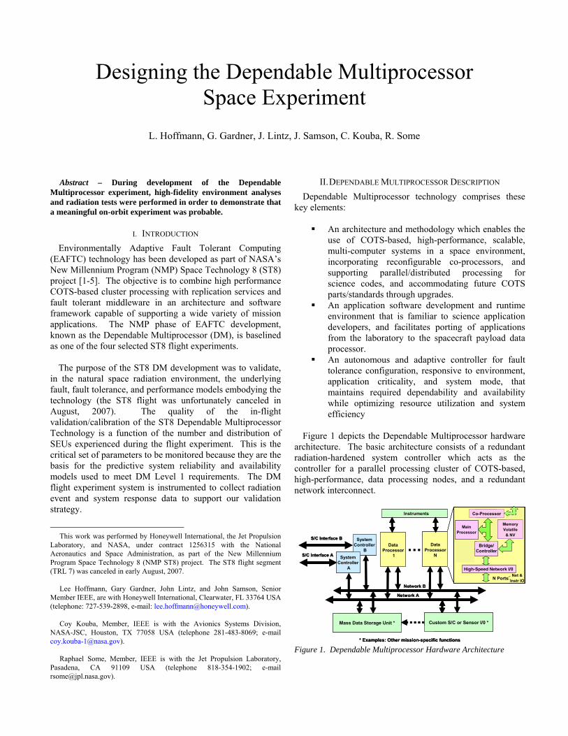
Designing the Dependable Multiprocessor Space Experiment L. Hoffmann, G. Gardner, J. Lintz, J. Samson, C. Kouba, R. Some Abstract – During development of the Dependable Multiprocessor experiment, high-fidelity environment analyses and radiation tests were performed in order to demonstrate that a meaningful on-orbit experiment was probable. I. INTRODUCTION Environmentally Adaptive Fault Tolerant Computing (EAFTC) technology has been developed as part of NASA’s New Millennium Program (NMP) Space Technology 8 (ST8) project [1-5]. The objective is to combine high performance COTS-based cluster processing with replication services and fault tolerant middleware in an architecture and software framework capable of supporting a wide variety of mission applications. The NMP phase of EAFTC development, known as the Dependable Multiprocessor (DM), is baselined as one of the four selected ST8 flight experiments. The purpose of the ST8 DM development was to validate, in the natural space radiation environment, the underlying fault, fault tolerance, and performance models embodying the technology (the ST8 flight was unfortunately canceled in August, 2007). The quality of the in-flight validation/calibration of the ST8 Dependable Multiprocessor Technology is a function of the number and distribution of SEUs experienced during the flight experiment. This is the critical set of parameters to be monitored because they are the basis for the predictive system reliability and availability models used to meet DM Level 1 requirements. The DM flight experiment system is instrumented to collect radiation event and system response data to support our validation strategy. This work was performed by Honeywell International, the Jet Propulsion Laboratory, and NASA, under contract 1256315 with the National Aeronautics and Space Administration, as part of the New Millennium Program Space Technology 8 (NMP ST8) project. The ST8 flight segment (TRL 7) was canceled in early August, 2007. Lee Hoffmann, Gary Gardner, John Lintz, and John Samson, Senior Member IEEE, are with Honeywell International, Clearwater, FL 33764 USA (telephone: 727-539-2898, e-mail: [email protected]). Coy Kouba, Member, IEEE is with the Avionics Systems Division, NASA-JSC, Houston, TX 77058 USA (telephone 281-483-8069; e-mail [email protected]). Raphael Some, Member, IEEE is with the Jet Propulsion Laboratory, Pasadena, CA 91109 USA (telephone 818-354-1902; e-mail [email protected]). II. DEPENDABLE MULTIPROCESSOR DESCRIPTION Dependable Multiprocessor technology comprises these key elements: An architecture and methodology which enables the use of COTS-based, high-performance, scalable, multi-computer systems in a space environment, incorporating reconfigurable co-processors, and supporting parallel/distributed processing for science codes, and accommodating future COTS parts/standards through upgrades. An application software development and runtime environment that is familiar to science application developers, and facilitates porting of applications from the laboratory to the spacecraft payload data processor. An autonomous and adaptive controller for fault tolerance configuration, responsive to environment, application criticality, and system mode, that maintains required dependability and availability while optimizing resource utilization and system efficiency Figure 1 depicts the Dependable Multiprocessor hardware architecture. The basic architecture consists of a redundant radiation-hardened system controller which acts as the controller for a parallel processing cluster of COTS-based, high-performance, data processing nodes, and a redundant network interconnect. S/C Interface B S/C Interface A Network B Network A … * Mass Data Storage Unit, Custom Spacecraft I/O, etc. * Examples: Other mission-specific functions System Controller A System Controller B S/C Interface B S/C Interface A Network B Network A Data Processor 1 Data Processor N … Instruments High-Speed Network I/0 Bridge/ Controller N Ports * Mass Data Storage Unit, Custom Spacecraft I/O, etc. Co-Processor Memory Volatile & NV Net & Instr IO Main Processor Mass Data Storage Unit * Custom S/C or Sensor I/0 * * Examples: Other mission-specific functions Figure 1. Dependable Multiprocessor Hardware Architecture
-
Upload
independent -
Category
Documents
-
view
1 -
download
0
Transcript of Designing the Dependable Multiprocessor Space Experiment
Designing the Dependable Multiprocessor Space Experiment
L. Hoffmann, G. Gardner, J. Lintz, J. Samson, C. Kouba, R. Some
Abstract – During development of the Dependable
Multiprocessor experiment, high-fidelity environment analyses and radiation tests were performed in order to demonstrate that a meaningful on-orbit experiment was probable.
I. INTRODUCTION
Environmentally Adaptive Fault Tolerant Computing (EAFTC) technology has been developed as part of NASA’s New Millennium Program (NMP) Space Technology 8 (ST8) project [1-5]. The objective is to combine high performance COTS-based cluster processing with replication services and fault tolerant middleware in an architecture and software framework capable of supporting a wide variety of mission applications. The NMP phase of EAFTC development, known as the Dependable Multiprocessor (DM), is baselined as one of the four selected ST8 flight experiments.
The purpose of the ST8 DM development was to validate, in the natural space radiation environment, the underlying fault, fault tolerance, and performance models embodying the technology (the ST8 flight was unfortunately canceled in August, 2007). The quality of the in-flight validation/calibration of the ST8 Dependable Multiprocessor Technology is a function of the number and distribution of SEUs experienced during the flight experiment. This is the critical set of parameters to be monitored because they are the basis for the predictive system reliability and availability models used to meet DM Level 1 requirements. The DM flight experiment system is instrumented to collect radiation event and system response data to support our validation strategy.
This work was performed by Honeywell International, the Jet Propulsion
Laboratory, and NASA, under contract 1256315 with the National Aeronautics and Space Administration, as part of the New Millennium Program Space Technology 8 (NMP ST8) project. The ST8 flight segment (TRL 7) was canceled in early August, 2007.
Lee Hoffmann, Gary Gardner, John Lintz, and John Samson, Senior
Member IEEE, are with Honeywell International, Clearwater, FL 33764 USA (telephone: 727-539-2898, e-mail: [email protected]).
Coy Kouba, Member, IEEE is with the Avionics Systems Division,
NASA-JSC, Houston, TX 77058 USA (telephone 281-483-8069; e-mail [email protected]).
Raphael Some, Member, IEEE is with the Jet Propulsion Laboratory,
Pasadena, CA 91109 USA (telephone 818-354-1902; e-mail [email protected]).
II. DEPENDABLE MULTIPROCESSOR DESCRIPTION
Dependable Multiprocessor technology comprises these key elements:
An architecture and methodology which enables the use of COTS-based, high-performance, scalable, multi-computer systems in a space environment, incorporating reconfigurable co-processors, and supporting parallel/distributed processing for science codes, and accommodating future COTS parts/standards through upgrades.
An application software development and runtime environment that is familiar to science application developers, and facilitates porting of applications from the laboratory to the spacecraft payload data processor.
An autonomous and adaptive controller for fault tolerance configuration, responsive to environment, application criticality, and system mode, that maintains required dependability and availability while optimizing resource utilization and system efficiency
Figure 1 depicts the Dependable Multiprocessor hardware
architecture. The basic architecture consists of a redundant radiation-hardened system controller which acts as the controller for a parallel processing cluster of COTS-based, high-performance, data processing nodes, and a redundant network interconnect.
SystemController
A
SystemController
B
S/C Interface B
S/C Interface A
Network B
Network A
DataProcessor
1
DataProcessor
N…
Instruments
Mission-Specific Devices *
750FXPPC
FPGACo-
Processor
High-Speed Network I/0
Memory
Bridge/Controller
N Ports
* Mass Data Storage Unit, Custom Spacecraft I/O, etc.
Co-Processor
MemoryVolatile
& NV
Net &Instr IO
MainProcessor
Mass Data Storage Unit * Custom S/C or Sensor I/0 *
* Examples: Other mission-specific functions
SystemController
A
SystemController
B
S/C Interface B
S/C Interface A
Network B
Network A
DataProcessor
1
DataProcessor
N…
Instruments
Mission-Specific Devices *
750FXPPC
FPGACo-
Processor
High-Speed Network I/0
Memory
Bridge/Controller
N Ports
* Mass Data Storage Unit, Custom Spacecraft I/O, etc.
Co-Processor
MemoryVolatile
& NV
Net &Instr IO
MainProcessor
Mass Data Storage Unit * Custom S/C or Sensor I/0 *
* Examples: Other mission-specific functions Figure 1. Dependable Multiprocessor Hardware Architecture
adm_GirardS
978-1-4244-1704-9/07/$25.00 ©2007 IEEE

Many next-generation space missions will require onboard
high-performance processing for science payload, as well as autonomous data analysis. Current space-qualified computing systems, built around radiation-hardened processors, cannot provide sufficient performance, throughput, or performance-density, e.g., throughput per watt, to meet these requirements. A cluster computer comprises a set of single board computers, interconnected by a high speed switched network, running a file-oriented multi-threading operating system and a “middleware” which controls and coordinates parallel processing applications. A typical system might consist of 10 to 20 Motorola G4 based single board computers, interconnected via a gigabit Ethernet, running the LINUX operating system and an MPI middleware. The parallel processing applications are typically written in a version of FORTRAN, C or C++ and are supported by parallel math libraries such as ScaLAPACK or PLAPACK. In the most advanced architectures, Field Programmable Gate Arrays (FPGAs) are used to implement the algorithms directly in hardware. FPGAs allow configuring of hardware “on the fly”, and provide the most power and time efficient implementations of mathematical routines. More information on the Dependable Multiprocessor and related technologies can be found in references [1] – [5].
III. ORBIT SELECTION
A large trade space was encountered during the orbit selection phase. Included in the trade space were needs for adequate radiation magnitude, a sun-synchronous orbit, the satellite orbit placement limitations of a Pegasus XL booster, and a desire to accomplish de-orbit via atmospheric drag once the experiment is complete. Circular and elliptical orbits at various apogee and perigee altitudes ranging from 300km to 1600km were considered for the experiment. All orbits under consideration planned to use an inclination in the range of 96.5 to 102.5 degrees. The heavy ion environment associated with this orbit family is essentially constant and is due to the high inclination orbit segments (“over-the-poles”) that depart from the Earth’s geomagnetic shielding, as shown in Figure 2. Figure 2. Comparison of heavy ion flux for several orbits under consideration for the ST8 application. All elliptical orbits are
described by their apogee value; the perigee for these orbits is 300km.
Figure 3 provides the proton spectra information associated with the orbits selected for consideration. The variations in proton flux for the orbits used in the study result in significant differences in the DM experiment upset rate. Using the configuration memory upset rate for a Virtex XC2V6000 (a candidate EAFTC co-processor component)
[6], Figure 4 displays the relative difference in upset rate for the various orbits that were studied. Figure 3. The orbit-averaged proton flux associated with orbits under consideration for ST8. The perigee for all elliptical orbits is 300km.
Apogee effect -- ST-8 Proton Spectrum
1.00E-01
1.00E+00
1.00E+01
1.00E+02
1.00E+03
0 100 200 300 400 500
Energy, MeVp
+/c
m2/s
1100km apogee
1200km apogee
1300km apogee
1400km apogee
1500km apogee
500km circular
600km circular
700km circular
800km circular
900km circular
1000km circular
0.00
5.00
10.00
15.00
20.00
25.00
30.00
35.00
40.00
Orbit Averaged Virtex
Configuration Upsets, per day
500 700 900 1100 1300 1500
Apogee, km
90 degreeinclination orbits
900 x 465 km orbit
Circular Orbits
Figure 4 – Variations in experiment upset rate occur for the various orbits under consideration. The Virtex 2 configuration memory provides relative upset rate information in this example.
IV. ORBIT PATH ANALYSIS
In order to assess the feasibility of modifying fault tolerance levels via environment monitoring, an orbital path analysis was initiated. The heavy ion upset rate appears sinusoidal in nature, with the peak upset rates corresponding to the “over-the-poles” segments of each orbit. Because of the elliptical orbit and the presence of the South Atlantic Anomaly, the proton path was observed to contain flux peaks and valleys (Figure 5) that could allow transitions in the degree of applied fault tolerance to be of benefit.
Comparison of elliptical and circular orbits -- ST-8 LET Spectrum (Heavy Ion)
1.00E-15
1.00E-13
1.00E-11
1.00E-09
1.00E-07
1.00E-05
1.00E-03
1.00E-01
1.00E+01
0 10 20 30 40 50 60 70 80 90 100 110
LET, MeV-cm2/mg
Flu
x, p
/cm
2 /s
1100km apogee
1200km apogee
1300km apogee
1400km apogee
1500km apogee
500km Circular
600km Circular
700km Circular
800km Circular
900km Circular
1000km Circular
The peak proton flux is observed to vary from zero (AP8
model) to 24,403 protons per square centimeter per second. For an Earth-observing application that uses an elliptical orbit, it is conceivable that all fault tolerance features could be disabled at perigee, where maximum processing

throughput could be applied for data gathering and processing. Then, as the satellite returns to apogee and enters the Van Allen and deep space environments, fault tolerance is enabled to provide the necessary payload protection.
A. Electrical Tests
Figure 5 – The 1300km x 300km x 98º orbit is used to demonstrate the variability in experiment proton flux at locations along the orbital path.
V. EAFTC HARDWARE DEVELOPMENT
The selection of the data processing nodes (DPN) used in the EAFTC design required that consideration be made for the natural space environment. A low destructive single event latchup rate was required, and the means of temperature management of the DPNs was considered. Commercial single board computers (SBC) capable of conduction cooling, and based on the Freescale PowerPC 7447A, were identified. With potential exception of radiation effects, all performance attributes of the single board computers met the needs of the DPN application. These attributes included:
Conduction-cooled 3U cPCI card Extended Shock/Vibration tolerance 512MB of 266MHz DDR SDRAM Three Gigabit Ethernet ports Two RS232 Serial Ports VXWorks, LynxOS, Green Hills INTEGRITY and
QNX Neutrino BSP; Linux LSP Additionally, a highly-reliable System Controller SBC was
required to achieve the necessary reliability and availability levels for space missions. Since the EAFTC performance on-orbit has not yet been proven, a more robust approach, using a Honeywell radiation-hard SBC design, is baselined. With the DRAM option, the System Controller is a 66krad(Si) design, free from any destructive SEE effects, and with SEU rates (defined as an error at the output of the SBC) as itemized in Table I [7].
Additionally, a flash-based radiation tolerant memory
module utilizing hardware EDAC was selected; a radiation-hard power supply rounds out the EAFTC design.
A particle detector is specified for more advanced
architectures, as is an FPGA-based co-processor. The primary goal of this experiment phase is to demonstrate that the fault tolerant hardware and software features, as well as the commercial DPN hardware, perform as anticipated in the natural space environment.
Table I. System Controller Soft Error Performance
Soft memory arrays have been successfully used in on-
orbit experiments for environment characterization. For this application, it is desired to anticipate environment changes in time to effect changes to the degree of applied fault tolerance (and resulting performance impact) in the EAFTC system. Note, as example, that the upset rate of the DPN SDRAM devices is not the dominant contributor to DPN upset rate. To anticipate environment intensity changes, it is desired to have more closely-spaced data with which to make environment variation determinations; several upsets in a 24-hour period do not provide the desired granularity. Accuracy in an Earth-based orbit could be enhanced by satellite ephemeris and environment knowledge. The EAFTC vision is to provide autonomous environment characterization applicable to missions to include Jovian probes and perhaps beyond, where less environmental information is known. Particle detector costs were not within the scope of the ST8 mission, and the ST8 mission goal is rather to demonstrate the performance of the system’s fault tolerance features; the environment-measuring and adjusting capabilities will be applied in a future evolutionary project phase.
proton flux along orbit path
0
5000
10000
15000
20000
25000
30000
0 500 1000 1500 2000
Minutes
Pro
ton
flu
x >
10M
eV,
cm2/
s
proton flux along orbit path
One orbital period (~101 minutes)
Soft Error Rate (upsets/device-day) /
Orbit / (Mean Time Between Upsets -Years)
Environment Galactic Trapped, Galactic Total
Heavy Ion (1) Proton (2) (heavy ion + proton)
Geosynchronous 9.9 x 10⁻⁶ 1.1 x 10⁻⁶ 1.1 x 10⁻⁵
35796 km x 0° (276 years) (2488 years) (248 years)
1450 km x 53° 6.7 x 10⁻⁷ 3.1 x 10⁻⁴ 3.1 x 10⁻⁴
(high LEO) (4071 years) (8.92 years) (8.9 years)
800 km x 98° 2.4 x 10⁻⁶ 2.3 x 10⁻⁵ 2.6 x 10⁻⁵
(polar LEO) (1151 years) (117 years) (106 years)
500 km x 52° 4.2 x 10⁻⁷ 1.5 x 10⁻⁷ 5.7 x 10⁻⁷
(Space Station) (6573 years) (18219 years) (4830 years)(1) – CREME96 solar minimum GCR [7], z = 1 to 92(2) - AP8MIN [8] trapped proton + CREME96 min. GCR
A. DPN Single Event Latchup Performance
While methods of accommodating single event latchup (SEL) are well-known, how demonstrative would the EAFTC experiment be if the System Controller is continually performing SEL recovery on the DPNs? A cost-effective method of reducing the ST8 experiment’s risk without performing a comprehensive (and expensive) SEL characterization of every component was proposed.
A simplified outline of the approach identified by the HI and JPL engineers is provided:
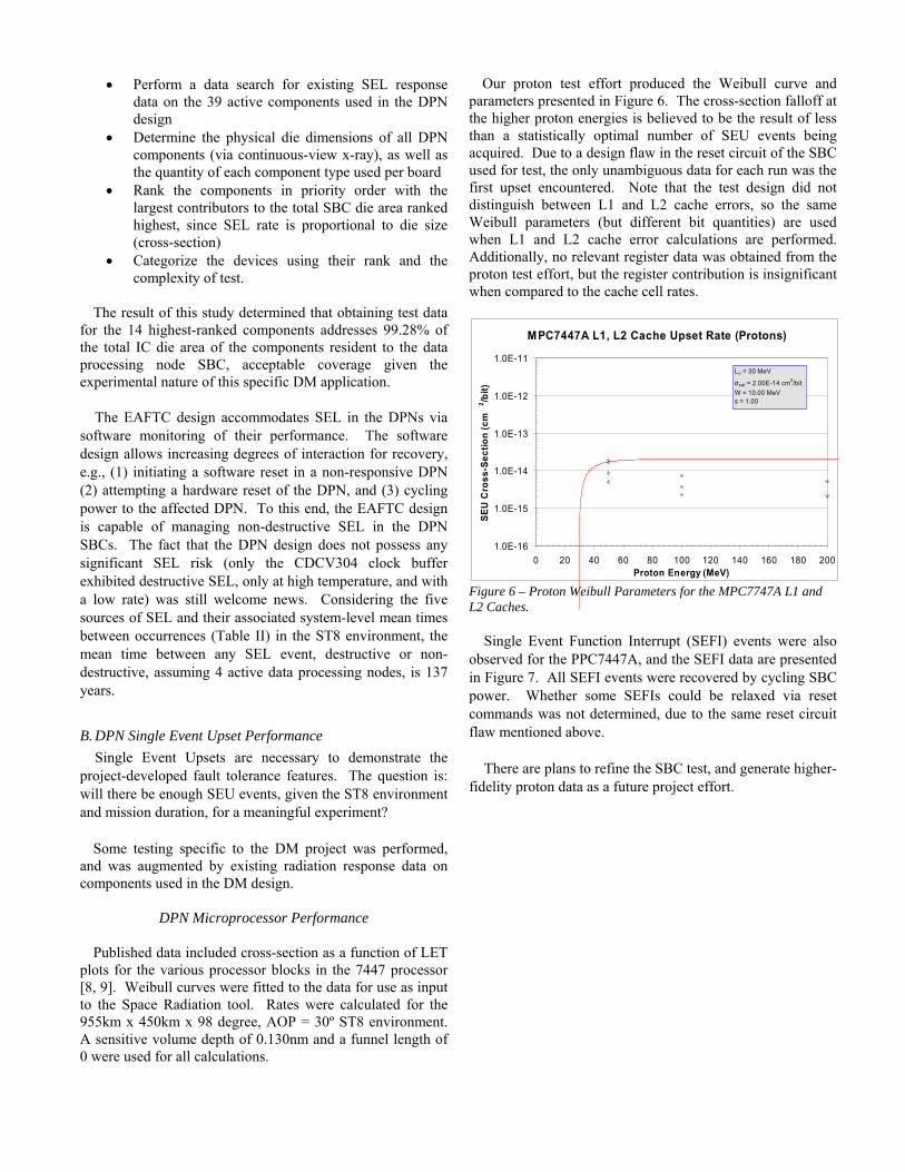
Our proton test effort produced the Weibull curve and parameters presented in Figure 6. The cross-section falloff at the higher proton energies is believed to be the result of less than a statistically optimal number of SEU events being acquired. Due to a design flaw in the reset circuit of the SBC used for test, the only unambiguous data for each run was the first upset encountered. Note that the test design did not distinguish between L1 and L2 cache errors, so the same Weibull parameters (but different bit quantities) are used when L1 and L2 cache error calculations are performed. Additionally, no relevant register data was obtained from the proton test effort, but the register contribution is insignificant when compared to the cache cell rates.
Perform a data search for existing SEL response data on the 39 active components used in the DPN design
Determine the physical die dimensions of all DPN components (via continuous-view x-ray), as well as the quantity of each component type used per board
Rank the components in priority order with the largest contributors to the total SBC die area ranked highest, since SEL rate is proportional to die size (cross-section)
Categorize the devices using their rank and the complexity of test.
The result of this study determined that obtaining test data
for the 14 highest-ranked components addresses 99.28% of the total IC die area of the components resident to the data processing node SBC, acceptable coverage given the experimental nature of this specific DM application.
MPC7447A L1, L2 Cache Upset Rate (Protons)
1.0E-16
1.0E-15
1.0E-14
1.0E-13
1.0E-12
1.0E-11
0 20 40 60 80 100 120 140 160 180 200Proton Energy (MeV)
SE
U C
ros
s-S
ec
tio
n (
cm
2/b
it)
Lo = 30 MeV
σsat = 2.00E-14 cm2/bit
W = 10.00 MeVs = 1.00
Figure 6 – Proton Weibull Parameters for the MPC7747A L1 and L2 Caches.
The EAFTC design accommodates SEL in the DPNs via
software monitoring of their performance. The software design allows increasing degrees of interaction for recovery, e.g., (1) initiating a software reset in a non-responsive DPN (2) attempting a hardware reset of the DPN, and (3) cycling power to the affected DPN. To this end, the EAFTC design is capable of managing non-destructive SEL in the DPN SBCs. The fact that the DPN design does not possess any significant SEL risk (only the CDCV304 clock buffer exhibited destructive SEL, only at high temperature, and with a low rate) was still welcome news. Considering the five sources of SEL and their associated system-level mean times between occurrences (Table II) in the ST8 environment, the mean time between any SEL event, destructive or non-destructive, assuming 4 active data processing nodes, is 137 years.
Single Event Function Interrupt (SEFI) events were also
observed for the PPC7447A, and the SEFI data are presented in Figure 7. All SEFI events were recovered by cycling SBC power. Whether some SEFIs could be relaxed via reset commands was not determined, due to the same reset circuit flaw mentioned above.
B. DPN Single Event Upset Performance
Single Event Upsets are necessary to demonstrate the project-developed fault tolerance features. The question is: will there be enough SEU events, given the ST8 environment and mission duration, for a meaningful experiment?
There are plans to refine the SBC test, and generate higher-
fidelity proton data as a future project effort.
Some testing specific to the DM project was performed, and was augmented by existing radiation response data on components used in the DM design.
DPN Microprocessor Performance
Published data included cross-section as a function of LET plots for the various processor blocks in the 7447 processor [8, 9]. Weibull curves were fitted to the data for use as input to the Space Radiation tool. Rates were calculated for the 955km x 450km x 98 degree, AOP = 30º ST8 environment. A sensitive volume depth of 0.130nm and a funnel length of 0 were used for all calculations.

PPC7447A SEFIs (Protons)
1.0E-11
1.0E-10
1.0E-09
1.0E-08
1.0E-07
1.0E-06
1.0E-05
0 20 40 60 80 100 120 140 160 180 200Proton Energy (MeV)
SE
U C
ros
s-S
ec
tio
n (
cm
2/b
it)
No SEFIs observed
Lo = 50 MeV
σsat = 2.50E-8 cm2/device
W = 10.00 MeVs = 0.80
Figure 7 – MPC7447A SEFI Data.
Table II. Summary of Single Event Latchup Data Obtained for the Data Processing Node Components
Device Descr.Test
Voltage, V
Test Condition SEL?Destructive
SEL?At What
Temperature?Required radiation for SEL
SEL Rate, upset/device-
day
System MTBF
(4 units), years
NC7S08 AND Gate 3.6 Clocked @ 1kHz No
LTC1772 Pwr Conv. 3.6Static (details not supplied)
No
LTC1387 RS422 5.25Loop-back confiuration with clk = 1kHz
No
CDCV855 PLL 2.7 Static NoCY22392 PLL Clk 3.45 Static NoAPA150 PLD 3.3V Standby and active NoS29GL512 Flash Mem 3.3V Standby and active NoMT46V64M8P-6T
SDRAM 2.5V Active access Yes No 70 C LET > 60 1.26E-07 86,975
DS1631 Dig. Therm 3.6 Static Yes No > 25 C LET > 26.6; σ = 1E-6 cm2 8.30E-08 132,035
LTC3413 Sync. Reg. 3.6
Configured to provide Vdd/2 (as in typical application), but with no load
Yes No > 25 C LET > 8.0; σ = 1E-5 cm2 1.10E-06 9,963
ADT7461 Temp Mon 3.6 Static Yes No > 25 C LET > 8.0; σ = 1E-5 cm2 1.50E-06 7,306 BCM5461 Ethnet Xcvr 2.5, 1.2 Static Yes No 25 C LET >19, σ = 3E-6 cm2 1.60E-06 142
CDCV304 Clk Buffer 3.6 Clocked @ 1kHz Yes Yes > 65 C LET > 37.5; σ = 2.2E-6 cm2 4.27E-08 256,649 Table III compiles the proton-caused upset rates, and
sums these rates with the heavy ion rates to produce the overall processor upset rate in the ST8 environment.
Table III. MPC7447A SEU Rates in the ST8 Environment
Element Proton
upset/dev-day Total upset/dev-
day L1 D Cache 4.26E-2 4.43E-2 L1 I Cache 4.23E-2 4.83E-2 Registers 4.48E-9 2.92E-5 L2 Cache 5.99E-1 6.20E-1 SEFI 1.47E-1 1.47E-1 Device Total 0.860
Host Chip Performance
The host (bridge) chip test effort revealed SEFI rate sensitivity which was high enough to overwhelm the gathering of SEU data for the device. For both proton and heavy ion exposures, SEFI occurrences were so frequent that no SEU events were logged. It is difficult to rationalize that a component could possess higher sensitivity to SEFI than to SEU, since SEFI is usually due to a small number of hidden register bits being corrupted and altering the normal operational mode of the device. Since the SEFI occurrences were high-current (but non-destructive) in nature, they could be considered to be SEL events, but it is again unusual for SEL sensitivity of a device to be greater than that for SEU. Since the EAFTC design accommodates non-destructive SEL and SEFI events equally well, understanding the exact single event effect was not crucial to EAFTC success, but remains nevertheless of interest.

Host Chip SEFI Events
1.0E-07
1.0E-06
1.0E-05
1.0E-04
1.0E-03
1.0E-02
0 10 20 30 4LET (MeV-cm2/mg)
SE
U C
ros
s-S
ec
tio
n (
cm2 /d
ev
ice
)
0
L0 = 0.5 MeV-cm2/mg
σ = 5E-3 cm2/device
W = 7.0 MeV-cm2/mgs = 2.0
Figure 8 – Host Chip Proton Data for SEFI Events
The SEFI data from the proton and heavy ion test efforts is found in Figures 8 & 9, respectively, and the rate calculations for the NMP ST8 orbit are summarized in Table IV. A device depth of 1µm was used. Table IV. Host Chip SEFI Rates in the ST8 Environment Heavy Ion Contribution, SEFI/device-day 2.79E-2 Proton Contribution SEFI/device-day 4.86E-2
Total 7.65E-2
Node SDRAM Performance
Heavy ion SEU data on the 512Mb SDRAM devices used in the SBC design produced Weibull parameters of: LO = 2 MeV-cm2/mg; σ = 1.5E-9 cm2/bit; W = 66 MeV-cm2/mg; and s = 2. This input set resulted in a heavy ion
Host Chip SEFI Events
1.0E-07
1.0E-06
1.0E-05
1.0E-04
1.0E-03
1.0E-02
0 10 20 30 4LET (MeV-cm2/mg)
SE
U C
ros
s-S
ec
tio
n (
cm
2 /de
vic
e)
0
L0 = 0.5 MeV-cm2/mg
σ = 5E-3 cm2/device
W = 7.0 MeV-cm2/mgs = 2.0
Figure 9 – Host Chip Heavy Ion Data for SEFI Events upset rate of 4.32 x 10⁻¹¹ upset/bit-day in the ST8 heavy ion environment. A 130µm sensitive volume depth was assumed.
The proton Weibull parameters used were LO = 20 MeV; σ = 2E-17 cm2/bit; W = 66 MeV, and s = 0.8. These inputs returned a per-bit upset rate from protons of 1.05 x 10⁻¹⁰ upset/bit-day in the NMP trapped proton environment.
The overall rate for the NMP environment is 1.48 x 10⁻¹⁰
upset/bit-day, and the device-level rate is 7.96 x 10⁻² upset/device-day.
SEFI events, while not reported here, were found to be
very low and presented no concern for a reliable EAFTC experiment.
ASIC Performance
Research engineers with CERN performed heavy ion
testing on the ASIC model used in the DPN design, and presented the results at the 2005 HERA-LHC Workshop [10]. In an array of 400 modules each containing one Accelerator ASIC, they estimated one upset every 4 hours, which corresponds to an upset rate for one ASIC of 6.25 x 10⁻⁴ upsets/device-day.
VI. EXPERIMENT RADIATION RESPONSE
Since the DPNs are the primary contributors to DM upset, the estimated 945 upsets (Table V) generated by the data processing nodes closely represents the anticipated number of DM upsets during the ST8 mission. Technology-representative SEU rates are currently substituted for the host chip SEU rates in Table V, until additional testing is completed.
The higher-level fault tolerant software features will be exercised by upsets other than those protected by hardware fault tolerance such as ECC. The estimated number of on-orbit errors that the software fault tolerance will encounter, and is expected to address, is 492. These 492 upsets are of high interest because they will affect the two most critical component types in the DM flight system: the microprocessors and the host chip devices. Figures 10 and 11 show the respective confidence intervals as a function of the number of upsets to these two devices for 90% and 95% confidence levels for the ST8 mission orbit and the nominal 120-day DM experiment period. The expected SEU rates and distribution are sufficient to meet the desired confidence level for the space experiment and, projecting forward, for the model validation including the Level 1 reliability and availability models/calculations.
Confidence Interval vs. Number of SEUs (@ 78% Critical Device Upsets)
0
5
10
15
20
25
75
12
5
17
5
22
5
27
5
32
5
37
5
42
5
47
5
52
5
Number of SEUs
Co
nfi
de
nc
e In
terv
al +
/%
90% Confidence Level
95% Confidence Level
Expected # of Upsets
Figure 10 – Confidence Interval as a Function of the Number of SEUs for 4 DPN processors
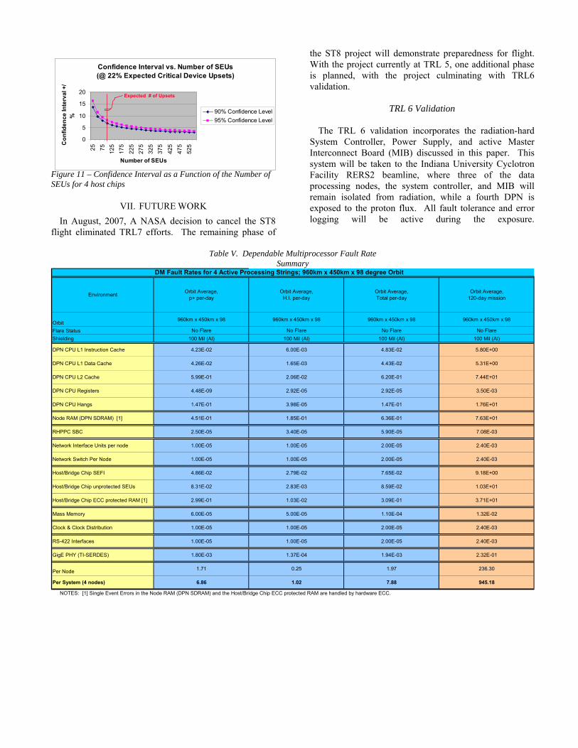
Figure 11 – Confidence Interval as a Function of the Number of SEUs for 4 host chips
VII. FUTURE WORK
In August, 2007, A NASA decision to cancel the ST8 flight eliminated TRL7 efforts. The remaining phase of
the ST8 project will demonstrate preparedness for flight. With the project currently at TRL 5, one additional phase is planned, with the project culminating with TRL6 validation.
Confidence Interval vs. Number of SEUs (@ 22% Expected Critical Device Upsets)
0
5
10
15
202
5
75
12
5
17
5
22
5
27
5
32
5
37
5
42
5
47
5
52
5
Number of SEUs
Co
nfi
de
nc
e In
terv
al +
/%
90% Confidence Level
95% Confidence Level
Expected # of Upsets TRL 6 Validation
The TRL 6 validation incorporates the radiation-hard
System Controller, Power Supply, and active Master Interconnect Board (MIB) discussed in this paper. This system will be taken to the Indiana University Cyclotron Facility RERS2 beamline, where three of the data processing nodes, the system controller, and MIB will remain isolated from radiation, while a fourth DPN is exposed to the proton flux. All fault tolerance and error logging will be active during the exposure.
Table V. Dependable Multiprocessor Fault Rate Summary
DM Fault Rates for 4 Active Processing Strings; 960km x 450km x 98 degree Orbit
EnvironmentOrbit Average,
p+ per-dayOrbit Average,
H.I. per-dayOrbit Average,Total per-day
Orbit Average,120-day mission
Orbit960km x 450km x 98 960km x 450km x 98 960km x 450km x 98 960km x 450km x 98
Flare Status No Flare No Flare No Flare No Flare
Shielding 100 Mil (Al) 100 Mil (Al) 100 Mil (Al) 100 Mil (Al)
DPN CPU L1 Instruction Cache 4.23E-02 6.00E-03 4.83E-02 5.80E+00
DPN CPU L1 Data Cache 4.26E-02 1.65E-03 4.43E-02 5.31E+00
DPN CPU L2 Cache 5.99E-01 2.06E-02 6.20E-01 7.44E+01
DPN CPU Registers 4.48E-09 2.92E-05 2.92E-05 3.50E-03
DPN CPU Hangs 1.47E-01 3.98E-05 1.47E-01 1.76E+01
Node RAM (DPN SDRAM) [1] 4.51E-01 1.85E-01 6.36E-01 7.63E+01
RHPPC SBC 2.50E-05 3.40E-05 5.90E-05 7.08E-03
Network Interface Units per node 1.00E-05 1.00E-05 2.00E-05 2.40E-03
Network Switch Per Node 1.00E-05 1.00E-05 2.00E-05 2.40E-03
Host/Bridge Chip SEFI 4.86E-02 2.79E-02 7.65E-02 9.18E+00
Host/Bridge Chip unprotected SEUs 8.31E-02 2.83E-03 8.59E-02 1.03E+01
Host/Bridge Chip ECC protected RAM [1] 2.99E-01 1.03E-02 3.09E-01 3.71E+01
Mass Memory 6.00E-05 5.00E-05 1.10E-04 1.32E-02
Clock & Clock Distribution 1.00E-05 1.00E-05 2.00E-05 2.40E-03
RS-422 Interfaces 1.00E-05 1.00E-05 2.00E-05 2.40E-03
GigE PHY (TI-SERDES) 1.80E-03 1.37E-04 1.94E-03 2.32E-01
Per Node 1.71 0.25 1.97 236.30
Per System (4 nodes) 6.86 1.02 7.88 945.18
NOTES: [1] Single Event Errors in the Node RAM (DPN SDRAM) and the Host/Bridge Chip ECC protected RAM are handled by hardware ECC.

DMDM
Figure 12 – ST8 Spacecraft and Experiment
TRL 7 Validation
It is unfortunate that after initial paper submittal, NASA elected to cancel the ST8 flight (August, 2007). However, the project will allow subcontractors to complete experimental development up to the TRL 6. Several military and space applications have already been identified with which DM and ultimately EAFTC development can complete. For reference, the proposed ST8 spacecraft is depicted in Figure 12. It was planned that the Dependable Multiprocessor (DM) experiment would share the spacecraft bus with three other ST8 experiments: 1) the NGU (Next Generation Ultra-flex) deployable solar array experiment, 2) the MLHP (Multiple Loop Heat Pipe) experiment, and 3) the deployable SAILMAST experiment.
VIII. CONCLUSIONS
Total dose and displacement damage effects are not a significant concern for emerging COTS technologies. Components have been evaluated with acceptable results to assure DM survivability. Test data suggest microprocessor hardness of 100krad(Si), and SDRAM tolerance of greater than 40krad(Si). While some of the commercial devices used in the design may possess lower total dose or displacement damage hardness, substitution of these devices, if necessary for longer-term space
missions, is more readily accomplished than microprocessor, host chip, or memory replacement.
The DPN design has been evaluated for its sensitivity to
SEL, and while destructive SEL was observed in one device, the total rate for both destructive and non-destructive SEL is adequately low to minimize risk to the DM design.
The rates of the more dominant contributors to DM SEU
have been calculated. Based upon the SEU estimates for the microprocessor, bridge (host) chip, and SDRAM, the overall DPN SEU rate can be approximated with reasonable accuracy, since the contributions from other, lower-density devices are expected to be insignificant when compared to these. In the event that other DPN components do exhibit SEU, the fault tolerant software designed as part of the DM development is capable of managing SEUs in any DPN element.
Experiencing 492 non-hardware-protected SEUs during
the ST8 DM flight experiment would have supported a statistically significant experiment, with a ±7% confidence interval for the worst case, i.e., smallest expected, data set (note that supporting ground tests at TRL 6 will still occur). Considerations for implementation of radiation detection apparatus and co-processing technologies will be refined as the design evolves. Particle detectors, spectrometers, soft memory response, and ephemeris

information are all candidate methodologies for environment monitoring, and reconfigurability is a prime goal of co-processor design.
IX. ACKNOWLEDGEMENTS
The authors wish to thank Farokh Irom and Tetsuo Miyahira of JPL, and Matt Clark, Rick Conchiglia, Deron Hayslip, Dave Montigny, Manuel Rodriguez, Craig Ross, and Matt Smith of Honeywell for their invaluable contributions to SEE testing. We also wish to acknowledge Allan Johnston (JPL) and Gary Swift (Xilinx; formerly with JPL) for the technical insight they provided.
X. REFERENCES [1] J. Ramos, J. Samson, M. Patel, A, George, and R. Some, “High
Performance, Dependable Multiprocessor,” Proceedings of the 2006 IEEE Aerospace Conference, Big Sky, MT, March 4-11, 2006.
[2] J. Greco, J. Cieslewski, A. Jacobs, I. Troxel, C. Conger, J. Curreri,
and A. George, “Hardware/ Software Interface for High-performance Space Computing with FPGA Coprocessors,” Proceedings of the 2006 IEEE Aerospace Conference, Big Sky, MT, March 4-11, 2006.
[3] J. Samson, J. Ramos, A. George, M. Patel, and R. Some,
“Environmentally-Adaptive Fault Tolerant Computing (EAFTC),” 9th High Performance Embedded Computing Workshop, M.I.T. Lincoln Laboratory, September 22, 2005.
[4] J. Ramos, and D. Brenner, “Environmentally-Adaptive Fault
Tolerant Computing (EAFTC): An Enabling Technology for COTS based Space Computing,” Proceedings of the IEEE Aerospace Conference, Big Sky, MT, March 8-15 2004.
[5] J. Samson, A. George, M. Patel, and R. Some, “Technology
Validation: NMP ST8 Dependable Multiprocessor Project” Proceedings of the IEEE Aerospace Conf, 2006.
[6] G. Swift & the members of the Xilinx SEE Consortium, “Xilinx
Single Event Effects Consortium Report: Virtex II Static SEU Characterization”, dated 9 September 2003.
[7] J. Lintz, L. Hoffmann, M. Smith, R. Van Cleave, and R. Cizmarik,
“Single Event Effects Hardening and Characterization of Honeywell’s Pass 3 RHPPC Processor Integrated Circuit” Proceedings of the Nuclear and Space Radiation Effects Conference (NSREC) Radiation Effects Data Workshop (REDW) 2007.
[8] F. Irom, F. Farmanesh, A. Johnston, G. Swift, and D. Millward,
“Single Event Upset in Commercial Silicon-on-Insulator Power PC Processors” Proceedings of the NSREC REDW 2002.
[9] R. Marec, G. Estaves, R. Harboe-Sorensen, L. Gilhodes, D.
Campillo, and P. Calvel, “Heavy Ions Single Event Effects Evaluation of PowerPC MC7447AHX1267LB from Freescale”, Proceedings of the RADECS Workshop 2006.
[10] E. Denes, A. Fenyvesi, A. Hirn, A. Kerek, T. Kiss, J. Molnar, D.
Novak, C. Soos, T. Tolyhi, and P. VandeVyvre, “Radiation Tolerant Source Interface Unit for the ALICE Experiment, Proceedings of the HERA-LHC Workshop 2005.