
AQuA: An Adaptive Architecture that Provides Dependable Distributed Objects
34
AQUA: AN ADAPTIVE ARCHITECTURE THAT PROVIDES DEPENDABLE DISTRIBUTED OBJECTS 1 Yansong (Jennifer) Ren, David E. Bakken, Tod Courtney, Michel Cukier, David A. Karr, Paul Rubel, Chetan Sabnis, William H. Sanders, Richard E. Schantz, and Mouna Seri • Yansong (Jennifer) Ren is with Bell Laboratories, 101 Crawfords Corner Road, Room 4F-619, Holmdel, NJ 07733. E-mail: [email protected]. • David E. Bakken is with Washington State University, School of Electrical Engineering and Computer Science, PO Box 642752, Pullman, WA 99164-2752. E-mail: [email protected]. • Tod Courtney, William H. Sanders, and Mouna Seri are with the University of Illinois at Urbana- Champaign, Coordinated Science Laboratory, 1308 West Main St., Urbana, IL 61801-2307. E- mails: {tod, whs, seri}@crhc.uiuc.edu. • Michel Cukier is with the Center for Reliability Engineering, University of Maryland at College Park, 2100H Marie Mount Hall, College Park, MD 20742. E-mail: [email protected]. • David A. Karr is with Titan Systems Corporation, 700 Technology Drive, Billerica, MA 01821. E-mail: [email protected]. • Paul Rubel and Richard E. Schantz are with BBN Technologies, 10 Moulton Street, Cambridge, MA 02138. E-mails: {prubel, schantz}@bbn.com. • Chetan Sabnis is with SingleSignOn.Net, 11417 Sunset Hills Rd., Reston, VA 20190-5258. E- mail: [email protected]. ABSTRACT Building dependable distributed systems from commercial off-the-shelf components is of growing practical importance. For both cost and production reasons, there is interest in approaches and architectures that facilitate building such systems. The AQuA architecture is one such approach; its goal is to provide adaptive fault tolerance to CORBA applications by replicating objects. The AQuA architecture allows application programmers to request desired levels of dependability during applications' runtimes. It provides fault tolerance mechanisms to ensure that a CORBA client can always obtain reliable services, even if the CORBA server object that provides the desired services suffers from crash failures and value faults. AQuA includes a replicated dependability manager that provides dependability management by configuring the system in response to applications’ requests and changes in system resources due to faults. It uses Maestro/Ensemble to provide group communication services. It contains a gateway to intercept standard CORBA IIOP messages to allow any standard CORBA application to use AQuA. It provides different types of replication schemes to forward messages reliably to the remote replicated objects. All of the replication schemes ensure strong data consistency among replicas. This paper describes the AQuA architecture 1 This research has been supported by DARPA Contract F30602-98-C-0187. 1
-
Upload
independent -
Category
Documents
-
view
0 -
download
0
Transcript of AQuA: An Adaptive Architecture that Provides Dependable Distributed Objects

AQUA: AN ADAPTIVE ARCHITECTURE THAT PROVIDES DEPENDABLE DISTRIBUTED OBJECTS 1
Yansong (Jennifer) Ren, David E. Bakken, Tod Courtney, Michel Cukier, David A. Karr, Paul Rubel, Chetan Sabnis, William H. Sanders, Richard E. Schantz, and Mouna Seri
• Yansong (Jennifer) Ren is with Bell Laboratories, 101 Crawfords Corner Road, Room 4F-619,
Holmdel, NJ 07733. E-mail: [email protected]. • David E. Bakken is with Washington State University, School of Electrical Engineering and
Computer Science, PO Box 642752, Pullman, WA 99164-2752. E-mail: [email protected]. • Tod Courtney, William H. Sanders, and Mouna Seri are with the University of Illinois at Urbana-
Champaign, Coordinated Science Laboratory, 1308 West Main St., Urbana, IL 61801-2307. E-mails: {tod, whs, seri}@crhc.uiuc.edu.
• Michel Cukier is with the Center for Reliability Engineering, University of Maryland at College Park, 2100H Marie Mount Hall, College Park, MD 20742. E-mail: [email protected].
• David A. Karr is with Titan Systems Corporation, 700 Technology Drive, Billerica, MA 01821. E-mail: [email protected].
• Paul Rubel and Richard E. Schantz are with BBN Technologies, 10 Moulton Street, Cambridge, MA 02138. E-mails: {prubel, schantz}@bbn.com.
• Chetan Sabnis is with SingleSignOn.Net, 11417 Sunset Hills Rd., Reston, VA 20190-5258. E-mail: [email protected].
ABSTRACT
Building dependable distributed systems from commercial off-the-shelf components is of growing practical importance. For both cost and production reasons, there is interest in approaches and architectures that facilitate building such systems. The AQuA architecture is one such approach; its goal is to provide adaptive fault tolerance to CORBA applications by replicating objects. The AQuA architecture allows application programmers to request desired levels of dependability during applications' runtimes. It provides fault tolerance mechanisms to ensure that a CORBA client can always obtain reliable services, even if the CORBA server object that provides the desired services suffers from crash failures and value faults. AQuA includes a replicated dependability manager that provides dependability management by configuring the system in response to applications’ requests and changes in system resources due to faults. It uses Maestro/Ensemble to provide group communication services. It contains a gateway to intercept standard CORBA IIOP messages to allow any standard CORBA application to use AQuA. It provides different types of replication schemes to forward messages reliably to the remote replicated objects. All of the replication schemes ensure strong data consistency among replicas. This paper describes the AQuA architecture
1 This research has been supported by DARPA Contract F30602-98-C-0187.
1

and presents, in detail, the active replication pass-first scheme. In addition, the interface to the dependability manager and the design of the dependability manager replication are also described. Finally, we describe performance measurements that were conducted for the active replication pass-first scheme, and we present results from our study of fault detection, recovery, and blocking times.
Keywords: Dependable distributed systems, replication protocols, adaptive fault-tolerant systems, CORBA, group communication.
2
1. INTRODUCTION
Providing fault tolerance to distributed applications is a challenging and important goal. In many applications, the cost of a custom hardware solution is prohibitive. Even if custom hardware is used, the flexibility that software can provide makes it a natural choice for implementing a significant portion of the fault tolerance of dependable distributed systems. Furthermore, when the dependability requirements change during the execution of an application, the fault tolerance approach must be adaptive in the sense that the mechanisms used to provide fault tolerance may change at runtime. Together, these requirements argue for a software solution that can reconfigure a system based both on the levels of dependability desired by a distributed system during its execution and on the faults that occur.
The AQuA architecture provides a flexible approach for building dependable, distributed, object-oriented systems that support adaptation due to both faults and changes in an application’s dependability requirements. Its goal is to provide a simple high-level way for applications to specify the level of dependability they desire and the type of faults that should be tolerated.
Proteus provides fault tolerance in AQuA by dynamically managing replicated distributed objects to make them dependable. It does this by configuring the system in response to faults and changes in desired dependability levels. The choice of how to provide fault tolerance involves choosing the types of faults to tolerate, the styles of replication to use, the degrees of replication to use, and the location of the replicas, among other factors. The replication protocols in Proteus assume the existence of an underlying group communication system that provides reliable multicast, total ordering, and virtual synchrony [Bir96]. For our implementation, we have used the Maestro/Ensemble [Bir96, Hay98, Vay98] group communication system. Communication between all architecture components is done using gateways, which translate CORBA object invocations into messages that are transmitted via Ensemble, and contain mechanisms to implement a chosen fault tolerance scheme.
The remainder of this paper is organized as follows. Section 2 reviews other approaches that provide fault tolerance for CORBA applications using group communication. Section 3 presents an overview of the AQuA architecture, reviewing the technologies it uses. Section 4 describes the two group types used in AQuA and the methods of reliable communication. Section 5 focuses on the gateway, a part of Proteus that is used to translate messages from the group communication level to the CORBA level and vice versa, and which contains several fault tolerance mechanisms. Section 6 details the implementation of the active replication pass-first scheme in the gateway. It includes the algorithms for the communication scheme, view changes, and fault occurrences. Section 7 focuses on the dependability manager and the object factory in the Proteus architecture. Section 8 presents the interface with the dependability manager that is used to manage the level of dependability requested, host information and decisions on which hosts to use, and detailed information from Proteus. Section 9 focuses on making the dependability manager dependable. Section 10 presents the performance measurement for the active replication pass-first
3

scheme, with fault detection, recovery, and replica blocking times. Finally, Section 11 concludes the paper.
2. RELATED WORK
There have been many attempts to build reliable distributed systems. One main thrust has been to provide fault tolerance at the process level through the use of the group communication paradigm. Work in this area includes ISIS [Bir94], Maestro/Ensemble, Totem [Mos95], ROMANCE [Rod93], Cactus [Bha97], SecureRing [Nar99a], and Rampart [Rei95]. In addition, there has been work with the explicit goal of building fault-tolerant systems. In particular, the Delta-4 project [Pow91] aimed to provide fault tolerance through the use of an atomic multicast protocol, and specialized hardware designed to ensure crash failure of processes. Also notable are Chameleon [Bag98], Aurora [AMW], DOORS [Moo99, Gok00], FRIENDS [Fab98], and MARS [Kop88]. All of these provide explicit support for building fault-tolerant applications.
We provide fault tolerance to distributed CORBA applications by using group communication. Several other projects have similar aims. These projects can be classified into three categories. The first approach is to create a fault-tolerant ORB. Both Electra [Maf95, Maf97, Lan97] and Maestro fall into this category. The second category involves providing fault tolerance through a CORBA service, above the CORBA Object Request Broker (ORB). The OpenDREAMS [Fel96] project and Arjuna [Lit98, Mor99] take this approach. A third method is to intercept messages from the ORB; this is the approach taken by Eternal [Mos98, Nar97, Nar99b, Nar00, Nar01].
More specifically, the first approach consists of building an ORB that has built-in fault tolerance capabilities. For example, Electra integrates adapter objects into the ORB. The adapter objects convert CORBA’s messages into the multicast messages in the group communication system, and make multiple replicas look like a single replica for use in active replication. Electra also enhances the Basic Object Adapter with the ability to create/remove replicas of a server object. Similarly, the Replicated Updates ORB is used in Maestro [Hay98]. It includes an IIOP Dispatcher and multiple request managers to actively replicate and manage applications across multiple hosts. The Replicated Updates ORB allows clients to access a pool of object references for server replicas. If one server replica fails, the client’s request is redirected to another server replica. Since both of the ORBs are integrated with fault tolerance mechanisms, these approaches can be made efficient. In addition, the details of fault tolerance mechanisms can be hidden inside the ORB. Therefore, they can provide fault tolerance transparently to the application’s programmers. However, because the ORB is modified, it is likely that these approaches provide fault tolerance at the cost of losing interoperability with standards-compliant CORBA ORBs.
Systems that use the CORBA service approach implement the fault tolerance mechanisms as a Common Object Service on top of the ORB. This approach takes advantage of standards and applications already in place to provide fault tolerance. For example, both OpenDREAMS and Arjuna use existing CORBA messaging services. OpenDREAMS provides an Object Group Service (OGS) that includes
4

server objects implemented above commercial ORBs. The OGS provides group communication by using a CORBA messaging sub-service, and detects object crash by using the monitoring sub-service. Arjuna uses a combination of a CORBA transaction service and group communication to provide groups of passively replicated objects. Since fault tolerance is provided through a set of CORBA objects above the ORB, the ORB does not need to be modified; this approach is thus CORBA-compliant. However, there are a number of drawbacks to the services. Programmers need to know how to use the interface provided by the services. The existing CORBA application thus will need to be modified to take advantage of these systems. The performance of these systems is also an issue, as fault tolerance is implemented at a high level in the communication stack of the system.
Interception is the approach taken by Eternal to capture specific system calls or library routines used by the application in order to enhance the application with fault tolerance. Eternal provides fault tolerance transparently both to the application and to the ORB. Thus, modification of the ORB and the application is not required. Eternal provides fault tolerance using techniques at both the ORB and group communication levels. With the Unix operating system, using either the /proc-based implementation or the library interpositioning implementation, it intercepts IIOP calls, and resends messages using the Totem [Mos95] group communication protocol. Intercepting calls at such a low level allows Eternal to provide fault tolerance with a low overhead. In addition, Eternal supports both active and passive replication, and supports dynamic system configuration changes in response to changing application requirements.
The Object Management Group (OMG), which designed CORBA, has also recently provided a Fault Tolerant CORBA standard [OMG99]. While it does not support all the functionality of the standard, the DOORS project [Gok00] implements many of its features. This standard provides fault tolerance to CORBA applications by the use of object replication, fault detection, and recovery. It allows flexibility in configuration management of the number of replicas, and of their assignment to different hosts. Replicated objects can invoke the methods of other replicated objects without regard to the physical location of those objects. The standard provides strong replica consistency among the replicated objects. It provides protection from crash failures in deterministic applications using either active or passive replication. This standard is an excellent step towards providing fault tolerance to CORBA applications. However, because current ORBs are not able to deal with ORB state properly when recovering an application object, all of the replicas of a replicated server must use ORBs from the same vendor. To guarantee strong replica consistency, application objects and ORBs are required to behave deterministically. If sources of non-determinism exist, they must be filtered out.
3. AQUA OVERVIEW
The AQuA architecture [Ren01a, Ren01b, Rub00] is a framework for building dependable, distributed, object-oriented systems that support adaptation to both faults and changes in an application's dependability requirements. It was developed concurrently with, but independently from, the CORBA fault tolerance standard. It provides the types of fault tolerance specified by the standard. Moreover,
5

AQuA currently is able to provide services that are not specified in the fault tolerance standard, such as support for any standard CORBA applications, without the limitation of requiring the replicated server objects to use the same ORB, and including support for protection against value faults in the body of the IIOP message.
3.1. AQuA Architecture Overview
Figure 1 shows the different components of the AQuA architecture in one particular configuration. These components can be assigned to hosts in many different ways, depending on an application’s desired level of dependability.
AQuA Object
ORB
Gateway
IIOP
QuOObject
ORB
Gateway
IIOP
QuOObject
ORB
Gateway
IIOP
DependabilityManager
ORB
Gateway
IIOP
ObjectFactory
Maestro/Ensemble Group Communication System
AQuA Object
ORB
Gateway
IIOP
QuOObject
ORB
Gateway
IIOP
QuOObject
ORB
Gateway
IIOP
DependabilityManager
ORB
Gateway
IIOP
ObjectFactory
Maestro/Ensemble Group Communication SystemMaestro/Ensemble Group Communication System
Figure 1: Overview of the AQuA Architecture
In AQuA, fault tolerance is achieved through the replication of objects. All replicas of an object form a group. Messages communicated among different objects are sent through groups. To provide fault tolerance at the most basic level, the AQuA system uses the Ensemble group communication system to ensure reliable communication between groups of processes, to ensure that totally ordered messages are delivered to the members in a group, to maintain group membership based on the virtual synchrony model, and to detect and exclude from the group members that fail by crashing. Ensemble assumes that process failures are fail-silent (or crash failures), and detects process failures through the use of “I am alive” messages. The AQuA architecture uses this detection mechanism to detect crash failures, and provides input to Proteus to aid in recovery.
In order to provide a way for an application to specify its dependability requirements, a Quality Object (QuO) [Loy98a, Loy98b, Zin97] can be used. It allows distributed applications to process and invoke dependability requests, and to receive information regarding the level of dependability that is being provided by the current system. QuO allows distributed object-oriented applications to specify dynamic QoS requirements. In the AQuA approach, QuO is used to transmit applications’ dependability
6

requirements to Proteus, which attempts to configure the system to achieve the desired level of dependability. QuO also provides an adaptation mechanism that is used when Proteus is unable to provide the specified level of dependability.
In AQuA, Proteus provides adaptive fault tolerance. It consists of a replicated dependability manager, a set of object factories, and gateway handlers. The dependability manager determines a system configuration based on reports of faults and desires of application objects. An object factory that resides on each host is used to create and kill objects, as well as to provide load and other information about the host to the dependability manager.
Communication between all architecture components (i.e., applications, the QuO runtime, object factories, and dependability managers) is done using gateways, which translate CORBA object invocations into messages that are transmitted via Maestro/Ensemble. Furthermore, the handlers in a gateway implement multiple replication schemes and communication mechanisms. The handlers are also used to detect application value faults, and to report value faults and group membership changes to the dependability managers. Before discussing the AQuA group structure and gateway architecture, we review Proteus.
3.2. Proteus Overview
Most group communication systems, including Ensemble, are based on the assumption that processes fail by crashing, but no mechanism is implemented to ensure that processes fail only by crashing. Furthermore, recovery by automatically starting new processes on the same or different hosts is not implemented in the protocol stack. Instead, it is left to the application. A fault tolerance framework is thus necessary to tolerate other fault types and provide recovery mechanisms that are more sophisticated than process exclusion. The framework could be implemented at the process level through an implementation of further fault tolerance in Ensemble. However, in order to be independent of any particular group communication system and to fully use the features offered by CORBA applications, we have provided additional fault tolerance above the group communication infrastructure. The framework we have developed is able to tolerate crash failures of processes and hosts, as well as value faults of CORBA objects. In addition to the fault tolerance mechanisms themselves, two types of replication can be used: active and passive. Active replication includes pass-first, leader-only, and majority voting schemes. In the pass-first scheme, each replica in the replication group executes each invocation independently and sends each request/reply to the leader of the group. The leader is responsible for forwarding the first received request/reply to the destination object group. In the leader-only scheme, the leader processes input messages and sends its output messages to the destination object group. The other replicas will process input messages and generate output messages that are suppressed. In the majority voting scheme, each replica in the replication group executes each invocation independently and multicasts its request/reply in the replication group. The leader is responsible for forwarding the voting results to the destination group. The first two schemes are able to tolerate crash failures, and the last scheme is able to tolerate value faults as well as process crash failures. Passive replication includes stable storage and state cast schemes. In the
7

stable storage scheme, the leader multicasts its state to the backup replicas. In the state cast scheme, the leader stores its state in stable storage. When the original leader fails, the new leader will take over from the original leader by getting the state from stable storage. Both of the passive replication schemes are able to tolerate process crash failures. Different replication schemes have different characteristics. The active replication schemes have less performance overhead and require applications to be deterministic. The passive replication schemes use less computation resources than the active replication schemes, and support both deterministic and non-deterministic applications. However, the passive replication schemes have more performance overhead than the active replication schemes. The multiple replication schemes supported by AQuA provide flexibility by giving applications several options to choose from in order to meet their desires.
4. GROUPS IN THE AQUA ARCHITECTURE
In AQuA, we use a general object model, rather than the more restrictive client/server model. The model of computation is thus based on interactions between objects that can be replicated. Objects can initiate requests (acting as clients) and respond to requests (acting as servers). In the AQuA architecture, the basic unit of replication is a two- or three-process pair, consisting of either an application and gateway, or application, gateway, and QuO runtime. A QuO runtime is included if an object contained in the application process makes a remote invocation of another object and wishes to specify a quality of service for that object. A basic replication unit may contain one or more distributed objects, but to simplify the following discussion, we refer to it as an AQuA object. Furthermore, when we say that an “object joins a group” we mean that the gateway process of the object joins the group. Mechanisms are provided to ensure that if one of the processes in the object crashes, the others are killed, thus allowing us to consider the object as a single entity that we want to make dependable.
Using this terminology, we can now describe the group structure and mechanism used in the AQuA architecture, including replication groups and connection groups. By defining multiple replication and connection groups, we can avoid the communication overhead that would occur if a single large group were used.
A replication group is composed of one or more replicas of an AQuA object. These objects may be transient or persistent members of the group. Persistent members join the group when they are created, and remain in the group. Transient members join a replication group only when they need to multicast a message to the replicas in the group. After sending a message, these objects leave the group. A replication group has one persistent object that is designated as its leader and may perform special functions. Each persistent object in the group has the capacity to become the object group leader, and a protocol is provided to ensure that a new leader is elected when the current leader fails.
A connection group is a group consisting of the persistent members of two replication groups that wish to communicate. It provides reliable message communication from one CORBA object to another CORBA object.
8

• • • •• • • • •
• • • •• • •Con
nect
ion
grou
p 1
Connection group 2
Replication group 1
Replication group 3 Replication group 4
Replication group 2
Connection group 3
• • • •• • • • •
• • • •• • •Con
nect
ion
grou
p 1
Connection group 2
Replication group 1
Replication group 3 Replication group 4
Replication group 2
Connection group 3
Figure 2: Example Group Structure in AQuA
As specified above, each replicated object is located inside a replication group. AQuA provides two methods of reliable communication between objects that are in two different replication groups. One way is to use a connection group, which is done if the sending object is a persistent member of its replication group, and hence is in a connection group shared by the destination replicated object. In that case, a replicated object that is inside a replication group multicasts messages within a connection group to forward them to the other replicated object. Using that approach, two different objects are able to communicate using both one-way and synchronous remote method invocations. This approach requires that there be a pre-established connection group before objects send messages to each other.
In the second method of reliable communication, the sending object becomes a transient member of a replication group with which it wishes to communicate. The invocations made by transient members can only be one-way. In addition, only the leader of a sender replication group is allowed to become a transient member of another replication group, and the leader is responsible for making invocations on behalf of the sender replication group. The method is only suitable for situations in which duplicate messages are allowable (at-least-once semantics). Communication through a transient group member is useful in situations in which communication is fairly infrequent. In such cases, the overhead in joining and leaving a replication group is small relative to that of maintaining a connection group between two replication groups.
For an illustration of the possible use of replication groups and connection groups, consider Figure 2. Solid lines define the replication and connection groups. The dashed oval represents the occurrence of a transient member joining a replication group. We see in Figure 2 that even though a connection group is composed of two replication groups, a member of a replication group can be included in several connection groups. For example, the replicas in replication group 3 communicate with the replicas in replication group 1 through connection group 1, and they communicate with the replicas in replication
9

group 2 through connection group 2. The leader of replication group 2 becomes a transient group member of replication group 1 in order to send messages to the replicas in replication group 2.
5. AQUA GATEWAY
The AQuA gateway is a process that is associated with each CORBA application. The AQuA gateway provides fault tolerance by implementing different communication schemes and replication protocols. These fault-tolerance mechanisms provide reliable remote method invocations, no matter when and where server object replicas fail before the client receives the replies. To achieve this dependability, each CORBA client's invocation is forwarded by its gateway to a set of replicated CORBA server objects, and only one copy of the reply message is allowed to return to the client object. The AQuA gateway is responsible for finding a set of replicated objects that can implement the request, passing them the parameters, invoking their methods, and returning the results. The client does not know where the server objects are located, or how many replicated server objects process the invocations.
ApplicationObject
ORB
HandlerFactory
Handler forAQuA object -1
Maestro/Ensemble
Gateway
Gateway Handlers
Local Area Network
IIOP
create handlers
DIIProcessor
Handler forAQuA object -2
Handler forAQuA object -n
NamingService
TAOORB
ApplicationObject
ORB
HandlerFactory
Handler forAQuA object -1
Maestro/Ensemble
Gateway
Gateway Handlers
Local Area Network
IIOP
create handlers
DIIProcessor
Handler forAQuA object -2
Handler forAQuA object -n
NamingService
TAOORB
Figure 3: AQuA Gateway
Figure 3 shows the physical structure of a gateway. It contains a gateway ORB, a naming service, a handler factory, a set of handlers, and a DII processor. The gateway ORB is a standard ORB (the TAO ORB [TAO] is used in our implementation). It works as a normal ORB to communicate with standard CORBA applications using IIOP messages. In that way, the AQuA gateway is able to communicate with different commercial ORBs to provide ORB transparency.
10

The naming service maps object names to object references. It is a local naming service in a gateway, and provides a way for the CORBA application to communicate with the gateway handlers. In particular, in the client gateway, the naming service associates the remote server objects' names with the handlers’ object references to direct all of the client’s invocations to the gateway handlers instead of allowing them to go directly to remote server objects. In the server gateway, the naming server helps the gateway handlers to locate the server objects.
The handler factory is responsible for creating handlers. It includes a handler repository that provides a set of different types of handlers. The handlers can be classified into two categories, static and dynamic. Static handlers have persistent group memberships, as described in Section 4. In this category, handlers will remain in the appropriate Ensemble process groups once they have been created and joined the groups. These handlers are used to implement replication schemes, and are therefore also called replication handlers. The replication handlers can be further classified into active and passive replication handlers. The active replication handlers are used to implement the active replication schemes. They include the pass-first handler, the leader-only handler, and the majority-voting handler. The passive replication handlers are used to implement the passive replication schemes. They include the state cast handler and the stable storage handler. Dynamic handlers, the second category of handlers, are transient replication group members. Transient replication group members are described in Section 4.
Each handler is responsible for sending and receiving messages for a particular replicated object. When a gateway handler receives an invocation, it will first remove the IIOP header, and then construct a gateway message that will carry the CORBA invocation to the gateways of the remote replicated servers. Each gateway message includes two parts: a message header and a payload of a CORBA IIOP message. The message header contains information used by replication schemes to process and deliver messages correctly. Each header has several fields: sender, receiver, is_oneway, sequence number, ID, and opcode. Each field has a special purpose related to the communication scheme. The sender and receiver fields specify the source and destination of an invocation. The is_oneway field indicates whether the invocation is an asynchronous (one-way) or synchronous CORBA message. The sequence number is an integer that is assigned to each invocation and is uniquely associated with a sender and receiver pair. The ID indicates which replica generated the message. The opcode is used for implementing replication steps.
After constructing a gateway message, the handler will encapsulate it into a Maestro/Ensemble group communication message so that it can be sent over the network to the replicated server gateways. If an invocation is a synchronous CORBA message, the handler is also responsible for receiving the reply from the group communication system. In the replicated server gateways, once a handler receives a group communication message, it will first unencapsulate the received Maestro message to get the gateway message. It will then remove the gateway header and get the name of the operation and the arguments for the original IIOP invocation from the gateway message payload. Next, it will construct a new dynamic invocation based on the information from the gateway message, and forward the invocation to the DII processor.
11

The DII processor is used to deliver invocations that are received from the handlers to the application object. In order to ensure strong data consistency among replicas, the DII processor contains a synchronous queue that ensures that the incoming invocations are delivered to the application in the order in which they were received from the group communication system. If the invocation is a synchronous CORBA message, the DII processor will wait for a reply, and then return the reply to the server gateway handler that is responsible for forwarding the reply to the client object. Since all of the replicated server objects generate their replies, the server gateway handlers will allow only one copy of the replies to be sent back to the handler servant in each client's gateway, to ensure that there are no duplicate replies. The algorithms that do this are explained in detail in the next section.
6. ACTIVE REPLICATION SCHEME
Multiple communication schemes have been developed using the defined group structure. The active replication pass-first, leader-only, and majority-voting schemes are detailed in [Ren01a, Ren01b], and the passive replication stable storage and state cast schemes are described in [Rub00]. All of the replication schemes provide the ability to 1) ensure reliable transmission of each CORBA message from one replicated object to another, so that messages will not be lost even if replicas crash, 2) guarantee strong data consistency among all object replicas, 3) guarantee that no duplicate messages are delivered to the replicated objects, and 4) correctly react when the number of replicas in a replication group changes. This section describes the active replication with pass-first scheme in detail. It first gives an overview of the communication steps of this scheme. Then, it explains the communication algorithms used to correctly communicate CORBA messages between replicated objects when the replication groups have stable group membership, and the view change algorithms used when the replication group membership changes. Finally, it explains how to tolerate process crash failures by using this scheme.
6.1. Communication Scheme in Active Replication
We first describe the steps involved in making a remote CORBA invocation. Let Oi,k be replica k of replication group i, and let object Oi,0 be the leader of the group. Suppose that replication group i is the sender group and group j the receiver group. One connection group is used to communicate between two replication groups, as described in Section 4. In order to describe the replication schemes clearly, we use two types of connection groups. A sender connection group is used to send out requests and to receive replies. A receiver connection group is used to receive requests and send out replies.
To send a request to the object replicas Oj,k, as shown in Figure 4, all objects Oi,k first use reliable point-to-point communication to send the request to Oi,0. Object replicas Oi,k also keep a copy of the request in case it needs to be re-sent (step 1 in Figure 4). The leader then multicasts the request in the sender connection group. The objects Oi,k use the multicast to signal that they can delete their local copies of the request. The objects Oj,k store the multicast on a list of pending rebroadcasts (step 2). Since there can be multiple replication groups, in order to maintain total ordering of all messages within the receiver replication group j, Oj,0 multicasts the message again in the replication group j. The objects Oj,k use the multicast as a signal that they can deliver the message and delete the previously stored copy from the
12

connection group multicast (step 3). After processing the request, all objects Oj,k send the result through a point-to-point communication to Oj,0 (step 4). The same set of steps used to transmit the request is then used to communicate the reply from replication group j to group i. Steps 5 and 6, which are responsible for transmitting the reply, are similar to steps 2 and 3 respectively.
sender connection group
(2)(2)
(2)
Replication group i
(2)(2)
(2)
(1)(1)(1)
Oi,0Oi,3 Oi,2 Oi,1
Replication group j(3) (3)
Oj,2Oj,1Oj,0
receiver connection group
(5)
(5)(5)
(5)
Replication group i
(6)(6)(6)
Oi,0Oi,3 Oi,2 Oi,1
(5) (5)
Replication group j(4) (4)
Oj,2Oj,1Oj,0
Figure 4: Communication Scheme
6.2. Active Replication Communication Algorithms
The algorithms that run in the active replication pass first handler are described in this section. To illustrate their use, we will describe the algorithms in the order in which they would be executed (on various nodes) as a single request/reply is processed, using the “step” nomenclature introduced earlier in this section.
Step 1: The first step of the communication scheme consists of sending a request to the replication group leader. This is done in two phases. First, each replica on the sender side receives a remote object request, via a CORBA IIOP message to the gateway. Note that these requests will not come at the same time, but they will come in the same order (since we assume application objects behave in a deterministic way and receive all external requests in the same order). After processing, the gateway calls SendRequest (Figure 5). Each message is then tagged with the opcode FORWARD_REQUEST, so that it is not misinterpreted as a reply to a previous message. The handler variable that keeps track of the last sent sequence number for the sender connection group is then set to the sequence number of the message. Next, the reply buffer associated with the sender connection group is checked to see if a reply has already been received for this message. RemoveReplyFromBuffer will return the reply if it is in the buffer and a NULL if the reply to this message is not found. The reply is stored in the buffer if another replica has previously forwarded its request to the leader (which is possible, since replicas behave asynchronously) and this replica has already received the reply. If the reply is present, it is delivered to the application (DeliverReplyToApp). If the reply is not present, the request is then sent to the leader using a Maestro point-to-point send (SendToLeader). Finally, the sequence number is checked to see if the request should be placed in the point-to-point buffer (so that it can be resent if a failure occurs). The request should be placed in the point-to-point buffer if a copy of it has not already been multicast in the connection group. (That would occur if another replica in the replication group has forwarded the request to the leader, which then multicasts it to the connection group.)
13

SendRequest( message request )
request.opcode := FORWARD_REQUEST SenderConnectionGroup.LastSent := request.SequenceNumber reply := SenderConnectionGroup.RemoveReplyFromReplyBuffer( request ) if ( reply ≠ NULL )
DeliverReplyToApp( reply ) else
SendToLeader( request ) if ( SenderConnectionGroup.LastMulticast < request.SequenceNumber ) AddToPtPBuffer( request )
SendReply( message reply )
reply.opcode := FORWARD_REPLY ReceiverConnectionGroup.LastSent := reply.SequenceNumber SendToLeader( reply ) if ( ReceiverConnectionGroup.LastMulticast < request.SequenceNumber ) AddToPtPBuffer( reply )
Figure 5: SendRequest and SendReply Algorithms
The second phase begins when the leader receives the request from Ensemble and calls ReceiveSendToLeader (Figure 6). As seen in Figure 4, the message sent to the leader can be either a request or a reply, as denoted by the opcode FORWARD_REQUEST or FORWARD_REPLY. At this step the message is a request. Non-leaders receiving this message do nothing. Since the message is a request, the opcode is changed from FORWARD_REQUEST to CONNECTION_GROUP_REQUEST. The PassFirstMessage returns the message passed to it (MessageToMulticast), unless it has already been multicast (which is determined by the sequence number of the message). The communication scheme then checks the message to see whether it should be multicast to the sender connection group; it does so by checking the content of MessageToMulticast and SenderConnectionGroup.LastMulticast. The LastMulticast variable is used to make the determination, and keeps the leader from multicasting duplicate requests that it may receive in the sender connection group. (A duplicate request may be received if a view change occurs and a replica’s point-to-point buffer is not empty.) If the request is not a duplicate, it is multicast in the connection group through the MulticastToConnectionGroup call, which uses the Maestro multicast facility. Finally, the handler’s last multicast request variable for the sender connection group is set to the message’s sequence number (since the Maestro multicast, as we have used it, does not send the message to the sender of the multicast).
Step 2: The second step of the communication scheme begins with the MulticastToConnection-Group call. When a multicast message is received by a connection group member, Ensemble calls ReceiveConnectionGroupMulticast (Figure 6). Since each member of the connection group receives the multicast, ReceiveConnectionGroupMulticast needs to determine whether the original request came from a replica in the replication group with the receiver, or a different replication group, and whether the received multicast is a request or reply message.
To distinguish among these cases, the method first checks the opcode of the message to see if the receiver of the message is a member of the group specified by the sender field. The method then checks to
14

see whether it is a request or a reply. A message received in step 2 will have the opcode CONNECTION_GROUP_REQUEST, marking it as a request multicast by the group leader. If the receiver of the message is a member of the group specified by the sender field, then the last multicast request variable corresponding to the sender connection group is then set to the sequence number of this message, for future reference. The message may have been stored in the point-to-point buffer so that it could be resent in case of failure, but since the multicasts are reliable, all other recipients of the message have now also received it. The receiver can thus safely remove this message from the point-to-point buffer, if it is there.
ReceiveSendToLeader( message m )
if ( Leader ) if ( m.opcode = FORWARD_REQUEST )
m.opcode := CONNECTION_GROUP_REQUEST message MessageToMulticast := PassFirstMessage( m )
if (( MessageToMulticast ≠ NULL ) and ( SenderConnectionGroup.LastMulticast < MessageToMulticast.SequenceNumber )) MulticastToConnectionGroup( SenderConnectionGroup, MessageToMulticast ) SenderConnectionGroup.LastMulticast := MessageToMulticast.SequenceNumber
if ( m.opcode = FORWARD_REPLY ) m.opcode := CONNECTION_GROUP_REPLY
message MessageToMulticast := PassFirstVotingProcess( m ) if (( MessageToMulticast ≠ NULL ) and
( ReceiverConnectionGroup.LastMulticast < MessageToMulticast.SequenceNumber )) MulticastToConnectionGroup( ReceiverConnectionGroup, MessageToMulticast )
ReceiverConnectionGroup.LastMulticast := MessageToMulticast.SequenceNumber ReceiveConnectionGroupMulticast( message m )
if ( m.Sender = myReplicationGroup ) if ( m.opcode = CONNECTION_GROUP_REQUEST )
SenderConnectionGroup.LastMulticast := m.SequenceNumber RemoveFromPtPBuffer( m )
if ( m.opcode = CONNECTION_GROUP_REPLY ) m.opcode = REPLICATION_GROUP_REPLY if ( RemoveMulticastDelayBuffer( m ) = NULL ) AddToTotalOrderBuffer( m ) if ( Leader ) MulticastToReplicationGroup( m )
if ( m.Receiver = myReplicationGroup ) if ( m.opcode = CONNECTION_GROUP_REQUEST )
m.opcode := REPLICATION_GROUP_REQUEST if ( RemoveMulticastDelayBuffer ( m ) = NULL ) AddToTotalOrderBuffer( m ) if ( Leader ) MulticastToReplicationGroup( m )
if ( m.opcode = CONNECTION_GROUP_REPLY ) ReceiverConnectionGroup.LastMulticast := m.SequenceNumber RemoveFromPtPBuffer( m )
ReceiveReplicationGroupMulticast( message m ) if ( m.opcode = REPLICATION_GROUP_REQUEST )
if ( m.SequenceNumber > ReceiverConnectionGroup.LastDelivered ) DeliverRequest( m )
ReceiverConnectionGroup.LastDelivered := m.SequenceNumber
15

if ( RemoveFromTotalOrderBuffer( m ) = NULL ) AddToMulticastDelayBuffer ( m ) if ( m.opcode = REPLICATION_GROUP_REPLY )
if ( m.SequenceNumber > SenderConnectionGroup.LastDelivered ) SenderConnectionGroup.LastDelivered := m.SequenceNumber if ( SenderConnectionGroup.LastSent ≥ m.SequenceNumber )
DeliverReplyToApp( m ) else AddToReplyBuffer( m )
if ( RemoveFromTotalOrderBuffer( m ) = NULL ) AddToMulticastDelayBuffer ( m )
Figure 6: ReceiveSendToLeader, ReceiveConnectionGroupMulticast, and ReceiveReplicationGroupMulticast Algorithms
In the second part of the algorithm, the method checks whether the receiver field of the message is the message receiver’s replication group. If the opcode of the message is a request, the opcode (CONNECTION_GROUP_REQUEST) is changed to REPLICATION_GROUP_REQUEST (initiating step 3). A multicast delay buffer is then used to store a copy of the message sent to the leader if a multicast in the connection group happened before the replica sent its message to the leader. This avoids the need to store the message in the total order buffer. The method then checks if the multicast delay buffer contains the request. If it does, then the request is removed from the buffer. Otherwise, the request is added to the total order buffer. The message is saved in the total order buffer to permit recovery in case of a replica failure. Then, if this replica is the leader, it multicasts the message to the members of the replication group through the MulticastToReplicationGroup call, again using the Maestro multicast facility.
Step 3: The third step of the communication scheme begins with the MulticastToReplication-Group call. When a multicast message sent via this call is received by a replication group member, Ensemble calls ReceiveReplicationGroupMulticast (Figure 6). In this step, the opcode is REPLICATION_GROUP_REQUEST, so the first block of code in this method is executed. First, the sequence number of the received message is checked (against the last delivered request in the receiver connection group) to confirm that this message has not already been delivered in the receiver connection group. That could happen if a leader crashed after sending a multicast, but before the replication group members received it. If that happens, the message is ignored. Otherwise, using DeliverRequest, the request is delivered to the application after processing by the gateway. The handler’s last delivered request variable associated with the receiver connection group is set to the message’s sequence number. The method then checks if the total order buffer contains the request. If the request is in the total order buffer, it is removed from it, since the message has now been delivered to all replication group members. If the buffer does not contain the request, it is added to the multicast delay buffer.
Steps 4-6 are similar to steps 1-3, but reliably communicate the reply back to the replicated object that issued the corresponding request. Through use of the above communication steps, requests and replies are reliably transmitted between replicated objects, thus ensuring that remote method invocations are reliable, in spite of process crash failures.
16

6.3. View Change Algorithms
When the membership of a group changes, a view change occurs. Replication group view changes signal changes that must be accounted for to maintain the correct replication group state and structure. A replication group view change will occur if a new persistent/transient member joins the replication group, if a member crashes, if a member is killed, or if a transient member leaves the replication group. Since the persistent group members must maintain strong data consistency among themselves, a new persistent group member needs to get state from an existing group member when it joins the replication group. The transient group member doesn’t have state transfer.
The state transfer is implemented with the help of Maestro state transfer calls. The state transfer occurs as part of Maestro view change processing, so it is atomic with respect to the processing of other messages in the group. When a new persistent member joins a group, Maestro initiates a state transfer by calling the GetState method of an existing group member. This method collects the state information needed by the new replica in a “transfer message.” The transfer message is passed to the new replica specified by a requestor. The transfer message consists of two parts: the gateway state and the application state. The gateway state includes the connection group state, the replication group state, and the DII processor’s synchronous queue state. The gateway state is added to the transfer message using the AddGatewayState method. The application object state is added to the transfer message using the AddApplicationState method. To get the state of the application, AddApplicationState executes a GetApplicationState method on the associated application object. This method, which must be implemented by the application object, packages up the needed state so that it can be placed in the transfer message and, ultimately, delivered to the new application object.
Once the transfer message is received by Maestro in the new replica, the replica calls the new replica SetState method to set the state of the replica to that prescribed by the transfer message. The state of the new replica’s handler is set via the SetGatewayState call. The state of the new application object is set by invoking the SetApplicationState method on the new application object. This method, implemented by the application object, unpacks the message to obtain the state information needed to set the new application object state to that obtained from an existing replica. Once the new persistent member is integrated into the group, Maestro invokes each group member’s ViewChange method (Figure 7), to notify each replication group member that a view change has occurred.
ViewChange( view newView ) if ( persistent group membership changes )
if ( NewLeader() ) for each message m in PtPBuffer
SendToLeader( m ) if ( Leader )
for each message m in TotalOrderBuffer MulticastToReplicationGroup( m )
if ( Leader ) SendToDependabilityManagerGroup( newView )
Figure 7: ViewChange Algorithm
17
Persistent group members first check if the view has changed because the (old) leader left the replication group. The existence of a new leader is determined via a call to method NewLeader. If the group has a new leader, all messages in each group member’s point-to-point buffer need to be sent to the (new) leader, since the buffer contains messages that were sent to the leader, but not yet multicast to the connection group. Likewise, the leader multicasts all messages in its total order buffer to its replication group, since they were received by the replication group from an associated connection group, but not yet successfully multicast by the leader to the group. Finally, the leader informs the dependability manager of the membership of the changed group, using the dynamic handler.
6.4. Algorithm’s Response to Faults
We now show how crash failures are tolerated using these algorithms. In particular, we consider all the points at which a crash failure can occur, for both the leader and non-leader replicas, in both the sender and receiver replication groups. Tolerating failures of non-leader replicas is simple using the AQuA group structure, since no message retransmission is necessary. In particular, a replica can crash before or after a multicast message is delivered. If a non-leader replica crashes after a multicast is delivered, there is no need to retransmit the message, because the message was delivered to all the correct replicas. If a non-leader replica crashes after the multicast is sent, but before it is delivered, there is no need to retransmit the message, because Maestro/Ensemble will deliver the multicast to all of the non-failed replicas. The other cases in which a non-leader replica can crash (before and after sending a point-to-point message) also require no action from other replicas.
If the leader of the sender replication group crashes before ReceiveSendToLeader is complete, the message transmission process is restarted by ViewChange once the replication group has gone through a view change and elected a new leader. In that case, SendToLeader is performed again. Specifically, the replicas in the sender replication group, having kept a copy of the message in the point-to-point buffer, resend the message to the new leader of the sender replication group. The new leader then multicasts each message in the sender connection group via ReceiveSendToLeader, and the message transmission process is resumed. If the original leader crashes immediately after sending the multicast, a new leader may be elected before the multicast is delivered. This case uses the same sequence calls as above. The new leader will also multicast the message, and this second multicast will be ignored by the members of the connection group. If the leader crashes in other stages of the communication scheme, no message retransmission is necessary, since the sender replication group leader is not responsible for message transmission in those stages.
If the leader of the receiver replication group crashes before ReceiveConnectionGroupMulticast is complete, the message transmission process is performed via ViewChange once the replication group has gone through a view change and elected a new leader. The new leader, having stored a copy of the message from the connection group multicast in the total order buffer, multicasts the message in the receiver replication group via MulticastToReplicationGroup. If the old leader crashes immediately after sending the multicast in the receiver replication group, a new leader may be elected before the multicast is
18
delivered. In that case, the same sequence calls are used. The new leader will multicast the message in the receiver replication group, and this second multicast of the message will be ignored by the members of the replication group. If the leader crashes in other stages of the communication scheme, no message retransmission is necessary, since the receiver replication group leader is not responsible for message transmission in those stages.
7. PROTEUS ARCHITECTURE
This section describes Proteus’s dependability manager and object factories. The functional interface between the dependability manager, the gateways, and the object factories will be described.
7.1. Dependability Manager
The dependability manager determines an appropriate system configuration based on requests transmitted through QuO requests and observations of the system, and carries out the decisions in a consistent way. The policy used by the dependability manager to make configuration decisions and the particular coordination algorithm used depend on the styles of replication used and the types of faults tolerated. However, the interface to other AQuA architecture components remains the same in all cases.
Specifically, the dependability manager’s CORBA interface consists of several methods. The view change method is called by application gateways to report Maestro/Ensemble view changes. The value fault method is called by application gateways if a value fault is reported by a gateway. The register host method is called by an object factory to register itself. The start reply, kill reply, and host information reply methods are called by an object factory to report, respectively, the status of a request to start an application, the status of a request to kill an application, and information (e.g., the host load) concerning the host.
A simple management policy was developed to support crash failures and value faults. In this policy, when the view change method (which is the result of a crash failure) is invoked, the dependability manager chooses to start a replica on the least-loaded host in the system that does not have a replica of the same application already running. When the value fault method is invoked, the dependability manager kills the faulty replica and creates a new replica to replace the failed one.
7.2. Object Factory
One object factory runs on each host in a system. The functions of an object factory are to start processes, to kill processes, and to provide information about the host. The object factory is not replicated, but since it does not contain state that needs to be preserved between failures, it can be restarted after a host failure so that the host can again be used to support AQuA objects.
19

When a factory is started, it registers itself with the dependability manager by calling the register host method. The dependability manager then knows that the factory’s host is available to start replicas. After receiving a reply from the dependability manager, the factory is ready to start and kill processes.
When the dependability manager sends a start replica request to the factory, the factory attempts to start the specified application. If an exception is generated while the application is starting, a start failure is reported. If no exception is generated, the factory adds the application to a list of running applications, and a successful start is reported to the advisor. A request from the dependability manager to kill an application (kill replica method) is handled in the same manner. If an exception is generated during an attempt to kill the application, a kill failure is reported. If no exception is generated, the factory removes the application from the list of running applications and a successful kill is reported. The dependability manager also notifies the factory, through the replica crashed method, if a replica on the factory’s host fails. This is done so that the factory has the correct state of its host. This method simply removes the crashed replica from the list of running remote objects.
The factory is also responsible for providing information to the dependability manager about its host. In the current implementation of the factory, the factory periodically sends the load of its host to the dependability manager through the host information reply method. The dependability manager uses this information to decide how to assign replicas to hosts. The dependability manager can also request this information at other times by using the get host information method.
8. PROGAMMER’S INTERFACE TO THE DEPENDABILITY MANAGER
This section describes how an application or QuO programmer interacts with the Proteus dependability manager 1) to request a particular level of dependability, 2) to be notified when that level is no longer met, 3) to obtain information concerning hosts managed by Proteus and give advice about which hosts the dependability manager should place replicas on, and 4) to obtain detailed information regarding decisions that the dependability manager makes, and the faults that it detects. The interface to the dependability manager can be divided into two sets of methods: those used to communicate with the components in the AQuA system core (composed of the dependability manager, the gateway handlers, and the object factories) that were described in Section 7, and those used by one or more AQuA objects to request and observe QoS, to observe the state of the dependability manager, and to observe and control hosts.
Proteus supports the development of three types of objects that can make QoS requests from the dependability manager and also observe its actions. One of these object types, called the QoS observer/requester, can be used to make QoS requests to the dependability managers and can receive callbacks regarding the ability of the dependability manager to satisfy the requester’s requests. (An example of an application that may contain a QoS observer/requester is QuO itself.) Furthermore, since the dependability manager supports a standard, well-defined interface, an application object can also make QoS requests directly to the dependability manager. The second type of object the dependability
20

manager supports is advisor observers. Advisor observers can “subscribe” to a variety of information used by the dependability manager to make decisions, including information about faults detected and fine-grained information regarding actions taken by the manager. Proteus also supports the development of a third type of objects, called host observer/controllers, that receive information regarding the status of hosts that may be used to execute object replicas, and that can be used to specify particular hosts for the execution of replicas. In particular, as will be seen in the following, host observers/controllers can be used by an application or QuO to specify hosts that should not be used to execute replicas, if the application or QuO has information that leads it to believe that the host should not be used.
8.1. Interface with the QoS Observer/Requester
QoS observer/requester objects specify the level of dependability desired of a remote object, and receive information regarding the ability of an AQuA-based system to meet that level of dependability. These objects can be implemented in a QuO system condition object or as part of an object that makes use of the remote object. Five methods are used in the interface between the dependability manager and the QoS observer/requester. Three of these methods are implemented in the dependability manager, and receive information regarding the desired dependability of AQuA-managed objects. The other two methods are implemented in the QoS observer/requester, and receive information about the dependability manager’s ability to meet a request.
The three methods implemented in the dependability manager support the definition of, modification of, and removal of QoS requests. The first method, register QoS request, is called to register a new QoS request (one that does not replace or supercede any pre-existing request). The argument QoSRequest_info is passed with this call and contains the specifics of the QoS request. The update QoS request method substitutes a new QoS request for one that was previously registered. The parameters of that call are the QoSRequest ID (identifying the QoS that will be updated) and the QoSRequest_info (containing the new information concerning the QoS request). Finally, the remove QoS request method eliminates a previously registered QoS request without replacing it with a new request. When the dependability manager receives a remove QoS request, it adjusts the number of replicas of the referenced object to satisfy any other requests that have been made for this object, killing replicas if appropriate.
The dependability manager calls two methods on QoS observers/requesters: one to indicate that a QoS request has become unsatisfied, and another to indicate that a QoS request that had become unsatisfied has once again become satisfied. Similarly, the QoS request satisfied method is called when a QoS request that previously could not be satisfied (indicated by the QoS request not satisfied call) can once again be satisfied.
8.2. Interface with the Advisor Observer
An advisor observer object can be used by QuO or an application object that wishes to receive more detailed information concerning fault notifications and decisions that the dependability manager advisor makes. An object may want this information, for example, to make higher-level decisions on how to adapt in a particular situation. To receive this information, each advisor observer implements several methods
21

that may be called by the dependability manager. The types of events and actions an advisor observer is notified of depends on the type of information the advisor observer requested when it registered with the dependability manager.
The dependability manager supports multiple advisor observers, which can dynamically register and de-register with the dependability manager at runtime. The register Advisor Observer method, called on the manager by advisor observers, registers an advisor observer with the dependability manager. When it registers, an advisor observer passes a reference to the advisor specifying the methods that should be called when events concerning this advisor observer occur, and the types of notifications it desires from the dependability manager. Upon a successful return, the register call returns an observer identification ID that can be used to de-register the advisor observer, using the remove Advisor Observer method. The types of information for which an advisor observer can register are given in the next paragraph.
Each advisor observer implements several methods, as shown in Table 1, to receive information from the dependability manager and to specify the action that is to be taken upon receiving that information. In particular, the fault occurred method is called on each advisor observer when the dependability manager detects a fault. This method provides, as arguments to the call, the type of fault detected, the host where the fault was detected, and the dependable object associated with the fault. All advisor observers receive this information, regardless of what other information they requested when they registered with the dependability manager. The seven other methods that must be implemented by an advisor observer are called on those advisor observers that have requested information related to a particular call. Specifically, the notify number of replicas method provides the name of the dependable object to which the call refers and the number of replicas of this object in the current system configuration. The remaining calls in Table 1 provide all the same information as notify number of replicas, plus the name and status information (e.g., load) for the host to which the call refers.
Method Function fault occurred Called when the dependability manager detects a crash failure or value fault. notify number of replicas Called when a new QoS request is registered and whenever the number of replicas in
the replication group changes. replica start attempted Called when the dependability manager attempts to start a replica. replica kill attempted Called when the dependability manager attempts to kill a replica. replica start failed Called when a new replica either could not be started by the object factory or could
be started but could not join the replication group. replica kill failed Called when the replica could not be killed by the object factory and the kill failure
was reported to the dependability manager. replica start successful Called when a replica was started successfully by the object factory, joined the
replication group, and was reported to the dependability manager. replica kill successful Called when a replica was killed successfully by the object factory and was removed
from the replication group, and the kill was reported to the dependability manager.
Table 1: Advisor Observer Callbacks
22

8.3. Interface to the Host Observer/Controller
The final type of interface that an application or QuO can have to the dependability manager is a host observer/controller. Host observer/controllers can receive status information concerning hosts that are being used to execute dependable objects, and give instructions regarding hosts that should or should not have replicas placed on them by the dependability manager. A host observer/controller gives these instructions by suggesting changes in the status of hosts. Depending on a host’s status, it is placed in a certain set by the dependability manager.
The dependability manager has three sets of hosts: an active host set, an inactive host set, and a removed host set. When an object factory registers a host with the dependability manager, the host is placed into the active host set. When a host observer/controller requests that a host be deactivated, the host is placed into the inactive host set. When the dependability manager detects the failure of an object factory or a host, the host is placed into the removed host set. Replicas running on removed hosts are assumed to have failed. If a host in the inactive host set is reactivated by a host observer/controller, the host is moved back to the active host set. If a failed object factory or a failed host is restarted, the host is moved from the removed host set to the active host set. The newly started object factory communicates with the dependability manager to initiate its state. The dependability manager will not create replicas on a host that is in the inactive host set or in the removed host set. It will also migrate the replicas on a host in the inactive host set to hosts in the active host set.
Host observer/controllers register with the dependability manager to obtain information and control the dependability manager’s operation. Like advisor observers, the dependability manager supports multiple host observer/controllers. Four methods are called by the host observer/controller on the dependability manager to register and remove host observer/controllers and to activate and deactivate hosts. The method register Observer/Controller registers a host observer/controller with the dependability manager. The method deactivate host is used to request that the dependability manager deactivate the host specified by the call. When this call is made, the dependability manager will move the host from the active host set to the inactive host set, and will also migrate the replicas from this inactive host to hosts in the active host set. The method activate host is used to request that the dependability manager move an inactive host from the inactive host set back to the active host set.
Each host observer/controller must implement four methods to receive information from the dependability manager. Whether these methods are called depends on the information that the host observer/controller requested when it registered with the dependability manager. The method host activated may be called 1) when a host that is either in the removed host set or in no host set registers with the dependability manager, and 2) when a host that is in the inactive host set is reactivated. The method host removed may be called when a host failure or an object factory failure is detected by the dependability manager, and the host is moved from the inactive or the active host set to the removed host set. This method will be implemented in the future, when the dependability manager is able to detect host and object factory failures. The method host deactivated may be called when a host is deactivated by a
23

host/observer controller. The method host information is called by the dependability manager for all hosts in the active set if the host information method is enabled.
9. REPLICATING THE DEPENDABILITY MANAGER
The dependability manager is an important component in managing a system's dependability, and (if not made dependable) a potential single point of failure. In particular, if it crashes, AQuA will not be able to continue to provide fault-tolerance management. If that happens, applications' new QoS requests will not be handled, and their existing QoS requests will not be able to receive system condition callbacks. Also, if crash failures or value faults occur in any object replica, the level of dependability of the corresponding system configuration will be decreased, since the system will no longer be able to recover from these failures/faults. Therefore, preventing the dependability manager from becoming a single point of failure is an important issue in the design of the AQuA architecture.
Replication Group 1
Replication Group 2
Object Factory
Advisor Observer
QoS Requester
Host Observer/Controller
Dependability Managers
Dashed ovals represent the occurrence of a transient member joining a replication group. Dark-colored dots represent the transient group members.
Replication Group 1
Replication Group 2
Object Factory
Advisor Observer
QoS Requester
Host Observer/Controller
Dependability Managers
Dashed ovals represent the occurrence of a transient member joining a replication group. Dark-colored dots represent the transient group members.
Figure 8: The Dependability Manager Group Structure
The dependability manager is a non-deterministic application because it not only handles incoming requests/replies, but also monitors replicas' states using timers. In order to prevent replicated dependability managers from making inconsistent decisions, the passive replication with every-message state transfer is used to provide fault tolerance to the dependability manager. In the scheme, the leader of the dependability managers checkpoints its state whenever it sends out an output message. Using both checkpointing and the message logging in the gateway, the backup dependability manager is able to provide consistent decisions when it recovers from the leader failure.
24

The replicated dependability managers form a replication group, and communicate with the other application components through two types of approaches: through connection groups and through joining replication groups as transient members, as shown in Figure 8. Connection groups are used to communicate with the object factories, QoS requesters, advisor observers, and host observers/controllers.
Sending messages to a replicated object by joining its replication group as a transient member is used in three cases: when the leader of a replication group reports persistent group membership changes to the dependability managers, when the leaders report value faults to the dependability managers, and when the leader of the dependability managers changes the other replicas’ gateway parameters. In all three cases, the sender uses a dynamic handler to become a member of the destination group, and then multicasts the appropriate messages to the destination group. After that, the sender will leave the group. Dynamic handlers require the dynamic joining and leaving of groups. Since the above cases do not happen often, frequent joining and leaving of groups should not occur. An alternative to communicating as a transient member is to communicate via connection groups. The advantage of communicating as a transient member is that it greatly reduces the number of connection groups kept by the dependability managers. As a consequence, we can avoid the scalability problem.
10. PERFORMANCE MEASUREMENT
To benchmark the performance of the active replication with pass-first scheme implemented in AQuA, and to test the system’s ability to recover from faults, we studied several test cases. The testbed machines used were standard Sparc 10 and Sparc 5 Sun workstations with processor speeds ranging from 140 MHz to 360 MHz, connected by a 100-Mbps Ethernet link. Up to eleven machines were used in the tests.
10.1. Performance of Active Replication with Pass-First Scheme
The performance of the active replication with pass-first scheme is measured using the “deet” application, which uses the Visibroker ORB for Java (4.1). The “deet” application [Rub00] is written in Java, and makes synchronous remote method invocations. The remote method receives a string as an argument and simply returns the string as a return code. The measurement includes the round-trip time recorded in the application, and the round-trip time spent on handlers in the client gateway, the server gateway, and the group communication subsystem. The application round-trip time is the time from when an application sends an invocation until it receives a reply, as shown in Figure 9. In order to measure the overhead caused by AQuA gateways, and particularly the replication schemes, the AQuA code was instrumented to record the round-trip times. The handler round-trip time is recorded from when TAO passes a request to the gateway handler until the handler receives the reply from the group communication subsystem and forwards it to TAO, minus the time needed by TAO in the server gateway and the server application to process the message. The time spent by TAO in the server gateway and the server application is measured from when the server gateway forwards the request to TAO until it receives the reply from TAO. In that way, we can determine the overhead in delay caused by the developed replication
25
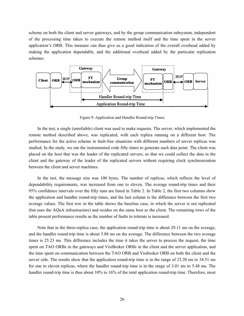
scheme on both the client and server gateways, and by the group communication subsystem, independent of the processing time taken to execute the remote method itself and the time spent in the server application’s ORB. This measure can thus give us a good indication of the overall overhead added by making the application dependable, and the additional overhead added by the particular replication schemes.
GroupcommunicationClient ORB ORB FT
mechanism ServerORB ORBFT mechanism
Gateway Gateway
Handler Round-trip Time
Application Round-trip Time
IIOP IIOPGroupcommunicationClient ORB ORB FT
mechanism ServerORB ORBFT mechanism
Gateway Gateway
Handler Round-trip Time
Application Round-trip Time
IIOP IIOP
Figure 9: Application and Handler Round-trip Times
In the test, a single (unreliable) client was used to make requests. The server, which implemented the remote method described above, was replicated, with each replica running on a different host. The performance for the active scheme in fault-free situations with different numbers of server replicas was studied. In the study, we ran the instrumented code fifty times to generate each data point. The client was placed on the host that was the leader of the replicated servers, so that we could collect the data in the client and the gateway of the leader of the replicated servers without requiring clock synchronization between the client and server machines.
In the test, the message size was 100 bytes. The number of replicas, which reflects the level of dependability requirements, was increased from one to eleven. The average round-trip times and their 95% confidence intervals over the fifty runs are listed in Table 2. In Table 2, the first two columns show the application and handler round-trip times, and the last column is the difference between the first two average values. The first row in the table shows the baseline case, in which the server is not replicated (but uses the AQuA infrastructure) and resides on the same host as the client. The remaining rows of the table present performance results as the number of faults to tolerate is increased.
Note that in the three-replica case, the application round-trip time is about 29.11 ms on the average, and the handler round-trip time is about 3.88 ms on the average. The difference between the two average times is 25.23 ms. This difference includes the time it takes the server to process the request, the time spent on TAO ORBs in the gateways and VisiBroker ORBs in the client and the server application, and the time spent on communication between the TAO ORB and Visibroker ORB on both the client and the server side. The results show that the application round-trip time is in the range of 23.20 ms to 34.51 ms for one to eleven replicas, where the handler round-trip time is in the range of 3.01 ms to 5.48 ms. The handler round-trip time is thus about 10% to 16% of the total application round-trip time. Therefore, most
26

of the application round-trip time must be spent on the TAO ORB and the communication between the TAO and the VisiBroker ORBs.
In order to show clearly the effect of varying the number of replicas, the application and handler round-trip times are plotted in Figure 10. From the figure, we can see that as the number of replicas increases, the handler round-trip time increases slightly. This performance increase is caused by the group communication system, since in order to ensure reliable and totally ordered message delivery, the cost of group communication grows with the size of the group.
Application Round-trip Time (ms)
Handler Round-trip Time (ms)
Number of
Replicas Mean Confidence Interval
Mean Confidence Interval
Time Difference
(ms)
1 23.20 (22.30, 24.09) 3.01 (2.82, 3.19) 20.19
2 27.20 (26.35, 28.04) 3.13 (2.93, 3.33) 24.07
3 29.11 (28.05, 30.16) 3.88 (3.74, 4.01) 25.23
4 30.54 (29.61, 31.46) 4.13 (3.96, 4.29) 26.41
5 31.46 (30.48, 32.43) 3.83 (3.67, 3.98) 27.63
6 31.72 (30.17, 33.27) 3.77 (3.49, 4.04) 27.95
7 32.99 (31.94, 34.03) 3.82 (4.54, 5.09) 28.17
8 33.24 (31.96, 34.31) 5.45 (5.21, 5.68) 27.79
9 33.70 (32.64, 34.75) 5.06 (4.75, 5.36) 28.64
10 34.51 (33.31, 35.70) 4.96 (4.77, 5.14) 29.55
11 34.17 (33.12, 35.21) 5.48 (5.21, 5.74) 28.69
Table 2. Round-trip Times of Active Replication Pass-First Scheme with Different Numbers of Replicas (Message Length = 100 bytes, 95% Confidence Level)
27

0
5
10
15
20
25
30
35
40
1 2 3 4 5 6 7 8 9 10 11
Number of Replicas
Rou
nd-tr
ip T
ime
(ms)
Application Round-trip Time
Handler Round-trip Time
Figure 10: Active Replication Pass-First Scheme with Different Numbers of Replicas (Message Length = 100 bytes)
10.2. Performance Results for Fault Detection and Fault Recovery
In this section, we present the performance results for fault detection and recovery in AQuA. The Maestro/Ensemble group membership protocol is used to detect crash failures. Recall that in this protocol, each group member periodically multicasts “I am alive” messages. If an “I am alive” message is not received within a particular period of time, which is defined as the fault detection threshold, the group member is considered to be crashed. In the test, we used the “pinger” application, which is written in C++ and uses the TAO ORB to communicate with the gateway. In this application, the message invocation sent from the pinger client to the replicated servers is a string. The replicated pinger servers return the same string back to the client as a reply. We caused a crash failure in a replica by having a QoS requester decrease its requested level of dependability by 1; the time at which an object factory killed a replica was recorded as the time that the replica crashed. In the test, the dependability manager, the object factory that was used to kill the replica, and the leader of the replicated servers were located on the same host. Therefore, we could collect data on them without requiring clock synchronization between different machines. We ran this experiment ten times for each case we studied. In the following figures, we show the average time this took over the 10 runs. The fault detection threshold was set at 3 seconds for each run. In the test, there are two replicated dependability managers and three server replicas. We crashed one of the nonleader replicas.
Figure 11 illustrates the fault detection times. In AQuA, the total crash failure fault detection time includes two parts. The first part is the time from when a replica crashes until the other replicas remove the crashed member from the group and receive a group view change, as shown in parts (1) to (2) of Figure 11. The second part is the time that it takes the leader of the replication group to report the new
28
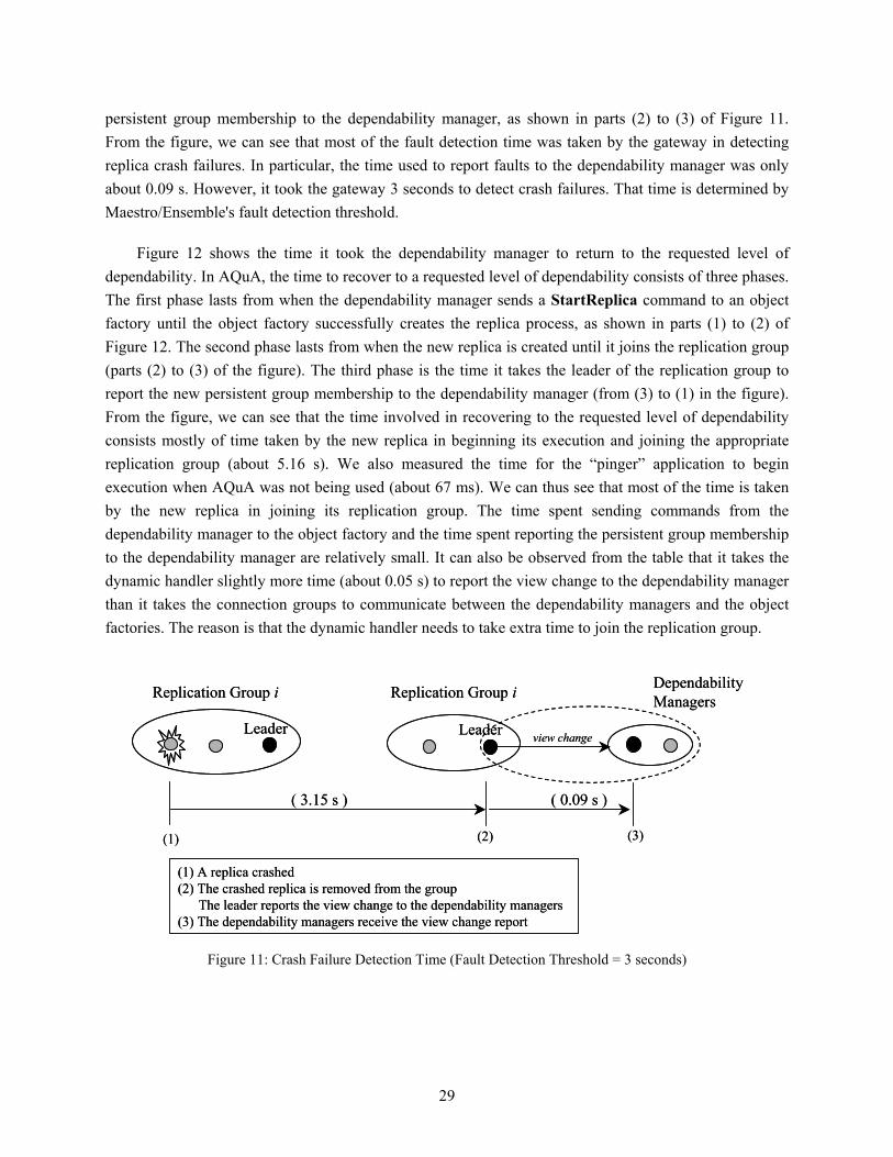
persistent group membership to the dependability manager, as shown in parts (2) to (3) of Figure 11. From the figure, we can see that most of the fault detection time was taken by the gateway in detecting replica crash failures. In particular, the time used to report faults to the dependability manager was only about 0.09 s. However, it took the gateway 3 seconds to detect crash failures. That time is determined by Maestro/Ensemble's fault detection threshold.
Figure 12 shows the time it took the dependability manager to return to the requested level of dependability. In AQuA, the time to recover to a requested level of dependability consists of three phases. The first phase lasts from when the dependability manager sends a StartReplica command to an object factory until the object factory successfully creates the replica process, as shown in parts (1) to (2) of Figure 12. The second phase lasts from when the new replica is created until it joins the replication group (parts (2) to (3) of the figure). The third phase is the time it takes the leader of the replication group to report the new persistent group membership to the dependability manager (from (3) to (1) in the figure). From the figure, we can see that the time involved in recovering to the requested level of dependability consists mostly of time taken by the new replica in beginning its execution and joining the appropriate replication group (about 5.16 s). We also measured the time for the “pinger” application to begin execution when AQuA was not being used (about 67 ms). We can thus see that most of the time is taken by the new replica in joining its replication group. The time spent sending commands from the dependability manager to the object factory and the time spent reporting the persistent group membership to the dependability manager are relatively small. It can also be observed from the table that it takes the dynamic handler slightly more time (about 0.05 s) to report the view change to the dependability manager than it takes the connection groups to communicate between the dependability managers and the object factories. The reason is that the dynamic handler needs to take extra time to join the replication group.
(1) A replica crashed(2) The crashed replica is removed from the group
The leader reports the view change to the dependability managers(3) The dependability managers receive the view change report
Replication Group i Replication Group i
Leader Leader
Dependability Managers
view change
(1) (2) (3)
( 3.15 s ) ( 0.09 s )
Figure 11: Crash Failure Detection Time (Fault Detection Threshold = 3 seconds)
29

(1) The dependability manager sends a command to start a replica(2) The object factory creates the replica (3) The leader reports the view change to the dependability managers
Replication Group i
Leader
Dependability Managers
start replica
(1)
(2)(3)
Object factory
createreplica
joins the group iNew replica
view change
( 0.06 s )
( 5.16 s )
( 0.11 s )
Figure 12: Time Spent Returning to the Requested Level of Dependability (Fault Detection Threshold = 3 seconds)
10.3. Replica Blocking Time
When a leader of a replication group dies, or when a new replica obtains the current state from an existing replica, the replicated server object is not available to provide services for a period of time, due to the changes in the AQuA configurations. We call this period of time the blocking time. Blocking time is important since it affects the availability of services. The blocking happens in two cases. The first case is the transfer of state to a new replica. During a state transfer, the replication group is blocked. The group communication system prevents the group members from receiving or sending out any messages other than the state transfer message. This blocking time lasts from when a new replica sends out a state request message to Maestro until it receives the state back from Maestro. To estimate this, we measured the blocking time with various application state sizes. The results are shown in Table 3. From the results, we can see that the blocking time increases with the size of the application state (the gateway state and the ORB state are fixed). When the state is larger, it takes more time for an existing replica to capture its state and for the group communication system to forward the state back to the new replica.
The second case in which the blocking time occurs is the failure of a leader. For all of the replication schemes, the leader is responsible for forwarding a request/reply to the receiver replicated object. If a leader fails, the group communication system takes a period of time to detect the leader failure and to elect a new leader. During that period of time (the blocking time), the nonleader replicas are unable to forward messages to the receiver replicated object. The time it takes the gateway to detect crash failures (about 3.15 s) represents this part of the blocking time. In addition, for the pass-first replication scheme,
30

the blocking time also includes the time that it takes the group members to resend the messages stored in the point-to-point buffer to the new leader; this additional time depends on the number of messages in the buffer, and the size of the messages, which is application-specific.
State Size (bytes)
Blocking Time (s)
State Size (bytes)
Blocking Time (s)
1000 0.23 6000 2.35 2000 0.60 7000 3.07
3000 0.82 8000 3.62
4000 1.30 9000 4.86 5000 1.84 10 000 5.32
Table 3. Blocking Times with Various Application State Sizes: A New Replica Joins a Replication Group
11. CONCLUSIONS
This paper presented an overview of the AQuA architecture, which provides a flexible and extensible approach to building dependable, object-oriented distributed systems. Systems built using the AQuA architecture support adaptation to changes in system resources due to both faults in the environment and changes in an application’s dependability requirements.
In AQuA, Proteus provides a flexible infrastructure for providing adaptive fault tolerance to CORBA applications. Our design permits an application to change the level of dependability that it requires, including the type of faults that should be tolerated dynamically during its execution. In order to make this possible, we have designed Proteus in a modular way, developing a scalable group structure and a set of communication algorithms that preserve needed communication properties during intergroup communication. Gateways were designed that make use of this group structure and support multiple replication and communication schemes through the use of different handlers. The implementation presented in this paper includes support for the active replication with pass-first scheme to tolerate crash failures, and a dependability manager policy that permits changing the degree of replication and placement of replicas during execution based on the dependability desires of an application. In addition, a graphical user interface for the dependability manager and object factories was developed to allow the functioning of Proteus to be monitored as it responds to dependability requests from applications and faults that occur. A user can monitor changes in membership that occur in replication and connection groups and in assignment of objects to hosts. Finally, performance measurements were taken for the active replication with pass-first scheme. The fault detection, recovery, and blocking times were also studied. The results show that AQuA has the ability to detect failures quickly, to recover from them, and to have short replica blocking times.
31

ACKNOWLEDGMENTS
We would like to thank several other members of the AQuA and QuO teams, particularly James Megquier, Joe Loyall, and John Zinky, for support and discussions. We would like to thank several members of the Ensemble team, Ken Birman, Tim Clark, Mark Hayden, and Alexey Vaysburd, for their help in using Maestro and Ensemble. We would also like to thank the reviewers for their helpful comments, and Jenny Applequist for her editorial comments.
REFERENCES
[AMW] R. Buskens, A. Siddlqui, and Y. Ren, “AURORA Management Workbench,” Bell Laboratories, http://www.dnrc.bell-labs.com/~ssm/aurora.html.
[Bag98] S. Bagchi, K. Whisnant, Z. Kalbarczyk, and R. K. Iyer, “Chameleon: A Software Infrastructure
for Adaptive Fault Tolerance,” Proceedings of the Seventeenth IEEE Symposium on Reliable Distributed Systems, West Lafayette, IN, USA, October 1998, pp. 261-267.
[Bha97] N. T. Bhatti, M. A. Hiltunen, R. D. Schlichting, and W. Chiu, “Coyote: A System for
Constructing Fine-Grain Configurable Communication Services,” Technical Report TR97-12, Department of Computer Science, University of Arizona, July 1997.
[Bir94] K. P. Birman and R. van Renesse, Eds., Reliable Distributed Computing with the Isis Toolkit, Los
Alamitos, CA: IEEE Computer Society Press, 1994. [Bir96] K. P. Birman, Building Secure and Reliable Network Applications, Greenwich, CT: Manning
Publications, 1996. [Cuk98] M. Cukier, J. Ren, C. Sabnis, D. Henke, J. Pistole, W. H. Sanders, D. E. Bakken, M. E. Berman,
D. A. Karr, and R. E. Schantz, “AQuA: An Adaptive Architecture that Provides Dependable Distributed Objects,” Proc. 17th IEEE Symposium on Reliable Distributed Systems, West Lafayette, IN, USA, Oct. 1998, pp. 245-253.
[Ezh95] P. D. Ezhilchelvan, R. A. Macedo, and S. K. Shrivastava, “Newtop: A Fault-Tolerant Group
Communication Protocol,” Proc. 15th IEEE Conf. on Distributed Computing Systems (ICDCS-15), Vancouver, May 1995, pp. 296-306.
[Fab98] J-C. Fabre and T. Perennou, “A Metaobject Architecture for Fault-Tolerant Distributed Systems:
The FRIENDS approach,” IEEE Transactions on Computers, vol. 47, no. 1, pp. 78-95, 1998. [Fel96] P. Felber, B. Garbinato, and R. Guerraoui, “The Design of a CORBA Group Communication
Service,” Proc. 15th IEEE Symposium on Reliable Distributed Systems, Niagara on the Lake, Ontario, Canada, Oct. 1996, pp. 150-159.
[Gok00] A. Gokhale, B. Natarajan, D. C. Schmidt, and S. Yajnik, “DOORS: Towards High-performance
Fault-Tolerant CORBA,” Proceedings of the 2nd International Symposium on Distributed Objects and Applications (DOA '00), OMG, Antwerp, Belgium, September 2000.
[Hay98] M. G. Hayden, “The Ensemble System,” Ph.D. thesis, Cornell University, 1998.
32

[Kop88] H. Kopetz et al., “Distributed Fault-Tolerant Real-Time Systems: The MARS approach,” IEEE
Micro, vol. 9, no. 1, February 1989, pp. 25-40. [Loy98a] J. P. Loyall, R. E. Schantz, J. A. Zinky, and D. E. Bakken, “Specifying and Measuring Quality
of Service in Distributed Object Systems,” Proc. First International Symposium on Object-Oriented Real-Time Distributed Computing (ISORC’98), Kyoto, Japan, Apr. 1998.
[Loy98b] J. P. Loyall, D. E. Bakken, R. E. Schantz, J. A. Zinky, D. A. Karr, R. Vanegas, and K. R.
Anderson, “QoS Aspect Languages and Their Runtime Integration,” Lecture Notes in Computer Science, vol. 1511: Proc. Fourth Workshop on Languages, Compilers, and Run-time Systems for Scalable Computers (LCR98), Pittsburgh, PA. Springer-Verlag, May 1998.
[Maf95] S. Maffeis, “Run-Time Support for Object-Oriented Distributed Programming,” Ph.D thesis,
University of Zurich, 1995. [Maf97] S. Maffeis, “Piranha: A CORBA Tool for High Availability,” IEEE Computer, vol. 30, no. 4, pp.
59-66, 1997. [Moo99] A. P. A. van Moorsel and S. Yajnik, “Design of a Resource Manager for Fault-Tolerant
CORBA,” Proc. of the International Workshop on Reliable Middleware Systems, Lausanne, Switzerland, October 1999, pp. 1-6.
[Mor99] G. Morgan, S. K. Shrivastava, P. D. Ezhilchelvan, and M. C. Little, “Design and Implementation
of a CORBA Fault-Tolerant Object Group Service,” Proc. Second IFIP WG 6.1 International Working Conference on Distributed Applications and Interoperable Systems (DAIS’99), Helsinki, June 1999.
[Mos95] L. E. Moser, P. M. Melliar-Smith, D. A. Agarwal, R. K. Budhia, C. Lingley-Papadopoulos, and
T. P. Archambault, “The Totem System,” Proc. 25th Annual International Symposium on Fault-Tolerant Computing (FTCS-25), Pasadena, CA, June 1995, pp. 61-66.
[Mos98] L. E. Moser, P. M. Melliar-Smith, and P. Narasimhan, “Consistent Object Replication in the
Eternal System,” Theory and Practice of Object Systems, vol. 4, no. 2, pp. 1-12, 1998 [Nar97] P. Narasimhan, L. E. Moser, and P. M. Melliar-Smith, “Replica Consistency of CORBA Objects
in Partitionable Distributed Systems,” Distributed Systems Engineering, vol. 4, no. 3, pp. 139-150, Sept. 1997.
[Nar99a] P. Narasimhan, K. P. Kihlstrom, L. E. Moser, and P. M. Melliar-Smith, “Proving Support for
Survivable CORBA with the Immune System,” Proc. of the IEEE 19th International Conference on Distributed Computing Systems, Austin, TX, May 1999, pp. 507-516.
[Nar99b] P. Narasimhan, L. E. Moser, and P. M. Melliar-Smith, “Using Interceptors to Enhance
CORBA,” IEEE Computer, vol. 32, no. 7, pp. 62-68, July 1999. [Nar00] P. Narasimhan, L. E. Moser, and P. M. Melliar-Smith, “Gateway for Accessing Fault Tolerance
Domain,” Middleware 2000: IFIP International Conference on Distributed Systems Platforms and Open Distributed Processing, New York, NY, April 2000, pp. 88-103.
33

[Nar01] P. Narasimhan, L. E. Moser, and P. M. Melliar-Smith, “State Synchronization and Recovery for Strongly Consistent Replicated CORBA Objects,” Proc. of the 2001 International Conference on Dependable Systems and Networks, pp. 261-270.
[Pow91] D. Powell, ed., “Delta-4: A Generic Architecture for Dependable Distributed Computing,”
ESPRIT Research Reports, vol. 1, Springer-Verlag, 1991. [Rei95] M. K. Reiter, “The Rampart Toolkit for Building High-integrity Services,” Theory and Practice
in Distributed Systems, Lecture Notes in Computer Science, pp. 99-110, Springer-Verlag, 1995. [Ren01a] Y. Ren, M. Cukier, and W. H. Sanders, “An Adaptive Algorithm for Tolerating Value Faults
and Crash Failures,” IEEE Transactions on Parallel and Distributed Systems, vol. 12, no. 2, pp. 173-192, February 2001.
[Ren01b] Y. Ren, “AQuA: A Framework for Providing Adaptive Fault Tolerance to Distributed
Applications,” Ph.D. thesis, University of Illinois at Urbana-Champaign, 2001. [Rod93] L. Rodrigues and P. Verissimo, “Replicated Object Management Using Group Technology,”
Proc. of the Fourth Workshop on Future Trends of Distributed Computing Systems, pp. 54-61, Lisboa, Portugal, September 1993.
[Rub00] P. G. Rubel, “Passive Replication in the AQuA System,” Master’s Thesis, University of Illinois,
2000. [Sab99] C. Sabnis, M. Cukier, J. Ren, P. Rubel, W. H. Sanders, D. E. Bakken, and D. A. Karr, “Proteus:
A Flexible Infrastructure to Implement Adaptive Fault Tolerance in AQuA,” Proc. 7th IFIP Working Conf. on Dependable Computing for Critical Applications (DCCA-7), San Jose, CA, USA, January 1999, pp. 137-156.
[Sch99] R. E. Schantz, J. A. Zinky, D. A. Karr, D. E. Bakken, J. Megquier, and J. P. Loyall, “An Object-
level Gateway Supporting Integrated-Property Quality of Service,” Proc. 2nd IEEE International Symposium on Object-oriented Real-time Distributed Computing (ISORC'99), Saint-Malo, France, May 1999.
[TAO] Department of Computer Science, Washington University, “Real-time CORBA with TAO (The
ACE ORB),” http://www.cs.wustl.edu/~schmidt/TAO.html/~schmidt/TAO.html. [Vay98] A. Vaysburd and K. P. Birman, “The Maestro Approach to Building Reliable Interoperable
Distributed Applications with Multiple Execution Styles,” Theory and Practice of Object Systems, vol. 4, no. 2, 1998.
[Zin97] J. A. Zinky, D. E. Bakken, and R. E. Schantz, “Architectural Support for Quality of Service for
CORBA Objects,” Theory and Practice of Object Systems, vol. 3, no. 1, pp. 55-73, Apr. 1997.
34