Aqua TROLL - Inteccon
42
Operator's Manual Aqua TROLL ® 400 Instrument Information subject to change without notice. In-Situ, In-Situ logo, Baro Merge, BaroTROLL, HERMIT, HydroVu™, iSitu, Pocket-Situ, RDO, RuggedCable, RuggedReader, SmarTROLL™, TROLL, and Win-Situ are trademarks or registered trademarks of In-Situ Inc. © 2015. All rights reserved. 0088302 | Rev. 003 | 07/2015
-
Upload
khangminh22 -
Category
Documents
-
view
0 -
download
0
Transcript of Aqua TROLL - Inteccon

Operator's ManualAqua TROLL® 400 Instrument
Information subject to changewithout notice. In-Situ, In-Situ logo, BaroMerge, BaroTROLL, HERMIT, HydroVu™, iSitu, Pocket-Situ, RDO,RuggedCable, RuggedReader, SmarTROLL™, TROLL, andWin-Situ are trademarks or registered trademarks of In-Situ Inc.© 2015. Allrights reserved.
0088302 |Rev. 003 | 07/2015

800-446-7488 2 www.in-situ.com
Copyright © 2012-2015 by In-Situ All rights reserved.
This document contains proprietary information which is protected by copyright. No partof this document may be photocopied, reproduced, or translated to another languagewithout the prior written consent of In-Situ
Mailing and Shipping Address: Phone: 970-498-1500 (international & domestic)
In-Situ221 East Lincoln AvenueFort Collins, CO 80524U.S.A.
Fax: 970-498-1598
Internet: www.in-situ.com
Support: 800-446-7488 (U.S.A. & Canada)
In-Situ makes no warranty of any kind with regard to this material, including, but notlimited to, its fitness for a particular application. In-Situ will not be liable for errorscontained herein or for incidental or consequential damages in connection with thefurnishing, performance, or use of this material.
In no event shall In-Situ Inc. be liable for any claim for direct, incidental, orconsequential damages arising out of, or in connection with, the sale, manufacture,delivery, or use of any product.
In-Situ and the In-Situ logo, Win-Situ, TROLL, Baro Merge, BaroTROLL, HERMIT,HydroVu™, iSitu, Pocket-Situ, RDO, RuggedCable, RuggedReader, SmarTROLL™,TROLL, and Win-Situ are trademarks or registered trademarks of In-Situ Inc. Microsoftand Windows are registered trademarks of Microsoft Corporation. Pentium is aregistered trademark of Intel. Tefzel and Delrin are registered trademarks of E. I.DuPont de Nemours and Company. Viton is a registered trademark of DuPont DowElastomers. Kellems is a registered trademark of Hubbell Inc. Alconox is a registeredtrademark of Alconox Company. Lime-A-Way is a registered trademark of ReckittBenckiser. iPod and iPhone are trademarks of of Apple Inc., registered in the U.S. andother countries. The Bluetooth word mark and logos are registered trademarks ownedby the Bluetooth SIG, Inc. and any use of such marks by In-Situ Inc. is under license.NIST is a registered trademark of the National Institute of Standards and Technology,U.S.A. Other brand names and trademarks are property of their respective owners.
The presence of the Waste Electrical and Electronic Equipment (WEEE) marking on the productindicates that the device is not to be disposed via the municipal waste collection system of anymember state of the European Union.
For products under the requirement of WEEE directive, please contact your distributor or local In-Situ office for the proper decontamination information and take back program, which will facilitatethe proper collection, treatment, recovery, recycling, and safe disposal of the device.
0088302 | Rev. 003

800-446-7488 3 www.in-situ.com
Table of Contents
1 Introduction 5Scope 5Serial Number Location 5
2 Safety 5Electrical Safety 5
3 General Specifications 64 Sensor Specifications 7
Level, Depth, Pressure Sensor Specifications 7Conductivity Sensor Specifications 7RDO Classic (Optical Dissolved Oxygen Sensor) Specifications 8ORP Sensor Specifications 8pH Sensor Specifications 9Sample Temperature Sensor Specifications (Probe) 9
5 Instrument Overview 10Instrument Description 10
6 System Components 10Probe Dimensions with Restrictor On 11Probe Dimensions with Restrictor Off 11Sensors 12Cable 12Win-Situ 5 Software 12
7 Probe Setup 13Installing the Sensors 14
8 Communication Settings and Calibration 16Connect the Instrument to the Computer 16Connect the Instrument to Win-Situ 5 Software 16Data Tab 17Set Communication Outputs 18Modbus Setup 19SDI-12 Setup 20View and Record Data 21Calibrate and Set Up Sensors 23Set Parameter Units and Sentinel Values 24RDO Sensor Calibration 25
Calibration 100% Oxygen Saturation 25Calibrate 0% Oxygen Saturation 26

800-446-7488 4 www.in-situ.com
Conductivity Calibration 28Pressure/Level 29pH/ORP Calibration 30
9 Controller Requirements and Connections 32Wiring Overview 32
Stripped-and-Tinned Cable 32Power Connections 32SDI-12 Wiring Diagram 33Modbus Master RS485 Wiring Diagram 34Modbus Master RS232 Wiring Diagram (Converter Required) 35RS485 Network Guidelines 36
DB-9 Diagram 36Communication Overview 36
Device ID 36Data Quality IDs and the Sensor Health Table 37
Sensor Health Table 37
10 Care and Maintenance 38Maintenance Schedule 38User-Serviceable Parts 38O-rings 38RDO Classic Sensor Cap Replacement 38pH/ORP Sensor Replacement 38Instrument Storage 38Cleaning the pH/ORP Sensor 39
Remove Crystalline Deposits 39Remove Oily or Greasy Residue 39Remove Protein-Like Material or Slimy Film 40
Cleaning the RDO Sensor 40Clean the Sensor Cap 40Clean the Optical Window 40
Cleaning the Conductivity Sensor 40Cleaning Procedure 1 41Cleaning Procedure 2 41Cleaning Procedure 3 41Cleaning Procedure 4 41
11 Declaration of Conformity 42

800-446-7488 5 www.in-situ.com
IntroductionThis manual is intended to describe the characteristics, operation, calibration, andmaintenance of the Aqua TROLL 400 Instrument. Communication registers andprogramming information can be found in the Modbus and SDI-12 Reference Guide.
ScopeThis manual covers the following information.
Chapter 1—Introduction
Chapter 2—Safety
Chapter 3—General Specifications
Chapter 4—Sensor Specifications
Chapter 5—Instrument Overview
Chapter 6—System Components
Chapter 7—Probe Setup
Chapter 8—Communication Settings and Sensor Calibration
Chapter 9—Controller Requirements and Connections
Chapter 10—Care and Maintenance
Chapter 11—Declaration of Conformity
Modbus registers and SDI-12 programming information can be found in the Modbusand SDI-12 Reference Guide.
Serial Number LocationThe serial number is located on the large label on the instrument body. The serialnumber is programmed into the instrument and displayed in the control software.
Safety
Electrical SafetyElectrical installation must be performed by properly trained and qualified personnel.
After the stripped-and-tinned cable has been properly wired to the controller, the usercan safely connect the instrument to the cable using the twist-lock connector.

800-446-7488 6 www.in-situ.com
General Specifications
Operatingtemperature
-5 to 50° C (23 to 122° F)
Storage temperature -40 to 65° C (-40 to 149° F)
Dimensions4.7 cm (1.85 in.) OD x 26.9 cm (10.6 in.) with restrictorinstalled (does not include connector)
Weight 694 g (1.53 lbs)
Wetted materialsPVC, 316 stainless steel, titanium, Acetal, Viton®,PC/PMMA
Environmental ratingIP68 with all sensors and cable attached. IP67 withsensors removed and cable detached.
Reading rate 1 reading every 5 seconds (no internal logging)
PowerRequired: 8–36 VDC (no internal battery).Measurement current: 16 mA @ 24 VDC.Sleep current: 40 µA @ 24 VDC
Interface
In-Situ Con TROLL® PRO System; In-Situ TROLL®
Link Telemetry 101 or 201 System; SCADA/PLC; andthird-party data loggers, samplers, controllers, andtelemetry systems.
CableCustomizable, non-vented (absolute) RuggedCable®
System is available in either Tefzel® or polyurethane.
Warranty 2 years
NotesSpecifications are subject to change without notice.Viton is a registered trademark of DuPontPerformance Elastomers L.L.C.

800-446-7488 7 www.in-situ.com
Sensor Specifications
Level, Depth, Pressure Sensor Specifications
Accuracy Typical ±0.1% FS @ 15° C; ±0.3% FS max. from 0 to 50° C
Range 76 m (250 ft); absolute (non-vented)
Resolution ±0.01% FS or better
Sensor Type Fixed
ResponseTime
Instantaneous in thermal equilibrium
Units ofMeasure
Pressure: psi, kPa, bar, mbar, mmHg, inHgLevel: mm, cm, m, in, ft
Methodology Piezoresistive; ceramic
Conductivity Sensor Specifications
Accuracy Typical ±0.5% + 1 μS/cm; ±1% max.
Range 5 to 100,000 μS/cm
Resolution 0.1 μS/cm
Sensor Type Fixed
ResponseTime
Instantaneous in thermal equilibrium
Units ofMeasure
Actual conductivity (μS/cm, mS/cm)Specific conductivity (μS/cm, mS/cm)Salinity (PSU)Total dissolved solids (ppt, ppm)Resistivity (Ohms-cm)Density (g/cm3)
Methodology Std. Methods 2510 EPA 120.1

800-446-7488 8 www.in-situ.com
RDO Classic (Optical Dissolved Oxygen Sensor) Specifications
Accuracy ±0.1 mg/L; ±0.2 mg/L; ±10% of reading
Range0 to 8 mg/L; 8 to 20 mg/L; 20 to 50 mg/L; Full operatingrange: 0 to 50 mg/L
Resolution 0.01 mg/L
Sensor TypeFixed with replaceable RDO Classic Sensor Cap (life: 1year typical)
ResponseTime
T90: <45 sec. T95: <60 sec.
Units ofMeasure
mg/L, % saturation, ppm
MethodologyEPA-approved In-Situ Methods 1002-8-2009 1003-8-20091004-8-2009
ORP Sensor Specifications
Accuracy ±5.0 mV
Range ±1400 mV
Resolution 0.1 mV
Sensor Type Replaceable pH/ORP combo sensor
ResponseTime
<15 sec.
Units ofMeasure
mV
Methodology Std. Methods 2580

800-446-7488 9 www.in-situ.com
pH Sensor Specifications
Accuracy ±0.1 pH unit from 0 to 12 pH units
Range 0 to 12 pH units
Resolution 0.01 pH unit
Sensor Type Replaceable pH/ORP combo sensor
ResponseTime
<15 sec., pH 7 to pH 4
Units ofMeasure
pH units
Methodology Std. Methods 4500-H+ EPA 150.2
Sample Temperature Sensor Specifications (Probe)
Accuracy ±0.1° C
Range -5 to 50° C (23 to 122° F)
Resolution 0.01° C or better
Sensor Type Fixed
ResponseTime
<30 sec.
Units ofMeasure
Celsius, Fahrenheit
Methodology EPA 170.1
800-446-7488 10 www.in-situ.com
Instrument Overview
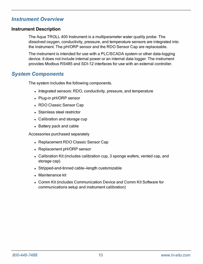
Instrument DescriptionThe Aqua TROLL 400 Instrument is a multiparameter water quality probe. Thedissolved oxygen, conductivity, pressure, and temperature sensors are integrated intothe instrument. The pH/ORP sensor and the RDO Sensor Cap are replaceable.
The instrument is intended for use with a PLC/SCADA system or other data-loggingdevice. It does not include internal power or an internal data logger. The instrumentprovides Modbus RS485 and SDI-12 interfaces for use with an external controller.
System ComponentsThe system includes the following components.
l Integrated sensors: RDO, conductivity, pressure, and temperature
l Plug-in pH/ORP sensor
l RDO Classic Sensor Cap
l Stainless steel restrictor
l Calibration and storage cup
l Battery pack and cable
Accessories purchased separately
l Replacement RDO Classic Sensor Cap
l Replacement pH/ORP sensor
l Calibration Kit (includes calibration cup, 3 sponge wafers, vented cap, andstorage cap)
l Stripped-and-tinned cable—length customizable
l Maintenance kit
l Comm Kit (includes Communication Device and Comm Kit Software forcommunications setup and instrument calibration)
800-446-7488 11 www.in-situ.com
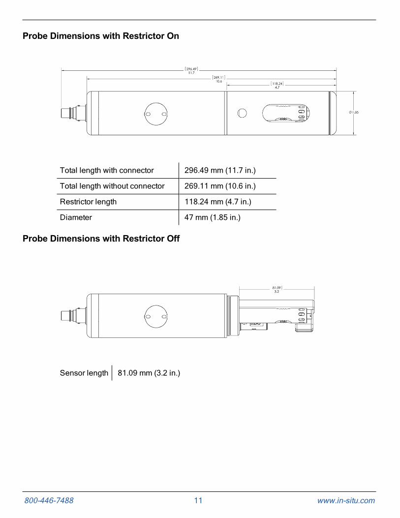
Probe Dimensions with Restrictor On
Total length with connector 296.49 mm (11.7 in.)
Total length without connector 269.11 mm (10.6 in.)
Restrictor length 118.24 mm (4.7 in.)
Diameter 47 mm (1.85 in.)
Probe Dimensions with Restrictor Off
Sensor length 81.09 mm (3.2 in.)

800-446-7488 12 www.in-situ.com
SensorsSensors include optical RDO (Rugged Dissolved Oxygen), pH/ORP, conductivity,pressure, and temperature.
1 Pressure sensor 76 m (250 ft)
2 pH/ORP sensor
3 Conductivity sensor
4 Temperature sensor
5 RDO Sensor
CableThe cable includes a twist-lock connection to the instrument and a stripped-and-tinnedtermination that must be wired to a controller. Cable length is customizable. Maximumlength is 1,219 m (4,000 ft) for Modbus output, and 60.9 m (200 ft) for SDI-12 output.
Win-Situ 5 SoftwareThe Win-Situ 5 Software is used to calibrate the sensors and to configure theinstrument settings to communicate with a process controller or data logger. See theCommunication Settings and Calibration section for more details.

800-446-7488 13 www.in-situ.com
Probe SetupThe probe is shipped with a storage plug and protective dust caps in place.
1Dust cap protector on the RDO Sensor. (Install the RDO Cap beforedeploying the instrument.)
2pH/ORP storage plug. (Remove the storage plug and install thepH/ORP sensor before deploying the instrument.)
3 Dust cap protector on the twist-lock cable connector.

800-446-7488 14 www.in-situ.com
Installing the Sensors

800-446-7488 15 www.in-situ.com
1. Twist the restrictor off the probe.
2. Locate the RDO Sensor Cap container and remove the cap.
3. Remove the dust cap from the RDO Sensor.
4. Align the flat edge of the RDO Sensor with the slotted edge of the RDO Cap andpress the cap into position. Push until the cap is firmly in place.
Important: Avoid touching the sensor lens and the sensingmaterial on the top of the cap.
5. Remove the orange plug from the pH/ORP port.
6. Remove the pH/ORP sensor from the storage bottle. Keep the bottle for futuresensor storage.
7. Use the alignment marks to properly align the pH/ORP sensor with the portconnection, and press firmly into place. Push until the sensor is completely insertedinto the port.
8. Twist the restrictor onto the probe.
9. Remove the dust cap from the quick-connect fitting. Align the flat edge of the cableconnector with the flat edge of the probe connector. Push together and twist untilyou hear a click. Ensure that the pin and the slot are firmly engaged.
Important: The RDO Sensor Cap and pH/ORP sensor must beinstalled firmly in place to prevent water from entering theinstrument.

800-446-7488 16 www.in-situ.com
Communication Settings and CalibrationBefore you program the instrument to work with your PLC/SCADA system, you must setappropriate communication settings using a TROLL Com, AC/DC converter, and Win-Situ 5 Software. The software can also be used to calibrate sensors and to restorefactory calibration and communication settings.
Always wear appropriate personal protective equipment and useproper laboratory technique when calibrating the sensors andoperating the instrument.
Connect the Instrument to the ComputerUsing a direct-connect TROLL Com Communication Device, powered with an AC/DCpower supply, you can connect the Aqua TROLL 400 to a computer running Win-Situ 5Software version 5.6.22 or later.
Connect the Instrument to Win-Situ 5 SoftwareInstall Win-Situ 5 Software from the Resources CD or from www.in-situ.com. Makesure you select the check box that installs the USB drivers.
Open Win-Situ 5 Software and click the Connect button to connect to theinstrument.

800-446-7488 17 www.in-situ.com
Data TabWhen you open Win-Situ 5 Software, the Data tab appears. The left side of the screencontains a file tree where you can view data you have exported to Microsoft OfficeExcel. The disconnected plug icon in the lower-right corner of the screen indicates thatthe software is not yet communicating with an instrument.
Screen Element Definition
The disconnected plug indicates the instrument is notcommunicating with the software. Click to establish communicationwith a connected instrument.
The connected plug indicates the instrument is communicatingwith the software. Click to disconnect the software from theinstrument.
The Home tab displays real-time readings from the instrument.When connection to the instrument is first established, the softwaredisplays one reading of all available parameters in light gray.You must click the Play button at the bottom of the screento view real-time readings.
The Logging tab displays a list of logs stored in the connectedinstrument. When you click the Logging tab, it can take a momentfor the software to retrieve information from the instrument. (Notapplicable for the RDO PRO-X and the Aqua TROLL 400.)

800-446-7488 18 www.in-situ.com
Screen Element Definition
The Sensors tab lists the sensors in the connected instrument,along with their serial numbers and the dates of factory calibrationand user calibration. Use the buttons in this tab to calibrate sensorsthat support user calibration and configure sensors that aresupported by the instrument.
The Device Setup tab allows access to instrument information andsettings such as instrument name, serial number, firmware version,communication settings, diagnostics, and factory reset options.
Set Communication OutputsThe Device Setup Tab allows you to access communication settings, instrumentinformation and status, factory reset, diagnostics, and alarm setup. The instrument cancommunicate via Modbus or SDI-12 protocols. However, the instrument can use onlyone of the protocols at a time.

800-446-7488 19 www.in-situ.com
Modbus SetupClick the Modbus setup button and assign instrument settings according to therequirements of your controller. For instrument Modbus registers, see the Modbus andSDI-12 Reference Guide.

800-446-7488 20 www.in-situ.com
SDI-12 SetupSDI-12 setup allows you to set the instrument address, select the parameters youintend to log, and select the order in which the parameters will appear in your SCADAsystem or datalogger file. See the Help menu in Win-Situ 5 Software for details. To viewSDI-12 programming information, see the Modbus and SDI-12 Reference Guide.

800-446-7488 21 www.in-situ.com
View and Record DataThe Home tab allows you to view data for the parameters that have been enabled. Grayvalues indicated that the instrument is not polling live data. To poll live data, click thePlay button.
Screen Element Definition
The Sites button allows you to add, edit, or delete a site. (Notapplicable for Aqua TROLL 400 and RDO PRO-X.)
These icons allow you to view the memory and battery usage for aninstrument that includes internal logging. (Not applicable for AquaTROLL 400 and RDO PRO-X.)
This icon allows you to view the logging status for aninstrument that includes internal logging. (Not applicable forAqua TROLL 400 and RDO PRO-X.)

800-446-7488 22 www.in-situ.com
Screen Element Definition
The Alarm icon provides additional instrument statusinformation.
Green—No alarms or warnings
Yellow—One or more warnings
Red—One or more alarms
Move the cursor over the alarm icon to view a description.Click the Device Setup tab for detailed information on thealarm or warning.
(Not applicable for Aqua TROLL 400 and RDO PRO-X.)
System Time is displayed on the left. Device Time is displayed onthe right. Clocks are updated once every two seconds. When theDevice Time is displayed in red, it differs from the current SystemTime, and should be synchronized.
The Time Sync button is used to write the current PC time to theinstrument. If you need to set the instrument clock to a time otherthan the system (PC) time, use the Set Clock button on the DeviceSetup tab.
Meter View shows the last known parameter values, displayed withcurrent units and time stamp. Readings are sized to occupy theentire screen. This is the default display in the Home tab. If the typeis black, the readings are updating in real time.
List View is a running list of the most recent records. New readingsare continuously added to the top of the list and old readings scrolloff the bottom.
Graph View shows a real-time trend graph of the selectedparameters.
The Snapshot button allows you to take a snapshot of the data thatcurrently appears on screen and save it to a file. Non-logginginstruments can save data as CSV files but not as WSL data files.
The Stop button allows you to continuously record live data andsave it to a file. Non-logging instruments can save data as CSV files,but not as WSL data files.
The Play button allows you to start and stop data polling.
800-446-7488 23 www.in-situ.com
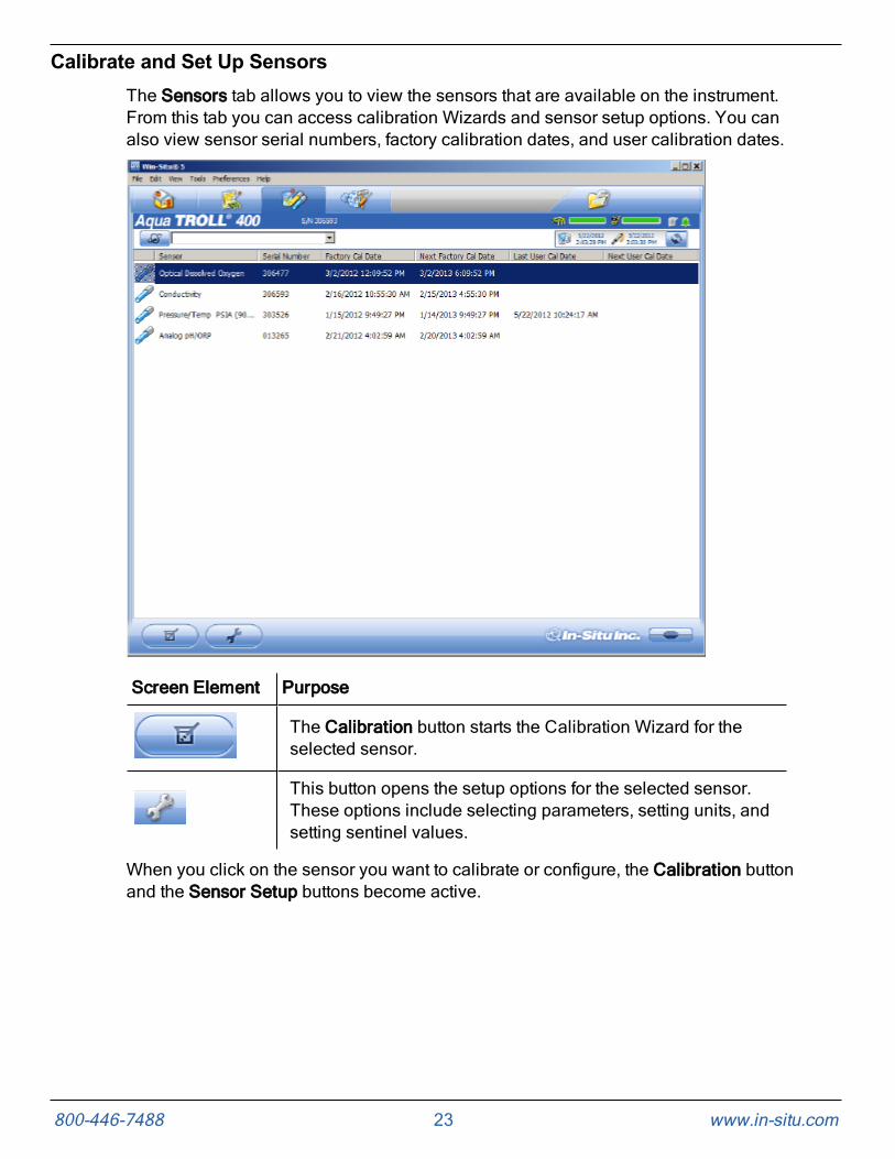
Calibrate and Set Up SensorsThe Sensors tab allows you to view the sensors that are available on the instrument.From this tab you can access calibration Wizards and sensor setup options. You canalso view sensor serial numbers, factory calibration dates, and user calibration dates.
Screen Element Purpose
The Calibration button starts the Calibration Wizard for theselected sensor.
This button opens the setup options for the selected sensor.These options include selecting parameters, setting units, andsetting sentinel values.
When you click on the sensor you want to calibrate or configure, the Calibration buttonand the Sensor Setup buttons become active.

800-446-7488 24 www.in-situ.com
Set Parameter Units and Sentinel ValuesYou can set sentinel values and set units for parameters by selecting a parameter andclicking the Setup Sensor button.
Screen Element Purpose
ParameterThis menu lists the parameters that are available for theselected sensor.
UnitsThis drop-down list allows you to select units for theparameter you selected.
Sentinel OfflineValue
This is a text field in which you can enter the value thatyou want to see in the data when a sensor is unable tocommunicate. After you have entered a value, click theSet button to save it.
ConfigureThis button becomes active when you select a parameterthat includes additional configuration options. Click theConfigure button to view the additional options.
Check markClicking the Check mark saves the changes you havemade in this screen.

800-446-7488 25 www.in-situ.com
RDO Sensor CalibrationThe optical Rugged Dissolved Oxygen sensor is very stable. The factory calibrationshould produce readings within 3% accuracy. If you require readings with greateraccuracy we recommend that you perform a 1-point, 100% water-saturated aircalibration as described below.
Calibration 100% Oxygen Saturation
1. Place the calibration cap, with the vent hole, on the top of the calibration cup.
1 Storage cap
2 Calibration cap with vent hole
2. Place the sponge wafer in the bottom of the calibration cup and saturate the spongewafer with approximately 10 mL clean water.
3. Gently dry the probe and sensing material with a paper towel. Ensure that the probeand the sensing surface are free of water and fouling.
4. Place the instrument into the calibration cup.
5. Wait 5 to 10 minutes for temperature stabilization prior to calibration.

800-446-7488 26 www.in-situ.com
Note: Do not leave the instrument in the calibration cup for morethan 30 minutes. This can cause condensation to form on thesensing material, providing false low readings after calibration.
6. In the software, select the Sensor Setup tab.
7. Select the RDO Dissolved Oxygen parameter.
8. Click Calibrate.
9. By default, 100% saturation is selected for the first point of the calibration. If youintend to perform a 2-point calibration, also select 0% saturation from the drop-downlist. Otherwise, leave as “None.”
10. Click Next.
11. Enter the barometric pressure or elevation at which the instrument will be deployed.
12. Click Next.
13. Click OK to start the calibration.
14. When the screen indicates that the calibration has reached stability, click Accept tocomplete the calibration, or click Cancel to return to the previous calibration.
Calibrate 0% Oxygen Saturation
We recommend that you perform the 0 % oxygen calibration only if you intend tomeasure dissolved oxygen at a concentration of less than 4 mg/L.
1. If you selected to perform a 2-point calibration, you are prompted to set up thesolution for the second point of the calibration.
2. Remove the wet sponge from the cup.
3. Fill the calibration cup to the fill line with approximately 130 mL of fresh sodiumsulfite solution.

800-446-7488 27 www.in-situ.com
4. Gently place the instrument in the calibration cup, taking care to not force thesolution out the top of the calibration cup.
5. Completely submerge the RDO Sensor into the solution.
6. Click OK, to start the calibration.
7. When the screen indicates that the calibration has reached stability, click Accept tocomplete the calibration, or click Cancel to return to the previous calibration.
8. You can save or print the calibration report.
9. Click OK to complete the calibration.
10. Once calibration is complete, remove the instrument from the calibration cup andrinse both thoroughly with clean water.

800-446-7488 28 www.in-situ.com
Conductivity CalibrationThe conductivity sensor is calibrated with NIST-traceable standards at the factory,which provides a high degree of linearity across the entire operating range of 5 to100,000 µS/cm. This sensor is capable of meeting its published specifications withoutrequiring additional calibration by the user. Most commercially available standards canintroduce a larger potential measurement error than the sensor’s initial factorycalibration.
User calibration is recommended only if you must conform to a standard operatingprocedure or if the conductivity cell has undergone physical change (e.g., deposits onconductivity cell walls that cannot be removed or physical damage to the conductivitycell walls).
1. Fill the calibration cup to the fill line with approximately 130 mL of the desiredcalibration solution.
2. Place the instrument in the solution taking care to not force the solution out the topof the calibration cup.
3. In Win-Situ 5 Software, select the Conductivity sensor.
4. Click the Calibrate button in the left corner of the screen.
5. Select either 20° C or 25° C as the reference temperature, as indicated by thereference calibration solution.

800-446-7488 29 www.in-situ.com
6. Select the appropriate calibration standard from the drop-down list. If you select“User Defined,” enter the value of the solution.
7. Click Next.
8. Place the instrument into the calibration cup and allow time for the temperature tostabilize.
9. Gently tap the sides of the calibration cup against the palm of your hand to removeany bubbles in the conductivity cell. Visually inspect to ensure that all bubbles areremoved.
10. Click OK to start the calibration.
11. When the screen indicates that the calibration has reached stability, click Accept tocomplete the calibration, or click Cancel to return to the previous calibration.
12. You can save or print the calibration report.
13. Click OK to complete the calibration.
14. Once calibration is complete, remove the instrument from the calibration cup andrinse both thoroughly with clean water.
Pressure/LevelThe pressure sensor has been factory calibrated with NIST standards to a greaterdegree of accuracy than can be achieved in nearly any alternative setting. Therefore,user calibration is not necessary for the pressure sensor if it is a gauged sensor. If you
800-446-7488 30 www.in-situ.com
encounter significant drift in pressure sensor readings, send the instrument to thefactory for service. For best results, use the pressure sensor to measure SurfaceElevation or Depth to Water.
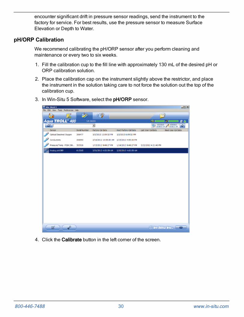
pH/ORP CalibrationWe recommend calibrating the pH/ORP sensor after you perform cleaning andmaintenance or every two to six weeks.
1. Fill the calibration cup to the fill line with approximately 130 mL of the desired pH orORP calibration solution.
2. Place the calibration cap on the instrument slightly above the restrictor, and placethe instrument in the solution taking care to not force the solution out the top of thecalibration cup.
3. In Win-Situ 5 Software, select the pH/ORP sensor.
4. Click the Calibrate button in the left corner of the screen.

800-446-7488 31 www.in-situ.com
5. Select either Calibrate pH or Calibrate ORP.
6. Click Next.
7. Select a value for the first calibration point. If you intend to perform a 2-point or 3-point calibration, select the appropriate values as indicated on the label of thecalibration standard.
8. Click Next.
9. Place the instrument into the calibration cup and allow time for the temperature tostabilize.
10. Click OK, to start the calibration.
11. When the screen indicates that the calibration has reached stability, click Accept tocomplete the calibration for that calibration point, or click Cancel to return to theprevious calibration.
12. Follow the Wizard to continue through the remaining calibration points.
13. You can save or print the calibration report.
14. Click OK to complete the calibration.
15. Once calibration is complete, remove the instrument from the calibration cup andrinse both thoroughly with clean water.

800-446-7488 32 www.in-situ.com
Controller Requirements and ConnectionsThe instrument can be connected to a controller or logger for communication via thefollowing protocols.
l SDI-12
l RS485 Modbus
l RS232 Modbus (with converter)
Wiring OverviewRefer to the diagrams on the following pages. Trim and insulate unused wires. Theshielded wire should be wired to a chassis ground or earth ground. See "Safety" onpage 5.
Stripped-and-Tinned Cable
Signal Color
Ground/Return Black
External Power Red
No Connection Brown
RS485 (-) Green
RS485 (+) Blue
SDI-12 White
Power ConnectionsThe Aqua TROLL 400 requires an external 8 to 36 VDC power source. The red wiremust be connected to the positive terminal of the power source. The black wire must beconnected to the negative terminal of the power source, which is often referred to as thesystem ground or return.

800-446-7488 33 www.in-situ.com
SDI-12 Wiring DiagramCable length must not exceed 60.9 m (200 ft).
Signal Color
Ground/Return Black
External Power (9.6-16 VDC) Red
SDI-12 White

800-446-7488 34 www.in-situ.com
Modbus Master RS485 Wiring DiagramCable length must not exceed 1,219 m (4,000 ft).
Signal Color
Ground/Return Black
External Power (12-36 VDC) Red
RS485 (-) Green
RS485 (+) Blue

800-446-7488 35 www.in-situ.com
Modbus Master RS232 Wiring Diagram (Converter Required)Cable length between Master and Slave must not exceed 1,219 m (4,000 ft). Cablelength between Master and Converter must not exceed 6 m (20 ft).
Signal Color
Ground/Return Black
External Power (12-36 VDC,voltage limited by converter)
Red
RS485 (-) Green
RS485 (+) Blue
800-446-7488 36 www.in-situ.com
RS485 Network GuidelinesThe instrument uses RS485 as its main digital communications link. RS485 is oftenused in an industrial setting as a small device network. There are some installationguidelines to follow when configuring an RS485 network with this instrument. See theModbus and SDI-12 Reference Guide.
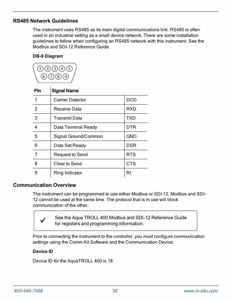
DB-9 Diagram
Pin Signal Name
1 Carrier Detector DCD
2 Receive Data RXD
3 Transmit Data TXD
4 Data Terminal Ready DTR
5 Signal Ground/Common GND
6 Data Set Ready DSR
7 Request to Send RTS
8 Clear to Send CTS
9 Ring Indicator RI
Communication OverviewThe instrument can be programmed to use either Modbus or SDI-12. Modbus and SDI-12 cannot be used at the same time. The protocol that is in use will blockcommunication of the other.
See the Aqua TROLL 400 Modbus and SDI-12 Reference Guidefor registers and programming information.
Prior to connecting the instrument to the controller, you must configure communicationsettings using the Comm Kit Software and the Communication Device.
Device ID
Device ID for the AquaTROLL 400 is 18.

800-446-7488 37 www.in-situ.com
Data Quality IDs and the Sensor Health TableEach sensor on the Aqua TROLL 400 instrument is associated with a correspondingData Quality ID register. (See the Aqua TROLL 400 Modbus and SDI-12 Guide to setup registers.) When Data Quality ID registers are configured, they will return DataQuality ID numbers that can help you to troubleshoot issues with the system or verifythat readings are normal. See the Sensor Health Table.
Sensor Health Table
Abbreviation Data Quality ID Text Description
None 0 None Normal Data Quality
UC 1User CalExpired
Parameter measured without errorsusing an expired user calibration.
FC 2Factory CalExpired
Parameter measured without errorsusing an expired factory calibration.
ERR 3 Unknown ErrorParameter measured with error,sentinel value supplied.
WU 4Sensor Warm-up
Sensor is warming up, sentinelvalue supplied.
DIS 5SensorWarning
Parameter measured but does notmeet normal quality criteria. Thesensor has sustained moderatedamage, or the recommendedlifespan has been reached.
CAL 6SensorCalibrating
Sensor is calibrating, calibrationvalue supplied.
OL 7 Sensor Missing
Sensor communication failed,sentinel value supplied. Make surethe sensor cap is installed andproperly seated.

800-446-7488 38 www.in-situ.com
Care and Maintenance
Maintenance ScheduleFor best results, send the instrument to the manufacturer for factory calibration every 12to 18 months.
User-Serviceable PartsThe user-serviceable parts on the instrument include the O-rings, the pH/ORP sensor,and the RDO Sensor Cap.
O-ringsThe instrument has several O-rings that can be maintained by the user in order to keepmoisture from entering the instrument and damaging the electronics. Apply a very thinlayer of vacuum grease to new O-rings upon installation. The O-rings are located in thefollowing areas.
1 Connector
2 Instrument housing
3 pH sensor
4 RDO Sensor
RDO Classic Sensor Cap ReplacementThe RDO Classic Sensor Cap has a 1-year typical life (15 months of total usage) afterthe sensor takes its first reading, or 36 months from the date of manufacture. Follow theinstructions included in the RDO Sensor Cap Replacement Kit. Replacement caps areavailable from In-Situ Inc. or your authorized In-Situ distributor.
pH/ORP Sensor ReplacementTo replace the pH/ORP sensor or to refill the reference junction, follow the instructionsin the pH/ORP Sensor Instruction Sheet that is included with the replacement sensor.
Instrument StorageTo store the probe for a week or less, place the probe in the calibration cup with a fewdrops of clean water to maintain a moist storage environment.
To store the probe for more than a week, perform the following procedure.

800-446-7488 39 www.in-situ.com
1. Remove the pH/ORP sensor and place the orange pH port plug into the emptypH/ORP port to prevent any humidity from entering the probe.
2. Locate the sensor storage bottle in which the pH sensor was originally shipped.
3. Open the bottle and remove the O-ring.
4. Moisten the sponge inside the bottle with either a pH storage solution or a pH 4solution.
5. Slide the O-ring onto the sensor, and then slide the bottle cap over the sensor asshown.
6. Place the sensor tip in the buffer and tighten the cap to prevent the glass bulb fromdrying.
Cleaning the pH/ORP SensorBegin with the gentlest cleaning method and continue to the other methods only ifnecessary. Do not directly touch or wipe the glass bulb.
To clean the pH sensor, gently rinse with cold water. If further cleaning is required,consider the nature of the debris to determine the appropriate method.
Remove Crystalline Deposits
1. Clean the sensor with warm water and mild soap.
2. Soak the sensor in 5% HCI solution for 10 to 30 minutes.
3. If deposits persist, alternate soaking in 5% HCI and 5% NaOH solutions.
Remove Oily or Greasy Residue
1. Clean the sensor with warm water and mild soap.
2. Methanol or isopropyl alcohol may be used for short soaking periods, up to 1 hour.
3. Do not soak the sensor in strong solvents, such as chlorinated solvents, ethers, orketones, including acetone.

800-446-7488 40 www.in-situ.com
Remove Protein-Like Material or Slimy Film
1. Clean the sensor with warm water and mild soap.
2. Soak the sensor in 0.1M HCI solution for 10 minutes and then rinse with deionizedwater.
Note: After performing any of these cleaning methods, rinse thesensor with water and then soak overnight in pH 4 buffer.
Cleaning the RDO Sensor
Clean the Sensor Cap
1. Leave the cap on the sensor.
2. Rinse the sensor with clean water from a squirt bottle or spray bottle.
3. Gently wipe with a soft cloth or brush if biofouling is present.
4. If extensive fouling or mineral build-up is present, soak the RDO Cap end (while thecap is still installed on the sensor) in commercially available household vinegar for15 minutes, then soak in deionized water for 15 minutes.
Note: Vinegar is safe for all of the sensors on the probe includingthe RDO Sensor if the sensor cap is on.
5. Do not use organic solvents because they will damage the sensing material. Do notremove the cap from the sensor prior to wiping.
6. After cleaning the sensor cap, perform a 2-point calibration.
Clean the Optical Window
1. Perform this task only once per year when you replace the sensor cap.
2. Pull to remove the sensor cap.
3. Gently wipe the optical window with the supplied lens wipe.
Important: Do not wet the interior lens area with water or anysolution.
Cleaning the Conductivity Sensor
1. Before you begin, ensure that the RDO Cap and any removable sensors are inplace. Rinse the conductivity sensor under running water to remove loose material.
2. Follow Cleaning Procedure 1. If debris is still present, progress to the next cleaningprocedure. If the debris is removed, skip to the last step.

800-446-7488 41 www.in-situ.com
Cleaning Procedure 1
Avoid damaging the plastic material of the conductivity cell. Gently scrub theconductivity cell with a soft swab and mild soap such as a dilute solution of dishdetergent. The probe is shipped with polyurethane foam swabs for this purpose. Youcan also achieve good results using a gentle back-and-forth motion with a thin cottonpipe cleaner. If debris is still present, continue to Cleaning Procedure 2. If the sensor isclean, skip to the last step.
Cleaning Procedure 2
Avoid damaging the plastic material of the conductivity cell. Gently scrub theconductivity cell with a foam swab and an aggressive soap such as Alconox cleaner. Ifdebris is still present, continue to Cleaning Procedure 3. If the sensor is clean, skip tothe last step.
Cleaning Procedure 3
Soak the sensor with dilute acetic acid (10:1 solution) or commercially availablehousehold vinegar to pre-soften calcium deposits. Follow this with Cleaning Procedure1 or Cleaning Procedure 2, depending on the degree of residual contamination. Theprobe can soak for any length of time in household vinegar. If debris is still present,continue to Cleaning Procedure 4. If the sensor is clean, skip to the last step.
Cleaning Procedure 4
Topically apply dilute phosphoric acid (< 27 %) or the consumer product LIME-A-WAYwith a soft swab to remove iron or calcium deposits that remain after using Process 3.Do not allow the cleaner to be in contact with the sensor for more than 10 minutes.Rinse well with clean water and continue to the last step.
Check the sensor calibration before redeployment. Recalibrate the sensor whennecessary.

800-446-7488 42 www.in-situ.com
Declaration of Conformity


![Aqua(4,4'-bipyridine-[kappa]N)bis(1,4-dioxo-1 ... - ScienceOpen](https://static.fdokumen.com/doc/165x107/63262349e491bcb36c0aa51f/aqua44-bipyridine-kappanbis14-dioxo-1-scienceopen.jpg)