Textile-Based Sound Sensors (TSS) - MDPI
11
Citation: Giglio, A.; Neuwerk, K.; Haupt, M.; Conti, G.M.; Paoletti, I. Textile-Based Sound Sensors (TSS): New Opportunities for Sound Monitoring in Smart Buildings. Textiles 2022, 2, 296–306. https:// doi.org/10.3390/textiles2020016 Academic Editor: Laurent Dufossé Received: 29 March 2022 Accepted: 11 May 2022 Published: 19 May 2022 Publisher’s Note: MDPI stays neutral with regard to jurisdictional claims in published maps and institutional affil- iations. Copyright: © 2022 by the authors. Licensee MDPI, Basel, Switzerland. This article is an open access article distributed under the terms and conditions of the Creative Commons Attribution (CC BY) license (https:// creativecommons.org/licenses/by/ 4.0/). Review Textile-Based Sound Sensors (TSS): New Opportunities for Sound Monitoring in Smart Buildings Andrea Giglio 1, * , Karsten Neuwerk 2 , Michael Haupt 2 , Giovanni Maria Conti 1 and Ingrid Paoletti 1 1 Department of Architecture, Built Environment and Construction Engineering, Politecnico di Milano, 20133 Milan, Italy; [email protected] (G.M.C.); [email protected] (I.P.) 2 DITF Denkendorf, German Institutes of Textile and Fibre Research Denkendorf, 73770 Denkendorf, Germany; [email protected] (K.N.); [email protected] (M.H.) * Correspondence: [email protected] Abstract: Persistent poor acoustic conditions can imbalance humans’ psychophysical capabilities. A good acoustic project starts with either correct measurements of the existing acoustic parameters or with the correct hypothesis of new sound conditions. International standards define invasive measurement conditions and procedures that can disturb user activities. For this reason, alternative methodologies have been developed by mounting real-time sound-monitoring devices. Most of the research on these aims to decrease their dimensions in order to be placed in the tight service spaces of modern architecture and to reduce their aesthetic impact on interiors design. In this perspective, this article explores the features and potentialities of textile-based sound sensors (TSS) as they can not only fulfill these needs but can also be used as architectural ornaments by partially wrapping interiors. The ubiquitous of e-textiles for wearable applications has led to increasing the performance of TSS. Therefore, a comparison of the sensitivity values, signal-to-noise ratio and noise floor of sound TSS with sound sensors is presented, which is still missing in the literature. The paper demonstrates how these can be exploited for sound monitoring and can provide valid opportunities for new smart acoustic textiles. Keywords: e-textiles; textile-based sound sensors; sound monitoring; smart building 1. Introduction Sound conditions can have physiological and psychological effects on people in either a positive or negative way. Studies have demonstrated effects in educational spaces [1], working spaces [2], restaurants [3], canteens [4] and outdoor spaces [5]. Negative con- ditions can cause permanent hearing damage, increased stress [6], reduced efficiency at work [7], disturbance of sleep patterns [8] and interference in communications [9] as well as cardiovascular illnesses [10]. Therefore, it is increasingly compelling to embed sound condition considerations starting in the first stages of the design process. International standards indeed provide the requirements for running considerations at the design stage of new programs [11], and for existing functions, international standards give the terms, definitions, measurement conditions, procedures and evaluation methodologies [12–14]. Nonetheless, most of these conditions are invasive and concern the use of annoying sources that can affect normal user activities. For this reason, non-invasive sound-monitoring devices have been developed to provide real-time sound-data gathering. These systems are framed in the consolidated trends of monitoring systems that help to maximise the energy savings, comfort and safety for the occupants [15]. The most commonly used sensing systems detect real-time information on the temperature and air quality and enable building environmental control systems, such as heating, ventilation, and air conditioning systems if the gathered data does not fulfill the fixed benchmarks. Textiles 2022, 2, 296–306. https://doi.org/10.3390/textiles2020016 https://www.mdpi.com/journal/textiles
-
Upload
khangminh22 -
Category
Documents
-
view
0 -
download
0
Transcript of Textile-Based Sound Sensors (TSS) - MDPI

Citation: Giglio, A.; Neuwerk, K.;
Haupt, M.; Conti, G.M.; Paoletti, I.
Textile-Based Sound Sensors (TSS):
New Opportunities for Sound
Monitoring in Smart Buildings.
Textiles 2022, 2, 296–306. https://
doi.org/10.3390/textiles2020016
Academic Editor: Laurent Dufossé
Received: 29 March 2022
Accepted: 11 May 2022
Published: 19 May 2022
Publisher’s Note: MDPI stays neutral
with regard to jurisdictional claims in
published maps and institutional affil-
iations.
Copyright: © 2022 by the authors.
Licensee MDPI, Basel, Switzerland.
This article is an open access article
distributed under the terms and
conditions of the Creative Commons
Attribution (CC BY) license (https://
creativecommons.org/licenses/by/
4.0/).
Review
Textile-Based Sound Sensors (TSS): New Opportunities forSound Monitoring in Smart BuildingsAndrea Giglio 1,* , Karsten Neuwerk 2, Michael Haupt 2 , Giovanni Maria Conti 1 and Ingrid Paoletti 1
1 Department of Architecture, Built Environment and Construction Engineering, Politecnico di Milano,20133 Milan, Italy; [email protected] (G.M.C.); [email protected] (I.P.)
2 DITF Denkendorf, German Institutes of Textile and Fibre Research Denkendorf, 73770 Denkendorf, Germany;[email protected] (K.N.); [email protected] (M.H.)
* Correspondence: [email protected]
Abstract: Persistent poor acoustic conditions can imbalance humans’ psychophysical capabilities.A good acoustic project starts with either correct measurements of the existing acoustic parametersor with the correct hypothesis of new sound conditions. International standards define invasivemeasurement conditions and procedures that can disturb user activities. For this reason, alternativemethodologies have been developed by mounting real-time sound-monitoring devices. Most of theresearch on these aims to decrease their dimensions in order to be placed in the tight service spacesof modern architecture and to reduce their aesthetic impact on interiors design. In this perspective,this article explores the features and potentialities of textile-based sound sensors (TSS) as they cannot only fulfill these needs but can also be used as architectural ornaments by partially wrappinginteriors. The ubiquitous of e-textiles for wearable applications has led to increasing the performanceof TSS. Therefore, a comparison of the sensitivity values, signal-to-noise ratio and noise floor of soundTSS with sound sensors is presented, which is still missing in the literature. The paper demonstrateshow these can be exploited for sound monitoring and can provide valid opportunities for new smartacoustic textiles.
Keywords: e-textiles; textile-based sound sensors; sound monitoring; smart building
1. Introduction
Sound conditions can have physiological and psychological effects on people in eithera positive or negative way. Studies have demonstrated effects in educational spaces [1],working spaces [2], restaurants [3], canteens [4] and outdoor spaces [5]. Negative con-ditions can cause permanent hearing damage, increased stress [6], reduced efficiency atwork [7], disturbance of sleep patterns [8] and interference in communications [9] as wellas cardiovascular illnesses [10].
Therefore, it is increasingly compelling to embed sound condition considerationsstarting in the first stages of the design process. International standards indeed providethe requirements for running considerations at the design stage of new programs [11], andfor existing functions, international standards give the terms, definitions, measurementconditions, procedures and evaluation methodologies [12–14]. Nonetheless, most of theseconditions are invasive and concern the use of annoying sources that can affect normal useractivities. For this reason, non-invasive sound-monitoring devices have been developed toprovide real-time sound-data gathering.
These systems are framed in the consolidated trends of monitoring systems that helpto maximise the energy savings, comfort and safety for the occupants [15]. The mostcommonly used sensing systems detect real-time information on the temperature and airquality and enable building environmental control systems, such as heating, ventilation,and air conditioning systems if the gathered data does not fulfill the fixed benchmarks.
Textiles 2022, 2, 296–306. https://doi.org/10.3390/textiles2020016 https://www.mdpi.com/journal/textiles
Textiles 2022, 2 297
Indoor environmental quality influences occupant productivity and health; therefore,its management is crucial, and sound has a prominent role. Sound-monitoring devices findapplications in urban contexts [16] with low-cost [17] wireless sensor networks [18] embed-ding spatial statistical analysis [19], through considering indexes that embed subjectivemeasures [20], in detecting noise levels while being powered by energy harvesting [21]and through the development of sensor nodes for accurate indoor sound-level measure-ments [22].
This article intends to compare the performances of sound sensors of the aforemen-tioned cases with textile-based sound sensors (TSS). The combination of electronics andtextiles is increasingly achieving important results in the trend for common computing.The rapid advancements of science and technologies keep revolutionizing traditional tex-tiles and achieving new applications; smart textiles have more functions, including tactilesensing [23], displays [24], communicating [25], self-charging [26] and regulating bodytemperature [27] and humidity [28].
In the last decades, important advances have been achieved in sound sensors as well.They can measure correlation between the subjective assessment of perceived sound qualityand the cardiac activity of the listeners [20], they can be embedded in gloves [29] and usedfor sound-direction detection, acoustic communications and heart-sound auscultation [30].Their applications are mostly in wearable fabrics. Greinke used piezo electric films forsound measurement by sticking the film into fabric and sewing a conductive path withconductive yarn [31].
Nakad et al. designed and implemented a large-scale e-textile that functions as anacoustic beamforming array [32]. The prototype aims to find the location of a passingvehicle based upon the vehicle’s acoustic emissions through a system that combines multi-ple lines-of-bearing to the vehicle’s traffic. These lines-of-bearing are computed using anacoustic beamforming algorithm under the assumption that the vehicle is in the far fieldand lies in the same plane as the e-textile. They concluded that, at the physical scale, robustconnectors are necessary for attaching electronic components, in order to insulate conduc-tive elements in the fabric. At the system scale, the communication is energy-efficient andfault-tolerant and can serve a wide range of e-textile applications.
Comparisons between the performances of sound sensors have already been presentedin the literature; however, a deep comparison of sound sensors for monitoring systems andTSS is still missing. This article intends to fill this gap.
2. Research Methodology
The article intends to compare the microphones embedded in sound-monitoring sys-tems with TSSs. Only case studies published in scientific journals or accredited conferenceare reported.
An imperfect selection of materials, transducer modes and processing circuity canlead poor acoustic functionalities by decreasing the values of the signal-to-noise ratio(SNR) [33–35]. The SNR depends on the sensitivity and noise measured at a given acousticpressure. The sensitivity is the converted sensing signal arising from the mechanicalvibration with respect to the applied acoustic pressure. Therefore, the higher the valueis, the better the performance. Furthermore, when the energy conversion takes place, anelectrical noise—in form of a voltage/current—is also introduced followed by the thermal-mechanical or Johnson noise [33,34,36]. As a consequence, the signal-to-noise ratio (SNR),sensitivity and noise floor (plotted in Table 1 with the related unit) are the parameters usedfor the comparison.

Textiles 2022, 2 298
Table 1. The main parameters and relative units for acoustic sensor performance.
Parameters Unit
Sensitivity at 1 kHz mV/Pa, or dBSignal-to-noise ratio (SNR) dB
Noise floor dBSensitivity Resonance Hz
3. Methods to Embed Sound Sensors in Textile
One of the most critical aspects for electronic textiles is the power supply. All electroniccomponents require an energy supply in order to be employed as a stand-alone component.Avoiding conventional batteries important since it makes the garment similar to an ordinaryone. Batteries are very bulky to add into the fabric, and they can limit the characteristics ofthe textile itself. Alternatives are given by flexible solar cells (Silicon Solar Inc, Bainbridge,New York, USA.) and micro fuel cells (Enfucell, Vantaa, Finland) since they can be usedas a power supply for electronic devices. Other options are given by materials that areable to transform changing pressures (such as body motions or sound pressures in electricpower [35]) using piezo electric materials [36]. The piezoelectricity is the generation ofelectrical polarization in a material under applied mechanical stresses. When a deformationoccurs, it generates an electric charge. Vice versa, under applied charge, the material woulddeform in response [37].
Piezoelectric material-based sensors offer two main advantages: (1) there is no specificrequirement for the input power and (2) a broad dynamic range. For these reasons, most ofthe cases considered for the purpose of this article are piezoelectric-based acoustic sensors(from here on PAS) and micro-electrotechnical systems (from here on MEMS).
Two methods are mainly used to embed sound sensors in textiles: 1. by attachingexternal sensors to the textile structures and 2. by embroidering piezo electric threads tocreate the fabric circuits. The two methodologies are described in the next paragraphs.
3.1. Piezoelectric Acoustic Sensors (PAS) Films
According to the plane in which the sensing phase is placed, the energy conversionsin piezoelectricity takes place in two transducing modes (Figure 1). In the case where itoccurs in plane 31, we consider the D31 mode. If it occurs in direction 3, it is the D33 mode.
Textiles 2022, 2, FOR PEER REVIEW 3
Signal-to-noise ratio (SNR) dB Noise floor dB
Sensitivity Resonance Hz
3. Methods to Embed Sound Sensors in Textile One of the most critical aspects for electronic textiles is the power supply. All
electronic components require an energy supply in order to be employed as a stand-alone component. Avoiding conventional batteries important since it makes the garment similar to an ordinary one. Batteries are very bulky to add into the fabric, and they can limit the characteristics of the textile itself. Alternatives are given by flexible solar cells (Silicon Solar Inc, Bainbridge, New York, USA.) and micro fuel cells (Enfucell, Vantaa, Finland) since they can be used as a power supply for electronic devices. Other options are given by materials that are able to transform changing pressures (such as body motions or sound pressures in electric power [35]) using piezo electric materials [36]. The piezoelectricity is the generation of electrical polarization in a material under applied mechanical stresses. When a deformation occurs, it generates an electric charge. Vice versa, under applied charge, the material would deform in response [37].
Piezoelectric material-based sensors offer two main advantages: (1) there is no specific requirement for the input power and (2) a broad dynamic range. For these reasons, most of the cases considered for the purpose of this article are piezoelectric-based acoustic sensors (from here on PAS) and micro-electrotechnical systems (from here on MEMS).
Two methods are mainly used to embed sound sensors in textiles: 1. by attaching external sensors to the textile structures and 2. by embroidering piezo electric threads to create the fabric circuits. The two methodologies are described in the next paragraphs.
3.1. Piezoelectric Acoustic Sensors (PAS) Films According to the plane in which the sensing phase is placed, the energy conversions
in piezoelectricity takes place in two transducing modes (Figure 1). In the case where it occurs in plane 31, we consider the D31 mode. If it occurs in direction 3, it is the D33 mode.
Figure 1. Definition of the planes where the sensing phases can be placed.
Upon an application of the acoustic pressure, the induced voltage (V) is defined as [34], V = E × s (1)
where E is the induced electric field and s is the electrode spacing. The electrode spacing (s) can be “t” or “d” (as shown in Figure 2), depending on the transducer mode. In D31
Figure 1. Definition of the planes where the sensing phases can be placed.
Upon an application of the acoustic pressure, the induced voltage (V) is defined as [34],
V = E × s (1)
where E is the induced electric field and s is the electrode spacing. The electrode spacing(s) can be “t” or “d” (as shown in Figure 2), depending on the transducer mode. In D31

Textiles 2022, 2 299
mode, the “3-1” refers to the induced polarization in direction 3 with respect to the perunit stress applied in direction 1 (Figure 2a) [35]. Thus, the thickness (t) limits the sensingsignal. The improvement of the SNR in order to fit it with new technology demands hasbeen achieved by incorporating different piezoelectric materials with different thicknesses,such as aluminium nitride (AlN) and D31 mode [36], sputtered zinc oxide (ZnO) and D31mode [38] as well as lead zirconate titanate (PZT) and D31 mode [39].
Textiles 2022, 2, FOR PEER REVIEW 4
mode, the “3-1” refers to the induced polarization in direction 3 with respect to the per unit stress applied in direction 1 (Figure 2a) [35]. Thus, the thickness (t) limits the sensing signal. The improvement of the SNR in order to fit it with new technology demands has been achieved by incorporating different piezoelectric materials with different thicknesses, such as aluminium nitride (AlN) and D31 mode [36], sputtered zinc oxide (ZnO) and D31 mode [38] as well as lead zirconate titanate (PZT) and D31 mode [39].
The highest thickness values can increase the induced voltage; however, at the same time, it makes the sensor bulky and generates higher noise followed by mass and gravitational acceleration. For instance, Wang et al. reported a 60 dB SNR and a 34 dB noise floor by utilizing 0.7 μm thick PZT [39]; whereas, the reported sensitivity was only 0.49 mV/Pa, which is still a challenge for further signal processing. Therefore, an increase in film thickness is not a favourable solution to enhance the SNR.
Figure 2. Piezoelectric acoustic sensor (PAS) with (a) D31 mode where t is the film thickness and (b) D33 mode where d is the electrode spacing [40].
For this reason, the D33 mode, where the stress and strain take place in the “3-3” directions (Figure 2b), has been developed. In this mode, the design focuses on the electrode spacing because this mode is not related to the film thickness [40]. Shen et al. incorporated inter-digitated electrodes (D33 mode) to enhance the sensitivity of the piezo electric sensors (PAS) [40]. However, they did not obtain substantial improvement on sensitivity using 250 μm electrode spacing as the reported sensitivity was 0.126 mV/Pa which is far behind than what Wang et al. achieved using D31 mode [39]. The main drawback of the Shen et al.’s PAS is the material selection.
The zirconate titanate (PZT) is good for energy scavenging due to its high piezoelectric constant when compared to other piezoelectric materials [41]. However, the incorporation of zirconate titanate (PZT) requires a special attention during the fabrication, i.e., for the poling process [42]. This is an additional drawback of zirconate titanate (PZT) because it shows the de-poling effect at higher electrode spacing starting from 16 μm which is 4 μm less than the nominal spacing of AlN, i.e., 20 μm [38,43,44].
As a result, the electric field as well as the sensing signal is lower at higher electrode spacing [43]. When compared to the PZT and D33, the combination AlN and D33 can be the better option for acoustic sensors. This combination does not show the de-poling effect since it depends on the lattice orientation [42]. Table 2 categorizes the previous studies by thickness, material, typology, sensitivity, SNR, noise floor and sensitivity peak. Others cases studies are plotted in Table 2 such as [44–47] for piezoelectric acoustic sensors in D31 mode. [48,49] refer to piezoelectric acoustic sensors in D33 mode and are plotted in Table 2
Figure 2. Piezoelectric acoustic sensor (PAS) with (a) D31 mode where t is the film thickness and(b) D33 mode where d is the electrode spacing [40].
The highest thickness values can increase the induced voltage; however, at the sametime, it makes the sensor bulky and generates higher noise followed by mass and gravita-tional acceleration. For instance, Wang et al. reported a 60 dB SNR and a 34 dB noise floorby utilizing 0.7 µm thick PZT [39]; whereas, the reported sensitivity was only 0.49 mV/Pa,which is still a challenge for further signal processing. Therefore, an increase in filmthickness is not a favourable solution to enhance the SNR.
For this reason, the D33 mode, where the stress and strain take place in the “3-3”directions (Figure 2b), has been developed. In this mode, the design focuses on the electrodespacing because this mode is not related to the film thickness [40]. Shen et al. incorporatedinter-digitated electrodes (D33 mode) to enhance the sensitivity of the piezo electric sensors(PAS) [40]. However, they did not obtain substantial improvement on sensitivity using250 µm electrode spacing as the reported sensitivity was 0.126 mV/Pa which is far behindthan what Wang et al. achieved using D31 mode [39]. The main drawback of the Shenet al.’s PAS is the material selection.
The zirconate titanate (PZT) is good for energy scavenging due to its high piezoelectricconstant when compared to other piezoelectric materials [41]. However, the incorporationof zirconate titanate (PZT) requires a special attention during the fabrication, i.e., for thepoling process [42]. This is an additional drawback of zirconate titanate (PZT) because itshows the de-poling effect at higher electrode spacing starting from 16 µm which is 4 µmless than the nominal spacing of AlN, i.e., 20 µm [38,43,44].
As a result, the electric field as well as the sensing signal is lower at higher electrodespacing [43]. When compared to the PZT and D33, the combination AlN and D33 can bethe better option for acoustic sensors. This combination does not show the de-poling effectsince it depends on the lattice orientation [42]. Table 2 categorizes the previous studiesby thickness, material, typology, sensitivity, SNR, noise floor and sensitivity peak. Otherscases studies are plotted in Table 2 such as [44–47] for piezoelectric acoustic sensors in D31mode. [48,49] refer to piezoelectric acoustic sensors in D33 mode and are plotted in Table 2.

Textiles 2022, 2 300
Table 2. References on D31 and D33 piezo acoustic sensors and the relative achieved values. NR: Notreported.
Reference PAS Thickness[µm] PAS Material Sensitivity mV/Pa
at 1 kHz SNR dB at 1 kHz Noise Floor Sensitivity PeakkHz
D31 mode
[36] 3 AlN (Aluminiumnitride) 1.82 57
37 in dB(A) (A-weighteddecibels expresses the
relative loudness of soundsin air as perceived by the
human ear)
NR
[40] 127 PZT (leadzirconate-titanate) 0.12 NR NR 13.71
[44] 3.5 ZnO (Zinc oxide) 0.92 37 57 Hz (resonance frequency) 18
[45] 2.14 AlN (Aluminiumnitride) 0.039 54 40 in dB SPL 20
[46] 0.267 PZT (leadzirconate-titanate) 0.00166 58.3
35.7 in dB SPL (Soundpressure level measured in
decibel)59
[47] 0.2 AlN (Aluminiumnitride) 0.68 NR NR 11.2
D33 mode
[48] 26 PP (polypropylene) 2 57 37 in dB SPL NR
[49] 0.5 AlN (Aluminiumnitride) 4.49 67 27.3 in dB SPL 10.18
3.2. Piezoelectric Acoustic Sensors (PAS) Yarns
The studies on piezoelectric yarns aim at overcoming their inability to control chang-ing properties over a wide range of frequencies [50]. This has led to the breach of newapplications fields, such as energy harvesting [51] and conformal acoustics [52].
The development of fabrication methods that facilitate multi-functional and multi-material yarns enable several attractive properties for new applications. The preform-basedthermal drawing process offers a scalable means of producing kilometre-long fibre deviceswith sub millimetric cross-sectional dimensions [53]. These long and flexible fibres caneasily be assembled into fabrics [54]. Furthermore, the integration of electrodes into thefibre enables the straightforward electrical connection of the device to an external electricalcircuit [55].
The latest advancements in this field have led to the development of piezoelectricfibres (based on polyvinylidene fluoride (PVDF) and its copolymer, polyvinylidene fluoride-trifluoroethylene, (PVDF-TrFE)), which are capable of emitting and detecting sound wavesover a broad range of frequencies [50]. While the small cross-sectional area of these fibresenables both miniaturization and flexibility, it seemingly involves an equally small activearea that potentially limits the fibre performance [52]. The research of Yan et al. overcamethe traditional use of acoustic fabrics by introducing a fabric that operates as a sensitiveaudible microphone while retaining the traditional qualities of fabrics, such as machinewashability and draping [30].
Key to the fibre sensitivity is an elastomeric cladding that concentrates the mechanicalstress in a piezocomposite layer with a high piezoelectric charge coefficient, of approxi-mately 46 picocoulombs per newton, due to the thermal drawing process [56]. With thefibre subsuming less than 0.1% of the fabric by volume, a single fibre draw enables tens ofsquare metres of fabric microphone. The measured sensitivity of the fibre-on-membrane is19.6 mV (at 94 dB and 1 kHz, making it comparable to that of off-the-shelf condenser anddynamic microphones [30].
4. Sound Sensors Typologies in Monitoring System
The advancements in low-power computing, microphone technology and networkinghave allowed to move from very expensive static acoustic sensors to low-cost easy-to-useones. Dedicated stations have been upgraded with real-time data transmission capabilities,but the most important advancements have been achieved in elaborating more flexiblesensor node that can perform advanced digital signal processing.

Textiles 2022, 2 301
Mydlarz et al. identified three general categories by relating sensor functionality andcost [16]. For the purposes of this article, we considered their sound performance related tothe dimensions. When the transfer factor is not specified, the following formula is used tocalculate it from sensitivity values in dB re. V/Pa (decibel relative to 1 volt per 1 pascal:
transfer factor = 10(sensitivity
20 )×1000 (2)
If only the transfer factor is presented, the sensitivity is calculated with the followingequation:
sensitivity = 20 × log10
(transfer factor
1000
)(3)
Table 3 categorizes the case studies according with the typology, application field(Indoor or outdoor), sensitivity, transfer factor, signal-to-noise ratio and thickness. It showsthat for sound-monitoring system in free field several typologies of microphone have beentested: from Microelectromechanical system (MEMS) to condenser microphones. In thesecases, the sensitivity range from −38to −42.04 dB re. 1 V/Pa with a thickness between1700 to 17,600 µm. Since the monitoring of noise pollution is more topical in socio-politicaldebate about the comfort of our cities, there are more explorations on open air applications.
Table 3. Comparison of sound sensors typologies, thickness, and relative acoustic performances inmonitoring systems.
ReferenceSource
Sound SensorsTypology Application Sensitivity at
1 kHz, dB re. 1 V/PaTransfer FactormV/Pa at 1 kHz SNR Thickness
[µm]
[16] MEMS Outdoor −38 12.59 63 dBA 11,000
[17] MonacorMCE-400 Outdoor −42.04 7.9 58 dB 6700
[18] Tmote-Invent Outdoor −35 17.78 NR 86,000
[19]Condenser
microphone 12 ”
C-130 CesvaOutdoor −35.14 17.5 NR 17,600
[20] ADMP401MEMS Outdoor −42 7.94 62 dBA 10,000
[21]
KnowlesSPU0410LR5H-
QB analogMEMS
Indoor −41 8.91 94 dBA 1700
Devices which embed all the hardware has adopted with a sensitivity higher thanthe previous examples at −41 V/Pa at 1 kHz [13]. The high performance represents anopportunity for furthermore applications, but the high volume represents a limitationrespect with the necessity to save the net area of use of interiors from services spaces, suchas false ceiling and false walls.
5. Comparison of Textile-Based Sound Sensors and Other Microphones
The sound sensors in current monitoring systems range between 1700 and 86,000 µm.The sensitivity coefficients cover a broad range between 7.9 to 17.78 mV/Pa re. at 1 kHz. Itcan be observed that the typologies of microphone in this case are mainly for environmentalmeasurements except for [13]. In this latter, the low thickness is combined with middlelow sensitivity respect to the other (Figure 3). These studies are identified in Figure 3 ingradient of green.
Textiles 2022, 2 302
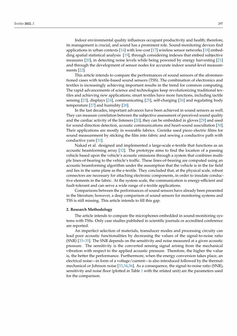
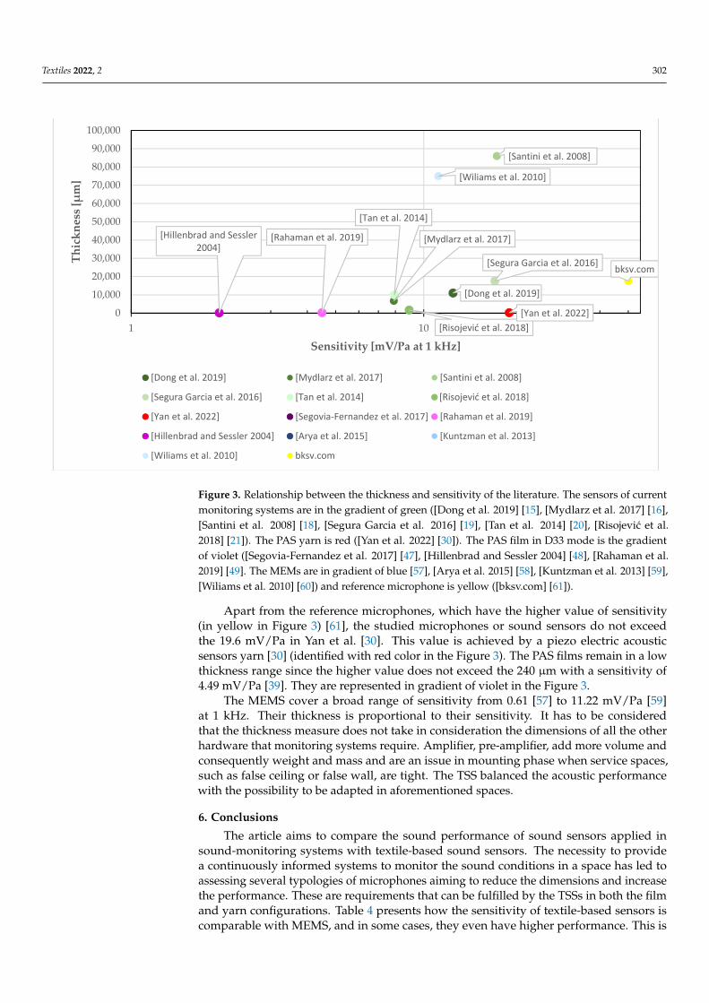
Textiles 2022, 2, FOR PEER REVIEW 7
Figure 3. Relationship between the thickness and sensitivity of the literature. The sensors of current monitoring systems are in the gradient of green ([Dong et al. 2019] [15], [Mydlarz et al. 2017] [16], [Santini et al. 2008,] [18], [Segura Garcia et al. 2016] [19], [Tan et al. 2014] [20], [Risojević et al. 2018] [21]). The PAS yarn is red ([Yan et al. 2022] [30]). The PAS film in D33 mode is the gradient of violet ([Hillenbrad and Sessler 2004] [48], [Rahaman et al. 2019] [49], . The MEMs are in gradient of blue[57], [Arya et al. 2015] [58], [Kuntzman et al. 2013] [59], [Wiliams et al. 2010] [60])and reference microphone is yellow ([bksv.com] [61]).
Apart from the reference microphones, which have the higher value of sensitivity(in yellow in Figure 3) [61], the studied microphones or sound sensors do not exceed the 19.6 mV/Pa in Yan et al. [30]. This value is achieved by a piezo electric acoustic sensors yarn [30] (identified with red color in the Figure 3). The PAS films remain in a low thickness range since the higher value does not exceed the 240 μm with a sensitivity of4.49 mV/Pa [39]. They are represented in gradient of violet in the Figure 3.
The MEMS cover a broad range of sensitivity from 0.61[57] to 11.22 mV/Pa [59] at 1kHz. Their thickness is proportional to their sensitivity. It has to be considered that the thickness measure does not take in consideration the dimensions of all the other hardware that monitoring systems require. Amplifier, pre-amplifier, add more volume and consequently weight and mass and are an issue in mounting phase when service spaces, such as false ceiling or false wall, are tight. The TSS balanced the acousticperformance with the possibility to be adapted in aforementioned spaces.
6. Conclusions
[Dong et al. 2019]
[Mydlarz et al. 2017]
[Santini et al. 2008]
[Segura Garcia et al. 2016]
[Tan et al. 2014]
[Risojević et al. 2018][Yan et al. 2022]
[Rahaman et al. 2019][Hillenbrad and Sessler 2004]
[Wiliams et al. 2010]
bksv.com
0
10,000
20,000
30,000
40,000
50,000
60,000
70,000
80,000
90,000
100,000
1 10
Thic
knes
s [μ
m]
Sensitivity [mV/Pa at 1 kHz]
[Mydlarz et al. 2017] [Santini et al. 2008]
[Tan et al. 2014] [Risojević et al. 2018]
[Segovia-Fernandez et al. 2017] [Rahaman et al. 2019]
[Arya et al. 2015] [Kuntzman et al. 2013]
[Dong et al. 2019]
[Segura Garcia et al. 2016]
[Yan et al. 2022]
[Hillenbrad and Sessler 2004]
[Wiliams et al. 2010] bksv.com
Figure 3. Relationship between the thickness and sensitivity of the literature. The sensors of currentmonitoring systems are in the gradient of green ([Dong et al. 2019] [15], [Mydlarz et al. 2017] [16],[Santini et al. 2008] [18], [Segura Garcia et al. 2016] [19], [Tan et al. 2014] [20], [Risojevic et al.2018] [21]). The PAS yarn is red ([Yan et al. 2022] [30]). The PAS film in D33 mode is the gradientof violet ([Segovia-Fernandez et al. 2017] [47], [Hillenbrad and Sessler 2004] [48], [Rahaman et al.2019] [49]. The MEMs are in gradient of blue [57], [Arya et al. 2015] [58], [Kuntzman et al. 2013] [59],[Wiliams et al. 2010] [60]) and reference microphone is yellow ([bksv.com] [61]).
Apart from the reference microphones, which have the higher value of sensitivity(in yellow in Figure 3) [61], the studied microphones or sound sensors do not exceedthe 19.6 mV/Pa in Yan et al. [30]. This value is achieved by a piezo electric acousticsensors yarn [30] (identified with red color in the Figure 3). The PAS films remain in a lowthickness range since the higher value does not exceed the 240 µm with a sensitivity of4.49 mV/Pa [39]. They are represented in gradient of violet in the Figure 3.
The MEMS cover a broad range of sensitivity from 0.61 [57] to 11.22 mV/Pa [59]at 1 kHz. Their thickness is proportional to their sensitivity. It has to be consideredthat the thickness measure does not take in consideration the dimensions of all the otherhardware that monitoring systems require. Amplifier, pre-amplifier, add more volume andconsequently weight and mass and are an issue in mounting phase when service spaces,such as false ceiling or false wall, are tight. The TSS balanced the acoustic performancewith the possibility to be adapted in aforementioned spaces.
6. Conclusions
The article aims to compare the sound performance of sound sensors applied insound-monitoring systems with textile-based sound sensors. The necessity to providea continuously informed systems to monitor the sound conditions in a space has led toassessing several typologies of microphones aiming to reduce the dimensions and increasethe performance. These are requirements that can be fulfilled by the TSSs in both the filmand yarn configurations. Table 4 presents how the sensitivity of textile-based sensors iscomparable with MEMS, and in some cases, they even have higher performance. This is

Textiles 2022, 2 303
more so apparent, when considering the volume of all the hardware that MEMs requireto complete a monitoring system. Figure 4 demonstrates that they would increase itconsiderably.
Table 4. Comparison of parameters between Pas D31, Pas D33, Acoustics MEMs and microphones.
References Source Sensitivity mV/Pa at 1 kHz SNR dBA at 1 kHz Noise Floor Thickness µm
Sound sensors in current monitoring system
[15] 12.59 63 NR 11,000[16] 7.9 58 NR 6700[18] 17.78 NR NR 860,000[19] 17.5 NR NR 17,600[20] 7.94 62 NR 10,000[21] 8.912 −41 NR 1700
PAS (Piezo acoustic sensors) yarn
[30] 19.6 30 NR 200
PAS (Piezo acoustic sensors) film D33 mode
[48] 2 57 37 in dB SPL 26[49] 4.49 67 27.3 in dB SPL 0.5
MEMS
[57] 1 NR 16 in (kHz) 2.0[58] 0.0966–0.1266 NR 85 in (kHz) 15[59] 0.61 NR 13 in (kHz) 29[60] 11.22 NR 176 in (kHz) 150,000[48] 2 57 37 125
Conventional microphone
[61] 50 NR 15 dBA 17,600
Textiles 2022, 2, FOR PEER REVIEW 8
The article aims to compare the sound performance of sound sensors applied in sound-monitoring systems with textile-based sound sensors. The necessity to provide a continuously informed systems to monitor the sound conditions in a space has led to assessing several typologies of microphones aiming to reduce the dimensions and increase the performance. These are requirements that can be fulfilled by the TSSs in both the film and yarn configurations. Table 4 presents how the sensitivity of textile-based sensors is comparable with MEMS, and in some cases, they even have higher performance. This is more so apparent, when considering the volume of all the hardware that MEMs require to complete a monitoring system. Figure 4 demonstrates that they would increase it considerably.
Table 4. Comparison of parameters between Pas D31, Pas D33, Acoustics MEMs and microphones.
References Source Sensitivity mV/Pa at 1 kHz SNR dBA at 1 kHz Noise Floor Thickness μm Sound sensors in current monitoring system
[15] 12.59 63 NR 11,000 [16] 7.9 58 NR 6700 [18] 17.78 NR NR 860,000 [19] 17.5 NR NR 17,600 [20] 7.94 62 NR 10,000 [21] 8.912 −41 NR 1700
PAS (Piezo acoustic sensors) yarn [30] 19.6 30 NR 200
PAS (Piezo acoustic sensors) film D33 mode [48] 2 57 37 in dB SPL 26 [49] 4.49 67 27.3 in dB SPL 0.5
MEMS [57] 1 NR 16 in (kHz) 2.0 [58] 0.0966–0.1266 NR 85 in (kHz) 15 [59] 0.61 NR 13 in (kHz) 29 [60] 11.22 NR 176 in (kHz) 150,000 [48] 2 57 37 125
Conventional microphone [61] 50 NR 15 dBA 17,600
Figure 4. The relations between the volume of the MEMS microphones themselves and with thehardware of the monitoring system. ([Dong et al. 2019] [15], [Mydlarz et al. 2017] [16], [Santini et al.2008], [18], [Segura Garcia et al. 2016] [19], [Tan et al. 2014] [21], [Risojevic et al. 2018] [22]).
The low thickness of TSSs can facilitate use in tight service spaces, such as false ceilingsand false walls, in order to reduce the aesthetic impact on the space design. Therefore, oneof main requests for these systems is either the reduction of their shapes or a high degreeof adaptability. Moreover, due to the aesthetic characteristics of the textile itself, in futureworks it could be interesting to demonstrate how they can be used to combine aestheticfeatures with sound-monitoring ones.

Textiles 2022, 2 304
This feature can enable sound smartness in fabrics with active absorption behaviours toimprove sound conditions in real time, thereby, opening new scenarios for the developmentof acoustic textiles.
Author Contributions: Conceptualization, investigation, writing—original draft preparation, A.G.;writing—review and editing, K.N.; supervision, M.H., G.M.C., I.P. All authors have read and agreedto the published version of the manuscript.
Funding: This research received no external funding.
Data Availability Statement: The data presented in this study are available in the article.
Conflicts of Interest: The authors declare no conflict of interest.
References1. Astolfi, A.; Puglisi, G.E.; Murgia, S.; Minelli, G.; Pellerey, F.; Prato, A.; Sacco, T. Influence of Classroom Acoustics on Noise
Disturbance and Well-Being for First Graders. Front. Psychol. 2019, 10, 2736. [CrossRef] [PubMed]2. Mikulski, W. Acoustic Conditions in Open Plan Offices. Med. Pract. 2018, 69, 153–166.3. Poncetti, N.F.; Soares, P.F. An analytical model for calculating the minimum space between restaurant tables in order to attenuate
the Lombard effect. Appl. Acoust. 2022, 194, 108771. [CrossRef]4. Marsico, G.; Brambilla, G.; Curcuruto, S.; Clapiz, M.; Betti, R.; Riccardi, M. Acoustic Climate inside a Canteen and Mitigation
Solutions. J. Acoust. Soc. Am. 2008, 123, 3354. [CrossRef]5. de Paiva Vianna, K.M.; Alves Cardoso, M.R.; Rodrigues, R.M.C. Noise Pollution and Annoyance: An Urban Soundscapes Study.
Noise Health 2015, 17, 125–133. [CrossRef]6. Westman, J.C.; Walters, J.R. Noise and Stress: A Comprehensive Approach. Environ. Health Perspect. 1981, 41, 291–309. [CrossRef]7. Seddigh, A.; Berntson, E.; Jönsson, F.; Danielson, C.B.; Westerlund, H. The Effect of Noise Absorption Variation in Open-Plan
Offices: A Field Study with a Cross-over Design. J. Environ. Psychol. 2015, 44, 34–44. [CrossRef]8. Griefahn, B.; Spreng, M. Disturbed Sleep Patterns and Limitation of Noise. Noise Health 2004, 6, 27.9. Noise Interference with Oral Communication|SpringerLink. Available online: https://link.springer.com/article/10.1007/BF030
53765 (accessed on 28 April 2022).10. Hahad, O.; Kröller-Schön, S.; Daiber, A.; Münzel, T. The Cardiovascular Effects of Noise. Dtsch. Arztebl. Int. 2019, 116, 245–250.
[CrossRef]11. UNI EN ISO 16283-1:2018; Building Acoustics—Estimation of Acoustic Performance of Buildings from the Performance of
lements—Part 1: Airborne Sound Insulation between Rooms. International Standard Organization: Geneva, Switzerland, 2018.12. ISO 3382-1:2009; Acoustics—Measurement of Room Acoustic Parameters—Part 1: Performance Spaces. International Standard
Organization: Geneva, Switzerland, 2009.13. ISO 3382-2:2008; Acoustics—Measurement of Room Acoustic Parameters—Part 2: Reverberation Time in Ordinary Rooms.
International Standard Organization: Geneva, Switzerland, 2008.14. ISO 3382-3:2012; Acoustics—Measurement of Room Acoustic Parameters—Part 3: Open Plan Offices. International Standard
Organization: Geneva, Switzerland, 2012.15. Dong, B.; Prakash, V.; Feng, F.; O’Neill, Z. A Review of Smart Building Sensing System for Better Indoor Environment Control.
Energy Build. 2019, 199, 29–46. [CrossRef]16. Mydlarz, C.; Salamon, J.; Bello, J.P. The Implementation of Low-Cost Urban Acoustic Monitoring Devices. Appl. Acoust. 2017, 117,
207–218. [CrossRef]17. Hakala, I.; Kivelä, I.; Ihalainen, J.; Luomala, J.; Gao, C. Design of Low-Cost Noise Measurement Sensor Network: Sensor Function
Design. In Proceedings of the 2010 First International Conference on Sensor Device Technologies and Applications, Venice, Italy,18–25 July 2010; pp. 172–179.
18. Santini, S.; Ostermaier, B.; Vitaletti, A. First Experiences Using Wireless Sensor Networks for Noise Pollution Monitoring. InProceedings of the Workshop on Real-World Wireless Sensor Networks; Association for Computing Machinery: New York, NY,USA, 2008; pp. 61–65.
19. Segura Garcia, J.; Pérez Solano, J.J.; Cobos Serrano, M.; Navarro Camba, E.A.; Felici Castell, S.; Soriano Asensi, A.; Montes Suay, F.Spatial Statistical Analysis of Urban Noise Data from a WASN Gathered by an IoT System: Application to a Small City. Appl. Sci.2016, 6, 380. [CrossRef]
20. Dourou, N.; Poli, A.; Terenzi, A.; Cecchi, S.; Spinsante, S. IoT-Enabled Analysis of Subjective Sound Quality Perception Basedon Out-of-Lab Physiological Measurements. In IoT Technologies for Health Care. HealthyIoT 2021; Spinsante, S., Silva, B., Goleva,R., Eds.; Lecture Notes of the Institute for Computer Sciences, Social Informatics and Telecommunications Engineering, 2022;Springer: Cham, Switzerland, 2021; Volume 432, pp. 153–165. [CrossRef]
21. Tan, W.M.; Jarvis, S.A. On the Design of an Energy-Harvesting Noise-Sensing WSN Mote. EURASIP J. Wirel. Commun. Netw.2014, 2014, 167. [CrossRef]
Textiles 2022, 2 305
22. Risojevic, V.; Rozman, R.; Pilipovic, R.; Cešnovar, R.; Bulic, P. Accurate Indoor Sound Level Measurement on a Low-Power andLow-Cost Wireless Sensor Node. Sensors 2018, 18, 2351. [CrossRef]
23. Jinno, H.; Fukuda, K.; Xu, X.; Park, S.; Suzuki, Y.; Koizumi, M.; Yokota, T.; Osaka, I.; Takimiya, K.; Someya, T. Stretchable andWaterproof Elastomer-Coated Organic Photovoltaics for Washable Electronic Textile Applications. Nat. Energy 2017, 2, 780–785.[CrossRef]
24. Zhang, Z.; Cui, L.; Shi, X.; Tian, X.; Wang, D.; Gu, C.; Chen, E.; Cheng, X.; Xu, Y.; Hu, Y.; et al. Textile Display for Electronic andBrain-Interfaced Communications. Adv. Mater. 2018, 30, 1800323. [CrossRef]
25. Takamatsu, S.; Lonjaret, T.; Ismailova, E.; Masuda, A.; Itoh, T.; Malliaras, G.G. Wearable Keyboard Using Conducting PolymerElectrodes on Textiles. Adv. Mater. 2016, 28, 4485–4488. [CrossRef]
26. Dong, K.; Wang, Y.-C.; Deng, J.; Dai, Y.; Zhang, S.L.; Zou, H.; Gu, B.; Sun, B.; Wang, Z.L. A Highly Stretchable and WashableAll-Yarn-Based Self-Charging Knitting Power Textile Composed of Fiber Triboelectric Nanogenerators and Supercapacitors. ACSNano 2017, 11, 9490–9499. [CrossRef]
27. Hsu, P.-C.; Song, A.Y.; Catrysse, P.B.; Liu, C.; Peng, Y.; Xie, J.; Fan, S.; Cui, Y. Radiative Human Body Cooling by NanoporousPolyethylene Textile. Science 2016, 353, 1019–1023. [CrossRef]
28. Zhou, G.; Byun, J.-H.; Oh, Y.; Jung, B.-M.; Cha, H.-J.; Seong, D.-G.; Um, M.-K.; Hyun, S.; Chou, T.-W. Highly Sensitive WearableTextile-Based Humidity Sensor Made of High-Strength, Single-Walled Carbon Nanotube/Poly (Vinyl Alcohol) Filaments. ACSAppl. Mater. Interfaces 2017, 9, 4788–4797. [CrossRef]
29. Edmison, J.; Jones, M.; Nakad, Z.; Martin, T. Using Piezoelectric Materials for Wearable Electronic Textiles. In Proceedings of theSixth International Symposium on Wearable Computers, Seattle, WA, USA, 10 October 2002; pp. 41–48.
30. Yan, W.; Noel, G.; Loke, G.; Meiklejohn, E.; Khudiyev, T.; Marion, J.; Rui, G.; Lin, J.; Cherston, J.; Sahasrabudhe, A.; et al. SingleFibre Enables Acoustic Fabrics via Nanometre-Scale Vibrations. Nature 2022, 603, 616–623. [CrossRef] [PubMed]
31. Greinke, B. Culture Lab. Advanced Placement Project “Twiddletone”; Queens Mary. University of London: London, UK, 2011.32. Nakad, Z.; Jones, M.; Martin, T.; Shenoy, R. Using Electronic Textiles to Implement an Acoustic Beamforming Array: A Case
Study. Pervasive Mob. Comput. 2007, 3, 581–606. [CrossRef]33. Gabrielson, T.B. Mechanical-Thermal Noise in Micromachined Acoustic and Vibration Sensors. IEEE Trans. Electron Devices 1993,
40, 903–909. [CrossRef]34. Littrell, R.J. High Performance Piezoelectric MEMS Microphones. Ph.D. Thesis, University of Michigan, Ann Arbor, MI, USA, 2010.35. Priya, S.; Song, H.-C.; Zhou, Y.; Varghese, R.; Chopra, A.; Kim, S.-G.; Kanno, I.; Wu, L.; Ha, D.S.; Ryu, J.; et al. A Review on
Piezoelectric Energy Harvesting: Materials, Methods, and Circuits. Energy Harvest. Syst. 2019, 4, 3–39. [CrossRef]36. Littrell, R.; Grosh, K. Noise Minimization in Micromachined Piezoelectric Microphones. Proc. Mtgs. Acoust. 2013, 19, 030041.
[CrossRef]37. Tuncay, A. Development of Piezoelectric PVDF Integrated Textile Yarn. Ph.D Thesis, The University of Manchester, Manchester,
UK, 2014.38. Baumgartel, L.; Vafanejad, A.; Chen, S.-J.; Kim, E.S. Resonance-Enhanced Piezoelectric Microphone Array for Broadband or
Prefiltered Acoustic Sensing. J. Microelectromech. Syst. 2013, 22, 107–114. [CrossRef]39. Wang, Z.; Wang, C.; Liu, L. Design and Analysis of a PZT-Based Micromachined Acoustic Sensor with Increased Sensitivity. IEEE
Trans. Ultrason. Ferroelectr. Freq. Control 2005, 52, 1840–1850. [CrossRef]40. Shen, Z.; Lu, J.; Tan, C.W.; Miao, J.; Wang, Z. D33 Mode Piezoelectric Diaphragm Based Acoustic Transducer with High Sensitivity.
Sens. Actuators A Phys. 2013, 189, 93–99. [CrossRef]41. Al Ahmad, M.; Plana, R. Piezoelectric Coefficients of Thin Film Aluminum Nitride Characterizations Using Capacitance
Measurements. IEEE Microw. Wirel. Compon. Lett. 2009, 19, 140–142. [CrossRef]42. Kim, D.; Hewa-Kasakarage, N.N.; Hall, N.A. A Theoretical and Experimental Comparison of 3-3 and 3-1 Mode Piezoelectric
Microelectromechanical Systems (MEMS). Sens. Actuators A Phys. 2014, 219, 112–122. [CrossRef]43. Kim, S.-B.; Park, J.-H.; Kim, S.-H.; Ahn, H.; Wikle, H.C.; Kim, D.-J. Modeling and Evaluation Ofd33mode Piezoelectric Energy
Harvesters. J. Micromech. Microeng. 2012, 22, 105013. [CrossRef]44. Ried, R.P.; Kim, E.S.; Hong, D.M.; Muller, R.S. Piezoelectric Microphone with On-Chip CMOS Circuits. J. Microelectromech. Syst.
1993, 2, 111–120. [CrossRef]45. Williams, M.D.; Griffin, B.A.; Reagan, T.N.; Underbrink, J.R.; Sheplak, M. An AlN MEMS Piezoelectric Microphone for Aeroa-
coustic Applications. J. Microelectromech. Syst. 2012, 21, 270–283. [CrossRef]46. Horowitz, S.; Nishida, T.; Cattafesta, L.; Sheplak, M. Development of a Micromachined Piezoelectric Microphone for Aeroacoustics
Applications. J. Acoust. Soc. Am. 2007, 122, 3428–3436. [CrossRef] [PubMed]47. Segovia-Fernandez, J.; Sonmezoglu, S.; Block, S.T.; Kusano, Y.; Tsai, J.M.; Amirtharajah, R.; Horsley, D.A. Monolithic Piezoelectric
Aluminum Nitride MEMS-CMOS Microphone. In Proceedings of the 2017 19th International Conference on Solid-State Sensors,Actuators and Microsystems (TRANSDUCERS), Kaohsiung, Taiwan, 18–22 June 2017; pp. 414–417.
48. Hillenbrand, J.; Sessler, G.M. High-Sensitivity Piezoelectric Microphones Based on Stacked Cellular Polymer Films (L). J. Acoust.Soc. Am. 2004, 116, 3267–3270. [CrossRef]
49. Rahaman, A.; Park, C.H.; Kim, B. Design and Characterization of a MEMS Piezoelectric Acoustic Sensor with the EnhancedSignal-to-Noise Ratio. Sens. Actuators A Phys. 2020, 311, 112087. [CrossRef]
Textiles 2022, 2 306
50. Egusa, S.; Wang, Z.; Chocat, N.; Ruff, Z.M.; Stolyarov, A.M.; Shemuly, D.; Sorin, F.; Rakich, P.T.; Joannopoulos, J.D.; Fink, Y.Multimaterial Piezoelectric Fibres. Nat. Mater. 2010, 9, 643–648. [CrossRef]
51. Zaarour, B.; Zhu, L.; Huang, C.; Jin, X.; Alghafari, H.; Fang, J.; Lin, T. A Review on Piezoelectric Fibers and Nanowires for EnergyHarvesting. J. Ind. Text. 2021, 51, 297–340. [CrossRef]
52. Chocat, N.; Lestoquoy, G.; Wang, Z.; Rodgers, D.M.; Joannopoulos, J.D.; Fink, Y. Piezoelectric Fibers for Conformal Acoustics.Adv. Mater. 2012, 24, 5327–5332. [CrossRef]
53. Chen, J. Capacitive Micromachined Ultrasonic Transducer Arrays for Minimally Invasive Medical Ultrasound. J. Micromech.Microeng. 2010, 20, 023001. [CrossRef]
54. Abouraddy, A.F.; Shapira, O.; Bayindir, M.; Arnold, J.; Sorin, F.; Hinczewski, D.S.; Joannopoulos, J.D.; Fink, Y. Large-ScaleOptical-Field Measurements with Geometric Fibre Constructs. Nat. Mater. 2006, 5, 532–536. [CrossRef] [PubMed]
55. Abouraddy, A.F.; Bayindir, M.; Benoit, G.; Hart, S.D.; Kuriki, K.; Orf, N.; Shapira, O.; Sorin, F.; Temelkuran, B.; Fink, Y. TowardsMultimaterial Multifunctional Fibres That See, Hear, Sense and Communicate. Nat. Mater. 2007, 6, 336–347. [CrossRef] [PubMed]
56. Brown, L.F. Design Considerations for Piezoelectric Polymer Ultrasound Transducers. IEEE Trans. Ultrason. Ferroelectr. Freq.Control 2000, 47, 1377–1396. [CrossRef] [PubMed]
57. Kim, E.S.; Kim, J.R.; Muller, R.S. Improved IC-Compatible Piezoelectric Microphone and CMOS Process. In Proceedings ofthe TRANSDUCERS ’91: 1991 International Conference on Solid-State Sensors and Actuators. Digest of Technical Papers, SanFrancisco, CA, USA, 24–27 June 1991; pp. 270–273.
58. Arya, D.S.; Prasad, M.; Tripathi, C.C. Design and Modeling of a ZnO-Based MEMS Acoustic Sensor for Aeroacoustic and AudioApplications. In Proceedings of the 2015 2nd International Symposium on Physics and Technology of Sensors (ISPTS), Pune,India, 7–10 March 2015; pp. 278–282.
59. Kuntzman, M.L.; Gloria Lee, J.; Hewa-Kasakarage, N.N.; Kim, D.; Hall, N.A. Micromachined Piezoelectric Microphones withIn-Plane Directivity. Appl. Phys. Lett. 2013, 102, 054109. [CrossRef] [PubMed]
60. Williams, M.D.; Griffin, B.A.; Meloy, J.; Sheplak, M. A Microelectromechanical Systems-based Piezoelectric Microphone forAeroacoustic Measurements. J. Acoust. Soc. Am. 2010, 128, 2444. [CrossRef]
61. Type 4190 12 -Inch Free-Field Microphone|Brüel & Kjær. Available online: https://www.bksv.com/en/transducers/acoustic/
microphones/microphone-cartridges/4190 (accessed on 28 April 2022).