TENDER NO 1900000053 - Mazagon Dock Shipbuilders ...
162
TENDER NO 1900000053 1 1 MAZAGON DOCK SHIPBUILDERS LIMITED (Formerly known as Mazagon Dock Ltd.) CIN : U35100MH1934GOI002079 (A Government of India Undertaking) Shipbuilders to the Nation Dockyard Road, Mazagon, Mumbai 400 010. INDIA Modernization of 1st, 2nd & 3rd floor Offices at West Block, North Yard, MDL, Mumbai TENDER NO 1900000053 Preferred Make & Technical Specification
-
Upload
khangminh22 -
Category
Documents
-
view
0 -
download
0
Transcript of TENDER NO 1900000053 - Mazagon Dock Shipbuilders ...
TENDER NO 1900000053
1
1
MAZAGON DOCK SHIPBUILDERS LIMITED (Formerly known as Mazagon Dock Ltd.)
CIN : U35100MH1934GOI002079 (A Government of India Undertaking)
Shipbuilders to the Nation Dockyard Road, Mazagon,
Mumbai 400 010. INDIA
Modernization of 1st, 2nd & 3rd floor Offices at West Block, North Yard, MDL,
Mumbai
TENDER NO 1900000053
Preferred Make
&
Technical Specification
TENDER NO 1900000053
2
2
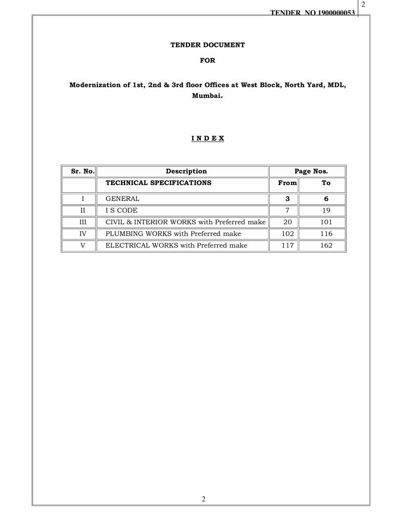
TENDER DOCUMENT
FOR
Modernization of 1st, 2nd & 3rd floor Offices at West Block, North Yard, MDL,
Mumbai.
I N D E X
Sr. No. Description Page Nos.
TECHNICAL SPECIFICATIONS From To
I GENERAL 3 6
II I S CODE 7 19
III CIVIL & INTERIOR WORKS with Preferred make 20 101
IV PLUMBING WORKS with Preferred make 102 116
V ELECTRICAL WORKS with Preferred make 117 162

TENDER NO 1900000053
3
3
SECTION - I
GENERAL
TENDER NO 1900000053
4
4
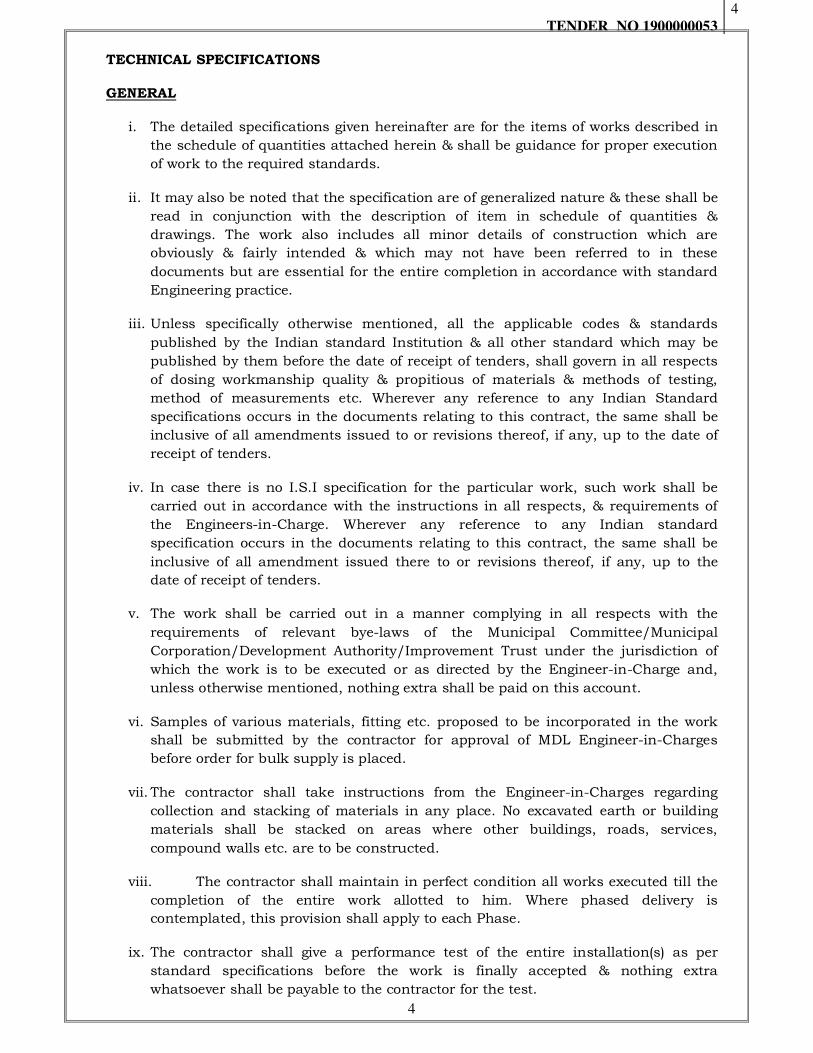
TECHNICAL SPECIFICATIONS
GENERAL
i. The detailed specifications given hereinafter are for the items of works described in
the schedule of quantities attached herein & shall be guidance for proper execution
of work to the required standards.
ii. It may also be noted that the specification are of generalized nature & these shall be
read in conjunction with the description of item in schedule of quantities &
drawings. The work also includes all minor details of construction which are
obviously & fairly intended & which may not have been referred to in these
documents but are essential for the entire completion in accordance with standard
Engineering practice.
iii. Unless specifically otherwise mentioned, all the applicable codes & standards
published by the Indian standard Institution & all other standard which may be
published by them before the date of receipt of tenders, shall govern in all respects
of dosing workmanship quality & propitious of materials & methods of testing,
method of measurements etc. Wherever any reference to any Indian Standard
specifications occurs in the documents relating to this contract, the same shall be
inclusive of all amendments issued to or revisions thereof, if any, up to the date of
receipt of tenders.
iv. In case there is no I.S.I specification for the particular work, such work shall be
carried out in accordance with the instructions in all respects, & requirements of
the Engineers-in-Charge. Wherever any reference to any Indian standard
specification occurs in the documents relating to this contract, the same shall be
inclusive of all amendment issued there to or revisions thereof, if any, up to the
date of receipt of tenders.
v. The work shall be carried out in a manner complying in all respects with the
requirements of relevant bye-laws of the Municipal Committee/Municipal
Corporation/Development Authority/Improvement Trust under the jurisdiction of
which the work is to be executed or as directed by the Engineer-in-Charge and,
unless otherwise mentioned, nothing extra shall be paid on this account.
vi. Samples of various materials, fitting etc. proposed to be incorporated in the work
shall be submitted by the contractor for approval of MDL Engineer-in-Charges
before order for bulk supply is placed.
vii. The contractor shall take instructions from the Engineer-in-Charges regarding
collection and stacking of materials in any place. No excavated earth or building
materials shall be stacked on areas where other buildings, roads, services,
compound walls etc. are to be constructed.
viii. The contractor shall maintain in perfect condition all works executed till the
completion of the entire work allotted to him. Where phased delivery is
contemplated, this provision shall apply to each Phase.
ix. The contractor shall give a performance test of the entire installation(s) as per
standard specifications before the work is finally accepted & nothing extra
whatsoever shall be payable to the contractor for the test.

TENDER NO 1900000053
5
5
x. The contractor shall clear the site thoroughly of all scaffolding materials & rubbish
etc. left out of his work & dress the site around the building to the satisfaction &
his decision in writing shall be final & binding on all concerned.
xi. Post construction inspection and testing: After completion of the work and
during maintenance period liability of the contractor, the work shall also be
subjected to 'Post construction inspection and testing'. In case the materials or
articles incorporated in the work are found to be inferior, though the sample
collected for the same might have been passed at the time of execution, it shall be
the responsibility of the contractor to replace the same at his own cost, failing
which the Department may rectify the same at the risk and cost of the contractor or
Department may accept the work as sub-standard, and cost be adjusted from the
outstanding security deposit, as per the terms and conditions of the contract for the
work.
xii. The MDL, shall be the sole deciding authority as to the meaning, interpretations
and implications for various provisions of the specifications and his decision in
writing shall be final and binding on all concerned.
xiii. In case any different or discrepancy between the specification & the
description in the schedule of quantities, the schedule of quantities shall take
precedence. In case of any difference or discrepancy between specification &
drawing, the specification shall take precedence.
A. Pricing The rate for each item of work shall, unless expressly stated otherwise, include the
following (but not limited to the list given below) for the completion of works in all
respects as per conditions of Contract, technical specifications, drawing:
1. All taxes such as Octroi, Sales tax, VAT, Service tax, Royalties, Transportation, Freights, Packing and forwarding charges Insurance , local taxes and all the prevailing taxes etc.
2. All requirements and expenses for completion of work/item as per Rules and Regulations of Local Bodies, State Government and Central Government of India.
3. All materials, equipments, accessories, consumable, controls and instruments, tools, tackles, plants, scaffolding/double scaffolding labour, maintenance, fixing, cleaning, , making good hauling, hoisting etc., for carrying out the item/work.
4. Waste on material and labour. 5. Loading, Unloading, handling/double handling, setting out protection from
weather, temporary supports, platforms, construction of temporary godwon/store for keeping of store etc., and the maintenance, of the same, dismantling of temporary works, disposal of debris and all other labour necessary for the execution of works.
6. Testing the installation as often as necessary, Contractors to arrange for all special instruments and tools required for such testing or getting it tested at approved lab.
7. Painting of all equipment, pipes, and supports etc., as per color codes to be decided for various systems.
8. Fees for testing the materials, equipment or overall installation by appropriate authorities as approved by MDL as per the latest version of IS. The testing lab will be decided by MDL/Consultant. Cost of the testing of materials shall be borne by the contractor.
9. Necessary coordination with all concerned agencies/persons involved in the completion of work.
TENDER NO 1900000053
6
6
10. All requirements of specification and drawings. Description of work given in the schedule of quantities is a brief description and shall be read in conjunction with specifications and drawings whether specifically mentioned or otherwise.
11. Removal of wrappings/ covering and carting away all unwanted material including POP.
The rates quoted by the tenderer will be deemed to be for the finished work complete in all
respects with accessories, fitting, mounting arrangements normally provided with such
equipment and/or needed for execution, completion, safe operation of equipment as
required though they may not have been specifically mentioned in technical specifications,
drawings and/or schedule of equipment.
All minor Masonry, Carpentry and Civil works such as cutting opening in Masonry Walls,
Internal Partitions, Chasing on walls, etc. and making good the same to match existing
works shall be provided by the contractor, whenever, asked for by the Consultant.
TENDER NO 1900000053
7
7
SECTION - II
IS CODE
TENDER NO 1900000053
8
8
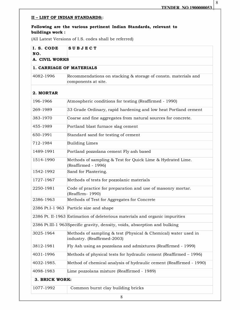
II – LIST OF INDIAN STANDARDS::
Following are the various pertinent Indian Standards, relevant to
buildings work :
(All Latest Versions of I.S. codes shall be referred)
I. S. CODE
NO.
S U B J E C T
A. CIVIL WORKS
1. CARRIAGE OF MATERIALS
4082-1996 Recommendations on stacking & storage of constn. materials and
components at site.
2. MORTAR
196-1966 Atmospheric conditions for testing (Reaffirmed - 1990)
269-1989 33 Grade Ordinary, rapid hardening and low heat Portland cement
383-1970 Coarse and fine aggregates from natural sources for concrete.
455-1989 Portland blast furnace slag cement
650-1991 Standard sand for testing of cement
712-1984 Building Limes
1489-1991 Portland pozzolana cement Fly ash based
1514-1990 Methods of sampling & Test for Quick Lime & Hydrated Lime.
(Reaffirmed - 1996)
1542-1992 Sand for Plastering.
1727-1967 Methods of tests for pozzolanic materials
2250-1981 Code of practice for preparation and use of masonry mortar.
(Reaffirm- 1990)
2386-1963 Methods of Test for Aggregates for Concrete
2386 Pt.I-1 963 Particle size and shape
2386 Pt. II-1963 Estimation of deleterious materials and organic impurities
2386 Pt.III-1 963Specific gravity, density, voids, absorption and bulking
3025-1964 Methods of sampling & test (Physical & Chemical) water used in
industry. (Reaffirmed-2003)
3812-1981 Fly Ash using as pozzolana and admixtures (Reaffirmed - 1999)
4031-1996 Methods of physical tests for hydraulic cement (Reaffirmed – 1996)
4032-1985. Method of chemical analysis of hydraulic cement (Reaffirmed - 1990)
4098-1983 Lime pozzolana mixture (Reaffirmed - 1989)
3. BRICK WORK:
1077-1992 Common burnt clay building bricks

TENDER NO 1900000053
9
9
I. S. CODE
NO.
S U B J E C T
1200 (Pt.III)-
19920
Method of measurements of brick work. (Reaffirmed - 1992)
2116-1980 Sand for masonry mortars. (Reaffirmed - 1998)
2212-1991 Code of practice for brick work
2250-1981 Code of practice for preparation & use of masonry mortar. (Reaffirmed
- 1990)
3102-1971 Classification of burnt clay solid bricks
3495 (Pt.ItoIV)-
1992 Method for test for burnt clay building brick
5454-1978 Method for sampling of clay building bricks. (Reaffirmed - 1995)
2185 (Part 3)
1984 Auto claved cellular (Areated) Concrete Blocks
5. MARBLE WORK:
1122-1974 Methods for determination of specific gravity and porosity of natural
building stones
1124-1974 Methods of test for water absorption of natural building stones
1130-1969 Marble (blocks, slabs and tiles)
6. WOOD WORK:
204-1991/92 Tower bolts (Part I-1991: ferrous metals; Part II - 1992 : Non ferrous
metals).
I. S. CODE
NO.
S U B J E C T
205-1992 Non-ferrous metal butt hinges
420-1953 Putty used on metal frame (withdrawn).
1734 - 1983 Methods of tests for plywood (IIR) (Ref 1993)
206-1992 Tee and strap hinges
207-1964 Gate and shutter hooks and eyes. (Reaffirmed - 1996)
208-1987 Door handles
281-1991 Mild steel sliding door bolts for use with padlocks
287-1973(Reaf-
98)
Recommendation for maximum permissible moisture contents of timber
used for Different purposes.
303-1989 Plywood for general purpose
362-1991 Parliament hinges
363-1993 Hasps and staples
364-1993 Fanlight catch
401-1982 Code of practice for preservation of timber
419 - 1967 Putty for use on window frame (I Rv.) (and out 3)

TENDER NO 1900000053
10
10
451-1999 Technical supply condition for wood screws
452-1973 Door springs, rat-tail type(II Rev.) (Reaffirmed 1990)
453-1993 Double acting spring hinges. (Reaffirmed – 1999)
723-1972 Steel counter sunk head wire nails. (Reaffirmed - 1996)
729-1979 Drawer locks, cup board locks, and box locks (III Rev.) (Reaffirmed
1992)
848-1974 Synthetic resin adhesive for plywood (phenolic and aminoplastic) ( I
RV) (
851-1978 Synthetic resin adhesive for construction work ( Non-structural) in
wood (I-Rev.) (amt )(Reaffirmed 1990)
852-1994 Specifications for animal glue for general wood working purposes. (II
Rev)
1003-1994 Timber panelled and glazed shutters
1003(Pt.I)-2003 Door shutters (III Rev.) (a 1)
1003(Pt.II)-1994 Window and ventilator shutters (III Rev.)
1019-1974 Rim latches. (Reaffirmed - 1991)
1141-1993 Code of practice for seasoning of timber (II Rev.)
1200 Method of measurement of Building and Civil Engineering works
1200(Pt.XIV)-
1984
Glazing. (Reaffirmed - 1990)
I. S. CODE
NO.
S U B J E C T
1200(Pt.XII)-1
973
Wood work and joinery. (Reaffirmed - 1992)
1322-1993 Bitumen felts for water proofing and damp proofing.
1328-1996 Veneered decorative plywood
1341-1992 Steel Butt hinges (VI Rev.)
1378-1987 Oxidized copper finishes. (Reaffirmed - 1998)
1629-1960 Rules for grading of out size of timber. Superseded in I.S. 1331
1659-2004 Block boards
1823-1980 Floor door stoppers. (Reaffirmed - 1992)
1868-1996 Anodic coating on Aluminium & its alloy (II Rev.) (Reaffirmed 1991)
2191-1983 Wooden flush door shutter (cellular and hollow core type). (Reaffirmed
- 1991)
2096-1992 A.C. flat sheet (I Rev.)
3828 - 1968 Ventilator chains (Reaf. 1990)
4835 - 1979 Polyvinyl acatete dispssion base adhasive for wood (1990)
TENDER NO 1900000053
11
11
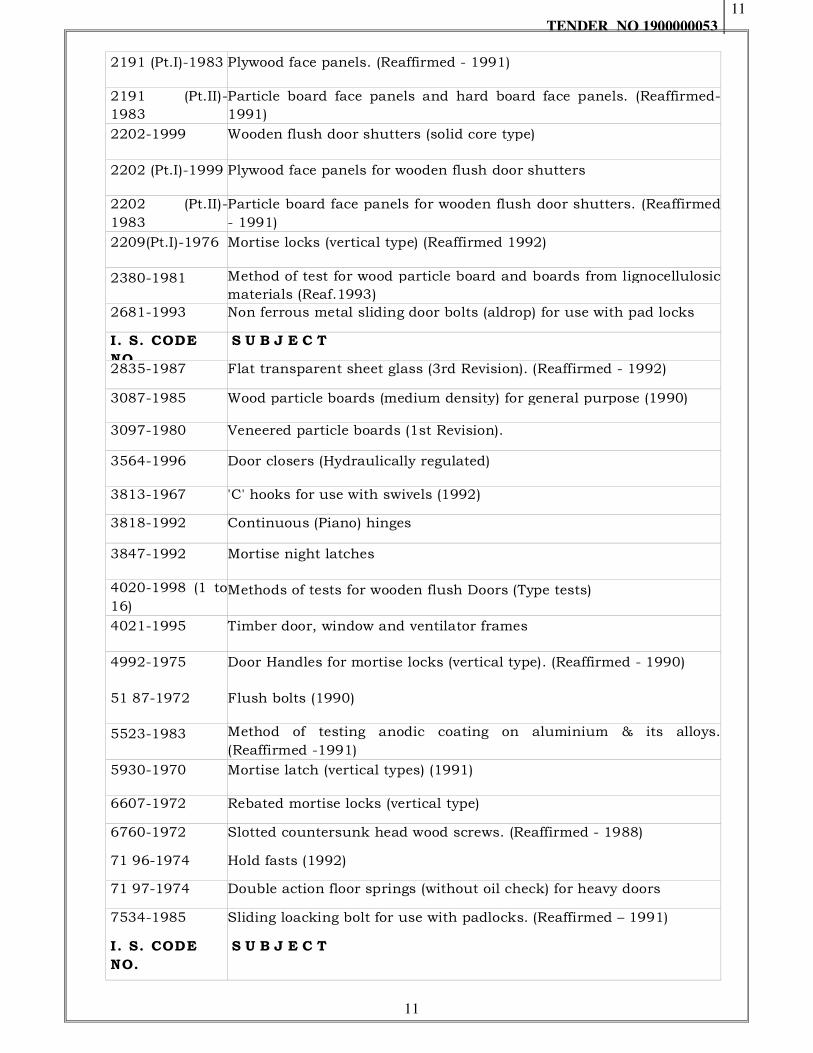
2191 (Pt.I)-1983 Plywood face panels. (Reaffirmed - 1991)
2191 (Pt.II)-
1983
Particle board face panels and hard board face panels. (Reaffirmed-
1991)
2202-1999 Wooden flush door shutters (solid core type)
2202 (Pt.I)-1999 Plywood face panels for wooden flush door shutters
2202 (Pt.II)-
1983
Particle board face panels for wooden flush door shutters. (Reaffirmed
- 1991)
2209(Pt.I)-1976 Mortise locks (vertical type) (Reaffirmed 1992)
2380-1981 Method of test for wood particle board and boards from lignocellulosic
materials (Reaf.1993)
2681-1993 Non ferrous metal sliding door bolts (aldrop) for use with pad locks
I. S. CODE
NO.
S U B J E C T
2835-1987 Flat transparent sheet glass (3rd Revision). (Reaffirmed - 1992)
3087-1985 Wood particle boards (medium density) for general purpose (1990)
3097-1980 Veneered particle boards (1st Revision).
3564-1996 Door closers (Hydraulically regulated)
3813-1967 'C' hooks for use with swivels (1992)
3818-1992 Continuous (Piano) hinges
3847-1992 Mortise night latches
4020-1998 (1 to
16) Methods of tests for wooden flush Doors (Type tests)
4021-1995 Timber door, window and ventilator frames
4992-1975 Door Handles for mortise locks (vertical type). (Reaffirmed - 1990)
51 87-1972 Flush bolts (1990)
5523-1983 Method of testing anodic coating on aluminium & its alloys.
(Reaffirmed -1991)
5930-1970 Mortise latch (vertical types) (1991)
6607-1972 Rebated mortise locks (vertical type)
6760-1972 Slotted countersunk head wood screws. (Reaffirmed - 1988)
71 96-1974 Hold fasts (1992)
71 97-1974 Double action floor springs (without oil check) for heavy doors
7534-1985 Sliding loacking bolt for use with padlocks. (Reaffirmed – 1991)
I. S. CODE
NO.
S U B J E C T

TENDER NO 1900000053
12
12
14856-2000 Glass fibre reinforced plastic (GRP) panel type door shutters for
internal use – Specifications
8 . FL OOR I NG :
1130-1969 Marble (blocks, slabs and tiles). (Reaffirmed – 1993)
1200 (Pt.XI)-
1977 Method of measurements of pavings and floor finishes.
1661-1972 Code of practice for application of cement and cement lime plaster
finishes
3400 (Pt.II)-
2003 Hardness
3400 (Pt.X)-
1977 Compression set at constant strain. (Reaffirmed – 2003)
3462-1986 Flexible P.V.C. Flooring. (Reaffirmed – 1991)
5318-1969 Code of practice for laying of flexible P.V.C. sheet & tiles flooring
5389-1969 Code of practice for laying of hardwood parquet and wood block floors.
(Reaffirmed – 1998)
I. S. CODE
NO.
S U B J E C T
9197-1979 Specifications for epoxy resin, hardeners and epoxy resin compositions
for floor topping (Reaffirmed – 2001)
13630 (Pt.1
to 13) Methods of tests for ceramic tiles (Part 1 to 13 : 1992-1993)
9 . R OOF ING :
1199-1959 Method of Sampling & Analysis of concrete. (Reaffirmed - 1991)
1200 (Pt.X)-
1973 Method of measurements of ceiling and lining
13607 -
1992
Ready Mixed Paint, Finishing, General Purposes, Synthetic (Reaffirmed
2002)
1346-1991 Code of practice for waterproofing of roof with bitumen felts
1609-1991 Code of practice for laying damp proof treatment using bitumen felts
1626-
1994(Part I-
Asbestos cement building pipes, gutters and fittings (Spigot and socket
types)
1834-1984 Specification for hot applied sealing compounds for joints in concrete.
(Reaffirmed - 1990)
1838-(Pt.I &
II)-1983
Preformed filler for expansion joints in concrete- non-extruding and
resilient type Bitumen impregnated fiber). (Reaffirmed - 1990)
I. S. CODE
NO.
S U B J E C T
10. FINISHING
77-1976 Linseed oil, boiled, for paints. (Reaffirmed - 1999)
102-1962 Ready mixed paint, brushing, red, lead, non setting, priming.( Reaffirmed
- 1996)

TENDER NO 1900000053
13
13
104-1979 Specification for ready mixed paint, brushing, zinc chrome, priming.
(Reaffirmed - 1999)
133-1993 Enamel, interior (a) under coating (b) finishing colour as required
137-1965 Ready mixed paint, brushing, matt or egg-shell flat, finishing, interior,
to Indian Standard Colour, as required. (Reaffirmed – 1999)
158-1981 Ready mixed paint, brushing, bituminous, black lead free acid alkali,
water and heat
168-1993 Ready mixed paint, air drying for general purpose.(Reaffirmed 2002)
337-1975 Varnish, finishing interior. (Reaffirmed – 2001)
341-1973 Black Japan, types A, B, and C (Reaffirmed 2002)
347-1975 Varnish, shellac for general purpose. (Reaffirmed – 2001)
348-1968 French polish. (Reaffirmed – 2001)
419-1967 Putty for use of window frames. (Reaffirmed – 2001)
427-1965 Distemper, dry, colour as required. (Reaffirmed – 1999)
428-2000 Washable distember
524-1983 Varnish, finishing, exterior, synthetic. (Reaffirmed – 2000)
525-1968 Varnish, finishing, exterior and general purposes. (Reaffirmed –2001)
533-1998 Gum spirit of turpentine (oil of turpentine) (Reaffirmed 2003)
1200 (Pt.
XII)-1976 Method of measurements of plastering and pointing
1200
(Pt.XIII)-1994
Method of measurements of white washing, colour washing, distempering
and other finishes
1200 (Pt.XV)-
1987 Methods of measurements of painting, polishing & varnishing.
2095-1996
(Pt.I - III) Gypsum plaster boards
2096-1992 Asbestos cement flat sheets.
I. S. CODE
NO.
S U B J E C T
2932-2003 Enamel synthetic, exterior (a) Under coating (b) Finishing.
2933-1975 Enamel, Exterior (a) Under coating (b) Finishing
5410-1992 Cement paint (Reaffirmed 1999)
5411 (Pt.I)-1
974 Plastic emulsion paint for interior use. (Reaffirmed – 1993)
I. S. CODE
NO.
S U B J E C T
6278-1971 Code of practice for white washing & colour washing. (Reaffirmed -1991)
14276-195 Cement particle board
TENDER NO 1900000053
14
14
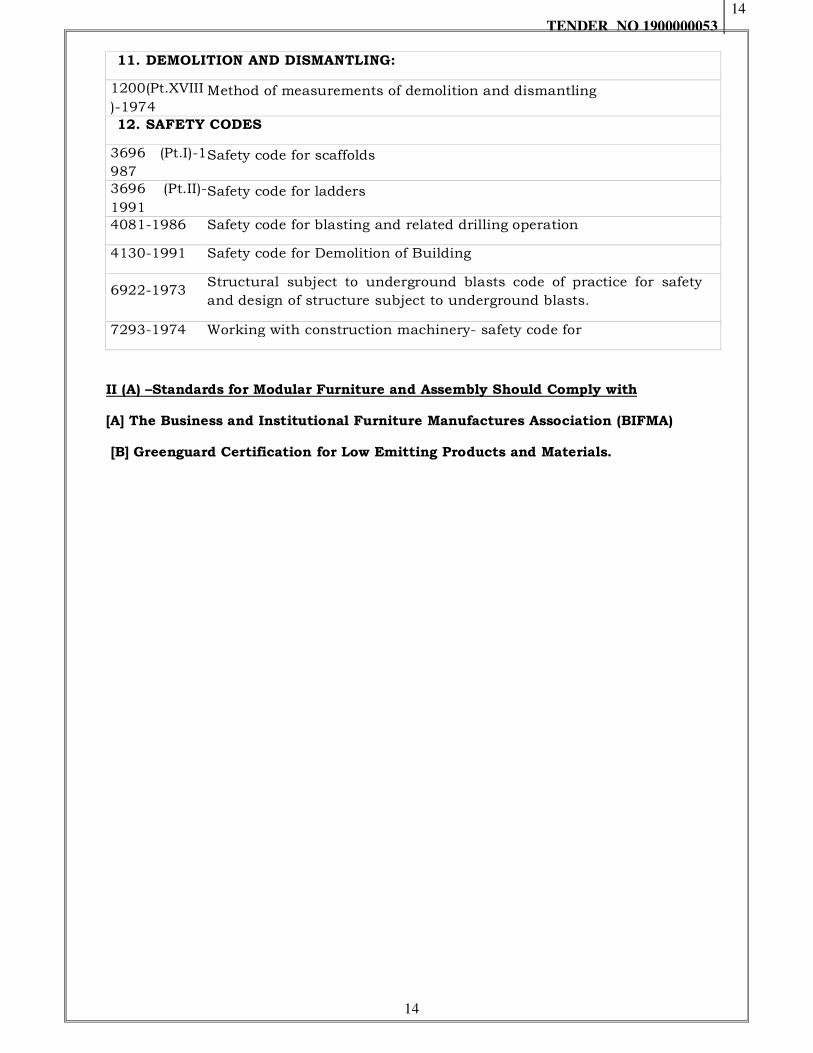
11. DEMOLITION AND DISMANTLING:
1200(Pt.XVIII
)-1974 Method of measurements of demolition and dismantling
12. SAFETY CODES
3696 (Pt.I)-1
987 Safety code for scaffolds
3696 (Pt.II)-
1991 Safety code for ladders
4081-1986 Safety code for blasting and related drilling operation
4130-1991 Safety code for Demolition of Building
6922-1973 Structural subject to underground blasts code of practice for safety
and design of structure subject to underground blasts.
7293-1974 Working with construction machinery- safety code for
II (A) –Standards for Modular Furniture and Assembly Should Comply with
[A] The Business and Institutional Furniture Manufactures Association (BIFMA)
[B] Greenguard Certification for Low Emitting Products and Materials.

TENDER NO 1900000053
15
15
III – MANDATORY TESTS
NOTES:
The mandatory tests shall be carried out when the quantity of materials to incorporate in the work exceeds the minimum quantity specified.
Optional tests specified or any other tests, shall be carried out in case of specialised works or important structures as per direction of the Engineer-in-Charge.
Testing charges, including incidental charges and cost of sample for testing shall be borne by the contractor for all tests.
In case of non-IS materials, it shall be the responsibility of the contractor to establish the conformity of material with relevant IS specification by carrying out necessary tests. Testing charges including incidental charge and cost of sample for testing shall be borne by the contractor for such tests.
THE MANDATORY TESTS SHALL BE AS FOLLOWS:
Material Test Field /
laboratory
test
Test procedure
Minimum
quantity of
material / Work
for carrying out
the test
Frequency of
testing
Reinforced cement concrete work
Water for Construction purposes
Ph value Limits of Acidity Limits of Alkality Percentage of solids Chlorides Suspended matter Sulphates Inorganic solids Organic solids
Lab IS 3025 Water from each
source
Before commencement of work & thereafter:
Mandatory – Once in one year from each source;
Optional: once in 3
months from each
source; Municipal
supply - optional.
Note : for all other small items and where RCC done in a day is less than 5 cum, test may be carried out as required by Engineer-in-Charge.
Mortars:
Material Test Field /
laboratory
test
Test procedure
Minimum
quantity of
material
Frequency of
testing
Sand Bulking of Sand
Field 20 CU.M. Every 20 cu.m or part thereof or more frequently as decided by Engineer-In-Charge
TENDER NO 1900000053
16
16
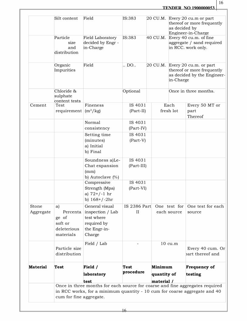
Silt content Field IS:383 20 CU.M. Every 20 cu.m or part thereof or more frequently as decided by Engineer-in-Charge
Particle size and distribution
Field Laboratory decided by Engr -in-Charge
IS:383 40 CU.M. Every 40 cu.m. of fine aggregate / sand required in RCC. work only.
Organic Impurities
Field .. DO.. 20 CU.M. Every 20 cu.m. or part thereof or more frequently as decided by the Engineer-in-Charge
Chloride & sulphate content tests
Optional Once in three months.
Cement Test
requirement
Fineness
(m²/kg)
IS 4031
(Part-II)
Each
fresh lot
Every 50 MT or
part
Thereof
Normal
consistency
IS 4031
(Part-IV)
Setting time
(minutes)
a) Initial
b) Final
IS 4031
(Part-V)
Soundness a)Le-
Chat expansion
(mm)
b) Autoclave (%)
IS 4031
(Part-III)
Compressive
Strength (Mpa)
a) 72+/-1 hr
b) 168+/-2hr
IS 4031
(Part-VI)
Stone
Aggregate
a)
Percenta
ge of
soft or
deleterious
materials
General visual
inspection / Lab
test where
required by
the Engr-in-
Charge
IS 2386 Part
II
One test for
each source
One test for each
source
Particle size
distribution
Field / Lab - 10 cu.m Every 40 cum. Or
part thereof and
Material Test Field /
laboratory
test
Test procedure
Minimum
quantity of
material /
Frequency of
testing
Once in three months for each source for coarse and fine aggregates required
in RCC works, for a minimum quantity - 10 cum for coarse aggregate and 40
cum for fine aggregate.
TENDER NO 1900000053
17
17
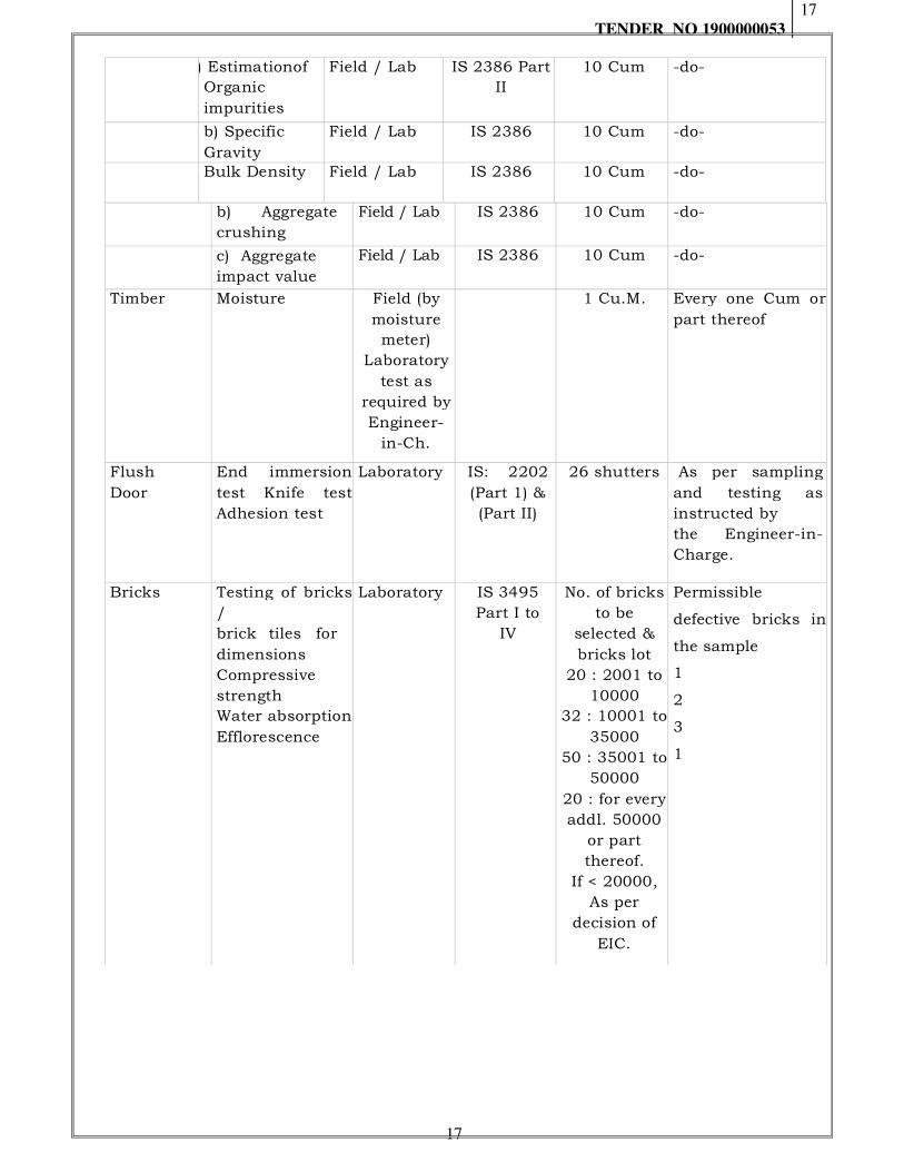
a) Estimationof
Organic
impurities
Field / Lab IS 2386 Part
II
10 Cum -do-
b) Specific
Gravity
Field / Lab IS 2386 10 Cum -do-
Bulk Density Field / Lab IS 2386 10 Cum -do-
b) Aggregate
crushing
strength
Field / Lab IS 2386 10 Cum -do-
c) Aggregate
impact value
Field / Lab IS 2386 10 Cum -do-
Timber Moisture Field (by
moisture
meter)
Laboratory
test as
required by
Engineer-
in-Ch.
1 Cu.M. Every one Cum or
part thereof
Flush
Door
End immersion
test Knife test
Adhesion test
Laboratory IS: 2202
(Part 1) &
(Part II)
26 shutters As per sampling
and testing as
instructed by
the Engineer-in-
Charge.
Bricks Testing of bricks
/
brick tiles for
dimensions
Compressive
strength
Water absorption
Efflorescence
Laboratory IS 3495
Part I to
IV
No. of bricks
to be
selected &
bricks lot
20 : 2001 to
10000
32 : 10001 to
35000
50 : 35001 to
50000
20 : for every
addl. 50000
or part
thereof.
If < 20000,
As per
decision of
EIC.
Permissible
defective bricks in
the sample
1
2
3
1
18
Material Test
Field /
laborator
y test
Test
procedu
re
Minimum
quantity of
material /
Work for
carrying out
the test
Frequency of testing
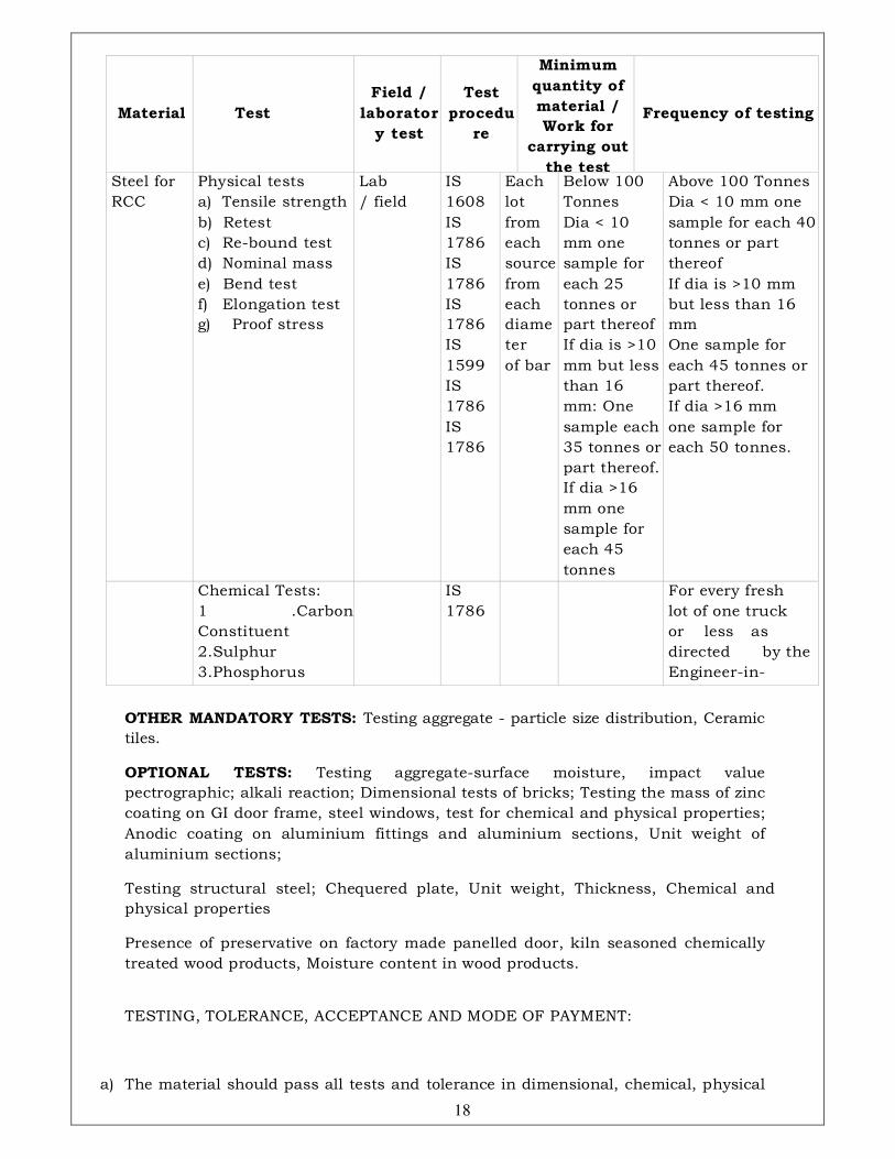
Steel for
RCC
Physical tests
a) Tensile strength
b) Retest
c) Re-bound test
d) Nominal mass
e) Bend test
f) Elongation test
g) Proof stress
Lab
/ field
IS
1608
IS
1786
IS
1786
IS
1786
IS
1599
IS
1786
IS
1786
Each
lot
from
each
source
from
each
diame
ter
of bar
Below 100
Tonnes
Dia < 10
mm one
sample for
each 25
tonnes or
part thereof
If dia is >10
mm but less
than 16
mm: One
sample each
35 tonnes or
part thereof.
If dia >16
mm one
sample for
each 45
tonnes
Above 100 Tonnes
Dia < 10 mm one
sample for each 40
tonnes or part
thereof
If dia is >10 mm
but less than 16
mm
One sample for
each 45 tonnes or
part thereof.
If dia >16 mm
one sample for
each 50 tonnes.
Chemical Tests:
1 .Carbon
Constituent
2.Sulphur
3.Phosphorus
4.Phosphorus &
IS
1786
For every fresh
lot of one truck
or less as
directed by the
Engineer-in-
Charge.
OTHER MANDATORY TESTS: Testing aggregate - particle size distribution, Ceramic
tiles.
OPTIONAL TESTS: Testing aggregate-surface moisture, impact value
pectrographic; alkali reaction; Dimensional tests of bricks; Testing the mass of zinc
coating on GI door frame, steel windows, test for chemical and physical properties;
Anodic coating on aluminium fittings and aluminium sections, Unit weight of
aluminium sections;
Testing structural steel; Chequered plate, Unit weight, Thickness, Chemical and
physical properties
Presence of preservative on factory made panelled door, kiln seasoned chemically
treated wood products, Moisture content in wood products.
TESTING, TOLERANCE, ACCEPTANCE AND MODE OF PAYMENT:
a) The material should pass all tests and tolerance in dimensional, chemical, physical
19
properties should be within the limit as stipulated in relevant IS for acceptance.
Such materials shall be accepted as standard.
b) Payment shall be restricted to standard unit mass, or as specified in the schedule
of work, without making any cost adjustment towards mass or any other properties,
provided the material pass all the tests and tolerances are within the specified
limits.In case of non-standard materials, materials not covered under any IS
Specifications, such as aluminium sections, the payment shall be made based on
the actual unit weight basis as determined by testing at random sampling.
20
SECTION - III
TECHNICAL SPECIFICATIONS
FOR
CIVIL & INTERIOR WORKS
21
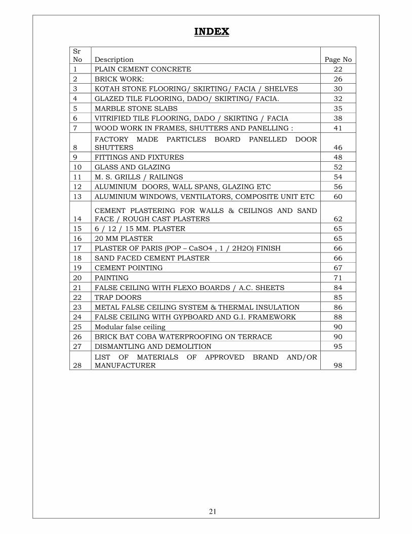
INDEX
Sr No Description Page No
1 PLAIN CEMENT CONCRETE 22
2 BRICK WORK: 26
3 KOTAH STONE FLOORING/ SKIRTING/ FACIA / SHELVES 30
4 GLAZED TILE FLOORING, DADO/ SKIRTING/ FACIA. 32
5 MARBLE STONE SLABS 35
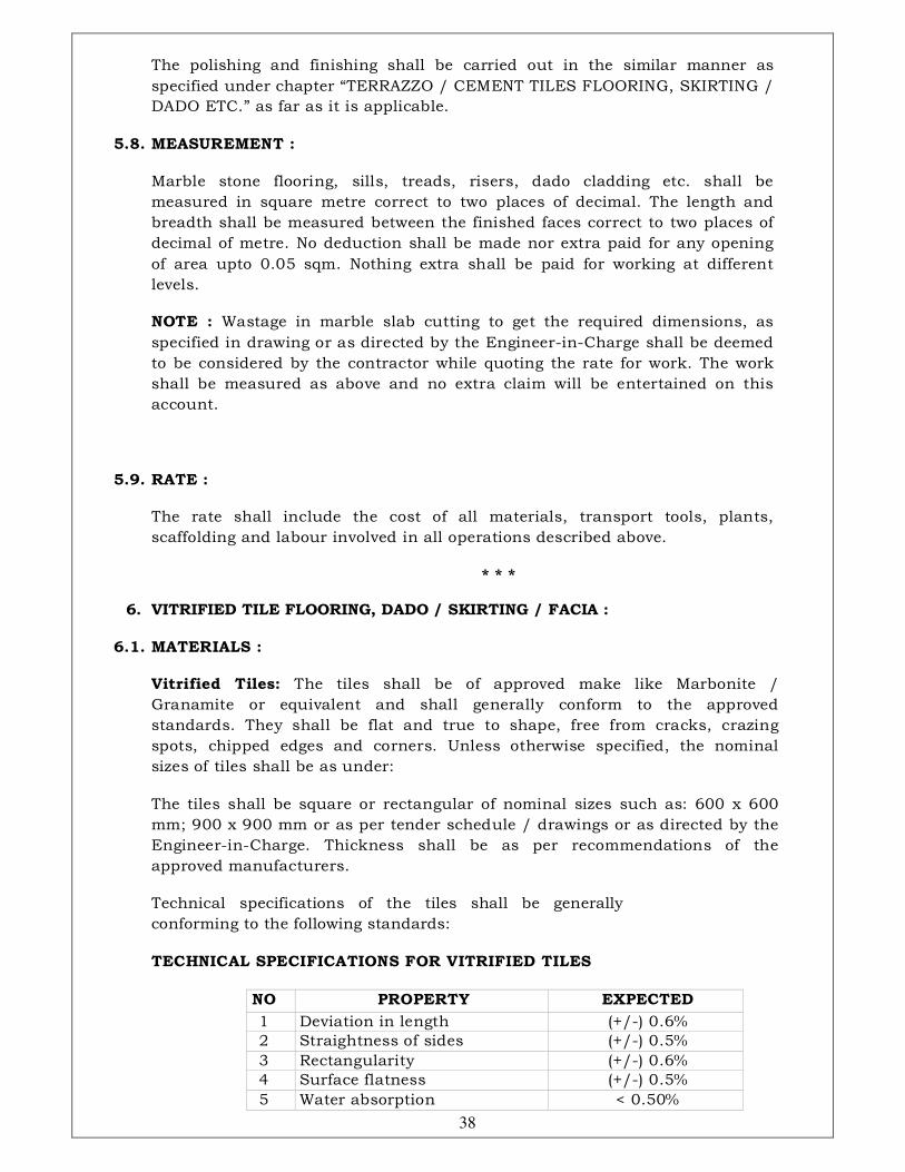
6 VITRIFIED TILE FLOORING, DADO / SKIRTING / FACIA 38
7 WOOD WORK IN FRAMES, SHUTTERS AND PANELLING : 41
8 FACTORY MADE PARTICLES BOARD PANELLED DOOR SHUTTERS 46
9 FITTINGS AND FIXTURES 48
10 GLASS AND GLAZING 52
11 M. S. GRILLS / RAILINGS 54
12 ALUMINIUM DOORS, WALL SPANS, GLAZING ETC 56
13 ALUMINIUM WINDOWS, VENTILATORS, COMPOSITE UNIT ETC 60
14 CEMENT PLASTERING FOR WALLS & CEILINGS AND SAND FACE / ROUGH CAST PLASTERS 62
15 6 / 12 / 15 MM. PLASTER 65
16 20 MM PLASTER 65
17 PLASTER OF PARIS (POP – CaSO4 , 1 / 2H2O) FINISH 66
18 SAND FACED CEMENT PLASTER 66
19 CEMENT POINTING 67
20 PAINTING 71
21 FALSE CEILING WITH FLEXO BOARDS / A.C. SHEETS 84
22 TRAP DOORS 85
23 METAL FALSE CEILING SYSTEM & THERMAL INSULATION 86
24 FALSE CEILING WITH GYPBOARD AND G.I. FRAMEWORK 88
25 Modular false ceiling 90
26 BRICK BAT COBA WATERPROOFING ON TERRACE 90
27 DISMANTLING AND DEMOLITION 95
28 LIST OF MATERIALS OF APPROVED BRAND AND/OR MANUFACTURER 98

22
SECTION ‘A’- CIVIL WORKS
1.1. PLAIN CEMENT CONCRETE FOR GENERAL WORK :
For plain cement concrete work, the specification for materials viz. cement,
sand, fine and coarse aggregates and water shall be the same as that
specified in reinforced concrete work specification.
But the proportion of mix will be nominal and the ratio of fine and coarse
aggregate may be slightly adjusted within limits, keeping the total value of
aggregates to a given volumes of cement constant to suit the sieve analysis of
both the aggregates. Cement shall on no account be measured by volume,
but it shall always be used directly from the bags (i.e. 50 kg/bag).
The proportion of cement, sand, aggregate and water for concrete of
proportion 1:5:10, 1:4:8, 1:3:6 & 1:2:4 by volume shall generally consist of
quantities as given below :
Proportio
n
of
Ingredien
ts
Cement Quantity of materials used per bag of
cement
Fine
aggregate
(sand)
Coarse
aggregate
Total of fine
sand
coarse
aggregates
Water
1:5:10 1 175 ltrs. 350
ltrs.
800
kgs.
60 ltrs.
1:4:8 1 140 ltrs. 280 625 45 ltrs.
1:3:6 1 105 ltrs. 210
ltrs.
480
kgs.
34 ltrs.
1:2:4 1 70 ltrs. 140
ltrs.
330
kgs.
32 ltrs.
The quantity of water used shall be such as to produce concrete of
consistency required by the particular class of work and shall be decided by
the use of a slump cone. Sufficient care should be taken to see that no
excess quantity of water is used. The final proportion of the aggregate and
quantity of water shall be decided by the Engineer-in-charge on the basis of
test in each case.
Mix proportion Cement
in bags
Sand
in cum
Coarse Aggregate in CUM Water
Ordinary mix in
volume 40 mm 20 mm 12 mm
1:5:10 2.60 0.475 0.6623 0.2583 - 156
1:4:8 3.40 0.500 0.688 0.6883 - 153
1:3:6 (with 40mm
aggr.)
4.4 0.485 0.672 0.672 0.262 176
1:3:6 (with 20 mm
aggr.)
4.4 0.485 - 0.727 0.242 162.5
1:2:4 (with 20 mm
aggr.)
6.4 0.47 - 0.705 0.235 205
1:2:4 (with 40 mm 6.4 0.47 0.544 0.241 0.126 235
23
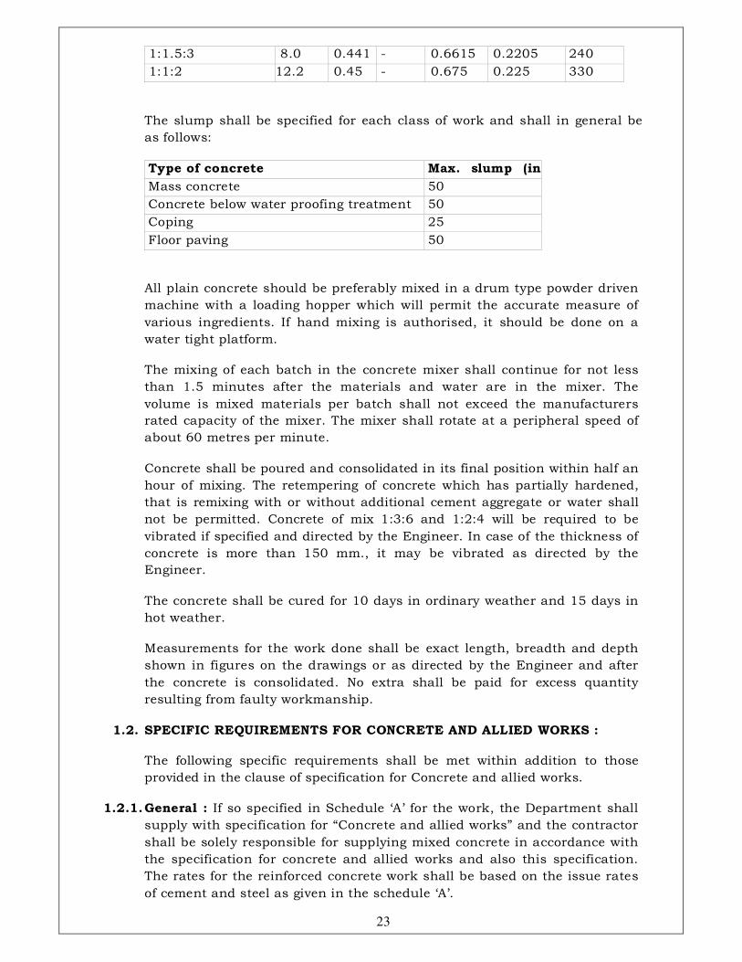
1:1.5:3 8.0 0.441 - 0.6615 0.2205 240
1:1:2 12.2
0
0.45 - 0.675 0.225 330
The slump shall be specified for each class of work and shall in general be
as follows:
Type of concrete Max. slump (in
mm.) Mass concrete 50
Concrete below water proofing treatment 50
Coping 25
Floor paving 50
All plain concrete should be preferably mixed in a drum type powder driven
machine with a loading hopper which will permit the accurate measure of
various ingredients. If hand mixing is authorised, it should be done on a
water tight platform.
The mixing of each batch in the concrete mixer shall continue for not less
than 1.5 minutes after the materials and water are in the mixer. The
volume is mixed materials per batch shall not exceed the manufacturers
rated capacity of the mixer. The mixer shall rotate at a peripheral speed of
about 60 metres per minute.
Concrete shall be poured and consolidated in its final position within half an
hour of mixing. The retempering of concrete which has partially hardened,
that is remixing with or without additional cement aggregate or water shall
not be permitted. Concrete of mix 1:3:6 and 1:2:4 will be required to be
vibrated if specified and directed by the Engineer. In case of the thickness of
concrete is more than 150 mm., it may be vibrated as directed by the
Engineer.
The concrete shall be cured for 10 days in ordinary weather and 15 days in
hot weather.
Measurements for the work done shall be exact length, breadth and depth
shown in figures on the drawings or as directed by the Engineer and after
the concrete is consolidated. No extra shall be paid for excess quantity
resulting from faulty workmanship.
1.2. SPECIFIC REQUIREMENTS FOR CONCRETE AND ALLIED WORKS :
The following specific requirements shall be met within addition to those
provided in the clause of specification for Concrete and allied works.
1.2.1. General : If so specified in Schedule ‘A’ for the work, the Department shall
supply with specification for “Concrete and allied works” and the contractor
shall be solely responsible for supplying mixed concrete in accordance with
the specification for concrete and allied works and also this specification.
The rates for the reinforced concrete work shall be based on the issue rates
of cement and steel as given in the schedule ‘A’.

24
1.2.2. Water : Clean water in pipes under pressure shall be provided by the
contractor with all necessary equipment for giving a nozzle pressure of not
less than 2.0 kg/ sqcm. for the convenient and effective jetting of rock
foundations and concrete surfaces, for cooling aggregate required for
concrete, for curing concrete and other requirements.
1.2.3. Fire Protection System : The contractor shall provide and maintain at all
times in adequate fire protection system to protect his equipment, materials
and construction In case of an emergency, the contractor shall permit the
Engineer-in-Charge to use the system for protecting equipment, works etc.
on the project.
1.2.4. Concrete : The rates for all concrete work should be based as per
specifications and taking into consideration the guidelines indicated in
special instruction under relevant clause.
1.2.5. The Placement Intervals: Each placement of concrete shall be allowed to
set for a period of 48 hours and longer when required, before the start of
subsequent placement. A time gap between the two adjoining pours in the
horizontal plane and the two adjacent pours in the vertical plane shall be 7
days and 3 days respectively.
1.2.6. FINISHING OF CONCRETE :
1. General : Unless otherwise specified, concrete finishes shall conform
to the following specifications: Finish F1, F2 and F3 shall describe
formed surface.
Finish U1, U2 and U3 shall describe un-formed surface.
Off sets or fins caused by disposed or misplaced form sheathing lining or
form sections or by defective form lumber shall be referred to as abrupt
irregularities. All other irregularities shall be referred to as gradual
irregularities. Gradual irregularities shall be measured as deviation from a
plane surface with a template 1.5 m. long for formed surface and 3 m. long
for unformed surfaces.
2. Formed Surfaces :
Finish F1—shall apply to all formed surfaces for which finish F2, F3 or any
other special finish is not specified and shall include filling up all form tie
holes.
Finish F2—shall apply to all formed surfaces so shown on the drawings or
specified by the Engineer-in-Charge. This shall include filling all form tie-
holes, repair of gradual irregularities exceeding 6 mm., removal of ridges
and abrupt irregularities by grinding.
Finish F3—shall apply to all formed surfaces exposed to view or where
shown in the drawings or specified by the Engineer-in-Charge. Finish F3 -
shall include all measures specified for Finish-F2 and in addition, Filling air
holes with mortar and treatment of the entire surface with sack rubbed
finish. It shall also include clean up of loose and adhering debris. Where a
25
sack rubbed finish is specified, the surfaces shall be prepared within two
days after removal of the forms.
The surface shall be wetted and allowed to dry slightly before mortar is
applied by sack rubbing. The mortar used shall consist of one part cement
to one and half parts by volume of fine (minus No. 16 mesh) sand. Only
sufficient mixing water to give the mortar a workable consistency shall be
used. The mortar shall then be rubbed over the surface with a fine burlap or
linen cloth so as to fill all the surface voids. The mortar rubbed in the voids
shall be allowed to stiffen and solidify after which the whole surface shall
be wiped clean so that the surface presents a uniform appearance without
air holes, irregularities etc.
Curing of the surface shall be continued for a period of ten (10) days.
Unformed Surfaces:
Finish U1—shall apply to all unformed surfaces for which the finish U2,
U3 or any other special finish is not specified and shall include screeding
the surface of the concrete to the required slope and grade. Unless the
drawing specifies a horizontal surface or shows the slope required, the tops
of narrow surfaces such as stair, treads, walls, curbs and parapets shall be
sloped approximately 10 mm. per 300 mm. width. Surfaces to be covered by
backfill or concrete sub-floors to be covered with concrete topping, terrazzo
and similar surfaces shall be smooth screeded and leveled to produce even
surface, irregularities not exceeding 6 mm.
Finish U2—shall apply to all unformed surfaces as shown in the drawing or
specified by the Engineer-in-Charge and shall include screeding and applying
a wood float finish to the surface of the concrete to the required slopes and
grade.
Repair of abrupt irregularities unless a roughened texture is specified. Repair
of gradual irregularities exceeding 6 mm.
Finish U3—shall apply to unformed surfaces for which a high degree of
surface smoothness is required, where shown on the drawing or specified by
the Engineer-in-Charge. This shall include screeding, floating and applying
a steel trowel finish to the surface of the concrete to the required slopes and
grade.
Repair of abrupt irregularities.
Repair of gradual irregularities exceeding 6 mm., finishing joints and edges
of concrete with edging tools.
1.3. MODE OF MEASUREMENT FOR CONCRETE WORK :
General : Concrete as actually done shall be measured for payment, subject
to the following tolerances, unless otherwise stated hereinafter. Any work
done extra over the specified dimensions shall not be measured for
payment.
26
a) Linear dimensions shall be measured in full centimetres except for the
thickness of slab which shall be measured to the nearest half centimetre.
b) Areas shall be worked out to the nearest 0.01 sqm.
c) Cubic contents shall be worked out to the nearest 0.001 cum.
d) The concrete shall be measured for its length, breadth and height/
depth limiting dimensions to those specified on drawings or as directed by
the Engineer-in-Charge.
NOTE : The sizes of RCC members as assumed in the estimate are based on
preliminary drawings and are likely to be changed. The contractor is not
entitled to any extra claim due to such changes.
Deductions:
No deductions shall be made for the following :
a) Ends of dissimilar materials e.g. joists, beams, posts, girders, rafters,
purlins, trusses, corbels, steps etc. upto 500 sq cm. in cross section.
b) Opening upto 0.1 sqm. (1000 sq cm)
c) Volume occupied by reinforcement.
d) Volume occupied by pipes, conduits, sheathing etc. not exceeding 25 sq
cm. each in cross sectional area. Nothing extra shall be paid for leaving
and finishing such cavities and holes.
* * *
2. BRICK WORK:
2.2 SCOPE OF WORK :
The work covered under this specification pertains to procurement of well
burnt clay bricks of class 35 unless otherwise specified and workmanship in
building walls of various thickness, in strict compliance with the
specifications and applicable drawings.
2.3 MATERIALS:
Brick shall be well burnt clay bricks of designated class and shall satisfy the
strength criteria and shall be got approved by the Engineer-in-Charge before
incorporation in the work. The bricks shall be hand moulded or machine
moulded and shall be free from nodules of free lime, visible cracks, flaws,
warpage and organic matter.
In general, the nominal size of bricks (F.P.S.) shall be 22.9 x 11.4 x 7 cm.
(9”x4.5”x2.75”). Permissible tolerance on dimensions shall not be more than
(+/-) 8%. The contractor shall get approved the sample and source of bricks
from Engineer-in-Charge before procurement on large scale and shall

27
maintain the same for the entire work. The bricks shall have smooth
rectangular faces with sharp corner and shall be uniform in colour.
Bricks for Mumbai / Pune and surrounding areas, unless otherwise specified,
shall be as per relevant IS of class
designation 35 of size 22.5 x 11.1 x 7 cm. Permissible tolerance on
dimensions shall not be more than (+/-) 8%.
Unless otherwise specified, bricks for Eastern Zone works (Kolkata /
Bhubneshwar / Shillong etc.) shall be of class designation 75 of size 25 x
12.5 x 7.5 cm. Permissible tolerance on dimensions shall be as per relevant
IS.
In case the size of bricks used in the work is found lesser than the specified
one but within the permissible tolerance i.e. {-} 8% , the following shall apply:
i. Extra cement consumed due to more number of joints and due to
additional thickness of plaster than the specified in the tender to match
with adjoining columns and beams, shall be borne by the contractor
without any extra cost to the department.
ii. If the plastering to be done is more than the specified thickness to
maintain the plaster surface to perfect line, level and plumb with
adjoining columns, beams, walls etc., the contractor shall be responsible
to provide more thickness of plaster at his own cost and nothing extra
will be paid on this account.
In case the size of bricks used in the work is found more than the
permissible, the contractor shall chip out the exposed edges of bricks upto
the required level of wall to receive specified thickness of plaster.
Bricks shall generally conform to I.S. 1077-1992. In any case minimum
crushing strength shall not be less than 35 kg/cm2 and water absorption shall
not be more than 25% by weight. The Engineer-in-Charge shall have the right
to reject bricks obtained from any field where the soil has an appreciable
quantity of sulphates and chlorides. The specifications for cement, sand and
water shall be same as described herein before under cement concrete.
Bricks shall be thoroughly soaked in water before using till the bubbles
ceases to come up. No half or quarter brick shall be used except as closer.
The closer shall be cut to required size and used near the end of the walls. The
walls shall be raised truly to plumb. The type of bond to be adopted shall be
decided by the Engineer-in-Charge, but vertical joints shall be laid staggered.
2.4 WORKMANSHIP :
Four courses of brick work with four joints should not exceed by more than 40
mm., the same bricks piled one over the other without mortar.
Brick work shall not be raised more than 10 courses a day unless otherwise
approved by the Engineer-in-Charge. The brick work shall be kept wet for at
least 7 days. Brick work shall be uniformly raised alround and no part shall be
raised more than 1.0 metre above another at any time.

28
All joints shall be thoroughly flushed with mortar of mix as specified in the
schedule of quantities, at every courses. Care shall be taken to see that the
bricks are bedded effectively and all joints completely filled to the full depth.
The joints of brick work to be plastered shall be raked out to a depth not less
than 10 mm. as the work proceeds. The surface of brick work shall be cleaned
down and watered properly before the mortar sets.
The adhesion between the brick masonry surface and the concrete surface of
columns, beams, chajjas, lintels etc. should be proper by ensuring that the
concrete surface coming in contact with brick masonry is hacked/ chipped/
keyed, cleaned and cement slurry is applied so that a proper bond is
achieved between the two dissimilar materials. It is the responsibility of the
contractors to ensure that there will not be any cracks/ fissures anywhere in
the brick masonry.
In case the cracks appear subsequently in those areas, they should be made
good by cement grouting or epoxy putty grouting/ poly sulphide compound
grouting or as per standard modern specifications/ methods with the prior
approval of the Engineer-in-Charge, at the cost of the contractor.
All the courses shall be laid truly horizontal and all vertical joints shall be
truly vertical. Specified mortar of good and approved quality shall be used.
Lime shall not be used where reinforcement is provided in brick work. The
mortar should completely cover the bed and sides of the bricks. Proper care
should be taken to obtain uniform mortar joint throughout the construction.
the walls should be raised uniformly in proper, approved bond. In
construction of the wall, first of all two end corners are carefully laid to line
and level and then in between portion is built, with a cord stretching along the
headers or stretchers held in position at the ends. This helps in keeping the
alignment of the courses and maintaining them in level. Similarly all other
courses are built. Care shall be taken to keep the perpends properly aligned
within following maximum permissible tolerances :
a. Deviation from vertical within a storey shall not exceed 6 mm per 3 m
height.
b. Deviation in verticality in total height of any wall of building more than one
storey in height shall not exceed 12.5mm.
c. Deviation from position shown on plan of any brick work shall not exceed
12.5 mm.
d. Relative displacement between load bearing wall in adjacent storeys
intended to be vertical alignments shall not exceed 6 mm.
e. A set of tools comprising of wooden straight edge, masonic spirit levels,
square, 1 meter rule line and plumb shall be kept on the site of work for
every 3 masons for proper check during the progress of work.
No brick work shall be carried on during frosty weather except with the
written permission of the Engineer-in-Charge, who will give special directions
as to the manner in which the work is to be performed. All brick work laid

29
during the day, shall, in seasons liable to frost, be properly covered up at
night as directed by the Engineer-incharge. Should any brick work be
damaged by frost, the brick work shall, at the discretion of the Engineer-in-
Charge, be pulled down and made good, at the cost of the contractor.
Concrete surfaces of columns, beams, lintels, chajjas etc. coming in contact
with masonry work shall be include wire brushing and cleaning brickwork
covered with fungus or deleterious materials.
Brick work shall be well watered/ cured throughout the day for at least a week
from the date of building and the work shall be protected from sun and rain.
2.5. HALF BRICK WORK:
Materials and workmanship for a half brick or brick on edge partition wall
shall be as specified above. The wall shall be stiffened by R.C.C. stiffeners of
size 115 mm. wide x 80 mm. thickness to the full length of wall and shall be
provided with 2 Nos. 6 mm. diameter M.S. bars or as specified in the schedule
as bottom reinforcement (only the M.S. reinforcement will be paid separately
under relevant item). These bars shall be securely anchored at their end where
the partition end. The free ends of the reinforcement shall be keyed into the
mortar of the main brick work to which the half brick work is joined. Overlaps
in reinforcement, if any, shall not be less than 30 cm.
The rates for brick work shall include the cost of the following:
i. Providing and fixing necessary single or double scaffolding and removing
the same after the work is completed.
ii. Form work for stiffeners concrete as required.
iii. Watering, curing, lifting of materials to any height.
iv. Raking out of joints to receive plaster.
v. Forming slab sittings, cutting or leaving holes for lugs of windows, doors,
sills, switch boxes etc.
vi. Making good all holes, chases, etc. to any depth due to conduit pipes,
holdfasts, bolts, switch & plug boxes etc.
vii. Bedding and pointing precast lintels, sills etc. in or on walls. For the
purpose of measurements, the thickness of one brick wall and over shall be
taken in terms of multiples of half brick.
2.6 SAMPLING AND TESTS:
Samples of bricks shall be subjected to the following mandatory tests :
a) Dimensional tolerance b) Water absorption c) Efflorescence d)
Compressive strength
Note : 1. Cost of above tests shall be borne by the contractor.
30
2. Frequency of test shall be as per relevant IS specifications.
2.7 MODE OF MEASUREMENT :
13.5 a) For Brick Work Measured in Cubic Metres :
The contract rate shall be for a unit of one cubic metre of brick masonry as
actually done. 230 mm. thick (or as specified in schedule) brick walls shall be
taken as one brick thick.
All openings in brick work for doors, windows and ventilators shall be
deducted to get the net quantity of actual brick work done.
Openings or chases required for P.H. or electrical inserts less than 0.1 sqm.
and bearing of precast concrete members shall not be deducted.
No extra payment shall be made for any extra work involved in making the
above openings or placements.
For brick work measured in square metre :
Half brick thick masonry walls shall be measured in sqm. All openings in
brick work for doors and windows and ventilators shall be deducted to get
the net quantity of actual work done. Openings or chases required for P.H. or
Electric inserts less than 0.1 sqm. and bearing of precast concrete members
shall not be deducted. No extra payment shall be made for extra work
involved in making the above openings or placements.
* * * *
GENERAL NOTE FOR ALL TILING WORKS:
Where the size of flooring tiles and height of risers, skirting or dado does not
admit full size of other finished size tiles, the tile(s) are to be cut / sawn to the
required size and nothing extra shall be paid for the same.
3. KOTAH STONE FLOORING/ SKIRTING/ FACIA / SHELVES :
3.1. MATERIALS : . The stone shall be hard, sound, durable, homogeneous in
texture and resistant to wear. These shall be without any soft veins, cracks or
flaws and shall have uniform colour. They shall have natural surface free from
broken flakes on top. Hand cut/ machine cut for exposed edges and machine
polished. Kotah stone shall be of the best quality and of the specified thickness,
size and the shade, which shall be got approved by the Engineer-in-charge.
The slabs / tiles shall be rectangular or square in shape or as per pattern shown
in drawing and as directed by the Engineer-in-charge. The sizes given in
schedule of quantities are tentative and can vary only slightly as per the
availability in the market. The thickness of the slab after it is dressed shall be
20, 25, 30 or 40 mm as specified in the item. Tolerance of (+/-) 2 mm shall be
allowed for the thickness. In respect of length & width, tolerance in length &
width shall be permissible upto (+/-) 5 mm for hand cut slabs & (+/-) 2 mm for
31
machine cut slabs. At its thinnest, no stone shall be thinner than the specified
thickness.
Uniformity of size and colour / shade shall generally be maintained for the
stones used in any one room. The exposed surface shall be machine polished to a
smooth, even and true plane and the edges hand cut and dressed true and
squares. The evenness of the surface of slabs and edges of the slab shall not be
marred by careless dressing or handling and no patching up shall be allowed for
the slab. The edges shall be quite straight. The under face may be left as required
or rough dressed. Before taking up the work, samples of stone slabs to be used
and their dressing and polishing shall be got approved by the Engineer-in-charge
and kept in his office as approved sample and the stone slabs to be used shall
conform to the same.
3.2. BEDDING/ BACKING COAT : In case of flooring / skirting / dado, the mortar
bedding / backing shall be of cement mortar of thickness and mix specified in
the schedule of work.
3.3. CEMENT MORTAR: Cement mortar bedding shall be as specified under relevant
specification for terrazzo / plain cement tile flooring.
3.4. CONSTRUCTION DETAILS: Cement mortar as specified for bedding shall be
uniformly mixed. The amount of water added shall be the minimum necessary to
give just sufficient plasticity for laying and satisfactory bedding. Care shall be
taken in preparing the mortar to ensure that there are no hard lumps that
would interfere with the even bedding of the stones. Before spreading the
mortar, the sub-floor or base shall be cleaned of all dirt, set mortar scum or
laitance and of loose materials by hacking and brought to original levels and
then well wetted without forming pool of water on surfaces.
3.5. FIXING THE STONE SLAB/ TILE : Before laying, the stone shall be thoroughly
wetted with clean water, neat cement grout (2.75 kg/ sqm.) of honey like
consistency shall be spread on the mortar bed over as much areas as could be
covered with the slabs within half an hour. The specified type of stone shall be
laid on the neat cement float and shall be evenly and firmly bedded to the
required level and slope in the mortar bed. Each stone shall be gently tapped
with wooden mallet till it is firmly and properly bedded.
There shall be no hollows left. If there is a hollow sound on gently tapping off
the slab, such slab shall be removed and reset properly. The joints shall be
grouted with matching cement slurry. Approved pigment shall be used in
cement slurry to match with shade of stone. Pigment required to match the
shade of stone shall be supplied by the contractor at no extra cost. The stone
adjoining the wall shall go about 12mm. under the plaster, skirting or dado for
the wall. All stone slabs, tiles shall be so laid as to have continuous lines from
various rooms to the corridors. No change of lines shall be permitted at junction
between rooms and corridors. Only one piece machine cut, Kotah stone shall be
used for treads and risers, unless otherwise specified in the tender schedule..
3.6. CURING : The work shall be kept well wetted with damp sand or water for seven
days.

32
3.7. POLISHING AND CLEANING : When the bedding and joints have completely set
and attained required strength, the surface shall be machine polished to give
smooth, even and true plane to the flooring. All flooring shall be thoroughly
cleaned and handed over free from any mortar stains etc. Polishing shall be
done as per relevant IS and IS-14223 (Specification for polished building
stones).
3.8. SKIRTING AND DADO/ FACIA : The quality and type of stone shall be same as
mentioned for flooring except of their height and thickness or backing coat
which shall be as mentioned in item schedule. The backing shall conform to the
specifications for cement mortar specified for item of terrazzo tiles. Contractor
should take into consideration the fact that touching up of the plaster at the
junction of skirting / dado is invariably done after the skirting/ dado/ facia
work is completed and quote rates accordingly. Nothing extra for the same shall
be entertained.
Fixing, curing, polishing and cleaning shall be as specified herein before under
cement/ terrazzo tile skirting. Polishing may be done by hand, but a smooth
surface and fine polishing shall be obtained. Joints shall be finished in neat
matching cement slurry. The junction of plaster and the upper edges of the
dado/ skirting shall be finished smoothly as directed by the Engineer-in-
charge without any extra cost.
3.9. MODE OF MEASUREMENTS : Flooring, skirting and dado/ facia shall be
measured same as that for terrazzo cement tile, flooring/ skirting/ dado. Unless
otherwise specified, shelves shall be paid on area basis in sqm. calculated to two
places of decimal, where length and breadth shall be measured inclusive of
bearings correct to a cm. The permissible tolerance in the specified thickness
shall be (+/-) 2 mm.
Note : Wastage in obtaining the required machine cut, hand cut sizes as
specified from the commercial sizes available in market shall be taken into
consideration by contractor while quoting the rate for work and no extra
claim on this account shall be entertained.
* * * *
4.0 GLAZED TILE FLOORING, DADO/ SKIRTING/ FACIA.
MATERIALS :
White Glazed Tiles : The tiles shall be of approved make and shall generally
conform to IS : 777. They shall be flat and true to shape and free from cracks,
blisters, welts, crawling, crazing spots, chipped edges, corners or other
imperfections detracting from their appearance. The glazing shall be of uniform
shade.
The tiles shall be of square or rectangular of nominal sizes such as
300x200mm, 150x150mm, 100x100mm, 100x200mm or other as directed by
the EIC. The length of all four sides shall be measured correct to 0.1 mm and
average length-breadth shall not vary more than (+ / -) 0.8 mm from specified
dimensions. The variation of individual dimensions from average value of
length/breadth shall not exceed (+ / -) 0.5 mm. Tolerance in thickness shall be

33
(+ / - ) 0.4 mm. Size of tiles different form the specified one, may be allowed to
be used with prior approval of the EIC.
The thickness of the tiles shall not be less than 5 mm or as specified in the
items and shall confirm to I.S. 777 in all respects. Samples of tiles shall be got
approved by the Engineer-in-charge before use on the work. Top surface of tile
shall be glossy or matt as specified. The underside of tiles shall not have glaze
on more than 5% of the area in order to have proper adherence to the back.
5.2 PREPARATION OF SURFACE & LAYING :
Sub grade concrete or RCC slab or side brick wall/ or plastered surfaces on
which tiles are to be laid shall be cleaned, wetted and mopped as specified for
terrazzo tile flooring.
The bedding/backing for the tile shall be of C.M. 1.3 or as specified and shall be
applied and allowed to harden. The mortar shall be roughened with wire
brushes or by scratching diagonal lines 1.5mm. deep at 7.5mm. centre both
ways.
The back of tiles shall be buttered with a coat of grey cement slurry paste and
edges with white cement slurry and set in the bedding mortar. The tiles shall
be tapped gently with wooden mallet and corrected to proper planes and lines.
The tile shall be butt jointed in pattern and joints shall be as fine as possible.
The top of skirting/ dado shall be truly horizontal and joints truly vertical.
After a period of curing of 7 days minimum, the tiles shall be cleaned and shall
not sound hollow when tapped.
The surface during laying shall be checked with a straight edge 2 m. long.
Where full size tiles cannot be fixed, these shall be cut/sawn to the required
size & their edges rubbed smooth to ensure straight and true joints.
Tiles shall enter not less than 10mm. under side skirting.
After the tiles have been laid, surplus cement grout shall be cleaned off.
5.3 MORTAR AND BEDDING :
Cement mortar for bedding shall be of proportion specified in items schedule
and shall conform to the specification for materials, preparations etc. as
specified under cement mortar. The amount of water added while preparing
mortar shall be the minimum necessary to give sufficient plasticity for laying.
Care shall be taken in preparation of the mortar to ensure that there are no
hard lumps that would interfere withe even bedding of the tiles. Before
spreading the mortar bed the base shall be cleaned of all dirt, scum or laitance
and loose materials and well wetted without forming any pools of water on the
surface. The mortar of specified proportion and thickness shall then be even
and smoothly spread over the base by use of screed battens to proper level or
slope.
Cement mortar of thickness and proportion as specified in the schedule for
dado shall be applied to the wall after preparing the wall surface as specified

34
under cement plaster 20mm. thick and brought to correct line and plumb and
the surface left rough to receive the tiles.
5.4 FIXING OF TILES FOR FLOORING :
The tiles before laying shall be soaked in water for atleast 2 hours. The tiles
shall be laid on the bedding mortar when it is still plastic but has become
sufficiently stiff to offer a fairly firm cushion for the tiles. Tiles which are fixed
on the flooring adjoining the wall shall be so arranged that the surface on the
round edge tiles shall correspond to the skirting or dado. Neat cement mortar
grout 1:2, using fine sand (table III, zone-IV and as per I.S. 383 ) of honey like
consistency shall be spread over the bedding mortar just to cover as much
area as can be tiled within half an hour. The edges of the tiles shall be
smeared with neat white cement slurry and fixed in this grout one after the
other, each tile being well pressed and gently tapped with a wooden mallet till
it is properly bedded and in level with the adjoining tiles. There shall be no
hollows in bed or joints. The joints shall be kept as close as possible and in
straight line. The surface of the flooring during laying shall be frequently
checked with a straight edge about 2M long to obtain a true surface with the
required slope. The joints between tiles shall not exceed 1.00 mm. in width.
The joint shall be grouted with white/matching colour cement slurry. After
fixing the tiles, finally in an even plane or slope, the flooring shall be covered
with wet sand and allowed undisturbed for 14 days.
5.5 FIXING TILES FOR DADO & SKIRTING/FACIA :
The dado work, shall be done only after fixing the tiles/slabs on the floor. The
approved white glazed tiles before laying shall be soaked in water for atleast 2
hours. Tiles shall be fixed when the cushioning mortar is still plastic and
before it gets very stiff.
The back of the tile shall be covered with this layer of cement mortar 1:2 using
fine sand (table III, zone IV, I.S. 383-1963) and the edge of the tile smeared
with neat white cement slurry. The tile shall then be pressed in the mortar and
gently tapped against the wall with a wooden mallet. The fixing shall be done
from bottom of wall upwards without any hollows in the bed of joints. Each tile
shall be as close as possible to one adjoining. The tiles shall be jointed with
white cement slurry. Any thickness difference in the thickness of the tiles shall
be arranged out in cushioning mortar so that all tiles faces are in one vertical
plane. The joints between the tile shall not exceed 1.00 mm. in width and they
shall be uniform.
While fixing tiles in dado work, care shall be taken to break the joints
vertically. The top of the dado shall be touched up neatly with the rest of the
plaster above.
After fixing the dado/skirting etc. they shall be kept continuously wet for 7
days.
If doors, windows or other openings are located within the dado area, the
corners, sills, jambs etc. shall be provided with true right angles without any
35
specials. The contractor will not be entitled to any extra claims on this account
for cutting of tiles if required.
5.6 CLEANING :
After the tiles have been laid in a room or the days fixing work is completed, the
surplus cement grout that may have come out of the joints shall be cleaned off
before it sets. After the complete curing, the dado or skirting over shall be
washed thoroughly clean. In the case of flooring, once the floor has set, the
floor shall be carefully washed clean and dried. When dry, the floor shall be
covered with oil free dry saw dust. It shall be removed only after completion of
the construction work and just before the floor is used.
5.7 POINTING AND FINISHING :
The joints shall be cleaned off with wire brush to a depth of 3 mm. and all dust
and loose mortar removed. Joints shall then be flush pointed with white cement
and floor kept wet for 7 days and then cleaned. Finished floor shall not sound
hollow when tapped with a wooden mallet.
5.8 MODE OF MEASUREMENT :
Dado/flooring/skirting shall be measured in sqm. correct to two places of
decimal. Length and breadth shall be measured correct to 1 cm. between the
exposed surfaces of skirting or dado. No deductions shall be made nor extra
paid for any opening of area upto 0.1 sqm.
The rate shall include all the cost of labour and materials involved.
* * *
5. MARBLE STONE FLOORING, TREADS, RISERS, SILLS, CLADDING, DADO ETC.
:
5.1. MARBLE STONE SLABS :
The colour and quality of marble slabs shall be of the kind of marble specified
in item/drawings/as directed by the Engineer-in-charge. The marble from
which the slabs are made, shall be of selected quality, hard, sound, dense and
homogenous in texture, free from cracks, decay, weathering and flaws. Before
starting the work, the contractor shall get the samples of marble slabs approved
by the Engineer-in-charge. All slabs which goes into work shall strictly conform
to the samples, failing which the entire materials are likely to be rejected.
The slabs shall be machine polished and machine cut to the dimensions
specified in items of schedules of quantities/drawings and as directed by the
Engineer-in-charge.
5.2. DRESSING OF SLABS :
36
Every stone shall be cut to the required size and shape, fine dressed on all
sides to the full depth so that a straight edge laid along the side of the stone is
full in contact with it. The top surface shall also be fine dressed to remove all
waviness. The top surface of slabs shall be machine polished and exposed
edges machine cut, or as specified in the item and as directed by the Engineer-
in-charge. All visible angles and edges of the slabs shall be true, square or as
required, and free from chippings and the surface shall be true and plane.
The thickness of the slabs shall be 25 mm. or as specified in the description of
item. The minimum size of stone to be used for various items shall be as
mentioned in the schedule of quantities/drawings of this tender. Marble stones
of approved smaller sizes other than mentioned in the schedule of quantities, if
required for bands, borders, flooring etc. shall be provided and laid as directed
by the Engineer-in-charge.
Any opening of required size and shape at any desired place in flooring, bands,
borders etc. shall be made in such a way that marble bounded by number of
marble stones/slabs. No broken or defaced stone shall be permitted in the
work.
5.3. BEDDING/BACKING MORTAR :
The bedding/backing shall be of cement mortar/lime mortar of mix and
thickness as specified in the description of the item.
5.3.1. Mixing : The mixing of mortar shall be done in mechanical mixer or
hand mixing as specified/as directed by the Engineer-in-Charge.
a) Mixing in Mechanical Mixer : Cement and sand in the specified
proportion shall be mixed dry thoroughly in a mixer. Water shall then be
added gradually and wet mixing continued for at least one minute. Care
shall be taken not to add more water than that which shall bring the
mortar to the consistency of stiff paste.
Only the quantity of mortar, which can be used within 30 minutes of its
mixing shall be prepared at a time.
Mixer shall be cleaned with water each time, before suspending the work.
b) Hand Mixing : If approved by Engineer-in-Charge, hand mixing shall be
allowed. The measured quantity of sand shall be levelled on clean
masonry platform and cement bags emptied on top. In hand mixing, the
quantity of cement shall be increased by 5% over the approved constant,
with no extra cost to the Department. The cement and sand shall be
thoroughly mixed dry by being turned over and over, backwards and
forwards, several times till the mixture gives an uniform colour. The
quantity or dry mix which can be used within 30 minutes shall then be
mixed on masonry through with just sufficient quantity of water to bring
the mortar to the consistency of stiff paste.
c) General : Mortar shall be used as soon as possible after mixing and
before it has begun to set, and in any case within 30 minutes after the
water is added to the dry mixture. Mortar unused for more than 30

37
minutes shall be rejected and removed from the site of work
immediately.
5.4. LAYING - FLOORING :
Before laying the cement mortar bedding/backing, the concrete/brick,
floor/wall surfaces shall be thoroughly hacked, cleaned of all mortar scales,
concrete lumps etc., brushed, washed with water to remove mud, dirt etc. from
the surface and shall be thoroughly wetted. Until and unless the surface is
approved by the Engineer-in-Charge, the flooring shall not be started. A
bedding of cement mortar of 20 mm. average thickness with the minimum
thickness at any place under the slab not less than 13mm. shall be laid evenly
and to the required slopes as directed. The marble slabs shall be thoroughly
washed and cleaned and then be laid on the bedding/ backing with cement
floating at the rate of 4.39 kg./sqm. All slabs shall be truly and evenly set in a
thick cement slurry or paste like consistency applied to the sides and bottom
and over the prepared base. The slabs shall then be tamped down with a
wooden mallet until they are exactly in true plane and line with adjacent slabs.
All slabs shall be extended upto the unplastered surface of masonry walls/RCC
columns/RCC walls. The slabs shall be close jointed in matching cement
slurry and the cement slurry coming out through the thin joints shall be
immediately wiped clean. The grains of marble stone shall be matched as
shown in drawing or as directed by the Engineer-in-Charge. All slabs shall be
so laid as to have continuous lines from various rooms to the corridors. No
change of lines shall be permitted at junction between rooms and corridor, if
the same flooring is specified in both the places.
5.5. MARBLE SILLS, TREADS ETC. :
Marble stone for sills shall be of approved quality. Dressing of stone slab,
mortar mix. for bedding/backing, laying etc. shall be similar to as described
above as far as applicable. Marble slabs of specified thickness and width shall
only be provided. The length of the each slab required for the sill shall be of
the pattern which shall coincide with the lines of the mullions of windows
where it is laid or as directed by the Engineer-in-Charge. Normally it shall not
be less than 1.0 m. length.
5.6. MARBLE STONE DADO & CLADDING :
Only machine cut and machine polished marble stone will be used. Brass
cramps and brass pins of approved quality, size and make shall be provided.
The brass pins shall be provided at the meeting of two marble slabs both ways
horizontally and vertically. The brass cramps shall be provided at the places
approved by the Engineer-in-Charge. Marble to be used shall be of approved
size, colour, type of veins and laid as specified in schedule of quantities or to
the pattern shown in drawings or as directed by the Engineer-in-Charge. Laying
of marble stone shall be similar as stated above as far as applicable.
5.7. POLISHING AND FINISHING :
38
The polishing and finishing shall be carried out in the similar manner as
specified under chapter “TERRAZZO / CEMENT TILES FLOORING, SKIRTING /
DADO ETC.” as far as it is applicable.
5.8. MEASUREMENT :
Marble stone flooring, sills, treads, risers, dado cladding etc. shall be
measured in square metre correct to two places of decimal. The length and
breadth shall be measured between the finished faces correct to two places of
decimal of metre. No deduction shall be made nor extra paid for any opening
of area upto 0.05 sqm. Nothing extra shall be paid for working at different
levels.
NOTE : Wastage in marble slab cutting to get the required dimensions, as
specified in drawing or as directed by the Engineer-in-Charge shall be deemed
to be considered by the contractor while quoting the rate for work. The work
shall be measured as above and no extra claim will be entertained on this
account.
5.9. RATE :
The rate shall include the cost of all materials, transport tools, plants,
scaffolding and labour involved in all operations described above.
* * *
6. VITRIFIED TILE FLOORING, DADO / SKIRTING / FACIA :
6.1. MATERIALS :
Vitrified Tiles: The tiles shall be of approved make like Marbonite /
Granamite or equivalent and shall generally conform to the approved
standards. They shall be flat and true to shape, free from cracks, crazing
spots, chipped edges and corners. Unless otherwise specified, the nominal
sizes of tiles shall be as under:
The tiles shall be square or rectangular of nominal sizes such as: 600 x 600
mm; 900 x 900 mm or as per tender schedule / drawings or as directed by the
Engineer-in-Charge. Thickness shall be as per recommendations of the
approved manufacturers.
Technical specifications of the tiles shall be generally
conforming to the following standards:
TECHNICAL SPECIFICATIONS FOR VITRIFIED TILES
NO PROPERTY EXPECTED
STANDARDS 1 Deviation in length (+/-) 0.6%
2 Straightness of sides (+/-) 0.5%
3 Rectangularity (+/-) 0.6%
4 Surface flatness (+/-) 0.5%
5 Water absorption < 0.50%

39
6 Mohs. hardness > 6
7 Flexural strength > 27 N / mm²
8 Abrasion resistance < 204 mm²
9 Skid resistance (friction > 0.4
10 Glossiness Min. 85% reflection
The tiles shall conform to the relevant standards in all respects. Samples of
tiles shall be got approved from the Engineer-in-charge before bulk
procurement for incorporation in the work.
6.2. PREPARATION OF SURFACE FOR FLOORING: Following procedure shall be
followed:
• Sub grade concrete or RCC slab or side brick wall / or plastered surfaces
on which tiles are to be laid shall be cleaned, wetted and mopped as
specified for terrazzo tile flooring.
• Mortar and bedding: Cement mortar for bedding shall be prepared of mix
1:4 or as specified in the schedule of items, to a consistent paste and shall
conform to the specification for materials, preparations etc. as specified
under cement mortar. The amount of water added while preparing mortar
shall be the minimum necessary to give sufficient plasticity for laying. Care
shall be taken in preparation of the mortar to ensure that there are no hard
lumps that would interfere with even bedding of the tiles. Before spreading
the mortar bed the base shall be cleaned off all dirt, scum or laitance and
loose materials and well wetted without forming any pools of water on the
surface. The mortar of specified proportion and thickness shall then be
evenly and smoothly spread over the base by use of screed battens to proper
level or slope.
• Once the mix is prepared, no further water be added and the same shall be
used within one hour of adding water. Apply on an average 20 mm thick
bedding of mortar over an area of 1 sqm. at a time over surface of the area for
laying tiles, in proper level and allowed to harden sufficiently to offer a fairly
good cushion for the tiles to set..
6.3. LAYING OF TILES FOR FLOORING : The tiling work shall be done as per the
pattern shown in the drawing or as directed by the Engineer-in-Charge. As a
general practice laying of tiles shall be commenced from the centre of the area
and advanced towards the walls. Cut tiles, if any, shall be laid along wall with
necessary border pattern as shown / directed by the Engineer-in-Charge. Tiling
work shall be completed by pressing tiles firmly into place along the wall / floor.
A white cement slurry to the back of the tile to be applied to ensure proper and
full bedding. The tiles shall be laid on the bedding mortar when it is still plastic
but has become sufficiently stiff to offer a fairly firm cushion for the tiles. Tiles,
which are fixed on the flooring adjoining the wall, shall be so arranged that the
surface on the round edge tiles shall correspond to the skirting or dado. Press
gently the tile with wooden mallet for even adherence at the back of the tile. Do
not use an iron hammer or some heavy material to press the tile.
40
The edges of the tiles shall be smeared with neat white cement slurry and fixed
in this grout one after the other, each tile being well pressed and gently tapped
with a wooden mallet till it is properly bedded and in level with the adjoining
tiles. There shall be no hollows in bed or joints. The joints shall be kept as close
as possible and in straight line. Unless otherwise specified, joint-less tiling shall
be done butting the tiles with each other. If joint is specified, the same shall not
exceed 1.00 mm. in width. The joint shall be grouted with white / matching
colour cement slurry. After fixing the tiles, finally in an even plane or slope, the
flooring shall be covered with wet sand and allowed undisturbed for 14 days.
6.4. FIXING TILES FOR DADO & SKIRTING / FACIA : : The fixing of tiles on wall
surfaces shall be done only after completing fixing of the tiles on the floor.
Following procedure shall be followed:
• The back of tiles shall be cleaned off and covered with layer of approved
adhesive like BAL-ENDURA or equivalent with proper trowelling as per
manufacturers recommendations.
• The edges of the tiles shall be smeared with the adhesive and fixed on the
wall one after the other, each tile being well pressed and gently tapped with a
wooden mallet till it is properly fixed in level with the adjoining tiles. There
shall be no hollows on the back or in joints. Unless otherwise specified, joint-
less tiling shall be done butting the tiles with each other. If joint is specified,
the same shall not exceed 1.00 mm. in width. The joint shall be grouted with
approved adhesive. The joints shall be kept in straight line or as per the
approved pattern.
• While fixing tiles in dado / skirting work, care shall be taken to break the
joints vertically. The top line shall be touched up neatly with the rest of the
plaster above. If doors, windows or other openings are located within the
dado area, the corners, sills, jambs etc. shall be provided with true right
angles without any specials. The contractor will not be entitled to any extra
claims on this account for cutting of tiles if required.
• The fixing shall be done from bottom of wall to upward without any hollows
in the bed of joints. Each tile shall be as close as possible to one adjoining.
All tiles faces shall be in one vertical plane.
6.5. GROUTING OF JOINTS IN FLOOR / SKIRTING / DADO: The joints, if specified,
shall be cleaned off and all dust and loose particles removed. Joints shall then be
filled with approved adhesive like BAL-ENDURA or equivalent grouts. After
finishing the grouting process, after 15 minute, wipe off excess grout with a damp
sponge and polish the tiles with a soft & dry cloth for a clean surface. The
Finished work shall not sound hollow when tapped with a wooden mallet.
6.6. CLEANING : As directed by the Engineer-in-Charge, the tiles shall be cleaned
by mild acid (However, Hydrofluoric acid and its derivatives should not be
used). After the tiles have been laid in a room or the days fixing work is
completed, the surplus cement grout / adhesive that may have come out of the
joints shall be cleaned off before it sets. The dado / skirting shall be thoroughly
cleaned. In the case of flooring, once the floor has set, the floor shall be carefully
washed clean and dried. When drying, the floor shall be covered with oil free

41
dry sawdust. It shall be removed only after completion of the construction work
and just before the floor is used.
6.7. MODE OF MEASUREMENT AND RATE: Dado / flooring / skirting shall be
measured in sqm correct to two places of decimal. Length and breadth shall be
measured correct to 1 cm. between the exposed surfaces of skirting or dado. No
deductions shall be made nor extra paid for any opening of area upto 0.1 sqm.
The rate shall include all the cost of labour and materials involved.
6.8. CLEANING AGENTS FOR VITRIFIED TILES:: Vitrified tiles are resistant to all
chemicals (except hydrofluoric acid and its derivatives), hence commercially
available detergents and cleaning agents can also be used for regular
maintenance. Any spills and stains must be removed immediately. If left dry
they may leave stains, which may be difficult to remove completely.
CLEANING AGENTS FOR VITRIFIED TILES
STAINS CLEANING AGENT
Robin Blue Household detergent / Warm water
Marker ink Turpentine / Acetone / Trichloroethylene
Pen ink Acetone / Isopropyl alcohol
Methylene blue Isopropyl alcohol / Acetone
Sauce Ammonia solution
Cement Turpentine / Acetone / Trichloroethylene /
Tea Hydrochloric acid / Bleaching powder
Coffee Sodium hydroxide / Potassium hydroxide
Beer Sodium hydroxide / Potassium hydroxide
Diesel Acetone / Petrol
Lab indicator Acetone / Isopropyl alcohol
Cement and grouting Hydrochloric acid
Pencil mark Benzene or Toluene or Xylene
Plaster of Paris (POP) Ammonium sulphate solution
Iodine (Tincture iodine) Sodium hydroxide / Potassium hydroxide
Hair dye Per chloric acid
Paan Lemon juice or citric acid
Marker pen Acetone
7. WOOD WORK IN FRAMES, SHUTTERS AND PANELLING :
7.1. WOOD WORK :
All timber mentioned in the item in schedule of quantities shall be from the
heart of a sound tree of nature growth entirely free from sap wood. It shall be
uniform in texture, straight in fiber and shall be well and properly seasoned. It
will be free from large, loose, dead or cluster knots, wedges, injuries, open
shakes, borer holes, rot, decay date, discoloration, soft or spongy spot, hollow
pockets, pith or centre bore and all other defects or any other damages of
harmful nature which will affect the strength, durability, appearance and its
usefulness for the purpose for which it is required. Only properly seasoned
timber shall be used.
TEAK WOOD:

42
First Class Teak Wood: Individual hard and sound knot shall not be more
than 25mm in diameter and aggregate area of all knots shall not exceed one
percent of the area of the piece. Sapwood shall not be allowed.
Second Class Teak Wood: Individual hard and sound knot shall not be more
than 40 mm in diameter and aggregate area of all knots shall not exceed one
and half percent of the area of the piece. Wood shall be generally free from
sapwood, but traces of sapwood may be allowed.
HARD WOOD:
No individual hard and sound knot shall exceed 25mm in diameter and
aggregate area of all knots shall not exceed one percent of the area of the
piece. Sapwood is very perishable and should not be used.
The samples of species to be used shall be deposited by the contractor with the
Engineer-in-Charge before commencement of the work. The contractor shall
produce cash vouchers and certificate from standard kiln seasoning plant
operator about the timber section to be used on the work having been kiln
seasoned by them, failing which it would not be so accepted as kiln seasoned.
Seasoning of timber shall be judged from its moisture content as laid down in
I.S. 287. The seasoning of timber shall conform to I.S.1141 -1 993. Scantling
of all types of timber shall be straight. Warped scantling shall not be used.
Before use in works, the scantling shall be kept in covered and well-ventilated
place and shall be got approved.
The workmanship shall be of best quality. All wrought timber is to be sawn,
planed, drilled or otherwise machine worked to the correct sizes and shall be as
indicated in drawing or as specified. All joinery work shall fit truly and without
wedging or filling. Wood work in frames shall be wrought. All frame joints shall
be put together with white lead and pinned with hard wood pins securing with
corrosion resistant star shaped metal pins as approved by the Engineer-in-
charge. If after fixing in position, any shrinking or substandard materials or
bad workmanship is detected, the contractor shall, forthwith remove them and
replace the same at his own cost, all as directed by the Engineer-in-charge.
Individual members shall be of continuous length. The finished size and
sections shall be as per drawing or as specified. The heads and posts of frames
shall be through tennoned into the mortises to the full widths as shown in the
drawing. All necessary mortising, tennoning, grooving, matching, tonguing,
housing rebate and other necessary works for correct jointing shall be carried
out, in the best workmanship like manner. Joints not specifically indicated
shall be recognised form of approved joints for each position. The door frames
shall be provided with 6 nos. approved iron hold fasts, fabricated out of 30 x 3
mm. section, 300 mm. long (150 mm. long for cross partitions) M.S. flats with
spliced end in case they are abutting brick masonry works. These M.S. hold
fasts shall be embedded in plain cement concrete 1:3:6 block of size 300 x 75
mm. depth (100 x 75 mm. for cross partitions) and for full width of brick
masonry. For frames abutting concrete surfaces, 6 nos., 100 mm. long coach
screws with sunk heads minimum 10 mm. from face of frames, shall be
provided. Each screw shall be secured in concrete with lead wool sufficiently
stuffed in the pre-drilled holes to receive the screws. Top member of door
43
frames for opening exceeding 1.25 m. in width, shall be secured with a coach
screw 100 mm. long in centre of member. All other T.W. scantlings shall be
fixed to structural openings with wood screws of suitable size & rawl plug so as
to get in effective hold of at least 40 mm. Suitable teak wood plugs shall be
provided to conceal the screw heads. The door frame shall rest on concrete
sub- base in ground floor or structural floor slab in case of upper floors, the
extra length of sides of frames thus embedded below finished floors shall not
be measured for payment. All parts of wood work resting on or set in masonry
or concrete shall be well painted with two coats of bituminous paint or
solignum as directed by the Engineer-in-charge, prior to installations. All
nails, screws, hold fasts, plates, plugs, pins required for wood work joinery and
fixing work, shall be provided by the contractor, at his own cost. All materials
shall be approved by Engineer-in-charge before using in works. Painting of
door frames shall be carried out as per specifications for painting for wood
work.
All the embedded timber shall be given two coats of hot tar or solignum before
erection. This is incidental to the item and shall not be measured for payment.
7.2. TEAK WOOD PANELLED SHUTTERS :
Teak wood door shutter shall generally conform to standard laid in I.S. 1002 or
the latest revision for requirements of materials, construction workmanship
and shall be of specified thickness and of 1st class C.P. teak wood of approved
design with stiles, top, bottom and lock rail generally as per drawing. Wherever
shown, each panel shall be in a single width piece, but when two or more
pieces have to be used and are permitted, all of them shall be of equal width
and shall be jointed with a tongue and groove joint with chamfered edges glued
together and reinforced with metal dowels.
7.3. TEAK WOOD GLAZED SHUTTERS :
The specifications for teak wood panelled shutter shall generally apply to glazed
shutters for frame, stiles etc.
The sash and beading required for glazing shall be of the best teak wood and
shall be fixed as per the design shown in relevant drawing. Any mouldings,
carvings shown shall be worked out from the teak wood member of bigger size.
7.4. GLAZING :
Glazing shall be generally with 4 mm. thick plain sheet glass/bajra glass
unless otherwise mentioned in the schedule of quantities. The detailed
specifications for glazing given hereafter shall be followed generally.
7.5. FLUSH DOOR SHUTTERS :
Solid core flush door shutters shall be of 5 ply construction and approved
make generally conforming to the I.S. specification 2202-1991 (specification for
wooden flush door shutter- solid core type). The finished thickness of the
shutter shall be as mentioned in the schedule of items.
7.6. FACE VENEERS :
44
Commercial face veneers used in flush door shutter shall conform to the
requirements laid down in I.S. 303 -1989 specifications for ply wood for
general purposes (revised) interior grade.
Decorative face veneers used in flush door shutters shall be of grade - I and
shall conform to the requirements of decorative veneer specified for grade - I
decorative ply wood in I.S. 1328 - 1982 specifications for veneered decorative
ply wood interior grade. Thickness of veneers shall not exceed 1 mm.
7.7. ADHESIVES :
Phenol formaldehyde synthetic resin (liquid type adhesives) conforming to I.S.
848 specifications for synthetic resins shall be used for bonding.
7.8. LIPPING :
The lipping shall be of best quality hard wood variety unless otherwise
mentioned. In case teak wood lipping is mentioned in the schedule of
quantities, it shall conform the specification for best quality teak wood. The
internal lipping alround the shutter sides shall be one piece of size not less
than 25 mm. wide and depth equal to the thickness of core. In case of double
leaf shutters, the meeting stiles shall have lipping of not less than 35 mm.
deep. Thickness of external lipping, wherever specified in the item, shall
not be more than 10mm and not less than 6mm.
7.9. WORKMANSHIP AND FINISH :
All the faces of the door shutter shall be at right angles. The shutter shall be
free from twist and warp in its plane. Both faces of the door shutters shall be
sanded to a smooth even texture. The workmanship and finish of the face
panels shall be in conformity with those specified in I.S. 303 - 1989
specification for plywood for general purpose (revised) for commercial type and
I.S. 1659 - 1990 specification for block boards for decorative type.
7.10. TESTS :
Tests shall be conducted as per mandatory test requirement, by the
Department at contractors cost and acceptance criteria shall be as per I.S.
2202. The flush door shutters manufactured shall be inspected for its quality
and workmanship and tested at the factory before dispatching. All facilities shall
be extended for such inspection and testing. The sampling and testing shall be
as per the IS requirements and all costs towards test including sample for
destructive tests shall be borne by the contractor.
7.11. TOLERANCE :
Tolerance on nominal width and height shall be (+/-) 3 mm. Tolerance on
nominal thickness shall be (+/-) 1.5mm. The thickness of the individual
shutter shall be uniform throughout.
7.12. MISCELLANEOUS :
45
Wherever mentioned in the Schedule of quantities, vision panels, venetians,
plastic laminates, push plates etc. shall be provided in the flush doors.
The vision panels shall be of size mentioned in the drawing and shall be
provided with teak wood lipping alround the glass. The glass shall be 4 mm.
thick or as specified of best quality (M/s. Triveni, I.A.G., Shree Vallabh or
equivalent approved), free from defects.
Teak wood venetians or louvers shall generally conform to relevant
specifications of timber. Necessary grooves and rebate in frames shall be
provided as per drawing.
Formica or approved equivalent plastic laminate of required design, required
shade and colour shall be provided and fixed on flush door to the required size
on any side of the shutter as shown in drawing. It shall be fixed with Fevicol or
any other approved adhesive. Fixing shall be done in such a way that there
shall not be any air gap, warpage or undulations on the surface. Finished
surface of formica shall be cleaned with wax polish.
The shutters shall be painted on commercial facing side with two coats of
synthetic/flat oil paint of approved shade and make over an approved coat of
primer. The decorative veneer side of the shutter shall be wax or french
polished with two or more coats so as to render a satisfactory surface.
The flush doors shall be single leaf or double leaf type as mentioned in the
schedule of quantities. In case of double leaf shutters, the meeting of the stiles
shall be rebated 20 mm. and shall be either splayed or square type and the T.W.
lipping around the meeting shall not be less than 35 mm. deep. The meeting
stiles shall be in single piece.
Sufficient care shall be taken to prevent any damage and loss of shape during
handling, transporting, stacking, fixing etc. The door shutters shall be handled
with utmost care to prevent any surface damage, warping etc.
7.13. MODE OF MEASUREMENT :
The work covered under the respective items in schedule and the above
specifications shall be measured as follows :
The cubic contents for wood work shall be measured for the finished size,
limiting to those shown in the drawings or ordered by the Engineer-in-charge.
The cross sectional dimensions shall be measured equivalent to nearest
enclosing rectangle (least rectangle/square) for wrought and planed sizes. The
cubical content shall be worked out correct upto three places of decimals of a
cubic metre. The frames embedded below finished floor shall not be measured.
The square meter areas for shutters shall be measured for the exposed
surfaces of shutter between frames from inside or outside whichever is more.
The linear dimensions shall be measured upto two places of decimals of a
metre. The area for payment shall be worked out correct upto two places of
decimals of a square metre. The rate for shutters shall include:
i. Cost of supply assembly and erecting in position.
ii. Cost of polishing, painting, supplying wood preservative, screws, nails, hold
46
fasts etc.
iii. Cost of labour for making adjustments in frames, if required, shutters and
also for fixing required fittings and fixtures.
iv. In case of flush doors, the rate for individual item mentioned in the
schedule of quantities shall include cost of shutters, labour for provision of
glass for vision panel, plastic laminate sheet push plate, teak wood louvers
etc., transporting charges and labour for fixing of fixtures and fastenings
except fixing of door closers and painting and polishing as specified.
* * *
8. FACTORY MADE PARTICLES BOARD PANELLED DOOR SHUTTERS.
8.1. GENERAL : Factory made particle board panelled door shutters shall be made
of kiln seasoned and chemically treated timber as specified generally with stiles
and top rails of 100 mm. in width, bottom rail and lock rails of 150/1 75 mm.
width and panels made of 12 mm. thick both side commercial veneered teak
wood particle board or as specified in schedule of quantities, bonded with
phenol formaldehyde synthetic resin adhesive and generally conforming to I.S.
3091.
Factory made shutters, as specified shall be obtained from factories to be
approved by the Engineer-in-Charge and shall conform to I.S. 2202 (Part-I). The
contractor shall inform well in advance to the Engineer-in-Charge the name
and address of the factory where from the contractor intends to get the shutters
manufactured. The contractor will place order for manufacture of shutters only
after written approval of the Engineer-in-Charge in this regard is given. The
contractor is bound to abide by the decision of the Engineer-in-Charge and
recommend the name of another factory from the approved list, in case the
factory already proposed by the contractor is not found competent to
manufacture quality shutters.
The contractor will also arrange stage-wise inspection of the shutters at factory
of the Engineer-in-Charge or his authorised representative. Contractor will
have no claim if the shutters brought at site are rejected by Engineer-in-
Charge in part or in full lot due to bad workmanship/quality. Such shutters
will not be measured and paid and the contractor shall remove the same from
the site of the work within seven days after the written instructions in this
regard are issued by Engineer-in-Charge or his authorised representative.
8.2. TIMBER :
The timber to be used in door shutters shall generally conform to relevant I.S.
specifications for materials, moisture content, seasoning, preservation and
workmanship.
All timber shall be from the heart of a sound tree of mature growth, entirely
free from sapwood. It shall be uniform in texture, straight in fiber and shall be
well and properly seasoned. It shall be free from large, loose, dead or cluster
knots, soft or spongy spots, hollow pockets, pith or centre heart, waves,
injurious open shakes, borer holes, rot, decay date, discoloration and all other
defects or any other damages of harmful nature which will affect the strength,

47
durability, appearance of its usefulness for the purpose for which it is
required.
8.3. PARTICLE BOARD PANELS :
It shall be of well seasoned teak timber particles of uniform thickness, bonded
with liquid phenol formaldehyde synthetic resin adhesive of the hot press type.
The particle board shall be either flat plate on press or extrusion type as
approved by the Department conforming to the latest I.S. specifications. Panels
shall be embedded into frames to a minimum of 12 mm. with 1.5 mm. air gaps.
8.4. SEASONING AND TREATMENT :
All timber to be used for sills and rails shall be kiln seasoned to the required
standards as per I.S. 1141 -1 973.
8.5. ADHESIVE :
The adhesive for bonding of stiles, rails etc. shall be of highly water resistant
type synthetic resins (liquid type) adhesive conforming to relevant
specifications for synthetic resins.
8.6. WORKMANSHIP AND FINISH :
The workmanship shall be of best quality. All members shall be in continues
length. All the faces of the door shutter shall be secured and in true planes. All
wrought timber is to be sawn, planed, drilled or otherwise moulded work to the
correct size and shapes indicated in drawing or as specified. All joinery work
shall fit truly and without wedging or filling. All the faces of the shutters shall
be sanded to smooth even texture. The finished sizes and sections shall be as
per drawing or as specified. The shutters shall be got approved from the
Engineer-in-Charge at factory site before carting the same to the site of work.
The shutters damaged during the cartage and if any sub-standard materials or
bad workmanship is detected, the contractor, shall forthwith remove them and
replace the same at his own cost, all as directed by the Engineer-in-charge.
8.7. 33.7 PRIMER COAT :
All factory made panel door shutters with seasoned teak wood/hard wood frame
shall be painted with approved Primer coat as per I.S. specifications 1003
(Part-I).
8.8. TESTS :
Tests shall be conducted as per mandatory test requirement by the
Department at the contractors cost. All shutters shall have manufacturer’s
trade marks.
8.9. TOLERANCES :
Tolerances on nominal width and height shall be (+/-) 3 mm. Tolerance on
nominal thickness shall be (+/-) 1 .5 mm. The thickness of the shutter frame
48
shall be uniform through out with a variation not exceeding 1 mm., when
measured at two points.
8.10. SAMPLES :
Sample of door shutter shall be got approved before
manufacturing on large scale.
8.11. FIXING:
The shutter shall be fixed to teak wood or rolled M.S./EZ door frame (teak
wood/rolled steel in door frames paid under relevant items) with necessary
fittings as per drawing (cost of fittings and fixtures paid under relevant items).
The shutter shall be painted as specified. The shutters of specified thickness
and of required sizes as fixed in position as shown in drawing/schedule of
quantities shall be measured for payment. The length and width of
the shutter fixed in position shall be measured correct upto three places of
decimal of a metre and the areas so worked out shall be corrected upto two
places of decimal of a square metre. The area of the shutter shall be measured
for the exposed surfaces of shutter between frames from inside or outside
whichever is more.
8.12. RATE TO INCLUDE :
The rate quoted by the contractor shall be :
i) or supplying and fixing in position of finished shutters with necessary
fittings and fixtures as per drawings (excluding cost of fittings and fixtures
which shall be paid under relevant items).
ii) painting/polishing as specified and as directed by the Engineer-in-charge.
* * * *
9 . FITTINGS AND FIXTURES:
9.1. SCOPE OF WORK :
The work covered under these specifications consist of supplying different
types of fittings and fixtures required for doors, windows, ventilators etc. The
supply shall be in accordance with the specification, drawings / approved
samples. Samples of various fittings and fixtures proposed to be incorporated in
the work shall be submitted by the contractor for approval of the Engineer-in-
charge before order for bulk supply is placed.
9.2. GENERAL :
All fittings and fixtures shall conform to relevant IS code and made of brass,
nodized aluminium, iron oxidised (M.S.) or as specified. These shall be well
made reasonably smooth and free from sharp edges, corners, flaws and other
defects. Screw holes shall be counter sunk to suit the heads of the specified
screws. All hinges pins shall be of steel for brass hinges and aluminium alloy
NR-6 or steel pins for aluminium hinges with nylon washers or as specified. All

49
riveted heads pertaining to hinge pins shall be well formed. Screws supplied
for fittings shall be of the same metal and finish as the fittings. However brass
cadmium plated/chromium plated screws shall be supplied with aluminium
fittings. Samples of each fixture/ fitting shall be furnished by the contractor
for approval of the Engineer-in-Charge. Order for procurement of fittings and
fixtures in bulk shall be placed only after approval by the Engineer-in-Charge.
The fittings and fixtures to be incorporated in the work shall be strictly
according to the approved sample. Fittings shall be fixed in proper position as
shown in the drawing and as directed by the Engineer-in-Charge. These shall
be truly vertical or horizontal as the case may be. Screws shall be driven home
with a screwdriver and not hammered in. Recess shall be cut to the exact size
and depth for the counter sinking of hinges. The fittings and fixtures shall be
fixed in a workman like manner and any damages done either to fittings and
fixtures or to the shutter frames etc. should be rectified by the contractor at his
own cost.
Fittings shall be of Mild steel, Stainless steel, aluminium, brass or as specified.
The fittings shall be well made, smooth, and free from sharp edges and corners,
flaws and other defects.
Mild steel fittings shall be bright satin finish black stone nodized or copper
oxidised (black finish), nickel chromium plated or as specified.
Brass fittings shall be finished bright satin finish or nickel chromium
plated or copper oxidised or as specified.
Aluminium fittings shall be nodized to natural matt finish or dyed anodic
coating less than grade AC 10 of IS: 1868
Stainless steel fittings shall be non-magnetic, rust & moisture proof, strong &
sturdy. Pin of hinges shall also be of stainless steel.
9.3. BUTT HINGES: Brass and aluminium hinges shall be manufactured from the
extruded sections and shall be free from cracks and other defects. M.S. butt
hinges shall be cranked and manufactured from M.S. sheets. All butt hinges
shall conform to latest I.S. specifications butt hinges shall generally condorm to
releval I.S viz IS 1341 (M.S.) IS : 205 (Cast brass & aluminium, IS : 362
(Parliament hinges); IS : 453 sprig higes, IS : 3818 (Piano higes) etc. The size of
butt hinges shall be taken as the length of the hinge. Width of the hinge shall
be measured from the centre line of hinge pin to end of flange.
9.4. PARLIAMENTARY HINGES: These shall be manufactured from extruded
section for brass and aluminium and from M.S. sheets for iron oxidised and
shall be free from cracks and other defects. The size of the parliamentary
hinges shall be taken as the width between open flanges, while the depth shall
be as specified.
9.5. PIANO HINGES :
These shall be generally conformed to I.S. 3818 and shall be made of either
brass oxidised, aluminium nodized, iron oxidised (M.S.) or as specified. Piano
50
hinges shall be fixed in the entire length of the cupboard shutters in a single
piece. No joints shall be allowed.
9.6. TOWER BOLTS : These shall generally conform to IS 204 (Part II & I). They shall
be well made and shall be free from defects.
The tower bolts shall be of the following types :
i. MS semi barrel tower bolt with ms sheet pressed barrel and G.I. bolt or
with ms barrel and ms Sheet bolt.
ii. Oxidised brass barrel tower bolt with brass sheet barrel and rolled or
drawn brass bolt.
iii. Anodised aluminium tower bolt with barrel and bolt of extruded sections of
aluminium alloy.
In case of M.S. tower bolt plates and straps after assembly shall be firmly
nodize or spot welded properly.
The knobs of brass tower bolts shall be cast and the bolt fixed into the knob
firmly as per I.S. specifications. The tower bolt shall be finished to correct
shape and pattern so as to have a smooth action. Wherever specified,
aluminium barrel tower bolts shall be manufactured from extruded sections of
barrel & bolts.
Knobs shall be properly screwed to the bolt and riveted at the back. The size of
the tower bolt shall be taken as the length of barrel without top socket.
9.7. Door Letch :
This shall be of MS, cast brass or as specified shall have smooth sliding action.
MS Latch shall be copper oxidised (black finish) or as specified. Brass Latch
shall be finished bright, CP or oxidised or as specified
9.8. ALDROPS :
These shall be oxidised brass or nodized aluminium, iron oxidised or as
specified and shall be capable of smooth sliding action and shall be as per
relevant I.S. Brass sliding door bolt (aldrop) shall be made from rolled brass
generally confirming to IS : 2681. M.S. sliding door bolt shall generally
conform to I.S.281. The hasp shall be of cast brass and screwed to the bolt in a
workman like manner. Alternatively the hasp and the bolt may be in one piece.
Bolts shall be finished to shape and threaded with worth standard and provided
with round brass washers and nuts of square or hexagonal shape. All
components shall be smooth and polished. The leading dimensions of aldrop
shall be as the length of the bolt and specified diameter.
9.9. DOOR HANDLES- BOW/PLATE HANDLES :
These should generally conform to IS : 208. Unless otherwise specified door
handles shall be of 100 mm size & windows handles of 75 mm size. These shall
be of cast brass of specified size, shape and pattern as approved by the

51
Engineer-in-charge. All edges and corners shall be finished smooth and correct
to shape and dimensions. Brass handles shall be finished bright, chromium
plated or oxidised as specified. Anodised aluminium or iron oxidised (m.s.)
handles shall be of specified size, shape and pattern. The size of the handle is
taken as the inside grip of the handle. In case of iron oxidised handles, the
same shall be manufactured from m.s. sheet pressed into oval section as per
I.S.
9.10. MORTISE LOCK & LATCH :
This should generally conform to I.S. 2209. Handles shall conform to IS 4992.
Mortise lock with latches and a pair of level handles shall be 6 levers, with zinc
alloy pressure die cast/brass or as specified body of approved quality, and shall
be right or left handed as specified. The pair of handles shall be either brass
chromium plated or nodized aluminium of approved shape and pattern or as
specified. It shall be of the best Indian make of approved quality. The size of
the lock shall be determined by its length. The lock for single leaf door shall
have plain face and that for double leaf door a rebated face. Level handles with
springs shall be mounted on plates and shall be of approved quality, nodized
aluminium or as specified.
9.11. HYDRAULIC DOOR CLOSER :
This shall be generally conform to IS : 3564. Hydraulic door closer shall be of
approved quality and make. The operation of the Hydraulic door closer shall be
very smooth.
This should be of H.D.-66 for external/main doors and elegant - 63 for all
internal doors. The overall height should not be more than 170 mm. for H.D.-66
and 160 mm. for elegant - 63, base shall be 110 x 60 mm. for H.D.-66 and 100 x
55 mm. for elegant - 63 weighing not less than 4.5 kg. for H.D.-66 and 4 Kg. for
elegant - 63. Speed of the Hydraulic door closer shall be adjustable and latch
closing also shall be adjustable type. Suspension and lubrication of door closer
shall be in perfect line and level.
9.12. The contractor shall provide for all the incidentals required for fixing
these fixtures and fittings such as cadmium plated screws etc. Fittings and
fixtures shall be fixed securely in a workman like manner all as directed by the
Engineer-in-charge. Any of the fixtures damaged during the fixing shall be
removed and new one fixed in their place and the surface of joinery made good
where affected, at his own expense. Mortise plates shall be used over holes
where the bolts enter in the wood work. Metal sockets shall be provided to all
bolts where the shoot enter brick, stone, concrete etc. The incidental Fixtures
like mortise plates, metal sockets, screws etc. shall not be paid for separately.
9.13. MORTICE NIGHT LATCH : This is a mortice lock having a single spring
bolt withdrawn from the outside by using the key and from inside by turning
the knob and with an arrangement whereby the lock can be prevented from
being opened by its key from outside while the night latch is used from inside
the room.

52
This should generally conform to IS: 3847. It shall be cast or sheet brass, cast
or sheet aluminium alloy or mild steel as specified and of approved make.
These shall be bright finished or copper oxidised (black) finish as specified.
Normal size of the latch shall be denoted by the length of the face over the
body in millimetres.
9.14. FLOOR DOOS STOPPER: The floor door stopper shall conform to IS:
1823. This shall be made of cast brass of overall size as specified and shall have
rubber cushion. The shape and pattern of stopper shall be approved by the
Engineer-in-Charge. It shall be of brass finished bright, chromium plated or
oxidised or as specified. The size of door stopper shall be determined by the
length of its plate. The body of the door stopper shall be cast in one piece. All
parts of the door stopper shall be of good workmanship and finish and free
from surface and casting defects. Aluminium stopper shall have anodic coating
of not less than grade AC-10 of IS 1868.
9.15. MODE OF MEASUREMENT AND RATE : Unless otherwise specified, all
fittings including all necessary accessories shall be measured in numbers and
the rate shall include the cost of all materials including taxes, octroi, excise
duty, if any, loading, unloading, transporting, cost of screws, bolts and other
accessories and fixing the same complete.
* * * *
10. GLASS AND GLAZING :
10.1. SCOPE OF WORK :
The work covered by this specification include furnishing and fixing the glass
panes to teak wood or steel doors and windows, strictly in accordance with
these specifications and drawings.
10.2. MATERIALS :
i) Glass : The glass shall be special selected / selected ordinary quantity glass
of M/s. Shree Vallabh / Triveni / I.A.G. or of equivalent manufacture, as
specified. Toughened float glass of approved manufacturer shall be used
wherever specified. The glass shall be free from bubbles, flaws specks, waves,
air holes, distortion, scratches, cracks or other defects. The glasses in bulk
quantities shall be brought to site in Makers original packings and Makers
guarantee shall be produced if called for by the Engineer-in-charge. The
glass shall be of required thickness as mentioned in the items of schedule
of quantities and/or drawing or as directed by the Engineer-in-charge. The
contractor shall submit the sample of the glass which he proposes to use on
the work and only such approved quality of glass shall be used in the works.
The glass brought to site shall be protected against damages. Wherever
frosted (obscure) glass is mentioned in the item of schedule of quantities
and / or shown in drawings, the glass shall be of sand blown pattern and
shall also be got approved from the Engineer-in-charge.
ii) Beading : The beading shall be of teak wood of superior quality timber in
case of teak wood doors and windows and/or required sizes mentioned in
the items of schedule of quantities and/or shown in drawing. In case of

53
steel / Aluminium doors and windows, the beading shall be anodised
aluminium beading of channel section as per sizes mentioned in the item
and / or shown in the drawing. The junction of the beadings shall be mitre
jointed.
iii) Dimensions, Thickness and weight of the glass: Unless otherwise
specified, these shall be as per table given below. All panes shall have
properly squared corner and straight edges
Normal
thickness
Range of
thickness
Weight in kg /
sqm 3.0 mm 2.8 to 3.2 mm 07.5
4.0 mm 3.8 to 4.2 mm 10.0
4.8 mm 4.6 to 5.1 mm 11.9
5.5 mm 5.2 to 5.8 mm 13.5
6.3 mm 6.0 to 6.6 15.5
10.3. WORKMANSHIP :
The glass shall be cut to the required sizes of panels where it is to be fitted,
and it shall be so cut that it fits properly in the frames without rattling. Pre-
measurement of each panel prior to the cutting of glass is essential.
The beading shall then be fixed to glass panes and screwed at close intervals
not more than 10 cm. from each corner and the intermediate not more than 20
cm. apart. When the glass panes are fixed with aluminium beading having
mitred joints, epoxy resin or silicon sealant shall be applied covering the area
in contact between the glass panes and sash bars and also between glass panes
and the beading. In case of louvers, all the exposed edges of the glass shall be
ground properly.
All glass panes shall be fixed within the aluminium framing by use of CP brass
or SS screws and the joints sealed with epoxy resin or silicon sealant to make
the unit completely waterproof. Glazing or caulking compound around the
perimeter of glass shall not be permitted. Fixed glass panes shall be supported
by setting blocks. There shall be no whistling or rattling.
10.4. GENERAL :
After the inspection is over and permitted by the Engineer-in-charge, glass
panes shall be cleaned off any labels, paints smears and spots and shall be
washed from both the sides and all glazing left clear, perfect and free from
rattling. The contractor shall provide all the scaffolding, tools and plants for
fixing the glass panes at his own cost. In case of steel windows, any hardware
if fixed in position, shall be removed temporarily before fixing the glass panes
and which shall be re-fixed back in position, all at the contractors cost.
10.5. MODE OF MEASUREMENT :
The rate for teak wood door/window shutters and/or steel door/window shall
normally cover the cost of glass and glazing also, unless otherwise mentioned. In
case the glazing is carried out as a separate item, the measurement shall be
54
taken out to cut size of teak wood/steel door/window frames forming the sides
of glass panes and area calculated to two places of decimal of a square meter.
The rate shall include the cost of supplying and fixing the glass panes, all
materials, labour, transport, scaffolding etc.
10.6 Glazing with patch fitting :
SS 316 brush finished patch fittings of approved make
6 + 6 mm thick sandwiched PVB glued, laminated glass or toughened glass as
per design and details.
Glass partition shall be complete with all stainless steel cappings and clamping
or fixing devices, resilient pads and separators, as well as closures, gaskets and
sealants as required for a complete installation in strict accordance with the
manufacturers’ specifications.
All exposed metal fittings shall be manufactured from type 316 stainless steel,
finish to match approved samples.
All openings/ doors shall be provided with operating hardware, floor spring,
patch fittings, locks and as per details and requirements.
Mode of measurement :
The rate for teak wood door / window shutters and / or steel door / patch
fittings shall normally cover the cost of glass and glazing also, unless otherwise
mentioned and area calculated to two places of decimal of a square meter.
The rate shall include the cost of supplying and fixing the glass panes, all
materials, labour, transport, scaffolding , hardware etc.
Guarantee:
All materials and workmanship in above work shall be guaranteed for a period
of one year (unless otherwise specified) from the date of handing over.
Unqualified performance guarantee for smooth operation of the windows, doors,
wall spans and precautionary measures against leakages etc. shall be furnished
by the contractor on stamped paper. If so specified, in schedule of quantities.
Any defect found during the guarantee period shall be replaced / made good to
the original conditions / positions entirely at the cost of the contractor.
* * *
11. M. S. GRILLS / RAILINGS :
11.1. GENERAL :
The contractor shall submit 6 copies of shop drawings covering all types of
work under this specifications before manufacture. The drawing shall show all
dimensions, details of construction, installation relating to the adjoining work.
11.2. MATERIALS :
All structural steel shall conform to I.S. 226 sections for grills and shall be free
from loose mill scales, rusts, pittings or any other defects affecting its strength
and durability.
55
11.3. FABRICATION :
The grill shall be fabricated to the design and pattern shown in the drawings.
All joints shall be made in best workman like manner with slotting and welding
as required to the specified size and shape. The edge of the M.S. flats shall be
suitably mitred before welding to get the desired shape. The joints shall be
filled to remove excess stay after welding. Screws, nuts, washers, bolts, rivets
and any other miscellaneous fastenings, devices shall be of steel and shall be
provided by the contractor.
Manufactured M.S. grills then be fixed in between the posts, balusters, M.S.
frame work etc. to correct alingnment. Any undulations, bends etc.found shall
be rectified by the contractor at his own cost. The complete assembly of
grill/railing so fixed shall be firm and there shall not be any lateral
movements.
11.4. SAMPLES :
Samples of grill and railings shall be submitted for approval of the Engineer-in-
Charge and to be got approved before taking up for mass fabrication.
11.5. INSTALLATION :
The approved grills shall be fixed in position where specified and shown in
drawings including in masonry walls, teakwood frames, hand railings etc. Any
damages to walls, frames etc. caused during fixing the grills shall be made
good by grouting with cement mortar/packing/repairing properly at the
contractors cost.
11.6. PAINTING :
Painting shall be done as per the specifications specified under painting.
11.7. MODE OF MEASUREMENT :
Actual area of m.s. grill manufactured and fixed in position shall only be
measured in square metre for payment. All measurements shall be taken to two
places of decimal of a metre and area shall be calculated to second place of
decimals of a square metre.
The rate is to include the cost of all materials, labour, transporting,
fabricating, installing, scaffolding if necessary, grouting etc. complete.
11.8. FINISHING/PAINTING/POLISHING FOR RAILING :
Teak wood hand rail shall be polished with wax polish/ french polish/solignum
with two or more coats over one coat of wood primer or painted with two coats
of synthetic enamel paint/flat oil paint of approved make and shade over one
coat of approved primer. M.S. grills, balusters etc. also to be painted as per
specifications specified under painting/polishing.
11.9. MODE OF MEASUREMENTS (HAND RAILS) :
56
Hand railing shall be measured for payment in running metre. The length shall
be measured along the top centre line of the hand rail and shall be measured
between ends of balusters, newels, posts as the case may be upto two places of
decimals of a metre. Rate shall include fabrication, leaving suitable pockets,
grouting the same, providing and fixing suitable teak wood plugs, fixing, all
labour, materials, transport, painting/polishing, finishing and scaffolding if
necessary.
* * *
12. ALUMINIUM DOORS, WALL SPANS, GLAZING ETC.
12.1. SCOPE OF WORK :
The scope of work in the present tender item includes fabrication, supply and
installation of white anodised matt finished aluminium entrance doors, glazing
etc. strictly in accordance with these specifications and relevant detailed
approved shop drawings.
12.2. GENERAL :
The material, fabrication and hardware shall conform to the IS 1948. The
contractor shall submit 6 copies of shops drawings covering all type/details of
work as generally shown in Architectural drawing and envisaged under these
specifications before manufacture. The drawing shall show all dimensions,
details of construction, installation of fixtures and relation to adjoining and
related works. No fabrication work shall be undertaken prior to obtaining
approval of the shop drawings from the Engineer-in-Charge. The tenderer shall
intimate at the time of tendering, the type of sections he proposes to use on the
works.
12.3. MATERIALS :
Aluminium alloy for extruded sections for the above work shall correspond to
I.S. 733 & 737 specifications or any further revision thereof(extruded sections
shall conform to I.S. Designation HE 9- WP. Hollow sections shall conform to
I.S. Designation HV9-WP) and shall be anodised before incorporating in the
work. Anodic coating shall conform to IS 1868. The frame work, stiles,
mullions, beadings, transoms and handles etc. shall be of aluminium anodised
sections as shown in detailed approved drawings. All aluminium sections shall
be of INDAL or other equivalent make as per drawing. The contractors can also
propose nearest alternative sections they manufacture/posses without
changing the elevation, structural stability & functional requirement.
Department reserves the right to accept the alternative section or otherwise.
The sections shall be structurally suitable to withstand all the loads, the
members have to sustain. Counter sunk screws, nuts, bolts, washers, rivets
and other miscellaneous fastenings devices shall be of approved brass
cadmium plated or stainless as specified in the approved drawing. Each door
leaf shall be prepared to receive glazed panel of required thickness. Glazing
shall be done with neoprene dry set glazing gasket (of best quality and
approved make) with snap-in-bevelled white anodised matt finish aluminium
metal glazing stops inside and outside. All doors shall have off- set pivots,

57
double action (1800 minimum swing) floor springs with oil check boxes of
approved manufacture. All doors shall have 4 lever concealed brass body
mortise lock without handles as per manufacturers design, with concealed
flush C.P. brass tower bolts provided at suitable locations. All doors shall have
push plates of design shown in the approved drawing as described in the
schedule of quantities. All entrances shall be without thresholds. All
aluminium surfaces in contact with masonry or concrete shall be given a thick
coat of bitumastic paint. After fabrication, aluminium sections shall be
protected from construction hazards that may damage their appearance or
finish. All exposed surfaces of aluminium door entrance shall be protected by
masking tape during transshipment and erection. All sections and hardware
shall have anodic film and cover a minimum thickness of 0.015 mm.
12.4. FABRICATION :
The frames shall be manufactured square and flat, the corners of the frame
being fabricated to true right angle. All the fixed, sliding and opening frames
shall be constructed of sections which have been cut to length, mitred, welded
and mechanically fixed at the corners. Where hollow sections are used with
welded joints, argon-arc welding or flash butt welding shall be employed (Gas
welding or brazing not to be done). In case welded joints are used, anodising
shall be done after fabrication as a whole. All welding shall be on unexposed
sides in order to prevent pitting/discolouration of other surface imperfections
after fixing etc. Necessary allowance shall be made while manufacturing the
aluminium door entrances, wall spans and glazing for receiving plaster. No
field fabrication of frames is permitted. A thick layer of clear transparent
lacquer based on methacrylates or cellulose butyrate shall be applied on the
finished sections of the aluminium work by the contractor to protect the
surfaces from wet cement, lime, dirts, dust etc. during the construction
activities. The size for door, window or ventilator frames shall not vary by more
than (+/-) 1.5 mm.
12.5. HARDWARE :
All cut outs, recesses, mortising or milling and operations required for fixing
the hardware shall be accurately made reinforced with packing plate as
required to ensure adequate strength of the connection. All the hardware
accessories shall be of best approved type and of anodised finish same as for
the frames and other sections. Each lock shall be supplied with two stainless
steel keys and each key shall be with number stamped thereon according to the
number on doors so installed. All hardware shall be free from defects, which
may affect the appearance and serviceability. All hardware shall be fixed after
obtaining the prior approval of the Engineer-in-Charge. Approved samples of
hardware shall be kept in the custody of the Engineer-in-Charge. Working and
moving parts of locksets shall be accurately fitted to smooth, close bearings and
shall be free from rattle. The floor springs shall be of heavy-duty type and
should allow door operation smoothly and shall conform to IS 6315. The
contractor shall furnish a guarantee for all finishing and quality of hardware
covered under this section and which shall remain free from defects of any
kind, either materials and/or workmanship for a period of one year (unless
otherwise specified) from the date of completion/handing over of work. The
contractor shall repair or replace any and all defective work and damage
58
caused, at any time or times during that period within 3 days from the written
notice. This shall be done without any extra cost to the Department and to the
complete satisfaction of the Engineer-in-Charge. In case the same are not
replaced immediately after the receipt of the notice to do so, the Department
shall do so at the cost of contractors. The cost as certified by the Engineer-in-
Charge shall be final and binding on the contractors.
12.6. FIXING :
Fixing and glazing of doors, windows and ventilators shall be conforming to IS
1081, unless otherwise specified. The frames shall be accurately fixed in the
flooring / brick masonry or R.C.C. works. The fixing of the frame shall be done
with cadmium plated brass counter sunk screws driven on to the teak wood
rough ground, or fixed to the wall with hold fasts as directed by the Engineer-
in-charge, and as shown in approved drawings. All aluminium works shall be
fixed in position as per relevant Indian Standard Specifications and code of
practice for fixing and glazing of aluminium work. Joints between metal and
masonry shall be fully caulked with mastic / polysulphide compound in order
to ensure water tight joints as directed by the Engineer-in-Charge. Joints shall
be neatly painted with matching cement and excess materials shall be removed.
Fixing of aluminium door entrances, hardware etc. shall be done in best
workmanship like manner true to line, level, plane, plumb etc. and all as
directed by the Engineer-in-Charge. Breaking of floor for providing floor springs
and restoration of the floor finishes to the original specification and finishes and
minor additions and alterations to the openings shall be deemed to have been
included in the quoted rates.
12.7. GLASS AND GLAZING :
12.7.1. Glass : The glass shall be of selected quality/special selected
quality of M/s. Triveni / Shree Vallabh, I.A.G. or equivalent
manufacture, as specified under the chapter GLASS AND GLAZING.
12.7.2. Glazing Clips/Beading : The glazing clips/beading where specified
in drawings for aluminium/steel doors and windows shall be anodised
aluminium beading of channel section or as specified & as per sizes
mentioned in the item and/or shown in the drawing.
The junction of the beadings shall be mitre jointed. Holes for glazing clips
shall be drilled prior to fabrication and shall not be done at any later
stage.
12.7.3. The glass shall be cut to the required sizes of panels where it is to
be fitted and it shall be so cut that it fits properly in the frames without
rattling. Premeasurement of each panel prior to the cutting of glass is
essential.
The clips/beading shall then be fixed to glass panes and screwed at
close intervals not more than 10 cm. from each corner and the
intermediate not more than 20 cm. apart. When glass panes are fixed
with wooden beadings having mitred joints or aluminium beading, a thin
layer of glaziers putty shall be applied covering the area in contact
59
between the glass and sash-bars and beadings. In case of louvers all the
exposed edges of the glass shall be ground properly.
12.7.4. Glazing : The glass panes shall be fixed to the frame as mentioned
above with approved Neoprene dry set glazing gasket (of best quality and
approved make) with snap-in-bevelled white anodised matt finished
aluminium metal glazing stops inside and outside. In the fixed side and
transom light, the thickness of glass or panel shall be accommodated by
the screw down glazing stops. The glass panels shall be fixed firmly and
truly parallel to the plane of frames. All damages or breakages during
glazing shall be made good at the contractors own cost till the work is
properly taken over by the Engineer-in-Charge. All wall spans glazing
and entrances, fixed glazing etc. shall be tested for water tightness. Any
leakage found during testing, it is the responsibility of the contractor to
rectify the same without any extra claim.
12.7.5. General : After the inspection is over and permitted by the
Engineer-in-Charge, the glass panes shall be cleaned off any labels, paint
smears and spots and shall be washed from both the side and all glazing
left clear, perfect and free from rattling. The contractor shall provide all
the scaffolding, tools and plants for fixing the glass panes at his own
cost. In case of aluminium/steel doors/windows any hardware if fixed in
position shall be removed temporarily before fixing the glass panes and
which shall be re-fixed back in position all at the contractors cost.
12.8. MODE OF MEASUREMENT :
a) Aluminium work: The measurement of aluminium sections shall be taken
only after the frames along with shutters are fixed in its final finished
position in line, level and plumb. Length of each extruded section used for
fabrication shall be measured outer to outer of cut length correct upto 1
mm
b) The weight of material used shall be calculated on the basis of actual
weight of extruded sections used for fabrication and shall be compared with
the weights given in the catalogue of the approved manufacturer subject to
the condition that the variation in actual weight should not exceed (+ / -)
10% than the approved catalogue weights. The payment shall be made for
the actual weight of the extruded section after anodising. The final weight
shall be calculated in kgs upto two places of decimal.
c) Glazing work: The length and width of opening for glazing inserts shall be
measured correct to a centimetre and area for payment shall be calculated
in square metre nearest to 0.01 sqm.
12.9. RATE :
Unless otherwise specified, Fittings and fixtures such as window handles,
hinges, peg stays, friction stays, concealed window lock, cleat angles, stiffener
plates etc. shall not be measured for payment and rate quoted shall include
cost of all such fittings, accessories and hardware. However, door handles,
60
mortise lock, dead lock, door closer, floor springs, concealed door tower bolts
shall be measured separately as specified in the item and paid for.
The rate quoted shall include all taxes, duties etc. tools, plants, labour
involved in all the operations described above, fixing in final position including
submitting shop drawings etc. and all incidentals to the job involved.
12.10. TESTING :
Aluminium sections shall be tested for its unit weight, anodic coating etc. as
per relevant IS codes.
12.11. GUARANTEE :
All materials used in above work shall be guaranteed for one year (unless
otherwise specified) from the date of handing over the work. Any defect found in
the guarantee period shall be replaced/repaired to original condition/position
entirely at the contractors cost.
* * *
13. ALUMINIUM WINDOWS, VENTILATORS, COMPOSITE UNIT ETC. :
13.1. SCOPE OF WORK :
The scope of work in the tender item includes fabrication, supply and
installation of white anodised matt finished aluminium windows, ventilators,
composite units, glazing etc. strictly in accordance with these specifications
and relevant detailed approved shop drawings.
13.2. GENERAL :
The material, fabrication and hardware shall conform to IS 1948 & 1949. The
contractor shall submit six copies of shop drawings covering all types/details of
work as generally shown in Architectural drawing and envisaged under these
specifications before manufacture. The drawing shall show all dimensions,
details of construction, installation, fixtures and relation to adjoining and
related works. No fabrication work shall be under- taken prior to the approval of
the shop drgs. from the Engineer-in-Charge. The tenderer shall intimate at the
time of tendering, the types of sections he proposes to use on the works.
13.3. MATERIALS :
The aluminium alloy used in the manufacture for extruded window section
shall correspond to I.S. 733 (or any further revision thereof). Extruded sections
shall conform to I.S. designation HE9-WP and Hollow sections shall conform to
I.S. Designation HV9-WP. The frame work, stiles, mullions, beadings,
transoms, hinges, pegstays, handles etc. shall be of aluminium anodised
sections as shown in the detailed drawings. All sections and hardware shall
have minimum anodic film thickness of 0.015 mm. All sections shall be of
INDAL or other equivalent make as per drg. The contractor can also propose
nearest alternative sections they manufacture/posses without changing the
elevations and functional requirements. Department reserves the right to

61
accept the alternative sections or otherwise. The sections shall be structurally
suitable to withstand all the load, the members have to sustain. Countersunk
screws, nuts, bolts, washers, rivets and other miscellaneous fastening devices
shall be of approved cadmium plated or stainless steel as specified in the
approved drawings.
13.4. FABRICATION :
The frames shall be manufactured square and flat. The corners of the frames
shall be fabricated to true right angles. All the fixed, sliding, openable frames
shall be constructed from sections which have been cut to length, mitred and
mechanically jointed or welded at the corners. Where hollow sections are used
with welded joints, argon arc welding or flash butt welding shall be employed
(Gas welding or brazing not to be done). Sub-dividing bars of units shall be
tennoned and rivetted into the frames. In case welded joints are used, all
welding shall be on unexposed sides in order to prevent pitting, discolouration
and other surface imperfections after finishing. The dimensions shown in the
drawing are overall heights and widths to the outside of frames of aluminium
windows. The side hung shutters shall have projected friction type hinges of
aluminium alloy. Concealed projected hinges having structural stability and of
good quality will also be considered only after the inspection of the sample
submitted by the tenderer. The necessary pegstays, handles, window fasteners
etc. shall be of aluminium. The handle shall be mounted on a handle plate
rivetted to the opening frame. The pegstays shall be 300 mm. long or as
required complete with peg and locking bracket and shall have holes for keeping
the shutter open in three different positions. No field fabrication of frames is
permitted. The complete fabricated assembly shall be anodised in approved
satin finish with minimum film thickness of 0.0 15 mm. for the entire surface. A
thick layer of clear transparent lacquer based on methacrylate or cellulose
butyrate shall be applied on the finished sections of the aluminium windows
etc. by the supplier to protect the surfaces from wet cement, lime, dirt, dust etc.
during the installation. This lacquer coating shall be removed after installation
is complete, if approved by the Engineer-in-Charge and all sections of the
windows shall be protected by P.V.C. film covering.
13.5. HARDWARE :
All cut outs, recesses, mortising or milling and operations required for fixing
the hardware shall be accurately made, reinforced with packing plate as
required to ensure adequate strength of the connection. All the hardware,
accessories shall be of best approved type and of anodised finish same as for
the frame and other sections. All hardware shall be free from defects which
may affect the appearance and serviceability. All hardware shall be fixed after
obtaining the prior approval of the Engineer-in-Charge. Approved samples of
hardware shall be kept in the custody of Engineer-in-Charge.
13.6. FIXING :
The window frames shall be accurately fixed in the brick masonry or R.C.C.
work. The fixing of the frame shall be done with cadmium plated brass counter
sunk screws driven on the teak wood rough grounds if required or fixed to the
wall with holdfasts. All aluminium windows shall be fixed in position as per

62
I.S. 1081-1960 (or any revision thereof): Code of practice for fixing and glazing
of aluminium windows. All joints between metal and masonry/rough ground
wooden frame shall be fully caulked with mastic or polysulphide compound in
order to ensure water tight joints. Joints shall be neatly painted with matching
cement and excess materials shall be removed. Hardware shall be fixed in
workman like manner all as directed by the Engineer-in-Charge.
13.7. SAMPLES :
The samples of different windows shall be submitted to the Engineer-in-charge,
for approval.
13.8. GLAZING :
The glazing shall be of Indian make plain sheet/frosted figured glass of special
selected quality and size as mentioned in item description and drawings and
shall be of M/S. Triveni/Shree Vallabh/I.A.G. or other approved equivalent.
The specifications specified here-in-before shall hold good as far as applicable.
13.9. MODE OF MEASUREMENT :
Similar to as described under chapter “Aluminium Windows, Ventilators,
Composite Unit Etc.”
13.10. GUARANTEE :
All materials and workmanship in above work shall be guaranteed for a period
of one year (unless otherwise specified) from the date of handing over the work.
Unqualified performance guarantee for smooth operation of the windows,
doors, wall spans and precautionary measures against leakages etc. shall be
furnished by the contractor on stamped paper, if so specified in schedule of
quantities. Any defect found during the guarantee period shall be
replaced/made good to the original conditions/positions entirely at the cost of
the contractor.
13.11. TESTING :
All windows shall be tested for water tightness. Any leakage found during
testing shall be rectified by the contractor without any extra charge.
* * *
14. CEMENT PLASTERING FOR WALLS & CEILINGS AND SAND FACE / ROUGH
CAST PLASTERS :
14.1. SCOPE OF WORK :
The work covered under these specifications consists of supplying all materials
and rendering all types of plaster/pointing finishes strictly in accordance with
these specifications, applicable drawings etc. For all finishing works mentioned
above, only blended cement shall be a used.
14.2. GENERAL :
63
Blended cement, sand and water required for the work shall conform to
specifications laid down herein before under chapter 4 i.e. Plain and reinforced
cement concrete, except that sand for finishing coat shall be fine sand
conforming to I.S. 1542. The plastering works shall generally conform to I.S.
1661 (Pt. III) (Code of practice for cement and cement plaster finish on walls
and ceilings). All general precautions as specified in I.S. 1661 (Pt. III) clause-8,
shall be taken and preparation of the back ground shall be done as laid down
in I.S. 1661 clause 12 and I.S. 2402 shall be generally followed for rough cast
and sand faced plaster work. Scaffolding required for facility of working shall
be provided by the contractor at his own cost. This may be double or single
according to the requirement and shall be approved by the Engineer-in-
Charge. Stage scaffolding shall be erected when ceiling plastering is done. The
contractor shall be responsible for accidents, if any, take place. The contractor
shall co-operate with the other agencies also. Whenever electrical
contractor/agency has to fix up switch boxes in walls, necessary Thiyyas,
Tapanish or Dhadas shall be arranged to be given in advance of actual
plastering process at these locations so that the boxes are fixed properly in line
with finished plaster surface. All finishing in and around these boxes as also
around the conduit boxes in ceiling shall be done by plastering contractor
without any extra cost to the Department. The decision of the Engineer-in-
Charge in this regard shall be final and binding on the contractor.
14.3. PREPARATION OF SURFACE :
The surface to be plastered shall first be thoroughly cleaned of all muck and
cleaned down. All joints shall be raked out in case of brick work / stone
masonry and closely hacked in case of concrete, under the relevant masonry /
concrete items. The surface to be plastered shall be well wetted for a
minimum period of 6 hours before commencing the work. The mortar for all
plaster work shall be blended cement mortar of mix as specified in the
schedule of quantities.
After erection of scaffolding and before commencement of plastering work, top
most junctions/joints/sides with beam/column shall be thoroughly packed
with blended cement mortar to prevent cracks.
Before commencement of plastering operation, the contractor shall ensure that
all the service pipes, electrical conduits, boxes, switch boxes etc. have been
installed in position by other agencies and the plastering surface is duly
approved by the Engineer-in-Charge. In order to enable other service
contractors to fix the electrical conduits, conduit boxes, EDBs, pipes, outlets
etc. in proper level and line with reference to the finished surface of the
plaster, Thiyyas and Tapanis i.e. finished plaster patches shall be given by the
main civil contractor on walls, ceiling at regular intervals well in advance of his
plaster work at no extra cost to the Department. The entire work of preparation
of surface before plastering shall thus be co-ordinated by the main civil
contractor with all other agencies working at site.
Just before actual plastering work is taken up in hand, all the ceilings and
walls etc. shall be marked with Tapanis or Thiyyas indicating the thickness of
plaster required and which shall be in true line, level and plumb. The
contractor shall get these marks approved by the Engineer-in-Charge before
64
starting the plastering work. The contractor shall also be responsible to render
the final surface true to line, level and plumb etc.
All building operations like construction of walls, concreting etc. shall have
been completed before plastering is taken up. The plastering operation should
be taken up only after the service pipes etc. that are to be embedded in the
wall or ceiling are completed and suitably protected against erosion by other
agencies and okayed by the Engineer-in-charge. Damage if caused to any of
the existing fittings, fixtures, including doors and windows etc. during the
plastering operation shall be made good by the contractor at his own cost.
If the surface which is to be plastered either internally or externally is out of
plumb and not in line and level and if the plastering to be done is more than
specified thickness to bring the plastered surface to perfect line and levels, in
such specific cases, chicken wire mesh is to be provided by the contractor at
his own cost and the plaster should be done to required line and level with no
extra cost whatsoever.
The finished plastered surface shall be free from cracks, fissures, crevices, hair
cracks, blisterings, local swellings and flakings. The finished surface shall be
true to line, level, plumb & plain and durable. The adhesion of the mortar with
the background surface is of prime importance as this affects durability of
plaster. Preparation of surface which has to take plastering is of great
importance. Before starting the plastering work the surface should be got
approved by the Engineer-in-charge.
In order to avoid the formation of deep and side cracks and for dispersion of
cracks at the junctions between concrete surfaces and brick masonry work as
also between junction of windows/door frames and brick masonry works,
cautionary measures such as fastening and lapping of chicken mesh over the
junction areas should be carried out over which the plastering work has to be
taken up as required by the Engineer-in-charge.
The minute gap between window/door frames with cills and jambs should be
filled up/caulked by plaster of paris/epoxy putty/silicon sealants, Rubber
based sealants (brand name TECHMAT/TECHCOAT) by caulking guns or by
approved methods as instructed/approved by Engineer-in-Charge.
14.4. GROOVES :
The grooves shall be of required dimensions. The same shall be made to turn
wherever necessary. The finish, inside, shall be of the same finish as that of
the plaster. The lines of the grooves shall be well defined and rounded. The
grooves are to be provided in plastering in internal and external surfaces and
shall be paid extra in the rates given in schedule of quantities.
14.5. MIX PROPORTIONS :
The mortar for plastering shall be of proportion as specified in the item
schedule. The mixes specified in the schedule are volumetric.
14.6. MIXING :
65
Cement and fine aggregates shall be mixed dry in the required proportions to
obtain a uniform colour. Water shall then be added to get the required
consistency for the plaster.
Mixing shall be done mechanically. However, manual mixing will be allowed only
in exceptional circumstances at the discretion of the Engineer-in-Charge.
Manual mixing, where adopted, shall be carried out on a clean water tight
platform. After water is added during mixing, the mix shall be held back and
forth for 10 to 15 minutes.
In machine mixing, the mixer shall run atleast five minutes after placing all the
ingredients in the drum. Only so much quantity of mortar which can be used
within half an hour after the addition of water shall be prepared at a time. Any
mortar for plaster which is set or partially set shall be rejected & shall be
removed forthwith from the site.
15. 6 / 12 / 15 MM. PLASTER :
The plaster shall be laid with somewhat more than 12 mm. thickness and
pressed and levelled with wooden ruler to a finished thickness of 12 mm.
Straight edges shall be freely used to ensure a perfectly even surface. All
exposed angles and junctions of walls, doors, windows, beams, slabs etc. shall
be carefully finished so as to furnish a neat and even surface.
Note: For 6mm plaster, approved bonding agent shall be used as per
manufacturer’s specifications, wherever specified in the Schedule of Items.
16. 20 MM PLASTER :
The proportions of sand and cement shall be as specified and shall cover all
irregularities, undulations, depressions due to chasing etc. in the surface to be
plastered. The mortar shall be applied slightly more than 20 mm. thick and
pressed and levelled with wooden ruler or straight edge to finished thickness of
20 mm. Straight edges shall be freely used to ensure a perfectly even surface.
The finished surface shall be true and even and present uniform texture
throughout and all joining marks shall be eliminated. All corners, edges and
angles shall be made perfectly to line, plane and plumb. All exposed angles
and junctions of walls, doors, windows, beams, slabs etc. shall be carefully
finished so as to furnish a neat and even surface.
Plastering items amongst all other things as described in various items also
include:
i) Preparation of surfaces to receive the plaster, providing cement plaster of
the specified average thickness and proportions with specified number of
coats.
ii) All labour, materials, scaffolding, use of tools and equipment to complete
the plastering work as per specifications.
iii) Curing for 10 days.
iv) Cleaning the surface of doors, windows, floors or any other surfaces where
66
plastering might have splashed.
v) Finishing the portion of plaster left above the terrazo, plain cement tiles,
ironite or any type of skirting work to be finished rounded or as directed by
the Engineer-in-Charge, in a separate operation after laying of floor tiles
skirting.
17. (C) PLASTER OF PARIS (POP – CaSO4 , 1 / 2H2O) FINISH :
Wherever specified, the wall / ceiling surfaces shall be finished smooth with
approved quality Plaster of Paris (POP). POP shall be mixed in water for
dehydration at site. Sufficient quantity, which can be used within half an hour
only, shall be prepared at a time.
POP shall be applied immediately after the under coat of cement plaster has
set. An entire unobstructed area shall be finished in one operation. POP shall
be applied on top of finished coat of plaster which should be levelled without
any scratch/key marks to the prepared and partially set. It shall be ensured
that the surface to be covered is free of loose particles, dust, dirt, grease, oil
and paint.It shall be applied with steel trowel to a thickness slightly exceeding
2 mm and rubbed down to 2 mm. It shall be polished to perfectly silk smooth
and even finish working from top to bottom. All corners shall be truly brought to
desired lines and levels in the base plaster along and the thickness of POP shall
not exceed 2 mm, at these locations.
If blow holes / cracks are observed in POP plaster at any time during the
contract period and during the defects liability period, the contractor will have
to rectify the same including redoing painting to match with the adjacent
surface etc., all at his own cost to the entire satisfaction of the Engineer-in-
charge.
18. SAND FACED CEMENT PLASTER:
18.1 GENERAL : Materials and preparation of surfaces and scaffolding etc. for
sand faced plaster wherever applicable shall conform to specification laid
down here-in-before under section cement plastering and the following
specifications are also to be complied with:
PREPARATION OF SURFACE : The surface to be plastered shall first be
thoroughly cleaned down. All joints shall be raked out in case of brick
work / stone masonry and closely hacked and wire brushed in case of
concrete, under the relevant masonry / concrete items. The surface to
be plastered shall be well wetted for a minimum period of 6 hours before
commencing the work. The mortar for all plaster work shall be cement
sand mortar of mix as specified in the schedule of quantities.
Double scaffoldings required for facility of construction shall be provided
by the contractor at his own expenses wherever directed by the Engineer-
in-Charge. Scaffolding shall be erected with pipes or ballies or bamboos
of adequate strength so as to be safe for all the dead, live and impact
loads likely to sustain by it during construction operations. The
contractor shall take all measures to ensure the safety of the work and
workmen. Any instruction of the Engineer-in-Charge in this respect shall

67
also be complied with. The contractor shall be entirely responsible for
any damage to Government property or injury to persons, resulting from
faulty scaffolding, defective ladders and materials or otherwise arising
out of his default in this respect. Proper scaffolding shall be provided to
allow easy approach for workmen and supervisory staff to every part of
the work. Ballies, bamboos etc. for scaffolding shall not be tied to the
windows, doors, mulliions, ventilators etc. Any damage done to the
windows, doors etc. shall be made good by the contractor to the original
conditions at his own cost. For better safety, steel pipe scaffolding is
preferred.
WORKMANSHIP: The surface to be plastered shall first be dubbed out
with cement mortar to cover all irregularities and faces upto proudest
part. The dubbing coat which shall be of proportion as specified in
schedule and a 12 mm. thick (1/2") layer shall then be applied/scored
and keys shall be formed on the surface by thoroughly combing it with
heavy horizontal lines about 12 mm. (1/2") apart and about 3 mm.
(1/8") deep when mortar has just set.
The cement mortar for sand faced plaster shall have washed and
approved sand with slightly larger proportions of coarse materials, but
not exceeding 3 mm. The proportion of cement to sand shall be as
specified in the schedule. The water is gradually added to make the
mixture homogenous. The thickness of finishing coat excluding key shall
be 8mm. (about 5/16"). After application the surface should be finished
with a wooden float lined with cork closely pricked on with a wet sponge
tapped gently to bring sand particles into prominence.
The chajjas and any other horizontal portions shall be cleaned and set
mortar that might have been fallen at the time of plastering at higher
elevation, before plastering work is taken up. Junction of wall and chajja
shall be rounded off simultaneously as directed by the Engineer-in-
Charge.
* * *
19. CEMENT POINTING :
19.1. PREPARATION OF
SURFACE :
The joints shall be raked out properly under masonry item. Dust and loose
mortar shall be brushed out. Efflorescence if any, shall also be removed by
brushing and scrapping. The surface shall be thoroughly washed with water,
cleaned and kept wet before pointing is commenced.
19.2. MORTAR :
Mortar mix for pointing shall be as described in the schedule of quantities.
Specifications for cement, sand and water shall be as described herein before
for concrete works.
19.3. APPLICATION OF MORTAR & FINISHING :

68
The mortar shall be pressed into the raked out joints with a pointing trowel,
either flush, sunk, ruled or raised according to type of pointing specified in the
schedule of quantities. The mortar shall not spread over the face of brick work
or stone work, corners, edges of the masonry but restricted to the width of
joints only.
The super-fluous mortar shall then the struck off and the surface of the
masonry shall be cleaned off completely. The finish shall be such that the
pointing is to the exact size and shape stipulated and the edges are straight,
neat and clean. The pointing lines shall be straight, regular and uniform. No
false joints shall be allowed.
19.4. CURING :
The pointing shall be kept wet for atleast seven days. During this period it
shall be suitably protected from all damages.
19.5. TYPES :
(a) Raised and Cut Pointing : Raised and cut pointing shall project from the
wall facing with its edges cut parallel so as to have a uniformly raised band
about 6 mm. raised and width 10 mm. or more as directed.
(b) Flush Pointing : The mortar pressed into the joints shall be finished off
flush and level with the edges of bricks, tiles or stones so as to give a
smooth appearance. The edges shall be neatly trimmed with a trowel and
straight edges.
(c) Ruled Pointing : The joints shall be initially formed as for flush pointing
and then while the mortar is still green, a groove of shape and size as
directed shall be formed by running a forming tool straight along the centre
line of the joints. This operation shall be continued till a smooth and hard
surface is obtained. The vertical joints shall also be finished in a similar
way. All vertical lines shall make true right angles at their junctions with
horizontal lines and shall not project beyond the same.
19.6. MODE OF
MEASUREMENT:
The area of surface actually pointed will be measured net and shall be paid for.
The measurement of length and height of walls pointed shall be taken correct to
a centimetre. All the openings of doors, windows, ventilators etc. shall be
deducted and jambs, soffits, sills etc. if pointed will be measured to arrive at
the net area for the payment. The rate shall include cost of all materials,
labour, transport, scaffolding, curing etc.
* * * *

69
WALL CARE PUTTY
19.7. SCOPE OF WORK:
Wall care putty consists of white cement, high quality polymers and specialty
chemicals and mineral fillers and is formulated to make it suitable to apply
even on damp surfaces. Being cement based putty, it has better compatibility
with the base plaster and forms a durable base for paints. It can be applied on
both, Interior and exterior plastered surfaces. It is a water resistant base
coating to the plastered surfaces to provide fine leveling and a protective base
for the surfaces to be painted.
19.8. GENERAL:
Wall care putty shall have superior water resisting properties to prevent paint
from flaking even if the walls are damp. It should fill-up fine pores in walls and
ceilings to get the smooth and dry surface for painting. Wall care putty shall
have better properties in terms of water-resistance, adhesive strength and
durability as compared to the ordinary putties. The putty shall provide a
breathable surface and allow any trapped moisture to move out keeping the wall
dry and clean.
19.9. MATERIAL:
Wall care Putty shall be in dry free flowing powder form. Required quantity of
Wall care putty shall be procured from the reputed manufacturers like M/s.
Birla White Wall Care Putty / M/s. Walplast Products Pvt. Ltd. or equivalent
approved manufacturers, or from their authorized dealers. The putty shall
conform to the International standards (viz. HDB-Singapore Standards with
Water-resistant properties).
The putty shall be procured in the form of FINE or COARSE (MATT) finish as
specified in the description of the item.
19.10. PREPARATION OF SURFACE:
• Surface should be clean of loose particles, dirt, grease and traces of
foreign material. Sand papering or chipping shall be done if so required.
• Loose plastered areas/defective materials shall be removed & surface re-
plastered and cracks filled-up properly.
• Uneven ceiling/wall surfaces shall be made even by re-plastering.
• Surface should be pre-wetted prior to application. This helps in providing
a strong bond with substrate.
19.11. MIXING:
• 12 to 16 litres of clean water shall be required for a bag of 40 kg of wall
care putty. Required quantity of putty (which is required to be used at a
time) shall be added to the water in right proportion. (Considering pot life
of the mix as 60 minutes).

70
• Mix shall be stirred continuously by using an electric mixer or by hand
to obtain a homogeneous lump-free paste.
• The paste shall be allowed to stand for about 10 minutes for the
additives to dissolve.
• The paste shall be re-mixed again for about 2 minutes.
• This mix should be used within 60 minutes.
19.12. APPLICATION:
• The plastered surface shall be dampened with clean water and excess
water shall be allowed to be drained-off.
• Using a steel trowel/blade, the above mix shall be applied to a thickness
of about 1 – 2 mm. Then the surface shall be levelled and smoothened.
This first coat shall be cured lightly after it dries-up.
• Then second coat shall be applied after first coat is fully dried and set.
Second coat shall be cured lightly for two days.
• Over plastered / Coarse putty substrate, fine wall care putty of about 1
to 1.5 mm thickness shall be applied, to smoothen the surface with a
steel trowel. Finished surface of wall care putty shall not require any
dressing by Emery Paper but if at all it is done, the paper should not be
less than 500 numbers.
• The thickness of each coat should not exceed 1.5mm and total wall putty
thickness should not exceed 3mm.
• If specified in the description of item, coarse wall care putty of about 6 to
10 mm thickness shall be applied to remove the undulations and level the
surface. More number of coats of coarse putty shall be applied to cover up
undulations, only after approval of the Engineer-in-Charge.
• Coverage of wall care putty depends upon surface quality. However,
approximate coverage for fine wall care putty shall be 20-22 Sqft/kg and
for coarse wall care putty, it shall be 9-10 Sqft/kg.
• Application of primer before painting is not necessary over the surfaces
finished with wall care putty.
19.13. SPECIFICATIONS
Specification of Wall care putty – For smooth Finish
SL.
NO. PROPERTY
AS PER HDB
(HOUSING
DEVELOPMENT
BOARD), SINGAPORE
TEST METHOD
Dry Adhesion >=0.8 N/sqmm EN 1015-12
Wet Adhesion >=0.3 N/sqmm Chinese
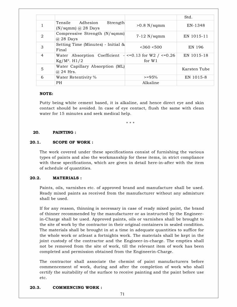
71
Std.
1 Tensile Adhesion Strength
(N/sqmm) @ 28 Days >0.8 N/sqmm EN-1348
2 Compressive Strength (N/sqmm)
@ 28 Days 7-12 N/sqmm EN 1015-11
3 Setting Time (Minutes) - Initial &
Final <360 <500 EN 196
4 Water Absorption Coefficient -
Kg/M². H1/2
<=0.13 for W2 / <=0.26
for W1
EN 1015-18
5 Water Capillary Absorption (ML)
@ 24 Hrs. Karsten Tube
6 Water Retentivity % >=95% EN 1015-8
PH Alkaline
NOTE:
Putty being white cement based, it is alkaline, and hence direct eye and skin
contact should be avoided. In case of eye contact, flush the same with clean
water for 15 minutes and seek medical help.
* * *
20. PAINTING :
20.1. SCOPE OF WORK :
The work covered under these specifications consist of furnishing the various
types of paints and also the workmanship for these items, in strict compliance
with these specifications, which are given in detail here-in-after with the item
of schedule of quantities.
20.2. MATERIALS :
Paints, oils, varnishes etc. of approved brand and manufacture shall be used.
Ready mixed paints as received from the manufacturer without any admixture
shall be used.
If for any reason, thinning is necessary in case of ready mixed paint, the brand
of thinner recommended by the manufacturer or as instructed by the Engineer-
in-Charge shall be used. Approved paints, oils or varnishes shall be brought to
the site of work by the contractor in their original containers in sealed condition.
The materials shall be brought in at a time in adequate quantities to suffice for
the whole work or atleast a fortnights work. The materials shall be kept in the
joint custody of the contractor and the Engineer-in-charge. The empties shall
not be removed from the site of work, till the relevant item of work has been
completed and permission obtained from the Engineerin-Charge.
The contractor shall associate the chemist of paint manufacturers before
commencement of work, during and after the completion of work who shall
certify the suitability of the surface to receive painting and the paint before use
etc.
20.3. COMMENCING WORK :
72
Scaffolding: Wherever scaffolding is necessary, it shall be erected on double
supports tied together by horizontal pieces, over which scaffolding planks shall
be fixed. No ballies, bamboos or planks shall rest on or touch the surface
which is being painted.
Where ladders are used, pieces of old gunny bags shall be tied on their tops to
avoid damage or scratches to walls.
For painting of the ceiling, proper stage scaffolding shall be erected.
Painting shall not be started until and unless the Engineer-in-Charge has
inspected the items of work to be painted, satisfied himself about their proper
quality and given his approval to commence the painting work.
Painting, except the priming coat, shall generally be taken in hand after all
other builders work, practically finished.
The rooms should be thoroughly swept out and the entire building cleaned up
at least one day in advance of the paint work being started.
20.4. PREPARATION OF SURFACE :
The surface shall be thoroughly cleaned. All dirt, rust, scales, smoke and
grease shall be thoroughly removed before painting is started. Minor patches if
any in plastered/form finished surfaces shall be repaired and finished in line
and level in C.M. 1:1 and cracks & crevices shall be filled with approved filler,
by the contractor at no extra cost to the Department. The prepared surface
shall have received the approval of the Engineer-in-Charge after inspection,
before painting is commenced.
20.5. APPLICATION :
Before pouring into smaller containers for use, the paint shall be stirred
thoroughly in its containers. When applying also, the paint shall be
continuously stirred in the smaller containers so that consistency is kept
uniform.
The external surfaces of the buildings under reference including the R.C.C.
Jalli, fins and the panels above and below the window etc. shall be finished in
different colours of approved shade. The contractor will make suitable samples
at site for Departments approvel before taking up the work in hand and they
will be allowed to proceed with the work only after getting Departments
approval for the same.
The painting shall be laid on evenly and smoothly by means of crossing and
laying off, the later in the direction of the grain in case of wood. The crossing &
laying off consists of covering the area with paint, brushing the surface hard
for the first time and then brushing alternately in opposite directions two or
three time and then finally brushing lightly in direction at right angles to the
same. In this process, no brush marks shall be left after the laying off is
finished. The full process of crossing and laying will constitute one coat.
Where so stipulated, the painting shall be done with spraying. Spray machine
used may be (a) a high pressure (small air aperture) type or (b) a low pressure

73
(large air gap) type, depending on the nature and location of work to be carried
out. Skilled and experienced workmen shall be employed for this class of work.
Paints used shall be brought to the requisite consistency by adding a suitable
thinner. Spraying should be done only when dry condition prevails.
Each coat shall be allowed to dry out thoroughly and rubbed smooth before the
next coat is applied. This should be fecilitated by thorough ventilation.
Each coat except the last coat, shall be lightly rubbed down with sand paper or
fine pumice stone and cleaned of dust before the next coat is laid.
No left over paint shall be put back into the stock tins. When not in use,
containers shall be kept properly closed.
The final painted surface shall present a uniform appearance and no streaks,
blisters, hair marks from the brush or clogging of paint puddles in the corners
of panels, angles of mouldings etc. shall be left on the work.
In case of cement based paints/primers, the absorbent surfaces shall be evenly
damped so as to give even suction. In any weather, freshly painted surfaces
shall be kept damp for atleast two days.
In painting doors and windows, the putty around the glass panes must also be
painted, but care must be taken to see that no paint stains etc. are left on the
glass. Tops of shutters and surfaces in similar hidden locations shall not be
left out while painting. Perspect covers of electrical switch boxes have to be
painted from inside by removing them. Care shall be taken while removing them
in position after painting with respective approved paints. In painting steel
work, special care shall be taken while painting over bolts, nuts, rivets,
overlaps etc.
The additional specifications for primer and other coats of paints shall be as in
accordance to the detailed specifications under the respective headings.
Any damage caused during painting work to the existing works/surfaces shall
be made good by the contractor at his own cost.
20.6. BRUSHES AND CONTAINERS :
After work, the brushes shall be completely cleaned off paint and linseed oil by
rinsing with turpentine. A brush in which paint has dried up is ruined and shall
on no account be used for painting work. The containers, when not in use, shall
be closed, kept air tight and shall be kept at a place free from dust. When the
paint has been used, the containers shall be washed with turpentine and
wiped dry with soft clean cloth, so that they are clean & can be used again.
20.7. MEASUREMENT :
a) Painting, unless otherwise stated shall be measured by area in square
metre. Length and breadth shall be measured correct upto two places of
decimal of a metre.
b) No deduction shall be made for opening not exceeding 0.05 sqm. and no
74
addition shall be made for painting to the beading, moulding edges, jambs,
soffits, sils, architraves etc. of such openings.
c) In measuring painting, varnishing, oiling etc. of joinery and steel work etc.,
the co-efficients as in the following table shall be used to obtain the areas
payable. The co-efficients shall be applied to the areas measured flat and
not girthed in all cases.
d) In case of painting of door shutter with push plates in plastic laminate,
deduction will be made for area of such laminations.
20.7.1. Table of multiplying Co-efficients to be applied over areas of
different surfaces to get equivalent plain areas is given in the Appendix-
“C-2” of this book.
20.7.2. Explanatory notes on the table of Co-efficients.
1. Where doors, window etc. are of composite types other than those
included in para 47.7 (c), the different portions shall be measured
separately with their appropriate co-efficients, the centre line of the
common rail being taken as the dividing line between the two portions.
2. Measurements for doors, windows etc. shall be taken flat (and not
girthed) over all including chowkhats or frames, where provided. Where
chowkhats or frames are not provided, the shutter measurements shall
be taken.
3. Collapsible gates shall be measured for width from outside to outside of
gate in its expanded position and for height from bottom to top of
channel verticals. No separate measurements shall be taken for the top
and bottom guide, rails, rollers, fittings etc.
4. Rolling shutters of interlocked laths shall be measured for the actual
shutter width and the height from bottom of opening to the centre of the
shaft. No separate measurements shall be taken for painting guides and
other exposed features within or outside the shutter area. The painting of
top cover or hood shall however be measured separately.
5. Co-efficients for sliding doors shall be the same as for normal types of
doors as mentioned in the table. Measurements shall be taken outside of
shutters, and no separate measurements shall be taken for painting
guides, rollers, fittings etc.
6. Measurement of painting of doors, windows, collapsible gates, rolling
shutters etc. as above shall be deemed to include painting all iron
fittings in the same or different shade for which no extra will be paid.
7. The measurements as above shall be deemed to include also the painting
of edges, blocks, cleats etc. for which no extra will be paid.
8. The co-efficients for doors and windows shall apply irrespective of the
size of frames and shutter members.
75
9. When the two faces of a door, window etc. are to be treated with different
specified finishes, measurable under separate items, the edges of frames
and shutters shall be treated with the one or the other type of finish as
ordered by the Engineer-in-Charge, and measurement of this will be
deemed to be included in the measurement of the face treated with that
finish.
10. In the case where shutters are fixed on both faces of the frames, the
measurements for the door frame and shutter on one face shall be taken
in the manner already described, while the additional shutter on the
other face will be measured for the shutter area only excluding the
frame.
11. Where shutters are provided with clearance at top or/and bottom, such
openings shall be deducted from the over all measurements and relevant
co-efficients shall be applied to obtain the area payable.
12. In case of trellis (or jaffri) work, the measurements shall include the
painting of the frame member for which no separate measurements shall
be taken. Trellis door or window shutters shall also be measured under
terllis work.
13. Wherever air conditioning grill, lighting, fixtures etc. in false ceiling are
painted along with, measurements shall be taken over all without
deductions for opening in grills and no extra shall be paid for the grills.
If grills, fixtures etc. are not painted, area of fixtures or grills as
measured flat (not girthed) shall be deducted when it exceeds 0.05 sqm.
individuals. Where walls and ceilings are painted in separate colours, the
junctions of two paints shall be brought down on the walls in a straight
line by about 6mm to 12mm. if so desired, if the junctions of walls and
ceilings are not even. Nothing extra shall be paid to the contractor on
this account. Beading wherever provided shall not be measured
separately but shall be deemed to be included in the area of false ceiling
etc. measured flat (not girthed).
14. For painting open palisade fencing and gates etc., the height shall be
measured from the bottom of the lowest rail, if the palisades do not go
below it, (or from the lower end of the palisades, if they project below the
lowest rail), upto the top of rails or palisades whichever are higher, but
not up to the top of standards when the latter are higher than the top
rails or palisades.
15. In the case of asbestos cement corrugated or semi-corrugated sheeting
and iron corrugated sheeting in roofs, side cladding etc., the work shall
be measured flat (not girthed) as fixed.
16. For trusses, compound girders, stanchions, lattice girder and similar
work, actual areas will be measured in sqm. and no extra shall be paid
for painting on bolt heads, nuts, washers etc. even when they are picked
out in a different tint to the adjacent work.
17. Painting of rain water, soil, waste, vent and water pipes etc. shall be
76
measured in running metres of the particular diameter of the pipe
concerned. Painting of specials such as bends, heads, branches, junctions,
shoes etc. shall be included in the length and no separate measurements
shall be taken for these or for painting brackets, clamps etc.
18. Measurements of wall surfaces and wood and other works not referred to
already shall be recorded as per actual and opening exceeding 0.05 sqm.
shall be deducted to get the net payable area. Length and breadth shall
be measured correct upto two places of decimal of a metre and area so
worked out shall be correct upto two places of decimal of a square metre.
19. In case the items of work requiring painting are inclusive of cost of
painting, the painting carried out shall not be measured separately.
20.8. PRECAUTIONS :
All furnitures, lightings, fixtures, sanitary fittings, glazing, floors etc. shall be
protected by covering and stains, smears, splashings, if any shall be removed
and any damage done shall be made good by the contractor at his cost.
20.9. RATES:
Rates shall include cost of all labour and materials involved on all the
operations described above and in the particular specifications given under the
several items.
20.10. (A) PAINTING PRIMING COAT ON WOOD, IRON OR PLASTERED
SURFACES :
20.10.1. Primer
1. The primer for wood work, iron work or plastered surface shall be as
specified in the description of the item.
2. Primer for Wood work / Iron & Steel / Plastered / Aluminium
surfaces shall be as specified below:
SN SURFACES PRIMER TO BE USED
a Wood work (hard & soft wood): Pink conforming to
I.S.3536-1966 b Resinous wood and ply wood: Aluminium primer
c Iron & Steel, Aluminium and
galvanised Steel
Zinc chromate primer
conforming to d Plastered surfaces, cement brick
work, Asbestos
Cement Primer
3. The primer shall be ready mixed primer of approved brand and
manufacture. Preparation of surface :
a) Wood work : The wood work to be painted shall be dry and free from
moisture.
The surface shall be thoroughly cleaned. All unevenness shall be rubbed
down smooth with sand paper and shall be well dusted. Knots, if any,
77
shall be covered with preparation of red lead made by grinding red lead
in water and mixing with strong glue sized and used hot. Appropriate
filler material with same shade as paint shall be used where so desired
by the Engineer-in-charge.
The surface treated for knotting shall be dry before painting is applied.
After the priming coat is applied, the holes and indentation on the
surface shall be stopped with glaziers putty or wood putty (for
specifications for glaziers putty and wood putty- refer as mentioned
here-in-before). Stopping shall not be done before the priming coat is
applied as the wood will absorb the oil in the stopping and the latter is
therefore liable to crack.
b) Iron and Steel Work : All rust and scales shall be removed by scrapping
or by brushing with steel wire brushes. Hard skin of oxide formed on the
surface of wrought iron during rolling which becomes loose by rusting,
shall be removed.
All dust and dirt shall be thoroughly wiped away from the surface.
If the surface is wet, it shall be dried before priming coat is undertaken.
c) Plastered Surface : The surface shall ordinarily not be painted until it
has dried completely. Trial patches of primer shall be laid at intervals
and where drying is satisfactory, painting shall be taken in hand. Before
primer is applied, holes and undulations, shall be filled up with plaster
of paris and rubbed smooth.
20.10.2. Application : The primer shall be applied with brushes, worked
well into the surface and spread even and smooth. The painting shall be
done by crossing and laying off as described here-in-before.
20.10.3. Other Details : The specifications for Painting (General) shall hold
good so far as it is applicable.
20.11. (B): PAINTING WITH SUPERIOR QUALITY & FLAT OIL READY MIXED
PAINTS ON NEW SURFACE :
20.11.1. Paint : Ready mixed paints shall be of approved brand and
manufacture and of the required shades. They shall conform in all
respects to the relevant I.S. specifications.
20.11.2. Preparation of Surface:
(a) Wood work : The surface shall be cleaned and all unevenness removed
as in para 47.10.2 (a). Knots if visible, shall be covered with a
preparation of red lead. Holes and indentations on the surface shall be
filled in with glaziers putty or wood putty and rubbed smooth before
painting is done. The surface should be thoroughly dry before painting.
(b) Iron and steel work : The primer coat shall have dried up completely
before painting is started. Rust and scaling shall be carefully removed by
scraping or by brushing with steel wire brushes. All dust and dirt shall

78
be carefully and thoroughly wiped away.
(c) Plastered surfaces : The priming coat shall have dried up completely
before painting is started. All dust or dirt that has settled on the priming
coat shall be thoroughly wiped before painting is started.
20.11.3. Application : The specifications mentioned here-in-before shall
hold good as far as applicable.
The number of coats to be applied will be as stipulated in the item. The
painted surface shall present a uniform appearance1 and
glossy/semiglossy finish, free from streaks, blisters etc.
20.11.4. Other details : The specifications for Painting (General) specified
here-in-before shall hold good in so far as they are applicable.
20.12. (C) PAINTING WITH SYNTHETIC ENAMEL/SEMI GLOSSY PAINT ON
NEW WORK :
1. Paint : Synthetic enamel/semi glossy paint of approved brand and
manufacture and required shade shall be used for the top coat and an
under coat of shade to match the top coat as recommended by the
manufacturer shall be used. The paint shall be conforming to IS : 1932-1
964.
2. Preparation of Surface : This shall be as per painting with superior quality
ready mixed paint as mentioned here- in- before.
3. Application : The number of coats including the under coat shall be as
stipulated in the item.
3.1. Under Coat : One coat of the specified paint of shade suited to the
shade of the top coat shall be applied and allowed to dry over night. It
shall be rubbed next day with the finest grade of wet abrasive paper to
ensure a smooth and even surface free from brush marks and all loose
particles shall be dusted off. All the cracks, crevices, roughness etc. will
be filled with approved putty as per manufacturers recommendations.
3.2. Top Coat : Finishing coats of specified paint of the desired colour
& shade shall be applied after the under coat is thoroughly dried.
Additional finishing coats shall be applied if found necessary to ensure
a proper and uniform semi glossy surface.
4. Other Details : The specifications for “Painting (General)” mentioned here-
in-before shall hold good as far as they are applicable.
20.13. (D) PAINTING WITH ACRYLIC EMULSION/PLASTIC EMULSION
PAINT.
1. This shall be polyvinyl based Acrylic/plastic emulsion paint of approved
manufacture of the required shade, conforming to I.S.5411-1969.
2. Primer: The primer to be used for the painting with acrylic emulsion on

79
cement concrete surfaces, plastered surfaces, A.C. sheets, timber and metal
surfaces, if necessary, shall be of approved base and as per
recommendations of the manufacturers.
3. Putty : Plaster filler to be used for filling up (putting) uneven surfaces,
small cracks and holes etc. shall be of approved compound and as per
recommendations of the manufacturers. No oil based putty shall be used.
The putty should be made from a mixture of whiting and plastic emulsion
paint or as per manufacturers recommendations.
4. Finishing coats : All the finishing coats shall be of matt finish or any other
finish as required by the Engineerin-charge. The number of finishing coats
shall be as specified in the item.
MODE OF MEASUREMENT :
All the measurements for payment shall be taken on net surface area actually
painted, unless otherwise specified. Deduction will be made from the areas for
fixtures, grills, ventilation, outlets, electrical boxes and such obstructions not
painted, if they are individually more than 0.05 sqm.
JOB REQUIREMENTS :
i) Acrylic emulsion paint is required to be provided on plastered and concrete
surfaces in portions of the building. The Department shall reserve the option
to delete or increase quantities in full or part from the scope of contract
during progress of work.
ii) All wood surfaces are to be painted with semi glossy synthetic enamel paint
with an approved primer.
iii) All shades and colours of paints shall be subjected to review and prior
approval of Engineer-in-Charge shall be taken before the application.
20.14. WHITE WASHING WITH LIME
20.14.1. Preparation of Surface : Before new work is white washed, the
surface shall be thoroughly brushed free from mortar droppings and
foreign-matter.
In the case of old work, all loose pieces and scales shall be scrapped off
and holes in plaster as well as patches of less than 0.05 sqm.area each
shall be filled up with mortar of the same mix. Where so specifically
ordered by the Engineer-in-charge, the entire surface of old white wash
shall be thoroughly removed by scrapping and this shall be paid for
separately.
20.14.2. Preparation of lime wash: The wash shall be prepared from fresh
stone white lime “Katani” or equivalent. The lime shall be thoroughly
slaked on the spot, mixed and stirred with sufficient water to make a
thin cream. This shall be allowed to stand for a period of 24 hours and
then shall be screened through a clean coarse cloth. 40 gm. of gum
dissolved in hot water, shall be added to each 10 cubic decimetre of the

80
cream. The approximate quantity of water to be added in making the
cream will be 5 litres of water to one kg. of lime.
Indigo (Neel) up to 3 gm. per kg. of lime dissolved in water, shall then be
added and wash stirred well. Water shall then be added at the rate of
about 5 ltrs. Per kg. Of lime to produce a milky solution.
The lime shall be tested in a chemical laboratory and test certificate
submitted, to conform the quality of lime with regard to its physical and
chemical properties. The cost of testing lime shall be borne by the
contractor.
20.14.3. White Washing: The white wash shall be applied with brushes or
by spray in the specified number of coats. The operation for each coat in
the case of brush application shall consist of a stroke of the brush given
from the top downwards, another from the bottom upwards over the first
stroke, and similarly one stroke horizontally from the right and another
from the left before it dries.
Each coat shall be allowed to dry before the next one is applied. Further
each coat shall be inspected and approved by the Engineer-in-charge
before the subsequent coat is applied. No portion of the surface shall be
left out initially to be patched up later on.
For new work, three or more coats shall be applied till the surface present
a smooth and uniform finish through which the plaster does not show.
The finished dry surface shall not show any sign of cracking and peeling
nor shall it come off readily on the hand when rubbed.
For old work, after the surface has been prepared as described here-in-
before, a coat of white wash shall be applied over the patches and
repairs. Then a single coat or two or more coats of white wash as
stipulated in the description of the item shall be applied over the entire
surface. The white washed surface should present a uniform finish
through which the plaster patched do not appear. The washing on
ceiling should be done prior to that on walls.
20.14.4. Protective Measures : Doors, windows, floors, articles of
furniture etc. and such other parts of the building not to be white
washed shall be protected from being splashed upon. Splashings and
droppings, if any, shall be removed by the contractor at his own cost
and the surfaces cleaned. Damages if any to painted surfaces, furnitures
or fittings and fixtures etc. shall be recoverable from the contractor.
20.14.5. Measurements: All measurements for payment shall be taken on
net surface areas actually white washed, unless otherwise specified.
Deductions will be made from the areas for fixtures, grills, ventilation,
outlets, electrical boxes and such obstruction not painted if they are
individually more than 0.05 sqm. Length and breadth shall be taken
correct upto two places of decimal of a metre and areas so worked out
shall be correct upto two places of decimals of a square metre.

81
Corrugated surfaces shall be measured flat as fixed and the area so
measured shall be increased by the following percentages to allow for
the girthed area.
Corrugated asbestos cement sheets 20
%
Semi-corrugated asbestos cement
sheets:
10
%
The number of coats of each treatment shall be stated. The item shall
include removing nails, making good holes, cracks, patches etc. not
exceeding 0.05 sqm. each with materials similar in composition to the
surface to be prepared.
20.14.6. Rate : The rate shall include the cost of all materials and labour
involved in all the operations described above.
20.15. COLOUR WASHING:
In the case of colour washing, mineral colours, not affected by lime, shall be
added to white wash with proper glue. No colour wash shall be done until a
sample of the colour wash to the required tint or shade has been got approved
from the Engineer-in-Charge. The colour shall be of even tint or shade over the
whole surface. If it is patchy or otherwise badly applied, it shall be redone by
the contractor, at no extra cost to the Department.
For new work, the priming coat shall be of white wash lime or with whiting as
specified in the description of the item. Two or three coats, shall then be
applied as specified on the entire surface till it represents a smooth and
uniform finish. Each coat after applying shall be got approved from the
Engineer-in-Charge.
The finished dry surface shall not be powdery and shall not readily come off on
the hand when rubbed.
Other specifications as detailed for Whitewashing with lime shall be applicable.
Indigo (Neel) shall however, not be added.
20.16. WATER PROOFING CEMENT BASED PAINT :
a) Material: Cement based paint (IS:541 0-1 969) of approved manufacture,
quality, shade and colour only shall be used.
b) Preparation of surfaces : The surface shall be thoroughly cleaned off all
mortar dropping, dirt, dust, algae, grease and other foreign matter by
brushing and washing the surfaces. The surface shall be thoroughly wetted
with clean water before the water proof cement paint is applied. The
prepared surface shall be got approved before painting is commenced.
82
The water proof cement paint shall be mixed in such quantities as can be
used up with in an hour of its mixing as otherwise the mixture will set and
thicken, affecting flow and finish.
Water proof cement paint shall be mixed with water in two stages. The first
stage shall comprise of 2 parts of water proof cement paint and one part of
water stirred thoroughly and allowed to stand for 5 minutes. Care shall be
taken to add the water proof cement paint gradually to the water and not
vice versa. The second stage shall comprise of adding further one part of
water to the mix and stirring thoroughly to obtain liquid of workable and
uniform consistency. In all cases the manufacturers instruction shall be
followed meticulously.
c) Application: The solution shall be applied on the clean and wetted surface
with brushes or spraying machine. The solution shall be kept well stirred
during the period of application. To avoid direct heat of the sun during
painting, the cement based paint shall be applied on the surface which is
on the shady side. Cement based paint shall not be applied on the surfaces
already treated with white wash, colour wash, dry or oil bound distemper,
varnishes, paints etc. It shall not be applied on gypsum, wood and metal
surfaces.
d) Other details : The specifications for Painting (General) mentioned here-
in-before shall hold good as far as they are applicable.
e) Mode of measurement for dry distemper, oil bound distemper and
water proof cement paint : All measurement for payment shall be taken
on net surface area actually painted unless otherwise specified and no co-
efficient shall be applied for working out areas. Deductions will be made
from areas for opening/obstructions not painted, if they are individually
more than 0.05 sqm. Length and breadth shall be taken correct upto two
places of decimal of a meter and areas shall be worked out correct upto
two places of decimal of a square meter.
Corrugated surfaces shall be measured flat as fixed and the area so
measured shall be increased by the following percentage to allow the
girthed area: a) Corrugated asbestos cement sheets - 20%; b) Semi
corrugated asbestos cement sheets - 10%.
The number of coats of each treatement shall be stated in the schedule of
quantities. The whole surface shall be applied with approved putty/filler to
get uniform and smooth surface at no extra cost to the Department.
Rates : The rate shall include cost of all materials and labour involved in
all the operation described above.
20.17. BEES WAXING OR POLISHING WITH READY MADE WAX
POLISH:(NEW WORK) :
20.17.1. Materials : The polishing shall be done with bees waxing prepared
locally or with ready made wax polish of approved brand and
manufacture, as stipulated in the description of item.
83
a) Where bees waxing is to be prepared locally, the following
specifications for the same shall apply:
Pure bees wax free from paraffin or stearing adulterants shall be used.
Its specific gravity shall be 0.965 to 0.969 and melting point shall be 63o
C. The polish shall be prepared from a mixture of bees wax, linseed oil,
turpentine and varnish in the ratio of 2: 1 .5: 1: 0.5 by weight.
The bees wax and boiled linseed oil shall be heated over a slow fire.
When the wax is completely dissolved, the mixture shall be cooled till it is
just warm and turpentine and varnish added to it in the required
proportions and the entire mixture shall be well stirred.
20.17.2. Preparation of surface : Preparation of surface will be as
mentioned here-in-under para 47.20.2 with the exception that knotting,
holes and cracks shall be stopped with a mixture of fine saw dust formed
of the wood being treated, beaten up with sufficient bees wax to enhance
cohesion.
20.17.3. Application : The polish shall be applied evenly with a clean soft
pad of cotton cloth in such a way that the surface is completely and fully
covered. The surface is then rubbed continuously for half an hour.
When the surface is quite dry, a second coat shall be applied in the same
manner and rubbed continuously for one hour or until the surface is dry.
The final coat shall then be applied and rubbed for two hours (more if
necessary) until the surface has assumed a uniform gloss and is dry
showing no sign of stickiness.
The final polish depends largely on the amount of rubbing which should
be continuous and with uniform pressure, with frequent changes in the
direction.
20.17.4. Other details : The specifications for painting (General) as
mentioned here-in-before shall hold good as for as they are applicable.
20.18. FRENCH SPIRIT POLISHING: (ON NEW WORK WITH A COAT OF
WOOD FILLER) :
20.18.1. Polish : Pure shellac varying from pale orange to lemon yellow
colour, free from resin or dirt shall be dissolved in methylated spirit at
the rate of 140 gm. of shellac to 1 litre of spirit. Suitable pigment shall be
added to get the required shade.
20.18.2. Preparation of surface : The surface shall be cleaned. All
unevenness shall be rubbed down smooth with sand paper and well
dusted off. Knots if visible shall be covered with a preparation of red lead
and glue size laid on while hot. Holes and indentations on the surface
shall be stopped with glaziers putty. The surface shall then be given a
coat of wood filler made by mixing whiting (ground chalk) in methylated
spirit at the rate of 1 .5 kg. of whiting per litre of spirit. The surface shall
again be rubbed down perfectly smooth with glass paper and wiped
84
clean.
20.18.3. Application : The number of coats of polish to be applied shall be
as described in the item.
A pad of woolen cloth covered by fine cloth shall be used to apply the
polish. The pad shall be moistened with the polish and rubbed hard on
the wood, in a series of overlapping circles applying the mixture
sparingly but uniformly over the entire area to give an even level
surface. A trace of linseed oil on the face of the pad facilitates this
operation. The surface shall be allowed to dry and the remaining coats
applied in the same way. To finish off, the pad shall be covered with a
fresh piece of clean fine cotton cloth, slightly damped with methylated
spirit and rubbed lightly and quickly with circular motions. The finished
surface shall have a uniform texture and high gloss.
20.18.4. Measurement, Rate and other Details : These shall be as for
Painting (General) mentioned here-inbefore as far as they are applicable.
NOTE: Consumption of paint for some painting items is given in
Appendix – “C-1”.
* * *
21. FALSE CEILING WITH FLEXO BOARDS / A.C. SHEETS :
21.1. SCOPE OF WORK :
The work envisaged under these specifications refer to supplying and fixing in
position false ceiling at any floor, any location and at any height.
21.2. MATERIAL :
The plain A.C. sheet or flexo board shall be of the thickness as mentioned in
the relevant items of the schedule of quantities and the size of panels and the
arrangement of panels etc. for different area of the building shall be as
indicated by the Engineer-in-Charge. Plain A.C. sheet or flexo board shall be of
approved quality and shall be free from cracks, bends and other defects.
Samples of materials to be used on the work shall first be furnished by the
contractor and got approved by the Engineer-in-Charge. All materials which
are used on the works shall strictly conform to the samples, other-wise the
materials shall be summarily rejected.
The plain A.C. sheet or flexo board shall be fixed to the angle iron frames
(frame work paid separately) work by means of suitable counter sunk brass
self tapping screws not more than 200 mm. centre to centre or as directed, and
all holes after fixing the screws be filled with approved filler. Necessary
openings in the ceiling shall be left for trap doors, ducts etc.
21.3. ERECTION :
The flexo boards/A.C. sheets when brought to site shall be stacked carefully
on floor over wooden sleeper supports. The boards shall be cut to required

85
sizes either by sawing or by score and snap method. The edges shall be
smoothened by wood rasp file or with emery paper. Wherever required the
edges of each panel may require bevelling which also shall be done carefully to
the correct line and dimensions.
The flexo boards/A.C. sheets shall be fixed to ridge frames either wooden or
metallic or mentioned in the item description. In case of metallic frame, the
flexo boards are held to the frame by means of self tapping screws or by the
ordinary machine screws and nuts, as directed by the Engineer-in-Charge.
Teak wood or aluminium beadings if required to be fixed shall be as mentioned
in the item description and shall be carried out in best workman-like manner.
Any other treatment for finishing such as gluing of wall papers, cement or oil
based paint etc. shall be as specified in the item description and shall be done
as per relevant specifications.
21.4. MODE OF MEASUREMENT :
Unless otherwise mentioned, the wooden or metallic-frame work shall be
separately measured and paid for. The flexo board/A.C. sheet false ceiling shall
be measured in square metre as actually laid over the frame work. The area
being worked out correct to two places of decimal with length and breadth
measured correct to a centimeter. The rates shall include the cost of all
materials, labour, scaffolding etc. as mentioned above and in item description,
unless otherwise specified.
22 TRAP DOORS :
The materials viz. M.S. frame, aluminium frame and A.C. sheet and
fabrications shall conform to the relevant specification given in this tender.
The trap doors shall be fixed in position with necessary M.S. angle frame
out of M.S. angle of size 40 x 40 x 6mm. for the shutter and fixed to M.S.
wall angle of size 40 x 25 x 6 mm. which is to be fixed by means of 40 x 25 x
6 mm. M.S. angle cleats, fixed to wall by means of M.S. hold fasts out of
M.S. flats of size 40 x 6mm., 150 mm. long and grouted with cement
concrete 1:2:4 in case of brick wall and with 100 mm. long M.S. coach
screws and rawl plugs in case R.C. columns etc. M.S. angle of size 40 x 25
x 5 mm. shall be provided for receiving the lever of the locking
arrangement. This angle shall be supported by 40 x 6 mm. M.S. flat
suspenders from ceiling fixed with 3/8" diameter metal
fasteners/expansion bolts. This angle, meant to receive the lever of the
lock, shall be supported by two numbers of M.S. angle of size 40 x 25 x 5
mm. on either side. The two angles also shall be provided with M.S. flat (40
x 6 mm.) suspenders @ 800 mm. centers at all other convenient spacing as
per drawing and as approved by the Engineer-in-Charge.
Sample of trap doors of single, double and multi panels shall be fabricated
and fixed in position and got approved before taking up fabrication of trap
doors on large scale.
86
All the exposed surfaces of M.S. work including the suspenders shall be
painted with two coats of synthetic enamel paint of approved make and
shade over a coat of approved primer.
MODE OF MEASUREMENT :
The area of trap door visible from underside of the false ceiling only shall
be measured in square metres for payment. The m.s. angles to be provided
for locking arrangements and supporting M.S. angles which shall not be
seen from underneath shall not be measured for payment and are supposed
to be included in the rate quoted for trap door, unless otherwise specified in
the schedule of work.
23. METAL FALSE CEILING SYSTEM & THERMAL INSULATION :
METAL FALSE CEILING SYSTEM (LUXALON 150 C / EQUIVQLENT):
23.1. MATERIALS
Manufacturing and Product: Hunter Douglas India Private Ltd. or equivalent
a) PRODUCT : Luxalon 150 C lineal aluminium false ceiling or equivalent
b) COLOUR : As specified or as approved by the Engineer-in-Charge
Material Description: All components shall be made of aluminium and
manufactured by M/s. Hunter Douglas India Private Limited OR Equivalent
and as per manufacturer's specification.
LUXALON 150 C METAL CEILING :
i) PANEL: The panel shall be cold roll formed panels 150mm wide and
15,5mm deep with a 5mm beveled edge creating an 8mm V groove made
from corrosion resistant Al.-Mg. Alloy AA5050, The length of each panel
shall be upto 6000mm. The aluminium panels shall be chromatised for
maximum bond between metal and paint enameled twice under high
temperature, one side with a full primer and finish coat in a polyester paint
for a dry film thickness of 20 microns, the other side (inner side) with a
primer coating and skin coat on a Continuous Paint Line.
ii) CARRIER : The carrier on which the panels shall be clipped on to will be
32mm wide, 39mm deep, made of black stove enameled 0.95mm thick
aluminium alloy AA5050. When two or more carriers are to be joined, they
shall be joined together by means of splices, which will clip on to holes
provided for the same.
iii) WALL TRIM : The wall trim shall be 15mm deep x 30mm wide x 15mm
deep x 0.4mm thick Aluminium Alloy AA5050 with square edges and
length of 5 mtr.
iv) ROD HANGER : The rod hanger of suitable length shall be made of 4mm
dia. galvanised steel (Zinc coating 120 gms/Sqm.)
v) SUSPENSION CLIP : The adjustment suspension clip shall be made of
87
galvanised spring steel V shaped with two holes to accommodate the rod
hanger.
vi) ANCHOR FASTNERS : The single piece sleeve anchor with assembled
hanger taper bolt and nut which has smaller driller dia. Anchor fastener
shall be of arrow make or equivalent with thread size 5mm.
vii) SUSPENSION SYSTEM : The carriers would be suspended from the roof by
4mm dia galvanised (Zinc coating 120gms/Sqm.) steel wire rod hangers
with height adjustment springs out of galvanised spring steel. Hangers shall
be fixed to roof by 'J' hooks and Anchor Fasteners
23.2. FINISHING OF SURFACE OF STRIPS FOR INTERNAL USE
(ALUMINIUM)
The coils from which aluminium panels are made shall be cold roll formed &
stove enameled on a continuous coil coating paint line with dried in place roller
coated application for pre-treatment. The coils to go through four stages of pre-
treatment, three times oven baked through conversion coating, priming and
finished coat, ensuring superior adhesion, high corrosion resistance and good
colour retention. The coils shall be painted on both sides after being degreased.
Prime coat of at least 5 microns to be applied on both sides and a back coat of 5
micron of neutral colour to be applied on the inside surface and 5 micron of
binder and 15 microns of top coat of desired colour shall be additionally
provided on the exposed surface.
Pencil Hardness. : phh > F
Light Fastness. : Light fastness of at least 6 according to
international wool scale.
Colour Fastness : All finishes shall have a colour fastness of at least 6.
Colour Variation. : Colour diff, Bet batches + 4 units Colour diff. Within
one batch + 2 units.
Colour Uniformity : Maximum allowable deviation is 2 NBS units.
Specular Glose. : 10 deg/00 (matt) ; 25 deg/00 (satin)
Resistance to Salt Spray : After 100 hrs testing under creep from the
edges or the Cross, shall Test exceed 2mm. Blistering shall not exceed F
8.
Impact resistance : To withstand an impact test of 5mN/mm
metal thickness Without loss of adhesion.
Paint adhesion. : Better than or equal rating 1
Humidity Resistance. : No formation of blister.
Chemical Resistance. : No loss of adhesion or gloss and no colour change or
Staining.
88
23.3. FIXING : The panels shall be clipped on to a carrier. The carriers to be
suspended with an adjustment spring of galvanised spring steel, V shaped with
two holes to accommodate the rod hanger. The rod hanger to be made of 4mm
dia, galvanised steel and suspended form the ceiling by J hooks fixed at 1.5mm
centre to centre.
23.4. WORKMANSHIP : The ceiling shall be erected in continuous sequence.
Spans would not exceed those recommended by M/s. Hunter Douglas India Pvt.
Ltd. All work in this section shall be performed in an efficient manner by the
installing agency approved by the manufacturers and as per manufacturer's
recommended procedures.
23.5. FIRE RESISTANCE : The false ceiling including the paint shall be fire
resistant as per DIN 4102.Class A2. It should also be classified as P-NOT
EASILY IGNITABLE - AS PER BS 476. Part 6 and should have a fire propagation
classification of Class as per BS 476. Part 6.
24. FALSE CEILING WITH GYPBOARD AND G.I. FRAMEWORK Scope of work:
The work envisaged under these specifications refer to supplying and
fixing in position false ceiling at any floor, any location and at any
height.
a) Providing and fixing suspended G.I frame work
b) Providing and fixing one layer of 12 mm gypboard over
this frame work
c) Jointing the board flush, applying two coats of primer
suitable for gypboard and two coats of acrylic emultion
matt finish paint of approved shade and make.
d)
Making necessary cut outs for light fitting, A.C grills
diffusers and other necessities. The work shall include
horizontal, vertical and inclined surfaces depending
upon the various requirements
e) The item includes p/f all necessary t.w. frame work
for A/C grills,electric fittings etc.complete all as directed
by consultant/Client.
Material :
G.I Frame work:
The system consists of G.I frame work suspended from the soffit of the RCC
ceiling. The following G.I components shall be used for grid work:
a) Ceiling section of 80 x 26 x 0.5 mm
b) Perimeter channel of 20 x 27 x 30 x 0.5mm
c) Intermediate channels of 15 x 45 x 0.9 mm
d) Ceiling angle of 25 x 10 x 0.55 mm
e) Connecting clips of 2.64 mm dia.
f) Soffit cleat 22 x 37 mm
g) Anchor fasteners 6 mm
89
All the G I components shall be of M/s.India Gypsum Limited make and bear
the embossing of “GYPSTEEL’ in each length.
The G.I grid work system shall be suspended from the soffit of RCC ceiling
using anchor fasteners of 6 mm of approved type and make and connected to
soffit cleats and ceiling angle by means of necessary nuts, bolts and washers
etc.
Gyp Board
Gyp Board of plain series 12 mm manufactured by India gypsum shall be used.
The Gyp board shall conforms to Is 2095. The longitudinal edge of the Gyp
board shall be of tapered / square edges, so as to have flush joints while fixing.
Handling and transporting of Gyp board shall be done carefully and as
recommended by the manufacturer. The board should always be kept in a dry
and covered place sheltered from rain and to avoid dampness from flow, they
should be supported on wooden battens which should not be more than 45 cm
apart on a flat surface. The material shall be stacked in piles of smaller
heights and should not be stacked on edges. Gyp board which have deformed
due to poor stacking should not be used.
Cutting of board should be made in faced side of the board by means of
retractable knife or by using a normal saw and the edges of the boards shall be
planed using proper files.
Finishing materials:
All jointing compounds, paper tapes, primer and paints shall be with materials
manufactured / recommended by India Gypsum.
Installation :
Perimeter channels are leveled at the required position of the finished ceiling
line and fixed to the wall at 610 mm center with the screws and nylon plugs.
The remaining G.I gird component are installed to form a regular grid
suspended from the soffit of RCC slab using soffit cleats ceiling angle and
anchor fasteners as specified. Extra frame for various cutouts of different
shapes, light fittings, AC grills, diffusers, smoke detectors and other necessities
have to be provided wherever required and is included in the scope of the work
at no extra cost. This frame work has to be made with perimeter channel of
specified size and shall be suitably supported. The line and level of the grid
work has to be checked for perfection and prior clearance of the grid work has
to be obtained from the Engineer-in-Charge before the placement of Gyp board.
The Gyp board are fixed with bound edges at right angles to ceiling section with
all joints staggered. All joints of Gyp board have to be fixed on ceiling section.
The Gyp boards are screwed to the ceiling section and perimeter channels with
Gyp board dry wall screws with joints staggered. Spotting of screws and
jointing are then carried out according to India Gypsum recommendations to
give a flush and smooth joint.
Necessary door openings of hinged type of suitable sizes have to be provided
with a suitable framework for control valves and for access above false ceiling /
AC duct boxing at no extra cost.
90
Joints at horizontal, vertical and inclined surfaces shall be suitably
strengthened with additional G.I frame work as required.
Finally the boards are jointed and finished so as to have a flush look which
includes filling and finishing the tapered and square edges of the board with a
jointing compound, paper tape and two coats of primer suitable for gyp board
(all as per recommended practices of Indian Gypsum). Then, the finished Gyp
board has to be painted with 2 coats of acrylic emulsion matt finish paint of
approved color and make.
The rate shall includes providing all material, erecting, suspending, G.I grid
work, jointing the boards, providing required cutouts and openable doors and
painting including providing necessary fittings and fixtures etc. complete as per
the specifications and all other activities related to the completion of the above
job.
Details of A.C grills, diffusers, recessed type electrical fittings to be erected in
false ceiling will be as per specifications and as shown in drawings.
The quantities indicated are approximate and is likely to vary depending upon
the site conditions.
The scope of works includes fixing with screws, fixtures etc. the recessed
electrical light fittings in the grid work of false ceiling / boxing. Marine
plywood ( 6 mm thick) / special G.I sections, if required, shall also be provided
at no extra cost. The rate quoted shall include all the above mentioned
activities related to the completion of the above job.
Mode of measurement :
Measurements will be made on flat plan area basis in Sq.M calculated to 2
places of decimal. Length and breadth shall be measured corrected to a cm.
No deduction shall be made for cutouts made for A.C. grills, diffusers,
electrical fittings, smoke detectors etc.
25. Modular false ceiling
Modular False Ceiling : Armstrong Modular ceiling grid(hot dipped galvanized
steel section) shall have 595 x 595 mm x 15mm fine fissured tiles(lay-in type)
in true horizontal level using a 15mm T bar section suspended from the ceiling
slab using 2 mm wire at every 1200mm interval. And shall have fire rating of 60
minutes as per BS 476/23 of 1987, Noise reduction Coefficient (NRC) of 0.50-
0.60, to resist temperature and humidity conditions up to 40 degree (104deg. F)
and humidity of 99% RH.
* * *
26. WATER PROOFING :
GENERAL : The guarantee for waterproofing treatment in prescribed proforma
must be given by the specialised agency which shall be countersigned by the
contractor in token of his over all responsibility. The guarantee for
waterproofing treatment in the prescribed proforma shall also cover Horizontal
expansion joint and Vertical expansion joint.
26.1. WATER PROOFING PLASTER IN TOILET AREA :
91
The following specification shall be followed unless otherwise stated in
schedule of quantities. This shall be 15 mm. thick plaster including an under
coat not exceeding 8 mm. thick. Approved water proofing compound like CICO
No. 1 or other approved equivalent shall be added @ 3% by weight of cement in
cement mortar or as per manufacturers specifications in both the coats. The
workmanship and material shall be same as described in plaster work in
general. All exposed surfaces shall be finished smooth with a coat of neat
cement as directed, except areas where tiling work is to be done, where the
plaster shall be left rough / float finish..
26.2. BRICK BAT COBA WATERPROOFING ON TERRACE :
26.2.1. Materials : The aggregate for brick bat coba shall be broken from
good and thoroughly well burnt bricks. These shall be strong, durable,
clean and free from impurities. They shall not contain any soft or
powdering materials. The aggregate shall be 20 mm. to 10 mm. size and
shall be approved by the Engineer-in-Charge before use.
Lime to be used for preparing brick bat coba shall be of lime class B,
conforming to I.S. 712-1959. Lime burnt from lime stone shall be used.
All impurities, ashes or pieces improperly burnt shall be screened or
picked out before slaking. It shall be in the form of lumps when brought
to site of work and not in powder form. The lime shall not be slaked with
water less than one week or more than two weeks before use.
26.2.2. Storage : The slaked lime if stored, shall be kept in a weather
proof and damp proof closed shed with impervious floor and sides to
protect it against rain, moisture, weather and extraneous materials
mixing with it, and shall be approved by the Engineer-in-Charge.
26.2.3. Proportion : The proportion for brick bat coba shall be 0.906
cum. (about 32cft.) of brick bat to 0.34 cum. (about 12 cft.) of slaked
lime.
26.2.4. Laying : The concrete surface shall be thoroughly rubbed, cleaned
of all set mortar, all dirt and dust and slightly wetted. The brick
aggregate shall be soaked in water before mixing with lime. The brick bat
coba shall be laid in an even layer and to the required thickness and
slope so as to form ridge, hip or valley line as may be necessary and as
indicated in the drawing or as directed by the Engineer-in-Charge. The
compaction shall be started immediately with wooden beaters and
during the above process, the surface shall be constantly kept wet by
sprinkling water observing the following precautions:
a) Brick bat coba shall not be rammed with heavy iron rammers as brick
aggregates are likely to be crushed into powder thereby, but shall be
beaten lightly and rapidly with wooden beaters to get the required
compaction and to obtain complete integration of brick bats and lime.
b) While beating, fresh fracture may take place which may cause
absorption of water from the mortar. Additional water may be sprinkled
with beating in such cases as considered necessary by the Engineer-in-

92
Charge. The beating work shall continue for at least 7 days.
c) The average thickness of coba shall be as specified in the items and the
top of the coba shall be given slope or made level and edges taken into
the brick masonry parapet or rounded off at junctions as shown in the
drawing and as directed by the Engineer-in-Charge.
26.2.5. MODE OF MEASUREMENT :
The length and breadth of the surface area shall be measured to two
places of decimals of a metre from the finished surface of wall and
parapet and cubic contents to be worked out with average thickness of
coba provided. Rate shall include cost of preparation of surface, cost of
materials, labour, rounding of junctions etc. complete.
26.3. CHINA MOSAIC WATER PROOFING :
26.3.1. General : This type of water proofing shall consist of setting in
thick cement slurry selected colour/white glazed tile broken pieces of
approved make and size over 20mm. thick bedding of cement mortar 1:4
with approved waterproofing agent or as specified in schedule of work, to
the required slope and level, over brick bat coba and finishing with neat
cement and cleaning to the required degree of fineness and evenness.
The different materials and workmanship shall conform to the relevant
I.S. specifications and shall be got approved before incorporating in the
work.
The surface of brick bat coba shall be thoroughly cleaned of dust, dirt
and loose particles removed and adequately watered. Thick coat of
cement slurry of the honey like consistency shall be sprayed on the base
before lime mortar screening of specified thickness is laid.
26.3.2. Laying : Over the prepared surface of brick bat coba, a layer of
cement mortar, 20 mm. thick or as specified, shall be laid and cement
slurry of consistency of honey, shall be spread over it using cement at a
rate of not less than 0.01 cum. per 10 sqm. While the bed is fresh, broken
pieces of 6 mm. thick selected white/colour glazed tiles not less than 25
mm. and not more than 50 mm. in any direction shall be set closely by
hand at random. The glazed tile pieces shall be soaked in water before
setting in position. The glazed surfaces shall be kept exposed and pressed
with wooden mallet. Over the glazed tile pieces a neat cement slurry,
using cement not less than 0.01 cum. per 10 sqm. shall be spread and
the surface brushed in and lightly rolled with wooden roller, taking care
that no air pocket is left between brick bat coba and china mosaic
flooring.
The top surfaces shall be cleaned with saw dust and cotton waste.
Finally the surface shall be cleaned with weak acid solution to remove
cement marks over the white glazed tile pieces. The finished work shall be
cured for at least 7 days. Care shall be taken to see that cement in joints
does not get dissolved due to acid washing. At corners and junctions with
93
parapet, the water proofing course shall be rounded off with cement
mortar as per drawing and shall be included in the quoted rate.
26.3.3. MODE OF MEASUREMENT :
The length and breadth shall be measured to two places of decimal of a
metre, along side the surface including rounding of junctions of walls and
wall & slab etc. and area worked out in square metre. The rain water out-
lets shall be finished as directed and no deduction shall be made for the
same (area upto 0.02 sqm.) while arriving at the net area for payment.
26.4. CEMENT BASED WATER PROOFING OF W.C. AND BATHS AREAS :
26.4.1. General : The water proofing treatment for the Bath and W.C.
shall be essentially of cement based water proofing treatment with
admixture of proprietary water proofing compound similar to M/s. India
water proofing companys treatment or any other equivalent approved
cement based water proofing treatment. The waterproofing treatment
shall consist of providing cement slurry mixed with proprietary water
proofing compound after preparation of surfaces, providing water
proofing cement plaster, finishing smooth/rough as required to the
required line, level, curing, finishing, guarantee for the water tightness
of the water proofing treatment etc.
26.4.2. Preparation of Surface : The surface to receive water proofing
treatment shall be thoroughly cleaned of scales, laitance, set mortar etc.
for receiving water proofing treatment, and necessary preparation of the
surface for providing water proofing treatment shall be done by the
contractor. If any honey combs are observed in beams and slabs of Bath
and W.C., the same shall be grouted with cement slurry mixed with
water proofing compound and the cracks and crevices, filled with
injection method.
26.4.3. Sequence of Treatment : All cutting and chasing in the floor and
walls for plumbing work shall be done by the plumbing agency. Water
proofing agency shall then provide CETROOF or equivalent approved
cement based water proofing treatment consisting of cement plaster
treatment mixed with the water proofing compound according to the
recommended specifications of the waterproofing agency. The thickness
of water proof plaster shall be about 35 mm. on floor area of the
depression and about 25 mm. thick on the vertical surface of
walls/concrete surface in case of sunken slabs, upto the finished floor
level. The thickness shall be about 18 mm. for the remaining wall height
upto 600 mm. from finished floor level.
The plumbing agency shall then lay and fix the pipes, W.C. pans, traps
etc. without disturbing the water proofing treatment. However, the joints
of water supply and waste connections including holes drilled for clamps
shall be treated by water proofing agency.
Waterproofing agency shall then fill-in the depression in the floor with
their ‘CETROOF’or equivalent approved waterproof brick bat coba with
94
the admixture of waterproofing compound according to waterproofing
agency’s specification and process, which should be furnished in writing
to the Engineer-in-Charge for effective supervision of completeness of
the process while executing the works.
26.4.4. Finishing : The surface of the exposed plaster shall be finished
smooth with neat cement. The plaster surface where tiling is to be
provided as well as brick bat coba filling where flooring to be provided,
shall be finished to proper line, level, plane and plumb to receive the
floor/dado finish. Curing of the waterproofing treatment shall be carried
out for 14 days.
26.4.5. Testing and Guarantee : The contractor shall test the surface
where waterproofing treatment is provided for the bone dry condition by
filling with water inside the depressed plastered portion. No wet patches
or leaks shall appear on he surrounding plastered walls or at the under
side of the slabs. The testing shall be carried out to the entire
satisfaction of the Engineer-in-Charge. The contractor shall furnish
guarantee in the Proforma as per Appendix D for the waterproofing
treatment for maintaining the under side of the waterproofed surface in
bone dry condition for a period of minimum ten years. During this
period, contractor shall attend to all leakages, defects etc. if noticed, free
of cost, starting his work of checking up and rectification with in a
weeks time from the date of receipt of information about such leakages
etc. by him.
The contractor shall submit the guarantee bond on appropriate stamp
paper and as per the enclosed proforma.
26.4.6. MODE OF MEASUREMENT :
i. Waterproof plaster shall be computed by taking the length and breadth
of the area actually plastered correct upto two decimal places of a metre.
No deduction shall be made for W.C. pans, pipes etc. in the
measurement.
ii. The filling with waterproof brick bat coba shall be computed by noting
the levels and dimensions of the filled up depression before and after the
filling, upto two decimal places of a metre and also no deductions shall be
made for W.C. pans, pipes etc.
26.5. CEMENT BASED WATERPROOFING OF ROOF TERRACES :
26.5.1. General : The waterproofing treatment shall be essentially a
cement based waterproofing treatment similar to that of M/s. India
Waterproofing Companys CETROOF or any other equivalent approved
waterproofing treatment. The waterproofing treatment shall consist of
providing cement slurry mixed with waterproofing compound, at desired
proportions including grouting the cracks and crevices with cement
slurry mixed with waterproofing compound, laying brick bats over
cement mortar bedding to the required slopes for roof drainage, filling
and grouting the joints with cement mortar, finishing the surface
95
smooth/chequered with cement plaster mixed with waterproofing
compound etc. as directed.
26.5.2. Preparation of Surfaces : All the rubbish, debris and other
materials left over by other agencies will be got removed by the
Department through other agencies. After removal of this rubbish,
debris etc., the surface to receive the waterproofing treatments shall be
thoroughly cleaned with wire brushes including removing of scales and
laitance, set mortar etc. by the waterproofing contractors. If any honey
combing including cracks and crevices are observed at column
junctions/and elsewhere, the same shall be grouted with cement slurry
mixed with approved waterproofing compound.
26.5.3. Treatment : The waterproofing treatment shall be generally as per
manufacturers own specifications, method and procedure. A typical
cross section of the waterproofing treatment shall generally consist of
the following:
i) Applying cement slurry mixed with waterproofing compound for the
entire surface to be treated.
ii) Laying of broken brick bat of required thickness over cement mortar
bedding to give proper roof drainage, grouted with cement mortar with
waterproofing compound.
iii) Laying of jointless cement based waterproofing cement mortar layer of
average thickness as specified in the item.
iv) Final rendering to give a smooth finish of cement colour with false lines
at 300 x 300 mm. or nearer convenient dimensions. Tenderer shall give
complete details of waterproofing treatment proposed by him, in writing
viz. details including roof fill material, waterproofing compound,
minimum and maximum thickness etc. for effective supervision of the
departmental Engineers, while the work is executed at site.
The contractor shall ensure that sufficient slope for effective roof
drainage is provided within the average thickness of waterproofing
treatment proposed by the contractor. In case the average specified
thickness of treatment exceeds, the fact shall be specifically brought to
the notice of the Engineer-in-Charge, before adopting the extra
thickness.
The rain water down take pipes if any, shall be fixed by the other agency
prior to commencement of waterproofing operation. Curing of the
finished surface by ponding shall be done for 7 days atleast.
26.5.4. Testing and Guarantee :
The contractor shall test the surface for the bone dry condition by
ponding water over roof for minimum seven days period to the entire
satisfaction of the Engineer-in-Charge. Alternately, the curing of the
finished surface done by ponding of water on the entire surface for seven
days, can also be used for testing water tightness. After a period of two
96
months, once again the roof should be ponded with water to check its
efficiency of waterproofing treatment against leakage. The contractor
shall furnish guarantee in the proforma as per Appendix D for the
waterproofing treatment provided by them, for maintaining the under
side of the roof in bone dry condition for a minimum period of ten years.
During this period, the contractor shall be liable to attend all the
leakages, defects etc. if noticed, free of cost, starting his work of checking
and rectifications within a weeks time from the date of receipt of
intimation of such leakages etc. by him.
26.5.5. MODE OF MEASUREMENT :
Net area in square metre of the roof measured in between the side walls,
i.e. plan dimensions including rounded junctions, kerbs, parapets where
waterproofing treatment provided etc. shall be measured for payment. No
deduction shall be made for openings upto 0.02 sqm such as rain water
outlets etc., but the same shall be finished as directed by the Engineer-
in-Charge. The rate shall include the cost of labour, materials,
scaffolding etc. and shall cover the cost of rounding of junctions etc.
which will not be measured separately. Brick bat filling done under this
item will not be measured separately and is deemed to be included in the
waterproofing treatment for roof with an average thickness of 115 mm.
* * *
27. DISMANTLING AND DEMOLITION :
27.1. SCOPE OF WORK :
The work envisaged under this sub-head is for dismantling and demolition of
brick masonry in cement/lime mortar, reinforced cement concrete works,
removing wooden chowkhats of doors, wooden or steel windows.
27.2. GENERAL :
The term Dismantling implies carefully taking up or down and removing
without damage. This shall consist of dismantling one or more parts of the
building as specified or shown on the drawings.
The term Demolition implies taking up or down or breaking up. This shall
consist of demolishing whole or part of work including all relevant items as
specified or shown on drawings.
27.3. PRECAUTIONS :
Necessary propping, shoring and/or underpinning shall be provided for the
safety of the adjoining work or property, which is to be left in tact, before
dismantling and demolishing is taken up and the work shall be carried out in
such a way that no damage is caused to the adjoining work or property.
Wherever required, temporary enclosures or partitions shall also be provided.
97
Necessary precautions shall be taken to keep the dust- nuisance down as and
when necessary.
Dismantling shall be commenced in a systematic manner. All materials which
are likely to be damaged by dropping from a height or demolishing roofs,
masonry etc., shall be carefully dismantled first. The dismantled articles shall
be passed by hand where necessary and lowered to the ground and not
thrown. The materials then be properly stacked as directed by the Engineer-in-
charge.
All materials obtained from dismantling or demolition shall be the property of
the Government unless otherwise specified and shall be kept in safe custody
until handed over to the Engineer-in-charge.
Any serviceable material, obtained during dismantling or demolition shall be
separated out and stacked properly as indicated by the Engineer-in-charge
within a lead of 150 m. or as specified in the item. All under serviceable
materials, rubbish etc. shall be disposed off as directed by the Engineer-in-
charge.
27.4. TREATMENT :
All the dismantled area shall be rendered clean off all debris, dust etc. The
sides of jambs, sills, soffits etc. of the openings if any, after taking out doors
and window chowkhats, unless and otherwise to be treated, shall be plastered
in C.M. 1:3 with neeru finish to render true sides, corners, edges etc.
27.5. MODE OF MEASUREMENT :
27.5.1. Brick Masonry & R.C.C. Works : The measurement of brick
masonry with or without plaster/painting shall be taken correct to a
centimeter and volume calculated in cubic metres upto two places of
decimal.
27.5.2. Doors and Windows : Dismantling of doors and windows (wooden
or steel) shall be enumerated. Removal of chowkhats (frame works) shall
include (unless otherwise separately mentioned for removing shutters
only), the removal of shutters along with architraves, beadings, fittings
and fastenings along with frames.
27.5.3. Roof Terracing : Dismantling of roof waterproofing treatment
shall be measured in square metre area. .Length and breadth shall be
measured correct to a centimeter between parapets. No separate
measurement shall be taken for gola and khurrah etc.
27.6. RATES :
The rate shall include cost of all such operations mentioned above including
necessary labour, materials, transport, scaffolding, stacking the serviceable
materials, disposing the unserviceable materials within the lead specified, all
as directed by the Engineer-in-charge.
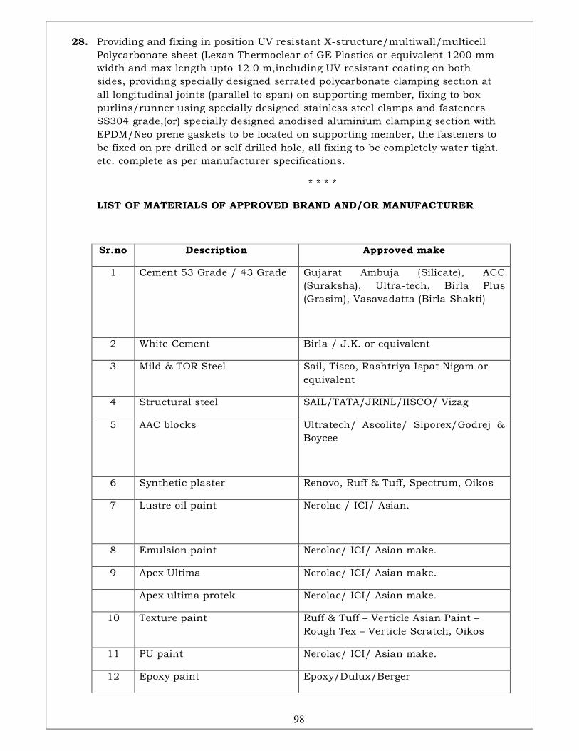
98
28. Providing and fixing in position UV resistant X-structure/multiwall/multicell
Polycarbonate sheet (Lexan Thermoclear of GE Plastics or equivalent 1200 mm
width and max length upto 12.0 m,including UV resistant coating on both
sides, providing specially designed serrated polycarbonate clamping section at
all longitudinal joints (parallel to span) on supporting member, fixing to box
purlins/runner using specially designed stainless steel clamps and fasteners
SS304 grade,(or) specially designed anodised aluminium clamping section with
EPDM/Neo prene gaskets to be located on supporting member, the fasteners to
be fixed on pre drilled or self drilled hole, all fixing to be completely water tight.
etc. complete as per manufacturer specifications.
* * * *
LIST OF MATERIALS OF APPROVED BRAND AND/OR MANUFACTURER
Sr.no Description Approved make
1 Cement 53 Grade / 43 Grade
Gujarat Ambuja (Silicate), ACC
(Suraksha), Ultra-tech, Birla Plus
(Grasim), Vasavadatta (Birla Shakti)
2 White Cement Birla / J.K. or equivalent
3 Mild & TOR Steel Sail, Tisco, Rashtriya Ispat Nigam or
equivalent
4 Structural steel SAIL/TATA/JRINL/IISCO/ Vizag
5 AAC blocks Ultratech/ Ascolite/ Siporex/Godrej &
Boycee
6 Synthetic plaster Renovo, Ruff & Tuff, Spectrum, Oikos
7 Lustre oil paint Nerolac / ICI/ Asian.
8 Emulsion paint Nerolac/ ICI/ Asian make.
9 Apex Ultima Nerolac/ ICI/ Asian make.
Apex ultima protek Nerolac/ ICI/ Asian make.
10 Texture paint Ruff & Tuff – Verticle Asian Paint –
Rough Tex – Verticle Scratch, Oikos
11 PU paint Nerolac/ ICI/ Asian make.
12 Epoxy paint Epoxy/Dulux/Berger

99
13 Vermiculite spray Proma spray
14 Vitrified tiles Matt or polished RAK /
Euro/KAJARIA/Somany/Jhonson
15 Granite First quality ruby red / jet black / light
grey/ Steel Grey Galaxy granite of
approved quality and Colour
16 Agglomerate Composite
Marble
Nitco/Kalinga stones
17 Italian Marble classic/ nitco/ elegant
18 Rubber flooring Sandick/NORA /Responsive
19 GRC (Glass Reinforced
Concrete)
Birla
20 Timber C.P seasoned teakwood of approved
quality for lipping, beading, framing
etc. Imported African
/Malaysian/Indokorian wood
21 Laminate Greenlam/ Marino/Euro
22 Plywood Anchor / Green ply /Century (IS 710 :
200)
23 Veneer Anchor / Green ply / Century /
Euro/Timey (1528 : 1996)
24 Melamine polish Asian paint / ICI/ NEROLAC
25 Duco paint MRF / ICI / ASIAN
26 Adhesive Fevicol
27 Modular doors & partitions Greenlam/Merino
28 Corian Dupont
29 Glass wool Rockwool/Twiga
30 Blinds Hunter Douglas/ Mac/ Vista/
Technifab/ Ferrari
31 Wallpaper Arte/Marshall /Ego /softek/Elemento
32 Frosted film 3M/Garware
33 Hardware fittings
DORMA/Hafele/Hettich/Blum
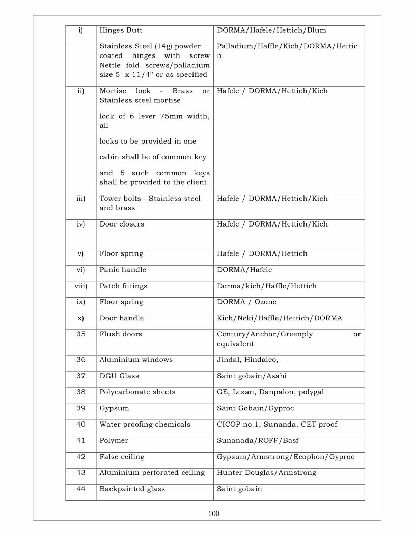
100
i) Hinges Butt DORMA/Hafele/Hettich/Blum
Stainless Steel (14g) powder
coated hinges with screw
Nettle fold screws/palladium
size 5" x 11/4'' or as specified
Palladium/Haffle/Kich/DORMA/Hettic
h
ii) Mortise lock - Brass or
Stainless steel mortise
lock of 6 lever 75mm width,
all
locks to be provided in one
cabin shall be of common key
and 5 such common keys
shall be provided to the client.
Hafele / DORMA/Hettich/Kich
iii) Tower bolts - Stainless steel
and brass
Hafele / DORMA/Hettich/Kich
iv) Door closers Hafele / DORMA/Hettich/Kich
v) Floor spring Hafele / DORMA/Hettich
vi) Panic handle DORMA/Hafele
viii) Patch fittings Dorma/kich/Haffle/Hettich
ix) Floor spring DORMA / Ozone
x) Door handle Kich/Neki/Haffle/Hettich/DORMA
35 Flush doors Century/Anchor/Greenply or
equivalent
36 Aluminium windows Jindal, Hindalco,
37 DGU Glass Saint gobain/Asahi
38 Polycarbonate sheets GE, Lexan, Danpalon, polygal
39 Gypsum Saint Gobain/Gyproc
40 Water proofing chemicals CICOP no.1, Sunanda, CET proof
41 Polymer Sunanada/ROFF/Basf
42 False ceiling Gypsum/Armstrong/Ecophon/Gyproc
43 Aluminium perforated ceiling Hunter Douglas/Armstrong
44 Backpainted glass Saint gobain
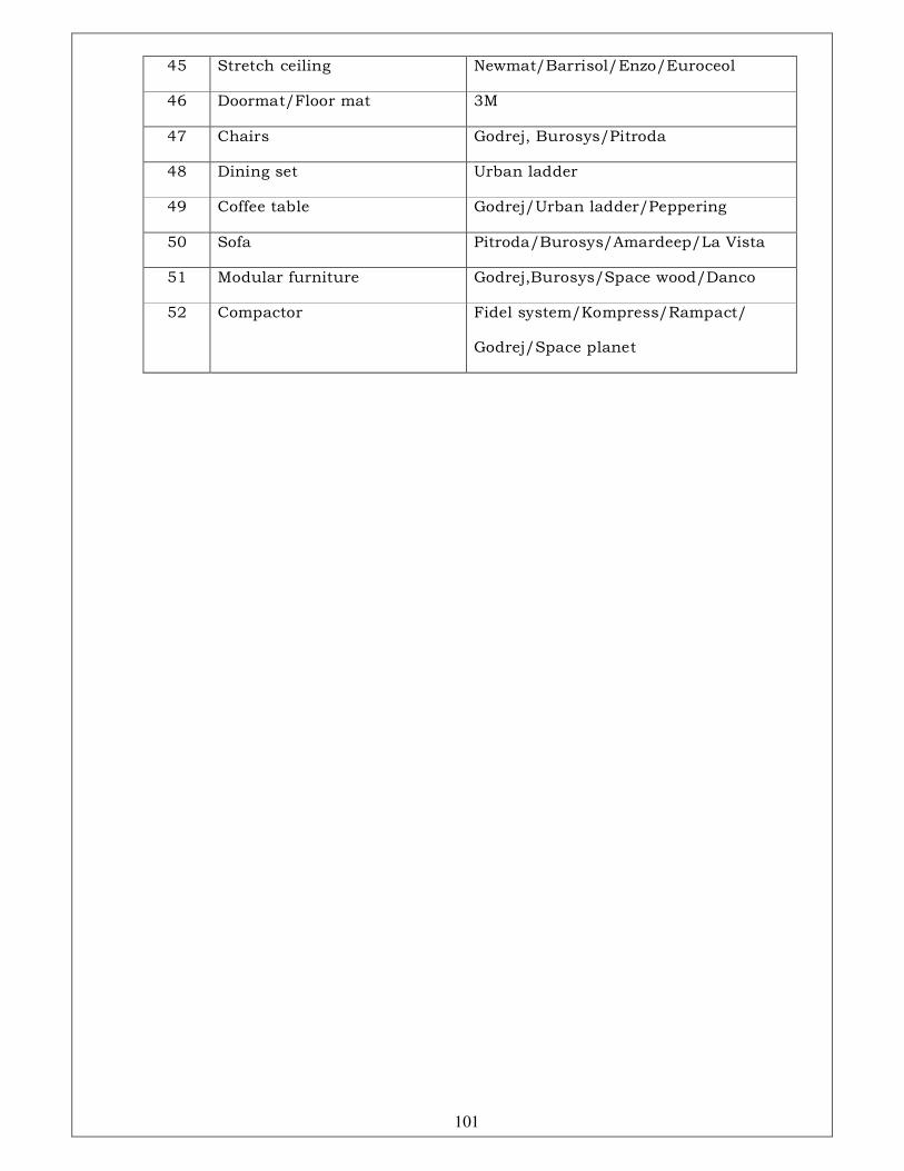
101
45 Stretch ceiling Newmat/Barrisol/Enzo/Euroceol
46 Doormat/Floor mat 3M
47 Chairs Godrej, Burosys/Pitroda
48 Dining set Urban ladder
49 Coffee table Godrej/Urban ladder/Peppering
50 Sofa Pitroda/Burosys/Amardeep/La Vista
51 Modular furniture Godrej,Burosys/Space wood/Danco
52 Compactor Fidel system/Kompress/Rampact/
Godrej/Space planet

102
SECTION - IV
TECHNICAL SPECIFICATIONS
FOR
PLUMBING WORKS

103
INDEX
Sr No Description Page No
1 GENERAL TECHNICAL SPECIFICATION FOR PLUMBING WORK 103
2 APPLICABLE CODES AND STANDARDS 104
3 QUALITY ASSURANCE AND QUALITY CONTROL 105
4 SANITARY FIXTURES & C.P. FITTINGS 106
5 INTRNAL WATER SUPPLY 107
6
INTERNAL DRAINAGE (SOIL, WASTE, VENT AND RAIN WATER
PIPES 111
7 LIST OF APPROVED MAKES 115
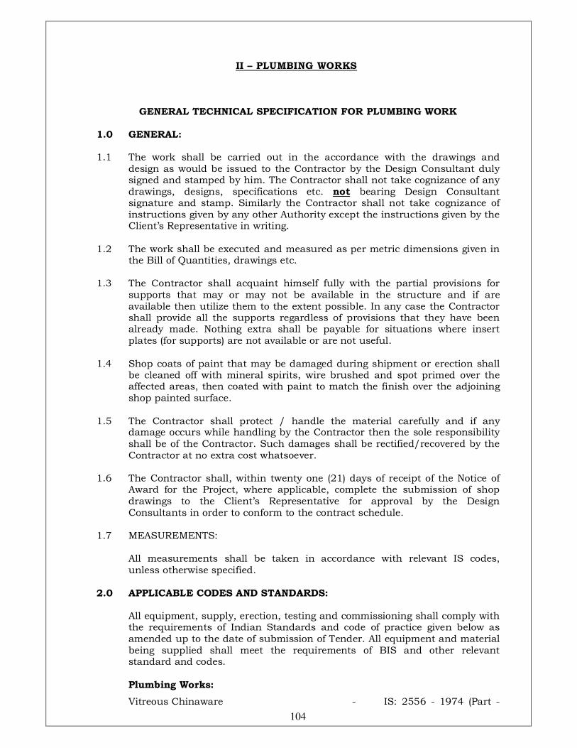
104
II – PLUMBING WORKS
GENERAL TECHNICAL SPECIFICATION FOR PLUMBING WORK 1.0 GENERAL: 1.1 The work shall be carried out in the accordance with the drawings and
design as would be issued to the Contractor by the Design Consultant duly signed and stamped by him. The Contractor shall not take cognizance of any drawings, designs, specifications etc. not bearing Design Consultant signature and stamp. Similarly the Contractor shall not take cognizance of instructions given by any other Authority except the instructions given by the Client’s Representative in writing.
1.2 The work shall be executed and measured as per metric dimensions given in
the Bill of Quantities, drawings etc. 1.3 The Contractor shall acquaint himself fully with the partial provisions for
supports that may or may not be available in the structure and if are available then utilize them to the extent possible. In any case the Contractor shall provide all the supports regardless of provisions that they have been already made. Nothing extra shall be payable for situations where insert plates (for supports) are not available or are not useful.
1.4 Shop coats of paint that may be damaged during shipment or erection shall
be cleaned off with mineral spirits, wire brushed and spot primed over the affected areas, then coated with paint to match the finish over the adjoining shop painted surface.
1.5 The Contractor shall protect / handle the material carefully and if any
damage occurs while handling by the Contractor then the sole responsibility shall be of the Contractor. Such damages shall be rectified/recovered by the Contractor at no extra cost whatsoever.
1.6 The Contractor shall, within twenty one (21) days of receipt of the Notice of
Award for the Project, where applicable, complete the submission of shop drawings to the Client’s Representative for approval by the Design Consultants in order to conform to the contract schedule.
1.7 MEASUREMENTS: All measurements shall be taken in accordance with relevant IS codes,
unless otherwise specified.
2.0 APPLICABLE CODES AND STANDARDS:
All equipment, supply, erection, testing and commissioning shall comply with the requirements of Indian Standards and code of practice given below as amended up to the date of submission of Tender. All equipment and material being supplied shall meet the requirements of BIS and other relevant standard and codes.
Plumbing Works:
Vitreous Chinaware - IS: 2556 - 1974 (Part -
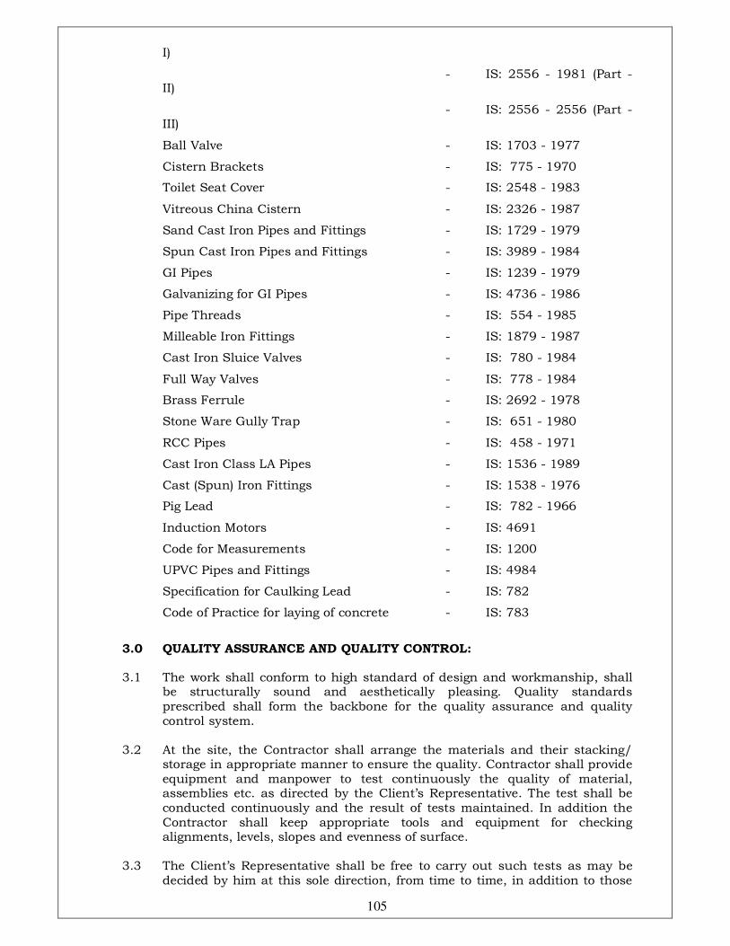
105
I)
- IS: 2556 - 1981 (Part - II)
- IS: 2556 - 2556 (Part - III)
Ball Valve - IS: 1703 - 1977
Cistern Brackets - IS: 775 - 1970
Toilet Seat Cover - IS: 2548 - 1983
Vitreous China Cistern - IS: 2326 - 1987
Sand Cast Iron Pipes and Fittings - IS: 1729 - 1979
Spun Cast Iron Pipes and Fittings - IS: 3989 - 1984
GI Pipes - IS: 1239 - 1979
Galvanizing for GI Pipes - IS: 4736 - 1986
Pipe Threads - IS: 554 - 1985
Milleable Iron Fittings - IS: 1879 - 1987
Cast Iron Sluice Valves - IS: 780 - 1984
Full Way Valves - IS: 778 - 1984
Brass Ferrule - IS: 2692 - 1978
Stone Ware Gully Trap - IS: 651 - 1980
RCC Pipes - IS: 458 - 1971
Cast Iron Class LA Pipes - IS: 1536 - 1989
Cast (Spun) Iron Fittings - IS: 1538 - 1976
Pig Lead - IS: 782 - 1966
Induction Motors - IS: 4691
Code for Measurements - IS: 1200
UPVC Pipes and Fittings - IS: 4984
Specification for Caulking Lead - IS: 782
Code of Practice for laying of concrete - IS: 783
3.0 QUALITY ASSURANCE AND QUALITY CONTROL: 3.1 The work shall conform to high standard of design and workmanship, shall
be structurally sound and aesthetically pleasing. Quality standards prescribed shall form the backbone for the quality assurance and quality control system.
3.2 At the site, the Contractor shall arrange the materials and their stacking/
storage in appropriate manner to ensure the quality. Contractor shall provide equipment and manpower to test continuously the quality of material, assemblies etc. as directed by the Client’s Representative. The test shall be conducted continuously and the result of tests maintained. In addition the Contractor shall keep appropriate tools and equipment for checking alignments, levels, slopes and evenness of surface.
3.3 The Client’s Representative shall be free to carry out such tests as may be
decided by him at this sole direction, from time to time, in addition to those

106
specified in this Document. The Contractor shall provide the samples and labour for collecting the samples. Nothing extra shall be payable to the Contractor for samples or for the collection of the samples.
3.4 The test shall be conducted at Standard Laboratory selected by Client’s
Representative. Contractor shall keep the necessary testing equipment such as hydraulic testing machine, smoke testing machine, gauges and other necessary equipment required.
3.5 The Client’s Representative shall transport the samples to the laboratory. 3.6 Testing charges shall be borne by the Client’s Representative. 3.7 Testing may be witnessed by the Contractor or his Authorised
Representative. Whether witnessed by the Contractor or not, the test results shall be binding on the Contractor.
4.0 SANITARY FIXTURES & C.P. FITTINGS:
4.1 SCOPE 4.1.1 Work under this section shall consist of transportation, furnishing,
installation, testing and commissioning and all labour as necessary as required to completely install all sanitary fixtures, brass and chromium plated fittings and accessories as required by the drawings and specified hereinafter or given in the Bill of Quantities.
4.2 GENERAL REQUIREMENTS 4.2.1 All fixtures and fittings shall be fixed with all such accessories as are
required to complete the item in working condition whether specifically mentioned or not in the Bill of Quantities, specifications, drawings or not.
4.2.2 All fixtures and accessories shall be fixed in accordance with a set pattern
matching the tiles or interior finish as per architectural design requirements. Wherever necessary the fittings shall be centered to dimensions and pattern desired.
4.2.3 Fixing screws shall be half round head chromium plated brass with C.P.
washers wherever required as per directions of Client’s Representative. 4.2.4 All fittings and fixtures shall be fixed in a neat workmanlike manner true to
levels and heights shows on the drawings & in accordance with the manufacturer’s recommendations. Care shall be taken to fix all inlet and outlet pipes at correct positions. Faulty locations shall be made good and any damage to the finished floor, wall or ceiling surfaces shall be made good at Contractors cost.
4.2.5 All fixtures of the similar materials shall be by the same manufacturers. 4.2.6 All fitting shall be of the chromium plated materials. 4.2.7 Without restricting to the generally of the foregoing the sanitary fixtures
shall include all sanitary fixtures, C.P. fittings and accessories etc. necessary and required for the building.
4.7.8 Whether specifically mentioned or not all fixtures and appliances shall be
provided with approved fixing devices, nuts, bolts, screws, and hangers as
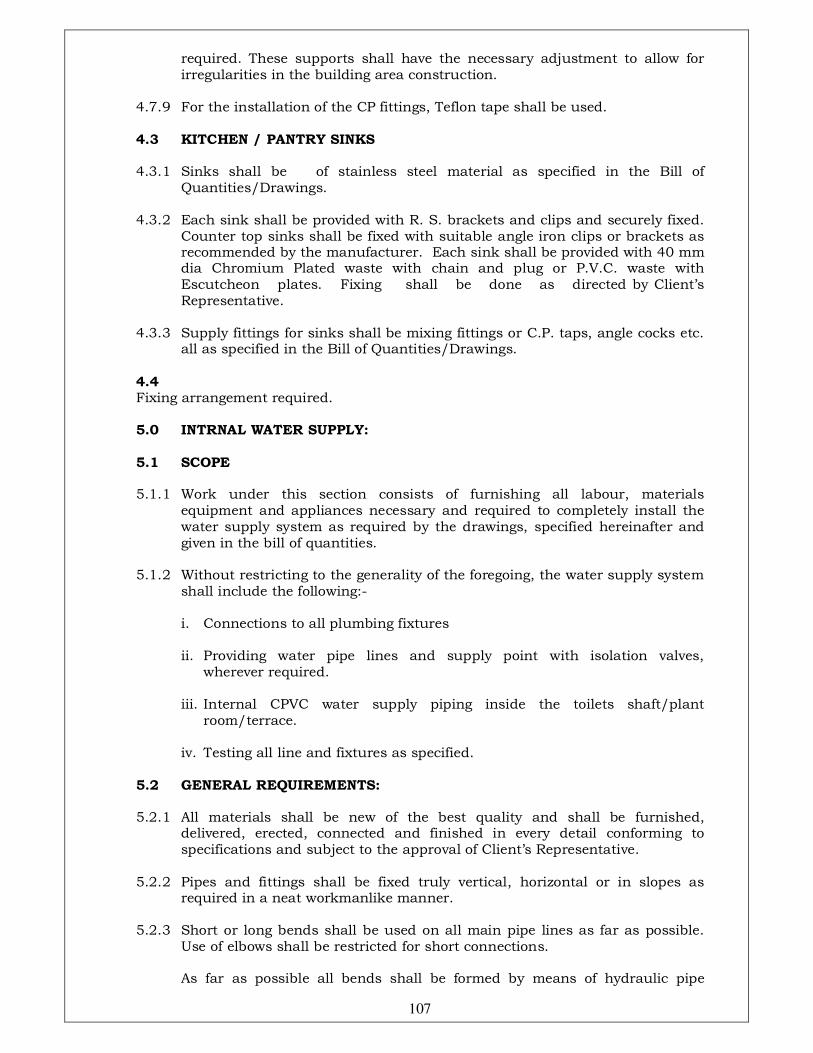
107
required. These supports shall have the necessary adjustment to allow for irregularities in the building area construction.
4.7.9 For the installation of the CP fittings, Teflon tape shall be used.
4.3 KITCHEN / PANTRY SINKS 4.3.1 Sinks shall be of stainless steel material as specified in the Bill of
Quantities/Drawings. 4.3.2 Each sink shall be provided with R. S. brackets and clips and securely fixed.
Counter top sinks shall be fixed with suitable angle iron clips or brackets as recommended by the manufacturer. Each sink shall be provided with 40 mm dia Chromium Plated waste with chain and plug or P.V.C. waste with Escutcheon plates. Fixing shall be done as directed by Client’s Representative.
4.3.3 Supply fittings for sinks shall be mixing fittings or C.P. taps, angle cocks etc.
all as specified in the Bill of Quantities/Drawings.
4.4 Fixing arrangement required. 5.0 INTRNAL WATER SUPPLY:
5.1 SCOPE 5.1.1 Work under this section consists of furnishing all labour, materials
equipment and appliances necessary and required to completely install the water supply system as required by the drawings, specified hereinafter and given in the bill of quantities.
5.1.2 Without restricting to the generality of the foregoing, the water supply system
shall include the following:-
i. Connections to all plumbing fixtures ii. Providing water pipe lines and supply point with isolation valves,
wherever required. iii. Internal CPVC water supply piping inside the toilets shaft/plant
room/terrace. iv. Testing all line and fixtures as specified.
5.2 GENERAL REQUIREMENTS: 5.2.1 All materials shall be new of the best quality and shall be furnished,
delivered, erected, connected and finished in every detail conforming to specifications and subject to the approval of Client’s Representative.
5.2.2 Pipes and fittings shall be fixed truly vertical, horizontal or in slopes as
required in a neat workmanlike manner. 5.2.3 Short or long bends shall be used on all main pipe lines as far as possible.
Use of elbows shall be restricted for short connections. As far as possible all bends shall be formed by means of hydraulic pipe

108
bending machine for pipes up to 65mm dia. 5.2.4 Pipes shall be fixed in a manner as to provide easy accessibility for repair and
maintenance and shall not cause obstruction in shafts, passages etc. and shall be selected and arranged so as to fit properly into the allocated building space.
5.2.5 Pipes shall be securely fixed to walls by suitable clamps at intervals specified. 5.2.6 Valves and other appurtenances shall be located to provide easy accessibility
for operation, maintenance and repairs. 5.2.7 Connection between dissimilar materials. 5.2.8 UNIONS: Contractor shall provide adequate no. of unions on all pipes to enable
dismantling later and for servicing. Union shall be provided near each gunmetal valve.
5.3 CPVC PIPES & FITTINGS:
i. The pipes and fittings chemically known as Chlorinated Poly Vinyl Chloride [CPVC] shall be produced in Copper Tube Size [CTS] from ½” to 2” with two different standard dimensional ratios – SDR 11 and 13.5. The fittings shall be produced as per SDR 11. All the CPVC pipes and fittings in SDR 11 and SDR 13.5 shall be made from the identical CPVC compound having the same physical properties. Pipes and fitting shall be produced as per SDR 11 & shall meet the requirement of ASTM D 2846 where as the pipes produced with SDR 13.5 shall meet the requirement derived from ASTM F 442, specific to CPVC in Iron Pipe Size[IPS] dimension, which also shall be applied to CPVC pipes in Copper Tube Size[CTS] dimension.
5.3.1. CUTTING AND JOINTING AND INSTALLATION OF CPVC PIPES & FITTINGS:
i. CUTTING: In order to make a proper and neat joint, the pipe length shall be
measured accurately and make a small mark. Ensure that the pipe and fittings are size compatible. It shall be easily cut with a wheel type plastic pipe cutter or hacksaw blade. Cutting tubing as squarely as possible shall provide optimal bonding area within a joint.
ii. DEBURRING / BEVELING: Burrs and filings shall prevent proper contact between tube and fitting
during assembly and should be removed from the outside and inside of the pipe. A pocket knife or file shall be used for this purpose. A slight bevel on the end of the tubing shall ease the entry of the tubing into the fitting socket.
iii. FITTING PREPARATION: Using a clean, dry rag, wipe dirt and moisture from the fitting sockets and
tubing end. The tubing should make contact with the socket wall 1/3 to 2/3 of the way into the fitting socket.
iv. SOLVENT CEMENTS APPLICATION: Use only CPVC cement or an all – purpose cement conforming to ASTM -
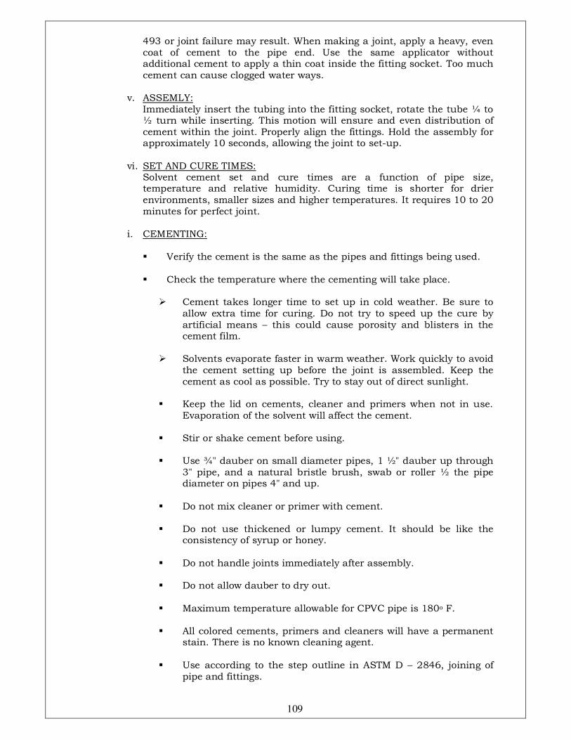
109
493 or joint failure may result. When making a joint, apply a heavy, even coat of cement to the pipe end. Use the same applicator without additional cement to apply a thin coat inside the fitting socket. Too much cement can cause clogged water ways.
v. ASSEMLY: Immediately insert the tubing into the fitting socket, rotate the tube ¼ to
½ turn while inserting. This motion will ensure and even distribution of cement within the joint. Properly align the fittings. Hold the assembly for approximately 10 seconds, allowing the joint to set-up.
vi. SET AND CURE TIMES: Solvent cement set and cure times are a function of pipe size,
temperature and relative humidity. Curing time is shorter for drier environments, smaller sizes and higher temperatures. It requires 10 to 20 minutes for perfect joint.
i. CEMENTING:
� Verify the cement is the same as the pipes and fittings being used.
� Check the temperature where the cementing will take place.
� Cement takes longer time to set up in cold weather. Be sure to
allow extra time for curing. Do not try to speed up the cure by artificial means – this could cause porosity and blisters in the cement film.
� Solvents evaporate faster in warm weather. Work quickly to avoid
the cement setting up before the joint is assembled. Keep the cement as cool as possible. Try to stay out of direct sunlight.
� Keep the lid on cements, cleaner and primers when not in use.
Evaporation of the solvent will affect the cement. � Stir or shake cement before using. � Use ¾" dauber on small diameter pipes, 1 ½" dauber up through
3" pipe, and a natural bristle brush, swab or roller ½ the pipe diameter on pipes 4" and up.
� Do not mix cleaner or primer with cement. � Do not use thickened or lumpy cement. It should be like the
consistency of syrup or honey. � Do not handle joints immediately after assembly.
� Do not allow dauber to dry out. � Maximum temperature allowable for CPVC pipe is 180o F. � All colored cements, primers and cleaners will have a permanent
stain. There is no known cleaning agent. � Use according to the step outline in ASTM D – 2846, joining of
pipe and fittings.
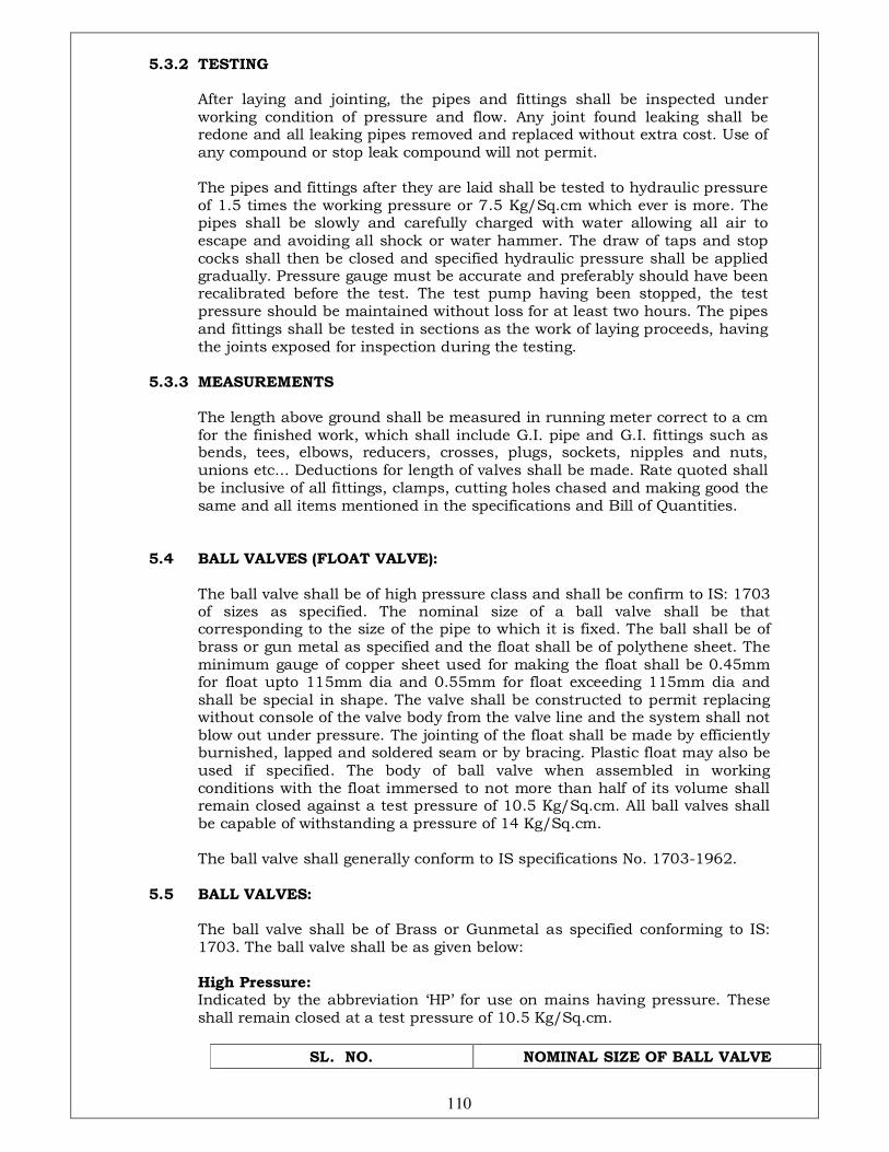
110
5.3.2 TESTING
After laying and jointing, the pipes and fittings shall be inspected under working condition of pressure and flow. Any joint found leaking shall be redone and all leaking pipes removed and replaced without extra cost. Use of any compound or stop leak compound will not permit.
The pipes and fittings after they are laid shall be tested to hydraulic pressure of 1.5 times the working pressure or 7.5 Kg/Sq.cm which ever is more. The pipes shall be slowly and carefully charged with water allowing all air to escape and avoiding all shock or water hammer. The draw of taps and stop cocks shall then be closed and specified hydraulic pressure shall be applied gradually. Pressure gauge must be accurate and preferably should have been recalibrated before the test. The test pump having been stopped, the test pressure should be maintained without loss for at least two hours. The pipes and fittings shall be tested in sections as the work of laying proceeds, having the joints exposed for inspection during the testing.
5.3.3 MEASUREMENTS The length above ground shall be measured in running meter correct to a cm
for the finished work, which shall include G.I. pipe and G.I. fittings such as bends, tees, elbows, reducers, crosses, plugs, sockets, nipples and nuts, unions etc... Deductions for length of valves shall be made. Rate quoted shall be inclusive of all fittings, clamps, cutting holes chased and making good the same and all items mentioned in the specifications and Bill of Quantities.
5.4 BALL VALVES (FLOAT VALVE): The ball valve shall be of high pressure class and shall be confirm to IS: 1703
of sizes as specified. The nominal size of a ball valve shall be that corresponding to the size of the pipe to which it is fixed. The ball shall be of brass or gun metal as specified and the float shall be of polythene sheet. The minimum gauge of copper sheet used for making the float shall be 0.45mm for float upto 115mm dia and 0.55mm for float exceeding 115mm dia and shall be special in shape. The valve shall be constructed to permit replacing without console of the valve body from the valve line and the system shall not blow out under pressure. The jointing of the float shall be made by efficiently burnished, lapped and soldered seam or by bracing. Plastic float may also be used if specified. The body of ball valve when assembled in working conditions with the float immersed to not more than half of its volume shall remain closed against a test pressure of 10.5 Kg/Sq.cm. All ball valves shall be capable of withstanding a pressure of 14 Kg/Sq.cm.
The ball valve shall generally conform to IS specifications No. 1703-1962. 5.5 BALL VALVES: The ball valve shall be of Brass or Gunmetal as specified conforming to IS:
1703. The ball valve shall be as given below: High Pressure: Indicated by the abbreviation ‘HP’ for use on mains having pressure. These
shall remain closed at a test pressure of 10.5 Kg/Sq.cm.
SL. NO. NOMINAL SIZE OF BALL VALVE

111
15 m
m
20m 25m 32m 40m 50mm
1. Diameter of spherical float (mm)
High Pressure 127 152 203 229 254 305
Low Pressure 114 127 178 203 203 254
Minimum weight of ball valve including back nut, body and piston (gms)
283 446 823 1149 1589 1852
The ball valves shall be of following nominal sizes 15mm, 20mm, 25mm, 32mm, 40mm and 50mm. The nominal size shall correspond with the nominal bore of the inlet shanks.
All valves shall be tested while installed in pipe by hydrostatic pressure of 1.5 time of the working pressure 7.5 Kg/Sq.cm which ever is more.
6.0 INTERNAL DRAINAGE (SOIL, WASTE, VENT AND RAIN WATER PIPES): 6.1 SCOPE: 6.1.1 Work under this section shall consist of furnishing all labour, materials,
equipment and appliances necessary and required to completely install all soil, waste, vent and rainwater pipes as required by the drawings, specified hereinafter and given in the Bill of Quantities.
6.1.2 Without restricting to the generality of the foregoing, the soil, waste, vent and
rainwater pipes system shall include the followings:-
i. Cast Iron / UPVC vertical and horizontal soil waste and vent pipes, rainwater pipes and fittings, joints clamps and connections to fixtures.
ii. Floor traps, floor drain clean out plugs, inlet fittings and rainwater roof
drain, area/local drains, trench drain... iii. Waste pipes connections from all fixtures e.g. wash basins, sinks, kitchen
equipment. iv. Testing of all pipes. v. Connection of main.
6.2 GENERAL REQUIREMENTS 6.2.1 All materials shall be new of the best quality conforming to specifications and
subject to the approval of Client’s Representative. 6.2.2 Pipes and fittings shall be fixed truly vertical, horizontal or in slopes as
required in a neat workmanlike manner. 6.2.3 Pipes shall be fixed in a manner as to provide easy accessibility for repair and
maintenance and shall not cause obstruction in shafts, passages etc. 6.2.4 Pipes shall be securely fixed to walls by suitable clamps at intervals specified.
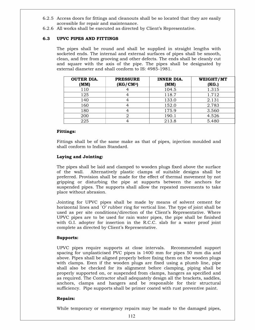
112
6.2.5 Access doors for fittings and cleanouts shall be so located that they are easily accessible for repair and maintenance.
6.2.6 All works shall be executed as directed by Client’s Representative. 6.3 UPVC PIPES AND FITTINGS The pipes shall be round and shall be supplied in straight lengths with
socketed ends. The internal and external surfaces of pipes shall be smooth, clean, and free from grooving and other defects. The ends shall be cleanly cut and square with the axis of the pipe. The pipes shall be designated by external diameter and shall conform to IS: 4985-1981.
OUTER DIA. (MM)
PRESSURE (KG/CM2)
INNER DIA. (MM)
WEIGHT/MT (KG.)
110 4 104.5 1.315
125 4 118.7 1.712
140 4 133.0 2.131
160 4 152.0 2.783
180 4 175.9 3.560
200 2 190.1 4.526
225 4 213.8 5.480
Fittings:
Fittings shall be of the same make as that of pipes, injection moulded and shall conform to Indian Standard.
Laying and Jointing:
The pipes shall be laid and clamped to wooden plugs fixed above the surface of the wall. Alternatively plastic clamps of suitable designs shall be preferred. Provision shall be made for the effect of thermal movement by not gripping or disturbing the pipe at supports between the anchors for suspended pipes. The supports shall allow the repeated movements to take place without abrasion.
Jointing for UPVC pipes shall be made by means of solvent cement for horizontal lines and `O’ rubber ring for vertical line. The type of joint shall be used as per site conditions/direction of the Client’s Representative. Where UPVC pipes are to be used for rain water pipes, the pipe shall be finished with G.I. adopter for insertion in the R.C.C. slab for a water proof joint complete as directed by Client’s Representative.
Supports:
UPVC pipes require supports at close intervals. Recommended support spacing for unplasticised PVC pipes is 1400 mm for pipes 50 mm dia and above. Pipes shall be aligned properly before fixing them on the wooden plugs with clamps. Even if the wooden plugs are fixed using a plumb line, pipe shall also be checked for its alignment before clamping, piping shall be properly supported on, or suspended from clamps, hangers as specified and as required. The Contractor shall adequately design all the brackets, saddles, anchors, clamps and hangers and be responsible for their structural sufficiency. Pipe supports shall be primer coated with rust preventive paint.
Repairs:
While temporary or emergency repairs may be made to the damaged pipes,
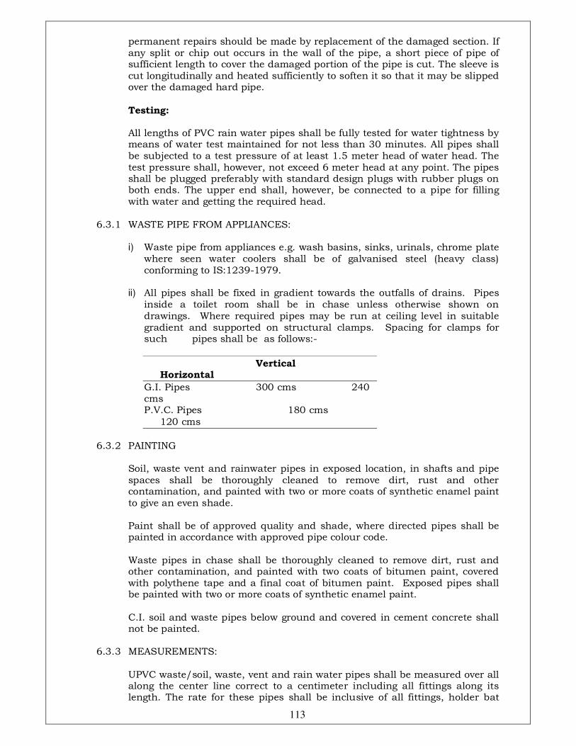
113
permanent repairs should be made by replacement of the damaged section. If any split or chip out occurs in the wall of the pipe, a short piece of pipe of sufficient length to cover the damaged portion of the pipe is cut. The sleeve is cut longitudinally and heated sufficiently to soften it so that it may be slipped over the damaged hard pipe.
Testing:
All lengths of PVC rain water pipes shall be fully tested for water tightness by means of water test maintained for not less than 30 minutes. All pipes shall be subjected to a test pressure of at least 1.5 meter head of water head. The test pressure shall, however, not exceed 6 meter head at any point. The pipes shall be plugged preferably with standard design plugs with rubber plugs on both ends. The upper end shall, however, be connected to a pipe for filling with water and getting the required head.
6.3.1 WASTE PIPE FROM APPLIANCES:
i) Waste pipe from appliances e.g. wash basins, sinks, urinals, chrome plate where seen water coolers shall be of galvanised steel (heavy class) conforming to IS:1239-1979.
ii) All pipes shall be fixed in gradient towards the outfalls of drains. Pipes
inside a toilet room shall be in chase unless otherwise shown on drawings. Where required pipes may be run at ceiling level in suitable gradient and supported on structural clamps. Spacing for clamps for such pipes shall be as follows:-
Vertical Horizontal
G.I. Pipes 300 cms 240 cms P.V.C. Pipes 180 cms
120 cms
6.3.2 PAINTING Soil, waste vent and rainwater pipes in exposed location, in shafts and pipe
spaces shall be thoroughly cleaned to remove dirt, rust and other contamination, and painted with two or more coats of synthetic enamel paint to give an even shade.
Paint shall be of approved quality and shade, where directed pipes shall be
painted in accordance with approved pipe colour code. Waste pipes in chase shall be thoroughly cleaned to remove dirt, rust and
other contamination, and painted with two coats of bitumen paint, covered with polythene tape and a final coat of bitumen paint. Exposed pipes shall be painted with two or more coats of synthetic enamel paint.
C.I. soil and waste pipes below ground and covered in cement concrete shall
not be painted. 6.3.3 MEASUREMENTS: UPVC waste/soil, waste, vent and rain water pipes shall be measured over all
along the center line correct to a centimeter including all fittings along its length. The rate for these pipes shall be inclusive of all fittings, holder bat
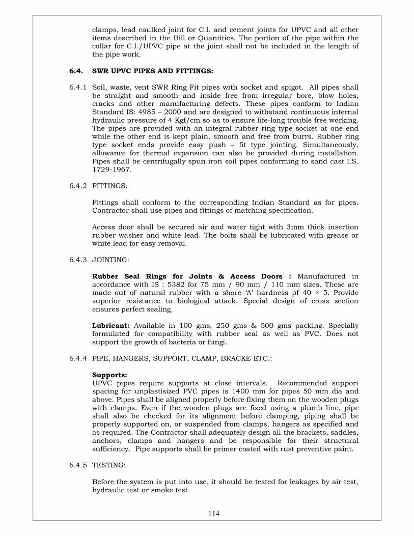
114
clamps, lead caulked joint for C.I. and cement joints for UPVC and all other items described in the Bill or Quantities. The portion of the pipe within the collar for C.I./UPVC pipe at the joint shall not be included in the length of the pipe work.
6.4. SWR UPVC PIPES AND FITTINGS: 6.4.1 Soil, waste, vent SWR Ring Fit pipes with socket and spigot. All pipes shall
be straight and smooth and inside free from irregular bore, blow holes, cracks and other manufacturing defects. These pipes conform to Indian Standard IS: 4985 – 2000 and are designed to withstand continuous internal hydraulic pressure of 4 Kgf/cm so as to ensure life-long trouble free working. The pipes are provided with an integral rubber ring type socket at one end while the other end is kept plain, smooth and free from burrs. Rubber ring type socket ends provide easy push – fit type jointing. Simultaneously, allowance for thermal expansion can also be provided during installation. Pipes shall be centrifugally spun iron soil pipes conforming to sand cast I.S. 1729-1967.
6.4.2 FITTINGS: Fittings shall conform to the corresponding Indian Standard as for pipes.
Contractor shall use pipes and fittings of matching specification. Access door shall be secured air and water tight with 3mm thick insertion
rubber washer and white lead. The bolts shall be lubricated with grease or white lead for easy removal.
6.4.3 JOINTING: Rubber Seal Rings for Joints & Access Doors : Manufactured in
accordance with IS : 5382 for 75 mm / 90 mm / 110 mm sizes. These are made out of natural rubber with a shore ‘A’ hardness pf 40 × 5. Provide superior resistance to biological attack. Special design of cross section ensures perfect sealing.
Lubricant: Available in 100 gms, 250 gms & 500 gms packing. Specially
formulated for compatibility with rubber seal as well as PVC. Does not support the growth of bacteria or fungi.
6.4.4 PIPE, HANGERS, SUPPORT, CLAMP, BRACKE ETC.: Supports: UPVC pipes require supports at close intervals. Recommended support
spacing for unplastisized PVC pipes is 1400 mm for pipes 50 mm dia and above. Pipes shall be aligned properly before fixing them on the wooden plugs with clamps. Even if the wooden plugs are fixed using a plumb line, pipe shall also be checked for its alignment before clamping, piping shall be properly supported on, or suspended from clamps, hangers as specified and as required. The Contractor shall adequately design all the brackets, saddles, anchors, clamps and hangers and be responsible for their structural sufficiency. Pipe supports shall be primer coated with rust preventive paint.
6.4.5 TESTING: Before the system is put into use, it should be tested for leakages by air test,
hydraulic test or smoke test.
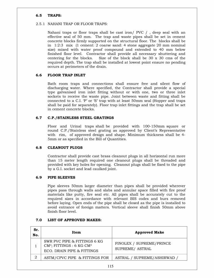
115
6.5 TRAPS: 2.5.1 NAHANI TRAP OR FLOOR TRAPS: Nahani traps or floor traps shall be cast iron/ PVC / , deep seal with an
effective seal of 50 mm. The trap and waste pipes shall be set in cement concrete blocks firmly supported on the structural floor. The blocks shall be in 1:2:3 mix (1 cement: 2 coarse sand: 4 stone aggregate 20 mm nominal size) mixed with water proof compound and extended to 40 mm below finished floor level. Contractor shall provide all necessary shuttering and centering for the blocks. Size of the block shall be 30 x 30 cms of the required depth. The trap shall be installed at lowest point ensure no pending occurs at perimeters of the drain.
6.6 FLOOR TRAP INLET Bath room traps and connections shall ensure free and silent flow of
discharging water. Where specified, the Contractor shall provide a special type galvanised iron inlet fitting without or with one, two or three inlet sockets to receive the waste pipe. Joint between waste and fitting shall be connected to a C.I. ‘P’ or ‘S’ trap with at least 50mm seal (Hopper and traps shall be paid for separately). Floor trap inlet fittings and the trap shall be set in cement concrete blocks.
6.7 C.P./STAINLESS STEEL GRATINGS Floor and Urinal traps shall be provided with 100-150mm square or
round C.P./Stainless steel grating as approved by Client’s Representative with rim, of approved design and shape. Minimum thickness shall be 4-5mm or as specified in the Bill of Quantities.
6.8 CLEANOUT PLUGS Contractor shall provide cast brass cleanout plugs in all horizontal run more
than 15 meter length required one cleanout plugs shall be threaded and provided with key holes for opening. Cleanout plugs shall be fixed to the pipe by a G.I. socket and lead caulked joint.
6.9 PIPE SLEEVES Pipe sleeves 50mm larger diameter than pipes shall be provided wherever
pipes pass through walls and slabs and annular space filled with fire proof materials like putty, fire seal etc. All pipes shall be accurately cut to the required sizes in accordance with relevant BIS codes and burs removed before laying. Open ends of the pipe shall be closed as the pipe is installed to avoid entrance of foreign matters. Vertical sleeve shall finish 50mm above finish floor level.
7.0 LIST OF APPROVED MAKES:
Sr.
No. Item Approved Make
1
SWR PVC PIPE & FITTINGS 6 KG CM²; FITTINGS : 6 KG CM²
ECO. DRAIN PIPE & FITTINGS
FINOLEX / SUPREME/PRINCE
SUPREME/ ASTRAL
2 ASTM/CPVC PIPE & FITTINGS FOR ASTRAL / SUPREME/ASHIRWAD /
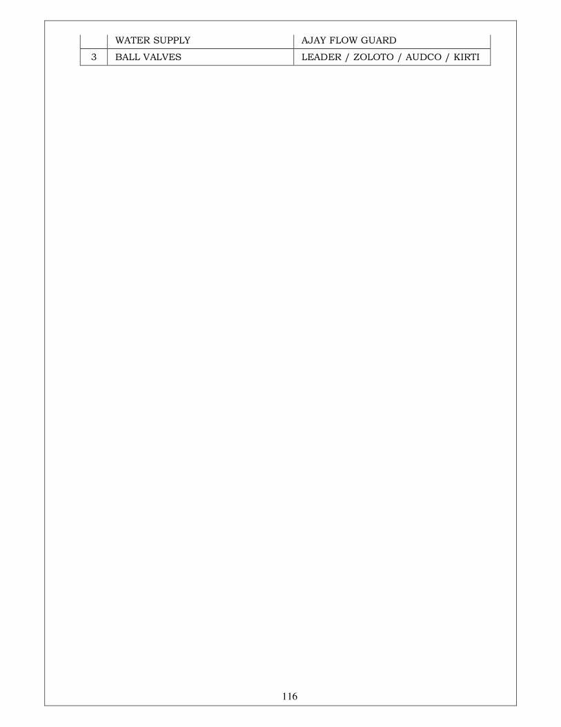
116
WATER SUPPLY AJAY FLOW GUARD
3 BALL VALVES LEADER / ZOLOTO / AUDCO / KIRTI

117
ELECTRICAL WORKS with Preferred make
SECTION - V
TECHNICAL SPECIFICATIONS
FOR
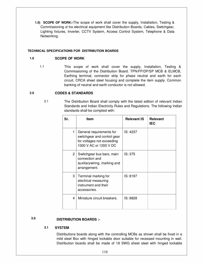
118
1.0) SCOPE OF WORK:-The scope of work shall cover the supply, Installation, Testing &
Commissioning of the electrical equipment like Distribution Boards, Cables, Switchgear,
Lighting fixtures, Inverter, CCTV System, Access Control System, Telephone & Data
Networking.
TECHNICAL SPECIFICATIONS FOR DISTRIBUTION BOARDS
1.0 SCOPE OF WORK
1.1 This scope of work shall cover the supply, Installation, Testing &
Commissioning of the Distribution Board. TPN/FP/DP/SP MCB & ELMCB,
Earthing terminal, connector strip for phase neutral and earth for each
circuit, CRCA sheet steel housing and complete the item supply. Common
banking of neutral and earth conductor is not allowed.
2.0 CODES & STANDARDS
2.1 The Distribution Board shall comply with the latest edition of relevant Indian
Standards and Indian Electricity Rules and Regulations. The following Indian
standards shall be complied with:
Sr. Item Relevant IS Relevant
IEC
1 General requirements for
switchgear and control gear
for voltages not exceeding
1000 V AC or 1200 V DC
IS: 4237
2 Switchgear bus bars, main
connection and
auxiliarywiring, marking and
arrangement.
IS: 375
3 Terminal marking for
electrical measuring
instrument and their
accessories.
IS: 8197
4 Miniature circuit breakers.
IS: 8828
3.0
DISTRIBUTION BOARDS :-
3.1 SYSTEM
Distributions boards along with the controlling MCBs as shown shall be fixed in a
mild steel Box with hinged lockable door suitable for recessed mounting in wall.
Distribution boards shall be made of 18 SWG sheet steel with hinged lockable
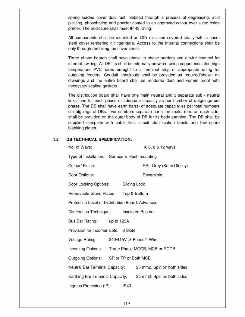
119
spring loaded cover duly rust inhibited through a process of degreasing, acid
pickling, phosphating and powder coated to an approved colour over a red oxide
primer. The enclosure shall meet IP 43 rating.
All components shall be mounted on DIN rails and covered totally with a sheet
steel cover rendering it finger-safe. Access to the internal connections shall be
only through removing the cover sheet.
Three phase boards shall have phase to phase barriers and a wire channel for
internal wiring. All DB’s shall be internally prewired using copper insulated high
temperature PVC wires brought to a terminal strip of appropriate rating for
outgoing feeders. Conduit knockouts shall be provided as required/shown on
drawings and the entire board shall be rendered dust and vermin proof with
necessary sealing gaskets.
The distribution board shall have one main neutral and 3 separate sub - neutral
links, one for each phase of adequate capacity as per number of outgoings per
phase. The DB shall have earth bar(s) of adequate capacity as per total numbers
of outgoings of DBs. Two numbers separate earth terminals, (one on each side)
shall be provided on the outer body of DB for its body earthing. The DB shall be
supplied complete with cable ties, circuit identification labels and few spare
blanking plates.
3.2 DB TECHNICAL SPECIFICATION:
No. of Ways: 4, 6, 8 & 12 ways
Type of Installation: Surface & Flush mounting
Colour/ Finish: RAL Grey (Semi Glossy)
Door Options: Reversible
Door Locking Options: Sliding Lock
Removable Gland Plates: Top & Bottom
Protection Level of Distribution Board: Advanced
Distribution Technique: Insulated Bus bar
Bus Bar Rating: up to 125A
Provision for Incomer slots: 8 Slots
Voltage Rating: 240/415V-,3 Phase/4 Wire
Incoming Options: Three Phase MCCB, MCB or RCCB
Outgoing Options: SP or TP or Both MCB
Neutral Bar Terminal Capacity: 25 mm2, Split on both sides
Earthing Bar Terminal Capacity: 25 mm2, Split on both sides
Ingress Protection (IP): IP43
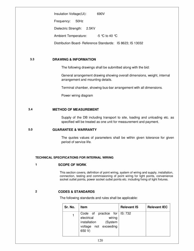
120
Insulation Voltage(Ui): 690V
Frequency: 50Hz
Dielectric Strength: 2.5KV
Ambient Temperature: -5 °C to 40 °C
Distribution Board- Reference Standards: IS 8623; IS 13032
3.3 DRAWING & INFORMATION
The following drawings shall be submitted along with the bid:
General arrangement drawing showing overall dimensions, weight, internal
arrangement and mounting details.
Terminal chamber, showing bus-bar arrangement with all dimensions.
Power wiring diagram
3.4 METHOD OF MEASUREMENT
Supply of the DB including transport to site, loading and unloading etc. as
specified will be treated as one unit for measurement and payment.
5.0 GUARANTEE & WARRANTY
The quotes values of parameters shall be within given tolerance for given
period of service life.
TECHNICAL SPECIFICATIONS FOR INTERNAL WIRING
1 SCOPE OF WORK
This section covers, definition of point wiring, system of wiring and supply, installation, connection, testing and commissioning of point wiring for light points, convenience socket outlet points, power socket outlet points etc. including fixing of light fixtures.
2 CODES & STANDARDS
The following standards and rules shall be applicable:
Sr. No. Item Relevant IS Relevant IEC
1 Code of practice for
electrical wiring
installation (System
voltage not exceeding
650 V)
IS: 732

121
2 Code of practice for fire
safety of buildings
(General) Electrical
installation.
IS: 1646
3 Rigid steel conduits for
electrical wiring.
IS: 9537 (Part -
2)
4 Fittings for rigid steel
conduits for electrical
wiring.
IS: 2667
5 Flexible steel conduits
for Electrical wiring.
IS: 3480
6 Accessories for rigid
steel conduit for
electrical wiring.
IS: 3837
7 PVC insulated cables. IS: 694
8 Rigid non-metallic
conduits for electrical
wiring.
IS: 9537 (Part -
3)
9 Flexible (Pliable) non-
metallic conduits for
electrical installation.
IS: 6946
10 3 pin plugs and sockets. IS: 1293
11 Specifications of
conduits for electrical
installation.
IS: 8130
12 Switches for domestic
purpose.
IS: 3854
13 Fittings for rigid non-
metallic conduits.
IS: 3419
14 Guide for electrical
layout in residential
buildings Indian
electricity act and rules.
IS: 4648
4 TECHNICAL REQUIREMENTS
4.1 POINT WIRING
4.1.1 A point shall consist of the branch wiring from the distribution board together with a switch as required, including the ceiling rose or pendant holder or swan holder, or socket or suitable termination. A point shall include, in addition, the earth continuity conductor/wire from the distribution board to the earth pin/stud of the outlet/switch box and to the outlet points

122
4.1.2 Supply, installation, fixing of conduits with necessary accessories, junction/pull/inspection/switch boxes and outlet boxes
4.1.3 Supplying and drawing of wires of required size including earth continuity wire
4.1.4 Supply, installation and connection of flush type switches, sockets, cover plates, and switch plates etc.
4.1.5 The point shall be complete with the branch wiring from the distribution board to the outlet point, through switch board, conduit with accessories, junction, pull, inspection boxes, control switch, socket, outlet boxes,etc.
5.0 SYSTEM OF WIRING
5.1 Unless otherwise mentioned on the drawings, the system of point wiring
shall be as follows:
The system of wiring shall consist of single core, FRLS insulated, 650/1100 volt grade, copper conductor wires/cables laid through exposed (surface mounted) PVC conduits as directed & wherever required, conduits shall be concealed in walls and slabs
6.0 GENERAL
6.1 Prior to laying of conduits, the contractor shall submit for approval, the shop drawing for conduit layout indicating the route of the conduits, number and size of the conduits, location of junction/inspection/pull/outlet boxes, size and location of switch boxes, number and size of wires pulled through each conduit and all other necessary relevant details. Only after the drawings are approved, the contractor shall proceed with the work of laying of conduits.
7.0 MATERIAL
7.1 PVC Conduit
All non-metallic PVC conduits shall conform to IS: 9537 (Part - 3 ). The conduit shall be planed and of type as specified in IS: 9537 and shall be used with the corresponding accessories (Refer IS: 3419 specification for fittings for rigid non metallic conduits). PVC conduits shall be rigid unplasticised, heavy gauge having 2.0 mm. wall thickness upto 20 mm. diameter conduit and 2.5 mm. wall thickness for all sizes above 20 mm. diameter
7.2
M.S. Conduit
Conduits shall conform to IS: 9537 ( Part - 2 ), finished with galvanized surface. No steel conduit less than 25 mm. in diameter shall be used. Conduits shall be solid drawn of lap welded type, with minimum wall thickness for conduits having 25 mm. and above diameter
The conduits shall be delivered to the site of construction in original bundles and each length of conduit shall bear the label of manufacturers
The conduit accessories such bends, coupling etc. shall be conforming to the relevant Indian Standard specification
7.3
Boxes
1. All the boxes for switches, sockets and other receptacles, junction boxes, pull boxes and outlet boxes shall be fabricated from 2.0 mm. thick mild sheet painted with two coats of red-oxide and then two coats of enamel paints as called for. Colour of the paints shall be as approved by the client. The boxes shall have smooth external and internal finished surface
2. Boxes in contact with earth or exposed to the weather shall be of 2 mm. mild steel and hot dip galvanized after fabrication
3. Separate screwed earth terminal shall be provided in the box for earthing
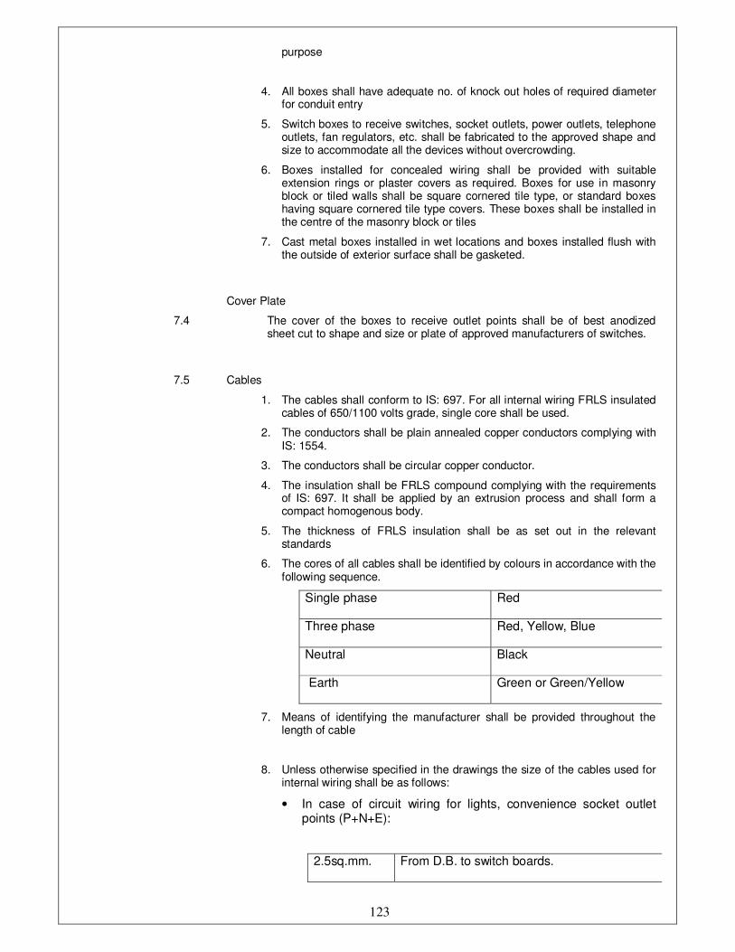
123
purpose
4. All boxes shall have adequate no. of knock out holes of required diameter for conduit entry
5. Switch boxes to receive switches, socket outlets, power outlets, telephone outlets, fan regulators, etc. shall be fabricated to the approved shape and size to accommodate all the devices without overcrowding.
6. Boxes installed for concealed wiring shall be provided with suitable extension rings or plaster covers as required. Boxes for use in masonry block or tiled walls shall be square cornered tile type, or standard boxes having square cornered tile type covers. These boxes shall be installed in the centre of the masonry block or tiles
7. Cast metal boxes installed in wet locations and boxes installed flush with the outside of exterior surface shall be gasketed.
7.4
Cover Plate
The cover of the boxes to receive outlet points shall be of best anodized sheet cut to shape and size or plate of approved manufacturers of switches.
7.5 Cables
1. The cables shall conform to IS: 697. For all internal wiring FRLS insulated cables of 650/1100 volts grade, single core shall be used.
2. The conductors shall be plain annealed copper conductors complying with IS: 1554.
3. The conductors shall be circular copper conductor.
4. The insulation shall be FRLS compound complying with the requirements of IS: 697. It shall be applied by an extrusion process and shall form a compact homogenous body.
5. The thickness of FRLS insulation shall be as set out in the relevant standards
6. The cores of all cables shall be identified by colours in accordance with the following sequence.
Single phase Red
Three phase Red, Yellow, Blue
Neutral Black
Earth Green or Green/Yellow
7. Means of identifying the manufacturer shall be provided throughout the length of cable
8. Unless otherwise specified in the drawings the size of the cables used for internal wiring shall be as follows:
• In case of circuit wiring for lights, convenience socket outlet points (P+N+E):
2.5sq.mm. From D.B. to switch boards.
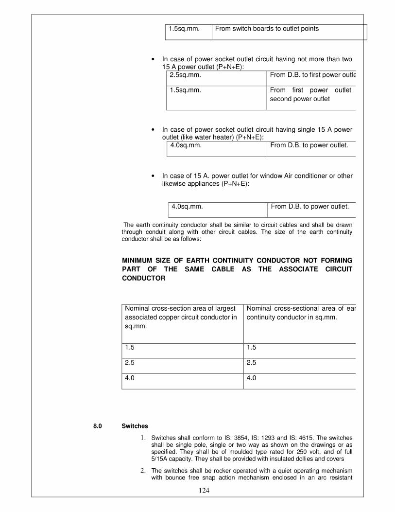
124
1.5sq.mm. From switch boards to outlet points
• In case of power socket outlet circuit having not more than two 15 A power outlet (P+N+E):
2.5sq.mm. From D.B. to first power outlet
1.5sq.mm. From first power outlet to
second power outlet
• In case of power socket outlet circuit having single 15 A power outlet (like water heater) (P+N+E):
4.0sq.mm. From D.B. to power outlet.
• In case of 15 A. power outlet for window Air conditioner or other likewise appliances (P+N+E):
4.0sq.mm. From D.B. to power outlet.
The earth continuity conductor shall be similar to circuit cables and shall be drawn through conduit along with other circuit cables. The size of the earth continuity conductor shall be as follows:
MINIMUM SIZE OF EARTH CONTINUITY CONDUCTOR NOT FORMING
PART OF THE SAME CABLE AS THE ASSOCIATE CIRCUIT
CONDUCTOR
Nominal cross-section area of largest
associated copper circuit conductor in
sq.mm.
Nominal cross-sectional area of earth
continuity conductor in sq.mm.
1.5 1.5
2.5 2.5
4.0 4.0
8.0 Switches
1. Switches shall conform to IS: 3854, IS: 1293 and IS: 4615. The switches shall be single pole, single or two way as shown on the drawings or as specified. They shall be of moulded type rated for 250 volt, and of full 5/15A capacity. They shall be provided with insulated dollies and covers
2. The switches shall be rocker operated with a quiet operating mechanism with bounce free snap action mechanism enclosed in an arc resistant
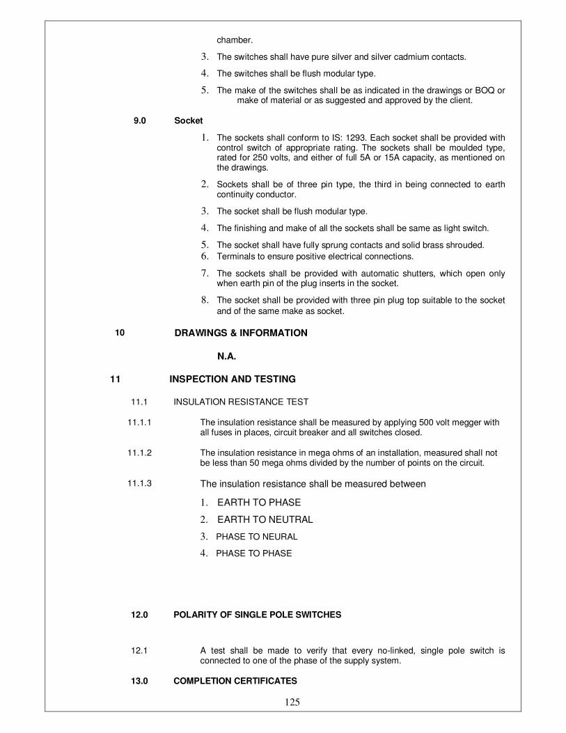
125
chamber.
3. The switches shall have pure silver and silver cadmium contacts.
4. The switches shall be flush modular type.
5. The make of the switches shall be as indicated in the drawings or BOQ or make of material or as suggested and approved by the client.
9.0 Socket
1. The sockets shall conform to IS: 1293. Each socket shall be provided with control switch of appropriate rating. The sockets shall be moulded type, rated for 250 volts, and either of full 5A or 15A capacity, as mentioned on the drawings.
2. Sockets shall be of three pin type, the third in being connected to earth continuity conductor.
3. The socket shall be flush modular type.
4. The finishing and make of all the sockets shall be same as light switch.
5. The socket shall have fully sprung contacts and solid brass shrouded.
6. Terminals to ensure positive electrical connections.
7. The sockets shall be provided with automatic shutters, which open only when earth pin of the plug inserts in the socket.
8. The socket shall be provided with three pin plug top suitable to the socket
and of the same make as socket.
10 DRAWINGS & INFORMATION
N.A.
11 INSPECTION AND TESTING
11.1 INSULATION RESISTANCE TEST
11.1.1 The insulation resistance shall be measured by applying 500 volt megger with all fuses in places, circuit breaker and all switches closed.
11.1.2 The insulation resistance in mega ohms of an installation, measured shall not be less than 50 mega ohms divided by the number of points on the circuit.
11.1.3 The insulation resistance shall be measured between
1. EARTH TO PHASE
2. EARTH TO NEUTRAL
3. PHASE TO NEURAL
4. PHASE TO PHASE
12.0 POLARITY OF SINGLE POLE SWITCHES
12.1 A test shall be made to verify that every no-linked, single pole switch is connected to one of the phase of the supply system.
13.0 COMPLETION CERTIFICATES
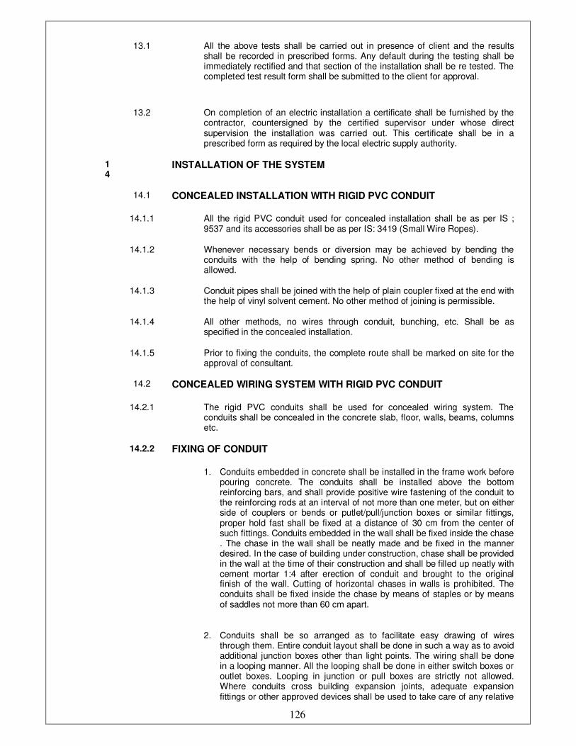
126
13.1 All the above tests shall be carried out in presence of client and the results shall be recorded in prescribed forms. Any default during the testing shall be immediately rectified and that section of the installation shall be re tested. The completed test result form shall be submitted to the client for approval.
13.2 On completion of an electric installation a certificate shall be furnished by the contractor, countersigned by the certified supervisor under whose direct supervision the installation was carried out. This certificate shall be in a prescribed form as required by the local electric supply authority.
14
INSTALLATION OF THE SYSTEM
14.1 CONCEALED INSTALLATION WITH RIGID PVC CONDUIT
14.1.1 All the rigid PVC conduit used for concealed installation shall be as per IS ; 9537 and its accessories shall be as per IS: 3419 (Small Wire Ropes).
14.1.2 Whenever necessary bends or diversion may be achieved by bending the conduits with the help of bending spring. No other method of bending is allowed.
14.1.3 Conduit pipes shall be joined with the help of plain coupler fixed at the end with the help of vinyl solvent cement. No other method of joining is permissible.
14.1.4 All other methods, no wires through conduit, bunching, etc. Shall be as specified in the concealed installation.
14.1.5 Prior to fixing the conduits, the complete route shall be marked on site for the approval of consultant.
14.2 CONCEALED WIRING SYSTEM WITH RIGID PVC CONDUIT
14.2.1 The rigid PVC conduits shall be used for concealed wiring system. The conduits shall be concealed in the concrete slab, floor, walls, beams, columns etc.
14.2.2 FIXING OF CONDUIT
1. Conduits embedded in concrete shall be installed in the frame work before pouring concrete. The conduits shall be installed above the bottom reinforcing bars, and shall provide positive wire fastening of the conduit to the reinforcing rods at an interval of not more than one meter, but on either side of couplers or bends or putlet/pull/junction boxes or similar fittings, proper hold fast shall be fixed at a distance of 30 cm from the center of such fittings. Conduits embedded in the wall shall be fixed inside the chase . The chase in the wall shall be neatly made and be fixed in the manner desired. In the case of building under construction, chase shall be provided in the wall at the time of their construction and shall be filled up neatly with cement mortar 1:4 after erection of conduit and brought to the original finish of the wall. Cutting of horizontal chases in walls is prohibited. The conduits shall be fixed inside the chase by means of staples or by means of saddles not more than 60 cm apart.
2. Conduits shall be so arranged as to facilitate easy drawing of wires through them. Entire conduit layout shall be done in such a way as to avoid additional junction boxes other than light points. The wiring shall be done in a looping manner. All the looping shall be done in either switch boxes or outlet boxes. Looping in junction or pull boxes are strictly not allowed. Where conduits cross building expansion joints, adequate expansion fittings or other approved devices shall be used to take care of any relative

127
movement
3. All conduits shall be installed so as to avoid steam and hot water pipes
4. Conduits shall be installed in such a way that the junction, derivation and pull boxes shall always be accessible for repairs and maintenance work. The location of junction/pull boxes shall be marked on the shop drawings and approved by the client
5. A separation of 200 mm shall be maintained between electrical conduits and hot water lines in the building
6. No run of conduit shall exceed ten mtr. between adjacent draw in points nor shall it contain more than two right angle bends, or other derivation from the straight line
7. Caution shall be exercised in using the PVC conduits in location where ambient temperature is 50 degree cel. or above. Use of PVC conduits in places where ambient temperature is more than 60 deg. cel. Is prohibited. The entire conduit system including boxes shall be thoroughly cleaned after completion of installations and before drawing of wires. Conduit system shall be erect and straight as far as possible. Traps where water may accumulate from condensation are to be avoided and if unavoidable, suitable provision for draining the water shall be made
8. All jointing method shall be subject to the approval of the client
9. Separate conduits shall be provided for the following system.
• 15 A power outlets.
• 5 A outlets and lighting system.
• Low voltage system.
• Telephone/intercom system.
• C.C.T.V. system
• Sound system
• Computer data cabling system
• Equipment wiring
14.3 CONDUIT JOINT
14.3.1 1. Conduits shall be joined by means of plain couplers vinyl and/or solvent cement. Where there are long runs of straight conduit, inspection type couplers shall be provided at intervals , as approved by the client.
2. The conduits shall be thoroughly cleaned before making the joints.
3. In case of plain coupler joints, proper jointing material like a vinyl solvent
cement (gray in color) or any material as recommended by the
manufacturer shall be used.
14.4 BENDS IN CONDUIT
14.4.1 Wherever necessary, bends or diversions may be achieved by bending the conduits or by employing normal bends. No bends shall have radius less than 2.5 times outside dia. of the conduit
14.4.2 Heat may be used to soften the PVC conduit for bending, but while applying heat to conduit, the conduit shall be filled with sand to avoid any damage to the conduit

128
14.5 OUTLETS
14.5.1 All the outlets for fittings, switches etc. shall be boxes of substantial construction.
14.5.2 In order to minimize condensation or sweating inside the conduits, all outlets of conduit system shall be properly drained and ventilated, but in such a manner as to prevent the entry of insects , etc.
14.5.3 Fixing between conduit and boxes, outlet boxes, switch boxes and the like must be provided with entry spouts and smooth PVC bushes.
14.5.4 Joints between conduit and any type of boxes shall be affected by means of conduit couplers in to each of which shall be coupled smooth PVC bush from inside the box. In any case all the joints shall be fully water tight.
14.6 BUNCHING OF CABLES
14.6.1 Cables of AC supply of different phase shall be bunched in separate conduits.
14.6.2 The number of insulated wires/ cables that may be drawn into the
conduits shall be as per the following table. In this table, the space
factor does not exceed 40%. However, in any case conduits having
lesser than 19 mm dia. shall not be used.
MAXIMUM PERMISSIBLE NUMBER OF 650 VOLT GRADE SINGLE
CORE CABLES THAT MAY BE DRAWN IN TO RIGID PVC
CONDUITS.
CABLE SIZE IN
MM SQ.
S I Z E O F C O N D U I T S (MM)
MAXIMUM NO. OF CABLES
25 32 38/40 51/50
1.5 8 15 --- ---
2.5 6 10 --- ---
7.0 4 8 12 ---
14.7 WIRING WITH RIGID STEEL CONDUIT
14.7.1 All conduits and it’s accessories shall be of threaded type and under no circumstances pin grip type or clamp type accessories be used.
14.8 FIXING OF CONDUIT
14.8.1 Conduit pipes shall be fixed by heavy gauge spacer bar saddles. The saddles shall be of 3 mm x 19 mm galvanized mild steel flat, properly treated and securely fixed to support by means of nuts and bolts raw bolts, brass machine screws, as mentioned, at an internal of not more than one meter but on either side of couplers, or bends, or junction/pull/outlet boxes or similar fittings, saddles shall be fixed at a distance of 30 cm from the centre of such fittings.
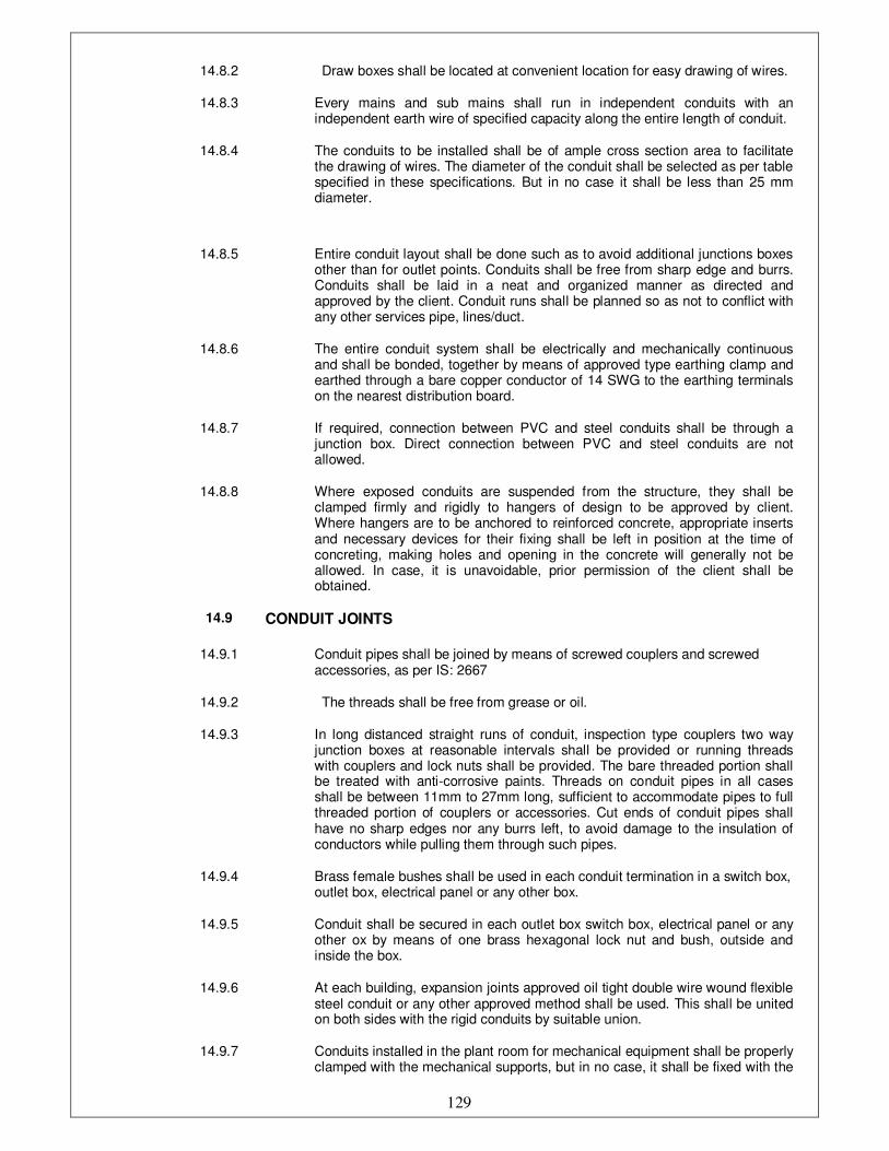
129
14.8.2 Draw boxes shall be located at convenient location for easy drawing of wires.
14.8.3 Every mains and sub mains shall run in independent conduits with an independent earth wire of specified capacity along the entire length of conduit.
14.8.4 The conduits to be installed shall be of ample cross section area to facilitate the drawing of wires. The diameter of the conduit shall be selected as per table specified in these specifications. But in no case it shall be less than 25 mm diameter.
14.8.5 Entire conduit layout shall be done such as to avoid additional junctions boxes other than for outlet points. Conduits shall be free from sharp edge and burrs. Conduits shall be laid in a neat and organized manner as directed and approved by the client. Conduit runs shall be planned so as not to conflict with any other services pipe, lines/duct.
14.8.6 The entire conduit system shall be electrically and mechanically continuous and shall be bonded, together by means of approved type earthing clamp and earthed through a bare copper conductor of 14 SWG to the earthing terminals on the nearest distribution board.
14.8.7 If required, connection between PVC and steel conduits shall be through a junction box. Direct connection between PVC and steel conduits are not allowed.
14.8.8 Where exposed conduits are suspended from the structure, they shall be clamped firmly and rigidly to hangers of design to be approved by client. Where hangers are to be anchored to reinforced concrete, appropriate inserts and necessary devices for their fixing shall be left in position at the time of concreting, making holes and opening in the concrete will generally not be allowed. In case, it is unavoidable, prior permission of the client shall be obtained.
14.9 CONDUIT JOINTS
14.9.1 Conduit pipes shall be joined by means of screwed couplers and screwed accessories, as per IS: 2667
14.9.2 The threads shall be free from grease or oil.
14.9.3 In long distanced straight runs of conduit, inspection type couplers two way junction boxes at reasonable intervals shall be provided or running threads with couplers and lock nuts shall be provided. The bare threaded portion shall be treated with anti-corrosive paints. Threads on conduit pipes in all cases shall be between 11mm to 27mm long, sufficient to accommodate pipes to full threaded portion of couplers or accessories. Cut ends of conduit pipes shall have no sharp edges nor any burrs left, to avoid damage to the insulation of conductors while pulling them through such pipes.
14.9.4 Brass female bushes shall be used in each conduit termination in a switch box, outlet box, electrical panel or any other box.
14.9.5 Conduit shall be secured in each outlet box switch box, electrical panel or any other ox by means of one brass hexagonal lock nut and bush, outside and inside the box.
14.9.6 At each building, expansion joints approved oil tight double wire wound flexible steel conduit or any other approved method shall be used. This shall be united on both sides with the rigid conduits by suitable union.
14.9.7 Conduits installed in the plant room for mechanical equipment shall be properly clamped with the mechanical supports, but in no case, it shall be fixed with the
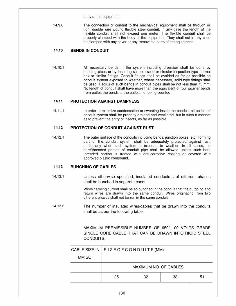
130
body of the equipment.
14.9.8 The connection of conduit to the mechanical equipment shall be through oil tight double wire wound flexible steel conduit. In any case the length of the flexible conduit shall not exceed one meter. The flexible conduit shall be properly clamped with the body of the equipment. They shall not in any case be clamped with any cover or any removable parts of the equipment.
14.10 BENDS IN CONDUIT
14.10.1 All necessary bends in the system including diversion shall be done by bending pipes or by inserting suitable solid or circular inspection type normal box or similar fittings. Conduit fittings shall be avoided as far as possible on conduit system exposed to weather, where necessary, solid type fittings shall be used. Radius of such bends in conduit pipes shall be not less than 75 mm. No length of conduit shall have more than the equivalent of four quarter bends from outlet, the bends at the outlets not being counted
14.11 PROTECTION AGAINST DAMPNESS
14.11.1 In order to minimize condensation or sweating inside the conduit, all outlets of conduit system shall be properly drained and ventilated, but in such a manner as to prevent the entry of insects, as far as possible
14.12 PROTECTION OF CONDUIT AGAINST RUST
14.12.1 The outer surface of the conduits including bends, junction boxes, etc., forming part of the conduit system shall be adequately protected against rust, particularly when such system is exposed to weather. In all cases, no bare/threaded portion of conduit pipe shall be allowed unless such bare threaded portion is treated with anti-corrosive coating or covered with approved plastic compound.
14.13 BUNCHING OF CABLES
14.13.1 Unless otherwise specified, insulated conductors of different phases
shall be bunched in separate conduit.
Wires carrying current shall be so bunched in the conduit that the outgoing and return wires are drawn into the same conduit. Wires originating from two different phases shall not be run in the same conduit.
14.13.2 The number of insulated wires/cables that be drawn into the conduits
shall be as per the following table.
MAXIMUM PERMISSIBLE NUMBER OF 650/1100 VOLTS GRADE
SINGLE CORE CABLE THAT CAN BE DRAWN INTO RIGID STEEL
CONDUITS.
CABLE SIZE IN
MM SQ.
S I Z E O F C O N D U I T S (MM)
MAXIMUM NO. OF CABLES
25 32 38 51
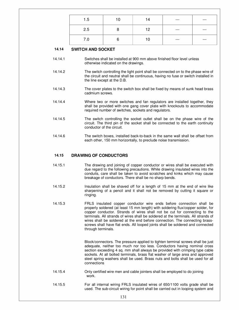
131
1.5 10 14 --- ---
2.5 8 12 --- ---
7.0 6 10 --- ---
14.14 SWITCH AND SOCKET
14.14.1 Switches shall be installed at 900 mm above finished floor level unless otherwise indicated on the drawings.
14.14.2 The switch controlling the light point shall be connected on to the phase wire of the circuit and neutral shall be continuous, having no fuse or switch installed in the line except at the D.B.
14.14.3 The cover plates to the switch box shall be fixed by means of sunk head brass cadmium screws.
14.14.4 Where two or more switches and fan regulators are installed together, they shall be provided with one gang cover plate with knockouts to accommodate required number of switches, sockets and regulators.
14.14.5 The switch controlling the socket outlet shall be on the phase wire of the circuit. The third pin of the socket shall be connected to the earth continuity conductor of the circuit.
14.14.6 The switch boxes, installed back-to-back in the same wall shall be offset from each other, 150 mm horizontally, to preclude noise transmission.
14.15 DRAWING OF CONDUCTORS
14.15.1 The drawing and joining of copper conductor or wires shall be executed with due regard to the following precautions. While drawing insulated wires into the conduits, care shall be taken to avoid scratches and kinks which may cause breakage of conductors. There shall be no sharp bends.
14.15.2 Insulation shall be shaved off for a length of 15 mm at the end of wire like sharpening of a pencil and it shall not be removed by cutting it square or ringing.
14.15.3 FRLS insulated copper conductor wire ends before connection shall be properly soldered (at least 15 mm length) with soldering flux/copper solder, for copper conductor. Strands of wires shall not be cut for connecting to the terminals. All strands of wires shall be soldered at the terminals. All strands of wires shall be soldered at the end before connection. The connecting brass-screws shall have flat ends. All looped joints shall be soldered and connected through terminals.
Block/connectors. The pressure applied to tighten terminal screws shall be just adequate, neither too much nor too less. Conductors having nominal cross section exceeding 4 sq. mm shall always be provided with crimping type cable sockets. At all bolted terminals, brass flat washer of large area and approved steel spring washers shall be used. Brass nuts and bolts shall be used for all connections
14.15.4 Only certified wire men and cable jointers shall be employed to do joining work.
14.15.5 For all internal wiring FRLS insulated wires of 650/1100 volts grade shall be used. The sub-circuit wiring for point shall be carried out in looping system and
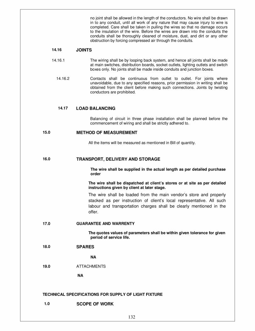
132
TECHNICAL SPECIFICATIONS FOR SUPPLY OF LIGHT FIXTURE
1.0 SCOPE OF WORK
no joint shall be allowed in the length of the conductors. No wire shall be drawn in to any conduit, until all work of any nature that may cause injury to wire is completed. Care shall be taken in pulling the wires so that no damage occurs to the insulation of the wire. Before the wires are drawn into the conduits the conduits shall be thoroughly cleaned of moisture, dust, and dirt or any other obstruction by forcing compressed air through the conduits.
14.16 JOINTS
14.16.1 The wiring shall be by looping back system, and hence all joints shall be made at main switches, distribution boards, socket outlets, lighting outlets and switch boxes only. No joints shall be made inside conduits and junction boxes.
14.16.2 Contacts shall be continuous from outlet to outlet. For joints where unavoidable, due to any specified reasons, prior permission in writing shall be obtained from the client before making such connections. Joints by twisting conductors are prohibited.
14.17 LOAD BALANCING
Balancing of circuit in three phase installation shall be planned before the commencement of wiring and shall be strictly adhered to.
15.0 METHOD OF MEASUREMENT
All the items will be measured as mentioned in Bill of quantity.
16.0 TRANSPORT, DELIVERY AND STORAGE
The wire shall be supplied in the actual length as per detailed purchase order
The wire shall be dispatched at client’s stores or at site as per detailed instructions given by client at later stage.
The wire shall be loaded from the main vendor’s store and properly
stacked as per instruction of client’s local representative. All such
labour and transportation charges shall be clearly mentioned in the
offer.
17.0 GUARANTEE AND WARRENTY
The quotes values of parameters shall be within given tolerance for given period of service life.
18.0 SPARES
NA
19.0 ATTACHMENTS
NA
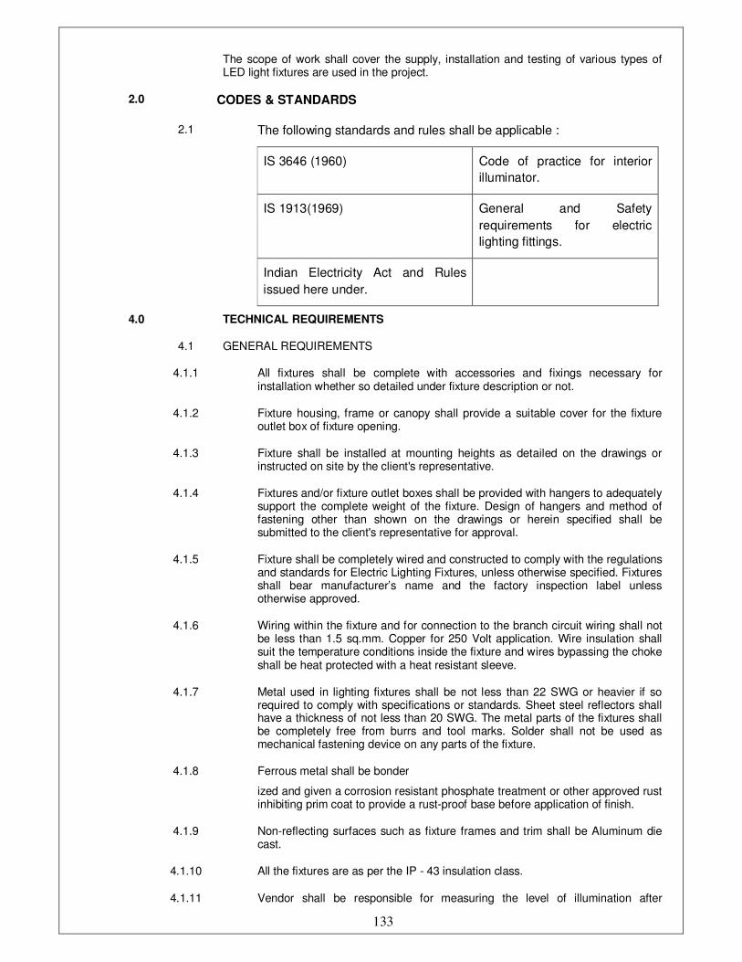
133
The scope of work shall cover the supply, installation and testing of various types of LED light fixtures are used in the project.
2.0 CODES & STANDARDS
2.1 The following standards and rules shall be applicable :
IS 3646 (1960) Code of practice for interior
illuminator.
IS 1913(1969) General and Safety
requirements for electric
lighting fittings.
Indian Electricity Act and Rules
issued here under.
4.0 TECHNICAL REQUIREMENTS
4.1 GENERAL REQUIREMENTS
4.1.1 All fixtures shall be complete with accessories and fixings necessary for installation whether so detailed under fixture description or not.
4.1.2 Fixture housing, frame or canopy shall provide a suitable cover for the fixture outlet box of fixture opening.
4.1.3 Fixture shall be installed at mounting heights as detailed on the drawings or instructed on site by the client's representative.
4.1.4 Fixtures and/or fixture outlet boxes shall be provided with hangers to adequately support the complete weight of the fixture. Design of hangers and method of fastening other than shown on the drawings or herein specified shall be submitted to the client's representative for approval.
4.1.5 Fixture shall be completely wired and constructed to comply with the regulations and standards for Electric Lighting Fixtures, unless otherwise specified. Fixtures shall bear manufacturer’s name and the factory inspection label unless otherwise approved.
4.1.6 Wiring within the fixture and for connection to the branch circuit wiring shall not be less than 1.5 sq.mm. Copper for 250 Volt application. Wire insulation shall suit the temperature conditions inside the fixture and wires bypassing the choke shall be heat protected with a heat resistant sleeve.
4.1.7 Metal used in lighting fixtures shall be not less than 22 SWG or heavier if so required to comply with specifications or standards. Sheet steel reflectors shall have a thickness of not less than 20 SWG. The metal parts of the fixtures shall be completely free from burrs and tool marks. Solder shall not be used as mechanical fastening device on any parts of the fixture.
4.1.8 Ferrous metal shall be bonder
ized and given a corrosion resistant phosphate treatment or other approved rust inhibiting prim coat to provide a rust-proof base before application of finish.
4.1.9 Non-reflecting surfaces such as fixture frames and trim shall be Aluminum die cast.
4.1.10 All the fixtures are as per the IP - 43 insulation class.
4.1.11 Vendor shall be responsible for measuring the level of illumination after

134
installation.
4.1.12 Lighting fixtures shall be designed for minimum glare and for continuous operation under specified atmospheric condition.
5.0 LED Lamps:
LED lamp is a light-emitting diode (LED) product which is assembled into
a lamp (or light bulb) for use in lighting fixtures. LED lamps have a lifespan
and electrical efficiency which are several times longer than incandescent
lamps, and significantly more efficient than most fluorescent lamps.LEDs
come to full brightness without need for a warm-up time; the life of
fluorescent lighting is also reduced by frequent switching on and off.
LEDs are “directional” light sources, which means they emit light in a
specific direction, unlike incandescent and compact fluorescent bulbs,
which emit light and heat in all directions.
The LED bulbs require much less wattage than the CFL or Incandescent
light bulbs.
6.0 LUMINAIRES:-
LED suspended luminaire are proposed.
CRI > 80, integrated in separate mini-LED louver with UXP technology.
Luminaire luminous flux 6000 lm. Construction height 18 mm. LED
segments flush integrated into the square luminaire body ensure optimal
thermal management. With integrated plastic cover for protection of
optics against soiling. Luminaire body of flat aluminium profile, white,
with colour highlighted, flush integrated end caps of anodized aluminium.
Protection rating IP20.
7.0 LED PANEL LIGHT(IP43) TECH SPECS:-
Sytem power :- 31 WATT LED PANEL LIGHT
LED Type :- High Brightness Power LED
Color Temperature :- 2700 - 4500K
CRI :- >80
Lens :- 120 Deg.
LED Driver Specification :-
Input Voltage 200V ~ 240V AC
Frequency Range 50-60 Hz
System Efficiency>85%
Power Factor(PF)> 0.8
THD < 10%
Other Parameters :-
Working Humidity 10 % ~ 90 % RH
Lamp Body Material PDC aluminium
IP Rating IP43
Surge Protection > 2.5KV
Working Life > 50,000 Hrs
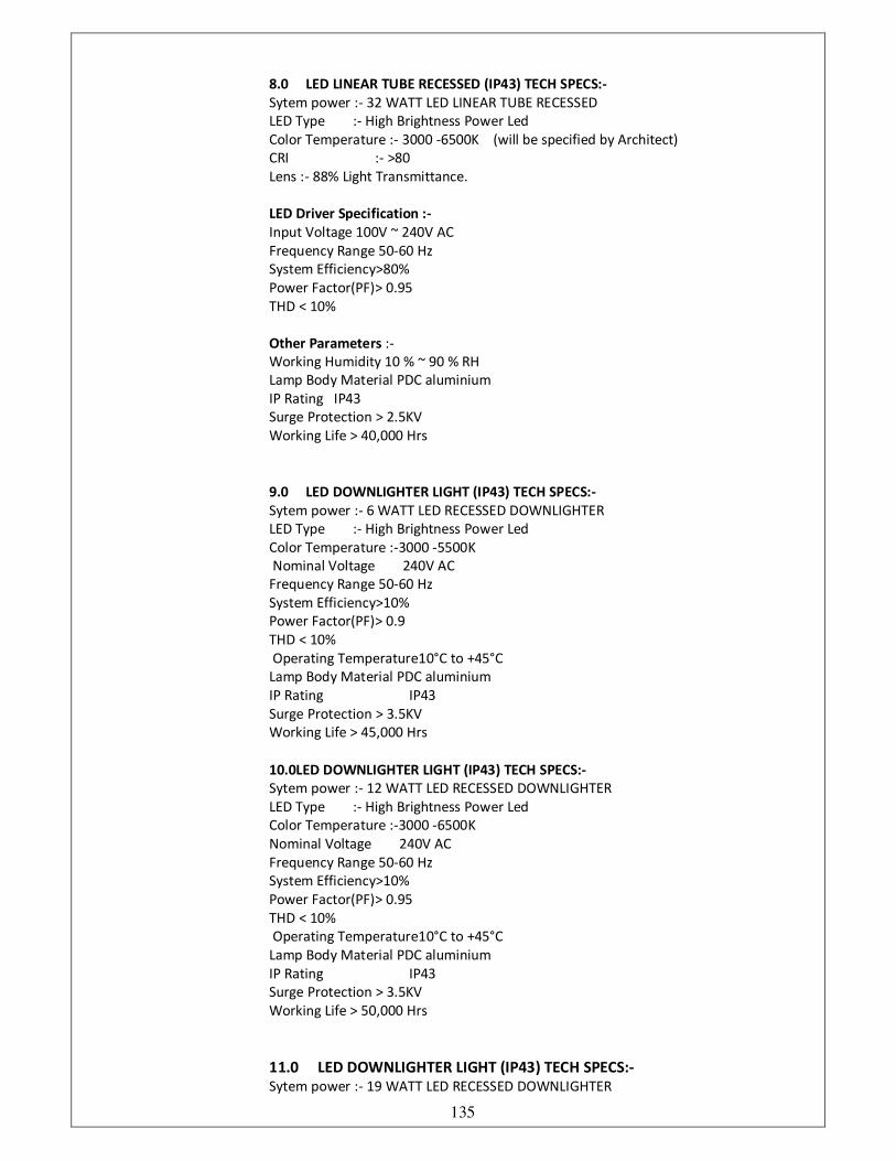
135
8.0 LED LINEAR TUBE RECESSED (IP43) TECH SPECS:-
Sytem power :- 32 WATT LED LINEAR TUBE RECESSED
LED Type :- High Brightness Power Led
Color Temperature :- 3000 -6500K (will be specified by Architect)
CRI :- >80
Lens :- 88% Light Transmittance.
LED Driver Specification :-
Input Voltage 100V ~ 240V AC
Frequency Range 50-60 Hz
System Efficiency>80%
Power Factor(PF)> 0.95
THD < 10%
Other Parameters :-
Working Humidity 10 % ~ 90 % RH
Lamp Body Material PDC aluminium
IP Rating IP43
Surge Protection > 2.5KV
Working Life > 40,000 Hrs
9.0 LED DOWNLIGHTER LIGHT (IP43) TECH SPECS:-
Sytem power :- 6 WATT LED RECESSED DOWNLIGHTER
LED Type :- High Brightness Power Led
Color Temperature :-3000 -5500K
Nominal Voltage 240V AC
Frequency Range 50-60 Hz
System Efficiency>10%
Power Factor(PF)> 0.9
THD < 10%
Operating Temperature10°C to +45°C Lamp Body Material PDC aluminium
IP Rating IP43
Surge Protection > 3.5KV
Working Life > 45,000 Hrs
10.0LED DOWNLIGHTER LIGHT (IP43) TECH SPECS:-
Sytem power :- 12 WATT LED RECESSED DOWNLIGHTER
LED Type :- High Brightness Power Led
Color Temperature :-3000 -6500K
Nominal Voltage 240V AC
Frequency Range 50-60 Hz
System Efficiency>10%
Power Factor(PF)> 0.95
THD < 10%
Operating Temperature10°C to +45°C Lamp Body Material PDC aluminium
IP Rating IP43
Surge Protection > 3.5KV
Working Life > 50,000 Hrs
11.0 LED DOWNLIGHTER LIGHT (IP43) TECH SPECS:-
Sytem power :- 19 WATT LED RECESSED DOWNLIGHTER
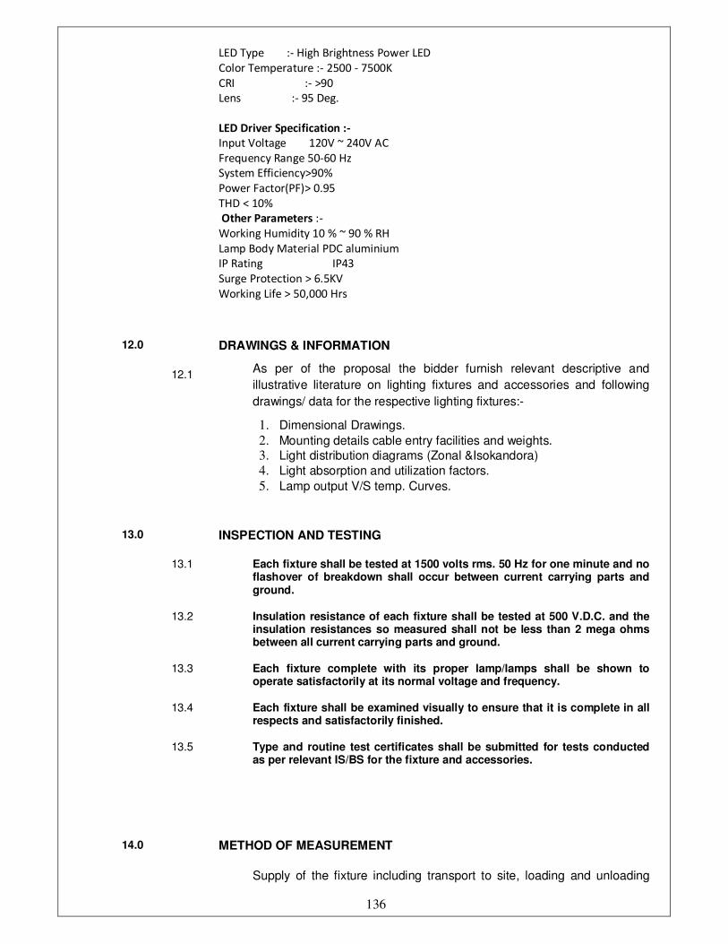
136
LED Type :- High Brightness Power LED
Color Temperature :- 2500 - 7500K
CRI :- >90
Lens :- 95 Deg.
LED Driver Specification :-
Input Voltage 120V ~ 240V AC
Frequency Range 50-60 Hz
System Efficiency>90%
Power Factor(PF)> 0.95
THD < 10%
Other Parameters :-
Working Humidity 10 % ~ 90 % RH
Lamp Body Material PDC aluminium
IP Rating IP43
Surge Protection > 6.5KV
Working Life > 50,000 Hrs
12.0 DRAWINGS & INFORMATION
12.1 As per of the proposal the bidder furnish relevant descriptive and
illustrative literature on lighting fixtures and accessories and following
drawings/ data for the respective lighting fixtures:-
1. Dimensional Drawings.
2. Mounting details cable entry facilities and weights.
3. Light distribution diagrams (Zonal &Isokandora)
4. Light absorption and utilization factors.
5. Lamp output V/S temp. Curves.
13.0 INSPECTION AND TESTING
13.1 Each fixture shall be tested at 1500 volts rms. 50 Hz for one minute and no flashover of breakdown shall occur between current carrying parts and ground.
13.2 Insulation resistance of each fixture shall be tested at 500 V.D.C. and the insulation resistances so measured shall not be less than 2 mega ohms between all current carrying parts and ground.
13.3 Each fixture complete with its proper lamp/lamps shall be shown to operate satisfactorily at its normal voltage and frequency.
13.4 Each fixture shall be examined visually to ensure that it is complete in all respects and satisfactorily finished.
13.5 Type and routine test certificates shall be submitted for tests conducted as per relevant IS/BS for the fixture and accessories.
14.0 METHOD OF MEASUREMENT
Supply of the fixture including transport to site, loading and unloading
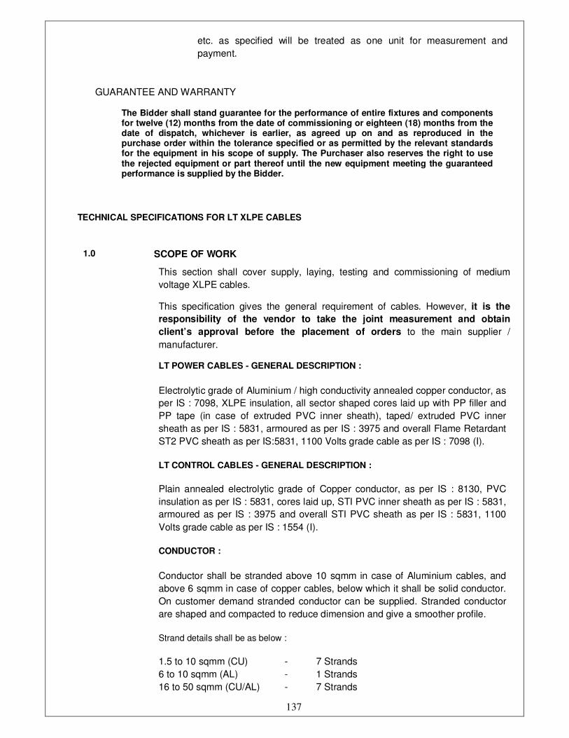
137
etc. as specified will be treated as one unit for measurement and
payment.
GUARANTEE AND WARRANTY
The Bidder shall stand guarantee for the performance of entire fixtures and components for twelve (12) months from the date of commissioning or eighteen (18) months from the date of dispatch, whichever is earlier, as agreed up on and as reproduced in the purchase order within the tolerance specified or as permitted by the relevant standards for the equipment in his scope of supply. The Purchaser also reserves the right to use the rejected equipment or part thereof until the new equipment meeting the guaranteed performance is supplied by the Bidder.
TECHNICAL SPECIFICATIONS FOR LT XLPE CABLES
1.0 SCOPE OF WORK
This section shall cover supply, laying, testing and commissioning of medium
voltage XLPE cables.
This specification gives the general requirement of cables. However, it is the
responsibility of the vendor to take the joint measurement and obtain
client’s approval before the placement of orders to the main supplier /
manufacturer.
LT POWER CABLES - GENERAL DESCRIPTION :
Electrolytic grade of Aluminium / high conductivity annealed copper conductor, as
per IS : 7098, XLPE insulation, all sector shaped cores laid up with PP filler and
PP tape (in case of extruded PVC inner sheath), taped/ extruded PVC inner
sheath as per IS : 5831, armoured as per IS : 3975 and overall Flame Retardant
ST2 PVC sheath as per IS:5831, 1100 Volts grade cable as per IS : 7098 (I).
LT CONTROL CABLES - GENERAL DESCRIPTION :
Plain annealed electrolytic grade of Copper conductor, as per IS : 8130, PVC
insulation as per IS : 5831, cores laid up, STI PVC inner sheath as per IS : 5831,
armoured as per IS : 3975 and overall STI PVC sheath as per IS : 5831, 1100
Volts grade cable as per IS : 1554 (I).
CONDUCTOR :
Conductor shall be stranded above 10 sqmm in case of Aluminium cables, and
above 6 sqmm in case of copper cables, below which it shall be solid conductor.
On customer demand stranded conductor can be supplied. Stranded conductor
are shaped and compacted to reduce dimension and give a smoother profile.
Strand details shall be as below :
1.5 to 10 sqmm (CU) - 7 Strands
6 to 10 sqmm (AL) - 1 Strands
16 to 50 sqmm (CU/AL) - 7 Strands
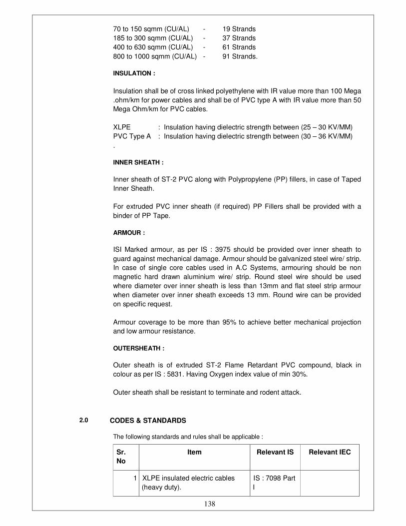
138
70 to 150 sqmm (CU/AL) - 19 Strands
185 to 300 sqmm (CU/AL) - 37 Strands
400 to 630 sqmm (CU/AL) - 61 Strands
800 to 1000 sqmm (CU/AL) - 91 Strands.
INSULATION :
Insulation shall be of cross linked polyethylene with IR value more than 100 Mega
.ohm/km for power cables and shall be of PVC type A with IR value more than 50
Mega Ohm/km for PVC cables.
XLPE : Insulation having dielectric strength between (25 – 30 KV/MM)
PVC Type A : Insulation having dielectric strength between (30 – 36 KV/MM)
.
INNER SHEATH :
Inner sheath of ST-2 PVC along with Polypropylene (PP) fillers, in case of Taped
Inner Sheath.
For extruded PVC inner sheath (if required) PP Fillers shall be provided with a
binder of PP Tape.
ARMOUR :
ISI Marked armour, as per IS : 3975 should be provided over inner sheath to
guard against mechanical damage. Armour should be galvanized steel wire/ strip.
In case of single core cables used in A.C Systems, armouring should be non
magnetic hard drawn aluminium wire/ strip. Round steel wire should be used
where diameter over inner sheath is less than 13mm and flat steel strip armour
when diameter over inner sheath exceeds 13 mm. Round wire can be provided
on specific request.
Armour coverage to be more than 95% to achieve better mechanical projection
and low armour resistance.
OUTERSHEATH :
Outer sheath is of extruded ST-2 Flame Retardant PVC compound, black in
colour as per IS : 5831. Having Oxygen index value of min 30%.
Outer sheath shall be resistant to terminate and rodent attack.
2.0 CODES & STANDARDS
The following standards and rules shall be applicable :
Sr.
No
Item Relevant IS Relevant IEC
1 XLPE insulated electric cables
(heavy duty).
IS : 7098 Part
I

139
2 Recommended current ratings for
cables. IS : 3961
3 Aluminium conductors for
insulated cables
IS : 8130
Indian Electricity
Act and Rules.
3.0 TECHNICAL REQUIREMENTS
3.1 GENERAL CONSTRUCTIONAL FEATURES
The medium voltage cables shall be supplied, laid, connected, tested and
commissioned in accordance with the drawings, specifications, relevant
Indian Standards specifications, manufacturer’s instructions. The cables
shall be delivered at site in original drums with manufacturer’s name, size,
and type, clearly written on the drums.
3.2 MATERIAL :
Medium voltage cable shall be XLPE insulated. PVC sheathed, aluminium
or copper conductor, armoured conforming to IS: 7098 Part I.
3.3 Type:
The cables shall be circular, multi core, annealed copper or aluminium
conductor, XLPE insulated and PVC sheathed, armoured or unarmoured.
3.4 Conductor:
Uncoated, annealed copper / aluminium, of high conductivity upto 4 mm.²
size, the conductor shall be solid and above 4 mm.², conductors shall be
concentrically stranded as per IEC : 228.
3.5 Insulation:
XLPE rated 70° c. extruded insulation.
3.6 Core Identification:
Two core : Red and Black
Three core : Red, Yellow and Blue
Four core : Red, Yellow, Blue and Black
Single core : Green, Yellow for earthing
Black shall always be used for neutral.
3.7 Assembly:
Two, three or four insulated conductors shall be laid up, filled with non-
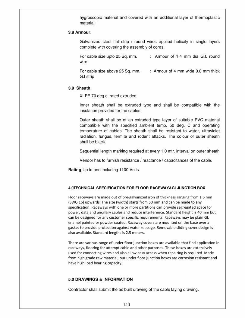
140
hygroscopic material and covered with an additional layer of thermoplastic
material.
3.8 Armour:
Galvanized steel flat strip / round wires applied helicaly in single layers
complete with covering the assembly of cores.
For cable size upto 25 Sq. mm. : Armour of 1.4 mm dia G.I. round
wire
For cable size above 25 Sq. mm. : Armour of 4 mm wide 0.8 mm thick
G.I strip
3.9 Sheath:
XLPE 70 deg.c. rated extruded.
Inner sheath shall be extruded type and shall be compatible with the
insulation provided for the cables.
Outer sheath shall be of an extruded type layer of suitable PVC material
compatible with the specified ambient temp. 50 deg. C and operating
temperature of cables. The sheath shall be resistant to water, ultraviolet
radiation, fungus, termite and rodent attacks. The colour of outer sheath
shall be black.
Sequential length marking required at every 1.0 mtr. interval on outer sheath
Vendor has to furnish resistance / reactance / capacitances of the cable.
Rating:Up to and including 1100 Volts.
4.0TECHNICAL SPECIFICATION FOR FLOOR RACEWAY&GI JUNCTION BOX
Floor raceways are made out of pre-galvanized iron of thickness ranging from 1.6 mm
(SWG 16) upwards. The size (width) starts from 50 mm and can be made to any
specification. Raceways with one or more partitions can provide segregated space for
power, data and ancillary cables and reduce interference. Standard height is 40 mm but
can be designed for any customer specific requirements. Raceways may be plain GI,
enamel painted or powder coated. Raceway covers are mounted on the base over a
gasket to provide protection against water seepage. Removable sliding cover design is
also available. Standard lengths is 2.5 meters.
There are various range of under floor junction boxes are available that find application in
raceways, flooring for attempt cable and other purposes. These boxes are extensively
used for connecting wires and also allow easy access when repairing is required. Made
from high grade raw material, our under floor junction boxes are corrosion resistant and
have high load bearing capacity.
5.0 DRAWINGS & INFORMATION
Contractor shall submit the as built drawing of the cable laying drawing.
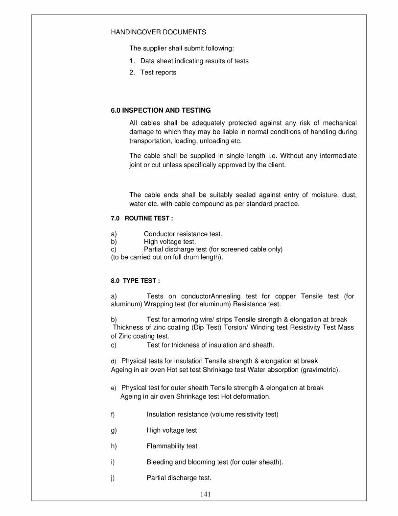
141
HANDINGOVER DOCUMENTS
The supplier shall submit following:
1. Data sheet indicating results of tests
2. Test reports
6.0 INSPECTION AND TESTING
All cables shall be adequately protected against any risk of mechanical
damage to which they may be liable in normal conditions of handling during
transportation, loading, unloading etc.
The cable shall be supplied in single length i.e. Without any intermediate
joint or cut unless specifically approved by the client.
The cable ends shall be suitably sealed against entry of moisture, dust,
water etc. with cable compound as per standard practice.
7.0 ROUTINE TEST :
a) Conductor resistance test. b) High voltage test. c) Partial discharge test (for screened cable only) (to be carried out on full drum length).
8.0 TYPE TEST :
a) Tests on conductorAnnealing test for copper Tensile test (for aluminum) Wrapping test (for aluminum) Resistance test. b) Test for armoring wire/ strips Tensile strength & elongation at break Thickness of zinc coating (Dip Test) Torsion/ Winding test Resistivity Test Mass
of Zinc coating test.
c) Test for thickness of insulation and sheath.
d) Physical tests for insulation Tensile strength & elongation at break
Ageing in air oven Hot set test Shrinkage test Water absorption (gravimetric).
e) Physical test for outer sheath Tensile strength & elongation at break
Ageing in air oven Shrinkage test Hot deformation.
f) Insulation resistance (volume resistivity test)
g) High voltage test
h) Flammability test
i) Bleeding and blooming test (for outer sheath).
j) Partial discharge test.
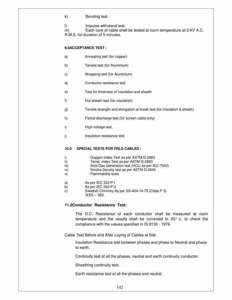
142
k) Bending test.
l) Impulse withstand test. m) Each core of cable shall be tested at room temperature at 3 KV A.C. R.M.S. for duration of 5 minutes.
9.0ACCEPTANCE TEST :
a) Annealing test (for copper)
b) Tensile test (for Aluminium)
c) Wrapping test (for Aluminium)
d) Conductor resistance test
e) Test for thickness of insulation and sheath
f) Hot sheath test (for insulation)
g) Tensile strength and elongation at break test (for insulation & sheath)
h) Partial discharge test (for screen cable only)
i) High voltage test.
j) Insulation resistance test.
10.0 SPECIAL TESTS FOR FRLS CABLES :
i) Oxygen Index Test as per ASTM-D-2863 ii) Temp. Index Test as per ASTM-D-2863 iii) Acid Gas Generation test (HCL) as per IEC-754(I) iv) Smoke Density test as per ASTM-D-2843 v) Flammability tests
a) As per IEC 332-P-I b) As per IEC 332-P-3 c) Swedish Chimney As per SS-424-14-75 (Class F 3) IEEE – 383.
11.0Conductor Resistance Test:
The D.C. Resistance of each conductor shall be measured at room
temperature and the results shall be corrected to 20° c. to check the
compliance with the values specified in IS 8130 - 1976.
Cable Test Before and After Laying of Cables at Site
Insulation Resistance test between phases and phase to Neutral and phase
to earth.
Continuity test of all the phases, neutral and earth continuity conductor.
Sheathing continuity test.
Earth resistance test of all the phases and neutral.

143
12.0 METHOD OF MEASUREMENT
The cables will be measured in meters. The unit rate shall include cutting
the cable into required lengths, packing, loading, unloading, insurance,
transportation, delivery to stores/site as per work order, stocking in stores,
testing of cables at stores etc. of medium voltage cable. Total quantity in
meters shall be measured lug to lug basis.
13.0 DATA SHEET FOR CABLES
(Must be furnished along with the quotation for all cable of conductor size
50 Sq. mm and above).
Sr No. DESCRIPTION GUARANTEED
PARTICULARS
1.0 Name of Manufacturer
2.0 Conductor
3.0 Form - circular/ segmented
4.0 Cross sectional area mm²
5.0 Whether cores identified by colours Yes/No
6.0 Overall dia. of finished cable
7.0
Critical Oxygen Index Value at 750oC when
tested for temperature index test as per
ASTMD-2863
8.0
Total acid gas generation by weight when
tested as per IEC 7541
%
9.0 Percentage of light transmission under fire
for assessment of smoke generation when
tested as per ASTM-D-2843.
%
10.0 Will cables offered pass the flammability
tests as per:
a) Class-F3-Swedish Standard S5-424-1475
b) IEC 332-1
c) IEC 331-1
Yes/No
Yes/No
Yes/No
TECHNICAL SPECIFICATIONS FOR MDF BOX / TELEPHONE SYSTEM

144
1.0 SCOPE OF WORK
The work described in this section shall apply to the supply, installation,
testing and commissioning of MDF Box with relevant equipment and
instruments. The work shall also include testing, connecting and
commissioning of telephone wiring system installed by others.
This installation is intended to provide an adequate system which shall
encompass the service requirements as described hereunder.
Work under this section shall incorporate the supply, installation, testing and
setting to work of the following :
1. The Main Distribution Frame (M.D.F.).
2. The telephone instruments, as required.
3. Connection, testing and commissioning of existing telephone
wiring, tag boxes, telephone outlets etc.
4. Any additional work found necessary for completion of the
system.
5. The rate shall also include necessary hardware, raceways,
brackets, cable tray, supports, tag etc. required in the control
room where MDF Box is to be installed.
3.0
TECHNICAL REQUIREMENTS
3.1 GENERAL
The following specification outlines the technical and operational
requirements of MDF consisting of simple functional units enabling
adaptations without interfering with the basic structure of the
exchange.
3.2 Equipment shall be of modular design and housed in dust-proof
cabinets.
3.3 Equipment shelves shall be of the modular type, with slide-in PC
boards.
3.4 The equipment shall be designed in such a way that the heat
dissipation does not require built-in forced ventilation or separate air
conditioning provisions.
4.0 SYSTEM PHILOSOPHY
4.1 The system must be provided with all the modern MDF facilities and it
must be possible to handle voice, text, data and safety devices

145
communications.
4.2 The system shall be 100% non-blocking.
4.3 The system should support ISDN (PRI/BRI) technology.
4.4
The MDF should be suited to work on an ac mains supply of 230V with
a tolerance of +10V and -15V.
4.5 The system should be ventilated by conventional airflow. No cooling
fans should be used in any part of the MDF.
4.6 MDF should be suitable for up to 5 digit extension numbering scheme.
This numbering scheme should be flexible. System should also allow mixed
numbering scheme.
4.7 The features mentioned below should be available from extensions.
1. Call forwarding
2. Do not disturb
3. Override do not disturb
4. Speed dialing: system numbers
5. Speed dialing: individual numbers
6. Barge in
7. Call back
8. Paging, both external and internal
9. Call parking
10. Blind Transfer
4.8 In the night mode when the operator is not present at the console,
the direct lines will have to be routed to different extensions for
incoming calls. Once the call lands in the department it should be
possible to answer it from any station.
4.9 It should also be possible to have a different class of service during
the day and during the night. The system should support automatic
changeover of class of services.
TECHNICAL SPECIFICATIONS FOR DATA & NETWORKING SYSTEM
SCOPE:-The work described in this section shall apply to the supply, installation, testing
and commissioning of Data & Networking system with relevant equipment and
instruments.
1) The Network switch offers a power-efficient Gigabit Ethernet (GbE) network-access
switching solution with integrated 10GbE uplinks. With high-performance capabilities and
wire-speed performance, utilizing a non-blocking architecture to easily handle
unexpected traffic loads, the switches offer simple management and scalability via an
40Gbps (full-duplex) high availability stacking architecture that allows management of up to four switches from a single IP address. An integrated 80PLUS-certified power supply
146
and features such as Energy-Efficient Ethernet and short cable detection provide energy
efficiency to help decrease power and cooling costs.
2) Modernize campus network architectures :-
Modernize campus network architectures with a power-efficient and resilient 1/10GbE
switching solution with Power over Ethernet Plus (PoE+). Select N1500 models offer 24 or 48
ports of PoE+ to deliver clean power to network devices such as wireless access points
(APs), Voice-over-IP (VoIP) handsets, video conferencing systems and security cameras. Technical Specification :-
1) Physical :- i) integrated front 10GbE SFP+ dedicated ports,ii) 10GbE can be used as
stacking ports USB (Type A) port for configuration via USB flash drive. Iii) Auto-
negotiation for speed and flow control iv) Auto MDI/MDIX, port mirroring v) Flow-based
port mirroring vi) Broadcast storm control vii) Energy-Efficient Ethernet per port settings
viii) Redundant variable speed fans ix) Air flow: I/O to power supply x) Integrated
power supply: 40W AC (N1524), 100W AC (N1548), 600W AC (N1524P, N1548P)RJ45
console port with RS232 signaling (RJ-45 to female DB-9 connector cable
included)Dual firmware images on-board
2) Chassis :- Size (1RU, H x W x D): N1524 and N1548: 1.7 in x 17.3 in x 10.1 in (43.2 mm x
440.0 mm x 257.0 mm) N1524P and N1548P: 1.7 in x 17.3 in x 15.2 in (43.2 mm x 440.0
mm x 387.0 mm)
Approximate weight: 6.6lbs/3kg (N1524), 12.8lbs/5.8kg (N1524P), 8.8lbs/4kg (N1548),
15.4lbs/7kg (N1548P) Rack mounting kit with 2 mounting brackets, bolts
and cage nuts.
3) Environmental :- Power supply efficiency: 80% or better in all operating modes
Max. thermal output (BTU/hr): 103.1 (N1524), 2972 (N1524P), 152.2 (N1548), 5824.3 (N1548P) Power consumption max (watts): 30.2 (N1524), 871 (N1524P), 44.6 (N1548), 1704 (N1548P) Operating temperature: 32° to 113°F (0° to 45°C) Operating humidity: 95% Storage temperature: –40° to 149°F (–40° to 65°C) Storage relative humidity: 85%
TECHNICAL SPECIFICATIONS FOR CCTV SYSTEM
SCOPE: -
This specification covers the general requirements for Supply, Installation, Testing, &
Commissioning of Closed Circuit Television systems (CCTV).
TECHNICAL REQUIREMENTS
SYSTEM DESIGN AND ARCHITECTURE
CCTV system should be designed such as to cover the strategic locations and sensitive areas
of High end cameras with Day/Night features to be installed for outdoor and perimeter
security application, these cameras shall be IR Compatible so that IR Lamps can be
introduced at a later stage to enhance night vision. All Speed domes shall be rugged and
shall be weather proof as per specifications. The fixed dome cameras shall necessarily be of
Varifocal / fixed lens as per detailed specifications. Day/Night Cameras with built in zoom
lenses shall be provided for select indoor/outdoor locations as per the detailed BOQ. Also the
systems should utilize only industry standard protocol.
System should be programmed such that operator’s intervention if required shall be minimal

147
and the system should provide features like guard tours, preset positions and the preset
positions will be linked to perimeter protection system/intrusion system in future. The NVR’s
should allow for recording of events both continuous and motion triggered as per
requirement and recordings should be able to create evidences and support post event
analysis.
o IP based Indoor Fixed Dome Cameras
SR
No. Parameter Description
1 Image sensor & Minimum
Effective Pixels (Resolution) or
better
1/3” or better CMOS or Equivalent & Minimum
2 MP @30fps
2 Electronic Shutter 1/30 to 1 / 10000 s or better
3 Min illumination/ light sensitivity
(Colour) or better
Minimum 0.5 lux (30 IRE, F 1.2) or better
4 Min illumination/ light sensitivity
(B/W)
Minimum 0.01 lux (30 IRE, F 1.2) & 0 Lux on IR on
5 Wide Dynamic Range Required
6 Backlight Compensation ON/OFF
7 IR Range 20-30 Meter
8 Focus Automatic / Manual
9 Automatic Gain Control Auto / Manual
10 Sharpness, Brightness, Contrast functionality Required
11 Frame Rate 25 FPS for 1920 x 1080 at H.264 Compression or
better
12 Fixed Lens 2.8 mm/4 mm/ 6mm fixed lens as per site
requirement
13 Video
Day and Night functionality Automatic, Color, Mono
Video Resolution Minimum 2 MP, @30fps
Video Streams Individually configurable 02 video streams (H.264,
MJPEG)
Intelligent Video Motion detection, Tampering Alert
14 Compression
Dual H.264 (Recording &
Viewing)
Required, Live stream 1080p should support min.
25 FPS and recording at lower resolution and
frame rate or vice versa as may be configured.
15 Audio
Audio support Required
Audio Compression Minimum G.711 or better AAC48KHz or better
Two-way audio Required
Input / Output 01 IN & 01 OUT
16 Network & Interface
Interface RJ-45 for 10/100 base-T Ethernet
Upgrade Through web browser , online, firmware upgrade
Network Protocols support IPv4, IPv6, TCP/IP, HTTP, , DHCP, UDP, DNS, SMTP,
RTP, RTSP, SNMP, UpnP, NTP, ICMP, IGMP,
Alarm Event Events / alerts send via FTP, HTTP, email, Pre-Post
alarm video buffering.
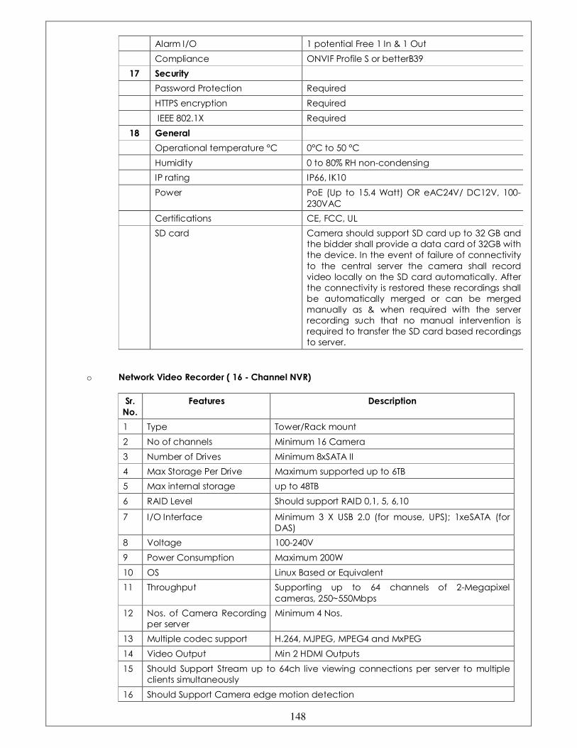
148
Alarm I/O 1 potential Free 1 In & 1 Out
Compliance ONVIF Profile S or betterB39
17 Security
Password Protection Required
HTTPS encryption Required
IEEE 802.1X Required
18 General
Operational temperature °C 0°C to 50 °C
Humidity 0 to 80% RH non-condensing
IP rating IP66, IK10
Power PoE (Up to 15.4 Watt) OR eAC24V/ DC12V, 100-
230VAC
Certifications CE, FCC, UL
SD card Camera should support SD card up to 32 GB and
the bidder shall provide a data card of 32GB with
the device. In the event of failure of connectivity
to the central server the camera shall record
video locally on the SD card automatically. After
the connectivity is restored these recordings shall
be automatically merged or can be merged
manually as & when required with the server
recording such that no manual intervention is
required to transfer the SD card based recordings
to server.
o Network Video Recorder ( 16 - Channel NVR)
Sr.
No.
Features Description
1 Type Tower/Rack mount
2 No of channels Minimum 16 Camera
3 Number of Drives Minimum 8xSATA II
4 Max Storage Per Drive Maximum supported up to 6TB
5 Max internal storage up to 48TB
6 RAID Level Should support RAID 0,1, 5, 6,10
7 I/O Interface Minimum 3 X USB 2.0 (for mouse, UPS); 1xeSATA (for
DAS)
8 Voltage 100-240V
9 Power Consumption Maximum 200W
10 OS Linux Based or Equivalent
11 Throughput Supporting up to 64 channels of 2-Megapixel
cameras, 250~550Mbps
12 Nos. of Camera Recording
per server
Minimum 4 Nos.
13 Multiple codec support H.264, MJPEG, MPEG4 and MxPEG
14 Video Output Min 2 HDMI Outputs
15 Should Support Stream up to 64ch live viewing connections per server to multiple
clients simultaneously
16 Should Support Camera edge motion detection
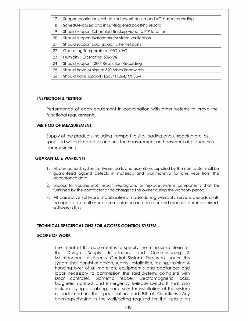
149
17 Support continuous, scheduled, event based and I/O based recording
18 Schedule-based and input-triggered boosting record
19 Should support Scheduled Backup video to FTP location
20 Should support Watermark for video verification
21 Should support Dual gigabit Ethernet ports
22 Operating Temperature : 0°C-40°C
23 Humidity : Operating: 5%-95%
24 Should support 12MP Resolution Recording
25 Should have Minimum 320 Mbps Bandwidth
26 Should have support H.265/ H.264/ MPEG4
INSPECTION & TESTING
Performance of each equipment in coordination with other systems to prove the
functional requirements.
METHOD OF MEASUREMENT
Supply of the products including transport to site, loading and unloading etc. as
specified will be treated as one unit for measurement and payment after successful
commissioning.
GUARANTEE & WARRENTY
1. All component, system software, parts and assemblies supplied by the contractor shall be
guaranteed against defects in materials and workmanship for one year from the
acceptance date.
2. Labour to troubleshoot, repair, reprogram, or replace system components shall be
furnished by the contractor at no charge to the owner during the warranty period.
3. All corrective software modifications made during warranty service periods shall
be updated on all user documentation and on user and manufacturer archived
software disks.
TECHNICAL SPECIFICATIONS FOR ACCESS CONTROL SYSTEM:-
SCOPE OF WORK
The intent of this document is to specify the minimum criteria for
the Design, Supply, Installation, and Commissioning &
Maintenance of Access Control System. The work under this
system shall consist of design, supply, installation, testing, training &
handing over of all materials, equipment’s and appliances and
labor necessary to commission the said system, complete with
Door controller, Biometric reader, Electromagnetic locks,
Magnetic contact and Emergency Release switch. It shall also
include laying of cabling, necessary for installation of the system
as indicated in the specification and Bill of Quantities. Any
openings/chasing in the wall/ceiling required for the installation
150
shall be made good in appropriate manner.
The scope of work shall include the design, supply, installation,
commissioning, integrating, guaranteeing and maintenance of an
integrated access control system.
TECHNICAL REQUIREMENTS
OPERATIONAL REQUIREMENTS
1.0 The Access Control System (ACS) as outlined in the tender
document
Shall be used to control the flow of authorized personnel through
the secured access area of the facility.
2.0 The document shall provide an outline of the various parameters
that
Are specified, as minimum requirements, with respect to various
hardware & software components required for the
implementation of an integrated security & access control system.
This document together with the detailed schedule of quantities
for the site forms the basis for the tender issued.
ACCESS SOFTWARE FEATURES & REQUIREMENTS
GENERAL DESCRIPTION
1.0 The Access control system software shall be a module in the
integrated software. The Access Control System software shall be
capable of integrating multiple functions including Access
control, Time and Attendance Management of employees, Alarm
Management, Database Partitioning, and external system
database sharing of employee personal information (Import
Utility).
2.0 The system shall be modular in nature, and shall permit expansion
of both capacity and functionality through the addition of control
panels, card readers, software modules and sensors.
3.0 The system shall incorporate the necessary hardware, software,
and firmware to collect, transmit, and process alarm, tamper and
trouble conditions, access requests, and advisories in accordance
with the security procedures configured. The system shall control
the flow of authorized personnel traffic through the secured areas
of a facility.
TECHNICAL SPECIFICATIONS FOR STANDALONE CALL BELL SYSTEM:-

151
TECHNICAL SPECIFICATION FOR UPS
1.0 SCOPE OF WORK
1.1 The scope of work for UPS system to be furnished in accordance with this
specification, shall include design, manufacture, fabrication, assembly,
pre – shipment, testing at manufacturer’s works, proper packing for
transportation, delivery at site, unloading, storage, erection,
interconnection of related equipments, calibration, commissioning,
testing and putting the UPS system together with all accessories and
auxiliaries as specified hereinafter in a fully operational condition. The
systems shall be furnished, erected and commissioned and all other
services shall be performed by the vendor as covered under this
specification and this work shall be fully in compliance with the
requirements stated herein.
2.0 CODES & STANDARDS
2.1 IEEE Standard 446—1987 Emergency and standby power systems.
IEEE Standard 450 – 1975
IEEE Paper 4-177 Some discharge characteristics of lead acid
batteries.
IEC 146 Performance testing of UPS
ANSI C37.90a,
IEEE Standard 472
Surge withstand capability test.
ANSI C 34.2 Practices and requirements for semiconductor
power rectifiers.
ANSI C 37.90 Relays and relay system associated with
electrical power apparatus.
NEMA PE-1983 Uninterrupted Power System Standard
IS 2208 & IS 9224 Cartridge fuses for voltages upto and including
650V (Part 1 & Part 2 ) (I.E.C. 269)
IS 9224 (Part – 4) Fuses for protection of semiconductors.
BS 2709 (I.E.C 119) The Electrical Performance of Semiconductor
Rectifiers. (Metal Rectifiers)
BS 4417 (I.E.C 146) Semi-conductor Rectifier Equipments.
IS 8623 (I.E.C 439) Factory – built Assemblies of switchgear and
controlgear for voltages upto and including 1
It should have following features:-
• It should have long lasting batteries and replaceable remote battery
• It should work on 12V,
• It should have minimum life of 1-2 years even after continuous usage
• Receiver should work on 12 volt supply,
• Adapter should be capable to convert 220VAC to 12VDC
• Remotes should have a call and a cancel button feature.
• It should have Flash light turns on when presses the remote button.

152
KV and 1200V DC
IS 694 (I.E.C 228) PVC insulated Cables for switchgear and
Controlgear wiring.
IS 1652 & IS1652 Lead-acid stationary cells and batteries.
BD 9720 Custom-built transformers and inductors of
assessed quality.
IP20 Degree of protection.
IEC Semi Conductor Convertor Standards.
ISO 9001certified
3.0
DESIGN BASIS
3.1
The requirements of UPS systems are specified herein on system basis.
The vendor shall be responsible for engineering and providing all
materials, equipments and services specified or otherwise, which are
required to fulfill the intent of ensuring operability, maintainability,
completeness and reliability of the total work covered under this
specification within his quoted price.
3.2 The vendor shall furnish his proposal for UPS systems with parallel
redundant configuration as per capacity as indicated in the data sheet
and bill of quantity.
During parallel redundant operation, if required any one UPS shall be
take out from the operation for maintenance without effecting the
output load and any circuitry. All necessary provisions shall be made by
the vendor.
3.3 The UPS equipment and the complete system shall have Surge
Withstand Capacity (SWC) to meet the requirements of ANSI C 37.90a,
IEEE Standard 472 0 1974.
3.4 All components of UPS system shall be capable of withstanding all
possible short circuit current without damage.
3.5 Following general requirements shall be met for ensuring proper circuit
protection.
For circuit with transformers, if secondary fuse protection is not provided
then the primary fuses must not be sized larger than 125% of the
transformer primary full-load amperes.
If secondary fuses are sized not greater than 125% of transformer
secondary current, individual transformer fuses are not required in the
primary provided the primary feeder fuses are not larger than 250% of the
transformer rated primary current.

153
All the neutral conductors used in three phase UPS systems are to be
sized equal to take at least 150% of the maximum phase current. In
addition, all the isolators and circuit breakers used in three phase UPS
system are to be rated such that the neutral poles will take at least 150%
of the maximum phase current.
All control shall be designed and positioned such that, possibility of
inadvertent or accidental operations are eliminated.
All UPS system cabinets, frames and power transmission circuits are to be
double earthed.
3.6 The UPS design philosophy shall ensure that a single component / device
failure shall not result in failure of the entire UPS system. i.e the design of
UPS System shall be modular to permit easy removal of any unit without
affecting other units.
3.7 The various overload capacities of inverters, static switch, step down
transformer/voltage stabilizer as specified herein are the minimum
requirements. However, if the Vendor’s offered system has better
overload capacities for the above devices, the same shall be highlighted
by the vendor in his offer.
3.8 The UPS system offered by the vendor shall be suitable for operating
continuously at the rated capacity indicated in tender with in ambient
temperature 5- 45 deg. C and relative humidity of 30 to 98%. Also the UPS
system shall be suitable for operation as per full rating up to 1000 meters
above sea level without derating. The Vendor shall furnish a certificate
towards compliance on ambient conditions permissible.
3.9 The UPS system to be supplied by the vendor shall have maximum
humming noise level of 75 DB at 3 meter from the surface of the UPS
cabinets.
3.10 Suppression of Radio Interference shall be provided to meet statutory
requirements.
3.11 Detailed literature should be provided showing Quality Assurance
Procedure.
3.12 The vendor shall submit along with the tender detailed item by item
compliance statement along with the tender.
3.13 The vendor shall submit along with the tender Credential certificates for
satisfactory completion of minimum five (5) UPS installation of similar
magnitude, capacity, application and operational philosophy. Vendor
Non compliance with above requirement shall be outright rejected.
3.14 All the equipment and components provided in the transformer and accessories
shall be suitably designed for installation and satisfactory operation as specified below.
4.0 TECHNICAL REQUIREMENTS
4.1 Static Converter
4.1.1 The static converter shall be fully microprocessor controlled full wave
controlled rectifier which shall include drive circuitry, over current
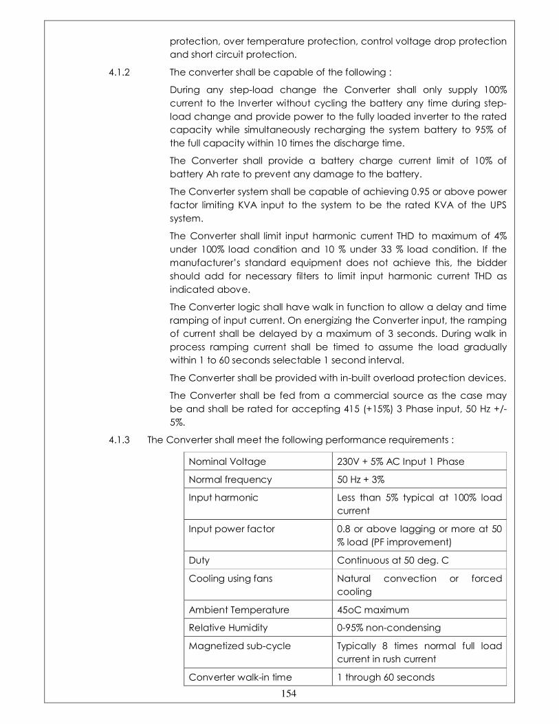
154
protection, over temperature protection, control voltage drop protection
and short circuit protection.
4.1.2 The converter shall be capable of the following :
During any step-load change the Converter shall only supply 100%
current to the Inverter without cycling the battery any time during step-
load change and provide power to the fully loaded inverter to the rated
capacity while simultaneously recharging the system battery to 95% of
the full capacity within 10 times the discharge time.
The Converter shall provide a battery charge current limit of 10% of
battery Ah rate to prevent any damage to the battery.
The Converter system shall be capable of achieving 0.95 or above power
factor limiting KVA input to the system to be the rated KVA of the UPS
system.
The Converter shall limit input harmonic current THD to maximum of 4%
under 100% load condition and 10 % under 33 % load condition. If the
manufacturer’s standard equipment does not achieve this, the bidder
should add for necessary filters to limit input harmonic current THD as
indicated above.
The Converter logic shall have walk in function to allow a delay and time
ramping of input current. On energizing the Converter input, the ramping
of current shall be delayed by a maximum of 3 seconds. During walk in
process ramping current shall be timed to assume the load gradually
within 1 to 60 seconds selectable 1 second interval.
The Converter shall be provided with in-built overload protection devices.
The Converter shall be fed from a commercial source as the case may
be and shall be rated for accepting 415 (+15%) 3 Phase input, 50 Hz +/-
5%.
4.1.3 The Converter shall meet the following performance requirements :
Nominal Voltage 230V + 5% AC Input 1 Phase
Normal frequency 50 Hz + 3%
Input harmonic Less than 5% typical at 100% load
current
Input power factor 0.8 or above lagging or more at 50
% load (PF improvement)
Duty Continuous at 50 deg. C
Cooling using fans Natural convection or forced
cooling
Ambient Temperature 45oC maximum
Relative Humidity 0-95% non-condensing
Magnetized sub-cycle Typically 8 times normal full load
current in rush current
Converter walk-in time 1 through 60 seconds

155
(every one second selectable, 0 to
100% rated load)
Input Vendor shall provide suitable
terminals for termination of cables
for connecting to the converter
from the AC distribution board to
be sup[plied by owner.
4.1.4 Static Inverter
The static Inverter shall have utilizing high speed switching Insulated Gate
Bipolar Transistor which shall include drive circuitry and devices to control
requirements including voltage regulation, current limiting, wave shaping,
transient recovery, automatic synchronization etc.
The static Inverter shall be use appropriate control circuitry to perform as
a constant voltage and constant current source to enable adapting its
performance for changing loads.
Inverter capacity
Each static inverter shall have the following minimum capacities without
causing any damage to the components and with current limiting
function not operating
4.1.5 The Inverter should be designed to meet the following.
Earth leak capacity
200% for 10 minutes minimum at all specified input.
Step load pick up
Upon transfer of the full load the inverter output voltage shall not drop
below 95% of nominal voltage. The recovery to within +/-1% of the
voltage shall be 20 milliseconds maximum.
Overloads short circuits and load loss
The Inverter should be capable of clearing an output fault of 1000% of
the rated capacity in 40 milliseconds.
Non linear loading
The Inverter shall be capable of operation with 100% nonlinear loads. The
bidder shall assume a non linear wave form providing a crest factor of
greater than 3.0 occurring coincident with the voltage peak.
The output wave form of the Inverter shall remain within the specified
tolerance when operating with these non linear loads at 100 percent
rated load. For 3 Phase UPS, the load carrying neutral conductors and
components throughout the UPS shall be rated for continuous operation
at a minimum of 150% of the phase ratings.
The Inverter shall be self protecting against all AC and DC transients,
voltage surges and steady state abnormal voltages and currents likely to
be encountered. The inverter shall be protected against high and low

156
input DC voltage.
Supply Voltage Variation and Loss
The Inverter shall include equipment necessary to protect itself from
damage resulting from excursion loss or restoration of DC input and
synchronizing voltage.
4.1.6 The Inverter also should be designed to supply the rated load at 40°C
ambient temperature continuously.
4.1.7 Automatic synchronization :
The Inverter equipment shall include all necessary control circuit and
devices with its own stable oscillators.
The Inverter should be able to synchronize with the bypass source when
the bypass source frequency is within the synchronization limits.
The Inverter should run on its own oscillator maintaining an output
frequency of 50 Hz +/- 0.01% when the bypass source is out of
Synchronization limits.
The Inverter should have provision for steeples adjustment of disconnect
synchronization frequency range at site from 50 Hz +/- 0.5% to 50Hz +/-
3%.
The Inverter should be capable of automatically adjusting the phase
Relationship between Inverter output and standby bypass source
gradually at controlled slew rate. It should be possible to adjust the slew
rate at site at the rate of 0.1 to 3.0 Hz in 0.1 steps.
The DC input current (except for short circuit within the Inverter) should
not exceed full load current even under the condition of transient as well
as steady state currents, inrush current upon initial energisation, load
energisation, short circuit external to the Inverter. For any load or load
power factor the Inverter shall not impose on DC source any voltage
oscillations.
The Inverter shall limit the total harmonic distortion to less than 3% for 100%
linear load and less than 5% for 100% non-linear load. Bidder to confirm
this specifically and in the event their normal equipment does not comply
should quote for additional filters to achieve this.
4.1.8 The Inverter shall comply with the following performance specifications in
addition to those described above :
Nominal output voltage 230V +/- 1% AC, 1 Phase 2 Wire.
Nominal input voltage To suit output requirement.
Details to be given by the bidder.
Inverter capacity As per schedule of quantities.
Voltage regulation The bidder should furnish compliance of
voltage regulation of less than +/- 1%
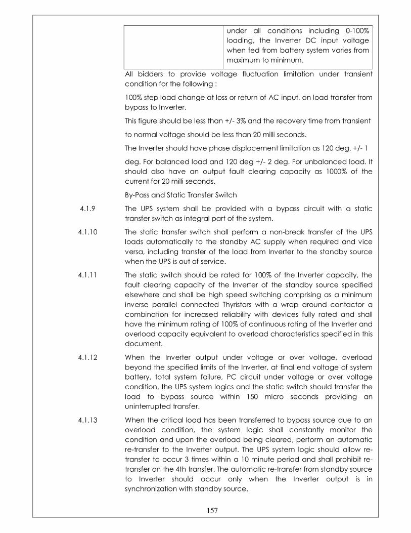
157
under all conditions including 0-100%
loading, the Inverter DC input voltage
when fed from battery system varies from
maximum to minimum.
All bidders to provide voltage fluctuation limitation under transient
condition for the following :
100% step load change at loss or return of AC input, on load transfer from
bypass to Inverter.
This figure should be less than +/- 3% and the recovery time from transient
to normal voltage should be less than 20 milli seconds.
The Inverter should have phase displacement limitation as 120 deg. +/- 1
deg. For balanced load and 120 deg +/- 2 deg. For unbalanced load. It
should also have an output fault clearing capacity as 1000% of the
current for 20 milli seconds.
By-Pass and Static Transfer Switch
4.1.9 The UPS system shall be provided with a bypass circuit with a static
transfer switch as integral part of the system.
4.1.10 The static transfer switch shall perform a non-break transfer of the UPS
loads automatically to the standby AC supply when required and vice
versa, including transfer of the load from Inverter to the standby source
when the UPS is out of service.
4.1.11 The static switch should be rated for 100% of the Inverter capacity, the
fault clearing capacity of the Inverter of the standby source specified
elsewhere and shall be high speed switching comprising as a minimum
inverse parallel connected Thyristors with a wrap around contactor a
combination for increased reliability with devices fully rated and shall
have the minimum rating of 100% of continuous rating of the Inverter and
overload capacity equivalent to overload characteristics specified in this
document.
4.1.12 When the Inverter output under voltage or over voltage, overload
beyond the specified limits of the Inverter, at final end voltage of system
battery, total system failure, PC circuit under voltage or over voltage
condition, the UPS system logics and the static switch should transfer the
load to bypass source within 150 micro seconds providing an
uninterrupted transfer.
4.1.13 When the critical load has been transferred to bypass source due to an
overload condition, the system logic shall constantly monitor the
condition and upon the overload being cleared, perform an automatic
re-transfer to the Inverter output. The UPS system logic should allow re-
transfer to occur 3 times within a 10 minute period and shall prohibit re-
transfer on the 4th transfer. The automatic re-transfer from standby source
to Inverter should occur only when the Inverter output is in
synchronization with standby source.

158
4.1.14 The UPS control system through the operating panel should have
capability to initiate manual transfer. During manual transfer or
automatic re-transfer, the UPS system logic shall force the Inverter output
voltage to match the bypass input voltage to achieve no-break transfer
along with controlled walk in load current to the Inverter.
4.1.15 Maintenance bypass switch :
The UPS shall be provided with, as an integral part of the system, a zero
energy maintenance bypass switch with lock and key arrangement of
adequate capacity and specification, the use of which by authorized
personnel using the key shall enable bypass of the entire UPS system,
including the static bypass switch, and connect the load to standby AC
source enabling maintenance personnel to work on the UPS system.
4.1.16 UPS Battery System
The UPS system shall, as an integral part, provide battery system for 30
minutes standby capacity.
The latest state of the art Valve Regulated Sealed Maintenance Free
Lead Acid Batteries should be used with a 10 minute discharge rating.
The battery system shall be sized to provide30 minutes back up time
when the UPS is supplying 100% rated load at 0.8 load power factor.
An ageing factor of 15% should be applied to the capacity arrived at, to
allow for compensation against capacity loss during float operation.
The battery system design should be provided with necessary devices to
prevent deep discharge beyond recommended limits to prevent the
batteries discharging beyond end cell voltage specified by the battery
maker. The connections from battery to battery shall be using copper bus
bar strips and the entire battery system shall be used in IP20 steel cabinet
enclosure and shall be similar to the UPS enclosure.
All batteries should be clearly identified and identification numbers
marked on the batteries and a schematic diagram along with the
complete calculations, including manufacturers supporting curves,
should be submitted with the tender.
4.1.17 OPERATION
Under normal operation, the UPS load will be fed from the Inverter with
the bypass switch inhibited. The Converter, apart from providing DC
power to the Inverter, also charges the battery under the float charge
mode. The battery charge system shall have float charge, equalizing
charge the recovery charge modes, to replenish the batteries self-
discharging part while the battery is fully charged, equalizing the battery
cell voltage to a constant value forcibly, and recharging the battery
system to the required values when the batteries have been used,
respectively.
The Inverter shall constantly monitor the AC source frequency and shall
be in synchronization with the AC input source till the frequency of the
AC input source is within synchronizing limit and if the frequency of the
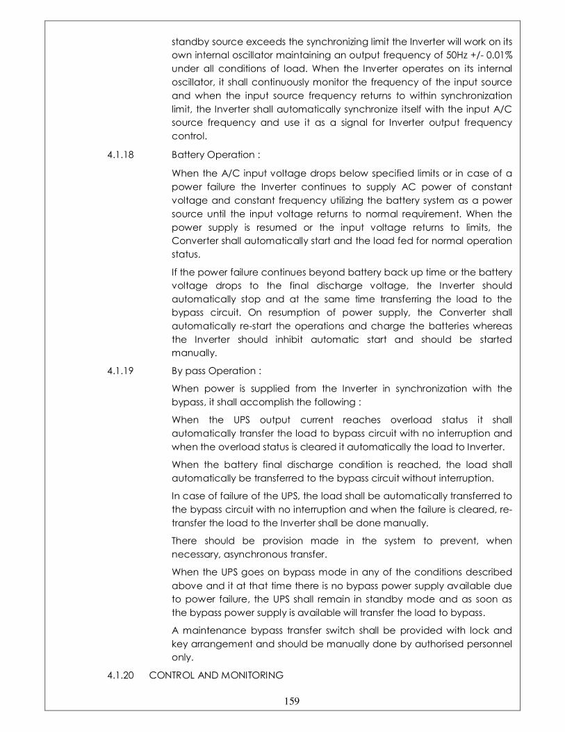
159
standby source exceeds the synchronizing limit the Inverter will work on its
own internal oscillator maintaining an output frequency of 50Hz +/- 0.01%
under all conditions of load. When the Inverter operates on its internal
oscillator, it shall continuously monitor the frequency of the input source
and when the input source frequency returns to within synchronization
limit, the Inverter shall automatically synchronize itself with the input A/C
source frequency and use it as a signal for Inverter output frequency
control.
4.1.18 Battery Operation :
When the A/C input voltage drops below specified limits or in case of a
power failure the Inverter continues to supply AC power of constant
voltage and constant frequency utilizing the battery system as a power
source until the input voltage returns to normal requirement. When the
power supply is resumed or the input voltage returns to limits, the
Converter shall automatically start and the load fed for normal operation
status.
If the power failure continues beyond battery back up time or the battery
voltage drops to the final discharge voltage, the Inverter should
automatically stop and at the same time transferring the load to the
bypass circuit. On resumption of power supply, the Converter shall
automatically re-start the operations and charge the batteries whereas
the Inverter should inhibit automatic start and should be started
manually.
4.1.19 By pass Operation :
When power is supplied from the Inverter in synchronization with the
bypass, it shall accomplish the following :
When the UPS output current reaches overload status it shall
automatically transfer the load to bypass circuit with no interruption and
when the overload status is cleared it automatically the load to Inverter.
When the battery final discharge condition is reached, the load shall
automatically be transferred to the bypass circuit without interruption.
In case of failure of the UPS, the load shall be automatically transferred to
the bypass circuit with no interruption and when the failure is cleared, re-
transfer the load to the Inverter shall be done manually.
There should be provision made in the system to prevent, when
necessary, asynchronous transfer.
When the UPS goes on bypass mode in any of the conditions described
above and it at that time there is no bypass power supply available due
to power failure, the UPS shall remain in standby mode and as soon as
the bypass power supply is available will transfer the load to bypass.
A maintenance bypass transfer switch shall be provided with lock and
key arrangement and should be manually done by authorised personnel
only.
4.1.20 CONTROL AND MONITORING
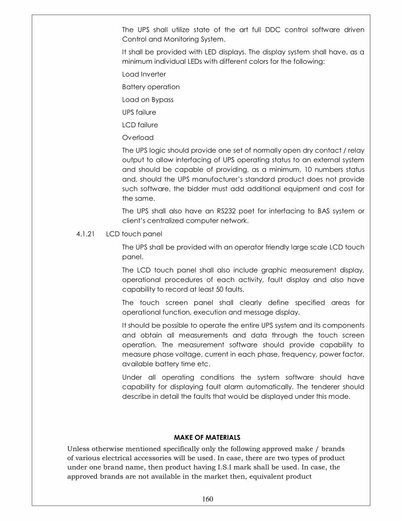
160
The UPS shall utilize state of the art full DDC control software driven
Control and Monitoring System.
It shall be provided with LED displays. The display system shall have, as a
minimum individual LEDs with different colors for the following:
Load Inverter
Battery operation
Load on Bypass
UPS failure
LCD failure
Overload
The UPS logic should provide one set of normally open dry contact / relay
output to allow interfacing of UPS operating status to an external system
and should be capable of providing, as a minimum, 10 numbers status
and, should the UPS manufacturer’s standard product does not provide
such software, the bidder must add additional equipment and cost for
the same.
The UPS shall also have an RS232 poet for interfacing to BAS system or
client’s centralized computer network.
4.1.21 LCD touch panel
The UPS shall be provided with an operator friendly large scale LCD touch
panel.
The LCD touch panel shall also include graphic measurement display,
operational procedures of each activity, fault display and also have
capability to record at least 50 faults.
The touch screen panel shall clearly define specified areas for
operational function, execution and message display.
It should be possible to operate the entire UPS system and its components
and obtain all measurements and data through the touch screen
operation. The measurement software should provide capability to
measure phase voltage, current in each phase, frequency, power factor,
available battery time etc.
Under all operating conditions the system software should have
capability for displaying fault alarm automatically. The tenderer should
describe in detail the faults that would be displayed under this mode.
MAKE OF MATERIALS
Unless otherwise mentioned specifically only the following approved make / brands
of various electrical accessories will be used. In case, there are two types of product
under one brand name, then product having I.S.I mark shall be used. In case, the
approved brands are not available in the market then, equivalent product
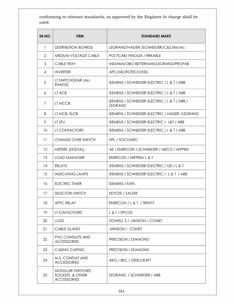
161
conforming to relevant standards, as approved by the Engineer In charge shall be
used.
SR.NO. ITEM STANDARD MAKE
1 DISTRIBUTION BOARDS LEGRAND/HAGER /SCHNEIDER/C&S Electric
2 MEDIUM VOLTAGE CABLE POLYCAB/ FINOLEX / RRKABLE
3 CABLE TRAY INDIANA/OBO BETTERMAN/LEGRAND/PROFAB
4 INVERTER APC/MICROTECH/XSIS
5 LT SWITCHGEAR (ALL RANGE)
SIEMENS / SCHNEIDER ELECTRIC / L & T / ABB
6 LT ACB SIEMENS / SCHNEIDER ELECTRIC / L & T / ABB
7 LT MCCB SIEMENS / SCHNEIDER ELECTRIC / L & T / ABB /
LEGRAND
8 LT MCB, ELCB SIEMENS / SCHNEIDER ELECTRIC / HAGER /LEGRAND
9 LT SFU SIEMENS / SCHNEIDER ELECTRIC / L&T / ABB
10 LT CONTACTORS SIEMENS / SCHNEIDER ELECTRIC / L & T / ABB
11 CHANGE OVER SWITCH HPL / SOCOMEC
12 METERS (DIGITAL) AE / ENERCON / SCHNEIDER / MECO / NIPPEN
13 LOAD MANAGER ENERCON / NIPPEN/ L & T
14 RELAYS SIEMENS / SCHNEIDER ELECTRIC / GE / L & T
15 INDICATING LAMPS SIEMENS / SCHNEIDER ELECTRIC / L & T / ABB
16 ELECTRIC TIMER SIEMENS / EAPL
17 SELECTOR SWITCH KEYCEE / SALZER
18 APFC RELAY ENERCON / L & T / TRINITY
19 LT CAPACITORS L & T / EPCOS
20 LUGS DOWELL’S / JAINSON / COMET
21 CABLE GLAND JAINSON / COMET
22 PVC CONDUITS AND
ACCESSORIES PRECISION / DIAMOND
23 CASING CAPING PRECISION / DIAMOND
24 M.S. CONDUIT AND
ACCESSORIES AKG / BEC / STEELCRAFT
25
MODULAR SWITCHES,
SOCKETS & OTHER ACCESSORIES
LEGRAND / SCHNEIDER / ABB
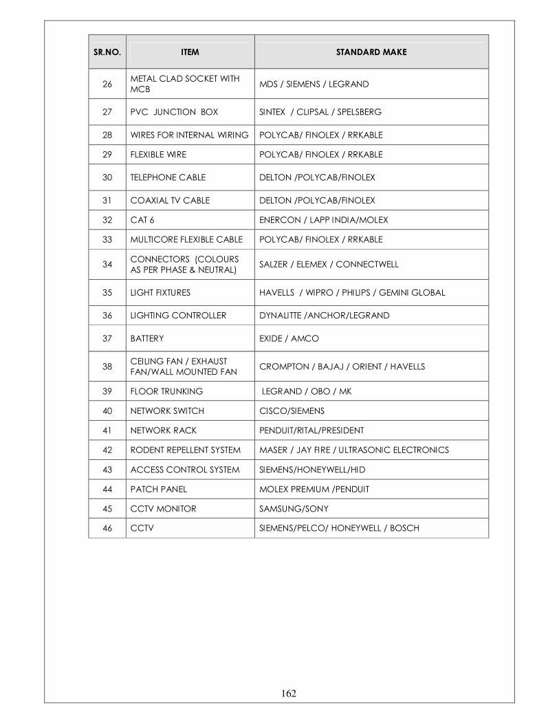
162
SR.NO. ITEM STANDARD MAKE
26 METAL CLAD SOCKET WITH
MCB MDS / SIEMENS / LEGRAND
27 PVC JUNCTION BOX SINTEX / CLIPSAL / SPELSBERG
28 WIRES FOR INTERNAL WIRING POLYCAB/ FINOLEX / RRKABLE
29 FLEXIBLE WIRE POLYCAB/ FINOLEX / RRKABLE
30 TELEPHONE CABLE DELTON /POLYCAB/FINOLEX
31 COAXIAL TV CABLE DELTON /POLYCAB/FINOLEX
32 CAT 6 ENERCON / LAPP INDIA/MOLEX
33 MULTICORE FLEXIBLE CABLE POLYCAB/ FINOLEX / RRKABLE
34 CONNECTORS (COLOURS
AS PER PHASE & NEUTRAL) SALZER / ELEMEX / CONNECTWELL
35 LIGHT FIXTURES HAVELLS / WIPRO / PHILIPS / GEMINI GLOBAL
36 LIGHTING CONTROLLER DYNALITTE /ANCHOR/LEGRAND
37 BATTERY EXIDE / AMCO
38 CEILING FAN / EXHAUST
FAN/WALL MOUNTED FAN CROMPTON / BAJAJ / ORIENT / HAVELLS
39 FLOOR TRUNKING LEGRAND / OBO / MK
40 NETWORK SWITCH CISCO/SIEMENS
41 NETWORK RACK PENDUIT/RITAL/PRESIDENT
42 RODENT REPELLENT SYSTEM MASER / JAY FIRE / ULTRASONIC ELECTRONICS
43 ACCESS CONTROL SYSTEM SIEMENS/HONEYWELL/HID
44 PATCH PANEL MOLEX PREMIUM /PENDUIT
45 CCTV MONITOR SAMSUNG/SONY
46 CCTV SIEMENS/PELCO/ HONEYWELL / BOSCH