TECHNICAL DATA - Firstflex
28
TECHNICAL DATA P: (09) 264 1000 | www.firstflex.co.nz Ingress Protection (IP) Rating .......... 288 Current Carrying Comparison .......... 289 Voltage Drop.................................... 289 Motor Currents ................................ 290 Conductor DC Resistance ................ 290 Cable Compounds ........................... 291 AWG to mm 2 Comparison and Resistance ................................ 291 Conductor Resistance ...................... 292 Strand Make-Up ............................... 293 Current carrying capacities Table 1.............................................. 294 Table 2 ............................................. 295 Table 3 ............................................. 296 Table 4 ............................................. 297 Table 5 ............................................. 298 Table 6 ............................................. 299 Table 7 ............................................. 300 Table 8 ............................................. 301 Stranded Conductor Information ..... 301 Core Colour Information .................. 302 Data, audio & instrumentation cables Cross References ............................. 304 Reference Standards ....................... 308 Glossary Of Terms ............................ 309 Chemical Rating Chart Organic Substances ......................... 310 Inorganic Substances ....................... 311 Cable Sizing Charts & Information ....312 Cable Sizing Chart: 12 Volt ................313 Cable Sizing Chart: 24 Volt ...............314
-
Upload
khangminh22 -
Category
Documents
-
view
16 -
download
0
Transcript of TECHNICAL DATA - Firstflex

TECHNICAL DATA
P: (09) 264 1000 | www.firstflex.co.nz
Ingress Protection (IP) Rating ..........288
Current Carrying Comparison ..........289
Voltage Drop ....................................289
Motor Currents ................................290
Conductor DC Resistance ................290
Cable Compounds ........................... 291
AWG to mm2 Comparison and Resistance ................................ 291
Conductor Resistance ......................292
Strand Make-Up ...............................293
Current carrying capacities
Table 1 ..............................................294
Table 2 .............................................295
Table 3 .............................................296
Table 4 ............................................. 297
Table 5 .............................................298
Table 6 .............................................299
Table 7 .............................................300
Table 8 ............................................. 301
Stranded Conductor Information ..... 301
Core Colour Information ..................302
Data, audio & instrumentation cables
Cross References .............................304
Reference Standards .......................308
Glossary Of Terms ............................309
Chemical Rating Chart
Organic Substances ......................... 310
Inorganic Substances ....................... 311
Cable Sizing Charts & Information ....312
Cable Sizing Chart: 12 Volt ................313
Cable Sizing Chart: 24 Volt ...............314

TECHNICAL DATA
TECHNICAL DATA
288 P: (09) 264 1000 | F: (09) 264 1001 | [email protected] | www.firstflex.co.nz
Firstflex has taken every precaution to ensure accurate information in this catalogue, but accept no liability for any errors or omissions. Firstflex reserves the right to modify specifications at any time.
First Characteristic Numeral Second Characteristic Numeral
Example IP Rating
Ingress Protection (IP) Rating
Protection against solid objects Effective againstIP Level Example Tests
0 No protection. Non-protected.
1 50Full penetration of 50mm
diameter of sphere not allowed. Contact with
hazardous parts not permitted.
Back of hand.
2 12.5
Full penetration of 12.5mm diameter of sphere not
allowed. The jointed test finger shall have adequate clearance
from hazardous parts.
Finger.
3 The access probe of 2.5mm diameter shall not penetrate. Tool.
4 The access probe of 1mm diameter shall not penetrate. Wire.
5Limited ingress of dust
permitted (no harmful deposit). Dust protected.
Wire.
6 No ingress of dust. Dust tight. Wire.
Protection against solid objects Effective againstIP Level Example Tests
0 No protection. Non-protected.
1 Protection against vertically falling drops of water.
Vertically dripping.
215°
Protected against vertically falling drops of water with
enclosure tilted 15º from thevertical.
Dripping up to 15º from the vertical.
330°
Protected against sprays 60º from the vertical.
Limited spraying.
4Protected against water
splashed from all directions - limited ingress permitted.
Splashing from all
directions
5Protected against low pressure jets of water from all directions
- limited ingress permitted.
Hosing jets from all
directions.
6Protected against strong jets of water, eg for use on ship decks
- limited ingress permitted.
Strong hosing jets from all directions.
7 1m
150mm Protected against the effects of immersion between 150mm
and 1m.
Temporaryimmersion.
8m Protected against continuous
submersion at a specified depth.
Continuousimmersion.
IP 6 5“Ingress Protection”
First Digit: Solids Protection
Second Digit: Solids Protection
TECHNICAL DATA
TECH
NICA
L DAT
A
289P: (09) 264 1000 | F: (09) 264 1001 | [email protected] | www.firstflex.co.nz
Firstflex has taken every precaution to ensure accurate information in this catalogue, but accept no liability for any errors or omissions. Firstflex reserves the right to modify specifications at any time.
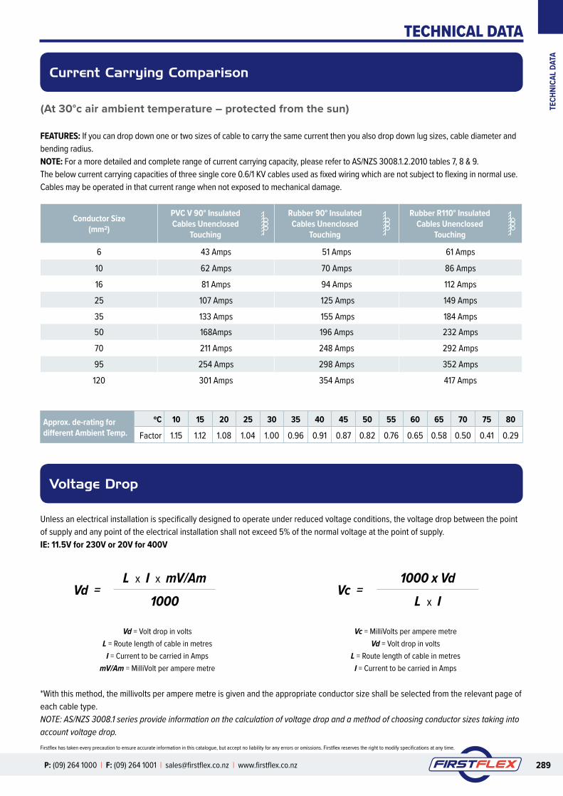
(At 30°c air ambient temperature – protected from the sun)
Current Carrying Comparison
Voltage Drop
Conductor Size (mm2)
PVC V 90° Insulated Cables Unenclosed
Touching
Rubber 90° Insulated Cables Unenclosed
Touching
Rubber R110° Insulated Cables Unenclosed
Touching
6 43 Amps 51 Amps 61 Amps
10 62 Amps 70 Amps 86 Amps
16 81 Amps 94 Amps 112 Amps
25 107 Amps 125 Amps 149 Amps
35 133 Amps 155 Amps 184 Amps50 168Amps 196 Amps 232 Amps
70 211 Amps 248 Amps 292 Amps
95 254 Amps 298 Amps 352 Amps
120 301 Amps 354 Amps 417 Amps
Approx. de-rating for different Ambient Temp.
ºC 10 15 20 25 30 35 40 45 50 55 60 65 70 75 80
Factor 1.15 1.12 1.08 1.04 1.00 0.96 0.91 0.87 0.82 0.76 0.65 0.58 0.50 0.41 0.29
FEATURES: If you can drop down one or two sizes of cable to carry the same current then you also drop down lug sizes, cable diameter and bending radius.NOTE: For a more detailed and complete range of current carrying capacity, please refer to AS/NZS 3008.1.2.2010 tables 7, 8 & 9.The below current carrying capacities of three single core 0.6/1 KV cables used as fixed wiring which are not subject to flexing in normal use.Cables may be operated in that current range when not exposed to mechanical damage.
Unless an electrical installation is specifically designed to operate under reduced voltage conditions, the voltage drop between the point of supply and any point of the electrical installation shall not exceed 5% of the normal voltage at the point of supply.IE: 11.5V for 230V or 20V for 400V
*With this method, the millivolts per ampere metre is given and the appropriate conductor size shall be selected from the relevant page of each cable type.NOTE: AS/NZS 3008.1 series provide information on the calculation of voltage drop and a method of choosing conductor sizes taking into account voltage drop.
Vd = Volt drop in voltsL = Route length of cable in metres
I = Current to be carried in AmpsmV/Am = MilliVolt per ampere metre
Vc = MilliVolts per ampere metreVd = Volt drop in volts
L = Route length of cable in metresI = Current to be carried in Amps
L x I x mV/Am 1000 x Vd1000 L x I
Vd = Vc =

TECHNICAL DATA
TECHNICAL DATA
290 P: (09) 264 1000 | F: (09) 264 1001 | [email protected] | www.firstflex.co.nz
Firstflex has taken every precaution to ensure accurate information in this catalogue, but accept no liability for any errors or omissions. Firstflex reserves the right to modify specifications at any time.
Three Phase AC Motors (415V AC)
Motor Currents Conductor DC Resistance
Approximate current per phase for AC Motors at full load, assuming average efficiency and power factor.
Approximate current per phase for AC Motors at full load, assuming average efficiency and power factor.
Power (kW)
Horse Power (HP)
Full Load Current (A)
0.75 1.0 1.91.1 1.5 2.51.5 2.0 3.52.2 3.0 5.03.0 4.0 6.54.0 5.5 8.05.5 7.5 117.5 10 1411 15 2115 20 28
18.5 25 3522 30 4030 40 5537 50 6645 60 8055 75 10275 100 13590 120 165110 150 200132 180 230150 200 260160 220 280185 250 325200 270 350220 300 385250 340 450315 430 545355 480 580400 545 650450 610 740500 680 820
Normal Cross-
Sectional Area
Maximum Resistance of Conductor @20ºC
(mm2)Plain
Copper(Ω/km)
Tinned Copper(Ω/km)
0.5 39.0 40.10.75 26.0 26.7
1 19.5 20.01.5 13.3 13.72.5 7.98 8.214 4.95 5.096 3.30 3.3910 1.91 1.9516 1.21 1.2425 0.78 0.79535 0.554 0.56550 0.386 0.39370 0.272 0.27795 0.206 0.210120 0.161 0.164150 0.129 0.132185 0.106 0.108240 0.0801 0.0817300 0.0641 0.0654400 0.0486 0.0495500 0.0384 0.0391630 0.0287 0.0292
Ambient Temp (ºC)
Correction Factor
20 1.00025 1.02030 1.03935 1.05940 1.07945 1.09850 1.11855 1.13860 1.15765 1.17770 1.19675 1.21680 1.23685 1.23590 1.275
NOTETo calculate the DC Resistance of copper conductors for a given temperature (ºC), the resistance factor at 20ºC, as detailed must be multiplied by the appropriate correction factor above.

TECHNICAL DATA
TECH
NICA
L DAT
A
291P: (09) 264 1000 | F: (09) 264 1001 | [email protected] | www.firstflex.co.nz
Firstflex has taken every precaution to ensure accurate information in this catalogue, but accept no liability for any errors or omissions. Firstflex reserves the right to modify specifications at any time.
Cable CompoundsAWG to mm2 Comparison and Resistance
These cable compounds are the base compounds. To improve performance Firstflex uses additives to create blends that achieve better field performance.
CPE Chlorinated PolyethyleneCSP Chlorosulphonated PolyethyleneEPDM Ethylene Propylene Dien Monomer Terpolymer
RubberEPR Ethylene Propylene Copolymer RubberEVA Ethylene Vinylacetate CopolymerHDPE High Density Thermoplastic PolyethyleneNBR (Acrylo) Nitrial Butadienne RubberPCP Polychloroprene (Neoprene)PE PolyethylenePETP PolyesterPP PolypropylenePUR PolyurethanePVC Polyvinyl ChlorideSER Special Elastomer RubberSER-G2 Special Elastomer Rubber G2SER-HF Special Elastomer Rubber LshfSHF PolyolefineSiR SiliconeSPVC Special Polyvinyl Chloride (Oil & Chemical Resistant)TPE Thermoplastic ElastomerTRP Thermoplastic Polyester ElastomerX-HF Cross Linked Halogen-Free Polyolefin CompoundXLPE Cross Linked Polyethylene
NOTE: The diameters and cross-section areas indicated above are the effective figures were the conductors a solid rod.The resistances indicated are according to the International Annealed Copper Standard (IACS) at 20°C.For most Oxygen Free Copper (OFC) types the resistances indicated are accurate to a few percent.
AWG mm2 RESISTANCE (ohm/m)4 / 0 = 0000 107.0 0.0001613 / 0 = 000 85.0 0.0002032 / 0 = 00 67.4 0.0002561 / 0 = 0 53.5 0.000323
1 42.4 0.0004072 33.6 0.0005133 26.7 0.0006474 21.1 0.0008155 16.8 0.001036 13.3 0.001307 10.5 0.001638 8.36 0.002069 6.63 0.0026010 5.26 0.0032811 4.17 0.0041312 3.31 0.0052113 2.62 0.0065714 2.08 0.0082915 1.65 0.010416 1.31 0.013217 1.04 0.016618 0.823 0.021019 0.653 0.026420 0.518 0.033321 0.410 0.042022 0.326 0.053023 0.258 0.066824 0.205 0.084225 0.162 0.106026 0.129 0.134027 0.102 0.16928 0.0810 0.21329 0.0642 0.26830 0.0509 0.33931 0.0404 0.42732 0.0320 0.53833 0.0254 0.67934 0.0201 0.85635 0.0160 1.0836 0.0127 1.3637 0.0100 1.7238 0.00797 2.1639 0.00632 2.7340 0.00501 3.44

TECHNICAL DATA
TECHNICAL DATA
292 P: (09) 264 1000 | F: (09) 264 1001 | [email protected] | www.firstflex.co.nz
Firstflex has taken every precaution to ensure accurate information in this catalogue, but accept no liability for any errors or omissions. Firstflex reserves the right to modify specifications at any time.
Conductor Resistance
Extracted from DIN VDE 0295, IEC 60228 and HD 383.Maximum resistance of bunched conductors @ 20°C.
The values are extracted from DIN VDE 0295 (equivalent with IEC 60228 and HD 383), according to cross-sections and conductor classes to give the maximum resistance value of bunched conductors at 20°C.
Cross Section (mm²)
Copper Conductor Plain Wires ( Ω/km )
Copper Conductor Tinned Wires ( Ω/km )
Stranding Class 1 and 2
Stranding Class 5 and 6
Stranding Class 1 and 2
Stranding Class 5 and 6
0.05 - 380 - 392 0.08 - 237 - 244 0.11 - 170 - 175 0.12 - 150 - 155 0.14 - 134 - 138 0.22 - 96 - 99 0.25 - 76 - 79 0.34 - 53 - 56 0.50 36.0 39 36.7 40.1 0.75 24.5 26 24.8 26.7 1.0 18.1 19.5 18.2 20.0 1.5 12.1 13.3 12.2 13.7 2.5 7.41 7.98 7.56 8.21 4 4.61 4.95 4.70 5.09 6 3.08 3.30 3.11 3.39 10 1.83 1.91 1.84 1.95 16 1.15 1.21 1.16 1.24 25 0.727 0.780 0.734 0.795 35 0.524 0.554 0.529 0.565 50 0.387 0.386 0.391 0.393 70 0.268 0.272 0.270 0.277 95 0.193 0.206 0.195 0.210 120 0.153 0.161 0.154 0.164 150 0.124 0.129 0.126 0.132 185 0.0991 0.106 0.100 0.108 240 0.0754 0.0801 0.0762 0.0817 300 0.0601 0.0641 0.0607 0.0654 400 0.0470 0.0486 0.0475 0.0495 500 0.0366 0.0384 0.0369 0.0391 630 0.0283 0.0287 0.0289 0.0292 500 680 820

TECHNICAL DATA
TECH
NICA
L DAT
A
293P: (09) 264 1000 | F: (09) 264 1001 | [email protected] | www.firstflex.co.nz
Firstflex has taken every precaution to ensure accurate information in this catalogue, but accept no liability for any errors or omissions. Firstflex reserves the right to modify specifications at any time.
Strand Make-Up
According to DIN VDE 0295, IEC 60228 and HD 383.
Cross Section (mm²)
STRANDED WIRES
MULTI STRANDED WIRES
FINE WIRES
EXTRA FINE WIRES
Class 2 DIN VDE 0295
Class 5 DIN VDE 0295
Class 6 DIN VDE 0295
Column 1 Column 2 Column 3 Column 4 Column 5 Column 6 Column 7
No. wires x diameter of single wires
No. wires x diameter of single wires
No. wires x diameter of single wires
No. wires x diameter of single wires
No. wires x diameter of single wires
No. wires x diameter of single wires
No. wires x diameter of single wires
0.05 14 x 0.07 26 x 0.05
0.08 40 x 0.05
0.09 24 x 0.07
0.14 18 x 0.10 18 x 0.10 18 x 0.10 36 x 0.07 72 x 0.05
0.25 14 x 0.15 32 x 0.10 32 x 0.10 65 x 0.07 128 x 0.05
0.34 7 x 0.25 19 x 0.15 42 x 0.10 42 x 0.10 88 x 0.07 174 x 0.05
0.38 7 x 0.27 12 x 0.20 21 x 0.15 48 x 0.10 100 x 0.07 194 x 0.05
0.50 7 x 0.30 7 x 0.30 16 x 0.20 28 x 0.15 64 x 0.10 131 x 0.07 256 x 0.05
0.75 7 x 0.37 7 x 0.37 24 x 0.20 42 x 0.15 96 x 0.10 195 x 0.07 384 x 0.05
1.0 7 x 0.43 7 x 0.43 32 x 0.20 56 x 0.15 128 x 0.10 260 x 0.07 512 x 0.05
1.5 7 x 0.52 7 x 0.52 30 x 0.25 84 x 0.15 192 x 0.10 392 x 0.07 768 x 0.05
2.5 7 x 0.67 19 x 0.41 50 x 0.25 140 x 0.15 320 x 0.10 651 x 0.07 1280 x 0.05
4 7 x 0.85 19 x 0.52 56 x 0.30 224 x 0.15 512 x 0.10 1040 x 0.07
6 7 x 1.05 19 x 0.64 84 x 0.30 192 x 0.20 768 x 0.10 1560 x 0.07
10 7 x 1.35 49 x 0.51 80 x 0.40 320 x 0.20 1280 x 0.10 2600 x 0.07
16 7 x 1.70 49 x 0.65 128 x 0.40 512 x 0.20 2048 x 0.10
25 7 x 2.13 84 x 0.62 200 x 0.40 800 x 0.20 3200 x 0.10
35 7 x 2.52 133 x 0.58 280 x 0.40 1120 x 0.20
50 19 x 1.83 133 x 0.69 400 x 0.40 705 x 0.30
70 19 x 2.17 189 x 0.69 356 x 0.50 990 x 0.30
95 19 x 2.52 259 x 0.69 485 x 0.50 1340 x 0.30
120 37 x 2.03 336 x 0.67 614 x 0.50 1690 x 0.30
150 37 x 2.27 392 x 0.69 765 x 0.50 2123 x 0.30
185 37 x 2.52 494 x 0.69 944 x 0.50 1470 x 0.40
240 61 x 2.24 627 x 0.70 1225 x 0.50 1905 x 0.40
300 61 x 2.50 790 x 0.70 1530 x 0.50 2385 x 0.40
400 61 x 2.89 2035 x 0.50
500 61 x 3.23 1768 x 0.60
630 91 x 2.97 2228 x 0.60
All values approximate only – The number of individual wires without obligation

TECHNICAL DATA
TECHNICAL DATA
294 P: (09) 264 1000 | F: (09) 264 1001 | [email protected] | www.firstflex.co.nz
Firstflex has taken every precaution to ensure accurate information in this catalogue, but accept no liability for any errors or omissions. Firstflex reserves the right to modify specifications at any time.
Table 1
Current carrying capacities of three single core 0.6/1 kV unscreened flexible cables with V-75 or V-90 insulation
Conductor Size
Current carrying capacity, A
Unenclosed Enclosed
Spaced Spaced from surface Touching Exposed to sun Wiring enclosed in air
mm2 Cu Cu Cu Cu Cu1 18 16 15 9 15
1.5 24 21 19 11 172.5 31 27 25 15 234 42 36 34 19 316 54 47 43 24 3910 75 65 62 33 5216 100 86 81 43 7025 133 114 107 56 8935 165 143 133 67 11250 209 179 168 83 13770 263 226 211 101 17395 318 272 254 119 203120 377 324 301 137 243150 437 374 348 154 275185 499 429 399 170 316240 602 514 479 196 383300 694 592 552 218 432400 837 708 659 246 526500 975 817 762 270 593630 1153 950 884 299 675
These ratings are based on 30°C ambient air temperature and 15°C ambient soil temperature. Maximum conductor temperature 90°C.Copyright Standard New Zealand 2011. This data is based on content from Table 7, AS/NZS 3008.1.2:2010. For other conditions refer to the Standard for full details.
Approx. de-rating for different Ambient Temp.
ºC 10 15 20 25 30 35 40 45 50 55 60 65 70 75 80
Factor 1.15 1.12 1.08 1.04 1.00 0.96 0.91 0.87 0.82 0.76 0.65 0.58 0.50 0.41 0.29
Copyright Standards New Zealand 2011. Selected tables from AS/NZS 3008.1.2:2010 Electrical installations - Selection of cables - Cables for alternating voltages up to and including 0.6/1 kV - Typical New Zealand conditions have been reproduced with permission from Standards New Zealand under Licence. Please refer to Standards New Zealand for the complete Standard available for purchase at www.standards.co.nz.

TECHNICAL DATA
TECH
NICA
L DAT
A
295P: (09) 264 1000 | F: (09) 264 1001 | [email protected] | www.firstflex.co.nz
Firstflex has taken every precaution to ensure accurate information in this catalogue, but accept no liability for any errors or omissions. Firstflex reserves the right to modify specifications at any time.
Table 2
Current carrying capacities of three single core 0.6/1 kV unscreened flexible cables with R-90 or X-90 insulation
Conductor Size
Current carrying capacity, A
Unenclosed Enclosed
Spaced Spaced from surface Touching Exposed to sun Wiring enclosed in air
mm2 Cu Cu Cu Cu Cu1 22 19 18 14 17
1.5 28 24 22 18 212.5 36 32 30 23 264 50 42 40 30 346 63 54 51 37 4510 88 76 70 53 6116 117 100 94 69 8025 156 133 125 91 10335 195 166 155 113 13050 245 210 196 141 15870 311 265 248 177 20195 375 319 298 211 235120 447 381 354 249 282150 517 440 409 286 320185 594 505 470 326 367240 716 608 565 387 430300 827 701 650 442 504400 1000 840 780 525 586500 1168 972 903 601 693630 1382 1133 1052 693 791
These ratings are based on 30°C ambient air temperature and 15°C ambient soil temperature. Maximum conductor temperature 90°C.Copyright Standard New Zealand 2011. This data is based on content from Table 8, AS/NZS 3008.1.2:2010. For other conditions refer to the Standard for full details.
Approx. de-rating for different Ambient Temp.
ºC 10 15 20 25 30 35 40 45 50 55 60 65 70 75 80
Factor 1.15 1.12 1.08 1.04 1.00 0.96 0.91 0.87 0.82 0.76 0.65 0.58 0.50 0.41 0.29
Copyright Standards New Zealand 2011. Selected tables from AS/NZS 3008.1.2:2010 Electrical installations - Selection of cables - Cables for alternating voltages up to and including 0.6/1 kV - Typical New Zealand conditions have been reproduced with permission from Standards New Zealand under Licence. Please refer to Standards New Zealand for the complete Standard available for purchase at www.standards.co.nz.

TECHNICAL DATA
TECHNICAL DATA
296 P: (09) 264 1000 | F: (09) 264 1001 | [email protected] | www.firstflex.co.nz
Firstflex has taken every precaution to ensure accurate information in this catalogue, but accept no liability for any errors or omissions. Firstflex reserves the right to modify specifications at any time.
Table 3
Current carrying capacities of three single core 0.6/1 kV or 1.9/3.3kV unscreened flexible cables with R-110 or X-110 insulation
Conductor Size
Current carrying capacity, A
Unenclosed Enclosed
Spaced Spaced from surface Touching Exposed to sun Wiring enclosed in air
mm2 Cu Cu Cu Cu Cu1 27 24 22 19 19
1.5 33 29 28 24 252.5 45 39 36 31 334 59 51 48 41 436 75 65 61 51 5410 106 91 86 72 7516 139 120 112 94 9725 185 159 149 124 12935 229 197 184 153 15850 289 249 232 192 20370 364 312 292 240 25095 439 378 352 288 296120 521 447 417 339 354150 601 516 482 391 404185 689 592 552 446 469240 829 712 663 534 576300 958 820 764 612 655400 1155 982 915 730 810500 1348 1138 1059 841 924630 1598 1327 1235 977 1063
These ratings are based on 30°C ambient air temperature and 15°C ambient soil temperature. Maximum conductor temperature 110°C.Copyright Standard New Zealand 2011. This data is based on content from Table 9, AS/NZS 3008.1.2:2010. For other conditions refer to the Standard for full details.
Approx. de-rating for different Ambient Temp.
ºC 10 15 20 25 30 35 40 45 50 55 60 65 70 75 80
Factor 1.15 1.12 1.08 1.04 1.00 0.96 0.91 0.87 0.82 0.76 0.65 0.58 0.50 0.41 0.29
Copyright Standards New Zealand 2011. Selected tables from AS/NZS 3008.1.2:2010 Electrical installations - Selection of cables - Cables for alternating voltages up to and including 0.6/1 kV - Typical New Zealand conditions have been reproduced with permission from Standards New Zealand under Licence. Please refer to Standards New Zealand for the complete Standard available for purchase at www.standards.co.nz.

TECHNICAL DATA
TECH
NICA
L DAT
A
297P: (09) 264 1000 | F: (09) 264 1001 | [email protected] | www.firstflex.co.nz
Firstflex has taken every precaution to ensure accurate information in this catalogue, but accept no liability for any errors or omissions. Firstflex reserves the right to modify specifications at any time.
Table 4
Current carrying capacities of two core 0.6/1kV insulated and sheathed (including copper braid screened) flexible cables with or without earth conductor, with V-75 or V-90 insulation
Conductor Size
Current carrying capacity, A
Unenclosed Enclosed
Spaced Touching Exposed to sun Wiring enclosed in air
mm2 Cu Cu Cu Cu1 18 17 14 15
1.5 23 21 16 192.5 30 29 22 264 40 38 30 336 51 48 36 4310 72 67 51 5816 95 89 67 7825 125 119 88 9935 156 146 107 12450 195 184 133 15370 245 230 165 19395 293 275 194 226120 347 325 227 269150 397 372 257 304185 450 422 287 348240 536 500 335 420300 612 572 377 473400 725 676 438 570500 830 773 491 643
These ratings are based on 30°C ambient air temperature and 15°C ambient soil temperature. Maximum conductor temperature 90°C.Copyright Standard New Zealand 2011. This data is based on content from Table 10, AS/NZS 3008.1.2:2010. For other conditions refer to the Standard for full details.
Approx. de-rating for different Ambient Temp.
ºC 10 15 20 25 30 35 40 45 50 55 60 65 70 75 80
Factor 1.15 1.12 1.08 1.04 1.00 0.96 0.91 0.87 0.82 0.76 0.65 0.58 0.50 0.41 0.29
Copyright Standards New Zealand 2011. Selected tables from AS/NZS 3008.1.2:2010 Electrical installations - Selection of cables - Cables for alternating voltages up to and including 0.6/1 kV - Typical New Zealand conditions have been reproduced with permission from Standards New Zealand under Licence. Please refer to Standards New Zealand for the complete Standard available for purchase at www.standards.co.nz.

TECHNICAL DATA
TECHNICAL DATA
298 P: (09) 264 1000 | F: (09) 264 1001 | [email protected] | www.firstflex.co.nz
Firstflex has taken every precaution to ensure accurate information in this catalogue, but accept no liability for any errors or omissions. Firstflex reserves the right to modify specifications at any time.
Table 5
Current carrying capacities of two core 0.6/1kV insulated and sheathed (including copper braid screened) flexible cables with or without earth conductor, with R-90 or X-90 insulation
Conductor Size
Current carrying capacity, A
Unenclosed Enclosed
Spaced Touching Exposed to sun Wiring enclosed in air
mm2 Cu Cu Cu Cu1 21 20 18 18
1.5 26 25 22 222.5 35 33 29 304 47 44 39 396 61 56 48 4810 86 79 68 6816 113 106 90 8825 150 141 119 11735 186 174 147 14250 234 219 184 17970 296 276 230 22895 354 330 273 266120 419 391 321 318150 482 449 366 361185 549 510 415 413240 656 609 491 483300 750 696 558 562400 892 826 657 655500 1025 948 747 769
These ratings are based on 30°C ambient air temperature and 15°C ambient soil temperature. Maximum conductor temperature 90°C.Copyright Standard New Zealand 2011. This data is based on content from Table 11, AS/NZS 3008.1.2:2010. For other conditions refer to the Standard for full details.
Approx. de-rating for different Ambient Temp.
ºC 10 15 20 25 30 35 40 45 50 55 60 65 70 75 80
Factor 1.15 1.12 1.08 1.04 1.00 0.96 0.91 0.87 0.82 0.76 0.65 0.58 0.50 0.41 0.29
Copyright Standards New Zealand 2011. Selected tables from AS/NZS 3008.1.2:2010 Electrical installations - Selection of cables - Cables for alternating voltages up to and including 0.6/1 kV - Typical New Zealand conditions have been reproduced with permission from Standards New Zealand under Licence. Please refer to Standards New Zealand for the complete Standard available for purchase at www.standards.co.nz.

TECHNICAL DATA
TECH
NICA
L DAT
A
299P: (09) 264 1000 | F: (09) 264 1001 | [email protected] | www.firstflex.co.nz
Firstflex has taken every precaution to ensure accurate information in this catalogue, but accept no liability for any errors or omissions. Firstflex reserves the right to modify specifications at any time.
Table 6
Current carrying capacities of three core and four core 0.6/1kV insulated and sheathed (including copper braid screened) flexible cables with or without earth conductor, with V-75 or V-90 insulation
Conductor Size
Current carrying capacity, A
Unenclosed Enclosed
Spaced Touching Exposed to sun Wiring enclosed in air
mm2 Cu Cu Cu Cu1 15 15 11 13
1.5 19 18 14 162.5 25 24 18 224 34 32 25 276 43 41 32 3610 62 58 43 4916 81 76 57 6525 107 101 74 8335 133 125 91 10550 169 157 114 12870 211 197 140 16295 253 236 165 196120 299 278 193 227150 343 319 219 261185 390 363 245 352240 464 431 286 -300 529 490 321 -400 626 579 372 -500 715 661 416 -
These ratings are based on 30°C ambient air temperature and 15°C ambient soil temperature. Maximum conductor temperature 90°C.Copyright Standard New Zealand 2011. This data is based on content from Table 13, AS/NZS 3008.1.2:2010. For other conditions refer to the Standard for full details.
Approx. de-rating for different Ambient Temp.
ºC 10 15 20 25 30 35 40 45 50 55 60 65 70 75 80
Factor 1.15 1.12 1.08 1.04 1.00 0.96 0.91 0.87 0.82 0.76 0.65 0.58 0.50 0.41 0.29
Copyright Standards New Zealand 2011. Selected tables from AS/NZS 3008.1.2:2010 Electrical installations - Selection of cables - Cables for alternating voltages up to and including 0.6/1 kV - Typical New Zealand conditions have been reproduced with permission from Standards New Zealand under Licence. Please refer to Standards New Zealand for the complete Standard available for purchase at www.standards.co.nz.

TECHNICAL DATA
TECHNICAL DATA
300 P: (09) 264 1000 | F: (09) 264 1001 | [email protected] | www.firstflex.co.nz
Firstflex has taken every precaution to ensure accurate information in this catalogue, but accept no liability for any errors or omissions. Firstflex reserves the right to modify specifications at any time.
Table 7
Current carrying capacities of three core and four core 0.6/1kV insulated and sheathed (including copper braid screened) flexible cables with or without earth conductor, with R-90 or X-90 insulation
Conductor Size
Current carrying capacity, A
Unenclosed Enclosed
Spaced Touching Exposed to sun Wiring enclosed in air
mm2 Cu Cu Cu Cu1 18 17 14 15
1.5 22 21 19 192.5 30 29 24 254 40 37 32 326 51 47 41 4110 73 67 57 5716 96 89 76 7425 128 119 101 9835 158 149 124 12250 200 187 156 15070 253 235 195 19095 303 282 232 222120 360 333 273 266150 413 383 311 301185 471 436 352 345240 562 519 417 417300 642 593 473 -400 761 702 554 -500 873 803 630 -
These ratings are based on 30°C ambient air temperature and 15°C ambient soil temperature. Maximum conductor temperature 90°C.Copyright Standard New Zealand 2011. This data is based on content from Table 14, AS/NZS 3008.1.2:2010. For other conditions refer to the Standard for full details.
Approx. de-rating for different Ambient Temp.
ºC 10 15 20 25 30 35 40 45 50 55 60 65 70 75 80
Factor 1.15 1.12 1.08 1.04 1.00 0.96 0.91 0.87 0.82 0.76 0.65 0.58 0.50 0.41 0.29
Copyright Standards New Zealand 2011. Selected tables from AS/NZS 3008.1.2:2010 Electrical installations - Selection of cables - Cables for alternating voltages up to and including 0.6/1 kV - Typical New Zealand conditions have been reproduced with permission from Standards New Zealand under Licence. Please refer to Standards New Zealand for the complete Standard available for purchase at www.standards.co.nz.

TECHNICAL DATA
TECH
NICA
L DAT
A
301P: (09) 264 1000 | F: (09) 264 1001 | [email protected] | www.firstflex.co.nz
Firstflex has taken every precaution to ensure accurate information in this catalogue, but accept no liability for any errors or omissions. Firstflex reserves the right to modify specifications at any time.
Guidelines for current carrying capabilitiesof 300/500v V-75 or V-90 flexible cords
De-rating factors for multicore cables up to 10mm²
Table 8
Cross Section mm2
Current carrying capacity (Amps) @ 25ºC ambient air
temperature0.5 30.75 7.51.0 101.5 162.5 204.0 25
Number of current carrying cores De-rating factor
5 0.757 0.6510 0.5514 0.5019 0.4524 0.4040 0.3561 0.30
Data, audio & instrumentation cables:Stranded conductor information
AWG Size
Conductor Stranding
Size (mm2)
Maximum resistance ohms / km 20°C. Bare copper wire
Maximum resistance ohms / km 20°C.
Tinned copper wire
Approximate current rating
(Amps)28 7/0.12 0.079 235.44 242.34 0.527 21/0.08 0.106 181.75 190.25 0.626 7/0.15
26/0.080.123 0.131
150.75 146.80
155.09 153.17
0.8 0.8
25 14/0.12 0.158 117.77 121.17 0.824 7/0.20 0.219 84.79 87.24 1.422 7/0.25 0.355 54.27 55.83 2.020 7/0.30
10/0.25 16/0.20
0.495 0.507 0.502
37.69 37.99 37.10
38.77 39.10 38.20
3.0 3.0 3.0
18 7/0.40 16/0.25 24/0.20
0.897 0.810 0.754
20.79 23.74 24.73
21.20 24.42 25.45
4.5 4.5 4.5
17 32/0.20 1.005 18.55 19.08 12.016 7/0.50
30/0.251.374 1.470
13.31 12.66
13.56 12.66
16.0 16.0
14 40/0.25 63/0.20
1.963 1.980
9.50 9.42
9.80 9.69
18.0 18.0
13 50/0.25 2.530 7.59 7.82 20.012 63/0.25 3.093 6.03 6.20 22.511 80/0.25 3.930 4.75 4.89 25.010 112/0.25
120/0.255.497 5.890
3.39 3.17
3.50 3.26
32.0 32.0
7 195/0.25 9.570 1.95 2.00 50.0

TECHNICAL DATA
TECHNICAL DATA
302 P: (09) 264 1000 | F: (09) 264 1001 | [email protected] | www.firstflex.co.nz
Firstflex has taken every precaution to ensure accurate information in this catalogue, but accept no liability for any errors or omissions. Firstflex reserves the right to modify specifications at any time.
Data, audio & instrumentation cables:Core colour information
Core No. Colours
1 Red2 Blue3 Green4 Yellow5 White6 Black7 Brown8 Violet9 Orange10 Pink11 Turquoise12 Grey13 Red/Blue14 Green/Red15 Yellow/Red16 White/Red17 Red/Black18 Red/Brown19 Yellow/Blue20 White/Blue21 Blue/Black22 Orange/Blue23 Green/Blue24 Grey/Blue25 Yellow/Green
Core No. Colours
26 White/Green27 Green/Black28 Orange/Green29 Grey/Green30 Yellow/Brown31 White/Brown32 Brown/Black33 Grey/Brown34 Yellow/Violet35 Violet/Black36 White/Violet37 White/Orange38 White/Grey39 White/Black40 Yellow/Grey41 Yellow/Black42 Grey/Orange43 Grey/Red44 Grey/Black45 Orange/Brown46 Orange/Black47 Green/Brown48 Blue/Brown49 Pink/Blue50 Pink/Orange
Chart A:Multiwire Cables

TECHNICAL DATA
TECH
NICA
L DAT
A
303P: (09) 264 1000 | F: (09) 264 1001 | [email protected] | www.firstflex.co.nz
Firstflex has taken every precaution to ensure accurate information in this catalogue, but accept no liability for any errors or omissions. Firstflex reserves the right to modify specifications at any time.
Data, audio & instrumentation cables:Core colour information
Pair No. Wire 1 Wire 2
1 White Blue2 White Orange3 White Green4 White Brown5 White Grey6 Red Blue7 Red Orange8 Red Green9 Red Brown10 Red Grey11 Black Blue12 Black Orange13 Black Green14 Black Brown15 Black Grey16 Yellow Blue17 Yellow Orange18 Yellow Green19 Yellow Brown20 Yellow Grey21 Violet Blue22 Violet Orange23 Violet Green24 Violet Brown25 Violet Grey26 Pink Blue27 Pink Orange28 Pink Green29 Pink Brown30 Pink Grey
Pair No. Wire 1 Wire 2
1 Red Blue2 Green Yellow3 White Black4 Brown Violet5 Orange Pink6 Turquoise Grey7 Black Orange8 Red White9 Red Green10 Red Black11 Red Yellow12 Red Brown13 Red Orange14 Green White15 Green Blue16 Green Black17 Green Brown18 Green Orange19 White Blue20 White Yellow21 White Brown22 White Orange23 Blue Yellow24 Blue Brown25 Blue Orange
Chart B:Multipair Cables
Chart C:Multipair Cables (FT95)

TECHNICAL DATA
TECHNICAL DATA
304 P: (09) 264 1000 | F: (09) 264 1001 | [email protected] | www.firstflex.co.nz
Firstflex has taken every precaution to ensure accurate information in this catalogue, but accept no liability for any errors or omissions. Firstflex reserves the right to modify specifications at any time.
Data, audio & instrumentation cables:Cross reference to nearest equivalent
FT20-CS SERIES
FT2001CS JD1PS B2001CS B8641
FT2002CS JD2PS B2002CS B1419A
FT2003CS JD3PS - B1420A
FT2004CS JD4PS B2004CS B1421A
FT2005CS - - -
FT2006CS - B2006CS B1423A
FT2008CS - B2008CS -
FT2010CS - B2010CS -
FT2012CS - B2012CS B1424A
FT2018CS - B2018CS -
FT2025CS - B2025CS -
FT20-ESCS SERIES
FT2002ESCS - B2002ESCS -
FT2003ESCS - - -
FT2004ESCS - B2004ESCS -
FT2005ESCS - - -
FT2006ESCS - B2006ESCS -
FT2008ESCS - B2008ESCS -
FT2010ESCS - B2010ESCS -
FT2012ESCS - B2012ESCS -
FT2018ESCS - B2016ESCS -
FT2025ESCS - B2020ESCS -
FT95-CS SERIES
FT9501CS - B9501CS B9501
FT9502CS - B9502CS B9502
FT9503CS - B9503CS B9503
FT9504CS - B9504CS B9504
FT9506CS - B9506CS B9506
FT9509CS - B9509CS -
FT9512CS - B9512CS -
FT9518CS - B9518CS -
FT9525CS - B9825CS B9525
FT50/55-CS SERIES
FT5001CS IEC 183AA001 B5001CS B1033B
FT5002CS IEC 183AA002 B5002CS B3016B
FT5004CS IEC 183AA004 B5004CS B1056B
FIRSTFLEX OLEX GENERAL MASER FIRSTFLEX OLEX GENERAL MASER
FT5006CS IEC 183AA006 B5006CS B5006B
FT5008CS IEC 183AA008 B5008CS B1057B
FT5010CS IEC 183AA010 B5010CS B5010B
FT5012CS IEC 183AA012 B5012CS B1058B
FT5016CS IEC 183AA016 B5016CS B1059B
FT5020CS IEC 183AA020 B5020CS B5020B
FT5024CS IEC 183AA024 B5024CS B1060B
FT5036CS IEC 183AA036 B5036CS B1061B
FT5102ES IEB 184AA001 B5102ES B1030B
FT5103ES IEB 184AA001 B5103ES B1031B
FT5502CS IEC 184AA002 B5502CS B3043B
FT5504CS IEC 184AA004 B5504CS B1484B
FT5506CS IEC 184AA006 B5506CS -
FT5508CS IEC 184AA008 B5508CS B1485B
FT5510CS IEC 184AA010 B5510CS -
FT5512CS IEC 184AA012 B5512CS B1486B
FT5516CS IEC 184AA016 B5516CS B3050B
FT5520CS IEC 184AA024 B5524CS B1489B
FT5536CS IEC 184AA036 B5536CS -
FT50/55-ESCS SERIES
FT5002ESCS IED 183AA001 B5002ESCS B1075B
FT5004ESCS IED 183AA004 B5004ESCS B1076B
FT5006ESCS IED 183AA006 B5006ESCS -
FT5008ESCS IED 183AA008 B5008ESCS B1077B
FT5010ESCS IED 183AA010 B5010ESCS -
FT5012ESCS IED 183AA012 B5012ESCS B1078B
FT5016ESCS IED 183AA016 B5016ESCS B1079B
FT5020ESCS - B5020ESCS -
FT5024ESCS IED 183AA024 B5024ESCS B1080B
FT5036ESCS IED 183AA036 B5036ESCS B1081B
FT5502ESCS IED 184AA002 B5503ESCS B1492B
FT5504ESCS IED 184AA004 B5504ESCS B1493B
FT5506ESCS - - -
FT5508ESCS IED 184AA008 B5508ESCS B1494B
FT5510ESCS - - -
FT5512ESCS IED 184AA012 B5512ESCS B1495B
FT5516ESCS IED 184AA016 B5516ESCS B3051B
FT5520ESCS - - -
FT5524ESCS IED 184AA024 - B1498B
FT5536ESCS IED 184AA036 - B1499B

TECHNICAL DATA
TECH
NICA
L DAT
A
305P: (09) 264 1000 | F: (09) 264 1001 | [email protected] | www.firstflex.co.nz
Firstflex has taken every precaution to ensure accurate information in this catalogue, but accept no liability for any errors or omissions. Firstflex reserves the right to modify specifications at any time.
FIRSTFLEX OLEX GENERAL MASER FIRSTFLEX OLEX GENERAL MASER
FT50/55-CS SWA SERIES
FT5001CS SWA - - B1033B SWA
FT5002CS SWA IEC183AA002 B5002CS SWA B3016B SWA
FT5004CS SWA IEG183AA004 B5004CS SWA B1055B SWA
FT5006CS SWA IEG183AA006 B5006CS SWA B5006B SWA
FT5008CS SWA IEG183AA008 B5008CS SWA B1057B SWA
FT5010CS SWA IEG183AA010 B5010CS SWA B5010B SWA
FT5012CS SWA IEG183AA012 B5012CS SWA B1058B SWA
FT5016CS SWA IEG183AA016 B5016CS SWA B1059B SWA
FT5020CS SWA IEG183AA020 B5020CS SWA B5020B SWA
FT5024CS SWA IEG183AA024 B5024CS SWA B1060B SWA
FT5036CS SWA IEG183AA036 B5036CS SWA B1061B SWA
FT5102ES SWA IEF 184AA001 B5102ES SWA B1030B SWA
FT5502CS SWA IEG 184AA002 B5502CS SWA B3043B SWA
FT5504CS SWA IEG 184AA004 B5504CS SWA B1484B SWA
FT5506CS SWA - B5506CS SWA -
FT5508CS SWA IEG 184AA008 B5508CS SWA B1485B SWA
FT5510CS SWA - - -
FT5512CS SWA IEG 184AA012 B5512CS SWA B1486B SWA
FT5516CS SWA IEG 184AA016 B5516CS SWA B3050B SWA
FT5520CS SWA - - -
FT5524CS SWA IEG 184AA024 - B1489B SWA
FT5536CS SWA IEG 184AA036 - B1490B SWA
FT50/55-ESCS SWA SERIES
FT5002ESCS SWA IEH 183AA002CXAA B5002ESCS SWA B1075B SWA
FT5008ESCS SWA IEH 183AA008CXAA B5008ESCS SWA B1077B SWA
FT5012ESCS SWA IEH 183AA012CXAA B5012ESCS SWA B1078B SWA
FT5024ESCS SWA IEH 183AA024CXAA B5024ESCS SWA B1080B SWA
FT5508ESCS SWA IEH 184AA008CXAA B5508ESCS SWA B1494B SWA
FT5512ESCS SWA IEH 184AA012CXAA B5512ESCS SWA B1495B SWA
FT5524ESCS SWA IEH 184AA024CXAA B5524ESCS SWA B1498B SWA
FT53/56-CS SERIES
FT5301CS - - B1526A
FT5302CS - - -
FT5303CS - - -
FT5304CS IGC 183AA004 B5304CS B3020B
FT5306CS IGC 183AA006 B5306CS -
FT5308CS - B5310CS -
FT5312CS IGC 183AA012 B5312CS B3022B
FT5316CS IGC 183AA016 B5316CS -
FT5320CS - - -
FT5324CS - B5324CS B3024A
FT5336CS IGC 183AA036 B5336CS -
FT5103ES IGB 184AA001 B5103CS B1031B
FT5602CS - - B3044B
FT5603CS - - -
FT5604CS IGC 184AA004 B5604CS B3046B
FT5606CS IGC 184AA006 B5606CS -
FT5608CS - B5608CS B3048B
FT5610CS - B5610CS -
FT5612CS IGC 184AA012 B5612CS -
FT5616CS IGC 184AA016 B5616CS B3052B
FT5620CS - - -
FT5624CS - B5624CS B3054B
FT5636CS IGC 184AA036 B5636CS -
FT53/56-ESCS SERIES
FT5302ESCS - - -
FT5303ESCS - - -
FT5304ESCS IGD 183AA004 B5304ESCS B1083B
FT5306ESCS IGD 183AA006 B5306ESCS -
FT5308ESCS - B5308ESCS B1084B
FT5310ESCS - B5310ESCS -
FT5312ESCS IGD 183AA012 B5312ESCS B1085B
FT5316ESCS IGD 183AA016 B5316ESCS -
FT5320ESCS - -
FT5324ESCS - B5324ESCS B1086A
FT5336ESCS IGD 183AA036 B5336ESCS B3067A
FT5602ESCS - - B3045B
FT5603ESCS - - -
FT5604ESCS IGD 184AA004 B5604ESCS B3047B
FT5606ESCS IGD 184AA006 B5606ESCS -
FT5608ESCS - B5608ESCS B3049B
FT5610ESCS - B5610ESCS -
FT5612ESCS IGD 184AA012 B5612ESCS B3069B
FT5616ESCS IGD 184AA016 B5616ESCS -
FT5620ESCS - - -
FT5624ESCS - B5624ESCS B3055B
FT5636ESCS IGD 184AA036 B5636ESCS -
Data, audio & instrumentation cables:Cross reference to nearest equivalent

TECHNICAL DATA
TECHNICAL DATA
306 P: (09) 264 1000 | F: (09) 264 1001 | [email protected] | www.firstflex.co.nz
Firstflex has taken every precaution to ensure accurate information in this catalogue, but accept no liability for any errors or omissions. Firstflex reserves the right to modify specifications at any time.
Data, audio & instrumentation cables:Cross reference to nearest equivalent
FIRSTFLEX OLEX GENERAL MASER FIRSTFLEX OLEX GENERAL MASER
FT53/56-CS SWA SERIES
FT5301CS SWA - B1526A SWA -
FT5302CS SWA - - -
FT5304CS SWA IGG183AA004 B5304CS SWA B3020B SWA
FT5306CS SWA - B5306CS SWA -
FT5308CS SWA - B5308CS SWA B3021B SWA
FT5310CS SWA - B5310CS SWA -
FT5312CS SWA IGG183AA012 B5312CS SWA B3022B SWA
FT5316CS SWA IGG183AA016 B5316CS SWA -
FT5320CS SWA - B5320CS SWA -
FT5324CS SWA - B5324CS SWA B3024A SWA
FT5336CS SWA - B5336CS SWA -
FT5103ES SWA B5103CS SWA B1031B SWA -
FT5602CS SWA - - -
FT5604CS SWA IGG184AA004 B5604CS SWA B3046B SWA
FT5606CS SWA - B5606CS SWA -
FT5608CS SWA - B5608CS SWA B3048B SWA
FT5610CS SWA - - -
FT5612CS SWA IGG184AA012 B5612CS SWA -
FT5616CS SWA - B5616CS SWA B3052B SWA
FT5620CS SWA - - -
FT5624CS SWA - B5624CS SWA B3054B SWA
FT5636CS SWA - B5636CS SWA -
FT53/56-ESCS SWA SERIES
FT5302ESCS SWA - - -
FT5304ESCS SWA IGH183AA004 B5304ESCS SWA B1083B SWA
FT5306ESCS SWA - B5306ESCS SWA -
FT5308ESCS SWA - B5308ESCS SWA B1084B SWA
FT5310ESCS SWA - B5310ESCS SWA -
FT5312ESCS SWA IGH183AA012 B5312ESCS SWA B1085B SWA
FT5316ESCS SWA IGH183AA016 B5316ESCS SWA -
FT5320ESCS SWA - - -
FT5324ESCS SWA - B5324ESCS SWA B1086A SWA
FT5336ESCS SWA - B5336ESCS SWA B3067A SWA
FT5602ESCS SWA - - B3054B SWA
FT5604ESCS SWA IGH184AA004 B5604ESCS SWA B3047B SWA
FT5606ESCS SWA - B5606ESCS SWA -
FT5608ESCS SWA - B5608ESCS SWA B3049B SWA
FT5610ESCS SWA - - -
FT5612ESCS SWA IGH184AA012 B5612ESCS SWA B3069B SWA
FT5616ESCS SWA - B5616ESCS SWA -
FT5620ESCS SWA - - -
FT5624ESCS SWA - B5624ESCS SWA B3055B SWA
FT5636ESCS SWA - B5636ESCS SWA -

TECHNICAL DATA
TECH
NICA
L DAT
A
307P: (09) 264 1000 | F: (09) 264 1001 | [email protected] | www.firstflex.co.nz
Firstflex has taken every precaution to ensure accurate information in this catalogue, but accept no liability for any errors or omissions. Firstflex reserves the right to modify specifications at any time.
Data, audio & instrumentation cables:Cross reference to nearest equivalent
FIRSTFLEX OLEX GENERAL BELDEN PRYSMIAN FIRSTFLEX OLEX GENERAL BELDEN PRYSMIAN
HCE3 SERIES
HCE302 - - - -
HCE303 JDCP7AA003 B2103CS 9533 -
HCE304 JDCP7AA004 B2104CS 9534 DVC-004-1
HCE306 JDCP7AA006 B2106CS 9536 DVC-006-1
HCE308 JDCP7AA008 B2108CS 9538 DVC-008-1
HCE310 - - 9540 -
HCE312 JDCP7AA012 B2112CS - DVC-012-1
HCE316 - - 9541 -
HCE320 JDCP7AA018 B2118CS 9542 DVC-018-1
HCE325 JDCP7AA025 B21124CS 9543 -
HCG1 SERIESHCG103 - - 9364 -
HCG104 - - - -
HCG106 - - - -
HCG108 - - 9280 -
HCG110 - - - -
HCG112 - - 9261 -
HCG116 - - - -
HCG120 - - - -
HCG125 - - - -
HCG3 SERIES HCG303 - - - -
HCG304 - - - -
HCG306 - - - -
HCG308 - - - -
HCG310 - - - -
HCG312 - - - -
HCG316 - - - -
HCG320 - - - -
HCG325 - - - -
HCM / HCMHF SERIESHCMHF2522 - - - -
HCMHFX130 - - 1192A -
HCS SERIES
HCS3301 - - 9708 -
HCS3302 - - - -
HCS3304 - - 9717 -
HCS3305 - - - -
HCS3306 - - 9718 -
HCS3314 - - - -
HCS3315 - - - -
HCS3321 - - 9712 -
HCSF SERIESHCSF3317 - - - -
HCSF3318 - - - -
HCSF3319 - - - -
HCSY SERIESHCSY076 - - - -
HCT SERIES HCT2027 - - - -
HCT2032 - - - -
HCT2035 - - - -
HCT2041 - - - -
HCT2047 - - 9047 -
HCT SERIES HCTCY2127 - - 8441 -
HCTCY2132 - - - -
HCTCY2135 - - - -
HCTCY2141 - - - -
HCTCY2147 - - - -
HCTCY2167 - - - -
HCTF SERIESHCTF2327 - - - -
HCTF2332 - - - -
HCTF2335 - - - -
HCTF2341 - - - -
HCTF2375 - - - -
HCTF2747 - - - -
HCY SERIESHCY097 - - 8102 -
HCY315 - - 8104 -
HCY366 - - 9841 -

TECHNICAL DATA
TECHNICAL DATA
308 P: (09) 264 1000 | F: (09) 264 1001 | [email protected] | www.firstflex.co.nz
Firstflex has taken every precaution to ensure accurate information in this catalogue, but accept no liability for any errors or omissions. Firstflex reserves the right to modify specifications at any time.
Data, Audio & Instrumentation Cables:Reference Standards
AS/NZS 1125 Conductors in insulated electric cables and flexible cords.
AS/NZS 3008 Electrical installations - Selection of cables - Cables for alternating voltages up to and including 0.6/1kV - Typical NZ conditions.
AS/NZS 3808 Insulating & sheathing materials for electric cables.AS/NZS 3013 Electric installation-classification of fire and mechanical performance.AS/NZS 3191 Electric flexible cords.AS/NZS 4961 Electric cables, polymeric insulated. For distribution and service applications.AS/NZS 5000.1 Electric cables, polymeric insulated. For working voltages up to and including 0.6/1kV.AS/NZS 5000.2 Electric cables, polymeric insulated. For working voltages up to and including 450/750V.AS/NZS 5000.3 Electric cables, polymeric insulated. Multi-core control cables.IEC 60092-350 Shipboard power cables. General construction and test requirements.
IEC 60092-351 Insulating materials for shipboard and offshore units, power, control, instrumentation, telecommunication and data cables.
IEC 60092-352 Choice and installation of electrical cables.
IEC 60092-353 Used for core insulation and sheathing purposes. The core insulation is particularly flexible and has very good electrical characteristics. The sheath material has excellent mechanical characteristics and high flexibility.
IEC 60092-375 General instrumentation, control and communication cables.IEC 60228 Conductors of insulated cables.IEC 60331 Fire resisting characteristics of electric cables.IEC 60332-1 Test for vertical flame propagation for a single insulated wire or cable - apparatus.
IEC 60332-3-22 Test for vertical flame spread of vertically-mounted bunched wires or cables - apparatus (7 litres of combustible material exposed to flame for 40 minutes).
IEC 60502-1 Power cables with extruded insulation and their accessories for rated voltages from 1kV (Um=1,2kV) up to 30kV (Um=36).
IEC 60754-1 Test on gases evolved during combustion of materials from cables. Part 1: Determination of the amount of halogen acid gas.
IEC 60754-2 Test on gases evolved during combustion of electric cables. Part 2: Determination of degree of acidity of gases evolved during the combustion of materials taken from electric cables by measuring pH and conductivity.
IEC 61034 Measurement of smoke density of cables burning under defined conditions.

TECHNICAL DATA
TECH
NICA
L DAT
A
309P: (09) 264 1000 | F: (09) 264 1001 | [email protected] | www.firstflex.co.nz
Firstflex has taken every precaution to ensure accurate information in this catalogue, but accept no liability for any errors or omissions. Firstflex reserves the right to modify specifications at any time.
Data, Audio & Instrumentation CablesGlossary Of Terms
ATTENUATION The power drop or signal loss in a circuit, expressed in decibels (dB). Generally attenuation increases (signal level decreases) with both frequency and cable length.
AWG Abbreviation for American Wire Gauge. A standard measurement for a size of a conductor.
BUS A network which functions like a signal line and is shared by a number of nodes.
CAPACITANCE (Capacity) That property of a system of conductors and a dielectric which permits the storage of electricity when potential difference exists between the conductors. A capacitance value is always positive.
DECIBEL (dB)One-tenth of a bel. Unit to express differences of power level. Example: The decibel is 10 times the common logarithm of the power ratio. It is used to express power gain in amplifiers or power loss in passive circuits or cables.
EMC Electromagnetic Compatibility (EMC). Ability to withstand electromagnetic interference and emissions (i.e. noise and interference from cables, wires and P.C.B. traces).
IMPEDANCE Resistance to flow of an alternating current at a particular frequency, expressed in ohms. It is a combination of resistance (R) and reactance (X), measured in ohms.
OHM (Ω) The electrical unit of resistance. The value of resistance through which a potential difference of one volt will maintain a current of one ampere.
POLYESTER (PETP)Pure hydrocarbon resins with excellent dielectric properties, i.e. Low dielectric constant, low dielectric loss across the frequency spectrum, mechanically rugged and resists abrasion and cold flow. The insulating materials derived from polymerization of lower molecular weight molecules.
POLYETHYLENE (PE) A thermoplastic similar to polyethylene, but stiffer and having higher softening point (temperature); excellent electrical properties.
RESISTANCE Property of an electric circuit which electric energy is converted into a heat and has a value measured in ohms.
RMS (Root Mean Square) The effective value of an alternating current or voltage.
S-PVCUsed for core insulation and sheathing purposes. The core insulation is particularly flexible and has very good electrical characteristics. The sheath material has excellent mechanical characteristics and high flexibility.

TECHNICAL DATA
TECHNICAL DATA
310 P: (09) 264 1000 | F: (09) 264 1001 | [email protected] | www.firstflex.co.nz
Firstflex has taken every precaution to ensure accurate information in this catalogue, but accept no liability for any errors or omissions. Firstflex reserves the right to modify specifications at any time.
Chemical Rating Chart: Organic Substances
FIRSTFLEX OLEX GENERAL MASERSERIES:
CT, CTCY,HDSY,
HDXCY-NBR
AHV,HO, HR,
HRP, HDXCY-
CPE,MLG2, P,
PR, PRVS
BFX,HD, OD, SMC
SIHF, SICY
CP, CCEPR,
CCP, EP, FX, PS,
PRRT
CTP, F-PVC,
HC, HCSF, JC, JFCY,
JFOB, JHCY,
JT, JTCY, MTR, TW-T
BGL, CW, FDXCY, FT, FTM, ICLV,
KSXCY, MCP SWA, MCX SWA, MC,
MCX, MCC SWA, MCH SWA, MDXCY,
MST, MTS, MTSV, PF, TC, VC
AFX, CTP-H,JFCY-H
AGL,HDXCY-
TPE,ML, P-2S
SOU, SMA
SUBSTANCE: ORGANIC CHEMICALS
Temp up to
°CSER90 CPE PCP SER 105 SILICONE PUR SPVC V-75, V-90 SER-HF TPE SHF
ACETIC ACID - F F F F F P P P G F G
ACETON 20 P F F P P P P P G F G
ANILINE 50 P P P P G P F F E P VG
BENZENE 50 P P P P P F F F F F P
BUTANE 20 VG G E VG P F F F VG E F
BUTTER 50 VG G G VG G E - - E E VG
CARBON TETRACHLORIDE 20 P P P P P P P P F P F
CHLOROBENZE 30 P P P P P P - - F F F
CITRIC ACID - E F E E E E G G E E E
DIESEL OIL - VG G G VG P F VG G E VG VG
DIETHYL ETHER 20 G P P G P G P P E P VG
ETHYL ALCOHOL 20 F E E F P P F F E E G
ETHYL CHLORIDE 50 E P F E P G P P VG F F
ETHYLENE GLYCOL 100 E E E E E G E E E E F
FORMIC ACID 20 F E E F G F E E G E E
FREON 20 G G P G P P E E E F VG
GLACIAL ACETIC ACID 50 F F P F G - - - G P G
GLYCERIN 50 E E E E P E E E E E VG
HYDRAULIC OIL (PETRO) 20 VG VG VG VG G E VG G G E G
HYDRAULIC OIL (SYNTHETIC) 20 G VG VG P G E VG G G G F
ISOPROPYL ALCOHOL 20 G E G G E F E VG E E G
KEROSENE 20 E G E E P E E VG G E G
LACTIC ACID - E E E E E G G G E G E
METHANOL 20 VG E E VG VG F VG G VG E G
METHYLEN CHORIDE 20 P P P P P P P P F F P
MINERAL OIL - VG G G VG F E VG VG G E F
MOTOR OIL 120 E - G E - G G G G - G
OLIVE OIL 50 P G G P P E F F G P G
OXALIC ACID 20 P G G P G G - - VG F G
GASOLINE (UNLEADED) 20 E E VG E P F G G G F G
GASOLINE (LEADED) 20 E VG VG E P F VG VG G F G
PICRIC ACID - F G E F P G P P E G VG
TARTARIC ACID, WAT - E E E E E E E E E E E
TOLUENE - P P P P P P P P P F P
TRICHLOROETHYLENE 20 P P P P P P P P P P P
VEGETABLE FATS & OILS - VG VG VG VG VG E VG VG G VG G
TRANSFORMER OIL 100 E G VG E G E VG G VG VG G
POLYSTYRENE - VG G G VG G VG P P G G G
WARNING This information is the result of many years of experience and has been compiled to the best of our knowledge. It is to be used ONLY as a guide in selecting equipment for appropriate chemical compatibility. Before permanent installation, test the equipment with the chemicals and under the specific conditions of your application.
DANGER Variations in chemical behavior during handling due to factors such as temperature, pressure, and concentration can cause equipment to fail, even though it passed an initial test. SERIOUS INJURY MAY RESULT use suitable guards and/or personal protection when handling chemicals.
WASTE WATER When installing cables in waste water it is important to inspect the cables on a regular basis. Due to the variable nature and composition of waste water the cables and equipment should be easily accessible for inspection.When aggressive and corrosive water is present the cables should be tested under the specific conditions.
RATINGS - CHEMICAL BEHAVIOR: E = EXCELLENT | VG = VERY GOOD | G = GOOD | F = FAIR | P = POOR | WAT = WATER LIQUID | - = NO DATA

TECHNICAL DATA
TECH
NICA
L DAT
A
311P: (09) 264 1000 | F: (09) 264 1001 | [email protected] | www.firstflex.co.nz
Firstflex has taken every precaution to ensure accurate information in this catalogue, but accept no liability for any errors or omissions. Firstflex reserves the right to modify specifications at any time.
Chemical Rating Chart: Inorganic Substances
SERIES:
CT, CTCY,HDSY,
HDXCY-NBR
AHV,HO, HR,
HRP, HDXCY-
CPE,MLG2, P,
PR, PRVS
BFX,HD, OD, SMC
SIHF, SICY
CP, CCEPR,
CCP, EP, FX, PS,
PRRT
CTP, F-PVC,
HC, HCSF, JC, JFCY,
JFOB, JHCY,
JT, JTCY, MTR, TW-T
BGL, CW, FDXCY, FT, FTM, ICLV,
KSXCY, MCP SWA, MCX SWA, MC,
MCX, MCC SWA, MCH SWA, MDXCY,
MST, MTS, MTSV, PF, TC, VC
AFX, CTP-H,JFCY-H
AGL,HDXCY-
TPE,ML, P-2S
SOU, SMA
SUBSTANCE: INORGANIC CHEMICALS
Temp up to
°CSER90 CPE PCP SER 105 SILICONE PUR SPVC V-75, V-90 SER-HF TPE SHF
AMMONIA, WAT 20 F P E VG - G E VG F G VGAMMONIUM CABONATE, WAT 20 G - E VG F G E VG E F EAMMONIUM CHLORIDE, WAT 20 G E G VG F E E VG E E EBARIUM SULFATE 20 E E E E E E G G E E EBITUMOUS TAR 20 G P F G G - G G G P FBORNIC ACID 20 E E P E E E E VG G E GCALCIUM CHLORIDE, WAT 20 E E E E E E F F E E VGCALCIUM NITRATE, WAT 20 E E E E G E E E E F VGCARBON DISULFIDE 20 P P P P - P P P P P PBLEACH 20 G G G G G F G G F P FCOPPER SULFATE 20 E F E E E E E E E E EHYDROCHLORIC ACID 37% 20 G G G G G P G G G P GHYDROGEN PEROXIDE, WAT 100% 20 P P P G G P E VG G F GHYDROGEN SULFIDE 20 P P E G F P G G E P VGMAGNESIUM SULFATE 20 E E E E E - E E E E EMERCURY 20 E E E E - E E E E E VGMETHYL ETHYL KETON 20 P P P P P P P P F G PNICKEL SULFATE, WAT 20 E E E E E E E E G E VGNITRIC ACID 10% 20 P G G P F F VG G G E PNITROBENZENE 50 P P P P P P - - G P PPHOSPHORIC ACID - 20% 20 P E G P G E G G E - PPOTASSIUM CHLORATE, WAT 20 E - E E G - E E E E EPOTASSIUM CHLORIDE, WAT 20 E E E E E E E E E E EPOTASSIUM DICROMATE, WAT 20 E E E E E E E E E E EPOTASSIUM HYDROXIDE 20 VG E VG VG G E E E E E EPOTASSIUM NITRATE, WAT 20 E E E E E E E E E E EPOTASSIUM PERMANGANATE, WAT 20 F - VG F - - VG VG VG P FPOTASSIUM SULPHATE, WAT 20 E E E E E E E E E E ESEA WATER 20 VG VG G VG VG G VG VG G VG ESODIUM BICARBONATE, WAT 20 E E E E E G E E G E ESODIUM BISULFATE, WAT 20 G E E G E G E E E E ESODIUM CHLORIDE, WAT 20 E E E E E E E E E E ESODIUM HYDROXIDE 50% (CAUSTIC SODA) 20 P E G VG E P VG VG G P GSODIUM THIOSULFAT, WAT 20 G E E G E E E E E E ESTANNOUS CHIORIDE 20 E E E E G G E E E E ESULFUR DIOXIDE 20 P - P P G G E E E P GSULFURIC ACID 75% 50 G G G G P P E E G P PWATER 20 VG E E VG G G G VG E E EZINC SULFATE, WAT 20 E E E E E G E E E E E
WARNING This information is the result of many years of experience and has been compiled to the best of our knowledge. It is to be used ONLY as a guide in selecting equipment for appropriate chemical compatibility. Before permanent installation, test the equipment with the chemicals and under the specific conditions of your application.
DANGER Variations in chemical behavior during handling due to factors such as temperature, pressure, and concentration can cause equipment to fail, even though it passed an initial test. SERIOUS INJURY MAY RESULT use suitable guards and/or personal protection when handling chemicals.
WASTE WATER When installing cables in waste water it is important to inspect the cables on a regular basis. Due to the variable nature and composition of waste water the cables and equipment should be easily accessible for inspection.When aggressive and corrosive water is present the cables should be tested under the specific conditions.
RATINGS - CHEMICAL BEHAVIOR: E = EXCELLENT | VG = VERY GOOD | G = GOOD | F = FAIR | P = POOR | WAT = WATER LIQUID | - = NO DATA
RESISTANCEUV RESISTANCE - VG E E VG E E VG G E E EOZONE RESISTANCE - G E VG G E E VG VG G G GTEAR & NOTCH RESISTANCE - VG VG G VG P E VG VG VG G VGABRASION RESISTANCE - G-VG VG VG G-VG P E G G VG VG VGLOW TEMPERATURE FLEXIBILITY - G VG VG G E E F F VG VG P

TECHNICAL DATA
TECHNICAL DATA
312 P: (09) 264 1000 | F: (09) 264 1001 | [email protected] | www.firstflex.co.nz
Firstflex has taken every precaution to ensure accurate information in this catalogue, but accept no liability for any errors or omissions. Firstflex reserves the right to modify specifications at any time.
Cable Sizing Chart Information
Example 1: The above winch draws 50amps 12VDC and the total route length is 10m. So to determine the size of cable refer to chart B (12 volts, 10% volt drop) go to 50amps on the left hand side of the chart align with 10m mark and the recommended cable will be 10mm2 (copper flex with 90° insulation).
NOTE: In warm areas, such as engine rooms and inside switchboards, you must consider the de-rating table below when sizing up cables.
50 Amp DC winch (Source of current to device)
5 metres
5 metres(Device back to source of current)
When sizing up cables for 12v and 24v circuits you must first determine what maximum volt drop % your circuit can handle. If the circuit is a DC circuit the cable length of route is measured from the source of current to the device then back to the source. For an AC application, the length of route is from the source of current to the device.
i.e. In the diagram, the length from the source of current to device is 5m and the length from the device back to current is 5m, therefore the total length of route is 10m (DC Circuit).A maximum of 3% volt drop is recommended for electronic equipment such as depth sounders, single side band radios, VHF radios and other installations such as navigation lights and bilge blowers. A maximum of 10% volt drop is satisfactory for most lighting and motor installations.
12 Volt and 24 Volt Charts over the page
Approx. de-rating for different Ambient Temp.
ºC 10 15 20 25 30 35 40 45 50 55 60 65 70 75 80
Factor 1.15 1.12 1.08 1.04 1.00 0.96 0.91 0.87 0.82 0.76 0.65 0.58 0.50 0.41 0.29
These ratings are based on 30°C ambient air temperature and 15°C ambient soil temperature. Maximum conductor temperature 90°C. For other conditions refer to AS/NZS 3008.1.2:1998.

TECHNICAL DATA
TECH
NICA
L DAT
A
313P: (09) 264 1000 | F: (09) 264 1001 | [email protected] | www.firstflex.co.nz
Firstflex has taken every precaution to ensure accurate information in this catalogue, but accept no liability for any errors or omissions. Firstflex reserves the right to modify specifications at any time.
12 VoltCable Sizing Chart
Conductor Sizes (mm2) for 3% Volt Drop
Amps 2m 4m 6m 8m 10m 12m 14m 16m 18m 20m 22m 24m 26m 28m 30m 35m 40m 45m 50m
5 0.75 1.5 1.5 2.5 4.0 4.0 4.0 6.0 6.0 6.0 10.0 10.0 10.0 10.0 10.0 10.0 16.0 16.0 16.0
10 1.5 4.0 4.0 6.0 6.0 10.0 10.0 10.0 10.0 16.0 16.0 16.0 16.0 16.0 25.0 25.0 25.0 25.0 35.0
15 2.5 4.0 6.0 10.0 10.0 10.0 16.0 16.0 16.0 16.0 16.0 25.0 25.0 25.0 25.0 35.0 35.0 35.0 50.0
20 2.5 6.0 10.0 10.0 16.0 16.0 16.0 25.0 25.0 25.0 25.0 25.0 35.0 35.0 35.0 50.0 50.0 50.0 70.0
25 4.0 6.0 10.0 10.0 16.0 16.0 25.0 25.0 25.0 35.0 35.0 35.0 35.0 50.0 50.0 50.0 70.0 70.0 70.0
30 4.0 6.0 10.0 16.0 16.0 25.0 25.0 35.0 35.0 35.0 35.0 50.0 50.0 50.0 70.0 70.0 70.0 95.0 95.0
40 6.0 10.0 16.0 25.0 25.0 35.0 35.0 35.0 50.0 50.0 50.0 70.0 70.0 70.0 70.0 95.0 95.0 120 120
50 6.0 16.0 25.0 25.0 35.0 35.0 50.0 50.0 50.0 70.0 70.0 70.0 95.0 95.0 95.0 120 120 150 150
60 10.0 16.0 25.0 35.0 35.0 50.0 50.0 70.0 70.0 70.0 70.0 95.0 95.0 95.0 120 120 150 150 185
70 10.0 16.0 25.0 35.0 50.0 50.0 70.0 70.0 70.0 95.0 95.0 120 120 120 150 150 185 185 240
80 10.0 16.0 35.0 35.0 50.0 70.0 70.0 70.0 95.0 95.0 95.0 120 120 150 150 185 185 240 240
90 10.0 25.0 50.0 50.0 50.0 70.0 70.0 95.0 95.0 120 120 120 150 185 185 240 240 300 300
100 16.0 25.0 50.0 50.0 70.0 95.0 95.0 120 120 150 150 150 185 185 240 240 300 300 400
Conductor Sizes (mm2) for 10% Volt Drop
Amps 2m 4m 6m 8m 10m 12m 14m 16m 18m 20m 22m 24m 26m 28m 30m 35m 40m 45m 50m
5 0.75 0.75 0.75 0.75 1.0 1.0 1.5 1.5 1.5 2.5 2.5 2.5 2.5 2.5 4.0 4.0 4.0 4.0 6.0
10 0.75 0.75 1.0 1.5 2.5 2.5 2.5 4.0 4.0 4.0 4.0 6.0 6.0 6.0 6.0 6.0 10.0 10.0 10.0
15 0.75 1.0 1.5 2.5 2.5 4.0 4.0 4.0 6.0 6.0 6.0 6.0 10.0 10.0 10.0 10.0 10.0 16.0 16.0
20 0.75 2.5 2.5 4.0 4.0 6.0 6.0 6.0 10.0 10.0 10.0 10.0 10.0 10.0 10.0 16.0 16.0 25.0 25.0
25 1.0 2.5 4.0 4.0 6.0 6.0 6.0 10.0 10.0 10.0 10.0 10.0 16.0 16.0 16.0 16.0 25.0 25.0 25.0
30 1.0 2.5 4.0 6.0 6.0 6.0 10.0 10.0 10.0 10.0 16.0 16.0 16.0 16.0 16.0 25.0 25.0 25.0 25.0
40 1.5 4.0 4.0 6.0 10.0 10.0 10.0 16.0 16.0 16.0 16.0 16.0 25.0 25.0 25.0 25.0 35.0 35.0 35.0
50 2.5 4.0 6.0 10.0 10.0 10.0 16.0 16.0 16.0 25.0 25.0 25.0 25.0 25.0 25.0 35.0 35.0 50.0 50.0
60 2.5 6.0 6.0 10.0 10.0 16.0 16.0 16.0 25.0 25.0 25.0 25.0 35.0 35.0 35.0 35.0 50.0 50.0 50.0
70 2.5 6.0 10.0 10.0 16.0 16.0 16.0 25.0 25.0 25.0 35.0 35.0 35.0 35.0 35.0 50.0 50.0 50.0 50.0
80 4.0 6.0 10.0 16.0 16.0 16.0 25.0 25.0 25.0 35.0 35.0 35.0 35.0 50.0 50.0 50.0 70.0 70.0 70.0
90 4.0 10.0 10.0 16.0 16.0 25.0 25.0 25.0 35.0 35.0 35.0 50.0 50.0 50.0 50.0 70.0 70.0 70.0 95.0
100 4.0 10.0 10.0 16.0 25.0 25.0 25.0 35.0 35.0 35.0 50.0 50.0 50.0 50.0 50.0 70.0 70.0 95.0 95.0
Note: For DC applications the distance of cable run measured is from the source to device and back to source.
Chart A
Chart B

TECHNICAL DATA
TECHNICAL DATA
314 P: (09) 264 1000 | F: (09) 264 1001 | [email protected] | www.firstflex.co.nz
Firstflex has taken every precaution to ensure accurate information in this catalogue, but accept no liability for any errors or omissions. Firstflex reserves the right to modify specifications at any time.
24 Volt Conductor Sizes (mm2) for 3% Volt Drop
Amps 2m 4m 6m 8m 10m 12m 14m 16m 18m 20m 22m 24m 26m 28m 30m 35m 40m 45m 50m
5 0.75 0.75 1.0 1.5 1.5 2.5 2.5 2.5 4.0 4.0 4.0 4.0 4.0 4.0 6.0 6.0 6.0 10.0 10.0
10 0.75 1.5 2.5 2.5 4.0 4.0 6.0 6.0 6.0 6.0 10.0 10.0 10.0 10.0 10.0 10.0 16.0 16.0 16.0
15 1.0 2.5 4.0 4.0 6.0 6.0 6.0 10.0 10.0 10.0 10.0 10.0 16.0 16.0 16.0 16.0 25.0 25.0 25.0
20 1.5 2.5 4.0 6.0 6.0 10.0 10.0 10.0 10.0 16.0 16.0 16.0 16.0 16.0 25.0 25.0 25.0 25.0 35.0
25 1.5 4.0 6.0 6.0 10.0 10.0 10.0 16.0 16.0 16.0 16.0 25.0 25.0 25.0 25.0 25.0 35.0 35.0 35.0
30 2.5 4.0 6.0 10.0 10.0 10.0 16.0 16.0 16.0 25.0 25.0 25.0 25.0 25.0 25.0 35.0 35.0 50.0 50.0
40 2.5 6.0 10.0 10.0 16.0 16.0 25.0 25.0 25.0 25.0 25.0 35.0 35.0 35.0 35.0 50.0 50.0 50.0 70.0
50 4.0 6.0 10.0 16.0 16.0 25.0 25.0 25.0 35.0 35.0 35.0 35.0 35.0 50.0 50.0 50.0 70.0 70.0 70.0
60 4.0 0.0 10.0 16.0 25.0 25.0 25.0 35.0 35.0 35.0 35.0 50.0 50.0 50.0 50.0 70.0 70.0 95.0 95.0
70 4.0 10.0 16.0 16.0 25.0 25.0 35.0 35.0 35.0 50.0 50.0 50.0 50.0 70.0 70.0 70.0 95.0 95.0 120.0
80 6.0 10.0 16.0 25.0 25.0 35.0 35.0 35.0 50.0 50.0 50.0 70.0 70.0 70.0 70.0 95.0 95.0 120.0 120.0
90 6.0 10.0 16.0 25.0 25.0 35.0 35.0 50.0 50.0 50.0 70.0 70.0 70.0 70.0 95.0 95.0 95.0 120.0 150.0
100 6.0 16.0 25.0 25.0 35.0 35.0 50.0 40.0 70.0 70.0 70.0 95.0 95.0 95.0 95.0 120.0 120.0 120.0 150.0
24 Volt Conductor Sizes (mm2) for 10% Volt Drop
Amps 2m 4m 6m 8m 10m 12m 14m 16m 18m 20m 22m 24m 26m 28m 30m 35m 40m 45m 50m
5 0.75 0.75 0.75 0.75 0.75 0.75 0.75 0.75 1.0 1.0 1.0 1.0 1.5 1.5 1.5 1.5 2.5 2.5 2.5
10 0.75 0.75 0.75 0.75 1.0 1.0 1.5 1.5 2.5 2.5 2.5 2.5 2.5 2.5 4.0 4.0 4.0 4.0 6.0
15 0.75 0.75 1.0 1.0 1.5 2.5 2.5 2.5 2.5 4.0 4.0 4.0 4.0 4.0 4.0 6.0 6.0 6.0 10.0
20 0.75 0.75 1.0 1.5 2.5 2.5 2.5 4.0 4.0 4.0 4.0 6.0 6.0 6.0 6.0 6.0 10.0 10.0 10.0
25 0.75 1.0 1.5 2.5 2.5 4.0 4.0 4.0 4.0 6.0 6.0 6.0 6.0 6.0 10.0 10.0 10.0 10.0 16.0
30 0.75 1.0 2.5 2.5 4.0 4.0 4.0 6.0 6.0 6.0 6.0 10.0 10.0 10.0 10.0 10.0 10.0 16.0 16.0
40 1.0 1.5 2.5 4.0 4.0 6.0 6.0 6.0 10.0 10.0 10.0 10.0 10.0 10.0 10.0 16.0 16.0 16.0 25.0
50 1.0 2.5 4.0 4.0 6.0 6.0 6.0 10.0 10.0 10.0 10.0 10.0 16.0 16.0 16.0 16.0 25.0 25.0 25.0
60 1.0 2.5 4.0 6.0 6.0 10.0 10.0 10.0 10.0 10.0 16.0 16.0 16.0 16.0 16.0 25.0 25.0 35.0 35.0
70 1.5 2.5 4.0 6.0 6.0 10.0 10.0 10.0 16.0 16.0 16.0 16.0 16.0 25.0 25.0 25.0 25.0 35.0 35.0
80 1.5 2.5 6.0 6.0 10.0 10.0 10.0 16.0 16.0 16.0 16.0 16.0 25.0 25.0 25.0 25.0 35.0 35.0 35.0
90 2.5 4.0 6.0 10.0 10.0 10.0 16.0 16.0 16.0 16.0 25.0 25.0 25.0 25.0 25.0 35.0 35.0 35.0 50.0
100 2.5 4.0 6.0 10.0 10.0 10.0 16.0 16.0 16.0 25.0 25.0 25.0 25.0 25.0 25.0 35.0 35.0 50.0 50.0
24 VoltCable Sizing Chart
Chart A
Chart B
NOTE: For DC applications the distance of cable run measured is from the source to device and back to source.