Technical data Your advantages - Sensors AS
12
email: [email protected] www.ncte.com - All data without guarantee, except technical modification - Page 1 - 12 V18-01 NCTE torque sensors Series 3000 Technical data Nominal torque: 50 Nm to 2.000 Nm, bidirectional Rotational speed: ≤ 10.000 rpm Accuracy: ≤ ±0,2 % Temperature range: -40 °C to +85 °C Protection class: IP50, IP65 Output signals: 0-10 V/4-20 mA Output frequency: 2.500 Hz Your advantages Made in Germany (Munich, Bavaria) Delivery ex warehouse (< two weeks) Best price-performance ratio Integrated electronic (Plug & Play) Contactless measurement system Including 5 m cable and calibration certificate The series 3000 covers the accurate and reliable professional torque measurement technology. This series is mainly used in laboratory, test facilities, trials, medical engineering, process monitoring and quality control. Transmitted torque can be measured statically and dynamically in real time. Shaft is available as Round shaft and Square shaft. Each sensor can be configured individually with a lot of extras, such as angle sensor and protection class IP65. Series 3000 offers different output signals such as 0-10 V, 4-20 mA. The sensor is provided as a complete unit with integrated evaluation electronic, including 5 m cable, keystones (Round shaft) and calibration certificate. Short description Sales rep.: Sensors AS +47 67 90 43 00 Setersletta 3 [email protected] NO-2006 LØVENSTAD www.sensors.no
-
Upload
khangminh22 -
Category
Documents
-
view
5 -
download
0
Transcript of Technical data Your advantages - Sensors AS

email: [email protected] www.ncte.com
- All data without guarantee, except technical modification - Page 1 - 12 V18-01
NCTE torque sensors Series 3000
Technical data
Nominal torque: 50 Nm to 2.000 Nm, bidirectional
Rotational speed: ≤ 10.000 rpm
Accuracy: ≤ ±0,2 %
Temperature range: -40 °C to +85 °C
Protection class: IP50, IP65
Output signals: 0-10 V/4-20 mA
Output frequency: 2.500 Hz
Your advantages
Made in Germany (Munich, Bavaria)
Delivery ex warehouse (< two weeks)
Best price-performance ratio
Integrated electronic (Plug & Play)
Contactless measurement system
Including 5 m cable and calibration certificate
The series 3000 covers the accurate and reliable professional torque measurement technology.
This series is mainly used in laboratory, test facilities, trials, medical engineering, process monitoring and
quality control.
Transmitted torque can be measured statically and dynamically in real time. Shaft is available as Round
shaft and Square shaft. Each sensor can be configured individually with a lot of extras, such as angle sensor
and protection class IP65.
Series 3000 offers different output signals such as 0-10 V, 4-20 mA.
The sensor is provided as a complete unit with integrated evaluation electronic, including 5 m cable,
keystones (Round shaft) and calibration certificate.
Short description
Sales rep.:
Sensors AS +47 67 90 43 00Setersletta 3 [email protected] LØVENSTAD www.sensors.no
email: [email protected] www.ncte.com
- All data without guarantee, except technical modification - Page 2 - 12 V18-01
NCTE torque sensors Series 3000
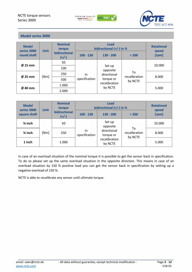
Model series 3000 round shaft
Unit
Nominal torque
bidirectional (+/-)
Load bidirectional (+/-) in %
Rotational speed [rpm] 100 - 130 130 - 200 > 200
Ø 15 mm
[Nm]
50
In specification
Set up opposite
directional torque or
recalibration by NCTE
To recalibration
by NCTE
10.000 100
Ø 25 mm 250
8.000 500
Ø 40 mm 1.000
5.000 2.000
Model series 3000
square shaft Unit
Nominal torque
bidirectional (+/-)
Load bidirectional (+/-) in %
Rotational speed [rpm] 100 - 130 130 - 200 > 200
⅜ inch
[Nm]
50
In specification
Set up opposite
directional torque or
recalibration by NCTE
To recalibration
by NCTE
10.000
¾ inch 250 8.000
1 inch 1.000 5.000
In case of an overload situation of the nominal torque it is possible to get the sensor back in specification.
To do so please set up the same overload situation in the opposite direction. This means in case of an
overload situation by 150 % positive load you can get the sensor back in specification by setting up a
negative overload of 150 %.
NCTE is able to recalibrate any sensor until ultimate torque.
Model series 3000

email: [email protected] www.ncte.com
- All data without guarantee, except technical modification - Page 3 - 12 V18-01
NCTE torque sensors Series 3000
Model series 3000
measuring range Unit Axial force [N]1 Lateral limit force [N]
Bending limit moment [Nm]
50 and 100
[Nm]
2.300 300 41,7
250 and 500 7.000 800 176
1.000 and 2.000 24.000 2.000 700
Each type of irregular stress can only be permitted with its given limit value (bending moment, lateral force
or axial force, exceeding the nominal torque) if none of the others can occur. Otherwise the permitted
limits must be reduced. If for instance 30 % of the limited bending moment and also 30 % of the limited
lateral force are present, only 40 % of the limited axial force are permitted, provided that the nominal
torque is not exceeded.
1 Direct acting axial force on the shaft. If the force affects the snap ring, just 50 % of the force is permitted. 2 The accuracy class implies that taken separately both the linearity deviation as well as the rotational signal uniformity are either lower than or equal to the value of the accuracy class. 3 %ME: related to a full scale measurement range. 4 Please check the exact data at the sensors calibration certificate.
No.
Model Series 3000
Accuracy class2 0,2
Unit Value
1 Linearity deviation incl. hysteresis
%ME3
< ±0,2
2 Rotational Signal Uniformity (RSU) < ±0,2
3 Repeatability < ±0,05
Output signal in general Unit Value
4 Frequency range, -3dB point, Bessel characteristics
Hz 2.500
5 Analog signal V | mA 0 … 10 4 … 20
6 Signal at torque = Zero4 V | mA 5 12
7 Signal at positive nominal torque4 V | mA 9 19
8 Signal at negative nominal torque4 V | mA 1 5
9 Calibration parameter (normed)4 V/Nm mA/Nm
4 V/Measurement range
8 mA/Measurement range
10 Error output V | mA 10 22
11 Output resistance Ω 62
Effect of temperature Unit Value
12 Zero point drift over temperature %/10 K < 0,2
13 Signal drift over temperature within nominal temperature range
%/10 K < 0,5
Load characteristics
Technical characteristics

email: [email protected] www.ncte.com
- All data without guarantee, except technical modification - Page 4 - 12 V18-01
NCTE torque sensors Series 3000
5 Wiring connected. 6 Based on the non-contact measurement principle the torque sensor is quite insensitive to bending and shearing forces. Self-aligning couplings are recommanded in case of dynamic loads.
Power supply Unit Value
14 Supply voltage VDC 11 … 28
15 Current consumption (max.) mA 150
16 Start-up peak mA < 200
17 Absolute max. supply voltage VDC 30
General information Unit Value
18 Protection class according to EN 605295
IP 50/65
19 Reference temperature °C +15 … +35
20 Operational temperature range °C -40 … +85
21 Storage temperature range °C -30 … +85
22 Bearing operating hours h approx. 20.000
Nominal rated torque M (bi-directional)
Nm 50 100 250 500 1.000 2.000
23 Weight kg 1,4 2,5 6
24 Moment of inertia kg mm2 5,9 59,5 626
EMI/EMC Unit Value
25 Tested standards
26 EN 61000-6-3: 2007 - Passed
27 EN 55011: 2009 + A1: 2010 class B - Passed
Load limits6 Unit Value
28 Maximum measurable torque % 110
29 Maximum torque, related to nominal torque
% 300
30 Ultimate torque % 500

email: [email protected] www.ncte.com
- All data without guarantee, except technical modification - Page 5 - 12 V18-01
NCTE torque sensors Series 3000
Dimensions
2 x M4 x 8 Only for preventing a rotation of the housing
Plug: Binder Series 423/723/425
Illuminated Tare-button

email: [email protected] www.ncte.com
- All data without guarantee, except technical modification - Page 6 - 12 V18-01
NCTE torque sensors Series 3000
Dimensions (in mm)
50 Nm 100 Nm 250 Nm 500 Nm 1.000 Nm 2.000 Nm
A 160 160 220 220 350 350
B 93 93 101 101 130 130
C 33,5 33,5 59,5 59,5 110 110
D 15g6 15g6 25g6 25g6 40g6 40g6
E 96 96 106 106 126 126
F 60 60 70 70 90 90
G 61 61 61 61 80 80
H 40 40 40 40 60 60
I 57 57 67 67 87 87
Dimensions keyway [mm] Keystones Key stone-
position
Shaft Width Depth Length Height Length Amount Distance L
Ø 15 mm 5N9 3 25,5 5 25 1 130,5
Ø 25 mm 8N9 4 50,5 7 50 2 165,5
Ø 40 mm 12N9 5 90,5 8 90 2 252,0
Keystone

email: [email protected] www.ncte.com
- All data without guarantee, except technical modification - Page 7 - 12 V18-01
NCTE torque sensors Series 3000
Connector Power supply and outputs
Typ Binder series 423/723/425
Item number: 09-0132-90-12 colour code according to DIN 47100
Pin Colour Description Value
A White Supply voltage VCC 11 V … 28 V
B Brown Ground GND -
C Green Analog Out 0 V … 10 V
D Yellow Analog GND -
E Grey Analog Out 4 mA … 20 mA
F Pink Angle Ch A 0 V … 5 V
G Blue Angle Ch I 0 V … 5 V
H Red Angle Ch B 0 V … 5 V
J Black - -
K Violet For internal use only RX (TTL Pegel)
L Grey-Pink For internal use only RX (TTL Pegel)
M Red-Blue Digital GND -
Connection example:
Connection plan
CHA CHB
Signal Signal GND
Vcc
GND
5-28 V max. 120 mA

email: [email protected] www.ncte.com
- All data without guarantee, except technical modification - Page 8 - 12 V18-01
NCTE torque sensors Series 3000
Parameter Min. Typ. Max. Units
High Level Output Voltage 2,4 5 - V
Low Level Output Voltage 0 - 0,4 V
Parameter Description
C One cycle of 360 CPR (degrees)
P The duration of high state of the output within one cycle.
S The number of electrical degress between a transition in Channel A and the neighboring transition in Channel B.
Φ The number of electrical degrees between the center of high state of Channel A and the Center of high state of Channel B.
Angle sensor

email: [email protected] www.ncte.com
- All data without guarantee, except technical modification - Page 9 - 12 V18-01
NCTE torque sensors Series 3000
Series 3000 accuracy 0,2 % Price
Measurement range
50 Nm including 5 m cable and calibration certificate
100 Nm including 5 m cable and calibration certificate
250 Nm including 5 m cable and calibration certificate
500 Nm including 5 m cable and calibration certificate
1.000 Nm including 5 m cable and calibration certificate
2.000 Nm including 5 m cable and calibration certificate
Angle sensor
0 Without angle sensor
1 Angle sensor 360CPR
Analog output
A Voltage output 0-10 V
S Current output 4-20 mA
Shaft ends
0 Round shaft with keystone
1 Square shaft (available with 50/250/1.000 Nm)
Protection class according to EN 60529
0 IP50
1 IP65
3000
Please feel free to contact your Sales Manager Serial products for additional information. Email:
[email protected] or Phone: +49 89 66 56 19 17
Order options

email: [email protected] www.ncte.com
- All data without guarantee, except technical modification - Page 10 - 12 V18-01
NCTE torque sensors Series 3000
Accessories Price
NCTE Readout Unit works with all NCTE Sensors
A
Torque sensor input: Voltage output 0-5 V and 0-10 V Order number: 400010-ATS001 1 angle encoder input, A/B USB interface, Windows software included SD card slot
S
Torque sensor input: current output 4-20 mA Order number: 400010-ATS002 1 angle encoder input, A/B USB interface, Windows software included SD card slot
Coupling
X Customized couplings, price on request
Please feel free to contact your Sales Manager Serial products for additional information. Email:
[email protected] or Phone: +49 89 66 56 19 17.

email: [email protected] www.ncte.com
- All data without guarantee, except technical modification - Page 11 - 12 V18-01
NCTE torque sensors Series 3000
Scope of delivery The torque sensor set consists of the sensor itself (signal pick-up and signal processing integrated into
sensor housing), one connecting cable 5 m with a soldered plug (binder plug no. 99-0426-10-08), key
stones (round shaft) and the calibration certificate.
Datasheets and instruction manuals are available at www.ncte.com.
Installation and removal Make sure to install the sensor shafts exactly with the proper aligned connecting shafts. The key stone
adapter/square endings of the connecting shafts are to be attached forceless to the corresponding ones of
the sensor. No external axial force should be on the housing of the sensor from distortion. A maximum
cable length of 5 m must not to be exceeded. Using a cable or connector other than supplied by NCTE, or a
similar cable that is of a different length may affect the overall performance of the sensor.
Do not remove the shaft with torque applied to the sensor.
Offset adjustment If required the zero point output signal (5 V) can be adjusted by pressing the Tare-button. By factory default
the sensor is set to 5 V at zero torque.
Interface description Mechanical connection: The key stone adapters on both ends of the measurement shaft are intended for torque transmission.
Electrical connector: On the sensor housing there is a 8-pin socket for the power supply and the signal output (chapter
connection plan).
Operation (in regular case or in optimal case) Optimal measurement parameters can be achieved if the sensor is applied in accordance to the
specification. By compliance with the specification the sensor works generally trouble-free and
maintenance-free.
Irregular operation, measures against disturbance The mechanical overload on the sensor (e. g. exceeding of maximum allowed torque or severe vibrations)
may cause damage to the sensor and in consequence the incorrect signal output. In such cases please do
not open the sensor. Contact NCTE directly for assistance.
Commissioning After sensor installation pay attention to the following:
The sensor may only be operated with a shielding.
Switch on the power supply unit and check the supply voltage. Peak voltage must be avoided! Be sure to verify the power supply voltage before connecting the sensor!
Connect the sensor to the power supply unit by using the delivered cable.
Connect the sensor output to a high-resistance device such as an A/D converter, oscilloscope, PC
measurement board. The sensor should be in mechanical unloaded state while connecting it.
Instruction manual

email: [email protected] www.ncte.com
- All data without guarantee, except technical modification - Page 12 - 12 V18-01
NCTE torque sensors Series 3000
Tare function and error indication: Series 3000 contains a LED button on the housing surface. Pressing the button will set the signal output to
5 V. The illumination of the button serves as a function/malfunction indicator.
Functional indicator: LED off: missing power supply or sensor is damaged LED on: Sensor is ready.
Error indicator: LED flashes: The sensor is not ready. Flashing of LED can have several possible causes. Various causes are interpreted through a flash code. After each flash code the LED makes a short pause before repeating the code.
2x flashing: Magnet field sensors defective. 4x flashing: Electronics defective.
Shaft coating The shafts are protected on both sides with a film of anticorrosion wax. We recommend to leave the
protection permanent. As far as technologically needed, the coating can be removed with spirit/ethanol
Handling and transportation By handling, storage and transportation keep the sensor away from magnetic or electromagnetic fields
which may exceed the maximal intensity defined from EMC (chapter technical characteristics) like
degaussing machines.
Precautions Do not open the sensor housing under any circumstances.
Do not remove or loosen the locking rings on the shaft ends.
Do not loosen or tighten the flange-mounting nut of the socket-connector (chapter dimensions).
Use only a separate power supply for the sensor.
Use the sensor only according to the specification (chapter technical characteristics).
Maintenance and overhaul As part of your testing and measuring equipment management, we recommend regular checking of your
testing and measuring equipment. Please also observe the corresponding standards and guidelines.
Recommended NCTE maintenance plan
Recalibration 12 month
Control of wiring, plug and shaft 12 month
Repairs Repairs must be carried out exclusively by employees of NCTE AG. The sensor must be sent to the NCTE AG
together with an RMA formula (Return Merchandise Authorization). You will receive an RMA formula via
the NCTE service-hotline.
Disposal For disposal the Sensor has to be returned to NCTE AG, Raiffeisenallee 3, 82041 Oberhaching, Germany.
Service-Hotline Phone: +49 89 66 56 19 17 Fax: +49 89 66 56 19 29 Email: [email protected] Sales rep.:
Sensors AS +47 67 90 43 00Setersletta 3 [email protected] LØVENSTAD www.sensors.no