
TATA METALIKS LIMITED KHARAGPUR - Environmental ...
64
TATA METALIKS LIMITED KHARAGPUR FEASIBILITY REPORT FOR THE CAPACITY EXPANSION OF HOT METAL PRODUCTION FROM 0.5 TO 0.75 MTPA,DI PIPE PRODUCTION FROM 0.3 to 0.5 MTPA AND PRODUCTION OF 0.1 MTPA CASTINGS & FITTINGS
-
Upload
khangminh22 -
Category
Documents
-
view
1 -
download
0
Transcript of TATA METALIKS LIMITED KHARAGPUR - Environmental ...

TATA METALIKS LIMITED
KHARAGPUR
FEASIBILITY REPORT
FOR THE CAPACITY EXPANSION OF HOT METAL PRODUCTION
FROM 0.5 TO 0.75 MTPA,DI PIPE PRODUCTION FROM 0.3 to 0.5 MTPA AND PRODUCTION OF
0.1 MTPA CASTINGS & FITTINGS

CONTENTS
*****************
S.N.
Description
Section
1.
CAPACITY ENHANCEMENT OF EXISTING MBF’s FOR INCREASED HOT METAL PRODUCTION OF 0.75 MTPA Section - 1
2.
CAPACITY ENHANCEMENT OF EXISTING DUCTILE IRON PIPE PLANT FOR 0.5 MTPA Section - 2
3. 0.1 MTPA CASTINGS & FITTINGS PRODUCTION Section - 3
4.
10MW WASTE HEAT RECOVERY CAPTIVE POWER PLANT
Section - 4
5.
OVERALL POWER REQUIREMENT
Section - 5
6.
WATER BALANCE DIAGRAM POST EXPANSION
FIG 1 & 1.1
7.
LAYOUT PLAN OF THE PROJECT
Provided separately in
Form -2
8.
PROCESS FLOW DIAGRAM
FIG 3
CAPACITY ENHANCEMENT OF EXISTING MBF’s FOR INCREASED HOT METAL PRODUCTION OF 0.75 MTPA
FEASIBILITY REPORT
FOR
CAPACITY ENHANCEMENT OF BOTH MBF’S
TO PRODUCE
HOT METAL - 7.5 LTPA

CAPACITY ENHANCEMENT OF EXISTING MBF’s FOR INCREASED HOT METAL PRODUCTION OF 0.75 MTPA
CONTENTS*****************
S.N. Description Pages
1. Introduction 2-3
2. Existing MBF Complex and Utilities 3-11
3. Proposed Modification in MBF for Production Enhancement 12-34
4.Water Requirement
35-40
5.Project Cost
35-40

CAPACITY ENHANCEMENT OF EXISTING MBF’s FOR INCREASED HOT METAL PRODUCTION OF 0.75 MTPA
01.00 INTRODUCTION
01.01 Preamble
Tata Metaliks Limited (TML), Kharagpur is presently operating two numbers of MBFs to produce
hot metal for used in DI Pipe Plant and balance in two PCM for producing ductile iron pipe & pig
iron respectively. Both the furnaces are to be upgraded on the basis of design, engineering and
consultancy rendered by MECON. As a part of their expansion plan, M/s TML is intended to
enhance their present production of both MBF’s from 700 tpd to1050 tpd depending upon the %
of Si in hot metal.
M/s MECON Limited has been appointed by Tata Metaliks Limited to prepare a feasibility report
for the proposed expansion of both MBF’s and study of both MBF’s Complex & its auxiliary
services to handle the enhanced production.
01.02 Assignment
In line with the above background, M/s Tata Metaliks Limited has engaged MECON to prepare a
feasibility report for production enhancement of existing MBF’s complex. The report will entail the
followings:
Study of existing system of MBF’s complex to be done for production enhancement.
Capital Cost estimate of new installations including modification required for enhance
production of MBF complex.
Duration of shut down required for proposed expansion.
01.03 Approach
The project has been envisaged to be carried out keeping the following considerations.
Upgradation of existing MBFs to 305 m3
Installation of 2 nos. Electric blower system for both MBF’s.
Handling of sludge from GCP by installing new ETP.
Replacement of existing GCP to facilitate enhanced production.
Installation of new bunkers as required in existing Stock House
Minimum shutdown time and interface with existing facilities.
2.0 EXISTING MBF COMPLEX AND UTILITIES
02.01 STOCK HOUSE & CHARGING SYSTEM
Raw material for both furnaces are received and kept in common raw material storage yard. Presently, raw
materials are fed to the MBF’s through ground hopper. The capacity of ground hopper is 12 m3.
Conveyors & Stock House bunker details based on the input provided by Client are given below:

CAPACITY ENHANCEMENT OF EXISTING MBF’s FOR INCREASED HOT METAL PRODUCTION OF 0.75 MTPA
Stock House details:
Sl. No DescriptionsMBF-1 MBF-2
1 Nos. of Day Bins 15 15
2
Nos. of Bins for Sinter 2 2
Volume of Sinter bins 120 m3 120 m3
3
No. of Bins for iron Ore 3 3
Volume of Iron ore bins 137 m3 160 m3
4
No. of Bins for coke 2 2
Volume of coke bins 212 m3 262 m3
5
Pearl coke 1 1
Volume of each Bin 100 m3 100 m3
6
No. of Bins for additives 6 6
Volume of each Bin 59 m3 60 m3
7
Coke fine Bins (outside the stockhouse)
1 no. 1
Volume of each bin 65 m3 65 m3
8 Screens
A.
Iron Ore Screens 3 3
Capacity 150 T/hr 150 T/hr.
B
Coke Screens 2 2Capacity 150 T/hr. 75 T/hr.
C
Sinter Screens 2 2
Capacity 150 T/hr. 150 T/hr
D
Flux Screens 4 4
Capacity75 T/hr (DB#5)20 T/hr (DB#6)
75 T/hr.
02.02 MBF #1 PROPER
The design and operating parameters / features of MBF are as follows:
Table: 01.3
Sl. No Blast Furnace Proper Parameters
A MBF Type MBF#1 MBF#2
1Free standing design with 4- poster tower structure
Yes Yes
B MBF proper
3Working volume (C.L. of Tuyere to stock line)
259 m3 259 m3
4Productivity (on useful volume) with 50% Lump ore with PCI
2.4 – 2.7 2.4-2.7
5 Hearth Diameter 4.7 4.2
6 No. of tuyeres 10 10
7 Throat Armour Fixed type Fixed Type
B Top Charging system
8 Chinese Bell less top Yes Yes
9Bleeder Valve pipe size 500 DN (Refractory ID 350 DN)
500 DN 500 DN

CAPACITY ENHANCEMENT OF EXISTING MBF’s FOR INCREASED HOT METAL PRODUCTION OF 0.75 MTPA
10Back Draught Valve pipe size 500DN (refractory ID 300 DN)
300 DN 300 DN
CRefractory & BF cooling system
11 Carbonaceous Hearth Yes Yes
12 SG Staves coolers in stack Yes Yes
13Under hearth water cooling system
Yes Yes
14 Box coolers in upper stack Yes Yes
E Cooling water system
15 Soft water cooling system Yes Yes
Blast furnace cooling
The Blast Furnaces are provided with soft water closed circuit cooling system for under hearth, tuyeres,
tuyere coolers, tuyere zone, bosh, belly, lower stack and middle stack of the blast furnace. Both Blast
furnace are provided with SG iron stave coolers in tuyere zone, bosh, belly, lower & middle stack and
Box coolers in upper stack. Each stave cooler is having 4 inlet and 4 outlet cooling pipes. 2 nos. of re-
circulating cooling water circuits are provided for better leak detection & heat load calculation.
02.03 Hot Blast System
Three nos. of internal combustion type hot Blast Stoves are provided for each MBF for supply of hot
Blast temperature of 1000-1050°C depending upon the PCI injection and pre heating of BF gas and
Combustion air. From the design point of view, the refractory lining is adequate to sustain the Hot Blast
temperature upto 1050°C. However, it is suggested to check the physical condition of the current
refractory lining and change accordingly with same pattern in coming major shutdown for better reliability.
Basic stove existing operating Parameters are as follows:
Table: 01.4
S.N. Description Parameters
1 Nos. of stoves 3 (cycle opn)
2 Checker height 21.6 m
3 Area of combustion 2.66 m2
4 Heating surface area ~8700 m2/ Stove
5 Combustion Chamber area 2.66 m2
6 Checker Chamber Area 9.12 m2
7Specific heating surface area per
checker brick~44 m2 / m3
8 Maximum dome temperature 1250° C
9Hot blast temperature with PCI & pre
heater (design)1100° C
10 Hot blast volume 45,000 Nm3 / hr avg

CAPACITY ENHANCEMENT OF EXISTING MBF’s FOR INCREASED HOT METAL PRODUCTION OF 0.75 MTPA
11 Cold blast pressure 1.5 Kg/cm2 (g)
12 Hot blast pressure at stove outlet 1.45 kg/cm2 (g) normal
13 Cold blast temperature 150 – 180° C
14BF Gas per stove (design requirement
for hot blast of 60000 Nm3/hr)12000-13000 Nm3/hr
15 Cold blast oxygen enrichment (Normal) 1-3%
16Calorific value of BF gas based on gas
analysis provided by client800-850 kCal/ Nm3 min.
Combustion air supply system for Hot Blast Stoves:
Combustion air fan of capacity 19000 Nm3/hr (IW+1S),650-700mm water column is installed for burning
of BF gas in Stoves.
Pre heater
Pre heater is being used for recovery of heat from the waste gases leaving the stoves are on gas in
order to achieve a higher BF gas temperature and higher combustion air temperature.
Cold Blast System:
Presently, the air blast requirements for MBF’s are met by electric blower fans. There are 5 numbers of
electric driven fans in series for each MBF. Each blower is of 45000-50000 Nm3/ hr capacity with
ultimate delivery pressure of 1.45 kg/cm2 (g). One number pendant operated Crane of around 6 t
capacity is provided in both the Blower House for the maintenance of the blower fans and its auxiliaries.
Sl. No Cold Blast System- Series Fans (W5)
1 Medium Handled Air
2 Capacity 45,000-50,000 Nm3/hr.
3 Suction temperature 39°C
4 Discharge temp. 145°C
5 Discharge Pressure 1.45 Kg/cm2(g)
6 Blower Speed 2950 RPM
7 Blower Motors All Blowers are at voltage level 3.3 KV.
BL-1: 450 KW
BL-2: 475 KW
BL-3: 475 KW
BL-4: 550 KW
BL-5: 550 KW
Total: 2500 KW (connected)
02.04 CAST HOUSE
The cast house is of structural construction with fire brick paving at required locations. There have been
fabricated steel runners with fire clay brick lining for the hot metal & slag. Main iron trough is of deep pool

CAPACITY ENHANCEMENT OF EXISTING MBF’s FOR INCREASED HOT METAL PRODUCTION OF 0.75 MTPA
type with natural cooling. The hot metal through the iron runners are led to 3 fixed spouts. The hot metal
from the ladles of 40 t capacity is sent to PCM by crane and for DI Pipe plant, ladles are transported by
tyre mounted truck.
02.05 SLAG GRANULATION PLANT
The slag is presently led to cast house slag granulation unit. The liquid slag is granulated by water jet
spray across the liquid slag with the help of Cast Iron blowing box. The slag water slurry is collected in
an existing tank.
The granulated slag is removed from settling tank by the help of pay loader and dumper and loaded on
to trucks for further transportation. The water reclaimed from the process is settled in a settling tank
before recycling through pump house.
In the event of non availability of the granulation system or slag quality not suitable for granulation, slag
is discharged to emergency dry slag pit for subsequent handling.
02.06 CYCLONE & GAS CLEANING PLANT AND GAS FLARE SYSTEM
The top gas generated is led through two uptakes and a down comer to the tangential Cyclone for
primary dust separation and further cleaned in Gas Cleaning Plant.
The parameters of crude gas generated from MBF’s are as follows:
Table: 01.6
Blast furnace ( BF ) gas is used mainly as fuel in stoves. In addition to this, BF Gas is also used in LRS for
ladle heating and semi-clean BF Gas is used for BF top pressure equalization. Surplus BF gas is utilized in
Sl. No Descriptions Parameter
1 Normal generation of BF Gas 121800 Nm3/hr
2 Maximum generation of BF Gas 125000 Nm3/hr
3 Top Gas Pressure 0.45 Kg/cm2(g)
4 Top Gas Temperature 150-200°C
5 Dust Content of Crude BF Gas 20-30 gms/ Nm3( Max.)

CAPACITY ENHANCEMENT OF EXISTING MBF’s FOR INCREASED HOT METAL PRODUCTION OF 0.75 MTPA
power plant to generate power. BF gas is distributed to the consumers through a system of piping network,
operating at a pressure of 700-750 mmWC.
02.07 Effluent Treatment Plant (ETP)
The slurry is discharged from saturator & GCP system and fed to one no. thickener and the slurry is
diverted into thickener. A chemical dosing system is provided for settling of the slurry water. The clean
water is circulated in the saturator and GCP system for cleaning of BF Gas.
02.08 Water System for MBF’s
The water system comprises of following units: Soft water closed loop water system for stave, tuyere, tuyere cooler, under
hearth cooling & hot blast valves. Industrial water cooling in upper stack & hearth.
Water system for Gas cleaning Plant
Water system for Slag granulation Plant
Water system for Pig Casting Machine Make-up System and
Emergency water over head tank
02.09 Ladle Repair Shop
The shop is under construction which is located near the 80 ton crane bay towards RMHS side.
02.10 PIG CASTING MACHINE (PCM)
2 (two) nos, of Single strand pig casting machine of capacity 600 t/day are installed between two
blast furnaces in 80 ton crane bay to cast the hot metal into pigs from both furnaces. However, due
to current operation practices, the output obtained are 500 t/day. The ladles are handled by one no.
of 80 ton crane and poured by 50t hoist in PCM of MBF #1 and by hydraulic tilting station in PCM of
MBF #2 . The pigs are discharged on truck tripper and stored in pig yard.
02.11 EXISTING HOT METAL HANDLING SYSTEM
Presently, the total hot metal requirement is fulfilled by road network through tyre mounted trolley
truck having the capacity to handle the 40 ton ladles from MBF in general. In MBF, there are 3
(three) hot metal spouts in each MBF used for tapping the hot metal through 40 ton of ladles.
Normally, DI plant Hot metal intake is 400 -600 ton on daily basis.
Hot Metal transportation time from MBF to DI plant and return to MBF is 45 minutes. Hot metal
requirement for DI plant is 40 ton at interval of 90-100 minutes.
02.12 DUCTILE IRON (DI) PIPE PLANT
As part of their expansion plan, TML is considering capacity enhancement of existing ductile iron
pipe plant up to 5.0 LTPA.
02.13 PELLETIZATION PLANT
CAPACITY ENHANCEMENT OF EXISTING MBF’s FOR INCREASED HOT METAL PRODUCTION OF 0.75 MTPA
As part of the expansion plan, TML is considering installation of a pellet plant of 0.45 MTPA capacity. Iron
ore fines of size in the range of -1 to -8 mm size will be brought to the plant mostly by railway wagon. The
iron ore fines are then dried and grinded in a ball mill to the desired size of D80 <50 microns. The iron ore
fines along with limestone and bentonite in requisite proportion will be fed to the mixer. These thoroughly
mixed materials would be fed to the disc pelletiser to produce green pellet. The green pellets would be
hardened for use as BF burden material in induration furnace operating at a temperature of 1300- 1350
degree C. Pelletizing produces hardened lumps of 8-16 mm diameter using very finely ground particles of
iron ore fines of size less than 200 mesh and additives like bentonite. The biggest advantage of
pelletization is the use of finer iron ore for its formation. Pellets have good reducibility because of high
porosity (25-30%). Pellets have higher iron content varying from 62% to 65% depending on the Fe content
of Ore fines. Absence of LOI is another advantage of using pellets. Pellets have high and uniform
mechanical strength and can be transported to long distances without generation of fines. Further it has
got resistance to disintegration. High mechanical and uniform strength of pellets is good even under
thermal stress in reducing atmosphere. In the proposed expansion project, a pellet plant of 0.45 MTPA
capacity would be installed considering the availability as well as environmental friendliness in using of
iron ore fines.
Water requirement for the pellet plant will be approximately 360 m3/ day (refer Water Balance Diagram
Fig. 1).
The pellet plant will be mainly comprising of – Storage & Mixing sections (having surge bins and rotary
driers), Bucket Elevators, Ball Mill, Balling section (with surge bins, disc & pelletizer), Grinding section
(with pulveriser), Screening & feeding section, Product & Hearth layer handling, Indurating Machine and
other auxiliary mechanical units.
03.00 PROPOSED MODIFICATION IN MBF’s COMPLEX
TML and MECON jointly discussed about the installation of electric blower and modification/
installation of Existing/ New system for MBF’s complex for enhanced production from 700 tpd to
1050 tpd.
Proposed modification to existing MBFs for its production enhancement has been suggested with
maximum utilization of existing equipment and facilities.
Area wise proposed modification is elaborated below:
03.1 COLD BLAST SYSTEM
03.1.1 Installation of Electric blower System
To meet the cold blast requirement of Blast Furnace, 2X60% capacity electric motor driven
Electric blowers are envisaged for each MBF’s. The proposed electric motor driven Electric
blower s along with all accessories & auxiliaries shall be installed inside a new Electric blower
building. The parameters of each electric motor driven Electric blower shall be as follow:-
Discharge Flow : 39000 Nm3/hr (Maximum)
36000 Nm3/hr (Normal)

CAPACITY ENHANCEMENT OF EXISTING MBF’s FOR INCREASED HOT METAL PRODUCTION OF 0.75 MTPA
31200 Nm3/hr (Minimum)
Discharge Pressure : 2.2 Kg/cm2(g) (Maximum)
2.0 Kg/cm2(g) (Normal)
1.6 Kg/cm2(g) (Minimum)
Based on the operating regime of blast furnace, operating range of each Electric blower is specified
below:
Duty point 1 2 3 4 5 6 7 8 9
Discharge Flow (Nm3/hr)
39000 39000 39000 36000 36000 36000 31200 31200 31200
Discharge Pressure(kg/cm2g)
2.2 2 1.6 2.2 2 1.6 2.2 2 1.6
Shaft Power Consumption
Shall be different at different duty points and the same shall be manufacturer specific.
Main Motor Rating (KW)
2500 (Tentative)
The blowers shall be designed to meet all the above duty points i.e. discharge air flow and
discharge pressure and any point within the range of discharge air flow and discharge pressure at
all ambient temperature condition.
The blowers shall also be designed for the most economical parameters having maximum
efficiency encompassing the entire regime of the blast furnace operation as indicated above. The
Blowers shall be suitable for simultaneous operation with automatic control.
03.1.1.1 Cooling Water System
Dedicated pump house along with cooling tower have been envisaged adjacent to the proposed
Electric blower building. Cooling water required for Electric blower & auxiliaries and compressed air
station shall be supplied from this pump house. FRP cooling tower has been envisaged for cooling
of hot water coming from Electric blower & auxiliaries and compressed air station. Make up water
requirement shall be made available by TML at sump of proposed pump house. Chemical dosing
system shall be provided as per requirement.
The parameters of cooling water system shall be as follow:-
No. of cooling water pump: 2 nos. (1W+ 1SB)
Motor Rating each : 60 KW
No. of Cooling Tower Motor: 2 nos. (both working)
Motor Rating each (tentative): 11 KW

CAPACITY ENHANCEMENT OF EXISTING MBF’s FOR INCREASED HOT METAL PRODUCTION OF 0.75 MTPA
03.1.1.2 Compressed Air Station
To meet the service air / instrument air requirement of Electric blower s and accessories and
auxiliaries, a compressed air station is envisaged. The compressor and air dryer units shall be
installed inside the proposed pump house cum compressor room. The parameters of compressed
air station shall be as follow:-
Air Compressor
No. of Compressors : 2 Nos. (1W+1SB)
Air volume flow (each compressor) : 300 Nm3/hr
Discharge Pressure at outlet flangeof after cooler and moisture separator
: 8.0 kg/cm2g
Motor rating each (Tentative) : 40KW
Service duty : Continuous
Installation : Indoor
Environment : Dusty
Each compressor shall be designed to meet the flow parameter as mentioned above at the rated
discharge pressure.
Air Dryer Unit
The air drying units are envisaged to install adjacent to the compressors inside the proposed
pump house cum compressor room to meet the requirement of instrument air. The dryer shall be
completed with all accessories and mountings.
The dryer shall be supplied along with all necessary auxiliaries. Design considerations of the air
dryer unit is indicated below:
No. of air dryer unit : 2 Nos. (1W+1SB)
Air volume flow (each) : 300 Nm3/hr
Inlet air pressure : 8.0 kg/cm2g
Motor rating each (Tentative) : 5KW
Service duty : Continuous
Inlet air temperature : Same as compressor outlet
Air Receiver

CAPACITY ENHANCEMENT OF EXISTING MBF’s FOR INCREASED HOT METAL PRODUCTION OF 0.75 MTPA
The air receiver is envisaged to install adjacent to the proposed pump house cum compressor
room. The air receiver shall be completed with all accessories and mountings.
The air receiver shall be supplied along with all necessary auxiliaries. Design considerations of
the air receiver is indicated below:
No. of Air Receiver : 1 No.
Capacity : 2m3
Working pressure : 8.0 kg/cm2g
03.1.1.3 Handling & Hoisting Facility
An electrically operated overhead traveling (EOT) crane of 20 ton capacity shall be installed in
the Electric blower building and an electric hoist of 2 ton capacity shall be installed in pump house
cum compressor room shall be used for operation & maintenance of various equipments installed
inside Electric blower building and pump house cum compressor room respectively.
Total power requirement for EOT crane shall be tentative 40KW and power requirement for
electric hoist shall be tentative 5KW.
03.1.1.4 Air Conditioning and Ventilation System
The following air condition and ventilation system have been envisaged for various premises of
Electric blower station.
Electric blower building : Roof ventilators
MCC room : Supply air ventilation system
Control room : Split air conditioning system
Battery room : Exhaust fan ventilation system
Cable cellar : Exhaust fan ventilation system
Toilet : Exhaust fan ventilation system
Pump house cum compressor room: Exhaust fan ventilation system
Total power requirement for air conditioning and ventilation system shall be tentative 40KW.
03.1.1.5 Electrics
Two nos. of 11KV power feeders from a nearby source of existing 11kV switchboard shall be
connected to one number of 11KV HT switchboard from where the power to the blower motor
shall be provided through HT cables. The blower synchronous motor shall be started through a
soft starter connected on the neutral side of the motor. 11KV HT board shall have one spare
motor feeder.

CAPACITY ENHANCEMENT OF EXISTING MBF’s FOR INCREASED HOT METAL PRODUCTION OF 0.75 MTPA
The rated power for each of the Electric blower Motors shall be 2500KW at 11KV voltage level
Two numbers of 415V LT power feeders (tentative rating 800Amps each) from a nearby source of
existing 415V LT switchboard shall be connected to one number of 415V PCC / LT board from
where the power required for the auxiliary power distribution to proposed electric motor driven
Electric blower auxiliaries, compressed air station, cooling water system, EOT crane, air
conditioning & ventilation system, etc. shall be done through MCC, PDB, etc. These equipments
shall be installed inside the electrical room of the proposed Electric blower building.
Illumination for the proposed turbo bower building and pump house cum compressor room shall
be provided through two nos. lighting transformers along with MLDB and LDBs.
03.1.1.6 Control & Instrumentation
The proposed electric motor driven Electric blower and its auxiliaries shall be fully automatic. The
basic philosophy of Control and Instrumentation (C&I) system shall be based on PLC system for
the package with 4-20 mA unified current signal superimposed on digital HART signal. The C&I
system shall ensure safe, efficient and smooth operation of the plant and equipment with
minimum intervention of the operating personnel during normal operation, start-up, load
fluctuation and shut down of the blower. The PLC system shall be installed inside the control
room of the proposed Electric blower building.
03.1.2 Cold Blast Line
Cold Blast line from new Electric blower shall be connected with existing cold blast line at suitable
location. Location shall be decided during detail engineering.
03.1.3 Oxygen Line (For enrichment)
Oxygen is provided to the MBF by existing oxygen plant. Oxygen enrichment in existing MBF’s
are being done maximum upto 2 %. Oxygen requirement shall be increased with Pulverised Coal
Injection requirement. Assuming that pulverized coal injection at a rate of 70 to 80 Kg/thm , the
oxygen requirement shall be in the range of 3 to 4 % depending upon the HBT.
Typical study of Pulveised coal injection, oxygen injection as well as steam requirement are given
below:
Parameter Units Case-1 Case-2 Case-3 Case-4
O2 % Enrichment % 3 4 5 6
Oxygen Rate Nm3/h 2468 3291 4114 4937
Cold Blast Rate Nm3/h 65000 65000 65000 65000
Steam Injection t/h 2.6 2.6 2.6 2.6
PCI Rate Kg/THM 60 90 120 150
RAFT Deg C 2182 2203 2223 2243
Accordingly, availability and line size for oxygen shall be checked at 5000 Nm3 /hr @ 6 Kg/cm2

CAPACITY ENHANCEMENT OF EXISTING MBF’s FOR INCREASED HOT METAL PRODUCTION OF 0.75 MTPA
(g).
03.1.4 Steam Line ( Humidification System)
Steam for humidification is available from the existing power house boiler. Steam injection in the
existing MBF’s are done at a rate of 40 gm/Nm3. Accordingly, availability and line size for steam
shall be checked at 3 ton/hr @ 6 Kg/cm2 (g).
03.2 Feeding Conveyor System
It is proposed to retain the existing ground hopper for feeding the Raw Materials in existing Stock
Housees.
03.3 Stock House & Charging System
Following assumptions are considered for the design of the stock house:
New Daily Hot Metal Production = 1050 TPD (depending on % Si) Typical Ferrous Charge Mix as
indicated by M/s TML is considered as follows:-
Sinter Burden = 60-70%
Ore Burden = 40-30%
Specific Consumption:-
Coke (without CDI) – 640 kg/thm
Ferrous burden – 1670 kg/thm
(Sinter – 1002 kg/thm, Ore – 668 kg/thm)
Daily Consumption of raw material is as follows:-
Coke – 640 T (1164 cu.m)
Sinter – 1002 T (573 cu.m)
Ore – 668 T (334 cu.m)
Number of batches per day = 215 (9 charges per hour)
For Coke Charge Operation:-
Daily Coke consumption in Blast Furnace = 1164 cu m.
Daily Coke requirement based on 15% fines consideration = 1370 cu m. Number of Coke
Bunkers in Stock House = 3 (two of 212 cu m and one of 137 cu m)
Storage capacity in Stock House = 561 cu m.
Number of hours of storage capacity of Coke in Stock House = 10 hrs
Coke batch volume per charge = 3t
Number of weigh hoppers for coke:-
2 numbers each of 3t capacity

CAPACITY ENHANCEMENT OF EXISTING MBF’s FOR INCREASED HOT METAL PRODUCTION OF 0.75 MTPA
1 number of 1 t capacity
Thus, it can be seen that a single batch of coke of 3t per charge can be made available by taking
either from one single weigh hopper of 3t capacity or in combination of any two weigh hoppers.
Further, any one weigh hopper and its upstream units can be taken into maintenance with the
balance two weigh hoppers in full operation.
Capacity of existing screens is adequate for 1050 tpd hot metal production.
For Ferrous Charge Operation:-
Quantity per batch:-
Sinter – 2.59 cu m (4.55 T)
Ore – 1.73 cu m (3.45 T)
Total ferrous charge per batch = 4.32 cu m (8.0 T)
Sinter-
Daily Sinter consumption in Blast Furnace = 573 cu m.
Daily Sinter requirement based on 15% fines consideration = 674 cu m. Number of Bunkers in
Stock House = 2 (each of 120 cu m) + 1 new bunker of 120 cu m
Storage capacity in Stock House = 360 cu m.
Number of hours of storage capacity in Stock House = 13 hrs
Number of weigh hoppers for sinter:-
2 numbers existing each of 11t capacity
1 number new of 11 t capacity
Thus, it can be seen that a single batch of sinter of 4.55t per charge can be made available by
taking from any of the three weigh hoppers.
Capacity of existing screens is adequate for 1050 tpd hot metal production.
,
Ore-
Daily Ore consumption in Blast Furnace = 334 cu m.
Daily Ore requirement based on 15% fines consideration = 393 cu m. Number of Bunkers in
Stock House = 2 (each of 137 cu m) + 1 new bunker of 137 cu m
Storage capacity in Stock House = 411 cu m.
Number of hours of storage capacity in Stock House = 25 hrs
Number of weigh hoppers for ore:-
2 numbers existing each of 4t capacity
1 number new of 4 t capacity
Thus, it can be seen that a single batch of ore of 3.45t per charge can be made available by
taking from any of the three weigh hoppers.

CAPACITY ENHANCEMENT OF EXISTING MBF’s FOR INCREASED HOT METAL PRODUCTION OF 0.75 MTPA
Capacity of existing screens is adequate for 1050 tpd hot metal production.
Following modification is proposed in stock house for production enhancement in MBF
I. No modification has been envisaged in the existing coke bunkers. One number of Iron Ore bunker
shall be converted into coke bunker. Necessary extension of coke fines conveyor has already
been executed by M/s TML. Capacity of existing coke fines conveyor is adequate for the
increased fines load.
ii. Two numbers of existing flux bunkers between column 9 and column 10 shall be converted into ore
bunker. It can be achieved by either dismantling both the fluxes bunkers and installing one new ore
bunker along with screen and weigh hopper arrangement completely identical with the other two
existing ore bunkers arrangement or retaining the two numbers of fluxes bunker as it is and
install/retrofit one number of screen and weigh hopper below the bunkers as per space available to
feed to CB-3. It shall be noted that storage capacity in the latter case shall be nearly half in
comparison to former arrangement.
BI. In view of conversion of flux bunkers between column 9 and column 10 into one new ore bunker,
ore fines conveyor CB 4 profile has to be modified to enable it to receive ore fines.
IV. One number new sinter bunker shall be added besides existing sinter
bunkers which shall be identical to existing sinter bunker arrangement.
Following modifications are envisaged:-
Extension of head pulley of existing conveyor FS-6 by approx 3.5 m.
Existing reversible conveyor FS-7 shall be changed to new reversible shuttle conveyor
to feed all three bunkers (two existing and one new).
Installation of one new bunker, vibro feeder, vibro screen and weigh hopper completely
identical with existing arrangement.
Extension of tail pulley and modification in profile of existing collecting conveyor FS-8.
New capacity shall be 400 tph.
Extension of tail pulley and modification in profile of existing fines conveyor Cr-2.
V. It is proposed to further review the present design and configuration of existing screens based on
current sieve analysis of incoming raw materials with OEM supplier to take up necessary
modification/replacement to achieve higher efficiency.
VI. Installation of bin vibrators at the bunker mouth level for all existing stock
house bunkers.
VII. Incorporation of rock ladder design in both existing sinter bunkers and new
sinter bunker to minimize de-gradation of sinter.
VIII. Occupancy time for belt conveyor CB-1 & CB-2 as per latest configuration is
approx 12 hours. Hence, no further modification is envisaged.

CAPACITY ENHANCEMENT OF EXISTING MBF’s FOR INCREASED HOT METAL PRODUCTION OF 0.75 MTPA
03.4 BF Cast House
TML has already reduced nos. of spouts from 4 (four) to 3 (three) and as per information
provided by TML, the metal evacuation is not constraint. Hence, it is proposed to retain
the existing Cast house runner system. However, as per client requirement, Cast house
area shall be increased by 6 m in front side to improve the working environment by
providing more space. Further, with increased production of1050 ton per day ,
considering 12-13 nos. of cast per day (as indicated by TML),per cast hot metal tapping
shall be ~75-77 ton in normal condition which is easily can be handled in 2 nos. of 40 ton
ladles. For emergency purpose, one ladle in ready condition shall be placed under the
third no. spout. Therefore, considering the above condition, reducing no. of hot metal
spout from 4 nos. to 3 nos. shall not be constraint for hot metal evacuation. In view of
cast house extension requirement and handling of hot metal to DI plant, client requested
to provide the one more spout.
Slag Granulation Plant
With increased hot metal production capacity (1050 TPD) of both MBF’s
slag output will increased by 35-45%. The capacity of existing slag pit have
been checked and found that the sizing is just adequate (considering the
depth of pit available is 3m). However, TML may opt for mechanical
evacuation of slag by introducing Grab Bucket based material handlingfacilities for quick evacuation of slag.
03.6 HOT BLAST SYSTEM
The existing stoves heating surface area is already increased for 60000 Nm3/hr of cold blast. The
requirement after installation of Electric blower of capacity 65000 Nm3/hr (max.) is tabulated
below: Table: 01.9
DESCRIPTION UNIT CASE-1 CASE-2
Normal vol. flow rate of cold blast Nm3/hr 60000 65000
BF gas volume flow rate per stove
Nm3/hr 17500 19000
Combustion air volume flow rate per stove
Nm3/hr 12000 13000
Waste gas generation per stove Nm3/hr 26800 29100
Although Electric blower of capacity 65000 Nm3/hr is considered however, all the operating
parameters of MBF’s complex including stoves, GCP shall be operated at normal flow of capacity

CAPACITY ENHANCEMENT OF EXISTING MBF’s FOR INCREASED HOT METAL PRODUCTION OF 0.75 MTPA
60000 Nm3/hr. The system is designed and checked considering maximum cold blast of 65000
Nm3/hr.
It is proposed to change the following system for production enhancement in MBF’s
I. Cold Blast line
It is proposed to retain the existing cold blast line of dia 750 mm with
the 60000 Nm3/hr at 2 Kg/cm2(g) or 65000 Nm3/hr at 2.2 Kg/cm2(g) considering at
operating pressure (> 1.6 Kg/cm2) and temperature (<150°C). Cold blast volume (60000
or 65000 Nm3/hr ) comprises of cold blast and oxygen enrichment.
AI. Hot Blast line
It is proposed to retain the existing Hot blast line of dia 750 mm ID
refractory with refractory thickness 325 mm for the cold blast volume
of 60000 Nm3/hr at 2 Kg/cm2(g) or 65000 Nm3/hr at 2.2 Kg/cm2(g) considering at
operating pressure (> 1.6 Kg/cm2) and temperature (<150°C).
BI. Cold blast mixing line
It is proposed to retain the existing cold blast mixing line of dia 500 mm with cold blast
mixing volume of 8500 Nm3/hr.at 2.2 Kg/cm2(g).
IV. Combustion air line
It is proposed to change the existing header of combustion air line from 800 mm (6 mm
thk.) to 900 mm (8 mm thk.) to cater the increased requirement of combustion air of
volume 26000 Nm3/hr for 2 stoves operation. For the branch line, it is proposed to retain
the existing line of dia.700 mm.
V. BF Gas line
It is proposed to change the existing header of BF Gas line from 800
am to 1000 mm to cater the increased requirement of BF Gas of volume 38000 Nm3/hr
for 2 stoves operation. For the branch line, it is proposed to retain the existing line of
dia.700 mm. For increasing the stove efficiency, It is proposed to increase the BF Gas
line pressure catering the stove for combustion shall be upto 1000 mmWC. This can be
achieved by installing control valve near the tapping point of stove.
VI. Waste Gas line
The existing waste gas header shall be studied in conjunction with air pre-heater design
parameter. However, in initial study, it appears to replace the existing waste gas line of
dia 1100 mm ID refractory to 1400 mm ID refractory with same thickness for the waste
gas generation of 53600 to 58400 Nm3/hr at 350°C. For the branch line, it is proposed to
retain the existing line of dia.1000 mm.
It is required to check the existing pre heater system for enhanced waste gas generation.
In view of future provision of Pulverized coal injection, a separate pipe line for depressurization
shall be provided in waste gas line of each stove with the common header which will be
connected directly to chimney.
VII. Stove valves
All stoves valves are required to check with OEM for increased volume of 65000

CAPACITY ENHANCEMENT OF EXISTING MBF’s FOR INCREASED HOT METAL PRODUCTION OF 0.75 MTPA
Nm3/h and pressure rating of 2.2 Kg/cm2 (g).
VIII. Combustion Fan for Hot Blast Stoves
Two (2) centrifugal fans (one working and one standby) of capacity 31000 Nm3/hr at
pressure 600-1000 mm WC with VFD drive motors have been considered complete with
all accessories for supply of combustion air to stoves.
The combustion air fans shall be complete with VIV dampers (for volume control),
electrical operated (ON/OFF) dampers, flexible connections and instrumentation.
03.7 Thickener of Gas Cleaning Plant
Two no. new high rate solid contact clarifier (HRSCC) has been envisaged for treatment of
contaminated GCP water. New HRSCC shall be installed near the existing sludge pit.
Treated water from HRSCC shall be gravitated to existing GCP sump. New chemical
dosing system shall be considered for HRSCC.
03.8 Bleeder Valve & Back Draught Valve
The existing pipe line size of bleeder line (400/300 DN) is adequate considering the evacuation
time of 2.5 minutes. However, with increase top pressure of 0.8 Kg/cm2 (g), the bleeder valve
shall be changed along with riser pipe size (600/500 DN).
Back draught valve shall be kept as original position and shall be checked with OEM for operating
hot blast pressure of 2.2 Kg/cm2(g). However, the pipe line size of existing back draught line
(500/300 DN) is adequate considering the evacuation time of 3 to 3.5 minutes. It is proposed to
provide the insulation sheets (SS with anchors for gunning/ceramic wool) to protect the hydraulic
and other installation at crown ring platform.
03.9 Material Hopper Equalization
03.10 BF Gas Line
For operating top pressure upto 0.8 Kg/cm2 (g), the septum valve will be installed. Also, one
silencer in gas line shall be installed after septum valve.
03.11 BF Gas Flare System
As such, It is proposed to installed flare stack of capacity 90000 Nm3/hr considering emergency
flaring with no utilization of clean BF gas in power plant as well as in stoves and other consumer
units.
BF gas flare system is meant to control the pressure of BF gas network by flaring the excess gas
to atmosphere. The excess gas released through the bleeder will be burnt in the burner located at

CAPACITY ENHANCEMENT OF EXISTING MBF’s FOR INCREASED HOT METAL PRODUCTION OF 0.75 MTPA
the top of the stack. The height of stack will be 45 meters.
To ignite the BF gas at the main burner tip and to maintain the flame, a system of pilot burners
and ignition device will be provided. The pilot burners will be based on LPG fuel.
Pilot burners will be ignited through automatic ignition system from the local control panel as well
as from BF control room. The pilot burner will remain ignited continuously till BF gas is flowing
through the stack for its complete ignition. Flame detection system shall be provided to de-
activate the auto- ignition system when pilot flame has been established. The auto ignition
system shall be re-activated if pilot flame goes out and BF gas flow is ON.
Indication with alarms shall be provided at the main BF control room for the operating condition of the flare system. Remote operation of the ignition system for pilot burner shall be provided from BF control room.
Operating parameter and BF gas typical composition is indicated at Table 01.11.
OPERATING PARAMETER OF FLARE STACK & LOCATION
Operating Parameters
Flaring Capacity : 90,000 Nm3/h (max)
BF Gas Parameters
Pressure 800 mmWC
Temperature 60-70 deg. C
Calorific Value 800-850 kcal/Nm3
Density 1.34 – 1.345 Kg/m3
Moisture (RH) Saturated
Diameter proposed for riser DN 1400
BF Gas Typical Composition
Carbon Dioxide 16.0 – 17.4 % by volume
Carbon Monoxide 22.8 – 23.8 % by volume
Nitrogen 52.8 – 55.3 % by volume
Hydrogen 1.8 – 2.3 % by volume
Oxygen 0.2 – 0.8 % by volume
Dust Content 5 mg/Nm3
03.12 Hot Metal Logistic
Following assumptions are being considered for the movement of ladles from MBF’s to PCM and
DI Pipe Plant.
I. 3 Nos. of hot metal spouts in each MBF’s has been considered which is adequate for
evacuation of future hot metal production of 1050 tpd.
II.TML indicated that in normal condition, the hot metal required for DI Pipe plant shall be catered by any MBF
BI. It is envisaged that the average production 1050 tpd from each MBF’s shall be cast after
installation of Electric blower and after modification done in the auxiliary units. TML
indicated that they are taking minimum 12-13 nos. of cast per day. Therefore, in normal

CAPACITY ENHANCEMENT OF EXISTING MBF’s FOR INCREASED HOT METAL PRODUCTION OF 0.75 MTPA
condition for every cast, 2 nos. of 40 ton ladles will be required to tap the average hot
metal of 75-77 ton, which shall be transported to either in DI Pipe Plant or PCM units.
IV. Nos, of ladles considered for handling of increased hot metal production of 1050 tpd from each
MBF’s shall be 9 nos. in circulation and 2 nos. under maintenance/ heating. Consideration of
ladles in circulation shall be as follows:
04.00 WATER REQUIREMENT
Water requirement post hot metal capacity expansion project (inclusive of MBF augmentation, Sinter plant
augmentation, Pellet plant, Oxygen plant) will be approximately 1800 m3/ day (refer Water Balance Diagram Fig. 1).
05.00 PROJECT COST
The estimated ultimate cost for proposed capacity enhancement of existing MBFs will be Rs. 150 Crores (including
pollution control devices). For Sinter plant augmentation and installation of Pellet plant the approximate cost will be
Rs. 90 crores.

FEASIBILITY REPORT
FOR
CAPACITY ENHANCEMENT OF DUCTILE IRON PIPE PLANT
FOR 0.5 MTPA PRODUCTION
1

CONTENTS
SL. No. DESCRIPTION Pages
1. INTRODUCTION 3
2.DUCTILE IRON PIPES PLANT, AXULIARY UNITS
AND PROCESS 3- 4
3.
PROPSED UNITS FOR CAPACITY ENHANCEMENT
OF DUCTILE IRON PIPE PLANT AND
DEBOTLENECKING OF EXISTING CONSTRAINTS
4 -8
4.PROCESS FLOW AND BRIEF DESCRIPTION OF
DUCTILE IRON PIPE PLANT8-17
5. CONSTRUCTION MANAGEMENT 17-18
6. ENVIRONMENTAL ASPECTS 18
7. PROJECT COST ESTIMATE 19
8. CONCLUSION 19
2

CAPACITY ENHANCEMENT OF EXISTING DUCTILE IRON PIPE PLANT FOR 0.5 MTPA
01.00 INTRODUCTION
01.01 Preamble
Tata Metaliks Limited as part of their expansion plan, considering debottlenecking & capacity
enhancement of existing ductile iron pipe plant to 5, 00,000 TPA with increase in size of max. dia. of
pipes from 800 mm to 1200 mm.
1.2 Approach
The up-gradation project has been envisaged to be carried out keeping the following considerations.
Capability study of four major units of production – Melting, Casting, Annealing and Finishing.
Maximum utilisation of existing facilities.
Ease of operation
Minimum shutdown time and interface with existing facilities.
Separate facility for casting small diameter pipes
Considering the above, it is proposed to install the new facilities near by the existing complex, where
adequate space and logistic for feeding hot metal exist.
The Blast furnace gas shall be tapped from the existing header near proposed annealing furnace. The
final pipe routing scheme shall be suitably designed during detailed engineering of DIP complex.
The existing LDO tank shall be used to feed the LDO requirement of proposed additional annealing
furnace required for capacity expansion. However, the location of existing LDO tank shall be shifted as
per enclosed layout. Also LPG is being used for other heating system.
All finished pipes shall be evacuated and stocked in the existing yard.
The Ductile Iron Pipes produced shall follow following technical standards.
ISO2531 – International Standard: Ductile Iron Pipes, Pipe Fittings, Accessories and Joints used for
water and coal gas,
BSEN545:2006 - Standard and testing method - Ductile Iron pipes, Pipe Fittings, Accessories and
Joints for water supply lines,,
ISO4197-1985 – Cement Mortar Lining thickness of ductile Iron pipes for pressure and non-pressure
pipes,
ISO6600-1980 – Test of components of fresh mortar in the cement mortar lining of ductile iron pipe by
centrifugal method,
IS8329- 2000 – Ductile Iron pipes.
And relevant standards to be followed in respect to manufacturing of DI pipes and DI pipe business.
02.00 DUCTILE IRON PIPES PLANT, AXULIARY UNITS AND PROCESS.
The ductile iron pipe plant consists of many sub units.
To cater the auxiliary requirements, separate pump house, compressor house and electrical substation
are provided and suitably located in the existing plant.3

CAPACITY ENHANCEMENT OF EXISTING DUCTILE IRON PIPE PLANT FOR 0.5 MTPA
The electric power to the existing plant is being fed from 132 kv/11kv substation with separate electric
feeder installed nearby the plant site.
The scrap required for process is being catered by steel scraps kept in scrap bay near induction furnace
and rejected crushed ductile iron pipes.
Finished ductile iron pipes is being kept nearby the plant side for dispatch to the customers.
The main raw material used for making pipes is liquid molten metal. The major operation constraint is to
transport the treated liquid metal from Magnesium treatment plant to Centrifugal Casting Machines
(CCMs). Presently, treated liquid metal is poured from Mg treatment converters into small ladles which
are placed in trolley car. This car is shifted to CCM bay and poured into CCM with help of cranes for
casting the ductile iron pipes. The whole process of transporting liquid metal becomes major constraint
with respect to time to achieve the rated capacity of the existing plant.
03.00 PROPOSED UNITS FOR CAPACITY ENHANCEMENT OF DUCTILE IRON PIPE PLANT
AND DEBOTLENECKING OF EXISTING CONSTRAINTS .
M/s Tata Metaliks Ltd. has envisaged to increase the production of lower diameter pipes of size100 mm
to 300 mm and higher diameter i.e. size 350mm to 1200mm as based on the marketing study, it is
determined that the total demand for DI pipes will be in the approx. ratio of 60% for smaller sizes and
40% for bigger sizes.
To meet the demand of lower diameter ductile iron pipe, it is envisaged to install a separate unit for
casting the lower diameter pipes and the existing unit with modification shall be used for casting bigger
diameter pipes. The Proposed plant layout with existing and proposed facility is enclosed with the report.
In order to achieve the total production of casted DI pipes of 5,00,000 TPA, there shall be modification in
existing unit as well as a new facilities shall be installed.
03.01 EXPANSION OF DI PIPE PLANT
In expansion project there will be another two new casting machine of size DN 80-400 mm existing
plant. The existing casting machines of size DN 200-600 and DN 300-800 will be shifted to expanded
zone along with other casting machines. Also existing Finishing line size DN 300-800 will be converted
to DN 80 – 400. This will take up the capacity to 500,000 MT with new facilities.
03.02 Broader View of Existing Unit and Proposed Expansion (included in section 3.04)
03.03 EXPANSION OF DI PIPE PLANT
New facilities shall be constructed for production of smaller and large diameter pipes of dia. 100 mm to
300 mm and 350 mm to 1200 mm.
New facilities shall consist of following.
o Two numbers of Induction furnaces of 25 t capacity and three numbers of magnesium
treatment units.
o 5 numbers of CCM for casting pipes with one no smaller diameter CCM. Out of these 5 CCM, 2 shall be
4

CAPACITY ENHANCEMENT OF EXISTING DUCTILE IRON PIPE PLANT FOR 0.5 MTPA
shifted from existing plant.
o One annealing furnace DN 200 to DN 1200 to be installed with WHRB.
o Two finishing line (One new finishing line will be installed in new plant. One large dia
finishing line will be
shifted from existing unit. And third new one is to be utilize existing line).
o Core shops
o Mould shops.
o Electrical installation and facilities.
o Laboratory Facilities.
o Aux units like compressor house, water system etc.
The existing unit shall be used to cast only smaller diameter pipes with existing and augmented facilities.
However, some existing equipments shall be modified / shifted to new unit and two new casting
machines for casting smaller diameter pipes (80 mm to 400 mm) shall be installed in existing plant.
The BF gas for new annealing furnace shall be tapped from existing/ additional pipe line which is
catering to existing annealing furnace.
Similarly, LDO system of existing annealing furnace shall be used for new annealing furnace. Or LPG
may be used by augmentation bullet facilities.
The new cooling tower and electric room shall be installed.
New mould shop machines shall be installed.
The main building shed shall be extended.
To fulfill the core requirement, second unit of core making shall be installed.
Units to be installed for capacity enhancement to achieve total production of 4, 00,000 TPA ductile iron
pipe plant have been given below tables.
Technical Study of expansion for 5.00LPA
Assumption:
a) Hot metal handling from MBF to DIP plant.
1) 4 Nos. (2 Nos existing and 2 nos. new) HMC for transporting of 40MT capacity ladle.
2) 6 Nos. (3 Nos existing and 3 nos. new) ladle for transporting of hot metal.
b) Melting :
Aprox. yearly Hot metal requirement 5 L MT/A and approx. 1500 MT / Day,
Metal Processing : Avg. 1415 MT/Day
1) Samall Dia. Pipe (SDP) Pick: 27 MT/Hour. 2) Higher Dia. Pipe (HDP) Pick: 55 MT/Hour.
C) Casting :
5

CAPACITY ENHANCEMENT OF EXISTING DUCTILE IRON PIPE PLANT FOR 0.5 MTPA
1) SDP : 5 nos. CCM Product range will be DN 100 to DN 200 : Pipes No: 1609836 (Tentative Wt #Minimum : 160806 MT to 170818 per Year).
2) HDP : 5 CCM nos. Product range will be DN 250 to DN 1200 : Pipes No: 597569 (Tentative Wt #Minimum : 323771 MT to 345863 per Year).
3) Production range of the pipe class in purview of variation in the of previous production mode. So theprobability of wide variation in class band. In this context the classes are being considered as K7 35 %to 70% and K9 30% to 65 %
4) Cast Pipe for Class K7 and K9 is considered for class mix of product lower and higher range ofproduct.
5) Weight Gain: 8% Avg. in total Metal consumption for pipes.
D) Annealing :
DN 100 to DN 200 will be annealed in Furnace No : 1DN 250 to DN 1200 will be annealed in Furnace No : 2
Annealing Furnace (60 Mtr. length) each. size (DN) Finger Requirement (nos.)100-200 1250-450 2500-700 3800-900 41000-1200
E) Zinc Coating & Processing Station : 6 Nos.
Line No : 1 will be used for DN 100Line No : 2 will be used for DN 100 and DN 150Line No : 3 will be used for DN 150, 200,250 and DN 350Line No : 4 will be used for DN 350, 400,450,500 and DN 600Line No : 5 will be used for DN 600, 700, 800,900, 1000,1100 and DN 1200Line No :Zn-Al will be used for Zn-Al. coating and emergency use for Zn. Coating pipes (DN 100 toDN 400)
F) Cement Internal lining (CML) Station : 5 nos.
Line No : 1 will be used for DN 100Line No : 2 will be used for DN 100 and DN 150Line No : 3 will be used for DN 150, 200,250 and DN 350Line No : 4 will be used for DN 350, 400,450,500 and DN 600Line No : 5 will be used for DN 600, 700, 800,900, 1000,1100 and DN 1200
G) Coating Unit and Finishing of pipes : 5 Nos.
Line No : 1 will be used for DN 100Line No : 2 will be used for DN 100 and DN 150Line No : 3 will be used for DN 150, 200,250 and DN 350Line No : 4 will be used for DN 350, 400,450,500 and DN 600Line No : 5 will be used for DN 600, 700, 800,900, 1000,1100 and DN 1200
H) Rejection :
Cast pipes. Rejection % for Product Mix. Overall avg. Range, Class and Ratio # from K7 (70%) : K9 (30%) = 4.28 % to K7 (35%) : K9 (65%) = 3.22 %
6

CAPACITY ENHANCEMENT OF EXISTING DUCTILE IRON PIPE PLANT FOR 0.5 MTPA
I) Finish Product :
Finish Pipes tentative output after final Inspection.
03.04 TOTAL TECHNOLOGICAL UNITS WILL BE AFTER EXPANSION AS MENTION BELOW.
Sl.No.
Unit Descriptions/ Capacity Remarks
Technological units
Existing Plant(Small dia. Unit)
No /Set
New Plant(Large dia. Unit)
No /Set
a Induction Furnace
2x 15 ton (2x2 crucible) 22x 25 ton (2x2 crucible)
2
bMg Treatment unit
Coverer type ( 5 ton) 3Coverer type ( 5 ton)
3
cCasting Machines
Pipe diameter 80 - 400 2Pipe diameter 80 - 400
1
Pipe diameter 80 - 300 3<# Pipe diameter 200- 600
2
# One m/cShifted from
exiting< 2 Nos New CCM Size DN80-300
^ Pipe diameter 300- 800
1^ M/c to be
Shifted fromexiting
Pipe diameter 700 - 1200
1
dAnnealing Furnace
Annealing Furnace- 60 meter Length (80-800)
1Annealing Furnace 60 meter L (200-1200)
1
eFinishing
FL-1 #Pipe diameter 80 –400 FL-2 #Pipe diameter80 – 400 FL-3 # Pipediameter 80 - 400
*3FL- 4# Pipe diameter 200 -600
1
* One no. newto be
incorporated.
Zinc-AL Line # Pipe diameter 80 - 400
1FL -5 # Pipe diameter 500 -1200
1
fCore Shop
Pipe diameter 80 - 400 2Pipe diameter 200 - 600
1
Pipe diameter 400 - 800 1Pipe diameter 700 - 1200
1
g Mould shop
Peening machine 3 Peening machine 3
Grinding Machine 3 Grinding Machine 3
SAW Welding machine 2SAW Welding machine
2
NC Lathe 2 NC Lathe 2
h Utilities Cooling tower2
SetCooling tower 1Set
Pumps 2
SetPumps 1 Set
ETP2
setETP 1 set
Partial Upgradation
LDO System 1set
Existing will beused and
Relocation todone
7

CAPACITY ENHANCEMENT OF EXISTING DUCTILE IRON PIPE PLANT FOR 0.5 MTPA
Sl.No.
Unit Descriptions/ Capacity Remarks
LPG Heating System 3 LPG System 1Bullet
ConsideredCranes 17 Cranes 15
Compressor Unit1
SetCompressor Unit 1 Set
i Electrical11 KVA Sub Station.
1set
11 KVA Sub Station. 1
Distribution System 1
setDistribution System 1 set
j LaboratoryLab equipment
1set
Lab equipment 1 set
Type test1
setType test 1 set
If required
03.05 Relocation and refurbishments of some existing facilities.
o Existing Plant BFG Line : Diversion.
o 100 Kl LDO/LVFO : Relocation
o As cast pipes breaking area. : Relocation
o Project Office and DIP Canteen : Relocation
o CCM-3&4 : Relocation
03.06 TENTATIVE ACCOUNTING ON 5 LTPA:
With the above configuration, DI pipe plant capacity of 5,00,000 TPA is expected to be achieved with targeted
product mix ratio of smaller diameter and big diameter ductile iron pipes as approx. 40:60 by weight.
Total Finish Pipe Production Target 500349 Ton/Year
The following assumptions have been considered for working of ductile iron pipe plant.
1. Uninterrupted supply of hot metal from MBF# 1 and MBF # 2 to DI Plant.
2. Working hour – 21 hrs in day with 3 shift operation.
3. 350 days operation per year.
04.00 PROCESS FLOW AND BRIEF DESCRIPTION OF DUCTILE IRON PIPE
04.01 Brief Description of DI Pipe plant
Melting unit -
As per existing procedure hot metal from existing MBFs in 40 ton hot metal ladle shall be transported to
Induction furnace through tyre-mounted vehicle. Hot metal shall be treated In induction furnaces. Each
induction furnaces shall have two number of crucible of 25 ton capacity.
Treated Hot metal shall be poured to 5 ton small hot metal ladles and shifted through crane to
Magnesium treatment unit.
After Mg treatment hot metal shall be shifted to centrifugal casting unit for casting the pipes.
Spinning Unit (CCM) -
8
CAPACITY ENHANCEMENT OF EXISTING DUCTILE IRON PIPE PLANT FOR 0.5 MTPA
The treated hot metal shall be poured in water cooled centrifugal casting machines. The predefined size
of mould fitted in machine produce the desired size of ductile iron pipes at its rated capacity. The casted
pipes transported to the annealing furnace.
Annealing Furnace Unit -
The casted pipes from centrifugal casting machine shifted to the continuous chain type annealing
furnace for heat treatment. Annealing furnace is heated by blast furnace gas and If required It can also
heated by help of LDO. Normally annealing furnace has following zones- heating zone, socking zone,
and fast cooling zone and slow cooling zone. As per treatment requirement annealing process shall to be
carried out.
Finishing Unit -
Finishing units has many machines which shall do the finishing work as per requirement. Generally one
machine shall be used in one finishing line.
The main machines are as per follows:
Zinc coating machine
Cutting machine
Grinding machines
Hydraulic testing machine
Ovality / Bend Correcting machine
Cement lining machine
Bitumen coating machine
Epoxy coating machine (optional)
Coating & packaging unit -
Here the Ductile iron pipes shall be marked and suitable stacked for dispatch or packaged as per
requirement of dispatch.
Mould shop & Core making shop
To operate the all machine smoothly maintenance shop shall be required.
As the number of machine going to be increased hence the maintenance unit shall be increased like
peeing machine, grinding machine, lathes etc. These machines shall be installed at new location as
indicated in layout drawing. As demand of core shall likely to be increase therefore, the second proposed
unit of core making machine shall be made operative.
a) Mould Repair shop b) Core making shop
Safety and Protective Measures:-
Ductile Iron pipe plant is very much manpower oriented shop. The hot metal handling and transportation
of pipes requires skill and attention of operators. The dust, heat fumes are generated in at all the major
steps for production of ductile iron pipes and keeping in view the labor intensive nature of production, the
safety protocol shall be maintained strictly and all protective measures to be followed.
Quality control and laboratory facilities:-
Quality control and Laboratory is key unit of the plant and it is responsible for quality control for input
9
CAPACITY ENHANCEMENT OF EXISTING DUCTILE IRON PIPE PLANT FOR 0.5 MTPA
raw material, operation process monitor and control and quality checking of finished product i.e. ductile
iron pipes. The whole processes are divided as follows.
Quality control of input raw material – In this process chemical composition, physical and
mechanical properties may be checked for the input raw materials.
Hot metal and treatment quality control – Measure chemical composition and residual
magnesium quantity of each tap.
Anneal quality control – Control and monitor temperature in various section of furnace as per
established annealing curve requirement.
Finish product quality control – It covers mainly the hydraulic testing of ductile iron pipes. It
may also cover clamping ring test, tensile test, impact and rigidity tests as well as other
mechanical properties testing by sampling and also carry out inspection of metallographic
structures of ductile iron pipes.
Core sand quality control – In order to ensure quality of core sand, compressive strength of
sand, air permeability, humidity and surface hardness are tested.
Quality control laboratory facilities normally consist of following equipment/ facilities to check the quality
of DI Pipes in different stages.
.Universal material testing machine
Impact testing machine
Hardness testing machine
Metalloscope
Spectrometer
Complete set mini type sand test equipment
04.02 OPERATION MANAGEMENT
A) HOT METAL MANAGEMENT
Both MBF # 1 & MBF # 2 shall cater the requirements of hot metal for 5, 00,000 TPA DI Pipe production.
The hot metal scheduling shall be done by BF operation plant in consultation with DI plant operational
requirement.
The entire hot metal shall be handled in hot metal ladle of 40 tons capacity and transported by trolley
truck as per existing practice.
Unit wise hot metal requirement shall be as follows:
(i) For small dia. Pipe (80 mm to 300 mm dia.): 2.10 LTPA
(ii) For large dia. Pipe (400 mm to 1200 dia pipe): 3.15 LTPA
B) MELTING MANAGEMENT
Configuration of melting will be as follows
1) Two nos. dual crucible mini heal induction furnace (capacity 25 MT of each crucible) will be
installed in same line. The crucibles are to be used with considering the stand by manner and
as when required basis.
2) There will be three nos. of magnesium converter (capacity 5 MT each ) which are to be used for
Mg. treatment followed by output of induction furnace. Two Mg. converters will be under
operation and rest will be remaining strand by.
10

CAPACITY ENHANCEMENT OF EXISTING DUCTILE IRON PIPE PLANT FOR 0.5 MTPA
C) CASTING
Configuration of casing machines in new plant and refurbishment in existing casting area as mentioned
below. New plant Centrifugal Casting Machines (CCM) will be:
a) CCM # DN 80-400 – 1 No.
b) CCM # DN 200-600 – 2 nos.
c) CCM # 300-800 -1 No.
d) CCM # 700-1200 – 1 No.
Existing plant Centrifugal Casting Machines (CCM) will be:
a) CCM # DN 80-300 -3 Nos.
b) CCM DN 80 -400 – 2 Nos.
CCM # DN 200-600 – 1 & CCM # 300-800 will be shifted from existing to new cast area and two nos.
new CCM # DN 80-300 are to be augmented in existing CCM area.
D) ANNEALING FURNACE
Observing the criticality of annealing furnace operation, It is analyzed that following configuration of
finger may be adopted for operation for new annealing furnace. Existing operation will unchanged.
E) FINISHING LINE
In addition to 04 nos. existing finishing lines another two nos. new finishing line will also be erected in.
expansion project, there shall be total 06 nos. of Finishing Line.
In expansion project there will be two new lines, i.e. Size DN 300-800 and size DN 500-1200. And
existing finishing line no ;2 will be refurbishment by augmentation of Size DN 80-400.
F) Requirement of Utility after expansion:
Sl. No. Item UOM
Total Requirement
after New
Establishment
1 BF Gas Nm3/hr 35,000 – 40,000
2 Compressed Air M3/hr 8950
3 Make Up Water M3/hr 65
4 Power kWh/thm 330
04.03 ELECTRICAL
1. Power requirementAdditional estimated power requirement of the proposed plant (including minor modification in existing unit) is asfollows:Additional Maximum demand After Phase-I: NilAdditional Maximum demand After Phase-II: 9.5 MW
2. Source of Power supply
11

CAPACITY ENHANCEMENT OF EXISTING DUCTILE IRON PIPE PLANT FOR 0.5 MTPA
The power requirement for the proposed expansion of the plant shall be made available from the existing 132kV
switchyard at MRS located at the plant premises.
In addition to the above, one number of 1000KVA DG Set is envisaged to meet the emergency power requirementof the proposed expansion of the plant.
3. Power Distribution Scheme
The Existing Main Receiving Station (MRS) of the plant has 132KV Switchyard, which is connected to a single132KV Bus. This switchyard capable to meet the power requirement of both Existing and Proposed Plant.Moreover one no. of 16/20 MVA, 132/11 KV transformer is installed for the existing plant and a provision forInstallation of one no of spare 16/20 MVA transformer bay is kept for future expansion.
To meet the power requirement of the expansion of the plant, one no. of spare transformer bay which was kept asfuture bay shall be utilized. 1 No. of 132/11kV, 16/20 MVA Power Transformers with 11kV, 2 Section Switchboards are proposed at HT cum LTSubstation for utilization in various units like annealing, melting, casting and finishing area.
To meet the plant LT power requirement, 1 Nos. of LT Substation is proposed at HT cum LT substation with 2 nos.of 2.5 – 3.00 MVA transformer.The downstream Power Distribution network for the proposed plant comprises 11 kV substations (fed by 132/11kV transformers of 16/20 MVA rating) and 11/0.415 kVDistribution substation, located at HT cum LTSS selected suitably to meet the requirements of loads operating at11 kV and 415V respectively.
Power produced through 1000KVA DG Set is connected at 415V switchboard.
Power factor compensation has been foreseen to achieve overall power factor in the region of 0.95 and above.
4. Design considerations
The power distribution network has been designed as a radial system, with two alternative supply feeders toeach load centre.The design of power distribution system and selection of equipment has been done based on theconsiderations of safety, reliability, ease of operation & maintenance as well as convenience of futureexpansion.The equipment shall conform to relevant IEC specifications and code of practice to meet the operationalrequirements and to ensure reliable and trouble free service in the plant.
Basic Design ParametersIncoming Power supply : 132 kV, 3 Ph, 50 Hz.
Primary/Secondary Distribution & Utilization: 11 kV, 3 ph, 50 Hz
Motor rated 200 kW & above : 11 kV, 3ph, 50Hz
Motors rated below 200kW and : 415 V, 3 ph, 50Hz
Other consumers
Illumination and small power : 240 V, 1 ph. 50 Hz
Control power supply AC : 240 V, 1 ph, 50 Hz
DC : 220 V
12

CAPACITY ENHANCEMENT OF EXISTING DUCTILE IRON PIPE PLANT FOR 0.5 MTPA
For drives are fed through VFD controllers.
Soft Starting devices, wherever applicable, have also been considered For smooth starting.
System Earthling- 132 kV : Effectively earthed- 11 kV : Resistance Earthed - 415 V : Solidly earthed
Symmetrical System Maximum Fault level considered- 132 kV bus : 31.5 KA - 11 kV bus : 40 KA - 415 V bus : 65 KA
a. Major Facilities
1. 132 kV Outdoor SwitchyardThe 132 kV switchyard at MRS have been considered with Single Bus configuration with consideration ofSymmetrical short circuit level of 31.5 kA at 132 kV bus. The equipment design is based on capacity to withstandshort circuit current of 31.5 kA for 3 seconds. Necessary system protections such as distance protection, busdifferential, transformer differential, over current, earth fault etc have been foreseen. Aluminum pipe / Zebraconductor has been considered for bus bars an DI interconnections.
3. HT Switchgear
The 11 kV switchgear shall be indoor type sheet metal clad, draw out type comprising of SF6/VCB circuitbreakers and shall be provided with necessary protection, control gear, metering and audio-visual alarmannunciation system. The circuit breaker mechanism shall be mechanically and electrically trip free. The circuitbreakers shall be electrically operated, stored energy type suitable for operation on 220 V DC control power
supply.
4. 415 V Switchgear
The 415 V switchboards shall comprise of air circuit breakers, in draw out design and multi tier formation. Theswitchboard shall have two bus sections and a bus coupler breaker with provision for auto changeover in theevent of loss of power on any one bus section.The circuit breakers shall be electrically operated and equipped with microprocessor / static type direct actingreleases for over load and short circuit as well as earth fault protection. And all motor control centers (MCCs),large drives (above 110 kW) and power distribution boards (PDBs) shall be supplied power from the 415 Vswitchboards. The 415V switchgear shall confirm to relevant IEC specifications.
5. Transformers
The transformers shall be copper wound, oil immersed, three phase and ONAN design. The maximumtemperature at the rated output and at principal tap shall be 85 °C for top oil by thermometer method and 95°Cfor winding by resistance method. Core shall be made of low loss CRGO silicon sheet. Transformer shall becapable of withstanding 40% over fluxing corresponding to rated voltage.The winding shall be made of electrolytic grade copper and shall be vacuum dried. Inter turn and Inter coilinsulation shall be so designed that the di-electrical stress is distributed uniformly throughout the winding underall operating conditions.To ensure reliable and trouble free operation, the transformers shall be designed to withstand short circuit on thesecondary side for duration of 5 seconds without any damage.The 132/11 kV power transformers shall be provided with OLTC and local & remote control cubicles. Off circuittap-changers/links shall be provided for 11/0.433 kV distribution transformers.All the standard accessories such as conservator, breather, Buchholz relay, OTI, WTI, oil level gauge, valves,explosion vent etc. shall be provided for all the transformers. The transformers shall conform to relevant IECspecifications
13
CAPACITY ENHANCEMENT OF EXISTING DUCTILE IRON PIPE PLANT FOR 0.5 MTPA
6. Cables
Power from MRS to various plants shall be distributed through cables in overhead cable galleries. The cablesshall either be directly buried underground or through concrete channels wherever applicable inside plantpremises. GI pipes/pipe blocks shall be used at road crossings and paved area.
Inside the substations and covered premises, the cables shall be laid In basement or in concrete channels (overcable supporting structures) or on columns and other available structures. Power cables shall be laid a laddertype GI cable trays, whereas control cable shall be laid on perforated cable trays. All 11 kV cables shall be heavy duty, XLPE insulated, PVC sheathed multi core, aluminum conductor steel wirearmored and shall be suitable for unearthed system.
Cables for 415 V systems shall be heavy duty, 1.1 kV grade, PVC insulated PVC sheathed aluminum conductor,armored / unarmored as required.The control cables shall be multi strand copper conductor, PVC insulated and PVC sheathed with minimumcross section of 2.5 sq.mm for voltage circuit and 4.0 sq. mm for current circuits.The HT cables, LT power and control cable shall confirm to relevant IEC specifications.
b. Shop Electrics
Power supply to all drives up to 110kW and other loads operating at 415 V, 3 phase, 50 Hz system is envisagedthrough motor control centers (MCCs). Drives beyond 110 kW shall be supplied power from 415 V switchboardscomprising of air circuit breakers (ACBs).
The MCCs / PDBs shall be sheet steel enclosed and of modular, multi tier design. MCCs shall be in draw outexecution whereas PDBs shall be in non-draw out execution. The enclosure class shall be IP-4X for
switchboards installed Inside switchgear room anDIP-55 for boards installed at shop floors. The use of MCCBs /MCBs in general has been foreseen for power supply to small loads.
All motors shall have TEFC construction and provided with class F insulation with temperature rise limited to thatpermissible for class B insulation with enclosure class IP54/IP55 as required. The motors generally shall besquirrel cage type suitable for direct on line starting.
Squirrel cage & Induction motor shall also be used for drives requiring frequent reversals, high starting torque,wide range of speed and precise speed control using VFD controller.Slip ring induction motors shall be considered for intermittent duty drives requiring frequent switching operations,high starting torque & for heavy duty applications requiring speed control.Use of energy efficient drive motors shall be preferred in general.
c. Automation
The automation of operations shall be achieved through HMI system using Programmable Logic Controllers(PLCs)/ (DCs) from the central control room of each unit. It shall be possible to operate any motor in Remotemode from the control room. To monitor the status of various drive motors, VDUs shall be provided in the controlroom.
The technological drives shall be grouped in logical control blocks, for the purpose of sequence of operations,monitoring and fault annunciation. Mimic display of the status of various drives is also foreseen.
d. Illumination
For supply of various illumination loads in the plant, provision of lighting distribution boards (LDBs) has beenconsidered. These LDBs shall be installed in LT substation and shall be fed from the 415 V switchboards. LDBsshall supply power to the various sub-lighting Distribution Boards (SLDBs) installed in various buildings.
The internal illumination of low roof buildings shall be with fluorescent tube light fittings whereas for shops aswell as high roof building shall be illuminated with HPSV lamp fittings. Wherever high color rendering is required(low colour distortion), metal halide lamp fittings shall be used.
Average illumination inside the shop building shall be 100-150 lux; however the illumination level in controlrooms shall be 300 lux.
Illumination in open yard and area illumination shall be provided with HPSV flood light fittings. The averageillumination level shall be 15 to 30 lux for outdoor illumination.
14

CAPACITY ENHANCEMENT OF EXISTING DUCTILE IRON PIPE PLANT FOR 0.5 MTPA
The use of energy saving, power factor lamp fittings shall be preferred.
04.04 CIVIL AND STRUCTURAL WORK
A. Civil work
a. General
Civil work comprises all plant units, its auxiliaries, site levelling, roads, drainage, sewerage and all other
infrastructure within the plant boundary including land scaping and arboriculture. General specification / details in
respect of type of structures, grade of concrete, materials, etc. for all units have been assumed to be as per BIS
stipulation.
b. Soil data and foundation type
In absence of soil data the following has been considered as general guidelines. Open foundation system has
been assumed for the civil structures. No Pile foundations have been envisaged.
Minimum allowable bearing capacity of soil has been assumed to be not less than 25 t/m2 at a depth of 3.0 from
EGL. Depth of foundation has been kept about 3.0 m for important buildings like electrical control room
buildings, substation building, equipment foundations, trestle foundations, junction houses and other similar
buildings.
However, for minor foundations like some single storied buildings, foundations of minor equipment, etc. minimum
depth of foundation has been assumed to be 1.5 m with allowable net bearing capacity not less than 15 t/ m2.
For deep underground foundations and basement of depth more than 3 m net allowable bearing capacity has
been assumed to be not less than 25 t/ m2.Depth of ground water table has been assumed to be up to finished
grade level (FGL). However, before starting final design/detail engineering works, soil investigation report of the
area will have to be referred and engineering will be done following the soil investigation report recommendation.
c. Type of civil work
Underground RCC tunnels are considered to consist of box sections with intermediate column
support inside the tunnel wherever necessary.
Underground transfer point/ junction houses are considered to consist of RCC basement structure.
An isolated/combined RCC foundation for steel structural trestles carrying over ground conveyor
galleries has been considered.
In the over ground transfer points / junction houses, isolated RCC foundations for steel super
structures has been considered along with RCC floor slab and roof slabs supported on steel beams
15
CAPACITY ENHANCEMENT OF EXISTING DUCTILE IRON PIPE PLANT FOR 0.5 MTPA
of steel super structure has been considered. The ground floor/grade floors have been considered
as RCC base slab on PCC sub base over boulder/stone soling.
Underground/partly-underground / on-ground RCC water tank / reservoir / sumps for storage of
water.
Other miscellaneous buildings like electrical substation building, control room buildings,
compressed air station building, pump house building, etc. is considered to consists of fully RCC
framed structure with isolated RCC foundations, RCC column, beams, floor slab and roof slab.
Floors with suitable floor finish and roof with suitable water proofing treatment has been considered.
The surface drainage system of the plant has been considered to have open drains of RCC
construction along the boundary wall of the project.
All underground basement structures like, conveyor tunnels, underground transfer point, sumps,
etc. in contact with earth is considered to have standard water proofing treatment as per standard
practices. Pressure grouting through PVC/metallic nipples along the constructions joints left during
concreting has been considered.
All underground RCC basement structures (base raft, walls, etc.) for truck hopper, tunnels, etc.
have been assumed to be designed as cracked section. However, water retaining structure like
underground/ partly underground/ on ground water reservoirs/sumps etc. have been assumed to be
designed as uncracked section as per IS 3370 2009.
d. Concrete grade
M-30, M-25, M-20, M-7.5, M-10 & M-15 concrete grades will be adopted for the project. Design mix concrete will
be used for all RCC works.
For PCC works M-7.5, M-10 & M-15 will be used.
e. Building material
Cement
In general cement has been considered to be ordinary Portland cement conforming to IS 269, IS 455, IS 8112
and IS 12269 or Portland pozzolana cement conforming to IS 1489. In special cases rapid hardening Portland
cement, slag cement sulphate resistant cement, etc. may be used as per requirement. Reinforcement steel for
RCC. For all RCC work, reinforcement bars has generally been considered to be of high strength deformed bars
conforming to IS: 1786 - 1985.
Brick masonry work : Brick has been considered to be locally available best quality conforming to the requirements of IS: 1077 for common burnt clay building bricks. (Grade M-5)
f. Standard and codes of practices (Mainly following IS codes will be referred in general)
IS : 456-2000 Code of practice for plain and reinforced cement concrete.
16

CAPACITY ENHANCEMENT OF EXISTING DUCTILE IRON PIPE PLANT FOR 0.5 MTPA
IS : 875-1987 Code of practice for design loads for buildings and structures.
IS : 2974 Code of practice for design and construction of machine foundations
IS: 3370-2009 Code of practice for concrete structures for the storage of liquid
IS: 1893-2002 Criteria for earthquake resistant design of structures.
General provisions and buildings.
Apart from the above, wherever necessary other relevant Indian Standard Code of practices/IRC standards has
been considered as per BIS. For the above plant, estimated RCC quantity for all civil work is approx. 26000CuM
B STEEL STRUCTURAL WORK
a. General
Building structures:
Steel structural work will include columns, column bracings, beams, plate flooring, bunkers, liner plates, crane girders, surge girders, wind girders, gable walk-ways, rafters, roof trusses, roof girders, purlins, side runners, roofbracings, stairs, ladders, handrails, etc. and roof & side sheeting (colour coated sheets). Structures will compriseboth rolled sections and built-up plated sections.
b. Design Parameters
Structures made of structural steel will be designed as per IS: 800 – 1984.Loading will be taken as per IS: 875 – 1987 (Part 1, 2, 3 and 5) in addition to the technological loads indicated bythe equipment manufacturer / supplier.Seismic loads shall be taken from IS: 1893 – 2002.
c. Material of Construction
The material for the structures to be designed shall be as follows:
a) All steel rolled sections and plates up to 20mm will conform to IS: 2062 -Grade A.
b) Structures subjected to dynamic loading and plates above 20mm thick will be as per IS 2062- Gr. B
c) Chequered plate shall conform to IS: 3502 – 1994.
d) Steel tubes for handrail shall conform to IS: 1161- 1998.
d. Method of Construction
Steel structures to be fabricated will generally be of welded construction. Covered electrodes will conform to IS:
814 – 1991. Elements will be fabricated in largest possible dimensions optimal with the transport requirement so
as to minimize site work. Site connection will be either by permanent bolts or by erection bolts followed by site
welding.
e. FabricationFabrication of structures will conform to IS: 800 – 1984 and other relevant standards therein. Appropriatesequence and procedure of welding will be followed during fabrication of structures so that distortions/ deviationsin the fabricated structures are kept to a minimum.
f. Inspection
All structures will be offered for inspection by the client. Material certificate for the fabricated structures will alsobe provided.
g. Erection
Erection will be carried out as per applicable standards, drawings, specifications and regulations. The erectiontolerance will be within the standard specified limits.
h. Painting
Paint System for Building Structures:a) Surface preparation St-2 as per Swedish Standard SIS 055900
17

CAPACITY ENHANCEMENT OF EXISTING DUCTILE IRON PIPE PLANT FOR 0.5 MTPA
b) Two coats of zinc phosphate primer in phenolic alkyd mediumc) Two coats of synthetic enamel conforming to IS: 2932 – 1974.
For the above plant, estimated quantity for all structural work is approx. 3000 ton of steel & 34000 m2 sheeting
works.
05.00 Construction Management Plan
05.01 Process of Execution is considering the priority in respect to existing plant.
Existing 100 KL LDO/LVFO Tank relocated and put in system. Diversion of existing BFG line and augmented with existing system. Shifting as cast pipe breaking area. Project office and DI Canteen relocation. New Plant. Construction. New utility System for upcoming plant. CCM -3&4 Shifting. 2 Nos. New CCM DN 80-300 to be installed in existing plant. Existing FL-2 is to be refurbishment by replacing DN 80-400 finishing line.
05.02 CONSTRUCTION SCHEDULE
The total project has been envisaged and planned to complete in a timeframe of 22 months in phases. Planning has been done to capture the total project covering from basic engineering upto the final commissioning of plant.
05.03 Constructability Assessment
The total project is divided into three working mode to enable construction in a sequential and phased manner. Working permission in all the concerned area will be initiated after only proper syndication with customerdepartment. The three modes are described below:-
Mode 1: Enabling Job for Relocation and diversification.
Mode 2: Main Plant construction.
Mode 3: Shifting of existing productive equipment and placing of new equipment existing areas.
06.00 ENVIRONMENTAL ASPECTS
06.01 The Ductile Iron Pipe Plant is batch process. To make the plant environment friendly and to protect the man
and machine de-dusting systems shall be installed in relevant area is as given below.
AREA EQUIPMENT NAME MAIN CONSTITUENT
Melting
Mg Treatment FumeInduction furnace FumeDe-Slaging (Ladle tilting) Fume and slagLadle repair Dust
Annealing furnace Annealing furnace Fumes -SOx & NOxZinc coating Zinc spray Zinc fume
Zi-Al spray Zi-Al fumeTreatment spigot cutting Fe dust
Socket internal grinding Fe dustCore making device Core making device Sand
Before Annealing Furnace SandCement Lining Cement lining machine Cement slurry
18

CAPACITY ENHANCEMENT OF EXISTING DUCTILE IRON PIPE PLANT FOR 0.5 MTPA
Cement internal grinding Cement internal grinding machine Cement slurry
The dust venting through stacks shall be as per Central pollution control board (CPCB) norms.
All the equipments of the DI Pipes plant shall be designed in such way that noise level of Plant or
individual equipments shall not be more than 85db maximum from 1 meter.
06.02 Water requirement after capacity enhancement will be 1560 Cu Meter per day approx. (refer Water Balance
Diagram Fig. 1 & Fig. 1.1)
06.03 Solid Waste Management
About 500 m3 of earth and rocks will be generated during the ground preparation required which will beutilized within the plant premises itself.Waste oil, used oil and other hazardous wastes will be safely stored in drums/tanks/covered shed andsold to authorized recyclers.
Organic waste will be used as organic manure in the green areas. The municipal waste will be given toauthorized agencies for suitable disposal.
The waste generated due the capacity enhancement will be handled as per the existing practices.Sewage will be treated in existing facility. The sludge will be used in green areas of the guest houseand plant site.
07.00 TOTAL COST ESTIMATE OF DI PIPE PLANT EXPANSION
Total cost estimate for the expansion project will be 350 crores.
08.00 CONCLUSION:
The present demand of DI pipes requirement is very high in the water transport solution in the domestic market
as well as international market. Therefore any increase in the production of DI pipes would be beneficial to the
economy. Additionally, this would help in saving precious foreign exchange, and the plant would help in making
proper and profitable utilization of India’s national mineral resources.
19
0.1 MTPA CASTINGS & FITTINGS PRODUCTION
FEASIBILITY REPORT
FOR
0.1 MTPA CASTINGS & FITTINGS PRODUCTION

0.1 MTPA CASTINGS & FITTINGS PRODUCTION
CONTENTS*****************
S.N. Description Pages
1. Introduction 1
2. Product Range 1
3. Raw Material Requirement 1-2
Water Requirement 2
4.
5.Manufacturing Process
2-4
6. List of Equipment 4-6
7. Project Cost 6

0.1 MTPA CASTINGS & FITTINGS PRODUCTION
01.00 INTRODUCTION
TML is planning to install 0.1 MTPA casting unit (foundry) in their existing plant premises at Gokulpur, Paschim Medinipur,
West Bengal. Out of the 0.75 MTPA Hot metal, volume of castings & fittings will depend on market demand and the
project is to be developed in phase wise manner. This will be an addendum to the ductile iron pipe product chain.
Production of Castings and Fittings will be carried out in Foundry Shop.
Foundry practice in the world and India, both in large and small scale sectors, is very old. Technology improvements that
have taken place in advanced countries in practically all areas of foundry operations like design and manufacture of
pattern mould and cores making, melting and pouring techniques are being adopted in the country.
TML has proposed a foundry with a machine shop to produce and supply quality compounds for it’s ductile iron pipe
fittings.
The unit will have a modern plant for production of mould and core-making and sand preparation. The melting unit will be
a coreless induction furnace of capacity of around 1,20,000 TPA. Each furnace will be having a rated capacity of 1000 -
kW and 500 Hz.
The foundry will house state of the art machinery. The pattern making will be done in order to achieve the most optimum
casting design to achieve optimum plant utilization time. Use of software such as PRO CAST and QUICK CAST will be
done to improve the lead time for every pattern designed. The proposed unit also emphasizes on product quality.
The proposed product of the unit will be castings & fittings for ductile iron pipes. Total production capacity is proposed to
be developed in two phases. In each phase, production will be about 50,000 ton/Annum i.e. at ultimate stage of the
project; production will be about 1,00,000 ton/Annum. This quantity of finished goods has been derived by considering the
optimist output capacity of castings based on the maximum furnace melting capacity of 1,20,000 ton /Annum at ultimate
stage.
02.00 Product Range
Ductile iron pipe fittings will include, tail pieces, double socket bends, all socketed tees, double socket tapers, all flanged
tees, double flanges bends and duck foot bends etc.
03.00 Raw Material Requirement
The raw material requirement is normally worked out based on the quantity of molten metal and not based on
finished goods/product. Considering the production in two phases (considering 60,000 ton /Annum of furnace melting
capacity in each phase) the raw material requirement for proposed production has been shown at Table No. 2.3
below.
Table No. 2.3 List of Raw Materials
SR. NO. RAW MATERIAL ton /month
MELTING RAW MATERIAL
1 Hot Metal 4500
3 Various Ferro-Alloys 500
4 Foundry returns 5500

0.1 MTPA CASTINGS & FITTINGS PRODUCTION
MOULDING CONSUMABLES
1 Return sand 50000
2 Bentonite 500
3 Coal-dust 100
4 New sand 1000
The major raw material i.e. hot metal will be sourced from in-house depending on the market scenario & demand.
Other raw materials will be sourced through local suppliers. Existing logistics will be deployed for the same.
03.02 Raw Material Quality
Apart from hot metal from MBFs, the furnace charge may consist ferro-alloys, scrap from outside sources or from
internal facilities and machine shops or any mixture of these materials. Melting losses have a strong influence on the
economics of production. The source of loss includes oxidation or volatilization of metallic constituents during
melting and the entrapment of liquid metal in dross or slag removed from the furnace or skimmed before pouring.
MS scrap will be purchased from outside sources which will be sorted and bundled as per requirement. The generalized
procedure for the acceptance of scrap is shown below:
Raw Material Characteristic
Sl.No Description Chemical
Requirement
1 Steel Scrap % C- 0.06 Max
% Mn - 0.08 Max
% Si - 2.3 Max%P – 0.O6 Max
%S – 0.045 Max
2 Hot Metal % C- 3.5 (min)
%Mn – 0.3 Max
% Si – 1.6-2.5
% S – 0.05 Max
% P – 0.08 Max
% Cr – 0.05 Max
04.00 Water Requirement
The total fresh water requirement for the proposed project will be around 360 cum/ day at ultimate stage (refer Water
Balance Diagram Fig. 1). In addition to this, the industrial effluent from utility, will be reused back in the process of
casting cooling.
05.00 Manufacturing Process
The manufacturing process mainly consists of receipt & treatment of hot metal for maintaining chemistry, preparation of
the moulds, pouring of the melted metal in the mould, cooling & knocking of the mould and finishing of the cast articles.
For, preparation of the mould and knocking of the mould, the State of Art foundry plant including a fully integrated sand
processing plant is proposed to be purchased. Because of this fully automated plant, pollution potential associated with
handling of sand, knocking of article as well as occupational hazards will be minimal along with conservation of resources

0.1 MTPA CASTINGS & FITTINGS PRODUCTION
and minimum process time for finished articles.
05.01 Production of Mould and core-making and sand preparation.
The first major stage in foundry is the production of the Mould. It is the impression of the casting (with the planned
provision for metal flow and feeding) made onto the sand.
The desired impression is made into the sand using patterns and in case of special cavities; core is made by the core
shooter.
Cores are essentially a Mould component of sufficient strength and are most commonly used as inserts in Moulds to form
design features that would be difficult or impossible to produce by direct Moulding.
A foundry Moulding mixture passes through four main production stages, namely preparation and distribution, mould and
core production, casting and cleaning and reclamation.
A fully integrated sand processing plant is proposed to be used. Closely controlled mixtures (using closed loop sand
controller) will be produced from blends of new and return sand, bentonite, coal dust and water.
After the sand is mixed in the SAM mixture, the sand is carried to the hopper of the Moulding machine.
Soon after the Mould has cooled on the cooling line, the sand is shaken off the Mould with the help of a vibrating conveyor.
The sand and casting are cooled in a cooling drum. Here, the sand is cooled down to manageable 50 0C. The ideal
temperature for sand mixing to take place is 45 0C. To achieve this; the sand will be used with water and churned using
chains during the transportation to the intensive mixture.
The entire sand plant is covered and will have dust extraction units at regular intervals to ensure the pollution is kept under
control.
05.02 Melting and casting
The furnace charge will be consisting of hot metal, ferro alloys and scrap from outside sources or from internal fettling and
machine shops, or any mixture of these materials.
Having three crucibles will give the flexibility of holding metal according to the requirement of the poured metal. However,
at any given time only two will be operational and one will act as holding crucible.
To maintain a quality, samples will be drawn from the liquid metal before pouring and will be subjected to analysis through
spectrophotometer and reports of the same will be kept for future reference.
Spillage is a source of loss during the manufacturing process. To avoid this, TML will be using state of the art auto-pour
systems. Auto pour also helps pour the molten metal accurately over the Mould entry and to deliver the correct amount of
liquid metal at the correct required rate; thus proving a better and sound casting.
05.03 Finishing operations.
Much of the remaining work in producing the finished casting is carried out in the fettling shop.
Basic requirements are initial cleaning for removal of adhering sand and core residues, separation of feeder heads and
runners, and final dressing to eliminate flash and excess metal.
The main bulk of Moulding material is normally removed in the vibrator conveyor and drum cooler. The runner and risers
will be cut off using hydraulic wedges. These runners and risers will be segregated depending upon their composition and
used as foundry return in future melts.
TML will be having state of the art machine shop with CNC turning centers and VMC machines; all castings will be
machined and will have surface finish of export quality.
06.00 LIST OF EQUIPMENTS
The list of equipments/machinery required to achieve ultimate production capacity are presented in table below. The
manufacturing activity will be taking place into two phases. However, the ultimate production capacity will remain same.

0.1 MTPA CASTINGS & FITTINGS PRODUCTION
List of Equipments / Machineries
Sr.
Name of Equipments NumbersPhase- Phase-2
No. 1
1 Vertical/Horizontal Moulding 1 1
2 Singernised Belt Conveyer 1 1
3 Mould dump Conveyer 1 1
4 Casting Cooling Drum 1 1
5 Bucket Elevator 3 3
6 Polygonal Sieve 1 1
7 Sand Mixture 1 1
8 Sand Aerator 1 1
9 Sand supply unit 1 1
10 Automatic Metal pouring unit 1 1
11 Continuous Shot Blasting 1 1
12 Melting Furnace Tri track 1 1
13 Scrap Charging Vibrator 2 2
14Over Head Crane
1 1
1 1
15 Air Compressor 2 2
18 Fettling Grinders 10-15 10- 15
06.01 Technical specification for APC system
Details on technical specifications for the air pollution control system to be provided by LCPL are presented below
Table. Primary Fume Extraction System for Induction Furnace
S. DESCRIPTION UNIT SPECIFICATION
No
.
1 Application Melting Furnace
2 Extraction System Reputed Indian Make
Manufacturer
3 INPUT DATA
a Source Furnace Suction Points
b Type of Furnace Induction Furnace
c Type of Hood Closed capture hood
e Type of dust Ferrous oxide fines
f Nature of Dust Abrasive, Dirty fumes with fine
dust
4 FILTER DATA
a Type Cassette Type Filter
b Emission Guaranteed @ Stack mg/Nm3 <50

0.1 MTPA CASTINGS & FITTINGS PRODUCTION
5 FILTER FABRIC
a Type Nonwoven
b Fabric material Polyester Needle felt with FC +
AS
6 BAG CLEANING MECHANISM
a Type OFF Line Reverse Air
11 DUST DISPOSAL
a Type for Cyclone Through DFDV
b Type for Filter
Table: Dust Extraction System for Sand Plant
Take over point Suction Hoods
Type of Dust Sand fines
Characteristics Abrasive, hygroscopic
Moisture content <3% v/v in gas stream
Dust content 5-10 g/Am3
Stack emission <50 mg/Nm3
Temperature of gas (filter inlet) 40-50 0C
Type of cleaning Off-line Reverse air by fan
Place of Erection Outdoor
07.00 PROJECT COST
The estimated ultimate cost for proposed project is Rs. 120 Crores (including pollution control devices).

1 X 10MW WASTE HEAT RECOVERY CAPTIVE POWER PLANT
FEASIBILITY REPORT
FOR
10 MW WHR CAPTIVE POWER PLANT
1 X 10MW WASTE HEAT RECOVERY CAPTIVE POWER PLANT
CONTENTS*****************
S.N. Description Pages
1. Introduction 3
2. Design basis and assumption 3-4
3. Power Plant configuration 4-9
4. Water Treatment Plant 10
5. Cooling Water System10
6. Compressed Air System 10
7. EOT Crain 10
8. Fire Protection System 10
9. Project Cost 10

1 X 10MW WASTE HEAT RECOVERY CAPTIVE POWER PLANT
01.00 INTRODUCTION
TML envisages to set up 1x10MW Coke oven flue gas waste heat recovery based Captive Power Plant at
Kharagpur, West Bengal. It also envisages to augment it’s existing 2.46 MW BFG fired power plant to 10 MW
through capital investment.
The 10 MW waste heat recovery based power plant to be configured with Two (2) numbers Waste Heat Recovery
Boiler (WHRB) and One (1) number bleed cum condensing Steam Turbine Generator (STG) connected to air
cooled condenser for generating the required power for the plant.
02.00 DESIGN BASIS AND ASSUMPTION
The Power Plant at Tata Metaliks Limited, Kharagpur to be designed based on the following basis:
Climatic conditions:
Average mean daily temperature : 35°C
Minimum mean daily temperature: 10°C
Design ambient conditions
Dry bulb temperature : 35°C
Wind speed : As per IS:875 (Part-3)
Earthquake factor : As per IS 1893-2002
02.01 COKE OVEN WASTE GAS ANALYSIS
The gas analysis to be considered for Boiler design shall be as below
S.No. Constituents Gas Analysis
1. Carbon di-oxide 4.1%
2. Moisture 13.5%
3. Nitrogen 68.69%
4. Oxygen 13.7%
5. Sulphur di-oxide 0.01%
6. Carbon Monoxide 95 ppm
Other Parameters
7. Gas Generation Nm3/hr
Maximum 56000
Average 50000
Minimum 45000
Worst Case 25000
8. Temperature 0C
Maximum 950
Average 900
Minimum 850
9. Dust Load <120 mg/Nm3
02.02 STEAM GENERATION
¨ Considering the above furnished Gas analysis the steam generation pattern in each boiler shall be
as below
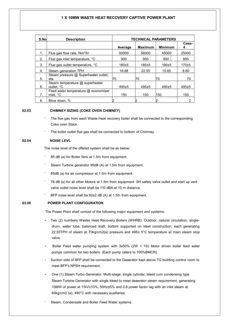
1 X 10MW WASTE HEAT RECOVERY CAPTIVE POWER PLANT
S.No Description TECHNICAL PARAMETERS
Average Maximum MinimumCase-4
1. Flue gas flow rate, Nm³/hr 50000 56000 45000 25000
2. Flue gas inlet temperature, °C 900 950 850 850
3. Flue gas outlet temperature, °C 180±5 185±5 180±5 170±5
4. Steam generation TPH 18.88 22.55 15.65 8.80
5.Steam pressure @ Superheater outlet, ata 70 70 70 70
6.Steam temperature @ superheater outlet, °C 495±5 495±5 495±5 495±5
7.Feed water temperature @ economiser inlet, °C 150 150 150 150
8. Blow down, % 2 2 2 2
02.03 CHIMNEY SIZING (COKE OVEN CHIMNEY)
¨ The flue gas from each Waste Heat recovery boiler shall be connected to the corresponding
Coke oven Stack.
¨ The boiler outlet flue gas shall be connected to bottom of Chimney.
02.04 NOISE LEVL
The noise level of the offered system shall be as below:
¨ 85 dB (a) for Boiler fans at 1.5m from equipment.
¨ Steam Turbine generator 90dB (A) at 1.5m from equipment.
¨ 85dB (a) for air compressor at 1.5m from equipment.
¨ 78 dB (a) for all other Motors at 1.5m from equipment. SH safety valve outlet and start up vent
valve outlet noise level shall be 110 dBA at 10 m distance.
¨ BFP noise level shall be 93±2 dB (A) at 1.5m from equipment.
03.00 POWER PLANT CONFIGURATION
The Power Plant shall consist of the following major equipment and systems:
- Two (2) numbers Waster Heat Recovery Boilers (WHRB): Outdoor, natural circulation, single-
drum, water tube, balanced draft, bottom supported on steel construction, each generating
22.55TPH of steam at 70kg/cm2(a) pressure and 495± 5°C temperature at main steam stop
valve.
- Boiler Feed water pumping system with 3x50% (2W + 1S) Motor driven boiler feed water
pumps common for two boilers. (Each pump caters to 100%BMCR).
- Suction side of BFP shall be connected to the Deaerator kept above TG building control room to
meet BFP’s NPSH requirement.
- One (1) Steam Turbo Generator: Multi-stage, single cylinder, bleed cum condensing type
Steam Turbine Generator with single bleed to meet deaerator steam requirement, generating
10MW of power at 11kV±10%, 50Hz±5% and 0.8 power factor lag with an inlet steam at
65kg/cm2 (a), 490°C with necessary auxiliaries.
¨ Steam, Condensate and Boiler Feed Water systems.

1 X 10MW WASTE HEAT RECOVERY CAPTIVE POWER PLANT
¨ Cooling Water System inclusive of one (1) Cooling Tower with Two (2) cells induced draft
(counter flow design, RCC construction with FRP stack, film fills and FRP fan blade).
¨ Water Treatment System.
¨ Compressed air system: Two (2) numbers Lubricated screw type air cooled air compressors
with DP filter of suitable capacity meeting the plant instrument and service air requirement shall
be provided. Air-drying (One (1) number heat less purge type twin tower) unit is provided to
cater to instrument air requirement for the plant.
¨ Split type Air conditioning for Main Control Room & wall mounted exhaust Ventilation System
for MCC room. Roof exhauster for STG building roof and wall mounted Exhaust fans for Battery
room and Toilet
¨ Portable fire extinguishers
¨ One (1) number EOT Crane of 15/5Ton.
¨ Plant Start up, Operation and control Philosophy
3.1 Power Block Area
1. The power block area shall comprise mainly the powerhouse building within which the STG and
its auxiliaries to be housed, and adjacent areas for the unit transformer and the boiler feed
pumps.
2. The STG Hall shall accommodate STG, lube oil filters, lube oil cooler, steam jet air ejector
arrangement, air compressor. The control room for the power plant, and battery room shall be
located in the STG Hall.
3. The location of the deaerator shall be above the control room at suitable elevation to meet
BFP’s NPSH requirement
4. The elevations of the building to be selected as per STG Vendor requirement.
5. Powerhouse building shall be developed based on various factors, few of the major factors are
listed below
- Adequate space for maintenance of steam turbine and generator.
- The deck elevation has to be selected based on:
- NPSH requirement of the Condensate extraction pumps
- Surface condenser dimensions
←6. The crane rails elevation of the turbine shall be selected based on the turbine height and crane
clearance required above turbine as per STG supplier’s recommendation.
7. The boiler feed pumps shall be located on the ground floor inside STG building.
8. Two numbers of external staircases to be provided at extreme end for easy access to each floor
9. Cable Cellar.
10. Adequate ventilation & AC system for control room.
3.2 Boiler Area
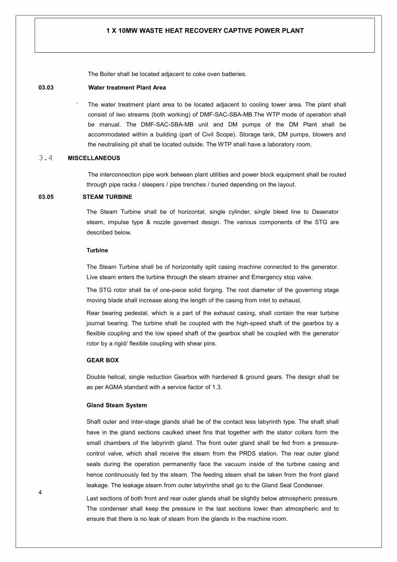
1 X 10MW WASTE HEAT RECOVERY CAPTIVE POWER PLANT
The Boiler shall be located adjacent to coke oven batteries.
03.03 Water treatment Plant Area
¨ The water treatment plant area to be located adjacent to cooling tower area. The plant shall
consist of two streams (both working) of DMF-SAC-SBA-MB.The WTP mode of operation shall
be manual. The DMF-SAC-SBA-MB unit and DM pumps of the DM Plant shall be
accommodated within a building (part of Civil Scope). Storage tank, DM pumps, blowers and
the neutralising pit shall be located outside. The WTP shall have a laboratory room.
3.4 MISCELLANEOUS
The interconnection pipe work between plant utilities and power block equipment shall be routed
through pipe racks / sleepers / pipe trenches / buried depending on the layout.
03.05 STEAM TURBINE
The Steam Turbine shall be of horizontal, single cylinder, single bleed line to Deaerator
steam, impulse type & nozzle governed design. The various components of the STG are
described below.
Turbine
The Steam Turbine shall be of horizontally split casing machine connected to the generator.
Live steam enters the turbine through the steam strainer and Emergency stop valve.
The STG rotor shall be of one-piece solid forging. The root diameter of the governing stage
moving blade shall increase along the length of the casing from inlet to exhaust.
Rear bearing pedestal, which is a part of the exhaust casing, shall contain the rear turbine
journal bearing. The turbine shall be coupled with the high-speed shaft of the gearbox by a
flexible coupling and the low speed shaft of the gearbox shall be coupled with the generator
rotor by a rigid/ flexible coupling with shear pins.
GEAR BOX
Double helical, single reduction Gearbox with hardened & ground gears. The design shall be
as per AGMA standard with a service factor of 1.3.
Gland Steam System
Shaft outer and inter-stage glands shall be of the contact less labyrinth type. The shaft shall
have in the gland sections caulked sheet fins that together with the stator collars form the
small chambers of the labyrinth gland. The front outer gland shall be fed from a pressure-
control valve, which shall receive the steam from the PRDS station. The rear outer gland
seals during the operation permanently face the vacuum inside of the turbine casing and
hence continuously fed by the steam. The feeding steam shall be taken from the front gland
leakage. The leakage steam from outer labyrinths shall go to the Gland Seal Condenser.4
Last sections of both front and rear outer glands shall be slightly below atmospheric pressure.
The condenser shall keep the pressure in the last sections lower than atmospheric and to
ensure that there is no leak of steam from the glands in the machine room.

1 X 10MW WASTE HEAT RECOVERY CAPTIVE POWER PLANT
Turbine Drain System
During every start-up it should be ensured that the drain valves provided on the turbine
casing, ESV casing, governor control valve and bleed steam line are opened to drain the
entrapped condensate to avoid damage due to high-energy water accumulation or ingress.
Turbine Lube Oil System
Oil Storage Tank
The turbine shall have one (1) Main oil tank either Skid mounted / separate as per STG
vendor Standard. The oil tank shall be provided with necessary level indicators, inlet and
outlet oil connections and exhaust fan to evacuate oil vapour from the tank. Oil tank to be
provided with
Turning Gear
When the unit is under shutdown for a long period, due to its inherent weight, the rotor shaft
will hot sag. Rolling of the unit with this condition will result in contact of the moving parts
with the stationary parts. Following tripping of the machine, due to condensation of the
locked up steam, the rotor shaft tends to hog. In order to prevent sagging and hogging of
the rotor shaft, a barring gear to be provided. The barring device shall be capable for auto /
manual engagement and auto disengagement. The barring gear shall be operated by an AC
motor. In case of AC mains failure, provision for hand barring of the rotor has to be
provided.
Main Steam Stop Valves
Emergency Stop Valve
A hydraulically Operated Emergency stop valve along with strainer shall be provided for
closing the supply to the Turbine under emergency condition.
Governing Valve
Governing valves for the turbines shall be of bar lift and multi-valve type & shall be used for speed regulation of the turbine.
Main Technical Parameters of Turbine
Parameter Unit Value
Power at generator terminal kW 10000
Main Steam Pressure at Turbine inlet Ata 65.0
Main Steam Temperature at Turbine inlet ° C 490
Main Steam Flow at Turbine inlet TPH 42.30
Main steam requirement for auxiliaries TPH 0.47
Deaerator Heating steam TPH 6.63
Exhaust steam Pressure Ata 0.1
Cooling water Inlet Temperature °C 32
Cooling water outlet Temperature °C 41
- Deaerator with LP dosing system
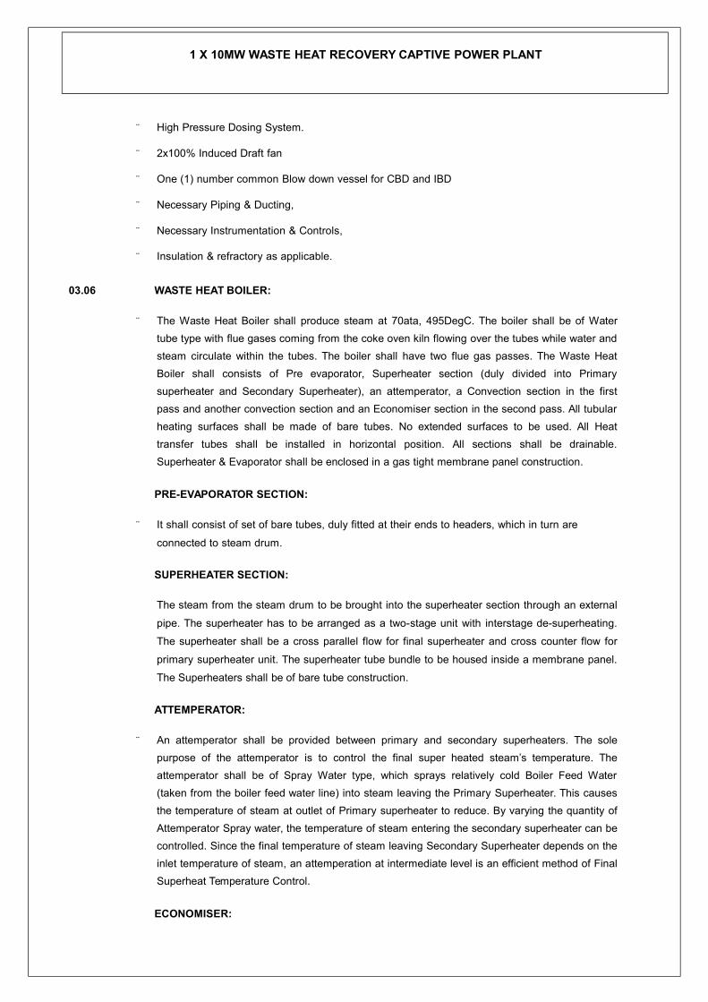
1 X 10MW WASTE HEAT RECOVERY CAPTIVE POWER PLANT
¨ High Pressure Dosing System.
¨ 2x100% Induced Draft fan
¨ One (1) number common Blow down vessel for CBD and IBD
¨ Necessary Piping & Ducting,
¨ Necessary Instrumentation & Controls,
¨ Insulation & refractory as applicable.
03.06 WASTE HEAT BOILER:
¨ The Waste Heat Boiler shall produce steam at 70ata, 495DegC. The boiler shall be of Water
tube type with flue gases coming from the coke oven kiln flowing over the tubes while water and
steam circulate within the tubes. The boiler shall have two flue gas passes. The Waste Heat
Boiler shall consists of Pre evaporator, Superheater section (duly divided into Primary
superheater and Secondary Superheater), an attemperator, a Convection section in the first
pass and another convection section and an Economiser section in the second pass. All tubular
heating surfaces shall be made of bare tubes. No extended surfaces to be used. All Heat
transfer tubes shall be installed in horizontal position. All sections shall be drainable.
Superheater & Evaporator shall be enclosed in a gas tight membrane panel construction.
PRE-EVAPORATOR SECTION:
¨ It shall consist of set of bare tubes, duly fitted at their ends to headers, which in turn are
connected to steam drum.
SUPERHEATER SECTION:
The steam from the steam drum to be brought into the superheater section through an external
pipe. The superheater has to be arranged as a two-stage unit with interstage de-superheating.
The superheater shall be a cross parallel flow for final superheater and cross counter flow for
primary superheater unit. The superheater tube bundle to be housed inside a membrane panel.
The Superheaters shall be of bare tube construction.
ATTEMPERATOR:
¨ An attemperator shall be provided between primary and secondary superheaters. The sole
purpose of the attemperator is to control the final super heated steam’s temperature. The
attemperator shall be of Spray Water type, which sprays relatively cold Boiler Feed Water
(taken from the boiler feed water line) into steam leaving the Primary Superheater. This causes
the temperature of steam at outlet of Primary superheater to reduce. By varying the quantity of
Attemperator Spray water, the temperature of steam entering the secondary superheater can be
controlled. Since the final temperature of steam leaving Secondary Superheater depends on the
inlet temperature of steam, an attemperation at intermediate level is an efficient method of Final
Superheat Temperature Control.
ECONOMISER:

1 X 10MW WASTE HEAT RECOVERY CAPTIVE POWER PLANT
¨ The economiser shall be incorporated in steel casing at the down stream of evaporator to
increase the efficiency of the system and shall be supplied in number of modules. The
economiser section to be provided to cool down the flue gases to the required outlet
temperature and use this heat to increase the temperature of Boiler Feed water entering the
Steam drum. The economiser shall be of bare tube construction. The tubes shall be horizontally
orientated and shall hung from the top by means of hangers and supports.
FLUE GAS DUCTING
¨ The boiler inlet hot gas duct along with necessary non-metallic expansion joint shall be
provided. The flue gas ducting between convection sections to economiser to be provided. The
cooled flue gas ducting from economiser outlet to coke oven process stack along with
necessary expansion joints, supports, insulation and cladding shall be supplied. TL shall provide
the ash discharge hoppers, inspection doors, manholes and drains in the boiler area wherever
required.
HIGH PRESSURE DOSING SYSTEM
¨ The High-Pressure dosing system shall dose the boiler water with required quantity of Chemical
water to control the contaminants in the boiler water. The dosing chemical normally used shall
be Tri-Sodium
Phosphate. The dosing system shall consist of a storage tank, which shall be filled with water
and chemicals to be added to it and stirred. A motorised stirrer to be provided for this purpose.
The mixed chemical solution shall be pumped to the steam drum by means of Reciprocating
type pumps.
¨ Three Pumps shall be provided (2W+1S).
SOOT BLOWERS:
¨ The boiler shall be provided with necessary quantity of soot blowers. The sole purpose of soot
blowers is to keep the heat transfer area clean of fouling. The Soot blowers shall be spaced in
such a manner that all heat transfer areas are sufficiently covered. Retractable soot blowers
shall be provided in High temperature zones (such as superheater) and rotary soot blowers
shall be provided in comparatively low temperature zones such as evaporator and Economiser.
All soot blowers shall be motor operated. A Local control panel shall operate sequentially the
soot blowers. The sequence can be started either from Local Control Panel or from Control
room.
INDUCED DRAFT FAN:
¨ The induced draft fan shall draw flue gas from the boiler and exhausts it through the stack. Two
no. of ID fans per boiler shall be provided. The fan shall be sized to provide necessary draft to
overcome the pressure drop across the boiler. The variable frequency drive shall be provided for
ID fan to maintain the desired draft at WHRB inlet.
¨
¨ Suitable design margins shall be provided on the capacity and head of the fans to take care of
various uncertainties and excess air requirement

1 X 10MW WASTE HEAT RECOVERY CAPTIVE POWER PLANT
External insulation
The machine made mineral wool mattresses shall be used as external insulating layer and
shall have a uniform density of 120 kg/m3.
04.00 WATER TREATMENT PLANT & DM PLANT
Water Treatment Plant shall comprise of two streams (both working) of DMF-SAC-SBA-MB.
The DM plant shall be designed to operate for a period of 20hrs before regeneration of the ion
exchangers becomes necessary. Maximum time for regeneration shall be 4hours. The Output
between Regenerations (OBR) for the DM plant shall be 60m3 of DM water.
04.01 WATER REQUIREMENT
Total water requirement for the new 10 MW WHR power plant and augmented existing power
plant will be 2016 cum/ day (refer Water Balance Diagram Fig. 1)
05.00 Cooling Water System
PROCESS DESCRIPTION
The cooling tower shall be of mechanical, induced draft, two cell and counter-flow type. The
cooling tower shall be of RCC construction with concrete storage basin and shall consist of
two cells. Each cell outlet shall have a coarse fine screen for filtering out any air borne debris
from the cooling water entering the pumps. The water drained from the drain sump in the
basin of the cooling tower shall be routed to the storm water drains.
06.00 COMPRESSED AIR SYSTEM
Instrument & Service air required in the Power Plant for operation of I/P converters, purge
instruments, pneumatic actuation of control valves, dampers, etc. for different systems shall
be catered by 2x100% (1W+1S) Air cooled lubricated Screw type Air Compressor.
1 x 100% air drier shall be envisaged to avoid carryover of moisture to instruments.
07.00 EOT CRANE
One (1) EOT crane shall be provided in the STG building for maintenance activities of Steam
Turbine Generator and auxiliaries. EOT crane has to be offered, considering movement of
components in both cross wise and longitudinal direction.
08.00 FIRE PROTECTION SYSTEM
Portable fire extinguishers (only CO2 bottles) shall be provided for the protection of the equipment
within the STG building. These fire extinguishers shall be placed in different areas of the building.
PIPING SYSTEM
The piping for the power plant shall be grouped into power cycle piping, low-pressure utility piping
and cooling water piping. The pipelines classified under each group have to be listed below:

1 X 10MW WASTE HEAT RECOVERY CAPTIVE POWER PLANT
09.00 PROJECT COST
Estimated project cost for the 10 MW WHR power plant is about Rs. 90 Crores.
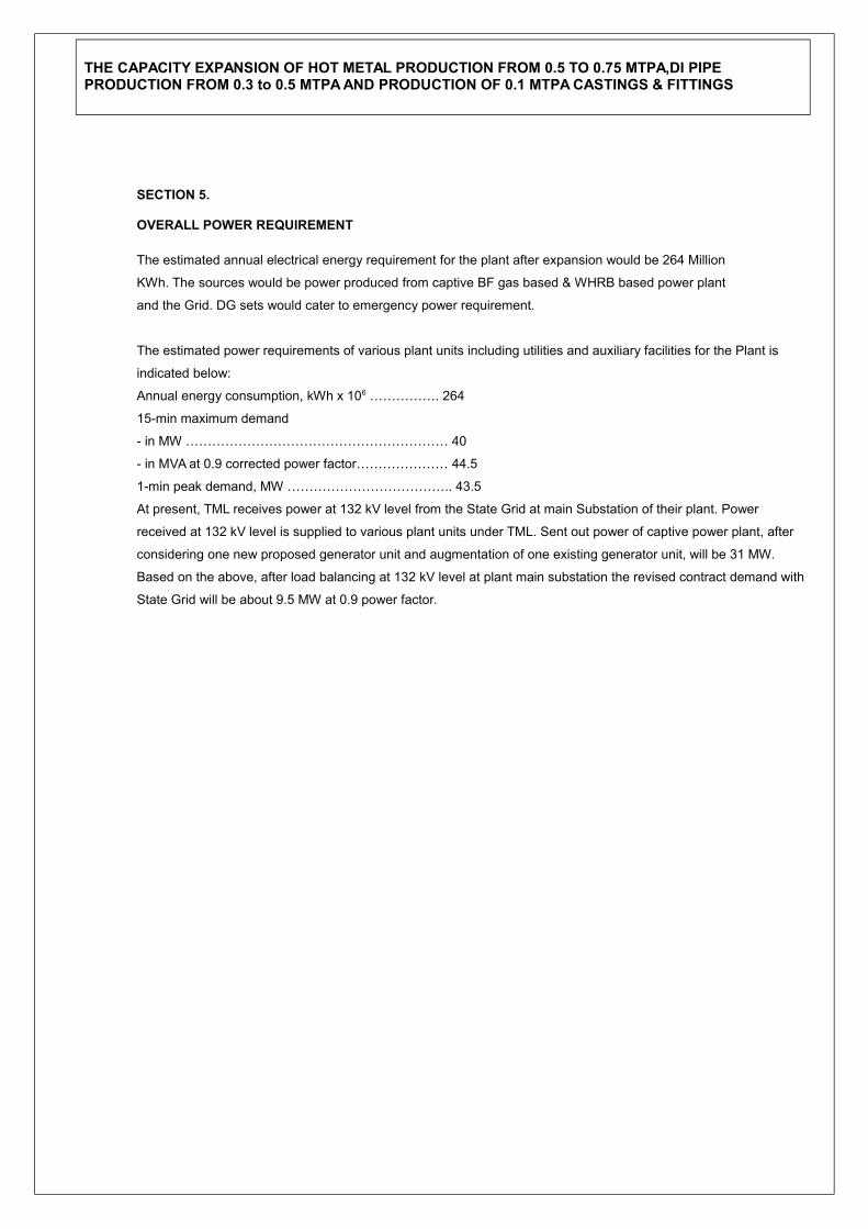
THE CAPACITY EXPANSION OF HOT METAL PRODUCTION FROM 0.5 TO 0.75 MTPA,DI PIPE PRODUCTION FROM 0.3 to 0.5 MTPA AND PRODUCTION OF 0.1 MTPA CASTINGS & FITTINGS
SECTION 5.
OVERALL POWER REQUIREMENT
The estimated annual electrical energy requirement for the plant after expansion would be 264 Million
KWh. The sources would be power produced from captive BF gas based & WHRB based power plant
and the Grid. DG sets would cater to emergency power requirement.
The estimated power requirements of various plant units including utilities and auxiliary facilities for the Plant is
indicated below:
Annual energy consumption, kWh x 106 ……………. 264
15-min maximum demand
- in MW …………………………………………………… 40
- in MVA at 0.9 corrected power factor………………… 44.5
1-min peak demand, MW ……………………………….. 43.5
At present, TML receives power at 132 kV level from the State Grid at main Substation of their plant. Power
received at 132 kV level is supplied to various plant units under TML. Sent out power of captive power plant, after
considering one new proposed generator unit and augmentation of one existing generator unit, will be 31 MW.
Based on the above, after load balancing at 132 kV level at plant main substation the revised contract demand with
State Grid will be about 9.5 MW at 0.9 power factor.

FIG. 1 - WATER BALANCE DIAGRAM

FIG. 1.1 - WATER BALANCE DIAGRAM

FIG. 3 PROCESS FLOW