tata power company limited - Mjunction
258
1 | Page TATA POWER COMPANY LIMITED e-SALE CATALOGUE FOR The sale of Unit No. 4 of the 150 MW Oil Fired Thermal Power Plant of TATA POWER COMPANY LIMITED at Trombay , Maharashtra CONDUCTED BY mjunction services limited
-
Upload
khangminh22 -
Category
Documents
-
view
1 -
download
0
Transcript of tata power company limited - Mjunction

1 | P a g e
TATA POWER COMPANY LIMITED
e-SALE CATALOGUE
FOR The sale of Unit No. 4 of the 150 MW Oil Fired Thermal Power Plant of TATA POWER
COMPANY LIMITED at Trombay , Maharashtra
CONDUCTED BY mjunction services limited
2 | P a g e
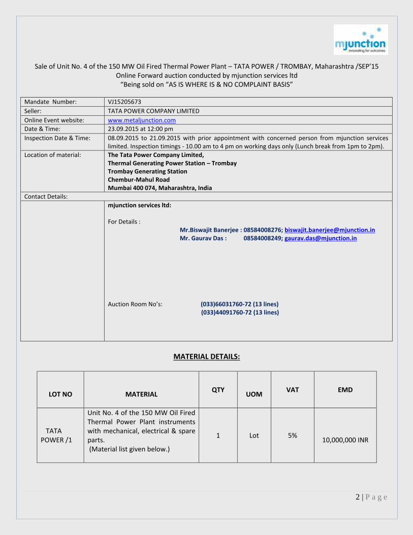
Sale of Unit No. 4 of the 150 MW Oil Fired Thermal Power Plant – TATA POWER / TROMBAY, Maharashtra /SEP’15 Online Forward auction conducted by mjunction services ltd
“Being sold on “AS IS WHERE IS & NO COMPLAINT BASIS”
Mandate Number: VJ15205673
Seller: TATA POWER COMPANY LIMITED
Online Event website: www.metaljunction.com
Date & Time: 23.09.2015 at 12:00 pm
Inspection Date & Time: 08.09.2015 to 21.09.2015 with prior appointment with concerned person from mjunction services limited. Inspection timings - 10.00 am to 4 pm on working days only (Lunch break from 1pm to 2pm).
Location of material: The Tata Power Company Limited, Thermal Generating Power Station – Trombay Trombay Generating Station Chembur-Mahul Road Mumbai 400 074, Maharashtra, India
Contact Details:
mjunction services ltd: For Details : Mr.Biswajit Banerjee : 08584008276; [email protected] Mr. Gaurav Das : 08584008249; [email protected] Auction Room No’s: (033)66031760-72 (13 lines) (033)44091760-72 (13 lines)
MATERIAL DETAILS:
LOT NO
MATERIAL
QTY
UOM
VAT
EMD
TATA POWER /1
Unit No. 4 of the 150 MW Oil Fired Thermal Power Plant instruments with mechanical, electrical & spare parts. (Material list given below.)
1 Lot 5%
10,000,000 INR

3 | P a g e
Details of the Lot 1 : Table -1 : – A: Mechanical Equipment
Sl. No Sub-Parts Presently available Quantity
1 CST tanks with pumps & pipes 2 set 2 Condensate Extraction Pumps with valves 2 set 3 LP Heaters: 1 set
3A L.P Heater - 1 with inlet / outlet valves 1 set 3B L.P Heater - 2 with inlet / outlet valves 1 set 3C L.P.Heater - 3 with inlet & outlet valves 1 set
4 De aerator with storage tank, valves, etc. 1 set 5 BFP with Booster Pump, Oil cooler, Gearbox & Skid 3 set
6A BFP Seal Injection Pumps with valves 2 set 6B LO Tank Vapour Extractor with pipe line 2 set 6C Condensate Sump Pumps with valves 2 set 6D BFP Lub Oil Coolers with Pipes & Valves 3 set 7 H.P.Heaters: 1 set
7A H.P.Heaters - 5 with valves 1 set 7B H.P. Heater -6 with valves 1 set 7C H.P.Heater -7 with valves 1 set 8 C.C.Pumps with discharge Valves 3 set 9 Heater Drip Pumps with Valves 2 set 10A Boiler Structure including floor, gallaries, roof, duct supports, ceiling girders, stairs
& Interconnection Corridoors 1 set
10B Boiler lift & lift structure 1 set Pressure Parts:
Water wall tubes with headers 1 set
Steam cooled wall tubes, roof tubes & Headers 1 set
Re heaters Coils with headers 1 set
Pendent Super heater coils with headers 1 set
LTSH Coils, Hgr Tubes and headers 1 set
Divisional panel & Platen super heaters 1 set
Boiler Drum with internals 1 set
Economiser coils with headers and links to Drum 1 set
Super heater link pipes & De-superheaters 1 set
Down comer pipes & Bottom drums 1 set
Buckstays and leveller guides 1 set
Skin casing & roof covering 1 set
Boiler integral pipes, valves, supports and firewater riser pipes 1 set
H & S for Pressure Parts 1 set
11 HP valves with actuators on boiler side 1 set 12 Boiler Wash down pumps without motors 2 sets

4 | P a g e
Sl. No Sub-Parts Presently available Quantity 13 Turbine: 13A Turbine Lube Oil Tank 1 no 13B Service Oil storage Tank 1 no 14 AOP without motor 1set
15 TGOP, EBOP & JOP without motor 1no.each
16 Bowser with oil circulation pump 1set
17 Oil Tank Vapour Extractor Fans with valves without motor
2sets
18 Main Ejector with valves
1set
19A Auxiliary Ejector System with valves
1set
19B Hogging Ejector with valves
1set
20 Gland Steam Exhauster with valves
1set
Fans for above
2sets
21 Condenser with hotwell & interconnection piece with Turbine
1set
22 CW pumps at jetty 4sets
Spare CW pumps lying at bottom of Boilers
2sets
Valves of CW pumps at jetty
4sets
23 Lube oil coolers
2sets
Spare tube bundle lying on floor
1set
24 Condenser Valves with Actuators:
Inlet & Outlet Valves
4sets
Back Wash Valves
2sets
Bellows with combination flanges
4sets
CW pipe lines, bends in Turbine Hall
2 sets
25 Priming Ejector with valves 1set
5 | P a g e
Sl. No Sub-Parts Presently available Quantity
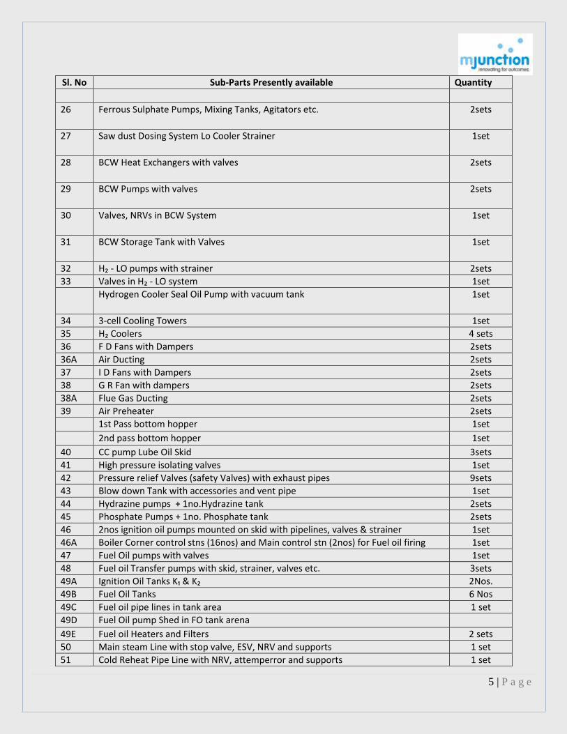
26 Ferrous Sulphate Pumps, Mixing Tanks, Agitators etc.
2sets
27 Saw dust Dosing System Lo Cooler Strainer
1set
28 BCW Heat Exchangers with valves
2sets
29 BCW Pumps with valves 2sets
30 Valves, NRVs in BCW System
1set
31 BCW Storage Tank with Valves 1set
32 H₂ - LO pumps with strainer 2sets 33 Valves in H₂ - LO system 1set Hydrogen Cooler Seal Oil Pump with vacuum tank 1set
34 3-cell Cooling Towers 1set 35 H₂ Coolers 4 sets 36 F D Fans with Dampers 2sets 36A Air Ducting 2sets 37 I D Fans with Dampers 2sets 38 G R Fan with dampers 2sets 38A Flue Gas Ducting 2sets 39 Air Preheater 2sets 1st Pass bottom hopper 1set
2nd pass bottom hopper 1set
40 CC pump Lube Oil Skid 3sets 41 High pressure isolating valves 1set 42 Pressure relief Valves (safety Valves) with exhaust pipes 9sets 43 Blow down Tank with accessories and vent pipe 1set 44 Hydrazine pumps + 1no.Hydrazine tank 2sets 45 Phosphate Pumps + 1no. Phosphate tank 2sets 46 2nos ignition oil pumps mounted on skid with pipelines, valves & strainer 1set 46A Boiler Corner control stns (16nos) and Main control stn (2nos) for Fuel oil firing 1set 47 Fuel Oil pumps with valves 1set 48 Fuel oil Transfer pumps with skid, strainer, valves etc. 3sets 49A Ignition Oil Tanks K₁ & K₂ 2Nos. 49B Fuel Oil Tanks 6 Nos 49C Fuel oil pipe lines in tank area 1 set 49D Fuel Oil pump Shed in FO tank arena 49E Fuel oil Heaters and Filters 2 sets 50 Main steam Line with stop valve, ESV, NRV and supports 1 set 51 Cold Reheat Pipe Line with NRV, attemperror and supports 1 set

6 | P a g e
Sl. No Sub-Parts Presently available Quantity 52 Hot Reheat pipe line with SV, Isolator and supports 1 set 53 By Pass lines to condencer with valves 1 set 54 BFP discharge line with valves, NRVs and supports 1 set 55 BFP Suction lines through LP Heaters 1 set 56 BFP recirculation line with valves, NRVs and supports 1 set 57 Extraction steam lines with valves, NRVs, and supports 1 set 58 Steam lines to Ejector, gland sealing and Ejector 1 set 59A Drip lines with valves and supports 1 set 59B Condenser vacuum lines 1 set 59C Cooling Water lines 1 set 60 Voltas VAM system 1 set 61 Tharmax Chiller plant 1 set 61A Chiller water pumps with valves 4 sets 61B Cooling Water Pumps with valves 3 sets 61C Pipe lines & valves for central A/C system 1 set 62 Hydraulic Test pump 1 set 63 LRSB with pipes/valves 16 sets 64 Furnace Temperature probe 1 set 65 City Water Pumps with valves and pipes 3 sets 65A Drain water sump Pumps at TG hall basement 3 sets 65B Acid storage tanks at LHS of boiler bay 2 sets 65C Rectangular Tanks at the side of acid tanks 2 sets 65D Pipes & racks on RHS of Boiler bay 1 set 65E Air washing system, ducts, Screen, & Blowers 1 set 66A Isolating Valve & Bypass valve 1 set 66B Gas Trip Valve 1 set 67 Gas Moisture separator 1 set 67A Around 400Mtr Fuel Gas pipe lines with flow meter 1 set 68 Ignitor air fans (2nos) with Ducts 1 set 69 Scanner Air Fans (2nos) with pipes 1 set 70 Mill bay structure complete with wrecked structures for coal conveyors, etc. 1 set
B. Electrical Equipment
Sr No
Equipment Category
Sub Parts Presently Available Qty
Motor
1 Boiler Feed Pump Motor 3
2 BFP seal injection pump Motor 2
3 Condensate sump pump Motor 2
4 CC Pump Motor 3
5 Compressor(4A,4B,4C & 4D) motor 4
6 H2LO pump Motor 2
7 BCW pump Motor 2

7 | P a g e
Sr No
Equipment Category
Sub Parts Presently Available Qty
8 Heater Drip pump Motor 2
9 Stn Sump Pump Motor 3
10 Generator seal Oil pump Motor 3
11 Condensate Pump Motor 2
12 Phosphate pump Motor 2
13 Hydrazine pump Motor 2
14 BFP oil vapour extractor fan motor 2
15 BFP discharge valve Motor 2
16 TGOP Motor 2
17 EBOP Motor 2
18 Ignator Air fan Motor 2
19 ID Fan Motor 2
20 GR Fan Motor 2
21 FD Fan Motor 2
22 Circulating water pump motor 2
23 Boiler wash down pump Motor 2
24 Ignition oil pump Motor 2
25 Chiller water pump motor 5
26 Cooling water pump Motor 3
27 Ferrous sulphate pump Motor 1
28 Fuel oil transfer pump Motor 3
29 Fuel oil pump motor 2
Panel
1 Control Systems ,DCS system & 415v LT switchgear and MCC Panel
13+8
Transformer
1 U#4,Lighting Transformer, 125 KVA, 400 V
1
2 SST-4A ,4B & 4D Transformer 1000 KVA, 3300V/400V
3
3 Ground Transformer 1200 KVA, 3300V/490V
1
Cables
1 Cable of different sizes for different Control Switches.
1000 Kg.
Store Items :

8 | P a g e
Mat Description Available stock
JUMPER,PER POL,COMPLETE WITH HARDWA 1
ENERGYMETER,PHASE:3 PH,NO OF WIRE:3 1
MTR MVA,120-0-120 2
MOVING COIL,RANGE:0-1/10A 2
BOLT,GUIDE,FEMALE CONTACT JAW 11
CHAIN,FLEXIBLE,CU,490X50X45MM 8
GSKT WITH O-RING,TELK 9
WSHR,CU ASB,PN:230606,KIRLOSKAR PNUM 7
COIL,MAGNETROL,SA2-115-50 2
HEATER ELEM,POS:11,ALEN BRDLY 1
JT,DIA:15X370/325MM 12
SW 1
HYDR OIL,BHEL,SF6,CIRCUIT BREAKER 15
BOLT,EYE,INTERRUPTER,SIEMENS 3
WSHR,STOP,REF:W10-21231310,VOLTAS 173
NAME PLATE 2
SW,CTRL,MM:ODC/02/N/180/SRS/P/2,EE 2
FUSE LINK HV,22KV,1A,J&P 3
WSHR,REF:G800247 1
WSHR,SPR,PN:H21231316 20
MCB,220VDC,6A,1NO 1NC 30
MCB,415VAC,3A,3P,1NO+1NC 30
NAME PLATE,AUTO SYNCHRONISER 1
SUPPORT,PRCLN,BHEL,REACTOR WINDING 6
SW,MM:CR2940U3 2
SW,MM:CR2940U301 3
SW,MODEL:10AX002G7 11
WSHR,CONTACT,PN:6441630 P1 9
9 | P a g e
Mat Description Available stock
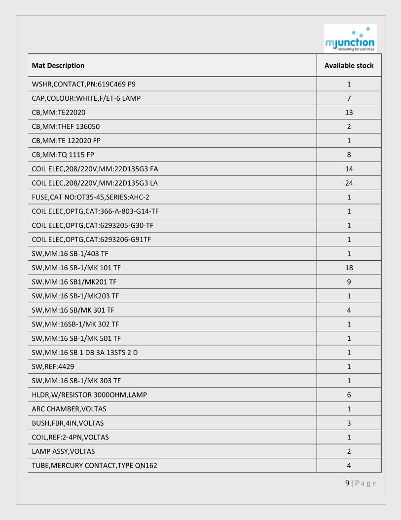
WSHR,CONTACT,PN:619C469 P9 1
CAP,COLOUR:WHITE,F/ET-6 LAMP 7
CB,MM:TE22020 13
CB,MM:THEF 136050 2
CB,MM:TE 122020 FP 1
CB,MM:TQ 1115 FP 8
COIL ELEC,208/220V,MM:22D135G3 FA 14
COIL ELEC,208/220V,MM:22D135G3 LA 24
FUSE,CAT NO:OT35-45,SERIES:AHC-2 1
COIL ELEC,OPTG,CAT:366-A-803-G14-TF 1
COIL ELEC,OPTG,CAT:6293205-G30-TF 1
COIL ELEC,OPTG,CAT:6293206-G91TF 1
SW,MM:16 SB-1/403 TF 1
SW,MM:16 SB-1/MK 101 TF 18
SW,MM:16 SB1/MK201 TF 9
SW,MM:16 SB-1/MK203 TF 1
SW,MM:16 SB/MK 301 TF 4
SW,MM:16SB-1/MK 302 TF 1
SW,MM:16 SB-1/MK 501 TF 1
SW,MM:16 SB 1 DB 3A 13STS 2 D 1
SW,REF:4429 1
SW,MM:16 SB-1/MK 303 TF 1
HLDR,W/RESISTOR 3000OHM,LAMP 6
ARC CHAMBER,VOLTAS 1
BUSH,FBR,4IN,VOLTAS 3
COIL,REF:2-4PN,VOLTAS 1
LAMP ASSY,VOLTAS 2
TUBE,MERCURY CONTACT,TYPE QN162 4
10 | P a g e
Mat Description Available stock
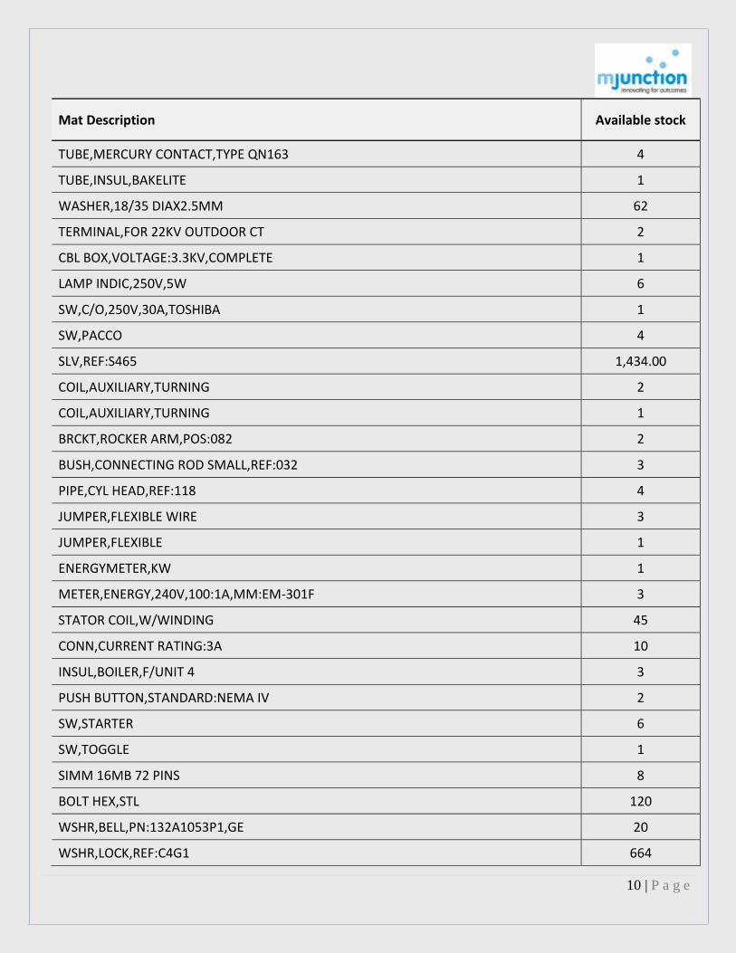
TUBE,MERCURY CONTACT,TYPE QN163 4
TUBE,INSUL,BAKELITE 1
WASHER,18/35 DIAX2.5MM 62
TERMINAL,FOR 22KV OUTDOOR CT 2
CBL BOX,VOLTAGE:3.3KV,COMPLETE 1
LAMP INDIC,250V,5W 6
SW,C/O,250V,30A,TOSHIBA 1
SW,PACCO 4
SLV,REF:S465 1,434.00
COIL,AUXILIARY,TURNING 2
COIL,AUXILIARY,TURNING 1
BRCKT,ROCKER ARM,POS:082 2
BUSH,CONNECTING ROD SMALL,REF:032 3
PIPE,CYL HEAD,REF:118 4
JUMPER,FLEXIBLE WIRE 3
JUMPER,FLEXIBLE 1
ENERGYMETER,KW 1
METER,ENERGY,240V,100:1A,MM:EM-301F 3
STATOR COIL,W/WINDING 45
CONN,CURRENT RATING:3A 10
INSUL,BOILER,F/UNIT 4 3
PUSH BUTTON,STANDARD:NEMA IV 2
SW,STARTER 6
SW,TOGGLE 1
SIMM 16MB 72 PINS 8
BOLT HEX,STL 120
WSHR,BELL,PN:132A1053P1,GE 20
WSHR,LOCK,REF:C4G1 664

11 | P a g e
Mat Description Available stock
FUSE,CC1051 CP GRB 20.127 10,FERRAZ 5
FUSE,CC1051 CP GRC 20.127 50,FERRAZ 10
GSKT SET,F/CTS PRIMARY & SECONDARY 3
FREQUENCY TRNSDCR 2
METER PWR,MW,24/0.12KV,600:5A,10-0-10MW 2
MEGAWATT METER,100-0-400 2000/5A 100KV 2
MEGAWATT METER,3W 0-150 1200/5 110KV 3
METER PWR,24/0.12KV,600:5A,10-0-10MVA 2
METER PWR,MVAR,3PHASE,200-0-200MVA 2
ADHSV,LOCTITE 680 10
BRG BALL,6324,SKF 1
FAN,ELEC WALL MTG,1/3HP,230V,1 PHASE 2
RGLTR,ELECTRONIC FAN,150W 13
XFMR LV,750VA,400V,230V,1 PHASE 2
MOT AC,415V,132M,3PH,7.5KW,1465RPM,B3 0
MOT AC,415V,29HP,3P,1405RPM 1
MOT AC,IND,415V,5HP,1430RPM 2
MOT AC,440V,50HZ,3PH,75HP,1440RPM 1
CARD,F/CV-CC 24V/1000A BC 2
CARD,DC U/V,BREAKER CIRCUIT,1000A 2
CARD,DC O/V,BREAKER CIRCUIT,1000A 2
FUSE,SCR,CV-CC 24V,BATTERY CHARGER 5
POTENTIOMETER,F/CV-CC 24V/1000A BC 5
CARD,DC U/V,BREAKER CIRCUIT,350A 2
CARD,DC O/V,BREAKER CIRCUIT,350A 2
CARD,ALARM,FUSE FAIL 2
CKT BRD,F/220V,350A 4
FLTR,CONDENSER,220V,350A 10

12 | P a g e
Mat Description Available stock
POTENTIOMETER,CNTRL,F/CV-CC 220V/350A BC 5
SCR,CTRL VLV,CC 220V/350A BC 4
CBL ARM,HTNSN PWR,AL,3.3KV,1C,1000MM2 350
CBL ARM,CU,650/1100V,1C,16MM2 521
CBL ARM,CU,650/1100V,3C,50MM2 250
CBL ARM,CU,650/1100V,3C,300MM2 178
CBL ARM,CU,600/1100V,4C,6MM2 990
CBL ARM,CU,650/1100V,7C,1.5MM2 990
CBL ARM,CTRL,CU,650/1100V,14C,1MM2 386
CBL NARM,COM,CU,250V,5P,22AWG 595
CBL NARM,COM,CU,250V,5P,22AWG 595
CBL NARM,CU,3C,6MM2 500
CBL GLND,SINGLE COMP,BRS,REF:1616 833
GLND,CBL,BRS,CAT:SIBG-2944,SIEMENS 65
GLND,CBL,BRS,CAT:SIBG-4284,SIEMENS 76
GROMMET,RBR,CBL GLAND,SIZE:1/2 IN 400
SLV SOLDERING,CU,6IN2 29
SLV SOLDERING,CU,1000IN2 30
JOINT KIT,PVC,0.062MM2 2
STR JOINT/HS,PVC,2.5MM2,3.3/6.6/22KV,4C 10
STR JOINT/HS,PVC,2.5MM2,3.3/6.6/22KV,4C 46
STR JOINT/HS,PVC,2.5MM2,3.3/6.6/22KV,7C 18
STR JOINT/HS,PVC,10MM2,3.3/6.6/1.1/22KV 10
STR JOINT/HS,PVC,16MM2,3.3/6.6/1.1/22KV 2
STR JOINT/HS,3.3/6.6/22KV 7
CBL JOINT KIT,11KV,3C,240MM2 4
TUBING,PN:BPTM 50/20MM 42
HLDR,BC,250V,STR/REGLR/BATTEN,3 PIN 0

13 | P a g e
Mat Description Available stock
HLDR,SC,250V,ANG/REG,BAKELITE 2
HLDR,ANGULAR,BRS,BAYONET CAP LAMP 89
PLUG,CUTLER HAMMER,IR CLD,PN:212D 10
PLUG,415/500V,ONE WAY FIT,5 PINS,30A 19
SOCKT,415/500V,15/30A,FLUSH,MM:2412B 86
CLMP,FIXED,BUS SUPPORT,IPS 3INPCD 3
CLMP,FIXED,BUS SUPPORT,IPS 3INPCD 4
CLMP,FIXED,BUS SUPPORT,11/2IN IPS 6
CLMP,SLIDING,BUS SUPPORT,11/4INIPS 4
CLMP,SLIDING,BUS SUPPORT,1-1/2IN 10
CLMP,GROUNDING,W/BRASS NUT AND BOLT 2
CLMP,FIXED,40MMX2IN 2
CLAMP REDUCER 6
CONNR,ELEC,SING BRN/TEE,2-1/4 X 1-1/4IN 7
CLMP,T,1-1/4IN IPS RUN TO 0.2IN2 CONDCT 6
CBL LUG,CU,630MM2,MM:630CUS-476,DOWELLS 13
CBL LUG,TUBULAR,CU,6MM2,PN:CUS/390 422
CLMP,CU,2IN 4
CLMP,FIXED,CU,2-1/2IN 5
CLMP,FLEXIBLE/LOOSE,1-1/2IN 1
CLMP,FLEXIBLE/LOOSE,2-1/2IN 1
CLMP,FLEXIBLE,1-1/4IN,SF6 9
CLMP,FLEX,2-1/2IN 6
CLMP,FIXED,STUD,1-1/4IN 9
CLMP,FLEXIBLE,2-1/2IN 2
CLMP,FIXED,F/1-1/4IN IPS H-HBB CT PALM 3
CLMP,FIXED,1-1/4INIPS,SF6 12
CLMP,FIXED,TINNED CU,HOR,42MM,1-1/4IN 3

14 | P a g e
Mat Description Available stock
CLMP,FLEX,TINNED CU,42MM TO 1-1/4IN,VH 3
CLMP,FIXED,TELK 3
CLMP,FLEX,TINNED CU,HOTDIP,2000A TELK CT 1
CLMP,FLEX,CU,2500A BKR PALM TO 2.5IN IPS 14
CLMAMP,SPACER 11
LED,SIG,230VAC,RED,300MM W/ BLINKER 2
LAMP,250V,200W,SC RGLR 250
LTRN,3DX3H,BRKVL,PST TP,MM:Z5640/1L 12
FTG,CAT:F 65007 (L) 4
LUMIN LIGHTING,RF DWNLGT,100W,DECO,REC 4
FTG,HPMV FLOODLIGHT,REF:IFL300 20
INTGRL CFL POST TOP LANTERN,18W,BAJAJ 13
CHOKE,230V,40W,COPPER (WIRE) 40
CHOKE,RATING:1000W 8
FXTR,FLM PRF,GL 1
LUMIN LIGHTING,FXTR,FLR TUBE,4X20W,DECO 6
LUMIN LIGHTING,ENVIRN FITTING,9W 19
LANTERN RING,BAJAJ,150 HPSV/BJOTL 6
REFLECTOR,MM:BJIV240HPF 5
LUMIN LIGHTING,IR,400W,230V 0
TAPE SEALANT,1/2IN,12M,CHAMPION 11
TAPE SEALANT,1/2IN,12M,CHAMPION 11
TAPE INSUL,1-1/2 IN,30 FT 25
CPCTR,ELECTROLYTIC,10000µF,50V 23
CPCTR,ELECTROLYTIC,10000MF,150V 90
CPCTR,ELECTROLYTIC,10µF,250V 50
ARSTR SURGE,LIGHT/ZN OXIDE GAPLESS,22KV 2
MCCB,25VDC,15A,2P 5

15 | P a g e
Mat Description Available stock
MCB,230V,20A,10KA,1P,INDO KOPP 60
MCB,415V,16A,3P 3
MCB,415V,16A,3P,MM:3VA31112PL,SIEMENS 4
MCB,500V,16A,3P,MM:3VA36112FB4Z,SIEMENS 15
CB,400A,500V,MM:NGEFMCCB401 4
MCCB,500V,630A,MM:DT630,L & T 4
MCB,415V,160A,1.5KA 1
MCB,415V,160A,1.9KA 1
MCB,415V,32A,4P 1
CB,440V,60A,3P 16
CONTR,MM:3TH3031OBM4,SIEMENS 10
CONTR,MOT,16A,3PP,440V,1NO 1NC 21
CONTR,32A,3P,230/250VAC,2NO 2NC 7
ACB,440V,60A,3 2
COIL ELEC,110VDC,F/CONTACTOR 10
COIL,CONTACTOR,EG-160 5
FUSE,CRTG/HRC/TRIP INDIC,MM:TI300,EE 10
FUSE LINK LV,CRTG/HRC,440V,15A,TIA,EE 49
FUSE,PN:800 ATLM,ENG-ELECT 6
FUSE LINK LV,CRTG/HRC,500V,8A 16
FUSE LINK LV,HRC/CARTG,500V,100A,MEI 4
FUSE LINK LV,CUT OUT,415V,63A,MM:SM 32H 47
FUSE LINK LV,CUT OUT,415V,63A,MM:SM 63H 39
FUSE LINK HV,HRC/CARTG,3.3KV,3A,EE 5
FUSE LINK HV,CRTG/DROPOUT/HRC,11KV,32A 12
FUSE LINK HV,CRTG/CUTOUT/HRC,22KV,50A 11
RELAY,THRM O/L,20-32A,PN:SS90070,L & T 4
RELAY,B/M THRM O/L,14-20A,MM:3UA19 3

16 | P a g e
Mat Description Available stock
RELAY,B/M THRM O/L,17-25A,MM:3UA192 1
RELAY,B/M THRM O/L,38-63A,MM:3UA193 6
RELAY,O/L,90-150A,PN:SS91861,L & T 2
RELAY,12VDC,3NO+3NC,MM:67DP12,OEN 11
RELAY,24VDC,2NO+2NC,OEN 24
RELAY,THERMISTOR MOTOR PRO,MM:EP100 2
RELAY,THRM O/L,1.5-2.5A,PN:SS90035,L & T 3
SW,ROTARY CAM,440VAC,10A,MM:1S16B,KAYCEE 8
SW LIMIT,500VAC,10A,1NO+1NC 10
SW,SPEED,110 V AC 1
ENCLOSURE,AMPLIFIER,PN:7245001 10
HORN,PN:13303-002 8
TELEPHONE COMM,AUTO WALL PATTERN,K8120 4
XFMR,LINE MATCHING 2
TRNSDCR CUR,AC,0-5A,MM:TRA-170 6
TRNSDCR,45-55 HZ,CLASS:0.2 2
TRNSDCR,SP,0-10VDC,4-20MA,230VAC,ABB 6
TRNSDCR,MULTIFUNCTION 17
DETECTOR,REF:LCJ 5056,LCJ27061 56
CARD,PN:CA-14505104005-K7G024 1
CARD,PN:LJ-14506344001-D7G159 1
MODULE,CTRL,PN:TC810A1056-B7I059 2
MODULE,FAULT ISOLTR,PN:TC811A1006-B7I059 2
MODULE,MONTR,PN:TC809A1059-B5G093 4
CPD SEALING,MLP LUB,CAN,PN:2-26,CRC 45
BAR FLAT,CU,3IN,3/8IN 12.43
PKG SHEET,CORK/NITRILE RBR,900MM,4.8MM 13
COMPOUND,CLEANER BATTERY,PN:SP98E13 1

17 | P a g e
Mat Description Available stock
COMPOUND,CLEANER,ELEC 4
BASE,WATER FLTR,CAPACITY:2L, PL 5
CPCTR,RUNNING,VOLTAS 2
CPCTR,STARTING,VOLTAS 2
FLTR,AIR 2
PISTON,W/KNOB & CAP,BLOW PUMP 3
WSHR,CUP,LEATHER,1-3/4X3/8X3/16IN 14
VLV,AUTO DRAIN,MITSUBISHI 6
SCRUB BRUSH,11IN,PN:820902-5,CLARKE 4
BUMPER CORNER,PN:821203-7,CLARKE 2
SUCTION ATTACHMENT F ELEC BLOWER 4
ELEM,HEATING,W/REFRACTORY FORMERS 6
CBL ELEC,3C,20AWG,RAYCHEM 655
CBL CTRL,IIST,8C,0.62MM2 7
CBL CTRL,JT ST,8C,0.62MM2 10
CBL CVR,FLEX,W/CONNECTION 30
SET TELEPHONE 2500 DMW-3, 102967734 3
JT,PN:27413,KIRLOSKAR 2
BREAKER,PN:2480100450,KIRLOSKAR 6
RING SEALING PT NO 2460071450 28
RING OIL WIPER PT NO 2480031350 10
RELAY 230V C 6360-362 DANTOSS MAKE 2
RELAY OVERLOAD MRA2920 KLIXON MAKE 2
BOLT CONNECTION ROD,1400-5788 2
CYL,41641IN,PN:3H6338 1
CYL,AIR,3IN,PN:3H6340 1
RTNR,OIL,SHAFT END COVER,IR,7T2 2
CONNECTING ROD,REF:3R22594/32003659,IR 2

18 | P a g e
Mat Description Available stock
CONNECTING ROD,REF:3R22593/32003642,IR 1
SW,LEVEL,OIL,PN:3R40619 1
VLV,SAFETY,PN:X1396T191300,IR,7T2 1
SPR,CYLINDRICAL,REF:PP660,IR,7T2 2
ROTOR,W/SHAFT 4
MOTOR,GE1/4 H.P, 1
TRANSFORMER, 5
ASSEMBLY TANDEM VALVE-1925 1
PWR RACK ASSY,COMPLETE 1
PWR RACK ASSY,COMPLETE 1
HEATER DVERLOAD ALLEN BRAND TYPE N4 1
HOLDER LAMP GRIMES 844228-0023 5
SEAL RING,PN:PL9131722G1,GE 1
MOT DC,SH,TDC225M,240VDC,3.7KW,2850RPM 1
MOT AC,IND,10HP,1000RPM 1
SHOE,PN:376B703G1,GE 4
RING,GE,KEEPER PT 24 1
SEAL RING,INNER 3
SEAL RING,OUTER 3
SEAL RING,FIT 1
RING,RETAINING,TURBO GENERATOR,UNIT 4 1
INDCTR,SELSYN,PN:3S9890AA101A3,GE 1
TRANSM,PN:2JD123A25 10F40,GE 1
BRUSH,PN:254A8778P0001 105
HOLDER BRUSH,PN:155 C 7052 G0002 2
HOLDER ASSY,CB,DW:S235C3903G0001,GE 7
HOLDER ASSY,CB,S235C3903G0009 7
COLLECTOR RING,DW:0911C336P0001,GE 2
19 | P a g e
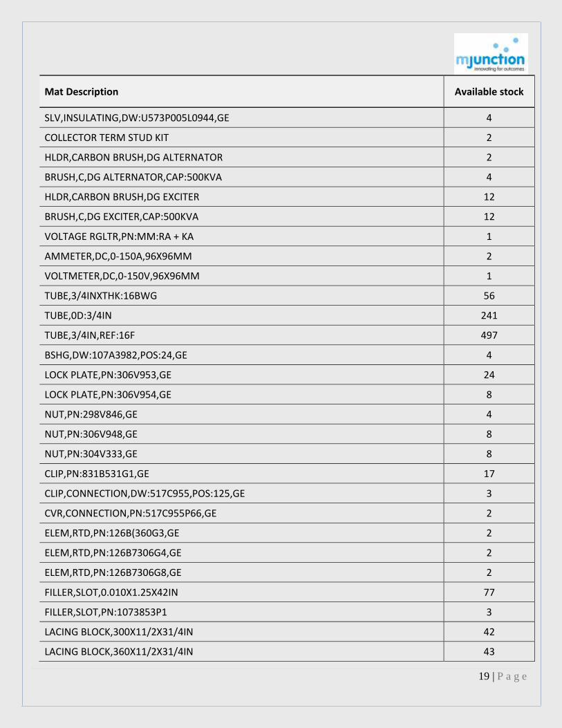
Mat Description Available stock
SLV,INSULATING,DW:U573P005L0944,GE 4
COLLECTOR TERM STUD KIT 2
HLDR,CARBON BRUSH,DG ALTERNATOR 2
BRUSH,C,DG ALTERNATOR,CAP:500KVA 4
HLDR,CARBON BRUSH,DG EXCITER 12
BRUSH,C,DG EXCITER,CAP:500KVA 12
VOLTAGE RGLTR,PN:MM:RA + KA 1
AMMETER,DC,0-150A,96X96MM 2
VOLTMETER,DC,0-150V,96X96MM 1
TUBE,3/4INXTHK:16BWG 56
TUBE,0D:3/4IN 241
TUBE,3/4IN,REF:16F 497
BSHG,DW:107A3982,POS:24,GE 4
LOCK PLATE,PN:306V953,GE 24
LOCK PLATE,PN:306V954,GE 8
NUT,PN:298V846,GE 4
NUT,PN:306V948,GE 8
NUT,PN:304V333,GE 8
CLIP,PN:831B531G1,GE 17
CLIP,CONNECTION,DW:517C955,POS:125,GE 3
CVR,CONNECTION,PN:517C955P66,GE 2
ELEM,RTD,PN:126B(360G3,GE 2
ELEM,RTD,PN:126B7306G4,GE 2
ELEM,RTD,PN:126B7306G8,GE 2
FILLER,SLOT,0.010X1.25X42IN 77
FILLER,SLOT,PN:1073853P1 3
LACING BLOCK,300X11/2X31/4IN 42
LACING BLOCK,360X11/2X31/4IN 43
20 | P a g e
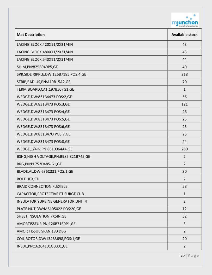
Mat Description Available stock
LACING BLOCK,420X11/2X31/4IN 43
LACING BLOCK,480X11/2X31/4IN 43
LACING BLOCK,540X11/2X31/4IN 44
SHIM,PN:825B949P5,GE 40
SPR,SIDE RIPPLE,DW:126B7185 POS:4,GE 218
STRIP,RADIUS,PN:A19B15A2,GE 70
TERM BOARD,CAT:197B507G1,GE 1
WEDGE,DW:831B4473 POS:2,GE 56
WEDGE,DW:831B473 POS:3,GE 121
WEDGE,DW:831B473 POS:4,GE 26
WEDGE,DW:831B473 POS:5,GE 25
WEDGE,DW:831B473 POS:6,GE 25
WEDGE,DW:831B47O POS:7,GE 25
WEDGE,DW:831B473 POS:8,GE 24
WEDGE,1/4IN,PN:8610964A4,GE 280
BSHG,HIGH VOLTAGE,PN:B985 821B745,GE 2
BRG,PN:PL752D485-G1,GE 2
BLADE,AL,DW:636C331,POS:1,GE 30
BOLT HEX,STL 2
BRAID CONNECTION,FLEXIBLE 58
CAPACITOR,PROTECTIVE PT SURGE CUB 1
INSULATOR,YURBINE GENERATOR,UNIT 4 2
PLATE NUT,DW:M6105022 POS:20,GE 12
SHEET,INSULATION,7X5IN,GE 52
AMORTISSEUR,PN:126B7160P1,GE 3
AMOR TISSUE SPAN,180 DEG 2
COIL,ROTOR,DW:134B3698,POS:1,GE 20
INSUL,PN:162C4101G0001,GE 2

21 | P a g e
Mat Description Available stock
INSUL CH,PN:183A3097,GE 12
LOCK PLATE,DW:09028465 P0001,GE 44
AGENT,LUBRICANT AND MOLD RELEASE,PN:A313 4.54
SEGMENTS RING,PN:0508L401G0003,GE 1
SEGMENTS RING,PN:0508L401G0004,GE 1
SUPPORT BAR,SPACER 21
TAPE,PN:A23 C4 G1-00100W000,DW:2485 6
SLOT,ARMAR/MYLAR,PN:115C8602,POS:9 124
BAND,INSUL,TARDE NAME:CONOLITE 2
BRUSH,C,80.6X31.6X12.6IN 26
CB,FLD,1000V,2000A,50KA,AC,ABB 1
CARD,OUTPUT,PN:HIEE 420304 E,AR C093 AE 1
CBL,PN:239A454 17.8
CAP,INSUL,TARDE NAME:CONOLITE 195
CARD,PSR PROCESSOR,PN:HIEE 420819 E 1
EQUILIZERS 134B3699PT1 20
FILLR,PN:115C8602,POS:10 113
FILLR,PN:115C8602,POS:11 119
FLTR AIR,FELT,620X490X50MM,FIBRE 18
GSKT,DW:038 38858P0003 2
GSKT,DW:038 38858P0012 4
HOOD,GLS,PN:115C8602,POS:3 2
INSULATION FLANGE GLASTIC PT30 5
INSULATION FLANGE GLASTIC PT 29 7
PCB,PRCSR BRD/CONV ELEC,ABB 1
PAD,INSULATION,3-5/16IN 6
INSUL,PAD,37377IN,CONOLITE 18
INSUL,INSULATION PAD,CONOLITE,4-3/8IN 17

22 | P a g e
Mat Description Available stock
PCB,REF:GBD021 1
PCB,REF:UPC 090 2
PCB,REF:UNS 4674 2
PCB,REF:UNS 3670 1
PCB,REF:UNS 3670 2
PCB,REF:UNS 4673 1
PNL,CTRL,PN:200130R0002-AFC,ABB 1
RELAY,O/V,PN:UNS 4681 VAR.0511,ABB 1
SFT AND GEAR,PN:653D588,GE 1
STP,ARCHING,PN:115C8602,POS:18 129
STRIP TIC PERMAFIL TR.TAPE 1
STUD,PN:2496570 20
SEAL,SPRING,DW:244A3016P0001,GE 4
THYRISTOR,STATIC EXCITATION SYSTEM 2
PWR SUPPLY UNIT,PN:HIEE 420307 E 1
WIRE,PN:181A8736P0002 1
WIRE,LOCK,30FT,DW:181A8736P0001,GE 1
RING,SEGMENT 1
SPRING SET,POS:2 2
TUBE,FINNED,LG:11FT 96
TRNSDCR,IALZ,0-500V,4-20MA,24VDC,ABB 1
TRNSDCR,IALZ,0-60MV,0-20MA,24VDC,ABB 1
TRNSDCR,IALZ,0-500V,0-20MA,24VDC,ABB 1
TRNSDCR,IALZ,0-60MV,4-20MA,24VDC,ABB 2
TRNSDCR,0-60-150MV,4-20MA,10V/5KV,7050 2
RELAY,1-5A,PN:22A11-F-715,IR 6
MOT AC,IND,1HP,1000RPM 2
PAD,CAT:34812 6

23 | P a g e
Mat Description Available stock
CONTACT BLOCK,PN:91021A 8F5 1
CONTACT BLOCK,PN:91021A 8F4 1
PIN,CPLG,W/RBR BUSH AND NUT 4
SPR 1
SPR,COMPRESSION,PN:424048 1
RELAY,PN:RL1 1
SW,MICRO,REF:RL1 1
HEATER,MODEL:BS50,COAL HANDLING SYSTEM 2
COIL,MAGNET,PN:PT1000T-20 3
SPR,REAR COIL,PN:16949 3
WHEEL,6IN 3
XFMR LV,2KVA,400V,220V 2
EARTHING DEVICE,SINGLE POLE,PN:18402 3
RELAY,THRM O/L,140-170A,MM:3UA13-LBO 5
LIMSW,GEAR,PN:10-12-31013 13
SW,STARTER,PN:194834A2 17
MOT AC,SYNCH,MM:364949-13 2
BSHG,PN:11B583 1
COIL,PN:6306748G2 3
CONTACT,PN:546A301G1 3
CONTACT,PN:455A351G1 5
GSKT,PN:132A1135P23 2
GSKT,PN:6315854P2 3
GUIDE ROD,LIFT,PN:181L0311G1 3
HEATER,PN:132A1049P23 1
INDCTR,LIQUID LEVEL 1
CLAMP RING,PN:6412116P001 10
PISTON RING,PN:132A1135P24 3

24 | P a g e
Mat Description Available stock
SHLD,LWR,PN:235C631P1 1
SPR,OPENING 1
SW,TEST CTRL,PN:64477878P2 1
SW,PN:6412114 P23 AA2 2
SW,AUXILIARY,PN:295B266GI 1
VLV,SAFETY,PN:132A1038P51 4
BSHG,PN:11B567 1
COIL ELEC,TRIP 1
CONTACT FINGER,EXT,PN:455A35G5 2
CURRENT FINGER,TFR,PN:392A202-G4 2
CONTACT FINGER,CUR,PN:392A261-G4 4
INTERRUPTER,PN:214X0236-G2 1
MOT,230VAC,F/115KV,CB 1
ROD,LOWER CONTACT,PN:389A696-G4 2
ROD,UPPER CONTACT,PN:389A510-G7 2
PRB,CONTCT,PN:455A348 P3 2
BUSH ASSY,PN:G-9023051-C,BHEL 2
BUSH ASSY,PN:G9023051,BHEL 2
PLATE,FBR,CIRCUIT BREAKER,G-9024513-3 22
PLATE,FBR,CIRCUIT BREAKER,G-9024513-5 16
PLATE,FBR,INTERRUPTER,MODEL:9134509 10
PLATE,FBR,CIRCUIT BREAKER,F-9134509-2 16
PLATE,FBR,CIRCUIT BREAKER,F-9134509-3 10
CROSS JET,POT,PN:G-9024512,BHEL 3
TRIP DEVICE,HYDRAULIC,REF:827033,VOLTAS 1
CONTACT KIT,ARCING,REF:5378786,M&G 2
RELAY,DIFFERENTIAL,HIGH IMPEDANCE 1
SWING ROD,PN:4109693008,3AF 3

25 | P a g e
Mat Description Available stock
ARC SHIELD,VOLTAS,3AF 6
INSULATOR,PN:4107907001,SIEMENS 6
STRUT BAR,PN:4107781003,3AF 6
FLANGE ASSY,PN:4535968004,SIEMENS 3
ACC,PN:372630,REF:5-81-180 1
BOTTON,PN:375556 1
COIL ELEC,TRIP,PN:372170 6
CONNECTION PI NO 24365091 6
BLOCK CONTACT,AUX,REFERENCE:280502G 1
CTRL UNIT,PN:827414 3
CENTERING DEVICE,PN:375-616 3
BLCK,DISTRN,PN:373472 3
DRL,PN:375353 1
GSKT,PN:258073 15
GSKT,PN:24367656 12
INSULATOR,SUPPORT,PRCLN,VOLTAS 2
KIT,REF:5378786,EQUIPMENT CB 3
INSULG PLATE 2
PLUG,PN:373469 3
PLUG,PN:373473 4
PUMP,HYDR,MM:372-126D 1
PUMP HYDRAULIC W/MOTOR-282848 1
RELAY,220VDC,PN:25727358,STPI GROUP 4
ROD CENTERING 375350 1
SCREW,PN:21662188,VOLTAS 3
CTRL UNIT,ETNA 2
INSULATOR,FA1 2
VLV,PN:372046,VOLTAS 9

26 | P a g e
Mat Description Available stock
VLV,NON RETURN,PN:37347,VOLTAS 3
WASHER,PN:21231306 3
BSHG,F/H4490047 7
COUNTER OPERATION,PN:H4450039,VOLTAS 1
SPR,F/CB,VOLTAS 2
SW,AUXILIARY CONTACT 4
LEVER BLACK ASSY,VOLTAS,DSA2-1000A 1
RELAY,MM:12BDD15B2ATF,I.G.E CO. LTD 5
RELAY,REF:12 CAPISB3A,IGE 1
RELAY,MM:12HFA51A41FTF,I.G.E CO. LTD 3
RELAY,MM:12 HFA54 B21TF,I.G.E CO. LTD 1
RELAY,TRIP,TRANSFER,F/TRIP,PN:NAA,IGE 1
RELAY,BUS FAULT,BUS FAULT 1
RELAY,DIR O/C,MM:GRD,I.G.E CO. LTD 1
RELAY,TIME DELAY,MM:DE9-22,I.G.E CO. LTD 2
RELAY,AUX,2A,MM:12HGA17C61 2
RELAY,MM:12HFA65D77F 1
RELAY,REVERSE TIME,REVERSE TIME 1
RELAY,INSTANTANEOUS OVERVOLTAGE 1
RELAY,INSTANTANEOUS OVERCURRENT 1
RELAY,AUX,MM:6293203G198 1
RELAY,DIFFERENTIAL 5
RELAY,OVERCURRENT,VOLT RESTRAINT 1
RELAY,TIME OVERCURRENT,IGE 1
RELAY,254X842MM,MM:M12A01P-SC6144 1
RELAY,4-16A,PN:121A538A 3
RELAY,1.5-6A,MM:121A 1
RELAY,TRIP,220VDC,2NC,I.G.E CO. LTD 8

27 | P a g e
Mat Description Available stock
RELAY,TRIP,220VDC,MM:HS AHT 1H 1
RELAY,TRIP,220VDC,MM:AHT 15 3
COIL ASSY,OPERATING,PN:264B993G108 1
COIL,OPERATING,PN:366A732G1,IGE 14
COIL,PN:366A732G5 1
COIL,PN:6174513GR10TF 1
COIL,PN:6174594GR9TF 1
COIL,PN:6293205G75 1
COIL,PN:6293205G140 1
COIL,PN:6293206G91 1
COIL,PN:6293206G121 1
COIL,PN:6293912GR6 1
COIL,PN:6306768GR4 1
COIL,PN:6306774G2 35
COIL,PN:6306774G7 1
COIL,PN:6306774G17 3
COIL,PN:6306774G46 2
COIL,PN:6306774G69 1
COIL,PN:6418079G13 2
CONTACT,PN:127A6770G1,IGE 28
CONTACT,PN:365A475G3,IGE 1
CONTACT,PN:6077624,IGE 2
CONTACT,PN:6158531-G-2 8
RELAY,POLARISED,MM:127A9506P1 2
INSTANTANEOUS UNIT,PN:6293204-G-56 2
UNIT,O/C INSTANTANEOUS,PN:6293204G91 2
PUNCHING AND COIL ASSY,PN:6193015G92TF 2
PUNCHING AND COIL ASSY,PN:6293912G-3TF 1

28 | P a g e
Mat Description Available stock
RSTR,17OHM 3
RSTR,25OHM 3
RSTR,PN:365A436P-32 1
RSTR,PN:365A436-38 2
RSTR,400OHM 2
RSTR,PN:365A436 P-23 1
RSTR,PN:365A436P-70 2
RSTR,PN:365A436P-25 1
RSTR,2KOHM 3
RSTR,250OHM 2
RSTR,PN:354A436P-31 2
RSTR,PN:365A436P-37 1
RSTR,PN:365A436P33 1
RSTR,PN:365A436P-76 4
RSTR,PN:365A436P-19 2
RSTR,PN:365A436P-77 1
RSTR,PN:365A436P-145 1
RSTR,PN:365A436P-166 3
RSTR,PN:365A436P-806 6
RSTR,PN:5901276G7500 2
RSTR,PN:0148A38BP2,IGE 2
RSTR,PN:403A321P29 1
RSTR,PN:403A321P23 1
RSTR,PN:403A32P13 2
RSTR,PN:403A321P50 1
RSTR,PN:403A322P20 1
RSTR,PN:403A321P20 1
SEAL-IN-UNIT,PN:6293203G1,IR 8
29 | P a g e
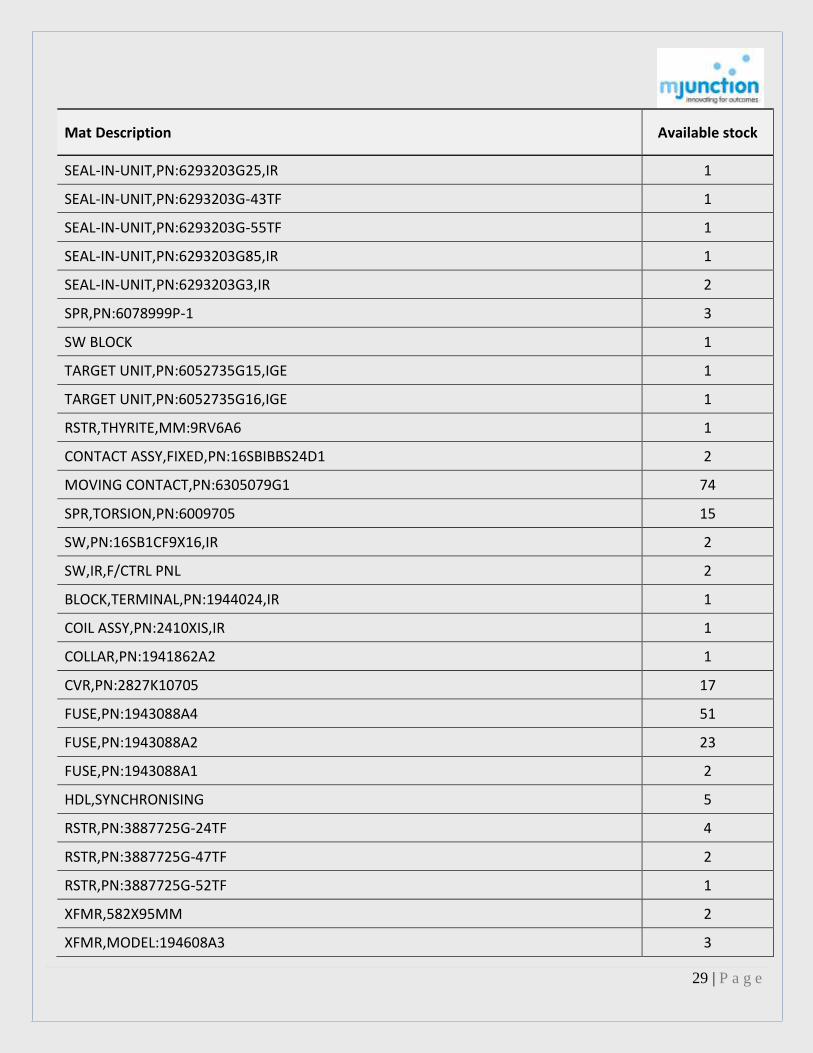
Mat Description Available stock
SEAL-IN-UNIT,PN:6293203G25,IR 1
SEAL-IN-UNIT,PN:6293203G-43TF 1
SEAL-IN-UNIT,PN:6293203G-55TF 1
SEAL-IN-UNIT,PN:6293203G85,IR 1
SEAL-IN-UNIT,PN:6293203G3,IR 2
SPR,PN:6078999P-1 3
SW BLOCK 1
TARGET UNIT,PN:6052735G15,IGE 1
TARGET UNIT,PN:6052735G16,IGE 1
RSTR,THYRITE,MM:9RV6A6 1
CONTACT ASSY,FIXED,PN:16SBIBBS24D1 2
MOVING CONTACT,PN:6305079G1 74
SPR,TORSION,PN:6009705 15
SW,PN:16SB1CF9X16,IR 2
SW,IR,F/CTRL PNL 2
BLOCK,TERMINAL,PN:1944024,IR 1
COIL ASSY,PN:2410XIS,IR 1
COLLAR,PN:1941862A2 1
CVR,PN:2827K10705 17
FUSE,PN:1943088A4 51
FUSE,PN:1943088A2 23
FUSE,PN:1943088A1 2
HDL,SYNCHRONISING 5
RSTR,PN:3887725G-24TF 4
RSTR,PN:3887725G-47TF 2
RSTR,PN:3887725G-52TF 1
XFMR,582X95MM 2
XFMR,MODEL:194608A3 3

30 | P a g e
Mat Description Available stock
XFMR LV,AUTO,5KVA,220V,220V 1
XFMR,PHASE SHIFTING 2
CONV,FREQUENCY,REF:ETF 35 1
RECORDER,FREQUENCY ERN 12 1
RELAY,O/L,MM:RMR-57954,WEST-ELC 3
RELAY,O/L,MM:MW31,WEST-ELC 1
GB,HELICAL 1
RELAY,INVERSE TIME OVERCURRENT,PN:AQ 3
SIGNAL BLOCK,TYPE B 1
CLMP,GI,W/SQUARE WASHER 24
CONTACT,MAIN 5
CONTACT,MAIN,2000A 2
GOD GROUP 2
KEY,COVER K-BOLT 3
CLIP,CONTACT,REF:72,GE 3
CONTACT ASSY,REF:5 6
CONTACT SPRING,PN:6401254 35
FINGER AND SPRING ASSY 81
EXPANSION LINK ASSY,REF:12 6
HINGE TIE ASSY,REF:15 3
LK,PN:1679,KIRLOSKAR 6
ISOLATOR,110KV,2000A,TMG,SDRE8 1
ADPTR,PN:H1630145 6
DRIVE MOT,EA,TMG 3
MECHANISM,OPERATING,TMG 2
PIVOT ASSY,CRANK,TMG 1
CONTACT,MALE,MAIN SWITCH,POS:11,TMG 1
CONTACT,FEMALE,MAIN SWITCH,POS:12,TMG 1

31 | P a g e
Mat Description Available stock
BOLT,PN:21431344 2
BOLT,PN:21431342 24
CLA,SINGLE,DW:H5511005,TMG 5
CLA,DOUBLE,DW:H5511005,TMG 4
NUT,NYL,PN:H21285216,TMG 2
PIN,SPLIT,PN:21187164 1
AUTO SYNCHRONISER,PN:ED7470400125 1
BSHG,HIGH VOLTAGE,TRANSFORMER 2
BSHG,LOW VOLTAGE,TRANSFORMER 2
CABLE CONNECTOR ASSY 1
CONV,DC-DC,PN:CN9090034200 1
DIODE,PN:CN9063356072 2
MODULE,COMBINING STAGE,PN:E-ED7470400036 1
MODULE,COMMAND UBIT,PN:ED7470400087 1
MODULE,DELTA FLMT VALVE,PN:ED7470400028 1
MODULE,INPUT/OUTPUT,PN:ED660IOMAA00 1
MODULE,GATE DRIVE,MM:ED 660 GGDDA,BHEL 3
MODULE,DET&VOLT LVL,PN:ED7470400052 1
MODULE,RLY,PN:ED7470400109 1
MODULE,STARTING STAGE,PN:ED7470400095 1
MODULE,SUPERVISION,PN:ED7470400060 1
MODULE,SWTCHG PT DETMN,PN:ED747040001 1
MODULE,SYNCHROSM CHK SUP,PN:ED7470400079 1
MODULE,FUNCTION:LCI AND IMD DRIVE,1 ARM 1
PLATE,PRIME MOVER,MAKE:BHEL 1
SPCR,PN:3699210221104,MODEL:CN9080174 8
BRK HYD,THRUSTER,PN:CN 906479010 2
BRG,FRONT,PN:S-517-A-152-G01 1

32 | P a g e
Mat Description Available stock
BRG,REAR,PN:S-520-B-623 G02 2
COIL,HALF,TOP,PN:S707-C-806-G01 6
COIL,HAL,F/BOTTOM,PN:S707-C-806-G02 6
FLTR,AIR/DRY 100
RING,BRG,OIL,FRONT,PN:S1488431 2
RING,BRG,OIL,REAR,PN:S1528695 2
BRG,ROLLER,UPPER,PN:1603039 2
PLATE,PR,PN:S-22C4643H01 1
SPR,PR,PN:S-45A8145H24 11
STATOR,WOUND,W/FRAME 1
HUB,PN:S-517C859H03 1
RETAINING RING,PN:S-1711081 1
ROTOR,PN:14C164096101 1
STATOR,WOUND,W/FRAME 1
BRG,BALL,LOWER,PN:S-1297250 2
BRG,ROLLER,UPPER,PN:33B8056H02 2
COIL,HALF,TOP,PN:S-707-C-807-G01 3
COIL,HAL,F/BOTTOM,PN:S-707-C-807-G02 3
POTENTIOMETER HEAD ASSY,185MM2 2
BRG,FRONT,PN:S-515-A-330-G01 2
COIL,HALF,TOP,PN:S-707-C-802-G01 3
COIL,HAL,F/BOTTOM,PN:S-707-C-802-G02 3
COIL,HALF,TOP,PN:S-707-C-804-G01 3
COIL,HAL,F/BOTTOM,PN:S-707-C-804-G02 3
COIL,HALF,TOP,PN:S-707-C-803-G01 3
COIL,HAL,F/BOTTOM,PN:S-707-C-802-G02 3
BRG,FRONT,PN:S-386C705G01 1
BRG,REAR,PN:S-386C706G01 1

33 | P a g e
Mat Description Available stock
SHIM,0.018X11-1/2X5IN 73
SHIM,0.014X11-1/2X5IN 48
PLATE,AL,2X2XTHK:1FT 8
TRMNL BLK,MODEL:EB-20,HD 3
ARC CHUTE ASSY,PN:254D747GI 5
BARRIER BOX,PN:619C465G1 2
BUFFER BREAKER,PN:619C464P9 9
BSHG,FRONT,PN:619C451G1 9
BSHG,REAR,PN:619C450G1 3
BSHG,FRONT,PN:619C438G2 4
BSHG,REAR,PN:619C438G1 3
CLIP,COVER,PN:V-6056771 68
COIL,CLOSING,PN:6375522G5 2
COIL,CTRL,PN:279A636P2 1
FINGER CONTACT,PN:236C791P8 31
CONTACT,PN:383A903G1 15
CONTACT,PN:619C469P1 12
CONTACT,PN:619C459P2 18
CONTACT,PN:619C469P3 20
CLMP,BUFFER,PN:6557243P2 22
CONTACT,PN:6591644P8 12
CONTACT,PN:6591644P7 12
CONTACT,PN:619C469P2 12
CVR,PN:802B724P2 18
DISCONN,PN:108B1931G10 3
DISCONN,PN:237C473G-9 3
GEAR,PN:24084 8
GEAR,POS:3,W/SHAFT 7
34 | P a g e
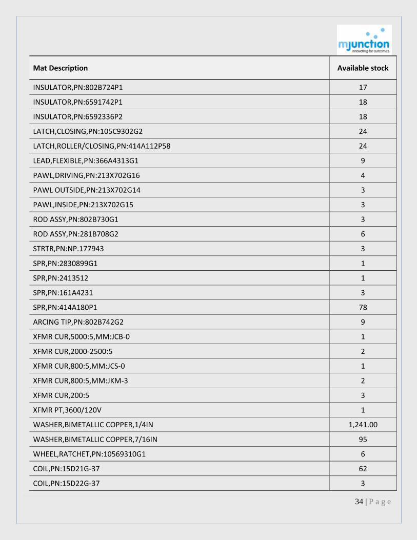
Mat Description Available stock
INSULATOR,PN:802B724P1 17
INSULATOR,PN:6591742P1 18
INSULATOR,PN:6592336P2 18
LATCH,CLOSING,PN:105C9302G2 24
LATCH,ROLLER/CLOSING,PN:414A112P58 24
LEAD,FLEXIBLE,PN:366A4313G1 9
PAWL,DRIVING,PN:213X702G16 4
PAWL OUTSIDE,PN:213X702G14 3
PAWL,INSIDE,PN:213X702G15 3
ROD ASSY,PN:802B730G1 3
ROD ASSY,PN:281B708G2 6
STRTR,PN:NP.177943 3
SPR,PN:2830899G1 1
SPR,PN:2413512 1
SPR,PN:161A4231 3
SPR,PN:414A180P1 78
ARCING TIP,PN:802B742G2 9
XFMR CUR,5000:5,MM:JCB-0 1
XFMR CUR,2000-2500:5 2
XFMR CUR,800:5,MM:JCS-0 1
XFMR CUR,800:5,MM:JKM-3 2
XFMR CUR,200:5 3
XFMR PT,3600/120V 1
WASHER,BIMETALLIC COPPER,1/4IN 1,241.00
WASHER,BIMETALLIC COPPER,7/16IN 95
WHEEL,RATCHET,PN:10569310G1 6
COIL,PN:15D21G-37 62
COIL,PN:15D22G-37 3

35 | P a g e
Mat Description Available stock
COIL,PN:22D135G-108 40
COIL,PN:22D135G-34 5
COIL,PN:22D135G-8 30
COIL,PN:281A171-G-34 2
COIL,PN:281A171G-8 3
COIL,PN:393B-200-G-7 3
COIL,PN:5073G-1 2
COIL,PN:55-150695G-42 2
COIL,PN:55-150695G-8 3
COIL,PN:55-1G-8 5
COIL,PN:55-6G-8 10
CONTACT,PN:55-153944G-15 20
CONTACT,PN:293-B 221G-1 13
CONTACT,PN:546A780G-1 10
CONTACT,PN:55-153944G-3 20
CONTACT,PN:6960045G-77 6
CONTACT,PN:6960045G-78 7
CONTACT,PN:6960046G-40 15
CONTACT,PN:6960047G-26 505
CONTR,10A,8P,102-110VAC,4NO 4NC 2
CVR,HGA RELAY 73
COIL ELEC,250VDC,PN:22D11G25A 1
COIL,OPERATING,PN:6275081G30 5
FIXED CONTACT,PN:365 A 475 G-2-TF 1
HEATER,PN:123C440B 4
HEATER,PN:123F300B 2
HEATER,PN:123C118A 4
HEATER,PN:123C198B 2

36 | P a g e
Mat Description Available stock
HEATER,PN:123C036A 4
HARDWARE,INDCATOR LAMP,PN:1124139 8
ELEM ELEC,RLY HEATER,MM:CR123C3.56A,GE 5
ELEM ELEC,RLY HEATER,MM:CR123 CO-71-A,GE 4
ELEM ELEC,RLY HEATER,MM:CR123 CO-87-A,GE 4
ELEM ELEC,RLY HEATER,MM:CR123 C1-48-A,GE 4
ELEM ELEC,RLY HEATER,MM:CR123 C1-96-A,GE 3
ELEM ELEC,RLY HEATER,MM:CR123 C2-20-A,GE 6
ELEM ELEC,RLY HEATER,MM:CR123 C2-39-A,GE 11
ELEM ELEC,RLY HEATER,MM:CR123 C2-68-A,GE 5
ELEM ELEC,RLY HEATER,MM:CR123 C3-01-A,GE 7
ELEM ELEC,RLY HEATER,MM:CR123 C3-26-A,GE 11
ELEM ELEC,RLY HEATER,MM:CR123 C3-79-A,GE 9
ELEM ELEC,RLY HEATER,MM:CR123 C4-19-A,GE 4
ELEM ELEC,RLY HEATER,MM:CR123 C4-66-A,GE 8
ELEM ELEC,RLY HEATER,MM:CR123 C5-92-A,GE 8
ELEM ELEC,RLY HEATER,MM:CR123 C6-30-A,GE 14
ELEM ELEC,RLY HEATER,MM:CR123 C6-95-A,GE 10
ELEM ELEC,RLY HEATER,MM:CR123 C7-78-A,GE 4
ELEM ELEC,RLY HEATER,MM:CR123 C8-67-A,GE 4
ELEM ELEC,RLY HEATER,MM:CR123 C9-55-A,GE 2
ELEM ELEC,RLY HEATER,MM:CR123 C11-3-B,GE 3
ELEM ELEC,RLY HEATER,MM:CR123 C12-5-B,GE 8
ELEM ELEC,RLY HEATER,MM:CR123 C13-7-B,GE 2
ELEM ELEC,RLY HEATER,MM:CR123 C15-1-B,GE 5
ELEM ELEC,RLY HEATER,MM:CR123 C18-0-B,GE 5
ELEM ELEC,RLY HEATER,MM:CR123 C22-8-B,GE 5
ELEM ELEC,RLY HEATER,MM:CR123 C33-0-B,GE 2

37 | P a g e
Mat Description Available stock
ELEM ELEC,RLY HEATER,MM:CR123 F48-7-B,GE 3
ELEM ELEC,RLY HEATER,MM:CR123 F56-7-B,GE 10
ELEM ELEC,RLY HEATER,MM:CR123 F61-4-B,GE 10
ELEM ELEC,RLY HEATER,MM:CR123 F65-8-B,GE 9
ELEM ELEC,RLY HEATER,MM:CR123 F77-2-B,GE 4
ELEM ELEC,RLY HEATER,MM:CR123 F84-8-B,GE 11
ELEM ELEC,RLY HEATER,MM:CR123 F91-4-B,GE 6
ELEM ELEC,RLY HEATER,MM:CR123 F11-8 C,GE 4
ELEM ELEC,RLY HEATER,MM:CR123 F13-3-C,GE 3
FTG,INDCTR LIGHT,PN:IGE 1615694 8
CONTACT,MOVABLE,PN:293-B-220-G-3 13
CONTACT,MOVABLE,PN:6158531-G12-TF 1
RELAY,PN:CR-120-LO-33008-MFP 1
RELAY,10A,102-110VAC,4NO 4NC 1
RELAY,PN:CR-2810-A-14-C-8-MFP 2
RELAY,PN:CR-2810-A-14-DE-8-MFP 2
RELAY,PN:CR-2820-A 100C-B02N 1
RELAY,PN:CR-2820-B-110-AA-8-MFP 1
RELAY,PN:CR-2820-B-111-AB-8 1
RELAY,PN:CR-2820-B 119AB-84 4
RELAY,PN:CR-2820-B-120-AA-8-MFP 1
RELAY,PN:CR-2820-B-414-AB-42 1
RELAY,MM:12HEA 61A 214 TF,I.G.E CO. LTD 8
RELAY,0.165A,MM:6775 G-2 TF 1
RELAY,51A,MM:12HFA 1
RELAY,11A,MM:12HGA 15
RELAY,17A,MM:12HGA 1
RSTR,MM:403A321P20 1

38 | P a g e
Mat Description Available stock
RELAY,MM:P300,I.G.E CO. LTD 1
RELAY,10A,380-460V,PN:CR2810A14AT 1
SEAL,PTFE,PN:6293203 G1 1
SPACE HEATER,PN:2A426 G2 5
SPR,PN:2414865P1 2
CONTACT,STATIONARY,PN:6209430 G2 1
XFMR,MODEL:138A1057P20 1
XFMR,MODEL:138A1059P39MFP 2
XFMR,MODEL:254X824 U 99P1 2
COAL BERTH ACCESSORIES,FOR CB E1 7100 18
CB,PN:NF 621020,ABC TRADING 2
CONTACT,ARCING,PN:9700 3
MOVING CONTACT,MAIN,PN:6041-1A 3
FINGER CONTACT,MOVABLE,PN:10-494-2A-6 2
LENS,1in,COLOUR:BLUE 2
PLATE,CENTER,PN:F M164-344 2
SPR,MAIN,PN:9399 3
SPR,MOVABLE CONTACT,PN:12-580-2 2
STRAP CONNECTING,PN:F M-16426 2
STRAP CONNECTING,PN:F M-16425 3
OPERATING MECHANISM,PN:1 HML-400096M1 1
O-RING,PN:1 HML 400331 P7,ABB 6
O-RING,PN:1 HML 400063 P28,ABB 2
O-RING,PN:1 HML 400063 P155,ABB 6
O-RING,PN:1 HML 400410 P170,ABB 6
O-RING,PN:1 HML 400410 P195,ABB 3
O-RING,PN:1 HML 400410 P205,ABB 6
O-RING,PN:1 HML 400389 P308,ABB 2

39 | P a g e
Mat Description Available stock
O-RING,PN:1 HML 400390 P428,ABB 3
O-RING,PN:1 HML 400389 P522,ABB 3
POLE COLUMN,PN:1HML400089M1,ABB 1
TUBE,PN:1HML300459-R10,GAS SET 1
BLADE,MOVING CONTCT,PN:877085,VOLTAS 2
BLADE,MOVING CONTCT,PN:876614A,VOLTAS 2
BLADE,VISBLE BREAK,PN:868051A,VOLTAS 1
BLADE,VISBLE BREAK,PN:879464,VOLTAS 1
ELEC COIL,PN:PT91204 2
CONTACT,ARCING FIXED,PN:H2410016,VOLTAS 2
ARCING CONTACT,MOVING,PN:878968 2
FINGER CONTACT,MAIN,PN:865390,VOLTAS 6
FINGER CONTACT,MAIN,PN:876589,VOLTAS 6
FINGER CONTACT,SPRING,PN:PT876666 12
CONTACT,FINGER SPRING,PN:87659,VOLTAS 8
INSULATOR,SUPPORT,PN:866072,VOLTAS 1
INSULATOR,SUPPORT,PN:876215,VOLTAS 1
POLE,W/OUT ARC CHAMBR,1250A 1
POLE,W/OUT ARC CHAMBR,2000A 1
ROD,OPERATING,PN:877328 1
OPERATING ROD,PN:PT879465 1
SPR,CLOSING,PN:872858,VOLTAS 7
SPR,CLOSING,PN:876770,VOLTAS 7
SPR,TAPPING,PN:866226,VOLTAS 2
SPR,TRIPPNG I,PN:869422,VOLTAS 1
SPR,TRIPPNG II,PN:868099,VOLTAS 1
SPRING ARCING CONTCT,PN:I1250A 877958 2
SPR,ARCING CONT-II,PN:877959,VOLTAS 1

40 | P a g e
Mat Description Available stock
SPR,ARCING CONT-I,PN:876992,VOLTAS 2
SW ASSY,PN:1502488,VOLTAS 1
ARC BOX,PN:1605221,VOLTAS 11
ARC BOX,PN:1577726,VOLTAS 10
ARC BOX,PN:1490402,VOLTAS 11
BREAKER,PN:50.2PF 600 V AC 1
BAR,CROSS,PN:1774347,VOLTAS 1
BASE,PN:1577727,VOLTAS 2
BASE,PN:1605218,VOLTAS 1
BSHG,RBR,VOLTAS 291
BSHG,RBR,1-1/16X1-11/16IN 471
BUSH,FIBRE,2IN 1
BUSBAR,EXTERNAL,CU,SIZE:AB,BB,CB 3
BUS,EXTENSION 3
BUS,EXT,VOLTAS,SIZE:A-1A,B-1A,C-1A 6
BUS,EXT,VOLTAS,SIZE:A-1B,B-1B,C-1B 6
COIL,PN:1574335 3
COIL,PN:1008517 1
COIL,PN:1003396 1
COIL,PN:1490653B 8
COIL,PN:1596637-B 7
COIL,PN:1611411 4
COIL,PN:1617652-A 3
CONTACT,PN:1730182 2
CONTACT,PN:1097234 2
CONTACT,PN:1002172 2
CONTACT,PN:1098858 2
FINGER CONTACT 11

41 | P a g e
Mat Description Available stock
BOX,ARC CHUTE,VOLTAS 1
CONTACT,MOVING 2
CONTR 2
FUSE,PN:1254953,25/60 CYCLES 4
HDL,PN:80-33-Y-7778 1
HEATER,PN:1265538BX61 2
HEATER,PN:966478 1
INTLK,PN:1490460 4
INTLK,PN:1314885 2
INTLK,PN:1314889 1
INTLK 3
INTERLOCK KIT,PN:453D976G05 7
INTERLOCK KIT,PN:453D976G09 7
RENEWAL KIT,PN:1625563 8
RENEWAL KIT,PN:S-1605202 4
RENEWAL KIT,PN:1490460 10
RENEWAL KIT,PN:1625243 1
LENS,INDICATING LAMP,PN:5549469B063 6
LENS,RECTANGULAR,VOLTAS 2
PLUG,VOLTAS,SIZE:A,B&C 83
RELAY,INST CUR,5.2A,MM:SC-1,ABB 2
ROTOR,VOLTAS 1
SEGMENT,SWITCH,VOLTAS 24
SPRG,PN:1000998 4
SPRT,PN:1314971 1
BSHG,CONDENSER,DW:BCE-4-1070 1
XFMR OIL,5A/2,415V,PUMP 1
SW,LEVEL,MAGNTIC LIQUID 1
42 | P a g e
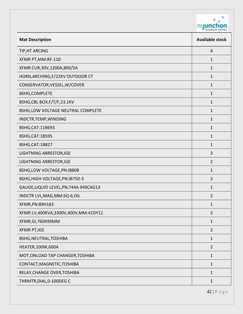
Mat Description Available stock
TIP,HT ARCING 4
XFMR PT,MM:RF-110 1
XFMR CUR,30V,1200A,800/5A 1
HORN,ARCHING,F/22KV OUTDOOR CT 1
CONSERVATOR,VESSEL,W/COVER 1
BSHG,COMPLETE 1
BSHG,CBL BOX,F/T/F,23.1KV 1
BSHG,LOW VOLTAGE NEUTRAL COMPLETE 1
INDCTR,TEMP,WINDING 1
BSHG,CAT:11B693 1
BSHG,CAT:1B595 1
BSHG,CAT:1B827 1
LIGHTNING ARRESTOR,IGE 3
LIGHTNING ARRESTOR,IGE 2
BSHG,LOW VOLTAGE,PN:IB808 1
BSHG,HIGH VOLTAGE,PN:IB750-3 2
GAUGE,LIQUID LEVEL,PN:744A 949CAG13 1
INDCTR LVL,MAG,MM:SQ-6,OIL 2
XFMR,PN:89H183 1
XFMR LV,400KVA,3300V,400V,MM:41DY11 2
XFMR,GI,760X99MM 1
XFMR PT,IGE 2
BSHG,NEUTRAL,TOSHIBA 1
HEATER,100W,600A 2
MOT,ONLOAD TAP CHANGER,TOSHIBA 1
CONTACT,MAGNETIC,TOSHIBA 1
RELAY,CHANGE OVER,TOSHIBA 1
THRMTR,DIAL,0-100DEG C 1

43 | P a g e
Mat Description Available stock
XFMR CUR,MM:BS125A300-A5 1
XFMR CUR,MM:BS175A300 5A 1
XFMR CUR,MM:BS180A1200 5A 1
BSHG,LOW TENSION,SIEMENS,TRANSFORMER 7
CPCTR,OIL FILLED,4000A 1
HEATER ELEC,CUBICLE,220V,234W 2
RELAY,CURRENT,MM:RA 14MU,SIEMENS 2
RELAY,AUX,MM:RH 25,SIEMENS 2
BREATHER SILICAGEL,CAP:4.8 KG 1
XFMR,CURRENT/DRY 3
XFMR,CURRENT/AIR COOLED 2
BSHG,CONDENSER,CGL 1
BSHG,CGL,PWR TRANSFORMER,3150A 2
DIAPH,BAKELTE,PRESSURE RELIEF VLV 5
JUMPER,FLEXIBLE,CU,231 KV BUSHING 2
PLATE,VLV,SIZE:DIA:200mm 2
BSHG,CONDENSER,52 KV,800A 2
XFMR CUR,5/5A 1
XFMR CUR,5A,50VA,CRT RATIO AMPS:5&5&5&5 1
SILICON IRON ANODE,75X85X1000MM 5
TRANSFORMER 1
STRTR,PN:3304199S-2410 47
GRIP,SERVICE DROP,MODEL:SD-8 42
GRIP,SERVICE DROP,MODEL:SD-10 49
GRIP,SERVICE DROP,MODEL:SD-5 24
GRIP,SERVICE DROP,MODEL:SD-9 20
HEATER ELEC,O/L,1.2A,PN:9701-2G 2
STRTR,PN:CR1061H2A1 1

44 | P a g e
Mat Description Available stock
ARSTR SURGE,LGTNG,400V 6
ROCKER ARM 083,RIGHT HAND 5
ARM,LEFT HAND 2
BOLT AND NUT,BIG END,PN:034/039 2
GOVERNOR COMPLETE 1
BRG SHELL,INSERTN FREE PT106 3
GUIDE BRG SET,INSERT 4
LNR,CYL,PN:21 5
LINER HEAD,POS:024 39
GUDGEON PIN,POS:42 6
PIN,ROCKER ARM,REF:093 5
PIN,ROCKER ARM,POS:098 6
PISTON,788,STARTING VLV 1
PISTON,F/5KODA DIESE ENGINE 6
PISTON RING,PT043 20
PISTON RING,LOWER SCRAPER,REF:PT044 6
PISTON RING,SCRAPER LOWER,REF:PT045 24
RING,SAFETY,PT046 24
RING HOLDER 117 6
SCREW,ROCKER ARM ADJUSTING,POS:101 6
SEAT VLV SUCTION AND EXHAUST,PN:085 22
CONNECTING ROD,SHANK,PN:PT031 2
SPR,POS:396 2
SPR,POS:397 2
THRMTR,DIAL,11-3/4IN,0-600DEG C 3
VALVE SUCTION/EXHAUST PT089 23
VLV SOL,230VDC,BSP,2 WAY,3/4IN 2
VLV SOL,230V,1IN,BSWF 2

45 | P a g e
Mat Description Available stock
VLV SOL,230V,2IN,BSWF 1
EYE,OPERATING,PN:6429316GR3 4
BRUSH,191X25X15.9MM 12
ELEC COIL,COMP1 STATOR 1/3 18
HLDR,BRUSH,DW:39924 4
RSTR,SS,SL.INSLTNG EDGE WOUND 4
XFMR CUR,20VA,100:5 1
XFMR CUR,15VA,2,600:5,PACTIL 4
XFMR PT,500VA,15000/125V 1
XFMR PT,50VA,3300/V3/110/J3,PRAGATI 1
XFMR CUR,600-800-120-2000/833-5-5-833 1
XFMR PT,110-100KV/J3/110V/J3/110V/J3 1
ANNUNCIATOR,PN:JAV 014 1
AMMETER,3-10A,MM:V528,MECO 1
VOLTMETER,DC,300-0-300V,96X96MM 1
INDCTR,RPM,0-4000RPM 1
AMMETER,DC,0-1000A,UBHA 1
AMMETER,AC,0-500A 1
VOLTMETER,AC,0-20V,96X96MM 1
SENSOR,CUR,41871A,MM:CTS 20 5
CTRLR TEMP,48X48MM,MM:16-702041,JUMO 5
DISPLAY CONTROLLER,64BIT 3
CNTRLR,SVGA,CAPACITY:1MB 1
CORD,MAIN POWER,F/PC 1
MONITOR,MONO,MM:SVGA 4
MALE CONTACT,SIEMENS,HCB ISOLATOR 4
FEMALE CONTACT,SIEMENS,HCB ISOLATOR 4
CONTACT FINGER,FLAT,CU,16X12MM,PN:PT9 3

46 | P a g e
Mat Description Available stock
MALE CONTACT ASSY,ELPRO 3
JAW FEMALE CONTACT ASSY,PN:3DU51504-7 1
JAW TERM CONTACT,PN:3DU51504-3 2
SPRING CONTACT,SS,REF:3DU51504-6 15
BRG BUSH,PTFE,DW:3DU51505PT2 12
CIRCLIP,FEMALE 34
CONTACT MALE ASSY,SWITCHGAER 6
JAW TERM CONTACT,PN:3D51505-3 3
SPRING CONTACT,SS,REF:3DU51505 2
CONTACT MALE ASSY,33KV,1250A 2
CONTACT MALE ASSY,33KV,2000A 9
CONTACT ASSY,FEMALE,33KV,1250A 4
CONTACT ASSY,FEMALE,33KV,2000A 9
XFMR CUR,660V,15VA,5-10-20-50-100:5 4
GLASS AND GSKT,LEVEL INDICATION 2
RELAY,FLASHER,220VDC,MM:RXSU4,ABB 2
AMMETER,MOVING IRON,0-2000A,96MM2,AEP 1
RELAY,MOT PROTECTION,MM:CTM-F24RF8004AM 1
RELAY,TIME,5A,240VAC,SIEMENS 1
AMMETER,AC,0-200A,MM:304 3
AMMETER,AC,0-300A,MM:476 2
CONTACT,MOBILE FIXED DISCONNECTING 7
ACCESS,F/110KV TMG GOD 2000A 5
ISOLATOR,2000A,W/O GROUNDING 2
ISOLATOR,33KV 3
ISOLATOR,33KV,1250A,W/EARTH BLAD 2
ISOLATOR,10KV,2000A,40KA 4
CTRLR,ELECTRONIC 1

47 | P a g e
Mat Description Available stock
INTERLOCK ASSY,W/220VDC SOLENOID 7
MOT AC,IND,40HP,KIRLOSKAR 1
MOT DC,230V,1.5HP,1500RPM 1
MOT,DC,LUBE OIL PUMP 1
MOT AC,IND,30KW,1475RPM,SIEMENS 1
MOT DC,220 VDC,355 W,22000 RPM,1.65 A 1
COIL,CU,TRANSFORMER,POWER RATING:27MVA 180
VISCOUS FLTR,25X16X2MM 6
BSHG BRG,CT 178 L411 G-3 2000/5 GE 6
XFMR,CAPACITIVE VOLTAGE 1
XFMR CUR,145KV,1200-800-400:5A,BHEL 2
RELAY,DEF TIME O/C,HBB 4
AMMETER,FLUSH,0-10A,85MM 2
DIMMERSTAT,15A,240V,50HZ 2
RELAY,MM:SPECM,EE MANUFACTURING 3
RELAY,SOLID STATE,230V,3NO+3NC 1
RELAY,TRIPPING,220VDC,MM:PQ8 DH2Y 2
RELAY,MM:MDC,MEI 3
RELAY,220VDC,MM:VAJH 13YF 66B 2
RELAY,PN:SPECM 2BF 255M,MM:VAG 21 1
RELAY,0.2/2A,MM:HCX-45,V/E 4
RELAY,REF:YCGF HAFIA 2
RELAY,MM:VAT 11ZG 126B 2
RELAY,MHO MEASURING UNIT,MM:YCG15PF 16 1
RELAY,220VDC,PN:SSX90,HBB 1
RELAY,MM:CAEM 33 AFID 1
RELAY,220VDC,MM:VAX31,EE MANUFACTURING 8
BRG RLR,N314 ECP 1

48 | P a g e
Mat Description Available stock
ARMATURE,PN:245C1,OTIS,FREIGHT ELEVATOR 2
BARRIER,AIR,PN:276H1,OTIS 4
BASE,PN:306FX1,OTIS,FREIGHT ELEVATOR 2
BASE ASSY,PN:306G7,OTIS 1
BRG BALL,6800 AN2 1
BRUSH,PN:240B3,OTIS,FREIGHT ELEVATOR 8
BRUSH,PN:240P2,OTIS,FREIGHT ELEVATOR 8
BRUSH ASSY,PN:6839F2,OTIS 1
BRUSH,PN:6839W1,OTIS,FREIGHT ELEVATOR 1
BUMPER,PN:320P4,OTIS,FREIGHT ELEVATOR 1
BUMPER,PN:320AY1,OTIS,FREIGHT ELEVATOR 1
CAM,PN:327DM1,OTIS,FREIGHT ELEVATOR 2
COIL,PN:222CD2,OTIS,FREIGHT ELEVATOR 1
COIL,PN:222CD3,OTIS,FREIGHT ELEVATOR 1
COIL,PN:222CV1,OTIS,FREIGHT ELEVATOR 1
COIL,PN:222CV6,OTIS,FREIGHT ELEVATOR 1
COIL,PN:222CY3,OTIS,FREIGHT ELEVATOR 1
COIL,PN:222CY6,OTIS,FREIGHT ELEVATOR 1
CONDENSER,PN:226H4,OTIS 1
COND,PN:175H1,OTIS 3
COND,PN:175J90,OTIS 2
CONN,PN:176KA4,OTIS 2
CONN,PN:176KA13,OTIS 6
CONTACT,AUXILIARY,PN:150C13,OTIS 3
CONTACT,AUXILIARY,PN:150C14,OTIS 3
CONTACT,PN:150H2,OTIS,FREIGHT ELEVATOR 2
CONTACT,PN:150H10,OTIS,FREIGHT ELEVATOR 2
CONTACT,MOVABLE,PN:150P4,OTIS 3

49 | P a g e
Mat Description Available stock
CONTACT,PN:150P27,OTIS,FREIGHT ELEVATOR 4
CONTACT,MOVABLE,PN:150P41,OTIS 1
CONTACT HOLDER ASSY,PN:150W7,OTIS 1
CONTACT ARM,PN:150Y2,OTIS 1
CONTACT,MOVABLE,PN:150AV2,OTIS 2
CONTACT,PN:153B1,OTIS,FREIGHT ELEVATOR 3
CONTACT,MOVABLE,PN:153Z1,OTIS 6
CONTACT,PN:154AD4,OTIS,FREIGHT ELEVATOR 1
CONTACT,PN:154AB1,OTIS,FREIGHT ELEVATOR 2
CONTACT,PN:156J5,OTIS,FREIGHT ELEVATOR 1
CONTACT ASSY,PN:6810A2,OTIS 1
CONTACT ASSY,PN:6810A3,OTIS 2
CONTACT,PN:1482081,OTIS 1
DEFLECTOR,PN:6313 A 1,OTIS 2
DEFLECTOR,PN:6534B 1,OTIS 4
FUSE,F/FREIGHT ELEVATOR,375H 3 3
FUSE,F/FREIGHT ELEVATOR,375H 10 6
GUARD,384 FS 1,PN:384 FS 1,OTIS 2
HLDR,PN:179AR1,OTIS,FREIGHT ELEVATOR 2
HLDR,PN:179AR2,OTIS,FREIGHT ELEVATOR 2
HLDR,PN:6134A2,OTIS,FREIGHT ELEVATOR 1
HLDR,PN:6134D1,OTIS,FREIGHT ELEVATOR 1
MICRO SW,PN:BZ-2 RW-A 2,OTIS 2
NUT,HEXAGON,MS BRS,POS:832,OTIS 8
OIL,RELAY,1360KG 42.53
PKG,PN:182A4,OTIS,FREIGHT ELEVATOR 1
PIN,PN:77TA1,OTIS,FREIGHT ELEVATOR 1
PLATE,PN:102DA1,OTIS,FREIGHT ELEVATOR 7

50 | P a g e
Mat Description Available stock
PUSH BUTTON,PN:7035A8,OTIS 2
RECTIFIER,PN:230AJ1,OTIS 2
RECTIFIER,230V,OTIS,AR 1 1
RECTIFIER,230V,OTIS,AY 1 1
RELAY,PN:222 CZ 1,OTIS 1
RELAY,PN:340 CX 1,OTIS 1
RSTR,PN:232B15,OTIS 3
RSTR,PN:232B21,OTIS ELEVATOR 1
RSTR,PN:232BA25,OTIS ELEVATOR 1
RSTR,PN:232BA31,OTIS ELEVATOR 1
RSTR,250 OHM,OTIS ELEVATOR 1
RHEOSTAT,VAR,10OHM,F/ELEVATOR 1
RING,PN:172DE9 1
RLR,PN:456C4,OTIS,FREIGHT ELEVATOR 2
SCREW,FLAT,OTIS,FREIGHT ELEVATOR 2
SCREW,OTIS,FREIGHT ELEVATOR 4
SCREW,ROUND HEAD,8-32X3/4,ELEVATOR,136KG 2
SEPR,PN:464BJ2,OTIS 2
SPR,PN:90DB4,OTIS,FREIGHT ELEVATOR 1
SPR,F/90 VA 16 4
STRIP,PN:298BX1,OTIS,FREIGHT ELEVATOR 2
STUD,PN:97C13,OTIS,FREIGHT ELEVATOR 1
SW,PN:A6839E1,OTIS,FREIGHT ELEVATOR 1
WSHR,PN:133A 1,OTIS,ORDER NO:FOJ4019 2
BRG,ROLLER,EQUIPMENT HML-600 4
HOSE,HYDRAULIC,HML-600 2
PIN,F/WHEEL ASSY,HML-600 2
PIPE,HYDRAULIC 20

51 | P a g e
Mat Description Available stock
ELEC WIRE,CAT:HML-600,HB271 25
BRG BUSH,HOMECH,221-44 12
O-RING,HOMECH,221-44 2
OIL SEAL,PN:274710,HOMECH,221-44 2
OIL SEAL,PN:386412,HOMECH,221-44 1
BRAKE SPRING,REF:80/380(221/44,HOMECH 2
BRAKE SPRING,BIG,4-1/2IN,HOMECH,221-44 2
BRAKE SPRING,SMALL,2-1/2IN,HOMECH 2
BRUSH,C,MUKAND,GENERATOR MOTOR 6
MCC UNIT,PN:18147,MUKAND 3
RECTIFIER,440/24VAC/DC,6A 2
CONTR,PN:3002-072-251,ME3 1
RLR,PN:468739 6
RLR,PN:9001-575-102 4
XFMR CUR,TCAL,36kV,2000/8.33A,2000/8.33A 2
VOLTMETER,AC,110X110MM,RECTIFIER TYPE 1
XFMR,STEP DOWN,GE 4
STRAIGHT THROUGH,3CX6MM2 1
CPLR,30A,F/4 CORE,CABLE 12
CPLR,60A,F/MC 4C CABLE 12
CPLR,REF:CYWL-400,400A 12
CPLR,REF:CYLW-600,600A 12
CONN,FLEX,MAKE:ABB,NSYB 120/1200 1
CONN,T,37987IN,F/IPS-2,.35 MM2 3
CONNR,ELEC,ST FIX,40MM,110KV,TMG 4
CLMP,HORIZ,10MM,40MM,SLIDING BUS SUPPORT 4
CLMP,F/2IN IPS CU TUBE 3
COUPLER CODED PROTECTN NSD 61 1

52 | P a g e
Mat Description Available stock
BOX ELEC,CABLE TERMINATION,F/EE63A FUS 16
ENCL,FLAME PROOF,CON GEAR 1
FTNG,FLAME PROOF,PN:65007,GE 4
FINGER CONTACT,TIPPED SILVER SS 81
COIL HOLDER,250V, PHASE:1PH 3
GB,CTRL,15HP, DOL STARTER 1
BOLT,COUNTER SUNK,GI,3/8X1/2IN 1,200.00
OVERHAND KIT,F/WATER PP 400GPM 1
CVR,DOME,300MM,CBL TRAY 8
CVR,PL,300MM,CBL TRAY 13
ELCTRD WELD,C,5MM,200MM,SCHUTS 71
ELCTRD WELD,C,6MM,200MM,SCHUTS 82
ELCTRD WELD,8MM,200MM,SCHUTS 94
TRNSDCR,MW,MM:CT4 260 2
BUSHING F/INTERNAL PLANT PNO 18803 6
SCREW DREANING P T NO 373136 3
SCREW 375351 1
VALVE SPINDLE P N 373468 3
MECHANISM LATCHING-878601A 1
SPRING OPENING 885364D 2
BRAID FLEX CU F/2000A H1630144VO 6
CRANK ASSEMBLY PT G781372 A 1
AXE ASSY H1630093 1
BRAID FLEXIBLE H-1610010 0
FINGER CONTACT W/SPRINGS-H1690175 18
FINGER FEMALE CONTACT H1630001 36
LEVER 1630553 1
SPRING R/F FOR FEM CONT H1630080 28

53 | P a g e
Mat Description Available stock
SUPPORT SP H1630291 1
MONITOR DENSITY 98005 HAGS 101785 7 1
INSULATOR SUPPORT 1HML400332R1 1
TUBE,GAS SET B PT NO 1HML300458-R10 1
BAR MICAPAL STATOR TOP PL184R860G4 10
BAR MICAPAL STATOR BOT PL184R860G5 10
BEARING GENERATOR MID 752D505G1 2
TE ALUM BLADES 636C326-1 4
TE ALUM BLADES 636C326-1 24
KIT,RETAINING RING INSTALN GFRR1K63 1
WEDGE FIELD ALUMINIUM 297A3536P0023 461
DISCHARGE VALVE SPRING P NO 3W21451 7
VALV PILOT 3W39986TA 1
METER MW,O.400MW,MM:EW-31 1
GSKT,ENCLOSING TUBE,REF:RP-552 4
BRG,PHOSPHROUS BRONZE,TWO HALVES 3
TUBE,GLS,37257IN,RATOSIGHT 2
SHFT,BRS,5/8INX2FT 2
FUSE,1A 4
DIAPH AND GSKT ASSY 2
INTEGRAL ASSY,BOILER,UNIT 4 1
GSKT,FLANGE TOP 2
SPRG,MAIN VALVE,2IN 3
CORE AND SPRING ASSY 1
GSKT,HEAD FLANGE 6
GSKT,CASE KEY NO.42 9
GSKT,RELAY,POS:7 10
GSKT,BELLOWS,POS:9 10

54 | P a g e
Mat Description Available stock
GSKT,SPRING PLATE,POS:13 10
GSKT,BELLOW FRAME,POS:46 10
GSKT,FILTER REGULATOR,POS:29 10
GSKT,RELAY BASE,POS:20 10
GSKT,SPRING PLATE,POS:13 10
GSKT,SPRING PLATE,NPRN,POS:18 10
GSKT,COVER,POS:21 10
GSKT,RELAY,POS:22 10
GSKT,RELAY BASE,POS:24 10
GSKT,SPRING PLATE,POS:13 10
GSKT,OUTER TUBE END,POS:14 2
GSKT,5IN,POS:12 5
GSKT,6IN,POS:12 3
SFT ASSY,GEAR 11
GSKT,YOKE,POS:15 1
GSKT,BODY,POS:12 2
NUT,DRIVE,POS:19 1
GSKT,JACKETED,ID:85.5XOD:105XTHK:2MM 4
GSKT,JACKETED,ID:74.5XOD:89XTHK:2MM 4
GSKT,JACKETED,51X38.2X12300MM 4
HD,POS:057,MASONEILAN,S/A FLAME PROOF 1
GSKT,PACKING SET,V543 1
GSKT,PACKING SET,V543/595 1
GSKT,CHECK VLV,SOF MTL 3
GSKT,BODY,37-73421 4
NUT,LOCK,STEM,37-73421 4
TRANSM DP,STD930-E1H-0-MBSMS2TGTCF1F1D3 1
MODULE,PWR SPLY,115/230VAC,15A,620-0036 1

55 | P a g e
Mat Description Available stock
MODULE,PWR SPLY,115/230VAC,8A,620-0041 1
MODULE,ISO ANALOG I/P,4-20MA,621-0022AR 1
MODULE,ISO ANALOG I/P,0-10V,621-0022VR 1
MODULE,DIGITAL O/P,24VDC,12 CH 1
MODULE,DIGITAL O/P,24VDC,8 CH,10201/2/1 1
MODULE,DIGITAL O/P,24VDC,4 CH,10216/2/1 1
MODULE,CONV MA/V,ANG I/P,16 CH 1
MODULE,CONV MA/V,ANG I/P,1 CH,10102/A/5 1
FUSE LINK LV,32V,REF:32V-12008700-034 10
POSITIONER CUM PRESS TRANSMITTER 1
GSKT,BODY,BV800 1
THRMTR,0-150C 4 IN DIAL BIMTLIC 1
CBL ARM,INSTR,CU,12P,0.5MM2 157
LENS,PN:10102 6
BOX,SOLENOID CONTROL 2
SWITCH PRESSURE 346312 AV-1 2
SW,PR,OIL,PN:X1535 TI,IR 1
THERMOSTAT,SUPPORT BREARING HOUSING 1
VALVE-OIL-SOLENOD 2
ASSY HAGON POWER W/PILOT VLY ASSY 7
FILTER AIR ASSY.3/2686-1 6
VALVE ASSEMBLY 4
WHEEL,SHEAVE,PN:80409 1
PCB ASSY SPARES 24570505AVV 1
PCB ASSY SPARES 24570501 AVV 1
RING PISTON RUBBER 16
TC,TURBINE CASING IN-OUT 2
DETECTOR,ECCENTRICITY,PN:5924945G36,GE 1

56 | P a g e
Mat Description Available stock
DETECTOR,ECCENTRICITY,PN:5797910G1,GE 1
SW,PR,POS:7 AND 9 3
TC,DUAL ELEMENT 2
TC,DUAL ELEMENT 2
TC DUAL ELEM 1
TC DUAL ELEM 1
GAUGE DP,0-1.6KG/CM2,150MM 1
THERMOSTAT,HEXAGONAL HEAD,1/2IN 3
SW,PR,SQUARE-D,CLASS 90-12 2
SW,PR,SQUARE-D,CLASS 90-13 2
MERCURY SW,PN:RP-1014 1
GSKT,HEAD FLANGE,PN:RP-1305 5
GSKT,HEAD FLANGE,PN:RP-1029 6
SW,LEVEL,ALARM 2
ELEM,PR,PN:BMD-127967 1
VLV,AUTOMATIC,1IN,CLAYTON 1
VLV SOL,115V,18A,20/43W,MAGNETROL 1
SW LVL,240VAC,5A,INDURE 1
TUBE,GLS,PN:FP-1-35G-10/83 3
FLM V/A,2.7-27GPM,1-1/2IN,MM:1258S3 1
GAUGE TEMP,WTR,REF:U-19811 3
POTENTIOMETER,PN:CU-19977 6
GAUGE,VACUUM,REF:U-11618 1
GSKT,LEAD,PN:41869 38
RGLTR,AIR,REF:UXB-17331 1
SW LVL,1NO+1NC,MM:LS-150-13,LEVCON 3
GAUGE PR,INDIC,0-4KG/CM2,150MM,HPI 3
GAUGE PR,INDIC,0-6KG/CM2,150MM,HPI,JNM 3

57 | P a g e
Mat Description Available stock
GAUGE PR,INDIC,0-10KG/CM2,150MM,HPI 3
SW PRESS,0.2-3BAR,MM:RT-110,DANFOSS 3
VLV,SOLENOID,PN:01164 2
SW PRESS,0.2-6BAR,MM:RT-200,DANFOSS 3
VLV SOL,3/4IN 1
SW,TORQUE,SIZE:900/1000mm 2
LIMSW,900/1000MM 2
SPR,COMPRESSION,AUMA 1
SW,LIMIT,TANDEM,FOURESS 2
SW,TORQUE,TANDEM,FOURESS 2
WHEEL,WORM,AUMA 1
COIL,SOLENOID,PN:WP-LB-X8210AI 4
COIL,SOLENOID,PN:XAT.WP-LB-X8210AI 2
COIL,SOLENOID,PN:WP-X821012 1
COIL,SOLENOID,PN:WP-X821012 1
COIL,SOLENOID,REF:GV-27-502-2 2
SPARE KIT,REF:WPLBX8210A97 1
SPARE KIT,CAT:WPX820A12 2
SPR,CLOSING,PN:34-766 5
VLV SOL,220V,50HZ,NPT,3 WAY,1/4IN 2
VLV SOL,220V,50HZ,NPT,3 WAY,3/4IN 5
VLV,SOLENOID,3/8IN 2
VLV,SOLENOID,PN:WPX8210A97 1
VLV SOL,SCR,2 WAY,1/2IN 1
VLV,SOLENOID,VKE,MODEL NO:MGT 510 2
VLV SOL,NPT,2 WAY,1/4IN 4
VLV,SOLENOID,1/2IN 1
O-RING,PN:195825A10 2

58 | P a g e
Mat Description Available stock
BELLOW ASSY,PN:408253A1 20
PINION ASSY,ROTOR 1
SPRING ASSY,PUSH ROD,PN:408268C1 2
AMPLIFIER ASSY,PN:666300-B2 1
AMPLIFIER ASSY,PN:666760-B1 1
ELEC COIL,PN:194235-A1 5
FIELD COIL,PN:194235-A2 1
PLUG MOUNTING CUP ASSY,PN:661736-A1 3
PLUG AMP. 667229-1 194963-A2 3
POTNTMTR,PN:194905-A7 4
ROTON UNIT, 1RPM 194997-A2 8
TERM,PN:1941342-A3 922
CTRLR ELEC,PN:BCN43AP-FA42N 1
DIAPH ASSY,PN:451979A1 2
BELLOW ASSY,PN:68347-A1 4
BELLOW,PN:452007-A1 2
POINTER SFT ASSY,PN:68966A1 1
LINK,PN:68842A1 12
SPR,REF:1252 3
TUBE,PN:681934F1 3
TRANSM,PNEU,PN:198251T1 1
SPARE PART KIT,PN:M42-26A 254055A1 2
VLV,EQUALISING,DW:P21-23 2
VLV,EQUALIZING,POS:191 3
SW,MICRO,PN:1941017 A1 2
SW,MM:DA-521 12
SW PRESS,DIFF,MM:BB 1
SW PRESS,25-600PSI,MM:DA-21-2,DWYER 1

59 | P a g e
Mat Description Available stock
MANSFIELD ATTACHMENTS TYPE B4 7
DIAPH,CU,DW:1951099A3/4 6
DIAPH,3/8IN,PN:195512A 3
POST FLTR,PN:1C1277-0903-2 2
RENEWAL UNIT 1IN 195513A1 1
SPRING SEAT,LOWER,PN:1E 5322-1103-2 2
SEAT,UPPER SPRING,PN:1B7985-2506-2 2
SEAT STEM AND PLUG,PN:7112460A1 1
SPR,DIAPH,PN:195514A-3/8 3
SPR,DIAPH,PN:195514A-3/4 10
SPR,PHO BRZ,0.530X0.815IN 9
SPR,VLV,PN:1C1273-3702-2 2
SPR,PN:189860-2721-2 2
SPR,PN:1B7883-2702-2 2
VLV,3/8IN,PN:195168L 1
VLV,1/2IN,PN:1951142A1 6
VLV,PRESSURE REDUCING 1
GSKT,FLOAT,PN:683067A1 1
GSKT,PN:683009A1 1
GSKT,PN:683010A1 1
PLATE,ORIFICE,PN:96575 2
ADPTR,STL,PN:391951VSF21 6
NIP PIPE,38018IN,REFERENCE:1070 2
UNION PIPE,F & M,SERIES:XFC-9 2
UNION PIPE,STL,3/8IN,3000LB 1
BELLOW ASSY,PN:408253-1 1
SUPPORT ASSY,BELL,PN:31400-A 1
GSKT,COVER,PN:311009-A3 3

60 | P a g e
Mat Description Available stock
SPARE PART KIT,BAILEY 1
SPRING ASSY,PN:68971A1 2
SPRING ASSY,PN:68375C1 3
CTRL,LIQUID LEVEL 3
VLV,CORE,PN:5324066A1 12
KNOB,LOCK,PN:5322650J1 3
NUT,THIN,PN:197528A1 12
ARM NOZZLE SPRING ASSY,PN:5322713D1 3
SW PRESS,DIFF,MM:DA211 1
VLV,1-1/2IN 1
DIAPH,LESLIE,VLV,SIZE:1-1/2 IN 6
DIAPH,LESLIE,VLV,SIZE:2 IN 6
FLTR,STEAM,SS,DIA:2-3/8XLG:5IN 3
SEAT,CTRLLING VLV,SIZE:2IN 4
SEAT,CTRLLING VLV,SIZE:2-1/2 IN 4
SPR,CTRLLING VLV,SIZE:2IN 4
SPR,MAIN VLV,SIZE:1-1/2IN 3
STUM AND PLUG,PN:7131547A3M 1
BODY,CTRL VLV,PN:7110481-1WCB 1
GSKT,PN:719228A32 6
GSKT,PN:1J8771 4
DIAPH,RBR,PN:712212A3 1
DIAPH,RBR,PN:712208A8 2
GAUGE AND PIPING ASSY 2
PKG,STEM,PN:719023A3 2
PKG,STEM,PN:71900A12 3
BSHG,PN:534988-A2 12
BSHG,PN:535673-E3 11
61 | P a g e
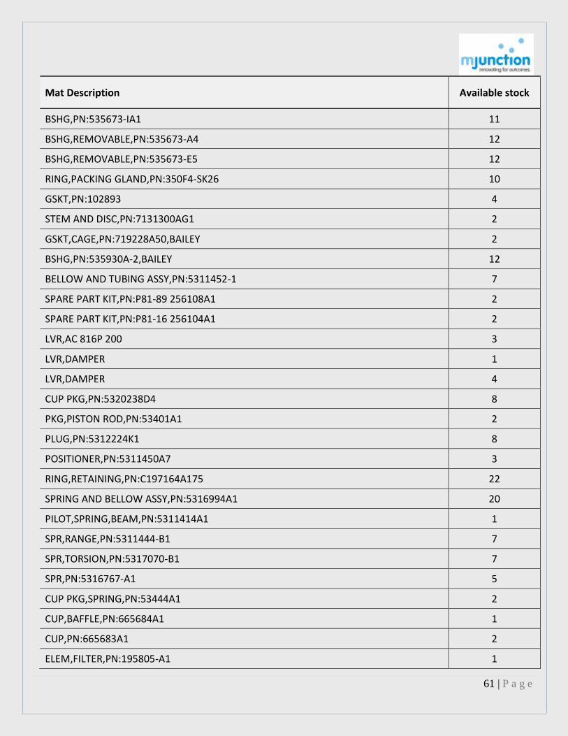
Mat Description Available stock
BSHG,PN:535673-IA1 11
BSHG,REMOVABLE,PN:535673-A4 12
BSHG,REMOVABLE,PN:535673-E5 12
RING,PACKING GLAND,PN:350F4-SK26 10
GSKT,PN:102893 4
STEM AND DISC,PN:7131300AG1 2
GSKT,CAGE,PN:719228A50,BAILEY 2
BSHG,PN:535930A-2,BAILEY 12
BELLOW AND TUBING ASSY,PN:5311452-1 7
SPARE PART KIT,PN:P81-89 256108A1 2
SPARE PART KIT,PN:P81-16 256104A1 2
LVR,AC 816P 200 3
LVR,DAMPER 1
LVR,DAMPER 4
CUP PKG,PN:5320238D4 8
PKG,PISTON ROD,PN:53401A1 2
PLUG,PN:5312224K1 8
POSITIONER,PN:5311450A7 3
RING,RETAINING,PN:C197164A175 22
SPRING AND BELLOW ASSY,PN:5316994A1 20
PILOT,SPRING,BEAM,PN:5311414A1 1
SPR,RANGE,PN:5311444-B1 7
SPR,TORSION,PN:5317070-B1 7
SPR,PN:5316767-A1 5
CUP PKG,SPRING,PN:53444A1 2
CUP,BAFFLE,PN:665684A1 1
CUP,PN:665683A1 2
ELEM,FILTER,PN:195805-A1 1

62 | P a g e
Mat Description Available stock
SLV,SS,ID:2XLG:8IN 10
TUBE,DIFFUSER,PN:665698A1 2
SENSOR,CONDCTY CELL,REF:CELVYOO1T 1
SENSOR,CONDCTY CELL,REFL CELVYOO1TY111 1
POTENTIOMETER,PN:RI 451R 2
TRANSFORMER RI469T 1
TRANSFORMER, OUTPUT RI68T 2
XFMR,POWER,MODEL:RI468T 2
SENSOR,CONDCTY CELL,MM:CEL-1 SS 006-KA 1
SENSOR,CONDCTY CELL,MM:CEL-1 SS 0002 KF 1
SENSOR,CONDCTY CELL,MM:CEL VS01S 1
GSKT,FLEXIBLE,MTL,PN:8941 1
HINGE ASSY,PN:2F/5B 1
COIL ASSY,VLV,VLV NO:195833A1 4
SW,FUEL SHUT OFF SOLENOID VLV 1
VLV SOL,3 WAY 2
VLV,SOLENOID,PN:826918R,ASCO 1
VLV,SOLENOID,PN:83118R,ASCO 1
VLV SOL,115V,MM:195833A1 4
GAUGE UNIT,PN:5314945A7 4
KNOB,SEL,PN:C5314642F1 17
LOADER COMPLETE TYPE AS 2120 3
RELAY,HAND,PN:5316800A1 2
RELAY,SET POINT,PN:5316800A2 3
SELECTOR STATION AM3100 4
SELECTOR STATION AM4100 3
BELLOW,PN:5317588-1 1
BELLOW ASSY,PN:5315804-1 13
63 | P a g e
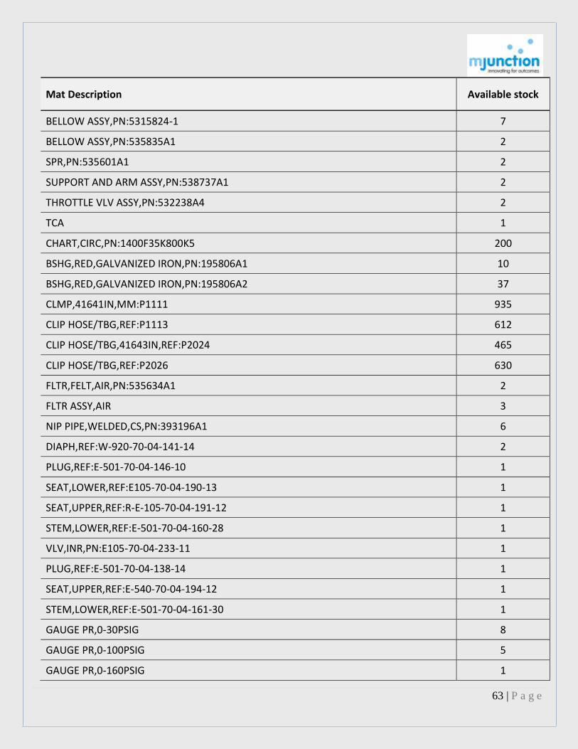
Mat Description Available stock
BELLOW ASSY,PN:5315824-1 7
BELLOW ASSY,PN:535835A1 2
SPR,PN:535601A1 2
SUPPORT AND ARM ASSY,PN:538737A1 2
THROTTLE VLV ASSY,PN:532238A4 2
TCA 1
CHART,CIRC,PN:1400F35K800K5 200
BSHG,RED,GALVANIZED IRON,PN:195806A1 10
BSHG,RED,GALVANIZED IRON,PN:195806A2 37
CLMP,41641IN,MM:P1111 935
CLIP HOSE/TBG,REF:P1113 612
CLIP HOSE/TBG,41643IN,REF:P2024 465
CLIP HOSE/TBG,REF:P2026 630
FLTR,FELT,AIR,PN:535634A1 2
FLTR ASSY,AIR 3
NIP PIPE,WELDED,CS,PN:393196A1 6
DIAPH,REF:W-920-70-04-141-14 2
PLUG,REF:E-501-70-04-146-10 1
SEAT,LOWER,REF:E105-70-04-190-13 1
SEAT,UPPER,REF:R-E-105-70-04-191-12 1
STEM,LOWER,REF:E-501-70-04-160-28 1
VLV,INR,PN:E105-70-04-233-11 1
PLUG,REF:E-501-70-04-138-14 1
SEAT,UPPER,REF:E-540-70-04-194-12 1
STEM,LOWER,REF:E-501-70-04-161-30 1
GAUGE PR,0-30PSIG 8
GAUGE PR,0-100PSIG 5
GAUGE PR,0-160PSIG 1

64 | P a g e
Mat Description Available stock
GAUGE PR,0-400PSIG 1
GAUGE PR,0-150KG/CM2,150MM 3
GAUGE PR,0-250KG/CM2,150MM 5
GAUGE PR,0-400KG/CM2,150MM 8
GAUGE PR,DS,0-200PSIG,100MM 1
BALL,FLOAT 1
FLOAT AND STEM,291-VP 2
FLOAT&STEM,249-VP 6
FLT,MTLC,DIA:3XLG:4IN 3
FLT,MTLC,DIA:3XLG:6IN 3
SW,HG,SPST,MM:RP1014-3 7
SW,HG,SPST,MM:RP 1013-3 5
SW,HG,SPST,MM:RP 6378-3 8
CASE ASSY,PN:1K3756 1
DIAPH ASSY,FISHER 2
KEY,UPPER,POS:8,DIAPH 7
PIN,TPR,POS NO:3 2
CS,AL,PN:4H2699 1
GAUGE,POS:23 7
TUBING ASSY,PN:37/38 16
TUBING ASSY,POS:34 15
TUBING ASSY,POS:35 15
TUBING ASSY,POS:36 14
BELLOW,SS,30PSI,POS NO:53 1
BELLOW ASSY,POS:42 12
DIAPH,POS:10,FISHER 10
HLDR,WALL MOUNTING,POS:65,FISHER 7
PROPORTIONAL BAND SUB ASSY,POS:26 6

65 | P a g e
Mat Description Available stock
SEAT RING,POS:55 9
CORE AND WIRE ASSY,POS:7 6
CTRLR,LEVEL 1
REPAIR KIT,PN:R2502X 0L52,2502R 2
SPRG,COTTER,POS:11 13
TORQUE TUBE ASSY,316SS,POS:9,FISHER 3
PROPORTIONAL BAND SUB ASSY,POS:36 4
DIAPH,POS:10,FISHER 10
PLUG AND WIRE ASSY,RESET,POS:16 8
TUBE ASSY,TORQUE,SS,POS:9 7
TORQUE TUBE ASSY,K-MONEL 1
BSHG,TOP,PTFE,2IN,FISHER 1
CSG,UPPER DIAPH,POS:32 1
PKG,STEM,PTFE,3/8IN,POS:75,FISHER 12
PKG,STEM,PTFE,1/2IN,POS:75,FISHER 5
RING,VLV,655AR 3
SEAT RING,1X1/4IN,POS:8&9,657A 1
SEAT RING,1X3/4IN,POS:8&9,655A 1
SEAT RING,POS:8,9,FISHER,657AR 1
SEAT RING,FISHER,657A 1
SEAT RING,POS:8,FISHER,657A 1
SEAT RING,TAG NO:C37,35,22 TY 657A 8&9 2
SEAT RING,POS:8,9,FISHER,357AR 1
SEAT RING,4X2-1/2IN 2
SEAT RING,POS:8,9,FISHER,657A 2
SPR,DIA:1-1/8IN,REF:STL 3-27,FISHER 1
SPR,VLV,1-1/2IN,FISHER 1
SPRG,ACTR,TAG NO:C41,C35 & C43 1

66 | P a g e
Mat Description Available stock
SPR,ACTUATOR 1
SPR,VLV,1IN,POS:16,FISHER 3
SPR,VLV,POS:6,FISHER 1
STEM,VLV,DIA:1/2IN,FISHER 2
STEM,VLV,DIA:1/2IN,FISHER 1
STEM,SIZE:1IN TYPE:655AR 3
SPR,DIA:3/4IN,REF:STL 3-27,FISHER 1
VLV,INR,SS,3/8X1/4IN,POS:11 1
VLV,INR,SS,1X3/4IN,POS:11 1
VLV INNER,REF:SPT PI-II 1
VLV,INR,SS,POS:11,DPV-PUP 1
VLV INNER,SS,SPT PT II TAG C-23 1
VLV INNER,SS,REF:SPT PT II TAG C-34 1
VLV INNER,SS,REF:DPT PT II TAG C-65 1
VLV,INR,SS,POS:11,DPT, TAG NO:C-33 1
FLPR,CI,1/2IN 10
FLPR,CI,2IN,PN:S-2027 8
FLPR,BRZ,1/2IN 7
FLPR,BRZ,3/4IN 17
FLT,BRS,W/ALARM EXTNSION RLOA-1 1
FLT,BRS,FISHER,RLOA-1-101 1
TUBE,FLUTED,PN:300H014,FISCHER&PORTER 1
BRUSH ASSY,PN:79690 45
CARG,PN:79981-002 5
CONV,PN:354210-1 3
GEAR AND PINION ASSY,PN:351763 14
GEAR,REF:TTD42/74,ITEM:1,HONEYWELL 9
GEAR,REF:TTD42/74,ITEM:2,HONEYWELL 9

67 | P a g e
Mat Description Available stock
GEAR&PINION ASSY,PN:353219 9
GEAR ASSY,SS,ITI,DW:TTD35/74 9
PAD,OIL,PN:353244 13
RCVR,DW:360876/1 1
RCVR,DW:360876/2 1
RECEIVER UNIT,DW:357125/1 1
RECEIVER UNIT,DW:357125/2 1
RECEIVER UNIT,DW:32-R-23-E-3/1 1
RSTR,F/NET WORK KFX5 1
TC,ASSY,MM:1-D-37AI2-1-W101 2
O-RING,PN:354697-3 32
AMPL,PN:702072-1 1
CABINET SCANNING SYST 1
THRMTR,30-300DEG F,PN:100287 1
THRMTR,UNIV,30-180 °FDEG F 2
THRMTR,6IN,30-180DEG F 2
THRMTR,12-1/16IN,30-180DEG F 6
THRMTR,30-240DEG F,PN:SS-9-06 4
THERMOMETER,DIAL/BIMETALLIC,304SS 5
THRMTR,30-330DEG F 2
THRMTR,100-550DEG F,PN:IS-9-06 1
THRMTR,100-550DEG F,PN:AS-9-06 1
SOCKT,SEPARABLE,3/4X2-3/4IN 4
SOCKT,SEPARABLE,3/4X3-1/2IN 2
SOCKT,SEPARABLE,1X6IN 6
SOCKT,SEPARABLE,1X7IN 6
SOCKT,SEPARABLE,1X8IN 1
SOCKT,WELDED 2

68 | P a g e
Mat Description Available stock
TEST WELL,SS,3/4IN,STEM SIZE:15 IN 1
STEM,SS,1X3IN,TEST WELL 2
STEM,SS,1X7IN,TEST WELL 2
STEM,SS,1X9IN,TEST WELL 2
STEM,SS,DIA:1XLG:12IN,TESTWELL 2
THERMO WELL,304SS 2
MERCURY SW ASSY,PN:089-7401-046 2
SYST ASSY,PN:43587 1
SYST ASSY,PN:AFD-1769C 1
SYST ASSY,PN:43592 1
SYST ASSY,PN:49467 1
SYST ASSY,PN:49466 1
SYST ASSY,PN:43583 1
SYST ASSY,PN:43589 1
SYST ASSY,PN:43591 1
SYST ASSY,PN:41895 1
SYST ASSY,PN:41897 1
SYST ASSY,PN:41899 1
PLUG,PIPE,SS,PN:915N 5
TRANSM PRESS,0-600PSI,MM:1214B 3
TRANSM,3-15PSI 1
BAROMETER,PRECISION 1
DAMPNER PULSATREN,BRS,1/4IN,PN:1106B 26
DIAL,DURAFRONT,6IN 9
GAUGE PR,0-3000,MM:1779D,ASHCROFT 5
GAUGE PR,30PSIG,MM:60-1018 2
GAUGE PR,0-300PSIG 1
GAUGE PR,RCVR,0-100PSIG,STL,MM:P1-13 2

69 | P a g e
Mat Description Available stock
GAUGE PR,RCVR,0-200PSIG,STL 1
GAUGE TEMP,RCVR,50-500 F,STL 1
GAUGE PR,RCVR,0-600PSIG,STL 3
GAUGE PR,RCVR,0-1500PSIG,STL 1
GAUGE PR,RCVR,0-2500LBS,STL 1
GAUGE PR,RCVR,0-3000PSIG,STL 1
GAUGE,VACUUM,W/VERNIER ARRANGEMENT 1
MOVEMENT,SS,REF:ABA-262A 11
SNUBBER,1/2IN,PN:1112BE 6
SYST ASSY,PN:AFE-1769 1
SYST ASSY,PN:AFX-1767 1
VLV ASSY,SUCT,PN:LA-313A 4
E-CHAIN,DRAG CHAIN 14
BRCKT,MOUNTING,DRAG CHAIN 1
VLV,GAUGE,CI,1/2IN,REF:151,MILTON ROY 2
VLV,GAUGE,CI,5/8IN,REF:151,MILTON ROY 3
PKG SET,POS:14 2
PKG,POS:32,ACTUATOR 1
PLUG,STEM,POS:11A 1
POSITIONER,ACTUATOR 2
RING,SEAT,PN:951211 1
STEM,POS:26 1
SEAL KIT,PN:R316SR60,VIRGO,ACTUATOR 1
SEAL KIT,PN:SN150SR,VIRGO,ACTUATOR 3
SEAL KIT,PN:SN100SR,VIRGO,ACTUATOR 4
VLV,QUICK EXHAUST,SCHRADER 9
RELAY,AIR LOCK,DEMBLA 4
VLV,FLOW CTRL,SCHRADER 1

70 | P a g e
Mat Description Available stock
LIMIT SW ASSY,VIRGO,SWITCH 6
G,REFLEX,3/4X22IN,PN:23164-2000 4
GAUGE PR,0-600LB 2
ELCTRD,HP,LEVELSTATE TYPE:882 5
SW PRESS,MM:4N3-LL4-N4-B1A-GG 1
SW PRESS,1/4IN,12-100PSI,6LCKK3M9C1ARRLL 2
SW PRESS,DIFF,1/4IN,MM:107-N12-P1-F1A-RR 1
SOFT GOOD KIT 1
SOFT GOOD KIT,ACTUA,4-100% FLOW CTRL VLV 1
SOFT GOOD KIT 1
SOFT GOOD KIT,ACTUA,4-25% FLOW CTRL VLV 1
SPACER,C,REF:62,1.12,6,HELWIG 1
CARB SPACER,FW CTRL VLV,25 1
STUD,1/2IN,MASONEILAN,F/UNIT 4 8
STUD THD,UNC,3/4-10IN,REF:2AL115/35/35 8
TRM,98108981LP VA1R,FLOW CTRL VLV 1
STEM,9810873 VA1R 1
TUBE TORQUE,REF:S/A AB 1F 600 1
LUBR,1IN,37-73421,WITH VALVE 12
PKG,PTFE,TEFLON VLV 36
SEAT RING,37-73421 5
STUD,37-73421 6
TRANSM,STD924-E1H-MBSMS2TCTGF1F1D3 2
TRANSM,STG94L-E1G-0-MBSMTGTCF1F1D3 1
TRANSM,STG180-E1G-000-MBSMCCTGF1IC 1
TRANSM,STA940-E1A-0-MBSMTGTCF1F1D3 1
MODULE,INTER,F/SGL I/O,MM:MC-PAIH03 1
MODULE,PRCSR,INTFC,MM:MC-PSTX03 1
71 | P a g e
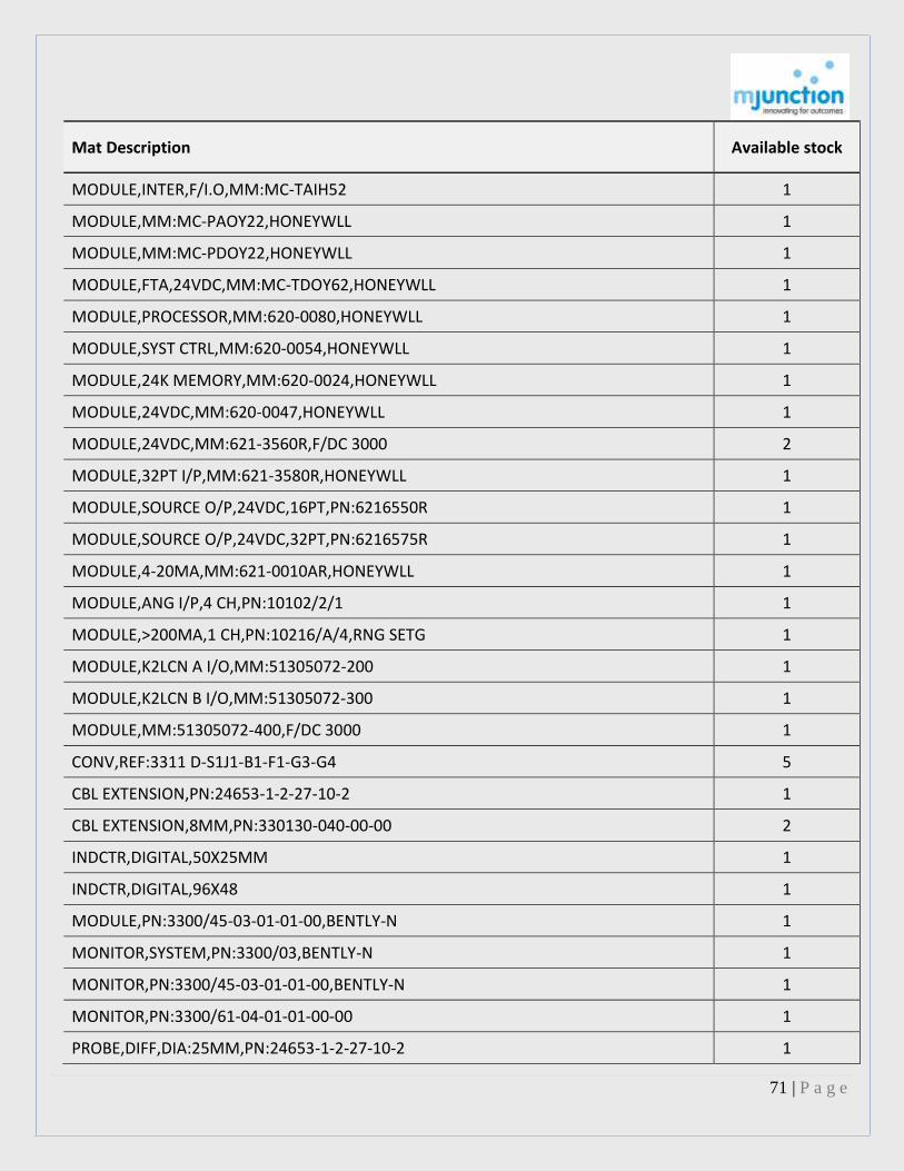
Mat Description Available stock
MODULE,INTER,F/I.O,MM:MC-TAIH52 1
MODULE,MM:MC-PAOY22,HONEYWLL 1
MODULE,MM:MC-PDOY22,HONEYWLL 1
MODULE,FTA,24VDC,MM:MC-TDOY62,HONEYWLL 1
MODULE,PROCESSOR,MM:620-0080,HONEYWLL 1
MODULE,SYST CTRL,MM:620-0054,HONEYWLL 1
MODULE,24K MEMORY,MM:620-0024,HONEYWLL 1
MODULE,24VDC,MM:620-0047,HONEYWLL 1
MODULE,24VDC,MM:621-3560R,F/DC 3000 2
MODULE,32PT I/P,MM:621-3580R,HONEYWLL 1
MODULE,SOURCE O/P,24VDC,16PT,PN:6216550R 1
MODULE,SOURCE O/P,24VDC,32PT,PN:6216575R 1
MODULE,4-20MA,MM:621-0010AR,HONEYWLL 1
MODULE,ANG I/P,4 CH,PN:10102/2/1 1
MODULE,>200MA,1 CH,PN:10216/A/4,RNG SETG 1
MODULE,K2LCN A I/O,MM:51305072-200 1
MODULE,K2LCN B I/O,MM:51305072-300 1
MODULE,MM:51305072-400,F/DC 3000 1
CONV,REF:3311 D-S1J1-B1-F1-G3-G4 5
CBL EXTENSION,PN:24653-1-2-27-10-2 1
CBL EXTENSION,8MM,PN:330130-040-00-00 2
INDCTR,DIGITAL,50X25MM 1
INDCTR,DIGITAL,96X48 1
MODULE,PN:3300/45-03-01-01-00,BENTLY-N 1
MONITOR,SYSTEM,PN:3300/03,BENTLY-N 1
MONITOR,PN:3300/45-03-01-01-00,BENTLY-N 1
MONITOR,PN:3300/61-04-01-01-00-00 1
PROBE,DIFF,DIA:25MM,PN:24653-1-2-27-10-2 1

72 | P a g e
Mat Description Available stock
PROXIMITOR,DIA:25MM,PN:24654-04 1
PROBE,PN:330102-05-35-50-02-00,BENTLY-N 2
TRNSDCR,PN:3300/03,BENTLY-N 2
TRANSM,POSITION,MIL,4-20 MA 3
TRANSM,POSITION,4-20 MA 3
POSITIONER,BHEL 2
SW,PR,0-400PSI,B761S 3
SW,PR,INDFOS,B761S 0-30 PSI 2
SW PRESS,BELLOW,0-7KG/CM²,220VAC,BHEL 5
CTRLR,PN:442RM1225-14-82,TAYLOR 1
SW TEMP,MM:T761T10030 65-125 CL,INDFOS 2
SW TEMP,BELLOW OPRTD,0-165DEGC,5 M 1
MECHANISM,SHUTTER ASSY,BHEL 4
DIAPH,ACTUATOR,VA1 CTRL VLV 5
POSITIONER,PN:8013,MIL 1
FTG,REF:2HK 4
FTG,PN:3000 4
PLUG SPARK SUB ASSY 7
FLAME ROD SUB ASSY 1
TUBE,GUIDE SPARK PLG/FLAME ROD ASSY 4
VLV,PN:IG4553D,INVALCO,14 GPH 1
VLV,PN:IG5056 1
WIRE,IGNITOR,PN:IG 4275,BHEL 130
VLV SOL,DUAL COIL/3 WAY,24VDC 5
INDCTR,BR GPH,PN:40005,MASIBUS 2
SCANNER,TEMP/DIGI,MM:8520,RATING:0-500F 1
CARD,MAIN CTRLLER 1
CARD,AUXILIARY CTRLLER 1
73 | P a g e
Mat Description Available stock
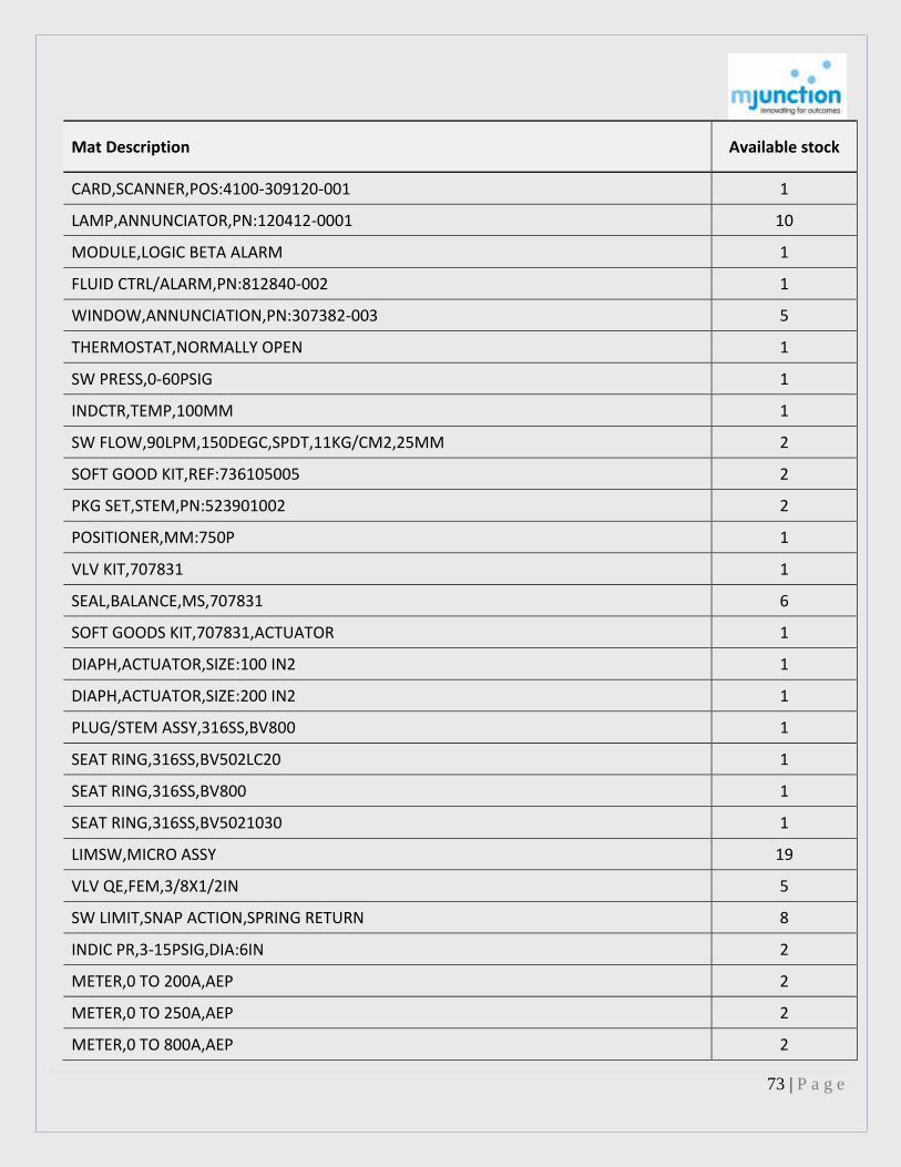
CARD,SCANNER,POS:4100-309120-001 1
LAMP,ANNUNCIATOR,PN:120412-0001 10
MODULE,LOGIC BETA ALARM 1
FLUID CTRL/ALARM,PN:812840-002 1
WINDOW,ANNUNCIATION,PN:307382-003 5
THERMOSTAT,NORMALLY OPEN 1
SW PRESS,0-60PSIG 1
INDCTR,TEMP,100MM 1
SW FLOW,90LPM,150DEGC,SPDT,11KG/CM2,25MM 2
SOFT GOOD KIT,REF:736105005 2
PKG SET,STEM,PN:523901002 2
POSITIONER,MM:750P 1
VLV KIT,707831 1
SEAL,BALANCE,MS,707831 6
SOFT GOODS KIT,707831,ACTUATOR 1
DIAPH,ACTUATOR,SIZE:100 IN2 1
DIAPH,ACTUATOR,SIZE:200 IN2 1
PLUG/STEM ASSY,316SS,BV800 1
SEAT RING,316SS,BV502LC20 1
SEAT RING,316SS,BV800 1
SEAT RING,316SS,BV5021030 1
LIMSW,MICRO ASSY 19
VLV QE,FEM,3/8X1/2IN 5
SW LIMIT,SNAP ACTION,SPRING RETURN 8
INDIC PR,3-15PSIG,DIA:6IN 2
METER,0 TO 200A,AEP 2
METER,0 TO 250A,AEP 2
METER,0 TO 800A,AEP 2

74 | P a g e
Mat Description Available stock
VLV,SOLENOID,2WAY,24VDC 3
SW LIMIT,GUN ENGAGE,MM:WLF2D,OMRON 2
GEAR,WITH WORM,GEAR MOTOR 4
SW PRESS,MM:STYL-GM-102C22 5
SW PRESS,MM:STYL-GM-99C22 5
SW PRESS,1/2 NPTIN,0-600PSIG 2
REPAIR KIT,FORBES MARSHALL 1
TRNSDCR PRESS,0-2.5KG,PN:FPT01 2
GEAR,TURBINE TEMP RECORDER 3
THRMTR 1
THRMTR,0-300DEG C,COLEY 2
THRMTR,0-120DEG F 2
THRMTR,0-200DEG F 1
THRMTR,1/2IN,5-1/4IN,200DEG F,4IN 2
THRMTR,1/2IN,5-1/4IN,300DEG F,4IN 1
GL,GAUGE,OD:3/4X60IN 5
SIGHTGLASS,1IN,TRADE NAME:SPIREX 7
SIGHTGLASS,2IN,TRADE NAME:SPIREX 12
GEAR WHEEL,BAKELTE 10
GEAR,FBR,PN:TTD35/74 IT2 4
GEAR,FBR,NO.OF TEETH:87 T,TACHOMETER 2
GEAR,FBR,NO.OF TEETH:25 T,TACHOMETER 6
TRANSM,CONDUCTIVITY,0-10MICS/CM,RET CELL 1
VLV SOL,FBSP,20-125PSI,2IN,230VAC,2 WAY 1
SCALE,VARIABLE RESISTOR 1
RELAY,CONTROL TIME,220V,50HZ,AM 4
DISC,CPLG,REF:80CC/500 2
POWER SUPPLY,PN:ED660PSFFAOO 1

75 | P a g e
Mat Description Available stock
RTD,3 WIRE SIMPLEX/PT100,8IN 1
O-RING,PN:1 HML 400275 P1,ABB 5
INDCTR,TEMP,PN:376D124P28 1
MVAR DIGI METER,60-0-60,96 SQMM,UBHA 1
EXJ,RBR,DIA:350MM 1
GAUGE,OIL,PN:909838-608,EMCO 1
TRANSM,PR,PN:112746000 1
SW,PR,PN:113100000 1
GAUGE PR,-1 TO 0BAR,100MM 1
GAUGE PR,-1 TO 3BAR,100MM 1
GAUGE PR,-1 TO 9BAR,100MM 3
MOT AC,110V,8W 2
O-RING AND GSKT,PN:P51350 1
INDIC TEMP,0-200DEGC,MM:144X144 1
INDIC TEMP,0-200DEG C 1
RGLTR,AIR FILTER 1
CONTACT,PN:6839Y4,OTIS,FREIGHT ELEVATOR 1
THERMOSTAT,STL,200F TO 900F 1
AMPL,ISOL,TYPE:1A 8
AMPL,SUMMATION,MM:SA4,220V 3
STUD ASSY(FRT BRG ASSY)-30350012 9
BOLT,HEXAGONAL HEAD,INCLUDE:WING NUT 400
GSKT,BRG COVER 1
GSKT,INSERT 1
BOLT FDN,1-3/4IN,7/8IN 12
BOLT,HEXAGONAL,12MM 7
NUT,BRG 24 3
GSKT,COVER,PACKED CHANNEL COVER 2

76 | P a g e
Mat Description Available stock
GSKT,FLEXIBLE 25
GSKT,1/8X1-1/8X1/8IN,IR 7
GSKT,FLEXIBLE,IR 15
GSKT,PRESSURE SEAL,STOP CHECK VLV 2
WSHR,PN:H-3HMT246X2 3
WSHR,MAIN STUD,DW:TTD19/85 19
NUT,IMPELLER 16 10
CPLG,LINE SHAFT 1
NUT,IMPELLER 2
NUT,IMPELLER 2
SFT 2
FLOAT ROD,REF:334 2
NUT,BRG,KIRLOSKAR 1
NUT,IMPELLER,KBL 1
O-RING,BOWL TAPER,DIA:1X50MM,REF:PC 115 2
O-RING,STUFFING BOX,DIA:1X40MM,POS:209 2
SFT,KIRLOSKAR,SALT WATER PUMP 4
GSKT,CAP,REF:408-0013-031 408-R 58
GSKT,MILTON ROY 15
GSKT,LIQUID END,POS:408,MILTON ROY 51
GSKT SET,TUSHACO,RELIEF VLV 1
GSKT,POS:24 1
WSHR,AL,PN:9991854050,KIRLOSKAR PNUM 4
WSHR,PN:2460071250,KIRLOSKAR PNUM 18
WSHR,PN:2520051150,KIRLOSKAR PNUM 7
WSHR,PN:2460012550,KIRLOSKAR 24
WSHR,LOCK,PN:2872B1,30589568,IR 1
GSKT,SPIRAL WOUND,ASB,2-15/16IN 14

77 | P a g e
Mat Description Available stock
WSHR,BRS,PN:88872 30
BOLT HEX,316SS,7/8IN,6IN 2
BOLT,16MM,30MM 368
WSHER BEVEL,5/8IN,PN:JK-6018-3 15
BOLT,DIA:3/8XLG:1IN,DW:JK-6018-3 32
BUTTON,SPRING,POS:762 1
BUTTON,SPRING,POS:666 2
GSKT,D/H-L/S,FARRIS 4
WSHR,LOCK,PN:1724-02 1
GSKT,CAP 6
GSKT,POS:31 4
GSKT,POS:32 1
O-RING,VWS 900mm 3
O-RING,VWS 1000mm 5
GSKT,POS:31 7
GSKT,POS:32 7
CLUTCH FORK ASSY,AUMA 1
BOLT,CPLG,TTD42 72,TYPE I 5
BOLT,CPLG,TTD42 72,TYPE II 5
BOLT,MAIN BRG,POS:018 1
NUT,ROCKER ARM ADJUSTING,REF:102 5
WIRE,1/8IN,METCO 27.5
CLUTCH 1
GSKT,AUXILIARY COVER 2
GSKT,CHANGE GEAR COVER 2
GSKT,L.S END COVER 2
GSKT,MODEL:E.H.S.,BOILER,LOCATION:4 2
NUT,LOCK,BEVEL PIN 1

78 | P a g e
Mat Description Available stock
NUT,LOCK,F/BOILER 1
PIPE,TEE,F/BOILER 2
GSKT,ROTOR HOUSING 12
GSKT,BRG CASE 9
GSKT,RELIEF VLV,BOILER,UNIT 4 12
GSKT,RELIEF VLV,BOILER,UNIT 4 6
ANGLE,2X3X1/2IN 8
BOLT,HEXAGONAL HEAD 78
BOLT,CENTRE,PLATE END,REF:TTD 6/76 RO 206
GSKT,WALDRON CPLG,SIZE:5-1/2 IN 6
BOLT HEX,HTS,3/4IN,2-7/16IN 476
BOLT HEX,HTS,3/4IN,1-5/8IN 275
WSHR,CS,PN:7/8 IDX1 3/4 OD 398
GSKT SPW,CGI,RF,CL 150,4.5MM,3MM 6
GSKT,SPIROTALLIC 16
FLAT,304SS,LG:41/2X1/4X66IN 4
FLAT,304SS,13X3/8XLG:66IN 2
FLAT,304SS,LG:2-1/8X1/4X10IN 8
GSKT,FLANGE OUTLET 37
GSKT,SPIRAL,5/8X3IN,POS:850 43
GSKT,FLEXIBLE,BOILER,UNIT 4 50
CHAIN ASSY,TRAVERSING 32.7
CHAIN ASSY,ROTARY 37
CHAIN,CHAIN,OUTER 36
SEAL,PN:70077,TRADE NAME:KLOZURE 5
WSHR,LAMINATED,PN:78392 10
GSKT,TRAVERSING MOTOR 7
NUT,DISC,EVALLOY-300HHN 1
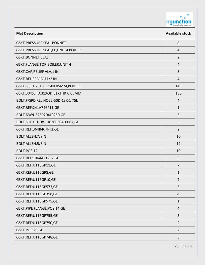
79 | P a g e
Mat Description Available stock
GSKT,PRESSURE SEAL BONNET 8
GSKT,PRESSURE SEAL,FE,UNIT 4 BOILER 4
GSKT,BONNET SEAL 2
GSKT,FLANGE TOP,BOILER,UNIT 4 4
GSKT,CAP,RELIEF VLV,1 IN 3
GSKT,RELIEF VLV,11/2 IN 4
GSKT,SS,51.75X31.75X0.05MM,BOILER 143
GSKT,304SS,ID:31XOD:51XTHK:0.05MM 136
BOLT,F/SPD REL NO22-50D-13K-1 75L 4
GSKT,REF:241A746P11,GE 1
BOLT,DW:U625P204L0250,GE 5
BOLT,SOCKET,DW:U626P304L0087,GE 5
GSKT,REF:364B467PT2,GE 2
BOLT ALLEN,7/8IN 10
BOLT ALLEN,5/8IN 12
BOLT,POS:12 10
GSKT,REF:106A4212P2,GE 3
GSKT,REF:U116GP11,GE 7
GSKT,REF:U116GP8,GE 1
GSKT,REF:U116GP10,GE 7
GSKT,REF:U116GP573,GE 5
GSKT,REF:U116GP358,GE 20
GSKT,REF:U116GP575,GE 1
GSKT,PIPE FLANGE,POS:14,GE 4
GSKT,REF:U116GP755,GE 5
GSKT,REF:U116GP750,GE 2
GSKT,POS:29,GE 2
GSKT,REF:U116GP748,GE 3

80 | P a g e
Mat Description Available stock
GSKT,REF:U116GP792,GE 1
GSKT,5IN,REF:DWGU11LGP495,GE 6
NUT,DW:751D253,POS:43,609,GE 4
BOLT,1IN 8
BOLT,1-1/4IN 2
BOLT,DW:609E989,GE 2
BOLT,HOLD DOWN,POS:46,GE 2
BOLT,HOLD DOWN,POS:33,GE 4
BOLT,HOLD DOWN,POS:39,GE 1
BOLT,HOLD DOWN,POS:40,GE 1
BOLT,GIB KEY COVER 12
BOLT,DW:U624P208L1000,GE 2
BOLT,DW:U624P208L0850,GE 2
BOLT,DW:U624P206L0900,GE 2
GSKT,REF:106A9401-28,GE 1
BOLT,CAP,DW:611E657,GE,VLV 20
GSKT,POS:10 2
GSKT,FLEXIBLE,REF:R-3-25-B 2
GSKT,POS:20,GE 2
NUT,DW:233A877,POS:11,GE 31
NUT,VLV CHEST 8
NUT,DW:K6978506,POS:3,GE 16
NUT,DW:233A877,POS:9,GE 27
NUT,CAT:U614P2104,GE 3
NUT,STEM,POS:47.42 1
BUSH AND SEAL RING ASSY,GE 2
GSKT,REF:U116G355,GE 2
NUT,DW:K6978506,POS:1,GE 29

81 | P a g e
Mat Description Available stock
NUT,DW:143A1564,POS:2,GE 1
NUT,REF:PT37 16
NUT,REF:PT8 9
BOLT,ALLEN HEAD,VLV CAP 1
GSKT,UP HEAD 2
GSKT,POS:629,GE,MAIN STOP VLV 4
NUT,DW:751D314,POS:37,GE 1
NUT,37MM,GE 2
BOLT,DW:109D657,GE 2
BOLT,OUTLET,POS:63 2
NUT,CAP,DW:109D657,POS:34,GE 2
BOLT,TURBINE GENERATOR 12
NUT,TURBINE GENERATOR,UNIT 5 22
WSHR,70MM 24
WSHR,3/8IN,PN:402P13T,GE 120
WSHR,3/8IN,PN:N402P13B5,GE 120
WSHR,1/2IN,PN:N402P45B5,GE 736
BRG,BALL,MS,1/2IN,PN:MS 12,NBC 2
CBL ELEC,WLDG,35MM2 100
MECH SEAL ASSY,ET-ISO4 1
OIL,LUBRICANT,PALL VACUUM PUMP,HS 77359 19
BELT FASTENER,PLATE 350
NAME PLATE,177X209MM,DW:915C,POS:2 2
NAME PLATE,177X311MM,DW:915C,POS:3 2
NAME PLATE,177X216MM,DW:915C677,POS:5 1
NAME PLATE,177X216MM,DW:915C677,POS:6 1
NAME PLATE,167X888MM,DW:915C677,POS:9 1
NAME PLATE,177X215MM,DW:915C677,POS:10 1
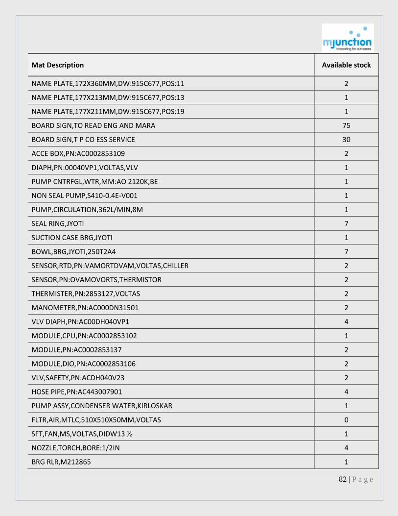
82 | P a g e
Mat Description Available stock
NAME PLATE,172X360MM,DW:915C677,POS:11 2
NAME PLATE,177X213MM,DW:915C677,POS:13 1
NAME PLATE,177X211MM,DW:915C677,POS:19 1
BOARD SIGN,TO READ ENG AND MARA 75
BOARD SIGN,T P CO ESS SERVICE 30
ACCE BOX,PN:AC0002853109 2
DIAPH,PN:00040VP1,VOLTAS,VLV 1
PUMP CNTRFGL,WTR,MM:AO 2120K,BE 1
NON SEAL PUMP,S410-0.4E-V001 1
PUMP,CIRCULATION,362L/MIN,8M 1
SEAL RING,JYOTI 7
SUCTION CASE BRG,JYOTI 1
BOWL,BRG,JYOTI,250T2A4 7
SENSOR,RTD,PN:VAMORTDVAM,VOLTAS,CHILLER 2
SENSOR,PN:OVAMOVORTS,THERMISTOR 2
THERMISTER,PN:2853127,VOLTAS 2
MANOMETER,PN:AC000DN31501 2
VLV DIAPH,PN:AC00DH040VP1 4
MODULE,CPU,PN:AC0002853102 1
MODULE,PN:AC0002853137 2
MODULE,DIO,PN:AC0002853106 2
VLV,SAFETY,PN:ACDH040V23 2
HOSE PIPE,PN:AC443007901 4
PUMP ASSY,CONDENSER WATER,KIRLOSKAR 1
FLTR,AIR,MTLC,510X510X50MM,VOLTAS 0
SFT,FAN,MS,VOLTAS,DIDW13 ½ 1
NOZZLE,TORCH,BORE:1/2IN 4
BRG RLR,M212865 1

83 | P a g e
Mat Description Available stock
BRG RLR,M212860 1
ENG,PN:6HP-762945-4,LV30 1
IMPLR,DIA:12IN,PN:764842-1,CLARKE 2
HOSE,PN:824105-1,CLARKE,TB 20EL 1
HOSE,PN:VAC824120,CLARKE TB 20EL 1
BRUSH,LITTER,PN:102385,466 3
BRUSH SET,REF:102153,466 60
BRUSH,C,REF:014067,DUOVAC,MOTOR 20
BARRIER FOAM,WET VAC,REF:42081 2
BLADE,WIPING,PN:042046 2
SPONGE SET,RBR,AIRTECH 13
MOT ELEC,RTRY BLWR,5HP,1440RPM 1
SW,PR,PN:AC000DH30707 2
PIPE M,CS,800MM 4.59
BEARING BIG END 270202 4
BRG,MAIN CENTRE,PN:270007,KIRLOSKAR 7
BEARING MAIN END 270008 3
BUSH SMALL END 280206 2
CYL,PN:270013,KIRLOSKAR 1
ELEMENT,FILTER,PN:2700521 3
PIPE JOINT,PN:281411 2
JT,PN:281404/271404,KIRLOSKAR 2
PISTON ASSY,PN:280500 1
PISTON,PN:270029,UNLOADER 3
SPRING PLATE 6
PLATE,PN:280903,DELIVERY VLV 28
RING,PISTON,PN:280502 8
RING,PISTON UNLOADER,PN:270030 9

84 | P a g e
Mat Description Available stock
RING,PISTON,PN:2916/88 3
RING,SCRAPER,PN:280503 4
SEAT,PN:280801,SUCTION VLV 2
SEAT,PN:280901,DELIVERY VLV 4
SPACER,DW:TTD 21/85,DISCHARGE VLV 2
VLV,DELIVERY,PN:280900,KIRLOSKAR PNUM 6
BOLT,CONNECTING ROD,PN:950030400 2
CVR,INNER,PN:2460010350,KIRLOSKAR 1
CVR,OUTER,PN:2460010250,KIRLOSKAR 1
NUT,CASTLE,5/8IN,PN:3120012100 26
NUT,PISTON ROD,PN:2460031650,KIRLOSKAR 2
ORING V C TQ H DEL HP 2460076050 12
PKG,PN:21460010550,KIRLOSKAR 1
PKG,PN:2460010750,KIRLOSKAR 26
PKG,PN:2460010950,KIRLOSKAR 1
PKG,PN:2460011950,KIRLOSKAR 2
PKG,PN:2460021950,KIRLOSKAR 2
PKG,PN:2460041150,KIRLOSKAR 2
PKG,PN:2460041250,KIRLOSKAR 4
PKG,PN:2460041350,KIRLOSKAR 1
PKG,PN:2460042050,KIRLOSKAR 4
PLATE,CUSHION,PN:2460065450 8
PLATE,CUSHION,PN:2460060450 4
PLATE,PN:2460065350 8
PLATE,PN:2460060350 12
PKG ASSY,PN:2480102150 8
PIN,WRIST,BUSHING,PN:950030300 2
SPLIT PIN,PN:9993026150,COMPR 20

85 | P a g e
Mat Description Available stock
PKG 3-PIECE(T)2480102150F/T-BTD/JM COPRE 6
RING GARTER,PN:2480039550,TBTD-JM 2
RING,PISTON LP,PN:2480033550 2
RING,SEAL ASSY HP,PN:2480039750 2
RING,SEALING OIL,PN:12221200 2
RING OIL SCRAPPER PT NO 2460042650 4
RING GUIDE LP PT NO 2480032451 2
OIL SEAL,PN:2460040850 2
SPR,PN:2460067350,HP DELIVERY VLV 18
SPR,PN:2460070550,LP DELIVERY VLV 18
SPR,PN:2460067450,LP SUCTION VLV 13
SPR,PN:2460067250,LP DELIVERY VLV 72
SPRING LP SUC VL V IMP 0024600674 18
SPR,PN:24600673,HP DELIVERY VLV 12
DELIVERY VLV ASSY,PN:2480075050 4
DELIVERY VLV ASSY,PN:2480070050 4
SUCTION VLV ASSY,PN:2480065050 4
SUCTION VLV ASSY,PN:2480060050 4
VLV,4IN,PN:301506050,KIRLOSKAR PNUM 2
VLV DRAIN,KIRLOSKAR,UFM-P,AIR DRYER 1
VLV,PUSHER,PN:2480090250,KIRLOSKAR 2
LOCK WSHER,PISTON NUT,PN:2460031550 7
THRUST WSHER,PN:2460051150,KIRLOSKAR 4
COMPRESSOR REFRIGERANT PART NO. BUR10805 1
FLTR AIR,CMPRSD,BIDR BOROST,5MIC,R1.25 2
FILTER ELEMENT PART NO. UV0730 2
CYLINDER HP F/T-BTD/MM KIRLOSKAR COMPRES 1
CYLINDER HP:T-BTD-MM PART NO.2690020150 1
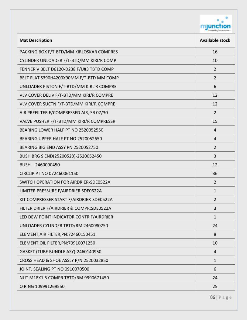
86 | P a g e
Mat Description Available stock
PACKING BOX F/T-BTD/MM KIRLOSKAR COMPRES 16
CYLINDER UNLOADER F/T-BTD/MM KIRL'R COMP 10
FENNER V BELT D6120-D238 F/U#3 TBTD COMP 2
BELT FLAT S390H4200X90MM F/T-BTD MM COMP 2
UNLOADER PISTON F/T-BTD/MM KIRL'R COMPRE 6
VLV COVER DELIV F/T-BTD/MM KIRL'R COMPRE 12
VLV COVER SUCTN F/T-BTD/MM KIRL'R COMPRE 12
AIR PREFILTER F/COMPRESSED AIR, SB 07/30 2
VALVE PUSHER F/T-BTD/MM KIRL'R COMPRESSR 15
BEARING LOWER HALF PT NO 2520052550 4
BEARING UPPER HALF PT NO 2520052650 4
BEARING BIG END ASSY PN 2520052750 2
BUSH BRG S END(25200523)-2520052450 3
BUSH – 2460090450 12
CIRCLIP PT NO 072460061150 36
SWITCH OPERATION FOR AIRDRIER-SDE0522A 2
LIMITER PRESSURE F/AIRDRIER SDE0522A 1
KIT COMPRESSER START F/AIRDRIER-SDE0522A 2
FILTER DRIER F/AIRDRIER & COMPR:SDE0522A 3
LED DEW POINT INDICATOR CONTR F/AIRDRIER 1
UNLOADER CYLINDER TBTD/RM 2460080250 24
ELEMENT,AIR FILTER,PN:72460150451 8
ELEMENT,OIL FILTER,PN:70910071250 10
GASKET (TUBE BUNDLE ASY)-2460140950 4
CROSS HEAD & SHOE ASSLY P/N.2520032850 1
JOINT, SEALING PT NO 0910070500 6
NUT M18X1.5 COMPR TBTD/RM 9990671450 24
O RING 109991269550 25

87 | P a g e
Mat Description Available stock
O RING TUBE BUNDLE ASSY -9991293450 3
PACKING/VALVE GASKET-072460021850 54
PACKING PT NO 102520010550 2
PACKING CYLNDR TO CVR HP-2490020550 2
PACKING 3 PC W.GARTER SP-2460102150 4
PACKING 6 PC W.GARTER SP-2460102050 7
PACKING 3 PC ASY TEFLON -2480102150 6
PACKING 6 PC ASY TEFLON -2480102050 18
PISTON HP & PISTON ROD ASSY P.2690037650 1
PISTON ROD & RING LP ASSY P/N.2690034950 2
SPLIT PIN,3.2X22MM,PN:9993026000 36
GUDGEON PIN,PN:2520031350,KIRLOSKAR 2
PLATE,CUSHION,HP/LP,PN:72460065450 40
PLATE,PN:72460065350,VLV HP/LP 32
RING,GUIDE,HIGH PRESSURE,PN:72500038750 6
RING,GUIDE,LOW PRESSURE,PN:72500032450 8
RING,PISTON,PN:72500030850 3
RING,PISTON HP,PN:72500035850 3
RING,OIL WIPER ASSY,PN:2480032950 3
RING,PISTON LP,PN:2501033550 4
RING,PISTON HP,PN:2501034050 4
SEAL RING ASSY,PN:2480034650 8
SEALING RING,CONTNR CAP,PN:122211000 6
SPROCKET,PN:120453190,KIRLOSKAR PNUM 24
OIL SEAL,FLYWHEEL,PN:2520040850 4
SPR,PN:72460090150,UNLOADER 24
DELIVERY VLV ASSY,PN:2480075050 7
PIN,CROSS HEAD 210903-1 3
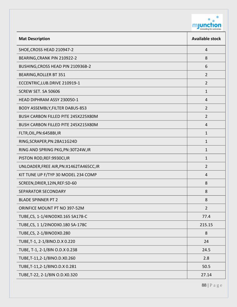
88 | P a g e
Mat Description Available stock
SHOE,CROSS HEAD 210947-2 4
BEARING,CRANK PIN 210922-2 8
BUSHING,CROSS HEAD PIN 210936B-2 6
BEARING,ROLLER BT 351 2
ECCENTRIC,LUB.DRIVE 210919-1 2
SCREW SET. SA 50606 1
HEAD DIPHRAM ASSY 230050-1 4
BODY ASSEMBLY,FILTER DA8US-853 2
BUSH CARBON FILLED PITE 245X225X80M 2
BUSH CARBON FILLED PITE 245X215X80M 4
FLTR,OIL,PN:6458BI,IR 1
RING,SCRAPER,PN:28A11G24D 1
RING AND SPRING PKG,PN:30T24W,IR 1
PISTON ROD,REF:9930CI,IR 1
UNLOADER,FREE AIR,PN:X1462TA465CC,IR 2
KIT TUNE UP F/TYP 30 MODEL 234 COMP 4
SCREEN,DRIER,12IN,REF:SD-60 8
SEPARATOR SECONDARY 8
BLADE SPINNER PT 2 8
ORINFICE MOUNT PT NO 397-52M 2
TUBE,CS, 1-1/4INODX0.165 SA178-C 77.4
TUBE,CS, 1 1/2INODX0.180 SA-178C 215.15
TUBE,CS, 2-1/8INODX0.280 8
TUBE,T-1, 2-1/8INO.D.X 0.220 24
TUBE, T-1, 2-1/8IN O.D.X 0.238 24.5
TUBE,T-11,2-1/8INO.D.X0.260 2.8
TUBE,T-11,2-1/8INO.D.X 0.281 50.5
TUBE,T-22, 2-1/8IN O.D.X0.320 27.14
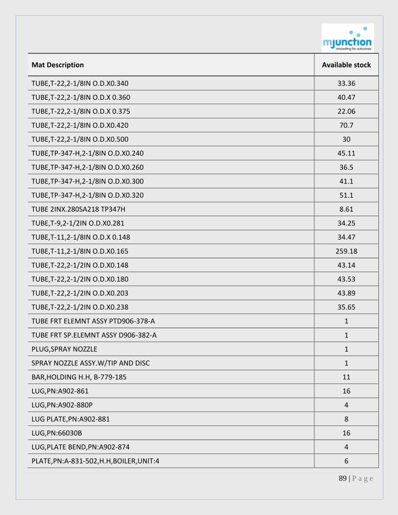
89 | P a g e
Mat Description Available stock
TUBE,T-22,2-1/8IN O.D.X0.340 33.36
TUBE,T-22,2-1/8IN O.D.X 0.360 40.47
TUBE,T-22,2-1/8IN O.D.X 0.375 22.06
TUBE,T-22,2-1/8IN O.D.X0.420 70.7
TUBE,T-22,2-1/8IN O.D.X0.500 30
TUBE,TP-347-H,2-1/8IN O.D.X0.240 45.11
TUBE,TP-347-H,2-1/8IN O.D.X0.260 36.5
TUBE,TP-347-H,2-1/8IN O.D.X0.300 41.1
TUBE,TP-347-H,2-1/8IN O.D.X0.320 51.1
TUBE 2INX.280SA218 TP347H 8.61
TUBE,T-9,2-1/2IN O.D.X0.281 34.25
TUBE,T-11,2-1/8IN O.D.X 0.148 34.47
TUBE,T-11,2-1/8IN O.D.X0.165 259.18
TUBE,T-22,2-1/2IN O.D.X0.148 43.14
TUBE,T-22,2-1/2IN O.D.X0.180 43.53
TUBE,T-22,2-1/2IN O.D.X0.203 43.89
TUBE,T-22,2-1/2IN O.D.X0.238 35.65
TUBE FRT ELEMNT ASSY PTD906-378-A 1
TUBE FRT SP.ELEMNT ASSY D906-382-A 1
PLUG,SPRAY NOZZLE 1
SPRAY NOZZLE ASSY.W/TIP AND DISC 1
BAR,HOLDING H.H, B-779-185 11
LUG,PN:A902-861 16
LUG,PN:A902-880P 4
LUG PLATE,PN:A902-881 8
LUG,PN:66030B 16
LUG,PLATE BEND,PN:A902-874 4
PLATE,PN:A-831-502,H.H,BOILER,UNIT:4 6

90 | P a g e
Mat Description Available stock
STUD,PN:B-779-185 11
TUBE,PIECES,REF;T 11 & T 22 5
PIN,TRUNNION GUIDE 2
RUNNER,KINGSBURY,THRUST BREARING 2
SHOE ASSY,KINGSBURY,THRUST BREARING 12
SPR,PISTON RING,STL,PN:TTD55/73 11
BRG,INNER INTERMIDIATE SHAFT 1
BEVEL PIN,BRG OUTER 2
BRG,OUTER INNER INTERMIDIATE SHAFT 2
COLLAR,UPPER BRG 1
GEAR,INTERMEDIATE 2
GEAR,BEVEL,F/BOILER 2
PINION,BEVEL 2
PLATE,THRUST UPPER BRG,BOILER 1
PINION,INT,PN:316528 2
OIL SEAL,LEFT SIDE SHAFT 2
SNAP RING,UNIT 4 2
SPACER,BEVEL PIN BRG 1
TROUGH OIL,PN:223988 1
UMBRELLA,L.S SHAFT,PN:147901 1
PLATE,STL,PN:A-1-251385 105
SCREW CAP,HEX 1
SCREW CAP,HEX 329
SCREW CAP,HEX 264
AXIAL SEAL,LEAF,COLD END 19
SEAL,LEAF,IN BOARD HOT END 12
SEAL,OUTER TAB-COLD END 24
SEAL,OUTER TAP-HOT END 30

91 | P a g e
Mat Description Available stock
SEAL ASSY, 12 RADIAL 85
SEAL ASSY. 12 RADIAL OUTER 96
SEAL ROTOR POST HOT END 8
STRIP HOLDING, HOT END 75
STRIP-HOLDING, COLD END 12
STRIPS HOLDING, OUTER D-7-41399 84
STRIP,HOLDING,PN:D-1-41146 25
STRIP REINFORCING 48
STRIP HOLDING,INBOARD 103
SEAL,ROTOR POST COLD END 15
SEAL,RADIAL,INBOARD COLD END 12
GASKET FOR SWIVEL JOINT P-9-1153 4
HOUSING, ROTOR 6
HOUSING,BALANCE PISTON 6
POWER ROTOR ASSEMBLY PT.13,15&19 7
PUMP DELAVAL IMO A313AD106 P-1444 1
RING PACKING ASB. GRAPHIT ACE-O-PAX 2
ROTORY IDLER 7
BUSH-FLANGED BRG. 8
POPPET,REGULATING VLV 2
PUMP,RTRY,ROPERIND,REF:18F3 P-28630 1
OIL SEAL,UNIT 4 4
CARTRIDGE,MICRO KLEAN 24
ANGLE,BOILER 2
PLATE,ANGLE 8
CPLG,HALF,3/8IN,PN:ZR-400,27359 1
PIN,TAPER,1/2X1IN,PN:E 26991 30
PIN,TAPER,LG:2IN,PN:P-16-25418 8

92 | P a g e
Mat Description Available stock
PLATE 13
SCREW CAP P-25403 32
SCREW CAP P-1225406 15
SCREW CAP HH 3/4X2 PN P-16-2-5405 7
SCREW CAP 3/4 X 3 1/2IN 8
SCREW CAP 3/4 X 5-1/2 P N P44-25405 8
SHIM,12GA 4
BLADE FOR IDFAN M S DRGTTD3/69 125
COUPLING, WALDRON, NO.5 ½ 1
COUPLING, WALDRON, NO.5 ½ 1
LINER-3/8IN HOUSING SCROLL 60
WHEEL WITH LINERS,2073 2
COUPLING,WALDRON COMPLETE,NO4A 1
COUPLING GEAR AFG106 FOR FD FAN 1
SHAFT WITH COLLARS AND KEYS 3
WHEEL,4073 1
WHEEL WITH LINERS,9073 2
BELLOW, EXPANSION NB 200 4
DAMPER NB 400 F/SCANNER FAN OF BMS 1
HOSE,SCANNER 2 IN NB FOR WIND BOX 8
HOSE,SCANNER 3-1/4IN NB F/WIND BOX 8
HOSE,GI,NB 300 4
HOSE,SS 1/4IN X 1500MM L – 96170037 16
HOSE SS 1/4IN X 1500MM L – 97166090 4
NOZZLE, IGNITOR 15 IN 4
PLATE, EDDY PT NO 92 025 078 8
TAPE-ASB, 1X1/8IN,8FT8IN 30.2
GASKET-CU-ASB 310

93 | P a g e
Mat Description Available stock
GUN OIL REMOVABLE PART-3(REMO PT J) 2
HOSE FLEX F/OIL GUN SS-D12.7 X613MM 7
HOSE FLEX SS FOR OIL NB 25 X 1500MM 8
HOSE FLEX SS F/STEAM NB 25 X 1500MM 9
HOSE FLEX SS 12.7X625MMF/OILBURNER300PSI 12
LEVER,EXTN (CFMF) FOR DIFFUSER CONE 25
PIPE HOSE 100NB SS CORRUGATED FLEXIBLE 8
UNION STATIONARY ASSY W.LMT SWITCH 4
ASSY,DESLAGGER GEAR BOX 2
BEARING BUSTON BR-2 21479 6
CLEVIS,RIGHT HAND,PN:62132 11
CLEVIS,LEFT HAND,PN:62133 6
NOZZLE,PN:61344 12
RACK-PINION,RE3E 4
ROD,TRIP,PN:62130 6
PIPE ASSY,FEED,PN:66170 1
TURNBUCKLE ASSY 2
GLND PKG BUSH,PN:78170 21
CARRIAGE ASSY,TRAVEELING 1
GLND,PN:31214 2
RING,RETAINER,PN:31346 7
SPROKET 14T NO-60 PT-31219 2
RING RETAINER 5100-156 PT-66321 2
ROLLER 41077 2
CONNECTOR CHAIN 5
CONNECTOR. CHAIN 9
LINK CRANK,CHAIN 4
CAM,PN:70160 2

94 | P a g e
Mat Description Available stock
NOZZLE HEAD ASSY,PN:69512 6
NOZZLE HEAD ASSY,PN:69514 6
VLV D HEAD,PN:68530 1
CAM,PN:32573 4
BUSH GEAR PH.BRONZE 2
BUSH,WORM PH.BRONZE 2
BUSH,LINER 1
GB,BOILER,UNIT 4 1
DISC INSERT,BOILER,UNIT 4 2
PIN,UPPER RING,PN:VP 813 F 1
PIN,LOWER RING,PN:VP 813 G 4
RING,ADJUSTING,UPPER 4
RING,ADJUSTING,LOWER 4
SPINDLE,VLV,2IN 1
SPR,VLV,BOILER,3IN,SER:1720 WE 2
DISC INSERT,BOILER,UNIT 4 1
PIN,UPPER RING 6
PIN,LOWER RING,PN:VP 813 C 2
SPINDLE F/2-1/2INVLV 1730W-109-RT 1
SPRING F/2 1/2IN VLV 1730 WA 2
DISC-INSERT,TAG-SV-1,60DURM 1
SPR,VLV,BOILER,3IN,SER:1720 WA 2
DISC INSERT,BOILER,UNIT 4 2
DISC INSERT,BOILER,UNIT 4 1
PIN UPPER RING PT NO VP 813 H 4
PIN-LOWER RING 1
RING-ADJUSTING, UPPER 2
RING-ADJUSTING, LOWER 1

95 | P a g e
Mat Description Available stock
SPINDLE F/4INVLV 1776WB-804-RT 1
DISC,BOILER,UNIT 4 3
GUIDE DISC,BOILER,UNIT 4 3
RING,BODY SEAT 6
PKG RING 165
STEM,TRADE NAME:EXCELLOY 1
DISC AND PISTON ASSY 1
DISC,SURFACE TREATMENT:STELLITED 1
GSKT RETAINER,VLV,1IN,PN:F3916Y 2
GSKT RETAINER,VLV,1IN,PN:F3916Y 2
RING SPACER 10IN VLV FIG3916Y PT 8 2
RING JUNK FOR 10IN VLV FIG3916Y P48 2
DISC & PISTON ASSY.STELITED 1
RING SPACER FIG 7548Y PT-8 6
RING JUNK FDR 1 FIG 75484 PT 37 6
DISC,SURFACE TREATMENT:STELLITED 1
KEY,LOCKING 1
RING-PACKING,EVAL PAK 187-1X 1
GASKET RETAINR 16IN VLV F3914MY PT9 1
RING SPACER 16IN VLV FIG 3914MY P18 1
RING JUNK 16IN VLV FIG3914MY PT10 1
SEAT,EVALOY 2
SPRING DWG NO 2678-4 2
RING, PACKING FOR VLV TAG.V2-44 127
RING PACKING FOR VLV TAG.V2-41 282
VLV GLOB TANDEM 2IN 3206 BLOW OFF 1
SPRING-ADJUSTING DWG NO WA54D PN24 2
VALVE-MAIN 1

96 | P a g e
Mat Description Available stock
DISC,BOILER,UNIT 4 1
BASE FOR RELIEF VLV, 1IN 1
DISC FOR RELIEF VLV, 1IN 2
DISC, 17-4 PH, FOR RELIEF VLV.UU02I 1
NOZZLE,304 SS,FOR RELIEF VLV,11/2IN 1
DISC,SS,MATERIAL SPECIFICATION:17-4 PH 2
NOZZLE 304SS 1
SPRING,CARBON STEEL ASSY. 1
SCREEN FOR 2IN Y-STRAINER 2
PIN-GUIDE ASSY. FOR 2IN STRAP 1
SEAT, VALVE FOR 2IN TRAP 2
BSKT ASSY,BOILER 4
BONNET 3
CLAMP AND HANDLES 3
RING-SPACER 8
RING-SHEAR 6
GASKET ASSY DP-3000 109270-000A 13
TOOL ASSY REFINISHING 108586-2033 2
VLV ASSY,PN:GA107681-8044 1
TUBE,EXPANSION,REF:18 2
CORNER PIECE AS PERDRG NO TTD10/69 50
CORNER PIECE FOR 2 BELLOW EXP.JT. 60
CORNER PIECE FOR 3 BELLOW EXP.JT. 43
CORNER PIECE FOR 4 BELLOW EXP.JT. 44
COVER F/DUCT EXP JT-DRG TTD-10/69 235
DAMPR OUTLET F/ID FAN TTD-70/74 10
DAMPR OUTLET F/FD FAN TTD-69/74 10
EXPANSION JOINT,1 BELLOW 50

97 | P a g e
Mat Description Available stock
EXPANSION JOINT,2 BELLOWS 40
EXPANSION JOINT,3 BELLOWS 31
EXPANSION JOINT,4 BELLOWS 78
EXPN JT F/DUT ITEM 1-DWGTTD 10/69 71
HOSE,METAL,FLEX,1IN,150LB 53.07
PLUG,SW,1.9IN OD.NO.5 4
PLUG,TEST,HYDROSTATIC,VQQ696 4
UNION,BRASS,THREADED,1IN,150LB 40
PACKING CHESTERTON STYLE I 7/16 IN 0.92
PACKING CHESTERTON STYLE I 1/2IN 0.9
BRG,PN:PL-749D859G1,GE 1
BRG,PN:PL565D950G1,GE 2
BRG,PN:PL-565D929G1,GE 1
TOOTH SEQ 220S CAT U316 D015 T0010 2
TOOTH SEQ 220B CAT U316 D017 T0009 3
TOOTH SEQ 220B CAT U316 D017 T0009 2
TOOTH SEQ 220S CAT U316 D018 T0009 1
BRG,THRUST,PN:9477392-1,GE 1
SEAL RING,PN:PL826B645G17,GE 1
SHIM,TURBINE END,DW:107C6638 POS:13,GE 2
SHIM,DW:107C6638 POS:14,GE 1
PLATE,TURBINE END,PN:PL107C7979G2,GE 2
PLATE,GENERATOR END,PN:PL107C7979G1,GE 1
DIAPH,DW:143A6601PT1,GE 5
BOLT,SPEED RELAY,PN:06968078P00410,GE 2
GUIDE BUSH,DW:878A986,POS:1,GE 1
GUIDE BUSH,DW:878A986,POS:2,GE 1
BUSH,PILOT VLV,PN:382 B531 P0001,GE 1

98 | P a g e
Mat Description Available stock
BSHG,PN:0302V918P0001,GE 1
CLEVIS,PN:08268885P0001,GE 1
DISC CLUTCH,PN:P43-478D972,GE 1
GOVERNOR ASSY,PN:PL107C7830G5,GE 1
SPEED RELAY,PISTON,GE 2
PLATE,LOCKING,PN:03666789P0005,GE,SCH B 10
PLATE,PN:0302V570P0001,GE 1
RING,SPRING RETAINER,PN:1.25DN901 1
RELAY,CYL,PN:0477D794P0001,GE 1
SET SCREW,GE 3
SEAT SPRING,PN:B-0302 V917P1,GE 1
SPR,PN:B-05489099P001,GE 2
SPR,CLUTCH,PN:P44-478D972,GE 1
STUD,SPEED RELAY,PN:0248732SP0001,GE 2
WEIGHT ASSY,PN:PL562D553G5,GE 1
WORM,DW:478D972 POS:66,GE 1
WORM WHEEL,DW:478D972 POS:67,GE 1
BSHG,TURBO GENERATOR,UNIT 4 3
WORM,POS:5,GE 1
BSHG,DW:142A3926,POS:1,GE 1
BSHG,DW:237A139,POS:1,GE 1
BSHG,DW:V9083657,POS:1,GE 1
RING,PISTON,TURBO GENERATOR,UNIT 4 3
PILOT,VLV,PN:PL142A4404G1,GE 1
DIAPH,PN:171X3085 5T,GE 1
DIAPH SET,HIGH PRESSURE,2 ND STAGE 1
DOWEL,DW:243A7679P0001,GE 5
GSKT,13.25X14.75MM,PN:341 A 2957 2

99 | P a g e
Mat Description Available stock
GIB,DW:186C567P0001 5
SEAL RING,PN:D7-X227-D71575QP11 1
SEAL RING,INNER,7.5X9XTHK:0.625MM 12
RETAINING RING,12-5/8X14XTHK:1-5/16IN 9
SEAL RING,LOCK NOZZLE BOX 5
CAP SCREW,HEXAGONAL,DW:N171 P21012,GE 15
SCREW CAP,HEX HEAD,DW:171P25020,GE 8
SCREW,SHIM,DW:171P25014,GE 5
SHIM,PN:320B9432P0001,GE 1
SHIM,PN:320B9432P0002,GE 1
SHIM,PN:320B9432P0003,GE 1
SHIM PLATE,DW:313A8374P0001,GE 5
SHIM PLATE,DW:341A9874P0001,GE 1
STRIP,PN:164A4232P0002,GE 5
TOOTH,STOCK/SPLIT,PN:09083789,GE,STR 16
RING,CU,TURBO GENERATOR,UNIT 4 12
BOLT,PN:U624P208L0850,GE 4
PKG RING,REF:N1 GRV1-OMIT PT-3 1
PKG RING,REF:N1 GRV2-OMIT PT-3 1
PKG RING,REF:N1 GRV3-6 OMIT PT-3 4
PKG RING,REF:N2 GRV1-3 OMIT PT-3 6
PKG RING,REF:N2 4 & 5 OMIT PT-3 4
PKG RING,REF:N3 GRV2 OMIT PT-9 1
PKG RING,REF:N3 GRV3 OMIT PT-3 1
PKG RING,REF:N5 GRV1-3 OMIT PT-3 1
SPRING N1,GROOVE-1,PN:513C870P55,GE 12
SPRING N1,GROOVE3-6,PN:513C870P11,GE 28
SPRING N3,GROOVE-2,PN:513C870P241,GE 6

100 | P a g e
Mat Description Available stock
SPRING N3,GROOVE-3,PN:513C870P58,GE 27
PKG RING,PN:0908C 577P0009,GE 3
SPRING N5,GROOVE1-3,PN:513C870P231,GE 11
PKG RING,PN:PL385L184G1,GE 1
PKG RING,PN:PL385L235G1,GE 2
PKG RING,PN:PL385L112G1,GE 3
PKG RING,PN:PL385L197G1,GE 1
PKG RING,PN:PL153112G1,GE 1
PKG RING,DW:U783 N202L0542,GE 1
PKG RING,PN:PL480L500G2,GE 1
PKG RING,PN:PL480L501G2,GE 2
PKG RING,PN:PL387L135G2,GE 4
PKG RING,PN:PL480L502G2,GE 1
PKG RING,PN:PL480L503G2,GE,UNIT 4 1
PKG RING,PN:PL386L102G2,GE 1
PKG RING,PN:PL480L502G2,GE 3
PKG RING,PN:PL480L503G2,GE,STA 24 2
PKG RING,PN:U694N412L1103,GE 1
SPR,DW:513C870 POS:31,GE 48
SPR,DW:513C870 POS:154,GE 27
SPR,DW:513C870 POS:144,GE 8
SPR,DW:513C870 POS:155,GE 11
SPR,DW:513C870 POS:32,GE 30
SPR,DW:2419581 POS:14,GE 58
SPR,DW:513C870 POS:176,GE 9
SPR,DW:513C870 POS:166,GE 3
SPR,DW:513C870 POS:162,GE 17
ORF,PN:143A3541P16,GE 1

101 | P a g e
Mat Description Available stock
SLV,DW:U122S POS:92,GE 1
GSKT,PN:106A4212PT.5&6,GE 2
STUD,PN:U619P205,GE 8
GSKT,PN:U116XG00P0355,GE 7
NUT,3/4IN,PN:243A321P3,GE 4
SLV,DW:U122S POS:30,GE 1
ELBOW,PN:U143E55P24,GE 2
SLV,PIPE,8X9IN,GE 2
SLV,2-1/2IN,DW:U122S POS:80,GE 2
GSKT,1-1/2IN,PN:U11LGP489,GE 4
SLV,PIPE,3X9IN,PN:U1225P102,GE 2
COLLAR,BRG,DW:384B401,POS:1,GE 1
COLLAR,BRG,DW:M9131302,POS:1,GE 1
IMPLR,PN:478D664G1,GE 2
SEAL RING,PN:PL9131303G1,GE 1
SEAL RING,PN:PL109B609G1,GE 1
SHOE,POS:58 4
BRG,DW:M9715684,POS:1,GE 1
BRG,PN:PL9788049G1,GE 2
GEAR,PN:K9041569PT1,GE 1
GEAR,CPLG,DW:193B677,POS:1,GE 1
OIL DEFLECTOR,DW:K9755608,POS:1,GE 1
SEAL RING,DW:K8638673 POS:8,GE 1
SEAL RING,DW:K8638673 POS:7,GE 1
SHIM,PN:127V257,GE 1
IMPLR,DW:608E659,GE 1
SFT,TURBO GENERATOR,UNIT 4 2
RING NOZZLE,DW:608E659,GE 1

102 | P a g e
Mat Description Available stock
WHEEL BUCKET,DW:4525E2451 POS:11,GE 1
BRG,THRUST,PN:MRC54079001075400,GE 2
BRG HUB,PN:4341800201,GE 2
IMPLR,BRZ,REF:5V7 437IN 1
IMPLR,POS:4 1
SEA,MECHANICAL,UNIT 4 1
BRG,BALL,TURBINE GENERATOR,UNIT 4 3
CAM,DRIVER,PN:D6 37 1
IDLER CAM,DW:CAM D6 371 1
PUMP LESS MOT,PN:7113100,GE 2
SFT,DRIVE,TURBO GENERATOR,UNIT 4 1
SFT,IDLER,TURBINE GENERATOR,UNIT 4 1
CAM SPACER,BP 39 4,BP 39 4 2
CAM SPACER,BP 39 5 2
SFT,POS:5,UNIT-4 1
PLUG,DW:857A635 POS:1,GE 40
SPR,DW:857A636,POS:4,GE 44
SPR,DW:857A636,POS:6,GE 75
SPR,DW:857A636 POS:7,GE 23
SPR,DW:857A636,POS:8,GE 46
SPR,DW:857A636,POS:9,GE 80
SPR,DW:857A636,POS:10,GE 90
SPR,DW:857A636,POS:11,GE 59
SPR,DW:857A636,POS:13,GE 25
SPR,DW:857A636,POS:14,GE 43
SPR,DW:857A636,POS:15,GE 25
STRIP,DW:201B826 POS:17,GE 18
STRIP,DW:201B826,POS:18,GE 36

103 | P a g e
Mat Description Available stock
STRIP,DW:201B826,POS:19,GE 18
STRIP,DW:201B826,POS:21,GE 18
STRIP,DW:201B826,POS:42,GE 45
STRIP,DW:201B826,POS:45,GE 90
STRIP,DW:201B826,POS:51,GE 135
STRIP,DW:201B826,POS:58,GE 151
STRIP,DW:382B372,POS:13,GE 16
STRIP,DW:382B372,POS:14,GE 17
STRIP,DW:382B372,POS:15,GE 16
STRIP,DW:382B372,POS:16,GE 16
STRIP,DW:382B372,POS:26,GE 30
STRIP,DW:382B372,POS:27,GE 47
STRIP,DW:382B372,POS:28,GE 22
STRIP,DW:375B811,POS:28,GE 22
STRIP,DW:375B811,POS:30,GE 20
STRIP,DW:375B811,POS:31,GE 24
STRIP,DW:375B811,POS:32,GE 25
STRIP,DW:375B811,POS:36,GE 26
STRIP,DW:375B811,POS:39,GE 29
STRIP,DW:375B811,POS:47,GE 34
BUSH HSG,PN:164A1135P0002 1
BELLOW ASSY,PN:PL8060988G3,GE 1
BELLOW ASSY,PN:PL111B6101G1,GE 1
BELLOW ASSY,PN:915C662G1,GE 1
CAP,PN:143A6913PT1,GE 1
GSKT,PN:U116XG00P0364,GE 1
GSKT,PN:106A9401PT.18,GE 1
ORIFICE FLG,4IN,PN:143A6283G3,GE 1

104 | P a g e
Mat Description Available stock
PISTON ASSY,PN:PL111B6047G1,GE 1
SEAT,HP VLV,DW:11B1880 POS:1,GE 1
STUD,5/8X3-3/8IN,PN:U619P205L0350,GE 4
STUD,DW:751D253 POS:5,GE 4
STUD,DW:751D253 POS:46,GE 4
STEM,VLV,DW:126B6177 POS:1,GE 1
VLV,LOW PRESSURE,POS:13,GE 1
STEM,VLV,POS:14,GE 1
BOLT,PN:609E989,GE 6
BOLT,PN:U623P210L0400,GE 12
BOLT,PN:U624P212L0675,GE 4
DOWEL,POS:32,GE 4
GSKT,PN:106A9400PT.72,GE 2
GSKT,PN:609E989 PT 13,GE 9
GSKT,PN:U336W059D0181,GE 2
KEY,PN:106A5774,GE 2
GIB KEY,UNIT 4 TURBINE GENERATOR 3
KEY,PN:143A1959P5 2
KEY,PN:106A8645P0001 6
KEY,PN:127B3280P0007 6
KEY,PN:163A8296P0001 1
NUT,PN:U615P220,GE 5
NUT,3-1/2IN,PN:U615 P221,GE 4
NUT,PN:U615P222,GE 6
NUT,PN:U615P224,GE 4
NUT,PN:U615P218,GE 11
NUT,PN:U615P226,GE 7
NUT,PN:U614P212,GE 4
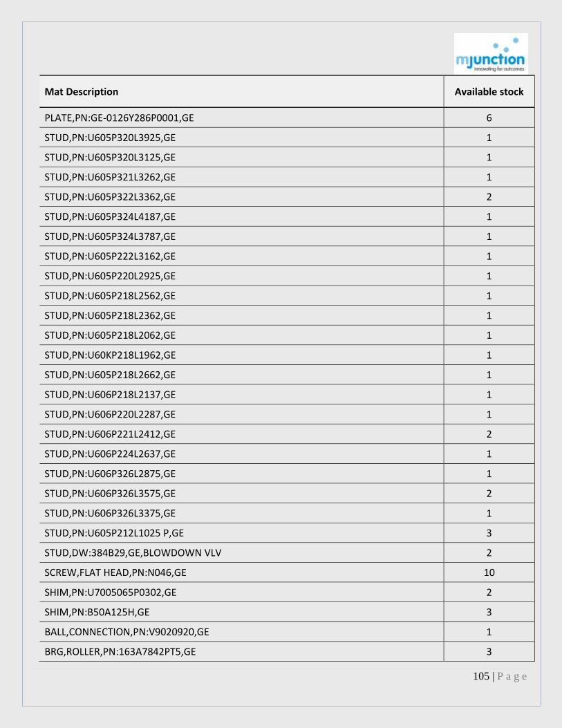
105 | P a g e
Mat Description Available stock
PLATE,PN:GE-0126Y286P0001,GE 6
STUD,PN:U605P320L3925,GE 1
STUD,PN:U605P320L3125,GE 1
STUD,PN:U605P321L3262,GE 1
STUD,PN:U605P322L3362,GE 2
STUD,PN:U605P324L4187,GE 1
STUD,PN:U605P324L3787,GE 1
STUD,PN:U605P222L3162,GE 1
STUD,PN:U605P220L2925,GE 1
STUD,PN:U605P218L2562,GE 1
STUD,PN:U605P218L2362,GE 1
STUD,PN:U605P218L2062,GE 1
STUD,PN:U60KP218L1962,GE 1
STUD,PN:U605P218L2662,GE 1
STUD,PN:U606P218L2137,GE 1
STUD,PN:U606P220L2287,GE 1
STUD,PN:U606P221L2412,GE 2
STUD,PN:U606P224L2637,GE 1
STUD,PN:U606P326L2875,GE 1
STUD,PN:U606P326L3575,GE 2
STUD,PN:U606P326L3375,GE 1
STUD,PN:U605P212L1025 P,GE 3
STUD,DW:384B29,GE,BLOWDOWN VLV 2
SCREW,FLAT HEAD,PN:N046,GE 10
SHIM,PN:U7005065P0302,GE 2
SHIM,PN:B50A125H,GE 3
BALL,CONNECTION,PN:V9020920,GE 1
BRG,ROLLER,PN:163A7842PT5,GE 3

106 | P a g e
Mat Description Available stock
BRG,ROLLER,PN:163A7842PT.4,GE 5
BRG,ROLLER,PN:163A7842PT.6,GE 2
BRG,ROLLER,PN:611E651,GE 3
BOLT,PN:107A6379PT.4,GE 6
BSHG,PN:231V367,GE 2
BSHG,PN:V8614516,GE 1
BSHG,CAM SHAFT,DW:297V838,POS:1,GE 4
BSHG,CAM SHAFT,DW:163A8487,POS:7,GE 4
BSHG,UPPER,F/TURBO GEN 2
BSHG,CTRL VLV 2
CAM AND SFT ASSY,PN:PL751D868G1 1
CAP,DW:126B8001P1,POS:7246,GE 1
CAP,PN:805A SCHB 1
CUP,BRG,DW:611E651,POS:56,GE 2
SEAT ASSY,CUP,POS:58 1
PIN,DOWEL,1/2X1,PN:N507P5016,GE 7
DOWEL,PN:141V238,GE 2
GSKT,PN:611E652 PT-10,GE 2
GSKT,PN:106A9400PT.75,GE 14
GSKT,PIPE FLANGE,PN:611E652,GE 4
GSKT,PN:106A9400PT.28,GE 16
RING,LOCK,PN:107A5168 4
NUT,PN:106A 8867 P0006,NUT SEQUENCE 7242 3
PIN,DW:164A1993 POS:1,GE 2
PIN,DW:142A8926 POS:1,GE 1
PIN,LIFTING,POS:57,GE 4
PIN,PN:PLK9386898G1,GE 2
PIN,POS:91,GE 2

107 | P a g e
Mat Description Available stock
PIN,PN:271A 8271 P0007 2
PIN,VLV STEM,REF:8062 1
RACK,DW:362B695 POS:1,GE 1
RACK,DW:362B695 POS:2,GE 1
RING,LOCK,OUTER DR,PN:U549LGJGBABB2,GE 4
RING,RETAINING,DW:U540J625JABB1,GE 4
RING BUSH,KEEPER LOWER,PN:72564 4
SEAL RING,DW:143A2742 POS:2,GE 3
SEAL RING,DW:164A5785 POS:1,GE 2
SEAL RING,DW:142A1016 POS:5,GE 3
SEAL RING,DW:119A403 POS:40,GE 5
SEAL RING,8-3/4X9-1/2X5/8IN 1
SEAL RING,7-1/2X9X5/8IN 19
RLR CAM AND BRG,PN:PLK9040396G2 4
RING,LOCK,PN:U542 R500 PJAL1 2
SEAL RING,PN:U526 PLN250 AL1,GE 3
RING,LOCK,PN:U542 R500 PJAL1 1
SEAL RING,PN:U526 KAH250 AL2,GE 2
RING,LOCK,PN:206B 9804P0006 3
SEAL RING,PN:U530P999NLALI-SEQ5215,GE 2
SEAL RING,PN:U534R000NLBAI-SEQ5219,GE 3
SEAL RING,RETAINING,PN:U544K750HRAG2,GE 4
RING,LOCK,DW:U542L375JGBA2 4
SEAL RING,DW:U534K750HRAM2,GE 4
SEAL RING,DW:U534K750HRAN2,GE 4
SEAL RING,INNER,DW:U528KCH250AL2,GE 8
SEAL RING,OUTER,DW:U530K750HRBE2,GE 4
SEAT,4-3/4IN,DW:106A5096 POS:1,GE 4

108 | P a g e
Mat Description Available stock
SPACER CAP,PN:7248 1
SPACER,PN:164A1961P0001,GE 1
SPR,PN:K5489052,GE 1
SPR,INNER,PN:K5489052,GE 1
SPR,OUTER,PN:K5489051,GE 2
STEM,PN:207B2520P0001,GE 1
STUD,DW:249A166 POS:42,GE 25
STUD,DW:878A107 POS:7,GE 12
STUD,DW:K6915956 POS:4,GE 12
STUD,DW:107A6176 POS:8,GE 4
STUD,TAP,DW:249A151 POS:16,GE 66
VLV,CAT:8009,GE 1
DISC VLV,2-3/4IN,PN:164A-1970,GE 2
DISC,VLV,DW:142A6778,POS:1,GE 3
DISC VLV,5-1/2IN,DW:126B800P,GE 1
SEAT,VLV,DW:106A4531 POS:1,GE 1
STEM,VLV,PN:126B8003,GE 2
PISTON BLOCK,TURBINE GENERATOR,UNIT 4 1
BOLT,PN:U624P112L0500,GE 6
BOLT,HEXAGONAL SOCKET,PN:129Y547PT.1,GE 2
BOLT,LOCK RING,PN:9197187P0007,GE 11
BSHG,DW:163A8487,POS:8,GE 2
BSHG,LOWER,DW:143A7530,POS:1,GE 2
BSHG,DW:143A3899,POS:1,GE 2
BSHG,DW:143A2021,POS:1,GE 2
BSHG,F/TURNO GEN,GE 2
BSHG,LOWER,DW:143A7542,POS:1,GE 2
BSHG,UPPER,DW:143A7541,POS:1,GE 2

109 | P a g e
Mat Description Available stock
BOLT,PN:9386443P0011,GE 16
BOLT,SOCKET,PN:K919718P7,GE 5
COLLAR,PN:143A2022-1,GE 2
GSKT,PN:106A9400/PT.144,GE 4
GSKT,PN:U336W056D0875,GE 4
KEY,PN:K9112852-13,GE 3
KEY,PN:K912852-34,GE 1
RING,LOCK,PN:128Y910 4
NUT,PN:4615P219,GE 46
PKG,DW:107A2867,POS:1,GE 4
GLND,PACKING,DW:V6959992,POS:1,GE 1
PKG,DW:185R940,POS:49,GE 2
PIN,DW:132V216 POS:1,GE 2
PIN,DW:143A3858 POS:4,GE 2
PIN,STEM,DW:143A3858 POS:3,GE 1
CLAMPING PLATE,DW:143A7531,POS:1,GE 2
PR SEAL HEAD,DW:111B6140 POS:1,GE 1
PISTON RING,DW:K4955353 POS:L21,GE 4
RIVET,STR,PN:294A937,GE 9
SEAL,VLV,DW:111B6142 POS:L1,GE 2
SFT,DW:142A9578 POS:1,GE 1
SFT,DW:142A95771 POS:1,GE 1
SFT,DW:143A4200 POS:1,GE 1
RING,SPLIT,DW:143A3859 POS:2 3
RING,SPLIT,DW:111B6426 POS:1 2
SPR,DW:107A9196 POS:1,GE 2
SEAL RING,STEM,DW:143A3856 POS:2,GE 10
STUD,PN:U606P219L13-63,GE 68

110 | P a g e
Mat Description Available stock
STUD,PN:U607P212L0-738,GE 5
STUD,DW:K6915956 POS:2,GE 8
STEM,VLV,DW:111B6147 POS:1,GE 2
VLV,16-1/2IN,PN:111B6148PT.1,GE 2
VLV,14IN,DW:111B6143 POS:1,GE 2
BOLT,PN:U624P307L0300,GE 13
BSHG,VLV,DW:111B1490,POS:1,GE 1
CAP,VLV,DW:111B1871,POS:1,GE 2
GSKT,PN:U336W050D0656,GE 2
GSKT,PN:106A9401PT.47,GE 6
KEY,PN:142A6265-5,GE 1
PIN,STEM,DW:143A2397 POS:3,GE 1
PISTON RING,DW:743D987 POS:24,GE 4
KEEPER RING,DW:143A2729,POS:8,GE 1
SCREEN,13.12X44.06IN,GE 1
SCREEN,13.12X43.37IN,GE 3
SEAL HEAD ASSY,W/BUSHING 2
STUD,POS:10 24
STUD,PRESSURE SEAL HEAD,POS:36 16
VLV,BY-PASS,DW:914C148 POS:1,GE 1
VLV,PN:914C147-1,GE 1
BOLT,PN:U624P306L0250,GE,UNIT 4 10
BOLT,PN:U624P308L3050,GE 30
BSHG,DW:16JA1247,POS:1,GE 1
BSHG,STEM,DW:106A1215,POS:1,GE 2
BSHG,STEM,PN:PL106A1216G1,GE 2
BSHG,VLV,DW:302V861,POS:1,GE 1
CAP,PN:142A3163-1,GE,VLV 1

111 | P a g e
Mat Description Available stock
COLLAR,PN:164A1246-1,GE 2
COLLAR,SPLIT,DW:125Y144,POS:1,GE 2
GSKT,PN:U336W050D0656,GE 1
GSKT,PN:13751D314,GE 4
NUT,PN:U615P221,GE 20
NUT,PN:U613P212,GE 4
PKG,DW:107A2867,POS:3,GE 12
RING,DW:164A1245 POS:1 1
PISTON RING,DW:8074277 POS:28,GE 2
KEEPER RING,DW:751D314,POS:86,GE 2
RIVET,PN:294A937-2,GE 28
RIVET,STR,PN:294A932P10,GE 66
SPR,DW:2419549 POS:1,GE 1
STUD,PN:U606P312L0-700,GE 4
STUD,PN:U606P321L1831,GE 33
STUD,DW:106A5671,POS:2,GE 16
VLV,PN:829B341G1 1
PIN,DW:296U872 POS:11,GE 2
SEAT,VLV,PN:PL828B811G1,GE 1
STEM,VLV,DW:111B6990 POS:1,GE 1
DIAPH,DW:U136VFP89,GE 1
BSHG,DW:241A926,POS:1,GE 1
BSHG,PN:241A925,GE 1
BSHG,PN:127V459,GE 1
CAP,VLV,PN:24A929PT1,GE 1
DOWEL,PN:127V464,GE 1
GSKT,PN:106A9400,GE 10
GSKT,PN:106A 9400 PT36,GE 3

112 | P a g e
Mat Description Available stock
GSKT,9-1/2IN,PN:384B294,GE 1
GSKT,PN:106A9460P0028,GE 4
NUT,PN:384B294,GE 10
RING,PN:128V755 2
INNER RING,DW:384B294,POS:5,GE 3
RING,OUTER,DW:384B294 3
RING,LOCK,DW:384B294 POS:9 1
SEAT,VLV,PN:PL247A161G1,GE 1
SPACER,PN:127V756,GE 1
SPACER,EXP JOINT,DW:384B294 POS:7,GE 1
STUD,PN:U606P214L1012,GE 3
STUD,CALLED OUTER SHELL,GE 2
VLV,PN:PL197B625G1,GE 1
VLV,BY-PASS,PN:PL241A930G1,GE 1
VLV,BY-PASS,DW:241A372 POS:1,GE 1
BUCKET,2ND STAGE,DW:126B839,GE 3
BUCKET,3RD STAGE,DW:12668391,GE 4
BUCKET,DW:126B8393,GE 2
BLOCK NOTCH,CLOSE PIECE 1
BUCKET,STAGE 23 135
BUCKET,STAGE 24 108
BURR CARBIDE,DW:106 A3069,POS:0002,GE 12
CVR,BRCKT,PN:12688600P005,GE 1
CVR,BRCKT,PN:11B9513P0030,GE 6
CVR,BRCKT,PN:11B9513P0031,GE 6
COVER SHROUD,F/STAGE 23 17
COVER SHROUD,F/STAGE 24 14
COVER STOCK,DW:SU943 B14UP 1271,GE 21

113 | P a g e
Mat Description Available stock
KEY,5TH STG COVER,PN:D644L146 04 004,GE 3
PIN ROOT,F/STAGE 23 2
PIN ROOT,F/STAGE 24 2
PUNCH DIE,STALLIE PLATE,F/STG 23 1
PUNCH DIE,SATELLITE PLATE 1
BLANKET,TURBINE GENERATOR 4
PLUG,PN:V90896239,GE 15
PIN,DW:143A7663 POS:1,GE 62
STR,BRS,1/2IN,PN:15408L,GE 1
SEAL SET,MECHANICAL,GE 2
LOCK PLATE,PN:306V734,GE 16
LOCK PLATE,PN:248A245P10,GE 59
LOCK PLATE,PN:K3666789P7,GE 32
LOCK PLATE,PN:K3666789P9,GE 60
LOCK PLATE,PN:K2671505P3,GE 9
LOCK PLATE,PN:K2671505P2,GE 8
DEFLECTOR,OIL,PN:9477318,GE 1
SPACER,DIAPH,DW:143A1435 POS:4,GE 1
SLOT ARMOR,CAT:163A5339P24,GE 4
PINION,PN:744C242P11,GE 1
CVR,CAT:0827B816 P0013,GE 1
BODY,DW:TTD46/70,POS:O1 3
BHING,DIFF,HIGH CARB.358506 6
COOLR OIL,140 F,100 PSIG 1
IMPLR,2ND STAGE,PN:921067-1 1
ORF,F/MULTIPLE PRESS REDUDCING 2
RTNR,SPLIT BRG 1
RING,PN:32072 12

114 | P a g e
Mat Description Available stock
RING,TORUSEAL,PN:E-20000-A 32067,WPIL 3
SHOE,THRUST,PN:32055 16
SLV,SUCTION GUIDE,PN:937719 2
SPOOL PIECE,20IT2 OFF TTD 46/70 2
SPR,BOILER FEED PUMP 3
BARREL,WEARING RING,175X205X120MM,WPIL 1
BARREL,WEARING RING,200X230X120MM,WPIL 1
BUSH,THRUST BUSHING,PN:13428 6
GSKT,SHAFT SEAL,PN:ROX127409/84 6
IMPLR,13% CR W/2 4,PUMP 1
PKG,DURA METALLIC 8
PKG,ACE-PAXSTYLE,PN:29916 3
SEAL,MECHANICAL,TYPE 80U SIZE:262 SIN 1
RING,WEAR,CASING 3 2
WEARING RING,STUFFBOX HEAD 3A 2
BRG,GEAR 1006 8
PINION,BRG,REF:1005 8
GEAR DRIVE,POS:509 3
GEAR IDLER,1012 3
PUMP,LUBE OIL,MM:W-2BC 1
PUMP ASSY,OIL/GEAR DRIVE,PN:N-8317 1
SFT,DRIVE,OIL PUMP 504 2
SFT,IDLER,OIL PUMP 505 2
CPLG,REF:AGFIE-1011/2 1
CPLG,REF:AGFIE-1011/2 2
CPLG,PN:GCME-1021/2 2
END CAP,40855-1 1
GSKT,PN:40257-4 12

115 | P a g e
Mat Description Available stock
ELEM,PN:63104-3,OIL FILTER 3
DISC,PISTON,PN:1017548 2
GSKT,PN:Y-337D363AX1 14
GSKT,PN:Y-512D363AX1 3
GSKT,PN:Y-662D363AX1 4
GSKT,PN:Y-937D363CX1 3
GAUGE,PR,PN:2A12-J-61,IR 1
GLND,PN:X-350616DX6 3
KEY,PN:11A9-Y-278-348CF,IMPELLER 6
KEY,PN:11A9X132,IR 3
GLND PKG,CART SEAL 3
GLND PKG,73X110X10MM,PMP DISCHR V/V 30
RING,GPH,DW:SK-1/2008 2
PUMP,LUBE OIL,IR 2
LUBE OIL COOLER,REMOVAL,NEIL FAB 1
PLUG AND SEAL ASSY,PN:1LAP BG12,IR 3
RING,CASING,PN:Y-1337D6AX1 2
RING,IMPELLER,PN:Y-1262D4AX1 9
RING,SPLIT,PN:Y-300D252CX1 2
RING,SPRING,POS:206,IR,X-14VEM398AX1 3
RING,SPRING,POS:241,IR,X-14VEM398BX1 2
ROTOR,PN:2LE-24 1
SFT,WITH KEYS 14 VEM 10X7 566 1
SPR,PN:Y-3HMTA341X2 55
SPR,PN:12VEM341X2 12
SW,LIMITORQUE,SMB-3 1
VLV GLB,FS,40MM 5
VLV,FAS,40MM,IR 7

116 | P a g e
Mat Description Available stock
CPLG,POS:185 1
GLND,REF:162 2
SEAL,MECHANICAL,1.75IN 2
COVER END,BALL BRG,REF:71918 111 2
IMPLR,POS:101,PUMP 1
BSHG,DW:2374 5
BSHG,SS,100X165X325MM 1
CPLG,HALF,MOTOR,PN:2317 1
CPLG,HALF,PN:2319 1
SEAL,DRIVE,PN:616269 1
IMPLR,1ST STAGE,TYPE:SUCT.2331 1
IMPLR,2ND STAGE,PUMP,UNIT 5 5
JT,EXPANSION,PN:565-2500-1 3
SLV,BRG,PN:2325 1
SLV,PN:2323 1
SLV,STUFFING BOX,PN:2321 2
SLV,SHAFT,PN:663286 1
SPR,COIL,PN:616268 2
INSERT GUIDE VANE,90-10 BRZ 2
STUFFING BOX ASSY 1
CSG,CS,BODY W/WEARING RING 1
CVR,BACK,CI,STUFFING BOX 1
IMPLR,CI,CPB/40/200 2
IMPLR,BRZ,REF:LG2,MATHER&PLATT 1
IMPLR,DW:ORD:06/T/5531/2C,KIRLOSKAR 1
NECK RING,410SS,ET-22 1
SFT,W/KEY,410SS,ET-22 2
IMPLR,BRZ,MATHER&PLATT,ET-12 1

117 | P a g e
Mat Description Available stock
SEAL,MECHANICAL,WATER PUMP,UNIT 4 1
BRG,LINE SHAFT 1
HOLDER ASSY,BRG,PUMP 2
CPLG,PUMP,JYOTI 1
CPLG,LINE SHAFT,SS,JYOTI 1
IMPLR,BRZ,JYOTI 6
SFT LINE,1.5M 1
SFT,IMPELLER,PUMP 1
BRG,LINE SHAFT 1
HOLDER ASSY,BRG,PUMP 4
CPLG,LINE SHAFT,JYOTI 1
IMPLR,BRZ,JYOTI 2
SFT LINE,1.5M 1
SFT,IMPELLER,PUMP 1
RING,WEAR,CASING,AL+BRZ,REF:VI 2642-A 1
SFT,75X705MM 1
SFT SLV,410SS,REF:VI 2645-B 1
JT,EXPANSION,RBR,DW:TTD-3/97 1
PUMP,SPLIT CASING,212M3/H,12.5M 1
RING,WEAR 1
CSG,CPB 32/160 1
CONNR HOSE,DW:500-008 3
IMPLR,DW:500-016 4
SEAL SET,UPPER,DW:500-049 2
STR,DW:500-023 4
ADPTR,DW:TTD62/72 1
IMPLR,POS:101,SW PUMP 4
CPLG SFT,DW:71902 5

118 | P a g e
Mat Description Available stock
COVER END,BALL BRG,REF:71907,111 4
BRG SHELL,BALL BRG,POS:134 2
CVR,INNER,GOULDS 2
BRG,HOLDER SPIDER,RBR,PUMP 4
BRG,JOURNAL,KIRLOSKAR 2
BOWL,8CM,POS:120 1
COIL,COOLING,KIRLOSKAR 3
CPLG,MUFF,KIRLOSKAR 3
HOLDER BRG,POS:254 1
IMPLR,KIRLOSKAR,SALT WATER PUMP 1
KEY,316SS,PN:3211,MUFF CPLG 8
KEY,IMPELLER,316SS,POS:320 1
KEY,SHAFT SLEEVE,316SS,PN:3232 4
KEY,CPLG,316SS,POS:321 1
KEY,THRUST COLLAR,316SS,POS:328 2
RING,SPLIT,POS:405,MUFF CPLG 4
SFT HEAD,KIRLOSKAR 1
SFT,IMPELLER,SALT WATER PUMP 1
LINE SFT,KIRLOSKAR 3
SLV,SHAFT,BRG HOLDER ON LINE,KBL 1
SFT SLV,IMPLLER,316SS,POS:316 1
DISTANCE SLV,316SS,POS:317-2 1
STOOL,MOTOR,POS:290,BHQ62 1
IMPLR,KIRLOSKAR,BHQ62 1
BRG,RBR,POS:357,TRANS,W/316 SHELL 2
PUMP,W/CPLG 1
PUMP,W/CPLG 1
BELLOW,EXPNSION,RBR,SK-29/2002 2

119 | P a g e
Mat Description Available stock
IMPLR,CI,KIRLOSKAR,8UP 2 1
IMPLR,CI,REF:8U2MPTNO2A,KIRLOSKAR 1
SEAL,MECHANICAL,65MM 2
STR,DW:TTD 6/87 2
BALL,PN:407-0014-172,MILTON ROY 22
BSKT,DISSOLVING,SS,MILTON ROY 2
CAP,LIQUID END,PN:222-A,MILTON ROY 8
PKG,POS NO:408-E,MILTON ROY 35
PLUNGER,DW:POS NO:212-A,MILTON ROY 2
SEAT,DW:POS NO:224A,MILTON ROY 23
SEAT,MILTON ROY 4
SPR,MILTON ROY,CHEMICAL PUMP 4
VLV RLF,1/2IN,4200PSI,FARRIS 1
TRUNNION SLV,BRG,PHOS PUMP 1
BOX,CONDUIT,MILTON ROY 1
CRANK,DW:69738-1-2,MILTON ROY 1
TRUNNION,OPEN,MILTON ROY,PHOS PUMP 2
WORM GEAR,MILTON ROY 2
WORM SFT,MILTON ROY,CHEMICAL PUMP 2
CAP,LIQUID END,PN:222-A,MILTON ROY 6
PKG,POS NO:408-E,MILTON ROY 46
PLUNGER,DW:POS NO:212-A,MILTON ROY 2
SEAT,DW:POS NO:224,MILTON ROY 23
TRUNNION SLV,BRG,SULPH PUMP 2
BRG,PN:69738-3-4,MILTON ROY 2
CRANK,DW:69738-3-4,MILTON ROY 1
TRUNNION,CLOSED,MILTON ROY 4
TRUNNION,OPEN,MILTON ROY,SULPH PUMP 2

120 | P a g e
Mat Description Available stock
WORM SFT,MILTON ROY,CHEMICAL PUMP 2
BALL,CHECK VLV,POS:407-D,MILTON ROY 3
CAP,LIQUID END,PN:222 A,MILTON ROY 12
PKG,REF:408E,MILTON ROY 66
PLUNGER,DW:POS NO:212-A,MILTON ROY 3
SEAT,DW:POS NO:224A,MILTON ROY 24
SEAT,FARRIS,2745 2
SPR,MILTON ROY,CHEMICAL PUMP 2
VLV RLF,1/2IN,420PSI,FARRIS 1
BSHG,LARGE END,POS:37B,MILTON ROY 2
FRAME,MILTON ROY 1
PKG,REF:5,MILTON ROY 49
SEAT,DW:POS NO:24,MILTON ROY,VLV 8
END REAGENT,PN:805286-3,MILTON ROY 5
FERRULE TUBE,PN:810400,MILTON ROY 3
NIP,FLARING,PN:G854,MILTON ROY 3
STROKE ADJUSTMENT UNIT,PN:808 809 1
VLV,CHECK,PN:806515-1,MILTON ROY 3
BUSH,LARGE,POS:37B,MILTON ROY 5
PLUNGER,316SS,1-1/2IN,POS:12,MILTON ROY 1
SEAT,SAFETY VLV,MILTON ROY 1
SEAT,DW:POS NO:24,MILTON ROY 2
SEAT VLV,3/4IN,MILTON ROY,CARP.20 3
SPR,VLV,1/2IN 4
SPR,VLV,3/4IN 3
VLV,BALL,REF:23,MILTON ROY 7
BSHG,SMALL,REF:37A 5
BSHG,LARGE,REF:37B 5

121 | P a g e
Mat Description Available stock
TEE,11/2IN,MILTON ROY 5
ELBOW,CROSS CARPENT,1-1/2IN,REF:20 4
FLG,3/4IN,MOC:CARPENT 20,PUMP 2
SEAT,POS:24,MILTON ROY 1
TEE PIPE,1/2 IN,CARP 20,OTY:11 9
VLV,BALL,REF:23,MILTON ROY 4
IMPLR,PN:63 .49356,MILTON ROY 2
IGNITION OIL,PP,W/FRAME+MOTOR 1
CRTG ASSY,TUSHACO 1
SEA,MECHANICAL,OIL PUMP 2
RELIEF VLV ASSY,TUSHACO 1
BUSH,BALANCING 4
BUSH,DISTANCE,POS:11 2
CIRCLIP,POS:37 2
INSERT,REF:2,ALLWEILER 3
MOT AC,400V,3PH,50HZ,75HP 1
SCREW,AUXILIARY 13 4
SLV,SFT 1
SPR,DW:TTD 7/99 100
VLV,RELIEF,DW:A4/03312,POS:134 2
BAG,NYL,STLWOOL FILLED 200
DIAPH,PN:297A2370P1 1
BELLOW,JOINT EXPANSION,RBR 2
PLUG,NPRN,20X26MM 1,405.00
PLUG,TAPER,RBR,15X28X75MM 100
RING,16-1/2X18-3/4X1/2IN 12
SPRING ASSY,VLV,DIA:1/2IN 3
TUBE,7/8INX28FT-2.8IN 277

122 | P a g e
Mat Description Available stock
TUBE,U-BENT,SS,GRADE:304 4
TUBE,U-BENT,DIA:1-3/8IN 1
TUBE,U-BENT,DIA:2-3/16IN 1
TUBE,U-BENT,3INRADIUS 1
TUBE,U-BENT,DIA:3-13/16IN 1
TUBE,U-BENT,DIA:5-7/16IN 1
TUBE,U-BENT,DIA:1-1/2IN 1
TUBE,U-BENT,DIA:2-7/16IN 1
TUBE,U-BENT,DIA:3-11/32IN 1
TUBE,U-BENT,DIA:4-1/4IN 1
BSKT,STR,PN:44092 6
NOZZLE,SECONDAR,PN:9107 2
NOZZLE,STEAM 1ST STAGE 1
VLV,FEEDWATER EXCHANGE 1
PLUG,TUBES,PN:11H611GR2 35
DISC,POS:8 4
SPR,POS:6 2
STEM,POS:7 4
RELIEF VLV ASSY,SHELL 1
GL,GAUGE ASSY 16
TUBE,GAUGE GLASS,3/4X213/8IN 5
VLV ASSY,GLOBE,1IN 1
DISC,POS:B-39 2
DISC,POS:N-749-A 2
SEAT RING,POS:742 2
DISC,POS:27 3
GSKT,PN:14,20,25,31 6
SPR,POS:17 1

123 | P a g e
Mat Description Available stock
STEM,POS:18 2
NOZZLE,CAST BRZ,ITEM 33 SEMI 2
DIAPH,MAN HOLE,PN:388A039 5
PLUG,POS:4,16BWG 650
GLND PKG,73X110X10MM,MOT ISOLAT V/V 30
DISC,SS,MATERIAL SPECIFICATION:A961-17 3
GSKT,PN:A96-14,HEAT EXCHANGER 17
DISC,W/RETAINING RING AND BUSHING 2
GSKT,PN:A1681-2,6,13,22,38 6
STEM,PN:A-1681-9 1
STEM ASSY 1
DISC,W/RETAINING RING & BUSHING 2
SPR,PN:A-1681-8 1
STEM,PN:A-1681-9 2
DISC,W/RETAINING RING & BUSHING 2
SPR,PN:A-1682-8 1
STEM,PN:A-1682-9 1
VLV GATE,4000PSI,10IN 2
GSKT,ANKORITE,PN:33893AS 1
SPR,PN:P434489-J 1
SPR,MONEL,F/SPRAY VLV 12
TRAY,FLAT,42IN 14
TUBE M,TI,22BWG,3/4IN,18FT 67
PLATE,AL+BRZ,DIA:600XTHK:40MM 1
PLATE,AL+BRZ,DIA:750XTHK:35MM 1
GL,GAUGE,PN:17603 3
PKG,GAUGE GLASS,PN:80163 47
FLTR UNIT,PN:38B33 3
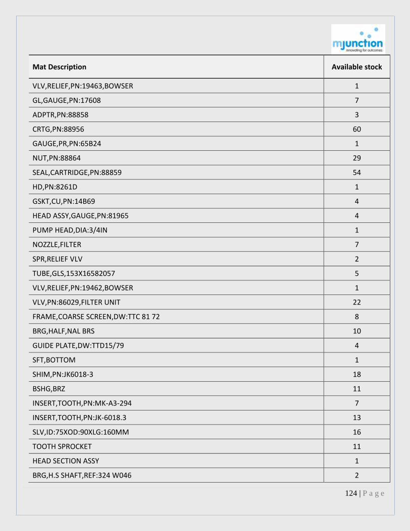
124 | P a g e
Mat Description Available stock
VLV,RELIEF,PN:19463,BOWSER 1
GL,GAUGE,PN:17608 7
ADPTR,PN:88858 3
CRTG,PN:88956 60
GAUGE,PR,PN:65B24 1
NUT,PN:88864 29
SEAL,CARTRIDGE,PN:88859 54
HD,PN:8261D 1
GSKT,CU,PN:14B69 4
HEAD ASSY,GAUGE,PN:81965 4
PUMP HEAD,DIA:3/4IN 1
NOZZLE,FILTER 7
SPR,RELIEF VLV 2
TUBE,GLS,153X16582057 5
VLV,RELIEF,PN:19462,BOWSER 1
VLV,PN:86029,FILTER UNIT 22
FRAME,COARSE SCREEN,DW:TTC 81 72 8
BRG,HALF,NAL BRS 10
GUIDE PLATE,DW:TTD15/79 4
SFT,BOTTOM 1
SHIM,PN:JK6018-3 18
BSHG,BRZ 11
INSERT,TOOTH,PN:MK-A3-294 7
INSERT,TOOTH,PN:JK-6018.3 13
SLV,ID:75XOD:90XLG:160MM 16
TOOTH SPROCKET 11
HEAD SECTION ASSY 1
BRG,H.S SHAFT,REF:324 W046 2

125 | P a g e
Mat Description Available stock
CHAIN ASSY,DRIVE,SS,PN:3188 11.14
CPLG,MODEL:STD/E/01,FLUID 2
PINION,PN:1791X003 2
SFT,HIGH SPEED 2
SPROCKET,REF:FR U-4 6T,PX158.8 3
SPROCKET,REF:FR 6TX158-2 1
PIN HUB ASSY 2
PIN,BRAKE,STL 14
LINK ASSY,RIGHT,POS:TTD 37
BSHG,CHAIN 24
PIN,DW:TTG 1/75 REV:1 44
PLATE,PN:JW3614-1 10
RLR,TRAVELLING WATER SCREEN 100
NOZZLE ASSY,SPRAY,PN:341Y/7-4 15
BOOT,CASING,RIGHT HAND,REF:TTD 6/81 R1 1
BOOT,CASING,LEFT HAND,REF:TTD 6/81RI 1
SPACER,A AND B 150
SPACER 105
WIRE MESH,CRIMPED,1500X645MM,PN:55316 30
SFT,SS,1X9INX4FT 2
VLV CHK,SCR,CARPENTER 20,3/4IN 4
VLV DIAPH,FLGD,PP,1-1/2IN 7
VLV DIAPH,SCREWED,SS,3/4IN 2
VLV DIAPH,SCREWED,SS 4
BSHG,316SS,1/2X1/4IN 5
BSHG,316SS,1/2X1IN 6
BSHG,CARPENTER,20SS,1/4X3/4IN 4
BSHG,CARPENTER,20SS,3/4X1-1/4IN 6

126 | P a g e
Mat Description Available stock
BSHG,CARPENTER,20SS,1-1/4X1IN 7
BSHG,1-1/4X2-1/2IN 1
CPLG,SS,3/8X3/4IN,CARP.20 3
CPLG,SS,3/4X2-1/2IN,CARP.20 3
CROSS,316SS,1/2IN 2
CROSS PIPE,SS,3/4IN,GRADE:CARPENTER 20 2
CROSS PIPE,SS,1-1/4IN 4
ELBOW PIPE,CARP 20 SS,1/4IN,90DEG 4
ELBOW PIPE,SS,1-1/4MM,90DEG 12
ELBOW PIPE,316SS,1/4IN,90DEG 12
FLG PIPE,316 SS,1/2X4-1/4IN 1
FLG PIPE,316 SS,1/4X4-5/8IN 2
TEE PIPE,CARP 20 SS,1/4IN 5
TEE PIPE,316SS,1IN 1
VLV DIAPH,15MM 4
VLV DIAPH,50MM,EBONITE 1
SPR,POS:56 22
NOZZLE,316SS,PN:3181 1
SPR,CS,REF:B-406 1
BUTTON,SPRING,PN:2077HRS 5
GSKT,BODY,PN:1285 1
GSKT,NOZZLE,PN:1309 1
SPR,PN:H-296 3
SPR,PN:H-100 3
DISC,BRS,PN:8025 3
DISC,BRZ,PN:587X3 1
DISC,PN:5205-4 1
HLDR,DISC,PN:3581 1

127 | P a g e
Mat Description Available stock
NOZZLE,PN:2808 1
RING,BLOWDOWN,4020X1MM 1
DISC,REF:1301 3
GSKT,LOCK SCREW,PN:1287,FARRIS 3
NOZZLE,PN:1302 1
DISC,HARDENED 1
GSKT,D/H-L/S,ASB,PN:4592,FARRIS 4
NOZZLE,PN:1316 1
RING,BLOWDOWN,1318X1MM 1
DISC,PN:12409 1
GSKT,CAP,ASB,PN:2938 4
RING,WEAR,PN:5481 1
SPR,PN:B-620-CP 1
NOZZLE,PN:5263 2
SPR,CS,REF:G-76 1
BALL VLV 3
DISC,PN:8489 1
GSKT,BODY,PN:1914 5
GSKT,CAP,PN:1902 4
NOZZLE,SS,PN:6623 1
GSKT,BODY,PN:1296 15
RING,BLOWDOWN,PN:13205 1
SPR,W STL,PN:C-714-T,FARRIS 1
VLV RLF,SFTY,1-1/2X2IN 1
GEAR UNIT,PN:9 AS 900/10 2
HSG,STARTING SWITCH,CI 1
SEGMENT ADJUSTER,BUTTERFLY VLV 16
SEGMENT RETAINER,BUTTERFLY VLV 14

128 | P a g e
Mat Description Available stock
MOT,ELECTRIC 2
SPYRET SEAL,NBR,VLV,900MM 1
SPYRET SEAL,NBR,VLV,100MM 1
SEAL,DISC,NBR,POS:6,AUDCO 4
NUT,DISC,PN:5525A04A 3
PKG RING,VLV,2IN,REF:V2-705 114
SEAT,PN:955H06A 7
GSKT,PN:605498 10
PKG,PN:15137 20
BRG,THRUST,AUMA 1
GEAR,COUNTER 4 TRAIN,FOURESS 1
RING,CLUTCH,AUMA 1
SEAL,VLV,DW:FW-42001-E (R2),FOURESS 2
V-BELT,PN:132A1081P2,IGE 2
SEAR VLV,PN:6477881 P6 2
PLUG,IR,WITH BRCKT 6
INDIC TEMP,WINDING,0-200DEGC 1
CAP,PN:S-22C3435H02,BRG/LOWER 1
CIRCLIP,ROCKER ARM 12
PUSH ROD,VLV,POS:219 2
SPR,SUCTION/EXHAUST VLV,REF:PT090 24
SPR,STARTING VLV,REF:115 3
VLV,398MM 1
FITTER AND DRAIN ASSY 3
CPLG,BIBBY RESILENT 2
PLUG,DRAIN,SU MOTORS 1
PUMP,DOSING,25HP,REF:R/S82 2
BRG UNIT,FLGD,2-3/16IN,MM:MFC35 4

129 | P a g e
Mat Description Available stock
CBL,4CX53MM2,LG:56M,MAN,GANTRY CRANE 56
COIL,NO VOLT,MAN,400 V 50 CPS BREAKER 4
CONTACT BRIDGE,CTRL CIRCUIT,PN:L14236 2
CONTACT BRIDGE,STATOR ELEMENT,MAN 6
CONTACT PIECE,MAN,STATOR/ROTOR 30
CONTACT PIECE,MAN,CTRL CIRCUIT 12
CYL,PR,OIL,PN:GR7-24,MAN 1
DISC,BLANK,DRUM CTRLLER 9
SPUR GEAR,DW:TTD 31/73,MAN 2
HOOK,CRANE 1
LINING,BRAKE,70/7INX400MM,MAN 3
PAD,ANTI VIBRATOR,M.A.N 8
PUMP,OIL,PN:280 14 118,MAN,GANTRY CRANE 1
PUMP,OIL,REF:KSW-1,MAN,GANTRY CRANE 1
RELAY,PREHEATING,MAN 1
RIVET,LININGS OF BRAKE,80X20,MAN 113
SFT,SPINDLE,PN:T2 61 1853,MAN 1
SPR,THRUSTER,DW:TA66-139,ELDRO/MAN 3
SPR,DW:TA66-163,ELDRO/MAN 6
SUPPORT,RUNWAY,DW:TA 76 015,MAN 11
BOLT,CPLG AND SHOCK ABSORBER 6
BRAKE SHOE,CRANE AND HOIST 2
CHAIN,FE,W/HANDLE,CRANE&HOIST IN TRANFRE 2
BRIDGE COLLECTOR,CURRENT 12
SFT,CRANE,F/CRANE&HOIST,10T 1
SFT,DRIVING 1
CONDENSER,PN:226H1,OTIS 3
CONTACT,BRUSH SWITCH,AG,OTIS 1
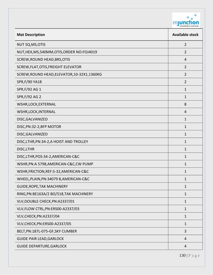
130 | P a g e
Mat Description Available stock
NUT SQ,MS,OTIS 2
NUT,HEX,MS,540MM,OTIS,ORDER NO:FOJ4019 2
SCREW,ROUND HEAD,BRS,OTIS 4
SCREW,FLAT,OTIS,FREIGHT ELEVATOR 2
SCREW,ROUND HEAD,ELEVATOR,10-32X1,1360KG 2
SPR,F/90 YA18 2
SPR,F/92 AG 1 1
SPR,F/92 AG 2 1
WSHR,LOCK,EXTERNAL 8
WSHR,LOCK,INTERNAL 4
DISC,GALVANIZED 1
DISC,PN:32-2,BFP MOTOR 1
DISC,GALVANIZED 1
DISC,LTHR,PN:34-2,A HOIST AND TROLLEY 1
DISC,LTHR 1
DISC,LTHR,POS:34-2,AMERICAN-C&C 1
WSHR,PN:A 5798,AMERICAN-C&C,CW PUMP 1
WSHR,FRICTION,REF:S-32,AMERICAN-C&C 1
WHEEL,PLAIN,PN:34079 B,AMERICAN-C&C 1
GUIDE,ROPE,TAK MACHINERY 1
RING,PN:BE163A/2 BO/518,TAK MACHINERY 1
VLV,DOUBLE CHECK,PN:A2337/01 1
VLV,FLOW CTRL,PN:ERS00-A2337/03 1
VLV,CHECK,PN:A2337/04 1
VLV,CHECK,PN:ERS00-A2337/05 1
BELT,PN:187L-075-GF,SKY CUMBER 3
GUIDE PAIR LEAD,GARLOCK 4
GUIDE DEPARTURE,GARLOCK 4

131 | P a g e
Mat Description Available stock
LVR,SAFETY 4
PAWL,BRAKE,PN:100-103,GARLOCK 4
RATCHET BRAKE,EOT CRANE 4
THIMBLE,IRON GRIP,3/8IN 6
BRAKE THRUSTER,DIA:250MM,18KG,ACME 1
BRAKE THRUSTER,DIA:250MM,34KG,ACME 1
INSULATOR,ACME 2
LINING,ACME,SIZE:1/4IN X 11/4IN X 65MM 24
LINING,ACME,SIZE:1/4IN X 11/4IN X 96MM 6
LINING,ACME 11
LINING,ACME,SIZE:1/4IN X4IN X 165MM 18
O-RING,ITEM REF:101,ACME 11
O-RING,102MM,LTDO,GEARED CPLG 4
PINION,ACME 1
PINION,13TX2.5M,ACME 1
PINION,15TX3M,ACME 1
PINION,LONG TRAVEL,16TX3M,ACME 1
OIL SEAL,PN:30-50-6,ACME 25
OIL SEAL,PN:35-54-10,ACME 6
OIL SEAL,PN:48-62-8,ACME 1
OIL SEAL,PN:48-65-10,ACME 2
OIL SEAL,PN:70-80-10,ACME 12
OIL SEAL,PN:80-100-10,ACME 14
OIL SEAL,PN:95-120-12,ACME 3
OIL SEAL,PN:95-120-13,ACME 1
SPR,BRAKE,LG:100MM,ACME 6
SPR,BRAKE,LG:110MM,ACME 2
SPR,BRAKE,LG:190MM,ACME 2

132 | P a g e
Mat Description Available stock
SPR,BRAKE,LG:200MM,ACME 6
SPR,BRAKE,LG:230MM,ACME 4
SPR,BRAKE,LG:250MM,ACME 4
BRG,HOMECH,221-44 6
BRG RLR,1816 Z 2
BRG SLV,ROPE SHEAVE,HOMECH 3
BUSH,SYN RBR,MUKAND 24
BUSH,RBR,25X13X6MM,MUKAND 12
BUSH,RBR,25X13X36MM,MUKAND 30
BUSH,RBR,40X25X39MM,MUKAND 56
PLATE,CLUTCH,MUKAND 1
CAM,UNCUT,MUKAND 12
SHOE,CI,DW:IEI-47,MUKAND 4
EYE HOOK,CHAIN BLOCK DFCS 1.5T 6
VLV,DBL ACTG,CI,125LB,75MM 2
TUBE PLATEN ELEMNT ASSY D906-357-A 1
TUBE SP.RR.ELEMNT ASSY D906-381-A 1
TUBE SPRR ELEMNT ASSY D906-380-A 1
SLEEVE BRG, 6INSAWC 449D147G11 4
RING,SPLIT-LOWER 2311 3
RING,SPLIT-UPPER 2314 3
INSERTS PLASTIC 6INLONG TTD3/76 2,000.00
INSERTS PLASTIC 6INLONG TTD3/76 300
BUSHING JK6018-6 PICE NO.14 2
PUMP,600M3/H,30M,MM:200-DS-40 4
Note : 1. The quantity mentioned is only indicative and approximate. Actual quantity as per the declared lot (even if the quantity is less or more than the indicated quantity) shall be fully cleared as demanded by Tata Power.

133 | P a g e
Tata Power shall not entertain any claim/ complaint from the buyer(s) for any deficiency in quantity or refund the whole or any part of the purchase money or loss of profit or otherwise. 2. The Bidders should thoroughly satisfy themselves about the nature, conditions and quality of the Plants, Machineries & other items and their working conditions. Tata Power gives no guarantee or warranty as to the conditions of the Plants and Machineries or / its quality or its fitness for any specific purpose or use. It should be clearly understood that no claim/ complaint about the quantity/ quality/ conditions/ fitness for use will be entertained by Tata Power. Payment & Lifting Schedule:
LOT No.
LOT VALUE LIFTING PERIOD
TATA POWER/1 The full payment along with taxes and duties is to be made in five equal instalments as shown in the table below Table 2. (Lot value + Applicable taxes & duties)
200 days from the receiving go ahead to commence lifting, after payment has been made
The winning buyer will need to deposit the material value including all taxes & duties in 5 equal instalments as shown in the table below: Table -2
Note:
Sl. No. Installments ( Material value with taxes & duties )
Time Line For Payment
(from receipt of Sale Order)
ACTION REQUIRED TO BE TAKEN
Material to be dismantled and lifted
1 On deposit of 1
st installment Within 10 Days Up to 1000 MT OF MATERIAL
2
On deposit of 2nd
installment Within 30 Days Up to 1500 MT OF MATERIAL plus balance material of first instalment.
3
On deposit of 3rd
installment Within 50 Days Up to 1500 MT OF MATERIAL plus balance material of first & second instalment.
4
On deposit of 4th
installment Within 75 Days Up to 1500 MT OF MATERIAL plus balance material of first , second & third instalment.
5
On deposit of 5th
installment Within 100 Days Balance material under sale.
134 | P a g e
i. If the Purchaser deposits the entire amount in a single instalment along with all taxes & duties, he will be allowed to dismantle & lift the material from any part of the segments. However, in such a case, prior approval for sequence of dismantling shall be obtained by the purchaser from the TPCL.
ii. Bank detail of TPCL for making payment through RTGS shall be provided to the successful H1 buyer.
Penalties: I. The entire Pre bid Security amount will be forfeited if the H1 Buyer fails to deposit the 1st instalment within the
stipulated time.
II. If the H-1 Buyer fails to deposit any of the further instalments within the stipulated time a late fee penalty of 1% per
week or part thereof upto a maximum of 2 weeks will be imposed. Beyond 2 weeks, the payment may not be
accepted & the entire Security deposit along with previous deposited instalment will stand forfeited.
III. Beyond the allotted time for dismantling and lifting (also considering extension, if provided), the H1 buyer will not
have the right to claim any of the material. TPCL/mjunction will have the right to re-sell the remaining material.
TERMS & CONDITIONS: 1. The successful high bidder is legally bound to pay for plant & equipment awarded in accordance with the bid
submitted by him. The Tata Power Company Limited reserves the right to reject any or all bids.
2. 100% of the EMD will be will be retained by Tata Power as Security Deposit and will be adjusted with the 5th and final
instalment.
3. For inter-state customers, concessional CST @ 2% will be charged if the customer separately submits differential CST
deposit of 3% along with EMD payment. This is to be submitted directly to TATA POWER.
The same will be refunded after receiving complete endorsed C form from the customer.
4. Total lifting and cutting period allowed shall be 200 days.
5. If the dismantling & lifting is not completed within stipulated timeline an extension will be provided after mutual discussion
between the customer, TPCL and mjunction.
6. The preferred mode of payment is by RTGS. The payment must be made along with 5% VAT.
7. Materials are being offered on “as is where is” & “no complaint” basis.
8. Inspection of Materials:
The bidder is invited, urged, and cautioned to inspect the property prior to submitting a bid. The failure to inspect property
shall not constitute cause for cancellation of sale. The material will be available for inspection at the places and times
specified by The Tata Power Company Limited.
9. All lots are ‘site to be cleared basis’.
10. Prices quoted must be valid for this sale event only. VAT will be applicable.
10. Price to be quoted ex- Maharashtra, exclusive of taxes
11. Preparation for Transportation, Loading and Removal:
The Purchaser shall be responsible for making all arrangements for the packaging and removal of their purchases. The Tata Power Company Limited does not warrant that the plant & equipment, as packaged, is suitable for shipment. Segregation, culling, or selection of property for the purpose of effecting partial or incremental release will not be Permitted. Cutting, dismantling, Transportation, loading & unloading is in the scope of the buyer. Cutting will be allowed on the plant premises. The material is being sold on "As- is- where- is basis". The quality and quantity has to be verified by the bidders before the auction, no complaint regarding the material will be entertained by Tata Power

135 | P a g e
Company Limited or mjunction after the auction is over. . Tata Power Company Limited reserves the right to determine the sequence of lifting of materials as decided by itself. No selective picking / sorting / grading of any kind will be permitted under any circumstances. 11. Only Oxy-DA cutting tool is allowed in the TATA POWER LTD premises.
12. Insurance: The contractor shall take an all risks policy which shall include but not be limited to his personnel , equipment and collateral damage to Tata Power property or personnel or any other third party. All activities associated work except those explicitly specified as responsibility of Tata Power in this document shall be with the Purchaser.
13. Compliance of Labour Laws : The Purchaser shall be responsible for strict compliance of all laws, rules and regulations concerning labour, social welfare and benefits of its workers During the lifting period in which purchaser's workers are employed within the Tata Power Co. Ltd., Trombay premises, they will be governed by the Labour Law, Rules and regulations and employee insurance act as applicable and it shall be wholly and solely responsibility of the purchaser for full compliance with the provisions under all the applicable labor laws and/or regulations
14. Indemnification.
Purchaser shall indemnify and hold harmless Seller and its owners, officers, directors, employees, agents and advisors from
and against any claim, loss, damage, suit, cause of action, liability, judgment or expense (including, without limitation,
attorneys' fees and costs), resulting from, arising out of or in connection with any injury, disease or death of persons or
damage to or loss of any property, or violation of any applicable laws or regulations resulting from or in connection with the
sale, collection and transportation of the Goods.
15. Dispute Resolution and Venue.
Any dispute arising out of this transaction shall be resolved by litigation or binding arbitration ("Dispute Resolution") at Seller's sole option. Such Dispute Resolution shall be conducted at a location selected by Seller and in the event of binding arbitration, by an arbitration service selected by Seller.
16. Governing Law The Contract shall be interpreted in accordance with the prevailing laws of Republic of India. For all disputes, appropriate court at Mumbai under the jurisdiction of Maharashtra High Court alone shall have exclusive jurisdiction in all matters arising under this agreement. 17.Statutory Compliance / Safety: The purchaser and all its personnel shall strictly comply to the safety standards and requirements of Tata Power as detailed in the Contractor Safety Manual (CSM) (copy attached) Purchaser shall submit a dismantling, removal, loading plan and take approval from the Seller, prior to commencement of any work related to the Sale. In case , Seller finds that the work is not being performed in accordance with the Safety standards and guidelines set by the Tata Power, Seller shall have the right to stop the activity and get the same corrected at purchaser’s risk and cost. All the bidders at the time of inspection will be required to have a session with safety department of TPCL, Trombay. 18.Tata Code of Conduct: The Tata Power Company abides by the Tata Code of Conduct in all its dealing with stake holders and the same shall be binding on the Purchaser and their representatives. A copy of the Tata Code of Conduct is available at our website: http://www.tatapower.com/aboutus/code-of-conduct.aspx.

136 | P a g e
Practices that eliminate competition, such as collusive bidding, may warrant immediate disqualification of the bidder/s. 19. Requirements of participation: 20.1 Registration: Before participation in the e-Tender, a prospective bidder shall be required to get registered with mjunction services limited. For details visit www.auction.metaljunction.com OR get in touch with the concerned person from mjunction. 20.2 Documentation: The following documents need to be submitted by the bidder interested for participating in the e-Sale to mjunction services limited prior to the date of the e-Sale:
Letter of Interest duly signed and stamped by bidder (attached with this catalogue).
Each page of this catalogue to be signed and stamped by the buyer and to be submitted to mjunction services limited.
New bidders (not registered with mjunction) are requested to submit notarized copies of their SOI's before participating in the e Sale. 20.3 Insurance: The contractor shall take an all risks policy which shall include but not be limited to his personnel, equipment and collateral damage to Tata Power property or personnel or any other third party. All activities associated with work except those explicitly specified as responsibility of Tata Power in this document shall be with the Purchaser. 20.4 Pre Bid Security Deposit: Non-Interest bearing security deposit of Rs. 1,000,0000 for LOT 1 in the form of NEFT to “MJUNCTION SERVICES LIMITED”. NEFT details below:
Table : 3
Beneficiary Name MJUNCTION SERVICES LIMITED
Beneficiary Account Number 00140310003480
IFSC Code HDFC0000014
Bene Bank Name HDFC BANK LTD
Bene Bank Branch Name SARAT BOSE ROAD
20.5 Last Date for submission of Pre Bid Security Deposit 21.09.2015 by 4 pm 20.6 Tata Power reserves the right to cancel the auction at any stage or reserve the right to cancel the sale even after completion of the auction without assigning any reason. The bidder shall be solely responsible for all efforts and expenses incurred for the bid. 21. Bidding modalities: 21.1 Price Bid Basis for Online Forward auction: In Rs/Lot. Price to be quoted is basic, ex- location exclusive of VAT/CST & TCS. 21.2 Type of auction: Online forward auction (English no-ties) 21.3 Bid Validity: Bid shall be valid for Sixty (60) days from the date of e-Tender. 22. Refund

137 | P a g e
a) For the winning customer, if price is approved the pre bid security will be retained till lifting of all material is completed & successful completion of the contract. b) For non H1 buyers, the pre-bid security will be refunded within 15 working days of receiving the refund request letter on company letter head along with cancelled cheque copy with company seal from the customer.
{ Letter of interest to be filled and submitted on company letter head by mail to [email protected] & [email protected] & [email protected] }
LETTER OF INTEREST
To The Manager

138 | P a g e
TATA POWER COMPANY LIMITED TROMBAY THROUGH: M/s mjunction services limited
REF. : Online Sale event of Unit No. 4 of the 150 MW Oil Fired Thermal Power Plant of TATA POWER COMPANY LIMITED
at Trombay , Maharashtra Dt. 23/09/2015 Dear Sir, (1) We are interested in participating in the Online sale event notified vide your notice under reference to the sale of Unit No. 4 of the 150 MW Oil Fired Thermal Power Plant of TATA POWER COMPANY LIMITED at TROMBAY and lifting of material to be done ex MAHARASHTRA by road. We also agree to abide by all the instructions contained in the indicated Online sale event Catalog above, General Rules and Regulations governed in Conduct of Online forward auction, invitation to online sale event auction notice. (2) We are hereby submitting the applicable Pre-bid security deposit of Rs. 1,000,0000 /- for LOT 1 as per following details in favour of “mjunction services limited” for participating in the above mentioned Online Sale event.
UTR No. RTGS date Bank, Branch Amount (Rs.)
(3) We agree to offer our best bid in the online event, in Rupees per Lot for the lot in the auction process, Ex- MAHARASHTRA exclusive of all taxes & duties, and other Statutory Levies if any, as legally applicable at the time of delivery/despatch and hold the same valid for 60 working days for acceptance of the bid from the date of online sale event. (4) We agree to comply with all "SAFETY MEASURES" of TATA POWER COMPANY LIMITED. As specified in the HSE/SHM document
and any compliance to any observations made during dismantling, lowering, movement and lifting of the material from the sale using the activity of lifting.
(5) We are providing the following details of ourselves in connection with the above Online Sale event. Name of the Company: ______________________________ Name of the contact person_______________________ Address of the Company: ____________________________ Telephone No: _________________________________ Mobile No._____________________________________ FAX No. : _______________________________________ e-mail Particulars: _______________________________ Yours faithfully Name and Signature of authorized Person.
For M/S _________________________________ (With Company’s Seal) Place_________________________,
Date_________________________
Following particulars to be furnished along with LETTER OF INTEREST on the company’s letterhead.

139 | P a g e
1) NAME OF THE COMPANY : 2) ADDRESS : 3) CONTACT PHONE & FAX NO. : 4) E-MAIL ID : 5) NAME OF CONTACT PERSON : 6) CONSIGNEE ADDRESS : 7) NAME OF BANK : 8) NAME OF BR. WITH ADDRESS: 9) BANK A/C. NO. : 10) BANK IFSC CODE : 11) VAT NO. : 12) CST NO. : 13) PAN NO : 14) ECC No. : 15) EXCISE RANGE : 16) EXCISE DIVN : 17) EXCISE COMM. :
Authorized Signatory (With Name and Seal)
CONTRACTOR SAFETY MANAGEMENT

140 | P a g e
K S Thimmiah P C Sridher S Padmanabhan
Chairman,
R1 CSM Sub Head - Corp.
ED(O) Committee Safety
Origin by Checked by Approved by
Revision No
& Date. 15th June 2011 2011 2011
SITE SAFETY PLAN CONTRACT VALUE > 50 LACS
CONTRACTOR SAFETY PLAN

141 | P a g e
PROJECT SAFETY PLAN
Introduction
We, as a principle employer, endeavor to care for the health and safety of all personnel and try to ensure minimum
degradation of environment by our acts. We remain attached to our commitments and ensure that all who get
associated with us follow the laid down guide lines described by us as well as the Government. As a minimum (boundary
is not defined and contractor may inculcate improved acceptable methodology to achieve even further better results),
we demand the compliance of following project Safety Rules from all our contractors. We declare this as “ZERO
ACCIDENTS” project with a "GOAL of ZERO INCIDENTS", where we will ensure that our social responsibility is fulfilled
without any reservations.
The Tata Power Corporate Contractor Safety Management Sub Committee is the keeper of this Project Safety Plan.
To revise this document, discuss your suggestion for revision with the Tata Power Safety Manager, write up your
suggestion and seek approval for change through the Tata Power Contractor Safety Management Sub Committee. If
your proposal is accepted, this document will be revised to include your suggestion and then reissued with the current
revision and approvals posted on the cover sheet.
Recognizing that this Project Safety Plan must conform to the requirements of the Corporate Safety Manual, This plan
will be revised as necessary to support any changes to the Safety Manual.

142 | P a g e
References
Contractor shall be wholly and solely responsible for full compliance with the provisions under all the applicable labour laws and/or regulations The Contract Labour (Regulation – Abolition Act- 1970The Building and other Construction Workers (Regulation of employment and conditions of services) Act, 1996 and its Rule- 1998, The Indian Electricity Act 2003 & Rules, The Employees State Insurance Act- 1948 and its Rules, The Indian Explosive Act- 1984 Amended 1985 & Rules, The Motor Vehicle Act- 1988, The Workman Compensation Act- 1923 Rules Gas Cylinder Rules, 2004 Payment of Wages Act 1948, Employees Liability Act 1938, Industrial Disputes Act 1947, Maternity Benefit Act 1961, Employees Provident Funds and Miscellaneous Provisions Act, 1952, Factories Act 1948 or any modifications thereof or any other law relating thereto and rules there under introduced from time to time. Following codes as are compliance for works: IS: 3696 (Part I) -1966 Safety code for scaffolds and ladders: Part I Scaffolds IS: 3696 (Part II)-1966 Safety code for scaffolds and ladders: Part II Ladders IS: 3764-1966 Safety code for excavation work IS: 4082-1977 Recommendations on stacking and storage of construction materials at site (first revision) IS: 4130-1976 Safety code for demolition of building (first revision) IS: 4912-1978 Safety requirements for floor and wall openings, railings and toe boards (first revision) IS: 5121-1969 Safety code for piling and other deep foundations IS: 5916-1970 Safety code constructions involving use of hot bituminous materials IS: 7205-1974 Safety code for erection of structural steel work IS: 7969-1975 Safety code for handling and storage of building materials IS: 8989-1978 Safety code for erection of concrete framed structures IS: 7293-1974 Safety code for working with construction machinery IS: 10291-1982 Code of dress in Civil Engineering works, safety IS: 875-1964 Code of practice for structural safety of buildings and loading standards IS: 1905-1980 Code of practice for structural safety of buildings, masonry walls IS: 10386-1983 General aspects Part 1 – 1983, Part 2 – 1982, Part 6 – 1983, Part 10 – 1983 Amenities, protective clothing and equipment, construction, storage, handling, detection and safety measures for gases, chemicals and flammable liquids IS: 2925-1984 Safety helmet tests IS: 5983-1980 Testing for Eye protectors IS: 7524 (Part I)-1979 Safety goggles

143 | P a g e
IS:1179-1967 Welding helmets IS: 5914-1970 Safety shoes IS: 4770-1991 Safety gloves Erase this following note after customizing it for your project:
NOTES: To develop your specific Project Safety Plan;
1. <Find and Replace> XprojX with your simplified project name. 2. Section 4.17.3, fill in a paragraph describing your Project Trash and Scrap Removal Plan. 3. Section 4.1.0.1, list your project recommended brands or approved suppliers for PPE. 4. Submit your customized Project Safety Plan to the Corp Contractor Safety Management Sub Committee for
approval. Complete the “revision” log on the cover sheet.

144 | P a g e
TABLE of CONTENTS Section 1................... HEALTH AND SAFETY POLICY TEN COMMANDMENTS Section 2 ............... SAFETY ORGANIZATION AND RESPONSIBILITIES Section 3 ............. PROJECT SAFETY COMMITTEES AND MEETINGS Section 4 ................. SAFETY RULES AND PROCEDURES Section 5 ................. EDUCATION AND TRAINING Section 6 ................. FIRST AID/ MEDICAL FACILITIES Section 7 ................. ACCIDENT/INCIDENT INVESTIGATION & ANALYSIS Section 8 ................. LOSS PREVENTION AND ASSURANCE AUDITS Section 9 .................. FIRE PREVENTION AND PROTECTION Section 10 .............. ENVIRONMENTAL HAZARDS Section 11 ................ HAZARD COMMUNICATION PROGRAM Section 12 ................ EMERGENCY RESPONSE PROCEDURES Section 13 …………. PENALTIES Section 14 …………. Annexure A (General Guidelines for Safety Plan) Annexure B (Guidelines for Contractor Camps & Temporary Buildings)

145 | P a g e
SECTION 1.O
SAFETY POLICY

146 | P a g e
TEN COMMANDMENDS

147 | P a g e
SECTION 2.0
SAFETY ORGANIZATION AND RESPONSIBILITIES
2.1 ORGANIZATION
XprojX Project will ensure a safe, healthy and environment friendly workplace for all Subcontractors and employees and
to those who work with the company, by insisting on no accidents, injuries, illnesses, and environmental incidents.
WE believe that our people are our most important asset and they have the following responsibilities;
2.2 XprojX PROJECT LEADERSHIP ROLES
The XprojX Project Leadership is committed to the safety of each employee and person entering and working in the site.
The Tata Power Project Management Team acknowledges responsibility for promoting the highest standards of safety
and is committed to developing and maintaining a Project Safety Plan with appropriate systems, and procedures to
achieve the mission and objective. The Tata Power Project Leadership includes The Tata Power Project Manager, Tata
Power Safety Managers, Tata Power Construction Manager, and the Site Contractor Senior Manager, and Safety
Manager/Supervisor from each of the contractor organizations.
2.2.1 XprojX Project Leaders, will lead the site construction organization as Safety Committee Leaders, committee
members and in their daily roles, guided by the Tata Power Health and Safety Policy. They will provide the vision, high
level of standards, guidance, and oversight to lead the organization toward the Goal of ZERO Incidents.
2.2.2. Tata Power Project Manager, Tata Power Project Manager will ensure the policies are communicated and
understood and understanding is verified throughout the organization. He will provide assurance to the owners that the
project complies with owner’s Health, Safety and Environmental Policies, and that the project conforms to the owner’s
requirements to proactively manage SHE. He will serve as an emissary of owners to ensure that owner’s image and
standing in the community is correctly presented by the Project to the contractors, third parties and the community in
general, in particular with respect to business ethics, to Safety, Health, and the Environment, and to Industrial Relations
and Security.
The Tata Power Project Manager has the responsibility of implementing the safety policies and programs within the
project. He is accountable for the safety performance of all construction aspects of the project. He will ensure that all
management, supervision and personnel who report to him are held accountable for the safety performance in their
respective areas. He shall periodically review JSA’s (Job Hazard Analysis) and evaluate compliance. He will take part in a
weekly safety tour to ensure that all personnel hold safety as their first priority.
The Tata Power Project Manager provides to the Tata Power Contractor Safety Management Sub Committee the
monthly safety performance reports for the XprojX Project. This report will include the project safety statistics and a
description of plans and programs to be implemented during the next month to address anticipated or current problem
areas.

148 | P a g e
2.2.3 Tata Power Safety Managers, Tata Power Safety Managers will serve as champions of the XprojX Project Safety
Plan, proactively monitoring safety performance to ensure continuous improvement. These individuals would report to
the Tata Power Project Manager and provide SHE oversight of the contractors, organize and participate in SHE
assessments and communicate shared learning’s.
They are responsible for implementing the SHE Program within the XprojX Project for all Contractors / Subcontractors.
They are resources to the Contractor's Site Management teams, assisting them in administering the safety programs and
educating employees and supervisors in safe work practices. They monitor the overall safety performance of the project,
identifying unsafe conditions and procedures and recommending corrective actions. They are responsible to ensure that
SHE audits are conducted and the results tabulated and analyzed for trends and opportunities to re-enforce safe
behaviors and to identify preventative measures.
They will be available to provide safety information and guidance to project, supervision on proper safety procedures,
current and potential hazards, risk assessment & mitigation measures, employee training requirements. They are
responsible to communicate the SHE message to the construction management supervision and contractor construction
organization. They will act as “coach” to Tata Power Staff, Contractor Staffs and to contractor safety stewards to make
certain that safe work practices are being implemented.
The Tata Power Safety Managers are responsible to monitor the contractor orientation training and all safety and health
record-keeping systems. They will prepare reports on project SHE performance for submission to the Tata Power Project
Manager.
2.2.4 Tata Power Construction Manager, the Tata Power Construction Manager has responsibility for the contractor
work force safety performance and through his Safety Committee Leadership, Safety Committee Membership and his
daily presence in the field he will lead by example and assure that all field contractors meet the requirements of this
Project Safety Plan. He will follow the DuPont Six Step Contractor Safety Management program to provide leadership
toward the GOAL of ZERO Incidents. He will lead the weekly safety review meeting with contractors to insure
coordination and communication among the different contractors around completing the work elements safely. He is
responsible to lead the Weekly Contractor Field Audit and provide the safety data and assist the Tata Power Safety
Manager to develop Safety Trends, programs and emphasis to provide continuous improvement in Contractor Safety
Performance to support the GOAL of ZERO incidents.
He will ensure that safety receives the highest priority on all jobs and that compliance with safety regulations is
maintained at all times. Safety planning is included in the scope of the work. He participates in the development of
method statements and JSA’s and the identification of hazards prior to the execution of any work. He will ensure that
the method and sequence of construction operation is in accordance with the approved method statements and he will
follow up, ensuring that the respective contractor supervisors understand the work hazards.
He will ensure that supervisors, contractors and subcontractors are trained in the safety requirements for the work and
are held accountable for the safety performance of workers and/or areas they supervise. He shall randomly attend and
participate in toolbox meetings. He shall enforce and ensure that housekeeping is maintained and that a weekly safety
tour is made to inspect for unsafe conditions or behaviors and to show support for the program at every given
opportunity. Items that require correction will be noted and acted upon immediately.

149 | P a g e
He is responsible to ensure that all Contractor equipment that is brought on site is safe and in good condition and must
ensure all equipment is inspected and approved prior to use.
2.2.6 Tata Power and Contractor Chief Operating Officers / Procurement Managers: The Procurement Managers will
take Tata Power's project requirements into consideration when formulating project bidding and procurement
strategies and procedures. MSDS shall be supplied for all the raw materials and chemicals to be purchased and the
storage and management meet SHE requirement. Tata Power Project’s SHE management requirements shall be supplied
to the vendors and contractors before selection. These Project Safety Plan terms shall be reviewed with potential
bidders before the contracts are signed.
2.3 FIELD CONSTRUCTION MANAGEMENT
2.3.1 Construction Field Engineers: directly supervise the activities of the contractors/subcontractors within their
area of responsibility. They shall act as ambassadors for safety, and shall continuously train the Contractor supervisors
on safe work practices. They shall participate in the SHE program through their daily routine and shall participate in JSA
reviews and evaluations as required.
2.3.2 Heads of Departments (HODs) QA/QC Supervisors, Quantity Surveyors: QA/QC Supervisors, Quantity Surveyors
interface with the contractor work force daily. They shall act as ambassadors for safety and will continuously monitor
the field workers and supervisors for compliance with the Project Safety Rules. If they observe safety violations they will
contact the contractor supervisors to correct the violations. If they see violations of “imminent danger” they will stop
the work & inform the responsible project leader and assist the contract supervisor to correct the deficiencies.
All Site Management Teams shall hold the prevention of job-related injuries and illnesses equal to quality, cost and
production.
2.4 CONTRACTOR SITE MANAGEMENT and SUPERVISION
Contractor management reports to and is accountable to the Tata Power Construction Manager. Each Contractor
Management Team shall at all times comply with, and ensure that its employees, agents and subcontractors comply
with, all Site Safety Plan, rules, regulations and safe work practices. Specifically, Contractors / Subcontractor shall
comply with all applicable provisions of the following:
This Project Safety Plan.
Indian Safety Regulations & Procedures.
2.4.1 Contractor Site Manager and SHE Manager or Safety Supervisor
Each Contractor shall provide one competent full time qualified safety manager, when staffing reaches 100 regular and
sub contract workers, including office staff. Safety supervisors shall be added at a rate of 1 per 50 employees. The XprojX
Tata Power Project Safety Manager will review and approve all safety supervisors. Contractor/Subcontractor safety
supervisors/managers will work with Project Safety Managers on matters related to SHE.
Contractors with less than 100 employees must have a supervisor assigned a safety supervisor in addition to his
supervisory role. He will attend and participate in the Project Safety Committee meetings

150 | P a g e
Each Contractor/Subcontractor Site Manager is responsible, and will be held accountable, for the safety of their sub
contractors and work crews and for ensuring that all equipment, materials, tools and procedures remain in compliance
with job site requirements, including:
Holding supervisors accountable for safety and actively promote safe work performance on the part of all
employees.
Participate in and cooperate with all safety program requirements to be implemented in order to meet XprojX
Tata Power Project SHE objectives for the project.
Provide timely reporting of safety performance and incidents
Maintain information regarding training and education in safety required by such programs.
Stopping unsafe work (acts and/or conditions) immediately until corrective action can be taken.
Contractor Site Manager will designate a safety supervisor to administer the SHE program requirements, to conduct
regular inspections of the work areas to identify safety hazards and to participate in SHE audits of
Contractor/Subcontractor work areas.
2.4.2 Contractors Supervisors and General Staff
Contractors’ supervisors and general staff members in charge of job site functions such as field engineering,
warehousing, purchasing, cost and scheduling, etc. are responsible for the safe performance of the work of those they
supervise. They must set an example for their fellow employees by being familiar with applicable sections of the Site SHE
Program and ensuring that all site activities are performed with SAFETY as the primary objective.
Each Supervisor is responsible and will be held accountable for identifying, analyzing and eliminating or controlling all
hazards through implementation of an aggressive, pro-active Health, Safety and Environmental Program from project
inception through project completion. Each supervisor will proactively participate in the SHE program by observing,
correcting unsafe acts, and recording these observations.
2.4.3 Employees and Workforce
Every member of the workforce is expected to report for work Drug/Alcohol-Free. Employees / Contractors must make
safety a part of their job by following safety rules and regulations and by using all safeguards and safety equipment
provided. They must take an active part in the Site SHE Program to ensure their own safety and injury-free employment
as well as being alert to unsafe practices of their fellow employees.
All employees are expected to report and correct, if possible - any hazardous conditions, practices and behaviors in their
work areas to their supervisor. All employees are invited to make suggestions for safety improvements on the job site.
Each individual is expected to comply with these requirements.
Employees are responsible for active participation in project safety and health programs, suggestion systems, training
activities and the immediate reporting all injuries, any unsafe practices, conditions or incidents observed to their
supervisor.

151 | P a g e
2.5 VENDORS and SERVICEMEN
Vendors and Servicemen shall at all times comply with, and ensure that their employees and agents comply with all site
safety rules and regulations. Specifically, with applicable provisions of the XprojX Project Safety Plan, and all statutory
safety rules and regulations.

152 | P a g e
SECTION 3
PROJECT SAFETY COMMITTEES AND MEETINGS
Meetings are an important method of ensuring successful supervisor - employee communications by making effective
use of communication time by allowing employee participation and providing equal exposure to vital information. These
meetings can also help to create a cooperative communication climate, encourage team spirit, and enhance the
supervisor’s leadership role. The meetings are to promote safety behaviors and observations for effective
implementation of Tata Power XprojX Project safety Plan.
3.2 Tool Box Meetings
Daily Tool Box Talk will be held daily, first thing in the morning, prior to start of work. A daily record of safety issues
discussed is to be submitted to the Tata Power XprojX Safety Manager on Friday of each week. It is also intended that
the contractor supervisor/foremen include safety planning as the first topic of discussion during daily work planning
meetings with their crews. Supervisors are encouraged to use these in their toolbox meetings.
"Topics” periodically will be distributed by the Tata Power XprojX Safety Manager. These topics will cover current safety
issues and the required solution, new safety rules and regulations and safety educational items.
NOTE: Tata Power XprojX Project management staff personnel will periodically attend the toolbox meetings to
demonstrate their participation in, and support of the project safety program. Contractor management is expected to do
the same.
3.3 Task Instruction–Task instructions shall be provided to the workers daily at all locations and for each individual
work task by their supervisor. This is a mandatory safety process and failure to utilize will result in disciplinary action up
to and including termination from the job site.
3.4 Construction/Progress Coordination Meetings
This meeting shall be presided over by the Tata Power Project Manager, will be held weekly or as required. The purpose
of the meeting is to deal with any problems detected in the engineering and construction interface, and to coordinate
the progress and relationship of each Contractor construction schedule and safe working practices.
In addition, the meeting shall discuss and coordinate safety matters in order to obtain safe working conditions and to
eliminate congested work conditions among contractors and to use the work areas safely and effectively.
3.5 Tata Power Site Central Safety Committee
The Site Central Safety Committee is the standing committee, chaired by the Tata Power Site Manager, at existing
operating sites. For project “Green Field” sites that don’t yet have an Operating Site staff, The Senior Tata Power
Managers at the site will act as the Site Central Safety Committee and they will meet as necessary to deal with issues of
a Tata Power confidential nature.

153 | P a g e
3.6 Tata Power XprojX Project Safety Committee Meeting
The XprojX Project Safety Committee reports to the Regional Projects Central Safety Committee and to the Site Central
Safety Committee (on established operating sites) and is responsible to provide leadership to the management
organizations to maintain safety rules, procedures, discipline and understanding over contractor management and
construction contracts and to provide guidance to achieve the Goal of ZERO Incidents. This committee is chaired by the
Tata Power Project Manager, with the Tata Power Safety Manager as convener and advisor and committee members
include Tata Power Construction Manager, HOD Civil, Elect, Instrumentation, Mech., Stores and Procurement, QA/QC
HODs and Contractor Project Managers and Contractor Sr. Safety Leaders.
Agenda of Meeting shall generally include the following:
Confirmation of last Minutes
Discussion of audits, observations, incidents from the last few weeks.
Discussion on how to improve the issues from the last weeks.
And a "Look Ahead” at the next 3 months to identify changing field conditions and identify safety training, tools,
communications, etc to inform the work force about the safety requirements of the changing work.
Confirm that all the parties concerned are properly carrying out the management of safety and health.
Ensure that the construction work is being performed safely and smoothly, complying with safety, rules,
regulations and method statements (SP’s).
Conduct safety inspections of the entire site prior to the Safety Committee Meeting.
Coordinate and control congested or hazardous workingconditions of the
contractor/Subcontractors.
Resolve safety issues raised by any contractor/Subcontractors.
Increase contractor/subcontractors’ safety knowledge and safety awareness.
Enforce Safety Training Program.
Participate and organize Safety Promotional Activities.
Promote and maintain housekeeping and waste disposal at the highest standards.
Promote and review progress on behavior based safety process.
Analyze trends from the SHE program data, and adjust safety program as required.
Tata Power XprojX Project Safety Committee Meetings will be held once a week.
3.7 Contractor Safety Committee Meeting
All Contractors/Subcontractors involved in the Tata Power XprojX Project are required to establish its own Safety &
Health Committee. This committee shall consist of contractor’s management, supervisor and representation from
subcontractors. Tata Power XprojX Safety managers will be invited to sit in on this meeting.
The meeting shall be held once a week preferably after the Tata Power Project Safety Committee Meeting. The meeting
shall be presided by the contractor’s senior site management.
When a contractor employs 100 or more persons at site he shall constitute a safety committee headed by a senior
person. This committee will function as a body to eliminate all the potential hazards on work places and reinforce the

154 | P a g e
safety activities at site. The senior person will be part of the Tata Power XprojX Project Safety Committee and will attend
and participate in the Project Safety Committee.
For contractors who have less than 100 employees, he will assign the safety responsibilities to a senior supervisor, who
will attend and participate in the Contractor Safety Meetings and the Project Safety Meetings.
3.8 Contractor / Subcontractor Safety Mobilization Meeting(s)
An initial mobilization and subsequent meetings as needed shall be held between the contractor and Tata Power XprojX
Project Management to communicate requirements for safe work practices, method statements (SP’s) and JSA’s. The
contractor SHE managers have the responsibility to schedule this meeting with the Tata Power XprojX Project SHE
manager prior to start of any work in the field. The Subcontractors method statements shall be reviewed for
completeness, and details during the initial meeting and thereafter as new tasks are identified. The purpose of this joint
meeting is to safely plan the work to be done under each contract. At this meeting Tata Power XprojX Project
Management will clearly communicate the project’s requirements for method statement reviews and enforcement.
These meeting(s) shall have minutes recorded and issued.

155 | P a g e
SECTION 4
SITE SAFETY RULES and PRACTICES
The performance of our work in the safest possible manner can only happen when the work has been carefully planned
and the project procedures are followed. These site safety practices are comprised of Tata Power best practices and the
Indian Government Regulations and Procedures. In each case, the most stringent regulation will be used. The
performance of our work in the safest possible manner can only happen when planned procedures are followed.
Contractor/Subcontractor shall develop and submit a method statement for all work activities. Tata Power Project and
SHE management will review these to determine which tasks require a formal Job Safety Analysis (JSA) for further
review and approval.
As a part of all work tasks, the supervisor in charge shall outline the procedures to be followed by their crew. He shall
incorporate the established general requirements in conjunction with the site-specific JSA requirements approved by the
Tata Power Project or Construction Safety Manager. These safe work practices shall be followed by all employees of Tata
Power Project, Contractors/Subcontractor, and by their subcontractors/vendors (anyone who comes on site).
Following rules and practices are extracts of Tata Power’s critical Safety Rules and Procedures. Contractor shall refer
to approved Rules and Procedures for detailed requirements and ensure conformance.
4.1 PERSONAL PROTECTIVE EQUIPMENT
This procedure outlines the guidelines pertaining to the issue and use of personal protective equipment (PPE), including
safety shoes, hard hats, gloves, hearing protection, and eye protection and other job required safety appliances.
All personal shall wear helmet, safety goggles (100% eye protection), and safety shoes in Tata Power XprojX Site except
inside covered vehicles, designated rest areas and site offices.
Contractor will provide all required personal protective equipment (PPE), free of charge, for all of their employees, as
part of lump sum or unit rate cost, including but not limited to the following – Eye/face protection, safety footwear,
proper gloves, full body safety harnesses, hearing protection and hard hats. Tata Power reserves the right to levy a
penalty on the contractor for non compliances; however in case the contractor can not provide the PPE, it will be
provided by Tata Power and back charge the contractor 1.5 times the original cost of the same.
In normal conditions any persons entering the project area shall wear Safety Helmet, Safety goggles and safety shoes
without any reservation. Incase he plans to perform any specific work then he should wear specific safety gears to
protect himself from hazard arising out of the work being performed.
All PPE shall conform to BIS/DGMS/DIN specification and maintained in good condition.

156 | P a g e
Following PPE are required as a minimum for the different activities (Please note that this is not the complete list.). For
each site, specific PPE requirement for all the activities need to be identified and implemented.
Sl. No.
Type of work PPE
1 Concrete and asphalt
mixing
Nose mask, hand glove, apron and leg guard, gum boot
2 Welders/ Grinders Welding/face screen, apron, hand gloves and leg guard
3 Stone breaker Ear muffs, Safety goggles, Hand gloves, ear plug
4 Electrical work Rubber hand glove, electrical resistant shoes
5 Insulation work Respiratory mask, hand-gloves
6 Work at height Double lanyard full body harness with Shock absorber, Fall
arrestor and safety net made of reinforced nylon fiber ropes
firmly supported with steel structures, life line shall be of tested
steel wire rope of min 8 mm dia. capable of withstanding 2300
kgs. Load (to be used exclusively for this purpose only).
As a minimum, eye protection (100% eye protection), safety shoes, helmet, long leg pants, and shirt are required for all
people on the project site
4.1.1.1 Cleaning of PPE
All personal protective equipment, such as safety glasses, hard hats, rubber boots, and respirators, must be
cleaned with dust free cloth prior to re-issue.
4.1.1.2 Training in use of PPE
Wearers of personal protective equipment must be properly trained on the use, care, and limitations of the
equipment. In addition training will be conducted to all the workers on usage of Personal protective equipment every
weekly.
4.1.0.1 References
IS: 2925-1984 Safety helmet
IS: 5914-1970 Safety shoes

157 | P a g e
IS 4770-1991 Rubber Gloves
IS 6994(Part I)-1973 Leather Gloves
IS: 7524(Part I)-1979 Safety goggles
IS: 5983-1980 eye protectors
(Projects, list any preferred brands or approved vendors here)
4.1.1 Safety Shoes
All employees must wear safety shoes in Tata Power site. Safety shoes may be readily available through stock. All safety
shoes must meet the requirements of the IS: 5914-1970 Safety shoes. Gum boots worn for wet work, concrete
placement, etc. must have safety toes.
4.1.2 Clothing
A minimum requirement for all male and female persons working on the Tata Power Project site prefers wearing of a
half/long sleeved shirt and long pants. No loose clothes permitted.
4.1.3 Hard Hats
Employees must wear hard hats in Tata Power XprojX construction site. Office employees and visitors must also wear
hard hats when visiting areas where hard hats are required. Areas must specify where hard hats are NOT required.
Hard hats must conform to the IS: 2925-1984 Safety helmets. Hard hats must be worn with the brim in the front except
when an employee is welding or performing other similar activities. Metal hard hats are not permitted. Hard hats must
be inspected for cracks or other evidence & any defected hat needs to be replaced. Replace hard hats and their
attachments at intervals specified by the manufacturer.
Welders must wear helmets with attachments for welder hoods.
Employees may not modify Safety hats in any way, such as drilling additional ventilation holes. All the contractors should
follow the below color codes for Hard Hats at site.
1. Staff/ visitors/Contractors officers – white
2. Workers/Contractors – yellow & blue
3. Electrician – red
4. Safety Personnel - green
All helmets will display stickers that identify the worker’s Company Logo and his personal blood group with name.

158 | P a g e
4.1.4 Eye Protection
All employees performing work requiring eye protection must wear safety glasses with side shields. The frames, lenses,
and side shields must meet the requirements of the IS: 7524(Part I)-1979 Safety goggles. Additional types of eye
protection may be required, depending on the hazard involved.
4.1.5 Gloves
All Tata Power construction site employees are expected to possess and use good quality gloves appropriate to their
work. IS 6994(Part I)-1973 Leather gloves should be worn when handling sharp metal, when using knives or similar
cutting tools. IS 4770-1991 Rubber Gloves must be worn during – Concrete works, Electrical works.
4.1.6 Hearing Protection
Employees exposed to noise levels that exceed 85 db for 8-hour, must wear hearing protection. A continuing, effective
hearing conservation program must be provided for each employee exposed to noise levels of more than 85 db for 8-
hour.
4.1.7 Face Shields
Always wear face shields over the helmet during activities such as, grinding, welding, handling chemicals and corrosive
liquids, power chipping, removing or installing ceiling panels, and drilling above shoulder height.
4.1.8 Personal Fall Arrest Systems
All employees, working at height without complete platforms, handrails and other related fall protection will wear a full
body safety harnesses when they are more than 2 meters above ground level, within 2 meters of an exposed edge
without complete fall protection, or when exposed to a lesser fall potential directly above dangerous equipment. All
safety harnesses shall be to Indian Standards or equally approved and shall be equipped with two shock-absorbing
lanyards.
4.1.9 Contact Lens
While the site does not prohibit the wearing of contact lens, Tata Power XprojX Project does not recommend their use.
4.1.10 Jewelry
Loose necklaces, dangling earrings and bracelets shall not be worn when working on the Tata Power XprojX Project.
4.1.11 Hair
Anyone working on site property with scalp hair longer than the top of his/her shoulders must tie-up and restrains the
hair within the hard hat or coveralls, shirt or jacket collar.

159 | P a g e
4.1.12 Respiratory Protection
Respiratory equipment must be worn in areas where health hazards exist due to accumulations of dust, fumes, mists, or
vapors. Tata Power the Project SHE Managers can provide information concerning respirator approval. Approved
respirators shall only be used for the purpose for which they were originally intended and must not be modified in any
way. All respirators purchased must be Indian Standards and all personnel must be properly fit tested and trained prior
to using respiratory protective equipment.
4.1.13 Fluorescent Jackets:
Contractor shall ensure that all their persons wear the fluorescent jackets while performing work at site. On the back of
the jacket companies name must appear.-
4.2 Unsafe Acts
Any deviation from safety rules/procedures, safe practices by an individual is known as Unsafe Act. Unsafe acts will not
be tolerated. It is everyone's responsibility to watch for unsafe work and halt it until the work can be done safely.
4.2.1 Fighting
Fighting anywhere on the Tata Power Project site, including in parking areas, is strictly forbidden; violators will be
barred from site and possibly subjected to legal action by local authorities.
4.2.2 Horseplay
Running, pushing, practical jokes, and other horseplay are forbidden on the Tata Power Project site, including in parking
areas.
4.2.3 Gambling
Gambling on the Tata Power Project site is not permitted.
4.2.4 Alcohol & Drugs
Intoxication or possession of alcohol or illegal drugs is strictly forbidden.
4.2.5 Weapons
Possession of weapons on the Tata Power Project site is strictly forbidden.
This includes parking lot areas.
4.2.6 Asbestos Material
No asbestos material is allowed to use in Tata Power Project Site.

160 | P a g e
4.2.7 Smoking
Smoking is not permitted on Tata Power XprojX property, except in specially designated areas as directed by Tata Power
Project Manager. The area shall have all fire preventive measures.
4.3 Project Disciplinary Policy and Procedures
Contractors/Subcontractors ensure strict compliance with the Tata Power Project SHE policies, procedures and site
safety practices. Condoning of blatant breaches of SHE by Supervision will not be tolerated on the Project. Tata Power
Project has the right and will exercise this right to remove any person from the Project for condoning, supporting or
instructing any employee to commit an unsafe act work in an unsafe environment or unhealthy conditions, endanger the
environment, endanger the health of others, or work with unsafe equipment.
Employees who violate OHS Tata Power Ten Safety Commandments will be disciplined as per Prevailing Consequence
Management Guidelines (Refer Page No.7).
4.4 Work at Height
Work at height involves greater risks therefore better safety arrangements. Height works above 2 mtrs. requires raised
platform/ ladders/ scaffolds, but however if it is necessary to protect a person from falling even from lesser height then
contractor shall ensure to provision working platform with toe guards/ hand and mid rails, proper ladder/ approach to
climb up or down and scaffolds etc. to work safely. In addition to this he shall ensure that Full Body Harness (safety belt
having double lanyard) is worn by the persons working at height and secured at safer and stronger place. Working more
than 5 mtrs, Fall Arrestor (for vertical movement) is required. To arrest falling objects safety net also required to be
installed above the Ground.
Use of empty drums:
Use of empty drums to climb up and work is banned. Proper stool/ ladder/ stage required to be used if intended to work
at height.
4.5 SCAFFOLDS
4.5.1 Scaffolds General
This procedure provides general information about the competent person, erection, inspection, and use of both welded-
frame and tube-and-coupler scaffolds.
1. Scaffolds are intended to provide safe working positions at elevations. To eliminate fall exposures, scaffolds
must have complete handrails, mid-rails, and decking. Do not use fall arrest equipment as a substitute for
handrails, mid-rails, or a complete deck.
2. Before erecting scaffolds, consider all nearby or overhead hazardous energy sources such as electrical,
mechanical, pneumatic, thermal, and chemical.
3. Welded-frame scaffolds are made of basic prefabricated end frames, cross-bracing, and frame-connecting
devices to hold the parts firmly in place. Tube-and-coupler and system scaffolds are made of various lengths of
tubing clamped together by special patented couplers to support working platforms of various shapes.

161 | P a g e
4. All complete scaffolds will have a top handrail approx. 1.1 meter above the platform, mid rail approx. 0.6 meter
above the platform and a toe plate 10 cm tall from the platform.
5. Do not inter mix scaffold components manufactured by different manufacturers unless the component parts fit
together without force or modification.
6. Bamboo components are not permitted on Tata Power projects.
Competent person: one who is capable of identifying existing and predictable hazards in the surroundings or working
conditions which are unsanitary, hazardous, or dangerous to employees, and who has authorization to take prompt,
corrective measures to eliminate those.
Qualified person: one who, by possession of a recognized degree, certificate, or professional standing, or who by
extensive knowledge, training, and experience, has successfully demonstrated his or her ability to solve or resolve
problems related to the subject matter, the work, or the project.
4.5.2 Erecting Scaffolds
1. Only employees who have been trained by and are under the supervision of a competent person will erect
scaffolds. The Tata Power HOD must approve scaffolds higher than15 meters above the base plates.
2. Where fall hazards cannot be eliminated, use fall-arrest systems while erecting, modifying, and dismantling
scaffolds. It is the responsibility of the competent person to determine the feasibility and type of fall-arrest
system to be used.
3. Set scaffold legs on base plates placed on foundations or mudsills that are adequate for supporting the
maximum intended loads. Scaffold boards and masonry blocks are not appropriate scaffold foundations. The
total load on a scaffold consists of the sum of the weight of the workers and materials on a scaffold plus the
weight of the scaffold.
4. Install adjusting screws only between the base plate and the vertical frame section. Never use adjusting screws
together with casters. Do not extend adjusting screws beyond 30 centimeters.
5. The position and number of braces used on a scaffold not only restricts the amount of side movement, but also
determines the strength of the scaffold. Never use cross-braces as substitutes for handrails or mid rails.
6. When the height of a scaffold exceeds three times the smallest width of the base, secure it to the building or
structure at every other elevation and every 9 meters horizontally. The scaffold should be secured by both ties
and braces to prevent movement. Equip scaffold working platforms with handrails approximately one meter
high, mid rails, and toe boards, all secured rigidly. Working platforms should be completely decked with safety
planks, manufactured scaffold decking or laminated wooden planks.
7. To allow access to the working platform of a tubular welded frame scaffold, the ladder built into the end frames
can be used if it has been specifically designed and constructed by the manufacturer for the purpose of access.
8. Employees engaged in erecting or dismantling tubular-welded frame scaffolds may use the end-frame horizontal
members for access provided they are parallel, level, and are not more than 55 centimeters apart vertically.
Hook-on attachable ladders shall be installed as soon as scaffold erection has progressed to a point that permits
safe installation and use. Consideration should be given to breaking the ladder at approximately 6 meter
intervals. Retractable or vertical lifelines should be used for fall protection while climbing more than 7 meters.
9. When portable straight or extension ladders are used for access to tube-and-coupler scaffolds, the 4-to-1 slope
should be maintained to avoid a horizontal tube interfering with the use of the ladder.
162 | P a g e
10. Scaffold users should be able to step off the scaffold access ladder directly onto the working platform. Provide
entry gates for scaffolds to eliminate the need for users to climb over handrails.
11. Tag or otherwise identify scaffolds that should not be occupied or that require particular safety precautions. The
tag should indicate special requirements, the date of erection, and the signature of the competent person.
12. Scaffolds and their components must be capable of supporting, without failure, at least four times the maximum
intended load. Materials should be evenly distributed on platforms and not concentrated in one small area.
13. During erection of scaffolds, the electrical clearances shall be maintained as per the tabulation mentioned
herein in this document
4.5.3 Scaffold Inspection
1. A competent person shall visually inspect all components of the scaffold for defects prior to each shift's use and
also after any occurrence that could affect the scaffold's structural integrity. Defective components will be
immediately discarded.
2. Before erecting and while dismantling scaffolds, inspect all components. Scaffold components should be straight
and free from bends, kinks, dents, and severe rusting. Immediately discard defective components. Inspections
should include an evaluation of the following components:
a. Handrails, mid-rails, toe boards, cross-bracing and steel tubing for nicks and other damage, especially
near the center span, and for signs that welding arcs may have struck the equipment
b. weld zones on the scaffold frame for cracks
c. the end of tubing for splits or cracks
d. manufactured decks for loose bolts or rivets connections and bent, kinked, or dented frames
e. safety planks for rot, cracks, cuts, and other external damage
f. tie rods or bolts and angle iron cleats
g. cams, springs, threaded connection, toggle pins, or other quick-connecting devices
h. Casters for rough rolling surfaces, "sticky" swivels, and defective locking mechanisms.
3. Scaffold Inspection Tag, Boards, identifying that the scaffold is “Safe for Use” or “Scaffolds under Construction”
must be attached to all scaffolds.
4.5.4.4 Training
Employees involved in the erection, dismantling, moving, repairing, etc., of scaffolding shall receive training from a
competent person. The purpose of the training is to recognize any hazards associated with the work in question.
Training shall consist of:
1. The nature of scaffold hazards
2. The correct procedures for erecting, disassembling, moving, operating, repairing, inspecting, and
maintaining the type of scaffold.
3. The design criteria, maximum intended load-carrying capacity, and intended use of the scaffold.
Employees who perform work while on a scaffold shall be trained by a qualified person so they will recognize hazards
associated with the type of scaffold being used and understand the procedures to control those hazards. Training will
cover the following topics as necessary:

163 | P a g e
1. The nature of any electrical hazards, fall hazards, and falling object hazards in the work area.
2. The correct procedures for dealing with electrical hazards and for erecting, maintaining, and disassembling the
fall protection systems and falling object protection systems used.
3. The proper use of the scaffold and the proper handling of materials on the scaffold.
4. The maximum intended load and the load-carrying capacities of the scaffolds used.
4.6 PORTABLE LADDERS – CONTROL AND INSPECTION
4.6.1 Scope
This procedure outlines general information on specifications, inspections, and care of portable ladders.
4.6.2. Definitions
Extension Trestle Ladder – A self-supporting portable ladder, adjustable in length, consisting of a trestle ladder base and
a vertically adjustable extension section, with a suitable means of locking the sections together
Ladder, Type I – Portable ladder that supports at least 113 kilograms of weight.
Ladder, Type IA – Portable ladder that supports at least 136 kilograms of weight.
Qualified Person – One who, by possession of a recognized degree, certificate, or professional standing, or who by
extensive knowledge, training, and experience, has successfully demonstrated his or her ability to resolve problems
relating to the subject matter, the work, or the project.
Trestle Ladder – A self-supporting portable ladder, nonadjustable in length, consisting of two sections hinged at the top
to form angles with the base
4.6.3 General
1. Only commercially available manufactured approved ladders of wood/ aluminum / fiber glass are allowed to be
used in Tata Power site. Do not use metal ladders around electrical services or welding.
2. The use of job-made ladders is discouraged. Job made ladders can only be used after receiving written approval
from the Tata Power Project Management.
Portable ladders
1. The user shall inspect every ladder before using it. Remove from service any ladder found defective.
2. Painted ladders are not permitted.
3. If it is necessary to place a ladder in or behind a doorway, barricade the work area and post warning signs on
both sides of the door.
4. While ascending and descending a ladder, hold on with both hands. Use a hand line to raise or lower materials.
5. Ladders must either support 136 kgs or meet local requirements, whichever is more stringent.

164 | P a g e
6. Keep both feet on the ladder steps or rungs. Do not reach out too far; keep your belt- buckle area inside the side
rails of the ladder. Do not place one foot on a line or piece of equipment and the other on a ladder step or rung.
Change the position of the ladder as often as necessary to keep within reach of the work.
7. Face a ladder when working from it. When it is not possible to work facing a ladder or when performing some
tasks requiring both hands, fall protection should be worn and properly anchored.
8. More than one person on a ladder is not allowed unless the ladder is designed to support more than one
person. Never exceed the rated capacity of the ladder.
9. Metal ladders shall not be used by persons performing electric welding or working near energized electric lines
or services.
10. If it is necessary to use a ladder on top of a scaffold or close to the edge of an elevated platform, roof, or
floor opening, tie off the ladder and utilize fall protection.
11. Extend at least 1m above any landing place beyond the highest rung from which a person may be
working or have a nearby handhold of equivalent height.
12. Under no circumstances should chairs or other furniture be used as ladders.
13. All ladders shall be inspected by a qualified person.
Straight or Extension Ladders
1. Place the ladder so that distance A is one-fourth distance B, as shown in this illustration:
i. 2. Every ladder shall be equipped with tie-off rope and non-skid safety feet.
3. Every ladder shall be adequately tied off or held.
4. The top of a straight or extension ladder shall extend at least 1 m above the supporting object when the ladder
is used as access to an elevated work area.
5. After an extension section has been raised to the desired height, ensure that safety latches are engaged and that
the extension rope is secured to a rung on the base section of the ladder.
6. The extension section of an extension ladder shall overlap the base section a minimum of three rungs.
7. Extension ladders shall not be taken apart to use either section separately.
8. Do not work from the top three rungs of any straight or extension ladder.
Stepladders
1. Set a stepladder level on all four feet, with spreaders locked in place. A stepladder shall not be used as a straight
ladder.
2. Do not sit or stand on the top of a stepladder unless the ladder is designed for this purpose.

165 | P a g e
3. On standard design stepladders, do not stand on the step below the top of any stepladder over three
feet high.
4. Remove tools and equipment from the ladder before moving it.
5. Tie off a stepladder when using it close to the edge of an elevated platform, roof, or floor opening, and utilize
fall protection.
6. Stepladders eight feet tall and taller should be tied off or held when in use.
Ladder Specifications
1. Straight ladders must not be longer than 7 meters.
2. Extension ladders must not be longer than 12 meters when fully extended.
3. All straight and extension ladders must have non-slip feet.
4. Stepladders and platform ladders must not be longer than 3.5 meters.
Inspecting Ladders
1. Ladders must be in good condition at all times. The user should inspect the ladder before each use. Ladders
should be formally inspected when put into service and at least quarterly thereafter. A qualified person should
attach to the ladder some type of formal, visual inspection indication (tape, tags, etc.)
2. Bends, dents, cracks, loose or missing rivets, disconnected braces, condition of steps and corrosion seriously
weaken a ladder. Carefully inspect the area around rivet points. Destroy or repair any defective ladders
immediately. Ladder repairs must be in accordance with manufacturers' recommendations.
Storing and Transporting Ladders
1. When not using ladders, store them on racks in locations protected from the elements, with good ventilation,
and away from excessive heat.
2. Storage racks should have sufficient supporting points to avoid sagging. Long ladders need support every 1.8
meters.
3. Do not put materials on stored ladders.
4.7 Barricades & signs
a) Barricades:
Barricades are of two types, indicative type and protective type. Contractors shall ensure that before excavation
or opening a platform or an area to carry out any work they shall first provide suitable barricades. They shall
decide about the type of barricades depending upon the nature of excavation/ openings and in consultation
with the owner. In no case an area shall be kept opened and without protection. Protective barricades are
strong enough to resist the weight of a 100 Kilo person leaning on the barricade. An indicative barricade must be
166 | P a g e
1.5 meters from the edge of the excavation or opening. Barricades, in areas with night traffic by vehicles or
people must be lighted with warning flashers every 50 meters.
b) Sign boards/ warning tapes: Protective Barricades can be made of GI pipe, sheet metal, wooden beams.
Indicative Barricades can be made of fluorescent tape, cable or rope with signs. Based on the severity of the
excavation either they may opt for fluorescent tapes or GI pipes to barricade the area. In addition they shall
place the caution boards and warning flags.
4.8 Excavation
4.8.1 Scope
This procedure describes the safety precautions and protective systems that help protect workers from excavation
hazards.
4.8.2 Definitions
Excavation: Any manmade cut, cavity, trench, or depression in an earth surface that is formed by earth removal. Work
below grade or enclosed line within a floor or wall that could possibly cause contact with piping, conduit, or other
obstructions resulting in injury or equipment damage. This work requires an excavation permit.
Shoring: A metal hydraulic, mechanical, or timber structure that supports the sides of an excavation and is designed to
prevent cave-ins.
Trench: A narrow excavation (in relation to its length) made below the surface of the ground. The width of a trench is
less than 5 meters, and the depth is generally greater than its width.
4.8.3 Planning
Site Conditions: Before an excavation begins, the construction engineer must consider specific site
conditions such as the following:
1 Traffic
2 vibrations in the vicinity of the worksite
3 proximity of structures and their conditions
4 soil
5 surface water and groundwater
6 chemical contamination of soil or water
7 water table
8 overhead and underground utilities
9 weather

167 | P a g e
4.8.4 Check List for Excavations.
Excavations Check List Items:
Contractor shall ensure that:
1. Proper safe procedure is prepared
2. Clearance is obtained from different authorities to consider underground and above ground utilities
3. Work Permit is obtained
4. Proper means of excavation is adapted
5. Persons engaged on excavations are trained on hazards related with excavation,
6. Soil strata is considered and decision is taken to provide stability to excavated pits
i.e. shoring/ shuttering if required has been designed
7. The excavated material shall be heaped at least 1 mtr. away from the edge of excavation ( to prevent the trench
collapse)
8. Proper approach like ramp/ passage/ ladders etc. is provided to enter inside the pit,
9. Emergency evacuation procedure is drafted and persons are trained on it
10. Angle of repose is considered, by a competent person or Engineer and is included in the Work Plan, and or step
cutting is provided for deep and or narrow excavations incase shoring is not done
11. Proper ramp is provided for equipment entry inside the trench
12. Proper and strong barricades are provided
13. Suitable warning boards/ flags/ red night lamps shall be posted
14. Traffic diversion boards/ signs shall be positioned
4.8.5 Minimum Precautions – Before beginning the job, the construction engineer or a designee must initiate an
excavation permit. Its purpose is to ensure that all interferences that might be encountered during underground digging
are identified and located before the work begins.
Before beginning an excavation, the construction engineer or designee must take the following additional minimal
precautions:
1. Provide warning vests for employees exposed to vehicular traffic.
2. Remove or stabilize all surface encumbrances that create hazards to employees such as trees, spoil dirt, or
boulders.
3. Erect either warning barricades or rigid, protective barricades to avoid leaving an excavation hazard
Unprotected. If warning barricades are used, place them a minimum of 1.5 meters from the excavation edge. A
spoil pile at least 1 meter high can be used as a barricade on one side of the excavation
4. Provide warning systems such as barricades or sign boards to alert operators of mobile equipment that they are
approaching the edge of excavations.
5. Keep spoil dirt and any material or equipment that may fall into an excavation at least 1 meter from the edge.
6. Trenches deeper than 1.5 meters will have a maximum height of vertical wall 1.5 meters with sloped edges at 45
degrees for depth exceeding 1.5 meters. Any exception to this shall be approved in writing by the Tata Power
Construction Manager.
168 | P a g e
7. Remove loose rock or soil that could fall from the face of an excavation.
8. Protect, support, or remove underground installations (e.g., electrical ducts, water lines, sewer lines, or fire
lines) as necessary to protect employees and the environment.
9. Prohibit employees from working or passing under the loads of lifting or digging equipment.
10. Provide support systems such as shoring, bracing, or underpinning to ensure the stability of adjoining buildings,
walls, or other structures endangered by excavation operations.
11. Ensure that Contractor Supervisor performs inspections of excavations, adjacent areas, and protective systems
for evidence of a situation that could result in possible cave-ins, failure of protective systems, hazardous
atmospheres, or other hazardous conditions. These inspections must be performed at least daily, and more
frequently if conditions warrant.
4.8.6 Protective Systems (Sloping, Benching, Shoring, and Shielding)
1. Protective Systems are required for soil depths up to 3 Meters depending on soil condition.
2. Protective systems for excavations deeper than 3 meters must be approved the Tata Power Construction
Manager.
4.8.7 Installing and Removing Protective Systems
1. Install protective support systems from the top down, and securely connect all components of the support
system.
2. When temporary removal of individual members is necessary, install other structural members to carry
loads imposed on the support system.
3. As soon as the work is completed, dismantle the protective systems, working slowly from the bottom up.
Backfilling and removal of support systems must progress together.
4.8.8 Access and Egress
Provide safe access and egress for all excavations. For excavations 1.5 meters deep or more, ladders, steps, or ramps for
safe access and egress must be provided within 8 meters of lateral travel.
4.9 ELECTRIC WELDING AND PORTABLE GENERATORS
4.9.1 Scope
This procedure addresses the safe use of electric welding machines, welding and small 110/220 volt portable generators.
This procedure also addresses the electrical hazards associated with electric welding and small portable generators, as
well as the electrical safety training requirements for welders.

169 | P a g e
4.9.2 General
4.9.2.1 Electrical Hazards and Training Requirements
The electrical hazards associated with electric welding and electric welding machines are:
1. Shock, from both the welding machine incoming power and the welding voltages.
2. Burn, from flash at the welding machine, electrode, incoming power cable & connections.
Shock to a welder might be assumed to be an acceptable practice due to the frequency of shocks to welders caused by
improper personal protection and awareness. This belief can and has been a fatal assumption. Shock can be avoided by
using proper welding techniques and PPE. Training will greatly reduce the myth that being shocked is an acceptable
practice and it will prevent injury or death.
Flash burn can also be prevented by welder training, awareness and the proper use of screens and of personal
protective equipment.
4.9.2.2 Welding Machine Installation
1. AC transformers are not allowed, use only generator set,
2. After installation of generator and before using, it shall be certified by an electrical engineer and the certificate
shall be displayed over the set, it is renewable every two months,
3. Install and inspect all electrically connected welding machine power sources at each new installation to ensure
that the integrity of the conductor and their terminations are sufficient.
4. Ensure that each electric welding machine is supplied from a properly sized switch with properly sized over
current protection and cable.
5. Where power is supplied by a plug and receptacle, the supply side of the connection is a female connector
interlocked to make it impossible to disconnect the plug when the main disconnect is on (energized).
6. Ensure that when two single-phase welding machines are installed in close proximity to each other, they are
connected to the same phase of power supply to minimize the possible differences in welding voltages due to
phase relationships.
4.9.2.3 Welders
Welders shall:
5. Inspect welding leads prior to use to ensure that the insulation is not damaged and that the conductor is not
exposed. Repair or discard damaged leads.
6. Connect welding leads to the welding machine by a male plug. Ensure that the female portion of the connector
is the energized part of the set.

170 | P a g e
7. Make sure welding lead connection points on the welding machine have guards to avoid accidental contact with
exposed terminals.
8. Install two leads to the work location. Do not use building steel or pipelines as the return path for the welding
current. While welding to the building steel or pipelines, connect the return lead to the same steel part where
welding needs to proceed.
9. Turn off welding machine while pulling leads to a new location and in some cases until the welder is in position
to make a weld. (In cases where the welder must lie/lean on a grounded surface to perform a welding task the
machine should be started by another person when the welder is ready to strike an arc and begin the task.)
10. Inspect rod holders for cracked or broken insulated covers, discard or repair insulation if found defective.
11. Remove the rod from the holder when unattended.
NOTE: Pipelines and equipment containing flammable or combustible materials must not be a part of
the welding path.
12. Provide proper earth to the welding generator set,
13. Keep the welding cables, holder in good conditions. Power supply cable shall not be more than 8 mtrs in length,
and should be without joints
14. Use only cable as earth for the welding set,
15. Welder on job shall posses a welder test certificate,
16. Use of aprons/ leg & hand guards is necessary while performing the welding,
17. Welder shall have welding helmet and his helper requires a set of welding goggles, with visual density of 10 or
11 for electric welding.
18. Fire extinguishers are arranged before start of hot work,
19. Hot work operation is carried out under strict work permit conditions,
20. While carrying out hot works, persons are protected from falling burned sparks,
21. Welder must catch or contain all sparks and slag. Falling sparks are not permitted, unless specifically allowed in
the specific work permit.
22. welders must not weld on GI material without first removing the zinc material back from the heat affected zone
of the weld.
4.9.2.4 Various Type Welding Machines Requirements
1. Portable Welding Machines: A driven ground rod or case ground to building steel is not required for
mechanically driven welding machines. When a portable welding machine includes a receptacle for convenience
power, the receptacle must be guarded with an Earth leakage circuit breaker (ELCB) if the voltage in alternating
current. If the voltage is direct current, the receptacle should be disabled and must not be used.
2. High-frequency Welding Machines: The potential for electrical shock is greater with high-frequency welding
that with direct -current welding. Both the work and return welding leads from high-frequency welding
machines must be as short as possible to prevent possible radio frequency interference with electronic
equipment.
171 | P a g e
4.9.3 CUTTING, BURNING, HEATING, OR MELTING
4.9.3 Scope
This procedure describes the safe practices for operating, inspecting, and testing portable oxy- fuel equipment. This
procedure also addresses fire protection and spark containment.
4.9.3 Definitions
Flame-Resistant Material - A material that burns slowly or is self-extinguishing after the external source of ignition is
removed. Chemical compounds are incorporated into a textile fiber during manufacturing of the material, or the fiber or
fabric is chemically treated during processing or subsequent use to reduce the item's flammability.
Qualified Inspector - An experienced craftsperson or engineer who has demonstrated to the site manager his or her
ability to inspect equipment.
Qualified Operator - An experienced craftsperson who has received training and demonstrated competency to operate
a specific piece of equipment
4.9.3 Procedure
1. Site management must approve welding, cutting, or heating a metal drum, barrel, or tank.
2. Each employee engaged in welding, cutting, burning, heating, or melting work must have a dry chemical
extinguisher rated or higher within a maximum distance of 3 meters. The employee must ensure that the
extinguisher is in proper working condition.
4.9.3.1 Personnel
1. Operators - All operators of oxy-fuel equipment, including both new and experienced operators, must receive
training that may include an actual demonstration of the equipment. The training should address compressed
gas cylinders, regulators, torches, hoses, flashback arresters/check valves, personal safety equipment, and fire
prevention practices.
2. Inspectors - All employees who inspect and test oxy-fuel equipment must be trained to conduct inspections
according to this procedure. Inspectors are responsible for ensuring that the equipment meets the standards of
this procedure.
4.9.3.2 Working near Combustible Materials Inside or Outside Buildings
Whenever oxy-fuel or electric welding, cutting, burning, heating, or melting work is done near combustible materials,
either inside or outside of buildings, observe the following precautions:
1. Do not begin work in any operating area without first obtaining work and flame permits authorized by the area
owner.
2. Before burning or welding a structure, check the blind side for combustible materials.

172 | P a g e
3. Contain sparks or hot slag produced from overhead work by using fire blankets, metal catch pans, or other
appropriate means.
4. Prevent flames, sparks, molten slag, and hot metal from coming in contact with combustible materials and
debris. Move all combustible materials within the area to a safe distance. If, because of excessive weight or bulk,
the material cannot be moved, protect it with a fire-retardant material or wet it down.
5. Ensure that the work area is free of flammable liquids.
6. Take special precautions when work on the roof involves flammables.
7. After completing the job or before leaving the area, check the immediate work area for signs of fire.
8. All compressed gas cylinders stacked under shed but with proper ventilations. Keeping compressed gas cylinders
under direct sunlight is prohibited, all gas cylinders must be stored vertically, tied or chained in a stable fashion.
All gas cylinders must have caps, collars or other suitable protection for the cylinder valves.
9. Empty & full cylinders shall be stacked separately at least 7 meters. apart with displaying suitable board
indicating “Empty” & “Full”
10. Provide boards “Use no oil and grease” at full Oxygen cylinder storage place and “No Fire” at “Acetylene”
cylinder storage,
11. All corrosive chemical/ oxidizing substances/ radioactive material and other hazardous chemicals stored by
contractors require “Material safety data Sheet” (MSDS) to be displayed near storage and proper care shall be
taken to store those substances as per the MSDS.
12. Compressed Gas Cylinders
13. Contractor shall ensure that necessary arrangement is made and proper precautions are taken while
transporting, handling and using the compressed gas cylinders
14. Cylinders are transported with their cap ON and over proper trucks/ trolleys
15. Cylinders are not dropped but lowered down from transport with its head top
16. Cylinders are moved, properly secured to carts or trolleys designed to carry the cylinders
17. Cylinders are connected through regulator, Non Return Valve (flash back arrestor), pressure gauges and not
used directly
18. Color code for each type hose pipe to be followed i.e. Blue for Oxygen & Red for D.A gas
19. Empty or full compressed gas cylinders will be stored in vertical position and securely fastened with cable or
chain
4.9.3.3 Check Valves and Flame Arresters
Directly attach reverse-flow check valves and flame arresters to the torch and the regulator. These attachments stop a
flashback flame, extinguish it, and cut off the flow of gases. Some torch manufacturers have check valves built into the
torch. If these valves can be tested, additional check valves at the torch are not required.
At the end of the shift, or when work is complete, remove the regulator from the cylinders, replace the protective
cylinder caps, and cap the regulator threaded compression nipples to prevent dirt and foreign matter from entering the
system. Store the torch, hoses, and regulators in a clean, dry, oil-free area and in a manner to protect them from
physical damage.
173 | P a g e
4.9.3.4 Inspecting and Testing the Equipment
Operator Inspections and Tests: The operator must inspect the equipment prior to each use. In particular, the operator
should look for leaks, burns, worn areas, and other defects.
Inspect and test all components of oxy-fuel equipment prior to their initial use on site and at least monthly thereafter.
While inspecting and testing components of oxy-fuel equipment, do not allow oil or grease to come in contact with any
part of the equipment.
After inspecting, testing, and certifying components of oxy-fuel equipment for operation, indicates that the equipment is
approved for operation.
Record each cutting torch, mixing chamber with reverse-flow check valve and flame arrester, and regulator with gauges
in a master log. Identify this equipment by the manufacturer's serial number or by a numbering system developed by
the site. Also indicate the dates each piece of equipment is inspected and tested and the name of the employee to
whom each piece of equipment is issued. Note any equipment that is removed from service.
Oxy-fuel hoses are typically assigned permanently to a cylinder buggy. Unless required by the site, these hoses do not
need to be assigned identification numbers.
4.9.3.5 Safety Reminders
1. DO use only qualified operators who have been trained and authorized to use the equipment.
2. DO use recommended personal protective equipment (PPE).
3. DO keep portable fire extinguishers at all oxy-fuel work locations.
4. DO tag any defective equipment.
5. DO remove the cylinder valve cap only when attaching the regulator.
6. DO replace the cylinder valve cap when the regulator is detached.
7. DO NOT use oxy-fuel equipment when the cylinders are not fastened in the upright position. NEVER lay the
cylinders down.
8. DO NOT use oxygen for any purpose other than operating the torch.
9. DO NOT use acetylene at pressures over 15 psi (105 kPa).
10. DO NOT use damaged or defective equipment.
11. DO NOT store the torch-mixing chamber in any closed container while it is connected to the cylinders or the
manifolds.
12. DO NOT use equipment that does not have reverse-flow check valves and flame arresters installed.
13. DO NOT use oxygen in the fuel-gas hose. Likewise, DO NOT use fuel gas in the oxygen hose.
14. DO NOT start any oxy-fuel work without first obtaining a hot permit.
15. DO NOT use oxy-fuel equipment while employees or flammable materials are below the work area.

174 | P a g e
4.9.3.6 Adhere to the following steps when setting up oxy-fuel equipment:
Step 1: When not in use, compressed fuel-gas cylinders must be secured in the upright position with cylinder valve
protector caps in place.
Reason: Cylinder valves can easily be knocked off, rapidly releasing the fuel gas and discharging the cylinder.
Step 2: Before installing a regulator on an oxygen or fuel cylinder, inspect the regulator valves and the cylinder valves for
oil or contaminants. Do not use dirty components. Check the cylinder valves for leaks around the valve packing glands.
Also check the cylinder valve threads for damage.
Reason: Oil and grease in the presence of oxygen can cause an explosion. Dirt and foreign matter can prevent the
regulator and the cutting equipment from working properly. Loose cylinder valves or fittings allow leaks.
Step 3: Standing to one side of the valve nozzle, crack the cylinder valves. (If the cylinder must be opened in a confined
space, do this carefully.)
Reason: This technique will blow any dirt out of the nozzle without injuring the operator.
Step 4: Release the tension on the regulator by adjusting the screw counterclockwise. Attach the regulator to the
cylinder. Do not over-tighten the regulator compression nuts at the cylinder valves.
Reason: This technique prevents damage to the regulator diaphragm and to the regulator valve seat. Also, this will not
give the operator a "full system" of gases before he or she can check the hose and torch. Over-tightening pulls the
threads on both the regulator valves and the cylinder valves, eventually causing leaks.
Step 5: Open the oxygen cylinder valve slowly, standing to one side of the regulator and the gauge.
Reason: This technique limits the risk of explosions and injuries to the operator. These accidents typically occur in
the front or the back of the regulator and the gauge.
Step 6: Fully open the oxygen cylinder valve.
Reason: The oxygen valve tightly seals when it is fully open or fully closed, but may leak when it is in an intermediate
position.
Step 7: Open the fuel-gas cylinder valve. (Acetylene cylinder valves should not be opened more than 3/4 turn. Other
cylinder valves may be opened fully.)
Reason: The fuel-gas cylinder valve (other than acetylene) tightly seals when it is fully open or fully closed, but it may
leak when it is in an intermediate position.
Step 8: Attach the hose to the regulator. If the hose is new or has been out of service, purge it for five seconds for every
50 feet (15 meters) of hose.
Reason: Purging removes contaminants from the hose, ensuring that it does not contain an explosive mixture of residual
fuel gas and air.
Step 9: Check the seating surfaces and the O-rings of the torch. Assemble the torch. Reason: This technique reduces the
risk of leaks that could cause a fire.
Step 10: Check the orifice of the nozzle. If it is blocked, clean it only with a nozzle-cleaning tool. Do not rub the cutting or
heating tip on any soft material (such as wood) to clean the tip.
Reason: Cleaning the nozzle removes any obstructions, a prime cause of backfires.

175 | P a g e
4.9.3.7 Lighting the Torch
Adhere to the following steps when lighting the torch:
Step 1: Open the fuel-gas valve on the torch. Then set the fuel-gas cylinder regulator to the recommended pressure: not
more than 30 psi (205 kPa) for fuel gas, and less than 15 psi (105 kPa) for acetylene. Close the torch fuel-gas supply
valve, then the fuel-gas cylinder valve. Watch the regulator pressure gauges. If the pressure drops, check for leaks in the
assembly. If the pressure remains constant, reopen the fuel-gas cylinder valve slowly.
Reason: These techniques set the correct pressure, check for leaks, and purge the line of any explosive gas mixtures.
Step 2: Open the oxygen valve on the torch. Then set the oxygen cylinder regulator to the recommended pressure per
the tip manufacturer’s tip chart, but not to exceed 80 psi (550 kPa).
Close the torch oxygen supply valve, then the oxygen cylinder valve. Watch the regulator pressure gauges. If the
pressure drops, check for leaks in the assembly. If the pressure remains constant, reopen the oxygen cylinder valve
slowly.
Reason: These techniques set the correct pressure, check for leaks, and purge the lines of explosive gas mixtures.
Step 3: Open only the torch fuel-gas valve to a high flow rate. Light the torch with an approved spark lighter.
Reason: A high flow of fuel gas cuts down on smoke. Lighting only fuel gas reduces the risk of flashback.
Step 4: Reduce the gas flow until the flame starts to smoke. Open the oxygen valve on the torch slowly to get the
desired flame.
Reason: This technique sets the correct flow of fuel gas and oxygen for the torch tip. If less heat is required for heating,
welding, or brazing, change the tip. Do not reduce the pressure or the flow of either fuel gas or oxygen.
4.9.3.8 Re-Lighting the Torch
Adhere to the following steps when re-lighting the torch:
Step 1: Always re-purge the system by opening and re-closing the fuel gas torch valve.
Reason: This technique removes any explosive mixtures that may have accumulated in the system.
Step 2: Re-purge the oxygen line by opening and re-closing the oxygen torch valve.
Reason: This technique removes any explosive mixtures that may have accumulated in the system.
Step 3: Open only the torch fuel-gas valve to a high flow rate. Light the torch with an approved spark lighter.
Reason: A high flow of fuel gas cuts down on smoke. Lighting only fuel gas reduces the risk of flashback.
Step 4: Reduce the gas flow until the flame starts to smoke. Open the oxygen valve on the torch slowly to get the
desired flame.
Reason: This technique sets the correct flow of fuel gas and oxygen for the torch tip. If less heat is required for heating,
welding, or brazing, change the tip. Do not reduce the pressure or the flow of either fuel gas or oxygen.
4.9.3.9 Closing the System
Adhere to the following steps when closing the system:
Step 1: Close the oxygen valve on the torch first. Then close the fuel-gas valve on the torch.

176 | P a g e
Reason: If the oxygen valve leaks, the system may backfire. If the fuel-gas valve leaks, the flame will not go out. Either
situation indicates that the equipment is defective and requires immediate repairs before continuing use.
Step 2: Close both cylinder valves. Release the hose pressure by opening the torch valves and allowing gas to escape
from the system.
Reason: This technique prevents leaks and fires. It also prepares the equipment for the next start-up.
Step 3: Close both regulator valves by releasing the tension on the regulator screw.
Note: When the regulator screw is turned counterclockwise, the valve is closed, and when turned clockwise, the valve is
opened.
Reason: This technique prepares the equipment for the next start-up. 4.0 Guidelines for Conducting Quarterly Tests
Use the following guidelines for monthly testing of specific parts of oxy-fuel equipment.
4.9.3.10 Regulators and Gauges
1. Visually inspect for damage all components of fuel-gas and oxygen regulators, including the following: –
compression nipples and nuts – filter screens in the inlet nozzles – gauges – regulator of approved make.
2. Attach the fuel-gas and the oxygen regulators to inert gas or oil-free air systems for testing. Use transition test
nipples for testing.
3. Release regulator-adjusting screws counter-clockwise. Then open the cylinder valve and verify that the high-
pressure gauge is operating properly. If no inert gas or air flows through the regulator when the cylinder valve is
opened, the regulator adjustment valve is in good condition and the regulator diaphragm is not damaged.
4. Block with a valve the outlet nozzle of the regulator using a plug or hose.
5. Adjust the regulator-adjusting screw clockwise until the low-pressure gauge indicates a normal operating pressure.
Use soapy water to inspect the regulator and gauge connections for leaks.
6. Close the cylinder valve, and watch the gauges for a drop in pressure. A drop in pressure indicates a leak. Reopen
the cylinder valve, and check the low-pressure gauge for any slight drop in pressure (needle creep). Gauge needle
creep greater than 2 to 3 psi (14 to 20 kPa) indicates that the diaphragm is damaged.
4.9.3.11 Hoses
1. Visually inspect each length of hose for burns, worn areas, decay, and other defects. If defects that could cause
leaks are found, repair them or remove the hose from the system.
2. Pressurize each length of hose, and run it through a water vat to check for leaks. Use inert gas or oil-free air for
this test at a pressure
Sufficient to indicate leaks, typically between 15 and 80 psi (103 and 550 kPa). Any length of hose that cannot be
tested in the water vat must be tested with soapy water. Repair or replace any length of hose that has leaks.
4.9.3.12 Combination Reverse-Flow Check Valves and Flame Arresters

177 | P a g e
1. Visually inspect each check valve/arrester to verify that the inlet nozzle is free of oxidation, burns, and other
defects.
2. Visually inspect each check valve/arrester by using reverse-flow pressure in the outlet nozzle to verify that the
check valve is sealing. For this test, either blow through the unit or use inert gas or oil-free air at a pressure
between 1 and 10 psi (7 and 70 kPa), sufficient to close the check valve.
3. Replace, but do not repair, defective check valves/arresters.
4. Between inspections and tests, if the units have significant backfires or flashbacks, remove the check
valve/arrester for additional inspections and tests.
4.9.3.13 Cutting Torches and Mixing Chambers
1. Visually inspect for damage to all components of each torch and mixing chamber. If found damaged,
replace/repair as necessitated.
4.10 Non Destructive Testing (N.D.T):
Radio active source used at site shall be as per the guide lines of B.A.R.C. Contractor shall ensure that violations towards
source transportation, Storage and handling are not allowed.
He shall provide the relevant and valid documents issued by the B.A.R.C to the owner and submit his plan of storage,
transportation and handling of source.
He shall ensure that person operating the source and his assistant possess the Dosimeter.
He shall ensure that a written permission is obtained from Tata Power Safety Manager to carry out the N.D.T. Before
installing the source, entire effective area where NDT is to be carried out needs to be effectively barricaded, warning
signs posted, red lamps stationed and neighboring working agencies are informed well in advance of his plan.
Contractor shall ensure that as far as possible NDT is carried out during night hour. However under unavoidable
circumstances it can be allowed during day hour between lunch hours only after ensuring adequate safety
arrangements.
Storage area of the NDT source requires selection of place away from the public place where minimum public
movement is considered. Storage room shall have proper underground pit constructed by concretes with the lead covers
and area fenced by the barbed wire having a proper gate with lock and key. The storage area shall be approved by the
B.A.R.C. warning symbols to be stationed at the storage place.

178 | P a g e
4.11 TEMPORARY WIRING
4.11.1 Scope
This procedure outlines the requirements necessary to install, maintain, and remove temporary electrical facilities. Some
examples of those facilities are new construction areas, change houses, shacks, and trailers.
4.11.2 Definitions
Words that have specific definitions related to this procedure are underlined in this text.
4.11.3 Procedure
4.11.3.1 Planning
A representative of the electrical craft, representatives of other major electricity users (e.g., welders), the business unit
representative, and the engineer who leads the work shall meet and analyze needs, available power sources, and
locations for temporary electrical equipment.
The temporary power distribution design to and including the unit substation should be designed or reviewed by an
electrical engineer. This design should be documented.
If the temporary electrical service requirement is large or complex, such as uninterruptible power supply (UPS) systems
or temporary construction (TC) administration buildings, seriously consider having an engineering firm develop and
provide the design.
4.11.3.2 General Temporary Electrical Installations
All Indian Electricity Rule-1956 (IER) regulations pertaining to permanent wiring also pertain to temporary wiring.
Temporary electrical power and lighting installations shall be permitted during the period of construction, remodeling,
maintenance, repair, or demolition of buildings, structures, equipment, or similar activities. Temporary wiring shall be
removed immediately upon completion of the construction or the purpose for which the wiring was installed.
The following general precautions apply to the use of temporary wiring:
1. Install temporary wiring so that it is not subjected to physical damage.
2. Do not use equipment in poor condition for temporary wiring.
3. Protect flexible cords and cables from accidental damage and avoid sharp corners and projections.
4. All the wiring should be overhead (more than 2.5 m height).
5. When passing wiring through doorways or other pinch points, provide protection to avoid damage.

179 | P a g e
6. When suspending temporary wiring from the building structure, use non conductive material.(ex- double
sheeted PVC insulated copper or aluminum conductor)
7. Protect temporary wiring from over current according to the requirements of IER.
8. Only industrial plug-tops and sockets should use. Naked wires are not allowed.
9. Electrical:
Safe uses of electricity are main issues at project site. Contractor shall ensure to comply with I.E. rules and
adhere to the followings-
1. Engage a wire-man (license holder) to work on all electrical installations,
2. Ensure that only industrial type plug and sockets are used,
3. Proper earth is provided on electrical installations,
4. Electrical distribution boxes area installed on mountings at predetermined locations,
5. Rain protections are provided on all the electrical installations and D.B’s,
6. Only three core double insulated cables are used for any temporary wiring or
7. portable/ hand held tools or lightings,
8. Minimum joints are present on cables and use appropriate cable jointers to joint the
9. cables,
10. All the cables are routed above ground at least 2 meters above ground or route them underground,
11. mA or less rated ELCB’s are provided on electrical installations, for all welding machines and portable electrical
hand held tools,
12. Handles/ body of portable electrical tools shall be of rubber or plastic,
13. Display suitable electrical warning boards at conspicuous place in Hindi & local language,
14. All electrical installations, distribution box and welding machines are prominently marked for identifications and
provide following information’s-
- Identification number
- Name of the contractor & subcontractor
- Source of incoming power
All hand lamps will only be 24 volt.
Power supply points with adequate capacity provided with proper switch, HRC fuse arrangement should be
installed at strategic locations.
Panel rooms/ distribution box pathways are clear and free from any obstructions. Never work on live electrical
wire and while working near the live
Electrical conductors follow following rules:-
(Temporary electrical installations must meet the same electrical code requirements as permanent installation, i.e.,
proper earthling, glands and seals at elect boxes, and cable repairs equal to the original cable insulation)
180 | P a g e
Voltage Range V Minimum safe distance in mm
750 – 3,500 307
3,501 – 10,000 614
10,001 – 50,000 921
50,001 – 100,000 1535
100,000 – 250,000 3070
4.11.4 Services
Install electrical services according to the requirements of IER (Indian Electricity Rule).
4.11.5 Earth Leakage Circuit Breaker (ELCB)
Earth protection for personnel on construction sites shall be provided by a 30mA Earth Leakage Circuit Breaker.
4.11.6 Temporary Lighting
Observe the following requirements when wiring for temporary lighting:
1. Use lighting levels sufficient to perform the specific task safely (Lux should be - 350 to 450).
2. Protect all lamps used for general illumination from accidental contact or breakage by using a suitable fixture or
lamp holder with a guard.
3. Use portable hand lights that have pre-molded cords and keep them in good condition.
4. Use non-conductive materials to suspend overhead cords.
5. Provide grounding.
6. Use only double insulated wires.
4.12 Electrical Equipment - All personnel, except qualified, authorized and licensed electricians, must keep clear of
electrical gear and wiring at all times. Only qualified, authorized and licensed personnel will be authorized to work on
electrical equipment.
4.13 Compressed Air - Personnel must never use compressed air to blow dirt from hands, hair, or clothing. They must
not misuse compressed air or release it at another person.
4.14 Emergency Equipment - Personnel must not use emergency equipment for other than its intended use during
an emergency, such as fire alarm equipment, fire extinguishes etc.
4.15 Use and INSPECTION OF Hand tools, PORTABLE TOOLS AND EQUIPMENT
4.15.1 Scope
181 | P a g e
This procedure provides general guidance on the method and frequency of formal inspections for tools and equipment.
4.15.2 Definitions
This procedure contains no unique definitions.
4.15.3 General
Inspection of tools and equipment used by contractors is required, whether the tool or equipment is contractor-owned
or rented. For most tools, such as wrenches, hammers and powered-hand tools, a “before use” inspection by a trained
user is sufficient. This includes electrically-powered hand-tools and electrical cords when used in conjunction with ELCB.
Electrical hand-tools and electrical cords used without ELCB must be included in an “assured grounding program and
inspected quarterly.
1. It is the responsibility of the person using the tool or equipment to ensure that it is safe to use and has been
inspected.
2. It is the responsibility of the Tata Power Safety Manager or his designee to ensure that each contractor has an
adequate tool and equipment inspection program. This includes training for the user of the tool or equipment to
perform an adequate “before use” inspection.
3. Before use on site, all tools and equipment must be inspected. For tools and some equipment, the authorized
employee performs or witnesses the inspection every monthly (drilling machine, chipping machine, crimping
tool etc). Any tools failing inspection will be tagged and sent offside for repair/replacement.
4. All formal inspections must be recorded & maintained in the inspection records. This may be in the form of logs,
inspection sheets, copies of inspection forms, etc.
5. All tools and equipment requiring a formal periodic inspection must be tagged, marked, labeled, etc., to indicate
that the formal inspection has been performed. A copy of the most current formal periodic inspection form
must be maintained with each piece of mobile equipment such as cranes, Builder Hoists etc., to indicate the
status of the equipment inspection.
6. Tools and equipment found defective or in need of inspection must be tagged with a “defective” tag and
returned to the appropriate person for repair or inspection.
7. The tool or equipment must be removed from site until repaired or inspected. Under no circumstances should
defective tools or equipment or those tools or equipment which has not been inspected be used.
4.15.4 Hand & Power Tools
Hand and power tools must be maintained in a safe condition, whether furnished by the contractor or by the employee.
When power-operated tools are designed to accommodate guards, they must be equipped with appropriate guards
when in use. Belts, gears, shafts, pulleys, sprockets, spindles, drums, flywheels, chains and other moving parts of
equipment must be guarded if the parts are exposed to contact by employees.

182 | P a g e
All hand-held power tools must be equipped with a constant pressure switch that shuts off when the pressure is
released. Electric power-operated tools shall be of the approved double insulated type, or grounded in accordance with
good electrical practice. Pneumatic power tools must be secured to the hose or whip by positive means. Safety clips or
retainers must be maintained on pneumatic impact (percussion) tools to prevent attachments from being accidentally
expelled.
All fuel-powered tools must be stopped while being refueled, serviced or maintained.
Only trained employees must be allowed to operate powder-actuated tool. Such tools must be tested each day before
loading to see that the safety devices are in proper working condition, in accordance with manufacturer’s recommended
test procedure. Fasteners shall not be driven into very hard or brittle materials such as cast iron, glass block, face brick,
hardened steel or hollow tile. For driving into materials that are easily penetrated, appropriate backing must be
available to prevent the pin fastener from passing completely through.
4.15.5 Hand Made Tools - Handmade or job-made tools shall not be used. In the event a special tool is needed for a
specific task for which no such manufactured tool exists, proper engineering design, specifications, and Tata Power
Project approval shall be obtained prior to construction of such a tool.
4.16 Sanitary Facilities – All contractors shall provide and maintain proper Sanitation facility for their male and
female workforce separately at the location marked by Tata Power Project Manager and shall ensure that their workers
use the sanitary facilities. The type of latrines or urinals should be as specified below:-
1. Every latrine shall be under cover & so partitioned off as to secure privacy, and shall have proper door and
fastenings.
2. Where both male and female workers are employed, there shall be a display outside of each block of latrines or
urinals a notice containing therein “For Men Only ”or “For Women Only” as the case may be, written in language
understood by the majority of such workers. Such notice shall also bear the figure of man or woman, as the case
may be.
3. Every latrine or urinal shall be convenient situated, accessible, adequately lighted and shall be maintained in a
clean and sanitary condition at all times.
4. Every latrine or urinal other than those connected with flush sewage system shall comply with requirements of
public health authorities.
5. Water shall be provided by means of tap or other wise so as to be conveniently accessible in or near every
latrine or urinal.
6. The walls ceilings and partition of every latrine or urinal shall be whitewashed or color washed once in quarter.
4.17 HOUSEKEEPING GUIDELINES
4.17.0 Scope

183 | P a g e
This procedure states a typical site housekeeping philosophy, defines housekeeping responsibilities, and enumerates a
number of specific guidelines to help in maintaining excellent housekeeping standards on the site.
4.17.2 Responsibility
Each employee is responsible for maintaining excellent housekeeping standards in the work environment on each and
every job.
Guidelines
Specific guidelines governing site housekeeping practices are listed: Aisle ways, Walkways, and Stairways
1 Where needed, establish clearly define walkways.
2 Keep clean and unobstructed, free of tripping hazards.
3 Do not permit storage of materials or equipment in aisle ways, in walkways, or on/under stairways.
4 Post signs or barricades to warn of temporary tripping or slipping hazards.
5 Maintain adequate lighting.
4.17.3 Trash removal plan – All contractor employees must do their part on a daily basis to keep jobsites clean to
ensure safety and efficiency. Each person is responsible for keeping their immediate work area free of trash, excess
scrap material, and tools not in use. The construction materials/ debris from the site activities shall be segregated and
dumped at the designated disposal area on a daily basis. These collection bins shall be cleared once a week from the site
and disposed as per Tata Power’s establish procedure.
4.17.4 Storage Areas
1. Clearly identify purpose of area and define boundary by barricades.
2. Provide area of adequate size. Do not store excess materials or equipment.
3. Store in a neat, safe, orderly fashion.
4. Keep area clean, and provide adequate lighting.
5. Properly label items requiring identification.
6. Material must be stored on dunnage or packing, to keep stored material off the ground and allow for safe
handling of the material.
7. Insure there are adequate walkways within the area for safe access to all materials.
4.17.5 Trash or Waste Material
1. Provide a sufficient number of labeled containers in proper locations.
2. Identify intended use for container such as to dispose of trash, oil rags, glass, and metal.
3. Monitor use to ensure proper materials are placed in containers.
4. Empty contents at sufficient frequency to prevent overfilling.
184 | P a g e
4.17.6 Yards, Grounds, Roadways and Ditches
1. Keep free of trash and miscellaneous scrap materials such as gaskets, wire, cardboard, and wood.
2. Clean up spills immediately.
3. Prevent casual storage of materials or equipment.
4. Provide adequate lighting.
5. Maintain street signs and road markings in good condition.
General
1. Keep safety and warning signs, posted instructions, and safety rules and procedures neat, clean, and legible.
2. Keep bulletin boards up-to-date, neat, and orderly.
3. Keep offices orderly and free of stored parts and materials, except where designated storage facilities are
provided.
4. Remove obsolete equipment and facilities.
5. Maintain clean, sanitary and eating facilities in the cafeteria.
6. Keep coffee pots, microwave ovens, and refrigerators clean, sanitary, and properly inspected.
4.18 ACCESS AND EGRESS IN CONSTRUCTION AREAS
4.18.1 Scope
This procedure provides basic guidance for planning and constructing access and egress for personnel in construction
areas.
4.18.3 General
4.18.4 Planning Personnel Pathways
When planning personnel pathways into work areas, consider the following:
1. Clearly mark entrances to barricaded work areas with “gate” signs or equivalent.
2. Where appropriate, post signs at the job site entrance warning of hazardous conditions.
3. Ensure that all personnel pathways (both interior and exterior) and stairs are well lighted.
4. Always anticipate emergency considerations. Establish emergency escape routes and keep them clear.
5. Be aware that pathways are often altered during the course of a job.
6. When planning personnel pathways, make provisions to locate stored material as close as possible to work
areas.
7. To minimize pooling, provide drainage for surface water in work areas.
8. When planning barricades, anticipate mobile equipment access and egress.

185 | P a g e
9. Use gravel in muddy or sandy areas.
4.18.5 Planning Below-Grade Access and Egress
When planning or constructing below-grade personnel pathways, consider the following:
1. Make drainage provisions if the excavation is to remain open for a period of time.
2. Determine if the excavation requires shoring or sloping that affects access or egress.
3. Provide required protective or warning barricades.
4. Properly secure ladders used for personnel access. Locate ladders no more than15 meters apart. Travel distance
to any ladder must not exceed meters.
5. Ensure that any bridge crossing a ditch has handrails and midrails, is anchored on either side of the ditch, and is
sufficiently strong to carry the intended loads.
4.18.3 Planning Above-Grade Access and Egress
When planning elevated work, consider the following:
1. Employ engineering resources to attempt to eliminate all fall hazards.
2. Use personal fall protection as a last resort.
3. Determine the location of relief valves, vents or emergency alarms.
4. Provide a sufficient number of ladders to allow adequate personnel escape time in the event of an emergency.
Take into account travel distance between ladders.
5. Use permanent or temporary stairways, ramps, or runways whenever possible.
6. Use properly placed and secured portable ladders or fixed ladders if they are available.
7. Build overhead protection using scaffolding at walkways entering and exiting the work area.
8. Be aware of over head electrical clearance requirements.
4.19 PERIMETER AND OPENING PROTECTION FLOORS, WALLS, AND ROOF EDGES
4.19.0 Scope
This procedure provides basic requirements for constructing protective structures for floor and wall openings, as well as
perimeter protection for roof and floor edges.
4.19.2 General
Incomplete or inadequate perimeter protection has a high potential for serious injury. Protection is required to prevent
personnel or material from falling through openings in floors or walls and from the edges of roofs or floors.

186 | P a g e
4.19.3 Protective Structures
When persons are required to work or pass under openings in floors or walls and the edges of roofs or floors, consider
installing wire mesh, netting, plywood, or an equivalent barrier between the guardrail and toe board to prevent material
from falling below.
4.19.4 Planning for fall Protection
Plan for fall protection before starting work that requires an opening
1. All openings or edges that could expose personnel or material to a fall hazard must be properly barricaded or
protected. The contractor creating the exposure must provide this protection. The contractor removing the
opening or edge protection is also responsible for disposing of, storing, or reinstalling opening or edge
protection properly.
2. Anytime it is necessary for personnel to work within 2 meters of an unguarded edge or opening, they must be
protected from falls, using equipment such as lifelines or full-body harnesses. The area below the activity must
be barricaded and have warning signs.
4.19.5 Floor Openings
4.19.5.1 Fall protection Guardrails:
Protect floor openings using fall protection guardrails in one of the following ways:
1. A rigid guardrail and mid-rail system of ledger pipe, capable of withstanding a 90 kilogram load in any direction,
and supported by posts on 2.5-meter centers with a 10- centimeter toe board. The guardrail height should be
1.1 m. Using tube and coupler scaffolding is an economical way to provide required protection.
2. A wire rope guardrail and mid-rail system at least 1.3 centimeters diameter capable of withstanding a 90-
kilogram load applied in any direction with minimum deflection, with a 10-centimeter toe board. Minimum
deflection is defined as 8 centimeters in any direction. Wire rope shall not be suspended from or attached to
steel supports using nuts or washers welded to the supporting structure. Where wire is anchored and wrapped
around vertical structural members, a minimum of one full wrap is required, and the proper number of wire
rope clips (based on rope diameter) must be used.
4.19.5.2 Hole/Openings Covers:
A Hole cover conforming to the following specifications is acceptable:
1. If one dimension of the opening is 50 centimeters or less, use plywood at least 2 centimeters thick.
2. If both dimensions of the opening exceed 50 centimeters, use two layers of 2-centimeter plywood or material at
least 5 centimeters thick.
3. G.I. corrugated sheeting can be used, if support every .5 meters across the corrugations.

187 | P a g e
4. Secure (cleat, wire, or nail) all covers to prevent displacement.
5. Clearly mark all covers with a “Danger - Hole Cover - Do Not Remove”.
6. Do not store materials or equipment on hole covers.
7. All the holes more than 5cm dia. should be covered.
4.19.5.3 Barricades: A temporary non-rigid warning barricade set back from the edge of the hole at least 2
meters is acceptable.
4.19.5.4 Railings: Ladder way floor openings or platforms must be guarded by standard railings with standard toe
boards on all exposed sides, except at the entrance to the opening. An entrance through the railing either must be a
swinging gate or be offset so a person cannot walk directly into the opening.
4.19.6 Wall Openings
If the bottom of a wall opening is less than 1 meter from the working surface, it must be protected as outlined in Section
4.19.5.1.
4.19.7 Roofs and Elevated Floor Edges
Protect roofs and elevated floor edges in one of the following ways:
1. Install a fall protection guardrail as described in Section 4.19.5.1.
2. Set a temporary, non-rigid warning barricade at least 2 meters from the edge of the roof or floor.
4.20 HOISTING EQUIPMENT PROCUREMENT TRAINING AND FIELD SAFETY
4.20.0 Scope
This procedure provides information about planning a rigging job, procuring rigging equipment, and training employees
in safe rigging practices. .
4.20.2 General
4.20.3 Developing a Rigging Plan
The planner of a rigging job (typically a foreman or supervisor) is responsible for the safety of the persons under his or
her direction.

188 | P a g e
4.20.4 Procuring Rigging Equipment
The following information provides guidelines for purchasing rigging equipment.
4.20.4.1 Manual Hoists
Safety Requirements: Manual hoists must have mechanical load brakes and enclosed gear trains. Hoists with ratchet
levels are not acceptable for material hoisting applications unless they are designed for hoisting/lifting applications. A
load-limit device must be provided on each manual hoist. This device is a torque-limited slip clutch located on the
driving wheel of the hoist. Safety latch hooks are required. All the movable equipments should be inspected before
entering into the Tata Power XprojX Project site.
4.20.4.2 Power-Operated Link Chain Hoists
Safety Requirements: Each hoist must have electro-mechanical motor and mechanical load or equivalent braking
system. A totally redundant holding brake means is required. Each brake must be “fail-safe.”
A load limit device must be provided to protect the hoist against over-capacity loads.
An upper limit-of-travel device for the hook is required.
Adjustable geared upper and lower limit-of-hook-travel switches must be provided.
A dedicated electrical ground wire must be provided in the electrification system - Coil cord, festooned cable, conductor
bar, or cable reel systems.
Safety-latch hooks are required.
4.20.4.3 Overhead Wire Rope Hoists and Cranes (Under hung and Top-Running Trolleys)
Safety Requirements: All under hung trolleys and end trucks must have trolley safety lugs to prevent the crane from
disengaging the monorail if an axle or wheel bearing fails.
Each hoist on the crane must have electromechanical motor and mechanical load or equivalent braking means. A totally
redundant holding brake system is required. Each brake must be “fail- safe.” An adjustable, electronic load-limiting
switch must be provided. This switch must immobilize the up-hoisting motion when an over-capacity load is detected.
A mainline contactor in the power-feed circuit to the motors must be provided. Red mushroom- style “stop” and
regular-style “start” buttons on the push-button station control the mainline contactor.
The crane’s hook must have an upper limit-of-travel switch. This switch must be wired into the mainline contactor and
open the contactor when the hook has traveled to a dangerously high position. A “reset” push button that allows the
hoist to lower the load safely must be located in the hoist control box. The reset button must immobilize the up-circuit
and allow only the lowering of the hook with the pendant push-button station.

189 | P a g e
Adjustable-geared upper and lower limit-of-hook-travel switches must be provided.
A dedicated electrical ground wire must be provided in each electrification system – coil cord, festooned cable,
conductor bar, or cable-reel systems.
Safety-latch hooks are required.
At each operator station there must be a “mushroom” button to push that stops the motion in case of emergency.
4.20.4.4 Rigging Training
Topics in the training program include the following:
1. Fiber rope (identification, inspection, handling, and knots and hitches)
2. Wire rope (identification, construction, inspection, handling, fittings, sheaves, and drums)
3. Rigging hardware (chain, hooks, shackles, eye bolts, rings, turnbuckles, coupling links, beam clamps, and trolleys)
4. Slings and hitches (identification, selection, load angle, fittings, and safety factors)
5. Hoists (chain hoists, lever hoists, power hoists, floor cranes, inspection, load testing, and maintenance)
6. Jacks, skids, and rollers (jacks, cribbing, skids, rollers, and dollies)
7. Rigging practices (safety precautions, load weight determination, center of gravity, hanging rigging, protecting
finished surfaces, lifting long loads, turning loads, drifting loads, planning, and job preparation)
4.20.5 Field Safety Hoisting Equipment - Project personnel are forbidden to ride on any hook, load, or any other part.
Equipment operators must be qualified/ certified before operating equipment, with certification on their person.
Equipment operator certifications shall be submitted to the Tata Power Project/Construction Safety Department prior to
operator beginning work on this project.
Unauthorized lifts are not permitted. The Tata Power Project Manager must be notified prior to any critical lift (a critical
lift is any lift that exceeds 80% of the design capacity of the lifting device/or exceeds 20 tons) being carried out. All lifting
equipment and devices shall be maintained to manufacturer specifications.
4.20.6 Mobile Lifting Equipment:
Contractor shall ensure that all mobile lifting equipment like cranes used by them at site has valid documents- RC &
insurance paper/ test certificates obtained from competent person. The SWL, Date of Testing & Due Date for Testing
clearly marked on the body. The crane operator / mobile equipment operators shall have valid driving license and
training certificate for handling such operations. Other requirements are as per it is mentioned in transport &
equipment paragraph.

190 | P a g e
Hydra is not considered to be mobile lifting equipment. It can only be used for loading / unloading purpose as per
specified / rated capacity in stationery position only. Hydra is not permitted to be used for transportation of load
from one point to another.
4.21 Confined Space
Working inside the confined space without any precautions may result into serious consequences. Confined Space
Permit is required. Contractors shall strictly adhere to the followings-
1. Ascertain whether the area of requires to be declared as confined space or not, confirm and if needed declare it
as confined space and develop and follow all the confined space entry procedure,
2. Prepare safe entry procedure and obtain work permits,
3. Provide on job training to persons making entry into confined space, persons supervising, and stand by
person and develop retrieval procedure,
4. Ensure proper ventilation / (metal fume extraction system in case of welding or solvents), lights and
provide exhaust and forced air in side,
5. Carry out checks for presence of toxic/ flammable gasses,
6. Check and monitor the oxygen contents in confined space,
Use all relevant PPE.
After completion of confined space work ensure all persons are out from the confined space. To ensure this head count
of the men entering should be maintained in a register(duly signed by the site supervisor) and shall be verified while
they come out at the end of the job
4.22 LOCKOUT & TAGOUT
4.22.0 Scope
This procedure defines the minimum requirements for locking, tagging, and trying, systems of energy sources, including
stored energy, or placing electrical equipment in an electrically safe work condition to allow work without injuring
employees or damaging equipment.
Electrical and non-electrical lockouts differ significantly in purpose:
– Electrical lockouts control exposure to electrical hazards, by protecting an employee from exposure to potential
electrical energy or by restricting an employee’s contact with an existing electrical hazard. A qualified person shall be
involved in the planning and implementation of electrical lockouts.

191 | P a g e
– Non-electrical lockouts control potentially hazardous energy, by completely eliminating hazardous energy from
the system where personnel will be working. An authorized person shall be involved in the planning and implementation
of non-electrical lockouts.
4.22.2 Procedure
4.22.3 General
Use lockout locks with danger tags only to prohibit operation of process and electrical equipment when personal injury
or property damage could result from operation. Danger tags and lockout locks shall be used for no other purpose. Tag
out procedures involving danger tags only are generally not permitted.
4.22.4 Responsibility
The Tata Power Commissioning In-charge / Operation In-charge shall instruct and train all employees in the content,
safety significance, and use of the lockout/tag out procedure.
The HOD shall assure overall coordination of the lockout/tag out plan. The contractor supervisor must ensure that the
lockout is performed according to the plan and that no employee works beyond the protection of lockout locks and
danger tags.
All people involved directly or indirectly in the work associated with hazardous energy sources must be involved in the
control of these hazards. This involvement may include, but is not limited to, one or more of the following:
1. Developing the lockout plan
2. Reviewing the lockout plan
3. Placing lockout locks and danger tags on isolation devices or group lock boxes
4. Observing the lockout
5. Signing on and off of a lockout/tag out log sheet
4.22.5 Discipline
Devices with lockout locks and/or danger tags must NOT be operated. Any person who willfully violates this procedure
or operates a switch or other device that has a lockout lock and danger tag attached will be subject to removal from the
site.
4.22.6 Stored Energy
Hazardous energy may exist as stored electrical or mechanical energy that might endanger personnel. Stored energy
must be relieved prior to blocking and installing lockout devices. The energy-generating mechanism must be defeated to

192 | P a g e
remove the possibility of regeneration. Examples of stored energy are springs, capacitors, batteries, elevated
components, contained pressure such as pneumatic or hydraulic, and flywheels.
4.22.7 Lockout Locks
Use only individually keyed lockout locks. Keys must remain in the control of the individual placing the lockout lock.
Identify and control lockout locks. Use them only for lockout purposes. Lockout locks shall be readily recognizable by all
employees as a lockout lock.
A master series of lockout locks may be provided to each contractor and engineer who requires them. Master keys
(where they exist) must remain in the control of the contractor supervisor and grandmaster keys must remain in the
control of the Tata Power Project Manager.
Multi-lock devices should be used, as needed, for additional lockout locks.
4.22.8 Tags
The Tata Power Site Management will provide danger tags to be used. The danger tag shall be readily recognizable by all
employees as a lockout/tag out tag.
Do not use danger tags for any purpose other than to prohibit operation of equipment. Do not use them as information
tags.
4.22.9 Preparation for Lockout/Tag out
Review appropriate current drawings (or other equally effective means), tags, labels, and signs to identify and locate all
energy isolating devices. Make a lockout list of energy isolating devices to be locked/ tagged.
Review energy isolating devices to determine adequacy of their isolating or interrupting ability.
Review other work activity in the area that may be impacted by the lockout to determine if other personnel may be
exposed to energy sources or electrical energy hazards. If any exposure is identified apply the appropriate energy
control methods.
Push-button or other control devices shall not be used for lockout.
4.22.10 Placing Lockout Locks and Danger Tags
Each person involved in the lockout must hang a lock unless the written lockout plan describes how personnel will be
accounted for during the lockout.

193 | P a g e
Placing danger tags – A danger tag must be placed only by the person whose signature appears on the danger tag.
Any employee installing a danger tag shall sign and print their names and the date on the danger tag. State the reason
for the lockout in the comment portion of the danger tag.
The lockout device must be installed in a way that effectively prevents operation of the energy isolation device.
Securely attach the danger tag to the lockout device. Protect the danger tag if it is located where weather or chemicals
might degrade it. The danger tag must remain readable and must remain in place through the duration of the lockout.
Pens or markers used to fill out danger tags must be good for the environment.
It is recommended that the identity of the equipment being locked out be written on the danger tag.
4.22.10.1 Procedure Involving More Than One Person
For a simple lockout/tag out and where more that one person is involved in the job/task, each person shall install his/her
own personal lockout/tag out device.
4.22.10.2 Procedure Involving More Than One Shift
When the lockout/tag out extends for more than one work period, the lockout/tag out shall be verified to be still in
place at the beginning of the next work period. Where the lockout/tag out is continued on successive shifts, the
lockout/tag out is considered to be a complex lockout/tag out.
4.22.10.3 Jointly Placing Lockout Locks and Danger Tags
When many people are involved in a lockout, site management may approve attaching danger tags (without lockout
locks) to the first lockout lock installed by the authorized employee. No lockout lock may be removed until all danger
tags have been removed by their individual owner, and all employees involved in the lockout are accounted for. In every
instance, all employees must have the opportunity to observe the lockout, attach a personal lockout lock if desired, and
agree or disagree with the lockout strategy. A written lockout plan is required for this strategy.
4.22.10.4 Complex Lockout/Tag out
Site management may implement a complex lockout procedure. A "complex" lockout/tag out plan is required where one
or more of the following exist:
(a) Multiple energy sources
(b) Multiple crews
(c) Multiple crafts
(d) Multiple locations

194 | P a g e
(e) Multiple employers
(f) Unique disconnecting means
(g) Complex or particular switching or isolating sequences, or
(h) Continues for more than one shift, i.e. new workers
A person-in-charge and/or principle authorized person shall be involved with the planning and execution of the
"complex" lockout/tag out procedure. The complex lockout procedure shall name the principle authorized person
and/or the person-in-charge.
The person-in-charge/principle authorized person shall develop a written plan of execution and communicate that plan
to all persons engaged in the job/task. The person-in-charge/principle authorized person shall be held accountable for
safe execution of the complex lockout/tag out plan. The complex lockout/tag out plan must address all the concerns of
employees who may be exposed, and they must understand how all energy sources and hazards are controlled. The
person-in-charge/principle authorized person shall assure that each person understands the hazards to which he/she is
exposed and the safety-related work practices they are to use.
All complex lockout/tag out plans identify the method to account for all persons who may be exposed to hazards in the
course of the lockout/tag out. Select which of the following methods are to be used:
Each individual will install his/her own personal lockout or tag out device, or
The person-in-charge/principle authorized person shall lock his/her lock key in a "lock box" and the person-in-
charge/principle authorized person shall maintain a sign in/out log for all personnel entering the area, or
Another equally effective methodology
Where the complex lockout/tag out is continued on successive shifts, the person-in-charge
/principle authorized person shall identify the method for transfer of the lockout and of communication with all
employees.
4.22.10.4.1 Elements of a Complex Lockout Procedure
All complex lockout procedures shall be written and must include all of the following:
1. Site management approval
2. Name of person responsible for coordinating the overall lockout (principal authorized person/person-in-charge)
3. A written, complete lockout plan identifying each lockout point
4. A joint Engineering, contractor, and operating unit inspection and lockout of the system
5. The opportunity for each employee to observe the lockout and agree or disagree with the lockout strategy
6. Measures to control lockout locks and keys
7. A system to account for all personnel at the beginning and the end of shifts
8. Joint removal of lockout locks when the work is complete

195 | P a g e
4.22.11 Removing Lockout Locks and Danger Tags
Danger tags must be removed at the end of the shift. Authorized employees or the person-in- charge may leave the
system locked out with their lockout locks and danger tags if the system is required to be shut down for than one shift. If
the work is being done on multiple shifts, the danger tags from the previous shift must be replaced by the on-coming
shift.
No danger tag may remain for more than 30 days without the approval of site management.
Paper danger tags shall not be reused or altered. Destroy them upon removing them from equipment.
4.22.11.1 Removing Lockout Locks and Danger Tags of Absent Personnel
No person shall remove another employee’s lockout lock and danger tag except when all of the following conditions are
met:
1. The owner is off the site
2. The owner cannot be contacted or cannot return to remove his/her lockout lock and danger tag
3. The removal is approved by the site manager
4. The system is visually inspected to verify that the system is safe to unlock
When the site manager is not on site, he/she may designate a person to be responsible to remove the lockout locks and
danger tags of absent site personnel according to this section.
If a lockout lock and danger tag are removed during the absence of the owner (the person who signed the danger tag),
the owner must be notified before he/she resumes work. The owner must verify that his/her lockout lock and danger
tag are in place at the beginning of his or her next shift.
Dismantling equipment with a lockout lock and danger tag attached is considered the same as removing a lockout lock
and danger tag without authorization.
4.22.12 Sequence of Lockout/Tag out System Procedure
4.22.12.1 Lockout/Tag out for Electrical Hazards
Lockout/tag out for exposure to electrical hazards requires establishing an "electrically safe working condition".
4.22.12.2 Sequence of Lockout/Tag out
1. Notify affected employees that a shutdown with a lockout/tag out is going to be implemented and the
reason for it.

196 | P a g e
2. The equipment owner de-energizes the system or equipment, demonstrates the accuracy of the shutdown to
the authorized person, and places a lockout lock and danger tag.
3. The authorized person verifies accuracy of the shutdown by reviewing drawings, identifying labels, and/or
visually tracing the energy supply. At this time, the authorized person must be particularly alert to circuit
interlocks. The authorized person and the equipment owner are jointly responsible for an accurate lockout.
4. The equipment owner tries the system.
4.22.13 Training
Each site must establish a program for training each site employee on this procedure. The training must include
information about the types and degrees of hazards the employee will be exposed to at work.
Recommended training includes, but is not limited to, the following:
(a) Recognizing lockout/tag out devices
(b) Installing lockout/tag out devices
(c) Duty of employer in writing the lockout/tag out procedure
(d) Duty of employee in executing the lockout/tag out procedure
(e) Duty of person-in-charge/authorized person
(f) Authorized and unauthorized removal of lockout locks/danger tags
(g) Consequences of violation of the lockout/tag out procedure
(h) Individual qualified employee control of energy
(i) Simple lockout/tag out
(j) Complex lockout/tag out
(k) Using single line and diagrammatic drawings to identify sources of energy
(l) Use of tags and signs
(m) Release of stored energy
(n) Personnel accounting methods
(o) Grounding requirements
(p) Safe use of voltage-detecting instruments
(q) Line break procedure
4.23 WORK PERMITS
4.23.1 Scope
This procedure outlines the basic requirements for obtaining written authorization and instructions before
beginning work in any area of the Tata Power XprojX Project Site.

197 | P a g e
4.23.2 Definitions
This procedure contains no unique definitions.
4.23.3 General
Tata Power XprojX Project site uses permits to safeguard personnel working in construction site. A permit must be
specific in its description of work to be performed and must address, at a minimum, the following conditions:
1 Potentially hazardous materials that operating equipment may contain or may have contained
2 Potential hazards that Engineering activities may create for operating personnel
3 The coordination and control that complex Engineering or operating activities require
4 Any special safety or health precautions or fire prevention measures required by the work
4.23.4 Responsibilities of the Construction Engineer/Designee
The Construction engineer or designee should be familiar with permit requirements and ensure that all permit
requirements are satisfied before any work begins.
4.23.5 Procedure
Authorized current permits are required before work may begin. Permits shall be posted at the worksite. The procedure
should meet the following requirements:
1 Satisfying Tata Power XprojX Project Safety Plan requirements
2 Define responsibilities to ensure safe working conditions for all persons involved
3 Establish requirements for completing, distributing, posting, and retaining permits
4 Define permit time and boundary limitations
4.23.6 Permit to Work (PTW)
Do not begin following work in site without a completed and authorized work permit.
In addition to PTW during normal working hours, all the works performed after normal working hours and on Holidays
require a separate Night / Holiday Work Permit & the same have to be signed by the working agency & Owner’s
concerned line manager & Safety Officer and authorized by the site In-charge.
4.24 ACCESS AND VISITOR CONTROL SECURITY PROCEDURE
4.24.1 PURPOSE

198 | P a g e
To define and set out the systems, rules and procedures for management of security and access control of personnel,
vehicles and materials on the Tata Power XprojX Project site so as to maintain sound security management within the
site.
4.24.2 SCOPE
The security and access control measures, rules and procedures shall apply to all personnel working on or visiting the
site which includes employees, contractors and visitors of Tata Power XprojX Project Site.
4.24.3 DEFINITIONS
1. SECURITY means who provides the security personnel to manage security systems for Tata Power XprojX Project
site.
2. Site Management means the functional leaders/managers of Tata Power XprojX project.
4.24.4 RESPONSIBILITIES
1. Tata Power XprojX Project has the overall responsibility to employ security personnel from the security agency
and manage the site security systems.
2. The site management of Tata Power XprojX Project is responsible for the security matters within their respective
boundary limits on the Tata Power XprojX Project site and ensures that their employees, contractors and visitors
observe all security rules and procedures.
3. The duties and responsibilities of the security personnel shall be in accordance with the terms of the Tata Power
XprojX contract.
4. All personnel on site are responsible for the security and safe custody of their personal belongings, company
issued equipment, tools and materials. Tata Power XprojX shall not be responsible for the loss or damage to any
personal belongings.
5. All Tata Power XprojX Project employees on site are responsible for ensuring only visitors with legitimate
purpose are invited and allowed to visit the site.
4.24.5 SECURITY SYSTEMS
1. The entire site is secured by fence with gates to control ingress and egress of personnel, goods, equipment,
vehicles and other materials.
2. Security posts will be manned at the open gates.

199 | P a g e
4.24.6 GATE PASSES
Identity Card
1. Contractors must first attend the Site Safety Orientation course, see item 4 below, receive a “Safety Training
Card” and submit the Safety Training Card to Security to request a Gate Pass.
2. A Gate Pass with individual photograph and name will be issued to all Tata Power XprojX and Contractor
employees assigned to work on Tata Power XprojX site.
3. Gate Pass has a maximum validity period of 6 months and re-validation will be done to ensure the particulars of
the gate pass holder are still valid.
4. Contractors, workers & visitors will only be allowed on Tata Power XprojX Project site after they have attended
the Safety Orientation Program.
5. Visitor Passes will be issued to all authorized visitors and vendors of Tata Power XprojX Project on a daily basis.
Visitor Pass will not be issued to anyone who will be involved in work of any nature on site.
6. Visitor Passes are issued on a daily basis and they must be returned to the security office before the pass holders
leave the site.
4.24.7 LOST OR DAMAGED GATE PASSES
1. All gate pass holders must return their gate passes to the Issuing Authority (Tata Power XprojX Project Security
Manager or his designate) upon their resignation, termination or expiry of employment or contract with Tata
Power XprojX Project.
2. Any contractor and visitor who have lost or will fully damage his/her gate pass will have to pay for the actual
material cost of the gate pass. This measure is necessary to ensure that they take good care of the gate passes
issued to them and minimize unnecessary damage or loss of gate passes. Tata Power XprojX Project employees
are expected to take good care of their gate passes the same way as they treat other company property issued
to them.
4.24.8 PERSONNEL ACCESS, VEHICLE AND MATERIAL/EQUIPMENT MOVEMENT CONTROL
All personnel, vehicles and materials moving into and out of the site shall be through the designated security check
points:
1. All personnel must register their ingress and egress by going through the security checkpoint to ensure that
they are accounted for.
2. Materials/equipment moving into and out of the site must be accompanied by approved Gate Pass. The
procedure for material/equipment movements is as follows:
3. Materials/equipment in this context include company and personal property such as computers, tools,
equipment, furniture and product but exclude items like personal effects and stationery for personal
consumption.
4. All personnel bringing their property such as personal computers, tools, equipment and samples must declare at
the security check points using the Material/Equipment Gate Pass before entering the site.

200 | P a g e
5. Approval will be required from the authorized signatories before bringing out any personal property which was
not previously declared at the security checkpoints.
4.24.9 SITE SECURITY RULES
4.24.9.1 Prevailing Laws and Regulations
While it is the responsibility of the site management of Tata Power XprojX Project to ensure their employees, visitors
and contractors observe all site security rules and procedures, the laws and regulations of Indian governing unlawful
activities such as drug abuse, gambling, fighting, theft and other criminal offences shall prevail. The security supervisors
on site are empowered to take necessary actions and measures including detaining those people who violate the laws
and regulations and hand them over to the Police.
4.24.9.3 Persons Prohibited from entering Tata Power XprojX Project Site
The following persons are prohibited from entering the site:
1. Persons alleged to be under the influence of alcohol or illegal drugs
2. Persons alleged to be possessing firearms, explosives or any dangerous weapons
3. Persons alleged to be suffering from any dangerous infectious disease
4. Any person using gate pass issued to another person.
4.24.9.4 Prohibition of Photography
1. Photography in the Tata Power XprojX Project site is not permitted unless prior approval is given by the site
management.
2. All company issued cameras must be registered with security office.
4.24.9.5 Motor Vehicles
1 Any motor vehicle without a valid registration issued by the Regional Transport Office (RTO) and insurance will not be
allowed into the site.
4.24.9.5.1 Truck Transport of Employees –
Project personnel are forbidden to ride on loads, fenders, running boards, sideboards, tailgates, or with legs or feet
hanging over sides of trucks. Transportation of passengers shall only be permitted in the passenger compartment of
vehicles. Drivers must not start trucks until they and all internal passengers have seat belts secured and all riders comply
with these rules and are properly seated. The following practices are considered unsafe; More than 2 people on a

201 | P a g e
motorcycle or scooter or people without crash helmet, People standing or sitting in the bed or back of a truck , buses,
pick up van, Tractors, Trolleys, mobile lifting equipments, excavator etc. is prohibited.
4.24.9.5.2 Mobile Equipment - Personnel are forbidden to ride on any mobile equipment where proper seating is
not provided. Drivers must wear their helmet and seat belts. No mobile equipment shall back up without the assistance
of a spotter/flagman. Other people are forbidden to take the mobile equipment except drivers, such as shoves and lift
trucks, etc.
4.24.9.5.3 Speed Limit - Vehicular traffic shall not exceed the posted speed limit. The speed limit in the site is 20
km/hr.
4.24.9.6 Violation of Security Rules and Procedures
1. Any person on site who is reported to have violated security rules and procedures will be required to submit his
Gate Pass to the Security Officer. The person will be taken to the security office for questioning by the security
supervision.
2. Any person who has violated security rules and procedures is subject to immediate disciplinary actions up to and
including removal from the site.
4.24.9.7 Disciplinary Action – Failure to follow Security Personnel instructions will result in disciplinary action up
to possible removal from the project.
4.24.9.8 Lost or Missing Material
1 Lost or missing material shall be the responsibility of the contractor.
4.25 BLASTING
4.25.1 Scope
This procedure provides general information about the qualified person, inspection of blasting area, and storage of
blasting material.
4.25.2 Definitions
Competent person: one who is capable of identifying existing and predictable hazards in the surroundings or working
conditions which are unsanitary, hazardous, or dangerous to employees, and who has authorization to take prompt,
corrective measures to eliminate those.
Qualified person: one who, by possession of a recognized degree, certificate, or professional standing, or who by
extensive knowledge, training, and experience, has successfully demonstrated his or her ability to solve or resolve
problems related to the subject matter, the work, or the project.
202 | P a g e
4.25.3 General
1. Only employees who have been trained by and are under the supervision of a competent person will involve in
blasting works.
2. A qualified person shall visually inspect all detonators, explosive material for defects prior to use. Defective
items will be immediately removed.
3. Blasting should done in following timings 1.00PM to 2:30PM
4. Mobile phones, walky Talkie & wireless sets should not allow in blasting area.
5. Put persons at all entrances of the blasting area to guard & stop persons/machinery movement.
6. Evacuate personnel 300m away from the blasting area during firing the holes.
7. Obtain clearance from the safety department before starting blasting activity.
4.25.4 Muffling
1. Muffle the charge shot holes by conveyor belts and three layers of sand bags, steel plates of 8mm thick to be
used as counter weights.
2. Sand filled bags should not be filled with stone chips, gravels etc.
3. Conveyor belts and sand filled bags to be placed on the charged shot holes under the strict supervision of shot
firer.
4. Sand filled bags and conveyor bags not to be dropped on the charged holes.
5. Sand filled bags to be tied with non-ferrous chord.
6. Persons engaged for muffling should not carry lighter, matchbox & not be in drunken condition.
7. Proper PPE to be used. Nail less safety shoe to be used.
8. Suitable place should be selected for firing station.
9. Check the series connection with ohm meter and megger is charged or not.
10. Blow the Siren before the blasting starts.
11. Only competent and authorized persons having valid shot firer permit to go to the site at least after 10 minutes
of firing for checking and giving final clearance to resume the work in writing.
12. Ensure the return of any extra blasting materials to the magazine.
4.26 LABOR EMPLOYMENT
Contractor shall not employ child labour at site under the age specified in the applicable act.
4.27 SHELTERS OR REST ROOMS
In every project site, wherein more than one hundred and fifty workers are ordinarily employed, adequate and suitable
shelters or rest rooms and a suitable lunch room, with provision for drinking water, where workers can eat meals
brought by them shall be provided and maintained for the use of the workers.

203 | P a g e
Provided that any canteen maintained in accordance with the provisions of section shall be regarded as part of the
requirements.
The shelters or rest rooms shall be sufficiently lighted and ventilated and shall be maintained in a cool and clean
condition.
4.28 CRECHES
1. In every project site wherein more than thirty women workers are ordinarily employed, contractor must provide
and maintain a suitable room or rooms for the use of children under the age of six years of such women.
2. Such rooms shall provide adequate accommodation, shall be adequately lighted and ventilated, shall be
maintained in a clean and sanitary condition and shall be under the charge of women trained in the care of
children and infants.
The Site Project Manager may make rules-
a) prescribing the location and the standards in respect of construction, accommodation, furniture and other
equipment of rooms to be provided under this section;
b) requiring the provision in project site to which this section applies of additional facilities for the care of
children belonging to women workers including suitable provision of facilities for washing and changing their
clothing;
c) requiring the provision for free milk or refreshment or both for such children;
d) requiring that facilities shall be given for the mothers of such children to feed them at the necessary
intervals.

204 | P a g e
SECTION 5.0
EDUCATION AND TRAINING
Safety education and training of personnel is a major component of any loss prevention program. All training required
must be provided and documented as specified by Tata Power XprojX Project and India Regulations. Tata Power Safety
Manager will audit contractors training and related documentation to assure its adequacy.
5.1.1 Tata Power XprojX Project Site Safety Orientation
All Tata Power XprojX Project employees, contractors, and subcontractors are required to attend Tata Power Site Safety
Orientation Training to receive a Safety Training Card, which is required to obtain a Gate Pass to the site, prior to entry
to the site.
This Safety Orientation Course will require approximately four hours to administer. The information provided during the
orientation will include, but is not limited to such topics as:
A. Job rules, personal safety and conduct
B. Hazards reporting
C. Reporting of injuries/pre-existing conditions
D. Emergency procedures
E. Working with Chemicals
F. Safety Activities and Program including disciplinary measure and incentives.
Objectives
The goal of the standardized Safety Orientation for project employees is:
1 To set minimum standards and requirements for completing work safely.
2 To ensure a consistent approach across the entire site.
3 To help ensure conformance to project safety polices and procedures.
At the end of each module of training, a brief review of the major topics will be conducted. Assessments/tests will be
administered to ensure that everyone has understood what was taught during the training session.

205 | P a g e
Safety Orientation Program
The safety Orientation Program is a Tata Power training course and will be given to the Tata Power and Contractor
Employees. The course contains all the government and Tata Power Safety requirements to work safely on the Tata
Power Project.
Contractors will submit the names of new employees to receive the training, 24 hours in advance; Tata Power will then
schedule the training and advise the contractor of the training time and venue.
5.1.2 Supervisor’s Role in Worker's Orientation
The attitude of employees toward accident prevention depends a great deal upon the attitude of the supervisor. The
supervisor shall take an active interest in the new worker, ensuring that the necessary safety information has been
provided and that the new worker is adjusting well to the job. A major focus area for Tata Power XprojX Project will be
toward the attitudes and behaviors of the supervisors working on the site.
The following action steps are a part of the supervisor's orientation of the new worker:
• Ask about last job
• Describe the new job
• Show worker around work area; point out hazards
• Introduce worker to others
• Describe basic rules
• Give worker a test run on tools and equipment
• Monitor new employee SHE performance. Provide coaching where necessary.
• Check back to see how the worker is progressing.
5.1.3 Supervisor's Re-Orientation
All personnel who are promoted to supervising grade or supervisor are promoted on site or moved from one area to
another, must be re-orientated to their new area and responsibilities by the Contractor Safety Manager. Information to
be covered includes:
Supervisor's safety responsibilities and project requirements
JSA Training
Safety motivation
Safe practices for specific crafts
Accident reporting/investigations
Conducting effective safety meetings
Working with Chemicals
The Tata Power XprojX Project and governmental requirements
Effects of unsafe acts, conditions and accidents on productivity

206 | P a g e
All supervisors must learn and enforce all the Tata Power XprojX Project Safety Rules applicable to their work. They must
set an example for their subordinates and co-workers by their compliance with work rules and their aggressive
leadership in safety. They must actively participate in the Safety program by observing and correcting unsafe acts.
Periodic Safety Training - Tata Power XprojX Project is likely to organize
Periodic safety training/ motivational programs at project: The contractor shall arrange to participate in all programs if
asked to do so. Date, time and venue of the programs shall be announced to the contractors well in advance in writing.
5.2 Safety Task Instruction / Job Safety Analysis Training (STI/JSA)
The STI/JSA components of the Safety program are designed to train supervisors to analyze the tasks to be performed,
the identification and elimination of hazards and communications with their crews in how to do the job safely. They in
turn will train their crews to work safely on the job through implementation of the program, during toolbox meetings
and as otherwise needed. Tata Power XprojX Safety Managers will take an active role in the evaluation of JSA’s. It has
been observed that routine and common tasks can have serious safety risks that can be eliminated by a proper JSA
review. The Safety Managers are responsible to enlist the required technical assistance to assure that thorough and
complete reviews are performed on all JSA’s.
5.3 Job Safety Analysis (JSA)
Contractors/Subcontractor must submit to the Project/Construction Safety Managers a method statement or
Construction Plan (CP) for each construction activity planned to complete their scope of work. These CP’s will be
reviewed by the Project/Construction HSE managers who will determine the need for a JSA. The
contractor/subcontractor Safety Managers in conjunction with the Tata Power Project Safety Manager is responsible for
performing all required JSA’s, and will obtain assistance from the Project Manager and field staff as required to
complete the JSA. All JSA’s will be in writing.
Once work has begun in the field, all tasks including routine tasks must be preceded by a Task Instruction meeting
between supervisor and worker, to identify potential hazards, and to discuss how the crew will perform the task safely.
During this meeting the JSA will be reviewed and the work planned.
A specific JSA is a requirement where the task is known to have a significant hazard, where the task is complex, where
there may be hidden hazards or where a high degree of coordination between workers is required. JSA’s will be required
for the following tasks as a minimum:
• Any new or non-routine task that has not been performed before on site that may be hazardous. (Tata Power
Safety Managers will determine what may be hazardous)
• All permit work, confined space entry, hot work, lockout-tag out, electrical, etc
• Work including high levels of the following: pressure, electrical voltage, chemical concentration, heights,
noise, etc.

207 | P a g e
• Deep excavations, pile driving, excavations near existing u/g lines or cables.
• Use of a crane supported work platform
• Pneumatic or hydro testing of pipelines or equipment
• Critical lifts, major lifts, heavy lifts, high lifts or lifts over equipment
• Erection of tall structures: elevators, tower cranes, ringer cranes, etc
• Elevated work where no engineering fall protection is provided.
• Work over or near water.
• Work over or near high voltage power lines
• Work involving specialized equipment: drilling pile
• Use of toxic or hazardous substances: chemical cleaning
• Use of explosives or radiation sources
• Any new technology or tasks identified at weekly safety meeting. Safe Work Procedure:
5.4. Project Work Plan.
Contractor shall develop a Safe Work Plan for his entire work expected to be performed immediately after mobilization
for owners review and comments. The contractor Safe Work Plan will include all pertinent clauses of this Project safety
Plan. He shall also prepare activity wise daily safe work procedure and obtain approval from owner on daily basis on
those jobs that require Daily Work Permits.
5.5 Trade and Skill Training
Appropriate training is given to ensure that a jobholder, either supervisor or worker, is competent to do his job safely.
Trade and skill training that is required in the construction industries are:
Lifting Supervisor
Crane operator
Scaffold Supervisors
Scaffold Erectors
Equipment Operator
Forklift Operator
Slinging and Rigging Operator
Drivers of mobile equipment
Licensed Electrical Workers
First Aid Training
Rescue Team Training
Contractors shall ensure that such training is provided at periodic intervals. All training information, records, and
certificates will be properly documented and made available for verification.
Employment criteria for site personnel:

208 | P a g e
Contractor shall ensure to appoint site personnel (Engineers/ Supervisor/ and Skilled/ Semiskilled/ unskilled tradesmen)
based on his previous best performance and background. The following category of persons, who are likely to work on
project, must possess the desired Licenses issued by the govt. authorities or competent people. Owner shall review the
original copy and retain a Xerox with him.
1 Sand Blasting
2 Electricians Wireman
3 Driving (LMV/HMV)
4 Equipment Operators
5 Radiography
Pre Employment Medical check up
Contractor shall arrange to conduct a pre-employment medical check-up for all its personnel at project and shall be able
to produce the certificate to owner prior to the employment. He shall also organize to conduct periodical medical
checkup (six monthly) for the following categories persons:
• Drivers (Check for Vision & Hearing)
• Equipment Operators (Check for Vision & Hearing)
• Height Workers (Check for Vision, Hearing, Vertigo & Height Phobia)
• Persons Handling the dangerous substances (After affect of chemical substance contact)
5.6 Notice Boards/ Caution Boards/ Safety Awareness Boards:
Contractor shall display all the relevant boards/ notices at appropriate places to create mass awareness. There must be a
Safety Boards which must contain following items:-
Manpower
Severity index
Frequency rate
Severity rate
Safe Work Hours
Safe Work Days
Date of last incident occurred
Details of the contact persons in case of emergency
5.7 Safety Awareness Campaign/ Programme:
Tata Power, at various times will organize safety promotional program. Contractors are encouraged to organize safety
promotional program in support of the owner’s program.

209 | P a g e
SECTION 6.0
FIRST AID / MEDICAL FACILITIES
It is the policy of Tata Power XprojX Project to place the highest priority on the safety and health of all personnel
working on the site through the use of a strong Safety Program. Prevention is the key element used to reduce the
number and severity of occupational injuries and/or illness. When unplanned events occur, it is important that adequate
emergency medical services be established so that prompt and competent medical care is provided to project
personnel.
Tata Power Project will provide the appropriate emergency rescue, first aid and medical staff, facilities and procedures
necessary to respond to anticipated onsite emergencies. These facilities and services will be established and maintained,
based on a detailed review of risk factors, present at the site.
6.1 Medical/First Aid Facility
6.1.1. A central first aid/medical facility will be operated on the project. This facility will be staffed by a trained, licensed
Medical Attendant and will be equipped to handle emergency and non-emergency situations.
6.1.2 The facility will be set up to administer care to all injured employees resulting out of course and scope of
employment. It will be suitably equipped to provide medical and rescue emergency response in all anticipated
situations, from minor to major medical/traumatic events. The facility will be provided and maintained by Tata Power
for all the workers & staff working at the Tata Power project with provision of Emergency vehicle for 24 hrs at site. All
the injuries will be recorded in First Aid Register by the First Aider which is available in First Aid Room.
Contractor First Aid Boxes
Contractor shall provide First Aid boxes in his office area and at remote field location where he is working, meeting with
requirements of applicable statutory requirement. First Aid Box should be checked weekly once to ensure they are fully
stocked and all items are in a usable condition. Sufficient quantities of each item should always be available in first aid
box.
The first-aid box should protect the content from dampness and dust.
6.2 Physician/Medical Services
Tata Power will establish a working relationship with a designated hospital to ensure prompt, professional care for all
occupational injuries and illnesses. The Tata Power Safety Manager shall ensure that the designated hospital provided
with the project policies and procedures, general project scope, anticipated safety/health hazards, craft job descriptions
and, the importance of good "medical management". Whenever a doctor’s visit is required the patient may also be

210 | P a g e
required to visit a designated Tata Power physician who will render a second opinion .The Tata Power physician will be
the final say in the determination of any work restriction, up to and including days away from work
6.3 Transportation
6.3.1 For cases involving severe injuries the medical attendant should give the required first aid and take the victim in
Project Emergency vehicle to nearest hospital. In all cases requiring advanced invasive procedures, the local ambulance
service shall be called for transport to the designated hospital emergency room, which is equipped to handle the
emergency.
6.3.2 For injuries not requiring emergency transportation to a hospital, use a jobsite vehicle suitable for that purpose.
Contractors are responsible for transporting their employees to the Medical Facility.
6.3.3 The Contractor will provide transportation for all follow-up visits (i.e., removal of stitches, physical therapy,
etc.).
6.4 Medical/First Aid Treatment
6.4.1 All the contractors working at Tata Power XprojX Project site should tie-up with near by hospital (Name the
Hospital here). The Tata Power Safety Manager is responsible to instruct all contractors on the location and procedure
for accessing the hospital.
6.4.2 Medical Attendant shall administer first care to injured project employees using established standards of
practice, or as directed by the local consulting physician.
6.4.3 When an injury occurs on the project and requires treatment beyond the limits of the Medical Attendant, his
employer and/or ambulance will transport the employee.
6.5 Injury Documentation
6.5.1 An injured employee should report all occupational injuries and illnesses to his foreman before reporting to a
First Aid Facility on the day of injury or onset of illness.
6.5.2 The Daily Activities First Aid Report is an official record and reflects how the injury occurred and what medical
care was administered by the medical attendant, or if the employee was referred, a physician. When an employee
reports to the Tata Power Project site First Aid for treatment, the Medical Attendant must log the incident on the Daily
Activities First Aid Report. This report records the date and time of injury/illness, employee's name, his number and
supervisor, the type of injury, treatment given and patient disposition.
NOTE: Report symptoms – ONLY, the physician is to diagnose.

211 | P a g e
6.5.3 Accident Investigation and Reporting
See Section 7.0 – Accident/Incident Investigation & Analysis
6.6 EXPOSURE CONTROL PLAN - Bloodborne Pathogens
These procedures focus attention on reducing the risk of contracting a blood borne pathogen while working on our
projects. Particular attention is given to the exposure categories associated with different jobs based on tasks which
individuals in those jobs may be called upon to perform. This is essential for developing, implementing and monitoring
training specifically directed at reducing the risk of infection to designated employees.
Occupational exposure to blood borne pathogens includes potentially infectious materials such as hepatitis "B" (HBV)
and human immunodeficiency virus (HIV). This type of exposure represents a significant occupational hazard to all
workers who contact blood or body fluids from injured employees when emergency medical care is administered.
Universal Precautions as advocated by the Center for Disease Control will be made an integral part of these exposure
control and prevention measures.
6.6.1 Exposure Control for Food Services
6.6.1.1 Kitchen staff---All persons involved in the preparation, serving of food on the Tata Power XprojX Project shall be
confirmed through medical testing to be in good health and free from potentially contagious diseases such as hepatitis
“B”. Record of medical report for the persons will be maintained with the Tata Power Site HR Department.
6.6.2 Emergency Medical Care Personnel
The following standard precautions apply to the staff of the Tata Power XprojX Project site First Aid, the Emergency
Response Team (ERT) members and Safety Personnel when attending to an injured worker where there is any risk of
exposure to a blood borne pathogen:
6.6.2.1 The Medical Attendant and ERT personnel shall be provided with a Response Kit, containing medical supplies
and protective devices.
6.6.2.2 Disposable gloves (rubber or latex surgical type) must be properly worn to protect skin and mucous membrane
when in contact with blood and body fluids. Gloves will be changed and hands washed between each patient.
6.6.2.3 To prevent exposure of mucous membranes of the mouth, eyes and nose, masks (surgical type) and protective
eye wear or face shields will be worn when a situation exists that are likely to generate splashing or squirting of blood
and other body fluids.
6.6.2.4 Gowns or aprons will be worn when a situation exists that are likely to generate splashes or squirting of blood
and other body fluids.

212 | P a g e
6.6.2.5 Saliva has not been implicated in any blood borne pathogen; however, protective instruments such as
mouthpieces, resuscitating (ambu) bags or other ventilation devices should be available for use in areas where the need
for mouth-to-mouth resuscitating is predictable. Ventilating devices will be fitted with or contain one-way valves.
Ventilation devices, which do not contain one-way valves, will not be used.
6.6.2.6 Employees who have skin lesions or weeping dermatitis should refrain from all direct patient care and from
handling medical equipment until condition clears up.
6.6.2.7 Employees who are pregnant are in greater risk to exposure and should be especially familiar with and strictly
adhere to these precautions to minimize the risk of blood borne pathogen exposure.

213 | P a g e
SECTION 7.0
ACCIDENT/INCIDENT INVESTIGATIONS & ANALYSIS
Prevention is the key element used to reduce the number and severity of occupational injuries and/or illness. When
unplanned events occur, it is important that adequate emergency medical services be established so that prompt and
competent medical care is provided to project personnel.
It is project policy that all incidents and environmental releases, regardless of severity, are reported immediately to
the Tata Power XprojX Project Safety Manager by written “preliminary” First incident Report (FIR), who will notify the
Tata Power Project Manager, and a joint written investigation will be conducted, with an initial report issued in
writing within 24 hours, even where no injuries occur. These incidents include potentially serious injuries (near
misses), illnesses, equipment damage, toxic gas leaks or hazardous liquid spills. The contractor or subcontractor safety
managers shall also prepare additional reports to satisfy their own corporate reporting requirements.
All reports and investigations must include a determination of the cause of the incident, any "Unplanned events"
occurring as well as corrective actions to be taken to prevent recurrences. Corrective actions taken shall be fully
documented. The goal of each incident investigation is to identify and correct inadequacies in the Site Safety Program
and/or those of our Contractors and Subcontractors, which allowed the incident to occur.
7.1 INCIDENT REPORTING
When an accident or a “near miss” occurs (even if seemingly minor with no injuries), several important steps must be
taken by supervisors: the injured must be attended to promptly; the root cause(s) of the accident determined; any
unsafe or inadequate policies, procedures, behaviors or conditions corrected. All incidents and near misses must be
reported.
Employees must report any unsafe conditions to their supervisor and/or the Safety Engineer/supervisor, without fear of
reprisal.
When an accident is reported to a supervisor, the supervisor must initiate or confirm all the above steps. When aid for
the employee is assured, the supervisor gathers all the information required for the report. In addition, on serious
injuries, the supervisor sees that the accident scene is not disturbed, pictures or sketches are obtained, damage
estimates are made, etc.

214 | P a g e
7.1.1 Incident reporting has several requirements, depending on the type of incident:
Type of Report By Whom When to File To
Daily Report of First Aid
or Medical Cases
Contractor /Subcontractor or
TP First Aid or
Safety Manager
Daily Project Managers
SHE Manager Tata
Power Corp.
Weekly Safety
Performance Report
Contractor /Subcontractor Or Tata Power
Safety Manager
In conjunction
w/ Monthly
Report
Tata Power Corp.
Project Managers
Report of Injury or
Property Damage
Initial Final Incident
Report
Supervisor Tata Power/
Contractor /
Subcontractor
Within 1 hour Within 24 hours.
SHE Managers
Project Managers
Tata Power Corp
Incident Report
Preliminary FIR
Prelim Report
(written) Draft Investigation
Report
Final Incident Report
Supervisor Contractor/
Subcontractor
Project SHE Mgr & Contractor /
Subcontractor
Tata Power /
Contractor /
Subcontractor
Within 1 hour By
end of shift Within
24 hours
Five working days
Project Managers SHE
Manager Tata Power
Corp. Project
Managers SHE
Manager Investigation
Team Project
Managers SHE
Manager Tata Power
Corp Near Miss Report Tata Power/
Contractor /
Subcontractor
w/in 24 hours SHE Managers
Project Manager
Tata Power XprojX Project requires that the Site incident reporting system be used in reporting and documenting
incidents on Company property.

215 | P a g e
The purpose of an Incident Report is to communicate the essential information about what happened, to whom, when,
where, and the injuries, damages and losses that occurred. This determines actual causes and contributing factors to the
incident. The most important part of the report and frequently the most poorly completed is a description of what
happened. Incomplete information can be worse than none at all. Consider the following descriptions:
1. Incomplete - Employee fell five feet from a 30-foot ladder.
2. Complete - Employee was climbing a 30' ladder carrying a 2" x 4" x 6' brace. His foot slipped on the oil-soaked
fifth rung. He fell, striking his head and shoulders on the concrete below.
It is obvious from the second description exactly what happened and what the potential injuries would be. We can
determine not only the main superficial cause, the oil-soaked rung, but also the contributing factor, the long 2" x 4" x 6'
brace in his hand that prevented him from holding on.
The supervisor must see that all the pertinent information is entered as required.
7.1.2 CLASSIFICATION OF INJURIES & ACCIDENTS
7.1.2.1 Lost Workday Case (LWC)
Any employee who is unable to report to work on any subsequent scheduled shift of work as a result of an occupational
injury or illness. Work-related fatality is to be considered as a LWC.
7.1.2.2 Restricted Workday Case (RWC)
Any occupational injury or illness which prevents the employee, on any subsequently scheduled shift, from either (1)
doing his regular scheduled job or (2) from working a complete shift.
7.1.2.3 Medical Treatment Case (MTC)
This includes cases where treatment must be administered by a physician or by registered medical personnel under the
standing orders of a physician and any cases requiring retreatment by medical personnel. The criteria for determining
whether an injury case was MTC are in accordance with SHE guideline.
7.1.2.4 First Aid Case (FAC)
This includes one-time treatment and subsequent observation of minor scratches, cuts, burns, splinters, and so forth,
which do not ordinarily require medical care even though it may be provided by a physician or registered medical
personnel.

216 | P a g e
7.1.2.5 NEAR MISS DEFINITION AND GUIDLINES
“Also sometimes referred to as A Serious Potential Incident”
Definition:
Near Miss – an incident or a situation with clear potential for an undesirable outcome to occur, even though no actual
negative consequences happened. In other words, it is an event with potential to cause injury, property damage,
environmental release or an adverse community reaction.
Generally the following events are some examples of near miss when:
• A person trips over an object and falls to the ground but did not get injured
• A person has to dive or jump out of the way to avoid a collision with a motorized vehicle, a moving object like a
suspended part on a conveyor or from an uncontrolled suspended load;
• A person has to jump from a falling ladder;
• An object with significant mass falls from a distance of sufficient height that would cause injury to a person if
they were struck*;
• A machine part becomes a projectile**;
• A person works on a piece of equipment that he/she believes is de-energized and that equipment starts up
putting that person in jeopardy;
• A low speed collision occurs and an occupant of that vehicle is not wearing a seat belt and is not injured.
• Stored energy unexpectedly releases which could cause injury if a person were struck or contacted, e.g. a high
tension spring (like your garage door spring) breaks or a pocket of steam releases;
• Any steps of the vessel entry procedure are omitted in a vessel entry;
• Any emergency equipment (fire extinguisher, Self Contained Breathing Air Apparatus, Oxygen sensor, eye wash,
etc) fails to operate properly when called on in an emergency.
*If Protective Equipment is called for and worn and it prevents an injury, then in this case it would not be a near miss.
As an example, a mechanic is wearing a hard hat in a barricaded area where hard hats must be worn and a 100gram bolt
falls from a height of 2 meters and strikes his hard hat and no injury occurs. That would not be a near miss. But if he
were not wearing a hardhat and the bolt falls a meter away, then it would be a near miss.
**If the machine is in a “cage” and people are not allowed inside the caged area unless they have locked out the said
machine, then even if the projectile lets loose, this would not be a near miss.
7.1.3 Incident Analysis

217 | P a g e
7.1.3.1 The Contractor/Subcontractor SHE Department completes the evaluation on the incident. Where the incident is
minor and no questionable conditions or procedures are noted, the report is completed based on the information
provided, ensuring corrective action is taken by the supervisor.
7.1.3.2 Where the actual or potential severity of the incident or behavior is significant or occurs frequently, the Project
Manager shall appoint a committee to investigate, the accident/incident, verifying the information, and completing a
Root Cause Analysis.
7.1.3.3 The committee would investigate and review all details in a non-threatening manner using techniques for root
cause discovery to determine the underlying causes and define the appropriate corrective actions.
7.1.3.4 All corrective actions shall be carried out, monitored by the Project/Construction SHE Department and
initialed/dated on the original report to confirm the hazard is remedied.
7.1.3.5 In investigating the incident, the following questions should be asked.
a. What unsafe conditions or practices existed? For how long? Did the employee understand the proper
procedures?
b. Why were they allowed to exist?
c. Were there any policies, procedures or a lack of such which caused or allowed the unsafe conditions or practices
to occur or continue?
d. What contributing factors added to the probability of the incident occurring or to an increase in the severity of
the damage?
e. Answers to the above questions are then used to complete the report. Each completed report goes to the Tata
Power XprojX Project Manager for review and approval and then copies will be issued to Tata Power Corp Safety
Manager and Tata Power XprojX Project Construction Managers and the appropriate contractors.
7.1.4 India Labor Regulations
IS: 3786-1983 – Method for Computation of Frequency and Severity rates for Industrial injuries and classification of
industrial accidents
All the incidents and accidents classification will be recorded as per the Tata Power reporting system. Above IS code will
be used for guidance.
7.2 RECORDKEEPING
7.2.1 Daily First Aid Record

218 | P a g e
This record should reflect how the injury occurred and what medical care was administered by the medical attendant, or
if the employee was referred to a physician. When an employee reports to the First Aid Facility for treatment, the
medical Technician must log the incident on the Daily Activities First Aid Report. This report records the date and time of
injury/illness, employee’s name, his number and foreman, the type of injury, treatment given, and patient disposition.
7.2.2 Serious / Days Away From Work / Fatal Injuries
Accidents, which involve restricted work or days away from work, require special handling. Restricted Workday Cases -
where the employee can safely return to work on modified duty as approved by the physician and the contractor. Lost
Time Cases with lost days from work are those injuries where the employee is unable to return to his or her normal
duties on the next scheduled shift. The Tata Power designated physician will determine these types of injuries.
7.2.3 Monthly Safety Performance Report
Monthly, the Tata Power XprojX Safety Manager will report on the project's injury and illness experience to the Project
Manager. Each contractor shall compile a similar report. The report is due in conjunction with the project monthly
report. Project Report will compile them by the site Safety department before the last day of the month.
The monthly report will show the number of man-hours worked on the project, the number of safe days worked, the
number of days away from work and non-lost time injuries, days lost to injury, etc, for Company, Contractors and
subcontractor work. Lower tier subcontractors, staff and staff support work hours are also included in the report.
Definitions used in the determination of record ability of the Factory Act 1948 and the OSHA reporting standard.
7.3 LEARNING
Near miss and incident report data will be analyzed for trends to identify and correct systematic deficiencies to maintain
the highest level of SHE performance.

219 | P a g e
SECTION 8.0
SAFETY AUDITS AND INSPECTIONS
Weekly Contractor Field Audits and Inspections will be conducted with joint representation of Tata Power XprojX Project
and Contractors. Area Supervisors as well as the Contractor Safety officer should participate in all workplace inspections
or audits. (Tata Power will provide training to project management for completing Weekly Contractor Field Audits)
During the audit/inspection, it is important to note examples of GOOD conduct, compliance, exemplary behavior and
worker initiative, in order to properly recognize - and reward - positive behaviors. UNSAFE or QUESTIONABLE behaviors
of work practices are also noted, including the type of unsafe acts, unsafe conditions, degree of compliance; corrective
actions that are required should also be noted. Audits should always verify that the work is being performed according
to the method statement or JSA that has been approved by Tata Power XprojX Project.
When a hazard or unsafe condition or act is observed, IMMEDIATE ACTION MUST BE TAKEN to advise the respective
area manager/contractor supervisor (if not part of the audit team) to correct or remove the hazard. If a supervisor is not
present, then the audit team should correct the unsafe condition or practice and advice the Supervisors of your actions;
make a note of the probability of an injury and the potential severity of an injury.
In the case of an Unsafe Act that presents IMMEMENT DANGER to the worker, the worker will be called immediately
into a safe position and the work stopped till it can be planned and completed safely.
All members of the construction Management Team are encouraged to regularly participate in workplace audits or
inspections. The area SHE managers will be responsible for establishing a tracking system for recommendations and
findings from safety audits and incident investigations. These findings will be discussed in the contractor weekly safety
meeting to determine and drive corrective actions.
8.1 Contractor Inspections and Audits
Contractors/Subcontractor supervisors are responsible to ensure that regular inspections are made of storage areas for
Flammable and/or combustible materials. Likewise, inspections of equipment are the responsibility of the
contractor/subcontractors’ management.
Project Safety Managers or his designates shall regularly audit project facilities and note deviations from this Project
Safety Plan and the site safety practice for FIRE PREVENTION.
8.2 Contractor Safety Assurance Audit
Copies of the Weekly Contractor Field Audits and inspection reports will be forwarded to the respective Project Manager
and to contractor's site management for corrective actions.

220 | P a g e
The respective contractor site management must take immediate corrective actions as may be required should
inspection results indicate undesirable conditions or practices. Items requiring more time shall be prioritized and
corrected as soon as possible.
8.3 Weekly Contractor Field Audits
The Weekly Contractor Field Audit is to encourage participation between Tata Power Project and the Contractors Line
Supervisor. The Tata Power Project Construction Manager will schedule and lead the audit weekly. Safety Managers,
Contractor leaders are encouraged to attend.
All deviations shall be rectified within the agreed period. Reports will be completed by the contractor’s representative
and submitted to the Project Managers and Project SHE Manager.
The Tata Power XprojX Project Safety Manager, PMC Safety Manager and Contractor Safety Managers/supervisors will
review the Weekly Contractor Field Audit trends to provide continuous improvement focus to the site initiatives for
contractor safety performance.
8.4 Daily/Periodic Safety Inspection
Contractor and site Supervisors shall conduct routine periodic safety inspections and monitoring. Inspections shall make
note of; hazardous substances, unsafe acts/conditions observations and correction; proper equipment, proper rigging,
electrical, scaffolding, ladder inspections, etc.
The Tata Power XprojX Project Safety Manager shall monitor the daily safety activities and ensure that they are carried
out responsibly and correctly.
Tata Power project staff and Contractor supervisors/foremen are responsible for preparing and submitting observation
safety reports to their project manager for his review. The latter shall comment and make recommendations to correct
any reported unsafe acts/conditions.
8.5 Safe-Work Practice Assessments
The Project Safety Managers will conduct periodic assessments of compliance with site safety practices and procedures
to ensure that they are effective and that they are being followed.
8.6 STOP Program Observations
“STOP Observations” are to be made on a routine basis, with frequency established by the Tata Power Project Manager
and the Safety Manager. All Project Managers and Supervisors will participate in the “STOP” Observation Program. Tata
Power Safety Manager will provide training for the Tata and Contractor Managers and supervisors.

221 | P a g e
The Project safety Committee and the Safety Manager will analyze the STOP data and develop safety Continuous
improvement Initiatives for the project.
8.7 Man Power Status:
Contractor must register daily man power status/ worked man hours every day in the next work day before 10 O’clock at
Project Office in writing

222 | P a g e
SECTION 9.0
FIRE PREVENTION & PROTECTION
All contractors must comply with the Tata Power XprojX Project Fire Prevention/Protection practices as outlined plan
below. They must train their personnel to follow this procedure when fire is discovered. The plan covers fire reporting,
personnel evacuation, safeguarding high value materials, first aid, fire fighting procedures, accidents involving hazardous
materials, and measures to correct fire hazards when reported.
9.1 FIRE PREVENTION POLICIES
As with other Tata Power XprojX Project policies, prevention of fires is the goal. Emphasis is placed on pre-planning of
work; hot work permit controls; flammable gas, liquid, and material control; the control of smoking; training and use of
warning signs, proper electrical wiring, and proper waste storage and removal.
It is the responsibility of ALL project personnel to participate in FIRE PREVENTION. Activities, which foster an atmosphere
of PREVENTION, include:
Training
Inspection of equipment for proper operation and condition
Containment and/or segregation of high-risk activities and/or materials (storage of fuels, refueling, etc)
Planning of work activities, utilizing the Job Safety Analysis technique Audits and inspections of workplace and activities
Supply of equipment to be used in the containment of fire
During routine fire inspections, if a hazard is noted, the responsible supervisor takes the necessary action to
immediately correct the discrepancy. Job site supervisors must advise the Project SHE managers of hazardous situations
that cannot be corrected by their personnel.
Contractors must develop and organize their fire management plan based on their work activities. They will also be fully
conversant with the owner’s fire management programme. As a minimum all the contractors are required to maintain
DCP & CO2 type portable fire extinguishers at their site offices and store area. Beside this, they shall maintain buckets
filled with water & sand and place them over a suitable stand near to the required places.
Contractors who perform the hot work need to place the fire water bucket, sand bucket & fire extinguishers at the work
place. They must be in a position to control the out break of fire at the early stage.
Contractor shall ensure to arrest all sparks/ hot butts in order to avoid burn injuries and or fire hazard. To do so they are
required to use either suitable fire blankets or provide locally manufactured trays which can arrest the hot splinter.

223 | P a g e
Any violation shall be treated seriously and contractors are likely to be penalized accordingly.
9.1.1 Training
Contractor/Subcontractor managers and supervisors must ensure all personnel assigned are educated in fire prevention
practices.
9.1.2 Smoking Control
Smoking is not permitted on Tata Power XprojX property, except in specially designated areas as directed by Tata Power
Project Manager. The area shall have all fire preventive measures.
9.1.4 Storage Areas for Flammable/Combustible Liquids/Materials
Flammable and/or combustible materials are required to be stored in segregated areas, in compliance with Tata Power
XprojX. Sources of ignition are prohibited in storage areas. Flammable and combustible liquids must be stored in
approved safety cans, labeled as to contents. Plastic or glass containers must not be used.
All bulk dispensing containers for flammable liquids must be grounded and provided with a bonding strap for the
containers filled from the dispenser.
All combustible materials must be kept at least 10meters away from other sources of ignition.
9.1.5 Temporary Facilities
All temporary facilities shall incorporate the following features:
Adequate access by fire fighting equipment shall be maintained between temporary structures, and between temporary
structures and permanent facilities.
The use of wood or combustible temporary structure around permanent buildings under construction shall be
minimized. All temporary structure shall be kept a minimum of 15 meters from the perimeter walls of such buildings.
Temporary buildings and shelves and storage containers in warehouses, shall be built of non- combustible materials,
whenever possible.
Fireproofed cabinets or other fire resistant storage facilities shall be used wherever important documents are stored.
9.1.6 Welding and Burning Operations

224 | P a g e
Welding and burning operations have a high potential for causing personnel injuries and fires; therefore all the Tata
Power and contractors supervisors shall follow these precautions and procedures as a minimum:
Welding or burning in a hazardous area without obtaining authorization from the responsible authority is prohibited.
Before starting to burn or weld, the work area around and below must be inspected to ensure that sparks or molten
metal won’t fall on combustible materials. If an employee is unable provide the necessary safeguards, he must not start
the job and immediately contact his supervisor.
Stored oxygen cylinders shall be separated from gas cylinders by either a one-hour rated firewall or a minimum distance
of 7 meters.
Check to make sure C02 or DCP fire extinguishing equipment is available in the work area.
Never weld or burn on barrels, tanks or piping systems, which may have contained either combustible or unknown
products without first obtaining approval from a designated authority.
Do not use matches to light torches. Spark ignites must be used. Torches must not be used to light smoking materials.
Welding screens/barricades must be used to reduce welding flash.
9.1.7 High Risk Welding Operations
Where there is a high fire risk or a risk of injury to other workers through sparks or hot slag the area shall be sheeted
with a flame-retardant material. A fire watch will be implemented if deemed necessary by supervision.
9.2 FIRE PROTECTION
9.2.1 Fire Extinguishers
Each contractor must provide Fire Extinguisher to comply with Tata Power Project requirements or Project Safety
Manager’s requirements. Contractors’ supervisory personnel must ensure that all fire extinguishers in their control areas
are sufficient for expected hazards, are accessible, in proper working order, and fully charged.
9.2.2 Inspection of Fire Extinguishers
All fire extinguishers are required to be inspected by the contractor safety representative, or a designated individual, on
a Monthly basis to identify conditions that may prevent emergency use of the appliance; any deficiencies must be
corrected immediately. Fire Extinguisher shall be visually inspected prior to each use.

225 | P a g e
The contractor's safety representative keeps a consolidated record of the location of all extinguishers, maintenance
received, and other conditions relative to the condition and maintenance of fire appliances. Each fire extinguisher must
have an inspection tag attached. The tag provides data such as the date of the inspection, date recharged, and
inspector's signature.
9.3 REPORTING EMERGENCIES
All fires, releases and spills, large or small, are to be reported IMMEDIATELY, to the Tata Power XprojX Project Safety
Manager.
Provide the following information:
State the specific Location and area of the emergency
State a fire (or a spill, leak or injury) is being reported
Unit or building name or number
Your name and the contractor you work for, and extension calling from
Status of Fire, if known
Contractor/Subcontractor personnel should only attempt to extinguish localized, incipient fires discovered in the course
of, or resulting from their own permitted work activities; this shall only apply if the fire is small, local, confinable, and if
the person is properly trained.
Fires, which are large, out of control or near a fuel source, should be immediately reported. Supervisor shall notify and
remove all personnel - regardless of organization - from the area immediately, without attempting to save property or
risking injury. When a fire has occurred a written report must be submitted to the Tata Power XprojX Safety Manager
before the end of the working day.
As magnitude or potential loss dictates, a formal Incident Committee may be convened within 24 hrs to evaluate the
causes, conditions, damage, and cost estimates, corrective actions taken.
Any fire extinguisher that was used shall be carefully inspected, discharged and fire extinguishers must be taken out of
service and replaced and/or recharged before returned to use.

226 | P a g e
SECTION 10.0
OCCUPATIONAL AND HEALTH HAZARDS
Tata Power XprojX Project and its contractors will use comprehensive professional environmental/industrial hygiene
methods, procedures and guidelines to anticipate, identify, evaluate and control workplace exposures that may cause
illness, lack of well being or discomfort. All hazards should be avoided wherever alternatives are available. The program
provides a structured means of documenting the project's efforts to anticipate identify, evaluate and control
occupational exposures to hazardous chemicals and physical agents.
The programs include the following elements.
1. Evaluation and examination of the project.
2. Interpretation of gathered data.
3. Preparation and Implementation of control measures.
10.1 Hazard Communication
Contractors and Subcontractors are responsible for complying with the Hazard Communication Program referenced in
Section 11.
10.2 Respiratory Protection
Respirator use provides the first line of employee protection against airborne contaminants.
Employees who, in the course of their job, may be required to use respiratory protection will meet all the requirements
outlined in Section 4.1.12. The highlights of the standard are (1) employees must be trained in the use and limitations of
the equipment; (2) respiratory equipment must be clean, inspected and stored in a sanitary manner; (3) employees must
be medically qualified to wear the equipment and perform the work; and (4) employees must complete an annual fit
test.
It must be stressed, however, that if job conditions change and respiratory protection is needed, employees not
qualified to wear respirators will be removed from the job. Jobs will be closely monitored to ensure that the conditions
associated with the job remain consistent.
10.3 Silica
Silica containing material will not be used as a blasting agent in the project. The health concerns of employee exposure
to airborne silica far outweigh any benefits that silica sand possesses during sandblasting. Blasting agents such “copper
slag” is approved for use on the project.

227 | P a g e
10.4 Welding
Welding, Cutting or Heating of Metals of Toxic Significance - Welding, cutting or heating of any the metals specified
below must be protected by local exhaust ventilation or by airline respirators.
a. Metals containing lead, other than as an impurity, or metals coated with lead-bearing materials.
b. Metals coated with mercury-bearing metals, cadmium bearing or cadmium-coated base metals.
c. Beryllium-containing base or filler metals. (Because of its high toxicity, work involving beryllium shall be
done with both local exhaust ventilation and airline respirator.)
d. Welding, cutting or heating of metals of toxic significance in the open air shall use air-line or other approved
filter-type respiratory protection.
e. Remove Zinc Oxide material from hot area.
10.5 Heat Stress
Contractors/Subcontractors will establish the necessary programs to ensure that project employees work safely in heat
stress conditions. The reduction of adverse health effects can be accomplished by engineering controls, work practices,
training, acclimatization, monitoring, water and electrolyte balance and the recognition and treatment of heat stress
emergencies.
10.6 ENVIRONMENTAL PROTECTION
Contractors and its subcontractors will comply with the following:
1. Oils, grease, fuels, lubricants, paints, solvents, acid or alkali’s, chemicals, or contaminated waste waters shall not
be allowed to migrate into the site ditch system, or discharge any of this material on the ground.
2. Spills of petroleum products, chemicals or other materials must be reported immediately to the
Project/Construction Safety Department and immediate spill containment and clean up actions will be taken. The
expense of spill clean up will be the responsibility of the company causing the spill. For any spills above 4 liters a written
spill report shall be prepared and submitted to the Project Safety Manager within 3 hrs of the spill. The Project Safety
Managers will distribute the report to the Corporate SHE Manager.
a. Washing and maintenance of vehicles may only be done in specifically designated contained areas
b. All tankage, storage and loading/unloading of chemicals, fuels and similar bulk materials (except refueling of
equipment from motorized fuel tankers) must be in curbed or diked areas. Individual drums must be placed in a tray or
similar device to contain potential spillage.
c. Cleaning, washing and hydro-blasting of equipment which has been exposed to chemicals, oils, acids, basis or
other contaminants must be performed in run off contained areas approved for this type work.

228 | P a g e
d. There will be no open burning of any materials.
e. The use of any toxic or hazardous materials or chemicals must be approved by the SHE Department
f. Nontoxic waste such as office trash, construction materials, concrete rubble and scrap metal generated from a project
will be properly disposed of on a daily basis. Each project must implement the recognized site wide, Waste Recycling
Program in order to minimize and manage waste during the life of the project.
10.7 HEALTH & HYGIENE STANDARDS
All the contractor workers shall use the latrines and urinals provided at site. Separate scavenger should be deployed for
cleaning the toilets. The contractor should take necessary Anti-malarial precautions.

229 | P a g e
SECTION 11.0
HAZARD COMMUNICATION PROGRAM
(CONTROL OF MOVEMENTS AND USE OF HAZARDOUS SUBSTANCES AND CHEMICALS)
11.1 INTRODUCTION
Tata Power XprojX Project is firmly committed to providing all of its employees, Contractors and Subcontractors with a
safe and healthy work environment. It is a matter of Tata Power XprojX Project policy to provide our employees,
contractors and Subcontractors with information about chemicals on the worksite through our hazard communication
program, which includes container labeling, Material Safety Data Sheets (MSDS) and employee information/training.
The SHE Department will have the overall responsibility for coordinating project hazard communication programs on the
site. The SHE Department will make this written hazard communication program available, upon request, to employees,
their designated representatives and contractors/subcontractors.
Note: The Tata Power XprojX Project Safety Manager or designee must approve any chemicals prior to their coming on
site.
11.2 LIST OF HAZARDOUS CHEMICALS & APPLICABLE MATERIALS
The Tata Power XprojX Project Safety Manager will compile a list of all chemicals and applicable materials that will be
used/stored on the worksite by receiving MSDS (Material Safety Data Sheet) for all known applicable and hazardous
materials specified for use. Warehouses will review container labels and Material Safety Data Sheets on materials
received or requested by site supervision.
Contractors/Subcontractors - MSDS for substances brought on site by contractors/subcontractors shall also be provided
and included as a separate list supplied to the Tata Power XprojX Safety Manager who will place the MSDS on file.
Approval must be obtained from the Project Safety Manager prior to bringing chemicals onto the site. Contractor must
appoint a competent person who shall be responsible in monitoring the usage and movement of the hazardous
substances and for coordination with Tata Power Safety Manager.
These lists will be updated as necessary and transmitted to the Tata Power Safety Manager, where the records and
official list will be maintained.
11.2.1 Labeling
It is the contractors’/subcontractors’ responsibility to ensure that each container of hazardous chemicals on a jobsite is
properly labeled. The labels will list the contents of the container and appropriate hazard warnings. To further ensure
that employees are aware of the chemical hazards of materials used in their work areas, it is policy to label all secondary
230 | P a g e
containers. Secondary containers will be labeled with either an extra copy of the manufacturer's label, or with a sign or
generic label that lists the container's contents and appropriate hazard warnings.
This responsibility has been assigned to the warehouse/receiving department/subcontractor competent person and
monitored by their SHE Department. Periodic compliance assurance evaluation will be conducted by the Tata Power
Safety Department.
11.3 MATERIAL SAFETY DATA SHEETS
Copies of material safety data sheets for all hazardous chemicals to which project personnel may be exposed will be
kept by the Tata Power Safety Manager and will be readily accessible to employees.
11.4 HANDLING AND STORAGING OF HAZARDOUS MATERIAL:
Any material that has the capacity to cause damage or produce effects that have a direct bearing on the standard of well
bearing on the environment and the health of the personnel and the radiation of the substance shall be affecting over a
prolonged period of time shall be termed as a Hazardous Material.
The handling of these materials shall be in accordance with the local governing authorities and shall also have to adapt
Rules and Regulations.
1. Bringing in of the Material in sealed and guarded containers and/or transport.
2. Only properly authorized and trained personnel shall be allowed to work on the Material. The Authority shall be
forthcoming from the Project Manager.
3. Use of the correct and specified Protective equipment shall be followed (lead gloves, shield, apron, leggings
etc.).
4. Loading and unloading of the material shall be in the presence of qualified technicians, duly certified by the local
authorities.
5. The storage of the material shall also be of great significance and shall be done in the presence of the qualified
technicians, in areas /containers/ properly guarded cubicles etc.
6. Entry of unauthorized personnel into the storage shall be strictly prohibited. A log book displaying the names of
personnel entering into the storage area, their authority, the time of entry and the time when they came out to be
maintained.
7. During the time of any such entry by the personnel the work shall be under surveillance, from a guarded area, by
authorized personnel on duty, for assisting the personnel should any emergency arise, and for calling for extra help.
8. Proper indicating devices and badges shall be worn by the personnel working with the material to gauge the
quantum of exposure they have been subjected to over a period of time.
9. The personnel shall be subjected to frequent medical test at intervals for the level of the exposure they have
been subjected to and for deducting whether they are to be treated medically for such exposure.
10. When the material is being used on site the area shall be barricaded and audio alarms and blinkers at night, shall
be used to keep away intruders and other workers into the area.

231 | P a g e
11. It is advisable to carry out such operations during times when the work for the day has been called off or when
the working strength is very lean.
11.5 EMPLOYEE TRAINING
Employees, contractor and subcontractor personnel will attend a training session on hazardous chemicals at the time of
their initial work assignment. The general new employee orientation training session will cover the following:
• An overview of the hazard communication requirements including employee obligations.
• A review of the chemicals present in their workplace.
• The location and availability of our written hazard communication program, a list of hazardous chemicals and
material safety data sheets.
The Contractors & subcontractor supervisory HAZCOM training shall include the following:
• Physical and health hazards of the chemicals in the work area.
• How to lessen or prevent exposure to hazardous workplace chemicals by using good work practices, personal
protective equipment, etc.
• Emergency procedures to be followed, in the event an employee is exposed to hazardous chemicals.
• An explanation of our hazard communication program, including how to read labels and material safety data
sheets to obtain appropriate hazard information.
Supervisors will then train employees in the hazards of the chemicals they are exposed to, providing the information
identified above for the specific substances they will use.
11.6 NON-ROUTINE TASKS
Periodically employees will be required to perform non-routine tasks. Prior to starting work on such projects, each
affected employee or contractor personnel will be informed by their supervisor about hazards to which they may be
exposed and appropriate protective and safety measures.

232 | P a g e
SECTION 12.0
EMERGENCY RESPONSE PROCEDURES
Construction work can be very hazardous. The policies and procedures in this plan are established to prevent accidents,
fires, explosions, etc. When these policies and procedures are violated or ignored or unforeseen circumstances occur, a
plan of action must be established for each type of situation so that loss of life and property are avoided and disruptions
are minimized.
The Emergency Response Procedures for the Tata Power XprojX Project are based on the following
A system is required that meets the needs for an emergency response to a situation on the construction project.
Contractor shall prepare emergency action plan in Hindi & English & spoken language of site and display at their work
place after taking owner’s approval.
12.1 Training
All Contractors and Subcontractor personnel will be briefed on the emergency reporting response procedures during the
new employee orientation and at frequent “Tool Box” SHE meetings. Emergency procedures and telephone numbers
will be posted at key locations throughout the jobsite.
Emergency evacuation plans must be developed for all work areas, contractors, and office areas and shall identify those
competent persons trained in emergency procedures. As directed by the Project Manager, the Project/Construction SHE
Manager shall schedule announced/unannounced drills, in order to ascertain the effectiveness of the training being
provided.
12.2 Emergency Procedures
12.2.1 Emergency Contacts
Post this form in the site project offices of the Site Safety Manager and at Contractor main offices.
Project name_______________ Project No.______________
The following are the business telephone numbers where project key personnel can be reached at all times. In
addition, the emergency telephone numbers of other vital agencies are listed:
BUSINESS RESIDENCE
Tata Power Director
Tata Power Project Manager

233 | P a g e
Tata Power Safety Manager
Tata Power Construction Manager
OTHER EMERGENCY TELEPHONE NUMBERS
Fire :
Ambulance :
Doctor :
Hospital :
Police :
Other :
Other :
12.2.2 Fire
Evacuate the area. Call or radio for help. Do not attempt to extinguish fire without stopping the fuel source. If possible
do so without greatly exposing personnel to injury. Use available fire extinguisher or fire equipment to extinguish fires in
enclosures.
12.2.3Inhalation
Move to fresh air immediately any worker suffering from headache, dizziness, unconsciousness, or other symptoms of
oxygen deficiency. Call or radio for emergency assistance immediately. If breathing has stopped apply artificial
respiration at once. In any event, do not hesitate or delay emergency treatment.
12.2.4 Alarm Activation
Any individual observing a fire, gas release, spill, leak, medical emergency or any unusual hazardous condition must
immediately notify their immediate supervisor.
The following information must be given
1 What? (Describe the emergency
2 Where? (Exact location, i.e., building number, grid location, etc.)
3 Name of person calling
4 Any other pertinent information
12.3 Emergency Evacuation Plan
12.3.1 Fire/Explosion

234 | P a g e
Contractor / Subcontractor’s personnel must report all fires. Report the fire by contacting their immediate supervisor
directly, giving the location of the emergency, type of emergency and the caller's name. Personnel will immediately
evacuate the emergency area in accordance with the following requirements;
a. All personnel will shut down any spark emitting equipment and evacuate, to the closest Emergency meeting
point, unless you must pass near the emergency. In that event move cross wind to an alternate remote assembly area.
b. If vehicles can not be safely removed they should be parked on the side of the road, turn off the engine, leave
keys in the vehicle, and walk to the closest Emergency meeting point.
c. Once arriving at a Emergency meeting point, contractor personnel should check in with the assembly area
coordinator as soon as possible and report their name, company and their supervisor's name.
d. Contractor personnel should remain at the Emergency meeting point until additional instructions are received.
Instructions will be given orally.
e. Location of emergency assembly points;
Emergency assembly points should be located “up wind” from the prevailing winds and easily accessible for emergency
personnel to communicate with those assembled and also for rapid evacuation of personnel, if evacuation is required.
The site must be clearly marked “Emergency Assembly Point”
12.4 Emergency Spill Response Plan
Spill plans:
The Spill Plan for the work site shall be aimed at locations where oils, greases, lubricants, fuels, paints or any other
chemicals used are discharged onto the ground, either intentionally and to prevent or minimize the spill:
1 Designating the location of the area where such spills may occur. For example tank / storage areas of diesel,
petrol paints, any other chemical that can contaminate the environment, specially the ground and soil.
2 Maintenance of vehicles and equipment where such spills are very common due to leakages and seepages.
3 Refueling areas for vehicles and equipment.
4 Maintenance areas of vehicles, wherein the liquids are stored in shallow containers to wash the parts of vehicles
and equipment.
5 Discarding or emptying of the liquids of such contaminating nature liquids, ignorantly on the ground.
The plan shall consist of:
a. Devising means of either eliminating or reducing the effects of such pollutants secreting into the soil and
thereby contaminating it.
b. Protecting the soil from getting polluted by providing a means of separation between the spills and the soil. A
membrane of plastic or polypropylene sheet. This shall be installed before any activity is starting in such areas and shall
be weighed down from blowing away.

235 | P a g e
c. All maintenance shall be done in areas where the washing of parts of equipments in diesel and the liquids being
discarded into containers or drums for further disposal in accordance with the local rules and regulations.
d. Oil and grease rags from maintenance works to be stored in bags for further disposal, according to local rules.
e. Arresting of leaks seepages through proper and timely maintenance and replacing of seals and gaskets.
f. Grounding of faulty equipments.
Emergency communications and control administration during spill:
1 Contact team members over cell-phones.
2 Location of effected area to be communicated in very clear terms.
3 If possible, the magnitude of spill can also be addressed and communicated.
4 Area to be cordoned off.
5 All personnel are to be kept away from the area of spill. If the incident occurrence is in an enclosed
area/store/warehouse; all electrical appliances, switches, burners are to be turned off.
6 All the spills more than 4 liters must be reported. If the amount of spill is large then necessary equipment for
removing effected soil is to be brought down.
7 Personnel engaged in the work are to use the necessary PPEs. For e.g., rubberized leggings/gumboots, to
prevent skin contact with the spill, full length gloves and safety goggles, to prevent splashes into the eyes, respiratory
appliances, to prevent inhalation of fumes or vapors.
8 The affected area is to be taken out and stored in either containers or plastic bags, to be sealed after filling.
9 Equipment being used is to be checked for proper functioning. Care to be taken that no sparks emanate during
such digging/trowel ling.
10 The spill contaminated spoil is to be disposed off in fill areas separately marked out for the purpose. This area
shall be designated in accordance with the local authorities to prevent any habitation of the area.
11 During the spill clean-up process, personnel not involved shall not be allowed to enter the area. Either
Temporary barricading of the area or posting of guards shall be done to prevent any unauthorized entry into the area.
All concerned personnel shall be notified to proceed into the area with the required PPEs.
12 Equipment involved in clean up shall be checked again before allowed into the area.

236 | P a g e
SECTION 13.
PENALTIES
Penalty shall be imposed on the contractors under the following circumstances for breaching the contractual
agreements:
Sr No Description of violation Penalty /
1 Safety Helmet (At Construction site) 250/- 2 Safety Helmet/ Crash Helmet (on bikes) 500/-
3 Without Safety belt (for work at height) 5000/-
4 Hand gloves - material Handling, Welding, Cutting, 100/-
5 Without Safety goggles/ face shield - Welding/Cutting 5000/-
6 Handling Chemical without PVC Apron 5000/-
7 Smoking in prohibited area (Closed Godowns, Storage of flammable material, Storage of Gas cylinders)
1000/-
8 Sleeping at Work Place 100/-
9 Driving beyond speed limit 1000/- 10 Seat Belt While Driving (for all passengers and driver) 1000/-
11 Driving without license 1000/-
12 Vehicle without reverse horn 500/-
13 Head light/ tail light and side indicators failed 500/-
14 Wrong Parking / Wrong Side Driving 500/-
15 Using Mobile Phone During Driving 5000/-
16 Poor visibility of registration number/ without registration number
100/-
17 Broken/ without Side view mirror 100/-
18 Over Taking Above Speed Limit 5000/-
19 Broken/ Without Pressure gauge on Oxygen/ LPG/ Acetylene cylinder.
500/-
20 Without Flash back arrestor on Industrial Acetylene & Oxygen cylinders for project site.
5000/-
21 Spillage of material (dripping) 1000/-
22 Electrical equipment without Earthing/ ELCB/ Double Insulation Cable.
1000/-
23 Lifting Tools & Tackles used without/ expired Test Certificates. 5000/-
24 Housekeeping repeatedly not maintained First Time Warning Second Time 5000/- Third Time 10000/-

237 | P a g e
25 Serious Violation Of House Keeping (after 1st or 2nd warning to be decided by Project Manager depending on the severity)
Rs.10000/- and above
Rewards and Recognition -
Awards, gifts, meals, etc., should be considered for achieving major safety milestones, such as, 1 Million Safe Hours, 100
Days Injury Free, Project Completion without a Lost Time Injury, Achieving “ZERO incident”, #1 Safe Contractor of the
Month, etc.
Consider contract bonuses for delivering the contract work safely and On Time, etc.

238 | P a g e
TATA POWER COMPANY LIMITED
Consequence Management Policy (Safety) - Contractors
1.0 Introduction
We, at TATA POWER, believe that our Contactors are our greatest assets and their safety is of the utmost importance. In
our journey towards attaining ZERO harm, we have implemented world-class safety systems, standards and procedures
The successful implementation of these standards and procedures require demonstrated management commitment and
behaviors at all levels, which are consistent with our Safety Principles, in particular, “Working safely is everybody‟s
responsibility and a condition of employment”. Safety is a critical requirement as per contract terms & conditions
2.0 Objective
This Policy establishes the process of corrective counseling and disciplinary actions in response to safety misconduct or
violation in-line with the Contract Safety Management (CSM) framework of TATA POWER
3.0 Scope
This Policy is applicable to all Contractors and Sub Contractors of TATA POWER, including subsidiary companies such as
CGPL, MPL, IEL and Power Services
The policy shall come into force with effect from 1st October 2012
4.0 Definitions Safety violation
Any act which is inconsistent with the fulfillment of express or implied requirement of Company‟s safety standards and
procedures.
Any breach of an express or implied duty on the part of the employee.
• Slips are unintended actions
• Lapses are unintended failures to act
• Mistakes are intended, but not what was really meant
• Violations are known failures. Violations can be seen as a form of mistake
Incident
An unplanned or an unusual event, or a series of events and circumstances that resulted in, or had the potential to result
in, an adverse or undesirable safety, process safety, health, fire and environmental consequence. Undesirable
consequences related to SHE, incidents include, but are not limited to the following:
• Injuries/illnesses
• Significant environmental impact
• Unfavorable impact on the public
• Significant property damage
• Business interruption
• Damage to Reputation

239 | P a g e
5.0 Dealing with violation(s) - reactively
Root cause(s) of incident
Root cause(s) of the incidents are graded in three categories
The incident investigation report will indicate the exact root causes for each incidents based upon which the disciplinary
actions shall be initiated
Human Factors
Unsafe acts by employee i.e. not following procedure, not using correct (fit for purpose) tools / equipment, not using
protective equipment / methods and inattention / lack of awareness and knowledge of safety standards
Physical Factors
Unsafe conditions / situation created by individual or group of personnel, which, if it continues, can lead to an incident
such as by pass or overlooked protective systems, use of defective or improper tools, equipment & vehicles, work with
energized system, inadequate work place environment etc.
System Factors
Management failure such as inadequate communication, inadequate work rules / policies / standards / procedures
(PSP), inadequate provision of tools & equipment, inadequate work planning, inadequate management / supervision /
employee leadership, inadequate training / knowledge transfer etc.

240 | P a g e
Loss / Potential loss (Severity) Severity of loss or immediate potential loss arising from the violation is graded in five levels as indicated in OH&S Risk Assessment Matrix (RAM) below:
OH&S Risk Assessment Matrix (RAM)
Pro
bab
ility
Very high Almost certain, it will
occur >80% in any time frame
(3)
Medium
(4)
High
(4)
High
(5)
Very High
(5)
Very High
High Expected to occur 10 % to 80 % chance in time
frame
(2)
Low
(3)
Medium
(4)
High
(4)
High
(5)
Very High
Medium It could occur less than up to 10 % chance in
time frame
(2) Low
(2) Low
(3) Medium
(4) High
(5) Very High
Low Not expected to occur less than .1 % in time
frame
(2) Low
(2) Low
(3) Medium
(3) Medium
(4) High
Very Low Almost certain it will
occur greater than .01% chance in time frame
(1)
Very Low
(2)
Low
(2)
Low
(3)
Medium
(3)
Medium
Very Low Low Medium High Very High 1 2 3 4 5
Consequence Severity Increases
Co
nse
qu
ence
s in
var
iou
s re
gim
es
People (Health and Safety)
No Health / Injury risk
First aid cases or
slight health problem
Lost time injury or potential
health problem
Partial disability or
major health problem
Total disability / fatality (s)
server healthy problem
Environmental Negligible effect confined
to in plant grounds /
environment
Minor effects neighbors
adjacent to plant
complain
Localize rerelease
makes local TV coverage / news paper
Major release make national TV coverage /
news paper
Massive damage makes
international TV coverage / new paper
Product or Service Some product Several Several Important / Loss of Quality or service fails costumer customer major substantial
to meet complain complain in customer marked share standards verbally writing cancelled due problem
orders Assets or finance loss Slight damage
is Up to Rs 10,000
Noticeable damage
between Rs 10,000 to 1
Lakh
Large damage 1 Lakh to 10
Lakhs
Major damage 10
Lakhs to 100 Lakhs
Severe damage more than 1 Crore
Reputation (Local, National, or International
Slight to moderate
impact
Loss of community reputation
Loss of state reputation
Loss of national reparation
Loss of international reputation

241 | P a g e
6.0 Dealing with violation(s) - Proactively Within Tata Power, potential Safety violations are identified proactively through safety inspections, audits, STOP, SIAT, CFSA, safety walkabout, etc. and the reports are generated. Based on the severity and intention of findings, the fact- finding committee shall initiate disciplinary actions 7.0 Guidelines for Implementation Step 1 - Fact Finding The Divisional Head / Unit Head shall appoint a team to establish the facts related to the incident including the circumstances leading to the safety violation(s) • Minimum of 3 Members in a team • Departmental head shall lead the team • Site Safety Advisor shall be involved, if needed Step 2 – Evaluation - Intent behind the incident In determining the appropriate root causes behind the violation, the team shall consider the following factors:
Level of Intent
Description
I -1 Unintentional non-compliance Lacks the knowledge of safety standards and the accompanying hazards
I -2 Rare / Exceptional violation Has good knowledge of the safety standards and the accompanying hazards but violated due to work exigency, pressure from peers and supervisors
I -3 Routine violation - Frequent, known and condone Has fair knowledge of safety standards and the accompanying hazards but violated due to routine activity without thought
I -4 Situational violation - Adapting to the problems in the workplace Has good knowledge of safety standards, and the accompanying hazards but violated due to work place constraints (lack of resources, tools, equipment etc)
I -5 Optimizing violation - Doing things better, for kicks Has good knowledge of safety standards and the accompanying hazards but violated due to over confidence, to save time, avoid discomfort, to gain attention, etc
Loss / Potential loss (Severity) In determining the appropriate level of severity category (i.e. very low, low, medium, high or very high) of the loss and / or potential loss arising from the violation, the team shall consider the following factors

242 | P a g e
Level of severity
Description
S -1 No Health / Injury risk, Negligible effect confined to in plant grounds / environment, Some product or service fails to meet standards, Slight damage is Up to `10,000 and Slight to moderate impact on reputation
S -2 First aid cases or slight health problem, Minor effects neighbors adjacent to plant complain, Several costumer complain verbally, Noticeable damage between `10,000 to 1 Lakh, Loss of community reputation
S -3 Lost time injury or potential health problem, Localize rerelease makes local TV coverage / news paper, Several customer complain in writing, Large damage `1 Lakh to 10 Lakhs, Loss of state reputation
S -4 Partial disability or major health problem Major release make national TV coverage / news paper, Important / major customer cancelled orders, Major damage `10 Lakhs to 100 Lakhs, Loss of national reparation
S -5 Total disability / fatality (s) server healthy problem, Massive damage makes international TV coverage / new paper, Loss of substantial marked share due problem, Severe damage more than `1 Crore, Loss of international reputation
Step 3 - Recommended disciplinary action - Based on step 1 and 2: The team will recommend the appropriate disciplinary action for individual, group or contractor as appropriate as per following table to Divisional Head
Intent (I)
I - 5 V - 3 M
V - 4 H
V - 4 H
V - 5 VH
V - 5 VH
I - 4 V - 2 L
V - 3 M
V - 4 H
V - 4 H
V - 5 VH
I - 3 V - 2 L
V - 2 L
V - 3 M
V - 4 H
V - 5 VH
I - 2 V - 2 L
V - 2 L
V - 3 M
V - 3 M
V - 4 H
I - 1 V - 1 VL
V - 2 L
V - 2 L
V - 3 M
V - 3 M
S -1 S - 2 S – 3 S - 4 S - 5 Severity (S)
Legend Financial Penalty (`) VL Very Low 500/- L Low 1,000/-
M medium 2,000/- H High 5,000/-
VH Very High 10,000/-
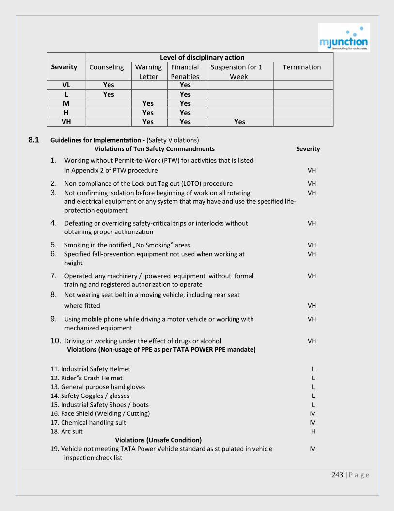
243 | P a g e
Severity Level of disciplinary action
Counseling Warning Letter
Financial Penalties
Suspension for 1 Week
Termination
VL Yes Yes L Yes Yes M Yes Yes H Yes Yes
VH Yes Yes Yes
8.1 Guidelines for Implementation - (Safety Violations) Violations of Ten Safety Commandments Severity
1. Working without Permit-to-Work (PTW) for activities that is listed
in Appendix 2 of PTW procedure VH
2. Non-compliance of the Lock out Tag out (LOTO) procedure VH
3. Not confirming isolation before beginning of work on all rotating VH and electrical equipment or any system that may have and use the specified life-protection equipment
4. Defeating or overriding safety-critical trips or interlocks without VH obtaining proper authorization
5. Smoking in the notified „No Smoking‟ areas VH
6. Specified fall-prevention equipment not used when working at VH height
7. Operated any machinery / powered equipment without formal VH training and registered authorization to operate
8. Not wearing seat belt in a moving vehicle, including rear seat
where fitted VH
9. Using mobile phone while driving a motor vehicle or working with VH mechanized equipment
10. Driving or working under the effect of drugs or alcohol VH Violations (Non-usage of PPE as per TATA POWER PPE mandate)
11. Industrial Safety Helmet L 12. Rider‟s Crash Helmet L 13. General purpose hand gloves L
14. Safety Goggles / glasses L 15. Industrial Safety Shoes / boots L 16. Face Shield (Welding / Cutting) M 17. Chemical handling suit M 18. Arc suit H
Violations (Unsafe Condition) 19. Vehicle not meeting TATA Power Vehicle standard as stipulated in vehicle
inspection check list M

244 | P a g e
20. Mobile lifting equipment i.e. Crane, hydra etc; not meeting TATA Power lifting equipment standard as stipulated in inspection check list
M
21. Confined Space not meeting TATA Power confined space standard as stipulated in confined inspection check list
M
22. Excavation not meeting TATA Power excavation standard as stipulated in excavation inspection check list
M
23. Gas cylinders not meeting TATA Power gas cylinders standard as stipulated in gas cylinder inspection check list
M
24. Hand tools not meeting TATA Power hand tools standard as stipulated in hand tools inspection check list
M
25. Housekeeping not meeting TATA Power housekeeping standard as stipulated in housekeeping inspection check list
M
26. Machines not meeting TATA Power machine safety standard as stipulated in machine safety inspection check list
M
27. Power operated hand tools not meeting TATA Power power operated hand tools standard as stipulated in power operated hand tools inspection check list
M
28. Personal protection Equipment (PPE) not meeting TATA Power personal protection Equipment (PPE) standard as stipulated in personal protection Equipment (PPE) inspection check list
M
29. Scaffolding not meeting TATA Power scaffolding standard as stipulated in scaffolding inspection check list
M
30. Temporary Electrical Supply not meeting TATA Power temporary electrical supply standard as stipulated in temporary electrical supply inspection check list
M
31. Welding machine not meeting TATA Power welding machine standard as stipulated in welding machine supply inspection check list
M
32. Winch not meeting TATA Power winch standard as stipulated in winch inspection check list
M
33. Housekeeping not meeting TATA Power housekeeping standard as stipulated in housekeeping inspection check list
M
34. Portable ladder / platform not meeting TATA Power portable ladder / platform standard as stipulated in portable ladder / platform inspection check list
M
Violations (Unsafe Acts) 35. Sleeping at Work Place L
Violations (Traffic) 36. Driving beyond speed limit M 37. Driving without license H 38. Over taking above speed limit /at no overtaking area
over taking area H 39. Wrong Parking / Wrong Side Driving L
9.1 General Guidelines a. All the records of disciplinary actions shall be maintained in vendor file at
Corporate Contracts Organization (CCO) b. Financial penalties shall be charged to main Contractors c. For repeated violations, the next level of disciplinary actions shall be initiated d. Corporate Contracts Organization (CCO) shall provide a monthly report of disciplinary actions taken to Corporate Safety e. It is incumbent upon every employee including contractor to report safety
incidents in which they are involved or which come to their notice. Withholding, non-reporting or manipulation of safety incidents and related
9.1 General Guidelines

245 | P a g e
a. All the records of disciplinary actions shall be maintained in vendor file at Corporate Contracts Organization (CCO) b. Financial penalties shall be charged to main Contractors c. For repeated violations, the next level of disciplinary actions shall be initiated d. Corporate Contracts Organization (CCO) shall provide a monthly report of disciplinary actions taken to Corporate Safety e. It is incumbent upon every employee including contractor to report safety incidents in which they are involved or which come to their notice. Withholding, non-reporting or manipulation of safety incidents and related information / data is an offence which will be viewed seriously and strict disciplinary action will be taken for such an offence including termination of service / contract f. All unsafe conditions identified through safety inspections are classified as „M‟ because it can be addressed proactively before an incident g. The Company reserves the right to take the circumstances of the rule breaking / violation into account to determine the disciplinary actions to be taken 10.0 Exceptions Any exception to this policy requir Corporate Safety

246 | P a g e
Reward and Recognition Policy for Safety (Contractors and Contractor’s Employees)
A. Objective: Tata Power has always believed in the principle that safety should be a way of life and every encouragement should be provided to ensure that all our Contractors and Contractor’s Employees voluntarily adopt the culture of safety in their daily working. The R&R scheme in safety has been designed to motivate Contractors and Contractor’s Employees by rewarding and recognizing their efforts and achievements in Safety. B. Scope: This policy is applicable to all Tata Power Contractors and Contractor’s Employees including sub- contractors and their employees. C. Scheme: Individual Awards (Quarterly) Division wise:
Sl no
Level of Award
Name of Award Purpose of Award Nature of Award
1 Individual Unsafe Acts / Conditions and Near Misses reporting
This award is for Contractor’s and sub-contractor’s employees reporting maximum Unsafe Acts / Conditions and Near Misses
The awards to be given quarterly during contractors safety meeting
First - Gift voucher of ` 1000/- and Appreciation Certificate.
Second - Gift Voucher of ` 750/- and Appreciation Certificate.
Third - Gift Voucher of ` 500/- and Appreciation Certificate.
Contractors Award (Annually):
Sl no
Level of Award
Name of Award Purpose of Award Nature of Award
2 Contractors Achievement of “ZERO” Lost Time Injury (LTI).
This award is given to the Contractors for achieving “ZERO” LTI in a particular year.
Award to be given annually during Contractor’s Safety Committee Meeting.
Trophy and appreciation certificate.

247 | P a g e
Reward and Recognition Policy for Safety (Contractors and Contractor’s Employees)
D. Process of R&R in Safety: 1. Divisions will distribute the individual awards in the Contractor’s Safety Committee Meeting held quarterly. 2. Contractor employees shall seek the help of concerned Tata Power Supervisor / Engineer / Safety Advisor for reporting Unsafe Acts / Conditions and Near Misses in SURAKSHA. Awareness regarding this aspect shall be generated through Safety Induction and Tool Box Talk. 3. Data regarding Unsafe Acts / Conditions and Near Misses reporting shall be maintained in SURAKSHA. This data shall be shared with the contractors in Contractor’s safety committee meeting. 4. Awards to Contractors and sub-contractors shall be distributed in the Contractor’s safety committee meeting. 5. The award should be from the Divisional budget and specific approval as per SOA shall be taken before distributing the awards. 6. The Safety R&R scheme will come into force with effect from October 2012. 7. Any exception to this policy requires the approval of the Head - Corporate Safety.

248 | P a g e
Annexure to Consequence Management Policy The Contractor shall abide by the latest version of Owners Consequence Management Policy towards safety violations including amendments thereon as and when issued. Tata Power follows a zero tolerance policy on safety violations and any safety violations shall be dealt accordingly. All contracts shall undergo a mandatory safety audit conducted by the Owner/ authorized representatives and the Contractor shall be evaluated based on their safety compliance and performance. 1. In case the Contractor is not already ISO 14001 / OSHAS certified, the Contractor shall obtain ISO 14001 / OSHAS certification not later than 6 months of the Effective Date of the Contract. 2. Contractors who are ISO and/ or OHSAS certified and have achieved 100% safety audit score for compliance will be eligible for 0.25% of the contract value as incentive. The incentive shall be payable at with the full and final settlement of the Contract based on overall safety audit score. 3 2% of monthly invoice value shall be retained towards safety assessment. The said payment will be released as per the safety audit / performance score calculated by the Company for the respective month and after deduction of applicable LDs if any towards any safety incidents as prescribed in the Contractor Safety Manual and its appendices and after deduction of LDs as enumerated below: a) 1st time violation of safety with severity 4 and 5 (highest severity) – Rs.10,000/- per incident b) 2nd time violation of safety with severity 4 and 5 (highest severity) – Rs.25,000/- per incident c) 3rd time onwards violation of safety with severity 4 and 5 (highest severity) – Rs.100,000/- per incident 4. In case of a widespread violation of safety guideline, the Company may ask the Contractors Project / Site Manager to apologies in public meeting commitment for safety performance improvement in future. 5. In case of multiple incidents (more than 5 incident during contract), the Company may ask the Contractor to change the Project Manager / Site Manager and the decision shall be binding on the Contractor. 6. In case of fatality, LD of Rs.5,00,000/- shall be payable by the Contractor. 7. The above LDs shall be over and above liabilities including 3rd party claims & liabilities / statutory liabilities arising out of bodily injury including death whether by accident or otherwise. 8. Contractor shall submit a list of tools & tackles with details of make, year of manufacturing, valid certification to the Project Manager/ User for approval by the Company. 9. Project Manager may during the execution of project inspect & verify that the tools & tackles are as per the qualification requirements approved by him and will have right to seek replacements in case of any discrepancies. The Contractor shall always comply with such directives.. 10. The Safety Committee at Site shall be the sole authority and shall have the sole right to assess the safety performance / audit the Contractor and their decision on rewards / LDs shall be final and binding on the Contractor. Contractor shall note that in case of repeated safety violations / gross violations of Company’s Safety Policy, the Contract may be terminated without notice and the Contractor delisted from Tata Power / associates / group companies.

249 | P a g e
Order of Priority In case of any conflict between documents the following order of priority in the sequence listed below shall prevail
Sr. No Document
1 This Document (Annexure to Consequence Management Policy)
2 a) Consequence Management Policy b) Reward and Recognition Policy for Safety
3 Contractor Safety Management (CSM) Site safety plan

250 | P a g e
TATA POWER COMPANY LIMITED Consequence Management Policy (Safety) – Contractors
1.0 Introduction We, at TATA POWER, believe that our Contactors are our greatest assets and their safety is of the utmost importance. In our journey towards attaining ZERO harm, we have implemented world-class safety systems, standards and procedures The successful implementation of these standards and procedures require demonstrated management commitment and behaviors at all levels, which are consistent with our Safety Principles, in particular, “Working safely is everybody‟s responsibility and a condition of employment”. Safety is a critical requirement as per contract terms & conditions 2.0 Objective This Policy establishes the process of corrective counseling and disciplinary actions in response to safety misconduct or violation in-line with the Contract Safety Management (CSM) framework of TATA POWER 3.0 Scope This Policy is applicable to all Contractors and Sub Contractors of TATA POWER, including subsidiary companies such as CGPL, MPL, IEL and Power Services The policy shall come into force with effect from 1st October 2012 4.0 Definitions Safety violation Any act which is inconsistent with the fulfillment of express or implied requirement of Company‟s safety standards and procedures. Any breach of an express or implied duty on the part of the employee. • Slips are unintended actions • Lapses are unintended failures to act • Mistakes are intended, but not what was really meant • Violations are known failures. Violations can be seen as a form of mistake Incident An unplanned or an unusual event, or a series of events and circumstances that resulted in, or had the potential to result in, an adverse or undesirable safety, process safety, health, fire and environmental consequence. Undesirable consequences related to SHE, incidents include, but are not limited to the following: • Injuries/illnesses • Significant environmental impact • Unfavorable impact on the public • Significant property damage • Business interruption • Damage to Reputation 5.0 Dealing with violation(s) - reactively Root cause(s) of incident Root cause(s) of the incidents are graded in three categories The incident investigation report will indicate the exact root causes for each incidents based upon which the disciplinary actions shall be initiated Human Factors Unsafe acts by employee i.e. not following procedure, not using correct (fit for purpose) tools / equipment, not using protective equipment / methods and inattention / lack of awareness and knowledge of safety standards

251 | P a g e
Physical Factors Unsafe conditions / situation created by individual or group of personnel, which, if it continues, can lead to an incident such as by pass or overlooked protective systems, use of defective or improper tools, equipment & vehicles, work with energized system, inadequate work place environment etc. System Factors Management failure such as inadequate communication, inadequate work rules / policies / standards / procedures (PSP), inadequate provision of tools & equipment, inadequate work planning, inadequate management / supervision / employee leadership, inadequate training / knowledge transfer etc. Loss / Potential loss (Severity) Severity of loss or immediate potential loss arising from the violation is graded in five levels as indicated in OH&S Risk Assessment Matrix (RAM) below:
OH&S Risk Assessment Matrix (RAM)
Pro
bab
ility
Very high Almost certain, it will
occur >80% in any time frame
(3)
Medium
(4)
High
(4)
High
(5)
Very High
(5)
Very High
High Expected to occur 10 % to 80 % chance in time
frame
(2) Low
(3) Medium
(4) High
(4) High
(5) Very High
Medium It could occur less than up to 10 % chance in
time frame
(2) Low
(2) Low
(3) Medium
(4) High
(5) Very High
Low Not expected to occur less than .1 % in time
frame
(2) Low
(2) Low
(3) Medium
(3) Medium
(4) High
Very Low Almost certain it will
occur greater than .01% chance in time frame
(1)
Very Low
(2)
Low
(2)
Low
(3)
Medium
(3)
Medium
Very Low Low Medium High Very High 1 2 3 4 5
Consequence Severity Increases
Co
nse
qu
ence
s in
var
iou
s re
gim
es People (Health and
Safety) No Health / Injury risk
First aid cases or
slight health problem
Lost time injury or potential
health problem
Partial disability or
major health problem
Total disability / fatality (s)
server healthy problem
Environmental Negligible effect confined
to in plant grounds /
environment
Minor effects neighbors
adjacent to plant
complain
Localize rerelease
makes local TV coverage / news paper
Major release make national TV coverage /
news paper
Massive damage makes
international TV coverage / new paper
Product or Service Some product Several Several Important / Loss of Quality or service fails costumer customer major substantial
to meet complain complain in customer marked share standards verbally writing cancelled due problem
orders

252 | P a g e
Assets or finance loss Slight damage is Up to Rs
10,000
Noticeable damage
between Rs 10,000 to 1
Lakh
Large damage 1 Lakh to 10
Lakhs
Major damage 10
Lakhs to 100 Lakhs
Severe damage more than 1 Crore
Reputation (Local, National, or International
Slight to moderate
impact
Loss of community reputation
Loss of state reputation
Loss of national reparation
Loss of international reputation
6.0 Dealing with violation(s) - Proactively Within Tata Power, potential Safety violations are identified proactively through safety inspections, audits, STOP, SIAT, CFSA, safety walkabout, etc. and the reports are generated. Based on the severity and intention of findings, the fact- finding committee shall initiate disciplinary actions 7.0 Guidelines for Implementation Step 1 - Fact Finding The Divisional Head / Unit Head shall appoint a team to establish the facts related to the incident including the circumstances leading to the safety violation(s) • Minimum of 3 Members in a team • Departmental head shall lead the team • Site Safety Advisor shall be involved, if needed Step 2 – Evaluation - Intent behind the incident In determining the appropriate root causes behind the violation, the team shall consider the following factors:
Level of Intent
Description
I -1 Unintentional non-compliance Lacks the knowledge of safety standards and the accompanying hazards
I -2 Rare / Exceptional violation Has good knowledge of the safety standards and the accompanying hazards but violated due to work exigency, pressure from peers and supervisors
I -3 Routine violation - Frequent, known and condone Has fair knowledge of safety standards and the accompanying hazards but violated due to routine activity without thought
I -4 Situational violation - Adapting to the problems in the workplace Has good knowledge of safety standards, and the accompanying hazards but violated due to work place constraints (lack of resources, tools, equipment etc)
I -5 Optimizing violation - Doing things better, for kicks Has good knowledge of safety standards and the accompanying hazards but violated due to over confidence, to save time, avoid discomfort, to gain attention, etc

253 | P a g e
Loss / Potential loss (Severity) In determining the appropriate level of severity category (i.e. very low, low, medium, high or very high) of the loss and / or potential loss arising from the violation, the team shall consider the following factors
Level of severity
Description
S -1 No Health / Injury risk, Negligible effect confined to in plant grounds / environment, Some product or service fails to meet standards, Slight damage is Up to `10,000 and Slight to moderate impact on reputation
S -2 First aid cases or slight health problem, Minor effects neighbors adjacent to plant complain, Several costumer complain verbally, Noticeable damage between `10,000 to 1 Lakh, Loss of community reputation
S -3 Lost time injury or potential health problem, Localize rerelease makes local TV coverage / news paper, Several customer complain in writing, Large damage `1 Lakh to 10 Lakhs, Loss of state reputation
S -4 Partial disability or major health problem Major release make national TV coverage / news paper, Important / major customer cancelled orders, Major damage `10 Lakhs to 100 Lakhs, Loss of national reparation
S -5 Total disability / fatality (s) server healthy problem, Massive damage makes international TV coverage / new paper, Loss of substantial marked share due problem, Severe damage more than `1 Crore, Loss of international reputation
Step 3 - Recommended disciplinary action - Based on step 1 and 2: The team will recommend the appropriate disciplinary action for individual, group or contractor as appropriate as per following table to Divisional Head
Intent (I)
I - 5 V - 3 M
V - 4 H
V - 4 H
V - 5 VH
V - 5 VH
I - 4 V - 2 L
V - 3 M
V - 4 H
V - 4 H
V - 5 VH
I - 3 V - 2 L
V - 2 L
V - 3 M
V - 4 H
V - 5 VH
I - 2 V - 2 L
V - 2 L
V - 3 M
V - 3 M
V - 4 H
I - 1 V - 1 VL
V - 2 L
V - 2 L
V - 3 M
V - 3 M
S -1 S - 2 S – 3 S - 4 S - 5 Severity (S)
Legend Financial Penalty (`) VL Very Low 500/- L Low 1,000/-
M medium 2,000/- H High 5,000/-
VH Very High 10,000/-

254 | P a g e
Severity Level of disciplinary action
Counseling Warning Letter
Financial Penalties
Suspension for 1 Week
Termination
VL Yes Yes L Yes Yes M Yes Yes H Yes Yes
VH Yes Yes Yes
8.1 Guidelines for Implementation - (Safety Violations) Violations of Ten Safety Commandments Severity
1. Working without Permit-to-Work (PTW) for activities that is listed
in Appendix 2 of PTW procedure VH
2. Non-compliance of the Lock out Tag out (LOTO) procedure VH 3. Not confirming isolation before beginning of work on all rotating VH
and electrical equipment or any system that may have and use the specified life-protection equipment
4. Defeating or overriding safety-critical trips or interlocks without VH obtaining proper authorization
5. Smoking in the notified „No Smoking‟ areas VH 6. Specified fall-prevention equipment not used when working at VH
height
7. Operated any machinery / powered equipment without formal VH training and registered authorization to operate
8. Not wearing seat belt in a moving vehicle, including rear seat
where fitted VH
9. Using mobile phone while driving a motor vehicle or working with VH mechanized equipment
10. Driving or working under the effect of drugs or alcohol VH Violations (Non-usage of PPE as per TATA POWER PPE mandate)
11. Industrial Safety Helmet L 12. Rider‟s Crash Helmet L 13. General purpose hand gloves L 14. Safety Goggles / glasses L 15. Industrial Safety Shoes / boots L
16. Face Shield (Welding / Cutting) M 17. Chemical handling suit M 18. Arc suit H
Violations (Unsafe Condition) 19. Vehicle not meeting TATA Power Vehicle standard as stipulated in vehicle inspection
check list M
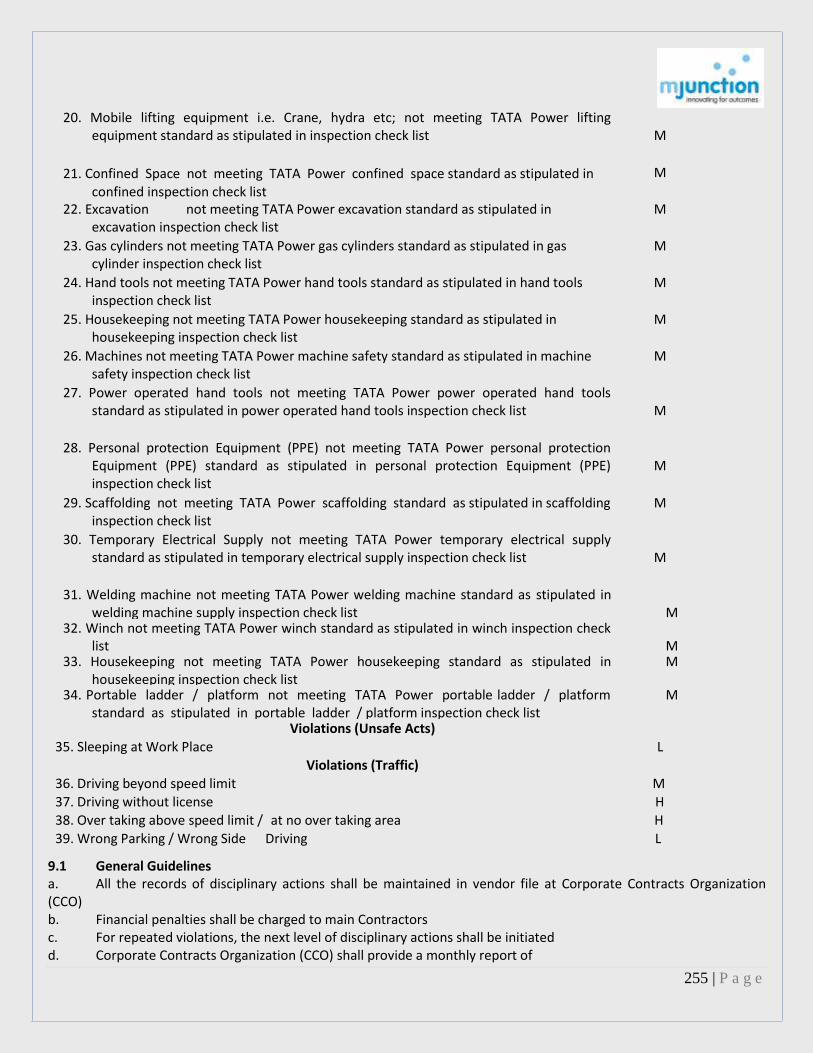
255 | P a g e
20. Mobile lifting equipment i.e. Crane, hydra etc; not meeting TATA Power lifting equipment standard as stipulated in inspection check list
M
21. Confined Space not meeting TATA Power confined space standard as stipulated in confined inspection check list
M
22. Excavation not meeting TATA Power excavation standard as stipulated in excavation inspection check list
M
23. Gas cylinders not meeting TATA Power gas cylinders standard as stipulated in gas cylinder inspection check list
M
24. Hand tools not meeting TATA Power hand tools standard as stipulated in hand tools inspection check list
M
25. Housekeeping not meeting TATA Power housekeeping standard as stipulated in housekeeping inspection check list
M
26. Machines not meeting TATA Power machine safety standard as stipulated in machine safety inspection check list
M
27. Power operated hand tools not meeting TATA Power power operated hand tools standard as stipulated in power operated hand tools inspection check list
M
28. Personal protection Equipment (PPE) not meeting TATA Power personal protection Equipment (PPE) standard as stipulated in personal protection Equipment (PPE) inspection check list
M
29. Scaffolding not meeting TATA Power scaffolding standard as stipulated in scaffolding inspection check list
M
30. Temporary Electrical Supply not meeting TATA Power temporary electrical supply standard as stipulated in temporary electrical supply inspection check list
M
31. Welding machine not meeting TATA Power welding machine standard as stipulated in welding machine supply inspection check list
M
32. Winch not meeting TATA Power winch standard as stipulated in winch inspection check list
M
33. Housekeeping not meeting TATA Power housekeeping standard as stipulated in housekeeping inspection check list
M
34. Portable ladder / platform not meeting TATA Power portable ladder / platform standard as stipulated in portable ladder / platform inspection check list
M
Violations (Unsafe Acts) 35. Sleeping at Work Place L
Violations (Traffic)
36. Driving beyond speed limit M 37. Driving without license H 38. Over taking above speed limit / at no over taking area H 39. Wrong Parking / Wrong Side Driving L
9.1 General Guidelines a. All the records of disciplinary actions shall be maintained in vendor file at Corporate Contracts Organization (CCO) b. Financial penalties shall be charged to main Contractors c. For repeated violations, the next level of disciplinary actions shall be initiated d. Corporate Contracts Organization (CCO) shall provide a monthly report of

256 | P a g e
disciplinary actions taken to Corporate Safety e. It is incumbent upon every employee including contractor to report safety incidents in which they are involved or which come to their notice. Withholding, non-reporting or manipulation of safety incidents and related information / data is an offence which will be viewed seriously and strict disciplinary action will be taken for such an offence including termination of service / contract f. All unsafe conditions identified through safety inspections are classified as „M‟ because it can be addressed proactively before an incident g. The Company reserves the right to take the circumstances of the rule breaking / violation into account to determine the disciplinary actions to be taken 10.0 Exceptions Any exception to this policy requires the prior written approval of the Head – Corporate Safety A. Objective: Tata Power has always believed in the principle that safety should be a way of life and every encouragement should be provided to ensure that all our Contractors and Contractor’s Employees voluntarily adopt the culture of safety in their daily working. The R&R scheme in safety has been designed to motivate Contractors and Contractor’s Employees by rewarding and recognizing their efforts and achievements in Safety. B. Scope: This policy is applicable to all Tata Power Contractors and Contractor’s Employees including sub- contractors and their employees. C. Scheme: Individual Awards (Quarterly) Division wise:
Sl no
Level of Award
Name of Award Purpose of Award Nature of Award
1 Individual Unsafe Acts / Conditions and Near Misses reporting
This award is for Contractor’s and sub-contractor’s employees reporting maximum Unsafe Acts / Conditions and Near Misses
The awards to be given quarterly during contractors safety meeting
First - Gift voucher of ` 1000/- and Appreciation Certificate.
Second - Gift Voucher of ` 750/- and Appreciation Certificate.
Third - Gift Voucher of ` 500/- and Appreciation Certificate.

257 | P a g e
Contractors Award (Annually):
Sl no
Level of Award
Name of Award Purpose of Award Nature of Award
2 Contractors Achievement of “ZERO” Lost Time Injury (LTI).
This award is given to the Contractors for achieving “ZERO” LTI in a particular year.
Award to be given annually during Contractor’s Safety Committee Meeting.
Trophy and appreciation certificate.
D. Process of R&R in Safety:
1. Divisions will distribute the individual awards in the Contractor’s Safety Committee Meeting held quarterly. 2. Contractor employees shall seek the help of concerned Tata Power Supervisor / Engineer / Safety Advisor for
reporting Unsafe Acts / Conditions and Near Misses in SURAKSHA. Awareness regarding this aspect shall be generated through Safety Induction and Tool Box Talk.
3. Data regarding Unsafe Acts / Conditions and Near Misses reporting shall be maintained in SURAKSHA. This data shall be shared with the contractors in Contractor’s safety committee meeting.
4. Awards to Contractors and sub-contractors shall be distributed in the Contractor’s safety committee meeting. 5. The award should be from the Divisional budget and specific approval as per SOA shall be taken before
distributing the awards. 6. The Safety R&R scheme will come into force with effect from October 2012. 7. Any exception to this policy requires the approval of the Head - Corporate Safety.

258 | P a g e
Photographs The photographs are indicative. Customers are requested to inspect the material before placing their bids in the online auction. :
------------------------------------------------------------------------------------------------------------------------------------------------------