RA2300MKⅡ - A&D Company, Limited
240
R A 2 3 0 0 M K Ⅱ O m n i a c e I N S T R U C T I O N M A N U A L 1WMPD4003503
-
Upload
khangminh22 -
Category
Documents
-
view
1 -
download
0
Transcript of RA2300MKⅡ - A&D Company, Limited

RA2300MKⅡ
Omniace
INSTRUCTION MANUAL
1WMPD4003503


Omniace RA2300MKⅡ
Instruction Manual


RA2300MKⅡ (1WMPD4003503) 1
Introduction We thank you for your purchase of our product Thermal-Dot Recorder OMNIACE RA2300MKⅡ. Please read this manual before operating this instrument. This manual provides the information necessary to operate the RA2000 series recorder safely. Place this manual within reach of the RA2300MKⅡ. This manual covers basic functions and operations of the RA2300MKⅡ and handling precautions. For operation of other functions, please refer to the separate-volume manuals listed below. If you encounter any problems in the manuals, please contact our company.
<Separate-volume manuals> Manual Contents
RA2000 series Amplifier Unit Instruction Manual
This manual explains how to use and install amp units.
Communication Command RA2000 series Instruction Manual
This manual provides the information necessary to operate the recorder with interfaces such as LAN or RS-232C. It also covers descriptions on interface commands to allow control by a PC.
Before Using
When Opening Package When opening the package in a warm room during the cold season, open the package after it has reached room temperature to avoid any operational failure due to condensation on the surface of the product.
Examining Contents in Package
This instrument is delivered after a thorough examination at the factory prior to shipment. However, please examine the product's condition and verify that no obvious shipping damage has occurred after opening the package. Also, examine the specifications of the input units and accessories. If there are any missing or damaged items, please contact our sales representative.
Notice Turn off the power when the operation is abnormal.
If it is impossible to trace the causes of an abnormal operation, please contact our sales representative. In this case, let us know in what way the unit was operating incorrectly and what the environmental conditions were.
The contents of this manual are subject to change without notice. This manual is copyrighted with all rights reserved. No parts of this manual may be transcribed
or reproduced without written permission. Please let us know if there are any points that are unclear or missing in this manual.

RA2300MKⅡ (1WMPD4003503) 2
Safety Measures - Warnings and Cautions To safely use products
The RA2300A is a product conforming to the IEC standard safety class I. The recorder is manufactured with safety in mind, however, accidents may occur due to misuse by the user. To avoid such accidents, read this manual carefully before use. Observe the following warning and cautions when using the interface and remote control functions. To safely use the input units, the following statements are used in this manual to call the readers' attention.
Be sure to observe the following instructions when using this recorder. The warranty does not cover damages resulting from the actions against instructions, cautions, or warnings mentioned in this manual. Besides, there are a lot of actions that are "cannot" and "do not". It is impossible to write all such descriptions in this manual. Accordingly, assume any actions to be "impossible" except the actions explicitly described as "possible". Power Supply
Make sure that the power supply is within the rating indicated on the rating plate attached to this recorder. If any voltage exceeding the rated voltage were supplied, there would be risk of damage to this recorder, or even a fire. Also, in order to prevent electric shock and hazards such as a fire, be sure to use only the AC power cable supplied with this recorder.
Protective Grounding
Be sure to ground this recorder before supplying power. Grounding is necessary to use this recorder safely, as well as to protect the user and peripheral equipment from injury or damage. Be sure to observe the following instructions:
1) This recorder uses a 3-conductor AC power supply cable containing a ground lead and a 3-prong AC power plug. By plugging the power supply cable into a 3-pole AC outlet with a ground pole, grounding will be done automatically.
2) When grounding, do not connect the grounding lead to a water pipe, as water pipes are not necessarily conductive to the earth. Never connect the ground lead to a gas pipe either, as it is extremely dangerous.
3) While the power is supplied to the recorder, do not cut or remove the protective grounding line. Otherwise, safety of the recorder is not guaranteed.
This indicates a condition or practice that could result in light injury or damage to the equipment or other property if this equipment is misused due to neglect of a Caution.
WARNING This indicates a condition or practice that could result in personal injury orloss of life, or may result in light injury or physical damage if thisequipment is misused due to neglect of a Warning.
CAUTION
WARNING
RA2300MKⅡ (1WMPD4003503) 3
Connection of Input Signals
Be sure to ground the grounding terminal of this recorder before connecting to the measurement target. Also, when connecting this recorder to another measurement instrument, be careful not to exceed the maximum allowable common mode input voltage range. A voltage exceeding the range can cause damage to this recorder.
Use in Gaseous Atmosphere Never use this recorder in a flammable or explosive atmosphere, or atmosphere of steam. Use in such atmosphere will result in danger to users and the recorder.
Disassembling the Frame It is dangerous to remove the frame due to high-voltage parts inside. Do not remove the frame from the recorder other than by our service engineers.
Fuse at AC Power Supply Block
The fuse for this unit cannot be replaced with the customer because this fuse is placed inside the main unit. Please contact our branches or sales offices if the fuse may be blown.
Handling of Back-up Battery (Cautions when Disposing) This recorder includes a lithium secondary battery (Lithium-ion secondary battery). When disposing of this recorder, remove the lithium secondary battery in advance. Do not dispose of it in fire or disassemble. The lithium secondary battery may explode when it is heated and organic electrolyte that may exude from it is harmful to human skin. When disposing of the lithium secondary battery, isolate terminals by covering with tape and dispose as a dangerous article.
Disposing of the used product In the European Union EU-wide legislation as implemented in each Member State requires that used electrical and electronic products carrying the mark (left) must be disposed of separately from normal household waste. This includes electrical accessories, such as chargers or AC adaptors. The mark on the electrical and electronic products only applies to the current European Union Member States.
Outside the European Union If you wish to dispose of used electrical and electronic products outside the European Union, please contact your local authority and ask for the correct method of disposal.
WARNING

RA2300MKⅡ (1WMPD4003503) 4
Caution in Handling
When using this recorder, always follow the precautions below. Improper handling may lead to erroneous operations and damages.
1) Users who are not familiar with the operation of this recorder should avoid using it.
2) Storage environment
The storage temperature of the input units is –10 to 60C (except for chart recording paper). Avoid storing in places where the temperature could rise over the storage temperature and where there is direct sunlight exposure such as inside an automobile.
3) Use this recorder at locations that satisfy the installation requirement, the category II (CAT II) of the safety standard for electrical measurement instruments in IEC61010-1 (JIS-C-1001-1).
4) This recorder is a product with a pollution degree of 2.
5) Do not use this recorder at the following locations. In addition, carefully check the environment when using this recorder.
1. Locations where the temperature and humidity rise due to direct sunlight or heaters. (The operating environment of the recorder; temperature: 5 to 40 °C, humidity: 35 to 80%)
2. Wet locations
3. Locations where salt, oil, or corrosive gases exist
4. Damp or dusty locations
5. Locations subject to strong vibrations
6. Locations with a strong electromagnetic field
7. This recorder is provided with ventilation openings in order to prevent overheating. Ensure that the ventilation openings remain unobstructed by covers or materials. Otherwise, the internal temperature of the recorder rises, causing malfunctions.
6) Be careful of power voltage fluctuations. Do not use the recorder when these are likely to exceed the rated voltage.
7) If the power supply includes a lot of noise or high-voltage inductive noise, use noise filters to avoid operation errors.
8) A hard disk drive (HDD) is installed in this product.
1.Please don’t power off during normal operation of HDD, due to the risk of data destruction. 2.Please don’t apply a strong impact or vibration to this product, due to the risk of HDD destruction. 3.Please use it under 5 to 40 °C conditions.
9) This recorder uses a touch panel. When touching the panel, do not use a sharp object or push with high-pressure other than necessary. Press the panel gently with the fingertip. In addition, do not press more than one button/key at once. Be sure to press only one button/key at a time. Pressing two or more buttons/keys at once may cause misoperations.
10) Use the chart recording paper specified by A&D. Use of a chart that is not recommended may cause failure in printing or shorten the life of the thermal head.
11) Do not insert a pointed or sharp object into the ventilation openings of this recorder.
12) To clean this recorder, first turn off the power, place it in a well-ventilated location, and wipe the recorder with soft cloth moistened with ethanol. Do not use benzene, petroleum solvents, or chemically treated cloths, as they can cause deformation or discoloration.
13) When transporting the recorder, use the package and packaging material supplied at factory shipment, or use a package and packaging material more shock-resistance than those supplied.
14) We recommend a periodical calibration to maintain the accuracy of the input units. More reliable measurements are possible by calibrating the input units once a year (extra cost option).
CAUTION
RA2300MKⅡ (1WMPD4003503) 5
Warranty - General We ship our products after conducting quality control, which covers from design to manufacturing. It is, however, possible that failures may occur in the products. If the product does not operate correctly, please make a check of the power supply, cable connections, or other conditions before returning this product to us. For repair or calibration, contact our sales agency. Before returning, be sure to inform us of the model (RA2300A), serial number, and problematic points. The following is our warranty.
Limited Warranty 1. Warranty period
One year from our shipment. 2. Warranty period
We will repair the defects of our product free of charge within the warranty period; however, this warranty does not apply in the following cases.
(1) Damage or faults caused by incorrect use. (2) Damage or faults caused by fire, earthquake, traffic accident, or other natural disasters. (3) Damage or faults caused by a repair or modification that is carried out by someone other than
a service representative of A&D. (4) Damage or faults caused by use or storage in environmental conditions that should be avoided. (5) Periodical calibration. (6) Damage or faults caused during transportation. 3. Liability
We do not assume any liabilities for equipment other than A&D.

RA2300MKⅡ (1WMPD4003503) 6
Terms and Symbols in This Manual Terms and symbols used in this manual denote as follows. Terms and Symbols Description
This indicates a condition or practice that could result in personal injury or loss of life, or may result in light injury or physical damage if this equipment is misused due to neglect of a Warning.
This indicates a condition or practice that could result in light injury or damage to the equipment or other property if this equipment is misused due to neglect of a Caution.
This indicates a condition or practice that could result in incorrect operation or damages in data if this equipment is misused due to neglect of Note.
This symbol gives setting restrictions and additional descriptions.
Reference page
This recorder RA2300MKⅡ [ ] Characters enclosed by brackets represent a key name on the operation panel. Memory
Internal memory of RA2300MKⅡ When measuring with memory recorder or transient recorder, measured data is recorded in this memory.
k (lower case) K (upper case)
A unit of numerical value "k" is used to represent 1000 such as "10 kg". "K" is used to represent 1024 such as "4 K data"
Liquid Crystal Display This recorder has a TFT color LCD for display. There may be cases where the light of pixels does not come on or off in the LCD. In addition, the LCD includes unevenness slightly due to temperature changes. Please be aware that these cases are not disorders.
CAUTION
WARNING
TIPS
NOTE
RA2300MKⅡ (1WMPD4003503) 7
Overview of Windows Embedded Standard 2009 This product employs Windows Embedded Standard 2009 as an OS. Please read and understand the following instructions carefully before use.
(1) License Windows Embedded Standard 2009 is provided as built-in only license. This product cannot function as general purpose PC, it is limited exclusively for RA2300MKⅡuse. Duplication of installed system of this product is not allowed to be used.
(2) Power ON/OFF Please make sure that HDD is not being accessed before turning the power off. If the power is turned off while HDD is being accessed, not only it may cause damage to data recorded on the HDD but also it may fatally damage the HDD machine itself to unusable condition. To confirm that HDD access has been stopped before turning the power off, please press EXIT on System button to stop the system, then turn off the power. When exit command is being processed, it does not leave record of starting or set ups in registry. OS will always start up in the condition set at the time of factory shipment. (Set values are saved under separate file and will not be lost.)
(3) Virus We take following measures in order to lower the possibilities of virus infections.
● Mailing function is not provided.
● System protect with write filter. System drive, which contains OS and other applications, cannot be overwritten; normally those will not be affected under any condition, however, if internal HDD has been accessed as a shared file on network system, it is possible that files saved in HDD will be infected by viruses. In case there are possibilities that virus-infected files are saved in HDD, please eliminate the virus by going through the following procedures. If other PCs connected to the same network access the subject file, the PC could become the source of infection. Please set up one to one network environment and run anti-virus software from a PC targeting the HDD of this product in order to check and eliminate viruses. Anti-virus software cannot be installed directly to this product.
(4) Network use Please consult your network administrator to make sure that other tasks are not affected by connecting this product to the network. (Transmitting high volume of data would cause higher network traffic.)
(5) USB compatible devices Devices that are compatible with this product are limited by default setting. It works differently than Windows on PCs, and it is not possible to install additional device drivers. Compatible devices for this product are limited to the devices listed below. Please do not connect other devices. Other devices are not subject of our guarantees. -USB memory (The USB memory with a security function cannot be used.)
(6) Maintenance Please use the files provided by our company for the back-ups of application programs and please run those application programs from system menu.
(7) Others We do not assume any responsibility or provide support for malfunctions if programs that are not provided by us are installed into the system or compulsory termination command is used through external keyboard and such. Windows, Windows XP, Windows Embedded Standard 2009 are trademarks or registered trademarks of Microsoft Corporation in US and other countries.

RA2300MKⅡ (1WMPD4003503) 8
Introduction......................................................................................................................1
Before Using ............................................................................................................................1
Safety Measures - Warnings and Cautions.........................................................................2
Warranty - General ..................................................................................................................5
Limited Warranty .....................................................................................................................5
Terms and Symbols in This Manual ....................................................................................6
Liquid Crystal Display ............................................................................................................6
Overview of Windows Embedded Standard 2009 ..............................................................7
1. RA2300MKⅡ Overview .......................................................................................... 1-1
1.1. Basic Specifications..........................................................................................................1-2 1.1.1. Overview and features ................................................................................................................1-2 1.1.2. Features ........................................................................................................................................1-2
2. Name and Function of Each Block .................................................................... 2-1
2.1. Overview of Blocks...........................................................................................................2-2
2.2. Display Block.....................................................................................................................2-3
2.3. Operation Panel .................................................................................................................2-4
2.4. Right-side Block ................................................................................................................2-6
2.5. Upper Surface Block.........................................................................................................2-7
3. Pre-measurement Procedures .............................................................................. 3-1
3.1. Before Switching on the Power .....................................................................................3-2 3.1.1. Usage Environment......................................................................................................................3-2 3.1.2. Before Connecting AC Power Cable .........................................................................................3-2 3.1.3. AC Power Cable ..........................................................................................................................3-3
3.2. Paper Loading....................................................................................................................3-4 3.2.1. Paper Roll.....................................................................................................................................3-4 3.2.2. Loading z-fold paper....................................................................................................................3-5
3.3. Insert the Amp Unit ..........................................................................................................3-9
3.4. Turning on the Power ....................................................................................................3-10
4. Operation Flow ....................................................................................................... 4-1
4.1. Operation Flow ..................................................................................................................4-2
4.2. Making Basic Settings......................................................................................................4-3 4.2.1. Explanation of Basic Screen Settings........................................................................................4-3 4.2.2. Explanation of setting keys.........................................................................................................4-4 4.2.3. Explanation of standard setting windows...................................................................................4-6
5. Input Signal Monitor.............................................................................................. 5-1
5.1. Observing Input Signals...................................................................................................5-2
5.2. Displaying Input Waveform Monitor ...............................................................................5-3
6. Auto Setup .............................................................................................................. 6-1

RA2300MKⅡ (1WMPD4003503) 9
6.1. Function Overview............................................................................................................ 6-2
6.2. Auto Range........................................................................................................................ 6-2
6.3. Auto Sampling................................................................................................................... 6-3 6.3.1. Target Setup Conditions.............................................................................................................. 6-3 6.3.2. Adjustment Range........................................................................................................................ 6-3
7. Amp Units ................................................................................................................7-1
7.1. Settings for Input Units................................................................................................... 7-2 7.1.1. Amp Basics Screen..................................................................................................................... 7-2 7.1.2. Amp Details Screen..................................................................................................................... 7-3
8. Pen Recorder...........................................................................................................8-1
8.1 Overview of Pen Recorder Mode.................................................................................... 8-2
8.2. Screen Operation.............................................................................................................. 8-3
8.3. Printing Operation ............................................................................................................ 8-4 8.3.1. Stop Due to Error........................................................................................................................ 8-5
9. Memory Recorder....................................................................................................9-1
9.1. Overview of Memory Recorder Mode............................................................................ 9-2
9.2. Recording Condition Setup............................................................................................. 9-3 9.2.1. Description of Icons..................................................................................................................... 9-3 9.2.2. Memory Recording Condition Setup Block................................................................................ 9-4
9.3. Recording Operation ........................................................................................................ 9-7
10. HD Recorder ........................................................................................................10-1
10.1. Overview of HD Recorder Mode ................................................................................ 10-2
10.2. Recording Condition Setup......................................................................................... 10-3 10.2.1. REC Icon.................................................................................................................................. 10-3 10.2.2. HD Recording Setup Block..................................................................................................... 10-4
10.3. Recording Operation .................................................................................................... 10-7 10.3.1. Start of Measurement.............................................................................................................. 10-7 10.3.2. To Finish Measurement (Forced Termination) ...................................................................... 10-7 10.3.3. Waveform Chart Printing......................................................................................................... 10-7 10.3.4. Upon Error Generation ............................................................................................................ 10-7 10.3.5. To display recorded data ........................................................................................................ 10-7
10.4. HD Recording Specifications ...................................................................................... 10-8 10.4.1. Recording File Size Calculation.............................................................................................. 10-8 10.4.2. Recording Speed Execution Restriction ................................................................................. 10-8
11. Multi Recorder.....................................................................................................11-1
11.1. Overview of Multi Recorder Mode............................................................................. 11-2
11.2. Recording Condition Setup......................................................................................... 11-3 11.2.1. REC Icon.................................................................................................................................. 11-3 11.2.2. Multi Recorder - Setup for Recording Condition .................................................................. 11-4
11.3. Recording Operation .................................................................................................... 11-6 11.3.1. Error Generation ...................................................................................................................... 11-6
12. X-Y Recorder .......................................................................................................12-1
12.1. Overview of X-Y Recorder Mode ............................................................................... 12-2
12.2. Screen Operation.......................................................................................................... 12-3
12.3. Printing Operation ........................................................................................................ 12-6

RA2300MKⅡ (1WMPD4003503) 10
12.3.1. Restrictions during X-Y Printing..............................................................................................12-6 12.3.2. Exception (Error) ......................................................................................................................12-6
13. Trigger Settings.................................................................................................. 13-1
13.1. Trigger Mode Description ............................................................................................13-2 13.1.1. Trigger Mode - Operation at OR ...........................................................................................13-2 13.1.2. Trigger Mode - Operation at AND .........................................................................................13-2 13.1.3. Trigger Mode – Operation at WINDOW................................................................................13-3 13.1.4. Trigger Mode – Operation at OFF.........................................................................................13-3
13.2. Manual Trigger/External Trigger..................................................................................13-4 13.2.1. Manual Trigger .........................................................................................................................13-4 13.2.2. External Trigger (TRIG IN) .....................................................................................................13-4 13.2.3. External Trigger Output (TRIG OUT).....................................................................................13-4 13.2.4. External Trigger Input/Output Circuit ......................................................................................13-5
13.3. Method of Trigger Settings..........................................................................................13-6
13.4. Settings by Trigger Mode ..........................................................................................13-7 13.4.1. Trigger Mode OR.....................................................................................................................13-7 13.4.2. Trigger Mode AND...................................................................................................................13-7 13.4.3. Trigger Mode WINDOW ..........................................................................................................13-8 13.4.4. Trigger Mode OFF...................................................................................................................13-9
13.5. Trigger Filter ..................................................................................................................13-9 13.5.1. Trigger Filter .............................................................................................................................13-9
13.6. Trigger Settings for Event Amp................................................................................13-10
13.7. Trigger Settings for Event unit .................................................................................13-11
14. Replay Display.................................................................................................... 14-1
14.1. Overview of Replay Monitor ........................................................................................14-2
14.2. Replay Data Selection ..................................................................................................14-3
14.3. Waveform Display Region............................................................................................14-4 14.3.1. Shift of Waveform Display Region .........................................................................................14-4 14.3.2. Shift of Cursor Position...........................................................................................................14-4
14.4. Digital Indication............................................................................................................14-5 14.4.1. Digital Indication Switching......................................................................................................14-5 14.4.2. Digital Indication .......................................................................................................................14-5 14.4.3. Cursor Display Information......................................................................................................14-5 14.4.4. Replay monitor mark display ON/OFF function ....................................................................14-5 14.4.5. Level Cursor .............................................................................................................................14-6 14.4.6. Simple calculation ....................................................................................................................14-7
14.5. Signal Settings...............................................................................................................14-8
14.6. Jump ...............................................................................................................................14-9 14.6.1. Basic Jump...............................................................................................................................14-9 14.6.2. Time Jump................................................................................................................................14-9 14.6.3. Address Jump ..........................................................................................................................14-9 14.6.4. Maximum/Minimum Search & Jump.....................................................................................14-10 14.6.5. Event Jump ............................................................................................................................14-11
14.7. Time Axis Magnification.............................................................................................14-11
14.8. Output Setup................................................................................................................14-12 14.8.1. Specifying Output Time Range.............................................................................................14-12 14.8.2. Specifying File Save Format.................................................................................................14-12 14.8.3. Specifying CSV Delimiter ......................................................................................................14-12 14.8.4. Specifying Number of Skip in CSV .....................................................................................14-13 14.8.5. Specifying File Save Destination ..........................................................................................14-13 14.8.6. Execution of Data Output .....................................................................................................14-13

RA2300MKⅡ (1WMPD4003503) 11
14.9. Copy ............................................................................................................................. 14-13
14.10. X-Y Waveform Display ............................................................................................. 14-14
14.11. Other Display Function............................................................................................ 14-15 14.11.1. Automatic replay with HD recorderdata display setting ................................................... 14-15
15. Display and Printing...........................................................................................15-1
15.1. Settings for Display and Printing .............................................................................. 15-2 15.1.1. Scale Indication........................................................................................................................ 15-2 15.1.2. Grid Display ............................................................................................................................. 15-2 15.1.3. Digital Value Display ............................................................................................................... 15-2 15.1.4. Signal Name Indication ........................................................................................................... 15-3 15.1.5. Cursor Value Indication........................................................................................................... 15-3 15.1.6. Waveform Segmentation ......................................................................................................... 15-3 15.1.7. Thumbnail ................................................................................................................................. 15-4
16. Interval statistical calculation ...........................................................................16-1
16.1. Interval statistical calculation function ..................................................................... 16-2
16.2. Operation procedure of interval statistical calculation........................................... 16-2 16.2.1. Data selection to be calculated.............................................................................................. 16-2 16.2.2. Setting of interval statistical calculation ................................................................................. 16-2 16.2.3. Executing interval statistical calculation ................................................................................. 16-3 16.2.4. CSV saving of interval statistical calculation......................................................................... 16-4
16.3. Types of interval statistical calculation .................................................................... 16-4 16.3.1. Maximum value (MAX) ............................................................................................................ 16-4 16.3.2. Minimum value (MIN) .............................................................................................................. 16-4 16.3.3. Peak-to-peak value (P-P)........................................................................................................ 16-4 16.3.4. Average value (Average) ........................................................................................................ 16-4 16.3.5. Area (AREA) ............................................................................................................................ 16-4 16.3.6. Root-mean-square value (RMS) ............................................................................................. 16-5 16.3.7. Standard deviation (STD)........................................................................................................ 16-5 16.3.8. Rising or falling time (Rise/Fall) ............................................................................................. 16-5
17. Function calculation ...........................................................................................17-1
17.1. Function calculation ..................................................................................................... 17-2
17.2. Operation procedure of function calculation ........................................................... 17-2 17.2.1. Data selection to be calculated.............................................................................................. 17-2 17.2.2. Setting of function calculation................................................................................................. 17-2 17.2.3. Arithmetic expression setup .................................................................................................... 17-3 17.2.4. Execution of function calculation ............................................................................................ 17-5 17.2.5. Output of function calculation result ...................................................................................... 17-5
17.3. Function calculation item............................................................................................ 17-6 17.3.1. Arithmetic expression............................................................................................................... 17-6 17.3.2. Function .................................................................................................................................... 17-6 17.3.3. Measured data ......................................................................................................................... 17-8 17.3.4. Constant.................................................................................................................................... 17-8
17.4. Output for incorrect calculation................................................................................. 17-9 17.4.1. Zero division............................................................................................................................. 17-9 17.4.2. Square root of negative value................................................................................................ 17-9 17.4.3. Overflow for exponential calculation....................................................................................... 17-9 17.4.4. Common logarithmic of zero or negative value.................................................................... 17-9 17.4.5. ASIN and ACOS for the value of >1 or <-1 ....................................................................... 17-9 17.4.6. Differential and integral for recorded data by using external synchronized clock............. 17-9
18. FFT analysis ........................................................................................................18-1

RA2300MKⅡ (1WMPD4003503) 12
18.1. FFT functions.................................................................................................................18-2
18.2. Operation procedure of FFT analysis ........................................................................18-2 18.2.1. Data selection to be analyzed................................................................................................18-2 18.2.2. Display of FFT monitor ...........................................................................................................18-2 18.2.3. Change of FFT analysis data.................................................................................................18-3 18.2.4. Starting point of FFT analysis ................................................................................................18-3 18.2.5. Setting of FFT analysis data length ......................................................................................18-3 18.2.6. Setting of FFT average...........................................................................................................18-3 18.2.7. Setting the FFT window function ...........................................................................................18-4 18.2.8. Setting the FFT analysis.........................................................................................................18-4 18.2.9. Display of FFT analysis results..............................................................................................18-5 18.2.10. Cursor operation.....................................................................................................................18-5 18.2.11. Magnification of X-axis ..........................................................................................................18-5 18.2.12. Output of binary file...............................................................................................................18-6 18.2.13. Output of CSV file .................................................................................................................18-6
18.3. FFT analysis function ...................................................................................................18-7 18.3.1. Waveform on time scale (One signal analysis)....................................................................18-7 18.3.2. Linear spectrum (One signal analysis) ..................................................................................18-7 18.3.3. RMS spectrum (One signal analysis) ....................................................................................18-7 18.3.4. Power spectrum and Density of power spectrum (One signal analysis) ...........................18-7 18.3.5. Octave analysis........................................................................................................................18-7 18.3.6. Cross power spectrum (Two signal analysis) .......................................................................18-8 18.3.7. Transfer function (Two signal analysis) .................................................................................18-8 18.3.8. Coherence function (Two signal analysis) .............................................................................18-8
18.4. Average processing ......................................................................................................18-9
19. System Setup...................................................................................................... 19-1
19.1. System Setup List.........................................................................................................19-2
19.2. Commonly Used System Screen ................................................................................19-3 19.2.1. Termination ...............................................................................................................................19-3 19.2.2. USB Drive Disconnection ........................................................................................................19-3
19.3. Measurement Mode .......................................................................................................19-4 19.3.1. Screen Display upon Startup..................................................................................................19-4 19.3.2. Measurement Mode .................................................................................................................19-4 19.3.3. Setup Value Save....................................................................................................................19-5 19.3.4. Initialize .....................................................................................................................................19-5
19.4. File Operations ..............................................................................................................19-6 19.4.1. Copy..........................................................................................................................................19-7 19.4.2. Deletion .....................................................................................................................................19-8 19.4.3. Folder Creation.........................................................................................................................19-8 19.4.4. Memory Save ...........................................................................................................................19-9 19.4.5. Enviroment Save....................................................................................................................19-10 19.4.6. Readout...................................................................................................................................19-10 19.4.7. Strengthen text storage of setting information ....................................................................19-11
19.5. Recording Setup..........................................................................................................19-14 19.5.1. Recording Channels...............................................................................................................19-14 19.5.2. Data No. Setting ....................................................................................................................19-15 19.5.3. Print Setup..............................................................................................................................19-15 19.5.4. Speed Table Setup................................................................................................................19-16 19.5.5. Time-axis Representation ......................................................................................................19-16 19.5.6. Timer Recording Settings......................................................................................................19-17 19.5.7. External Sync Rate Setting...................................................................................................19-17 19.5.8. Automatic Reproduction of Display Setting of Data Recorded by HDD Recorder..........19-17
19.6. Communication Setup.................................................................................................19-19
19.7. Auxiliary Setup.............................................................................................................19-21 19.7.1. Buzzer/Clicking Sound ...........................................................................................................19-21 19.7.2. Auto Display off .....................................................................................................................19-21
RA2300MKⅡ (1WMPD4003503) 13
19.7.3. Screen Copy Output Destination.......................................................................................... 19-21 19.7.4. Key lock Password................................................................................................................ 19-22 19.7.5. Feed Length Set Up ............................................................................................................. 19-22 19.7.6. Mouse Cursor ON/OFF......................................................................................................... 19-22
19.8. Maintenance................................................................................................................. 19-23 19.8.1. Version Indication................................................................................................................... 19-23 19.8.2. Test Print................................................................................................................................ 19-24 19.8.3. Data Printing .......................................................................................................................... 19-24 19.8.4. Time Calibration ..................................................................................................................... 19-24 19.8.5. Maintenance Mode................................................................................................................. 19-24
20. How to Use Optional Units...............................................................................20-1
20.1. Connecting optional units ........................................................................................... 20-2
20.2. Remote Unit (RA23-144) .............................................................................................. 20-3 20.2.1. Overview................................................................................................................................... 20-3 20.2.2. Connector/Pin Location............................................................................................................ 20-3 20.2.3. To Synchronize to External Pulse and Perform Waveform Chart Printing and Printing .. 20-4 20.2.4. Compatibilities with Conventional Products (Waveform Chart Printing) .............................. 20-5 20.2.5. Memory Acquisition Using External Sampling....................................................................... 20-5 20.2.6. Start/Stop recording (Start/Stop button) ................................................................................. 20-6 20.2.7. Chart Feed ............................................................................................................................... 20-6 20.2.8. Mark Printing ............................................................................................................................ 20-6 20.2.9. Protecting File Data (UPS DOWN)........................................................................................ 20-6 20.2.10. Monitoring errors on recording areas .................................................................................. 20-6 20.2.11. Parallel Operation .................................................................................................................. 20-7
20.3. Event Unit (RA23-145).................................................................................................. 20-8 20.3.1. Overview................................................................................................................................... 20-8 20.3.2. Connector/Pin Location............................................................................................................ 20-8 20.3.3. Event Unit Setup ..................................................................................................................... 20-9 20.3.4. Event Waveform Adjustment................................................................................................. 20-10
20.4. Event Box (RA23-146) ................................................................................................ 20-11 20.4.1. Overview and features .......................................................................................................... 20-11 20.4.2. Built-in and connection.......................................................................................................... 20-11 20.4.3. Connector/Pin Location.......................................................................................................... 20-11 20.4.4. Event box setting................................................................................................................... 20-12 20.4.5. Event box waveform setting ................................................................................................. 20-12 20.4.6. Event box trigger setting....................................................................................................... 20-12
20.5. RS-232C Unit (RA23-142) ........................................................................................... 20-13 20.5.1. Names of each parts and their functions ........................................................................... 20-13
20.6. AC Bridge Excitation unit (RA23-143) ..................................................................... 20-14 20.6.1. Names of each parts and their functions ........................................................................... 20-14 20.6.2. Set up for Synchronization ................................................................................................... 20-14
21. Maintenance and Cleaning................................................................................21-1
21.1. Handling and Storing Recording Paper and Data................................................... 21-2 21.1.1 Storing the Recording Paper ................................................................................................... 21-2 21.1.2 Caution for Handling and Storage of Recorded Data........................................................... 21-2
21.2. Battery Backup.............................................................................................................. 21-2
21.3. Cleaning the Display.................................................................................................... 21-2
21.4. Replacement of touch panel protection sheet......................................................... 21-3
21.5. Cleaning and Preserving the Thermal Head ............................................................ 21-3 21.5.1. Cleaning.................................................................................................................................... 21-3 21.5.2. Life ............................................................................................................................................ 21-4
21.6. Platen Roller Storage................................................................................................... 21-4
21.7. Dealing with Power Outages, etc. ............................................................................. 21-4

RA2300MKⅡ (1WMPD4003503) 14
21.8. Cautions When Disposing of This Instrument .........................................................21-4
22. Troubleshooting.................................................................................................. 22-1
22.1. Troubleshooting and Inspection..................................................................................22-2
22.2. Frequently Asked Questions (Q&A)............................................................................22-3
23. Specifications...................................................................................................... 23-1
23.1. Configuration..................................................................................................................23-2 23.1.1. Model ........................................................................................................................................23-2 23.1.2. Main Unit/Amp Unit..................................................................................................................23-2 23.1.3. Standard options (Japanese version/100VAC system)..........................................................23-2 23.1.4. Options and Consumables ......................................................................................................23-3 23.1.5. Other Options...........................................................................................................................23-3
23.2. Basic Specifications......................................................................................................23-4 23.2.1. Recorder Unit Specifications ...................................................................................................23-4 23.2.2. Recording Function ..................................................................................................................23-5 23.2.3. Amp Unit Function ...................................................................................................................23-6 23.2.4. Trigger Function .......................................................................................................................23-6 23.2.5. File Function.............................................................................................................................23-7 23.2.6. Monitor displaying and setting function..................................................................................23-8
23.3. Specifications by each measurement mode .............................................................23-9 23.3.1. Memory Recorder mode..........................................................................................................23-9 23.3.2. HD Recorder Mode................................................................................................................23-10 23.3.3. Pen Recorder Mode ..............................................................................................................23-10 23.3.4. X-Y Recorder Mode...............................................................................................................23-10 23.3.5. Multi Recorder mode .............................................................................................................23-11
23.4. Acquisition Data Output .............................................................................................23-12
23.5. Calculation/FFT Function............................................................................................23-12 23.5.1. Interval statistical function .....................................................................................................23-12 23.5.2. Function calculation................................................................................................................23-12 23.5.3. FFT function ...........................................................................................................................23-12
23.6. Standard Function .......................................................................................................23-13
23.7. Interface ........................................................................................................................23-13 23.7.1. LAN (Standard).......................................................................................................................23-13 23.7.2. USB (Standard) ......................................................................................................................23-13 23.7.3. TRIG IN/TRIG OUT (Standard) ............................................................................................23-13
23.8. Remote Unit (RA23-144:Optional)..............................................................................23-14
23.9. Event Unit(RA23-145:Optional)...................................................................................23-15
23.10. Event Box (RA23-146: Optional extras)) ................................................................23-16
23.11. RS-232C Unit (RA23-142:Optional) ..........................................................................23-17
23.12. AC Bridge Power Supply Unit (RA23-143:Optional).............................................23-17
23.13. Dimensions of RA2300MKⅡ ....................................................................................23-18 23.13.1. Dimensions of RA2300MKⅡ Standard Unit ......................................................................23-18 23.13.2. Option Unit Outline Drawing ...............................................................................................23-19
24. Cables・Probes・Spare Parts List ...................................................................... 24-1
24.1. Cables List .....................................................................................................................24-2
24.2. Probes・Clamp Meter List .............................................................................................24-6
24.3. Spare Parts List ............................................................................................................24-6

1. RA2300MKⅡ Overview
1. RA2300MKⅡ Overview
RA2300MKⅡ (1WMPD4003503) 1-2
1.1. Basic Specifications
1.1.1.Overview and features RA2300MKⅡ is the product based on the concept of Simple Measurement for Anyone at Anywhere. New features such as the dynamic waveform view on a large display and the visualized amp setting screen provide simple operation for Pen Recorder users to make quick measurement. In addition, built-in large-capacity HD and memory enable a long continuous recording with multi channels.
● Configuration
1.1.2.Features
● Simple Pen Recorder mode Visualized amp setting screen and touch panel provide simple operation like Pen Recorder. This mode allows you to make a measurement as easily as Pen Recorder without complicated settings.
● Long-time HD recording Built-in HD (160GB) enables long-time recording of data at a high speed. This HD has enough space for 508 days recording at 10ms speed with 16 input channels.
● Waveform display on a large display The 12.1 inches LCD display is adopted for better visibility of measuring data. The16ch waveforms can be dynamically displayed.
● Various choices for measurement mode Five measurement modes are provided such as Pen Recorder enabling a pen recorder-like operation, HD Recorder enabling long time recording, and X-Y Recorder displaying input signals with 1ch in the X-axis direction and 3ch in the Y-axis direction. This allows you to choose an appropriate function according to your purpose.
● Standard LAN and USB interface LAN (100BASE-TX) for data communication and USB for storage devices (USB memory are equipped.)
● Auto functions Pressing the Auto button on the operation panel automatically adjusts recording/recording speeds and amp sensitivity for measurement of input signal under optimum conditions.
● Compatibility with AP amp series Compatibility with AP amp series of RA1000 and DL2000 is supported. This allows RA1000 and RA2000 and DF1100 and DL2000 users to concurrently use their AP amp series to make a measurement at low cost.
● AP amp unit Eight units from 11 types of amp units can be selected according to measurements. Each amp unit supports an isolation input so that a unit can be easily replaced with another unit.
Display + Touch panel 1024 x 768 dot
Operation Panel Key Jog Dial
Board PC OS:WES2009 CPU
Printer Unit
Am
p M
otherboard
AP-amp
AP-amp AP-amp AP-amp AP-amp AP-amp
AP-amp AP-amp
CF for OS
Internal HDD or SSD
Recording Board
AP
series A
mp
Unit
USB(host)
LAN

2. Name and Function of Each Block

2. Name and Function of Each Block
RA2300MKⅡ (1WMPD4003503) 2-2
2.1. Overview of Blocks The RA2300MKⅡ consists of the following blocks.
Front view
Upper Surface For details
2-4 page For details
2-3 page For details Operation panel
Display block
Left side Right side For details
Printer block Amp block
Grip
Interface block (Optional)
2-6 page
2-7 page

2. Name and Function of Each Block
RA2300MKⅡ (1WMPD4003503) 2-3
2.2.Display Block The RA2300A has TFT color LCD with touch panel. This LCD displays screen for setup and user can make settings by touching the setting items that is displayed on the LCD. Turn on the recorder that has the factory default settings. The following screen appears. The contents for amplifiers differ depending on the amplifiers that are installed.
[Input Monitor] screen The buttons on the operation panel switches the screen display; the touch panel buttons on a displayed panel makes settings for input units, recording conditions, acquisition, and triggers. The conditions of the signals that are input can be observed on the display.
There may be few dots that always illuminate or do not illuminate on the display or slight brightness unevenness on the display. These phenomena are not defects.
NOTE

2. Name and Function of Each Block
RA2300MKⅡ (1WMPD4003503) 2-4
2.3. Operation Panel This section explains button functions on the operation panel block.
Buttons related to jog dial
(1) Cursor X1/X2: Switching between cursors X1 and X2 This button is used to switch between cursors X1 and X2. The cursor whose LED comes on can be moved through the touch panel or jog dial.
(2) Scroll: Scrolling displayed waveform This button used to scroll the waveform. After this button is pressed, LED above comes on, and then scrolling can be made with scroll bar on the touch panel and jog dial.
(3) Fine Tuning: Controlling movement speed of cursor and scroll This button is used to change the scrolling speed for cursor or waveform. This change is made by changing values on the screen.
(4) Jog dial: Continuous value changes, cursor movement on the monitor, and waveform scrolling
Value can be continuously changed by rotating the jog dial. On the replay monitor, smooth cursor movement and waveform scrolling can be made.
Waveform selection button
(5) Input Signal: Displaying input signal on the monitor The input monitor screen, which has blue background, offers real-time observation of input signals in the form of digital value or waveform.
(14)
(1)
(2)
(5) (6)
(7)
(8)
(9)
Buttons related to the job dial
(10)
(19)
(15)
(4)
Waveform monitoring selection buttons
Buttons related to recording and printing
(11)
(12)
(18)
(16)
Buttons related to signal recording
(13)
(15)
(3)
2. Name and Function of Each Block
RA2300MKⅡ (1WMPD4003503) 2-5
(6) Replay: Replay of recorded data The replay monitor screen, which has gray background, offers replay and observation of the data stored in memory, internal HDD, and external media. Replay format can be selected from among waveform, value, and X-Y.
Buttons related to recording
(7) Amp: Displaying the amp screen Setting for amp units such as range and input ON/OFF can be made.
(8) Recording conditions: Setting recording speed Settings for recording such as sampling speed, chart feed speed, pre-trigger settings are made.
(9) Trigger: Displaying trigger screen Settings for trigger conditions such as trigger level selection, trigger level setup, and trigger conditions.
(10) Auto: Automatic operation settings Auto makes automatic settings for analog amp range and recording speed.
(11) Display/Printing: Settings for data display on the monitor and printing on the chart paper
Printing and display format can be set.
(12) System: Displaying system screen The following settings are available: Measurement mode that decides measurement method, Maintenance that sets date, RS-232C, LAN, and Communication that sets remote.
Buttons related to recording and printing
(13) Chart Feed: Feeding chart recording paper While this button is pressed, chart recording paper is fed.
(14) Screen Copy: Hard copy for screen Pressing this button makes hard copy for the current screen. The output media (paper or bitmap file) can be designated in the System Setup.
(15) Trigger: Trigger LED LED comes on when the trigger is generated.
(16) Marking/Manual Trigger: Adding mark indication on printing or manually triggering
Mark indication such as time can be added to printing. Measurement can be started by manual trigger.
(17) Start: Starting measurement Pressing this button starts measuring. The LED of the button blinks during the measurement.
(18) Stop: Halting operation Pressing this button halts the measurement or operations such as screen hardcopy.
(19) HDD/POWER: LED HDD: LED blinks when the internal HDD is accessed. POWER: LED blinks immediately after power-on.

2. Name and Function of Each Block
RA2300MKⅡ (1WMPD4003503) 2-6
2.4. Right-side Block Up to eight optional amps can be installed in this block.
(This is an example that installs eight 2CH High-Speed DC Amp Units)
(1) Faceplate Power voltage input range and power dissipation is indicated.
(2) Power switch This switch turns on or off this recorder.
(3) AC socket AC power cable is connected to the socket.
(4) TRIG IN This terminal is used to enter an external trigger signal when input signal level is not used as a trigger source.
(5) TRIG OUT This terminal is used to synchronously operate other instruments by outputting trigger signal. Additionally, signal from this terminal is used to monitor the status of the trigger.
(6) LAN This is a connector for LAN connection. This connector is useful when a communication between personal computers is made.
(7) USB This is a USB connector. Memory devices such as USB memory or external drives can be connected.
(8) AC bridge power switch (INT/EXT)/OSC terminal This is INT/EXT switch for AC bridge power unit (RA23-143, optional) and OSC terminal.
When EXT, be sure to input synchronous signals for the AC bridge power supply unit from the OSC terminal. When INT, the instrument that is connected to the OSC terminal should be set to EXT. In either case, wrong settings may prevent the recorder from correct measurement and cause failure.
(9) Input block Up to optional eight amps can be installed.
NOTE
(8) (7) (6)
(1)
(4)
(5)
(3)
(2)
(9)

2. Name and Function of Each Block
RA2300MKⅡ (1WMPD4003503) 2-7
2.5. Upper Surface Block
(1) Grip Use this grip when carrying.
(2) Reserved This slot is a blank slot.
(3) RS-232C RS-232C unit (RA23-142, optional) is inserted in this portion. Connection to external machines
such as the host computer is made.
(4) EVENT Event unit (RA23-145, optional) is inserted in this portion. Sixteen event signals can be input.
(5) REMOTE Remote unit (RA23-144, optional) can be inserted in this portion. Stat or stop for recording/printing, feed, marking, or synchronous operation can be made.
Do not use the old AC bridge power supply unit (RA23-116), the old RS-232C unit (RA23-114), the former event amplifier unit (RA23-113), or the old remote unit (RA23-112) in the RA2300 MKⅡ. If it is forcibly mounted, it may cause malfunction.
(2) (3) (4) (5)
(1)
NOTE


3. Pre-measurement Procedures

3. Pre-measurement Procedures
RA2300MKⅡ (1WMPD4003503) 3-2
3.1. Before Switching on the Power The preparations for using this recorder and the cautions are explained below.
3.1.1. Usage Environment
Cautions regarding the installation site.
・Use this recorder on a flat surface. ・Use this recorder in a place that meets the requirements of Installation Category II (CAT II) of the Safety Standards for Electrical Measurement Instrument, JIS-C-1010-1(IEC61010-1).
・Use this recorder in a place with an ambient temperature between 0 and 40°C (when using HDD: 5 to 40°C) and humidity between 35 and 80% RH.
・This recorder has a pollution degree of 2 ・Use this recorder in a sufficiently safe environment, taking care to avoid use in the following places.
(1) Places with excessive humidity due to exposure to direct sunlight or proximity to heating fixtures
(2) Damp or wet place (3) Places with salty, oily or gaseous atmosphere (4) Humid or dusty place (5) Places subject to strong vibration or shock (6) Places subject to voltage surges due to an electromagnetic field (7) To protect from an excessive internal temperature, this recorder is provided
with ventilation openings. These openings must under no circumstances be obstructed by surrounding objects, as an excessive internal temperature may cause damage to the recorder.
(8) Do not place paper or other flammable materials near this recorder.
3.1.2. Before Connecting AC Power Cable Be sure to check the following points before connecting the AC power cable to this recorder.
● The power supply switch (POWER) of this recorder must be OFF.
● The power supply must conform to the rating specified on the rating plate.
● Ensure amp or interface units are inserted.
Power supply switch
Rating plate
CAUTION

3. Pre-measurement Procedures
RA2300MKⅡ (1WMPD4003503) 3-3
This recorder must be grounded before power is applied. This grounding protection is for the safety of this recorder, as well as for that of the user and peripheral equipment.
・If AC power cable that comes with this recorder is connected to a 3-pin power outlet equipped with a protective conductor pin, the recorder is automatically grounded.
3.1.3. AC Power Cable The AC power cable that is included in this recorder (0311-5044: 100-VAC system, 2.5 m) is a 3-pin type which has the round pin at the center for protective grounding.
CAUTION

3. Pre-measurement Procedures
RA2300MKⅡ (1WMPD4003503) 3-4
3.2. Paper Loading Load either a paper roll or Z-fold paper into this recorder.
3.2.1. Paper Roll
(1) Attach the paper holders to the paper roll. Attach a paper holder to both ends of the paper roll. When loading a partially used roll, trim the edges for ease of loading, as shown in the figure below.
Use only the paper roll prepared exclusively for this recorder by our company (YPS 106 and YPS 108). If other types are used, the recording quality cannot be guaranteed, and the normal operation of the paper feed may be affected. Do not use the portion of the new roll that is covered with tape, as colors may not be printed normally on this area.
(2) Open the cover of the recording paper section by raising the lock
(3) Load the paper in the compartment slots following the recorder guide
Press the paper holders into the slots until a click is heard.
Be sure the paper roll is loaded so that the thermally sensitive side is faced up; if this side is faced down, the paper cannot be printed.
NOTE
NOTE
Pull the lock lever upwards.
Insert the paper holders into the slots.
Check the winding direction carefully.

3. Pre-measurement Procedures
RA2300MKⅡ (1WMPD4003503) 3-5
(4) Pull out the paper Insert the paper in the opening under the platen roller (block roller) of the recording section and pull it out about 10 cm. (1) Insert the paper under the platen roller (2) Pull the paper out about 10 cm
(5) Close the cover After pulling the paper, close the cover firmly pressing down on both sides (until a click is heard). Pull the paper out keeping it straight. When using without both sides of the paper pushed into the recording section, the paper is not normally recorded.
3.2.2. Loading Z-fold paper To use Z-fold paper (YPS112), a Z-fold paper case (RA12-103, sold separately) is required.
《Z-fold paper》 YPS112 ・Length: 200 m ・Folded width: 30 cm ・To indicate how much paper is remaining, a page number (669 to 000) is printed on each page.
Use only the Z-fold paper prepared exclusively for this recorder by our company. If other types are used, the recording quality cannot be guaranteed, and the normal operation of the paper feed may be affected.
《Z-fold paper case》 Z-fold paper case: RA12-103 ・Z-fold paper case: About 3 kg ・A Z-fold stock box ( about 300 g) comes with the Z-fold paper case. ・A Z-fold paper case adapter: About 200 g
《Z-fold paper case outer dimensions》
According to the outline drawing of the Z-fold paper case (6) in 23.13.2. Option Unit Outline Drawing.
NOTE
Recording chart paper
Platen roller

3. Pre-measurement Procedures
RA2300MKⅡ (1WMPD4003503) 3-6
The procedures for loading the Z-fold paper are explained as follows.
(6) Place the recorder on top of the paper case Set the paper case on a flat surface with its opening on the left. Then place this recorder on top of the case, aligning the rubber legs with the metal fittings of the case.
(7) Put the paper in the case (1) Remove the contents from the case, open the plastic bag and take out the piece of cardboard
covering the paper. Use the top cover of the case as a receptacle for the recorded paper.
(2) Place the paper in the stock box with the thermally sensitive side (the side with blue numbers printed on the edges) facing up.
(3) Position the stock box so the paper flap edge (non-folded edge) is facing toward you and insert the box into the case opening.
感熱面
折畳紙用ストック箱
RA1200 RA1300
Z-fold paper case
Main Unit
Z-fold paper supply case Aperture
ボール紙(白)上ブタ
(記録紙受け箱として使用)Top cover
Paper board (white)
Thermal sensitive side
Z-fold paper stock box
RA2300MKⅡ

3. Pre-measurement Procedures
RA2300MKⅡ (1WMPD4003503) 3-7
(8) Open the recording section cover by raising the lever After opening the cover, pull out the paper from the case through the opening under the cover.
(9) Thread the paper through the Z-fold paper adapter Thread the paper pulled out from under the cover through the Z-fold paper adapter as shown below.
(10) Insert the paper adapter in the slots of the cover Press the paper adapter with the paper wound on it into the slots until a click is heard. Insert the paper wound on the adapter in the opening under the platen roller (black roller) of the recording section and pull it out about 10 cm.
Paper pulled out from under the adapter.
Z-fold paper adapter
Pull out the paper throughthe opening under the cover
Recording paper cover

3. Pre-measurement Procedures
RA2300MKⅡ (1WMPD4003503) 3-8
(11) Close the cover After pulling out the paper, making sure it is straight, close firmly pressing with both hands on the both sides of the cover
Place the cover of the box containing the paper in front of the recording section cover to use as a paper receptacle. To ensure smooth paper output, fold one or two sheets into the receptacle before use. Note that although Z-fold paper usually folds automatically as it is output, some environmental conditions, such as a humid atmosphere or the setting location, may cause the paper not to fold normally.
TIPS
Pull the paper wound on the paper adapter out the cover as shown route.

3. Pre-measurement Procedures
RA2300MKⅡ (1WMPD4003503) 3-9
3.3. Insert the Amp Unit Caution in handling
When replacing an amp unit, turn the power off, disconnect the power cable and the signal input cable from the recorder. Replacement of the unit while the power switch is on causes damage to the unit and the recorder. During the replacement, avoid touching the internal parts. If a user having static electricity touches internal parts, the parts may be damaged. As touching the parts may cause a failure, never touch the parts other than panels during the replacement.
(1) Turn off the power (2) Remove the power cable. (3) Remove input cables connected each amp unit. (4) Check if the power switch is off.
Tighten each amp-fixing screw on the upper and the lower using a screwdriver to fix the unit. (Screwdriver: edge width, 0.65 mm or less) Loosen the screws until removing the connection of this recorder. (Do not over-loosen the screws. It may remove the unit.)
(5) Pull out the amp unit by pulling two screws at the upper and lower part of the unit. By doing so, you
can remove the unit smoothly. To insert a unit, perform the reverse procedure. Tighten the screws firmly using a screwdriver. Perform this procedure while the power is off.
To prevent an electric shock and damage due to an entry of obstacles, always attach a blank panel for the slot without amp unit.
CAUTION
CAUTION

3. Pre-measurement Procedures
RA2300MKⅡ (1WMPD4003503) 3-10
3.4. Turning on the Power
When all the preparations are complete, turn the recorder on.
<Points to be checked before applying power>
● Has this recorder been set on a safe place?
● Has this recorder been set under a proper environment?
● Is the power switch currently off?
● Is this recorder grounded?
● Are writing utensils, tools, etc on the touch panel? After confirming that these points above are all yes, turn the recorder on by following the steps below.
(1) Connect the inlet side of the AC power cable to the AC socket of this recorder
Connect the inlet side of the accessory AC power cable to the AC socket on the power supply panel of this recorder.
(2) Connect the plug of the AC power cable to the power outlet
(3) Turn on the recorder power Turn on the power switch located on the power supply panel of this recorder.
AC power cable
3-pin power outlet
1. To AC socket
3. POWER switch ON
2. To power outlet

3. Pre-measurement Procedures
RA2300MKⅡ (1WMPD4003503) 3-11
After power application After applying power, check the following.
(1) Confirm that the image is properly displayed on the screen When the recorder is turned on, after a few minutes of startup operation, the [System] screen will be displayed on the screen.
(2) Confirm that paper feed is performed normally This can be confirmed by pressing the [Feed] button on the operation panel. If no paper is fed, check whether the cover is closed properly or not.
(3) The pre-measurement procedures are completed.
After turning the power off, be sure to wait for at least 20 seconds before turning the power on again. If you turn on the power without waiting for more than 20 seconds, malfunction may result.
Press
Feed
NOTE


4. Operation Flow Flow of Measurement,
Basic Settings and Operations

4. Operation Flow (Flow of Measurement, Basic Settings and Operations)
RA2300MKⅡ (1WMPD4003503) 4-2
4.1. Operation Flow This recorder records, stores, and replays input signals, following the procedures described below.
(1) Before power application Confirm that this recorder has been set in a safe place, and that all the accessories are properly attached.
Refer to Chapter 3 for details.
(2) Applying power
● Inputting signals to the amp units. Note that applying a voltage greater than the maximum allowable input voltage specified by the sensitivity setting of each amplifier unit may cause damage to the main unit or internal components.
Refer to AMP Unit Instruction Manual for details.
● Confirming the status of the signals Input signals can be monitored in real-time.
Refer to Chapter 5 for details.
(3) Settings
● Amplifier unit settings Set the conditions for the data to be recorded.
Refer to Chapter 7 for details.
● Trigger settings Set the trigger for activating to be recorded.
Refer to Chapter 13 for details.
● Measurement mode settings Select the mode appropriate for the kind of object desired from the 5 available measurement modes. ・To print the recording chart paper Pen recorder mode
Refer to Chapter 8 for details. ・To store high-speed events in memory Memory recorder mode
Refer to Chapter 9 for details. ・To store and record events over a long time in HDD HD recorder mode
Refer to Chapter 10 for details. ・To store events quickly during low-speed signal recording Multi-recorder mode
Refer to Chapter 11 for details. ・To use as X-Y recorder X-Y recorder mode
Refer to Chapter 12 for details.
(4) Measurement Start measurement with the [START] key on the operation panel. Stop measurement with the [STOP] key on the operation panel.
(5) Replay Display stored data Replay settings
Refer to Chapter 14 for details. Copy stored data on the recording paper or save a file of the data Output selection Refer to Chapter 14 for details.

4. Operation Flow (Flow of Measurement, Basic Settings and Operations)
RA2300MKⅡ (1WMPD4003503) 4-3
4.2. Making Basic Settings This section explains various setting items and icons on the screen. As the display is of a touch panel, settings can be made by directly touching the keys on the display screen.
4.2.1. Explanation of Basic Screen Settings The setting screen is broadly divided into the control, waveform monitoring, and setting blocks.
Display
Operation panel
3. Waveform monitoring block
2. Setting block
1. Control block

4. Operation Flow (Flow of Measurement, Basic Settings and Operations)
RA2300MKⅡ (1WMPD4003503) 4-4
(1) Control block This block is always displayed on the top of the screen and is used for setting function and switching the screen. The contents of the control block change in accordance with a measurement mode and a setting item being selected. Refer to various measurement modes of Chapters 8-12 for details about control block.
(2) Setting block To display a setting screen on this block, press the [Amp], [Store condition], and [Trigger] button on the operation panel. Refer to description of various measurement modes of [Chapter 7 Amp Units], [Chapter 13 Trigger Settings], and [Chapters 8-12] for details about operation on a setting screen.
(3) Waveform monitor block Because the input waveform monitor is always displayed on the normal setting screen, settings can be made while observing the input signals.
4.2.2. Explanation of setting keys Each setting item displays a different image depending on the input method to be used. The various input methods are explained below.
● Jog key When the jog dial image is displayed in the setting block, the jog dial on the operation panel can make settings. Use the jog dial to change the setting value of the item that is highlighted (active).
● Window key “Hand” icon displayed on the key indicates that a window will open upon selection. Settings can be made in this newly opened window.
● Jog key + “HAND” icon In this case, the operation is a combination of the above two items. When the blank of the setting block is selected, the key operates as the jog dial (item highlighted), and when the icon is selected, a setting window will open.
NormalActive (settable)
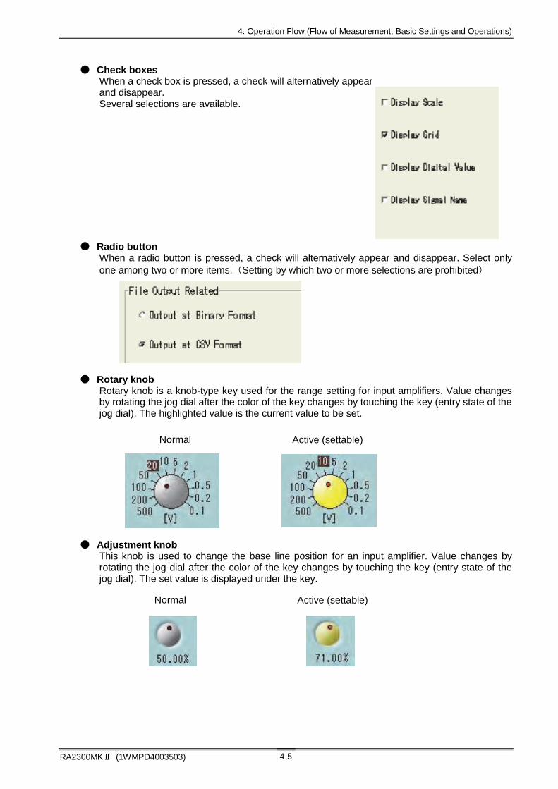
4. Operation Flow (Flow of Measurement, Basic Settings and Operations)
RA2300MKⅡ (1WMPD4003503) 4-5
● Check boxes When a check box is pressed, a check will alternatively appear and disappear. Several selections are available.
● Radio button When a radio button is pressed, a check will alternatively appear and disappear. Select only one among two or more items. (Setting by which two or more selections are prohibited)
● Rotary knob Rotary knob is a knob-type key used for the range setting for input amplifiers. Value changes by rotating the jog dial after the color of the key changes by touching the key (entry state of the jog dial). The highlighted value is the current value to be set.
● Adjustment knob This knob is used to change the base line position for an input amplifier. Value changes by rotating the jog dial after the color of the key changes by touching the key (entry state of the jog dial). The set value is displayed under the key.
通常時 エントリ時
通常時 エントリ時
Normal Active (settable)
Normal Active (settable)

4. Operation Flow (Flow of Measurement, Basic Settings and Operations)
RA2300MKⅡ (1WMPD4003503) 4-6
4.2.3. Explanation of standard setting windows This recorder uses common setting windows to set values that are commonly used.
● Numeral input window Use this window to enter numerical values.
● Character input window Use this window to input character strings.
1: Window title
This displays contents of the setting item.
2: Input display section This section displays input character strings and cursor position.
To register the setting, press the [Execute] key. The window then closes.
Numeric input key
Allowable setting range
Current setting
Current input value
1
2
3
5 4
4. Operation Flow (Flow of Measurement, Basic Settings and Operations)
RA2300MKⅡ (1WMPD4003503) 4-7
3: Input operation section
This section operates input character strings from various keys.
[Delete line] Erases only the line indicated by the cursor
Capital letters and symbols can be input by pressing the [SHIFT] key When the key is pressed, images displayed on the keyboard are changed after the key is highlighted, thereby capital letters and symbols can be input.
Character strings to convert into kanji can be input by pressing the [IME] key.
When the key is pressed, kana input mode using Roman character is changed after the key is highlighted. To convert kana into kanji, press the [Blank/Conversion] key. To select among kanji list, press the [Arrow] key or [Blank/Conversion] key. (To select among kanji list on the panel, touch the panel directly.) To confirm the selection, press the [Return] key. Avoid inputting special characters (the upper key on input operation section such as Ω, μ, ε) during IME mode.
4. [Execute] key To register character strings to input, press this key. The window will then close.
5: [Undo] key To restore the previous entry, press this key.


5. Input Signal Monitor Observing Input Signals

5. Input Signal Monitor (Observing Input Signals)
RA2300MKⅡ (1WMPD4003503) 5-2
5.1. Observing Input Signals To observe the signals that are input, use the Input Signal screen. This screen displays the signals that are input in real time. The waveforms can be frozen as necessary.
When the measurement mode is Pen Recorder or X-Y Recorder, a special screen appears.
TIPS
Pen recorder screen X-Y recorder screen

5. Input Signal Monitor (Observing Input Signals)
RA2300MK2 (1WMPD4003503) 5-3
5.2. Displaying Input Waveform Monitor The screen below appears when the Input Signal button is pressed in the Memory Recorder Mode.
(1) Waveform display block Waveform display format can be set. With this setting, waveform segmentation for display and printing can be made. Chapter 15 Display and Printing
(2) Pen position Current values for analog amps are indicated with the pen position.
(3) Position marker This is zero position for all analog amps.
(4) Amplitude scale This is amplitude scale for analog amps. This scale can be hidden depending on the setup. Chapter 15 Display and Printing
(5) Signal name Signal names that are entered by user are indicated. The signal names can be hidden depending on the setup. Chapter 15 Display and Printing Chapter 19 System Setup
(6) Value indication Numerical values of currently input signals are indicated. The values can be hidden depending on the setup.
Chapter 15 Display and Printing
(1) Waveform display block
(2) Pen position
(3) Position marker (4) Amplitude scale
(7) REC icon (8) TOP bar
(5) Signal name
(6) Value indication

5. Input Signal Monitor (Observing Input Signals)
RA2300MKⅡ (1WMPD4003503) 5-4
(7) REC icon Status of printing and recording is shown. The contents differ depending on the measurement mode. For more information, see descriptions of measurement modes in Chapters 8 to 12.
(8) TOP bar
(9) Trigger sync This button sets whether updating for input waveform monitoring is made through the trigger detection or not. To monitor high-speed and periodic signals, this function is effective.
(10) Temporary stop This button halts monitoring. Pressing the button again resumes monitoring.
(11) Monitor switching This button switches input waveform monitor modes. The monitor mode changes with button. The monitor mode varies depending on the measurement mode. See the table below.
Recorder mode Monitor mode Description
Memory HD Multi Input Monitor Fixed-speed for input monitor Enabled Enabled Enabled Chart Feed Speed Monitor displaying same speed as the
chart feed speed. Disabled Enabled Enabled
Memory Sampling Speed Monitor displaying same speed as the memory sampling speed
Enabled Disabled Enabled
HD Recording Speed Monitor displaying same speed as the HD recording speed
Disabled Enabled Enabled
※ Monitor speed setting becomes disabled when settings other than the Input Monitor mode is set. ※ This button does not appear in the Pen Recorder and X-Y Recorder modes. ※ In the Memory Recorder mode, the left edge of the monitor is displayed as the reference trigger point.
(12) Monitoring speed When the monitor mode is set to Input Monitor, monitoring speed can be selected. Use the jog dial or the window to set. If the monitor mode is set to other than the Input Monitor, the monitoring speed indicates a fixed-recording speed. If the setting is changed, the fixed speed is changed.
(9) Trigger sync
(10) Temporary stop
(11) Monitor switching
(12) Monitoring speed
(14) Timer indication
(15) Time
(16) Key lock(13) Digital indication

5. Input Signal Monitor (Observing Input Signals)
RA2300MK2 (1WMPD4003503) 5-5
(13) Digital indication Input signal values are indicated in the form of digital value. Pressing this button switches between No and Digital Value.
(14) Timer indication If the timer printing is set, the recording time for the next session is indicated. If it is not set, nothing is indicated.
19 System Setup
(15) Time This portion indicates the current time.
(16) Key lock By setting this function, key entries on the operation panel are blocked. Pressing this button switches key lock on and off. 19 System Setup
Key lock OFF Key lock ON


6. Auto Setup Automatically Setting Recording Conditions
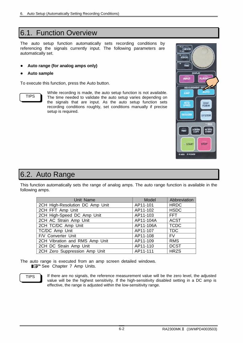
6. Auto Setup (Automatically Setting Recording Conditions)
RA2300MKⅡ (1WMPD4003503) 6-2
6.1. Function Overview The auto setup function automatically sets recording conditions by referencing the signals currently input. The following parameters are automatically set.
● Auto range (for analog amps only)
● Auto sample To execute this function, press the Auto button.
While recording is made, the auto setup function is not available. The time needed to validate the auto setup varies depending on the signals that are input. As the auto setup function sets recording conditions roughly, set conditions manually if precise setup is required.
6.2. Auto Range This function automatically sets the range of analog amps. The auto range function is available in the following amps.
Unit Name Model Abbreviation 2CH High-Resolution DC Amp Unit AP11-101 HRDC 2CH FFT Amp Unit AP11-102 HSDC 2CH High-Speed DC Amp Unit AP11-103 FFT 2CH AC Strain Amp Unit AP11-104A ACST 2CH TC/DC Amp Unit AP11-106A TCDC TC/DC Amp Unit AP11-107 TDC F/V Converter Unit AP11-108 FV 2CH Vibration and RMS Amp Unit AP11-109 RMS 2CH DC Strain Amp Unit AP11-110 DCST 2CH Zero Suppression Amp Unit AP11-111 HRZS
The auto range is executed from an amp screen detailed windows.
See Chapter 7 Amp Units. If there are no signals, the reference measurement value will be the zero level, the adjusted value will be the highest sensitivity. If the high-sensitivity disabled setting in a DC amp is effective, the range is adjusted within the low-sensitivity range.
TIPS
TIPS

6. Auto Setup (Automatically Setting Recording Conditions)
RA2300MKⅡ (1WMPD4003503) 6-3
6.3. Auto Sampling The auto sampling function sets the monitor displaying speed, chart paper feed speed, memory sampling speed, and file recording speed based on the signals currently input.
6.3.1. Target Setup Conditions The relation between settable conditions and mode are as follows. The monitor displaying speed is always settable.
Measurement Mode Pen
Recorder Memory HD Multi X-Y
Monitor displaying speed Available Available Available Available - Chart feed speed Available - - - -
Memory sampling speed - Available - Available - File recording speed - - Available - - X-Y sampling speed - - - - -
Available: Adjusted, -: Not adjusted In the X-Y Recorder mode, the auto sampling does not function. (For X-Y data sampling speed, make adjustment while seeing the monitor.)
6.3.2. Adjustment Range
Chart feed speed Memory sampling speed File recording speed 100 mm/s (1 ms) 1 μs 10 μs 50 mm/s (2 ms) 2 μs 100 μs 20 mm/s (5 ms) 5 μs 200 μs 10 mm/s (10 ms) 10 μs 500 μs 5 mm/s (20 ms) 20 μs 1 ms 1 mm/s (100 ms) 50 μs 2 ms
100 mm/min (60 ms) 100 μs 5 ms 50 mm/min (120 ms) 200 μs 10 ms 20 mm/min (300 ms) 500 μs 20 ms 10 mm/min (600 ms) 1 ms 50 ms
5 mm/min (1.2 s) 2 ms 100 ms 1 mm/min (6 s) 5 ms 200 ms
The values in parentheses in chart feed speed correspond to the data sampling speed.
TIPS


7. Amp Units

7. Amp Units
RA2300MKⅡ (1WMPD4003503) 7-2
7.1. Settings for Input Units This section covers how to make settings on the Amp Basics and Amp Details screens. For detailed settings for amps, see Instruction Manual, RA2000 Series Amplifier Units. To set range and waveform printing for input unit, the Amp screen is used. The following screen appears after pressing the Amp button.
7.1.1. Amp Basics Screen In the Amp Basics screen, input unit setup condition can be checked by channel. To change the channel, use the Scroll key.
(1) Channel Channel number, amp type, and waveform color are indicated on this button. Pressing this button displays the Amp Details screen, making more detailed setup.
(2) Amp setup block This block is used to set basic settings for amp. As contents differ depending on the amp type, refer to the descriptions of each amp.
(3) Information display Setup information that is not indicated in the Amp Basic screen is displayed. The detailed settings are made in the Amp Details screen. As contents differ depending on the amp type, refer to the descriptions of each amp.
(1) Channel
(3) Info display
(2) Amp setup block
2CH High-Resolution DC Amp Setting
Scroll key

7. Amp Units
RA2300MKⅡ (1WMPD4003503) 7-3
7.1.2. Amp Details Screen The Amp Details screen appears when the Channel button is pressed on the Amp Basic screen. Detailed channel settings can be made. The following screen is a screen for 2CH High-Resolution DC Amp (AP11-101).
(1) Channel Channel to be set up is selected. Pressing a button changes the contents of (5) Detailed setup block.
(2) Extra Event Perform detailed setting of Event Unit (RA 23 - 145) or Event Input BOX (option: RA 23 - 146). Pressing the button changes the contents of (5) Detailed setup block.
If Optional Event Unit (RA 23 - 145) or Event Input BOX (option: RA 23 - 146) is not connected, detailed settings cannot be made.
(3) Batch Batch setting for the same type of amp can be made. Pressing the button highlights this button, indicating the batch setup is effective. In addition, the Channel buttons of target channels of batch setup highlight, too. If specific channels should setup through batch setup, cancel the highlight of the channels by pressing the Channel button that will not be set. To set through the batch setup, highlight the target channels again.
Only the same type of units can be set through the batch setup.
(4) Input setup ON, OFF, and GND for input is set. GND may not be provided depending on the amp. If the input is set to OFF, neither waveform nor digital values are displayed.
(5) Detailed setup block Contents differ depending on the amp type. Refer to the description of each amp type.
NOTE
NOTE
(4) Input setup
(3) Batch
(2) Extra Event
(1) Channel
(5) Detailed setup block


8. Pen Recorder Recording Low-speed Signal for Long Time

8. Pen Recorder (Recording Low-speed Signal for Long Time)
RA2300MKⅡ (1WMPD4003503) 8-2
8.1.Overview of Pen Recorder Mode The Pen Recorder mode offers a pen recorder function, which is dedicated to waveform printing. Chart feed speed and amp settings are made on a screen, which are exactly equivalent to the operability of a pen recorder. To set the recorder main unit to the Pen Recorder mode, use the Measuring Mode tab in the System screen. Measurement mode setting is made on the Startup screen that is displayed upon the startup. (Depending on the startup screen, the Startup screen may not be displayed.)
As the Pen Recorder mode only performs waveform printing on a chart recording paper, even if the Input Signal, Amp, Recording Condition, and Trigger buttons are pressed, the screen display does not change.
NOTE
System screen
Press Execute.
Measurement mode selection
Operation panel
Setup completes after themode turns to yellow afterexecution.
Pressing Close closes the Setup screen. Themode setting completes after the screen is switched.

8. Pen Recorder (Recording Low-speed Signal for Long Time)
RA2300MKⅡ (1WMPD4003503) 8-3
8.2. Screen Operation Open the following screen by pressing one button among Input Signal, Amp, Recording Condition, and Trigger buttons in the Pen Recorder mode.
(1) Waveform display block Input signals are displayed in this block. The basic functions are almost the same as the Input Monitor. The signal monitoring speed in this block is the same as the chart feed speed. For more details, see Chapter 5. Input Signal Monitor.
(2) Amp setup block This block is used to set amp unit. For more details, see Chapter 7. Amp Units
(3) Chart feed speed These buttons are used to set chart recording paper feed speed. Value is set by pressing a button. Through User 1 and User 2 buttons, user can set arbitrary feed speeds. For more details, see Chapter 19. System Setup
(4) Annotation printing ON/OFF for annotation printing can be set. For more details, see Chapter 19. System Setup.
(1) Waveform display block (2) Amp setup block
(3) Chart feed speed (4) Annotation printing

8. Pen Recorder (Recording Low-speed Signal for Long Time)
RA2300MKⅡ (1WMPD4003503) 8-4
8.3. Printing Operation Pressing the Start button on the Operation Panel starts printing. Pressing the Stop button stops printing.
Sample printing
(1) Waveform printing Input signals are printed in a form of waveform. The same waveforms as those displayed in the monitor are printed. Waveform segmentation and grid pattern can be set. For more details, see Chapter 15. Display and Printing
(2) System annotation (above/below) System information related to printing is printed. Print start time is indicated on the top of the recording paper and print speed is indicated on the bottom of the recording paper. Data No.: Automatically added number by printing is printed. ID number: Recorder serial number is printed.
10:54:20 04/09/01 データNo.0001 ID:123457
H1:HRDC
0s 5s Chart speed 10ms (1s/div)
CH1 [mV] 50.000 40.000 30.000 20.000 10.000 0.0000 -10.000 -20.000 -30.000 -40.000 150.000
(2) System annotation (below) (7) Measurement information
(5) Scale
(1) Waveform printing
(2) System annotation (above) (3) Mark printing
(9) Channel annotation
(8) Page annotation (6) Time axis
(4) Signal name
AAAA BBBB CCCC AAAA BBBB CCCC AAAA BBBB CCCC AAAA BBBB CCCC AAAA BBBB CCCC AAAA BBBB CCCC AAAA BBBB CCCC AAAA BBBB CCCC AAAA BBBB CCCC AAAA BBBB CCCC AAAA BBBB CCCC AAAA BBBB CCCC AAAA BBBB CCCC AAAA BBBB CCCC
CH1: Signal name
Page annotation Page annotation Page annotation Page annotation Page annotation Page annotation Page annotation Page annotation Page annotation Page annotation Page annotation Page annotation Page annotation Page annotation Page annotation Page annotation Page annotation Page annotation Page annotation Page annotation Page annotation Page annotation Page annotation Page annotation Page annotation Page annotation Page annotation Page annotation Page annotation Page annotation
8. Pen Recorder (Recording Low-speed Signal for Long Time)
RA2300MKⅡ (1WMPD4003503) 8-5
(3) Marking Marking is printed by pressing the Marking button on the Operation Panel during recording. Marking time is also printed after ↓M.
Example: ↓M17:06:20 2004/11/29
(4) Signal name Character strings set by user by channel are printed. The position of printing is near the zero level of each signal. If the annotation printing position overlaps with a signal waveform, the annotation is printed above or below the waveform. If annotation cannot be printed within the waveform printing range, the annotation printing is omitted. For printing ON/OFF for signal name and character string settings, see Chapter 19. System Setup.
(5) Scale Analog waveform amplitude scale is printed. Printing OFF and scale printing format can be changed with settings. For details of scale settings, see Chapter 19. System Setup.
(6) Time axis Time axis scale is printed below the waveform printing grid. Printing ON, OFF, and format (e.g. value and time) can be set. For more details on settings, see Chapter 19. System Setup.
(7) Measurement information Character strings specified by user are printed before waveforms are printed. To set printing ON, OFF, or character strings, see Chapter 19. System Setup.
(8) Page annotation Following system annotation, character strings defined by user are printed over waveform printing. To set printing ON, OFF, or character strings, see Chapter 19. System Setup.
(9) Channel annotation Recording condition by signal is printed.
8.3.1. Stop Due to Error Printing stops in the following cases.
● Chart paper-out In the case when chart paper runs out, printing cannot be made. In this case, printing is terminated. When red marks at the both sides of the chart recording paper, prepare new chart recording paper as they signifies paper-out.
● Thermal head overheating If the thermal head for printing is heated too much, operation stops due to error. If printing of entire screen is repeatedly made, the temperature of the thermal head at printing block rises. In this case, the recorder automatically controls the print density, thereby prohibiting temperature rise. However, if the ambient temperature is so high or heat release is not made smoothly, thermal head temperature excessively rises. In such case, printing is terminated due to error so as to prevent fire breakout.


9. Memory Recorder Recording High-speed
Signals

9. Memory Recorder (Recording High-speed Signals)
RA2300MKⅡ (1WMPD4003503) 9-2
9.1. Overview of Memory Recorder Mode The Memory Recorder mode is useful for recording high-speed signals since the mode features a highest sampling speed of 1 s. Data recording of a certain period of time before trigger is available. Automatic printing of data on chart recording paper (Auto Copy) or file saving (Backup Filing) is also available. In addition, replay of waveforms on the monitor is possible. To set the RA2300MKⅡ to the Memory Recorder mode, use the Measuring Mode tab in the System screen. Mode setting can also be made on the Startup screen that is displayed upon the startup. (Depending on the startup screen, the Startup screen may not be displayed.)
Operation panel
Measurement mode selection
Pressing Close closes the Setup screen. Themode setting completes after the screen isswitched.
Setup completes after the mode turns yellow afterexecution.
Press Execute.

9. Memory Recorder (Recording High-speed Signals)
RA2300MKⅡ (1WMPD4003503) 9-3
9.2. Recording Condition Setup Open the following screen by pressing the Recording Condition button on the Operation Panel to set the recording conditions for Memory Recorder. The recording condition setup should be made while the recorder stops its operation. Setup cannot be made during recording.
9.2.1. Description of Icons The icons signify recording settings and status.
(1) Memory Recording (2) Auto Copy (3) Backup Filing (4) Others
Stop OFF (White)
Stop ON (Green)
Trigger wait (Yellow)
None None
Measuring (Amber)
Error (Red)
As waveform chart printing, HD recording does not operate, no indication is made.
(1) Memory recordingstatus indication
(2) Setting for Auto Copyand status indication
(3) Setup for Backup Filing and status indication
Memory Recording Setup Block
REC Icon

9. Memory Recorder (Recording High-speed Signals)
RA2300MKⅡ (1WMPD4003503) 9-4
9.2.2. Memory Recording Condition Setup Block
(1) Sampling rate Sampling rate for memory recording is set.
(2) Memory block size Memory recording block size is displayed. Pressing a button opens a setup dialog box. Select a memory size
Recording time: Recording time is calculated based on the sampling speed. Block count: The block count is calculated based on the block size.
Memory block size can be expanded to more than 4 MW by limiting the number of channel for recording. To limit the number of channel for recording, see Chapter 19. System Setup.
(3) Memory block and status indication Block number to be recorded and data existence are indicated. Block number can be changed using the jog dial.
NOTE
(5) Pre-trigger
(6) Memory Recording Operation
(3) Memory Block & Status Indication
(4) Sample recording image
(8) Output range
(9) File output path
(7) Auto data output
(1) Sampling rate
(2) Memory Block Size
(10) File save processing indicator

9. Memory Recorder (Recording High-speed Signals)
RA2300MKⅡ (1WMPD4003503) 9-5
(4) Sample recording image Trigger position for entire recording and sample for output range are displayed. Recording time: Pre-trigger, post-trigger and total recording times are displayed.
(5) Pre-trigger Recording size before trigger can be set in percentage. Changing this setting renews the sample recording image, which enables a user to confirm recording time allocation.
If a trigger is detected immediately after the start of recording, the data length satisfying the specified data size cannot be recorded. Example: Under pre-trigger setup of 30 ms, a trigger is detected 10 ms after the start of recording. The pre-trigger recording data length is 10 ms, resulting in shorter data length than pre-set length. If the Stop button is pressed shortly after a trigger is detected, only the data having the length shorter than the post-trigger recording time displayed in the sample recording image is recorded. Example: Under post-trigger setup of 50 ms, if the Stop button is pressed 30 ms after the trigger detection, the recording length after the trigger is 30 ms, resulting in shorter data length than pre-set length.
(6) Memory recording operation These buttons are used to specify the memory recording operation.
Recording operation Description Single Operation closes after recording of one block is finished. Repeat Recording operation repeats for the number of blocks. It finishes when
all blocks are recorded. Endless Recording operation repeats for the number of blocks. After recording
of all blocks, overwriting from the top is repeated. Recording stops when the Stop button on the Operation Panel is pressed.
(7) Auto data output This portion specifies data output after memory recording.
Output format Description Auto Copy This function prints out the waveforms area, which is specified by
output range. Binary Save All data region is saved as a file with the FSD extension. CSV Save Area that is specified through output range is saved in the CSV
format. The binary save performs saving of entire part of file regardless of output range settings. When performing the CSV save, always execute the binary save. For more details on the CSV save, see Chapter 14. Replay Display.
(8) Output range Data output range for Auto Copy and CSV save is specified. The setting is made in % in reference to the trigger detection point.
NOTE
NOTE

9. Memory Recorder (Recording High-speed Signals)
RA2300MKⅡ (1WMPD4003503) 9-6
(9) File output path The file save target path can be specified. Pressing the button opens the following dialog box.
a) Save target path Save target path is specified. As well as internal HDD, USB storage drive can be specified.
b) ON/OFF for folder made by user When the check box is ticked, a folder can be made by user. The data save destination will be under the folder.
c) ON/OFF for creating folder everyday When the check box is ticked, starting time is referenced and folder is created everyday. The data save destination will be under the folder.
d) Arbitrary file name (Limited to the top four letters) Top four letters for the save file is designated. The file name will have designated top four letters and four-digit serial number. The extension has “fsd” for the binary save and “csv” for the CSV save.
a)
b)
c)
d)

9. Memory Recorder (Recording High-speed Signals)
RA2300MKⅡ (1WMPD4003503) 9-7
9.3. Recording Operation Pressing the Start button on the Operation Panel starts the Memory Recording. After the recording starts, the recorder is in the wait status for trigger detection. Pressing the Stop button stops the operation forcibly. The following diagram explains the flow of operation.
(1) Data recording before trigger After the memory recording starts, trigger detection wait status starts. Memory block recording continues until the trigger detection is made or the Stop button is pressed. When the trigger is detected, data recording operation starts after the trigger. When the Stop button is pressed and operation is forcibly terminated, the trigger recording is not made but the operation judgment processing starts.
Other then trigger detection by an input signal, trigger detection can be made through the Manual Trigger or External Trigger signal. For details on trigger condition settings, see Chapter 13. Trigger Settings. If the Stop button is pressed and forcible termination is made before the trigger detection, data recording is made up to the size set by the pre-trigger. Example: Under pre-trigger of 20 ms, if the recording is forcibly terminated before the trigger detection, the recording length is up to 20 ms.
(2) Data recording after trigger The amount of data specified by the pre-trigger is retained and recording for remaining amount of data is made. The recording automatically ends but forcible termination is also made through the Stop button. In this case, the data length will be shorter than the data length displayed as recording time.
(3) Automatic judgment When Auto Copy and Backup Filing are selected to be effective, automatic data output of recording data is made. Memory block recording is repeated depending on the recording operation.
If forcible termination is made with the Stop button, memory recording finishes without repeated endless operations. If the block for overwriting is outputting data in endless manner, recording starts after the outputting is completed.
(4) Auto Copy Auto Copy and Backup Filing are executed.
NOTE
NOTE
NOTE
NOTE


10. HD Recorder Recording Data in Internal
HDD

10. HD Recorder (Recording data in the internal HDD)
RA2300MKⅡ (1WMPD4003503) 10-2
10.1. Overview of HD Recorder Mode The HD Recorder mode can record data in the internal hard disk, which is suitable for a long-time measurement. In addition, waveform chart paper printing can be made with the HD recording at the same time. The data recorded in the HD can be replayed on the monitor screen in the form of waveforms. To set the recorder in the HD Recorder mode, use the Measuring Mode tab in the System screen. Settings of measurement mode can be made on the Startup screen displayed upon the startup. (*The startup screen does not appear depending on the setup.)
The drive for data recording is fixed to the internal HDD only. For details on data output to the USB storage, see Replay Screen - Data Output or System - File Operation.
NOTE
Measurement mode selection
Pressing Close closes the Setup screen. Themode setting completes after the screen isswitched.
Setup completes after themode turns yellow afterexecution
Operation Panel
Press Execute.

10. HD Recorder (Recording data in the internal HDD)
RA2300MKⅡ (1WMPD4003503) 10-3
10.2. Recording Condition Setup Open the following screen by pressing the Recording Condition button on the Operation Panel to set the recording conditions for HD Recorder. The recording condition setup should be made while the recorder stops its operation. Setup cannot be made during recording.
10.2.1. REC Icon The icons signify recording settings and status.
(1) Chart Printing (2) HD Recording (3) Others
Recorder stop OFF (White)
Recorder stop ON (Green)
Trigger wait (Yellow)
None
Operating (Amber)
Error (Red)
Remark Setup while the recorder is recording data is possible.
As memory recording does not operate, indication is invalid.
(1) Waveform chart printing setup and status display (2) HD recording status indication
REC Icon
HD Recording Setup Block

10. HD Recorder (Recording data in the internal HDD)
RA2300MKⅡ (1WMPD4003503) 10-4
NOTE
b)
a)
c)
d)
10.2.2. HD Recording Setup Block
(1) File save path Save target path for HD recording is indicated. Pressing the button opens the next dialog box and the path can be set. a) Save target folder
The save target folder is specified. b) User name entry folder
When this box is ticked, a folder is created and the save target will become inside of this folder.
c) Arbitrary file name (Limited to the top four letters)
Binary has fsd as its extension. d) File name
Arbitrary file name (Limited to the top four letters) Top four letters for the save file is specified. The file name will include designated top four letters and four-digit serial number. The extension has fsd for the binary save and csv for the CSV save.
(2) Recording speed Recording speed can be set.
Recording time changes if the recording speed is changed. Check before recording start.
(1) File save path
(6) Data format
(2) Recording speed
(4) Maximum recording space in internal HDD
(3) Recording length
(5) Recording operation
(7) Filing format
(8) Waveform chart printing

10. HD Recorder (Recording data in the internal HDD)
RA2300MKⅡ (1WMPD4003503) 10-5
(3) Recording length The length of recording in HD is indicated in the number of recording data and recording time. Setup can be made in the setup dialog box that is displayed when the button is pressed. The recording time changes in conjunction with the change of the number of recording data, and vice versa. The recording time can be determined by multiplying the number of recording data by the sampling speed.
Recording time = Number of recording data x Sampling speed
When the number of recording data is set to 0, “Max length” appears and recording is made up to the size of free space of HD. As a user does not need to take care of recording length, the Max length is best choice when recording is made with Start and Stop.
If free space is shortened during HD recording, operation stops with an error. In this case, shorter recording time than specified recording length of time will result. When the number of recoding data is set to 2GB or over (such as “Max length”), the recording data is stored by every 2GB to protect the file. The maximum capacity for the loop filing format is 2GB.
(4) Maximum recording space in internal HDD It represents the current number of bytes of the HDD's maximum recording capacity in the total capacity.
(5) Recording operation HD recording operation can be made with trigger detection. Setup item Contents Starts recording with the START key.
When the Start button is pressed, recording starts.
Start trigger After the Start button is pressed, recording starts upon trigger activation. Record starts by trigger Record the trigger detection point. The marking points can be checked
on the replay monitor. Single Recording operation completes after one recording action. Repeat HD recording repeats until the Stop button is pressed. However in the
following cases, operation will be invalid because one recording automatically finishes. The recording mode is “Loop.” The recording length is “Up to the size of free space.”
When “Start trigger” is selected, the recording starts upon trigger activation.
Therefore, the recorded data has not trigger mark “(T).”
In order to record the trigger detection point, start recording with a start trigger and set [E2] to ON as described in 19.5.1. Recording Channels.
NOTE
NOTE

10. HD Recorder (Recording data in the internal HDD)
RA2300MKⅡ (1WMPD4003503) 10-6
NOTE
(6) Data format Setup item Description Peak One data consists of two values: maximum and minimum values. Regardless of
recording speed, peak data is stored with the highest A/D conversion speed of amp. It is possible to observe waveform having high-frequency element for long period of time.
Sampling One data consists of one instantaneous value. The data number per one piece of data is half. Consequently, the recording speed and recording length will double.
(7) Filing format Setup item Description Linear
Operation stops when specified number of data is recorded.
Loop Overwriting for specified number of data is made. (Overwriting is made from old data.) The operation stops when the Stop button is pressed.
(8) Waveform chart printing Settings related to waveform chart printing are made.
a) Waveform ON/OFF ON/OFF for waveform chart printing is made. Changes during operation cannot be made.
b) Same printing speed as recording speed When the check box is ticked, the waveform chart printing speed is automatically set to the speed the same as current recording speed. To separate the recording speed from the chart feed speed, do not check this box.
The highest chart feed speed is 100 mm/s. If the recording speed is higher than this speed, the printing is made at the highest printing speed.
c) Chart feed speed setup When the check box for “Same printing speed as recording speed” is not ticked, the chart feed speed is separated from the data recording speed.
Data
Recording start
Recording stop
Data
Recording start
Continues until forced stop
a)
b)
c)

10. HD Recorder (Recording data in the internal HDD)
RA2300MKⅡ (1WMPD4003503) 10-7
10.3. Recording Operation Pressing the Start button on the operation panel starts HD recording. While recording is made, pressing the Stop button forcibly stops the recording.
10.3.1. Start of Measurement Pressing the Start button on the operation panel starts HD recording. If the setup in which the start of recording is initiated with a trigger signal, the start of recording is made with a trigger detection.
If the combination of recording speed, recording length, data format, and number of recording channels is not covered by recorder specifications, recording cannot be made and operation finishes with an error. For HD recording, see 10.4 HD Recording Specifications.
10.3.2. To Finish Measurement (Forced Termination) Pressing the Stop button on the Operation Panel executes forced termination. If recording length is specified, operation completes when specified number is recorded.
10.3.3. Waveform Chart Printing During HD recording, waveform chart printing is started and stopped as necessary. Moreover, chart feed speed can be changed. For operation, see 10.2 Recording Condition Setup.
10.3.4. Upon Error Generation Error that may occur during HD recording and operations are described as follows. Generated error Operation File error HD recording will stop with an error. If the waveform chart printing is
operating, the operation continues. Paper-out error HD recording continues. The waveform chart printing will stop with an
error. After the chart paper is filled, the printing resumes.
10.3.5. To display recorded data The recorded data is displayed in the replay monitor. For details, see Chapter 14. Replay Display.
NOTE
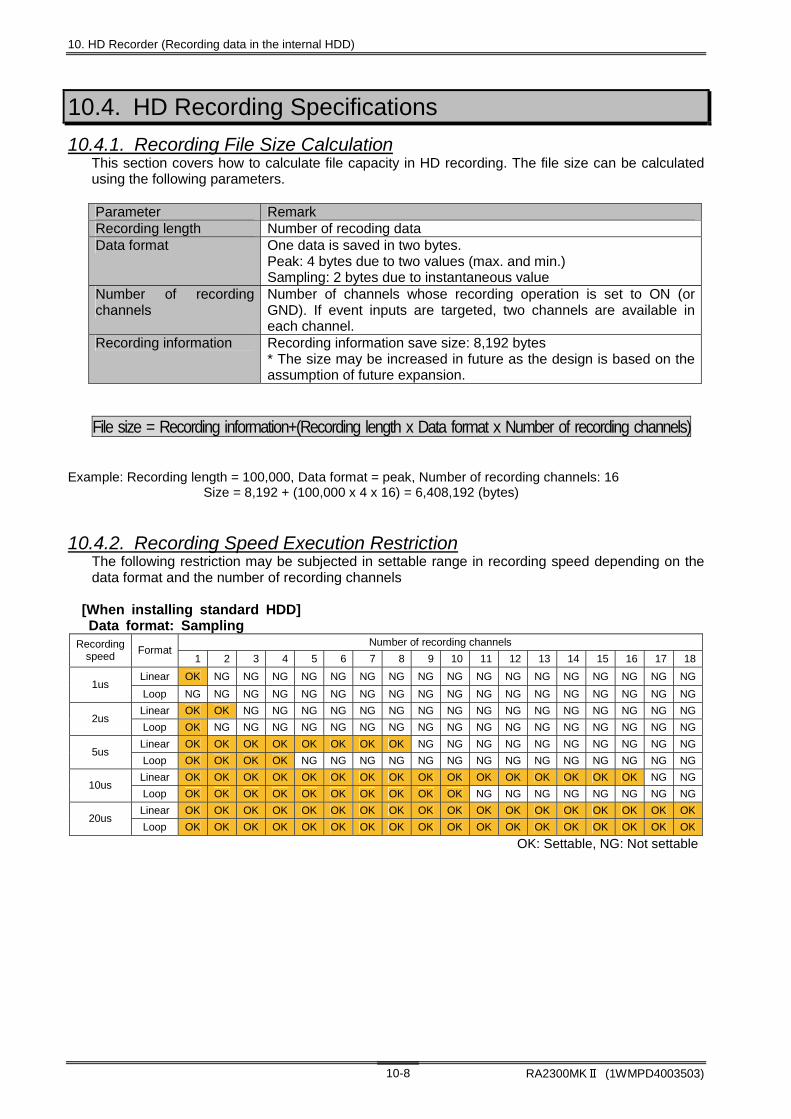
10. HD Recorder (Recording data in the internal HDD)
RA2300MKⅡ (1WMPD4003503) 10-8
10.4. HD Recording Specifications
10.4.1. Recording File Size Calculation This section covers how to calculate file capacity in HD recording. The file size can be calculated using the following parameters. Parameter Remark Recording length Number of recoding data Data format One data is saved in two bytes.
Peak: 4 bytes due to two values (max. and min.) Sampling: 2 bytes due to instantaneous value
Number of recording channels
Number of channels whose recording operation is set to ON (or GND). If event inputs are targeted, two channels are available in each channel.
Recording information Recording information save size: 8,192 bytes * The size may be increased in future as the design is based on the assumption of future expansion.
File size = Recording information+(Recording length x Data format x Number of recording channels)
Example: Recording length = 100,000, Data format = peak, Number of recording channels: 16 Size = 8,192 + (100,000 x 4 x 16) = 6,408,192 (bytes)
10.4.2. Recording Speed Execution Restriction The following restriction may be subjected in settable range in recording speed depending on the data format and the number of recording channels
[When installing standard HDD] Data format: Sampling
Number of recording channels Recording speed
Format 1 2 3 4 5 6 7 8 9 10 11 12 13 14 15 16 17 18
Linear OK NG NG NG NG NG NG NG NG NG NG NG NG NG NG NG NG NG 1us
Loop NG NG NG NG NG NG NG NG NG NG NG NG NG NG NG NG NG NG
Linear OK OK NG NG NG NG NG NG NG NG NG NG NG NG NG NG NG NG 2us
Loop OK NG NG NG NG NG NG NG NG NG NG NG NG NG NG NG NG NG
Linear OK OK OK OK OK OK OK OK NG NG NG NG NG NG NG NG NG NG 5us
Loop OK OK OK OK NG NG NG NG NG NG NG NG NG NG NG NG NG NG
Linear OK OK OK OK OK OK OK OK OK OK OK OK OK OK OK OK NG NG 10us
Loop OK OK OK OK OK OK OK OK OK OK NG NG NG NG NG NG NG NG
Linear OK OK OK OK OK OK OK OK OK OK OK OK OK OK OK OK OK OK 20us
Loop OK OK OK OK OK OK OK OK OK OK OK OK OK OK OK OK OK OK
OK: Settable, NG: Not settable

10. HD Recorder (Recording data in the internal HDD)
RA2300MKⅡ (1WMPD4003503) 10-9
TIPS
[When installing standard HDD] Data format: Peak
Number of recording channels Recording speed
Format 1 2 3 4 5 6 7 8 9 10 11 12 13 14 15 16 17 18
Linear NG NG NG NG NG NG NG NG NG NG NG NG NG NG NG NG NG NG 1us
Loop NG NG NG NG NG NG NG NG NG NG NG NG NG NG NG NG NG NG
Linear OK NG NG NG NG NG NG NG NG NG NG NG NG NG NG NG NG NG 2us
Loop OK NG NG NG NG NG NG NG NG NG NG NG NG NG NG NG NG NG
Linear OK OK OK NG NG NG NG NG NG NG NG NG NG NG NG NG NG NG 5us
Loop OK NG NG NG NG NG NG NG NG NG NG NG NG NG NG NG NG NG
Linear OK OK OK OK OK OK OK OK OK NG NG NG NG NG NG NG NG NG 10us
Loop OK OK OK OK NG NG NG NG NG NG NG NG NG NG NG NG NG NG
Linear OK OK OK OK OK OK OK OK OK OK OK OK OK OK OK OK NG NG 20us
Loop OK OK OK OK OK OK OK OK OK OK OK NG NG NG NG NG NG NG
Linear OK OK OK OK OK OK OK OK OK OK OK OK OK OK OK OK OK OK 50us
Loop OK OK OK OK OK OK OK OK OK OK OK OK OK OK OK OK OK OK
OK: Settable, NG: Not settable [When installing standard SDD] Data format: Sampling
Number of recording channels Recording speed
Format 1 2 3 4 5 6 7 8 9 10 11 12 13 14 15 16 17 18
Linear OK NG NG NG NG NG NG NG NG NG NG NG NG NG NG NG NG NG 1us
Loop OK NG NG NG NG NG NG NG NG NG NG NG NG NG NG NG NG NG
Linear OK OK OK NG NG NG NG NG NG NG NG NG NG NG NG NG NG NG 2us
Loop OK OK OK NG NG NG NG NG NG NG NG NG NG NG NG NG NG NG
Linear OK OK OK OK OK OK OK NG NG NG NG NG NG NG NG NG NG NG 5us
Loop OK OK OK OK OK OK OK NG NG NG NG NG NG NG NG NG NG NG
Linear OK OK OK OK OK OK OK OK OK OK OK OK OK OK OK OK OK NG 10us
Loop OK OK OK OK OK OK OK OK OK OK OK OK OK OK OK OK OK NG
OK: Settable, NG: Not settable [When installing standard SDD] Data format: Peak
Number of recording channels Recording speed
Format 1 2 3 4 5 6 7 8 9 10 11 12 13 14 15 16 17 18
Linear NG NG NG NG NG NG NG NG NG NG NG NG NG NG NG NG NG NG 1us
Loop NG NG NG NG NG NG NG NG NG NG NG NG NG NG NG NG NG NG
Linear OK OK OK NG NG NG NG NG NG NG NG NG NG NG NG NG NG NG 2us
Loop OK OK OK NG NG NG NG NG NG NG NG NG NG NG NG NG NG NG
Linear OK OK OK OK OK OK OK NG NG NG NG NG NG NG NG NG NG NG 5us
Loop OK OK OK OK OK OK OK NG NG NG NG NG NG NG NG NG NG NG
Linear OK OK OK OK OK OK OK OK OK OK OK OK OK OK OK OK OK NG 10us
Loop OK OK OK OK OK OK OK OK OK OK OK OK OK OK OK OK OK NG
OK: Settable, NG: Not settable
If a filing error occurs, please review the recording speed and number of recorded channels. HDD may not be able to maintain performance due to aged deterioration.


11. Multi Recorder Separately Executing
Waveform Printing, Memory Recording and HD
Recording
11. Multi Recorder - Separately Executing Waveform Printing, Memory Recording and HD Recording
RA2300MKⅡ (1WMPD4003503) 11-2
11.1.Overview of Multi Recorder Mode Multi Recorder enables operations of Memory Recorder, HD Recorder, and waveform printing at the same time. This Recorder is suitable to measure data that is precisely recorded before or after the trigger while long-time recording is made. The waveforms of recorded data file are displayed on the replay monitor screen. With the event jump function of replay monitor, switching between HD recording data and memory recording data can be switched to confirm the data being recorded. For the event jump function, see Chapter 14. Replay Display. In order to set the recorder to the Multi-Recorder mode, use the Measuring Mode tab in the System screen. Besides, setting of measurement mode can be made in the Startup screen displayed upon the recorder startup. (* The Startup screen may not be displayed depending on the settings.)
Measurement mode selection
Pressing Close closes the Setup screen.The mode setting completes after thescreen is switched.
Setup completes after themode turns yellow afterexecution.
Operation panel
Press Execute

11. Multi Recorder - Separately Executing Waveform Printing, Memory Recording and HD Recording
RA2300MKⅡ (1WMPD4003503) 11-3
11.2. Recording Condition Setup Open the following screen by pressing the Recording Condition button on the Operation Panel to set the recording conditions for HD Recorder. The recording condition setup should be made while the recorder stops its operation. Setup cannot be made during recording.
11.2.1.REC Icon The icons signify recording settings and status.
① Chart Printing
② Memory Recording
③ Backup Filing
④ HD Recording ⑤ Others
Stop OFF
(White)
NA
Stop ON
(Green) Measuring (Amber)
Error (Red)
Auto copy does not operate. Icons are invalid.
* Pressing the chart recording button can switch ON/OFF for chart printing. (During recording only)
①Waveform chart printing and status indication
②Memory recording status indication
③Setup for Backup Filing and status indication
④HD recording status indication
Multi Recorder setup
REC Icon

11. Multi Recorder - Separately Executing Waveform Printing, Memory Recording and HD Recording
RA2300MKⅡ (1WMPD4003503) 11-4
NOTE
NOTE
11.2.2. Multi Recorder - Setup for Recording Condition
Setting procedure for ② in the screen above is the same as that in 9. Memory Recorder. However, the following settings are not available due to the recorder mode difference.
● Data output related settings
Setting procedure for ③ in the screen above is the same as that in 10. HD Recorder. However, the following settings are not available due to the recorder mode difference.
● Start trigger (Single and Repeat)
● Data format [Peak]
● Waveform chart recording related settings
① File output path
④ Waveform recording
②Memory recording setup block
The setup steps are the sameas in 9. Memory Recorder.
③ HD recording setup block
The setup steps are the sameas in 10. HD Recorder.
Memory Block
Pretrigger Logging Mode
Filing recording

11. Multi Recorder - Separately Executing Waveform Printing, Memory Recording and HD Recording
RA2300MKⅡ (1WMPD4003503) 11-5
① File output path The path for file save can be specified. Pressing the key opens the following dialog box.
a) Path for file save Specify the path for file save. You can choose a USB storage drive other than internal HDD.
b) ON/OFF for user-specified folder Setting to ON creates a folder that is specified by user. The place under this folder becomes the place for file save.
c) ON/OFF for folder by day Pressing ON creates the file by day referencing the starting time. The place under this folder becomes the place for file save.
d) Arbitrary file name (Top four letters) An individual file name can be set in memory recording and file recording. The file name consists of eight letters: specified four letters for the first half and automatically assigned four letters for the latter half. “fsd” (binary save) is appended as an extension.
② Memory recoding setup block Settings for memory recording can be made.
③ HD recording setup block Settings for HD recording can be made.
④ Waveform chart recording Settings for waveform chart printing can be made.
a) ON/OFF for printing ON/OFF for waveform chart printing can be set. Changes during recording cannot be made.
b) Operations synchronized to recording speed Ticking the check box permits a synchronized operation between waveform chart printing speed and recording speed. To separate recording speed and chart printing speed, remove the tick.
a)
b)
C)
a)
b)
c)
d)
11. Multi Recorder - Separately Executing Waveform Printing, Memory Recording and HD Recording
RA2300MKⅡ (1WMPD4003503) 11-6
The fastest chart feed speed is 100 mm/s. If the value equivalent to recording speed exceeds this value, printing with fastest speed will be made.
c) Chart feed speed setup When no tick is made for the checkbox for Operations synchronized to recording speed, setting of the chart feed speed that is separated from the recording speed can be made.
11.3. Recording Operation The multi-recording begins when the Start button on the Operation Panel is pressed. Recording set through waveform printing, Memory Recording, or HD Recording can be made simultaneously. The multi-recording stops when the Stop button on the Operation Panel is pressed. For memory recording, see Chapter 9. Memory Recorder. For HD recording, see Chapter 10. HD Recorder.
To link to memory data in the Multi-Recorder mode, the memory block recording time after trigger should be set longer than the HD recording time. When it is short and multiple triggers are generated during the HD recording time, the jump function to replay data cannot be performed properly. Example: When the HD recording time is 1 ms, perform the setting so that the memory block recording time after trigger will be 1 ms or longer. (With the sampling speed of 1 s and pre-trigger of 50%, a memory free space of 2000 or over is required. 1000 data after trigger=1 ms)
11.3.1. Error Generation Error that may occur during multi recording and operations are described as follows. Error Operation File error HD recording will stop with an error. If the waveform chart printing and
memory recording or memory recording are operating, the operation continues.
Paper-out error Memory recording and HD recording continue. The waveform chart printing will stop with an error. After the chart paper is filled, recording resumes.
NOTE
TIPS

12. X-Y Recorder

12. X-Y Recorder
RA2300MKⅡ (1WMPD4003503) 12-2
NOTE
12.1. Overview of X-Y Recorder Mode The X-Y Recorder mode is a mode that is specialized to real-time X-Y printing, which outputs X-Y waveforms on chart paper. Data sample speed and amp settings are available on a screen. To set the recorder to the X-Y recorder mode, press the Measuring Mode tab in the System screen. In addition, the measurement mode settings can be made on the Startup screen that is displayed when the recorder is started up. (* The Startup screen may not be displayed depending on the settings.)
Since the X-Y Recorder is a mode that is specialized to the X-Y printing, the same screen is displayed even with screen buttons of Input Signal, Amp, Recording Condition, and Trigger.
Press Execute.
Measurement mode selection
Pressing Close closes the Setup screen.The mode setting completes after thescreen is switched.
Setup completes afterthe mode turns yellowafter execution
Operation Panel

12. X-Y Recorder
RA2300MKⅡ (1WMPD4003503) 12-3
12.2. Screen Operation Press any button among Input Signal, Amp, Recording Condition, and Trigger buttons. The following screen appears.
(1) X-Y monitor X-Y display for input signals is made.
signifies current input signal position (hereafter called “pen mark.”)
(2) X-axis scale Measurement scale specified to the X axis is displayed.
(3) Y-axis scale Only one measurement scale specified to the Y axis is displayed. The scale to be displayed can be changed using the Y Scale button.
(4) Amp setup The setup for the channel specified to X and Y axes can be made. For how to use amp units, see Chapter 7. Amp Units.
(5) Print Icon
(7) X-Y Recorder control block
(8) X-Y axis settings
(3) Y axis scale (2) X axis scale
(1) X-Y monitor
(6) File Icon
(9) Copy
(4) Amp settings
(10) Amp settings

12. X-Y Recorder
RA2300MKⅡ (1WMPD4003503) 12-4
NOTE
(5) Print Icon Pressing this icon button executes the printout for the X-Y monitor currently displayed. The following table illustrates the X-Y printing status during X-Y recording.
Normal To execute Error
(6) File Icon Pressing this icon button sets file recording to ON or OFF. Setting to ON saves data of X-Y recording in internal HDD file. The data saved can be displayed in the X-Y graph on the replay monitor. Moreover, operating status is indicated during X-Y recording. The File icons that appear are as follows.
ON OFF To execute Error
File save destination during X-Y recording is a folder in the internal HDD. The file name is created based on the time that starts recording. Example: D:\RA2300XY\XY041201.fsd
(7) X-Y Recorder Control Block
a) Sampling speed This button is used to set data sampling speed for X-Y recording.
b) Grid This button is used to set grid to ON or OFF in the X-Y monitoring and X-Y printing. For grid pattern for the X-Y printing, see Chapter 19. System Setup.
c) Temporary stop The X-Y monitoring can be stopped temporarily. Pressing this button again cancels this temporarily stop.
d) Clear This button is used to clear the waveforms on the X-Y monitor.
e) Y-axis scale This button is used to switch the Y-axis scale representation.
f) Data interpolation X-Y waveform data interpolation can be set.
a) Sampling speed c) Temporary stop
b) Grid d) Clearf) Data interpolation
e) Y-axis scale

12. X-Y Recorder
RA2300MKⅡ (1WMPD4003503) 12-5
NOTE
(8) XY-axis setting
a) Channel settings One channel for X axis and three channels for Y axes can be made. The amp types that can be registered are only analog amps.
b) Pen-up and down X-Y waveform display ON or OFF can be set for three Y-axis channels. Pen-down draws waveforms; Pen-up does not draw waveforms. Pen mark always appears regardless of the up/down setting. However, the pen mark appears on the X-Y monitor only and does not appear on the X-Y printing.
When XY mode is set, the print base width of the recording waveform is fixed to "0.125 mm".
(9) Copy Pressing the "copy" key outputs data to the recording paper.
(10) File output path Specify the path of the file save destination. When you press the key, the following dialog will be displayed.
b) Pen-up and down (Y axis 1)
a) Channel settings (Y axis 3)
b) Pen-up and down (Y axis 2)
b) Pen-up and down (Y axis 3)
a) Channel setting (X axis)
a) Channel settings (Y axis)
a) Channel setting (Y axis 2)
a)
b)
c)
d)

12. X-Y Recorder
RA2300MKⅡ (1WMPD4003503) 12-6
NOTE
NOTE
a) Save destination path Specify the path for file save. You can choose a USB storage drive besides internal HDD. b) ON/OFF for user-specified folder Ticking the check box creates a folder that is specified by user. The place under this folder becomes the file save destination. c) ON/OFF for folder by day
Ticking the check box creates the file by day referencing the starting time. The place under this folder becomes the file save destination.
d) Arbitrary file name (Top four letters) Top four letters for the save file is specified. The file name will include designated top four letters and four-digit serial number. The extension is “fsd” for the binary save and “csv” for the CSV save.
12.3. Printing Operation Pressing the Start button on the operation panel clears X-Y data display from the X-Y monitor and, shortly after that, re-displays the X-Y data display again. Pressing the Stop button stops the X-Y monitor and prints the X-Y waveforms on chart paper. If the file saving is set to be valid during this period, recording data can be saved in a file.
Pressing the Stop buttons two times cancels the output to chart paper. Avoid pressing the button more than two times.
12.3.1. Restrictions during X-Y Printing There are following restrictions in X-Y printing.
● Setup changes cannot be made.
● X-Y monitor clear and stop cannot be made.
● Screen movement cannot be made. Press the STOP button and finish the X-Y printing to execute the operations above.
12.3.2. Exception (Error) An error may be generated during X-Y printing due to the following reasons.
● Paper-out This error is generated when the chart paper is run out. Fill in chart recording paper.
After X-Y printing, the monitor stops displaying temporarily. After filling chart recording paper, pressing the Print icon button performs printing the same contents as the X-Y printing.
● File error This error occurs when file recording cannot be made due to internal HDD free space shortage or other causes. After reducing data in the internal HDD, execute recording. Even if a file error occurs, the X-Y printing continues.

13. Trigger Settings Capturing Target Data to be
Recorded

13. Trigger Settings (Capturing Target Data to be Recorded)
RA2300MKⅡ (1WMPD4003503) 13-2
13.1. Trigger Mode Description This recorder provides four trigger modes: OR, AND, WINDOW, and OFF. Other than these modes, there are manual trigger and external triggers, which are valid regardless of the input signal.
13.1.1. Trigger Mode - Operation at OR A trigger is generated when either of two channels that are set for trigger source satisfies the trigger condition. The OR setting for all channels are also available. Example: Both of slopes for CH1 and CH3 are set to “rising edge.”
13.1.2. Trigger Mode - Operation at AND A trigger is generated when all channels that are set for trigger source satisfy the trigger condition. The AND setting for all channels are also available. Example: Both of slopes for CH1 and CH3 are set to “rising edge.”
Trigger level CH1
CH3
Trigger Trigger
Trigger Trigger
Trigger level
Trigger level CH1
CH3
Trigger Trigger
Trigger level

13. Trigger Settings (Capturing Target Data to be Recorded)
RA2300MKⅡ (1WMPD4003503) 13-3
NOTE
13.1.3. Trigger Mode – Operation at WINDOW When the signal level enters into the pre-set range of the trigger source channel (i.e. IN) or goes out of the range of the trigger source channel (i.e. OUT), a trigger is generated. The trigger setup can be made for all analog channels. A trigger is generated upon satisfying of either of the trigger settings. Example: When CH8 is set to OUT
13.1.4. Trigger Mode – Operation at OFF Trigger caused by a signal input into amp is not made. Only the manual and external triggers are effective.
When printing is made, only the trigger made after the startup is effective. If the trigger condition is satisfied before the start of recording, the status enters into the wait for next trigger condition.
Upper level
Lower level
CH8
Trigger Trigger

13. Trigger Settings (Capturing Target Data to be Recorded)
RA2300MKⅡ (1WMPD4003503) 13-4
13.2. Manual Trigger/External Trigger Regardless of trigger modes, trigger is activated manually or externally, thereby initiating the recording.
13.2.1. Manual Trigger Pressing the Manual/Marking button on the operation panel generates a trigger irrespective of other trigger settings.
13.2.2. External Trigger (TRIG IN) A trigger is generated by the falling edge of a 0 to 5-V signal. To use, enter a signal into TRIG IN in the recorder.
13.2.3. External Trigger Output (TRIG OUT) When a trigger is generated, the L level of the signal, which has TTL level and 10-ms pulse width, is output from the TRIG OUT terminal.
Press Manual Trigger/Marking. A trigger is generated andtrigger LED (green) comes on.
TRIG OUT
TRIG IN
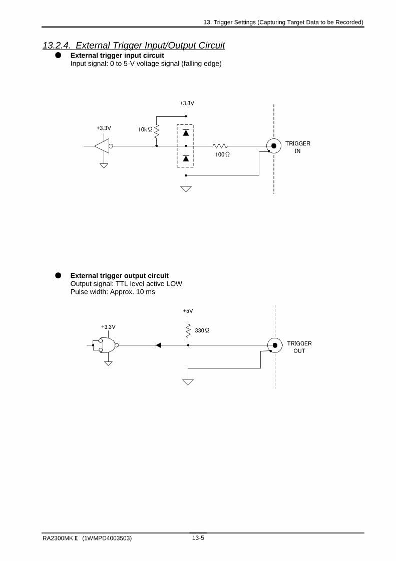
13. Trigger Settings (Capturing Target Data to be Recorded)
RA2300MKⅡ (1WMPD4003503) 13-5
13.2.4. External Trigger Input/Output Circuit ● External trigger input circuit
Input signal: 0 to 5-V voltage signal (falling edge)
● External trigger output circuit Output signal: TTL level active LOW Pulse width: Approx. 10 ms
TRIGGERIN
100Ω
10kΩ
+3.3V
+3.3V
トレラント5V 機能付ロジック低電圧
+5V
TRIGGEROUT
330Ω+3.3V
トレラント5V 機能付ロジック低電圧

13. Trigger Settings (Capturing Target Data to be Recorded)
RA2300MKⅡ (1WMPD4003503) 13-6
13.3. Method of Trigger Settings Trigger is a timing signal to start recording. The RA2300A has a variety of trigger function, thus enabling efficient data recording and printing. Pressing the Trigger button on the Operation Panel opens the Trigger Setting screen.
Trigger setting
Operation panel
Target channel
The color of this portion changesby touching. Then, signal levelcan be set by dialing the jog dial.
Pressing this portion switches the slope. ・Trigger detection at rising edge of a
signal. ・Trigger detection at falling edge of a
signal ・OFF
Trigger settings screen
Trigger filter setup
13-9 page See
Trigger mode setup
13-2 page See

13. Trigger Settings (Capturing Target Data to be Recorded)
RA2300MKⅡ (1WMPD4003503) 13-7
13.4. Settings by Trigger Mode
13.4.1. Trigger Mode OR Trigger is generated upon the satisfaction of either of the trigger conditions set as the trigger source. The OR setting for all channels are available.
13.4.2. Trigger Mode AND Trigger is generated upon the satisfaction of the trigger condition for all channels that are set as the trigger source.
Trigger setting
Trigger setting
Setting the trigger generation level
Selection of the trigger source channels to be set andsettings of rising or falling edge for the signal is made.
Selection of the trigger source channels to be set andsettings of rising or falling edge for the signal is made.
Setting the trigger mode to AND.
Setting the trigger generation level
Setting the trigger mode to OR.

13. Trigger Settings (Capturing Target Data to be Recorded)
RA2300MKⅡ (1WMPD4003503) 13-8
13.4.3. Trigger Mode WINDOW When the signal level enters into the pre-set range of the trigger source channel (i.e. IN) or goes out of the range of the trigger source channel (i.e. OUT), a trigger is generated. The trigger setup can be made for all analog channels. A trigger is generated upon satisfying of either of the trigger settings.
Touching this portion makes jump to the firstchannel.
Touching this portion makes channelincrement one by one.
Setting the upper level Touch the screen and turn the jog dial toset the signal level.
Setting the lower level Pressing this portion switches the slope.
・Trigger detection at rising edge of asignal.
・Trigger detection at falling edge of asignal
・OFF
▲ ▲
▲
Trigger setting
Setting the trigger mode to WINDOW

13. Trigger Settings (Capturing Target Data to be Recorded)
RA2300MKⅡ (1WMPD4003503) 13-9
NOTE
NOTE
13.4.4. Trigger Mode OFF Trigger caused by a signal input into amp is not made. Only the manual and external triggers are effective.
When printing is made, only the trigger made after the startup is effective. If the trigger condition is satisfied before the start of recording, the status enters into the wait for next trigger condition.
13.5. Trigger Filter
13.5.1. Trigger Filter After the trigger condition that is set is satisfied, the trigger is activated after this satisfied condition continues for a specified period of time. This function is effective to eliminate noises whose pulse length is relatively short.
In the peak including by HD recording, make calculation based on Recording Sampling Speed = 1 s.
Setting the trigger mode to OFF

13. Trigger Settings (Capturing Target Data to be Recorded)
RA2300MKⅡ (1WMPD4003503) 13-10
NOTE
13.6. Trigger Settings for Event Amp Trigger settings for event amp differ from those of other amps. The settings are made in the following screen.
M
● Trigger condition settings
Trigger condition Volt (Voltage input) H The H condition is satisfied when the input voltage reaches +2.5 V or higher. L The L condition is satisfied when the input voltage becomes +0.5 V or lower. X Exempting from trigger conditions
In the event amp, a trigger is activated when first trigger condition is satisfied. If the trigger condition has been satisfied, a trigger will not be activated. Especially, for example, when one channel has already been satisfying the trigger condition in the OR mode, the trigger will not be activated even when other channel’s trigger condition is satisfied.
Open the window and perform conditionsetting for triggers from CH 1 to 8. Select and set from H, L or X. .
Trigger settings are made when the check box is ticked.
AND: When all trigger conditions thathave been set are satisfied, atrigger is activated.
OR: When either of the trigger conditions is satisfied, a trigger isactivated.
Select from trigger condition (OR, AND,OFF) and set.

13. Trigger Settings (Capturing Target Data to be Recorded)
RA2300MKⅡ (1WMPD4003503) 13-11
13.7. Trigger Settings for Event unit Trigger settings for event Unit (Optional RA23-145) and event Box (Optional RA23-146) differ from those of other amps. The settings are made in the following screen.
Trigger condition Volt (Voltage input) H The H condition is satisfied when the input voltage reaches +2.5V or higher. L The L condition is satisfied when the input voltage becomes +0.5 V or lower. X Exempting from trigger conditions
Trigger conditions for channels 1 to 16 are set to H, L or X.
Trigger settings are made when the checkbox is ticked.
AND: When all trigger conditions that have been set are satisfied, atrigger is activated.
OR: When either of the triggerconditions is satisfied, a trigger isactivated.
●Trigger condition settings when Event Unit (Optional RA23-145) and Event Box (Optional RA23-146) are used.


14. Replay Display Displaying Recording Data

14. Replay Display (Displaying Recording Data)
RA2300MKⅡ (1WMPD4003503) 14-2
14.1. Overview of Replay Monitor The Replay screen is used to display the data recorded in memory or file. Waveform display for recorded data is available after the data is selected in the list. (1) Data Selection Selects referencing data 14.2Replay Data Selection (2) Output Selection Outputs to chart or file 14.8 Output Setup (3) Copy Copies “Output Selection” settings 14.8 Output Setup (4) Thumbnail Displays Y-T waveform display area 14.3Waveform Display Region (5) Digital Indication Switches digital indication 14.4 Digital Indication (6) Signal Setup Sets each signal channel 14.5 Signal Settings (7) Jump Executes time axis jump 14.6 Jump (8) Time Axis Scaling Enlarges or compresses time axis 14.7 Time Axis Magnification (9) X-Y Display Switches X-Y waveform display 14.10 X-Y Waveform Display (10) Y-T Display Switches Y-T waveform display (11) Position Indicates zero position for each signal (12) Scale Displays scale for amplitude axis 15. Display and Printing (13) Signal Name Signal name indication 15. Display and Printing (14) Digital Indication Indicates value at cursor position 14.4 Digital Indication (15) Cursor position info Indicates cursor position info 14.4 Digital Indication (16) Simple calculation Indicates simple calculations between cursors (*Only in V3.2 or later versions) 14.4 Digital Indication
Display can be set to OFF for scale, signal name, digital indication, and cursor position info. To keep the waveform display area as large as possible, set these settings to OFF. For more information, see Chapter 15. Display and Printing.
TIPS
Operation Panel
(1) (2) (4) (5) (6) (7) (8) (9)
(10) (11) (13) (14)(12)
(3)
(15)
(16)
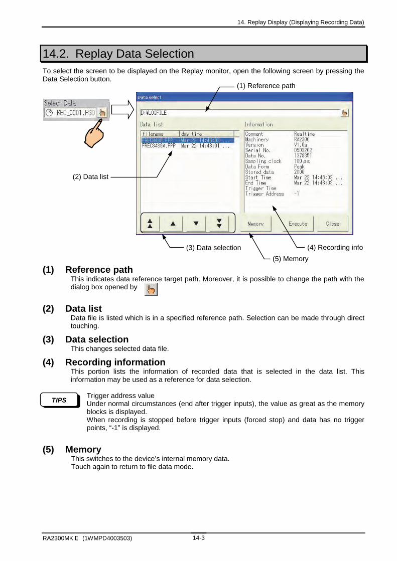
14. Replay Display (Displaying Recording Data)
RA2300MKⅡ (1WMPD4003503) 14-3
14.2. Replay Data Selection To select the screen to be displayed on the Replay monitor, open the following screen by pressing the Data Selection button.
(1) Reference path This indicates data reference target path. Moreover, it is possible to change the path with the dialog box opened by
(2) Data list Data file is listed which is in a specified reference path. Selection can be made through direct touching.
(3) Data selection This changes selected data file.
(4) Recording information This portion lists the information of recorded data that is selected in the data list. This information may be used as a reference for data selection.
Trigger address value Under normal circumstances (end after trigger inputs), the value as great as the memory blocks is displayed. When recording is stopped before trigger inputs (forced stop) and data has no trigger points, “-1” is displayed.
(5) Memory This switches to the device’s internal memory data. Touch again to return to file data mode.
TIPS
(2) Data list
(1) Reference path
(4) Recording info (3) Data selection
(5) Memory

14. Replay Display (Displaying Recording Data)
RA2300MKⅡ (1WMPD4003503) 14-4
14.3. Waveform Display Region The thumbnail that indicates waveform display region is displayed on the Replay Monitor screen and the Y-T waveform.
(1) Waveform Display Region This is the time axis domain currently being displayed.
(2) Cursor position Cursor positions X1 and X2 are indicated.
(3) Thumbnail Full data for a channel is displayed in a compressed form. Also, touching the thumbnail portion can move the display position of the Y-T waveform.
Channel that can be displayed on the thumbnail can be specified. For more information, see Chapter 15. Display and Printing.
(4) Auto scroll The displayed region can be scrolled automatically. By touching a thumbnail display portion, auto-scrolling stops.
14.3.1. Shift of Waveform Display Region To shift the waveform display region, refer to the following methods.
● Operation with thumbnail By touching the thumbnail display portion, the waveform display region can be shifted. The auto-scroll buttons at both sides allow one-direction scrolling.
● Shift through operation panel Press the Scroll button on the operation panel to make scrolling effective. When scrolling becomes usable, the LED of the Scroll button comes on. Turning the job dial shifts the display region.
● Shift through jump function Jump to the trigger detection point or making point is available. Moreover, jump to the maximum or minimum point for each channel is available. For more details, see 14.6 Jump.
14.3.2. Shift of Cursor Position To shift the cursor position, refer to the following methods.
● Shift through operation panel Press the Cursor button on the Operation Panel to make the cursor effective. When the cursor becomes usable, the LED of X1 or X2 of the Cursor button comes on. Turning the jog dial can move the cursor. Smaller-step shift is available using the Fine button on the Operation Panel.
● Shift through screen touch Direct cursor shift is possible by touching the waveform display portion when the cursor shift is effective on the Operation Panel.
TIPS
(4) Auto scroll (4) Auto scroll (2) Cursor position
(1) Waveform display region (3) Thumbnail

14. Replay Display (Displaying Recording Data)
RA2300MKⅡ (1WMPD4003503) 14-5
14.4. Digital Indication Indications for digital values and cursor position information for measurement values can be made.
14.4.1.Digital Indication Switching By pressing the Digital Indication button on the upper part of the Replay monitor, contents of indication can be switched.
The indication changes to No Indication, Digital Value, Cursor Value, Digital Value + Cursor Value, and No Indication, in this order.
Digital indication switching can be set in the Display and Printing screen. For more details, see Chapter 15. Display and Printing.
14.4.2. Digital Indication Measurement values are indicated in digital values. Time-axis position to be displayed changes depending on the LED status.
● X1 LED On Measurement values of the cursor 1 position are indicated while cursor X1 is moving.
● X2 LED On Measurement values for cursor 2 are indicated while cursor X2 is moving.
● Others Measurement values at the top of the waveform display region are displayed during the time excepting when the cursor is moving as well as when waveform display position is moving.
If the recording data is the peak format, one data consists of two values: maximum and minimum value. To specify the digital value in either of maximum and minimum values, open the Display/Printing screen. For more details, see Chapter 15. Display and Printing.
14.4.3. Cursor Display Information This portion indicates the position information of cursors X1 and X2 and the time difference between cursors (T). Time axis display format changes to Duration, Time, and Value in this order, depending on the setting. For more details, see Chapter 19. System Setup.
14.4.4. Replay monitor mark display ON/OFF function This function allows the display of Trigger Detection and Mark Detection lines shown on the replay monitor to be toggled ON/OFF.
This function is available for device version V3.2 or later. For details on version upgrade method and the program, visit our website.
Press the Digital Display button on the top bar to display cursor position information. Check the Mark ON/OFF box above the cursor position information box to toggle the mark display above the waveform monitor ON/OFF.
TIPS
TIPS
TIPS
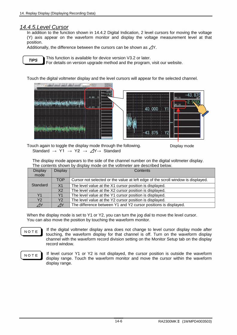
14. Replay Display (Displaying Recording Data)
RA2300MKⅡ (1WMPD4003503) 14-6
14.4.5.Level Cursor In addition to the function shown in 14.4.2 Digital Indication, 2 level cursors for moving the voltage (Y) axis appear on the waveform monitor and display the voltage measurement level at that position. Additionally, the difference between the cursors can be shown as ⊿Y.
This function is available for device version V3.2 or later. For details on version upgrade method and the program, visit our website.
Touch the digital voltmeter display and the level cursors will appear for the selected channel. Touch again to toggle the display mode through the following. Standard → Y1 → Y2 → ⊿Y→ Standard The display mode appears to the side of the channel number on the digital voltmeter display. The contents shown by display mode on the voltmeter are described below.
Display mode
Display Contents
TOP Cursor not selected or the value at left edge of the scroll window is displayed.
X1 The level value at the X1 cursor position is displayed. Standard X2 The level value at the X2 cursor position is displayed.
Y1 Y1 The level value at the Y1 cursor position is displayed. Y2 Y2 The level value at the Y2 cursor position is displayed. ⊿Y ⊿Y The difference between Y1 and Y2 cursor positions is displayed.
When the display mode is set to Y1 or Y2, you can turn the jog dial to move the level cursor. You can also move the position by touching the waveform monitor.
If the digital voltmeter display area does not change to level cursor display mode after touching, the waveform display for that channel is off. Turn on the waveform display channel with the waveform record division setting on the Monitor Setup tab on the display record window.
If level cursor Y1 or Y2 is not displayed, the cursor position is outside the waveform display range. Touch the waveform monitor and move the cursor within the waveform display range.
Display mode
NOTE
NOTE
TIPS
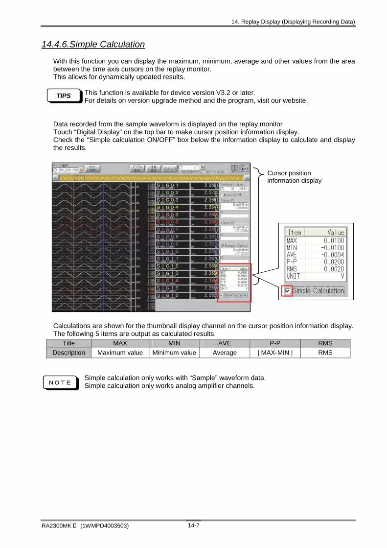
14. Replay Display (Displaying Recording Data)
RA2300MKⅡ (1WMPD4003503) 14-7
14.4.6.Simple Calculation
With this function you can display the maximum, minimum, average and other values from the area between the time axis cursors on the replay monitor. This allows for dynamically updated results.
This function is available for device version V3.2 or later. For details on version upgrade method and the program, visit our website.
Data recorded from the sample waveform is displayed on the replay monitor Touch “Digital Display” on the top bar to make cursor position information display. Check the “Simple calculation ON/OFF” box below the information display to calculate and display the results.
演算対象範囲は時間軸カーソルX1、X2で指定された領域となります。
Calculations are shown for the thumbnail display channel on the cursor position information display. The following 5 items are output as calculated results.
Simple calculation only works with “Sample” waveform data. Simple calculation only works analog amplifier channels.
Title MAX MIN AVE P-P RMS
Description Maximum value Minimum value Average | MAX-MIN | RMS
Cursor position information display
NOTE
TIPS

14. Replay Display (Displaying Recording Data)
RA2300MKⅡ (1WMPD4003503) 14-8
14.5. Signal Settings It is possible to confirm the recording conditions for channel of the signal that are recorded as data and change the setup for waveform display. Press the Signal Setting button on the upper part of the Replay screen. The Setup Screen appears. The contents differ depending on the amp type.
Operations of Signal Setup screen are the same as those of the Amp screen. For more details, see Chapter 7. Amp Units
TIPS
Analog amp setup screen ・ Waveform ON/OFF setting ・ Zero position setting ・ Physical unit conversion setting ・ Other recording condition
display
Event amp setup screen ・ Waveform ON/OFF setting ・ ON/OFF setting by signal ・ Event waveform adjustment ・ Signal type display
Event amp setup screen ・ Waveform ON/OFF setting ・ ON/OFF setting by signal ・ Event waveform adjustment

14. Replay Display (Displaying Recording Data)
RA2300MKⅡ (1WMPD4003503) 14-9
14.6. Jump Jump of Y-T waveform display position can be made after the time axis position is specified. Pressing the Jump button on the upper part of the Replay screen displays the following screen.
14.6.1Basic Jump 14.6.2Time Jump
14.6.1. Basic Jump Basic jump operation is made.
Start point: Jump to recording data start point End point: Jump to the end point of the recording data Trigger detection point: Jump to the trigger detection point for recording data
If there is no trigger detection point, jump is made to the start point. Cursor X1/X2: Jump to current cursor position
14.6.2. Time Jump Jump is made after the waveform display position is specified. Specify the time using the Time tab on the Jump screen. Pressing the Apply and Execute keys executes a jump.
When the Apply button is pressed, the Jump screen does not close even after the jump execution. To execute jump continuously, this button is usable. If the recording speed of the recording data is external sync, time jump cannot be made because the time axis cannot represent as time. Use [14.6.3Address Jump]
14.6.3. Address Jump Jump can be made after waveform position is designated in address. Open the Address tab on the Jump screen, and then specify the address. Press the Apply and Execute keys to execute a jump.
TIPS
NOTE

14. Replay Display (Displaying Recording Data)
RA2300MKⅡ (1WMPD4003503) 14-10
14.6.4. Maximum/Minimum Search & Jump Searching for maximum and minimum values for all analog channels is available. Jump to the searched position is possible after listing the result. Operation steps for the maximum and minimum values search are as follows.
(1) Use the Significant Point tab on the jump screen.
(2) Specify the search range. Choose Full range or Between Cursors. Pressing a button begins searching, and after the search, a list appears.
(3) Select a channel Select a target channel. Selection can be made through a direct touch of listed portion.
(4) Jump to maximum value or minimum value is made. Pressing a button executes a jump.
(1)
(2)
(3) (4)

14. Replay Display (Displaying Recording Data)
RA2300MKⅡ (1WMPD4003503) 14-11
14.6.5. Event Jump Marking information that is recorded in the recorded data is searched and jump is made.
(1) The Event tab on the Jump screen is displayed.
(2) Marking jump is executed when a search direction button is pressed.
The event jump needs the data which includes E2. To include E2 in the recording data, the following setting is necessary. ・System- Recording Setup- Recording Channels: E2 ON ・Amp Basics Screen : E2 ON
Marking jump is a jump to the mark address that is closest to the direction that is specified by jump target address (Waveform, x1, x2). Also, a trigger mark is regarded as a mark. If the mark is not found, jump to the start/end point is made.
(3) Jump to link data is made. When this button is pressed after the making jump is made while the data file (extension of FPD) recorded in the Multi Recorder mode is displayed, a jump to the link data (memory recording data) is made.
14.7. Time Axis Magnification To enlarge or compress the time axis, press [Time Axis] button. The screen to the right appears.
Press the Close button. After the screen is closed, the selected time axis scaling factor will be effective.
The scaling factor can be changed while monitoring the waveform without opening the screen shown above through the following steps. 1) Press the left side of the time axis scaling button, and then make jog dial change
effective. Scaling factor will be highlighted. 2) Change the value by turning the jog dial.
Time axis for waveform display will be enlarged or compressed according to the scaling factor.
NOTE
(3)
(1)
(2) (2)
TIPS
NOTE

14. Replay Display (Displaying Recording Data)
RA2300MKⅡ (1WMPD4003503) 14-12
14.8. Output Setup Displayed data can be printed out or exported into a file. To execute data output, press the Output Setup button on the upper part of the Replay screen. Then the following screen opens.
14.8.1. Specifying Output Time Range Use the (1) button to specify the data output time-axis range. Select from among “Between cursors” or “Specifying in percentage in reference to the trigger point” If “Specifying in percentage in reference to the trigger point” is selected, specify percentage.
To output all, select “Specifying in percentage in reference to the trigger point” and choose 100 for percentage.
14.8.2. Specifying File Save Format Use the (2) button to specify the format at file save. Select binary or CSV. If CSV is selected, the number of skip and delimiter can be specified. In addition, by selecting (8) “With header”, header information such as amp setting can be saved.
The file extension that is output in the binary format will be DRT. The binary save file can be referenced in the Replay screen. The file extension that is output in the CSV format will be CSV. The CSV save file cannot be referenced in the Replay screen.
14.8.3. Specifying CSV Delimiter Use the (3) button to specify the delimiter upon the CSV save. Select comma or tab.
TIPS
NOTE
NOTE
(1)
(6) (7)
(4)
(3)
(8)
(2)
(5)

14. Replay Display (Displaying Recording Data)
RA2300MKⅡ (1WMPD4003503) 14-13
14.8.4. Specifying Number of Skip in CSV Use the (4) button to specify the number of skip in CSV save.
Data will be rough when skipping is specified, but it is possible to make file size small.
14.8.5. Specifying File Save Destination Use the (5) button to specify the file save destination.
The output file extension will be fixed. (Binary save = DRT, CSV save = CSV)
14.8.6. Execution of Data Output Output to chart paper is made with the (6) button. File save is made with the (7) button.
Output can be stopped with the Stop button on the Operation Panel. If the file save operation is terminated, the file being saved will be discarded.
During the data output, the other operations do not start. Do not disconnect the connection to a drive during file save.
To output two or more data correctively, use the File Operation in the System screen. For more details, see Chapter 19. System Setup.
14.9.Copy Press the copy key to output the contents configured in “Output Setup” to recording paper.
The same copy output can be used many times without changes to the configurations in “Output Setup”.
TIPS
TIPS
TIPS
NOTE
TIPS
TIPS

14. Replay Display (Displaying Recording Data)
RA2300MKⅡ (1WMPD4003503) 14-14
14.10. X-Y Waveform Display To display replay data in the X-Y graph, press the X-Y icon on the top of the screen. If the recorded data is the Sample format, X-Y display is made; if the data is the Peak format, X-Y display is not made.
(1) Data selection This portion displays the data file name whose data is being displayed. Pressing this button selects the data file to be referenced. The operations are the same as those for Y-T waveform display. For more details, see 14.2 Replay Data Selection.
The X-Y display is available only in the Sample format data. Choose the Sample format data, accordingly.
(2) X-Y Waveform Printout The X-Y waveform being displayed will be output to the chart printing paper. Operations during outputting are disabled but forcible stop can be made with the Stop button on the Operation Panel.
(3) Signal setting Signal setting information is displayed. The zero position and physical unit conversion settings are available.
(4) Switching to Y-T waveform display Display is returned to the Y-T waveform display.
(5) Specifying X-Y axis channel Specification of the X-Y axis channel is made.
NOTE
(1) (2) (3) (4)
(5)

14. Replay Display (Displaying Recording Data)
RA2300MKⅡ (1WMPD4003503) 14-15
14.11.Other Display Function
14.11.1.Automatic replay with HD recorder data display settings When replaying data stored in HD recorder mode, you can display waveforms with the same waveform division and other settings used when the data was recorded.
For details, refer to “19.5.8. Automatic Reproduction of Display Settings of Data Recorded by HDD Recorder”.
This function is available for device version V3.2 or later. For details on version upgrade method and the program, visit our website.
TIPS


15. Display and Printing Settings for Monitor Display
and Printing

15. Display and Printing (Settings for Monitor Display and Printing)
RA2300MK2 (1WMPD4003503) 15-2
15.1. Settings for Display and Printing Display and Printing is used to set X-Y display of waveforms or printing format for waveform. Pressing the Display and Printing button on the Operation Panel opens the screen for settings.
15.1.1. Scale Indication The Y axis appears beside the waveform monitor when check mark is added to the check box (1) on the Display and Printing screen. Channel whose scale is displayed can be specified with the channel buttons (2) on the Display and Printing screen.
Only one row is used for scale indication. If there are two or more channels on one waveform recording frame, only the first channel’s scale will be indicated. To display the next channel, turn off the channel display for the first channel.
15.1.2. Grid Display Pressing the button (5) on the Display and Printing screen turns on or off the grid indication.
15.1.3. Digital Value Display To indicate digital values of each channel, tick the check box for (3) on the Display and Print screen. Also, when Peak-format data is referenced in the Replay monitor, it is possible to set whether maximum or minimum value should be displayed or not using button (4).
Note
(1)
(2)
(3)
(6)
(7)
(4)
(10)
(9)
(8)
(11)
(5)
(NOTE) This part is displayed only when the replay monitor is selected.
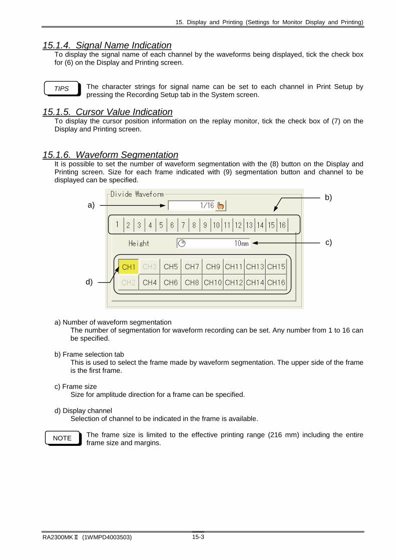
15. Display and Printing (Settings for Monitor Display and Printing)
RA2300MKⅡ (1WMPD4003503) 15-3
15.1.4. Signal Name Indication To display the signal name of each channel by the waveforms being displayed, tick the check box for (6) on the Display and Printing screen.
The character strings for signal name can be set to each channel in Print Setup by pressing the Recording Setup tab in the System screen.
15.1.5. Cursor Value Indication To display the cursor position information on the replay monitor, tick the check box of (7) on the Display and Printing screen.
15.1.6. Waveform Segmentation It is possible to set the number of waveform segmentation with the (8) button on the Display and Printing screen. Size for each frame indicated with (9) segmentation button and channel to be displayed can be specified.
a) Number of waveform segmentation
The number of segmentation for waveform recording can be set. Any number from 1 to 16 can be specified.
b) Frame selection tab
This is used to select the frame made by waveform segmentation. The upper side of the frame is the first frame.
c) Frame size
Size for amplitude direction for a frame can be specified. d) Display channel
Selection of channel to be indicated in the frame is available.
The frame size is limited to the effective printing range (216 mm) including the entire frame size and margins.
TIPS
NOTE
a)
d)
c)
b)

15. Display and Printing (Settings for Monitor Display and Printing)
RA2300MK2 (1WMPD4003503) 15-4
15.1.7. Thumbnail (Displayed on the replay monitor screen only) Channel selection of the thumbnail to be displayed on the Replay monitor is made using the channel button in (10) on the Display and Printing screen. Pressing the Thumbnail Save button in (11) executes the save of the created thumbnail. The thumbnail display can be made quickly in the next time.
Select analog channels. If other channels, which are invalid, are selected, thumbnail waveform display cannot be made. The setting part of the thumbnail is displayed only with the replay monitor.
[Apply] : The contents changed on the setting screen are reflected on the monitor. When you close the setting screen, the contents are not retained. (To keep, press [execute]) [Execute] : Maintains the changed settings on the setting screen. [Close] : Close the setting screen.
NOTE
NOTE

16. Interval statistical calculation

16. Interval statistical calculation
RA2300MKⅡ(1WMPD4003503) 16-2
16.1. Interval statistical calculation function The statistical calculations are used for applying statistical operations and processing for each channel data recorded in the memory. The interval statistical calculation involves functions to calculate the maximum, minimum, and average values of the data recorded in the memory for desired interval as specified. The interval statistical operation can be performed during the memory mode under the measurement.
16.2. Operation procedure of interval statistical calculation Operation procedure is explained for interval statistical calculation.
16.2.1. Data selection to be calculated First press the [REPLAY] button on the display in order to display recorded data to be calculated. Select the data area to be calculated by using [Select Data] on the upper left corner of the display.
For details on data selection, refer to "14.2. Replay Data Selection".
16.2.2. Setting of interval statistical calculation Press the [Diplay/Printing] button on the display to display the diagram below indicates 1) Calculation channel setting
Channel to be calculated are set.
If there is no data or amplifier on specified channel, calculated result is unable to be display.
NOTE
1) Channel
2) Calculation

16. Interval statistical calculation
RA2300MKⅡ(1WMPD4003503) 16-3
2) Calculation content setting
Calculation contents are specified. Area calculation method is selected from among the following three methods.
Calculating the area by using absolute values of measurement data. Calculating the area by using positive values of measurement data. Calculating the area by using negative values of measurement data.
Standard deviation calculation method is selected from among the following two methods.
Calculating the standard deviation with N as denominator Calculating the standard deviation with N-1 as denominator
16.2.3. Executing interval statistical calculation In order to conduct and execute interval statistical calculation, press the [Output Setting] button on the upper left corner of the display to display the diagram below indicates. 1) Time axis span setting
Time axis span is set to conduct and execute interval statistical calculation.
For details on specifying the time axis range, see "14.8.1. Specifying Output Time Range".
2) Calculation executing Press the [Execute Statistics] button to conduct and execute interval statistical calculation, and display the calculated results, as show in below.
1) TIME AXIS SPAN
2) EXECUTION

16. Interval statistical calculation
RA2300MKⅡ(1WMPD4003503) 16-4
Specified range
Maximum value
16.2.4. CSV saving of interval statistical calculation To save calculated results as CSV format, press the [CSV save] on the lower right corner of the display.
The settings relating to file save destination and CSV file are the same as CSV save of recorded data. For details, refer to "14.8. Output Setup".
16.3. Types of interval statistical calculation Overviews are given below, for the arithmetic types of interval statistical calculations.
16.3.1. Maximum value (MAX) The maximum value is shown within the specified data range
16.3.2. Minimum value (MIN) The minimum value is shown within the specified data range.
16.3.3. Peak-to-peak value (P-P) The difference is computed between the maximum and minimum value.
Equation: P-P=I Maximum value-Minimum value I
16.3.4. Average value (Average) The mean value is computed within the specified data range
D: Sample data in the specified range Equation: n: number of data
16.3.5. Area (AREA) The area, surrounded by the measured waveform and the base-line within the specified range, is computed. Area calculation method is selected from among the following three methods.
(1) Area (All) The area is computed by using absolute values of measurement data. Equation: D: Sample data within the specified range
(2) Area (positive) The area is computed area by using positive values of measurement data. Equation: D: Sample data within the specified range
(3) Area (negative) The area is computed area by using negative values of measurement data. Equation: D: Sample data within the specified range
Dn
1AVE
DAREA
)D(AREA
D-AREA
A
B
Specified range
Base-line
Minimum value
Specified range
P-P
Maximum value
Minimum value
Specified range

16. Interval statistical calculation
RA2300MKⅡ(1WMPD4003503) 16-5
16.3.6. Root-mean-square value (RMS) The root-mean-square value is computed for specified data range.
D: Sample data within the specified range Equation: n: number of data
16.3.7. Standard deviation (STD) The standard deviation is computed for the specified data Set the standard deviation parameter to select “n” or “n-1” for the denominator.
1) N: The standard deviation is calculated with parameter on 1/n for the data within the specified range. Equation: D: Sample data within the specified range n: number of data
2) N-1: The standard deviation is calculated with parameter on 1/(n-1) for the data within the specified range. Equation: D: Sample data within the specified range n: number of data
16.3.8. Rising or falling time (Rise/Fall) The rising time or falling time is calculated as follows. Both maximum and minimum values are found within the specified data range, and then the medium level between the maximum and minimum values is defined. Both the rising and falling time are calculated by using 90%and 10% values of absolute value of difference between the maximum and minimum values, as shown in bellows. The calculation results are indicated in terms of the number of sample data. The results are also converted into the time expression by the multiplication of the calculation result and sampling speed.
n
DD
n
1SD
2
2
Maximum value
10%
Medium level (50%)
90%
Falling time
Specified range
Minimum value
Minimum value
Rising time
Specified range
Maximum value 90%
Medium level (50%)
10%
n
DRMS
2
1n
DD
1n
1SD
2
2


17. Function calculation
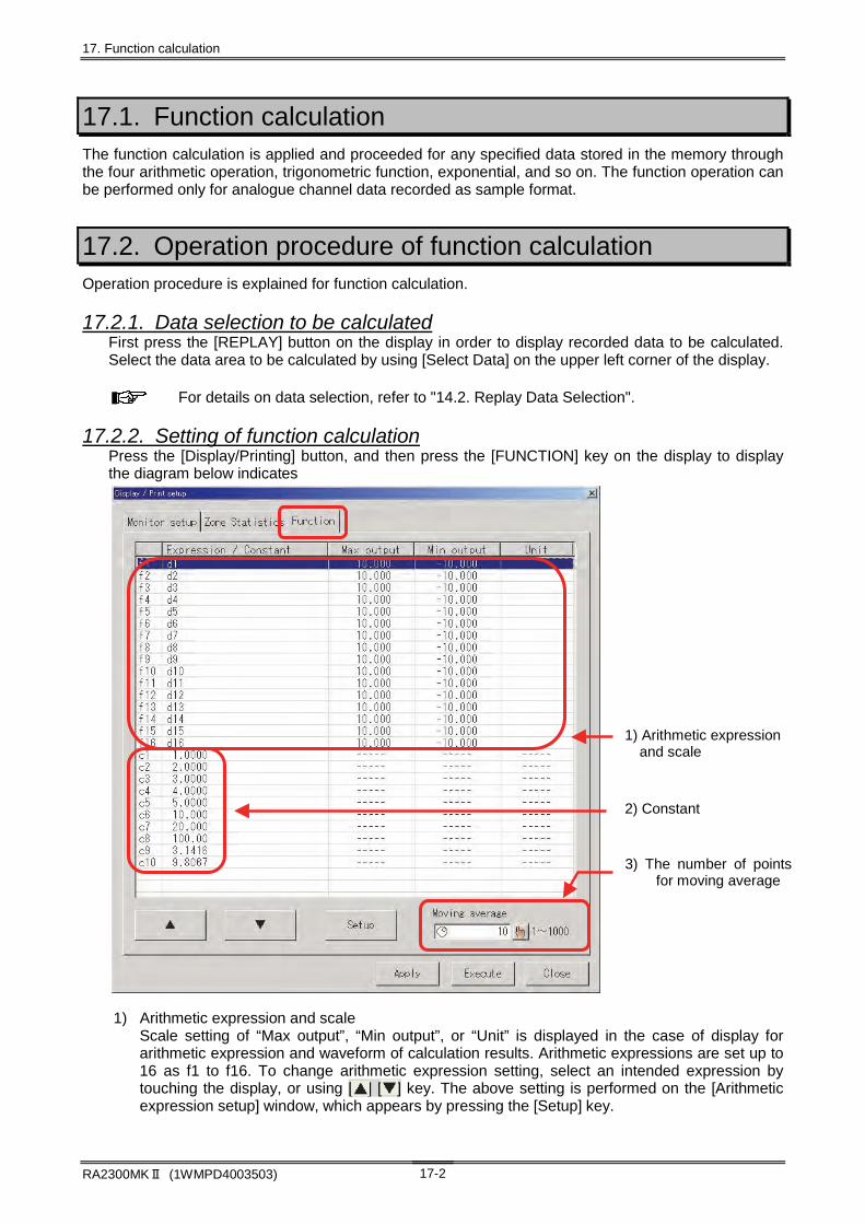
17. Function calculation
RA2300MKⅡ (1WMPD4003503) 17-2
17.1. Function calculation The function calculation is applied and proceeded for any specified data stored in the memory through the four arithmetic operation, trigonometric function, exponential, and so on. The function operation can be performed only for analogue channel data recorded as sample format.
17.2. Operation procedure of function calculation Operation procedure is explained for function calculation.
17.2.1. Data selection to be calculated First press the [REPLAY] button on the display in order to display recorded data to be calculated. Select the data area to be calculated by using [Select Data] on the upper left corner of the display.
For details on data selection, refer to "14.2. Replay Data Selection".
17.2.2. Setting of function calculation Press the [Display/Printing] button, and then press the [FUNCTION] key on the display to display the diagram below indicates 1) Arithmetic expression and scale
Scale setting of “Max output”, “Min output”, or “Unit” is displayed in the case of display for arithmetic expression and waveform of calculation results. Arithmetic expressions are set up to 16 as f1 to f16. To change arithmetic expression setting, select an intended expression by touching the display, or using [ ] [ ] key. The above setting is performed on the [Arithmetic expression setup] window, which appears by pressing the [Setup] key.
1) Arithmetic expression and scale
2) Constant
3) The number of pointsfor moving average

17. Function calculation
RA2300MKⅡ (1WMPD4003503) 17-3
2) Constant
Constant, which is used in the arithmetic expression, is displayed. Constants are set up to 10 as c1 to c10. To change constant setting, select a intended number by touching the display, or using [ ] [ ] key. The above setting is performed on the [Entry of constant] window, which appears by pressing the [Setup] key.
3) The number of points for moving average The number of points is displayed when the moving average is specified as arithmetic expression. To change moving average point setting, select an intended point by using jog-dial or [ ] key.
17.2.3. Arithmetic expression setup To set arithmetic expression, press the [FUNCTION] tab key, and then press the [Setup] button on the [Arithmetic expression setup] window to display the diagram below indicates. 1) Arithmetic expression and editing window
This is a window for current arithmetic expression and its edition.
2) Explanation Number of input arithmetic expressions and explanation for the input expressions are shown in this window. In addition, If there is any error in registered arithmetic expression, the details of error are shown in this window.
The total number of numerical values and operators used in one expression is up to 32.
3) Input key for parenthesis and four arithmetic operators Both parenthesis and four arithmetic operators are input into the arithmetic expression by using these keys.
1) Arithmetic expression and editing window
2) Explanation
3) Input key for parenthesis and four arithmetic operators
4) Function input key (tab key switching)
5) Scale setting
6) Arithmetic expression switching key
NOTE

17. Function calculation
RA2300MKⅡ (1WMPD4003503) 17-4
4) Function input key (tab key switching)
This is a function input key. Function is changed by switching the tab key.
D
I
F
,
D
First differential, second differential, single integral, and double integral must be used in the first term in the arithmetic expression. In addition, only one of the above four functions is applied to the arithmetic expression Only former calculated results are input into the current expression. For example, if the current expression is fn, f1 to fn-1 can be input into fn If measured data of d1 to d16 is used in the arithmetic expression, the following data is inapplicable to the expression. 1) Data recorded on the channel in which input setting is off 2) Data recorded on the channel in which event amplifier is set. 3) Data recorded on the channel in which input unit is unset.
Measured data is calculated based on scale preset on Amp Screen window. For example, if desired user scale is applied, calculation is performed based on the user scale.
Measured data is calculated with conforming physical quantity unit; voltage is V, frequency is Hz, strain is us, acceleration is m/s2 or G.
Example: CH1 range: 1V CH2 range: 500mV, arithmetic expression f1=d1+d2 If measured data on CH1 is 0.2V, and measured data on CH2 is 100mV, calculated value F1 is 0.300V (0.2+0.1).
5) Scale setting Maximum scale, minimum scale and unit are set for waveform output of calculated result. Each item is set by pressing [ ] key. 6) Arithmetic expression switching key Current compilation is registered by using [ ] [ ] key on the bottom of the display, and you can select next or former equation in a same way.
TAB KEY DESCRIPTION
Function Functions are input into arithmetic expression.
Measured data Each channel data is input into arithmetic expression as d1 to d16
Calculation result Calculated results are input into arithmetic expression as f1 to f15. If expression is fn, f1 to fn-1 can be input into fn.
Constant Constant is input into arithmetic expression.
NOTE
NOTE
NOTE
NOTE

17. Function calculation
RA2300MKⅡ (1WMPD4003503) 17-5
17.2.4. Execution of function calculation Press the [Output Setting] key on the upper left corner of the replay monitoring display to execute function calculation and display the following window. 1) Setting of time range
Time axis range is set in the window to execute function calculation. For details on specifying the time axis range, see "14.8.1. Specifying Output Time Range".
2) Execution of function calculation Press the [Execute Function] key to execute function calculation, output the calculated result as binary file, and display the result. Output destination is as follows, depending on data forms.
File data: Calculated result is output as “Path name of the former data file + file
extension of CLC” Memory data: Calculated result is output as “Path name of memory backup file + file
extension of CLC”
Check that available memory capacity for the output destination is enough before execution of function calculation, File size of calculated result is depend on number of arithmetic expression and data volume. If function calculation is performed for whole data, the file size of the calculated result is about 2 times of the former data file size. File size of calculated result = Number of expression x Data volume x 4 + 4096 (Byte)
17.2.5. Output of function calculation result Function calculation results can be selected as data file. In addition, they are converted into binary or CSV file. They are also recorded on the recording chart.
For details, refer to "14.8. Output Setup".
1) Setting of time range
2) Execution of function calculation
NOTE
17. Function calculation
RA2300MKⅡ (1WMPD4003503) 17-6
17.3. Function calculation item Outline of function calculation items is described. The arithmetic expression consists of function, valuable number, and fixed number as follows.
Example: f1 = SIN (d1) * c1
f1: Arithmetic expression Function SIN: Function
d1: Valuable number, c1: Fixed number
17.3.1. Arithmetic expression Arithmetic expressions are set up to 16 as f1 to f16. One arithmetic expression contains up to 32 items of function, valuable number, and fixed number. The expression fn contains the expressions from f1 to f (n-1). However, the expression fn dose not involve f (n+1).
17.3.2. Function The following functions are used and set in this program.
1) The four rules of arithmetic ( * , / , + , - )
2) Absolute value (ABS)
3) Square root (SQRT) Data to be calculated must be positive. If negative value is entered it will be treated as zero.
4) Second power (POW2)
5) Exponential (EXP) The range of value to be entered is from +38.0 to –45.0. Any value beyond the range entered will be interpreted as +38 or –45.
6) Common logarithmic (LOG) Data to be calculated must be positive. If zero is entered, the calculated result will be available maximum negative value of -3.4E38. In addition, if negative value is entered, the result is zero.
7) First differential (DIF)
8) Second differential (DDIF) Calculation of first and second differentials uses Lagrange’s interpolation formula of the fifth order, where value of an interesting point is estimated from ten point values on both sides of the interesting point. Designating measured values of n sample points, t0,t1,t2…,tn to be y0,y1,y2,…,yn, respectively, the arithmetic expressions for the first differential are given as follows:
t0 Y0 = 43210 y3y16y36y48y25h12
1
t1 Y1 = 43210 yy6y18y10y3h12
1

17. Function calculation
RA2300MKⅡ (1WMPD4003503) 17-7
t2 Y2 = 4310 yy8y8yh12
1
t i YI = 2i1i1i2i yy8y8yh12
1
tn-2 Yn-2 = n1n3n4n yy8y8yh12
1
tn-1 Yn-1 = n1n2n3n4n y3y10y18y6yh12
1
tn Yn = n1n2n3n4n y25y48y36y16y3h12
1
Where y is data of calculated result, and h is sampling time. The arithmetic expressions for the first differential are given as follows:
t0 Y0 = 432102y11y56y114y104y35
h12
1
t1 Y1 = 432102yy4y6y20y11
h12
1
t2 Y2 = 432102yy16y30y16y
h12
1
t i YI = 2i1ii1i2i2yy16y30y16y
h12
1
tn-2 Yn-2 = n1n2n3n4n2yy16y30y16y
h12
1
tn-1 Yn-1 = n1n2n3n4n2y11y20y6y4y
h12
1
tn Yn = n1n2n14n2y35y104y114y56y11
h12
1
Where y is data of calculated result, and h is sampling time.
9) Single integral (INT)
10) Double integral (DINT) Calculation of both single and double integrals uses the trapezoidal rule. The arithmetic expression for the single integral is given as follows.
Point t0 I0 = 0 Point t1 I1 = 1/2(d0+d1)*h Point t2 I2 = 1/2(d0+d1)*h + 1/2(d1+d2)*h = I1 + 1/2(d1+d2)*h Point tn In = In-1 + 1/2(dn-1 + dn)*h
where I0,I1…In are data of calculated result, and h is sampling time. The arithmetic expression for the double integral is given as follows.
Point t0 II0 = 0 Point t1 II1 = 1/2(I0+I1)*h Point t2 II2 = 1/2(I0+I1)*h = 1/2(I1+I2)*h = II1 + 1/2(d1+d2)*h Point tn II n = IIn-1 + 1/2(In-1 + In)*h
where II0, II1…II n are data of calculated result, and h is sampling time.
… …
…
…
… …
… …
… …

17. Function calculation
RA2300MKⅡ (1WMPD4003503) 17-8
11) Trigonometric function (SIN,COS,TAN, ASIN,ACOS,ATAN) Parameters for SIN,COS and TAN are entered in the unit of radian. In the case of both ASIN and ACOS, if an entered value is more than 1 (>1), the value is treated as 1. If an entered value is less than -1 (<-1), the value is treated as -1.
12) Moving average (MEAN) The number of the points for the moving average can be set at any integer within 1 to 1000. If sample point is less than the number of the points N, the arithmetic expression is If sample points are more than the number of the points N, the arithmetic expression is
First differential, second differential, single integral, double integral, and moving average must be used in the first term in the arithmetic expression. In addition, only one of the above five functions is applied to the arithmetic expression. If function calculation, such as first differential, second differential, single integral, double integral, is performed for recorded data by using external synchronized clock, sampling time is always used as 1 sec for calculation.
17.3.3. Measured data Measured data of each channel is set as variable of d1 to d16, where dn is measured data for channel n.
17.3.4. Constant Ten constants are set as c1 to c10. The range of the fixed value is –9.9999E+12 to 9.9999E+12.
NOTE
NOTE
iDiT
T
/0
NDiT
NiT
/
17. Function calculation
RA2300MKⅡ (1WMPD4003503) 17-9
17.4. Output for incorrect calculation When incorrect calculation, such as restriction of function itself, and impossible calculation in principle, is carried out, following results are output.
17.4.1. Zero division Zero division gives following results. For f1=d1/d2, and d2=0, the calculated result is dependent upon the value of d2.
If d1 is positive value, f1 is +3.4000E+38 If d1 is negative value, f1 is -3.4000E+38. If d1 is 0, f1 is 0.
17.4.2. Square root of negative value Square root of negative value fives the calculated value of 0.0.
17.4.3. Overflow for exponential calculation Overflow for exponential calculation is presented as follows. For f1=EXP(d1),
d1 is more than 38.0, f1 is 10E+38. d1 is less than -45.0, f1 is 10E-45.
17.4.4. Common logarithmic of zero or negative value Common logarithmic of zero or negative value gives following results. For f1=LOG(d1),
if d1 is 0, f1 is –3.4000E+38. if d1 is negative value, f1 is 0.0000.
17.4.5. ASIN and ACOS for the value of >1 or <-1 Both ASIN and ACOS for the value of >1 or <-1 gives following results. For f1=ASIN(d1) and f2=ACOS(d1),
if d1is less than -1, f1 is ASIN(-1), and f2 is ACOS(-1) if d1 is more than 1, f1 is ASIN(1), and f2 is ACOS(1).
17.4.6. Differential and integral for recorded data by using external synchronized clock
If function calculation, such as first differential, second differential, single integral, double integrals, is performed for recorded data by using external synchronized clock, sampling time is always used as 1 sec for calculation.


18. FFT analysis

18. FFT analysis
RA2300MKⅡ (1WMPD4003503) 18-2
18.1. FFT functions The FFT functions are used for spectrum analysis of recorded data in both memory recorder and HDD recorder modes FFT. The functions, involve those of time axis waveform, linear spectrum, RMS (Root mean square) spectrum, power spectrum, power spectrum density, transfer function, cross power spectrum, coherence function, and octave analysis. FFT analysis is applied only to the data recorder in sample format. Therefore, the FFT analysis is inapplicable the data in both peak format and recorded data by using external synchronized clock.
18.2. Operation procedure of FFT analysis Operation procedure is explained for FFT analysis.
18.2.1. Data selection to be analyzed First press the [REPLAY] button on the display in order to display recorded data to be calculated. Select the data area to be calculated by using [Select Data] on the upper left corner of the display.
For details on data selection, refer to "14.2. Replay Data Selection".
18.2.2. Display of FFT monitor Operation procedure is explained for FFT monitor. In order to display FFT monitor, first press the [REPLAY] button on the display. Press the [ ] key on the upper right corner of the display, the window appears as shown in below Press the [ ] key on the upper right corner of the FFT monitor, normal Y-T monitor appears on the display.
If the peak data or the data recorded by using external synchronized clock, to which FFT analysis is inapplicable, is selected, the [ ] key is not automatically valid.
Replay monitor
FFT monitor
NOTE

18. FFT analysis
RA2300MKⅡ (1WMPD4003503) 18-3
18.2.3. Change of FFT analysis data The [Select Data] key on the upper right corner of the FFT monitor is used to change recorded data to be FFT-analyzed. FFT analysis is applicable only to the data recorded in the sample format. Information about selected data to be analyzed is shown in the [INFORMATION] window on the bottom left of the FFT monitor.
For details on data selection, refer to "14.2. Replay Data Selection".
18.2.4. Starting point of FFT analysis The FFT analysis area is shown as the thumbnail image on the upper side of the FFT monitor. The starting point is designated by using red cursor1 on the Y-T DISPLAY, and it is also set by touching thumbnail image. Ending point is primarily determined, depending on both data length and averaging number. The white window shows the FFT analysis proceeding. The FFT analysis has already completed in the area from the red cursor to the left edge of the white window, while it is just getting underway in the white window.
18.2.5. Setting of FFT analysis data length FFT data length is set by using the [DATA LENGTH] key on the lower right corner of the FFT monitor. In order to show the FFT data length setup window, press the [ ] key, and the analyzed data length is set.
Value set for data length means number of data on time axis. The frequency resolution for FFT analysis is also shown.
18.2.6. Setting of FFT average FFT average is set by using the [Averaging] key on the bottom center of the FFT monitor.
1) On/Off of average processing The average processing is switched by checking this box.
2) Setting of addition method The addition method is specified in the window of addition method setting by pressing the [ ] key.
3) Exponential weighted mean constant The exponential weighted mean constant is set in the window of exponential weighted mean constant setting by pressing the [ ] key. The exponential weighted mean constant is available only when the frequency axis exponential weighted average is specified as the addition method.
4) Number of addition processing The number of addition processing is set in the window of addition number setting by using ten-key by pressing the [ ] key.
1) On/Off of average processing
2) Setting of addition method
3) Exponential weighted mean constant
4) Number of addition processing
Starting point (Red cursor) )
End point (Blue cursor)
FFT analysis area(White window)
NOTE
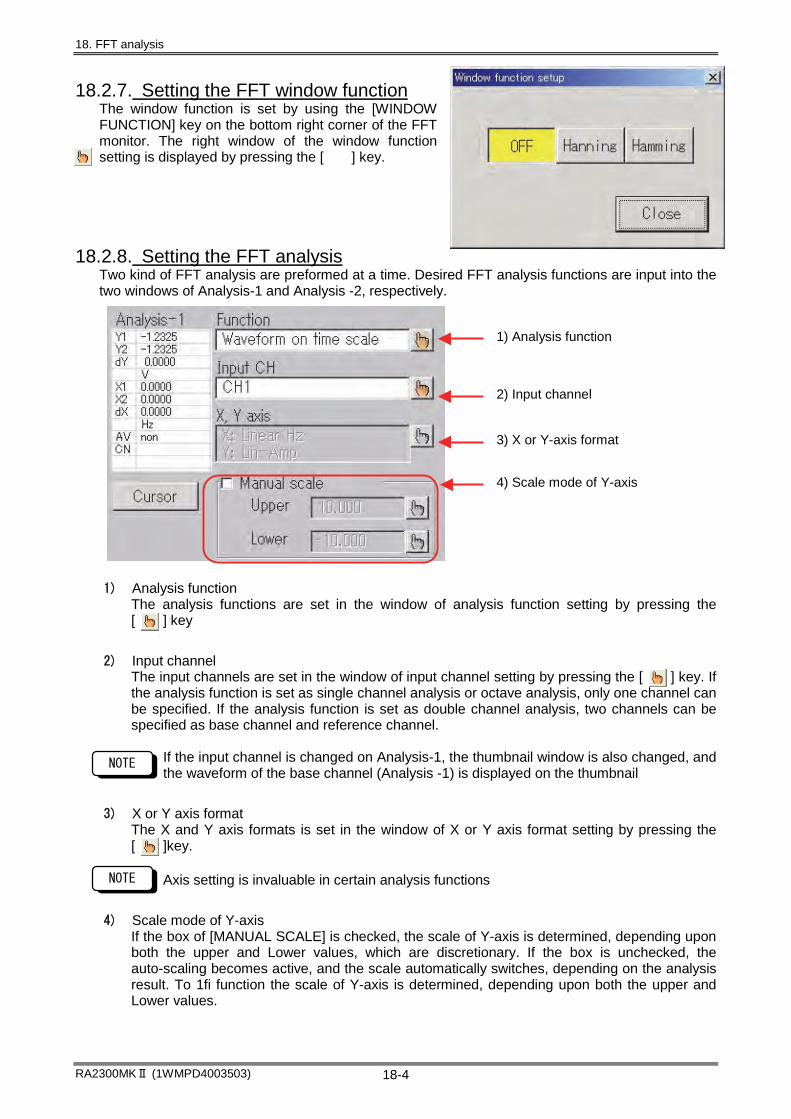
18. FFT analysis
RA2300MKⅡ (1WMPD4003503) 18-4
18.2.7. Setting the FFT window function The window function is set by using the [WINDOW FUNCTION] key on the bottom right corner of the FFT monitor. The right window of the window function setting is displayed by pressing the [ ] key.
18.2.8. Setting the FFT analysis Two kind of FFT analysis are preformed at a time. Desired FFT analysis functions are input into the two windows of Analysis-1 and Analysis -2, respectively.
1) Analysis function The analysis functions are set in the window of analysis function setting by pressing the [ ] key
2) Input channel The input channels are set in the window of input channel setting by pressing the [ ] key. If the analysis function is set as single channel analysis or octave analysis, only one channel can be specified. If the analysis function is set as double channel analysis, two channels can be specified as base channel and reference channel.
If the input channel is changed on Analysis-1, the thumbnail window is also changed, and the waveform of the base channel (Analysis -1) is displayed on the thumbnail
3) X or Y axis format The X and Y axis formats is set in the window of X or Y axis format setting by pressing the [ ]key.
Axis setting is invaluable in certain analysis functions
4) Scale mode of Y-axis If the box of [MANUAL SCALE] is checked, the scale of Y-axis is determined, depending upon both the upper and Lower values, which are discretionary. If the box is unchecked, the auto-scaling becomes active, and the scale automatically switches, depending on the analysis result. To 1fi function the scale of Y-axis is determined, depending upon both the upper and Lower values.
3) X or Y-axis format
4) Scale mode of Y-axis
2) Input channel
1) Analysis function
NOTE
NOTE

18. FFT analysis
RA2300MKⅡ (1WMPD4003503) 18-5
18.2.9. Display of FFT analysis results When input of FFT analysis condition is completed, FFT analysis starts, its results are shown in the display. The result is gray during analysis. After the analysis is finished, it changes from gray to the same color with one of the data waveform shown in the display.
18.2.10. Cursor operation FFT analysis result and frequency value are read by using both cursors X1 and X2, and they are shown in the window of cursor data.
1) Window of cursor data The FFT analysis results are shown for both cursors X1 and X2. The display color of the analysis result during cursor movement is a reverse of one for the cursor X1 and X2. AV means average function as shown below, and CN means number of average.
Sum (TIME): Time axis averaging process is applied to the display of analysis results. Sum (FRQ): Frequency averaging process is applied to the display of analysis results. Exp (FRQ): Frequency exponential weighted mean process is applied to the display of
analysis results. Peak (FRQ): Peak-hold process is applied to the display of analysis results.
2) Cursor change Cursor is changed by pressing the [CURSOR] key.
3) Cursor X1(Red cursor) and Cursor X2(Blue cursor) Cursor movement is performed by using jog-dial or direct touching on waveform monitor.
18.2.11. Magnification of X-axis The X-axis area surrounded by the cursors X1 and X2 is magnified by pressing the [ZOOM] key on the FFT monitor.
[Zoom] : The X-axis area surrounded by the cursors X1 and X2 is magnified [Prev] : Pressing the [Prev] key goes back to the previous screen before pressing the [Zoom] key. [ALL]: Pressing the [ALL] key goes back to the initial screen with whole X-axis area.
3) Cursor X1(Red cursor)
Cursor X2(Blue cursor)
2) Cursor change
1) Window of cursor data
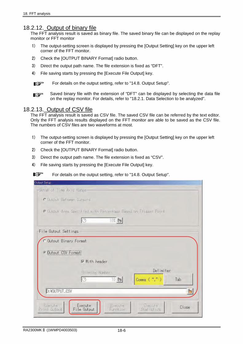
18. FFT analysis
RA2300MKⅡ (1WMPD4003503) 18-6
18.2.12. Output of binary file The FFT analysis result is saved as binary file. The saved binary file can be displayed on the replay monitor or FFT monitor
1) The output-setting screen is displayed by pressing the [Output Setting] key on the upper left corner of the FFT monitor.
2) Check the [OUTPUT BINARY Format] radio button.
3) Direct the output path name. The file extension is fixed as “DFT”.
4) File saving starts by pressing the [Execute File Output] key.
For details on the output setting, refer to "14.8. Output Setup". Saved binary file with the extension of “DFT” can be displayed by selecting the data file on the replay monitor. For details, refer to "18.2.1. Data Selection to be analyzed".
18.2.13. Output of CSV file The FFT analysis result is saved as CSV file. The saved CSV file can be referred by the text editor. Only the FFT analysis results displayed on the FFT monitor are able to be saved as the CSV file. The numbers of CSV files are two waveforms at most.
1) The output-setting screen is displayed by pressing the [Output Setting] key on the upper left corner of the FFT monitor.
2) Check the [OUTPUT BINARY Format] radio button.
3) Direct the output path name. The file extension is fixed as “CSV”.
4) File saving starts by pressing the [Execute File Output] key.
For details on the output setting, refer to "14.8. Output Setup".

18. FFT analysis
RA2300MKⅡ (1WMPD4003503) 18-7
18.3. FFT analysis function
18.3.1. Waveform on time scale (One signal analysis) The time-axis waveform is used as input signal.
18.3.2. Linear spectrum (One signal analysis) Individual frequency component G is defined by the equation; G=R + jI. The linear spectrum analysis gives information about both amplitude and phase for each frequency component
Vertical axis Computation equation Real part (Lin-Real) R Imaginary part (Lin-Img) I Amplitude (Lin-Amp) )IR( 22
Logarithmic amplitude (Log-Amp) )IR(log20 22
Phase (Phase) )RI(tan 1
18.3.3. RMS spectrum (One signal analysis) The RMS spectrum analysis gives information about both amplitude (Root-mean-square value) and phase for each frequency component
Vertical axis Computation equation Real part (Lin-Rel) 2R
Imaginary part (Lin-Img) 2I
Amplitude (Lin-Amp) 2)IR( 22
Logarithmic amplitude (Log-Amp) 2)IR(log(20 22 )
Phase (Phase) )RI(tan 1
18.3.4. Power spectrum and Density of power spectrum (One signal analysis)
The power spectrum analysis gives only the amplitude information such as the power of input signal (Square value of amplitude). The power spectrum density analysis shows power spectrum per unit frequency.
Vertical axis Computation equation Amplitude (Lin-Amp) )IR( 22
Logarithmic amplitude (Log-Amp)
)IRlog(10 22
18.3.5. Octave analysis 1/1 octave band or 1/3 octave band can be analyzed. In this software, the octave analysis is done for adding data within individual band ranges after obtaining the power spectrum.
Vertical axis Computation equation Amplitude (Lin-Amp) Oct Logarithmic amplitude (Log-Amp)
Octlog20

18. FFT analysis
RA2300MKⅡ (1WMPD4003503) 18-8
18.3.6. Cross power spectrum (Two signal analysis) The cross power spectrum indicates the power product between two signals. The cross power spectrum is obtained by multiplying two linear spectra of Gx* and Gy*, where Gx* is a conjugate number of the linear spectrum Gx of the reference signal, and Gy is the linear spectrum of a compared signal. Linear spectrum for the reference signal: Linear spectrum for a compared signal: Therefore, cross power spectrum : where IyIxRyRxRyx
Vertical axis Computation equation
Real part (Lin-Rel) Ryx
Imaginary part (Lin-Img) Iyx
Amplitude (Lin-Amp) )IyxRyx( 22
Logarithmic amplitude(Log-Amp) )IyxRyx(log10 22
Phase (Phase) )RyxIyx(tan 1
18.3.7. Transfer function (Two signal analysis) The transfer function indicates frequency characteristics between the input and the output of a transfer system. The transfer function is obtained as a ratio of the output linear spectrum Gy to the input linear spectrum Gx. Output linear spectrum: Input linear spectrum: Transfer function where Gx* is the conjugate of the input linear spectrum
Vertical axis Computation equation Real part (Lin-Rel) )IxRx(Ryx 22
Imaginary part (Lin-Img) )IxRx(Iyx 22
Amplitude (Lin-Amp) )IxRx()IyxRyx( 2222
Logarithmic amplitude(Log-Amp) )IxRx()IyxRyx(log20 2222
Phase (Phase) )RyxIyx(tan 1
18.3.8. Coherence function (Two signal analysis) The coherence coefficient function is the ratio of the power generated by the input signal of a certain transfer system to the total output power.
Coherence coefficient function
Vertical axis Computation equation Amplitude (Lin-Amp) )GyyGxx()IyxRyx( 22
You will get only one of coherence function over whole frequency range in one-time measurement. By all means, you must perform average processing for the frequency-axis.
TIPS
jIxRxGx,jIxRxGx
jIyRyGy Gyx GxGyGyx jIyxRyx)jIxRx)(jIyRy(
RyIxRxIyIyx
jIyRyGy jIxRxGx,jIxRxGx
GxxGyx)GxGx()GxGy(GxGy
)IxRx()jIyxRyx( 22
)GyyGyx(GyxGyx

18. FFT analysis
RA2300MKⅡ (1WMPD4003503) 18-9
18.4. Average processing Even if average processing is set, the average processing is invalidity if average processing is invalidity on each analysis function specified. The next table lists validity or invalidity of average processing on all analysis functions.
Average processing Analysis function Y-axis form
Time-axis Frequency-axis Peak waveform on time scale Amplitude (Lin-Amp) Validity Invalidity Invalidity
Real part (Lin-Rel) Invalidity Validity Invalidity Imaginary part (Lin-Img)
Invalidity Validity Invalidity
Amplitude (Lin-Amp) Invalidity Validity Validity Logarithmic amplitude (Log-Amp)
Invalidity Validity Validity Linear spectrum
Phase (Phase) Invalidity Validity Invalidity Real part (Lin-Rel) Invalidity Validity Invalidity Imaginary part (Lin-Img)
Invalidity Validity Invalidity
Amplitude (Lin-Amp) Invalidity Validity Validity Logarithmic amplitude (Log-Amp)
Invalidity Validity Validity RMS spectrum
Phase (Phase) Invalidity Validity Invalidity Amplitude (Lin-Amp) Invalidity Validity Validity
Power spectrum Logarithmic amplitude
(Log-Amp) Invalidity Validity Validity
Amplitude (Lin-Amp) Invalidity Validity Validity Density of power spectrum Logarithmic amplitude
(Log-Amp) Invalidity Validity Validity
Real part (Lin-Rel) Invalidity Validity Invalidity Imaginary part (Lin-Img)
Invalidity Validity Invalidity
Amplitude (Lin-Amp) Invalidity Validity Validity Logarithmic amplitude (Log-Amp)
Invalidity Validity Validity Cross power spectrum
Phase (Phase) Invalidity Validity Invalidity Real part (Lin-Rel) Invalidity Validity Invalidity Imaginary part (Lin-Img)
Invalidity Validity Invalidity
Amplitude (Lin-Amp) Invalidity Validity Validity Logarithmic amplitude (Log-Amp)
Invalidity Validity Validity Transfer function
Phase (Phase) Invalidity Validity Invalidity Coherence function Amplitude (Lin-Amp) Invalidity Validity Invalidity
Amplitude (Lin-Amp) Invalidity Validity Validity 1/1 octave band Logarithmic amplitude
(Log-Amp) Invalidity Validity Validity
Amplitude (Lin-Amp) Invalidity Validity Validity 1/3 octave band Logarithmic amplitude
(Log-Amp) Invalidity Validity Validity


19. System Setup Other Functions

19. System Setup (Other Functions)
RA2300MKⅡ(1WMPD4003503) 19-2
19.1.System Setup List
19.1. System Setup List.........................................................................................................19-2
19.2. Commonly Used System Screen.................................................................................19-3 19.2.1. Termination............................................................................................................................... 19-3 19.2.2. USB Drive Disconnection ....................................................................................................... 19-3
19.3. Measurement Mode .......................................................................................................19-4 19.3.1. Screen Display upon Startup ................................................................................................. 19-4 19.3.2. Measurement Mode................................................................................................................. 19-4 19.3.3. Setup Value Save ................................................................................................................... 19-5 19.3.4. Initialize..................................................................................................................................... 19-5
19.4. File Operations...............................................................................................................19-6 19.4.1. Copy ......................................................................................................................................... 19-7 19.4.2. Deletion .................................................................................................................................... 19-8 19.4.3. Folder Creation........................................................................................................................ 19-8 19.4.4. Memory Save .......................................................................................................................... 19-9 19.4.5. Environment Save ................................................................................................................. 19-10 19.4.6. Readout .................................................................................................................................. 19-10 19.4.7. Strengthen text storage of setting information ................................................................... 19-11
19.5. Recording Setup..........................................................................................................19-14 19.5.1. Recording Channels .............................................................................................................. 19-14 19.5.2. Data No. Setting ................................................................................................................... 19-15 19.5.3. Print Setup............................................................................................................................. 19-15 19.5.4. Speed Table Setup ............................................................................................................... 19-16 19.5.5. Time-axis Representation...................................................................................................... 19-16 19.5.6. Timer Recording Settings ..................................................................................................... 19-17 19.5.7. External Sync Rate Setting .................................................................................................. 19-17 19.5.8. Automatic Reproduction of Display Settings of Data Recorded by HDD Recorder ....... 19-18
19.6. Communication Setup.................................................................................................19-19
19.7. Auxiliary Setup.............................................................................................................19-21 19.7.1. Buzzer/Click Sound ............................................................................................................... 19-21 19.7.2. Auto Display Off .................................................................................................................... 19-21 19.7.3. Screen Copy Output Destination ......................................................................................... 19-21 19.7.4. Key lock Password ............................................................................................................... 19-22 19.7.5. Feed Length Setup ............................................................................................................... 19-22 19.7.6. Mouse Cursor ON/OFF......................................................................................................... 19-22
19.8. Maintenance..................................................................................................................19-23 19.8.1. Version Indication .................................................................................................................. 19-23 19.8.2. Test Print ............................................................................................................................... 19-24 19.8.3. Data Printing.......................................................................................................................... 19-24 19.8.4. Time Calibration .................................................................................................................... 19-24 19.8.5. Maintenance Mode ................................................................................................................ 19-24

19. System Setup (Other Functions)
RA2300MKⅡ(1WMPD4003503) 19-3
19.2.Commonly Used System Screen Termination and USB Storage Disconnection, which are frequently used in the System screen, are placed on the front.
19.2.1. Termination This button initiates the termination processing of the recorder. After message of “You can shut off the power” appears, turn off the power of this recorder. Block data that is stored in memory is saved. The data that is saved resumes at the next startup of the recorder.
Selecting “Not to save waveform data that is stored in memory (high-speed termination) will quicken the termination processing.
19.2.2. USB Drive Disconnection This button is used to disconnect the USB storage devices that are connected to this recorder. After this button is pressed, message of “You can disconnect USB devices” appears. Then, disconnect the USB device.
USB storage device disconnection should be made while recording is not made. If the disconnection is made during recording, an error may occur. Please use mass storage class (USB 1.0 / 2.0) for USB storage.
NOTE
TIPS
19.2.1 Termination 19.2.2 USB Drive Disconnection

19. System Setup (Other Functions)
RA2300MKⅡ(1WMPD4003503) 19-4
19.3. Measurement Mode In the Measurement Mode screen of the System screen, measurement mode settings for this recorder as well as saving, readout, and initialization of all setup information can be made. Pressing the System button on the operation panel and then pressing the Measuring Mode tab displays the following screen. The same setup can be made in the Startup Screen that is displayed upon the startup.
19.3.1. Screen Display upon Startup This screen can be opened upon startup when the check box is ticked. If this recorder is used under the condition whose measurement mode is fixed, recording can be made immediately after the recorder is turned on when this check box is not ticked.
19.3.2. Measurement Mode Measurement mode can be changed. Pressing the measurement mode button displays the Window for confirmation. To execute, press the Execute key. The Input Monitor screen appears. The following screen appears when the Memory Recorder button is pressed. The same screen appears for other measurement mode.
19.3.2 Measurement Mode
19.3.1 Screen Display upon Startup
19.3.3 Setup Value Save
19.3.4 Initialize

19. System Setup (Other Functions)
RA2300MKⅡ(1WMPD4003503) 19-5
19.3.3. Setup Value Save The settings of this recorder can be saved in or read from the internal memory. Comments can be entered, which makes it useful to recognize file. Additionally, setup can be indicated as a list.
19.3.4. Initialize The setup of this recorder can be restored to the factory default. Also, the item to be initialized can be set.
(1) Recorder setup data The setup status can be restored to the factory default.
(2) Setup data related to communication Communication setup can be initialized to the factory default.
(3) Annotation Deletion of user page annotation, measurement information, and signal name are made.
(4) Internal memory data Data in memory blocks are all deleted.
(1)
(2)
(3)
(4)
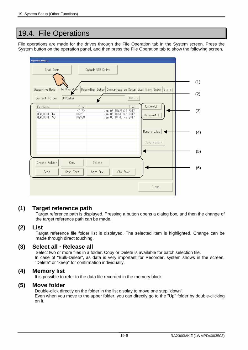
19. System Setup (Other Functions)
RA2300MKⅡ(1WMPD4003503) 19-6
19.4. File Operations File operations are made for the drives through the File Operation tab in the System screen. Press the System button on the operation panel, and then press the File Operation tab to show the following screen.
(1) Target reference path Target reference path is displayed. Pressing a button opens a dialog box, and then the change of the target reference path can be made.
(2) List Target reference file folder list is displayed. The selected item is highlighted. Change can be made through direct touching.
(3) Select all · Release all Select two or more files in a folder. Copy or Delete is available for batch selection file. In case of "Bulk-Delete", as data is very important for Recorder, system shows in the screen, "Delete" or "keep" for confirmation individually.
(4) Memory list It is possible to refer to the data file recorded in the memory block
(5) Move folder Double-click directly on the folder in the list display to move one step "down". Even when you move to the upper folder, you can directly go to the "Up" folder by double-clicking on it.
(1)
(2)
(3)
(4)
(6)
(5)

19. System Setup (Other Functions)
RA2300MKⅡ(1WMPD4003503) 19-7
(6) Other file processing Several file processing is made for the file in the target reference path. For more information, see the description after the next page.
To protect the recorder system, writing into the boot drive (C) is prohibited. Thus, file creation and deletion in the C drive cannot be made.
19.4.1.Copy Copy of selected file or folder is made. The following screen appears when the Copy button is pressed after selecting copy source items in the File Operation tab in the System screen.
(1) Source files and folders for Copy List of files and folders selected in the File Operation screen is displayed. Utilize for copy confirmation.
Copy for several files is available when batch selection is made in the File Operation screen.
(2) Copy destination folder The copy destination folder is displayed. Pressing the Copy button opens a dialog box to change the destination.
(3) CSV save The source file for copy as a data file (with the FSD, FPP, IDX, or DRT extension) can be saved as the CSV format.
Time axis range, thinning-out, and delimiter code can be specified in Output Settings in the Replay screen. For more details, see Chapter 14. Replay Display.
TIPS
TIPS
NOTE
(1)
(2) (3)

19. System Setup (Other Functions)
RA2300MKⅡ(1WMPD4003503) 19-8
19.4.2. Deletion Selected files or folders are deleted. The following screen appears by pressing the Delete button after selecting the deleting files or folders in the File Operation tab in the System screen.
(1) File folder to be deleted List of files and folders selected in the File Operation screen is displayed. Utilize for delete confirmation.
(2) Deletion Pressing the Delete button executes deletion.
The deleted files and folders cannot be recovered. Take due care before deletion.
19.4.3. Folder Creation A new folder can be created under the current target reference folder. Press the File Operation tab in the System screen to move to the path where a folder is created and press the Create Folder button. Enter a folder name and press the Execute key to create the folder.
NOTE
(1)
(2)

19. System Setup (Other Functions)
RA2300MKⅡ(1WMPD4003503) 19-9
19.4.4. Memory Save The block data stored in memory can be saved. The following screen appears by pressing the Memory List button after moving to the folder where data will be saved in the File Operation tab in the System screen.
(1) Memory list Pressing the button opens a list of memory block data.
(2) Memory block data list Memory block data list is displayed. Data selection can be made by directly touching.
(3) Save memory The save destination folder is displayed. Pressing the Save Memory button opens a dialog box to change the destination.
(4) CSV save Memory block data can be saved as the CSV-format data. To save data as CSV file, add a check mark. To save data as a binary format, do not add a check mark.
Time axis range, thinning-out, and delimiter code can be specified in Output Settings in the Replay screen. For more details, see Chapter 14. Replay Display
TIPS
(1)
(2)
(4)
(3)

19. System Setup (Other Functions)
RA2300MKⅡ(1WMPD4003503) 19-10
19.4.5. Environment Save Setup information can be saved in a file. It is useful to save the setup information in external media or read out it from another RA2300MKⅡ recorder. The following screen appears by pressing the Save Env. (Environment) button after moving to the folder where saving is made using the File Operation tab in the System screen. After setting the information to be saved, press the Execute key to save file. The extension of file to be saved is ENV for environment information and TXT for text information.
For device version V3.2 or later, the text information storage function of environmental information has been expanded. For details, please refer to "19.4.7. Strengthen text storage of setting information" on the next page.
The file made by character strings only has an extension of “txt”. A text editor can read this file, accordingly. Conversely, a text file edited by a personal computer can also be read by the RA2300MKⅡ. If an environment file is read by another RA2300MKⅡ, the setup in which hardware configuration is different is displayed to be default.
19.4.6. Readout The selected environment and text files can be read in this recorder. The following screen appears by pressing the Read button after selecting a readout file using the File Operation tab in the System screen.
NOTE
TIPS

19. System Setup (Other Functions)
RA2300MKⅡ(1WMPD4003503) 19-11
19.4.7.Strengthen text storage of setting information In addition to saving and reading text files of conventional "signal name" "user annotation" "measurement information", setting information of "communication setting" and "function calculation" can also be saved as a text file. The saved text file can be edited on a personal computer and loaded into the main body. The setting items to be saved can be individually selected. Press the File Operation tab in the System screen and select the folder to save. Press the [Save Text] key at the bottom of the screen. The Save Text dialog is displayed. (Figure below) Set the file name. Select the setting item to save and press the Execute key to save the setting information as a text file (.TXT). The setting information text data saved in the above "Enhanced Text Storage Function of Setting Information" is described in the following format. According to these formats, the setting information text data can be directly edited by a personal computer. (1) Format of signal name text file
The file format of the signal name character string of each channel is explained. In addition to the prefix of "TSN", the signal name character string consists of a 3-digit channel number and a 3-digit signal number, followed by an arbitrary character string.
・There are signal numbers from 001 to 016, but 002 and later are valid only for event amplifiers. ・For RA2300 MK II, the channel number is up to 018. 017 is for the optional event unit and 018 is reserved.
//Signal Name
TSN001,001, Signal name of CH1 TSN001,002,
~<To omit>~ TSN002,001,
TSN002,002,
~<To omit>~ TSN018,015,
TSN018,016,

19. System Setup (Other Functions)
RA2300MKⅡ(1WMPD4003503) 19-12
(2) Format of page annotation text file
The file format of page annotation character strings is explained. In addition to the prefix of "TIP", the page annotation character string consists of a 3-digit line number, followed by an arbitrary character string. Line numbers are from 001 to 108.
(3) Format of measurement information text file
The file format of measurement information character strings is explained. In addition to the prefix of "THD", the measurement information character string consists of a 3-digit line number, followed by an arbitrary character string. Line numbers are from 001 to 108.
(4) Format of measurement information text file
The file format of communication setting information is explained. In addition to the prefix of "COM", communication setting information character string consists of a three-digit line number, followed by communication setting information. Odd line numbers are comment information about settings. Even line numbers are configuration information. (Please refer to the comment in the line above)
//Page Annotation
TIP001, User page annotation TIP002,
~<To omit>~ TIP106,
TIP107,
TIP108,
//Header
THD001, Measurement information character string THD002,
THD003,
~<To omit>~ THD107,
THD108, End of measurement information character string
//Communication
COM001,Communication Port : NONE / LAN / RS-232C
COM002,NONE
COM003,Connect UPS to RS232C : ON / OFF
COM004,OFF
COM005,Baudrate : 2400 / 4800 / 9600 / 19200 / 38400
COM006,9600
COM007,Data bits : 8 / 7
COM008,8
COM009,Stop bits : 1 / 2
COM010,1
COM011,Parity : NONE / ODD / EVEN
COM012,NONE
COM013,Flow control : RTSCTS / XONXOFF
COM014,RTSCTS
COM015,Delimiter : CRLF / CR / LF
COM016,CRLF
COM017,Timeout : [0-60]s
COM018,10
COM019,Use DHCP : ON / OFF
COM020,OFF
COM021,IP address
COM022,192.168.15.21
COM023,Sub net mask
COM024,255.255.255.0
COM025,Gateway address
COM026,192.168.15.1

19. System Setup (Other Functions)
RA2300MKⅡ(1WMPD4003503) 19-13
(5) Format of function calculation text file
The file format of function calculation setting information is explained. In addition to the prefix of "FNC", the function calculation setting information character string consists of a 3-digit line number, followed by an arbitrary character string. There are line numbers from 001 to 500.
line number Meaning of string
001 ~ 032 Arithmetic expression
101 ~ 132 Waveform display range (maximum value)
201 ~ 232 Waveform display range (minimum value)
301 ~ 332 Display unit of calculation result
401 ~ 332 constant
500 Moving average points
・For RA2300 MK II, the operation number is up to * 16.
//Function
FNC001,SQRT(POW2(d1)+POW2(d2)+POW2(d3))
~<To omit>~ FNC016,d16
FNC101, 10.000
FNC201,-10.000
FNC301,Ω
~<To omit>~ FNC116, 10.000
FNC216,-10.000
FNC316,Ω
FNC401, 1.0000
FNC402, 2.0000
FNC403, 3.0000
~<To omit>~ FNC409, 3.1416
FNC410, 9.8067
FNC500,10

19. System Setup (Other Functions)
RA2300MKⅡ(1WMPD4003503) 19-14
19.5. Recording Setup Press the System button on the operation panel, and then press the Recording Setup tab. The following screen appears.
19.5.1Recording Channels 19.5.2Data No. Setting 19.5.3Print Setup 19.5.4Speed Table Setup 19.5.5Time-axis Representation 19.5.6Timer Recording Settings 19.5.7External Sync Rate Setting
19.5.1. Recording Channels By restricting the number of recording channels, block size per channel for memory recording can be increased.
Channels excluded from the recording target are neglected. Even if a unit is installed, nothing is displayed. If recording channel settings are changed, the memory size changes, thereby deleting the memory block data. "E1" Set it to ON when recording event channels 1-16 by the optional event unit (RA 23-145). "E 2" Set it to ON when recording the trigger detection point (mark information) in the recorder mode described in “10.1. Overview of HD Recorder Mode”. After recording the data, you can search the trigger detection point (mark information) recorded in the data and execute the event jump. For details, see Chapter 14. Replay Display.
TIPS
TIPS
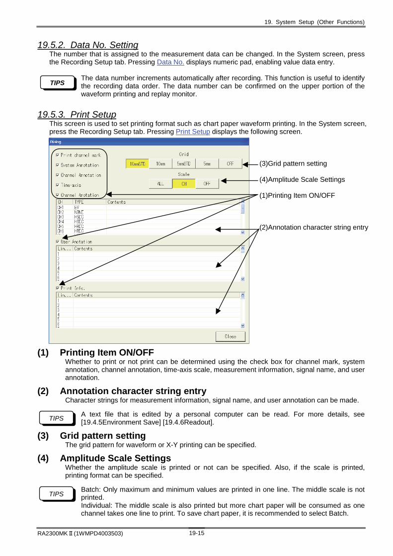
19. System Setup (Other Functions)
RA2300MKⅡ(1WMPD4003503) 19-15
19.5.2. Data No. Setting The number that is assigned to the measurement data can be changed. In the System screen, press the Recording Setup tab. Pressing Data No. displays numeric pad, enabling value data entry.
The data number increments automatically after recording. This function is useful to identify the recording data order. The data number can be confirmed on the upper portion of the waveform printing and replay monitor.
19.5.3. Print Setup This screen is used to set printing format such as chart paper waveform printing. In the System screen, press the Recording Setup tab. Pressing Print Setup displays the following screen.
(3)Grid pattern setting (4)Amplitude Scale Settings (1)Printing Item ON/OFF (2)Annotation character string entry
(1) Printing Item ON/OFF Whether to print or not print can be determined using the check box for channel mark, system annotation, channel annotation, time-axis scale, measurement information, signal name, and user annotation.
(2) Annotation character string entry Character strings for measurement information, signal name, and user annotation can be made.
A text file that is edited by a personal computer can be read. For more details, see [19.4.5Environment Save] [19.4.6Readout].
(3) Grid pattern setting The grid pattern for waveform or X-Y printing can be specified.
(4) Amplitude Scale Settings Whether the amplitude scale is printed or not can be specified. Also, if the scale is printed, printing format can be specified.
Batch: Only maximum and minimum values are printed in one line. The middle scale is not printed. Individual: The middle scale is also printed but more chart paper will be consumed as one channel takes one line to print. To save chart paper, it is recommended to select Batch.
TIPS
TIPS
TIPS

19. System Setup (Other Functions)
RA2300MKⅡ(1WMPD4003503) 19-16
19.5.4. Speed Table Setup User can set the speed for waveform chart printing, memory recording, and HD recording. In the System screen, press the Recording Setup tab. Pressing the Speed Table Setup button displays the following screen.
19.5.5. Time-axis Representation In the System screen, press the Recording Setup tab. Pressing Time-axis Representation keys change the time-axis units upon waveform recording.
If the recording speed is set to the external synchronization, time-format representation is disabled. Numerical value representation is forcibly set. · In "Value", the number of data is indicated. In memory mode, the trigger reference point is (0).
· In "Time", indicate the recording time. In the memory mode, the trigger reference point is (0 s). · In "Period", the recording time and trigger point are indicated in the (year, month, day, hour, minute, second) notation.
TIPS

19. System Setup (Other Functions)
RA2300MKⅡ(1WMPD4003503) 19-17
19.5.6. Timer Recording Settings Recording start and finish is controlled by time. Recording start and finish can be set to the time whose timer function can be validated. Recording operation in constant interval and constant time is available. In the System screen, press the Recording Setup tab. Ticking the User Start Timer Function check box opens the following screen. (Be sure to enter the end time when using the start timer and interval function)
Example: To make 20-minute recording every hour from 0:00 a.m. on December 24, 2017 to 0:00 a.m. on the next day.
(1)Tick the box for “Use Start Timer Function.” To use timer function, add a check mark.
(2)Select the start time (2017/12/24 0:00)
(3)Select the stop time (2017/12/25 0:00)
(4)Tick the box for “Use Interval Recording Function.” Do not tick if the measurement is only once. Add a check mark only when repeated recording is made.
(5)Specify the start interval of time (1 H)
(6)Specify the duration. (20 min)
The actual recording duration may be shortened depending on the recording length settings. When the timer function is set, a symbol of clock is displayed on the upper part of the screen. The next recording start time is indicated near the clock. See below.
19.5.7. External Sync Rate Setting When External Sync is set for the chart feed speed for waveform chart printing, the chart feed speed per one pulse for external synchronous signal can be set.
To execute the external sync printing, Remote Unit (RA23-144, optional) is necessary. For more details on the remote unit and external sync printing, see Chapter 20. How to Use Optional Units.
TIPS
NOTE
(1)
(4)
(2)
(3)
(5)
(6)

19. System Setup (Other Functions)
RA2300MKⅡ(1WMPD4003503) 19-18
19.5.8.Automatic Reproduction of Display Settings of Data Recorded by HDD Recorder
At the end of data recording, the environment file (.ENV) is automatically saved with the same file name as the data file. This environmental file is automatically read when selecting the replay data. And the display format such as waveform splitting done on the input monitor is played back.
This function is available for device version V3.2 or later. For details on version upgrade method and the program, visit our website.
Items automatically reproduced during data replay are as follows.
Waveform display Print setup Waveform segmentation Time axis representation User annotation printing
Scale indication Channel mark printing User annotation string Scale indication channel System annotation printing Measurement information printing
Grid display Channel annotation printing Measurement information string Digital value display Time axis printing Grid
Signal name indication Signal name printing Amplitude axis scale Cursor value indication Signal name string Feed length
*Reproduction of these items does not affect the setting of the input monitor. In the System screen, press the Recording Setup tab. Tick the "Save environment after saving the file" check box, the environment file (.ENV) will be saved after recording the file with the HD recorder. When you select a file recorded under the above conditions on the replay monitor, it searches for an environment file (. ENV) with the same name in the folder and automatically reproduces the display environment of the recorded time using the file. If there is no environment file with the same name as recorded data in the same folder, the replay environment will not be changed. With the replay monitor displayed, press the "DISP. FORM" button to display the "Display record setting" screen. The current display settings are displayed. By changing the setting on this screen, you can change the current replay monitor display method.
If you change the replay setting here, its contents will not be reflected in the corresponding environment file. If you reopen the recorded data, the environment file will be re-applied to the replay environment.
TIPS
TIPS
TIPS

19. System Setup (Other Functions)
RA2300MKⅡ(1WMPD4003503) 19-19
19.6. Communication Setup Press the System button on the operation panel, and then press the Communication Setup tab. The following screen appears.
(1) UPS Connection
(2) Communication Function
(3) RS-232C Settings
(4) LAN Settings
To use the UPS and RS-232C function, RS-232C Unit (RA23-142, optional) is necessary.
(1) UPS Connection Connection to uninterruptible power supply (UPS) can be made by ticking the check box. The UPS avoid sudden shutdown of the recorder upon the electric power outage, enabling safe shutdown of the recorder.
(2) Communication Function The control of RA2300MKⅡ through a communication port is possible through this function
Setup Description RS-232C Control of this recorder through RS-232C can be made. (Cannot be used with the
UPS connection) LAN Control of this recorder can be made through TCP/IP port No. 2300. None Control of the recorder through a communication port is disabled.
Communication control for this recorder uses dedicated communication commands. For more details, see separated volume of instruction manual, RA2000 Series Communication Command Manual (1WMPD4003507).
NOTE
NOTE

19. System Setup (Other Functions)
RA2300MKⅡ(1WMPD4003503) 19-20
(3) RS-232C Settings RS-232C communication protocol can be set. Pressing this button displays the screen below. Set the RS-232C conditions in this screen.
(4) LAN Settings Communication protocol setup for the LAN connection is made. Pressing this button displays the screen below. Set the LAN conditions through this screen.
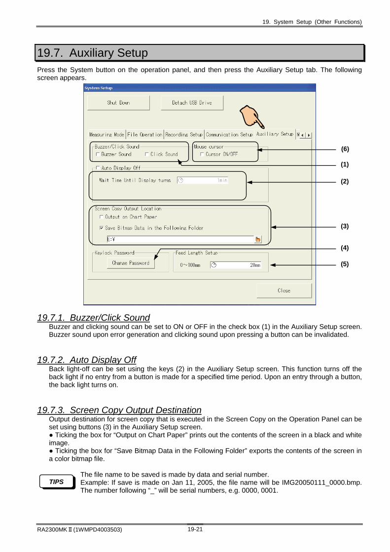
19. System Setup (Other Functions)
RA2300MKⅡ(1WMPD4003503) 19-21
19.7. Auxiliary Setup Press the System button on the operation panel, and then press the Auxiliary Setup tab. The following screen appears.
19.7.1. Buzzer/Click Sound Buzzer and clicking sound can be set to ON or OFF in the check box (1) in the Auxiliary Setup screen. Buzzer sound upon error generation and clicking sound upon pressing a button can be invalidated.
19.7.2. Auto Display Off Back light-off can be set using the keys (2) in the Auxiliary Setup screen. This function turns off the back light if no entry from a button is made for a specified time period. Upon an entry through a button, the back light turns on.
19.7.3. Screen Copy Output Destination Output destination for screen copy that is executed in the Screen Copy on the Operation Panel can be set using buttons (3) in the Auxiliary Setup screen. ● Ticking the box for “Output on Chart Paper” prints out the contents of the screen in a black and white image. ● Ticking the box for “Save Bitmap Data in the Following Folder” exports the contents of the screen in a color bitmap file.
The file name to be saved is made by data and serial number. Example: If save is made on Jan 11, 2005, the file name will be IMG20050111_0000.bmp. The number following “_” will be serial numbers, e.g. 0000, 0001.
TIPS
(2)
(3)
(5)
(4)
(6)
(1)

19. System Setup (Other Functions)
RA2300MKⅡ(1WMPD4003503) 19-22
19.7.4. Key lock Password Pressing the button (4) in the Auxiliary Setup screen displays a character entry screen and enables registration of a key lock password. The key lock password is used to resume from the key lock condition. To lock the screen, press the icon on the upper right.
To unlock, enter the password. If any password has not been set, key lock can be unlocked without password.
19.7.5. Feed Length Setup Feed length after printing can be set with the button (5) in the Auxiliary Setup screen. Set a smaller value if chart consumption must be saved under continuous printing.
19.7.6. Mouse Cursor ON/OFF To control the recorder using the USB mouse, ON/OFF for the mouse cursor can be set.
This function is available for device version V3.2 or later. For details on version upgrade method and the program, visit our website.
Ticking the check box (6) in the Auxiliary Setup screen turns the mouse cursor on or off.
Normal Locked
TIPS

19. System Setup (Other Functions)
RA2300MKⅡ(1WMPD4003503) 19-23
19.8. Maintenance Press the System button on the operation panel, and then press the Maintenance tab. The following screen appears.
19.8.1. Version Indication Product serial number and program version are indicated. Press the Version Display button in the Maintenance screen. The following screen appears.
19.8.1.Version Indication
19.8.2.Test Print
19.8.3.Data Printing
19.8.4.Time Calibration
19.8.5.Maintenance Mode

19. System Setup (Other Functions)
RA2300MKⅡ(1WMPD4003503) 19-24
19.8.2. Test Print Test printing is made in order to check the printer printing quality. Pressing the Test Print button in the Maintenance screen opens the confirmation screen. Pressing the Execute key starts the test print. To close, press “Cancel” button.
19.8.3. Data Printing The measurement mode is set to Data Chart Print. In this mode, measured values are printed out in character strings. Pressing the Data Recording button in the Maintenance screen opens the confirmation screen. Pressing the Execute key starts the Data Printing. To close, press the Cancel key.
19.8.4. Time Calibration Internal watch is set. Press the Clock Setup button in the Maintenance screen. The following screen appears. Select the window whose value should be set among windows of year, month, day, hour, time, minute, and second. Enter a value and press the Execute key. Time can be set.
19.8.5. Maintenance Mode When the recorder is turned on with the tick mark in the check box for “Start next time in Maintenance Mode”, the maintenance screen is displayed. The maintenance mode is used for updating the software version and may affect the system. Use the maintenance mode only when necessary.

20. How to Use Optional Units

20. How to Use Optional Units
RA2300MKⅡ (1WMPD4003503) 20-2
20.1.Connecting optional units Please insert blank panel into empty slots when optional units are not connected in order to avoid electrical shock and to prevent damages to the recorder unit caused by irruptions of extraneous substances
Please turn the power off and unplug power strip from the recorder unit before connecting or disconnecting optional units. If optional units are connected or disconnected while the power of the recorder unit is ON, it may damage the optional unit and/or the recorder unit.
When exchanging units, do not touch internal parts. Internal parts may be damaged if touched by static body. Do not touch anything except for the panel when exchanging units. This may cause damages. When connecting optional units, please be sure of top and bottom of the units and insert units in accordance with the guideline specified in input slot area. Tighten the screw with flat-head screwdriver after connecting optional units to the recorder unit. Connecting optional units requires a flat head screwdriver (screwdriver’s end must be thinner than 0.65 mm).
CAUTION
WARNING
CAUTION
CAUTION
Top
Right side
RS-232C EVENT REMOTE
AC Bridge Excitation
Not in use
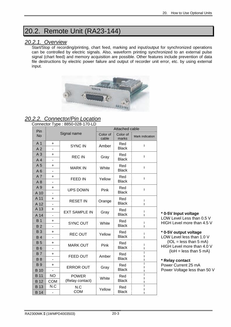
20. How to Use Optional Units
RA2300MKⅡ(1WMPD4003503) 20-3
20.2. Remote Unit (RA23-144)
20.2.1. Overview Start/Stop of recording/printing, chart feed, marking and input/output for synchronized operations can be controlled by electric signals. Also, waveform printing synchronized to an external pulse signal (chart feed) and memory acquisition are possible. Other features include prevention of data file destructions by electric power failure and output of recorder unit error, etc. by using external input.
20.2.2. Connector/Pin Location Connector Type : 8850-028-170-LD
Attached cable Pin No
Signal name Color of cable
Color of marks
Mark indication
A 1 +
A 2 - SYNC IN Amber Red
Black
I
A 3 +
A 4 - REC IN Gray
Red Black
I
A 5 +
A 6 - MARK IN White
Red Black
I
A 7 +
A 8 - FEED IN Yellow
Red Black
I
A 9 +
A 10 - UPS DOWN Pink
Red Black
I
A 11 +
A 12 - RESET IN Orange
Red Black
Ι I
A 13 +
A 14 - EXT SAMPLE IN Gray
Red Black
Ι I
B 1 +
B 2 - SYNC OUT White
Red Black
Ι I
B 3 +
B 4 - REC OUT Yellow
Red Black
Ι I
B 5 +
B 6 - MARK OUT Pink
Red Black
Ι I
B 7 +
B 8 - FEED OUT Amber
Red Black
Ι I I
B 9 +
B 10 - ERROR OUT Gray
Red Black
Ι I I
B 11 NO
B 12 COM POWER
(Relay contact) White
Red Black
Ι I I
B 13 N.C
B 14 - N.C
COM Yellow
Red Black
Ι I I
* 0-5V Input voltage LOW Level Less than 0.5 V HIGH Level more than 4.5 V * 0-5V output voltage LOW Level less than 1.0 V
(IOL = less than 5 mA) HIGH Level more than 4.0 V
(IoH = less than 5 mA) * Relay contact Power Current 25 mA Power Voltage less than 50 V

20. How to Use Optional Units
RA2300MKⅡ (1WMPD4003503) 20-4
20.2.3. To Synchronize to External Pulse and Perform Waveform Chart Printing and Printing
Waveform recording, input monitor, filing acquisitions can be synchronized to external pulse. Instructions on how to connect remote terminals and how to set up the recorder unit are explained below.
(1) Connecting external input pulse signal To print waveforms synchronized to external pulse signal, use the A1 pin (SYNC IN) of remote terminals. For input monitor and filing acquisitions, input external signal to synchronize in the A13 pin (EXT IN).
Paper Feeding Pitch Setting
SYNC OUT Pulse Output Frequency Maximum Input
Frequency
0.025 mm/pulse (Paper feeding speed: mm/s)/0.025mm(Hz) Example: 20mm/s→ 800Hz, 1mm/min→approx.0.667Hz
2kHz
0.1 mm/pulse (Paper feeding speed: mm/s)/0.1mm(Hz) Example: 20mm/s→ 200Hz, 1mm/min→approx.0.167Hz
500Hz
(2) Setting the recorder unit for external synchronization a) Set the measurement mode of the recorder unit to Pen Record mode.
b) In the screen for speed/recording condition setting, set chart speed to External Synchronization. [Monitor and acquisition speed] will also be set to external synchronization by this setup. See 8.2. Screen Operation.
(3) Start recording Once the signal connection of remote terminal is established and the set up for recording speed is completed, it is now ready to perform external synchronized recordings. By pressing the Start button, external pulse will be synchronized and acquisitions and recording of waveforms will begin
By inputting the same synchronized external signal into the A1 pin (SYN IN) of remote terminal and the A13 pin (EXT IN), waveform printing, display of input monitor, and recording can be performed simultaneously. This is valid under Pen Recorder, Multi, HDD Recorder mode.
TIPS
By pressing the external button located in upper right of thePen Recorder screen, the color will change and externalsynchronization will be set.

20. How to Use Optional Units
RA2300MKⅡ(1WMPD4003503) 20-5
20.2.4. Compatibilities with Conventional Products (Waveform Chart Printing) This product is compatible with the conventional products, so it is possible to set up external pulse control. Setup is done by changing external synchronization ratios from the Recording Setup tab in the System Screen. This setup is valid for real-time waveform printing as well as input monitor. The setup shown below is to control the amount of chart feed for external input pulse to 1 pulse.
● When the setting is 【0.1mm/Pulse】(between recorder units) In Pen Recorder waveform printing, one pulse corresponds to one line (0.1 mm) of printing, and in HD recorder, one pulse is acquired as one piece of data.
● When the setting is [0.025mm/Pulse] (SYNC OUT connection of past products.] In Pen Recorder waveform printing, four pulses correspond to one line (0.1 mm) of printing, and in HD recorder, one pulse is acquired as one piece of data.
20.2.5. Memory Acquisition Using External Sampling Described below are the instructions to perform acquisitions using external samples.
(4) Connect external input sampling signal Connect the signal to use into the A13 (EXT IN) pin located in the backside of remote terminal. Please use the A14 pin for the common.
Recorder Mode Maximum Input Frequency Memory Recorder
10kHz
HDD Recorder 100Hz
(5) Set recorder unit to external sampling setting a) Set measurement mode of the recorder unit to Memory Recorder mode.
b) Set the Sampling speed to External Synchronization in detail setting for speed and condition screen. Monitor/Recording Speed will be set to external synchronization by this setup.
See 9.2.2. Memory Recording Condition Setup Block.
(6) Start recording External synchronization sample set up is now completed by connecting signal of remote terminal and setting sample speed. Pressing the Start button here will synchronize the external pulse and acquisition to the memory will start.
The color will change pressing buttons andexternal synchronized ratios will be set.
By pressing external synchronization button,the color will change and sample speed willbe set as external synchronization.

20. How to Use Optional Units
RA2300MKⅡ (1WMPD4003503) 20-6
20.2.6. Start/Stop recording (Start/Stop button) It functions the same way as pressing the Start button on the panel and it starts acquisition. The A3 pin (REC IN) of remote terminal is controlled externally. For the common, use the A4 pin.
REC IN Signal ↑ ↑
Start acquisition Stop acquisition Acquisition will start when the falling edge of the signal is detected in the low level, and will continue until the rising edge is detected. Once the rising edge is detected, acquisition will stop.
20.2.7. Chart Feed It functions the same way as pressing the Feed button on the panel and it starts to blank feed recording chart paper. The A7 pin (FEED IN) is controlled externally. Please use the A7 pin for the common.
FEED IN ↑ ↑
Start Feed Stop Feed Feed will start when the falling edge of the signal is detected, and will continue in the low level until the rising edge is detected. Once the rising edge is detected, feed will stop.
20.2.8. Mark Printing It functions the same way as pressing the Mark Printing button on the panel and it prints marks. This becomes valid when the recorder unit is performing real time recording. The A5 pin (MARK IN) of remote terminal is controlled externally. Please use the A6 pin for the common. MARK IN Signal
↑ ↑ ↑ ↑ ↑ Mark is printed when the falling edge of signal is detected during real time recordings.
20.2.9. Protecting File Data (UPS DOWN) This function prevents destructions of files, etc by external protection using uninterruptible power source in case of electrical power failure when accessing files during filing acquisitions of the recorder unit. The A9 pin (UPS DOWN) of remote terminal is controlled externally. Please use the A10 pin for the common.
UPS DOWN Signal ↑
Start discontinuation process
20.2.10. Monitoring errors on recording areas Error signal is sent out when an error occurs in printing area (due to out of recording chart paper or thermal head abnormal temperature rise). Signal is sent out to the B9 pin (ERROR.OUT). For the common please use the B10.
ERROR OUT Signal ↑ ↑
Error occurrence Error correction Low-level output will continue while an error is occurring. Output occurs independently with no relations to the acquisitions of the recorder unit.

20. How to Use Optional Units
RA2300MKⅡ(1WMPD4003503) 20-7
20.2.11. Parallel Operation This product can perform recording, chart feed, marking functions simultaneously by connecting remote terminals in parallel with multiple recorder units. Instructions below show how to connect (1) as a master recorder unit.
Name Pin No. Name Pin No. REC OUT (B3) REC IN (A3) FEED OUT (B7) FEED IN (A7) MARK OUT (B5) MARK IN (A5) SYNC OUT (B1) SYNC IN (A1)
(COMMON is B14.) Through the connection above, panel operation on (1) controls recorder unit of (2) simultaneously. *For Input/Output of trigger (TRIG.IN, OUT), see 13.2.2. External Trigger (TRIG IN). and 13.2.3. External Trigger Output (TRIG OUT).
(1) (2)
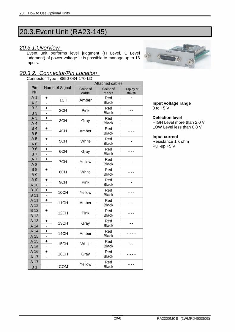
20. How to Use Optional Units
RA2300MKⅡ (1WMPD4003503) 20-8
20.3.Event Unit (RA23-145)
20.3.1.Overview Event unit performs level judgment (H Level, L Level judgment) of power voltage. It is possible to manage up to 16 inputs.
20.3.2. Connector/Pin Location Connector Type : 8850-034-170-LD
Attached cables Pin №
Name of Signal Color of cable
Color of marks
Display of marks
A 1 + A 2 -
1CH Amber Red Black
-
B 2 + B 3 -
2CH Pink Red
Black - -
A 3 + A 4 -
3CH Gray Red
Black -
B 4 + B 5 -
4CH Amber Red
Black - - -
A 5 + A 6 -
5CH White Red
Black -
B 6 + B 7 -
6CH Gray Red
Black - - -
A 7 + A 8 -
7CH Yellow Red
Black -
B 8 + B 9 -
8CH White Red
Black - - -
A 9 + A 10 -
9CH Pink Red
Black -
B 10 + B 11 -
10CH Yellow Red
Black - - -
A 11 + A 12 -
11CH Amber Red
Black - -
B 12 + B 13 -
12CH Pink Red
Black - - -
A 13 + A 14 -
13CH Gray Red
Black - -
A 14 + A 15 -
14CH Amber Red
Black - - - -
A 15 + A 16 -
15CH White Red
Black - -
A 16 + A 17 -
16CH Gray Red
Black - - - -
A 17 B 1
-
COM
Yellow Red
Black - - -
Input voltage range 0 to +5 V Detection level HIGH Level more than 2.0 V LOW Level less than 0.8 V Input current Resistance 1 k ohm Pull-up +5 V

20. How to Use Optional Units
RA2300MKⅡ(1WMPD4003503) 20-9
20.3.3. Event Unit Setup Pressing the Amp button on the Operation Panel opens the Amp Basic screen. Pressing the Channel button opens the Amp Detail screen.
(1) Basic - Channel Channel number, amp type and waveform color are indicated on this button. Pressing the button opens the Amp Detail screen.
(2) Basic – Event waveform batch printing ON/OFF for event waveform printing of all sixteen signals can be set. Touch to switch between ON and OFF.
(3) Detail – Event waveform printing ON/OFF for event waveform printing of each signal can be set. Touch to switch between ON and OFF.
(4) Detail – Initialize The setup can be restored to the factory default.
E1 in the Amp Basic screen corresponds to event amplifier unit (RA23-145, optional) or event box (RA23-146, optional). “Extra Event” in the Amp Detail screen is the same as “E1.”
TIPS
(1) Channel (2) Event waveform batch printing
(3) Event waveform printing
(4) Initialize

20. How to Use Optional Units
RA2300MKⅡ (1WMPD4003503) 20-10
20.3.4. Event Waveform Adjustment Press the Extend tab in the Amp Detail screen to adjust event waveform. In the adjustment, the settings of the waveform recording position, signal pitch, signal amplitude and base line thickness can be changed for better viewing according to the measurement conditions. Use the jog dial or window key in each box of the waveform recording position, signal pitch, signal amplitude and base line thickness to make changes. Pressing the Auto Adjustment (Auto Adj.) button performs adjustments automatically so that the event waveform fits to the grid pattern.
(1) Recording position The waveform recording position of signal 16 is specified. Signals 1 to 16 are positioned upwards with a pitch that is specified in (2).
(2) Signal pitch A pitch with which to position sixteen signals is specified.
(3) Signal amplitude A waveform amplitude (amplitude when signals change from low level to high or from high level to low) of sixteen signals is specified.
(4) Base line thickness A waveform width when signals are high is specified.
(5) Auto adjustment Adjustments are performed automatically so that the event waveform fits to the grid pattern.
Depending on the setting values of the recording position and signal pitch, the resultant waveform may exceed the effective recording width and consequently event waveform cannot be printed.
For Event Unit trigger setting, see 13.7. Trigger Settings for Event Unit.
(1) Recording position (2) Signal pitch (3) Signal amplitude
(4) Base line thickness
(5) Auto adjustment
NOTE
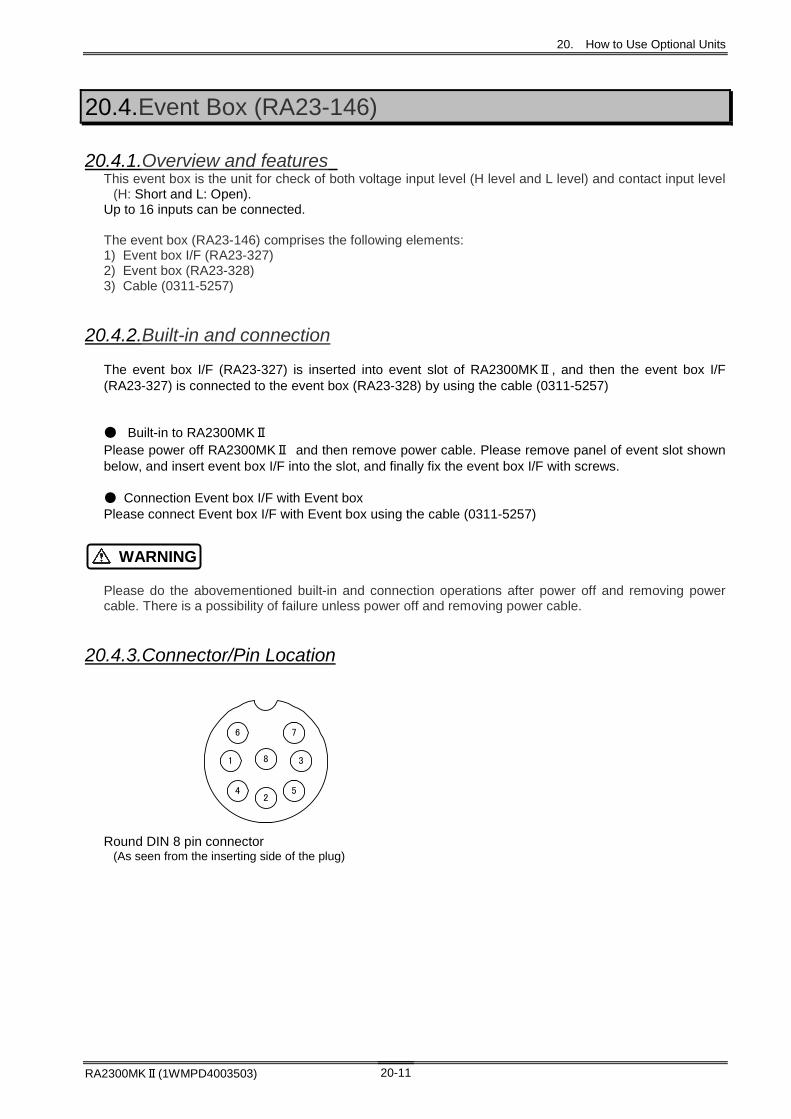
20. How to Use Optional Units
RA2300MKⅡ(1WMPD4003503) 20-11
20.4.Event Box (RA23-146)
20.4.1.Overview and features This event box is the unit for check of both voltage input level (H level and L level) and contact input level
(H: Short and L: Open). Up to 16 inputs can be connected. The event box (RA23-146) comprises the following elements: 1) Event box I/F (RA23-327) 2) Event box (RA23-328) 3) Cable (0311-5257)
20.4.2.Built-in and connection
The event box I/F (RA23-327) is inserted into event slot of RA2300MKⅡ, and then the event box I/F (RA23-327) is connected to the event box (RA23-328) by using the cable (0311-5257) ● Built-in to RA2300MKⅡ Please power off RA2300MKⅡ and then remove power cable. Please remove panel of event slot shown below, and insert event box I/F into the slot, and finally fix the event box I/F with screws. ● Connection Event box I/F with Event box Please connect Event box I/F with Event box using the cable (0311-5257)
Please do the abovementioned built-in and connection operations after power off and removing power cable. There is a possibility of failure unless power off and removing power cable.
20.4.3.Connector/Pin Location Round DIN 8 pin connector
(As seen from the inserting side of the plug)
WARNING
8 31
4 52
76

20. How to Use Optional Units
RA2300MKⅡ (1WMPD4003503) 20-12
Round DIN 8 pin connector
Pin No.
Signal name
Pin No.
Signal name
Pin No.
Signal name
Pin No.
Signal name
1 1CH INPUT 1 5CH INPUT 1 9CH INPUT 1 13CH INPUT 2 2CH INPUT 2 6CH INPUT 2 10CH INPUT 2 14CH INPUT 3 3CH INPUT 3 7CH INPUT 3 11CH INPUT 3 15CH INPUT 4 4CH INPUT 4 8CH INPUT 4 12CH INPUT 4 16CH INPUT 5 GND 5 GND 5 GND 5 GND
6 +15V
OUTPUT
6 +15V
OUTPUT
6 +15V
OUTPUT
6 +15V
OUTPUT 7 NC 7 NC 7 NC 7 NC 8 NC 8 NC 8 NC 8 NC
Input voltage range 0 to +24 V
Detection level H-level: Approximately 2.5 V or over L-level: Approximately 0.5 V or less
Voltage input
Input current no more than 1uA
Detection level Open: 2 k or less Short: 250 or over
Contact input
Load current 2 mA (MAX)
20.4.4.Event box setting
For Event box setting, see 20.3.3. Event Unit Setup.
20.4.5.Event box waveform setting
For Event box waveform setting, see 20.3.4. Event Waveform Adjustment.
20.4.6.Event box trigger setting
For Event box trigger setting, see Chapter 13. Trigger Settings.
Connectors 1 to 4 Connectors 5 to 8 Connectors 9 to 12 Connectors 13 to 16

20. How to Use Optional Units
RA2300MKⅡ(1WMPD4003503) 20-13
20.5. RS-232C Unit (RA23-142)
20.5.1.Names of each part and their functions
Function Connect to host computer and control Omni ace by command. Specifications JIS X5101 (former C6361)compliant
Data Format Bit Serial Transfer speed 38400, 19200, 9600, 4800, and 2400[bps] Transfer format Asynchronous communication, total square transmission
method Start bit 1[bit] Data bit 7,8[bit] Stop bit 1,2[bit] Parity bit No Parity bit, EVEN, ODD
Mass Approx. 50g Pin Alignment
Pin No Name of signal Pin No Name of signal 1 CD (Carrier Detect) 6 DR (Data set Ready) 2 RD (Received Data) 7 RS (Request to Send) 3 SD (Transmitted Data) 8 CS (Clear to Send) 4 ER (Data Terminal Ready) 9 RI (Ring Indicator) 5 SG (Signal GND)
For RS-232C settings, see 19.6. Communication Setup.
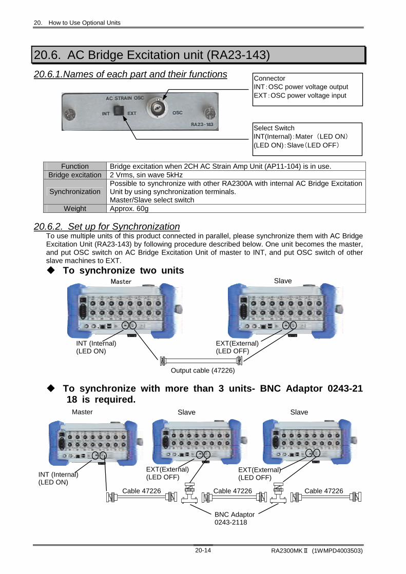
20. How to Use Optional Units
RA2300MKⅡ (1WMPD4003503) 20-14
20.6. AC Bridge Excitation unit (RA23-143)
20.6.1.Names of each part and their functions
Function Bridge excitation when 2CH AC Strain Amp Unit (AP11-104) is in use. Bridge excitation 2 Vrms, sin wave 5kHz
Synchronization Possible to synchronize with other RA2300A with internal AC Bridge Excitation Unit by using synchronization terminals. Master/Slave select switch
Weight Approx. 60g
20.6.2. Set up for Synchronization To use multiple units of this product connected in parallel, please synchronize them with AC Bridge Excitation Unit (RA23-143) by following procedure described below. One unit becomes the master, and put OSC switch on AC Bridge Excitation Unit of master to INT, and put OSC switch of other slave machines to EXT.
To synchronize two units
To synchronize with more than 3 units- BNC Adaptor 0243-2118 is required.
Connector INT:OSC power voltage output EXT:OSC power voltage input
Select Switch INT(Internal):Mater (LED ON) (LED ON):Slave(LED OFF)
Master Slave
INT (Internal)(LED ON)
Output cable (47226)
EXT(External)(LED OFF)
BNC Adaptor0243-2118
Master Slave Slave
Cable 47226
EXT(External)(LED OFF) INT (Internal)
(LED ON)
EXT(External)(LED OFF)
Cable 47226 Cable 47226

21. Maintenance and Cleaning

21. Maintenance and Cleaning
RA2300MKⅡ(1WMPD4003503) 21-2
This is precision equipment. Do not allow anyone other than a qualified technician from our company to open the main unit case.
21.1.Handling and Storing Recording Paper and Data
Care is required when handling the thermo-sensitive paper used by this instrument. The chemical reaction caused by using a thermal head to add heat to the underside of the recording paper used for the RA2300MKⅡ allows distinct black on white recording. Take care to handle the recording part of this paper so as to avoid color leakage or discoloration of the white sheet through writing materials, chemicals, or the environment (etc.).
21.1.1 Storing the Recording Paper ・ Do not store the paper in a hot environment. ・ Do not store the paper near heating fixtures. ・ Store the paper in an environment with ambient temperature of 40°C or less, and do not store for a
long period of time, as this may cause discoloration of the white sheet. ・ Do not expose the paper to direct sunlight for long periods of time, especially in an unwrapped state,
as this may cause discoloration of the white sheet. Take especial care, therefore, when using this instrument outside.
21.1.2 Caution for Handling and Storage of Recorded Data ・ Do not store recorded data in a hot or humid environment. ・ Do not expose recorded data to sunlight or strong light for a long period of time. ・ Recorded data may suffer from color leakage or white sheet discoloration due to heat, humidity, or
light. ・ Store recorded data at 40°C and 80% RH or less. ・ Data recorded in color will retain its color even if rubbed or exposed to water. However, the color will
come off if rubbed strongly, so avoid doing so. ・ The color on the recording paper will come off with volatile solvents such as alcohol and ester. It will
not come off with oil-based solvents such as benzene. ・ If non-volatile solvents such as plastics are absorbed the color-recording capability will be reduced,
causing color leakage in the recorded section. ・ The recorded section may leak color if the thermo-sensitive paper is touched while it is not
sufficiently dry.
21.2.Battery Backup ・ The setting values, date and time of the recording conditions are backed up for about 5
years (at an ambient temperature of 25°C). ・ Recorded data cannot be backed up. ・ If【Save/Load of setups】in the System screen is saved, these can be saved and read
regardless of the battery. (Refer to Chapter 14 for details).
21.3.Cleaning the Display If the display screen becomes wet, wipes it either with a soft, dry cloth, or with gauze soaked in ethanol.
NOTE
NOTE
WARNING

21. Maintenance and Cleaning
RA2300MKⅡ(1WMPD4003503) 21-3
21.4.Replacement of touch panel protection sheet Follow the procedure below to replace the touch panel protection sheet. The touch panel protection sheet is fixed with the upper three claws and the lower two slide hooks.
When replacing, please release the lower slide hooks.
21.5.Cleaning and Preserving the Thermal Head
21.5.1. Cleaning If recording for long periods of time, the heat dissipating part of this instrument's thermal head may become clogged with paper remains, etc. If the head is dirty, the quality of the printing and image reproduction will be reduced, so in this case the head will require cleaning. 1. Pull the lock lever upwards to open the cover of the recording paper section.
Remove the recording paper if loaded.
The color on the recording paper will come off with ethanol. Remove the recording paper before cleaning.
2. The thermal head is in the upper side of the recording paper section. The heat dissipating part is located at 4.4 mm from the edge of the thermal head. Clean the heat dissipating part.
3. Clean the part lightly using a cotton swab or gauze soaked in ethanol.
4. Wait for the thermal head to get dry and load the recording paper.
NOTE

21. Maintenance and Cleaning
RA2300MKⅡ(1WMPD4003503) 21-4
21.5.2. Life The life of the thermal head is about 30 km (about 1000 rolls of YPS106 recording paper). The recording quality may drop if the head is used in excess of this amount. In this case the thermal head must be replaced (additional cost). Please contact our sales representative.
21.6.Platen Roller Storage If the platen roller collects dust or other dirt, the thermal head may incur damage, or the quality of the printing or image reproduction may drop. When the roller shows signs of dirt, it must be cleaned carefully with gauze soaked in ethanol.
21.7.Dealing with Power Outages, etc. If a power outage occurs, or the power cable is removed during recording, the status of the system following restoration of power will be the same as the [STOP] key on the operation panel is pressed. In this case, because the settings at power off are backed up, recording can be started again immediately.
21.8.Cautions When Disposing of This Instrument Be aware of the following when disposing of this instrument.
This instrument employs a lithium secondary cell as the battery for back up. Be sure to remove the lithium battery before disposing of this instrument. The lithium battery should not be burned or broken open. The lithium battery may explode if exposed to excessive heat. Moreover, the acid that may leak out if this battery is broken open is extremely dangerous and could cause serious injury. Tape the two potentials of the battery and dispose of it in the unburnable trash. This instrument also employs an LCD screen. Disposal of this LCD may be subject to local regulations. Be sure to follow the relevant regulations when disposing of this LCD.
WARNING

22. Troubleshooting

22. Troubleshooting
RA2300MKⅡ(1WMPD4003503) 22-2
22.1.Troubleshooting and Inspection If the recorder does not operate normally or need to be repaired after following the instructions for abnormal conditions, please contact our sales offices listed at the end of this manual.
Problem Possible cause Instruction Refer to
The power switch is turned off. Turn on the power switch Chapter
3
The power cord is not properly connected.
After the power switch is turned off, connect the power cord correctly, and then turn on the switch again.
Chapter 3
The fuse is blown.
The AC line input fuse for this unit cannot be replaced by the customer because this fuse is placed inside the main unit. Please contact us if the fuse may be blown.
End of this
manual
No power supply. Nothing displayed on the screen.
The screen is automatically turned off. Touching any button turns it on.
Chapter 19
The screen frozen.
Abnormal condition occurs in the system.
Turn off the power switch, and then turn it on again
Chapter 2
No reactions when any button on the touch panel is pressed.
A recording operation is in progress in Memory mode or Multi-recorder mode. The start LED or the copy LED is on.
Press the STOP button on the operation panel to stop measuring, and then press any button.
Chapter 2
There is no recording paper. Insert recording paper. Chapter
3
The printer block is opened. Close the cover of the printer block. Chapter
3 No recording. The temperature of the
thermal head is abnormally high. (The environment temperature is over 40 degrees centigrade.)
Use the main body in a 0 to 40 degrees environment.
Chapter 23
The start trigger is on. Turn off the start trigger. Chapter
10
Recording is set as an external synchronization recording
Recording is started only after inputting a pulse signal to a remote terminal. Therefore, input the signal, and then press the START button.
Chapter 20
Not start recording when the START button is pressed.
There is no chart paper. Load a chart paper. Chapter
3
The media is not formatted. Format the media. Chapter
19
The disk space is insufficient. Erase unwanted files or use new media. Chapter
19 Cannot save data to the selected media.
The media is write-protected. Unprotect the media. -
The media is not correctly formatted.
Format the media correctly. Chapter
19 Not detected the media.
The media is damaged. - - Cannot specify and control operation through a communication interface.
The communication parameters are not specified correctly.
Specify addresses and communication parameters correctly.
Chapter 19
NOTE

22. Troubleshooting
RA2300MKⅡ(1WMPD4003503) 22-3
22.2.Frequently Asked Questions (Q&A) This section covers frequently asked questions.
Question List Q 1: A copy of a screen can be saved into a file?.................................................................................22-4 Q 2:Please inform details of the folder or directory that is automatically generated after acquisition. .22-4 Q 3: What is the relation between the available acquisition time and the media (recording medium)
space? ...........................................................................................................................................22-5 Q 4: A data cannot be saved in CSV format, displaying an insufficient media space message...........22-5 Q 5: A recording operation can be started when inputting a frequency exceeding external
synchronization clock specifications (10 kHz), but is this operation available? ............................22-5 Q 6: After the speed of recoding paper feeding is externally synchronized, a monitor waveform is not
displayed........................................................................................................................................22-5 Q 7: After changing the speed of recording paper feeding or acquisition, the view of an input monitor is
also changed. ................................................................................................................................22-6 Q 8: Can another RA2300A replay the acquisition data? .....................................................................22-6 Q 9: Can the setup environment file be used for other recorders? .......................................................22-6 Q 10: After installing newly purchased amp unit, the setting value is initialized. ..................................22-6 Q 11: Extensions are different between the data stored with memory auto-save function and the data
stored manually with Copy button in Output Specification. ...........................................................22-6 Q 12: Can option units be added later? ................................................................................................22-6 Q 13: Are there any considerations upon using remote terminals? ......................................................22-6 Q 14: What is the “peak” format? ..........................................................................................................22-7 Q 15: How to set the recorder for unmanned operation?......................................................................22-7

22. Troubleshooting
RA2300MKⅡ(1WMPD4003503) 22-4
Q 1: A copy of a screen can be saved into a file?
Answer The copy can be saved in bitmap format.
Details
Select the Auxiliary Setup tab by the System button and specify the folder in Save Screen Copy Destination. After this setting, you can press the Screen Copy button on the operation panel to save the copy to the specified folder in bitmap format.
Q 2:Please inform details of the folder or directory that is automatically generated after acquisition.
Answer The following folders are generated according to settings.
Details
“\LOGFILE” is the specified folder. HD Recorder mode (DNo.): \ LOGFILE\ (USERNAME) \ (Date Folder) \FREC_???? Memory Recorder mode (DNo.): \ LOGFILE\ (USERNAME) \ (Date Folder)\MEM_???? Multi Recorder mode (DNo.) : \ LOGFILE\ (USERNAME) \ (Date Folder)\MIX_???? Under the structure, data is saved using “MEM_FDS” and “FIL_FPP” as file names

22. Troubleshooting
RA2300MKⅡ(1WMPD4003503) 22-5
Q 3: What is the relation between the available acquisition time and the media (recording medium) space?
Answer The available time depends on Media space, a Data type, and a Channel Number.
Details
The available time can be roughly estimated by the following formulas. Sample time: Recording length = (media space – 4KB) / (used channel numbers x 2) Peak time: Recording length = (media space – 4KB) / (used channel numbers x 4) Maximum time of acquisition of 8Ch of 640MB data at sample time (recording length 39,999,750 data)
Sampling speed
Maximum recording time
[ms] [s] [min] [h] [day]
200us Approx. 2 hours 7,999,950 8,000.0 133.3 2.2
500us Approx. 5 hours and 30 minutes.
19,999,875 19,999.9 333.3 5.6
1ms Approx. 11 hours 39,999,750 39,999.8 666.7 11.1
2ms Approx. 22 hours 79,999,500 79,999.5 1,333.3 22.2
5ms Approx. 2 days and 7 hours
199,998,750 199,998.8 3,333.3 55.6 2.3
10ms Approx. 4 days and 15 hours
399,997,500 399,997.5 6,666.6 111.1 4.6
20ms Approx. 9 days and 15 hours
799,995,000 799,995.0 13,333.3 222.2 9.3
50ms Approx. 23 days 1,999,987,500 1,999,987.5 33,333.1 555.6 23.1
100ms Approx. 46 days 3,999,975,000 3,999,975.0 66,666.3 1,111.1 46.3
200ms Approx. 115 days 7,999,950,000 7,999,950.0 133,332.5 2,222.2 92.6
500ms Approx. 231 days 19,999,875,000 19,999,875.0 333,331.3 5,555.5 231.5
1s Approx. 463 days 39,999,750,000 39,999,750.0 666,662.5 11,111.0 463.0
Q 4: A data cannot be saved in CSV format, displaying an insufficient media space message.
Answer The file size for saving in CSV format is about five times larger than in binary format. Details Use the media having enough space.
Q 5: A recording operation can be started when inputting a frequency exceeding external synchronization clock specifications (10 kHz), but is this operation available?
Answer A memory external synchronization is recorded by a 1μs gating internal clock with an external clock.
Details
A recording operation is available with the sampling speed up to about 1μs, but the 1μs maximum delay from an external clock develops. Therefore, inputting a fast clock may trigger a waveform distortion. The value of this specification is provided the value that can neglect the influence of a waveform distortion (1% or lower.)
Q 6: After the speed of recoding paper feeding is externally synchronized, a monitor waveform is not displayed.
Answer Once the paper feeding speed is externally synchronized, a real-time monitor is externally synchronized as well.
Details The input terminal of an external synchronization is dedicated to a paper feeding motor. Therefore, for the monitor, the same clock signals must be input to the input terminal of external samples.

22. Troubleshooting
RA2300MKⅡ(1WMPD4003503) 22-6
Q 7: After changing the speed of recording paper feeding or acquisition, the view of an input monitor is also changed.
Answer The input monitor has two modes, scroll and display update.
Details When the sampling speed is up to 200 μs (20 ms/div), the input monitor is in scroll mode. When the sampling speed exceeds 200 μs, the input monitor is in display update mode.
Q 8: Can another RA2300MKⅡ replay the acquisition data?
Answer Another RA2300MKⅡ can replay the data.
Details However, if an amp unit for replay includes the old version of program, this unit cannot play the waveform of channels recorded by the later type of unit.
Q 9: Can the setup environment file be used for other recorders?
Answer This file can be used.
Details
However, if the type of an implemented amp is different between this recorder and the other recorder, the other recorder applies its own default setting. Caution: If the environment file is created in a state of Using the communication unit such as
RS-232C, this file cannot be used for the main unit without an appropriate unit.
Q 10: After installing newly purchased amp unit, the setting value is initialized.
Answer If the hardware combination such as an amp unit or a communication unit is changed, the setting of the main part is initialized.
Details If the setting file is saved in Environment File or Save Settings Value, the settings of hardware other than newly added amp can be used continuously.
Q 11: Extensions are different between the data stored with memory auto-save function and the data stored manually with Copy button in Output Specification.
Answer The extension is .FSD when using Memory Save function with file tabs in the System button and auto-save function. On the other hand, the extension is .DRT when saving in Output Specification.
Details
An FSD file is dedicated to memory block. A file must be saved in this format when reprocessing such as operation is needed. A DRT file is used for the data of memory and filing in a common format. The data such as cursor gap can be saved anytime while viewing a replay screen. This product can play both types of files.
Q 12: Can option units be added later?
Answer Except for the units that should be included at factory shipping, all of additional units can be implemented.
Details
Units which can be additionally included (as of September 2017.) Remote unit (RA23-144), Event unit (RA23-145), RS-232C (RA23-142), AC bridge power supply unit (RA23-143)
Units which cannot be additionally included Remote unit (RA23-112), Event unit (RA23-113), RS-232C (RA23-114), AC bridge power supply unit (RA23-116)
Q 13: Are there any considerations upon using remote terminals?
Answer A start ON/OFF input terminal works the same as the Start/Stop buttons.
Details This terminal is available in any recording mode. However, the terminal always works after detecting rising or falling edges when voltage signal is on and off. Therefore, do not use the terminal that produces chattering (signal fluctuations) such as mechanical contacts.

22. Troubleshooting
RA2300MKⅡ(1WMPD4003503) 22-7
Q 14: What is the “peak” format?
Answer One-point data is composed of both maximum and minimum values.
Details
Maximum and minimum points are detected at the maximum rate of amp. This controls the number of data and allows completely catching changes in a signal. The following data is peak format. Extension of .FPP and .IDX signifies the peak format. *The file, when a peak file is saved once again, with .DRT extension is also peak format. Real-time record to recording paper also uses peak format. No data is lost by changing the paper feeding speed.
Q 15: How to set the recorder for unmanned operation?
Answer The Timer function of System allows this measurement.
Details
The following is setting examples. Example 1: Recording from 12:00, Jan 7 to 10:00, Jan 8 in 2005 Example 2: Recording from 9:00 to 10:00 every day Example 3: Recording for 10 minutes every two hours for a month from now on.
Case of Example 1 Start Timer
Start date 2005/12/05/ 12:00 End date 2005/12/06/ 10:00 (A recording interval is not used)
Case of Example 2 Start Timer
Start date **/**/**** 9:00 End date **/**/**** 10:00 (A recording interval is not used)
Case of Example 3 Start Timer
Start date 2005/01/05/12:00 (specify the time after the current time) End date 2005/02/06/12:00 (specify the time at the finish time of a measurement)
Recording interval Recording starting interval: 2 hours. Recording operation interval: 10 minutes
The START button is automatically pressed at the time specified in the start timer, and then a recording operation is initiated. After starting, this operation works according to the specified interval and ending time Comment:
In combination with the Trigger button function, Trigger detection can be waited during specified time. - If the Trigger mode is turned off in Memory Recorder mode, the memory auto-save takes effect during Stop. This allows automatically saving memory data based on the Stop time.
Caution: Recording is not initiated with only Recording Interval Function ticked. To use interval, make sure to configure the Start Timer and tick.


23. Specifications

23. Specifications
RA2300MKⅡ(1WMPD4003503) 23-2
23.1.Configuration
23.1.1. Model This product is configured with the recorder unit, optional units, and a set of standard accessories.
Description Model Comment OMNIACE RA2300MKⅡ HDD 160GB installed OMNIACE RA2300MKⅡ-S SSD 256GB installed
23.1.2. Main Unit/Amp Unit
Description Configuration Comment Main Unit (Operation Unit, Display Unit, Amp insertion Unit, and Control Unit)
1 USB port x 2 LAN port x 1
Built-in Printer 1 Power Supply Unit(100V AC to 240VAC) 1 Remote Unit Optional RA23-144 Event Unit Optional RA23-145 RS 232C Unit Optional RA23-142 AC Bridge Power Supply Unit Optional RA23-143
Mai
n U
nit
Event Box Optional RA23-146
Am
p U
nit
Unit Description Model Comment
2CH high resolution DC Amp Unit AP11-101 HRDC 2CH FFT Amp Unit AP11-102 FFT 2CH High-speed DC Amp Unit AP11-103 HSDC 2CH AC Strain Amp Unit AP11-104A ACST Event Amp Unit AP11-105 EV 2CH TC/DC Amp Unit AP11-106A TCDC TC/DC Amp Unit AP11-107 TDC F/V Converter Unit AP11-108 FV 2CH Vibration/RMS Amp Unit AP11-109 RMS 2CH DC strain Amp Unit AP11-110 DCST 2CH Zero Suppression Amp Unit AP11-111 HRZS
23.1.3. Standard options (Japanese version/100VAC system)
Description Model Rating Quantity AC Power Code 0311-5044 AC100V type 2.5 m 1 User’s Manual 1WMPD4003503 For Mainframe 1 User’s Manual 1WMPD4003507 For Communication 1 User’s Manual 1WMPD4003505 For Amp Unit 1 Recording Paper Folder
5633-1794 One folder per each end of Recording paper
2
Recording Paper 0511-3167 A roll of paper 219.5 mm x 30 m
1
Amp Blank Panel
37137-7002-0000 8 (with equipped panels)
Interface Blank Panel
38410-2416-0000 *1 blank panel with 2 screws
4 (with equipped panels)
Interface Blank Panel
38410-2417-0000 *1 blank panel with 2 screws
1 (with equipped panels)
Display protection cover
1084042597 1
23. Specifications
RA2300MKⅡ(1WMPD4003503) 23-3
23.1.4. Options and Consumables
(1) Options for Event Amp Unit (AP11-105) Description Model Comment
Logic IC Code 0311-5007 2 pieces per unit IC Clip Code 0311-5008 4 pieces per a bag, 2 bags per unit Alligator Clip Code 0311-5009 4 pieces per a bag, 2 bags per unit
(2) Options for Remote Unit (RA23-144) Description Model Comment
Remote Cable 00311-5251-0000 1 piece per unit
(3) Options for Event Unit (RA23-145) Description Model Comment
Event Cable 00311-5252-0000 1 piece per unit
(4) Options for Event Box (RA23-146) Description Model Comment
Cable 0311-5257 1 piece per unit
(5) Recording Paper Description Model Rating
Recording Paper YPS106 A roll of paper 219.5 mm x 30 m, Five rolls per box Recording Paper YPS108 A roll of paper 219.5 mm x 30 m, Five rolls per box
Paper with tear-off strip, 300 mm pitch Remaining indicator print 300 mm 99 to 01 pitch
Recording Paper YPS112 Fold-up paper 219.55 x 200 mm, fold width 300 mm Remaining indicator print (page) 669-000
23.1.5. Other Options
Description Model Comment Dedicated Transport Box RA11-117 On wheels Dust Cover RA11-121 Plastic dust cover Hand Truck RA11-118 Take-up Equipment RT31-164 External take-up equipment Carrying Case RT36-115

23. Specifications
RA2300MKⅡ(1WMPD4003503) 23-4
23.2.Basic Specifications
23.2.1. Recorder Unit Specifications
Input part Slot Number 8 (mixing different amp units are available)
Display Equipment 12.1 inches TFT color LCD Display Part
Available Display Area 245.8mm x 184.3mm (1024 x 768 dots)
Internal memory
Acquisition data capacity: 2MW/Ch
Internal Drive RA2300MKⅡ :HDD 160GB (including approx 5GB of system area) RA2300MKⅡ-S:SSD 256GB (including approx 5GB of system area) Drive
External Drive (USB Connection 1/2)
USB Memory Standard 2.0
RS-232C Compliant with JIS X5103 or RS-232C (Optional) I/O Port
LAN IEEE802.3U 100BASE-TX Recording Type and
Recording width Heat-sensitive recording by thermal head, Recording width 216 mm
Recording data Waveform records, X-Y records, screenshots and so on
Recording Paper Roll paper 219.5 mm x 30 m (YPS106) Fold-up paper (219.5 mm x 200 m) is available by using adaptor. Recording
Part
Waveform Recording Density
[dots/mm] Voltage Axis Time Axis
Chart Record 8 10~40 Replay Copy 8 10
Rating Line Voltage 100 to 240 VAC
Line Voltage Fluctuations Tolerance
90 to 264 VAC
Rating Power Supply Frequency
50/60 Hz
Power Supply Frequency Tolerance
47 to 63 Hz
Withstanding Voltage Power Supply Input Terminal – between groundings 1.5k VAC one minute
Insulation Resistance Power Supply Input Terminal – between groundings 500 VDC more than 100M Ohms
Power Supply
Power Consumption Maximum approx.300 VA Standby condition approx. 80 VA (2Ch High-speed DC Amp 8 units equipped)
Maximum Rating Voltage 250 V
Maximum Rating Current 5 A
Type Time-lug Fuse
*The fuse for this unit cannot be replaced with the customer because this fuse is placed inside the main unit. Please contact our branches or sales offices if the fuse may be blown.

23. Specifications
RA2300MKⅡ(1WMPD4003503) 23-5
Usage Environment
Temperature: 5 to 40°C Humidity: 35-80%RH (without condensation) Location of use: indoor use Altitude: Not higher than 2000m Resistance to vibration:
There is not a malfunction according to the following examination. (excluding when at paper output)
[RA2300MKⅡ] (1) The durability examination at random vibration
Frequency 10 to 200 Hz Level 4.9 m/s2(0.5G) Direction 3 axial directions
(2) The durability examination at sine wave vibration Frequency 5 to 40 Hz Level 2.45 m/s2(0.25G) Direction 3 axial directions
[RA2300MKⅡ-S] (1) The durability examination at random vibration
Frequency 10 to 200 Hz Level 19.6 m/s2(2G) Direction 3 axial directions
(2) The durability examination at sine wave vibration Frequency 5 to 40 Hz Level 19.6 m/s2(2G) Direction 3 axial directions
Environment
Save Environment Temperature: -10 to 60°C Humidity: 35-85%RH (without condensation)
Dimension 400±2(W)×176±2(H)×337±2(D)mm (including rubber legs) Excluding protrusions (handle part)
Apperance/ Weight Weight
Approx. 8.6 kg Main body only (excluding Amps and options) Approx. 9.4 kg with options and 4 units of 2CH High -resolution DC amps installed (including RS-232C, AC Bridge Power Supply, and Recording paper.
Built-in Clock ±30 seconds error per month (ambient temperature 25 degrees centigrade
Others Backup
A clock and setting information are backed up by built-in battery. (manganese dioxide primary battery) Battery life: approx. five years (ambient temperature 25 degrees centigrade)
23.2.2. Recording Function The followings are common functions of printing on recording papers regardless of a recording mode.
Function waveform X-Y Explanation
Scale Print Scales are automatically adjusted based on sensitivity and base line positions, and then printing is available before or at the end of recording.
Trigger Information - After printing a trigger point as the arrow mark (↓), the occurrence date and time of trigger can be printed together.
Data Information
Records can be printed with information such as recording mode, measuring date and starting time, data No. , trigger conditions (trigger points and trigger date and time), sampling speed, paper feeding speed, and time axis.
User Page annotation -
An annotation is printed on records. Maximum 64 characters x 108 rows can be specified.
Channel Annotation - Channel information is printed on records.
Signal Name - An annotation per signal is printed before waveform records. Maximum 31 characters can be specified.
Measurement Information -
An annotation is printed before waveform information. Maximum 64 characters x 108 rows can be specified.

23. Specifications
RA2300MKⅡ(1WMPD4003503) 23-6
23.2.3. Amp Unit Function The followings are functions of recording and monitoring related to an amp unit.
Function Record Monitor Explanation
Physical Quantity Conversion
The waveform of an amp unit and full scale of display output can be changed, and Input signals can be configured in physical quantity or an arbitrary unit.
Wide Scale Full scale can be changed to display or record tall range possible to be input at standard sensitivity.
Channel Discrimination -
Channel No. can be printed near waveform records.
Signal Name Any input character can be printed. Maximum 8 characters x 1 row.
Base Line Setting - The base line thickness of a waveform record can be specified per channel.
Zero Position Zero position can be specified at 5%, 10%, or 0.05% step of full scale
23.2.4. Trigger Function
(1) Basic Function Internal Trigger Trigger by input signals from each amp. Manual Trigger Trigger by the manual trigger key on the operation panel Trigger Source External Trigger Trigger by trigger inputs
Pre-trigger From 0 to 100%, 1% step Trigger Filter From 1 to 65534 samples
Trigger Operation
Single, Repeat, Endless
Trigger Mode
Four types: OR, AND, Window, and OFF ON/OFF switching of Monitor synchronize available with the TRIG/SYNC key
Trigger Mode
Source Channel Generating conditions of triggers
from input signals OR When a condition is met in any channel.
AND When all conditions are met in all selected channels.
Window
Any Channel can be selected from all channels When a signal level changes out of
range or into range of maximum / minimum trigger levels.
OFF - Any Trigger is not used. *Manual triggers and External triggers may be generated regardless of a trigger mode.
*An event amp unit cannot be specified as a source channel of Windows trigger.
Trigger Output When a trigger condition is met, 0 to 5V voltage signals (Active Low, Pulse width approx, 10ms) is output.
(2) Trigger Function of Analog System Amp Unit Trigger
Detection Accuracy
±2%/FS
Trigger Level This level is specified by a physical value.
Trigger slope
Different depends on a trigger mode.
Trigger Mode Slope OR Rising, Falling
AND Rising, Falling Window IN/OUT to the specified range

23. Specifications
RA2300MKⅡ(1WMPD4003503) 23-7
(3) Trigger Function of Event Amp State setting H, L, or OFF in every input from 1 to 8.
State Mode
OR, AND State Mode Achieving conditions of channel triggers
OR When any input state equals to a specified trigger state. AND When All input states equal to a specified trigger state.
*This mode cannot be specified in the source channel of a Windows trigger. *After a condition of channel trigger is achieved, the next trigger is not generated until the condition is not achieved again.
23.2.5. File Function
(1) Available Drive Drive Name Drive No. Available Media (Drive)
Built-in HDD D drive fixed RA2300MKⅡ :HDD 160GB (including approx 5GB of system area) RA2300MKⅡ-S:SSD 256GB (including approx 5GB of system area)
External (USB) Connecting Drive
- USB memory * The USB memory with a security function cannot be used.
*Only recommended drives and media are supported.
(2) Filing Recording Function Measuring data can be sent to a built-in HDD drive in real-time to be saved as a file.
Common Function Name Function Details
Automatically creating a folder specified by a user
If multiple users use a recorder body, the folder specified by each user is automatically created at the time of recording to manage user’s data.
Automatically creating folder specified per day
The folder per day can be created to manage filing data.
Auto Name A File or a Folder can be saved with the name of any four characters plus automatically updated four-digit number. *If multiple files are saved at one recording, a folder is created.
(3) File Operation operating devices Built-in HDD drive and External drive (USB connection) Format Logical/Physical format in NTFS is available Saving Environment File
Setting and annotation information can be saved as four files.
Saving Text File Text information of signal names and user’s annotation can be saved. This information can be saved as a file in the start up screen displayed when the power supply is on.
Saving Memory Data Acquired memory data can be saved in binary or CSV format. Creating Folder Any name of folder can be created. Deleting Files and folders can be deleted. Importing File An environmental file (ENV) and an annotation text (TXT) can be imported.

23. Specifications
RA2300MKⅡ(1WMPD4003503) 23-8
23.2.6. Monitor displaying and setting function Use the Operation Panel (including jog dial) and the touch panel to configure various settings
(1) Input Setting Screen Use this screen to configure the waveform of input signals and input setting. Digital values and cursor values of an input signal can be displayed.
Operation Panel Configuration Input Display waveforms on the whole screen. Amp Configure amp settings and physical quantity conversion of an input signal. Trigger Configure the settings of trigger modes, trigger conditions, recording
operations, pre-triggers, and trigger filters. Acquisition Configure the settings about recording such as speed. View/Record Configure the settings such as scale views, signal names, grids, waveform
segmentations. Operation Button Configuration FREEZE Monitor Displaying can be paused. TRIG SYNC Monitor Displaying synchronized a trigger detection is available. Switching Monitor
Monitor Displaying under each of specified condition is available.
Monitor Speed Configure the speed of input monitor. Digital Display Display input signals in digital form. Key Lock Cancel the Key Lock setting.
(2) Replay Setting Screen Use this screen to select the main unit’s memory and the filing data, configure physical quantity conversion setting, display replay waveforms, and so on.
Screen Select Button
Configuration
Selecting Data Select the data for replay. Output Specification
Configure where to output and the output condition.
Copy Copy the range specified by an output setting. Digital Display Configure the digital value for displaying. Signal Setting Configure the display setting of a channel of which data is played back. Jump Configure an arbitrary position to move the range of monitor displaying. Time Axis Configure narrowing/extending of waveform time axis. X-Y Display data in X-Y format. Key Lock Configure ON/OFF of a Key Lock

23. Specifications
RA2300MKⅡ(1WMPD4003503) 23-9
23.3.Specifications by each measurement mode
23.3.1. Memory Recorder mode Use this mode to acquire measuring data of input signals to the main body’s memory. This mode is mainly used for measuring high-speed phenomenon based on the trigger. After the recording, the data can be displayed on a replay monitor and be copied.
(1) Memory Acquisition
recording speed
Configure by the sampling speed (period). 1 to 999 s, 1 to 999 ms, and 1 to 100 s. can 1 to 999 s, 1 to 999 ms, and 1 to 100 s can be configured for user 1 and user 2. *Acquisition by external clock synchronization (Remote Unit: due to the option of an external sample input)
Time Axis 0.01% Memory Space 2 MW/CH Block division 1 to 128 Block
Acquisition Operation
Press the Start button on the operation panel to start. (Starting with time trigger is also available) Single, Repeat, and Endless settings are available.
Acquisition Method
Acquisition Operation
Single Measurement is made once and is finished.
Repeat A measurement is repeated the same times as the number of memory block and is finished.
Endless A measurement is repeated until it is stopped. *For endless, the existing data is overwritten.
Copy Range
Specified Range, Centering Trigger
Copy Range Copy Operation Specified Range Within any cursors, copy between two points Centering Trigger Center Trigger to copy with 1% to 100% of data.
(2) Auto Copy Printing After recording of memory data into a main unit, the data is copied or output to a file. (ON/OFF is available) Copy Range Center Trigger to copy to a recording paper with 1% to 100% of data. Where to output Output to a recording paper or a file.
Data Format for File Output
Center Trigger to output to a file with 1% to 100% of data. *CSV is a comma or tab delimited text format that can be used in spreadsheet software. *File extension FSD (binary), CSV (CSV)
Acquisition Drive Built-in HDD drive or External Drive (USB supported)

23. Specifications
RA2300MKⅡ(1WMPD4003503) 23-10
23.3.2. HD Recorder Mode Use this mode to acquire measuring data of input signals directly to a built-in HDD. The acquisition method can be configured to sample or peak. Acquisition Operation
Press the Start button on the operation panel to start. (Starting with built-in timer is also available)
Acquisition Drive Built-in HDD drive Recording Speed 1 to 999 s, 1 to 999 ms, and 1 to 100 s;User1,User2. Maximum continuous recording length
Continuous recording up to 52 GB of data length (file name auto attachment A to Z, 1 file maximum 2 GB)
Time Axis 0.01%
Acquisition Method Sample (Acquiring data in every recording speed to media) Peak (Acquiring maximum and minimum values in every recording interval during 1μs sampling to media.)
Waveform Recording ON/OFF
While acquiring data, recording waveform on recording papers is available. Recording can be configured aside form recording.
Data Output Format
Only binary Sampling Peak
23.3.3.Pen Recorder Mode Use this mode to record measuring data with the image of a pen recorder.
1, 5, 10, 20, 50, 100 mm/s 1, 5, 10, 20, 50, 100 mm/min
Paper Feeding Speed
User setting 1, User setting 2: Any speed from 1 to 100 mm/s and 1 to 100 mm/min can be specified. Recording waveforms with external clock synchronization is also available. (by the external pulse input of a remote unit) *Time/div display is available.
Time Axis Within ±0.01%(Error of time and printed grid, at ordinary temperatures) Paper Feeding Accuracy
Within ±2%
Time Axis 10 mm/div Interpolation Available Data recording Peak detection with 1μs sampling Time Axis dot pitch
10 dots/mm
Amplitude Axis dot pitch
8 dots/mm
23.3.4. X-Y Recorder Mode Use this mode to output an X-Y image on a screen/recording paper. HDD recording is also available at the same time. The acquisition method can be configured to sample. Setting Channel Any 1Ch in the X axis and 3Ch in the Y axis can be specified. Recording Density At the time of output on recording papers: 1600 x 1600 dots Interpolation Available (line)/Not available (dot) Sample Speed 1 to 1000 ms
*An Even Amp Unit is not available.

23. Specifications
RA2300MKⅡ(1WMPD4003503) 23-11
23.3.5. Multi Recorder mode
(1) Memory Recording
Recording speed
The speed is set with sampling cycle. 1 to 999 s, 1 to 999 ms, and 1 to 100 s. 1 to 999 s, 1 to 999 ms, 1 to 100 s can be set for Users 1 and 2. * Recording started by external clock synchronization (External sampling input from remote unit)
Memory size 2M data/CH Block segmentation 1, 2, 4, 8, 16, 32, 64, and 128 segmentations
Recording operation
Starting with the Start button on the operation panel. Chose a mode from among Single, Repeat, and Endless.
Recording mode Recording operation
Single Ends after recording once
Repeat Ends after recording the number of times equivalent to the number of memory block
Endless Continuously records until the operation is stopped
* The Endless mode overwrites new data over old data.
Data output format Only binary Sampling Peak
(2) HD Recording Recording operation
Recording operation starts with the Start button on the operation panel. Starting with a time trigger is also possible.
Recording drive Internal HDD drive or external drive (USB supported)
Recording speed 1 to 999 s, 1 to 999 ms, and 1 to 100 s;User1,User2. * High-speed recording may not be available depending on the drive to be recorded and channels to be recorded.
Recording method Peaks (Recording max. and min. values among sampled values by 1 μs in HDD)
Waveform printing ON/OFF
Waveform printing on chart paper with recording data is available. The chart feed speed is the same as the speed of monitor printing.
Data output format Only binary Peak
(3) Pen Recording It is possible to print input signals directly on the chart paper.
Paper Feeding Speed
1 to 100mm/s, 1 to 100mm/min. Waveform printing synchronized with external clock, i.e. external sampling input in the remote unit, is possible.
Paper Feeding Accuracy
Within ±0.01%(Error of time and printed grid, at ordinary temperatures)
Time Axis 10mm/div Interpolation Provided Data recording Peak detection with 1μs sampling Time Axis dot pitch
10 dots/mm
Amplitude Axis dot pitch
8 dots/mm

23. Specifications
RA2300MKⅡ(1WMPD4003503) 23-12
23.4.Acquisition Data Output Record a part of or all recording data. In addition, the data can be saved in a different format.
Where to output Output Format Output Method Waveform Recording
Narrowing and Extending the time axis of a waveform are available. Extending 1/1 (standard), 2, 5, 10, 20, 50, and 100 times Narrowing 1/2, 1/5, 1/10, 1/20, 1/50, 1/100, 1/200, 1/500, 1/1000, 1/2000, 1/5000, and 1/10000 * Standard (one time) = 100data/div
Recording Part
X-Y Recording Binary All specified range of data is saved.
File CSV Saving data interval 1, 2, 5, 10, 20, 50, 100, 200, 500, and 1000 steps
23.5.Calculation /FFT Function
23.5.1.Interval statistical function
Target data Memory data, filing data (filename extension .DRT, .FSD) *Excluding peak format (filename extension .FPP, .IDX)
Computation contents Maximum value, minimum value, PP value, average value, area, r.m.s value, standard deviation, rise time, fall time
Data storage CSV format
23.5.2.Function calculation
Target data Memory data, filing data (filename extension .DRT, .FSD) *Excluding peak format (filename extension .FPP, .IDX)
Computation contents The four rules of arithmetic ,Absolute value ,Square root ,Second power ,Exponential ,Common logarithmic ,First differential, Second differential ,Single integral ,Double integral ,Trigonometric function ,Moving average
Data storage Binary format, CSV format
23.5.3.FFT function
Target data Memory data, filing data (filename extension .DRT, .FSD) *Excluding peak format (filename extension .FPP, .IDX)
Analysis data length 1000,2000,4000
One signal analysis Linear Spectrum, RMS Spectrum, Power Spectrum · Power Spectrum Density, Octave Analysis
Two signal analysis Cross power spectrum, transfer function, coherence function FFT window function Hanning,Hamming Data storage Binary format, CSV format

23. Specifications
RA2300MKⅡ(1WMPD4003503) 23-13
23.6.Standard Function Function Name Function Details
Screen Copy Hard copy of displayed screen with recording part is available. Saving Screen Image Saving to a file in bitmap format is available. Paper Feeding While pressing the Paper Feeding key, preliminary feeding of
a recording paper is available. List View The information of current settings can be listed. Initialization A main unit can be reset to the default setting. When Using an Optional RS-232C and Recommended UPS
When recovering from power failure or power interruption, the original state can be automatically restored.
Saving and loading data and setting information
Saving memory recording data and maximum four setting conditions of a main unit can be saved to media.
System Check A main unit can be self-checked. Test Print Printing state can be confirmed. Data No. setting Any measuring data number can be assigned to each
measuring data. Backlight Auto Off If no settings and operations are made for a fixed time (from 1
to 60 minutes) with the operation panel key or the touch panel key, the backlight is automatically turned off
Alarm/Error Displaying Function When an error occurs (recording paper empty, release of thermal head connecting, and abnormal rise of thermal head temperature), an alarm can be raised. An error window is also displayed.
Memory Space Changing Function Restricting the number of channels used for memory recording enable increasing memory space per channel.
23.7.Interface
23.7.1. LAN (Standard) Spec
Communication speed: 100-BASE-TX Communication Protocol: TCP/IP *A category 5 LAN cable must be used.
23.7.2. USB (Standard) Spec USB port x 2, USB 2.0
23.7.3. TRIG IN/TRIG OUT (Standard)
Spec TRIG IN: 0 to 5 voltage input (LOW level: 0.5V or less, HIGH level: 4.5V or more) TRIG OUT: When a trigger condition is met, TTL level voltage signals (Active Low, Pulse width approx, 10ms) is output.
23. Specifications
RA2300MKⅡ(1WMPD4003503) 23-14
23.8.Remote Unit (RA23-144:Optional)
Function
Electric signals controls start or stop of recording/recording, paper feeding, mark input, and input/output for synchronized operation. In addition, recording waveforms and acquiring memory synchronized external pulse signals are available. External input enables preventing the corruption of data files by power failure and the output of a main unit’s errors.
Specification
0-5V Voltage Input 0-5 Voltage Output Relay Connetion
LOW Level less than 0.5 V HIGH Legel more than 4.5 V
LOW Level less than1.0 V (IOL=less than 5 mA)
HIGH Level more than 4.0 V (IoH=less than 5 mA)
Current less than 25 mA Voltage less than 50 V
Connector
Connector System:8850-028-170-LD
Pin Configuration
Supplied Cable Pin
No. Wire Mark Signal Notes
A1 Red - + A2
Amber Black - -
SYNC IN External Pulse Synchronized Signal Input
A3 Red - + A4
Gray Black - -
REC IN Start ON/OFF Signal Input
A5 Red - + A6
White Black - -
MARK IN External Even Mark Signal Input
A7 Red - + A8
Yellow Black - -
FEED IN Paper Feeding Signal Input
A9 Red - + A10
Pink Black - -
UPS DOWN Power Failure Input
A11 Red - - + A12
Amber Black - - -
RESET IN Reset Signal Input
A13 Red - - + A14
Gray Black - - -
EXT SAMPLE IN
External Sample Signal Input
B1 Red - - + B2
White Black - - -
SYNC OUT External Pulse Synchronized Signal Output
B3 Red - - + B4
Yellow Black - - -
REC OUT Start ON/OFF Signal
B5 Red - - + B6
Pink Black - - -
MARK OUT External Even Mark Signal Output
B7 Red - - - + B8
Amber Black - - - -
FEED OUT Paper Feeding Signal Output
B9 Red - - - + B10
Gray Black - - - -
ERROR OUT
Error Output
B11 Red - - - + B12
White Black - - - -
POWER Power Supply Status Output (Relay Connetion)
B13 Red - - - + B14
Yellow Black - - - -
N.C. COM

23. Specifications
RA2300MKⅡ(1WMPD4003503) 23-15
23.9.Event Unit(RA23-145:Optional)
Function Event Unit is the unit to judge voltage level(H-Level、L-Level judgement). One unit accepts up to 16 inputs.
Specification
Input Voltage Range Dectation Level Input Current
0 to +5V HIGH Level more than 2.0 V LOW Level less than 0.8V
Resistance 1 k ohm pull-up +5V
Connector
Connector System:8850-034-170-LD
Pin Configuration
Supplied Cable Pin No. Wire Mark
Signal
A1 Red - + A2
Amber Black - -
1 CH
B2 Red - - + B3
Pink Black - - -
2 CH
A3 Red - + A4
Gray Black - -
3 CH
B4 Red - - - + B5
Amber Black - - - -
4 CH
A5 Red - + A6
White Black - -
5 CH
B6 Red - - - + B7
Gray Black - - - -
6 CH
A7 Red - + A8
Yellow Black - -
7 CH
B8 Red - - - + B9
White Black - - - -
8 CH
A9 Red - + A10
Pink Black - -
9 CH
B10 Red - - - + B11
Yellow Black - - - -
10 CH
A11 Red - - + A12
Amber Black - - -
11 CH
B12 Red - - - + B13
Pink Black - - - -
12 CH
A13 Red - - + A14
Gray Black - - -
13 CH
B14 Red - - - - + B15
Amber Black - - - - -
14 CH
A15 Red - - + A16
White Black - - -
15 CH
B16 Red - - - - + B17
Gray Black - - - - -
16 CH
A17 Red - - - B1
Yellow Black - - -
COM
23. Specifications
RA2300MKⅡ(1WMPD4003503) 23-16
23.10.Event Box (RA23-146: Optional extras))
Function This event box is the unit for check of both voltage input level (H level and L level) and contact input level (H: Short and L: Open). 16.inputs are usable.
Constitution
The event box (RA23-146) comprises the following elements: 1) Event box I/F (RA23-327) 2) Event box (RA23-328) 3) Cable (0311-5257)
Specification
input voltage range 0 - +24 V
detection level H-level: more than 2.5Vapproximately L-level: less than 0.5 V approximately
Voltage input
input current no more than 1uA
detection level open: no less than 2 k short: no more than 250
Contact input
load current 2 mA (MAX)
Connector
8-Pins DIN Connector (as seen from the inserting side of the plug)
Pin assignment
Connector 1 - 4 Connector 5 - 8
Pin No
Signal assignment
Pin No
Signal assignment
1 ch 1 input 1 ch 5 input 2 ch 2 input 2 ch 6 input 3 ch 3 input 3 ch 7 input 4 ch 4 input 4 ch 8 input 5 ground 5 ground 6 +15 V
output 6 +15 V
output 7 not
connected 7 not
connected 8 not
connected 8 not
connected
Connector 9 - 12 Connector 13- 16
Pin No
Signal assignment
Pin No
Signal assignment
1 ch 9 input 1 ch 13 input 2 ch 10 input 2 ch 14 input 3 ch 11 input 3 ch 15 input 4 ch 12 input 4 ch 16 input 5 ground 5 ground 6 +15 V
output 6 +15 V output
7 not connected
7 not connected
8 not connected
8 not connected
8 31
4 52
76

23. Specifications
RA2300MKⅡ(1WMPD4003503) 23-17
23.11.RS-232C Unit (RA23-142:Optional) Function Access host computer, control OMNIACE by commands.
Specification
JIS X5103 compliance Data type Bit Serial Transmission Speed
38400, 19200, 9600, 4800, and 2400[bps]
Transmission Mode
Start-Stop Transmission, Full-duplex transmission
Start Bit 1[bit] Data Bit 7,8[bit] Stop Bit 1,2[bit] Parity Bit Without parity bit, EVEN, ODD
Connector
D Sub-Connector 9 Pin
Mass Approx. 50g
Pin Configuration
Pin No Signal Pin No Signal
1 CD(Carrier Detect) 6 DR ( Data set Ready ) 2 RD ( Received Data ) 7 RS(Request to Send) 3 SD(Transmitted Data) 8 CS ( Clear to Send ) 4 ER(Data Terminal Ready) 9 RI(Ring Indicator) 5 SG ( Signal GND)
23.12. AC Bridge Power Supply Unit (RA23-143:Optional) Function Bridge Power for 2CH AC Strain amp unit (AP11-104/104A) Birdge Power 2Vrms、Sinusoidal Wave 5kHz
Synchronization
With synchronization ternimals, synchronyzation with RA2300A included in other Acbridge power supply units is available. With master/slave switch ※Synchronization with RT3424ST is available; Be careful of connector contact.
Mass Approx. 60g Note) 2CH AC strain amp unit (AP11-104/104A) needs to be installed into the main unit to use.

23. Specifications
RA2300MKⅡ(1WMPD4003503) 23-18
23.13.Dimensions of RA2300MKⅡ
23.13.1.Dimensions of RA2300MKⅡ Standard Unit
400
337
247
( 376.4 )
(374.
5)
171 5

23. Specifications
RA2300MKⅡ(1WMPD4003503) 23-19
23.13.2. Option Unit Outline Drawing
(1) RS-232C Unit
(2) Remote Unit

23. Specifications
RA2300MKⅡ(1WMPD4003503) 23-20
(3) Event Unit
(4) AC Bridge Power Supply Unit

23. Specifications
RA2300MKⅡ(1WMPD4003503) 23-21
(5) Event Box
23. Specifications
RA2300MKⅡ(1WMPD4003503) 23-22
(6) Z-fold paper case
(Mass) Approx. 3.8 kg

24. Cables・Probes・Spare Parts List
24. Cables・Probes・Spare Parts List
RA2300MKⅡ(1WMPD4003503) 24-2
24.1. Cables List
Name (model) Form Comment AC Power Code 100 V (0311-5044)
Length 2.5m
AC Power Code 200 V (0311-5112)
Length 3.5m
Signal input cable (0311-5175)
Safety BNC ←→Alligator Clip Red + Black -
Length 2m
Signal input cable (0311-5177)
Safety BNC ←→Lad Wire Red + Black… -
Length 2m
Signal input cable (0311-5198)
Safety BNC ←→Lead Wire Red + Black - With ferrite core
Length 2m
Trigger input cable (0311-2057)
BNC ←→Alligator Clip Red + Black - Mold color: black
Length 2m
Signal input cable (0311-5200)
BNC ←→Safety BNC
Length 2m

24. Cables・Probes・Spare Parts List
RA2300MKⅡ(1WMPD4003503) 24-3
Name (System) Form Comment
Round DIN8P Plug ←→EI Connector
Logic IC code (0311-5007)
Thin wire color Blown, Red, Orange, Yellow,
Black Black Black Black
1ch 2ch 3ch 4ch
or
5ch 6ch 7ch 8ch
Length 1.5m
EI Connector ←→IC Clip
IC clip code (0311-5008)
Thin wire color Blown, Black Red, Orange, Yellow,
(+) (GND) (+) (+) (+)
1ch 2ch 3ch 4ch
or
5ch 6ch 7ch 8ch
Length 15cm
EI Connector ←→Alligator Clip
Alligator clip code (0311-5009)
Wire color Blown (+) ……1ch 5ch Black (GND) Red (+) ……2ch 6ch Black (GND) Orange (+) or ……3ch 7ch Black (GND) Yellow (+) ……4ch 8ch Black (GND)
Length 15cm
Logic IC code゙(0311-5007) With two ferrite cores
Round DIN8P Plug ←→EI Connector
Event input cable (RT31-163)
IC clip code (0311-5008) 2 bags Alligator clip code (0311-5009) 2 bags
Length 15cm
Or a n g e
B l o w n
B l a c k
R e d
B l a c k
B l a c k
Y e l l o w
B l a c k
Blown, Black
Red, Black
Orange, Black
Yellow, Black
Orange
Red
Black
Blown
Yellow
Blown, Black
Red, Black
Orange, Black
Yellow, Black

24. Cables・Probes・Spare Parts List
RA2300MKⅡ(1WMPD4003503) 24-4
Name (System) Form Comment
Round DIN8P
Event input cable (0311-5001)
Thin cable color Blown ……1ch 5ch Red ……2ch or 6ch Orange ……3ch 7ch Yellow ……4ch 8ch Shield ……GND(0V) White ……+15V Output
*When the white+15V output wire is not used, make sure to terminate.
Length 1.5m
Event input extension cable (0311-5005)
Round DIN8P Plug ←→Round DIN8P Socket
Length 1.5m
Voltage output cable (0311-5004)
Pin Chip ←→Banana Plug
Length 1.5m
Voltage output extension cable (0311-5006)
Pin Chip ←→Pin Chip Jack
Length 1.4m
Clamp meter output cable (0311-5184)
Safety BNC ←→Microphone Mini Plug
Length 2m

24. Cables・Probes・Spare Parts List
RA2300MKⅡ(1WMPD4003503) 24-5
Name (System) Form Comment Trigger input cable (0311-5084)
BNC ←→Alligator Clip Red…+ Black…- Mold Color : Red
Length 2m
Output cable (47226)
BNC←→BNC Length 2m
Remote cable (00311-5251-0000)
Connector:28 pin
Length 1.5m No cut
Event cable (00311-5252-0000)
Connector:34 pin
Length 1.5m No Cut

24. Cables・Probes・Spare Parts List
RA2300MKⅡ(1WMPD4003503) 24-6
24.2. Probes・Clamp Meter List
Name (System) Form Comment Floating voltage probe (1539)
Alligator Clip ←→Round DIN8P Plug
4 Input
Voltage regulation probe (1540: 100/120 VAC) (1543: 220/240 VAC)
・Alligator Clip ←→Round DIN8P Plug
・Banana Plug ←→Pin Chip
1 Input
24.3.Spare Parts List
System Name Rating Comment YPS106
Recording paper Roll Paper 219. 5mm × 30 m 5Rolls/Box
0511-3167(5 Rolls)
YPS108
Recording paper Roll Paper 219. 5mm×30m、 220. With tear-off Strip 150 mm Pitch Remaining Indicator Printing: 300 mm Pitch 99 to 00 5Rolls/Box
0511-3166(5 Rolls)
YPS112
Recording paper
Z-Fold Paper 219. 5mm × 200 m, Folding width 300
mm Remaining Indicator Printing: per page 669 to 000 1book/Box
0511-3182
5633-1794 Recording paper Folder 2 pieces / pair

MEMO

MEMO

To Ensure Prolonged Use
A&D Company,Limited Thank you for purchasing an A&D Company,Limited product. To ensure prolonged use of the product that you have purchased, we offer the following lineup of maintenance services.
1. Warranty Period
The warranty period for this product is one year from the date of purchase. In case of a failure, the product will be repaired free of charge (only if the failure is ascribable to the responsibility of A&D).
2. Disclaimers
We take no responsibility for any damages caused by the following reasons; (1) Consequential damages and production compensation caused by any accidents of our product; (2) Damages of our product generated by other companies' equipment and their construction; (3) When operation, proper maintenance, and regular inspection are not done; (4) Troubles which are apparently not attributable to our company or those that cannot be decided clearly whether our company is responsible for those troubles; (5) Exhaustion of consumptions and repair parts; (6) Troubles attributed to third party's conflicts; (7) Troubles caused by a force majeure such as natural disasters
Address inquiries to:

(1) This manual may not be reproduced to any form in whole or in part. (2) The contents in this manual may be updated without prior notice.
Omniace RA2300MKⅡ MAINFRAME Instruction Manual (1WMPD4003503)
1st Edition: September 2017
A&D Company,Limited


������� �� ����������
������� ���������������� ����!����� ��"� �#������� $���% &'��() *+�, -�. /�0������ 1�2) *+�, -�. /�0�����+�33')445556��(776��68'4