
Forbes & Company Limited
136
High Performance Cutting Tools ® Forbes & Company Limited
-
Upload
khangminh22 -
Category
Documents
-
view
0 -
download
0
Transcript of Forbes & Company Limited

High Performance Cutting Tools
®
Forbes & Company Limited

High Performance Cutting Tools
®
2
• 2019GlobalAerospaceandDefenceIndustryOutlook........................................................................................ 04
• AerospaceandDefenceBusinessClassification................................................................................................. 08
• CommercialAircrafts......................................................................................................................................... 09
• Space................................................................................................................................................................ 13
• Defence............................................................................................................................................................. 14
♦ LandDefenceSystems................................................................................................................................. 14
♦ AirDefenceSystems..................................................................................................................................... 16
♦ SeaDefenceSystems................................................................................................................................... 17
MachinabilityofAerospace&DefenceParts............................................................................................................ 18
• Theindustryneeds............................................................................................................................................ 18
• Materials........................................................................................................................................................... 20
♦ Steel............................................................................................................................................................. 20
♦ HardenedSteel............................................................................................................................................. 21
♦ CastIron....................................................................................................................................................... 21
♦ StainlessSteel.............................................................................................................................................. 22
♦ PrecipitationHardenedSteel......................................................................................................................... 22
♦ Aluminium.................................................................................................................................................... 23
♦ Composites................................................................................................................................................... 24
♦ CFRP............................................................................................................................................................. 25
♦ Polymers....................................................................................................................................................... 27
♦ Plastics......................................................................................................................................................... 27
♦ HeatResistantSuperAlloys(Polymers)......................................................................................................... 29
♦ Titanium....................................................................................................................................................... 31
Index

High Performance Cutting Tools
®
3
• Characteristicsofalloyingelements................................................................................................................... 33
• StrategiesofMachining-TrochoidalMilling........................................................................................................ 34
• LeadtimeandspendonEndMillsinAerospaceIndustry................................................................................... 40
• SpecificCuttingForce........................................................................................................................................ 41
• UnderstandingtheQualityrequirementsinAerospace........................................................................................ 41
• OptimizedProductionPlanningProcess............................................................................................................. 42
♦ AnalysisofFeatures...................................................................................................................................... 42
♦MachiningStrategy....................................................................................................................................... 42
♦ CutterStyleSelection.................................................................................................................................... 44
♦ CutterData,ToolSelection............................................................................................................................ 44
♦ ProgramCAM............................................................................................................................................... 58
• ThinWallMachiningGuide-Essentials............................................................................................................... 59
• IndustrySolutions.............................................................................................................................................. 67
• ProductContent................................................................................................................................................. 72
Index

High Performance Cutting Tools
®
4
In 2018, the global aerospace and defence (A&D) industry recuperated and experienced a solid year as passenger travel demand strengthened and global military expenditure continued to rise.
The industry is expected to continue its growth trajectory in 2019, led by growing commercial aircraft production and strong defence spending. In the commercial aerospace sector, aircraft order backlog remains at an all-time high as demand for next-generation, fuel-efficient aircraft continues to surge with the rise in oil prices.
2019 Global Aerospace and defence Industry Outlook
With the aircraft backlog at its peak, manufacturers are expected to ramp up production rates, hence, driving growth in the sector. However, manufacturers could experience supply chain interruptions as some suppliers may struggle to increase production to keep up with the growing backlog.
In the defence sector, heightened global tensions and geopolitical risks, recovery in the US defence budget, and higher defence spending by other major regional powers such as China, India, and Japan are expected to drive global defence sector growth in 2019 and beyond.
PrOductIOn rAmP uP
defence Industry GrOwth
• Production ramp-up likelyas commercial aircraft order backlog remains strong
• Thecommercial aircraft orderbacklog is at its peak of more than 14,000, with about 38,000 aircraft expected to be produced globally over the next 20 years.
• Resurgence of globalmilitary spending as geopolitical risks increases worldwide.
• Geopolitical tensions arecontinuing to intensify and demand for military equipment is on the uptick, driving defence spending across the globe.

High Performance Cutting Tools
®
5
InternAtIOnAl trAde lAws• Changesintheinternationaltradeagreementslikelytodisrupttheglobal
supply chain and increase costs • FreetradeisimportanttotheA&Dindustryasaircraftandarmsexports
drive revenue growth, especially for companies from the developed world. • Forinstance,A&DistheleadingnetexportingindustryintheUnitedStates,
which generated a net trade surplus of US$86 billion in 2017. But there is a possibility that brewing transatlantic and transpacific trade tensions could affect this as duties being placed on steel and aluminium impact companies’ bottom lines.
• Import tariffs on aluminium and steel—key raw materials imported byA&D manufacturers in the production of aircraft, missiles, rockets, tankers, etc.—willlikelyincreasemanufacturingcostsandimpactprofitability.
merGers And AcquIsItIOns• Mergers&Acquisitionsactivitytoremainstrongaspressurecontinueson
suppliers to reduce costs and increase production rates • TheA&Dindustryexperiencedsignificantmergersandacquisitions(M&A)
activity over the last two years.

High Performance Cutting Tools
®
6
• USleadsAerospaceanddefencespend• IndiaandChinawilllikelydrivegrowthinbothcommercialaerospace
and defence sectors, Japan is expected to be a key market primarily for the defence sector.
• DefenceexpenditureinFranceisalsolikelytoexpandastheUnitedStates encourages NATO countries to increase military spending to 2 percentofGDP.
• Over the next 20 years, China could require 7,690 newcommercial aircraft worth US$1.2 trillion.
• The country is the second-largest defence-spendingnation after the United States; however, China’s military expendituretoGDPpercentageismuchlowerthanthatofthe United States.
• China’s2018defencebudgetgrew8.1percentyearoveryear to US$175 billion, which is the largest increase in the past three years.
• Thecountry’sdefenceexpenditureisprojectedtogrowinthe range of 9–10 percent in the near future.
• By2025,Indiaisexpectedtobecomethe“thirdlargest” aviation market and supply about 478 million passengers transport by 2036.
• Therecouldbeademandformorethan2,000new aircraft in India over the next two decades, which would be dominated by single-aisle aircraft.
• The2018–19defencebudgetfor thecountrystood at US$43.8 billion, a 7.7 percent increase from the 2017–18 budget.
• Franceplanstoboostitsdefencespendingby40percentover the next six years as it aims to meet the NATO target of“2percentofGDP”spentondefenceby2025.
• The defence ministry is targeting to increase defencespending of approximately US$2 billion per year between 2019–22 and US$3.5 billion each year during the 2023–25 period.
• The 2019 defence budget is expected to be aroundUS$42.2 billion, up 5 percent year over year.
• Militaryspending inFrance isprojected to increaseby5percent per year until 2022.
• Japan’spassengertrafficgrowthoverthenext20yearsisexpectedtobesluggishatabout3.2percent,muchbelowtheAsiaPacificpassenger growth of 5.3 percent.
• The country’s domestic market is dominated by two majorJapanese airlines, but their market share has decreased over the past decade.
• However, the recent surge in low-cost carriers (LCCs) is likely todrive commercial aircraft demand in the future.
• Japaneseairlinesareprimarilyaimingtoincreasetrafficfromthehigh-growthAsiaPacificregionbycollaborationwithotherairlines.
• Japan’s defence budget for 2018–19wasup by2.1 percent toUS$47.6 billion, marking an all-time high and the seventh straight annualincrease;however,itremainedbelow1percentofGDP.
Industry Growth by country
• In theMiddleEast,defencespending isexpectedtorecoverasoilprices stabilize at much higher levels compared to the 2015–17 period.
• WithrespecttotheUnitedKingdom,thereisuncertaintyaroundtheimpact of Brexit on the country’s A&D industry.
CHINA
INDIA
FRAnCE
JAPAn

High Performance Cutting Tools
®
7
• Overthe2018–37period,passengertrafficintheMiddleEastisforecasttogrowat5.2percent,creatingdemandfor 2,990 new aircraft valued at US$660 billion.
• IntheMiddleEast,wide-bodyaircraftarelikelytocomprisemore than 40 percent of the total aircraft demand over the next two decades, as the region primarily accounts for high-volume, ultra-long-haul flights.
• Seven out of the top ten countries with the highestmilitary expenditure as a percentage ofGDPare in theMiddleEast:Oman,SaudiArabia,Kuwait,Jordan,Israel,Lebanon,andBahrain.
• Though thepaceofgrowth indefencespendingby thetwo key countries in terms of defence expenditure in the region—the UAE and Saudi Arabia—has slowed,their defence expenditure is significant, and the region is expected to see mid-single-digit growth annually over the next decade.
• The United Kingdom’s defence budget of aboutUS$52billion(£40billion)isnear2percentofGDP.
• This budget could increase as a recent defencecommittee report recommended increasing the budget to 3 percent of GDP or US$78 billion (£60billion) to strengthen the country’s armed forces, including anti-submarine warfare to counter possible threatsfromRussia.
• AsBrexitnears,thereisuncertaintyarounditsimpactontheUKA&Dindustry—itmayleadtodisruptioninsupply chains and create new trade barriers as the country would renegotiate trade agreements with the EuropeanUnionandothermajortradingnations.
MIDDLEEAST
UnITEDKInGDOM

High Performance Cutting Tools
®
8
MedicalandEvac Fighter
Aerospace & defence
Commercial Aircrafts
Space Defence
Land
Amoured Vechicles
GunsAmmunition
Missiles Electronics/CameraLaser/Radar&
Telecommunication
Destroyers Aircraft Carriers Submanine
Unmanned Surface
Vechicles
Air to Surface Air to Air Surface to Air
SRBM MRBM IRBM ICBM
BalisticMissiles AntiShipMissiles
light HeavyLight/Civillian/VIP
PersonalCarrier
Heavy Duty /Tanks
Unmanned&RemoteControl Stations
Sea AirOuter Space Exploratory
Telecommunication
Satelites
DefenceLanding
Components
Wings
PowerPlantEngineComponents
Fuselage
StructuralParts
Empennage
SmallManufacturers
BigManufacturers
HelmetMountedSyetems
Helicopters MilitaryTrasport
RadarSystems LaserSystems
Bombers
VehicleMountedSystems
Fighters
Aerospace and defence industry can be broadly classified into the below 3 verticals
Aerospace and defence Business classification
Aerospace & defence
Commercial Aircrafts Space Defence
High Performance Cutting Tools
®
9
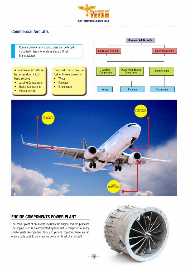
enGIne cOmPOnents POwer PlAnt
The power plant of an aircraft includes the engine and the propeller. The engine itself is a complicated system that is comprised of many smaller parts like cylinders, fans, and pistons. Together, these aircraft engine parts work to generate the power or thrust of an aircraft.
Commercial Aircraft manufacturers can be broadly classified in terms of scale as Big and Small Manufacturers
A Commercial Aircraft can be broken down into 3 basic sections• LandingComponents• EngineComponents• StructuralParts
Structural Parts can befurther broken down into• Wings• Fuselage• Empennage
commercial Aircrafts
commercial Aircrafts
Small Manufacturers
Landing Components
EmpennageFuselageWings
Power Plant Engine Components
Big Manufacturers
Structural Parts
Landing gEar CoMPonEntS
StruCturaL CoMPonEntS
EnginE CoMPonEntS

High Performance Cutting Tools
®
10
lAndInG GeAr
You cannot have a safe plane without having a good landing gear. Not only are these parts imperative for landing, but the landing gear is also used to help an aircraft take off and taxi. The landing gear includes shock absorbers for a smooth landing and takeoff, as well as the wheels on the plane. These components are typicallymadeofTitaniumalloys.Locatedunderneath thefuselage this is either fixed or retractable.

High Performance Cutting Tools
®
11
wInGs
The wings, also commonly known as foils, are aircraft parts that are imperative for flight. The airflow over the wings is what generates the majority of the lifting force necessary for flight.
The wings of a modern aircraft can be designed as a combination of different types of materials, depending on their specific structural function. The structure of the wing of an aircraft is comprised of several different elements, namely spars, skin and ribs, as well as control surfaces, such as ailerons and flaps.
Each of these components needs to support different loadsand, thus, the right material needs to be selected. Titanium and aluminium alloys can be used in the manufacturing of ribs, whilst glass reinforced composite materials can be used in the design of the wing skin and the control surfaces.
fuselAGe
The fuselage is one of the major components on an aircraft. It is the long hollow tube that’s also known as the body of the airplane, which holds the passengers, as well as the cargo. This area includes the cockpit, so the pilots are located in the front of the fuselage. Essentially, thefuselage connects all of the major parts of an airplane together. Titanium Fuselages are used majorly however Graphite epoxy, or carbon-fiber-reinforced polymer are under development.

High Performance Cutting Tools
®
12
emPennAGe
The empennage is the tail end of the aircraft. It helps with the stability of the plane and has two main components called the rudder and the elevator. The rudder helps the aircraft steer from right to left, and the elevator helps with up and down movement.

High Performance Cutting Tools
®
13
Space as a vertical in aerospace and defence can be classified under
space
outer space exploratory
telecommunication defence
Satellites
Space can be classified in two types Outer space exploratory and Satellites
Satellites can be of two major types telecommunication and defence
VariousMaterialsused• PureAluminum&AlumniumAlloys• Brass• Bronze• PureCopper• CarbonSteel• ColdRolledSteel• Hastelloy®• Inconel®• Monel®
• Delrin®• nylon• Polyethylene• Polytetrafluoroethylene(PTFE)• StainlessSteel
Currently the option of 3D printing items in space holds many advantages over manufacturing situated on Earth. With 3D printing technologies,ratherthanexportingtools,partsandequipmentfromEarthintospace,astronauts have the option to manufacture needed items directly. On-demand patterns of manufacturing make long-distance space travel more feasible and self-sufficient as space excursions require less cargo. Missionsafetyisalsoimproved.
sAtellIte telecOmmunIcAtIOn
Outer sPAce exPlOrAtOrydefence
space

High Performance Cutting Tools
®
14
land defence systems can be classified as below
ArmOured VehIclesMaterial used is Rolled homogeneousarmour(RHA)whichisatypeofarmourmade of a single steel composition hot-rolled to improve its material characteristics, as opposed to layered or cemented armour.
land defence systems
defence
DefenceisaveryvastbusinessunderaerospaceanddefenceandhasthreemajorbusinessesnamelyLandDefenceSystems,AirDefenceSystemsand Sea Defence Systems.
MajorspendhappensintheLandandAirdefencesystemsfollowedbytheSeaDefencesystems.
defence
Land Sea Air
land
Electronics/CameraLaser/Radar&TelecommunicationArmouredVehicles
Light/Clvillian/VIP
PersonalCarrier
HeavyDuty/Tanks
Unmanned&RemoteControlStations
GunsAmmunition
AirtoSurface
AirtoAir
SurfacetoAir
BalisticMissilies
SRBM MRBM IRBM
AntiShipMissiles
HelmetMountedSystems
RadarSystems
LaserSystems
VehicleMountedSystems
Light
Heavy
Missiles
ICBM

High Performance Cutting Tools
®
15
Guns And AmmunItIOnGuns and Ammunition are one of thehighest manufactured defence product in theworld,Madeupofmultiplematerials,including Steel, Aluminium and Plastics.They are primary categorized into light or heavy based on the calibre and Intensity
mIssIlesThere are five types, air-to-air, air-to-surface, surface-to-air, anti ship/tank & Ballistic missiles are most often categorized as short-range, medium-range, intermediate-range, and intercontinentalballisticmissiles (SRBMs,MRBMs,IRBMs,andICBMs)
electrOnIcs/ cAmerA’s/ lAsers/rAdAr And cOmmunIcAtIOn systemsNavigation Systems, Servers, Camera’s, Laser Guided Systems & Radar Systems,Defence Servers, Telecommunication modules use a lot of plastics and Aluminium.

High Performance Cutting Tools
®
16
BOmBersBombers is a combat aircraft designed to attack ground and naval targets by dropping air-to-ground weaponry (such as bombs), firing torpedoes and bullets, or deploying air-launched cruise missiles.
fIGhtersThe biggest fleet in any air force is the fighter aircraft is a military aircraft designed primarily for air-to-air combat against other aircraft. The hallmarks of a fighter are its speed, maneuverability, and small size relative to other combat aircraft. Although helicopters are sometimes used in similar roles, the term fighter is at present applied only to fixed-wing aircraft.
Air crafts have been in use in defence industry since 1783 when hydrogen balloons were used for air strikes. Now in the 21st century the air defence systems has reached the pinnacle of technology and is exploring unmanned and supersonic fighters for air strikes and defence.
mIlItAry trAnsPOrtThe number of aircrafts used in Military Transport fortransporting personal, ammunition, food and health support in and out of war zones. The typical carriers are big aircrafts designed to transport as high as 100 tonnes over 6000 kilometres range.
helIcOPtersDue to the extreme maneuverability and short space requirement for landing and takeoff, they are used for medical evacuation and as a fighter chopper
Air defence systems
Air
Helicopters
MedicalandEvac Fighter
MilitaryTransport Bombers Fighters

High Performance Cutting Tools
®
17
sea defence systems
unmAnned surfAce VehIcles (USV; also known as Unmanned Surface Vessels (USV) or (in some cases) Autonomous Surface Vehicles (ASV)) are boats that operate on the surface of the water without a crew. The new generation USVs can be operated remotely (by an operator on land or on a nearby vessel). These are used majorly for surveillance purposes
suBmArIneA submarine (or sub) is a watercraft capable of independent operation underwater Submarines are referred to as “boats” rather than “ships” irrespective of their size. Thedevelopment of submarine-launched ballistic missile and submarine-launched cruise missiles gave submarines a substantial and long-ranged ability to attack both land and sea targets with a variety of weapons ranging from cluster bombs to nuclear weapons.
AIrcrAft cArrIer An aircraft carrier is a warship that serves as a seagoing airbase, equipped with a full-length flight deck and facilities for carrying, arming, deploying, and recovering aircraft. It is the capital ship of a fleet, as it allows a naval force to project air power without depending on local bases for staging aircraft operations.
destrOyerIn naval terminology, a destroyer is a fast, maneuverable, long endurance warship intended to escort larger vessels in a fleet, convoy or battle group and defend them against powerful short range attackers.
sea
Destroyers Aircraft Carriers Submanine Unmanned Surface Vechicles

High Performance Cutting Tools
®
18
• Steel(P)• ArmourSteel(H)• CastIron(K)• StainlessSteel(M)
Materials that Matter
machinability of Aerospace & defence Parts
the Industry needs
• Innovations in materials science and engineering has led to improved materials and solutions to technological, societal and environmental
problems.
• TheenhancementandrefinementofnewgenerationmaterialshasledtobetterMachinability
• Materials science has advanced and Engineering is advancing biomaterials, ceramics, electronic materials, metals, polymers that effect all
engineering areas.
• AlternateMaterialstoscarcemetalsandalloys
• newgenerationmaterialswithhigherstrengthtoweightratio
• Biodegradablematerials
Example:-ExhaustManifold–SGIrontoTeflon
Example:-Knuckle–ForgedSteeltoADI
Example:-Aluminium–AluminiumMatrixComposites
mAchInABIlIty
Machinabilityistheeasewithwhichametalcanbecutpermittingtheremovalwithsatisfactoryfinishandlowcost
• Materialswithgoodmachinabilityrequirelowpowertocut,canbecutquickly,easilyobtainagoodfinish,anddonotwearthetoolmuch;such
materials are referred to free machining .
• Thefactorsthattypicallyimproveamaterialsperformanceoftendegradeitsmachinability.
• Whenmanufacturingcomponentseconomically,engineersarechallengedtofindwaystoimprovemachinabilitywithoutharmingperformance.
• Machinabilitycanbedifficulttopredictastherearesomanyvariablesinmachining
• Twomajorfactorsthatdecidethemachinabilityaretheconditionoftheworkmaterialandthephysicalproperties
• Otherimportantfactorsareoperatingconditions,cuttingtoolmaterial,geometryandmachiningprocessparameters
• TherearemanyfactorsforQuantifyingmachinability;theonescommonlyusedaretoollife,surfacefinish,cuttingtemperature,toolforces,power
consumption
• Thelatesttrendintheaerospaceindustryismovingtolightermaterialsandalternatematerialswhichofferhigherstrengthtoweightratioand
structural integrity
• Theaviationindustryhavemovedalotofpartstoqualifiedvendorswhocurrentlyarelookingattoolingsupplierswhocandeliver
A) Higher productivity
B)LighterMaterials
C) Structural Integrity
• Thebiggestchallengeisproductivityduringmachining.
• Conditionoftheworkpieceincludeeightfactors-microstructure,grainsize,heattreatment,chemicalcomposition,fabrication,hardness,yield
strength and tensile strength.
• Physical Properties are those of individual material groups such as Modulus of elasticity, thermal conductivity, thermal expansion and work
hardening
• nonFerrous(n)• Aluminium• CFRP• GFRP• PolymersandPlastics• Composites
• HeatResistantSuperAlloys(S1-S3)• Titanium(S4)

High Performance Cutting Tools
®
19
The interdisciplinary field of materials science, also commonly termed materials science and engineering, involves the discovery and design of
new materials, with an emphasis on solids.
The origin of materials science stem from the enlightenment, when researchers began to use analytical thinking from chemistry, physics,
and engineering to understand ancient, phenomenological observations in metallurgy and mineralogy.
Materialsscienceisasyncreticdisciplinehybridizing metallurgy, ceramics, solid-state physics, and chemistry.
structure–Materialsscienceexaminesthestructureofmaterialsfromtheatomicscale,allthewayuptothemacroscale.
Properties–Materialsexhibitvariousproperties,whichincludethebelow.
• Mechanical&Physicalproperties-Strengthofmaterials
• Chemicalproperties-Chemistry
• Electricalproperties-Electricity
• Thermalproperties-Thermodynamics
• Opticalproperties-Optics&Photonics
• Magneticproperties-Magnetism
Performance – Studying the relative performance for a particular application
Processing/ synthesizing – This involves the creation of a material with the desired micro-nanostructure.
characterization – Characterization is the way materials scientists examine the structure of a material. Various methods such as diffraction
with X-rays, electrons, or neutrons, spectroscopy, Chemical analysis, thermal analysis, electron microscope analysis, etc.
what is materials science?

High Performance Cutting Tools
®
20
steel
The carbon content in steel greatly effects its machinability. High carbon steels are difficult to machine because they are strong and because they contain carbides that abrade cutting tools. • Ontheotherhandifthecarboncontentislowtheyaresoftandgummyandsticktothetoolresultinginbuiltupedgewhichreducesthetoollife.• Alloyingelementssuchaschromium,Molybdenumareoftenaddedtoimprovethestrengthofsteel.Howeverthesealloyingelementsdecrease
the machinability of steel. Addition of oxides abrade the cutting tools• SteelhasthebestmachinabilitywhentheCarbonpercentageisabout0.20%-Toolandmanufacturingengineershandbook(1989)• Steel is an alloy of iron and carbon, and sometimes other elements. Because of its high tensile strength and low cost, it is one of the major
materials used in an aircraft. • Ironisabletotakeontwocrystallineforms(allotropicforms),bodycenteredcubicandfacecenteredcubic,dependingonitstemperature.• Inthebody-centeredcubicarrangement,thereisanironatominthecenterandeightatomsattheverticesofeachcubicunitcell.• Intheface-centeredcubic,thereisoneatomatthecenterofeachofthesixfacesofthecubicunitcellandeightatomsatitsvertices.• Itistheinteractionoftheallotropesofironwiththealloyingelements,primarilycarbon,thatgivessteeltheirrangeofuniqueproperties.
In pure iron, the crystal structure has relatively little resistance to the iron atoms slipping past one another, and so pure iron is quite ductile, or soft and easily formed.
In steel, small amounts of carbon, other elements, and inclusions within the iron act as hardening agents that prevent the movement of dislocations.
Thecarbonintypicalsteelalloysmaycontributeupto2.14%ofitsweight.
Varying the amount of carbon and many other alloying elements, as well as controlling their chemical and physical makeup in the final steel slows the movement of those dislocations that make pure iron ductile, and thus controls and enhances its qualities.
These qualities include the hardness, quenching behaviour, need for annealing, tempering behaviour, yield strength, and tensile strength of the resulting steel.
The increase in steel’s strength compared to pure iron is possible only by reducing iron’s ductility
materials

High Performance Cutting Tools
®
21
hArdened steel
In general, hard milling involves cutting primarily tool steel or precipitation hardening stainless steel, such as 15-5 or 17-4, that has been hardened toatleast50HRC.Afteraworkpieceisroughedinthesoftstate,itissenttothefurnaceforhardeningandthenfinishmachinedwithcoatedcarbide,ceramicorPCBntools.Theamountofmetalremovalinthehardenedstateisminimal—perhapsjust0.010“to0.020“persurface—makingthisprocess feasible for most hardened parts.
Depending on the workpiece configuration, production volume and amount of stock removal, however, it may be feasible to machine the workpiece entirelyfromahardenedstate.Modernmachinetools,advancedcuttingtoolmaterialsandsophisticatedCAMprogramsmakewhatwasonceahighlyimprobable machining operation into one within the reach of many shops. The advantage of machining from a hardened state is having to cut it only once. Once you enter the cut ensure that you do not leave the cut.
HardenedSteel-CanbemachinedwithtwostrategiesHPMandHSM
hPm• Highcuttingspeed(Vc)• Largecuttingdepth(Ap)• Smallcuttingwidth(Ae)• Mediumfeedpertooth(Fz)/tablefeed(Vf)
hsm• Highcuttingspeed(Vc)• Smallcuttingdepth(Ap)• Smallcuttingwidth(Ae)• Highfeedpertooth(Fz)/tablefeed(Vf)
cAst IrOn
Cast Iron among the most common and least expensive of all the types, contains carbides in the form of lamellar graphite particles, which gives it excellent vibration damping properties and makes it ideal choice for engine components. It also has the highest level of machinability when compared to other types. • VermIculAr cAst IrOn, also known as compacted graphite iron, offers greater strength and lower weight when compared to grey cast iron.
Because vermicular cast iron is suitable for components subjected to both mechanical and thermal stress, automotive manufacturers are using it more in the production of cylinder heads and brake parts.
• sIlIcOn AllOyed ferrItIc ductIle cAst IrOnisidealfortheproductionofwheelhubsandaxles.Givenitshighdegreeofmachinabilityand excellent mechanical properties, the material is becoming increasingly popular within the automotive industry.
• nOdulAr ductIle cAst IrOn,whichconsistsofspheroidnodulargraphiteparticlesinferriteand/orpearlitematrix,possesseshighductility,good fatigue strength, superior wear resistance and a high modulus of elasticity, and hence have been the choice of material for transmission housings and wheel suspension parts within the automotive and heavy equipment industries.
* Note Cast Iron does not have a significance use in Aerospace• AustemPered ductIle IrOn offers high strength, high fatigue strength, good wear resistance and high values of elongation to fracture,
making it a very competitive material in relation to many cast and forged steels. Because of great strength and elastic properties, Austempered ductile iron has the lowest level of machinability when compared to the other types of cast iron mentioned here.
the sOlutIOn• Theidealcuttingtoolmaterialformachiningcastironshouldhavehighstrengthandhardnessinadditiontohighfracturetoughness.Although
this combination of properties is impossible to achieve in practice since high strength and low fracture toughness are synonymous, the selection of the proper cutting tool is important for machining various types of cast irons.

High Performance Cutting Tools
®
22
Alloy UNS No. Composition %
C Mn Si Cr Ni Mo Cu Ti Other
Martensitic
PH13-8Mo S13800 0.05 0.1 0.1 12.8 8 2.3 AI=1.1
15-5Ph S15500 0.07 1 1 14.8 4.5 - 3.5 Nb=0.3
17-4PH S17400 0.09 1 1 16.3 4 - 4 Nb=0.3
Custom455 S45500 0.05 0.5 0.5 12 8.5 0.5 2 1.1 Nb=0.3
Semi-austentic
PH15-7Mo S15700 0.09 1 1 15 7.1 2.5 - - AI=1.1
17-7PH S17700 0.08 0.9 0.5 16.5 7.5 - AI=1.0
Austenitic
A-286 S66286 0.08 2 1 15 25.5 1.25 - - Ti:2.1
AI:≤0.35
V:0.3
stAInless steel
Stainless steels have poor machinability compared to carbon steel because they are tougher and gummier and tend to work harden very rapidly• Slightlyhardeningstainlesssteelreducesitsgumminessandmakesiteasiertomachine.AISIgrades304and416areeasiertomachine
because of the addition of sulphur and phosphorus• Itisessentialtokeepthecuttingtoolssharpwhenmachiningstainlesssteels.• Carefulgrindingandhoningofthetoolfacestogiveaccurateandsharpfaceanglesisimportant.Thishelpsoptimise;toollife,finish,accuracy
and tolerances productivity between regrinds and reduce tool breakages• Itisessentialthatcuttingfluidsareusedwhenstainlesssteelsaremachinedtoovercomeworkhardening• Designmachiningprocesswithdepthofcutbelowtheworkhardeningzone.• StainlessSteel :-Useadequatebutnotexcesscuttingspeedstoavoidbuildupedgeandquickwear.
PresIPItAtIOn hArdened
PrecipitationHardening(PH)stainlesssteelsareafamilyofcorrosionresistantalloyssomeofwhichcanbeheattreatedtoprovidetensilestrengthsof850MPato1700MPaandyieldstrengthsof520MPAtoover1500MPa-somethreeorfourtimesthatofanausteniticstainlesssteel such as type 304 or type 316. • PrecipitationHardening(PH)stainlesssteelsareclassifiedasMartensiticorsemi-austenitic.• Theydeveloptheirhighstrengthandhardnessthroughavarietyofheattreatmentsresultinginaveryhighstrength-to-weightratio.• Semi-austenitic grades are 17-7 PH® and PH 15-7 Mo®.They are austenitic in the annealed state, and Martensitic in the hardened
condition.• Martensiticgradesinclude17-4PH®and15-5PH®.ThePHgradesachievehightensilepropertiesinheattreatedconditions.• ApplicationsforPHsteelsarehighinaerospacecomponents.• Precipitationhardeningisachievedbytheadditionofcopper,molybdenum,aluminiumandtitaniumeithersinglyorincombination.
dIfferent tyPes Of Ph mAterIAls used In the AerOsPAce Industry.• 13-8MoPH-13%Cr-8%ni-2.3%Mo• 15-5PH-15%Cr-5%ni• 17-4PH-17%Cr-4%ni• 15-7MoPH-15%Cr-7%ni-2.5%Mo• 17-7PH-17%Cr-7%ni
tyPIcAl chAllenGes fAced mAchInInG Ph• Thermalcrackingduetocorrosion• notchwear• Lubricity, which is needed to reduce
material build-up but can cause unwanted contamination in some instances
• Imbalanced cutting forces (it isnecessary to maintain balance to avoid vibration, so in addition to stronger, more rigid cutting tools, good machine tools are a must).
sOlutIOn fOr mAchInInG Ph• AdequateEdgePrep• HeatResistantRawMaterial• RightMachiningStrategyandtoolpath• Chamfer or radius on edge to protect
the edge

High Performance Cutting Tools
®
23
AlumInIum
Theprimarytoolingconcernswhenmachiningaluminiumare:♦ Minimizingthetendencyofaluminiumtosticktothetoolcuttingedges;♦ Ensuringthereisgoodchipevacuationfromthecuttingedge;♦ Ensuringthecorestrengthofthetoolissufficienttowithstandthecuttingforceswithoutbreaking.
• Materials,surfaceconditionsandgeometryarethethreeelementsintooldesignthatinterrelatetominimizetheseconcerns.• Ifthesethreeelementsdonotworktogether,successfulhigh-speedmachiningisnotpossible.Itisimperativetounderstandallthreeofthese
elements in order to be successful in the high-speed machining of aluminium.• Theruleofthumbforhigh-speedaluminiummachiningtoolingdesignsistomaximizespaceforchipevacuation.Thisisbecausealuminiumisa
very soft material, and the feed rate is usually increased which creates more and bigger chips.• AluminiumDLCcoatingsprovidethebestCPCaddingabout20–25%tothetotaltoolcost.Thisextendsthetoollifesignificantlyascompared
to an uncoated tool.• AdventofPCDandMCDtoolshaveshowngreatincreaseinproductivity
A BrIef hIstOryThe Wright brothers chose aluminium for the cylinder block and other engine parts on their first manned flight in 1903. It was the first time an Al alloy had been heat-treated, a discovery that positioned aluminium’s dominance in aerospace engineering.commonly used aluminium alloys• Grade 2014- is a strong, tough metal suitable for arc and resistance welding*• Grade 2024- high-grade alloy with excellent fatigue resistance, 2024 is used in sheet forms such as for the fuselage and wings due to its high
tensile strength• Grade 5052- non heat treatable, provides the highest strength and is highly ductility, so it can be formed into various shapes. It is also highly
corrosion resistant.• Grade 6061(t6)-iscommon tomakeaircrafts light.Easilyweldedandmanipulated,6061 isvery lightand fairlystrong,making it ideal for
fuselage and wings.• Grade 7050- This alloy has high corrosion resistance and maintains strength in wide sections, making it more resistant to fractures. It’s commonly used
in wing skins and fuselage, especially in military aircraft.• Grade 7068- the strongest alloys strength and low mass make it perfect for military aircraft. • Grade 7075- With strength as steel due to its high levels of zinc, has excellent fatigue resistance. It can be machined easily.

High Performance Cutting Tools
®
24
• Benefitsfromcompositematerialsareespeciallyimportantwhereweightcontroliscritical:Aerospaceindustry(mainfocus)• newaeroplanemodelshave>50%inweightfromcomposites*
cOmPOsIte mAterIAls dePendInG On APPlIcAtIOns• Structuralapplication High-MediumTemperatureEpoxy• Interiors Phenolics,HScarbonfibres,Glassfibres,Aramid(Kevlar)• non-structuralapplications Lowcostresins-Polyester,Vinylesters
definition:Engineeredmaterialsmade fromtwoormoreconstituentmaterialswithsignificantlydifferentphysicalorchemicalpropertieswhichremain separate and distinct on a macroscopic level within the finished structure.
POlymer mAtrIx cOmPOsItes (Pmc’s) Themostcommon.AlsoknownasFRP-FibreReinforcedPolymers-thesematerialsuseapolymer-basedresinasthematrix,andavarietyoffibressuch as glass, carbon and Aramid as the reinforcement.
metAl mAtrIx cOmPOsItes (mmc’s) Increasingly found in the automotive industry, the matrix is a metal such as aluminium, the reinforcement fibres such as silicon carbide.
cerAmIc mAtrIx cOmPOsItes (cmc’s) Used in very high temperature environments, these materials use a ceramic as the matrix and reinforce it with short fibres, or whiskers such as silicon carbide and boron nitride.
Compositesmakeupabout50%oftheaircraftstructure.AboveillustrationisofaBoeing787body.*777modelused12%Compositesand50%Aluminium
cOmPOsItes

High Performance Cutting Tools
®
25
whAt mAkes uP A cOmPOsIte?
resins• Epoxy-Thehigh-qualitystandard• Phenolic-Fireresistant• BMI,Cyanate-Hightemperature• Polyester,Vinylester-Lowcost• Thermoplastic(PEEK,PEKK)• Highimpactresistance
fiber reinforcements• Carbonfiber/Graphitefiber(highstrengthorhighmodulus)• Glassfibers• Ceramicfibers• Polymerfibers(Kevlar,Polyethylene)• Tungstenfibers
fiber Orientation and structure• Unidirectionalreinforcement(UD)• Planarreinforcement(PD)
unidirectional reinforcement (ud)Maximumstrengthandstiffnessareobtainedinthedirectionofthefiber
Properties•Higheststrengthindirectionoffiberorientation•Badhandlingfeatures•Criticalmachiningduetohighdelaminationrisk
Planar reinforcement (Pd)Two dimensional woven fabric
Properties•Uniformstrengthinalldirections•Betterhandlingfeatures•Lowerdelaminationrisk
cfrP
Carbon-fiber reinforced polymers (particularly epoxy) have gained tremendous importance due to their high strength-to-weight ratio.
cfrPs are often used in stacks with aluminium or titanium • Primarystructuralcomponents• Floorpanels,forfastening
laminates• Fiber-resin“prepregs”(tape),withonelaidontopofanother(eachtapelaidinoneorseveraldirections)inonebagandvacuummoldedtoform
a laminate.
PrepregsPrepregsarecompositematerialsinwhichareinforcementfiberispre-impregnatedwithathermoplasticorthermosetresinmatrixinacertainratio.

High Performance Cutting Tools
®
26
cfrP vs GfrP • Thereasonforusingglassfiberonrandomcoveringsissimple:Electromagnetictransparency.Carbonfiberconductselectricity,soitwillabsorb
muchofwhattheantennaradiatesawayor“listens”for.Glassfibersaregoodinsulatorsandtransparenttoradarwaves.• The reason forglassfiberon forward-facingsurfaces is impact tolerance.Compared tocarbonfiber,glassfibershaveahigherelongationat
fracture and are a homogenous material.
why does elongation point matter?• Energyabsorptionisintegralunderthestress-straincurve,andahigherelongationatfracturegivesglassfiberbetterenergyabsorptionqualities.
Thepeakloadsforcarbonmightbeabithigher,butcarbonbreaksatanelongationoflessthan2%whileglassstretchesto5%beforerupture.Both, however, are inferior to most metals which have a phase of plastic deformation before rupture.
• Thesecondpointisbasedintheanisotropicnatureofcarbonfiber:Whenacarbonfiberisloadedinadirectionawayfromitslengthwiseaxis,itwillbreakeasily.Glass,beinganisotropicmaterial,hasthesamestrengthinalldirections,soaglassfibercompositeismuchbetterintakingarbitrary and impact loads.
rapid tool wearVery rapid flank wear due to the abrasive nature of composites.
Machining of carbon fiber is generally done with a router;however, standard metal machining methods can be used. Machining carbon fiber requires higher spindle speeds thanmetals, but lower feed rates. The feed rates need to be adjusted to minimize the heat in the part while machining. Carbon fiber has a low thermal conductivity and the majority of the heat remains in the part since there are no chips to help dissipate the heat when machining. This heat from cutting can cause damage to the resin. Since coolant might not be permitted when machining carbon fiber, the tool path and tool must be used to control the heat in the part while machining. Additionally, fracturing of the fibers creates considerable abrasion on the cutting tool, so special tooling is required when machining carbon fiber.
• Drilling is a difficult machining procedure on carbon fiber.Carbon fiber is constructed of layers of material that could easily splinter or delaminate during machining. Drilling speed must be adjusted based on the size and depth of hole. Special drill bits designed specifically for carbon fiber help eliminate delamination during drilling.
• Thedustfromcarbonfiberisconductive,andcanmigrateintoelectronics and short them out. Vacuum the dust frequently when machining to avoid damage to the machine.
mIllInG drIllInG
Delamination (separation of
layers)
Breakout
Fiberpullout
Uncut fibers
Challenges faced in machining compositesSurfaceQuality

High Performance Cutting Tools
®
27
Double Angle Composite Drills help combat delamination and push-out in layered composite materials with specialized point geometry. The primary 130° point angle allows the drill to efficiently engage laminated composites without lifting the top layer of material. The shallower secondary 60° point angle reduces the amount of force required to move the drill through the material, further reducing the probability of delamination. The higher shear angle also aids in reducing push-out at the back of the workpiece by more gradually breaking through the part.
Brad Point Composite Drills are designedspecifically for superior performance in fibrous composite materials. The trident-like brad point ensures that holes in fiber filled and reinforced materials come out clear and free of fraying. The outer points accurately score the outer diameter of drilled holes, eliminating uncut fibers, tear-out, and splintering. This avoids residual uncut fibres and fibre tear out.
POlymers
Polymersarelengthychaincompoundscomposedofmonomers.Amonomerisamoleculethatcanbebondedtootheridenticalmolecules.Polymersarebasicallyenormousmoleculesmadewithamassiveamountofsmaller, identicalmolecules.Polymershaveadifferentphysicalandchemicalmakeup than their monomers, and more uniquely, their properties can be tailored depending on their main purpose.
PlAstIcs
Plasticsaresemi-organicmaterialsthatcomefromoilorpetroleum.Theyareroutinelylabelledaspolymers,astheyarecomprisedofpolymers.Plasticsareproducedbycondensationandadditionpolymerizationreactions.Theyareclassifiedeitherasthermosettingpolymersorthermoplasticpolymers.
thermOPlAstIcs Vs thermOsets
Whenitcomestopolymers,youhavetwobasictypes:thermoplastics&thermosets.It’s crucial to know which one you’re working with due to distinct differences between how those polymers react to heat and temperature.thermoplastics are capable of being repeatedly softened and pliable when temperature increases, meaning that when heat is applied, that results in a physical change for the polymer.
thermosets, in contrast, turn into an infusible and insoluble material when cured by application of heat or chemical means, making for poor elasticity.
thermosets properties
HighResistanceto Creep
CannotMelt Insoluble
RarelySwellinPresenceof
Solvents
01
04
03
02
05GoodResistanceto Creep
MayMeltBeforeTurningtoGaseous
State
Soluble in Certain Solvents
SwellinPresenceof CertainSolvents
PlasticDeformation
when Heated
thermoplastics properties

High Performance Cutting Tools
®
28
Alloy Group MaterialHardness HB
Ann Aged
Nickel Inconell718 425
Inconell706 285
Inconell625 200
HastelloyS
HastelloyX 160
NimonicPK33 350
Udimet720
Waspaloy
Iron GreekAscoloy 300
A286 300
Incoloy909
Cobalt Haynes25
Stellite21 280 340
Stellite31
HRSAmaterialsfallintothreegroups:• nickel-based• Iron-based• Cobalt-basedalloysThe physical properties and machining behaviour of each varies considerably, due both to the chemical nature of the alloy and the precise metallurgical processing it receives during manufacture.
Whether the metal is annealed or aged is particularly influential on the subsequent machining properties.
nickel-basedarethemostwidelyused,andcurrentlyconstituteover50%oftheweightofadvancedaircraftengines.Thetrendisthatthiswillincrease in new engines in the future.
Commontypesinclude:• Inconel718,Waspaloy,Udimet720–precipitationhardened• Inconel625–solutionstrengthened(nothardenable)
Iron-based have been developed from austenitic stainless steels. Some have very low thermal expansion coefficients (such as Incoloy 909) which make them especially suited for shafts, rings, and casings in aircrafts
Theyhavethepooresthotstrengthpropertiesofthethreegroups.Commontypes:• Inconel909,• A286• GreekAscoloy
cobalt-based display superior hot corrosion resistance at high temperatures compared to nickel-based alloys. They are more expensive and also more difficult to machine due to their great wear resistance.
Theiruseinturbinesisrestrictedtocombustionpartsinthehottestengineareas.Commontypes:• CoCr• Haynes25• Stellite31
POlymers

High Performance Cutting Tools
®
29
Below table has the most common used heat resistant super alloys in the aerospace industry. With such a wide spread of materials under the generic headingofHRSAthemachiningbehaviourcanvarygreatlyevenwithinthesamealloygroup.
In fact the same material can have numerous machining recommendations.
Nimonic 1023
Nimonic 80A
Nimonic 263
Nimonic 75
ni based alloys
tendency for notch wear
fe based alloysstainlesssteels
Incoloy 901
CrucibleA286
17-4PH
Incoloy 901
Inconel 625Incoloy 800Sanicro 30
Austenitics
100
10 20 30 40 50 60 70 80 90
Precipitationhardenablealloys in annealed conditions
weight %nickel & cobolt
hardnesshB
= Solution treated (annealed)
= Heat treated (aged)
= Stainless steel
Heat generated during cutting (tendency for plastic deformation)
200
300
400
JetheteM152
nimonicPK33WaspaloyNimonic 90Nimonic 105
Inconel 718
machinability / raw material condition
• Thestateofheattreatmentaffectsthehardnessofthecomponentandhencethewearmechanisms.• Theformationofthechipisagoodindicatorofthehardness–withhardmaterialsitiseasiertobreakthechip.• Hardenedmaterialshaveincreasedcuttingtemperaturesandshowatendencytonotchingofthecuttingedgeatthedepthofcut.• Thecombinationofalowenteringangleandahardsubstratewithacoatingofferingaheatbarrierisrequired.• Softermaterialsmachinesimilarlytothestainlesssteelfamily.• Carbidegradeswithgreater toughnessand reducedhothardness– resistance tohigh temperatures–are requireddue to reducedcutting
temperatures and increased chip hammering. • Here,damagetoareasoutsidetheactualcuttingedgeiscausedbythechipshittingagainstthetool.
HeatTreatment
Annealing Headtingtocontrolledtemperaturethencoolingatcontrolledrate <30HRC
SolutionTreatment Heatingfollowedbyrapidcooling <30HRC
Ageing Slowcoolingaftersolutiontreatment upto48HRC

High Performance Cutting Tools
®
30
ByfarthemostcommonapplicationforHRSAmaterialsistheaircraftengine.• TheuseofHRSAinthecombustionpartoftheengineisincreasing.Thisistypifiedbythefactthat,whereasin1950onlyabout10%ofthetotal
weightofanaircraftgasturbineenginewasmadeofsuperalloys,thishasnowrisento50%intoday’smodernengines.• Coolantshouldbeappliedinalloperationsexcludingmillingwithceramics.Thevolumeandpressureshouldbehigh.
AerOsPAce And GAs turBIne - nIckel BAsedComponent Turning
Discs
Casings
Rings
BladesBlisksImpellers
Shafts
60%
45%
95%
10%
70%
50%
5%
40%
10%
40%
5%
15%
5%
25%
25%
Milling Drilling Others

High Performance Cutting Tools
®
31
tItAnIum
• Millingmakesupabout~90%ofallthematerialremoval(machining)processes in structural parts in aerospace machining.
• Titaniumisoneofthefastestgrowingmaterialsusedinaerospaceapplications. The prime rationale for designers to chose titanium in their designs is its relative low mass for a given strength level and its relative resistance to high temperature.
• Titanium sets complex machining demands. It has metallurgicalcharacteristics and material properties that affect the cutting action more severely than other metals such as cast iron and stainless steel.
• However, by combining a well-planned process with dedicatedapplication knowledge and tools/set-ups optimized for titanium,gains can be made to take advantage of the great properties that this material has to offer.
titanium and its alloys are used extensively in the following areas:• Aerospaceengine,•Aerospaceframe,•Aerospacelandinggear• Titanium components are machined in the forged condition
and often require removal of up to 90% of the weight of theworkpiece.
• Thehigh-chemicalreactivityoftitaniumalloyscausesthechiptoweld to the tool, leading to cratering and premature tool failure. The low thermal conductivity of these materials does not allow the heat generated during machining to dissipate from the tool
edge. This causes high tool tip temperatures and excessive tool deformation and wear.
• Titaniumalloysretainstrengthathightemperaturesandexhibitlowthermal conductivity. This distinctive property does not allow heat generated during machining to dissipate from the tool edge, causing high tool tip temperatures and excessive plastic deformation wear - leading to higher cutting forces.
• The high work-hardening tendency of titanium alloys can alsocontribute to the high cutting forces and temperatures that may lead to depth-of-cut notching.
In addition, the Chip-Tool contact area is relatively small, resulting in large stress concentration due to these higher cutting forces and temperatures resulting in premature failure of the cutting tool
• Titaniumalloys fall into threeclassesdependingon thestructuresand alloying types present. These additions are reflected in the designation codes used to describe each alloy.
• Alphaalloys–additionsofAl,Oand/ornpreferentiallystabilisethephase.
• Betaalloys–additionsofMb,Fe,VCrand/orMnstabilisethephase.• Mixed+alloys,inwhichamixtureofbothclassesispresent.Mixed
+alloysaccountforthemajorityoftitaniumalloysemployedtoday.• Ti-6Al-4V, first developed in 1954, remains the most common
general purpose grade in use, not only for aerospace but also for general purpose applications. These chemical additions have a direct influence on the physical properties of the alloys, their chemical and thermal behaviour and their machinability.

High Performance Cutting Tools
®
32
Machinabilitycomparisonofdifferenttitaniumtypesisshownintheabovetable.
The cutting data in this guide focuses on speeds for ti6Al4V. The same strategy and feeds should be used for other grades of titanium but the speed should be altered depending upon the level of machinability.
ti-10V-2fe-3Al is a non ferrous near Alloy of Titanium which has an excellent combination of strength, ductility, fracture toughness and high cycle fatigue strength. This grade is used extensively in landing gears.
ti-8Al-1mo-1V is most commonly used alloy. Special annealing cycles have been developed for this grade, which enhances its creep strength and fracture toughness while permitting it to maintain good strength levels.
Issues In mAchInInG tItAnIum• Relativelypoortoollife,evenatlowcuttingspeeds.• Highchemicalreactivitycauseschipstogallandweldtocuttingedges.• Lowthermalconductivityincreasescuttingtemperatures.• Usuallyproducesabrasive,tough,andstringychips.• Takeprecautionarymeasureswhenmachiningareactivemetal.• Lowelasticmoduluseasilycausesdeflectionofworkpiece.• Easyworkhardening
• TheTi6Al4VTitaniumalloyswhichfeaturebothandphasesandcontainbothandstabilizers is themostpopularalloy inthisgroup,which isprimarily used in the aerospace industry. Alloys in this category are easily formable and exhibit high room-temperature strength and moderate high-temperature strength. The properties of these alloys can be altered through heat treatment.
Condition Designation Composition(approx%) Tensilestrength Hardness SpecificcuttingAl Sn Mo V Zr Cr Others Nmm-2 BHN forcekc/Mpa
aandnearaalloys
Ti-5Al-2.5Sn 5 2.5 x.xx 790
300-400 1200Ti-5Al-2.5SNELI 5 2.5 690Ti-8Al-1Mo-1V 8 1 1 900Ti-6Al-2Sn-4Zr-2Mo 6 2 2 4 900Ti-3Al-2.5V 3 620
aandnearβalloys
Ti-6Al-4V 6 4 900
310-350 1700
Ti-6Al-6V-2Sn 6 2 6 1030Ti-6Al-2Sn-4Zr-6Mo 6 2 6 4 1170Ti-5Al-2Sn-4Mo-27r-4Cr(Ti-17) 5 2 4 2 4 1125Ti-7Al-4Mo 7 4 1030Ti-6Al-32Sn-27r-2Mo-2Cr-0,25Si 6 2 2 2 2 0.25 1280Ti-8Mn 8 860Ti-13V-11Cr-3Al 3 13 11 1170
275-400 2400
Ti-11.5Mo-6Zr-4.5Sn(βIII) 4.5 11.5 6 700Ti-3Al-8V-6Cr-4Zr-4Mo(βC) 3 4 8 4 6 900Ti-10V-2Fe-3Al 3 10 2 1170Ti-15V-3Al-3Cr-3Sn 3 3 15 3 1000Ti-5553 3 5 5 3 1.3 1160
tItAnIum AllOys And mAchInInG chAllenGes
Machining PropertiesFeature Influence on cutting toolsRetainsstengthatrelativelyhightemperatures HighforcesandheatgenerationThinchipthickness,narrowcontactareaonrakeface Concentratedcuttingforces,lowerthanaveragefeedPoorthermalconductivity HighhothardnessrequiredSpeed/feedsensitiveCyclicchipformation-variableforces Pronetovibration/chatterChemicallyreactivewithcuttingmaterials CraterwearHighlevelofcarbidecontent Flankwear

High Performance Cutting Tools
®
33
• manganese (mn)–improveshardenability,ductilityandwearresistance.Mneliminatesformationofharmfulironsulfides,increasingstrengthat high temperatures.
• nickel (ni) – increases strength, impact strength and toughness, impart corrosion resistance in combination with other elements.• chromium (cr) –improveshardenability,strengthandwearresistance,sharplyincreasescorrosionresistanceathighconcentrations(>12%).• tungsten (w) – increases hardness particularly at elevated temperatures due to stable carbides, refines grain size.• Vanadium (V) – increases strength, hardness, creep resistance and impact resistance due to formation of hard vanadium carbides, limits grain size.• molybdenum (mo) – increases hardenability and strength particularly at high temperatures and under dynamic conditions.• silicon (si) – improves strength, elasticity, acid resistance and promotes large grain sizes, which cause increasing magnetic permeability.• lead (Pb) – It is almost insoluble in liquid or solid steel. However, lead is sometimes added to carbon and alloy steels by means of
mechanical dispersion during pouring to improve the machinability. • titanium (ti) – improves strength and corrosion resistance, limits austenite grain size.• cobalt (co) – improves strength at high temperatures and magnetic permeability.• Zirconium (Zr) – increases strength and limits grain sizes.• Boron (B) – highly effective hardenability agent, improves deformability and machinability.• copper (cu) – improves corrosion resistance.• Aluminum (Al) – deoxidizer, limits austenite grains growth.• sulphur (s) – Improves machinability in free-cutting steels, but without sufficient manganese it produces brittleness at red heat. It decreases
weldability, impact toughness and ductility.• tantalum (tA) –Usedasstabilizingelementsinstainlesssteels.Eachhasahighaffinityforcarbonandformscarbides,whichareuniformly
dispersed throughout the steel. Thus, localized precipitation of carbides at grain boundaries is prevented.• Phosphorus (P) – Increases strength and hardness and improves machinability. However, it adds marked brittleness or cold-shortness to steel.• Zirconium (Zr) – It is added to killed high strength low alloy steels to achieve improvements in inclusion characteristics. Zirconium
causes sulphide inclusions to be globular rather than elongated thus improving toughness and ductility in transverse bending.
characteristics of alloying elements

High Performance Cutting Tools
®
34
strategies of machining - trochoidal milling
trochoidal milling is a method of high material removal in which we create a slot wider than the cutting tool’s cutting diameter. The circular cut is known as a trochoidal path.
Trochoidal milling is largely based on the concept of chip thinning. Conventional thinking suggests that cutting tools have an optimal chip load that determines the ideal width and size of the chips produced. The concept of combating chip thinning involves machining with a chip load that is larger than“optimal” inorder tomaintainaconstantmaximumchip thickness.
In contrast to a completely linear radial tool path in conventional machining, trochoidal milling takes advantage of a spiral tool path with a lowradialdepthofcut(Ae)toreduceloadandwearonthetool(Figure1).
(ß) is the engagement angle of the tool
(Ae) is the radial depth of cut.(Ap) is the axial depth of cut .
Letusnowlookatthedifferencesbetweenconventionalandtrochoidalmilling
Trochoidal milling methods were originally developed for roughing of difficultmaterialssuchashardsteels, ISOH,andHRSA-materials,butcan also be used with other materials, especially in vibration sensitive applications. Trochoidal milling is primarily used for machining slots and roughing parts.
Itisreferredwithmultiplenames(HVM-HighVolumeMachining)(HEM-High Efficiency Machining) .This technique has an improvement overtraditional milling methods which have an advantage of using high speeds while maintaining a low radial depth of cut (Ae) and a high axial depth of cut (Ap).
Forunderstandingtheseletmeusethebelowtermstomakeiteasytounderstand this concept
fz is the feed per tooth of the tool
Z is the number of teeth in the tool
RPM(n)istherevolutionsperminuteofthetool
Vc is the cutting speed or surface speed of the tool which is got by the formula
Vf is the table feed which is got by the formula
(hm) is the average chip thickness
ap
ae
ap
ae
In Conventional milling the (fz) which is the feed per tooth is constant and unidirectional
fz = constant
fz
Vf = variable
hm = constant
In trochoidal milling machining happens along programmed trajectories at a constant (Vf) (which is the table feed ) with different engagement angles (ß) based on the radial engagement of the tool (Ae)

High Performance Cutting Tools
®
35
hm= average chip thlckness [mm]
fz= 0059in [0.15mm]
feed per tooth fz = programmed
100% Conventional
50% Conventional
fz=.0059 in [0,15mm]fz=programmed feed per tooth
fz = .0069 in[0,15mm]fz = programmed feed per tooth
hm = .0039 in[0.1mm]hm = average chip thickness
hm = .0039 in[0.1mm]hm = average chip thickness
fz= 0059in [0.15mm]
feed per tooth fz = programmed
20% Trochoidal
hm = .0028 in [0.07mm]hm = average chip thickness
10% Trochoidal
hm =.0018 in[0,046mm]hm =average chip thickness
InconventionalMillingtheFeediscalculatedusingtheFormula
In trochoidal milling the dynamic feed is calculated by keeping the average chip thickness constant based on the engagement with the part
In conventional Milling we use a regular end mill with 3-4 Flutes foreffective chip evacuationIn trochoidal milling we use a specific trochoidal end mill design with a bigger core diameter and more number of optimized 3-4-5-6-7 flutes
In conventional milling we use a regular end mill where we go with a low axial depth (Ap) and a higher radial depth (Ae), we cannot go higher as the heat generated would be high
In Trochoidal you can have two strategies 1 static where the average chip thickness (hm) is maintained constant
based on the material to be machined
2 dynamic where the engagement angle and the average chip thickness (hm) is defined based on the profile to be machined and the material to be machined.
ß max
ß min
ae max
ae min
ß max
ß min
ae max
ae min
Static
Dynamic
In trochoidal milling we use a high axial depth (Ap) and a low radial depth (Ae) with less heat generated, resulting in longer tool life.
In conventional milling the tools are used on standard cnc center with normal Vc and fz
In trochoidal milling you will need to use a more dynamic cnc center with a high Vc and fz
In conventional milling the machining process is linear and standard
In trochoidal milling you will need to use a software which can help you generate this trochoidal program or can be manually programmed
In conventional milling the chip thickness (hm) is not constant and the cutting forces vary at entry of cut and exit of cut and are dependent on the work piece material.
In trochoidal milling the chip thickness (hm) is programmed to be uniform and the milling process happens with a constant force and a constant engagement angle in static trochoidal milling and constant force with varying engagement angle in dynamic trochoidal milling hence ensuring least shock load and uniform heat dissipation
In conventional milling generally cutters are engaged between ½ of the cutter diameter to full engagement where the average chip thickness (hm) value remains more or less constant at the center line of the cutter so it does not impact the feed rate
High Performance Cutting Tools
®
36
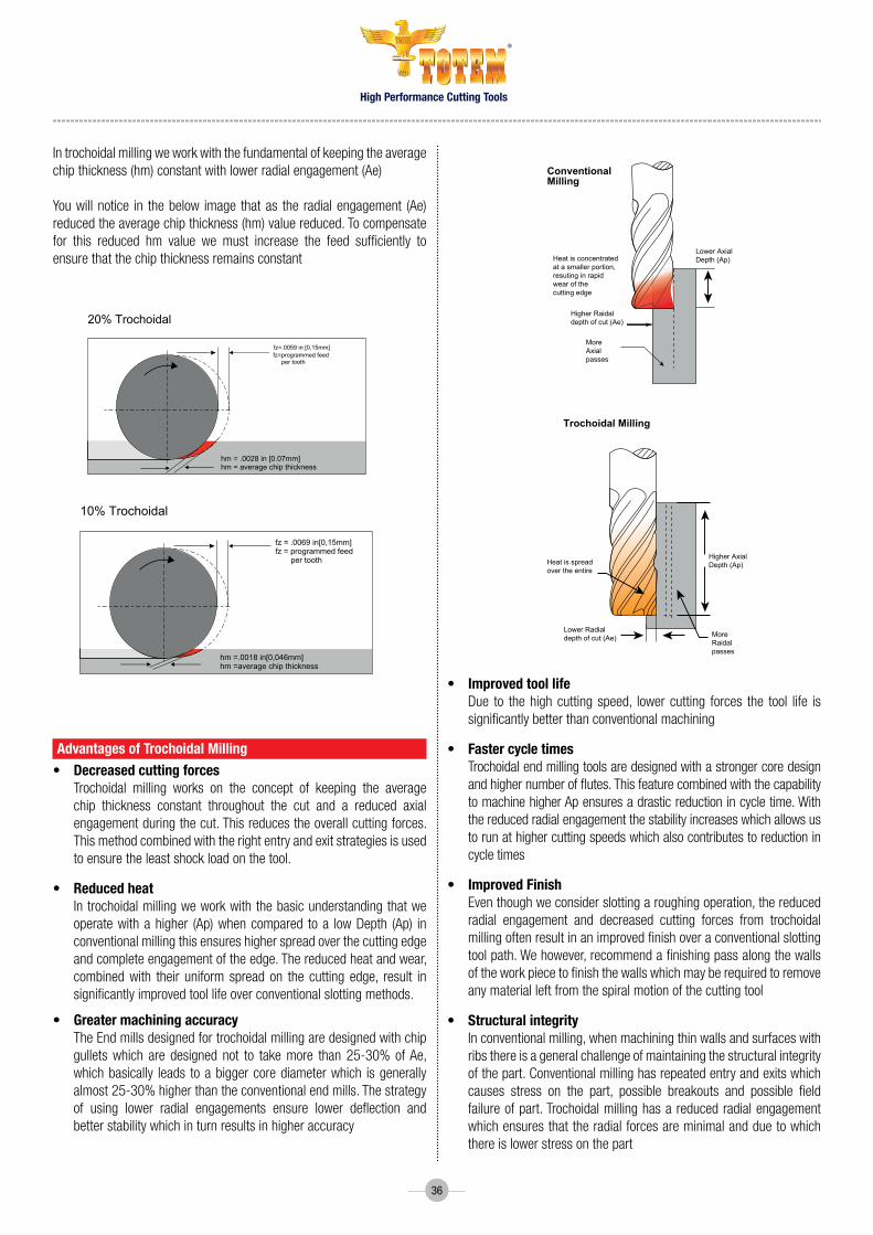
In trochoidal milling we work with the fundamental of keeping the average chip thickness (hm) constant with lower radial engagement (Ae)
You will notice in the below image that as the radial engagement (Ae) reduced the average chip thickness (hm) value reduced. To compensate for this reduced hm value we must increase the feed sufficiently to ensure that the chip thickness remains constant
Advantages of trochoidal milling• decreased cutting forces Trochoidal milling works on the concept of keeping the average
chip thickness constant throughout the cut and a reduced axial engagement during the cut. This reduces the overall cutting forces. This method combined with the right entry and exit strategies is used to ensure the least shock load on the tool.
• reduced heat In trochoidal milling we work with the basic understanding that we
operate with a higher (Ap) when compared to a low Depth (Ap) in conventional milling this ensures higher spread over the cutting edge and complete engagement of the edge. The reduced heat and wear, combined with their uniform spread on the cutting edge, result in significantly improved tool life over conventional slotting methods.
• Greater machining accuracy TheEndmillsdesignedfortrochoidalmillingaredesignedwithchip
gulletswhich are designed not to takemore than25-30%ofAe,which basically leads to a bigger core diameter which is generally almost25-30%higherthantheconventionalendmills.Thestrategyof using lower radial engagements ensure lower deflection and better stability which in turn results in higher accuracy
hm= average chip thlckness [mm]
fz= 0059in [0.15mm]
feed per tooth fz = programmed
100% Conventional
50% Conventional
fz=.0059 in [0,15mm]fz=programmed feed per tooth
fz = .0069 in[0,15mm]fz = programmed feed per tooth
hm = .0039 in[0.1mm]hm = average chip thickness
hm = .0039 in[0.1mm]hm = average chip thickness
fz= 0059in [0.15mm]
feed per tooth fz = programmed
20% Trochoidal
hm = .0028 in [0.07mm]hm = average chip thickness
10% Trochoidal
hm =.0018 in[0,046mm]hm =average chip thickness
Heat is concentratedat a smaller portion,resuting in rapidwear of thecutting edge
ConventionalMilling
Higher Raidaldepth of cut (Ae)
MoreAxialpasses
Lower AxialDepth (Ap)
Trochoidal Milling
Heat is spreadover the entire
Lower Radialdepth of cut (Ae)
Higher AxialDepth (Ap)
MoreRaidalpasses
Heat is concentratedat a smaller portion,resuting in rapidwear of thecutting edge
ConventionalMilling
Higher Raidaldepth of cut (Ae)
MoreAxialpasses
Lower AxialDepth (Ap)
Trochoidal Milling
Heat is spreadover the entire
Lower Radialdepth of cut (Ae)
Higher AxialDepth (Ap)
MoreRaidalpasses
• Improvedtoollife Due to the high cutting speed, lower cutting forces the tool life is
significantly better than conventional machining
• Fastercycletimes Trochoidal end milling tools are designed with a stronger core design
and higher number of flutes. This feature combined with the capability to machine higher Ap ensures a drastic reduction in cycle time. With the reduced radial engagement the stability increases which allows us to run at higher cutting speeds which also contributes to reduction in cycle times
• ImprovedFinish Eventhoughweconsiderslottingaroughingoperation,thereduced
radial engagement and decreased cutting forces from trochoidal milling often result in an improved finish over a conventional slotting tool path. We however, recommend a finishing pass along the walls of the work piece to finish the walls which may be required to remove any material left from the spiral motion of the cutting tool
• Structuralintegrity In conventional milling, when machining thin walls and surfaces with
ribs there is a general challenge of maintaining the structural integrity of the part. Conventional milling has repeated entry and exits which causes stress on the part, possible breakouts and possible field failure of part. Trochoidal milling has a reduced radial engagement which ensures that the radial forces are minimal and due to which there is lower stress on the part
High Performance Cutting Tools
®
37
Trochoidal Milling 16mm End Mill for a vendor of Boeing
Challenge reduction in CPC
Component Structural Part for Boeing
Competiton Hanita 57n8
Solution EM 16.00MMX34X48X100SH16 5FLt Cr1 aLt
Cutting data Machine:Makino-HMC,Shrinkfit-Totem ,Coolant–SolubleoilrPM = 1550-1620 l Feed = 850-920 l ap = 22mm, ae = 1.6mmExistingToolLife–220minuteslAchievedToolLife–300minutes
result 36%improvementinToollife
Benefit reduction in tool Change
Trochoidal Milling 16mm End Mill for a vendor of Boeing
Challenge reduction in CPC
Component Boeing Floor to Frame Fitting
Competiton Hanita 57n8
Solution EM 16.00MMX34X48X100SH16 6F Cr3 5FLtaLt
Cutting data Machine:MitsubishiDH80HMCHolderBT50Side-lockTotem,Coolant–SolubleOilrPM = 1200 l Feed = 420 l ap = 30mm, ae = 4mmExistingToolLife–240minuteslAchievedToolLife–344 minutes
result 43%improvementinToollife
Benefit reduction in tool Change
understand that we need heat to shear and that would mean the cutting speeds need to be increased accordingly. knowledge of the specific cutting force (kc) is very important to optimize parameters
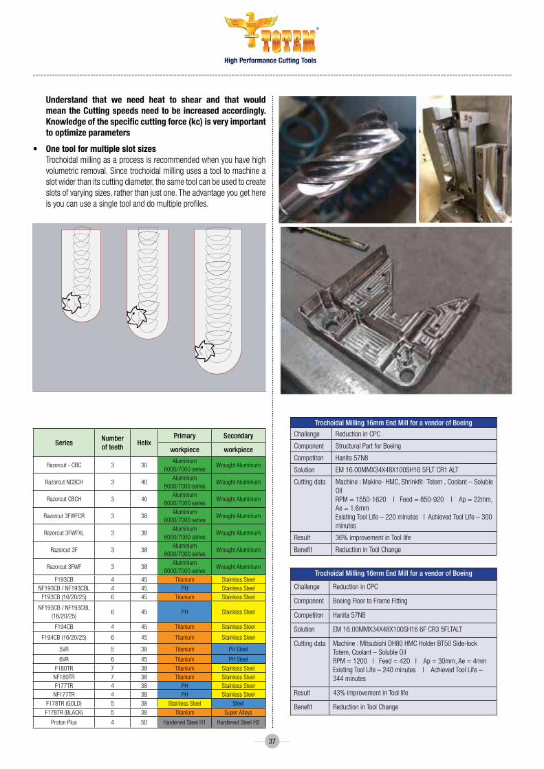
• One tool for multiple slot sizes Trochoidal milling as a process is recommended when you have high
volumetric removal. Since trochoidal milling uses a tool to machine a slot wider than its cutting diameter, the same tool can be used to create slots of varying sizes, rather than just one. The advantage you get here is you can use a single tool and do multiple profiles.
SeriesNumber of teeth
HelixPrimary Secondary
workpiece workpiece
razorcut - CBC 3 30aluminium
6000/7000 seriesWrought aluminium
razorcut nCBCH 3 40aluminium
6000/7000 seriesWrought aluminium
razorcut CBCH 3 40aluminium
6000/7000 seriesWrought aluminium
razorcut 3FWFCr 3 38aluminium
6000/7000 seriesWrought aluminium
razorcut 3FWFXL 3 38aluminium
6000/7000 seriesWrought aluminium
razorcut 3F 3 38aluminium
6000/7000 seriesWrought aluminium
razorcut 3FWF 3 38aluminium
6000/7000 seriesWrought aluminium
F193CB 4 45 titanium Stainless SteelnF193CB / nF193CBL 4 45 PH Stainless Steel
F193CB (16/20/25) 6 45 titanium Stainless Steel
nF193CB / nF193CBL (16/20/25)
6 45 PH Stainless Steel
F194CB 4 45 titanium Stainless Steel
F194CB (16/20/25) 6 45 titanium Stainless Steel
5Vr 5 38 titanium PH Steel
6Vr 6 45 titanium PH SteelF180tr 7 38 titanium Stainless Steel
nF180tr 7 38 titanium Stainless SteelF177tr 4 38 PH Stainless Steel
nF177tr 4 38 PH Stainless SteelF178tr (goLd) 5 38 Stainless Steel SteelF178tr (BLaCK) 5 38 titanium Super alloys
Proton Plus 4 50 Hardened Steel H1 Hardened Steel H2

High Performance Cutting Tools
®
38
Based on our experience and study of usage of trochoidal milling tools on various materials we have come up with a quick reference guide for starting parametersforDynamicTrochoidalmachining.WehavearrivedatAe/DRatiomaxandminlimitersaswellastheengagementangleofthesetoolswhen tackling flat surfaces (ß max) and corners (ß min)
Use these above conditions to get optimum results while machining.
Material Group Ae/D Ratio Engagement Angles
Series Ae Max Ae Min ß Max ß Min
Steel P1, P2 20.00% 10.00% 53.1 10
High alloy Steel P3, P4, P5 & PH 15.00% 10.00% 53.1 10
tool Steels 45 Hrc, P6, PH upto 48 Hrc 16.00% 0.80% 47.2 10
Stainlees Steel M1, M2 15.00% 7.00% 53.1 10
Stainless M3, duplex and Super duplex 10.00% 7.00% 53.1 10
Cast iron K1 25.00% 20.00% 53.1 10
S g iron K2, K3 20.00% 15.00% 53.1 10
alumminium 30.00% 20.00% 66.4 10
titanium S4 12.00% 8.00% 40.54 10
inconel S3 10.00% 6.00% 43.2 10
Super alloys S1, S2 10.00% 5.00% 40.54 10
Hardened Steel H1 (44-48) Hrc 12.00% 0.80% 40.54 10
Hardened Steel H2 (49-55) Hrc 4.70% 0.80% 25 10
Hardened Steel H3 (56-60) Hrc 2.20% 0.80% 17 10
Hardened Steel H4 >60 Hrc 1.10% 0.80% 12 10
Parameter calculation for trochoidal milling
step 1:- Based on the work piece material to be machined select the righttoolmakeaofnotethenumberofflutes/overhanglength/cuttinglength/helixangleandinputthisintotheCAMsoftware
step 2 :- SelecttheAe/DRatiolimitsandengagementanglelimitsfromthe above chart based on the material to be machined and enter this the CAMsoftware
step 3:- From thebelowchart basedon theAe/D ratio calculate thecorrect feed rate by multiplying the catalogue recommended feed the feed multiplication factor to get the correct chip load and enter this into theCAMsoftware.
step 4:- From thebelowchart basedon theAe/D ratio calculate thecorrect Vc by multiplying the catalogue recommended Vc with the cutting speed multiplication factor to achieve the right specific cutting force for the material group and enter the revised cutting speed into the CAMsoftware.
Ae/D Ratio Radial depth of cut (ae) based on diameter mm Engagement Angle ß
Feed Multiplication
Factor
Cutting Speed Multiplication
Factor Series 6 8 10 12 16 20
0.10% 0.006 0.008 0.010 0.012 0.016 0.020 3.620 15.819 2.2500.50% 0.030 0.040 0.050 0.060 0.080 0.100 8.110 7.089 2.2001.00% 0.060 0.080 0.100 0.120 0.160 0.200 11.480 5.025 2.1002.00% 0.120 0.160 0.200 0.240 0.320 0.400 16.260 3.571 2.0003.00% 0.180 0.240 0.300 0.360 0.480 0.600 19.950 2.931 1.8004.00% 0.240 0.320 0.400 0.480 0.640 0.800 23.070 2.552 1.7505.00% 0.300 0.400 0.500 0.600 0.800 1.000 25.840 2.294 1.6506.00% 0.360 0.480 0.600 0.720 0.960 1.200 28.360 2.105 1.6008.00% 0.480 0.640 0.800 0.960 1.280 1.600 32.860 1.843 1.55010.00% 0.600 0.800 1.000 1.200 1.600 2.000 36.870 1.667 1.50012.00% 0.720 0.960 1.200 1.440 1.920 2.400 40.540 1.539 1.45015.00% 0.900 1.200 1.500 1.800 2.400 3.000 45.570 1.400 1.40020.00% 1.200 1.600 2.000 2.400 3.200 4.000 53.130 1.250 1.35025.00% 1.500 2.000 2.500 3.000 4.000 5.000 60.000 1.155 1.33030.00% 1.800 2.400 3.000 3.600 4.800 6.000 66.420 1.091 1.30040.00% 2.400 3.200 4.000 4.800 6.400 8.000 78.460 1.021 1.27050.00% 3.000 4.000 5.000 6.000 8.000 10.000 90.000 1.000 1.25060.00% 3.600 4.800 6.000 7.200 9.600 12.000 101.540 0.950 1.15075.00% 4.500 6.000 7.500 9.000 12.000 15.000 120.000 0.900 1.100
100.00% 6.000 8.000 10.000 12.000 16.000 20.000 180.000 0.800 1.000

High Performance Cutting Tools
®
39
Series FG Code Cutting Dia
Flute Length OAL Shank
DiaNeck
DiameterNeck
LengthCorner
ChamferCorner Radius
Number of teeth
HelixPrimary
W/PAe (max)
hm (max)
F194CB FBK0510346 16 32 92 16 0.35 6 45 titanium 1.92 0.02
Series FG Code Cutting Dia
Flute Length OAL Shank
DiaNeck
DiameterNeck
LengthCorner
ChamferCorner Radius
Number of teeth
HelixPrimary
W/PAe (max)
hm (max)
6Vr FBK0508793 16 32 92 16 6 45 titanium 1.92 0.022
Letme illustratewithanexamplehowtocalculate theparameters formachining a structural part of titanium using static trochoidal milling
Material:-Ti6AL4V(Grade5)
Stocktoberemoved:-Ap25mmAe2mmonthewall
In the interest of optimizing structural integrity and surface finish, let us select a roughing and finishing tool.
StockforRoughingAe1.8mm/Ap25mm
StockforFinishAe0.2mm/Ap25mm
UpdatetheabovedimensionsintheCAMProgram
BasedonthestocktheAe/Dratiocanbecalculatedasbelow(1.8/16)=11%
FromtheChartabovethisconditioniswellwithinourlimitformachiningof12%
Fromthecatalogue the referenceVc is55m/minand fz is0.035mm/tooth
BasedonthestocktheAe/Dratiocanbecalculatedasbelow(0.2/16)=1.25%
FromtheChartabovethisconditioniswellwithinourlimitformachiningof12%
Fromthecatalogue thereferenceVc is55m/minand fz is0.064mm/tooth
for dynamic trochoidal milling
• Transfer the basic idea control of chip thickness to dynamic processes.
• Dynamic adaption of feed in relation to ae and engagement angles throughanintelligentCAMSoftware.
static trochoidal milling for a full slot
• UseatoolinwhichD<b• ProgramcirclesintheCnCprogram(asacycle)• Afteronecircle,repeatthesamewithanoffset.• Optimisebyshorteningthelane“intheair”toaformlikea“D”
Corner “picking”
Smooth toolpath blends Trochoidal
slotting strategy
Optimized feedrate
MultiplythecorrespondingchiploadfactorandtheVccorrectionfactorandyouwillgettherevisedVcas77m/minandfzas0.055mm/tooth
ThecorrespondingRPM1531andVf506mm/minarecalculated
FromtheCalculatorprovidedcalculate thecorrespondingengagementangle which is 39.19o
noteallthesevaluesandupdateitintheCAMsoftware
for the finish cycle
Basedonthetoolselectorletusgowithafinishingtool6VRFBK0508793
MultiplythecorrespondingchiploadfactorandtheVccorrectionfactorandyouwillgettherevisedVcas110m/minandfzas0.288mm/tooth
ThecorrespondingRPM2188andVf3780mm/minarecalculated
From thecalculatorprovidedcalculate thecorrespondingengagementangle which is 12.84o
noteallthesevaluesandupdateitintheCAMsoftware
requirements
stAtIc trOchOIdAl mIllInG•Dynamicmachine.•CnC-Program.•Moderntool.•Cuttingdatafortrochoidalmachining.
dynAmIc trOchOIdAl mIllInG•DynamicCnC-machine.•CAD/CAMSolutionslikeiMachiningfromSolidCAM.•Moderntool.•Cuttingdatafortrochoidalmachining.
for the roughing cycleBasedonthetoolselectorletusselectaroughingtoolF194CBFBK0510346

High Performance Cutting Tools
®
40
OldGen-AluminiumParts
Aluminium
800 2000 3000 5000
StainlessSteel Titanium Inconel
LeadTime
Monthlyspendonmillingcutting tools in $
newGen-TitaniumParts
1 15
16
14
12
10
8
6
4
2
0
6000
5000
4000
3000
2000
1000
0
Aerospace component manufacturing time
milling tooling spend in $ per month per spindle operating 20x7
lead time and spend on end mills in aerospace industry

High Performance Cutting Tools
®
41
specific cutting force• Forpower,torqueandcuttingforcecalculations,thespecificcuttingforce,orkc1,isused.Itcanbeexplainedastheforce,Fc,inthecutting
direction (Image 1), needed to cut a chip area of 1 mm² that has a thickness of 1 mm. The kc value is different for the six material groups, • notethattheSpecificcuttingForcecanvarybasedonthefeedrateandthematerialhardnesswithinthematerialgroup.Thiscanbedetermined
experimentally by conducting actual cutting tests• UsingtheSpecificCuttingForcefortheapplication,YoucancalculatethePowerinkWatthecuttingedgeandthemotor.Usingthisdatayoucan
calculate the Torque needed by the spindle to cut. • Thiswillhelpyouunderstandbeforecuttingwhetherthespindleiscapableoftakingtheloadandwhethertheparameterscalculatedforcutting
are suitable for that machine.
As9100 is the international quality management system standard for the Aviation, space and defence (As&d) industry, created by theIAQG,andAS9100RevD(2016)isthemostrecentversion.
The standard provides suppliers with requirements for creating and maintaining a comprehensive quality system for providing safe and reliable products to the As&d industry, as well as civil & military aviation requirements. “As9100 certified” means an organization has met the requirements of As9100d.
TherearethreeASDStandards,typicallymutuallyexclusive:As9100 – design, develop or manufactureAS9110–AircraftMaintenanceOrganizationsAS9120 – ASD Distributors of components like electronics and hardwareAS9100 mentions several other guidance standards that you should understand.
These additional standards don’t require certification, they provide guidance.• ItdoesnOtmatterwhatsizeyourorganizationis:1personor1millionpeople• It isnOt a product standard that defines product quality. AS9100 asks you to control your processes, so your end product meets customer
requirements.• ItisnOt a personal Standard – a person cannot get certified to AS9100.
As9100 Includes all of ISO 9001 quality management system requirements and specifies additional requirements for a quality management system for the aerospace industry.
Important aspects for a tool manufacturer to be covered in understanding the quality requirementsStress induced by tool on the part.Thermal stress induced due to machining.Accuracy and tolerance of the part.Functionalityofthepart.Warpage of thin wall components.
understanding the quality requirements in Aerospace
Material grop
SpecificCuttingForceKc(n/mm2)
P 1400-3200
M 1700-2800
K 780-1650
N 350-1350
S 1300-3300
H 3090-4750
Pc =
ap
x ae
x vf x k
c
60 x 106
Image 1

High Performance Cutting Tools
®
42
Optimized Production Planning Process
Analysisof
features
01 02 03 04 05machining strategy
cutter style selection
cutting data, tool selection
Program cAm
Optimising the above is of course necessary, however, to achieve an optimised process these must be combined with process and application ‘know how’toachievesecureproductivemachining.ThisinformationconsidersinwhichordertobuildanoptimisedprocessforHRSAmillinganddiscussesimportant ‘success factors’ for each stage.
Analysis of the features MostHRSAcomponentsarecriticalpartsoftheaircraftenginewithcomplexfeaturestobemachined.Carefulplanningandapplicationofmoderncuttingtoolmaterialscandramaticallyreducecycletime.Planningtheorderofoperationsinordertoreducepartdistortionisalsoanimportantfactorwhen planning the machining strategy.
machining strategiesMachiningStrategy,MachineRequirements:-Horizontal/Vertical,Configuration–3/4/5-axis,SpindleSpeed,tablefeed,PowerTorquerequirements,Spindlecoupling,CoolantRequirements,FixturingandStabilityoftheMachine
DuetothehighhothardnessandtoughnessofHRSA,theyareoneofthe most difficult to machine materials placing great demands on the tool. The outcome is traditionally, low cutting speeds and hence lower productivity/highermachiningcosts.
high speed machining (hsm) techniques offer an effective way to increase productivity and to mill intricate and thin-walled components. The high feed rates do not allow as much heat to get transferred into the component, due to the short contact time, compared to conventional milling techniques. However low radial cuts are required to keep the chip thickness small and allow for the higher feed rate.
typical components - aerospace

High Performance Cutting Tools
®
43
HSMuseshighRPMandaxialcut(ap)withasmallradialengagement(ae)andfeedpertooth(fz).Thisispossibledueto
This method requires a machine with high spindle speed and high feed dynamics putting no extra load and demand on the rigidity of the machine
trochoidal milling• Aroughing/highmaterialremovalmethodusedwheninaconfinedspaceorslot.• Acontinuousspiralingpathfeedingintheradialdirectiontoformagrooveoraprofile.• Itrequiresspecialisedprogrammingandmachinecapabilities.
Peel millingItisverysimilartotheTrochoidalPath.Ituses• Smallradialcuttingdepth• Deepcuttingdepth• Highcuttingspeed• SpiralCutter• Roughingmethodwhichnormallyeliminatessemi-finishing
slicingAsemi-roughingtechniqueusedtoproduceaprofile.Multiplepassesto reduce the radial immersion. It requires a machine with high spindle speed and dynamic capability.
PrOcesses usInG hsm technIques
fActOr effect BenefIt
Thin chip thicknessSmall arc of engagement
Lowercuttingforce/deflectionReducedtemperatureatcuttingzone
Deeper axial cutsHigher speeds

High Performance Cutting Tools
®
44
Plunge millingHere, the end of the cutter (axial cutting edge) is used instead of the side (radial cutting edge). This method offers an ideal solution for difficult materials like titanium.
Application•Demandingconditionssuchasinstability,longtoollength•Intooloverhangsover4×Dc•Forsemi-finishingofcorners•Whenmachinepower/torqueislimited•Horizontalmachinesfacilitatechipevacuation
Advantages•Lowpowerconsumption/noise
ProfilingA finishing technique used to produce a finished profile e.g. flank milling which reduces the number of axial passes. This requires a machine with high spindle speed and specialised programming techniques for simultaneous 5 axisforblisk/impellormachining.
SomeofthetypicalcomponentsthatcanbemachinedusingHSMtechniquesforexampleareblisks,impellers,turbines(LPTandHPT)andexhaustcasings.
APPlIcAtIOn recOmmendAtIOns
down millingIt is almost always more favourable to apply down milling rather than up milling. When the cutting edge goes into contact in down milling, the chip thickness has its maximum value, in up milling the chip thickness is zero.
The tool life is generally shorter in up milling due to the fact that there is considerably more heat generated due to the rubbing action that takes place on entry. The radial forces are also considerably higher in up milling.
Slots - shafts Blisk/impeller Scallops - casings
top View
+ +++
+
1 2
3

High Performance Cutting Tools
®
45
Avoid excessive deflectionShallow radial cuts (ae) should be applied to avoid excessive deflection of the cutting tool and to keep a high tolerance level and geometrical accuracies on the machined component. It is important to use a tool with a maximum core diameter (higher bending stiffness).
l = overhangDc = tool diameterF = radialforceδ = deflectionE = modulusofrigidityofthetoolδ = Fxl3/Ex(π x Dc4)
run Out controlOne of the main criteria when deciding both the tool and holding device is to have as small a run out as possible.
This keeps a uniform chip thickness on each cutting edge and hence has an even load distribution.
Thetotalindicatorrunout(TIR)shouldnotbemorethan10microns.Agoodruleofthumbisthat‘Forevery10micronsinaddedrunoutthetoollifereducesby50%’!
use shrink fits to get
Minimisedrunout - increasedtoollife.
Stability - reduced vibrations allowing higher depths of cut.
ReducedClampingforces - resistspulloutwithhighhelixcutters
20%overhangreductionreducestooldeflectionby50%.20%increasedDc(10to12mm)reducestooldeflectionby50%.
D
F
cδ
machining strategies for titanium/ hrsA- difficult to machine super alloys need various strategies to be implemented while manufacturing the tool and when machining
• KeepRadialEngagementLow• IncreaseFluteQuantity• MakeaThick-to-ThinChip-ClimbMilling• ArcIn-TrochoidalMethod• EndonaChamfer
• RelyonSecondaryRelief• AltertheAxialDepth• LimittheAxialDepthAroundSlenderFeatures(8:1)(15:1)(30:1)• ChooseaToolMuchSmallerthanthePocket• TakeaCuefromToolSteel(HSMstrategy)

High Performance Cutting Tools
®
46
machine requirement horizontal/VerticalForlargercomponentssuchasenginecasingswheretherearemanydifferentfeaturesandwhereaccessisanissueitisbesttouseahorizontalmachine.Thisalsomakesiteasiertoevacuatethechips,preventingre-cuttingofthechips,givingamoresecuretoollife.Forsomeringcomponentsand mounting brackets vertical machine tools can create improved stability.
configuration – 3/4/5-axisItiscommontohaveafourth/fifthaxisonhorizontalmachinestogivegoodaccessibilitye.g.forcasingsandclosedfaces.Forcomplexparts(3Dprofiles,blisks)5-axisrigidmachinesareused,withfullysimultaneousfiveaccesscontrol.
spindle speedThreecuttingstrategiesdictatethespindlespeedrequirements:a) Solidcarbidetools–(lowtorque)–thecuttingspeed(Vc)isbetween30to100m/min.Forcutterdiameters8to16mmthiswillgiveanrpm
requirement between 4000 to 600 rpmb) Carbideinserts–(hightorque)-thecuttingspeed(vc)isnormallylimitedtoamaximumof40m/min,forcutterdiameters25mmto80mmthis
will give an rpm requirement of 500 rpm to 159 rpm. c) Ceramicinserts–(highpowerandtorque)–typicallycuttingspeeds(vc)canbeashighas1000m/min,forcutterdiameters50mmthiswillgive
an rpm of 6365.
table feeda) Forroughing,usingcarbideinserts,thetablefeedisnaturallyrelativelylow,puttingdemandsonstabilityratherthanspeed.b) Forroughing,withceramics,thetablefeedcanbeuptoaround2.5m/min.Whilstthisisnotanextremetablefeed,caremustbetakenthatthe
controlsystemcancopewithdirectionchangeatthisfeedtoavoidundercutting/shortcutsetc.
Power/torque requirement a) Basically, the power requirement varies with the amount of metal to be removed, average chip thickness, cutter geometry and speed. The greater
themetalremovalrate(Qcm3/min)thehigherthepowerrequirement.b) With spindle speeds for roughing much lower than for less exotic materials, it puts great importance on ensuring that power and torque are
available at low rpms (a machine with insufficient torque and power will give fluctuating chip thickness in turn giving unstable performance).
spindle couplinga) MostHRSAalloyswork-hardenduringmachiningandhavehigherstrengthand‘gumminess’nottypicalinothermaterials.b) Heavy duty machining equipment and an ISO 50 taper (or equivalent) spindle is recommended to minimise chatter and work-hardening of the alloy
ahead of the cutting.
coolanta) Unlike milling in most other materials, coolant is always recommended to assist in chip removal, control heat at the cutting edge and prevent
re-cuttingofthechips.Highpressurecoolant (70bars)appliedthroughthespindle/toolsandexternallyhasbeenseentogivegoodbenefitscompared to low pressure.
fixturinga) The shape and fixturing of the component is of great importance. Aerospace engine components are often thin-walled and have a lot of complex
features which easily create distortion and vibration. b) This is often the reason why engine casings have complex fixtures to reduce vibration and support the workpiece in relation to the direction of the
cuttingforces.Lightcuttingtoolswithpositivegeometriescanhelptoensureasafe,distortion-freemachiningoperation.c) Use of Dampening elements (example :- Aluminium light weight fixtures for titanium parts)
stabilitya) Theconditionandstabilityofthemachinehasaneffectonthequalityofthesurfaceandcanimpairtoollife.Excessivewearofthespindlebearings
or feed mechanism can result in a poor surface structure. b) As well as ensuring a stable machine tool, other factors such as tool overhang, tuned adaptors etc should be considered.

High Performance Cutting Tools
®
47
wearTypical wear observed on an end mill in the case of Inconel is micro chipping rather than flank wear.
The edge line starts frittering before it leads to total cutting edge failure. The transition from micro chipping to failure is exponential, hence once this wearisobservedthetoolshouldbeimmediatelyindexed.Thiscanbemonitoredwiththepower/loadgaugeorbysound.
In Titanium micro chipping occurs at a much later stage when compared to Inconel
Optimized number of flutes
• Optimisedcutterdesign&cuttingparametersandselectionofnoofflutes (zn) are critical to machine super alloys
• Inconelisastickymaterialwhichcancauseproblemswithcloggingofthechipflutes.ThereforeeventhoughwithHSM,employinglowradial engagement with thin chips, extra close multi-fluted end mills (as used in hardened steel) are not recommended.
• The thin chip produced can prove catastrophic if it sticks to thecutting edge and can lead to tool breakage.
• AThumb rule used when selecting an end mill for roughing andfinishing of Inconel is as below
4 flutes - 8-12mm 5 flutes - 12.5-20mm 6 flutes - 20-25mm 7 flutes – 25mm and above
• However a balance should thus be struck between productivity(multi-flute) and security (lesser no of flutes).
Straight cutting edgeRa=0,5-0.8
Rz=4-6
300 450 600
Cord profileRa=12-14Rz=90-110
FlatprofileRa=2,5-3,5Rz=20-25
RoughingprofileRa=2,5-3,5Rz=20-25
Finisher Sinusoidal FlatChamfered
Power consumption
Roughing

High Performance Cutting Tools
®
48
helix angleAn end mill’s helix angle is defined as the angle of the cutting edge relative to the centreline of the tool. The helix influences tool performance mainly by affecting chip flow and cutting forces by determining the length of engagement of the cutting edge for a given depth of cut.
The greater the helix angle, the longer the cutting edge length allowing longer tool life and also giving a more gradual entry and exit into and from the workpiece. This lowers the radial forces that want to push the end mill and workpiece away from each other.
The result is a smoother machining action with less deflection. In most cases, high helix is recommended for finishing operations and a low helix in roughing because of the added strength.
One general rule of thumb is that as the helix angle increases, the length of engagement along the cutting edge will decrease. That said,there are many benefits and drawbacks to slow and high helix angles that can impact any machining operation.
low helix ( Below 40 dgrees)
Benefits• EnhancedStrength–Alargercorecreatesastrongtoolthatcanresistdeflection,ortheforcethatwillbendatoolunderpressure.• ReducedLifting–Aslowhelixwilldecreaseapartfromliftingoffoftheworktableinsettingsthatarelesssecure.• LargerChipEvacuation–Theslowhelixallowsthetooltocreatealargechip,greatforhoggingoutmaterial.
drawbacks• RoughFinish–Aslowhelixendmilltakesalargechip,butcansometimesstruggletoevacuatethechip.Thisinefficiencycanresultinasub-par
part finish.• SlowerFeedRate–Theincreasedradialforceofaslowhelixendmillrequiresrunningtheendmillataslowerfeedrate.
high helix ( above 40 degrees)
Benefits• LowerRadialForce–Thetoolwillrunquieterandsmootherduetobettershearingaction,andallowforlessdeflectionandmorestabilityinthin
wall applications.• EfficientChipEvacuation–Asthehelixangleincreases,thelengthofcuttingedgeengagementwilldecrease,andtheaxialforcewillincrease.
This lifts chips out and away, resulting in efficient chip evacuation.• ImprovedPartFinish–Withlowerradialforces,highhelixtoolsareabletocutthroughmaterialmuchmoreeasilywithabettershearingaction,
leaving an improved surface finish.
A 40-50 degree helix is optimally suited for milling in Inconel when radial cuts (ae) are less than 20% of the cutter diameterDc, for example trochoidal, slicing and finishing.
Helixangle
300 450 600

High Performance Cutting Tools
®
49
Simulation to show the Increase in cutting edge length as the helix angle increasesThediagramshowsincreasedlengthofcuttingedge(LCE)asthehelixangle(hx)increases.
Case 1 Case 2
dia (dc) = 12mmhelix Angle (hx) = 50o
ø = 40o
ap = tan(40) * π * 12ap = 31.64mmlce=ap/sin(40)lce=31.64mm/sin(40)lce = 49.22mm
dia (dc) = 12mmhelix Angle (hx) = 30o
ø = 60o
ap = tan(60) * π * 12ap = 65.32mmlce =ap/sin(60)lce =65.32mm/sin(60)lce =75.42mm
cAse 1
cAse 2
ap
ø = 400
π = D
LCE
ap
hx = 500
Dc = 12 mm
aphx = 300
Dc = 12 mm
ap
ø = 600
π = D
LCE
drawbacks• WeakerCuttingTeeth–Withahigherhelix,theteethofatoolwillbethinner,andthereforeweaker.• DeflectionRisk–Thesmallerteethofthehighhelixtoolwillincreasetheriskofdeflection,ortheforcethatwillbendatoolunderpressure.This
limits how fast you can push high helix tools.• IncreasedRiskofToolFailure–Ifdeflectionisn’tproperlymanaged,thiscanresultinapoorfinishqualityandtoolfailure.
InmyyearsofexperienceIhavecometounderstandthattheHelixangleonanEndMillisoneofthemostneglectedfeaturesoftheEndMill,duetothe lack of information on this featureLetusnowlookattheinfluenceofhelixonthelengthofthecuttingedgeincontactwhilemachining
Basic Terms used during the discussion belowap Axial depth of cutaeRadialdepthofcutHelix angle hxΦ =( 90o-hx) LCE=LengthofthecuttingedgeZ= number of teethLCEz=Lengthofthecuttingedgeperteeth
This basically indicates that at a lower helix, the length of the cutting edge increasesLetusnowassumethatinCase2,weneedtotakethesameapasinCase1whichis31.64mm.
LCE=ap/sin(60)LCE=31.64mm/sin(60)LCE=36.53mm
ThisgivesusaninsightthatatasimilaraptheLCEreducesastheHelixreduces

High Performance Cutting Tools
®
50
Now using simple trigonometry we can achieve
This is a case where there is no teeth overlapping, which causes zero or no micro vibrations
This Case is where the flutes overlap while cutting. This causes micro vibrations.
To resolve this, you can either modify the helix angle (hx) or the Diameter of the tool
Dia (Dc)= 12mm, apz = 12mm Helix Angle (hx) = 50o ø =40o
FromCase3
We know apz for no overlap is 7.91mm with hx 50o
Forapz=12mmwithnooverlapwith12mmDia,wewillrecalculatethehx
tan(ø)=apz/(πXD/4)
tan(ø)=12/(πX12/4)
tan(ø) = 1.2727
ø = tan-1(1.2727)
ø = 51.84o
hx = 38.16o
dia (dc) = 12mm
helix Angle (hx) = 50o
ø = 40o
apz = tan (40) * π*12/4
apz = 7.91mm
lcez = apz/sin(40)
lcez=7.91mm/sin(40)
lcez = 12.305mm
cAse 3ap
hx = 500
Dc = 12 mm
ø = 400
LCE2 = 12.305mm
apz
apz
apz
apz
ø = 400 ø = 400ø = 400 ø = 400
π=D/4 π=D/4π=D/4 π=D/4
LCE z
LCE z
LCE z
LCE z
Now that we have understood that the helix has a relationship to the cutting edge length.
Letusnowunderstandtherelevancein2scenarios(SlottingandSideMilling)
nowletusassumeyouareslottingapartwithadiameterof12mmandyouneedtomakeaslotof12mmwitha4fluteendmill(LetusconsiderCase1thatthetoolhasa50degreeHelixandtheLCEis49.22mm.
LetusconsiderthatthemaxapbasedoneachflutebeforethesecondflutestartstocutisapzandthemaxlengthofcuttingedgeisLCEz
SideMilling SlottingMilling

High Performance Cutting Tools
®
51
This Case is where the flutes do not overlap while cutting. Causing micro vibration.To resolve this, you can either modify the helix angle (hx) or the Diameter of the tool
Forapz = 12mm with no
overlap with 12mm Dia, we will recalculate the hx
tan(ø) = apz/(πXD/4)
tan(ø) =12/(πX12/4)
tan(ø) = 1.2727
ø = tan-1(1.2727)
ø = 51.84o
hx = 38.16o
cAse 4
ap
hx = 500
Dc = 12 mm
ø = 400
LCE2 = 12.305mm
ø = 400 ø = 400 ø = 400 ø = 400
π=D/4
12
34
π=D/4 π=D/4 π=D/4
apzLCE z
LCE z
LCE z
LCE z
ø = 51.84 ø = 51.84 ø = 51.84 ø = 51.84
π=D/4 π=D/4 π=D/4 π=D/4
LCE
LCE
LCE
LCE ap
z = 12mm
4

High Performance Cutting Tools
®
52
dia (dc) = 12mm
apz = 6mm
helix Angle (hx) = 50o
ø =40o
FromCase3
We know apz for no overlap
is 7.91mm with hx 50o
for apz = 6mm with no overlap with 12mm Dia, we will recalculate the hx
tan (ø) = apz/(πXD/4)
tan (ø)=6/(πX12/4)
tan (ø) = 1.2727
ø = tan-1(0.67364)
ø = 32.55o
hx = 57.55o
cAse 5
ø = 400
ø = 32.550 ø = 32.550 ø = 32.550 ø = 32.550
ø = 400 ø = 400 ø = 400
π=D/4
π=D/4 π=D/4 π=D/4 π=D/4
π=D/4 π=D/4 π=D/4
LCE
LCE
LCE
LCE
apz
= 6mm
apz
= 6mm
1
1 2 3 4
2
3
4
ap
hx = 500
Dc = 12 mm
ø = 400
LCE2 = 12.305mm
This Case is where the flutes do not overlap while cutting. Causing micro vibration. To resolve this, you can either modify the helix angle (hx) or the Diameter of the tool
This in essence tells you that if you want to slot the part at 1XD you will need to optimize your helix angle at 38.16 degrees to ensure that you have noMicrovibrationsduetoteethoverlapping
PleaseseebelowtablewhichindicatesthemaximumdeptyoucanmachinewithoutteethoverlapwithvariousnumberoffluteoptionswithStandardHelix angles offered by various suppliers
3 Flute
Helix 30 35 38 40 42 45 50 60
Dc MaxAxialDepth(ap)inmm
4 7.26 5.98 5.36 4.99 4.65 4.19 3.52 2.42
6 10.89 8.98 8.05 7.49 6.98 6.29 5.27 3.63
8 14.52 11.97 10.73 9.99 9.31 8.38 7.03 4.84
10 18.15 14.96 13.41 12.49 11.63 10.48 8.79 6.05
12 21.77 17.95 16.09 14.98 13.96 12.57 10.55 7.26
16 29.03 23.94 21.45 19.98 18.62 16.76 14.06 9.68
20 36.29 29.92 26.82 24.97 23.27 20.95 17.58 12.10

High Performance Cutting Tools
®
53
4 Flute
Helix 30 35 38 40 42 45 50 60
Dc MaxAxialDepth(ap)inmm
4 5.44 4.49 4.02 3.75 3.49 3.14 2.64 1.81
6 8.17 6.73 6.03 5.62 5.24 4.71 3.96 2.72
8 10.89 8.98 8.05 7.49 6.98 6.29 5.27 3.63
10 13.61 11.22 10.06 9.36 8.73 7.86 6.59 4.54
12 16.33 13.47 12.07 11.24 10.47 9.43 7.91 5.44
16 21.77 17.95 16.09 14.98 13.96 12.57 10.55 7.26
20 27.22 22.44 20.11 18.73 17.45 15.71 13.19 9.07
5 Flute
Helix 30 35 38 40 42 45 50 60
Dc MaxAxialDepth(ap)inmm
4 4.35 3.59 3.22 3.00 2.79 2.51 2.11 1.45
6 6.53 5.39 4.83 4.49 4.19 3.77 3.16 2.18
8 8.71 7.18 6.44 5.99 5.58 5.03 4.22 2.90
10 10.89 8.98 8.05 7.49 6.98 6.29 5.27 3.63
12 13.06 10.77 9.65 8.99 8.38 7.54 6.33 4.35
16 17.42 14.36 12.87 11.99 11.17 10.06 8.44 5.81
20 21.77 17.95 16.09 14.98 13.96 12.57 10.55 7.26
6 Flute
Helix 30 35 38 40 42 45 50 60
Dc MaxAxialDepth(ap)inmm
4 3.63 2.99 2.68 2.50 2.33 2.10 1.76 1.21
6 5.44 4.49 4.02 3.75 3.49 3.14 2.64 1.81
8 7.26 5.98 5.36 4.99 4.65 4.19 3.52 2.42
10 9.07 7.48 6.70 6.24 5.82 5.24 4.40 3.02
12 10.89 8.98 8.05 7.49 6.98 6.29 5.27 3.63
16 14.52 11.97 10.73 9.99 9.31 8.38 7.03 4.84
20 18.15 14.96 13.41 12.49 11.63 10.48 8.79 6.05
7 Flute
Helix 30 35 38 40 42 45 50 60
Dc MaxAxialDepth(ap)inmm
4 3.11 2.56 2.30 2.14 1.99 1.80 1.51 1.04
6 4.67 3.85 3.45 3.21 2.99 2.69 2.26 1.56
8 6.22 5.13 4.60 4.28 3.99 3.59 3.01 2.07
10 7.78 6.41 5.75 5.35 4.99 4.49 3.77 2.59
12 9.33 7.69 6.90 6.42 5.98 5.39 4.52 3.11
16 12.44 10.26 9.19 8.56 7.98 7.18 6.03 4.15
20 15.55 12.82 11.49 10.70 9.97 8.98 7.53 5.18

High Performance Cutting Tools
®
54
Byusingasmallerae%wecanuseensurewehaveaverysmallengagementangleBeta(ß).ThiswillallowustousethemaxLCEwhilemillingwithoutshocking the spindle. This is now dependant on the Workpiece material and the pitch of the tool
Inthebelow3imagesyoucanseethatastheradialengagement(ae/D)Ratiogoesfrom50%to10%theEngagementanglereduces
You can further improve your productivity by1) Using a variable index to reduce vibrations caused due to harmonics caused due to the constant sound of Impact.2) You can add a edge rounding value to strengthen your cutting edge3) YoucandampenthevibrationsfurtherbyworkingintheSafezonesaftercalculatingtheFRFofthemachine.
nowlet’slookatsidemillingasaTopicandunderstandtherelevanceofusingtheentireedgeforPeelMillingandSlicingwithouttoothoverlapswhichcause micro vibrations with high axial cuts
ItisverysimilartotheTrochoidalPath.Ituses•Smallradialcuttingdepth•Deepcuttingdepth•Highcuttingspeed•SpiralCutter•Roughingmethodwhichnormallyeliminatessemi-finishing
hm= average chip thlckness [mm]
fz= 0059in [0.15mm]
feed per tooth fz = programmed
100% Conventional
50% Conventional
fz=.0059 in [0,15mm]fz=programmed feed per tooth
fz = .0069 in[0,15mm]fz = programmed feed per tooth
hm = .0039 in[0.1mm]hm = average chip thickness
hm = .0039 in[0.1mm]hm = average chip thickness
fz= 0059in [0.15mm]
feed per tooth fz = programmed
20% Trochoidal
hm = .0028 in [0.07mm]hm = average chip thickness
10% Trochoidal
hm =.0018 in[0,046mm]hm =average chip thickness

High Performance Cutting Tools
®
55
Further advanced method is to reduce the load on the spindle andcalculate hoe many teeth are in cut based on the pitch and the number of teeth
PleaseTableshowsthenumberofteethincontactandtheengagementanglerangeforvariousoptionsof4/5/6/7fluteendmillsbasedonthepitch.
By having this information you can tweak your ae/D ratio to ensure 1 teeth is in contact and the spindle load is the least.
InthebelowChartwehaveindicatedthesafe(ae/D)limitstoworkwithwhilemachiningvariousmaterialgroups
corner geometryThemainwearobservedinthecaseofHSMinInconelismicrochippingat the cutting edge. A radius end mill, due to increased strength is always better compared to a chamfer or sharp corner.
Comparison between chamfer and radius end mill Vc100m/min,ap10mm,hex0.02mm,ae0.5mm,fz0.05mm/toothMaterial:Inconel718
80
70
60
50
40
30
20
10
0
80
70
60
50
40
30
20
10
0
Minutes= Total metal removed
= Tool lifecm3
CR3 CHAMFER
52
73
20
27
Material group ae/d Max
ae/d Min
Beta Max
SteelP1,P2 20% 10% 53.1
HighAlloySteelP3,P4,P5&PH 15% 10% 53.1
ToolSteels45HRc,P6,PHupto48HRc 16% 1% 47.2
StainleesSteelM1,M2 15% 7% 53.1
StainlessM3,DuplexandSuperDuplex 10% 7% 53.1
CastIronK1 25% 20% 53.1
SGIronK2,K3 20% 15% 53.1
Aluminium 30% 20% 66.4
TitaniumS4 12% 8% 40.54
InconelS3 10% 6% 43.2
SuperAlloysS1,S2 10% 5% 40.54
HardenedSteelH1(44-48)HRc 12% 1% 40.54
HardenedSteelH2(49-55)HRc 5% 1% 25
HardenedSteelH3(56-60)HRc 2% 1% 17
HardenedSteelH4>60HRc 1% 1% 12
Pitch Teeth Angle min Angle max Teeth in contact
90.00 4 0 90 190.00 4 90 180 272.00 5 0 72 172.00 5 72 144 2
60.00 6 0 60 160.00 6 60 120 260.00 6 120 180 351.43 7 0 51.43 151.43 7 51.43 102.86 251.43 7 102.86 154.29 3
120.00 3 0 120 1120.00 3 120 240 2

High Performance Cutting Tools
®
56
cutting speed (Vc)BecauseoftherelativelylowradialengagementsinHSMonecanmakeuseofhigherthannormalcuttingspeed(Vc),75to100m/mingivesthebestbalance between productivity and tool life. The chart shows the difference in performance relative to cutting speed.
chip thickness (hex)Thelowradialengagementreducesthechipthicknesscomparedtothefeed/tooth.Usingtheoptimisedchipthicknessispivotalinoptimisationoffinishing, slicing or trochoidal milling.
Ae/D % Cutting Speed
Multiplica-tion Factor
% (Ae/D) Enagagement
Chip Load Factor
Lower Limit Upper Limit0.10% 15.819
0.50% 7.089
0.10% 0.50% 2.20 1.00% 5.025
0.50% 1.00% 2.10 2.00% 3.571
1.01% 1.99% 2.00 3.00% 2.931
2.00% 2.99% 1.80 4.00% 2.552
3.00% 3.99% 1.75 5.00% 2.294
4.00% 4.99% 1.65 6.00% 2.105
5.00% 5.99% 1.60 8.00% 1.843
6.00% 10.00% 1.50 10.00% 1.667
10.01% 15.00% 1.40 12.00% 1.539
15.01% 20.00% 1.35 15.00% 1.400
20.01% 25.00% 1.33 20.00% 1.250
25.01% 30.00% 1.30 25.00% 1.155
30.01% 40.00% 1.25 30.00% 1.091
40.01% 50.00% 1.25 40.00% 1.021
50.01% 60.00% 1.15 50.00% 1.000
60.01% 75.00% 1.10 60.00% 1.000
75.01% 100.00% 1.00 75.00% 1.000
100.00% 1.000
ToolLife,min
40
35
30
25
20
15
10
5
0
75 100 125
Cutting speed, m/min
aß0
e
hex
f z
DC

High Performance Cutting Tools
®
57
trochoidal millingThis is an established process in hardened steels and aluminium. Now it isbeingextensivelyusedinHSRAandTitanium
The process puts low demands on stability and can be an extremely productive and secure method. This is advantageous especially where the components are large and costly calling for a secure productive solution.
Parameter selectionAs can be seen, during trochoidal milling, the maximum width of cut – ae max is not equal to the programmed step over-‘w’. The maximum radial cut(ae)maxshouldnotexceed20%ofthecutterdiameter.Startrecommendationsfortrochoidalmilling:Cutterdiameter,mmDc=65%slotwidthStepover,mmw=8%Dc,ap=1to1.5xDc,Cuttingspeedvc=75m/minFeed/toothfz=0.05mm/tooth
ae max
w
depthap
Width
radial cut (ae)For roughing applications it can be seen in thediagram that the maximum total material removed, when running with a constant speed and chip thickness, can be achieved with ae = 1.0 mm. ( for a 12mm tool)
Total metal removed and tool life vs radial cutvc75m/min,ap10mm,hex0.04mmMaterial:Inconel 718Test conducted with a 4 Flute (50 degree helixtool)
Thisequatesto8%ae/Dcandshouldbeusedasabase when roughing operations are required.
100908070605040302010
0
1009080706050403020100
cm3min
87 9094
77 77
2218 16 12 11
0.5 0.75 1 1.25 1.5
Radialcutae mmTool life
Total metal removal

High Performance Cutting Tools
®
58
Program cAmCAD/CAMstandsforcomputer-aideddesign&computer-aidedmanufacturing.CAD/CAMsoftwareisusedtodesignandmanufactureprototypes,finished products and production runs.
Inordertogeneratetheactualmodel,CAMworksalongsideCAD—usingCADdesigns,CAMusesnumericalcodingtorunthemachinethatcreatestheproduct.ACAD/CAMpackageallowscompaniestodevelopandsavetheirownproductdesigns,andprogrammachinestocreatetheactualcomponent.
ae/D RatioRadial depth of cut (ae) based on diameter mm Enagagement
Angle ßFeed
Factor
Cutting Speed Factor6 8 10 12 16 20
0.10% 0.006 0.008 0.010 0.012 0.016 0.020 3.62 15.819 2.25
0.50% 0.030 0.040 0.050 0.060 0.080 0.100 8.11 7.089 2.20
1.00% 0.060 0.080 0.100 0.120 0.160 0.200 11.48 5.025 2.10
2.00% 0.120 0.160 0.200 0.240 0.320 0.400 16.26 3.571 2.00
3.00% 0.180 0.240 0.300 0.360 0.480 0.600 19.95 2.931 1.80
4.00% 0.240 0.320 0.400 0.480 0.640 0.800 23.07 2.552 1.75
5.00% 0.300 0.400 0.500 0.600 0.800 1.000 25.84 2.294 1.65
6.00% 0.360 0.480 0.600 0.720 0.960 1.200 28.36 2.105 1.60
8.00% 0.480 0.640 0.800 0.960 1.280 1.600 32.86 1.843 1.55
10.00% 0.600 0.800 1.000 1.200 1.600 2.000 36.87 1.667 1.50
12.00% 0.720 0.960 1.200 1.440 1.920 2.400 40.54 1.539 1.45
15.00% 0.900 1.200 1.500 1.800 2.400 3.000 45.57 1.400 1.40
20.00% 1.200 1.600 2.000 2.400 3.200 4.000 53.13 1.250 1.35
25.00% 1.500 2.000 2.500 3.000 4.000 5.000 60.00 1.155 1.33
30.00% 1.800 2.400 3.000 3.600 4.800 6.000 66.42 1.091 1.30
40.00% 2.400 3.200 4.000 4.800 6.400 8.000 78.46 1.021 1.27
50.00% 3.000 4.000 5.000 6.000 8.000 10.000 90.00 1.000 1.25
60.00% 3.600 4.800 6.000 7.200 9.600 12.000 101.54 1.000 1.15
75.00% 4.500 6.000 7.500 9.000 12.000 15.000 120.00 1.000 1.10
100.00% 6.000 8.000 10.000 12.000 16.000 20.000 180.00 1.000 1.00

High Performance Cutting Tools
®
59
thin Wall Machining is a new norm in aerospace Parts, especially structural parts where the use of High strength to weight ratio materials are used like ti6al4V and al6061. to understand the application let us understand BtF ratio. BtF ratio is the weight oftherawmaterialdividedbytheweightofthefinalcomponent.Forconventionalmetalmanufacturinglikemilling,theBTFratiois often higher than 10, which means that less than 10% of the rawmaterialremainsinthefinalpart.NowthatweunderstandBTFratio,Let’staketheexampleforafloortoframefittinginanaircraft which at a raw material stage is 20 Kgs of ti6al4V and thefinishweightisshyofakilogram.SomeoftheEnginepartsinanaircraftwhichhaveasomplexprofilewithstrategiesofthinwall are iBr (integral Blisk rotors), aerofoils and impellers which willneedadvancedCAMprogrammingtechniquestoensureasmoothprofileona5Axismachine.
PROPER TOOLiNG imagine that you need to machine a part where the wall thicknesstotheheightRatioisabove15.Alonglengthtool,combinedwithalonglengthofcut,cannotbeusedduetodeflection,chatterandbreakage.Itisessentialtokeepthetoolasstableaspossiblewhilemaintainingtheabilitytoreachtothedesired depth. it is essential to look at necked-down tooling when reaching depths more than 3 times the diameter.
UNDERSTANDiNG AxiAL DEPTH OF CUT (ADOC) Keepingawidecross-sectionbehindthewallforsupportonthewaydownisvital.Below,werecommendproducinga“steppeddown”approachdividingthetotalwallheighttomanageabledepthswhileworkingeachsideofthewall.Inthebelowimagethemangebaledepthhasbeenindicatedwithnumbersbetween1to8.Eachblockheightindicatingthedepththatcanbemachinedinonepass.TheADOCdimensioncan/willvarydependingonthematerial(anditshardness)beingcut.
THiN wALL MACHiNiNG GUiDE- ESSENTiALS
(Figure 1)
11
3
5
7 8
6
4
21
3
5
7 8
6
4
2
A
3
5
7 8
6
4
2
5
7
6
8
4
Start withstub/ reglengthtooling

High Performance Cutting Tools
®
60
DetailArepresentsa5-stepprogressiveradialapproach.Thenumberofpasseswilldependuponyourparticularapplication,material/hardness&finalwallthickness/height.
note:Thinwallsdeflectunderpressuresoseparatemachiningpassesarerequiredtominimizefrictionandvibration.
Millingpartfeatureswiththinwallcharacteristicswhilemaintainingdimensionalaccuracyandstraightnesscanbedifficultatbest.Althoughmultiplefactorscontribute,somekeycomponentsarediscussedbelowandcanhelpturnthesetypesofapplicationsaround.
THiN wALL MACHiNiNG CAN BE CATEGORiSED iNTO 3 TyPES BASED ON THE HEiGHT TO THiCKNESS RATiO (H:T)
STRATEGy
RatioH:Tof15:1
RatioH:T>30:1
RatioH:Tbetween15:1-30:1
4:1for Non Ferrous
8:1 for Steel/ Stainless Steel/ Super alloys
(Figure 2)
7 8
6
8
This is thetool's Neck length
Relived neckwill not rub onwall
Detail A
1st rdoC - up to 50% cutter dia.
2nd rdoC - 30% cutter dia.
3rd rdoC - 15% cutter dia.
4th rdoC - 5% cutter dia.
UNDERSTANDiNG RADiAL DEPTH OF CUT (DOC) Aprogressiveradialdepthofcut(RDOC)strategyisofequalimportanceaswallheightisbeingestablished.Reducingtoolpressurewhilesupportstockisdisappearingisequallyimportanttokeepwallstable.
OTHER iDEAS • Climbmillingwillhelptokeeptoolpressuretoaminimum.• Vibrationdampening/wallstabilizationcanbeachievedin“hardtofixturethinwallsituations”byusingthermoplasticcompoundsorwax-whichcanberemoved(IdealwhenmachiningpartswhichhaveahighthermalstabilitylikeSuper alloys and titanium) (thermally).
• Theuseofultra-highperformancetoolpathscanoptimizetool performance, work with lighter depths of cut and offer less tool cutting pressure.

High Performance Cutting Tools
®
61
2
5
4
6
F 2
F 1
3
3
1
2
11 4
5
4
6
F
1
2
3
2
5
4
6
F 2
F 1
3
3
1
2
11 4
5
4
6
F
1
2
3
2
5
4
6
F 2
F 1
3
3
1
2
11 4
5
4
6
F
1
2
3
• Machineeachsideofthewallinoverlappingpasses• Leaveclearanceonthefacesforfinishingpasses• Whenmachining15:1andlowerpleaseensurethatyoufollowtheaboveflowofsteps
• Choosestep-supportmilling,withpassesonalternatesidesofthewall• Overlappingpassesprovidematerialsupporttoaddstability• Lessthan30:1forNonferrousstructuresensurethatthelastmachiningpasstakesout
80% of the material and For high strength materials like super alloys keep 0.2mm as a finishstock.Forferrousmaterialsyoucankeepstockbetween0.2mm-1mm
• Machinepassesonalternatingsidesofthewall• Approachthewallthicknessinstages• Thematerialsupportofthickersectionsiscrucialasthinnersectionsarebeing
machined• Movepassesdownthewallinastepformationmovingoutwards
RATiO H:T OF 15:1
RATiO H:T OF 30:1
RATiO H:T >30:1
STABiLiTyrELatiVELy
StaBLE
STABiLiTyLESS StaBLE
and PronE to dEFLECtion
STABiLiTyVEry unStaBLE
1
1
1
2
2
2
3
3
3
4
4
4
2
5
4
6
F 2
F 1
3
3
1
2
11 4
5
4
6
F
1
2
3
1
2
1
34
2
7
3
F
135
2
468
9
4
1
2
1
34
2
7
3
F
135
2
468
9
4
1
2
1
34
2
7
3
F
135
2
468
9
4
1
2
1
34
2
7
3
F
135
2
468
9
4

High Performance Cutting Tools
®
62
• 4:1rule–ratioofwallheighttowallthickness• Inourcasethewallis36mmtall,henceinroughingwe
reduced the wall to 9 mm thick • DuringfinishingtootheaxialDOCcannotbelargerthan4x
wall thickness • Inourcasefinishedwallthicknessis1.5mm,hencemax.
axial doC is 6 mm • Finishingistypicallydonein2radialpasses,withthelastpassremoving~80%offinalwallthickness,i.e.aradialDOCof 1.2 mm
• Hencewallis3.9mmthickbeforefinalfinishing,i.e.apre-finishwillremove5.1mm.
• Applythe4:1ruleagain,i.e.4x3.9=15.6mmaxialDOCforpre-finishcut.(Practicallytakeas12mm)
• Applyingthe4:1ruleresultsin18passestofinisheachwall.• Wallisdividedintothreelevels,eachlevelrequiring2pre-finishcutsandfourfinishcuts.
STRATEGy 4:1 FOR ALUMiNiUM WaterfallTechnique
fillet=1.0mmD12xR1.0
semi-finishpass1of6:ap=12.0,ae=2.55mm
semi-finishpass5of6
finishpasses1and3of12:ap=6.0,ae=1.20mm
finishpasses10and11of12(sameas3thru9)
(Figure 3)
(Figure 4) (Figure 5)
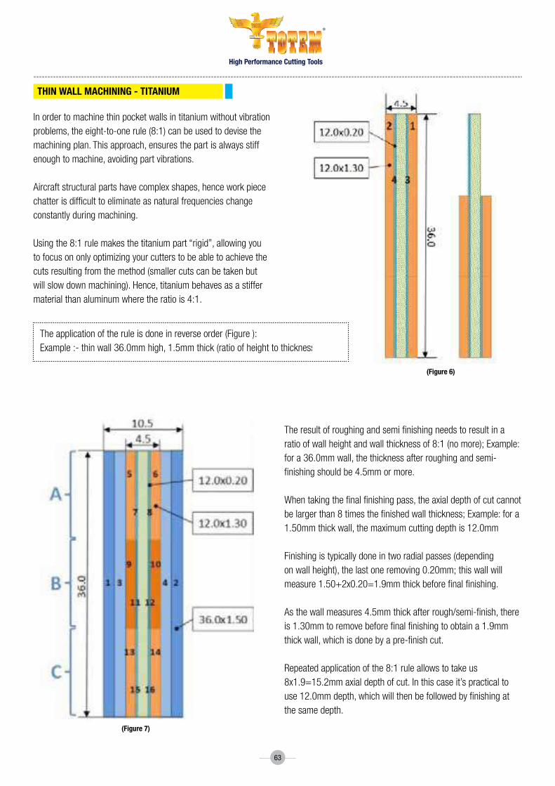
High Performance Cutting Tools
®
63
Inordertomachinethinpocketwallsintitaniumwithoutvibrationproblems,theeight-to-onerule(8:1)canbeusedtodevisethemachining plan. this approach, ensures the part is always stiff enoughtomachine,avoidingpartvibrations.
Aircraftstructuralpartshavecomplexshapes,henceworkpiecechatterisdifficulttoeliminateasnaturalfrequencieschangeconstantly during machining.
Usingthe8:1rulemakesthetitaniumpart“rigid”,allowingyoutofocusononlyoptimizingyourcutterstobeabletoachievethecutsresultingfromthemethod(smallercutscanbetakenbutwillslowdownmachining).Hence,titaniumbehavesasastiffermaterial than aluminum where the ratio is 4:1.
Theapplicationoftheruleisdoneinreverseorder(Figure):Example :- thin wall 36.0mm high, 1.5mm thick (ratio of height to thickness = 24)
Theresultofroughingandsemifinishingneedstoresultinaratio of wall height and wall thickness of 8:1 (no more); Example: for a 36.0mm wall, the thickness after roughing and semi-finishingshouldbe4.5mmormore.
Whentakingthefinalfinishingpass,theaxialdepthofcutcannotbelargerthan8timesthefinishedwallthickness;Example:fora1.50mm thick wall, the maximum cutting depth is 12.0mm
Finishing is typically done in two radial passes (depending onwallheight),thelastoneremoving0.20mm;thiswallwillmeasure1.50+2x0.20=1.9mmthickbeforefinalfinishing.
Asthewallmeasures4.5mmthickafterrough/semi-finish,thereis1.30mmtoremovebeforefinalfinishingtoobtaina1.9mmthickwall,whichisdonebyapre-finishcut.
repeated application of the 8:1 rule allows to take us 8x1.9=15.2mm axial depth of cut. in this case it’s practical to use12.0mmdepth,whichwillthenbefollowedbyfinishingatthe same depth.
THiN wALL MACHiNiNG - TiTANiUM
(Figure 6)
(Figure 7)

High Performance Cutting Tools
®
64
Figure 8 Titanium plate machining steps; 1-4 roughing; 5-6 semi-finish, 7,8 finish; images of the partially machined work pieces were generated using Unigraphics Nx7.5
Roughing wall thickness readings
Semi Finish wall thickness readings
First Stage
Second Stage
(Figure 9)
(Figure 8)
(Figure 10)

High Performance Cutting Tools
®
65
Thebelowreadingswerefurtherdealtwithusinganaccelerometerandthevibrationswereresolved.(Figure12)
Finish wall thickness Readings
Third Stage
THiN wALL MACHiNiNG GUiDE- TiTANiUM 8:1 (ACTUAL READiNG)
Machining Step Location Part deflection (μm)
Tool deflection (μm)
Total deflection (μm)
NC program Compensation
(μm)
Step 1 roughing top 42 130 172 250
Step 2 roughing top 52 130 182 250
Step 3 roughing top 69 130 199 250
Step 4 roughing top 114 130 244 250
Step5Semi-finishing top 108 117 225 250
Step6Semi-finishing top 131 117 248 250
Step 7 Finishing top 37 28 65 50
Step 8 Finishing top 41 28 69 50
Step9Semi-finishing Middle 44 117 161 180
Step10Semi-finishing Middle 60 117 177 180
Step 11 Finishing Middle 20 28 48 50
Step 12 Finishing Middle 23 28 51 50
Step13Semi-finishing Bottom 12 117 129 140
Step14Semi-finishing Bottom 25 117 142 140
Step 15 Finishing Bottom 14 28 42 50
Step 16 Finishing Bottom 15 28 43 50
(Figure 11)

High Performance Cutting Tools
®
66
identifying the FRF Frequency Response Function of the machine using an accelerometer and a impact hammer identifying stable cutting zones/ Safe zones for the setup incorporating those Stable cutting zones and cutting with those revised parameters
Ifathinpocketfloorisfullysupportedbyfixturingonesidedweb,see(Figure13),radialstep-overandfeedareadjustedtoobtaintherequiredsurfacefinish,bypocketing from the center to the walls. Youstartbyopeningitfromthecenterand then going outward towards the walls.
Ifyouhaveatwo-sidedwebthatisnotsupported(Figure14)whenthesecondsideisbeingfinished,youhavetoleaveathickerflooronthelastsidetofinish.Thefirstsidecanbefinishedasifitwassupported.Thelastsideissteppeddowninsmallaxialpassesuntilthefinishedfloorbeforeyoustepoutradially(“downandover”technique).Thismethodwilltakelongertomachinebuthastheadvantageofsimpleandcheapfixturing.Forverylargeproductionruns,vacuumtoolingmaybemorecost-effective.
Note:-WhenmachiningthefinalpassoffirstsidekeepAe30%ofD.ThiswillensurethattheSurfacedoesnotattracttoomuchofAxialforcebutmoreradialforce.WhenmachiningthefinalpassofthesecondsideensurethattheAeis60%ofD.Itmaynotgiveyouthebestsurfacefinishbutwillensureleastvibrationsandwarpage
THiN wALL MACHiNiNG GUiDE- TiTANiUM 8:1 (FRF)
THiN POCKET FLOOR MACHiNiNG
(Figure 12)
(Figure 13)
(Figure 14)

High Performance Cutting Tools
®
67
Industry solutions
AerOenGIne
cAsInGs
manufacturing components of Aero engine requires an in-depth knowledge in the field the complex difficult to machine materials, their properties and best tools to do the job.
Totem offers range of high performance tooling solutions that can help you manufacture most of the aero engine component.
Our highly experienced team of application engineers bring in years of experience in aero-engine solutions, which ensure high tool life and required cost for component.
casing are manufactured from nickel and exotic alloys, these large and highly complex components present a host of machining challenges for cost effective manufacture.
Totem has number of proven case studies for the machining of combustion casings, including scallops, bosses and all scanned surfaces.
Aerospace industry is one of the most technically advanced industries in the world. Continuous improvement in material science, high level precision involved and cost pressure add to the list of challenges.
Totem’s wide range of high performance tooling solution gives best performance in class performance which meets all the stringent tolerance requirements of the aerospace industry.
Through the focused application of Technology in Cutting, Totem is your ideal productivity partner.
tooling solutions that takes productivity to next level.

High Performance Cutting Tools
®
68
BlIsk
fAn dIsc
fAn BlAdes
Blisks are manufactured from both titanium and nickel, these are considered as difficult to machine materials, these critical components are becoming more common due to the advantages of weight, efficiency and through-life servicing.
Totem has developed range of tooling solutions for the roughing, semi-finish and finish machining of various bladed rotors.
manufactured from titanium this highly complex component has numerous critical features.
Through an extensive programme of research & development, Totem has developed market leading fan disc tooling and application strategies for the production of multiple features, including:• Bulbslotmilling• Hookmilling• Scallopmilling• Flangemilling
traditionally manufactured from titanium, totem has a wide range of tools specially developed for machining of complete components including; aerofoil surfaces, platforms and roots.
Recent market developments have introduced carbon fibre fanblade technology with the subsequent need for highly complex titanium shrouds or leading edges. Totem has optimised tooling range which are apt for the production of these difficult to machine components.

High Performance Cutting Tools
®
69
AerOfOIls
IP / hP dIsc
nGV
Aerofoils are manufactured from titanium, nickel and other hrsA’s, totem has wide range of tooling solution specially developed machining aerofoil and application strategies for the machining of complete components including; aerofoil surfaces, leading & trailing edges, platforms and roots.
Carbon fibre fan blade technology has being developed with the subsequent need for highly complex titanium shrouds or leading edges. Totem has been pioneer in this component evolution and has developed optimised tooling solutions for the production of these critical parts.
IP/hP discs are manufactured from nickel and exotic alloys, totem has developed range of specially designed tooling solutions for the manufacturing of high pressure disc component with below features.
• V-SlotRoughMilling
• Fir-TreeMilling
nozzle Guide Vanes are advance form of airfoils which are made of composite materials as it has to bear extreme temperatures inside the turbine
TotemhasyearsofexperienceinthemachiningofnozzleGuideVanes using carbide end mills, ball nose cutters, drills and reamers.
TighttoleranceismaintainedtoallowcomplexnGVshapestobemachined with very high accuracy as well as being suitable for adaptivemachining/auto-correction.

High Performance Cutting Tools
®
70
AerOstructure
tItAnIum structures
AlumInIum structures
totem has special solutions developed keeping in mind the complex aerospace structural components requirements which have advanced applications with reduced cycle time.
Our tooling solutions comprises of tool material and geometry optimisation, tool holder specification, defined application parameter provision and programming methodology support to ensure the delivery of absolute component quality with maximised cost effectiveness.
totem’s innovative titanium machining tools has numerous applications including:• PylonBrackets• EngineMounts• LandingGearStructures• Floortoframefittings
totem’s solutions for aluminium machining solutions are designed for several aerospace applications including:• Ribs• Spars• Skins Our Razorcut series are specially designed to provide high
performance machining for all aerospace alloy grades keeping in mind the machining challenges of the components such as thethinwallsandbasesofRibsetc.
Totem’s aluminium tooling ranges are balanced by design to
precisely control the consistency of the cutting edge at high speed rotations enabling high efficiency and stable machining with repeatable accuracy.

High Performance Cutting Tools
®
71
AIrfrAme
cOmPOsItes
totem offers unique drilling and machining solutions for a wide range of airframe applications across fuselage, wing, leading edge, trailing edge and tail structures.
Many different types of materials are used in airframemanufacture, including aluminium, composites and titanium, Totem manufactures many different tooling solutions in carbide, diamond coated and polycrystalline diamond (PCD) for HoleProduction,Edging,TrimmingandSurfaceGenerationapplications.
composite structures demand unique tooling solutions. totem’s composite tooling excellent production performance with reduced cost per component.
The combination of stacked composite structures, commonly layered with aluminium and titanium alloys, generate additional manufacturing challenges and increase the need for optimised tooling designs.
Totem’s range of composite tooling is developed to overcome the inherent challenges of these demanding material combinations.
hOle PrOductIOn
Our drill geometries produce high quality holes by actively reducing delamination and splintering, while effectively controlling chip evacuation.
Totem supplies complete process tooling solutions for all composite applications including, drills, reamers, countersinks in both carbide and diamond coated options
edGInG, trImmInG & surfAce GenerAtIOn
Our composite machining solutions, both diamond coated carbide, reduce fibre splintering and generate improved MRR’s, withthe ability to reduce or eliminate secondary operations through significantly improved surface finish.

81
82
81
83
72
81RazoRcut cBc/cBcH/NcBcH
RazoRcut 2FWF
RazoRcut 3F
RazoRcut 1F
RazoRcut 3FWF/3FWFcR/3FWFXL
HEX3 & HEX3L
coNtENt
WoRk piEcE MatERiaLsPrimary(Aluminium 6000/7000 series)sEcoNdaRy(Wrought Aluminium 6061 & Cast Aluminum 6061)FEatuREs• 3Flutes• CenterCutting• CoarsePitch(CBC)/ChamferedPitch
(CBCH/NCBCH)• RoughingforAluminium• UncoatedFuNctioN• HighMRR• ExcellentforRoughingofAlumniumBENEFitsSuperiorToolLife
WoRk piEcE MatERiaLsPrimary(Aluminium 6000/7000 series)sEcoNdaRy(Wrought Aluminium 6061 & Cast Aluminum 6061)FEatuREs• 2Flutes• 45DegreeHelix• CenterCutting• WiperDesignforExcellentfloorfinish• UncoatedFuNctioN• HighMRR• ExcellentforfinishingofAlumniumBENEFits• SuperiorToolLife• Excellentfloorfinish
WoRk piEcE MatERiaLsPrimary(Aluminium 6000/7000 series)sEcoNdaRy(Wrought Aluminium 6061 & Cast Aluminum 6061)FEatuREs• 3Flutes• UnequalfluteDesign• CenterCutting• UncoatedFuNctioN• HighMRR• ExcellentforsemifinishingofAlumniumBENEFits• SuperiorToolLife• Excellentfloorfinish
WoRk piEcE MatERiaLsPrimary(Aluminium&Plastics)sEcoNdaRy(Delerine,PEEK,OrganicMaterials)FEatuREs• 1Flute• 30DegreeHelix• Uniqueflutedesignforexcellentwallfinish• Uncoated&Polished• SharpCuttingEdgeFuNctioN• HighMRR• ExcellentformachiningPlastics,Delerine
andOrganicmaterialsBENEFits• SuperiorToolLife• Excellentfloorfinish
WoRk piEcE MatERiaLsPrimary(Aluminium 6000/7000 series)sEcoNdaRy(Wrought Aluminium 6061 & Cast Aluminum 6061)FEatuREs• 3Flutes• UnequalfluteDesign• CenterCutting• WiperDesignforExcellentfloorfinish• UncoatedFuNctioN• HighMRR• ExcellentforfinishingofAlumniumBENEFits• SuperiorToolLife• Excellentfloorfinish
WoRk piEcE MatERiaLsPrimary(Aluminium 6000/7000 series)sEcoNdaRy(Wrought Aluminium 6061 & Cast Aluminum 6061)FEatuREs• 3Flutes• RobustCoreforGeneralMilling
ofnonferrousmaterials• CenterCutting• UncoatedFuNctioN• HighMRR• ExcellentforsemifinishingBENEFits• SuperiorToolLife• Excellentfloorfinish
Note:-AskfortheTiCNCoatedProgramtomachineCastAluminiumSkin Note:-AskfortheHardCarboncoatedforsuperiorproductivity
Note:-AskfortheTiCNCoatedProgramtomachineCastAluminiumSkin
FoR tRocHoidaL
MiLLiNg
High Performance Cutting Tools
®
80
FoR tRocHoidaL
MiLLiNg
FoR tRocHoidaL
MiLLiNg

85
86
85
83 84F192cB / F192 cBL F193cB/NF193cB/NF193cBL
WoRk piEcE MatERiaLsPrimary: (Steel)sEcoNdaRy: (Cast Iron)FEatuREs• 3-4Flutes• CenterCutting• SinosoidalPitch• SuperiorCoatingFuNctioN• HighMRR• StablecuttingathighcuttingspeedsBENEFitsSuperiorToolLife
WoRk piEcE MatERiaLsPrimary:(Titanium&PHSteel)sEcoNdaRy: (Stainless Steel)FEatuREs• 4-6Flutes• CenterCutting• 45degreeHelixforfasterchip
evacuation• Flatpitch• SuperiorCoatingFuNctioN• HighMRR• ExcellentformachiningPlastics,
DelerineandOrganicmaterialsBENEFits• SuperiorToolLife• Excellentfloorfinish FoR
tRocHoidaL MiLLiNg
85F194cB
WoRk piEcE MatERiaLsPrimary: (Titanium)sEcoNdaRy: (Stainless Steel)FEatuREs• 4-6Flutes• CenterCutting• 45degreeHelixforfasterchipevacuation• Flatpitch• SuperiorCoatingFuNctioN• HighMRR• StablecuttingathighcuttingspeedsBENEFitsSuperiorToolLife
FoR tRocHoidaL
MiLLiNg
73
NaNo
tuRBo RougHER-tR (F179tR / F179tRL)
tuRBo RougHER-tR (F177tR / NF177tR)
coNtENt
WoRk piEcE MatERiaLsPrimary: (Steel & Stainless Steel)sEcoNdaRy: (Cast Iron)FEatuREs• 4Flutes• CenterCutting• ShortLengthFuNctioN• HighMRR• StablecuttingathighcuttingspeedsBENEFits• SuperiorToolLife• Onetoolforroughingandfinishingopera-
tions.• Millingatavaluepricewhenre-grindingis
notjustified.• Stable,low-vibrationsolutionwithsoftcut
formill-turnmachines.
WoRk piEcE MatERiaLsPrimary:(PHSteel)sEcoNdaRy:(HeatResistantSuperAlloys)FEatuREs• VariablepitchandVariablehelix• Stablecoregeometry• Optimizedcentrecuttinggeometryballprofile• Newgenerationcoating• Avaiablein4flutesFuNctioN• AbilitytoworkathighParametersduetothe
reinforcedcore.• HighMRR• HigherproductivityBENEFits• SuperiorToolLife.• Excellentwallsurfacefinish.• HighMRR
WoRk piEcE MatERiaLsPrimary:(PHSteel)sEcoNdaRy: (Stainless Steel)FEatuREs• VariablepitchandVariablehelix• Stablecoregeometry• Optimizedcentrecuttinggeometry• Newgenerationcoating• Availablein4Flutes• AvailablewithNeckoptionsFuNctioN• HighMRR• AbilitytoworkathighParametersdueto
thereinforcedcore.BENEFits• Higherproductivity• SuperiorToolLife.• ExcellentSurfaceFinish.
FoR tRocHoidaL
MiLLiNg
High Performance Cutting Tools
®

88 88
89
87 87
89
74
5VR 6VR
pRotoN pLus
coNtENt
WoRk piEcE MatERiaLsPrimary: (Titanium)sEcoNdaRy:(PHSteel)FEatuREs• RobustCoreDesign• 5flutesforHighProductivity• Optimizedcentrecuttinggeometrywith3degree
RmpingcapabilityFuNctioN• Operatesathighcuttingspeeds• Geometryprogrammedtosuitadequatematerial
removalatvariousenagemnetanglesBENEFits• Highestdynamicspeedrates• Highestmaterialremovalrate• Leastcuttingforces• Prolongedtoollifeduetoreducedshock• Highsavingsincycletimewhencomparedtothe
conventionalmillingstrategy
WoRk piEcE MatERiaLsPrimary: (Titanium)sEcoNdaRy: (Stainless Steel)FEatuREs• RobustCoreDesign• 6flutesforHighProductivityFuNctioN• Operatesathighcuttingspeeds• Geometryprogrammedtosuitadequatemate-
rialremovalatvariousenagemnetanglesBENEFits• Highestdynamicspeedrates• Highestmaterialremovalrate• Leastcuttingforces• Prolongedtoollifeduetoreducedshock• Highsavingsincycletimewhencomparedto
the conventionalmillingstrategy
WoRk piEcE MatERiaLsPrimary:(HardenedSteelH1)sEcoNdaRy:(HardenedSteelH2)FEatuREs• Superiornanograinstructurerawmaterial• Wearresistantgrade• IdealChipflowgeometry• Closetoleranceendmillsforfinishingfor
higheraccuracyFuNctioN• Operatesathighcuttingspeedsonhard-
enedmaterials• Polishingforhardeneddiescanbemini-
mized• Noneedofmultiplesetups,Jobcanbe
finishedwithsingleclampinganditismucheasyytoachievehighaccuracy
BENEFits• SuperiorToolLife• Excellentfloorfinish
FoR tRocHoidaL
MiLLiNg
FoR tRocHoidaL
MiLLiNg
High Performance Cutting Tools
®
tuRBo RougHER-tR (F178tR- BLack) tuRBo RougHER-tR (F178tR- goLd)WoRk piEcE MatERiaLsPrimary: (Titanium)sEcoNdaRy:(HeatResistantSuperAlloys)FEatuREs• VariablepitchandVariablehelix• Stablecoregeometry• Optimizedcentrecuttinggeometrywith3degree
rampingcapability• Newgenerationcoating• Avaiablein5FlutesFuNctioN• AbilitytoworkathighParametersduetothe
reinforcedcore.• HighMRR• HigherproductivityBENEFits• SuperiorToolLife.• Excellentwallsurfacefinish.• HighMRR
WoRk piEcE MatERiaLsPrimary: (Stainless Steel)sEcoNdaRy: (Steel)FEatuREs• VariablepitchandVariablehelix• Stablecoregeometry• Optimizedcentrecuttinggeometrywith3degree
rampingcapability• Newgenerationcoating• Avaiablein5FlutesFuNctioN• AbilitytoworkathighParametersduetothe
reinforcedcore.• HighMRR• HigherproductivityBENEFits• SuperiorToolLife.• Excellentwallsurfacefinish.• HighMRR
FoR tRocHoidaL
MiLLiNg
FoR tRocHoidaL
MiLLiNg
tuRBo RougHER-tR (F180tR/NF180tR/F180tRL)
WoRk piEcE MatERiaLsPrimary: (Titanium)sEcoNdaRy: (Stainless Steel)FEatuREs• VariablepitchandVariablehelix• Stablecoregeometry• Optimizedcentrecuttinggeometry• Newgenerationcoating• Avaiablein7Flutes• AvaiablewithNeckoptionsFuNctioN• AbilitytoworkathighParameters
duetothereinforcedcore.• HighMRR• HigherproductivityBENEFits• SuperiorToolLife.• Excellentwallsurfacefinish.• HighMRR
FoR tRocHoidaL
MiLLiNg

91
94 95
92 93
92
75
HsM
spiRaL poiNt pM taps spiRaL FLutE pM taps
cHaMFER
spottiNg caRBidE cENtER dRiLL
coNtENt
WoRk piEcE MatERiaLsPrimary: (Steel)FEatuREs• Superiormicrograinstructure
rawmaterial• Wearresistantgrade• SametoolforRoughingand
FinishingforMouldMachining• Idealtomachineupto42HRcFuNctioNs• Operatesathighcuttingspeeds
onMouldsBENEFits• HigherToolLifeandconsistency
WoRk piEcE MatERiaLsPrimary:(StainlessSteel,Titanium&Inconel)FEatuREs• SuperiorgradeHSSE/HSSEPMsteel• Specialangulargeometryensureschipsare
pusheddownwards• Edgepolishingforbetterthreadfinishand
highertoollifeFuNctioN• Bettercoolantflowsincethechipsare
pusheddownwardsBENEFits• Increasedproductivitythroughhighspeed
cuttingandlongtoollife
WoRk piEcE MatERiaLsPrimary: (Stainless Steel)FEatuREs• Specialflutegeometryforexcellentchip
evacuation• Newchamfergeometryandreducedhelix
(15deg)forshortbrokenchips• Stressrelievingandedgepolishingdone
forcuttingedgestoavoidchippingoffFuNctioN• Fordeepholetapping–2.5DBENEFits• Betterthreadfinish
High Performance Cutting Tools
®
60 dEgREE couNtERsiNk tooLs WitH 4 FLutEs RaNgE 3mmto16mm
90 dEgREE couNtERsiNk tooLs WitH 4 FLutEsRaNgE3mmto16mm
60 dEgREE spottiNg dRiLLs, Right-handhelix,standardlengthCutShankDia.=h6tolerancerange;pointangletolerance+0°/-1°
RaNgE: 2mmto16mm
90 dEgREE spottiNg dRiLLs, Right-handhelix,standardlengthCut/ ShankDia.=h6tolerancerange; pointangletolerance+0°/-1°
RaNgE: 2mmto16mm
120 dEgREE spottiNg dRiLLs, Right-handhelix,standardlengthCut/ ShankDia.=h6tolerancerange;pointangletolerance+0°/-1°
RaNgE: 2mmto16mm
CenterDrillavailableinDIN333StandardinLH/RHwithbothFormA&FormB
RaNgE: 1mm to 8mm

76
coNtENtHigh Performance Cutting Tools
®
REguLaR HELicaL FLutE soLid
REguLaR HELicaL FLutE cooLaNt
REguLaR HELicaL FLutE tapER soLid
REguLaR HELicaL FLutE tapER cooLaNt
REguLaR HELicaL FLutE soLid
REguLaR HELicaL FLutE tapER soLid
REguLaR HELicaL FLutE tapER cooLaNt
REguLaR HELicaL FLutE cooLaNt
REguLaR HELicaL FLutE soLid
iNtERNaL tHREadiNg FoR iso MEtRic tHREad
iNtERNaL tHREadiNg FoR (uNc, uNF, uNEF) uNiFiEd tHREad
iNtERNaL/EXtERNaL tHREadiNg FoR NptF
iNtERNaL/EXtERNaL tHREadiNg FoR NptF
iNtERNaL/EXtERNaL tHREadiNg FoR Bsp (g)
iNtERNaL/EXtERNaL tHREadiNg FoR Npt
iNtERNaL/EXtERNaL tHREadiNg FoR Npt
iNtERNaL tHREadiNg FoR iso MEtRic tHREad
iNtERNaL tHREadiNg FoR (uNc, uNF, uNEF) uNiFiEd tHREad
Detail View A
A
D
LL 1
D1
P
6 0
Detail View A
P
6 0
D
LL 1
D1
A
32
41
IMPORTANT PARAMETERS1 Helix(RH) 15°2 Number of �utes 43 Internal coolant No4 Shank diameter D5 Coating TA6 Material Micro�ne carbide
APPLICATION DETAILS1 Material2 Component name3 Hardness
00 30/04/2019REV. NO. REVISION BY DATE
CUSTOMER APPROVALCustomer nameCustomer reference no.Approved date Sign
D
CB
CBA
A D
12
34
****MARK DETAILS
NOTE:1) All dimensions are in mm.2) All other details are as permanufacturer's standard.3) Not to the scale.
Forbes & Company Limited , B-13, MIDC Area,Waluj, Aurangabad- 431133, Maharashtra, India
Sign Date MATERIAL
DRAWN NLA ALTERNATE MATERIAL
CHECKED RNS SCALE NTSAPPROVED RNS REVISION 00QA SNPMFG DSOperation Head SUW
TITLE:Thread mill 15°Hx 4�t TA DRAWING NO.:
SAP CODE: SHEET 1 Of 1
D
LL 1
D1
For Thread size:M10.0x1.0
P i t c h
6 0
32
41
IMPORTANT PARAMETERS1 Helix(RH) 15°2 Number of �utes 53 Internal coolant Yes4 Shank diameter D5 Coating TA6 Material Micro�ne carbide
APPLICATION DETAILS1 Material2 Component name3 Hardness
00 30/04/2019REV. NO. REVISION BY DATE
CUSTOMER APPROVALCustomer nameCustomer reference no.Approved date Sign
D
CB
CBA
A D
12
34
****MARK DETAILS
NOTE:1) All dimensions are in mm.2) All other details are as permanufacturer's standard.3) Not to the scale.
Forbes & Company Limited , B-13, MIDC Area,Waluj, Aurangabad- 431133, Maharashtra, India
Sign Date MATERIAL
DRAWN NLA ALTERNATE MATERIAL
CHECKED RNS SCALE NTSAPPROVED RNS REVISION 00QA SNPMFG DSOperation Head SUW
TITLE:Thread mill 15°Hx 5�t TC TA DRAWING NO.:
SAP CODE: SHEET 1 Of 1
P i t c h
6 0
D1
LL 1
D
96
99 100
101 101 102
100
97 98
L 1
D1
D
L
6 0
Detail view A
A6 0
Detail view AL 1
L
D1
D
L 1
D1
D
L
6 0
Detail view A
A6 0
Detail view AL 1
L
D1
D
Detail View A
A
D1
LL 1
D
P
55

77
coNtENtHigh Performance Cutting Tools
®
siNgLE tootH paRtiaL pRoFiLE
MuLti tootH 2d MuLti tootH 3d / MuLti tootH 4d
MuLti tootH 3d
MuLti tootH 2d MuLti tootH 3d / MuLti tootH 4d
REguLaR HELicaL FLutE cooLaNt
REguLaR HELicaL FLutE tapER soLid
REguLaR HELicaL FLutE tapER cooLaNt
iNtERNaL/ EXtERNaL tHREadiNg FoR paRtiaL pRoFiLE 600
iNtERNaL tHREadiNg upto 2d FoR (uNc, uNF) uNiFiEd tHREad
iNtERNaL tHREadiNg upto 3d/4d FoR (uNc, uNF) uNiFiEd tHREad
iNtERNaL tHREadiNg upto 3d FoR (uNJ) uNiFiEd tHREad
iNtERNaL tHREadiNg upto 2d FoR iso MEtRic tHREad
iNtERNaL tHREadiNg upto 3d/4d FoR iso MEtRic tHREad
iNtERNaL/EXtERNaL tHREadiNg FoR Bsp (g)
iNtERNaL/EXtERNaL tHREadiNg FoR Bspt (Rc)
iNtERNaL/EXtERNaL tHREadiNg FoR Bspt (Rc)
Detail View A
P
55
D1
LL 1
D
A L 1
D1
D
L
6 0
Detail view A
A6 0
Detail view AL 1
L
D1
D
L
D1
(h6
)
L 1
D
A
Detail View A
6 0
AL
D1
(h6
)
L 1
D
P
6 0
Detail view A
AL
D1
(h6
)
L 1
DP
6 0
Detail view A
AL
D1
(h6
)
L 1
D
P
6 0
Detail view A
AL
D1
(h6
)
L 1
D
P
6 0
Detail view A
AL
D1
(h6
)
L 1
D
P
6 0
Detail view A
102 103 103
104
107 108 109
105 106

78
MuLti tootH 3d
REguLaR stRaigHt FLutE soLid
REguLaR stRaigHt FLutE tapER soLid
REguLaR stRaigHt FLutE tapER soLid
MuLti tootH 2d FoR HaRd paRt
MuLti tootH 2d FoR HaRd paRt
MuLti tootH 3d FoR HaRd paRt
MuLti tootH 3d FoR HaRd paRt
REguLaR stRaigHt FLutE soLid
iNtERNaL tHREadiNg upto 3d FoR (MJ) iso tHREad
iNtERNaL tHREadiNg FoR (uNc, uNF, uNEF) uNiFiEd tHREad
iNtERNaL/EXtERNaL tHREadiNg FoR Npt
iNtERNaL/EXtERNaL tHREadiNg FoR NptF
iNtERNaL tHREadiNg FoR HaRd MatERiaLs upto 2d FoR iso MEtRic tHREad
iNtERNaL tHREadiNg FoR HaRd MatE-RiaLs upto 2d FoR (uN, uNF) uNiFiEd tHREad
iNtERNaL tHREadiNg FoR HaRd MatERiaLs upto 3d FoR iso MEtRic tHREad
iNtERNaL tHREadiNg FoR HaRd MatERiaLs upto 3d FoR (uN, uNF) uNiFiEd tHREad
iNtERNaL tHREadiNg FoR iso MEtRic tHREad
AL
D1
(h6
)
L 1
D
P
6 0
Detail view A
AL
D1
(h6
)
L 1D
P
6 0
Detail view A
AL
D1
(h6
)
L 1
D
P
6 0
Detail view A
AL
D1
(h6
)
L 1
D
P
6 0
Detail view A
AL
D1
(h6
)
L 1
D
P
6 0
Detail view A
32
41
APPLICATION DETAILS1 Material2 Component name3 Hardness
00 30/04/2019REV. NO. REVISION BY DATE
CUSTOMER APPROVALCustomer nameCustomer reference no.Approved date Sign
D
CB
CBA
A D
12
34
****MARK DETAILS
NOTE:1) All dimensions are in mm.2) All other details are as permanufacturer's standard.3) Not to the scale.
IMPORTANT PARAMETERS1 Helix(RH) Straight2 Number of �utes 53 Internal coolant No4 Shank diameter D5 Coating TA6 Material Micro�ne carbide
Forbes & Company Limited , B-13, MIDC Area,Waluj, Aurangabad- 431133, Maharashtra, India
Sign Date MATERIAL
DRAWN NLA ALTERNATE MATERIAL
CHECKED RNS SCALE NTSAPPROVED RNS REVISION 00QA SNPMFG DSOperation Head SUW
TITLE:Thread mill Straight 5�t TA DRAWING NO.:
SAP CODE: SHEET 1 Of 1
P i t c h
6 0
D1
D
L 1L
6 0
Detail view A
D1
LL 1
D
coNtENtHigh Performance Cutting Tools
®
109 110 110
111
113
111
114
112
114

79
REguLaR stRaigHt FLutE soLid
REguLaR stRaigHt FLutE tapER soLid
tapER pREpERatioN tooL
aNgLE 90 sHoRt tooL
aNgLE 90 LoNg tooL
iNtERNaL/EXtERNaL tHREadiNg FoR Bsp (g)
iNtERNaL/EXtERNaL tHREadiNg FoR Bspt (Rc)
tapER pREpERatioN FoR Mpt aNd Bspt tHREads
iNtERNaL cHaMFERiNg- sHoRt FoR cHaMFER tooLs
iNtERNaL cHaMFERiNg- LoNg FoR cHaMFER tooLs
Detail View A
P
55
D1
D
L 1L
A 55
Detail view A
D1
LL 1
D
Detail View AL
L 1
D1
(h6
)
D
AH900
0.2B
Detail View AL
L 1
D1
(h6
)
D
AH900
0.2B
L1
L
D2 D
D1
45 o
CH
(h6
)
ADetail View A
coNtENtHigh Performance Cutting Tools
®
115 115 116
116 117

High Performance Cutting Tools
®
80
FG Code
Cutting Dia
Flute Length
OAL Shank Dia
Corner Chamfer
Number of teeth
Helix Primary w/P
Ae (max)
hm (max) Secondary w/P
Ae (max)
hm (max)
ØD1 L1 L ØD2 CH Z 30% 20%
FBK0508672 6.00 13.00 57.00 6.00 0.50 3 30 Al6000/7000 1.80 0.036 WroughtAlumnium 1.20 0.036
FBK0508673 8.00 16.00 63.00 8.00 1.00 3 30 Al6000/7000 2.40 0.048 WroughtAlumnium 1.60 0.048
FBK0508674 10.00 22.00 72.00 10.00 1.00 3 30 Al6000/7000 3.00 0.060 WroughtAlumnium 2.00 0.06
FBK0508675 12.00 26.00 83.00 12.00 1.00 3 30 Al6000/7000 3.60 0.072 WroughtAlumnium 2.40 0.072
FBK0508676 16.00 32.00 92.00 16.00 1.00 3 30 Al6000/7000 4.80 0.096 WroughtAlumnium 3.20 0.096
FBK0508677 20.00 38.00 104.00 20.00 1.00 3 30 Al6000/7000 6.00 0.120 WroughtAlumnium 4.00 0.12
FBK0508678 25.00 45.00 121.00 25.00 1.00 3 30 Al6000/7000 7.50 0.151 WroughtAlumnium 5.00 0.151
FG Code
Cutting Dia
Flute Length
OAL Shank Dia
Neck Diameter
Neck Length
Corner Radius
Number of teeth
Helix Primary w/P
Ae (max)
hm (max) Secondary w/P
Ae (max)
hm (max)
ØD1 L1 L ØD2 ØD3 NL Cr Z 30% 20%
FBK0509069 6.00 8.00 57.00 6.00 5.00 18.00 0.25 3 40 Al6000/7000 1.80 0.039 WroughtAlumnium 1.20 0.039
FBK0509070 8.00 10.00 63.00 8.00 7.00 24.00 0.25 3 40 Al6000/7000 2.40 0.053 WroughtAlumnium 1.60 0.053
FBK0509071 10.00 12.00 76.00 10.00 9.00 30.00 0.50 3 40 Al6000/7000 3.00 0.066 WroughtAlumnium 2.00 0.066
FBK0509072 12.00 15.00 83.00 12.00 11.00 36.00 0.50 3 40 Al6000/7000 3.60 0.079 WroughtAlumnium 2.40 0.079
FBK0509073 16.00 20.00 92.00 16.00 15.00 48.00 1.00 3 40 Al6000/7000 4.80 0.105 WroughtAlumnium 3.20 0.105
FBK0509074 20.00 24.00 104.00 20.00 19.00 104.00 1.00 3 40 Al6000/7000 6.00 0.131 WroughtAlumnium 4.00 0.131
RazoRcut cBc foR Roughing of aluminium
RazoRcut ncBch foR Roughing of aluminium
RazoRcut cBch foR Roughing of aluminium
FG Code
Cutting Dia
Flute Length
OAL Shank Dia
Corner Chamfer
Number of teeth
Helix Primary w/P
Ae (max)
hm (max) Secondary w/P
Ae (max)
hm (max)
ØD1 L1 L ØD2 CH Z 30% 20%
FBK0508701 6.00 13.00 57.00 6.00 0.250 3 40 Al6000/7000 1.80 0.039 WroughtAlumnium 1.20 0.039
FBK0508702 8.00 16.00 63.00 8.00 0.250 3 40 Al6000/7000 2.40 0.053 WroughtAlumnium 1.60 0.053
FBK0508703 10.00 22.00 72.00 10.00 0.500 3 40 Al6000/7000 3.00 0.066 WroughtAlumnium 2.00 0.066
FBK0508704 12.00 26.00 83.00 12.00 0.500 3 40 Al6000/7000 3.60 0.079 WroughtAlumnium 2.40 0.079
FBK0508705 16.00 32.00 92.00 16.00 1.000 3 40 Al6000/7000 4.80 0.105 WroughtAlumnium 3.20 0.105
FBK0508706 20.00 38.00 104.00 20.00 1.000 3 40 Al6000/7000 6.00 0.131 WroughtAlumnium 4.00 0.131
FBK0508707 25.00 45.00 121.00 25.00 1.500 3 40 Al6000/7000 7.50 0.142 WroughtAlumnium 5.00 0.142
Carbide
Carbide
REG
REG
REG
400
400
300

High Performance Cutting Tools
®
81
FG Code Cutting Dia Flute Length OAL Shank Dia Number of teeth Helix
ØD1 L1 L ØD2 Z
FBK0509238 3.00 12.00 50.00 3.00 1 30
FBK0509239 4.00 15.00 60.00 4.00 1 30
FBK0509240 5.00 17.00 60.00 5.00 1 30
FBK0509241 6.00 20.00 65.00 6.00 1 30
FBK0509242 8.00 25.00 65.00 8.00 1 30
FBK0509243 10.00 25.00 75.00 10.00 1 30
RazoR cut 1f foR machining alumnium and plastics
Carbide REG300
FG Code Cutting Dia Flute Length OAL Shank Dia Number of teeth Helix
ØD1 L1 L ØD2 Z
FBK0508795 1.50 6.00 38.00 3.00 2 45
FBK0508796 2.00 8.00 38.00 3.00 2 45
FBK0508797 2.50 9.00 38.00 3.00 2 45
FBK0508798 3.00 12.00 38.00 3.00 2 45
FBK0508799 4.00 12.00 50.00 4.00 2 45
FBK0508800 5.00 14.00 50.00 5.00 2 45
FBK0508801 5.00 14.00 50.00 6.00 2 45
FBK0508802 6.00 16.00 50.00 6.00 2 45
FBK0508803 8.00 20.00 63.00 8.00 2 45
FBK0508804 10.00 22.00 76.00 10.00 2 45
FBK0508805 12.00 25.00 76.00 12.00 2 45
FBK0508806 16.00 32.00 89.00 16.00 2 45
FBK0508807 20.00 38.00 104.00 20.00 2 45
RazoRcut 2fWf foR finishing of alumnium
Carbide REG450
RazoRcut 3fWf foR finishing of alumnium
FG Code
Cutting Dia
Flute Length
OAL Shank Dia
Number of teeth
Helix Primary w/P
Ae (max)
hm (max) Secondary w/P
Ae (max)
hm (max)
ØD1 L1 L ØD2 Z 30% 20%
FBK0508708 3.00 12.00 38.00 3.00 3 38 Al6000/7000 0.90 0.02 WroughtAlumnium 0.60 0.02
FBK0508709 4.00 12.00 51.00 4.00 3 38 Al6000/7000 1.20 0.02 WroughtAlumnium 0.80 0.02
FBK0508710 5.00 14.00 51.00 5.00 3 38 Al6000/7000 1.50 0.02 WroughtAlumnium 1.00 0.02
FBK0508711 6.00 16.00 50.00 6.00 3 38 Al6000/7000 1.80 0.03 WroughtAlumnium 1.20 0.03
FBK0508712 8.00 20.00 63.00 8.00 3 38 Al6000/7000 2.40 0.04 WroughtAlumnium 1.60 0.04
FBK0508713 10.00 22.00 76.00 10.00 3 38 Al6000/7000 3.00 0.04 WroughtAlumnium 2.00 0.04
FBK0508714 12.00 25.00 76.00 12.00 3 38 Al6000/7000 3.60 0.05 WroughtAlumnium 2.40 0.05
FBK0508715 16.00 32.00 89.00 16.00 3 38 Al6000/7000 4.80 0.06 WroughtAlumnium 3.20 0.06
FBK0508716 20.00 38.00 104.00 20.00 3 38 Al6000/7000 6.00 0.06 WroughtAlumnium 4.00 0.06
Carbide REG380

High Performance Cutting Tools
®
82
FG Code
Cutting Dia
Flute Length
OAL Shank Dia
Neck Diameter
Neck Length
Corner Radius
Number of teeth
Helix Primary w/P
Ae (max)
hm (max)
Secondary w/P
Ae (max)
hm (max)
ØD1 L1 L ØD2 ØD3 NL Cr Z 30% 20%
FBK0508685 6.00 9.00 63.00 6.00 5.40 18.00 0.20 3 38 Al6000/7000 1.80 0.03 WroughtAlumnium 1.20 0.03
FBK0508686 6.00 9.00 63.00 6.00 5.40 18.00 0.50 3 38 Al6000/7000 1.80 0.03 WroughtAlumnium 1.20 0.03
FBK0508687 6.00 9.00 63.00 6.00 5.40 18.00 1.00 3 38 Al6000/7000 1.80 0.03 WroughtAlumnium 1.20 0.03
FBK0508688 8.00 12.00 76.00 8.00 7.20 24.00 0.20 3 38 Al6000/7000 2.40 0.04 WroughtAlumnium 1.60 0.04
FBK0508689 8.00 12.00 76.00 8.00 7.20 24.00 0.50 3 38 Al6000/7000 2.40 0.04 WroughtAlumnium 1.60 0.04
FBK0508690 8.00 12.00 76.00 8.00 7.20 24.00 1.00 3 38 Al6000/7000 2.40 0.04 WroughtAlumnium 1.60 0.04
FBK0508691 10.00 15.00 89.00 10.00 9.00 30.00 0.20 3 38 Al6000/7000 3.00 0.06 WroughtAlumnium 2.00 0.06
FBK0508692 10.00 15.00 89.00 10.00 9.00 30.00 0.50 3 38 Al6000/7000 3.00 0.06 WroughtAlumnium 2.00 0.06
FBK0508693 10.00 15.00 89.00 10.00 9.00 30.00 1.00 3 38 Al6000/7000 3.00 0.06 WroughtAlumnium 2.00 0.06
FBK0508694 12.00 18.00 100.00 12.00 10.80 36.00 0.20 3 38 Al6000/7000 3.60 0.07 WroughtAlumnium 2.40 0.07
FBK0508695 12.00 18.00 100.00 12.00 10.80 36.00 0.50 3 38 Al6000/7000 3.60 0.07 WroughtAlumnium 2.40 0.07
FBK0508696 12.00 18.00 100.00 12.00 10.80 36.00 1.00 3 38 Al6000/7000 3.60 0.07 WroughtAlumnium 2.40 0.07
FBK0508697 16.00 24.00 110.00 16.00 14.40 48.00 0.20 3 38 Al6000/7000 4.80 0.09 WroughtAlumnium 3.20 0.09
FBK0508698 16.00 24.00 110.00 16.00 14.40 48.00 0.50 3 38 Al6000/7000 4.80 0.09 WroughtAlumnium 3.20 0.09
FBK0508699 16.00 24.00 110.00 16.00 14.40 48.00 1.00 3 38 Al6000/7000 4.80 0.09 WroughtAlumnium 3.20 0.09
FBK0508700 16.00 24.00 110.00 16.00 14.40 48.00 2.00 3 38 Al6000/7000 4.80 0.09 WroughtAlumnium 3.20 0.09
FG Code
Cutting Dia
Flute Length
OAL Shank Dia
Neck Diameter
Neck Length
Corner Radius
Number of teeth
Helix Primary w/P
Ae (max)
hm (max) Secondary w/P
Ae (max)
hm (max)
ØD1 L1 L ØD2 ØD3 NL Cr Z 30% 20%
FBK0508679 6.00 10.00 100.00 6.00 5.50 42.00 0.20 3 38 Al6000/7000 1.20 0.02 WroughtAlumnium 0.90 0.021
FBK0508680 8.00 13.00 100.00 8.00 7.30 48.00 0.20 3 38 Al6000/7000 1.60 0.03 WroughtAlumnium 1.20 0.029
FBK0508681 10.00 16.00 125.00 10.00 9.10 60.00 0.20 3 38 Al6000/7000 2.00 0.04 WroughtAlumnium 1.50 0.036
FBK0508682 12.00 20.00 125.00 12.00 11.00 73.00 0.20 3 38 Al6000/7000 2.40 0.04 WroughtAlumnium 1.80 0.043
FBK0508683 16.00 26.00 150.00 16.00 14.56 100.00 0.20 3 38 Al6000/7000 3.20 0.06 WroughtAlumnium 2.40 0.057
FBK0508684 20.00 32.00 150.00 20.00 18.20 100.00 0.20 3 38 Al6000/7000 4.00 0.07 WroughtAlumnium 3.00 0.072
RazoRcut 3fWfcR foR semifinishing and finishing aluminium
RazoRcut 3fWfXl long Reach tool foR semifinishing and finishing aluminium
Carbide
Carbide
REG380
380
LonGREaCh
FG Code
Cutting Dia
Flute Length
OAL Shank Dia
Number of teeth
Helix Primary w/P
Ae (max)
hm (max) Secondary w/P
Ae (max)
hm (max)
ØD1 L1 L ØD2 Z 30% 20%
FBK0509996 3.00 12.00 38.00 3.00 3 38 Al6000/7000 0.90 0.02 WroughtAlumnium 0.60 0.02
FBK0509997 4.00 12.00 50.00 4.00 3 38 Al6000/7000 1.20 0.02 WroughtAlumnium 0.80 0.02
FBK0509998 5.00 14.00 50.00 5.00 3 38 Al6000/7000 1.50 0.02 WroughtAlumnium 1.00 0.02
FBK0509999 6.00 16.00 50.00 6.00 3 38 Al6000/7000 1.80 0.03 WroughtAlumnium 1.20 0.03
FBK0510000 8.00 20.00 63.00 8.00 3 38 Al6000/7000 2.40 0.04 WroughtAlumnium 1.60 0.04
FBK0510001 10.00 22.00 76.00 10.00 3 38 Al6000/7000 3.00 0.04 WroughtAlumnium 2.00 0.04
FBK0510002 12.00 25.00 76.00 12.00 3 38 Al6000/7000 3.60 0.05 WroughtAlumnium 2.40 0.05
FBK0510003 16.00 32.00 89.00 16.00 3 38 Al6000/7000 4.80 0.06 WroughtAlumnium 3.20 0.06
FBK0510004 20.00 38.00 104.00 20.00 3 38 Al6000/7000 6.00 0.06 WroughtAlumnium 4.00 0.06
RazoRcut 3f foR geneRal machining of non feRRous mateRials
Carbide REG380

High Performance Cutting Tools
®
83
FG Code Cutting Dia Flute Length OAL Shank Dia Number of teeth Helix
ØD1 L1 L ØD2 Z
FBK0508669 6 13 57 6 3 20
FBK0504029 8 16 64 8 3 20
FBK0504089 10 20 70 10 4 20
FBK0508670 12 26 83 12 4 20
FBK0508671 16 32 89 16 4 20
FBK0504094 20 38 102 20 4 20
f192cB - sinusoidal chip BReakeR RougheR foR machining steel, stainless steel and cast iRon
Carbide200
TialnREG3-4
0.1x45o
FG Code Cutting Dia Flute Length OAL Shank Dia Number of teeth Helix
ØD1 L1 L ØD2 Z
FBK0508823 2.00 3.00 50.00 6.00 3 30
FBK0508824 2.50 3.00 50.00 6.00 3 30
FBK0508825 3.00 4.00 50.00 6.00 3 30
FBK0508826 3.50 4.00 50.00 6.00 3 30
FBK0508827 4.00 5.00 54.00 6.00 3 30
FBK0508828 4.50 5.00 54.00 6.00 3 30
FBK0508829 5.00 6.00 54.00 6.00 3 30
FG Code Cutting Dia Flute Length OAL Shank Dia Number of teeth Helix
ØD1 L1 L ØD2 Z
FBK0508844 2.00 6.00 53.00 6.00 3 30
FBK0508845 2.50 6.00 53.00 6.00 3 30
FBK0508846 3.00 7.00 57.00 6.00 3 30
FBK0508847 3.50 7.00 57.00 6.00 3 30
FBK0508848 4.00 8.00 57.00 6.00 3 30
FBK0508849 4.50 8.00 57.00 6.00 3 30
FBK0508850 5.00 10.00 57.00 6.00 3 30
heX3 foR geneRal machining of non feRRous mateRials
heX3l foR geneRal machining of non feRRous mateRials
Carbide
Carbide
REG
REG
300
300

High Performance Cutting Tools
®
84
FG Code Cutting Dia Flute Length OAL Shank Dia Number of teeth Helix
ØD1 L1 L ØD2 Z
FBK0509830 6 40 100 6 3 20
FBK0509831 8 40 100 8 3 20
FBK0509833 10 45 100 10 4 20
FBK0509835 12 50 100 12 4 20
f192cBl- sinusoidal chip BReakeR RougheR foR machining steel, stainless steel and cast iRon
FG Code
Cutting Dia
Flute Length
OAL Shank Dia
Corner Radius
Number of teeth
Helix Primary w/P
Ae (max)
hm (max) Secondary w/P
Ae (max)
hm (max)
ØD1 L1 L ØD2 Cr Z 30% 20%
FBK0510347 6.00 8.00 57.00 6.00 0.75 4 45 Titanium 0.72 0.008 StainlessSteel 0.90 0.010
FBK0510348 8.00 10.00 63.00 8.00 0.75 4 45 Titanium 0.96 0.011 StainlessSteel 1.20 0.013
FBK0510349 10.00 12.00 72.00 10.00 0.75 4 45 Titanium 1.20 0.013 StainlessSteel 1.50 0.016
FBK0510350 12.00 16.00 83.00 12.00 1.00 4 45 Titanium 1.44 0.016 StainlessSteel 1.80 0.020
FBK0510351 16.00 18.00 92.00 16.00 1.00 6 45 Titanium 1.92 0.020 StainlessSteel 2.40 0.024
f193cB chip BReakeR RougheR foR machining titanium and stainless steel
Carbide200
TialnLonG3-4
0.1x45o
Carbide450
TialnREG4-6
FG Code
Cutting Dia
Flute Length
OAL Shank Dia
Neck Diameter
Neck Length
Corner Radius
Number of teeth
Helix Primary w/P
Ae (max)
hm (max) Secondary w/P
Ae (max)
hm (max)
ØD1 L1 L ØD2 ØD3 NL Cr Z 30% 20%
FBK0510352 6.00 8.00 57.00 6.00 5.50 21.00 0.75 4 45 PH 0.90 0.011 StainlessSteel 0.90 0.010
FBK0510353 8.00 10.00 63.00 8.00 7.30 28.00 0.75 4 45 PH 1.20 0.014 StainlessSteel 1.20 0.013
FBK0510354 10.00 12.00 72.00 10.00 9.10 35.00 0.75 4 45 PH 1.50 0.017 StainlessSteel 1.50 0.016
FBK0510355 12.00 14.00 83.00 12.00 11.00 42.00 1.00 4 45 PH 1.80 0.022 StainlessSteel 1.80 0.020
FBK0510356 16.00 18.00 92.00 16.00 14.56 56.00 1.00 6 45 PH 2.40 0.027 StainlessSteel 2.40 0.024
nf193cB chip BReakeR RougheR foR machining ph steel and stainless steel
Carbide450
TialnREG4-6
FG Code
Cutting Dia
Flute Length
OAL Shank Dia
Neck Diameter
Neck Length
Corner Radius
Number of teeth
Helix Primary w/P
Ae (max)
hm (max) Secondary w/P
Ae (max)
hm (max)
ØD1 L1 L ØD2 ØD3 NL Cr Z 30% 20%
FBK0510555 6.00 8.00 100.00 6.00 5.50 42.00 0.75 4 45 PH 0.90 0.010 StainlessSteel 0.90 0.010
FBK0510556 8.00 10.00 100.00 8.00 7.30 42.00 0.75 4 45 PH 1.20 0.013 StainlessSteel 1.20 0.013
FBK0510557 10.00 12.00 100.00 10.00 9.10 42.00 0.75 4 45 PH 1.50 0.016 StainlessSteel 1.50 0.016
FBK0510558 12.00 14.00 125.00 12.00 11.00 42.00 1.00 4 45 PH 1.80 0.020 StainlessSteel 1.80 0.020
FBK0510559 16.00 18.00 125.00 16.00 14.56 56.00 1.00 6 45 PH 2.40 0.024 StainlessSteel 2.40 0.024
nf193cBl chip BReakeR RougheR foR machining ph steel and stainless steel
Carbide450
TialnLonG4-6
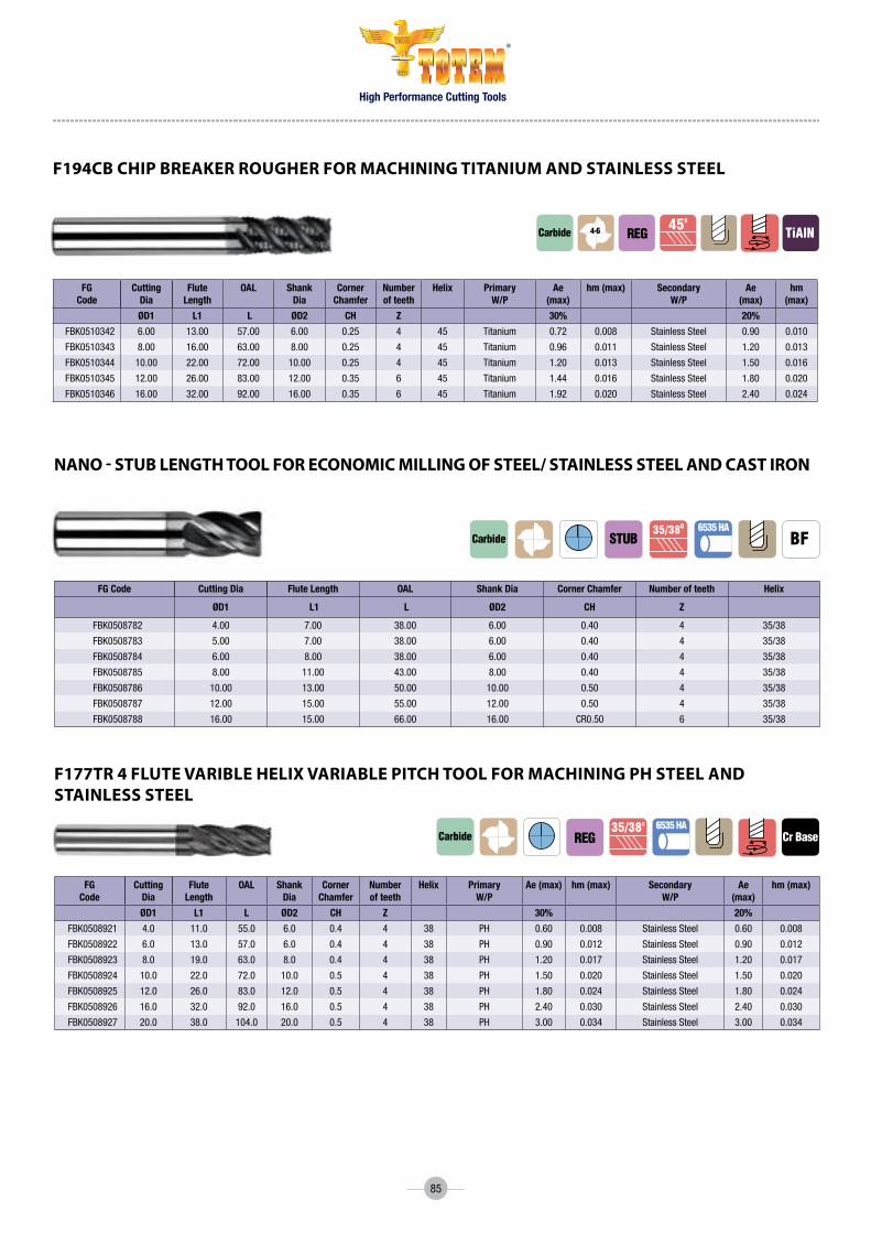
High Performance Cutting Tools
®
85
FG Code
Cutting Dia
Flute Length
OAL Shank Dia
Corner Chamfer
Number of teeth
Helix Primary w/P
Ae (max)
hm (max) Secondary w/P
Ae (max)
hm (max)
ØD1 L1 L ØD2 CH Z 30% 20%
FBK0510342 6.00 13.00 57.00 6.00 0.25 4 45 Titanium 0.72 0.008 StainlessSteel 0.90 0.010
FBK0510343 8.00 16.00 63.00 8.00 0.25 4 45 Titanium 0.96 0.011 StainlessSteel 1.20 0.013
FBK0510344 10.00 22.00 72.00 10.00 0.25 4 45 Titanium 1.20 0.013 StainlessSteel 1.50 0.016
FBK0510345 12.00 26.00 83.00 12.00 0.35 6 45 Titanium 1.44 0.016 StainlessSteel 1.80 0.020
FBK0510346 16.00 32.00 92.00 16.00 0.35 6 45 Titanium 1.92 0.020 StainlessSteel 2.40 0.024
f194cB chip BReakeR RougheR foR machining titanium and stainless steel
Carbide450
TialnREG4-6
FG Code Cutting Dia Flute Length OAL Shank Dia Corner Chamfer Number of teeth Helix
ØD1 L1 L ØD2 CH Z
FBK0508782 4.00 7.00 38.00 6.00 0.40 4 35/38
FBK0508783 5.00 7.00 38.00 6.00 0.40 4 35/38
FBK0508784 6.00 8.00 38.00 6.00 0.40 4 35/38
FBK0508785 8.00 11.00 43.00 8.00 0.40 4 35/38
FBK0508786 10.00 13.00 50.00 10.00 0.50 4 35/38
FBK0508787 12.00 15.00 55.00 12.00 0.50 4 35/38
FBK0508788 16.00 15.00 66.00 16.00 CR0.50 6 35/38
nano - stuB length tool foR economic milling of steel/ stainless steel and cast iRon
Carbide35/380
STUB
FG Code
Cutting Dia
Flute Length
OAL Shank Dia
Corner Chamfer
Number of teeth
Helix Primary w/P
Ae (max) hm (max) Secondary w/P
Ae (max)
hm (max)
ØD1 L1 L ØD2 CH Z 30% 20%
FBK0508921 4.0 11.0 55.0 6.0 0.4 4 38 PH 0.60 0.008 StainlessSteel 0.60 0.008
FBK0508922 6.0 13.0 57.0 6.0 0.4 4 38 PH 0.90 0.012 StainlessSteel 0.90 0.012
FBK0508923 8.0 19.0 63.0 8.0 0.4 4 38 PH 1.20 0.017 StainlessSteel 1.20 0.017
FBK0508924 10.0 22.0 72.0 10.0 0.5 4 38 PH 1.50 0.020 StainlessSteel 1.50 0.020
FBK0508925 12.0 26.0 83.0 12.0 0.5 4 38 PH 1.80 0.024 StainlessSteel 1.80 0.024
FBK0508926 16.0 32.0 92.0 16.0 0.5 4 38 PH 2.40 0.030 StainlessSteel 2.40 0.030
FBK0508927 20.0 38.0 104.0 20.0 0.5 4 38 PH 3.00 0.034 StainlessSteel 3.00 0.034
f177tR 4 flute VaRiBle heliX VaRiaBle pitch tool foR machining ph steel and stainless steel
Carbide REG35/380
Cr Base6535 ha

High Performance Cutting Tools
®
86
FG Code
Cutting Dia
Flute Length
OAL Shank Dia
Neck Diameter
Neck Length
Corner Radius
Number of teeth
Helix Primary w/P
Ae (max)
hm (max) Secondary w/P
Ae (max)
hm (max)
ØD1 L1 L ØD2 ØD3 NL Cr Z 30% 20%
FBK0508731 6.00 12.00 100.00 6.00 5.50 42.00 0.40 4 38 PH 0.90 0.012 StainlessSteel 0.90 0.012
FBK0508732 8.00 16.00 100.00 8.00 7.30 62.00 0.40 4 38 PH 1.20 0.017 StainlessSteel 1.20 0.017
FBK0508733 10.00 20.00 100.00 10.00 9.10 60.00 0.50 4 38 PH 1.50 0.020 StainlessSteel 1.50 0.020
FBK0508734 12.00 24.00 125.00 12.00 11.00 73.00 0.50 4 38 PH 1.80 0.024 StainlessSteel 1.80 0.024
FBK0508735 16.00 32.00 150.00 16.00 14.56 100.00 0.50 4 38 PH 2.40 0.030 StainlessSteel 2.40 0.030
FBK0508736 20.00 40.00 175.00 20.00 18.20 100.00 0.50 4 38 PH 3.00 0.034 StainlessSteel 3.00 0.034
nf177tR 4 flute VaRiBle heliX VaRiaBle pitch tool foR machining ph steel and stainless steel
Carbide REG35/380
Cr Base6535 ha
FG Code
Cutting Dia
Flute Length
OAL Shank Dia
Number of teeth
Helix
ØD1 L1 L ØD2 Z
FBK0510279 6.00 13.00 57.00 6.00 4 38
FBK0510280 8.00 19.00 63.00 8.00 4 38
FBK0510281 10.00 22.00 72.00 10.00 4 38
FBK0510282 12.00 26.00 83.00 12.00 4 38
FBK0510283 16.00 32.00 92.00 16.00 4 38
f179tR Ball nose 4 flute VaRiBle heliX VaRiaBle pitch tool foR machining ph steel & stainless steel
Cr BaseCarbide REG35/380 6535 ha
FG Code Cutting Dia Flute Length OAL Shank Dia Neck Diameter Neck Length Number of teeth Helix
ØD1 L1 L ØD2 ØD3 NL Z
FBK0510487 6 9 101 6 5.8 32 4 38
FBK0510625 8 12 101 8 7.6 42 4 38
FBK0510626 10 15 127 10 9.6 52 4 38
FBK0510627 12 18 152 12 11.4 62 4 38
FBK0510628 16 24 152 16 15.2 82 4 38
f179tRl Ball nose 4 flute VaRiBle heliX VaRiaBle pitch tool foR machining ph steel and stainless steel
Cr BaseCarbide REG35/380 6535 ha

High Performance Cutting Tools
®
87
FG Code
Cutting Dia
Flute Length
OAL Shank Dia
Corner Radius
Number of teeth
Helix Primary w/P
Ae (max)
hm (Max) Secondary w/P
Ae ( max) hm (max)
GOLD ØD1 L1 L ØD2 Cr Z 12% 10%
FBK0510616 4.00 11.00 55.00 6.00 0.25 5 38 StainlessSteel 0.60 0.007 Steel 0.60 0.013
FBK0510617 4.00 11.00 55.00 6.00 5 38 StainlessSteel 0.60 0.007 Steel 0.60 0.013
FBK0510414 6.00 13.00 57.00 6.00 0.40 5 38 StainlessSteel 0.90 0.011 Steel 0.90 0.02
FBK0510618 6.00 13.00 57.00 6.00 5 38 StainlessSteel 0.90 0.011 Steel 0.90 0.02
FBK0510338 8.00 19.00 63.00 8.00 0.50 5 38 StainlessSteel 1.20 0.015 Steel 1.20 0.027
FBK0510619 8.00 19.00 63.00 8.00 5 38 StainlessSteel 1.20 0.015 Steel 1.20 0.027
FBK0510339 10.00 22.00 72.00 10.00 0.50 5 38 StainlessSteel 1.50 0.019 Steel 1.50 0.032
FBK0510620 10.00 22.00 72.00 10.00 5 38 StainlessSteel 1.50 0.019 Steel 1.50 0.032
FBK0510340 12.00 26.00 83.00 12.00 0.75 5 38 StainlessSteel 1.80 0.022 Steel 1.80 0.037
FBK0510621 12.00 26.00 83.00 12.00 5 38 StainlessSteel 1.80 0.022 Steel 1.80 0.037
FBK0510341 16.00 32.00 92.00 16.00 0.75 5 38 StainlessSteel 2.40 0.027 Steel 2.40 0.045
FBK0510622 16.00 32.00 92.00 16.00 5 38 StainlessSteel 2.40 0.027 Steel 2.40 0.045
FBK0510623 20.00 38.00 104.00 20.00 0.75 5 38 StainlessSteel 3.00 0.031 Steel 3.00 0.051
FBK0510624 20.00 38.00 104.00 20.00 5 38 StainlessSteel 3.00 0.031 Steel 3.00 0.051
f178tR gold (5 flute VaRiBle heliX VaRiaBle pitch tool foR machining stainless steel and steel)
Carbide REG35/380
Cr Base6535 ha
FG Code
Cutting Dia
Flute Length
OAL Shank Dia
Corner Radius
Number of teeth
Helix Primary w/P
Ae (max)
hm (Max) Secondary w/P
Ae ( max) hm (max)
BLACK ØD1 L1 L ØD2 Cr Z 12% 10%
FBK0508717 4.00 11.00 55.00 6.00 0.25 5 38 Titanium 0.48 0.006 SuperAlloys 0.40 0.004
FBK0508718 4.00 11.00 55.00 6.00 5 38 Titanium 0.48 0.006 SuperAlloys 0.40 0.004
FBK0508719 6.00 13.00 57.00 6.00 0.40 5 38 Titanium 0.72 0.009 SuperAlloys 0.60 0.006
FBK0508720 6.00 13.00 57.00 6.00 5 38 Titanium 0.72 0.009 SuperAlloys 0.60 0.006
FBK0508721 8.00 19.00 63.00 8.00 0.50 5 38 Titanium 0.96 0.013 SuperAlloys 0.80 0.008
FBK0508722 8.00 19.00 63.00 8.00 5 38 Titanium 0.96 0.013 SuperAlloys 0.80 0.008
FBK0508723 10.00 22.00 72.00 10.00 0.50 5 38 Titanium 1.20 0.016 SuperAlloys 1.00 0.01
FBK0508724 10.00 22.00 72.00 10.00 5 38 Titanium 1.20 0.016 SuperAlloys 1.00 0.01
FBK0508725 12.00 26.00 83.00 12.00 0.75 5 38 Titanium 1.44 0.018 SuperAlloys 1.20 0.012
FBK0508726 12.00 26.00 83.00 12.00 5 38 Titanium 1.44 0.018 SuperAlloys 1.20 0.012
FBK0508727 16.00 32.00 92.00 16.00 0.75 5 38 Titanium 1.92 0.022 SuperAlloys 1.60 0.015
FBK0508728 16.00 32.00 92.00 16.00 5 38 Titanium 1.92 0.022 SuperAlloys 1.60 0.015
FBK0508729 20.00 38.00 104.00 20.00 0.75 5 38 Titanium 2.40 0.026 SuperAlloys 2.00 0.017
FBK0508730 20.00 38.00 104.00 20.00 5 38 Titanium 2.40 0.026 SuperAlloys 2.00 0.017
f178tR Black 5 flute VaRiBle heliX VaRiaBle pitch tool foR machining titanium & supeR alloys)
Carbide REG35/380
Cr Base6535 ha

High Performance Cutting Tools
®
88
FG Code
Cutting Dia
Flute Length
OAL Shank Dia
Neck Diameter
Neck Length
Corner Radius
Number of teeth
Helix Primary w/P
Ae (max)
hm (max) Secondary w/P
Ae (max)
hm (max)
ØD1 L1 L ØD2 ØD3 NL Cr Z 12% 15%
FBK0508649 6.00 13.00 64.00 6.00 5.64 18.00 0.50 5 38 Titanium 0.72 0.009 PH 0.90 0.012
FBK0508650 6.00 13.00 64.00 6.00 5.64 18.00 1.00 5 38 Titanium 0.72 0.009 PH 0.90 0.012
FBK0508651 6.00 13.00 64.00 6.00 5.64 18.00 1.50 5 38 Titanium 0.72 0.009 PH 0.90 0.012
FBK0508652 6.00 14.00 64.00 6.00 5.64 18.00 5 38 Titanium 0.72 0.009 PH 0.90 0.012
FBK0508653 8.00 19.00 76.00 8.00 7.52 24.00 0.50 5 38 Titanium 0.96 0.013 PH 1.20 0.017
FBK0508654 8.00 19.00 76.00 8.00 7.52 24.00 1.00 5 38 Titanium 0.96 0.013 PH 1.20 0.017
FBK0508655 8.00 18.00 76.00 8.00 7.52 24.00 5 38 Titanium 0.96 0.013 PH 1.20 0.017
FBK0508656 10.00 22.00 76.00 10.00 9.40 30.00 0.50 5 38 Titanium 1.20 0.016 PH 1.50 0.020
FBK0508657 10.00 22.00 76.00 10.00 9.40 30.00 1.00 5 38 Titanium 1.20 0.016 PH 1.50 0.020
FBK0508658 10.00 22.00 76.00 10.00 9.40 30.00 2.00 5 38 Titanium 1.20 0.016 PH 1.50 0.020
FBK0510260 10.00 22.00 76.00 10.00 9.40 30.00 3.00 5 38 Titanium 1.20 0.016 PH 1.50 0.020
FBK0508659 10.00 22.00 76.00 10.00 9.40 30.00 5 38 Titanium 1.20 0.016 PH 1.50 0.020
FBK0508660 12.00 26.00 84.00 12.00 11.28 36.00 0.50 5 38 Titanium 1.44 0.018 PH 1.80 0.024
FBK0510270 12.00 26.00 84.00 12.00 11.28 36.00 1.00 5 38 Titanium 1.44 0.018 PH 1.80 0.024
FBK0510271 12.00 26.00 84.00 12.00 11.28 36.00 2.00 5 38 Titanium 1.44 0.018 PH 1.80 0.024
FBK0510259 12.00 26.00 84.00 12.00 11.28 36.00 3.00 5 38 Titanium 1.44 0.018 PH 1.80 0.024
FBK0508663 12.00 26.00 84.00 12.00 11.28 36.00 5 38 Titanium 1.44 0.018 PH 1.80 0.024
FBK0508664 16.00 32.00 100.00 16.00 15.04 48.00 0.50 5 38 Titanium 1.92 0.022 PH 2.40 0.030
FBK0508665 16.00 32.00 100.00 16.00 15.04 48.00 1.00 5 38 Titanium 1.92 0.022 PH 2.40 0.030
FBK0508666 16.00 32.00 100.00 16.00 15.04 48.00 2.00 5 38 Titanium 1.92 0.022 PH 2.40 0.030
FBK0510261 16.00 32.00 100.00 16.00 15.04 48.00 3.00 5 38 Titanium 1.92 0.022 PH 2.40 0.030
FBK0510269 16.00 32.00 100.00 16.00 15.04 48.00 5.00 5 38 Titanium 1.92 0.022 PH 2.40 0.030
FBK0508668 16.00 32.00 100.00 16.00 15.04 48.00 5 38 Titanium 1.92 0.022 PH 2.40 0.030
FG Code
Cutting Dia
Flute Length
OAL Shank Dia
Number of teeth
Helix Primary w/P
Ae (max) hm (max) Secondary w/P
Ae (max) hm (max)
ØD1 L1 L ØD2 Z 12% 15%
FBK0508789 6.00 13.00 57.00 6.00 6 45 Titanium 0.72 0.009 PH 0.90 0.012
FBK0508790 8.00 19.00 63.00 8.00 6 45 Titanium 0.96 0.013 PH 1.20 0.017
FBK0508791 10.00 22.00 72.00 10.00 6 45 Titanium 1.20 0.016 PH 1.50 0.020
FBK0508792 12.00 26.00 83.00 12.00 6 45 Titanium 1.44 0.018 PH 1.80 0.024
FBK0508793 16.00 32.00 92.00 16.00 6 45 Titanium 1.92 0.022 PH 2.40 0.027
FBK0508794 20.00 38.00 104.00 20.00 6 45 Titanium 2.40 0.026 PH 3.00 0.03
5VR VaRiaBle heliX and VaRiaBle pitch tool foR machining titanium and ph steel
6VR 6 flute tool foR finish machining of titanium and ph steel
CarbideVaRI 6535 ha
Tialn
Carbide450
Tialn6535 ha
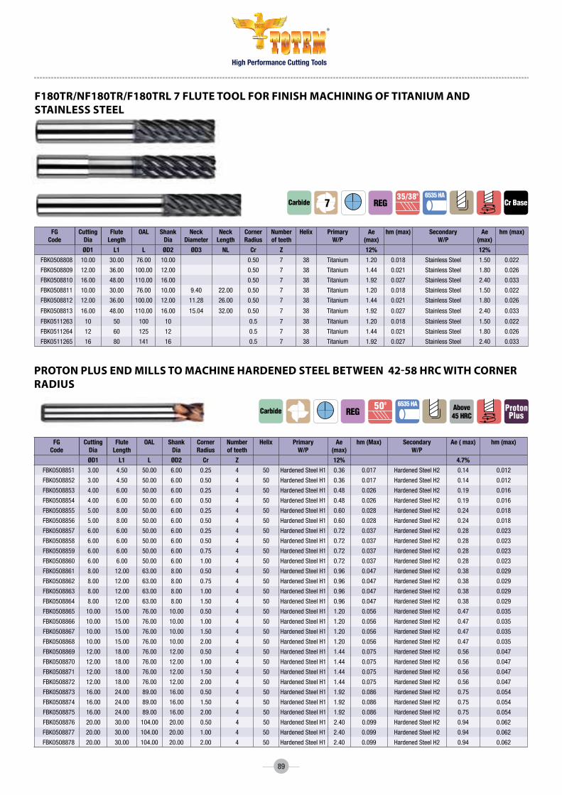
High Performance Cutting Tools
®
89
FG Code
Cutting Dia
Flute Length
OAL Shank Dia
Corner Radius
Number of teeth
Helix Primary w/P
Ae (max)
hm (Max) Secondary w/P
Ae ( max) hm (max)
ØD1 L1 L ØD2 Cr Z 12% 4.7%
FBK0508851 3.00 4.50 50.00 6.00 0.25 4 50 HardenedSteelH1 0.36 0.017 HardenedSteelH2 0.14 0.012
FBK0508852 3.00 4.50 50.00 6.00 0.50 4 50 HardenedSteelH1 0.36 0.017 HardenedSteelH2 0.14 0.012
FBK0508853 4.00 6.00 50.00 6.00 0.25 4 50 HardenedSteelH1 0.48 0.026 HardenedSteelH2 0.19 0.016
FBK0508854 4.00 6.00 50.00 6.00 0.50 4 50 HardenedSteelH1 0.48 0.026 HardenedSteelH2 0.19 0.016
FBK0508855 5.00 8.00 50.00 6.00 0.25 4 50 HardenedSteelH1 0.60 0.028 HardenedSteelH2 0.24 0.018
FBK0508856 5.00 8.00 50.00 6.00 0.50 4 50 HardenedSteelH1 0.60 0.028 HardenedSteelH2 0.24 0.018
FBK0508857 6.00 6.00 50.00 6.00 0.25 4 50 HardenedSteelH1 0.72 0.037 HardenedSteelH2 0.28 0.023
FBK0508858 6.00 6.00 50.00 6.00 0.50 4 50 HardenedSteelH1 0.72 0.037 HardenedSteelH2 0.28 0.023
FBK0508859 6.00 6.00 50.00 6.00 0.75 4 50 HardenedSteelH1 0.72 0.037 HardenedSteelH2 0.28 0.023
FBK0508860 6.00 6.00 50.00 6.00 1.00 4 50 HardenedSteelH1 0.72 0.037 HardenedSteelH2 0.28 0.023
FBK0508861 8.00 12.00 63.00 8.00 0.50 4 50 HardenedSteelH1 0.96 0.047 HardenedSteelH2 0.38 0.029
FBK0508862 8.00 12.00 63.00 8.00 0.75 4 50 HardenedSteelH1 0.96 0.047 HardenedSteelH2 0.38 0.029
FBK0508863 8.00 12.00 63.00 8.00 1.00 4 50 HardenedSteelH1 0.96 0.047 HardenedSteelH2 0.38 0.029
FBK0508864 8.00 12.00 63.00 8.00 1.50 4 50 HardenedSteelH1 0.96 0.047 HardenedSteelH2 0.38 0.029
FBK0508865 10.00 15.00 76.00 10.00 0.50 4 50 HardenedSteelH1 1.20 0.056 HardenedSteelH2 0.47 0.035
FBK0508866 10.00 15.00 76.00 10.00 1.00 4 50 HardenedSteelH1 1.20 0.056 HardenedSteelH2 0.47 0.035
FBK0508867 10.00 15.00 76.00 10.00 1.50 4 50 HardenedSteelH1 1.20 0.056 HardenedSteelH2 0.47 0.035
FBK0508868 10.00 15.00 76.00 10.00 2.00 4 50 HardenedSteelH1 1.20 0.056 HardenedSteelH2 0.47 0.035
FBK0508869 12.00 18.00 76.00 12.00 0.50 4 50 HardenedSteelH1 1.44 0.075 HardenedSteelH2 0.56 0.047
FBK0508870 12.00 18.00 76.00 12.00 1.00 4 50 HardenedSteelH1 1.44 0.075 HardenedSteelH2 0.56 0.047
FBK0508871 12.00 18.00 76.00 12.00 1.50 4 50 HardenedSteelH1 1.44 0.075 HardenedSteelH2 0.56 0.047
FBK0508872 12.00 18.00 76.00 12.00 2.00 4 50 HardenedSteelH1 1.44 0.075 HardenedSteelH2 0.56 0.047
FBK0508873 16.00 24.00 89.00 16.00 0.50 4 50 HardenedSteelH1 1.92 0.086 HardenedSteelH2 0.75 0.054
FBK0508874 16.00 24.00 89.00 16.00 1.50 4 50 HardenedSteelH1 1.92 0.086 HardenedSteelH2 0.75 0.054
FBK0508875 16.00 24.00 89.00 16.00 2.00 4 50 HardenedSteelH1 1.92 0.086 HardenedSteelH2 0.75 0.054
FBK0508876 20.00 30.00 104.00 20.00 0.50 4 50 HardenedSteelH1 2.40 0.099 HardenedSteelH2 0.94 0.062
FBK0508877 20.00 30.00 104.00 20.00 1.00 4 50 HardenedSteelH1 2.40 0.099 HardenedSteelH2 0.94 0.062
FBK0508878 20.00 30.00 104.00 20.00 2.00 4 50 HardenedSteelH1 2.40 0.099 HardenedSteelH2 0.94 0.062
pRoton plus end mills to machine haRdened steel BetWeen 42-58 hRc With coRneR Radius
Carbide 500above45 hRC
ProtonPlus
6535 haREG
FG Code
Cutting Dia
Flute Length
OAL Shank Dia
Neck Diameter
Neck Length
Corner Radius
Number of teeth
Helix Primary w/P
Ae (max)
hm (max) Secondary w/P
Ae (max)
hm (max)
ØD1 L1 L ØD2 ØD3 NL Cr Z 12% 12%
FBK0508808 10.00 30.00 76.00 10.00 0.50 7 38 Titanium 1.20 0.018 StainlessSteel 1.50 0.022
FBK0508809 12.00 36.00 100.00 12.00 0.50 7 38 Titanium 1.44 0.021 StainlessSteel 1.80 0.026
FBK0508810 16.00 48.00 110.00 16.00 0.50 7 38 Titanium 1.92 0.027 StainlessSteel 2.40 0.033
FBK0508811 10.00 30.00 76.00 10.00 9.40 22.00 0.50 7 38 Titanium 1.20 0.018 StainlessSteel 1.50 0.022
FBK0508812 12.00 36.00 100.00 12.00 11.28 26.00 0.50 7 38 Titanium 1.44 0.021 StainlessSteel 1.80 0.026
FBK0508813 16.00 48.00 110.00 16.00 15.04 32.00 0.50 7 38 Titanium 1.92 0.027 StainlessSteel 2.40 0.033
FBK0511263 10 50 100 10 0.5 7 38 Titanium 1.20 0.018 StainlessSteel 1.50 0.022
FBK0511264 12 60 125 12 0.5 7 38 Titanium 1.44 0.021 StainlessSteel 1.80 0.026
FBK0511265 16 80 141 16 0.5 7 38 Titanium 1.92 0.027 StainlessSteel 2.40 0.033
f180tR/nf180tR/f180tRl 7 flute tool foR finish machining of titanium and stainless steel
Cr BaseCarbide REG35/380 6535 ha
7

90
FG Code
Cutting Dia
Flute Length
OAL Shank Dia
Number of teeth
Helix Primary w/P
Ae ( max) hm (Max)
Secondary w/P
Ae ( max) hm (max)
ØD1 L1 L ØD2 Z 12% 4.70%
FBK0509820 6.00 15.00 76.00 6.00 4 50 HardenedSteelH1 0.72 0.037 HardenedSteelH2 0.28 0.023
FBK0509821 8.00 20.00 100.00 8.00 4 50 HardenedSteelH1 0.96 0.047 HardenedSteelH2 0.38 0.029
FBK0509822 10.00 25.00 100.00 10.00 5 50 HardenedSteelH1 1.20 0.056 HardenedSteelH2 0.47 0.035
FBK0509823 12.00 30.00 125.00 12.00 6 50 HardenedSteelH1 1.44 0.075 HardenedSteelH2 0.56 0.047
FBK0509824 16.00 40.00 125.00 16.00 6 50 HardenedSteelH1 1.92 0.086 HardenedSteelH2 0.75 0.054
FBK0509825 20.00 50.00 150.00 20.00 6 50 HardenedSteelH1 2.40 0.099 HardenedSteelH2 0.94 0.062
FBK0509826 25.00 63.00 150.00 25.00 6 50 HardenedSteelH1 3.00 0.121 HardenedSteelH2 1.18 0.067
pRoton plus end mills to machine haRdened steel BetWeen 42-58 hRc
Carbide500
above45 hRC
ProtonPlus
6535 haREG
High Performance Cutting Tools
®
FG Code
Cutting Dia
Flute Length
OAL Shank Dia
Number of teeth
Helix Primary w/P
Ae ( max) hm (Max)
Secondary w/P
Ae ( max) hm (max)
ØD1 L1 L ØD2 Z 12% 4.70%
FBK0508765 3.00 5.00 50.00 6.00 4 50 HardenedSteelH1 0.36 0.017 HardenedSteelH2 0.14 0.012
FBK0508766 4.00 6.00 50.00 6.00 4 50 HardenedSteelH1 0.48 0.026 HardenedSteelH2 0.19 0.016
FBK0508767 5.00 8.00 50.00 6.00 4 50 HardenedSteelH1 0.60 0.028 HardenedSteelH2 0.24 0.018
FBK0508768 6.00 9.00 50.00 6.00 4 50 HardenedSteelH1 0.72 0.037 HardenedSteelH2 0.28 0.023
FBK0508769 8.00 12.00 63.00 8.00 4 50 HardenedSteelH1 0.96 0.047 HardenedSteelH2 0.38 0.029
FBK0508770 10.00 15.00 76.00 10.00 4 50 HardenedSteelH1 1.20 0.056 HardenedSteelH2 0.47 0.035
FBK0508771 12.00 18.00 76.00 12.00 4 50 HardenedSteelH1 1.44 0.075 HardenedSteelH2 0.56 0.047
FBK0508772 16.00 24.00 89.00 16.00 4 50 HardenedSteelH1 1.92 0.086 HardenedSteelH2 0.75 0.054
FBK0508773 20.00 30.00 104.00 20.00 4 50 HardenedSteelH1 2.40 0.099 HardenedSteelH2 0.94 0.062
FBK0508774 25.00 38.00 121.00 25.00 5 50 HardenedSteelH1 3.00 0.121 HardenedSteelH2 1.18 0.067
FG Code
Cutting Dia
Flute Length
OAL Shank Dia
Number of teeth
Helix Primary w/P
Ae ( max) hm (Max)
Secondary w/P
Ae ( max) hm (max)
ØD1 L1 L ØD2 Z 12% 4.70%
FBK0508775 6.00 21.00 76.00 6.00 4 50 HardenedSteelH1 0.72 0.037 HardenedSteelH2 0.28 0.023
FBK0508776 8.00 28.00 100.00 8.00 4 50 HardenedSteelH1 0.96 0.047 HardenedSteelH2 0.38 0.029
FBK0508777 10.00 35.00 100.00 10.00 5 50 HardenedSteelH1 1.20 0.056 HardenedSteelH2 0.47 0.035
FBK0508778 12.00 42.00 125.00 12.00 6 50 HardenedSteelH1 1.44 0.075 HardenedSteelH2 0.56 0.047
FBK0508779 16.00 56.00 125.00 16.00 6 50 HardenedSteelH1 1.92 0.086 HardenedSteelH2 0.75 0.054
FBK0508780 20.00 70.00 150.00 20.00 6 50 HardenedSteelH1 2.40 0.099 HardenedSteelH2 0.94 0.062
FBK0508781 25.00 88.00 150.00 25.00 6 50 HardenedSteelH1 3.00 0.121 HardenedSteelH2 1.18 0.067
pRoton plus end mills to machine haRdened steel BetWeen 42-58 hRc
pRoton plus end mills to machine haRdened steel BetWeen 42-58 hRc
Carbide500
above45 hRC
ProtonPlus
6535 ha
0.1x45o
REG
Carbide500
LonG above45 hRC
ProtonPlus
6535 ha
0.1x45o

High Performance Cutting Tools
®
91
hsm end mill foR RiB milling of multiple mateRials
FG Code
Cutting Dia
ShankDia
FluteLength
NeckLength
NeckDiameter
OAL Numberof teeth
Helix
ØD1 ØD2 L1 NL ØD3 L Z
FBK0508963 1 4 1.5 4 0.97 50 2 30
FBK0508964 1 4 1.5 6 0.97 50 2 30
FBK0508965 1 4 1.5 8 0.95 50 2 30
FBK0508966 1 4 1.5 10 0.95 50 2 30
FBK0508967 1 4 1.5 12 0.93 50 2 30
FBK0508968 1.2 4 1.5 6 1.17 50 2 30
FBK0508969 1.2 4 1.8 8 1.15 50 2 30
FBK0508970 1.2 4 1.8 10 1.15 50 2 30
FBK0508971 1.2 4 1.8 12 1.13 50 2 30
FBK0508972 1.2 4 1.8 16 1.13 50 2 30
FBK0508973 1.4 4 2.1 6 1.37 50 2 30
FBK0508974 1.4 4 2.1 8 1.35 50 2 30
FBK0508975 1.4 4 2.1 10 1.35 50 2 30
FBK0508976 1.4 4 2.1 12 1.33 50 2 30
FBK0508977 1.4 4 2.1 16 1.31 50 2 30
FBK0508978 1.4 4 2.1 18 1.31 50 2 30
FBK0508979 1.4 4 2.1 20 1.31 50 2 30
FBK0508980 1.5 4 2.3 6 1.47 50 2 30
FBK0508981 1.5 4 2.3 8 1.47 50 2 30
FBK0508982 1.5 4 2.3 10 1.45 50 2 30
FBK0508983 1.5 4 2.3 12 1.43 50 2 30
FBK0508984 1.5 4 2.3 16 1.41 50 2 30
FBK0508985 1.5 4 2.3 18 1.41 63 2 30
FBK0508986 1.5 4 2.3 20 1.39 63 2 30
FBK0508987 1.8 4 2.7 6 1.77 50 2 30
FBK0508988 1.8 4 2.7 12 1.73 50 2 30
FBK0508989 2 4 3 6 1.97 50 2 30
FBK0508990 2 4 3 8 1.97 50 2 30
FBK0508991 2 4 3 10 1.95 50 2 30
FBK0508992 2 4 3 12 1.95 50 2 30
FBK0508993 2 4 3 16 1.91 50 2 30
FBK0508994 2 4 3 20 1.89 63 2 30
FBK0508995 2 4 3 30 1.89 75 2 30
FBK0508996 2.5 4 3.7 8 2.4 50 2 30
FBK0508997 2.5 4 3.7 10 2.4 50 2 30
FBK0508998 2.5 4 3.7 12 2.4 50 2 30
FBK0508999 2.5 4 3.7 14 2.4 50 2 30
FBK0509000 2.5 4 3.7 16 2.4 63 2 30
FBK0509001 2.5 4 3.7 20 2.4 63 2 30
FBK0509002 2.5 4 3.7 25 2.4 63 2 30
FBK0509003 2.5 4 3.7 30 2.4 80 2 30
FBK0509004 3 6 4.5 8 2.85 50 2 30
FBK0509005 3 6 4.5 10 2.85 50 2 30
FBK0509006 3 6 4.5 12 2.85 50 2 30
FBK0509007 3 6 4.5 16 2.85 63 2 30
FBK0509008 3 6 4.5 20 2.85 63 2 30
FBK0509009 3 6 4.5 30 2.85 80 2 30
Carbide300
Tialn6535 ha

High Performance Cutting Tools
®
92
chamfeR tool (60o/90o)
spoting dRill (60o/90o/120o)
600 900 1200
FG Code 60o FG Code 90o Cutting Dia Flute Length Shank Dia OAL Number of teethHelix
ØD1 L1 ØD2 L Z
FBJ0505363 FBJ0505410 3.00 20.00 3.00 50.00 4 30
FBJ0505364 FBJ0505411 4.00 20.00 4.00 50.00 4 30
FBJ0505365 FBJ0505357 5.00 20.00 5.00 50.00 4 30
FBJ0505366 FBJ0505358 6.00 20.00 6.00 50.00 4 30
FBJ0505367 FBJ0505359 8.00 25.00 8.00 60.00 4 30
FBJ0505368 FBJ0505360 10.00 30.00 10.00 75.00 4 30
FBJ0505369 FBJ0505361 12.00 30.00 12.00 75.00 4 30
FBJ0505370 FBJ0505362 16.00 30.00 16.00 100.00 4 30
FG Code 60o FG Code 90o FG Code 120o Cutting Dia Flute Length Shank Dia OAL Number of teethHelix
ØD1 L1 ØD2 L Z
FBJ0505371 FBJ0505380 FBJ0505389 2.00 6.00 2.00 50.00 2 30
FBJ0505372 FBJ0505381 FBJ0505390 3.00 8.00 3.00 50.00 2 30
FBJ0505373 FBJ0505382 FBJ0505391 4.00 11.00 4.00 50.00 2 30
FBJ0505374 FBJ0505383 FBJ0505392 5.00 13.00 5.00 50.00 2 30
FBJ0505375 FBJ0505384 FBJ0505393 6.00 15.00 6.00 50.00 2 30
FBJ0505376 FBJ0505385 FBJ0505394 8.00 20.00 8.00 60.00 2 30
FBJ0505377 FBJ0505386 FBJ0505395 10.00 25.00 10.00 75.00 2 30
FBJ0505378 FBJ0505387 FBJ0505396 12.00 30.00 12.00 75.00 2 30
FBJ0505379 FBJ0505388 FBJ0505397 16.00 45.00 16.00 100.00 2 30
Carbide
Carbide
300
300

High Performance Cutting Tools
®
93
caRBide centeR dRill
Descrption EDP
CENTER DRILL 1 X3.15 TYPE A RH DIN333 FBJ0505428
CENTER DRILL 1.25 X3.15 TYPE A RH DIN333 FBJ0505429
CENTER DRILL 1 X4 TYPE A RH DIN333 FBJ0505430
CENTER DRILL 1.6 X4 TYPE A RH DIN333 FBJ0505431
CENTER DRILL 2 X5 TYPE A RH DIN333 FBJ0505432
CENTER DRILL 2.5 X6.3 TYPE A RH DIN333 FBJ0505433
CENTER DRILL 3 X8 TYPE A RH DIN333 FBJ0505434
CENTER DRILL 3.15 X8 TYPE A RH DIN333 FBJ0505461
Descrption EDP
CENTER DRILL 1 X3.15 TYPE A LH DIN333 FBJ0505442
CENTER DRILL 1.25 X3.15 TYPE A LH DIN333 FBJ0505443
CENTER DRILL 1 X4 TYPE A LH DIN333 FBJ0505444
CENTER DRILL 1.6 X4 TYPE A LH DIN333 FBJ0505445
CENTER DRILL 2 X5 TYPE A LH DIN333 FBJ0505446
CENTER DRILL 2.5 X6.3 TYPE A LH DIN333 FBJ0505447
CENTER DRILL 3 X8 TYPE A LH DIN333 FBJ0505448
CENTER DRILL 3.15 X8 TYPE A LH DIN333 FBJ0505460
foRm a Rh foRm a lh
Descrption EDP
CENTER DRILL 1 X3.15 TYPE B RH DIN333 FBJ0505435
CENTER DRILL 1.25 X3.15 TYPE B RH DIN333 FBJ0505436
CENTER DRILL 1 X4 TYPE B RH DIN333 FBJ0505437
CENTER DRILL 1.6 X4 TYPE B RH DIN333 FBJ0505438
CENTER DRILL 2 X5 TYPE B RH DIN333 FBJ0505439
CENTER DRILL 2.5 X6.3 TYPE B RH DIN333 FBJ0505440
CENTER DRILL 3 X8 TYPE B RH DIN333 FBJ0505441
CENTER DRILL 3.15 X8 TYPE B RH DIN333 FBJ0505459
foRm B Rh
Descrption EDP
CENTER DRILL 1 X3.15 TYPE B LH DIN333 FBJ0505449
CENTER DRILL 1.25 X3.15 TYPE B LH DIN333 FBJ0505450
CENTER DRILL 1 X4 TYPE B LH DIN333 FBJ0505451
CENTER DRILL 1.6 X4 TYPE B LH DIN333 FBJ0505452
CENTER DRILL 2 X5 TYPE B LH DIN333 FBJ0505453
CENTER DRILL 2.5 X6.3 TYPE B LH DIN333 FBJ0505454
CENTER DRILL 3 X8 TYPE B LH DIN333 FBJ0505455
CENTER DRILL 3.15 X8 TYPE B LH DIN333 FBJ0505458
foRm B lh
Carbide
Carbide
FORMA
FORMB
DIn333
DIn333
118o
118o

High Performance Cutting Tools
®
94
spiRal point pm taps foR stainless steel m& mf
spiRal point pm taps foR titanium and inconel
spiRal point pm taps foR stainless steel unc
spiRal point pm taps foR stainless steel unf
Size FG Code Description
M3X0.5 FAB0207083 HPT3X.5SAS5PMDIN371
M4X0.7 FAB0207084 HPT4X.7SAS5PMDIN371
M5X0.8 FAB0207085 HPT5X.8SAS5PMDIN371
M6X1 FAB0207086 HPT6X1SAS5PMDIN371
M8X1 HPT8X1SAS5PMDIN374
M8X1.25 FAB0207087 HPT8X1.25SAS5PMDIN371
M10X1 HPT10X1SAS5PMDIN374
M10X1.25 HPT10X1.25SAS5PMDIN374
M10X1.5 FAB0207088 HPT10X1.5SAS5PMDIN371
M12X1.25 HPT12X1.25SAS5PMDIN374
M12X1.5 HPT12X1.5SAS5PMDIN374
M12X1.75 FAB0207089 HPT12X1.75SAS5PMDIN376
Size FG Code Description
4UNF FAB0207171 HPT4UNFSAS5PMDIN371
6UNF FAB0207172 HPT6UNFSAS5PMDIN371
8UNF FAB0207173 HPT8UNFSAS5PMDIN371
10UNF FAB0207174 HPT10UNFSAS5PMDIN371
1/4UNF FAB0207175 HPT1/4UNFSAS5PMDIN371
5/16UNF FAB0207176 HPT5/16UNFSAS5PMDIN371
3/8UNF FAB0207177 HPT3/8UNFSAS5PMDIN371
Size FG Code Description
4UNC FAB0207151 HPT4UNCSAS5PMDIN3716UNC FAB0207152 HPT6UNCSAS5PMDIN3718UNC FAB0207153 HPT8UNCSAS5PMDIN37110UNC FAB0207154 HPT10UNCSAS5PMDIN3711/4UNC FAB0207155 HPT1/4UNCSAS5PMDIN3715/16UNC FAB0207156 HPT5/16UNCSAS5PMDIN3713/8UNC FAB0207157 HPT3/8UNCSAS5PMDIN371
Size FG Code Description
M3X0.5 FAB0204694 HPT3X.5SAI6PMDIN371
M4X0.7 FAB0204695 HPT4X.7SAI6PMDIN371
M5X0.8 FAB0204696 HPT5X.8SAI6PMDIN371
M6X1 FAB0204697 HPT6X1SAI6PMDIN371
M8X1 FAB0204810 HPT8X1SAI6PMDIN374
M8X1.25 FAB0204698 HPT8X1.25SAI6PMDIN371
6hxDIn371/376
C/2-3P
6hxDIn371/376
B/4-4.5PhSS-EPM
hSS-EPM
Size FG Code Description
M10X1 FAB0204812 HPT10X1SAI6PMDIN374
M10X1.25 FAB0204811 HPT10X1.25SAI6PMDIN374
M10X1.5 FAB0204699 HPT10X1.5SAI6PMDIN371
M12X1.25 FAB0204815 HPT12X1.25SAI6PMDIN374
M12X1.5 FAB0204816 HPT12X1.5SAI6PMDIN374
M12X1.75 FAB0204700 HPT12X1.75SAI6PMDIN376
a L1
L
D3
D1
L3
a L3 L1
D1
D3
L
Reinforced Shank DIN371 (1/4” - 3/8”)
Reduced Shank DIN376 (7/16” - 1”)
Reinforced Shank (M3 - M10)
D1
L1 L3 L
D3
a
a L3 L1
D1
D3
L
Male Centre upto M5
Reduced Shank (M12 - M16)

High Performance Cutting Tools
®
95
Size FG Code Description
M3X0.5 FAB0205539 HPT3X.5SBS5PMDIN371
M4X0.7 FAB0205540 HPT4X.7SBS5PMDIN371
M5X0.8 FAB0205541 HPT5X.8SBS5PMDIN371
M6X1 FAB0205542 HPT6X1SBS5PMDIN371
M8X1 FAB0206392 HPT8X1SBS5PMDIN374
M8X1.25 FAB0205543 HPT8X1.25SBS5PMDIN371
M10X1 HPT10X1SBS5PMDIN374
M10X1.25 HPT10X1.25SBS5PMDIN374
M10X1.5 FAB0205544 HPT10X1.5SBS5PMDIN371
M12X1.25 HPT12X1.25SBS5PMDIN374
M12X1.5 HPT12X1.5SBS5PMDIN374
M12X1.75 FAB0205545 HPT12X1.75SBS5PMDIN376
Size FG Code Description
4UNF FAB0207178 HPT4UNFSBS5PMDIN371
6UNF FAB0207179 HPT6UNFSBS5PMDIN371
8UNF FAB0207180 HPT8UNFSBS5PMDIN371
10UNF FAB0207181 HPT10UNFSBS5PMDIN371
1/4UNF FAB0207182 HPT1/4UNFSBS5PMDIN371
5/16UNF FAB0207183 HPT5/16UNFSBS5PMDIN371
3/8UNF FAB0207184 HPT3/8UNFSBS5PMDIN371
Size FG Code Description
4UNC FAB0207158 HPT4UNCSBS5PMDIN371
6UNC FAB0207159 HPT6UNCSBS5PMDIN371
8UNC FAB0207160 HPT8UNCSBS5PMDIN371
10UNC FAB0207161 HPT10UNCSBS5PMDIN371
1/4UNC FAB0205558 HPT1/4UNCSBS5PMDIN371
5/16UNC FAB0205559 HPT5/16UNCSBS5PMDIN371
3/8UNC FAB0205560 HPT3/8UNCSBS5PMDIN371
a L1
L
D3
D1
L3
a L3 L1
D1
D3
L
Reinforced Shank DIN371 (M3 - M10)
Reduced Shank DIN376 (M12 - M20)
6hxDIn371/376
C/2-3P 450
hSS-EPM
spiRal flute pm taps foR stainless steel m and mf spiRal flute pm taps foR stainless steel unc
spiRal flute pm taps foR stainless steel unf
spiRal flute pm taps foR stainless steel
Size FG Code Description
M3X0.5 FAB0204703 HPT3X.5SBI6PMDIN371
M4X0.7 FAB0204704 HPT4X.7SBI6PMDIN371
M5X0.8 FAB0204705 HPT5X.8SBI6PMDIN371
M6X1 FAB0204706 HPT6X1SBI6PMDIN371
M8X1 FAB0204738 HPT8X1SBI6PMDIN374
M8X1.25 FAB0204707 HPT8X1.25SBI6PMDIN371
6hxDIn371/376
hSS-EPM
C/2-3P 180
Size FG Code Description
M10X1 FAB0204814 HPT10X1SBI6PMDIN374
M10X1.25 FAB0204813 HPT10X1.25SBI6PMDIN374
M10X1.5 FAB0204708 HPT10X1.5SBI6PMDIN371
M12X1.25 FAB0204739 HPT12X1.25SBI6PMDIN374
M12X1.5 FAB0204898 HPT12X1.5SBI6PMDIN374
M12X1.75 FAB0204709 HPT12X1.75SBI6PMDIN376
a L1
L
D3
D1
L3
a L3 L1
D1
D3
L
Reinforced Shank DIN371 (M3 - M10)
Reduced Shank DIN376 (M12 - M16)

High Performance Cutting Tools
®
96
defined by: r262 (dIn 13) l tolerance class: 6h
32
41
IMPORTANT PARAMETERS1 Helix(RH) 15°2 Number of �utes 43 Internal coolant No4 Shank diameter D5 Coating TA6 Material Micro�ne carbide
APPLICATION DETAILS1 Material2 Component name3 Hardness
00 30/04/2019REV. NO. REVISION BY DATE
CUSTOMER APPROVALCustomer nameCustomer reference no.Approved date Sign
D
CB
CBA
A D1
23
4
****MARK DETAILS
NOTE:1) All dimensions are in mm.2) All other details are as permanufacturer's standard.3) Not to the scale.
Forbes & Company Limited , B-13, MIDC Area,Waluj, Aurangabad- 431133, Maharashtra, India
Sign Date MATERIAL
DRAWN NLA ALTERNATE MATERIAL
CHECKED RNS SCALE NTSAPPROVED RNS REVISION 00QA SNPMFG DSOperation Head SUW
TITLE:Thread mill 15°Hx 4�t TA DRAWING NO.:
SAP CODE: SHEET 1 Of 1
D
LL 1
D1
For Thread size:M10.0x1.0
P i t c h
6 0
Multi Flute iso metric threadInternal threading
Thread Size Pitch mm
Description D L1 L D1 Flutes EDP No
Coarse Fine mm mm mm mm
M5 0.5 TMRHS-0.5ISO-3.8MMX10.3X57 SH6 3FL TA 3.8 10.3 57 6 3 FBV0503000
M7 0.5 TMRHS-0.5ISO-5.9MMX10.2X57 SH6 3FL TA 5.9 10.2 57 6 3 FBV0503001
M4.5 M5 0.75 TMRHS-0.75ISO-3.6MMX10.1X57 SH6 3FL TA 3.6 10.1 57 6 3 FBV0503002
M8 0.75 TMRHS-0.75ISO-5.9MMX10.8X57 SH6 3FL TA 5.9 10.8 57 6 3 FBV0503003
M10 0.75 TMRHS-0.75ISO-7.9MMX15.3X63 SH8 4FL TA 7.9 15.3 63 8 4 FBV0503004
M5 0.8 TMRHS-0.8ISO-3.9MMX10X57 SH6 3FL TA 3.9 10 57 6 3 FBV0503005
M6 M7 1 TMRHS-1.0ISO-4.8MMX11.5X57 SH6 3FL TA 4.8 11.5 57 6 3 FBV0503006
M6 M7 1 TMRHS-1.0ISO-4.8MMX14.5X57 SH6 3FL TA 4.8 14.5 57 6 3 FBV0503007
M8 1 TMRHS-1.0ISO-5.9MMX12.5X57 SH6 3FL TA 5.9 12.5 57 6 3 FBV0503008
M10 1 TMRHS-1.0ISO-7.9MMX17.5X63 SH8 4FL TA 7.9 17.5 63 8 4 FBV0503009
M12 1 TMRHS-1.0ISO-9.9MMX20.5X73 SH10 4FL TA 9.9 20.5 73 10 4 FBV0503010
M8 M9 1.25 TMRHS-1.25ISO-5.9MMX14.4X57 SH6 3FL TA 5.9 14.4 57 6 3 FBV0503011
M8 M9 1.25 TMRHS-1.25ISO-5.9MMX19.5X57 SH6 3FL TA 5.9 19.5 57 6 3 FBV0503012
M10 M11 1.5 TMRHS-1.5ISO-7.9MMX18.5X63 SH8 3FL TA 7.9 18.5 63 8 3 FBV0503013
M13 1.5 TMRHS-1.5ISO-9.9MMX21.8X73 SH10 4FL TA 9.9 21.8 73 10 4 FBV0503014
M15 1.5 TMRHS-1.5ISO-11.9MMX26.3X84 SH12 4FL TA 11.9 26.3 84 12 4 FBV0503015
M20 1.5 TMRHS-1.5ISO-15.9MMX35.2X105 SH16 6FL TA 15.9 35.2 105 16 6 FBV0503016
M12 1.75 TMRHS-1.75ISO-9.2MMX21.8X73 SH10 3FL TA 9.2 21.8 73 10 3 FBV0503017
M14 2 TMRHS-2.0ISO-9.9MMX25X73 SH10 3FL TA 9.9 25 73 10 3 FBV0503018
M16 2 TMRHS-2.0ISO-11.9MMX27X84 SH12 4FL TA 11.9 27 84 12 4 FBV0503019
M20 2 TMRHS-2.0ISO-15.9MMX37X105 SH16 5FL TA 15.9 37 105 16 5 FBV0503020
M20 2.5 TMRHS-2.5ISO-15.9MMX36.3X105 SH16 5FL TA 15.9 36.3 105 16 5 FBV0503021
M24 M27 3 TMRHS-3.0ISO-15.9MMX40.5X105 SH16 3FL TA 15.9 40.5 105 16 3 FBV0503022
M27 3 TMRHS-3.0ISO-19.9MMX43X105 SH20 4FL TA 19.9 43 105 20 4 FBV0503023
1/4P
60O
1/8P
Internal
External
iT iSOMFMTM RHS
Detail View A
A
DL
L 1
D1
P
6 0

High Performance Cutting Tools
®
97
defined by: r262 (dIn 13) l tolerance class: 6h
32
41
IMPORTANT PARAMETERS1 Helix(RH) 15°2 Number of �utes 53 Internal coolant Yes4 Shank diameter D5 Coating TA6 Material Micro�ne carbide
APPLICATION DETAILS1 Material2 Component name3 Hardness
00 30/04/2019REV. NO. REVISION BY DATE
CUSTOMER APPROVALCustomer nameCustomer reference no.Approved date Sign
D
CB
CBA
A D1
23
4
****MARK DETAILS
NOTE:1) All dimensions are in mm.2) All other details are as permanufacturer's standard.3) Not to the scale.
Forbes & Company Limited , B-13, MIDC Area,Waluj, Aurangabad- 431133, Maharashtra, India
Sign Date MATERIAL
DRAWN NLA ALTERNATE MATERIAL
CHECKED RNS SCALE NTSAPPROVED RNS REVISION 00QA SNPMFG DSOperation Head SUW
TITLE:Thread mill 15°Hx 5�t TC TA DRAWING NO.:
SAP CODE: SHEET 1 Of 1
P i t c h
6 0
D1
LL 1
D
Multi Flute iso metric threadInternal threading
Thread Size Pitch Mm
Description D L1 L D1 Flutes EDP No
Coarse Fine mm mm mm mm
M5 0.5 TMRHC-0.5ISO-3.8MMX10.3X57 SH6 3FL TA 3.8 10.3 57 6 3 FBV0503024
M7 0.5 TMRHC-0.5ISO-5.9MMX10.2X57 SH6 3FL TA 5.9 10.2 57 6 3 FBV0503025
M4.5 M5 0.75 TMRHC-0.75ISO-3.6MMX10.1X57 SH6 3FL TA 3.6 10.1 57 6 3 FBV0503026
M8 0.75 TMRHC-0.75ISO-5.9MMX10.8X57 SH6 3FL TA 5.9 10.8 57 6 3 FBV0503027
M10 0.75 TMRHC-0.75ISO-7.9MMX15.3X63 SH8 4FL TA 7.9 15.3 63 8 4 FBV0503028
M5 0.8 TMRHC-0.8ISO-3.9MMX10X57 SH6 3FL TA 3.9 10 57 6 3 FBV0503029
M6 M7 1 TMRHC-1.0ISO-4.8MMX11.5X57 SH6 3FL TA 4.8 11.5 57 6 3 FBV0503030
M6 M7 1 TMRHC-1.0ISO-4.8MMX14.5X57 SH6 3FL TA 4.8 14.5 57 6 3 FBV0503031
M8 1 TMRHC-1.0ISO-5.9MMX12.5X57 SH6 3FL TA 5.9 12.5 57 6 3 FBV0503032
M10 1 TMRHC-1.0ISO-7.9MMX17.5X63 SH8 4FL TA 7.9 17.5 63 8 4 FBV0503033
M12 1 TMRHC-1.0ISO-9.9MMX20.5X73 SH10 4FL TA 9.9 20.5 73 10 4 FBV0503034
M8 M9 1.25 TMRHC-1.25ISO-5.9MMX14.4X57 SH6 3FL TA 5.9 14.4 57 6 3 FBV0503035
M8 M9 1.25 TMRHC-1.25ISO-5.9MMX19.5X57 SH6 3FL TA 5.9 19.5 57 6 3 FBV0503036
M10 M11 1.5 TMRHC-1.5ISO-7.9MMX18.5X63 SH8 3FL TA 7.9 18.5 63 8 3 FBV0503037
M13 1.5 TMRHC-1.5ISO-9.9MMX21.8X73 SH10 4FL TA 9.9 21.8 73 10 4 FBV0503038
M15 1.5 TMRHC-1.5ISO-11.9MMX26.3X84 SH12 4FL TA 11.9 26.3 84 12 4 FBV0503039
M20 1.5 TMRHC-1.5ISO-15.9MMX35.2X105 SH16 6FL TA 15.9 35.2 105 16 6 FBV0503040
M12 1.75 TMRHC-1.75ISO-9.2MMX21.8X73 SH10 3FL TA 9.2 21.8 73 10 3 FBV0503041
M14 2 TMRHC-2.0ISO-9.9MMX25X73 SH10 3FL TA 9.9 25 73 10 3 FBV0503042
M16 2 TMRHC-2.0ISO-11.9MMX27X84 SH12 4FL TA 11.9 27 84 12 4 FBV0503043
M20 2 TMRHC-2.0ISO-15.9MMX37X105 SH16 5FL TA 15.9 37 105 16 5 FBV0503044
M20 2.5 TMRHC-2.5ISO-15.9MMX36.3X105 SH16 5FL TA 15.9 36.3 105 16 5 FBV0503045
M24 M27 3 TMRHC-3.0ISO-15.9MMX40.5X105 SH16 3FL TA 15.9 40.5 105 16 3 FBV0503046
M27 3 TMRHC-3.0ISO-19.9MMX43X105 SH20 4FL TA 19.9 43 105 20 4 FBV0503047
1/4P
60O
1/8P
Internal
External
iT iSOM MFTM RHC
Detail View A
A
DL
L 1
D1
P
6 0
with coolant hole

High Performance Cutting Tools
®
98
defined by: AnsI B1.1:74 l tolerance class: 2B
Multi Flute (Unc, Unf, Unef) unified threadInternal threading
Thread Size Pitch Mm
Description D L1 L D1 Flutes EDP No
Coarse UNC
Fine UNF
Extra Fine UNEF
mm mm mm mm
5/16" 32 TMRHS-32UN-5.9MMX14X57 SH6 3FL TA 5.9 14 57 6 3 FBV0503048
3/8" 32 TMRHS-32UN-7.9MMX18X63 SH8 3FL TA 7.9 18 63 8 3 FBV0503049
1/4" 28 TMRHS-28UN-5.1MMX12.2X57 SH6 3FL TA 5.1 12.2 57 6 3 FBV0503050
7/16"-1/2" 28 TMRHS-28UN-7.9MMX15.8X63 SH8 4FL TA 7.9 15.8 63 8 4 FBV0503051
5/16" 24 TMRHS-24UN-5.9MMX10.8X57 SH6 3FL TA 5.9 10.8 57 6 3 FBV0503052
3/8" 24 TMRHS-24UN-7.9MMX15.3X63 SH8 4FL TA 7.9 15.3 63 8 4 FBV0503053
9/16" ,5/8" 24 TMRHS-24UN-11.9MMX22.7X84 SH12 4FL TA 11.9 22.7 84 12 4 FBV0503054
1/4" 20 TMRHS-20UN-4.8MMX12X57 SH6 3FL TA 4.8 12 57 6 3 FBV0503055
7/16" 20 TMRHS-20UN-7.9MMX19.7X63 SH8 3FL TA 7.9 19.7 63 8 3 FBV0503056
1/2" 20 TMRHS-20UN-9.9MMX22.5X73 SH10 4FL TA 9.9 22.5 73 10 4 FBV0503057
3/4"-1" 20 TMRHS-20UN-11.9MMX26X84 SH12 4FL TA 11.9 26 84 12 4 FBV0503058
5/16" 18 TMRHS-18UN-5.7MMX16X57 SH6 3FL TA 5.7 16 57 6 3 FBV0503059
9/16" ,5/8" 18 TMRHS-18UN-9.9MMX23.5X73 SH10 4FL TA 9.9 23.5 73 10 4 FBV0503060
3/8" 16 TMRHS-16UN-6.8MMX18.2X63 SH8 3FL TA 6.8 18.2 63 8 3 FBV0503061
3/4" 16 TMRHS-16UN-11.9MMX26.2X84 SH12 4FL TA 11.9 26.2 84 12 4 FBV0503062
7/16" 14 TMRHS-14UN-7.8MMX20.8X63 SH8 3FL TA 7.8 20.8 63 8 3 FBV0503063
7/8" 14 TMRHS-14UN-11.9MMX24.5X84 SH12 4FL TA 11.9 24.5 84 12 4 FBV0503064
1/2" 13 TMRHS-13UN-9.3MMX24.4X73 SH10 3FL TA 9.3 24.4 73 10 3 FBV0503065
9/16" 12 TMRHS-12UN-10.6MMX26.4X84 SH12 4FL TA 10.6 26.4 84 12 4 FBV0503066
1" 12 TMRHS-12UN-15.9MMX39.1X105 SH16 5FL TA 15.9 39.1 105 16 5 FBV0503067
5/8" 11 TMRHS-11UN-11.5MMX31.1X84 SH12 3FL TA 11.5 31.1 84 12 3 FBV0503068
3/4" 10 TMRHS-10UN-14.3MMX36.8X105 SH16 4FL TA 14.3 36.8 105 16 4 FBV0503069
7/8" 9 TMRHS-9UN-15.9MMX40.9X105 SH16 4FL TA 15.9 40.9 105 16 4 FBV0503070
1" 8 TMRHS-8UN-19.7MMX42.8X105 SH20 4FL TA 19.7 42.8 105 20 4 FBV0503071
32
41
IMPORTANT PARAMETERS1 Helix(RH) 15°2 Number of �utes 43 Internal coolant No4 Shank diameter D5 Coating TA6 Material Micro�ne carbide
APPLICATION DETAILS1 Material2 Component name3 Hardness
00 30/04/2019REV. NO. REVISION BY DATE
CUSTOMER APPROVALCustomer nameCustomer reference no.Approved date Sign
D
CB
CBA
A D1
23
4
****MARK DETAILS
NOTE:1) All dimensions are in mm.2) All other details are as permanufacturer's standard.3) Not to the scale.
Forbes & Company Limited , B-13, MIDC Area,Waluj, Aurangabad- 431133, Maharashtra, India
Sign Date MATERIAL
DRAWN NLA ALTERNATE MATERIAL
CHECKED RNS SCALE NTSAPPROVED RNS REVISION 00QA SNPMFG DSOperation Head SUW
TITLE:Thread mill 15°Hx 4�t TA DRAWING NO.:
SAP CODE: SHEET 1 Of 1
D
LL 1
D1
For Thread size:M10.0x1.0
P i t c h
6 0
1/4P
1/8P
60O
Internal
External
iTTM RHS UNC UNEF UNF UNiFiED
Detail View A
A
D
LL 1
D1
P
6 0
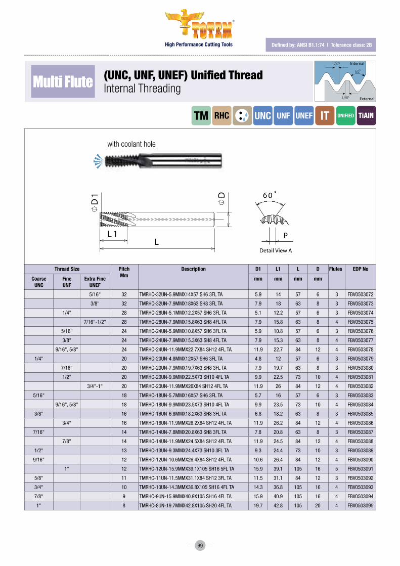
High Performance Cutting Tools
®
99
Multi Flute (Unc, Unf, Unef) Unified threadInternal Threading
Thread Size Pitch Mm
Description D1 L1 L D Flutes EDP No
Coarse UNC
Fine UNF
Extra Fine UNEF
mm mm mm mm
5/16" 32 TMRHC-32UN-5.9MMX14X57SH63FLTA 5.9 14 57 6 3 FBV0503072
3/8" 32 TMRHC-32UN-7.9MMX18X63SH83FLTA 7.9 18 63 8 3 FBV0503073
1/4" 28 TMRHC-28UN-5.1MMX12.2X57SH63FLTA 5.1 12.2 57 6 3 FBV0503074
7/16"-1/2" 28 TMRHC-28UN-7.9MMX15.8X63SH84FLTA 7.9 15.8 63 8 4 FBV0503075
5/16" 24 TMRHC-24UN-5.9MMX10.8X57SH63FLTA 5.9 10.8 57 6 3 FBV0503076
3/8" 24 TMRHC-24UN-7.9MMX15.3X63SH84FLTA 7.9 15.3 63 8 4 FBV0503077
9/16",5/8" 24 TMRHC-24UN-11.9MMX22.7X84SH124FLTA 11.9 22.7 84 12 4 FBV0503078
1/4" 20 TMRHC-20UN-4.8MMX12X57SH63FLTA 4.8 12 57 6 3 FBV0503079
7/16" 20 TMRHC-20UN-7.9MMX19.7X63SH83FLTA 7.9 19.7 63 8 3 FBV0503080
1/2" 20 TMRHC-20UN-9.9MMX22.5X73SH104FLTA 9.9 22.5 73 10 4 FBV0503081
3/4"-1" 20 TMRHC-20UN-11.9MMX26X84SH124FLTA 11.9 26 84 12 4 FBV0503082
5/16" 18 TMRHC-18UN-5.7MMX16X57SH63FLTA 5.7 16 57 6 3 FBV0503083
9/16",5/8" 18 TMRHC-18UN-9.9MMX23.5X73SH104FLTA 9.9 23.5 73 10 4 FBV0503084
3/8" 16 TMRHC-16UN-6.8MMX18.2X63SH83FLTA 6.8 18.2 63 8 3 FBV0503085
3/4" 16 TMRHC-16UN-11.9MMX26.2X84SH124FLTA 11.9 26.2 84 12 4 FBV0503086
7/16" 14 TMRHC-14UN-7.8MMX20.8X63SH83FLTA 7.8 20.8 63 8 3 FBV0503087
7/8" 14 TMRHC-14UN-11.9MMX24.5X84SH124FLTA 11.9 24.5 84 12 4 FBV0503088
1/2" 13 TMRHC-13UN-9.3MMX24.4X73SH103FLTA 9.3 24.4 73 10 3 FBV0503089
9/16" 12 TMRHC-12UN-10.6MMX26.4X84SH124FLTA 10.6 26.4 84 12 4 FBV0503090
1" 12 TMRHC-12UN-15.9MMX39.1X105SH165FLTA 15.9 39.1 105 16 5 FBV0503091
5/8" 11 TMRHC-11UN-11.5MMX31.1X84SH123FLTA 11.5 31.1 84 12 3 FBV0503092
3/4" 10 TMRHC-10UN-14.3MMX36.8X105SH164FLTA 14.3 36.8 105 16 4 FBV0503093
7/8" 9 TMRHC-9UN-15.9MMX40.9X105SH164FLTA 15.9 40.9 105 16 4 FBV0503094
1" 8 TMRHC-8UN-19.7MMX42.8X105SH204FLTA 19.7 42.8 105 20 4 FBV0503095
32
41
IMPORTANT PARAMETERS1 Helix(RH) 15°2 Number of �utes 53 Internal coolant Yes4 Shank diameter D5 Coating TA6 Material Micro�ne carbide
APPLICATION DETAILS1 Material2 Component name3 Hardness
00 30/04/2019REV. NO. REVISION BY DATE
CUSTOMER APPROVALCustomer nameCustomer reference no.Approved date Sign
D
CB
CBA
A D
12
34
****MARK DETAILS
NOTE:1) All dimensions are in mm.2) All other details are as permanufacturer's standard.3) Not to the scale.
Forbes & Company Limited , B-13, MIDC Area,Waluj, Aurangabad- 431133, Maharashtra, India
Sign Date MATERIAL
DRAWN NLA ALTERNATE MATERIAL
CHECKED RNS SCALE NTSAPPROVED RNS REVISION 00QA SNPMFG DSOperation Head SUW
TITLE:Thread mill 15°Hx 5�t TC TA DRAWING NO.:
SAP CODE: SHEET 1 Of 1
P i t c h
6 0
D
LL 1
D1
defined by: AnsI B1.1:74 l tolerance class: 2B
1/4P
1/8P
60O
Internal
External
iTTM RHC UNC UNEF UNF UNiFiED
Detail View A
AD
LL 1
D1
P
6 0
with coolant hole

High Performance Cutting Tools
®
100
defined by: usAs B2.1:1968tolerance class: standard nPt
Multi Flute
Multi Flute
nPtInternal/externalthreading
nPtInternal/externalthreading
Thread Size
Pitch TPI
Description D L1 L D1 Flutes EDP No
mm mm mm mm
1/16" 27 TMRHTS-27NPT-5.9MMX9.8X57 SH6 3FL TA 5.9 9.8 57 6 3 FBV0503096
1/8" 27 TMRHTS-27NPT-7.7MMX10.9X63 SH8 3FL TA 7.7 10.9 63 8 3 FBV0503097
1/4"-3/8" 18 TMRHTS-18NPT-9.9MMX16.4X73 SH10 4FL TA 9.9 16.4 73 10 4 FBV0503098
1/2" 14 TMRHTS-14NPT-11.9MMX20.8X84 SH12 4FL TA 11.9 20.8 84 12 4 FBV0503099
1/2" 14 TMRHTS-14NPT-15.9MMX20.8X93 SH16 4FL TA 15.9 20.8 93 16 4 FBV0503100
1"-2" 11.5 TMRHTS-11.5NPT-19.9X29.7X105 SH20 4F TA 19.9 29.7 105 20 4 FBV0503101
2 1/2"-6" 8 TMRHTS-8NPT-19.9MMX38.1X105 SH20 4FL TA 19.9 38.1 105 20 4 FBV0503102
Thread Size
Pitch TPI
Description D L1 L D1 Flutes EDP No
mm mm mm mm
1/16" 27 TMRHTC-27NPT-5.9MMX9.8X57 SH6 3FL TA 5.9 9.8 57 6 3 FBV0503103
1/8" 27 TMRHTC-27NPT-7.7MMX10.9X63 SH8 3FL TA 7.7 10.9 63 8 3 FBV0503104
1/4"-3/8" 18 TMRHTC-18NPT-9.9MMX16.4X73 SH10 4FL TA 9.9 16.4 73 10 4 FBV0503105
1/2" 14 TMRHTC-14NPT-11.9MMX20.8X84 SH12 4FL TA 11.9 20.8 84 12 4 FBV0503106
1/2" 14 TMRHTC-14NPT-15.9MMX20.8X93 SH16 4FL TA 15.9 20.8 93 16 4 FBV0503107
1"-2" 11.5 TMRHTC-11.5NPT-19.9X29.7X105 SH20 4F TA 19.9 29.7 105 20 4 FBV0503108
2 1/2"-6" 8 TMRHTC-8NPT-19.9MMX38.1X105 SH20 4FL TA 19.9 38.1 105 20 4 FBV0503109
defined by: usAs B2.1:1968 l tolerance class: standard nPt
1/4P
60O
1/8P
De�ned by: R262 (DIN 13)Tolerance class: 6H
Internal
External
1/4P
1/8P
60O
De�ned by: ANSI B1.1:74Tolerance class: 2B
Internal
External
55O
R0.137P
R0.137P Internal
External
De�ned by: B.S.84:1956, DIN 259, ISO228/1:1982Tolerance class: Medium class A
De�ned by: B.S.21:1985Tolerance class: Standard BSPT
R0.137P
47' R0.137P
27.5O 27.5O
90O 1O
Internal
External
R 0.137P
R 0.137P55O
Internal
External
De�ned by: B.S.2779:1956 Tolerance class: Medium class
1O47’
30O 30O
90O
Internal
External
De�ned by: USAS B2.1:1968Tolerance class: Standard NPT
NPTF
1O47’
External / Internal
30O 30O
90O
Internal
External
De�ned by: ANSI 1.20.3-1976Tolerance class: Standard NPTF
Tolerance class: Medium class
R0.137P
55o R0.137P
De�ned by: B.S.2779:1956
Internal
External
Tolerance class: Standard BSPT
27.5o 27.5o
90o 1o 47' R0.137P
R0.137P
De�ned by: B.S.21:1985
Internal
External
De�ned by: MIL-S-8879C
R 0.18042PR
0.15011P
5/16P
60o
max
min
Tolerance class: 3B
Internal
External
1/4P
1/8P
60o
Internal
External
De�ned by: ISO 5855Tolerance class: 4h/6h-4H/5H
Two cutting teeth: Partial Pro�le for leading tooth followed by Full Pro�le for �nishing.
1 Pitch
The work direction should be from the top to the bottom (Climb Milling).
MTH 2D/MTH 3D are left handed. For CNC use M04 code.
Roughing (Partial Pro�le) Finish (Full Pro�le)
2
1 36 4
5
* Recommendation: At tool entry, set the Feed f [mm/tooth] to 70% lower
than the threading Feed.
Example:Threading Feed: 0.3[mm/tooth]Tool entry Feed: 0.09[mm/tooth]
Tool entry along tangential arc
1 2 3
5
8 9 10 11
6 7
4
1/4P
60O
1/8P
De�ned by: R262 (DIN 13)Tolerance class: 6H
Internal
External
1/4P
1/8P
60O
De�ned by: ANSI B1.1:74Tolerance class: 2B
Internal
External
55O
R0.137P
R0.137P Internal
External
De�ned by: B.S.84:1956, DIN 259, ISO228/1:1982Tolerance class: Medium class A
De�ned by: B.S.21:1985Tolerance class: Standard BSPT
R0.137P
47' R0.137P
27.5O 27.5O
90O 1O
Internal
External
R 0.137P
R 0.137P55O
Internal
External
De�ned by: B.S.2779:1956 Tolerance class: Medium class
1O47’
30O 30O
90O
Internal
External
De�ned by: USAS B2.1:1968Tolerance class: Standard NPT
NPTF
1O47’
External / Internal
30O 30O
90O
Internal
External
De�ned by: ANSI 1.20.3-1976Tolerance class: Standard NPTF
Tolerance class: Medium class
R0.137P
55o R0.137P
De�ned by: B.S.2779:1956
Internal
External
Tolerance class: Standard BSPT
27.5o 27.5o
90o 1o 47' R0.137P
R0.137P
De�ned by: B.S.21:1985
Internal
External
De�ned by: MIL-S-8879C
R 0.18042PR
0.15011P
5/16P
60o
max
min
Tolerance class: 3B
Internal
External
1/4P
1/8P
60o
Internal
External
De�ned by: ISO 5855Tolerance class: 4h/6h-4H/5H
Two cutting teeth: Partial Pro�le for leading tooth followed by Full Pro�le for �nishing.
1 Pitch
The work direction should be from the top to the bottom (Climb Milling).
MTH 2D/MTH 3D are left handed. For CNC use M04 code.
Roughing (Partial Pro�le) Finish (Full Pro�le)
2
1 36 4
5
* Recommendation: At tool entry, set the Feed f [mm/tooth] to 70% lower
than the threading Feed.
Example:Threading Feed: 0.3[mm/tooth]Tool entry Feed: 0.09[mm/tooth]
Tool entry along tangential arc
1 2 3
5
8 9 10 11
6 7
4
iTET
iTET
TM
TM
RHTS
RHTC
NPT
NPT
NPT
NPT
L 1
D1
L
6 0
Detail view A
A
D
6 0
Detail view AL 1
L
D1
Dwith coolant hole

High Performance Cutting Tools
®
101
defined by: AnsI 1.20.3-1976tolerance class: standard nPtf
Multi Flute
Multi Flute
nPtfInternal/externalthreading
nPtfInternal/ExternalThreading
Thread Size
Pitch TPI
Description D L1 L D1 Flutes EDP No
mm mm mm mm
1/16" 27 TMRHTS-27NPTF-5.9MMX9.9X57 SH6 3FL TA 5.9 9.9 57 6 3 FBV0503110
1/8" 27 TMRHTS-27NPTF-7.7MMX10.8X63 SH8 3FL TA 7.7 10.8 63 8 3 FBV0503111
1/4"-3/8" 18 TMRHTS-18NPTF-9.9MMX16.2X73 SH10 4FL TA 9.9 16.2 73 10 4 FBV0503112
1/2" 14 TMRHTS-14NPTF-11.9MMX20.8X84 SH12 4F TA 11.9 20.8 84 12 4 FBV0503113
1"-2" 11.5 TMRHTS-11.5NPTF-19.9MMX29.7X105SH204FTA 19.9 29.7 105 20 4 FBV0503114
2 1/2"-6" 8 TMRHTS-8NPTF-19.9MMX38.1X105 SH20 4F TA 19.9 38.1 105 20 4 FBV0503115
Thread Size
Pitch TPI
Description D L1 L D1 Flutes EDP No
mm mm mm mm
1/16" 27 TMRHTC-27NPTF-5.9MMX9.9X57 SH6 3FL TA 5.9 9.9 57 6 3 FBV0503116
1/8" 27 TMRHTC-27NPTF-7.7MMX10.8X63 SH8 3FL TA 7.7 10.8 63 8 3 FBV0503117
1/4"-3/8" 18 TMRHTC-18NPTF-9.9MMX16.2X73 SH10 4FL TA 9.9 16.2 73 10 4 FBV0503118
1/2" 14 TMRHTC-14NPTF-11.9MMX20.8X84 SH12 4F TA 11.9 20.8 84 12 4 FBV0503119
1"-2" 11.5 TMRHTC-11.5NPTF-19.9MMX29.7X105SH204FTA 19.9 29.7 105 20 4 FBV0503120
2 1/2"-6" 8 TMRHTC-8NPTF-19.9MMX38.1X105 SH20 4F TA 19.9 38.1 105 20 4 FBV0503121
defined by: AnsI 1.20.3-1976 l tolerance class: standard nPtf
1/4P
60O
1/8P
De�ned by: R262 (DIN 13)Tolerance class: 6H
Internal
External
1/4P
1/8P
60O
De�ned by: ANSI B1.1:74Tolerance class: 2B
Internal
External
55O
R0.137P
R0.137P Internal
External
De�ned by: B.S.84:1956, DIN 259, ISO228/1:1982Tolerance class: Medium class A
De�ned by: B.S.21:1985Tolerance class: Standard BSPT
R0.137P
47' R0.137P
27.5O 27.5O
90O 1O
Internal
External
R 0.137P
R 0.137P55O
Internal
External
De�ned by: B.S.2779:1956 Tolerance class: Medium class
1O47’
30O 30O
90O
Internal
External
De�ned by: USAS B2.1:1968Tolerance class: Standard NPT
NPTF
1O47’
External / Internal
30O 30O
90O
Internal
External
De�ned by: ANSI 1.20.3-1976Tolerance class: Standard NPTF
Tolerance class: Medium class
R0.137P
55o R0.137P
De�ned by: B.S.2779:1956
Internal
External
Tolerance class: Standard BSPT
27.5o 27.5o
90o 1o 47' R0.137P
R0.137P
De�ned by: B.S.21:1985
Internal
External
De�ned by: MIL-S-8879C
R 0.18042PR
0.15011P
5/16P
60o
max
min
Tolerance class: 3B
Internal
External
1/4P
1/8P
60o
Internal
External
De�ned by: ISO 5855Tolerance class: 4h/6h-4H/5H
Two cutting teeth: Partial Pro�le for leading tooth followed by Full Pro�le for �nishing.
1 Pitch
The work direction should be from the top to the bottom (Climb Milling).
MTH 2D/MTH 3D are left handed. For CNC use M04 code.
Roughing (Partial Pro�le) Finish (Full Pro�le)
2
1 36 4
5
* Recommendation: At tool entry, set the Feed f [mm/tooth] to 70% lower
than the threading Feed.
Example:Threading Feed: 0.3[mm/tooth]Tool entry Feed: 0.09[mm/tooth]
Tool entry along tangential arc
1 2 3
5
8 9 10 11
6 7
4
1/4P
60O
1/8P
De�ned by: R262 (DIN 13)Tolerance class: 6H
Internal
External
1/4P
1/8P
60O
De�ned by: ANSI B1.1:74Tolerance class: 2B
Internal
External
55O
R0.137P
R0.137P Internal
External
De�ned by: B.S.84:1956, DIN 259, ISO228/1:1982Tolerance class: Medium class A
De�ned by: B.S.21:1985Tolerance class: Standard BSPT
R0.137P
47' R0.137P
27.5O 27.5O
90O 1O
Internal
External
R 0.137P
R 0.137P55O
Internal
External
De�ned by: B.S.2779:1956 Tolerance class: Medium class
1O47’
30O 30O
90O
Internal
External
De�ned by: USAS B2.1:1968Tolerance class: Standard NPT
NPTF
1O47’
External / Internal
30O 30O
90O
Internal
External
De�ned by: ANSI 1.20.3-1976Tolerance class: Standard NPTF
Tolerance class: Medium class
R0.137P
55o R0.137P
De�ned by: B.S.2779:1956
Internal
External
Tolerance class: Standard BSPT
27.5o 27.5o
90o 1o 47' R0.137P
R0.137P
De�ned by: B.S.21:1985
Internal
External
De�ned by: MIL-S-8879C
R 0.18042PR
0.15011P
5/16P
60o
max
min
Tolerance class: 3B
Internal
External
1/4P
1/8P
60o
Internal
External
De�ned by: ISO 5855Tolerance class: 4h/6h-4H/5H
Two cutting teeth: Partial Pro�le for leading tooth followed by Full Pro�le for �nishing.
1 Pitch
The work direction should be from the top to the bottom (Climb Milling).
MTH 2D/MTH 3D are left handed. For CNC use M04 code.
Roughing (Partial Pro�le) Finish (Full Pro�le)
2
1 36 4
5
* Recommendation: At tool entry, set the Feed f [mm/tooth] to 70% lower
than the threading Feed.
Example:Threading Feed: 0.3[mm/tooth]Tool entry Feed: 0.09[mm/tooth]
Tool entry along tangential arc
1 2 3
5
8 9 10 11
6 7
4
ET
ET
iT
iT
TM
TM
RHTS
RHTC
NPTF
NPTF
NPT
NPTF
L 1
D1
L
6 0
Detail view A
A
D
6 0
Detail view AL 1
L
D1
Dwith coolant hole

High Performance Cutting Tools
®
102
defined by: B.s.2779:1956tolerance class: medium class
Multi Flute
Multi Flute
BsP (G)Internal/externalthreading
BsP (G)Internal/externalthreading
Thread Size
Pitch TPI
Description D L1 L D1 Flutes EDP No
mm mm mm mm
1/16" 28 TMRHS-28BSP-5.9MMX11.3X57 SH6 3FL TA 5.9 11.3 57 6 3 FBV0503122
1/8" 28 TMRHS-28BSP-7.9MMX14X63 SH8 3FL TA 7.9 14.0 63 8 3 FBV0503123
1/4"-3/8" 19 TMRHS-19BSP-9.9MMX16.6X73 SH10 4FL TA 9.9 16.6 73 10 4 FBV0503124
1/2"-7/8" 14 TMRHS-14BSP-11.9MMX22.7X84 SH12 4FL TA 11.9 22.7 84 12 4 FBV0503125
1"-2" 11 TMRHS-11BSP-15.9MMX32.1X105 SH16 4F TA 15.9 32.1 105 16 4 FBV0503126
1"-6" 11 TMRHS-11BSP-19.9MMX40.4X105 SH20 5F TA 19.9 40.4 105 20 5 FBV0503127
Thread Size
Pitch TPI
Description D L1 L D1 Flutes EDP No
mm mm mm mm
1/16" 28 TMRHC-28BSP-5.9MMX11.3X57 SH6 3FL TA 5.9 11.3 57 6 3 FBV0503128
1/8" 28 TMRHC-28BSP-7.9MMX14X63 SH8 3FL TA 7.9 14.0 63 8 3 FBV0503129
1/4"-3/8" 19 TMRHC-19BSP-9.9MMX16.6X73 SH10 4FL TA 9.9 16.6 73 10 4 FBV0503130
1/2"-7/8" 14 TMRHC-14BSP-11.9MMX22.7X84 SH12 4FL TA 11.9 22.7 84 12 4 FBV0503131
1"-2" 11 TMRHC-11BSP-15.9MMX32.1X105 SH16 4F TA 15.9 32.1 105 16 4 FBV0503132
1"-6" 11 TMRHC-11BSP-19.9MMX40.4X105 SH20 5F TA 19.9 40.4 105 20 5 FBV0503133
defined by: B.s.2779:1956 l tolerance class: medium class
1/4P
60O
1/8P
De�ned by: R262 (DIN 13)Tolerance class: 6H
Internal
External
1/4P
1/8P
60O
De�ned by: ANSI B1.1:74Tolerance class: 2B
Internal
External
55O
R0.137P
R0.137P Internal
External
De�ned by: B.S.84:1956, DIN 259, ISO228/1:1982Tolerance class: Medium class A
De�ned by: B.S.21:1985Tolerance class: Standard BSPT
R0.137P
47' R0.137P
27.5O 27.5O
90O 1O
Internal
External
R 0.137P
R 0.137P55O
Internal
External
De�ned by: B.S.2779:1956 Tolerance class: Medium class
1O47’
30O 30O
90O
Internal
External
De�ned by: USAS B2.1:1968Tolerance class: Standard NPT
NPTF
1O47’
External / Internal
30O 30O
90O
Internal
External
De�ned by: ANSI 1.20.3-1976Tolerance class: Standard NPTF
Tolerance class: Medium class
R0.137P
55o R0.137P
De�ned by: B.S.2779:1956
Internal
External
Tolerance class: Standard BSPT
27.5o 27.5o
90o 1o 47' R0.137P
R0.137P
De�ned by: B.S.21:1985
Internal
External
De�ned by: MIL-S-8879C
R 0.18042PR
0.15011P
5/16P
60o
max
min
Tolerance class: 3B
Internal
External
1/4P
1/8P
60o
Internal
External
De�ned by: ISO 5855Tolerance class: 4h/6h-4H/5H
Two cutting teeth: Partial Pro�le for leading tooth followed by Full Pro�le for �nishing.
1 Pitch
The work direction should be from the top to the bottom (Climb Milling).
MTH 2D/MTH 3D are left handed. For CNC use M04 code.
Roughing (Partial Pro�le) Finish (Full Pro�le)
2
1 36 4
5
* Recommendation: At tool entry, set the Feed f [mm/tooth] to 70% lower
than the threading Feed.
Example:Threading Feed: 0.3[mm/tooth]Tool entry Feed: 0.09[mm/tooth]
Tool entry along tangential arc
1 2 3
5
8 9 10 11
6 7
4
1/4P
60O
1/8P
De�ned by: R262 (DIN 13)Tolerance class: 6H
Internal
External
1/4P
1/8P
60O
De�ned by: ANSI B1.1:74Tolerance class: 2B
Internal
External
55O
R0.137P
R0.137P Internal
External
De�ned by: B.S.84:1956, DIN 259, ISO228/1:1982Tolerance class: Medium class A
De�ned by: B.S.21:1985Tolerance class: Standard BSPT
R0.137P
47' R0.137P
27.5O 27.5O
90O 1O
Internal
External
R 0.137P
R 0.137P55O
Internal
External
De�ned by: B.S.2779:1956 Tolerance class: Medium class
1O47’
30O 30O
90O
Internal
External
De�ned by: USAS B2.1:1968Tolerance class: Standard NPT
NPTF
1O47’
External / Internal
30O 30O
90O
Internal
External
De�ned by: ANSI 1.20.3-1976Tolerance class: Standard NPTF
Tolerance class: Medium class
R0.137P
55o R0.137P
De�ned by: B.S.2779:1956
Internal
External
Tolerance class: Standard BSPT
27.5o 27.5o
90o 1o 47' R0.137P
R0.137P
De�ned by: B.S.21:1985
Internal
External
De�ned by: MIL-S-8879C
R 0.18042PR
0.15011P
5/16P
60o
max
min
Tolerance class: 3B
Internal
External
1/4P
1/8P
60o
Internal
External
De�ned by: ISO 5855Tolerance class: 4h/6h-4H/5H
Two cutting teeth: Partial Pro�le for leading tooth followed by Full Pro�le for �nishing.
1 Pitch
The work direction should be from the top to the bottom (Climb Milling).
MTH 2D/MTH 3D are left handed. For CNC use M04 code.
Roughing (Partial Pro�le) Finish (Full Pro�le)
2
1 36 4
5
* Recommendation: At tool entry, set the Feed f [mm/tooth] to 70% lower
than the threading Feed.
Example:Threading Feed: 0.3[mm/tooth]Tool entry Feed: 0.09[mm/tooth]
Tool entry along tangential arc
1 2 3
5
8 9 10 11
6 7
4
ET
ET
iT
iT
TM
TM
RHS
RHC
BSP
BSP
BS
BS
Detail View A
P
55
D1
LL 1
D
A
Detail View A
A
D1
LL 1
D
P
55
with coolant hole

High Performance Cutting Tools
®
103
defined by: B.s.21:1985 l tolerance class: tolerance class: standard BsPt
Multi Flute
Multi Flute
BsPt (rc)Internal/externalthreading
BsPt (rc)Internal/externalthreading
Thread Size
Pitch TPI
Description D L1 L D1 Flutes EDP No
mm mm mm mm
1/16" 28 TMRHTS-28BSPT-5.9MMX11.3X57 SH6 3FL TA 5.9 11.3 57 6 3 FBV0503134
1/8" 28 TMRHTS-28BSPT-7.9MMX14X63 SH8 3FL TA 7.9 14.0 63 8 3 FBV0503135
1/4"-3/8" 19 TMRHTS-19BSPT-9.9MMX16.6X73 SH10 4FL TA 9.9 16.6 73 10 4 FBV0503136
1/2"-7/8" 14 TMRHTS-14BSPT-11.9MMX22.7X84SH12 4FL TA 11.9 22.7 84 12 4 FBV0503137
1"-2" 11 TMRHTS-11BSPT-15.9MMX32.1X105SH16 4F TA 15.9 32.1 105 16 4 FBV0503138
1"-6" 11 TMRHTS-11BSPT-19.9MMX40.4X105SH20 5F TA 19.9 40.4 105 20 5 FBV0503139
Thread Size
Pitch TPI
Description D L1 L D1 Flutes EDP No
mm mm mm mm
1/16" 28 TMRHTC-28BSPT-5.9MMX11.3X57 SH6 3FL TA 5.9 11.3 57 6 3 FBV0503140
1/8" 28 TMRHTC-28BSPT-7.9MMX14X63 SH8 3FL TA 7.9 14.0 63 8 3 FBV0503141
1/4"-3/8" 19 TMRHTC-19BSPT-9.9MMX16.6X73 SH10 4FL TA 9.9 16.6 73 10 4 FBV0503142
1/2"-7/8" 14 TMRHTC-14BSPT-11.9MMX22.7X84SH12 4FL TA 11.9 22.7 84 12 4 FBV0503143
1"-2" 11 TMRHTC-11BSPT-15.9MMX32.1X105SH16 4F TA 15.9 32.1 105 16 4 FBV0503144
1"-6" 11 TMRHTC-11BSPT-19.9MMX40.4X105SH20 5F TA 19.9 40.4 105 20 5 FBV0503145
defined by: B.s.21:1985 l tolerance class: tolerance class: standard BsPt
1/4P
60O
1/8P
De�ned by: R262 (DIN 13)Tolerance class: 6H
Internal
External
1/4P
1/8P
60O
De�ned by: ANSI B1.1:74Tolerance class: 2B
Internal
External
55O
R0.137P
R0.137P Internal
External
De�ned by: B.S.84:1956, DIN 259, ISO228/1:1982Tolerance class: Medium class A
De�ned by: B.S.21:1985Tolerance class: Standard BSPT
R0.137P
47' R0.137P
27.5O 27.5O
90O 1O
Internal
External
R 0.137P
R 0.137P55O
Internal
External
De�ned by: B.S.2779:1956 Tolerance class: Medium class
1O47’
30O 30O
90O
Internal
External
De�ned by: USAS B2.1:1968Tolerance class: Standard NPT
NPTF
1O47’
External / Internal
30O 30O
90O
Internal
External
De�ned by: ANSI 1.20.3-1976Tolerance class: Standard NPTF
Tolerance class: Medium class
R0.137P
55o R0.137P
De�ned by: B.S.2779:1956
Internal
External
Tolerance class: Standard BSPT
27.5o 27.5o
90o 1o 47' R0.137P
R0.137P
De�ned by: B.S.21:1985
Internal
External
De�ned by: MIL-S-8879C
R 0.18042PR
0.15011P
5/16P
60o
max
min
Tolerance class: 3B
Internal
External
1/4P
1/8P
60o
Internal
External
De�ned by: ISO 5855Tolerance class: 4h/6h-4H/5H
Two cutting teeth: Partial Pro�le for leading tooth followed by Full Pro�le for �nishing.
1 Pitch
The work direction should be from the top to the bottom (Climb Milling).
MTH 2D/MTH 3D are left handed. For CNC use M04 code.
Roughing (Partial Pro�le) Finish (Full Pro�le)
2
1 36 4
5
* Recommendation: At tool entry, set the Feed f [mm/tooth] to 70% lower
than the threading Feed.
Example:Threading Feed: 0.3[mm/tooth]Tool entry Feed: 0.09[mm/tooth]
Tool entry along tangential arc
1 2 3
5
8 9 10 11
6 7
4
1/4P
60O
1/8P
De�ned by: R262 (DIN 13)Tolerance class: 6H
Internal
External
1/4P
1/8P
60O
De�ned by: ANSI B1.1:74Tolerance class: 2B
Internal
External
55O
R0.137P
R0.137P Internal
External
De�ned by: B.S.84:1956, DIN 259, ISO228/1:1982Tolerance class: Medium class A
De�ned by: B.S.21:1985Tolerance class: Standard BSPT
R0.137P
47' R0.137P
27.5O 27.5O
90O 1O
Internal
External
R 0.137P
R 0.137P55O
Internal
External
De�ned by: B.S.2779:1956 Tolerance class: Medium class
1O47’
30O 30O
90O
Internal
External
De�ned by: USAS B2.1:1968Tolerance class: Standard NPT
NPTF
1O47’
External / Internal
30O 30O
90O
Internal
External
De�ned by: ANSI 1.20.3-1976Tolerance class: Standard NPTF
Tolerance class: Medium class
R0.137P
55o R0.137P
De�ned by: B.S.2779:1956
Internal
External
Tolerance class: Standard BSPT
27.5o 27.5o
90o 1o 47' R0.137P
R0.137P
De�ned by: B.S.21:1985
Internal
External
De�ned by: MIL-S-8879C
R 0.18042PR
0.15011P
5/16P
60o
max
min
Tolerance class: 3B
Internal
External
1/4P
1/8P
60o
Internal
External
De�ned by: ISO 5855Tolerance class: 4h/6h-4H/5H
Two cutting teeth: Partial Pro�le for leading tooth followed by Full Pro�le for �nishing.
1 Pitch
The work direction should be from the top to the bottom (Climb Milling).
MTH 2D/MTH 3D are left handed. For CNC use M04 code.
Roughing (Partial Pro�le) Finish (Full Pro�le)
2
1 36 4
5
* Recommendation: At tool entry, set the Feed f [mm/tooth] to 70% lower
than the threading Feed.
Example:Threading Feed: 0.3[mm/tooth]Tool entry Feed: 0.09[mm/tooth]
Tool entry along tangential arc
1 2 3
5
8 9 10 11
6 7
4
ET
ET
iT
iT
TM
TM
RHTS
RHTC
BSPT
BSPT BS
BS
L 1
D1
L
55
Detail view A
A
D
55
Detail view AL 1
L
D1
D
with coolant hole
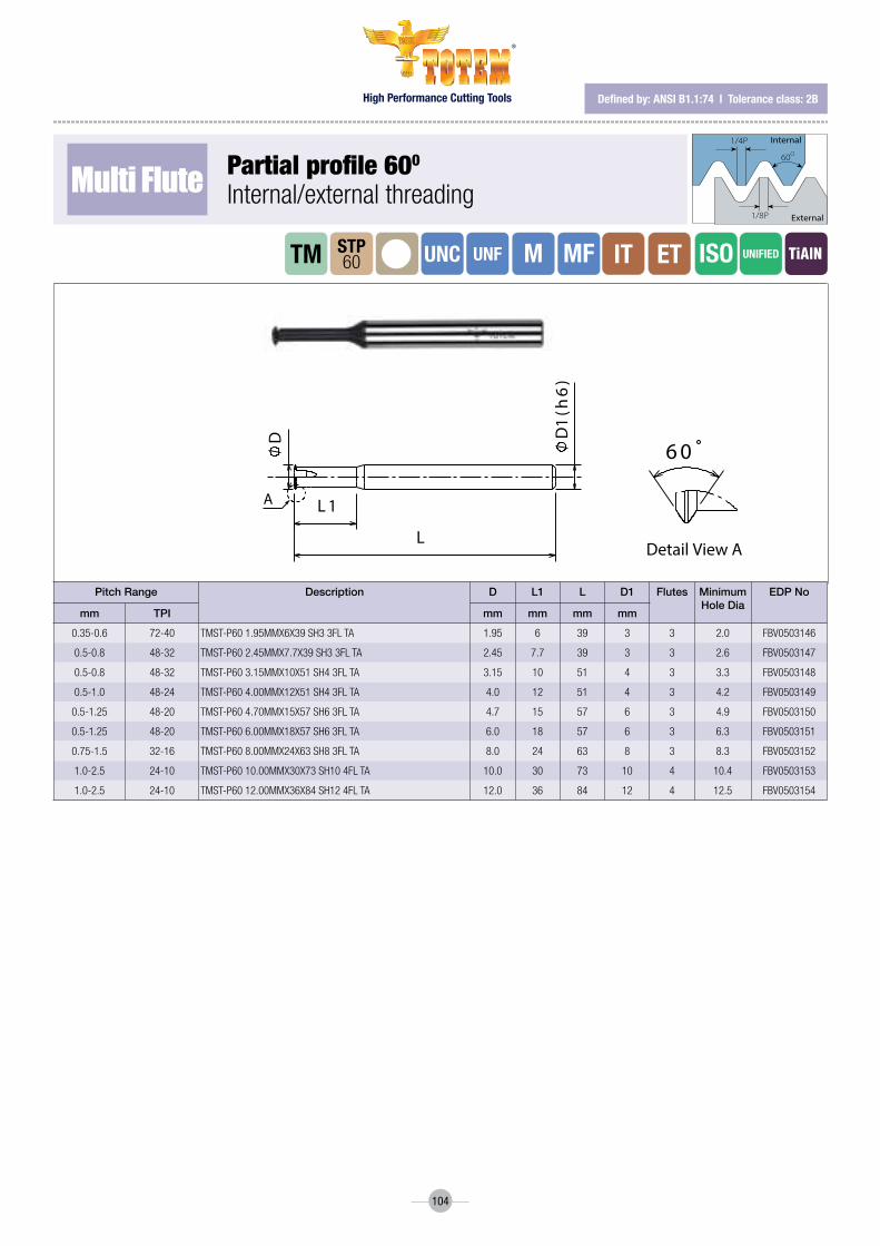
High Performance Cutting Tools
®
104
defined by: AnsI B1.1:74 l tolerance class: 2B
LD
1(h
6)
L 1
D
A
Detail View A
6 0
Multi Flute Partial profile 600
Internal/externalthreading
Pitch Range Description D L1 L D1 Flutes Minimum Hole Dia
EDP No
mm TPI mm mm mm mm
0.35-0.6 72-40 TMST-P60 1.95MMX6X39 SH3 3FL TA 1.95 6 39 3 3 2.0 FBV0503146
0.5-0.8 48-32 TMST-P60 2.45MMX7.7X39 SH3 3FL TA 2.45 7.7 39 3 3 2.6 FBV0503147
0.5-0.8 48-32 TMST-P60 3.15MMX10X51 SH4 3FL TA 3.15 10 51 4 3 3.3 FBV0503148
0.5-1.0 48-24 TMST-P60 4.00MMX12X51 SH4 3FL TA 4.0 12 51 4 3 4.2 FBV0503149
0.5-1.25 48-20 TMST-P60 4.70MMX15X57 SH6 3FL TA 4.7 15 57 6 3 4.9 FBV0503150
0.5-1.25 48-20 TMST-P60 6.00MMX18X57 SH6 3FL TA 6.0 18 57 6 3 6.3 FBV0503151
0.75-1.5 32-16 TMST-P60 8.00MMX24X63 SH8 3FL TA 8.0 24 63 8 3 8.3 FBV0503152
1.0-2.5 24-10 TMST-P60 10.00MMX30X73 SH10 4FL TA 10.0 30 73 10 4 10.4 FBV0503153
1.0-2.5 24-10 TMST-P60 12.00MMX36X84 SH12 4FL TA 12.0 36 84 12 4 12.5 FBV0503154
1/4P
1/8P
60O
Internal
External
iT ETTM UNC UNF UNiFiEDSTP60 M MF iSO

High Performance Cutting Tools
®
105
defined by: r262 (dIn 13) l tolerance class: 6h
Multi Flute iso metric threadInternal threading upto 2D
Thread Size
Pitch mm
Description D L1 L D1 Flutes EDP No
mm mm mm mm
M1.6 0.35 TMMT2D-0.35-ISO-1.2MMX3.3X39 SH3 3FL TA 1.2 3.3 39 3 3 FBV0503155
M1.6 0.35 TMMT2D-0.35-ISO-1.2MMX3.3X57 SH6 3FL TA 1.2 3.3 57 6 3 FBV0503156
M2 0.4 TMMT2D-0.4-ISO-1.54MMX4.4X39 SH3 3FL TA 1.54 4.4 39 3 3 FBV0503157
M2 0.4 TMMT2D-0.4-ISO-1.54MMX4.4X57 SH6 3FL TA 1.54 4.4 57 6 3 FBV0503158
M2.2 0.45 TMMT2D-0.45-ISO-1.63MMX4.8X39 SH3 3FL TA 1.63 4.8 39 3 3 FBV0503159
M2.5 0.45 TMMT2D-0.45-ISO-1.96MMX5.3X57 SH6 3FL TA 1.96 5.3 57 6 3 FBV0503160
M3 0.5 TMMT2D-0.5-ISO-2.4MMX6.4X57 SH6 3FL TA 2.4 6.4 57 6 3 FBV0503161
M3.5 0.6 TMMT2D-0.6-ISO-2.75MMX7.4X57 SH6 3FL TA 2.75 7.4 57 6 3 FBV0503162
M4 0.7 TMMT2D-0.7-ISO-3.15MMX8.6X57 SH6 3FL TA 3.15 8.6 57 6 3 FBV0503163
M5 0.8 TMMT2D-0.8-ISO-4MMX12D57 SH6 3FL TA 4 12 57 6 3 FBV0503164
M6 1 TMMT2D-1.0-ISO-4.75MMX13X57 SH6 3FL TA 4.75 13 57 6 3 FBV0503165
M8 1.25 TMMT2D-1.25-ISO-5.95MMX17.3X57 SH6 3F TA 5.95 17.3 57 6 3 FBV0503166
M10 1.5 TMMT2D-1.5-ISO-7.90MMX22D63 SH8 3FL TA 7.9 22 63 8 3 FBV0503167
M12 1.75 TMMT2D-1.75-ISO-9.40MMX25.5X73 SH10 3FTA 9.4 25.5 73 10 3 FBV0503168
M14 2 TMMT2D-2.0-ISO-9.95MMX29X73 SH10 3FL TA 9.95 29 73 10 3 FBV0503169
M16 2 TMMT2D-2.0-ISO-11.95MMX33X84 SH12 4FL TA 11.95 33 84 12 4 FBV0503170
M20 2.5 TMMT2D-2.5-ISO-15.90MMX42D105 SH16 5F TA 15.9 42 105 16 5 FBV0503171
1/4P
60O
1/8P
Internal
External
iTTM M iSOMT2d
AL
D1
(h6
)L 1
D
P
6 0
Detail view A

High Performance Cutting Tools
®
106
defined by: r262 (dIn 13) l tolerance class: 6h
Multi Flute iso metric threadInternalthreadingupto3D/4D
Thread Size
Pitch mm
Description D L1 L D1 Flutes EDP No
mm mm mm mm
M0.8 0.20 TMMT3D-0.2-ISO-0.6MMX1.8X39 SH3 3FL TA 0.6 1.8 39 3 3 FBV0503172
M1 0.25 TMMT3D-0.25-ISO-0.72MMX2.9X39 SH3 3FL TA 0.72 2.9 39 3 3 FBV0503173
M1.2 0.25 TMMT3D-0.25-ISO-0.9MMX3X39 SH3 3FL TA 0.9 3 39 3 3 FBV0503174
M1.4 0.30 TMMT3D-0.3-ISO-1.06MMX3.9X39 SH3 3FL TA 1.06 3.9 39 3 3 FBV0503175
M1.6 0.35 TMMT3D-0.35-ISO-1.2MMX5.1X39 SH3 3FL TA 1.2 5.1 39 3 3 FBV0503176
M1.6 0.35 TMMT3D-0.35-ISO-1.2MMX5.1X57 SH6 3FL TA 1.2 5.1 57 6 3 FBV0503177
M2 0.40 TMMT3D-0.4-ISO-1.54MMX6.1X39 SH3 3FL TA 1.54 6.1 39 3 3 FBV0503178
M2 0.40 TMMT3D-0.4-ISO-1.54MMX10X39 SH3 3FL TA 1.54 10 39 3 3 FBV0503179
M2 0.40 TMMT3D-0.4-ISO-1.54MMX6.1X57 SH6 3FL TA 1.54 6.1 57 6 3 FBV0503180
M2 0.40 TMMT4D-0.4-ISO-1.54MMX6.1X100 SH6 3FL TA 1.54 6.1 100 6 3 FBV0503181
M2.5 0.45 TMMT3D-0.45-ISO-1.96MMX7.6X39 SH6 3FL TA 1.96 7.6 39 6 3 FBV0503182
M2.5 0.45 TMMT3D-0.45-ISO-1.96MMX7.6X100 SH6 3F TA 1.96 7.6 100 6 3 FBV0503183
M3 0.50 TMMT3D-0.5-ISO-2.4MMX9.3X57 SH6 3FL TA 2.4 9.3 57 6 3 FBV0503184
M3 0.50 TMMT4D-0.5-ISO-2.4MMX9.3X100 SH6 3FL TA 2.4 9.3 100 6 3 FBV0503185
M3.5 0.60 TMMT3D-0.6-ISO-2.75MMX10.6X57 SH6 3FL TA 2.75 10.6 57 6 3 FBV0503186
M4 0.70 TMMT3D-0.7-ISO-3.15MMX12.4X57 SH6 3FL TA 3.15 12.4 57 6 3 FBV0503187
M4 0.70 TMMT3D-0.7-ISO-3.15MMX16X57 SH6 3FL TA 3.15 16 57 6 3 FBV0503188
M4 0.70 TMMT4D-0.7-ISO-3.15MMX12.4X100 SH6 3F TA 3.15 12.4 100 6 3 FBV0503189
M5 0.80 TMMT3D-0.8-ISO-4MMX15.6X57 SH6 3FL TA 4 15.6 57 6 3 FBV0503190
M5 0.80 TMMT3D-0.8-ISO-4MMX21X57 SH6 3FL TA 4 21 57 6 3 FBV0503191
M5 0.80 TMMT4D-0.8-ISO-4MMX15.6X100 SH6 3FL TA 4 15.6 100 6 3 FBV0503192
M6 1.00 TMMT3D-1.0-ISO-4.75MMX19X57 SH6 3FL TA 4.75 19 57 6 3 FBV0503193
M6 1.00 TMMT4D-1.0-ISO-4.75MMX19X100 SH6 3FL TA 4.75 19 100 6 3 FBV0503194
M6 1.00 TMMT3D-1.0-ISO-4.75MMX24D57 SH6 3FL TA 4.75 24 57 6 3 FBV0503195
M8 1.25 TMMT3D-1.25-ISO-5.95MMX24.3X57 SH6 3F TA 5.95 24.3 57 6 3 FBV0503196
M8 1.25 TMMT4D-1.25-ISO-5.95MMX24.3X100 SH6 3FTA 5.95 24.3 100 6 3 FBV0503197
M10 1.50 TMMT3D-1.5-ISO-7.9MMX31X63 SH8 3FL TA 7.9 31 63 8 3 FBV0503198
M10 1.50 TMMT4D-1.5-ISO-7.90MMX31X100 SH8 3FL TA 7.9 31 100 8 3 FBV0503199
M12 1.75 TMMT3D-1.75-ISO-9.4MMX36X73 SH10 3FL TA 9.4 36 73 10 3 FBV0503200
M16 2.00 TMMT4D-2.0-ISO-11.95MMX48X100 SH12 4F TA 11.95 48 100 12 4 FBV0503201
1/4P
60O
1/8P
Internal
External
iTTM M iSOMT3d
MT4d
AL
D1
(h6
)
L 1
D
P
6 0
Detail view A

High Performance Cutting Tools
®
107
defined by: AnsI B1.1:74 l tolerance class: 2B
Multi Flute (Unc, Unf) unified threadInternal threading upto 2D
Thread Size Pitch TPI
Description D L1 L D1 Flutes EDP No
Coarse Fine mm mm mm mm
1 72 TMMT2D-72-UN-1.44MMX3.8X39 SH3 3FL TA 1.44 3.8 39 3 3 FBV0503202
1 2 64 TMMT2D-64-UN-1.4MMX3.9X39 SH3 3FL TA 1.40 3.9 39 3 3 FBV0503203
2 3 56 TMMT2D-56-UN-1.66MMX4.6X39 SH3 3FL TA 1.66 4.6 39 3 3 FBV0503204
2 3 56 TMMT2D-56-UN-1.66MMX4.6X57 SH6 3FL TA 1.66 4.6 57 6 3 FBV0503205
3 4 48 TMMT2D-48-UN-1.88MMX5.4X57 SH6 3FL TA 1.88 5.4 57 6 3 FBV0503206
4 40 TMMT2D-40-UN-2.12MMX6.2X57 SH6 3FL TA 2.12 6.2 57 6 3 FBV0503207
5 6 40 TMMT2D-40-UN-2.46MMX7.1X57 SH6 3FL TA 2.46 7.1 57 6 3 FBV0503208
8 36 TMMT2D-36-UN-3.31MMX8.8X57 SH6 3FL TA 3.31 8.8 57 6 3 FBV0503209
6 32 TMMT2D-32-UN-2.57MMX7.3X57 SH6 3FL TA 2.57 7.3 57 6 3 FBV0503210
8 32 TMMT2D-32-UN-3.22MMX10.1X57 SH6 3FL TA 3.22 10.1 57 6 3 FBV0503211
10 32 TMMT2D-32-UN-3.7MMX10.5X57 SH6 3FL TA 3.70 10.5 57 6 3 FBV0503212
12 28 TMMT2D-28-UN-4.2MMX10.9X57 SH6 3FL TA 4.20 10.9 57 6 3 FBV0503213
1/4" 28 TMMT2D-28-UN-5.2MMX14X57 SH6 3FL TA 5.20 14.0 57 6 3 FBV0503214
10 24 TMMT2D-24-UN-3.55MMX10.4X57 SH6 3FL TA 3.55 10.4 57 6 3 FBV0503215
5/16" 24 TMMT2D-24-UN-6.65MMX16.7X63 SH8 3FL TA 6.65 16.7 63 8 3 FBV0503216
1/4" 7/16" 20 TMMT2D-20-UN-4.85MMX13.7X57 SH6 3FL TA 4.85 13.7 57 6 3 FBV0503217
7/16" 20 TMMT2D-20-UN-7.95MMX24X63 SH8 3FL TA 7.95 24.0 63 8 3 FBV0503218
5/16" 18 TMMT2D-18-UN-5.95MMX16.5X57 SH6 3FL TA 5.95 16.5 57 6 3 FBV0503219
5/8" 18 TMMT2D-18-UN-11.9MMX34X84 SH12 4FL TA 11.90 34.0 84 12 4 FBV0503220
3/8" 16 TMMT2D-16-UN-6.9MMX21X63 SH8 3FL TA 6.90 21.0 63 8 3 FBV0503221
7/16" 14 TMMT2D-14-UN-7.95MMX23.5X63 SH8 3FL TA 7.95 23.5 63 8 3 FBV0503222
1/2" 13 TMMT2D-13-UN-9.3MMX27X73 SH10 3FL TA 9.30 27.0 73 10 3 FBV0503223
9/16" 12 TMMT2D-12-UN-9.95MMX29X63 SH10 3FL TA 9.95 29.0 63 10 3 FBV0503224
5/8" 11 TMMT2D-11-UN-11.5MMX33X84 SH12 3FL TA 11.50 33.0 84 12 3 FBV0503225
1/4P
1/8P
60O
Internal
External
iTTM UNFUNCMT2d
UNiFiED
AL
D1
(h6
)
L 1
D
P
6 0
Detail view A
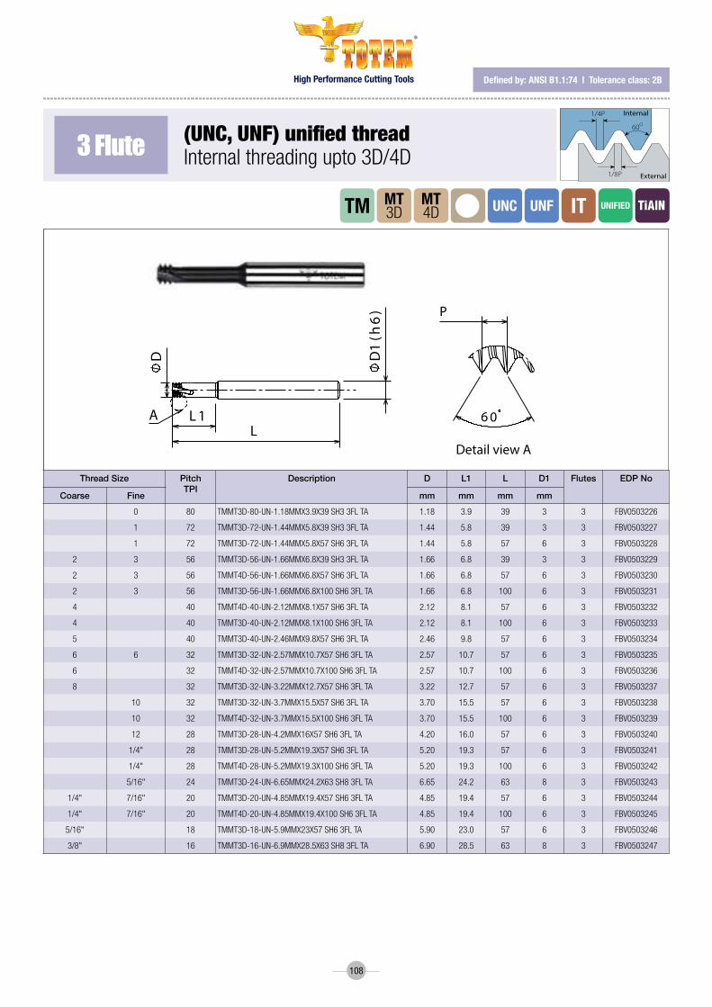
High Performance Cutting Tools
®
108
defined by: AnsI B1.1:74 l tolerance class: 2B
3 Flute (Unc, Unf) unified threadInternalthreadingupto3D/4D
Thread Size Pitch TPI
Description D L1 L D1 Flutes EDP No
Coarse Fine mm mm mm mm
0 80 TMMT3D-80-UN-1.18MMX3.9X39 SH3 3FL TA 1.18 3.9 39 3 3 FBV0503226
1 72 TMMT3D-72-UN-1.44MMX5.8X39 SH3 3FL TA 1.44 5.8 39 3 3 FBV0503227
1 72 TMMT3D-72-UN-1.44MMX5.8X57 SH6 3FL TA 1.44 5.8 57 6 3 FBV0503228
2 3 56 TMMT3D-56-UN-1.66MMX6.8X39 SH3 3FL TA 1.66 6.8 39 3 3 FBV0503229
2 3 56 TMMT4D-56-UN-1.66MMX6.8X57 SH6 3FL TA 1.66 6.8 57 6 3 FBV0503230
2 3 56 TMMT3D-56-UN-1.66MMX6.8X100 SH6 3FL TA 1.66 6.8 100 6 3 FBV0503231
4 40 TMMT4D-40-UN-2.12MMX8.1X57 SH6 3FL TA 2.12 8.1 57 6 3 FBV0503232
4 40 TMMT3D-40-UN-2.12MMX8.1X100 SH6 3FL TA 2.12 8.1 100 6 3 FBV0503233
5 40 TMMT3D-40-UN-2.46MMX9.8X57 SH6 3FL TA 2.46 9.8 57 6 3 FBV0503234
6 6 32 TMMT3D-32-UN-2.57MMX10.7X57 SH6 3FL TA 2.57 10.7 57 6 3 FBV0503235
6 32 TMMT4D-32-UN-2.57MMX10.7X100 SH6 3FL TA 2.57 10.7 100 6 3 FBV0503236
8 32 TMMT3D-32-UN-3.22MMX12.7X57 SH6 3FL TA 3.22 12.7 57 6 3 FBV0503237
10 32 TMMT3D-32-UN-3.7MMX15.5X57 SH6 3FL TA 3.70 15.5 57 6 3 FBV0503238
10 32 TMMT4D-32-UN-3.7MMX15.5X100 SH6 3FL TA 3.70 15.5 100 6 3 FBV0503239
12 28 TMMT3D-28-UN-4.2MMX16X57 SH6 3FL TA 4.20 16.0 57 6 3 FBV0503240
1/4" 28 TMMT3D-28-UN-5.2MMX19.3X57 SH6 3FL TA 5.20 19.3 57 6 3 FBV0503241
1/4" 28 TMMT4D-28-UN-5.2MMX19.3X100 SH6 3FL TA 5.20 19.3 100 6 3 FBV0503242
5/16" 24 TMMT3D-24-UN-6.65MMX24.2X63 SH8 3FL TA 6.65 24.2 63 8 3 FBV0503243
1/4" 7/16" 20 TMMT3D-20-UN-4.85MMX19.4X57 SH6 3FL TA 4.85 19.4 57 6 3 FBV0503244
1/4" 7/16" 20 TMMT4D-20-UN-4.85MMX19.4X100 SH6 3FL TA 4.85 19.4 100 6 3 FBV0503245
5/16" 18 TMMT3D-18-UN-5.9MMX23X57 SH6 3FL TA 5.90 23.0 57 6 3 FBV0503246
3/8" 16 TMMT3D-16-UN-6.9MMX28.5X63 SH8 3FL TA 6.90 28.5 63 8 3 FBV0503247
1/4P
1/8P
60O
Internal
External
iTTM UNFUNCMT4d
MT3d
UNiFiED
AL
D1
(h6
)
L 1
D
P
6 0
Detail view A

High Performance Cutting Tools
®
109
defined by: mIl-s-8879c l tolerance class: 3B
3 Flute
Multi Flute
(UnJ) unified threadInternal threading upto 3D
(MJ) iso threadInternal Threading upto 3D
Thread Size Pitch mm
Description D L1 L D1 Flutes EDP No
Coarse Fine mm mm mm mm
4 6 40 TMMT3D-40-UNJ-2.1MMX8X57 SH6 3FL TA 2.1 8 57 6 3 FBV0503248
8 10 32 TMMT3D-32-UNJ-3.3MMX13X57 SH6 3FL TA 3.3 12 57 6 3 FBV0503249
1/4" 28 TMMT3D-28-UNJ-5.4MMX19X57 SH6 3FL TA 5.4 19 57 6 3 FBV0503250
5/16" , 3/8" 24 TMMT3D-24-UNJ-6.7MMX24X63 SH8 3FL TA 6.7 24 63 8 3 FBV0503251
1/4" 20 TMMT3D-20-UNJ-5MMX19X63 SH6 3FL TA 5 19 63 6 3 FBV0503252
7/16" 20 TMMT3D-20-UNJ-7.9MMX28X63 SH8 3FL TA 7.9 28 63 8 3 FBV0503253
5/16" 18 TMMT3D-18-UNJ-6.4MMX24X63 SH8 3FL TA 6.4 24 63 8 3 FBV0503254
3/8" 16 TMMT3D-16-UNJ-6.9MMX24X63 SH8 3FL TA 6.9 24 63 8 3 FBV0503255
7/16" 14 TMMT3D-14-UNJ-7.9MMX26X63 SH8 3FL TA 7.9 26 63 8 3 FBV0503256
1/2" 13 TMMT3D-13-UNJ-9.9MMX28X73 SH10 3FL TA 9.9 28 73 10 3 FBV0503257
Thread Size
Pitch mm
Description D L1 L D1 Flutes EDP No
mm mm mm mm
MJ4.0 0.70 TMMT3D-0.7-MJ-3.2MMX13X57 SH6 3FL TA 3.2 12 57 6 3 FBV0503258
MJ5.0 0.80 TMMT3D-0.8-MJ-4MMX15X57 SH6 3FL TA 4 15 57 6 3 FBV0503259
MJ6.0 1.00 TMMT3D-1.0-MJ-4.8MMX18X57 SH6 3FL TA 4.8 18 57 6 3 FBV0503260
MJ8.0 1.25 TMMT3D-1.25-MJ-6.5MMX24X63 SH8 3FL TA 6.5 24 63 8 3 FBV0503261
MJ10.0 1.50 TMMT3D-1.5-MJ-7.9MMX31X63 SH8 3FL TA 7.9 31 63 8 3 FBV0503262
MJ12.0 1.75 TMMT3D-1.75-MJ-9.4MMX31X73 SH10 3FL TA 9.4 31 73 10 3 FBV0503263
MJ14.0 , MJ16.0 2.00 TMMT3D-2.0-MJ-9.9MMX36X73 SH10 3FL TA 9.9 36 73 10 3 FBV0503264
defined by: IsO 5855 l tolerance class: 4h/6h-4h/5h
1/4P
60O
1/8P
De�ned by: R262 (DIN 13)Tolerance class: 6H
Internal
External
1/4P
1/8P
60O
De�ned by: ANSI B1.1:74Tolerance class: 2B
Internal
External
55O
R0.137P
R0.137P Internal
External
De�ned by: B.S.84:1956, DIN 259, ISO228/1:1982Tolerance class: Medium class A
De�ned by: B.S.21:1985Tolerance class: Standard BSPT
R0.137P
47' R0.137P
27.5O 27.5O
90O 1O
Internal
External
R 0.137P
R 0.137P55O
Internal
External
De�ned by: B.S.2779:1956 Tolerance class: Medium class
1O47’
30O 30O
90O
Internal
External
De�ned by: USAS B2.1:1968Tolerance class: Standard NPT
NPTF
1O47’
External / Internal
30O 30O
90O
Internal
External
De�ned by: ANSI 1.20.3-1976Tolerance class: Standard NPTF
Tolerance class: Medium class
R0.137P
55o R0.137P
De�ned by: B.S.2779:1956
Internal
External
Tolerance class: Standard BSPT
27.5o 27.5o
90o 1o 47' R0.137P
R0.137P
De�ned by: B.S.21:1985
Internal
External
De�ned by: MIL-S-8879C
R 0.18042PR
0.15011P
5/16P
60o
max
min
Tolerance class: 3B
Internal
External
1/4P
1/8P
60o
Internal
External
De�ned by: ISO 5855Tolerance class: 4h/6h-4H/5H
Two cutting teeth: Partial Pro�le for leading tooth followed by Full Pro�le for �nishing.
1 Pitch
The work direction should be from the top to the bottom (Climb Milling).
MTH 2D/MTH 3D are left handed. For CNC use M04 code.
Roughing (Partial Pro�le) Finish (Full Pro�le)
2
1 36 4
5
* Recommendation: At tool entry, set the Feed f [mm/tooth] to 70% lower
than the threading Feed.
Example:Threading Feed: 0.3[mm/tooth]Tool entry Feed: 0.09[mm/tooth]
Tool entry along tangential arc
1 2 3
5
8 9 10 11
6 7
4
1/4P
60O
1/8P
De�ned by: R262 (DIN 13)Tolerance class: 6H
Internal
External
1/4P
1/8P
60O
De�ned by: ANSI B1.1:74Tolerance class: 2B
Internal
External
55O
R0.137P
R0.137P Internal
External
De�ned by: B.S.84:1956, DIN 259, ISO228/1:1982Tolerance class: Medium class A
De�ned by: B.S.21:1985Tolerance class: Standard BSPT
R0.137P
47' R0.137P
27.5O 27.5O
90O 1O
Internal
External
R 0.137P
R 0.137P55O
Internal
External
De�ned by: B.S.2779:1956 Tolerance class: Medium class
1O47’
30O 30O
90O
Internal
External
De�ned by: USAS B2.1:1968Tolerance class: Standard NPT
NPTF
1O47’
External / Internal
30O 30O
90O
Internal
External
De�ned by: ANSI 1.20.3-1976Tolerance class: Standard NPTF
Tolerance class: Medium class
R0.137P
55o R0.137P
De�ned by: B.S.2779:1956
Internal
External
Tolerance class: Standard BSPT
27.5o 27.5o
90o 1o 47' R0.137P
R0.137P
De�ned by: B.S.21:1985
Internal
External
De�ned by: MIL-S-8879C
R 0.18042PR
0.15011P
5/16P
60o
max
min
Tolerance class: 3B
Internal
External
1/4P
1/8P
60o
Internal
External
De�ned by: ISO 5855Tolerance class: 4h/6h-4H/5H
Two cutting teeth: Partial Pro�le for leading tooth followed by Full Pro�le for �nishing.
1 Pitch
The work direction should be from the top to the bottom (Climb Milling).
MTH 2D/MTH 3D are left handed. For CNC use M04 code.
Roughing (Partial Pro�le) Finish (Full Pro�le)
2
1 36 4
5
* Recommendation: At tool entry, set the Feed f [mm/tooth] to 70% lower
than the threading Feed.
Example:Threading Feed: 0.3[mm/tooth]Tool entry Feed: 0.09[mm/tooth]
Tool entry along tangential arc
1 2 3
5
8 9 10 11
6 7
4 iT
iTTM
TM UNJFUNJ
MJMT3d
MT3d
UNiFiED
MJ
AL
D1
(h6
)
L 1
D
P
6 0
Detail view A
AL
D1
(h6
)
L 1
D
P
6 0
Detail view A

High Performance Cutting Tools
®
110
defined by: r262 (dIn 13) l tolerance class: 6h
3 Flute
Multi Flute
iso metric threadInternal threading for hard materials upto 2D
iso metric threadInternal threading for hard materials upto 3D
Thread Size
Pitch mm
Description D L1 L D1 Flutes EDP No
mm mm mm mm
M1.6 0.35 TMMTH2D-0.35-ISO-1.2MMX3.3X57 SH6 3FL TA 1.2 3.3 57 6 3 FBV0503265
M2 0.40 TMMTH2D-0.4-ISO-1.54MMX4.4X57 SH6 3FL TA 1.54 4.4 57 6 3 FBV0503266
M2.2 0.45 TMMTH2D-0.45-ISO-1.63MMX4.8X57 SH6 3FL TA 1.63 4.8 57 6 3 FBV0503267
M2.5 0.45 TMMTH2D-0.45-ISO-1.96MMX5.3X57 SH6 3FL TA 1.96 5.3 57 6 3 FBV0503268
M3 0.50 TMMTH2D-0.5-ISO-2.4MMX6.4X57 SH6 3FL TA 2.4 6.4 57 6 3 FBV0503269
M3.5 0.60 TMMTH2D-0.6-ISO-2.75MMX7.4X57 SH6 3FL TA 2.75 7.4 57 6 3 FBV0503270
M4 0.70 TMMTH2D-0.7-ISO-3.15MMX8.6X57 SH6 3FL TA 3.15 8.6 57 6 3 FBV0503271
M5 0.80 TMMTH2D-0.8-ISO-4MMX12X57 SH6 3FL TA 4 12 57 6 3 FBV0503272
M6 1.00 TMMTH2D-1-ISO-4.75MMX13X57 SH6 3FL TA 4.75 13 57 6 3 FBV0503273
M8 1.25 TMMTH2D-1.25-ISO-5.95MMX17.3X57 SH6 3FL TA 5.95 17.3 57 6 3 FBV0503274
M10 1.50 TMMTH2D-1.5-ISO-7.9MMX22X63 SH8 3FL TA 7.9 22 63 8 3 FBV0503275
Thread Size
Pitch mm
Description D L1 L D1 Flutes EDP No
mm mm mm mm
M1.6 0.35 TMMTH3D-0.35-ISO-1.2MMX5.1X57 SH6 3FL TA 1.2 5.1 57 6 3 FBV0503276
M2 0.4 TMMTH3D-0.4-ISO-1.54MMX6.1X57 SH6 3FL TA 1.54 6.1 57 6 3 FBV0503277
M2.2 0.45 TMMTH3D-0.45-ISO-1.96MMX7.6X57 SH6 3FL TA 1.96 7.6 57 6 3 FBV0503278
M3 0.5 TMMTH3D-0.5-ISO-2.4MMX9.3X57 SH6 3FL TA 2.4 9.3 57 6 3 FBV0503279
M4 0.7 TMMTH3D-0.7-ISO-3.15MMX12.4X57 SH6 3FL TA 3.15 12.4 57 6 3 FBV0503280
M5 0.8 TMMTH3D-0.8-ISO-4MMX15.6X57 SH6 3FL TA 4 15.6 57 6 3 FBV0503281
M6 1 TMMTH3D-1-ISO-4.75MMX19X57 SH6 3FL TA 4.75 19 57 6 3 FBV0503282
M8 1.25 TMMTH3D-1.25-ISO-5.95MMX24.3X57 SH6 3FL TA 5.95 24.3 57 6 3 FBV0503283
defined by: r262 (dIn 13) l tolerance class: 6h
1/4P
60O
1/8P
Internal
External
1/4P
60O
1/8P
Internal
External
iT
iT
TM
TM
M
M
MTH2d
MTH3d
iSO62HrC
62HrC iSO
AL
D1
(h6
)
L 1
D
P
6 0
Detail view A
AL
D1
(h6
)
L 1
D
P
6 0
Detail view A

High Performance Cutting Tools
®
111
defined by: AnsI B1.1:74 l tolerance class: 2B
3 Flute
3 Flute
(Un, Unf) unified threadInternal threading for hard materials upto 2d
(Un, Unf) Unified threadInternalThreadingForHardMaterialsupto3D
Thread Size Pitch mm
Description D L1 L D1 Flutes EDP No
Coarse Fine mm mm mm mm
1 72 TMMTH2D-72-UN-1.44MMX3.8X57 SH6 3FL TA 1.44 3.8 57 6 3 FBV05032841 2 64 TMMTH2D-64-UN-1.4MMX3.9X57 SH6 3FL TA 1.4 3.9 57 6 3 FBV05032852 3 56 TMMTH2D-56-UN-1.66MMX4.6X57 SH6 3FL TA 1.66 4.6 57 6 3 FBV05032863 4 48 TMMTH2D-48-UN-1.88MMX5.4X57 SH6 3FL TA 1.88 5.4 57 6 3 FBV05032874 40 TMMTH2D-40-UN-2.12MMX6.2X57 SH6 3FL TA 2.12 6.2 57 6 3 FBV05032885 6 40 TMMTH2D-40-UN-2.46MMX7.1X57 SH6 3FL TA 2.46 7.1 57 6 3 FBV0503289
8 36 TMMTH2D-36-UN-3.31MMX8.8X57 SH6 3FL TA 3.31 8.8 57 6 3 FBV05032906 32 TMMTH2D-32-UN-2.57MMX7.8X57 SH6 3FL TA 2.57 7.8 57 6 3 FBV05032918 10 32 TMMTH2D-32-UN-3.22MMX10.3X57 SH6 3FL TA 3.22 10.3 57 6 3 FBV0503292
1/4" 28 TMMTH2D-28-UN-5.2MMX14X57 SH6 3FL TA 5.2 14 57 6 3 FBV050329310 24 TMMTH2D-24-UN-3.55MMX10.4X57 SH6 3FL TA 3.55 10.4 57 6 3 FBV0503294
5/16" 24 TMMTH2D-24-UN-6.65MMX16.7X64 SH8 3FL TA 6.65 16.7 64 8 3 FBV05032951/4" 7/16" 20 TMMTH2D-20-UN-4.85MMX13.7X57 SH6 3FL TA 4.85 13.7 57 6 3 FBV0503296
7/16" 20 TMMTH2D-20-UN-7.95MMX24X64 SH8 3FL TA 7.95 24 64 8 3 FBV05032975/16" 18 TMMTH2D-18-UN-5.95MMX16.5X57 SH6 3FL TA 5.95 16.5 57 6 3 FBV05032983/8" 16 TMMTH2D-16-UN-6.9MMX20X63 SH8 3FL TA 6.9 20 63 8 3 FBV0503299
7/16" 14 TMMTH2D-14-UN-7.95MMX23.5X63 SH8 3FL TA 7.95 23.5 63 8 3 FBV0503300
Thread Size Pitch mm
Description D L1 L D1 Flutes EDP No
Coarse Fine mm mm mm mm
1 72 TMMTH3D-72-UN-1.44MMX5.8X57 SH6 3FL TA 1.44 5.8 57 6 3 FBV0503301
5 6 40 TMMTH3D-40-UN-2.46MMX9.8X57 SH6 3FL TA 2.46 9.8 57 6 3 FBV0503302
8 10 32 TMMTH3D-32-UN-3.22MMX12.7X57 SH6 3FL TA 3.22 12.7 57 6 3 FBV0503303
1/4" 28 TMMTH3D-28-UN-5.2MMX19.3X57 SH6 3FL TA 5.2 19.3 57 6 3 FBV0503304
5/16" 24 TMMTH3D-24-UN-6.65MMX24.2X63 SH8 3FL TA 6.65 24.2 63 8 3 FBV0503305
1/4" 7/16" 20 TMMTH3D-20-UN-4.85MMX19.4X57 SH6 3FL TA 4.85 19.4 57 6 3 FBV0503306
defined by: AnsI B1.1:74 l tolerance class: 2B
1/4P
1/8P
60O
Internal
External
1/4P
1/8P
60O
Internal
External
iT
iT
TM
TM
MTH2d
MTH3d
UNiFiED
UNiFiED
UNC
UNC
UNF
UNF
62HrC
62HrC
AL
D1
(h6
)
L 1
D
P
6 0
Detail view A
AL
D1
(h6
)
L 1
D
P
6 0
Detail view A

High Performance Cutting Tools
®
112
defined by: r262 (dIn 13) l tolerance class: 6h
32
41
APPLICATION DETAILS1 Material2 Component name3 Hardness
00 30/04/2019REV. NO. REVISION BY DATE
CUSTOMER APPROVALCustomer nameCustomer reference no.Approved date Sign
D
CB
CBA
A D
12
34
****MARK DETAILS
NOTE:1) All dimensions are in mm.2) All other details are as permanufacturer's standard.3) Not to the scale.
IMPORTANT PARAMETERS1 Helix(RH) Straight2 Number of �utes 53 Internal coolant No4 Shank diameter D5 Coating TA6 Material Micro�ne carbide
Forbes & Company Limited , B-13, MIDC Area,Waluj, Aurangabad- 431133, Maharashtra, India
Sign Date MATERIAL
DRAWN NLA ALTERNATE MATERIAL
CHECKED RNS SCALE NTSAPPROVED RNS REVISION 00QA SNPMFG DSOperation Head SUW
TITLE:Thread mill Straight 5�t TA DRAWING NO.:
SAP CODE: SHEET 1 Of 1
P i t c h
6 0
D1
D
L 1L
Multi Flute iso metric threadInternal threading
Thread Size Pitch mm
Description D L1 L D1 Flutes EDP No
Coarse Fine mm mm mm mm
M8 0.75 TMRSS-0.75-ISO-5.9MMX10.8X57 SH6 3FL TA 5.9 10.8 57 6 3 FBV0503307
M5 0.80 TMRSS-0.8-ISO-3.9MMX10X57 SH6 3FL TA 3.9 10 57 6 3 FBV0503308
M6 M7 1.00 TMRSS-1-ISO-4.8MMX11.5X57 SH6 3FL TA 4.8 11.5 57 6 3 FBV0503309
M10 1.00 TMRSS-1-ISO-7.9MMX17.5X63 SH8 4FL TA 7.9 17.5 63 8 4 FBV0503310
M12 1.00 TMRSS-1-ISO-9.9MMX20.5X73 SH10 4FL TA 9.9 20.5 73 10 4 FBV0503311
M8 M9 1.25 TMRSS-1.25-ISO-5.9MMX14.4X57 SH6 3FL TA 5.9 14.4 57 6 3 FBV0503312
M10 M11 1.50 TMRSS-1.5-ISO-7.9MMX18.5X63 SH8 3FL TA 7.9 18.5 63 8 3 FBV0503313
M13 1.50 TMRSS-1.5-ISO-9.9MMX21.8X73 SH10 4FL TA 9.9 21.8 73 10 4 FBV0503314
M15 1.50 TMRSS-1.5-ISO-11.9MMX26.3X84 SH12 4FL TA 11.9 26.3 84 12 4 FBV0503315
M12 1.75 TMRSS-1.75-ISO-7.9MMX18X64 SH8 3FL TA 7.9 18 64 8 3 FBV0503316
M14 2.00 TMRSS-2-ISO-9.9MMX25X73 SH10 3FL TA 9.9 25 73 10 3 FBV0503317
M16 2.00 TMRSS-2-ISO-11.9MMX27X84 SH12 4FL TA 11.9 27 84 12 4 FBV0503318
M20 2.50 TMRSS-2.5-ISO-11.9MMX30X84 SH12 4FL TA 11.9 30 84 12 4 FBV0503319
M24 M27 3.00 TMRSS-3-ISO-11.5MMX40.5X105 SH16 4FL TA 11.5 40.5 105 16 4 FBV0503320
1/4P
60O
1/8P
Internal
External
iTTM RSS M MF iSO

High Performance Cutting Tools
®
113
defined by: AnsI B1.1:74 l tolerance class: 2B
Multi Flute (Unc, Unf, Unef) unified threadInternal threading
Thread Size Pitch TPI
Description D L1 L D1 Flutes EDP No
Coarse UNC
Fine UNF
Extra Fine UNEF
mm mm mm mm
5/16" 32 TMRSS-32-UN-5.9MMX14X57 SH6 3FL TA 5.9 14 57 6 3 FBV0503321
1/4" 28 TMRSS-28-UN-5.1MMX12.2X57 SH6 3FL TA 5.1 12.2 57 6 3 FBV0503322
7/16"-1/2" 28 TMRSS-28-UN-7.9MMX15.8X63 SH8 4FL TA 7.9 15.8 63 8 4 FBV0503323
5/16" 24 TMRSS-24-UN-5.9MMX10.8X57 SH6 3FL TA 5.9 10.8 57 6 3 FBV0503324
1/4" 20 TMRSS-20-UN-4.8MMX12X57 SH6 3FL TA 4.8 12 57 6 3 FBV0503325
7/16" 20 TMRSS-20-UN-7.9MMX19.7X63 SH8 3FL TA 7.9 19.7 63 8 3 FBV0503326
1/2" 20 TMRSS-20-UN-9.9MMX17.5X73 SH10 4FL TA 9.9 17.5 73 10 4 FBV0503327
5/16" 18 TMRSS-18-UN-5.7MMX16X57 SH6 3FL TA 5.7 16 57 6 3 FBV0503328
9/16"-5/8" 18 TMRSS-18-UN-7.9MMX18.5X63 SH8 3FL TA 7.9 18.5 63 8 3 FBV0503329
3/8" 16 TMRSS-16-UN-6.8MMX18.2X63 SH8 3FL TA 6.8 18.2 63 8 3 FBV0503330
3/4" 16 TMRSS-16-UN-11.9MMX26.2X84 SH12 4FL TA 11.9 26.2 84 12 4 FBV0503331
7/16" 14 TMRSS-14-UN-7.8MMX20.8X63 SH8 3FL TA 7.8 20.8 63 8 3 FBV0503332
7/8" 14 TMRSS-14-UN-11.9MMX24.5X84 SH12 4FL TA 11.9 24.5 84 12 4 FBV0503333
1/2" 13 TMRSS-13-UN-9.3MMX24.4X73 SH10 3FL TA 9.3 24.4 73 10 3 FBV0503334
9/16" 12 TMRSS-12-UN-10.6MMX26.4X84 SH12 4FL TA 10.6 26.4 84 12 4 FBV0503335
1” 12 TMRSS-12-UN-15.9MMX39.1X105 SH16 5FL TA 15.9 39.1 105 16 5 FBV0503336
5/8" 11 TMRSS-11-UN-11.5MMX31.1X84 SH12 4FL TA 11.5 31.1 84 12 4 FBV0503337
3/4" 10 TMRSS-10-UN-14.3MMX36.8X105 SH16 4FL TA 14.3 36.8 105 16 4 FBV0503338
7/8" 9 TMRSS-9-UN-15.9MMX40.9X105 SH16 4FL TA 15.9 40.9 105 16 4 FBV0503339
1” 8 TMRSS-8-UN-19.7MMX39.7X105 SH20 4FL TA 19.7 39.7 105 20 4 FBV0503340
32
41
APPLICATION DETAILS1 Material2 Component name3 Hardness
00 30/04/2019REV. NO. REVISION BY DATE
CUSTOMER APPROVALCustomer nameCustomer reference no.Approved date Sign
D
CB
CBA
A D
12
34
****MARK DETAILS
NOTE:1) All dimensions are in mm.2) All other details are as permanufacturer's standard.3) Not to the scale.
IMPORTANT PARAMETERS1 Helix(RH) Straight2 Number of �utes 53 Internal coolant No4 Shank diameter D5 Coating TA6 Material Micro�ne carbide
Forbes & Company Limited , B-13, MIDC Area,Waluj, Aurangabad- 431133, Maharashtra, India
Sign Date MATERIAL
DRAWN NLA ALTERNATE MATERIAL
CHECKED RNS SCALE NTSAPPROVED RNS REVISION 00QA SNPMFG DSOperation Head SUW
TITLE:Thread mill Straight 5�t TA DRAWING NO.:
SAP CODE: SHEET 1 Of 1
P i t c h
6 0
D1
D
L 1L
1/4P
1/8P
60O
Internal
External
iTTM RSS UNC UNEF UNF UNiFiED

High Performance Cutting Tools
®
114
defined by: usAs B2.1:1968tolerance class: standard nPt
Multi Flute
Multi Flute
nPtInternal/externalthreading
nPtfInternal/externalthreading
Thread Size
Pitch TPI
Description D L1 L D1 Flutes EDP No
mm mm mm mm
1/16"-1/8" 27 TMRSTS-27-NPT-5.9MMX9.8X57 SH6 3FL TA 5.9 9.8 57 6 3 FBV0503341
1/4"-3/8" 18 TMRSTS-18-NPT-9.9MMX16.2X73 SH10 4FL TA 9.9 16.2 73 10 4 FBV0503342
1/2" 14 TMRSTS-14-NPT-11.9MMX20.8X83 SH12 4FL TA 11.9 20.8 83 12 4 FBV0503343
1"-2" 11.5 TMRSTS-11.5-NPT-19.9MMX29.7X105 SH20 4FL TA 19.9 29.7 105 20 4 FBV0503344
2 1/2"-6" 8 TMRSTS-8-NPT-19.9MMX38.1X105 SH20 4FL TA 19.9 38.1 105 20 4 FBV0503345
Thread Size
Pitch TPI
Description D L1 L D1 Flutes EDP No
mm mm mm mm
1/16"-1/8" 27 TMRSTS-27-NPTF-5.9MMX9.9X57 SH6 3FL TA 5.9 9.9 57 6 3 FBV0503346
1/4"-3/8" 18 TMRSTS-18-NPTF-9.9MMX16.2X73 SH10 4FL TA 9.9 16.2 73 10 4 FBV0503347
1/2" 14 TMRSTS-14-NPTF-11.9MMX20.8X83 SH12 4FL TA 11.9 20.8 83 12 4 FBV0503348
1"-2" 11.5 TMRSTS-11.5-NPTF-19.9MMX29.7X105SH20 4FTA 19.9 29.7 105 20 4 FBV0503349
2 1/2"-6" 8 TMRSTS-8-NPTF-19.9MMX38.1X105 SH20 4FL TA 19.9 38.1 105 20 4 FBV0503350
defined by: usAs B2.1:1968 l tolerance class: standard nPt
1/4P
60O
1/8P
De�ned by: R262 (DIN 13)Tolerance class: 6H
Internal
External
1/4P
1/8P
60O
De�ned by: ANSI B1.1:74Tolerance class: 2B
Internal
External
55O
R0.137P
R0.137P Internal
External
De�ned by: B.S.84:1956, DIN 259, ISO228/1:1982Tolerance class: Medium class A
De�ned by: B.S.21:1985Tolerance class: Standard BSPT
R0.137P
47' R0.137P
27.5O 27.5O
90O 1O
Internal
External
R 0.137P
R 0.137P55O
Internal
External
De�ned by: B.S.2779:1956 Tolerance class: Medium class
1O47’
30O 30O
90O
Internal
External
De�ned by: USAS B2.1:1968Tolerance class: Standard NPT
NPTF
1O47’
External / Internal
30O 30O
90O
Internal
External
De�ned by: ANSI 1.20.3-1976Tolerance class: Standard NPTF
Tolerance class: Medium class
R0.137P
55o R0.137P
De�ned by: B.S.2779:1956
Internal
External
Tolerance class: Standard BSPT
27.5o 27.5o
90o 1o 47' R0.137P
R0.137P
De�ned by: B.S.21:1985
Internal
External
De�ned by: MIL-S-8879C
R 0.18042PR
0.15011P
5/16P
60o
max
min
Tolerance class: 3B
Internal
External
1/4P
1/8P
60o
Internal
External
De�ned by: ISO 5855Tolerance class: 4h/6h-4H/5H
Two cutting teeth: Partial Pro�le for leading tooth followed by Full Pro�le for �nishing.
1 Pitch
The work direction should be from the top to the bottom (Climb Milling).
MTH 2D/MTH 3D are left handed. For CNC use M04 code.
Roughing (Partial Pro�le) Finish (Full Pro�le)
2
1 36 4
5
* Recommendation: At tool entry, set the Feed f [mm/tooth] to 70% lower
than the threading Feed.
Example:Threading Feed: 0.3[mm/tooth]Tool entry Feed: 0.09[mm/tooth]
Tool entry along tangential arc
1 2 3
5
8 9 10 11
6 7
4
1/4P
60O
1/8P
De�ned by: R262 (DIN 13)Tolerance class: 6H
Internal
External
1/4P
1/8P
60O
De�ned by: ANSI B1.1:74Tolerance class: 2B
Internal
External
55O
R0.137P
R0.137P Internal
External
De�ned by: B.S.84:1956, DIN 259, ISO228/1:1982Tolerance class: Medium class A
De�ned by: B.S.21:1985Tolerance class: Standard BSPT
R0.137P
47' R0.137P
27.5O 27.5O
90O 1O
Internal
External
R 0.137P
R 0.137P55O
Internal
External
De�ned by: B.S.2779:1956 Tolerance class: Medium class
1O47’
30O 30O
90O
Internal
External
De�ned by: USAS B2.1:1968Tolerance class: Standard NPT
NPTF
1O47’
External / Internal
30O 30O
90O
Internal
External
De�ned by: ANSI 1.20.3-1976Tolerance class: Standard NPTF
Tolerance class: Medium class
R0.137P
55o R0.137P
De�ned by: B.S.2779:1956
Internal
External
Tolerance class: Standard BSPT
27.5o 27.5o
90o 1o 47' R0.137P
R0.137P
De�ned by: B.S.21:1985
Internal
External
De�ned by: MIL-S-8879C
R 0.18042PR
0.15011P
5/16P
60o
max
min
Tolerance class: 3B
Internal
External
1/4P
1/8P
60o
Internal
External
De�ned by: ISO 5855Tolerance class: 4h/6h-4H/5H
Two cutting teeth: Partial Pro�le for leading tooth followed by Full Pro�le for �nishing.
1 Pitch
The work direction should be from the top to the bottom (Climb Milling).
MTH 2D/MTH 3D are left handed. For CNC use M04 code.
Roughing (Partial Pro�le) Finish (Full Pro�le)
2
1 36 4
5
* Recommendation: At tool entry, set the Feed f [mm/tooth] to 70% lower
than the threading Feed.
Example:Threading Feed: 0.3[mm/tooth]Tool entry Feed: 0.09[mm/tooth]
Tool entry along tangential arc
1 2 3
5
8 9 10 11
6 7
4
ET
ET
iT
iT
TM
TM
RSTS
RSTS
NPT
NPTF
NPT
NPTF
6 0
Detail view A
D1
LL 1
D
6 0
Detail view A
D1
LL 1
D

High Performance Cutting Tools
®
115
defined by: B.s.21:1985 l tolerance class:tolerance class: standard BsPt
Multi Flute
Multi Flute
BsP (G)Internal/externalthreading
BsPt (rc)Internal/externalthreading
Thread Size
Pitch TPI
Description D L1 L D1 Flutes EDP No
mm mm mm mm
1/16"-1/8" 28 TMRSS-28-BSP-5.9MMX11.3X57 SH6 3FL TA 5.9 11.3 57 6 3 FBV0503351
1/4"-3/8" 19 TMRSS-19-BSP-9.9MMX16.6X73 SH10 4FL TA 9.9 16.6 73 10 4 FBV0503352
1/2"-7/8" 14 TMRSS-14-BSP-11.9MMX22.7X83 SH12 4FL TA 11.9 22.7 83 12 4 FBV0503353
1"-2" 11 TMRSS-11-BSP-15.9MMX32.1X105 SH16 4FL TA 15.9 32.1 105 16 4 FBV0503354
Thread Size
Pitch TPI
Description D L1 L D1 Flutes EDP No
mm mm mm mm
1/16"-1/8" 28 TMRSTS-28-BSPT-5.9MMX11.3X57 SH6 3FL TA 5.9 11.3 57 6 3 FBV0503355
1/4"-3/8" 19 TMRSTS-19-BSPT-9.9MMX16.6X73 SH10 4FL TA 9.9 16.6 73 10 4 FBV0503356
1/2"-7/8" 14 TMRSTS-14-BSPT-11.9MMX22.7X83 SH12 4FL TA 11.9 22.7 83 12 4 FBV0503357
1"-2" 11 TMRSTS-11-BSPT-15.9MMX32.1X105 SH16 4FL TA 15.9 32.1 105 16 4 FBV0503358
iT
iT
ET
ET
TM
TM
RSS
RSTS
BSP
BSP
BS
BS
defined by: B.s.21:1985 l tolerance class: tolerance class: standard BsPt
1/4P
60O
1/8P
De�ned by: R262 (DIN 13)Tolerance class: 6H
Internal
External
1/4P
1/8P
60O
De�ned by: ANSI B1.1:74Tolerance class: 2B
Internal
External
55O
R0.137P
R0.137P Internal
External
De�ned by: B.S.84:1956, DIN 259, ISO228/1:1982Tolerance class: Medium class A
De�ned by: B.S.21:1985Tolerance class: Standard BSPT
R0.137P
47' R0.137P
27.5O 27.5O
90O 1O
Internal
External
R 0.137P
R 0.137P55O
Internal
External
De�ned by: B.S.2779:1956 Tolerance class: Medium class
1O47’
30O 30O
90O
Internal
External
De�ned by: USAS B2.1:1968Tolerance class: Standard NPT
NPTF
1O47’
External / Internal
30O 30O
90O
Internal
External
De�ned by: ANSI 1.20.3-1976Tolerance class: Standard NPTF
Tolerance class: Medium class
R0.137P
55o R0.137P
De�ned by: B.S.2779:1956
Internal
External
Tolerance class: Standard BSPT
27.5o 27.5o
90o 1o 47' R0.137P
R0.137P
De�ned by: B.S.21:1985
Internal
External
De�ned by: MIL-S-8879C
R 0.18042PR
0.15011P
5/16P
60o
max
min
Tolerance class: 3B
Internal
External
1/4P
1/8P
60o
Internal
External
De�ned by: ISO 5855Tolerance class: 4h/6h-4H/5H
Two cutting teeth: Partial Pro�le for leading tooth followed by Full Pro�le for �nishing.
1 Pitch
The work direction should be from the top to the bottom (Climb Milling).
MTH 2D/MTH 3D are left handed. For CNC use M04 code.
Roughing (Partial Pro�le) Finish (Full Pro�le)
2
1 36 4
5
* Recommendation: At tool entry, set the Feed f [mm/tooth] to 70% lower
than the threading Feed.
Example:Threading Feed: 0.3[mm/tooth]Tool entry Feed: 0.09[mm/tooth]
Tool entry along tangential arc
1 2 3
5
8 9 10 11
6 7
4
Detail View A
P
55
D1
DL 1
LA
55
Detail view A
D1
LL 1
D

High Performance Cutting Tools
®
116
3 Flute
3 Flute
chamfer toolsInternal chamfering- short
chamfer toolsInternal chamfering- long
Description D L1 L D1 H B Angle No. Of Flutes
EDP No
mm mm mm mm mm mm a
CT-A90S-1.5MMX4X39 SH3 3FL TA 1.50 4 39 3 0.3 0.4 90 3 FBV0503359
CT-A90S-2MMX5X39 SH3 3FL TA 2.00 5 39 3 0.4 0.5 90 3 FBV0503360
CT-A90S-2.5MMX6X39 SH3 3FL TA 2.50 6 39 3 0.5 0.6 90 3 FBV0503361
CT-A90S-3.1MMX8X51 SH4 3FL TA 3.10 8 51 4 0.6 0.6 90 3 FBV0503362
CT-A90S-3.9MMX10X51 SH4 3FL TA 3.90 10 51 4 0.8 0.9 90 3 FBV0503363
CT-A90S-4.5MMX11X58 SH6 3FL TA 4.50 11 58 6 1.1 1.2 90 3 FBV0503364
CT-A90S-4.9MMX12X58 SH6 3FL TA 4.90 12 58 6 1.1 1.2 90 3 FBV0503365
CT-A90S-5.9MMX14X58 SH6 3FL TA 5.90 14 58 6 1.5 1.6 90 3 FBV0503366
CT-A90S-7.9MMX20X64 SH6 3FL TA 7.90 20 64 8 1.6 1.7 90 3 FBV0503367
Description D L1 L D1 H B Angle No. Of Flutes
EDP No
mm mm mm mm mm mm a
CT-A90L-3.1MMX12X51 SH4 3FL TA 3.1 12 51 4 0.6 0.6 90 3 FBV0503368
CT-A90L-3.9MMX16X51 SH4 3FL TA 3.9 16 51 4 0.8 0.9 90 3 FBV0503369
CT-A90L-4.9MMX20X58 SH6 3FL TA 4.9 20 58 6 1.1 1.2 90 3 FBV0503370
CT-A90L-5.9MMX24X58 SH4 3FL TA 5.9 24 58 6 1.5 1.6 90 3 FBV0503371
CT-A90L-7.9MMX30X64 SH8 3FL TA 7.9 30 64 8 1.6 1.7 90 3 FBV0503372
iTiC
iTiC
CT
CT
SHORT
LONG
A90S
A90L
Detail View AL
L 1
D1
(h6
)
D
AH900
0.2B
Detail View AL
L 1
D1
(h6
)
D
AH900
0.2B
Detail View AL
L 1
D1
(h6
)
D
AH900
0.2B
Detail View AL
L 1
D1
(h6
)
D
AH900
0.2B

High Performance Cutting Tools
®
117
4 Flutetaper end mills for conic preperation for taper threads (nPt, nPtf, BsPt) 45 degree chamfer preperation tool Internal chamfering- short
Description D L1 L D1 D2 TPR Angle
CH No. Of Flutes
EDP No
mm mm mm mm mm a mm
EM 3.00MMX15X58 SH6 CH1 TPR1.47 4FL TA 3 15 58 6 5 1.47 1 4 FBV0503373
EM 5.60MMX25X73 SH10 CH1.4 TPR1.47 4F TA 5.6 25 73 10 8.4 1.47 1.4 4 FBV0503374
EM 6.30MMX33X84 SH12 CH1.8 TPR1.47 4FTA 6.3 33 84 12 9.9 1.47 1.8 4 FBV0503375
ECPEC iCPiCTP
L1
L
D2 D
D1
45 o
CH
(h6
)
ADetail View A
1047’
INTERNALTAPERPREPARATION
EXTERNALTAPERPREPARATION
INTERNALCHAMFERING
EXTERNALCHAMFERING
1047’
450 450

High Performance Cutting Tools
®
118
cutting parametersrAZOrcut- cBc
rAZOrcut- cBch/ncBch
rAZOrcut 1f
For better finish reduce the feed rate.
Centrecuttinghighperformance3flutechipbreakerendmillforroughingofaluminiumwithcornerchamfer-RazorcutCBC-6.0mmto25.0mm
If you are using Trochoidal Strategy with the Razorcut CBC. Program the helix as 30 degrees, use the starting hm value as given in the catalogue section, Use an engagement angle starting value of 53.13 degrees to get good results.
Centrecuttinghighperformance3flutechipbreakerendmillforroughingofaluminiumwithcornerradius-RazorcutCBCH/nCBCH-6.0mmto25.0mm
If you are using Trochoidal Strategy with the Razorcut CBCH/NCBCH. Program the helix as 40 degrees, use the starting hm value as given in the catalogue section, Use an engagement angle starting value of 53.13 degrees to get good results.
RazorCut1Fformachiningalumniumandplastics-3.0mmto10.0mm
Material
Cuttingspeed(Vc)forShoulderMilling(roughandsemifinish).Ifhighpowerspindleis
available,youcanincreaseVcupto2times
Cuttingspeed(Vc)forslotmilling
RecommendedFeed/Tooth(fz=mm/th)forshouldermilling/slotmilling,reducefzby20%
5 2.3 1.6 1.4 1.2 1.1 1Multiplyfzbythismultiplicationfactorbasedonae.Forexcellantfloorfinish,usethestandardfzperchartbelow.Only
addchipthinningmultiplicationfactorwhenroughingorsemi-finishing.
apMax
apMax
ap2D
ap1.5D
ap1.25D
ap1D
ap1D
ap apCuttingSpeedVc
mmDiameterinmm
6.0 8.0 10.0 12.0 16.0 20.0 25.0
ae1%
ae5%
ae10%
ae15%
ae20%ae30%
ae50%
0.75XD 1xD min max Range min max min max min max min max min max min max min max
NonFerrous
N1 1050 825 750 700 675 650 625 1000 1250 500 2000 fz 0.053 0.066 0.070 0.088 0.088 0.110 0.106 0.132 0.141 0.176 0.176 0.220 0.220 0.275
2 1050 825 750 700 675 650 625 800 1000 500 1500 fz 0.047 0.059 0.063 0.079 0.079 0.099 0.095 0.119 0.126 0.158 0.158 0.198 0.198 0.248
Material
Cuttingspeed(Vc)forShoulderMilling(roughandsemifinish).Ifhighpowerspindleisavailable,
youcanincreaseVcupto2times
Cuttingspeed(Vc)for
slotmillingRecommendedFeed/Tooth(fz=mm/th)forshouldermilling/slotmilling,reducefzby20%
5 2.3 1.6 1.4 1.2 1.1 1Multiplyfzbythismultiplicationfactorbasedonae.Forexcellantfloorfinish,usethestandardfzperchart
below.Onlyaddchipthinningmultiplicationfactorwhenroughingorsemi-finishing.
apMax
apMax
ap2D
ap1.5D
ap1.25D
ap1D
ap1D
ap apCuttingSpeed
Vcmm
Diameterinmm
6.0 8.0 10.0 12.0 16.0 20.0 25.0
ae1%
ae5%
ae10%
ae15%
ae20%
ae30%
ae50%
0.75XD 1xD min max Range min max min max min max min max min max min max min max
NonFer-rous
N
1 1050 825 750 700 675 650 625 1000 1250 500 2000 fz 0.058 0.072 0.077 0.096 0.096 0.120 0.115 0.144 0.154 0.192 0.192 0.240 0.208 0.260
2 1050 825 750 700 675 650 625 800 1000 500 1500 fz 0.052 0.065 0.069 0.086 0.086 0.108 0.104 0.130 0.138 0.173 0.173 0.216 0.192 0.240
3 1050 825 750 700 675 650 625 800 1000 500 1500 fz 0.040 0.050 0.054 0.067 0.067 0.084 0.081 0.101 0.107 0.134 0.134 0.168 0.144 0.180
4 840 660 600 560 540 520 500 460 575 400 750 fz 0.046 0.058 0.062 0.077 0.077 0.096 0.092 0.115 0.123 0.154 0.154 0.192 0.164 0.205
5 525 413 375 350 338 325 313 500 625 250 1000 fz 0.052 0.065 0.069 0.086 0.086 0.108 0.104 0.130 0.138 0.173 0.173 0.216 0.187 0.234
Material
Cuttingspeed(Vc)forShoulderMilling(roughandsemifinish).Ifhighpowerspindleisavailable,youcanincrease
Vcupto2times
Cuttingspeed(Vc)forslotmilling
RecommendedFeed/Tooth(fz=mm/th)forshouldermilling/slotmilling,reducefzby20%
Diameterinmm
apMaxapMax
ap1.2D
ap1.2D
ap1.1D
ap1D
ap1D
ap apCuttingSpeed
Vcmm 3.0 4.0 5.0 6.0 8.0 10.0
ae1%
ae5%
ae10%
ae15%
ae20%
ae30%
ae50%
1XD 0.5XD min max Range min max min max min max min max min max min max
NonFerrous
N1 1050 825 750 700 675 650 625 1000 1250 500 2000 fz 0.017 0.021 0.022 0.028 0.028 0.035 0.034 0.042 0.045 0.056 0.056 0.070
2 1050 825 750 700 675 650 625 800 1000 500 1500 fz 0.014 0.017 0.018 0.022 0.022 0.028 0.027 0.034 0.036 0.045 0.045 0.056

High Performance Cutting Tools
®
119
rAZOrcut- 3fwf/ 3f
cutting parameters
rAZOrcut- 3fwfxl/rAZOr cut 3fwfcr
rAZOrcut 2fwfCentrecuttinghighperformanceendmillfornonferrousmaterialswithwipertechnology-Razorcut2FWF-1.5mmto20.0mm
Centrecuttinghighperformance3fluteendmillfornonferrousmaterialswithwipertechnology-Razorcut3FWF/3F-3.0mmto20.0mm
If you are using Trochoidal Strategy with the Razorcut 3FWF. Program the helix as 38 degrees, use the starting hm value as given in the catalogue section, Use an engagement angle starting value of 53.13 degrees to get good results.
Centrecuttinghighperformance3fluteendmillfornonferrousmaterialswithwipertechnology-Razorcut3FWFXL/3FWFCR-6.0mmto20.0mm
If you are using Trochoidal Strategy with the Razorcut 3FWFCR. Program the helix as 38 degrees, use the starting hm value as given in the catalogue section, Use an engagement angle starting value of 66.42 degrees to get good results.
Material
Cuttingspeed(Vc)forShoulderMilling(roughandsemifinish).Ifhighpowerspindleisavailable,youcanincreaseVcupto2times
Cuttingspeed(Vc)forslotmilling
RecommendedFeed/Tooth(fz=mm/th)forshouldermilling/slotmilling,reducefzby20%
5 2.3 1.6 1.4 1.2 1.1 1Multiplyfzbythismultiplicationfactorbasedonae.Forexcellantfloorfinish,usethestandardfzperchartbelow.Onlyaddchip
thinningmultiplicationfactorwhenroughingorsemi-finishing.
apMax
apMax
ap2D
ap1.5D
ap1.25D
ap1D
ap1D
ap apCuttingSpeedVc
mmDiameterinmm
1.5 2.0 4.0 6.0 8.0 10.0 12.0 16.0 20.0
ae1%
ae5%
ae10%
ae15%
ae20%
ae30%
ae50%
1XD 0.5XD min max Range min max min max min max min max min max min max min max min max min max
NonFerrous
N1 1050 825 750 700 675 650 625 1000 1250 500 2000 fz 0.011 0.014 0.014 0.018 0.029 0.036 0.043 0.054 0.058 0.072 0.072 0.090 0.086 0.108 0.115 0.144 0.144 0.180
2 1050 825 750 700 675 650 625 800 1000 500 1500 fz 0.010 0.012 0.013 0.016 0.026 0.032 0.039 0.049 0.052 0.065 0.065 0.081 0.078 0.097 0.104 0.130 0.130 0.162
Material
Cuttingspeed(Vc)forShoulderMilling(roughandsemifinish).Ifhighpowerspindleisavailable,
youcanincreaseVcupto2times
Cuttingspeed(Vc)
forslotmillingRecommendedFeed/Tooth(fz=mm/th)forshouldermilling/slotmilling,reducefzby20%
5 2.3 1.6 1.4 1.2 1.1 1Multiplyfzbythismultiplicationfactorbasedonae.Forexcellantfloorfinish,usethestandardfzperchartbelow.Only
addchipthinningmultiplicationfactorwhenroughingorsemi-finishing.
apMax
apMaxap2D
ap1.5D
ap1.25D
ap1D
ap1D
ap apCuttingSpeedVc
mmDiameterinmm
3.0 6.0 8.0 10.0 12.0 16.0 20.0
ae1%
ae5%
ae10%
ae15%
ae20%
ae30%
ae50%
0.75XD 1xD min max Range min max min max min max min max min max min max min max
NonFerrous
N1 1050 825 750 700 675 650 625 1000 1250 500 2000 fz 0.022 0.027 0.043 0.054 0.058 0.072 0.072 0.090 0.086 0.108 0.115 0.144 0.144 0.180
2 1050 825 750 700 675 650 625 800 1000 500 1500 fz 0.019 0.024 0.039 0.049 0.052 0.065 0.065 0.081 0.078 0.097 0.104 0.130 0.130 0.162
Material
Cuttingspeed(Vc)forShoulderMilling(roughandsemifinish).Ifhighpowerspindleisavailable,
youcanincreaseVcupto2times
Cuttingspeed(Vc)for
slotmillingRecommendedFeed/Tooth(fz=mm/th)forshouldermilling/slotmilling,reducefzby20%
5 2.3 1.6 1.4 1.2 1.1 1Multiplyfzbythismultiplicationfactorbasedonae.Forexcellantfloorfinish,usethestandardfzperchart
below.Onlyaddchipthinningmultiplicationfactorwhenroughingorsemi-finishing.
apMaxapMax
ap2D
ap1.5Dap
1.25Dap1D
ap1D
ap apCuttingSpeed
Vcmm
Diameterinmm
6.0 8.0 10.0 12.0 16.0 20.0
ae1%
ae5%
ae10%
ae15%ae20%
ae30%
ae50% 0.75XD 1xD min max Range min max min max min max min max min max min max
NonFerrous
N1 1050 825 750 700 675 650 625 1000 1250 500 2000 fz 0.048 0.060 0.064 0.080 0.080 0.100 0.096 0.120 0.128 0.160 0.160 0.200
2 1050 825 750 700 675 650 625 800 1000 500 1500 fz 0.043 0.054 0.058 0.072 0.072 0.090 0.086 0.108 0.115 0.144 0.144 0.180

High Performance Cutting Tools
®
120
Material
SideMilling SlotMilling
RecommendedFeed/Tooth(fz)ForSideMilling&ForSlotting,Reducedfzby20%.
5 2.3 1.6 1.4 1.2 1.1 1 1 1 1 MultiplyfzbythisXFactorbasedonae.Whenfinishing,usethestandardfzperchartbelow.Onlyaddchipthinningwhenroughingorsemi-finishing.
ae1%ae5%
ae10%
ae15%
ae20%
ae30%
ae50%
0.25xD 0.5xD 1xD
CuttingSpeedVc
mmDiameterinmm
1.0 1.5 2.0 2.5 3.0 3.5 4.0 4.5 5.0
min max Range min max min max min max min max min max min max min max min max min max
NonFerrous
N
1 1000 786 714 667 643 619 595 571 524 571 476 1000 Fz 0.003 0.004 0.005 0.006 0.006 0.008 0.008 0.010 0.010 0.012 0.011 0.014 0.013 0.016 0.014 0.018 0.016 0.020
2 750 589 536 500 482 464 446 429 393 429 357 750 Fz 0.003 0.004 0.005 0.006 0.006 0.008 0.008 0.010 0.010 0.012 0.011 0.014 0.013 0.016 0.014 0.018 0.016 0.020
3 750 589 536 500 482 464 446 429 393 429 357 750 Fz 0.003 0.004 0.005 0.006 0.006 0.008 0.008 0.010 0.010 0.012 0.011 0.014 0.013 0.016 0.014 0.018 0.016 0.020
cutting parameters
hex3/hex3l
nAnO
Centre cutting stub length high performance end mill - NANO - 4.0 mm to 12.0 mm
MaterialGroup
CuttingSpeed(Vc)forShoulderMilling/RoughandSemiFinishCuttingSpeed(Vc)forSlotMilling
RecommendedFeed/Tooth(fz=mm/th)forshouldermilling/slotmilling,
reducefzby20%
5 2.3 1.6 1.4 1.2 1.1 1MultiplyfzbythisXFactorbasedonae.Whenfinishing,usethestandardfzperchart
below.Onlyaddchipthinningwhenroughingorsemi-finishing.
apMax
apMax
ap1.5D
ap1.5D
ap1.25D
ap1D
ap1D
ap1D
CuttingSpeed(Vc)
mm Diameterinmm
ae/D1%
ae/D5%
ae/D10%
ae/D15%
ae/D20%
ae/D30%
ae/D50%
ae/D100%
min max Range 4.0 6.0 8.0 10.0 12.0 12.0
Steel
P
1 378 297 270 252 243 234 225 200 180 378 fz 0.030 0.050 0.060 0.070 0.075 0.080
2 336 264 240 224 216 208 200 180 160 336 fz 0.030 0.050 0.060 0.070 0.075 0.080
3 336 264 240 224 216 208 200 170 160 336 fz 0.025 0.040 0.050 0.060 0.070 0.075
4 294 231 210 196 189 182 175 150 140 294 fz 0.023 0.036 0.045 0.054 0.063 0.070
Stain-
less
Steel
M1 189 149 135 126 122 117 113 103 90 189 fz 0.025 0.040 0.050 0.060 0.065 0.070
2 126 99 90 84 81 78 75 70 60 126 fz 0.020 0.030 0.040 0.050 0.060 0.070
CastIron
K
1 252 198 180 168 162 156 150 135 120 252 fz 0.030 0.050 0.060 0.070 0.080 0.090
2 231 182 165 154 149 143 138 120 110 231 fz 0.025 0.040 0.050 0.060 0.070 0.080
3 210 165 150 140 135 130 125 115 100 210 fz 0.020 0.030 0.040 0.050 0.060 0.070

High Performance Cutting Tools
®
121
cutting parametersf177tr/nf177tr/f179tr/f179trlCentre cutting high performance end mill / ball nose for roughing & finishing - F177 TR/ NF177 TR / F179 TR / F179 TRL - 4.0 mm to 20.0 mm
MaterialGroup
CuttingSpeed(Vc)forShoulderMillingCuttingSpeed(Vc)for
SlotMilling
RecommendedFeed/Tooth(fz=mm/th)forshouldermilling/slotmilling,reducefzby20%
5 2.3 1.6 1.4 1.2 1.1 1 1MultiplyfzbythisXFactorbasedonae.Whenfinishing,usethestandardfzperchartbelow.
Onlyaddchipthinningwhenroughingorsemi-finishing.
CTNCT
CTNCT
CTNCT
CTNCT
CTNCT CT CT CTCutting
Speed(Vc)
Diameterinmm
apmax
apmax
ap2D
ap1.5D
ap1.25D
ap1D
ap1D
ap1D
CuttingSpeed(Vc)forSlotMilling
mm 4.0 6.0 8.0 10.0 12.0 16.0 20.0
ae1%
ae5%
ae10%
ae15%
ae20%
ae30%
ae50%
ae/D100%
min max Range min max min max min max min max min max min max min max
Steel
P
1 315 248 225 210 203 195 188 1XD 175 150 315 fz 0.022 0.028 0.035 0.044 0.048 0.060 0.058 0.072 0.066 0.083 0.081 0.101 0.091 0.114
2 294 231 210 196 189 182 175 1XD 165 140 294 fz 0.022 0.028 0.035 0.044 0.048 0.060 0.058 0.072 0.066 0.083 0.081 0.101 0.091 0.114
3 252 198 180 168 162 156 150 1XD 140 120 252 fz 0.018 0.023 0.029 0.036 0.040 0.050 0.049 0.061 0.056 0.070 0.070 0.087 0.081 0.101
4 189 149 135 126 122 117 113 0.75XD 120 90 189 fz 0.017 0.021 0.026 0.033 0.036 0.045 0.043 0.054 0.050 0.062 0.062 0.077 0.070 0.088
5 126 99 90 84 81 78 75 1XD 80 60 126 fz 0.015 0.019 0.023 0.029 0.032 0.040 0.038 0.048 0.045 0.056 0.056 0.070 0.065 0.081
6 105 83 75 70 68 65 63 0.75XD 62.5 50 105 fz 0.013 0.016 0.020 0.025 0.027 0.034 0.032 0.040 0.038 0.047 0.046 0.057 0.052 0.065
Stainless
Steel
M1 189 149 135 126 122 117 113 1XD 102.5 90 189 fz 0.018 0.023 0.029 0.036 0.040 0.050 0.049 0.061 0.056 0.070 0.070 0.087 0.081 0.1012 126 99 90 84 81 78 75 1XD 70 60 126 fz 0.015 0.019 0.023 0.029 0.032 0.040 0.038 0.048 0.045 0.056 0.056 0.070 0.065 0.0813 126 99 90 84 81 78 75 1XD 65 60 126 fz 0.013 0.016 0.020 0.025 0.027 0.034 0.032 0.040 0.038 0.047 0.046 0.057 0.052 0.065
CastIron
K
1 252 198 180 168 162 156 150 1XD 135 120 252 fz 0.022 0.028 0.035 0.044 0.048 0.060 0.058 0.072 0.066 0.083 0.081 0.101 0.091 0.114
2 231 182 165 154 149 143 138 1XD 120 110 231 fz 0.018 0.023 0.029 0.036 0.040 0.050 0.049 0.061 0.056 0.070 0.070 0.087 0.081 0.101
3 210 165 150 140 135 130 125 1XD 115 100 210 fz 0.015 0.019 0.023 0.029 0.032 0.040 0.038 0.048 0.045 0.056 0.056 0.070 0.065 0.081
SuperAlloys
S
1 105 83 75 70 68 65 0.3XD 70 50 105 fz 0.018 0.023 0.029 0.036 0.040 0.050 0.049 0.061 0.056 0.070 0.070 0.087 0.081 0.1012 53 41 38 35 34 33 0.3XD 32.5 25 53 fz 0.010 0.013 0.015 0.019 0.021 0.026 0.026 0.032 0.030 0.037 0.037 0.046 0.043 0.0543 126 99 90 84 81 78 75 1XD 70 60 126 fz 0.015 0.019 0.023 0.029 0.032 0.040 0.038 0.048 0.045 0.056 0.056 0.070 0.065 0.081
4 105 83 75 70 68 65 63 1XD 55 50 105 fz 0.013 0.016 0.021 0.026 0.030 0.037 0.036 0.045 0.042 0.052 0.051 0.064 0.059 0.074
Hard
Materials
H 1 168 132 120 112 108 104 100 0.75XD 110 80 168 fz 0.017 0.021 0.026 0.033 0.036 0.045 0.043 0.054 0.050 0.062 0.062 0.077 0.070 0.088
CT- indicates that when using these end mills – use the Chip load multiplication factorNCT- Indicates that when using these end mills- do not use the chip load multiplication factor
4Flute 4Flute 4Flute
Flat Flat/Neck Ball
CT Standard F177TR NF177TR F179TR
NCT Long NF179TR
d d
ap de� de�
ap
ß
ß = 0; de� = d x sin ß ± arc cos 1-2ap/d
ß = 0; de� = d x sin ß ± arc cos d - 2ap
d
* Forballnoseendmills-Ifaxialdepth(ap)islessthantheballdiameter,thespeedisfiguredusingtheeffectivecuttingdiameter (deff) Formula 1
* Forballnoseendmills-Ifaxialdepth(ap)islessthantheballdiameter,andtoolistiltedbyanangleβ,thespeedisfiguredusingtheeffectivecuttingdiameter (d
eff) Formula 2
Deff
= 2 x ADOC x (D-ADOC)
Formula 1 Formula 2
Deff
= D x sine ß + arccos D-2 x ADOC( (D
Disclaimer*Technicaldataprovidedshouldbeconsideredadvisoryonlyasvariationsmaybenecessarydependingontheparticularapplication.
NoteWhenmaximumspeedofthemachinespindlelessthanvalueofrecommendedmillingconditions,adjustconditionsbycalculationasfollows.(MaximumSpindleSpeedofSpindle)/(SpindleSpeedofRecommendedMillingCondition)=ConversionRate(a)
Feed of recommended Milling Condition( Vf mm/min) X a=CorrectedVf(mm/min)

High Performance Cutting Tools
®
122
f180tr / nf180tr / f180trl semI fInIshInG
f178tr BlAck/ GOld
cutting parameters
F178TR Gold to be used on Stainless Steel and Steel as first preferance/ SuperAlloys, Cast Iron and Hard Steel as a second preferanceF178TR Black to be used on Titanium and Super Alloys as a frist preferance/ Stainless Steel/ Steel/ Cast Iron and Hard Steel as the second preferance
Centre cutting high performance 5 flute end mill for roughing & finishing - F178 TR Black/Gold - 4.0 mm to 20.0 mm
Centre cutting high performance 7 flute end mill for roughing & finishing - F180TR/NF 180TR Semi Finishing - 10.0 mm to 16.0 mm
MaterialGroup
CuttingSpeed(Vc)forShoulderMillingforRoughandSemiFinish
CuttingSpeed(Vc)forSlotMilling
RecommendedFeed/Tooth(fz=mm/th)forshouldermilling/slotmilling,reducefzby20%
5 2.3 1.6 1.4 1.2 1.1 1MultiplyfzbythisXFactorbasedonae.Whenfinishing,usethestandardfzperchartbelow.
Onlyaddchipthinningwhenroughingorsemi-finishing.
apMax
apMax
ap2D
ap1.5D
ap1.25D
ap1D
ap1D
ap1D
CuttingSpeed(Vc)forSlotMilling
CuttingSpeed(Vc)
Diameterinmm
mm 4.0 6.0 8.0 10.0 12.0 16.0 20.0
ae/D1%
ae/D5%
ae/D10%
ae/D15%
ae/D20%
ae/D30%
ae/D50%
ae/D100%
min max Range min max min max min max min max min max min max min max
Steel
P
1 315 248 225 210 203 195 188 1xD 175 150 315 fz 0.022 0.028 0.035 0.044 0.048 0.060 0.058 0.072 0.066 0.083 0.081 0.101 0.091 0.114
2 294 231 210 196 189 182 175 1xD 165 140 294 fz 0.022 0.028 0.035 0.044 0.048 0.060 0.058 0.072 0.066 0.083 0.081 0.101 0.091 0.114
3 252 198 180 168 162 156 150 1xD 140 120 252 fz 0.018 0.023 0.029 0.036 0.040 0.050 0.049 0.061 0.056 0.070 0.070 0.087 0.081 0.101
4 189 149 135 126 122 117 113 0.75XD 120 90 189 fz 0.017 0.021 0.026 0.033 0.036 0.045 0.043 0.054 0.050 0.062 0.062 0.077 0.070 0.088
5 126 99 90 84 81 78 75 1xD 80 60 126 fz 0.015 0.019 0.023 0.029 0.032 0.040 0.038 0.048 0.045 0.056 0.056 0.070 0.065 0.081
6 105 83 75 70 68 65 63 0.75XD 62.5 50 105 fz 0.013 0.016 0.020 0.025 0.027 0.034 0.032 0.040 0.038 0.047 0.046 0.057 0.052 0.065
Stainless
Steel
M
1 189 149 135 126 122 117 113 1xD 102.5 90 189 fz 0.018 0.023 0.029 0.036 0.040 0.050 0.049 0.061 0.056 0.070 0.070 0.087 0.081 0.101
2 126 99 90 84 81 78 75 1xD 70 60 126 fz 0.015 0.019 0.023 0.029 0.032 0.040 0.038 0.048 0.045 0.056 0.056 0.070 0.065 0.081
3 126 99 90 84 81 78 75 1xD 65 60 126 fz 0.013 0.016 0.020 0.025 0.027 0.034 0.032 0.040 0.038 0.047 0.046 0.057 0.052 0.065
CastIron
K
1 252 198 180 168 162 156 150 1xD 135 120 252 fz 0.022 0.028 0.035 0.044 0.048 0.060 0.058 0.072 0.066 0.083 0.081 0.101 0.091 0.114
2 231 182 165 154 149 143 138 1xD 120 110 231 fz 0.018 0.023 0.029 0.036 0.040 0.050 0.049 0.061 0.056 0.070 0.070 0.087 0.081 0.101
3 210 165 150 140 135 130 125 1xD 115 100 210 fz 0.015 0.019 0.023 0.029 0.032 0.040 0.038 0.048 0.045 0.056 0.056 0.070 0.065 0.081
SuperAlloys
S
1 105 83 75 70 68 65 0.3XD 70 50 105 fz 0.018 0.023 0.029 0.036 0.040 0.050 0.049 0.061 0.056 0.070 0.070 0.087 0.081 0.101
2 53 41 38 35 34 33 0.3XD 32.5 25 53 fz 0.010 0.013 0.015 0.019 0.021 0.026 0.026 0.032 0.030 0.037 0.037 0.046 0.043 0.054
3 126 99 90 84 81 78 75 1xD 70 60 126 fz 0.015 0.019 0.023 0.029 0.032 0.040 0.038 0.048 0.045 0.056 0.056 0.070 0.065 0.081
4 105 83 75 70 68 65 63 1xD 55 50 105 fz 0.013 0.016 0.021 0.026 0.030 0.037 0.036 0.045 0.042 0.052 0.051 0.064 0.059 0.074
Hard
Materials
H 1 168 132 120 112 108 104 100 0.75XD 110 80 168 fz 0.017 0.021 0.026 0.033 0.036 0.045 0.043 0.054 0.050 0.062 0.062 0.077 0.070 0.088
MaterialGroup
CuttingSpeed(Vc)forShoulderMilling
RecommendedFeed/Tooth(fz)
5 2.3 1.6 1.4 1.2MultiplyfzbythisXFactorbasedonae.Whenfinishing,usethestandardfzper
chartbelow.Onlyaddchipthinningwhenroughingorsemi-finishing.
apMax
ap2.5D
ap2.5D
ap2D
ap2D
CuttingSpeed(Vc)
Diameterinmm
mm 10.0 12.0 16.0
ae/D1%
ae/D5%
ae/D10%
ae/D15%
ae/D20%
min max Range min max min max min max
Steel
P
1 500 393 750 333 298 238 500 fz 0.048 0.060 0.052 0.065 0.064 0.080
2 240 189 360 160 143 115 240 fz 0.048 0.060 0.052 0.065 0.064 0.080
3 150 118 225 100 89 72 150 fz 0.043 0.054 0.050 0.062 0.062 0.077
4 150 118 225 100 89 72 150 fz 0.043 0.054 0.050 0.062 0.062 0.077
5 100 78 150 67 59 48 100 fz 0.038 0.048 0.045 0.056 0.056 0.070
Stainless
Steel
M1 115 90 173 77 69 55 115 fz 0.049 0.061 0.056 0.070 0.070 0.0872 80 63 120 53 48 38 80 fz 0.038 0.048 0.045 0.056 0.056 0.0703 70 55 105 47 42 34 70 fz 0.032 0.040 0.038 0.047 0.046 0.057
SuperAlloys
S
1 90 71 135 60 54 43 90 fz 0.049 0.061 0.056 0.070 0.070 0.0872 40 31 60 27 24 19 40 fz 0.026 0.032 0.030 0.037 0.037 0.0463 80 63 120 53 48 38 80 fz 0.038 0.048 0.045 0.056 0.056 0.070
4 60 47 90 40 36 29 60 fz 0.036 0.045 0.042 0.052 0.051 0.064
Hard
Materials
H1 140 110 210 93 83 67 140 fz 0.043 0.054 0.050 0.062 0.062 0.077
2 120 94 180 80 71 57 120 fz 0.032 0.040 0.038 0.047 0.046 0.057

High Performance Cutting Tools
®
123
cutting parameters
6Vr
5VrCentre cutting 5 flute end mill for finishing steel and super alloys for Trochoidal milling - 5VR- 4.0 mm to 20.0 mm
Centre cutting high performance 6 flute end mill for Trochoidal milling - 6VR - 6.0 mm to 20.0 mm
MaterialGroup
CuttingSpeed(Vc)forShoulderMillingforRoughandSemiFinish
CuttingSpeed(Vc)forSlotMilling
RecommendedFeed/Tooth(fz=mm/th)forshouldermilling/slotmilling,reducefzby20%
5 2.3 1.6 1.4 1.2 1.1 1MultiplyfzbythisXFactorbasedonae.Whenfinishing,usethestandardfzperchartbelow.
Onlyaddchipthinningwhenroughingorsemi-finishing.
apMax
apMax
ap2D
ap1.5D
ap1.25D
ap1D
ap1D
ap1D
CuttingSpeed(Vc)forSlotMilling
CuttingSpeed(Vc)
Diameterinmm
mm 4.0 6.0 8.0 10.0 12.0 16.0 20.0
ae/D1%
ae/D5%
ae/D10%
ae/D15%
ae/D20%
ae/D30%
ae/D50%
ae/D100%
min max Range min max min max min max min max min max min max min max
Steel
P
1 315 248 225 210 203 195 188 1xD 175 150 315 fz 0.022 0.028 0.035 0.044 0.048 0.060 0.058 0.072 0.066 0.083 0.081 0.101 0.091 0.114
2 294 231 210 196 189 182 175 1xD 165 140 294 fz 0.022 0.028 0.035 0.044 0.048 0.060 0.058 0.072 0.066 0.083 0.081 0.101 0.091 0.114
3 252 198 180 168 162 156 150 1xD 140 120 252 fz 0.018 0.023 0.029 0.036 0.040 0.050 0.049 0.061 0.056 0.070 0.070 0.087 0.081 0.101
4 189 149 135 126 122 117 113 0.75XD 120 90 189 fz 0.017 0.021 0.026 0.033 0.036 0.045 0.043 0.054 0.050 0.062 0.062 0.077 0.070 0.088
5 126 99 90 84 81 78 75 1xD 80 60 126 fz 0.015 0.019 0.023 0.029 0.032 0.040 0.038 0.048 0.045 0.056 0.056 0.070 0.065 0.081
6 105 83 75 70 68 65 63 0.75XD 62.5 50 105 fz 0.013 0.016 0.020 0.025 0.027 0.034 0.032 0.040 0.038 0.047 0.046 0.057 0.052 0.065
Stainless
Steel
M1 189 149 135 126 122 117 113 1xD 102.5 90 189 fz 0.018 0.023 0.029 0.036 0.040 0.050 0.049 0.061 0.056 0.070 0.070 0.087 0.081 0.1012 126 99 90 84 81 78 75 1xD 70 60 126 fz 0.015 0.019 0.023 0.029 0.032 0.040 0.038 0.048 0.045 0.056 0.056 0.070 0.065 0.0813 126 99 90 84 81 78 75 1xD 65 60 126 fz 0.013 0.016 0.020 0.025 0.027 0.034 0.032 0.040 0.038 0.047 0.046 0.057 0.052 0.065
CastIron
K
1 252 198 180 168 162 156 150 1xD 135 120 252 fz 0.022 0.028 0.035 0.044 0.048 0.060 0.058 0.072 0.066 0.083 0.081 0.101 0.091 0.114
2 231 182 165 154 149 143 138 1xD 120 110 231 fz 0.018 0.023 0.029 0.036 0.040 0.050 0.049 0.061 0.056 0.070 0.070 0.087 0.081 0.101
3 210 165 150 140 135 130 125 1xD 115 100 210 fz 0.015 0.019 0.023 0.029 0.032 0.040 0.038 0.048 0.045 0.056 0.056 0.070 0.065 0.081
SuperAlloys
S
1 105 83 75 70 68 65 0.3XD 70 50 105 fz 0.018 0.023 0.029 0.036 0.040 0.050 0.049 0.061 0.056 0.070 0.070 0.087 0.081 0.1012 53 41 38 35 34 33 0.3XD 32.5 25 53 fz 0.010 0.013 0.015 0.019 0.021 0.026 0.026 0.032 0.030 0.037 0.037 0.046 0.043 0.0543 126 99 90 84 81 78 75 1xD 70 60 126 fz 0.015 0.019 0.023 0.029 0.032 0.040 0.038 0.048 0.045 0.056 0.056 0.070 0.065 0.081
4 105 83 75 70 68 65 63 1xD 55 50 105 fz 0.013 0.016 0.021 0.026 0.030 0.037 0.036 0.045 0.042 0.052 0.051 0.064 0.059 0.074
Hard
Materials
H 1 168 132 120 112 108 104 100 0.75XD 110 80 168 fz 0.017 0.021 0.026 0.033 0.036 0.045 0.043 0.054 0.050 0.062 0.062 0.077 0.070 0.088
Material
CuttingSpeed(Vc)forShoulderMilling
RecommendedFeed/Tooth(fz=mm/th)forshouldermilling/slotmilling,reducefzby20%
5 2.3MultiplyfzbythisXFactorbasedonae.Whenfinishing,usethestandardfzperchartbelow.
Onlyaddchipthinningwhenroughingorsemi-finish
apmax
ap1.5D
Diameterinmm
CuttingSpeed(Vc) mm 6.0 8.0 10.0 12.0 16.0 20.0
ae/D1%
ae/D5%
min max Range min max min max min max min max min max min max
Ste
el
P
1 315 248 150 315 fz 0.035 0.044 0.048 0.060 0.058 0.072 0.066 0.083 0.081 0.101 0.091 0.1142 294 231 140 294 fz 0.035 0.044 0.048 0.060 0.058 0.072 0.066 0.083 0.081 0.101 0.091 0.1143 252 198 120 252 fz 0.029 0.036 0.040 0.050 0.049 0.061 0.056 0.070 0.070 0.087 0.081 0.1014 189 149 90 189 fz 0.026 0.033 0.036 0.045 0.043 0.054 0.050 0.062 0.062 0.077 0.070 0.0885 126 99 60 126 fz 0.023 0.029 0.032 0.040 0.038 0.048 0.045 0.056 0.056 0.070 0.065 0.0816 105 83 50 105 fz 0.020 0.025 0.027 0.034 0.032 0.040 0.038 0.047 0.046 0.057 0.052 0.065
Sta
in-
less
S
teel
M1 168 132 80 168 fz 0.029 0.036 0.040 0.050 0.049 0.061 0.056 0.070 0.070 0.087 0.081 0.1012 126 99 60 126 fz 0.023 0.029 0.032 0.040 0.038 0.048 0.045 0.056 0.056 0.070 0.065 0.0813 126 99 60 126 fz 0.020 0.025 0.027 0.034 0.032 0.040 0.038 0.047 0.046 0.057 0.052 0.065
Cas
t Ir
on
K1 252 198 120 252 fz 0.035 0.044 0.048 0.060 0.058 0.072 0.066 0.083 0.081 0.101 0.091 0.1142 231 182 110 231 fz 0.029 0.036 0.040 0.050 0.049 0.061 0.056 0.070 0.070 0.087 0.081 0.1013 210 165 100 210 fz 0.023 0.029 0.032 0.040 0.038 0.048 0.045 0.056 0.056 0.070 0.065 0.081
Sp
ecia
lA
lloys
S
1 105 83 50 105 fz 0.029 0.036 0.040 0.050 0.049 0.061 0.056 0.070 0.070 0.087 0.081 0.1012 42 33 20 42 fz 0.015 0.019 0.021 0.026 0.026 0.032 0.030 0.037 0.037 0.046 0.043 0.0543 105 83 50 105 fz 0.023 0.029 0.032 0.040 0.038 0.048 0.045 0.056 0.056 0.070 0.065 0.0814 95 74 45 95 fz 0.021 0.026 0.030 0.037 0.036 0.045 0.042 0.052 0.051 0.064 0.059 0.074
Har
d-
ened
S
teel
H 1 168 132 80 168 fz 0.026 0.033 0.036 0.045 0.043 0.054 0.050 0.062 0.062 0.077 0.070 0.088

High Performance Cutting Tools
®
124
f192cB/ f192cBl metrIcSinusoidalregularlength3/4flutechipbreakerendmill-F192CB/nF192CB/F192CBL-6.0mmto25.0mm
Sinusoidalregularlength3/4flutechipbreakerendmill-F192CB/nF192CB/F192CBL-6.0mmto25.0mm
cutting parameters
MaterialGroup
CuttingSpeed(Vc)forShoulderMilling/RoughandSemiFinish
CuttingSpeed(Vc)forSlotMilling
RecommendedFeed/Tooth(fz=mm/th)forshouldermilling/slotmilling,reducefzby20%
5 2.3 1.6 1.4 1.2 1.1 1 1 1MultiplyfzbythisXFactorbasedonae.Whenfinishing,usethestandardfzperchartbelow.
Onlyaddchipthinningwhenroughingorsemi-finishing.
CTNCT
CTNCT
CTNCT
CTNCT
CTNCT CT CT CT CT Diameterinmm
apMax
apMax
ap2D
ap1.5D
ap1.25D
ap1D
ap1D
ap1D
CuttingSpeed(Vc)forSlotMilling
CuttingSpeed(Vc)
mm 6.0 8.0 10.0 12.0 16.0 20.0 25.0
ae/D1%
ae/D5%
ae/D10%
ae/D15%
ae/D20%
ae/D30%
ae/D50%
ae/D100%
ae/D100%
min max Range min max min max min max min max min max min max min max
Steel
P
1 315 248 225 210 203 195 188 1xD 175 150 315 fz 0.033 0.041 0.039 0.049 0.047 0.059 0.058 0.072 0.070 0.087 0.074 0.093 0.078 0.098
2 294 231 210 196 189 182 175 1xD 165 140 294 fz 0.033 0.041 0.039 0.049 0.047 0.059 0.058 0.072 0.070 0.087 0.074 0.093 0.078 0.098
3 252 198 180 168 162 156 0.75D 140 120 252 fz 0.026 0.033 0.033 0.041 0.039 0.049 0.049 0.061 0.060 0.075 0.066 0.082 0.070 0.087
4 189 149 135 126 122 117 0.5xD 120 90 189 fz 0.023 0.029 0.030 0.037 0.035 0.044 0.043 0.054 0.053 0.066 0.058 0.072 0.061 0.076
5 126 99 90 84 81 78 0.75XD 80 60 126 fz 0.020 0.025 0.026 0.033 0.031 0.039 0.039 0.049 0.048 0.06 0.052 0.065 0.056 0.07
Stainless
Steel
M1 168 132 120 112 108 104 0.75xD 90 80 168 fz 0.026 0.033 0.033 0.041 0.039 0.049 0.049 0.061 0.060 0.075 0.066 0.082 0.070 0.0872 126 99 90 84 81 78 0.75xD 70 60 126 fz 0.020 0.025 0.026 0.033 0.031 0.039 0.039 0.049 0.048 0.06 0.052 0.065 0.056 0.073 126 99 90 84 81 78 0.75xD 70 60 126 fz 0.014 0.018 0.021 0.026 0.026 0.032 0.031 0.039 0.038 0.048 0.042 0.052 0.045 0.056
CastIron
K
1 252 198 180 168 162 156 150 1xD 140 120 252 fz 0.033 0.041 0.039 0.049 0.047 0.059 0.058 0.072 0.070 0.087 0.074 0.093 0.078 0.098
2 231 182 165 154 149 143 1xD 125 110 231 fz 0.026 0.033 0.033 0.041 0.039 0.049 0.049 0.061 0.060 0.075 0.066 0.082 0.070 0.087
3 210 165 150 140 135 130 1xD 115 100 210 fz 0.020 0.025 0.026 0.033 0.031 0.039 0.039 0.049 0.048 0.06 0.052 0.065 0.056 0.07
Super
Alloys
S1 105 83 75 70 68 65 0.75xD 70 50 105 fz 0.026 0.033 0.033 0.041 0.039 0.049 0.049 0.061 0.060 0.075 0.066 0.082 0.070 0.0873 105 83 75 70 68 65 0.75xD 65 50 105 fz 0.020 0.025 0.026 0.033 0.031 0.039 0.039 0.049 0.048 0.06 0.052 0.065 0.056 0.07
Hard
Materials
H 1 168 132 120 112 108 104 0.75xD 110 80 168 fz 0.023 0.029 0.030 0.037 0.035 0.044 0.043 0.054 0.053 0.066 0.058 0.072 0.061 0.076
CT- indicates that when using these end mills – use the Chip load multiplication factorNCT- Indicates that when using these end mills- do not use the chip load multiplication factor
3Flute4Flute
CT Stub F192CBS
CT Standard F192CB
NCT Long F192CBL
Disclaimer*Technicaldataprovidedshouldbeconsideredadvisoryonlyasvariationsmaybenecessarydependingontheparticularapplication.
NoteWhenmaximumspeedofthemachinespindlelessthanvalueofrecommendedmillingconditions,adjustconditionsbycalculationasfollows.(MaximumSpindleSpeedofSpindle)/(SpindleSpeedofRecommendedMillingCondition)=ConversionRate(a)
Feed of recommended Milling Condition( Vf mm/min) X a=CorrectedVf(mm/min)
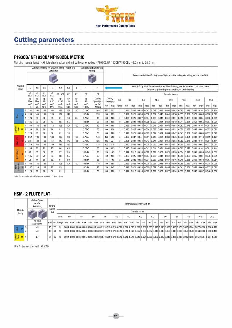
High Performance Cutting Tools
®
125
cutting parameters
f193cB/ nf193cB/ nf193cBl metrIcFlatpitchregularlength4/6flutechipbreakerendmillwithcornerradius-F193CB/nF193CB/F193CBL-6.0mmto25.0mm
note:Forendmillswith6flutesuseap60%oftablevalues
hsm- 2 flute flAt
Dia 1-3mm- Slot with 0.2XD
MaterialGroup
CuttingSpeed(Vc)forShoulderMilling/RoughandSemiFinish
CuttingSpeed(Vc)forSlotMilling
RecommendedFeed/Tooth(fz=mm/th)forshouldermilling/slotmilling,reducefzby20%
5 2.3 1.6 1.4 1.2 1.1 1 1 1MultiplyfzbythisXFactorbasedonae.Whenfinishing,usethestandardfzperchartbelow.
Onlyaddchipthinningwhenroughingorsemi-finishing.CTNCT
CTNCT
CTNCT
CTNCT
CTNCT CT CT CT CT Diameterinmm
apMax
apMax
ap2D
ap1.5D
ap1.25D
ap1D
ap1D
ap1D
CuttingSpeed(Vc)forSlotMilling
CuttingSpeed(Vc)
mm 6.0 8.0 10.0 12.0 16.0 20.0 25.0
ae/D1%
ae/D5%
ae/D10%
ae/D15%
ae/D20%
ae/D30%
ae/D50%
ae/D100%
min max Range min max min max min max min max min max min max min max
Steel
P
3 252 198 180 168 162 156 150 0.75xD 140 120 252 fz 0.025 0.031 0.034 0.043 0.041 0.051 0.050 0.063 0.062 0.078 0.081 0.101 0.091 0.114
4 189 149 135 126 122 117 0.5xD 120 90 189 fz 0.022 0.028 0.030 0.038 0.037 0.046 0.045 0.056 0.055 0.069 0.070 0.088 0.078 0.098
5 126 99 90 84 81 78 75 0.75xD 80 60 126 fz 0.020 0.025 0.027 0.034 0.033 0.041 0.041 0.051 0.050 0.063 0.065 0.081 0.073 0.091
6 105 83 75 70 68 65 0.5xD 63 50 105 fz 0.017 0.021 0.023 0.029 0.027 0.034 0.034 0.042 0.041 0.051 0.052 0.065 0.057 0.071
Stainless
Steel
M
1 168 132 120 112 108 104 100 0.75xD 90 80 168 fz 0.025 0.031 0.034 0.043 0.041 0.051 0.050 0.063 0.062 0.078 0.081 0.101 0.091 0.114
2 126 99 90 84 81 78 0.75xD 70 60 126 fz 0.020 0.025 0.027 0.034 0.033 0.041 0.041 0.051 0.050 0.063 0.065 0.081 0.073 0.091
3 126 99 90 84 81 78 0.75xD 70 60 126 fz 0.017 0.021 0.023 0.029 0.027 0.034 0.034 0.042 0.041 0.051 0.052 0.065 0.057 0.071
CastIron
K
1 252 198 180 168 162 156 150 0.75xD 140 120 252 fz 0.030 0.037 0.041 0.051 0.049 0.061 0.060 0.075 0.073 0.091 0.091 0.114 0.099 0.124
2 231 182 165 154 149 143 138 0.75xD 125 110 231 fz 0.025 0.031 0.034 0.043 0.041 0.051 0.050 0.063 0.062 0.078 0.081 0.101 0.091 0.114
3 210 165 150 140 135 130 0.75xD 115 100 210 fz 0.020 0.025 0.027 0.034 0.033 0.041 0.041 0.051 0.050 0.063 0.065 0.081 0.073 0.091
SuperAlloys
S
1 105 83 75 70 68 65 0.75xD 70 50 105 fz 0.025 0.031 0.034 0.043 0.041 0.051 0.050 0.063 0.062 0.078 0.081 0.101 0.091 0.114
2 42 33 30 28 27 26 0.3xD 30 20 42 fz 0.014 0.017 0.018 0.022 0.022 0.027 0.026 0.033 0.034 0.042 0.043 0.054 0.049 0.061
3 105 83 75 70 68 65 0.75xD 65 50 105 fz 0.020 0.025 0.027 0.034 0.033 0.041 0.041 0.051 0.050 0.063 0.065 0.081 0.073 0.091
4 95 74 68 63 61 59 0.5xD 55 45 95 fz 0.018 0.022 0.025 0.031 0.030 0.038 0.037 0.046 0.046 0.058 0.059 0.074 0.067 0.084
Hard
Materials
H
1 168 132 120 112 108 104 100 0.5xD 110 80 168 fz 0.022 0.028 0.030 0.038 0.037 0.046 0.045 0.056 0.055 0.069 0.070 0.088 0.078 0.098
2 147 116 105 98 95 0.3xD 95 70 147 fz 0.017 0.021 0.023 0.029 0.027 0.034 0.034 0.042 0.041 0.051 0.052 0.065 0.057 0.071
3 126 99 90 84 81 0.2xD 75 60 126 fz 0.014 0.017 0.018 0.023 0.022 0.027 0.027 0.034 0.033 0.041 0.042 0.052 0.046 0.057
MaterialGroup
CuttingSpeed(Vc)for
SlotMilling CuttingSpeed(Vc)
RecommendedFeed/Tooth(fz)
Diameterinmm
mm 1.0 1.5 2.0 3.0 4.0 5.0 6.0 8.0 10.0 12.0 14.0 16.0 20.0
ap0.5Dae/D100%
min max Range min max min max min max min max min max min max min max min max min max min max min max min max min max
Steel
P3 45 45 72 fz 0.004 0.005 0.006 0.008 0.008 0.010 0.012 0.015 0.016 0.020 0.020 0.025 0.029 0.036 0.038 0.048 0.048 0.060 0.058 0.072 0.067 0.084 0.077 0.096 0.096 0.120
4 40 40 68 fz 0.003 0.004 0.005 0.006 0.006 0.008 0.010 0.012 0.013 0.016 0.016 0.020 0.024 0.030 0.032 0.040 0.040 0.050 0.048 0.060 0.056 0.070 0.064 0.080 0.080 0.100
Stainless
Steel
M 1 27 27 45 fz 0.002 0.003 0.004 0.005 0.005 0.006 0.007 0.009 0.010 0.012 0.012 0.015 0.019 0.024 0.026 0.032 0.032 0.040 0.038 0.048 0.045 0.056 0.051 0.064 0.064 0.080

High Performance Cutting Tools
®
126
hsm- 4 flute flAt/ 4 flute BAll
hsm- 2 flute BAll
Dia 1-3mm- Profile( Ae) with 0.2XD
#RPM = Vc x 318.057/Tool Dia. #mm/min = RPM x number of teeth x mm/toothL1 max = maximum length of cutting as per catalog
Disclaimer* Technical data provided should be considered advisory only as variations may be necessary depending on the particular application.* For ball nose end mills - If axial depth (ap) is less than the ball diameter, the speed is figured using the effective cutting diameter ( Deff) Formula 1* For ball nose end mills - If axial depth (ap) is less than the ball diameter, and tool is tilted by an angle ß, the speed is figured using the effective cutting diameter
(Deff) Formula 2
Deff
= 2 x ADOC x (D-ADOC) Deff
= D x sine ß + arccos D-2 x ADOC( (D
Formula 1 Formula 2
cutting parameters
MaterialGroup
CuttingSpeed(Vc)forShoulderMilling
CuttingSpeed(Vc)
RecommendedFeed/Tooth(fz)
Diameterinmm
mm 1.0 1.5 2.0 3.0 4.0 5.0 6.0 8.0 10.0 12.0 14.0 16.0 20.0
ap1Dae/D10%
min max Range min max min max min max min max min max min max min max min max min max min max min max min max min max
Steel
P3 90 90 120 fz 0.004 0.005 0.006 0.008 0.008 0.010 0.012 0.015 0.016 0.020 0.020 0.025 0.029 0.036 0.038 0.048 0.048 0.060 0.058 0.072 0.067 0.084 0.077 0.096 0.096 0.120
4 75 75 90 fz 0.003 0.004 0.005 0.006 0.006 0.008 0.010 0.012 0.013 0.016 0.016 0.020 0.024 0.030 0.032 0.040 0.040 0.050 0.048 0.060 0.056 0.070 0.064 0.080 0.080 0.100
Stainless
Steel
M 1 60 60 75 fz 0.002 0.003 0.004 0.005 0.005 0.006 0.007 0.009 0.010 0.012 0.012 0.015 0.019 0.024 0.026 0.032 0.032 0.040 0.038 0.048 0.045 0.056 0.051 0.064 0.064 0.080
MaterialGroup
CuttingSpeed(Vc)forShoulderMilling
CuttingSpeed(Vc)
RecommendedFeed/Tooth(fz)
Diameterinmm
mm 1.0 1.5 2.0 3.0 4.0 5.0 6.0 8.0 10.0 12.0 14.0 16.0 20.0
ap0.2Dae/D30%
min max Range min max min max min max min max min max min max min max min max min max min max min max min max min max
Steel
P3 90 90 120 fz 0.009 0.011 0.013 0.017 0.018 0.022 0.026 0.033 0.035 0.044 0.044 0.055 0.058 0.072 0.077 0.096 0.096 0.120 0.115 0.144 0.134 0.168 0.154 0.192 0.192 0.240
4 75 75 90 fz 0.007 0.009 0.011 0.014 0.014 0.018 0.022 0.027 0.029 0.036 0.036 0.045 0.048 0.060 0.064 0.080 0.080 0.100 0.096 0.120 0.112 0.140 0.128 0.160 0.160 0.200
Hardened
Steel
M 1 60 60 75 fz 0.007 0.009 0.011 0.014 0.014 0.018 0.022 0.027 0.029 0.036 0.036 0.045 0.048 0.060 0.064 0.080 0.080 0.100 0.096 0.120 0.112 0.140 0.128 0.160 0.160 0.200

High Performance Cutting Tools
®
127
cutting parameters
PrOtOn - 2 flute BAll
PrOtOn- 4 flute flAt And cOrner rAdIus
Material
ProfileMilling
RecommendedFeed/Tooth(fz)Forprofilemilling
MultiplyfzbythisXFactorbasedonae.Whenfinishing,usethestandardfzperchartbelow
Ap2%D Paraemeters 1.0 1.5 2.0 3.0 4.0 5.0 6.0 8.0 10.0 12.0
min min max min max min max min max min max min max min max min max min max min max
Ste
el
p
5 5%fz 0.011 0.013 0.012 0.015 0.013 0.016 0.020 0.025 0.026 0.033 0.034 0.043 0.038 0.048 0.042 0.052 0.044 0.055 0.047 0.059
Vc 157 236 312 312 313 292 262 279 292 262
6 5%fz 0.009 0.012 0.011 0.013 0.011 0.014 0.019 0.023 0.025 0.031 0.031 0.039 0.034 0.043 0.037 0.046 0.039 0.049 0.042 0.052
Vc 157 226 300 300 300 280 253 269 280 252
Har
den
ed S
teel
H
1 5%fz 0.009 0.012 0.010 0.013 0.011 0.014 0.017 0.021 0.022 0.028 0.028 0.035 0.032 0.039 0.034 0.042 0.036 0.045 0.038 0.048
Vc 141 203 251 250 251 236 207 226 236 211
2 5%fz 0.008 0.011 0.009 0.012 0.010 0.013 0.015 0.019 0.020 0.025 0.025 0.032 0.028 0.035 0.030 0.038 0.032 0.040 0.035 0.043
Vc 126 174 220 222 220 212 189 201 207 189
3 5%fz 0.008 0.010 0.009 0.011 0.010 0.012 0.015 0.019 0.020 0.025 0.025 0.031 0.027 0.034 0.030 0.037 0.032 0.040 0.032 0.040
Vc 110 156 201 198 201 181 166 176 182 166
4 5%fz 0.007 0.009 0.009 0.011 0.009 0.011 0.014 0.017 0.018 0.022 0.022 0.028 0.025 0.031 0.027 0.033 0.029 0.036 0.029 0.037
Vc 110 140 179 179 182 165 151 163 167 151
Material
ProfileMilling
RecommendedFeed/Tooth(fz)Forprofilemilling
MultiplyfzbythisXFactorbasedonae.Whenfinishing,usethestandardfzperchartbelow
Ap1XD Paraemeters 1.0 1.5 2.0 3.0 4.0 5.0 6.0 8.0 10.0 12.0 10.0 12.0
min min max min max min max min max min max min max min max min max min max min max min max min max
Ste
el
p
5 5%fz 0.003 0.003 0.004 0.005 0.005 0.006 0.007 0.009 0.009 0.012 0.011 0.014 0.013 0.016 0.017 0.021 0.020 0.024 0.023 0.029 0.027 0.033 0.029 0.036
Vc 151 180 209 206 210 247 247 248 245 251 246 245
6 5%fz 0.002 0.003 0.003 0.004 0.004 0.005 0.006 0.008 0.009 0.011 0.010 0.013 0.012 0.015 0.015 0.019 0.018 0.022 0.021 0.026 0.025 0.031 0.027 0.034
Vc 119 141 163 163 166 196 195 196 193 198 196 195
Har
den
ed S
teel
H
1 5%fz 0.002 0.003 0.003 0.004 0.004 0.005 0.006 0.008 0.009 0.011 0.010 0.013 0.012 0.015 0.015 0.019 0.018 0.022 0.021 0.026 0.024 0.031 0.028 0.034
Vc 80 95 110 108 111 130 130 131 129 132 131 129
2 5%fz 0.002 0.002 0.002 0.003 0.003 0.004 0.005 0.006 0.007 0.008 0.008 0.010 0.009 0.011 0.011 0.014 0.013 0.016 0.016 0.020 0.018 0.023 0.021 0.026
Vc 64 78 91 90 91 101 100 101 101 100 101 101
3 5%fz 0.001 0.002 0.002 0.002 0.003 0.003 0.004 0.005 0.005 0.007 0.006 0.008 0.007 0.009 0.009 0.011 0.011 0.013 0.012 0.016 0.015 0.018 0.017 0.021
Vc 50 60 69 71 70 80 79 80 80 79 80 82
4 5%fz 0.001 0.002 0.002 0.002 0.002 0.003 0.003 0.004 0.004 0.005 0.005 0.007 0.006 0.008 0.007 0.009 0.009 0.011 0.010 0.013 0.012 0.016 0.014 0.018
Vc 39 50 60 60 60 70 70 70 69 70 70 69
#RPM = Vc x 318.057/Tool Dia. #mm/min = RPM x number of teeth x mm/tooth
(Maximum Spindle Speed of Spindle)/(Spindle Speed of Recommended Milling Condition)= Convertion Rate(a)Feed of Recommeded Milling Condition( Vf mm/min) X a = Corrected Vf (mm/min)
Disclaimer* Technical data provided should be considered advisory only as variations may be necessary depending on the particular application.* For ball nose end mills - If axial depth (ap) is less than the ball diameter, the speed is figured using the effective cutting diameter ( Deff) Formula 1* For ball nose end mills - If axial depth (ap) is less than the ball diameter, and tool is tilted by an angle ß, the speed is figured using the effective cutting diameter
(Deff) Formula 2
When maximum speed of the machine spindle less than value of recommended milling conditions, adjust conditions by calculation as follows.
(Maximum Spindle Speed of Spindle)/(Spindle Speed of Recommended Milling Condition)= Convertion Rate(a)Feed of Recommeded Milling Condition( Vf mm/min) X a = Corrected Vf (mm/min)
Deff
= 2 x ADOC x (D-ADOC) Deff
= D x sine ß + arccos D-2 x ADOC( (D
Formula 1 Formula 2

High Performance Cutting Tools
®
128
cutting parameters
sPOttInG drIlls
chAmfer tOOl
WorkpieceMaterialGroupCuttingSpeed(Vc)
Feedmm/rev
Diameterinmm
2 3 4 5 6 8 10 12 16
Ste
el
P
1 70-80 0.0635 0.0991 0.1245 0.1499 0.1753 0.2007 0.2261 0.2515 0.2769
2 60-70 0.0635 0.0991 0.1194 0.1397 0.1600 0.1803 0.2007 0.2210 0.2413
3 50-60 0.0508 0.0787 0.0940 0.1143 0.1346 0.1549 0.1753 0.1956 0.2159
4 40-50 0.0406 0.0635 0.0754 0.0872 0.0991 0.1109 0.1228 0.1347 0.1465
5 20-25 0.0508 0.0787 0.0940 0.1143 0.1346 0.1549 0.1753 0.1956 0.2159
Stainless
Steel
M
1 20-25 0.0635 0.0991 0.1194 0.1397 0.1600 0.1803 0.2007 0.2210 0.2413
2 15-20 0.0508 0.0787 0.0940 0.1143 0.1346 0.1549 0.1753 0.1956 0.2159
3 12-15 0.0508 0.0787 0.0940 0.1143 0.1346 0.1549 0.1753 0.1956 0.2159
CastIron
K
1 80-90 0.0635 0.0991 0.1194 0.1397 0.1600 0.1803 0.2007 0.2210 0.2413
2 70-80 0.0635 0.0991 0.1194 0.1397 0.1600 0.1803 0.2007 0.2210 0.2413
3 60-70 0.0635 0.0991 0.1194 0.1397 0.1600 0.1803 0.2007 0.2210 0.2413
Super
Alloys
S1 15-20 0.0406 0.0635 0.0754 0.0872 0.0991 0.1109 0.1228 0.1347 0.1465
4 10-15 0.0406 0.0635 0.0754 0.0872 0.0991 0.1109 0.1228 0.1347 0.1465
CastIron
K
1 150-200 0.1245 0.2007 0.2388 0.2769 0.3150 0.3531 0.3912 0.4293 0.4674
2 120-150 0.0991 0.1600 0.1897 0.2193 0.2489 0.2786 0.3082 0.3379 0.3675
3 100-120 0.0991 0.1600 0.1897 0.2193 0.2489 0.2786 0.3082 0.3379 0.3675
NonFerrous
N
1 160-180 0.0787 0.1245 0.1499 0.1753 0.2007 0.2261 0.2515 0.2769 0.3023
2 160-180 0.0787 0.1245 0.1499 0.1753 0.2007 0.2261 0.2515 0.2769 0.3023
3 120-130 0.0787 0.1245 0.1499 0.1753 0.2007 0.2261 0.2515 0.2769 0.3023
4 20-30 0.0635 0.0991 0.1194 0.1397 0.1600 0.1803 0.2007 0.2210 0.2413
5 40-50 0.0508 0.0787 0.0940 0.1143 0.1346 0.1549 0.1753 0.1956 0.2159
WorkpieceMaterialGroupCuttingSpeed(Vc)
Feedmm/rev
Diameterinmm
3 6 8 10 12 16 20
Ste
el
P
1 150-160 0.010 0.013 0.015 0.025 0.033 0.043 0.048
2 130-140 0.008 0.010 0.013 0.015 0.025 0.033 0.043
3 100-110 0.008 0.010 0.013 0.015 0.025 0.033 0.043
4 80-90 0.008 0.010 0.013 0.015 0.025 0.033 0.043
5 60-70 0.008 0.010 0.013 0.015 0.025 0.033 0.043
Stain-
less
Steel
M1 60-70 0.008 0.010 0.013 0.015 0.025 0.033 0.043
2 40-50 0.008 0.010 0.013 0.015 0.025 0.033 0.043
Super
Alloys
S1 65-70 0.008 0.010 0.013 0.015 0.025 0.033 0.043
2 40-45 0.008 0.010 0.013 0.015 0.025 0.033 0.043
Cast
Iron
K1 140-150 0.010 0.013 0.015 0.025 0.033 0.043 0.048
2 120-130 0.008 0.010 0.013 0.015 0.025 0.033 0.043
Non
Ferrous
N 1 165-175 0.127 0.018 0.025 0.033 0.043 0.048 0.064

High Performance Cutting Tools
®
129
cutting parameters
center drIlls
hIGh PerfOrmAnce tAPs
WorkpieceMaterialGroupCuttingSpeed(Vc)
Feedmm/rev
Diameterinmm
0.5 1 1.25 1.6 2 2.5 3 3.15 4 5 6.3 8
Ste
el
P
1 60-70 0.008 0.015 0.028 0.028 0.037 0.051 0.059 0.064 0.079 0.079 0.099 0.124
2 45-50 0.008 0.015 0.028 0.028 0.037 0.051 0.059 0.064 0.079 0.079 0.099 0.124
3 35-45 0.008 0.013 0.024 0.023 0.031 0.041 0.049 0.051 0.064 0.064 0.079 0.099
4 20-35 0.008 0.015 0.028 0.028 0.037 0.051 0.059 0.064 0.079 0.079 0.099 0.124
5 15-20 0.005 0.008 0.015 0.017 0.023 0.033 0.039 0.041 0.051 0.051 0.064 0.079
Stainless
Steel
M
1 30-20 0.008 0.013 0.024 0.023 0.031 0.041 0.049 0.051 0.064 0.064 0.079 0.099
2 20-15 0.008 0.013 0.024 0.023 0.031 0.041 0.049 0.051 0.064 0.064 0.079 0.099
3 15-Oct 0.008 0.013 0.024 0.023 0.031 0.041 0.049 0.051 0.064 0.064 0.079 0.099
CastIron
K
1 50-60 0.013 0.018 0.036 0.041 0.056 0.079 0.094 0.099 0.124 0.124 0.16 0.201
2 60-70 0.013 0.018 0.036 0.041 0.056 0.079 0.094 0.099 0.124 0.124 0.16 0.201
3 50-60 0.01 0.015 0.03 0.033 0.045 0.064 0.076 0.079 0.099 0.099 0.124 0.16
Super
Alloys
S1 Oct-15 0.005 0.005 0.011 0.013 0.018 0.025 0.031 0.033 0.041 0.041 0.051 0.064
4 Oct-15 0.005 0.008 0.015 0.017 0.023 0.033 0.039 0.041 0.051 0.051 0.064 0.079
NonFerrous
N
1 150-160 0.015 0.02 0.043 0.05 0.07 0.099 0.119 0.124 0.16 0.16 0.201 0.249
2 100-120 0.013 0.018 0.036 0.041 0.056 0.079 0.094 0.099 0.124 0.124 0.16 0.201
3 140-150 0.013 0.018 0.036 0.041 0.056 0.079 0.094 0.099 0.124 0.124 0.16 0.201
4 120-130 0.01 0.015 0.03 0.033 0.045 0.064 0.076 0.079 0.099 0.099 0.124 0.16
5 90-100 0.01 0.015 0.03 0.033 0.045 0.064 0.076 0.079 0.099 0.099 0.124 0.16
Series MaterialGroupCuttingSpeed(Vc)
SAS5PM
Stainless
Steel
M
1
2
3
Series MaterialGroupCuttingSpeed(Vc)
SBS5PM
Stainless
Steel
M
1 10-12
2 8-10
3 6-8
Series MaterialGroupCuttingSpeed(Vc)
SAI6PM
SuperAlloys
S
1 10-15
2 6-12
3 8-12
4 4-6
Series MaterialGroupCuttingSpeed(Vc)
SBI6PM
SuperAlloys
S
1 6-10
2 5-8
3 6-8
4 3-5

High Performance Cutting Tools
®
130
Workpiece Material GroupHardness
HBCutting Speed
m/min (Vc)
Feed (fz) mm/tooth Cutting Diameters
1.5-3 3-5 5-7 7-9 9-11 11-14 14-20
Ste
el
P
1 130 70-130 0.03 0.04 0.06 0.07 0.09 0.09 0.12
2 200 60-120 0.02 0.04 0.05 0.06 0.08 0.08 0.1
3 240 60-110 0.02 0.03 0.04 0.05 0.05 0.05 0.08
4 270 60-100 0.02 0.03 0.04 0.05 0.05 0.05 0.06
5 400 50-80 0.01 0.02 0.03 0.03 0.04 0.04 0.05
Sta
inle
ss S
teel
M
1 200 70-100 0.02 0.02 0.03 0.04 0.05 0.05 0.07
2 240 70-90 0.02 0.02 0.03 0.04 0.04 0.04 0.06
3 400 60-80 0.015 0.02 0.02 0.03 0.03 0.03 0.04
Cas
t Ir
on
K
K
1 190 60-110 0.02 0.03 0.06 0.07 0.08 0.09 0.11
2 180 60-90 0.02 0.03 0.05 0.06 0.08 0.09 0.12
3 240 60-90 0.02 0.02 0.03 0.05 0.07 0.08 0.11
No
n F
erro
us
N
1 80 80-300 0.03 0.04 0.06 0.07 0.10 0.13 0.15
2 90 100-300 0.03 0.04 0.06 0.07 0.11 0.13 0.16
3 100 60-250 0.03 0.04 0.06 0.07 0.11 0.13 0.16
4 100-400 0.05 0.06 0.08 0.09 0.13 0.15 0.18
Sup
er A
lloys
N
1 270 25-50 0.01 0.01 0.01 0.02 0.02 0.03 0.03
2 350 20-40 0.01 0.01 0.01 0.02 0.02 0.03 0.03
3 300 20-40 0.01 0.01 0.01 0.02 0.02 0.03 0.03
4
40-80
30-60
20-50
20-50
0.02
0.02
0.02
0.02
0.02
0.02
0.02
0.02
0.02
0.02
0.02
0.02
0.03
0.03
0.03
0.02
0.04
0.03
0.03
0.03
0.04
0.04
0.03
0.03
0.05
0.05
0.04
0.04
Har
den
ed
Ste
el
H
2 50HRc 25-40 0.01 0.01 0.02 0.02 0.02 0.03 0.03
3 56HRc 25-50 0.01 0.01 0.02 0.02 0.02 0.03 0.03
CARBIDE GRADE : K40UF AN ADVANCED PVD TiALN COATED GRADE OVER A TOUGH WEAR-RESISTANT SUBMICRON SUBSTRATE FOR GENERAL PURPOSE MACHINING OF STEEL, STAINLESS STEEL, SUPERALLOYS.
threAd mIll

High Performance Cutting Tools
®
131
threAd mIll AddItIOnAl InfOrmAtIOn
TANGENTiAL APPROACHThread milling cutter strategy of Machining and how to enter and exit the work piece. The Tangential arc approach is considered as the best method.
With this method, the tool enters and exits the work piece smoothly. No marks are left on the work piece and there is no vibration, even with harder materials.
Although it requires slightly more complex programming than the radial approach (see below), this is the method recommended for machining the highest quality threads.
1-2: Rapid approach2-3: Tool entry along tangential arc, with simultaneous feed along z-axis (@ 30% of the programming Feed)3-4: Helical movement during one full orbit (360 degrees in cut at full programmed Feed)4-5: Tool exit along tangential arc, with continuing feed along z-axis5-6: Rapid return
RADiAL APPROACHThis is the simplest method.There are two characteristics worth noting about the radial approach:• asmallverticalmarkmaybeleftattheentry(andexit)point.Thisisofnosignificancetothethreaditself.• whenusingthismethodwithveryhardmaterials,thetoolmayhaveatendencytovibrateasitapproachesthefullcutting
depth.
Note: Radial feed during entry to the full profile depth should only be 1/3 of the subsequent circular feed.
1-2: Radial entry2-3: Helical movement during one full orbit (360 degrees in cut at full programmed Feed)3-4: Radial exit
INFEED METHOD
2
5
3
4
1
6
looT gni
daerhTD
2
Wecei
pkroD
1
2
1 36 4
5
eceipkro
WD
1
eceipkro
W
looT gni
daerhT
D1
D212
3 4
External ThreadInternal Thread
1 24 3
eceipkro
W
looT gni
daerhT
D1
D2
External ThreadInternal Thread
2
5
3
4
1
6
looT gni
daerhTD
2
Wecei
pkroD
1
2
1 36 4
5
eceipkro
WD
1
eceipkro
W
looT gni
daerhT
D1
D212
3 4
External ThreadInternal Thread
1 24 3
eceipkro
W
looT gni
daerhT
D1
D2
External ThreadInternal Thread

High Performance Cutting Tools
®
132
THREAD MILLING METHODS
Climb Milling
Climb Milling
Internal right hand threadInternal left hand thread
Conventional Milling
Conventional Milling
Internal right hand threadInternal left hand thread
M03
G03
Z- M03
G03
Z+
G02
Z+
G02
Z-
External right hand threadExternal left hand thread
External right hand threadExternal left hand thread
Z+M03
G02
Z-M03
G02
Z-M03
G03
M03
G03
Z+
M03 M03
INTERNAL THREADING
G CODES
M CODESExTERNAL THREADING
G00 Send to position with rapid feed
G01 Send to position with linear movement and control by feed
G02 Clockwise circular interpolation
G03 Counter-clockwise circular interpolation
G40 Cutter compensation cancel
G41 Turn on left hand cutter compensation
G42 Turn on right hand cutter compensation
G54-59 Available workpiece coordinate settings
G90 Absolute positioning
G91 Incremental positioning
M00 Program stop
M01 Program optional stop
M03 Turn on spindle clockwise direction
M04 Turn on spindle counter-clockwise direction
M05 Turn off spindle rotation
M06 Tool change
M08 Coolant on
M09 Coolant off
M30 Program end and reset to start of program

High Performance Cutting Tools
®
133
THREADMILL CYCLE FOR MT2D/MT3D/MT4D
THREADMILL CYCLE FOR RHTS/RHTC/RHS/RHC/RSS/RSTS

High Performance Cutting Tools
®
134
CT iCP
UNiFiED
ECP
iT
ET
EC
iC
iSO
M
MF
UNC
UNEF
UNF
NPT
NPTF
BSPT
BSF
BSP
BSw
NPT
BS
TP
TM
STP60
MT2d
RHS
RHTS
RHC
RHTC
RSS
RSTS
A90S
A90L
MT3d
MT4d
MTH2d
MTH3d
Tool Type opeRaTaIoN Type
THReaD FoRM
FeaTURe
leNGTH
cUTTING DIRecTIoN
applIcaTIoN
FlUTe STyle
coaTING
THReaD FoRM DeTaIl
DeSIGN Type
Chamfer Tool InternalConicPrep
ISO
Solid
Short
LeftHand
Helical
FormaterialsUpto62HrC
Forarospaceapplication
Straight
CoolantFeed
Long
RightHand
MetricScrewThreadSeries
MetricFineScrewThreadSeries
Unified Coarse Thread Series
UnifiedExtraFineThreadSeries
UnifiedFineThreadSeries
American National Standard Taper PipeThread
Dryseal American National Standard Taper PipeThread
BritishStandardTaperPipeThread
BritishStandardFineThreadSeries
BritishStandardPipe
British Standard Whitworth Coarse Thread Series
nationalPipeThread PipeThread
British Standard
Unified
ExternalConicPrep
Internal Threading
ExternalThreading
ExternalChamfer
Internal ChamferSingleToothPartialProfile
MultiTooth2D
RegularHelicalFluteSolid
MultiTooth3D
RegularHelicalFlute Taper Solid
MultiTooth4D
RegularHelicalFluteCoolant
MultiTooth2DForHardPart
MultiTooth3DForHardPart
RegularHelicalFlute Taper Coolant
RegularStraightFluteSolid
RegularStraightFlute Taper Solid
Angle 90 Short Tool
Angle90LongTool
TaperPreperation
ThreadMill
SHORT
LH
H
RH
SLONG
Titanium Aluminium Nitride Coating
62HrC
iCONGALLERY

High Performance Cutting Tools
®
135
Tool SUBSTRaTe
Carbide Carbide
EndMills/Taps/Reamers
HelIx aNGle
poINT aNGle
118 Degree
90 Degree
60 Degree
120 Degree
118o
90o
60o
120o
NUMBeR oF FlUTeS
cUTTING Type
Center Cutting
200180 300 35/380
380 450 VaRI
350
3Flutes
4Flutes
2Flutes 6Flutes
5Flutes
4to6Flutes4-6
7Flutes7
above45 hRC Hardnessabove45HRc
woRkpIece HaRDNeSS
Weldon Shank
SHaNk Type
RoundShank
BrightFinish
Titanium Aluminium Nitride Coating
SURFace TReaTMeNT
Titanium Nitride Coating
Chromium Based Coating
Universal Shank
iCONGALLERY
SquareEnd
Corner Chamfer
CornerReinforcement
Ball Nose
CornerRadius
coRNeR STyle
0.1x45o
LonG
LonGREaCh
ExTRaLonG
LongLength
ExtraLongLength
LongReachLength
REG Regular/StandardLength
eND MIllS leNGTH
hSS HighSpeedSteelM2Grade
hSS-EPM HighSpeedSteelPowderMetallurgy
STRaTeGy
TrochoidalMilling
ProtonPlusCoating
STaNDaRD
DIN333DIn333
DIN371DIn371
DIN376DIn376
6hx 6HX
claSS oF THReaD
cHaMFeR
2 to 3 ChamferC/2-3P
4 to 4.5 ChamferB/4-4.5P
FORMA
FORMB
DRIll FoRMS
FormA
FormB

High Performance Cutting Tools
Forbes & Company LimitedForbes Building, Charanjit Rai Marg, Fort, Mumbai 400 001, India Phone: +91 22 6135 8902Email: [email protected]: www.totem-forbes.com