TAP TSI and TAF TSI Sector Handbook for the Communication ...
198
Page TAP TSI and TAF TSI Sector Handbook for the Communication between Railway Undertakings and Infrastructure Managers (RU/IM Telematics Sector Handbook) Submitted on 21 st October 2021 Project: TAP/TAF TSI Date: 21 October 2021 Owner: RU/IM Telematics Joint sector Group Document Ref: RU/IM Telematics Sector Handbook
-
Upload
khangminh22 -
Category
Documents
-
view
1 -
download
0
Transcript of TAP TSI and TAF TSI Sector Handbook for the Communication ...
Page 1
TAP TSI and TAF TSI Sector Handbook for the Communication between Railway Undertakings and Infrastructure Managers (RU/IM Telematics Sector Handbook)
Submitted on 21st October 2021
Project: TAP/TAF TSI
Date: 21 October 2021
Owner: RU/IM Telematics Joint sector Group Document Ref: RU/IM Telematics Sector Handbook
Page 2
TAP TSI and TAF TSI RU/IM Sector Handbook Submitted on: 21/10/2021
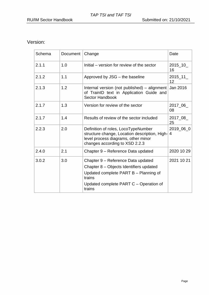
Version:
Schema Document Change Date
2.1.1 1.0 Initial – version for review of the sector 2015_10_ 16
2.1.2 1.1 Approved by JSG – the baseline 2015_11_ 12
2.1.3 1.2 Internal version (not published) – alignment of TrainID text in Application Guide and Sector Handbook
Jan 2016
2.1.7 1.3 Version for review of the sector 2017_06_ 08
2.1.7 1.4 Results of review of the sector included 2017_08_ 25
2.2.3 2.0 Definition of roles, LocoTypeNumber structure change, Location description, High-level process diagrams, other minor changes according to XSD 2.2.3
2019_06_04
2.4.0 2.1 Chapter 9 – Reference Data updated 2020 10 29
3.0.2 3.0 Chapter 9 – Reference Data updated
Chapter 8 – Objects Identifiers updated
Updated complete PART B – Planning of trains
Updated complete PART C – Operation of trains
2021 10 21
Page 3
TAP TSI and TAF TSI RU/IM Sector Handbook Submitted on: 21/10/2021
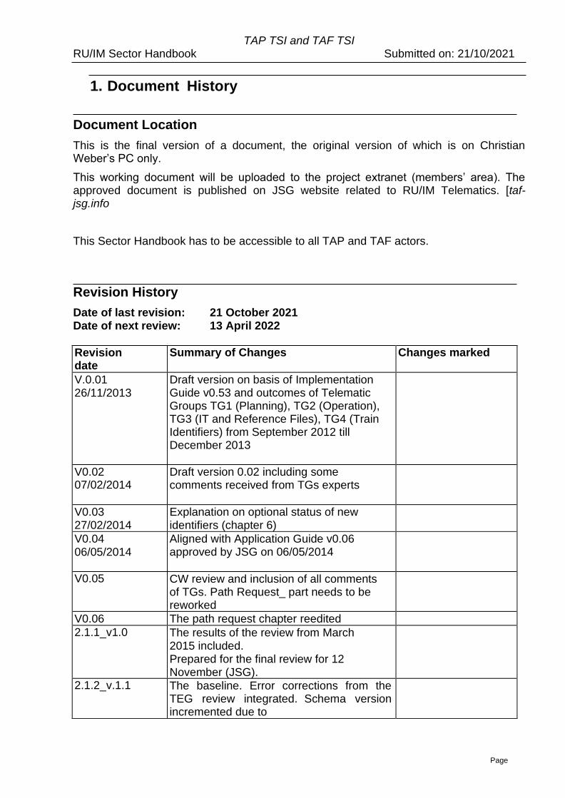
1. Document History
Document Location
This is the final version of a document, the original version of which is on Christian Weber’s PC only.
This working document will be uploaded to the project extranet (members’ area). The approved document is published on JSG website related to RU/IM Telematics. [taf-jsg.info
This Sector Handbook has to be accessible to all TAP and TAF actors.
Revision History
Date of last revision: 21 October 2021 Date of next review: 13 April 2022
Revision date
Summary of Changes Changes marked
V.0.01 26/11/2013
Draft version on basis of Implementation Guide v0.53 and outcomes of Telematic Groups TG1 (Planning), TG2 (Operation), TG3 (IT and Reference Files), TG4 (Train Identifiers) from September 2012 till December 2013
V0.02 07/02/2014
Draft version 0.02 including some comments received from TGs experts
V0.03 27/02/2014
Explanation on optional status of new identifiers (chapter 6)
V0.04 06/05/2014
Aligned with Application Guide v0.06 approved by JSG on 06/05/2014
V0.05 CW review and inclusion of all comments of TGs. Path Request_ part needs to be reworked
V0.06 The path request chapter reedited
2.1.1_v1.0 The results of the review from March 2015 included. Prepared for the final review for 12 November (JSG).
2.1.2_v.1.1 The baseline. Error corrections from the TEG review integrated. Schema version incremented due to
Page 4
TAP TSI and TAF TSI RU/IM Sector Handbook Submitted on: 21/10/2021
approved error fix CRs
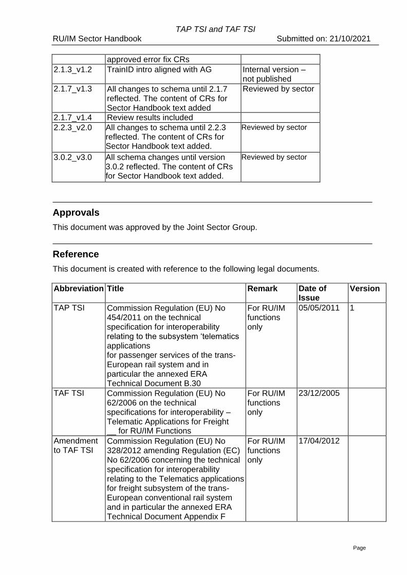
2.1.3_v1.2 TrainID intro aligned with AG Internal version – not published
2.1.7_v1.3 All changes to schema until 2.1.7 reflected. The content of CRs for Sector Handbook text added
Reviewed by sector
2.1.7_v1.4 Review results included
2.2.3_v2.0 All changes to schema until 2.2.3 reflected. The content of CRs for Sector Handbook text added.
Reviewed by sector
3.0.2_v3.0 All schema changes until version 3.0.2 reflected. The content of CRs for Sector Handbook text added.
Reviewed by sector
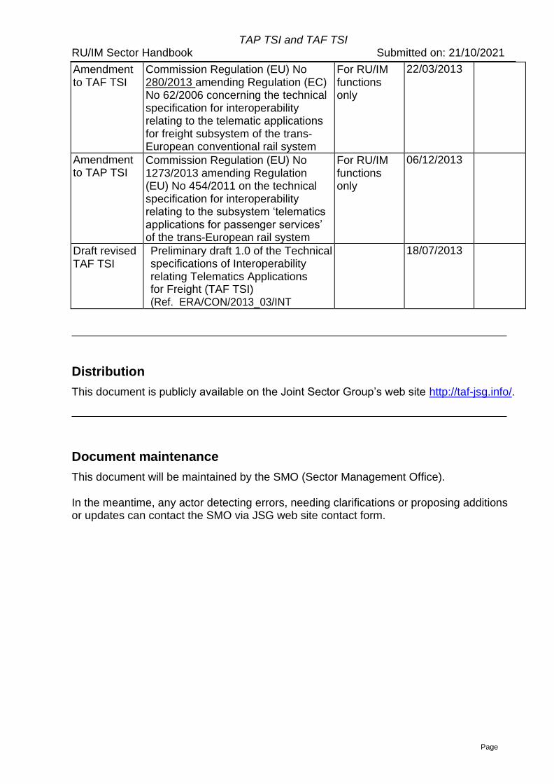
Approvals
This document was approved by the Joint Sector Group.
Reference
This document is created with reference to the following legal documents.
Abbreviation Title Remark Date of Issue
Version
TAP TSI Commission Regulation (EU) No 454/2011 on the technical specification for interoperability relating to the subsystem ‘telematics applications for passenger services of the trans-European rail system and in particular the annexed ERA Technical Document B.30
For RU/IM functions only
05/05/2011 1
TAF TSI Commission Regulation (EU) No 62/2006 on the technical specifications for interoperability – Telematic Applications for Freight __ for RU/IM Functions
For RU/IM functions only
23/12/2005
Amendment to TAF TSI
Commission Regulation (EU) No 328/2012 amending Regulation (EC) No 62/2006 concerning the technical specification for interoperability relating to the Telematics applications for freight subsystem of the trans-European conventional rail system and in particular the annexed ERA Technical Document Appendix F
For RU/IM functions only
17/04/2012
Page 5
TAP TSI and TAF TSI RU/IM Sector Handbook Submitted on: 21/10/2021
Amendment to TAF TSI
Commission Regulation (EU) No 280/2013 amending Regulation (EC) No 62/2006 concerning the technical specification for interoperability relating to the telematic applications for freight subsystem of the trans-European conventional rail system
For RU/IM functions only
22/03/2013
Amendment to TAP TSI
Commission Regulation (EU) No 1273/2013 amending Regulation (EU) No 454/2011 on the technical specification for interoperability relating to the subsystem ‘telematics applications for passenger services’ of the trans-European rail system
For RU/IM functions only
06/12/2013
Draft revised TAF TSI
Preliminary draft 1.0 of the Technical specifications of Interoperability relating Telematics Applications for Freight (TAF TSI) (Ref. ERA/CON/2013_03/INT
18/07/2013
Distribution
This document is publicly available on the Joint Sector Group’s web site http://taf-jsg.info/.
Document maintenance
This document will be maintained by the SMO (Sector Management Office).
In the meantime, any actor detecting errors, needing clarifications or proposing additions or updates can contact the SMO via JSG web site contact form.
Page 6
TAP TSI and TAF TSI RU/IM Sector Handbook Submitted on: 21/10/2021
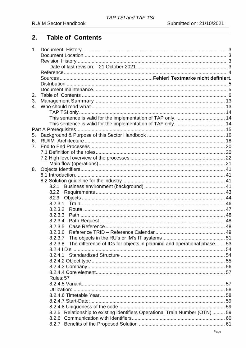
2. Table of Contents
1. Document History ......................................................................................................... 3
Document Location ....................................................................................................... 3 Revision History ............................................................................................................ 3
Date of last revision: 21 October 2021 .................................................................. 3 Reference ...................................................................................................................... 4 Sources ................................................................... Fehler! Textmarke nicht definiert. Distribution .................................................................................................................... 5
Document maintenance................................................................................................. 5 2. Table of Contents ......................................................................................................... 6 3. Management Summary .............................................................................................. 13
4. Who should read what ................................................................................................ 13 TAP TSI only ......................................................................................................... 14 This sentence is valid for the implementation of TAP only. ................................... 14
This sentence is valid for the implementation of TAF only. ................................... 14
Part A Prerequisites ........................................................................................................... 15 5. Background & Purpose of this Sector Handbook ........................................................ 16
6. RU/IM Architecture ..................................................................................................... 18 7. End to End Processes ................................................................................................. 20
7.1 Definition of the roles ............................................................................................. 20 7.2 High level overview of the processes .................................................................... 22
Main flow (operations) ........................................................................................... 21 8. Objects Identifiers ........................................................................................................ 41
8.1 Introduction ............................................................................................................ 41
8.2 Solution guideline for the industry .......................................................................... 41 8.2.1 Business environment (background) .......................................................... 41 8.2.2 Requirements ............................................................................................. 43
8.2.3 Objects ....................................................................................................... 44
8.2.3.1 Train ........................................................................................................ 46
8.2.3.2 Route ...................................................................................................... 47
8.2.3.3 Path ........................................................................................................ 48
8.2.3.4 Path Request .......................................................................................... 48
8.2.3.5 Case Reference ...................................................................................... 48
8.2.3.6 Reference TRID – Reference Calendar .................................................. 49 8.2.3.7 The objects in the RU’s or IM’s IT systems ............................................. 51
8.2.3.8 The difference of IDs for objects in planning and operational phase ....... 53 8.2.4 I D s ............................................................................................................. 54
8.2.4.1 Standardized Structure ........................................................................... 54
8.2.4.2 Object type ................................................................................................ 55 8.2.4.3 Company ................................................................................................... 56
8.2.4.4 Core element ............................................................................................. 57 Rules: 57
8.2.4.5 Variant ....................................................................................................... 57
Utilization: ............................................................................................................. 58
8.2.4.6 Timetable Year .......................................................................................... 58 8.2.4.7 Start-Date: ................................................................................................. 59 8.2.4.8 Uniqueness of the code ............................................................................ 59
8.2.5 Relationship to existing identifiers Operational Train Number (OTN) ......... 59
8.2.6 Communication with Identifiers ................................................................... 60
8.2.7 Benefits of the Proposed Solution .............................................................. 61
Page 7
TAP TSI and TAF TSI RU/IM Sector Handbook Submitted on: 21/10/2021
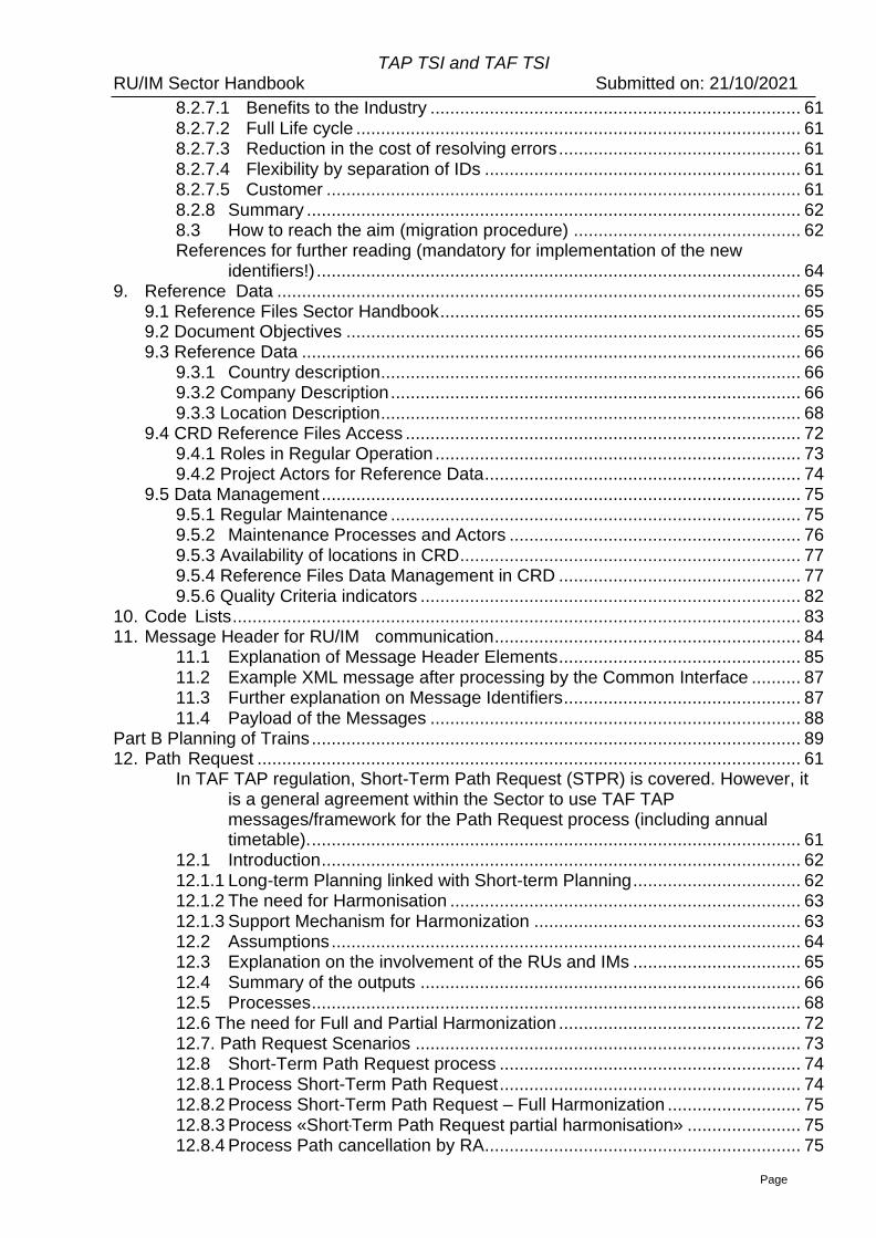
8.2.7.1 Benefits to the Industry ........................................................................... 61
8.2.7.2 Full Life cycle .......................................................................................... 61 8.2.7.3 Reduction in the cost of resolving errors ................................................. 61
8.2.7.4 Flexibility by separation of IDs ................................................................ 61 8.2.7.5 Customer ................................................................................................ 61
8.2.8 Summary .................................................................................................... 62
8.3 How to reach the aim (migration procedure) .............................................. 62 References for further reading (mandatory for implementation of the new
identifiers!) .................................................................................................. 64 9. Reference Data .......................................................................................................... 65
9.1 Reference Files Sector Handbook ......................................................................... 65 9.2 Document Objectives ............................................................................................ 65 9.3 Reference Data ..................................................................................................... 66
9.3.1 Country description ..................................................................................... 66 9.3.2 Company Description ................................................................................... 66
9.3.3 Location Description ..................................................................................... 68 9.4 CRD Reference Files Access ................................................................................ 72
9.4.1 Roles in Regular Operation .......................................................................... 73
9.4.2 Project Actors for Reference Data ................................................................ 74 9.5 Data Management ................................................................................................. 75
9.5.1 Regular Maintenance ................................................................................... 75 9.5.2 Maintenance Processes and Actors ........................................................... 76
9.5.3 Availability of locations in CRD ..................................................................... 77 9.5.4 Reference Files Data Management in CRD ................................................. 77
9.5.6 Quality Criteria indicators ............................................................................. 82
10. Code Lists ................................................................................................................... 83 11. Message Header for RU/IM communication .............................................................. 84
11.1 Explanation of Message Header Elements ................................................. 85
11.2 Example XML message after processing by the Common Interface .......... 87 11.3 Further explanation on Message Identifiers ................................................ 87
11.4 Payload of the Messages ........................................................................... 88 Part B Planning of Trains ................................................................................................... 89 12. Path Request .............................................................................................................. 61
In TAF TAP regulation, Short-Term Path Request (STPR) is covered. However, it is a general agreement within the Sector to use TAF TAP messages/framework for the Path Request process (including annual timetable). ................................................................................................... 61
12.1 Introduction ................................................................................................. 62
12.1.1 Long-term Planning linked with Short-term Planning .................................. 62 12.1.2 The need for Harmonisation ....................................................................... 63
12.1.3 Support Mechanism for Harmonization ...................................................... 63
12.2 Assumptions ............................................................................................... 64 12.3 Explanation on the involvement of the RUs and IMs .................................. 65
12.4 Summary of the outputs ............................................................................. 66 12.5 Processes ................................................................................................... 68
12.6 The need for Full and Partial Harmonization ................................................. 72
12.7. Path Request Scenarios .............................................................................. 73 12.8 Short-Term Path Request process ............................................................. 74
12.8.1 Process Short-Term Path Request ............................................................. 74 12.8.2 Process Short-Term Path Request – Full Harmonization ........................... 75
12.8.3 Process «Short-Term Path Request partial harmonisation» ....................... 75
12.8.4 Process Path cancellation by RA ................................................................ 75
Page 8
TAP TSI and TAF TSI RU/IM Sector Handbook Submitted on: 21/10/2021
12.8.5 Process Path alteration by IM ..................................................................... 77
12.8.6 Process Path modification by RA ............................................................... 79 12.8.7 Process Path Utilisation Notification by RA ................................................ 84
12.8.8 The Need for Path Studies ......................................................................... 84 12.9 Train Identifiers ........................................................................................... 89
12.9.2 Referenced objects as Part of RelatedPlannedTransportIdentifiersSection 90
12.9.3 Related Trains as Part of Train Activity ...................................................... 90 12.10. Messages for Short Term Path Request .................................................... 91
12.10.2 Structure of the Message ....................................................................... 91 Message header ................................................................................................... 91
Identifiers .............................................................................................................. 91 Train information ................................................................................................... 92
Path information .................................................................................................... 94
Status of Harmonisation ........................................................................................ 94 On Demand Paths ................................................................................................. 94
The usage of “on demand paths” is optional and subject to national rules. It has to be activated by RA for use of the path. ....................................................... 94
Operational Train Number (OTN) .......................................................................... 94 Network Specific Parameters section .................................................................... 95
Affected Section .................................................................................................... 95
12.11. Overview of the messages ......................................................................... 96 12.11.1 Message ‘Path Request’ ........................................................................ 96
12.11.2 Message ‘Path Details’........................................................................... 96 12.11.3 Message ‘Path Confirmed’ ..................................................................... 97
12.11.4 Message ‘Path Details Refused’ ............................................................ 97
12.11. 5 Message ‘Path Cancelled’ ....................................................................... 97
12.11.6 Message ‘Path Not Available’ ................................................................ 97 12.11.7 Message ‘Path Coordination’ and ‘Path Section Notification’ ............... 98
12.11.8 Message ‘ErrorMessage” ....................................................................... 98
12.11.9 Message ‘Path Section Notification’ ....................................................... 99
12.11.10 Message ‘Receipt Confirmation’ .......................................................... 99
12.12 Elements specific to actors ....................................................................... 100
12.13 Business Scenarios .................................................................................. 100 12.13.1 Ordinary train running across two IMs networks .................................. 101
Situation .............................................................................................................. 101
Preconditions ...................................................................................................... 101
Approach ............................................................................................................. 101
RA communicating with the IM ............................................................................ 101
IM communicating with the RA ............................................................................ 102 12.13.2 Ordinary train running across two networks ......................................... 103 Situation .............................................................................................................. 103
Preconditions: ..................................................................................................... 103
Approach ............................................................................................................. 103
RA communication with cooperating RU ............................................................. 103 RA communicating with the IM ............................................................................ 103
IM communicating with the RA ............................................................................ 104
12.13.3 Splitting of a train ................................................................................. 105 Situation .............................................................................................................. 105
Preconditions ...................................................................................................... 105 Approach ............................................................................................................. 105
RA communicating with the IM ............................................................................ 105 IM communicating with the RA ............................................................................ 106
Page 9
TAP TSI and TAF TSI RU/IM Sector Handbook Submitted on: 21/10/2021
How it looks like in the messages: ...................................................................... 106
12.13.4 Attaching of a train to another train ...................................................... 107 Situation .............................................................................................................. 107
Preconditions ...................................................................................................... 107 Approach ............................................................................................................. 107
RA communicating with the IM ............................................................................ 107
IM communicating with the RA ............................................................................ 108 12.13.5 Trains with different routes on specific days ........................................ 109
Preconditions ...................................................................................................... 109 Approach ............................................................................................................. 109
RA communicating with the IM ............................................................................ 109 IM communicating with the RA ............................................................................ 110
RA communicating with the IM ............................................................................ 110
12.13.6 Change of a booked train for certain days (e.g. planned re-routing) .... 112 Situation .............................................................................................................. 112
Preconditions ...................................................................................................... 112
Approach ............................................................................................................. 112
IM communicating with the RA ............................................................................ 113 RA communicating with the IM ............................................................................ 113 12.13.7 Trains with Through Coaches .............................................................. 114
Preconditions ...................................................................................................... 114 Approach ............................................................................................................. 114
RA communicating with the IM: ........................................................................... 114 IM communicating with the RA: ........................................................................... 115
12.13.8 Trains that cannot leave before another train has arrived (diagram dependence)............................................................................................. 116
Preconditions ...................................................................................................... 116 Approach ............................................................................................................. 116
RA communicating with the IM ............................................................................ 117
For the first train (A to F) ..................................................................................... 117
For the second train (F to A) ............................................................................... 117
IM communicating with the RA ............................................................................ 117
For the first train (A to F) ..................................................................................... 117 For the second train (F to A) ............................................................................... 118
12.13.9 Trains that need to be shunted from one platform to another at a location during the train run ................................................................................... 119
Preconditions ...................................................................................................... 119
Approach ............................................................................................................. 119
RA communicating with the IM ............................................................................ 119 IM communicating with the RA ............................................................................ 120
12.14. Business rules .......................................................................................... 123 12.14.1 Train Weight/Train Length ................................................................... 123
Determining the Train Weight.............................................................................. 123
Determining the Train Length .............................................................................. 123 12.14.2 Loco Type Number .............................................................................. 123
12.14.3 Combined Traffic Load Profile .............................................................. 124 12.14.5 Highest planned speed and minimum break weight percentage .......... 125 12.14.6 Braking weight and Minimum Brake Weight Percentage ..................... 125
12.14.7 Use of the Train Activity Type and Associated Trains .......................... 125 12.14.8 Timing at location ................................................................................. 125
12.14.9 Dwell Time ........................................................................................... 126 12.14.10 Received on Time .............................................................................. 126
Page 10
TAP TSI and TAF TSI RU/IM Sector Handbook Submitted on: 21/10/2021
12.14.11 Status of RU/IM harmonization .......................................................... 127
12.14.12 Use of Affected Section ..................................................................... 127 12.14.13 Network Specific Parameters ............................................................. 128
12.14.14 Contact Detail .................................................................................... 128 12.14.15 Use of the Error Message .................................................................. 128
12.14.16 Type of Request ................................................................................. 129
12.14.17 Type of Information ............................................................................ 130 12.14.18 ReasonOfReference .......................................................................... 131
12.15 Application of the Calendar in the Message ............................................. 134 12.15.2 Preconditions for the use of the calendar ............................................. 137
12.15.3 Calendar used in section related Messages ........................................ 137 12.15.4 Rules related to the Calendar Element ................................................ 138
12.15.5 Rules related to the Calendar of the Route .......................................... 139
12.15.6 Using the calendar element ................................................................. 139 12.15.7 The use of the Calendar for a Path Request ........................................ 140
Situation .............................................................................................................. 140
Preconditions ...................................................................................................... 140
Approach ............................................................................................................. 141 Message ............................................................................................................. 142 12.15.8 Application of the Calendar in the Affected Section ............................. 145
12.16 Handling of Handover in Border Sections ................................................. 146 Part C Operation of Trains ............................................................................................... 148 13. General Information ................................................................................................... 149 14. Train Preparation ...................................................................................................... 150
14.3 Train Ready message ................................................................................. 152
14.4 Content of the message ............................................................................ 153
15. Train Running Information and Forecast .................................................................... 154 15.1 Process triggering the Train Running Information message ...................... 154
15.2 Process triggering the Train Running Forecast message .......................... 154 15.3 – Information to the Station Manager ....................................................... 155
15.4 Content of the messages .......................................................................... 155
15.6 Accuracy of train running forecast information ......................................................... 156 15.6.1 Background and purpose of Forecasts and ETAs for planning operations ..... 156 15.6.2 References to Forecasts and ETAs in TAF-TSI.............................................. 156 15.6.3 Examples of Forecasts and ETAs used by operators/planners ...................... 157 15.6.4 Description and definitions of terms used in the sector .................................. 157 15.6.5 How to compute ETA qualifiers (based on relative error, error, accuracy,
probability, threshold values etc.) ........................................................................ 158 15.6.6 How RNE TIS facilitates the assessment of forecast quality for the recipient 159
16 Service Disruption/Train Running Interrupted ............................................................ 160 16.1 Process triggering the message ............................................................... 160
16.2 Information storage ................................................................................... 160 16.3 Content of the message ........................................................................... 160
17 Change of Track/Platform ........................................................................................... 162 18 Train Delay Cause ..................................................................................................... 163
18.1 IM informs the RU on the delay cause ....................................................... 163
18.2 Content of the message ............................................................................ 164 19 Passengers information in station area and vehicle area ........................................... 165
19.1 Passenger information in station area ............................................................... 165 19.2 Passenger information in vehicle area ............................................................... 165
Part D Overall requirements ............................................................................................ 169 18 General remarks ....................................................................................................... 170
a. Use of common elements in the messages Free text field ....................... 170
Page 11
TAP TSI and TAF TSI RU/IM Sector Handbook Submitted on: 21/10/2021
Message reference ............................................................................................. 170
b. Mandatory or Optional Elements in the Messages ................................... 170 c. Message exchange partners .................................................................... 171
Note on Network specific or national specific parameters .................................... 172 Rules 172
d. Masterplan ................................................................................................ 172
19 Data quality ............................................................................................................... 173 20 Functional Governance ............................................................................................ 162
a. Code allocation ......................................................................................... 162
Processes for the maintenance of codes ............................................................ 162 b. Change of messages and/or the structure of the reference file ................ 162
c. Allocation of certificates for messages ..................................................... 163
d. Access to reference data .......................................................................... 163
21 Glossary .................................................................. Fehler! Textmarke nicht definiert. 22 List of Appendices .................................................................................................... 164
Messages ............................................................................................................ 164
Annexes to Part A ............................................................................................... 164 • TrainID – Variant Framework (Annex 8.2) ................................................ 164
• TrainID – Update Link Framework (Annex 8.3) ........................................ 164 • TrainID – Case Reference Framework (Annex 8.4) .................................. 165
• TrainID – Object Info Framework (Annex 8.5) .......................................... 165
• Testing Framework with Example of PCS (Annex 8.6) ............................. 165 • Test Cases with Identifiers (Annex 8.7) .................................................... 165
• TrainID – UML Model (Annex 8.8) ............................................................ 165 • Annex 9.1 Data Model for Reference Files ............................................... 165
• Update Message for Locations ................................................................. 166
• Annex 9.3 HMI for Maintenance of Location .............................................. 166 • Annex 9.4 Table of codes for Subsidiary locations (subsidiary type codes)
................................................................................................................. 166
• Annex 10.1 Code lists ............................................................................... 166
Annexes to Part B ............................................................................................... 166
Annexes to Part C Operations ............................................................................ 166
Annexes to Part D ............................................................................................... 166

Page 12
TAP TSI and TAF TSI RU/IM Sector Handbook Submitted on: 21/10/2021
Page 13
TAP TSI and TAF TSI RU/IM Sector Handbook Submitted on: 21/10/2021
3. Management Summary
The Sector Handbook describes messages and elements used by the sector for RU/IM communications for planning and operation in freight and passenger traffic.
Some of these messages are basic parameters described in TAF and TAP regulation. Others are out of the scope of the regulation, designed by the sector for the sector and implementation by the actors under agreement.
The “legal” messages, described in TAF and TAP TSI, will be presented in a separate document called Application Guide. This application Guide is foreseen to replace the document B.56 quoted in the TAP revision text approved by RISC in June 2013 (and corresponding to the Implementation Guide delivered during TAP Phase 1 in May 2012). The decision of replacement will be taken by the Steering Committee co-chaired by the Commission and the Sector. In practice, the Application Guide is the subset of the Sector Handbook relevant for TAF and TAP regulation.
The Sector Handbook is targeted to those people within railway companies and their suppliers, who are in charge of organizing, supervising and/or carrying out the implementation of the TAP and/or TAF RU/IM Communication within their company.
This document explains the TAP and TAF messages derived from both regulations1, giving a hint on their legal status, explains their usage the overall architecture, the establishment and use of the reference data and relevant code list.
The document covers the RU/IM communication of both TAF2 and TAP. Some parts are specific to one of the TSIs only and are marked accordingly. The relevant TSI for passenger Railway Undertakings (RU), Infrastructure Managers (IM) and Station Managers (SM) is TAP TSI. The relevant TSI for freight RUs and IMs is TAF TSI.
The messages described in the regulation are completed by optional messages out of the regulations that can be used after agreement by the RUs and IMs (and SMs if relevant) for information exchange. These messages are maintained by the Sector Management Office under the authority of the Joint Sector Group.
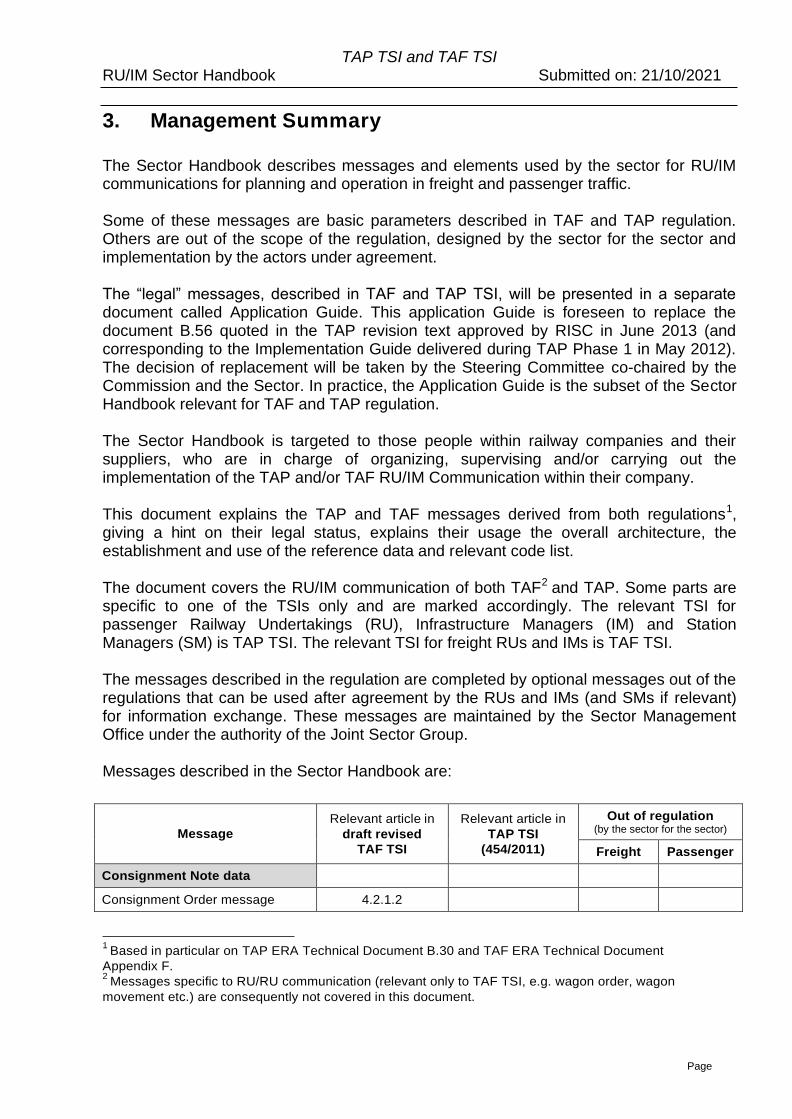
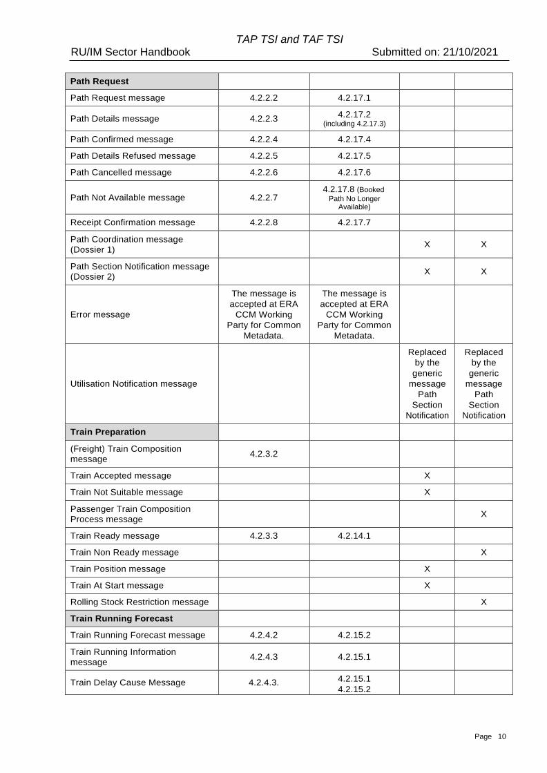
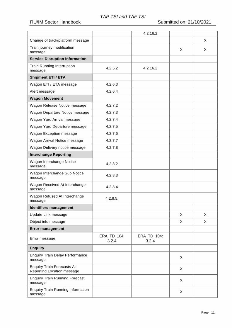
Messages described in the Sector Handbook are:
Message
Relevant article in
draft revised
TAF TSI
Relevant article in
TAP TSI
(454/2011)
Out of regulation (by the sector for the sector)
Freight Passenger
Consignment Note data
Consignment Order message 4.2.1.2
1
Based in particular on TAP ERA Technical Document B.30 and TAF ERA Technical Document
Appendix F. 2
Messages specific to RU/RU communication (relevant only to TAF TSI, e.g. wagon order, wagon
movement etc.) are consequently not covered in this document.
TAP TSI and TAF TSI RU/IM Sector Handbook Submitted on: 21/10/2021
Page 10
Path Request
Path Request message 4.2.2.2 4.2.17.1
Path Details message 4.2.2.3 4.2.17.2
(including 4.2.17.3)
Path Confirmed message 4.2.2.4 4.2.17.4
Path Details Refused message 4.2.2.5 4.2.17.5
Path Cancelled message 4.2.2.6 4.2.17.6
Path Not Available message
4.2.2.7
4.2.17.8 (Booked
Path No Longer Available)
Receipt Confirmation message 4.2.2.8 4.2.17.7
Path Coordination message
(Dossier 1)
X X
Path Section Notification message
(Dossier 2)
X X
Error message
The message is
accepted at ERA
CCM Working
Party for Common
Metadata.
The message is
accepted at ERA
CCM Working
Party for Common
Metadata.
Utilisation Notification message
Replaced
by the
generic
message
Path
Section
Notification
Replaced
by the
generic
message
Path
Section
Notification
Train Preparation
(Freight) Train Composition
message 4.2.3.2
Train Accepted message X
Train Not Suitable message X
Passenger Train Composition
Process message
X
Train Ready message 4.2.3.3 4.2.14.1
Train Non Ready message X
Train Position message X
Train At Start message X
Rolling Stock Restriction message X
Train Running Forecast
Train Running Forecast message 4.2.4.2 4.2.15.2
Train Running Information
message 4.2.4.3 4.2.15.1
Train Delay Cause Message 4.2.4.3. 4.2.15.1
4.2.15.2
TAP TSI and TAF TSI RU/IM Sector Handbook Submitted on: 21/10/2021
Page 11
4.2.16.2
Change of track/platform message X
Train journey modification
message
X X
Service Disruption Information
Train Running Interruption
message 4.2.5.2 4.2.16.2
Shipment ETI / ETA
Wagon ETI / ETA message 4.2.6.3
Alert message 4.2.6.4
Wagon Movement
Wagon Release Notice message 4.2.7.2
Wagon Departure Notice message 4.2.7.3
Wagon Yard Arrival message 4.2.7.4
Wagon Yard Departure message 4.2.7.5
Wagon Exception message 4.2.7.6
Wagon Arrival Notice message 4.2.7.7
Wagon Delivery notice message 4.2.7.8
Interchange Reporting
Wagon Interchange Notice
message 4.2.8.2
Wagon Interchange Sub Notice
message 4.2.8.3
Wagon Received At Interchange
message 4.2.8.4
Wagon Refused At Interchange
message 4.2.8.5.
Identifiers management
Update Link message X X
Object info message X X
Error management
Error message ERA_TD_104:
3.2.4 ERA_TD_104:
3.2.4
Enquiry
Enquiry Train Delay Performance
message
X
Enquiry Train Forecasts At
Reporting Location message
X
Enquiry Train Running Forecast
message
X
Enquiry Train Running Information
message
X
TAP TSI and TAF TSI RU/IM Sector Handbook Submitted on: 21/10/2021
Page 12
Enquiry Trains At Reporting
Location message
X
Enquiry Wagon Deviation
message
X
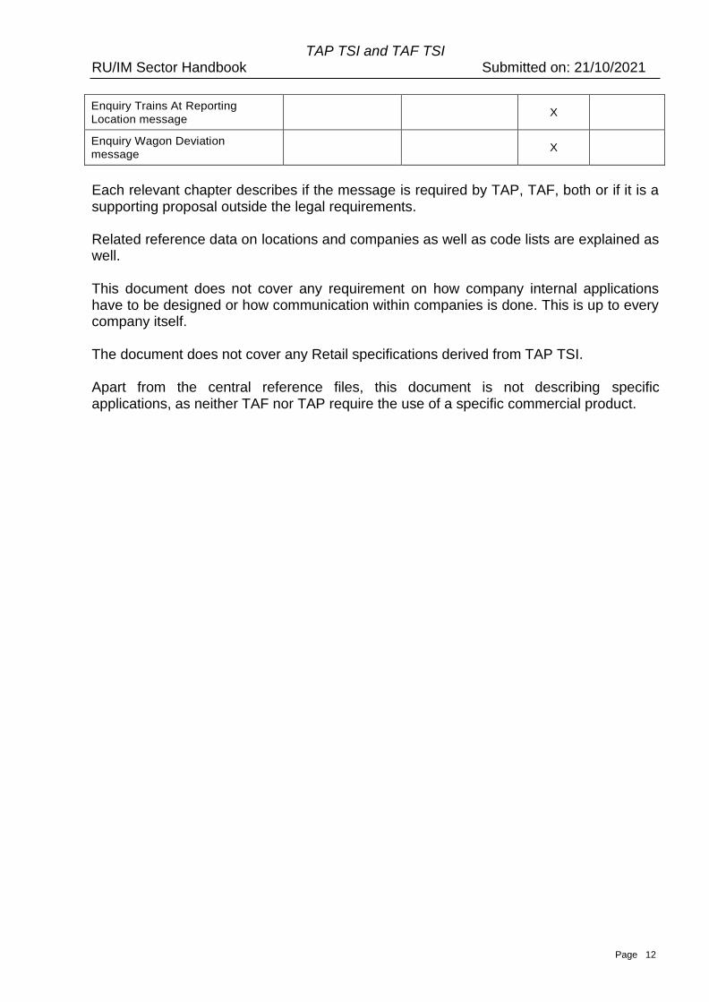
Each relevant chapter describes if the message is required by TAP, TAF, both or if it is a supporting proposal outside the legal requirements.
Related reference data on locations and companies as well as code lists are explained as well.
This document does not cover any requirement on how company internal applications have to be designed or how communication within companies is done. This is up to every company itself.
The document does not cover any Retail specifications derived from TAP TSI.
Apart from the central reference files, this document is not describing specific applications, as neither TAF nor TAP require the use of a specific commercial product.
TAP TSI and TAF TSI RU/IM Sector Handbook Submitted on: 21/10/2021
Page 13
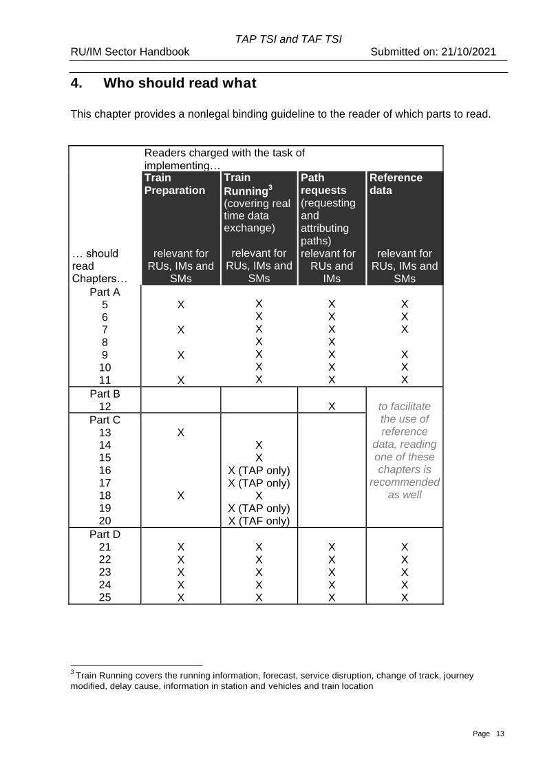
4. Who should read what
This chapter provides a nonlegal binding guideline to the reader of which parts to read.
Readers charged with the task of implementing… Train Preparation
… should relevant for read RUs, IMs and Chapters… SMs
Train
Running3
(covering real time data exchange)
relevant for RUs, IMs and
SMs
X X X X X X X
Path requests (requesting and attributing paths) relevant for
RUs and IMs
X X X X X X X
Reference data
relevant for RUs, IMs and
SMs
X X X
X X X
Part A 5 6 7 8 9 10 11
X X X X X
X
Part B 12
X
to facilitate the use of reference
data, reading one of these chapters is
recommended as well
Part C 13 14 15 16 17 18 19 20
X
X
X X
X (TAP only) X (TAP only)
X X (TAP only) X (TAF only)
Part D 21 22 23 24 25
X X X X X
X X X X X
X X X X X
X X X X X
3 Train Running covers the running information, forecast, service disruption, change of track, journey
modified, delay cause, information in station and vehicles and train location
TAP TSI and TAF TSI RU/IM Sector Handbook Submitted on: 21/10/2021
Page 14
This document covers the implementation of the RU/IM Communication of TAP TSI and TAF TSI. Normally, explanations given are valid for both TSIs (and hence the passenger and freight sector).
• TAP TSI is relevant for passenger Railway Undertakings (RU), Infrastructure Managers (IM) on whose networks passenger train services can be performed and Station Managers (SM). Companies dealing with the implementation of TAP should read all common parts valid for both TSIs and the specific TAP only sections.
• TAF TSI is relevant for freight RUs and IMs on whose networks freight train services can be performed. Companies dealing with the implementation of TAF should read all common parts valid for both TSIs and the specific TAF only sections.
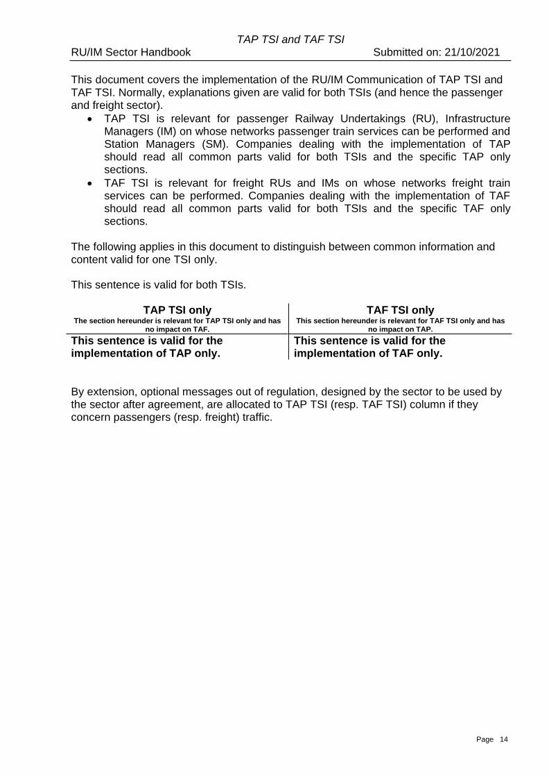
The following applies in this document to distinguish between common information and content valid for one TSI only.
This sentence is valid for both TSIs.
TAP TSI only The section hereunder is relevant for TAP TSI only and has
no impact on TAF.
This sentence is valid for the implementation of TAP only.
TAF TSI only This section hereunder is relevant for TAF TSI only and has
no impact on TAP.
This sentence is valid for the implementation of TAF only.
By extension, optional messages out of regulation, designed by the sector to be used by the sector after agreement, are allocated to TAP TSI (resp. TAF TSI) column if they concern passengers (resp. freight) traffic.

TAP TSI and TAF TSI RU/IM Sector Handbook Submitted on: 21/10/2021
Page 15
Part A Prerequisites
TAP TSI and TAF TSI RU/IM Sector Handbook Submitted on: 21/10/2021
Page 16
5. Background & Purpose of this Sector Handbook
The TAP and TAF TSI operational part describes the communication between Railway Undertaking (RU), Station Manager (SM) and Infrastructure Manager (IM). In addition to data exchange, the TAF TSI describes business processes for operational interoperability.
The purpose of these standards is to allow railway companies _ in the same way for domestic and interoperable4 services – to
• order paths for trains
• control and manage their train services (and indirectly staff and fleet)
• Improve customer information provided by RUs and SMs5
The implementation of TAF and TAP TSI is one step towards interoperability. Full interoperability requires further steps besides TAF and TAP, as e.g. different operational rules and organisational set ups are valid in the different Member States, requiring different use of these messages. Gradually, these rules should be aligned.
Various requirements in the Passenger Rights Regulation (PRR) and TAP TSI are the basis for these RU/IM communications. For example, Annex II Part II of PRR requires passenger RUs to inform their customers about delays and main connecting services during their train ride. Basic Parameter (BP) 4.2.12 of TAP TSI requires SMs to inform passengers about material delays, change of track or platforms, full or partial cancellation of trains and train rerouting. In order to give this information, data exchange between IMs, RUs and SMs is needed, covered by B.30 of TAP TSI. The supporting processes of ordering train paths and informing the IM about the readiness of a train are covered as well, facilitating the interoperable train run for RUs.
There are common functions for planning and operations that are cited in both regulations and are common or similar to both TAP and TAF actors. These functions are:
Common System Components:
• Common Interface (TAP BP 4.2.21o TAF BP 4.2.14)
• Reference Files (TAP BP 4.2.19o TAF BP 4.2.12)
Common/similar messages (or groups of messages):
• Train Running Information (TAP BP 4.2.15o TAF BP 4.2.4)
• Train Running Forecast (TAP BP 4.2.15o TAF BP 4.2.4)
• Service Disruption (TAP BP 4.2.16o TAF BP 4.2.5)
• Train Preparation (TAP BP 4.2.14o TAF BP 4.2.3)
• Path Request6 (TAP BP 4.2.17o TAF BP 4.2.2)
4 For RU/IM an “interoperable” train service is understood as a train that involves more than one IM and/or
more than one RU. 5
And IMs, in case they provide services as a station manager or in direct communication to passengers.
TAP TSI and TAF TSI RU/IM Sector Handbook Submitted on: 21/10/2021
Page 17
Specific to TAF are certain parts of train preparation7. Specific to TAP are messages intended for customer information.
The application of the Common System Components should be used by both TAF and TAP communities for the operational RU/IM communications. Therefore, the related standards and specifications are being aligned.
The Common Messages are based on operational business communications that are also common to the TAF and TAP communities. These operational messages are contained in the message catalogue and have been aligned between TAF and TAP working groups so that they include certain functionality needed in the Passenger and Freight domains.
This implementation guide provides the necessary information to actors of both TAF and TAP to assist in the implementation of the RU/IM functions of both TSIs. The document integrates all parts relevant from the RU/IM part of both regulations in one single guide. It covers prerequisites, such as reference data, the planning part, the operational part and general requirements, e.g. on data quality. Where necessary the document refers to further specifications relevant for the use of the message exchange and described elsewhere. It has to be assured that these referenced documents relevant for implementation are accessible to all actors in a fair and transparent manner. This document also shows the remaining differences between freight and passenger specific processes and/or data according to business needs.
6
In TAF TAP regulation, Short Term Path Request (STPR) is covered. However, it is a general agreement
within the Sector to use TAF TAP messages framework for the Path Request process (including annual
timetable) 7
The Infrastructure Restriction Notice database is specific to TAF and not covered in this document
TAP TSI and TAF TSI RU/IM Sector Handbook Submitted on: 21/10/2021
Page 18
6. RU/IM Architecture
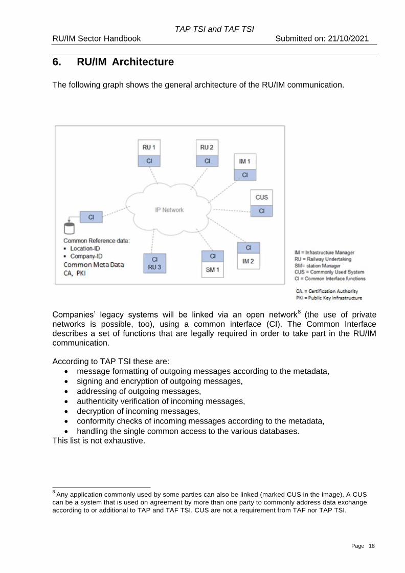
The following graph shows the general architecture of the RU/IM communication.
Companies’ legacy systems will be linked via an open network8 (the use of private networks is possible, too), using a common interface (CI). The Common Interface describes a set of functions that are legally required in order to take part in the RU/IM communication.
According to TAP TSI these are:
• message formatting of outgoing messages according to the metadata,
• signing and encryption of outgoing messages,
• addressing of outgoing messages,
• authenticity verification of incoming messages,
• decryption of incoming messages,
• conformity checks of incoming messages according to the metadata,
• handling the single common access to the various databases. This list is not exhaustive.
8
Any application commonly used by some parties can also be linked (marked CUS in the image). A CUS
can be a system that is used on agreement by more than one party to commonly address data exchange
according to or additional to TAP and TAF TSI. CUS are not a requirement from TAF nor TAP TSI.
TAP TSI and TAF TSI RU/IM Sector Handbook Submitted on: 21/10/2021
Page 19
The solution to cover the functions of the common interface used by a company can be
either a commonly built CI9 or another development with the required functions. In case a company (in the picture: RU 3) develops and builds new applications, the message exchange can directly be according to TAP and TAF TSI, with no additional application (separate interface) needed. The required functions of the Common Interface (as described above) will have to be covered by this application directly. (In case the new application does not support TAP and TAF messages and/or the functions of a CI, a common interface is still needed.) A company’s CI will have to be in accordance with the external interface specification, describing the communication between CIs. That external interface specification of the reference implementation can be found on the website of the European Commission (ERA_TD_104): http://www.era.europa.eu/Document_ Register/Documents/ERA_Technical_Document_TAF_D_2_Appendix_E_v2_0.pdf
Common reference data (as described in chapter 9) including location codes, company codes and country codes are stored centrally, with different possibilities to access them (e.g. messages, bulk data load, web interface). RUs and IMs will need to have a current subscription to the TAP/TAF governance entity to be given access rights to the reference data service. Common code lists are enumerated values that are available to be used within the RU/IM messages. These codes are to be used unless a bilateral agreement exists between partners to use other codes. These common Code Lists are published centrally by ERA for the codes messages required by the regulation and by Joint Sector Group _ sector RU/IM Telematic governance entity for the codes used out of the legal TAP/TAF requirements.
Reference data and code lists are mirrored in the companies’ systems (see chapter 9.3 for ways to access the data), i.e. each actor holds a copy of the reference data in its own system environment. The exchange of bilateral and multilateral agreed messages remains possible as well. This covers the use of both messages and codes in the TAP and TAF messages. In the further document, the references and excerpts of the XSD schema (the metadata definition for TAF TSI messages) are used, and often in the form of graphic models. The syntax of the model used in the pictures through the document which reflect the message or element structure is described in the Annex 6.1. The full export of the XSD model in the “readable form” including diagrams and cross-references is given in the Annex 6.2. The code lists are exported in the readable form in the Annex 6.3.
9 e.g. the CI developed initially under the supervision of the Common Components Groups (“CCG CI”).
Update 2017: It is now called “Common Components System (CCS)” under the umbrella of RailNetEurope
TAP TSI and TAF TSI RU/IM Sector Handbook Submitted on: 21/10/2021
Page 20
7. End to End Processes This chapter provides an overview on the main end-to-end process covering planning and operations. The details or any other associated processes (e.g. path cancellation) can be found in the individual chapters (see section 12.5).
7.1 Definition of the roles Lead RU (Railway Undertaking) The Lead RU is responsible for coordination of an interoperable traffic service and train journey. It is not necessarily the first RU at the origin of the planned journey of the train. The Lead RU undertakes the harmonization and coordination in the pre-planning phases and the whole communication between involved RUs. For freight traffic, the Lead RU may be the single point of contact of the customer. Among the tasks of the Lead RU are: the creation of the object train, the definition of TrainID and assurance of its uniqueness. The Lead RU may be RA (responsible applicant) and/or a RRU (responsible RU) as well. If that is not the case, the Lead RU has to inform that both other roles if they are taken by other RUs. In principal, in such a case the communication exchange takes place primarily between Lead RU and RA. Communication exchange between Lead RU and infrastructure manager (IM) is optional; no special rights and obligations to the IM. Legal reference: EU Regulation No 1305/2014 (TAF), p10, §2.3.1 Involved Entities Responsible Applicant (RA) Applicant means a railway undertaking or an international grouping of railway undertakings or other persons or legal entities, such as competent authorities under Regulation (EC) No 1370/2007 and shippers, freight forwarders and combined transport operators, with a public-service or commercial interest in procuring infrastructure capacity (Directive 2012/34/EU (3)). The RA is the applicant/customer and contractor as well as the single point of contact for respective IM in the whole planning process phase. The main task of the role RA is to request the booking of capacity to an IM. The RA does not need to be a RU, it can also be another entity, which is able and permitted to book capacity. The RA (if it is an RU) may take the roles Lead RU and/or RRU as well. If that is not the case, RA has to inform the both other roles if they are taken in by other RUs. The RA has to create a Path Request and a PathRequestID to request for a desired path in network of a particular IM. If it is not an interoperable train managed by a planning Lead RU, the RA also creates the object train, the TrainID and assures the uniqueness and takes the Lead RU role too. Furthermore, the RA is allowed to confirm or to refuse a path offer, to book a path (sign the contract), to change or to cancel the booked path.
Legal reference:
EU Regulation No 1305/2014 (TAF), p10, §2.3.1 Involved Entities & Appendix II, Glossary
EU Regulation No 454/2011 (TAP), §8 Glossary: mentioned as "Access Party" Responsible RU (RRU) Railway Undertaking (Directive 2004/49/EC (9)) means railway undertaking as defined in Directive 2001/14/EC, and any other public or private undertaking, the activity of which is to provide transport of goods and/or passengers by rail on the basis that the undertaking must ensure traction; this also includes undertakings which provide traction only;
TAP TSI and TAF TSI RU/IM Sector Handbook Submitted on: 21/10/2021
Page 20
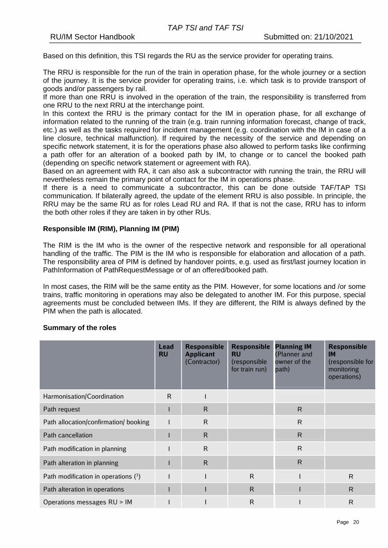
Based on this definition, this TSI regards the RU as the service provider for operating trains. The RRU is responsible for the run of the train in operation phase, for the whole journey or a section of the journey. It is the service provider for operating trains, i.e. which task is to provide transport of goods and/or passengers by rail. If more than one RRU is involved in the operation of the train, the responsibility is transferred from one RRU to the next RRU at the interchange point. In this context the RRU is the primary contact for the IM in operation phase, for all exchange of information related to the running of the train (e.g. train running information forecast, change of track, etc.) as well as the tasks required for incident management (e.g. coordination with the IM in case of a line closure, technical malfunction). If required by the necessity of the service and depending on specific network statement, it is for the operations phase also allowed to perform tasks like confirming a path offer for an alteration of a booked path by IM, to change or to cancel the booked path (depending on specific network statement or agreement with RA). Based on an agreement with RA, it can also ask a subcontractor with running the train, the RRU will nevertheless remain the primary point of contact for the IM in operations phase. If there is a need to communicate a subcontractor, this can be done outside TAF/TAP TSI communication. If bilaterally agreed, the update of the element RRU is also possible. In principle, the RRU may be the same RU as for roles Lead RU and RA. If that is not the case, RRU has to inform the both other roles if they are taken in by other RUs. Responsible IM (RIM), Planning IM (PIM) The RIM is the IM who is the owner of the respective network and responsible for all operational handling of the traffic. The PIM is the IM who is responsible for elaboration and allocation of a path. The responsibility area of PIM is defined by handover points, e.g. used as first/last journey location in PathInformation of PathRequestMessage or of an offered/booked path. In most cases, the RIM will be the same entity as the PIM. However, for some locations and /or some trains, traffic monitoring in operations may also be delegated to another IM. For this purpose, special agreements must be concluded between IMs. If they are different, the RIM is always defined by the PIM when the path is allocated. Summary of the roles
Lead RU
Responsible Applicant (Contractor)
Responsible RU (responsible for train run)
Planning IM (Planner and owner of the path)
Responsible IM (responsible for monitoring operations)
Harmonisation/Coordination R I
Path request I R R
Path allocation/confirmation/ booking I R R
Path cancellation I R R
Path modification in planning I R R
Path alteration in planning I R R
Path modification in operations (1) I I R I R
Path alteration in operations I I R I R
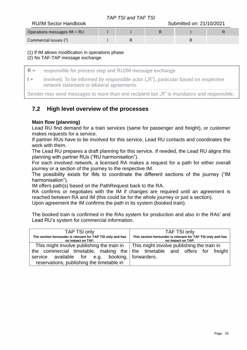
Operations messages RU > IM I I R I R
TAP TSI and TAF TSI RU/IM Sector Handbook Submitted on: 21/10/2021
Page 20
Operations messages IM > RU I I R I R
Commercial issues (2) I R R
(1) If IM allows modification in operations phase (2) No TAF-TAP message exchange
R = responsible for process step and RU/IM message exchange I = involved. To be informed by responsible actor („R“), particular based on respective
network statement or bilateral agreements
Sender may send messages to more than one recipient but „R“ is mandatory and responsible.
7.2 High level overview of the processes
Main flow (planning) Lead RU find demand for a train services (same for passenger and freight), or customer makes requests for a service. If partner RUs have to be involved for this service, Lead RU contacts and coordinates the work with them. The Lead RU prepares a draft planning for this service. If needed, the Lead RU aligns this planning with partner RUs (“RU harmonisation”). For each involved network, a licensed RA makes a request for a path for either overall journey or a section of the journey to the respective IM. The possibility exists for IMs to coordinate the different sections of the journey (“IM harmonisation”). IM offers path(s) based on the PathRequest back to the RA. RA confirms or negotiates with the IM if changes are required until an agreement is reached between RA and IM (this could be for the whole journey or just a section). Upon agreement the IM confirms the path in its system (booked train).
The booked train is confirmed in the RAs system for production and also in the RAs’ and Lead RU’s system for commercial information.
TAP TSI only
The section hereunder is relevant for TAP TSI only and has no impact on TAF.
TAF TSI only This section hereunder is relevant for TAF TSI only and has
no impact on TAP.
This might involve publishing the train in This might involve publishing the train in the commercial timetable, making the the timetable and offers for freight service available for e.g. booking, forwarders.
reservations, publishing the timetable in
TAP TSI and TAF TSI RU/IM Sector Handbook Submitted on: 21/10/2021
Page 21
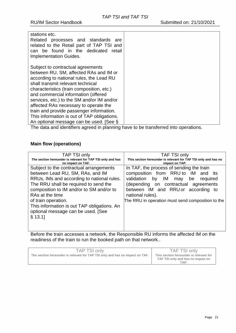
stations etc. Related processes and standards are related to the Retail part of TAP TSI and can be found in the dedicated retail Implementation Guides.
Subject to contractual agreements between RU, SM, affected RAs and IM or according to national rules, the Lead RU shall transmit relevant technical characteristics (train composition, etc.) and commercial information (offered services, etc.) to the SM and/or IM and/or affected RAs necessary to operate the train and provide passenger information. This information is out of TAP obligations. An optional message can be used. [See § 13.1]
The data and identifiers agreed in planning have to be transferred into operations.
Main flow (operations)
TAP TSI only The section hereunder is relevant for TAP TSI only and has
no impact on TAF.
TAF TSI only This section hereunder is relevant for TAF TSI only and has no
impact on TAP.
Subject to the contractual arrangements In TAF, the process of sending the train between Lead RU, SM, RAs, and IM composition from RRU to IM and its RRUs, IMs and according to national rules. The RU
validation by IM may be required The RRU shall be required to send the actual train
(depending on contractual agreements composition to IM and/or to SM and/or to from RU to SM
between IM and RRU or according to RAs at the time national rules).
TT
of train operation. The RRU in operation must send composition to the next RRU before interchange point. This information is out TAP obligations. An
optional message can be used. [See
§ 13.1]
Before the train accesses a network, the Responsible RU informs the affected IM on the readiness of the train to run the booked path on that network..
TAP TSI only
The section hereunder is relevant for TAP TSI only and has no impact on TAF.
TAF TSI only This section hereunder is relevant for
TAF TSI only and has no impact on TAP.
TAP TSI and TAF TSI RU/IM Sector Handbook Submitted on: 21/10/2021
Page 22
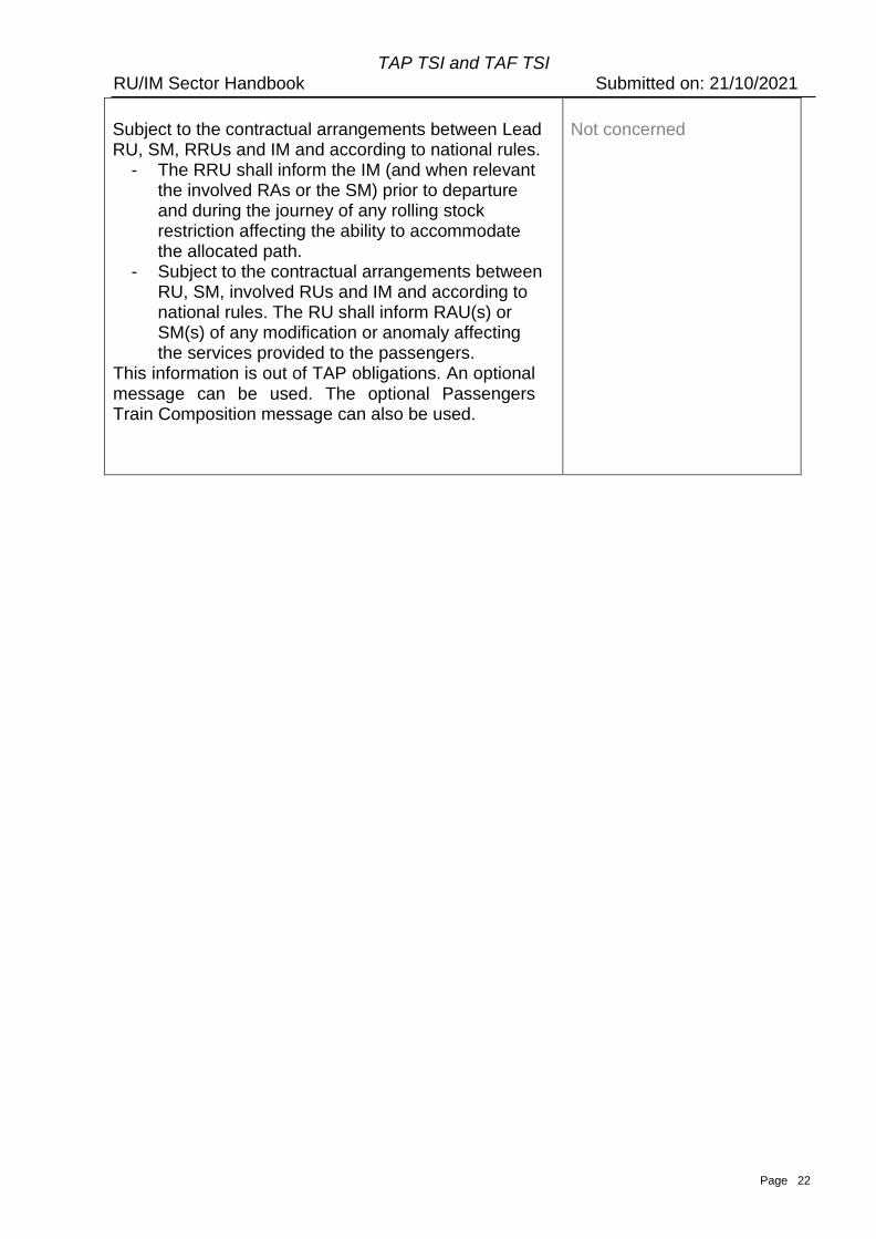
Subject to the contractual arrangements between Lead RU, SM, RRUs and IM and according to national rules.
- The RRU shall inform the IM (and when relevant the involved RAs or the SM) prior to departure and during the journey of any rolling stock restriction affecting the ability to accommodate the allocated path.
- Subject to the contractual arrangements between RU, SM, involved RUs and IM and according to national rules. The RU shall inform RAU(s) or SM(s) of any modification or anomaly affecting the services provided to the passengers.
This information is out of TAP obligations. An optional message can be used. The optional Passengers Train Composition message can also be used.
Not concerned
TAP TSI and TAF TSI RU/IM Sector Handbook Submitted on: 21/10/2021
Page 23
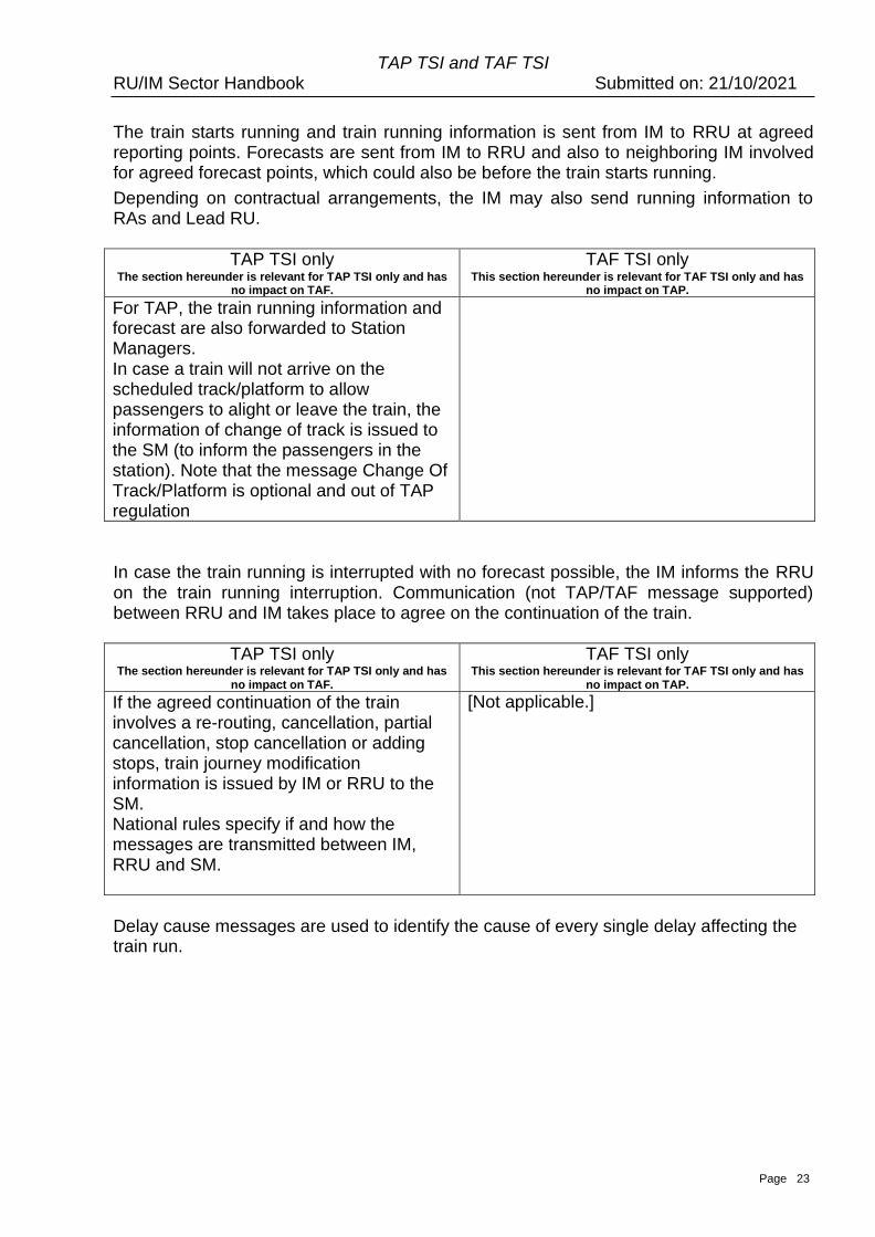
The train starts running and train running information is sent from IM to RRU at agreed reporting points. Forecasts are sent from IM to RRU and also to neighboring IM involved for agreed forecast points, which could also be before the train starts running.
Depending on contractual arrangements, the IM may also send running information to RAs and Lead RU.
TAP TSI only
The section hereunder is relevant for TAP TSI only and has no impact on TAF.
TAF TSI only This section hereunder is relevant for TAF TSI only and has
no impact on TAP.
For TAP, the train running information and forecast are also forwarded to Station Managers. In case a train will not arrive on the scheduled track/platform to allow passengers to alight or leave the train, the information of change of track is issued to the SM (to inform the passengers in the station). Note that the message Change Of Track/Platform is optional and out of TAP regulation
In case the train running is interrupted with no forecast possible, the IM informs the RRU on the train running interruption. Communication (not TAP/TAF message supported) between RRU and IM takes place to agree on the continuation of the train.
TAP TSI only
The section hereunder is relevant for TAP TSI only and has no impact on TAF.
TAF TSI only This section hereunder is relevant for TAF TSI only and has
no impact on TAP.
If the agreed continuation of the train involves a re-routing, cancellation, partial cancellation, stop cancellation or adding stops, train journey modification information is issued by IM or RRU to the SM. National rules specify if and how the messages are transmitted between IM, RRU and SM.
[Not applicable.]
Delay cause messages are used to identify the cause of every single delay affecting the train run.

TAP TSI and TAF TSI RU/IM Sector Handbook Submitted on: 21/10/2021
Page 24
TAP TSI only The section hereunder is relevant for TAP TSI only and has
no impact on TAF.
TAF TSI only This section hereunder is relevant for TAF TSI only and has
no impact on TAP.
The train running information and delay causes are used for passenger information, passenger rights handling and performance regimes.
The delay causes are used to inform the customer and for performance analysis.
Page 41
TAP TSI and TAF TSI RU/IM Sector Handbook Submitted on: 21/10/2021
8. Objects Identifiers
8.1 Introduction
The aim is to have a unique ID for all objects over their complete lifecycle. The lifecycle
starts with the planning phase until the phase of accounting.
Identifiers in the messages for TAF as set out in Regulation (EC) No 62/2006 replaced
by the Regulation (EU) 1305/2014 in 2014 and amended by the Regulation (EU)
2021/541 in 2021 and TAP as set out in Commission Regulation (EU) No 454/2011 (as
amended by Commission Regulation (EU) No 1273/2013) as well as further industry
needs have been analysed and are specified hereafter.
The problems of the identification of trains have been an issue since the early days of the
railways. This can be borne out by the considerable amount of time it has taken to
complete.
During the analysis of the message exchange in TAF/TSI and the existing international
systems it became apparent that identifiers for almost all of the elements involved in the
transport process are needed. Today’s identifiers (and also the operational train number,
in the further text the abbreviation is used: OTN) are not able to cope with the new
business processes. More precisely, all IMs and RUs use some form of train number or
train description to identify their trains to operational staff. Depending on the country this
code can be used to perform a number of different tasks. This can include information
such as a speed of train, priority, route, direction, running order, timetable and some
special needs (such as exceptional loads or hazardous goods). If this information
changes the train’s number (OTN) must also be changed. While the majority of trains will
keep the same number for their entire journey this can often make it worse for the
occasion where the number is changed as the company procedures for handling the
changes are “ad hoc”. That’s why the train could be lost.
8.2 Solution guideline for the industry
The intentions of the industry are:
1. To create and develop the recommendations and specifications for the coding of Train
ID and the other TSI identifiers
2. To find a solution for medium and long term
8.2.1 Business environment (background)
The solution is based on the available documents from TAF/TSI regulation 62/2006
replaced by regulation 1305/2014 amended by regulation 2021/541, TAP/TSI regulation
454/2011, and the results of the other TAF/TSI working groups showing that one of the
key elements required for the majority of the message types is a “Unique Identifier” that
relates to the train from the business perspective and the link to the path can be managed
Page 42
TAP TSI and TAF TSI RU/IM Sector Handbook Submitted on: 21/10/2021
in a standardized way.
It does not take into account any newer developments of regulations, e.g. the
regulation (EU) 913/2010.
In principal the solutions have been designed to be flexible to allow it to be used to meet
new regulations as well.
Identifiers in the messages for TAF/TAP and further industry needs have been analysed
and are represented in this chapter.
Important note: Both ERTMS/ETCS and GSM-R remain untouched by the proposed
solution.
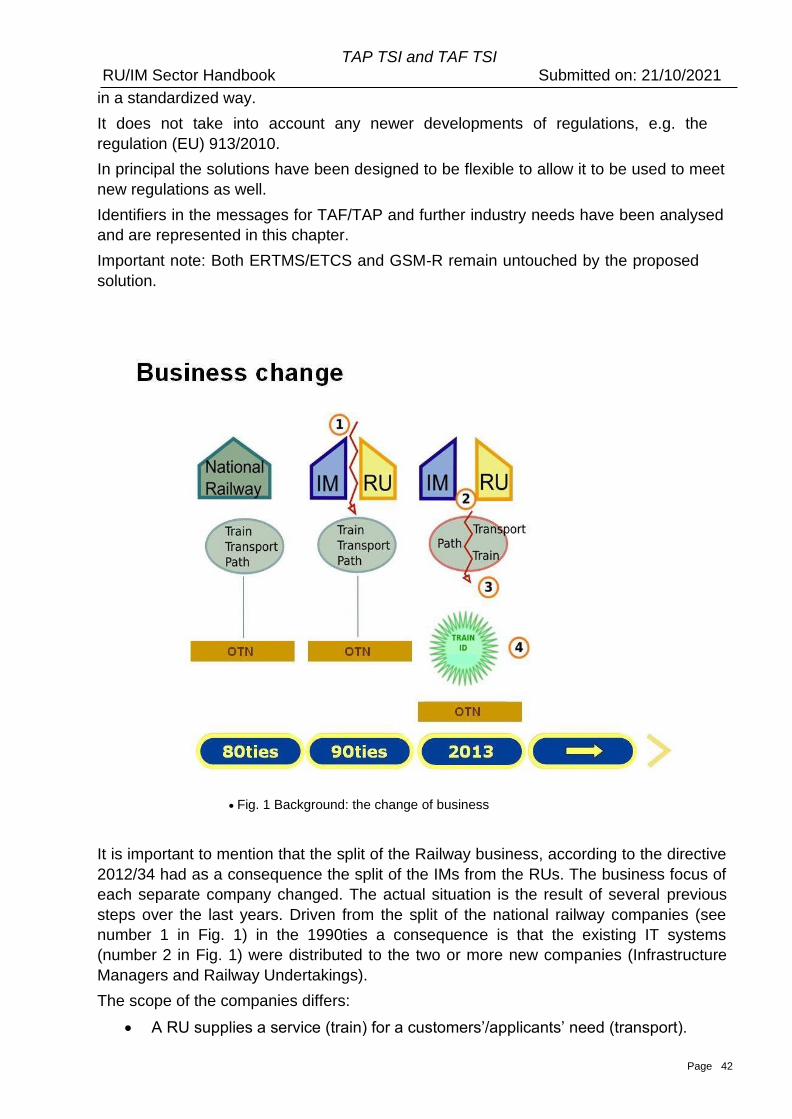
• Fig. 1 Background: the change of business
It is important to mention that the split of the Railway business, according to the directive
2012/34 had as a consequence the split of the IMs from the RUs. The business focus of
each separate company changed. The actual situation is the result of several previous
steps over the last years. Driven from the split of the national railway companies (see
number 1 in Fig. 1) in the 1990ties a consequence is that the existing IT systems
(number 2 in Fig. 1) were distributed to the two or more new companies (Infrastructure
Managers and Railway Undertakings).
The scope of the companies differs:
• A RU supplies a service (train) for a customers’/applicants’ need (transport).
Page 43
TAP TSI and TAF TSI RU/IM Sector Handbook Submitted on: 21/10/2021
• An IM responsibility is to manage the capacity of its network (path).
Together with the split of the companies and the separation of the systems new
processes have been developed to cope with the new situation. These processes are
based on new (separated) data objects “Path” and “Train” (number 3 in Fig. 1). In former
times a data object “Trainpath” has been used in the systems. The consequence was the
need to separate into two objects: “Train” and “Path”. In the communication between
RUs, RU and IM, IMs these separated data objects must be uniquely identified (number 4
in Fig. 1). A new data model has been developed to deal with the changed situation
described in TAF/TAP regulation and the results of the other working groups.
The new model needs (new) identifiers. Those identifiers are described in this chapter of
the Sector Handbook.
8.2.2 Requirements
When establishing this concept, the following high-level requirements have been taken
into account:
1. Need for identification:
A new model for identifiers is needed for some of the existing objects in the railway
business.
2. Coverage of the whole business process
The future solution must support all existing railway business processes starting with
the end customer request for transportation until the accounting phase
3. Compliance with the results of the other working groups
The solution must be in compliance with TAF TSI and TAP TSI (for RU/IM
exchanges) regulations and the changes coming out from the TAF TSI and
TAP TSI working groups or telematics expert groups.
4. Existing identifiers remain
Given the need to maintain compatibility with existing systems and infrastructure it
was concluded that the usage of the operational train number must be kept “as is”.
Each IM would set it in accordance with its national rules and safety standards.
International trains could continue to follow UIC leaflets 419-1&2.
The detailed requirements analysis had as a consequence the following demands:
i. The identifier must be unique for the planning phase.
ii. The identifier must be unique for the operational phase.
iii. The identifier must work for both domestic and international trains.
iv. The identifier must support splitting and joining of trains.
v. The identifier of the train must remain the same when a train is diverted, delayed or
disrupted in any way.
vi. The operational train number should be retained as used today, e.g. in operations
within both IMs and RUs. (In the Annex 8.1 (OTN Framework), there is an
explanation of the usage of OTN in TAF/TAP messages, related to the TAF/TAP
Page 44
TAP TSI and TAF TSI RU/IM Sector Handbook Submitted on: 21/10/2021
objects and identifiers).
vii. The identifier (in combination with the new business rules for the implementation of
the Train ID) must allow operational train number to be changed in transit and
guarantee traceability.
viii. There must be a separate path identity, controlled by the IM.
ix. The identifier must be unique on its own. It doesn’t rely on data to meet this
requirement.
x. The format of the core part of the reference is decided by its creator (subject to
the rules set out in this document).
xi. There should be as few rules as possible about format for not constraining the
future use of the reference.
xii. The identifier has to cover the whole lifecycle of the referenced object.
8.2.3 Objects
It has been agreed on the level of the working groups which produced this result to use
the data analysis techniques developed by the IT industry for designing databases.
Computer systems can be made to do very difficult things but only if they are designed
correctly. Computer systems often have to deal with complex pieces of information. The
analysis process involves understanding the data in its simplest forms and the
relationships between the different bits of information. In this process the “Data” is
normally information about something. This something is called an “Object”. In the IT
industry this may also be called an “Entity”, a “Class” or a “Class Object”. In databases it
may be called a table. For consistency in this document it will always be called an
“Object”. In order to keep track of objects, an identity (ID) has to be defined for them. The
ID needs to be a name or code for each time an object occurs which “uniquely” identifies
each instance of an object.
The main “Objects” identified in this chapter are:
a. Train (including Reference TRID with Reference Calendar)
b. Route
c. Path
d. Path Request
e. Case Reference
The Path is defined according to TAF TSI (regulation 1305/2014 as amended by regulation
2021/541) or TAP TSI (regulation 454/2011) : path means the infrastructure capacity
needed to run a train between two places over a given period (route defined in time and
space).
The Train is a more complex object to define with its different faces (physical set of
vehicles, entity moving on track that can change the composition during the journey or be
rerouted, seamless journey from one point to another, term used by RU to define a
Page 45
TAP TSI and TAF TSI RU/IM Sector Handbook Submitted on: 21/10/2021
traffic/Transport service etc.).
In this document focused on RU/IM communications, the Train is defined according to OPE
TSI (regulation 2019/773) : a train is defined as (a) traction unit(s) with or without coupled
railway vehicles with train data available operating between two or more defined points.
The LRU/RA/RRUs inside their own IT systems should also consider the ‘Commercial
Train” that could be defined as a seamless offer of transport for the passengers or freight
loads between origin and destination of the ‘commercial train’, including intermediate stops,
meaning a traffic/Transport service. This concept and the link with the ‘operation production
train’ are not developed in this document.
The objects are used in the chain of processes from train creation and harmonization via
path request and path allocation (yearly timetable to short term path request) until the end
of operation, and even for post operation tasks (e.g. statistics, accounting) :
• The LRU/RA decides to offer a ‘train service’ ensured by a ‘family of trains’ with
similar (but not necessary identical) characteristics (train technical data, timings,
commercial data if relevant, etc.) :
▪ Significant number of trains have same characteristics (running on the same line
and in the same direction)
▪ Some trains can slightly differ (composition, stops, timings, etc.)
▪ On a given day of the Reference Calendar only one train of the same family will
run
▪ Same LRU, cooperating RA/RRUs could be different
▪ It’s up to the LRU to define if it uses the concept of train family and the trains
belonging to the same family
• The LRU/RA defines the ‘family of trains’ during the RU harmonisation phase and
describes the ‘family of trains’ in its own IT system with the useful characteristics,
usually :
- Information for Path Allocation and Train Operation (‘RU/IM information’) ;
- Customer-oriented information ;
- Commercial and retail information ;
- Etc.
• At the end of the RU harmonisation phase, each LRU/RA sends for the first time to
the concerned IM the Path Request which contains :
- An identifier, called ‘Reference TRID’, unique and unchanged during the entire
lifecycle of the Train, used also to trace the objects (Route, Path Request, Path,
Case Reference) and messages attached to the Train during its entire lifecycle ;
- The direct identifiers that are mandatory (ROID, PRID),
- Other related identifiers are optional (CRID and PAID as related identifier) ;
- The relevant information to allow the IMs to design the path and coordinate
between them, namely the Route (for an overview of entire train’s journey) and
details for requested Path in a given network as part of the train’s journey.
• When coordinated , each IM sends the path offer(s) as answer to the requesting RA.
Page 46
TAP TSI and TAF TSI RU/IM Sector Handbook Submitted on: 21/10/2021
There can be more than one Path as answer to a Path Request.
• At the end of the path allocation process, if necessary after a dialogue between RAs
and IMs for adjustment, the path is confirmed by the RU and booked by the IM.
• The Train, which characteristics are if relevant updated in the LRU/RA/RRU IT
system according to the booked paths and considered as reliable, can then be used
by the LRU/RA/RRU for further duties :
- Rostering of ressources ;
- Client information ;
- Retail ;
- Etc.
• The ReferenceTRID, completed by the Reference Day, identifies the Train in daily
operation and permits the tracing with the daily objects Route and (booked) Path.
8.2.3.1 Train
The train object first comes into existence at the earliest planning phase when the RA
starts to develop plans to run a train in order to offer a ‘train service’. This ‘train service’
is ensured by a ‘family of trains’ with similar (but not necessary identical) charateristics.
The Lead RU creates the identification TRID (see 8.2.4) for the train at this stage:
• The variant 00 of the TRID (called Reference TRID, see 8.2.3.6) identifies the
family of trains and will be exchanged with the IM;
• The variants 01 to ZZ identify the sub-sets of the family of trains with identical
characteristics and are used inside the LRU/RA/RRU world; ‘identical’ is meant
according to LRU/RA/RRU rules.
The object Train with its identifier is modelled in the LRU/RA/RRU own IT system
according to the duties to be performed by the LRU/RA/RRU.
The object Train is used inside the LRU/RA/RRU world and has not to be exchanged with
the IM which needs only :
• the Reference TRID variant v00 (see 8.2.3.6);
• the (planned) objects Route (see 8.2.3.2) and Path Request (see 8.2.3.4) in the path
allocation phase;
• the (daily) objects Route and Path (see 8.2.3.3) in the preparation and operation
phases linked to a (daily) ReferenceTRID (with variant v00 and Reference day).
The Lead RU will then go through a harmonisation process with all RAs involved in the
particular business case. The aim of the harmonization is to permit all involved RAs to
apply for paths to run the trains.
Regarding the aim of path request which follows the train harmonisation, the attributes of
the object Train in the LRU/RA/RRU own IT system are at least those which will be
incorporated in the Path Request message sent to the IMs:
• Train routing (geography, journey sections / locations, timing, indication of
responsible RU and IM)
Page 47
TAP TSI and TAF TSI RU/IM Sector Handbook Submitted on: 21/10/2021
• To fulfill the Path Request message sent to each IM, the locations to be defined for
the train routing shall be at least:
o origin of the train route
o border points (Handover points, Interchange points, network border points)
o destination of train route
• Train parameters (weight, length)
• Train calendar
• Start location of path elaboration defined in element
PathPlanningReferenceLocation.
To fulfill easily the Path Request message sent to each IM, it is recommended to the
LRU/RA/RRU to use in the Train modelling inside the own IT system at least the
element TrainInformation which contains the relevant information on the entire journey
(see the current TAF/TAP XSD Schema / data catalogue – see JSG web site
http://taf_jsg.info/).
Nota :
• If agreed between LRU/RA/RRU and IM, the object Train or the Full Assembled Path
(FAP) can be shared with the IM for defined use cases. Same with other
stakeholders e.g. Station Manager. That concerns usually the object Train
consolidated after path booking.
• In theory the LRU/RA/RRU can use another ID (different core element) for the Train
inside its own IT system so long the Reference TRID and the RU/IM messages are
correctly exchanged with the IM. It is nevertheless recommended to use the TRID
with same core element as in ReferenceTRID in the internal IT system of
LRU/RA/RRU.
8.2.3.2 Route
The Route is the minimum set of information on the entire journey of a planned train that
the IM needs to perform its duties (Path Coordination/Harmonisation, Path Allocation,
Path Publication, Traffic Management).
Composed by origin, handover, destination, calendar, the Route is attached to one Train.
Indeed the Route follows the lifecycle of the Train and is updated in case of modification
of origin, handover, destination or calendar. Until end of the preparation phase, the route
update is performed. When operation has started the update follows bilateral agreement.
Created by the LRU it is exchanged for the first time between LRU/RA and IM when the
Path Request message is sent from each LRU/RA to the concerned IM, via the element
TrainInformation limited to the elements origin, handover, destination and calendar (see
the current TAF/TAP XSD Schema / data catalogue).
Page 48
TAP TSI and TAF TSI RU/IM Sector Handbook Submitted on: 21/10/2021
8.2.3.3 Path
In response to Path Request(s) issued by RA, the IM will offer Path(s) or answer that no
capacity is available (see Path Request process). The IM will need to create an ID for this
Path. It may also offer a number of paths each with their own IDs.
The attributes of the Path object are:
• Geography – Journey(path) sections / locations, timing, indication of the
responsible IM
• Path parameters
• OTN for each section of path (journey)
• Calendar
Shown here is the minimum requirement from the technical point of view. The technical
details of the object Path can be found in the XSD structure (see the current TAF/TAP
XSD Schema / data catalogue) within the element PathInformation.
8.2.3.4 Path Request
In order to get a Path for a Train, the path request has to be issued. Therefore, the Path
Request is an object in its own right with a separate ID. The technical attributes of the
Path Request object are contained in the Path Request Message in the current TAF/TAP
XSD Schema / data catalogue (the message header elements which are used for all
messages in TAF/TAP are excluded from the model).
8.2.3.5 Case Reference
This object heavily depends on the agreements between the partners that exchange the
information with the means of TAF/TAP messages in the industry. The object is here
mentioned for the purpose of:
_ Umbrella for the business case: The cases where the partners want to provide an
identifier as an umbrella for the whole business case which is handled in the
process of organizing the Train, sending the Path Requests for it_ and
constructing, offering and keeping the track on Path for it.
_ Transaction scope: this identifier is used in a sequence of actions that have to be
started, processed and ended as a whole.
_ Differentiation of parallel applications: All the (re-)planning activities to be
processed in parallel have to be differentiated by using this identifier.
Therefore, the structure of this object is not further defined in this document, As
mentioned before, it rests on the agreements between the partners in the industry.
Page 49
TAP TSI and TAF TSI RU/IM Sector Handbook Submitted on: 21/10/2021
8.2.3.6 Reference TRID – Reference Calendar
i) Reference TRID
• The Reference TRID is the unique and stable identifier that ensures the link
between all objects (Train, Route, Path Request, Path) and related messages
during the entire lifecycle of these objects.
• The Reference TRID is always the variant v00 of the TRID of the family of trains.
• Consequently it is defined by the LRU.
ii) Reference Calendar
• In Preparation and Operation phase the Reference TRID is completed by a
Reference Day to ensure uniqueness : TRIDv00 + Reference Day.
• The set of Reference Days defined for the same Reference TRID constitutes the
Reference Calendar.
• Each day of the Reference Calendar is associated with one and only one train of
the ‘family of trains’ to ensure uniqueness of the daily TRIDv00 + Reference Day.
• The Reference Calendar is defined by the LRU.
iii) Offset To Reference (OTR)
• The Reference Day is commonly the Start Date of the Train. To belong to the
same family, the Reference day of a large part of the trains of the same family
commonly corresponds to the ‘requested/expected’ Start Date.
• Nevertheless it could happen that, due to slight midnight shifting, the same start
date of the (real) train corresponds to two (Reference) trains with the same
Reference TRID. E.g. all trains of the family of trains normally start at 00h10 each
day, but on Monday one train starts at 00h10 and another at 23h50 due to slight
shifting of the train of Tuesday to Monday before midnight. If using the actual start
date instead of the initial start date of Reference Train, this situation would lead to
a double TRID for the same date (Monday), which is not possible.The problem is
avoided if the original Reference Day is always kept : the train on Monday 23h50
(actual date) keeps its Reference start date on Tuesday i.e. the Reference Day
remains compliant with the day of the referenced train of train’s family.
• The gap/shift between the Reference Day (to be added to TRIDv00 to ensure
uniqueness in operation for daily objects and in mind for calendar objects) and the
‘requested/expected’ or actual Start Date of train/route/path request/path defines
the Offset To Reference (OTR).
• The OTR indicates more widely the gap between the Reference Calendar and the
Planned Calendar of an object Train, Route, Path Request, Path (we consider not
the complete Reference Calendar, but only the subset related to the respective
Planned Calendar).
• In other words, considering the Planned Calendar with its OTR of any object Train,
Route, Path Request and Path, the (subset of) Reference Calendar can
Page 50
TAP TSI and TAF TSI RU/IM Sector Handbook Submitted on: 21/10/2021
immediately be determined.
• The same rule applies for the daily object : considering the start date in daily
identifier of any object Train, Route, Path request and Path, with the OTR of the
object, the corresponding start date of the Reference Train can immediately be
determined. Vice versa, when receiving a message with a daily Reference Train
ID, the corresponding daily objects for each stakeholders can be unambiguously
determined.
• The very common case is OTR = 0 (Reference Calendar = Planned Calendar) :
- PlannedCalendar = 10/02 to 20/02 and OTR = 0 means that corresponding
Reference Calendar = 10/02 to 20/02
• It can be negative (Planned Calendar earlier than Reference Calendar as in the
example), the only expected negative value is -1 :
- PlannedCalendar = 10/02 to 20/02 and OTR = -1 means that corresponding
Reference Calendar = 11/02 to 21/02
• It can be positive (Planned Calendar later than Reference Calendar), especially for
the last paths of long journey train :
- PlannedCalendar = 10/02 to 20/02 and OTR = 1 means that corresponding
Reference Calendar = 09/02 to 19/02
• The OTR is part of the element PlannedCalendar which is used in the element
TrainInformation and PathInformation.
• The Reference Calendar is shared indirectly with the IM via the Planned Calendar
and the OTR of the object Route (TrainInformation), Path Request and Path
(PathInformation). Usually the Reference Calendar is sum of Planned Calendars
inclusive its OTR of currenly booked paths linked to Reference TRID (without
intermediate path cancellations). But a partial match can happen as well if path
requests or paths don't exist for all Reference days.
iv) Reference TRID Sub-Calendar
• To allow consistency check the subset of the Reference Calendar related to the
PlannedCalendar and OTR in PathInformation is also exchanged between RUs
and IMs in the element ReferenceTRIDSubCalendar.
• In other words the PlannedCalendar+OTR in PathInformation are the same days
than in element ReferenceTRIDSubCalendar.
• The element ReferenceTRIDSubCalendar is present in following messages and
corresponds to the PlannedCalendar+OTR in the element PathInformation :
▪ PathRequestMessage – at message level,
▪ PathDetailsMessage – at message level,
▪ PathCoordinationMessage – at message level,
▪ ObjectInfoMessage – at message level for the concerned object,
▪ UpdateLinkMessage – in element Operation.
• The element ReferenceTRIDSubCalendar is present in following messages and
corresponds to the PlannedCalendar+OTR in the element AffectedSection :
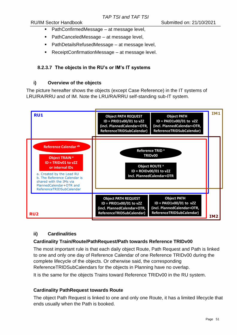
Page 51
TAP TSI and TAF TSI RU/IM Sector Handbook Submitted on: 21/10/2021
▪ PathConfirmedMessage – at message level,
▪ PathCanceledMessage – at message level,
▪ PathDetailsRefusedMessage – at message level,
▪ ReceiptConfirmationMessage – at message level.
8.2.3.7 The objects in the RU’s or IM’s IT systems
i) Overview of the objects
The picture hereafter shows the objects (except Case Reference) in the IT systems of
LRU/RA/RRU and of IM. Note the LRU/RA/RRU self-standing sub-IT system.
ii) Cardinalities
Cardinality Train/Route/PathRequest/Path towards Reference TRIDv00
The most important rule is that each daily object Route, Path Request and Path is linked
to one and only one day of Reference Calendar of one Reference TRIDv00 during the
complete lifecycle of the objects. Or otherwise said, the corresponding
ReferenceTRIDSubCalendars for the objects in Planning have no overlap.
It is the same for the objects Trains toward Reference TRIDv00 in the RU system.
Cardinality PathRequest towards Route
The object Path Request is linked to one and only one Route, it has a limited lifecycle that
ends usually when the Path is booked.
RU1 IM1
RU2IM2
Object TRAIN a
ID = TRIDv01 to vZZor internal IDs
Object PATH REQUESTID = PRID1v00/01 to vZZ
(incl. PlannedCalendar+OTR,ReferenceTRIDSubCalendar)
Reference TRID a
TRIDv00
Reference Calendar ab
Object PATHID = PAID1v00/01 to vZZ
(incl. PlannedCalendar+OTR,ReferenceTRIDSubCalendar)
Object ROUTE a
ID = ROIDv00/01 to vZZIncl. PlannedCalendar+OTR
a. Created by the Lead RUb. The Reference Calendar isshared with the IMs via PlannedCalendar+OTR and ReferenceTRIDSubCalendar
Object PATH REQUESTID = PRID1v00/01 to vZZ
(incl. PlannedCalendar+OTR,ReferenceTRIDSubCalendar)
Object PATHID = PAID1v00/01 to vZZ
(incl. PlannedCalendar+OTR,ReferenceTRIDSubCalendar)
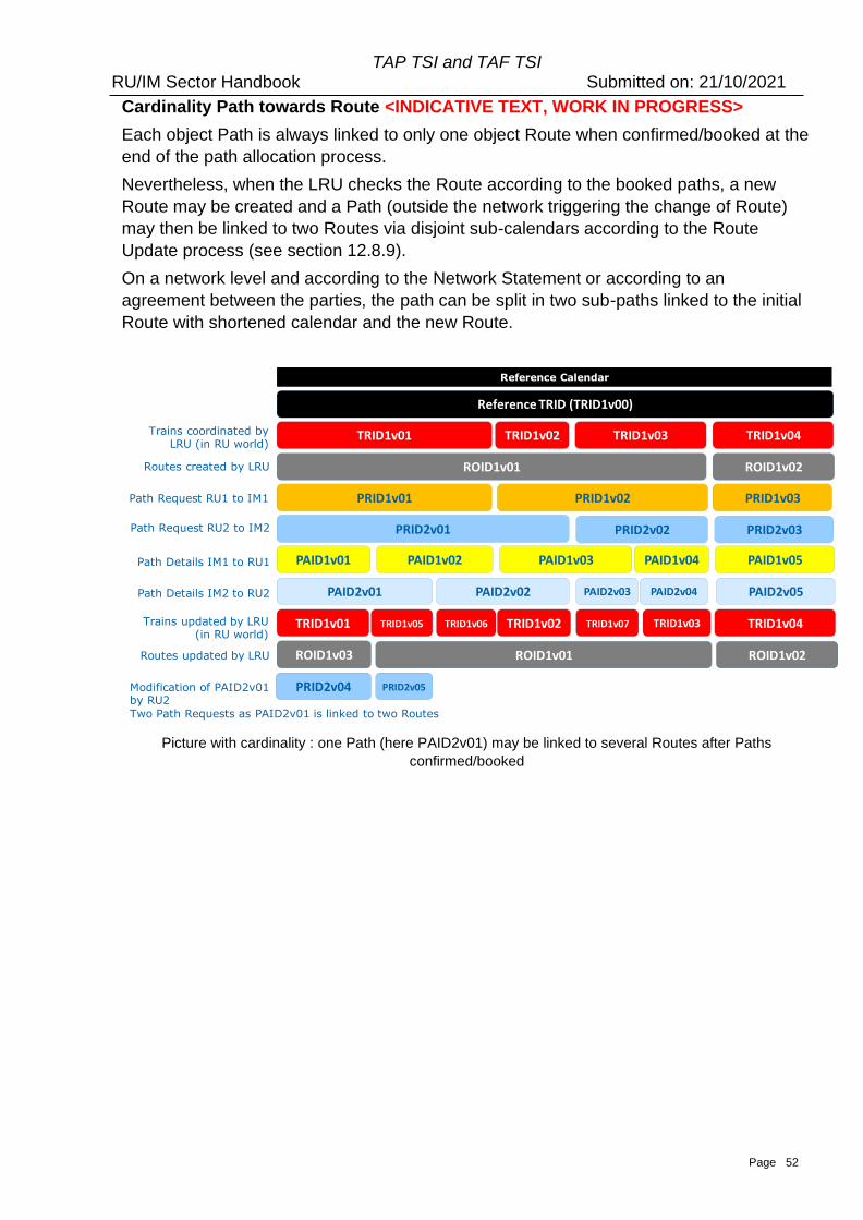
Page 52
TAP TSI and TAF TSI RU/IM Sector Handbook Submitted on: 21/10/2021
Cardinality Path towards Route <INDICATIVE TEXT, WORK IN PROGRESS>
Each object Path is always linked to only one object Route when confirmed/booked at the
end of the path allocation process.
Nevertheless, when the LRU checks the Route according to the booked paths, a new
Route may be created and a Path (outside the network triggering the change of Route)
may then be linked to two Routes via disjoint sub-calendars according to the Route
Update process (see section 12.8.9).
On a network level and according to the Network Statement or according to an
agreement between the parties, the path can be split in two sub-paths linked to the initial
Route with shortened calendar and the new Route.
Picture with cardinality : one Path (here PAID2v01) may be linked to several Routes after Paths
confirmed/booked
Reference TRID (TRID1v00)
ROID1v01
PRID1v01
ROID1v02
PRID1v02
PAID1v03
PRID1v03
PAID1v01 PAID1v02 PAID1v04
PRID2v01 PRID2v02 PRID2v03
PAID2v01 PAID2v02 PAID2v03
PAID1v05
PAID2v05PAID2v04
Reference Calendar
TRID1v01 TRID1v02 TRID1v03 TRID1v04
TRID1v01 TRID1v02 TRID1v07 TRID1v03 TRID1v04TRID1v05 TRID1v06
ROID1v01ROID1v03 ROID1v02
PRID2v04 PRID2v05
Trains coordinated by LRU (in RU world)
Routes created by LRU
Path Request RU1 to IM1
Path Request RU2 to IM2
Path Details IM1 to RU1
Path Details IM2 to RU2
Trains updated by LRU (in RU world)
Routes updated by LRU
Modification of PAID2v01by RU2
Two Path Requests as PAID2v01 is linked to two Routes
Page 53
TAP TSI and TAF TSI RU/IM Sector Handbook Submitted on: 21/10/2021
8.2.3.8 The difference of IDs for objects in planning and operational phase
When a RU creates a train or a route and an IM a path it may be for a single day or a
number of days. In the planning phase the object (train, route, path request and path) will
have a calendar as an attribute to indicate which days it operates that means the object is
valid. However, when the object is used in operation each object (train, route and path) on
each day needs a unique ID for only one day.
For this reason, the objects and the format of their IDs come in two forms:
• The Planning object (with the ID of the planning object without the element StartDate).
The Planning object (calendar object) train, route, path request or path with its
PlannedCalendar inclusive OTR must be consistent and unique to the Reference
calendar of ReferenceTRID in compliance with the rules and requirements mentioned
above.
and
• The Daily (operational) object (with the ID of the planned object enlarged and
made unique with the element StartDate indicating the Reference Day).
The Daily Reference TRID is composed by the Reference TRID (TRIDv00) completed
by the Reference Day (as described in 8.2.3.6).
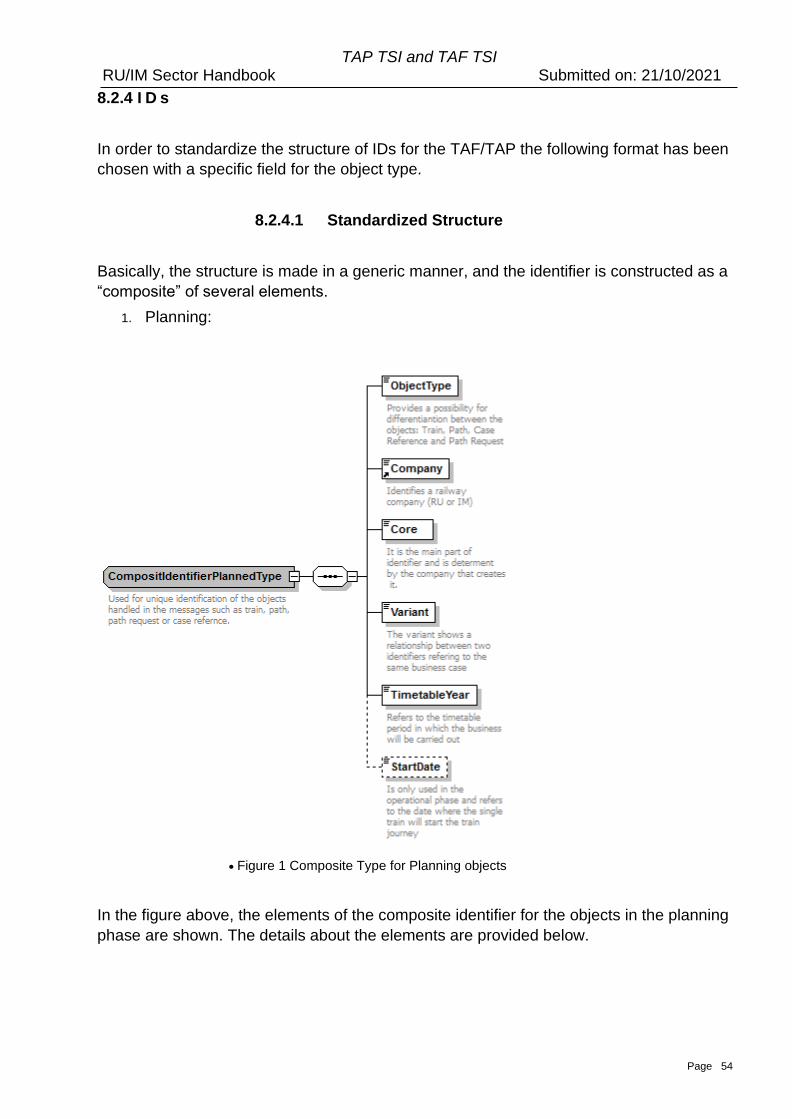
Page 54
TAP TSI and TAF TSI RU/IM Sector Handbook Submitted on: 21/10/2021
8.2.4 I D s
In order to standardize the structure of IDs for the TAF/TAP the following format has been
chosen with a specific field for the object type.
8.2.4.1 Standardized Structure
Basically, the structure is made in a generic manner, and the identifier is constructed as a
“composite” of several elements.
1. Planning:
• Figure 1 Composite Type for Planning objects
In the figure above, the elements of the composite identifier for the objects in the planning
phase are shown. The details about the elements are provided below.
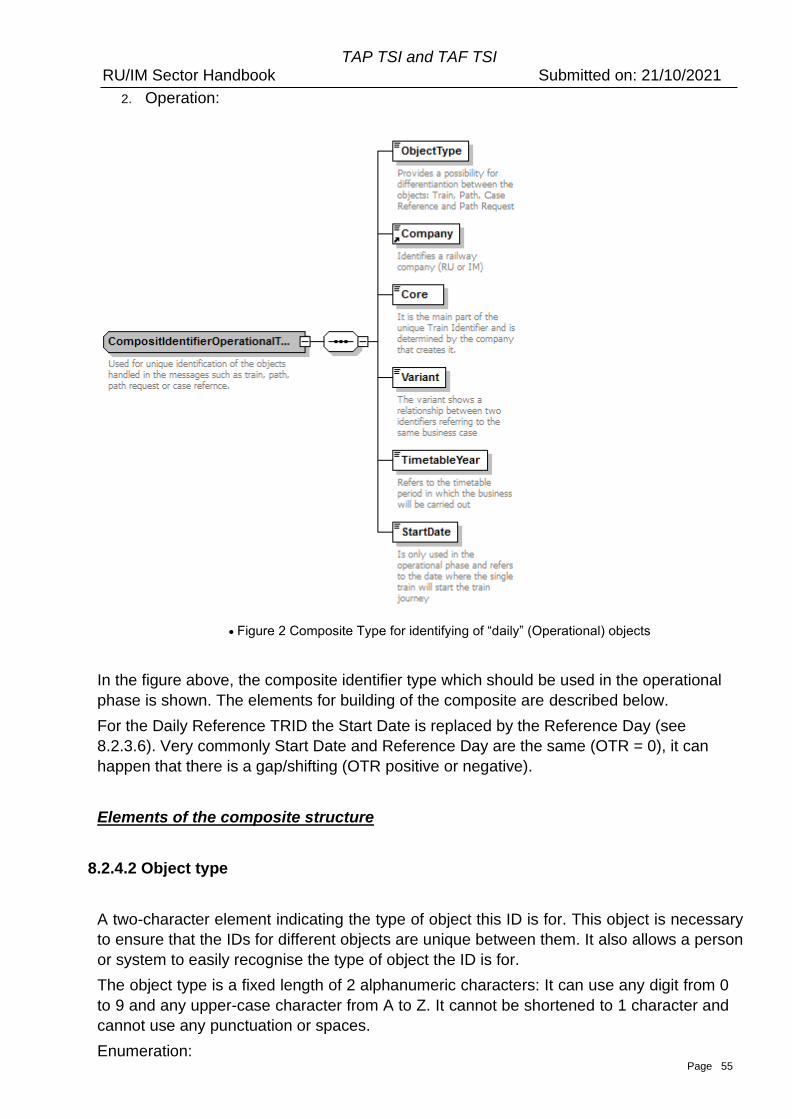
Page 55
TAP TSI and TAF TSI RU/IM Sector Handbook Submitted on: 21/10/2021
2. Operation:
• Figure 2 Composite Type for identifying of “daily” (Operational) objects
In the figure above, the composite identifier type which should be used in the operational
phase is shown. The elements for building of the composite are described below.
For the Daily Reference TRID the Start Date is replaced by the Reference Day (see
8.2.3.6). Very commonly Start Date and Reference Day are the same (OTR = 0), it can
happen that there is a gap/shifting (OTR positive or negative).
Elements of the composite structure
8.2.4.2 Object type
A two-character element indicating the type of object this ID is for. This object is necessary
to ensure that the IDs for different objects are unique between them. It also allows a person
or system to easily recognise the type of object the ID is for.
The object type is a fixed length of 2 alphanumeric characters: It can use any digit from 0
to 9 and any upper-case character from A to Z. It cannot be shortened to 1 character and
cannot use any punctuation or spaces.
Enumeration:
Page 56
TAP TSI and TAF TSI RU/IM Sector Handbook Submitted on: 21/10/2021
• TR for Train
• RO for Route
• PA for Path
• PR for Path Request
• CR for Case Reference
The object types are managed by the SMO to ensure their correct application.
In the XSD schema, it looks as follows:
<xs:element name="ObjectType">
<xs:annotation>
<xs:documentation>Provides a possibility for differentiation between the objects: Train (TR), Route
(RO), Path (PA), Case Reference (CR) and Path Request (PR)</xs:documentation>
</xs:annotation>
<xs:simpleType>
<xs:restriction base="xs:string">
<xs:minLength value="2"/>
<xs:maxLength value="2"/>
<xs:pattern value="[0-9A-Z]{2}"/>
<xs:enumeration value="TR"/>
<xs:enumeration value="RO"/>
<xs:enumeration value="PA"/>
<xs:enumeration value="CR"/>
<xs:enumeration value="PR"/>
</xs:restriction>
</xs:simpleType>
</xs:element>
8.2.4.3 Company
A four-character element is indicating the company who created the object. By prefixing
all IDs with the company ID, it allows the company to use its own code and still ensure the
ID is unique. The company codes to be used will be the current standard set down by the
TAF/TAP. These codes are made up of only numbers at the moment. From 01/01/2026
the allocated CompanyCodes could contain figures and/or letters. The transitional period
for TAF and TAP stakeholders to adapt their IT system to handle Company Codes on
alphanumerical format lasts until 31/12/2025.
In the XSD schema, it looks as follows:
<xs:simpleType name="CompanyCode">
<xs:annotation>
<xs:documentation>Identifies the RU, IM or other company involved in the Rail
Transport Chain</xs:documentation>
</xs:annotation>
<xs:restriction base="String4-4">
<xs:pattern value="[0-9A-Z]{4}"/>
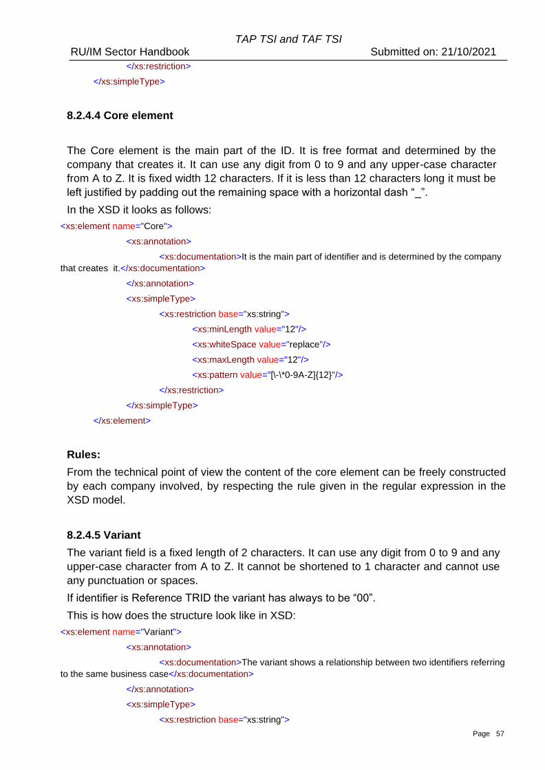
Page 57
TAP TSI and TAF TSI RU/IM Sector Handbook Submitted on: 21/10/2021
</xs:restriction>
</xs:simpleType>
8.2.4.4 Core element
The Core element is the main part of the ID. It is free format and determined by the
company that creates it. It can use any digit from 0 to 9 and any upper-case character
from A to Z. It is fixed width 12 characters. If it is less than 12 characters long it must be
left justified by padding out the remaining space with a horizontal dash “_”.
In the XSD it looks as follows:
<xs:element name="Core">
<xs:annotation>
<xs:documentation>It is the main part of identifier and is determined by the company
that creates it.</xs:documentation>
</xs:annotation>
<xs:simpleType>
<xs:restriction base="xs:string">
<xs:minLength value="12"/>
<xs:whiteSpace value="replace"/>
<xs:maxLength value="12"/>
<xs:pattern value="[\-\*0-9A-Z]{12}"/>
</xs:restriction>
</xs:simpleType>
</xs:element>
Rules:
From the technical point of view the content of the core element can be freely constructed
by each company involved, by respecting the rule given in the regular expression in the
XSD model.
8.2.4.5 Variant
The variant field is a fixed length of 2 characters. It can use any digit from 0 to 9 and any
upper-case character from A to Z. It cannot be shortened to 1 character and cannot use
any punctuation or spaces.
If identifier is Reference TRID the variant has always to be “00”.
This is how does the structure look like in XSD:
<xs:element name="Variant">
<xs:annotation>
<xs:documentation>The variant shows a relationship between two identifiers referring
to the same business case</xs:documentation>
</xs:annotation>
<xs:simpleType>
<xs:restriction base="xs:string">
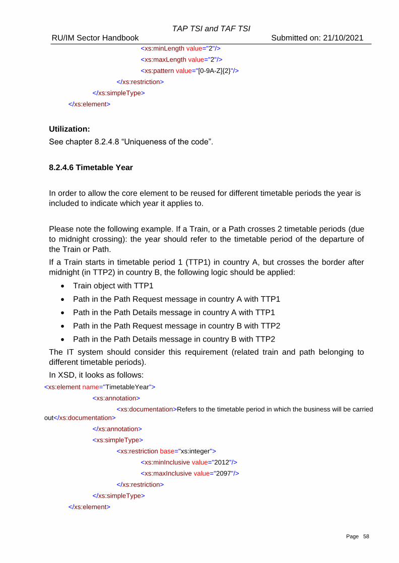
Page 58
TAP TSI and TAF TSI RU/IM Sector Handbook Submitted on: 21/10/2021
<xs:minLength value="2"/>
<xs:maxLength value="2"/>
<xs:pattern value="[0-9A-Z]{2}"/>
</xs:restriction>
</xs:simpleType>
</xs:element>
Utilization:
See chapter 8.2.4.8 “Uniqueness of the code”.
8.2.4.6 Timetable Year
In order to allow the core element to be reused for different timetable periods the year is
included to indicate which year it applies to.
Please note the following example. If a Train, or a Path crosses 2 timetable periods (due
to midnight crossing): the year should refer to the timetable period of the departure of
the Train or Path.
If a Train starts in timetable period 1 (TTP1) in country A, but crosses the border after
midnight (in TTP2) in country B, the following logic should be applied:
• Train object with TTP1
• Path in the Path Request message in country A with TTP1
• Path in the Path Details message in country A with TTP1
• Path in the Path Request message in country B with TTP2
• Path in the Path Details message in country B with TTP2
The IT system should consider this requirement (related train and path belonging to
different timetable periods).
In XSD, it looks as follows:
<xs:element name="TimetableYear">
<xs:annotation>
<xs:documentation>Refers to the timetable period in which the business will be carried
out</xs:documentation>
</xs:annotation>
<xs:simpleType>
<xs:restriction base="xs:integer">
<xs:minInclusive value="2012"/>
<xs:maxInclusive value="2097"/>
</xs:restriction>
</xs:simpleType>
</xs:element>
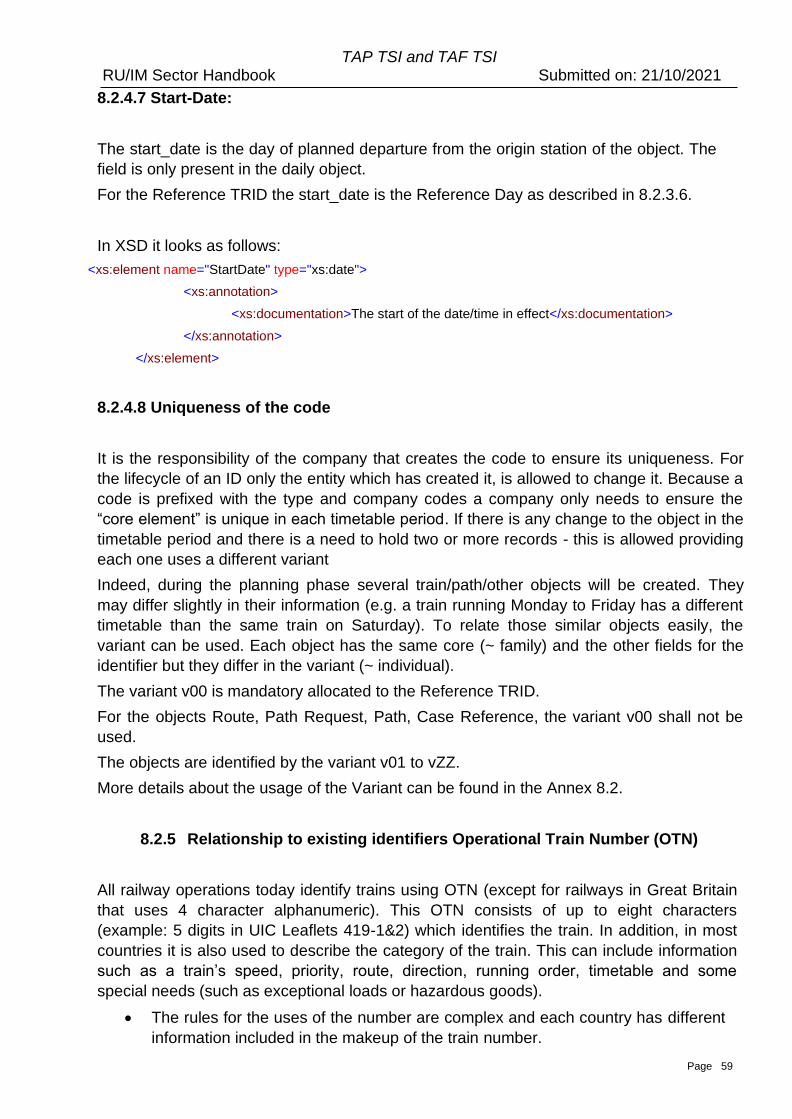
Page 59
TAP TSI and TAF TSI RU/IM Sector Handbook Submitted on: 21/10/2021
8.2.4.7 Start-Date:
The start_date is the day of planned departure from the origin station of the object. The
field is only present in the daily object.
For the Reference TRID the start_date is the Reference Day as described in 8.2.3.6.
In XSD it looks as follows:
<xs:element name="StartDate" type="xs:date">
<xs:annotation>
<xs:documentation>The start of the date/time in effect</xs:documentation>
</xs:annotation>
</xs:element>
8.2.4.8 Uniqueness of the code
It is the responsibility of the company that creates the code to ensure its uniqueness. For
the lifecycle of an ID only the entity which has created it, is allowed to change it. Because a
code is prefixed with the type and company codes a company only needs to ensure the
“core element” is unique in each timetable period. If there is any change to the object in the
timetable period and there is a need to hold two or more records - this is allowed providing
each one uses a different variant
Indeed, during the planning phase several train/path/other objects will be created. They
may differ slightly in their information (e.g. a train running Monday to Friday has a different
timetable than the same train on Saturday). To relate those similar objects easily, the
variant can be used. Each object has the same core (~ family) and the other fields for the
identifier but they differ in the variant (~ individual).
The variant v00 is mandatory allocated to the Reference TRID.
For the objects Route, Path Request, Path, Case Reference, the variant v00 shall not be
used.
The objects are identified by the variant v01 to vZZ.
More details about the usage of the Variant can be found in the Annex 8.2.
8.2.5 Relationship to existing identifiers Operational Train Number (OTN)
All railway operations today identify trains using OTN (except for railways in Great Britain
that uses 4 character alphanumeric). This OTN consists of up to eight characters
(example: 5 digits in UIC Leaflets 419-1&2) which identifies the train. In addition, in most
countries it is also used to describe the category of the train. This can include information
such as a train’s speed, priority, route, direction, running order, timetable and some
special needs (such as exceptional loads or hazardous goods).
• The rules for the uses of the number are complex and each country has different
information included in the makeup of the train number.
Page 60
TAP TSI and TAF TSI RU/IM Sector Handbook Submitted on: 21/10/2021
• In all countries the train number is used by the signaling system to route and track
the train across the rail network.
• The existing operational train number (OTN) must be retained as a reference to
existing systems. It would no longer serve as the actual “identifier” of the train (as
this creates the problems to be solved) but would be used as a way of identifying
the train as part of the existing operational procedures.
• In addition, it was agreed that each IM (in conjunction with its national authorities)
should be free to determine the rules for how it is used in accordance with its
operational and safety standards.
• The numbering scheme described in UIC leaflet 419-1&2 regarding a decision of
the RUs could continue to be used as the basis for the train numbering of
international trains.
In the operational environment the operational train number (OTN) can be changed if
national rules allow or require it. IMPORTANT: This is subject to the new rule that the IM
must update the OTN in the Path object and inform all other affected IMs and RUs
involved in the train run. In all these cases they would be required to do so electronically
and include in the message the Train ID and the Path ID.
8.2.6 Communication with Identifiers
Both RU and IM must be able to receive and act on all types of identifiers. When
exchanging messages and using the identifiers a RU or IM must be able to receive and
process the message on occurrence. Consequently, Reference TrainID, Route ID, Path
Request ID and Path ID and the corresponding objects they identify must be recorded in
systems of both RU and IM as well as the links between the objects (that concerns also
the object Train if it is exchanged after agreement between LRU/RA/RRU and IM). The
responsible entity changing an ID shall inform all actors concerned about such a change,
which results in an update of links between the corresponding objects. The entity which
has received an update of a link notification shall introduce this update in its own systems.
Changes of the Path ID and/or OTN without update of the links between the
corresponding objects Path and Train can be described as irregular link destruction (i.e.
inconsistent state in the databases of the partners/actors), a situation which leads into
losing the possibility of tracking the train with all negative consequences.
Note: The details about the framework for updating the links between the objects can be
found in the document “Update Link Framework” (#reference to be added) which is
attached to the Sector Handbook.
Page 61
TAP TSI and TAF TSI RU/IM Sector Handbook Submitted on: 21/10/2021
8.2.7 Benefits of the Proposed Solution
8.2.7.1 Benefits to the Industry
The working group had to consider a large number of problems and constraints to be
resolved in the identification of train. The benefits of resolving the problem of not being
able to identify trains uniquely are widespread and not limited to those described here.
8.2.7.2 Full Life cycle
The Reference TRID is created at the earliest possible time in the creation of a train by
an RU (mostly in role LeadRU) and retained throughout its existence. This allows it to be
used throughout all the steps of the business process of railway operation.
8.2.7.3 Reduction in the cost of resolving errors
By having clear identifiers, it will simplify the process of resolving incorrect data. All
companies will have to check the data before it is exchanged with another company. Data
can be checked as messages are received. All identifiers will contain their creators ID so
may be traced back to who created them. By having the Reference TRID, the 2 IDs
(RouteID and Path ID) and the operational Train number (OTN) it will be possible to cross
check one ID against the others so simplifying the checking process.
8.2.7.4 Flexibility by separation of IDs
In the past the ID of trains has had to be used for many different purposes. Each one has
constrained its use for the other purpose. By splitting the IDs for Train and Path, creating
the Route and using the Reference TRID (TRIDv00) as stable identifier while retaining the
operational train number (OTN) will allow each one to be used for the respective purpose
and set for that purpose. E.g. the Train ID may be set by the (lead) RU as a commercial
reference inside the RU world that would be understood by its customers. In addition, this
will help to reduce the cost of implementation, as it will be possible to include the IDs from
legacy systems in the core element of the IDs.
8.2.7.5 Customer
An end customer in the future can follow its product throughout the entire lifecycle. It
gives more reliability of information for the customer and allows tracking and traceability
(ETA/ETI).
Page 62
TAP TSI and TAF TSI RU/IM Sector Handbook Submitted on: 21/10/2021
8.2.8 Summary
• The solution will give a separate identity to the Train, the Route and the Path. All
these IDs will be new and different from the existing train number.
• The splitting into the Reference TRID (as ‘key identifier’) and the object Train in itself
permits updates of the TrainID inside the LRU/RA/RRU world while ensuring the
100% stability of the Reference TRID.
• During the transitional phase until new identifiers are implemented, the legacy identifier
(such as operational train number OTN) is used as train identifier. After implementation,
the legacy identifier will continue to be used for compatibility with signaling and other
systems.
• A standard ID structure is created which might be used for all objects for which data is
exchanged between companies in TAF and TAP messages within RU/IM
communication (TAP messages are also related to the commercial area that is not
influenced at the moment by this IDs structure). Therefore, the information about other
objects may be exchanged between IM and RU when they agree to do so. They could
use the standardized generic ID structure too.
8.3 How to reach the aim (migration procedure)
8.3.1 Overview of the migration procedure
In order to reach the aim of using the new identifiers in the industry, the following has to be
taken into account.
• The use of messages between the partners depends on implementation status.
• The use of optional messages depends on local needs and rules.
• Use of optional elements depends on local needs and rules.
• The use of identifiers depends on implementation status of each partner
There are some basic rules to be considered:
It is up to every company itself to investigate and be responsible for its own internal
migration. Due to different implementation steps of each of the involved partners and due
to the different local use of optional messages and elements, each pair of partners needs
to agree on the details of RU/IM message exchange prior to sending.
During the migration, the companies that use legacy identifiers have to agree with those
that use the new identifiers about the content of the messages. Consequently, the
companies that use new identifiers will additionally have to transfer the legacy identifiers to
those companies that have still not adopted the new approach.
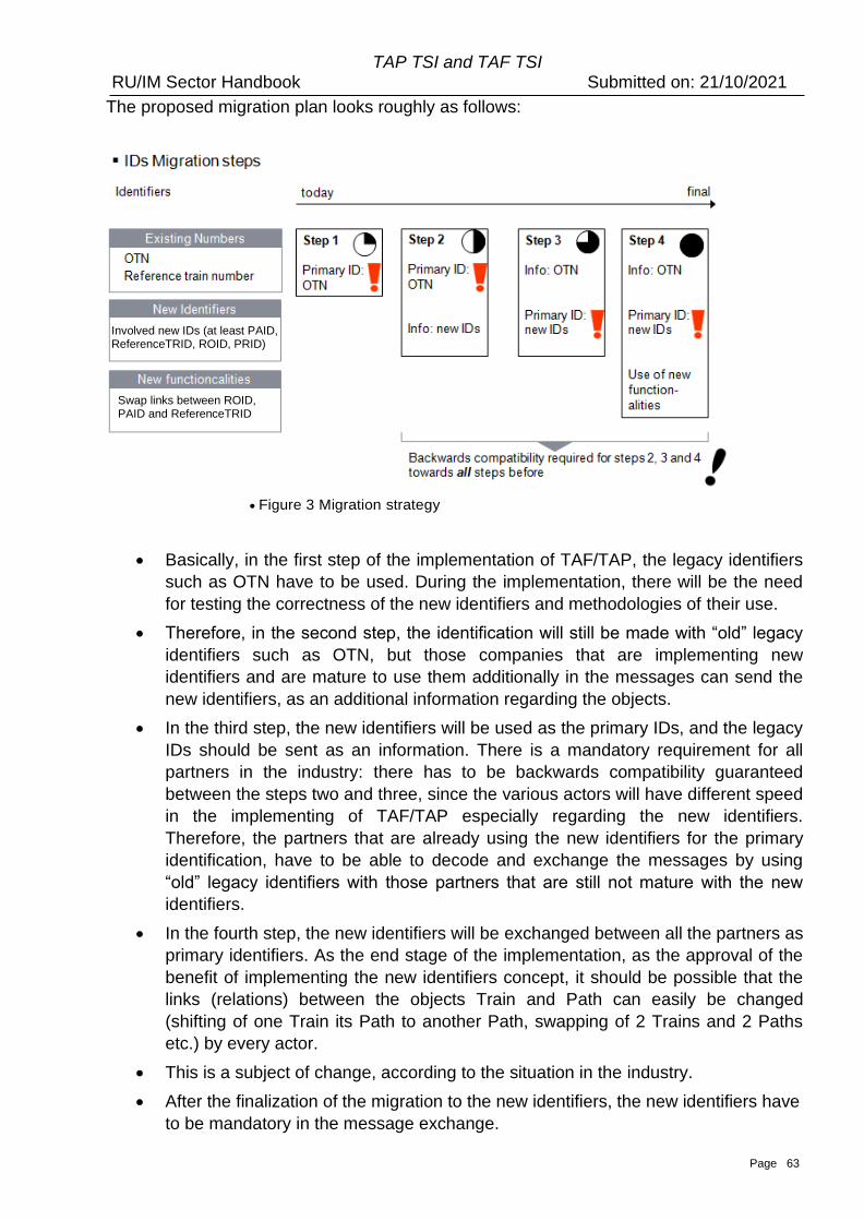
Page 63
TAP TSI and TAF TSI RU/IM Sector Handbook Submitted on: 21/10/2021
The proposed migration plan looks roughly as follows:
• Figure 3 Migration strategy
• Basically, in the first step of the implementation of TAF/TAP, the legacy identifiers
such as OTN have to be used. During the implementation, there will be the need
for testing the correctness of the new identifiers and methodologies of their use.
• Therefore, in the second step, the identification will still be made with “old” legacy
identifiers such as OTN, but those companies that are implementing new
identifiers and are mature to use them additionally in the messages can send the
new identifiers, as an additional information regarding the objects.
• In the third step, the new identifiers will be used as the primary IDs, and the legacy
IDs should be sent as an information. There is a mandatory requirement for all
partners in the industry: there has to be backwards compatibility guaranteed
between the steps two and three, since the various actors will have different speed
in the implementing of TAF/TAP especially regarding the new identifiers.
Therefore, the partners that are already using the new identifiers for the primary
identification, have to be able to decode and exchange the messages by using
“old” legacy identifiers with those partners that are still not mature with the new
identifiers.
• In the fourth step, the new identifiers will be exchanged between all the partners as
primary identifiers. As the end stage of the implementation, as the approval of the
benefit of implementing the new identifiers concept, it should be possible that the
links (relations) between the objects Train and Path can easily be changed
(shifting of one Train its Path to another Path, swapping of 2 Trains and 2 Paths
etc.) by every actor.
• This is a subject of change, according to the situation in the industry.
• After the finalization of the migration to the new identifiers, the new identifiers have
to be mandatory in the message exchange.
Involved new IDs (at least PAID, ReferenceTRID, ROID, PRID)
Swap links between ROID, PAID and ReferenceTRID
Page 64
TAP TSI and TAF TSI RU/IM Sector Handbook Submitted on: 21/10/2021
• This section can then be deleted !
8.3.2 Foreseen implementation calendar
Besides few RUs and IMs applying already on national or bilateral level, the
implementation and the use of the objects identifiers is expected to start by forerunners
RUs and IMs from the yearly timetable 2024 (that means for the path requests introduced
beginning 2023 and the operation from end 2023).
The implementation and the use will be extended for yearly timetables 2025 and 2026
when the implementation is expected complete in the Single European Railway Area.
References for further reading (mandatory for implementation of the new
identifiers!)
The following documents are necessary to be used:
• TrainID – OTN Framework (Annex 8.1)
• TrainID – Variant Framework (Annex 8.2)
• TrainID – Update Link Framework (Annex 8.3)
• TrainID – Case Reference Framework (Annex 8.4)
• TrainID – Object Info Framework (Annex 8.5)
With these documents, the details about the procedures of handling of the new identifiers
and their relationship with legacy identifiers (such as OTN) is provided.
Page 65
TAP TSI and TAF TSI RU/IM Sector Handbook Submitted on: 21/10/2021
9. Reference Data
9.1 Reference Files Sector Handbook
This chapter describes the Sector Handbook for TAF and TAP TSI Reference Files for Countries, Companies/Organisations and Primary Locations and Subsidiary Locations.
The Reference files comprise:
• Countries
• Companies/Organisations
• Locations • Primary • Subsidiary
The legal requirements for the reference files are derived from TAF 4.2.1.2 and TAP 4.2.19.1.
TAP TSI only The section hereunder is relevant for TAP TSI only and has
no impact on TAF.
TAF TSI only This section hereunder is relevant for TAF TSI only and
has no impact on TAP.
For the operation of passenger trains on the European network, the following reference files must be available and accessible to all service providers (infrastructure managers, railway undertakings, authorised third parties and station managers). The data must represent the actual status at all times.
For the operation of freight trains on the European network the following reference files must be available and accessible to all service providers (IMs, RUs, logistic providers and fleet managers). The data must represent the actual status at all times.
• reference file of the coding for all infrastructure managers, terminal operators (act as IM or RU), railway undertakings, station managers, service provider companies,
• reference file of the coding of locations,
• […]
Other reference files, e.g. for Retail, and the use of location reference data for TAP Retail are not in scope of this document.
9.2 Document Objectives
This Implementation Guideline describes how to deal with various reference files that are shared between TAP and TAF TSI and could be used with legacy systems or other purposes (e.g. RINF…). This guideline set out:
• Definition of the reference files and their content
• The initial load of the reference file data base by the national location allocation
entity
• The options for processes to maintain the reference files
• The maintenance of the reference files (responsible entities, companies)
• Exchange of Reference files using the Common Interface
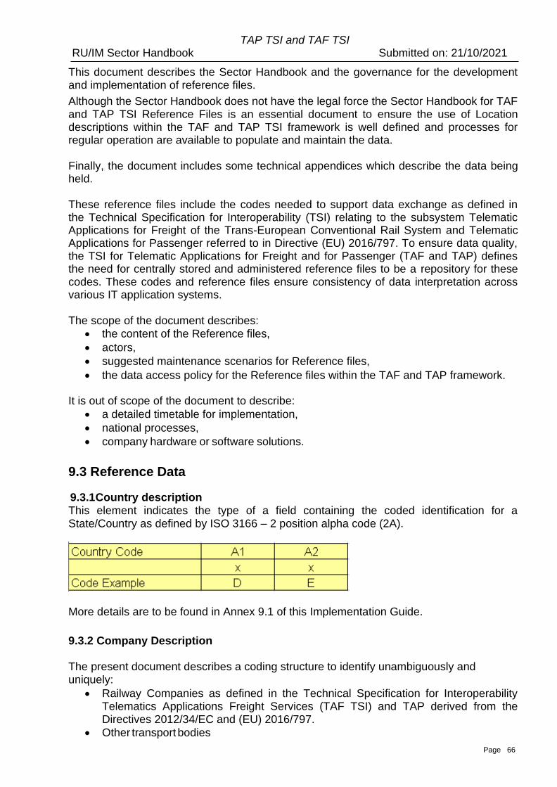
Page 66
TAP TSI and TAF TSI RU/IM Sector Handbook Submitted on: 21/10/2021
This document describes the Sector Handbook and the governance for the development and implementation of reference files.
Although the Sector Handbook does not have the legal force the Sector Handbook for TAF and TAP TSI Reference Files is an essential document to ensure the use of Location descriptions within the TAF and TAP TSI framework is well defined and processes for regular operation are available to populate and maintain the data.
Finally, the document includes some technical appendices which describe the data being held.
These reference files include the codes needed to support data exchange as defined in the Technical Specification for Interoperability (TSI) relating to the subsystem Telematic Applications for Freight of the Trans-European Conventional Rail System and Telematic Applications for Passenger referred to in Directive (EU) 2016/797. To ensure data quality, the TSI for Telematic Applications for Freight and for Passenger (TAF and TAP) defines the need for centrally stored and administered reference files to be a repository for these codes. These codes and reference files ensure consistency of data interpretation across various IT application systems.
The scope of the document describes: • the content of the Reference files,
• actors,
• suggested maintenance scenarios for Reference files,
• the data access policy for the Reference files within the TAF and TAP framework.
It is out of scope of the document to describe:
• a detailed timetable for implementation,
• national processes,
• company hardware or software solutions.
9.3 Reference Data
9.3.1 Country description This element indicates the type of a field containing the coded identification for a State/Country as defined by ISO 3166 – 2 position alpha code (2A).
More details are to be found in Annex 9.1 of this Implementation Guide.
9.3.2 Company Description
The present document describes a coding structure to identify unambiguously and uniquely:
• Railway Companies as defined in the Technical Specification for Interoperability Telematics Applications Freight Services (TAF TSI) and TAP derived from the Directives 2012/34/EC and (EU) 2016/797.
• Other transport bodies
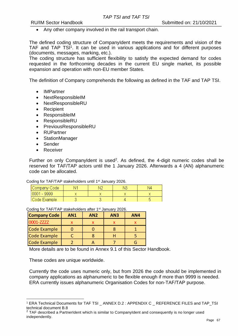
Page 67
TAP TSI and TAF TSI RU/IM Sector Handbook Submitted on: 21/10/2021
• Any other company involved in the rail transport chain.
The defined coding structure of CompanyIdent meets the requirements and vision of the TAF and TAP TSI1. It can be used in various applications and for different purposes (documents, messages, marking, etc.). The coding structure has sufficient flexibility to satisfy the expected demand for codes requested in the forthcoming decades in the current EU single market, its possible expansion and operation with non-EU member States.
The definition of Company comprehends the following as defined in the TAF and TAP TSI.
• IMPartner
• NextResponsibleIM
• NextResponsibleRU
• Recipient
• ResponsibleIM
• ResponsibleRU
• PreviousResponsibleRU
• RUPartner
• StationManager
• Sender
• Receiver
Further on only CompanyIdent is used2. As defined, the 4-digit numeric codes shall be reserved for TAF/TAP actors until the 1 January 2026. Afterwards a 4 (AN) alphanumeric code can be allocated.
Coding for TAF/TAP stakeholders until 1st January 2026.
Coding for TAF/TAP stakeholders after 1st January 2026.
More details are to be found in Annex 9.1 of this Sector Handbook.
These codes are unique worldwide.
Currently the code uses numeric only, but from 2026 the code should be implemented in company applications as alphanumeric to be flexible enough if more than 9999 is needed.
ERA currently issues alphanumeric Organisation Codes for non-TAF/TAP purpose.
1 ERA Technical Documents for TAF TSI _ ANNEX D.2 : APPENDIX C _ REFERENCE FILES and TAP_TSI technical document B.8 2 TAF described a PartnerIdent which is similar to CompanyIdent and consequently is no longer used independently.
Company Code AN1 AN2 AN3 AN4
0001-ZZZZ x x x x
Code Example 0 0 8 1
Code Example C 8 H 5
Code Example 2 A 7 G
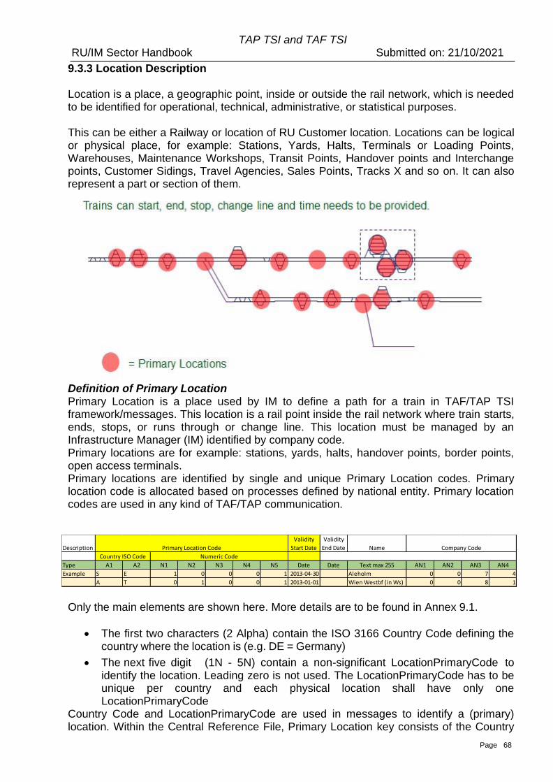
Page 68
TAP TSI and TAF TSI RU/IM Sector Handbook Submitted on: 21/10/2021
9.3.3 Location Description
Location is a place, a geographic point, inside or outside the rail network, which is needed to be identified for operational, technical, administrative, or statistical purposes. This can be either a Railway or location of RU Customer location. Locations can be logical or physical place, for example: Stations, Yards, Halts, Terminals or Loading Points, Warehouses, Maintenance Workshops, Transit Points, Handover points and Interchange points, Customer Sidings, Travel Agencies, Sales Points, Tracks X and so on. It can also represent a part or section of them.
Definition of Primary Location Primary Location is a place used by IM to define a path for a train in TAF/TAP TSI framework/messages. This location is a rail point inside the rail network where train starts, ends, stops, or runs through or change line. This location must be managed by an Infrastructure Manager (IM) identified by company code. Primary locations are for example: stations, yards, halts, handover points, border points, open access terminals. Primary locations are identified by single and unique Primary Location codes. Primary location code is allocated based on processes defined by national entity. Primary location codes are used in any kind of TAF/TAP communication.
Only the main elements are shown here. More details are to be found in Annex 9.1.
• The first two characters (2 Alpha) contain the ISO 3166 Country Code defining the country where the location is (e.g. DE = Germany)
• The next five digit (1N - 5N) contain a non-significant LocationPrimaryCode to identify the location. Leading zero is not used. The LocationPrimaryCode has to be unique per country and each physical location shall have only one LocationPrimaryCode
Country Code and LocationPrimaryCode are used in messages to identify a (primary) location. Within the Central Reference File, Primary Location key consists of the Country
Description
Validity
Start Date
Validity
End Date Name
Type A1 A2 N1 N2 N3 N4 N5 Date Date Text max 255 AN1 AN2 AN3 AN4
Example S E 1 0 0 0 1 2013-04-30 Aleholm 0 0 7 4
A T 0 1 0 0 1 2013-01-01 Wien Westbf (in Ws) 0 0 8 1
Country ISO Code Numeric Code
Primary Location Code Company Code
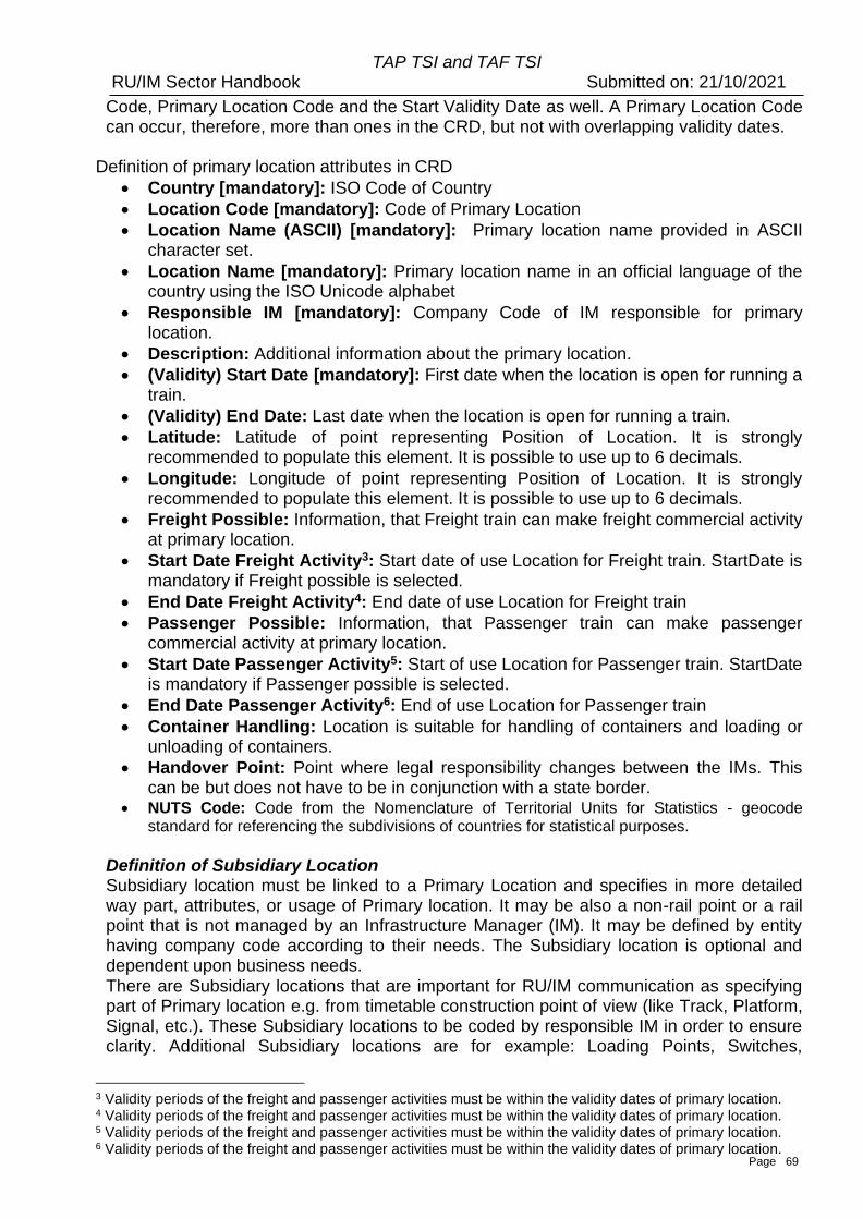
Page 69
TAP TSI and TAF TSI RU/IM Sector Handbook Submitted on: 21/10/2021
Code, Primary Location Code and the Start Validity Date as well. A Primary Location Code can occur, therefore, more than ones in the CRD, but not with overlapping validity dates.
Definition of primary location attributes in CRD
• Country [mandatory]: ISO Code of Country
• Location Code [mandatory]: Code of Primary Location
• Location Name (ASCII) [mandatory]: Primary location name provided in ASCII character set.
• Location Name [mandatory]: Primary location name in an official language of the country using the ISO Unicode alphabet
• Responsible IM [mandatory]: Company Code of IM responsible for primary location.
• Description: Additional information about the primary location.
• (Validity) Start Date [mandatory]: First date when the location is open for running a train.
• (Validity) End Date: Last date when the location is open for running a train.
• Latitude: Latitude of point representing Position of Location. It is strongly recommended to populate this element. It is possible to use up to 6 decimals.
• Longitude: Longitude of point representing Position of Location. It is strongly recommended to populate this element. It is possible to use up to 6 decimals.
• Freight Possible: Information, that Freight train can make freight commercial activity at primary location.
• Start Date Freight Activity3: Start date of use Location for Freight train. StartDate is mandatory if Freight possible is selected.
• End Date Freight Activity4: End date of use Location for Freight train
• Passenger Possible: Information, that Passenger train can make passenger commercial activity at primary location.
• Start Date Passenger Activity5: Start of use Location for Passenger train. StartDate is mandatory if Passenger possible is selected.
• End Date Passenger Activity6: End of use Location for Passenger train
• Container Handling: Location is suitable for handling of containers and loading or unloading of containers.
• Handover Point: Point where legal responsibility changes between the IMs. This can be but does not have to be in conjunction with a state border.
• NUTS Code: Code from the Nomenclature of Territorial Units for Statistics - geocode standard for referencing the subdivisions of countries for statistical purposes.
Definition of Subsidiary Location Subsidiary location must be linked to a Primary Location and specifies in more detailed way part, attributes, or usage of Primary location. It may be also a non-rail point or a rail point that is not managed by an Infrastructure Manager (IM). It may be defined by entity having company code according to their needs. The Subsidiary location is optional and dependent upon business needs.
There are Subsidiary locations that are important for RU/IM communication as specifying part of Primary location e.g. from timetable construction point of view (like Track, Platform, Signal, etc.). These Subsidiary locations to be coded by responsible IM in order to ensure clarity. Additional Subsidiary locations are for example: Loading Points, Switches,
3 Validity periods of the freight and passenger activities must be within the validity dates of primary location. 4 Validity periods of the freight and passenger activities must be within the validity dates of primary location. 5 Validity periods of the freight and passenger activities must be within the validity dates of primary location. 6 Validity periods of the freight and passenger activities must be within the validity dates of primary location.
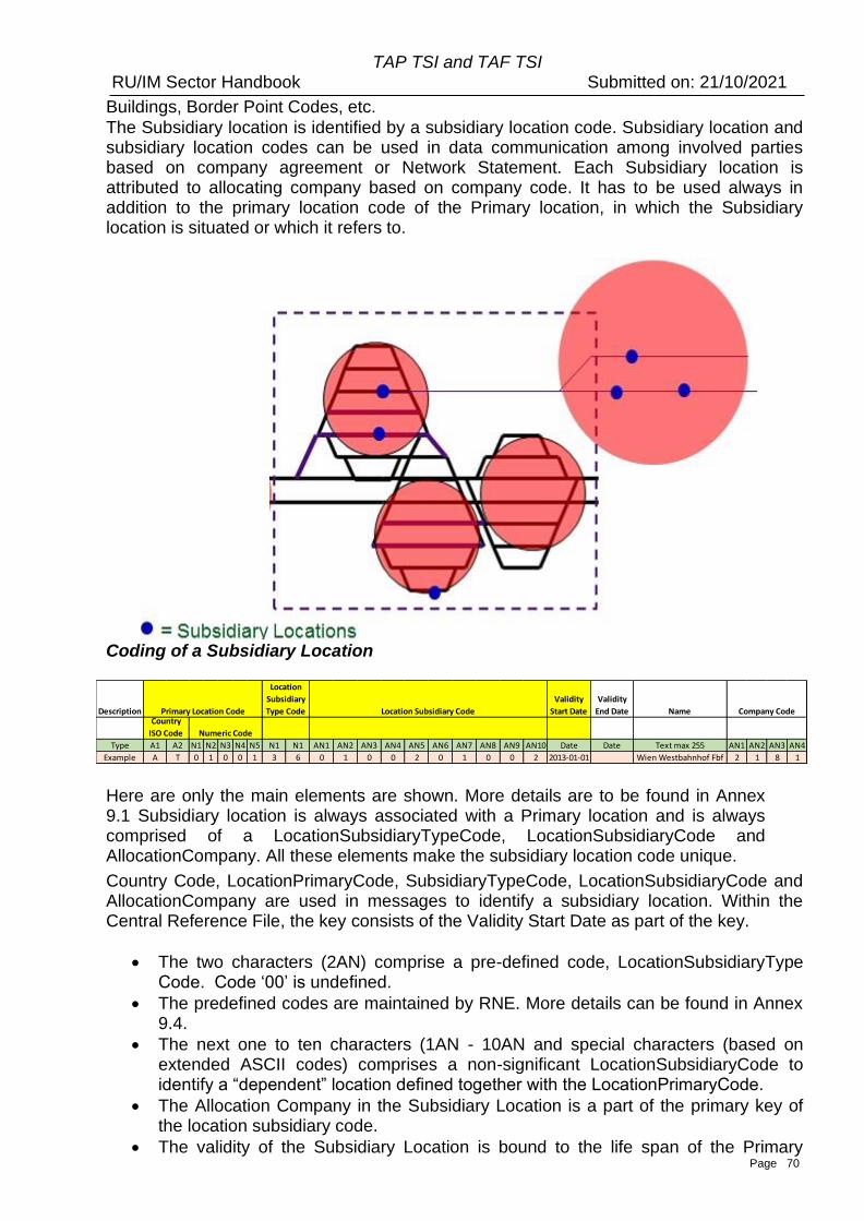
Page 70
TAP TSI and TAF TSI RU/IM Sector Handbook Submitted on: 21/10/2021
Buildings, Border Point Codes, etc.
The Subsidiary location is identified by a subsidiary location code. Subsidiary location and subsidiary location codes can be used in data communication among involved parties based on company agreement or Network Statement. Each Subsidiary location is attributed to allocating company based on company code. It has to be used always in addition to the primary location code of the Primary location, in which the Subsidiary location is situated or which it refers to.
Coding of a Subsidiary Location
Here are only the main elements are shown. More details are to be found in Annex 9.1 Subsidiary location is always associated with a Primary location and is always comprised of a LocationSubsidiaryTypeCode, LocationSubsidiaryCode and AllocationCompany. All these elements make the subsidiary location code unique.
Country Code, LocationPrimaryCode, SubsidiaryTypeCode, LocationSubsidiaryCode and AllocationCompany are used in messages to identify a subsidiary location. Within the Central Reference File, the key consists of the Validity Start Date as part of the key.
• The two characters (2AN) comprise a pre-defined code, LocationSubsidiaryType Code. Code ‘00’ is undefined.
• The predefined codes are maintained by RNE. More details can be found in Annex 9.4.
• The next one to ten characters (1AN - 10AN and special characters (based on extended ASCII codes) comprises a non-significant LocationSubsidiaryCode to identify a “dependent” location defined together with the LocationPrimaryCode.
• The Allocation Company in the Subsidiary Location is a part of the primary key of the location subsidiary code.
• The validity of the Subsidiary Location is bound to the life span of the Primary
Description
Validity
Start Date
Validity
End Date Name
Type A1 A2 N1 N2 N3 N4 N5 N1 N1 AN1 AN2 AN3 AN4 AN5 AN6 AN7 AN8 AN9 AN10 Date Date Text max 255 AN1 AN2 AN3 AN4
Example A T 0 1 0 0 1 3 6 0 1 0 0 2 0 1 0 0 2 2013-01-01 Wien Westbahnhof Fbf 2 1 8 1
Company CodeLocation Subsidiary CodePrimary Location CodeCountry
ISO Code Numeric Code
Location
Subsidiary
Type Code
Page 71
TAP TSI and TAF TSI RU/IM Sector Handbook Submitted on: 21/10/2021
Location. There can be no Subsidiary Location without a valid Primary Location. General rules for establishing Subsidiary location type. At least one of the following must be covered.
3. The Subsidiary location type defines a physical part (signal, track, platform, siding, etc.) of the Primary location which is important for the exchange of information related to the path.
4. Subsidiary location type defines an attribute or logical point related to a Primary location which is important for communication between the partners IM, RU and their partners related to their business needs.
5. Subsidiary location types are not to be used to describe the technical details of a Primary location beside the above mentioned
6. New type codes should be fitting to the above described rules and their allocation must follow the TAF/TAP Change Control Management (CCM) process.
Subsidiary type codes
Locations are defined by a primary location and optionally by a subsidiary location.
Primary locations are used for stations and can be used for parts of stations. They will be usually maintained by the Infrastructure Manager or a National Allocation Entity.
Subsidiary locations are usually used between the Railway Undertakings where detailed information within a primary location is needed. For specific reasons as specified in certain messages for the communication between IM and RU the primary location needs to be further detailed, e.g. to indicate a specific track in the station, a subsidiary location can also be used in messages between RU and IM.
A subsidiary location depends always on a primary location. Subsidiary locations are grouped by subsidiary types. Each Subsidiary Location is allocated by an Allocation Company. Bases on national rules Freight and Passenger Companies are allowed to maintain subsidiary locations for certain subsidiary types directly in the Common Reference Files Database.
This coding was established under the premise to support the coding of Subsidiary Locations
• in TAF and TAP TSI messages
• in the related business applications and
• other activities
Any entity can maintain subsidiary locations directly in CRD which is maintained at a country level by NAE.
The list and the description of the Subsidiary Location Type Codes is provided in Annex 9.4.
Description of the CRD data model The data model is described in Annex 9.1 and the description of the update message is provided in the official document TAF TSI — ANNEX D.2: APPENDIX F — TAF TSI DATA AND MESSAGE MODEL.
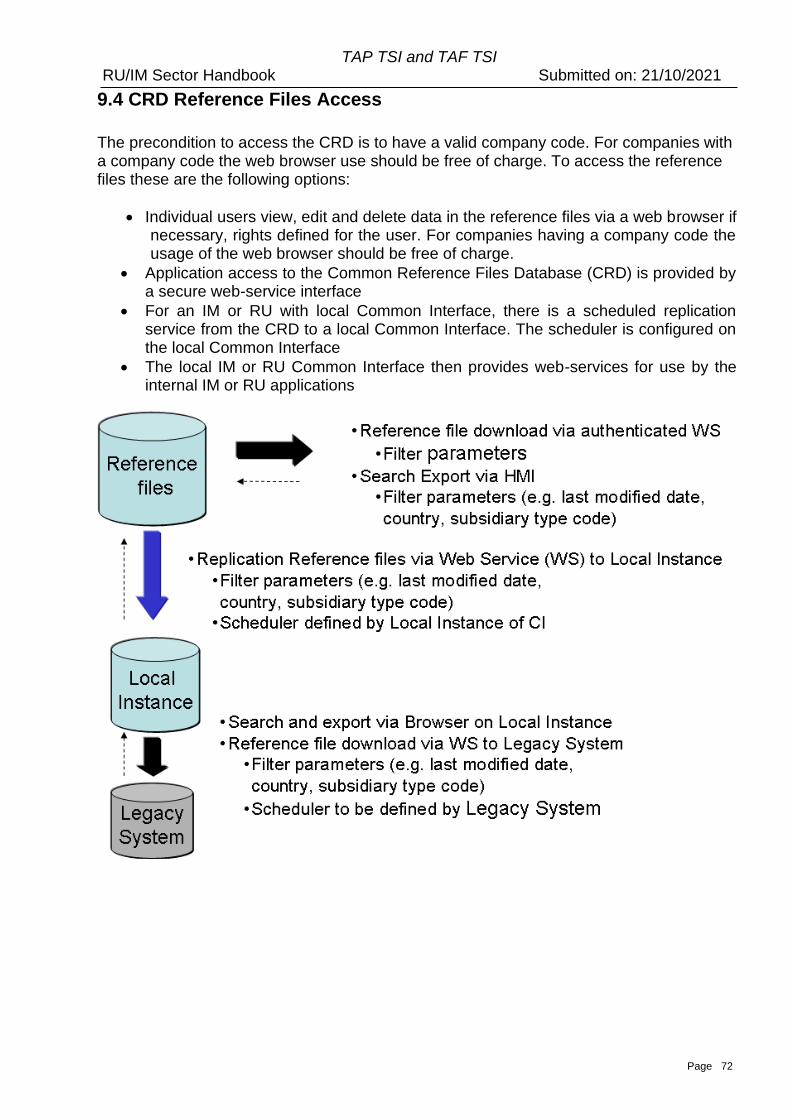
Page 72
TAP TSI and TAF TSI RU/IM Sector Handbook Submitted on: 21/10/2021
9.4 CRD Reference Files Access
The precondition to access the CRD is to have a valid company code. For companies with a company code the web browser use should be free of charge. To access the reference files these are the following options:
• Individual users view, edit and delete data in the reference files via a web browser if necessary, rights defined for the user. For companies having a company code the usage of the web browser should be free of charge.
• Application access to the Common Reference Files Database (CRD) is provided by a secure web-service interface
• For an IM or RU with local Common Interface, there is a scheduled replication service from the CRD to a local Common Interface. The scheduler is configured on the local Common Interface
• The local IM or RU Common Interface then provides web-services for use by the internal IM or RU applications
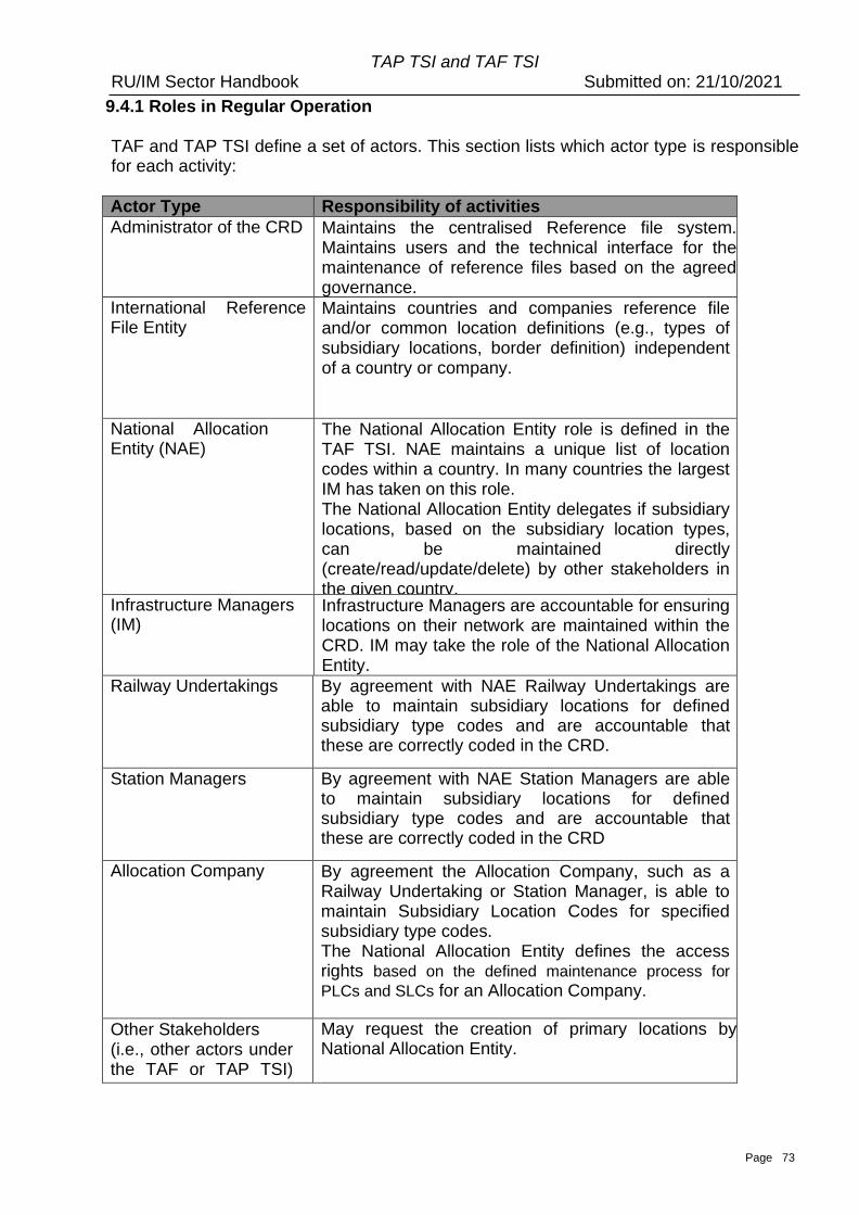
Page 73
TAP TSI and TAF TSI RU/IM Sector Handbook Submitted on: 21/10/2021
9.4.1 Roles in Regular Operation
TAF and TAP TSI define a set of actors. This section lists which actor type is responsible for each activity:
Actor Type Responsibility of activities
Administrator of the CRD Maintains the centralised Reference file system. Maintains users and the technical interface for the maintenance of reference files based on the agreed governance.
International Reference File Entity
Maintains countries and companies reference file and/or common location definitions (e.g., types of subsidiary locations, border definition) independent of a country or company.
National Allocation Entity (NAE)
The National Allocation Entity role is defined in the TAF TSI. NAE maintains a unique list of location codes within a country. In many countries the largest IM has taken on this role. The National Allocation Entity delegates if subsidiary locations, based on the subsidiary location types, can be maintained directly (create/read/update/delete) by other stakeholders in the given country. Infrastructure Managers
(IM) Infrastructure Managers are accountable for ensuring locations on their network are maintained within the CRD. IM may take the role of the National Allocation Entity.
Railway Undertakings By agreement with NAE Railway Undertakings are able to maintain subsidiary locations for defined subsidiary type codes and are accountable that these are correctly coded in the CRD.
Station Managers By agreement with NAE Station Managers are able to maintain subsidiary locations for defined subsidiary type codes and are accountable that these are correctly coded in the CRD
Allocation Company By agreement the Allocation Company, such as a
Railway Undertaking or Station Manager, is able to maintain Subsidiary Location Codes for specified subsidiary type codes. The National Allocation Entity defines the access rights based on the defined maintenance process for
PLCs and SLCs for an Allocation Company.
Other Stakeholders (i.e., other actors under the TAF or TAP TSI) definition)
May request the creation of primary locations by National Allocation Entity.
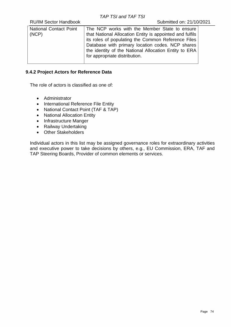
Page 74
TAP TSI and TAF TSI RU/IM Sector Handbook Submitted on: 21/10/2021
National Contact Point (NCP)
The NCP works with the Member State to ensure that National Allocation Entity is appointed and fulfils its roles of populating the Common Reference Files Database with primary location codes. NCP shares the identity of the National Allocation Entity to ERA for appropriate distribution.
9.4.2 Project Actors for Reference Data
The role of actors is classified as one of:
• Administrator
• International Reference File Entity
• National Contact Point (TAF & TAP)
• National Allocation Entity
• Infrastructure Manger
• Railway Undertaking
• Other Stakeholders
Individual actors in this list may be assigned governance roles for extraordinary activities and executive power to take decisions by others, e.g., EU Commission, ERA, TAF and TAP Steering Boards, Provider of common elements or services.
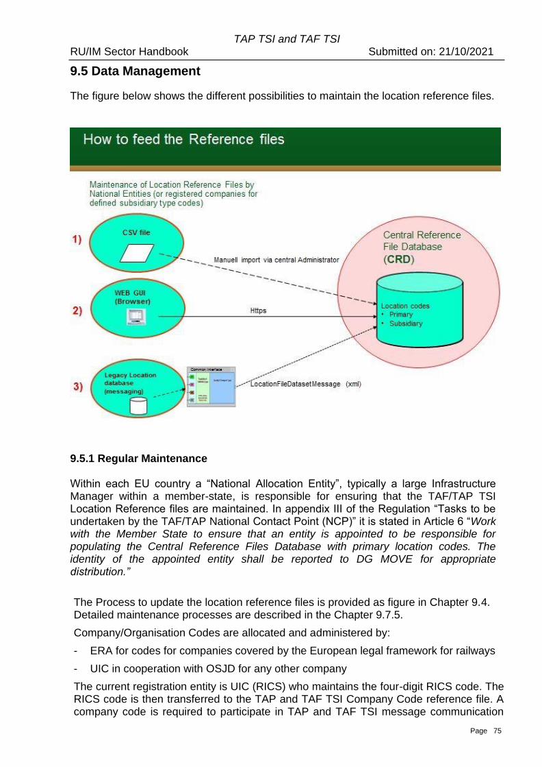
Page 75
TAP TSI and TAF TSI RU/IM Sector Handbook Submitted on: 21/10/2021
9.5 Data Management
The figure below shows the different possibilities to maintain the location reference files.
9.5.1 Regular Maintenance
Within each EU country a “National Allocation Entity”, typically a large Infrastructure Manager within a member-state, is responsible for ensuring that the TAF/TAP TSI Location Reference files are maintained. In appendix III of the Regulation “Tasks to be undertaken by the TAF/TAP National Contact Point (NCP)” it is stated in Article 6 “Work with the Member State to ensure that an entity is appointed to be responsible for populating the Central Reference Files Database with primary location codes. The identity of the appointed entity shall be reported to DG MOVE for appropriate distribution.”
The Process to update the location reference files is provided as figure in Chapter 9.4. Detailed maintenance processes are described in the Chapter 9.7.5.
Company/Organisation Codes are allocated and administered by:
- ERA for codes for companies covered by the European legal framework for railways
- UIC in cooperation with OSJD for any other company
The current registration entity is UIC (RICS) who maintains the four-digit RICS code. The RICS code is then transferred to the TAP and TAF TSI Company Code reference file. A company code is required to participate in TAP and TAF TSI message communication
Page 76
TAP TSI and TAF TSI RU/IM Sector Handbook Submitted on: 21/10/2021
and locations file maintenance and exchange. Currently Company Codes are requested using UIC WEB Page: https://uic.org/support-activities/it/rics.
ERA currently allocates 4 (AN) digit alphanumeric Company/Organisation Codes for RINF and other administrative purposes for entities who do not exchange TAF/TAP messages. ERA web page for Organisation Code allocation:
https://www.era.europa.eu/registers/evr_en.
From 1st January 2026 ERA will allocate also 4 (AN) alphanumeric Company/Organisation Codes to TAF/TAP actors.
Country Codes are maintained by the International Organization for Standardisation (ISO). If a change or new Country Code is required, the requester should follow the process as laid out by ISO and documented on their website. www.iso.org/iso/country_codes.htm
9.5.2 Maintenance Processes and Actors (CRUD: Create, Read, Update, Delete)
1. Initial loading of locations (primary and/or subsidiary) in the form of a bulk import is
performed by CRD Administrator.
The National Allocation Entity (or any other delegated actor) delivers a file to the CRD Administrator. At the time RailNetEurope (RNE) is acting as CRD Administrator. The file structure is available in Annex 9.5.
2. Countries Reference File and Companies Reference File CRUD is
performed by International Reference File Entity 3. Primary Location Reference File CRUD can be performed by:
a. Infrastructure Manager – Constraint:
• Element “ResponsibleIM” (Company Code) must be the same as IM user’s Company Code.
• Element “AllocationCompany” must be the same as IM user’s Company Code
b. National Allocation Entity (NAE) – Constraint: • Country ISO Code of primary location must be the same
as the NAE user company’s Country ISO Code. c. International Reference File Entity d. CRD Administrator
4. Subsidiary Location Reference File CRUD can be performed by:
a. Infrastructure Manager – Constraint: • Element “ResponsibleIM” (Company Code) must be the
same as IM user’s Company Code. • Element “AllocationCompany” must be the same as IM
user’s Company Code • “Subsidiary Location Type” must be any subsidiary
location type whose maintenance by IM companies is allowed
b. Railway Undertaking – Constraint:
Page 77
TAP TSI and TAF TSI RU/IM Sector Handbook Submitted on: 21/10/2021
• “Subsidiary Location Type” must be any subsidiary location type whose maintenance by Railway Undertaking company is allowed within each country
c. National Allocation Entity (NAE) – Constraint: • Country ISO Code of “Primary Location” must be the
same as the NAE user company’s Country ISO Code. • “Subsidiary Location Type” must be any subsidiary
location type whose maintenance by National Allocation Entity is allowed
d. International Reference File Entity – Constraint: • “Subsidiary Location Type” must be any subsidiary
location type whose maintenance by Central Entity is allowed
e. CRD Administrator
5. Subsidiary Location Type Reference File CRUD can be performed by: a. CRD Administrator
9.5.3 Availability of locations in CRD General rule for the first availability of a location in CRD is defined below (X – start of a yearly timetable, range is in months):
• Before definition of Temporary Capacity restriction (TCR) – X-36
• before construction of Prearranged Path (PAP) – X-24 • before PAP publication – X-12
• before Network statement publication – X-11 • before date for accepting of path requests – X-8
• before first use of respective code in data Communication (e.g., New short-term validity point because of infra works)
9.5.4 Reference Files Data Management in CRD
The figure below shows the process to maintain Location Reference Files. For primary locations allocation process is described below:
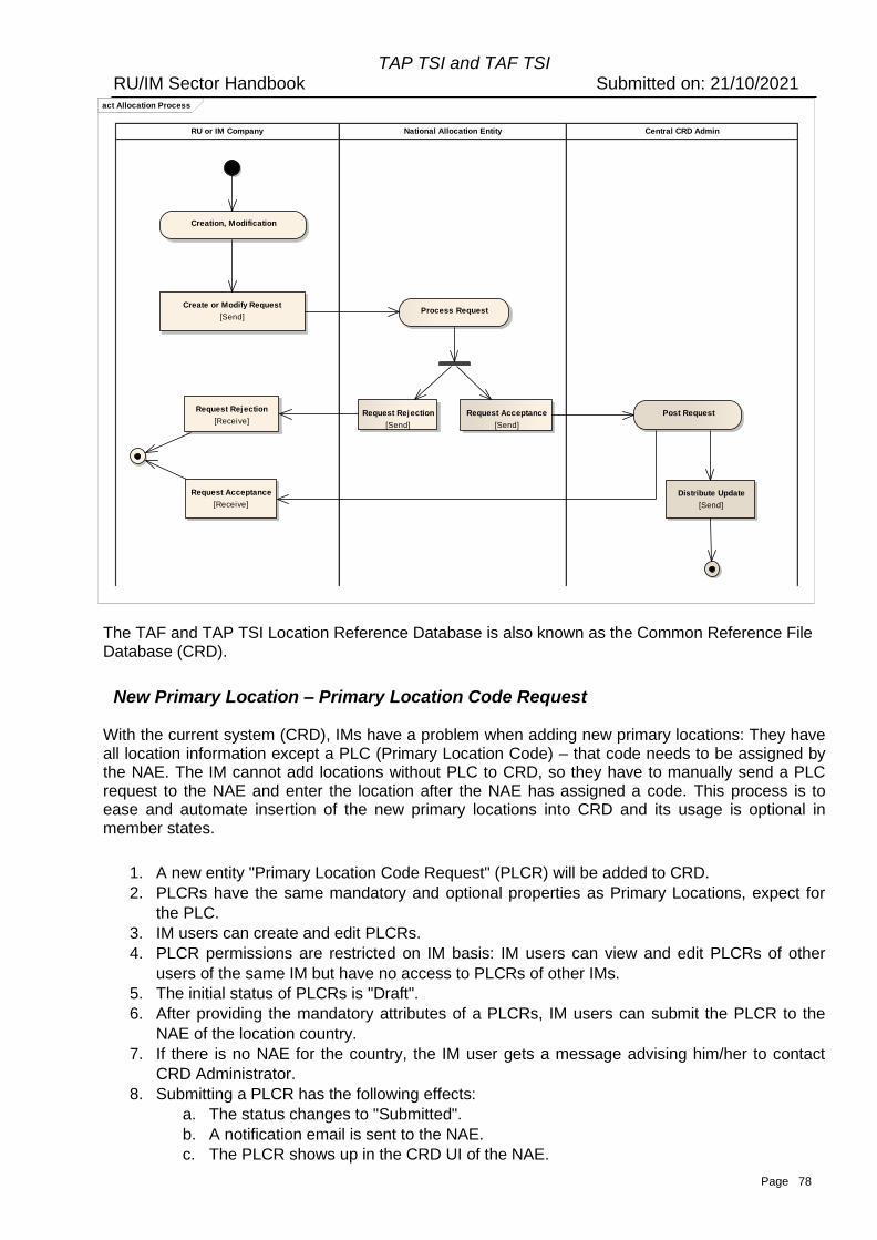
Page 78
TAP TSI and TAF TSI RU/IM Sector Handbook Submitted on: 21/10/2021
The TAF and TAP TSI Location Reference Database is also known as the Common Reference File Database (CRD).
New Primary Location – Primary Location Code Request
With the current system (CRD), IMs have a problem when adding new primary locations: They have all location information except a PLC (Primary Location Code) – that code needs to be assigned by the NAE. The IM cannot add locations without PLC to CRD, so they have to manually send a PLC request to the NAE and enter the location after the NAE has assigned a code. This process is to ease and automate insertion of the new primary locations into CRD and its usage is optional in member states.
1. A new entity "Primary Location Code Request" (PLCR) will be added to CRD.
2. PLCRs have the same mandatory and optional properties as Primary Locations, expect for
the PLC.
3. IM users can create and edit PLCRs.
4. PLCR permissions are restricted on IM basis: IM users can view and edit PLCRs of other
users of the same IM but have no access to PLCRs of other IMs.
5. The initial status of PLCRs is "Draft".
6. After providing the mandatory attributes of a PLCRs, IM users can submit the PLCR to the
NAE of the location country.
7. If there is no NAE for the country, the IM user gets a message advising him/her to contact
CRD Administrator.
8. Submitting a PLCR has the following effects:
a. The status changes to "Submitted".
b. A notification email is sent to the NAE.
c. The PLCR shows up in the CRD UI of the NAE.
act Allocation Process
Central CRD AdminNational Allocation EntityRU or IM Company
Creation, Modification
Process RequestCreate or Modify Request
[Send]
Request Rejection
[Send]
Request Acceptance
[Send]
Request Rejection
[Receive]Post Request
Distribute Update
[Send]
Request Acceptance
[Receive]
Page 79
TAP TSI and TAF TSI RU/IM Sector Handbook Submitted on: 21/10/2021
d. The PLCR becomes read-only for the IM user.
9. In status "Submitted", the NAE user has two possible actions for the PLCR:
a. Approving the request by assigning a PLC. The system aids the user by proposing
the next logical PLC (current highest PLC of the country + 1) and validating that no
PLC that is already in use is chosen.
b. Rejecting the PLCR.
10. Approval of a PLCR has the following effects:
a. The status changes to "Approved".
b. A Primary Location with the information of the PLCR and the assigned PLC is
created.
11. Rejection of a PLCR changes its status to "Rejected" and the reason for rejection can be
provided.
12. In statuses "Approved" and "Rejected", no one can edit the information of the PLCR.
13. Every status change of PLCRs causes an email notification for users of the affected IM.
14. Every modification of a PLCR causes an audit log entry.
15. Internally, PLCRs are not bound to a specific NAE so that when the validity of one NAE ends
and another user becomes the active NAE for a country, the new NAE has access to the
PLCRs of his/her country.
New Subsidiary Location – Subsidiary Location Code Request Similar to the Primary Location Code Request (PLCR) described earlier, there should also be process in CRD for requesting codes for Subsidiary Locations. This Subsidiary Location Code Request (SLCR) works the same as the PLCR, except:
1. SLCRs are based on Subsidiary Locations instead of Primary Locations.
2. Instead of IM users, any CRD user can initiate a SLCR.
3. Permissions and notifications are then restricted to the user company, instead of on IM basis.
4. NAEs can appoint one company of the same country as the NAE per subsidiary type.
5. Users of the appointed company have the same permissions on SLCRs of the matching
subsidiary type as the NAE.
6. Users of the appointed company also receive email notifications for SLCRs with their
subsidiary type.
7. Changing the country of an appointed company must cause a validation failure, or remove
the "appointed" status of the company. Otherwise, a company could be appointed to manage
SLCRs outside of its country.
Primary Location Proposal
With the current system, some users - typically RUs - have no formal way to request addition of a new primary location.
The goal is to support and automate this process in CRD where possible.
1. A new entity "Primary Location Proposal" (PLP) will be added to CRD.
2. PLPs have a subset of Primary Location properties: Name, Latitude, Longitude, Country, and
Description.
3. All properties except Description are mandatory.
4. Any CRD user with permission "Create PLP" can create a new PLP. Via roles, CRD can be
configured to grant this permission to all users.
5. PLP permissions are restricted on user basis: A user has only access to their own PLPs.
6. The initial status of PLPs is "Draft".
Page 80
TAP TSI and TAF TSI RU/IM Sector Handbook Submitted on: 21/10/2021
7. After providing the mandatory properties of a PLP, the user can submit the PLP to the NAE of
the location country.
8. If there is no NAE for the country, the user gets a message advising them to contact CRD
Administrator.
9. Submitting a PLP has the following effects:
a. The status changes to "Submitted".
b. A notification email is sent to the NAE.
c. The PLP shows up in the CRD UI of the NAE.
d. The PLP becomes NAE-only for the user.
10. In status "Submitted", the NCP user has two possible actions for the PLP:
a. Approving the request by assigning a responsible IM.
b. Reject the PLP.
11. Approval of a PLP has the following effects:
a. The status changes to "Approved".
b. The PLP shows up in the CRD UI of the users of the responsible IM.
c. An email notification is sent to all users of the responsible IM.
12. Rejection of a PLP changes its status to "Rejected".
13. In statuses "Approved" and "Rejected", no one can edit the information of the PLP.
14. In status "Approved", IM users have two possible actions for the PLP:
a. Create a Primary Location Code Request based on the PLP
b. Create a Primary Location based on the PLP
15. Every status change of PLPs causes an email notification for the user who created it.
16. Every modification of a PLP causes an audit log entry.
17. Internally, PLPs are not bound to a specific NAE so that when the validity of one NAE ends
and another user becomes the active NAE for a country, the new NAE has access to the
PLPs of his/her country.
Deleting Primary Location
To discontinue primary location (invalidate it for the future use – deactivate) End Date must be set to the day until this location is valid. End Date value must be greater or equal to Start Date value. To discontinue primary location, subsidiary location must be discontinued first by setting its End Date value and it must be less or equal to the primary location’s End Date value. Therefore, discontinuing primary location that has any subsidiary location(s) attached is a two-step process: Step 1: Discontinue all attached subsidiary locations Step 2: Discontinue primary location For any subsidiary location (SL) attached to some primary location (PL) the following rules apply for Start Date and End Date values:
(PL) Start Date ≤ (SL) Start Date ≤ (SL) End Date ≤ (PL) End Date
Primary location records deletion should be avoided. The only exception is deletion of new location created by technical mistake.
Updating Mandatory Data of Primary Location Every Primary Location in CRD is uniquely identified by:
1. Location Code
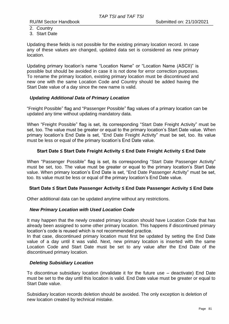
Page 81
TAP TSI and TAF TSI RU/IM Sector Handbook Submitted on: 21/10/2021
2. Country 3. Start Date
Updating these fields is not possible for the existing primary location record. In case any of these values are changed, updated data set is considered as new primary location.
Updating primary location’s name “Location Name” or “Location Name (ASCII)” is possible but should be avoided in case it is not done for error correction purposes. To rename the primary location, existing primary location must be discontinued and new one with the same Location Code and Country should be added having the Start Date value of a day since the new name is valid.
Updating Additional Data of Primary Location
“Freight Possible” flag and “Passenger Possible” flag values of a primary location can be updated any time without updating mandatory data. When “Freight Possible” flag is set, its corresponding “Start Date Freight Activity” must be set, too. The value must be greater or equal to the primary location’s Start Date value. When primary location’s End Date is set, “End Date Freight Activity” must be set, too. Its value must be less or equal of the primary location’s End Date value.
Start Date ≤ Start Date Freight Activity ≤ End Date Freight Activity ≤ End Date When “Passenger Possible” flag is set, its corresponding “Start Date Passenger Activity” must be set, too. The value must be greater or equal to the primary location’s Start Date value. When primary location’s End Date is set, “End Date Passenger Activity” must be set, too. Its value must be less or equal of the primary location’s End Date value. Start Date ≤ Start Date Passenger Activity ≤ End Date Passenger Activity ≤ End Date
Other additional data can be updated anytime without any restrictions.
New Primary Location with Used Location Code It may happen that the newly created primary location should have Location Code that has already been assigned to some other primary location. This happens if discontinued primary location’s code is reused which is not recommended practice. In that case, discontinued primary location must first be updated by setting the End Date value of a day until it was valid. Next, new primary location is inserted with the same Location Code and Start Date must be set to any value after the End Date of the discontinued primary location.
Deleting Subsidiary Location
To discontinue subsidiary location (invalidate it for the future use – deactivate) End Date must be set to the day until this location is valid. End Date value must be greater or equal to Start Date value. Subsidiary location records deletion should be avoided. The only exception is deletion of new location created by technical mistake.
Page 82
TAP TSI and TAF TSI RU/IM Sector Handbook Submitted on: 21/10/2021
9.5.6 Quality Criteria indicators
This section explains the Quality criteria for the Reference Files, in particular the delivery of Reference Files by responsible actors and the successful validation of Reference Files.
IM must validate the completeness and uniqueness of all primary locations used in messages between IM and RU within its network. The IM must ensure all missing locations are added by the responsible National Allocation Entity.
A company using a primary code in messages has to make sure that this code is available in the Reference File.
The National Allocation Entity is responsible to ensure that the primary location for the same physical location is unique.
Subsidiary Locations will be regulated by the railway sector based on the business needs. The completeness of Subsidiary Locations will be ensured by the railway sector itself. An actor using a subsidiary location code has to ensure the subsidiary location code is available in the Common reference files database.
When a company ceases to exist, the ownership of its subsidiary locations must be transferred to another entity or the associated subsidiary locations identified and the proper validity end date set. In case the action is not performed by the company itself the NAE shall manage this.
Page 83
TAP TSI and TAF TSI RU/IM Sector Handbook Submitted on: 21/10/2021
10. Code Lists
This chapter is just a reference to the Annexes where the codes used in the RU/IM message exchange are given. For the simplicity purpose, and easier maintenance of the f code list documentation, only the direct export from the most accurate XSD (schema) will always be provided. Since it is agreed within the sector, that every code list and the code should be documented in the annotation of the XSD, it is easier to keep the code list documentation centralized. Some of the code lists are agreed by the sector to be only kept in the annotation of the element for the flexibility reasons:
_ Message Type _ Error Code
The code lists can be found in Annex 6.3 (full code list document) and Annex 10.2 containing the important annotations for Message Type and Error Code.
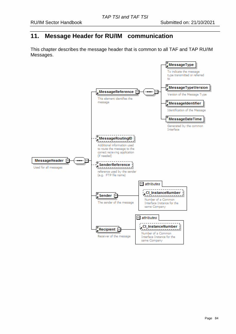
Page 84
TAP TSI and TAF TSI RU/IM Sector Handbook Submitted on: 21/10/2021
11. Message Header for RU/IM communication
This chapter describes the message header that is common to all TAF and TAP RU/IM Messages.
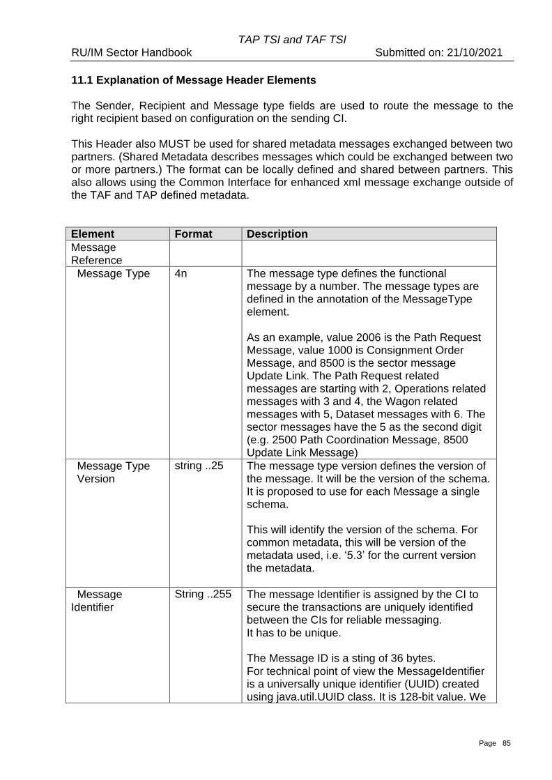
Page 85
TAP TSI and TAF TSI RU/IM Sector Handbook Submitted on: 21/10/2021
11.1 Explanation of Message Header Elements
The Sender, Recipient and Message type fields are used to route the message to the right recipient based on configuration on the sending CI.
This Header also MUST be used for shared metadata messages exchanged between two partners. (Shared Metadata describes messages which could be exchanged between two or more partners.) The format can be locally defined and shared between partners. This also allows using the Common Interface for enhanced xml message exchange outside of the TAF and TAP defined metadata.
Element Format Description
Message Reference
Message Type 4n The message type defines the functional message by a number. The message types are defined in the annotation of the MessageType element.
As an example, value 2006 is the Path Request Message, value 1000 is Consignment Order Message, and 8500 is the sector message Update Link. The Path Request related messages are starting with 2, Operations related messages with 3 and 4, the Wagon related messages with 5, Dataset messages with 6. The sector messages have the 5 as the second digit (e.g. 2500 Path Coordination Message, 8500 Update Link Message)
Message Type Version
string ..25 The message type version defines the version of the message. It will be the version of the schema. It is proposed to use for each Message a single schema.
This will identify the version of the schema. For common metadata, this will be version of the metadata used, i.e. ‘5.3’ for the current version the metadata.
Message Identifier
String ..255 The message Identifier is assigned by the CI to secure the transactions are uniquely identified between the CIs for reliable messaging. It has to be unique.
The Message ID is a sting of 36 bytes. For technical point of view the MessageIdentifier is a universally unique identifier (UUID) created using java.util.UUID class. It is 128-bit value. We
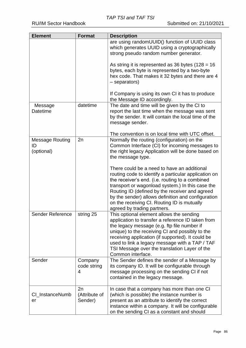
Page 86
TAP TSI and TAF TSI RU/IM Sector Handbook Submitted on: 21/10/2021
Element Format Description are using randomUUID() function of UUID class
which generates UUID using a cryptographically strong pseudo random number generator.
As string it is represented as 36 bytes (128 = 16 bytes, each byte is represented by a two-byte hex code. That makes it 32 bytes and there are 4 – separators)
If Company is using its own CI it has to produce
the Message ID accordingly.
Message Datetime
datetime The date and time will be given by the CI to report the last time when the message was sent by the sender. It will contain the local time of the message sender.
The convention is on local time with UTC offset.
Message Routing ID (optional)
2n Normally the routing (configuration) on the Common Interface (CI) for incoming messages to the right legacy Application will be done based on the message type.
There could be a need to have an additional routing code to identify a particular application on the receiver’s end. (i.e. routing to a combined transport or wagonload system.) In this case the Routing ID (defined by the receiver and agreed by the sender) allows definition and configuration on the receiving CI. Routing ID is mutually agreed by trading partners.
Sender Reference string 25 This optional element allows the sending application to transfer a reference ID taken from the legacy message (e.g. ftp file number if unique) to the receiving CI and possibly to the receiving application (if supported). It could be used to link a legacy message with a TAP / TAF TSI Message over the translation Layer of the Common interface.
Sender Company code string 4
The Sender defines the sender of a Message by its company ID. It will be configurable through message processing on the sending CI if not contained in the legacy message.
CI_InstanceNumb er
2n (Attribute of Sender)
In case that a company has more than one CI (which is possible) the instance number is present as an attribute to identify the correct instance within a company. It will be configurable on the sending CI as a constant and should
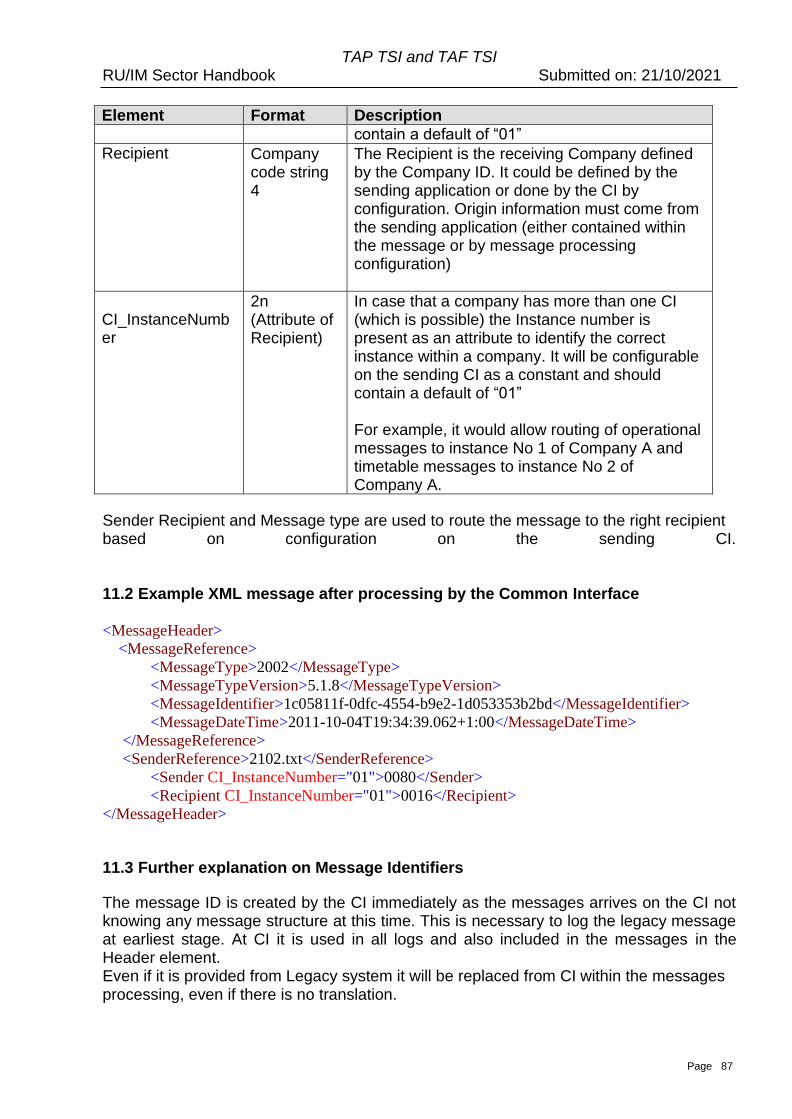
Page 87
TAP TSI and TAF TSI RU/IM Sector Handbook Submitted on: 21/10/2021
Element Format Description contain a default of “01”
Recipient Company code string 4
The Recipient is the receiving Company defined by the Company ID. It could be defined by the sending application or done by the CI by configuration. Origin information must come from the sending application (either contained within the message or by message processing configuration)
CI_InstanceNumb er
2n (Attribute of Recipient)
In case that a company has more than one CI (which is possible) the Instance number is present as an attribute to identify the correct instance within a company. It will be configurable on the sending CI as a constant and should contain a default of “01”
For example, it would allow routing of operational messages to instance No 1 of Company A and timetable messages to instance No 2 of Company A.
Sender Recipient and Message type are used to route the message to the right recipient based on configuration on the sending CI.
11.2 Example XML message after processing by the Common Interface
<MessageHeader>
<MessageReference>
<MessageType>2002</MessageType>
<MessageTypeVersion>5.1.8</MessageTypeVersion>
<MessageIdentifier>1c05811f-0dfc-4554-b9e2-1d053353b2bd</MessageIdentifier>
<MessageDateTime>2011-10-04T19:34:39.062+1:00</MessageDateTime>
</MessageReference>
<SenderReference>2102.txt</SenderReference>
<Sender CI_InstanceNumber="01">0080</Sender>
<Recipient CI_InstanceNumber="01">0016</Recipient>
</MessageHeader>
11.3 Further explanation on Message Identifiers
The message ID is created by the CI immediately as the messages arrives on the CI not knowing any message structure at this time. This is necessary to log the legacy message at earliest stage. At CI it is used in all logs and also included in the messages in the Header element. Even if it is provided from Legacy system it will be replaced from CI within the messages processing, even if there is no translation.
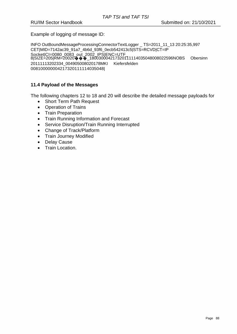
Page 88
TAP TSI and TAF TSI RU/IM Sector Handbook Submitted on: 21/10/2021
Example of logging of message ID:
INFO OutBoundMessageProcessingConnectorTextLogger _ TS=2011_11_13 20:25:35,997
CET|MID=7142ac39_91a7_4b6d_93f6_0ecb542413c5|STS=RCVD|CT=IP Socket|CI=0080_0083_out_2002_IPS|ENC=UTF_ 8|SIZE=205|RM=20020���_180030004217320111114035048008022596NOBS Obersinn
20111113202334_004905008020178MKI Kiefersfelden
008100000004217320111114035048|
11.4 Payload of the Messages
The following chapters 12 to 18 and 20 will describe the detailed message payloads for
• Short Term Path Request
• Operation of Trains
• Train Preparation
• Train Running Information and Forecast
• Service Disruption/Train Running Interrupted
• Change of Track/Platform
• Train Journey Modified
• Delay Cause
• Train Location.

TAP TSI and TAF TSI RU/IM Sector Handbook Submitted on: 21/10/2021
Page 60
Part B Planning of Trains
TAP TSI and TAF TSI RU/IM Sector Handbook Submitted on: 21/10/2021
Page 61
12. Path Request
In TAF TAP regulation, Short-Term Path Request (STPR) is covered. However, it is a
general agreement within the Sector to use TAF TAP messages/framework for the Path
Request process (including annual timetable).
Introduction
This chapter aims to provide with the necessary planning specific information that is
required for the implementation of the messages by the various actors impacted as a
result of complying with the TAF/TAP regulations.
The TAF and TAP TSIs are focused on the planning process for short term planning as
the annual train services have short term amendments made to them e.g. cancellation of
the service for the day, change of route for a week.
In addition to the diversity of processes there is also a need to identify a train service
during the different phases of planning and into operation. The use of the TAF/TAP
processes for Long-term Planning is a recommendation outside and in addition to both
TSIs. It is therefore up to the involved parties to agree on using it.
Assumptions:
• The term “Short Term Path Request” process denotes a number of different
processes that range from Path Request, Path Cancellation, Path
Modification/Alteration, Path Not Available and Path Utilisation.
• The Network Statement defines on each network when the Short-Term Path
Request period is applicable before the running of a train.
• The application of Short-Term Path Request is mandatory according to TAP and
TAF. The application of the same messages for Annual Timetable/Long Term
Planning is optional.
• It is assumed that all activities described within the processes that are carried out
by each IM are done so in accordance with their Network Statement.
The purpose of implementing TAF/TAP TSIs is to ensure an efficient and concrete
exchange of information between IMs, Allocation Bodies, RAs and other service
providers. The exchange of information is done in relation to the processes during the
planning stage.
This information exchange is essentially bilateral and takes place between the IM in charge of
the Path Section and the RU that will operate over the Path Section. In the case of an
Open Access Operator the RU will be dealing with several Infrastructure Managers.
The framework for the allocation processes are laid down in Directive 2012/34 EU and
described in detail in National Network Statements of the Infrastructure Managers.
A list of the main content is shown in the following table. The content of these can be
accessed in the referenced Annex.
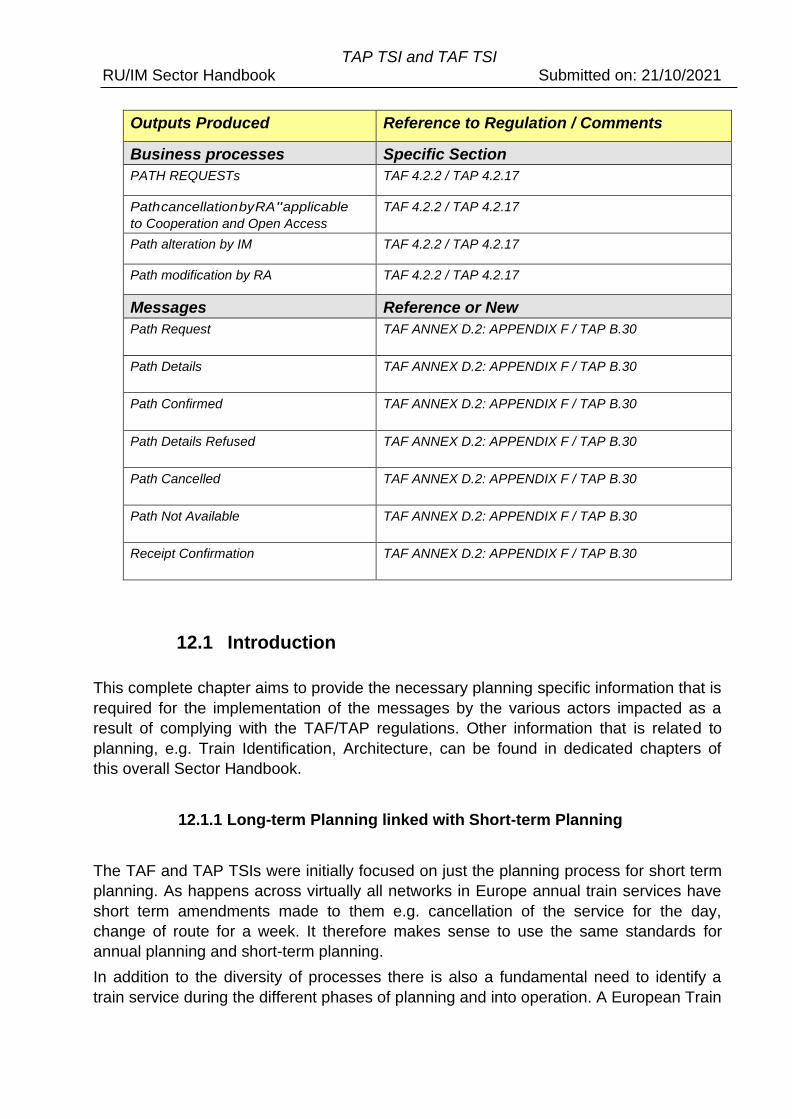
TAP TSI and TAF TSI RU/IM Sector Handbook Submitted on: 21/10/2021
Outputs Produced Reference to Regulation / Comments
Business processes Specific Section
PATH REQUESTs TAF 4.2.2 / TAP 4.2.17
Path cancellation by RA " applicable
to Cooperation and Open Access
models
TAF 4.2.2 / TAP 4.2.17
Path alteration by IM TAF 4.2.2 / TAP 4.2.17
Path modification by RA TAF 4.2.2 / TAP 4.2.17
Messages Reference or New
Path Request TAF ANNEX D.2: APPENDIX F / TAP B.30
Path Details TAF ANNEX D.2: APPENDIX F / TAP B.30
Path Confirmed TAF ANNEX D.2: APPENDIX F / TAP B.30
Path Details Refused TAF ANNEX D.2: APPENDIX F / TAP B.30
Path Cancelled TAF ANNEX D.2: APPENDIX F / TAP B.30
Path Not Available TAF ANNEX D.2: APPENDIX F / TAP B.30
Receipt Confirmation TAF ANNEX D.2: APPENDIX F / TAP B.30
12.1 Introduction
This complete chapter aims to provide the necessary planning specific information that is
required for the implementation of the messages by the various actors impacted as a
result of complying with the TAF/TAP regulations. Other information that is related to
planning, e.g. Train Identification, Architecture, can be found in dedicated chapters of
this overall Sector Handbook.
12.1.1 Long-term Planning linked with Short-term Planning
The TAF and TAP TSIs were initially focused on just the planning process for short term
planning. As happens across virtually all networks in Europe annual train services have
short term amendments made to them e.g. cancellation of the service for the day,
change of route for a week. It therefore makes sense to use the same standards for
annual planning and short-term planning.
In addition to the diversity of processes there is also a fundamental need to identify a
train service during the different phases of planning and into operation. A European Train
TAP TSI and TAF TSI RU/IM Sector Handbook Submitted on: 21/10/2021
Identifier whose main benefit is to have the same number across the various stages –
that includes moving from long term planning into short term planning is used in the
messages. Extending the TAF/TAP processes to include long term activities as well as
short term the problem of train identification for planning can be overcome.
The use of the TAF/TAP processes for Long-term Planning is a recommendation
outside/in addition to both TSIs. It is therefore up to the involved parties to agree on using
it.
12.1.2 The need for Harmonisation
At present, there is no mandate as such for the regulations to include harmonisation7
activities between:
• RAs when setting up a path request
• IMs when planning the path details
However, the handover point from one IM to the next IM, where the legal responsibility is
changing, is often on a line section there the trains do not stop. This means, the RA
interchange point is either in one of the journey locations before or after the handover
point. Interchange point could be also on the Handover point. In this case, RAs could
have the need to collaborate on these sections (e.g. who is requesting till where, which
rolling stock is used). On the IM side, the times at the handover point are often just run
through times. In any case, the times at handover provided by both of the IMs shall be
the same. Therefore, some collaboration between the two involved IMs is required.
In order to have a fully joined up ‘Short-term Path Request’ process it could be
considered that the harmonisation phases between the respective parties (Applicant to
Applicant under the leadership of the LeadRU, IM to IM) are included as relevant
activities. These activities take place currently in planning and they are incorporated into
the overall process. However, harmonisation is not included in the regulations. Therefore,
it has been made optional with a strong recommendation that RAs/IMs adopt them within
their working practices.
12.1.3 Support Mechanism for Harmonization
A support mechanism that has the capability to support and maintain the Short-Term
Path Request process as well as the information (messages) that the process produces
helps in tracking and coordinating the different steps of a path request. Having such
support not only helps to provide evidence of the message transactions that take place
between the actors but also to provide benefits such as auditability, traceability and data
recovery (in the case where information can be lost by sending/receiving systems).
Having the planning information stored commonly will also help with management
reporting and the ability to measure how the process is being utilised by the different
7 However, Directive 2012/34 Article 40 requires IMs to cooperate which each other for the allocation of infrastructure capacity which refers to a harmonization process.
TAP TSI and TAF TSI RU/IM Sector Handbook Submitted on: 21/10/2021
parties.
This common support mechanism is likely to be in the form an IT system or tool, that is
common to the usage of TAF/TAP and that will work in conjunction with the Actor
systems. The tool will have to be fully compliant and could be adopted especially for the
traffic involving more than one network or being interoperable in any other kind.
Interactions to this tool within the specific processes that make up Short Term Path
Request process (e.g. Path Request, Path Alteration) is represented by the swim lanes
“coordination” and “order tracking” within the process diagrams themselves, see Annex
12.1.
The technical analysis of such a tool has to be carried out by interested parties. This will
involve working with different actors (RAs, IMs) in order to define the best way to interact.
The harmonization process also works when using a bilateral data exchange between
two communicating parties8 without a need of adopting the common support mechanism.
The communication will use the same TAP and TAF standards.
12.2 Assumptions
• The term “Short-Term Path Request” process denotes a number of different
processes that range from Path Request, Path Cancellation, Path
Modification/Alteration, Path Not Available and Path Utilisation Notification.
• The Network Statement defines on each network when the Short-Term Path
Request period is applicable before the running of a train.
• As described Short Term Path Request processes, for Short-Term Planning, have
been further extended to include Long-Term Planning processes for the Annual
Timetable (working timetable). Where there is information in the Planning section
that is applicable to both processes, only Short-Term Planning will be mentioned
even though it could apply to Long-Term Planning as well. Where there is
information that is only applicable to one process and not the other, it will be
specifically mentioned which process it is applicable to.
• The application of Short-Term Path Request is mandatory according to TAP and
TAF. The application of the same messages for Annual Timetable/Long Term
Planning is optional.
• It is assumed that all activities described within the processes that are carried out
by each IM are done so in accordance with their Network Statement.
• Even if based on the fulfilment of TAF/TAP regulation, there might be the
possibility that ‘Short-term Path Request’ processes will not be applied, and
companies will be able to follow their national practices and regulations. This will
be in the case of exceptional transport such as the planning of nuclear or military
trains. This will have to be decided by the authorities that determine the national
practices and regulations.
8 The two communicating parties are sender and receiver of the messages. The bilateral exchange could involve all parties relevant for the harmonization. E.g. RU1 to IM1, IM2 to RU2 etc.
TAP TSI and TAF TSI RU/IM Sector Handbook Submitted on: 21/10/2021
• Activities of third parties (e.g. for shunting), acting on behalf of an RA or IM, have
to be dealt by the responsible RA or IM who mandate the third party to handle the
task(s). There will be no requirement for these third parties to be TAF/TAP
compliant, this responsibility lies within the mandating company
• Where there is a change of an RU in the operation, the responsible RA may
use the resources (rolling stock/staff) of another company (e.g. RU).
Responsibility and path ownership stay at the RA with the path contract.
This has no impact to the TAF and TAP apply both to interoperable traffic
and domestic traffic.
• In relation to this document the term IM refers to an IM or an Allocation
Body (AB) that carries out the same function as an IM.
• The term Path Section is used to describe a specific network section where
there is an interoperable journey, however it also refers to a journey that is
within one network.
• If the IM is the owner of the transport (e.g. maintenance train) it will carry
out the same role as an RA and all processes will then be applied as
normal.
12.3 Explanation on the involvement of the RUs and IMs
The principle of TAP and TAF regulation are underpinned by the communication
and collaborative relationship between an RA and the relevant IM. For
interoperable business this usually involves more than one RA and/or IM involved
during the different sections of the path request. However, for domestic business
the relationship can be between one IM and one RA only as well.
The diagram demonstrates the different types of relationships that the processes
will apply to.
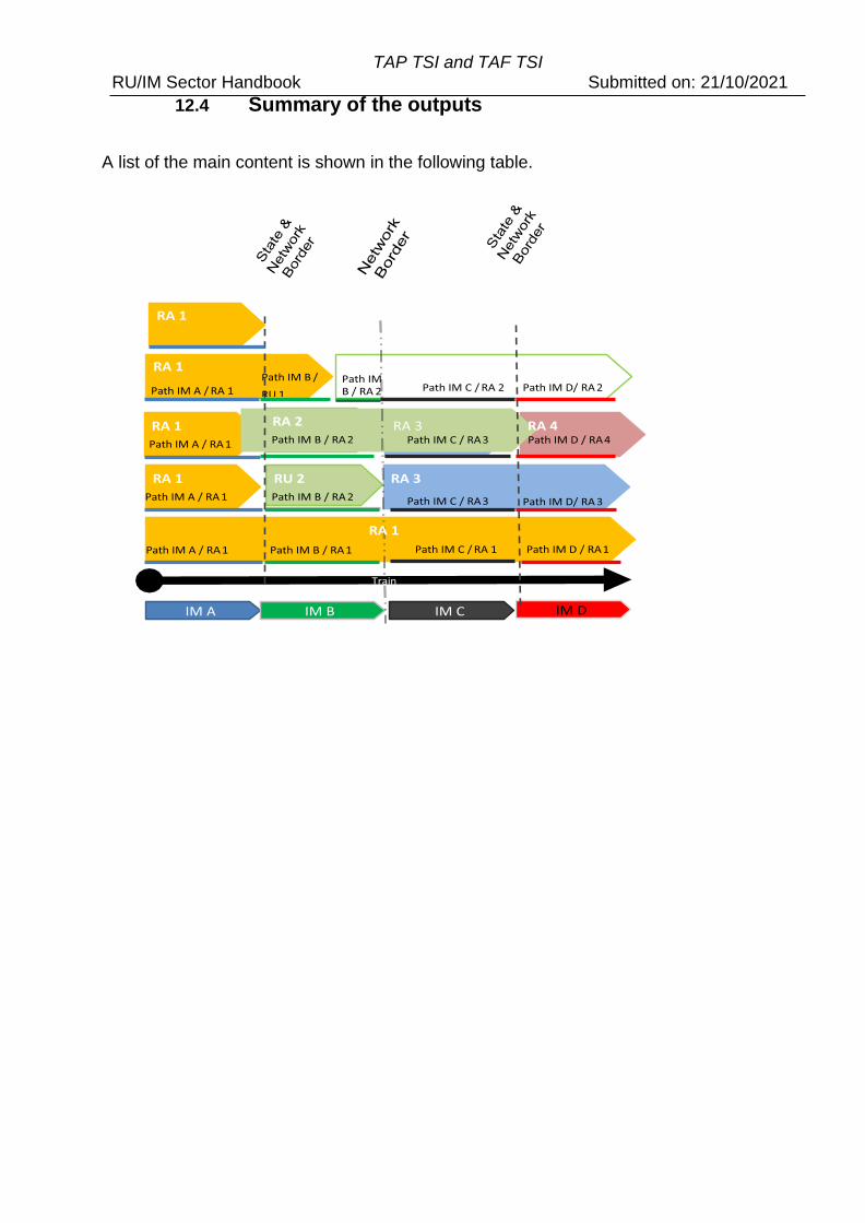
TAP TSI and TAF TSI RU/IM Sector Handbook Submitted on: 21/10/2021
12.4 Summary of the outputs
A list of the main content is shown in the following table.
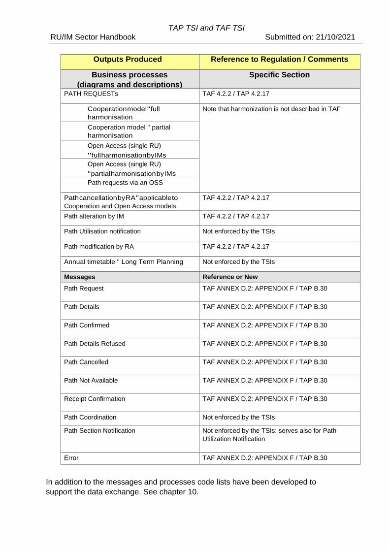
TAP TSI and TAF TSI RU/IM Sector Handbook Submitted on: 21/10/2021
Outputs Produced Reference to Regulation / Comments
Business processes
(diagrams and descriptions)
Specific Section
PATH REQUESTs TAF 4.2.2 / TAP 4.2.17
Cooperation model " full
harmonisation
Note that harmonization is not described in TAF
Cooperation model " partial
harmonisation
Open Access (single RU)
" full harmonisation by IMs
Open Access (single RU)
" partial harmonisation by IMs
Path requests via an OSS
Path cancellation by RA " applicable to
Cooperation and Open Access models
TAF 4.2.2 / TAP 4.2.17
Path alteration by IM TAF 4.2.2 / TAP 4.2.17
Path Utilisation notification Not enforced by the TSIs
Path modification by RA TAF 4.2.2 / TAP 4.2.17
Annual timetable " Long Term Planning Not enforced by the TSIs
Messages Reference or New
Path Request TAF ANNEX D.2: APPENDIX F / TAP B.30
Path Details TAF ANNEX D.2: APPENDIX F / TAP B.30
Path Confirmed TAF ANNEX D.2: APPENDIX F / TAP B.30
Path Details Refused TAF ANNEX D.2: APPENDIX F / TAP B.30
Path Cancelled TAF ANNEX D.2: APPENDIX F / TAP B.30
Path Not Available TAF ANNEX D.2: APPENDIX F / TAP B.30
Receipt Confirmation TAF ANNEX D.2: APPENDIX F / TAP B.30
Path Coordination Not enforced by the TSIs
Path Section Notification Not enforced by the TSIs: serves also for Path
Utilization Notification
Error TAF ANNEX D.2: APPENDIX F / TAP B.30
In addition to the messages and processes code lists have been developed to
support the data exchange. See chapter 10.
TAP TSI and TAF TSI RU/IM Sector Handbook Submitted on: 21/10/2021
12.5 Processes
12.5.1 High Level Overview of the Process
The purpose of implementing TAF/TAP TSIs is to ensure an efficient and concrete
exchange of information between IMs, Allocation Bodies, RAs and other service
providers. The exchange of information is done in relation to the processes during the
planning stage.
This information exchange is essentially bilateral and takes place between the IM in
charge of the Path Section and the RU that will operate over the Path Section. In the
case of an Open Access Operator the RU will be dealing with several IMs.
The processes that make up the ‘Short-term Path Request’ and the “Long Term Path
Request” are shown as a high-level process overview. The TAF/TAP messages that
need to be produced are overlaid onto the process activities that take place.
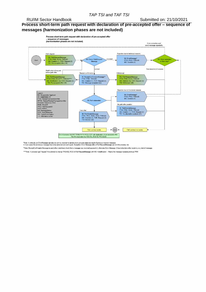
TAP TSI and TAF TSI RU/IM Sector Handbook Submitted on: 21/10/2021
Process short-term path request with declaration of pre-accepted offer – sequence of
messages (harmonization phases are not included)
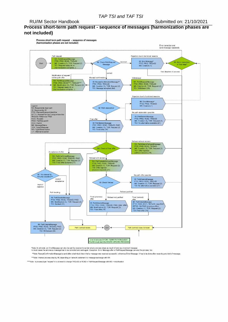
TAP TSI and TAF TSI RU/IM Sector Handbook Submitted on: 21/10/2021
Process short-term path request - sequence of messages (harmonization phases are
not included)
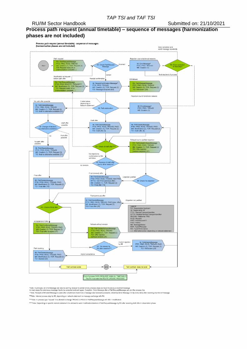
TAP TSI and TAF TSI RU/IM Sector Handbook Submitted on: 21/10/2021
Process path request (annual timetable) – sequence of messages (harmonization
phases are not included)
TAP TSI and TAF TSI RU/IM Sector Handbook Submitted on: 21/10/2021
12.6 The need for Full and Partial Harmonization
Where a short-term path request for traffic (either passenger or freight) running across
one or more networks is placed in sufficient time ahead of the operation, the IMs will be
able to deliver full harmonisation for the path details for all of the sections that comprise
the whole journey. Full harmonisation is when the complete journey for the traffic,
covering all of the respective path sections, has been able to be fully validated by the IMs
involved and all times are confirmed, especially those where the train changes from one
IM to another.
Where a path request is placed at the short notice or if the complexity of the path request
requires more time than anticipated (according to the deadlines set in national
agreements or in their Network Statements), the IMs will not be able to coordinate all of
the sections for the whole journey. In this case the Applicant(s) will receive path details
from the IM which are just coordinated with the next neighbouring IM only ensuring that
the train travel across that section. In addition, if the Applicants are not in a position to
coordinate the request, (e.g. do not have resources for the request because of the short
notice) the Lead RU199 or the RA at the beginning of the traffic may place a partially
harmonised request. In this case the first IM/RA pair is able to start working on the
request the following IM/RA pair(s) will follow as soon as the request is ready for the next
path section. The request is handled more sequentially, and it is not necessary that all the
latter sections have been confirmed before that train sets off across its journey. This is
called partial harmonisation.
There are separate path request processes for the two types of harmonisation.
In some cases, a request for traffic starts off with the aim of carry out a fully harmonised
process and it may be necessary, for whatever reason, to switch from full to partial
harmonisation processes. By default, the aim of harmonisation is to achieve a full
harmonisation of the journey (all path sections), as represented in the Message (Path
Request or Path Details) by two separate elements “Type of RA Harmonisation” and
“Type of IM Harmonization”.
If this is the case the Lead RA or Coordinating IM sets the Type of Harmonisation to Full.
However, this is not possible in all cases and can subsequently be changed to Partial. For
example if the Lead RA realises that it will not be possible to harmonise the path request
with all other involved RUs in due time (e.g. RA at the end of the journey has not clarified
the appropriate need for resources), the Lead RU shall have the possibility to change the
element ‘Type of RA Harmonisation’ in the message Path Request from ‘full’ to ‘partial’.
On the other hand, it could happen that the IMs are not in a position to send harmonised
path details to the RA (in case of an Open Access request) or to all involved RAs
(cooperation model) in due time. This could be for example in a case where there is a
shortage of time between placing the request involving several networks and the foreseen
departure time at the origin of the train. The Coordinating IM or as a default the IM at the
first network of the train departure shall have the possibility to change the element ‘Type
of IM Harmonisation’ in the message ‘Path Details from ‘full’ to ‘partial’.
9 See chapter 7 for the different uses of the term “Lead RU” in TAF and TAP. In the following text, “Lead RU” is used to designate this RU/AP for TAP.
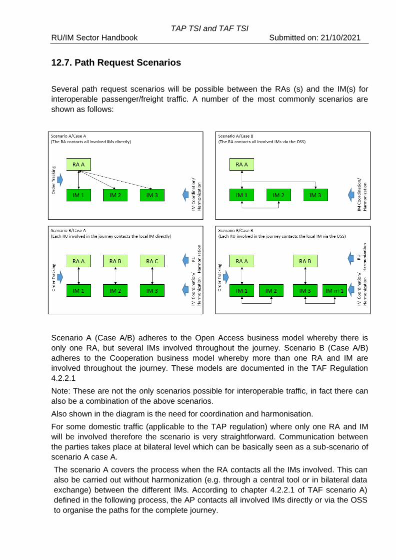
TAP TSI and TAF TSI RU/IM Sector Handbook Submitted on: 21/10/2021
12.7. Path Request Scenarios
Several path request scenarios will be possible between the RAs (s) and the IM(s) for
interoperable passenger/freight traffic. A number of the most commonly scenarios are
shown as follows:
Scenario A (Case A/B) adheres to the Open Access business model whereby there is
only one RA, but several IMs involved throughout the journey. Scenario B (Case A/B)
adheres to the Cooperation business model whereby more than one RA and IM are
involved throughout the journey. These models are documented in the TAF Regulation
4.2.2.1
Note: These are not the only scenarios possible for interoperable traffic, in fact there can
also be a combination of the above scenarios.
Also shown in the diagram is the need for coordination and harmonisation.
For some domestic traffic (applicable to the TAP regulation) where only one RA and IM
will be involved therefore the scenario is very straightforward. Communication between
the parties takes place at bilateral level which can be basically seen as a sub-scenario of
scenario A case A.
The scenario A covers the process when the RA contacts all the IMs involved. This can
also be carried out without harmonization (e.g. through a central tool or in bilateral data
exchange) between the different IMs. According to chapter 4.2.2.1 of TAF scenario A)
defined in the following process, the AP contacts all involved IMs directly or via the OSS
to organise the paths for the complete journey.
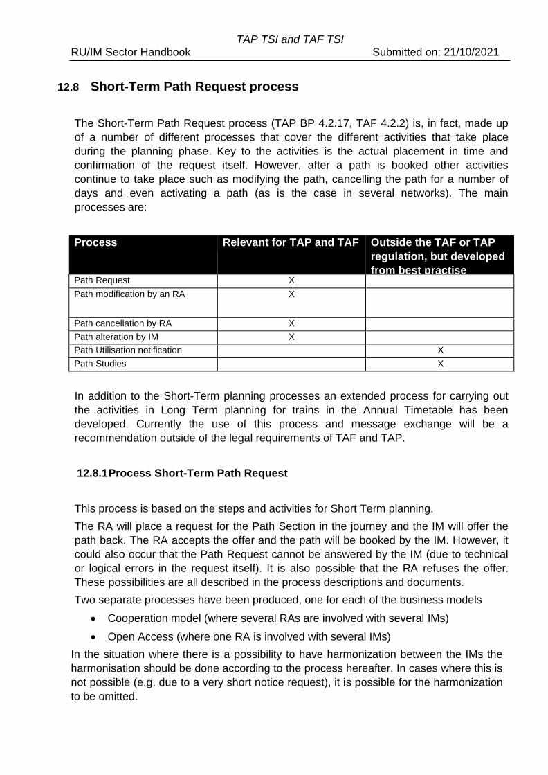
TAP TSI and TAF TSI RU/IM Sector Handbook Submitted on: 21/10/2021
12.8 Short-Term Path Request process
The Short-Term Path Request process (TAP BP 4.2.17, TAF 4.2.2) is, in fact, made up
of a number of different processes that cover the different activities that take place
during the planning phase. Key to the activities is the actual placement in time and
confirmation of the request itself. However, after a path is booked other activities
continue to take place such as modifying the path, cancelling the path for a number of
days and even activating a path (as is the case in several networks). The main
processes are:
Process Relevant for TAP and TAF Outside the TAF or TAP
regulation, but developed
from best practise Path Request X
Path modification by an RA X
Path cancellation by RA X
Path alteration by IM X
Path Utilisation notification X
Path Studies X
In addition to the Short-Term planning processes an extended process for carrying out
the activities in Long Term planning for trains in the Annual Timetable has been
developed. Currently the use of this process and message exchange will be a
recommendation outside of the legal requirements of TAF and TAP.
12.8.1 Process Short-Term Path Request
This process is based on the steps and activities for Short Term planning.
The RA will place a request for the Path Section in the journey and the IM will offer the
path back. The RA accepts the offer and the path will be booked by the IM. However, it
could also occur that the Path Request cannot be answered by the IM (due to technical
or logical errors in the request itself). It is also possible that the RA refuses the offer.
These possibilities are all described in the process descriptions and documents.
Two separate processes have been produced, one for each of the business models
• Cooperation model (where several RAs are involved with several IMs)
• Open Access (where one RA is involved with several IMs)
In the situation where there is a possibility to have harmonization between the IMs the
harmonisation should be done according to the process hereafter. In cases where this is
not possible (e.g. due to a very short notice request), it is possible for the harmonization
to be omitted.
TAP TSI and TAF TSI RU/IM Sector Handbook Submitted on: 21/10/2021
12.8.2 Process Short-Term Path Request – Full Harmonization
This process is based on the steps and activities for Short-Term planning.
All path sections must be harmonised and agreed between the involved RAs before
requesting and all involved IMs before an offer can be made back to the RUs.
The RA will place a request for the Path Section in the journey and the IM will offer the
path back. The RA accepts the offer and the path will be booked by the IM. However, it
could also be the case that the Path Request cannot be answered by the IM (due to
technical or logical errors in the request itself). It is also possible that the RA refuses the
offer. These possibilities are all described in the process descriptions and documents.
Two separate processes have been produced, one for each of the business models
• Cooperation model (where several RAs are involved with several IMs)
• Open Access (where one RA is involved with several IMs)
12.8.3 Process «Short-Term Path Request partial harmonisation»
This process is based on the steps and activities for Short Term planning for Full
Harmonisation.
It might be that all path requests may not be able to be harmonised between the
Applicants and that the IMs will not be in a position to always deliver harmonised path
details. This is mostly in the case of very short-term Path Requests where the time limit
between the path request and the train departure is too short and it is not possible to
harmonise the path request and/or path details. This process may be applied for the
following business models:
Two separate processes have been produced, one for each of the business models
• Cooperation model (where several RAs are involved with several IMs)
• Open Access (where one RA is involved with several IMs)
12.8.4 Process Path cancellation by RA
This process applies to both paths in the Annual Timetable and those booked using the
Short-term planning process.
Whether the path was booked in the long-term planning (annual timetable) or as a short
request, the RA must have always the possibility to cancel a booked path. This path
cancellation may refer to one single day, several or all remaining days. It is also possible
to cancel the whole traffic (all of the path sections) or just one or more partial sections of
the traffic (one path section).
However, in case there are several path sections with RAs involved, it may even be
possible that one of the involved RAs may keep its booked path section and reuse it for
another train. By doing so, the path modification process shall be applied instead for the
RA that still wishes to use the path section for other traffic. Partial cancellation is not
recommended without harmonization with partner RAs and IMs in order not to destroy the
path.
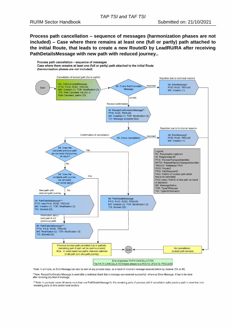
TAP TSI and TAF TSI RU/IM Sector Handbook Submitted on: 21/10/2021
Process path cancellation – sequence of messages (harmonization phases are not
included) – Case where there remains at least one (full or partly) path attached to
the initial Route, that leads to create a new RouteID by LeadRU/RA after receiving
PathDetailsMessage with new path with reduced journey..
TAP TSI and TAF TSI RU/IM Sector Handbook Submitted on: 21/10/2021
12.8.5 Process Path alteration by IM
This process applies to both paths in the Annual Timetable and those booked using the
Short-term planning process.
Based on the path agreement, the RA can expect that a booked path is available up to its
operation. However, if an event occurs (e.g. disruption to the path) prior to the start of the
operation and the booked path from either the long-term (annual timetable) or short-term
planning is no longer available, the IM must inform the RA as soon as it has the
knowledge about this fact.
A cause of the event (e.g. an interruption on the path) needs to be indicated to the RA.
This can happen at any time between the moment the path is booked and the departure
of the train. The IM is obliged to send an alternative proposal together with the indication
the Path is not available. However, this is not always possible. In that case the IM must
inform RA immediately. Special cases like the interruption of the path in the middle of the
route have to be handled separately. The general rule agreed in the sector is to avoid
such situations of path interruption in the middle, if possible. If it cannot be avoided, the
handling of such a case needs to be started immediately between the partners and the
following possibilities need to be analysed:
• Providing an immediate alternative by the IM on which territory the interruption
happened, all other paths (and/or path sections) remain booked as before
• No possibility to provide the alternative for the interrupted section: all other paths
(and/or path sections) remain booked and used by RA (example of 3 IMs in 3
countries: the second IM has an interruption, but the RUs keep using the paths in
IM1 and IM3 territories). In such a case, the “Train splitting” consequences for the
RA (significant change on the train object) have to be considered.
• Cancelation of the whole path by the RA and request a new one – depending on
the commercial conditions between IMs and RA
• Non-availability announced by IMs for the whole path and providing the
coordinated alternative
This path alteration may refer to one single day, several days or all remaining days. It is
also possible to alter the whole path section or just a part of it.
The simplified process model with messages looks as follows.
Nota : The Path Alteration process is also used by a simplified manner for the Route
Update process, see section 12.8.9.
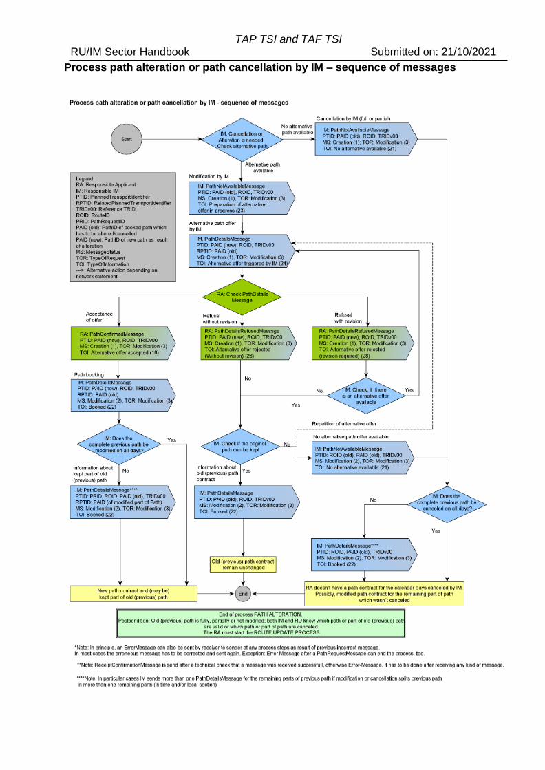
TAP TSI and TAF TSI RU/IM Sector Handbook Submitted on: 21/10/2021
Process path alteration or path cancellation by IM – sequence of messages
TAP TSI and TAF TSI RU/IM Sector Handbook Submitted on: 21/10/2021
Page 79
Where the alternative is physically not possible, the Path Not Available message will carry
the corresponding type of information (21) which should indicate that the alternative is not
possible. In all other cases, the IM will send Path Not Available message with type of
information 23 (preparation of alternative offer in progress) and then send the Path
Details message containing the alternative offer. After receiving and confirming that
alternative offer LeadRU/RA has to start process for updating the route if needed.
12.8.6 Process Path modification by RA
This process applies to both paths in the Annual Timetable and those booked using the
Short-term planning process.
Based on the path agreement, the RA intends to change some elements of the train that
could impact the path details after it has been booked. A modification can be done for one
day, several or all remaining booked days. Modifications that need to be communicated
are described in the Network Statement and could be for example:
• Change of engine type with same performance
• reduction in the train length/weight
• operational stop changes to technical stop
If a Path Modification has a strong impact on the path, the IM can reject the modification.
The RA needs to cancel the allocated path (fully or partially) and to place a new request.
This will lead to a new path request where the IM will send first a draft offer after the path
elaboration.
The simplified process model with messages looks as follows.
There are in fact two processes :
• if the requested path to modify a booked path after RU harmonization (before
sending the path request) keeps the same Route (same origin, handover,
destination), ROID is unchanged ;
• if the requested path to modify a booked path after RU harmonization (before
sending the path request) leads to a new Route (e.g. if origin is modified by RU),
the Route has to be modified with a new ROID (usually new variant) by LeadRU.
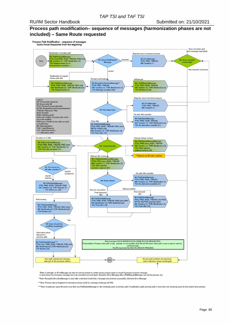
TAP TSI and TAF TSI RU/IM Sector Handbook Submitted on: 21/10/2021
Page 80
Process path modification– sequence of messages (harmonization phases are not
included) – Same Route requested
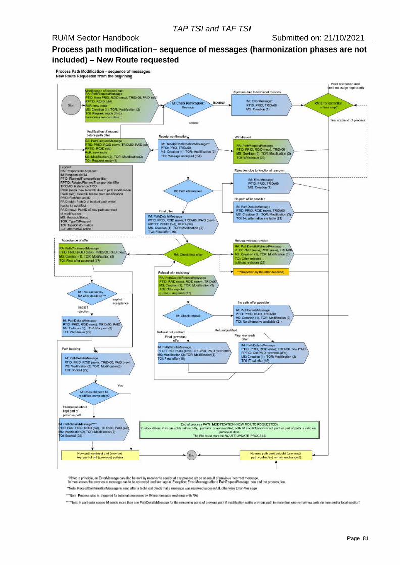
TAP TSI and TAF TSI RU/IM Sector Handbook Submitted on: 21/10/2021
Page 81
Process path modification– sequence of messages (harmonization phases are not
included) – New Route requested
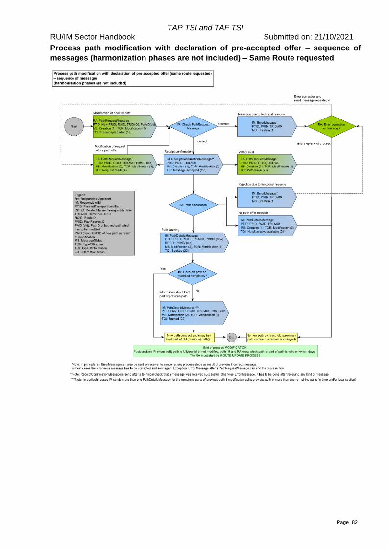
TAP TSI and TAF TSI RU/IM Sector Handbook Submitted on: 21/10/2021
Page 82
Process path modification with declaration of pre-accepted offer – sequence of
messages (harmonization phases are not included) – Same Route requested
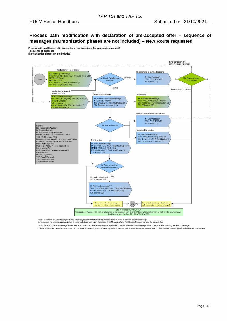
TAP TSI and TAF TSI RU/IM Sector Handbook Submitted on: 21/10/2021
Page 83
Process path modification with declaration of pre-accepted offer – sequence of
messages (harmonization phases are not included) – New Route requested
TAP TSI and TAF TSI RU/IM Sector Handbook Submitted on: 21/10/2021
Page 84
12.8.7 Process Path Utilisation Notification by RA
This process applies to both paths in the Annual Timetable and those booked using the
Short-term planning process.
In some networks it is possible to pre-book a path and it is called an “on demand path”.
The capacity has been allocated to an RA who has to inform the IM in due time and prior
to the operation on the utilisation of this path, meaning that the train should then be run
operationally. This type of practice between RA and IM is mainly used in cases where an
RA has regular transport needs but does not know when to make the path request e.g.
due to fluctuations in business. All of the path information (e.g. period, origin location,
route etc..) is built up in the “on demand path” and is treated in exactly the same way by
the IM whereby a path is offered and subsequently booked.
12.8.8 The Need for Path Studies
The intention of a path study is to support the RA by the IMs while setting up a path
request in anticipation of placing the actual request. It allows the RA to get timings for its
intended train service to be used in its planning before placing a path request. Path
studies make a significant contribution to the efficiency of the path allocation process for
the annual timetable. These studies allow applicants’ service plans to be checked for
feasibility and, as necessary, taken through into the next stages of the planning process.
It is used mainly in the working timetable but can also be applied for the running
timetable. No separate process description has been considered for this. This is because
the process is identical for a path request, except the last step of the booking the path will
not be carried out by the IM.
The IM answer to a path study request before the timetable starts is never binding. If the
path study had been placed within the running timetable, the legal status of an IM answer
depends to company/national rules.
Path studies are in addition to TAF and TAP. It follows best practice from the sector and
can be used with the TAP and TAF standards although it is not mandated by TAP and
TAF.
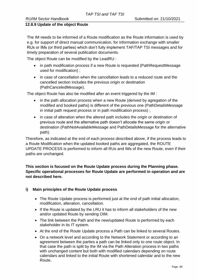
TAP TSI and TAF TSI RU/IM Sector Handbook Submitted on: 21/10/2021
Page 85
12.8.9 Update of the object Route
The IM needs to be informed of a Route modification as the Route information is used by
e.g. for support of direct manual communication, for information exchange with smaller
RUs or IMs (or third parties) which don’t fully implement TAF/TAP TSI messages and for
timely preparation of several publication documents.
The object Route can be modified by the LeadRU :
• in path modification process if a new Route is requested (PathRequestMessage
used for modification) ;
• in case of cancellation when the cancellation leads to a reduced route and the
cancelled section includes the previous origin or destination
(PathCanceledMessage).
The object Route has also be modified after an event triggered by the IM :
• in the path allocation process when a new Route (derived by agregation of the
modified and booked paths) is different of the previous one (PathDetailsMessage
in initial path request process or in path modification process) ;
• in case of alteration when the altered path includes the origin or destination of
previous route and the alternative path doesn’t allocate the same origin or
destination (PathNotAvailableMessage and PathDetailsMessage for the alternative
path).
Therefore, as indicated at the end of each process described above, if the process leads to
a Route Modification when the updated booked paths are aggregated, the ROUTE
UPDATE PROCESS is performed to inform all RUs and IMs of the new Route, even if their
paths are unchanged.
This section is focused on the Route Update process during the Planning phase.
Specific operational processes for Route Update are performed in operation and are
not described here.
i) Main principles of the Route Update process
• The Route Update process is performed just at the end of path initial allocation, modification, alteration, cancellation.
• If the Route is updated by the LRU it has to inform all stakeholders of the new and/or updated Route by sending OIM.
• The link between the Path and the new/updated Route is performed by each stakeholder in its IT system.
• At the end of the Route Update process a Path can be linked to several Routes.
• On a network level and according to the Network Statement or according to an agreement between the parties a path can be linked only to one route object. In that case the path is split by the IM via the Path Alteration process in two paths with unchanged content but both with modified calendars depending on route calendars and linked to the initial Route with shortened calendar and to the new Route.
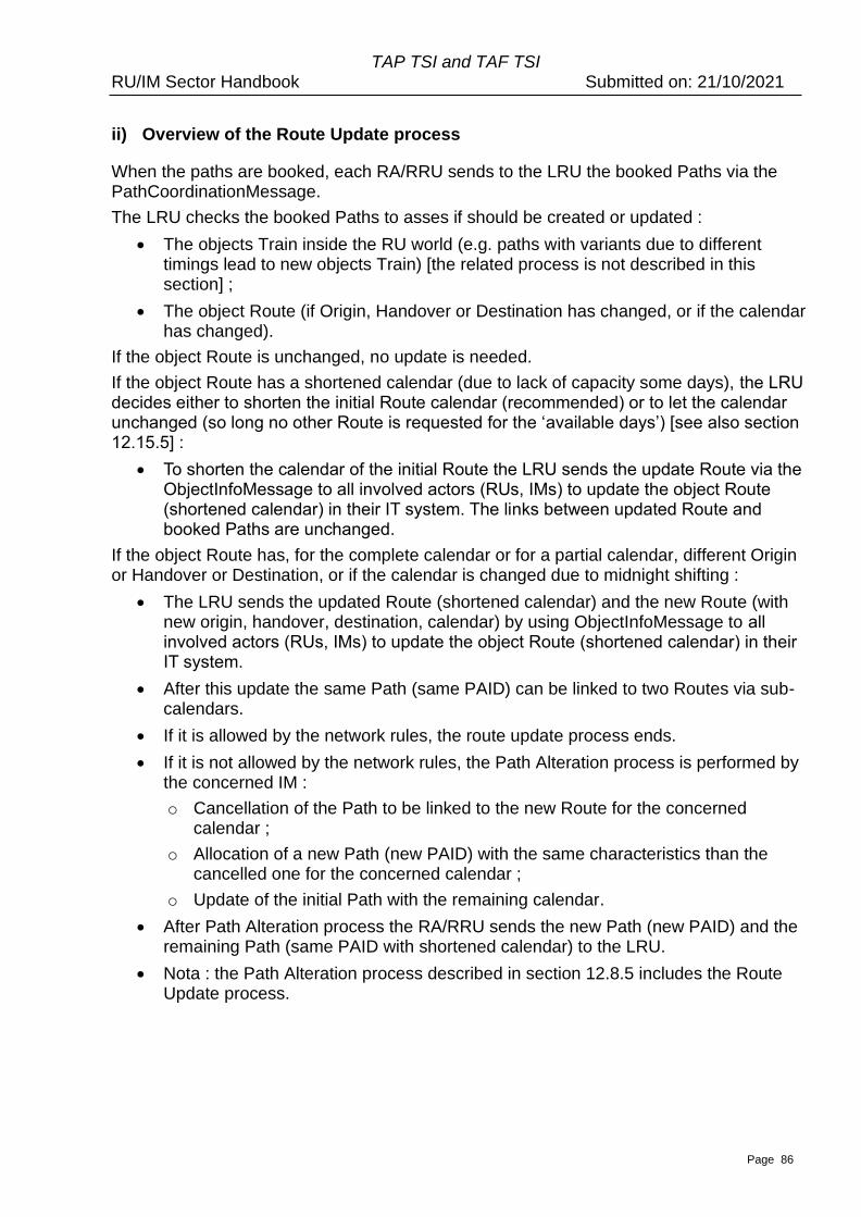
TAP TSI and TAF TSI RU/IM Sector Handbook Submitted on: 21/10/2021
Page 86
ii) Overview of the Route Update process
When the paths are booked, each RA/RRU sends to the LRU the booked Paths via the PathCoordinationMessage.
The LRU checks the booked Paths to asses if should be created or updated :
• The objects Train inside the RU world (e.g. paths with variants due to different timings lead to new objects Train) [the related process is not described in this section] ;
• The object Route (if Origin, Handover or Destination has changed, or if the calendar has changed).
If the object Route is unchanged, no update is needed.
If the object Route has a shortened calendar (due to lack of capacity some days), the LRU decides either to shorten the initial Route calendar (recommended) or to let the calendar unchanged (so long no other Route is requested for the ‘available days’) [see also section 12.15.5] :
• To shorten the calendar of the initial Route the LRU sends the update Route via the ObjectInfoMessage to all involved actors (RUs, IMs) to update the object Route (shortened calendar) in their IT system. The links between updated Route and booked Paths are unchanged.
If the object Route has, for the complete calendar or for a partial calendar, different Origin or Handover or Destination, or if the calendar is changed due to midnight shifting :
• The LRU sends the updated Route (shortened calendar) and the new Route (with new origin, handover, destination, calendar) by using ObjectInfoMessage to all involved actors (RUs, IMs) to update the object Route (shortened calendar) in their IT system.
• After this update the same Path (same PAID) can be linked to two Routes via sub-calendars.
• If it is allowed by the network rules, the route update process ends.
• If it is not allowed by the network rules, the Path Alteration process is performed by the concerned IM :
o Cancellation of the Path to be linked to the new Route for the concerned calendar ;
o Allocation of a new Path (new PAID) with the same characteristics than the cancelled one for the concerned calendar ;
o Update of the initial Path with the remaining calendar.
• After Path Alteration process the RA/RRU sends the new Path (new PAID) and the remaining Path (same PAID with shortened calendar) to the LRU.
• Nota : the Path Alteration process described in section 12.8.5 includes the Route Update process.
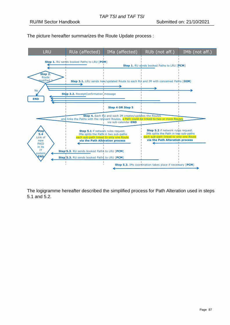
TAP TSI and TAF TSI RU/IM Sector Handbook Submitted on: 21/10/2021
Page 87
The picture hereafter summarizes the Route Update process :
The logigramme hereafter described the simplified process for Path Alteration used in steps
5.1 and 5.2.
LRU RUa (affected) IMa (affected) RUb (not aff.) IMb (not aff.)
Step 1. RU sends booked Paths to LRU [PCM]
Step 2.Route
modified ?
No
END
Step 3.1. LRU sends new/updated Route to each RU and IM with concerned Paths [OIM]
Step 4. Each RU and each IM creates/updates the Routes and links the Paths with the relevant Routes, a Path could be linked to two or more Routes
via sub-calendar END
Step 1. RU sends booked Paths to LRU [PCM]
Step 5.3. RU sends booked Paths to LRU [PCM]
Step 5.1 if network rules request.IMa splits the Path in two sub-paths
each sub-path linked to only one Routevia the Path Alteration process
Step 5.3. RU sends booked Paths to LRU [PCM]
Step 3.2. ReceiptConfirmation message
Step 5.2 if network rules request.IMb splits the Path in two sub-paths
each sub-path linked to only one Routevia the Path Alteration process
Step 4 OR Step 5
Step 5.3. IMs coordination takes place if necessary [PCM]
Step5.4
Link of new PAID in its
IT systemEND
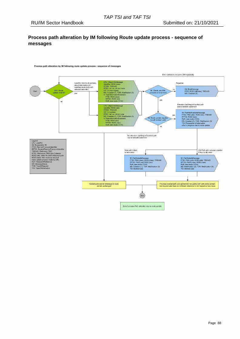
TAP TSI and TAF TSI RU/IM Sector Handbook Submitted on: 21/10/2021
Page 88
Process path alteration by IM following Route update process - sequence of
messages
TAP TSI and TAF TSI RU/IM Sector Handbook Submitted on: 21/10/2021
Page 89
12.9 Train Identifiers
12.9.1 Identification of the train
With the full implementation of TAP and TAF the messages used in the Path Request will
need to follow the Train Identification convention that will be applied as mandatory. It is a
composite set of identifiers exchanged between LRU/RA/RRU andIM that uses the
following:
• Reference Train ID (TRIDv00). A unique ID provided by the LeadRU/RA that stays
with train throughout the different planning activities and beyond into Operation.
The link between Route ID, Path ID and Reference Train ID is confirmed/fixed with
the Path Confirmation Message.
• Route ID. A unique ID provided by the LeadRU/RA that stays with route throughout
the different planning activities and beyond into Operation. The link between Route
ID and Reference Train ID is established with PathRequestMessage (sent by RA)
and confirmed/fixed with the Path Confirmation Message (path accepted by RA
and booked by IM).
• Path Request ID – A unique ID provided by the RA when making the path request
(staying on through the whole planning process). After a path is booked, any
request for Path Modification by the RA (planning or operation) must use a new
PathRequest Identifier. The lifecycle of the PRID ends when the path is booked or
the offer was rejected or no alternative offer was possible.
• Path ID. A unique ID provided by the IM when offering a requested path
• Case Reference ID – A unique ID that can be used to identify business cases that
cover one or more trains that have been requested and can be used by both the
RU and IM. For example, an RA requests a regular set services for a train
travelling A – Z and then Z – A. The RU uses one single Case Reference ID for
both services but there will be two separate trains, one for A – Z and another for Z
– A. For more explanation see chapter 8.2.3.4.
The Train ID itself (TRID with variant v01 to vZZ) remains in LRU/RA/RRU ecosystem and
is created and updated according to LRU/RA/RRU rules.
Within the “Identifiers” section of the messages, only one ID with the same object type
(ReferenceTRIDv00, ROID, PRID, PAID, TRIDv01-ZZ in RU world) should be used
(except CaseReferenceID)). The exception is the related Identifiers, where more than one
relation can be represented.
Currently TAF/TAP regulation does not stipulate the use the Train Identifiers as
mandatory for the initial implementation. However, provision has been made in the
planning messages to allow the use the composite identifier. It is therefore possible, that
for the initial implementation and up to the point where the use of Train Identifiers
becomes mandatory, to use tailored identifiers as defined by the Actors and represented
in the TAF and TAP message catalogues.
The use of a legacy identifier such as the ‘Operational Train Number’ as an identifier
during the planning and operational phase will be possible for use as by an RA or IM for
train identification until the proposed structure of the Train Identifiers has been
implemented as a mandatory requirement.
TAP TSI and TAF TSI RU/IM Sector Handbook Submitted on: 21/10/2021
Page 90
For some Actors the initial implementation may see them using a combination of the Train
Identifiers and the legacy identifiers as per their national regulations relating to train
identification.
Further details on the aims and usage of the different identifiers throughout the different
processes are explained in Chapter 8 of this document where also the link to the
description of the TrainID is made.
12.9.2 Referenced objects as Part of RelatedPlannedTransportIdentifiersSection
Within the RelatedPlannedTransportIdentifiers section there are elements that are able to
identify other objects that are related to the train in the Message itself. This is to show the
relationship for business activities that are related to the train identified in the path
request. This includes for example the following scenarios:
• identifying the train with an earlier request e.g. a path study
• identifying connecting services
• induced traffic
These elements are held in the RelatedPlannedTransportIdentifiersSection of the
Message.
They are used as follows
• Case reference IDs. the path request is related to a case reference object or
grouped by the CRID
• Route ID – the path request is related to one or more other routes
• Path IDs – the path request is related to one or more (other) specific paths
• Path Request ID – the path request is related to another path requests
Within the related identifier section, more than one ID of the same type can be
transmitted. It is currently under analysis of the sector how to indicate the purpose of the
particular identifier in the “related identifiers” section by using specific
ReasonOfReference.
12.9.3 Related Trains as Part of Train Activity
It is also possible to include other trains identifiers in a Message based on a relationship
as a result of a specific train activity. Within the Train Activity section, it is possible to
identify one or more trains as a result of specific activities that can take place on a
location within the schedule.
If the Activity Code is related to another train, then one or both of the elements
“associatedTrID” and/or “associatedOTN” (that is relevant for the transition to TrID) will
need to be completed.
For example, it is possible to identify another train that are related to each other as a
result of ”Connecting service to other train” (0044)/”Connecting service from other train”
(0045) train activity that can take place at a specific train location. Both trains in
connections are identified by their Reference TRID (TRID1v00 for one train and
TRID2v00 for the other train).
TAP TSI and TAF TSI RU/IM Sector Handbook Submitted on: 21/10/2021
Page 91
12.10. Messages for Short Term Path Request
12.10.1 General remarks to all Messages
• An error (as defined by the codes used for Error Message (Annex 10.2) identified
for an optional element will have to be treated in the same way as an error for
mandatory element. It will have to be corrected and then resubmitted following the
normal process if required.
• A message may contain an indication on the event in the business process. This is
driven from the business context point of view in order to inform the recipient of
this message regarding the consequence of the process activity that has just taken
place (e.g. ‘No alternative available’ in the message ‘path details’). For this
purpose, the element TypeOfInformation is used.
• All messages have an element “Message status” that identifies its current status
(‘creation’, ‘modification’, ‘deletion’). This status is generated and subsequently
updated only by the system as a result of process activity step that has taken place
(e.g. ‘modification’ in the case when the RU changes a train parameter in the
message ‘path request’ and re-submits the request).
• TypeOfRequest element indicates which process should be applied: Path Request,
Path Study or Path Modification. The element TypeOfRequest is used in all
messages. When TypeOfRequest is used in Path Details message by IM, and the
type “Path Modification” is used, it indicates the Path Alteration process (in the
same way as it is used for Path Request to indicate that there is the Path
Modification process ongoing).
12.10.2 Structure of the Message
This section aims to give a brief overview of the main message elements:
Message header
The message header is common for all RA/IM messages and therefore has no business
relevance related to Short Term Planning process. It is purely a technical part of the
message. See chapter 11.
Identifiers
This element group holds the composite identifiers for Reference TRID, RouteID, Path ID,
Path Request ID and Case Reference ID (PlannedTrasportIdetifiers) and any other
related identifier (RelatedPlannedTransportIdentifiers) that interacts with e.g. related Train
ID could well be the one of another train that is attached to the main train during its
journey.
TAP TSI and TAF TSI RU/IM Sector Handbook Submitted on: 21/10/2021
Page 92
Train information
When used inside the LRU/RA/RRU ecosystem, this element group is used to facilitate
the harmonisation between the involved RAs, and to be used for information publication
needs.
When the Train information is sent by the LRU/RA/RRU to the IM in Path Request
message, it contains only the elements describing the Route (origin, handover,
destination, planned calendar, OTR) completed by the Path Planning Reference Location
(PPRL). Even if transmitted by the element Train Information, the PPRL is not part of the
Route also transmitted by the element Train Information.
The element TrainInformation sent by the LRU/RA/RRU to the IM can also contain
agreed elements such ResponsibleApplicant and ResponsibleIM in order to facilitate the
coordination between IMs. These elements transmitted via TrainInformation are not part
of the object Route.
The train information element contains the following information related to the train to
permit Train Harmonisation in LRU/RA/RRU ecosystem and to prepare the Path Request
message (where the Train Information contains only Route information, PPRL and
ResponsibleApplicant / ResponsibleIM if agreed) :
• Schedule for the entire journey which includes all the key locations (Origin, final
destination, interchange, handover, points with commercial stops) and their timings
and activities.
• Path Planning Reference Location indicates the point from which the timetable
needs to be planned to/from
o It is not always at the origin of a train run where the path planning starts. It
may happen that an RA received a specific slot in a terminal at the final
destination. In this case, the path planning is done backwards. The planning
could also start in an interchange point in the middle of the journey based
on an optimal engine circulation program. Therefore the (lead) RA has the
possibility to choose the start of the path planning, according to the
particular business case.
The calendar provided in the Train object still represents the dates of
departure at the first location provided in the Train Information.
It means:
• if the reference location is within the scope of the IM, the IM should start
planning calculation from the reference location for the calendar
calculated the following way : provided calendar in the request + offset at
the location in the request which corresponds to the reference location in
the Train Information
• If the reference location is outside the scope of IM, the IM should start
planning calculation from handover point for the calendar calculated in
following way: the calendar in the request + offset corresponding to the
handover point which is closest to the reference point.
• planned train technical data which refers to the composition of the train and other
technical parameters for the entire journey from the origin of the train until its final

TAP TSI and TAF TSI RU/IM Sector Handbook Submitted on: 21/10/2021
Page 93
destination and the eventual change of composition and/or technical parameters
during the run of the train. This is used for harmonization and information. The
technical parameters for the path construction are derived from the Path
Information Section.
TAP TSI and TAF TSI RU/IM Sector Handbook Submitted on: 21/10/2021
Page 94
Path information
This element group is used as a mechanism of communication by the RA and IM which
holds the details from RA for each Path section or offered/booked journey section from one
IM. The journey section starts at the origin of the train or at the handover point between
IM’s and ends at final destination or at the next handover point. This consists of all points
that are specific to the Path Section (e.g. Station Stops, Run Throughs, Handover Points).
The data in the Path Information section is used to construct the path (from Path Request)
and to inform about the offered path (in Path Details). The Planned Journey Location
structure has the same elements as the train information. The Path Information section
carries the planned calendar and the OTR but, differently as in Train Information, it does
not carry the “Reference Point”. In the Path Information section, the reference point for
calculation of the offsets in the calendar is the first point of the Planned Journey Location
array.
The Planned Calendar and the OTR permit to calculate the related Reference Calendar of
any path.
The Reference Calendar is also indicated in the element ReferenceTRIDSubCalendar
referring to the object described in the element PathInformation of the message.
Status of Harmonisation
This element identifies the type of harmonisation (Full, Partial). A dossier (especially path
request and/or path details) may be fully or partially harmonised. This attribute indicates
the relevant status.
In case of just one single RA and one IM where the train is travelling in one network only,
either “full” or “none” can be used, but not “partially”.
On Demand Paths
The usage of “on demand paths” is optional and subject to national rules. It has to be
activated by RA for use of the path.
Operational Train Number (OTN)
This element, OTN, is given by the IM to the RA as soon as the foreseen OTN is known, at
the latest before operation (before train preparation phase) by updating the message “Path
Details” (status “modification”). In some networks it can be provided beforehand by the RA
as part of the Path Request in conjunction with the IM. The OTN is seen as an attribute of
the Path object and therefore it is contained in each path section (on each Planned
Journey Location element level). Technically speaking, in the XSD it is an optional element
since the RA may indicate the OTN in the path request in the conjunction with IM as
indicated above. On the other hand, it is likely that the IM will treat the OTN as a
mandatory part of each path section when the path details are provided to the RU,
especially if the OTN is changed from one path section to another.
TAP TSI and TAF TSI RU/IM Sector Handbook Submitted on: 21/10/2021
Page 95
Network Specific Parameters section
This element group may be used for specific attributes which are not mandatory on all
networks and can be used bilaterally by the RA and IM. This element group should only be
used between an RA /IM on a national section when it is absolutely necessary and where
no common element in the main message can be identified. Otherwise there is a danger
that the RA /IM could start using elements in this group and not use the elements from the
common sections.
Before a company creates a Network Specific Parameter element it is required that the
company checks the use of the element with the governance entity and its relevant work
groups who will advise them if no common element can be created. See also chapter 22.
Affected Section
This element group will be applied only in case of planning activities related to the full or
partial path cancellation, alteration or utilisation notification of a path section.
Affected section is a part of the path and it’s defined by the start point of section (first point)
and the end point of section (last point), where start point and end point appear only once
in the section optionally with its BookedLocationTime (planning) or
BookedLocationDateTime (operation) to avoid ambiguity, and is effectively used for
identifying a specific train that is within a section.
Affected section is also carried in the messages as an array, and therefore serves to
indicate which sections are affected as precise as possible. The level of the detail
indicated by the array of affected sections should be the same as in the Path Information
section of the Path object delivered in the Path Details message.
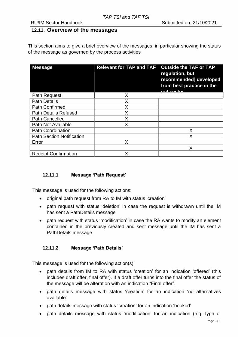
TAP TSI and TAF TSI RU/IM Sector Handbook Submitted on: 21/10/2021
Page 96
12.11. Overview of the messages
This section aims to give a brief overview of the messages, in particular showing the status
of the message as governed by the process activities
Message Relevant for TAP and TAF Outside the TAF or TAP
regulation, but
recommended] developed
from best practice in the
rail sector Path Request X
Path Details X
Path Confirmed X
Path Details Refused X
Path Cancelled X
Path Not Available X
Path Coordination X
Path Section Notification X
Error X
X
Receipt Confirmation X
12.11.1 Message ‘Path Request’
This message is used for the following actions:
• original path request from RA to IM with status ‘creation’
• path request with status ‘deletion’ in case the request is withdrawn until the IM
has sent a PathDetails message
• path request with status ‘modification’ in case the RA wants to modify an element
contained in the previously created and sent message until the IM has sent a
PathDetails message
12.11.2 Message ‘Path Details’
This message is used for the following action(s):
• path details from IM to RA with status ‘creation’ for an indication ‘offered’ (this
includes draft offer, final offer). If a draft offer turns into the final offer the status of
the message will be alteration with an indication “Final offer”.
• path details message with status ‘creation’ for an indication ‘no alternatives
available’
• path details message with status ‘creation’ for an indication ‘booked’
• path details message with status ‘modification’ for an indication (e.g. type of
TAP TSI and TAF TSI RU/IM Sector Handbook Submitted on: 21/10/2021
Page 97
information = booked) of the path contract, at the end of the Path Alteration or
Path Modification process, which is executed after the path allocation.
• The final Path Details message contains all data needed for the train run, i.e. the
timing at all operational points along the train journey.
12.11.3 Message ‘Path Confirmed’
This message is used for the following action:
• path confirmation from RA to IM with status ‘creation’
12.11.4 Message ‘Path Details Refused’
This message is used for the following action:
• refusal of path details from the RA to IM with status ‘creation’
12.11. 5 Message ‘Path Cancelled’
This message is used for the following action:
• (partial or full) path cancellation from RA to IM with status ‘creation’
12.11.6 Message ‘Path Not Available’
‘Path Not Available message’ means the path cannot be used.
If an alternative path is available, the TypeOfInformation 23 must be used and, together
with this message or as soon as that path is known, the IM must send without any further
request from the RA an alternative proposal. This is done with the ‘Path Details message’
related to this ‘Path Not Available message’.
If an alternative proposal is not possible, the IM must inform the RA immediately.
This message is used for the following action:
• Information from IM to RU that the booked path is not available
o Message Status: Creation
o Type of Request: Modification
o Type of Information:
• Code 23: draft offer in preparation
This type of information is used when the IM is able to provide the
alternative path. It means, a PathDetails will follow.
• Code 21: no alternative available
This type of information is used if it is not possible for the IM to
provide an alternative to the path that is not available any more. This
TAP TSI and TAF TSI RU/IM Sector Handbook Submitted on: 21/10/2021
Page 98
is used only in the cases like natural disaster (e.g. the bridge is
broken, or the tunnel is closed)
12.11.7 Message ‘Path Coordination’ and ‘Path Section Notification’
These messages are in addition to TAF and TAP. They follow best practice from the
sector and are therefore recommended although it is not mandated by TAP and TAF.
They are used for the following actions:
• Holds the objects and elements related to the Short-Term Path Request process
by keeping them up to date among the partners
• For the purpose of coordination. One is containing all planned journey locations of
train and path and the another one is strictly related to path sections
o Path Coordination Message* is linked with the messages. Path Request,
Path Details, Path Confirmed, Error. and holds the information related to
train passing each of the locations of the entire train journey and the related
path information
o Path Section Notification Message** is linked with the messages Path
Cancellation, Path Not Available, replaces Path Utilisation Notification and
holds information related to path either for all path sections or for the
specific sequence of sections of the path
12.11.8 Message ‘ErrorMessage”
This message follows best practice from the sector and is therefore recommended
although it is not initially mandated by TAP and TAF. It has been processed as a change
request by ERA CCM Working Party and accepted to be contained in the Common
Metadata XSD 2.1.
It is used for the following action:
Error message will be sent in return in cases an IM receives an RA message indicating
that
• functional elements based on business rules (e.g. no path details mandatory
elements missing, etc.) are wrong or missing
• technical elements (e.g. system failure) are wrong or missing
• both above mentioned are wrong or missing
In the same way, the RA can send the Error Message to the IM in the case of the
incomplete offer or any other reason known to both parties to be the error source.
The Error Message has elements with defined coding structure for Type of error, Severity
and Error Code. For further description of the Error message in itself see also 12.14.15.
In one Error Message, several Errors (an array!) can be contained. This is done for the
purpose of avoiding unnecessary communication about the errors, if several errors are
linked to the same source and would have been sent one after another anyhow.
Nevertheless, the error handling is up to the bilateral or multilateral agreement between
TAP TSI and TAF TSI RU/IM Sector Handbook Submitted on: 21/10/2021
Page 99
the partners in the communication. If the partner still insists on sending the separate error
messages for each error, it is possible with the message structure as well.
Note: ErrorMessage has replaced the “AnswerNotPossible” message. The ErrorMessage
as such can be used in any TAF/TAP procedure, it is not limited only to the path request
related processes. The list of error codes is given in the Annex 10.2.
12.11.9 Message ‘Path Section Notification’
This message is in addition to TAF and TAP and it has been rejected by the ERA CCM
Working Party since the procedure of activation of the pre-booked paths is used only by
some IMs within the TAF/TAP stakeholder community. Therefore, the sector decided to
replace this message by the Path Section Notification message and to use the “type of
information” element accordingly. It is used for the following action:
• RA requests to the IM to activate or de-active a path with message element “Type
of information” and code for “utilisation notification”
Some networks offer the possibility to book an optional path in advance. This means, that
capacity has been allocated to an RA who has to activate it in order to run the train or to
de-activate in case the train is not running.
Additionally, this message is utilized in the Operations for the applications such as RNE
TIS. It contains on the message level the optional element “Scheduled Date Time at
Transfer Point”. This information is currently needed in the daily business when using
applications such as TIS. The above-mentioned element is used as a key element for
compiling single message to one entire train Practically speaking, it is used within the
TAF TSI Framework also as the replacement of the UIC Train Failure message. The
optional element is only used in Operations for communicating the train failure on the
specific path. In the Planning phase, this element is not needed.
12.11.10 Message ‘Receipt Confirmation’
According to TAF and TAP this message should be sent from the recipient of the
message to the originator of the message in order to acknowledge that its legacy system
has received the message.
To identify which message is confirmed by the legacy system, the related reference of the
actual message sender can be added in the RelatedSenderReference element.
This is required for purposes described in the Regulation where it is important to know at
which point in time does the message arrive at receiving systems e.g. when a path
request reaches a legacy system of an IM it has several days to plan and offer back the
path.
TAP TSI and TAF TSI RU/IM Sector Handbook Submitted on: 21/10/2021
Page 100
12.12 Elements specific to actors
Key element data of the RAs, the content as for example train parameters, commercial
information, cannot be changed by the IM or key element data of the IMs (e.g. received
on time, maximum planned speed) by the RA. The data in these elements will be only
passing through the messages and should not be allowed to be changed during the other
stages of the process. For this purpose, the messages Path Request and Path Details
have the structure to protect the data according to actors. Path Request message
contains Train Information section to carry the route object data, and Path Information
section to specify the all necessary details of the path request for the particular train. The
Path Details message contains only Path Information section in order to be as precise as
possible and to avoid the situation that the Train Information section, which is owned by
RA is changed by IM.
A list of the key element data ownership can be seen in Annex 12.2.
It is up to the implementers to ensure that the mechanism of access control/validation is
carried out according to their needs.
12.13 Business Scenarios
This section provides examples of specific real-life scenarios for a number of the different
activities that take place during the planning phase. It shows how messages will be
utilised during the communication between the RA and IM at the various stages of the
exemplified scenarios.
In all examples described below the use of TrainID/OTN will only be shown where there is
references to other trains being involved within the scenario e.g. attach train. This is
because this section aims to focus the reader on the scenario itself as opposed to how
the scenario works together with train identification – these are covered in other TAF/TAP
documentation such as the Handbook on Train Identification, referenced in chapter 8.
Additionally, the test cases (Appendix 8.6 and 8.7.1) for the TrainID cover some of the
business scenarios given here, from the aspect of identifiers.
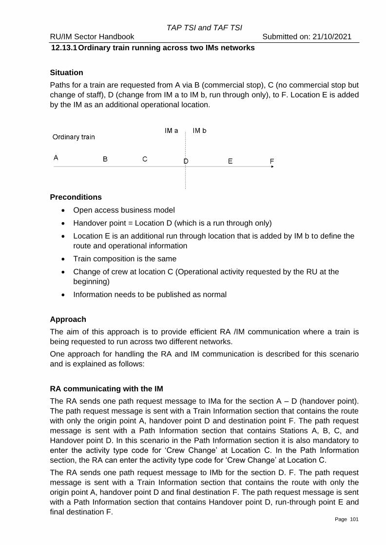
TAP TSI and TAF TSI RU/IM Sector Handbook Submitted on: 21/10/2021
Page 101
12.13.1 Ordinary train running across two IMs networks
Situation
Paths for a train are requested from A via B (commercial stop), C (no commercial stop but
change of staff), D (change from IM a to IM b, run through only), to F. Location E is added
by the IM as an additional operational location.
Preconditions
• Open access business model
• Handover point = Location D (which is a run through only)
• Location E is an additional run through location that is added by IM b to define the
route and operational information
• Train composition is the same
• Change of crew at location C (Operational activity requested by the RU at the
beginning)
• Information needs to be published as normal
Approach
The aim of this approach is to provide efficient RA /IM communication where a train is
being requested to run across two different networks.
One approach for handling the RA and IM communication is described for this scenario
and is explained as follows:
RA communicating with the IM
The RA sends one path request message to IMa for the section A – D (handover point).
The path request message is sent with a Train Information section that contains the route
with only the origin point A, handover point D and destination point F. The path request
message is sent with a Path Information section that contains Stations A, B, C, and
Handover point D. In this scenario in the Path Information section it is also mandatory to
enter the activity type code for ‘Crew Change’ at Location C. In the Path Information
section, the RA can enter the activity type code for ‘Crew Change’ at Location C.
The RA sends one path request message to IMb for the section D. F. The path request
message is sent with a Train Information section that contains the route with only the
origin point A, handover point D and final destination F. The path request message is sent
with a Path Information section that contains Handover point D, run-through point E and
final destination F.

TAP TSI and TAF TSI RU/IM Sector Handbook Submitted on: 21/10/2021
Page 102
IM communicating with the RA
IMa sends one path details message to the RA for the section A – D. The Path Details
message is sent with a Path Information section that contains Stations A, B, C, and
Handover point D.
IMb sends one path details message to the RA for the section D. F. The path details
message is sent with a Path Information section that contains Handover point D, Station
F and in the run-through Location E.
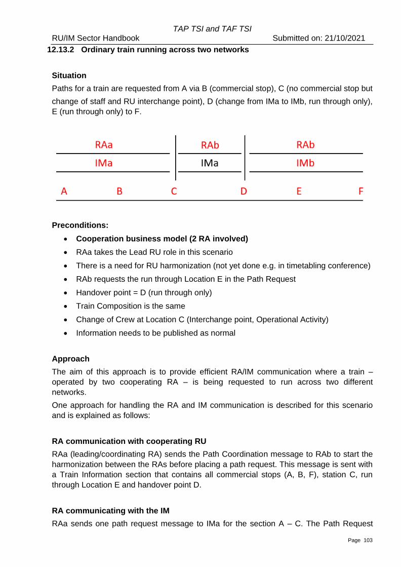
TAP TSI and TAF TSI RU/IM Sector Handbook Submitted on: 21/10/2021
Page 103
12.13.2 Ordinary train running across two networks
Situation
Paths for a train are requested from A via B (commercial stop), C (no commercial stop but
change of staff and RU interchange point), D (change from IMa to IMb, run through only),
E (run through only) to F.
Preconditions:
• Cooperation business model (2 RA involved)
• RAa takes the Lead RU role in this scenario
• There is a need for RU harmonization (not yet done e.g. in timetabling conference)
• RAb requests the run through Location E in the Path Request
• Handover point = D (run through only)
• Train Composition is the same
• Change of Crew at Location C (Interchange point, Operational Activity)
• Information needs to be published as normal
Approach
The aim of this approach is to provide efficient RA/IM communication where a train –
operated by two cooperating RA – is being requested to run across two different
networks.
One approach for handling the RA and IM communication is described for this scenario
and is explained as follows:
RA communication with cooperating RU
RAa (leading/coordinating RA) sends the Path Coordination message to RAb to start the
harmonization between the RAs before placing a path request. This message is sent with
a Train Information section that contains all commercial stops (A, B, F), station C, run
through Location E and handover point D.
RA communicating with the IM
RAa sends one path request message to IMa for the section A – C. The Path Request
TAP TSI and TAF TSI RU/IM Sector Handbook Submitted on: 21/10/2021
Page 104
message is sent with Train Information section that contains the route with origin A,
handover point D and terminus F, the Path Information section that contains Stations A,
B, until interchange point C. In the Path Information section, it is also mandatory to enter
the activity type code for ‘Crew Change’ at Location C, if known.
RAb sends one path request message to IMa for the section C.D and the second Path
Request message to IMb for the section D. F. Both path request message are sent with
Train Information section that contains the route with origin A, handover point D and the
destination point F. It is up to the LeadRU to decide if C is also part of the route, together
with additional information about change of ResponsibleApplicant . The Path Information
section contains C and D. The second Path Request message has the same content in
Train Information block but contains in the Path Information the locations from handover
point D, run through location E to the station F.
IM communicating with the RA
IMa sends one path details message to RAa for the section A – C. The path details
message is sent with a Path Information section that contains Stations A, B, C.
IMa sends the second Path Details message to RAb for the section C, D.
IMb sends one path details message to RAb for the section D. F. The path details
message is sent with a Path Information section that contains Handover point D, run
through location E and Station F.
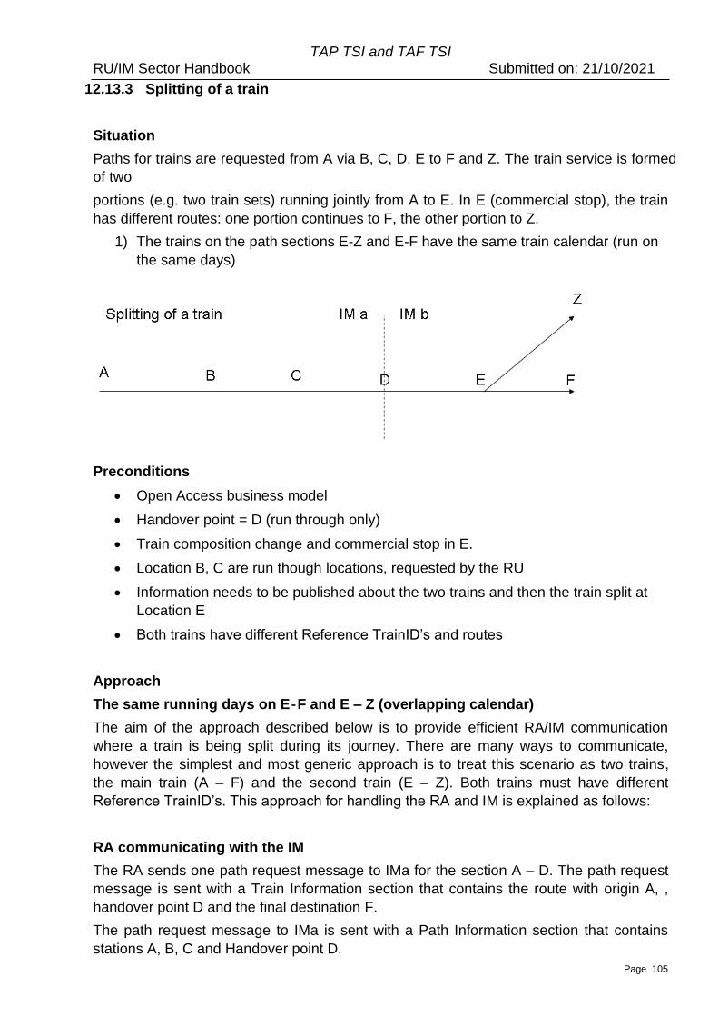
TAP TSI and TAF TSI RU/IM Sector Handbook Submitted on: 21/10/2021
Page 105
12.13.3 Splitting of a train
Situation
Paths for trains are requested from A via B, C, D, E to F and Z. The train service is formed
of two
portions (e.g. two train sets) running jointly from A to E. In E (commercial stop), the train
has different routes: one portion continues to F, the other portion to Z.
1) The trains on the path sections E-Z and E-F have the same train calendar (run on
the same days)
Preconditions
• Open Access business model
• Handover point = D (run through only)
• Train composition change and commercial stop in E.
• Location B, C are run though locations, requested by the RU
• Information needs to be published about the two trains and then the train split at
Location E
• Both trains have different Reference TrainID’s and routes
Approach
The same running days on E – F and E – Z (overlapping calendar)
The aim of the approach described below is to provide efficient RA/IM communication
where a train is being split during its journey. There are many ways to communicate,
however the simplest and most generic approach is to treat this scenario as two trains,
the main train (A – F) and the second train (E – Z). Both trains must have different
Reference TrainID’s. This approach for handling the RA and IM is explained as follows:
RA communicating with the IM
The RA sends one path request message to IMa for the section A – D. The path request
message is sent with a Train Information section that contains the route with origin A, ,
handover point D and the final destination F.
The path request message to IMa is sent with a Path Information section that contains
stations A, B, C and Handover point D.
TAP TSI and TAF TSI RU/IM Sector Handbook Submitted on: 21/10/2021
Page 106
The RA sends two path request messages to IMb. One for the main train (A – F) and one
for the second train (E – Z). The first path request message is sent with a Train
Information section that contains the origin A, handover point D and destination F for the
main train. The Path Information section of the first message (for the first train) contains
the section D to F with E. In E the RA has to include train activity code 0017 and
Reference TrainID of second train to give information to the split.
The second Path Request message for the second train with different ReferenceTrainID
is sent with the Train Information with origin E and destination Z for the route. The Path
Information section contains stations E and Z. It is also mandatory to enter the train
activity code 0045 for ‘train split’ and add the associated/attached train code (Reference
TRID of first train) at Location E,.
In RelatedPlannedTransportIdentifiers section the RA can include Reference TrainID of
the other train to refer it, in both PathRequestMessages sent to IMb vice versa. That is
similar valid and possible for the PathRequestID.
IM communicating with the RA
IMa sends one path details message to the RA for the section A – D. The path details
message is sent with a Path Information section that contains stations A, B, C and
Handover point D.
IMb sends two path details messages to the RA, one for the main train for section D – F
and the other for the second train for section E – Z. For the main train the Path
Information section contains stations E and F as well as the Handover point D. For the
second train the Path Information section contains stations E and Z. Both
PathDetailsMessages sent by IMb are linked to different Reference TrainID’s and routes.
In location E the trainactivity codes are includes as similar as described for
PathRequestMessage above.
How it looks like in the messages:
The messages layout can be examined in the reference system PCS. For this purpose,
use the documentation for the test cases. We recommend to reader to validate the Test
Cases in the Annex 8.6 and Annex 8.7.x. Annex 8.7.1 contains the general test cases
provided by the TEG TrainID members, and Annex 8.7.2 contains the test cases which
will be used in the Joint Sector Pilot Program for Short-Term Path Request and TrainID.
The test cases contained in 8.7.2 are the simple test cases aimed to reflect the
basic steps and information exchange within the Short-Term Path Request process with
Identifiers.
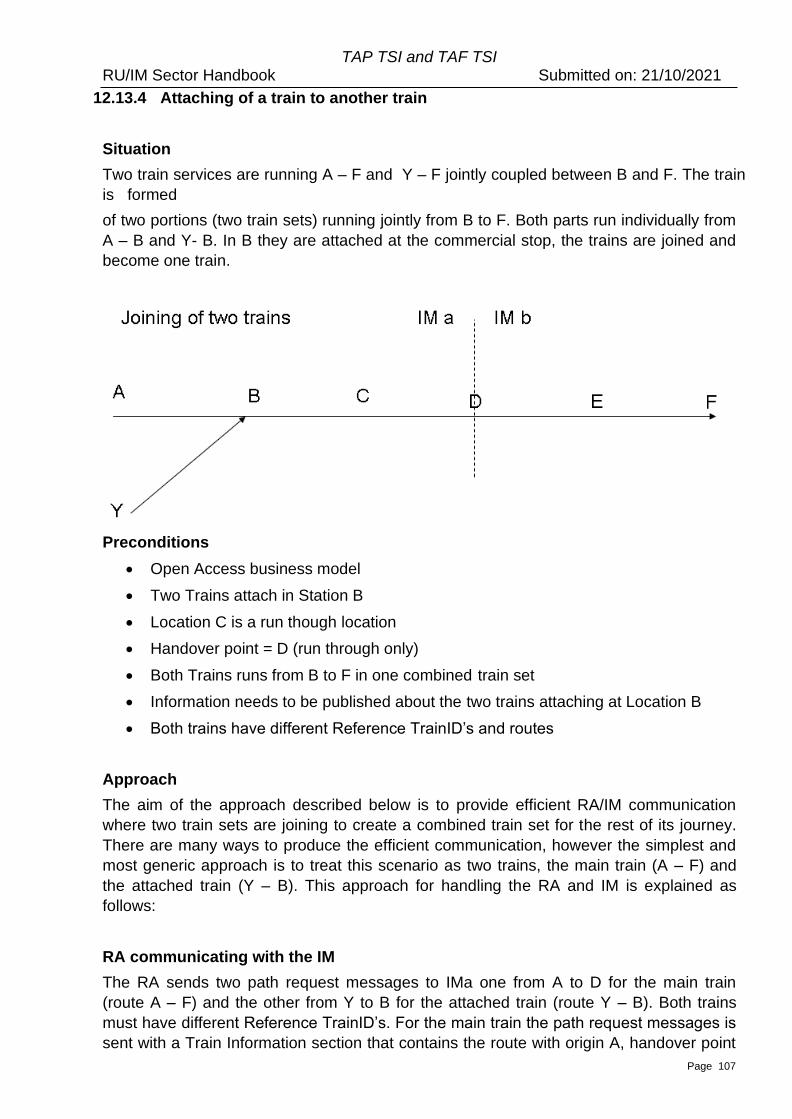
TAP TSI and TAF TSI RU/IM Sector Handbook Submitted on: 21/10/2021
Page 107
12.13.4 Attaching of a train to another train
Situation
Two train services are running A – F and Y – F jointly coupled between B and F. The train
is formed
of two portions (two train sets) running jointly from B to F. Both parts run individually from
A – B and Y- B. In B they are attached at the commercial stop, the trains are joined and
become one train.
Preconditions
• Open Access business model
• Two Trains attach in Station B
• Location C is a run though location
• Handover point = D (run through only)
• Both Trains runs from B to F in one combined train set
• Information needs to be published about the two trains attaching at Location B
• Both trains have different Reference TrainID’s and routes
Approach
The aim of the approach described below is to provide efficient RA/IM communication
where two train sets are joining to create a combined train set for the rest of its journey.
There are many ways to produce the efficient communication, however the simplest and
most generic approach is to treat this scenario as two trains, the main train (A – F) and
the attached train (Y – B). This approach for handling the RA and IM is explained as
follows:
RA communicating with the IM
The RA sends two path request messages to IMa one from A to D for the main train
(route A – F) and the other from Y to B for the attached train (route Y – B). Both trains
must have different Reference TrainID’s. For the main train the path request messages is
sent with a Train Information section that contains the route with origin A, handover point
TAP TSI and TAF TSI RU/IM Sector Handbook Submitted on: 21/10/2021
Page 108
D and destination F. The path request message for the main train (A – F) is sent with a
Path Information section that contains stations A, B, C as well as the Handover point D. In
the Path Information section, it is also mandatory to enter the train activity type ‘0016 at
Location B . The related train identifier (Reference TRID) / OTN (for the attached second
train) that will be attached at Location B will also be added into the Train Activity section.
For the attached train Y – B the path request message is sent with a Train Information
and Path Information section of Y and B only. In location B the train activity code 0044
and the related train identifier (Reference TRID) / OTN (for the main train) that the train
will be attached to will also be added. In RelatedPlannedTransportIdentifiers section the
RA can include Reference TrainID of the other train to refer it, in both
PathRequestMessages sent to IMa vice versa. That is similar valid and possible for the
PathRequestID.
The RA sends one path request message to IMb for the section D - F. The path request
message is sent with a Train Information section that contains the route of the main train
with origin A, handover point D and destination F. The path request message is sent with
a Path Information section that contains Handover point D, location E and destination F.
IM communicating with the RA
IMa sends two path details messages to the RA, one for the main train for section A – D
and one for the second train Y – B. The path details messages are sent with a Path
Information section that contains A, B, C, D in the message for the main train and stations
Y and B for the attached train. Both PathDetailsMessages sent by IMa are linked to
different Reference TrainID’s and routes. In location B the train activity codes are includes
as similar as described for PathRequestMessage above.
IMb sends one path details message to the RA for the section D - F. The path details
message is sent with a Path Information section that contains E and F and Handover
point D.
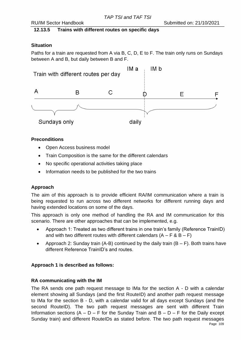
TAP TSI and TAF TSI RU/IM Sector Handbook Submitted on: 21/10/2021
Page 109
12.13.5 Trains with different routes on specific days
Situation
Paths for a train are requested from A via B, C, D, E to F. The train only runs on Sundays
between A and B, but daily between B and F.
Preconditions
• Open Access business model
• Train Composition is the same for the different calendars
• No specific operational activities taking place
• Information needs to be published for the two trains
Approach
The aim of this approach is to provide efficient RA/IM communication where a train is
being requested to run across two different networks for different running days and
having extended locations on some of the days.
This approach is only one method of handling the RA and IM communication for this
scenario. There are other approaches that can be implemented, e.g.
• Approach 1: Treated as two different trains in one train’s family (Reference TrainID)
and with two different routes with different calendars (A – F & B – F)
• Approach 2: Sunday train (A-B) continued by the daily train (B – F). Both trains have
different Reference TrainID’s and routes.
Approach 1 is described as follows:
RA communicating with the IM
The RA sends one path request message to IMa for the section A - D with a calendar
element showing all Sundays (and the first RouteID) and another path request message
to IMa for the section B - D, with a calendar valid for all days except Sundays (and the
second RouteID). The two path request messages are sent with different Train
Information sections (A – D – F for the Sunday Train and B – D – F for the Daily except
Sunday train) and different RouteIDs as stated before. The two path request messages
TAP TSI and TAF TSI RU/IM Sector Handbook Submitted on: 21/10/2021
Page 110
are sent with different Path Information sections (A – D for the Sunday Train and B – D
for the Daily except Sunday train). In both PathRequestMessages the same Reference
TrainID can be used. But it is also possible to use different Reference TrainID’s. It is up to
the LeadRU to decide it.
The RA sends one path request message to IMb for the Sunday train and another path
request message for train running every day except Sunday. The two path request
messages are sent with different Train Information sections (A – D – F for the Sunday
Train and B –D – F for the Daily except Sunday train) and different RouteIDs. The
messages are sent with the same content in the Path Section (D – F) but different
calendars (once only Sundays, and once for all other days except Sunday). Both
PathDetailsMessages sent by IMa are linked to different Reference TrainID’s and routes.
In location B the train activity codes are includes as similar as described for
PathRequestMessage above.
In RelatedPlannedTransportIdentifiers section the RA can include Reference TrainID of
the other train to refer it, in both PathRequestMessages vice versa. That is similar valid
and possible for the PathRequestID.
It is recommended to use the RelatedPlannedTransportIdentifier with specific
ReasonOfReferenceCode to indicate that the RA wishes to get the same path and details
for both Path Requests.
IM communicating with the RA
IMa will send back two path details messages one for Daily except Sundays train (B – D)
and one for Sunday (A – D).
IMb will send back two path details messages one for Mon – Sat (D – F) and one for
Sunday (D - F). This could be the same path (from Monday to Sunday same stops,
timings, etc.) but as there are two Routes (Mon – Sat and Su) two PathIDs are allocated.
Indeed, it is important for both RA and IM to keep the record about the links between
Route and Path objects.
Approach 2 is described as follows:
The approach 2 covers the case where the planned train service is split into two trains
and two path requests according to the geographical aspect, not the calendar (First a
path for the Train A-B (Sundays) is requested, second a path for the train B-F is
requested for all days including Sunday). Both trains have different Reference
TrainID’s and routes with different RouteID’s.
RA communicating with the IM
The RA sends the first Path RequestMessage to IMa for the section B-D and the
calendar containing all the days (including Sundays) with the first Reference TrainID.
The TrainInformation contains the Route B – D – F and the Path Information contains
the section B-D.
The RA sends the second Path Request to IMa for the relation A-B for Sundays with the
second Reference TrainID. TrainInformation block carries the route A-B and the calendar

TAP TSI and TAF TSI RU/IM Sector Handbook Submitted on: 21/10/2021
Page 111
containing Sundays. The Path Information section also carries only the section A-B and
the calendar containing Sundays.
IMPORTANT: In the PathRequestMessage for the train only on Sunday in section A to B
on location B the Train Activity Type 0044 must carry the information about the
AttachedTrainID (Reference TRID of the other train for all days on section B-F). Vice
versa in the PathRequestMessage for the train for all days in section B to F on location B
the Train Activity Type 0045 must carry the information about the AttachedTrainID
(Reference TRID of the other train for Sunday only on section A to B).
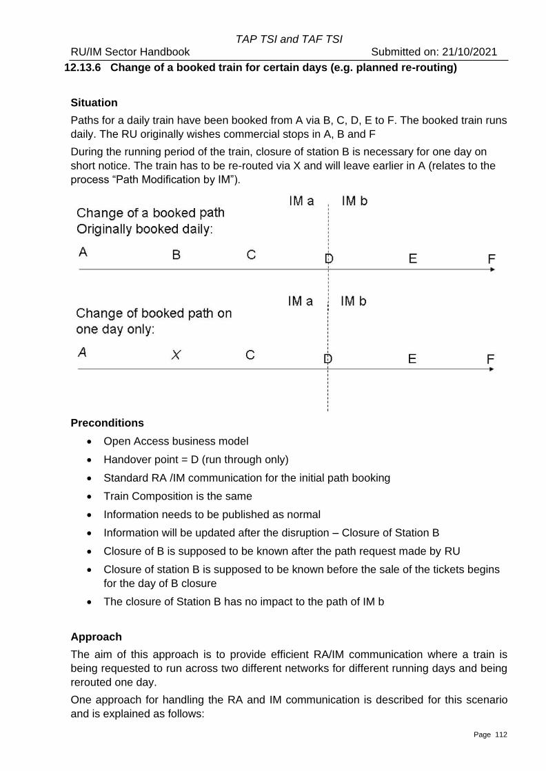
TAP TSI and TAF TSI RU/IM Sector Handbook Submitted on: 21/10/2021
Page 112
12.13.6 Change of a booked train for certain days (e.g. planned re-routing)
Situation
Paths for a daily train have been booked from A via B, C, D, E to F. The booked train runs
daily. The RU originally wishes commercial stops in A, B and F
During the running period of the train, closure of station B is necessary for one day on
short notice. The train has to be re-routed via X and will leave earlier in A (relates to the
process “Path Modification by IM”).
Preconditions
• Open Access business model
• Handover point = D (run through only)
• Standard RA /IM communication for the initial path booking
• Train Composition is the same
• Information needs to be published as normal
• Information will be updated after the disruption – Closure of Station B
• Closure of B is supposed to be known after the path request made by RU
• Closure of station B is supposed to be known before the sale of the tickets begins
for the day of B closure
• The closure of Station B has no impact to the path of IM b
Approach
The aim of this approach is to provide efficient RA/IM communication where a train is
being requested to run across two different networks for different running days and being
rerouted one day.
One approach for handling the RA and IM communication is described for this scenario
and is explained as follows:
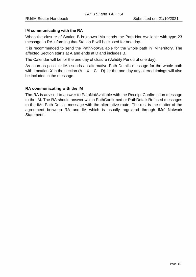
TAP TSI and TAF TSI RU/IM Sector Handbook Submitted on: 21/10/2021
Page 113
IM communicating with the RA
When the closure of Station B is known IMa sends the Path Not Available with type 23
message to RA informing that Station B will be closed for one day.
It is recommended to send the PathNotAvailable for the whole path in IM territory. The
affected Section starts at A and ends at D and includes B.
The Calendar will be for the one day of closure (Validity Period of one day).
As soon as possible IMa sends an alternative Path Details message for the whole path
with Location X in the section (A – X – C – D) for the one day any altered timings will also
be included in the message.
RA communicating with the IM
The RA is advised to answer to PathNotAvailable with the Receipt Confirmation message
to the IM. The RA should answer which PathConfirmed or PathDetailsRefused messages
to the IMs Path Details message with the alternative route. The rest is the matter of the
agreement between RA and IM which is usually regulated through IMs’ Network
Statement.
TAP TSI and TAF TSI RU/IM Sector Handbook Submitted on: 21/10/2021
Page 114
12.13.7 Trains with Through Coaches
Situation
Paths are requested for a train A via B, C, D, E to F. Some coaches of the train are
detached in E. These coaches are attached to another train from W via E to Z. Through
coaches (coach groups) from A to Z are established.
Preconditions
• Through coaches in a station of IMb
• Train W – Z a priori unknown from IMa
• Trains A – F and W – Z are nevertheless associated
• Both trains have different Reference TrainID’s and routes.
Approach
The aim is to provide efficient RA /IM communication, where two different trains stop
at the same station, in order that a coach is detached from one train and attached to a
second train.
RA communicating with the IM:
A Path Request Message is sent by the RA to IMa. The Train Information contains no
train activity code at Location E “Detach Coach” as the Train Information contains origin
A, handover D and destination F.
A Path Request Message is sent by the RA to IMb for train (A – F). The Message has to
indicate that a coach is detached in Location E via the train activity type 0014 “Detach
Coach”. The related Reference TrainID and/or OTN on which the attached Coach will be
added (train W – Z) at E will also be added into the Train Activity section by using code
0046.
<PlannedJourneyLocation JourneyLocationTypeCode="02">
<CountryCodeISO>XY</CountryCodeISO>
<LocationPrimaryCode>45000</LocationPrimaryCode>
<PrimaryLocationName>E</PrimaryLocationName>
<TimingAtLocation>
TAP TSI and TAF TSI RU/IM Sector Handbook Submitted on: 21/10/2021
Page 115
<Timing TimingQualifierCode="ALA">
<Time>14:25:00.0</Time>
<Offset>0</Offset>
</Timing>
<Timing TimingQualifierCode="ALD">
<Time>14:35:00.0</Time>
<Offset>0</Offset>
</Timing>
</TimingAtLocation>
….
<TrainActivity>
<TrainActivityType>0001</TrainActivityType>
</TrainActivity>
<TrainActivityType>0046</TrainActivityType>
<TrainActivity>
<AssociatedAttachedTrainID>
<ObjectType>TR</ObjectType>
<Company>9001</Company>
<Core>*****0006789</Core>
<Variant>00</Variant>
<TimetableYear>2012</TimetableYear>
</AssociatedAttachedTrainID>
<TrainActivityType>0014</TrainActivityType></TrainActivity>
<OperationalTrainNumber>0001234</OperationalTrainNumber>
</PlannedJourneyLocation>
The Path Request Message sent by the Applicant to IMb for the other train (W – Z) has to
indicate that the train in station E receives a coach from train A – F (related identifiers
section: attached train’s Reference TrainID). The Message has to indicate that a coach is
attached in Location E via the Activity Code 0013 “Attach Coach”. The related Reference
TrainID and/or OTN on which the attached coach came from (train A – F) at E will also be
added into the Train Activity section with train activity code 0047.
IM communicating with the RA:
A Path Details Message is sent by the IMa back to the RA.
Two Path Details Messages are sent back by IMb to the RA. First Path Details Message
is sent by the IMb back to the RA for Train A - F. The Message has to indicate the times
at station E, the Reference TrainID and/or OTN of the train for which the coach is
attached to (train W – Z) and the train activity types 0014 and 0046.
Second Path Details Message is sent by the IMb back to the RA for Train W - Z. The
Message has to indicate the times at station E, the Reference TrainID and/or OTN of the
train for which the coach is detached (train A – F) and the train activity types 0013 and
0047..
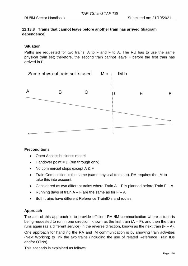
TAP TSI and TAF TSI RU/IM Sector Handbook Submitted on: 21/10/2021
Page 116
12.13.8 Trains that cannot leave before another train has arrived (diagram
dependence)
Situation
Paths are requested for two trains: A to F and F to A. The RU has to use the same
physical train set; therefore, the second train cannot leave F before the first train has
arrived in F.
Preconditions
• Open Access business model
• Handover point = D (run through only)
• No commercial stops except A & F
• Train Composition is the same (same physical train set). RA requires the IM to
take this into account.
• Considered as two different trains where Train A – F is planned before Train F – A
• Running days of train A – F are the same as for F – A
• Both trains have different Reference TrainID’s and routes.
Approach
The aim of this approach is to provide efficient RA /IM communication where a train is
being requested to run in one direction, known as the first train (A – F), and then the train
runs again (as a different service) in the reverse direction, known as the next train (F – A).
One approach for handling the RA and IM communication is by showing train activities
(Next Working) to link the two trains (including the use of related Reference Train IDs
and/or OTNs).
This scenario is explained as follows:
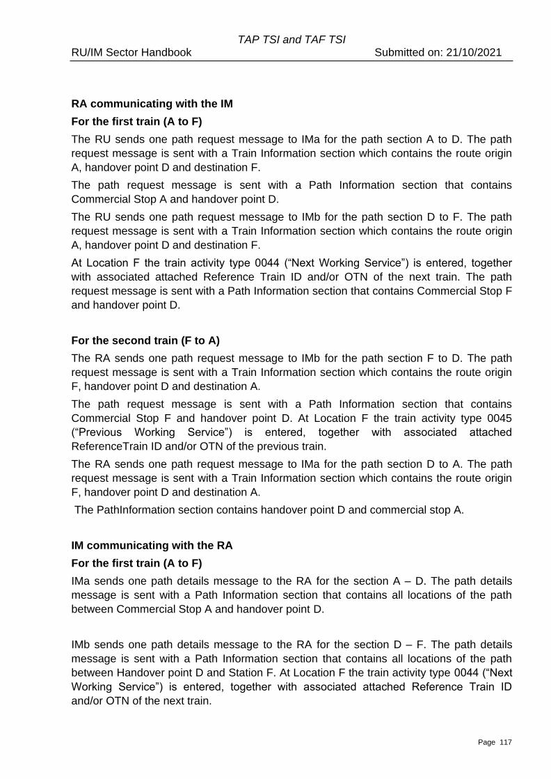
TAP TSI and TAF TSI RU/IM Sector Handbook Submitted on: 21/10/2021
Page 117
RA communicating with the IM
For the first train (A to F)
The RU sends one path request message to IMa for the path section A to D. The path
request message is sent with a Train Information section which contains the route origin
A, handover point D and destination F.
The path request message is sent with a Path Information section that contains
Commercial Stop A and handover point D.
The RU sends one path request message to IMb for the path section D to F. The path
request message is sent with a Train Information section which contains the route origin
A, handover point D and destination F.
At Location F the train activity type 0044 (“Next Working Service”) is entered, together
with associated attached Reference Train ID and/or OTN of the next train. The path
request message is sent with a Path Information section that contains Commercial Stop F
and handover point D.
For the second train (F to A)
The RA sends one path request message to IMb for the path section F to D. The path
request message is sent with a Train Information section which contains the route origin
F, handover point D and destination A.
The path request message is sent with a Path Information section that contains
Commercial Stop F and handover point D. At Location F the train activity type 0045
(“Previous Working Service”) is entered, together with associated attached
ReferenceTrain ID and/or OTN of the previous train.
The RA sends one path request message to IMa for the path section D to A. The path
request message is sent with a Train Information section which contains the route origin
F, handover point D and destination A.
The PathInformation section contains handover point D and commercial stop A.
IM communicating with the RA
For the first train (A to F)
IMa sends one path details message to the RA for the section A – D. The path details
message is sent with a Path Information section that contains all locations of the path
between Commercial Stop A and handover point D.
IMb sends one path details message to the RA for the section D – F. The path details
message is sent with a Path Information section that contains all locations of the path
between Handover point D and Station F. At Location F the train activity type 0044 (“Next
Working Service”) is entered, together with associated attached Reference Train ID
and/or OTN of the next train.

TAP TSI and TAF TSI RU/IM Sector Handbook Submitted on: 21/10/2021
Page 118
For the second train (F to A)
IMb sends one path details message to the RA for the section F - D. The path details
message is sent with a Path Information section that contains all locations of the path
between station F and Handover point D. At Location F the train activity type 0045
(“Previous Working Service”) is entered, together with associated attached
ReferenceTrain ID and/or OTN of the previous train.
IMa sends one path details message to the RA for the section D to A. The path details
message is sent with a Path Information section that contains all locations of the path
between handover point D and commercial stop A.
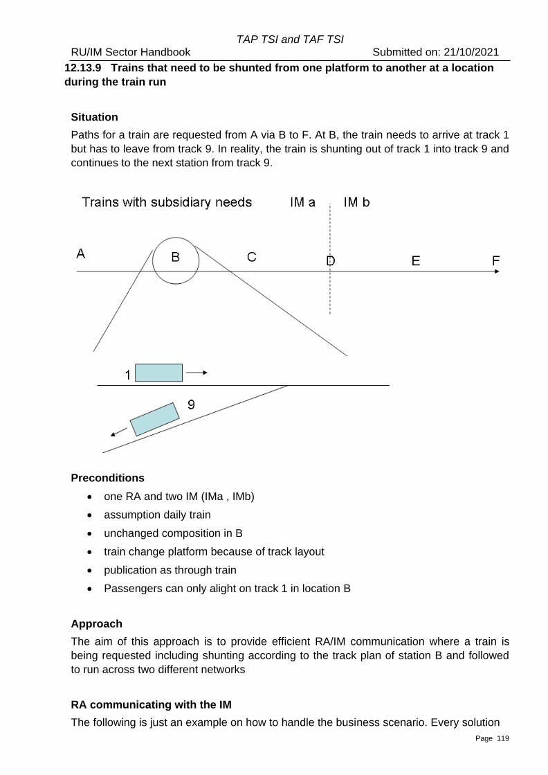
TAP TSI and TAF TSI RU/IM Sector Handbook Submitted on: 21/10/2021
Page 119
12.13.9 Trains that need to be shunted from one platform to another at a location
during the train run
Situation
Paths for a train are requested from A via B to F. At B, the train needs to arrive at track 1
but has to leave from track 9. In reality, the train is shunting out of track 1 into track 9 and
continues to the next station from track 9.
Preconditions
• one RA and two IM (IMa , IMb)
• assumption daily train
• unchanged composition in B
• train change platform because of track layout
• publication as through train
• Passengers can only alight on track 1 in location B
Approach
The aim of this approach is to provide efficient RA/IM communication where a train is
being requested including shunting according to the track plan of station B and followed
to run across two different networks
RA communicating with the IM
The following is just an example on how to handle the business scenario. Every solution
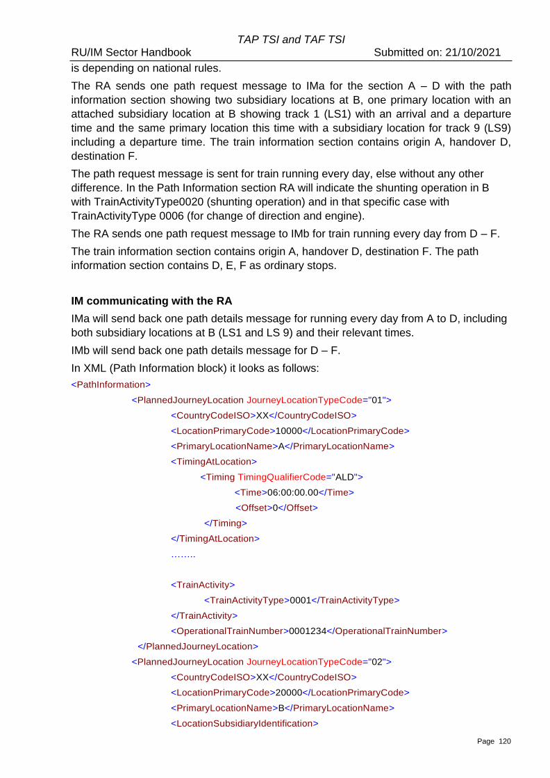
TAP TSI and TAF TSI RU/IM Sector Handbook Submitted on: 21/10/2021
Page 120
is depending on national rules.
The RA sends one path request message to IMa for the section A – D with the path
information section showing two subsidiary locations at B, one primary location with an
attached subsidiary location at B showing track 1 (LS1) with an arrival and a departure
time and the same primary location this time with a subsidiary location for track 9 (LS9)
including a departure time. The train information section contains origin A, handover D,
destination F.
The path request message is sent for train running every day, else without any other
difference. In the Path Information section RA will indicate the shunting operation in B
with TrainActivityType0020 (shunting operation) and in that specific case with
TrainActivityType 0006 (for change of direction and engine).
The RA sends one path request message to IMb for train running every day from D – F.
The train information section contains origin A, handover D, destination F. The path
information section contains D, E, F as ordinary stops.
IM communicating with the RA
IMa will send back one path details message for running every day from A to D, including
both subsidiary locations at B (LS1 and LS 9) and their relevant times.
IMb will send back one path details message for D – F.
In XML (Path Information block) it looks as follows:
<PathInformation>
<PlannedJourneyLocation JourneyLocationTypeCode="01">
<CountryCodeISO>XX</CountryCodeISO>
<LocationPrimaryCode>10000</LocationPrimaryCode>
<PrimaryLocationName>A</PrimaryLocationName>
<TimingAtLocation>
<Timing TimingQualifierCode="ALD">
<Time>06:00:00.00</Time>
<Offset>0</Offset>
</Timing>
</TimingAtLocation>
……..
<TrainActivity>
<TrainActivityType>0001</TrainActivityType>
</TrainActivity>
<OperationalTrainNumber>0001234</OperationalTrainNumber>
</PlannedJourneyLocation>
<PlannedJourneyLocation JourneyLocationTypeCode="02">
<CountryCodeISO>XX</CountryCodeISO>
<LocationPrimaryCode>20000</LocationPrimaryCode>
<PrimaryLocationName>B</PrimaryLocationName>
<LocationSubsidiaryIdentification>

TAP TSI and TAF TSI RU/IM Sector Handbook Submitted on: 21/10/2021
Page 121
<LocationSubsidiaryCode
LocationSubsidiaryTypeCode="01">0123456789</LocationSubsidiaryCode>
<AllocationCompany>1001</AllocationCompany>
<LocationSubsidiaryName>Location B Platform
1</LocationSubsidiaryName>
</LocationSubsidiaryIdentification>
<TimingAtLocation>
<Timing TimingQualifierCode="ELA">
<Time>08:00:00.00</Time>
<Offset>0</Offset>
</Timing>
<Timing TimingQualifierCode="LLD">
<Time>08:02:00.00</Time>
<Offset>0</Offset>
</Timing>
</TimingAtLocation>
…
<TrainActivity>
<TrainActivityType>0001</TrainActivityType>
</TrainActivity>
<TrainActivity>
<TrainActivityType>0020</TrainActivityType>
</TrainActivity>
<OperationalTrainNumber>0001234</OperationalTrainNumber>
</PlannedJourneyLocation>
<PlannedJourneyLocation JourneyLocationTypeCode="02">
<CountryCodeISO>XX</CountryCodeISO>
<LocationPrimaryCode>20000</LocationPrimaryCode>
<PrimaryLocationName>B</PrimaryLocationName>
<LocationSubsidiaryIdentification>
<LocationSubsidiaryCode
LocationSubsidiaryTypeCode="09">0123456789</LocationSubsidiaryCode>
<AllocationCompany>1001</AllocationCompany>
<LocationSubsidiaryName>Location B Platform
9</LocationSubsidiaryName>
</LocationSubsidiaryIdentification>
<TimingAtLocation>
<Timing TimingQualifierCode="LLD">
<Time>08:10:00.00</Time>
<Offset>0</Offset>
</Timing>
</TimingAtLocation>
…
<TrainActivity>

TAP TSI and TAF TSI RU/IM Sector Handbook Submitted on: 21/10/2021
Page 122
<TrainActivityType>0020</TrainActivityType>
</TrainActivity>
<OperationalTrainNumber>0001234</OperationalTrainNumber>
</PlannedJourneyLocation>
<PlannedJourneyLocation JourneyLocationTypeCode="02">
<CountryCodeISO>XX</CountryCodeISO>
<LocationPrimaryCode>30000</LocationPrimaryCode>
<PrimaryLocationName>C</PrimaryLocationName>
…
TAP TSI and TAF TSI RU/IM Sector Handbook Submitted on: 21/10/2021
Page 123
12.14. Business rules
This section provides the specific business rules/conditions on how specific elements
within the messages will need to be applied for certain situations.
The business rules for applying the calendar are explained in 12.15.
12.14.1 Train Weight/Train Length
Determining the Train Weight
If the “Traction Weight” and the “Weight of the set of carriages” are both entered into the
message, the “Train Weight” can be calculated as the sum of the two elements.
If the “Train Weight” and the “Weight of the set of carriages” are both entered into the
message, the “Traction Weight” can be calculated as the difference of the two elements:
Train Weight – Weight of the Set of Carriages
If the “Train Weight” and the “Traction Weight” are both entered into the message, the
“Weight of the set of carriages” can be calculated as the difference of the two elements:
Train Weight – Traction Weight.
Determining the Train Length
Note: The element Length under the element group Traction Details denotes to the length
of the Traction Unit. It is a global element that is reused in other Messages hence it is
given the generic element name of Length.
Note: The Length element will need to be entered in millimetres and will need to be
converted on application level only to metres if it is used in the calculation.
If the “Length” and the “Length of the set of carriages” are both entered, the “Train
Length” can be calculated as the sum of the two elements.
If the “Train Length” and the “Length of the set of carriages” are both entered into the
message, the “Length” can be calculated as the difference of the two elements: Train
Length – Length of the set of carriages
If the “Train Length” and the “Length” are both entered into the message, the “Length of
the set of carriages” can be calculated as the difference of the two elements: Train Length
– Length
Therefore, as a general rule, at the application level, it will not be required to implement
all three elements regarding the weight/length as mandatory elements in the XML. It
might be left to the application to calculate one of the three elements – under the
precondition that the two remaining elements are entered as mandatory.
12.14.2 Loco Type Number
Even if some principles are shared by most countries concerning the structure (based on
the decision 2007/756), there is currently no common coding for the European Loco
Type. It can be assumed that each IM is familiar with the Loco Types and its
TAP TSI and TAF TSI RU/IM Sector Handbook Submitted on: 21/10/2021
Page 124
characteristics of its registered customers (the RUs). Therefore, this element will be
based on national basis, defined by each IM or by the Allocation Body. However, this
element remains within main structure of the Message as opposed to being in the
Network Specific Parameters section – this is because there is likely, at some point in
time, to be a European Coding standard. It also serves to keep all traction details together
in one section as opposed to splitting the information across the two sections.
In accordance with the specifications of decision 2007/756 (as amended by decision
2012/756), the 12 digits of the element “LocoTypeNumber” are structured as the following
composite identifier:
• Digit 1 = TypeCode1, Value 9 as in Part 0 of the Appendix of the decision
2007/756
• Digit 2 = TypeCode2, Type of tractive rolling stock as in Part 8 of the Appendix 6 of
the decision 2007/756
• Digits 3-4 = CountryCode, Numerical country code as in Part 4 of the Appendix 6
of the decision 2007/756
• Digits 5-8 = SeriesNumber, 4 digits representing the type according to the country
rules and based on the national vehicle register of the country indicated with the
CountryCode
• Digits 9-11 = SerialNumber, Three digits representing the serial number of the
traction of the series. Optionally used in Planning to identify the subseries.
Composite identifier should be unique with the series number within a country.
• Digit 12 = ControlDigit, 1 control digit as usual at the end of the 12-digit UIC
identifier. Not used in Planning
First four elements identify the series of the loco, rest can identify the exact individual
locomotive or a subseries of the serialNumber depending on the EVN structure in the
country. Note that the element LocoNumber or EuropeanVehicleNumber is normally used
to identify a defined locomotive or trainset in Train Composition message.
The list of LocoTypeNumber is defined, maintained and published by the Allocation Body
or the IM of each country. The storage in the CRD will be studied.
12.14.3 Combined Traffic Load Profile
This element refers to combined load units that can be used for Freight Requests only.
There are two entry options:
• One option refers to “P” (Semi-trailer/road semi-trailer):
P1 requires the code in case the gauge of the semi-trailer is ≤ 2500 mm. P2
requires the code in case the gauge of the semi-trailer is > 2500 mm ≤ 2600 mm
• The other option refers to “C” (Swap body): C1 requires the code in case the
gauge of the swap body is ≤ 2550 mm. C2 requires the code in case the gauge of
the swap body is > 2550 mm ≤ 2600 mm
The RUs may indicate the relevant values if they are familiar with the IMs line profiles. In
case there is a path request for a train with combined traffic load, the IM should indicate
in the Path Details Message the possible max. value for all 4 elements (P1, P2, C1, C2)
TAP TSI and TAF TSI RU/IM Sector Handbook Submitted on: 21/10/2021
Page 125
12.14.5 Highest planned speed and minimum break weight percentage
Data elements that need to be entered into the Path Details Messages to keep them
consistent on their structure referring to IM requirements and information towards the RU.
Not to be used in the communication from RA to the IM but only when the IM
communicates back to the RA.
12.14.6 Braking weight and Minimum Brake Weight Percentage
Braking Ratio value is entered by the RA in a Path Request whereas the
MinBrakedWeightPercentage value is entered by the IM in the Path Details. Both values
are integers 1.999.
From a business perspective these elements must be referred to in terms of a % but have
to be entered in the Message as a numeric integer value in the range from 1 up to 999
e.g. 11% will be entered as 11
12.14.7 Use of the Train Activity Type and Associated Trains
The list of Activity Type Codes is split into two types: Common European Codes that are
available to be used by all countries and National/Company codes that are only relevant
to a specific network and to be used in the RA / IM communication only for that network.
In both cases the element size will be 4 alpha numeric.
Common European Codes will have the structure as follows:
• 4 Digit Code (numeric) that represents the Code List values for the common
activities
National Codes will have the structure as follows:
• The first two characters will represent the country of the network in ISO format e.g.
UK
• The remaining two characters (represented as a numeric) will represent a single
unique activity within the network e.g. 01 = Stops shorter than 30 secs
See also chapter 12.9.3
12.14.8 Timing at location
When placing a Path Request the RA enters the following times if the location is a
stopping point (e.g. at station): Earliest or Latest or both time(s) for Arrival and/or
Departure.
Depending on the agreement between the sender and receiver of the path request
messages, when placing a Path Request the RA may enter the times if the location is the
“run-through” or leave Arrival and Departure blank.
TAP TSI and TAF TSI RU/IM Sector Handbook Submitted on: 21/10/2021
Page 126
On the other hand, when preparing the Path Details, the IM always enters the times if the
location is a run through: Actual times for Arrival and Departure which must be same. In
addition, the IM must use the Activity Type Code for “Run Through”.
When editing Path Details the IM enters the following times if the location is a stopping
point (at station): Actual time(s) for Arrival and/or Departure
For the purpose of publication of the timings (e.g. on the stations), the Public location
arrival and Public location departure is specified. The public location time may differ from
the actual location time. This is relevant only for TAP.
As the child element of the Timing, the BookedLocationDateTime is provided. This
element should not be used in the path request (planning) process. It is supposed to be
used within the Operations procedures for notification about contracted timetable (daily
object Path), when the path object is transformed from planning to operation. The value
of the element should correspond to the “Actual Location Departure / Arrival” timing.
12.14.9 Dwell Time
The Dwell Time element is entered in the Path Request to include a required minimum
waiting time of the train at a particular location. It is given in the format of a one decimal
numeric value whereby the integer part of the value represents the time minutes and the
decimal part of the value represents the time in seconds.
The integer value will be represented in minutes only, therefore any dwell time that is in
hours (> 60mins) will need to be converted to minutes e.g. 3 hours dwell will need to be
represented as 180
The decimal value will be required in all cases (even if there are no additional seconds).
Each decimal value represents 6 seconds of time e.g. 0.1 = 6 secs, 0.2 = 12 secs etc...
Any other value will have to be rounded to the nearest 6th second e.g. 16 secs will be
rounded to 18 seconds and will be represented as 0.3
For example: A Dwell Time of 12mins & 28 seconds will need to be represented as a
value 12.5
And indication of a non-zero dwell time on the first or on the last location of a train may be
used to request for a minimum delay before or after another (linked) train, requested or
already booked by the RU.
12.14.10 Received on Time
This element, included in the sector messages only, is only to be used for the Long-
Term planning purposes (for the annual timetable) in order to indicate whether a request
has been placed before or after the deadline for placing request for the annual timetable
(working timetable). An RA may place a path request either on time (before the second
Monday in April of the year before) in order to “benefit” from the procedure as described
in EU Dir. 2012/34, Articles 45 and 46 or may place a late path request (after the second
Monday in April of the year before). The IM must indicate if the path request was received
on time. This is mainly a legal issue.
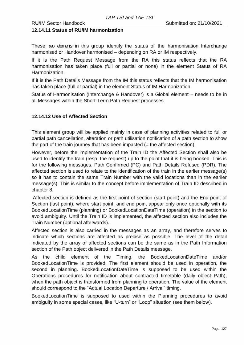
TAP TSI and TAF TSI RU/IM Sector Handbook Submitted on: 21/10/2021
Page 127
12.14.11 Status of RU/IM harmonization
These two elements in this group identify the status of the harmonisation Interchange
harmonised or Handover harmonised – depending on RA or IM respectively.
If it is the Path Request Message from the RA this status reflects that the RA
harmonisation has taken place (full or partial or none) in the element Status of RA
Harmonization.
If it is the Path Details Message from the IM this status reflects that the IM harmonisation
has taken place (full or partial) in the element Status of IM Harmonization.
Status of Harmonisation (Interchange & Handover) is a Global element – needs to be in
all Messages within the Short-Term Path Request processes.
12.14.12 Use of Affected Section
This element group will be applied mainly in case of planning activities related to full or
partial path cancellation, alteration or path utilisation notification of a path section to show
the part of the train journey that has been impacted (= the affected section).
However, before the implementation of the Train ID the Affected Section shall also be
used to identify the train (resp. the request) up to the point that it is being booked. This is
for the following messages. Path Confirmed (PC) and Path Details Refused (PDR). The
affected section is used to relate to the identification of the train in the earlier message(s)
so it has to contain the same Train Number with the valid locations than in the earlier
message(s). This is similar to the concept before implementation of Train ID described in
chapter 8.
Affected section is defined as the first point of section (start point) and the End point of
Section (last point), where start point, and end point appear only once optionally with its
BookedLocationTime (planning) or BookedLocationDateTime (operation) in the section to
avoid ambiguity. Until the Train ID is implemented, the affected section also includes the
Train Number (optional afterwards).
Affected section is also carried in the messages as an array, and therefore serves to
indicate which sections are affected as precise as possible. The level of the detail
indicated by the array of affected sections can be the same as in the Path Information
section of the Path object delivered in the Path Details message.
As the child element of the Timing, the BookedLocationDateTime and/or
BookedLocationTime is provided. The first element should be used in operation, the
second in planning. BookedLocationDateTime is supposed to be used within the
Operations procedures for notification about contracted timetable (daily object Path),
when the path object is transformed from planning to operation. The value of the element
should correspond to the “Actual Location Departure / Arrival” timing.
BookedLocationTime is supposed to used within the Planning procedures to avoid
ambiguity in some special cases, like “U-turn” or “Loop” situation (see them below).
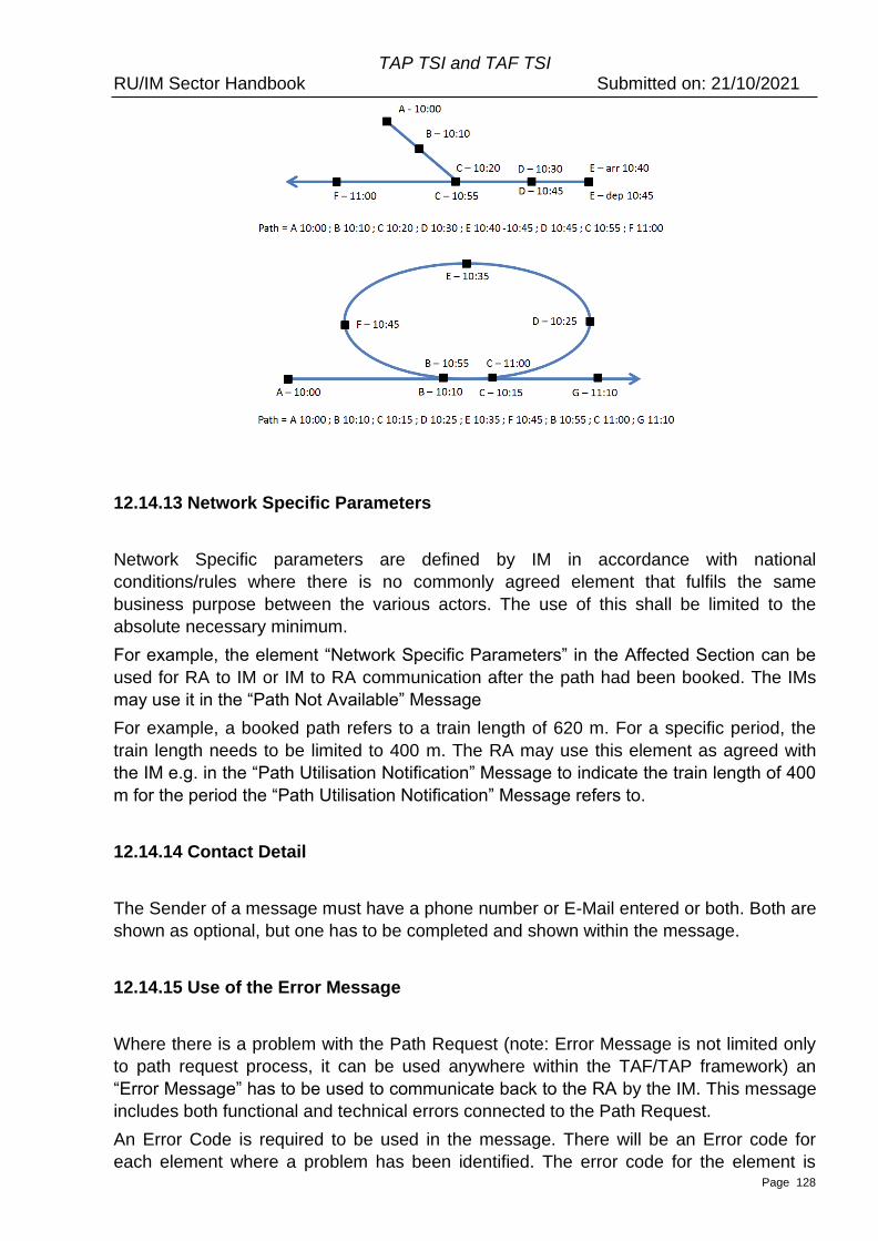
TAP TSI and TAF TSI RU/IM Sector Handbook Submitted on: 21/10/2021
Page 128
12.14.13 Network Specific Parameters
Network Specific parameters are defined by IM in accordance with national
conditions/rules where there is no commonly agreed element that fulfils the same
business purpose between the various actors. The use of this shall be limited to the
absolute necessary minimum.
For example, the element “Network Specific Parameters” in the Affected Section can be
used for RA to IM or IM to RA communication after the path had been booked. The IMs
may use it in the “Path Not Available” Message
For example, a booked path refers to a train length of 620 m. For a specific period, the
train length needs to be limited to 400 m. The RA may use this element as agreed with
the IM e.g. in the “Path Utilisation Notification” Message to indicate the train length of 400
m for the period the “Path Utilisation Notification” Message refers to.
12.14.14 Contact Detail
The Sender of a message must have a phone number or E-Mail entered or both. Both are
shown as optional, but one has to be completed and shown within the message.
12.14.15 Use of the Error Message
Where there is a problem with the Path Request (note: Error Message is not limited only
to path request process, it can be used anywhere within the TAF/TAP framework) an
“Error Message” has to be used to communicate back to the RA by the IM. This message
includes both functional and technical errors connected to the Path Request.
An Error Code is required to be used in the message. There will be an Error code for
each element where a problem has been identified. The error code for the element is
TAP TSI and TAF TSI RU/IM Sector Handbook Submitted on: 21/10/2021
Page 129
obtained from the code list and is used to identify an invalid or missing element. In
addition, there is a possibility to provide additional text along with the predefined code,
known as the Error text. The element can remain as blank, does not need to be
completed for each Error Code.
Optionally, additional information can be provided in the MessageSenderReference
element about the message that caused the error.
The Error Codes have been structured so that it is possible to indicate there is an error
with a specific element in the message or within the element group of the message. It can
therefore be possible to populate the Error Message with specific errors or errors related
to an element group. This will be done at the application level.
In addition, it is possible to enter a textural description of errors within the request
message within the FreeText element that is also available. This can be for element
specific errors but can also be extended to cover logical errors within the request, e.g.
where the train locations do not make sense. Again, this will have to be built at the
application level.
The code list of Error Codes element is split into two types: Codes for the Common
elements in the Message and codes that are only relevant to the elements within the
Network Specific Parameters.
Common codes will have the structure as follows:
• 4 Digit Code starting from 5000
Network specific codes will have the structure as follows:
• 4 Digit Code starting from 6000
These will be national Error Codes related to elements entered into the Network Specific
Parameters section that have been agreed by RU/IM and held and maintained on the IM
system only. These are not required as a common list.
The current Error Code list is given below in the Annex 10.2 “Important codes”.
Note: the elements of the error message, such as error code, type and severity, are
packed into one complex element. This complex element, as already indicated in the
12.11.8, is an array (i.e. can be repeated several times within one message). This is done
for the purpose, as explained in 12.11.8, to reduce the effort for the communication about
the errors, if multiple errors are related to the same error cause.
Note: ErrorMessage has replaced the “AnswerNotPossible” message. The ErrorMessage
as such can be used in any TAF/TAP procedure, it is not limited only to the path request
related processes.
12.14.16 Type of Request
The “Type of Request” element is needed to indicate which particular business process
the RA is applying for. Indication of the request type is necessary for IMs to start the
particular business process according to the type (study, or binding path request or
modification of the existing contracted object). It is mandatory in Path Request and Path
Details, but optional in Receipt Confirmation (as this just provides additional information
about the process from which the receipt is required).
TAP TSI and TAF TSI RU/IM Sector Handbook Submitted on: 21/10/2021
Page 130
Process “Study” is always starting with PathRequestMessage to request for a path study
or study program and is ending with the offer of a result with PathDetailsMessage.
Process “Request” is starting with PathRequestMessage for the first request for allocation
of a path for a train and is ending with the process step “booked” or the refusal of the path
offer by RA, or PathDetails ‘no alternative’.
Process “Modification”contains modification, alteration or cancellation of a booked path.
The process is starting either with PathRequestMessage or with PathNotAvailableMessage
and is also ending with the process step “booked” or the refusal of the path offer by the
RA. In case of a cancellation the process starts with the PathCanceledMessage sent by
RA and is ending with PathDetailsMessage “booked” sent by IM.
12.14.17 Type of Information
The “Type of Information” is used in several messages and are used several times for
different purposes. Therefore, the recipient has to know the status which indicates why
the message was sent. To recognise to which process does this message fit, and also to
which particular process step does this particular message have to be considered. It is
Mandatory in Path Request, Path Details and Path Utilisation Notification, optional in
Receipt Confirmation.
The following values are contained in the TypeOfInformation code list:
1 harmonisation – in process
2 harmonisation – accepted
3 harmonisation – rejected
4 request ready
5 path study request
6 pre-arranged path/reserve capacity
7 create offer
8 coordination update
9 draft offer
10 draft alternative offer
11 observation – in process
12 observation – complete
13 preparation of final offer – in process
14 preparation of final offer – accepted
15 preparation of final offer – rejected
16 final offer
17 final offer – accepted
18 alternative offer accepted
19 pre-accepted offer
21 no alternative available
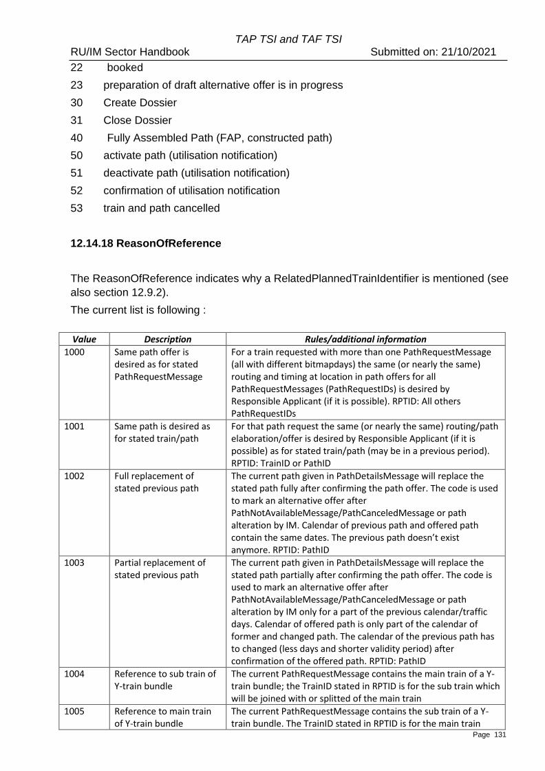
TAP TSI and TAF TSI RU/IM Sector Handbook Submitted on: 21/10/2021
Page 131
22 booked
23 preparation of draft alternative offer is in progress
30 Create Dossier
31 Close Dossier
40 Fully Assembled Path (FAP, constructed path)
50 activate path (utilisation notification)
51 deactivate path (utilisation notification)
52 confirmation of utilisation notification
53 train and path cancelled
12.14.18 ReasonOfReference
The ReasonOfReference indicates why a RelatedPlannedTrainIdentifier is mentioned (see
also section 12.9.2).
The current list is following :
Value Description Rules/additional information
1000 Same path offer is desired as for stated PathRequestMessage
For a train requested with more than one PathRequestMessage (all with different bitmapdays) the same (or nearly the same) routing and timing at location in path offers for all PathRequestMessages (PathRequestIDs) is desired by Responsible Applicant (if it is possible). RPTID: All others PathRequestIDs
1001 Same path is desired as for stated train/path
For that path request the same (or nearly the same) routing/path elaboration/offer is desired by Responsible Applicant (if it is possible) as for stated train/path (may be in a previous period). RPTID: TrainID or PathID
1002 Full replacement of stated previous path
The current path given in PathDetailsMessage will replace the stated path fully after confirming the path offer. The code is used to mark an alternative offer after PathNotAvailableMessage/PathCanceledMessage or path alteration by IM. Calendar of previous path and offered path contain the same dates. The previous path doesn’t exist anymore. RPTID: PathID
1003 Partial replacement of stated previous path
The current path given in PathDetailsMessage will replace the stated path partially after confirming the path offer. The code is used to mark an alternative offer after PathNotAvailableMessage/PathCanceledMessage or path alteration by IM only for a part of the previous calendar/traffic days. Calendar of offered path is only part of the calendar of former and changed path. The calendar of the previous path has to changed (less days and shorter validity period) after confirmation of the offered path. RPTID: PathID
1004 Reference to sub train of Y-train bundle
The current PathRequestMessage contains the main train of a Y-train bundle; the TrainID stated in RPTID is for the sub train which will be joined with or splitted of the main train
1005 Reference to main train of Y-train bundle
The current PathRequestMessage contains the sub train of a Y-train bundle. The TrainID stated in RPTID is for the main train
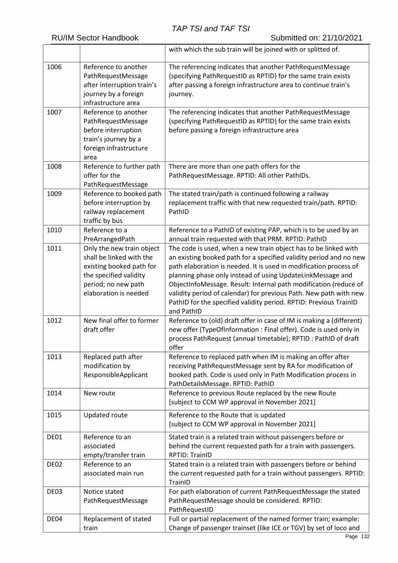
TAP TSI and TAF TSI RU/IM Sector Handbook Submitted on: 21/10/2021
Page 132
with which the sub train will be joined with or splitted of.
1006 Reference to another PathRequestMessage after interruption train’s journey by a foreign infrastructure area
The referencing indicates that another PathRequestMessage (specifying PathRequestID as RPTID) for the same train exists after passing a foreign infrastructure area to continue train’s journey.
1007 Reference to another PathRequestMessage before interruption train’s journey by a foreign infrastructure area
The referencing indicates that another PathRequestMessage (specifying PathRequestID as RPTID) for the same train exists before passing a foreign infrastructure area
1008 Reference to further path offer for the PathRequestMessage
There are more than one path offers for the PathRequestMessage. RPTID: All other PathIDs.
1009 Reference to booked path before interruption by railway replacement traffic by bus
The stated train/path is continued following a railway replacement traffic with that new requested train/path. RPTID: PathID
1010 Reference to a PreArrangedPath
Reference to a PathID of existing PAP, which is to be used by an annual train requested with that PRM. RPTID: PathID
1011 Only the new train object shall be linked with the existing booked path for the specified validity period; no new path elaboration is needed
The code is used, when a new train object has to be linked with an existing booked path for a specified validity period and no new path elaboration is needed. It is used in modification process of planning phase only instead of using UpdateLinkMessage and ObjectInfoMessage. Result: Internal path modification (reduce of validity period of calendar) for previous Path. New path with new PathID for the specified validity period. RPTID: Previous TrainID and PathID
1012 New final offer to former draft offer
Reference to (old) draft offer in case of IM is making a (different) new offer (TypeOfInformation : Final offer). Code is used only in process PathRequest (annual timetable); RPTID : PathID of draft offer
1013 Replaced path after modification by ResponsibleApplicant
Reference to replaced path when IM is making an offer after receiving PathRequestMessage sent by RA for modification of booked path. Code is used only in Path Modification process in PathDetailsMessage. RPTID: PathID
1014 New route Reference to previous Route replaced by the new Route [subject to CCM WP approval in November 2021]
1015 Updated route Reference to the Route that is updated [subject to CCM WP approval in November 2021]
DE01 Reference to an associated empty/transfer train
Stated train is a related train without passengers before or behind the current requested path for a train with passengers. RPTID: TrainID
DE02 Reference to an associated main run
Stated train is a related train with passengers before or behind the current requested path for a train without passengers. RPTID: TrainID
DE03 Notice stated PathRequestMessage
For path elaboration of current PathRequestMessage the stated PathRequestMessage should be considered. RPTID: PathRequestID
DE04 Replacement of stated train
Full or partial replacement of the named former train; example: Change of passenger trainset (like ICE or TGV) by set of loco and

TAP TSI and TAF TSI RU/IM Sector Handbook Submitted on: 21/10/2021
Page 133
wagons in case of technical problems, delay or other reasons. It is not only change of TrainID. RPTID: TrainID
DE05 Reference to a reserved capacity
This code can be used to refer to a study offer (with booking option) as a result of the KFB process (internal process for a specific product of DB Netz). RPTID: PathID
DE06 Use of same OTN as of stated train
Responsible Applicant wants to use same OTN as in stated train because of all trains are part of same family. The trains have only slightly differences on various days. RPTID: TrainID
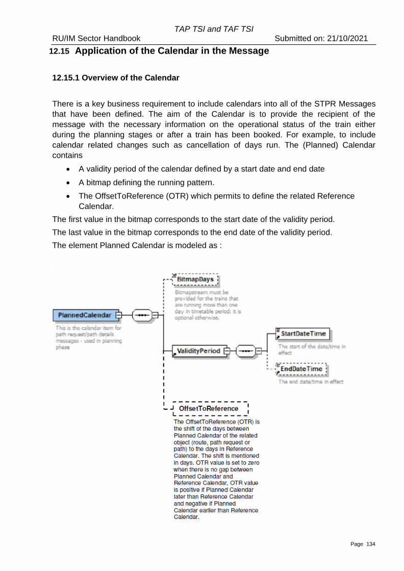
TAP TSI and TAF TSI RU/IM Sector Handbook Submitted on: 21/10/2021
Page 134
12.15 Application of the Calendar in the Message
12.15.1 Overview of the Calendar
There is a key business requirement to include calendars into all of the STPR Messages
that have been defined. The aim of the Calendar is to provide the recipient of the
message with the necessary information on the operational status of the train either
during the planning stages or after a train has been booked. For example, to include
calendar related changes such as cancellation of days run. The (Planned) Calendar
contains
• A validity period of the calendar defined by a start date and end date
• A bitmap defining the running pattern.
• The OffsetToReference (OTR) which permits to define the related Reference
Calendar.
The first value in the bitmap corresponds to the start date of the validity period.
The last value in the bitmap corresponds to the end date of the validity period.
The element Planned Calendar is modeled as :
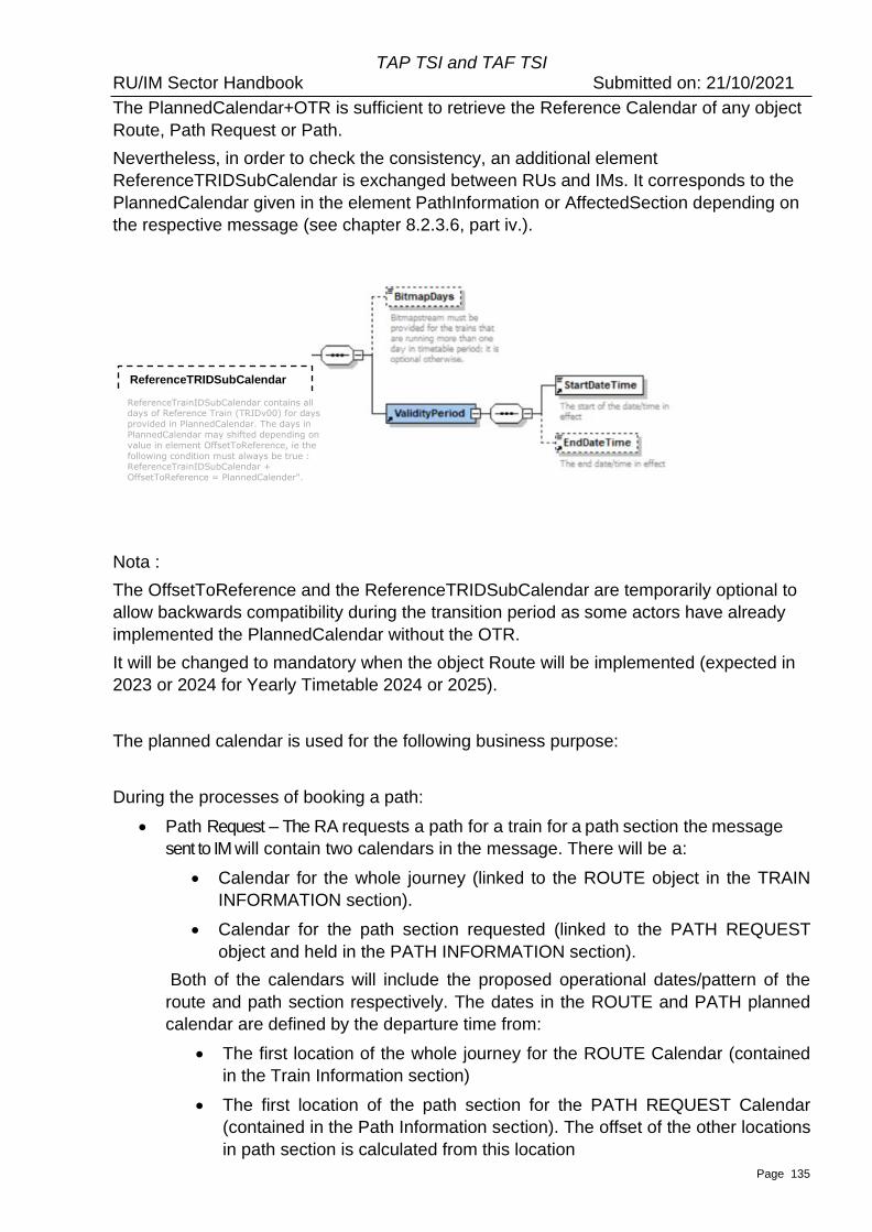
TAP TSI and TAF TSI RU/IM Sector Handbook Submitted on: 21/10/2021
Page 135
The PlannedCalendar+OTR is sufficient to retrieve the Reference Calendar of any object
Route, Path Request or Path.
Nevertheless, in order to check the consistency, an additional element
ReferenceTRIDSubCalendar is exchanged between RUs and IMs. It corresponds to the
PlannedCalendar given in the element PathInformation or AffectedSection depending on
the respective message (see chapter 8.2.3.6, part iv.).
Nota :
The OffsetToReference and the ReferenceTRIDSubCalendar are temporarily optional to
allow backwards compatibility during the transition period as some actors have already
implemented the PlannedCalendar without the OTR.
It will be changed to mandatory when the object Route will be implemented (expected in
2023 or 2024 for Yearly Timetable 2024 or 2025).
The planned calendar is used for the following business purpose:
During the processes of booking a path:
• Path Request – The RA requests a path for a train for a path section the message
sent to IM will contain two calendars in the message. There will be a:
• Calendar for the whole journey (linked to the ROUTE object in the TRAIN
INFORMATION section).
• Calendar for the path section requested (linked to the PATH REQUEST
object and held in the PATH INFORMATION section).
Both of the calendars will include the proposed operational dates/pattern of the
route and path section respectively. The dates in the ROUTE and PATH planned
calendar are defined by the departure time from:
• The first location of the whole journey for the ROUTE Calendar (contained
in the Train Information section)
• The first location of the path section for the PATH REQUEST Calendar
(contained in the Path Information section). The offset of the other locations
in path section is calculated from this location
ReferenceTRIDSubCalendar
ReferenceTrainIDSubCalendar contains all days of Reference Train (TRIDv00) for days
provided in PlannedCalendar. The days in
PlannedCalendar may shifted depending on
value in element OffsetToReference, ie the
following condition must always be true : ReferenceTrainIDSubCalendar +
OffsetToReference = PlannedCalender".
TAP TSI and TAF TSI RU/IM Sector Handbook Submitted on: 21/10/2021
Page 136
• As reminder, the Planned Calendar in Route and Path contains the OTR at
the first location of Route and Path, which permits to define the related
Reference Calendar and consequently the Reference Day completing the
Reference TRID (TRID v00) to ensure uniqueness in operation.
• Error (Answer Not Possible) – If, for whatever reason, the IM is not able to process the
path request the message will contain the indication of the logical errors (schedule
does not make logical sense) and/or physical message content errors (element in the
message is unknown /missing)
• Path Details – If the Path Request is processed by the IM who makes an offer back to
the RA the message will contain the PlannedCalendar that is linked to the first
location of the Path Information section. It contains
o the offered operational calendar for the path section that was requested. The
RA makes one request with one path section calendar, but the IM could
reply offering one or more Path Details message each containing a different
path section calendar that complements the originally requested RA
calendar (except if there is a date offset between request and offer. In this
case the RequestedCalendar element in the Path Details will complement
the originally requested RA calendar).
o the OTR which is changed only if the IM provides a path with ‘midnight
shifting’. If not the OTR is the same than the OTR indicated in the
PathInformation of the PathRequestMessage.
For example: An RA requests a train service for Mon to Fri in the path section
calendar of the Path Request. The IM may offer back two path details messages
covering the overall Mon – Fri request with one path details message for the
service for Mon to Thu and the other message for the Fri only service.
If the offered path on Friday starts on Thursday due to midnight shifting (e.g. Path
Request with start at Friday 00:10 and Path Details with start at Thursday 23:50),
the OTR is then modified by -1.
• Path Confirmed & Path Details Refused – The RA either confirms the IM offer or
rejects it the message will contain the path section calendar of the IM from the Path
Details Message
After a path has been booked
• Path Cancelled – The RA is able to make a partial or complete cancellation of the
booked path the message will contain the calendar that is linked to the first location of
the affected section together with the operational dates/pattern the RA wishes to
cancel.
• Path Not Available – If the IM has to withdraw an allocated/contracted path (e.g. as a
result of a disruption) the message will contain the calendar that is linked to the first
location of the affected section together with the operational dates/pattern that the IM
TAP TSI and TAF TSI RU/IM Sector Handbook Submitted on: 21/10/2021
Page 137
has to cancel
Activating/Deactivating a Path
• Path Section Notification with TypeOfInformation for activation and de-activation – For
certain networks there is a requirement for the RA to indicate whether a train will run
or not against a booked path the message will contain the calendar that is linked to
the first location of the affected section together with the operational dates/pattern that
have either been activated or deactivated.
Receipt Confirmation
• A calendar will be an optional element in this message which relates to the affected
Section. The message will contain the calendar that is linked to the first location of the
affected section.
12.15.2 Preconditions for the use of the calendar
The Calendar for Train Information and Path Information in the messages between
LRU/RA/RRU and IM are always calculated from the origin of each object (whole journey
for Route object, first location of Path or Path Request object) irrespective of Path
Planning Reference Location.
The rule for the Offset is always from the Origin Location and offsets in both Train
Information and Path Information sections are always calculated from that point forwards.
This will result in always a positive offset in all cases.
The Calendar contains the OTR at the first location of TrainInformation (for the Route)
and PathInformation (for PathRequest or Path) , which permits to define the related
Reference Calendar and consequently the Reference Day completing the Reference
TRID (TRID v00) to ensure uniqueness in operation. The OTR is usually null, can be
negative or positive in some cases (see 8.2.3.6).
The Reference Location for planning is still the location for which the RA requests that
the planning is made from. It remains unchanged throughout the communication with the
IM and every participant will need to calculate the calendar at the Reference Location
based on the calendar at the Origin Location in conjunction the Offset in the Path
Request Message. In the case where the Reference Location needs to be changed by
the RA then the revised Reference Location needs to be defined.
12.15.3 Calendar used in section related Messages
For all of the messages related to an affected section within a Path the calendar is used
linked to the start location of that section. That is, OTR gives an information about the
shift of the calendar days that apply at start location of affected section structure to the
ReferenceCalendar.
The affected section can be for the whole path section or part of a section.
TAP TSI and TAF TSI RU/IM Sector Handbook Submitted on: 21/10/2021
Page 138
Offsets will not be required to be calculated for these messages as no specific locations
are identified in these messages – only the start and end of a section are provided in the
message.
The messages that are based on the affected section are:
• Path Confirmed
• Path Cancellation
• Path Details Refused
• Path Not Available
• Generic sector message Path Section Notification
12.15.4 Rules related to the Calendar Element
• Both the Start Date and End Date are mandatory elements and must be present
with a date that is within the Timetable period
• Bitmap Days elements is a mandatory element and need to be included along with
the Start date.
• The Bitmap Days is a string of values where 1 represents a day that the train will
run and 0 represents a day that the train will not run Each value signifies a day
between the Start and End Date
• Where a specific pattern is needed (e.g. running every Friday) or the train is
running more than one day a Bitmap must be included in the message to reflect
that pattern
• If there is a Bitmap days string
o The size of the string for Bitmap days must equal the number of days
between Start Date and End Date inclusive and cannot be more or less. If
the pattern is different than this will give rise to an error
• If the Start and End Date are the same
o Then the Bitmap String will still apply even though the train is only running
for one day
• Midnight crossing: The midnight crossings are handled by the Offset element in
the PlannedJourneyLocation/TimingAtLocation. If the offset is greater than 0 for
the particular location, the legacy systems have to recalculate the bitmap stream
accordingly (offset to the reference location). The offset is expressed in days.
• The Calendar used in TrainInformation and PathInformation contains the OTR at
the first location of Route and Path, which permits to define the related Reference
Calendar and consequently the Reference Day completing the Reference TRID
(TRID v00) to ensure uniqueness in operation. The OTR is usually null, can be
negative or positive in some cases (see 8.2.3.6). If no OTR is indicated that means
that OTR=0.
TAP TSI and TAF TSI RU/IM Sector Handbook Submitted on: 21/10/2021
Page 139
12.15.5 Rules related to the Calendar of the Route
• The Route calendar sent to the IM after initial RU harmonisation can be the longest
calendar in sum of the calendars for the journeys described by the Path Requests
(each individual PR or the set of PRs after harmonisation) and consequently the
related Paths Details.
• No Route update in the past, only for the future.
• It can happen that after path booking, even if the Route is unchanged, the Route
calendar is different than the sum of the booked paths calendars due to lack of
capacity for some days. In this case the LRU decides either to shorten the initial
Route calendar (recommended) or to let the calendar unchanged (so long no other
Route is requested for the ‘available days’).
• It can happen that after path booking, the initial Route is partially or totally changed.
In this case see section 12.8.9.
• If the Route calendar is extended, it is recommended to create a new object Route
(new variant) for the additional calendar.
• It can also happen that the Origin, Handover, Destination is changed.
• The LRU shall update the Route according to the Route Update Process.
• The calendars of two Routes attached to the same TRIDv00 cannot have same
days, especially after paths booking, an update of the initial Route calendar and the
creation of a second Route is mandatory. ‘Calendar’ is meaning the associated
Reference Calendar (or the Planned Calendar + OTR).
12.15.6 Using the calendar element
Following examples is for showing the use of the different calendar elements. They are
only seen as support for exemplifying for implementation and are not covering all
scenarios. Each IM and RA is responsible for correct implementation of these
functionalities in their national applications so all situations according to national
allocation rules are covered.
In all following examples start day and Reference day are the same.
Train running for one day
• Start Date = 1/1/12 End Date = 1/1/12
• Number of Days the train will run = 1 day
• Bitmap Days = “1”
• OTR = 0
Train running for all days for a period
• Start Date = 1/1/12 End Date = 6/1/12
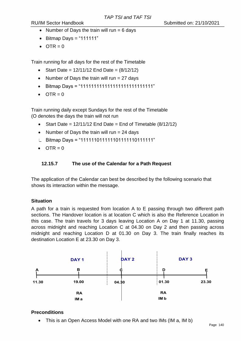
TAP TSI and TAF TSI RU/IM Sector Handbook Submitted on: 21/10/2021
Page 140
• Number of Days the train will run = 6 days
• Bitmap Days = “111111”
• OTR = 0
Train running for all days for the rest of the Timetable
• Start Date = 12/11/12 End Date = (8/12/12)
• Number of Days the train will run = 27 days
• Bitmap Days = “111111111111111111111111111”
• OTR = 0
Train running daily except Sundays for the rest of the Timetable
(O denotes the days the train will not run
• Start Date = 12/11/12 End Date = End of Timetable (8/12/12)
• Number of Days the train will run = 24 days
Bitmap Days = “111111011111101111110111111”
• OTR = 0
12.15.7 The use of the Calendar for a Path Request
The application of the Calendar can best be described by the following scenario that
shows its interaction within the message.
Situation
A path for a train is requested from location A to E passing through two different path
sections. The Handover location is at location C which is also the Reference Location in
this case. The train travels for 3 days leaving Location A on Day 1 at 11.30, passing
across midnight and reaching Location C at 04.30 on Day 2 and then passing across
midnight and reaching Location D at 01.30 on Day 3. The train finally reaches its
destination Location E at 23.30 on Day 3.
Preconditions
• This is an Open Access Model with one RA and two IMs (IM a, IM b)
TAP TSI and TAF TSI RU/IM Sector Handbook Submitted on: 21/10/2021
Page 141
• A single train has been requested across a start / end date of 30th July 2012 to
2nd of August 2012
• The train travels across 3 day leaving A on Day 1 at 11.30 and arriving on Day 3 at
23.30 (based on the RA requested timetable)
• The train is offered back with one Path Details Message per IM (IMa and IMb)
• Location times arrival and departure will be treated as the same for request and
offer
• The Path Request is correct and contains no logical or physical errors
• All train activities and other preconditions have been ignored in this scenario
Approach
The aim of this approach is to provide efficient RA/IM communication where a train is
being requested and offered. In particular this scenario shows how the Calendar and
offsets will work together.
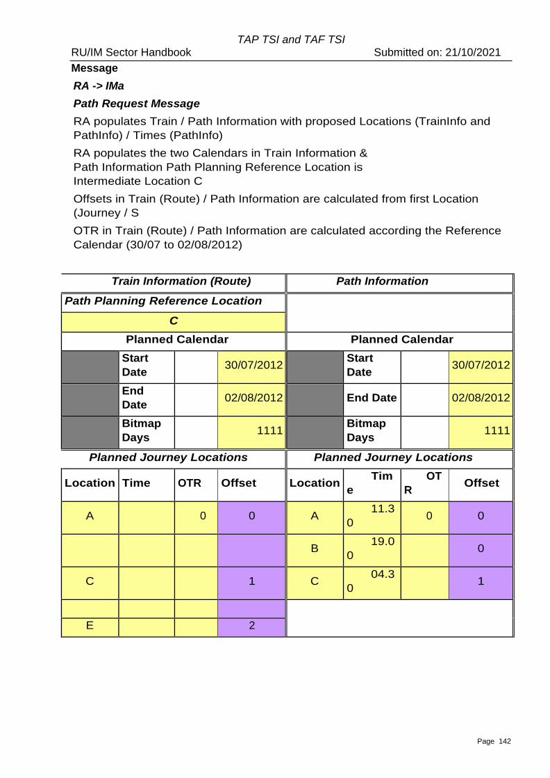
TAP TSI and TAF TSI RU/IM Sector Handbook Submitted on: 21/10/2021
Page 142
Message
RA -> IMa
Path Request Message
RA populates Train / Path Information with proposed Locations (TrainInfo and
PathInfo) / Times (PathInfo)
RA populates the two Calendars in Train Information &
Path Information Path Planning Reference Location is
Intermediate Location C
Offsets in Train (Route) / Path Information are calculated from first Location
(Journey / S
OTR in Train (Route) / Path Information are calculated according the Reference
Calendar (30/07 to 02/08/2012)
Train Information (Route) Path Information
Path Planning Reference Location
C
Planned Calendar Planned Calendar
Start
Date 30/07/2012
Start
Date 30/07/2012
End
Date 02/08/2012 End Date 02/08/2012
Bitmap
Days 1111
Bitmap
Days 1111
Planned Journey Locations Planned Journey Locations
Location Time OTR Offset Location Tim
e
OT
R Offset
A 0 0 A 11.3
0 0 0
B 19.0
0 0
C 1 C 04.3
0 1
E 2
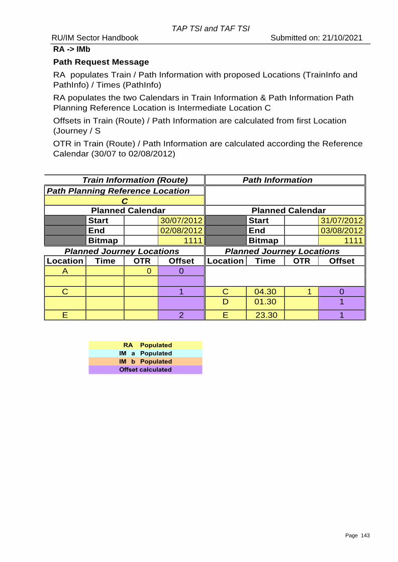
TAP TSI and TAF TSI RU/IM Sector Handbook Submitted on: 21/10/2021
Page 143
RA -> IMb
Path Request Message
RA populates Train / Path Information with proposed Locations (TrainInfo and
PathInfo) / Times (PathInfo)
RA populates the two Calendars in Train Information & Path Information Path
Planning Reference Location is Intermediate Location C
Offsets in Train (Route) / Path Information are calculated from first Location
(Journey / S
OTR in Train (Route) / Path Information are calculated according the Reference
Calendar (30/07 to 02/08/2012)
Train Information (Route) Path Information
Path Planning Reference Location C
Planned Calendar Planned Calendar
Start
Date
30/07/2012 Start
Date
31/07/2012
End
Date
02/08/2012 End
Date
03/08/2012
Bitmap
Days
1111 Bitmap
Days
1111
Planned Journey Locations Planned Journey Locations
Location Time OTR Offset Location Time OTR Offset
A 0 0
C 1 C 04.30 1 0 D 01.30 1
E 2 E 23.30 1
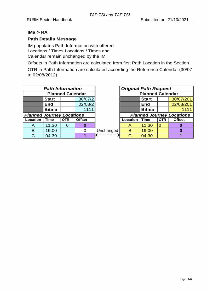
Page 144
TAP TSI and TAF TSI RU/IM Sector Handbook Submitted on: 21/10/2021
IMa -> RA
Path Details Message
IM populates Path Information with offered
Locations / Times Locations / Times and
Calendar remain unchanged by the IM
Offsets in Path Information are calculated from first Path Location in the Section
OTR in Path Information are calculated according the Reference Calendar (30/07
to 02/08/2012)
Path Information Original Path Request
Planned Calendar Planned Calendar
Start
Date
30/07/2
012 Start
Date
30/07/201
2 End
Date
02/08/2
012 End
Date
02/08/201
2 Bitma
p Days
1111 Bitma
p Days
1111
Planned Journey Locations Planned Journey Locations Location
n
Time OTR Offset Location Time OTR Offset
A 11.30 0 0 A 11.30 0 0
B 19.00 0
0
Unchanged B 19.00 0
C 04.30 1
C 04.30 1
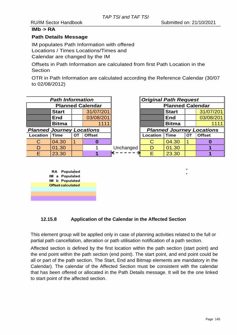
Page 145
TAP TSI and TAF TSI RU/IM Sector Handbook Submitted on: 21/10/2021
IMb -> RA
Path Details Message
IM populates Path Information with offered
Locations / Times Locations/Times and
Calendar are changed by the IM
Offsets in Path Information are calculated from first Path Location in the
Section
OTR in Path Information are calculated according the Reference Calendar (30/07
to 02/08/2012)
Path Information Original Path Request
Planned Calendar Planned Calendar
Start
Date
31/07/201
2 Start
Date
31/07/201
2 End
Date
03/08/201
2 End
Date
03/08/201
2 Bitma
p Days
1111 Bitma
p Days
1111
Planned Journey Locations Planned Journey Locations Location
n
Time OT
R
Offset Location
n
Time OT
R
Offset
C 04.30 1 0 C 04.30 1 0
D 01.30 1
1
Unchanged D 01.30 1
E 23.30 1
E 23.30 1
12.15.8 Application of the Calendar in the Affected Section
This element group will be applied only in case of planning activities related to the full or
partial path cancellation, alteration or path utilisation notification of a path section.
Affected section is defined by the first location within the path section (start point) and
the end point within the path section (end point). The start point, and end point could be
all or part of the path section. The Start, End and Bitmap elements are mandatory in the
Calendar). The calendar of the Affected Section must be consistent with the calendar
that has been offered or allocated in the Path Details message. It will be the one linked
to start point of the affected section.
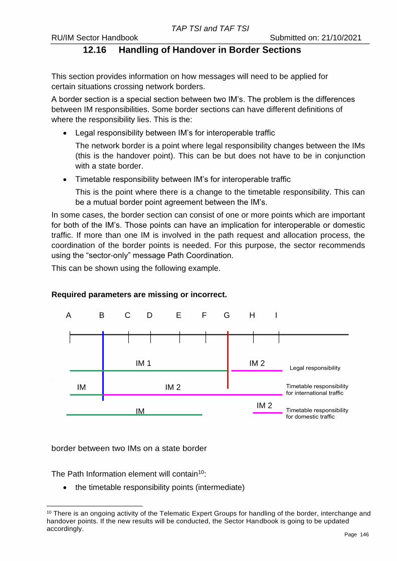
Page 146
TAP TSI and TAF TSI RU/IM Sector Handbook Submitted on: 21/10/2021
Required parameters are missing or incorrect. Location B = Timetable responsibility point Location G = State border point (only)
The solution for the mutual communication between all actors must be possible for all
types of border sections scenarios. IMs will need to identify the mutual agreements of the
location points which are important for timetable information for every border section.
Those points will be part of Path Information section for Path Coordination Message
which is created by the IM who is responsible for timetable construction at the border
section. In this case the second IM will have all the necessary information that is needed.
30
The described situation can apply to the border between two IMs within one country as well as to the
12.16 Handling of Handover in Border Sections
This section provides information on how messages will need to be applied for
certain situations crossing network borders.
A border section is a special section between two IM’s. The problem is the differences
between IM responsibilities. Some border sections can have different definitions of
where the responsibility lies. This is the:
• Legal responsibility between IM’s for interoperable traffic
The network border is a point where legal responsibility changes between the IMs
(this is the handover point). This can be but does not have to be in conjunction
with a state border.
• Timetable responsibility between IM’s for interoperable traffic
This is the point where there is a change to the timetable responsibility. This can
be a mutual border point agreement between the IM’s.
In some cases, the border section can consist of one or more points which are important
for both of the IM’s. Those points can have an implication for interoperable or domestic
traffic. If more than one IM is involved in the path request and allocation process, the
coordination of the border points is needed. For this purpose, the sector recommends
using the “sector-only” message Path Coordination.
This can be shown using the following example.
border between two IMs on a state border
The Path Information element will contain10:
• the timetable responsibility points (intermediate)
10 There is an ongoing activity of the Telematic Expert Groups for handling of the border, interchange and handover points. If the new results will be conducted, the Sector Handbook is going to be updated accordingly.
A B C D E F G H I
IM 1 IM 2
IM IM 2
IM IM 2
Page 147
TAP TSI and TAF TSI RU/IM Sector Handbook Submitted on: 21/10/2021
• the sections between the origin and timetable responsibility point (if origin is in the
network section)
• the sections between the timetable responsibility point and destination point. (if
destination is in the network section)
• all the sections need to carry the indication “ResponsibleIM” in order to differentiate which
section is operated by which IM. The Path Information element will have all mutual agreed
points from the border section (especially state border point where is changed legal responsibility
between IM’s and often between RA too). This solution solves the problem how to have the
necessary information for both IM’s and both RA for every type of border section.
12.17 Usage of Identifiers in Planning Related Messages
The explanation on how to utilize the concept of new identifiers in planning related
messages is given in the UML model attached to this Sector Handbook. The following
UML diagrams are recommended (in the folder “Business Process Model/Business Use
Cases/Planning/Handbook Planning):
. 4.6 Planning
. 4.7 Utilization Notification
. 4.8 Planning Y-Traffic
12.18 Re-planning
Reserved

Page 148
TAP TSI and TAF TSI RU/IM Sector Handbook Submitted on: 21/10/2021
Part C Operation of Trains
Page 149
TAP TSI and TAF TSI RU/IM Sector Handbook Submitted on: 21/10/2021
13. General Information The following chapters describe the messages used in the operations phase and the modalities of their exchange. Guidelines on the message exchange in incident management in operations are laid down in Annex 13 (Business Cases Operations).
13.1 – Data sharing with involved stakeholders for Freight traffic TAF TSI (regulation 2021/541) states in chapter 4.2: In addition to the provisions from the Chapter 4 and its sub-chapters every stakeholder may exchange the messages according to Chapters 4.2.2.3 (only during operation or preparation of train operation) [Path Details], 4.2.4.2 [Train Running Forecast], 4.2.4.3 [Train Running Information and Train Delay Cause], 4.2.5.2 [Train Running Interruption], 4.2.6.3 [Wagon ETI/ETA] and 4.2.6.4 [Alert message] with other stakeholders involved in the same freight service, under the condition that the stakeholders are identifiable. These exchanges of messages may be charged by the sender. Nota: ▪ ‘May exchange’ means each stakeholder may decide to exchange (or not) the messages to
another stakeholder on request. ▪ ‘The stakeholders are identifiable’ implies that they have received a Company Code. ▪ The exchange can be charged e.g. if the message is adapted before sending to the other
stakeholders. ▪ Wagon ETI/ETA message and Alert message are not subject to this document and are
subject to RU/RU data exchange
13.2 – Use of some key elements in operations messages The following key elements are used in various in operations messages and are to be used as described here:
• ScheduledTimeAtHandover = The scheduled date and time of departure or entrance at the network border between two different IMs
• ScheduledDateTimeAtTransfer = The scheduled date and time of arrival or exit at the network border between two different IMs
• TransferPoint = Last location on a network (network border) The most recent information available shall be used to populate these elements (e.g. for rescheduling of trains).
Page 150
TAP TSI and TAF TSI RU/IM Sector Handbook Submitted on: 21/10/2021
14. Train Preparation
14.1 Train Composition ResponsibleRU sends the train composition message to all relevant IMs, with which the ResponsibleRU operates for a journey section within a path contract if IM contractually requires receiving TCM. In case the train is taken over as a whole by the next RU, the Responsible RU shall send the Train Composition to the next Responsible RU. Responsible RU should send TCM to IM before departure of the train from origin or before it will enter the network, unless National rule, Network statement or contract states otherwise. Whenever there is a change in the composition during the journey of a train, the Responsible RU has to update this message to all parties involved. Compliance with TAF/TAP TSI requirements cannot be regarded as compliance with safety requirements unless agreed otherwise by IM and RU. Therefore, values given in the message will have no impact on the safe operation of a train, unless stated by national rules or Network Statement. ResponsibleRU is however always responsible for providing the exact and up-to-date composition of its trains. Freight Train Composition Message is mandatory according to TAF TSI. Passenger Train Composition Message is optional and it is subject to companies’ agreements.
14.2 ResponsibleRU informs the IM, SM and next RU about restrictions on the rolling stock The ResponsibleRU must inform the IM of any modification or anomaly to the characteristics of the train affecting its performance or affecting the ability to accommodate the train in its allocated path (§ 4.2.2.7 and § 4.2.3.3.2 of OPE TSI decision 2012/757), e.g. any operational restrictions on a vehicle concerned (gauge, speed restrictions, etc.). Based on local rules this could be done using the TAF TrainComposition message/ TAP PassengerTrainComposition message. According to agreed rules, the ResponsibleRU could also inform involved RU(s) and/or SM(s) of any modification or anomaly affecting the access doors, internal fitting and comfort requirement, or in case of non-availability of commercial services that were planned.
In this chapter, the word “restriction” could concern: a) any modification in the train composition that prevents the train to run according to the allocated path (e.g. addition of a coach with lower maximal speed than the planned speed) b) any anomaly or defect that implies specific disposition in the train preparation, access to network authorization, train run c) any anomaly or defect that heavily decrease the level of services offered to the passengers (e.g. air conditioning failure in summer).
For the restrictions a) and b), the process between ResponsibleRU and IM of information exchange and route continuation/alteration has to be according to network statement. The RU must follow the operational process, if not available the RU has to wait for the feedback of the IM before running the train. The information about restriction is transmitted prior to departure and during the journey according to agreed rules (which define the timing) from ResponsibleRU to IM and/or from ResponsibleRU to the involved RUs and/or from RU to the SM, depending on the kind of restriction.
Page 151
TAP TSI and TAF TSI RU/IM Sector Handbook Submitted on: 21/10/2021
14.1.5 Passengers Train Composition – Complement on Unit identification and Unit description
Unit identification
The units composing the train can be identified by their type or by their number.
The type is indicated as following: • For locomotive and (tractive) trainset, the type is the element LocoTypeNumber ; • For coach or hauled passengers composition (without motors), the type is the element
HauledTypeID.
The number of the unit is: • For individual vehicle: the European Vehicle Number; • For tractive trainset or hauled passengers composition: the Trainset ID (number
identifying the trainset/composition as a whole and usually indicated in front and rear of the trainset/composition);
• If the TrainsetID is used, the LocoTypeNumber or the HauledTypeID shall be mandatory filled to ensure the unicity.
For energy settlement, the EVN of the tractive unit(s) shall be sent by the RU to the IM.
For (tractive) trainset, the composition message can send simultaneously: • The trainset type (LocoTypeNumber) and the TrainsetID, commonly used in operation
and traffic management; • The EVN of all vehicles composing the trainset, to be used by the IM in the energy
settlement process.
Unit Description
There are two manners to describe the units of a passenger train, especially when trainsets are used:
• either vehicle per vehicle (UnitCount = 1), all vehicles (tractive, hauled, incorpored in a trainset or in a fixed hauled composition) are listed;
• or trainset per trainset (UnitCount = 2), each trainset is considered as a whole; for fixed hauled composition pushed/pulled by a locomotive, the fixed hauled composition is one unit and the locomotive is another unit;
• if the composition is described per trainsets, the list of all vehicles can be provided via the element EuropeanVehicleNumber, e.g. for energy settlement purpose.
Example
TGV Duplex, type 93 87 0029000, trainset number 239, composed by 10 vehicles with EVNs:
93870029077-9, 93870291737-9, 93870292737-8, 93870293737-7, 93870294737-6, 93870295737-5, 93870296737-4, 93870297737-3, 93870298737-2, 93870029078-7
If UnitCount = 1 (vehicle), then: NumberOfUnits = 10 UnitData = 10 occurrences (one for each vehicle) UnitData / UnitIdentification / EuropeanVehicleNumber = the EVN of the vehicle which is
Page 152
TAP TSI and TAF TSI RU/IM Sector Handbook Submitted on: 21/10/2021
described
If UnitCount = 2 (trainset) NumberOfUnits = 1 UnitData = 1 occurrence (the trainset is considered as a whole) UnitData / UnitIdentification / LocoTypeNumber = 93870029000 UnitData / UnitIdentification / TrainsetID = 239 UnitData / UnitIdentification / EuropeanVehicleNumber = the list of the 10 EVNs above
14.1.7 – Train composition and energy settlement.
Sector associations signed in November 2020 the ‘EU railway sector declaration on traction energy metering and settlement’. According to the declaration, the RUs commit ‘to deliver to the IM train compositions (including EVNs of all traction units) by 2023. This shall be done preferably at departure of train-run and latest 48 hours later’. Therefore, the Freight or Passenger Train Composition message sent by the RU to the IM must contain:
- either the EVN of the tractive rolling stock (element LocoNumber in TCM, element EuropeanVehicleNumber for PTCM);
- or, for passenger trains composed by trainsets and under agreement with the IM, the type of the trainset (element LocoTypeNumber) and the identifier of the trainset (element TrainsetID).
If the EVN of the tractive rolling stock is not available, the rolling stock type (element LocoTypeNumber) must be sent. Handling of message status
Use of element message status:
1 (creation) = new message
2 (modification) = can be used (if used, provided information about composition of train for
specified journey section(s) in TCM with message status = 2 replaces information for these
section(s) provided in previously sent TCM(s))
3 (deletion) = error in message content, message is deleted.
To allow the recipient to find the message, which shall be deleted, the best option is to
populate the SenderReference element in each message and to refer to that reference for
deletion – i.e. the content of SenderReference of the message with status 3 shall be the
same as the original one with status 1, that shall be deleted. It is recommended to use the
message identifier to populate the SenderReference element to ensure uniqueness.
If either the sender or the recipient is not able to use this option, the original message to be
deleted can also be found by its content, which should be identical except for the
MessageStatus. Key elements to identify a message are: TrainOperationalIdentification/
OTNIdentifier, JourneySection.
14.3 Train Ready message
Page 153
TAP TSI and TAF TSI RU/IM Sector Handbook Submitted on: 21/10/2021
According to TAF/TAP TSI, the ResponsibleRU shall send a ‘train ready’ message to the infrastructure manager every time a train is ready to start after train preparation, unless under national rules the infrastructure manager accepts the timetable as a ‘train ready’ message. In the case of combined transport, the Terminal Operator shall send a ‘train ready’ message to the RU every time a wagon set is ready to start. The RU providing traction to the IM entry point shall send the ‘train ready’ message to the RU operating the train service on the IM network (ResponsibleRU). In addition, other existing standards (e.g. GSM-R) may be used for the same purpose if there is a specific agreement between the parties involved. Acceptance of the timetable as TrainReady message means the IM assumes the train to be ready for departure when the departure time is reached and ResponsibleRU did not report any problems. In this case, the ResponsibleRU shall inform the infrastructure manager and, if applicable, the station manager if the train is not ready as soon as possible.
Local rules specify how long before the departure a “train ready” messages has to be sent.
14.4 Content of the message OTN is mandatory in this message as it is used for verbal communication between RU/IM/SM/terminal staff. If the TrainReadyStatus element is not used, the IM shall assume the train to be ready. Handling of message status
Use of element message status:
1 (creation) = new message
2 (modification) = not used for changes to TrainReadyStatus (if used, it shall be handled
like status 1)
3 (deletion) = error in message content, message is deleted.
To allow the recipient to find the message, which shall be deleted, the best option is to
populate the SenderReference element in each message and to refer to that reference for
deletion – i.e. the content of SenderReference of the message with status 3 shall be the
same as the original one with status 1, that shall be deleted. It is recommended to use the
message identifier to populate the SenderReference element to ensure uniqueness.
If either the sender or the recipient is not able to use this option, the original message to be
deleted can also be found by its content, which should be identical except for the
MessageStatus. Key elements to identify a message are: TrainOperationalIdentification/
OTNIdentifier, TrainLocation, TrainReadyStatus
Page 154
TAP TSI and TAF TSI RU/IM Sector Handbook Submitted on: 21/10/2021
15. Train Running Information and Forecast
15.1 Process triggering the Train Running Information message
The IM has to provide train reporting at appropriate reporting points indicating actual time
and the delta-time value (as described in OPE TSI § 4.2.3.4.2.1). This message is sent
to the ResponsibleRU to inform RU controllers.
The IM sends to the ResponsibleRU a Train Running Information message as soon as
the train reaches/leaves:
• origin,
• destination,
• handover points,
• interchange points,
• other contractually agreed reporting points.
Reporting at additional points than the agreed ones can be sent by the IM to the ResponsibleRU.
The time limit to send the message after the train has reached the reporting point is
defined by national rules or contractual agreement. In practice, the sending is done in “real
time” in case of electronic tracking and tracing systems.
15.2 Process triggering the Train Running Forecast message
The IM sends to the ResponsibleRU a Train Running Forecast message as soon as the
train reaches contractually agreed reporting points and/or the forecast delay (increasing or
decreasing) varies more than an agreed threshold to deliver a forecast time for:
• destination,
• handover points,
• interchange points,
• other contractually agreed points.
Each IM provides forecasts for points for which it is responsible for traffic management.
This implies that the forecast time can be defined. If not, a Train Running Interrupted
Message is sent. The message can also be sent before the train starts running.
The message is also sent by the IM to the next IM involved in the train run, details of
sending conditions can be defined in a bilateral agreement. The time limit to send the
message after the train has reached the reporting point is defined by national rules or
contractual agreement. The method to calculate the forecast time is defined by each IM.
By contractual agreement, this message can also be sent from ResposibleRU to the IM.
If agreed, the message shall also be sent from ResponsibleRU to the next
ResponsibleRU/LeadRU for the estimated time of interchange (change of responsibility for
the train).
In the case of combined transport under contractual agreement, the
Page 155
TAP TSI and TAF TSI RU/IM Sector Handbook Submitted on: 21/10/2021
LeadRU/ResponsibleRU shall ensure the Train Running Forecast message is provided to
the Terminal Operator.
15.3 – Information to the Station Manager
According to TAP TSI, the Station Manager receives Train Running Forecast messages
and Delay Cause messages.
These messages are sent in due time under contractual agreement by:
• IM to SM or
• by IM to RU and then RU to SM (depending on national railway organisation) according to contractual agreement. The RU may change the value of the message before passing the message on to the SM.
15.4 Content of the messages
The element LocationDateTime is populated with the actual time in the Train Running
Information message and populated with the forecasted time in the Train Running
Forecast message.
For both messages:
The planned time of a train at the reporting point can be specified in
15.4.1 ReferencedLocationDateTime: thisis the originally (and internationally agreed/published) datetime.
15.4.2 BookedLocationDateTime : this is the last agreed (booked) datetime at this location, also after a re-planning
If no re-planning has taken place, both elements contain the same datetime.
If the delay (actual/forecasted) is given in the TrainDelay section, the element
AgainstBooked is used to indicate the delay according to the (last) booked timing. The
AgainstReferenced is used to indicate the delay to the originally planned timing.
Pattern for the delta-t value in the TrainDelay element as listed below (examples):
• (+0024) indicating the train is running with 24 min delay
• (-0023) indicating the train is running 23 min before schedule
• (-0000) indicating the train is running on time
• (+0000) indicating the train is running on time
• if the element is not given, the delta t value is not known
Handling of message status
Use of element message status:
Page 156
TAP TSI and TAF TSI RU/IM Sector Handbook Submitted on: 21/10/2021
1 (creation) = new message
2 (modification) = not used (if used, it shall be handled like status 1)
3 (deletion) = error in message content, message is deleted.
To allow the recipient to find the message, which shall be deleted, the best option is to
populate the SenderReference element in each message and to refer to that reference
for deletion – i.e. the content of SenderReference of the message with status 3 shall be
the same as the original one with status 1, that shall be deleted. It is recommended to
use the message identifier to populate the SenderReference element to ensure
uniqueness.
If either the sender or the recipient is not able to use this option, the original message to
be deleted can also be found by its content, which should be identical except for the
MessageStatus. Key elements to identify a message are: Location, LocationStatus,
LocationDateTime, TrainOperationalIdentification/OTNIdentifier.
In case a previous TrainRunningForecast message for the same train included more
than one TrainLocationReport, the deletion message is valid only if the same list is
provided – or use of SenderReference. Partial deletion aren’t accepted and will trigger
ErrorMessage in reply.
15.6 Accuracy of train running forecast information
15.6.1 Background and purpose of Forecasts and ETAs for planning operations
Train running forecast information serves to plan onward operations in a specific train service or for onward connections either by rail or other transport modes. As the train forecast information is an estimate, any operator, who intends to use the information for planning the onward connection, needs to be aware of the level of accuracy and reliability of the information.
15.6.2 References to Forecasts and ETAs in TAF-TSI
TAF TSI defines the Train Running Forecast message as having the purpose to carry information about estimated time of trains at forecast points and to give the forecast time for agreed forecast points. As of 2022 the TAF TSI will also prescribe that it should be possible for the recipient of the train running forecast information or of an Estimated Time of Arrival (ETA), Estimated Time of Interchange (ETI), or Train Estimated Time of Arrival (TETA), which is computed and shared with stakeholders, to assess its accuracy and reliability. The terminology and principles for such assessment are summarised in Annex IV of the TAF TSI. Against this background this chapter in the joint sector handbook elaborates on the definition, computation and use of qualifiers for forecast information. As regards the use of the Train Running Forecast messages the TAF TSI specifies that Infrastructure Managers (IMs) must send this message to Railway Undertakings and neighbouring IMs. In practice the message is resent when there is new information on the forecast time of arrival. Evidently train arrival information consists of estimates, which get more accurate as the train approaches. The practice is further that on international trains there will be several IMs sending Train Running Forecast messages to the RUs involved.
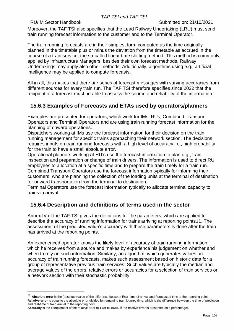
Page 157
TAP TSI and TAF TSI RU/IM Sector Handbook Submitted on: 21/10/2021
Moreover, the TAF TSI also specifies that the Lead Railway Undertaking (LRU) must send train running forecast information to the customer and to the Terminal Operator.
The train running forecasts are in their simplest form computed as the time originally planned in the timetable plus or minus the deviation from the timetable as accrued in the course of a train service, the so-called linear time shifting method. This method is commonly applied by Infrastructure Managers, besides their own forecast methods. Railway Undertakings may apply also other methods. Additionally, algorithms using e.g., artificial intelligence may be applied to compute forecasts. All in all, this makes that there are series of forecast messages with varying accuracies from different sources for every train run. The TAF TSI therefore specifies since 2022 that the recipient of a forecast must be able to assess the source and reliability of the information.
15.6.3 Examples of Forecasts and ETAs used by operators/planners
Examples are presented for operators, which work for IMs, RUs, Combined Transport Operators and Terminal Operators and are using train running forecast information for the planning of onward operations. Dispatchers working at IMs use the forecast information for their decision on the train running management for specific trains approaching their network section. The decisions requires inputs on train running forecasts with a high level of accuracy i.e., high probability for the train to have a small absolute error. Operational planners working at RU’s use the forecast information to plan e.g., train inspection and preparation or change of train drivers. The information is used to direct RU employees to a location at a specific time and to prepare the train timely for a train run. Combined Transport Operators use the forecast information typically for informing their customers, who are planning the collection of the loading units at the terminal of destination for onward transportation from the terminal to destination. Terminal Operators use the forecast information typically to allocate terminal capacity to trains in arrival.
15.6.4 Description and definitions of terms used in the sector
Annex IV of the TAF TSI gives the definitions for the parameters, which are applied to describe the accuracy of running information for trains arriving at reporting points11. The assessment of the predicted value’s accuracy with these parameters is done after the train has arrived at the reporting points. An experienced operator knows the likely level of accuracy of train running information, which he receives from a source and makes by experience his judgement on whether and when to rely on such information. Similarly, an algorithm, which generates values on accuracy of train running forecasts, makes such assessment based on historic data for a group of representative previous train services. Such values are typically the median and average values of the errors, relative errors or accuracies for a selection of train services or a network section with their stochastic probability.
11 Absolute error is the (absolute) value of the difference between Real-time of arrival and Forecasted time at the reporting point.
Relative error is equal to the absolute error divided by remaining train journey time, which is the difference between the time of prediction and real-time of train arrival to the reporting point. Accuracy is the complement of the relative error to 1 (or to 100%, if the relative error is presented as a percentage).
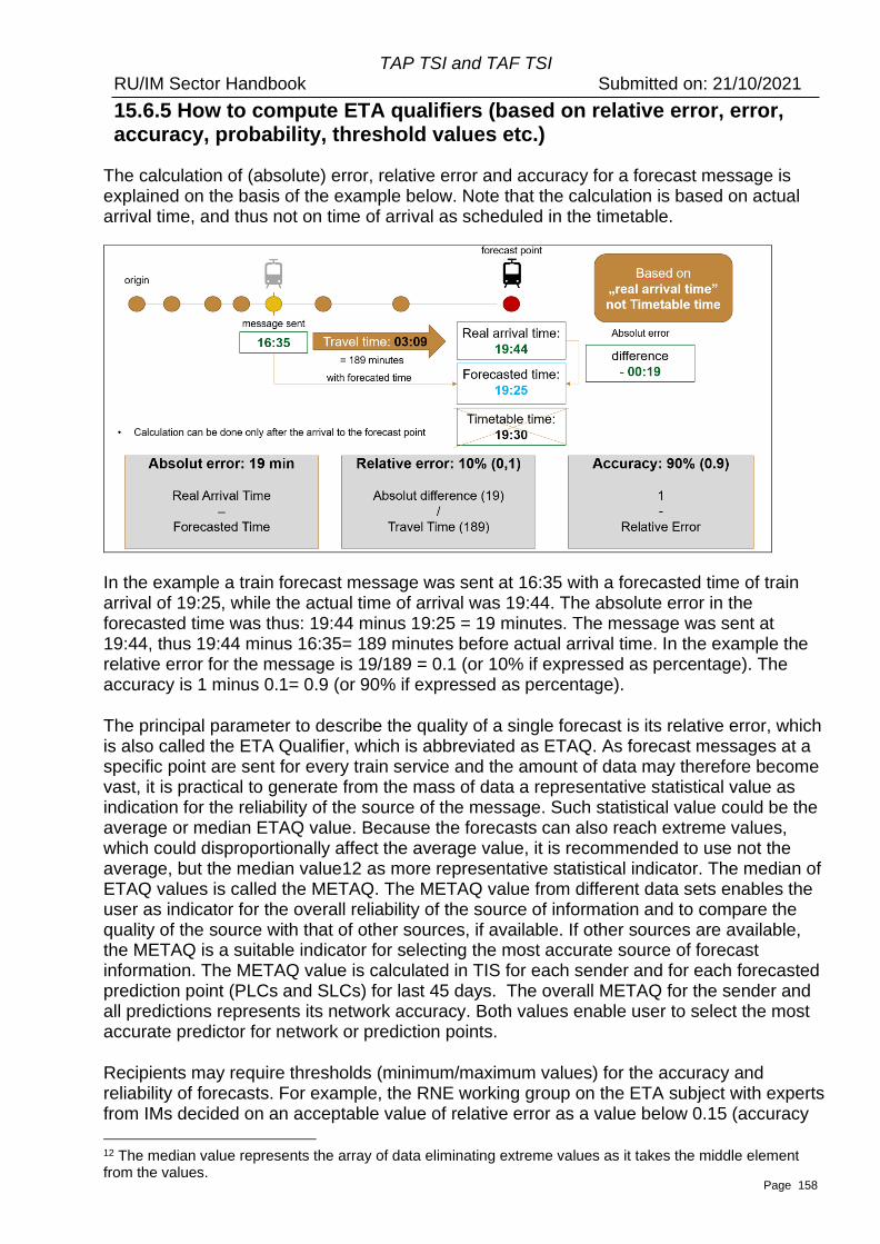
Page 158
TAP TSI and TAF TSI RU/IM Sector Handbook Submitted on: 21/10/2021
15.6.5 How to compute ETA qualifiers (based on relative error, error, accuracy, probability, threshold values etc.)
The calculation of (absolute) error, relative error and accuracy for a forecast message is explained on the basis of the example below. Note that the calculation is based on actual arrival time, and thus not on time of arrival as scheduled in the timetable.
In the example a train forecast message was sent at 16:35 with a forecasted time of train arrival of 19:25, while the actual time of arrival was 19:44. The absolute error in the forecasted time was thus: 19:44 minus 19:25 = 19 minutes. The message was sent at 19:44, thus 19:44 minus 16:35= 189 minutes before actual arrival time. In the example the relative error for the message is 19/189 = 0.1 (or 10% if expressed as percentage). The accuracy is 1 minus 0.1= 0.9 (or 90% if expressed as percentage). The principal parameter to describe the quality of a single forecast is its relative error, which is also called the ETA Qualifier, which is abbreviated as ETAQ. As forecast messages at a specific point are sent for every train service and the amount of data may therefore become vast, it is practical to generate from the mass of data a representative statistical value as indication for the reliability of the source of the message. Such statistical value could be the average or median ETAQ value. Because the forecasts can also reach extreme values, which could disproportionally affect the average value, it is recommended to use not the average, but the median value12 as more representative statistical indicator. The median of ETAQ values is called the METAQ. The METAQ value from different data sets enables the user as indicator for the overall reliability of the source of information and to compare the quality of the source with that of other sources, if available. If other sources are available, the METAQ is a suitable indicator for selecting the most accurate source of forecast information. The METAQ value is calculated in TIS for each sender and for each forecasted prediction point (PLCs and SLCs) for last 45 days. The overall METAQ for the sender and all predictions represents its network accuracy. Both values enable user to select the most accurate predictor for network or prediction points. Recipients may require thresholds (minimum/maximum values) for the accuracy and reliability of forecasts. For example, the RNE working group on the ETA subject with experts from IMs decided on an acceptable value of relative error as a value below 0.15 (accuracy
12 The median value represents the array of data eliminating extreme values as it takes the middle element from the values.
Page 159
TAP TSI and TAF TSI RU/IM Sector Handbook Submitted on: 21/10/2021
0.85). For the calculation of ETAQ and overall accuracy indicator represented by METAQ the forecast messages from the last 30 minutes of a train journey are disregarded, in particular for freight trains, to avoid extreme values. This is illustrated by means of the figure below, which presents the case of a train service whereby the information recipient requires that the relative error should be less than 0.15 (or 15%).
Combined Transport Operators as recipient of ETA information required that the absolute error of the ETAs, which are provided by a source for the destination terminal of the train, must be less than 60 minutes with 95% probability not later than 4 hours before train arrival.
15.6.6 How RNE TIS facilitates the assessment of forecast quality for the recipient
The RNE Train Information System (TIS) facilitates the exchange of messages in the format of TAF TSI amongst parties, which are connected to TIS and are entitled to receive the information. TIS can forward for a train run also train running forecast messages from different sources, if these are available. Starting on 2022 TIS also presents in a new Forecast tab in the User Interface (UI) for each source of forecast information the median value of ETAQ for train services, which are identified by their train number, and which are calculated from the train runs in previous 45 calendar days. In case there are different sources of forecast messages, TIS will compare the METAQ values for each source and advise on the use of the most accurate source in the Train info tab UI.
Page 160
TAP TSI and TAF TSI RU/IM Sector Handbook Submitted on: 21/10/2021
16 Service Disruption/Train Running Interrupted
16.1 Process triggering the message
If the train has been stopped due to a disruption (e.g. line blocked, loco breakdown) and
no forecast of its further run is yet available, the Train Running Interrupted messages must
be sent from IM to ResponsibleRU. The message is the trigger to inform the
ResponsibleRU (and the next IM if relevant). In the case of combined transport under
contractual agreement, the LeadRU/ResponsibleRU shall ensure the Train Running
Interruption message is provided to the Terminal Operator.
A train could not yet has reached the disruption but is likely to be affected (i.e. forecasts
for locations after the disruption point are not possible). In this case, a warning can
optionally be issued from the IM to the ResponsibleRU using the Train Running
Interruption message with an indication in the TrainNotAtInterruptionPoint element.
Each IM may apply a different rule beyond which the Train Running Interruption message
is sent. This is agreed between IM and ResponsibleRU.
When the disruption is on the RU-side (e.g. loco breakdown) it has to inform the IM
according to § 4.2.3.3.2 of OPE TSI. The ResponsibleRU could use the Train Running
Interruption message if this agreed.
After the problem is analysed, ResponsibleRU and IM decide on a way of action (e.g.
rerouting, cancellation, delaying the train). Guidelines for message exchange in such
situation is described in annex 13.
16.2 Information storage
To fulfil passenger’s rights regulation, TAP TSI requests to store service disruption data
for 12 months. As service disruption means only that the forecast cannot be sent
immediately, the utility is limited as the train running information and forecast can
nevertheless be sent later.
To fulfil the passenger’s rights regulation, the requirement for data to be stored should
therefore be understood for Train Running Information instead. It has to be compliant with
the requirements of European Performance Regime process.
16.3 Content of the message
The Location where the interruption occurs must be given. If the train is stopped at a place
not existing in the reference file (between two locations), the next location from the
reference file has to be given.
For the exact specification of the place the optional element Detailed Description of
Location can be used (free text).
Page 161
TAP TSI and TAF TSI RU/IM Sector Handbook Submitted on: 21/10/2021
There are 2 options how the interruption message can be used:
1. train already interrupted – element TrainNotAtInterruptionPoint empty or equals 0
2. train might be interrupted – element TrainNotAtInterruptionPoint equals 1
In addition, the cause of interruption and the estimated duration (earliest and/or latest
estimated end time) can optionally be stated. At the very moment of sending the message
the possible cause doesn’t have to be yet identified. However, whenever possible the
delay cause coding should be used.
The Train Running Interruption message will be treated only as a message to inform about
the interruption of a single train run.
Handling of message status
Use of element message status:
1 (creation) = new message
2 (modification) = used (it shall be handled like status 1)
3 (deletion) = error in message content, message is deleted.
To allow the recipient to find the message, which shall be updated/deleted, the best
option is to populate the SenderReference element in each message and to refer to that
reference for update/deletion – i.e. the content of SenderReference of the message with
status 2/3 shall be the same as the original one with status 1, that shall be
updated/deleted. It is recommended to use the message identifier to populate the
SenderReference element to ensure uniqueness.
If either the sender or the recipient is not able to use this option, the original message to
be updated/deleted can also be found by its content, which should be identical except for
the MessageStatus. Key elements to identify a message are: Location, date part of
InterruptionDateTime, TrainOperationalIdentification/OTNIdentifier.
Page 162
TAP TSI and TAF TSI RU/IM Sector Handbook Submitted on: 21/10/2021
17 Change of Track/Platform
This information is needed to enable the Station Manager to fulfil passenger information
requirements according to TAP BP 4.2.12. The SM shall inform the passenger about
changes of track (or platform) for train services. The information needs to be delivered to
the SM, Change of Track message may be used for that purpose.
By using the different SubsidiaryLocationTypeCodes this message may indicate a track by
TypeCode “01” (normally the technical designation of the track, like track “103”) or a
platform by TypeCode “15” (normally the designation indicated to the customer, like
platform “8”).
The message may be sent in due time under contractual agreement by:
• either IM to SM and ResponsibleRU
• or IM to ResponsibleRU and then ResponsibleRU to SM (depending on national railway organisation).
Handling of message status
Use of element message status:
1 (creation) = new message
2 (modification) = used (it shall be handled like status 1)
3 (deletion) = error in message content, message is deleted.
To allow the recipient to find the message, which shall be updated/deleted, the best
option is to populate the SenderReference element in each message and to refer to that
reference for update/deletion – i.e. the content of SenderReference of the message with
status 2/3 shall be the same as the original one with status 1, that shall be
updated/deleted. It is recommended to use the message identifier to populate the
SenderReference element to ensure uniqueness.
If either the sender or the recipient is not able to use this option, the original message to
be updated/deleted can also be found by its content, which should be identical except for
the MessageStatus. Key elements to identify a message are: Location,
TrainOperationalIdentification/OTNIdentifier.
Page 163
TAP TSI and TAF TSI RU/IM Sector Handbook Submitted on: 21/10/2021
18 Train Delay Cause
This chapter applies when IM has to inform the RU of the reason of a delay.
18.1 IM informs the RU on the delay cause
The IM has the responsibility to find when possible, the cause of a delay, according to national rules, and to enter the code of the Delay Cause into the IT system. The dedicated Delay Cause message is issued by the IM to the ResponsibleRU as reasonably possible to make known the cause of an additional delay in a train’s journey. The acknowledgement of the Delay Cause is made by internal process. Dispute process is described by national rules. Under agreement, the Delay Cause can be sent from the ResponsibleRU to the partner RU(s).
TAP TSI only
The section hereunder is relevant for TAP TSI only and has no impact on TAF.
TAF TSI only This section hereunder is relevant for TAF TSI only and has no impact
on TAP.
If the RU wants to inform the passengers in stations of the reason of
a delay, the Delay Cause message can be used. The message is
delivered to the Station Manager under a contractual agreement by
the IM or the RU according to the national railway organization. It is
delivered in due time i.e. which permits to undertake the
announcements (voice, screen, etc.) before the train arrives in the
station.
[Not applicable.]
Main rules concerning Delay Cause message are:
• every delay (incl. every additional delay35) should be reported, not only those happening at reporting points
• if a delay occurs in a place not included in reference file, it will be shifted to the next reference file point
• Delay Cause message should be sent at the moment when the code for a delay is assigned (according to UIC leaflet 450-2) and always when the code is changed
• Unspecified default codes (like „00“) can be used to send a message informing about the delay if the cause is not yet known.
• one message is sent for each Delay Cause.
It is out of the scope of the TAF and TAP TSI to define the detailed rules for coding or
validating the delay causes, or to specify any threshold values for coding of delays. The
threshold for coding the additional delay is depending on the national law or internal IM
rules. The only requirement is that whenever the code for the delay is defined or
changed, the Delay Cause message should be sent to the ResponsibleRU.
Page 164
TAP TSI and TAF TSI RU/IM Sector Handbook Submitted on: 21/10/2021
18.2 Content of the message
The time, when the delay occurred (DelayEventDateTime), the amount of the delay
(DelayTime) and the cause of delay (DelayCause) have to be stated. The Internal
Reference Identifier can optionally be used to specify the IMs internal system reference
(e.g incident number or national delay cause code). DelayCodingDateTime can optionally
be used as a time stamp when the coding was done. This can serve to create a history of
coding.
Handling of message status
Use of element message status:
1 (creation) = new message
2 (modification) = used (usage of SenderReference is strongly recommended to allow
the recipient to identify the correct message)
3 (deletion) = message is deleted (reason can be an error in the message or normal
procedure of changing/splitting a delay cause for which a message has already been
sent).
To allow the recipient to find the message, which shall be updated/deleted, the best
option is to populate the SenderReference element in each message and to refer to that
reference for update/deletion – i.e. the content of SenderReference of the message with
status 2/3 shall be the same as the original one with status 1, that shall be
updated/deleted. It is recommended to use the message identifier to populate the
SenderReference element to ensure uniqueness.
If either the sender or the recipient is not able to use this option, the original message to
be updated/deleted can also be found by its content, which should be identical except for
the MessageStatus.
Key elements to identify a message are: Location, TrainLocationStatus,
DelayEventDateTime, DelayCause, TrainOperationalIdentification/OTNIdentifier 35
Additional delay – occurs, when the new delay event appears. It is the first delay and every increase of
the delay during the train run. Examples:
b) train was on time in previous point and now is delayed for 5 minutes: additional delay is 5 minutes
c) train had 5 minutes delay and now is delayed for 7 minutes: additional delay is 2 minutes
d) train was 10 minutes in advance and now is only 5 minutes in advance: no additional delay
e) train was 5 minutes in advance and now is 3 minutes delayed: additional delay is 3 minutes.
Page 165
TAP TSI and TAF TSI RU/IM Sector Handbook Submitted on: 21/10/2021
19 Passengers information in station area and vehicle area
Information has to be provided to passengers by displays or voice announcements in
stations at which trains performing international service stop and within the vehicle area of
trains performing international service. That concerns planned information and also real-
time information in case of deviation of the plan.
19.1 Passenger information in station area
The Station Manager has the responsibility to inform the passengers with train running
information within the station via voice announcements and/or display.
Information described in TAP TSI § 4.2 is provided to Station Managers by IM and/or RU
according to contractual agreement. That is essentially information about a change of
track, a delay or another deviation from the plan like a rerouting or (partial) cancellation of
a train service. This can be done using the following messages:
• TrainRunningInformation/Forecast/Interruption
• TrainDelayCause
• ChangeOfTrack
• PassengerTrainCompositionMessage (Can also be used in planning phase for
planned train data)
Other means of information can also be used.
19.2 Passenger information in vehicle area
The RU has the responsibility to inform the passengers with train running information
within the vehicle area via voice announcements and/or display systems according to TAP
TSI § 4.2.
Real time information is provided by IM to ResponsibleRU according to messages described in the sections above. Other information can be provided under contractual agreement (other means, rules, process, etc.).
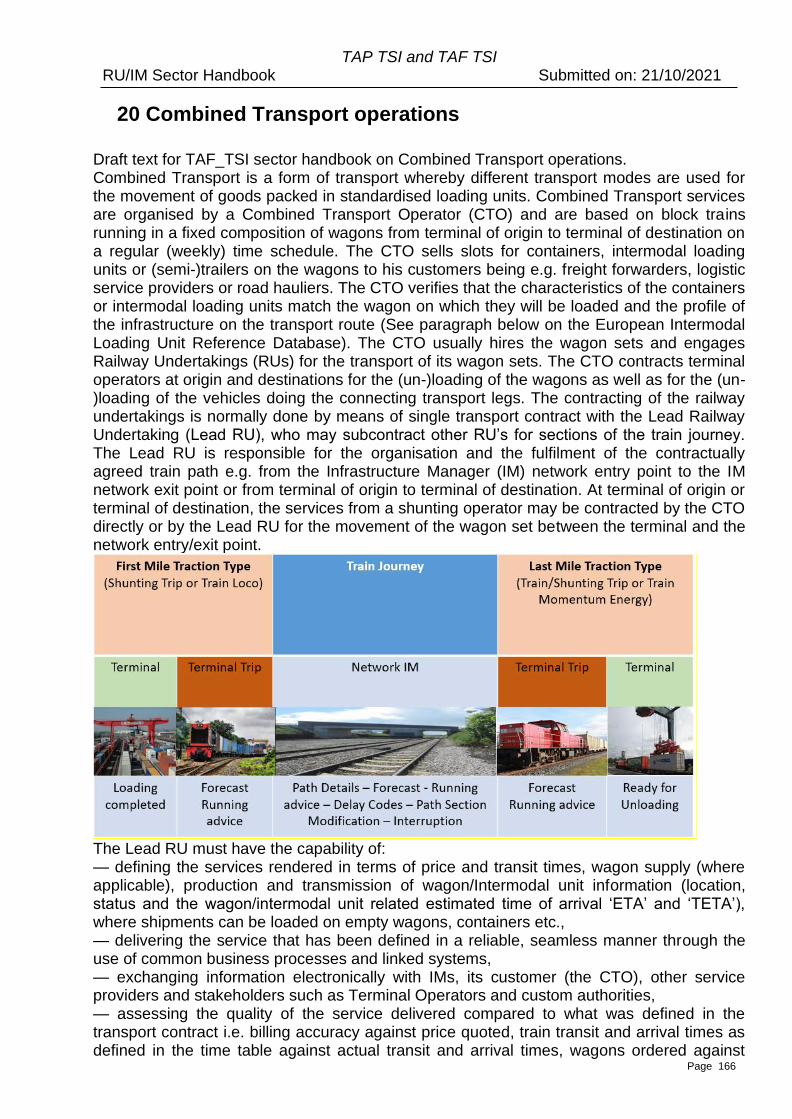
Page 166
TAP TSI and TAF TSI RU/IM Sector Handbook Submitted on: 21/10/2021
20 Combined Transport operations Draft text for TAF_TSI sector handbook on Combined Transport operations. Combined Transport is a form of transport whereby different transport modes are used for the movement of goods packed in standardised loading units. Combined Transport services are organised by a Combined Transport Operator (CTO) and are based on block trains running in a fixed composition of wagons from terminal of origin to terminal of destination on a regular (weekly) time schedule. The CTO sells slots for containers, intermodal loading units or (semi-)trailers on the wagons to his customers being e.g. freight forwarders, logistic service providers or road hauliers. The CTO verifies that the characteristics of the containers or intermodal loading units match the wagon on which they will be loaded and the profile of the infrastructure on the transport route (See paragraph below on the European Intermodal Loading Unit Reference Database). The CTO usually hires the wagon sets and engages Railway Undertakings (RUs) for the transport of its wagon sets. The CTO contracts terminal operators at origin and destinations for the (un-)loading of the wagons as well as for the (un-)loading of the vehicles doing the connecting transport legs. The contracting of the railway undertakings is normally done by means of single transport contract with the Lead Railway Undertaking (Lead RU), who may subcontract other RU’s for sections of the train journey. The Lead RU is responsible for the organisation and the fulfilment of the contractually agreed train path e.g. from the Infrastructure Manager (IM) network entry point to the IM network exit point or from terminal of origin to terminal of destination. At terminal of origin or terminal of destination, the services from a shunting operator may be contracted by the CTO directly or by the Lead RU for the movement of the wagon set between the terminal and the network entry/exit point.
The Lead RU must have the capability of: — defining the services rendered in terms of price and transit times, wagon supply (where applicable), production and transmission of wagon/Intermodal unit information (location, status and the wagon/intermodal unit related estimated time of arrival ‘ETA’ and ‘TETA’), where shipments can be loaded on empty wagons, containers etc., — delivering the service that has been defined in a reliable, seamless manner through the use of common business processes and linked systems, — exchanging information electronically with IMs, its customer (the CTO), other service providers and stakeholders such as Terminal Operators and custom authorities, — assessing the quality of the service delivered compared to what was defined in the transport contract i.e. billing accuracy against price quoted, train transit and arrival times as defined in the time table against actual transit and arrival times, wagons ordered against
Page 167
TAP TSI and TAF TSI RU/IM Sector Handbook Submitted on: 21/10/2021
wagons supplied. Information exchange at (terminal of) origin The transport process starts with the receipt of the train consignment note by the Lead RU from its customer (the CTO). The consignment note specifies the train composition with all wagon numbers and for each wagon the details of loaded containers or Intermodal Loading Units (ILUs). The RU prepares the Consignment Order Message (TAF-TSI paragraph 4.2.1.2) and Train Composition Message (TAF-TSI paragraph 4.2.3.2) based on the consignment note.
The CTO will send a loading list directly to the terminal of destination with information on wagon numbers and per wagon the details of containers or ILUs. The execution of the transport starts with the release of the wagon set by the terminal operator. Either the CTO, the Terminal Operator or the shunting operator shall provide train related status information to the responsible RU and the IM responsible for the network entry point. When the wagon set has been loaded and has been released for transport by the wagon master, the operator of the departure terminal shall send information that the wagon set is ready for departure with a time stamp (the so-called Heure-Limite-de-Remise or HLR) to the Lead RU or to the RU providing traction from the terminal to the IM network entry point and possibly to the IM. The departure terminal will send this information based on the ‘train ready’ message (TAF-TSI paragraph 4.2.3.3). Information exchange when the train is running When the train is running on the public rail infrastructure network, the IM shall send Train Running Information messages (TAF-TSI paragraph 4.2.4.3) and Train Running Forecast messages (TAF-TSI paragraph 4.2.4.2) with a forecast time for the contractually agreed forecast points to the Responsible RU and the next IM. The TAF-TSI mentions in paragraph 4.2.6.3. that under contractual agreement the Lead RU shall calculate and provide an accurate ETA or TETA to its Customer and to the Terminal Operator. In practice the Lead RU is however not always in position to do so. Moreover, the reference to the contractual agreement implies that in many cases the Lead RU will not be calculating and providing an ETA. However, the CTO has the possibility to receive the Train Running Information messages (TAF-TSI paragraph 4.2.4.3) and Train Running Forecast messages (TAF-TSI paragraph 4.2.4.2) by means of the RNE/TIS database based on the so-called Rotterdam clause in TAF-TSI paragraph 4.2, which specifies that these messages may be exchanged with identifiable stakeholders. Information exchange at (terminal of) destination Before the train arrives at the IM network exit point, the Terminal Operator at destination will receive a Train Running Forecast message from the IM. The Terminal Operator will inform the responsible RU or, if applicable, the shunting operator on the time slot allocated for the handling of the wagon set at the terminal of destination. Upon arrival of the wagon set at the terminal the last RU must send a Wagon Yard Arrival message according to paragraph 4.2.7.4 of the TAF-TSI to the Lead RU. Based on the so-called Rotterdam clause in the TAF-TSI also this message may be exchanged with identifiable stakeholders such as the CTO. The time that the wagon set has arrived at the terminal of destination and has been handed
Page 168
TAP TSI and TAF TSI RU/IM Sector Handbook Submitted on: 21/10/2021
over to the Terminal Operator for being unloaded is called the Mise-A-Disposition (MAD) of the train. The wagon ETIs are also ETIs for the loading units on the wagons. Based on these ETIs, the ETA or TETA, the Terminal Operator will provide to the CTO the time that loading units can be picked up from the terminal, the so-called Estimated Time of Pick-Up (ETP). The CTO will inform his customers (such as freight forwarders or logistics service providers) on the ETP. The definition of the mandatory structure of Train Composition, Train Ready, Train Running Information and Train Running Forecast messages and the elements to be followed are described in the document ‘TAF TSI — Annex D.2: Appendix F — TAF TSI Data and Message Model’ listed in Appendix I. The European Intermodal Loading Unit Reference Database Because the CTO, the operator of its service facility and its RUs must verify that an intermodal loading unit (ILU) is technically suitable for transportation on a CT train, they must be able to retrieve the technical specifications of intermodal loading units. To this effect each ILU has a unique identification number under which its relevant technical and loading characteristics and its administrative data related to certification and ownership are registered. These data can be obtained by means of the European ILU Reference Database as defined in paragraph 4.2.9.3 of the TAF-TSI.

Page 169
TAP TSI and TAF TSI RU/IM Sector Handbook Submitted on: 21/10/2021
Part D Overall requirements
Page 170
TAP TSI and TAF TSI RU/IM Sector Handbook Submitted on: 21/10/2021
21 General remarks
This chapter provides information on general requirements, further explanations and
information to be taken into account when implementing the RU/IM Message exchange.
Use of new identifiers and their combination with the existing legacy identifiers is explained in chapter 8 and additionally referenced through the chapters 12, 15, 16 and 18. For the full concept of the new identifiers the following attached documents and references are provided (see list of Annexes for Chapter 8 – Annex_8.x):
. UML Model of the concept for the new identifiers
. Update Link Framework
. UpdateLinkMessage
. ObjectInfoMessage
Baseline document used for the initial content of this Sector Handbook: WG10 Identifiers Handbook, endorsed by the industry after TAF Phase 1 in November 2011.
• Use of common elements in the messages
Free text field
Normally local language is to be used but in bilateral agreements a different rule could be
agreed upon.
Message reference
In case of alteration or deletion of the message the reference to the original message
should be made via the functional data as a key (e.g. Train Ident, Location Ident).
• Mandatory or Optional Elements in the Messages
Within the message structure, there are number of elements that are either mandatory or
optional.
• Mandatory elements have to be in the message content for all message exchange.
• Optional fields only need to be filled in where there is a need to have them between RU/IM or where network regulations may well dictate or where there is mutual agreement to do so.
Optional status may well apply to individual elements or groups of elements (e.g. the use
of ON DEMAND path element may only be relevant to the RU and IMs in certain
networks).
Page 171
TAP TSI and TAF TSI RU/IM Sector Handbook Submitted on: 21/10/2021
Optional elements may also apply to groups of elements where the entire group may be
either needed or not needed.
Where a message element is identified as ‘optional’, this may be changed by the IM who
may declare it as mandatory according to the requirements in their Network Statement for
their path section. It will be mandatory for interoperable/international trains where there is
a requirement to use an element as per their national regulation or bilateral agreement
between RU and IM. This will mean that all validation rules of the element(s) will be
applied as per normal.
If there is no Network Statement demand for the optional parameter or no bilateral
agreement between RU and IM underpinning that, no one can force the partner (RU
and/or IM) to use the particular parameter as mandatory.
In addition, some elements and sub-elements are conditional. That means, they are
optional in a technical sense, but if there is a specific business need or purpose – based
on IMs requirement published in the Network Statement – some or all of the (sub.)
element will be mandatory.
There are also a number of elements that are either mandatory or optional depending on
whether they are for freight or passenger traffic.
Several message elements are global, that means they are used for communication
purposes in several processes (e.g. for planning and operations). E.g. some message
elements used in the ‘Short-term path request’ have to be optional from the technical
point of view because they are optionally in operations but must be mandatory when they
are applied for planning and vice-versa.
• Message exchange partners
Messages are exchanged between parties having a business relation with each other.
That means that a message exchange is between the
• IM and the RU that wants to or already has booked a path with this IM
• IM and the neighbouring IM involved in the train panning or operation
• IM and/or RU and the SM involved in the operation of the train
• RU and any partner RU involved in the train planning or operation (this possibility is on bilateral agreement outside TAF and TAP obligations). For example, for a train running on two IMs and operated by two RUs (one per IM) the information flow can be
• IM 1 to IM 2 and then IM 2 to RU 2O or
• IM 1 to RU 1 and RU1 to RU 2 depending on the agreement.
Page 172
TAP TSI and TAF TSI RU/IM Sector Handbook Submitted on: 21/10/2021
Note on Network specific or national specific parameters
The agreement of the sector is that no new national specific elements in the Common metadata should be introduced.
. All national specific elements should be defined in the Shared metadata
. When building the shared metadata, the common metadata can be included
. Any message from Common metadata can be adapted in the shared metadata according to the BILATERAL / Multilateral agreement
Rules . Shared metadata must contain the TAF/TSI Header with the message type
. If the message with additional national parameters is an extension of the message from Common metadata, the Message Type has to be different from the one from the Common metadata
• Masterplan
Each individual actor has submitted its own implementation masterplan for TAF and TAP.
These masterplans were consolidated in two European-wide documents, respectively 20130117_TAF.TSI.Master.Plan.pdf and 20130428_TAP Master Plan Delivery_final.pdf available on JSG website.
The target dates contained in the consolidated masterplans are:
. Recommended for actors having delivered their masterplan (delivered dates remain mandatory)
. Mandatory for actors having not delivered a masterplan.
The reporting process is described in the governance document TAF_org 2014 20130829 V8.pdf.
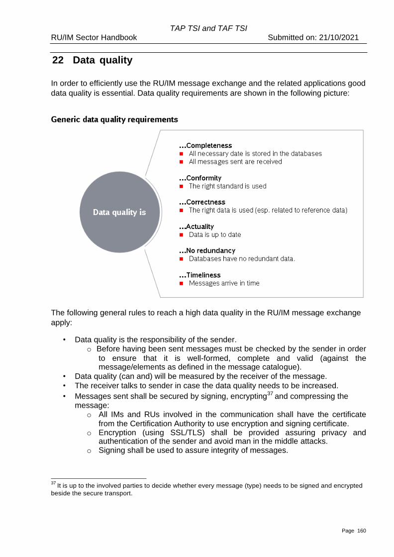
Page 160
TAP TSI and TAF TSI RU/IM Sector Handbook Submitted on: 21/10/2021
22 Data quality
In order to efficiently use the RU/IM message exchange and the related applications good
data quality is essential. Data quality requirements are shown in the following picture:
The following general rules to reach a high data quality in the RU/IM message exchange
apply:
• Data quality is the responsibility of the sender. o Before having been sent messages must be checked by the sender in order
to ensure that it is well-formed, complete and valid (against the message/elements as defined in the message catalogue).
• Data quality (can and) will be measured by the receiver of the message.
• The receiver talks to sender in case the data quality needs to be increased.
• Messages sent shall be secured by signing, encrypting37 and compressing the message:
o All IMs and RUs involved in the communication shall have the certificate from the Certification Authority to use encryption and signing certificate.
o Encryption (using SSL/TLS) shall be provided assuring privacy and authentication of the sender and avoid man in the middle attacks.
o Signing shall be used to assure integrity of messages.
37 It is up to the involved parties to decide whether every message (type) needs to be signed and encrypted
beside the secure transport.
Page 161
TAP TSI and TAF TSI RU/IM Sector Handbook Submitted on: 21/10/2021
o Two actors keeping a communication should have the certificate generated with same Root certificate to work with encryption functionality and a security alias of the certificate should be provided.
The following possibilities are supported by the RU/IM architecture to detect and increase
data quality:
• Syntactically incorrect messages are placed in temporary storage for analysis and reporting (Dead letter queues. storage of message that could not be delivered in a Common Interface or on application level). This would indicate problems in format data quality.
• In case a message is not delivered (no acknowledgment by the CI) the message can still be found in sending queues. – It is up to the sender to check the delivery.
• The Error message can be used to report and measure semantic data quality (content level). The Error message is sent from the receiver of an earlier message to the sender of that earlier message. The message is used when the information in the original message was not good enough to create an answer. The message supports a list of elements that have errors or could also be business related errors (e.g. a schedule is not logical). The level of detail of this Error message will depend on the application that emits this message. It should be as detailed as feasible with the legacy system with the minimum information: Message was not usable. Detailed information, if supported by legacy system, shall use a subset or all of the common error codes described for the Error message.
• In case of the same message with the same content (e.g. train running message for train X at location Y sent several times), rules like “Last message wins”, relying on the MessageHeader time stamp, would avoid the handling of ambiguous message information. This has to be implemented at application level.
• For the central reference database, specific Entities are responsible for the storage of specific codes (e.g. national entity for primary codes in its country). This Entity has to makes sure, that one location is coded once – avoiding ambiguous codes like 10 different primary codes for the same physical station (for example only). See also chapter 9.6 for quality requirements on reference data.
• Timeliness of message exchange can be checked on application level, e.g. comparing the actual timing of a train run and the timestamp of the message arriving. It depends on contractual agreements.
Page 162
TAP TSI and TAF TSI RU/IM Sector Handbook Submitted on: 21/10/2021
23 Functional Governance
This chapter provides information about contact and processes for receiving the
certification for the RU/IM message exchange and for functional changes. This includes
ways to request code values and also ways to request changes in the message structure.
5. Code allocation
Codes are divided into three categories:
i. A for functional codes that have no impact on the message exchange. It represents functional information that is sent through the messages for functional use within the business processes (e.g. planning of a short-term train)
ii. B for process codes that have a relevance for the way applications deal with the message (e.g. the status of the message new, update, delete)
iii. C for external codes that are used within the business processes but are controlled by different domains (e.g. Retail, UN Codes) that have their own governance processes. A reference to the controlling body is given.
iv. D for codes used only in messages out of the scope of TAF and TAP.
Processes for the maintenance of codes
v. Category A and Category B Any involved actor (e.g. RU, IM, AB, SM) can put the request for a change (new, alteration, deletion) to the JSG/SMO. The entity can consult relevant expert working groups on the need of that change. The proposal is submitted to ERA CCM process (described in document ERA_Telematics_CCM_Guide_V1_3_r11G09G2013.docx). If relevant, a migration strategy has to be developed as well.
vi. Category C.> see respective controlling body. The entity publishes these codes as well for information as soon as they are known. A delay notice until the use of these codes can be agreed.
vii. Category D Any involved actor (e.g. RU, IM, AB, SM) can put the request for a change (new, alteration, deletion) to the JSG/SMO. The entity can consult relevant expert working groups on the need of that change. The proposal is agreed according to the sector internal governance (tbd). If approved, a migration strategy has to be developed as well.
6. Change of messages and/or the structure of the reference file
Any involved actor (RU, IM, AB, SM) can put the request for a change (new, alteration,
deletion of a message) to the <sector RU/IM governance entity>. The entity can consult
relevant expert working groups on the need of that change. The working group can reject,
ask for clarifications and give recommendations, eventually following an impact analysis
within a given timeframe. If approved, a migration strategy has to be developed as well.
Page 163
TAP TSI and TAF TSI RU/IM Sector Handbook Submitted on: 21/10/2021
The proposal is submitted to ERA CCM process (described in document
ERA_Telematics_CCM_Guide_V1_3_r11G09G2013.docx). If relevant, a migration strategy
has to be developed as well.
Change of message can only be once per year on a given date. Migration plan needs to
allow companies to implement it (communication of change at least 1 year before usage).
A migration plan should be proposed by the WG, including a minimum period in which the
change is optional and a time from which the change is mandatory.
The WG of the TAF and TAP governance entity should take into account both business
and IT needs.
7. Allocation of certificates for messages
Every participant in the RU/IM message exchange will have to use valid (X509)
certificates for secure communication and if needed for message encryption and
signature. These certificates are issued under the authority of the governance entity.
Every company has to register once to central admin (currently this is the admin of CCG)
The governance admin service will verify the user and will subsequently grant access to a
secured website where certificate can be downloaded.
The Expiry dates of the certificate are mentioned in the certificate. The company has to
make sure to get a new certificate before.
8. Access to reference data
Every actor in the RU/IM message exchange needs to register for the message exchange
(see 23.3 on allocation of certificates) through the governance admin service. Following
certification, the actor has access to all location codes stored in the Central Repository
File Database. The reference data can be used for all TAP and TAF purposes and related
processes. To perform these processes, actors may give the data to suppliers under the
precondition that the actor ensures the data is solely used for these purposes and is not
used for other commercial activities.
Access to all reference data will be provided through the use of a reference data service
managed by the governance entity. This service will meet the requirements described in
this Implementation Guide or as subsequently decided by the governance entity. Access
requirements are not subject to approval by the TAP.CCM or TAF.CCM.
Page 164
TAP TSI and TAF TSI RU/IM Sector Handbook Submitted on: 21/10/2021
24 List of Appendices
Messages
• Annex 1 – Message Catalogue (target TAP TD B.30 and TAF Annex D.2,
Appendix F)
The XSD is stored by the sector in http://taf-jsg.info/?page_id=172
The XSD is organized as follows:
• taf_cat_complete_sector.xsd: One merged schema with comments to
differentiate the "sector" messages and elements from the official (ERA)
common metadata. This schema contains both sector as well as the ERA
(TAF/TAP mandatory) messages. Namespace for the sector is provided, to
differentiate from the official schema since it contains sector messages and
elements. Sector baseline will always be made after ERA publishes the official
baseline. Version identifier of ERA contains two digits (e.g. 2.1). The version
identifier of the sector contains 3 digits: 2.1.1. The third number is incremented
on any change in the schema except annotations (textual descriptions of the
elements).
• taf_cat_codelist_sector.xsd: all codelists used in the main schema.
The Messages are in xsd. Note that rtf/document formats should only be looked at
by xml/message experts and it is not recommended to be printed for all others. It is
anyhow recommended to look at the specific messages in an xml.editor/viewer.
The both schemas (“complete” and “codelist”) are provided as MS Word
documents (exported from the XML processing tool) in the Annex 6.2 and Annex
6.3 respectively. The explanation of the XSD model graphic representation is given
in the Annex 6.1
Annexes to Part A
• TrainID – OTN Framework (Annex 8.1) This framework document explains the relationship between new TAF/TAP identifiers and Operational Train Number (OTN).
• TrainID – Variant Framework (Annex 8.2) This framework document contains the basic rules for the usage of the Variant element in the composite identifier TrainID.
• TrainID – Update Link Framework (Annex 8.3)
Page 165
TAP TSI and TAF TSI RU/IM Sector Handbook Submitted on: 21/10/2021
This document contains the explanation of the usage of UpdateLinkMessage which serves primarily for indication and update of the relation between business object train and path.
• TrainID – Case Reference Framework (Annex 8.4) This document explains the framework for the usage of the Case Reference ID as the new identifier in TAF/TAP TSI.
• TrainID – Object Info Framework (Annex 8.5) This document explains the usage of the ObjectInfoMessage which serves for efficient information exchange on the content of the objects, primarily Train, Path and Path Request.
• Testing Framework with Example of PCS (Annex 8.6) Please check PCS Communication Guide for details https://cms.rne.eu/pcs/pcs-documentation/pcs-taf-tsi-communication-guide
• Test Cases with Identifiers (Annex 8.7) This is the Excel sheet containing test cases according to business scenarios in Planning, Re-planning (change management of objects Train and Path, “fine. tuning”) and Operations. The test cases are mainly provided by the stakeholders and coordinated within the TEG TrainID. Annex 8.7.1 contains the general list of test cases with the introductory explanation of the structure. The Annex 8.7.2 contains the simple test cases in the Short-Term Path Request process which will be used within the Joint Sector Pilot Program for Short Term Path Request and TrainID (see footnote 26).
• TrainID – UML Model (Annex 8.8) The UML model is provided in the form of activity diagrams for all business scenarios given in the WG10 handbook as well as the object model and object lifecycle (state) diagrams. This UML model is not limited only to the identifiers, it can be used for the simple business cases in Planning, Re-planning (change management of objects Train and Path, “fine-tuning”) and Operations.
• Annex 9.1 Data Model for Reference Files
The Class diagram is used from the Central Repository Files Database.
Within the functional data model (class diagram) the tables (classes) are described
with their elements. The relations between the Tables are maintained. Elements
are described by their Names and Type.
Page 166
TAP TSI and TAF TSI RU/IM Sector Handbook Submitted on: 21/10/2021
• Update Message for Locations
The XML schema shows the message to be used to update the CRD for locations by National Allocation Entity or companies for Subsidiary locations for defined Subsidiary type code. " see xsd file in Annex 1, including this message
• Annex 9.3 HMI for Maintenance of Location
The screen shows the draft User interface to update the CRD for update the
locations by privileged users.
• Annex 9.4 Table of codes for Subsidiary locations (subsidiary type codes)
• Annex 9.5 Code structure for initial population of and manual Bulk updates
This structure can be used for those companies wishing to upload from existing
databases (ENEE).
• Annex 10.1 Code lists
The export from XSD containing code list is provided. Any change to the code list will be registered in XSD and exported again from the XSD tool. Every code in the code list should have the explanation. In the annotation of the code list element, the source of the code should be written.
• Annex 10.2 – Code lists as annotations: MessageType and ErrorCode Some of the codes are provided only as the annotation of the elements. The important examples are MessageType and ErrorCode
Annexes to Part B
• Annex 12.1 – Elements specific to actors
• Annex 12.2 – UML Model for Path Request processes
UML model was provided in the TAF phase 1 and adapted to the current messages in 2015. It is recommended to be used when planning the bilateral or multilateral communication in the Path Request process by using TAF/TAP TSI message framework (both mandatory as well as the optional sector messages).
• Annex 12.3 – Temporary Capacity Restriction (TCR)
Annexes to Part C Operations
• Annex 13
The annex document covers operational processes diagrams, containing the TAP and TAF process diagrams relevant for chapter 13 to chapter 19.
Annexes to Part D