T1/E1 with Inverse Multiplexing for ATM (IMA) Module Guide
56
Stinger ® T1/E1 with Inverse Multiplexing for ATM (IMA) Module Guide For software version 9.6.1 April 2004
-
Upload
khangminh22 -
Category
Documents
-
view
0 -
download
0
Transcript of T1/E1 with Inverse Multiplexing for ATM (IMA) Module Guide

Stinger®
T1/E1 with Inverse Multiplexing for ATM (IMA) Module Guide
For software version 9.6.1April 2004

Lucent Technologies
Copyright © 2002-2004 Lucent Technologies Inc. All rights reserved.
This material is protected by the copyright laws of the United States and other countries. It may not be reproduced, distributed, or altered inany fashion by any entity (either internal or external to Lucent Technologies), except in accordance with applicable agreements, contracts, orlicensing, without the express written consent of Lucent Technologies. For permission to reproduce or distribute, please email your request [email protected].
Notice
Every effort was made to ensure that the information in this document was complete and accurate at the time of printing, but information issubject to change.
European Community (EC) RTTE compliance
Hereby, Lucent Technologies, declares that the equipment documented in this publication is in compliance with the essential require-ments and other relevant provisions of the Radio and Telecommunications Technical Equipment (RTTE) Directive 1999/5/EC.
To view the official Declaration of Conformity certificate for this equipment, according to EN 45014, access the Lucent INS online documentationlibrary at http://www.lucentdocs.com/ins.
Safety, compliance, and warranty Information
Before handling any Lucent Access Networks hardware product, read the Edge Access and Broadband Access Safety and Compliance Guide includedin your product package. See that guide also to determine how products comply with the electromagnetic interference (EMI) and networkcompatibility requirements of your country. See the warranty card included in your product package for the limited warranty that LucentTechnologies provides for its products.
Security statement
In rare instances, unauthorized individuals make connections to the telecommunications network through the use of access features.
Trademarks
Lucent, the Lucent logo, and all Lucent brand and product names are trademarks or registered trademarks of Lucent Technologies Inc. Otherbrand and product names are trademarks of their respective holders.
Ordering Information
You can order the most up-to-date product information and computer-based training online at http://www.lucentdocs.com/bookstore.
Feedback
Lucent Technologies appreciates customer comments about this manual. Please send them to [email protected].

Customer Service
Stinger® T1/E1 IMA Module Guide iii
Customer ServiceProduct and service information, and software upgrades, are available 24 hours a day.
Technical assistance options accommodate varying levels of urgency.
Finding information and software
To obtain software upgrades, release notes, and addenda for this product, log in to
Lucent OnLine Customer Support at http://www.lucent.com/support.
Lucent OnLine Customer Support also provides technical information, product
information, and descriptions of available services. The center is open 24 hours a day,
seven days a week. Log in and select a service.
Obtaining technical assistance
Lucent OnLine Customer Support at http://www.lucent.com/support provides access
to technical support. You can obtain technical assistance through email or the
Internet, or by telephone. If you need assistance, make sure that you have the
following information available:
■ Active service or maintenance contract number, entitlement ID, or site ID
■ Product name, model, and serial number
■ Software version
■ Software and hardware options If supplied by your carrier, service profile
identifiers (SPIDs) associated with your line
■ Your local telephone company’s switch type and operating mode, such as AT&T,
5ESS Custom, or Northern Telecom National ISDN-1
■ Whether you are routing or bridging with your Lucent product
■ Type of computer you are using
■ Description of the problem
Obtaining assistance through email or the Internet
If your services agreement allows, you can communicate directly with a technical
engineer through Email Technical Support or a Live Chat. Select one of these sites
when you log in to http://www.lucent.com/support.
Calling the technical assistance center (TAC)
If you cannot find an answer through the tools and information of Lucent OnLine
Customer Support or if you have a very urgent need, contact TAC. Access Lucent
OnLine Customer Support at http://www.lucent.com/support and click Contact Us
for a list of telephone numbers inside and outside the United States.
Alternatively, call 1-866-LUCENT8 (1-866-582-3688) from any location in North
America for a menu of Lucent services. Or call +1 510-747-2000 for an operator. You
must have an active services agreement or contract.


Stinger® T1/E1 IMA Module Guide v
Contents
Customer Service ........................................................................................................iii
About This Guide ................................................................................xi
What is in this guide ...................................................................................................xiDocumentation conventions .......................................................................................xiStinger documentation set .........................................................................................xii
Chapter 1 T1/E1 Module Overview...................................................................1-1
T1/E1 module specifications .................................................................................... 1-2T1/E1 module status lights....................................................................................... 1-4IMA and ATM feature support................................................................................. 1-4
IMA features ...................................................................................................... 1-4ATM features ..................................................................................................... 1-6
Chapter 2 T1/E1 Module Provisioning ..............................................................2-1
Configuration profiles .............................................................................................. 2-2Provisioning T1 or E1 ports for ATM mode ............................................................. 2-3
Overview of the ds1-atm profiles....................................................................... 2-3Sample connection profile for a VCC on a T1 or E1 port .................................. 2-7
Provisioning IMA groups.......................................................................................... 2-7What is an IMA group? ..................................................................................... 2-7Restrictions on port groupings on the 24-port T1/E1 modules ......................... 2-8Configuring ds1-atm profiles for IMA mode...................................................... 2-8Creating an imagroup profile............................................................................ 2-10Sample minimal IMA group configuration...................................................... 2-12Sample connection profile for a VCC using the IMA group ............................ 2-13Configuring processing options of the IMA chip ............................................. 2-13
Provisioning CAC for T1/E1 modules .................................................................... 2-14LIM slot CAC ................................................................................................... 2-15Trunk port CAC ............................................................................................... 2-15
Configuring VPCs on T1/E1 modules in LIM slots ................................................. 2-16Parameters that determine valid VPIs to use for VPCs .................................... 2-16Sample configuration to support multiple VPCs per LIM port ........................ 2-17Sample LIM-to-IMA trunk VPC....................................................................... 2-17Sample LIM-to-LIM T1/E1 VPC configuration ................................................ 2-18
Using PNNI over an IMA group ............................................................................. 2-18IMA physical addresses and PNNI requirements ............................................. 2-19IMA physical address updates following failover............................................. 2-19PNNI bandwidth advertisements ..................................................................... 2-20

vi Stinger® T1/E1 IMA Module Guide
Contents
LIM slot sparing with PNNI links..................................................................... 2-21Sample applications................................................................................................ 2-23
Aggregating subscriber connections................................................................. 2-24Subtending from remote Stinger RT systems .................................................. 2-25
Chapter 3 Monitoring T1/E1 and IMA...............................................................3-1
Administrative profiles providing status information .............................................. 3-1Status information in the ds1-atm-stat profile................................................. 3-2Status information in the ima-group-stat profile ............................................. 3-4
Administrative commands for IMA interfaces ......................................................... 3-7Using imalines to view information about IMA interfaces ............................... 3-7Using imagroups to display IMA group information.......................................... 3-8

Stinger® T1/E1 IMA Module Guide vii
Figures
Figure 2-1 Inverse multiplexing over ATM (IMA)................................................. 2-1Figure 2-2 Sample VCC from a DSL subscriber to a T1 port .................................. 2-7Figure 2-3 Example of oversubscribing trunk bandwidth on an IMA group....... 2-15Figure 2-4 PNNI link across T1............................................................................. 2-22Figure 2-5 Aggregation of ATM subscriber traffic ................................................ 2-24Figure 2-6 Subtending on IMA groups................................................................. 2-26


Stinger® T1/E1 IMA Module Guide ix
Tables
Table 1-1 Stinger platform support ..................................................................... 1-1Table 1-2 T1/E1 module specifications................................................................ 1-2Table 1-3 Stinger FS/FS+, LS, and RT status light indicators .............................. 1-4Table 1-4 Supported optional IMA functions...................................................... 1-5Table 2-1 Configuration profiles for T1/E1 and IMA .......................................... 2-2Table 2-2 ATM mode configuration overview .................................................... 2-3Table 2-3 IMA group configuration overview..................................................... 2-8Table 2-4 Restrictions on which ports can be used together in an IMA group ... 2-8Table 3-1 Read-only status profiles for T1/E1 and IMA ...................................... 3-1Table 3-2 Administrative commands for T1/E1 and IMA ................................... 3-7


Stinger® T1/E1 IMA Module Guide xi
About This Guide
To use the information in this guide, you must have already installed the Stinger unit. Instructions for installing and configuring the management functions of the system are found in the Getting Started Guide for your Stinger platform.
Warning Before installing your Stinger unit, be sure to read the safety instructions in the Edge Access and Broadband Access Safety and Compliance Guide. For information specific to your unit, see the “Safety-Related Physical, Environmental, and Electrical Information” appendix in the Getting Started Guide for your Stinger unit.
What is in this guideThis guide describes how to configure and monitor the physical interfaces of the Stinger T1 and E1 modules, which support Inverse Multiplexing over ATM (IMA). Information in this guide applies to all models of T1 and E1 modules unless otherwise specified.
For details about ATM connections, switching operations and output queues, and other system issues as they relate to LIMs, see the Stinger ATM Configuration Guide.
Note Instructions for installing a module in a Stinger unit are provided in the platform-specific Getting Started Guide. Please see that guide if you are installing the T1 or E1 module.
Documentation conventionsFollowing are all the special characters and typographical conventions used in this manual:
Convention Meaning
Monospace text Represents text that appears on your computer’s screen, or that could appear on your computer’s screen.
Boldface monospace text
Represents characters that you enter exactly as shown (unless the characters are also in italics—see Italics, below). If you could enter the characters but are not specifically instructed to, they do not appear in boldface.
Italics Represent variable information. Do not enter the words themselves in the command. Enter the information they represent. In ordinary text, italics are used for titles of publications, for some terms that would otherwise be in quotation marks, and to show emphasis.

xii Stinger® T1/E1 IMA Module Guide
About This GuideStinger documentation set
Stinger documentation setThe Stinger documentation set consists of the following manuals, which can be found at http://www.lucent.com/support and http://www.lucentdocs.com/ins.
■ Read me first:
– Edge Access and Broadband Access Safety and Compliance Guide. Contains important safety instructions and country-specific information that you must read before installing a Stinger unit.
– TAOS Command-Line Interface Guide. Introduces the TAOS command-line environment and shows you how to use the command-line interface effectively. This guide describes keyboard shortcuts and introduces commands, security levels, profile structure, and parameter types.
■ Installation and basic configuration:
– Getting Started Guide for your Stinger platform. Shows how to install your Stinger chassis and hardware. This guide also shows you how to use the
[ ] Square brackets indicate an optional argument you might add to a command. To include such an argument, type only the information inside the brackets. Do not type the brackets unless they appear in boldface.
| Separates command choices that are mutually exclusive.
> Points to the next level in the path to a parameter or menu item. The item that follows the angle bracket is one of the options that appear when you select the item that precedes the angle bracket.
Key1+Key2 Represents a combination keystroke. To enter a combination keystroke, press the first key and hold it down while you press one or more other keys. Release all the keys at the same time. (For example, Ctrl+H means hold down the Ctrl key and press the H key.)
Press Enter Means press the Enter or Return key or its equivalent on your computer.
Note
Introduces important additional information.
Caution
Warns that a failure to follow the recommended procedure could result in loss of data or damage to equipment.
Warning
Warns that a failure to take appropriate safety precautions could result in physical injury.
Warning
Warns of danger of electric shock.
Convention Meaning

About This GuideStinger documentation set
Stinger® T1/E1 IMA Module Guide xiii
command-line interface to configure and verify IP access and basic access security on the unit, and how to configure Stinger controller redundancy on units that support it.
– Module guides. For each Stinger line interface module (LIM), trunk module, or other type of module, an individual guide describes the module's features and provides instructions for configuring the module and verifying its status.
■ Configuration:
– Stinger ATM Configuration Guide. Describes how to integrate the Stinger into the ATM and Digital Subscriber Line (DSL) access infrastructure. The guide explains how to configure PVCs, and shows how to use standard ATM features such as quality of service (QoS), connection admission control (CAC), and subtending.
– Stinger IP2000 Configuration Guide. For Stinger systems with the T1/E1 controller, this guide describes how to integrate the system into the IP infrastructure. Topics include IP-routed switch-through ATM PVCs and RFC 1483 PVCs that terminate on the T1/E1, IEEE 802.1Q VLAN, and forwarding multicast video transmissions on DSL interfaces.
– Stinger Private Network-to-Network Interface (PNNI) Supplement. For the optional PNNI software, this guide provides quick-start instructions for configuring PNNI and soft PVCs (SPVCs), and describes the related profiles and commands.
– Stinger SNMP Management of the ATM Stack Supplement. Describes SNMP management of ATM ports, interfaces, and connections on a Stinger unit to provide guidelines for configuring and managing ATM circuits through any SNMP management utility.
– Stinger T1000 Module Routing and Tunneling Supplement. For the optional T1000 module, this guide describes how to configure the Layer 3 routing and virtual private network (VPN) capabilities.
■ RADIUS: TAOS RADIUS Guide and Reference. Describes how to set up a unit to use the Remote Authentication Dial-In User Service (RADIUS) server and contains a complete reference to RADIUS attributes.
■ Administration and troubleshooting: Stinger Administration Guide. Describes how to administer the Stinger unit and manage its operations. Each chapter focuses on a particular aspect of Stinger administration and operations. The chapters describe tools for system management, network management, and Simple Network Management Protocol (SNMP) management.
■ Reference:
– Stinger Reference. An alphabetic reference to Stinger profiles, parameters, and commands.
– TAOS Glossary. Defines terms used in documentation for Stinger units.

Stinger® T1/E1 IMA Module Guide 1-1
1T1/E1 Module Overview
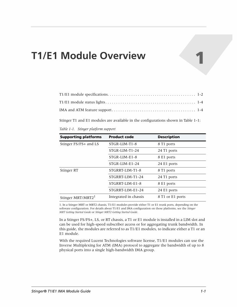
Stinger T1 and E1 modules are available in the configurations shown in Table 1-1:
In a Stinger FS/FS+, LS, or RT chassis, a T1 or E1 module is installed in a LIM slot and can be used for high-speed subscriber access or for aggregating trunk bandwidth. In this guide, the modules are referred to as T1/E1 modules, to indicate either a T1 or an E1 module.
With the required Lucent Technologies software license, T1/E1 modules can use the Inverse Multiplexing for ATM (IMA) protocol to aggregate the bandwidth of up to 8 physical ports into a single high-bandwidth IMA group.
T1/E1 module specifications. . . . . . . . . . . . . . . . . . . . . . . . . . . . . . . . . . . . . . . . . 1-2
T1/E1 module status lights. . . . . . . . . . . . . . . . . . . . . . . . . . . . . . . . . . . . . . . . . . 1-4
IMA and ATM feature support . . . . . . . . . . . . . . . . . . . . . . . . . . . . . . . . . . . . . . . 1-4
Table 1-1. Stinger platform support
Supporting platforms Product code Description
Stinger FS/FS+ and LS STGR-LIM-T1-8 8 T1 ports
STGR-LIM-T1-24 24 T1 ports
STGR-LIM-E1-8 8 E1 ports
STGR-LIM-E1-24 24 E1 ports
Stinger RT STGRRT-LIM-T1-8 8 T1 ports
STGRRT-LIM-T1-24 24 T1 ports
STGRRT-LIM-E1-8 8 E1 ports
STGRRT-LIM-E1-24 24 E1 ports
Stinger MRT/MRT21
1. In a Stinger MRT or MRT2 chassis, T1/E1 modules provide either T1 or E1 trunk ports, depending on the software configuration. For details about T1/E1 and IMA configuration on those platforms, see the Stinger MRT Getting Started Guide or Stinger MRT2 Getting Started Guide.
Integrated in chassis 8 T1 or E1 ports

1-2 Stinger® T1/E1 IMA Module Guide
T1/E1 Module OverviewT1/E1 module specifications
T1/E1 module specifications The module illustration at the left of the page shows the 24-port T1 model for Stinger FS/FS+, LS, and RT platforms (STGR-LIM-T1-24 or STGRRT-LIM-T1-24).
Table 1-2. T1/E1 module specifications
Category Specification
Transmission convergence sublayer
ITU-T G.704
Clocking options Reference clock source can be derived from BITS input to the Stinger, trunk or module line input, or local oscillator
Loopback options Local—digital
Local—analog (full local loopback)
Remote
Physical dimensions Height: 15 in (38.1cm)
Width: 1.06 in (2.69cm)
Depth: 9 in (22.8cm)
Weight: 3.2 lb (1.26 Kg)
Operating humidity 10% to 90%, noncondensing
Storage humidity 10% to 90%, noncondensing
Ambient operating temperature
FS/LS 32°F–131°F (0°C–55°C)
RT 40°F–149°F (-40°C–65°C)
Storage temperature -40°F to 176° F (-40°C to 80°C)
Maximum rate of temperature change
54°F/hour (30°C/hour)
Operating altitude 0 to 13,123 feet (0 to 4000 meters)
Status conditions detected
Loss of signal (LOS)
Loss of frame (LOF)
Remote alarm indication (RAI)
Alarm indication signal (AIS)
Loss of cell delineation (LOCD)
IMA compliance Compliant with ATM Forum IMA specifications v1.0 (AF-PHY-0086.000) and v1.1 (AF-PHY-0086.001)
Maximum number of physical ports per IMA group
Eight
IMA differential delays T1 Up to 281ms among group constituents
E1 Up to 225ms among group constituents

T1/E1 Module OverviewT1/E1 module specifications
Stinger® T1/E1 IMA Module Guide 1-3
Interface standards ATM Forum IMA v1.0 and v1.1
ATM Forum UNI v3.0 and v3.1
ATM Traffic Management v4.0
ATM Forum IMA MIB
RFC 1406 DS1 MIB
Line code T1 G.703 bipolar 8-zero substitution (B8ZS) or alternate mark inversion (AMI)
E1 High-density bipolar 3 (HDB3)
Frame format T1 Extended superframe (ESF) (ANSI T1.408) or D4
E1 ITU-T G.704
Output impedance T1 100 ohms
E1 120 ohms
Receive sensitivity T1 0 - 36 db
E1 0 - 43 db
Line buildout (T1) Short-haul < 133 feet (<40.5M) = 0.6dB
134 to 266 feet (40.8m to 81.2m) = 1.2dB
267 to 399 feet (81.3m to 121.7m) = 1.8dB
400 to 533 feet (121.8M to 162.6m) = 2.4dB
534 to 655 feet (162.7M to 199.6m) = 3.0dB
Long-haul 0dB
7.5dB
15dB
22.5dB
Performance T1 1.544Mbps (± 50bps) physical port rate
1.536Mbps payload rate (ATM mode)
3622 cells/second (ATM mode)
Maximum of 12.234Mbps for T1 IMA (depending on frame size and number of links in the IMA group)
E1 2.048Mbps (± 50bps) physical port rate
1.920Mbps payload rate (ATM mode)
4828 cells/second (ATM mode)
Maximum of 15.292Mbps for E1 IMA depending on frame size and number of links in the IMA group)
Table 1-2. T1/E1 module specifications
Category Specification

1-4 Stinger® T1/E1 IMA Module Guide
T1/E1 Module OverviewT1/E1 module status lights
T1/E1 module status lightsOn a T1/E1 module in a LIM slot, all status lights illuminate briefly upon startup or restart, and then remain dark until the module passes its power-on self test (POST). When the module passes the POST and becomes operational, the ACTIVE light illuminates. It is the only light that is on during normal operation.
IMA and ATM feature supportAll T1/E1 modules conform to certain ATM Forum requirements for IMA and to requirements of the ATM Forum and the ITU-T for ATM.
IMA features
T1/E1 modules are compliant with all mandatory specifications of the ATM Forum Inverse Multiplexing for ATM (IMA) Specification Version 1.1, (AF-PHY-0086.001), March, 1999. In addition, the modules conform to 28 optional functions in the ATM Forum IMA specifications, providing a versatile implementation of the standards. The modules are backward compatible with Version 1.0 of the ATM Forum IMA Specification, to provide interoperability with older equipment from other vendors.
Between 1 and 8 T1 or E1 ports can be assigned to a single IMA group. An 8-port module supports up to 4 IMA groups, and a 24-port module supports up to 12 IMA groups.
T1 or E1 ports can be added to an IMA group or deleted from an IMA group dynamically, without disrupting existing traffic.
T1/E1 modules support a built-in test pattern procedure for detecting misconnected links within an IMA group.
T1/E1 modules can tolerate up to 282 milliseconds of differential delay on the individual links of an IMA group.
T1/E1 modules support both independent transmit clock mode and common transmit clock mode configurations, and provide 15-minute, 24-hour, and total statistics for a rich set of performance parameters, accessible via the Simple Network Management Protocol (SNMP).
Table 1-3. Stinger FS/FS+, LS, and RT status light indicators
LED label Color Indicates
STBY Orange The LIM is a spare.
ACTIVE Green 1
1. On a few T1/E1modules manufactured in late 2000, the ACTIVE LED is red. The purpose of the light is identical, regardless of the color.
Fully operational , no errors have been detected.
FAULT Orange Failed to pass POST.
BYPASS Orange Bypass mode. (The spare is active.)
PORT Green Frame synchronization has been achieved at both ends, and the local end has achieved cell delineation. If the light is not illuminated, the port is inactive.

T1/E1 Module OverviewIMA and ATM feature support
Stinger® T1/E1 IMA Module Guide 1-5
Table 1-4. Supported optional IMA functions
Optional function Description
0-1 Uniform distribution of IMA Control Protocol (ICP) cells within an IMA frame.
O-2, O-3 User can configure IMA frame sizes of 32, 64, 128 (the default), or 256.
O-4 User can configure the IMA-ID and LID.
O-9, O-10 Supports Independent Transmit Clock (ITC) and Common Transmit Clock (CTC) modes.
O-11 Indicates an incoming stuff event in the 4th, 3rd, and 2nd ICP cells preceding the event.
O-12 At least one ICP cell with correct cyclic redundancy check (CRC) required to process the incoming stuff event code.
O-13 User can configure maximum differential delay among IMA group constituents.
O-14 Supports inhibited, failed, fault, or misconnected report causes for unusable links.
O-15 User can increase the minimum number of links in a group to keep it from entering an alarm (nonoperational) state if constituent links fail.
O-16 User can configure the values of alpha (links 1 through 8), beta (links 9 through 16), and gamma (links 17 through 24) per link set to control the IMA Frame Sync procedure.
O-17 Transitions from any state to hunt state when cells are no longer being received from the physical layer.
O-18 Maintains IMA frame synchronization when one of the two SICP cells has a header error control (HEC) or CRC error.
O-20 Out-of-IMA-frame anomalies maintained.
O-21 Far-end transmit failure count maintained.
O-22 Far-end receive failure count maintained.
O-23, O-24 Count stuff events inserted in transmit or receive directions.
O-25 Far-end group failure count maintained.
O-26, O-27 IMA performance parameters are accessible via SNMP for 15-minute and 24-hour intervals, and since startup. (Only total statistics are provided because startup statistics are available from the command line.)
O-28, O-29 Implementation-specific transmit fault or receive fault conditions are declared at the near end.

1-6 Stinger® T1/E1 IMA Module Guide
T1/E1 Module OverviewIMA and ATM feature support
ATM features
For details about configuring ATM functionality for the T1/E1 modules, see the Stinger ATM Configuration Guide and, if applicable, the Stinger PNNI Supplement. The modules provide the following ATM features:
■ Support for up to 384 PVCs per module.
■ Support for CBR, rtVBR, nrtVBR, and UBR QoS categories.
■ Connection admission control (CAC).
■ Support for multiple VPCs per interface, making it possible to set up one VPC for each class of service.
■ Configurable payload scrambling.
■ Cell buffers of up to 8 MB for both incoming and outgoing traffic.
■ Traffic policing using dual leaky bucket policing per UNI 3.1.
■ Configurable discard policies (EPD, PPD), queue length exceeded.
■ Supports ITU-T 1.432, with the option of omitting the coset polynomial while calculating HEC.
■ OAM support.
■ Under a special software license, PNNI signaling and routing.
■ Compliant with the following standards:
– ATM Forum T1 physical interface specification AF-PHY-0016.000 (T1).
– ATM Forum E1 physical interface specification AF-PHY-0064-000 (E1).
– ATM Forum inverse multiplexing specification v1.1, AF-PHY-086.001 (backward compatible with ATM Forum specification v1.0, AF-PHY-0086.000).
– ATM Forum specifications for UNI 3.0 and 3.1.
– ATM Forum specification for Traffic Management 4.0.
– ATM Forum specifications for PNNI.
– ITU-T I.432 recommendation.
– ITU-T G.803 and G.804 recommendations for performing cell mapping into T1 and E1 transmission systems.
O-30 For loss of IMA frame (LIF), link out-of-dialog synchronization (LODS), remote failure indicator (RFI)-IMA, and fault failures, the user can specify the default checking time for initiating an alarm condition, and the default persistence time for retiring the alarm condition.
O-31 Conforms with the test pattern procedure for testing connectivity.
O-32, O-33 Supports the IMA MIB and SNMP-based management.
Table 1-4. Supported optional IMA functions (Continued)
Optional function Description

Stinger® T1/E1 IMA Module Guide 2-1
2T1/E1 Module Provisioning
A T1 or E1 interface that is not bundled with other T1 or E1 interfaces to form an IMA group operates in ATM mode. Bundled interfaces operate in IMA mode.
The ports of a T1/E1 module can be provisioned in ATM mode to support a single high-speed link per port. With the required Lucent Technologies software license, multiple ports of a T1/E1 module can be bundled and configured to operate in IMA mode. In IMA mode, inverse multiplexing is used to break up a high-speed cell stream at the transmit side and send it across multiple constituent links, and then to reconstruct the transmission back into the original order of ATM cells at the receive end. The bundled links belong to an IMA group. IMA is defined in the ATM Forum Inverse Multiplexing for ATM (IMA) Specification Version 1.1.
Figure 2-1 shows a block diagram of how IMA processing occurs between the transmit and receive sides of a link.
Figure 2-1. Inverse multiplexing over ATM (IMA)
Configuration profiles . . . . . . . . . . . . . . . . . . . . . . . . . . . . . . . . . . . . . . . . . . . . . 2-2
Provisioning T1 or E1 ports for ATM mode . . . . . . . . . . . . . . . . . . . . . . . . . . . . . 2-3
Provisioning IMA groups . . . . . . . . . . . . . . . . . . . . . . . . . . . . . . . . . . . . . . . . . . . 2-7
Provisioning CAC for T1/E1 modules . . . . . . . . . . . . . . . . . . . . . . . . . . . . . . . . 2-14
Configuring VPCs on T1/E1 modules in LIM slots . . . . . . . . . . . . . . . . . . . . . . . 2-16
Using PNNI over an IMA group . . . . . . . . . . . . . . . . . . . . . . . . . . . . . . . . . . . . . 2-18
Sample applications . . . . . . . . . . . . . . . . . . . . . . . . . . . . . . . . . . . . . . . . . . . . . . 2-23
Inverse Multiplexer Inverse MultiplexerVariable delay T1 or E1 circuits
Cells distributed to T1 or E1 lines Cells reassembled in proper order

2-2 Stinger® T1/E1 IMA Module Guide
T1/E1 Module ProvisioningConfiguration profiles
Configuration profilesBecause the module is exclusively used for trunk bandwidth on Stinger MRT and Stinger MRT2 platforms, some minor configuration differences, related to trunk versus LIM interfaces, apply on those systems.
Table 2-1lists profiles for provisioning T1 or E1 ports and configuring virtual circuits to make use of the ports.
Table 2-1. Configuration profiles for T1/E1 and IMA
Profile Description
connection Created by the operator for ATM links bound to the T1, E1, or IMA nailed-group. Sample connection profiles are shown in the examples in this chapter. For detailed information about configuring ATM connections, see the Stinger ATM Configuration Guide.
ds1-atm Created by the system for each T1 or E1 port when a module is installed. This profile is used to provision the line and to configure specifics of IMA transmit and receive links.
imagroup Created by the operator for defining an IMA group. All group-related IMA parameters are stored in this profile.
imahw-config Created by the system for each IMA chip on the module. This profile is used to fine-tune processing options for the chip.
slot-static-config Created by the system for each T1/E1 slot. This profile is used to specify a priority for ingress traffic on a LIM, to increase the number of virtual paths the LIM can support, and configure LIM connection admission control (CAC).
On Stinger MRT/MRT2 platforms, this profile is used to configure the trunk module to support either T1 or E1.
high-speed-slot-static-config
Created by the system for each T1 or E1 port, and for each IMA group as it becomes active. This profile is used to configure connection admission control (CAC) for trunk interfaces.
lim-sparing-config Created by the system when it detects the presence of PSM or CLT modules. You manage LIM sparing by configuring this profile on a spare T1/E1 LIM. For background information, see the Stinger Line Protection Module (LPM) Guide. For details related to sparing for PNNI links, see “LIM slot sparing with PNNI links” on page 2-21.
This profile does not apply to T1/E1 trunk modules on Stinger MRT/MRT2 platforms.

T1/E1 Module ProvisioningProvisioning T1 or E1 ports for ATM mode
Stinger® T1/E1 IMA Module Guide 2-3
Provisioning T1 or E1 ports for ATM modeTable 2-2 shows the basic steps for configuring a T1 or E1 port for use:
Overview of the ds1-atm profilesWhen the system detects the presence of a T1/E1 module, it creates a ds1-atm profile for each one of the module’s ports. These profiles are indexed by the physical address of a port. For example, the following command shows the ds1-atm profiles created for an 8-port T1 module in slot 11:
admin> dir ds1-atm 38 02/21/2004 13:20:25 { shelf-1 slot-11 1 } 1:11:1 36 02/21/2004 20:40:17 { shelf-1 slot-11 2 } 1:11:2 36 02/21/2004 20:40:17 { shelf-1 slot-11 3 } 1:11:3 36 02/21/2004 20:40:17 { shelf-1 slot-11 4 } 1:11:4 36 02/21/2004 20:40:17 { shelf-1 slot-11 5 } 1:11:5 36 02/21/2004 20:40:17 { shelf-1 slot-11 6 } 1:11:6 36 02/21/2004 20:40:17 { shelf-1 slot-11 7 } 1:11:7 36 02/21/2004 20:40:17 { shelf-1 slot-11 8 } 1:11:8
Following are the top-level parameters, shown with default settings for a T1 or E1 port:
admin> read ds1-atm { 1 11 1 }
admin> list[in DS1-ATM/{ shelf-1 slot-11 1 }]name = 1:11:1physical-address* = { shelf-1 slot-11 1 }enabled = nospare-physical-address = { any-shelf any-slot 0 }sparing-mode = inactiveignore-lineup = system-definedline-config = { esf b8zs 501 no-loopback not-eligible high-priority none no+
Table 2-2. ATM mode configuration overview
T1 or E1 configuration for ATM mode
1 Configure the ds1-atm profile. At a minimum, enable the interface. The system assigns a unique nailed-group number, which is used to reference the line from other profiles, such as connection profiles. In many cases, the default values for other provisioning options can also be used.
2 Create connection profiles. Configure virtual circuits to use the enabled T1 or E1 interfaces.
Parameter Setting
name Text name assigned to the interface for administrative purposes, up to 16 characters.
physical-address Physical address of the port in the Stinger unit.

2-4 Stinger® T1/E1 IMA Module Guide
T1/E1 Module ProvisioningProvisioning T1 or E1 ports for ATM mode
All ds1-atm parameters are explained in the Stinger Reference. In addition, LIM sparing is described in the Stinger Line Protection Module (LPM) Guide.
Sample minimal T1 configuration
Using default values, you configure the line simply by setting the enabled parameter to yes. For example, the following commands enable line 1 of a module installed in slot 11:
admin> read ds1-atm { 1 11 1 }
admin> set enabled = yes
admin> write -f
Configuring the system’s call-control procedure
The system’s call-control mechanism enables the Stinger to establish and maintain soft PVCs (SPVCs) across port state changes. By default, the Stinger unit monitors the physical line state of its interfaces and allows connections to be established only when the line state is fully up. You can change this default system-wide, or on a per-port basis. Following are the relevant parameters, shown with default values:
[in SYSTEM]ignore-lineup = no
[in DS1-ATM/{ shelf-1 slot-11 1 ]ignore-lineup = system-defined
In the system profile, the ignore-lineup setting specifies the desired systemwide call-control setting used when the ignore-lineup setting in the port profile is set to its default of system-defined. Setting ignore-lineup to yes in the system profile instructs the Stinger to ignore line state and allow calls to be established on a port as long as the specified slot is operational and the specified port is enabled. Connections are broken only if the slot or port stops operating or is disabled by an administrator. For example:
admin> read system
admin> set ignore-lineup = yes
admin> write -f
In the ds1-atm profile, you can override the system setting by setting the ignore-lineup parameter to no or yes rather than its default system-defined. For example:
admin> read ds3-atm { 1 17 1 }
admin> set ignore-lineup = no
admin> write -f
enabled Enables or disables the interface. (Disabled by default.)
spare-physical-address Physical address of the port to be used as a spare.
sparing-mode Sparing mode for the port.
ignore-lineup Whether line status affects the Stinger call-control mechanism on the port.
line-config A subprofile for line provisioning options. See “Overview of line provisioning options” on page 2-5.
Parameter Setting

T1/E1 Module ProvisioningProvisioning T1 or E1 ports for ATM mode
Stinger® T1/E1 IMA Module Guide 2-5
Overview of line provisioning options
Following are the line configuration settings (shown with default values) for a T1 LIM in slot 11. Some default values differ for an E1 line, but the parameters are the same.
admin> list line-config[in DS1-ATM/{ shelf-1 slot-11 1 }:line-config]frame-type = esfencoding = b8zsnailed-group = 501loopback = no-loopbackclock-source = not-eligibleclock-priority = high-priorityFDL = nonesend-code = no-codefront-end-type = short-haulline-length = 1-133line-build-out = 0-dbpcm-mode = clear-channelcoset-enabled = yesscrambling-enabled = nohec-correction-enabled = novp-switching-vpi = 15vc-oamf4-support = [ no no no no no no no no no no no no no no no no no no n+ima-option-config = { { 0 3 fast auto 10 0 } { 3 fast 10 100 auto 10 2500 1+status-change-trap-enable = no
Parameter Setting
frame-type The carrier determines the correct framing for traffic on the line. In most cases, leave the default setting.
encoding The carrier determines the correct encoding for traffic on the line. In most cases, leave the default setting.
nailed-group System-wide unique number that represents a specific port. This number is referenced from other profiles, such as a connection profile, to bind a connection to the port. Unless the line will be bundled into an IMA group, leave the default unique value assigned by the system.
loopback Enables or disables loopback for diagnosing connectivity or possible equipment problems. Loopback is disabled by default, which is the setting required for normal operations.
clock-sourceclock-priority
Eligibility and priority of the line for selection as the master clock source for synchronous communications.
FDL Facilities data link type used for end-to-end performance monitoring.
send-code Type of code to be sent across the interface.
front-end-type Type of front-end interface: (long-haul or short-haul).
line-length Length of the line (in feet) for a short-haul front-end interface.

2-6 Stinger® T1/E1 IMA Module Guide
T1/E1 Module ProvisioningProvisioning T1 or E1 ports for ATM mode
For more details about all parameters in the line-config subprofile, see the Stinger Reference. For additional information about VC-OAMF4 support and traps, see the Stinger Adminstration Guide.
line-build-out Amount of attenuation (in decibels) for a long-haul front-end interface.
pcm-mode Not currently used. Number of active channels in the Pulse Code Modulation (PCM) highway.
coset-enabled If set to yes, the ATM Forum polynomial (coset polynomial) is added to the header error control (HEC) before the HEC verification of a received cell, and the HEC is generated in the transmit direction with the coset polynomial value.
If set to no, the ATM Forum polynomial (coset polynomial) is not added to the HEC before HEC verification of a received cell, and the HEC is generated in the transmit direction without the coset polynomial value.
scrambling-enabled Enables or disables descrambling of the ATM cell payload received on the port, for compatibility with a far end that enables scrambling.
hec-correction-enabled Enables or disables correction of cells received with a single-bit error in the HEC.
vp-switching-vpi For T1 or E1 LIM ports, the value of the vp-switching-vpi parameter is the minimum VPI value to be used for virtual path switching. All VPIs from the specified value through the top of the VPI range specified in the LIM slot’s vpi-vci-range parameter are allocated for virtual path switching. See “Configuring VPCs on T1/E1 modules in LIM slots” on page 2-16.
For T1 or E1 trunk ports on Stinger MRT or MRT2 platforms, the vp-switching-vpi parameter does not appear in the ds1-atm profile. Instead, the vc-switching-vpi subprofile appears. For details about the vc-switching-vpi subprofile, see the Stinger ATM Configuration Guide.
vc-oamf4-support Array of 32 settings enabling or disabling VC OAM F4 support on the line. For details about OAM F4, see the Stinger Administrator’s Guide.
ima-option-config A subprofile for configuring the unidirectional IMA links for this line. Used only if the line is bundled into an IMA group.
status-change-trap-enable
Enables or disables sending an SNMP trap when the line changes status. For details about traps, see the Stinger Administrator’s Guide.
Parameter Setting

T1/E1 Module ProvisioningProvisioning IMA groups
Stinger® T1/E1 IMA Module Guide 2-7
Sample connection profile for a VCC on a T1 or E1 portAfter you have written the ds1-atm profile, you configure connection profiles that reference the T1 or E1 port’s nailed-group assignment. Referencing the nailed-group of the ds1-atm profile binds the connection to that line.
In the following example, the user requires an ATM circuit between an ADSL port (with the default nailed group 5) and the T1 interface (with the default nailed group 501).
Figure 2-2. Sample VCC from a DSL subscriber to a T1 port
The following commands create a connection profile named atm-conn for the DSL user. With this profile, the T1 bandwidth is used for trunk egress of the user-side traffic.
admin> new connection atm-conn
admin> set active = yes
admin> set atm-options nailed-group = 5
admin> set atm-options vpi = 0
admin> set atm-options vci = 36
admin> set atm-connect-options nailed-group = 501
admin> set atm-connect-options vpi = 0
admin> set atm-connect-options vci = 38
admin> write -f
For details about configuring ATM circuits, see the Stinger ATM Configuration Guide.
Provisioning IMA groupsInverse multiplexing over ATM (IMA) is a software option that requires a software license. If the license is not enabled in your system, the related functionality and profiles are not accessible. To verify that a license is enabled, check the base profile. For example, the following command verifies that the IMA license is enabled:
admin> get base ima-enabled[in BASE:ima-enabled]ima-enabled = yes
For information about obtaining and enabling Lucent Technologies software licenses, contact your Lucent sales representative.
What is an IMA group?An IMA group is a configuration that represents the aggregate bandwidth equivalent to the facility rate times the number of T1 or E1 links in the IMA group. Each IMA
Network side User side
ATM T1
VPI 0, VCI 36
ADSL
VPI 0, VCI 38

2-8 Stinger® T1/E1 IMA Module Guide
T1/E1 Module ProvisioningProvisioning IMA groups
group can include a maximum of 8 T1 or E1 links, for a maximum aggregate bandwidth of 12.234Mbps for T1 or 15.292Mbps for E1. Table 2-2 shows the basic steps for configuring an IMA group:
Restrictions on port groupings on the 24-port T1/E1 modules
Inverse multiplexing operations are supported by a dedicated processor (an IMA chip), which can handle up to 4 IMA groups and up to 8 bundled links.
On an 8-port T1/E1 module, all 8 ports are supported by the same IMA chip. However, on a 24-port T1/E1 module, 3 IMA chips are supported. Each chip supports IMA operations on a discrete set of 8 ports, as shown in Table 2-4.
Note IMA groups cannot cross chip boundaries. That is, you cannot bundle a port associated with one IMA chip with a port associated with a different chip.
Configuring ds1-atm profiles for IMA mode
To belong to an IMA group, the ds1-atm profile for a port must be enabled and must specify the same nailed-group number as the imagroup profile. This is the minimum requirement. Additional line configuration might be required for a specific link to work properly, depending on the characteristics of the link.
Nailed-group considerations
If you configure multiple ds1-atm profiles with the same nailed-group number before configuring the imagroup profile, the system will log an error message and refuse to activate the line when it detects the first instance of a duplicate nailed-group. However, when you save the imagroup profile with the same nailed-group, the system activates the constituent ds1-atm links.
Table 2-3. IMA group configuration overview
IMA group basic configuration
1 Group the T1 or E1 links to be included in the group.
All links bundled into an IMA group must have the same nailed-group number to represent the bundled bandwidth.
2 Create an imagroup profile. At a minimum, assign the nailed-group for the aggregated T1 or E1 links.
3 Create connection profiles. Configure virtual circuits to use the IMA group.
Table 2-4. Restrictions on which ports can be used together in an IMA group
IMA chip Port numbers Possible IMA configurations
#1 1 through 8 Up to 4 groups, which can contain a total maximum of 8 bundled links among ports 1–8
#2 9 through 16 Up to 4 groups, which can contain a total maximum of 8 bundled links among ports 9–16
#3 17 through 24 Up to 4 groups, which can contain a total maximum of 8 bundled links among ports 17–24

T1/E1 Module ProvisioningProvisioning IMA groups
Stinger® T1/E1 IMA Module Guide 2-9
Similarly, if you disable or delete an imagroup profile, when the system detects a duplicate nailed-group it logs error messages and brings down all but one of the constituent links. To reactivate those interfaces in ATM mode, you must reconfigure the ds1-atm profile with a unique nailed-group assignment.
IMA transmit and receive link configurationsAn IMA link corresponds to a unidirectional logical channel carried over one direction of a clear channel facility. An IMA link is identified by the value of the link ID (LID) field contained in the IMA control protocol (ICP) cells carried over that IMA link.
Each end of an IMA link (near end and far end) operates independently in the transmit and receive directions, to allow for the smooth introduction of a link as well as the graceful removal of a link if error conditions occur. The system maintains a link state machine (LSM) for each direction of the link, to ensure that it has up-to-date link information at all times.
The ima-options subprofile contains the txlink-config and rxlink-config subprofiles for configuring settings that can affect the LSM for the transmitting and receiving side, respectively. Following are sample listings of the two subprofiles, shown with default values:
admin> list ima-option txlink[in DS1-ATM/{ shelf-1 slot-11 1 }:line-config:ima-option-config:txlink-config]ne-tx-lid = 0add-link-cond-time = 0link-recovery-type = fastfault-clearing-type = autofault-clearing-time = 0priority = 0
admin> list .. rxlink[in DS1-ATM/{ shelf-1 slot-11 1 }:line-config:ima-option-config:rxlink-config]add-link-cond-time = 0link-recovery-type = fastrec-link-cond-time = 0rx-lid-learning-time = 0fault-clearing-type = autofault-clearing-time = 0in-defect-int-time = 0out-defect-int-time = 0defect-ratio = 0
Parameter Setting
ne-tx-lid Near end transmit LID for the link (0-31).
add-link-cond-time Link conditioning time-out during link addition/insertion (in seconds).
link-recovery-type Type of link recovery (manual, slow, or fast).
fault-clearing-type Type of fault clearing (automatic or manual).

2-10 Stinger® T1/E1 IMA Module Guide
T1/E1 Module ProvisioningProvisioning IMA groups
Creating an imagroup profile
For the inverse multiplexing and demultiplexing of an ATM cell stream to occur properly, both ends of the IMA link must agree on certain configuration values. For details about the values in the imagroup profile, see the Stinger Reference. For an overview of IMA, see the ATM Forum Inverse Multiplexing for ATM (IMA) Specification Version 1.1.
You create an imagroup profile to create an IMA group. All group-related IMA parameters are stored in this profile. Following are the imagroup parameters, shown with default settings:
[in IMAGROUP/""]name* = ""active = nonailed-group = 0group-symmetry-mode = symmetric-operationversion = v1-1do-version-fallback = noignore-lineup = system-definedlasr = yesne-tx-clk-mode = ctctx-min-num-links = 1rx-min-num-links = 1ima-id = 0frame-length = 128diff-delay-max = 25check-far-end-ima-id = noexpected-far-end-ima-id = 0far-end-check-frame-length = noexpected-far-end-frame-length = 128atm-if-delay = 0tpp-test-link = 0tpp-test-pattern = -1tpp-state = disabledvp-switching-vpi = 15
fault-clearing-time Time after which a fault is cleared if fault clearing is set to automatic.
priority Priority defined for timing reference link (TRL), automatically select highest priority link to become the TRL.
rec-link-cond-time Link conditioning time-out during link recovery.
rx-lid-learning-time Time to learn the receive LID (in ICP cells).
in-defect-int-time Number of milliseconds a defect can persist before the LSM for the receive link enters a FAILED state.
out-defect-int-time Number of milliseconds beyond which, if no defect persists, the LSM for the receive link leaves the FAILED state.
defect-ratio Defect to no-defect ratio.
Parameter Setting

T1/E1 Module ProvisioningProvisioning IMA groups
Stinger® T1/E1 IMA Module Guide 2-11
vc-oamf4-support = [ no no no no no no no no no no no no no no no no no no n+pref-physical-address = { any-shelf any-slot 0 }
Parameter Setting
name A text name for the profile, up to 15 characters.
active Enables or disables the profile.
nailed-group A nailed-group number assigned to the IMA group and all of its constituent T1 or E1 links.
group-symmetry-mode Specifies the symmetry mode of the IMA group.
version ATM Forum IMA specification version (1.0 or 1.1).
do-version-fallback Enables or disables fallback to version 1.0 of the IMA specification if the far end does not support 1.1. If this is disabled (the default), the system moves to the configAborted state if a version mismatch is detected.
ignore-lineup Specifies whether the Stinger unit ignores line status when determining whether calls are established. See the Stinger Reference.
lasr Enables or disables link addition and slow recovery (LASR) procedures.
ne-tx-clk-mode Specifies the IMA group clocking mode (common or independent).
tx-min-num-links Specifies the minimum number of active transmission links required for the IMA interface to remain in operational state (from 1 to 8).
rx-min-num-links Specifies the minimum number of active receive links required for the IMA interface to remain in operational state (from 1 to 8).
ima-id Specifies the IMA ID (0 through 255) for the group.
frame-length Specifies the number of cells in an IMA frame (frame length to be used by the IMA group.
diff-delay-max Specifies the maximum differential delay of the IMA group in milliseconds, from 0 through 281.
check-far-end-ima-id Enables or disables verification of the far-end IMA ID during group startup.
expected-far-end-ima-id Specifies the expected IMA ID at the far end. If check-far-end-ima-id is set to yes, this must match the IMA ID configured at the other end of the link.
far-end-check-frame-length
Enables or disables verification of the far-end frame length during group start up.
expected-far-end-frame-length
Specifies the expected IMA fame length at the far end. If the parameter far-end-check-frame-length is set to yes, this must match the frame length configured at the other end of the link.

2-12 Stinger® T1/E1 IMA Module Guide
T1/E1 Module ProvisioningProvisioning IMA groups
Sample minimal IMA group configuration
In the following sample configuration, T1 interfaces 1 through 3 in slot 11 are bound to an IMA group named ima1. The following commands enable the T1 interfaces. Note that the group uses the nailed-group assigned by default to the first T1 interface in the group: nailed-group = 501. All subsequent T1 interfaces in the group, and the group configuration, must use that nailed-group assignment.
admin> read ds1-atm { 1 11 1 }
admin> set enabled = yes
admin> write -f
atm-if-delay Specifies the minimum time in seconds for IMA data cell rate (IDCR) changes between the subsequent ATM layers.
tpp-test-link Specifies an SNMP interface as the test link for use in the test pattern procedure.
tpp-test-pattern Indicates the test pattern transmitted in the IMA control protocol (ICP) cell (octet 17) on the link during the IMA test pattern procedure.
tpp-state Enables or disables the test pattern procedure.
vp-switching-vpi For IMA groups bundling T1 or E1 links on a LIM slot, the value of the vp-switching-vpi parameter is the minimum VPI value to be used for virtual path switching. All VPIs from the specified value through the top of the VPI range specified in the LIM slot’s vpi-vci-range parameter are allocated for virtual path switching. See “Configuring VPCs on T1/E1 modules in LIM slots” on page 2-16.
For T1 or E1 trunk ports on Stinger MRT or MRT2 platforms, the vp-switching-vpi parameter does not appear in the imagroup profile. Instead, the vc-switching-vpi subprofile appears. For details about the vc-switching-vpi subprofile, see the Stinger ATM Configuration Guide.
vc-oamf4-support Enables or disables specific F4 Segment/End-to-End OAM processing on the Stinger vc-switching-vpi. See the Stinger Adminstration Guide.
pref-physical-address Specifies a preferred physical address for the IMA group. With the default value, the system software allocates a valid physical address to each configured IMA group when it activates the group, and writes the physical address to this field. If you specify an address, the system validates it before writing the profile. If it is not valid, the system software allocates a correct physical address and saves the correct address in this field. See “Sample minimal IMA group configuration” on page 2-12.
Parameter Setting

T1/E1 Module ProvisioningProvisioning IMA groups
Stinger® T1/E1 IMA Module Guide 2-13
admin> read ds1-atm { 1 11 2 }
admin> set line-config nailed-group = 501
admin> set enabled = yes
admin> write -f
admin> read ds1-atm { 1 11 3 }
admin> set line-config nailed-group = 501
admin> set enabled = yes
admin> write -f
The following commands create an imagroup profile for this IMA group:
admin> new imagroup ima1
admin> set active = yes
admin> set nailed = 501
admin> write -f
Sample connection profile for a VCC using the IMA group
The following commands create a connection profile named ima-conn for an ATM circuit between an ADSL port (with the default nailed group 9) and the IMA group (with the nailed group 501).
admin> new connection ima-conn
admin> set active = yes
admin> set atm-options nailed = 9
admin> set atm-options vpi = 0
admin> set atm-options vci = 40
admin> set atm-connect-options = 501
admin> set atm-connect-options vpi = 0
admin> set atm-connect-options vci = 42
admin> write -f
For details about configuring ATM circuits, see the Stinger ATM Configuration Guide.
Configuring processing options of the IMA chip
The imahw-config profile is used to configure IMA frame synchronization and cell delineation options. These mechanisms are defined in ITU-T Recommendation I.432 and ANSI T1.646 .
The system creates one imahw-config profile for each IMA chip on the module: one profile for an 8-port T1/E1 module and three profiles for a 24-port module. For example, the following command output shows the profiles created for a 24-port E1 IMA module:
admin> dir imahw-config 20 07/30/2004 12:06:02 { any-shelf any-slot 0 } 1:12:3
20 07/24/2004 17:39:00 { shelf-1 slot-12 1 } 1:12:1 20 07/24/2004 17:39:00 { shelf-1 slot-12 2 } 1:12:2 20 07/24/2004 17:39:00 { shelf-1 slot-12 3 } 1:12:3

2-14 Stinger® T1/E1 IMA Module Guide
T1/E1 Module ProvisioningProvisioning CAC for T1/E1 modules
Following are the parameters, shown with default settings for the third IMA chip on the module in slot 12:
admin> read imahw-config { 1 12 3 }
admin> list[in IMAHW-CONFIG/{ shelf-1 slot-12 3 }]name = 1:12:3physical-address* = { shelf-1 slot-12 3 }alpha-ima-value = 2beta-ima-value = 2gamma-ima-value = 1alpha-cell-delin-value = 7delta-cell-delin-value = 6
Provisioning CAC for T1/E1 modulesConnection admission control (CAC) verifies that available bandwidth capacity can support the bandwidth reserved for CBR, rtVBR, and nrtVBR connections, and allows for oversubscription of bandwidth. CAC is not performed for UBR connections. For background information about CAC, see the Stinger ATM Configuration Guide.
For T1/E1 modules in LIM slots, both LIM slot and trunk port connection admission control (CAC) are performed by default. For T1/E1 modules in Stinger MRT or MRT2 platforms, only trunk port CAC is performed.
Parameter Setting
name A text name for the profile, up to 15 characters. By default, the system assigns the physical address of the port in the format shelf:slot:interface.
physical-address Physical address of the port.
alpha-ima-value Alpha value ( 1 or 2) used to specify the number of consecutive invalid IMA Control Protocol (ICP) cells to be detected before changing to IMA HUNT state from the SYNC state.
beta-ima-value Number of consecutive invalid ICP cells (from 1 to 5) to be detected before moving to the IMA HUNT state from the SYNC state.
gamma-ima-value Gamma value (from 1 to 5) used to specify the number of consecutive valid ICP cells to be detected before moving to IMA SYNC state from the PRESYNC state.
alpha-cell-delin-value Cell delineation alpha value (from 1 to 6), which designates the number of consecutive cells with incorrect header error checks (HEC) to leave the SYNC state to go to the HUNT state.
delta-cell-delin-value Number of consecutive cells with correct HEC (from 1 to 16) to leave the PRESYNC state to go to the SYNC state.

T1/E1 Module ProvisioningProvisioning CAC for T1/E1 modules
Stinger® T1/E1 IMA Module Guide 2-15
LIM slot CAC
LIM slot CAC is performed for LIM-to-trunk cross-connections on service contracts that guarantee bandwidth, to ensure that the slot has sufficient upstream bandwidth before the system accepts a connection. If cac-preference is set to connection-time (its default value), the system refuses to bring up a connection if insufficient bandwidth is available on the LIM slot.
Following are the relevant parameters, shown with default values for a T1/E1 module in slot 11:
[in SLOT-STATIC-CONFIG/{ shelf-1 slot-11 0 }]allow-guaranteed-up-stream-bandwidth = 42500slot-cac-enable = yesslot-over-subscription = 10
Trunk port CAC
Trunk port CAC is performed for terminating PVCs, SPVC initiator connections, and egress traffic of LIM-to-trunk cross-connections on service contracts that guarantee bandwidth. If cac-preference is set to connection-time (its default value), the system refuses to establish a connection if insufficient bandwidth is available on the LIM slot or trunk port.
Following are the relevant CAC parameters, shown with default values, for a sample IMA group containing two T1 ports in slot 11:
[in HIGH-SPEED-SLOT-STATIC-CONFIG/{ shelf-1 slot-11 9 }:trunk-cac-config[1]]enable = yesport-num = ""line-rate = 3047over-subscription = 10
The line-rate setting specifies the usable payload bandwidth of the interface in kilobits per second. For an ATM-mode T1 port, for example, the value would be 1536. For an IMA group, the value reflects the aggregate payload bandwidth of the constituent links.
For example, in the setup shown in Figure 2-3, assume that the DSL connections on the user side require 6000Kbps of trunk-side bandwidth. The trunk egress port is a two-link T1 IMA group, with a frame size of 128 and a maximum data rate of 3046Kbps. To allow 6000Kpbs of connections on a maximum capacity of 3047, oversubscription is required.
Figure 2-3. Example of oversubscribing trunk bandwidth on an IMA group
The following commands configure the IMA group in slot 11:
admin> read ds1-atm { 1 11 1 }
Network side User side
ATM
DSL subscribers
T1 IMA

2-16 Stinger® T1/E1 IMA Module Guide
T1/E1 Module ProvisioningConfiguring VPCs on T1/E1 modules in LIM slots
admin> set line-config nailed-group = 501
admin> set enabled = yes
admin> write -f
admin> read ds1-atm { 1 11 2 }
admin> set line-config nailed-group = 501
admin> set enabled = yes
admin> write -f
admin> new imagroup ima-9
admin> set active = yes
admin> set nailed-group = 501
admin> write -f
The following commands configure oversubscription on the IMA group:
admin> read high-speed-slot-static-config { 1 11 9 }
admin> set trunk-cac-config 1 over-subscription = 20
admin> write -f
With an over-subscription value of 20, the IMA interface can accept upstream traffic from the DSL LIMs until the total of required bandwidth for all connections is twice the IMA group’s payload bandwidth. However, no single connection can be provisioned for guaranteed bandwidth greater than the actual IMA payload bandwidth of 3046Kbps.
Configuring VPCs on T1/E1 modules in LIM slotsFor information about configuring VP switching on Stinger MRT or MRT2 T1/E1 trunk ports, see the Stinger ATM Configuration Guide.
For T1/E1 modules in LIM slots, the ports are subject to some virtual connection limitations that apply to all LIM slots. For example, Stinger LIMs support an 11-bit VPI-VCI range. However, unlike other LIMs, T1/E1 modules support up to 6 VPCs per port. The increased VPC capacity is typically used on IMA groups used for high-bandwidth trunk applications. The total number of VPCs is limited to 11 per slot, or if OAM is disabled, to a maximum of 14 per slot.
Parameters that determine valid VPIs to use for VPCs
For all LIMs, the VPI used for a VPC must always fall within the provisioned range of valid VPIs for the slot. Further, VPCs should be configured using the highest provisioned VPI number.
Following is the parameter that provisions the valid range of VPI and VCI numbers for a LIM slot. The parameter is shown with a default value for a LIM in slot 11:
[in SLOT-STATIC-CONFIG/{ shelf-1 slot-11 0 }]vpi-vci-range = vpi-0-15-vci-32-127
With the default setting, VPIs 0 through 15 are available for use for both VCCs and VPCs on all ports of the LIM. VPI 0 is always reserved for VCCs. VPI 15 is provisioned for LIM VPCs by the default setting (shown below) of the following parameter:

T1/E1 Module ProvisioningConfiguring VPCs on T1/E1 modules in LIM slots
Stinger® T1/E1 IMA Module Guide 2-17
[in DS1-ATM/{ shelf-1 slot-11 1 }:line-config]vp-switching-vpi = 15
With the default settings in both the ds1-atm and slot-static-config profiles, VPI 15 can be used to provision a VPC on the port or IMA group containing it.
Note For T1 or E1 LIM ports, the vp-switching-vpi parameter specifies the minimum VPI value to be used for virtual path switching. All VPIs from the specified value through the top of the VPI range specified in the slot’s vpi-vci-range parameter are allocated for virtual path switching. The T1/E1 LIM can support a maximum of 6 VPCs per port, and 11 per module when OAM has not been disabled. For background information about disabling OAM to increase the number of VPCs allowed on the LIM, see the Stinger ATM Configuration Guide.
Sample configuration to support multiple VPCs per LIM portThe maximum number of VPCs per port is 6. In the following sample configuration, the first port of a T1/E1 LIM in slot 11 will support up to 3 VPCs, because VPIs 13, 14, and 15 are provisioned for VP switching on the port. For example:
admin> read ds1-atm { 1 11 1 }
admin> set line-config vp-switching-vpi = 13
admin> write -f
To provision multiple VPIs for VP switching on an IMA group, you must configure both the ds1-atm and imagroup profiles. For example, the following commands configure VPIs 13, 14, and 15 for VPCs on an IMA group:
admin> read ds1-atm { 1 11 1 }
admin> set line-config nailed-group = 501
admin> set line-config vp-switching-vpi = 13
admin> set enabled = yes
admin> write -f
admin> read ds1-atm { 1 11 2 }
admin> set line-config nailed-group = 501
admin> set line-config vp-switching-vpi = 13
admin> set enabled = yes
admin> write -f
admin> new imagroup ima-9
admin> set active = yes
admin> set vp-switching-vpi = 13
admin> set nailed = 501
admin> write -f
Sample LIM-to-IMA trunk VPCWith the IMA configuration shown immediately above, the following connection profile creates a VPC from a DSL LIM in slot 1 to the IMA trunk port:
admin> read connection vpc-ima-egress
admin> set active=yes

2-18 Stinger® T1/E1 IMA Module Guide
T1/E1 Module ProvisioningUsing PNNI over an IMA group
admin> set atm-options nailed-group = 105
admin> set atm-options vpi = 13
admin> set atm-options vp-switching = yes
admin> set atm-connect-options nailed-group = 501
admin> set atm-connect-options vpi = 15
admin> set atm-connect-options vp-switching = yes
admin> write -f
Sample LIM-to-LIM T1/E1 VPC configuration
The following commands enable two T1 interfaces. The default VP-switching VPI of 15 will be used.
admin> read ds1-atm { 1 12 5 }
admin> set enabled = yes
admin> write -f
admin> read ds1-atm { 1 12 9 }
admin> set enabled = yes
admin> write -f
The following commands obtain the default nailed-group assignment for those interfaces:
admin> which -n { 1 12 5 }Nailed group corresponding to port { shelf-1 slot-12 5 } is 555
admin> which -n { 1 12 9 }Nailed group corresponding to port { shelf-1 slot-12 9 } is 559
The following commands create a VPC between the two interfaces:
admin> new connection vpswitch
admin> set active = yes
admin> set atm-options vpi = 15
admin> set atm-options nailed-group = 555
admin> set atm-options vp-switching = yes
admin> set atm-connect-options vpi = 15
admin> set atm-connect-options nailed-group = 559
admin> set atm-connect-options vp-switching = yes
admin> write -f
For more information about configuring ATM circuits, see the Stinger ATM Configuration Guide.
Using PNNI over an IMA groupPrivate Network-to-Network Interface (PNNI) is a software option that requires a software license. If the license is not enabled in your system, the related functionality and profiles are not accessible. To verify that a license is enabled, check the base profile. For example, the following command verifies that the IMA license is enabled:

T1/E1 Module ProvisioningUsing PNNI over an IMA group
Stinger® T1/E1 IMA Module Guide 2-19
admin> get base pnni-enabled[in BASE:pnni-enabled]pnni-enabled = yes
For information about obtaining and enabling Lucent Technologies software licenses, contact your Lucent sales representative.
You enable and configure PNNI on an IMA group as described in the Stinger Private Network-to-Network Interface (PNNI) Supplement. The basic configuration on a T1 or E1 IMA interface does not differ from that on another type of Stinger trunk interface. However, this section describes considerations that apply only when using PNNI over a T1 or E1 IMA interface.
IMA physical addresses and PNNI requirements
The system assigns a physical address to each configured IMA group as the group becomes active. For example, the following command output shows the physical addresses of four IMA groups configured on an 8-port T1 module in slot 11:
admin> imagroups -a
All IMA groups: (dvOp dvUpSt dvRq sAdm nailg) i1 { 1 11 9 } (Up Assign UP UP 501) i2 { 1 11 10 } (Up Assign UP UP 502) i3 { 1 11 11 } (Up Assign UP UP 503) i4 { 1 11 12 } (Up Assign UP UP 504)
The system assigns the IMA group a physical address higher than the highest port number on the module. In the sample output, IMA group interface numbers begin with 9 and increment for each configured group.
By default, physical addresses are assigned to IMA groups on a first-available basis as the IMA groups become active. However, for PNNI over IMA, the system must have a consistent physical address for specific bandwidth, even if the slot or system resets. To ensure that the system remembers a physical address assigned to a particular IMA group, the system writes the assigned physical address to the pref-physical-address parameter in the imagroup profile.
For example, the following output shows an assigned address for the group named i1 in the sample output immediately above:
admin> get imagroup i1 pref[in IMAGROUP/i1:pref-physical-address]shelf = shelf-1slot = slot-11item-number = 9
The system is able to check this parameter for the physical address to use for the IMA group named i1.
IMA physical address updates following failover
If a T1/E1 module fails, causing a failover to a spare LIM in another slot, the system updates the preferred physical address setting in the imagroup profile to the address on the spare LIM. For example, if the system switches over to a spare T1/E1 module in slot 12, the imagroup profile for the i1 group would be updated as follows:

2-20 Stinger® T1/E1 IMA Module Guide
T1/E1 Module ProvisioningUsing PNNI over an IMA group
admin> get imagroup i1 pref[in IMAGROUP/i1:pref-physical-address]shelf = shelf-1slot = slot-12item-number = 9
PNNI bandwidth advertisements
For a PNNI-enabled T1 or E1 port or IMA group to advertise the guaranteed bandwidth of its link, the system must preallocate bandwidth to the interface. The system then allocates additional bandwidth as guaranteed by service contracts in SPVC configurations. For example, the following command shows the bandwidth of a two-link T1 IMA group (frame size 128) with preallocated bandwidth, before SPVCs have been established. (Unrelated command output is not shown.)
admin> atmcacstat -pCONTROL MODULE TRUNK PORTS AND IMA PORTS B/W CONFIGPORT {1 11 9} (ima-8-t1-card) (ACTIVE) (PRIMARY)Stream Total BW Gtd BW Gtd Allocated Gtd AvailableUP 3047 3047 208 2839DN 3047 3047 208 2839
The following command lists the settings of a CBR contract for 2860Kbps:
admin> get atm-qos qos.1.1[in ATM-QOS/qos.1.1]contract-name* = qos.1.1traffic-descriptor-index = 5traffic-descriptor-type = noclp-noscratm-service-category = cbrpeak-rate-kbits-per-sec = 2800peak-cell-rate-cells-per-sec = 6603sustainable-rate-kbits-per-sec = 2800sustainable-cell-rate-cells-per-sec = 6603ignore-cell-delay-variation-tolerance = yescell-delay-variation-tolerance = 20ignore-max-burst-size = yesmax-burst-size = 4aal-type = aal-0early-packet-discard = nopartial-packet-discard = notag-or-discard = discardexternal-change = nosub-channel = 1
The following command configures an SPVC on the PNNI-enabled interface:
admin> new connection spvctest
admin> set active = yes
admin> set atm-qos-options usr-up = qos.1.1
admin> set atm-qos-options usr-dn = qos.1.1
admin> set atm-options nailed-group = 501
admin> set atm-options conn-kind = spvc-init

T1/E1 Module ProvisioningUsing PNNI over an IMA group
Stinger® T1/E1 IMA Module Guide 2-21
admin> set atm-options target-atm-address = 39:84:0f:80:01:bc:72:00:01:0c:7c:9e:00:ff:a7:e4:9b:3e:01:00
admin> set atm-options target-vci = 35
admin> write -f
The following commands show the bandwidth allocated for the SPVC after the connection has come up:
admin> atmcacstat -pCONTROL MODULE TRUNK PORTS AND IMA PORTS B/W CONFIGPORT {1 11 93} (ima-8-t1-card) (ACTIVE) (PRIMARY)Stream Total BW Gtd BW Gtd Allocated Gtd AvailableUP 3047 3047 3008 39DN 3047 3047 3008 39
LIM slot sparing with PNNI linksFor T1/E1 trunk modules on Stinger MRT/MRT2 platforms, LIM slot sparing does not apply.
LIM sparing provides a one-to-one backup function for LIM slots. The LIM to be backed up must have a line protection module with port redundancy (LPM-RP) plugged in behind it for line protection. The LIM to be used as the spare must be of the same type (T1 or E1) and requires a path selector module (PSM) or copper loop test (CLT) module plugged in behind or next to it, in place of an LPM.
Note For T1/E1 modules in LIM slots, slot-level LIM sparing is supported. Port-level LIM sparing is not supported.
PNNI control channels associated with primary interfaces
LIM slot sparing is supported for PNNI links on T1 or E1 ports in a LIM slot. If a PNNI link is switched from a primary T1/E1 LIM to the spare LIM, the control channels of the primary interface are reused. For example, the following command shows the system-generated profiles for the routing control channel (RCC) and signaling channel for a PNNI link on ports 5 and 9 of slot 2:
admin> dir connection2517 06/24/2004 07:54:41 rcc-2-5-0-18
2517 06/24/2004 07:53:56 rcc-2-9-0-18 2517 06/24/2004 07:54:59 sig-2-5-0-5 2517 06/24/2004 07:54:59 sig-2-9-0-5
If the LIM in slot 2 fails and a spare LIM is available, the system transfers the PNNI links to the spare LIM but does not create new control channels for the spare interfaces.
ATM interfaces on spare LIM do not enable PNNI
You do not need to enable PNNI in the atm-if-config config-type setting for the interfaces of the spare LIM. For example, the following command shows that the atm-if-config profile for a spare interface in slot 15 is not configured for PNNI signaling:
admin> get atm-if-congig { { 1 15 5 } 0 }[in ATM-IF-CONFIG/{ { shelf-1 slot-15 5 } 0 }]

2-22 Stinger® T1/E1 IMA Module Guide
T1/E1 Module ProvisioningUsing PNNI over an IMA group
address* = { { shelf-1 slot-15 5 } 0 }base-config = { 15 2048 4 7 0 0 0.0.0.0 "" 39:84:0f:80:01:bc:72:00:01:89:ca:9e:+extension-config = { atmf-uni-pvc-only other no no 1 5 4 private 15 15 32 +
With this configuration, the interface can be used to spare PNNI links. No modification of atm-if-config settings is required to spare PNNI links on the interface.
Example of a PNNI link on a spared T1 IMA module
Figure 2-4 shows an active horizontal PNNI link on a T1 line between two Stinger systems.
Figure 2-4. PNNI link across T1
The following command shows the modules installed in the system labeled Stinger-1 in Figure 2-4:
admin> showController { first-control-module } ( PRIMARY ): Reqd Oper Slot Type { second-control-module } UP UP ( SECONDARY ) { shelf-1 slot-2 0 } UP UP ima-8-t1-card { shelf-1 slot-7 0 } UP UP sdsl-atm-v2-card { shelf-1 slot-10 0 } UP UP sdsl-atm-card { shelf-1 slot-11 0 } UP UP sdsl-atm-v2-card { shelf-1 slot-12 0 } UP UP terminator-card { shelf-1 slot-13 0 } UP UP sdsl-atm-v2-card { shelf-1 slot-15 0 } UP UP ima-8-t1-card { shelf-1 trunk-module-1 0 } UP UP ds3-atm-trunk-daughter-card { shelf-1 trunk-module-2 0 } UP UP ds3-atm-trunk-daughter-card
The next command shows that the T1 module in slot 15 has a PSM, so can be used as a spare:
admin> rear Slot Slot ID [ 1 ] 0 Empty ( IRM, LPM ) [ 2 ] 92 48 port Enhanced LPM [ 3 ] 92 48 port Enhanced LPM [ 4 ] 0 Empty ( IRM, LPM ) [ 5 ] 0 Empty ( IRM, LPM ) [ 6 ] 0 Empty ( IRM, LPM ) [ 7 ] 0 Empty ( IRM, LPM ) [ 10 ] 92 48 port Enhanced LPM [ 11 ] 0 Empty ( IRM, LPM ) [ 12 ] ea T1000 LEM card for Stinger FS/LS/RT
T1
Stinger-1 Stinger-2
PNNI links

T1/E1 Module ProvisioningSample applications
Stinger® T1/E1 IMA Module Guide 2-23
[ 13 ] 0 Empty ( IRM, LPM ) [ 14 ] 0 Empty ( IRM, LPM ) [ 15 ] 93 Path Selector Module ( PSM ) [ 16 ] 0 Empty ( IRM, LPM )
The next command shows a PNNI link on an IMA group { 1 2 9 } and one on a T1 port in ATM mode { 1 2 5 }:
admin> pnnilinkdisplayNode PortId PhysAddr:VPI IntfIndex LinkType HelloState1 51 {1 2 9}: 0 297 Lowest horiz Twoway inside
RemoteNodeId 60:a0:39:84:0f:80:01:bc:72:00:01:89:ca:9e:55:ff:c1:c9:65:03:00:00 Node PortId PhysAddr:VPI IntfIndex LinkType HelloState1 55 {1 2 5}: 0 303 Lowest horiz Twoway inside
RemoteNodeId 60:a0:39:84:0f:80:01:bc:72:00:01:89:ca:9e:55:ff:c1:c9:65:03:00:00
The following commands invoke manual sparing for the LIM in slot 2:
admin> read lim-sparing-config { 1 15 0 }
admin> list[in LIM-SPARING-CONFIG/{ shelf-1 slot-15 0 }]physical-address* = { shelf-1 slot-15 0 }spare-slot-type = ima-8-t1-cardsparing-mode = inactivespare-slot-number = slot-15manually-spared-slot-number = slot-2if-sparing-config = [ any-slot any-slot any-slot any-slot any-slot any-slot+auto-lim-sparing-config = { [ { yes 10 100 3 12 } { yes 10 100 3 12 } { yes+
admin> set sparing-mode = manual
admin> write -f
The following command shows that, following the manual sparing operation, the PNNI links have shifted to slot 15 (the spare T1 LIM):
admin> pnnilinkdisplayNode PortId PhysAddr:VPI IntfIndex LinkType HelloState1 51 {1 15 9}: 0 250 Lowest horiz Twoway inside
RemoteNodeId 60:a0:39:84:0f:80:01:bc:72:00:01:89:ca:9e:55:ff:c1:c9:65:03:00:00
Node PortId PhysAddr:VPI IntfIndex LinkType HelloState1 55 {1 15 5}: 0 258 Lowest horiz Twoway inside
RemoteNodeId 60:a0:39:84:0f:80:01:bc:72:00:01:89:ca:9e:55:ff:c1:c9:65:03:00:00
Sample applicationsThis section provides examples of how to configure the T1/E1 module for specific applications.

2-24 Stinger® T1/E1 IMA Module Guide
T1/E1 Module ProvisioningSample applications
Aggregating subscriber connectionsFigure 2-5 shows ATM customer premises equipment (CPE), such as Lucent PacketStar® PSAX 100 Multiservice Media Gateways, connected through T1 links to a central office (CO) Stinger.
Figure 2-5. Aggregation of ATM subscriber traffic
In this example, the PSAX systems are aggregating subscriber VCCs onto a 2-link T1 IMA group, and the CO Stinger is uplinking the input from two 2-link T1 IMA groups to the network using VP switching. This example shows only the CO Stinger configuration.
The following commands provision two T1 IMA groups in central office Stinger. The first group contains ports 2 and 3 of a T1 module in slot 12.
admin> read ds1-atm { 1 12 2 }
admin> set line-config nailed-group = 552
admin> set line-config vp-switching-vpi = 14
admin> set enabled = yes
admin> write -f
admin> read ds1-atm { 1 12 3 }
admin> set line-config nailed-group = 552
admin> set line-config vp-switching-vpi = 14
admin> set enabled = yes
admin> write -f
admin> new imagroup psax1-ima
admin> set active = yes
admin> set vp-switching-vpi = 14
admin> set nailed-group = 552
admin> write -f
The second group contains ports 5 and 7 of the T1 module in slot 12. This group uses the default VPI 15 for VP switching.
admin> read ds1-atm { 1 12 5 }
admin> set line-config nailed-group = 555
admin> set enabled = yes
admin> write -f
admin> read ds1-atm { 1 12 7 }
ATM
VPI 14
VPI 15
VPI 32VPI 18
T1 IMA
T1 IMA
Subscriber side Trunk side
DS3
VPI 0 VCI 35
VPI 0 VCI 36
VPI 0 VCI 35
VPI 0 VCI 36
PSAX-1
PSAX-2
CO Stinger

T1/E1 Module ProvisioningSample applications
Stinger® T1/E1 IMA Module Guide 2-25
admin> set line-config nailed-group = 555
admin> set enabled = yes
admin> write -f
admin> new imagroup psax2-ima
admin> set active = yes
admin> set nailed-group = 555
admin> write -f
The next commands configure two VPCs. The first VPC accepts input from the first IMA group (psax1-ima) and switches it to the DS3 trunk for an uplink to the network using VPI 32:
admin> new connection psax1-vpc
admin> set active = yes
admin> set atm-options nailed-group = 552
admin> set atm-options vpi = 14
admin> set atm-options vp-switching = yes
admin> set atm-connect-options nailed-group = 801
admin> set atm-connect-options vpi = 32
admin> set atm-connect-options vp-switching = yes
admin> write -f
The next VPC accepts input from the second IMA group (psax2-ima) and switches it to the DS3 trunk for an uplink to the network using VPI 18:
admin> new connection psax2-vpc
admin> set active = yes
admin> set atm-options nailed-group = 555
admin> set atm-options vpi = 15
admin> set atm-options vp-switching = yes
admin> set atm-connect-options nailed-group = 801
admin> set atm-connect-options vpi = 18
admin> set atm-connect-options vp-switching = yes
admin> write -f
Subtending from remote Stinger RT systems
In a subtending application, virtual circuits from a number of Stinger units that are connected through trunk modules (subtended units) all converge onto a single unit (the subtending unit) for transmission to an ATM core network. The subtended units can be geographically remote.
Figure 2-6 shows subtended Stinger RT units, connected via IMA interfaces to a central office (subtending) Stinger’s ATM egress port.

2-26 Stinger® T1/E1 IMA Module Guide
T1/E1 Module ProvisioningSample applications
Figure 2-6. Subtending on IMA groups
The units labeled RT-1 and RT-2 are the subtended units. The unit labeled Stinger-CO is the subtending unit.
The subtended units switch VCC traffic from DSL subscribers on LIM interfaces to an IMA group, where it is transmitted to the central office Stinger via IMA using VPI 13.
Subtended unit sample configuration
The subtended Stinger RT units are configured with LIM-to-trunk ATM circuits using an IMA group as the subtended trunk port. The following commands configure a 4-link IMA group on a subtended unit:
admin> read ds1-atm { 1 10 1 }
admin> set line-config nailed-group = 451
admin> set line-config vp-switching-vpi = 13
admin> set enabled = yes
admin> write -f
admin> read ds1-atm { 1 10 2 }
admin> set line-config nailed-group = 451
admin> set line-config vp-switching-vpi = 13
admin> set enabled = yes
admin> write -f
admin> read ds1-atm { 1 10 3 }
admin> set line-config nailed-group = 451
admin> set line-config vp-switching-vpi = 13
admin> set enabled = yes
admin> write -f
admin> read ds1-atm { 1 10 4 }
admin> set line-config nailed-group = 451
admin> set enabled = yes
admin> set line-config vp-switching-vpi = 13
admin> write -f
admin> new imagroup subtended-egress
admin> set active = yes
admin> set nailed = 451
ATM
Stinger-CORT-1
RT-2OC3-ATM

T1/E1 Module ProvisioningSample applications
Stinger® T1/E1 IMA Module Guide 2-27
admin> set line-config vp-switching-vpi = 13
admin> write -f
The operator can then create connection profiles for VCCs using VPI 13 for egress on the IMA group (nailed group 451). For example:
admin> new connection user-1
admin> set active = yes
admin> set atm-options vci = 35
admin> set atm-options vpi = 8
admin> set atm-options nailed-group = 155
admin> set atm-connect-options vci = 32
admin> set atm-connect-options vpi = 13
admin> set atm-connect-options nailed-group = 451
admin> write -f
Subtending unit sample configuration
The central office Stinger unit is configured with an IMA-to-trunk ATM circuit, for receiving the subtended traffic on an 8-link IMA group and transferring it to an OC3 trunk port to ATM core. For example, the following commands configure an 8-link IMA group on a 24-port T1 IMA module in slot 12:
admin> read ds1-atm { 1 12 1 }
admin> set line-config nailed-group = 551
admin> set line-config vp-switching-vpi = 13
admin> set enabled = yes
admin> write -f
admin> read ds1-atm { 1 12 2 }
admin> set line-config nailed-group = 551
admin> set line-config vp-switching-vpi = 13
admin> set enabled = yes
admin> write -f
admin> read ds1-atm { 1 12 3 }
admin> set line-config nailed-group = 551
admin> set line-config vp-switching-vpi = 13
admin> set enabled = yes
admin> write -f
admin> read ds1-atm { 1 12 4 }
admin> set line-config nailed-group = 551
admin> set line-config vp-switching-vpi = 13
admin> set enabled = yes
admin> write -f
admin> read ds1-atm { 1 12 5 }

2-28 Stinger® T1/E1 IMA Module Guide
T1/E1 Module ProvisioningSample applications
admin> set line-config nailed-group = 551
admin> set line-config vp-switching-vpi = 13
admin> set enabled = yes
admin> write -f
admin> read ds1-atm { 1 12 6 }
admin> set line-config nailed-group = 551
admin> set line-config vp-switching-vpi = 13
admin> set enabled = yes
admin> write -f
admin> read ds1-atm { 1 12 7 }
admin> set line-config nailed-group = 551
admin> set line-config vp-switching-vpi = 13
admin> set enabled = yes
admin> write -f
admin> read ds1-atm { 1 12 8 }
admin> set line-config nailed-group = 551
admin> set line-config vp-switching-vpi = 13
admin> set enabled = yes
admin> write -f
admin> new imagroup subtending-trunk
admin> set active = yes
admin> set vp-switching-vpi = 13
admin> set nailed = 551
admin> write -f
The following set of commands configures a VPC between the IMA group (which receives subtended upstream traffic) and an egress OC3 trunk port { 1 18 2 }:
admin> new connection subtend-switchthru
admin> set active = yes
admin> set atm-options vpi = 13
admin> set atm-options nailed-group = 551
admin> set atm-options vp-switching = yes
admin> set atm-connect-options vpi = 53
admin> set atm-connect-options nailed-group = 852
admin> set atm-options vp-switching = yes
admin> write -f

Stinger® T1/E1 IMA Module Guide 3-1
3Monitoring T1/E1 and IMA
Slot management for the modules also uses the same infrastructure and commands provided for other LIMs, as documented in the Stinger Adminstration Guide. The Stinger Adminstration Guide also describes setting alarms and traps, and configuring the unit to support access from external management utilities.
SNMP support for the T1/E1 and IMA configuration and management is provided at a level similar to that of other LIMs in the system.
This chapter describes some administrative tools specifically geared toward T1/E1 interfaces and IMA groups.
Administrative profiles providing status informationTable 3-1 lists read-only profiles the system creates when a T1/E1 module is installed or an IMA group becomes operational. These are volatile, read-only profiles that provide alarm and performance monitoring statistics. The statistical information is viewable both in the command-line interface and by external management utilities.
The system creates additional read-only profiles that are related to LIM o rinterface operations but are not specific to the module. For details about the following profiles, see the Stinger Adminstration Guide.
■ device-state
■ atm-if-stat
■ atmpvc-stat
■ atmvcc-stat
Administrative profiles providing status information . . . . . . . . . . . . . . . . . . . . . 3-1
Administrative commands for IMA interfaces . . . . . . . . . . . . . . . . . . . . . . . . . . . 3-7
Table 3-1. Read-only status profiles for T1/E1 and IMA
Profile Description
ds1-atm-stat Created for each T1 or E1 interface when the module is installed.
ima-group-stat Created when an IMA group becomes active.

3-2 Stinger® T1/E1 IMA Module Guide
Monitoring T1/E1 and IMAAdministrative profiles providing status information
Status information in the ds1-atm-stat profileWhen a T1/E1 interface module becomes operational, the system creates a ds1-atm-stat profile for each of its interfaces. This is a volatile, read-only profile that provides alarm and status information. The information is viewable both in the command-line interface and by external management utilities.
Following are the profile contents, shown with representative values for an operational T1 interface in slot 11:
[in DS1-ATM-STAT/{ shelf-1 slot-11 1 }]physical-address* = { shelf-1 slot-11 1 }line-mode = uniline-state = activeloss-of-carrier = noloss-of-sync = noais-receive = noyellow-receive = nober-receive = nocarrier-established = yescell-delineation = yesnetwork-loopback = nospare-physical-address = { any-shelf any-slot 0 }sparing-state = sparing-nonesparing-change-reason = unknownsparing-change-time = 0sparing-change-counter = 0vpi-vci-range = vpi-0-15-vci-32-127vp-switching-vpi = 15ima-link-status = { not-in-group not-in-group not-in-group not-in-group no+ima-link-statistic = { 0 0 0 0 0 0 0 0 0 0 0 0 0 0 0 0 677034 }send-code-status = disabledpattern-test-status = nonestatus-change-time-stamp = 3671
Parameter Indicates
physical-address Physical address of an interface in the Stinger system
line-mode Mode in which the line is operating, uni (a single ATM interface) or ima (a member of an IMA group).
line-state Overall state of a line.
loss-of-carrier Loss of carrier on the line (true or false).
loss-of-sync Loss of synchronization the line (true or false).
ais-receive Whether the remote end is sending an alarm indication signal (AIS) on the line (true or false).
The remote end sends an AIS (instead of normal data) to take the line out of service.
yellow-receive Whether the local device has received a loss-of-frame (Yellow Alarm) indication (true or false).
A Yellow Alarm indicates that a device on the line has detected framing errors in the signal.

Monitoring T1/E1 and IMAAdministrative profiles providing status information
Stinger® T1/E1 IMA Module Guide 3-3
ber-receive Whether the bit-error rate threshold has been reached on the line (true or false).
carrier-established Whether the line was error free (true or false).
cell-delineation Wether ATM cell delineation (cell transfer below specified HEC level) has been reached on the line (true or false).
network-loopback Whether there is a line looped back out to the network (true or false).
spare-physical-address Physical address of a spare T1/E1 LIM in the Stinger system
sparing-state State of the sparing function.
sparing-none Sparing is not enabled.
primary-active Primary line is active.
primary-inactive Primary line is inactive.
secondary-active Spare is active
secondary-inactive
Spare is inactive.
not-applicable LIM sparing is not applicable.
sparing-change-reason Cause of sparing function being activated.
inactive Sparing is not activated.
manual Sparing was manually activated.
automatic Sparing occurred automatically.
sparing-change-time Time the last change in the sparing state occurred.
sparing-change-counter Count of each sparing change, including primary to secondary, or secondary to primary. The counter is reset when the system resets.
vpi-vci-range VPI-VCI range configured for the T1/E1 module. For details, see the Stinger ATM Configuration Guide.
vp-switching-vpi VPI used for VP switching on the T1/E1 interface. If the value is less than the maximum VPI in the configured VPI-VCI range, multiple VPIs are supported for VPCs, beginning with the specified VPI and extending through the maximum VPI in the configured range.
ima-link-status Subprofile indicating read-only status of the IMA link
ima-link-statistic Subprofile containing statistics relevant to the IMA link.
send-code-status Current state of the Send Code.
disabled Send code procedure is currently disabled on this link.
line-loopback Line loopback has been requested to the remote end.
payload-loopback Payload loopback has been requested to the remote end.
Parameter Indicates

3-4 Stinger® T1/E1 IMA Module Guide
Monitoring T1/E1 and IMAAdministrative profiles providing status information
Status information in the ima-group-stat profile
The system creates an ima-group-stat profile when an IMA group becomes operational. It contains read-only information about current conditions. You can access the information in this profile through the command-line interface, by listing the contents of the profile, or through an external management utility.
Following are sample profile contents for an active IMA group named ima3_1:
admin> get ima-group-stat ima3_1[in IMA-GROUP-STAT/ima3_1]name* = ima3_1physical-address = { shelf-1 slot-3 25 }near-end-ima-group-state = operationalfailure-status = no-failurefar-end-txclock-mode = ctctx-timing-ref-link = 0rx-timing-ref-link = 0rx-ima-id = 0rx-frame-length = 128least-delay-link = 0diff-delay-max-obs = 0running-secs = 1435tx-avail-cellrate = 2147488176rx-avail-cellrate = 4493tx-num-config-links = 2rx-num-config-links = 2tx-num-active-links = 1rx-num-active-links = 1tx-oam-label-value = 3rx-oam-label-value = 3last-change-time = 52tpp-test-link = 1 tpp-test-pattern = 100 tpp-test-status = link-fail valid-intervals = 0invalid-intervals = 96vpi-vci-range = vpi-0-15-vci-32-127vp-switching-vpi = 0ima-group-statistic = { 40 0 6571424 }nailed-group = 101
pattern-test-status Result of the Pattern test.
none No pattern test has been executed on this link.
in-sync Pattern test indicates that the line is synchronized.
lost-sync Pattern test indicates that the line has lost synchronization.
Parameter Indicates

Monitoring T1/E1 and IMAAdministrative profiles providing status information
Stinger® T1/E1 IMA Module Guide 3-5
Parameter Indicates
name Name of the IMA group.
physical-address Physical address of the IMA group.
near-end-ima-group-state Current operational state of the near-end IMA group state machine.
failure-status Current failure status of the IMA group (the reason why the group traffic state machine is in the down state).
far-end-txclock-mode Transmit clocking mode used by the far-end IMA group.
ctc Common transmit clock: Transmit clock of the links within the IMA group are derived from same clock source.
itc Independent transmit clock: Transmit clock of the links within the IMA group are derived from their respective receive clocks.
tx-timing-ref-link Index of the transmit timing reference link (0 to 24) to be used by the near-end for IMA data cell clock recovery. The value of 0 (zero) is used if no link has been configured in the IMA group, or if the transmit timing reference link has not yet been selected.
rx-timing-ref-link Index of the receive timing reference link (0 to 24) to be used by the near end for IMA data cell clock recovery from the physical layer. The system uses the recovered clock as a reference when it delivers cells to the higher layer, which is the ATM layer.
The value of 0 (zero) is used if no link has been configured in the IMA group, or if the receive timing reference link has not yet been detected.
rx-ima-id IMA ID currently in use by the near-end IMA function ((0 to 255).
rx-frame-length Indicates the IMA frame length received from the remote IMA function: 32, 64, 128, or 256 cells in length.
least-delay-link Index of the link (0 to 24) configured in the IMA group which has the smallest link propagation delay. The value of 0 (zero) is used if no link has been configured in the IMA group, or if the link with the smallest link propagation delay has not yet been determined.
diff-delay-max-obs Latest maximum differential delay observed (in milliseconds) between the links having the least and most link propagation delay, among the receive links that are currently configured in the IMA group.
running-secs Number of seconds this IMA group has been in the operational state.

3-6 Stinger® T1/E1 IMA Module Guide
Monitoring T1/E1 and IMAAdministrative profiles providing status information
tx-avail-cellrate Current cell rate (truncated value in cells per second) provided by this IMA group in the transmit direction, considering all the transmit links in the active state.
rx-avail-cellrate Current cell rate (truncated value in cells per second) provided by this IMA group in the receive direction, considering all the receive links in the active state.
tx-num-config-links Number of links (0 to 24) configured to transmit in this IMA group. This parameter overwrites the value of the imaGroupNumRxActLinks attribute when the IMA group is configured in group symmetry mode.
rx-num-config-links Number of links (0 to 24) configured to receive in this IMA group.
tx-num-active-links Number of links (0 to 24) configured to transmit and currently active in this IMA group.
rx-num-active-links Number of links (0 to 24) configured to receive and currently active in this IMA group.
tx-oam-label-value IMA OAM label value (1 to 255) transmitted by the near end IMA unit.
rx-oam-label-value IMA OAM label value (0 to 255) transmitted by the far end IMA unit. A value of 0 indicates that the system has not received an OAM label yet.
last-change-time The number of seconds or milliseconds since the IMA group last changed state.
tpp-test-link SNMP interface (-1 through 24) to be used as the test link in the test pattern procedure.
tpp-test-pattern Number that specifies the test pattern transmitted in the IMA control protocol (ICP) cell (octet 17) on the link during the IMA test pattern procedure.
tpp-test-status Current state of the test pattern procedure.
disabled Test pattern procedure is currently disabled on this link.
operating Test pattern procedure is currently operating on this link.
link-fail Test pattern procedure has failed on this link.
valid-intervals Indicates the number of previous 15-minute intervals for which valid data was collected.
Valid range for this read-only parameter is from 0 (zero) through 96. The value is 96 unless the IMA link was added to the IMA group within the last 24 hours, in which case the value is the number of complete 15-minute intervals since the link was added to an IMA group.
Parameter Indicates

Monitoring T1/E1 and IMAAdministrative commands for IMA interfaces
Stinger® T1/E1 IMA Module Guide 3-7
Administrative commands for IMA interfacesTable 3-2 lists administrative commands for displaying information about IMA interfaces.
Using imalines to view information about IMA interfaces
The imalinescommand displays information about all IMA interfaces. For example:
admin> imalines -a All IMA lines: (dvOp dvUpSt dvRq sAdm rxMode txMode RxNailg TxNailg) Line { 1 5 1 } (Down Idle UP UP UNI UNI 00204 00204) Line { 1 5 2 } (Down Idle UP UP UNI UNI 00205 00205) Line { 1 5 3 } (Down Idle UP UP UNI UNI 00206 00206) Line { 1 5 4 } (Down Idle UP UP UNI UNI 00207 00207) Line { 1 5 5 } (Down Idle UP UP UNI UNI 00208 00208) Line { 1 5 6 } (Down Idle UP UP UNI UNI 00209 00209) Line { 1 5 7 } (Down Idle UP UP UNI UNI 00210 00210) Line { 1 5 8 } (Down Idle UP UP UNI UNI 00211 00211) Line { 1 5 9 } (Down Idle UP UP UNI UNI 00216 00216) Line { 1 5 10 } (Down Idle UP UP UNI UNI 00217 00217) Line { 1 5 11 } (Down Idle UP UP UNI UNI 00218 00218)
invalid-intervals Indicates the number of 15-minute intervals for which no valid data is available.
Valid range for this read-only parameter is from 0 (zero) through 96.
vpi-vci-range VPI-VCI range configured for the T1/E1 module. For details, see the Stinger ATM Configuration Guide.
vp-switching-vpi VPI used for VP switching on the IMA interface. If the value is less than the maximum VPI in the configured VPI-VCI range, multiple VPIs are supported for VPCs, beginning with the specified VPI and extending through the maximum VPI in the configured range.
ima-group-statistic Subprofile containing IMA group statistics.
nailed-group Nailed-group number assigned to the IMA group and its constituent links.
Parameter Indicates
Table 3-2. Administrative commands for T1/E1 and IMA
Command Description
imalines Displays the status of all T1/E1 lines, or those that are in use, free, or disabled, on any IMA modules in a Stinger unit.
imagroups Displays the status of any IMA groups that have been created, or those that are in use, free, or disabled, on any T1/E1 modules in a Stinger unit.

3-8 Stinger® T1/E1 IMA Module Guide
Monitoring T1/E1 and IMAAdministrative commands for IMA interfaces
Line { 1 5 12 } (Down Idle UP UP UNI UNI 00219 00219) Line { 1 5 13 } (Down Idle UP UP UNI UNI 00220 00220) Line { 1 5 14 } (Down Idle UP UP UNI UNI 00221 00221) Line { 1 5 15 } (Down Idle UP UP UNI UNI 00222 00222) Line { 1 5 16 } (Down Idle UP UP UNI UNI 00223 00223) Line { 1 5 17 } (Down Idle UP UP UNI UNI 00228 00228) Line { 1 5 18 } (Down Idle UP UP UNI UNI 00229 00229) Line { 1 5 19 } (Down Idle UP UP UNI UNI 00230 00230) Line { 1 5 20 } (Down Idle UP UP UNI UNI 00231 00231) Line { 1 5 21 } (Down Idle UP UP UNI UNI 00232 00232) Line { 1 5 22 } (Down Idle UP UP UNI UNI 00233 00233) Line { 1 5 23 } (Down Idle UP UP UNI UNI 00234 00234) Line { 1 5 24 } (Down Idle UP UP UNI UNI 00235 00235)
Using imagroups to display IMA group informationThe imagroups commands displays information about all IMA groups. For example:
admin> imagroups -a All IMA groups: (dvOp dvUpSt dvRq sAdm nailg) Line { 1 5 25 } (Down Idle UP UP 00200) Line { 1 5 26 } (Down Idle UP UP 00201) Line { 1 5 27 } (Down Idle UP UP 00202) Line { 1 5 28 } (Down Idle UP UP 00203) Line { 1 5 29 } (Down Idle UP UP 00212) Line { 1 5 30 } (Down Idle UP UP 00213) Line { 1 5 31 } (Down Idle UP UP 00214) Line { 1 5 32 } (Down Idle UP UP 00215) Line { 1 5 33 } (Down Idle UP UP 00224) Line { 1 5 34 } (Down Idle UP UP 00225) Line { 1 5 35 } (Down Idle UP UP 00226) Line { 1 5 36 } (Down Idle UP UP 00227)
For details, see the Stinger Reference.