T-BERD/MTS 5800 Timing Expansion Module User Manual
100
T-BERD/MTS 5800 Timing Expansion Module User Manual
-
Upload
khangminh22 -
Category
Documents
-
view
0 -
download
0
Transcript of T-BERD/MTS 5800 Timing Expansion Module User Manual

T-BERD/MTS 5800Timing Expansion Module User Manual

Viavi Solutions 1-844-GO-VIAVI www.viavisolutions.com
T-BERD/MTS 5800 Timing Expansion Module User Manual
T-BERD/MTS 5800 Timing Expansion Module User ManualPage ii 22112315, Rev. 004 July 2017
Notice
Every effort was made to ensure that the information in this manual was accurate at the time of printing. However, information is subject to change without notice, and Viavi reserves the right to provide an addendum to this manual with information not available at the time that this manual was created.
Copyright/Trademarks
© Copyright 2017 Viavi Solutions Inc. All rights reserved. No part of this guide may be reproduced or transmitted, electronically or otherwise, without written permission of the publisher. Viavi Solutions and the Viavi logo are trademarks of Viavi Solutions Inc. (“Viavi”). All other trademarks and registered trademarks are the property of their respective owners.
Copyright release
Reproduction and distribution of this guide is authorized for US Government purposes only.
Ordering information
A PDF of this manual is provided on the USB stick that shipped with your TEM Module. You may also obtain a PDF by contacting your Viavi Account Manager directly, or by calling 1-844-GO-VIAVI.
Terms and conditions
Specifications, terms, and conditions are subject to change without notice. The provi-sion of hardware, services, and/or software are subject to Viavi’s standard terms and conditions, available at www.viavisolutions.com/en/terms-and-conditions.
Open Source Disclaimer - IMPORTANT READ CAREFULLY
The T-BERD/MTS 5800 and TEM Module include third party software licensed under the terms of separate open source software licenses. By using this software you agree to comply with the terms and conditions of the applicable open source software licenses. Software originated by Viavi is not subject to third party licenses. Terms of the Viavi Software License different from applicable third party licenses are offered by Viavi alone.
Industry Canada Requirements
This device complies with Industry Canada license-exempt RSS standard(s). Operation is subject to the following two conditions: (1) this device may not cause interference, and (2) this device must accept any interference, including interference that may cause undesired operation of the device.
T-BERD/MTS 5800 Timing Expansion Module User ManualJuly 2017 22112315, Rev. 004 Page iii
Le présent appareil est conforme aux CNR d'Industrie Canada applicables aux appar-eils radio exempts de licence. L'exploitation est autorisée aux deux conditions suiva-ntes: (1) l'appareil ne doit pas produire de brouillage, et (2) l'utilisateur de l'appareil doit accepter tout brouillage radioélectrique subi, même si le brouillage est susceptible d'en compromettre le fonctionnement.
This Class A digital apparatus complies with Canadian ICES-003.
Cet appareil numérique de la classe A est conforme à la norme NMB-003 du Canada.
FCC Notice
This equipment has been tested and found to comply with the limits for a Class A digital device, pursuant to Part 15 of the FCC Rules. These limits are designed to provide reasonable protection against harmful interference when the equipment is operated in a commercial installation. This equipment generates, uses and can radiate radio frequency energy and, if not installed and used in accordance with the instructions, may cause harmful interference to radio communications. Operation of this equipment in a residential area is likely to cause harmful interference, in which case, the user will be required to correct the interference at this own expense. However, there is no guar-antee that interference will not occur in a particular installation.
This device complies with Part 15 of the FCC Rules. Operation is subject to the following two conditions: (1) This device may not cause harmful interference, and (2) This device must accept any interference received, including interference that may cause undesired operation.
If this equipment does cause harmful interference to radio or television reception, which can be determined by turning the equipment off and on, the user is encouraged to try to correct the interference by one or more of the following measures:
• Reorient or relocate the receiving antenna.
• Increase the separation between the equipment and receiver.
• Connect the equipment into an outlet on a circuit different from that to which the receiver is connected.
• Consult the dealer or an experienced radio/TV technician for help.
In order to maintain compliance with the limits of a Class A digital device Viavi requires that quality interface cables be used when connecting to this equipment. Any changes or modifications not expressly approved by Viavi could void the user's authority to operate the equipment.
WEEE and Battery Directive Compliance
Viavi has established processes in compliance with the Waste Electrical and Electronic Equipment (WEEE) Directive, 2012/19/EU, and the Battery Directive, 2006/66/EC.
This product, and the batteries used to power the product, should not be disposed of as unsorted municipal waste and should be collected separately and disposed of according to your national regulations. In the European Union, all equipment and batteries purchased from Viavi after 2005-08-13 can be returned for disposal at the end of its useful life. Viavi will ensure that all waste equipment and batteries returned are

T-BERD/MTS 5800 Timing Expansion Module User ManualPage iv 22112315, Rev. 004 July 2017
reused, recycled, or disposed of in an environmentally friendly manner, and in compli-ance with all applicable national and international waste legislation.
It is the responsibility of the equipment owner to return equipment and batteries to Viavi for appropriate disposal. If the equipment or battery was imported by a reseller whose name or logo is marked on the equipment or battery, then the owner should return the equipment or battery directly to the reseller.
Instructions for returning waste equipment and batteries to Viavi can be found in the Environmental section of Viavi’s web site at www.viavisolutions.com. If you have ques-tions concerning disposal of your equipment or batteries, contact Viavi’s WEEE Program Management team.
T-BERD/MTS 5800 Timing Expansion Module User ManualJuly 2017 22112315, Rev. 004 Page v
Contents
About this Guide i
Purpose and scope . . . . . . . . . . . . . . . . . . . . . . . . . . . . . . . . . . . . . . . . . . . . . . . . . . . . . . . . . . . . . . . . . . . . . . . iiAssumptions . . . . . . . . . . . . . . . . . . . . . . . . . . . . . . . . . . . . . . . . . . . . . . . . . . . . . . . . . . . . . . . . . . . . . . . . . . . . . iiTerminology. . . . . . . . . . . . . . . . . . . . . . . . . . . . . . . . . . . . . . . . . . . . . . . . . . . . . . . . . . . . . . . . . . . . . . . . . . . . . . iiRelated Information . . . . . . . . . . . . . . . . . . . . . . . . . . . . . . . . . . . . . . . . . . . . . . . . . . . . . . . . . . . . . . . . . . . . . iiiConventions. . . . . . . . . . . . . . . . . . . . . . . . . . . . . . . . . . . . . . . . . . . . . . . . . . . . . . . . . . . . . . . . . . . . . . . . . . . . . iiiSafety and compliance information . . . . . . . . . . . . . . . . . . . . . . . . . . . . . . . . . . . . . . . . . . . . . . . . . . . . . . viTechnical assistance . . . . . . . . . . . . . . . . . . . . . . . . . . . . . . . . . . . . . . . . . . . . . . . . . . . . . . . . . . . . . . . . . . . . . vi
Chapter 1 Overview 1
About the TEM Module . . . . . . . . . . . . . . . . . . . . . . . . . . . . . . . . . . . . . . . . . . . . . . . . . . . . . . . . . . . . . . . . . . . 2Features and capabilities . . . . . . . . . . . . . . . . . . . . . . . . . . . . . . . . . . . . . . . . . . . . . . . . . . . . . . . . . . . . . . . . .2What ships with the TEM Module? . . . . . . . . . . . . . . . . . . . . . . . . . . . . . . . . . . . . . . . . . . . . . . . . . . . . . . . . 3Unpacking the components. . . . . . . . . . . . . . . . . . . . . . . . . . . . . . . . . . . . . . . . . . . . . . . . . . . . . . . . . . . . . . .4Inspecting the components for damage . . . . . . . . . . . . . . . . . . . . . . . . . . . . . . . . . . . . . . . . . . . . . . . . . . .4Exploring the TEM Module connector panel . . . . . . . . . . . . . . . . . . . . . . . . . . . . . . . . . . . . . . . . . . . . . . . 5
Chapter 2 Getting Started 7
Connecting the TEM Module to your test instrument . . . . . . . . . . . . . . . . . . . . . . . . . . . . . . . . . . . . . .8Connecting a GNSS antenna . . . . . . . . . . . . . . . . . . . . . . . . . . . . . . . . . . . . . . . . . . . . . . . . . . . . . . . . . . . . . 10Powering the TEM Module . . . . . . . . . . . . . . . . . . . . . . . . . . . . . . . . . . . . . . . . . . . . . . . . . . . . . . . . . . . . . . 11
Verifying that you have the correct adapter. . . . . . . . . . . . . . . . . . . . . . . . . . . . . . . . . . . . . . . . . . . 12Using the AC power adapter. . . . . . . . . . . . . . . . . . . . . . . . . . . . . . . . . . . . . . . . . . . . . . . . . . . . . . . . . . 12Turning on the instrument . . . . . . . . . . . . . . . . . . . . . . . . . . . . . . . . . . . . . . . . . . . . . . . . . . . . . . . . . . . 13Checking the battery. . . . . . . . . . . . . . . . . . . . . . . . . . . . . . . . . . . . . . . . . . . . . . . . . . . . . . . . . . . . . . . . . 13
Verifying the local time zone . . . . . . . . . . . . . . . . . . . . . . . . . . . . . . . . . . . . . . . . . . . . . . . . . . . . . . . . . . . . 13Turning on the Rubidium Oscillator . . . . . . . . . . . . . . . . . . . . . . . . . . . . . . . . . . . . . . . . . . . . . . . . . . . . . . 14Navigating the TEM Module user interface . . . . . . . . . . . . . . . . . . . . . . . . . . . . . . . . . . . . . . . . . . . . . . . 15
Timing Module tab . . . . . . . . . . . . . . . . . . . . . . . . . . . . . . . . . . . . . . . . . . . . . . . . . . . . . . . . . . . . . . . . . . . 16Setup/Results soft key . . . . . . . . . . . . . . . . . . . . . . . . . . . . . . . . . . . . . . . . . . . . . . . . . . . . . . . . . . . . . . . 17Message Bar . . . . . . . . . . . . . . . . . . . . . . . . . . . . . . . . . . . . . . . . . . . . . . . . . . . . . . . . . . . . . . . . . . . . . . . . . 17LED Panel. . . . . . . . . . . . . . . . . . . . . . . . . . . . . . . . . . . . . . . . . . . . . . . . . . . . . . . . . . . . . . . . . . . . . . . . . . . . 17
Current and history LEDs . . . . . . . . . . . . . . . . . . . . . . . . . . . . . . . . . . . . . . . . . . . . . . . . . . . . . . . . . . . . 17LED colors . . . . . . . . . . . . . . . . . . . . . . . . . . . . . . . . . . . . . . . . . . . . . . . . . . . . . . . . . . . . . . . . . . . . . . . . . 17
Contents
T-BERD/MTS 5800 Timing Expansion Module User ManualPage vi 22112315, Rev. 004 July 2017
Action Buttons . . . . . . . . . . . . . . . . . . . . . . . . . . . . . . . . . . . . . . . . . . . . . . . . . . . . . . . . . . . . . . . . . . . . . . . 17Result Buttons . . . . . . . . . . . . . . . . . . . . . . . . . . . . . . . . . . . . . . . . . . . . . . . . . . . . . . . . . . . . . . . . . . . . . . .18
Turning off the Rubidium Oscillator . . . . . . . . . . . . . . . . . . . . . . . . . . . . . . . . . . . . . . . . . . . . . . . . . . . . . .19Turning off the instrument. . . . . . . . . . . . . . . . . . . . . . . . . . . . . . . . . . . . . . . . . . . . . . . . . . . . . . . . . . . . . . .19Disconnecting a GNSS antenna . . . . . . . . . . . . . . . . . . . . . . . . . . . . . . . . . . . . . . . . . . . . . . . . . . . . . . . . . . .19Disconnecting the TEM Module . . . . . . . . . . . . . . . . . . . . . . . . . . . . . . . . . . . . . . . . . . . . . . . . . . . . . . . . . 20
Chapter 3 High Accuracy Timing 21
Basic timing principles . . . . . . . . . . . . . . . . . . . . . . . . . . . . . . . . . . . . . . . . . . . . . . . . . . . . . . . . . . . . . . . . . . 22GNSS timing . . . . . . . . . . . . . . . . . . . . . . . . . . . . . . . . . . . . . . . . . . . . . . . . . . . . . . . . . . . . . . . . . . . . . . . . 22
Satellite Based Augmentation Systems . . . . . . . . . . . . . . . . . . . . . . . . . . . . . . . . . . . . . . . . . . . . . . . 22GNSS antennas . . . . . . . . . . . . . . . . . . . . . . . . . . . . . . . . . . . . . . . . . . . . . . . . . . . . . . . . . . . . . . . . . . . . 22Available survey modes . . . . . . . . . . . . . . . . . . . . . . . . . . . . . . . . . . . . . . . . . . . . . . . . . . . . . . . . . . . . 23Fixed position mode . . . . . . . . . . . . . . . . . . . . . . . . . . . . . . . . . . . . . . . . . . . . . . . . . . . . . . . . . . . . . . . 24Receiver modes . . . . . . . . . . . . . . . . . . . . . . . . . . . . . . . . . . . . . . . . . . . . . . . . . . . . . . . . . . . . . . . . . . . 24Resynchronizing GNSS time. . . . . . . . . . . . . . . . . . . . . . . . . . . . . . . . . . . . . . . . . . . . . . . . . . . . . . . . . 24
External 1 PPS and 10 MHz timing. . . . . . . . . . . . . . . . . . . . . . . . . . . . . . . . . . . . . . . . . . . . . . . . . . . . 25External BITS/SETS timing . . . . . . . . . . . . . . . . . . . . . . . . . . . . . . . . . . . . . . . . . . . . . . . . . . . . . . . . . . . 25Holdover mode. . . . . . . . . . . . . . . . . . . . . . . . . . . . . . . . . . . . . . . . . . . . . . . . . . . . . . . . . . . . . . . . . . . . . . 25
Common test applications . . . . . . . . . . . . . . . . . . . . . . . . . . . . . . . . . . . . . . . . . . . . . . . . . . . . . . . . . . . . . . 26Precision time protocol (PTP) measurements . . . . . . . . . . . . . . . . . . . . . . . . . . . . . . . . . . . . . . . . . 26
PTP Delay . . . . . . . . . . . . . . . . . . . . . . . . . . . . . . . . . . . . . . . . . . . . . . . . . . . . . . . . . . . . . . . . . . . . . . . . 26PTP Delay Symmetry. . . . . . . . . . . . . . . . . . . . . . . . . . . . . . . . . . . . . . . . . . . . . . . . . . . . . . . . . . . . . . . 27PTP Time Errors . . . . . . . . . . . . . . . . . . . . . . . . . . . . . . . . . . . . . . . . . . . . . . . . . . . . . . . . . . . . . . . . . . . 27
One way delay measurements . . . . . . . . . . . . . . . . . . . . . . . . . . . . . . . . . . . . . . . . . . . . . . . . . . . . . . . 27Wander and jitter analysis . . . . . . . . . . . . . . . . . . . . . . . . . . . . . . . . . . . . . . . . . . . . . . . . . . . . . . . . . . . 27
Warming up the oscillator. . . . . . . . . . . . . . . . . . . . . . . . . . . . . . . . . . . . . . . . . . . . . . . . . . . . . . . . . . . . . . . 28Configuring the module. . . . . . . . . . . . . . . . . . . . . . . . . . . . . . . . . . . . . . . . . . . . . . . . . . . . . . . . . . . . . . . . . 29
Specifying oscillator and timing settings . . . . . . . . . . . . . . . . . . . . . . . . . . . . . . . . . . . . . . . . . . . . . 29Specifying GNSS settings . . . . . . . . . . . . . . . . . . . . . . . . . . . . . . . . . . . . . . . . . . . . . . . . . . . . . . . . . . . . 30Specifying location settings . . . . . . . . . . . . . . . . . . . . . . . . . . . . . . . . . . . . . . . . . . . . . . . . . . . . . . . . . .31
Survey settings. . . . . . . . . . . . . . . . . . . . . . . . . . . . . . . . . . . . . . . . . . . . . . . . . . . . . . . . . . . . . . . . . . . . .31Fixed position settings . . . . . . . . . . . . . . . . . . . . . . . . . . . . . . . . . . . . . . . . . . . . . . . . . . . . . . . . . . . . . 32
Saving location coordinates. . . . . . . . . . . . . . . . . . . . . . . . . . . . . . . . . . . . . . . . . . . . . . . . . . . . . . . . . . 33Surveying GNSS constellations . . . . . . . . . . . . . . . . . . . . . . . . . . . . . . . . . . . . . . . . . . . . . . . . . . . . . . . . . . 34
Resetting the start location. . . . . . . . . . . . . . . . . . . . . . . . . . . . . . . . . . . . . . . . . . . . . . . . . . . . . . . . . . 34Tuning the oscillator . . . . . . . . . . . . . . . . . . . . . . . . . . . . . . . . . . . . . . . . . . . . . . . . . . . . . . . . . . . . . . . . . . . . 34
Tuning to an external reference clock or signal . . . . . . . . . . . . . . . . . . . . . . . . . . . . . . . . . . . . . . . 35Tuning to the internal GNSS receiver . . . . . . . . . . . . . . . . . . . . . . . . . . . . . . . . . . . . . . . . . . . . . . . . . 35
Forcing the oscillator into holdover mode. . . . . . . . . . . . . . . . . . . . . . . . . . . . . . . . . . . . . . . . . . . . . . . . 35Qualifying GNSS antennas . . . . . . . . . . . . . . . . . . . . . . . . . . . . . . . . . . . . . . . . . . . . . . . . . . . . . . . . . . . . . . 36
Chapter 4 1PPS Wander Analysis 39
About 1PPS wander analysis. . . . . . . . . . . . . . . . . . . . . . . . . . . . . . . . . . . . . . . . . . . . . . . . . . . . . . . . . . . . . 40Signal Input . . . . . . . . . . . . . . . . . . . . . . . . . . . . . . . . . . . . . . . . . . . . . . . . . . . . . . . . . . . . . . . . . . . . . . . . . 40LEDs and test results . . . . . . . . . . . . . . . . . . . . . . . . . . . . . . . . . . . . . . . . . . . . . . . . . . . . . . . . . . . . . . . . 40
Impact on oscillator tuning. . . . . . . . . . . . . . . . . . . . . . . . . . . . . . . . . . . . . . . . . . . . . . . . . . . . . . . . . . . . . . .41Monitoring oscillator drift . . . . . . . . . . . . . . . . . . . . . . . . . . . . . . . . . . . . . . . . . . . . . . . . . . . . . . . . . . . .41Using a GNSS tuned oscillator . . . . . . . . . . . . . . . . . . . . . . . . . . . . . . . . . . . . . . . . . . . . . . . . . . . . . . . .41
Contents
T-BERD/MTS 5800 Timing Expansion Module User ManualJuly 2017 22112315, Rev. 004 Page vii
Measuring TIE and calculating MTIE/TDEV . . . . . . . . . . . . . . . . . . . . . . . . . . . . . . . . . . . . . . . . . . . . . . .42Analyzing 1PPS wander . . . . . . . . . . . . . . . . . . . . . . . . . . . . . . . . . . . . . . . . . . . . . . . . . . . . . . . . . . . . . . . . . .44Saving and exporting TIE measurement data . . . . . . . . . . . . . . . . . . . . . . . . . . . . . . . . . . . . . . . . . . . . 46
Chapter 5 Timing and 1 PPS Analysis Results 49
About TEM Module timing and 1 PPS analysis results . . . . . . . . . . . . . . . . . . . . . . . . . . . . . . . . . . . . .50LEDs . . . . . . . . . . . . . . . . . . . . . . . . . . . . . . . . . . . . . . . . . . . . . . . . . . . . . . . . . . . . . . . . . . . . . . . . . . . . . . . . . . . .50
Oscillator LEDs. . . . . . . . . . . . . . . . . . . . . . . . . . . . . . . . . . . . . . . . . . . . . . . . . . . . . . . . . . . . . . . . . . . . . . .50GNSS LEDs. . . . . . . . . . . . . . . . . . . . . . . . . . . . . . . . . . . . . . . . . . . . . . . . . . . . . . . . . . . . . . . . . . . . . . . . . . . 51
Event Log . . . . . . . . . . . . . . . . . . . . . . . . . . . . . . . . . . . . . . . . . . . . . . . . . . . . . . . . . . . . . . . . . . . . . . . . . . . . . . . 51Satellite Results . . . . . . . . . . . . . . . . . . . . . . . . . . . . . . . . . . . . . . . . . . . . . . . . . . . . . . . . . . . . . . . . . . . . . . . . . 52
Sky Plot . . . . . . . . . . . . . . . . . . . . . . . . . . . . . . . . . . . . . . . . . . . . . . . . . . . . . . . . . . . . . . . . . . . . . . . . . . . . . 53Signal Strength . . . . . . . . . . . . . . . . . . . . . . . . . . . . . . . . . . . . . . . . . . . . . . . . . . . . . . . . . . . . . . . . . . . . . .54CNO Map Spectrogram and CNO Map Table. . . . . . . . . . . . . . . . . . . . . . . . . . . . . . . . . . . . . . . . . . .54
GNSS Results. . . . . . . . . . . . . . . . . . . . . . . . . . . . . . . . . . . . . . . . . . . . . . . . . . . . . . . . . . . . . . . . . . . . . . . . . . . . 55Status . . . . . . . . . . . . . . . . . . . . . . . . . . . . . . . . . . . . . . . . . . . . . . . . . . . . . . . . . . . . . . . . . . . . . . . . . . . . . . .56Location . . . . . . . . . . . . . . . . . . . . . . . . . . . . . . . . . . . . . . . . . . . . . . . . . . . . . . . . . . . . . . . . . . . . . . . . . . . . .56Time. . . . . . . . . . . . . . . . . . . . . . . . . . . . . . . . . . . . . . . . . . . . . . . . . . . . . . . . . . . . . . . . . . . . . . . . . . . . . . . . . 57
Oscillator Results . . . . . . . . . . . . . . . . . . . . . . . . . . . . . . . . . . . . . . . . . . . . . . . . . . . . . . . . . . . . . . . . . . . . . . . .581 PPS Analysis Results . . . . . . . . . . . . . . . . . . . . . . . . . . . . . . . . . . . . . . . . . . . . . . . . . . . . . . . . . . . . . . . . . . .59ToD Results . . . . . . . . . . . . . . . . . . . . . . . . . . . . . . . . . . . . . . . . . . . . . . . . . . . . . . . . . . . . . . . . . . . . . . . . . . . . .59
Chapter 6 Troubleshooting 61
About troubleshooting . . . . . . . . . . . . . . . . . . . . . . . . . . . . . . . . . . . . . . . . . . . . . . . . . . . . . . . . . . . . . . . . . .62Assembly and setup . . . . . . . . . . . . . . . . . . . . . . . . . . . . . . . . . . . . . . . . . . . . . . . . . . . . . . . . . . . . . . . . . . . . .62
Can I hot-swap the TEM Module?. . . . . . . . . . . . . . . . . . . . . . . . . . . . . . . . . . . . . . . . . . . . . . . . . . . . .62Can I hot-swap GNSS antennas? . . . . . . . . . . . . . . . . . . . . . . . . . . . . . . . . . . . . . . . . . . . . . . . . . . . . . .62
Operating the TEM Module . . . . . . . . . . . . . . . . . . . . . . . . . . . . . . . . . . . . . . . . . . . . . . . . . . . . . . . . . . . . . .62TEM Module is not recognized. . . . . . . . . . . . . . . . . . . . . . . . . . . . . . . . . . . . . . . . . . . . . . . . . . . . . . . .62Oscillator LEDs are not illuminated . . . . . . . . . . . . . . . . . . . . . . . . . . . . . . . . . . . . . . . . . . . . . . . . . . .62No GNSS Time is detected . . . . . . . . . . . . . . . . . . . . . . . . . . . . . . . . . . . . . . . . . . . . . . . . . . . . . . . . . . . .63No GNSS Satellites are located. . . . . . . . . . . . . . . . . . . . . . . . . . . . . . . . . . . . . . . . . . . . . . . . . . . . . . . .63
Performing tests . . . . . . . . . . . . . . . . . . . . . . . . . . . . . . . . . . . . . . . . . . . . . . . . . . . . . . . . . . . . . . . . . . . . . . . .63Application does not appear on the Test menu . . . . . . . . . . . . . . . . . . . . . . . . . . . . . . . . . . . . . . . 64Test results are inconsistent . . . . . . . . . . . . . . . . . . . . . . . . . . . . . . . . . . . . . . . . . . . . . . . . . . . . . . . . . 64Result values are unavailable . . . . . . . . . . . . . . . . . . . . . . . . . . . . . . . . . . . . . . . . . . . . . . . . . . . . . . . . 64Can I use the TEM Module to support dual port testing? . . . . . . . . . . . . . . . . . . . . . . . . . . . . . 64
Maintaining your TEM Module. . . . . . . . . . . . . . . . . . . . . . . . . . . . . . . . . . . . . . . . . . . . . . . . . . . . . . . . . . 64Does the module need to be calibrated? . . . . . . . . . . . . . . . . . . . . . . . . . . . . . . . . . . . . . . . . . . . . . .65
Appendix A Specifications 67
About the TEM Module specifications. . . . . . . . . . . . . . . . . . . . . . . . . . . . . . . . . . . . . . . . . . . . . . . . . . . 68Physical specifications . . . . . . . . . . . . . . . . . . . . . . . . . . . . . . . . . . . . . . . . . . . . . . . . . . . . . . . . . . . . . . . . . . 68Environmental specifications . . . . . . . . . . . . . . . . . . . . . . . . . . . . . . . . . . . . . . . . . . . . . . . . . . . . . . . . . . . 68Power specifications. . . . . . . . . . . . . . . . . . . . . . . . . . . . . . . . . . . . . . . . . . . . . . . . . . . . . . . . . . . . . . . . . . . . .69Connector specifications. . . . . . . . . . . . . . . . . . . . . . . . . . . . . . . . . . . . . . . . . . . . . . . . . . . . . . . . . . . . . . . . .69
SMA connector . . . . . . . . . . . . . . . . . . . . . . . . . . . . . . . . . . . . . . . . . . . . . . . . . . . . . . . . . . . . . . . . . . . . . .69
Contents
T-BERD/MTS 5800 Timing Expansion Module User ManualPage viii 22112315, Rev. 004 July 2017
SMB connectors . . . . . . . . . . . . . . . . . . . . . . . . . . . . . . . . . . . . . . . . . . . . . . . . . . . . . . . . . . . . . . . . . . . . . 69Performance specifications. . . . . . . . . . . . . . . . . . . . . . . . . . . . . . . . . . . . . . . . . . . . . . . . . . . . . . . . . . . . . . 70
GNSS specifications . . . . . . . . . . . . . . . . . . . . . . . . . . . . . . . . . . . . . . . . . . . . . . . . . . . . . . . . . . . . . . . . . 70Time specifications . . . . . . . . . . . . . . . . . . . . . . . . . . . . . . . . . . . . . . . . . . . . . . . . . . . . . . . . . . . . . . . . . . 70
Oscillator specifications . . . . . . . . . . . . . . . . . . . . . . . . . . . . . . . . . . . . . . . . . . . . . . . . . . . . . . . . . . . . . . . . . . 711 PPS Analysis specifications . . . . . . . . . . . . . . . . . . . . . . . . . . . . . . . . . . . . . . . . . . . . . . . . . . . . . . . . . . . . . 71
Appendix B Storage and Shipment 73
Storing the instrument and module . . . . . . . . . . . . . . . . . . . . . . . . . . . . . . . . . . . . . . . . . . . . . . . . . . . . . 74Using the instrument and module after prolonged storage . . . . . . . . . . . . . . . . . . . . . . . . . . . 74
Transporting your TEM Module . . . . . . . . . . . . . . . . . . . . . . . . . . . . . . . . . . . . . . . . . . . . . . . . . . . . . . . . . 74Shipping your TEM Module . . . . . . . . . . . . . . . . . . . . . . . . . . . . . . . . . . . . . . . . . . . . . . . . . . . . . . . . . . . . . 75
Disconnecting the components . . . . . . . . . . . . . . . . . . . . . . . . . . . . . . . . . . . . . . . . . . . . . . . . . . . . . . 75Packing the components . . . . . . . . . . . . . . . . . . . . . . . . . . . . . . . . . . . . . . . . . . . . . . . . . . . . . . . . . . . . 75
Returning equipment to Viavi . . . . . . . . . . . . . . . . . . . . . . . . . . . . . . . . . . . . . . . . . . . . . . . . . . . . . . . . . . . 75
Glossary 77

T-BERD/MTS 5800 Timing Expansion Module User ManualJuly 2017 22112315, Rev. 004 Page i
About this Guide
This preface explains how to use this User Manual. Topics discussed in this chapter include the following:
• “Purpose and scope” on page ii
• “Assumptions” on page ii
• “Terminology” on page ii
• “Related Information” on page iii
• “Conventions” on page iii
• “Safety and compliance information” on page vi
• “Technical assistance” on page vi
About this GuidePurpose and scope
T-BERD/MTS 5800 Timing Expansion Module User ManualPage ii 22112315, Rev. 004 July 2017
Purpose and scopeThe purpose of this manual is to help you successfully use the features and capabilities of the T-BERD / MTS 5800 Timing Expansion Module (TEM). This manual includes task-based instructions that describe how to configure, use, and troubleshoot the general functions of the TEM when the module is connected to a 5800v2 test instru-ment.
AssumptionsThis manual is intended for novice, intermediate, and experienced users who want to use their test instruments effectively and efficiently. We are assuming that you have basic computer experience and are familiar with basic telecommunication concepts, terminology, and safety.
TerminologyThe T-BERD 5800 is branded as the MTS-5800 in Europe, and it is interchangeably referred to as the T-BERD 5800, MTS 5800, MTS-5800, MTS5800 and Media Test Set 5800 throughout supporting documentation.
The following terms are used to represent instrument components throughout this manual:
• 5800 Assembly — Used throughout this manual to refer to a complete set of hardware components assembled as an instrument and used for testing. This manual supports the T-BERD ⁄ MTS 5800v2 test instrument, battery module, and Timing Expansion Module (TEM) module, which together constitute a T-BERD ⁄ MTS 5800 assembly used for high accuracy timing applications.
• Battery Module — The module connected to the back of the 5800, which supplies power whenever power is not provided using the AC power adapter.
• Component — Used throughout this manual to refer to an individual hardware component which is connected to the other components to build a complete test instrument (assembly). This manual supports the following components: the T-BERD ⁄ MTS 5800 and the Timing Expansion Module (TEM).
• GNSS — Global Navigation Satellite System. Used throughout this manual to refer to satellite navigation systems from which timing may be derived using the TEM module and antenna. GNSS is used on the user interface to represent LEDs and test results irrespective of the actual navigation system that is actually used (for example, GLONASS, which is operated by the Russian Federation and avail-able worldwide, or BeiDou, which is operated by People’s Republic of China, and is available in China and adjacent regions).
• GNSS Antenna — An antenna (connected to the TEM Module) to receive timing and location information from one or more GNSS satellites.
About this GuideRelated Information
T-BERD/MTS 5800 Timing Expansion Module User ManualJuly 2017 22112315, Rev. 004 Page iii
• GNSS Receiver — A receiver within the TEM Module that receives timing and location information from one or more GNSS satellites via a connected GNSS Antenna. The receiver processes the signals received from the satellites within a GNSS constellation in order to provide high accuracy timing.
• GPS — Global Positioning System. Used throughout this manual to refer to a literal GPS system (used globally).
• SBAS — Satellite Based Augmentation Systems. Systems that are used in combination with GPS, GLONASS, or BeiDou navigation systems to enhance the availability of GNSS satellites during surveys conducted in areas with poor satel-lite visibility.
• TEM — Timing Expansion Module. The module can optionally be connected to the back of the T-BERD ⁄ MTS 5800 to support testing using a Global Navigation Satellite System (GNSS) based clock or other precise sources.
• Viavi Ethernet test set — A test set marketed by Viavi and designed to transmit an Acterna Test Packet (ATP) payload. These packets carry a time stamp used to calculate a variety of test results. The FST-2802 TestPad, the SmartClass Ethernet tester, the HST with an Ethernet SIM, the T-BERD/MTS 8000 Transport Module, the T-BERD/MTS 6000A MSAM, and the T-BERD ⁄ MTS 5800 can all be configured to transmit and analyze ATP payloads, and can be used in end-to-end and loopback configurations during testing.
Related InformationThis is the user manual for the T-BERD ⁄ MTS 5800 Timing Expansion Module (TEM). It provides basic instructions for connecting the TEM to your 5800v2 test instrument, connecting a GNSS antenna to the TEM Module (when deriving timing from GNSS satellites), setting up the TEM Module to provide high accuracy timing, TEM specifica-tions, and contact information for Viavi’s Technical Assistance Center (TAC). Read this manual carefully before connecting the TEM Module to your instrument.
Use this manual in conjunction with the following manuals:
• T-BERD/MTS/SC Getting Started Guide. This guide provides an overview of the connectors provided on the T-BERD / MTS 5800, instructions for connecting to the circuit you are testing, and specifications for the T-BERD / MTS 5800 hard-ware components.
• T-BERD/MTS/SC Ethernet and Fibre Channel Testing Guide. The manual provides detailed instructions for testing on all supported networks. It also explains how to run key scripts and describes each of the available test results.
• T-BERD/MTS/SC SONET, SDH, OTN and PDH Testing Manual for the T-BERD 5800, SC 4800, MSAM, and CSAM. The manual provides detailed instructions for testing on each of the listed networks.
ConventionsThis Manual uses typographical and symbols conventions as described in the following tables.

About this GuideConventions
T-BERD/MTS 5800 Timing Expansion Module User ManualPage iv 22112315, Rev. 004 July 2017
Table 1 Text formatting and other typographical conventions
Item(s) Example(s)
Buttons, keys, or switches that you press or flip on a physical device.
Press the On button.– Press the Enter key.– Flip the Power switch to the on position.
Buttons, links, menus, menu options, tabs, or fields on a PC-based or Web-based user inter-face that you click, select, or type information into.
Click Start– Click File > Properties.– Click the Properties tab.– Type the name of the probe in the Probe
Name field.
Directory names, file names, and code and output messages that appear in a command line interface or in some graphical user interfaces (GUIs).
$NANGT_DATA_DIR/results (directory)– test_products/users/
defaultUser.xml (file name)– All results okay. (output message)
Text you must type exactly as shown into a command line interface, text file, or a GUI text field.
– Restart the applications on the server using the following command: $BASEDIR/startup/npiu_init restart
Type: a:\set.exe in the dialog box.
References to guides, books, and other publications appear in this typeface.
Refer to Newton’s Telecom Dictionary.
Command line option separa-tors.
platform [a|b|e]
Optional arguments (text vari-ables in code).
login [platform name]
Required arguments (text vari-ables in code).
<password>
About this GuideConventions
T-BERD/MTS 5800 Timing Expansion Module User ManualJuly 2017 22112315, Rev. 004 Page v
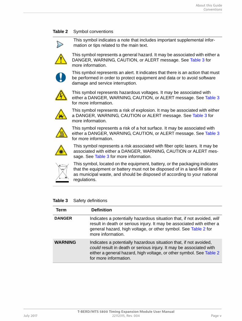
Table 2 Symbol conventions
This symbol indicates a note that includes important supplemental infor-mation or tips related to the main text.
This symbol represents a general hazard. It may be associated with either a DANGER, WARNING, CAUTION, or ALERT message. See Table 3 for more information.
This symbol represents an alert. It indicates that there is an action that must be performed in order to protect equipment and data or to avoid software damage and service interruption.
This symbol represents hazardous voltages. It may be associated with either a DANGER, WARNING, CAUTION, or ALERT message. See Table 3 for more information.
This symbol represents a risk of explosion. It may be associated with either a DANGER, WARNING, CAUTION or ALERT message. See Table 3 for more information.
This symbol represents a risk of a hot surface. It may be associated with either a DANGER, WARNING, CAUTION, or ALERT message. See Table 3 for more information.
This symbol represents a risk associated with fiber optic lasers. It may be associated with either a DANGER, WARNING, CAUTION or ALERT mes-sage. See Table 3 for more information.
This symbol, located on the equipment, battery, or the packaging indicates that the equipment or battery must not be disposed of in a land-fill site or as municipal waste, and should be disposed of according to your national regulations.
Table 3 Safety definitions
Term Definition
DANGER Indicates a potentially hazardous situation that, if not avoided, will result in death or serious injury. It may be associated with either a general hazard, high voltage, or other symbol. See Table 2 for more information.
WARNING Indicates a potentially hazardous situation that, if not avoided, could result in death or serious injury. It may be associated with either a general hazard, high voltage, or other symbol. See Table 2 for more information.
About this GuideSafety and compliance information
T-BERD/MTS 5800 Timing Expansion Module User ManualPage vi 22112315, Rev. 004 July 2017
Safety and compliance informationSafety and compliance information for the 5800v2 test instrument and the TEM Module are provided in the printed T-BERD ⁄ MTS 5800 Safety Information document that shipped with the instrument or module.
Technical assistanceIf you require technical assistance, call 1-844-GO-VIAVI. For the latest TAC informa-tion, go to http://www.viavisolutions.com/en/services-and-support/support/technical-assistance.
CAUTION Indicates a potentially hazardous situation that, if not avoided, could result in minor or moderate injury and/or damage to equip-ment.
It may be associated with either a general hazard, high voltage, or risk of explosion symbol. See Table 2 for more information.
When applied to software actions, indicates a situation that, if not avoided, could result in loss of data or a disruption of software operation.
ALERT Indicates that there is an action that must be performed in order to protect equipment and data or to avoid software damage and ser-vice interruption.
Table 3 Safety definitions (Continued)
Term Definition

T-BERD/MTS 5800 Timing Expansion Module User ManualJuly 2017 22112315, Rev. 004 Page 1
1
Chapter 1Overview
This chapter provides a general description of each of the TEM Module. Topics discussed in this chapter include the following:
• “About the TEM Module” on page 2
• “Features and capabilities” on page 2
• “What ships with the TEM Module?” on page 3
• “Unpacking the components” on page 4
• “Inspecting the components for damage” on page 4
• “Exploring the TEM Module connector panel” on page 5
Chapter 1 OverviewAbout the TEM Module
T-BERD/MTS 5800 Timing Expansion Module User ManualPage 2 22112315, Rev. 004 July 2017
About the TEM ModuleThe TEM Module provides a stable, highly accurate timing reference for the T-BERD / MTS 5800v2, and the ability to conduct synchronized timing tests across multiple instruments with the support of a Global Navigation Satellite System (GNSS) and an internal rubidium oscillator. This equips technicians and engineers to perform highly accurate one-way delay testing; timing and synchronization experts to measure time and phase on systems, particularly wireless systems that require precise synchroniza-tion; and certification labs to verify timing and synchronization of new equipment and network configurations. The TEM Module can also be used to provide a stable external timing reference via the 1PPS and 10MHz output connectors on the module.
Finally, the TEM Module also provides field construction teams with the ability to qualify GNSS antenna installations by verifying the strength of signals received from specific satellites and detecting obstructions to the antennas.
Features and capabilitiesFeatures and capabilities of the TEM Module include the following (assuming your 5800v2 instrument is optioned and configured to do so):
• Rubidium Oscillator. The TEM Module is equipped with its own, dedicated rubidium oscillator which tunes to the frequency of a specified synchronization source (for example, a GNSS satellite, or an external 1PPS or 10MHz reference clock). After tuning, the oscillator on the TEM Module can be used as the timing source when performing measurements that require highly accurate timing, or to provide an external timing reference to another device.
• Holdover mode. After the TEM Module’s oscillator warms up and is tuned to the frequency of the synchronization source, it can be placed into holdover mode, allowing the TEM Module to use its own rubidium oscillator as a stable timing reference for a period of time while using the connected instrument to perform tests. After the oscillator is placed into holdover mode, the signal from which synchronization was obtained can be disconnected.
• GNSS antenna. A GNSS antenna ships with the TEM Module. When connected to the TEM module, provides the highest accuracy and stability using the module’s high precision GNSS timing receiver.
• GNSS high precision timing receiver. The TEM Module provides a GNSS high precision timing receiver, which supports all GNSS frequencies when a GNSS antenna is connected.
• Supported GNSS Systems. The TEM Module supports GNSS systems for satel-lite constellations that are available worldwide (GPS and GLOSNASS), and in specific areas of the world (for example, BeiDou). If they are available, satellites supporting different GNSS systems can be selected as sources of timing informa-tion.
• GNSS surveys. You can configure the TEM Module to survey GNSS constella-tions, obtain position measurements from satellites within the constellation, and then and then generate accurate coordinates based on the average position measurement.
Chapter 1 OverviewWhat ships with the TEM Module?
T-BERD/MTS 5800 Timing Expansion Module User ManualJuly 2017 22112315, Rev. 004 Page 3
• Satellite Based Augmentation Systems (SBAS). SBAS can be used in combina-tion with GPS, GLONASS, or BeiDou GNSS systems to improve the availability of satellites during surveys of areas with poor satellite visibility. In the future, QZSS augmentation will also be supported for satellite constellations in Japan and Australia.
• Saved GNSS coordinates. If you intend to conduct testing at a particular location on a routine basis, you can save the coordinates for the location, and then retrieve them before testing.
• External Synchronization Sources. In addition to the internal GNSS receiver, you can configure the TEM Module to use an external BITS/SETS clock, an external 1 Pulse Per Second (PPS signal), or an external 10 MHz signal to tune the module’s rubidium oscillator.
• Precise one way delay measurements. By synchronizing two 5800v2 test instru-ments (each with a connected TEM Module), you can use the instruments to accurately measure one way delay.
• Precision Time Protocol (PTP) Time Error, Asymmetry, and Packet Delay Varia-tion (PDV) measurements. You can also use a 5800v2 instrument with a TEM Module to operate as a PTP slave, and measure time errors and PDV against a PTP Grandmaster or boundary clock.
• Wander analysis. You can use the TEM Module as a highly precise reference when conducting 1PPS Wander measurements with a 1PPS input signal under test. You can also use the TEM Module to provide a highly precise timing refer-ence when conducting DS1/E1, 10MHz/2MHz Clock, and 1GigE Optical Ethernet wander analysis.
• High precision 1PPS wander analysis. If your TEM Module is optioned to do so, you can use it to perform highly accurate wander analysis of a 1PPS signal in a graphical manner by measuring the Time Interval Error (TIE) and calculating the Maximum Time Interval Error/Time Deviation (MTIE/TDEV) on the module itself. You can also export TIE data for analysis on a PC using optional O.172 MTIE/TDEV Offline Analysis software.
• GNSS antenna installation qualification. You can use the TEM Module (with a connected GNSS antenna) to determine the quality of the signals received from selected GNSS satellites, and to verify that a stationary antenna has been installed at the optimal location.
For a comprehensive list of features and capabilities for specific technologies or proto-cols (for example, Ethernet or SONET), refer to the Testing Manual that shipped with your instrument or upgrade.
What ships with the TEM Module?The following items ship with the TEM Module:
• TEM Module
• GNSS Antenna
• SMA to SMB adapters
• SMB to SMB adapters
Chapter 1 OverviewUnpacking the components
T-BERD/MTS 5800 Timing Expansion Module User ManualPage 4 22112315, Rev. 004 July 2017
• A USB stick with supporting user documentation.
In addition to items that ship standard with the TEM Module, an optional glove bag and a power inverter are available to protect and supply power to the module when you transport it to various test locations. When transporting the TEM Module and 5800v2 in a powered on state, Viavi strongly recommends only using the optional glove bag to transport the assembled test instrument. The standard bag should not be used.
For details concerning the glove bag, power inverter, or additional options, contact Viavi Customer Care at 1-866-228-3762 or at www.viavisolutions.com.
Unpacking the componentsViavi typically ships our instruments using anti-static packing material to stabilize the components inside the box. When unpacking the components, verify that all the items you ordered are included in the package. Accessories may be shipped in a separate box.
After you unpack the components, you should inspect them for damage. If undamaged, consider saving the box and packing materials in case you need to repackage the components for shipment. For information about shipping equipment, see Appendix B “Storage and Shipment” .
Inspecting the components for damageAfter you unpack the components, examine the connectors, ports, and LEDs for damage. Be sure to check the top, bottom, and front and back panel of the TEM Module.
If you find damage, contact Viavi Customer Care at 1-844-GO-VIAVI. For the latest TAC information, go to http://www.viavisolutions.com/en/services-and-support/support/tech-nical-assistance.
For information about returning equipment, see “Returning equipment to Viavi” on page 75.
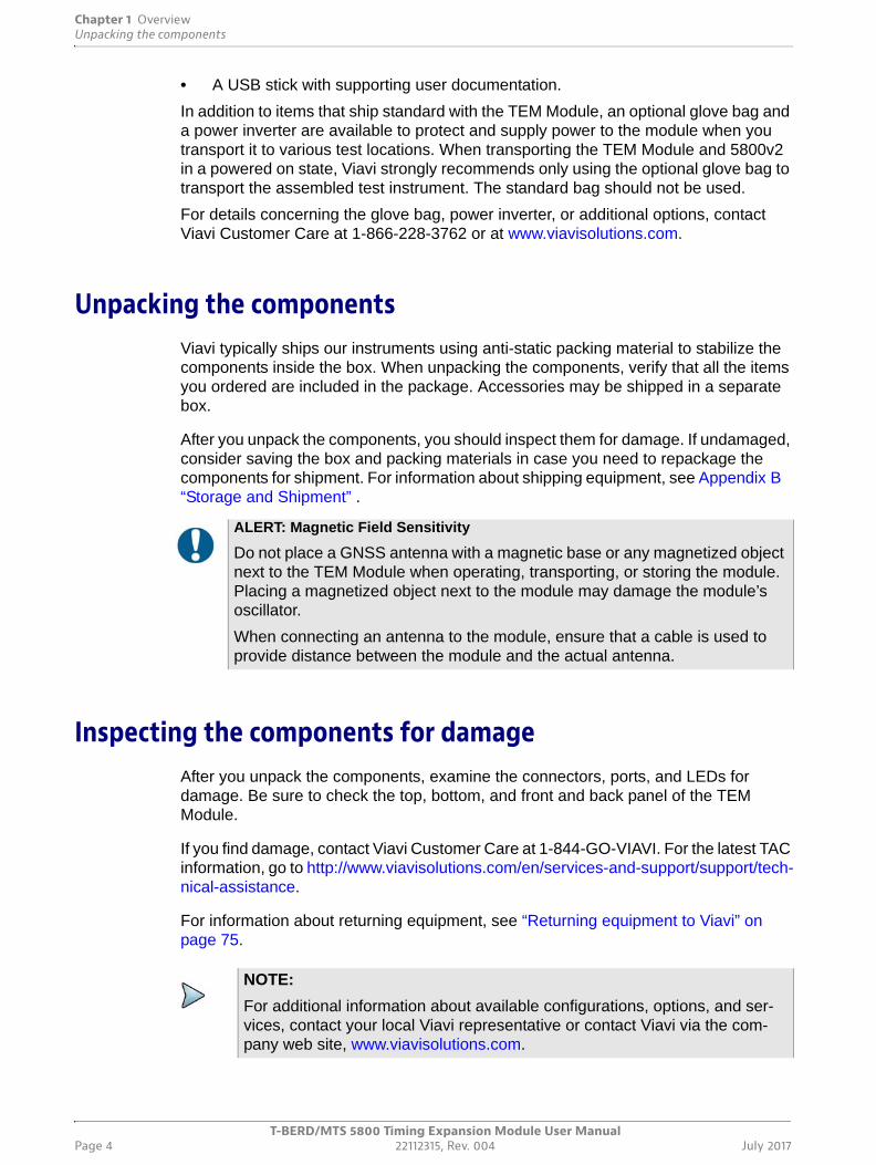
ALERT: Magnetic Field Sensitivity
Do not place a GNSS antenna with a magnetic base or any magnetized object next to the TEM Module when operating, transporting, or storing the module. Placing a magnetized object next to the module may damage the module’s oscillator.
When connecting an antenna to the module, ensure that a cable is used to provide distance between the module and the actual antenna.
NOTE:
For additional information about available configurations, options, and ser-vices, contact your local Viavi representative or contact Viavi via the com-pany web site, www.viavisolutions.com.
Chapter 1 OverviewExploring the TEM Module connector panel
T-BERD/MTS 5800 Timing Expansion Module User ManualJuly 2017 22112315, Rev. 004 Page 5
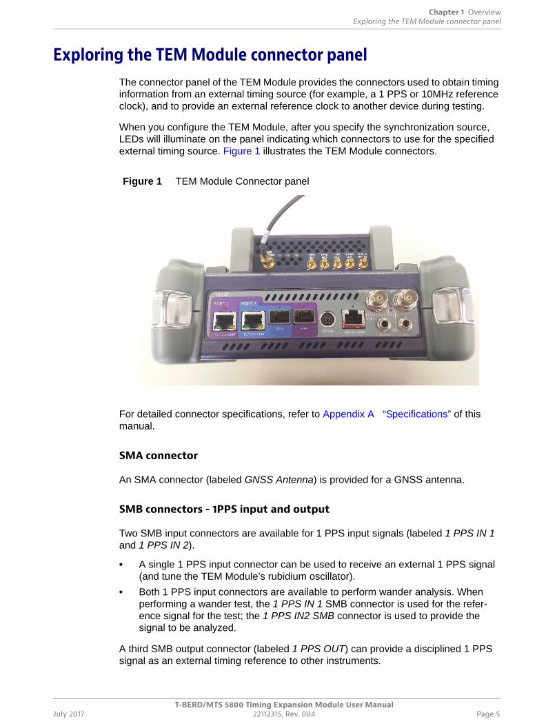
Exploring the TEM Module connector panelThe connector panel of the TEM Module provides the connectors used to obtain timing information from an external timing source (for example, a 1 PPS or 10MHz reference clock), and to provide an external reference clock to another device during testing.
When you configure the TEM Module, after you specify the synchronization source, LEDs will illuminate on the panel indicating which connectors to use for the specified external timing source. Figure 1 illustrates the TEM Module connectors.
For detailed connector specifications, refer to Appendix A “Specifications” of this manual.
SMA connector
An SMA connector (labeled GNSS Antenna) is provided for a GNSS antenna.
SMB connectors - 1PPS input and output
Two SMB input connectors are available for 1 PPS input signals (labeled 1 PPS IN 1 and 1 PPS IN 2).
• A single 1 PPS input connector can be used to receive an external 1 PPS signal (and tune the TEM Module’s rubidium oscillator).
• Both 1 PPS input connectors are available to perform wander analysis. When performing a wander test, the 1 PPS IN 1 SMB connector is used for the refer-ence signal for the test; the 1 PPS IN2 SMB connector is used to provide the signal to be analyzed.
A third SMB output connector (labeled 1 PPS OUT) can provide a disciplined 1 PPS signal as an external timing reference to other instruments.
Figure 1 TEM Module Connector panel
Chapter 1 OverviewExploring the TEM Module connector panel
T-BERD/MTS 5800 Timing Expansion Module User ManualPage 6 22112315, Rev. 004 July 2017
SMB connectors - 10 MHz input and output
Two additional SMB connectors are provided on the connector panel for 10 MHz input and output (labeled 10 MHz OUT and 10 MHz REF IN).
The connector labeled 10 MHz OUT can be used to provide an external, disciplined 10MHz timing reference to other instruments, and emulate an accurate master 10MHz clock. The connector 10 MHz REF IN can be used to receive an external 10MHz timing reference (and tune the TEM Module’s rubidium oscillator).
Specifications for the SMB connectors are provided in Appendix A “Specifications” of this manual.
T-BERD/MTS 5800 Timing Expansion Module User ManualJuly 2017 22112315, Rev. 004 Page 7
2
Chapter 2 Getting Started
This chapter explains how to connect the TEM Module to your instrument, how to connect a GNSS antenna (if you are using GNSS timing as your synchronization source), and how to navigate the user interface. Topics discussed in this chapter include the following:
• “Connecting the TEM Module to your test instrument” on page 8
• “Connecting a GNSS antenna” on page 10
• “Powering the TEM Module” on page 11
• “Verifying the local time zone” on page 13
• “Turning on the Rubidium Oscillator” on page 14
• “Navigating the TEM Module user interface” on page 15
• “Turning off the instrument” on page 19
• “Disconnecting a GNSS antenna” on page 19
• “Disconnecting the TEM Module” on page 20
Chapter 2 Getting StartedConnecting the TEM Module to your test instrument
T-BERD/MTS 5800 Timing Expansion Module User ManualPage 8 22112315, Rev. 004 July 2017
Connecting the TEM Module to your test instrumentBefore connecting your new TEM Module to a T-BERD ⁄ MTS 5800:
• Verify that the instrument is a 5800v2 by checking the label on the back panel of the instrument, which will indicate whether or not it is a 5800v2. If a module is connected to the back of the 5800 (obstructing the label), you can assume that the instrument is a 5800v2; v1 5800’s do not support the connection of additional modules.
• Power down the 5800, and disconnect the AC power adapter. The TEM Module is not hot-swappable.
To connect the TEM Module to your test instrument
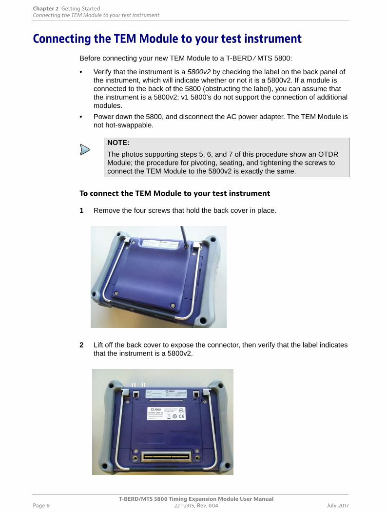
1 Remove the four screws that hold the back cover in place.
2 Lift off the back cover to expose the connector, then verify that the label indicates that the instrument is a 5800v2.
NOTE:
The photos supporting steps 5, 6, and 7 of this procedure show an OTDR Module; the procedure for pivoting, seating, and tightening the screws to connect the TEM Module to the 5800v2 is exactly the same.
Chapter 2 Getting StartedConnecting the TEM Module to your test instrument
T-BERD/MTS 5800 Timing Expansion Module User ManualJuly 2017 22112315, Rev. 004 Page 9
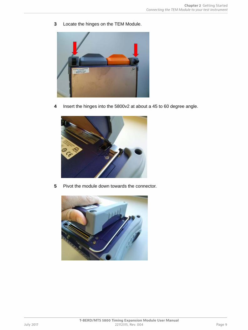
3 Locate the hinges on the TEM Module.
4 Insert the hinges into the 5800v2 at about a 45 to 60 degree angle.
5 Pivot the module down towards the connector.
Chapter 2 Getting StartedConnecting a GNSS antenna
T-BERD/MTS 5800 Timing Expansion Module User ManualPage 10 22112315, Rev. 004 July 2017
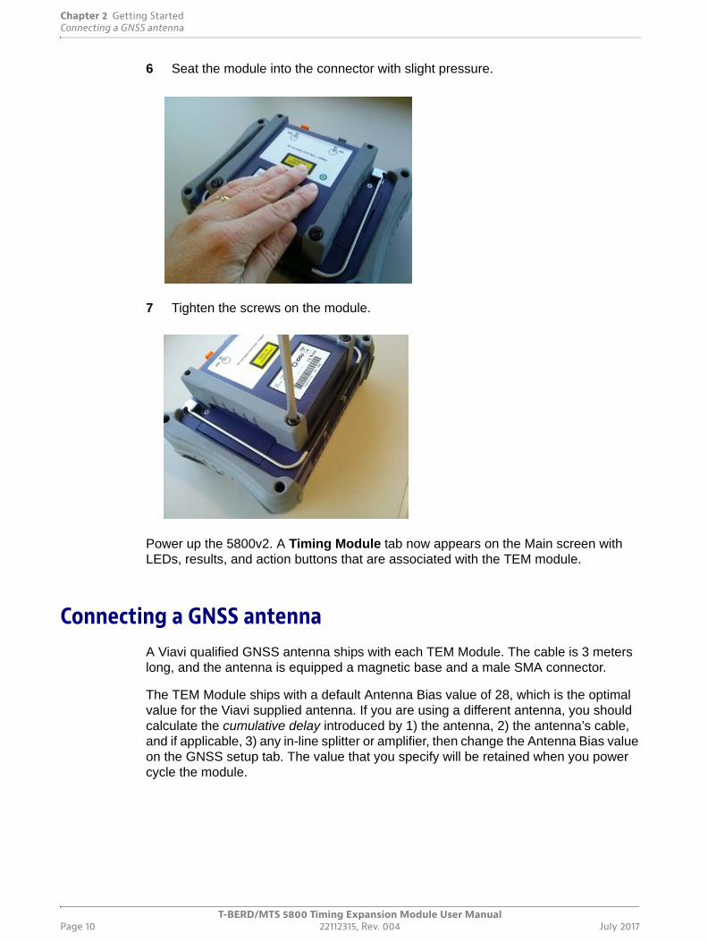
6 Seat the module into the connector with slight pressure.
7 Tighten the screws on the module.
Power up the 5800v2. A Timing Module tab now appears on the Main screen with LEDs, results, and action buttons that are associated with the TEM module.
Connecting a GNSS antennaA Viavi qualified GNSS antenna ships with each TEM Module. The cable is 3 meters long, and the antenna is equipped a magnetic base and a male SMA connector.
The TEM Module ships with a default Antenna Bias value of 28, which is the optimal value for the Viavi supplied antenna. If you are using a different antenna, you should calculate the cumulative delay introduced by 1) the antenna, 2) the antenna’s cable, and if applicable, 3) any in-line splitter or amplifier, then change the Antenna Bias value on the GNSS setup tab. The value that you specify will be retained when you power cycle the module.
Chapter 2 Getting StartedPowering the TEM Module
T-BERD/MTS 5800 Timing Expansion Module User ManualJuly 2017 22112315, Rev. 004 Page 11
For details, see “Specifying GNSS settings” on page 30 of Chapter 3 “High Accuracy Timing”.
To connect an antenna
1 Connect the male SMA connector on the end of the antenna cable to the female SMA connector on the TEM Module (labeled GNSS Antenna).
2 Tighten the connector until the antenna is securely attached.
Powering the TEM ModulePower is supplied to the TEM Module by the battery or the AC power adapter that provides power to the test instrument (the 5800v2). When using the TEM Module, use only the AC adapter or batteries that shipped with your 5800v2.
When supplying power to your test instrument, consider the following:
• The rubidium oscillator on the TEM Module consumes a significant amount of power, and takes time to warm up and tune to the specified synchronization source before it can be used. Therefore, it is recommended that you power your instrument using the AC adapter when the oscillator is warming up and tuning.
• Optical wander analysis — If you intend to use your instrument for optical wander analysis, before you start, you must connect the AC power adapter that shipped with the instrument.
• When transporting the TEM Module to a test location after the oscillator has warmed up and tuned, Viavi recommends using an optional power inverter for the duration of the trip.
To discuss the various power adapters and inverters available for the 5800v2, contact Viavi Customer Care, or contact Viavi via the company web site,www.viavisolu-tions.com.
ALERT: Magnetic Field Sensitivity
Do not place a GNSS antenna with a magnetic base (or any magnetized object) next to the TEM Module when operating, transporting, or storing the module. Placing a magnetized object next to the module may damage the module’s oscillator.
When connecting an antenna to the module, ensure that a cable is used to provide distance between the module and the actual antenna.
Chapter 2 Getting StartedPowering the TEM Module
T-BERD/MTS 5800 Timing Expansion Module User ManualPage 12 22112315, Rev. 004 July 2017
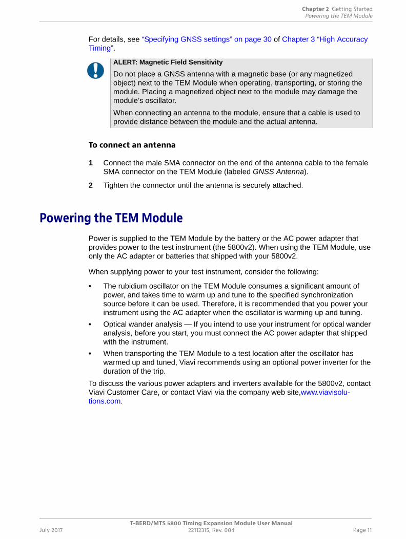
Verifying that you have the correct adapterFigure 2 shows the label on the adapter that ships with T-BERD / MTS 5800v2 test instruments. This adapter must be used to provide power to the 5800v2 instrument and connected TEM Module.
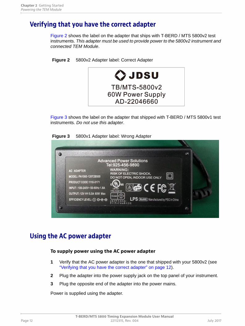
Figure 3 shows the label on the adapter that shipped with T-BERD / MTS 5800v1 test instruments. Do not use this adapter.
Using the AC power adapter
To supply power using the AC power adapter
1 Verify that the AC power adapter is the one that shipped with your 5800v2 (see “Verifying that you have the correct adapter” on page 12).
2 Plug the adapter into the power supply jack on the top panel of your instrument.
3 Plug the opposite end of the adapter into the power mains.
Power is supplied using the adapter.
Figure 2 5800v2 Adapter label: Correct Adapter
Figure 3 5800v1 Adapter label: Wrong Adapter
Chapter 2 Getting StartedVerifying the local time zone
T-BERD/MTS 5800 Timing Expansion Module User ManualJuly 2017 22112315, Rev. 004 Page 13
For power specifications, see the Getting Started Guide that shipped with your instru-ment.
Turning on the instrument
To power the instrument
• Press the ON/OFF key.
The On LED, located on the front panel, illuminates green when the unit is powered, and the instrument beeps.
Checking the batteryYou can check the status of the battery in two ways:
Method 1 — The battery status indicator in the upper right corner of the screen provides a graphic indication of the approximate battery charge.
Method 2 — The Battery Level percentage on the Battery status page.
1 Select the SYSTEM icon.
2 Select Power Management.
The battery status appears.
3 View the Battery Level.
The Battery Status page indicates the charge level (both in percentage under the battery and the color of the battery), whether the adapter is plugged in, and indicates the battery temperature range.
Verifying the local time zone Before using the TEM Module as a timing reference, to ensure that the local time is correct, you must verify that the connected 5800v2 is configured to use the correct time zone for the region, country, and area. If daylight savings time is active for your time zone, you should also select the corresponding setting.
NOTE:
If your instrument does not have sufficient power to turn on the Rubidium Oscillator, a message will state so in the message bar that is located directly above the LED Panel.
Chapter 2 Getting StartedTurning on the Rubidium Oscillator
T-BERD/MTS 5800 Timing Expansion Module User ManualPage 14 22112315, Rev. 004 July 2017
To verify the time zone
1 Select the SYSTEM/HOME icon.
The System screen appears.
2 Select Date and Time.
3 Review, and, if necessary, specify the Region, Country, and Area.
The time zone has been verified.
Turning on the Rubidium OscillatorBy default, the TEM Module’s Rubidium Oscillator is off when you turn on your test instrument. This is to conserve power until you need to warm up, tune, and then use the oscillator for high accuracy timing.
To turn on the oscillator
• Press the grey Rubidium Osc. Off action button.
The action button turns yellow (indicating that the oscillator is on), and the text on the button changes to Rubidium Osc. On.
The oscillator immediately enters Warm Up mode and begins to tune to the frequency provided by the synchronization source see (“Specifying oscillator and timing settings” on page 29). The LED Panel and a dedicated action button show the oscillator’s status as it progresses through each of the modes described in Table 4.
NOTE:
Before using the oscillator as a source of high accuracy timing, the oscillator must be left in a controlled environment (such as a cell site, local central office, instrument depot, or laboratory) to provide sufficient time for 1) the oscillator to warm up, and 2) the oscillator to be tuned to the frequency pro-vided by the specified synchronization source.
If you prefer to start to warm the oscillator up immediately after you turn your test instrument on, you can configure the TEM Module to turn the oscillator on by default. For details, see “Specifying oscillator and timing settings” on page 29 of this manual.
Table 4 Oscillator Modes
Mode Description
Warm Up The oscillator is warming up. NOTE: Do not use the TEM Module for high accuracy timing while the oscillator is in warm up mode; the oscillator must be tuned in order to provide a stable timing reference.
Chapter 2 Getting StartedNavigating the TEM Module user interface
T-BERD/MTS 5800 Timing Expansion Module User ManualJuly 2017 22112315, Rev. 004 Page 15
Additional information concerning the oscillator is provided in “Oscillator Results” on page 58.
Navigating the TEM Module user interfaceThe TEM Module user interface (UI) lets you configure the module, control the module’s rubidium oscillator, survey GNSS constellations (to obtain position measurements from satellites within the constellation), and review test results associated with the timing
Wait for 1PPS The TEM Module is waiting for a valid 1PPS signal from the specified synchronization source.
Coarse Tune The oscillator is beginning to tune to the frequency for the synchronization source that you specified when you configured the oscillator. After you turn the oscilla-tor on, it may take 7 to 12 minutes to reach a coarse tune. The oscillator will remain coarsely tuned for at least 17 minutes.
Intermediate Tune The oscillator is tuned to the frequency of the syn-chronization source that you specified when you con-figured the oscillator, and the oscillator has been tuned for a sufficient period of time to support accu-racy in holdover mode, after frequency stabilization. After you turn the oscillator on, it will take at least 20 to 25 minutes to reach an intermediate tune. The oscillator will remain in an intermediately tuned mode for at least 167 min.
Fine Tune The oscillator is finely tuned to the frequency of the synchronization source that you specified when you configured the oscillator, and the oscillator has been tuned for a sufficient period of time to support accu-racy in holdover mode, after frequency stabilization.
Holdover The oscillator was placed into holdover mode (either manually, using the Force Holdover action key, or due to the removal of a GNSS antenna or an external timing reference).NOTE: For optimal performance during testing, allow the oscillator to reach Fine Tune mode before placing it into Holdover mode.
Table 4 Oscillator Modes (Continued)
Mode Description

Chapter 2 Getting StartedNavigating the TEM Module user interface
T-BERD/MTS 5800 Timing Expansion Module User ManualPage 16 22112315, Rev. 004 July 2017
provided to and by the module. Figure 4 shows the Timing Module tab when the module is configured to use a GNSS synchronization source.
For a detailed description of the UI elements on the 5800v2 user interface, refer to the Getting Started Guide that shipped with your instrument. The sections below provide an overview of UI elements that are specifically applicable to the TEM Module.
Timing Module tabWhen the TEM Module is connected to your instrument, a Timing Module tab appears on the Main screen (in addition to the tab or tabs for any tests that you have selected). The UI elements on the Timing Module tab function in a similar manner to those on the test tabs; however, the Timing Module tab can not be removed. It will be available when-ever the module is connected to your instrument and your instrument is powered on.
Figure 4 Main screen (Timing Module, GNSS Synchronization Source)
NOTE:
To review LEDs and results for a specific test, select the corresponding test tab. If you are running two tests concurrently, pressing the Dual Test View soft key will display results for both tests in the two result panes, or you can view Timing results in one pane, and results for one test in the second pane.
Chapter 2 Getting StartedNavigating the TEM Module user interface
T-BERD/MTS 5800 Timing Expansion Module User ManualJuly 2017 22112315, Rev. 004 Page 17
Setup/Results soft keyThe Setup soft key located on the right side of the UI provides quick access to the screen and the setup tabs that you use to configure the TEM Module. After configuring the module, use the Results soft key to return to the Timing Module tab on the Main screen.
Message BarThe message bar above the LED Panel displays the current status of the TEM Module and the duration that the module has been running (in hours, minutes, and seconds).
LED PanelThe LEDs in the panel to the left of the Results Windows help you determine whether key events have occurred when synchronizing the TEM Module’s rubidium oscillator to a high accuracy timing source.
Current and history LEDs
The round LEDs on the inside column provide the current state of the key event; the square LEDs on the outside column provide the historical state (in other words, the event occurred in the past).
LED colors
Green LEDs indicate an event occurred as expected, yellow LEDs indicate that an event occurred that warrants additional investigation, and red LEDs indicate that an error, anomaly, alarm, or defect has occurred.
If an event has not occurred, the LEDs remain grey.
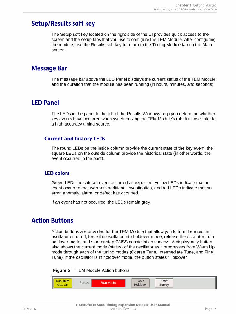
Action ButtonsAction buttons are provided for the TEM Module that allow you to turn the rubidium oscillator on or off, force the oscillator into holdover mode, release the oscillator from holdover mode, and start or stop GNSS constellation surveys. A display-only button also shows the current mode (status) of the oscillator as it progresses from Warm Up mode through each of the tuning modes (Coarse Tune, Intermediate Tune, and Fine Tune). If the oscillator is in holdover mode, the button states “Holdover”.
Figure 5 TEM Module Action buttons
Chapter 2 Getting StartedNavigating the TEM Module user interface
T-BERD/MTS 5800 Timing Expansion Module User ManualPage 18 22112315, Rev. 004 July 2017
Figure 5 illustrates the buttons with the oscillator turned on and warming up.
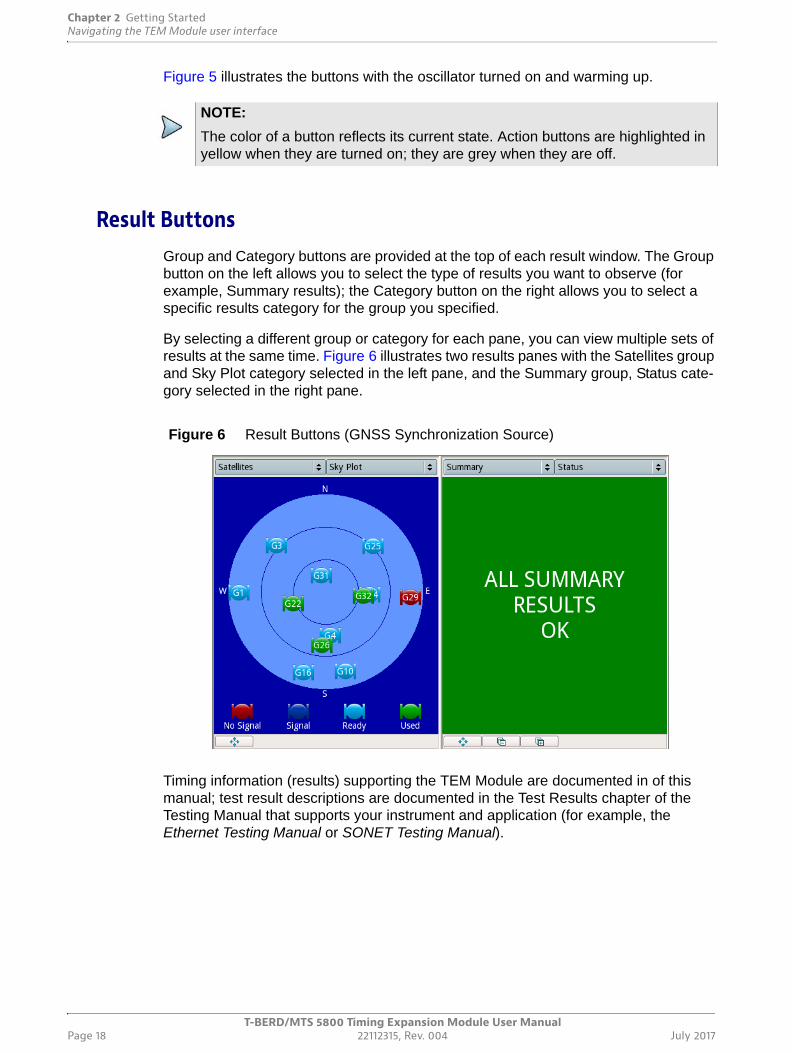
Result ButtonsGroup and Category buttons are provided at the top of each result window. The Group button on the left allows you to select the type of results you want to observe (for example, Summary results); the Category button on the right allows you to select a specific results category for the group you specified.
By selecting a different group or category for each pane, you can view multiple sets of results at the same time. Figure 6 illustrates two results panes with the Satellites group and Sky Plot category selected in the left pane, and the Summary group, Status cate-gory selected in the right pane.
Timing information (results) supporting the TEM Module are documented in of this manual; test result descriptions are documented in the Test Results chapter of the Testing Manual that supports your instrument and application (for example, the Ethernet Testing Manual or SONET Testing Manual).
NOTE:
The color of a button reflects its current state. Action buttons are highlighted in yellow when they are turned on; they are grey when they are off.
Figure 6 Result Buttons (GNSS Synchronization Source)
Chapter 2 Getting StartedTurning off the Rubidium Oscillator
T-BERD/MTS 5800 Timing Expansion Module User ManualJuly 2017 22112315, Rev. 004 Page 19
Turning off the Rubidium Oscillator
To turn off the oscillator
• Press the yellow Rubidium Osc. On action button.
The action button turns grey, and the text on the button changes to Rubidium Osc. Off.
Turning off the instrument
To turn off the instrument
• Press the ON/OFF key.
The On LED, located on the front panel, extinguishes when the unit turned off, and the instrument beeps.
Disconnecting a GNSS antennaIf you intend to use the TEM Module as a high accuracy timing reference, before disconnecting the antenna, verify that the oscillator is finely tuned, and is in Holdover mode. If you remove the antenna before placing the oscillator into Holdover mode, the tuning frequency may drift slightly. The oscillator mode (status) appears on the LED panel and the Action Panel of the UI.
To disconnect an antenna
1 Verify that the oscillator is in Holdover mode, or Fine Tune mode. If it is in Fine Tune mode, force it into holdover mode using the Force Holdover action key.
2 Loosen the connector at the base of the antenna that is attached to the SMA connector on the TEM Module (labeled GNSS Antenna).
3 Gently pull the connector at the base of the antenna up to disengage the antenna from the TEM Module.
The antenna is disconnected. Be certain to store the antenna per manufacturer instruc-tions and specifications.
ALERT: Magnetic Field Sensitivity
Do not place a GNSS antenna with a magnetic base (or any magnetized object) next to the TEM Module when operating, transporting, or storing the module. Placing a magnetized object next to the module may damage the module’s oscillator.
Chapter 2 Getting StartedDisconnecting the TEM Module
T-BERD/MTS 5800 Timing Expansion Module User ManualPage 20 22112315, Rev. 004 July 2017
Disconnecting the TEM Module
To disconnect the TEM Module from your instrument
1 Verify that power is OFF on your instrument and that the AC power adapter is unplugged.
2 Turn the instrument over so the display is facing downwards, and the back panel of the module is facing upwards.
3 Loosen the screws on the module.
4 Pull gently on the bottom of the module to release it from the connector on the instrument.
5 Pivot the bottom of module upwards at about a 45 to 60 degree angle, then release the hinges (located at the top of the module) from the instrument.
The TEM Module is disconnected from your instrument. Be certain to replace the back panel of the instrument to protect the connector.
T-BERD/MTS/SC Timing Expansion Module User ManualJuly 2017 22112315, Rev. 004 Page 21
3
Chapter 3 High Accuracy Timing
This chapter explains how to setup and configure the TEM Module for use as a high accuracy timing reference during testing. Topics discussed in this chapter include the following:
• “Basic timing principles” on page 22
• “Common test applications” on page 26
• “Warming up the oscillator” on page 28
• “Configuring the module” on page 29
• “Surveying GNSS constellations” on page 34
• “Tuning the oscillator” on page 34
• “Forcing the oscillator into holdover mode” on page 35
• “Qualifying GNSS antennas” on page 36
Chapter 3 High Accuracy TimingBasic timing principles
T-BERD/MTS/SC Timing Expansion Module User ManualPage 22 22112315, Rev. 004 July 2017
Basic timing principlesThe TEM Module is designed to provide a stable, highly accurate timing reference when performing tests that require:
• The precise synchronization of multiple test instruments;
• High accuracy wander analysis,
• Stable and precise external timing references.
Before configuring the TEM to support testing (by placing the module into Tuning mode), it is useful to review some basic timing principles as they apply to the TEM.
GNSS timingThe TEM Module supports GNSS systems for satellite constellations that are available worldwide (GPS and GLOSNASS), and in specific areas of the world (for example, BeiDou). If they are available, satellites supporting different GNSS systems can be selected together to be used as a synchronization source and derive timing.
Satellite Based Augmentation Systems
A satellite-based augmentation system (SBAS) is a system that provides additional satellite-broadcast messages to enhance the availability of GNSS satellites during surveys conducted in areas with poor satellite visibility. The systems are typically comprised of multiple ground stations that are precisely positioned to support measure-ments of the GNSS satellites, signals, and environmental factors that may impact the quality of the signal received.This information is then sent in messages to the supported satellites so that the messages can be broadcast to GPS receivers.
When using the TEM Module, SBAS should only be selected with a synchronization source to optimize the availability satellites during surveys. After completing a survey, the synchronization source should be reset without SBAS to ensure optimal timing performance. For details, see “Survey settings” on page 31.
GNSS antennas
The TEM Module ships with a GNSS antenna that supports all TEM supported GNSS systems. You can also use your own antenna; however, you should verify that the antenna supports the GNSS system(s) that you intend to use as synchronization sources when tuning the oscillator. For example, if you intend to use BeiDou or GLONASS as a synchronization source, you cannot use a GPS-only antenna.
Position
The position of supporting GNSS antennas is important when using the TEM Module to conduct surveys (to generate accurate coordinates) and when maintaining precise timing from a fixed position.
Chapter 3 High Accuracy TimingBasic timing principles
T-BERD/MTS/SC Timing Expansion Module User ManualJuly 2017 22112315, Rev. 004 Page 23
Voltage
When you configure the TEM module, you can select the voltage used by the connected antenna (3.3V or 5V), or select 0V. If you select 3.3V or 5V, the module will report antenna faults due to low voltage that indicates an antenna may be discon-nected, damaged, or defective.
Delay bias
The TEM Module ships with a default Antenna Bias value of 28, which is the optimal value for the Viavi supplied antenna. If you are using a different antenna, you should calculate the cumulative delay introduced by 1) the antenna, 2) the antenna’s cable, and if applicable, 3) any in-line splitter or amplifier, then change the Antenna Bias value on the GNSS setup tab. The value that you specify will be retained when you power cycle the module.
The specified bias setting may also be used to adjust the absolute timing of the TEM to match other system components or standards. To determine the delay value introduced by each item, refer to supporting vendor specifications. For instructions on specifying the bias value, see “Specifying GNSS settings” on page 30.
Available survey modes
When you configure the TEM Module to use GNSS timing, you must either specify a survey mode or manually specify the latitude, longitude, altitude, and survey position accuracy for the test instrument.
If you configure the module to generate accurate coordinates by surveying a GNSS constellation, you select a survey mode or manually specify survey settings based on 1) the minimum duration of the survey, and 2) the survey accuracy requirement, in meters, representing the maximum allowed standard deviation of the position data collected throughout the survey. The survey will run until both conditions are satisfied. Surveys conducted for a longer period of time will provide more data points, observe more satellite orbits, and as a result, yield more accurate coordinates.
If you are conducting surveys in areas with poor satellite visibility, you can configure the module to use SBAS to optimize availability of the satellites during the survey.
The survey will not begin until you select the Start Survey action button provided on either the Location setup tab, or the bottom of the Timing Module tab on the Main screen. After the survey is complete, you can save the generated coordinates with a specific location name; this allows you to retrieve the coordinates in the future if you return to conduct additional tests.
NOTE:
If you configure a manual survey with a position accuracy of less than one meter (without providing an accurate fixed location), the survey will take a very long time to complete.
Chapter 3 High Accuracy TimingBasic timing principles
T-BERD/MTS/SC Timing Expansion Module User ManualPage 24 22112315, Rev. 004 July 2017
Fixed position mode
If the values that the TEM Module’s GNSS receiver currently has in memory for position and altitude are correct and your instrument will remain in the same location, you do not need to conduct a survey. You can simply verify the fixed position accuracy, latitude, longitude, and altitude, then select the Position Fixed action button provided on the Location tab. In this mode, precise timing can be maintained using the signal received from a single satellite.
Receiver modes
When you configure the TEM Module to use GNSS timing as the synchronization source, the GNSS receiver goes into one of the following receiver modes, which vary depending on 1) the Survey Mode that you specified, and 2) the information that the receiver already has. Messages will appear above the LED panel informing you of the current mode. The receiver may be:
• Searching for satellites,
• Collecting or renewing an almanac of information concerning a satellite constella-tion (which is broadcast by every satellite within the constellation),
• Receiving detailed ephemeris data from one or more satellites,
• Calculating the position and timing information using the provided satellite data, or
• Using position information that it already has, and is providing timing information without continually recomputing position coordinates.
After the receiver locates satellites that satisfy the criteria that you specified when you configured the module, an illustration of the satellites and their status (nosignal, signal, ready, or used) is provided in the Satellites Sky Plot results category. For details, see “Sky Plot” on page 53 of this manual.
Resynchronizing GNSS time
If you are conducting tests indoors and the oscillator was initially tuned using GNSS, you can periodically resynchronize the oscillator to GNSS by 1) taking the instrument with a connected GNSS antenna to an outside area with a clear view of open sky, 2) obtaining an updated position fix, 3) releasing holdover mode, and then 4) letting the oscillator resynchronize for a short period of time (for example, five to 15 minutes). This realigns the oscillator with UTC time (as indicated in the Time Results category). After resynchronization, the oscillator can be placed back into holdover mode, and testing may resume indoors.
If you are resynchronizing to GNSS time from a new location, for optimal synchroniza-tion you may need to modify the antenna time bias (see “Specifying GNSS settings” on
Chapter 3 High Accuracy TimingBasic timing principles
T-BERD/MTS/SC Timing Expansion Module User ManualJuly 2017 22112315, Rev. 004 Page 25
page 30) and perform a short survey to generate accurate coordinates (see “Surveying GNSS constellations” on page 34).
External 1 PPS and 10 MHz timing The TEM Module allows you to synchronize timing to an external 1 PPS reference signal (provided via the SMB connector labeled 1 PPS IN 1) or a 10 MHz reference signal (provided via the SMB connector labeled 10 MHz REF IN). After tuning the TEM Module’s rubidium oscillator to the external signal’s frequency, you can use your test instrument to:
• Perform tests using 1 PPS or 10 MHz timing (provided by the oscillator on the TEM Module).
• Provide an external 1 PPS or 10 MHz reference to another instrument using the corresponding 1 PPS OUT or 10 MHz OUT connector on the TEM.
• Verify the accuracy of the TEM Module in holdover mode in a lab by connecting either the 1 PPS OUT or the 10 MHz OUT connector to a more accurate clock (for example, a clock in the laboratory that is directly connected to a GNSS system, or a clock that has a Cesium oscillator).
External BITS/SETS timing The TEM Module allows you to synchronize timing to an external BITS/SETS reference signal (for example, a BITS/SETS signal from another device in a central office) via the EXT CLK connector on the 5800v2 test instrument. After tuning the TEM Module’s rubidium oscillator to the external signal’s frequency, you can use your test instrument to perform tests.
Holdover modeAfter the TEM Module’s rubidium oscillator warms up and is tuned to the frequency of the synchronization source, you can force it into holdover mode, allowing the TEM to use the oscillator as a stable timing reference for a period of time during testing. After you force the oscillator into holdover mode, the signal from which synchronization was obtained can be disconnected without adversely impacting tuning.
The TEM’s oscillator is also automatically placed into holdover mode whenever you place the TEM into 1PPS Analysis mode. For details, refer to Chapter 4 “1PPS Wander Analysis”.
NOTE:
The TEM Module provides the highest degree of accuracy and stability when it is operated with a connected GNSS antenna and with an accurate Antenna Time Bias setting and in fixed timing mode; this is especially import-ant for absolute time or phase based measurements.
Chapter 3 High Accuracy TimingCommon test applications
T-BERD/MTS/SC Timing Expansion Module User ManualPage 26 22112315, Rev. 004 July 2017
When you configure the TEM Module, you can indicate the maximum acceptable drift while operating the module in holdover mode; the module will then estimate the time remaining before the oscillator drifts to an unacceptable level, and provide the time remaining in the Oscillator results category. For details, see “Specifying oscillator and timing settings” on page 29 and “Oscillator Results” on page 58.
Common test applicationsThe following sections describe common test applications that require a high accuracy timing reference such as the TEM Module.
Precision time protocol (PTP) measurementsPrecision time protocol (PTP) is an industry-standard protocol (based on IEEE 1588v2) that enables the precise transfer of frequency and time to synchronize clocks over packet-based Ethernet networks. The PTP protocol synchronizes the PTP local slave clock on each PTP network device with a PTP system Grandmaster clock. Therefore, it is important to be able to accurately characterize the one way delay of the Sync, Follow_Up, Delay_Req, and Delay_Resp messages between a grandmaster and slave clocks.
PTP Delay
To accurately measure PTP delay, you must either use two precisely synchronized Viavi Ethernet test instruments that are optioned and configured for PTP testing, or one test instrument synchronized to a PTP Master (for example, a Grandmaster or Boundary Clock).
TEM Modules can be used to synchronize 5800v2s to a high accuracy timing reference. The synchronized instruments will tag outgoing PTP packets with timestamps. Both instruments will recognize received PTP packets, and use the timestamps carried within the packets to measure delay.
NOTE:
Operating the module with an active reference signal (or in the case of GNSS, a connected GNSS antenna and accurate bias setting) is always preferable to operating the module in holdover mode, even if the module’s rubidium oscillator is finely tuned.
NOTE: 1 PPS Reference Signal Input
If you are not using a TEM, and you are using a different source of high accu-racy timing (for example, a GPS receiver), the cable used on the Multi Access SMA Timing Cable Adapter to input the signal varies depending on the 5800v2 instrument’s software version. Signal input connections for these applications are provided in the Ethernet, IP, TCP/UDP, Fibre Channel, and IP Video Testing Manual or the PDH, SONET, SDH, NextGen, and OTN Testing Manual.
Chapter 3 High Accuracy TimingCommon test applications
T-BERD/MTS/SC Timing Expansion Module User ManualJuly 2017 22112315, Rev. 004 Page 27
PTP Delay Symmetry
To accurately measure PTP delay symmetry, you must either use two precisely synchronized Viavi Ethernet test instruments that are optioned and configured for PTP testing, or one test instrument synchronized to a PTP Master (for example, a Grand-master or Boundary Clock). When using two synchronized test instruments, one instru-ment would be configured as a PTP slave, and the other would be configured as the PTP Master.
PTP Time Errors
Finally, using a single 5800v2 with a connected TEM Module configured as a PTP slave, you can measure PTP time errors (the difference in the timestamps provided by the instrument and those provided by a third party PTP Grandmaster clock).
Instructions for measuring PTP time errors, asymmetry, and delay are provided in the Ethernet, IP, TCP/UDP, Fibre Channel, VoIP, and Video Testing Manual that shipped with your instrument or upgrade.
One way delay measurementsOne way delay measurements are measurements of delay in a single direction (from a source node to a destination node on an Ethernet link). They differ from round trip delay measurements because they help you determine whether a problem exists in the upstream or the downstream direction, and they do not include the cumulative network delays associated with inbound and outbound traffic.
To accurately measure one way delay, you must use two precisely synchronized Viavi Ethernet test instruments that are optioned and configured for one way delay testing. TEM Modules can be used to synchronize near and far end 5800v2 test instruments to a GNSS synchronization source before measuring one way delay. The synchronized instruments will tag outgoing Acterna Test Packets (ATP) with timestamps. Both instru-ments will recognize received ATPs, and use the timestamps carried within the packets to measure delay.
Instructions for measuring one way delay are provided in the Ethernet, IP, TCP/UDP, Fibre Channel, VoIP, and Video Testing Manual that shipped with your instrument or upgrade.
Wander and jitter analysisSlow, periodic and non-periodic phase changes in the 0 Hz to 10 Hz frequency range are known as wander. Wander can also be described as the phase difference between a very precise reference clock and the signal under test. The phase difference is sampled over time and is expressed in nanoseconds.
Jitter is defined as any phase modulation with a frequency above 10 Hz in a digital signal. This unwanted phase modulation is always present in devices, systems and networks.
Chapter 3 High Accuracy TimingWarming up the oscillator
T-BERD/MTS/SC Timing Expansion Module User ManualPage 28 22112315, Rev. 004 July 2017
The TEM Module’s oscillator, when tuned to a highly accurate synchronization source, can be used as a precise reference clock when analyzing wander or jitter on the 5800v2 test instrument. Specific applications include:
• Analyzing the wander between two 1 PPS signals to ensure that a primary and backup timing mechanism are adequately synchronized.
• Analyzing the wander between a a 1PPS signal under test and the 1 PPS signal received by the satellite.
• Analyzing the wander between a 1 GigE Optical Synchronous Ethernet signal and a TEM Module with an oscillator that has been tuned to provide a precise timing reference.
• Analyzing the wander or jitter between an electrical PDH signal and a TEM Module with an oscillator that has been tuned to provide a precise timing refer-ence.
Instructions for analyzing 1 PPS and SyncE wander are provided in the Ethernet, IP, TCP/UDP, Fibre Channel, VoIP, and Video Testing Manual that shipped with your instrument or upgrade.
Instructions for analyzing wander or jitter on electrical PDH signals are provided in the PDH, SONET, SDH, NextGen, and OTN Testing Manual that shipped with your instru-ment or upgrade. This manual also provides an appendix that explains basic jitter and wander principles, and describes the measurements that are available when testing jitter and wander using instruments that are optioned and configured to do so.
For details on the device and interface standards for measuring jitter and wander, refer to ITU-T Recommendations O.172 and O.173.
Warming up the oscillatorThe rubidium oscillator in the TEM Module needs to warm up before it can tune to a synchronization source. If the TEM Module is connected to a 5800v2 test instrument and you configured the TEM Module to turn the oscillator on by default whenever you turn on the test instrument (“Specifying oscillator and timing settings” on page 29), the oscillator will start to warm up as soon as you turn the 5800v2 on. If you configured the
NOTE: 1 PPS Wander Analysis
If your TEM Module is optioned to do so, you can put the TEM into 1PPS Anal-ysis mode, then perform highly accurate wander analysis using the supporting application provided on the TEM. For details, see Chapter 4 “1PPS Wander Analysis”.
NOTE:
Test instruments must be configured and optioned to support Wander or Jitter Analysis. Due to intense resource requirements, and the duration of time required for useful wander analysis, wander applications must be run exclusively. We recommend providing AC power to your test instrument for the duration of wander tests.
Chapter 3 High Accuracy TimingConfiguring the module
T-BERD/MTS/SC Timing Expansion Module User ManualJuly 2017 22112315, Rev. 004 Page 29
TEM Module to leave the oscillator off by default, you must manually turn the oscillator on to allow it to warm up.
To turn the oscillator on
• Press the grey Rubidium Osc. Off action button on the Timing Module tab. The button turns yellow, and states Rubidium Osc. On.
The oscillator begins to warm up (as indicated by the text on the Status action button).
Configuring the moduleBefore using the TEM Module as a high accuracy timing reference, you must configure the module to use a specific synchronization source. If you intend to use the internal GNSS receiver as the synchronization source, you must also specify settings that indi-cate how the receiver will obtain the timing and location information from GNSS satel-lites (for example, the GNSS system that will provide the information, whether augmented information will be used in addition to that provided by the satellites, and whether you intend to conduct a survey of satellites to obtain the information).
Specifying oscillator and timing settingsBefore tuning the TEM Module’s rubidium oscillator to a synchronization source, you must ensure that the TEM is in Tuning mode, then specify the source that is providing the reference signal (and frequency). You can also indicate whether the oscillator should turn On or remain Off when the 5800v2 is powered on, and specify the maximum acceptable drift allowed while operating in Holdover Mode.
To specify oscillator and timing settings
1 Select the Timing Module tab, then select the Setup soft key.
2 On the left of the screen, select Oscillator/Timing.
The Oscillator/Timing setup tab appears.
3 Under Mode, select Tuning.
Chapter 3 High Accuracy TimingConfiguring the module
T-BERD/MTS/SC Timing Expansion Module User ManualPage 30 22112315, Rev. 004 July 2017
4 In Sync Source, select the synchronization source to be used to tune the TEM Module’s rubidium oscillator.
– If you want the module to use GNSS timing, verify that you have connected a GNSS antenna (see “Connecting a GNSS antenna” on page 10), then select Internal GNSS.
– If you want the oscillator to tune to an external 1PPS reference clock, select External SMB 1PPS, then connect the cable providing the external 1 PPS signal to the TEM Module connector labeled 1 PPS IN 1.
– If you want the oscillator to tune to an external 10 MHz reference clock, select External SMB 10M, then connect the cable providing the external 10 MHz signal to the TEM Module connector labeled 10 MHz REF IN.
– If you want the oscillator to tune to an accurate external BITS/SETS clock, select External 5800 BITS/SETS, then connect the cable providing the clock to the EXT CLK connector on the connector panel of the 5800v2 test instru-ment.
5 In Oscillator On at Startup do the following:
– If you want the oscillator to turn on automatically when the test instrument is turned on (and start to warm up immediately), select the checkbox.
– If you do not want the oscillator to turn on automatically when the test instru-ment is turned on, clear the checkbox.
6 In Holdover Drift Allowed (ns), specify the maximum acceptable drift allowed while operating the module in holdover mode (in nanoseconds). The module will then estimate the time remaining before the oscillator drifts to an unacceptable level, and provide the time remaining in the Oscillator results category. For details, see “Oscillator Results” on page 58.
The oscillator and timing settings are specified. If the oscillator is ON, and you specified an external synchronization source, the oscillator will begin to tune to the frequency of the source as soon as the cable providing the reference signal is connected to the TEM Module. LEDs indicating that a signal is present and frequency is valid will also illumi-nate (for details, see “Oscillator LEDs” on page 50).
If you specified Internal GNSS as the synchronization source, proceed to “Specifying GNSS settings” on page 30.
Specifying GNSS settingsIf you are using GNSS timing as your synchronization source, you must specify settings that indicate which type of satellite system (or systems) to be used, whether you want to use SBAS to augment the information that is provided by the satellite(s), and details concerning the time, antenna, and elevation.
To specify GNSS settings
1 Select the Timing Module tab, then select the Setup soft key.
The GNSS setup tab appears.
Chapter 3 High Accuracy TimingConfiguring the module
T-BERD/MTS/SC Timing Expansion Module User ManualJuly 2017 22112315, Rev. 004 Page 31
2 In GNSS System, select the value representing the GNSS system (or systems) supported in the region where you intend to conduct testing. If you want to use Satellite Based Augmentation Systems (SBAS) to augment the GNSS system (or systems), select the option that provides SBAS (indicated with + SBAS).
3 Specify the remaining values as follows:
a Select the Time Type (GPS or UTC), then select the Time Format (12-hour or 24-hour).
b In Elevation Limit (deg), specify the elevation limit in degrees. This value represents the lowest point on the horizon on which the receiver will try to locate and obtain information from GNSS satellites. The default elevation is set to 5 degrees. Using satellites near the horizon may degrade performance.
c In Minimum C/No (dB-Hz), specify the minimum Carrier to Noise Ratio (C/No) for the satellite signals that will be used by the module’s GNSS receiver. The C/No is an indication of signal strength ranging from 0 to 50 dB-Hz. The default value is 9 dB-Hz. Using satellites with a weak C/No may degrade performance.
d Select the Antenna Power (0, 3.3, or 5 volts). If you select 3.3 or 5 volts, the TEM Module will report a fault if the antenna is not drawing sufficient current (and therefore appears to be either disconnected, damaged, or defective). If you are using a passive antenna or splitter (another device is providing power to the antenna), or you are using a special low-power antenna, select 0.
e The default Antenna Time Bias value is 28 (the optimal value for the Viavi qualified antenna). If you are using a different antenna, determine the optimal bias value by referring to the vendor specifications for the antenna (and, if applicable, splitter or amplifier), then specify the bias value in nanoseconds.
This value represents the bias that is used to compensate for the delay intro-duced by your antenna, the antenna’s cable, and if applicable, an in-line splitter or amplifier where absolute accuracy of PPS is important. You can also specify a bias value if you need to adjust the absolute timing of the TEM Module to match other instruments or standards.
The GNSS settings are specified; proceed to “Specifying location settings” on page 31.
Specifying location settingsIf you are using GNSS timing as your synchronization source, you must specify settings that indicate that the TEM Module should survey satellite constellations and generate accurate coordinates, or that your instrument will remain in a fixed position and you will provide the latitude, longitude, and altitude of the instrument.
Survey settings
If you intend to use the module to survey GNSS constellations to generate accurate coordinates, you must select a survey mode. If you select the Manual survey mode, you must also specify the survey position accuracy and the duration of the survey.
Chapter 3 High Accuracy TimingConfiguring the module
T-BERD/MTS/SC Timing Expansion Module User ManualPage 32 22112315, Rev. 004 July 2017
When you configure a manual survey, you must specify 1) the minimum duration of the survey, and 2) the survey accuracy requirement, in meters, representing the maximum allowed standard deviation of the position data collected throughout the survey. The survey will run until both conditions are satisfied. Each selectable survey mode is auto-matically associated with a specific duration and survey position accuracy.
For optimal timing performance, Viavi recommends conducting surveys for at least 12 to 24 hours. Satellites complete two orbits per day; therefore, a survey of at least 12 hours will provide data from an entire constellation. Surveys conducted for a longer period of time (up to 24 hours) will provide more data points and, as a result, yield more accurate coordinates.
To specify survey settings
1 Select the Timing Module tab, then select the Setup soft key.
The GNSS setup tab appears.
2 On the left of the screen, select Location.
The Location setup tab appears.
3 Select the Survey Mode (Quick, Fast, Typical, Expanded, or Manual). Surveys conducted for a longer period of time will provide more position measurements, and as a result, yield more accurate coordinates.
– In Quick mode, the survey will run for at least one minute.
– In Fast mode, the survey will run for at least fifteen minutes with a survey position accuracy limit of forty five meters.
– In Typical mode, the survey will run for at least three hours with a survey posi-tion accuracy limit of one meter.
– In Extended mode, the survey will run for at least 24 hours with a survey posi-tion accuracy limit of one meter.
– In Manual mode, the survey will be conducted for the duration of time and with the survey position accuracy limit that you specify.
4 If you selected Manual survey mode, specify the Survey Position Accuracy in meters, and the Survey Duration in days, hours, or minutes.
The survey settings are specified; proceed to “Surveying GNSS constellations” on page 34.
Fixed position settings
If the values that the TEM Module’s GNSS receiver currently has in memory for position and altitude are correct and your instrument will remain in the same location, you can select the saved location (to restore the coordinates) or manually enter the accuracy, latitude, longitude, and altitude, then select the Position Fixed action button provided
Chapter 3 High Accuracy TimingConfiguring the module
T-BERD/MTS/SC Timing Expansion Module User ManualJuly 2017 22112315, Rev. 004 Page 33
on the Location tab to indicate that a survey does not need to be conducted. In this mode, precise timing can be maintained from the signal received from a single satellite.
To specify fixed position settings
1 Select the Timing Module tab, then select the Setup soft key.
The GNSS setup tab appears.
2 On the left of the screen, select Location.
The Location setup tab appears.
3 Do one of the following:
– If you have previously saved the location (and its coordinates), select the Location Name.
– If you are certain of the coordinates, and you want to enter them manually, specify the Fixed Position Accuracy (in meters), Latitude (as degrees), Longitude (as degrees), and Altitude (in meters). The specified altitude should represent the height above the reference ellipsoid (which approxi-mates the earth’s surface); do not specify the altitude as it relates to the height above mean sea level.
4 Select the grey Position Fixed action button to the left of the Fixed Position Accu-racy (m) field.
The button turns yellow (indicating that it is On), and the position is fixed.
The fixed position settings are specified.
Saving location coordinatesIf you know that you will conduct testing in the future at the same location, you can save the location’s coordinates.
To save location coordinates
1 At the bottom of the Location tab, select Location Name.
2 Enter the name of the location.
3 Select OK.
The coordinates for the location are saved.
NOTE:
The specified Fixed Position Accuracy value must be reasonably accurate or performance may be degraded.
Chapter 3 High Accuracy TimingSurveying GNSS constellations
T-BERD/MTS/SC Timing Expansion Module User ManualPage 34 22112315, Rev. 004 July 2017
Surveying GNSS constellationsAfter specifying survey settings (as described in “Survey settings” on page 31), you are ready to start the survey.
To start the survey
1 Press the grey Start Survey action button on the Timing Module tab of the Main screen.
The button turns yellow, and the survey runs for the duration specified or associ-ated with the selected Survey Mode (see “Survey settings” on page 31).
2 To observe the surveyed constellation, do the following:
a Press the View button (under the LED Panel) to set the results display to a single pane.
b Select the Satellite result group and the Sky Plot result category.
The surveyed constellation will appear in the Sky Plot. After the TEM Module’s GNSS receiver receives valid GNSS time information from the surveyed satellites, the green GNSS Time LED will illuminate, and the oscillator will begin to tune to the signal(s) provided.
The constellation has been surveyed. When complete, the GNSS status on the LED Panel will state “Fixed Position.”
Resetting the start locationIf your survey does not appear to be progressing as expected, and the GNSS Location Latitude, Longitude and Altitude coordinates are not correct, use the Reset Start Location button (located on the right of the Survey Mode field). The button will turn yellow, the GNSS receiver will be reset, and the current location and synchronization information will be cleared.
Tuning the oscillatorThe TEM Module’s rubidium oscillator can tune to the internal GNSS receiver, or to reference signals provided by an external BITS/SETS clock, 1 Pulse Per Second (PPS signal), or 10 MHz signal. Before tuning the oscillator to an internal or external synchro-nization source, the oscillator must be warmed up (see “Warming up the oscillator” on page 28), and you must specify the synchronization source to which the oscillator will tune (see “Specifying oscillator and timing settings” on page 29).
NOTE:
If you included SBAS when you selected the GNSS synchronization source (before starting the survey), after the survey is complete, you should reset the synchronization source without SBAS to ensure optimal timing performance.
Chapter 3 High Accuracy TimingForcing the oscillator into holdover mode
T-BERD/MTS/SC Timing Expansion Module User ManualJuly 2017 22112315, Rev. 004 Page 35
Tuning to an external reference clock or signalIf you are using an external 1 PPS or 10 MHz reference signal as the synchronization source, you must provide the signal to the TEM Module via the appropriate input connector on the module’s connector panel (see “Exploring the TEM Module connector panel” on page 5).
• An external 1 PPS reference signal must be provided via the SMB connector labeled “1 PPS IN 1.”
• An external 10 MHz reference signal must be provided via the SMB connector labeled “10 MHz REF IN.”
If you are using an external BITS/SETS reference clock as the synchronization source, the signal must be provided via EXT CLK connector on the 5800v2 connector panel.
After connecting the cable with the input reference clock or signal, the oscillator will begin to tune to the synchronization source. You can observe time-stamped events associated with the tuning process in the Event log (see “Event Log” on page 51 of Chapter 5 “Timing and 1 PPS Analysis Results”).
Tuning to the internal GNSS receiverIf you are using the internal GNSS receiver as the synchronization source, in addition to oscillator and timing settings, you must specify:
• GNSS settings (see “Specifying GNSS settings” on page 30)
• Location settings (“Specifying location settings” on page 31).
If you are conducting a survey to obtain GNSS coordinates, you must then intentionally start the survey (see “Surveying GNSS constellations” on page 34). A survey is not necessary if the TEM Module already has accurate coordinates and the instrument will remain in a fixed position.
After the TEM Module’s GNSS receiver receives valid GNSS time information from the surveyed satellites, the green GNSS Time LED will illuminate, and the oscillator will begin to tune to the signal(s) provided.
Forcing the oscillator into holdover modeThe rubidium oscillator can be manually forced into holdover mode. Although it can be forced into holdover mode when it is coarsely tuned, it is strongly recommended that you wait until the oscillator has reached at least an intermediate tune, which indicates that it has been tuned for a sufficient period of time to support accuracy in holdover

Chapter 3 High Accuracy TimingQualifying GNSS antennas
T-BERD/MTS/SC Timing Expansion Module User ManualPage 36 22112315, Rev. 004 July 2017
mode, or fine tune, which provides the best accuracy when testing for a prolonged period of time.
To force the oscillator into holdover mode
• Press the grey Force Holdover action button on the Timing Module tab of the Main screen.
The button turns yellow, and the label changes to Release Holdover. If you determine that the oscillator frequency has not been sufficiently stabilized, ensure that a valid synchronization source is selected and connected, then press Release Holdover to resume tuning.
Qualifying GNSS antennasYou can use the TEM Module (with a connected GNSS antenna) to determine the quality of the signals received from selected GNSS satellites, and to verify that a stationary antenna has been installed at the optimal location. You do not need to specify GNSS as the synchronization source to qualify antennas; however, you do need to connect a GNSS antenna to the TEM Module.
To qualify the location of a GNSS antenna
1 Connect the GNSS antenna that shipped with your TEM Module to the module (see “Connecting a GNSS antenna” on page 10).
2 Specify the required GPS and location settings (see “Specifying GNSS settings” on page 30). When specifying the settings, consider the following:
– When specifying the GNSS system on the GPS tab, select the option for the system that includes SBAS.
– When specifying the timing mode on the Location tab, select Survey to indi-cate that the GPS receiver should survey the satellite constellation.
– Specify Manual as the Survey Mode, then specify the Survey Position Accu-racy (in meters), and the Survey Duration (in seconds, hours, or days).
3 Use the Results softkey to return to the Main screen, then press the grey Start Survey action button to start the survey.
4 Wait for the period of time that you specified as the survey duration, then observe the signal strength for the surveyed satellites in the Satellites Signal Strength result category.
NOTE:
The oscillator should be placed into holdover mode before removing the reference signal for a synchronization source. If you do not place the oscillator into holdover mode before removing the signal, tuning may be adversely impacted.

Chapter 3 High Accuracy TimingQualifying GNSS antennas
T-BERD/MTS/SC Timing Expansion Module User ManualJuly 2017 22112315, Rev. 004 Page 37
If the signal strength for the satellites used is “40 or higher,” you can conclude that the antenna is in the optimal location. For details concerning the supporting results, see “Signal Strength” on page 54 of this manual.

Chapter 3 High Accuracy TimingQualifying GNSS antennas
T-BERD/MTS/SC Timing Expansion Module User ManualPage 38 22112315, Rev. 004 July 2017
T-BERD/MTS 5800 Timing Expansion Module User ManualJuly 2017 22112315, Rev. 004 Page 39
4
Chapter 4 1PPS Wander Analysis
This chapter provides step-by-step instructions for analyzing 1PPS wander using the TEM Module. Topics discussed in this chapter include the following:
• “About 1PPS wander analysis” on page 40
• “Impact on oscillator tuning” on page 41
• “Measuring TIE and calculating MTIE/TDEV” on page 42
• “Analyzing 1PPS wander” on page 44
• “Saving and exporting TIE measurement data” on page 46
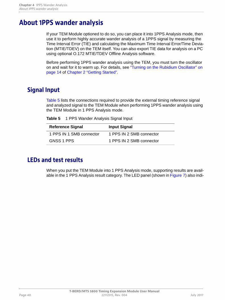
Chapter 4 1PPS Wander AnalysisAbout 1PPS wander analysis
T-BERD/MTS 5800 Timing Expansion Module User ManualPage 40 22112315, Rev. 004 July 2017
About 1PPS wander analysisIf your TEM Module optioned to do so, you can place it into 1PPS Analysis mode, then use it to perform highly accurate wander analysis of a 1PPS signal by measuring the Time Interval Error (TIE) and calculating the Maximum Time Interval Error/Time Devia-tion (MTIE/TDEV) on the TEM itself. You can also export TIE data for analysis on a PC using optional O.172 MTIE/TDEV Offline Analysis software.
Before performing 1PPS wander analysis using the TEM, you must turn the oscillator on and wait for it to warm up. For details, see “Turning on the Rubidium Oscillator” on page 14 of Chapter 2 “Getting Started”.
Signal InputTable 5 lists the connections required to provide the external timing reference signal and analyzed signal to the TEM Module when performing 1PPS wander analysis using the TEM Module in 1 PPS Analysis mode.
LEDs and test resultsWhen you put the TEM Module into 1 PPS Analysis mode, supporting results are avail-able in the 1 PPS Analysis result category. The LED panel (shown in Figure 7) also indi-
Table 5 1 PPS Wander Analysis Signal Input
Reference Signal Input Signal
1 PPS IN 1 SMB connector 1 PPS IN 2 SMB connector
GNSS 1 PPS 1 PPS IN 2 SMB connector
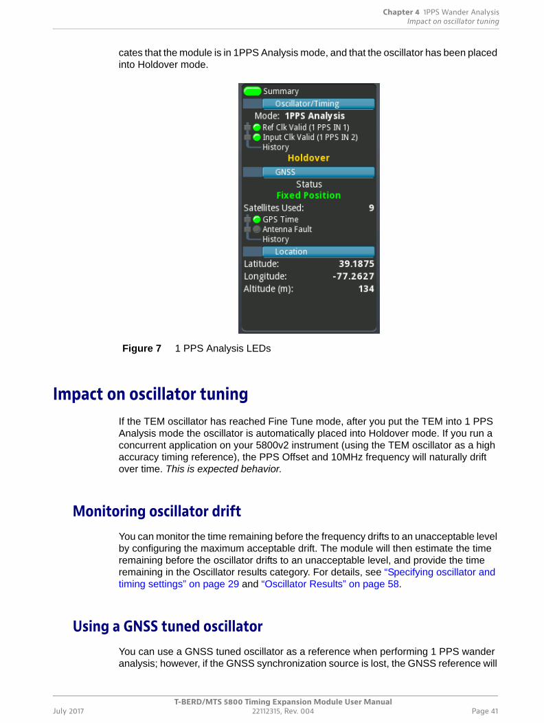
Chapter 4 1PPS Wander AnalysisImpact on oscillator tuning
T-BERD/MTS 5800 Timing Expansion Module User ManualJuly 2017 22112315, Rev. 004 Page 41
cates that the module is in 1PPS Analysis mode, and that the oscillator has been placed into Holdover mode.
Impact on oscillator tuningIf the TEM oscillator has reached Fine Tune mode, after you put the TEM into 1 PPS Analysis mode the oscillator is automatically placed into Holdover mode. If you run a concurrent application on your 5800v2 instrument (using the TEM oscillator as a high accuracy timing reference), the PPS Offset and 10MHz frequency will naturally drift over time. This is expected behavior.
Monitoring oscillator driftYou can monitor the time remaining before the frequency drifts to an unacceptable level by configuring the maximum acceptable drift. The module will then estimate the time remaining before the oscillator drifts to an unacceptable level, and provide the time remaining in the Oscillator results category. For details, see “Specifying oscillator and timing settings” on page 29 and “Oscillator Results” on page 58.
Using a GNSS tuned oscillatorYou can use a GNSS tuned oscillator as a reference when performing 1 PPS wander analysis; however, if the GNSS synchronization source is lost, the GNSS reference will
Figure 7 1 PPS Analysis LEDs
Chapter 4 1PPS Wander AnalysisMeasuring TIE and calculating MTIE/TDEV
T-BERD/MTS 5800 Timing Expansion Module User ManualPage 42 22112315, Rev. 004 July 2017
be lost too. If you want use a GNSS tuned oscillator to perform measurements at a loca-tion without a GNSS synchronization source, you must use the 1 PPS OUT connector on the TEM to provide the GNSS derived reference signal to the 1 PPS IN 1 connector.
To use a GNSS tuned oscillator as a reference signal
1 Before traveling to a location without a GNSS synchronization source, place the oscillator into holdover mode (see “Forcing the oscillator into holdover mode” on page 35).
2 After you reach the location (and are ready to begin 1 PPS analysis), use a cable to provide a signal from the 1 PPS OUT connector to the1 PPS IN 1 connector.
3 When you configure the TEM for 1 PPS Analysis (see “Measuring TIE and calcu-lating MTIE/TDEV” on page 42 and “Analyzing 1PPS wander” on page 44), be certain to select 1 PPS IN 1 as the configuration on the Oscillator/Timing setup tab. This indicates that the reference signal is provided by the 1 PPS IN 1 connector.
4 Connect the cable providing the signal to be analyzed to the TEM connector labeled 1 PPS IN 2.
The reference signal (provided by the GNSS tuned oscillator in holdover mode) is now provided via the 1 PPS IN 1 connector on the TEM.
Measuring TIE and calculating MTIE/TDEVMeasuring TIE and calculating MTIE/TDEV involves ensuring that the TEM is placed into 1PPS Analysis mode, then enabling and specifying pass and fail thresholds for the maximum allowable time offset, maximum allowable MTIE, and minimum and maximum allowable TIE. The Event Log will log an event and timestamp each time a measurement exceeds the threshold that you specified, and the Summary result pane will change to red to indicate that a threshold was exceeded. Reports will also indicate that the test passed or failed for each enabled threshold.
To measure TIE and calculate MTIE/TDEV
1 Verify that the TEM oscillator has been turned on, and that it has warmed up. For details, see “Turning on the Rubidium Oscillator” on page 14 of Chapter 2 “Getting Started”.
2 Select the Timing Module tab, then select the Setup soft key.
3 On the left of the screen, select Oscillator/Timing.
The Oscillator/Timing setup tab appears.
NOTE:
The time it takes to update the TIE data or calculate MTIE/TDEV depends on the amount of data collected.
Chapter 4 1PPS Wander AnalysisMeasuring TIE and calculating MTIE/TDEV
T-BERD/MTS 5800 Timing Expansion Module User ManualJuly 2017 22112315, Rev. 004 Page 43
4 Under Mode, select 1PPS Analysis, then specify the source of the reference timing signal:
– If you want to use an external 1PPS reference clock:
- Select 1 PPS IN 1.
- In Differential Time Bias, specify the time difference between the refer-ence 1 PPS IN 1 and the analyzed 1 PPS IN 2 input in nanoseconds.
- Connect the cable providing the external reference signal to the TEM Module connector labeled 1 PPS IN 1.
- Connect the cable providing the signal to be analyzed to the TEM Module connector labeled 1 PPS IN 2.
– If you want the TEM to use GNSS for reference timing:
- Verify that you have connected a GNSS antenna (see “Connecting a GNSS antenna” on page 10).
- Select GNSS 1 PPS.
- Use a cable to provide a signal from the 1 PPS OUT connector to the 1 PPS IN 1 connector. This signal will serve as the reference signal.
- Connect the cable providing the signal to be analyzed to the TEM Module connector labeled 1 PPS IN 2.
5 In Oscillator On at Startup do the following:
– If you want the oscillator to turn on automatically when the test instrument is turned on (and start to warm up immediately), select the checkbox.
– If you do not want the oscillator to turn on automatically when the test instru-ment is turned on, clear the checkbox.
6 In Holdover Drift Allowed (ns), specify the maximum acceptable drift allowed while operating the module in holdover mode (in nanoseconds). The module will then estimate the time remaining before the oscillator drifts to an unacceptable level, and provide the time remaining in the Oscillator results category. For details, see “Oscillator Results” on page 58.
7 On the left of the screen, select 1 PPS Analysis.
The 1 PPS Analysis setup tab appears.
8 Under 1PPS Thresholds, do the following
a Select the box to the left of each setting that will be used to establish pass / fail thresholds.
b For each enabled setting, specify the allowable threshold in the unit of measure indicated. For example, if the Maximum allowable MTIE threshold is enabled, specify the maximum allowable value in nanoseconds (ns).
9 On the left of the screen, select Timed Test.
The Timed Test setup tab appears.
10 Specify a duration for the test that will yield appropriately accurate results. Test results will be frozen after the test ends.
11 Verify that the Ref Clk Valid and Input Clk Valid LEDs are green.
12 Select Restart.
Chapter 4 1PPS Wander AnalysisAnalyzing 1PPS wander
T-BERD/MTS 5800 Timing Expansion Module User ManualPage 44 22112315, Rev. 004 July 2017
TIE is measured, and MTIE/TDEV is calculated. To view the supporting results, display the 1 PPS Analysis category.
Analyzing 1PPS wanderAfter you accumulate TIE data, you can analyze the data for wanter using the On-board Wander Analysis tool.
To analyze 1PPS wander
1 Measure TIE and calculate the MTIE/TDEV (see “Measuring TIE and calculating MTIE/TDEV” on page 42).
2 Select the Wander Analysis soft key.
The graphical wander analysis screen appears with the TIE tab selected.
3 Select the Update TIE Data soft key.
This refreshes the data in the Wander Analysis screen. All of the TIE samples accumulated so far (including those gathered since the tool itself was launched) are redrawn, and then MTIE and TDEV are recalculated.
The TIE graph appears. The Wander Analyzer automatically displays the last block of continuous valid data.
4 To observe another block of data, select the Current Block field, type the block number, and then select OK.
The data block you specified appears.
A block of TIE data is a contiguous subset of all TIE samples that is not inter-rupted by any alarms. For Wander measurements, TIE values are sampled at a constant rate. If an alarm occurs (e.g. LOS), the receiver is not able to produce meaningful TIE values and stops producing TIE entries until it is able to recover. These alarms separate the whole measurement into sections, or “blocks”.
NOTE:
• You can run on-board Wander Analysis while the test is in progress; however, if you restart the test, the data collected previously will be cleared. If you want to preserve the data for the previous measurement, save the data before restarting the test.
• Saved data cannot be loaded into the on-board Wander Analysis tool; it calculates MTIE and TDEV on all the data accumulated during the course of the current test.
• Wander analysis is restricted to the first 8.64 million samples. If your measurement contains more samples, you must export the wander data for offline analysis.
For detailed information about saving and exporting wander data, see “Saving and exporting TIE measurement data” on page 46.
Chapter 4 1PPS Wander AnalysisAnalyzing 1PPS wander
T-BERD/MTS 5800 Timing Expansion Module User ManualJuly 2017 22112315, Rev. 004 Page 45
5 If you want to observe the frequency offset curve, clear the Remove Offset checkbox.
6 To select the data curve to observe, under Curve Selection, do one of the following:
– To observe both TIE and frequency offset data curves, select Both Curves.
– To observe only the frequency offset data curve, select Offs.rem.only.
7 To refresh the graph, select the Update TIE Data soft key again.
8 To observe the MTIE/TDEV result graph, select the MTIE/TDEV tab.
The MTIE/TDEV graph screen appears.
9 Select Calculate MTIE/TDEV to start calculating MTIE and TDEV results.
The MTIE/TDEV graphs appear.
10 To customize the graph, do the following:
a To select the data curves you want to observe, use the first field to select MTIE only, TDEV only, or MTIE+TDEV.
b To select the curve style, select the arrows to the right of the Curve Style field, and then select Line+Dots, or Dots only.
11 If you want to select a mask to compare the data against, do the following:
a In the Mask Type field, specify a mask type.
b In the Mask field, specify a mask to compare the data to.
The mask curve appears on the result graph.
If you do not want to compare the data against a mask, in the Mask field, select None.
12 Do one of the following:
– To stop calculating MTIE/TDEV before the calculation is complete, select the Stop Calculation soft key.
– To refresh the graph, select Calculate MTIE/TDEV again.
– To create a report with snapshots of the TIE and MTIE/TDEV graphs, select the Create Report soft key.
– To return to the Main screen, select the Results soft key.
– To stop wander analysis and return to the Main screen, select the Close Analysis soft key.
NOTE:
Selecting the Close Analysis soft key stops analyzing the data and clear all MTIE and TDEV results calculated inside the Analysis tool. It will not discard the real-time MTIE results displayed in the Interface/Wander category. To return to the Main screen without ending the current analysis, use the Results soft key.
Chapter 4 1PPS Wander AnalysisSaving and exporting TIE measurement data
T-BERD/MTS 5800 Timing Expansion Module User ManualPage 46 22112315, Rev. 004 July 2017
Saving and exporting TIE measurement dataYou can save TIE data to a .hrd file or .chrd (compressed and encrypted .hrd file) on the base unit’s hard drive; export the saved file to a USB memory key, and then do further analysis of MTIE and TDEV by loading the file on a remote PC using an offline analysis tool.
To save the TIE data
1 Select the Save TIE Data soft key.
The data is saved into a .hrd or .chrd file in the following folder on your unit:
../acterna/user/disk/bert/reports
The file name is automatically assigned with a TIE_ prefix followed by date, time, test mode, and interface information as shown in the following example:
TIE_2007-08-16T15.59.19_TermDs1WanderTieEvalMsec.hrd
The TIE data is saved.
To export the TIE data to a USB memory key
1 Insert a USB memory key into one of the two slots provided on the top panel of the base unit.
2 Select the Export TIE Data soft key.
The Wander Data Files screen appears, listing the wander data files in:
../acterna/user/disk/bert/reports
3 Select the wander data file you want to export, and then press the Export to USB soft key.
The File Export dialog box appears, indicating that the unit is copying the selected report file to the USB memory key.
The TIE data is exported. If desired, it can now can be loaded into the offline analysis tool.
Analyzing Time of Day (ToD)
To compare ToD from a signal under test (DUT) against the reference ToD from the TEM, hook up the DUT to the USB connector on the side of the instrument. The ToD results are displayed in the ToD Time results category.
NOTE:
Restarting a test clears the TIE data. If you want to preserve the data for the current measurement, you must export the data before restarting the test.
NOTE:
The Viavi offline analysis tool can only analyze .hrd files.
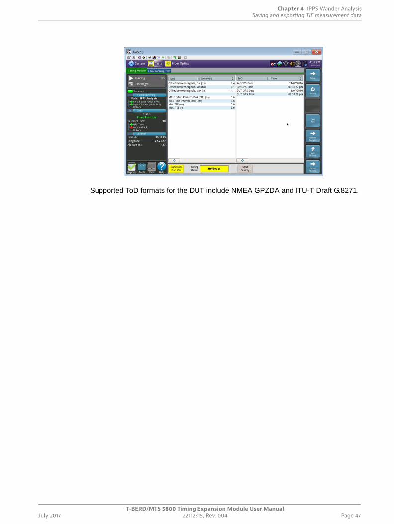
Chapter 4 1PPS Wander AnalysisSaving and exporting TIE measurement data
T-BERD/MTS 5800 Timing Expansion Module User ManualJuly 2017 22112315, Rev. 004 Page 47
Supported ToD formats for the DUT include NMEA GPZDA and ITU-T Draft G.8271.

Chapter 4 1PPS Wander AnalysisSaving and exporting TIE measurement data
T-BERD/MTS 5800 Timing Expansion Module User ManualPage 48 22112315, Rev. 004 July 2017
T-BERD/MTS 5800 Timing Expansion Module User ManualJuly 2017 22112315, Rev. 004 Page 49
5
Chapter 5 Timing and 1 PPS Analysis Results
This chapter describes the groups, categories and results that are available when tuning the TEM Module oscillator for use as a high accuracy timing reference or performing 1 PPS wander analysis. Topics discussed in this chapter include the following:
• “About TEM Module timing and 1 PPS analysis results” on page 50
• “LEDs” on page 50
• “Event Log” on page 51
• “Satellite Results” on page 52
• “GNSS Results” on page 55
• “Oscillator Results” on page 58
• “1 PPS Analysis Results” on page 59
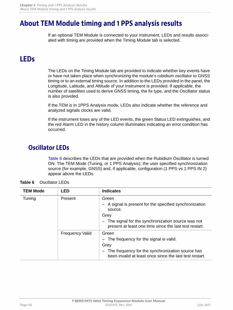
Chapter 5 Timing and 1 PPS Analysis ResultsAbout TEM Module timing and 1 PPS analysis results
T-BERD/MTS 5800 Timing Expansion Module User ManualPage 50 22112315, Rev. 004 July 2017
About TEM Module timing and 1 PPS analysis resultsIf an optional TEM Module is connected to your instrument, LEDs and results associ-ated with timing are provided when the Timing Module tab is selected.
LEDsThe LEDs on the Timing Module tab are provided to indicate whether key events have or have not taken place when synchronizing the module’s rubidium oscillator to GNSS timing or to an external timing source. In addition to the LEDs provided in the panel, the Longitude, Latitude, and Altitude of your instrument is provided. If applicable, the number of satellites used to derive GNSS timing, the fix type, and the Oscillator status is also provided.
If the TEM is in 1PPS Analysis mode, LEDs also indicate whether the reference and analyzed signals clocks are valid.
If the instrument loses any of the LED events, the green Status LED extinguishes, and the red Alarm LED in the history column illuminates indicating an error condition has occurred.
Oscillator LEDsTable 6 describes the LEDs that are provided when the Rubidium Oscillator is turned ON. The TEM Mode (Tuning, or 1 PPS Analysis), the user specified synchronization source (for example, GNSS) and, if applicable, configuration (1 PPS vs 1 PPS IN 2) appear above the LEDs.
Table 6 Oscillator LEDs
TEM Mode LED Indicates
Tuning Present Green– A signal is present for the specified synchronization
source.Grey– The signal for the synchronization source was not
present at least one time since the last test restart.
Frequency Valid Green– The frequency for the signal is valid.Grey– The frequency for the synchronization source has
been invalid at least once since the last test restart.
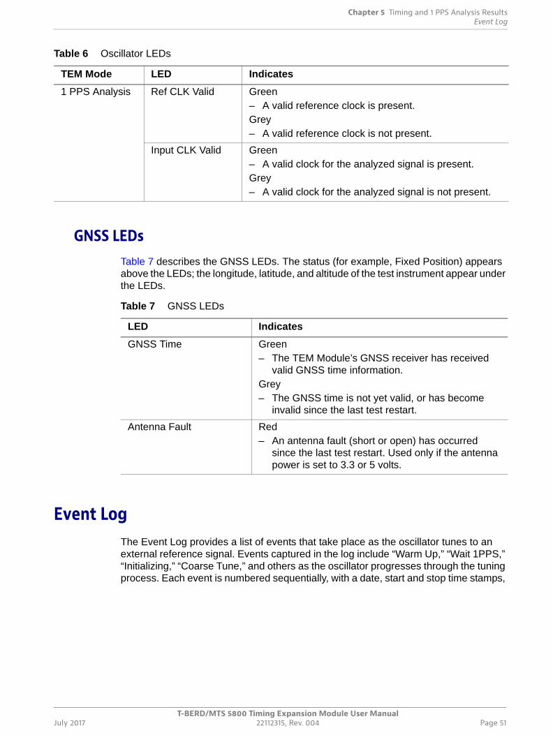
Chapter 5 Timing and 1 PPS Analysis ResultsEvent Log
T-BERD/MTS 5800 Timing Expansion Module User ManualJuly 2017 22112315, Rev. 004 Page 51
GNSS LEDsTable 7 describes the GNSS LEDs. The status (for example, Fixed Position) appears above the LEDs; the longitude, latitude, and altitude of the test instrument appear under the LEDs.
Event LogThe Event Log provides a list of events that take place as the oscillator tunes to an external reference signal. Events captured in the log include “Warm Up,” “Wait 1PPS,” “Initializing,” “Coarse Tune,” and others as the oscillator progresses through the tuning process. Each event is numbered sequentially, with a date, start and stop time stamps,
1 PPS Analysis Ref CLK Valid Green– A valid reference clock is present.Grey– A valid reference clock is not present.
Input CLK Valid Green– A valid clock for the analyzed signal is present.Grey– A valid clock for the analyzed signal is not present.
Table 6 Oscillator LEDs
TEM Mode LED Indicates
Table 7 GNSS LEDs
LED Indicates
GNSS Time Green– The TEM Module’s GNSS receiver has received
valid GNSS time information.Grey– The GNSS time is not yet valid, or has become
invalid since the last test restart.
Antenna Fault Red– An antenna fault (short or open) has occurred
since the last test restart. Used only if the antenna power is set to 3.3 or 5 volts.
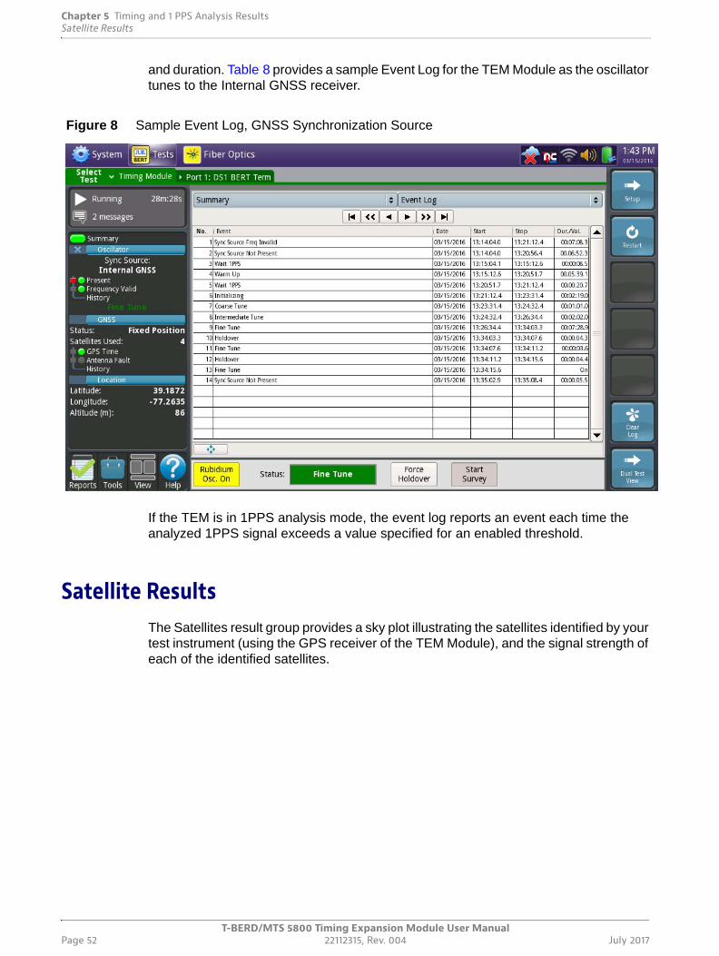
Chapter 5 Timing and 1 PPS Analysis ResultsSatellite Results
T-BERD/MTS 5800 Timing Expansion Module User ManualPage 52 22112315, Rev. 004 July 2017
and duration. Table 8 provides a sample Event Log for the TEM Module as the oscillator tunes to the Internal GNSS receiver.
If the TEM is in 1PPS analysis mode, the event log reports an event each time the analyzed 1PPS signal exceeds a value specified for an enabled threshold.
Satellite ResultsThe Satellites result group provides a sky plot illustrating the satellites identified by your test instrument (using the GPS receiver of the TEM Module), and the signal strength of each of the identified satellites.
Figure 8 Sample Event Log, GNSS Synchronization Source
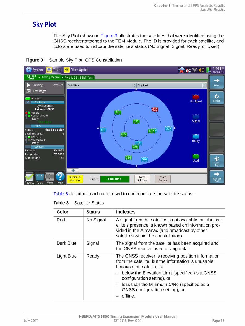
Chapter 5 Timing and 1 PPS Analysis ResultsSatellite Results
T-BERD/MTS 5800 Timing Expansion Module User ManualJuly 2017 22112315, Rev. 004 Page 53
Sky PlotThe Sky Plot (shown in Figure 9) illustrates the satellites that were identified using the GNSS receiver attached to the TEM Module. The ID is provided for each satellite, and colors are used to indicate the satellite’s status (No Signal, Signal, Ready, or Used).
Table 8 describes each color used to communicate the satellite status.
Figure 9 Sample Sky Plot, GPS Constellation
Table 8 Satellite Status
Color Status Indicates
Red No Signal A signal from the satellite is not available, but the sat-ellite’s presence is known based on information pro-vided in the Almanac (and broadcast by other satellites within the constellation).
Dark Blue Signal The signal from the satellite has been acquired and the GNSS receiver is receiving data.
Light Blue Ready The GNSS receiver is receiving position information from the satellite, but the information is unusable because the satellite is: – below the Elevation Limit (specified as a GNSS
configuration setting), or– less than the Minimum C/No (specified as a
GNSS configuration setting), or– offline.
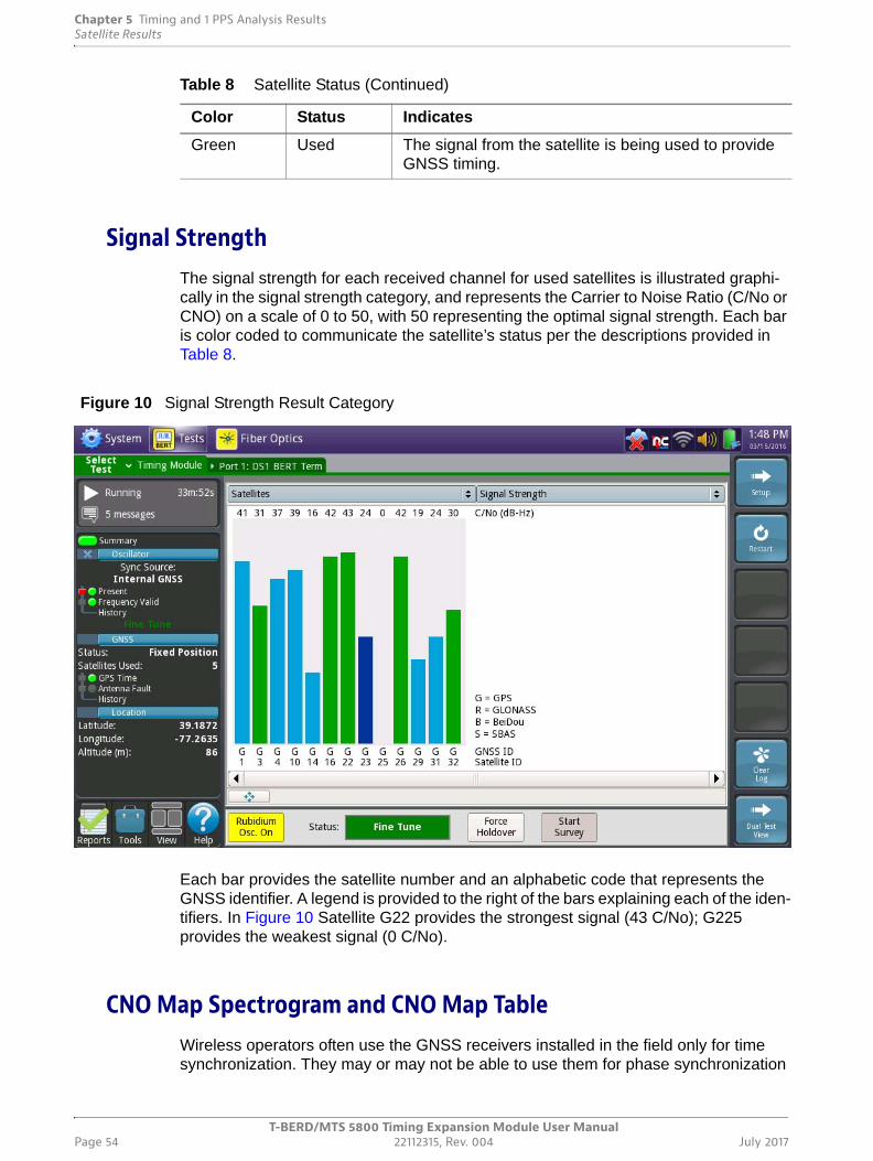
Chapter 5 Timing and 1 PPS Analysis ResultsSatellite Results
T-BERD/MTS 5800 Timing Expansion Module User ManualPage 54 22112315, Rev. 004 July 2017
Signal StrengthThe signal strength for each received channel for used satellites is illustrated graphi-cally in the signal strength category, and represents the Carrier to Noise Ratio (C/No or CNO) on a scale of 0 to 50, with 50 representing the optimal signal strength. Each bar is color coded to communicate the satellite’s status per the descriptions provided in Table 8.
Each bar provides the satellite number and an alphabetic code that represents the GNSS identifier. A legend is provided to the right of the bars explaining each of the iden-tifiers. In Figure 10 Satellite G22 provides the strongest signal (43 C/No); G225 provides the weakest signal (0 C/No).
CNO Map Spectrogram and CNO Map Table Wireless operators often use the GNSS receivers installed in the field only for time synchronization. They may or may not be able to use them for phase synchronization
Green Used The signal from the satellite is being used to provide GNSS timing.
Table 8 Satellite Status (Continued)
Color Status Indicates
Figure 10 Signal Strength Result Category
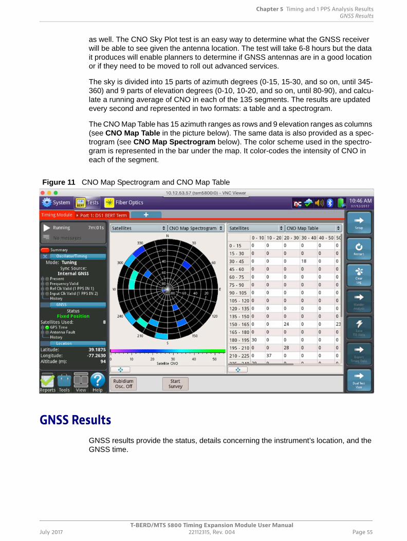
Chapter 5 Timing and 1 PPS Analysis ResultsGNSS Results
T-BERD/MTS 5800 Timing Expansion Module User ManualJuly 2017 22112315, Rev. 004 Page 55
as well. The CNO Sky Plot test is an easy way to determine what the GNSS receiver will be able to see given the antenna location. The test will take 6-8 hours but the data it produces will enable planners to determine if GNSS antennas are in a good location or if they need to be moved to roll out advanced services.
The sky is divided into 15 parts of azimuth degrees (0-15, 15-30, and so on, until 345-360) and 9 parts of elevation degrees (0-10, 10-20, and so on, until 80-90), and calcu-late a running average of CNO in each of the 135 segments. The results are updated every second and represented in two formats: a table and a spectrogram.
The CNO Map Table has 15 azimuth ranges as rows and 9 elevation ranges as columns (see CNO Map Table in the picture below). The same data is also provided as a spec-trogram (see CNO Map Spectrogram below). The color scheme used in the spectro-gram is represented in the bar under the map. It color-codes the intensity of CNO in each of the segment.
GNSS ResultsGNSS results provide the status, details concerning the instrument’s location, and the GNSS time.
Figure 11 CNO Map Spectrogram and CNO Map Table
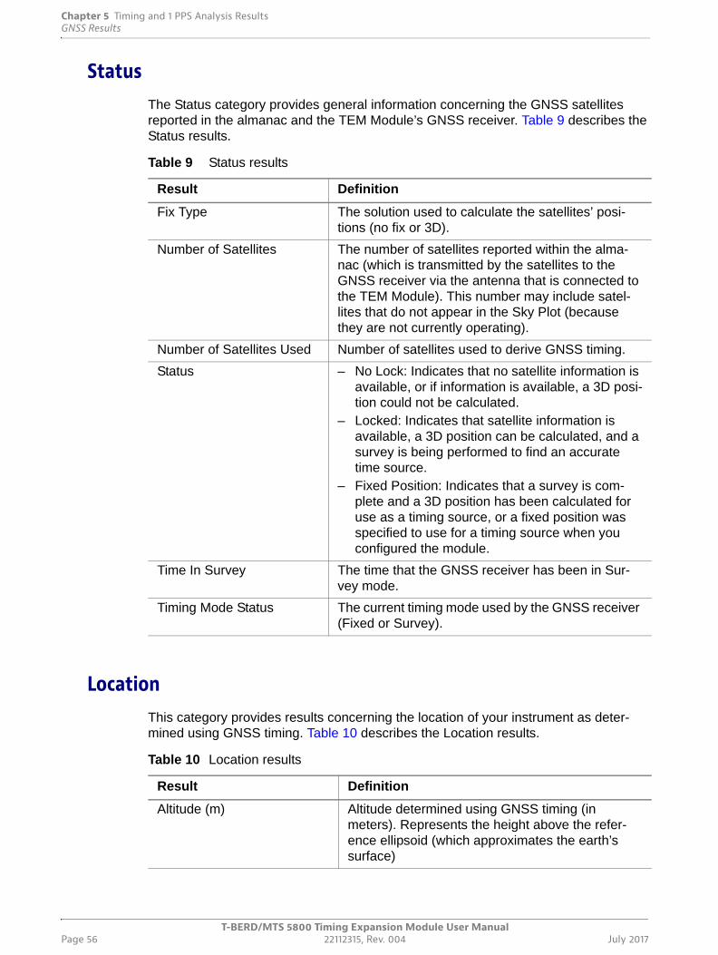
Chapter 5 Timing and 1 PPS Analysis ResultsGNSS Results
T-BERD/MTS 5800 Timing Expansion Module User ManualPage 56 22112315, Rev. 004 July 2017
StatusThe Status category provides general information concerning the GNSS satellites reported in the almanac and the TEM Module’s GNSS receiver. Table 9 describes the Status results.
LocationThis category provides results concerning the location of your instrument as deter-mined using GNSS timing. Table 10 describes the Location results.
Table 9 Status results
Result Definition
Fix Type The solution used to calculate the satellites’ posi-tions (no fix or 3D).
Number of Satellites The number of satellites reported within the alma-nac (which is transmitted by the satellites to the GNSS receiver via the antenna that is connected to the TEM Module). This number may include satel-lites that do not appear in the Sky Plot (because they are not currently operating).
Number of Satellites Used Number of satellites used to derive GNSS timing.
Status – No Lock: Indicates that no satellite information is available, or if information is available, a 3D posi-tion could not be calculated.
– Locked: Indicates that satellite information is available, a 3D position can be calculated, and a survey is being performed to find an accurate time source.
– Fixed Position: Indicates that a survey is com-plete and a 3D position has been calculated for use as a timing source, or a fixed position was specified to use for a timing source when you configured the module.
Time In Survey The time that the GNSS receiver has been in Sur-vey mode.
Timing Mode Status The current timing mode used by the GNSS receiver (Fixed or Survey).
Table 10 Location results
Result Definition
Altitude (m) Altitude determined using GNSS timing (in meters). Represents the height above the refer-ence ellipsoid (which approximates the earth’s surface)
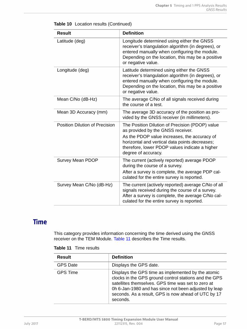
Chapter 5 Timing and 1 PPS Analysis ResultsGNSS Results
T-BERD/MTS 5800 Timing Expansion Module User ManualJuly 2017 22112315, Rev. 004 Page 57
TimeThis category provides information concerning the time derived using the GNSS receiver on the TEM Module. Table 11 describes the Time results.
Latitude (deg) Longitude determined using either the GNSS receiver’s triangulation algorithm (in degrees), or entered manually when configuring the module. Depending on the location, this may be a positive or negative value.
Longitude (deg) Latitude determined using either the GNSS receiver’s triangulation algorithm (in degrees), or entered manually when configuring the module. Depending on the location, this may be a positive or negative value.
Mean C/No (dB-Hz) The average C/No of all signals received during the course of a test.
Mean 3D Accuracy (mm) The average 3D accuracy of the position as pro-vided by the GNSS receiver (in millimeters).
Position Dilution of Precision The Position Dilution of Precision (PDOP) value as provided by the GNSS receiver. As the PDOP value increases, the accuracy of horizontal and vertical data points decreases; therefore, lower PDOP values indicate a higher degree of accuracy.
Survey Mean PDOP The current (actively reported) average PDOP during the course of a survey. After a survey is complete, the average PDP cal-culated for the entire survey is reported.
Survey Mean C/No (dB-Hz) The current (actively reported) average C/No of all signals received during the course of a survey. After a survey is complete, the average C/No cal-culated for the entire survey is reported.
Table 10 Location results (Continued)
Result Definition
Table 11 Time results
Result Definition
GPS Date Displays the GPS date.
GPS Time Displays the GPS time as implemented by the atomic clocks in the GPS ground control stations and the GPS satellites themselves. GPS time was set to zero at 0h 6-Jan-1980 and has since not been adjusted by leap seconds. As a result, GPS is now ahead of UTC by 17 seconds.
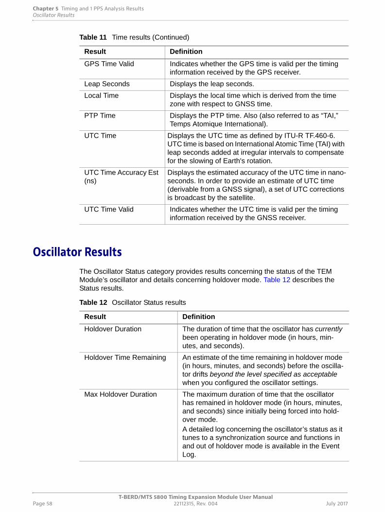
Chapter 5 Timing and 1 PPS Analysis ResultsOscillator Results
T-BERD/MTS 5800 Timing Expansion Module User ManualPage 58 22112315, Rev. 004 July 2017
Oscillator ResultsThe Oscillator Status category provides results concerning the status of the TEM Module’s oscillator and details concerning holdover mode. Table 12 describes the Status results.
GPS Time Valid Indicates whether the GPS time is valid per the timing information received by the GPS receiver.
Leap Seconds Displays the leap seconds.
Local Time Displays the local time which is derived from the time zone with respect to GNSS time.
PTP Time Displays the PTP time. Also (also referred to as “TAI,” Temps Atomique International).
UTC Time Displays the UTC time as defined by ITU-R TF.460-6. UTC time is based on International Atomic Time (TAI) with leap seconds added at irregular intervals to compensate for the slowing of Earth's rotation.
UTC Time Accuracy Est (ns)
Displays the estimated accuracy of the UTC time in nano-seconds. In order to provide an estimate of UTC time (derivable from a GNSS signal), a set of UTC corrections is broadcast by the satellite.
UTC Time Valid Indicates whether the UTC time is valid per the timing information received by the GNSS receiver.
Table 11 Time results (Continued)
Result Definition
Table 12 Oscillator Status results
Result Definition
Holdover Duration The duration of time that the oscillator has currently been operating in holdover mode (in hours, min-utes, and seconds).
Holdover Time Remaining An estimate of the time remaining in holdover mode (in hours, minutes, and seconds) before the oscilla-tor drifts beyond the level specified as acceptable when you configured the oscillator settings.
Max Holdover Duration The maximum duration of time that the oscillator has remained in holdover mode (in hours, minutes, and seconds) since initially being forced into hold-over mode. A detailed log concerning the oscillator’s status as it tunes to a synchronization source and functions in and out of holdover mode is available in the Event Log.
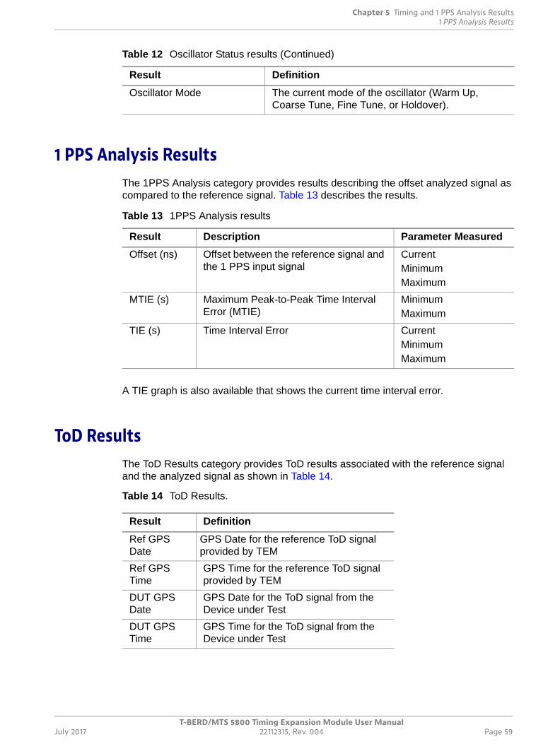
Chapter 5 Timing and 1 PPS Analysis Results1 PPS Analysis Results
T-BERD/MTS 5800 Timing Expansion Module User ManualJuly 2017 22112315, Rev. 004 Page 59
1 PPS Analysis ResultsThe 1PPS Analysis category provides results describing the offset analyzed signal as compared to the reference signal. Table 13 describes the results.
A TIE graph is also available that shows the current time interval error.
ToD ResultsThe ToD Results category provides ToD results associated with the reference signal and the analyzed signal as shown in Table 14.
Table 14 ToD Results.
Oscillator Mode The current mode of the oscillator (Warm Up, Coarse Tune, Fine Tune, or Holdover).
Table 12 Oscillator Status results (Continued)
Result Definition
Table 13 1PPS Analysis results
Result Description Parameter Measured
Offset (ns) Offset between the reference signal and the 1 PPS input signal
CurrentMinimumMaximum
MTIE (s) Maximum Peak-to-Peak Time Interval Error (MTIE)
MinimumMaximum
TIE (s) Time Interval Error CurrentMinimumMaximum
Result Definition
Ref GPS Date
GPS Date for the reference ToD signal provided by TEM
Ref GPS Time
GPS Time for the reference ToD signal provided by TEM
DUT GPS Date
GPS Date for the ToD signal from the Device under Test
DUT GPS Time
GPS Time for the ToD signal from the Device under Test

Chapter 5 Timing and 1 PPS Analysis ResultsToD Results
T-BERD/MTS 5800 Timing Expansion Module User ManualPage 60 22112315, Rev. 004 July 2017
T-BERD/MTS 5800 Timing Expansion Module User ManualJuly 2017 22112315, Rev. 004 Page 61
6
Chapter 6 Troubleshooting
This chapter describes how to identify and correct issues related to the operation of the TEM Module. Topics discussed in this chapter include the following:
• “About troubleshooting” on page 62
• “Assembly and setup” on page 62
• “Operating the TEM Module” on page 62
• “Performing tests” on page 63
• “Maintaining your TEM Module” on page 64
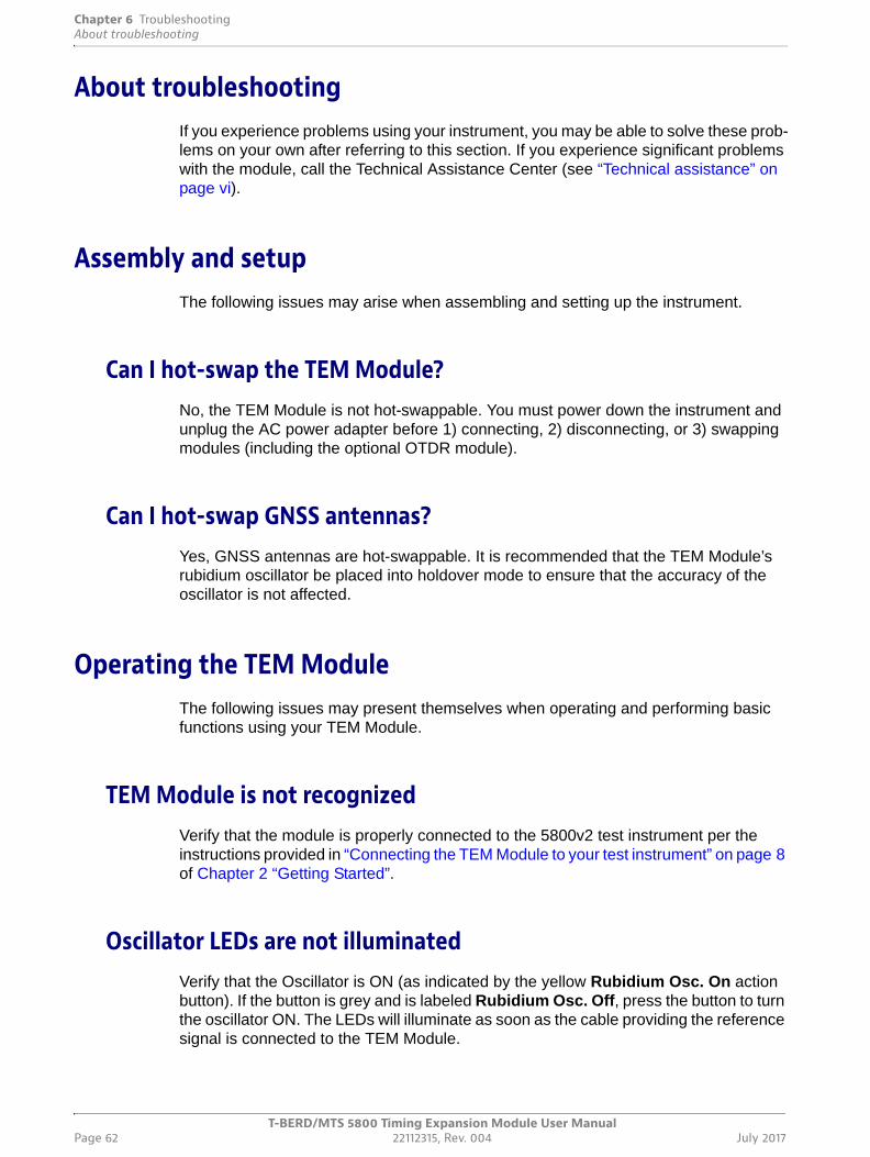
Chapter 6 TroubleshootingAbout troubleshooting
T-BERD/MTS 5800 Timing Expansion Module User ManualPage 62 22112315, Rev. 004 July 2017
About troubleshootingIf you experience problems using your instrument, you may be able to solve these prob-lems on your own after referring to this section. If you experience significant problems with the module, call the Technical Assistance Center (see “Technical assistance” on page vi).
Assembly and setupThe following issues may arise when assembling and setting up the instrument.
Can I hot-swap the TEM Module?No, the TEM Module is not hot-swappable. You must power down the instrument and unplug the AC power adapter before 1) connecting, 2) disconnecting, or 3) swapping modules (including the optional OTDR module).
Can I hot-swap GNSS antennas?Yes, GNSS antennas are hot-swappable. It is recommended that the TEM Module’s rubidium oscillator be placed into holdover mode to ensure that the accuracy of the oscillator is not affected.
Operating the TEM ModuleThe following issues may present themselves when operating and performing basic functions using your TEM Module.
TEM Module is not recognizedVerify that the module is properly connected to the 5800v2 test instrument per the instructions provided in “Connecting the TEM Module to your test instrument” on page 8 of Chapter 2 “Getting Started”.
Oscillator LEDs are not illuminatedVerify that the Oscillator is ON (as indicated by the yellow Rubidium Osc. On action button). If the button is grey and is labeled Rubidium Osc. Off, press the button to turn the oscillator ON. The LEDs will illuminate as soon as the cable providing the reference signal is connected to the TEM Module.
Chapter 6 TroubleshootingPerforming tests
T-BERD/MTS 5800 Timing Expansion Module User ManualJuly 2017 22112315, Rev. 004 Page 63
No GNSS Time is detectedThere are several reasons why GNSS time may not be detected:
• Verify that the GNSS antenna is properly connected (see “Connecting a GNSS antenna” on page 10), and that the antenna power level specified is correct for the antenna that you are using (see “Specifying GNSS settings” on page 30).
• Verify that you have specified a GNSS system as the synchronization source with supporting settings (see “Specifying GNSS settings” on page 30).
• Observe the Sky Plot to determine whether satellites within a constellation for the GNSS system(s) that you specified are in view (see “Sky Plot” on page 53 of Chapter 5 “Timing and 1 PPS Analysis Results”).
• Determine whether any of the satellites are used (indicated in green on the Sky Plot, and as a test result in the GPS Status category). For details, see “Sky Plot” on page 53, and “Status” on page 56 of Chapter 5 “Timing and 1 PPS Analysis Results”
No GNSS Satellites are locatedThere are several reasons why GNSS satellites may not be located (or the module only locates a small number of satellites):
• Verify that the GNSS antenna is properly connected (see “Connecting a GNSS antenna” on page 10), and that the antenna power level specified is correct for the antenna that you are using (see “Specifying GNSS settings” on page 30).
• Verify that you have specified a GNSS system that is available worldwide (for example, GPS or GLONASS), in your geographical region (for example, BeiDou), or both (for example, GPS and BeiDou). For details, see “Specifying GNSS settings” on page 30.
• If the module only located a few satellites, you can optimize the number of satel-lites located by selecting multiple GNSS systems as the synchronization source (for example, you can use GPS and GLONASS concurrently). For details, see “Specifying GNSS settings” on page 30.
• Verify that you specified the Elevation Limit (deg) value, which represents the lowest point on the horizon on which the receiver will try to locate and obtain infor-mation from GNSS satellites. If the value is too low, there may be obstructions preventing the antenna from receiving signals with almanac data. For details, see “Specifying GNSS settings” on page 30.
• If you are using the TEM Module inside a building (for example, in a lab environ-ment), verify that the building is equipped to receive GNSS signals.
Performing testsThe following section addresses questions that may be asked about completing tests with the connected TEM Module.
Chapter 6 TroubleshootingMaintaining your TEM Module
T-BERD/MTS 5800 Timing Expansion Module User ManualPage 64 22112315, Rev. 004 July 2017
Application does not appear on the Test menuVerify that all required test options are installed on your 5800v2 test instrument. For example, if you are using the TEM Module to provide high accuracy timing during PTP or One Way Delay testing, verify that the associated test option has been installed.
Test results are inconsistentVerify the following:
• Verify that your instrument is properly connected to the circuit for the test you are running. This is the primary reason for inconsistent test results.
• If you are performing 1PPS analysis, 2 MHz clock wander analysis, or 10 MHz clock wander analysis, verify that the input signal under test is connected to the proper connector on the SMA Timing Cable Adapter (Part Number 22035050), and that the adapter is securely connected to the EXT CLK connector on the 5800v2 connector panel. The input under test must be connected to the blue CLK 2 (IN/OUT) connector on the adapter.
• If an object or person coming in contact with the instrument causes a temporary burst of errors to be recorded, the errors might have been caused by an ESD event. The recorded errors can be cleared by pressing Test Restart. Please note that the test set is fully compliant with IEC 61326-1 ESD requirements for indus-trial equipment and has passed testing according to IEC 61000-4-2 using test limits of 4 kV/8 kV contact/air and performance criterion B.
Result values are unavailableResults are not available if gating criteria have not been met. For example, if the TEM Module has not been placed into holdover mode, the Max Holdover Duration result is unavailable.
Can I use the TEM Module to support dual port testing?If you need to perform dual port tests, your 5800v2 must be configured with the connec-tors required to support each circuit that you are testing. The TEM Module can be used as a high accuracy timing reference when running dual port tests.
Maintaining your TEM ModuleThe following section addresses questions that may be asked about maintaining your TEM Module.
Chapter 6 TroubleshootingMaintaining your TEM Module
T-BERD/MTS 5800 Timing Expansion Module User ManualJuly 2017 22112315, Rev. 004 Page 65
Does the module need to be calibrated?The TEM Module does not need to be calibrated; every time rubidium oscillator is tuned to a high accuracy synchronization source, the oscillator is disciplined.

Chapter 6 TroubleshootingMaintaining your TEM Module
T-BERD/MTS 5800 Timing Expansion Module User ManualPage 66 22112315, Rev. 004 July 2017
T-BERD/MTS 5800 Timing Expansion Module User ManualJuly 2017 22112315, Rev. 004 Page 67
A
Appendix A Specifications
This appendix contains specifications for the TEM Module. Topics discussed in this appendix include the following:
• “About the TEM Module specifications” on page 68
• “Physical specifications” on page 68
• “Environmental specifications” on page 68
• “Power specifications” on page 69
• “Connector specifications” on page 69
• “Performance specifications” on page 70
• “Oscillator specifications” on page 71
• “1 PPS Analysis specifications” on page 71
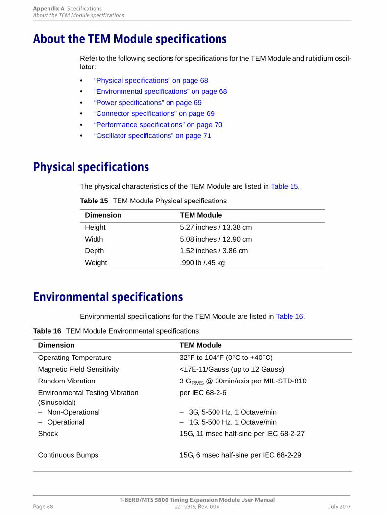
Appendix A SpecificationsAbout the TEM Module specifications
T-BERD/MTS 5800 Timing Expansion Module User ManualPage 68 22112315, Rev. 004 July 2017
About the TEM Module specificationsRefer to the following sections for specifications for the TEM Module and rubidium oscil-lator:
• “Physical specifications” on page 68
• “Environmental specifications” on page 68
• “Power specifications” on page 69
• “Connector specifications” on page 69
• “Performance specifications” on page 70
• “Oscillator specifications” on page 71
Physical specificationsThe physical characteristics of the TEM Module are listed in Table 15.
Environmental specificationsEnvironmental specifications for the TEM Module are listed in Table 16.
Table 15 TEM Module Physical specifications
Dimension TEM Module
Height 5.27 inches / 13.38 cm
Width 5.08 inches / 12.90 cm
Depth 1.52 inches / 3.86 cm
Weight .990 lb /.45 kg
Table 16 TEM Module Environmental specifications
Dimension TEM Module
Operating Temperature 32°F to 104°F (0°C to +40°C)
Magnetic Field Sensitivity <±7E-11/Gauss (up to ±2 Gauss)
Random Vibration 3 GRMS @ 30min/axis per MIL-STD-810
Environmental Testing Vibration (Sinusoidal)– Non-Operational– Operational
per IEC 68-2-6
– 3G, 5-500 Hz, 1 Octave/min– 1G, 5-500 Hz, 1 Octave/min
Shock 15G, 11 msec half-sine per IEC 68-2-27
Continuous Bumps 15G, 6 msec half-sine per IEC 68-2-29
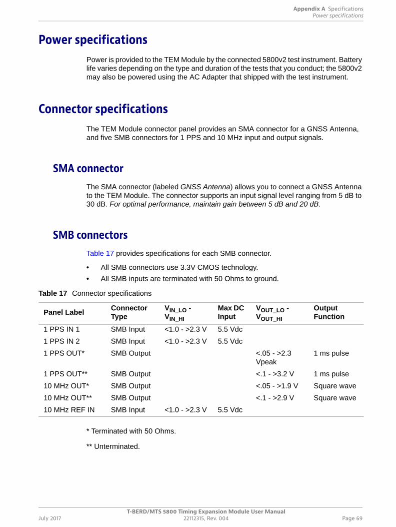
Appendix A SpecificationsPower specifications
T-BERD/MTS 5800 Timing Expansion Module User ManualJuly 2017 22112315, Rev. 004 Page 69
Power specificationsPower is provided to the TEM Module by the connected 5800v2 test instrument. Battery life varies depending on the type and duration of the tests that you conduct; the 5800v2 may also be powered using the AC Adapter that shipped with the test instrument.
Connector specificationsThe TEM Module connector panel provides an SMA connector for a GNSS Antenna, and five SMB connectors for 1 PPS and 10 MHz input and output signals.
SMA connectorThe SMA connector (labeled GNSS Antenna) allows you to connect a GNSS Antenna to the TEM Module. The connector supports an input signal level ranging from 5 dB to 30 dB. For optimal performance, maintain gain between 5 dB and 20 dB.
SMB connectorsTable 17 provides specifications for each SMB connector.
• All SMB connectors use 3.3V CMOS technology.
• All SMB inputs are terminated with 50 Ohms to ground.
* Terminated with 50 Ohms.
** Unterminated.
Table 17 Connector specifications
Panel LabelConnector Type
VIN_LO - VIN_HI
Max DC Input
VOUT_LO - VOUT_HI
Output Function
1 PPS IN 1 SMB Input <1.0 - >2.3 V 5.5 Vdc
1 PPS IN 2 SMB Input <1.0 - >2.3 V 5.5 Vdc
1 PPS OUT* SMB Output <.05 - >2.3 Vpeak
1 ms pulse
1 PPS OUT** SMB Output <.1 - >3.2 V 1 ms pulse
10 MHz OUT* SMB Output <.05 - >1.9 V Square wave
10 MHz OUT** SMB Output <.1 - >2.9 V Square wave
10 MHz REF IN SMB Input <1.0 - >2.3 V 5.5 Vdc
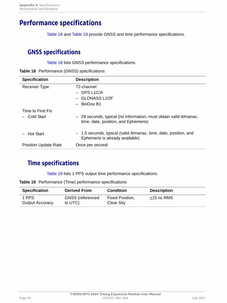
Appendix A SpecificationsPerformance specifications
T-BERD/MTS 5800 Timing Expansion Module User ManualPage 70 22112315, Rev. 004 July 2017
Performance specificationsTable 18 and Table 19 provide GNSS and time performance specifications.
GNSS specificationsTable 18 lists GNSS performance specifications.
Time specificationsTable 19 lists 1 PPS output time performance specifications.
Table 18 Performance (GNSS) specifications
Specification Description
Receiver Type 72-channel– GPS L1C/A– GLONASS L1OF– BeiDou B1
Time to First Fix– Cold Start
– Hot Start
– 29 seconds, typical (no information, must obtain valid Almanac, time, date, position, and Ephemeris)
– 1.5 seconds, typical (valid Almanac, time, date, position, and Ephemeris is already available)
Position Update Rate Once per second
Table 19 Performance (Time) performance specifications
Specification Derived From Condition Description
1 PPS Output Accuracy
GNSS (referenced to UTC)
Fixed Position, Clear Sky
+15 ns RMS
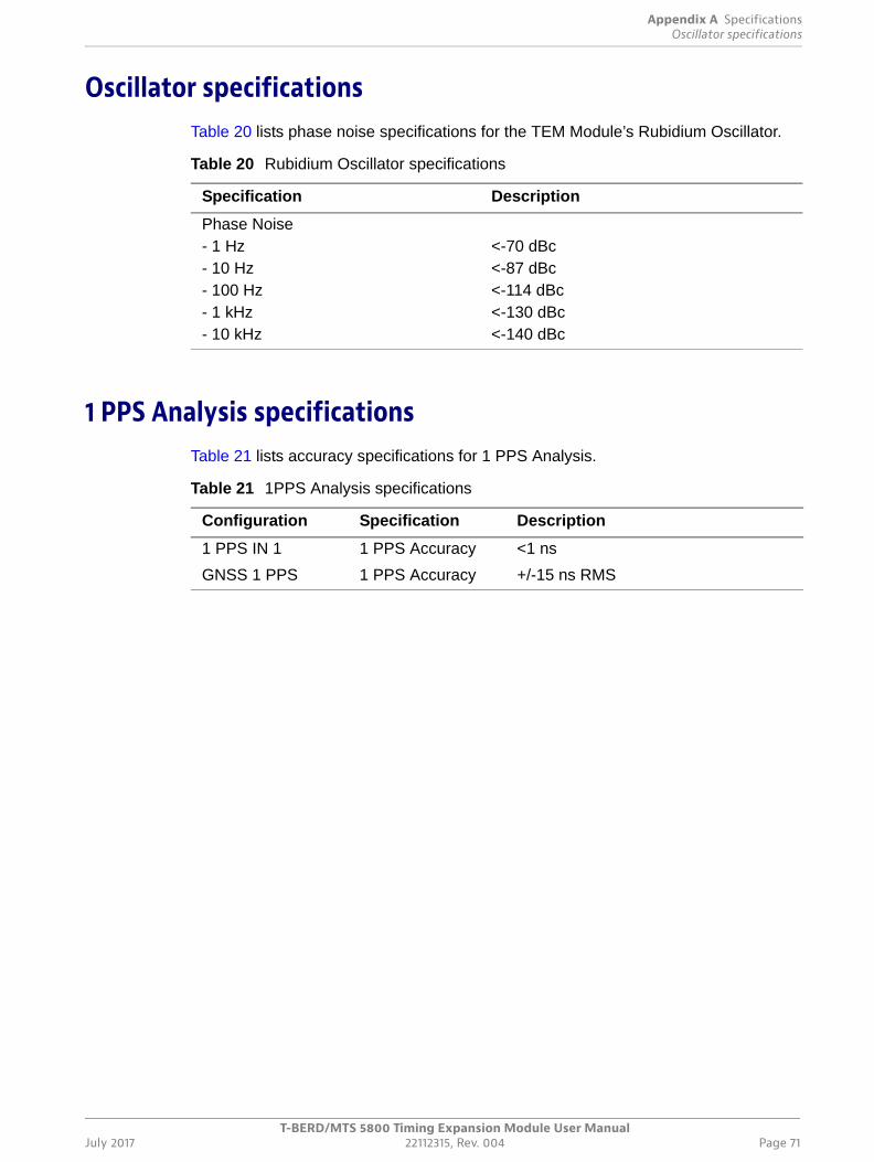
Appendix A SpecificationsOscillator specifications
T-BERD/MTS 5800 Timing Expansion Module User ManualJuly 2017 22112315, Rev. 004 Page 71
Oscillator specificationsTable 20 lists phase noise specifications for the TEM Module’s Rubidium Oscillator.
1 PPS Analysis specificationsTable 21 lists accuracy specifications for 1 PPS Analysis.
Table 20 Rubidium Oscillator specifications
Specification Description
Phase Noise- 1 Hz- 10 Hz- 100 Hz- 1 kHz- 10 kHz
<-70 dBc<-87 dBc<-114 dBc<-130 dBc<-140 dBc
Table 21 1PPS Analysis specifications
Configuration Specification Description
1 PPS IN 1 1 PPS Accuracy <1 ns
GNSS 1 PPS 1 PPS Accuracy +/-15 ns RMS

Appendix A Specifications1 PPS Analysis specifications
T-BERD/MTS 5800 Timing Expansion Module User ManualPage 72 22112315, Rev. 004 July 2017
T-BERD/MTS 5800 Timing Expansion Module User ManualJuly 2017 22112315, Rev. 004 Page 73
B
Appendix B Storage and Shipment
This appendix describes how to store, transport, and ship your test instrument. Topics discussed in this appendix include the following:
• “Storing the instrument and module” on page 74
• “Transporting your TEM Module” on page 74
• “Shipping your TEM Module” on page 75
• “Returning equipment to Viavi” on page 75
Appendix B Storage and ShipmentStoring the instrument and module
T-BERD/MTS 5800 Timing Expansion Module User ManualPage 74 22112315, Rev. 004 July 2017
Storing the instrument and moduleWhen the instrument and TEM Module are not in use, they can be stored.
The battery discharges slowly while in the instrument. Continued storage while in a discharged state could result in performance degradation. For this reason, Viavi recom-mends removing the battery if the instrument will not be used for more than a week. Store the battery in a cool, dry, clean environment. Do not leave the battery in a car or truck, particularly during extremely warm weather.
While out of the instrument, the battery will discharge at a slow rate. Viavi recommends checking the battery periodically while it is in storage, and keeping it charged to at least 40%. For additional information about maintaining the battery, see “Maintaining the battery” in the base unit manual that shipped with your instrument.
Using the instrument and module after prolonged storageThe first time you use the instrument and TEM Module after prolonged storage, use the AC power adapter to power up the 5800v2 and TEM Module. The time required to warm up the TEM Module’s oscillator will vary depending on the storage temperature.
Transporting your TEM ModuleWhen taking your TEM Module and 5800v2 instrument to a new location for testing, consider the following:
• The “auto-off” Power Management feature on the 5800v2 should be disabled to ensure that the TEM Module does not suddenly lose power.
• Viavi strongly recommends using a power inverter during transport. If you are not using an inverter, consider removing all test applications before transporting the instrument. This will maximize the battery run time to the best degree possible.
• The components (TEM Module, GNSS antenna, and 5800V2 test instrument) must be protected from rain, snow, and extreme weather conditions to the best degree possible.
• The components should be transported in the passenger area of your vehicle, and secured to prevent damage in the event of a sudden stop or collision.
An optional glove bag is available to protect the components, and an optional power inverter is available that allows you to leave the oscillator ON (to maintain 1PPS preci-sion) during transport. For details concerning the glove bag or power inverter, contact Viavi Customer Care at 1-866-228-3762 or at www.viavisolutions.com.
NOTE:
Viavi is not liable for any damage that may occur during transport.
Appendix B Storage and ShipmentShipping your TEM Module
T-BERD/MTS 5800 Timing Expansion Module User ManualJuly 2017 22112315, Rev. 004 Page 75
Shipping your TEM ModuleIf you will be shipping the TEM Module or GNSS antenna, follow the guidelines below.
Disconnecting the componentsBefore shipping the TEM Module or GNSS antenna, disconnect the antenna from the module, and disconnect the module from your test instrument. For instructions, see “Disconnecting a GNSS antenna” on page 19 and “Disconnecting the TEM Module” on page 20 of Chapter 2 “Getting Started”.
Packing the componentsWhen packing the components for shipment, Viavi recommends using the original ship-ping container and packing materials. If the original container and packing materials are damaged or not available, the components should be carefully packed so that they will not be damaged in transit. Viavi recommends using anti-static packing material to secure the components inside a box or other container. If needed, you can obtain appropriate packing materials by contacting Viavi Customer Care at 1-866-228-3762 or at www.viavisolutions.com.
Returning equipment to ViaviBefore you return any equipment to Viavi, contact Viavi Customer Care at 1-844-GO-VIAVI or www.viavisolutions.com for the correct shipping address and for a Return or Reference Authorization. You must have a Return or Reference Authorization when-ever you return equipment to Viavi.
For each piece of equipment returned for repair, attach a tag that includes the following information:
• Owner’s name, address, and telephone number.
• The serial number, product type, and model.
• Warranty status. (If you are unsure of the warranty status of your instrument, contact Viavi Customer Care.)
• A detailed description of the problem or service requested.
• The name and telephone number of the person to contact regarding questions about the repair.
• The return authorization (RA) number (US customers), or reference number (European Customers).
NOTE:
Viavi is not liable for any damage that may occur during shipping.

Appendix B Storage and ShipmentReturning equipment to Viavi
T-BERD/MTS 5800 Timing Expansion Module User ManualPage 76 22112315, Rev. 004 July 2017
Clearly mark the outside of the package with the Viavi-issued Return or Reference Authorization number and ship it prepaid and insured to Viavi. For information on pack-aging equipment for shipment, see “Packing the components” on page 75.
T-BERD/MTS 5800 Timing Expansion Module User ManualJuly 2017 22112315, Rev. 004 Page 77
Glossary
Symbols/Numerics
10 MHz — 10 Megahertz timing reference. The TEM Module provides one 10 MHz input connectors and one 10 MHz output connector.
1 PPS — 1 Pulse Per Second timing reference. The TEM Module provides two 1 PPS input connectors and one 1 PPS output connector.
802.11b — IEEE standard for wireless LANs. You can establish wireless LAN connec-tions to the T-BERD ⁄ MTS 8000, 6000A, and 5800 using an 802.11 PCMCIA card.
A
AC — Alternating Current. An AC power adapter is supplied with the T-BERD ⁄ MTS 5800v2 test instrument.
Almanac — Information concerning the time, status, and location of every satellite within a GNSS satellite constellation.
Antenna Time Bias — A value (specified in nanoseconds), that is used to compen-sate for the delay introduced by your antenna, the antenna’s cable, and if applicable, an in-line splitter or amplifier.
Assembly — Used throughout this manual to refer to a complete set of components assembled as an instrument and used for testing. This manual supports the T-BERD ⁄ MTS 5800v2 assembly when using a TEM Module for high accuracy timing.
ATP — Acterna test packet. A test packet that contains a time stamp and sequence number for measuring round trip delay and counting out-of-sequence frames.
B
BeiDou — Timing referenced used by GNSS Satellites operated out of the Peoples Republic of China and adjacent regions.
BER — Bit Error Rate.
Glossary
T-BERD/MTS 5800 Timing Expansion Module User ManualPage 78 22112315, Rev. 004 July 2017
BERT — Bit error rate test. A known pattern of bits is transmitted, and errors received are counted to figure the BER. The Bit Error Rate test is used to measure transmission quality.
BITS — Building Integrated Timing Supply.
C
C/No — Carrier to Noise Ratio. The signal-to-noise ratio (SNR) of a modulated signal, such as the signals transmitted by GNSS satellites. When connected to a test instru-ment and configured to derive GNSS timing, the TEM Module displays the C/No of each received satellite signal in a bar graph, in the Signal Strength result category.
Coarse tune — Mode where the oscillator has been tuned to the frequency of an external synchronization source for a period of time, but the frequency is not adequately stabilized to support accuracy in holdover mode.
Component — Used throughout this manual to refer to an individual hardware compo-nent which is connected to the other components to build a test instrument (assembly). This manual supports the following components when connected to build an assembly: the T-BERD / MTS 5800v2, the Timing Expansion Module (TEM), and the GNSS Antenna that is used to provide GPS timing to the module (and test instrument).
D
DHCP — Dynamic Host Configuration Protocol. A communications protocol that assigns IP addresses dynamically as needed. The test instrument supports static IP address assignment.
E
Ephemeris data — Information broadcast by a GNSS satellite that provides accurate orbital data, atmospheric propagation data, and clock error data for a specific satellite.
Ethernet — A LAN protocol. Using the T-BERD ⁄ MTS 8000, 6000A, and 5800, you can test and verify Ethernet network elements and services.
Ethernet link partner — The nearest Ethernet device on a link. The T-BERD ⁄ MTS 5800v2 auto-negotiates its capabilities with this device when you initialize a link.
F
Fine tune — Mode where the oscillator has been tuned to the frequency of an external synchronization source for a period of time that is sufficient to support accuracy in hold-over mode, after frequency stabilization.
Fix — A solution used to calculate a satellite’s position. The TEM Module indicates whether a 2D or 3D solution was used to calculate the position of satellites.
Frequency drift — The change in frequency of a tuned oscillator over time.
Glossary
T-BERD/MTS 5800 Timing Expansion Module User ManualJuly 2017 22112315, Rev. 004 Page 79
Frequency stabilization — The process of tuning an oscillator to a specific frequency for a period of time sufficient to ensure that the oscillator provides a stable timing refer-ence. The frequency of the TEM Module’s oscillator must be stabilized before it is used for high accuracy timing applications.
FTP — File transfer protocol. Protocol used on LANs and the Internet to transfer files.
G
GAUSS — Unit of magnetic induction.
GLONASS — Global Navigation Satellite System. Time reference used by Russian GNSS satellites operated by the Russian Federation and available worldwide.
GNSS — Global Navigation Satellite System.
GNSS Augmentation — A method of improving a GNSS system's attributes, such as accuracy, reliability, and availability, through the integration of external information into the calculation process. See also SBAS (Satellite-based augmentation system).
GNSS Receiver — A device that receives and processes the signals received from a GNSS satellite constellation in order to provide position, velocity and time (of the receiver). The TEM Module is equipped with an internal GNSS receiver.
GNSS System — The time reference used by GNSS satellites operated by different countries, and available either worldwide (for example, GPS and GLONASS), or in specific areas of the world (for example, the BeiDou constellation).
GPS — Global Positioning System. Time reference used by North and South American GNSS satellites and available worldwide.
Grandmaster clock — PTP clock that generates and distributes precisely synchro-nized time across packet networks per the IEEE1588 v2 standard. The TEM Module, when connected to a test instrument and synchronized to GNSS can provide a highly accurate timing and supports measurements of delay between a PTP master clock and PTP slave clocks.
GRMS — Root mean square acceleration. Unit of measure used to communicate random vibration specifications.
GUI — Graphical User Interface. Layout of commands in a user-friendly environment. See also UI (user interface).
H
Holdover mode — Mode of oscillator operation where the external synchronization source is disconnected, and the oscillator provides high accuracy timing using the frequency that was obtained from the synchronization source previously (during the tuning process). The TEM Module’s oscillator can operate in holdover mode after it has
Glossary
T-BERD/MTS 5800 Timing Expansion Module User ManualPage 80 22112315, Rev. 004 July 2017
reached coarse tune, intermediate tune, or fine tune mode (as indicated by the corre-sponding action key); however, for optimal timing performance, the oscillator should first reach fine tune mode.
ISO — International Organization for Standardization.
IP — Internet Protocol. Protocol specifying the format and address scheme of packets transmitted over the Internet. Typically used with TCP.
L
LAN — Local Access Network.
LED — Light emitting diode.
LLB — Line loopback.
LiION — Lithium Ion. The T-BERD ⁄ MTS 5800v2 can be equipped with a rechargeable Lithium Ion battery.
M
Master clock — See Grandmaster Clock.
Msg — Message.
MTIE — Maximum Time Interval Error.
O
OWD — One-Way Delay.
P
Packet — Bundle of data, configured for transmission. Consists of data to be trans-mitted and control information.
Packet Delay Variation — The difference in one-way-delay as experienced by a series of packets.
PDV — Packet Delay Variation.
PTP — Precision Time Protocol. An industry-standard protocol (based on IEEE 1588) that enables the precise transfer of frequency and time to synchronize clocks over packet-based Ethernet networks.
Q
QZSS — Quasi-Zenith Satellite System. Satellite based augmentation system (SBAS) used by Japanese and Australian satellites.
Glossary
T-BERD/MTS 5800 Timing Expansion Module User ManualJuly 2017 22112315, Rev. 004 Page 81
R
Rx — Receive or receiver or input.
S
SBAS — Satellite-based augmentation system. A GNSS augmentation system that improves satellite availability when performing surveys in areas with poor satellite visibility. See GNSS Augmentation.
SETS — Synchronous Equipment Timing Source.
Slave clock — PTP clock that obtains precisely synchronized time generated and distributed by a Grandmaster clock over packet networks (per the IEEE1588 v2 stan-dard). The TEM Module, when connected to a test instrument and synchronized to GNSS can provide highly accurate timing and supports measurements of delay between a PTP master clock and PTP slave clocks.
SONET — Synchronous optical network.
SQ — See Signal Quality.
Sync — Synchronization.
SyncE — Synchronized Ethernet.
T
TDEV — Time Deviation
TEM — Timing Expansion Module
Term — See Terminate
Terminate — An application where the test set is terminating the circuit. In these appli-cations, the test set sends and receives traffic.
Through — An application where the test set is used in series with a network circuit to monitor the traffic on that circuit.
TIE — Time Interval Error.
Tuning — The process of synchronizing the frequency of an oscillator to the frequency of a synchronization source (for example, a received GNSS satellite signal, or an external 10MHz reference clock). Also referred to as “disciplining” the oscillator.
Tx — Transmit or transmitter or output.
Glossary
T-BERD/MTS 5800 Timing Expansion Module User ManualPage 82 22112315, Rev. 004 July 2017
U
USB — Universal Serial Bus. A bus designed to handle a broad range of devices, such as keyboards, mouses, printers, modems, and hubs.
V
VNC — Virtual Network Computing. A thin client system that enables you to run appli-cations on a VNC server from any other computer connected to the Internet. Using VNC, you can run the T-BERD ⁄ MTS 5800 v2 from a remote workstation, and you can run remote applications from the T-BERD ⁄ MTS 5800v2.
W
WAN — Wide area network.
X
XFP — 10 Gigabit Small Form Factor Pluggable optical transceiver. A variety of optional XFPs are available for testing 10 Gigabit LAN or 10 Gigabit WAN fibre circuits.


Viavi Solutions
North America: 1.844.GO VIAVI / 1.844.468.4284
Latin America +52 55 5543 6644
EMEA +49 7121 862273
APAC +1 512 201 6534
All Other Regions: viavisolutions.com/contacts
email [email protected]
22112315Rev. 004, July 2017English