Synthesis of platinum and platinum–ruthenium-modified diamond nanoparticles
Upload
independentCategory
view
6download
0
www.elsevier.com/locate/micromeso
Microporous and Mesoporous Materials 79 (2005) 185–194
Synthesis of well-dispersed ruthenium nanoparticles insidemesostructured porous silica under mild conditions
V. Hulea a,*, D. Brunel a, A. Galarneau a, K. Philippot b, B. Chaudret b,P.J. Kooyman c, F. Fajula a
a Laboratoire de Materiaux Catalytiques et Catalyse en Chimie Organique, UMR 561, CNRS-ENSCM-UM1, Institut C. Gerhardt,
FR 1878, 8 rue de l’Ecole Normale, 34 296 Montpellier Cedex 5, Franceb Laboratoire de Chimie de Coordination du CNRS, 205, route de Narbonne, 31077 Toulouse Cedex, France
c DelftChemTech/NCH REM, Delft University of Technology, Julianalaan 136, 2628 BL Delft, The Netherlands
Received 2 September 2004; received in revised form 25 October 2004; accepted 26 October 2004
Available online 6 January 2005
Abstract
This study reports an efficient method for the preparation of well-dispersed ruthenium nanoparticles of controlled size loaded
into micelle-templated silica (MTS). This method is based on an organometallic approach consisting in mild decomposition of
Ru(COD)(COT) (COD = g4-cycloocta-1,5-diene; COT = g6-cycloocta-1,3,5-triene) embedded inside mesostructured porous silica.
The role assigned to the regular channels of MTS is to host and stabilize the metal nanoparticles. Different procedures of precursor
decomposition, variation of metal loadings and of MTS pore sizes were examined in order to identify the crucial parameters gov-
erning the location, size and dispersion of the nanoparticles. The composite materials were characterized using elemental analysis,
thermal gravimetric analysis, X-ray diffraction, nitrogen sorption at 77 K and TEM. The advantage of this new procedure lies in the
absence of particles sintering due to the Ru reduction at room temperature and the stabilization of the nanoparticles by suitable pore
size of the host.
� 2004 Elsevier Inc. All rights reserved.
Keywords: Ruthenium; Ru(COD)(COT); Nanoparticles; Mesostructured porous silica; MCM-41
1. Introduction
Because of their unique chemical and physical proper-
ties as compared to their bulk metal or single metal
atoms, metal nanoparticles have been attracting a lot ofattention, especially in the fields of catalysis, optoelec-
tronics and microelectronics. This interest in the proper-
ties of these nano-objects has given rise to the need for the
control of size, shape andmonodispersity of the nanopar-
ticles. The stabilization of nanoscale colloidal metals has
been achieved previously by the use of protecting hydro-
1387-1811/$ - see front matter � 2004 Elsevier Inc. All rights reserved.
doi:10.1016/j.micromeso.2004.10.041
* Corresponding author. Tel.: +33 04 67 16 3464; fax: +33 04 67 16
3470.
E-mail address: [email protected] (V. Hulea).
philic surfactants during the chemical or electrochemical
reduction of metal salts or organometallic complexes
[1,2]. More recently, Chaudret and co-workers [3] have
developed an organometallic approach to the synthesis
of noble metal nanoparticles by mild decomposition ofthe metal complexes under dihydrogen. On the other
hand, porous metal oxide supports have been used for
embedding metal nanoparticles. In particular, ordered
mesoporous silica (possessing well-ordered and adjust-
able mesopores size with a narrow pore size distribution)
are valuable hosts for including individual nanoparticles
of noble metals such as Pt, Ru, Pd, Au [4–11].
Different techniques have been developed to promotethe formation of metal nanoparticles onto the mesopor-
ous silica support: incipient wetness impregnation with

186 V. Hulea et al. / Microporous and Mesoporous Materials 79 (2005) 185–194
subsequent reduction [4–8,12–18], ion exchange [9,19–
23], chemical vapor deposition [24–26], direct intro-
duction of metal precursors during the synthesis of
mesoporous materials [10,11,27–30].
In order to gain high performance materials, it is of
paramount importance that nanoparticle size and struc-ture have to be controlled. Unfortunately, the most
accessible and used methods (impregnation or direct
incorporation) lead to the uncontrolled growth of metal
nanoparticles inside the pores and especially on the
growth of clusters on the external surface of the support,
resulting in a broad particles size distribution. Conse-
quently, there is extensive interest in the development
of new methodologies to obtain well-dispersed metalnanoparticles into the pores of mesostructured silica.
This study reports an organometallic approach for
the preparation of well-dispersed ruthenium nanoparti-
cles into the pores of mesoporous silica, based on the
decomposition of ruthenium complexes at room temper-
ature under dihydrogen. The weakly bound organic
ligand containing Ru(COD)(COT) complex (COD =
g4-cycloocta-1,5-diene; COT = g6-cycloocta-1,3,5-tri-ene) was chosen as ruthenium source. This accessible
complex (obtained by the reaction of RuCl3 and 1,5-
COD in the presence of zinc dust [31]) is an ideal precur-
sor since it contains only hydrocarbon ligands which are
easily eliminated under mild conditions. The COD and
COT ligands are easily reduced into cyclooctane and
metallic ruthenium nanoparticles are generated (Eq. (1))
nRuðCODÞðCOTÞ þ 5nH2 ! Run þ 2nC8H16 ð1Þ
This property was recently used for the preparation
of Ru-nanoparticles either unsupported [3] or supportedon polyorganophosphazenes [32] and on Al2O3 [33]. To
prevent the undesired aggregation of the Ru-nanoparti-
cles during the decomposition of the precursor com-
plexes with H2, the processes for producing isolated
metal nanoparticles are usually performed in the pres-
ence of a polymer matrix [3] or ligands (alkylamines,
alkylthiols) [3,33]. In the absence of any stabilizers, pre-
cipitation of metallic powder or low metal dispersion onthe supports was obtained.
In the present approach, the regular channels of mes-
ostructured porous silica of MCM-41 type [34] are used
as both host and stabilizer for metal nanoparticles. One
could expect that each mesopore is an ideal reactor for
nanoparticles formation due to limitation of the reaction
zone by the pore walls. Indeed, we investigated the effect
of the pore size of the MTS, which could be crucial forsuch an application.
2. Experimental
The host MTS type materials MS3.5, MS5 and MS8,
having channel size of 3.5, 5.0, and 8.0 nm, respectively,
were synthesized according to previously reported pro-
cedure [35], using cetyltrimethylammonium bromide
(CTAB) (Aldrich), pyrogenic silica (Aerosil 200V
Degussa), sodium hydroxide (SDS) and deionized water.
The swelling agent used for the MS5 and MS8 syntheses
was 1,3,5-trimethylbenzene (TMB) (Aldrich). The reac-tants were added under stirring at room temperature
in the following order: H2O, NaOH, CTAB, TMB,
SiO2. After addition of silica, the slurries have the molar
composition of: 1SiO2:0.10CTAB:0.14NaOH:32H2O
for MS3.5; 1SiO2:0.10CTAB:0.26NaOH:21H2O and
0.24TMB for MS5 and 1.27TMB for MS8. The mixtures
were stirred during 30 min and then autoclaved during
20 h under static conditions at 115 �C. The gels werethen filtered, washed with distilled water and dried over-
night at 115 �C. The calcination of the as-synthesized
MSx (with x = 3.5, 5 and 8) was performed at 550 �Cduring 8 h under air flow.
Samples with different Ru contents were prepared by
loading the MTS supports with the complex Ru(COD)-
(COT), under inert atmosphere (argon), in tetrahydrofu-
rane (THF) as solvent. Ru(COD)(COT) was preparedvia literature procedure [31]. THF was purified by distil-
lation over sodium benzophenone immediately before
use. In a typical synthesis, 300 mg of calcined MSx
was exposed under vacuum for 8 h at 150 �C in a
Fischer–Porter bottle prior the addition of the Ru-
(COD)(COT) complex solution. Three different routes
of Ru-containing MTS synthesis were then performed
(Scheme 1):(i) Concentrated impregnation–dry reduction (CId)
method: The impregnation uses a concentrated THF
solution of Ru complex (0.29 M) and the reduction is
performed on the dried impregnated solid. A solution
of 90 mg Ru(COD)(COT) in 1 ml of oxygen-free anhy-
drous THF (0.29 M) was added to out gassed MSx sam-
ples at room temperature. The resulting yellow mixture
was stirred for 8 h under argon and the wet solid wasfirst dried under vacuum and then reduced under H2
pressure (3 bars) for 8 h at room temperature to obtain
RuMxCId (d = dry) samples (x = 3.5, 5 and 8).
(ii) Sequential diluted impregnation (SI) method: The
sequential impregnation method uses a diluted THF
solution of Ru complex (0.08 M). A solution of
180 mg Ru(COD)(COT) in 7 ml of oxygen-free anhy-
drous THF was added over out gassed MSx at roomtemperature. The resulting mixture was stirred for 8 h
under argon and then the supernatant (S1) was removed
by filtration. In order to eliminate the Ru(COD)(COT)
placed on the external surface the solid was flushed with
2 ml of THF and then the excess liquid was removed by
filtration. The wet solid was pressurized under 3 bars of
H2 at room temperature for 8 h in order to decompose
the ruthenium precursor. A rapid color change of thesolid samples from yellow to light brown was observed,
indicative of the reduction of the organometallic com-
H2
RuMxCIw
H2
RuMxSIaRuMxSIa
RuMxSIb
RuMxSIb
RuMxSIc
H2
RuMxCId
outgassing
Mx
stirring
reduction(Wet)
drying vacuum
Route (iii) (wet decomposition)
MSx
MSx
outgassing
1st ImpregnationRu(COD)(COT)in THF(0.08 M)
Mx
stirring
separationfirst filtrate(S1)
pentane
separation liquid
reduction
drying
stirring
separation2nd filtrate(S2)
drying
vacuum
vacuum
Route (ii) (sequential)
washing
2nd Impregnation(with S1)
3rd Impregnation(with S2)
outgassing
ImpregnationRu(COD)(COT)in THF( 0.29M)
Mx
stirring
reduction (dry)
drying vacuum
Route (i) (dry decomposition)
MSx
ImpregnationRu(COD)(COT)in THF( 0.29M)
Scheme 1. Preparation of MTS samples containing Ru-nanoparticles.
V. Hulea et al. / Microporous and Mesoporous Materials 79 (2005) 185–194 187
plex. Finally, the mixture was dried under vacuum. The
Ru/MTS composite thus obtained is denoted in this
study as RuMxSIa (x = 3.5, 5 and 8 nm). In order to
prepare samples with higher Ru loadings (denotedRuMxSIb and RuMxSIc) sequential impregnations
were performed by re-engaging the filtrates (S1 and S2)
recovered at the preceding step as described in Scheme
1, route ii.
(iii) Concentrated impregnation–wet reduction (CIw)
method: The impregnation uses a concentrated THF
solution of Ru complex (0.29 M) and the reduction is
performed on the wet solid. The outgassed powderedMTS was impregnated at room temperature, in a
Fischer–Porter bottle with a concentrated solution
(90 mg Ru(COD)(COT) in 1 ml of oxygen-free anhy-
drous THF). The resulting yellow mixture was stirred
for 8 h under argon and then the wet solid was main-
tained under 3 bars of H2 for 8 h at room temperature.
The resulting Ru/MTS was dried under vacuum to ob-
tain RuMxCIw (w = wet) samples (x = 3.5, 5 and 8).The nanoparticles-loaded MTS materials were char-
acterized using elemental analysis, thermal gravimetric
analysis (TGA) (Netzsch TG 209C thermobalance), X-
ray diffraction (XRD) (Bruker AXS D8 diffractometer)
and nitrogen sorption at 77 K (Micromeritics ASAP
2000). The metal nanoparticles size, dispersion and loca-
tion were determined from TEM images obtained with a300 kV Phillips CM30T electron microscope with a
LaB6 filament as the source of electrons. The specific
surface areas of all materials were determined from the
BET equation in the p/p0 range of 0.12–0.25, the meso-
porous volumes are calculated at the top of the adsorp-
tion step, the average pore diameters are calculated
according to the Broekhoff and de Boer method (BdB)
[36].
3. Results and discussion
3.1. Support materials
The MTS type materials investigated as supports to
host ruthenium nanoparticles feature the similar surfaceareas around 900 m2 g�1 and three different pore
sizes, in order to analyze the channel size effect on the
metal loading, the size and the dispersion of the

0 1 2 3 4 5 6 72-Theta (˚)
Inte
nsity
(a.
u.)
MS3.5
RuM3.5 SIa
RuM3.5 SIc
Fig. 1. XRD patterns of MS3.5-type materials.
0
200
400
600
800
1000
1200
1400
0 0.1 0.2 0.3 0.4 0.5 0.6 0.7 0.8 0.9 1p/p0
Adso
rbed
vol
ume
(ml S
TP/g
)
MS5
MS3.5
MS8
Fig. 2. N2 adsorption–desorption isotherms at 77 K of MS8, MS5 and
MS3.5 materials.
188 V. Hulea et al. / Microporous and Mesoporous Materials 79 (2005) 185–194
Ru-nanoparticles. The MTS prepared without TMB asswelling agent features the XRD pattern characteristic
of a well ordered MCM-41 type material [34] identified
by the (100), (110) and (200) diffraction peaks of the
hexagonal symmetry (space group p6mm) (Fig. 1).
This material presents a reversible nitrogen adsorp-
tion–desorption isotherm showing a sharp step at about
0.35 p/p0 characteristic of the filling of pores of monodis-
perse size of 3.6 nm. The MTS supports prepared in thepresence of swelling agent exhibit a single low-angle
broad diffraction peak, followed by a second order
(not shown), as described previously [36]. These materi-
als are less ordered than 3.5 nm pore size MTS, but are
nevertheless two-dimensional structures. The materials
featured an irreversible type-IV adsorption–desorption
isotherm with a H1 hysteresis loop with a desorption
step at p/p0 0.55 and 0.75, respectively (Fig. 2), charac-teristic of materials with 5.1 nm and 8.3 nm pore dia-
meter. All textural parameters of MTS materials are
reported in Table 1.
Table 1
Composition and physicochemical properties of the parent MSx and RuMx
Samples Ru loading
(wt.%)
Average pore
size (nm)
BET surfa
area (m2/g
MS3.5 0 3.6 740
RuM3.5SIa 2.36 3.6 680
RuM3.5SIc 8.30 3.6 620
MS5 0 5.1 950
RuM5SIa 3.43 5.0 910
RuM5SIc 12.67 4.8 780
MS8 0 8.3 1080
RuM8SIa 3.38 8.2 935
RuM8SIb 7.30 8.2 905
RuM8SIc 11.02 8.1 850
a Standardized versus pure silica weight.b The number of (+) corresponds to the intensity of XRD lines at 2h = 4
3.2. RuMxCId samples
The RuMxCId samples prepared according to con-
centrated impregnation–dry reduction method (CId)
were firstly analyzed by thermogravimetry in order tocheck the efficiency of both sorption and decomposition
of the Ru(COD)(COT) complexes. In Fig. 3 is reported
the curve obtained by thermogravimetric analysis for the
MS8 samples before and after the CId treatment.
For the calcined support MS8, only a low weight loss
of 2% between 50 and 125 �C due to the elimination of
the physisorbed water was observed. In the case of the
RuM8CId sample, an important weight loss of 15% isobserved which decomposed in two steps. The first
weight loss (4.5 wt.%) could be related to the elimination
of the THF (75–225 �C), while the second one (11 wt.%,
in the range of 225–250 �C) could be due to the thermal
oxidation in air of the Ru complex. This last loss
corresponds to a ligand removal of 71% from the ini-
tial Ru(COD)(COD) complex. Elemental analysis of
RuM8CId sample (13.7 wt.% C, 8.1 wt.% Ru) confirmthese results: Ru(COD)(COT) complexes were only par-
SI materials
ce
)aVmesop,
(mL/g)aRu XRD
signalbRu-nanoparticles
size (nm)
0.54 –
0.48 ++ 2.5
0.44 ++++ 2.5
1.09 –
1.01 – 2.5�4.50.74 +++ 3–5
2.02 –
1.43 � 3.5
1.25 + 5–7
1.07 +++ 6–7
3� (see Fig. 6).

80
84
88
92
96
100
50 150 250 350 450 550Temperature, °C
Mas
s, %
MS8
RuM8CIw
RuM8SIc
RuM8CId
Fig. 3. TGA curves of MS8, RuM8CIw, RuM8SIc, and RuM8CId.
0
100
200
300
400
500
600
700
800
900
0 0.1 0.2 0.3 0.4 0.5 0.6 0.7 0.8 0.9 1p/p0
Adso
rbed
vol
ume
(ml S
TP/g
)
MS5
RuM5SIa
RuM5SIc
Fig. 4. N2 adsorption–desorption isotherms at 77 K of MS5,
RuM5SIa, RuM5SIc (standardized versus pure silica weight).
0
100
200
300
400
500
600
0 0.1 0.2 0.3 0.4 0.5 0.6 0.7 0.8 0.9 1p/p0
Adso
rbed
vol
ume
(ml S
TP/g
)
MS3.5
RuM3.5SIc
Fig. 5. N2 adsorption–desorption isotherms at 77 K of MS3.5 and
RuM3.5SIc (standardized versus pure silica weight).
V. Hulea et al. / Microporous and Mesoporous Materials 79 (2005) 185–194 189
tially decomposed with H2 in absence of solvent so for
the CId method.
The X-ray powder patterns of the resulting materials
feature no additional diffraction peaks in comparison to
that of the parent support. The absence of the formationof Ru nanoparticles and/or larger aggregates is observed
on TEM micrographs, demonstrating the inefficiency of
the dry reduction method CId for the reduction of the
Ru complexes and the formation of nanoparticles.
3.3. RuMxSI materials
The composition (Ru content) and the textural prop-erties (from N2 sorption isotherms and XRD) of MSx
and RuMxSI materials (obtained by sequential impreg-
nation of diluted solution (0.08 M) of Ru(COD)(COT)
complex) are summarized in Table 1. Samples with dif-
ferent Ru loadings (RuMxSIa, RuMxSIb and RuMx-
SIc) were analyzed by thermogravimetry. The letters
a–c correspond to the first, second and third impregna-
tion over the same material (Scheme 1, route ii). Thecurves for the RuMxSI samples show a weight loss of
around 8% in the range 75–225 �C related to the elimi-
nation of THF. The example of RuM8SIc is given in
Fig. 3. A MTS impregnated only with THF and evacu-
ated at the same vacuum and temperature conditions of
RuMxSI samples did not present any THF loss. It is
important to note that no significant weight loss are ob-
served at temperatures above 225 �C, so no COT andCOD ligands are present in RuMxSI materials, as previ-
ously indicated for the RuMxCId materials. These re-
sults are consistent with the complete reduction of the
ligands during treatment with dihydrogen when THF
was not totally evacuated by distillation.
The nitrogen sorption isotherms of the RuMxSI sam-
ples were investigated in order to study the Ru location
inside or outside the pores. The nitrogen isotherms ofRu-containing MTS materials feature a similar shape
than starting MTS materials, their mesoporous structure
did not change during the incorporation of Ru-nanopar-
ticles. Nevertheless, due to the additional weight corre-sponding to Ru nanoparticles loading, the adsorbed
nitrogen volumes seriously decreased. To understand if
the decrease of pore volume is only due to the extra
weight brought by the Ru-nanoparticles on the solid,
the nitrogen isotherms were standardized versus pure sil-
ica weight (Table 1, Figs. 4 and 5).
It is noteworthy that the nitrogen adsorption iso-
therms standardized versus pure silica weight reveal thatthe surface areas and the pore volumes of Ru-nanopar-
ticles containing MTS materials decreased as a function
of the metal loading for MS5 (Fig. 4). This confirms that
the Ru nanoparticles are present inside the mesopores,
undergoing then a decrease of the pore volume accessi-
ble for nitrogen. Moreover the inflexion p/p0 of the
desorption step decreases with the same trend, which
confirms that the metal loading in SI method mainly oc-curs inside the channels. This trend is also observed in
the case of the MS8 materials with 8 nm pore diameter
although the relative effect concerning the p/p0 variation
was lower mainly due to the larger pore size. On the
contrary, the MS3.5 materials did not behave similarly.

Inte
nsit
y (a
.u.)
MS8
RuM8SIa
RuM8SIc
+++
+
5 10 15 20 25 30 35 40 45 50
2-Theta (˚)
Fig. 6. X-ray powder diffraction patterns of MS8, RuM8SIa and
RuM8SIc; the number of (+) corresponds to the intensity of XRD line.
190 V. Hulea et al. / Microporous and Mesoporous Materials 79 (2005) 185–194
The p/p0 desorption step of the standardized isotherms
(Fig. 5) does not change after the Ru-nanoparticles
loading, suggesting that the loading does not occur in-
side the channels, but only on the outer surface of the
material.
The decrease of pore volume between RuMxSIc sam-ples and the parent MSx (for x = 5 and 8) are 3 and 9
times, respectively, compared to MS3.5. This trend sug-
gests an easier internal Ru loading for the MTS materials
having a higher pore size. Note that several authors have
previously reported that nanoparticles of ruthenium can
be easily encapsulated even into the low diameter pores
of mesostructured silica. Thus, using anionic ruthenium
cluster carbonylates as precursors, Zhou et al. [37] incor-porated nanoparticles of ruthenium into the 3 nm dia-
meter pores of MCM-41 mesoporous silica. It seems
that in our case the Ru complexes used are too large to
enter in the pores of 3.5 nm and Ru-nanoparticles are
mainly formed outside the pore of MS3.5.
In the case of the MS3.5 materials, the pore volume
slightly decreases even though the pore size did not
change significantly during the metal loading (Fig. 5).Similar results were recently reported concerning the ef-
fect of impregnation of a [Ru(bpy)3]2+ complex [38] or
of surfactant Ru complexes used to directly template
mesoporous silicates [39,40]. It was assumed that the ad-
sorbed molecules aggregate in the cylindrical mesopore
and suppress the adsorption of nitrogen into the meso-
pore. We can also suggest that the lower the pore size,
the more pore openings are blocked by larger Ru aggre-gates which could be formed on the external surface by
Ru complex reduction.
Furthermore, powder X-ray diffraction of the Ru-
containing materials has been investigated to confirm
or rule out this assumption. As shown in Fig. 1, for
the samples having an initial pore size of 3.5 nm, the
low angle XRD patterns (2h = 0.7–7�) of Ru-containingMTS materials were not affected by the metal incorpora-tion, indicating that the initial structure was preserved.
In order to identify the Ru clusters possibly formed on
the MTS surface, the XRD data recorded at higher an-
gles (2h = 7–50�) were used. As can be seen in Fig. 6, theX-ray diffraction patterns of RuM8SI samples were sim-
ilar to that of the parent MS8 except the appearance of a
new diffraction line at around 43�, assigned to Ru crys-
tallites [40,41], especially for RuM8SIc obtained afterthree impregnation.
At a relatively low Ru loading level, as 2 wt.% Ru
(RuM8SIa sample), this line is barely visible, but it be-
comes prominent for RuM8SIc containing 8 wt.% Ru.
These results suggest that the fraction of large Ru parti-
cles (named in this study crystallites), which are not lo-
cated in the mesopores, increases and the intensity of the
metallic diffraction line increases with increasing load-ing. We note that a large band centered between 20�and 25� is assigned to the ‘‘amorphous’’ silica nature
of the walls. A pronounced behavior is pointed out for
the MS5 series. Indeed, this trend is stressed by the X-
ray diffraction patterns of the MS3.5 materials, which
reveal the characteristic diffraction line of Ru crystallites
already after the first impregnation step. This evidences
the previous assumption about the possible pore block-
ing of the mesopore entrances for 3.5 nm materials,
which will be stronger for the materials possessing thesmaller pore size, revealing lower accessibility to the
large metal complex used in our study by diffusion lim-
itation. The higher intensity of XRD peaks correspond-
ing to Ru crystallites has been indicated in Table 1 with
a higher number of (+) sign.
Direct examination of all as-synthesized samples by
transmission electron microscopy clearly confirmed the
different conclusions previously stated. Typical TEMpictures of Ru-containing MSx named RuMxSIa and
RuMxSIc are shown in Fig. 7. The TEM image of
RuM3.5SIa shows only a few small individual metal
nanoparticles (2.5 nm) incorporated inside the meso-
pores. Most of the metal particles are agglomerated out-
side the pores as larger dark spots.
In the case of the RuM3.5SIc (not shown), more indi-
vidual metal nanoparticles are observed inside the poresas compared to sample RuM3.5SIa, but also a lot of lar-
ger crystallites are formed on the external surface of the
materials. Hence, this result confirms the possible pore
blocking by the agglomerated larger particles previously
suggested to explain the decrease of the standardized
mesopore volume.
In the case of the RuM5SIa sample containing 3 wt.%
of Ru, many individual nanoparticles (2.5–4.5 nm) arepresent throughout the material, mainly inside the mes-
oporous structure.
The average Ru-nanoparticle size and the number
of individual nanoparticles appear to be slightly larger
for RuM5SIc, containing 13 wt.% of Ru, than for

Fig. 7. TEM image of (a) RuM3.5SIa, (b) RuM5SIa, (c) RuM5SIc.
V. Hulea et al. / Microporous and Mesoporous Materials 79 (2005) 185–194 191
RuM5SIa. The distribution of Ru over the mesoporousmaterial seems to be a little more homogeneous than for
RuM5SIa, but some Ru crystallites are also present at
the external surface.
The RuM8SI materials revealed comparable features
as for RuM5SI materials with a slight increase of the
individual Ru nanoparticles size after each impregnation
step. Indeed, RuM8SIa revealed many individual Ru
nanoparticles of ca. 3–5 nm throughout the whole mate-rial and mainly inside the pores. TEM images of RuM8-
SIc and RuM8SIb (not shown) show that larger
particles (6–7 nm) are formed, mainly inside the meso-
porous material, and Ru loading increases from
3 wt.% to 11 wt.% for the first and the third impregna-
tion, respectively. At the third impregnation (RuM8SIc)
crystallites of Ru are present at the outer surface. The
size of the Ru crystallites (20–30 nm) also increases withthe number of impregnation.
The distribution of Ru-nanoparticles over MTS
material was much more homogeneous for RuM8SIc
than for RuM5SIc. There could be several reasons for
this difference. The higher homogeneity in Ru nanopar-
ticles distribution observed in the MS8 materials com-
pare to the MS5 materials could result from a better
diffusivity of the Ru complexes induced by larger porediameter.
The increase of the internal Ru-nanoparticles size as afunction of the successive impregnations, particularly
for the two MTS possessing the larger pore size, suggests
a possible catalytic effect of the nanoparticle surface
during the complex decomposition under dihydrogen.
The presence of confined solvent (THF) inside the chan-
nels would be crucial to favor both local dihydrogen
concentration and the complex molecule diffusion to
the activated nanoparticle and to allow their reactiveencounter. Unfortunately, the successive impregnation
leads also to the formation of Ru crystallites at the outer
surface due probably to the nucleation of the clusters
from the particles at the mouth of the pore opening.
3.4. RuMxCIw samples
The role of the confined THF solvent in the reductionefficiency of the Ru complexes prompted us to investi-
gate again the CI method, but this time using wet condi-
tions during the hydrogenation step (method CIw). The
thermogravimetric analysis (Fig. 3) of the RuMxCIw
samples confirms that the Ru complexes were totally
reduced upon dihydrogen treatment under mild (room
temperature) and wet conditions. Table 2 reports the
compositions and the textural characteristics of theRuMxCIw.
Table 2
Composition and textural properties of RuM3.5CIw and RuM8CIw materials
Ru loading
(wt.%)
Average pore
size (nm)
BET surface
area (m2/g)aVmesop,
(mL/g)aRu XRD
signalbRu-nanoparticles
size (nm)
MS3.5 0 3.6 740 0.54 –
RuM3.5CIw 10.12 3.5 690 0.50 +++ 3.3 ± 0.2
MS8 0 8.3 1080 2.02 –
RuM8CIw 11.51 8.2 910 1.51 + 3.5 ± 0.5
a Standardized versus pure silica weight.b The number of (+) corresponds to the intensity of XRD line.
192 V. Hulea et al. / Microporous and Mesoporous Materials 79 (2005) 185–194
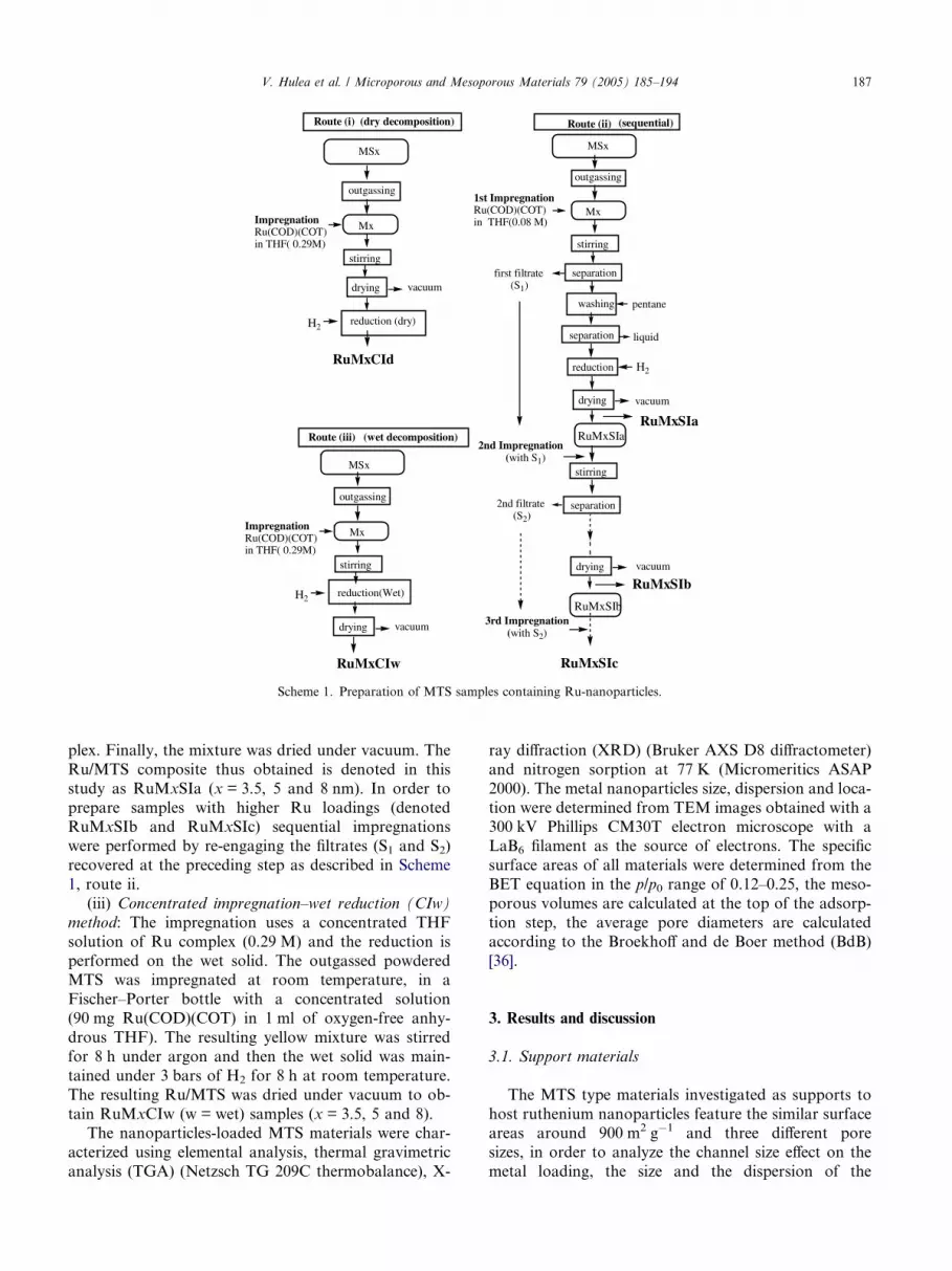
It must be noted that the Ru-containing MTS mate-rials prepared according to the impregnation method
with concentrated Ru (COD)(COT) complex solution
possess nearly the same Ru-loading at 10 wt.% whatever
the pore size is. In spite of such a similar loading be-
tween RuM3.5CIw and RuM8CIw, the features of the
materials are different. The pore size of the MS3.5 was
not modified and the standardized surface area and pore
volume have barely decreased. For MS8, the pore sizehas significantly decreased simultaneously with the stan-
dardized pore volume and surface area. Furthermore,
XRD patterns of the different RuMxCIw revealed differ-
Fig. 8. Transmission electron micrograph of (a) R
ent features. An important diffraction line at ca.2h = 43� ascribed to Ru-crystallites is present in the dif-
fractogram of the RuM3.5CIw sample, but is absent for
the RuM8CIw material. Hence, the slight decrease in the
porosity of the MS3.5 upon Ru loading is consistent
with the conclusion drawn for the MS3.5 treatment
according to the SI method. The TEM image of
RuM3.5CIw clearly reveals isolated Ru-nanoparticles
of monodisperse size (2.5 nm) inside the mesopores ofthe MS3.5 materials but also larger particles (4–5 nm)
on the external surface indicating that clustering has oc-
curred (Fig. 8a).
uM3.5CIw, (b) RuM8CIw, (c) RuM5CIw.

Scheme 2. Formation of well-dispersed Ru-nanoparticles inside the mesopores.
V. Hulea et al. / Microporous and Mesoporous Materials 79 (2005) 185–194 193
These external larger particles could also explain the
loss of standardized mesopore volume and surface area
by pore blocking taking into account the nearly constant
pore size. Nevertheless, the size of such larger particles isnot so important as those observed for the sample
RuM3.5SIc possessing nearly the same Ru loading. This
result shows that the Ru-nanoparticles already present
at the surface of the support used in RuM3.5SIc prepa-
ration may be considered as activating sites for the for-
mation of larger Ru crystallites.
In the case of the MS8 materials, even though the
porosity modification is well in line with an importantinternal loading, it is noteworthy that no larger particles
were detected by TEM (Fig. 8b) although such cluster-
ing was observed during the sequential method with a
comparable Ru loading (RuM8SIc) of around 10 wt.%.
For RuM5CIw, the TEM image (Fig. 8c) shows Ru-
nanoparticles of very homogeneous size (3.3 ± 0.2 nm)
inside the pores of MS5 (5 nm pore diameter).
A similar result is observed for MS8 with 8.3 nm poresize (RuM8CIw), which can accept up to 11.5 wt.% of
well-dispersed Ru-nanoparticles with a homogeneous
size in the range of 3.5 ± 0.5 nm (Fig. 8b). Such a result
would be explained by the stabilizing role played by the
mesoporous walls, which prevents aggregation (Scheme
2) and avoids getting larger nanoparticles.
This effect, which may be due to the presence of sila-
nols in a constrained environment, is very similar to thatobserved for the reaction in heptanol [42]. In the latter
case, the nanoparticles are monodisperse (3 nm), well
dispersed in the solvent and adopt the hexagonal com-
pact (hcp) structure of bulk ruthenium. The silanols
may act as similar coordinating groups as heptanol.
Moreover, the texture of the silica support and the
impregnation method play an important role in the
resulting Ru-nanoparticles size.Opposed to particle growth when using the successive
impregnation (SI method), in the CI method as well as
in the first impregnation step for the SI method, both
the amount and the size of Ru-nanoparticles result from
a rapid reduction of the complex by dihydrogen with
Ru–Ru formation from activated complexes (partially
hydrogenated) and incorporated in a constrained vol-
ume of the channels possessing well-defined size. In thecase of MS3.5, the size of the nanoparticles is strongly
limited by both diffusion and constrained environment.
On the contrary, in the case of MS8, the size of the
nanoparticles would not be limited by these later effects,
but the chemical surface properties would play a role forpreventing the particle agglomeration. The MTS pos-
sessing a pore size of 5 nm seems to be the best compro-
mise to obtain the best monodisperse Ru nanoparticles
of 3 nm inside the channels up to a Ru loading of ca.
12 wt.%.
4. Conclusion
Well-dispersed ruthenium nanoparticles have been
stabilized into the pores of mesostructured silica by
using an organometallic approach. The advantage of
this procedure based on the decomposition under H2
at room temperature of organometallic precursor Ru-
(COD)(COT) is the absence of particle sintering result-
ing from the mild reduction conditions and suitable poresize of the host. The mesoporous walls of MTS materi-
als, as well as the silanol groups play an important role
in the formation of well-dispersed Ru nanoparticles of
uniform size.
The size of the Ru nanoparticles and their location
significantly depend on the mesopore size, the metal
loading and the impregnation method. Thus, the ruthe-
nium was mainly aggregated on the external surface ofthe 3.5 nm pore size MTS and only a few nanoparticles
were found inside the pores. In the case of 5 and 8 nm
pore size MTS, well-dispersed nanoparticles of 3 nm
were found inside the pores.
The distribution of Ru-nanoparticles was more
homogeneous for metal loading lower than 3 wt.% in
the case of the sequential impregnation method using
a diluted THF solution of metal precursor. At higherloading, some external aggregation takes place on the
external surface of MTS. In the case of the impregnation
of MTS achieved in one step and using a more concen-
trated THF solution of metal precursor, very monodis-
perse Ru-nanoparticles were obtained inside the
channels possessing pore size of 5 or 8 nm with a loading
of Ru up to 12 wt.%. Concentrated impregnation allows
to form well-dispersed Ru-nanoparticles of 3 nm as soonas the silica host presents pore larger than 5 nm.

194 V. Hulea et al. / Microporous and Mesoporous Materials 79 (2005) 185–194
Acknowledgment
V. Hulea thanks CNRS for a research-associate posi-
tion. The authors thank Marie-France Driole for the
preparation of the parent MTS samples.
References
[1] H. Bonnemann, G. Braun, W. Brijoux, R. Brinkmann, A. Schulze
Tilling, K. Seevogel, K. Siepen, J. Organomet. Chem. 520 (1996)
143.
[2] J.D. Aiken III Jr., R.G. Finke, J. Mol. Catal., A: Chem. 145
(1999) 1.
[3] C. Pan, K. Pelzer, K. Philippot, B. Chaudret, F. Dassenoy, P.
Lecante, M.-J. Casanove, J. Am. Chem. Soc. 123 (2001)
7584.
[4] W. Chen, W.P. Cai, C.H. Liang, L.D. Zhang, Mater. Res. Bull.
36 (2001) 335.
[5] M. Hartmann, C. Bischof, Z. Luan, L. Kevan, Micropor.
Mesopor. Mater. 44–45 (2001) 385.
[6] A. Fukuoka, H. Araki, Y. Sakamoto, S. Inagaki, Y. Fukushima,
M. Ichikawa, Inorg. Chim. Acta 350 (2003) 371.
[7] P. Tian, J. Blanchard, K. Fajerwerg, M. Breysse, M. Vrinat, Z.
Liu, Micropor. Mesopor. Mater. 60 (2003) 197.
[8] W. Chen, J. Zhang, Scripta Mater. 49 (2003) 321.
[9] I. Yuranov, P. Moeckli, E. Suvorova, Ph. Buffat, L. Kiwi-
Minsker, A. Renken, J. Mol. Catal. A 192 (2003) 239.
[10] M.A. Aramendia, V. Borau, C. Jimenez, J.M. Marinas, F.J.
Romero, Chem. Commun. (1999) 873.
[11] H.B. Jervis, M.E. Raimondi, R. Raja, T. Maschmeyer, J.M.
Seddon, D.W. Bruce, Chem. Commun. (1999) 2031.
[12] R. Long, R.T. Yang, Catal. Lett. 52 (1998) 91.
[13] S. Coman, V.I. Parvulescu, B. Tesche, H. Bonnemann, J.F. Roux,
S. Kaliaguine, P.A. Jacobs, J. Mol. Catal. A 146 (1999) 247.
[14] H. Shi, L. Zhang, W. Cai, Mater. Res. Bull. 35 (2001) 1689.
[15] W. Chen, W.P. Cai, Z.X. Chen, L.D. Zhang, Ultrason. Sono-
chem. 8 (2001) 335.
[16] Q.-H. Xia, K. Hidajat, S. Kawi, Catal. Today 68 (2001) 255.
[17] W. Chen, J. Zhang, W. Cai, Scripta Mater. 48 (2003) 1061.
[18] J. Hajec, N. Kumar, P. Maki-Arvela, T. Salmi, D.Yu. Murzin, I.
Paseka, T. Heikkila, E. Laine, P. Laukkanen, J. Vayrynen, Appl.
Catal. A 251 (2003) 385.
[19] B.M. Choudary, M. Lakshmi Kantam, N. Mahender Reddy, K.
Koteswara Rao, Y. Haritha, V. Bhaskar, F. Figueras, A. Tuel,
Appl. Catal. A 181 (1999) 139.
[20] M. Shirai, N. Suzuki, Y. Nishiyama, K. Torii, M. Arai, Appl.
Catal. A 177 (1999) 219.
[21] P. Magnoux, N. Lavaud, M. Guisnet, Top. Catal. 13 (2000) 291.
[22] J. Michalik, D. Brown, J.-S. Yu, M. Danilczuk, J.Y. Kim, L.
Kevan, Phys. Chem. Chem. Phys. 3 (2001) 1705.
[23] C.M. Yang, M. Kalwei, F. Schuth, K.J. Chao, Appl. Catal. A 254
(2003) 289.
[24] M. Okumura, K. Tanaka, A. Ueda, M. Haruta, Solid State Ionics
95 (1997) 143.
[25] M. Okumura, S. Nakamura, S. Tsubota, T. Nakamura, M.
Azuma, M. Haruta, Catal. Lett. 51 (1998) 53.
[26] Y.-J. Han, J.M. Kim, G.D. Stucky, Chem. Mater. 12 (2000) 2068.
[27] U. Junges, W. Jacobs, I. Voigt-Martin, B. Krutzsch, F. Schuth, J.
Chem. Soc. Chem. Commun. (1995) 2283.
[28] C.A. Morris, M.L. Anderson, R.M. Stroud, C.I. Merzbacher,
D.R. Rolison, Science 284 (1999) 622.
[29] Y. Wu, L. Zhang, G. Li, C. Liang, X. Huang, Y. Zhang, G.
Song, J. Jia, C. Zhixiang, Mater. Res. Bull. 36 (2001) 253.
[30] J.P.M. Niederer, A.A.J. Arnold, W.F. Hoelderich, B. Spliethof,
B. Tesche, M. Reetz, H. Boenneman, Stud. Surf. Sci. Catal. 135
(2001) 4780.
[31] P. Pertici, G. Vitulli, Inorg. Synth. 22 (1983) 176.
[32] A. Spitaleri, P. Pertici, N. Scalera, G. Vitulli, M. Hoang, T.W.
Turney, M. Gleria, Inorg. Chim. Acta 352 (2003) 61.
[33] G. Marconi, P. Pertici, C. Evangelisti, A.M. Caporusso, G.
Vitulli, G. Capannelli, M. Hoang, T.W. Turney, J. Organomet.
Chem. 689 (2004) 639.
[34] J.S. Beck, J.C. Vartuli, W.J. Roth, M.E. Leonowicz, C.T. Kresge,
K.D. Schmit, C.T.-W. Chu, D.H. Olson, E.W. Sheppared, S.B.
McCullen, J.B. Higgins, J.L. Schlenker, J. Am. Chem. Soc. 114
(1992) 10834.
[35] D. Desplantier-Giscard, A. Galarneau, F. Di Renzo, F. Fajula,
Stud. Surf. Sci. Catal. 135 (2001) 1105.
[36] A. Galarneau, D. Desplantier, R. Dutartre, F. Di Renzo,
Micropor. Mesopor. Mater. 27 (1999) 297.
[37] W. Zhou, J.M. Thomas, D.S. Shephard, B.F.G. Johnson, D.
Ozkaya, T. Maschmeyer, R.G. Bell, Q. Ge, Science 280 (1998)
705.
[38] P. Zhang, J. Guo, Y. Wang, W. Pang, Mater. Lett. 53 (2002) 400.
[39] N. Kumar, P. Maki-Arvela, J. Hajek, T. Salmi, D.Yu. Murzin,
T. Heikkila, E. Laine, P. Laukkanen, J. Vayrynen, Micropor.
Mesopor. Mater. 69 (2004) 173.
[40] M.J. Danks, H.B. Jervis, M. Nowotny, W. Zhou, T.A. Masch-
meyer, D.W. Bruce, Catal. Lett. 82 (2002) 95.
[41] W.F. McClune (Ed.), Powder Diffraction File, Inorganic Mate-
rials, JCPDS International Centre for Diffraction Data, Swarth-
more, USA, 1979, p. 681.
[42] K. Philippot, B. Chaudret, C. R. Chim. 6 (2003) 1019.
Copyright © 2022 FDOKUMEN