Synthesis of polymeric micro- and nanostructural materials for application in non-linear optics
7
Synthesis of polymeric micro- and nanostructural materials for application in non-linear optics Lyubov Kravets a, * , Natalia Palistrant b , Valerii Bivol b , Stepan Robu b , Nikolai Barba b , Oleg Orelovitch a a Joint Institute for Nuclear Research, Flerov Laboratory of Nuclear Reactions, Joliot-Curie Str. 6, 141980 Dubna, Moscow Region, Russian Federation b Institute of Applied Physics of Moldavian Academy of Sciences, Academiei Str. 5, MD-2028 Chisinau, Moldova Received 18 April 2007; received in revised form 9 July 2007 Available online 14 September 2007 Abstract The present paper describes a new approach developed for the preparation of micro- and nanostructural materials on the basis of polymeric compositions used as a matrix in non-linear optics. This approach consists in filling the pores of poly(ethylene terephthalate) track membranes (PET TM) from polymeric compositions using an impregnation method. It is shown that depending on the concen- tration of polymeric compositions in the solution it is possible to form a variety of micro- and nanostructural materials (tubules and wires as well as composite membranes) with a wide spectrum of characteristics. The developed method of producing micro- and nano- structural materials provides a possible way for creating polymeric objects with non-linear optic properties which can be used to design electronic micro- and nanodevices and to obtain chemical and optical sensors. Ó 2007 Elsevier B.V. All rights reserved. PACS: 61.46.Tw Keywords: Template synthesis; Track membrane; Polymeric compositions; Micro- and nanostructural materials; Non-linear optics 1. Introduction In recent years the problem of producing micro- and nanostructural materials with porous materials as a tem- plate has excited great interest [1,2]. This method consists in filling the pores of the template with a desired material by various physicochemical methods. These investigations are of major practical and scientific importance since they allow obtaining of a wide spectrum of micro- and nano- structural materials with unique properties for application in various areas of modern science and technologies: nano- electronics, photonics, chemotronics, biotechnologies, etc. Two types of porous membranes: the aluminum mem- branes and the polymeric track membranes are often used as templates. Aluminum membranes are achieved via anod- ization of aluminum foil in acid media [3], and the track membranes are produced by an irradiation of polymeric films with a beam of highly energetic heavy ions followed by a subsequent chemical etching of the resulting particle latent tracks [4,5]. Both types of membranes have cylindri- cal pores with a narrow pore size distribution that gives an opportunity for the synthesis of micro- and nanostructural objects – wires, tubules as well as composite membranes. When the pore area is completely filled by a desired mate- rial, micro- and nanowires are produced, if the used mate- rial is deposited along the pore walls only, micro- and nanotubules are formed. In order to fill the pores of the template various materials can be used: metals [6–8], carbon [9,10], semiconductors [11,12], polymers [13–15]. The micro- and nanostructures can remain inside the pores of the template or they can be freed from the membrane. To produce free micro- and nanowires as well as free micro- and nanotubules, the porous matrix is dissolved 0168-583X/$ - see front matter Ó 2007 Elsevier B.V. All rights reserved. doi:10.1016/j.nimb.2007.09.020 * Corresponding author. Tel.: +7 49621 62448; fax: +7 49621 28933. E-mail address: [email protected] (L. Kravets). www.elsevier.com/locate/nimb Available online at www.sciencedirect.com Nuclear Instruments and Methods in Physics Research B 264 (2007) 311–317 NIM B Beam Interactions with Materials & Atoms
Transcript of Synthesis of polymeric micro- and nanostructural materials for application in non-linear optics
Available online at www.sciencedirect.com
www.elsevier.com/locate/nimb
Nuclear Instruments and Methods in Physics Research B 264 (2007) 311–317
NIMBBeam Interactions
with Materials & Atoms
Synthesis of polymeric micro- and nanostructural materialsfor application in non-linear optics
Lyubov Kravets a,*, Natalia Palistrant b, Valerii Bivol b, Stepan Robu b,Nikolai Barba b, Oleg Orelovitch a
a Joint Institute for Nuclear Research, Flerov Laboratory of Nuclear Reactions, Joliot-Curie Str. 6, 141980 Dubna, Moscow Region, Russian Federationb Institute of Applied Physics of Moldavian Academy of Sciences, Academiei Str. 5, MD-2028 Chisinau, Moldova
Received 18 April 2007; received in revised form 9 July 2007Available online 14 September 2007
Abstract
The present paper describes a new approach developed for the preparation of micro- and nanostructural materials on the basis ofpolymeric compositions used as a matrix in non-linear optics. This approach consists in filling the pores of poly(ethylene terephthalate)track membranes (PET TM) from polymeric compositions using an impregnation method. It is shown that depending on the concen-tration of polymeric compositions in the solution it is possible to form a variety of micro- and nanostructural materials (tubules andwires as well as composite membranes) with a wide spectrum of characteristics. The developed method of producing micro- and nano-structural materials provides a possible way for creating polymeric objects with non-linear optic properties which can be used to designelectronic micro- and nanodevices and to obtain chemical and optical sensors.� 2007 Elsevier B.V. All rights reserved.
PACS: 61.46.Tw
Keywords: Template synthesis; Track membrane; Polymeric compositions; Micro- and nanostructural materials; Non-linear optics
1. Introduction
In recent years the problem of producing micro- andnanostructural materials with porous materials as a tem-plate has excited great interest [1,2]. This method consistsin filling the pores of the template with a desired materialby various physicochemical methods. These investigationsare of major practical and scientific importance since theyallow obtaining of a wide spectrum of micro- and nano-structural materials with unique properties for applicationin various areas of modern science and technologies: nano-electronics, photonics, chemotronics, biotechnologies, etc.Two types of porous membranes: the aluminum mem-branes and the polymeric track membranes are often usedas templates. Aluminum membranes are achieved via anod-
0168-583X/$ - see front matter � 2007 Elsevier B.V. All rights reserved.
doi:10.1016/j.nimb.2007.09.020
* Corresponding author. Tel.: +7 49621 62448; fax: +7 49621 28933.E-mail address: [email protected] (L. Kravets).
ization of aluminum foil in acid media [3], and the trackmembranes are produced by an irradiation of polymericfilms with a beam of highly energetic heavy ions followedby a subsequent chemical etching of the resulting particlelatent tracks [4,5]. Both types of membranes have cylindri-cal pores with a narrow pore size distribution that gives anopportunity for the synthesis of micro- and nanostructuralobjects – wires, tubules as well as composite membranes.When the pore area is completely filled by a desired mate-rial, micro- and nanowires are produced, if the used mate-rial is deposited along the pore walls only, micro- andnanotubules are formed. In order to fill the pores of thetemplate various materials can be used: metals [6–8],carbon [9,10], semiconductors [11,12], polymers [13–15].The micro- and nanostructures can remain inside the poresof the template or they can be freed from the membrane.To produce free micro- and nanowires as well as freemicro- and nanotubules, the porous matrix is dissolved

Fig. 1. Scheme of the impregnation device: (1) drum; (2) membrane; (3)reducer; (4) reversible engine; (5) bath with solution of polymericcomposition.
312 L. Kravets et al. / Nucl. Instr. and Meth. in Phys. Res. B 264 (2007) 311–317
by a suitable solvent and free particles are therefore recov-ered on a substrate by filtration. If the micro- and nano-structural objects (wires or tubules) are still linked to thesurface of the substrate after matrix dissolution, a brushstructure can be obtained. The synthesized micro- andnanotubules can be also left inside the pores of the templateand composite membranes are then produced. If the tubuleinner diameter is around a few nanometers: usually from 1to 4 nm, a so-called ‘‘ion-gated’’ membrane is thereforeformed and its properties can vary under the influence ofexternal factors, such as pH of the solution, electric currentand ionic force of the solution [16–18].
One of the ways to obtain micro- and nanostructuresusing porous membranes as templates is the electrolyticdeposition. This method is used for the synthesis of micro-and nanowires as well as micro- and nanotubules frommetals. Another way is related to the chemical or electro-chemical polymerization of monomers. This looks morepromising as it allows to use a wide variety of organic com-pounds and to obtain a micro- or nanostructural compositematerial that often possess unique properties, as e.g. poly-mers with electric conducting properties [19–21]. Morerecently, the method of obtaining nanomembranes by poly-merization of monomer vapors in plasma has been moreand more often used [22,23]. In our opinion, the use ofplasma has a number of advantages such as the possibilityto regulate thickness and density of the deposited poly-meric layer. It also provides its high adhesion to the tem-plate, reduces the synthesis time and gives access to awider range of organic compounds for which the standardpolymerization is impossible.
This paper presents a new approach developed for prep-aration of micro- and nanostructural materials (wires andtubules as well as composite membranes) from polymericcompositions by filling the pores of a track etched mem-branes. The used track membranes were developed andserially produced from a poly(ethylene terephthalate) filmat the Flerov Laboratory of Nuclear Reactions of the JointInstitute for Nuclear Research. The polymeric composi-tions were based on styrene, butylmethacrylate and 4-aminostyrene, the impregnation method was applied forobtaining polymeric micro- and nanostructural materials.We studied the mechanism of formation of these materialsas well as their structure and properties. The developedmethod of producing micro- and nanostructural materialsprovides a possible way for creation of polymeric objectswith non-linear optic properties which can be used todesign electronic micro- and nanodevices and to obtainchemical and optical sensors.
2. Experimental
Two types of membrane were used as templates for syn-thesis of micro- and nanostructural materials: a PET trackmembranes with a thickness of 10.8 lm and an effectivepore diameter of 1.0 lm (pore density was1.5 · 107 cm�2) and a PET track membrane with a thick-
ness of 19.8 lm and an effective pore diameter of 3.0 lm(pore density was 1.0 · 106 cm�2). In order to producethe membranes, poly(ethylene terephthalate) films (Hosta-phan RE5, Kalle) were irradiated by krypton positive ions,accelerated at the energy �3 MeV/nucleon at the cyclotronof the Flerov Laboratory of Nuclear Reactions. The irradi-ation is carried out under vacuum of 0.15 Pa at room tem-perature. The irradiated samples were kept in air undernormal conditions. Then the ion irradiated films were addi-tionally sensitized with ultraviolet irradiation from a sourcewith maximum intensity at 310 nm. Chemical etching wasperformed in an alkaline (NaOH) aqueous solution of 3.0or 5.0 N at 85 �C for a time up to 6 min. The techniqueof producing the track membranes is described more detailin [5].
Polymeric compositions were used as a precursor forobtaining micro- and nanostructural materials. These poly-meric compositions were prepared by radical copolymeri-zation of styrene and butylmethacrylate in ratio of50:50 mol% and styrene, butylmethacrylate and 4-amino-styrene in ratio of 20:50:30 mol% as described in [24]. Tol-uene was used to dissolve the polymeric compositions. Theconcentration of the polymeric compositions in the solu-tion was varied from 0.5 up to 20%. The membranes werecovered by the solution of polymeric compositions usingthe impregnation device of a ‘‘meniscus’’ type (see thescheme in Fig. 1). The technique of applying of the poly-meric compositions on the membrane surface consists inthe following. The membrane samples of size100 mm · 100 mm, as a flexible basis, are fixed on a rotat-ing drum of a diameter of 50 cm. The drum begins itsmovement with the help of reversible engine. The bath witha solution of the polymeric composition is placed on a hor-izontal small table under the drum. As far as the bathapproaches the drum, the solution is uniformly distributedall over the membrane surface. Then the solvent is sub-jected to evaporation at room temperature. Full drying ofthe samples was carried out in free of dust chamber at ele-vated temperature.
The characteristics of initial membrane and the oneswith a deposited layer of the polymeric compositions weredetermined through a series of complementary procedures.The amount of the polymeric composition on the mem-brane surface determined by relation
Qg ¼ ðmg � moÞ � 100=mo;

L. Kravets et al. / Nucl. Instr. and Meth. in Phys. Res. B 264 (2007) 311–317 313
where mo is the mass of the initial membrane and mg is themass of the membrane with the layer of polymeric compo-sition. The change of the membrane thickness was mea-sured with an electron counter of thickness ‘‘Tesa Unit’’(Austria), the precision of the measuring being ±0.1 lm.The air flow rate was measured at a pressure drop of104 Pa through a 1 cm2 membrane using a float-type flowmeter and a gas-dynamical pore diameter (an effective porediameter) was therefore determined as described in [25].The evolution of the membrane surface properties wasestimated by measuring the contact angle. For this purposethe sessile drop method was applied using a horizontalmicroscope equipped with a goniometer. Twice distilledwater was used as test liquid and six measurements weremade at different places on the membrane surface. Themeasurement accuracy was ±1�. The study of the samplesmicrostructure as well as the determination of the porediameter on the membrane surface was carried out bySEM using a JSM-840 (JEOL). Before scanning, a thingold layer was deposited using a JEOL JFC-1100 ionsputter. In order to get a clear fracture of the membranesamples, they were preliminary exposed to UV-radiationto destroy the initial polymeric matrix [26].
Table 1Change of the membrane characteristics during a process of template synthes
Concentration of polymericcompositiona in solvent, %
Relative increasein the mass, %
Thickness,lm
Relative increain the thicknes
Control – 10.8 –0.5 1.7 10.8 0.501.0 2.4 10.9 0.952.0 3.6 11.0 1.852.5 4.0 11.1 2.75
Control – 19.8 –2.0 1.8 20.0 1.05.0 4.3 20.2 2.0
10.0 7.4 20.4 3.015.0 9.4 20.6 4.0
a The polymeric composition of styrene and butylmethacrylate in ratio of 50
Fig. 2. SEM images of the surface of the initial membrane with a pore diamebutylmethacrylate in ratio of 50:50 mol% (b) and after deformation of the polythe solution was 2%.
3. Results and discussion
Research on the process of synthesis of the micro- andnanostructural materials by the impregnation method withuse of TM as a template has shown that for both type ofmembranes an increase of concentration of polymeric com-positions in the solution induces a gradual growth of thesample mass (Table 1) connected with the deposition of apolymeric layer on their surface. Moreover, while increas-ing the sample weight, one can observe increase of themembrane thickness and decrease of its effective pore diam-eter. This means that the deposition of the polymer occursboth on the membrane surface and on the pore walls. Theessential reduction (up to 100%) of the effective pore diam-eter of the membranes in comparison with the insignificantincrease (up to 4%) of their thickness allows one to con-clude that the deposition of the polymer inside the poresprevails of its deposition on the membrane surface. Theperformed research shows that the use of this techniqueof applying of the polymeric compositions on the surfaceof membranes provides their uniform distribution all overof the sample area. The measurement error at the determi-nation of the thickness of the treated membranes is no
is
ses, %
Air flow rate atDP = 104 Pa, ml/min cm2
Effective porediameter, lm
Relative decrease in theeffective pore diameter, %
3200 1.00 –965 0.74 26.0525 0.62 38.0185 0.46 54.090 0.38 62.0
6600 3.00 –4650 2.75 8.31200 1.90 36.7180 1.15 61.7
0 0 100
:50 mol% was used in these experiments.
ter of 3.0 lm (a), with layer of a polymeric composition from styrene andmeric composition layer (c). The polymeric composition concentration in

314 L. Kravets et al. / Nucl. Instr. and Meth. in Phys. Res. B 264 (2007) 311–317
more than 1%, while the measurement error at the determi-nation of the effective pore diameter of the membranes isno more than 4%.
At low concentration of the polymeric compositions inthe solution, the pore diameter on the membrane surface,determined with the help of electron microscopy, doesnot differ significantly from the pore diameter of the initialmembrane surface (Fig. 2b). Besides, the cross-sections ofthese membranes show that the deposition of the polymeron the pore wall is uniform, and the formed compositemembranes have therefore cylindrical pores since theircross-section does not change along the whole channel.In other words, tubular membranes are produced by usinglow concentrations of polymeric compositions in the solu-tion. In these conditions the structure of the membranes ispreserved and the nominal pore diameter of the resultingtubular membranes is determined by the initial pore diam-eter and by the concentration of the polymeric compositionin the solution. For PET TM with a pore diameter of1.0 lm, the formation of this type occurs at the concentra-tion of the polymeric compositions in a range from 0.5 upto 1.0%. For PET TM with a pore diameter of 3.0 lm, theformation of tubular membranes is observed at the concen-tration of the polymeric compositions is in a range from 2.0up to 5.0%. Let us note that in the carried out experimentsfor each type of membranes we investigated the certainranges of the concentration of polymeric compositionswhich are presented in Table 1. It is necessary to assume,however, that, when a PET TM with a pore diameter of1.0 lm is chosen as a template, the formation of tubularmembranes takes place if solutions of polymeric composi-tions with a concentration less than 0.5% are used. Simi-larly, for PET TM with a pore diameter of 3.0 lm,tubular membranes are formed in the case of solutions ofpolymeric compositions with concentration less than 2%.Certainly the using of solutions of polymeric compositions
CH
CH CHCH C
COOC H
n
22
3
4 9
n
C
Fig. 3. Chemical structures of copolymer from styrene and butylmethacrylate(b).
Table 2Change of relative content of oxygen to carbon atoms during a processbutylmethacrylate
Membrane sample Initial PET TM PET TM
0.5
Relative content of oxygen to carbon atoms, % 39.0a 35.8
a The calculated value of content of oxygen to carbon atoms is 40%.
with the concentration less than 0.5% in the case of mem-branes with pore diameter of 1.0 lm as well as with theconcentration less than 2.0% at pore diameter of 3.0 lmof ones is rather risk as is not absolutely clear that formedon the membrane surface and walls polymeric layer will becontinuous. It should be taken into account at a choice oftreatment conditions of TM. Thus, the choice of treatmentconditions for obtaining of tubular membranes is con-nected with the establishment of boundary concentrationsof polymeric composition in solution according to whichthe polymer layer on the membrane surface would be con-tinuous, and pore filling would not occur.
Investigation of surface properties of tubular mem-branes shows that formation of polymers from a mixtureof monomers selected for the research leads to hydrophob-ization of the membrane surface as the water contact anglefor all membranes increases. If for the initial PET TM thewater contact angle is 65�, the treated membranes show awater contact angle of 80� when using a copolymer of sty-rene and butylmethacrylate and of 95� for a terpolymer ofstyrene, butylmethacrylate and 4-aminostyrene, whateverthe concentration of the polymeric compositions in thesolution. In both cases all measured values of water contactangle are identical for all modified membranes. This meansthat the polymeric compositions, even at low concentrationin the solution, completely cover the membrane surface andare uniformly distributed all over the membrane surface.The particular value of the water contact angle of the mem-brane surface is determined by the properties of the poly-meric compositions whose chemical structures can beexpressed in the case of double copolymer from styreneand butylmethacrylate by the formula given in Fig. 3(a)and in the case of terpolymer from styrene, butylmethacry-late and 4-aminostyrene by the formula given in Fig. 3(b).The deposition of the polymer on the surface of the initialmembrane with clearer hydrophobic characteristics is seen
CH
CH CHH C
COOC H
CH CH
NHn
22
3
4 9
n
2
2
(a) and terpolymer from styrene, butylmethacrylate, and 4-aminostyrene
of treatment by solution of polymeric composition from styrene and
treated by solution of polymeric composition with concentration of (%)
1.0 2.0 2.5
35.3 34.9 34.6

L. Kravets et al. / Nucl. Instr. and Meth. in Phys. Res. B 264 (2007) 311–317 315
also from the results of the characteristic X-ray radiationanalysis performed by electron microscopy. So, accordingto experimental data (Table 2), the content of oxygendecreases in the membranes modified by the solutions ofpolymeric compositions formed from copolymer of styreneand butylmethacrylate. In this case, the thicker the layer ofthe polymeric composite on the membrane surface, the
Fig. 4. SEM images of the cross-sections of the initial membrane with apore diameter of 3.0 lm (a) and composite membranes with variousthickness of the selective layer. Concentration of the polymeric compo-sition of styrene and butylmethacrylate in the solution was 5% (b), 10%(c), and 15% (d).
Fig. 5. SEM images of the surface of the composite membranes with a pore dand butylmethacrylate in ratio of 50:50 mol% with concentration of 5% (a) an
more noticeable decrease of the oxygen content in themembrane matrix is observed.
As the polymeric composition concentration in the solu-tion increases a significant reduction of the effective porediameter (Table 1) is observed, even if in some cases thepore diameter on the membrane surface does not practi-cally change. This means that the pores of such membranesare filled up to a certain depth from the surface, this beingconfirmed by the electron microscopy results. As it is seenfrom the microphotographs in Fig. 4, upon completing thetreatment by impregnation method a polymeric layer isformed in membrane pores. The structure of such typemembranes in this case changes, i.e. the pores get an asym-metric form. The nominal pore diameter of such mem-branes is determined by the pore diameter of thepolymeric layer. The pore diameter of this layer is muchless than the pore diameter of the initial membrane, sothe selectivity in the process of electrolyte separationof the produced membranes grows up; that is, in this casethe formation of nanomembranes with a selective layertakes place. Detail investigation of selective layer by usingthe electron microscopy shows that the increases of com-posite concentration in solution leads to the graduallydecrease of pore diameter of this layer (Fig. 5). I.e., in thiscase using of developed method of applying of polymericcomposition on the membrane surface results the forma-tion of membranes in which the selective layer has the cap-illary pores. It should be noted that if a PET TM with apore diameter of 1.0 lm is used as a template, the pore fill-ing takes place in the case of polymeric compositions with alower concentration in comparison with PET TM with apore diameter of 3.0 lm. It is caused by significant diffi-culty in filling up the pores of a smaller diameter whenincreasing the concentration of polymeric compositionsdue to increasing viscosity of the solution. Moreover, theconcentration of the polymeric compositions in the solu-tion essentially influences the thickness of the selectivelayer. As it is clearly seen (Fig. 4), at increasing the concen-tration of polymeric composition in the solution the thick-ness of the selective layer increases. However, the choice ofinsignificant concentration of polymeric composition insolution can be a cause that the formation of selective layertakes place not in all pores. Such case we observed atapplying of polymeric composition with the concentration
iameter of 3.0 lm after applying of a polymeric composition from styrened 10% (b).
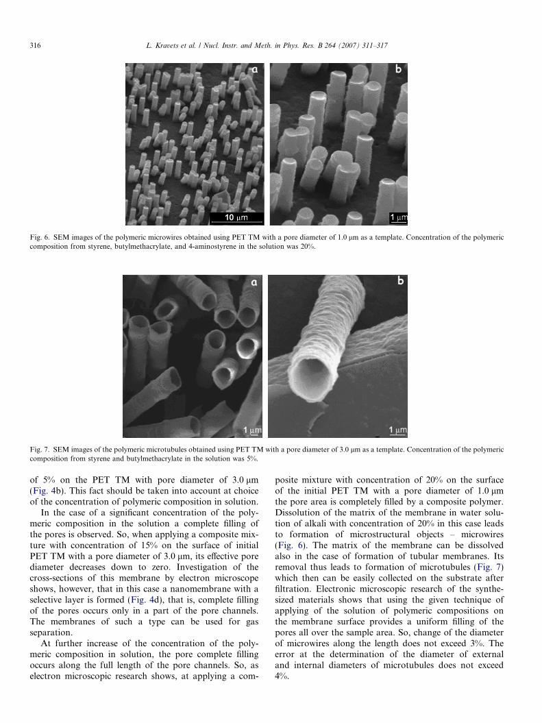
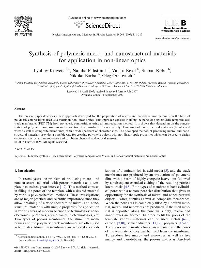
Fig. 6. SEM images of the polymeric microwires obtained using PET TM with a pore diameter of 1.0 lm as a template. Concentration of the polymericcomposition from styrene, butylmethacrylate, and 4-aminostyrene in the solution was 20%.
Fig. 7. SEM images of the polymeric microtubules obtained using PET TM with a pore diameter of 3.0 lm as a template. Concentration of the polymericcomposition from styrene and butylmethacrylate in the solution was 5%.
316 L. Kravets et al. / Nucl. Instr. and Meth. in Phys. Res. B 264 (2007) 311–317
of 5% on the PET TM with pore diameter of 3.0 lm(Fig. 4b). This fact should be taken into account at choiceof the concentration of polymeric composition in solution.
In the case of a significant concentration of the poly-meric composition in the solution a complete filling ofthe pores is observed. So, when applying a composite mix-ture with concentration of 15% on the surface of initialPET TM with a pore diameter of 3.0 lm, its effective porediameter decreases down to zero. Investigation of thecross-sections of this membrane by electron microscopeshows, however, that in this case a nanomembrane with aselective layer is formed (Fig. 4d), that is, complete fillingof the pores occurs only in a part of the pore channels.The membranes of such a type can be used for gasseparation.
At further increase of the concentration of the poly-meric composition in solution, the pore complete fillingoccurs along the full length of the pore channels. So, aselectron microscopic research shows, at applying a com-
posite mixture with concentration of 20% on the surfaceof the initial PET TM with a pore diameter of 1.0 lmthe pore area is completely filled by a composite polymer.Dissolution of the matrix of the membrane in water solu-tion of alkali with concentration of 20% in this case leadsto formation of microstructural objects – microwires(Fig. 6). The matrix of the membrane can be dissolvedalso in the case of formation of tubular membranes. Itsremoval thus leads to formation of microtubules (Fig. 7)which then can be easily collected on the substrate afterfiltration. Electronic microscopic research of the synthe-sized materials shows that using the given technique ofapplying of the solution of polymeric compositions onthe membrane surface provides a uniform filling of thepores all over the sample area. So, change of the diameterof microwires along the length does not exceed 3%. Theerror at the determination of the diameter of externaland internal diameters of microtubules does not exceed4%.

L. Kravets et al. / Nucl. Instr. and Meth. in Phys. Res. B 264 (2007) 311–317 317
4. Conclusion
The carried out investigations have allowed us to makethe following conclusions. Research on the process of for-mation of micro- and nanostructural materials by theimpregnation method with the use of track membranes astemplates has shown that depending on the concentrationof polymeric compositions in the solution it is possible toform both micro- and nanostructural materials (tubulesor wires) and composite nanomembranes. For productionof micro- and nanowires as well as micro- and nanotubules,the pore region of the initial membranes was filled with apolymeric composition, then the membrane matrix was dis-solved in water solution of alkali, and the synthesizednanoobjects were accumulated on the substrate after filtra-tion. In doing so, in the first case the pore region was filledfully with polymeric composition, while in the second casethe polymeric composition was formed only on the porewalls. To obtain nanomembranes, polymeric compositionsafter deposition remained inside the pores of the mem-branes. The research in the mechanism of nanomembraneformation shows that depending on concentration of poly-meric compositions in the solution, there may be formedtubular membranes, in which the deposition of the poly-meric layer on the pore walls occurs along the full length,and nanomembranes with a selective layer, in which thepolymeric composition deposition occurs along a part ofthe pore channel.
This work only considers a method of forming themicro- and nanostructures on the basis of polymeric com-positions that can serve as a matrix to produce micro- andnanotubules, micro- and nanowires as well as compositenanomembranes with non-linear optical properties. Inorder to impart the non-linear properties to these materi-als, organic compounds containing chromophore groupsshould be introduced into their structure. Such compoundscan be introduced as monomers at the stage of synthesizingcopolymers used to fabricate of micro- and nanostructuralmaterials, or by adding to the solvent at the preparationstage of the polymeric composition solutions. Thus,depending on chemical structure of the organic compoundused, it is possible to obtain micro- and nanostructuralmaterials with a high polarizability and photorefractiveand photochromic properties. We intend to do it in ournext detailed study.
Acknowledgement
This work was supported by a Grant (No. 06-02-90878)of the Russian Foundation for Basic Research and a Grant(No. 07R) of the Moldavian Academy of Sciences.
References
[1] C.R. Martin, Chem. Mater. 8 (1996) 1739.[2] J. Hulteen, C.R. Martin, J. Mater. Chem. 7 (1997) 1075.[3] A. Despic, V.P. Parkhutic, in: J.O. Bockris, R.E. White, B.E.
Conway (Eds.), Modern Aspect of Electrochemistry, Vol. 20, PlenumPress, New York, 1989.
[4] H.W. Ballew, Basics of Filtration and Separation, Nucleopore Co.,Pleasanton, CA, 1978.
[5] G.N. Flerov, Vestnik Akademii Nauk SSSR 4 (1984) 35 (in Russian).[6] G.L. Hornyak, C.J. Patrissi, C.R. Martin, J. Phys. Chem. 101 (1997)
1548.[7] H. Schwanbeck, U. Schmidt, Electrochem. Acta 45 (2000) 4389.[8] M. Wirtz, C.R. Martin, Adv. Mater. 15 (2003) 455.[9] G. Che, B.B. Lakshmi, C.R. Martin, E.R. Fisher, R.S. Ruoff, Chem.
Mater. 8 (1998) 260.[10] T. Abatemarco, J. Stickel, J. Belfort, B.P. Frank, P.M. Ajayan, G.
Belfort, J. Phys. Chem. 103 (1999) 3534.[11] B.B. Lakshmi, P.K. Dorhout, C.R. Martin, Chem. Mater. 9 (1997)
857.[12] I. Enculescu, M. Sima, V. Ghiordanescu, M. Secu, Chalogenide Lett.
2 (2005) 9.[13] L. Dauginet-De Pra, E. Ferain, R. Legras, S. Demoustier-Cham-
pagne, Nucl. Instr. and Meth. B 196 (2002) 81.[14] E. Ferain, R. Legras, Nucl. Instrum. and Meth. B 208 (2003) 115.[15] V.M. Cepak, C.R. Martin, Chem. Mater. 11 (1999) 1363.[16] Y. Kobayashi, C.R. Martin, Anal. Chem. 71 (1999) 3665.[17] S.B. Lee, C.R. Martin, Anal. Chem. 73 (2001) 768.[18] C.R. Martin, M. Nishizawa, M.K. Jirage, M. Kang, S.B. Lee, Adv.
Mater. 13 (2001) 1351.[19] H. Qiu, J. Zhai, S. Li, L. Jiang, M. Wan, Adv. Funcl. Mater. 13
(2003) 925.[20] S.K. Saha, Y.K. Su, C.L. Lin, D.W. Jaw, Nanotechnology 15 (2004)
66.[21] A. Malinauskas, J. Malinauskiene, A. Ramanavicius, Nanotechnol-
ogy 16 (2005) 51.[22] L. Kravets, S. Dmitriev, A. Gilman, A. Drachev, G. Dinescu, J.
Memb. Sci. 263 (2005) 127.[23] A. Lazea, L.I. Kravets, S.N. Dmitriev, G. Dinescu, Romanian
Reports Phys. 57 (2005) 396.[24] N. Palistrant, H. Meinhard, P. Grau, V. Bivol, S. Robu, in: SPIE
Proceeding, Canada 5582, 2004, p. 452.[25] V.V. Ovchinnikov, V.D. Seleznev, Izmerit. Tekhnika 3 (1989) 12, in
Russian.[26] O.L. Orelovitch, P.Yu. Apel, Instrum. and Experimental Techn. 44
(2001) 111.