Chapter 22 Wave Optics
154
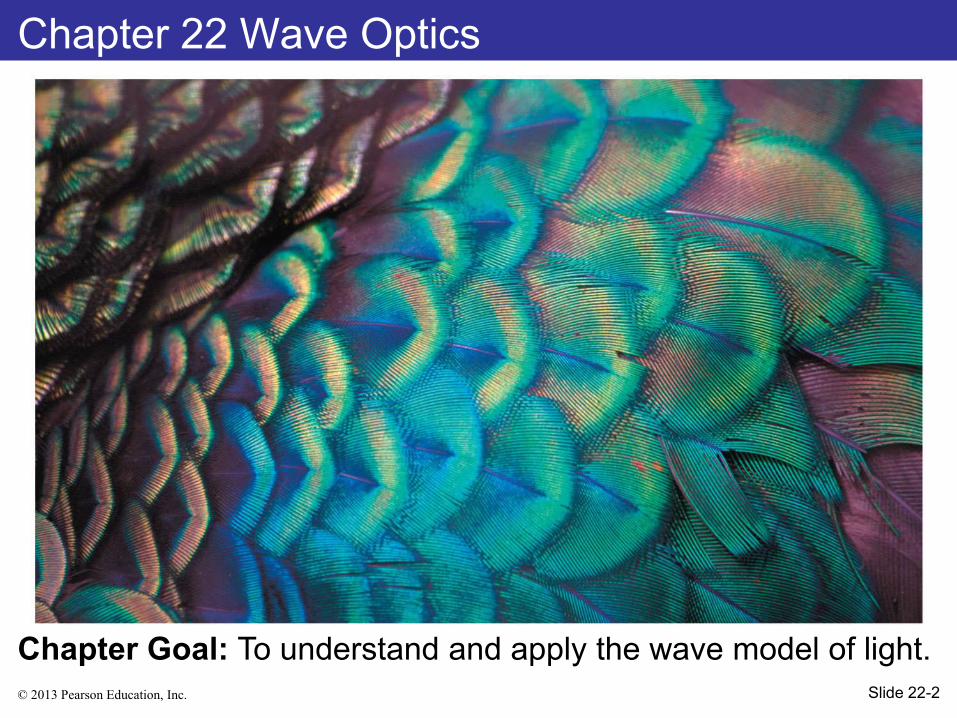
© 2013 Pearson Education, Inc. Chapter 22 Wave Optics Chapter Goal: To understand and apply the wave model of light. Slide 22-2
-
Upload
khangminh22 -
Category
Documents
-
view
0 -
download
0
Transcript of Chapter 22 Wave Optics
© 2013 Pearson Education, Inc.
Chapter 22 Wave Optics
Chapter Goal: To understand and apply the wave model of light.
Slide 22-2
© 2013 Pearson Education, Inc.

© 2013 Pearson Education, Inc.
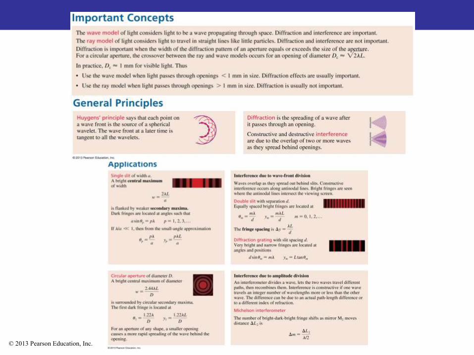
Models of Light
The wave model: Under many circumstances, light exhibits the same behavior as sound or water waves. The study of light as a wave is called wave optics.
The ray model: The properties of prisms, mirrors, and lenses are best understood in terms of light rays. The ray model is the basis of ray optics. Chapter 23
The photon model: In the quantum world, light behaves like neither a wave nor a particle. Instead, light consists of photons that have both wave-like and particle-like properties. This is the quantum theory of light. Physics 43
Slide 22-29
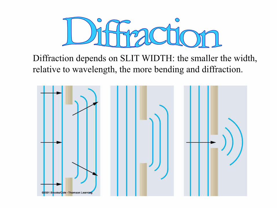
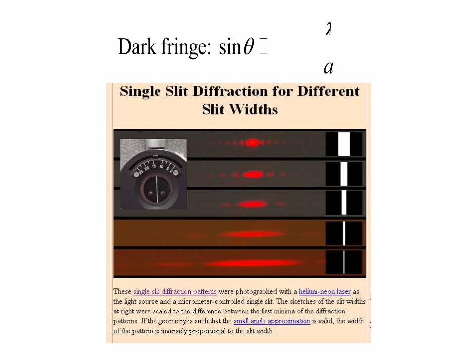
Diffraction depends on SLIT WIDTH: the smaller the width,
relative to wavelength, the more bending and diffraction.
Diffraction depends on SLIT WIDTH: the smaller the width,
relative to wavelength, the more bending and diffraction.
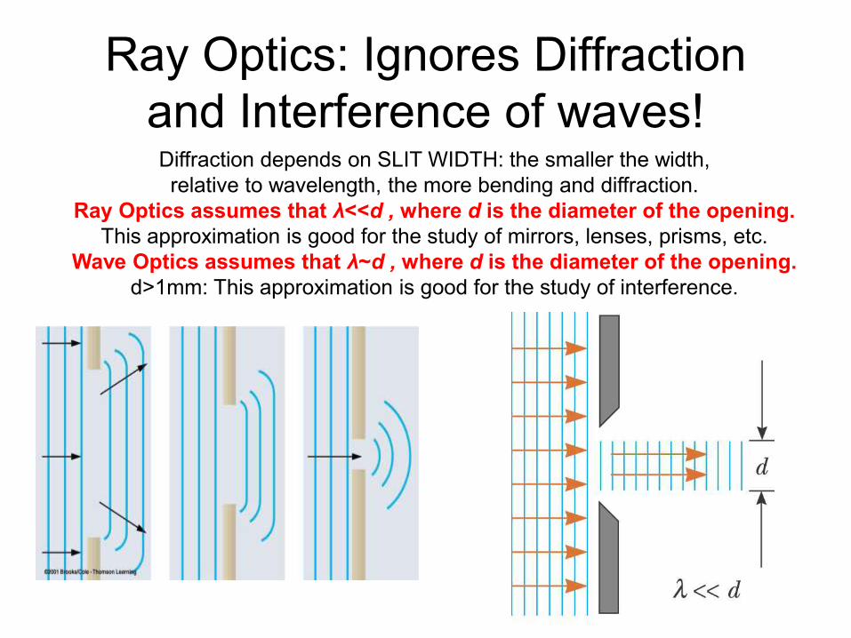
Ray Optics assumes that λ<<d , where d is the diameter of the opening.
This approximation is good for the study of mirrors, lenses, prisms, etc.
Wave Optics assumes that λ~d , where d is the diameter of the opening.
d>1mm: This approximation is good for the study of interference.
Ray Optics: Ignores Diffraction
and Interference of waves!
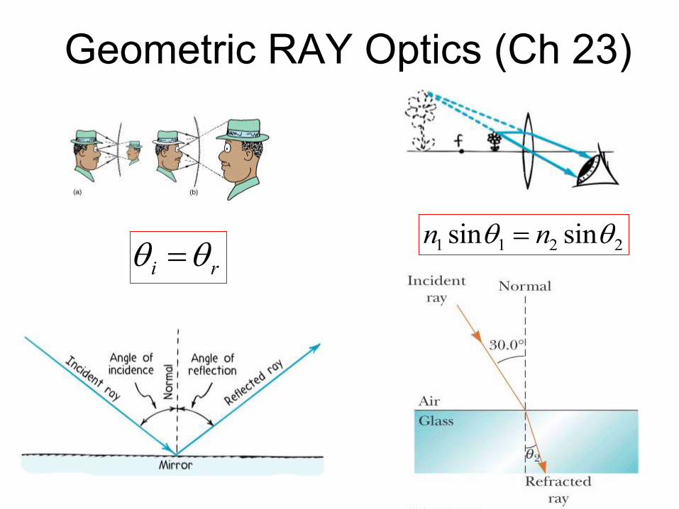
Geometric RAY Optics (Ch 23)
i r 1 1 2 2sin sinn n
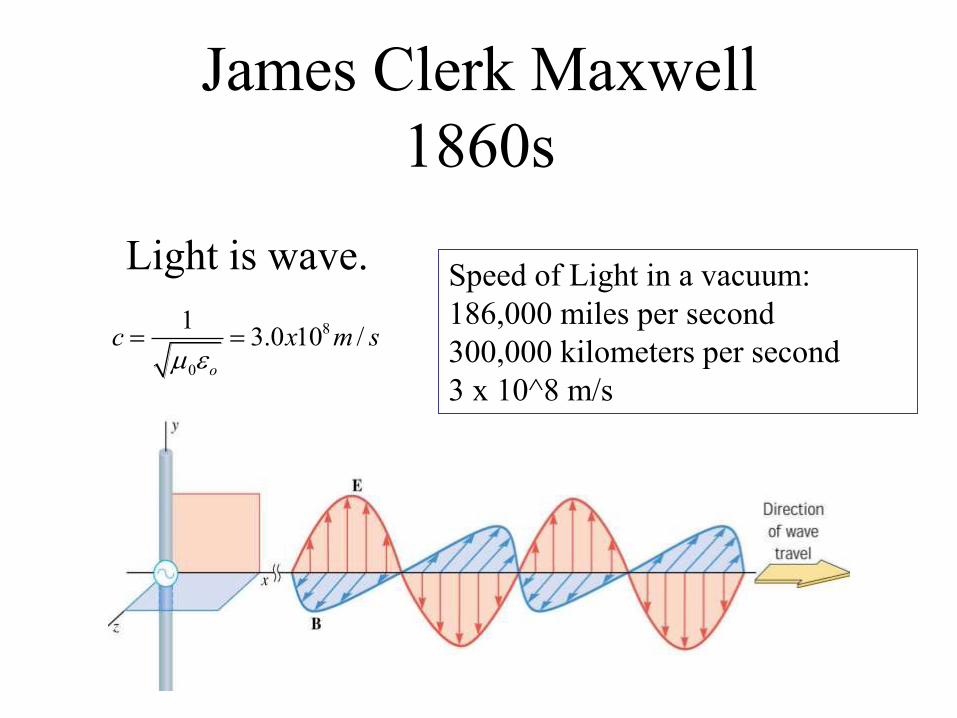
James Clerk Maxwell
1860s
Light is wave.
8
0
13.0 10 /
o
c x m s
Speed of Light in a vacuum:
186,000 miles per second
300,000 kilometers per second
3 x 10^8 m/s
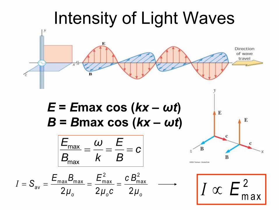
Intensity of Light Waves
E = Emax cos (kx – ωt)
B = Bmax cos (kx – ωt)
max
max
E ω Ec
B k B
2 2
max max max maxav
2 2 2I
o o o
E B E c BS
μ μ c μ
I 2
m axE
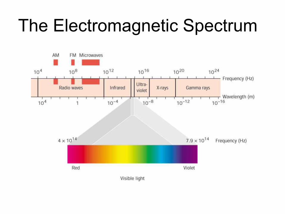
The Electromagnetic Spectrum

Visible Light
• Different wavelengths
correspond to
different colors
• The range is from red
(λ ~ 7 x 10⁻⁷ m) to
violet (λ ~4 x 10⁻⁷ m)
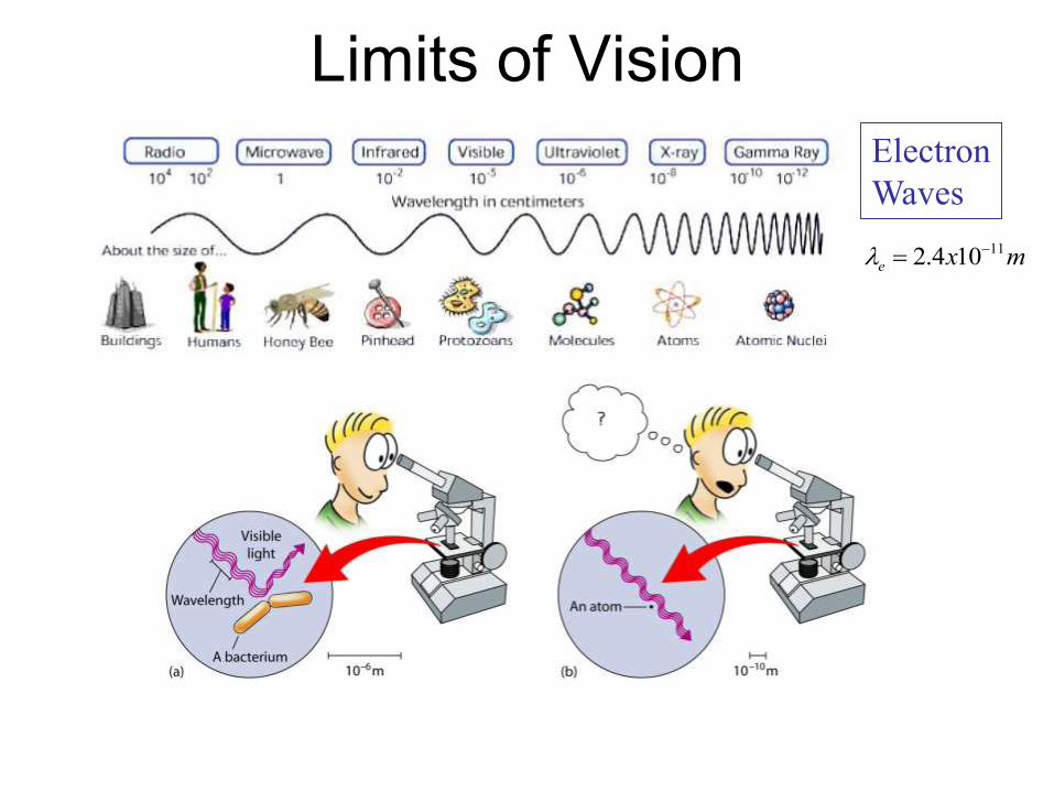
Limits of Vision
112.4 10e x m
Electron
Waves

Interference of Light
Wave Optics
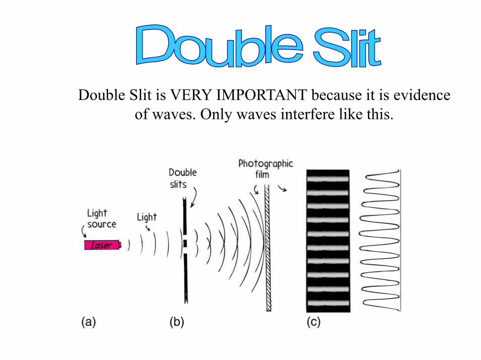
Double Slit is VERY IMPORTANT because it is evidence
of waves. Only waves interfere like this.
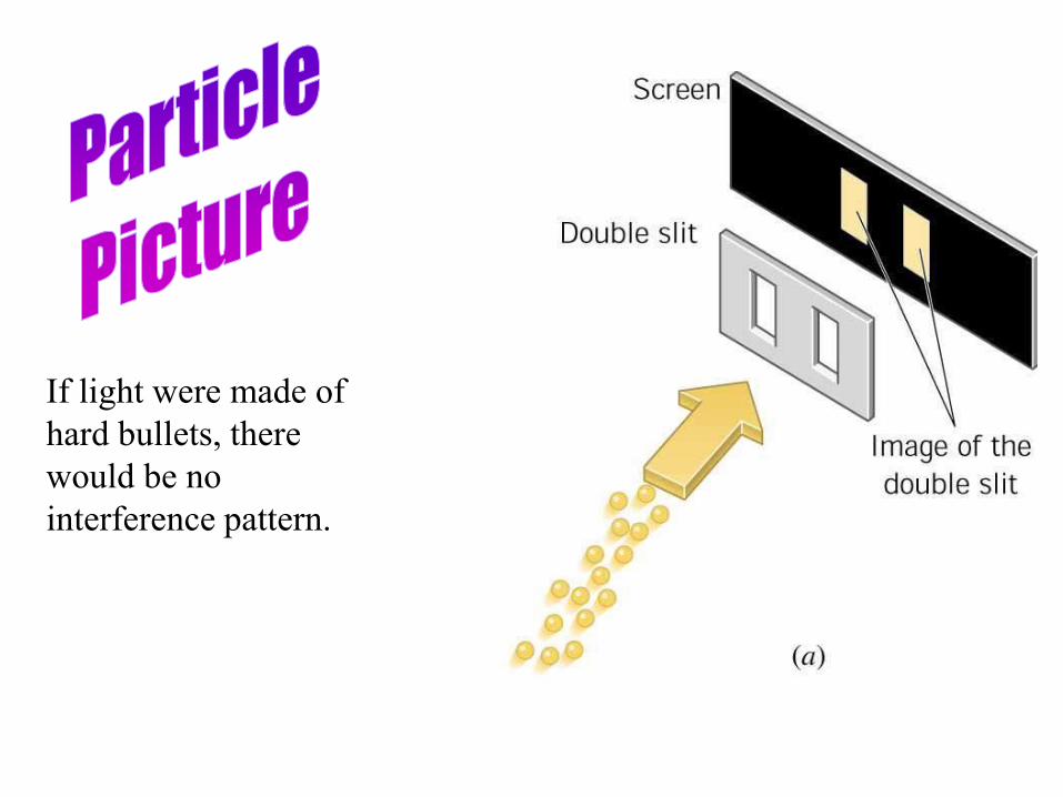
If light were made of
hard bullets, there
would be no
interference pattern.
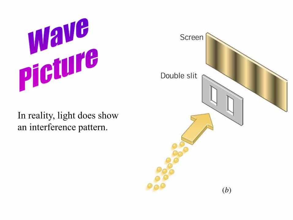
In reality, light does show
an interference pattern.
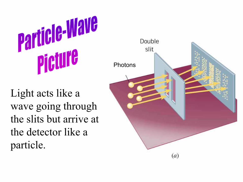
Light acts like a
wave going through
the slits but arrive at
the detector like a
particle.
Photons
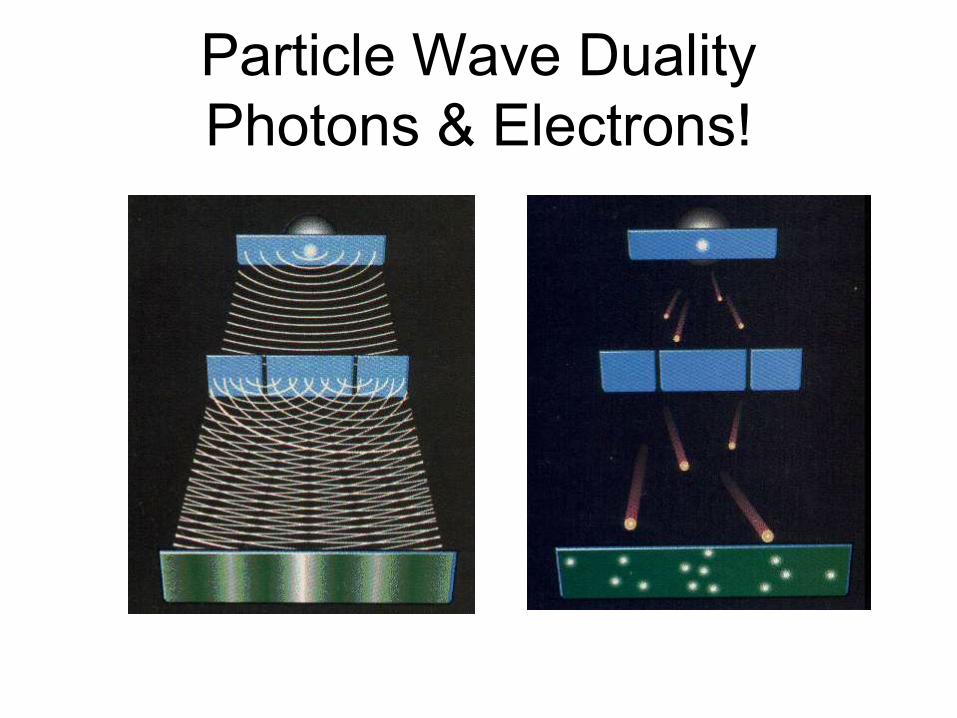
Particle Wave Duality
Photons & Electrons!
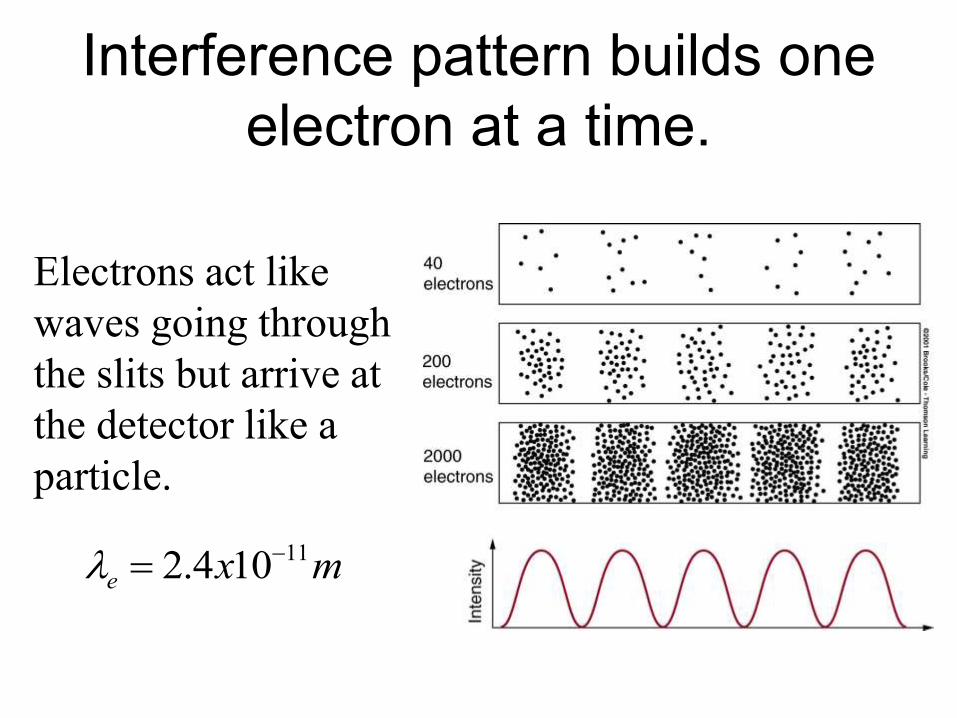
Interference pattern builds one
electron at a time.
Electrons act like
waves going through
the slits but arrive at
the detector like a
particle.
112.4 10e x m
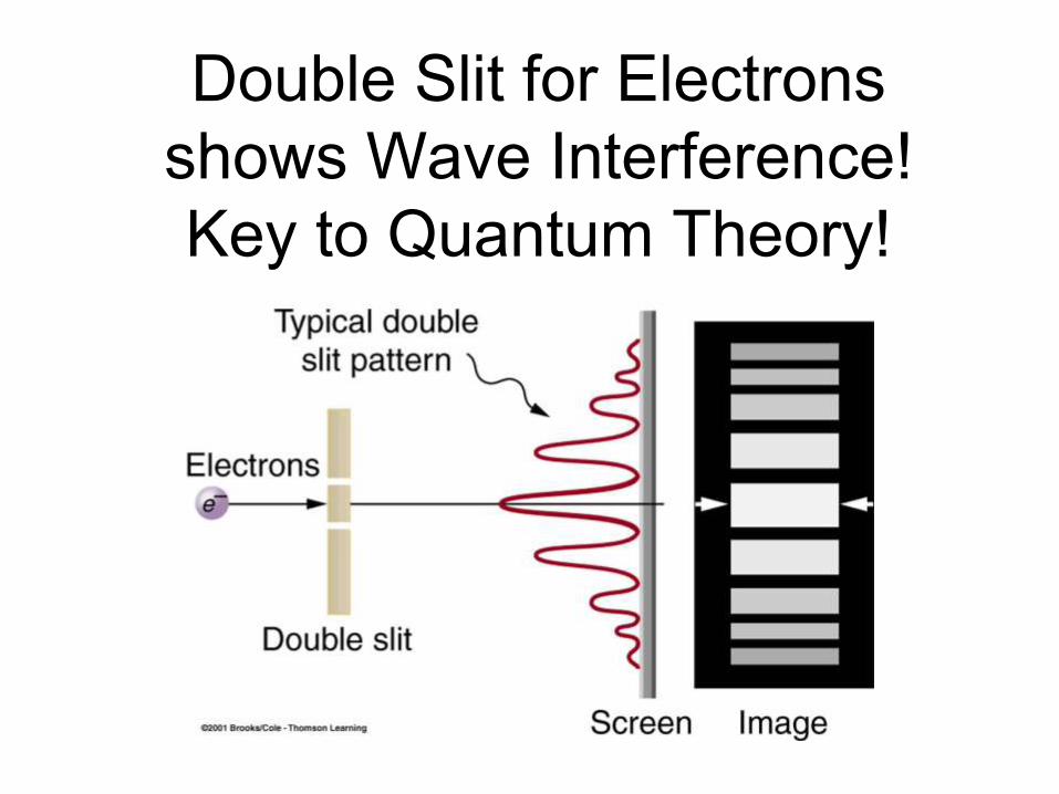
Double Slit for Electrons
shows Wave Interference!
Key to Quantum Theory!
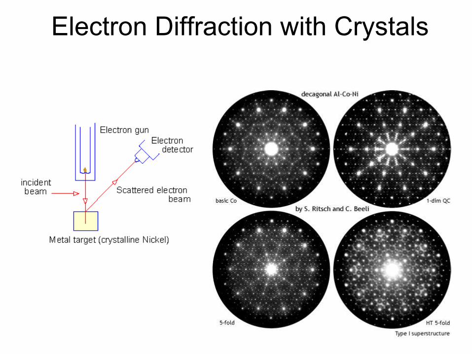
Electron Diffraction with Crystals
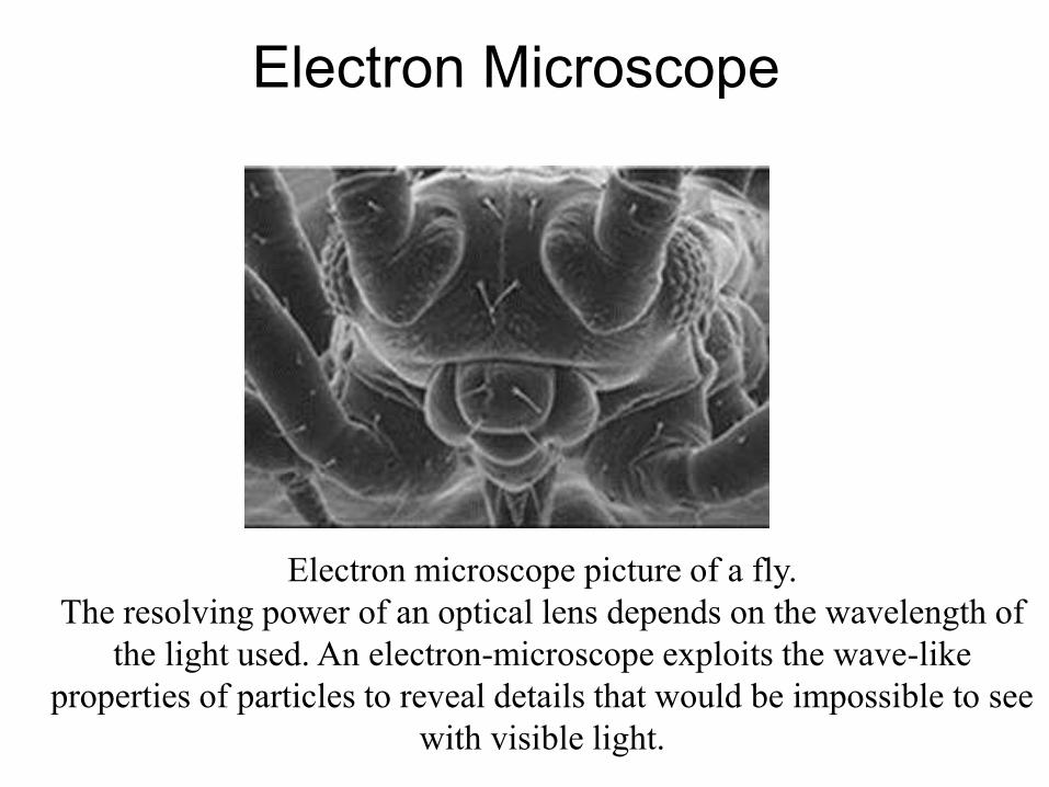
Electron Microscope
Electron microscope picture of a fly.
The resolving power of an optical lens depends on the wavelength of
the light used. An electron-microscope exploits the wave-like
properties of particles to reveal details that would be impossible to see
with visible light.
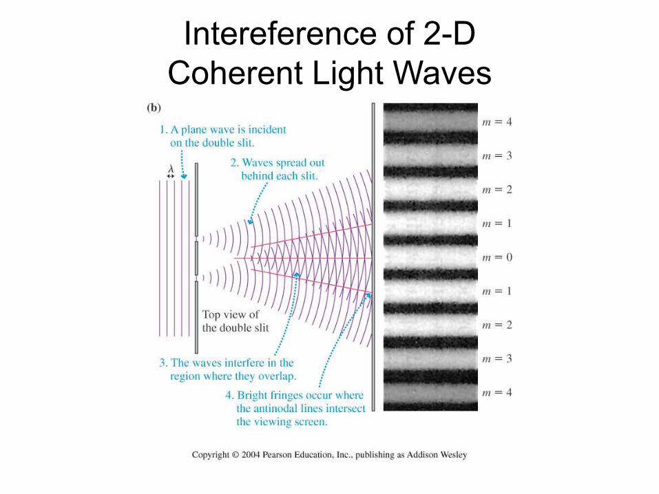
Intereference of 2-D
Coherent Light Waves
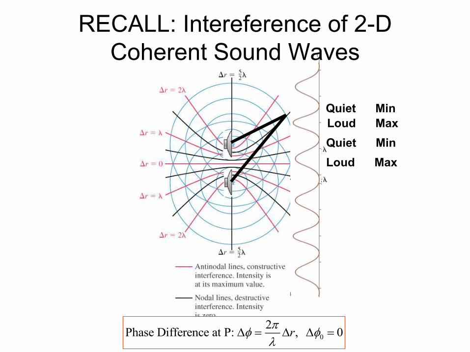
Loud Max
Quiet Min
Quiet Min
Loud Max
RECALL: Intereference of 2-D
Coherent Sound Waves
0
2Phase Difference at P: , 0r
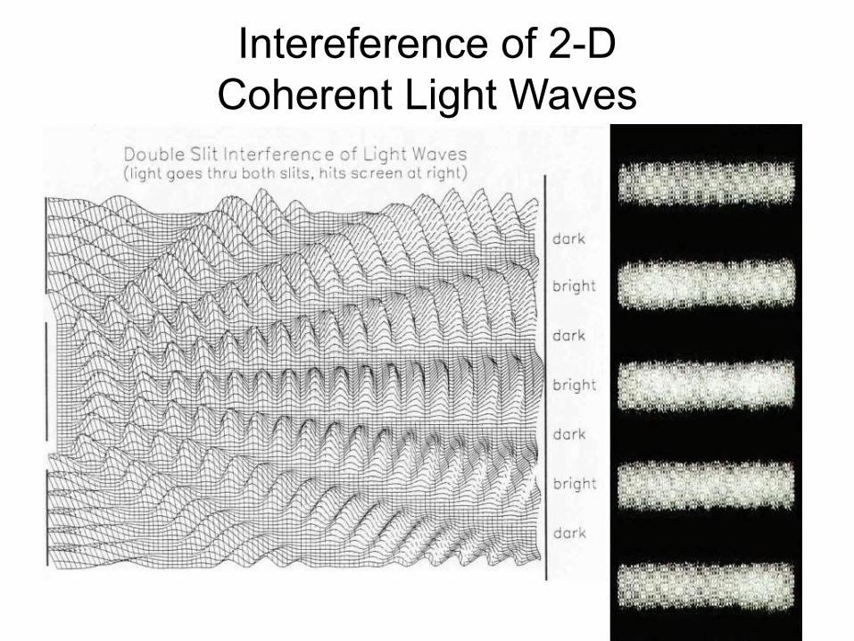
Intereference of 2-D
Coherent Light Waves
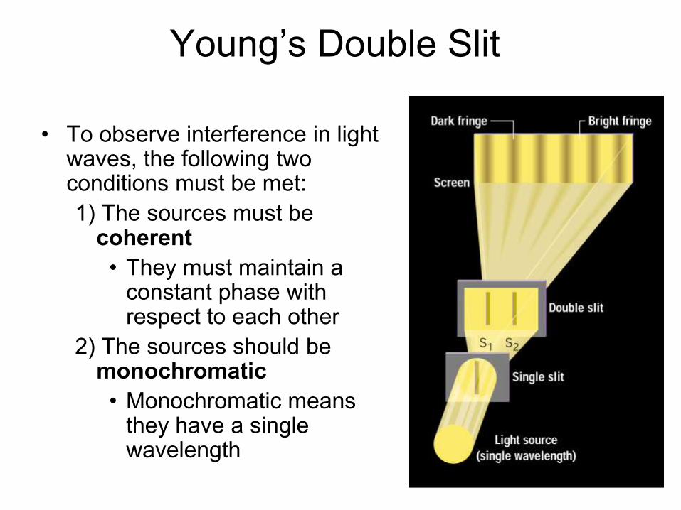
Young’s Double Slit
• To observe interference in light waves, the following two conditions must be met:
1) The sources must be coherent
• They must maintain a constant phase with respect to each other
2) The sources should be monochromatic
• Monochromatic means they have a single wavelength
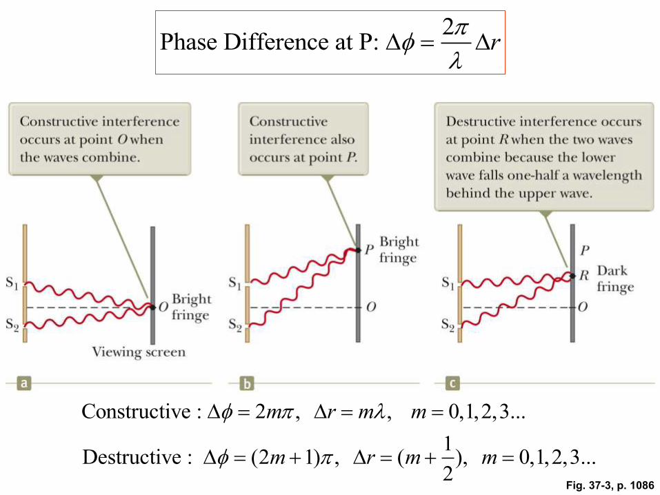
Fig. 37-3, p. 1086
2Phase Difference at P: r
Constructive : 2 , , 0,1,2,3...
1Destructive : (2 1) , ( ), 0,1,2,3...
2
m r m m
m r m m
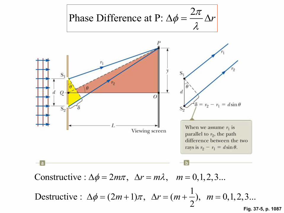
Fig. 37-5, p. 1087
2Phase Difference at P: r
Constructive : 2 , , 0,1,2,3...
1Destructive : (2 1) , ( ), 0,1,2,3...
2
m r m m
m r m m
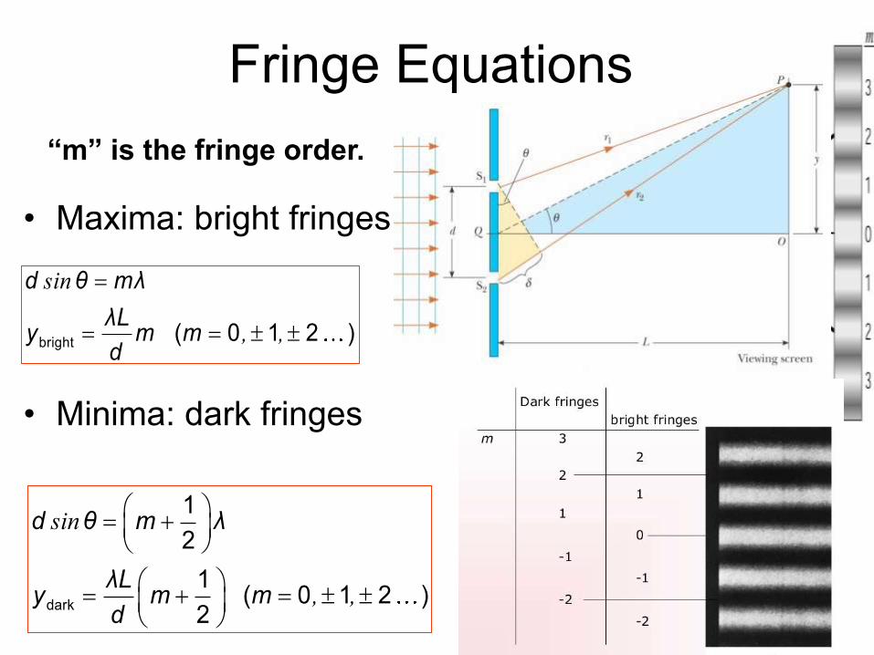
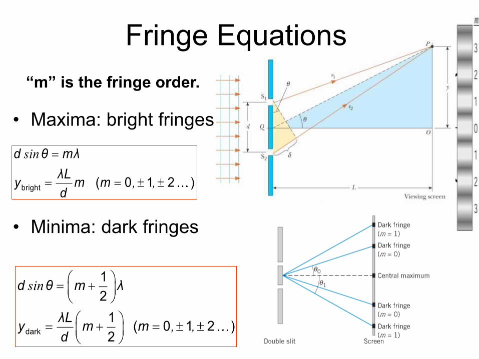
Fringe Equations
• Maxima: bright fringes
• Minima: dark fringes
sin
, ,
bright ( 0 1 2 )
d θ mλ
λLy m m
d
sin
, ,
dark
1
2
1( 0 1 2 )
2
d θ m λ
λLy m m
d
“m” is the fringe order.
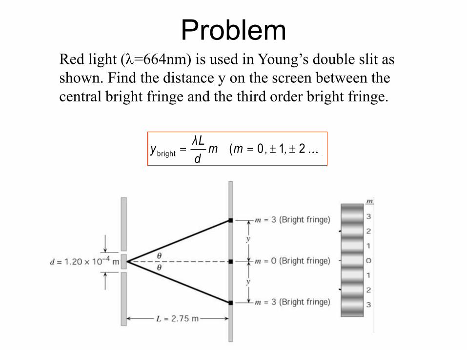
Red light (=664nm) is used in Young’s double slit as
shown. Find the distance y on the screen between the
central bright fringe and the third order bright fringe.
Problem
bright ( 0 1 2 ), ,λL
y m md
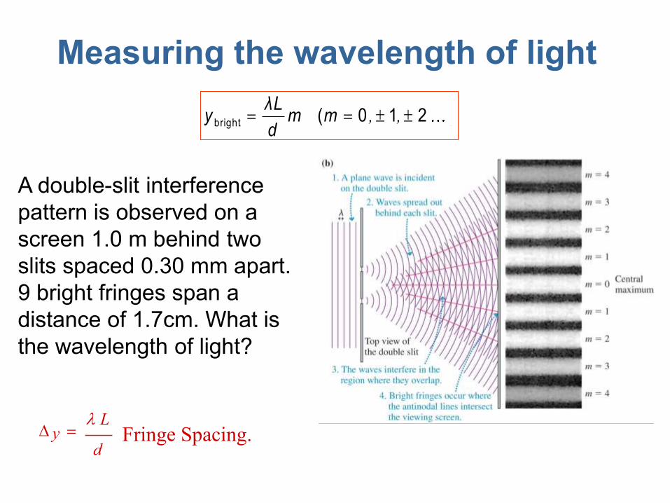
Measuring the wavelength of light
A double-slit interference
pattern is observed on a
screen 1.0 m behind two
slits spaced 0.30 mm apart.
9 bright fringes span a
distance of 1.7cm. What is
the wavelength of light?
y L
dFringe Spacing.
bright ( 0 1 2 ), ,λL
y m md
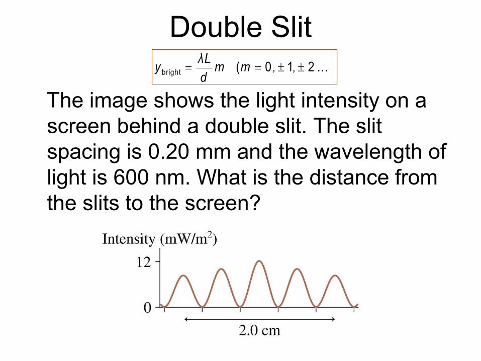
Double Slit
The image shows the light intensity on a
screen behind a double slit. The slit
spacing is 0.20 mm and the wavelength of
light is 600 nm. What is the distance from
the slits to the screen?
bright ( 0 1 2 ), ,λL
y m md
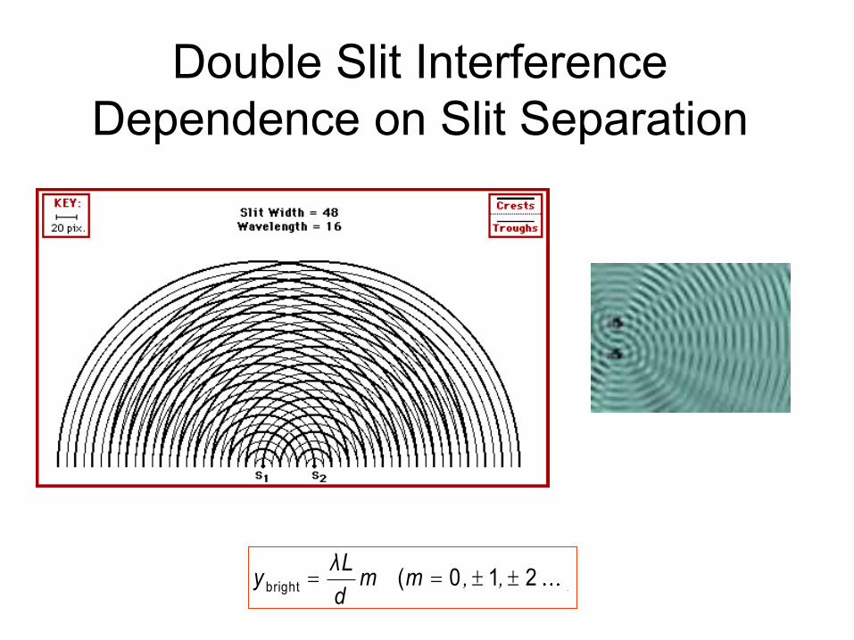
Double Slit Interference
Dependence on Slit Separation
bright ( 0 1 2 ), ,λL
y m md
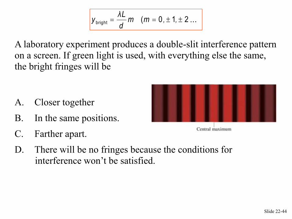
A laboratory experiment produces a double-slit interference pattern
on a screen. If green light is used, with everything else the same,
the bright fringes will be
QuickCheck 22.5
A. Closer together
B. In the same positions.
C. Farther apart.
D. There will be no fringes because the conditions for
interference won’t be satisfied.
Slide 22-44
bright ( 0 1 2 ), ,λL
y m md
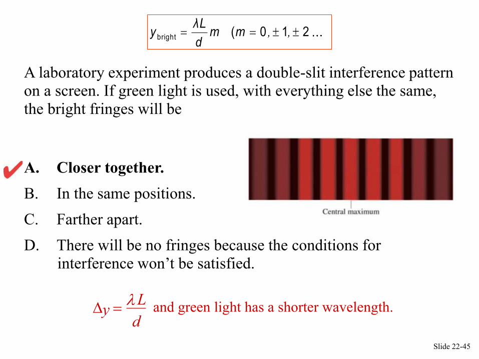
A laboratory experiment produces a double-slit interference pattern
on a screen. If green light is used, with everything else the same,
the bright fringes will be
QuickCheck 22.5
dy
Land green light has a shorter wavelength.
A. Closer together.
B. In the same positions.
C. Farther apart.
D. There will be no fringes because the conditions for
interference won’t be satisfied.
Slide 22-45
bright ( 0 1 2 ), ,λL
y m md

A laboratory experiment produces a double-slit interference
pattern on a screen. If the slits are moved closer together, the
bright fringes will be
QuickCheck 22.6
A. Closer together.
B. In the same positions.
C. Farther apart.
D. There will be no fringes because the conditions for
interference won’t be satisfied.
Slide 22-46
bright ( 0 1 2 ), ,λL
y m md
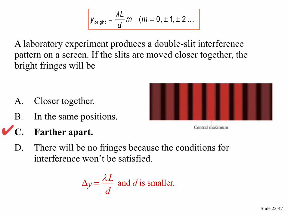
A laboratory experiment produces a double-slit interference
pattern on a screen. If the slits are moved closer together, the
bright fringes will be
QuickCheck 22.6
A. Closer together.
B. In the same positions.
C. Farther apart.
D. There will be no fringes because the conditions for
interference won’t be satisfied.
y L
dand d is smaller.
Slide 22-47
bright ( 0 1 2 ), ,λL
y m md
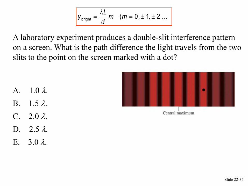
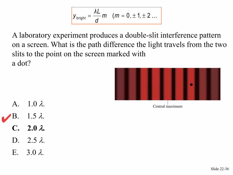
A laboratory experiment produces a double-slit interference pattern
on a screen. What is the path difference the light travels from the two
slits to the point on the screen marked with a dot?
A. 1.0 .
B. 1.5 .
C. 2.0 .
D. 2.5 .
E. 3.0 .
QuickCheck 22.3
Slide 22-35
bright ( 0 1 2 ), ,λL
y m md
A laboratory experiment produces a double-slit interference pattern
on a screen. What is the path difference the light travels from the two
slits to the point on the screen marked with
a dot?
A. 1.0 .
B. 1.5 .
C. 2.0 .
D. 2.5 .
E. 3.0 .
QuickCheck 22.3
Slide 22-36
bright ( 0 1 2 ), ,λL
y m md
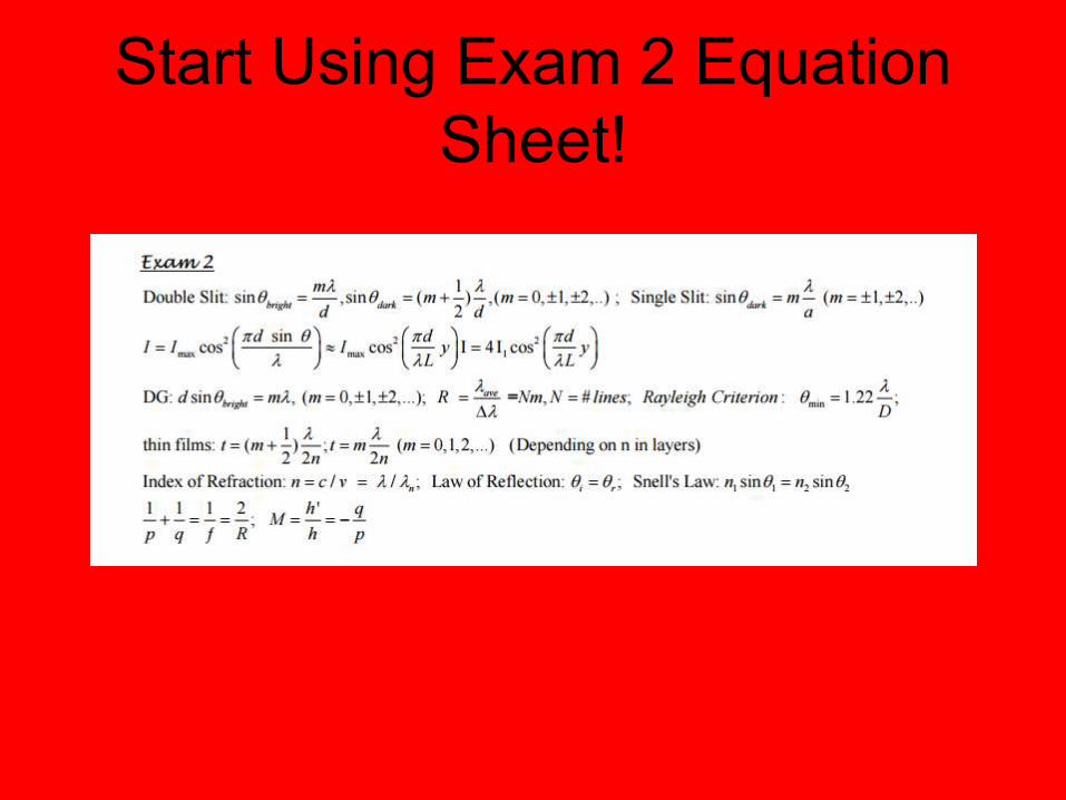
Start Using Exam 2 Equation
Sheet!
Fringe Equations
• Maxima: bright fringes
• Minima: dark fringes
sin
, ,
bright ( 0 1 2 )
d θ mλ
λLy m m
d
sin
, ,
dark
1
2
1( 0 1 2 )
2
d θ m λ
λLy m m
d
“m” is the fringe order.
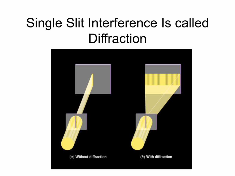
Single Slit Interference Is called
Diffraction
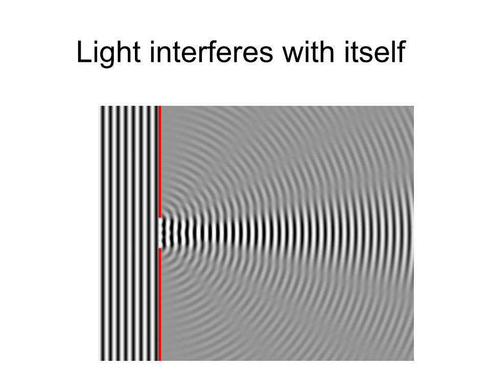
Light interferes with itself
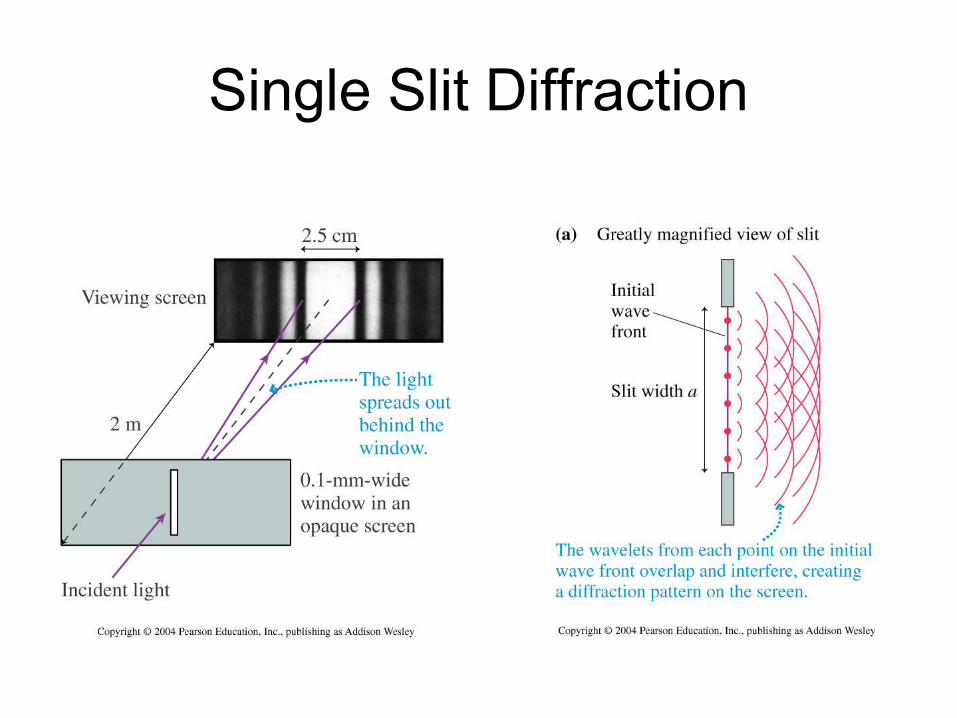
Single Slit Diffraction
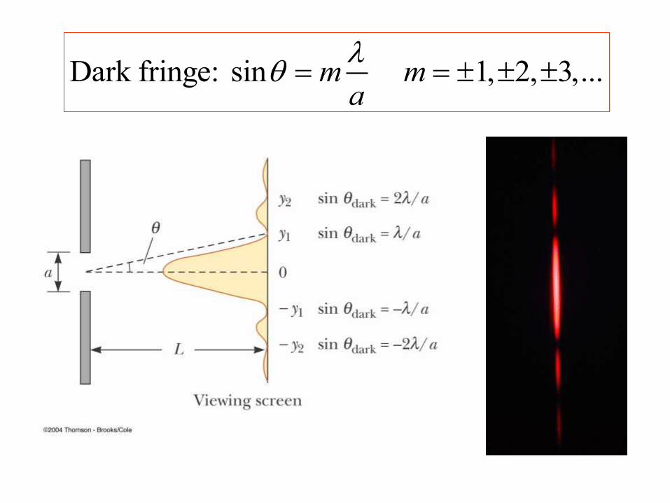
Dark fringe: sin 1, 2, 3,...m ma

Single Slit Problem
A narrow slit is illuminated with sodium yellow light
of wavelength 589 nm. If the central maximum
extends to ±30, how wide is the slit?
Dark fringe: sin 1, 2, 3,...m ma
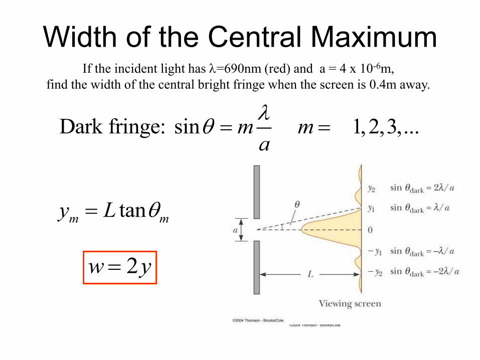
If the incident light has =690nm (red) and a = 4 x 10⁻⁶m,
find the width of the central bright fringe when the screen is 0.4m away.
Dark fringe: sin 0,1,2,3,...m ma
2w y
tanm my L
Width of the Central Maximum
Dark fringe: sin ma
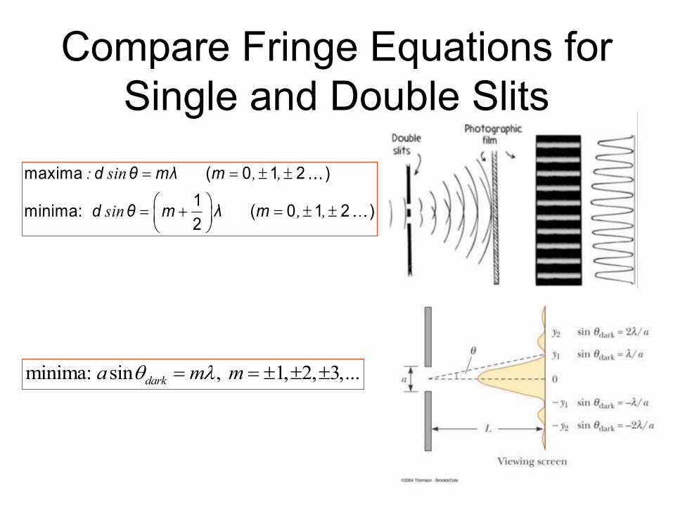
Compare Fringe Equations for
Single and Double Slits
: sin , ,
sin , ,
maxima ( 0 1 2 )
1minima: ( 0 1 2 )
2
d θ mλ m
d θ m λ m
minima: sin , 1, 2, 3,...darka m m
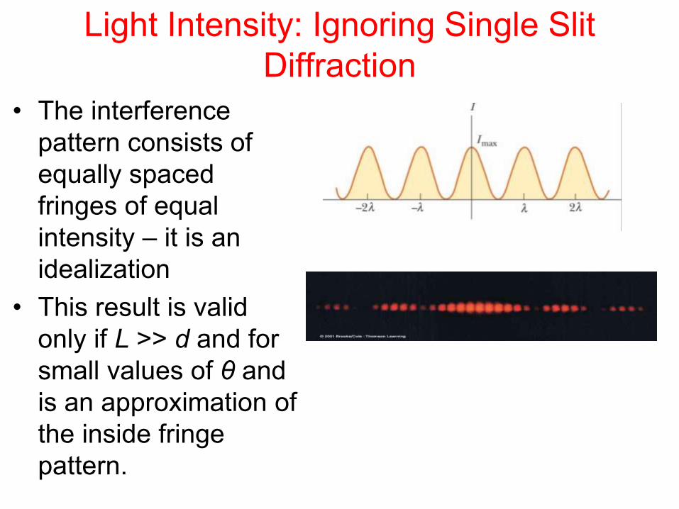
Light Intensity: Ignoring Single Slit
Diffraction
• The interference
pattern consists of
equally spaced
fringes of equal
intensity – it is an
idealization
• This result is valid
only if L >> d and for
small values of θ and
is an approximation of
the inside fringe
pattern.

Reality: Combined EffectsInterference maximum coincides with the first diffraction minimum.

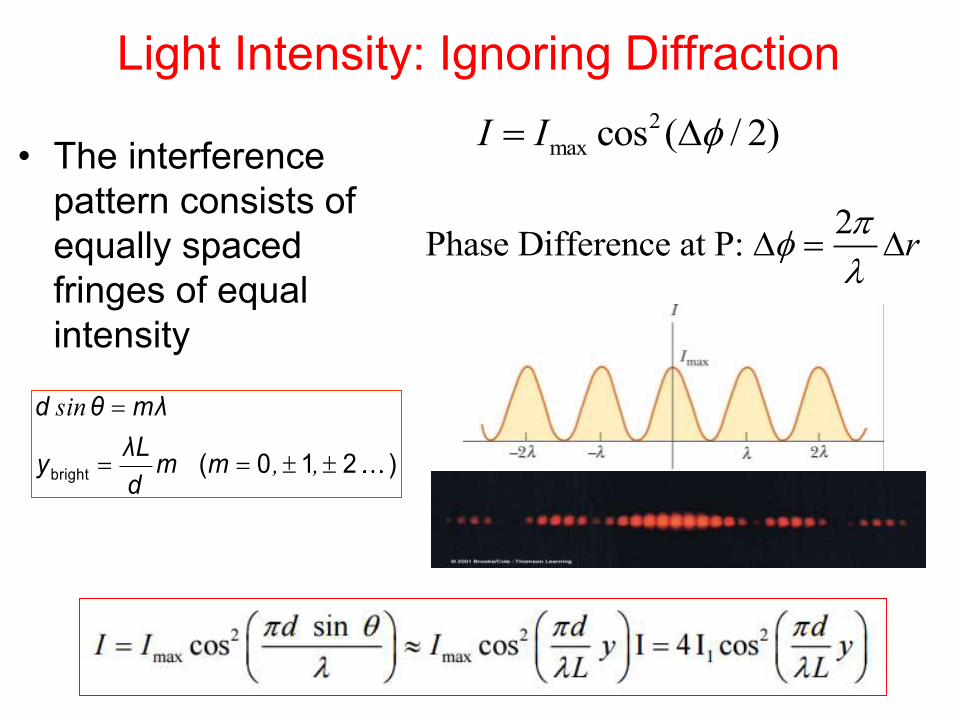
Light Intensity: Ignoring Diffraction
• The interference
pattern consists of
equally spaced
fringes of equal
intensity
2
max cos ( / 2)I I
2Phase Difference at P: r
sin
, ,
bright ( 0 1 2 )
d θ mλ
λLy m m
d
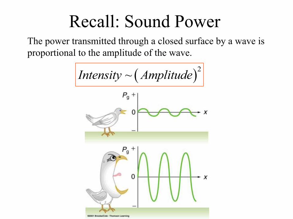
The power transmitted through a closed surface by a wave is
proportional to the amplitude of the wave.
Recall: Sound Power
2
~Intensity Amplitude
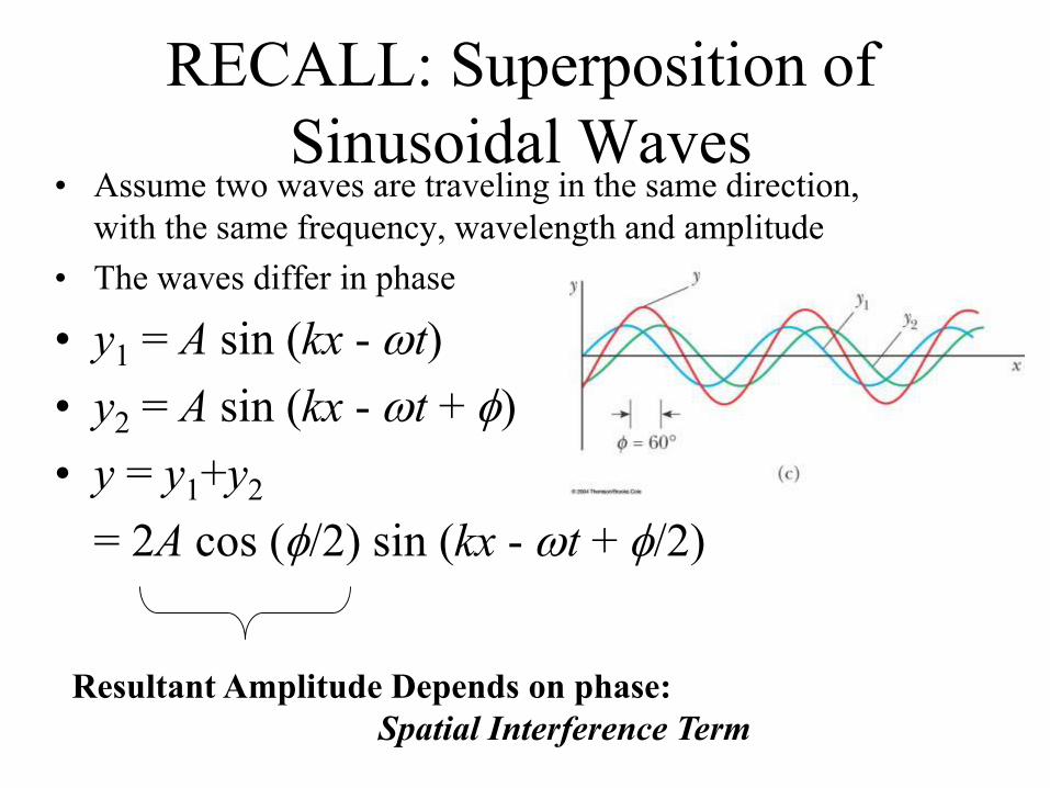
RECALL: Superposition of
Sinusoidal Waves• Assume two waves are traveling in the same direction,
with the same frequency, wavelength and amplitude
• The waves differ in phase
• y1 = A sin (kx - wt)
• y2 = A sin (kx - wt + )
• y = y1+y2
= 2A cos (/2) sin (kx - wt + /2)
Resultant Amplitude Depends on phase:
Spatial Interference Term
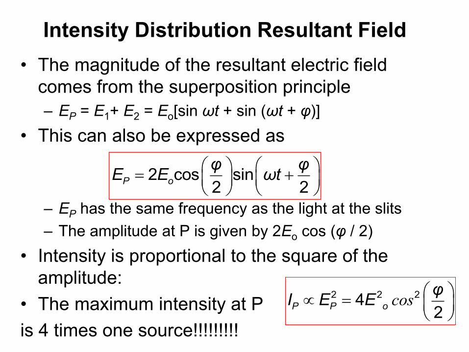
Intensity Distribution Resultant Field
• The magnitude of the resultant electric field
comes from the superposition principle
– EP = E1+ E2 = Eo[sin ωt + sin (ωt + φ)]
• This can also be expressed as
– EP has the same frequency as the light at the slits
– The amplitude at P is given by 2Eo cos (φ / 2)
• Intensity is proportional to the square of the
amplitude:
• The maximum intensity at P
is 4 times one source!!!!!!!!!
2 cos sin2 2
P o
φ φE E ωt
cos
2 2 242
P P o
φI E E
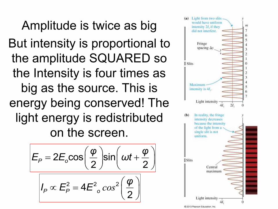
Amplitude is twice as big
But intensity is proportional to
the amplitude SQUARED so
the Intensity is four times as
big as the source. This is
energy being conserved! The
light energy is redistributed
on the screen.
2 cos sin2 2
P o
φ φE E ωt
cos
2 2 242
P P o
φI E E
Light Intensity: Ignoring Diffraction
• The interference
pattern consists of
equally spaced
fringes of equal
intensity
2
max cos ( / 2)I I
2Phase Difference at P: r
sin
, ,
bright ( 0 1 2 )
d θ mλ
λLy m m
d

Intensity
In a double-slit experiment, the distance between the slits is 0.2 mm, and the distance to the screen is 150 cm. What wavelength (in nm) is needed to have the intensity at a point 1 mm from the central maximum on the screen be 80% of the maximum intensity?
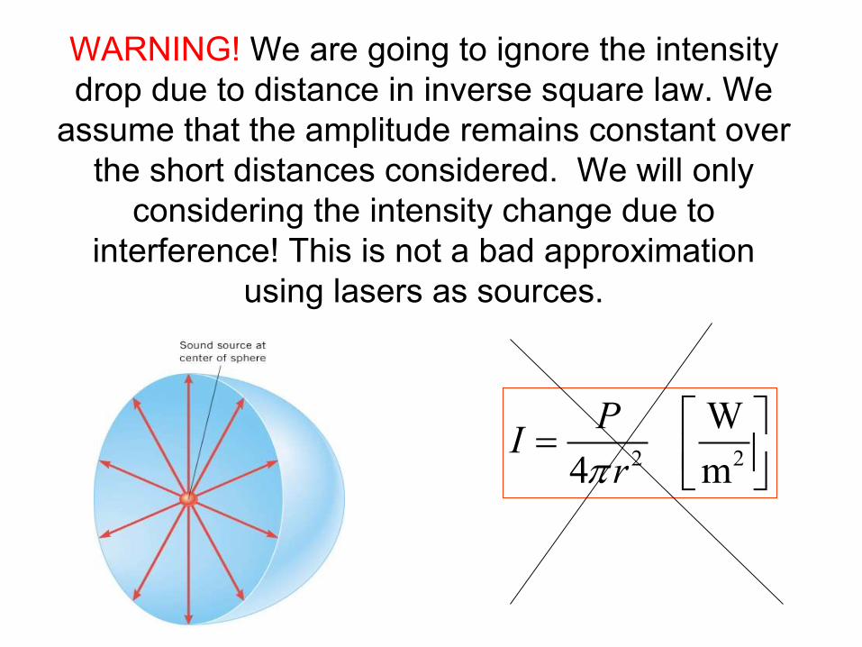
WARNING! We are going to ignore the intensity
drop due to distance in inverse square law. We
assume that the amplitude remains constant over
the short distances considered. We will only
considering the intensity change due to
interference! This is not a bad approximation
using lasers as sources.
2 2
W
4 m
PI
r
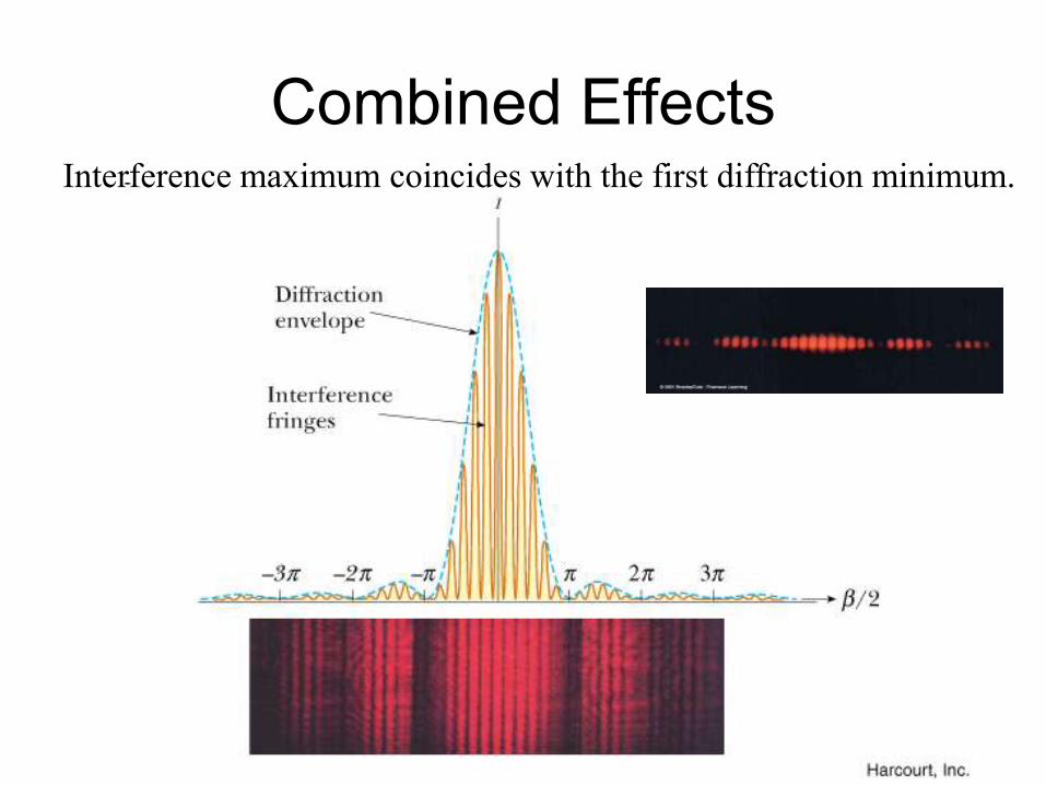
Combined EffectsInterference maximum coincides with the first diffraction minimum.
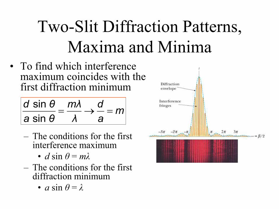
Two-Slit Diffraction Patterns,
Maxima and Minima• To find which interference
maximum coincides with the first diffraction minimum
– The conditions for the first interference maximum
• d sin θ = mλ
– The conditions for the first diffraction minimum
• a sin θ = λ
sin
sin
d θ mλ dm
a θ λ a

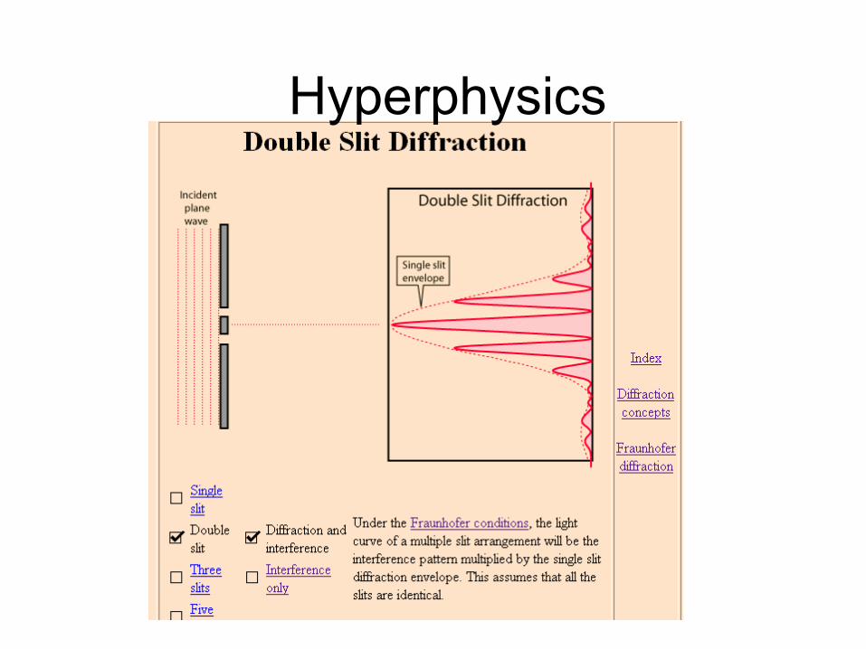
Intensity of Two-Slit Diffraction
The Complete Equation
Section 38.2
2
2
max
sin sin sin cos
sin
/I I
/
πa θ λπd θ
λ πa θ λ
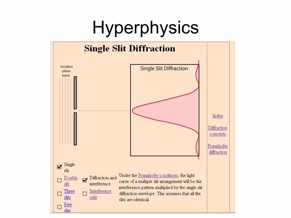
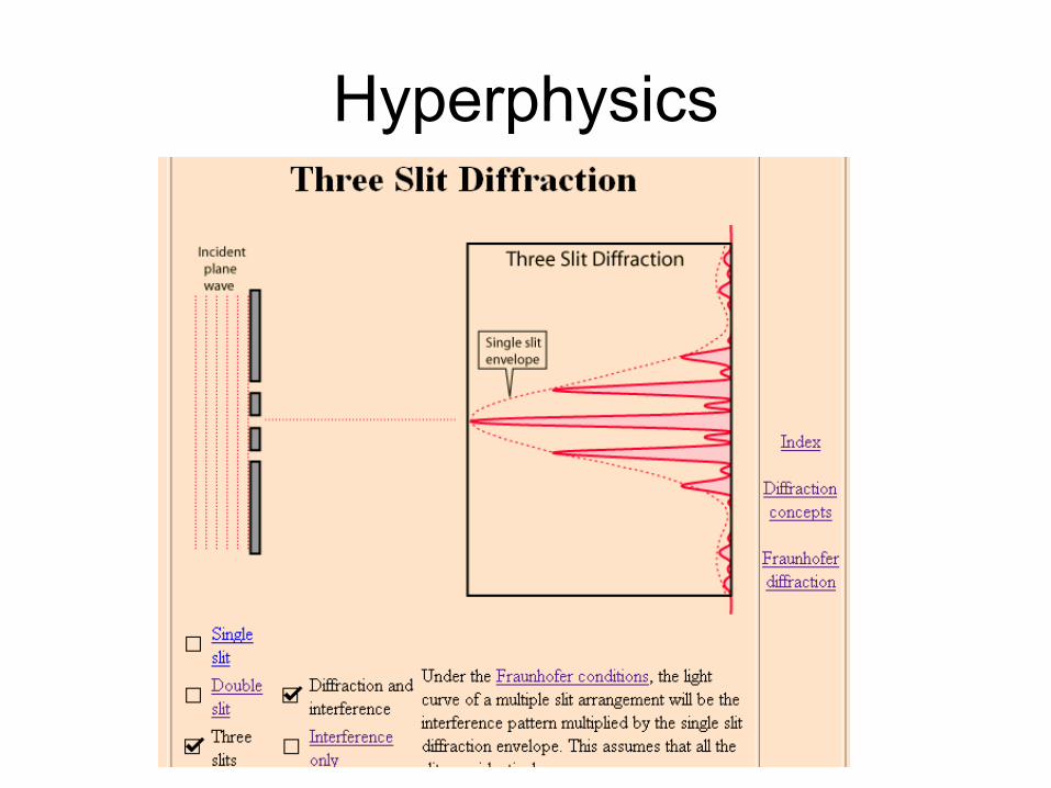
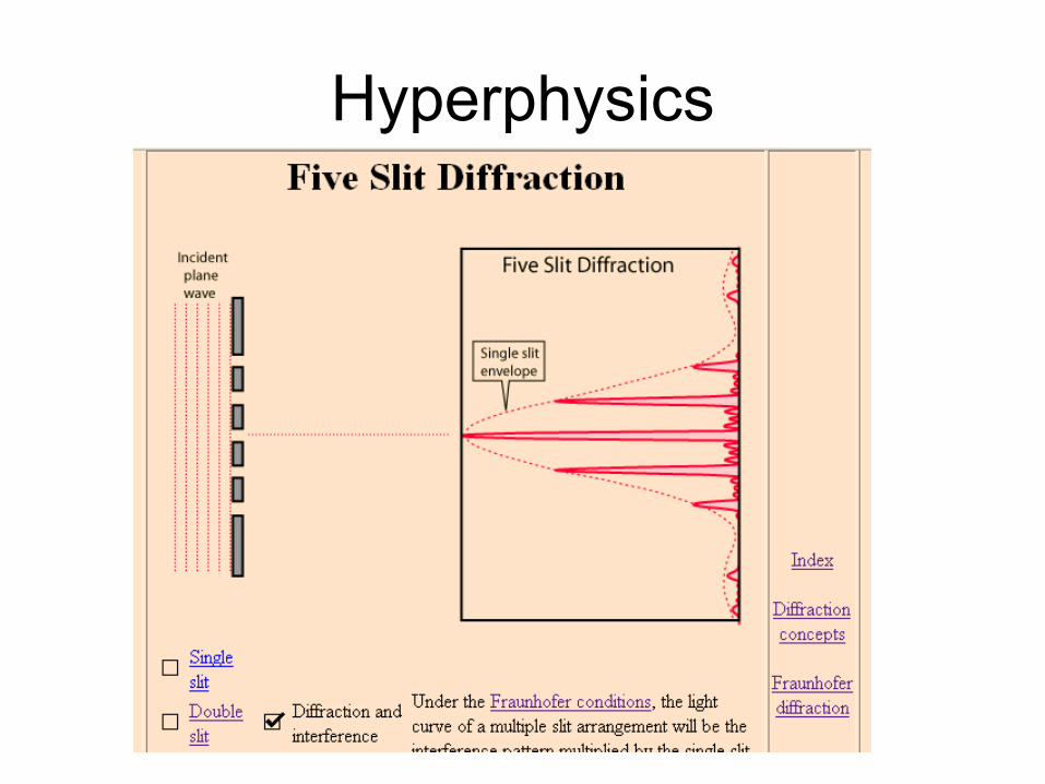
Hyperphysics
Hyperphysics
Hyperphysics
Hyperphysics
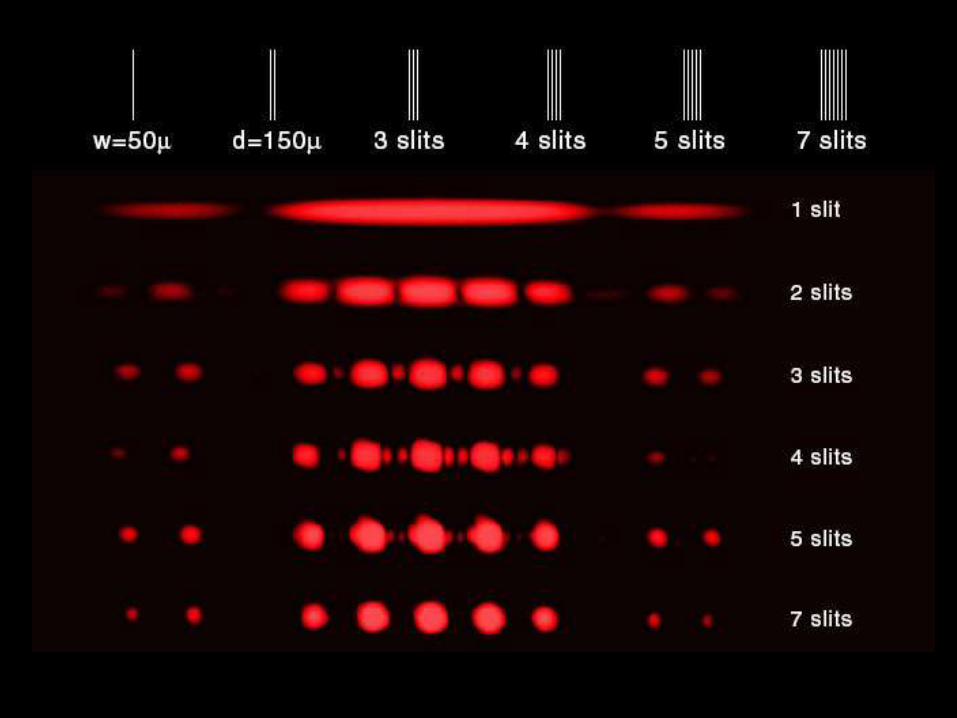
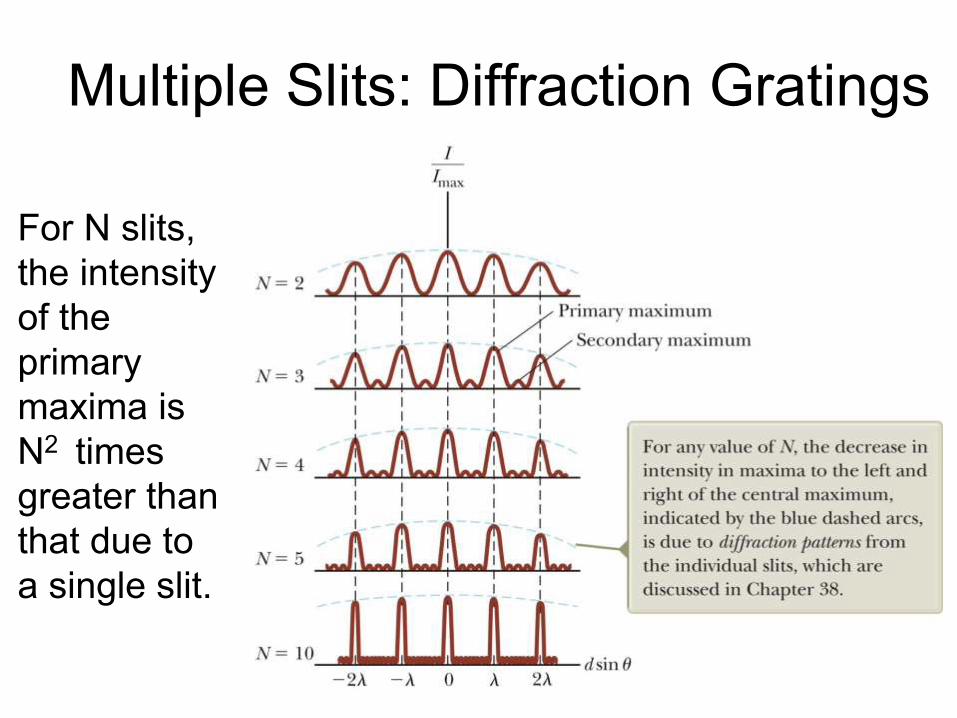
Multiple Slits: Diffraction Gratings
Section 37.3
For N slits,
the intensity
of the
primary
maxima is
N2 times
greater than
that due to
a single slit.
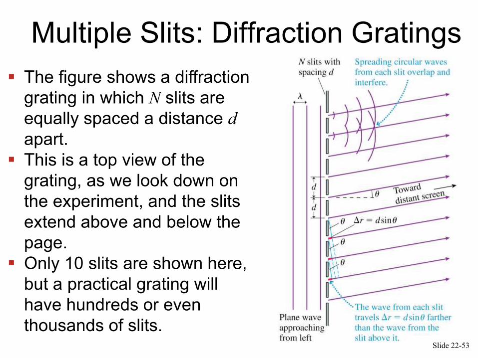
The Diffraction Grating
The figure shows a diffraction
grating in which N slits are
equally spaced a distance d
apart.
This is a top view of the
grating, as we look down on
the experiment, and the slits
extend above and below the
page.
Only 10 slits are shown here,
but a practical grating will
have hundreds or even
thousands of slits.Slide 22-53
Multiple Slits: Diffraction Gratings
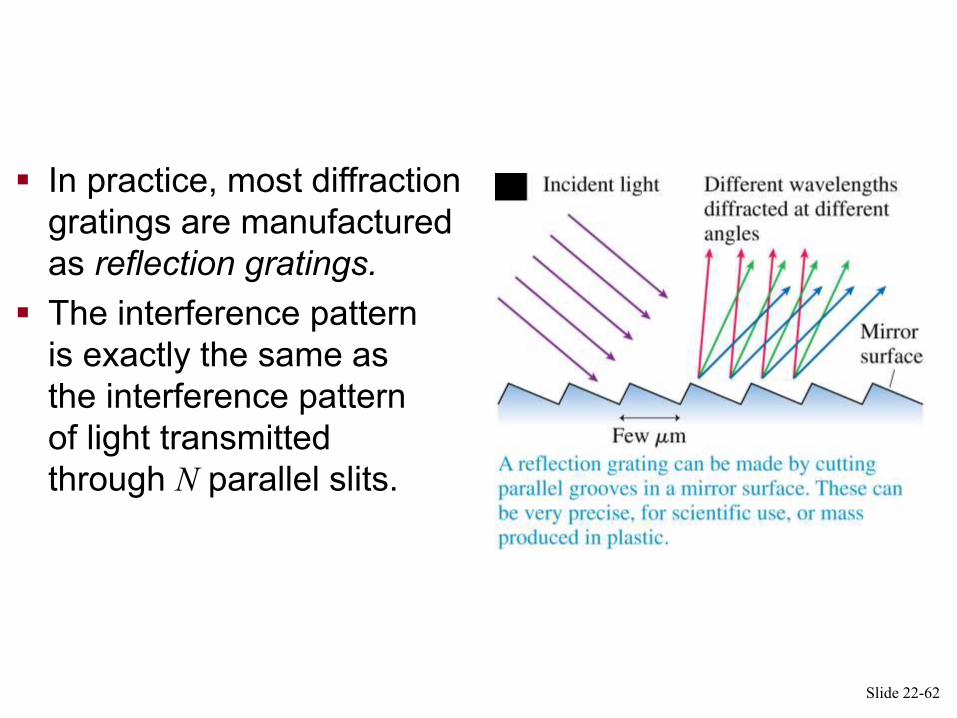
Reflection Gratings
In practice, most diffraction
gratings are manufactured
as reflection gratings.
The interference pattern
is exactly the same as
the interference pattern
of light transmitted
through N parallel slits.
Slide 22-62

The Diffraction Grating
Bright fringes will
occur at angles m,
such that
d sinm = m
where m = 0, 1, 2, 3, …
The y-positions of these fringes are:
Slide 22-54
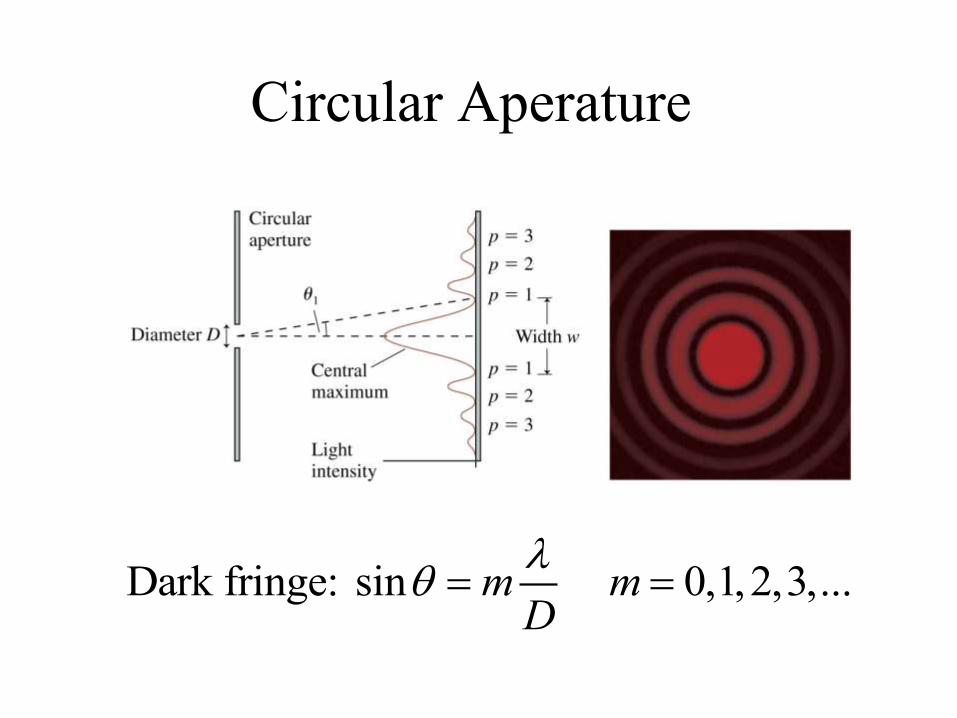
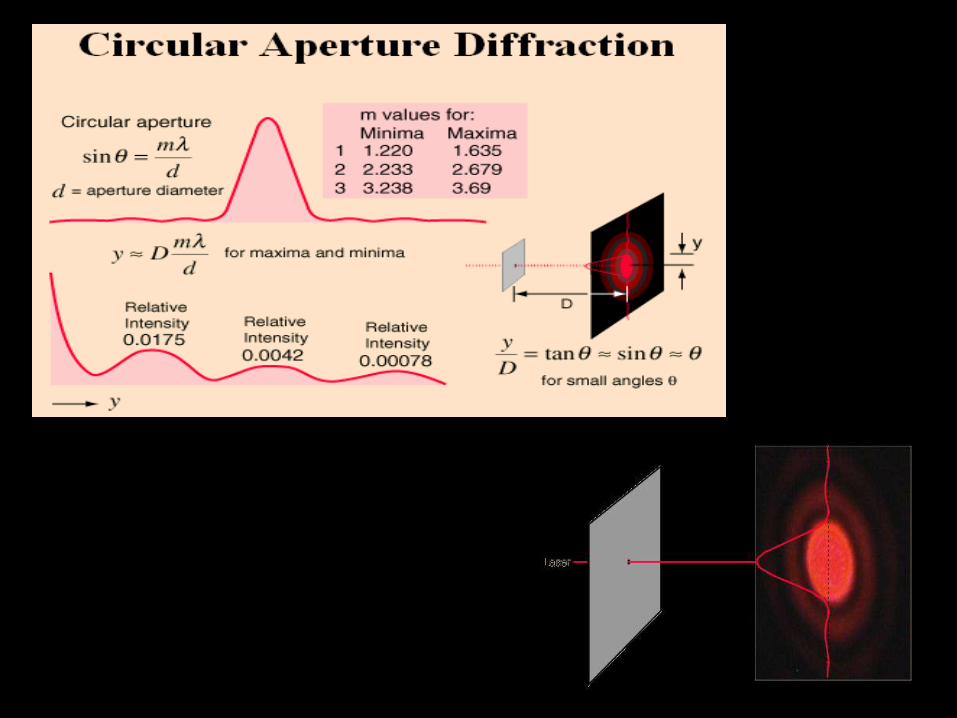
Circular Aperature
Dark fringe: sin 0,1,2,3,...m mD
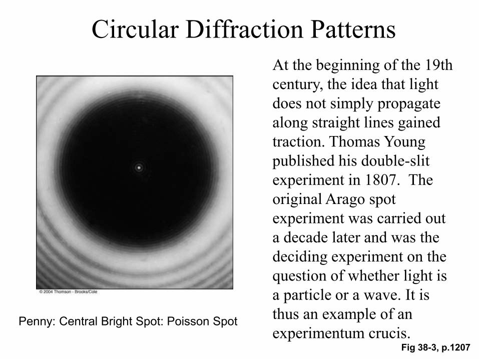
Circular Diffraction Patterns
Fig 38-3, p.1207
Penny: Central Bright Spot: Poisson Spot
At the beginning of the 19th
century, the idea that light
does not simply propagate
along straight lines gained
traction. Thomas Young
published his double-slit
experiment in 1807. The
original Arago spot
experiment was carried out
a decade later and was the
deciding experiment on the
question of whether light is
a particle or a wave. It is
thus an example of an
experimentum crucis.
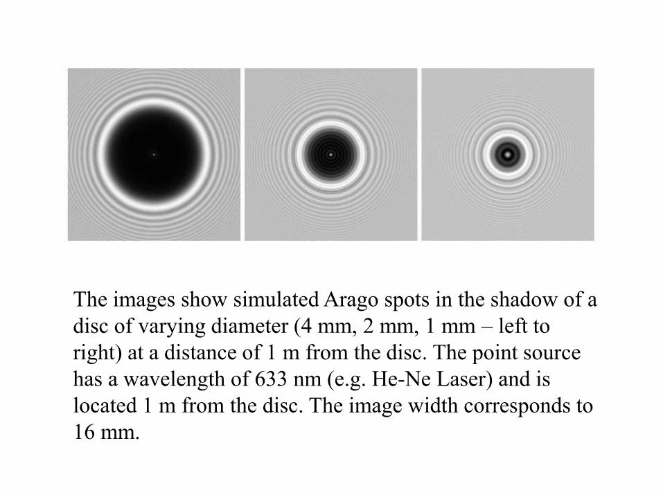
The images show simulated Arago spots in the shadow of a
disc of varying diameter (4 mm, 2 mm, 1 mm – left to
right) at a distance of 1 m from the disc. The point source
has a wavelength of 633 nm (e.g. He-Ne Laser) and is
located 1 m from the disc. The image width corresponds to
16 mm.

Airy DiskDue to diffraction, the
smallest point to which a lens
or mirror can focus a beam of
light is the size of the Airy
disk. Even if one were able
to make a perfect lens, there
is still a limit to the
resolution of an image
created by such a lens. An
optical system in which the
resolution is no longer
limited by imperfections in
the lenses but only by
diffraction is said to be
diffraction limited.
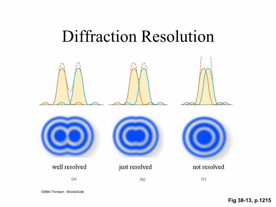
Fig 38-13, p.1215
Diffraction Resolution
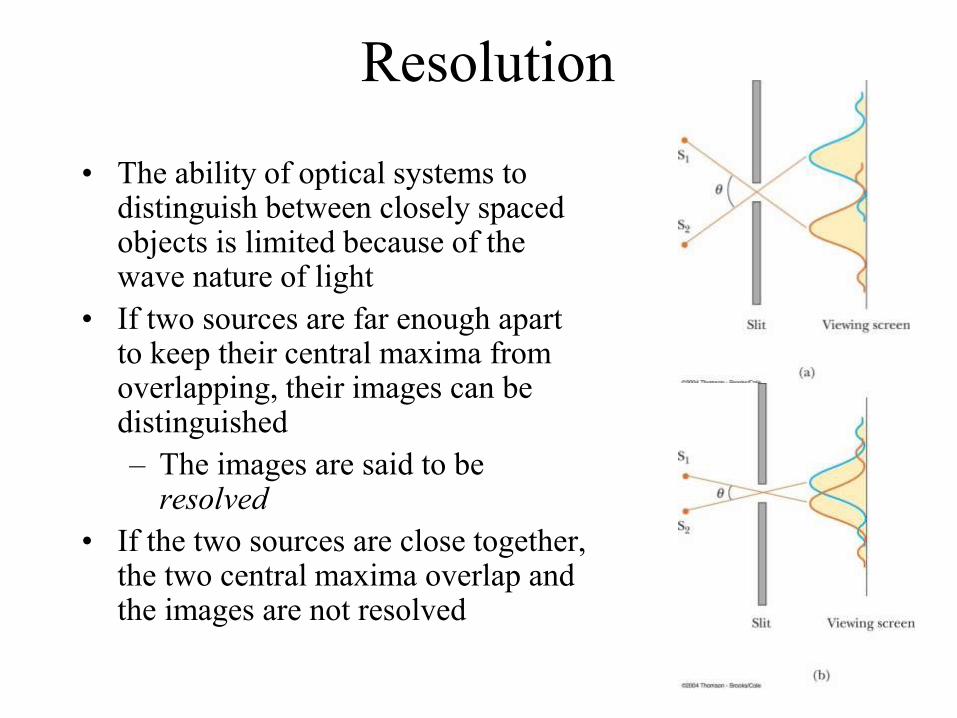
Resolution
• The ability of optical systems to distinguish between closely spaced objects is limited because of the wave nature of light
• If two sources are far enough apart to keep their central maxima from overlapping, their images can be distinguished
– The images are said to be resolved
• If the two sources are close together, the two central maxima overlap and the images are not resolved
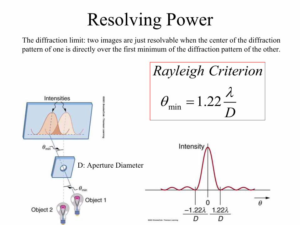
Resolving Power
min
1.22
Rayleigh Criterion
D
The diffraction limit: two images are just resolvable when the center of the diffraction
pattern of one is directly over the first minimum of the diffraction pattern of the other.
D: Aperture Diameter

Space Shuttle Resolution
What, approximately is the distance between objects on Earth that the astronauts can resolve by eye at 200 km height from the space shuttle? Assume l = 500 nm light and a pupil diameter D = 0.50 cm. Ignore the index of refraction from vitreous eye fluid.
min
1.22
Rayleigh Criterion
D
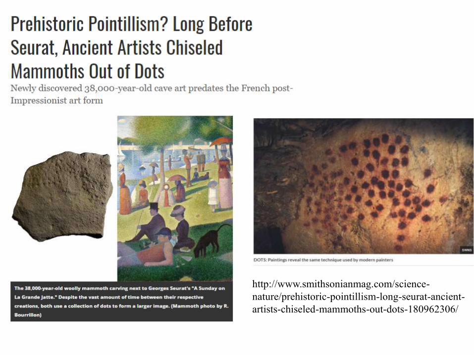
http://www.smithsonianmag.com/science-
nature/prehistoric-pointillism-long-seurat-ancient-
artists-chiseled-mammoths-out-dots-180962306/
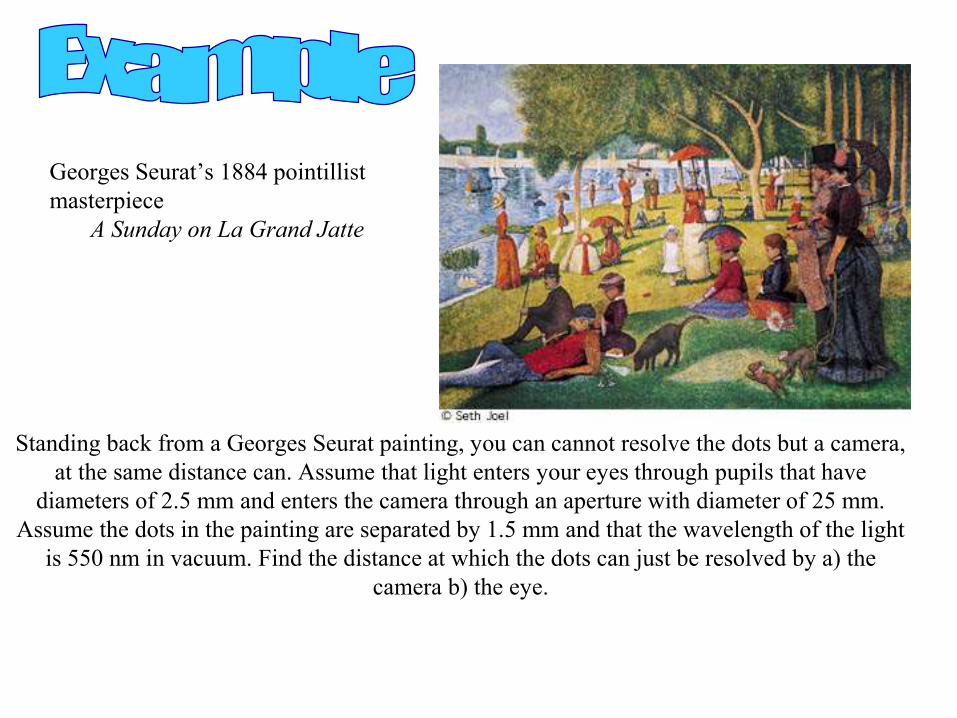
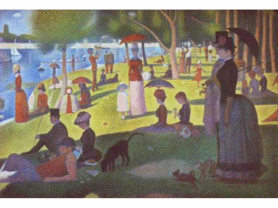
Standing back from a Georges Seurat painting, you can cannot resolve the dots but a camera,
at the same distance can. Assume that light enters your eyes through pupils that have
diameters of 2.5 mm and enters the camera through an aperture with diameter of 25 mm.
Assume the dots in the painting are separated by 1.5 mm and that the wavelength of the light
is 550 nm in vacuum. Find the distance at which the dots can just be resolved by a) the
camera b) the eye.
Georges Seurat’s 1884 pointillist
masterpiece
A Sunday on La Grand Jatte

Thin Film
Interference

RGB Color Theory
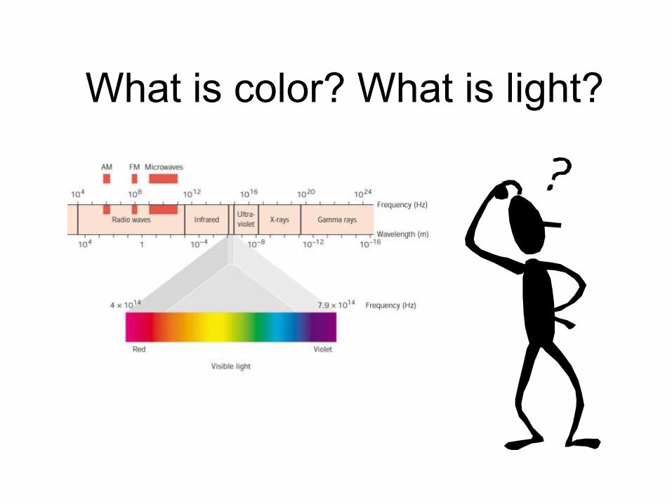
What is color? What is light?
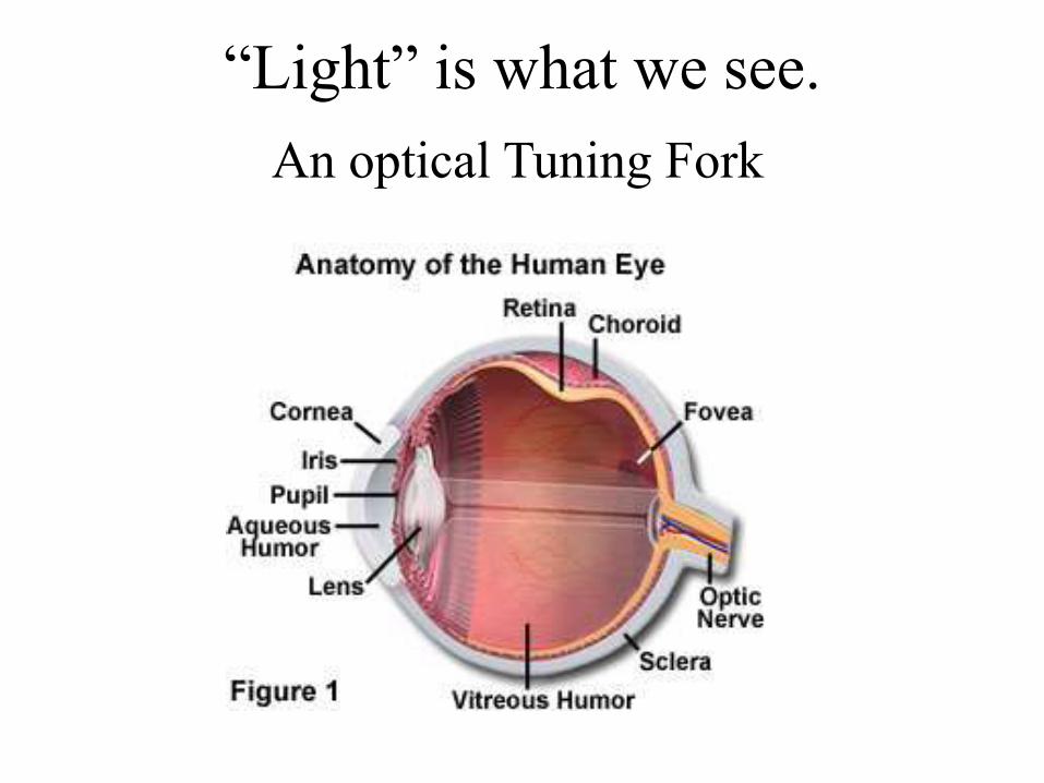
“Light” is what we see.
An optical Tuning Fork
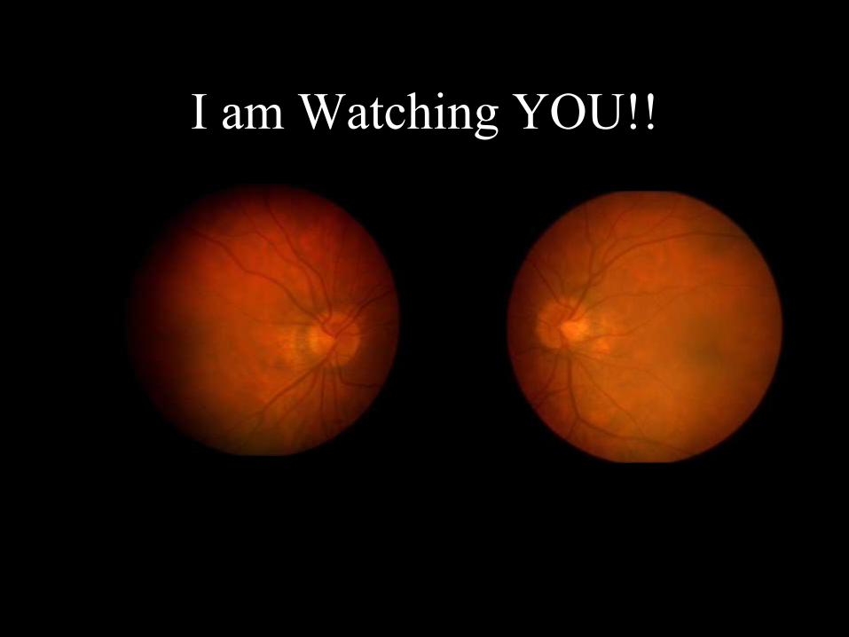
I am Watching YOU!!
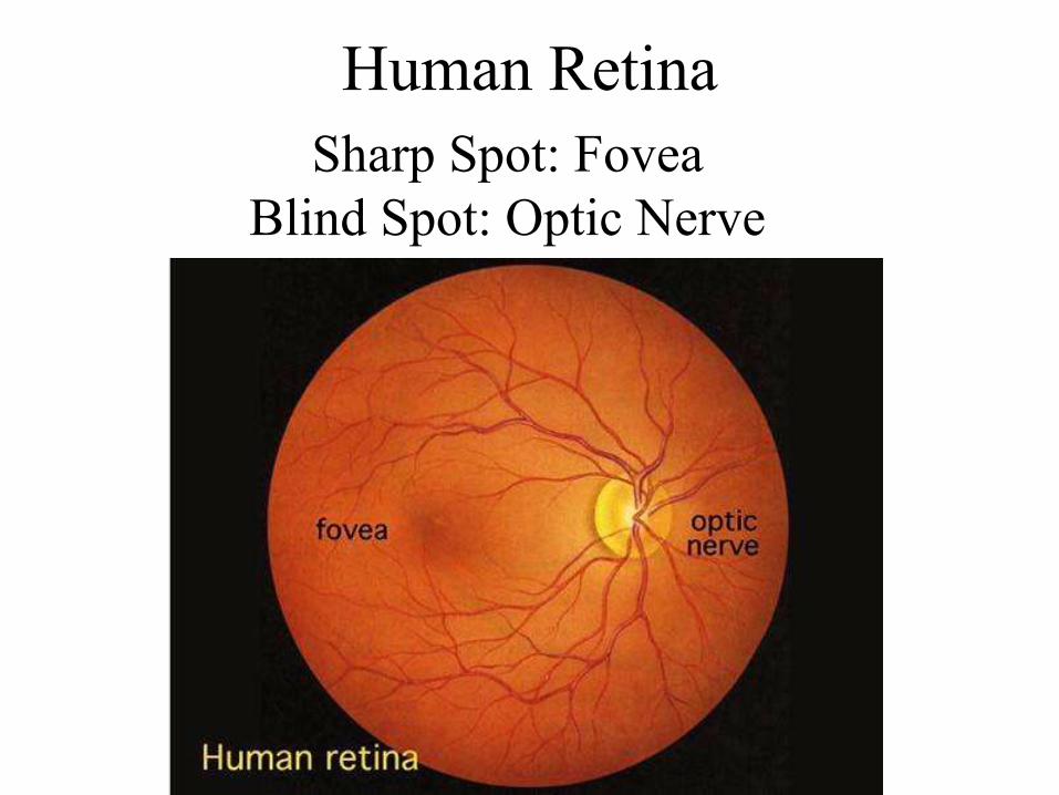
Human Retina
Sharp Spot: Fovea
Blind Spot: Optic Nerve

Optical Antennae: Rods & ConesRods: Intensity Cones: Color
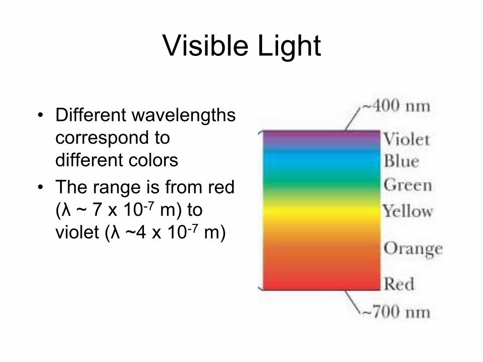
Visible Light
• Different wavelengths
correspond to
different colors
• The range is from red
(λ ~ 7 x 10⁻⁷ m) to
violet (λ ~4 x 10⁻⁷ m)

Limits of Vision
112.4 10e x m
Electron
Waves
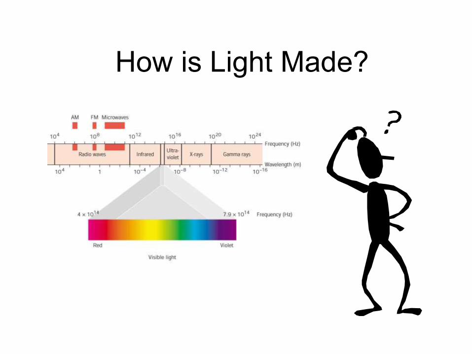
How is Light Made?
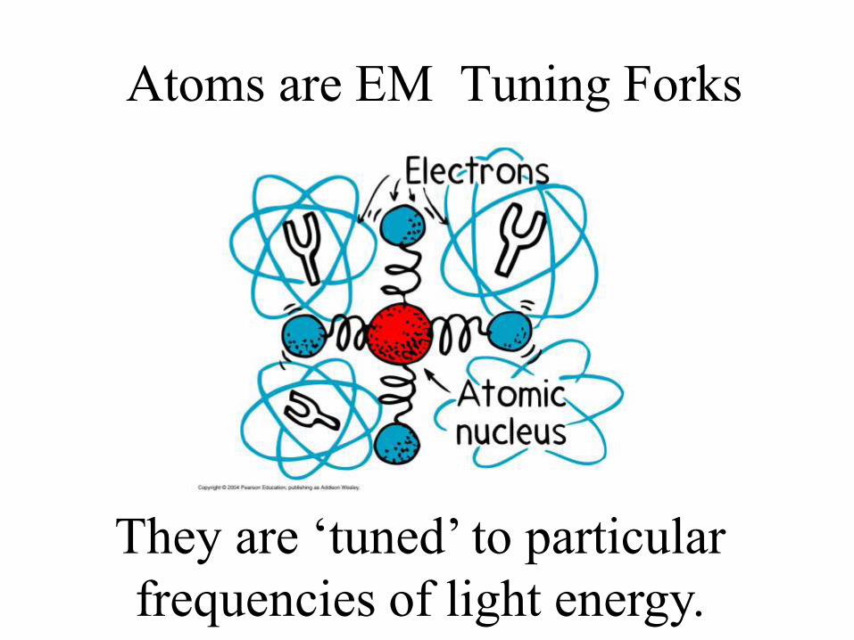
Atoms are EM Tuning Forks
They are ‘tuned’ to particular
frequencies of light energy.
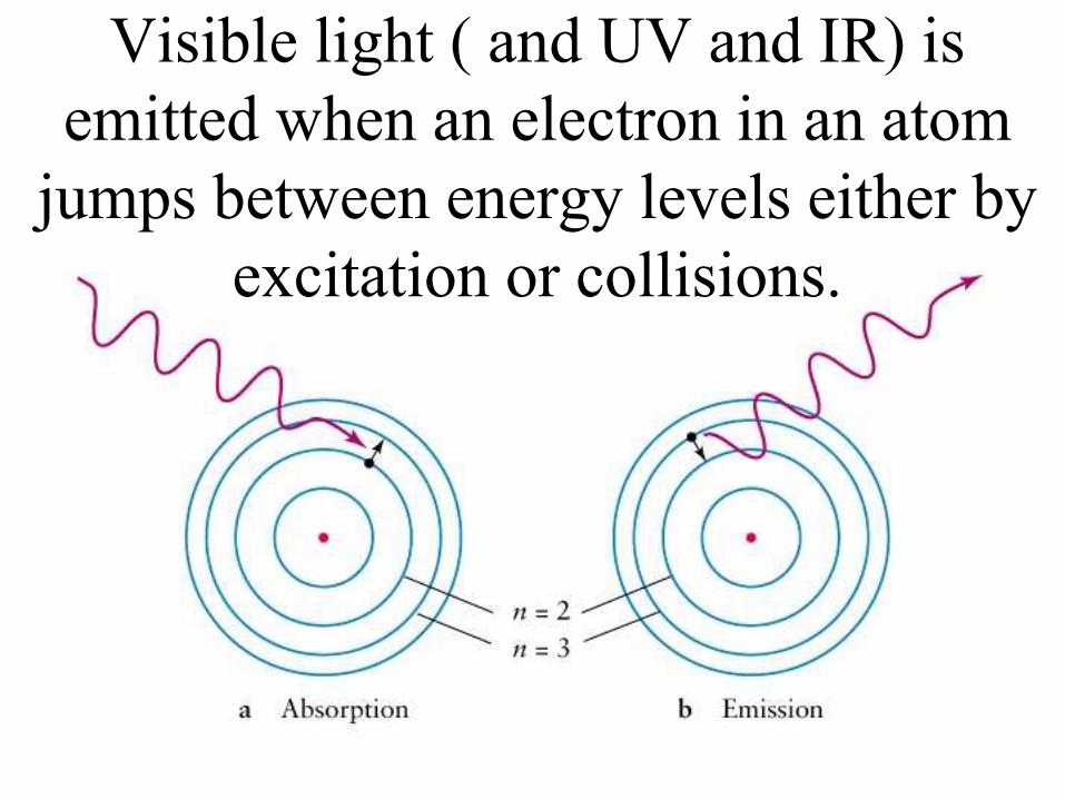
Visible light ( and UV and IR) is
emitted when an electron in an atom
jumps between energy levels either by
excitation or collisions.
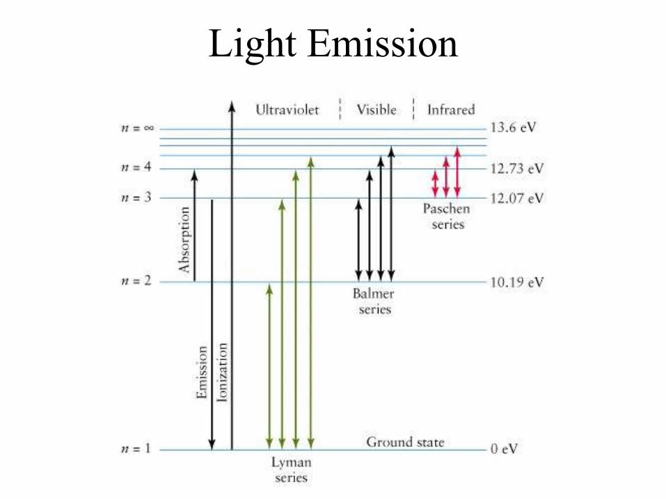
Light Emission
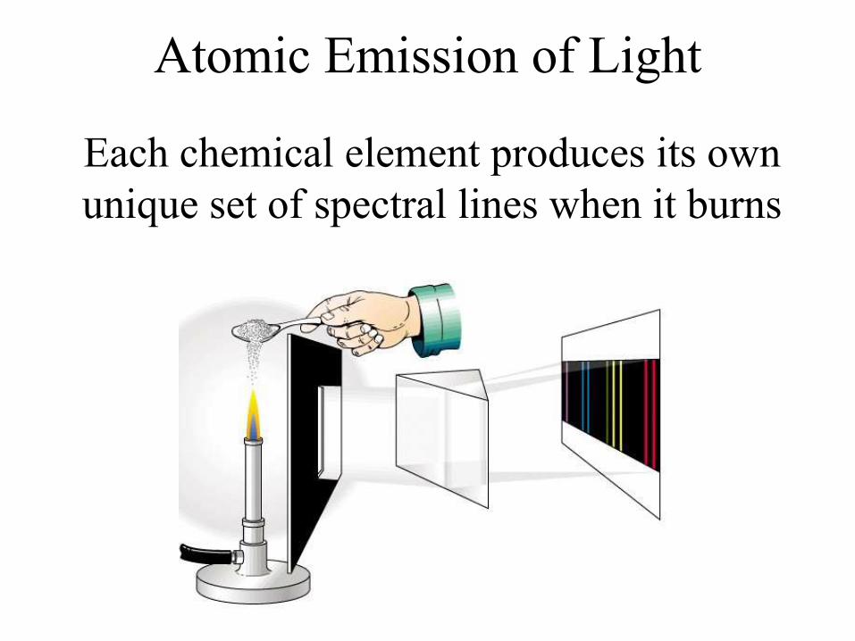
Atomic Emission of Light
Each chemical element produces its own
unique set of spectral lines when it burns
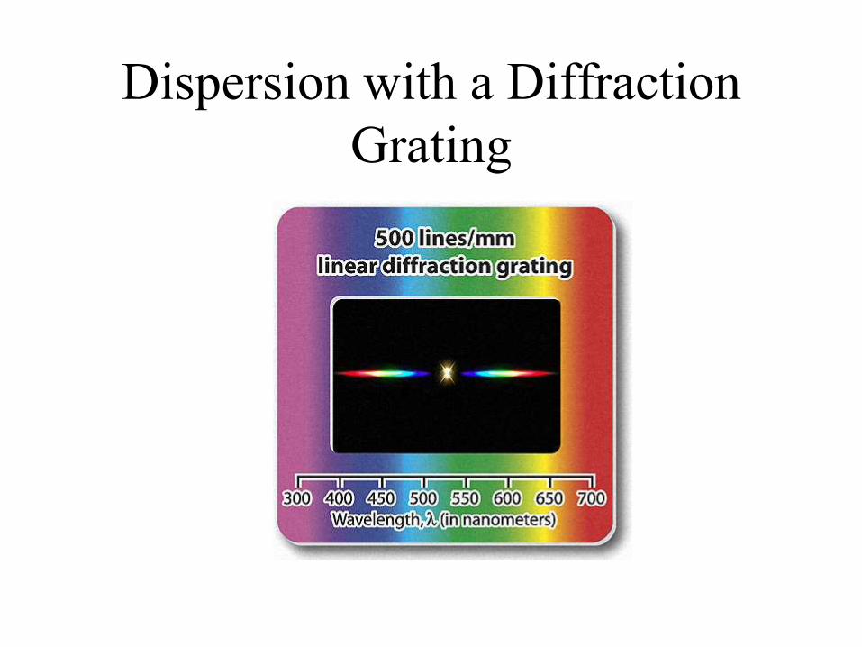
Dispersion with a Diffraction
Grating
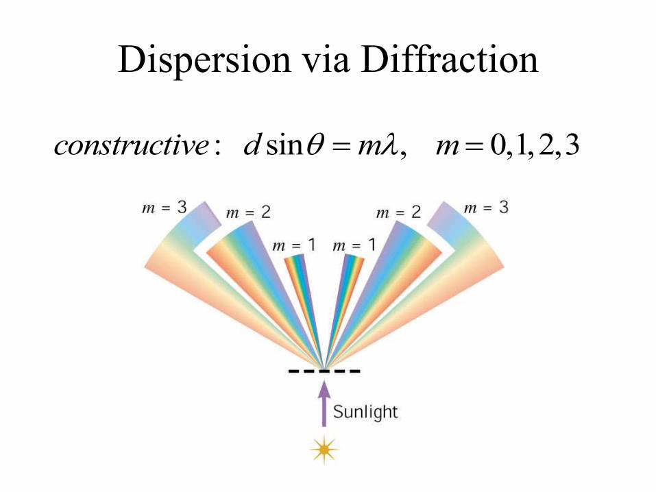
Dispersion via Diffraction
: sin , 0,1,2,3constructive d m m
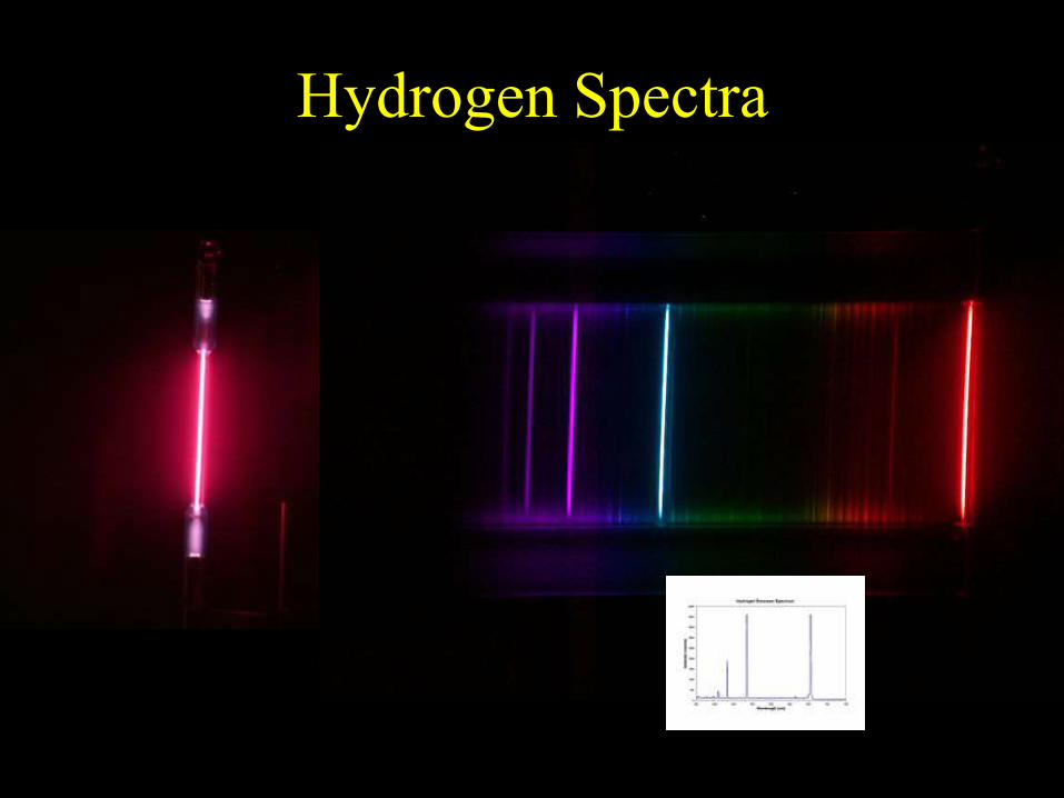
Hydrogen Spectra

Incandescent Light Bulb
Full Spectrum of Light
All frequencies excited!
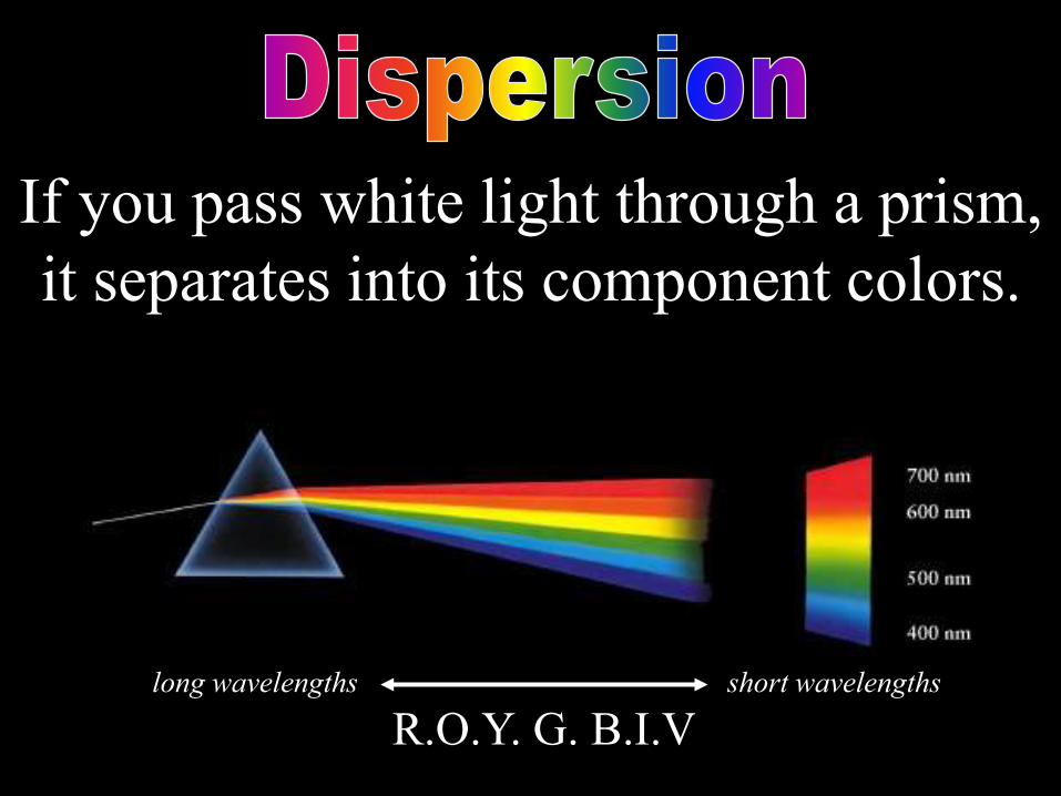
If you pass white light through a prism,
it separates into its component colors.
R.O.Y. G. B.I.Vlong wavelengths short wavelengths

Dispersion via Diffraction
: sin , 0,1,2,3constructive d m m
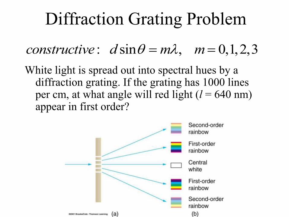
Diffraction Grating Problem
White light is spread out into spectral hues by a diffraction grating. If the grating has 1000 lines per cm, at what angle will red light (l = 640 nm) appear in first order?
: sin , 0,1,2,3constructive d m m
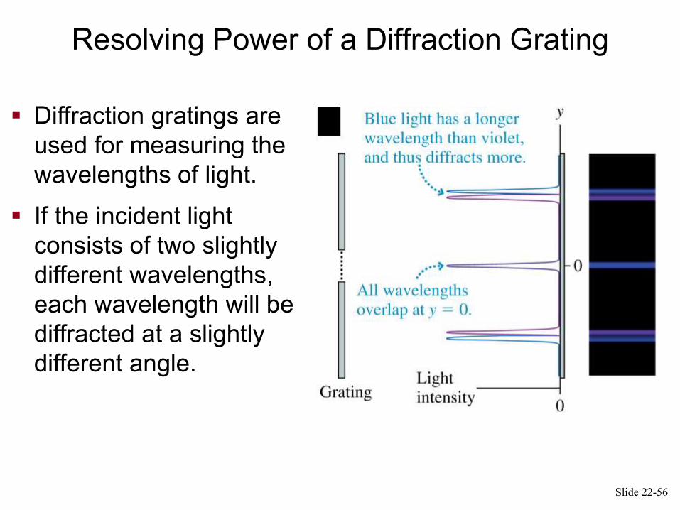
The Diffraction Grating
Diffraction gratings are
used for measuring the
wavelengths of light.
If the incident light
consists of two slightly
different wavelengths,
each wavelength will be
diffracted at a slightly
different angle.
Slide 22-56
Resolving Power of a Diffraction Grating
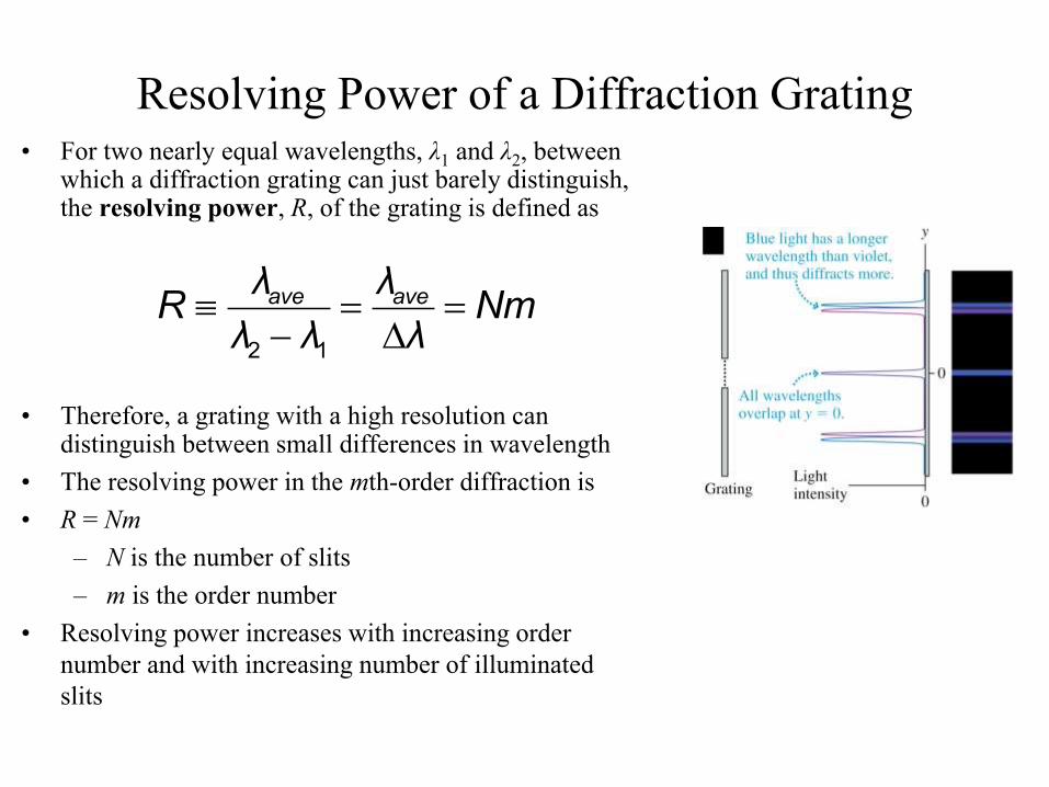
Resolving Power of a Diffraction Grating• For two nearly equal wavelengths, λ1 and λ2, between
which a diffraction grating can just barely distinguish, the resolving power, R, of the grating is defined as
• Therefore, a grating with a high resolution can distinguish between small differences in wavelength
• The resolving power in the mth-order diffraction is
• R = Nm
– N is the number of slits
– m is the order number
• Resolving power increases with increasing order
number and with increasing number of illuminated
slits
2 1
ave aveλ λR Nm
λ λ λ
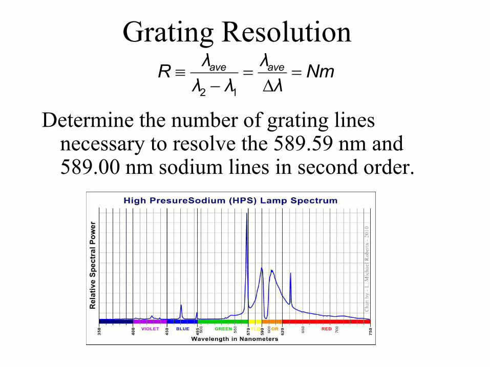
Grating Resolution
Determine the number of grating lines necessary to resolve the 589.59 nm and 589.00 nm sodium lines in second order.
2 1
ave aveλ λR Nm
λ λ λ
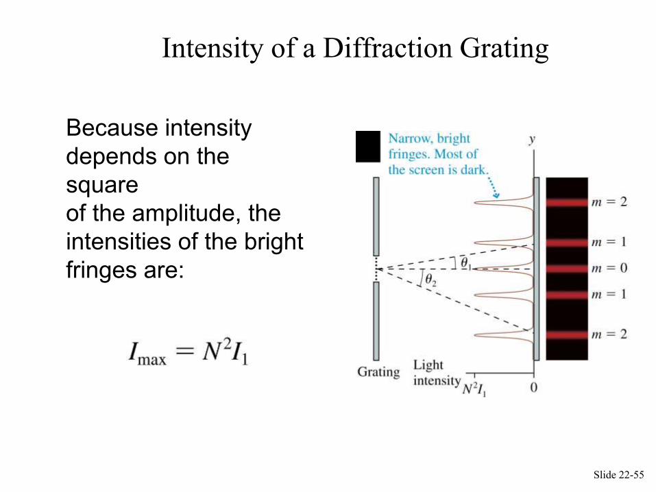
Intensity of a Diffraction Grating
Because intensity
depends on the
square
of the amplitude, the
intensities of the bright
fringes are:
Slide 22-55
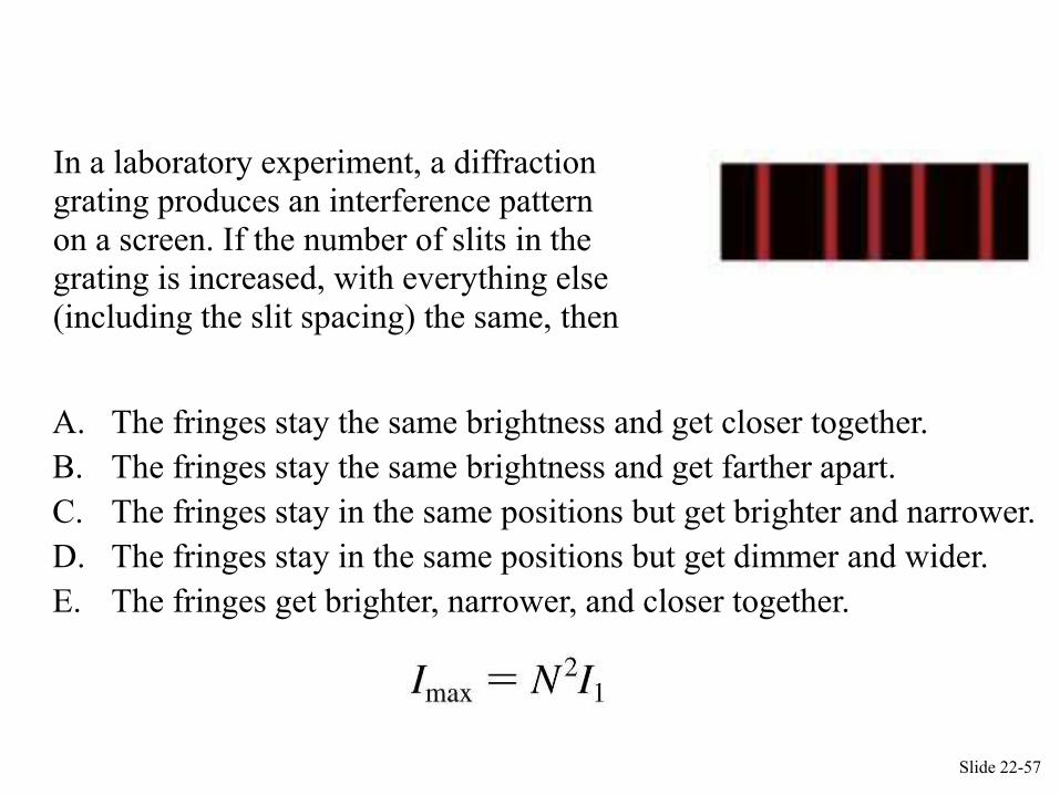
QuickCheck 22.8
In a laboratory experiment, a diffraction grating produces an interference pattern
on a screen. If the number of slits in the grating is increased, with everything else
(including the slit spacing) the same, then
A. The fringes stay the same brightness and get closer together.
B. The fringes stay the same brightness and get farther apart.
C. The fringes stay in the same positions but get brighter and narrower.
D. The fringes stay in the same positions but get dimmer and wider.
E. The fringes get brighter, narrower, and closer together.
Slide 22-57
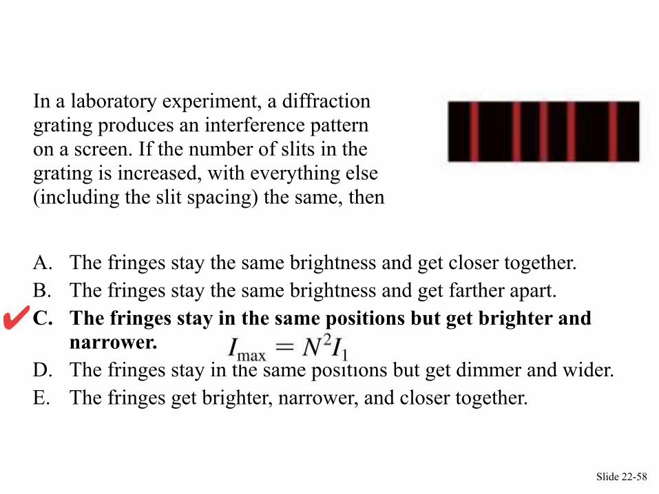
QuickCheck 22.8
In a laboratory experiment, a diffraction grating produces an interference pattern
on a screen. If the number of slits in the grating is increased, with everything else
(including the slit spacing) the same, then
A. The fringes stay the same brightness and get closer together.
B. The fringes stay the same brightness and get farther apart.
C. The fringes stay in the same positions but get brighter and
narrower.
D. The fringes stay in the same positions but get dimmer and wider.
E. The fringes get brighter, narrower, and closer together.
Slide 22-58
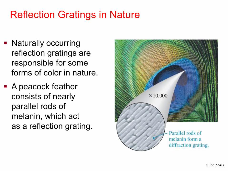
Reflection Gratings in Nature
Naturally occurring
reflection gratings are
responsible for some
forms of color in nature.
A peacock feather
consists of nearly
parallel rods of
melanin, which act
as a reflection grating.
Slide 22-63
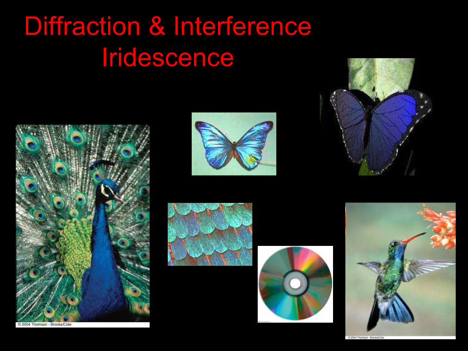
Diffraction & Interference
Iridescence
Thin Film
Interference
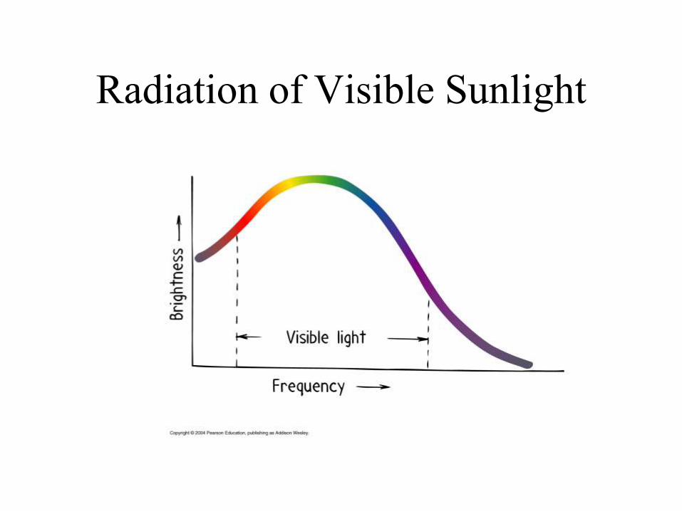
Radiation of Visible Sunlight
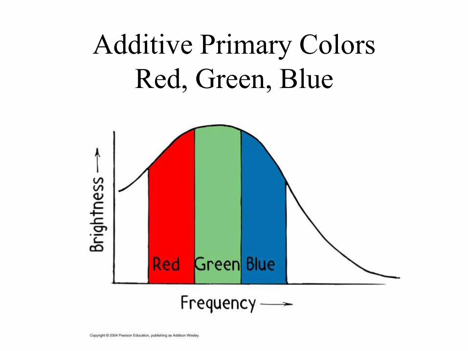
Additive Primary Colors
Red, Green, Blue
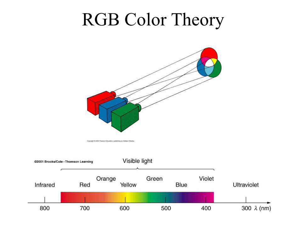
RGB Color Theory

Additive Complementary Colors
Yellow, Cyan, Magenta
The color you have to add to get white light.
Red + Green = Yellow
Blue + Green = Cyan
Red + Blue = Magenta
Red + Blue + Green = White
White light – yellow light = ??
White light – red light = ??
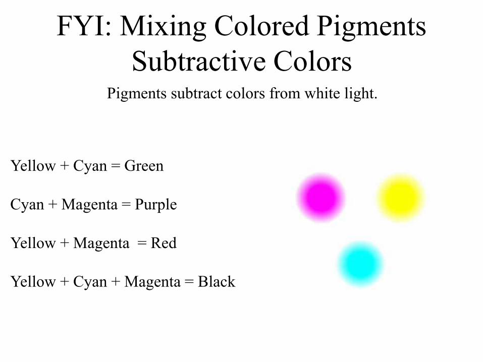
FYI: Mixing Colored Pigments
Subtractive ColorsPigments subtract colors from white light.
Yellow + Cyan = Green
Cyan + Magenta = Purple
Yellow + Magenta = Red
Yellow + Cyan + Magenta = Black

Why are some materials colored?
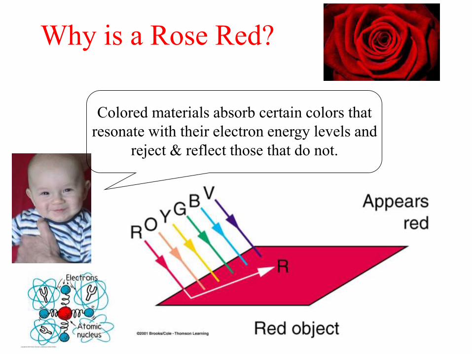
Why is a Rose Red?
Colored materials absorb certain colors that
resonate with their electron energy levels and
reject & reflect those that do not.
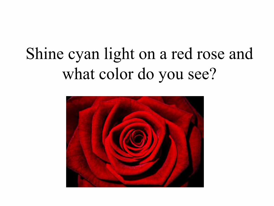
Shine cyan light on a red rose and
what color do you see?
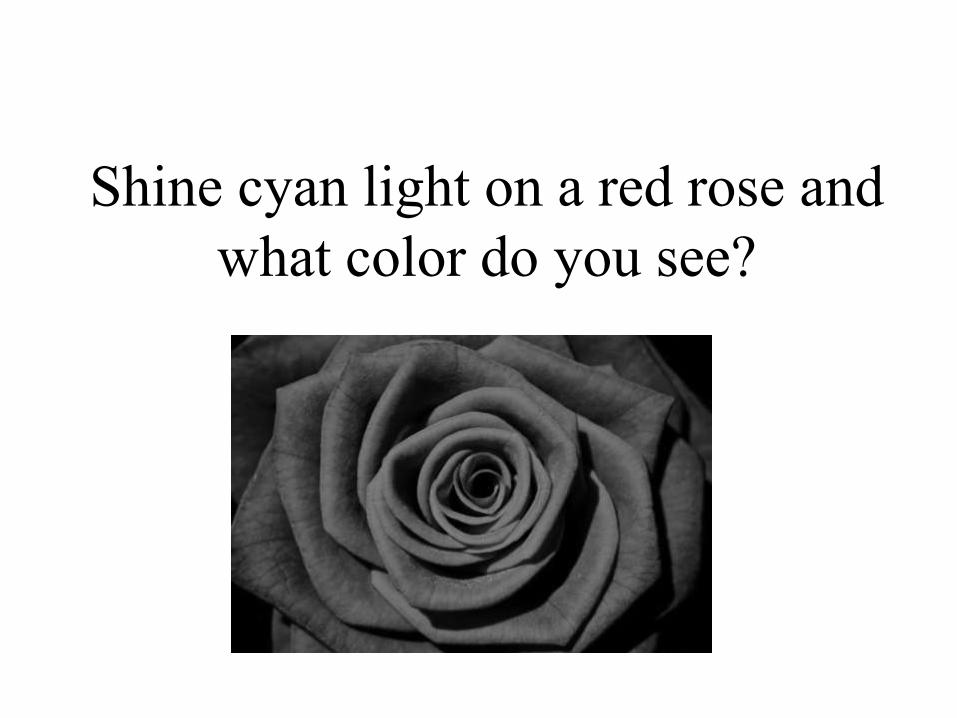
Shine cyan light on a red rose and
what color do you see?
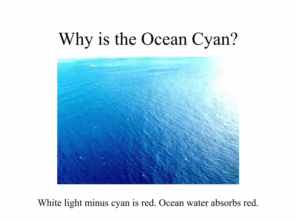
Why is the Ocean Cyan?
White light minus cyan is red. Ocean water absorbs red.

Thin Film
Interference
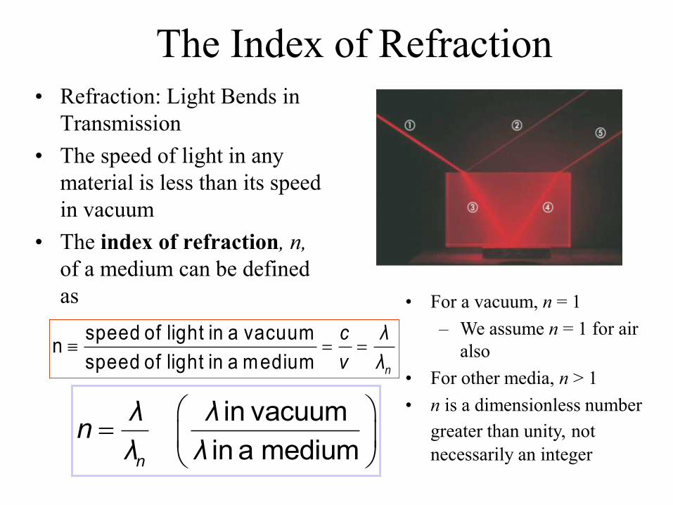
The Index of Refraction• Refraction: Light Bends in
Transmission
• The speed of light in any
material is less than its speed
in vacuum
• The index of refraction, n,
of a medium can be defined
as
speed of light in a vacuum
nspeed of light in a medium n
c λ
v λ
in vacuum
in a mediumn
λ λn
λ λ
• For a vacuum, n = 1
– We assume n = 1 for air
also
• For other media, n > 1
• n is a dimensionless number
greater than unity, not
necessarily an integer
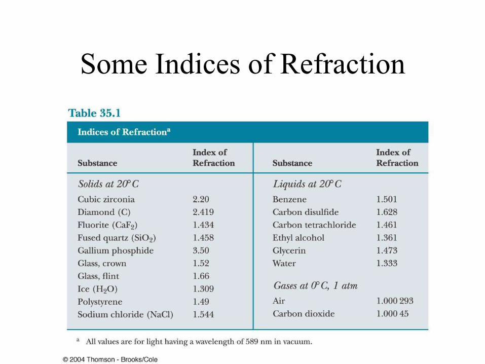
Some Indices of Refraction
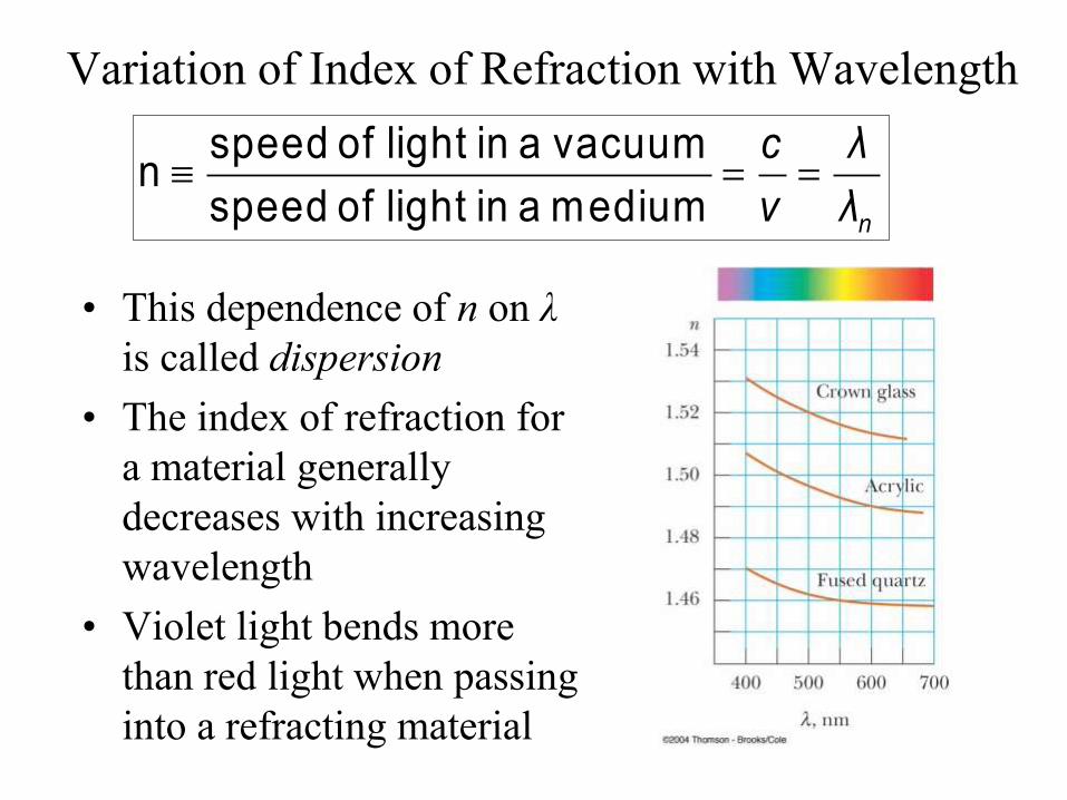
Variation of Index of Refraction with Wavelength
• This dependence of n on λ
is called dispersion
• The index of refraction for
a material generally
decreases with increasing
wavelength
• Violet light bends more
than red light when passing
into a refracting material
speed of light in a vacuum
nspeed of light in a medium n
c λ
v λ
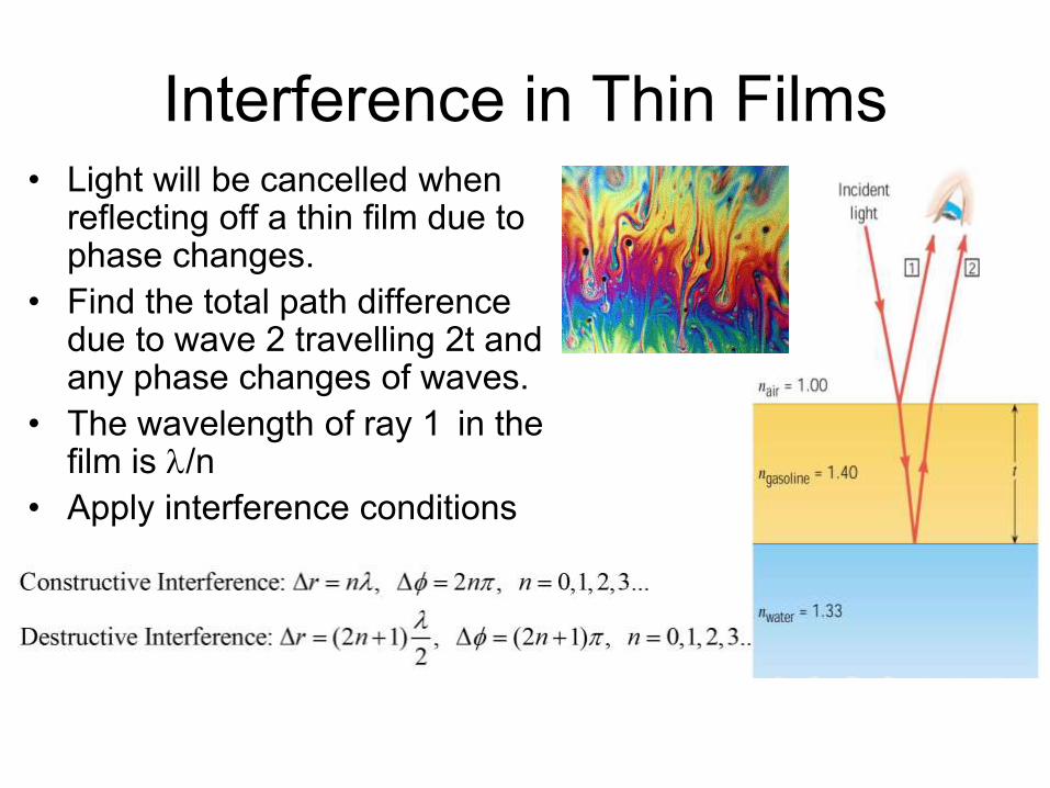
Interference in Thin Films• Light will be cancelled when
reflecting off a thin film due to phase changes.
• Find the total path difference due to wave 2 travelling 2t and any phase changes of waves.
• The wavelength of ray 1 in the film is /n
• Apply interference conditions
© 2013 Pearson Education, Inc.
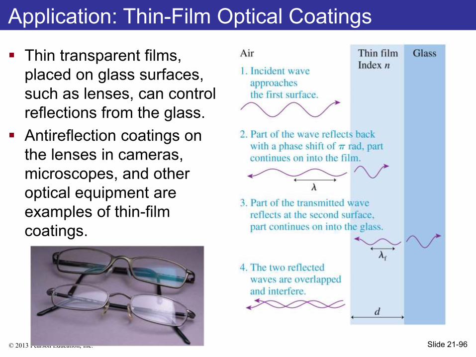
Thin transparent films,
placed on glass surfaces,
such as lenses, can control
reflections from the glass.
Antireflection coatings on
the lenses in cameras,
microscopes, and other
optical equipment are
examples of thin-film
coatings.
Application: Thin-Film Optical Coatings
Slide 21-96
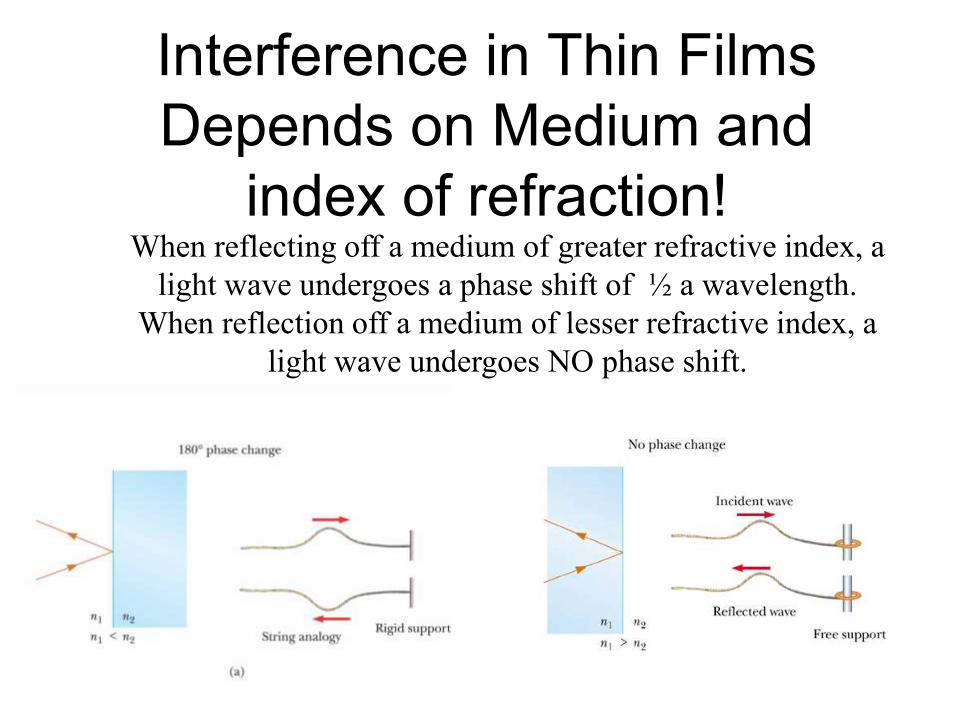
Interference in Thin Films
Depends on Medium and
index of refraction!When reflecting off a medium of greater refractive index, a
light wave undergoes a phase shift of ½ a wavelength.
When reflection off a medium of lesser refractive index, a
light wave undergoes NO phase shift.

From Low to
High, a phase
change of pi!
From High to
Low, a phase
change? NO!
Reflections Phase Shift Chant
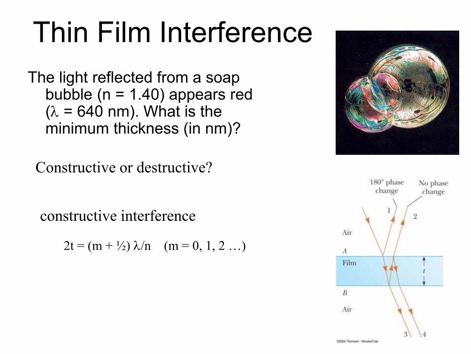
Thin Film Interference
The light reflected from a soap bubble (n = 1.40) appears red ( = 640 nm). What is the minimum thickness (in nm)?
Constructive or destructive?
constructive interference
2t = (m + ½) /n (m = 0, 1, 2 …)
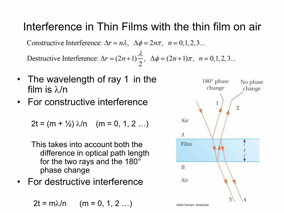
Interference in Thin Films with the thin film on air
• The wavelength of ray 1 in the film is /n
• For constructive interference
2t = (m + ½) /n (m = 0, 1, 2 …)
This takes into account both the difference in optical path length for the two rays and the 180°phase change
• For destructive interference
2t = m/n (m = 0, 1, 2 …)
© 2013 Pearson Education, Inc.
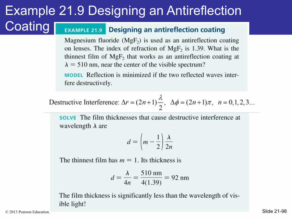
Example 21.9 Designing an Antireflection
Coating
Slide 21-98

© 2013 Pearson Education, Inc.
Example 21.9 Designing an Antireflection
Coating
Slide 21-100
© 2013 Pearson Education, Inc.
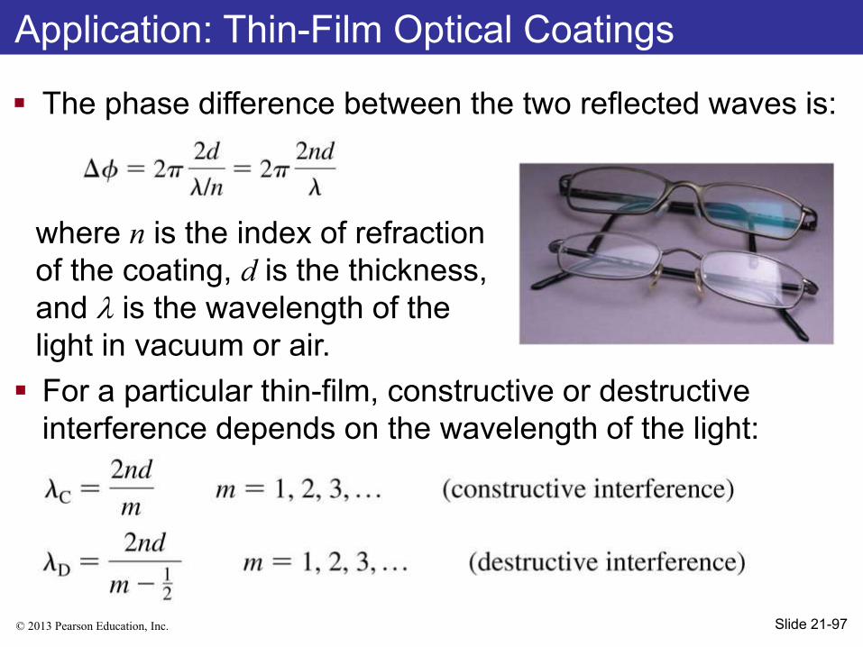
The phase difference between the two reflected waves is:
where n is the index of refraction
of the coating, d is the thickness,
and is the wavelength of the
light in vacuum or air.
For a particular thin-film, constructive or destructive
interference depends on the wavelength of the light:
Application: Thin-Film Optical Coatings
Slide 21-97
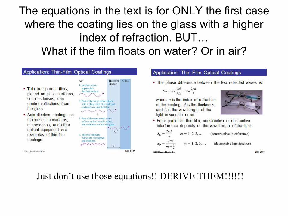
The equations in the text is for ONLY the first case
where the coating lies on the glass with a higher
index of refraction. BUT…
What if the film floats on water? Or in air?
Just don’t use those equations!! DERIVE THEM!!!!!!
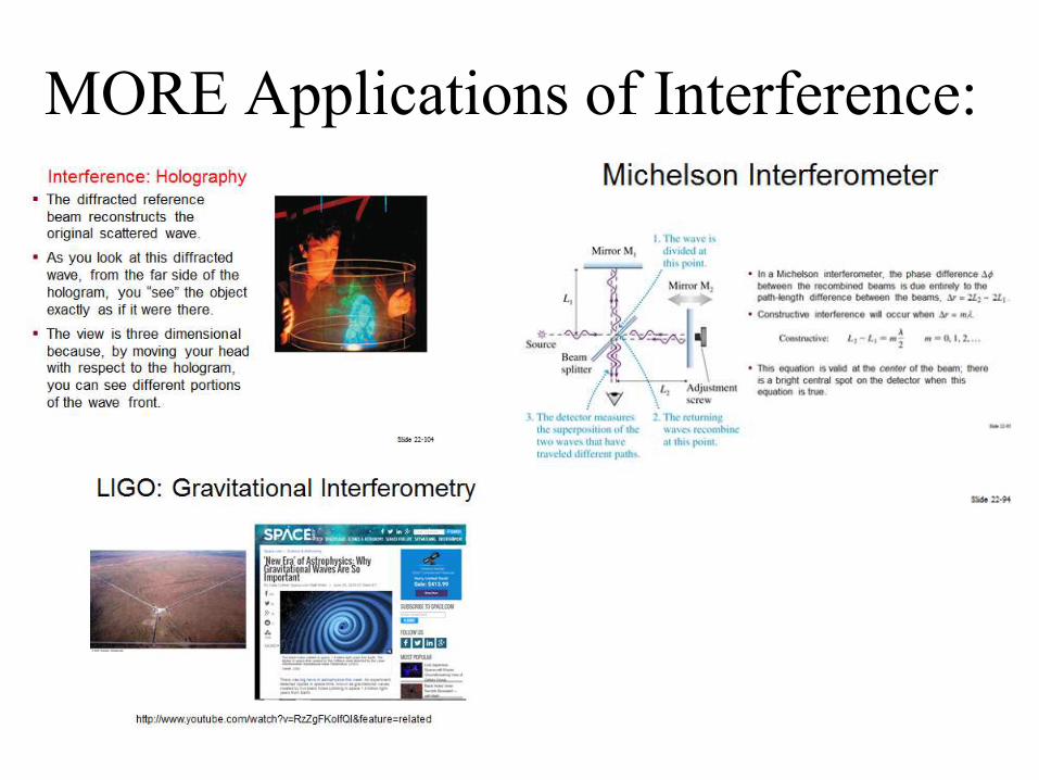
MORE Applications of Interference:
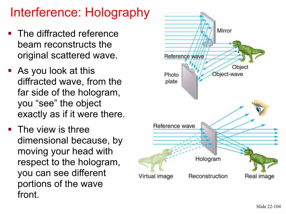
Interference: Holography
The diffracted reference beam reconstructs the original scattered wave.
As you look at this diffracted wave, from the far side of the hologram, you “see” the object exactly as if it were there.
The view is three dimensional because, by moving your head with respect to the hologram, you can see different portions of the wave front.
Slide 22-104
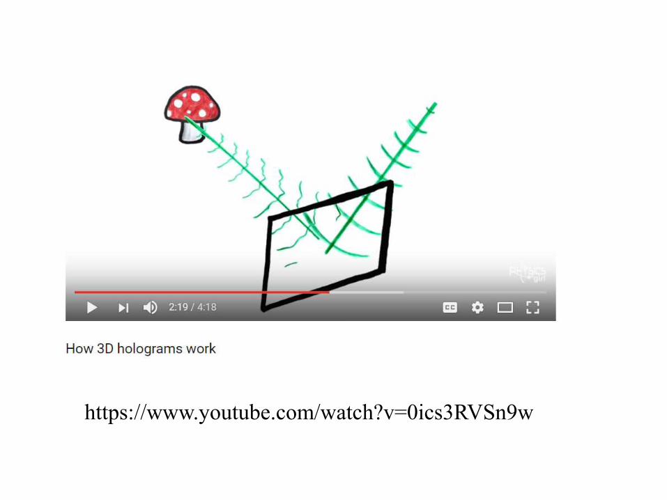
https://www.youtube.com/watch?v=0ics3RVSn9w
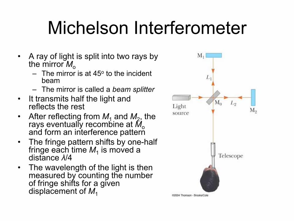
Michelson Interferometer
• A ray of light is split into two rays by the mirror Mo
– The mirror is at 45o to the incident beam
– The mirror is called a beam splitter
• It transmits half the light and reflects the rest
• After reflecting from M1 and M2, the rays eventually recombine at Moand form an interference pattern
• The fringe pattern shifts by one-half fringe each time M1 is moved a distance λ/4
• The wavelength of the light is then measured by counting the number of fringe shifts for a given displacement of M1
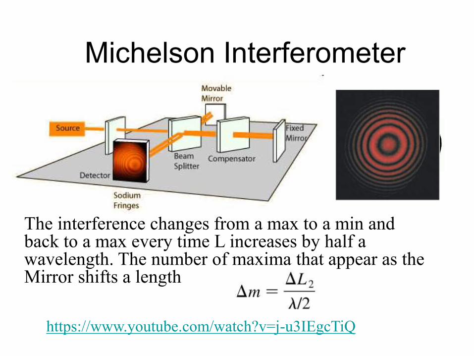
Michelson Interferometer
The interference changes from a max to a min and back to a max every time L increases by half a wavelength. The number of maxima that appear as the Mirror shifts a length
https://www.youtube.com/watch?v=j-u3IEgcTiQ
https://www.youtube.com/watch?v=j-u3IEgcTiQ
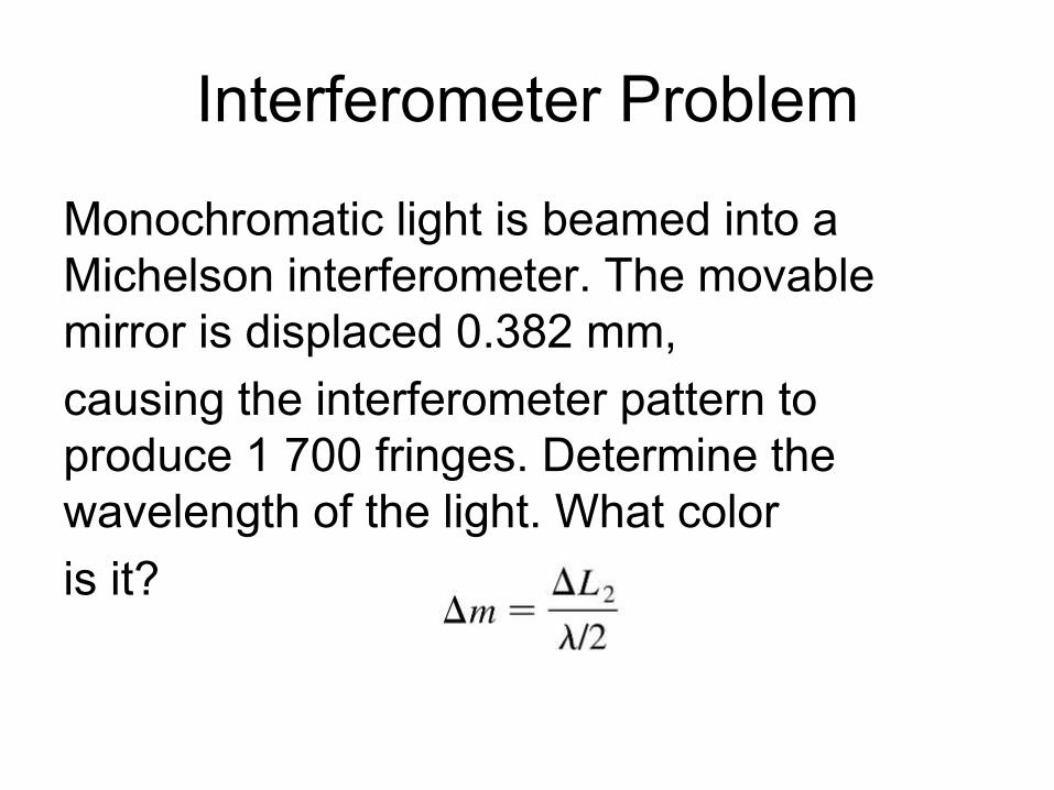
Interferometer Problem
Monochromatic light is beamed into a
Michelson interferometer. The movable
mirror is displaced 0.382 mm,
causing the interferometer pattern to
produce 1 700 fringes. Determine the
wavelength of the light. What color
is it?
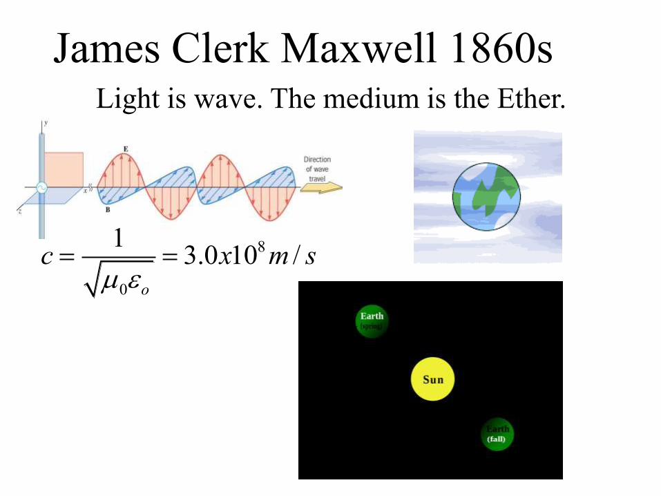
James Clerk Maxwell 1860sLight is wave. The medium is the Ether.
8
0
13.0 10 /
o
c x m s
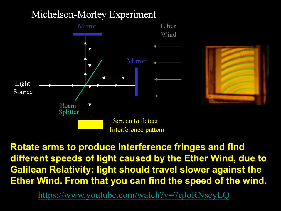
Rotate arms to produce interference fringes and find
different speeds of light caused by the Ether Wind, due to
Galilean Relativity: light should travel slower against the
Ether Wind. From that you can find the speed of the wind.
https://www.youtube.com/watch?v=7qJoRNseyLQ
http://www.youtube.com/watch?v=4KFMeKJySwA&feature=related
http://www.youtube.com/watch?v=XavC4w_Y9b8&feature=related
http://www.youtube.com/watch?v=ETLG5SLFMZo
http://www.youtube.com/watch?v=Z8K3gcHQiqk&feature=related
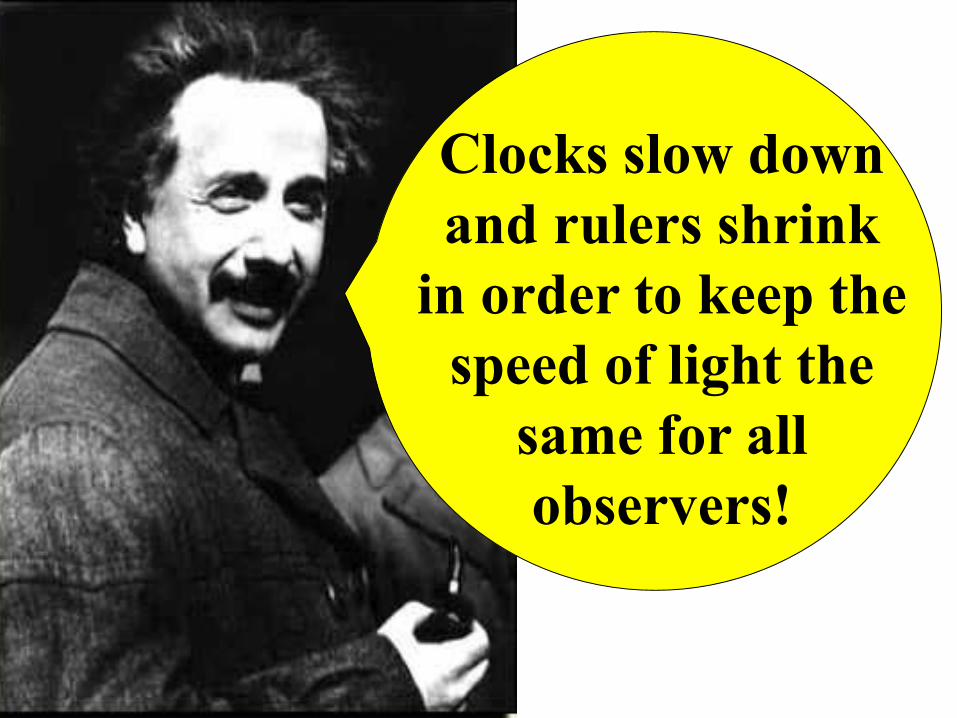
Clocks slow down
and rulers shrink
in order to keep the
speed of light the
same for all
observers!
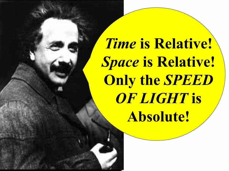
Time is Relative!
Space is Relative!
Only the SPEED
OF LIGHT is
Absolute!
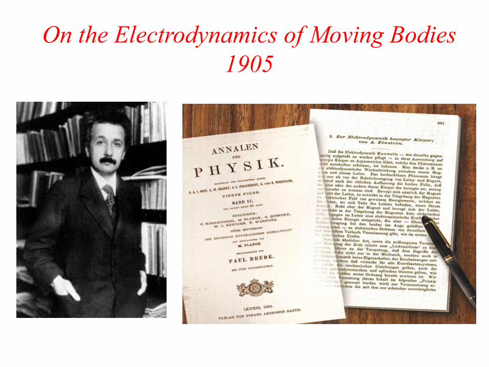
On the Electrodynamics of Moving Bodies
1905
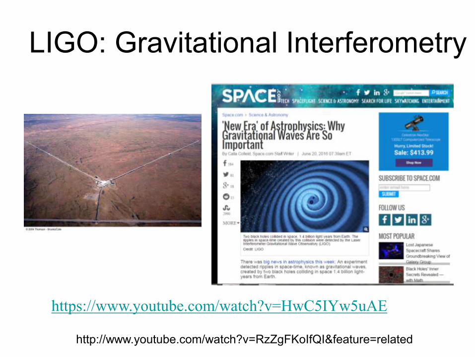
LIGO: Gravitational Interferometry
http://www.youtube.com/watch?v=RzZgFKoIfQI&feature=related
https://www.youtube.com/watch?v=HwC5IYw5uAE
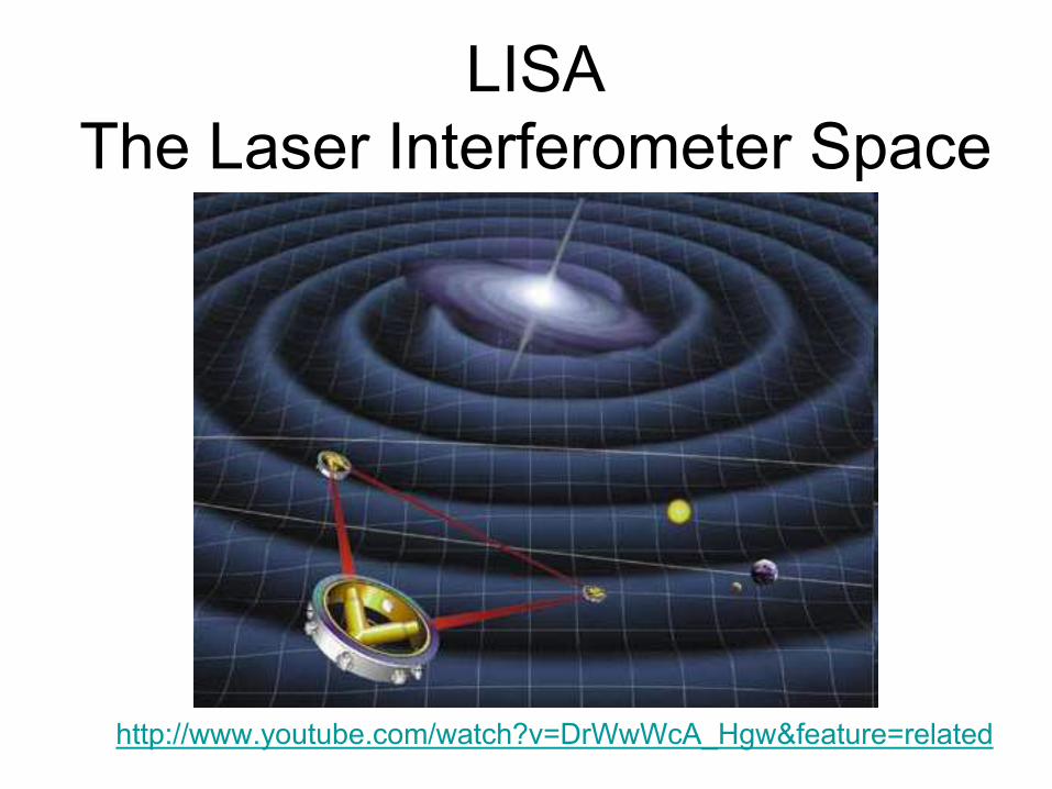
LISA
The Laser Interferometer Space
Antenna
http://www.youtube.com/watch?v=DrWwWcA_Hgw&feature=related
http://www.youtube.com/watch?v=tUpiohbBv6o
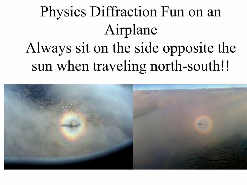
Physics Diffraction Fun on an
Airplane
Always sit on the side opposite the
sun when traveling north-south!!
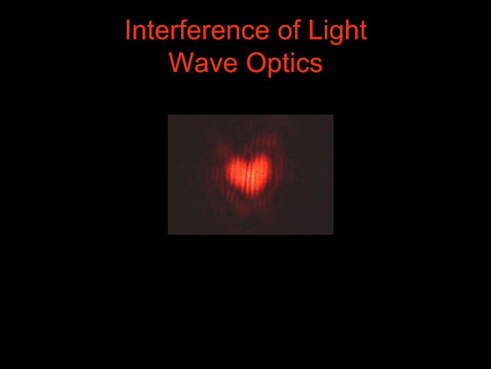
Interference of Light
Wave Optics