Ocean Optics 2006 Catalog - physique
196
Ocean Optics 2006 Catalog Spectrometers, Sensors & Accessories
-
Upload
khangminh22 -
Category
Documents
-
view
1 -
download
0
Transcript of Ocean Optics 2006 Catalog - physique

Ocean Optics
2006Catalog
Spectrometers, Sensors&
Accessories

Worldwide HeadquartersOcean Optics, Inc.830 Douglas Avenue,Dunedin, FL 34698USA727.733.2447Fax [email protected]
(general sales inquiries)[email protected]
(order inquiries)
European HeadquartersOcean Optics B.V.Geograaf 24, 6921 EWDuivenThe Netherlands+31 (0) 26 319 0500Fax +31 (0) 26 319 [email protected]
Application AssistanceOur experienced staff ofApplications Scientists canassist you with pre-saleproduct or applicationquestions, and providepost-sale support.
Ocean Optics spectrometers have been used inside human bodies, in space and onMars, in research labs and process streams, atop forest canopies and alongside activevolcanoes. And, of course, in water, where it all began for us 15 years ago. A sampleof ocean applications gives a snapshot of what Ocean Optics spectrometers can do injust one of the many challenging environments our customers face -- the sea.
Pricing:All prices are subject to change without notice. Forthe most up-to-date pricing, contact Ocean Optics.For information on pricing in Europe, please contactour office in Duiven, The Netherlands.
Terms:Net 30 days with credit approval. Contact us forfuther information. All shipments are deliveredEXWORKS, Dunedin, Florida, USA. For allshipments into California and Florida, we arerequired to charge sales tax unless a valid resalecertificate is received prior to shipment. Fax resalecertificates to our Accounting Department at727.734.0957. Specifications, descriptions,ordering information and item codes describedherein are subject to change without notice.
Credit Cards:Ocean Optics accepts American Express,MasterCard and VISA credit cards.
Shipping:Shipping charges are the responsibility of thecustomer. Orders are shipped UPS Ground, unlessotherwise requested. Customers may reverseshipping charges to use the carrier of their choice.
Alexander Cheroske was a Ph.D.candidate when he used the USB2000Spectrometer and a CC-3 CosineCorrector to study how light intensity inthe ocean affects the color vision andcommunication of marine animals. Divingnear Lizard Island, Australia, Cheroskemeasured irradiance at 1-meter intervalsfrom the water's surface to its floor, 18meters below. Cheroske is now a biologyprofessor with Moorpark College.
Real People,Real Answers
Call Ocean Optics and
talk over your optical
sensing needs with one
of our knowledgeable
Applications Scientists.
ExpandedService Hours
(EST)
8 a.m to 8 p.m.
Mondays - Thursdays
8 a.m. to 6 p.m.
Fridays
Ask us about our new
order-processing hours
and late-day shipping
option!
727.733.2447
Contact Information
Ordering Information
Chris Martens, professor at the Universityof North Carolina at Chapel Hill, ismeasuring sponge consumption ofoxygen and sponge production andrecycling of new nitrogen in coral-reefecosystems. The health of the Floridacoral-reef ecosystem has declined inrecent years and one cause could be theexcessive nutrient fluxes brought on bysponges. He is conducting his researchfrom Aquarius, a NOAA UnderseaResearch Center in the Florida Keys. Fordetails, visit www.uncw.edu/aquarius/2005/08_2005/expd.htm.
Dana Riddle of Riddle AquaticLaboratories, Hawaii, is working on aNOAA grant to investigate how tomanipulate reflective and fluorescentpigment production in corals, and howto maintain the vivid coloration inartificial environments. Riddle researchedhow narrow-bandwidth light sourcespromote (or destroy) reflective and/orfluorescing pigments. He measured boththe color and fluorescence of coral inresponse to artificial light sources,specifically the LEDs we offer.
Eric Hochberg from the Hawaii Instituteof Marine Biology measures reflectancefrom a soft coral near Okinawa, Japan.Here he uses an entirely self-contained,diver-operated system, which includes aUSB2000 Spectrometer and a handheldcomputer, to acquire spectra. A colleagueof Hochberg’s designed and built thewater-proof housing. Hochberg also hastaken his custom-built system down 110feet to study light ecology of an octocoraloff Waikiki. For more details, visitwww.soest.hawaii.edu/marlin/hochberg/.

3 Our Value Proposition4 Partnerships5 Original Equipment Manufacturers6 Worldwide Distribution7 Pricing Options8 Grant Programs
9 Spectrometers: Systems & Setups10 The Maxwell Absorbance System11 The Curie Fluorescence System12 CHEM2 Systems for Education14 Flow-through Absorbance System15 Flow Injection Analysis16 LED Measurement Tools17 Transmission of Optics Tools18 NanoCalc Thin-film Reflectometry System19 SpecEl Ellipsometer System19 PlasCalc Plasma Monitoring System20 Laser-induced Breakdown Spectrometer22 Laser Ablation Sampling System23 Endospore Detection System24 Air Monitoring Systems26 Raman Measurement Tools28 Raman Systems
29 Spectrometers: Preconfigured30 Broadband Spectrometers32 Gated Spectrometer for Fluorescence33 Fluorescence Spectrometers33 Temperature-regulated Spectrometers34 General Purpose UV-VIS & VIS-NIR
Spectrometers
35 Spectrometers: User-Configured38 USB2000 Plug-and-Play Spectrometer40 S2000 & PC2000 Miniature
Spectrometers41 Deep Well Detector Spectrometers42 “S”-series Optical Bench Options
46 HR4000 High-resolution Spectrometer48 HR2000 High-resolution Spectrometer49 HR2000+ High-speed, High-res
Spectrometer50 “HR”-series Optical Bench Options
54 QE65000 Scientific-grade Spectrometer55 “QE”-series Optical Bench Options
58 NIR-512 Near-infrared Spectrometer59 NIR256 Extended-range NIR
Spectrometers60 “NIR”-series Optical Bench Options
QE65000 Scientific-grade Spectrometer
p. 54
HR2000+ High-speed,High-res Spectrometer
p. 49
The Sentry AirMonitoring System
p. 24
LIBS-ELITE Laser AblationSampling System
p. 22
WWhhaatt’’ss IInnssiiddee && WWhhaatt’’ss NNeeww

63 Optical Sensors64 FOXY Oxygen Sensors68 FOXY Oxygen Sensor Accessories71 FOXY-LITE Handheld Oxygen Sensor72 Fiber Optic pH Sensors
73 Software & Data Acquisition76 SpectraSuite78 OmniDriver80 Application Software82 GRAMS Spectroscopy Software83 SpecLine Software for Compound ID84 Analog-to-Digital Converters
85 Sampling Accessories88 Collimating Lenses & Accessories90 Cuvette Holders & Cuvettes94 Filters & Filter Holders98 Sampling Cells & Accessories
104 Light Control106 Emission Sampling109 Reflection Sampling111 Metrology
117 Light Sources120 Deuterium Tungsten Halogen Sources124 Deuterium Light Sources125 Xenon Sources126 Tungsten Halogen Light Sources128 LED Light Sources130 Radiometric Calibration Standards132 Wavelength Calibration Standards
135 Fibers & Probes138 Standard Assemblies141 Bulk Fiber142 Custom Assembly Options144 Fiber Optic Probes151 Vacuum Feedthroughs152 Optical Fiber Kits
157 Thin Films & Optics159 Capabilities160 Custom Filters & Optics161 “Colored Light” Technology162 Metrology Tools
165 Resources167 Sample Setups178 Spectral Identity183 Indices
VacuumFeedthroughs
p. 151
USB-DTDeuterium Tungsten
Halogen Sourcep. 123
SpectraSuite Spectroscopy Platform Softwarep. 76
WWhhaatt’’ss IInnssiiddee && WWhhaatt’’ss NNeeww

4 Partnerships
5 Original EquipmentManufacturers
6 Worldwide Distribution
7 Pricing Options
8 Grant Programs
oo
ooOO
uurr VV
aalluu
ee PP
rrooppoossiittiioo
nn
OOuurr VVaalluuee PPrrooppoossiittiioonnOOuurr VVaalluuee PPrrooppoossiittiioonn

To expand the frontiers ofoptical sensing and make it
the foundation on which innovative,life-changing ideas are built.
-- Ocean Optics Vision Statement
What Really MattersWe value the opportunities to learn and to grow -- and toexpand the frontiers of optical sensing -- that come frompartnership. Recognizing and seizing these opportunities iswhat Ocean Optics is all about -- and is reflected in an open,collaborative approach that appeals to everyone from theinnovators and early adopters to the skeptics and thetraditionalists.
The Partnership PropositionPartners come in many types:
� Original Equipment Manufacturers (OEMs) integrateour components into their own analytical devices. Ourspectrometers in particular are ideal for embedding intoother devices. One such OEM is NanoDrop(nanodrop.com), a Delaware-based supplier of UV-Visspectrophotometers for extremely small-volumesampling. NanoDrop is a sort of poster child of thecustomer-innovator: a small team of researchers with anexciting application, the passion and know-how to makeit happen, and an appreciation for the advantages ofsize, cost and flexibility that our spectrometers provide.
� “One-off” customers typically collaborate with us on aspecific application need. In fact, our flexible, modularproduct line is designed especially for the researcherwith a custom application. One-off customers oftenbecome OEMs and distributors.
� Distributors purchase products from us and resell thoseproducts to their own customers. We have more than 40distributors worldwide and offer them competitivepricing, marketing and training support. (See our list ofdistributors at OceanOptics.com/Distributors.asp).
� Value-added Resellers and Private Labelers typicallyrepackage and add value to our products -- and thenmarket those products under their own brand names.
� Vendors and Suppliers provide us with fun, interestingand useful products that we resell. We’re always on thelookout for cool stuff that complements our line of 900+products.
� Grant Seekers and Proposal Writers collaborate with us on grants and proposals seeking funding forthe development of new technologies. Ocean Optics got its start as the result of a Small BusinessInnovation Research grant for a pH sensor. We’veworked with both corporate and institutional innovatorsand developers.
� Grant Program Winners earn cost-sharing rewards forpromoting science in high school and undergraduatecurricula. Additional information on the Innovations inEducational Spectroscopy Grant Program is available onpage 8.
Our Online Distributor PartnersOcean Optics products are now available for purchase onlineat VWR.com and FiberOpticStuff.com.
VWR is one of the leading suppliers of scientific equipment,labware and chemicals in the world, and offers a remarkablecatalog of 750,000 products, including virtually every item inour product line. VWR.com is a nice option for customers whoare familiar with ourproduct line, have acredit card, anddon’t require salesconsultation.
FiberOpticStuff.com provides low-cost fiber optic products forresearchers, experimenters and tinkerers. In addition to fiberassembly-making kits and components, FiberOpticStuff.comoffers discounted “scratch & dent” patch cords and probes,plus sampling fixtures, lab accessories and optical standards.
PPAARRTTNNEERRSSHHIIPPSS
For all your sensing needs, visit OceanOptics.com4
We often invite our partners to share trade show space with us. Funny pirateshirts are just a bonus. Nick Sebastian, now our Worldwide Distribution SalesAssociate, will never live down Pittcon 2001.
OOuurr VV
aalluu
ee PP
rrooppoossiittiioo
nn
oo
oo

We Treat Our OEMs Like “Star Partners”The inherent size, cost and modularity of Ocean Opticsspectrometers and accessories make them ideal for OEMs andproduct developers. With our OEM Star Partner Program, thebenefits of our flexible approach -- including savings associatedin start-up and engineering expenses -- are significant.
OEMs profit from our vertical manufacturing structure. Weassemble optoelectronic systems, grind and polish optics, addcoatings, develop optical sensors, and make our own opticalfiber assemblies. And, with more than 55,000 spectroscopysystems sold, we’re light years ahead of our competitors inapplications know-how.
Getting StartedProspective OEMs purchase an evaluation unit at retail price todetermine technical feasibility. If the application is viable, theprospective OEM purchases an OEM Developer's Agreement for$999. This agreement entitles the OEM Developer to discountson equipment purchased during the first year of the OEMagreement, regardless of quantity. The OEM Agreement must berenewed annually, at $599, to ensure discounts and benefits:� Limited access to our proprietary technical information� OEM Interface Guide, wiring diagrams, register maps and
spectrometer pin-out information� Hands-on support from our OEM Sales Manager, who is a
trained engineer with nearly a decade of experiencedesigning and working with Ocean Optics spectrometers
Discounts & SavingsOnce the OEM's product development cycle is complete,sizeable savings on spectrometers and other components arepossible. We offer volume discounts on gross margin forspectrometers, based on annual blanket purchase orders. Thechart (below, right) shows savings based on the number of unitsper year for a USB2000-UV-VIS Spectrometer. After the first 12months of the OEM Developer's Agreement, we requestquarterly volume updates to ensure that production needs aremet, and to manage our inventory accordingly.
Modular ComponentsWe offer a comprehensive toolkit of optical-sensing componentsthat can be configured in an amazing number of variations. For example, by mixing and matching optical benchcomponents such as gratings and slits, the “S” Optical Bench
alone can be configured more than500 different ways.
Full-service SupportOEMs have at their disposal anarray of R&D services, from optical design and softwareengineering to prototypedevelopment and testing andvalidation. As with our modularhardware, R&D services areavailable on an à la carte basis. Inaddition, some OEMs take
advantage of cooperative marketing services such as sharedbooth space at trade shows and postings on our website.
Partnership OpportunitiesTo reap benefits such as volume pricing, customers aren’t strictlylimited to OEM partnerships. We’re willing to work with you ona private label or value-added reseller basis, or even act asboth your OEM supplier and as a reseller of your products. Thelatter option can be attractive to smaller companies lacking thesales and marketing resources that we bring to the table.
Contact InformationFor more information on OEM opportunities, call us at727.733.2447 or e-mail us at [email protected].
US: 727.733.2447 • Europe: +31 (0) 26 319 0500 5
OOrriiggiinnaall EEqquuiippmmeenntt MMaannuuffaaccttuurreerrss
* OEM Discount Price does not include the OEM Developer’s fee of $999 inthe first year and the $599 renewal fee each year thereafter.
Number of Units USB2000-UV-VIS
per Year Discount with OEM Discount*
1 Gross Margin $2,649
5 10% $2,384 per unit
10 15% $2,251 per unit
20 20% $2,119 per unit
35 25% $1,986 per unit
50 30% $1,854 per unit
75 35% $1,721 per unit
100 40% $1,589 per unit
150 45% $1,456 per unit
200 50% $1,324 per unit
250 53% $1,245 per unit
500 55% $1,192 per unit
OEM Manager, Rob Waterbury
oo
ooOO
uurr VV
aalluu
ee PP
rrooppoossiittiioo
nn
CEREX Environmental Services, Inc. is an OEM that uses one of our high-resolution spectrometers in its Sentry and Hound Monitoring Systems,advanced, EPA-approved detection methods for conducting real-time parts-per-trillion analysis of toxins in the air. See pages 24-25 for details.

Worldwide Distribution NetworkOur distributors are distinguished by their applicationsexpertise and extensive knowledge of our product line.Many are scientists and engineers with significant hands-onexperience using our products. For an up-to-date list ofOcean Optics distributors, click on the “WorldwideDistribution” link at OceanOptics.com.
Sales & Service in EuropeWe operate a full-service sales office, Ocean Optics B.V., inDuiven, The Netherlands. Ocean Optics B.V. carries the fullarray of Ocean Optics inventory and is equipped to handlesales consultation, customer service, technical support andengineering services. A network of sub-distributors coversareas such as Germany, France and the United Kingdom.
Distributors Add ValueThere are two compelling reasons to work with a distributor:convenience and service. Around the world, there is widevariation in the rules of business. We use distributors who areexperienced in local regulations to help our customers avoid theinconvenience of customs documents, payment details andshipping issues. Also, our distributors provide pre- and post-sales application assistance, and offer a level of support that,for logistical reasons, Ocean Optics may not be able to provide.
Worldwide Pricing Ensures FairnessOur distributors abide by our “Worldwide Pricing” policy, whichensures that a single, universal price applies to every OceanOptics product. Extra costs due to currency exchange, customsduties and shipping charges should not be confused with aproduct’s selling price. We originated this policy to provideclients with relief from excessive add-on costs that manymanufacturers and distributors pass on to overseas customers.Worldwide pricing is prominently displayed on our website andin our print catalog. We adhere to fair business practices andemploy these principles in the Ocean Optics worldwidedistributor agreement.
Progressive Distributor ProgramWe are always looking for companies with skilled salesengineers to add to our family of distributors. If you’re interestedin becoming a distributor, we’d love to hear from you. OceanOptics distributors enjoy a number of benefits:
Discounted PricingDepending on sales volume and other qualifications, distributorsenjoy deep discounts on most products. Discounts are based onthe gross margin of the product as well as volume purchasing.The latter is reviewed at year’s end so that the next year's rate isadjusted to reward top performers. Also, top-tier distributorsenjoy sales prospect-generation and market-support benefits topromote Ocean Optics products in their regions.
Lead SharingOcean Optics marketing efforts generate thousands ofprospects. Top-tier distributors qualify for lead sharing, anexchange of leads between Ocean Optics and the distributor.
Lead sharing ensures that our overseas prospects receive rapidresponse to their sales and technical needs.
Sales & Marketing SupportOcean Optics makes available to distributors variouspromotional items, and encourages distributor participation atmajor trade shows. For top-tier distributors we offer a marketingmatching funds program -- i.e., a dollar-for-dollar match -- forthe purpose of promoting Ocean Optics through advertising,trade shows and other marketing vehicles. Top-tier distributorsupport also includes sales prospect lead-sharing and market-coordination programs designed for greater territorial coverageand customer sales support.
OEM Client DevelopmentOur spectrometers are used in thousands of OEM devices invarious industries worldwide. We offer special pricing fordistributors who prospect and manage OEM clients within theirterritories. Under this unique margin-sharing program, OEMclient development offers a premium profit advantage for bothOcean Optics and the distributor.
Technical TrainingBecause selling Ocean Opticsproducts requires skilled applicationsengineers who perform a significantconsultative role, we providedistributors with regular technicaltraining. Also, Gary Manche, ourWorldwide Distribution Manager,makes frequent site visits to providesales and technical support for newprograms and products.
Contact InformationTo find a distributor, visitOceanOptics.com/Distributors.asp.For information on distributing our products, contact GaryManche at [email protected].
For all your sensing needs, visit OceanOptics.com6
WWoorrllddwwiiddee DDiissttrriibbuuttiioonnOO
uurr VV
aalluu
ee PP
rrooppoossiittiioo
nn
oo
oo
Worldwide DistributionManager, Gary Manche
Distributors from around the globe meet at Ocean Optics headquarters in Florida for training.

US: 727.733.2447 • Europe: +31 (0) 26 319 0500 7
Published Prices Please Prospects Our philosophy is simple: If a prospect takes the time to checkus out, we’re not going to make him or her jump through hoopsto find pricing. And so, we continue to publish prices on ourwebsite, in our catalog, and in other materials. For up-to-datepricing, contact an Applications Scientist at 727.733.2447 [email protected], or visit our website atOceanOptics.com.
Worldwide Pricing PolicyWorldwide pricing ensures that a single, universal price appliesto every Ocean Optics product, regardless of where it’s sold.While extra costs due to currency exchange, and customs,shipping and other costs are borne by the customer, they should not be confused with a product’s selling price. Weadopted this policy – which our distributors observe -- to provideclients with relief from the occasionally excessive add-on coststhat many manufacturers and distributors pass on to overseascustomers.
Price ChangesThere are a few things to keep in mind about prices. First, wetry not to raise prices too often. In 1992, our S1000Spectrometer, the flagship of the product line, retailed for$1,800, plus another $500 or so for an analog-to-digitalconverter. Today, our most popular spectrometer, the USB2000,is just $2,199, and doesn’t need an external A/D converter.Second, prices are subject to change without notice. It would benice if prices never changed, but things happen – material andproduction costs increase, exchange rates change, and so on. Inany event, here are some tips about pricing:� Prices are subject to change without notice.� For accurate pricing, check with an Applications
Scientist at 727.733.2447, e-mail us [email protected] our visit our websiteat OceanOptics.com.
� We resell some popular light sources and accessories fromour European partner Mikropack. Pricing for theseproducts is subject to the vagaries of exchange rates, andcan vary frequently.
� We honor the pricing cited in a quotation for 30 days. � Discounts are available on volume orders, for
qualifying distributors and OEMs, via cost sharing for qualified educators and researchers, and through our trade-in program. Ask an Applications Scientist fordetails.
Volume Discounts & Other Options for the Savvy Shopper
� Become an OEM or qualify as a distributor.OEMs and distributors earn discounts based on volumepurchases and other commitments.
� Buy in volume.You don’t have to be an OEM to enjoy volume pricing.Volume discounts are available on most every product,and apply to orders of 5 or more of a particular item.
� Visit FiberOpticStuff.com for “scratch & dent” items.Discounted optical fibers, probes and more are availablefor purchase online at FiberOpticStuff.com. We also keepa limited number of scratch & dent items on our mainwebsite at OceanOptics.com/Products/Scratchdent.asp.All scratch & dent items are in good working order; anywear-and-tear is primarily cosmetic.
� Apply for an educational grant.We do not offer so-called educational discounts. Instead,we provide cost-sharing support to qualified educatorstoward the purchase of Ocean Optics products to beused in science curricula. For more, see page 8 or visitOceanOptics.com/Corporate/Grantprogram.asp.
� Take advantage of our trade-in program.We offer all sorts of trade-in options: Educators can tradein old spectrometers to earn discounts worth up to$2,000 on the purchase of CHEM2-seriesSpectrophotometers. Anyone with an Avantes orStellarNet spectrometer can trade it in and earn $1,000off a new Ocean Optics spectrometer; anyone with anykind of spectrometer will earn a $500 discount with theirtrade-in. Customers also can trade in their old OceanOptics A/D cards and FOXY-24G Probes for additionalsavings. For trade-in program details, visit our website at:OceanOptics.com/Tradeins.asp.
PPrriicciinngg:: OOppeenn,, FFaaiirr,, HHoonneesstt
oo
ooOO
uurr VV
aalluu
ee PP
rrooppoossiittiioo
nn
Ocean Optics has several trade-in offers. You may remember this eye-catching mailer from a few months ago.

For all your sensing needs, visit OceanOptics.com8
IInnnnoovvaattiioonnss iinn EEdduuccaattiioonnaall SSppeeccttrroossccooppyy GGrraannttss
Since 1999, we have awarded over $1 million tolearning institutions for funding spectroscopicapplications such as:
� Analysis of surface water samples
� Identification of organic dyes in textiles
� Chlorophyll absorbance and its relationship tophotosynthesis
� High school-level introduction to principles ofnanotechnology
� Visible tissue reflectance as a diagnostic tool instudies of the use of laser therapy fordermatological lesions
� Raman spectroscopy to analyze atmosphericpollutants
� Luminescence of mineral crystals to determinethe histories of components in sedimentaryrocks
� Metabolic rate, oxygen tension andhemoglobin concentration in fish
� Detection and identification of atomic emissionlines from gas discharge tubes
� Measurement of ionization constants in acidsand pH dyes
� Study of seaweed photosynthesis and animalrespiration in aquatic chambers and undervarious water velocities
� Determination of DNA concentration usingabsorbance spectroscopy
� Fluorescence measurements of luminescentsemiconductor-nanocrystal quantum dots
� Analysis of stellar and planetary absorptionspectra
� Identification of organic dyes in Peruvian textilesfor archaeological and ethnographic origin
� Measuring photosynthetic radiation throughleaf reflectance
� Theoretical functioning and the effects ofdifferent variables on the ability of glowdischarge plasmas to destroy pollutants
� Color perception of bees
� High temporal resolution measurements ofvolcanic degassing
� NIR analysis of the nutritional content of(yikes!) feces of various grazing animals
$1,000,000Worth of Grant Winners
OOuurr VV
aalluu
ee PP
rrooppoossiittiioo
nn
oo
oo
Innovations in Educational Spectroscopy Grant ProgramToday's students are the most tech-savvy generation in history. Tap theirenthusiasm by bringing the power of optical sensing to the modern teachinglab. The Innovations in Educational Spectroscopy Grant Program providescost-sharing resources to educators and researchers to promote the use offiber optic spectroscopy in curricula and research. This is a great option foreducators on a limited budget, or for those who are outfitting an entire lab.
Cost Sharing on Proposals for Extramural FundingWe provide cost-sharing support for proposals to federal, state or privateinstitutions for the express purpose of purchasing our products to be used inscience or engineering teaching. Cost sharing varies according to theproduct, but can be as much as 50% of the equipment’s retail value. Thereis no limit to the total cost-sharing amount.
Cost Sharing for Ocean Optics Equipment Used in CurriculaWe provide cost sharing for purchasing products used to develop newscience and engineering curricula. Cost sharing varies according to theproduct, but can be as much as 50% of the equipment’s retail value.Funding may come from any source, including an organization's internalfunds; however, awards are based on the strength of the applicant'stechnical proposal and the novelty of the proposed curricula. The developedmaterials must be made available for publication at OceanOptics.com, sothat other educators may have access to the information.
Trade-in SavingsOur trade-in programs provide discounts for all educational institutions onthe purchase of CHEM2-series Spectrophotometers for the purpose of settingup a lab. Institutions qualify for discounts of up to 50% on CHEM2 unitsprovided the institution trades in an old spectrometer, regardless of itscondition.
EligibilityCost sharing is available to any qualified non-profit learning institution. Formore information, or to request an application, visitOceanOptics.com/Corporate/Grantprogram.asp or contact an ApplicationsScientist at 727.733.2447 or [email protected].

Systems and Setups are either turnkey systems in
one enclosure or a review of all the tools necessary
for a specific application.
10 The Maxwell Absorbance System
11 The Curie Emission Spectrofluorometer
12 CHEM2 Systems for Education
14 Flow-through Absorbance System
15 Flow Injection Analysis System
16 LED Measurement Tools
17 Transmission of Optics Tools
18 NanoCalc Thin-film Reflectometry System
19 SpecEl Ellipsometer System
19 PlasCalc Plasma Measurement System
20 Laser-induced Breakdown Spectrometer
22 Laser Ablation Sampling System
23 Endospore Detection System
24 Air Monitoring Systems
26 Raman Measurement Tools
28 Raman Measurement Systems
oo
ooSS
ppeeccttrroomm
eetteerrss:: SS
yysstteemm
ss &&
SSeettuuppss
SSppeeccttrroommeetteerrss::SSppeeccttrroommeetteerrss::SSyysstteemmss && SSeettuuppssSSyysstteemmss && SSeettuuppss

SYSTEM
Wavelength range: 200-1100 nm
Optical resolution: ~0.75 nm FWHM
Dynamic range: 2 x 10⁹ (system); 1300:1 for a single acquisition
Stray light: ~0.05% at 600 nm, <0.10% at 435 nm
Photometric range: 0.0-3.0 absorbance units; 0-100% transmission
Photometric accuracy: 99.9%
Wavelength accuracy: 1.0 pixel (~0.27 nm)
Dimensions: 33 cm x 24.9 cm x 12.2 cm
Weight: 7.65 kg
Temperature limits: 0-60 °C
Humidity limits: 0-90%, non-condensing
DETECTOR & OPTICAL BENCH
Detector: Linear silicon CCD array, UV-enhanced
Pixels: 3648 pixels; pixel size of 8 µm x 200 µm
Signal-to-noise ratio: 300:1 (at full signal)
Optical bench design: f/4, crossed Czerny-Turner, 101.6 mm focal length
ELECTRONICS & COMPUTER
Power consumption: 2.3 A @ 5 VDC
Data transfer speed: Full scans to memory every 4 ms with USB 2.0 port
Operating systems: Windows 98/Me/2000/XP, Mac OS X and Linux using
USB port; any 32-bit Windows OS using serial port
Computer interfaces: USB 2.0 @ 480 Mbps (USB 1.1 compatible
LIGHT SOURCE
Light source: Deuterium and tungsten halogen
Bulb life (hours): 800 hours
Warm-up time: 30 minutes to stabilized output
SAMPLE CHAMBER
Pathlength: 1-cm standard
Cuvette shape: Square
“Z” dimension: 15 mm (from bottom of chamber to center of light path)
TThhee MMaaxxwweellll AAbbssoorrbbaannccee SSppeeccttrroopphhoottoommeetteerr
SSppeecciiffiiccaattiioonnss
Fully Integrated SystemThe Maxwell Absorbance System is a complete turnkeylab spectrophotometer for full spectral analysis ofsolutions. This fully integrated system offers the quality,convenience and accuracy of more expensive systems,and provides an attractive, affordable alternative tooutdated monochromators and spectrophotometers.
0.75 nm Resolution from 200-1100 nmAt the heart of the Maxwell Absorbance System is a3648-element CCD-array detector inside a high-resolution optical bench. This design yields full spectral analysis -- i.e., 3648 wavelengths over the200-1100 nm spectral range -- and optical resolutionof 0.75 nm (FWHM), stray light of <0.05% andphotometric linearity ~99.9%.
Easy-to-Use SoftwareThe Maxwell’s easy-to-use operating software displaysand logs real-time absorbance units, percenttransmission and concentration values, as well asgraphical spectra. Users can set timed data acquisitionand set and lock experimental procedures. The softwarealso includes streamlined features such as kinetics andBeer’s Law plots.
PC-based System with USB 2.0 InterfaceThe Maxwell interfaces to a PC via a USB port (USBcable included). The Maxwell is compatible with USB 2.0and USB 1.1. All system parameters are set via theincluded operating software.
Versatile Sample ChamberThe Maxwell’s sample chamber is designed for standard1-cm square cuvettes,and has a retractablecover to block ambientlight. Illumination isprovided by a novelminiature light source thatcombines the continuousspectrum of an RF-exciteddeuterium source and atungsten-halogen source in a single optical path.
Cuvettes & OtherAccessories We offer both quartz anddisposable cuvettes (page93), as well as a cuvette-shaped adapter thatconnects to a mercuryargon source forperforming spectrometerwavelength calibration (atleft, and page 133).
OOI-MAX: $7,499
For all your sensing needs, visit OceanOptics.com10
SSppeeccttrroomm
eetteerrss::
SSyysstteemm
ss &&
SSeettuuppss
oo
oo
Titration of phenol red: Spectra are of a single solution of phenol red at 4 levels ofpH. The spectra are overlaid to demonstrate the isobestic point at 480 nm.

Filtering Technology -- No Monochromator!The Curie Emission Spectrofluorometer is a high-sensitivitysystem for detecting picomolar-range concentration offluorophores in solutions from 200-850 nm. The Curie is aversatile lab system distinguished by internal filteringtechnology that helps to discriminate between powerfulpulsed xenon excitation source wavelengths and the weakspectral emissions from samples. The Curie is the onlyspectrofluorometer with built-in Linear Variable Filters(LVFs). These filters are ideal for spectrally shaping theexcitation energy from the onboard pulsed xenon source,and eliminate the need for scanning monochromators. Thismakes additional correction for excitation and emissionwavelengths unnecessary and data more reliable.
Filtering OptionsYou have several filtering options with the Curie. You canuse the built-in LVFs to adjust the excitation wavelength ofthe xenon source by moving each filter’s transmission orblocking band throughout the 230-500 nm or 300-750 nmwavelengths. You could also use your own filter or no filterto get the maximum response from your fluorophore. TheCurie has a built-in filter slot for the excitation side and onefor the emission side. Included with the Curie are threebandpass or excitation-shaping filters and four longpass oremission-shaping filters, all of which are removable.
Gated ModeThe Curie has a high-sensitivity CCD-array detector thatprovides full spectral analysis -- i.e., 2048 wavelengths overthe 200-850 nm spectral range -- and is preloaded withmicrocode that allows users to select a delay (from 5-500microseconds) between activation of the excitation sourceand the start of the spectrofluorometer’s integration time.This gated-mode operation is ideal for measuringfluorophores that have long fluorescence lifetimes, such aslanthanides.
Cold & Standard MirrorsThe Curie system also includes a knob forselecting a cold or standard mirror (atright). The cold mirror has a proprietary Agcoating to increase ultraviolet reflectance,which increases the sensitivity of thespectrometer. This cold mirror absorbsnearly all visible light, virtually eliminating the excitationsource's spectra from interfering with the sample spectra.
Sample ChamberThe Curie’s sample chamberaccepts 1-cm square cuvettes,and has a retractable cover toblock ambient light. A niftystorage compartment is great forspare filters and cuvettes. (One
quartz cuvette is included. Disposable plastic cuvettes areavailable at prices beginning as low as $10. See page 93.)
OOI-CURIE: $8,499
SYSTEM
Emission wavelength range: 200-850 nm
Excitation wavelength range: 220-700 nm
Optical resolution: 10.0 nm FWHM
Stray light: ~0.05% at 600 nm, <0.10% at 435 nm
Dynamic range: 2 x 10⁸ (system); 1300:1 for a single acquisition
Wavelength accuracy: 1 pixel (~0.35 nm)
Photometric accuracy: 99.9%
Dimensions: 33 cm x 24.9 cm x 12.8 cm
Weight: 6.75 kg
Temperature limits: 0-60 °C
Humidity limits: 0-90%, non-condensing
DETECTOR & OPTICAL BENCH
Detector: linear silicon CCD array
Pixels: 2048 pixels, pixel size of 14 µm x 200 µm
Signal-to-noise ratio: 250:1 (at full signal)
Optical bench design: f/4, crossed Czerny-Turner, 101.6 mm focal length
ELECTRONICS & COMPUTER
Power consumption: 90 mA @ 5 VDC + 0.2 A @ 12 VDC = 2.9 W
Data transfer speed: Full scans to memory every 13 ms with USB 2.0
or USB 1.1 port
Operating systems: Windows 98/Me/2000/XP, Mac OS X, Linux using
USB port
Computer interfaces: USB 2.0 @ 12 Mbps (USB 1.1 compatible)
LIGHT SOURCE
Light source: Pulsed xenon
Bulb life: >1 x 10⁸ flashes
SAMPLE CHAMBER
Pathlength: 1-cm; standard 1-cm square cuvettes required
Bandpass filters: 526 nm, 330 nm, 407 nm
Longpass filters: 610 nm, 550 nm, 420 nm, 530 nm
“Z” dimension: 15 mm (from bottom of chamber to light path)
TThhee CCuurriiee EEmmiissssiioonn SSppeeccttrroofflluuoorroommeetteerr
SSppeecciiffiiccaattiioonnss
US: 727.733.2447 • Europe: +31 (0) 26 319 0500 11 oo
ooSS
ppeeccttrroomm
eetteerrss:: SS
yysstteemm
ss &&
SSeettuuppss
Sample Spectra of Fluorescein Levels
With the Curie, you can detect picomolar-range concentration of fluoro-phores. Above shows three different levels of fluorescein concentration.
RE
LA
TIV
E I
RR
AD
IAN
CE
500 520 540 560 580 600
WAVELENGTH (nm)
0.4
0.35
0.3
0.25
0.2
0.15
0.1
0.05
0
1 nM
800 pM
500 pM

The FL-400 Flame Loop takes
the guesswork out of visual
flame analysis by providing
real-time atomic emission lines
of Na, K, Cu, Ca and more
when heated in a Bunsen
burner flame.
Our Transmission Dip Probes
bring the spectrometer to the
sample. To measure
absorbance, just dip the probe
into a beaker, flask or reaction
vessel, or immerse it in a
stream or pond in the field.
The R400 Reflection Probe
turns the spectrophotometer
into a reflectometer. Add
our color software to
demonstrate the science of
visual perception and
colorspace.
We offer several types of 1-cm
pathlength disposable
cuvettes. Prices start at $10
for a pack of 8 cuvettes.
Photometric Standards for
Absorbance are used to check
the accuracy of spectrometer
systems. The kits consist of a
reference and low, medium
and high absorbance
solutions.
Unique Teaching Tool = More Data, FasterOur CHEM2-series Spectrophotometers for Education are small-footprint, PC-based systems designed for chemistry professors,teachers and others who use spectroscopy as a teaching tool. Thesefully integrated systems -- including spectrometer, light source,cuvette holder and operating software -- are available at dramaticdiscounts with the trade-in of an old lab instrument. Acquire anddisplay data -- 2048 wavelengths -- in <1 second with ourconvenient, PC-based systems.
Sampling Optics: Direct-attach or FiberEach CHEM2 system comes with a fully integrated light source andcuvette holder that attaches to the spectrometer for a remarkablysmall-footprint system. The cuvette holders for all of the systems aredesigned for standard 1-cm square cuvettes.
Direct Attach:The CHEMUSB2-VIS has a direct-attach combination tungstenand blue LED source. The CHEMUSB2-UV-VIS has a state-of-the-art, miniature RF-excited deuterium tungsten source. You canseparate each spectrometer from its integrated light source tocouple the spectrometer to any of our fiber optic accessories andlight sources.
Fiber:The CHEM2-UV-FIBER and CHEM2-VIS-FIBER include a lightsource and cuvette assembly that attaches to the spectrometerwith an optical fiber. The advantage of this design is that thelight source can be easily coupled to other fiber optic accessoriessuch as reflection probes or transmission dip probes. TheCHEM2-VIS-FIBER comes with a tungsten source and theCHEM2-UV-FIBER uses a deuterium tungsten source.
USB Interface for Easy StartupAll of our CHEM2 systems interface to a PC via USB. All you needis to install the software and connect the included USB cable toyour PC to be up and running. Wavelength calibration data areloaded automatically upon startup, and spectrometer power issupplied through the USB.
Software for Linux, Macintosh & WindowsAll CHEM2 systems come with student-friendly software, whichincludes functions for absorbance, transmission, relative irradianceand kinetics measurements. The systems also work with our newcross-platform SpectraSuite Spectroscopy Software (pages 76-77),which works in Linux, Macintosh and Windows operating systems.
Discount Pricing & Cost SharingAny learning institution qualifies for trade-in prices for CHEM2systems. Save $1,500 by trading in your old monochromator orspectrometer. See the facing page for trade-in savings. OurInnovations in Education Spectroscopy Grant Program rewardseducators and researchers for utilizing fiber optic spectroscopy incurricula or in research. See page 8 for details.
CHEMUSB2-UV-VIS: $3,999 or $2,499 with trade-inCHEMUSB2-VIS-NIR: $2,999 or $1,499 with trade-inCHEM2-UV-FIBER: $3,999 or $2,499 with trade-inCHEM2-VIS-FIBER: $2,999 or $1,499 with trade-in
CCHHEEMM22 SSyysstteemmss ffoorr EEdduuccaattiioonn
For all your sensing needs, visit OceanOptics.com12oo
ooSS
ppeeccttrroomm
eetteerrss::
SSyysstteemm
ss &&
SSeettuuppss
More Tools for Teaching Labs
page 93
page 145
The CHEM2’s range of applications can be expanded by
purchasing a few additional accessories:
page 93
page 146
pages148-150

oo
ooSS
ppeeccttrroomm
eetteerrss:: SS
yysstteemm
ss &&
SSeettuuppss
US: 727.733.2447 • Europe: +31 (0) 26 319 0500 13
CHEMUSB2-UV-VIS CHEMUSB2-VIS-NIR CHEM2-UV-FIBER CHEM2-VIS-FIBER
SYSTEM
Wavelength range: 200-850 nm 390-950 nm 200-850 nm 400-850 nm
Optical resolution: ~1.0 nm FWHM ~1.0 nm FWHM ~1.0 nm FWHM ~1.0 nm FWHM
Integration time: 3 ms to 65 seconds 3 ms to 65 seconds 3 ms to 65 seconds 3 ms to 65 seconds
Dimensions (in mm): 89.1 x 63.3 x 34.4 (USB2000) 89.1 x 63.3 x 34.4 (USB2000) 89.1 x 63.3 x 34.4 (USB2000) 89.1 x 63.3 x 34.4(USB2000)
198 x 105.1 x 40.6 (USB-ISS-UV) 40.7 x 88.8 x 34.1 (USB-ISS-VIS) 198 x 104.9 x 40.9 (ISS-UV-VIS) 155 x 50 x 53.3 (ISS-2)
DETECTOR & OPTICAL BENCH
Detector: Sony CCD array (page 43) Sony CCD array (page 43) Sony CCD array (page 43) Sony CCD array (page 43)
Pixels: 2048 pixels 2048 pixels 2048 pixels 2048 pixels
Optical bench design: f/4, crossed Czerny-Turner f/4, crossed Czerny-Turner f/4, crossed Czerny-Turner f/4, crossed Czerny-Turner
Entrance aperture: 25 µm wide slit (page 42) 25 µm wide slit (page 42) 25 µm wide slit (page 42) 25 µm wide slit (page 42)
Grating: Grating #1 (page 44) Grating #2 (page 44) Grating #1 (page 44) Grating #2 (page 44)
Order-sorting filters: OFLV-200-850 (page 43) OFLV-350-1000 (page 43) OFLV-200-850 (page 43) OFLV-350-1000 (page 43)
LIGHT SOURCE/SAMPLE CHAMBER
Bulb(s): Deuterium and tungsten halogen Tungsten halogen and violet LED Deuterium and tungsten halogen Tungsten halogen
Bulb lifetime: 800 hours 45,000 hours 800 hours 900 hours
Cuvette pathlength: 1 cm 1 cm 1 cm 1 cm
Optical fiber: N/A N/A 300 µm solarization-resistant, 1 m 400 µm diameter fiber, 2 m
ELECTRONICS & COMPUTER
Operating systems: Windows 98/Me/2000/XP, Mac OS X and Linux when using the USB port; any 32-bit Windows OS when using the serial port
Computer interfaces: USB 2.0 @ 12 Mbps (USB 1.1 compatible); RS-232 (2-wire) @ 57.6 K baud
CCHHEEMM22 SSyysstteemmss ffoorr EEdduuccaattiioonn
SSppeecciiffiiccaattiioonnss
CHEMUSB2-UV-VIS
Spectrometer &
A/D Converter
USB2000-UV-VIS
USB2000-VIS-NIR
USB2000-UV-VIS
USB2000-VIS-NIR
Light Source &
Sample Holder
USB-ISS-UV-VIS
integrated
deuterium tungsten
halogen light
source and cuvette
holder for 1-cm
square cuvettes
USB-ISS-VIS
integrated tungsten
bulb with a violet
LED and cuvette
holder for 1-cm
square cuvettes
ISS-UV-VIS
integrated
deuterium tungsten
halogen light
source and cuvette
holder for 1-cm
square cuvettes
ISS-2 integrated
tungsten halogen
light source and
cuvette holder for
1-cm square
cuvettes
Retail
Price
$3,999
$2,999
$3,999
$2,999
Trade-in
Price
$2,499
(save
$1,500)
$1,499
(save
$1,500)
$2.499
(save
$1,500)
$1,499
(save
$1,500)
Wavelength
Range
200-850 nm
390-950 nm
200-850 nm
400-850 nmCHEM2-VIS-FIBER
CHEMUSB2-VIS-NIR
CHEM2-UV-FIBER
Optical Fiber
None -- integrated
light source and
sample holder
directly attaches to
spectrometer
None -- integrated
light source and
sample holder
directly attaches to
spectrometer
Lamp and sample
holder attach to
spectrometer via
1-meter long
P300-1-SR
assembly with
300 µm diameter
solarization-
resistant fiber
Lamp and sample
holder attach to
spectrometer via
2-meter long
P400-2-UV-VIS
assembly with
400 µm diameter
fiber

oo For all your sensing needs, visit OceanOptics.com14
oo FFLLOOWW22000000 FFllooww--tthhrroouugghh AAbbssoorrbbaannccee SSyysstteemmSS
ppeeccttrroomm
eetteerrss::
SSyysstteemm
ss &&
SSeettuuppss
In-line MonitoringDesigned for measuring ozonated water, theFLOW2000 Flow-through AbsorbanceSystem combines a miniaturespectrometer, UV light source,flexible tubing withSwagelok fittings, and a1-cm quartz flow cellto measureabsorbance of solutionsfrom ~220-850 nm. The FLOW2000 can be used formost any type of on-line absorbance measurement, butis particularly handy for monitoring ozoneconcentration in potable water and in water used inspoilage control, environmental remediation,semiconductor cleaning processes, and aquaculture. (TheFLOW2000 is not a good choice for applications whereobservation of very small absorbance changes -- to0.00001 AU -- is necessary. For those applications,consider the S1024DW Deep Well Detector Spectrometeron page 41.)
Example Application: OzoneOzone is a naturally occurring gas that is used in dozensof industries for oxidizing, bleaching and disinfecting.Ozone concentration can be monitored with a system likethe FLOW2000 by observing changes in the absorbancespectrum of ozone in water; as ozone concentrationincreases, a peak at 254 nm increases in intensity.
What’s IncludedThe FLOW2000 consists of a USB2000-UV-VISSpectrometer (200-850 nm), a miniature pulsed xexonsource and a 1-cm quartz flow cell that are packaged in asingle housing, with connectors that accept flexible tubingwith Swagelok fittings. Operating software is included.Also, you will need a pump. Consult an Ocean OpticsApplications Engineer for help choosing the correct pump.
Operating InterfaceOperate the FLOW2000 via its USB or serial port. Thelatter is especially versatile, since it can be used tointerface to desktop or portable PCs, PLCs and otherdevices that support the RS-232 communication protocol.Operation via RS-232 allows the spectrometer to store upto 16 spectra (2048 points for each spectrum) in thespectral data section. When used in its defaultconfiguration, the FLOW2000 provides ozoneconcentration values at predefined calibration coefficients.If some other analyte is to be measured, the user mustperform a calibration routine in our operating software todetermine the optimum calibration wavelengths. To thenoperate via RS-232 mode, the user stores thosecalibration values in the EEPROM. Acquisition parameterssuch as integration time and flash rate also can be storedon the EEPROM.
FLOW2000: $7,199
SYSTEM
Optical resolution: 1.02 nm FWHM
Wavelength range: 200-850 nm
Stray light: <0.05% @ 600 nm; <0.10% @ 435 nm
Dynamic range: 2 x 10⁸ (system); 1300:1 for single acquisition
Dimensions: 155 mm x 145 mm x 75 mm
Weight: 451 g
Integration time: 3 milliseconds to 65 seconds
Temperature limits: -0 °C to +60 °C
Humidity limits: 0% - 90% non-condensing
Sample flow rate: 1 liter per minute
DETECTOR & OPTICAL BENCH
Detector: 2048-element linear silicon CCD array (page 42)
Signal-to-noise ratio: 250:1 (at full signal)
Dark noise: 3.2 RMS counts
Optical bench design: f/4, crossed Czerny-Turner
Entrance aperture: 10 µm wide slit (page 42)
Grating: Grating 1, 600 lines per mm (page 44)
Order-sorting filter: OFLV-200-850 (page 43)
ELECTRONICS & COMPUTER
Power consumption: 90 mA @ 5 VDC + 0.2 A @ 12 VDc = 2.9 W
Data transfer speed: Full scans to memory every 13 ms with USB 2.0
or USB 1.1 port
Operating systems: Windows 98/Me/2000/XP, Mac OS X, Linux
using the USB port; any 32-bit Windows OS
using the serial port
Computer interfaces: USB 2.0 @ 12 Mbps (USB 1.1 compatible);
RS-232 @ 57.6 K baud with limited command set
LIGHT SOURCE & SAMPLE CHAMBER
Light source: Pulsed xenon
Bulb life: >1 x 10⁸ flashes
Pathlength: 1-cm quartz flow-through cuvette
FITTINGS
Fittings: 1/4” OD standard tube fittings
Maximum pressure: 3 bar
SSppeecciiffiiccaattiioonnss
FFIIAA--LLAABB--22550000 FFllooww IInnjjeeccttiioonn AAnnaallyyssiiss SSyysstteemm
US: 727.733.2447 • Europe: +31 (0) 26 319 0500 15 oo
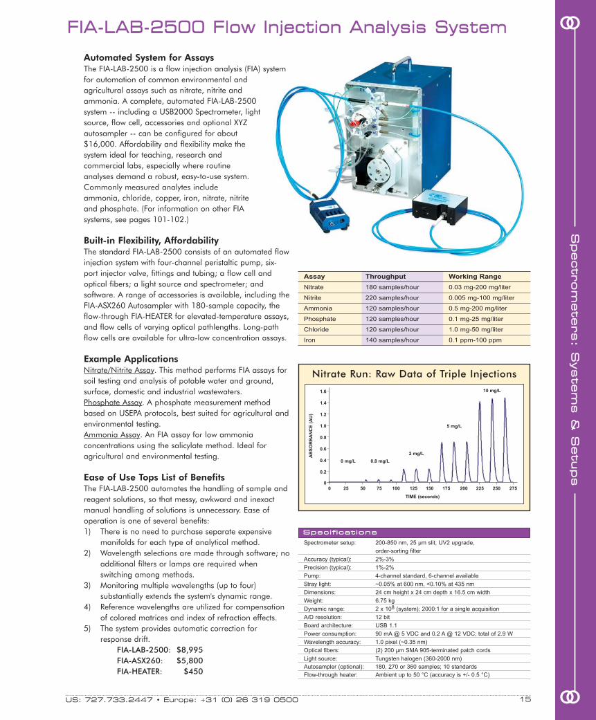
ooAutomated System for AssaysThe FIA-LAB-2500 is a flow injection analysis (FIA) systemfor automation of common environmental andagricultural assays such as nitrate, nitrite andammonia. A complete, automated FIA-LAB-2500system -- including a USB2000 Spectrometer, lightsource, flow cell, accessories and optional XYZautosampler -- can be configured for about$16,000. Affordability and flexibility make thesystem ideal for teaching, research andcommercial labs, especially where routineanalyses demand a robust, easy-to-use system.Commonly measured analytes includeammonia, chloride, copper, iron, nitrate, nitriteand phosphate. (For information on other FIAsystems, see pages 101-102.)
Built-in Flexibility, AffordabilityThe standard FIA-LAB-2500 consists of an automated flowinjection system with four-channel peristaltic pump, six-port injector valve, fittings and tubing; a flow cell andoptical fibers; a light source and spectrometer; andsoftware. A range of accessories is available, including theFIA-ASX260 Autosampler with 180-sample capacity, theflow-through FIA-HEATER for elevated-temperature assays,and flow cells of varying optical pathlengths. Long-pathflow cells are available for ultra-low concentration assays.
Example ApplicationsNitrate/Nitrite Assay. This method performs FIA assays forsoil testing and analysis of potable water and ground,surface, domestic and industrial wastewaters. Phosphate Assay. A phosphate measurement methodbased on USEPA protocols, best suited for agricultural andenvironmental testing. Ammonia Assay. An FIA assay for low ammoniaconcentrations using the salicylate method. Ideal foragricultural and environmental testing.
Ease of Use Tops List of BenefitsThe FIA-LAB-2500 automates the handling of sample andreagent solutions, so that messy, awkward and inexactmanual handling of solutions is unnecessary. Ease ofoperation is one of several benefits:1) There is no need to purchase separate expensive
manifolds for each type of analytical method.2) Wavelength selections are made through software; no
additional filters or lamps are required whenswitching among methods.
3) Monitoring multiple wavelengths (up to four)substantially extends the system's dynamic range.
4) Reference wavelengths are utilized for compensationof colored matrices and index of refraction effects.
5) The system provides automatic correction forresponse drift.
FIA-LAB-2500: $8,995FIA-ASX260: $5,800FIA-HEATER: $450
Spectrometer setup: 200-850 nm, 25 µm slit, UV2 upgrade,
order-sorting filter
Accuracy (typical): 2%-3%
Precision (typical): 1%-2%
Pump: 4-channel standard, 6-channel available
Stray light: ~0.05% at 600 nm, <0.10% at 435 nm
Dimensions: 24 cm height x 24 cm depth x 16.5 cm width
Weight: 6.75 kg
Dynamic range: 2 x 10⁸ (system); 2000:1 for a single acquisition
A/D resolution: 12 bit
Board architecture: USB 1.1
Power consumption: 90 mA @ 5 VDC and 0.2 A @ 12 VDC; total of 2.9 W
Wavelength accuracy: 1.0 pixel (~0.35 nm)
Optical fibers: (2) 200 µm SMA 905-terminated patch cords
Light source: Tungsten halogen (360-2000 nm)
Autosampler (optional): 180, 270 or 360 samples; 10 standards
Flow-through heater: Ambient up to 50 °C (accuracy is +/- 0.5 °C)
SSppeecciiffiiccaattiioonnss
Assay Throughput Working Range
Nitrate 180 samples/hour 0.03 mg-200 mg/liter
Nitrite 220 samples/hour 0.005 mg-100 mg/liter
Ammonia 120 samples/hour 0.5 mg-200 mg/liter
Phosphate 120 samples/hour 0.1 mg-25 mg/liter
Chloride 120 samples/hour 1.0 mg-50 mg/liter
Iron 140 samples/hour 0.1 ppm-100 ppm
Nitrate Run: Raw Data of Triple Injections
0 25 50 75 100 125 150 175 200 225 250 275
1.6
1.4
1.2
1.0
0.8
0.6
0.4
0.2
0
AB
SO
RB
AN
CE
(A
U)
0 mg/L 0.8 mg/L
2 mg/L
5 mg/L
10 mg/L
TIME (seconds)
SSppeeccttrroomm
eetteerrss:: SS
yysstteemm
ss &&
SSeettuuppss

SSppeeccttrroomm
eetteerrss::
SSyysstteemm
ss &&
SSeettuuppss
After taking a reference and a darkspectrum, insert an LED into the
LED-PS Power Supply, whichholds and powers the LED,displays the LED drive current,and allows you adjust the current.The LED-PS is placed over the
FOIS-1, so that the LED is insertedinto the sample port of the FOIS-1.
For all your sensing needs, visit OceanOptics.com16
oo LLEEDD MMeeaassuurreemmeenntt TToooollss
Dimensions: 89.1 mm x 63.3 mm x 34.4 mm
Weight: 190 g (without cable)
Power consumption: 90 mA @ 5 VDC
Wavelength range: 350-1000 nm
Detector: 2048-element CCD array (page 43)
with L2 Collection Lens
Grating: Grating #2, 600 lines per mm
blazed at 300 nm (page 44)
Entrance aperture: 25 µm wide slit (page 42)
Order-sorting filters: OFLV-350-1100 (page 43)
Optical resolution: ~1.33 nm FWHM
Board architecture: USB and RS-232 interface
Dynamic range: 2 x 10⁸ (system); 2000:1 for a single acquisition
Stray light: <0.05% at 600 nm
Operating systems: Windows 98/Me/2000/XP, Mac OS X and Linux
operating systems when using the USB port
SSppeeccttrroommeetteerr SSppeecciiffiiccaattiioonnss
Item Description Page Price
USB2000 Spectrometer with 25 µm slit, 38 $2,649
L2 Lens, OFLV-350-1100
LS-1-CAL-INT Radiometrically calibrated LS-1 131 $749
FOIS-1 Fiber Optic Integrating Sphere 108 $499
LED-PS-NIST NIST-traceable LED power supply 107 $749
OOIIrrad-C Software for Color and Irradiance 81 $399
P400-2-VIS-NIR Optical fiber for connecting 138 $120
FOIS-1 to USB2000
P200-2-VIS-NIR Optical fiber for connecting 138 $100
LS-1-CAL-INT to USB2000
Before measuring the absolute irradiance of your LED,you need to take a reference spectrum of a calibratedblackbody energy source. The LS-1-CAL-INT RadiometricReference Source was designed for the FOIS-1Integrating Sphere, our sample chamber for LEDs. TheLS-1-CAL-INT is inserted into the sample port of theFOIS-1 (at right); optical fiber collects the light from theFOIS-1 and funnels it to the USB2000 Spectrometer.
In this setup, the LED-PS is on top of the FOIS-1 Integrating Sphereand a P400-2-VIS-NIR Optical Fiber collects the light energy fromthe FOIS-1 and sends it to the USB2000 Spectrometer. Our softwarereports the absolute spectral intensities for the LED as well as colorvalues, photopic data and more.
When coupled with the optimum sampling accessories, theUSB2000 Spectrometer is a highly accurate spectroradiometerfor measuring the color, relative power and absolute spectralintensity of LEDs.
Miniature Fiber Optic SpectrometerA USB2000 Spectrometer optimized for LED measure-ments is configured with a 350-1000 nm wavelengthrange, a 25 µm entrance aperture and an L2Collection Lens to increase light efficiency. With thisconfiguration, optical resolution is ~1.33 nm (FWHM).
LED Power Supply: Secures,Powers & Drives LEDThe LED-PS Power Supply provides three usefulfunctions: securing the LED in place, powering the LED,and displaying the LED’s drive current. Use theadjustable drive current feature to increase or decreasean LED’s current up to 50 mA. We offer a standardLED-PS and a NIST-traceable version.
Integrating Sphere: 360° Energy CollectionThe LED is powered by the LED-PS and is inserted intothe 9.5-mm diameter port of the FOIS-1 Fiber OpticIntegrating Sphere, which has a 360° field of view. TheP400-2-VIS-NIR Optical Fiber collects the light from theFOIS-1 and funnels it to the USB2000 Spectrometer.
Light Source: Radiometric Reference SourceThe LS-1-CAL-INT is a NIST-traceable light sourcedesigned specifically to calibrate the spectral responseof a spectroradiometric system that uses the FOIS-1 asthe sampling device. It provides known absoluteintensity values at several wavelengths. The LS-1 isused as a reference for relative power measurements.
Spectral & Color MeasurementOur software provides absolute spectral intensities forLEDs, and calculates L*a*b*, XYZ, xyz, u'v'w', hue, RGB,chroma, saturation and more. See page 81 for details.
oo

US: 727.733.2447 • Europe: +31 (0) 26 319 0500 17 oo
ooTTrraannssmmiissssiioonn ooff OOppttiiccss TToooollss
Quantity Item Description Page Price
1 HR4000 HR4000 ($3,999) with HC-1 Composite Grating ($600); 25 µm slit ($150); 46 $5,149
OFLV-H4 Order-sorting Filter ($250); UV4 Detector Upgrade ($150)
1 DT-MINI-2 Miniature Deuterium Tungsten Halogen Light Source 122 $1,499
1 74-ACH Adjustable Collimating Lens Holder 89 $299
2 74-UV Collimating Lens 88 $318
2 P600-1-SR 600 µm diameter optical fiber in 1-meter length 139 $238
TOTAL: $7,503
We offer all of the componentsyou need for measuring thetransmission of optics. Listedbelow is a sample order thatspecifies an HR4000 High-resolution Spectrometerconfigured with our novel HC-1Composite Grating, whichprovides a 200-1100 nmwavelength range. In addition, wesuggest a DT-MINI-2 DeuteriumTungsten Halogen Source, plusfibers, collimating lenses and alens fixture for sampling.
HR4000 with 200-1100 nm Wavelength RangeThe HR4000 configuration we recommend for this application includes anew 3648-element CCD-array detector, the proprietary HC-1 CompositeGrating and an order-sorting filter to provide a 200-1100 nm wavelengthrange and optical resolution better than 1.0 nm (FWHM). We also suggest a25 µm entrance slit and a UV2 Detector Upgrade to enhance performancein the UV. The HR4000 interfaces to a PC via a USB 2.0 port.
Broad Spectral Range Light SourceThe DT-MINI-2 Deuterium Tungsten Halogen Light Source combines thecontinuous spectrum of a deuterium UV light source and a tungsten halogenVIS-NIR light source in a single optical path. The combined-spectrum sourceproduces stable spectral output from ~200-2000 nm in a compact package.
Holder for a Variety of SamplesThe 74-ACH Adjustable Collimating Lens Holder consists of adjustable barswith several threaded holes for collimating lenses. The bars can be set toaccept samples up to ~100 mm thick, making the 74-ACH a convenientoption for transmission measurements of large samples.
Collimating LensesThe 74-UV Collimating Lenses screw into the threaded holes of the 74-ACHto collimate light. The lenses have an inner barrel threaded for attaching tooptical fibers. When focused for collimation, beam divergence is 2° or less.The inner barrel can slide relative to the lens fixture to adjust the focus.
Optical FiberOur fiber assemblies can act as both illumination and read fibers. The two600 µm diameter optical fibers recommended are 1 meter in length andconnect easily from the collimating lenses installed in the 74-ACH to theHR4000 Spectrometer and the light source.
Dimensions: 148.6 mm x 104.8 mm x 45.1 mm
Weight: 570 g
Power consumption: 450 mA @ 5 VDC
Detector: 3648-element linear CCD array
(page 51)
Wavelength range: 200-1100 nm
Optical resolution: ~1.0 nm FWHM
Grating: HC-1, 300 lines per mm grating
(page 52)
Entrance aperture: 25 µm wide slit (page 50)
Order-sorting filters: Installed OFLV-200-1100 (page 51)
Focal length: f/4, 101 mm
Dynamic range: 2 x 10⁹ (system); 2000:1 for
a single acquisition
Stray light: <0.05% at 600 nm;
<0.10% at 435 nm
Data transfer rate: Full scans into memory every 4 ms
with USB 2.0; 18 ms with USB 1.1;
600 ms with the serial port
Operating systems: Windows 98/Me/2000/XP,
Mac OS X and Linux when using
the USB port; any 32-bit Windows
operating system when using
the serial port
Inputs/outputs: 10 digital user-programmable GPIOs*
Analog channels: One 13-bit analog input and
one 9-bit analog output
SSppeeccttrroommeetteerr SSppeecciiffiiccaattiioonnss
SSppeeccttrroomm
eetteerrss:: SS
yysstteemm
ss &&
SSeettuuppss
* Programming the GPIOs requires SpectraSuiteSoftware, OmniDriver or another one of our devicedrivers. See pages 76-79 for details.

For all your sensing needs, visit OceanOptics.com18oo
oo NNaannooCCaallcc TThhiinn FFiillmm RReefflleeccttoommeettrryy SSyysstteemm
NanoCalc Software displays a sample interference spectrum, predictedspectra and up to four layers.
Item Wavelength Thickness Light Source Included
NC-UV-VIS-NIR 250-1100 nm 10 nm-70 µm Deuterium and Tungsten Halogen
NC-UV-VIS 250-850 nm 10 nm-20 µm Deuterium and Tungsten Halogen
NC-VIS-NIR 400-1100 nm 50 nm-100 µm (optional 1 µm-250 µm) Tungsten Halogen
NC-VIS 400-850 nm 50 nm-20 µm Tungsten Halogen
NC-NIR 650-1100 nm 70 nm-70 µm Tungsten Halogen
NC-NIR-HR 700-978 nm 1 µm-250 µm Tungsten Halogen
NC-512-NIR 900-1700 nm 50 nm-200 µm High-power Tungsten Halogen
Angle of incidence: 90°
Number of layers: 4 or fewer
Reference measurement needed: Yes (bare substrate)
Transparent materials: Yes
Transmission mode: Yes
Rough materials: Yes
Measurement speed: 100 milliseconds to 1 second
On-line possibilities: Yes
Mechanical tolerance (height): With new reference or collimation (74-UV)
Mechanical tolerance (angle): Yes, with new reference
Microspot option: Yes, with microscope
Vision option: Yes, with microscope
Mapping option: 6" and 12" XYZ mapping tables
Vacuum possibilities: Yes
SSppeecciiffiiccaattiioonnss
Analyze Layers from 10 nm in ThicknessThe optical properties of thin films arise from reflection andinterference. The NanoCalc Thin Film Reflectometry Systemallows you to analyze the thickness of optical layers from 10 nm to ~250 µm. You can observe a single thickness witha resolution of 0.1 nm. Depending on your software choice,you can analyze single-layer or multilayer films in less thanone second and can measure the thickness and removalrates of semiconductor process films or anti-scratch coatings,hard coatings and anti-reflection coatings.
Theory of OperationThe two most common ways to measure thin filmcharacteristics are spectral reflectance/transmission andellipsometry. NanoCalc utilizes the reflectance method andmeasures the amount of light reflected from a thin film overa range of wavelengths, with the incident light normal to thesample surface.
Search by n and kAs many as four layers can be specified in a film stack. Thevarious films and substrate materials can be metallic,dielectric, amorphous or crystalline semiconductors. TheNanoCalc Software includes a large library of n and k valuesfor the most common materials. You can edit and add to thislibrary. Also, you can define material types by equation ordispersion formulas.
ApplicationsNanoCalc Thin Film Reflectometry Systems are ideal for insitu, on-line thickness measurements and removal rateapplications, and can be used to measure the thickness ofoxides, SiNx, photoresist and other semiconductor processfilms. NanoCalc Systems measure anti-reflection coatings,anti-scratch coatings and rough layers on substrates such assteel, aluminum, brass, copper, ceramics and plastics.
SSppeeccttrroomm
eetteerrss::
SSyysstteemm
ss &&
SSeettuuppss

US: 727.733.2447 • Europe: +31 (0) 26 319 0500 19 oo
ooSSppeeccEEll EElllliippssoommeetteerr SSyysstteemm
Wavelength range: 450-900 nm
Optical resolution: 4.0 nm FWHM
Accuracy: 0.1 nm thickness; 0.005% refractive index
Angle of incidence: 70°
Film thickness: from 0.1 to 8000 nm for single transparent film
Spot size: 2 mm x 4 mm (standard) or 200 µm x 400 µm (optional)
Sampling time: 5-15 seconds (minimum)
Kinetic logging: 5 seconds
Mechanical tolerance: Height ± 1 mm, angle ± 1.0°
Number of layers: Up to 32 layers
Reference: Not applicable
SSppeecciiffiiccaattiioonnss
Full Spectral Range in Easy-to-use SystemMeasure refractive index, absorbance and thickness of substrateswith the touch of a button! The SpecEl-2000-VIS Ellipsometerfrom Mikropack measures polarized light reflected from thesurface of a substrate to determine the thickness and refractiveindex of the material as a function of wavelength. The SpecEl iscontrolled via a PC.
All-in-one Accurate SystemThe SpecEl houses an integrated light source, a spectrometer andtwo polarizers fixed to 70°. It also includes a PC with a 32-bitWindows operating system. The SpecEl can detect a single layeras thin as 0.1 nm and up to 5 µm thick. In addition, it canprovide refractive indices to 0.005° over lambda.
SpecEl Software and “Recipe” FilesIn SpecEl Software, you can configure and save experimentmethod files for one-step analysis. After creating a “recipe,” youcan select the recipe to execute the experiment.
This screen from the SpecEl Software demonstrates the Psi and Deltavalues you can calculate for thickness, refractive index and absorbance.
Real-time, Full-spectral Plasma MonitoringPlasCalc-UV-NIR measures plasma emission from 200-1100 nmin only 3 milliseconds. The PlasCalc benefits from advancedprocess control systems and sophisticated algorithms for dataacquisition.
Recipe EditorThe Recipe Editor tool allows you to easily and rapidly configure,build and save experiment methods. It is easy to build robustrecipes for the most difficult plasma processes such as measuringfilm deposition, monitoring plasma etching, examining surfacecleaning, analyzing plasma chamber health control, andmonitoring abnormal pollution or discharge phenomena.
Multiple Tools for Easy Plasma DiagnosisThe Integrated Formula Editor provides easy access to a full rangeof mathematical and algorithmic functions. An EmissionWavelength Library provides species identification, while theWavelength Editor allows you to optimize signal-to-noise. A dual-window interface shows the actual spectrum and all processcontrol information.
Spectral range: 200-1100 nm
Optical resolution: 1.0 nm FWHM
D/A-converter: 14 bit
Digital input/output: 8 x TTL digital input/output
Analog output: 4 x [0-10V]
Interface: USB 1.1
Power consumption: 12 VDC @ 1.25 A
Power requirements: 90-240 VAC 50/60 Hz
Dimensions: 257 mm x 152 mm x 263 mm
Weight: 5 kg
PPllaassCCaallcc PPllaassmmaa MMoonniittoorriinngg && CCoonnttrrooll
SSppeecciiffiiccaattiioonnss
SSppeeccttrroomm
eetteerrss:: SS
yysstteemm
ss &&
SSeettuuppss

Instant Elemental Analysis from 200-980 nmWe offer a full range of systems and components for laser-inducedbreakdown spectroscopy, a technique for real-time, qualitative spectralanalysis of elements in solids, solutions and gases. The LIBS2000+ isa broadband (200-980 nm), high-resolution detection system withoptical resolution of ~0.1 nm (FWHM). Sensitivity to parts-per-billion
and picogram levels is possible.
How the LIBS WorksA high-intensity, pulsed laser beam is focused on the sample area.
A single 10 nanosecond-wide laser pulse ablates the sample andgenerates a plasma. As the plasma decays or cools, excited atoms inthe plasma emit light at wavelengths that are distinct to each element.The emission is collected by a probe and sent to the spectrometersystem. Each scan provides full spectral analysis from 200-980 nm --the region in which all elements emit energy. This emission is collectedby a probe and sent to a high-resolution, spectrometer system foranalysis.
Diverse ApplicationsThe LIBS2000+ is noninvasive so users can perform real-timemeasurements in hostile environments with little or no samplepreparation. LIBS2000+ Systems are being used in these areas:� Environmental monitoring: soil, particulates, sediments� Materials analysis: metals, metal alloys, slag, plastics, glass� Forensics and biomedical: teeth, bones� Metrology: silicone wafers� Bioresearch: plants, grains� Safety & military applications: explosive particles, chemical and
biological warfare agents� Art restoration/conservation: pigments, paints� Gemology: precious metals, gems
High-resolution SpectrometersOur LIBS2000+ Spectrometer uses seven linear CCD-array detectorsfor broadband analysis. All spectrometers are triggered to acquire andread out data simultaneously. The detection system is portable and canbe interfaced to a PC via a USB port.
Operating SoftwareOOILIBS Software includes a library of elemental emission lines andenables automatic identification of all elements present in the sample.Other software features allow tracking emission intensities overmultiple scans and correlation of analysis routines.
LIBS2000+: $30,000OOILIBS: $500
For all your sensing needs, visit OceanOptics.com20oo
oo LLaasseerr--iinndduucceedd BBrreeaakkddoowwnn SSppeeccttrroommeetteerr
Dimensions: 133 mm x 267 mm x 450 mm
(spectrometer system)
Weight: 13 kg (spectrometer system only)
Power consumption: 1 A @ 5 VDC (spectrometer system only)
Detector: (7) 2048-element linear silicon CCD arrays
Wavelength range: 200-980 nm
Optical resolution: ~0.1 nm (FWHM)
Frame rate: 10 Hz capability (PC-controlled)
Integration time: 2.1 ms; variable in free-run mode
Trigger delay: -121 µs to +135 µs in 500 ns steps
(PC-controlled)
Trigger jitter: ± 250 ns
Trigger level: TTL not to exceed 5.5 volts
SSppeeccttrroommeetteerr SSppeecciiffiiccaattiioonnss
SSppeeccttrroomm
eetteerrss::
SSyysstteemm
ss &&
SSeettuuppss
LIBS2000+ Spectra of Silicon
240 250 260 270 280 290
WAVELENGTH (nm)
INT
EN
SIT
Y(c
ou
nts
)
4000
3000
2000
1000
0
Parameter
Sample depth:
Sensitivity:
Precision:
Accuracy:
Analysis time:
Sample consump:
Complexity:
Cost:
Discrimination:
SEM/EDS
~5 µm
1000 ppm
Poor
Qualitative
Slow
non-destructive
Easy to use
$120,000
Poor
EPMA
<1 µm
100 ppm
Fair
Semi-quantitative
Slow
non-destructive
Complicated
$600,000
Fair
XRF
~100 µm
100 ppm
Fair-good
Semi-quantitative
Very slow
non-destructive
Easy to use
$120,000
Good
LA-ICP-MS
~80 µm
<1 ppm
Excellent
Quantitative
Slow
almost non-destructive
Complicated
$250,000
Excellent
LIBS
~50-100 µm
10-50 ppm
Fair-good
Semi-quantitative
Fast
almost non-destructive
Easy to use
$60,000
Good
Advantages of LIBS over other Technologies
LIBS spectra for silicon surface contamination rangingfrom 0 to 2%. The LIBS spectrum for a silicon-rich sampleis shown at the bottom of the graph for comparison.
A LIBS system often includes the LIBS-LASER (page 21) as the excitationsource, which includes the laser power supply (left) and thelaser head that sits on top of the sample chamber. The LIBS-SC Sample Chamber (page 21, and shown above center)includes a stage and probe. The LIBS2000+ SpectrometerSystem is above right.
Custom SetupsAs lower-cost
options, lab and field
systems are avail-
able with fewer than
seven spectrometer
channels, with a
narrower wavelength
range for element-
specific analyses.

US: 727.733.2447 • Europe: +31 (0) 26 319 0500 21 oo
ooSS
ppeeccttrroomm
eetteerrss:: SS
yysstteemm
ss &&
SSeettuuppss
AAddddiittiioonnaall LLIIBBSS CCoommppoonneennttss
LIBS Sample Chamber
LIBS Imaging Modules for Pinpoint Analysis
LIBS Laser Options
Item Description Resolution Price
LIBS-IM B&W Imaging Module for the LIBS-SC to 40 µm $7,500
LIBS-IM-C Color Imaging Module for the LIBS-SC to 60 µm $8,000
LIBS-IM-PCI FireWire PCI card for desktop PC N/A $30
LIBS-IM-MCIA FireWire PCMCIA card for notebook PC N/A $56
We offer multiple laser power options as sources for the LIBS2000+. Most all LIBS laserablation is performed with a Q-switched 1064 nm Nd:YAG laser with variable repetitionrates from 1-20 Hz, and a pulse stability of +/-3%. The choice of laser depends onyour sample and its moisture content. For metals and compressed dry materials, selectthe 50 mJ ULTRA CFR Nd:YAG laser from Big Sky Laser Technologies (LIBS-LASER). Forglass and high OH content materials, or for measuring a variety of materials, werecommend a 200 mJ Nd:YAG laser from New Wave Research (LIBS-LAS200MJ).
Though you can supply your own Q-switched pulsed laser for excitation as long as itsenergy is 30 mJ or above, please consult with our Ocean Analytics division beforeconsidering a laser not listed here. We offer other laser options; contact us for details.
LIBS-LASER: $14,500LIBS-LAS200MJ: $22,500
The LIBS-LAS200MJ is a 200 mJNd:YAG laser from New Wave Researchcalled the Tempest.
The eye-safe LIBS-SC Sample Chamber is a key component of a LIBS system andis designed to perform various functions safely and in clear view. The chamberaccommodates a sample up to 6.5 cm x 6.5 cm x 6 cm and houses a manuallycontrolled x-y stage. The chamber is made of an eye-protective polymer thatprovides a clear view of a sample. The chamber has a safety-interlock so the laserwill not fire when the door is open. It is magnetically latched and interacts with alaser safety cutoff switch.
LIBS-SC: $9,800The chamber includes a blower and an evacuationsystem that removes material from the samplearea. You also can feed gases, such as Argon,into the sample chamber. Flooding the chamberwith an inert gas provides greater sensitivity for avariety of elements.
The LIBS-IM and LIBS-IM-C Imaging Modules directly attach to the LIBS-SC SampleChamber to enable users to magnify a sample image and to establish precisely alaser ablation target on the sample. The cameras used in the imaging modulesprovide frame rates of up to 12.7 frames-per-second at 1280 x 1024 pixelresolution. Both are well suited to a variety of application areas that include forensics,semiconductor analysis, botany, biomedical analysis, gemology and metallurgy.
The imaging modules allow a user to see a magnified image of a sample via a CCDcamera and PixeLINK image-capture software. PixeLINK lets you capture an image,annotate it and archive it on your PC.
The LIBS-IM produces black and white images with image resolution to 40 microns;the LIBS-IM-C provides color images at resolution to 60 microns. We recommend animaging module for those purchasing the LIBS-SC Sample Chamber because animaging module will provide rapid and convenient laser focus. The modules connectto a PC via a FireWire cable and FireWire PCI or PCMCIA card.
This image --taken with aLIBS-IM -- isthe "O" in thetext, “QuarterDollar” on aU.S. quarter.
Stages: Manual x-y stage, z axis controlled manually via the focusing lens
Sample size: 6.5 cm x 6.5 cm x 6 cm maximum
Laser safety shield: OD - 6 for 1.064 mm laser energy (call for other wavelengths)
Internal optics: 25 mm diameter lenses, 75 mm focal length supplied
SSppeecciiffiiccaattiioonnss

For all your sensing needs, visit OceanOptics.com22oo
ooHighly Refined Sampling System for LIBSThe LIBS-ELITE, developed by New Wave Research andOcean Optics, is a high-quality, high-precision LIBS samplingsystem platform with unparalleled sample imaging andcontrol. The LIBS-ELITE consists of a laser head, samplechamber, software-controlled X-Y positioner and a high-resolution imaging system combined in a single housing.New Wave Research partnered with Ocean Optics to developthe LIBS-ELITE to work with the LIBS2000+ Laser-inducedBreakdown Spectrometer System.
200 mJ Nd:YAG LaserThe LIBS-ELITE-200 comes with New Wave Research'sTempest 200 mJ Nd:YAG laser. The Tempest delivers high-energy densities to the sample to create plasma from eventhe most challenging materials. The accuracy and precisionof the LIBS-ELITE-200 relies on the 98% pulse-to-pulsestability of the Tempest. A laser power meter located adjacentto the sample and a software-controlled attenuator arestandard features that help enable quantitative sampleanalysis. Others laser options are available; the LIBS-ELITE-90 comes with a 90 mJ laser.
Sample Chamber: Unprecedented ControlThe open architecture of the sample chamber allows thesample and ablation plume to be viewed easily through itsClass 1 shield. The sample chamber includes a quick-loading sample drawer, and can accommodate samples upto 2 inches in diameter. A gas port on the rear of thehousing enables the chamber to be purged with argon,which is useful for increasing sampling sensitivity, or withnitrogen or helium, which is useful when measuringemissions of elements like oxygen that are found in ambientenvironments. An integrated rotometer regulates the gas flowin the chamber.
Exact Positioning & High Resolution ImagingThe system's software-controlled X-Y stage allows you toprecisely control the target location, to create reproduciblemaps, and to automate sample mapping, patterning andrastering for testing sample homogeneity or for bulk analysis.The spot size controller can be used to set the ablation spotsize from 20 µm to 1200 µm. The LIBS-ELITE’s high-resolution sample magnification capability (see softwarescreen capture at right) allows you to view an exact spot ofthe sample before and after the ablation event.
Software with Spectral LibraryThe LIBS-ELITE comes with intuitive operating software and alibrary of elemental emission lines, which enables automaticidentification of all elements present in a sample. Thesoftware includes controls for ablation mode, laser repetitionrate, laser power, sample spot size selection, X-Y positioning,sample viewing, sample mapping, gas routing, spectrometersystem triggering and automating sampling processes.Pricing does not include the spectrometers.
LIBS-ELITE-200: $68,000LIBS-ELITE-90: $65,000
LLIIBBSS--EELLIITTEE LLaasseerr AAbbllaattiioonn SSaammpplliinngg SSyysstteemm
View an exact spot of the sample before, during and after the ablationprocess. The LIBS-ELITE provides real-time, high-resolution qualitativeanalysis of trace elements in diverse materials such as metals, biologicaltissues, soils, optics, semiconductors, gems, and other geological,biological and environmental specimens.
SSppeeccttrroomm
eetteerrss::
SSyysstteemm
ss &&
SSeettuuppss
The LIBS-ELITEworks with the OceanOptics LIBS2000+Spectrometer System (seepage 20) to provide full spectral analysis from 200-980 nm, with opticalresolution of 0.1 nm and sensitivity to parts-per-billion. Below is a magnificationof the sampling area where the ablation plume is produced behind the orangeClass 1 shield. The sample compartment itself contains a quarter.

Instant Endospore DetectionThe EDS2000 Endospore Detection System is afield-deployable system that offers rapid front-endscreening to instantly indicate the presence ofBacillus and Clostridium endospores, which includeBacillus anthracis (anthrax). The EDS2000 has adetection level of 100,000 spores, making it idealfor screening suspicious powders encountered byfirst-response teams. The entire system fits into arugged carrying case for field use.
Principle of OperationAnalysis begins with swabbing of the potentiallyinfected surface. The swab is swirled in adisposable plastic cuvette containing specialreagents. (The EDS-TEST endospore detectionreagent is available in a box of 100 reagent-filledcuvettes.) The cuvette is placed into the system'scuvette holder and exposed to ultraviolet pulsedxenon light. We use our USB2000-FLGSpectrofluorometer in gated fluorescence mode todetect and quantify the fluorescence from bacterialendospores in suspect samples.
Gated FluorescenceThe USB2000-FLG is preloaded with variable-delaygating microcode. This gated mode adds 5-500microseconds between the excitation source firingand the start of the spectrometer's integration time,or the amount of time the detector “sees” thesample. In this mode, the spectrometer only detectsthe sample light when the source is off. TheUSB2000-FLG in gated fluorescence mode detectsand quantifies the fluorescence of the sample;software then compares the sample with astandard for endospores. The software displays thecomparative results -- positive, possible or belowlimits of detection -- within seconds of the analysis.
Special Mirrors Prevent Scattered LightIn addition to detecting fluorescence from asample, a spectrofluorometer will also detectscattered excitation light from the light source andthe sampling compartment. Another feature helpsavoid detecting scattered light: special mirrors inthe bench absorb UV light and improve sensitivity.
What’s Been TestedWe are collaborating with other organizations tooptimize the reagents now being used to detectbacterial endospores, in an effort to lowerdetection limits. In earlier tests, the system reportedpositive contamination when two anthrax strainswere used as the sample: the Sterne strain(gamma-killed anthrax) and the Pasteur strain (anavirulent form of anthrax).
EDS2000: $5,000EDS-TEST: $300
US: 727.733.2447 • Europe: +31 (0) 26 319 0500 23 oo
ooEEDDSS22000000 EEnnddoossppoorree DDeetteeccttiioonn SSyysstteemm
SYSTEM
Dimensions: 17.5 cm x 14.5 cm x 6 cm
Weight: 1.10 kg (without battery)
Photometric accuracy: <0.1%
Stray light: ~0.05% at 600 nm, <0.10% at 435 nm
Dynamic range: 2 x 10⁸ (system); 2000:1 for a single acquisition
A/D resolution: 12 bit
Board architecture: USB 1.1
Power consumption: 90 mA @ 5 VDC and 0.2 A @ 12 VDC for a total of 2.9 W
OPTICAL BENCH & DETECTOR
Detector: Linear silicon CCD array
Pixels: 2048
Pixel size: 14 µm x 200 µm
Well depth: ~62,500 electrons
LIGHT SOURCE
Light source: Pulsed xenon
Bulb life: >1 x 10⁸ flashes
SAMPLE CHAMBER
Pathlength: 1-cm standard
Cuvette shape: Square
“Z” dimension: 15 mm (distance from bottom of chamber to center of light path)
SSppeecciiffiiccaattiioonnss
SSppeeccttrroomm
eetteerrss:: SS
yysstteemm
ss &&
SSeettuuppss

For all your sensing needs, visit OceanOptics.com24
SSeennttrryy SSyysstteemm ffoorr OOppeenn--PPaatthh AAiirr MMoonniittoorriinngg
The SENTRY-5000 is ideal for fenceline monitoringapplications of up to 850 meters. The SENTRY-STAN (at right, being inserted into the optical path of theSENTRY-5000) is a NIST-traceable calibration cell thatcomes with the SENTRY-5000.
Innovative Open-Path Air MonitorThe Sentry is a fully automated, low-cost, open-pathair monitoring system that detects and quantifiesmultiple atmospheric toxic compounds in real time,with a single analyzer. The Sentry senses dangerouschemicals at parts-per-trillion levels in wide-areaenvironments (up to 850 meters in length), and isespecially useful for community groups,environmental regulators, industrial corporations andgovernment agencies in mapping hazardousemissions from pollution sources.
Partnership with CerexDeveloped by Cerex Environmental Services ofAtlanta, Georgia, the portable Sentry is equipped with
an integrated Ocean Optics HR2000 High-resolution Spectrometer that can resolve thefine spectral features of dangerous air-borne toxins including benzene, butadiene,toluene and xylene. (See the facing pagefor a list of the 20 compounds included inthe current Sentry Software. If thecompound you wish to monitor is not onthe list, contact Ocean Optics. Additionalcompounds may be added to the
software’s library.)
Detects Airborne Toxins in Real TimeThe Sentry includes a UV deuterium opticaltransmitter unit and a UV optical receiver unit. Thetransmitter projects a continuous collimated beam ofUV light through the sample area to an opticalreceiving unit using telescope optics. The receiver,which contains the Ocean Optics HR2000 High-resolution Spectrometer, collects the light. Becauseeach compound has a unique absorption spectral“fingerprint,” the software is able to determine andspecify the presence of airborne toxins along thebeam's path. A release of a chemical anywhere alongthe beam is immediately detected and quantified. Bycomparison, traditional “point sampling” monitorsmay report only the part of a toxic plume that reachesthe sensor's input port.
Used at Industrial SitesIn a highly publicized investigation, HillsboroughCounty, Florida, officials reported using the Sentry tomonitor the air around Coronet Industries in PlantCity, Florida. In the Coronet tests, the Sentry detectedthe presence of sulphur dioxide and nitric oxide nearthe plant but that the pollution levels were within legalstandards. Sentry systems are being used to monitorthe atmosphere for BTEX, SO2 and other compoundsat oil refineries, airports, animal feed operations,rubber manufacturing plants and more. In Durban,South Africa, for example, the Sentry differentiatedbetween emissions that the refinery is responsible forand those produced by other sources.
Item Description Price
SENTRY-5000 Open-Path Air Monitoring System with $63,000
Deuterium Optical Transmitter, Integrated
Spectrometer Optical Receiver, 2 Detachable
Sighting Scopes, 2 power cables, 1 USB cable,
Software, Spectral Library, and Calibration cell
SENTRY-SUR-MT Heavy duty surface mount (2 required) $3,080
SENTRY-TRIPOD Heavy duty tripod mounts, used for portable $3,960
long distance applications (2 required)
SENTRY-STAN NIST-traceable Replacement Calibration $910
Cell for Sentry
SENTRY-CASE Transit Case for Sentry $1,999
SENTRY-DEUT Replacement Deuterium Source for Sentry $1,074
The Sentry’s software allows for continuous automated monitoring of compounds.
oo
ooSS
ppeeccttrroomm
eetteerrss::
SSyysstteemm
ss &&
SSeettuuppss

Portable Air MonitorThe Hound is a portable point sampling air monitor that cansimultaneously detect, quantify and identify up to 20 toxicairborne compounds at parts-per-billion concentration levels. TheHound instantly resolves the fine spectral features of hazardousair toxins including acrolein, benzene, sulfur dioxide, mercury,ozone and formaldehyde -- at concentrations below regulatorythreshold levels.
Easy to Set Up & DeployThe Hound is a self-contained, compact system that’s just 33"long and weighs less than 25 pounds. In minutes, you candeploy the Hound on to a vehicle for emergency responsemonitoring, or place it in a fixed location for industrial hygieneor survey monitoring. All you need to operate the Hound is anotebook or desktop PC. The Hound interfaces very easily to thePC via a USB port and comes with a power cord (batteryoperation is also possible). In addition, the Hound can beoperated around the clock, unmanned.
Spectroscopy Method Used for DetectionUsing the Hound’s software, you select the target gas you wish tomonitor. Once you switch on the Hound, it begins to draw in andexpel ambient air continuously. The air travels through a uniquefolded-path optical design, providing a 25-meter samplepathlength. At the heart of the Hound is an Ocean OpticsHR2000 High-resolution Spectrometer optimized for the UV. Asthe gas passes through deuterium light, it will absorb light atwavelengths that are characteristic of that gas, creating anabsorption spectrum.
Spectral Library Used for MatchingThe Hound’s software matches the measured spectrum against alibrary of stored reference absorption spectra for the 20compounds listed at right. Each compound can absorb onlycertain wavelengths of energy; each has its own absorptionspectral “fingerprint” unique to that compound. All of thisanalysis and reporting takes place in just milliseconds.
HOUND-7000: $49,000HOUND-CASE: $1,999HOUND-DEUT: $1,074HOUND-STAN: $910
TThhee PPoorrttaabbllee HHoouunndd SSnniiffffss OOuutt TTooxxiicc GGaass
US: 727.733.2447 • Europe: +31 (0) 26 319 0500 25
Sentry & Hound20 Detectable Compounds
AcetaldehydeAcrolein
AmmoniaBenzene
1,3-ButadieneCarbon Disulfide
ChlorineEthyl BenzeneFormaldehyde
Hydrogen SulfideIsopreneMercury
Nitric OxideNitrogen Dioxide
OzoneSulfur Dioxide
Toluenem-Xyleneo-Xylenep-Xylene
oo
oo
The Hounddraws air continuously into thesystem's intake vent. The air is passedthrough an analysis chamber and then expelled. Gases inthe air are detected and reported instantly. The software comeswith a spectral library of chemicals and allows for compoundselection and data logging.
SSppeeccttrroomm
eetteerrss:: SS
yysstteemm
ss &&
SSeettuuppss

Dimensions: 182 x 110 x 47
Weight: 1050 grams
Detector: Hamamatsu back-thinned CCD (page 55)
Pixels: 1024 x 58 (1044 x 64 total pixels)
Signal-to-noise ratio: 1000:1 (at full signal)
Dark noise: 3 RMS counts
Optical bench design: f/4, Symmetrical crossed Czerny-Turner
Focal length: 101.6 mm input and 101.6 mm output
Entrance aperture: 5, 10, 25, 50, 100, or 200 µm wide slits (page 56)
Gratings: 14 gratings UV through Shortwave NIR (page 56)
Integration time: 7 milliseconds to 15 minutes
Dynamic range: 7.5 x 10⁹ (system); 25000:1 for one acquisition
Fiber optic connector: SMA 905 to 0.22 numerical aperture fiber
Power consumption: 3 A @ 5 VDC with TE cooling
Data transfer speed Full scans to memory every 4 ms with USB 2.0
Inputs/outputs 10 onboard digital user-programmable GPIOs
Operating systems: Windows 98/Me/2000/XP, Mac OS X and Linux
when using the USB port
Temperature limits: 0 °C to 50 °C
Temperature range: 13 °C maximum range between high and low
Set point: Software controlled
Lowest Set point: 40 °C below ambient, to -15 °C
Stability: ±0.1 °C of set temperature in <2 minutes
New Scientific-grade SpectrometerThe QE65000 Spectrometer is a unique combination of detectorand optical bench technologies that provides users with highspectral response and high optical resolution in one package.
Demanding Low Light-level ApplicationsThe QE65000 was designed for low-light level applications such
as Raman spectroscopy. The detector is TE-cooled, resulting invirtually no dark noise, which allows you to set the integration
time of the spectrometer (analogous to a camera’s shutterspeed) at up to 15 minutes with little spectral distortion.
Quantum Efficiency to 90%With the scientific-grade detector, the QE65000 achieves
up to 90% quantum efficiency (defined as how efficiently aphoton is converted to a photoelectron). With this “2D” detector
in the QE65000, we bin a vertical row of 64 pixels, which increasesthe signal-to-noise ratio to 1200:1. (See page 54 for allspecifications on the QE65000.)
Increased System SensitivityQE65000 system sensitivity is improved because the 2D detectorallows us to take advantage of the height of the entrance slit. In ourspectrometers, you regulate the light entering the bench accordingto the slit’s width. Most of our other spectrometers use lineardetectors; in those spectrometers, slit height doesn’t matter becauselinear detectors cannot efficiently collect the light from the entireheight of the slit. But with the 2D detector in the QE65000, we canbetter take advantage of this additional light.
NIST-traceable Raman StandardsThe STAN-RAM785 and STAN-RAM532 are NIST-certified standardsfor determining the absolute spectral intensity of your Ramansystem. They consist of an optical glass that emits a broadbandluminescence spectrum when excited with a laser. (Select the STAN-RAM785 when using a 785 nm laser as your excitationsource; select the STAN-RAM532 when using a 532 nm laser.) Theshape of this luminescence spectrum is expressed by a polynomialequation that relates the relative spectral intensity to thewavenumber from the excitation wavelength. Determining theabsolute spectral intensity of your Raman system is essential forthose performing peak-to-peak height analysis and those collectinga spectral library.
QE65000: $9,999STAN-RAM532: $1,015STAN-RAM785: $1,015
For all your sensing needs, visit OceanOptics.com26oo
oo RRaammaann MMeeaassuurreemmeenntt TToooollssSS
ppeeccttrroomm
eetteerrss::
SSyysstteemm
ss &&
SSeettuuppss
SSppeecciiffiiccaattiioonnss
We used the QE65000 Sample Configuration #3 (describedin the table at lower right), and an InPhotonics probe toacquire Raman spectra of xylene samples.
INT
EN
SIT
Y
RAMAN SHIFT (cm-1)
Comparing Xylenes Using Raman
0 500 1000 1500 2000 2500 3000 3500 4000
40000
35000
30000
25000
20000
15000
10000
5000
0
Mixed Xylene
O-Xylene
Sample Spectral Excitation Grating Slit Resolution
Config. Range Source p. 56 p. 56 (approx.)
1 150-4000 cm-1 532 nm laser H6 10 µm ~8 cm-1
2 150-4000 cm-1 532 nm laser H6 25 µm ~10 cm-1
3 150-7500 cm-1 532 nm laser H14 10 µm ~16 cm-1
4 150-7500 cm-1 532 nm laser H14 25 µm ~19 cm-1
5 150-2100 cm-1 785 nm laser H6 50 µm ~6 cm-1
6 150-2100 cm-1 785 nm laser H6 100 µm ~8 cm-1
7 150-3950 cm-1 785 nm laser H14 50 µm ~13 cm-1
8 150-3950 cm-1 785 nm laser H14 100 µm ~18 cm-1
Examples of QE65000 Configurations for Raman
Above, the QE65000 is configured for use with aLASER-785 and an RIP-RPBprobe (see facing page fordetails). At left is the STAN-RAM785 for determining
the absolute spectral intensityof your Raman system.

We offer several fiber optic probes for Raman spectroscopy from ourcorporate partner InPhotonics. Each probe provides complete opticalfiltering of the Rayleigh line and high signal collection in a compact,rugged probe design. Several probe models are available forlaboratory, industrial and environmental applications.
The probes listed below are available for several excitationwavelengths. Please contact Ocean Optics for details.
Fiber Optic Probes for Raman Applications
US: 727.733.2447 • Europe: +31 (0) 26 319 0500 27
RRaammaann MMeeaassuurreemmeenntt TToooollss
RPB Laboratory Probe
oo
ooSS
ppeeccttrroomm
eetteerrss:: SS
yysstteemm
ss &&
SSeettuuppss
Item
RIP-RPB
RIP-RPS
RIP-RP2
RIP-RPR-H
RIP-RPR-S
RIP-RPP
RIP-PA-SH
Probe Size
(in mm)
114 x 38 x 12.7
12.7 OD x
101 length
15.87 OD x
203 length
15.87 OD x
330 length
15.87 OD x
330 length
9.52 OD x
300 length
not applicable
Fiber
Length
1.5 meter
5 meters
5 meters
5 meters
5 meters
5 meters
not applicable
Price
$2,750
$4,950
$6,745
$9,200
$8,200
$10,200
$850
Description
Laboratory probe for use with lasers up to 3 nm from specified operating
wavelength; has 7.5-mm focal length
Stainless-steel focused probe for lab and field use; has 5-mm focal
length (7.5 mm or 10 mm also available)
Stainless-steel immersion probe is immersible up to 200 °C and has
adjustable working distance
Hastelloy C immersion probe with gold gasket for use in process control
applications up to 200 °C and 1500 psi; comes with sapphire window
and has adjustable working distance
Stainless-steel immersion probe with elastomeric O-ring seal for use in
process control applications up to 200 °C and 1500 psi; comes with
sapphire window and has adjustable working distance
Stainless-steel probe with external optics for process control applications
up to 500 °C and 3000 psi; comes with sapphire lens and has short
working distance
Sample holder, with inserts for round vials, square cuvettes, and cups
INT
EN
SIT
YWAVELENGTH (nm)
HR4000 Spectrum of LASER-785
784.4 784.6 784.8 785.0 785.2 785.4 785.6
14000
12000
10000
8000
6000
4000
2000
0
Dimensions: 110 mm x 89 mm x 53 mm
Weight: 600 grams
Noise: <0.5% RMS
Output fiber: 100 µm @ 0.22 NA
Warm-up: 15 minutes
Temperature: -10 °C to 40 °C
Stability: <3% peak-to-peak in
8 hours
Humidity: 5-95% non-condensing
Laser life: 10,000 hours
Power consumption: 3.0 A @ 5 VDC
Power output (CW): >500 mW
Peak wavelengths: 785 +/- 0.3 nm
Spectral line width: 0.2 nm (typical)
Rise time: <500 msec
Control: TTL modulation
-- 0 to 100 kHz
Connector: SMA 905
SSppeecciiffiiccaattiioonnss
The LASER-785 is a 500-milliwatt, continuous-wave laserspecifically developed for Raman spectroscopy. The high-power excitation source has an integrated laser driver, athermoelectric cooler, a TEC controller and a TTLmodulation port for controlling the input up to 100 kHz.The LASER-785 has a narrow spectral line width of only0.2 nm (see spectrum below). Its compact and ruggeddesign and its hermetically sealed laser component makeit optimal for various industrial and medical applications.
LASER-785: $6,499
785 nm Excitation Laser for Raman

For all your sensing needs, visit OceanOptics.com28
Dimensions: 305 mm x 52 mm x 76 mm
Weight: 1.72 kg
Raman shift range: ~200-2700 cm-1
Resolution: ~15 cm-1
Laser: Solid-state 785 nm diode
Output power: 500 mW
Detection via: Linear CCD-array detector spectrometer
Sampling via: Shuttered probe for solutions, solids, gels, etc.
Remote sampling: Up to 200 meters using optical fibers
Battery: 2-hour rechargeable battery
Computer: Embedded PC with spectral-matching software
Calibration: Self-calibration and automated validation
Compliance: Compliant with 21CFR Part 11
SSppeecciiffiiccaattiioonnss
LLooww--rreessoolluuttiioonn RRaammaann MMeeaassuurreemmeenntt SSyysstteemmss
Small FootprintThe RSL-1 Handheld Raman Spectrometer is a 12" x 6" system forperforming low-resolution Raman spectroscopy for on-site materialsanalysis. Although a high-resolution Raman spectrum gives detailedinformation about the vibrational fine structure of sample molecules,most routine applications need only ~15 cm-1 resolution forquantitative or qualitative analysis. As a result, a system such as theRSL-1 can be assembled using less expensive optics and lasers --without sacrificing the power of Raman analysis.
Compact Spectral Matching SystemThe RSL-1 consists of an embedded computer with spectral matchingsoftware for quality control, verification and validation routines. Thesystem includes a linear CCD-array spectrometer, a 785 nm diodelaser, a fiber optic probe, and a 2-hour rechargeable battery.
FDA ComplianceThe operating software of the RSL-1 is compliant with the Food andDrug Administration’s 21CFR Part 11, and includes features such asaudit logging, database creation, spectral matching, and automaticdetection of data tampering.
RSL-1: $25,000
Lasers: Solid-state 785 nm or 532 nm diode
Raman shift range: ~200-2700 cm-1
Resolution: ~10 cm-1
Detector: Linear CCD-array; optional cooled detector available
Stability: 1 cm-1 wavelength, 4% output stability
Power output: 125 mW and 250 mW; software-controlled
Sampling via: Fiber optic probe for solutions, solids, gels
Remote sampling: Up to 200 meters using optical fibers
PC interface: USB
Data storage: SPC or ASCII format
Calibration: One-touch calibration
Laser safety: Class 3b laser requires use of safety eyewear
Tolerances: Up to 1500 psi and up to 200 ºC for tube and caps
Temperature limit: Up to 80 ºC for probe head and fiber
SSppeecciiffiiccaattiioonnss
oo
oo
HHaannddhheelldd RRaammaann SSyysstteemm
SSppeeccttrroomm
eetteerrss::
SSyysstteemm
ss &&
SSeettuuppss
Great Resolution & Stability in a Versatile PackageThe Raman Systems R-3000 is a fully integrated analyzer forreal-time qualitative and quantitative analysis of solutions,powders, tablets, gels and surface media from ~200-2700 cm-1.The R-3000’s high-performance laser provides resolution betterthan 10 cm-1 and achieves better than 1 cm-1 wavelengthstability and 4% output stability. The R-3000 is used inpharmaceutical monitoring, petrochemical process control, drugand explosives detection, and water-quality analysis.
Fully Integrated System with New SoftwareThe R-3000 comes with a 785 nm or 532 nm solid-state diodelaser; a fiber optic spectrometer with optional TE cooling; amulti-purpose fiber optic probe for solutions, solids and powders;focusing and calibration caps; a software-controlled lasershutter; operating software; a sample holder; and safetygoggles. In addition, the R-3000 has new software features thatinclude fingerprinting and quantification capabilities, control ofintegration times of up to several minutes, and a multiple-spectrum display function.
Versatile Sampling Optics Add Value The sample tubes and probe "caps" that come with the R-3000provide easy transferability between samples in transparentcontainers and in immersion applications. The probe head iscoupled to the spectrometer and laser via two 1-meter fibers (200 µm and 100 µm in diameter). Fibers come with PVCmonocoil or stainless steel sheathing.
R-3000-785: $14,950R-3000-532: $18,300
The R-3000’sstainless steelsampling tube is12.7 mm in diameterand 89 mm in length.The tube can be anylength up to 254 mm. Thereare two focusing caps: one for direct contact with asample; the other for use with a sample container.

Spectrometers that are configured -- with grating,
wavelength range and other preselected optical
bench options -- for specific applications. Not
included is the light source or sampling system
needed for a complete setup.
30 HR4000CG-UV-NIR BroadbandSpectrometer
31 HR2000+CG High-Speed BroadbandSpectrometer
32 USB2000-FLG Gated Spectrometer for Fluorescence
33 Fluorescence Spectrometers
33 Temperature-regulated Spectrometers
34 General Purpose UV-VIS & VIS-NIR Spectrometers
oo
ooSS
ppeeccttrroomm
eetteerrss:: PP
rreeccoonnffiigg
uurreedd
SSppeeccttrroommeetteerrss::SSppeeccttrroommeetteerrss::PPrreeccoonnffiigguurreeddPPrreeccoonnffiigguurreedd
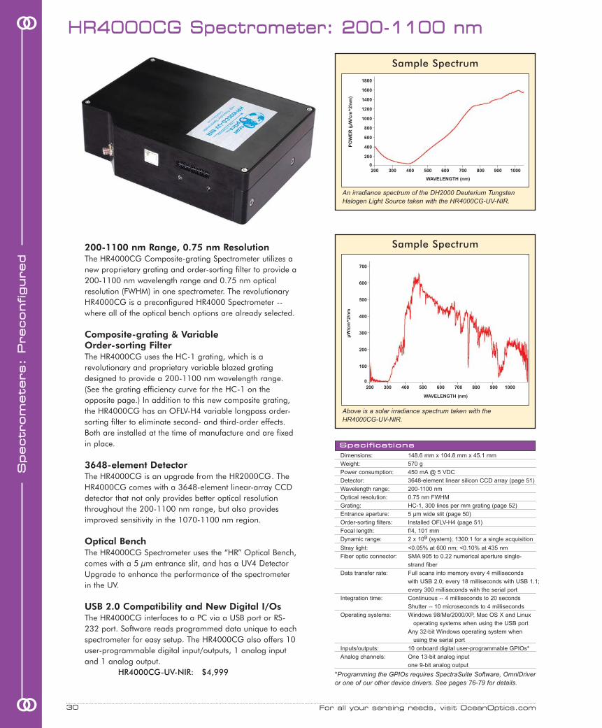
HHRR44000000CCGG SSppeeccttrroommeetteerr:: 220000--11110000 nnmm
Dimensions: 148.6 mm x 104.8 mm x 45.1 mm
Weight: 570 g
Power consumption: 450 mA @ 5 VDC
Detector: 3648-element linear silicon CCD array (page 51)
Wavelength range: 200-1100 nm
Optical resolution: 0.75 nm FWHM
Grating: HC-1, 300 lines per mm grating (page 52)
Entrance aperture: 5 µm wide slit (page 50)
Order-sorting filters: Installed OFLV-H4 (page 51)
Focal length: f/4, 101 mm
Dynamic range: 2 x 10⁹ (system); 1300:1 for a single acquisition
Stray light: <0.05% at 600 nm; <0.10% at 435 nm
Fiber optic connector: SMA 905 to 0.22 numerical aperture single-
strand fiber
Data transfer rate: Full scans into memory every 4 milliseconds
with USB 2.0; every 18 milliseconds with USB 1.1;
every 300 milliseconds with the serial port
Integration time: Continuous -- 4 milliseconds to 20 seconds
Shutter -- 10 microseconds to 4 milliseconds
Operating systems: Windows 98/Me/2000/XP, Mac OS X and Linux
operating systems when using the USB port
Any 32-bit Windows operating system when
using the serial port
Inputs/outputs: 10 onboard digital user-programmable GPIOs*
Analog channels: One 13-bit analog input
one 9-bit analog output
SSppeecciiffiiccaattiioonnss
200-1100 nm Range, 0.75 nm ResolutionThe HR4000CG Composite-grating Spectrometer utilizes anew proprietary grating and order-sorting filter to provide a200-1100 nm wavelength range and 0.75 nm opticalresolution (FWHM) in one spectrometer. The revolutionaryHR4000CG is a preconfigured HR4000 Spectrometer --where all of the optical bench options are already selected.
Composite-grating & Variable Order-sorting FilterThe HR4000CG uses the HC-1 grating, which is arevolutionary and proprietary variable blazed gratingdesigned to provide a 200-1100 nm wavelength range.(See the grating efficiency curve for the HC-1 on theopposite page.) In addition to this new composite grating,the HR4000CG has an OFLV-H4 variable longpass order-sorting filter to eliminate second- and third-order effects.Both are installed at the time of manufacture and are fixedin place.
3648-element DetectorThe HR4000CG is an upgrade from the HR2000CG. TheHR4000CG comes with a 3648-element linear-array CCDdetector that not only provides better optical resolutionthroughout the 200-1100 nm range, but also providesimproved sensitivity in the 1070-1100 nm region.
Optical BenchThe HR4000CG Spectrometer uses the “HR” Optical Bench,comes with a 5 µm entrance slit, and has a UV4 DetectorUpgrade to enhance the performance of the spectrometerin the UV.
USB 2.0 Compatibility and New Digital I/OsThe HR4000CG interfaces to a PC via a USB port or RS-232 port. Software reads programmed data unique to eachspectrometer for easy setup. The HR4000CG also offers 10user-programmable digital input/outputs, 1 analog inputand 1 analog output.
HR4000CG-UV-NIR: $4,999
For all your sensing needs, visit OceanOptics.com30
SSppeeccttrroomm
eetteerrss::
PPrreeccoonnffiigguurreedd
oo
oo
Sample Spectrum
Above is a solar irradiance spectrum taken with theHR4000CG-UV-NIR.
An irradiance spectrum of the DH2000 Deuterium TungstenHalogen Light Source taken with the HR4000CG-UV-NIR.
700
600
500
400
300
200
100
0
µW
/cm
^2/n
m
Sample Spectrum
1800
1600
1400
1200
1000
800
600
400
200
0
WAVELENGTH (nm)
200 300 400 500 600 700 800 900 1000
WAVELENGTH (nm)
PO
WE
R (
µW
/cm
^2/n
m)
200 300 400 500 600 700 800 900 1000
*Programming the GPIOs requires SpectraSuite Software, OmniDriveror one of our other device drivers. See pages 76-79 for details.

Dynamic ElectronicsThe HR2000+CG Spectrometer integrates a powerfulanalog-to-digital (A/D) converter, programmableelectronics and a high-resolution optical bench. Thisinnovative combination produced our fastest spectrometeryet -- one scan every millisecond -- and achieves opticalresolution to 1.0 nm (FWHM) over the entire 200-1100 nm wavelength range.
1,000 Full Spectral Scans Every SecondThe HR2000+CG utilizes an onboard, 2-MHz A/Dconverter to capture and store one full spectral scan intomemory every millisecond, when the spectrometer isinterfaced to a PC via the USB 2.0 port (a serial port isalso available). The HR2000+CG is ideal for applicationswhere fast reactions need to be monitored and highresolution is necessary, such as certain chemistry andbiochemistry applications.
Programmable MicrocontrollerThe HR2000+CG has an onboard programmablemicrocontroller that provides flexibility in controlling thespectrometer and accessories. By using a new 30-pinconnector, you can implement numerous operatingparameters in the software, including controlling externallight sources and retrieving data on external objects. Youhave access to 10 programmable digital I/Os forinterfacing to other equipment; one analog input and oneanalog output; and a pulse generator for triggeringdevices.
“HR” Optical BenchThe excellent resolution of the HR2000+CG over itsbroadband range of 200-1100 nm is achieved by usingthe “HR” Optical Bench -- a 25.4-mm diameter, 101.6-mmfocal length (f/4), crossed Czerny-Turner optical design.
Plug-and-Play OperationThe HR2000+ interfaces to a PC via USB 2.0 or RS-232serial port. When interfaced to a PC via the USB port, itdraws its power from the PC. Data unique to eachspectrometer are programmed into EEPROM on theHR2000+CG; software reads these values for easy setupand hot swapping among PCs.
HR2000+CG: $4,499
US: 727.733.2447 • Europe: +31 (0) 26 319 0500 31 oo
ooSS
ppeeccttrroomm
eetteerrss:: PP
rreeccoonnffiigg
uurreedd
HHRR22000000++CCGG HHiigghh--ssppeeeedd ++ BBrrooaaddbbaanndd
Stray light: <0.05% at 600 nm; <0.10% at 435 nm
Fiber optic connector: SMA 905 to 0.22 numerical aperture single-strand fiber
Data transfer rate: Full scans into memory every 1 ms with USB 2.0,
every 15 ms with USB 1.1,
every 200 milliseconds with the serial port
Integration time: Continuous -- 1 millisecond to 60 seconds
Operating systems: Windows 98/Me/2000/XP, Mac OS X and Linux
operating systems when using the USB port
Any 32-bit Windows OS when using the serial port
Analog channels: One 13-bit analog input and one 9-bit analog output
Dynamic range: 2 x 10⁹ (system); 1300:1 for a single acquisition
Dimensions: 148.6 mm x 104.8 mm x 45.1 mm
Weight: 570 g
Power consumption: 450 mA @ 5 VDC
Detector: 2048-element linear silicon CCD array (page 51)
Wavelength range: 200-1100 nm
Optical resolution: 1.0 nm FWHM
Grating: HC-1, 300 lines per mm grating (page 52)
Entrance aperture: 5 µm wide slit (page 50)
Order-sorting filters: Installed OFLV-200-1100 (page 51)
Focal length: f/4, 101 mm
Inputs/outputs: 10 onboard digital user-programmable GPIOs*
SSppeecciiffiiccaattiioonnss
HC-1 Grating Efficiency Curve
RE
FL
EC
TIO
N E
FF
ICIE
NC
Y(%
)
WAVELENGTH (nm)
200 400 600 800 1000
Spectrum of Holmium Oxide
HR2000+CG absorbance spectrum of holmium oxide-impregnated glass.
200 300 400 500 600 700 800 900 1000 1100
1.2
1.0
0.8
0.6
0.4
0.2
0
AB
SO
RB
AN
CE
(A
U)
WAVELENGTH (nm)
60
50
40
30
20
10
0
*Programming the GPIOs requires SpectraSuite Software, OmniDriver orone of our other device drivers. See pages 76-79 for details.

GGaatteedd SSppeeccttrroommeetteerr ffoorr FFlluuoorreesscceennccee
Dimensions: 89.1 mm x 63.3 mm x 34.4 mm
Weight: 190 g
Power consumption: 90 mA @ 5 VDC
Wavelength range: 380-1050 nm
Detector: 2048-element linear silicon CCD array (page 43)
Grating: Grating #3 -- 600 lines per millimeter, blazed at 500 nm
Entrance aperture: 200 µm wide slit (page 42)
Optical resolution: ~10.0 nm FWHM
Stray light: ~0.05% at 600 nm, <0.10% at 435 nm
Fiber optic connector: SMA 905 to 0.22 numerical aperture single-strand fiber
Integration time: Gated mode - 5 milliseconds, normal mode - 3 milliseconds to 60 seconds
Operating systems: Windows 98/Me/2000/XP, Mac OS X and Linux operating systems when
using the USB port; any 32-bit Windows OS when using the serial port
SSppeecciiffiiccaattiioonnss
For all your sensing needs, visit OceanOptics.com32
In addition to theUSB2000-FLG, acommon fluorescence setupmay include products like thoseshown above: the PX-2 Pulsed XenonSource, the CUV-ALL-UV Cuvette Holder, LVF Linear Variable Filters,and optical fibers.
Ultimate Fluorescence SpectrometerThe USB2000-FLG Spectrofluorometer is apreconfigured spectrometer for fluorescenceapplications from 380-1050 nm. We utilize aproprietary thin film technology and a time-gated spectrometer to provide a spectro-fluorometer that is 20 percent more sensitivethan the standard USB2000 Spectrometer.
Avoiding Scattered LightIn addition to detecting fluorescence from asample, a spectrofluorometer will also detectscattered excitation light from the light sourceand the sampling compartment. (Scattering isespecially prevalent in turbid samples.) TheUSB2000-FLG uses two features to avoiddetecting scattered light: special mirrors in theoptical bench to absorb ultraviolet light andimprove sensitivity and -- for fluorophores withlong fluorescence lifetimes -- a time-gatedmode that delays the start of spectral dataacquisition by 5-500 microseconds after theexcitation source is turned on (or pulses).
Gated Fluorescence ModeThe USB2000-FLG is preloaded with variable-delay gating microcode, which allows you toselect a delay (from 5-500 microseconds) inour software between the light turning on andthe start of the spectrometer's integration time,when the detector “sees” the sample. In thisGated Mode, the spectrometer only detects thesample light when the source is off. In order touse the Gated Mode, your fluorophore musthave a long fluorescence lifetime. Thoseworking with lanthanides and photoluminescentmaterials will find this mode very useful. Thebest excitation source to use with the GatedMode is our PX-2 Pulsed Xenon Source.
SAG+ High-reflectivity MirrorsIn the USB2000-FLG, we replaced ourstandard mirrors with proprietary Ag-coatedmirrors to increase reflectance, which increasesthe sensitivity of the spectrometer by more than20 percent. They also absorb nearly allultraviolet light, virtually eliminating theexcitation source's spectra from interfering withthe sample spectra.
Application FlexibilityThe USB2000-FLG can detect fluorophores insolutions and powders, and from surfaces. Weuse the USB2000-FLG in our EDS2000 Endo-spore Detection System, and the USB2000-FLGhas been used to measure fluorescence incoral, fruit and other flora and fauna.
USB2000-FLG: $2,999
SSppeeccttrroomm
eetteerrss::
PPrreeccoonnffiigguurreedd
oo
oo
Terbium-dipicolinic acid (Tb-DPA) photoluminescence spectra acquired with the USB2000-FLG while in the Gated Mode, with the data acquisition delay set at a range of values.Analysis of samples with long emission lifetimes such as Tb-DPA improves when dataacquisition is delayed until the energy from the lamp pulse is no longer observed in thespectrum, resulting in a cleaner, more resolved Tb-DPA spectrum -- achieved without usingoptical filters. At delay times below 40 microseconds, lingering excitation energy andbackground fluorescence overlap the Tb-DPA photoluminescence spectrum.

FFlluuoorreesscceennccee SSppeeccttrroommeetteerrss
USB2000-FL USB2000-FL-450
Dimensions: 63.34 mm x 89.10 mm x 34.37 mm 89.1 mm x 120.3 mm x 34.4 mm
Weight: 180 grams 310 grams
Power consumption: 90 mA @ 5 VDC 150 mA @ 5 VDC
Wavelength range: ~360-1000 nm for spectrometer ~360-1000 nm for spectrometer
Detector: 2048-element linear silicon CCD array (page 43) 2048-element linear silicon CCD array (page 43)
Grating: Grating #3 -- groove density of 600 lines per millimeter, Grating #3 -- groove density of 600 lines per millimeter,
set to 360-1000 nm, blazed at 500 nm set to 360-1000 nm, blazed at 500 nm
Entrance aperture: 200 µm wide slit (page 42) 200 µm wide slit (page 42)
Focal length: 42 mm (input); 68 mm (output) 42 mm (input); 68 mm (output)
Optical resolution: ~10.0 nm FWHM ~10.0 nm FWHM
Stray light: <0.05% at 600 nm; <0.10% at 435 nm <0.05% at 600 nm; <0.10% at 435 nm
Fiber optic connector: SMA 905 to 0.22 numerical aperture single-strand fiber SMA 905 to 0.22 numerical aperture single-strand fiber
Excitation source: Not applicable; see pages 120-129 to select excitation source USB-LS-450; see page 129 for full specifications
SSppeecciiffiiccaattiioonnss
US: 727.733.2447 • Europe: +31 (0) 26 319 0500 33
High Sensitivity for FluorescenceThe USB2000-FL and USB2000-FL-450 are high-sensitivity, preconfigured spectrometers --originally conceived for use with our fluorescence-based sensors -- that can be used forgeneral fluorescence applications. Each fluorescence unit is set to 360-1000 nm andcomes with a 200-µm slit and an L2 Detector Collection Lens for increased sensitivity.
Select an Excitation SourceThe difference between the USB2000-FL and USB2000-FL-450 is that the latter comes withthe USB-LS-450 LED Module, which is an LED that produces either pulsed or continuousoutput centered at 470 nm -- the blue region -- for fluorescence measurements. The USB-LS-450 directly attaches to the spectrometer to provide you with a fully integratedspectrofluorometer. The USB2000-FL does not come with an excitation source and is themore appropriate choice if you wish to use one of the LEDs on pages 128-129.
Benefit for FOXY UsersThe USB-LS-450 features a built-in, 24-bit analog-to-digital converter that is configuredfor a 100 ohm platinum temperature probe (USB-LS-450-TP). The USB-LS-450’s onboardmemory can be programmed to store temperature and oxygen calibration coefficients.
USB2000-FL: $2,499USB2000-FL-450: $3,049
TTeemmppeerraattuurree--rreegguullaatteedd SSppeeccttrroommeetteerrss
The SD2000-TR Spectrometers come with the unitshown. Optical fiber and sampling chambers or probesare additional.
Who Needs a Temperature Regulator? When temperature changes occur over time in the optical bench and lightsource, the stored reference spectrum becomes invalid. Taking a newreference spectrum corrects for the drift; however, there are times whenfrequent reference-taking is impractical. For these applications, we createdthe preconfigured SD2000-TR-UV and SD2000-TR-VIS. Each unit has twospectrometer channels, with each channel connected to its own TR-2 Temp-erature Regulator to regulate the spectrometer’s temperature. The masterchannel monitors the sample; the second channel monitors the light source.
SD2000-TR-UV or SD2000-TR-VISEach spectrometer channel in the SD2000-TR-UV has a 200-850 nmwavelength range. The unit comes with the DT-MINI Deuterium TungstenHalogen Light Source. In the SD2000-TR, each spectrometer channel has a350-1000 nm wavelength range. It comes with the R-LS-1 TungstenHalogen Light Source. For complete details and specifications on theSD2000-TR-UV and SD2000-TR-VIS, please visit our website.
SD2000-TR-UV: $7,999SD2000-TR-VIS: $6,999TR-2: $999
oo
ooSS
ppeeccttrroomm
eetteerrss:: PP
rreeccoonnffiigg
uurreedd
Temperature regulator type: Peltier thermoelectric device
Temperature set-point range: 15 °C below ambient to +37 °C
Temperature set-point default: User-programmable; set to 20 °C
Temperature of optical bench: ± 0.1 °C of set temperature
Baseline and spectral stability: ± 0.001 absorbance units
measured over 24-hour period
SSppeecciiffiiccaattiioonnss

For all your sensing needs, visit OceanOptics.com34
ooGreat VersatilityWe offer a preconfigured UV-VIS and VIS-NIRspectrometer -- where all of the optical benchoptions are already selected -- to use as general-purpose instruments. By switching out light sourcesand sampling accessories, these spectrometers canmeasure absorbance in solutions or reflectance ofsolids.
UV-VIS Preconfigured SpectrometersThe USB2000-UV-VIS utilizes the “S” OpticalBench. It has a 200-850 nm wavelength rangeand comes with a detector upgrade for working inthe UV, a variable longpass detector filter forsecond- and third-order rejection, and a 25-µmslit as the entrance aperture. Optical resolution is~1.5 nm (FWHM).
VIS-NIR Preconfigured SpectrometersThe USB2000-VIS-NIR spectrometer also utilizesthe “S” Optical Bench. It has a 350-1000 nmwavelength range and comes with a 25-µmentrance slit and a variable longpass detector filterfor second- and third-order rejection. With thisoptical bench configuration, the USB2000-VIS-NIRachieves ~1.5 nm optical resolution (FWHM).
AccessorizeTo complete your spectrometer system, select fromour comprehensive line of fiber optic accessories --light sources, sensors and probes, sample holders,flow cells, optical fiber assemblies and more.
Interfacing to your PCWith the USB2000-UV-VIS and the USB2000-VIS-NIR, the A/D converter is built intothe spectrometers' electronic boards, so thatexternal A/D converters or power supplies areunnecessary. The spectrometers interface to PCsvia USB 1.1 or serial ports.
USB2000-UV-VIS: $2,649USB2000-VIS-NIR: $2,499
GGeenneerraall PPuurrppoossee:: 220000--885500 nnmm oorr 335500--11000000 nnmm
USB2000-UV-VIS USB2000-VIS-NIR
Wavelength range: 200-850 nm 350-1000 nm
Detector: 2048-element linear silicon CCD array (page 43) 2048-element linear silicon CCD array (page 43)
Grating: Grating #1, 600 lines per mm grating, blazed at 300 nm Grating #3, 600 lines per mm grating, blazed at 500 nm
Entrance aperture: 25 µm wide slit (page 42) 25 µm wide slit (page 42)
Order-sorting filters: OFLV-200-850 (page 43) OFLV-350-1000 (page 43)
Focal length: 42 mm (input); 68 mm (output) 42 mm (input); 68 mm (output)
Optical resolution: ~1.5 nm FWHM ~1.5 nm FWHM
Stray light: <0.10% at 250 nm; <0.10% at 435 nm; <0.05% at 600 nm <0.10% at 435 nm; <0.05% at 600 nm
Dynamic range: 2 x 10⁸ (system); 1300:1 for a single scan 2 x 10⁸ (system); 1300:1 for a single scan
Operating systems: Windows 98/Me/2000/XP, Mac OS X and Linux operating Windows 98/Me/2000/XP, Mac OS X and Linux when using
systems when using the USB port systems when using the USB port
Any 32-bit Windows operating system when using serial port Any 32-bit Windows operating system when using serial port
SSppeecciiffiiccaattiioonnss
SSppeeccttrroomm
eetteerrss::
PPrreeccoonnffiigguurreedd
oo
A setup with the USB2000-UV-VISmight include components similarto this setup: UV-VIS Optical FiberAssemblies, a DH2000 DeuteriumTungsten Halogen Light Sourceand a CUV-UV-10 Cuvette Holder.
A setup with theUSB2000-VIS-NIRcould include thesecomponents: an R200-VIS-NIRReflection Probe, anLS-1 Tungsten HalogenLight Source and aRPH-1 ReflectionProbe Holder.

oo
ooSS
ppeeccttrroomm
eetteerrss:: UU
sseerr--CC
oonnffiigg
uurreedd
User-configured Spectrometers are for those who wish
to select components and options in their spectrometer,
from the wavelength range and grating type to the size
of the entrance aperture and coating on the detector.
38 USB2000 Plug-and-Play Spectrometer
40 S2000 & PC2000 Miniature Spectrometers
41 S1024DW Deep Well Spectrometers
42 “S”-series Optical Bench Options
46 HR4000 High-resolution Spectrometer
48 HR2000 High-resolution Spectrometer
49 HR2000+ High-speed High-Resolution Spectrometer
50 “HR”-series Optical Bench Options
54 QE65000 Scientific-grade Spectrometer
55 “QE”-series Optical Bench Options
58 NIR-512 Near-infrared Spectrometer
59 NIR256 Extended-range NIR Spectrometers
60 “NIR”-series Optical Bench Options
SSppeeccttrroommeetteerrss::SSppeeccttrroommeetteerrss::UUsseerr--CCoonnffiigguurreeddUUsseerr--CCoonnffiigguurreedd

OOvveerrvviieeww:: UUsseerr--ccoonnffiigguurreedd SSppeeccttrroommeetteerrss
We Have Your Spectrometer!
For all your sensing needs, visit OceanOptics.com36
SSppeeccttrroomm
eetteerrss::
UUsseerr--CC
oonnffiigguurreedd
oo
oo
Detector Type
CCD DetectorsThe Sony ILX511 is a 2048-pixel linear CCD-array detector that is ideal for general-purposeapplications. It’s used in our “S” optical benchas well as in our high-resolution “HR” bench.We also use a 3648-pixel CCD-array detectorfrom Toshiba in our “HR” optical bench as itprovides better resolution than the Sony.
Photodiode DetectorsLess-sensitive photodiode detectors provide ahigh signal-to-noise ratio for applications withhigh light levels. We use Hamamatsu’s S3903and S3904 photodiode silicon linear arrays.They can be specified only for an “S” bench.
Back-thinned TE-cooled DetectorThe Hamamatsu S7031-1006 detector in the“QE” optical bench provides high quantumefficiency, fast signal processing speed and ahigh signal-to-noise ratio. This TE-cooleddetector generates virtually no dark noise.
InGaAs DetectorsWe use three different Hamamatsu linear arrayInGaAs detectors in our “NIR” optical bench forgeneral-purpose NIR applications.
Spectrometer Type
Spectrometer Systems & SetupsSystems are turnkey spectropho-tometers where all the componentsare included in one integratedenclosure. Setups provide a list oftools necessary for an application.Both Systems and Setups include aspectrometer, the necessarysampling accessories, a lightsource and software.
Preconfigured SpectrometersA preconfigured spectrometer ispreset with a grating, wavelengthrange and other benchaccessories. You still specify othercomponents, such as light sourcesand sampling accessories.
User-configured SpectrometersYou select the optical benchoptions, such as the grating,entrance aperture size, detector,wavelength range and more tocreate the optimum spectrometerfor your application.
Bench Type
General-purpose “S” BenchThe “S” optical bench is ideal forabsorbance, reflectance, fluorescenceand color measurements. It’s a versatilebench that is used in tens of thousandsof spectrometers around the world.
High-resolution “HR” BenchThe “HR” optical bench is designed forapplications requiring angstrom andsub-angstrom resolution, such as lasercharacterization and atomic emissionspectroscopy.
Scientific-grade “QE” BenchThe “QE” optical bench is designed fordemanding applications with low lightlevels such as Raman spectroscopy andfluorescence.
Near-Infrared “NIR” BenchThe “NIR” optical bench is designed forapplications that require sensitivity inthe NIR region, such as moistureanalysis, tunable laser wavelengthcharacterization and general NIRspectroscopy.
Since we introduced the world's first miniature fiber optic spectrometerover 12 years ago, we've sold more than 55,000 spectrometers andenabled nearly as many applications. We pioneered the notion offlexible, modular spectroscopy, making it possible for users in manyindustries to configure systems for very different applications.
For those who wish to select the components in their spectrometer, weoffer a complete range of options. You can make it your way.� The size of your entrance aperture helps determine how much light
enters your optical bench and your resolution. We have 6 sizes.� Our filters block second- and third-order effects or balance color.� You can opt to install standard collimating and focusing mirrors or
SAG+ mirrors, which increase reflectance and increase sensitivity.� We offer 14 different gratings, and your choice helps determine
your resolution and wavelength range.� An optional collection lens increases light-collection efficiency.� Our OFLV filters precisely block second- and third-order light from
reaching specific detector elements.� A UV upgrade enhances the spectrometer’s performance in the UV.
Our Applications Scientists have configured thousands of setups, sowhatever your need, our consultative selling approach guaranteesyou a partner in solving your application challenge.

89.1 x 63.3 x 34.4
190 grams
Sony ILX511 linear silicon
CCD array
200-1100 nm
2048 pixels
14 µm x 200 µm
~62,500 electrons
250:1 (at full signal)
12 bit
3.2 RMS counts
>99.8%
400 nm: 75 photons/count
600 nm: 41 photons/count
f/4, Asymmetrical crossed
Czerny-Turner
42 mm
68 mm
5, 10, 25, 50, 100, or
200 µm wide slits or fiber
14 gratings, UV through
Shortwave NIR
No
Yes, L2
OFLV-200-850
OFLV-350-1000
Longpass OF-1 filters
Grating dependent
~0.3-10.0 nm FWHM
3 ms to 65 seconds
2 x 10⁸ (system); 1300:1 for
a single acquisition
<0.05% at 600 nm
<0.10% at 435 nm
SMA 905 to 0.22 numerical
aperture single-strand fiber
90 mA @ 5 VDC
Full scans to memory every
13 ms with USB 2.0 or
USB 1.1 port,
300 ms with serial port
No
No
Windows 98/Me/2000/XP,
Mac OS X and Linux when
using the USB port;
Any 32-bit Windows OS
when using the serial port
USB 2.0 @ 12 Mbps
(USB 1.1 compatible);
RS-232 (2-wire) @ 57.6 K
baud
I2C inter-integrated circuit
No
Yes
3 modes
Yes
Specifications USB2000 p. 38 HR2000 p. 48 HR2000+ p. 49 HR4000 p. 46 QE65000 p. 54
148.6 x 104.8 x 45.1
570 grams
Sony ILX511 linear silicon
CCD array
200-1100 nm
2048 pixels
14 µm x 200 µm
~62,500 electrons
250:1 (at full signal)
12 bit
3.2 RMS counts
>99.8%
400 nm: 75 photons/count
600 nm: 41 photons/count
f/4, Symmetrical crossed
Czerny-Turner
101.6 mm
101.6 mm
5, 10, 25, 50, 100 or
200 µm wide slits or fiber
14 gratings, UV through
Shortwave NIR
provides 200-1100 nm range
Yes, L2
OFLV-200-1100
Longpass OF-1 filters
Grating dependent
~0.035-6.8 nm FWHM
3 ms to 65 seconds
2 x 10⁹ (system); 1300:1 for
a single acquisition
<0.05% at 600 nm
<0.10% at 435 nm
SMA 905 to 0.22 numerical
aperture single-strand fiber
450 mA @ 5 VDC
Full scans to memory every
13 ms with USB 2.0 or
USB 1.1 port,
300 ms with serial port
No
No
Windows 98/Me/2000/XP,
Mac OS X and Linux when
using the USB port;
Any 32-bit Windows OS
when using the serial port
USB 2.0 @ 12 Mbps
(USB 1.1 compatible);
RS-232 (2-wire) @ 115.2 K
baud
SPI (3-Wire);
I2C inter-integrated circuit
No
No
3 modes
Yes
148.6 x 104.8 x 45.1
570 grams
Sony ILX511 linear silicon
CCD array
200-1100 nm
2048 pixels
14 µm x 200 µm
~62,500 electrons
250:1 (at full signal)
12 bit
3.2 RMS counts
>99.8%
400 nm: 75 photons/count
600 nm: 41 photons/count
f/4, Symmetrical crossed
Czerny-Turner
101.6 mm
101.6 mm
5, 10, 25, 50, 100 or
200 µm wide slits or fiber
14 gratings, UV through
Shortwave NIR
provides 200-1100 nm range
Yes, L2
OFLV-200-1100
Longpass OF-1 filters
Grating dependent
~0.035-6.8 nm FWHM
1 ms to 65 seconds
2 x 10⁸ (system); 1300:1 for
a single acquisition
<0.05% at 600 nm
<0.10% at 435 nm
SMA 905 to 0.22 numerical
aperture single-strand fiber
450 mA @ 5 VDC
Full scans to memory every
1 ms with USB 2.0 port,
15 ms with USB 1.1 port,
200 ms with serial port
Yes, 10 onboard digital
user-programmable GPIOs
One 13-bit analog input
One 9-bit analog output
Windows 98/Me/2000/XP,
Mac OS X and Linux when
using the USB port;
Any 32-bit Windows OS
when using the serial port
USB 2.0 @ 480 Mbps
(USB 1.1 compatible);
RS-232 (2-wire) @ 115.2 K
baud
SPI (3-Wire);
I2C inter-integrated circuit
Yes
Yes
4 modes
Yes
148.6 x 104.8 x 45.1
570 grams
Toshiba TCD1304AP linear
CCD array
200-1100 nm
3648 pixels
8 µm x 200 µm
~100,000 electrons
300:1 (at full signal)
14 bit
12 RMS counts
>99.8%
400 nm: 130 photons/count
600 nm: 60 photons/count
f/4, Symmetrical crossed
Czerny-Turner
101.6 mm
101.6 mm
5, 10, 25, 50, 100 or
200 µm wide slits or fiber
14 gratings, UV through
Shortwave NIR
provides 200-1100 nm range
Yes, L4
OFLV-H4
Longpass OF-1 filters
Grating dependent
~0.02-8.4 nm FWHM
10 µs to 65 seconds
2 x 10⁹ (system); 1300:1 for
a single acquisition
<0.05% at 600 nm
<0.10% at 435 nm
SMA 905 to 0.22 numerical
aperture single-strand fiber
450 mA @ 5 VDC
Full scans to memory every
4 ms with USB 2.0 port,
18 ms with USB 1.1 port,
300 ms with serial port
Yes, 10 onboard digital
user-programmable GPIOs
One 13-bit analog input
One 9-bit analog output
Windows 98/Me/2000/XP,
Mac OS X and Linux when
using the USB port;
Any 32-bit Windows OS
when using the serial port
USB 2.0 @ 480 Mbps
(USB 1.1 compatible);
RS-232 (2-wire) @ 115.2 K
baud
SPI (3-Wire);
I2C inter-integrated circuit
Yes
Yes
4 modes
Yes
182 x 110 x 47
1050 grams
Hamamatsu S7031-1006
back-thinned area CCD
200-1100 nm
1024 x 58 (1044 x 64 total)
24.6 µm square size
300,000 electrons/well
~1.5 mill. electrons/column
1000:1 (at full signal)
16 bit
3 RMS counts
>99.8%
22 electrons/count for all
wavelengths
250 nm: 26 photons/count
f/4, Symmetrical crossed
Czerny-Turner
101.6 mm
101.6 mm
5, 10, 25, 50, 100 or
200 µm wide slits or fiber
14 gratings, UV through
Shortwave NIR
provides 200-950 nm range
No
OFLV-QE
Longpass OF-1 filters
Grating dependent
~0.14-7.7 nm FWHM
7 ms to 15 minutes
7.5 x 10⁹ (system); 25000:1
for a single acquisition
<0.08% at 600 nm
<0.4% at 435 nm
SMA 905 to 0.22 numerical
aperture single-strand fiber
500 mA @ 5 VDC no TE cool
3 A @ 5 VDC with TE cool
Full scans to memory every
7 ms with USB 2.0 port,
18 ms with USB 1.1 port,
300 ms with serial port
Yes, 10 onboard digital user-
programmable GPIOs
No
Windows 98/Me/2000/XP,
Mac OS X and Linux when
using the USB port;
Any 32-bit Windows OS
when using the serial port
USB 2.0 @ 480 Mbps;
RS-232 (2-wire) @ 115.2 K
baud
SPI (3-wire);
I2C inter-integrated circuit
Yes
No
4 modes
Yes
OOvveerrvviieeww:: SSppeeccttrroommeetteerr CCoommppaarriissoonn CChhaarrtt
US: 727.733.2447 • Europe: +31 (0) 26 319 0500 37 oo
ooSS
ppeeccttrroomm
eetteerrss:: UU
sseerr--CC
oonnffiigg
uurreedd
This table outlines the specifications of our most popular user-configured spectrometers.Please refer to specific product pages for more detailed information.
PHYSICAL
Dimensions (in mm):
Weight:
DETECTOR
Detector:
Detector range:
Pixels:
Pixel size:
Pixel well depth:
Signal-to-noise ratio:
A/D resolution:
Dark noise:
Corrected linearity:
Sensitivity:
OPTICAL BENCH
Design:
Focal length (input):
Focal length (output):
Entrance aperture:
Gratings:
HC-1 grating option:
Detector collection lens:
OFLV filters:
Order-sorting filters:
SPECTROSCOPIC
Wavelength range:
Optical resolution:
Integration time:
Dynamic range:
Stray light:
Fiber optic connector:
ELECTRONICS
Power consumption:
Data transfer speed:
Inputs/Outputs:
Analog channels:
COMPUTER
Operating systems:
Computer interfaces:
Peripheral interfaces:
OTHER
Breakout box compat.:
Gated delay feature:
Trigger modes:
Strobe functions:

Order-sorting filters: OFLV filters and longpass OF-1 filters (page 43)
Wavelength range: Grating dependent
Optical resolution: ~0.3-10.0 nm FWHM
Integration time: 3 ms to 65 seconds
Dynamic range: 2 x 10⁸ (system); 1300:1 for a single acquisition
Stray light: <0.05% at 600 nm; <0.10% at 435 nm
Fiber optic connector: SMA 905 to 0.22 numerical aperture single-strand fiber
Power consumption: 90 mA @ 5 VDC
Data transfer speed: Full scans to memory every 13 ms with USB 2.0 or 1.1 port,
300 ms with serial port
Operating systems: Windows 98/Me/2000/XP, Mac OS X and Linux when using
USB port; any 32-bit Windows OS when using serial port
Computer interfaces: USB 2.0 @ 12 Mbps (USB 1.1 compatible);
RS-232 (2-wire) @ 57.6 K baud
Dimensions: 89.1 mm x 63.3 mm x 34.4 mm
Weight: 190 g
Detector: Sony ILX511 linear silicon CCD array (page 43)
Detector range: 200-1100 nm
Pixels: 2048 pixels, pixel size of 14 µm x 200 µm
Pixel well depth: ~62,500 electrons
Signal-to-noise ratio: 250:1 (at full signal)
Dark noise: 3.2 RMS counts
Sensitivity: 400 nm: 75 photons/count, 600 nm: 41 photons/count
Optical bench design: f/4, Asymmetrical crossed Czerny-Turner
Focal length: 42 mm input, 68 mm output
Entrance aperture: 5, 10, 25, 50, 100 or 200 µm wide slits (page 42)
or fiber (no slit)
Gratings: 14 gratings; UV through Shortwave NIR (page 44)
UUSSBB22000000 PPlluugg--aanndd--PPllaayy SSppeeccttrroommeetteerr
SSppeecciiffiiccaattiioonnss
For all your sensing needs, visit OceanOptics.com38
SSppeeccttrroomm
eetteerrss::
UUsseerr--CC
oonnffiigguurreedd
oo
oo
USB-CBL-PSPower Supply
USB-ADP-DT2Adapter Block
Price
$25
$75
$25
$50
$75
Free
Cable
USB-CBL-1
USB-ADP-PC
USB-CBL-PS
USB-ADP-PX2
USB-ADP-DT2
ACC-CON-US2
Description
Cable connects from USB port on USB2000 to USB
port on PC; comes with USB2000
Cable and adapter block connect from serial port on
USB2000 to serial port on desktop or notebook PC;
comes with USB-CBL-PS power supply
Spare 5 VDC power supply
Adapter block and cable to connect PX-2 Pulsed
Xenon Lamp (page 125), DT-MINI (page 122) or
LS-450 Blue LED (page 128) to the USB2000
Adapter for directly attaching the USB-DT Deuterium
Tungsten Light Source (page 123) to the USB2000
Accessory connector for external triggeringUSB-ADP-PX2Adapter Block
ACC-CON-US2
Voted Most PopularWith its small-footprint design and plug-and-play convenience -- itsonboard A/D converter ensures a hassle-free instrument-to-PCinterface -- the USB2000 has become the most frequently specifiedminiature fiber optic spectrometer in the world.
Streamlined Start-up Software & Hot SwappingThe USB2000 plugs directly into the USB or serial port of any desktopor notebook PC. Interfacing the USB2000 to a PC via the USB portsupports hot swapping of the spectrometer. Our software recognizesand reads data programmed on the USB2000 -- such as calibrationcoefficients -- saving time and reducing configuration errors. Whenconnected to a PC via USB, the USB2000 draws its power from thecomputer.
User-configured SetupThe “S” Optical Bench is used in the world's first, and still the bestminiature spectrometer. We’ve sold over 55,000 spectrometer channelsfor thousands of applications, and we've used that experience to makethe most flexible, versatile and cost-effective spectrometer ever built.What makes the “S” bench so special are several options that allowyou to optimize the bench for your application. Choose from optionssuch as the size of the entrance slit, the type of grating and detectoradd-ons for the Sony ILX511 linear CCD array. (See pages 42-45 formore information on the detector and “S” Optical Bench.)
AccessoriesThough all of our spectroscopic accessories work with the USB2000,the accessories on the next page directly attach to the front of theUSB2000 for added convenience, ease of use and software control.
USB2000: $2,199
An example of a setup using theUSB2000: UV-VIS fiber, deuteriumtungsten light source and a 10-cmpathlength cuvette holder.

UUSSBB22000000 DDiirreecctt--aattttaacchh AAcccceessssoorriieess
USB-BP Portable Lithium Ion Battery Pack
USB-FHS Filter Holder System
USB-ISS-T Integrated Sampling System for Test Tubes
USB-LS-450 Pulsed Blue LED Module
USB-ISS-VIS Integrated Sampling System for CuvettesThe USB-ISS-VIS is a direct-attach sample holder and violet LED-boosted tungsten light source(390-900 nm) combination for measuring relative absorbance. The light source boosts signalin the blue and provides over 10,000 hours of use. See page 92 for full specifications.
USB-ISS-VIS: $499
USB-ISS-UV-VIS Integrated Sampling System for Cuvettes
The USB-ISS-T is a direct-attach sample holder and violet LED-boosted tungsten light source(390-900 nm) combination for measuring absorbance in 12-mm outer diameter test tubes.The sampling optics combine a diffuse source with a collimated input to the spectrometer toeliminate optical artifacts in the test tubes. See page 92 for specifications.
USB-ISS-T: $499
The USB-FHS is a filter holder and violet LED-boosted tungsten light source for measuringfilters and other samples up to 18-mm thick. The USB-FHS is optimized for 390-900 nmand attaches to the USB2000 via a mounting plate. See page 97 for more.
USB-FHS: $499
The USB-BP provides eight hours of power to a USB2000 and to any direct-attach accessoryexcept for the USB-ISS-UV-VIS or the USB-DT. The USB-BP measures 108 mm x 86 mm anddelivers two amp-hours at 5 volts by utilizing two lithium ion cells. The battery charges inthree hours with the included charger.
USB-BP: $499
The USB-LS-450 is an LED module designed for fluorescence measurements in the lab orfield, or as part of a FOXY Oxygen Sensor system. In addition, the USB-LS-450 has a port forattaching a 100 ohm RTD temperature sensor and onboard memory for storing temperatureand oxygen calibration coefficients. See page 129 for details.
USB-LS-450: $549
The USB-ISS-UV-VIS is a direct-attach sample holder and deuterium tungsten light source(200-1100 nm) for measuring absorbance. This sampling system allows you to control boththe intensity of the tungsten bulb and the shutter via software. The USB-ISS-UV-VIS requiresan external power supply (included). See page 92 for more.
USB-ISS-UV-VIS: $1,499
USB-DT Deuterium Tungsten Light SourceThe USB-DT Deuterium Tungsten Light Source is our most versatile combination UV-VIS lamp.Use the USB-DT as a stand-alone unit with any spectrometer, stack it with a USB2000Spectrometer, or combine it with a “breakout box” accessory and an “HR”-series orQE65000 Spectrometer for software control of lamp functions. This compact source is aboutthe size of a deck of cards, provides stable, broadband output from 200-2000 nm, andrequires a simple 5-volt wall transformer to operate. See page 123 for details.
USB-DT: $1,499
US: 727.733.2447 • Europe: +31 (0) 26 319 0500 39 oo
ooSS
ppeeccttrroomm
eetteerrss:: UU
sseerr--CC
oonnffiigg
uurreedd

Detector: Sony ILX511 linear silicon CCD array (page 43)
Detector range: 200-1100 nm
Pixels: 2048 pixels, pixel size of 14 µm x 200 µm
Pixel well depth: ~62,500 electrons
Signal-to-noise ratio: 250:1 (at full signal)
Dark noise: 3.2 RMS counts
Sensitivity: 400 nm: 75 photons/count, 600 nm: 41 photons/count
Optical bench design: f/4, Asymmetrical crossed Czerny-Turner
Focal length: 42 mm input, 68 mm output
Gratings: 14 gratings; UV through Shortwave NIR (page 44)
Entrance aperture: 5, 10, 25, 50, 100 or 200 µm wide slits (page 42)
or fiber (no slit)
Order-sorting filters: OFLV filters and longpass OF-1 filters (page 43)
Wavelength range: Grating dependent
Optical resolution: ~0.3-10.0 nm FWHM
Integration time: 3 milliseconds to 60 seconds with 1 MHz A/D converter
2 milliseconds to 60 seconds with 2 MHz A/D converter
Dynamic range: 2 x 10⁸ (system); 1300:1 for a single acquisition
Stray light: <0.05% at 600 nm; <0.10% at 435 nm
Fiber optic connector: SMA 905 to 0.22 numerical aperture single-strand fiber
* A system with more than two channels requires the separate purchase of a housing.
Item
S2000 (master)
S2000 (additional)
SD2000
PC2000
PC2000-S-ISA
PCI2000-S
PC2000-PC104
Description
Master spectrometer channel with housing
Additional spectrometer channel, no housing*
Two spectrometer channels in dual housing
Master spectrometer channel on A/D converter to insert in PC
Additional spectrometer channel on A/D converter to insert in PC
Additional spectrometer channel on A/D converter to insert in PC
Master spectrometer mounted onto a PC/104 A/D converter, for
OEM customers only
Power Consump.
110 mA @ 5 VDC
60 mA @ 5 VDC
170 mA @ 5 VDC
250 mA @ 5 VDC
70 mA @ 5 VDC
70 mA @ 5 VDC
250 mA @ 5 VDC
A/D Converter
not included
not included
not included
1 MHz ISA-bus
1 MHz ISA-bus
1 MHz PCI-bus
1 MHz PC/104
Price
$1,800
$799
$2,599
$1,999
$799
$799
$2,199
SS22000000 && PPCC22000000 MMiinniiaattuurree SSppeeccttrroommeetteerrss
Flexible & ModularThe S2000 and PC2000 Miniature Fiber Optic Spectrometers arehigh-performance spectrometers that are easily configured forthousands of applications. They have high sensitivity and provideexcellent optical resolution -- for a fraction of the cost of larger, lessflexible systems. S2000s and PC2000s have been used in moreapplications than any other miniature spectrometers in the world.
User-configured Spectrometers = OptimizedApplicationsWith the user-configured S2000 and PC2000, you select from 14
gratings, six slits and other optical bench accessories to configureapplication-specific spectrometers. (See pages 42-45 for “S”Optical Bench options.) Like all of our fiber optic spectrometers, theS2000 and PC2000 couple via an SMA 905 Connector to ourextensive line of fiber optic light sources, probes, sensors and otheraccessories.
S2000 is Stackable for Multiple-sample MeasurementsYou have the option of connecting multiple spectrometers forsimultaneous multipoint sampling and reference monitoring or toexpand the wavelength range of the system. With the S2000, you canselect a master spectrometer channel and up to seven additionalspectrometer channels -- hard-wired together and in one housing.(The single box is upper left. For other housing options, see page62.) The S2000 interfaces to a PC via an A/D Converter (notincluded). See page 84 for A/D Converter options.
PC2000 Takes No Bench SpaceThe PC2000 Plug-in Miniature Spectrometer (at left) consists of aspectrometer mounted onto an A/D Converter that fits inside yourdesktop PC. You can add up to seven spectrometer channels to amaster PC2000. (A master PC2000 comes in ISA-bus architectureonly.) Each additional PC2000 channel (available in ISA-bus andPCI-bus) connects to the master channel, occupies its own slot in aPC’s motherboard, and has its own optics and detector. Be awarethat ISA-bus slots are becoming obsolete.
For all your sensing needs, visit OceanOptics.com40
SSppeeccttrroomm
eetteerrss::
UUsseerr--CC
oonnffiigguurreedd
oo
oo
Before purchasinga PC2000, be sure thatyour PC has an available ISA-bus slot. ISA-bus slots arebecoming obsolete.
SSppeecciiffiiccaattiioonnss

Sensitivity to 0.00001 Absorbance UnitsThe S1024DW Deep Well Detector Spectrometer features a 1024-element photodiode array detector for applications requiringhigh signal-to-noise ratio measurements. With the S1024DW, you canobserve absorbance changes of less than 0.00001 absorbance units -- performance that makes the spectrometer ideal for high light-level applications.
“X” Option: Extra-deep Well Detector The S1024DW is our standard deep well detector spectrometer. Itsphotodiode-array detector has a signal-to-noise ratio of 2500:1. Alsoavailable is the S1024DWX, with a detector distinguished by itsdeeper well depth and S:N of 8000:1.
Bench Ideal for High Light-level ApplicationsThe S1024DW uses the “S” Optical Bench (see page 42 for slitchoices and page 44 for grating choices). The S1024DW accepts lightenergy via an optical fiber and disperses it across a 1024-elementphotodiode array.
Stackable System for Multipoint SamplingYou can add up to seven S1024DW Spectrometer channels to yourmaster S1024DW Spectrometer channel to measure multiple samples,expand your wavelength range or monitor a reference. All channelsoperate from a single ADC1000-USB A/D Converter, which has achannel rotator function that enables simultaneous acquisition of datafrom up to eight spectrometer channels. The ADC1000-USBinterfaces the S1024DW to your PC via a USB or serial port. You canpurchase the S1024DW and the ADC1000-USB as separate items, orbuy them as one item (S1024DW-USB) and save $99. See page 84for details on the ADC1000-USB.
S1024DW-USB: $3,099S1024DW (master channel): $2,599S2-1024DW (additional channel): $1,399S1024DW X (master channel): $3,999S2-1024DWX (additional channel): $2,899ADC1000-USB: $599
Item
L2 Detector
Collection
Lens
OFLV-DW
OFLV-350-DW
Description
Cylindrical lens placed on the
detector for increased light-
collection efficiency
Variable longpass filter removes
second- and third-order effects
for systems from 200-850 nm
Variable longpass filter removes
second- and third-order effects
for systems from 350-1000 nm
Price
$150
$150
$150
SS11002244DDWW DDeeeepp WWeellll UUnniittss ffoorr HHiigghh SS::NN
Dimensions: 153.4 mm x 105.2 mm x 65.6 mm (when housed with the
ADC1000-USB A/D Converter)
Power consumption: 180 mA @ 5 VDC (master channels for S1024DW & DWX)
140 mA @ 5 VDC (additional channels for S1024DW & DWX)
Detector: Linear photodiode array (see above)
Detector range: 200-1100 nm
Gratings: 14 gratings; UV through Shortwave NIR (page 44)
Entrance aperture: 5, 10, 25, 50, 100 or 200 µm wide slits (page 42)
or fiber (no slit)
Detector Options for S1024DW-seriesFeatures S1024DW S1024DWX
Detector: Hamamatsu S3903 Hamamatsu S3904
linear photodiode array linear photodiode array
Number of Elements: 1024 pixels 1024 pixels
Pixel Size: 25 µm x 500 µm 25 µm x 2500 µm
Well Depth: 31,000,000 electrons 156,000,000 electrons
S:N (at full signal): 2500:1 8000:1
A/D Resolution: 12 bit 16 bit
Dark Noise: 2 RMS counts 2 RMS counts
Corrected Linearity: >99% >99%
Order-sorting filters: Installed bandpass and longpass filters (page 43)
Focal length: 42 mm (input); 68 mm (output)
Optical resolution: ~0.3-10.0 nm FWHM (depending on grating and size of
entrance aperture)
Stray light: <0.05% at 600 nm; <0.10% at 435 nm
Relative sensitivity: Compared to CCD detector in USB2000, S1024DW is ~30x
less sensitive in the UV and ~80x less sensitive in the VIS
Fiber optic connector: SMA 905 to 0.22 numerical aperture single-strand fiber
Integration time: 31 milliseconds to 65 seconds
SSppeecciiffiiccaattiioonnss
US: 727.733.2447 • Europe: +31 (0) 26 319 0500 41
Detector Accessories for S1024DW-series
oo
ooSS
ppeeccttrroomm
eetteerrss:: UU
sseerr--CC
oonnffiigg
uurreedd

L2 Detector Collection Lens:
optional
This cylindrical lens, made in-house to
ensure aberration-free performance, is
fixed to the detector to focus the light
from the tall slit onto the shorter detector
elements. It increases light-collection
efficiency.
OFLV Filter: optional
Our proprietary filters precisely block
second- and third-order light from
reaching specific detector elements. We
are the only miniature spectrometer
manufacturer to offer “clean” first-order
spectra.
UV2 Detector Upgrade: optional
When selected, the detector’s standard
BK7 window is replaced with a quartz
window to enhance the performance of
the spectrometer for applications
<340 nm.
Detector
We offer a high-sensitivity linear CCD
array (or lower-sensitivity photodiode
arrays). Each pixel responds to the
wavelength of light that strikes it.
Electronics bring the complete spectrum
to the software.
Grating: specify grating
We install the grating on a platform that
we then rotate to select the starting
wavelength of your system. Then we
permanently fix the grating in place to
eliminate mechanical shifts or drift.
Focusing Mirror: specify standard
or SAG+
This mirror focuses first-order spectra on
the detector plane. Both the collimating
and focusing mirrors are made in-house to
guarantee the highest reflectance and the
lowest stray light possible. You can opt to
install a standard mirror or SAG+ mirror.
Components of the “S” Optical BenchHere is a diagram of the “S” Optical Bench used in USB2000, S2000 and PC2000Spectrometers that shows how light moves through the bench. The optical bench -- with itsmechanically stable crossed Czerny-Turner design -- has no moving parts that can wear orbreak; all the components you specify are fixed in place at the time of manufacture.
OOppttiioonnss ffoorr tthhee ““SS”” OOppttiiccaall BBeenncchh
1
23
4
5
6
7 9
Slit Description Pixel Resolution Price
SLIT-5 5-µm wide x 1-mm high ~3.0 pixels $150
SLIT-10 10-µm wide x 1-mm high ~3.2 pixels $150
SLIT-25 25-µm wide x 1-mm high ~4.2 pixels $150
SLIT-50 50-µm wide x 1-mm high ~6.5 pixels $150
SLIT-100 100-µm wide x 1-mm high ~12.0 pixels $150
SLIT-200 200-µm wide x 1-mm high ~24.0 pixels $150
Fixed Entrance SlitsSelecting the size of the entrance aperture is one option available with user-configuredspectrometers. Entrance slits are rectangular apertures, 1-mm tall and various widths from5 µm to 200 µm, with the width determining the amount of light entering the optical bench.A slit is permanent; it only can be changed by our technicians. You can opt against havinga slit, in which case the diameter of the fiber connected to the spectrometer determines thesize of the entrance aperture.
The “S” Optical Bench is used in the world's first, and still the best miniature spectrometer. We’vesold over 55,000 spectrometer channels for thousands of applications, and we've used thatexperience to make the most flexible, versatile and cost-effective spectrometer ever built. Whatmakes the “S” bench so special are several options that allow you to optimize the bench for yourapplication. Our Applications Scientists can help you choose the optimum components, or youcan follow this guide to pick the slit, grating, filter, lens and detector options that are best for you.
6
7
5
8
9
10
10
A slit isinstalledon the insideedge of thebulkhead of anSMA 905 Connector.
For all your sensing needs, visit OceanOptics.com42
SSppeeccttrroomm
eetteerrss::
UUsseerr--CC
oonnffiigguurreedd
oo
oo
Spectrometerswith the
“S” Optical Bench
USB2000
S2000
PC2000
S1024DW
SMA 905 Connector
Light from a fiber enters the optical bench
through the SMA 905 Connector. The SMA
905 bulkhead provides a precise locus for
the end of the optical fiber, fixed slit,
absorbance filter and fiber clad mode
aperture.
Fixed Slit: specify slit size
Light passes through the installed slit, which
acts as the entrance aperture. Slits come in
various widths from 5 µm to 200 µm. Each is
permanently fixed in the SMA 905 bulkhead
to sit against the end of a fiber. (Without a
slit, a fiber acts as the entrance aperture.)
Absorbance Filter: optional
If selected, an absorbance filter is installed
between the slit and the clad mode aperture
in the SMA 905 bulkhead. The filter is used
to block second- and third-order effects or to
balance color.
Collimating Mirror: specify standard
or SAG+
The collimating mirror is matched to the
0.22 numerical aperture of our optical fiber.
Light reflects from this mirror, as a
collimated beam, toward the grating. You
can opt to install a standard mirror or a UV-
absorbing SAG+ mirror.
1
2
4
3
8

OOppttiioonnss ffoorr tthhee ““SS”” OOppttiiccaall BBeenncchh
Order-sorting & Blocking Filters
Item Description Price
OFLV-200-850 Variable longpass filter is applied to the detector's window to eliminate second- and third-order $150
effects for systems from 200-850 nm (use with Gratings #1 and #2)
OFLV-350-1000 Variable longpass filter is applied to the detector's window to eliminate second- and third-order $150
effects for systems from 350-1000 nm (use with Gratings #2, #3 and #4)
OF1-WG305 Longpass filter; transmits light >305 nm $50
OF1-GG375 Longpass filter; transmits light >375 nm $50
OF1-GG475 Longpass filter; transmits light >475 nm $50
OF1-OG515 Longpass filter; transmits light >515 nm $50
OF1-OG550 Longpass filter; transmits light >550 nm $50
OF1-OG590 Longpass filter; transmits light >590 nm $50
Our variable longpass OFLV Filters (at right) are order-sorting filters thatare applied to the detector’s window to eliminate second- and third-order effects. We use proprietary technology to apply the coating ontothe substrate.
We also offer longpass absorbing or blocking filters (far right) that areinstalled permanently between the slit and the clad mode aperture inthe SMA 905 bulkhead. Each filter (4.75-mm in diameter and 2-mmthick) has a transmission band and a blocking band to restrict radiationto a certain wavelength region, and is used to eliminate second- andthird-order effects.
Item
UV2
Detector
Upgrade
L2 Detector
Collection
Lens
OFLV Filters
Price
$150
$150
$150
Description
We replace the detector’s standard BK7 window
with a quartz window to enhance performance from
200-340 nm
The cylindrical lens is affixed to the detector's window
(at far right) to increase light-collection efficiency and
reduce stray light; it’s useful with a large-diameter fiber
for low light-level applications
A variable longpass (order-sorting) filter is applied to
the window on the detector to eliminate second- and
third-order effects; see details below
Detector & Optional Detector AccessoriesIn each USB2000, S2000 and PC2000 Spectrometer, we use the SonyILX511 shallow-well linear CCD-array detector (see the specificationstable below). Here are optional detector accessories available for user-configured S2000, PC2000 and USB2000 Spectrometers:
Detector: Sony ILX511 linear CCD array
No. of elements: 2048 pixels
Sensitivity: 400 nm -- 90 photons per count; 600 nm -- 41 photons per count
800 nm -- 203 photons per count; also, see graph at right
Pixel size: 14 µm x 200 µm
Well depth: ~62,500 electrons
Signal-to-noise ratio: 250:1 (at full signal)
A/D resolution: 12 bit
Dark noise: 2.5 RMS counts
Corrected linearity: >99.8%
DDeetteeccttoorr SSppeecciiffiiccaattiioonnss
CCD Array Detector Sensitivity
3
2
1
0
300 400 500 600 700 800
CO
UN
T/1
00 P
HO
TO
NS
US: 727.733.2447 • Europe: +31 (0) 26 319 0500 43 oo
ooSS
ppeeccttrroomm
eetteerrss:: UU
sseerr--CC
oonnffiigg
uurreedd
WAVELENGTH (nm)

Wide Selection Allows FlexibilityYou choose from among 14 gratings for each spectrometer.With each grating, you consider its groove density (whichhelps determine the resolution), its spectral range (whichhelps determine the wavelength range) and its blazewavelength (which helps determine the most efficient range).
Performance & StabilityInstead of the gratings rotating as they do in instruments suchas scanning monochromators, our gratings are permanentlyfixed in place at the time of manufactureto ensure long-term performance andstability. (Gratings can only be changed atthe factory.) A grating must be specifiedfor each spectrometer channel.
Ruled & Holographic Diffraction GratingsWe offer ruled and holographic diffraction gratings. Both are polymer replicas of master gratings. There aretrade-offs between these gratings: holographic gratingsproduce less stray light while ruled gratings
are more reflective, resulting in highersensitivity.
Grating Selection ChartThe chart below allows you -- with thehelp of our Applications Scientists -- toselect the best grating. Terms in the column headings are:� Groove Density. The groove density (mm-1) of a grating
determines its dispersion, while the angle of the groovedetermines the most efficient region of the spectrum. Thegreater the groove density, the better the opticalresolution possible, but the more truncated the spectralrange.
� Spectral Range. The dispersion of the grating across thelinear array. The spectral range (bandwidth) is a functionof the groove density and does not change. When youchoose a starting wavelength for a spectrometer, youadd its spectral range to the starting wavelength todetermine the wavelength range.
� Blaze Wavelength. For ruled gratings, the peakwavelength in an efficiency curve. For holographicgratings, the most efficient wavelength region.
� Best Efficiency (>30%).All of our gratings optimizefirst-order spectra at certainwavelength regions; themost efficient region is therange where efficiency is>30%. In some cases,gratings have a greaterspectral range than isefficiently diffracted. Forexample, Grating #1 has a650 nm spectral range, butis most efficient from 200-575 nm. In this case,wavelengths >575 nm willhave lower intensity at thedetector due to the thegrating’s reduced efficiency.
Grating Intended Groove Spectral Blaze Best Efficiency
Number Use Density Range Wavelength (>30%)
1 UV 600 650 nm 300 nm 200-575 nm
2 UV-VIS 600 650 nm 400 nm 250-800 nm
3 VIS-Color 600 650 nm 500 nm 350-850 nm
4 NIR 600 625 nm 750 nm 530-1100 nm
5 UV-VIS 1200 300 nm Holographic UV 200-400 nm
6 NIR 1200 200-270 nm 750 nm 500-1100 nm
7 UV-VIS 2400 100-140 nm Holographic UV 200-500 nm
8 UV 3600 50-75 nm Holographic UV 290-340 nm
9 VIS-NIR 1200 200-270 nm Holographic VIS 400-800 nm
10 UV-VIS 1800 100-190 nm Holographic UV 200-635 nm
11 UV-VIS 1800 120-160 nm Holographic VIS 320-720 nm
12 UV-VIS 2400 50-120 nm Holographic VIS 250-575 nm
13 UV-VIS-NIR 300 1700 nm 500 nm 300-1100 nm
14 NIR 600 625 nm 1000 nm 650-1100 nm
Choosing a Grating
SAG+ Mirrors
OOppttiioonnss ffoorr tthhee ““SS”” OOppttiiccaall BBeenncchh
SAG+ Mirror Reflectivity
RE
FL
EC
TIV
ITY
WAVELENGTH (nm)
Another optical bench option is to replace the standard aluminum-coated reflective mirrors with our proprietary, UV-absorbing SAG+Mirrors, which increase reflectance in the visible and near-infraredand, in turn, increase the sensitivity of the spectrometer. Thesemirrors are often specified for use in spectrometers used forfluorescence applications. Not only do these mirrors create a moresensitive spectrometer, they also absorb nearly all ultraviolet light,which reduces the effects of excitation scattering in fluorescencemeasurements. Unlike typical silver-coated mirrors, the SAG+mirrors won't oxidize. They have excellent reflectivity -- more than95% across the VIS-NIR.
SAG+UPG: $250
200 400 600 800 1000
100%
80%
60%
40%
20%
0
For all your sensing needs, visit OceanOptics.com44
SSppeeccttrroomm
eetteerrss::
UUsseerr--CC
oonnffiigguurreedd
oo
oo
Grating Selection Chart

OOppttiioonnss ffoorr tthhee ““SS”” OOppttiiccaall BBeenncchh
Efficiency Curves for Gratings 10 and 11.
Efficiency Curves for Gratings 5, 6 and 9.
Efficiency Curves for Gratings 1, 2, 3, 4 and 14.
Grating Efficiency Curves
Efficiency Curves for Gratings 7 and 12.
RE
LA
TIV
E E
FF
ICIE
NC
Y
200 400 600 800 1000 1200
WAVELENGTH (nm)
#1
#2
#3
#4
#14
Gratings with Groove Density of 1200
#5
#6
#9
Gratings with Groove Density of 1800
#10
#11
Gratings with Groove Density of 2400
#7
#12
Below are the Grating Efficiency Curves for gratingswith groove densities of 600, 1200, 1800 and 2400 mm-1. See curves for all of our gratings atOceanOptics.com/Technical/GratingCharts.asp.
Predicted Ranges & Resolution
Example:If the startingwavelength is250 nm, thenthe range is~667 nm,providing a250-917 nmwavelengthrange and1.34 nmresolution.
600 mm-1 Grating and 25-µm Slit
SP
EC
TR
AL
RA
NG
E (
nm
)
680
670
660
650
640
630
620
610
600
590
580200 300 400 500 600 700 800 900 1000
STARTING WAVELENGTH (nm)
1.36
1.34
1.32
1.30
1.28
1.26
1.24
1.22
1.20
RE
SO
LU
TIO
N (
nm
)
Example:If the startingwavelength is350 nm, thenthe range is~310 nm,providing a350-660 nmwavelengthrange and0.63 nmresolution.
1200 mm-1 Grating and 25-µm Slit
SP
EC
TR
AL
RA
NG
E (
nm
)
350
330
310
290
270
250
230
210
190
170
150200 300 400 500 600 700 800 900 1000
STARTING WAVELENGTH (nm)
0.65
0.60
0.55
0.50
0.45
0.40
0.35
0.30
RE
SO
LU
TIO
N (
nm
)
Example:If the startingwavelength is400 nm, thenthe range is~190 nm,providing a400-590 nmwavelengthrange and0.38 nmresolution.
1800 mm-1 Grating and 25-µm Slit
SP
EC
TR
AL
RA
NG
E (
nm
)
200 300 400 500 600 700 800
STARTING WAVELENGTH (nm)
0.45
0.40
0.35
0.30
0.25
0.20
RE
SO
LU
TIO
N (
nm
)
Example:If the startingwavelength is300 nm, thenthe range is~140 nm,providing a300-440 nmwavelengthrange and0.29 nmresolution.
2400 mm-1 Grating and 25-µm Slit
SP
EC
TR
AL
RA
NG
E (
nm
)
160
150
140
130
120
110
100
90
80200 300 400 500 600
STARTING WAVELENGTH (nm)
0.32
0.30
0.28
0.26
0.24
0.22
0.20
0.18
0.16
RE
SO
LU
TIO
N (
nm
)
Here are a series of graphs to demonstrate the range and opticalresolution (FWHM) of your “S” Bench Spectrometer with a 25 µm slit.See our website for additional graphs of ranges and resolutions forevery slit size.
US: 727.733.2447 • Europe: +31 (0) 26 319 0500 45
240
220
200
180
160
140
120
100
oo
ooSS
ppeeccttrroomm
eetteerrss:: UU
sseerr--CC
oonnffiigg
uurreedd
80
70
60
50
40
30
20
RE
LA
TIV
E E
FF
ICIE
NC
Y
200 400 600 800 1000 1200
WAVELENGTH (nm)
80
70
60
50
40
30
20
Gratings with Groove Density of 600
RE
LA
TIV
E E
FF
ICIE
NC
Y
200 400 600 800 1000 1200
WAVELENGTH (nm)
80
70
60
50
40
30
20
RE
LA
TIV
E E
FF
ICIE
NC
Y
200 400 600 800 1000 1200
WAVELENGTH (nm)
80
70
60
50
40
30
20

0.02 nm Optical Resolution (FWHM) PossibleThe HR4000 Spectrometer is our next-generation high-resolution spectrometer. The HR4000 has a 3648-element CCD-array detector from Toshiba that enablesoptical resolution as precise as 0.02 nm (FWHM). TheHR4000 is responsive from 200-1100 nm, but thespecific range and resolution depend on your grating
and entrance slit choices (see pages 50-53 foroptions). This novel combination of optics and
electronics is ideal for applications such ascharacterizing lasers, measuring gasabsorbance, and determining atomicemission lines.
Electronic Shutter: Open Detector for 10 Microseconds
Integration Time is a setting in our softwarethat is specified by the user. It’s analogous to
the shutter speed of a camera: the value specifiedfor the integration time is the amount of time the detector“looks” at the incoming photons. Because the Toshibadetector has an electronic shutter, you can specify, viasoftware, minimum integration times as short as 10microseconds, which allow you to measure transientevents like laser pulses. Also, the ability to integrate thespectrometer for short durations eliminates saturationproblems that can occur in high light-level applicationssuch as laser analysis.
Onboard MicrocontrollerThe HR4000’s onboard microcontroller provides you withconsiderable flexibility in controlling the spectrometer andaccessories. Through a 30-pin connector, you canimplement all operating parameters in the software:control light sources, create processes, and retrieveinformation on external objects. You have access to 10user-programmable digital Inputs/outputs for interfacingto other equipment; one analog input and one analogoutput; and a pulse generator for triggering otherdevices. (Programming the GPIOs requires SpectraSuiteSoftware, OmniDriver or one of our other device drivers.See pages 76-79 for details.)
Plug-and-Play USB OperationThe HR4000 interfaces to a PC, PLC or other embeddedcontrollers via USB 2.0 or RS-232 serial port. When usingthe serial port, the HR4000 requires a single 5-volt powersupply (not included). Data unique to each spectrometerare programmed into a memory chip on the HR4000;our spectrometer operating software reads these valuesfor easy setup and hot swapping among PCs.
Using the Serial PortIf you want to interface your HR4000 to your PC via theRS-232 port, you will not be able to use our standardoperating software. A serial port Command Set isincluded for writing your own software.
HR4000: $3,999
HHRR44000000 HHiigghh--rreessoolluuttiioonn SSppeeccttrroommeetteerr
Dimensions: 148.6 mm x 104.8 mm x 45.1 mm
Weight: 570 g
Detector: Toshiba TCD1304AP linear CCD array (page 51)
Detector range: 200-1100 nm
Pixels: 3648 pixels, pixel size of 8 µm x 200 µm
Signal-to-noise ratio: 300:1 (at full signal)
Dark noise: 12 RMS counts
Sensitivity: 400 nm: 130 photons/count, 600 nm: 60 photons/count
Optical bench design: f/4, Symmetrical crossed Czerny-Turner
Focal length: 101.6 mm input, 101.6 mm output
Entrance aperture: 5, 10, 25, 50, 100 or 200 µm wide slits (page 50) or fiber
Gratings: 14 gratings, UV through Shortwave NIR (page 52)
Order-sorting filters: OFLV-H4 and longpass OF-1 filters (pages 51-52)
Wavelength range: Grating dependent
Optical resolution: ~0.02-8.4 nm FWHM
Integration time: 10 µs to 65 seconds
Dynamic range: 2 x 10⁹ (system); 1300:1 for a single acquisition
Fiber optic connector: SMA 905 to 0.22 numerical aperture single-strand fiber
Power consumption: 450 mA @ 5 VDC
Data transfer speed: Full scans to memory every 4 ms with USB 2.0 port,
18 ms with USB 1.1 port, 300 ms with serial port
Inputs/outputs: 10 onboard digital user-programmable GPIOs
Analog channels: One 13-bit analog input, One 9-bit analog output
Operating systems: Windows 98/Me/2000/XP, Mac OS X and Linux using
USB port; any 32-bit Windows OS using serial port
Computer interfaces: USB 2.0 @ 480 Mbps (USB 1.1 compatible);
RS-232 (2-wire) @ 115.2 K baud
Peripheral interfaces: SPI (3-Wire), I2C inter-integrated circuit
SSppeecciiffiiccaattiioonnss
For all your sensing needs, visit OceanOptics.com46
SSppeeccttrroomm
eetteerrss::
UUsseerr--CC
oonnffiigguurreedd
oo
oo
We acquired this spectrum of a 810-nm Multimode Diode Laser withan HR4000, Grating H11 and a 5-µm slit.
AM
PL
ITU
DE
(C
ou
nts
)
WAVELENGTH (nm)
Sample Spectrum of Laser
800 805 810 815 820
1000
800
600
400
200
0
One popular application for theHR4000 is laser analysis. A typicalsetup may look something like this: alaser’s beam is directed into the FOIS-1Integrating Sphere. An optical fiber collectsthe light and sends it to the HR4000.

Dimensions: 40.6 mm x 68.6 mm x 68.6 mm
Wavelength range: 550-900 nm
Fiber size: 50 µm
Integration time: 2 seconds (minimum)
Optical resolution: 7x-10x improvement; see table
at left for examples
Optical throughput: 20-25%
For easier access to a variety of functions found in the HR4000,specify the HR4-BREAKOUT, a passive module that separates thesignals from its 30-pin port to an array of standard connectors andheaders. The Breakout Box allows multiple interfaces to aspectrometer, such as:� External triggering� General Purpose Input/Output (GPIO)� RS-232 interface� Light sources� Analog Input/Output
In addition to the accessory connector, the Breakout Box features acircuit board based on a neutral breadboard pattern that allowscustom circuitry to be prototyped on the board itself. The BreakoutBox receives its power from the spectrometer, which runs off of aPC via a USB port, or requires a separate 5-volt power supplywhen the spectrometer interfaces to a PC via the serial port. If youare wiring custom circuitry on the Breakout Box, you likely will needthe USB-CBL-PS power supply (purchased separately).
The Breakout Box can be used with the following spectrometers:� HR4000 Spectrometers with serial numbers beginning HR4B.� HR2000+ High-speed, High-resolution Spectrometer (page 49)� QE65000 Scientific-grade Spectrometer (page 54)
HR4-BREAKOUT: $199USB-CBL-PS: $25
HHRR44000000 AAcccceessssoorriieess
SSppeecciiffiiccaattiioonnss
US: 727.733.2447 • Europe: +31 (0) 26 319 0500 47
Breakout Box
ExternalTrigger
GPIORS-232
Light SourceAccessory
Analog I/O
oo
ooSS
ppeeccttrroomm
eetteerrss:: UU
sseerr--CC
oonnffiigg
uurreedd
Get even higher spectral resolution from your spectrometer with the SHA-1Spectral Hyper Adapter from Ocean Optics partner Spectral AppliedResearch. The SHA-1 Spectral Hyper Adapter further improves the opticalresolution of the already high-performance HR4000. The Hyper Adapterprovides superior resolution while retaining the entire wavelength range ofthe HR4000.
Increased resolution is achieved by plugging theSHA-1 into a setup between the sampling deviceand the HR4000. The SHA-1 plugs directly into theHR4000’s 30-pin connector and connects to theHR4000’s optical bench via the included 50-µmoptical fiber. Commands are transmitted via theUSB port and data acquisition is synchronized withthe HR4000. The table below gives examples ofthe improvement in optical resolution the SHA-1provides for certain HR4000 configurations.
SHA-1: $5,000
Spectral Hyper Adapter for Picometer Resolution
This enlarged photo of the Breakout Box shows the connectorsavailable. Below is an example of a setup with the HR4000 andBreakout Box.
Slit Grating Starting Wavelength Resolution ResolutionWavelength Range no SHA-1 with SHA-1
5 H11 700 nm 700-791 nm 0.05 nm 0.004-0.006 nm
(1800 mm-1) or 4.0-6.0 pm
5 H12 550 nm 550-615 nm 0.035 nm 0.003-0.004 nm
(2400 mm-1) or 3.0-4.0 pm
The Breakout Box includes a 30-pinHR4000-CBL-BB Ribbon
Cable that connects theBox to the spectrometer.

Optical resolution: ~0.035-6.8 nm FWHM
Integration time: 3 ms to 65 seconds
Dynamic range: 2 x 10⁹ (system); 1300:1 for a single acquisition
Stray light: <0.05% at 600 nm; <0.10% at 435 nm
Fiber optic connector: SMA 905 to 0.22 numerical aperture single-strand fiber
Power consumption: 450 mA @ 5 VDC
Data transfer speed: Full scans to memory every 13 ms with USB 2.0 or
USB 1.1 port, 300 ms with serial port
Operating systems: Windows 98/Me/2000/XP, Mac OS X and Linux using
USB port; any 32-bit Windows OS using serial port
Computer interfaces: USB 2.0 @ 12 Mbps (USB 1.1 compatible);
RS-232 (2-wire) @ 115.2 K baud
Peripheral interfaces: SPI (3-Wire); I2C inter-integrated circuit
Dimensions: 148.6 mm x 104.8 mm x 45.1 mm
Weight: 570 grams
Detector: Sony ILX511 linear silicon CCD array (page 51)
Detector range: 200-1100 nm
Pixels: 2048 pixels, pixel size of 14 µm x 200 µm
Pixel well depth: ~62,500 electrons
Signal-to-noise ratio: 250:1 (at full signal)
Sensitivity: 400 nm: 75 photons/count, 600 nm: 41 photons/count
Optical bench design: f/4, Symmetrical crossed Czerny-Turner
Focal length: 101.6 mm input, 101.6 mm output
Entrance aperture: 5, 10, 25, 50, 100 or 200 µm wide slits (page 50) or fiber
Gratings: 14 gratings; UV through Shortwave NIR (page 52)
Order-sorting filters: OFLV filter and longpass OF-1 filters (pages 51-52)
Vapor-phase Benzene
HHRR22000000 HHiigghh--rreessoolluuttiioonn SSppeeccttrroommeetteerr
SSppeecciiffiiccaattiioonnss
For all your sensing needs, visit OceanOptics.com48
Resolve Fine Spectral FeaturesReleased in 2001, the HR2000 High-resolutionMiniature Fiber Optic Spectrometer was the first of aline of high-resolution, “HR” Optical Benchspectrometers that today includes the HR4000 and theHR2000+. The HR2000 helped to prove that greatspectrometer performance -- optical resolution to0.035 nm (FWHM) -- is possible in a miniaturespectrometer platform.
High-resolution in Small FootprintThe HR2000 measures ~149 mm x 105 mm and isideal for applications where high resolution isnecessary, such as wavelength characterization oflasers and absorbance of gases. For solution chemistryor for color measurements, the USB2000 is more likelyto fill your requirements.
Modular Design Lets You Optimize SetupThe excellent resolution of the HR2000 is achieved byusing the “HR” Optical Bench -- a 25.4-mm diameter, 101.6-mm focal length (f/4), symmetrical crossedCzerny-Turner optical design. The HR2000 isresponsive from 200-1100 nm, but the specific rangeand resolution depends on your grating and entranceslit selections. With the HR2000, you select “HR”Optical Bench options such as the grating, wavelengthrange and entrance aperture size (see pages 50-53 foroptions) to optimize system setups.
Plug-and-Play OperationThe HR2000 needs no external A/D converter -- itinterfaces to a PC via a USB port. Wavelengthcalibration coefficients unique to each spectrometer areprogrammed into a memory chip on the HR2000; ourspectrometer operating software reads these valuesfrom the spectrometer to calibrate the wavelength ofyour spectrometer. The HR2000 also has a serial portfor interfacing to PCs, PLCs and other devices thatsupport the RS-232 protocol.
No External Power RequirementsWhen interfaced to a PC via the USB port, the HR2000does not require an external power supply -- it drawsits power from the PC to which it is connected.
HR2000: $2,999
SSppeeccttrroomm
eetteerrss::
UUsseerr--CC
oonnffiigguurreedd
oo
oo
This absorbance spectrum of vapor-phase benzene was acquiredwith an HR2000 with a Grating H10 and a 5-µm slit. The setup alsoconsisted of two 400-µm solarization-resistant fibers, a cuvetteholder for 1-cm cuvettes, and a D-1000 Deuterium Light Source.This spectrum was taken with the integration time set at 500 msec.
AB
SO
RB
AN
CE
225 235 245 255 265 275
WAVELENGTH (nm)
2.0
1.8
1.6
1.4
1.2
1.0
0.8
0.6
0.4
0.2
0

Dimensions (in mm): 148.6 x 104.8 x 45.1
Weight: 570 grams
Detector: Sony ILX511 linear silicon CCD array (page 51)
Detector range: 200-1100 nm
Pixels: 2048 pixels, pixel size: of 14 µm x 200 µm
Signal-to-noise ratio: 250:1 (at full signal)
Dark noise: 3.2 RMS counts
Sensitivity: 400 nm: 75 photons/count, 600 nm: 41 photons/count
Optical bench design: f/4, Symmetrical crossed Czerny-Turner
Entrance aperture: 5, 10, 25, 50, 100 or 200 µm wide slits (page 50) or fiber
Gratings: 14 gratings, UV through Shortwave NIR (page 52)
Order-sorting filters: OFLV and longpass OF-1 filters (pages 51-52)
Optical resolution: ~0.035-6.8 nm FWHM
Integration time: 1 ms to 65 seconds
Dynamic range: 2 x 10⁸ (system); 1300:1 for a single acquisition
Stray light: <0.05% at 600 nm, <0.10% at 435 nm
Fiber optic connector: SMA 905 to 0.22 numerical aperture single-strand fiber
Power consumption: 450 mA @ 5 VDC
Data transfer speed: Full scans to memory every 1 ms with USB 2.0 port,
15 ms with USB 1.1 port, 200 ms with serial port
Inputs/Outputs: 10 onboard digital user-programmable GPIOs*
Analog channels: One 13-bit analog input, One 9-bit analog output
Operating systems: Windows 98/Me/2000/XP, Mac OS X and Linux using
USB port; any 32-bit Windows OS using serial port
Computer interfaces: USB 2.0 @ 480 Mbps (USB 1.1 compatible);
RS-232 (2-wire) @ 115.2 K baud
Peripheral interfaces: SPI (3-Wire); I2C inter-integrated circuit
Dynamic Electronics Gives You ControlThe HR2000+ Spectrometer integrates a powerfulanalog-to-digital (A/D) converter, programmableelectronics and a high-resolution optical bench. Thisinnovative combination produces our fastest spectrometeryet and provides optical resolution to 0.035 nm (FWHM).
1,000 Full Spectral Scans/SecondThe HR2000+ utilizes an onboard, 2-MHz A/D converter,which allows you to capture and transfer one full spectralscan into memory every millisecond when thespectrometer is interfaced to a PC via the USB port (aserial port interface is also available).
Programmable MicrocontrollerThe HR2000+ has an onboard programmablemicrocontroller that provides flexibility in controlling thespectrometer and accessories. Through a new 30-pinconnector, you can implement all operating parametersin the software, such as:� controlling external light sources� creating processes and routines� retrieving data from external devices
The HR2000+ gives you access to 10 user-programmable digital I/Os for interfacing to otherequipment; one analog input and one analog output;and a pulse generator for triggering other devices.(Programming the I/Os requires one of our device driversor SpectraSuite Spectroscopy Platform Software.)
“HR” Optical BenchThe HR2000+ is responsive from 200-1100 nm, but itsspecific range, resolution and sensitivity depend on your“HR” Optical Bench options. You select the grating,wavelength range, mirror coating, detector window andentrance aperture size. Choose from hundreds ofaccessories to create application-specific systems.
High-resolution ApplicationsThe HR2000+ is ideal for applications where fastreactions need to be monitored and high resolution isnecessary, such as protein dynamics. For solutionchemistry or for color measurements, the USB2000 ismore likely to fill your requirements.
Plug-and-Play OperationThe HR2000+ interfaces to a PC, PLC or otherembedded controllers via USB 2.0 or serial port. Whenconnected to a PC via the USB port, the HR2000+ doesnot require an external power supply -- the spectrometerdraws its power from the PC. When operating via theserial port, the HR2000+ requires a power supply (notincluded). Data unique to each spectrometer areprogrammed into a memory chip on the HR2000+;software reads these values for easy setup and hotswapping among PCs.
HR2000+: $3,499
HHRR22000000++:: NNeeww EElleeccttrroonniiccss == SSppeeeedd && CCoonnttrrooll
SSppeecciiffiiccaattiioonnss
US: 727.733.2447 • Europe: +31 (0) 26 319 0500 49
AM
PL
ITU
DE
(C
ou
nts
)
Monitoring LS-1 Start-up Condition
300 400 500 600 700 800 900 1000
16000
14000
12000
10000
8000
6000
4000
2000
080
6040
200
TIME (ms)WAVELENGTH (nm)
Above is the power-up data from our LS-1 Tungsten Halogen LightSource. The data was taken at 2-millisecond increments. The graphshows the tremendous amount of data generated with the HR2000+’sacquisition rate speed of 1000 spectra/sec.
oo
ooSS
ppeeccttrroomm
eetteerrss:: UU
sseerr--CC
oonnffiigg
uurreedd
*Programming the GPIOs requires SpectraSuite Software, OmniDriver orone of our other device drivers. See pages 76-79 for details.

OOppttiioonnss ffoorr tthhee ““HHRR”” OOppttiiccaall BBeenncchh
Fixed Entrance SlitsAnother option available with “HR” User-configured Spectrometers is selecting the size of theentrance aperture. Entrance slits are rectangular apertures, 1-mm tall and various widths from5 µm to 200 µm, with the width determining the amount of light entering the bench. A slit isfixed in place. Note that the smallest slit achieves the best optical resolution.
A slit is installedon the insideedge of thebulkhead of anSMA 905Connector.
When the HR2000 debuted in 2001 to great success, it contained the same detector used inour “S” optical bench. Our next-generation high-resolution spectrometer, the HR4000, utilizes adetector that provides even better resolution than the HR2000. Not only do you have detectorchoices with the “HR” bench, you also have a whole host of other options when configuringyour High-resolution Spectrometer. You can choose various entrance aperture sizes, detectoraccessories, filters, gratings and more to optimize your spectrometer.
Collimating Mirror: specify standard or SAG+
The collimating mirror is matched to the 0.22 numerical aperture of our optical
fiber. Light reflects from this mirror, as a collimated beam, toward the grating.
You can opt to install a standard mirror or a UV absorbing SAG+ mirror.
Grating: specify grating
We install the grating on a platform that we then rotate to select the starting
wavelength you’ve specified. Then we permanently fix the grating in place to
eliminate mechanical shifts or drift.
Focusing Mirror: specify standard or SAG+
This mirror focuses first-order spectra on the detector plane. Both the
collimating and focusing mirrors are made in-house to guarantee the highest
reflectance and the lowest stray light possible. You can opt for a standard
mirror or SAG+ mirror.
L2 and L4 Detector Collection Lenses: optional
This cylindrical lens, made in-house to ensure aberration-free performance, is
fixed to the detector to focus the light from the tall slit onto the shorter detector
elements. It increases light-collection efficiency.
OFLV Filters: optional
Our proprietary filters precisely block second- and third-order light from
reaching specific detector elements.
UV2 and UV4 Detector Upgrades: optional
When selected, the detector’s standard BK7 window is replaced with a
quartz window to enhance the performance of the spectrometer for
applications <340 nm.
Detector: specify Sony or Toshiba detector
We offer 2 detectors for the “HR” Bench; both are linear CCD arrays. Each
pixel responds to the wavelength of light that strikes it. Electronics bring the
complete spectrum to the software.
Components of the “HR” Optical BenchBelow is a diagram of the “HR” Optical Bench used in HR2000, HR2000+, and HR4000Spectrometers. It shows how light moves through the symmetrical crossed Czerny-Turnerdesign of the bench. All components in the bench are fixed in place during manufacturing.
For all your sensing needs, visit OceanOptics.com50
SMA 905 Connector
Light from a fiber enters the optical bench through the SMA 905 Connector.
The SMA 905 bulkhead provides a precise locus for the end of the optical fiber,
fixed slit, absorbance filter and fiber clad mode aperture.
Fixed Entrance Slit: specify slit size
Light passes through the installed slit, which acts as the entrance aperture.
Slits are available in widths from 5 µm to 200 µm. Each is permanently fixed
to the SMA 905 bulkhead. (Without a slit, a fiber acts as the entrance aperture.)
Absorbance Filter: optional
If selected, an absorbance filter is installed between the slit and the clad mode
aperture in the SMA 905 bulkhead. The filter is used to block second- and third-
order effects or to balance color.
SSppeeccttrroomm
eetteerrss::
UUsseerr--CC
oonnffiigguurreedd
oo
oo
1
2
3
4
5
6
7
8
9
10
12
3
4
56
9
10
Spectrometerswith the
“HR” Optical Bench
HR2000
HR2000+
HR4000
Slit Description HR2000 HR2000+ HR4000 PricePixel Resolution Pixel Resolution Pixel Resolution
SLIT-5 5-µm wide x 1-mm high 1.5 pixels 1.5 pixels 2.0 pixels $150
SLIT-10 10-µm wide x 1-mm high 2.0 pixels 2.0 pixels 4.5 pixels $150
SLIT-25 25-µm wide x 1-mm high 2.5 pixels 2.5 pixels 5.6 pixels $150
SLIT-50 50-µm wide x 1-mm high 4.2 pixels 4.2 pixels 9.4 pixels $150
SLIT-100 100-µm wide x 1-mm high 8.0 pixels 8.0 pixels 18.0 pixels $150
SLIT-200 200-µm wide x 1-mm high 15.3 pixels 15.3 pixels 34.0 pixels $150
8
7

Detector: Toshiba TCD1304AP linear CCD array
Detector range: 200-1100 nm
Pixels: 3648 pixels
Pixel size: 8 µm x 200 µm
Pixel well depth: ~100,000 electrons
Signal-to-noise ratio: 300:1 (at full signal)
A/D resolution: 14 bit
Dark noise: 12 RMS counts
Corrected linearity: >99.8%
Sensitivity: 400 nm: 130 photons/count,
600 nm: 60 photons/count
Maximum pixel rate: Rate at which pixels are digitized is 1 MHz
Detector: Sony ILX511 linear silicon CCD array
Detector range: 200-1100 nm
Pixels: 2048 pixels
Pixel size: 14 µm x 200 µm
Pixel well depth: ~62,500 electrons
Signal-to-noise ratio: 250:1 (at full signal)
A/D resolution: 12 bit
Dark noise: 3.2 RMS counts
Corrected linearity: >99.8%
Sensitivity: 400 nm: 75 photons/count,
600 nm: 41 photons/count
Maximum pixel rate: Rate at which pixels are digitized is 2 MHz
OOppttiioonnss ffoorr tthhee ““HHRR”” OOppttiiccaall BBeenncchh
TToosshhiibbaa TTCCDD11330044AAPP SSppeecciiffiiccaattiioonnss
INT
EN
SIT
Y(C
OU
NT
S)
4000
3000
2000
1000
0
200 300 400 500 600 700 800 900
STARTING WAVELENGTH (nm)
Sony 2048-element ILX511 Detector
Toshiba 3648-element TCD1304AP Detector
Detector Sensitivity ComparisonBoth the HR2000 and HR2000+ utilize the Sony ILX511 linear siliconCCD array detector, the same detector used in our USB2000Spectrometer. Our next-generation high-resolution spectrometer, theHR4000, utilizes a Toshiba detector, which has some electronicadvances over the Sony, such as a user-programmable microcontroller.There are several trade-offs between the two detectors. For example,the Detector Sensitivity Comparison graph illustrates that the Sony ismore sensitive than the Toshiba detector; however, the Toshiba detectorachieves better optical resolution (see page 53). In addition, theToshiba detector provides better response in the 1080-1100 nm range.Because the Toshiba detector has an electronic shutter, you canmeasure transient events like laser pulses and avoid saturating thedetector. For a full comparison of all “HR” Spectrometers, see page 37.
US: 727.733.2447 • Europe: +31 (0) 26 319 0500 51
SSoonnyy IILLXX551111 SSppeecciiffiiccaattiioonnss
oo
ooSS
ppeeccttrroomm
eetteerrss:: UU
sseerr--CC
oonnffiigg
uurreedd
Item
UV2 Detector Upgrade
or
UV4 Detector Upgrade
L2 Detector Collection Lens
or
L4 Detector Collection Lens
OFLV-200-1100
or
OFLV-H4
Description
We replace the detector’s standard BK7 window with a quartz window to enhance the spectrometer‘s
performance from 200-340 nm.
Use the UV2 with the Sony detector and the UV4 with the Toshiba detector.
The cylindrical lens is affixed to the detector's window to increase light-collection efficiency and reduce
stray light; it’s useful with a large-diameter fiber for low light-level applications.
Use the L2 with the Sony detector and the L4 with the Toshiba detector.
A variable longpass (order-sorting) filter is applied to the window on the detector to eliminate second-
and third-order effects; it’s required when using an HC-1 Grating in a 200-1100 nm wavelength range
system. Use the OFLV-200-1100 with the Sony detector and the OFLV-H4 with the Toshiba detector.
Price
$150
$150
$250
Optional Detector Accessories
Detector Options
Item
OF1-WG305
OF1-GG375
OF1-GG475
OF1-OG515
OF1-OG550
OF1-OG590
Description
Longpass filter; transmits light >305 nm
Longpass filter; transmits light >375 nm
Longpass filter; transmits light >475 nm
Longpass filter; transmits light >515 nm
Longpass filter; transmits light >550 nm
Longpass filter; transmits light >590 nm
Price
$50
$50
$50
$50
$50
$50
Order-sorting & Blocking FiltersIn addition to the variable longpass OFLV Filters (in tableabove), we offer longpass blocking filters to restrict radiationto certain regions for eliminating second- and third-ordereffects. These filters are 4.75-mm in diameter and 2-mm thickand are installed permanently between the slit and the cladmode aperture in the bulkhead of the SMA 905 Connector.
2048-element Sony Detector 3648-element Toshiba Detector

You choose from 14 gratings for each spectrometer, giving youflexibility in configuring your system. With each grating, you know itsgroove density (which helps determine the resolution), its spectralrange (which helps determine the wavelength range) and its blazewavelength (which helps determine the range with the most efficiency).
Instead of the gratings rotating as they do in instruments such asscanning monochromators, our gratings are permanently fixed inplace to ensure long-term device performance and stability. A gratingmust be specified for each spectrometer. We offer ruled andholographic diffraction gratings. Both are polymer replicas of mastergratings. There are trade-offs between them: holographic gratingsprovide less stray light while ruled gratings are more reflective,resulting in higher sensitivity.
Grating Efficiency Curves for “HR” gratings (see page 45) are identicalto those in the “S” Optical Bench. Because the HC-1 CompositeGrating is not available for the “S” Bench, its Grating Efficiency Curveis shown above right.
OOppttiioonnss ffoorr tthhee ““HHRR”” OOppttiiccaall BBeenncchh
* We provide gratings free with the purchase of a spectrometer except for the HC-1, which is $600.
Grating Intended Groove Spectral Blaze Best Efficiency
Number Use Density Range Wavelength (>30%)
HC-1* UV-NIR 300 200-1100 nm variable 200-1100 nm
H1 UV 600 425-445 nm 300 nm 200-575 nm
H2 UV-VIS 600 415-445 nm 400 nm 250-800 nm
H3 VIS-Color 600 410-440 nm 500 nm 350-850 nm
H4 NIR 600 410-430 nm 750 nm 530-1100 nm
H5 UV-VIS 1200 205-220 nm holographic: UV 200-400 nm
H6 NIR 1200 140-195 nm 750 nm 500-1100 nm
H7 UV-VIS 2400 72-102 nm holographic: UV 200-500 nm
H9 VIS-NIR 1200 165-205 nm holographic: VIS 400-800 nm
H10 UV-VIS 1800 95-140 nm holographic: UV 200-635 nm
H11 UV-VIS 1800 75-135 nm holographic: VIS 320-800 nm
H12 UV-VIS 2400 60-100 nm holographic: VIS 250-575 nm
H13 UV-VIS-NIR 300 900 nm 500 nm 300-1100 nm
H14 NIR 600 410-420 nm 1000 nm 650-1100 nm
Grating Selection ChartThe Groove Density (mm-1) of agrating determines its dispersion. Thegreater the groove density, the better theoptical resolution possible, but the moretruncated the spectral range. TheSpectral Range is the dispersion of thegrating across the linear array. Thespectral range is set by the groovedensity and does not change. For ruledgratings, the Blaze Wavelength is thepeak wavelength in an efficiency curve;for holographic gratings, it’s the mostefficient wavelength region. The BestEfficiency region is the range whereefficiency is >30%. In some cases,gratings have a greater spectral rangethan is efficiently diffracted.
Choosing a Grating
For all your sensing needs, visit OceanOptics.com52
SSppeeccttrroomm
eetteerrss::
UUsseerr--CC
oonnffiigguurreedd
oo
oo
HC-1 Grating Efficiency Curve
RE
FL
EC
TIO
N E
FF
ICIE
NC
Y(%
)WAVELENGTH (nm)
200 300 400 500 600 700 800 900 1000 1100
60
50
40
30
20
10
0
SAG+ Mirrors
SAG+ Mirror Reflectivity
RE
FL
EC
TIV
ITY
WAVELENGTH (nm)
Another optical bench option is to replace the standard aluminum-coated reflective mirrors with our proprietary, UV-absorbing SAG+Mirrors, which increase reflectance in the visible and near-infraredand, in turn, increase the sensitivity of the spectrometer. Thesemirrors are often specified for use in spectrometers used forfluorescence applications. Not only do these mirrors create a moresensitive spectrometer, they also absorb nearly all ultraviolet light,which reduces the effects of excitation scattering in fluorescencemeasurements. Unlike typical aluminum-coated mirrors, the SAG+mirrors won't oxidize. They have excellent reflectivity -- more than95% across the VIS-NIR.
SAG+UPG-HR: $250
200 400 600 800 1000
100%
80%
60%
40%
20%
0

OOppttiioonnss ffoorr tthhee ““HHRR”” OOppttiiccaall BBeenncchh
Predicted Ranges & Resolution
Example:If the startingwavelength is400 nm, thenthe range is~437 nm,providing a400-837 nmwavelengthrange and0.239 nmresolution.
Example:If the startingwavelength is300 nm, thenthe range is~215 nm,providing a300-515 nmwavelengthrange and0.117 nmresolution.
Example:If the startingwavelength is700 nm, thenthe range is~90 nm,providing a700-790 nmwavelengthrange and0.05 nmresolution.
Example:If the startingwavelength is600 nm, thenthe range is~56 nm,providing a600-656 nmwavelengthrange and0.029 nmresolution.
These graphs demonstrate the range and resolution of your “HR” Bench Spectrometer with a 5 µm slit. See ourwebsite for additional graphs of ranges and resolutions for every slit size.
SP
EC
TR
AL
RA
NG
E (
nm
)
RE
SO
LU
TIO
N (
nm
)
1200 mm-1 Grating and 5 µm Slit
200 400 600 800 1000
220
210
200
190
180
170
160
150
140
0.120
0.115
0.110
0.105
0.100
0.095
0.090
0.085
0.080
0.075
STARTING WAVELENGTH (nm)
SP
EC
TR
AL
RA
NG
E (
nm
)
RE
SO
LU
TIO
N (
nm
)
1800 mm-1 Grating and 5 µm Slit
200 400 600 800 1000
150
140
130
120
110
100
90
80
70
0.080
0.070
0.060
0.050
0.040
STARTING WAVELENGTH (nm)
SP
EC
TR
AL
RA
NG
E (
nm
)
RE
SO
LU
TIO
N (
nm
)
2400 mm-1 Grating and 5 µm Slit
200 400 600 800 1000
110
100
90
80
70
60
50
40
30
0.055
0.045
0.035
0.025
0.015
STARTING WAVELENGTH (nm)
450
445
440
435
430
425
420
415
410
405
400
SP
EC
TR
AL
RA
NG
E (
nm
)
RE
SO
LU
TIO
N (
nm
)
200 400 600 800 1000
STARTING WAVELENGTH (nm)
0.245
0.240
0.235
0.230
0.225
0.220
600 mm-1 Grating and 5 µm Slit
“HR” Bench with Sony Detector:HR2000 & HR2000+
“HR” Bench with Toshiba Detector:HR4000
Example:If the startingwavelength is600 nm, thenthe range is~188 nm,providing a600-788 nmwavelengthrange and0.137 nmresolution.
SP
EC
TR
AL
RA
NG
E (
nm
)
RE
SO
LU
TIO
N (
nm
)
1200 mm-1 Grating and 5 µm Slit
200 400 600 800 1000
220
210
200
190
180
170
160
150
140
0.16
0.15
0.14
0.13
0.12
0.11
0.10
STARTING WAVELENGTH (nm)
Example:If the startingwavelength is700 nm, thenthe range is~90 nm,providing a700-790 nmwavelengthrange and0.065 nmresolution.
SP
EC
TR
AL
RA
NG
E (
nm
)
RE
SO
LU
TIO
N (
nm
)
1800 mm-1 Grating and 5 µm Slit
200 400 600 800 1000
150
140
130
120
110
100
90
80
70
0.10
0.09
0.08
0.07
0.06
0.05
STARTING WAVELENGTH (nm)
Example:If the startingwavelength is600 nm, thenthe range is~56 nm,providing a600-656 nmwavelengthrange and0.039 nmresolution.
SP
EC
TR
AL
RA
NG
E (
nm
)
RE
SO
LU
TIO
N (
nm
)
2400 mm-1 Grating and 5 µm Slit
200 400 600 800 1000
110
100
90
80
70
60
50
40
30
0.07
0.06
0.05
0.04
0.03
0.02
STARTING WAVELENGTH (nm)
Example:If the startingwavelength is400 nm, thenthe range is~437 nm,providing a400-837 nmwavelengthrange and0.32 nmresolution.
450
445
440
435
430
425
420
415
410
405
400
SP
EC
TR
AL
RA
NG
E (
nm
)
200 400 600 800 1000
STARTING WAVELENGTH (nm)
US: 727.733.2447 • Europe: +31 (0) 26 319 0500 53
600 mm-1 Grating and 5 µm Slit
oo
ooSS
ppeeccttrroomm
eetteerrss:: UU
sseerr--CC
oonnffiigg
uurreedd
0.33
0.32
0.31
0.30
RE
SO
LU
TIO
N (
nm
)
0.293

An example ofa fluorescence
setup with a QE65000.
QQEE6655000000 SScciieennttiiffiicc--ggrraaddee SSppeeccttrroommeetteerr
New Scientific-grade SpectrometerThe QE65000 Spectrometer is a unique combination of detectorand optical bench technologies that provides users with highspectral response and high optical resolution in one package.
Quantum Efficiency to 90%The Hamamatsu S7031-1006 FFT-CCD area detector used inthe QE65000 provides 90% quantum efficiency (defined ashow efficiently a photon is converted to a photo-electron). Mostof our other detectors are linear CCDs but with this “2D” areadetector, we can bin a vertical row of pixels, which offerssignificant improvement in the signal-to-noise ratio and signalprocessing speed of the detector compared with a linear CCDwhere signals are digitally added by an external circuit.
Increased System SensitivityIn our spectrometers with linear CCDs, the slit’s width, not itsheight, regulates the amount of light entering the benchbecause linear CCDs cannot efficiently collect the light from theentire height of the slit. But in the QE65000, the 2D areadetector can better take advantage of the height of the slit andthe additional light, greatly improving system sensitivity.
Back-thinned: Great for the UVBecause the detector in the QE65000 is back-thinned (or back-illuminated), it has great native response in the UV and doesnot require the additional coatings that we typically apply toother detectors for UV applications.
Demanding Low Light-level ApplicationsThe QE65000 Spectrometer is a great option for low-light levelapplications such as fluorescence, Raman spectroscopy, DNAsequencing, astronomy and thin-film reflectivity. The TE-cooleddetector (down to -15 °C) features low noise and low darksignal, which enables low-light-level detection and longintegration times from 7 milliseconds to 15 minutes.
Onboard ProgrammingThe QE65000 also has an onboard programmable micro-controller for controlling the spectrometer and accessories. Youhave access to 10 user-programmable digital Inputs/ Outputsand a pulse generator for triggering other devices.
QE65000: $9,999
For all your sensing needs, visit OceanOptics.com54
SSppeecciiffiiccaattiioonnss
We used a QE65000 with a 10 µm slit and Grating H14, plus a 532 nm laser and probe, to acquire Raman spectra for xylene.
INT
EN
SIT
Y
RAMAN SHIFT (cm-1)
Comparing Xylenes
0 500 1000 1500 2000 2500 3000 3500 4000
40000
35000
30000
25000
20000
15000
10000
5000
0
Mixed Xylene
O-Xylene
SSppeeccttrroomm
eetteerrss::
UUsseerr--CC
oonnffiigguurreedd
oo
oo
PHYSICAL
Dimensions (in mm): 182 x 110 x 47
Weight: 1050 grams
DETECTOR
Detector: Hamamatsu S7031-1006 back-thinned CCD (page 55)
Detector range: 200-1100 nm
Pixels: 1024 x 58 (1044 x 64 total)
Pixel size: 24.6 µm square size
Signal-to-noise ratio: 1000:1 (at full signal)
Dark noise: 3 RMS counts
Sensitivity: 400 nm: 22 electrons/count, 250 nm: 26 photons/count
OPTICAL BENCH
Design: f/4, Symmetrical crossed Czerny-Turner
Focal length: 101.6 mm input, 101.6 mm output
Entrance aperture: 5, 10, 25, 50, 100, or 200 µm wide slits (page 56)
Gratings: 14 gratings, UV through Shortwave NIR (page 56)
Filters: OFLV-QE and OF-1 order sorting filters (page 56)
SPECTROSCOPIC
Wavelength range: Grating dependent
Optical resolution: ~0.14-7.7 nm FWHM
Integration time: 7 milliseconds to 15 minutes
Dynamic range: 25000:1 a single acquisition; 7.5 x 10⁹ (system)
Stray light: <0.05% at 600 nm, <0.10% at 435 nm
Fiber optic connector: SMA 905 to 0.22 numerical aperture single-strand fiber
ELECTRONICS
Power consumption: 500 mA @ 5 VDC no TE cool;
3 A @ 5 VDC with TE cool
Data transfer speed: Full scans to memory every 4 ms with USB 2.0 port,
18 ms with USB 1.1 port, 300 ms with serial port
Inputs/Outputs: 10 onboard digital user-programmable GPIOs
TEMPERATURE & THERMOELECTRIC (TE) COOLING
Temperature limits: 0 °C to 50 °C for spectrometer, no condensation
Temperature range: 13 °C maximum range between the high and low
Set point: Software controlled
Lowest set point: 40 °C below ambient, to -15 °C
Stability: ±0.1 °C of set temperature in <2 minutes
COMPUTER
Operating systems: Windows 98/Me/2000/XP, Mac OS X and Linux when
using the USB port; 32-bit Windows OS when using
the serial port
Computer interfaces: USB 2.0 @ 480 Mbps; RS-232 (2-wire) @ 115K baud
Peripheral interfaces: SPI (3-wire); I2C inter-integrated circuit

OOppttiioonnss ffoorr tthhee ““QQEE”” OOppttiiccaall BBeenncchh
US: 727.733.2447 • Europe: +31 (0) 26 319 0500 55 oo
ooSS
ppeeccttrroomm
eetteerrss:: UU
sseerr--CC
oonnffiigg
uurreedd
Absorbance Filter: optional
If selected, an OF-1 absorbance filter is installed between the slit and
the clad mode aperture in the SMA 905 bulkhead. The filter is used to
block second- and third-order effects.
Collimating Mirror: specify standard or SAG+
The collimating mirror is matched to the 0.22 numerical aperture of our
optical fiber. Light reflects from this mirror, as a collimated beam, toward
the grating. Opt to install a standard mirror or a SAG+UPG-HR mirror.
Grating: specify grating
We install the grating on a platform that we then rotate to select the
starting wavelength you’ve specified. Then we permanently fix the
grating in place to eliminate mechanical shifts or drift.
Focusing Mirror: specify standard or SAG+
This mirror focuses first-order spectra on the detector plane and sends
higher orders to light traps built into the optical bench. Both the
collimating and focusing mirrors are made in-house to guarantee the
highest reflectance and the lowest stray light possible. Opt for a
standard mirror or a UV-absorbing SAG+UPG-HR mirror.
OFLV Filters: optional
Our proprietary filters precisely block second- and third-order light from
reaching specific detector elements.
Detector with TE cooling
The TE-cooled, back-thinned, “2D” detector provides great signal
processing speed, improved signal-to-noise ratio and great native
response in the UV. It generates virtually no dark noise, allowing for
long integration times.
Components of the “QE” Optical Bench
SMA 905 Connector
Light from a fiber enters the optical bench through the SMA 905 Connector.
The SMA 905 bulkhead provides a precise locus for the end of the optical fiber,
fixed slit, absorbance filter and fiber clad mode aperture.
Fixed Entrance Slit: specify slit size
Light passes through the installed slit, which acts as the entrance aperture.
Slits are available in widths from 5 µm to 200 µm. Each is permanently fixed
to the SMA 905 bulkhead. (Without a slit, a fiber acts as the entrance aperture.)
1
2
3
4
5
6
7
8
1
4
56
7
8
2
3
Detector: Hamamatsu S7031-1006 back-thinned area CCD
Detector range: 200-1100 nm
Pixels: 1024 x 58 (1044 x 64 total)
Pixel size: 24.6 µm square size
Active pixel area: 24.576 mm x 1.392 mm
Pixel well depth: 300,000 electrons/well;
~1.5 million electrons/column sum well
Signal-to-noise ratio: 1000:1 (at full signal)
A/D resolution: 16 bit
Dark noise: 3 RMS counts
Corrected linearity: >99.8%
Sensitivity: 400 nm: 22 electrons/count, 250 nm: 26 photons/count
Dark current: 4000 e-/pixel/sec @ 25 °C; 200 e-/pixel/sec @ 0 °C
Quantum efficiency: 90% peak (see graph above)
The Hamamatsu S7031-1006 FFT-CCD area detector in theQE65000 provides 90% quantum efficiency (defined as howefficiently a photon is converted to a photoelectron). The TE-cooled detector features low noise and low dark signal, whichenables low-light-level detection and long integration times,thus achieving a wide dynamic range.
The S7031 is a 2D array, which allows us to bin pixels in avertical column to acquire light from the entire height of thespectrometer’s slit image. This improves light collection andsignal-to-noise significantly. Because the detector is back-thinned (or back-illuminated), it has great native response inthe UV and does not require the detector upgrade that weapply to other detectors for UV applications.
In our spectrometers withlinear CCDs, the slit’swidth, not its height,regulates the amount oflight entering the benchbecause linear CCDscannot efficiently collect the light from the entire height of theslit. But in the QE65000, the 2D area detector can better takeadvantage of the height of the entrance slit and the additionallight, greatly improving system sensitivity.
Back-thinned Area Detector
DDeetteeccttoorr SSppeecciiffiiccaattiioonnss
QU
AN
TU
M E
FF
ICIE
NC
Y%
100
80
60
40
20
0200 400 600 800 1000 1200
WAVELENGTH (nm)
Hamamatsu S7031-1006
Typical linear CCD
Typical linear CCD withUV Coating
Detector Quantum Efficiency

Choosing a GratingYou choose from 14 gratings for each spectrometer, giving youflexibility in configuring your system. With each grating, you know itsgroove density (which helps determine the resolution), its spectral range(which helps determine the wavelength range), and its blazewavelength (which helps determine the range with the most efficiency).
The Groove Density (mm-1) of a grating determines its dispersion. Thegreater the groove density, the better the optical resolution possible, butthe more truncated the spectral range. The Spectral Range is thedispersion of the grating across the linear array. The spectral range isset by the groove density and does not change. For ruled gratings, theBlaze Wavelength is the peak wavelength in an efficiency curve; forholographic gratings, it’s the mostefficient wavelength region. The BestEfficiency region is the range whereefficiency is >30%. In some cases,gratings have a greater spectral rangethan is efficiently diffracted.
Grating Efficiency Curves are found onthe following page, except for the HC-1Composite Grating; its curve is shownhere. We provide all gratings free withthe purchase of a spectrometer, exceptfor the HC-1, which is $600. Whenusing the HC-1 in the QE65000, thewavelength range of the spectrometer is200-950 nm.
HC-1 Grating Efficiency Curve
RE
FL
EC
TIO
N E
FF
ICIE
NC
Y(%
)
WAVELENGTH (nm)
200 300 400 500 600 700 800 900 1000 1100
60
50
40
30
20
10
0
OOppttiioonnss ffoorr tthhee ““QQEE”” OOppttiiccaall BBeenncchh
For all your sensing needs, visit OceanOptics.com56
SSppeeccttrroomm
eetteerrss::
UUsseerr--CC
oonnffiigguurreedd
oo
oo
Grating Intended Groove Spectral Blaze Best Efficiency
Number Use Density Range Wavelength (>30%)
HC-1 UV-NIR 300 200-950 nm variable 200-1100 nm
H1 UV 600 373-390 nm 300 nm 200-575 nm
H2 UV-VIS 600 365-390 nm 400 nm 250-800 nm
H3 VIS-Color 600 360-386 nm 500 nm 350-850 nm
H4 NIR 600 360-377 nm 750 nm 530-1100 nm
H5 UV-VIS 1200 180-193 nm holographic: UV 200-400 nm
H6 NIR 1200 123-170 nm 750 nm 500-1100 nm
H7 UV-VIS 2400 63-90 nm holographic: UV 200-500 nm
H9 VIS-NIR 1200 145-180 nm holographic: VIS 400-800 nm
H10 UV-VIS 1800 83-123 nm holographic: UV 200-635 nm
H11 UV-VIS 1800 66-120 nm holographic: VIS 320-800 nm
H12 UV-VIS 2400 52-88 nm holographic: VIS 250-575 nm
H13 UV-VIS-NIR 300 790 nm 500 nm 300-1100 nm
H14 NIR 600 360-370 nm 1000 nm 650-1100 nm
Slit Description Pixel Resolution Price
SLIT-5 5-µm wide x 1-mm high ~2.0 pixels $150
SLIT-10 10-µm wide x 1-mm high ~2.2 pixels $150
SLIT-25 25-µm wide x 1-mm high ~2.6 pixels $150
SLIT-50 50-µm wide x 1-mm high ~3.3 pixels $150
SLIT-100 100-µm wide x 1-mm high ~4.7 pixels $150
SLIT-200 200-µm wide x 1-mm high ~8.9 pixels $150
Fixed Entrance SlitsOne option available with the user-configured QE65000 Spectrometer is selecting the size ofthe entrance aperture with the width determining the amount of light entering the bench. A slitis fixed in place; it only can be changed by our technicians.
A slit is installed on the insideedge of the bulkhead of anSMA 905 Connector.
Item
OFLV-QE
OF1-WG305
OF1-GG375
OF1-GG475
OF1-OG515
OF1-OG550
OF1-OG590
Description
Variable longpass filter is applied to the detector's
window to eliminate second- and third-order effects for
systems from 200-950 nm (use with Grating HC-1)
Longpass filter; transmits light >305 nm
Longpass filter; transmits light >375 nm
Longpass filter; transmits light >475 nm
Longpass filter; transmits light >515 nm
Longpass filter; transmits light >550 nm
Longpass filter; transmits light >590 nm
Price
$250
$50
$50
$50
$50
$50
$50
Order-sorting & Blocking FiltersThe OFLV-QE is a variable longpass filter thateliminates second- and third-order effects and is usedwith an HC-1 Grating in a 200-950 nm wavelengthrange system. Longpass blocking filters can also beused to restrict radiation to certain wavelengthregions for eliminating second- and third-ordereffects. These 2-mm thick filters are installedpermanently between the slit and the clad modeaperture in the bulkhead of the SMA 905 Connector.

OOppttiioonnss ffoorr tthhee ““QQEE”” OOppttiiccaall BBeenncchh
Predicted Ranges & ResolutionThese graphs demonstrate the range and resolution of your“QE” Bench Spectrometer with a 5 µm slit. See our websitefor more graphs of ranges and resolutions for every slit size.
US: 727.733.2447 • Europe: +31 (0) 26 319 0500 57
Example:If the startingwavelength is400 nm, thenthe range is~364 nm,providing a400-764 nmwavelengthrange and0.645 nmresolution.
380
375
370
365
360
355
350
345
340
335
SP
EC
TR
AL
RA
NG
E (
nm
)
RE
SO
LU
TIO
N (
nm
)
200 400 600 800 1000
STARTING WAVELENGTH (nm)
0.67
0.66
0.65
0.64
0.63
0.62
0.61
0.60
0.59
600 mm-1 Grating and 5 µm Slit
Example:If the startingwavelength is600 nm, thenthe range is~152 nm,providing a600-752 nmwavelengthrange and0.295 nmresolution.
190
180
170
160
150
140
130
120
110
100
SP
EC
TR
AL
RA
NG
E (
nm
)
RE
SO
LU
TIO
N (
nm
)
200 400 600 800 1000
STARTING WAVELENGTH (nm)
0.32
0.31
0.30
0.29
0.28
0.27
0.26
1200 mm-1 Grating and 5 µm Slit
Example:If the startingwavelength is300 nm, thenthe range is~112 nm,providing a300-412 nmwavelengthrange and0.226 nmresolution.
120
110
100
90
80
70
60
50
SP
EC
TR
AL
RA
NG
E (
nm
)
RE
SO
LU
TIO
N (
nm
)
200 400 600 800 1000
STARTING WAVELENGTH (nm)
0.23
0.22
0.21
0.20
0.19
1800 mm-1 Grating and 5 µm Slit
Example:If the startingwavelength is450 nm, thenthe range is~62 nm,providing a450-512 nmwavelengthrange and0.139 nmresolution.
85
75
65
55
45
35
25
SP
EC
TR
AL
RA
NG
E (
nm
)
RE
SO
LU
TIO
N (
nm
)
200 400 600 800 1000
STARTING WAVELENGTH (nm)
0.15
0.145
0.14
0.135
0.13
0.125
0.12
2400 mm-1 Grating and 5 µm Slit
Grating Efficiency CurvesBelow are the Grating Efficiency Curves for gratings withgroove densities of 600, 1200, 1800 and 2400 mm-1.See curves for all of our gratings at our website.
oo
ooSS
ppeeccttrroomm
eetteerrss:: UU
sseerr--CC
oonnffiigg
uurreedd
Efficiency Curves for Gratings 10 and 11.
Efficiency Curves for Gratings 5, 6 and 9.
Efficiency Curves for Gratings 1, 2, 3, 4 and 14.
Efficiency Curves for Gratings 7 and 12.
RE
LA
TIV
E E
FF
ICIE
NC
Y
200 400 600 800 1000 1200
WAVELENGTH (nm)
#1
#2
#3
#4
#14
Gratings with Groove Density of 1200
#5
#6
#9
Gratings with Groove Density of 1800
#10
#11
Gratings with Groove Density of 2400
#7
#12
80
70
60
50
40
30
20
RE
LA
TIV
E E
FF
ICIE
NC
Y
200 400 600 800 1000 1200
WAVELENGTH (nm)
80
70
60
50
40
30
20
Gratings with Groove Density of 600
RE
LA
TIV
E E
FF
ICIE
NC
Y
200 400 600 800 1000 1200
WAVELENGTH (nm)
80
70
60
50
40
30
20
RE
LA
TIV
E E
FF
ICIE
NC
Y
200 400 600 800 1000 1200
WAVELENGTH (nm)
80
70
60
50
40
30
20

NNIIRR--551122 NNeeaarr--IIRR SSppeeccttrroommeetteerr
For all your sensing needs, visit OceanOptics.com58
SSppeeccttrroomm
eetteerrss::
UUsseerr--CC
oonnffiigguurreedd
oo
ooInGaAs Array Detector with TE CoolingThe NIR-512 Near-infrared Spectrometer features a 512-element InGaAs linear-array detector with onboardthermoelectric cooling. A thermistor monitors the array'stemperature and a thermoelectric device can cool thearray to 30 °C below ambient, keeping the array stable towithin ±0.1 °C. You can set and monitor the detector'stemperature via software.
900-1700 nm Wavelength RangeThere is only one diffractive grating available with the NIR-512, Grating N1, and it provides a 900-1700 nmwavelength range.
Plug-and-Play USB OperationThe NIR-512 interfaces to a PC via USB 2.0. Data uniqueto each spectrometer are programmed into a memory chipon the NIR-512; when operating via the USB port, ourspectrometer operating software reads these values foreasy setup and hot swapping among PCs. The NIR-512also has a serial port for interfacing to PCs, PLCs andother devices that support the RS-232 protocol. A 5 VDC wall transformer (included) is required foroperation, whether interfacing to a PC via USB or RS-232.
Slit Size vs. Resolution vs. IntensityUse the chart below left to help determine the bestentrance aperture slit size for your application. Note thatthe smaller-sized slits provide excellent resolution, but lowlevels of throughput to the detector.
ApplicationsThe NIR-512 and NIR256 Spectrometers may be used in avariety of applications:� Sugar analysis � Alcohol analysis in brewing� Moisture analysis � Nitrogen detection in soils� Pulpwood QC � Analysis of lubricants� Laser characterization � Fat, oil and lipid
determination
NIR-512: $14,995
See page 61 for a Spectrometer Comparison Chart of specifications forthe NIR-512, NIR256-2.1 and NIR256-2.5.
NIR-512: Silicon Wafer Reflectivity
NO
RM
AL
IZE
D R
EF
LE
CT
IVIT
Y
1000 1100 1200 1300 1400 1500 1600 1700
WAVELENGTH (nm)
104
102
100
98
96
RE
SO
LU
TIO
N i
n n
an
om
ete
rs (
FW
HM
)
16
14
12
10
8
6
4
2
0
0 50 100 150 200
SLIT SIZE (microns)
60
50
40
30
20
10
0
RE
LA
TIV
E I
NT
EN
SIT
Y
NIR-512 Resolution and Intensityvs. Slit Size
Resolution
Intensity

59US: 727.733.2447 • Europe: +31 (0) 26 319 0500
NNIIRR225566 NNeeaarr--IIRR SSppeeccttrroommeetteerrss
oo
ooSS
ppeeccttrroomm
eetteerrss:: UU
sseerr--CC
oonnffiigg
uurreedd
High PerformanceThe NIR256-2.1 and NIR256-2.5 Near-infraredSpectrometers are designed for applications thatrequire sensitivity in the near-infrared region. Theyfeature cooled InGaAs array detectors and acquiredata as fast as 10 milliseconds.
NIR256-2.1 Spectrometer: to 2100 nmThe NIR256 uses a 256-element InGaAs linear-arraydetector. With the NIR256 you have two gratingoptions. With Grating N1, you have a 1200-2100 nmwavelength range. Grating N2 provides a 900-2100 nm wavelength range.
NEW NIR256-2.5 Spectrometer: to 2500 nmThe NIR256-2.5 Extended-range Spectrometer extendsfarther into the NIR, acquiring spectra up to 2.5 µm.Like its predecessors the NIR-512 and NIR256-2.1, thenew NIR256-2.5 is centered around an InGaAsdetector array, which is internally cooled for optimumsignal-to-noise and sensitivity.
“Cool” DesignEach InGaAs detector has onboard thermoelectric cooling. Athermistor monitors the array's temperature and a thermoelectricdevice can cool the array to 30 °C below ambient, keeping thearray stable to within ±0.1 °C. You can set and monitor thedetector's temperature via software.
Integrated Design Provides Streamlined Start-upA 16-bit A/D converter is mounted with the spectrometer in thesame housing. A 5 VDC wall transformer (included) is required.When an NIR256 Spectrometer interfaces to a PC via the USBport, you have access to the spectrometer’s EEPROM, wherewavelength calibration coefficients and other information uniqueto your spectrometer are stored. Interface via an RS-232 serialport interface is also possible.
NIR256-2.1: $19,999NIR256-2.5: $21,995
See page 61 for a Spectrometer Comparison Chart of specifications for theNIR-512, NIR256-2.1 and NIR256-2.5.
NIR256-2.1 Reflectance of Sugar
RE
FL
EC
TIV
ITY
1250 1300 1450 1550 1650 1750 1850 1950
WAVELENGTH (nm)
100%
80%
60%
40%
20%
0
Sugar
Saccharin
NIR256-2.5 Heptane Absorbance
AB
SO
RB
AN
CE
UN
ITS
900 1100 1300 1500 1700 1900 2100 2300 2500
WAVELENGTH (nm)
0.3
0.25
0.2
0.15
0.1
0.05
0

Fixed Entrance SlitsAnother option available with user-configured “NIR” spectrometers isselecting the size of the entrance aperture. Entrance slits arerectangular apertures, 1-mm tall and various widths from 10 µm to200 µm, with the width determining the amount of light entering theoptical bench. A slit is fixed in place; it only can be changed by ourtechnicians. You can opt against having a slit, in which case thediameter of the fiber connected to the spectrometer determines thesize of the entrance aperture.
This graph compares the spectral response of the three NIRdetectors at an operating temperature of 25 °C.
NIR-512 NIR256-2.1 NIR256-2.5
Detector: Hamamatsu G9204-512 Hamamatsu G9206-256 Hamamatsu G9208-256
InGaAs linear array InGaAs linear array InGaAs linear array
Detector range: 850-1700 nm 900-2100 nm 900-2550 nm
Pixels: 512 256 256
Pixel size: 25 µm x 500 µm 50 µm x 250 µm 50 µm x 250 µm
Defective pixels: None 2% 5%
Signal-to-noise ratio: 4000:1 4000:1 4000:1
A/D resolution: 16 bit 16 bit 16 bit
Dark noise: 12 RMS counts 12 RMS counts 12 RMS counts
Maximum dark current: 60 pA @ 20° C 120 pA @ -15° C 2000 pA @ 15° C
Responsivity peak: 1.6 µm 1.95 µm 2.3 µm
Dynamic range: 5000:1 5000:1 4000:1
Operating temperature: -5° C -15° C -15° C
Above zero integration time: 1000 ms N/A N/A
OOppttiioonnss ffoorr tthhee ““NNIIRR”” OOppttiiccaall BBeenncchh
Detectors
DDeetteeccttoorr SSppeecciiffiiccaattiioonnss
For all your sensing needs, visit OceanOptics.com60
In the “NIR” Spectrometers, we offer three different InGaAs linear arraydetectors, one 512-element array and two 256-element arrays.
The Hamamatsu detectors used in the “NIR” Optical Bench are InGaAsphotodiode linear arrays with each pixel connected to a chargeamplifier array comprised of CMOS transistors. These detectors deliverhigh sensitivity and stable operation in the near infrared.
The detectors all include onboard thermoelectric cooling. A thermistormonitors the array's temperature and a thermoelectric device can cool
the arrays to 30 °C belowambient, keeping thearray stable to within±0.1 °C. In addition, youcan set and monitor thedetector's temperature viasoftware.
PH
OT
O S
EN
SIT
IVIT
Y(A
/W)
1.4
1.2
1.0
0.8
0.6
0.4
0.2
0500 1000 1500 2000 2500 3000
WAVELENGTH (nm)
NIR-512
NIR256-2.1
NIR256-2.5
Spectral Response Curves
Slit Description NIR-512 NIR256-2.1 NIR256-2.5 PricePixel Resolution Pixel Resolution Pixel Resolution
SLIT-10 10-µm wide x 1-mm high ~2.4 pixels ~1.2 ~1.2 $150
SLIT-25 25-µm wide x 1-mm high ~2.4 pixels ~1.2 ~1.2 $150
SLIT-50 50-µm wide x 1-mm high ~2.9 pixels ~1.5 ~1.5 $150
SLIT-100 100-µm wide x 1-mm high ~4.4 pixels ~2.2 ~2.2 $150
SLIT-200 200-µm wide x 1-mm high ~7.9 pixels ~4.0 ~4.0 $150
A slit isinstalledon the insideedge of thebulkhead of anSMA 905 Connector.
SSppeeccttrroomm
eetteerrss::
UUsseerr--CC
oonnffiigguurreedd
oo
oo

Grating Selection Chart & Grating Efficiency Graphs
OOppttiioonnss ffoorr tthhee ““NNIIRR”” OOppttiiccaall BBeenncchh
Grating Intended Groove Spectral Blaze Best Efficiency
Number Use Density Range Wavelength
N1 NIR256 or NIR-512 300 900 nm 1000 nm 700-2100 nm
N2 NIR256 only 150 1600 nm 1600 nm 700-2500 nm
N1 Grating Efficiency N2 Grating Efficiency
RE
LA
TIV
E E
FF
ICIE
NC
Y
700 900 1100 1300 1500 1700
WAVELENGTH (nm)
100%
80%
60%
40%
20%
0
RE
LA
TIV
E E
FF
ICIE
NC
Y
700 900 1100 1300 1500 1700 1900
WAVELENGTH (nm)
100%
80%
60%
40%
20%
0
Here are the Grating Selection Chart and the Grating Efficiency Curves for the two gratingsavailable with the “NIR” optical bench.
US: 727.733.2447 • Europe: +31 (0) 26 319 0500 61 oo
ooSS
ppeeccttrroomm
eetteerrss:: UU
sseerr--CC
oonnffiigg
uurreedd
Specification NIR-512 NIR256-2.1 NIR256-2.5
Dimensions: 153.4 mm x 105.2 mm x 76.2 mm 153.4 mm x 105.2 mm x 76.2 mm 153.4 mm x 105.2 mm x 76.2 mm
Weight: 190 grams 190 grams 190 grams
Wavelength range: 900-1700 nm with Grating N1 900-2100 nm with Grating N2 900-2500 with Grating N2
1200-2100 nm with Grating N1
Responsivity peak: 1.6 µm 1.95 µm 2.3 µm
Detector: Hamamatsu G9204-512 Hamamatsu G9206-256 Hamamatsu G9208-256
InGaAs linear array InGaAs linear array InGaAs linear array
Detector range: 850-1700 nm 900-2100 nm 900-2550 nm
Pixels: 512 256 256
Pixel size: 25 µm x 500 µm 50 µm x 250 µm 50 µm x 250 µm
Defective pixels: None 2% 5%
Signal-to-noise ratio: 4000:1 4000:1 4000:1
A/D resolution: 16 bit 16 bit 16 bit
Dark noise: 12 RMS counts 12 RMS counts 12 RMS counts
Max dark current: 60 pA @ 20° C 120 pA @ -15° C 2000 pA @ 15° C
Operating temperature: -5° C -15° C -15° C
Above zero integration time: 1000 ms N/A N/A
Focal length: f/4, 40 mm f/4, 40 mm f/4, 40 mm
Entrance aperture: 10, 25, 50, 100 or 200 µm wide slits 10, 25, 50, 100 or 200 µm wide slits 10, 25, 50, 100 or 200 µm wide slits
Optical resolution: typical resolution is ~3.0 nm FWHM typical resolution is ~12.0 nm FWHM typical resolution is ~3.0 nm FWHM
Integration time: 1 millisecond to 3 seconds 1 millisecond to 1 second* 1 millisecond to ~30 milliseconds*
Dynamic range: 5 x 10⁶ (system); 5 x 10⁶ (system); 5 x 10⁶ (system);
5000:1 for a single acquisition 5000:1 for a single acquisition 4000:1 for a single acquisition
Fiber optic connector: SMA 905 to 0.22 numerical aperture fiber SMA 905 to 0.22 numerical aperture fiber SMA 905 to 0.22 numerical aperture fiber
Power consumption: 2 A @ 5 VDC 3 A @ 5 VDC 2 A @ 5 VDC
Data transfer speed: Full scans into memory every 10 ms Full scans into memory every 10 ms Full scans into memory every 10 ms
with USB port with USB port with USB port
Operating systems: Windows 98/Me/2000/XP, Mac OS X and Windows 98/Me/2000/XP, Mac OS X and Windows 98/Me/2000/XP, Mac OS X and
Linux when using the USB port Linux when using the USB port Linux when using the USB port
Any 32-bit Windows OS using serial port Any 32-bit Windows OS using serial port Any 32-bit Windows OS using serial port
NIR-512, NIR256-2.1 & NIR256-2.5 Spectrometer Comparison Chart
* Hardware can go to 32 seconds, but the detectors’ dark characteristics do not support it.

Item
BOX-RACK
BOX-DESKTOP
BOX-DUAL
BOX-SINGLE
Dimensions
3U x 84 HP: 133 mm x 450 mm x 267 mm
3U x 42 HP: 133 mm x 213 mm x 267 mm
153 mm x 105 mm x 66 mm
143 mm x 105 mm x 40 mm
Price/Master
$1,800
$2,799
($1,800 +
$999 for TR-2)
$1,999
$2,599
$3,999
$2,199
$3,999
Page
40
33
40
41
41
38
46
Stackable
Yes
Yes
No
Yes
Yes
No
No
Spectrometer
S2000
S2000 with
TR-2 Temperature
Regulator
PC2000
S1024DW
S1024DWX
USB2000
HR4000
Maximum Channels
Master + 7 Additionals
Master + 5 Additionals
Master + 7 Additionals
Master + 7 Additionals
Master + 7 Additionals
1 Master only
1 Master only
Price/Additional
$799
$1,798
($799 + $999 for TR-
2)
$799
$1,399
$2,899
not applicable
not applicable
RRaacckk--mmoouunntt OOppttiioonnss ffoorr SSttaacckkiinngg
Several of our spectrometers will support up to eight channels -- one master channel andseven additional channels. S2000 or S1024DW Spectrometer systems of three or morespectrometer channels or three or more devices of any kind are installed into a Desktop Box(BOX-DESKTOP) or Rack Box (BOX-RACK). We use the item code prefix “MC” to designatesystems that include a Desktop Box or Rack Box; for example, “MC-2000-5” describes anS2000 Spectrometer system with five channels.
Multiple USB2000 and HR4000 Spectrometers are configured using expansion hubs, in aseries of master channels only. Also, USB2000 Spectrometers are available with accessoriesthat attach directly to the spectrometer to create a self-contained system.
Item
ADC1000-USB
TR-2 Temperature
Regulator
R-LS-1 Tungsten Halogen
Light Source
R-DT-MINI Deuterium Tung-
sten Halogen Light Source
R-LS-450 Pulsed LED Light
Source
Housing Options
Stackable ComponentsComponents that can be installed into Rack or Desktop housings include spectrometers,temperature regulators, analog-to-digital converters and light sources. In addition,accessories such as optical fibers, probes and sample holders couple to multiple-spectrometer systems via SMA 905 Connectors.
Multiple spectrometers and components can be installed into available slots in our Rack Boxor Desktop Box. Single- and dual-channel spectrometers are available in standard, compacthousings, which are included in the spectrometer price. The Rack Box and Desktop Box arepriced separately.
Price
$900
$825
comes with spectrometer
comes with spectrometer
Weight
3.6 kg
2.5 kg
0.7 kg
0.5 kg
Slots
14
7
2
1
Spectrometers
Our fiber optic spectrometers and accessories are both flexible and modular, so that you caneasily stack them in a variety of combinations, and install them into either a desktop-sizedhousing or a standard 19" industrial rack mount. This flexibility makes it possible to combine allcomponents into a single, fully integrated package.
Page
84
33
126
122
128
Description
Of the A/D options, only the ADC1000-USB can be installed into one of the housings
The TR-2 is a thermoelectric device that stabilizes a bench to ± 0.1 °C, and provides
spectral stability to ± 0.001 absorbance units (each channel requires its own TR-2)
The R-LS-1 and R-LS-1-LL Tungsten Halogen Light Sources are versatile white-light
sources optimized for 360-2000 nm
The R-DT-MINI Deuterium Tungsten Halogen Light Source includes deuterium and
tungsten halogen bulbs covering a ~200-2000 nm range
The R-LS-450 Pulsed LED Light Source produces pulsed and continuous output for
fluorescence measurements; dual versions and other LED bulbs available
Price
$599
$999
$499
$1,199
$499
BOX-RACK has 14 slots.
BOX-DESKTOP has 7 slots.
BOX-DUAL has 2 slots . . .
R-LS-450 Pulsed LED with anS2000 Spectrometer.
. . . for a spectrometer andanother accessory.
This configuration requiresa BOX-RACK.
For all your sensing needs, visit OceanOptics.com62
SSppeeccttrroomm
eetteerrss::
UUsseerr--CC
oonnffiigguurreedd
oo
oo

64 Overview
65 FOXY Oxygen Sensor Operation
66 FOXY Oxygen Sensor Probes
68 FOXY Oxygen Sensor Accessories
70 FOXY Temperature Compensation
70 FOXY Sensor Software
71 FOXY-LITE Handheld Oxygen Sensor
72 Fiber Optic pH Sensors
oo
ooOO
ppttiicc
aall SS
eennssoorrss
OOppttiiccaall SSeennssoorrssOOppttiiccaall SSeennssoorrss

Commercial Electrodes
Most electrodes are designed for use in
gas or liquids, but not both media
Polarographic electrodes can be
affected by changes in pH, salinity and
ionic strength of the environment
Electrochemical electrodes are subject
to interference from a number of
substances and sampling conditions
Electrodes can have a response time of
1.5 minutes, depending on temperature
Electrodes have a typical lifetime of
3 months
Electrodes can consume oxygen of
~0.1 micrograms/hour
Calibration may be needed hourly
The temperature range for some
electrodes is 0-45 °C
Electrodes often introduce electrical
currents into a sampling setup
�
�
�
�
�
�
�
�
�
FOXY O2 Sensors Stack Up Against Electrodes
OOvveerrvviieeww:: OOppttiiccaall SSeennssoorrss
For all your sensing needs, visit OceanOptics.com64
Ocean Optics Offers OpticalSensor Coating Services
We’ve expanded our optical-sensorcoating services, providing OEMs andproduct developers with multiplesolutions in creating proprietaryaccessories for chemical sensingapplications. You can take advantage ofthese services to develop andmanufacture a variety of custom opticaloxygen and pH sensor accessoriesincluding fiber optic probes, cuvettes,Petri dishes, microscope slides andmore. The added services include thelicensing of Ocean Optics proprietaryoxygen and pH coating technologies,custom sensor coating development,and contract manufacturing services.
We can supply our proprietary opticalsensor coating technologies to youthrough a license agreement. Wemanufacture the coatings and applythem to any media specified.
You can supply a proprietary indicatorto be included in an Ocean Opticscoating. We then produce the coatingand apply it to the media specified.
You can supply a proprietary coatingand indicator to us and we will applythe coating to the media specified. Thisoption requires a contract agreement.
We can research and develop aproprietary coating for you. This optionis available through NRE and/orresearch fees.
Services may also include costsassociated with the type of sensormaterial; the surface area; and the timerequired to apply the sensor material toa substrate.
Sensors for Real-Time, In Situ Analyte Monitoring
FOXY Oxygen Sensors
FOXY measures both oxygen gas and
dissolved oxygen in gases and liquids
FOXY is immune to environmental
changes in pH, salinity and ionic
strength
FOXY is immune to interference from
moisture, carbon dioxide, methane
and other substances
FOXY has fast response time, <1
second for dissolved O2 and O2 gas
FOXY has a long life – more than
1 year
FOXY does not consume oxygen,
allowing for continuous contact with
sample
Frequent calibration is unnecessary
FOXY probe temperature range is
-60 °C to +80 °C
FOXY allows remote sampling without
introducing electrical fields to sample
Ocean Optics has combined itsexpertise in miniature fiber opticspectroscopy with advances inmaterials science to develop aninnovative line of modular fiber opticchemical-sensing systems.
Sensors are constructed byplacing a transducer material at thetip of an optical fiber. These materialschange optical properties in responseto specific analytes in their immediateenvironment.
Our transducer materials includeboth fluorescence-based andabsorbance-based indicators. Theseindicators are immobilized or trappedin a variety of proprietary materials,including sol-gels, hydrophobic andhydrophilic polymers, and celluloseacetate. Materials can be coated onflat substrates such as optical fibers,optical flats, cuvettes and othercontainers.
We produce components that canbe used to monitor oxygen or pH inbiological samples, headspace gases,slurries, cosmetics, foods, gases andliquids in natural environments.
Optical sensors can be used for a variety ofapplications. Here, our FOXY Fiber OpticOxygen Sensor monitors headspace gases infood packaging.
OOppttiicc
aall SS
eennssoorrss
oo
oo

Novel TechnologyFOXY Fiber Optic Oxygen Sensors are sol-gel coated probes that usefluorescence quenching of a rutheniumcomplex trapped in a sol-gel matrix tomeasure the partial pressure of dissolvedor gaseous oxygen. You specify one of ourFOXY probes -- along with a spectrometer,A/D converter, light source and software --to build a complete oxygen-sensingsystem.
Optical O2 Sensors vs. ElectrodesUnlike electrodes, FOXY Sensors consumeno oxygen and can be used in continuouscontact with viscous samples such asfoods, pharmaceuticals and biologicalsamples. There are no membranes tochange, solutions to fill, or samples to stir.FOXY Sensors are immune to EMI, tointerference from various chemicals andgases, and to changes in pH, salinity andionic strength.
Theory of Operation1. A blue LED sends light, at ~475 nm, to
one leg of a bifurcated optical fiber.2. The fiber carries the light to the FOXY
probe, which is polished to a 30°angle. The distal end of the probe tipconsists of a thin layer of hydrophobicsol-gel material. A ruthenium complexis trapped in the sol-gel matrix,immobilized and protected from thesample.
3. The light from the LED excites theruthenium complex at the probe tip.The excited ruthenium complexfluoresces, emitting energy at ~600 nm.
4. If the excited ruthenium complex at theprobe tip encounters an oxygenmolecule, the excess energy istransferred to the oxygen molecule in anon-radiative transfer, decreasing orquenching the fluorescence signal. The degree of quenching correlates tothe partial pressure of oxygen in thesol-gel, which is in dynamic equilibriumwith oxygen in the sample.
5. The fluorescence is collected by theprobe and carried to the spectrometervia the other leg of the bifurcatedoptical fiber. The fluorescence intensityis measured and related to the partialpressure of oxygen through the Stern-Volmer equation.
FFOOXXYY OOxxyyggeenn SSeennssoorr OOppeerraattiioonn
QBIF600-VIS-NIR
FOXY-R
USB2000-FLconnected to aUSB-LS-450
21-02Splice Bushing
Components Page Price
1. USB2000-FL Fluorescence Spectrometer 33 $2,499
Grating #3, 360-1000 nm range 44 included
200 µm Slit as entrance aperture 42 included
L2 Detector Collection Lens 43 included
2. USB-LS-450 Pulsed Blue LED Excitation Source 129 $549
3. QBIF600-VIS-NIR Premium-grade Bifurcated Fiber Assembly 140 $369
4. 21-02 Splice Bushing 156 $13
5. FOXY-R Fiber Optic Oxygen Sensor Probe 66 $499
6. OOISensors Application Software 70 $199
7. ASP Annual Service Package 193 $250
Total: $4,428
OverviewOxygen is sensed by measuring the decrease in fluorescence intensity ofa fluorophore bound to the tip of an optical fiber. The sensor responds tothe partial pressure of oxygen. It works equally well in gases, solutionsand even viscous samples. Below is a list of components typicallyspecified in an oxygen sensing application.
SpectrometerWe recommend the USB2000-FL Fluorescence Spectrometer, which ispreconfigured with a 200 µm Slit, Grating #3 and a 360-1000 nmwavelength range. Grating #3 is blazed at 500 nm to optimize thefluorescence signal at 600 nm. Also included in the optical bench is anL2 Detector Collection Lens to increase light-collection efficiency.
Sampling OpticsThe USB-LS-450 Pulsed Blue LED Excitation Source transmits light (at~475 nm) to one leg of a QBIF600-VIS-NIR Bifurcated Optical FiberAssembly, which is connected to one of our oxygen sensor probes via a21-02 Splice Bushing. If the excited ruthenium at the probe tip encountersan oxygen molecule, the fluorescence signal decreases. OOISensorsApplication Software calculates partial pressure of the oxygen from thissignal.
MeasurementsOOISensors Software relates the fluorescence intensity to the level ofoxygen using the Stern-Volmer equation. The software compares levelsrecorded by the user with the probe in known conditions.
US: 727.733.2447 • Europe: +31 (0) 26 319 0500 65 oo
ooOO
ppttiicc
aall SS
eennssoorrss

FFOOXXYY OOxxyyggeenn SSeennssoorr PPrroobbeess
Item
FOXY-R
FOXY-AL300
FOXY-AL300-TM
FOXY-18G
FOXY-21G
FOXY-OR125
FOXY-OR125-G
FOXY-OR125-GT
FOXY-T1000
FOXY-T1000-RTD
FOXY-PI600
FOXY-RESP
Probe Assembly
1000 µm fiber in
stainless steel ferrule
300 µm fiber with
aluminum jacketing
300 µm fiber with
aluminum jacketing
300 µm fiber with stain-
less steel 18-gauge tip
300 µm fiber with stain-
less steel 21-gauge tip
1000 µm fiber in
stainless steel ferrule
1000 µm fiber in
stainless steel ferrule
1000 µm fiber in
titanium ferrule
1000 µm fiber in
stainless steel ferrule
1000 µm fiber in
stainless steel ferrule
600 µm fiber with
polyimide jacketing
200 µm fiber in a
plastic ferrule
Dimensions
1.587 mm OD x
152.4 mm length
~500 µm OD x
1 meter length
~500 µm OD x
1 meter length
1.37 mm diameter
90 mm length tip
790 µm diameter
90 mm length tip
3.175 mm OD x
63.5 mm length
3.175 mm OD x
63.5 mm length
3.175 mm OD x
63.5 mm length
6.35 mm OD x
177.8 mm length
6.35 mm OD x
177.8 mm length
710 µm OD x
2 meter length
6.35 mm OD x
107.9 mm length
Pressure
300 psi
300 psi
300 psi
300 psi
300 psi
300 psi
300 psi
300 psi
3000 psi
300 psi
300 psi
300 psi
Fiber
BIF600-VIS-NIR
BIF200-VIS-NIR
BIF200-VIS-NIR
BIF200-VIS-NIR
BIF200-VIS-NIR
BIF600-VIS-NIR
BIF600-VIS-NIR
BIF600-VIS-NIR
BIF600-VIS-NIR
BIF600-VIS-NIR
BIF400-VIS-NIR
not applicable
Typical Usage
general purpose
fine spatial resolution
applications
tissue monitoring
penetration of vial septa
and rigid sample packaging
penetration of soft sample
packaging
direct replacement for
1/8" OD O2 electrodes
direct replacement for
O-ring grooved electrodes
direct replacement for
O-ring grooved electrodes
process environments,
high-pressure applications
process environments
(includes embedded RTD)
environments where non-
metallic probe is indicated
measurement of oxygen
tension in respiratory gases
Price
$499
$499
$549
$599
$599
$599
$599
$649
$999
$1,499
$499
$549
1 4
5 7 86 9
1
2
2
3
3
4
5
5
6
7
8
9
2 3
For all your sensing needs, visit OceanOptics.com66
OOppttiicc
aall SS
eennssoorrss
oo
oo

Calibration: Standard 2-point calibration (linear fit) is acceptable but multipoint calibration (second-order polynomial fit) is recommended for improved
accuracy and extended dynamic range; single-temperature, single-point calibration using factory-calibrated FOXY Sensor probes
Operating temperature: For coated probes -60 °C to 80 °C
Chemical Reaction
Methyl Methacrylate Problematic
Nitrogen Trifluoride (NF3) Safe
Non-polar solvents Problematic
N-Vinyl-2-Pyrrolidinone Problematic
Organic solvents Problematic
Perfluorodecalin (C10F18) Safe
Perfluorohexane Safe
Skydrol (Aviation Hydraulic Fluid) Problematic
Sodium Hypochlorite Safe
Sodium Sulfide Safe
Sodium Hydroxide Safe
1 Molar (NaOH)
Solutions with pH >10 Problematic
Styrene Problematic
Sulfur Dioxide (SO2) Problematic
Sulfur Hexafluoride (SF6) Safe
Tetrahydrofuran Problematic
Toluene Problematic
Toluene/Ethyl Acetate Problematic
Trichloroethyelene Problematic
Xylene Problematic
Oxygen Gas (at 1 atmosphere of total pressure)
Dynamic range: 0-100 mole%, 0-760 mm Hg partial pressure
Response time: Standard probe <1 second, 20-30 seconds with silicone overcoat
Resolution: 0.01% at 0% Oxygen, 0.04% at 20.9% Oxygen,
0.40% at 100% Oxygen
Stability: 0.03% per hour in temperature-controlled environment
Dissolved Oxygen in Water (at 25 °C)
Dynamic range: 0-40.7 ppm, 0-760 mm Hg partial pressure
Response time: Standard probe <1 second; 30-50 seconds with silicone overcoat
Resolution: 0.003 ppm at 0 ppm Oxygen, 0.02 ppm at 8.5 ppm Oxygen,
0.2 ppm at 40 ppm Oxygen
Stability: 0.02 ppm per hour in temperature-controlled environment
SSppeecciiffiiccaattiioonnss
FOXY Sensor Specifications
FFOOXXYY OOxxyyggeenn SSeennssoorr PPrroobbeess
Chemical Reaction
Acetone Problematic
Acetonitrile Problematic
Acids Safe
Acrylonitrile Problematic
Alcohols >50% concentration Problematic
Alcohols <50% concentration Safe (overcoat required)
Ammonia Safe
Benzene (removes overcoat) Problematic
Benzene (if analysis is short-term) Safe
Diesel Fuel Problematic
Dimethyl Sulfoxide (>60 hours) Problematic
Ethanol Problematic
Gasoline Problematic
Heptane (removes overcoat) Problematic
Hexane (removes overcoat) Problematic
Hydrofluoric acid (HF) Problematic
Isopropyl Acetate >60% concentration Problematic
Isopropyl Alcohol <60% concentration Safe (overcoat required)
Hydrogen Peroxide Problematic
Ketones (such as acetone) Problematic
Methanol <50% concentration Safe (overcoat required)
Chemical Compatibility
US: 727.733.2447 • Europe: +31 (0) 26 319 0500 67 oo
ooOO
ppttiicc
aall SS
eennssoorrss
Sterilization Method
Sodium hypochlorite (bleach)
Gamma radiation
Hydrogen peroxide plasma gas, low temperature, Plazlyte
Autoclaving (steam sterilization) >30 minutes at 121 °C
Methanol and ethanol wash
Hydrogen peroxide
Ozone
EtO (100% ethylene oxide gas) at room temperature
EtO at temperatures above 100 °C
UV radiation
Results
Safe -- seems to have no effect on probes
Safe -- seems to have no effect on probes
Degrades probe signal by about 15% with each cycle
Each cycle decreases signal by 50%; probe lifetime is 6 to 8 cycles
Destroys probe signal with extended exposure, even with overcoat
Destroys probe signal with extended exposure, even with overcoat
Preliminary results indicate that it is harmful to probes
Unknown
Unknown
Unknown
Care of FOXY Probe
Here are the specifications for using the standard FOXY sensing material with one of the probes on page66, coupled to an S2000 or USB2000 Spectrometer.
Your FOXY probe is very easy to maintain. It can be left in air indefinitely, but don’t leave it exposedto your excitation source when it is not in use. Dropping the probe could cause the optical fiber tobreak. Be sure not to over-tighten the SMA connections. For cleaning options, see below.
Though FOXY Probes work well in most solutions, some chemicals interfere with performance bydeteriorating the fluorescence irreversibly or by chemically attacking the coating. Overcoats may reducesuch interference. For chemical compatibility testing of samples, we suggest our FOXY-SGS products(page 68), where we coat various substrates such as microscope glass cover slips.

Item
FOXY-AF
FOXY-AF-MG
Description
RTV silicone adhesive overcoat (overcoat increases
response time)
High-strength RTV silicone adhesive overcoat is a medical implant-
grade silicone -- a much thicker and more robust coating than the
FOXY-AF (overcoat increases response time)
Response in Gases
10-30 seconds
15-45 seconds
Response in Solutions
15-45 seconds
45-60 seconds (depending
on viscosity)
Silicone Overcoats
FFOOXXYY OOxxyyggeenn SSeennssoorr AAcccceessssoorriieess
For all your sensing needs, visit OceanOptics.com68
FOXY Reconditioning/Recoating ServiceThe active material on all of our FOXY Probes is a fluorescent ruthenium complex immobilized in asubmicron-thin sol-gel matrix. Cleaning and protection from harsh environments will extend the life of thesensor. Severe biofouling, physical abrasion, and chemical etching of the glass may erode the sensingsurface. Should this erosion happen, we offer a probe recovery service. For FOXY-18G and FOXY-21GNeedle Probes we re-polish the probe and add a new needle tip for $125. For all other FOXY probes, were-polish and re-coat the probe for $100. Probe recovery takes about 2 weeks after receiving the probe.
FOXY-RECOV: $100FOXY-RECOV-N: $125
We can apply silicone overcoats to FOXY Probes to improve chemical resistance, exclude ambient lightand eliminate refractive index effects of the sample. We recommend an overcoat if you are usingsolutions or if you are switching between gases and solutions. Overcoats are free.
Item
FOXY-SGS
FOXY-SGS-M
FOXY-GF
FOXY-RESP-FILM
Description
Custom coating service for coating various substrates (supplied by
user or Ocean Optics) with different transducer materials
One 1" x 3" sol-gel spin-coated microscope slide
Pack of 5 sol-gel coated fiberglass filters
Pack of 25 sol-gel coated glass fiber membranes for FOXY-RESP
Respiration Monitor (see page 66)
Typical Usage
qualitative, quantitative feasibility
testing
qualitative, quantitative testing
qualitative, quantitative testing
qualitative, quantitative testing
Price
Custom Pricing
$80
$50
$50
Planar FOXY Sensors
FOXY-GFFOXY-SGS-M
Though FOXY Probes work well in most solutions, some chemicals interfere with sensor performance bydeteriorating the fluorescence irreversibly or by chemically attacking the coating. We offer a variety ofcoated substrates for testing chemical reactions or for other applications where a probe is undesirable.
Example ofFOXY-SGS
Phenol Red pH Test KitThe CHEMTEST-PH is a Phenol Red pH Test Kit that includes 100 tests incuvettes with covers. The CHEMTEST-PH can be used to determine the pHlevel in solution. Simply add 3 mL solution to a cuvette, cap it, shake thecuvette to disperse the dye, and then measure the absorbance value of thereactive color to determine the pH level.
CHEMTEST-PH works with any Ocean Optics system that is configured forabsorbance, including the CHEM2-series Spectrometers on pages 12-13 andthe Maxwell Spectrophotometer on page 10. Software included.
CHEMTEST-PH: $99
OOppttiicc
aall SS
eennssoorrss
oo
oo

The FOXY-FLOW-CELL is an in-line flow cell for 1.587 mm (1/16") ODFOXY probes, such as the FOXY-R. It was designed to use in a low-pressure flowing stream of liquid with a peristaltic or positivedisplacement pump. The flow cell also can be used as an on-linesampling accessory for 1/16" OD reflectance probes.
The tee flow cell is made of PEEK polymer, a radiation-resistant materialthat has excellent chemical resistance. Also included are 4 tubingbarbs: 2 for 1/16" ID tubing and 2 for 1/8" ID tubing. (Tubing andpump are not included.) You can replace these fittings with other-sizedfittings from Upchurch Scientific as long as they have 1/4-28 threading.
FOXY-FLOW-CELL: $100
O2 Acrylic Sampling Chambers
Item
RESP-CL2IN
RESP-BL2IN
RESP-CL4IN
RESP-BL4IN
RESP-CL6IN
RESP-BL6IN
Dimensions
44.4 mm ID x 139.7 mm length
139.7 mm x 50.8 mm x 50.8 mm
95.2 mm ID x 139.7 mm length
140 mm x 101.6 mm x 101.6 mm
146 mm ID x 139.7 mm length
139.7 mm x 127 mm x 127 mm
Fittings
1 bored 1/4" OD tubing fitting
1 bored 1/4" OD tubing fitting
2 bored 1/4" OD tubing fittings
2 bored 1/4" OD tubing fittings
3 bored 1/4" OD tubing fittings
3 bored 1/4" OD tubing fittings
Price
$160
$180
$175
$195
$190
$210
FFOOXXYY OOxxyyggeenn SSeennssoorr AAcccceessssoorriieess
US: 727.733.2447 • Europe: +31 (0) 26 319 0500 69 oo
ooOO
ppttiicc
aall SS
eennssoorrss
Our Acrylic Sampling Chambers are great accessories for O2 sensingapplications. The chambers can be used by biologists and zoologists indissolved oxygen sensing applications such as respiration rate and metabolismrate monitoring of fish and crustaceans. The sampling chambers provide userswith a fixed-volume environment.
Each chamber cover, depending on the model, is equipped with up to threehigh-pressure (220 psi) polypropylene collars and a Swagelok fitting for aFOXY Oxygen Sensor Probe. You can combine a sample chamber, probe,spectrometer and light source to configure a complete respirometer. The acrylicchambers have a temperature range of -30 °C to 82 °C and are FDA-approvedfor food-contact applications. The polypropylene fittings are temperature ratedfrom 0 °C to 100 °C. Each chamber has a watertight seal seated between thebody and its cover. Four thumbscrews are included to tighten the cover.
FOXY Flow CellA FOXYprobe wouldbe insertedinto the flowcell here, forO2 measure-ments.
Two sets oftubing barbsare includedwith the cell.
Tee: Upchurch Scientific PEEK tee
Tubing barbs: (2) 1/8" Tefzel tubing barbs
(2) 1/16" Tefzel tubings barbs
Ferrule: 1/16" ETFE ferrule
Nut: 1/16" PEEK nut
Threading size: 1/4-28
Pressure limits: 1000 PSI
SSppeecciiffiiccaattiioonnss
Puncturing NeedleThe FOXY-R-PNA Puncturing Needle is a FOXY Sensor accessory thatallows 1.587 mm (1/16") outer diameter sensors -- such as the FOXY-R(page 66) -- to puncture through a septum and seal without damagingthe sensor coating. The FOXY-R-PNA includes a 1/16" needle and a 1/16" Swagelok adapter to seal the sensor in place.
FOXY-R-PNA: $150
Description
Clear Acrylic Round Chamber
Black/Opaque Rectangle Acrylic Chamber
Clear Acrylic Round Chamber
Black/Opaque Rectangle Acrylic Chamber
Clear Acrylic Round Chamber
Black/Opaque Rectangle Acrylic Chamber

FOXY Thermistor & ThermocouplesItem
FOXY-TS1
FOXY-T-MOD-1
FOXY-TK1
FOXY-TK1-W
FOXY-T-MOD-K
FFOOXXYY TTeemmppeerraattuurree CCoommppeennssaattiioonn
FFOOXXYY SSeennssoorr SSooffttwwaarree
Price
$105
$500
$105
$105
$500
Description
Thermistor is 1/8" outer diameter stainless steel tubular electrode probe that monitors temperatures from
0 °C to 100 °C; it most often is used for liquid immersion
An RS-232 module interfaces up to 4 of the FOXY-TS1 Thermistors to your PC
Thermocouple is a 1/8" outer diameter K-type electrode that monitors temperatures from -150 °C to 220 °C
Wire-type thermocouple that monitors temperatures from -150 °C to 220 °C
An RS-232 module interfaces up to 4 of the FOXY-TK1 Thermocouples to your PC
FOXY RTDs
If your sample cannot be maintained at a constant temperature (± 3 °C), you canperform a temperature calibration in OOISensors Software or we can perform thecalibration for you. The FOXY-CAL is an in-house factory-calibration service forenvironments from 0-80 °C. The FOXY-CAL-EXT is a factory-calibration service forextended temperature ranges below 0 °C or above 80 °C. You’ll need to determine thetemperature and O2 concentration range of your sample environment beforeordering an in-house calibration service.
FOXY-CAL: $199FOXY-CAL-EXT: $299
FOXY Sensors are affected by temperature. Temperature affects the fluorescence decay time,fluorescence intensity, collisional frequency of the oxygen molecules with the fluorophore, andthe diffusion coefficient of oxygen. The net effect: a change in the calibration slope. Becauseof this, the sample must be maintained at a constant temperature (± 3 °C) for best results. Ifthis is impractical, the sensor can be calibrated by measuring temperature and oxygenconcurrently using one of our temperature-compensation accessories and in-housecalibration services.
In-house FOXY Temperature Calibration Services
We offer three RTDs to adjust for temperature changes. The USB-LS-450-TP is a 1/8" outerdiameter, 100 ohm platinum RTD that connects to the USB-LS-450 Excitation Source.The USB-LS-450’s onboard memory can be programmed to store temperature andoxygen calibration coefficients. (For more on the USB-LS-450, see page 129.) TheUSB-LS-450-TP16 is a 16-gauge needle RTD, also for use with the USB-LS-450.The FOXY-T1000-RTD (at right) is a FOXY-T1000 probe, but with an embeddedRTD in the 1/4" outer diameter casing.
USB-LS-450-TP: $99USB-LS-450-TP16: $249FOXY-T1000-RTD: $1,499
OOISensors Software is a 32-bit, advanced acquisition and display program that provides areal-time interface to display and processing functions for use with our O2 and pH sensors.OOISensors can acquire data, convert the data into concentration values, and save the datain spectral files and logs. The software has the ability to perform timed experiments and todisplay and correct for temperature fluctuations and for atmospheric pressure changes inthe sample. It can also display pH values when used with our pH probe.
OOISensors: $199
The USB-LS-450-TPPlatinum RTD -- for use with the
USB-LS-450 -- helps adjust fortemperature changes.
For all your sensing needs, visit OceanOptics.com70
OOppttiicc
aall SS
eennssoorrss
oo
oo

Oxygen Gas (at 1 atmosphere of total pressure) Dissolved Oxygen in Water (at 25 °C)Dynamic range: 0-100 mole%; 0-760 mm Hg partial pressure 0-40.7 ppm; 0-760 mm Hg partial pressure
Resolution: 0.06% at 0% Oxygen 0.02 ppm at 0 ppm Oxygen
0.3% at 20% Oxygen 0.12 ppm at 8.5 ppm Oxygen
5% at 100% Oxygen 2.04 ppm at 40.7 ppm Oxygen
Stability: ± 0.03 mole%; ± 0.23 mm Hg ± 0.012 ppm; ± 0.23 mm Hg
Minimum detection: 0.1% mole%; 0.76 mm Hg 0.04 ppm
Accuracy (0-25 Mole%): Linear (2-point Minimum Calibration): 3% Linear (2-point Minimum Calibration): 3%
Polynomial (3-point Minimum Calibration): 2% Polynomial (3-point Minimum Calibration): 2%
Accuracy (0-100 Mole%): Linear (2-point Minimum Calibration): 30% Linear (2-point Minimum Calibration): 30%
Polynomial (3-point Minimum Calibration): 6% Polynomial (3-point Minimum Calibration): 6%
Response time: <1 second (no overcoat necessary) <1 second (no overcoat necessary)
Operating temperature: 0 °C to 50 °C 0 °C to 50 °CSterilization: Gamma radiation or sodium hypochlorite (bleach or Clorox) Gamma radiation or sodium hypochlorite (bleach or Clorox)
Probe assembly: 1000 µm fiber in stainless steel ferrule 1000 µm fiber in stainless steel ferrule
Probe dimensions: 1.587 mm OD x 152.4 mm length 1.587 mm OD x 152.4 mm length
SSppeecciiffiiccaattiioonnss
Handheld SystemThe FOXY-LITE Handheld Oxygen Sensor is a compact, portable sensorthat combines the convenience of handheld operation with theadvantages of optical sensing. The FOXY-LITE uses time-resolvedfluorometry and sol-gel based optical sensing technology toenable a variety of oxygen sensing applications.
Time-resolved FluorometryThe FOXY-LITE uses an onboard blue (470 nm) pulsedLED excitation source and a single-element detectorthat is filtered to sense fluorescence at 600 nm. TheFOXY-LITE measures the decay of fluorescence overtime to determine oxygen levels in a sample. Thissetup makes the FOXY-LITE immune to effects fromambient light, refractive index changes andphotobleaching.
Digital DisplayThe FOXY-LITE features an easy-to-read LCD screenthat displays oxygen concentration or a strip chart thatplots oxygen values over time. Oxygen values can alsobe shown in ppm, in % oxygen or in user-defined units.TTL signals in the FOXY-LITE are accessible to set overlimit/underlimit alarms for oxygen values. For measurements thatrequire temperature compensation, temperature is displayedwhen the FOXY-LITE is used with an RTD. If needed, the FOXY-LITEcan interface to a PC via a USB or serial port. Optional software onyour PC can be used to analyze and log data.
Optical Sensor with Standard FOXY CoatingThe FOXY-LITE comes with an optical fiber and the FOXY-R Oxygen Probe(page 66) with the standard FOXY sol-gel coating.
New HIOXY Sensor Formulation!We are developing a new sol-gel matrix sensor coating that measures oxygenin solvents. This new HIOXY formulation is applied to a probe for use withthe FOXY-LITE, to use in a variety of applications including fuel tank head-space analysis and dissolved O2 monitoring in non-polar solvents such as:� Acetone � Diesel Fuel� Ethanol � Trichloroethyelene� JET-A (Jet Fuel) � Methyl Methacrylate� Xylene � Skydrol (Aviation Hydraulic Fluid)
FOXY-LITE: $1,999
US: 727.733.2447 • Europe: +31 (0) 26 319 0500 71 oo
ooOO
ppttiicc
aall SS
eennssoorrss
FFOOXXYY--LLIITTEE HHaannddhheelldd OOxxyyggeenn SSeennssoorr

For all your sensing needs, visit OceanOptics.com72
OOppttiicc
aall SS
eennssoorrss
oo
oo
Item Film Type pH Range Color Change Price
F-PR Phenol Red 6.5-8.5 yellow-purple $50
F-CR Cresol Red 8.0-10.0 orange-purple $50
F-MCP m-Cresol Purple 8.5-10.5 yellow-purple $50
F-TB Thymol Blue 9.0-12.0 yellow-purple $50
F-BY Brilliant Yellow 7.0-9.0 yellow/red-purple $50
F-xxx Transparent Film reference not applicable $50
FILM300 Sample pack of transmissive films $50
FFiibbeerr OOppttiicc ppHH SSeennssoorrss
Sensor Holds Indicator DyesThe Fiber Optic pH Sensor system consists of afiber optic probe designed to hold immobilizedcolorimetric indicator dye materials, plus a lightsource, spectrometer and OOISensors Software.You can supply your own indicator material, orselect from our line of transparent or reflectivefilms. Calibration involves recording spectra inhigh and low pH samples, and in at least one pHstandard such as a NIST-traceable buffer.
Transmissive & Reflective pH FilmsTransmissive films are for clean, transparentsamples. These films consist of a cellulosemechanical matrix surrounded by a hydrophilicpolymer that entraps the indicator dye. Reflectivefilms are used for turbid or absorbing media.
Film PerformanceWhen immersed in water, the film dyes may leachvery slowly over time and will have to be replaced.The film response rate is slow (on the order ofminutes), being limited by diffusion of ions into thematerial. Increasing stirring speed, ionic strengthand temperature all tend to increase the responserate and do not affect the pH measurement.Nearly any aqueous sample environment issuitable, as are some solvents. Contact ourApplications Scientists for details.
TP300 ProbeThe TP300-UV-VIS Probe (at right) is a chemicallyinert PEEK transmission probe that can beequipped with a tip (RT-PH) for mountingtransmissive films in the optical path. Light isdirected via one fiber through the mounted film toa mirror. Then light is redirected back through thefilm to a receive fiber that returns the light to thespectrometer. The sample is free to flow over thesides of the film. By using an RTP-2-10 (adjustablefrom 2-10 mm) or RTP-10-20 (adjustable from 10-20 mm) transmission tip, the TP300-UV-VIS canbe used for routine transmission measurements.See page 149 for details.
TP300-UV-VIS: $750RT-PH Tip: $240
RFP200 ProbeThe RFP200-UV-VIS Reflective Film Probe consistsof a 6-around-1 fiber bundle in a chemically inert6.35-mm outer diameter Torlon body. The opentip of the probe screws onto the body to hold3.17-mm to 4.76-mm discs of reflective indicatormaterial. The 6-fiber leg attaches to the lightsource; the central fiber leg connects to thespectrometer. The sample has access to thesensing material from one side only.
RFP200-UV-VIS: $499All pH films come in packages of 5 films.
Item Film Type pH Range Color Change Price
FR-PR Phenol Red 6.5-8.5 yellow-purple $50
FNY-PR Phenol Red Nylon 6.5-8.5 yellow-purple $50
FR-CR Cresol Red 8.0-10.0 orange-purple $50
FR-MCP m-Cresol Purple 8.5-10.5 yellow-purple $50
FR-TB Thymol Blue 9.0-12.0 yellow-purple $50
FR-BY Brilliant Yellow 7.0-9.0 yellow/red-purple $50
FILM Sample pack of reflective films $50
All pH films come in packages of 5 films.
Use transmissive films withthe TP300-UV-VIS Probefor transparent samples.Use reflective films withthe RFP-200-UV-VISProbe for turbid, densesamples.
Transmissive Indicator Dye Films for pH Sensing
Reflective Indicator Dye Films for pH Sensing

74 Overview
75 A New Generation of Spectroscopy Software
76 SpectraSuite Spectroscopy Platform Software
78 OmniDriver Spectroscopy Development Platform
80 Application Software
82 GRAMS Spectroscopy Software
83 SpecLine Software for Compound ID
84 Analog-to-Digital Converters
SSooffttwwaarree &&SSooffttwwaarree &&DDaattaa AAccqquuiissiittiioonnDDaattaa AAccqquuiissiittiioonn
oo
ooSS
oofftt
wwaarree &&
DDaattaa AA
ccqquuiiss
iittiioo
nn

OOvveerrvviieeww:: SSooffttwwaarree && DDaattaa AAccqquuiissiittiioonn
Real-time Interface to the PC of Your Choice
More About Java
One of the most importantdecisions in developingSpectraSuite and OmniDriverwas the selection of Java asthe programming language.Java is an object-orientedprogramming language,developed in the mid-‘90s bySun Microsystems, Inc., thatwas designed as a robust,platform-independentprogramming environmentthat manages memory on itsown. (When it comes todistributed applications,nothing beats Java. Foradditional information, visitjava.sun.com.) We’ve takenJava a step further bymaking it platform- andspectrometer-independent –i.e., the same code works forall of our USB-basedspectrometers.
The Joys of Java
Ocean Optics data acquisitionoptions allow you to interfaceyour spectrometer to anydesktop or notebook PC,whether it operates in Mac,Linux or Windows operatingsystems. Our plug-and-playspectrometers connect directlyto the USB port of any desktopor notebook PC.
We also offer analog-to-digitalconverters, including USB, PCI-bus and ISA-bus cards. Real-time data acquisition for almostany type of application is made possible by our newoperating, application andsoftware developmentpackages. We also offer customsoftware-development services.
For all your sensing needs, visit OceanOptics.com74
SSoofftt
wwaarree &&
DDaattaa AA
ccqquuiiss
iittiioo
nn
oo
oo
Introducing SpectraSuite and OmniDriver: Multi-platform Marvels
You spoke, we listened. After nearly 15 years andthousands of spectroscopy applications, we’vetaken the best of your suggestions – and added afew clever wrinkles of our own -- to create theindustry’s first modular, operating system-independent spectroscopy software platform anddriver. SpectraSuite, a Java-based spectroscopysoftware that operates on Windows, Macintosh andLinux operating systems, offers a host of robustfeatures for remarkable power and flexibility.
Like SpectraSuite, OmniDriver is cross-platform,Java-based software. It combines the best of ourearlier device driver packages – high-speed dataacquisition, customization of acquisition andprocessing parameters, and so on – with additionalfeatures to make it the only spectroscopy driveryou’ll ever need.
There’s much more on SpectraSuite andOmniDriver in the next few pages – so prepare tobe dazzled.

SpectraSuite & OmniDriverIt’s long been a goal of ours to create one hardware device driver programthat would control all of our hardware as well as other manufacturers’devices, from any type of computer operating system environment and fromwhich all software applications would run. The answer was to use Java as theprogramming language. Java was designed to be platform-neutral, makingit the perfect programming language for our customers around the globe.
What SpectraSuite & OmniDriver Mean for YouAside from the additional power and flexibility they provide, SpectraSuite andOmniDriver will affect customers in two significant ways. First, there is a$199 charge for SpectraSuite, a price that’s comparable to what ourcompetitors offer. Second, all existing Ocean Optics software will no longerbe upgraded -- supported, yes; upgraded, no. Here’s some additionalimportant information about the transition to SpectraSuite and OmniDriver:
Does SpectraSuite replace OOIBase32? Is there a charge forSpectraSuite? Yes, SpectraSuite replaces OOIBase32, and yes, there is a charge forSpectraSuite -- $199. You’ll still have access to free operating software-- OOIBase32 will be available for download from our website -- but itwill no longer be upgraded and will not work withspectrometers developed and introduced after August 2005.
Can I upgrade from OOIBase32 to SpectraSuite?Absolutely. Anyone who provides us with the serial numberof an Ocean Optics USB-interface spectrometer will be ableto upgrade to SpectraSuite for just $99.
Which existing Ocean Optics software will SpectraSuiteand OmniDriver replace?OOIBase32 Spectrometer Operating Software andOOIBase32 Platinum Script-writing Software; plus theOOIWinIP Windows Interface Package, OOILVD LabVIEWSoftware Device Driver Package, OOIHSD High-speedDriver Library and OOISPM Spectral Processing Module.Windows CE tools such as OOIPS2000-S OperatingSoftware and OOIHIP Handheld Interface Package willbecome obsolete.
What about existing applications software?SpectraSuite is the platform for all future Ocean Opticsapplication software development. At press time, softwareapplications including OOIChem, OOISensors, OOIColorand OOIIrrad-C were being migrated to the SpectraSuiteplatform. The applications software on pages 80-81 isactually the pre-SpectraSuite applications software.
Will Ocean Optics continue to support earlier versionsof its software?Yes, we will continue to technically support old versions of allof our software products and, if necessary, post softwarefixes on our website. In fact, we still occasionally get supportquestions about SpectraScope – our original spectrometeroperating software, which is older than dirt in softwareyears. What we won’t do is upgrade any older software withnew features, nor will we upgrade older software to workwith Ocean Optics hardware developed after August 2005.
AA NNeeww GGeenneerraattiioonn ooff SSppeeccttrroossccooppyy SSooffttwwaarree
US: 727.733.2447 • Europe: +31 (0) 26 319 0500 75 oo
ooSS
oofftt
wwaarree &&
DDaattaa AA
ccqquuiiss
iittiioo
nn
Ocean Optics is a member of SunMicrosystems’ iForce Partner Program.Sun developed Java.
OOIBase32 (above), our free spectrometer operating software for over6 years, will still be available for free download from our website – butit will no longer be upgraded and will not work with hardware createdafter August 2005. Our software products, including OOIWinIPWindows Interface Package for software development (below), willcontinue to be supported.
Q
A
QA
Q
A
QA
Q
A

The New RevolutionIn 1992, we revolutionized theoptical sensing industry when weintroduced the first-evermodular, miniature spectrometer.Now, with more than 55,000spectrometers sold and theexperience of thousands ofapplications, we’re kick-startingthe market again withSpectraSuite, the first modular,OS-independent spectroscopysoftware platform.
Spectroscopy on anyOperating SystemSpectraSuite is a completelymodular, Java-basedspectroscopy software platformthat operates on Windows,Macintosh and Linux operatingsystems. The software cancontrol any Ocean Optics USBspectrometer and device, as wellas any other manufacturer’sUSB instrumentation (using the appropriate drivers). The SpectraSuiteinterface looks and feels the same on all operating systems yet retains thefamiliar appearance of an application native to each OS. Ocean Optics isthe first to offer such a flexible, feature-packed application with this levelof cross-platform capability.
Our Platform for the FutureSpectraSuite is the platform for all future Ocean Optics applicationsoftware development. Current software applications including OOIChem,OOISensors, OOIColor and OOIIrrad-C will be migrated to theSpectraSuite platform in the near future.
Ultimate USB Spectrometer & Device ControlSpectraSuite easily manages multiple USB spectrometers – each withdifferent acquisition parameters – in multiple windows, and providesgraphical and numeric representation of spectra from each spectrometer.Using SpectraSuite, you can combine data from multiple sources forapplications that include upwelling/downwelling measurements, dual-beam referencing and process monitoring.
Modular Framework Lets SpectraSuiteWork The Way You Work The SpectraSuite framework is modular, so thatevery function in it can be altered or replaced. Forinstance, the data acquisition functions, thescheduling functions, the data processing functionsand the rendering functions are all separatemodules. You can add or delete modules to create aproprietary user interface or functionality; createmodules to perform calculations; automateexperiment routines and more. You or your OceanOptics application developer can easily customizeSpectraSuite through Java code.
SSppeeccttrraaSSuuiittee SSppeeccttrroossccooppyy PPllaattffoorrmm SSooffttwwaarree
For all your sensing needs, visit OceanOptics.com76
SSoofftt
wwaarree &&
DDaattaa AA
ccqquuiiss
iittiioo
nn
oo
oo
SpectraSuite is a platform-independent application that provides graphical and numeric representation of spectrain one window.
SpectraSuiteCan be used with these
Ocean Optics Spectrometers:
USB2000
HR2000
HR4000
HR2000+
QE65000
when interfacing to a PC via USB port

US: 727.733.2447 • Europe: +31 (0) 26 319 0500 77 oo
ooSS
oofftt
wwaarree &&
DDaattaa AA
ccqquuiiss
iittiioo
nn
In a Linux Operating System.
In a Macintosh Operating System.
In a Windows Operating System.
SSppeeccttrraaSSuuiittee SSppeeccttrroossccooppyy PPllaattffoorrmm SSooffttwwaarree
Original Equipment ManufacturersOEMs in particular will find SpectraSuite’s modularitymost beneficial, as all visual aspects of the program’suser interface can be altered to create a fully brandedapplication.
Advanced Data Capture ControlSpectraSuite provides the user with advanced control ofepisodic data capture attributes. For instance, a usercan acquire data for a fixed number of scans or for aspecific interval. Initiation of each scan can be externallytriggered or event-driven. Captured data is quicklystored into system memory at speeds as fast as 1 scanper millisecond, with speeds limited by hardwareperformance.
21 CFR Part 11 CompliantSpectraSuite is 21 CFR Part 11 compliant with anencoded binary file. This binary data format tracks thecomplete history of all processing steps that areperformed on the data. SpectraSuite stores and providesdata in a variety of other formats including tab-delimited ASCII (for Excel or other analysis packages),GRAMS SPC, and JCAMP. Additionally, SpectraSuiteoffers a database module where arbitrary data can bestored in any user-selectable format. Another benefit ofthe software’s binary data tracking function is that itoffers a user “process do-overs.” A user can change thevalues of various parameters in a process and applythose changes to data without having to recreate anentire process.
We Are The WorldSpectraSuite is fully “internationalized.” All of thesoftware’s menus, dialog boxes, prompts, messagesand files can reflect a native language by simplychanging a single file. Currently, modules that supportEnglish, German, Japanese and Russian are available.Support for Chinese, French and Spanish will beavailable in late 2005.
Limited-time PricingSpectraSuite is priced at $199. For all of our customerswho can provide a serial number for an Ocean Opticsspectrometer with a USB interface that was purchasedbefore September 1, 2005, SpectraSuite is available for$99 for a limited time (specify SpectraSuite-I). To down-load upgrades to SpectraSuite, sign up for a yearlysubscription (SpectraSuite-U). We also offer volumediscounts, so please call for pricing of multiple copies. Ifyou need unlimited copies of SpectraSuite, a site licensecan be purchased for $4,999, which allows onelocation, such as a university, to download as manycopies of the software as necessary.
SPECTRASUITE: $199SPECTRASUITE-I: $99SPECTRASUITE-U: $99SPECTRASUITE-S: $4,999

More Than a Device DriverOmniDriver is more than just adevice driver – it’s a driving force– a multi-platform softwaremarvel that eliminates OS-imposed boundaries and createsendless possibilities for those whodemand absolute control of USBspectrometers, accessories anddevices in their optical sensingsystems.
A culmination of our bestsoftware driver packages,OmniDriver lets you harness thepower of high-speed dataacquisition, spectral processing,data analysis, visual datarepresentation and data flow in asingle cross-platform driver.Integrate OmniDriver into your own softwareapplication for complete control over USBspectrometers and devices in virtually any environment.
Developed in JavaOmniDriver was created in the Java environment andincludes native libraries for select Windows, Macintoshand Linux operating systems. Using OmniDriver, youcan develop robust applications to control multipleOcean Optics USB spectrometers and direct-attachdevices across these different operating systems. OceanOptics is the first and only provider in the opticalsensing industry to offer this level of cross-platformcompatibility.
Why Java? Who Gives a Hill of Beans?Java was designed as a platform-neutral developmentlanguage, making it the perfect language for ourcustomers who work in diverse industries, markets,environments and geographic areas. Applicationswritten in Java are environment-independent; they canwork across all operating systems. This is a veryadvantageous feature for product developers andOEMs wanting to expand their product offering withsystems that work on multiple operating platforms.
Complete Platform & Device IndependenceIn developing OmniDriver, we took the Java philosophya step further to create a device driver that is not onlyplatform-independent, but also spectrometer-independent; the same Java code works with all OceanOptics USB spectrometers and direct-attach devices.Plus, OmniDriver can control any manufacturer’s USBspectrometer and supports any USB device with theappropriate drivers.
For all your sensing needs, visit OceanOptics.com78
SSoofftt
wwaarree &&
DDaattaa AA
ccqquuiiss
iittiioo
nn
oo
oo
OmniDriverCan be used with these
Operating Systems
Windows Windows 2000 or later
Macintosh OSX 10.2 or later
Linux* Red Hat 9 or later
Fedora Core, any version
Debian 3.1 (Sarge)
SUSE, 9.0 or later
* OmniDriver will work with any Linux OS with a kernel2.4.27 or later and libstdc ++ version 5.
OOmmnniiDDrriivveerr SSppeeccttrroossccooppyy DDeevveellooppmmeenntt PPllaattffoorrmm

US: 727.733.2447 • Europe: +31 (0) 26 319 0500 79 oo
ooSS
oofftt
wwaarree &&
DDaattaa AA
ccqquuiiss
iittiioo
nnWWiinnddoowwss,, MMaacc && LLiinnuuxx DDrriivveerr:: OOmmnniiDDrriivveerr
“I don’t know how to program in Java”But chances are you know how to program in C,C++, Pascal, Visual Basic, Delphi, C++ Builderor one of many Microsoft Office Applications. Thebottom line is that you don’t need to know Javato use OmniDriver. Our wrapper libraries takecare of the Java code; we provide Framework(Mac), Dynamic Link Library (Windows), SharedObject (Linux) and a .NET object (Windows). Didwe mention that you don’t have to know Java?
OmniDriver ComponentsWhat does it take to make such a robust driver?OmniDriver offers these components:
UniUSBThe only fully functional cross-platform USBdevice driver library in existence! UniUSB letssoftware communicate with any USB deviceon any Windows, Macintosh or Linuxoperating system.
HighResTimingTime stamping that is accurate to sub-microsecond performance; great forchemical kinetics and other applications thatrequire complex time accountability.
SPAMYes, you’ll want this SPAM! SpectralProcessing and Manipulation performs allspectral processing math from subtractingdark to radiometric color analysis. SPAMprovides you with the ability to harness thepower of Ocean Optics’ spectral processingcommands for your own applications anddoes not require you to use Ocean Opticsspectrometers or hardware. SPAM isavailable as a stand-alone module or aspart of the OmniDriver package(OMNI+SPAM).
OMNIDRIVER: $399SPAM: $199OMNI+SPAM: $499

For all your sensing needs, visit OceanOptics.com80
SSoofftt
wwaarree &&
DDaattaa AA
ccqquuiiss
iittiioo
nn
oo
ooSoftware for Chemistry Teaching Labs
Software for Operating Sensors
AApppplliiccaattiioonn SSooffttwwaarree
� Provides an easy-to-follow format ideal forundergraduate-level students and beginningspectroscopists
� Contains five modes of operation: Scope,Absorbance, Transmission, Relative Irradianceand Concentration
� Includes a Beer's Law spreadsheet for performingcalibrations from standard solutions
� Adds into the spectral window as many as eightpreviously saved overlay spectra
� Performs kinetics experiments
� Saves data as ASCII files and stores and retrievessample spectra
� Requirements: minimum 32 MB RAM and aWindows 32-bit operating system
OOIChem: $199
� Operating software for our FOXY Fiber OpticOxygen Sensing systems and Fiber Optic pHSensors
� Obtains partial pressure, pH or concentrationvalues from sensors
� Controls all system parameters
� Performs time acquisition experiments
� Collects data from up to eight spectrometerchannels simultaneously and displays the resultsin a single spectral window
� Allows each spectrometer channel to have itsown data acquisition parameters
� Monitors temperature and corrects the data for any fluctuations in temperature and pressure
� Oxygen calibration procedure supports first-andsecond-order polynomial algorithms
� Requirements: minimum 32 MB RAM and aWindows 32-bit operating system
OOISensors: $199
The user interface in OOIChem Software allows you to view a spectrum, such as theabsorbance spectrum above, and make changes to acquisition parameters -- suchas the integration period and boxcar smoothing -- in one window.
OOISensors Software gives you the opportunity to view spectral data frommultiple spectrometer channels (top part of the graph) as well as collect and viewoxygen, sensor or pH data over time (bottom part of the graph).
Note: The applications described here areavailable as is, but soon will be migrated to our
new SpectraSuite platform (pages 74-77). Consultan Applications Scientist for details.

US: 727.733.2447 • Europe: +31 (0) 26 319 0500 81 oo
ooSS
oofftt
wwaarree &&
DDaattaa AA
ccqquuiiss
iittiioo
nn
Software for Reflective & Emissive Color & Absolute Irradiance
AApppplliiccaattiioonn SSooffttwwaarree
� Provides radiometric and color analysis in onepackage
� Provides dominant wavelength and wavelengthpurity
� Analyzes peak wavelength, full width at half max,centroid and central wavelength
� Measures absolute spectral intensity of light andother emission sources
� Calculates integrated intensity between user-specified wavelengths
� Obtains photopic or scotopic data calculated inlumen, lux and candela based on CIE standards
� Provides microjoules, microwatts, number ofphotons and much more
� Calculates reflective or emissive color
� Provides color-space values XYZ and L*a*b* ingraph form
� Offers CIE standard illuminants for reflective color(A, B, C, D50, D55, D65, D75, F1, etc.)
� Calculates L*a*b*, XYZ, xyz, u'v'w', hue, RGB,chroma, saturation, CCT (correlated colortemperature) and more
� Supplies intensity values of 19 standard CIEilluminants and calibrates field tiles
� Requirements: minimum 32 MB RAM and aWindows 32-bit operating system
OOIIrrad-C: $399

GGRRAAMMSS SSppeeccttrroossccooppyy SSooffttwwaarree
For all your sensing needs, visit OceanOptics.com82
SSoofftt
wwaarree &&
DDaattaa AA
ccqquuiiss
iittiioo
nn
oo
oo
GRAMS/AI
Spectral ID
PLSplus/IQ
Spectral ID is a comprehensive software package for spectral pattern matching or "library searching" forqualitative identification of compounds. It includes proven and powerful search algorithms for materialsidentification. You can easily add spectra to a custom collection using the QuickAdd feature, or byimporting entire directories or lists of raw data files. Commercial spectral library collections can becombined with custom-built collections to give you broad coverage of compounds in a single search. Youcan combine Text, Peak and Full Spectrum searches, select specific spectral regions, or select whole spectra.You can even automatically remove the spectrum of a match from the spectrum of a mixture sample, thensearch the remainder spectrum again. Spectral ID can automatically link and share data with GRAMS/AI.
GR-SPECID: $749
The PLSplus/IQ module allows you to create and deploy chemometric calibration models for the laboratoryand the production line. Chemometric techniques such as PLS help to quickly analyze complex samplesfrom their spectral signatures. PLSplus/IQ is designed to make this process as simple as possible:� First, the spreadsheet-like Training Set Editor gathers all spectral data files together for a calibration.� Next, the Experiment Manager creates combinations of modeling conditions to investigate as a series
of separate "experiments." Each experiment consists of settings that define the model to be calculated.This includes model type (PLS, PCR, PCA), data preprocessing options and the spectral regions to use.
� Finally, you choose the type of model diagnostics to run and start the calculations.GR-PLSPLUS/IQ $595
GRAMS/AI is a comprehensive processing, visualizationand reporting package for data from many types ofspectroscopic instruments. GRAMS/AI provides multiplemethods for accessing data including directly loadingdata files created by Ocean Optics software andspectrometers. GRAMS/AI includes capabilities forinterchanging data with Microsoft Excel, and canaccess data from other GRAMS applications such asSpectral ID spectral search libraries (see below).
Multi-page workbooks store specific data display preferences; workbook pages or even entire workbookscan be automated to perform specific functions or process data. The Design Science Equation Editor allowsyou to add mathematical formulas. From simple data smoothing to advanced peak fitting, GRAMS/AItracks all file changes in the data set's Audit Trail section.
GRAMS/AI works with data from UV-VIS, fluorescence, Raman and NIR spectrometers and offers:� Baseline correction (multi-point, polynomial fit), peak fitting (Gaussian, Lorentzian, Voigt), smoothing,
derivatives, automatic spectral subtraction, spectral unit conversion, and more. � Raman support such as ATR pathlength correction, interferogram compute, Kramers-Kronig transform,
Raman shift correction, and a CCD spectrometer calibration routine.� Colorimetric analyses such as L*a*b* using standard CIE illuminants.
GRAMSAI: $2,095
GRAMS spectroscopy software provides great tools forvisualizing, processing and managing spectroscopy data.The GRAMS software includes several productivityapplications that can be used alone or work together. AllOcean Optics software allows you to save data in SPCand ASCII formats, both of which are supported by theGRAMS applications described here.
The GRAMS/AI window above shows wine analysis performed with our NIR-512Spectrometer and then processed in GRAMS/AI.

SSppeeccLLiinnee SSooffttwwaarree ffoorr CCoommppoouunndd IIDD
US: 727.733.2447 • Europe: +31 (0) 26 319 0500 83 oo
ooSS
oofftt
wwaarree &&
DDaattaa AA
ccqquuiiss
iittiioo
nn
In the Identify Lines window, you can search atoms from a Periodic Table, moleculesfrom an extensive list, and elements in single or multiple ionization states.
In this window, a search on the peaks and lines in a spectrum has been completedand identified successfully.
This window demonstrates SpecLine’s ability to provide detailed data on just oneemission line.
Identifies Elements & CompoundsSpecLine Software is a powerful new tool designedfor identifying atomic emission lines and molecularbands in spectral data. SpecLine’s advanced evalua-tion, search, compare and identify functions -- and itsextensive library of over 100 elements and over 400compounds -- enable you to quickly identify unknownlines, peaks and bands. SpecLine was designed forscientists, engineers and researchers using emissionspectroscopy in fields such as astrophysics, theplasma sciences, and plasma processing.
Searching and Comparing DataIn the Line Identification window, you can define allthe parameters for your search in a Periodic Tablescreen (top right), and begin the process with just asingle click. SpecLine can analyze even the mostcomplex spectral data, including spectra with doublelines, line shoulders and complex band structures. Upto 12 separate spectra, even if they are in differentfile formats, can be combined for comparativepurposes.
IdentificationSpecLine applies a variety of sophisticated filterfunctions such as Wiener-Fourier and polynomialnoise removal to identify the elements andcompounds in your spectra. After SpecLine appliescomparative searches to its extensive atomic, ionicand molecular database of over 100 elements inseveral ionization states and over 400 elementalcompounds, it provides detailed data on eachidentified peak and line, such as the name of theelement, the peak’s wavelength, the electron voltageand its transition state and quantum number.
Opening Spectra & Saving DataSpecLine can analyze spectral data from variousspectroscopy software applications; it also can openall Ocean Optics software file formats as well as SPCand ASCII file formats. In addition, you can save allof SpecLine’s identification data in its native fileformat or export it into various applications, such asExcel.
Hardware KeysSpecLine Software comes with a USB or parallel-port(printer port) hardware key. The key is a securitydevice to protect against unlicensed copies. Itconnects to an input/output port on your computerand must be used to run the software. SpecLine-Ucomes with a USB hardware key for use withWindows 98/2000/ME/XP operating systems (but notWindows 95 or NT). SpecLine-P comes with a feed-through parallel port hardware key.
SPECLINE-P: $3,078SPECLINE-U: $3,078

� Easily connects to PCs via USB port or serial port� 1 MHz sampling frequency enables acquisition of data in 3 ms � Plugs directly into back of your existing spectrometer (as in the main
picture at right), or can be stacked or rack-mounted with thespectrometer in the same housing (see insets, one with housingand one without)
� Channel rotator function enables simultaneous acquisition ofdata from up to eight spectrometer channels
� Has standard modes for free-running operation and external triggermodes for synchronization of external events
� Provides D-Sub-15 pass-through for triggering the spectrometer andother accessories
ADC1000-USB: $599USB-CBL-1 USB Cable: $25 (included)ADC-USB-SER Serial Cable: $49 (not included)
For all your sensing needs, visit OceanOptics.com84
SSoofftt
wwaarree &&
DDaattaa AA
ccqquuiiss
iittiioo
nn
oo
oo AAnnaalloogg--ttoo--DDiiggiittaall CCoonnvveerrtteerrss
ADC2000-PCI+ ADC1000-USB
Dimensions: 168.8 mm x 127.9 mm x 18.3 mm 105.83 mm x 104.9 mm x 40.9 mm
Weight: 90 g 230 g
Power consumption: 250 mA @ 5 VDC 150 mA @ 5 VDC
Sampling frequency: 2 MHz (maximum) 1 MHz (maximum)
Integration time: 2 milliseconds to 60 seconds 3 milliseconds to 60 seconds
Data transfer rate: Full scans into memory every 4 milliseconds; Via USB port, full scans into memory every 14 milliseconds;
software time acquisition ~25 ms via RS-232, full scans into memory every 300 milliseconds
Programmable flash delay: 0-65 seconds 0-255 milliseconds
Inputs/outputs: 8 digital I/Os 8 analog outputs, requires ADC-1000-DAC
Shutdown S2000 power: yes no
Spectrometer compatibility: Supports S2000 Spectrometers Supports S2000 and S1024DW Spectrometers
Board architecture/design: 32 bit/PCI bus USB and RS-232 interface external A/D board
Operating systems: Any 32-bit Windows operating system Via USB port, Windows 98/Me/2000/XP, Mac OS X and Linux
Via RS-232, any 32-bit Windows operating system
Interface cable: Comes with a 25-pin, 1-meter cable for connecting Via USB port, comes with 1-meter cable (USB-CBL-1) to connect ADC1000-USB to PC
the ADC2000-PCI+ to the spectrometer Via RS-232, requires serial cable (not included, order ADC-USB-SER)
Software compatibility: All 32-bit Ocean Optics software, except SpectraSuite and OmniDriver
Multiple-channel capability: Up to eight spectrometer channels
A/D resolution/channels: 12 bit/up to 8 spectrometer channels
Rotator capability: yes
Trigger modes: 3
ADC2000-PCI+ for PCI-bus
ADC1000-USB for External USB
� This A/D card has 2 MHz sampling frequency for data acquisition within2 milliseconds
� Channel rotator function acquires data from up to eight spectrometerchannels simultaneously
� Has standard modes for free-running operation and external triggermodes for synchronizing external events
� Processes full scans into memory every 5 milliseconds� Half-length, 12-bit A/D card fits easily into a PCI-bus
slot in a PC and connects to the spectrometer via a 1-meter CBL-2 cable (included)
� Additional PC slot protector provides eight digital inputs/outputsand eight analog outputs (analog outputs incur additional fees)
� Provides advanced features such as pixel rotation with no loss of resolution
ADC2000-PCI+: $699CBL-2 Cable: $50 (included)
SSppeecciiffiiccaattiioonnss

86 Overview
88 Collimating Lenses & Accessories
90 Cuvette Holders & Cuvettes
92 Integrated Sampling Systems
94 Filter Holders & Filters
98 Sampling Systems for Fluid Analysis
104 Light Control Systems
106 Semiconductor Nanocrystals
107 Emission Sampling
109 Diffuse Reflection Sampling
111 Specular Reflection Sampling
112 Tools for Metrology
oo
ooSS
aamm
pplliinn
gg AA
cccceessssoorriiee
ss
SSaammpplliinngg AAcccceessssoorriieessSSaammpplliinngg AAcccceessssoorriieess

TECH NOTE
The divergence (a) of a beamfocused using a single lens is: tan(a)= d/f where f is the focal length of
the lens and d is the aperture orfiber diameter.
OOvveerrvviieeww:: SSaammpplliinngg AAcccceessssoorriieess
What’s Your Field of View?
Optical Fiber: 25° Adjustable Collimating Lens: ~0-45°
Cosine Corrector: ~180° Integrating Sphere: 360°
Four of our devices are used to control field of view (FOV) and aperture:Optical Fiber (25° FOV, aperture = fiber diameter) Collimating Lens (0° - 45° FOV, aperture = 3 mm)Cosine Corrector (180° FOV, aperture = 3.9 mm)Integrating Sphere (360° FOV, aperture = 25 mm)
Ocean Optics provides modular components that can be configured easily forabsorbance, transmission, reflectance, fluorescence, emission or scattering experi-ments. Often the sampling accessory is where light or excitation energy iscollected from the light source, interacts with the sample, and sends theabsorbed/transmitted, reflected or emitted light to the spectrometer. Samplingaccessories also include the fixtures, such as collimating lenses, that providespecific sampling geometries. Accessories and fibers can be combined in analmost endless variety of configurations.
For all your sensing needs, visit OceanOptics.com86
SSaamm
pplliinngg AA
cccceessssoorriiee
ss
oo
oo
Partner Spotlight:Mikropack
We’ve known the folks at
Mikropack GmbH ever since the
German supplier of thin film
and spectroscopy products
became a distributor of our
products nearly a decade ago.
Today, Ocean Optics is the
exclusive worldwide distributor
of Mikropack spectroscopy
products, and remains a
supplier of OEM spectroscopy
components used in Mikropack's
thin film and ellipsometry
measurement systems.
By adding nearly 200 of
Mikropack’s spectrometer
sampling accessories, light
sources and more to our
product line, we’re able to offer
our customers the most
comprehensive line of miniature
fiber optic spectroscopy products
in the industry. Mikropack
benefits from another sales
outlet for its products, the
integration of our spectrometers
into its thin film measurement
products, and the resale of our
products in Germany, Austria
and Switzerland.
Sampling Accessories for Every Application

Absorbance/Transmission
Emission
Fluorescence
Modifying Light
Reflectance
SSaammpplliinngg AAcccceessssoorriieess bbyy MMeeaassuurreemmeenntt TTyyppee
Our fiber optic sampling accessories create the optical interface part of our modular spectrometersystems. With so many sampling accessories from which to choose, you can meet the demands of avariety of experiments for absorbance, transmission, fluorescence, reflectance and emission.
LED Power Supply,p. 107
Integrating Spheres,p. 108
Collimating Lenses,p. 88
Direct-attach IntegratingSphere, p. 108
Cosine Correctors,p. 107
Temperature-regulatedCuvette Holder, p. 91
EviDots and EviTags,p. 106
Linear Variable Filters,p. 94
Flow Cells,p. 100
4-way Cuvette Holder,p. 90
Integrating Spheres,p. 109
Long Trace Profilometer,p. 116
Reflection Stage, p. 115 Reflection SamplingSystem, p. 114
Diffuse ReflectanceStandard, p. 110
Filter Holders,p. 97
Filters,p. 96
Gershun Tube Kit,p. 105
Multiplexer,p. 104
Variable Attenuator,p. 104
10-cm Cuvette Holder,p. 90
Longpass Flow Cells,p. 98
Cuvettes, p. 93 Integrated SamplingSystems, p. 92
1-cm Cuvette Holder, p. 90
US: 727.733.2447 • Europe: +31 (0) 26 319 0500 87 oo
ooSS
aamm
pplliinn
gg AA
cccceessssoorriiee
ss

CCoolllliimmaattiinngg LLeennsseess
Item Diameter Focal Material Wavelength Operating Connector Price
Length Temp.
74-UV 5 mm 10 mm f/2 fused silica Dynasil 200-2000 nm 70 °C SMA 905, 6.35-mm ferrule, $159
3/8-24 external thread
74-VIS 5 mm 10 mm f/2 BK-7 glass 350-2000 nm 70 °C SMA 905, 6.35-mm ferrule, $159
3/8-24 external thread
74-DA 5 mm 10 mm f/2 fused silica Dynasil 200-2000 nm 70 °C SMA 905, 1/4-36 internal $159
thread, 3/8-24 external thread
74-ACR 5 mm 10 mm BaF10 and FD10 350-2000 nm 70 °C SMA 905, 6.35-mm ferrule, $199
3/8-24 external thread
74-UV-HT 5 mm 10 mm High-temperature version 200-2000 nm 150 °C SMA 905, 6.35-mm ferrule, $159
of 74-UV 3/8-24 external thread
84-UV-25 25.4 mm 100 mm f/2 fused silica Dynasil 200-2000 nm 70 °C SMA 905, 6.35-mm ferrule, $499
3/8-24 external thread
The 74-series Collimating Lenses are the common fiber optic-coupled lens fixture usedthroughout our extensive line of sampling accessories. The 74-series Lenses have aninner barrel threaded for SMA 905 Connectors. (FC barrels are available for $29; seepage 156 for more.) The inner barrel slides relative to the lens fixture for adjusting thefocus; a setscrew secures the barrel. Adjustment from a converging to diverging field ofview (~45°) is possible.
74-UV Collimating Lens (200-2000 nm)The 74-UV has an f/2 fused silica lens for 200-2000 nm. When focused forcollimation, beam divergence is 2° or less, depending on fiber diameter. The 74-UVcan be adjusted for UV-VIS or VIS-NIR setups.
74-VIS Collimating Lens (350-2000 nm)The 74-VIS -- the basic lens fixture in an LS-1 Light Source -- has a BK-7 lenssuitable for the VIS-NIR. These single-lens systems have the disadvantage ofchromatic aberration, due to dispersion or variation in refractive index withwavelength.
74-ACR Collimating Lens (350-2000 nm)The 74-ACR has two optical elements cemented together to form an achromaticdoublet, optimized to correct for the spherical and chromatic aberrations inherent tosingle-lens systems.
74-DA Collimating Lens (200-2000 nm)The 74-DA screw-in lens attaches directly to spectrometers for increased lightthroughput.
74-series Lens Fixtures
84-series Lens FixtureThe 84-series Collimating Lens is designed for coupling larger free-space beams to fibers. The fiber is coupled to the assembly with aninner 17.85-mm threaded barrel. The barrel positions the fiber~100 mm from the lens surface and is adjusted to achieve a finefocus. The lens of the 84-UV-25 is especially suitable for collimatinglight at long distances in open air (it’s been tested to distances of upto 40 feet). The 84-UV-25 has an 8-32 tapped hole for attaching toan optical post mount and then installing the mount in an opticalbreadboard or other fixture (far right).
For all your sensing needs, visit OceanOptics.com88
SSaamm
pplliinngg AA
cccceessssoorriiee
ss
oo
oo

A CollimatingLens, above,is notincluded with
the 74-90-UV.
Adjustable Collimating Lens Holders
CCoolllliimmaattiinngg LLeennss AAcccceessssoorriieess
Optical Post Mount & Optical Posts
Right-angle Collimating Lens Holder
SSppeecciiffiiccaattiioonnss
74-90-UV 74-ACH ACH-CUV-VAR OPM-SMA OPM-M
Dimensions (in mm): 16.5 x 16.5 x 19.9 152.4 x 76.2 x 152.4 200 x 67 x 157 38.1 OD x 10.2 width 30 mm OD x 6.5 width
Weight: 11.3 g 890.2 g 1,000 g 130 g (including post) 220 g (including post)
Threads: 3/8-24 (ports) 3/8-24 (mounting bars) 3/8-24 (mounting bars) 3/8-24 (lens holder) 3/8-24 (lens holder)
9.525 x 25.4 mm (nipple) 10-32 (setscrews for base) M6 (setscrews for base) 8-32 (bore for mounting) M4 (bore for mounting)
Material: Black anodized Al Blue anodized Al (base) Black anodized Al (base) Black anodized Al (mount) Black anodized Al (mount)
Black anodized Al (bars) Black anodized Al (bars) Stainless steel (post) Stainless steel (post)
Collimating lens included: No No (2) 74-UV Lenses No No
The 74-ACH Adjustable Collimating Lens Holder (near right)consists of adjustable bars with several threaded holes forcollimating lenses. The bars can be set far enough apart toaccept samples up to ~100 mm thick, making the 74-ACH aconvenient option for transmission measurements of largesamples. (Collimating lenses and optical fibers not included.)
The ACH-CUV-VAR Adjustable Collimating Lens andCuvette Holder (see inset) is two products in one: afixture for positioning collimating lenses at variousheights or for holding extra-large or especially thicksamples, and a holder for accepting cuvettes fortransmission measurements. Its adjustable mount bars acceptsamples up to ~150 mm thick and its threaded holes holdcollimating lenses (two 74-UV Collimating Lenses are included).
74-ACH: $299ACH-CUV-VAR: $1,323
US: 727.733.2447 • Europe: +31 (0) 26 319 0500 89 oo
ooSS
aamm
pplliinn
gg AA
cccceessssoorriiee
ss
The 74-90-UV is an assembly for mounting lenses at right angles, and is especiallyuseful for applications involving awkward optical fiber routing. It has a mirror locatedunder its cap that reflects light from the collimating lens to 90°. Two portsaccommodate 74-series Collimating Lenses (not included). An included nipple allowsyou to mount the 74-90-UV in male or female ports.
74-90-UV: $139
74-ACHAdjustableCollimatingLens Holder
ACH-CUV-VAR AdjustableCollimating Lens and Cuvette Holder
Optical Post-mount AssemblyAlso available is the OPM-M, which is a post-mount assembly for opticaltables with metric M6 grids. The OPM-M has a lens holder (for a 74-UVCollimating Lens), an M4 metric optical post and an M6 metric post holder.
OPM-M: $180
The OPM-SMA is a fixture for mounting 74-series Collimating Lenses and SMA 905-terminated optical fibers. The OPM-SMA consists of a 1.5" OD diskwith 3/8-24 threads to accommodate the lenses. You can use the OPM-SMAwith SMA 905-terminated optical fibers. The OPM-SMA includes 8-32(Imperial) and M6 (metric) threads for attaching to an optical post.
We offer four optical posts (in 25.4-mm, 50.8-mm, 76.2-mm and 101.6-mmheights) to attach to the OPM-SMA. These posts screw into optical bread-boards via a 1/4-20 tapped hole in the bottom of each post.
OPM-SMA: $149OPM-1, -2, -3, -4: $15 each OPM-SMA
Optical Post Mount
OPM-1, OPM-2 andOPM-4 Optical Posts
OPM-M OpticalPost MountAssembly

CUV-UV CUV-UV-10 CUV-ALL-UV CUV-FL-DA CUV-VAR
Dimensions: 58 mm x 140 mm x 38 mm 97 mm x 248 mm x 50 mm 147 mm x 147 mm x 40 mm 57 mm x 61 mm x 29 mm 200 mm x 67 mm x 70 mm
Weight: 230 g 1,040 g 540 g 80 g 726 g
Pathlength: 1 cm 10 cm 1 cm 1 cm 1 cm up to 10 cm
Filter slot: Up to 6 mm, screw clamp Up to 6 mm, wheel clamp Up to 6 mm, screw clamp Up to 6 mm, screw clamp none
Water input fittings: 3.175-mm (1/8") NPT 3.175-mm (1/8") NPT 3.175-mm (1/8") NPT none none
Collimating lenses: 2 each 74-UV 2 each 74-UV 4 each 74-UV 2 each 74-UV 2 each 74-UV
Fiber termination: SMA 905 SMA 905 SMA 905 SMA 905 SMA 905
“Z” dimension: 15 mm 15 mm 15 mm 15 mm 15 mm
CCuuvveettttee HHoollddeerrss
SSppeecciiffiiccaattiioonnss
CUV-UV Cuvette Holder
CUV-UV-10 Cuvette HolderThe CUV-UV-10 (200-2000 nm) accepts 10-cm cylindrical or flat-bottomedcuvettes. The CUV-UV-10 has two 74-UV Collimating Lenses that couple tolight sources and spectrometers via optical fiber to make absolute absorbancesystems for solutions and gases. Included is a shutter, a clamp for filters, waterchannels for temperature regulation, and a cover to exclude ambient light.
CUV-UV-10: $549
The CUV-UV (200-2000 nm) couples to lamps and spectrometers to createabsorbance or transmission measurement systems. Two 74-UV lenses aremounted across a cell holder for square 1-cm cuvettes. The base includeschannels for connection to a water bath for temperature regulation. The unitalso accepts filters. An optional cover (CUV-COVER) excludes ambient light.
CUV-UV: $399
For all your sensing needs, visit OceanOptics.com90
SSaamm
pplliinngg AA
cccceessssoorriiee
ss
oo
oo
The CUV-FL-DA attaches to our light sources and couples via fibers to ourspectrometers, creating systems for fluorescence and relative absorbance. Theholder has a collimating lens and two mirrored screw plugs (74-MSP), whichcan be positioned per your application. A 6.35-mm slot is included for filters.
CUV-FL-DA: $399
CUV-FL-DA Direct-attach Cuvette Holder
CUV-VAR Variable Pathlength Cuvette HolderThe CUV-VAR has three functions: use its cuvette holder insert to create a 1-10 cm pathlength cuvette holder, create a 2-mm pathlength filter holder, orposition its two 74-UV collimators to accept a flow cell. The includedcollimators are screwed into fixtures that slide along the base and can be setto create pathlengths up to 10 cm. Also available is a flow-cell adapter option(CUV-VAR-OPTION) for the CUV-VAR.
CUV-VAR: $1,186CUV-VAR-OPTION: $363
The CUV-ALL-UV provides ports for 1-cm cuvettes from four directions.Position two collimators at 180° for absolute absorbance and transmissionmeasurements, position two collimators at 90° for fluorescence or scattering,or use all four for simultaneous absorbance and fluorescence measurements.For fluorescence applications, increase the signal by replacingcollimators with 74-MSP Mirror Plugs (see inset), which redirectenergy back to the sample or back into a collimating lens.
CUV-ALL-UV: $80974-MSP: $99
CUV-ALL-UV 4-way Cuvette Holder

Full (maximum) temperature range: -55 °C to +105 °C
Normal temperature range: 0 °C to 85 °C
Precision: ± 0.02 °C
Reproducibility: ± 0.05 °C
Maximum illuminated area: 12 x 10 mm
“Z” dimension: 8.5 mm
An absorbance setup mightinclude the USB2000Spectrometer, an LS-1 LightSource and two optical fibers.
TTeemmppeerraattuurree--rreegguullaatteedd CCuuvveettttee HHoollddeerr
SSppeecciiffiiccaattiioonnss
Price
$3,820
$470
$180
$70
$95
$99
$175
$290
$50
$4,374
$4,834
$4,964
Precise Temperature ControlThe CUV-TLC-50F Temperature-regulated Cuvette Holder isa high-quality, versatile sample chamber with a Peltiertemperature controller calibrated against a NIST-traceablethermometer. The device controls the temperature of theholder from -55 °C to +105 °C and maintains a constanttemperature to within ± 0.02 °C. The CUV-TLC-50F includesthe cuvette holder and the external temperature controllerbox. To run the thermoelectric cooler efficiently, we offera simple water pump and a water container.
Absorbance or FluorescenceThe CUV-TLC-50F (200-2000 nm) provides ports forviewing or illuminating 1-cm square cuvettes from fourdirections. Lenses are purchased separately to allowyou to choose the best lenses for your application. Forabsorbance and transmission measurements, position twoCUV-TLC-CL Collimating Lenses at 180°. For fluorescenceapplications, position two CUV-TLC-IL Imaging Lenses at 90°and position two CUV-TLC-MP Mirror Plugs in the remainingtwo collimator positions for increasing light throughput.
Additional Features� A dry gas purge rids the chamber of condensation when
operating at low temperatures or excludes O2 (tubingfor water and gas connections are included)
� Variable-speed magnetic stirring (a stir bar is included)� Slit slots for each collimating lens port for modifying
light entering and/or leaving the sample chamber(several removable optical slits included)
PC Adapter PackageAn optional CUV-TLC-ADP adapter package comes withWindows-compatible software that allows you to remotelystart a test sequence, operate the controller box and monitorexperiments. Without the CUV-TLC-ADP, you can control theholder’s temperature mechanically from the controller box.
The CUV-TLC-50F includes thecontroller box and the cuvetteholder. Optical fibers and the
CUV-TLC-BATH are separate.
Another option isthe CUV-TLC-FHFilter Holder.
A CollimatingLens (far left)and Mirror Plug.
US: 727.733.2447 • Europe: +31 (0) 26 319 0500 91 oo
ooSS
aamm
pplliinn
gg AA
cccceessssoorriiee
ss
The CUV-TLC-IJInsulation Jacket.
Item Description
CUV-TLC-50F Fiber optic temperature-controlled cuvette holder and controller box with slits, magnetic stirrer and tubing
CUV-TLC-FH Filter holder for the CUV-TLC-50F
CUV-TLC-CL AR-coated fused-silica collimating lens with SMA 905 Connector (comes with steering plate)
CUV-TLC-MP Mirror plug for use with CUV-TLC-IL when conducting fluorescence measurements
CUV-TLC-ADP Optional PC adapter package for remotely operating the cuvette holder (serial cable included)
CUV-TLC-BATH Water pump and bucket for running the thermoelectric cooler efficiently
CUV-TLC-IJ Insulating jacket for the CUV-TLC-50F
CUV-TLC-IL Imaging or focusing lens snaps onto CL collimating lens with SMA 905 Connector (comes with steering plate)
CUV-TLC-SP Steering plate that mounts a lens or mirror plug onto the cuvette holder
CUV-TLC-ABSKIT A kit for absorbance/transmission; contains CUV-TLC-50F, CUV-TLC-ADP, two CUV-TLC-CL, CUV-TLC-BATH
CUV-TLC-FLKIT A kit for fluorescence; contains the CUV-TLC-50F, the CUV-TLC-ADP, two CUV-TLC-IL, two CUV-TLC-MP, two
CUV-TLC-SP, CUV-TLC-BATH
CUV-TLC-MPKIT A kit with all of the items necessary for absorbance/transmission and fluorescence
1
2
3 4
5
6
7
1
2
3
4
5
6
7

* The wavelength range of the source may exceed the wavelength range of your spectrometer.
IInntteeggrraatteedd SSaammpplliinngg SSyysstteemmss
USB-ISS-VIS Integrated Sampling Systems
USB-ISS-UV-VIS Integrated Sampling System
ISS-UV-VIS Integrated Sampling System
SSppeecciiffiiccaattiioonnss
USB-ISS-UV-VIS USB-ISS-VIS USB-ISS-T ISS-UV-VIS ISS-2
Dimensions (mm): 198 x 105.1 x 40.6 40.7 x 88.8 x 34.1 40.7 x 88.8 x 34.1 198 x 104.9 x 40.9 155 x 50 x 53.3
Weight: 200 g 130 g 130 g 400 g 240 g
Power consumption: 1.8 A @ 5 VDC 160 mA @ 5 VDC 160 mA @ 5 VDC 420 mA @ 12 VDC 600 mA @ 12 VDC
Wavelength range (source)*: 200-2000 nm 390-2000 nm 390-2000 nm 200-2000 nm 400-2000 nm
Pathlength: 1 cm 1 cm 12 mm OD 1 cm 1 cm
Cuvette shape: Square Square Round test tube Square Square
Light source: Deuterium tungsten Tungsten and violet LED Tungsten and violet LED Deuterium tungsten Tungsten
Bulb life (hours): 800 (deut.); 2,000 (tung.) 45,000 45,000 800 (deut.); 2,000 (tung.) 900
Time to stabilized output: ~30 minutes ~5 minutes ~5 minutes ~30 minutes ~30 minutes
Filter slot: None None None None 6.35 mm
Recommended optical fibers: None None None QP400-025-SR QP400-2-UV-VIS
Spectrometers: USB2000 USB2000 USB2000 All All
“Z” dimension: 15 mm 15 mm 15 mm 15 mm 15 mm
The USB-ISS-UV-VIS Integrated Sampling System is a direct-attach sampleholder and deuterium tungsten halogen light source for 1-cm squarecuvettes. The USB-ISS-UV-VIS allows you to adjust the intensity of the bulbvia software. The sampling system has an electronic shutter for takingdark measurements and comes with a 5-volt power supply.
USB-ISS-UV-VIS: $1,499
The USB-ISS-VIS and USB-ISS-T both have a violet LED-boosted tungstensource and a sample holder that bolts to a 10-pin connector on the frontof a USB2000 Spectrometer, which provides the power and controlsignals for the light source. The USB-ISS-VIS holds 1-cm cuvettes while theUSB-ISS-T holds 12-mm OD test tubes. Both sampling systems cover the390-900 nm range.
USB-ISS-VIS: $499USB-ISS-T: $499
ISS-2 Integrated Sampling System
For all your sensing needs, visit OceanOptics.com92
SSaamm
pplliinngg AA
cccceessssoorriiee
ss
oo
oo
The ISS-UV-VIS combines a light source with a 1-cm cuvette holder forabsorbance measurements. The ultraviolet light is provided by adeuterium bulb; visible light from a tungsten halogen bulb is focusedthrough the deuterium lamp onto a diffuser. Solarization-resistant fiber(not included) is recommended. A 12 VDC wall transformer is included.
ISS-UV-VIS: $1,599
The ISS-2 combines a tungsten halogen light source with a diffuser on theillumination side and a collimating lens on the receiving side of a 1-cmcuvette holder, for absorbance measurements. A fiber (not included)connects the ISS-2 to any of our miniature spectrometers. A 12 VDC walltransformer is included.
ISS-2: $799
An Integrated Sampling System is a spectroscopy accessory where the light source and samplecompartments have been integrated into one package. These systems perform the same function asour cuvette holders, but have an advantage in that one or both fibers are eliminated from the setup.
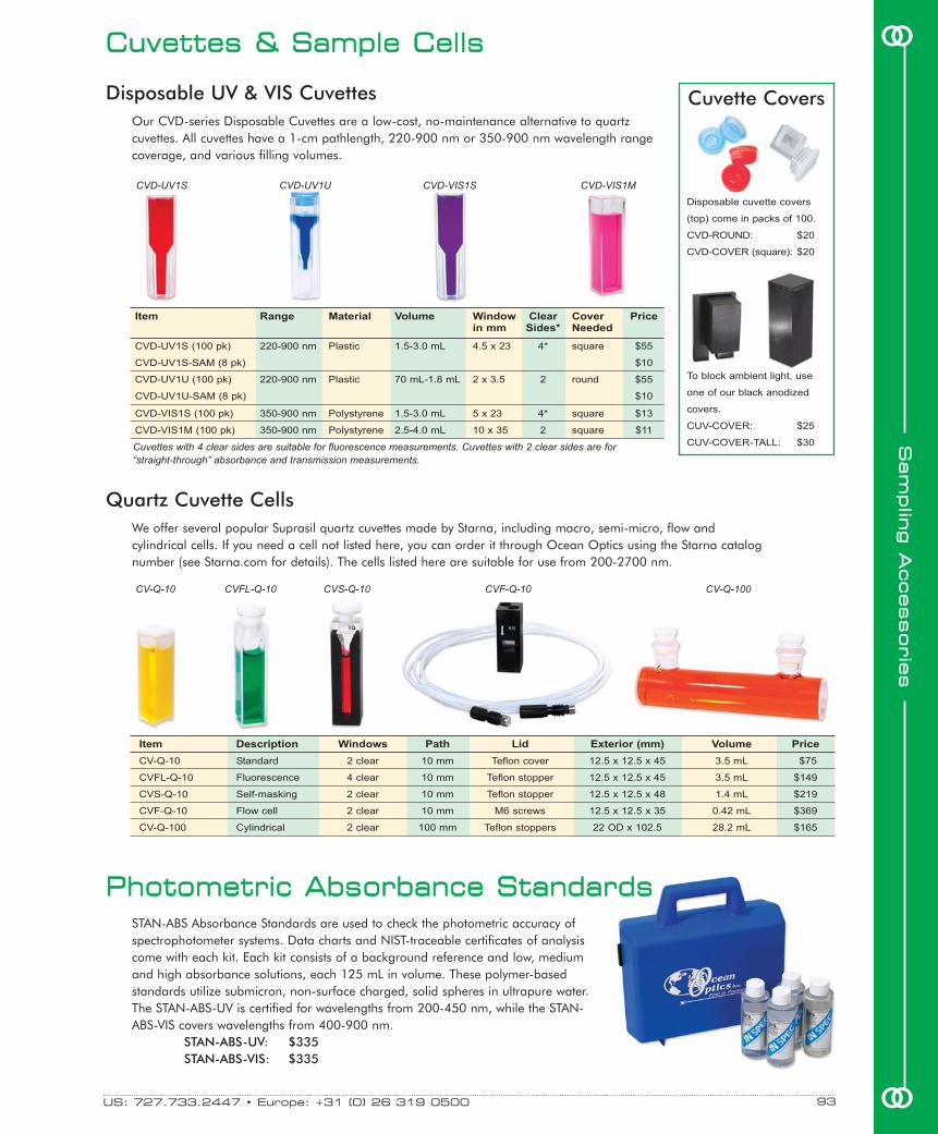
We offer several popular Suprasil quartz cuvettes made by Starna, including macro, semi-micro, flow andcylindrical cells. If you need a cell not listed here, you can order it through Ocean Optics using the Starna catalognumber (see Starna.com for details). The cells listed here are suitable for use from 200-2700 nm.
CCuuvveetttteess && SSaammppllee CCeellllss
Quartz Cuvette Cells
Disposable UV & VIS Cuvettes
Item Description Windows Path Lid Exterior (mm) Volume Price
CV-Q-10 Standard 2 clear 10 mm Teflon cover 12.5 x 12.5 x 45 3.5 mL $75
CVFL-Q-10 Fluorescence 4 clear 10 mm Teflon stopper 12.5 x 12.5 x 45 3.5 mL $149
CVS-Q-10 Self-masking 2 clear 10 mm Teflon stopper 12.5 x 12.5 x 48 1.4 mL $219
CVF-Q-10 Flow cell 2 clear 10 mm M6 screws 12.5 x 12.5 x 35 0.42 mL $369
CV-Q-100 Cylindrical 2 clear 100 mm Teflon stoppers 22 OD x 102.5 28.2 mL $165
STAN-ABS Absorbance Standards are used to check the photometric accuracy ofspectrophotometer systems. Data charts and NIST-traceable certificates of analysiscome with each kit. Each kit consists of a background reference and low, mediumand high absorbance solutions, each 125 mL in volume. These polymer-basedstandards utilize submicron, non-surface charged, solid spheres in ultrapure water.The STAN-ABS-UV is certified for wavelengths from 200-450 nm, while the STAN-ABS-VIS covers wavelengths from 400-900 nm.
STAN-ABS-UV: $335STAN-ABS-VIS: $335
Our CVD-series Disposable Cuvettes are a low-cost, no-maintenance alternative to quartzcuvettes. All cuvettes have a 1-cm pathlength, 220-900 nm or 350-900 nm wavelength rangecoverage, and various filling volumes.
CV-Q-10 CVF-Q-10CVFL-Q-10 CV-Q-100
CVD-UV1S CVD-VIS1MCVD-VIS1SCVD-UV1U
CVS-Q-10
PPhhoottoommeettrriicc AAbbssoorrbbaannccee SSttaannddaarrddss
US: 727.733.2447 • Europe: +31 (0) 26 319 0500 93 oo
ooSS
aamm
pplliinn
gg AA
cccceessssoorriiee
ss
Item Range Material Volume Window Clear Cover Pricein mm Sides* Needed
CVD-UV1S (100 pk) 220-900 nm Plastic 1.5-3.0 mL 4.5 x 23 4* square $55
CVD-UV1S-SAM (8 pk) $10
CVD-UV1U (100 pk) 220-900 nm Plastic 70 mL-1.8 mL 2 x 3.5 2 round $55
CVD-UV1U-SAM (8 pk) $10
CVD-VIS1S (100 pk) 350-900 nm Polystyrene 1.5-3.0 mL 5 x 23 4* square $13
CVD-VIS1M (100 pk) 350-900 nm Polystyrene 2.5-4.0 mL 10 x 35 2 square $11
Disposable cuvette covers
(top) come in packs of 100.
CVD-ROUND: $20
CVD-COVER (square): $20
To block ambient light, use
one of our black anodized
covers.
CUV-COVER: $25
CUV-COVER-TALL: $30Cuvettes with 4 clear sides are suitable for fluorescence measurements. Cuvettes with 2 clear sides are for“straight-through” absorbance and transmission measurements.
Cuvette Covers

Novel Filtering TechnologyWe've combined our patented high-pass and low-pass LinearVariable Filters to create the world's first bandpass filter with an
adjustable center wavelength and adjustable bandpass. Eachfilter features an excellent transmission band (~90%) andblocking band (99.8%). These filters -- with interferencecoatings applied to 57 mm x 10 mm quartz substrates -- are
especially useful for spectrally shaping the excitation energyfrom broadband sources used for fluorescence.
Slide CarriersThese off-the-shelf filters are epoxied into slide carriers that allow youto move the transmission or blocking band throughout the filter’swavelength range.
Single High-pass & Single Low-pass FilterThe LVF-H High-pass Filter is a single filter that blocks light at 98.8%up to a transition wavelength that varies along its length. At thatpoint, the LVF-H passes light better than 90%. The LVF-L Low-passFilter is a single filter that passes light at 88% up to a transitionwavelength that varies along its length. At that point, the LVF-L blockslight better than 98.8%.
Double High-pass & Double Low-pass FiltersWe take two identical LVF-H or LVF-L filters, align them so that thetransition wavelengths of both filters are matched, and then epoxythem together in their slide carriers. The benefit of having doublefilters versus a single filter is that the optical density of the blockingband increases to 99.96%. However, the transmission band isreduced to 80%.
High-pass & Low-pass Variable Bandpass FiltersBy fastening together a high-pass filter and a low-pass filter, wecreated a variable bandpass filter that allows you to adjust the centerwavelength and the bandwidth. We preset the transmissionbandwidth at ~25 nm FWHM, but adjusting four screws allows youto slide the filters against one another to create a transmissionbandwidth as wide as ~100 nm and as narrow as ~20 nm.
LVF AccessoriesThe LVF filters and slide carriers can be inserted easily intospectrometer setups with our LVF accessories. See the next page for details.
These spectra were taken with an LVF-HL to showhow a transmission bandwidth can be set throughoutthe filter's range (300-750 nm).
LVF-HL Variable Bandwidth Filter
%T
RA
NS
MIS
SIO
N
250 350 450 550 650
WAVELENGTH (nm)
80
60
40
20
0
The transition wavelength from blocking totransmission band varies according to the filter'sposition in front of the collimating lens.
LVF-H High-pass Filter
%T
RA
NS
MIS
SIO
N
250 350 450 550 650 750
WAVELENGTH (nm)
100
80
60
40
20
0
LLiinneeaarr VVaarriiaabbllee FFiilltteerrss
Item
LVF-H
LVF-L
LVF-HH
LVF-LL
LVF-HL
LVF-UV-H
LVF-UV-L
LVF-UV-HH
LVF-UV-LL
LVF-UV-HL
Price
$249
$249
$499
$499
$499
$249
$249
$499
$499
$499
Description
A single high-pass filter for 300-750 nm
A single low-pass filter for 300-750 nm
Two LVF-H high-pass filters epoxied together for 300-750 nm
Two LVF-L low-pass filters epoxied together for 300-750 nm
An LVF-H high-pass filter and LVF-L low-pass filter fastened together to create an adjustable bandpass
linear variable filter
A single high-pass filter for 230-500 nm
A single low-pass filter for 230-500 nm
Two LVF-UV-H high-pass filters epoxied together for 230-500 nm
Two LVF-UV-L low-pass filters epoxied together for 230-500 nm
An LVF-UV-H high-pass filter and LVF-UV-L low-pass filter fastened together to create an adjustable
bandpass linear variable filter
For all your sensing needs, visit OceanOptics.com94
SSaamm
pplliinngg AA
cccceessssoorriiee
ss
oo
oo

LVF Accessories in SetupsWe offer several LVF Linear Variable Filters aseither high-pass, low-pass or, when we use themas pairs -- as we do for the LVF-HL -- variablebandwidth filters. These filters are installed intoslide carriers, which can accommodate both thesingle-filter and double-filter configurations. Theslide carriers fit into our slidecarrier accessories, which makeit possible to integrate LVFs withour spectrometers and accessoriesinto fluorescence and absorbancesetups.
In-Line Filtering with LVFsThe FHS-LVF is an in-line filter holder usedin absorbance and transmissionapplications. This in-line LVF holder featurestwo collimating lenses with SMA 905 Connectors.Its slot accommodates the LVF slide carrier.Screws hold the LVF in place.
Cuvette Holder AdapterThe LVF-CUV-ADP is an adapter that fits onto our1-cm cuvette holders and holds the LVF slidecarrier. The cuvette adapter slides over the topof the cuvette holder and includes screws toclamp the LVF’s slide carrier into place. TheLVF-CUV-ADP comes with a cover to blockout ambient light.
Diffuser for Redirecting Excitation LightThe CVD-DIFFUSE, a 1-cm cuvette-shaped pieceof PTFE material, has a 45° surface at themeasurement height and is used with an LVF in afluorescence cuvette holder to redirect excitationenergy 90° into the spectrometer. This facilitatessetting the filter position -- i.e., while the CVD-DIFFUSE is inserted in the cuvette holder, youposition the LVF to select the wavelength regionpassed by the filter.
AAcccceessssoorriieess ffoorr LLiinneeaarr VVaarriiaabbllee FFiilltteerrss
Item
LVF-CUV-ADP
CVD-DIFFUSE
FHS-LVF
LVF-KIT
LVF-UV-KIT
Price
$99
$99
$399
$999
$999
Description
An adapter for a 1-cm pathlength cuvette holder that holds the slide carriers in place
A 1-cm cuvette-shaped PTFE for redirecting excitation energy
In-line filter holder for LVFs
Consists of the LVF-HL, LVF-CUV-ADP, FHS-LVF and CVD-DIFFUSE
Consists of the LVF-UV-HL, LVF-CUV-ADP, FHS-LVF and CVD-DIFFUSE
The LVF is epoxied intoa slide carrier, which fitsinto our LVF accessories,like the FH-LVF FilterHolder.
The CVD-DIFFUSEredirects excitationenergy into thespectrometer andhelps set the filterposition.
When using an LVF with acuvette holder like ourCUV-ALL 4-way CuvetteHolder, you will need theLVF-CUV-ADP CuvetteHolder Adapter. The LVF(in a slide carrier) isinserted in front of thesample and held in placeby the LVF-CUV-ADP(shown at right), with acover to block ambientlight.
US: 727.733.2447 • Europe: +31 (0) 26 319 0500 95 oo
ooSS
aamm
pplliinn
gg AA
cccceessssoorriiee
ss

FH-SMA INLINE-FH
Dimensions: 16 mm diameter 15 mm diameter
Weight: 10 g 20 g
Filter size: 8 mm diameter, 1-7 mm thick 8 mm diameter, 2-5 mm thick
Material: Anodized aluminum Stainless steel (collimating lenses have
anodized housings)
SSppeecciiffiiccaattiioonnss
FFiilltteerrss && FFiilltteerriinngg TTeecchhnnoollooggyy
Schott off-the-shelf filters.
Custom interference filters.
LVF Linear Variable Filters.
FFiilltteerr HHoollddeerrss ffoorr OOppttiiccaall FFiibbeerrss
The INLINE-FH In-line Filter Holder (top photo) holds INLINE-OF Filters or otherfilters 8 mm in diameter and 2-5 mm thick. The Filter Holder includes twocollimating lenses and connects to two fibers for in-line filtering.
The FH-SMA (bottom photo) allows you to mount filters or diffusers at the end ofSMA 905-terminated optical fibers. The FH-SMA accepts 8-mm diameter filters inthicknesses of 1-7 mm. We include an Allen wrench to adjust the barrel of theSMA 905 Connector to accommodate various filter thicknesses.
See page 164 for information on available Absorbing Glass Filters and NeutralDensity Filters for the INLINE-FH or FH-SMA.
INLINE-FH: $402INLINE-OF: $102FH-SMA: $130
Patented Filtering TechnologyWe offer a complete line of custom and off-the-shelf optical filters -- includingfilters produced using our novel dichroic filter array and linear variable filtertechnologies -- for a variety of optical-sensing applications.
Custom FiltersOur dichroic filters can be patterned in areas as small as 2 µm, with spatialregistration to within 1 µm, to produce multiwavelength arrays, stochasticpatterns and even images. We possess the design savvy and manufacturingcapacity necessary to produce high-volume OEM orders of virtually anyprecision optical filter design. For details, see page 160.
Off-the-Shelf FiltersWe inventory a variety of Schott filters, as well as our own LVF Linear VariableFilters, for installation into optical benches, light sources, cuvette holders and in-line filter holders. For a complete list of off-the-shelf filters, see page 164. Ouroptical filters can be categorized by function:� Longpass (Order-Sorting) Filters eliminate second- and third-order effects in
spectrometer setups, and are installed into the optical benches ofspectrometers (page 43) or used as loose filters.
� Low-pass and High-pass Filters eliminate second-order effects, limit straylight, and block excitation energy in fluorescence experiments. Optionsinclude our LVF Filters (page 94) or Schott filters (page 164).
� Balancing Filters absorb energy in some regions while transmitting energyin others, such as the BG 34 filter that comes with our LS-1 TungstenHalogen Source. We also offer Schott-brand balancing filters (page 164).
� Bandpass Filters pass energy in a certain region and block the energyabove and below that region. We offer Schott filters and our LVF Filters, thelatter in an adjustable-bandwidth design (page 94).
For all your sensing needs, visit OceanOptics.com96
SSaamm
pplliinngg AA
cccceessssoorriiee
ss
oo
oo

FFiilltteerr SSaammppllee HHoollddeerrss
We offer a variety of fixtures that couple via SMA 905 Connectorsto our fiber optic spectrometers and light sources for transmissionmeasurements of optical filters.
FHSA-TTL FHS-UV USB-FHS
Dimensions: 140 mm x 50 mm x 50 mm 50.6 mm x 140 mm x 43.1 mm 153.3 mm x 89 mm x 40.8 mm (with base plate)
Weight: 490 g 240 g 320 g (with base plate)
Power consumption: 100 mA @ 12 VDC None 160 mA @ 5 VDC
Filter size (maximum): Any sample up to 7 mm thick 25-mm diameter round; 50-mm diameter round;
any sample up to 6-mm thick any sample up to 18-mm thick
Light source: None None Tungsten bulb and violet LEDs
Wavelength range: 200-2000 nm 200-2000 nm 390-950 nm
Optical fibers required: Yes Yes No
Spectrometer: All All USB2000
Cuvette dimensions: 10 mm x 10 mm None None
Shutter frequency: 5 Hz/60 dB (maximum) None None
Shutter response time: 7 µsec None None
SSppeecciiffiiccaattiioonnss
The FHS-UV In-line Filter Holder is a dual-purpose fixture forprojecting a collimated beam of light through a flat opticalfilter. The FHS-UV can measure the transmission of filters, orprovide a location in an optical system for inserting filters. Ithas two 74-UV Collimating Lenses mounted across a filterholder, which holds round filters up to 25 mm in diameterand samples up to 6 mm thick. (For large filters and othersamples, see the 74-ACH Adjustable Collimating LensHolder.) A bushing keeps the filter against the referencesurface. A shutter facilitates taking dark measurements.
FHS-UV: $399
In-line Filter Holder
Direct-attach Filter Holder for USB2000
Filter & Cuvette Holders
The USB-FHS Filter Holder has a light source mounted ontoa base plate designed to fixture the lamp to a USB2000Spectrometer. The light source includes a tungsten sourceand violet LED, which provide extra signal in the blueregion. The USB-FHS is used to measure the transmissionof filters and other samples up to 18-mm thick.
USB-FHS: $499
What’s unique about the FHSA Filter/Cuvette Holders is youcan configure the holders to sample either cuvettes or filters.Use the FHSAs to measure transmission of 1-cm squarecuvettes or filters up to 7 mm thick. In addition, FHSAsinterface via RS-232 bus to PCs, allowing you to controlsome functions of the FHSAs via software, which is included.With the FHSA-TTL, you have manual control of attenuation(adjustable from 0-100%), and manual or software control ofa shutter. With the FHSA-RS232, you have software control ofboth the attenuation and shutter functions. Both versionsinclude a 12 VDC power supply.
FHSA-TTL: $1,223FHSA-RS232: $2,156
US: 727.733.2447 • Europe: +31 (0) 26 319 0500 97 oo
ooSS
aamm
pplliinn
gg AA
cccceessssoorriiee
ss

SSppeeccttrrooPPiippeetttteerr MMiiccrroocceellll
Wavelength range: 230-850 nm
Sample volume: 2 µL
Light pathlength of cell: 10 mm
Temperature range: 4 °C to 99 °C
Optical fiber length: 1.3 m
Core diameter of launch fibers: Bundle of (3) 200 µm optical fibers
Core diameter of return fiber: 200 µm
SSppeecciiffiiccaattiioonnss
Easy to Use -- Just Pipette and MeasureThe PIP-10-2 SpectroPipetter Microcell is a combination micropipetter
and 10-mm pathlength microcell for low-volume sampling.Samples are loaded into a capillary tube with an optical fiberplunger, which is activated by depressing the thumbpad andreleasing it to draw in the fluid. A mirror on the distal side ofthe capillary completes the optical path.
Requires 2 µL of SampleThe pipetter is equipped with a bifurcated fiber, which couples
to our spectrometers and compact light sources to create low-volume absorbance systems. The
SpectroPipetter requires only 2 µL ofsample for a spectral measurement.
Cleaning KitTo remove fluid or dye from the cell, usethe PIP-UCK Cleaning Kit. It contains anultrasonic cleaning bath (at right) and abottle of cleaning solution. AdditionalPIP-UCK-CS Cleaning Solution(below right) is also available.
PIP-10-2: $1,995PIP-UCK: $165PIP-UCK-CS: $25
For all your sensing needs, visit OceanOptics.com98
SSaamm
pplliinngg AA
cccceessssoorriiee
ss
oo
oo
LLoonnggppaassss FFllooww CCeellllss100x Increase in SensitivityLPC Longpass Flow Cells couple to our spectrometers and lightsources for simple, efficient measurements of low-volume, low-concentration aqueous samples (230-800 nm). With the LPC-1, youhave a 1-meter cell with an internal volume of only 240 µL, givingyou 100x the sensitivity over a 1-cm pathlength cuvette holder asyour sampling device.
Easy to UseLPC cells use a capillary tube as both the sample compartment andthe light waveguide. You inject the sample into the fluidic ports with asyringe or pump; optical fibers connect to SMA 905 Connectors to
deliver and return light to the spectrometer. We offerthese cells in 1- and 5-meter pathlengths (call for other
pathlengths). A 5-meter cell (250 µL/meter) increases the absorbancesignal 500x more than a 1-cm cuvette. Alsoavailable is the LPC-CLEANKIT (see inset), awaveguide cleaning kit for the LPCs.
LPC-1: $1,695LPC-5: $3,350LPC-CLEANKIT: $59
Maximum sample temperature: 160 °C
Tubing inner diameter: 550 µm
Tubing: Fused silica inner tubing coated with Teflon AF
Fluid fittings: 1/16", 1/32" compression fittings
Maximum pressure: 2000 psi
Chemical resistance: Most organic and inorganic solvents
Dimensions: 254 mm x 279 mm
Weight: 140 g
Wavelength range: 230-800 nm (depending on sample solution)
Tubing volume: 250 µL/meter
Fiber connectors: SMA 905
Fiber core diameter: 400 µm
SSppeecciiffiiccaattiioonnss
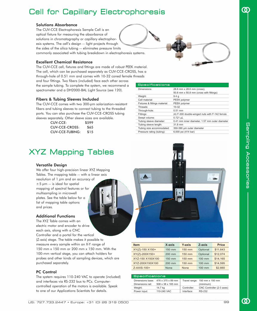
Item X-axis Y-axis Z-axis Price
XY(Z)-150 X150+ 150 mm 150 mm Optional $11,643
XY(Z)-200X150+ 200 mm 150 mm Optional $12,074
XYZ-150 X150X100 150 mm 150 mm 100 mm $14,165
XYZ-200X150X100 200 mm 150 mm 100 mm $14,595
Z-AXIS-100+ None None 100 mm $2,660
XXYYZZ MMaappppiinngg TTaabblleess
Versatile DesignWe offer four high-precision linear XYZ MappingTables. The mapping table -- with a linear axisresolution of 1 µm and an accuracy of± 5 µm -- is ideal for spatialmapping of spectral features or formultisampling in microwellplates. See the table below for alist of mapping table optionsand prices.
Additional FunctionsThe XYZ Table comes with anelectric motor and encoder to driveeach axis, along with a CNCController and a portal for the vertical(Z-axis) stage. The table makes it possible tomeasure every sample within an X-Y range of 150 mm x 150 mm or 200 mm x 150 mm. With the100-mm vertical stage, you can attach holders forprobes and other kinds of sampling devices, which arepurchased separately.
PC ControlThe system requires 110-240 VAC to operate (included)and interfaces via RS-232 bus to PCs. Computer-controlled operation of the motors is available. Speakto one of our Applications Scientists for details.
CCeellll ffoorr CCaappiillllaarryy EElleeccttrroopphhoorreessiiss
Solutions AbsorbanceThe CUV-CCE Electrophoresis Sample Cell is anoptical fixture for measuring the absorbance ofsolutions in chromatography or capillary electrophor-esis systems. The cell’s design -- light projects throughthe sides of the silica tubing -- eliminates pressure limitscommonly associated with tubing breakdown in electrophoresis systems.
Excellent Chemical ResistanceThe CUV-CCE cell, fixtures and fittings are made of robust PEEK material.The cell, which can be purchased separately as CUV-CCE-CROSS, has athrough-hole of 0.51 mm and comes with 10-32 coned female threadsand four fittings. Two fibers (included) face each other acrossthe sample tubing. To complete the system, we recommend aspectrometer and a DH2000-BAL Light Source (see 120).
Fibers & Tubing Sleeves IncludedThe CUV-CCE comes with two 300-µm solarization-resistantfibers and tubing sleeves to connect tubing to the threadedports. You can also purchase the CUV-CCE-CROSS tubingsleeves separately. Other sleeve sizes are available.
CUV-CCE: $599CUV-CCE-CROSS: $65CUV-CCE-TUBING: $15
Dimensions: 28.6 mm x 28.6 mm (cross);
50.8 mm x 50.8 mm (cross with fittings)
Weight: 9.4 g
Cell material: PEEK polymer
Fixtures & fittings material: PEEK polymer
Threads: 10-32
Through-hole: 0.51 mm
Fittings: (4) F-300 double-winged nuts with F-142 ferrule
Swept volume: 0.721 µL
Tubing sleeve diameter: 0.41 mm inner diameter, 1.57 mm outer diameter
Tubing sleeve length: 31.8 mm
Tubing size accommodated: 350-390 µm outer diameter
Pressure rating (tubing): 6,000 psi (414 bar)
SSppeecciiffiiccaattiioonnss
US: 727.733.2447 • Europe: +31 (0) 26 319 0500 99 oo
ooSS
aamm
pplliinn
gg AA
cccceessssoorriiee
ss
Dimensions base: 476 x 375 x 89 mm
Dimensions rail: 508 x 38 x 165 mm
Weight: 14.7 kg
Power input: 110-240 VAC
Travel range: 150 mm x 150 mm
(minimum)
Controller: CNC Controller (2-3 axes)
Interface: RS-232
SSppeecciiffiiccaattiioonnss

Item Description Pathlength Cell Material Price
FIA-ZCELL-PEEK Z Flow Cell with ferrules 10 mm PEEK $365
FIA-ZCELL-PLEX Z Flow Cell with ferrules 10 mm Plexiglas $365
FIA-ZCELL-SS Z Flow Cell with ferrules 10 mm Stainless steel $365
FIA-ZCELL-TEF Z Flow Cell with ferrules 10 mm Teflon $365
Cell materials: PEEK, Plexiglas, Teflon or SS
Inner diameter: 1.5 mm
Window material: UV-grade fused silica
Window thickness: 1 mm
Wavelength range: 260-2000 nm
FIA connectors: 1/4-28
Tubing: 1/16" Teflon, ~3 m
Fiber connectors: SMA 905 for FIA-Z-SMA cells;
1.58-mm stainless steel
ferrules for FIA-Z-CELL cells
FFllooww CCeellllss ffoorr FFllooww IInnjjeeccttiioonn AAnnaallyyssiiss
For all your sensing needs, visit OceanOptics.com100
SSaamm
pplliinngg AA
cccceessssoorriiee
ss
oo
ooWe offer two optical flow cells with a “Z” configuration, to measure the optical absorbance offluids moving through flow injection systems. Each flow cell has a 1.5-mm inner diameter; sampleand waste tubing are connected with 1/4-28 fittings (included). Couple flow cells to our spec-trometers to monitor chemical or biological processes, and immunoassays. These automatedfluid sampling systems eliminate measurement errors that can occur with manual processes.
This fiber is designed for theFIA-Z-SMA.
FIA-Z-CELL: For Use with Ferruled Fibers
In the FIA-Z-SMA Flow Cell, optical fibers (available separately) connect to SMA 905fittings to transmit and receive light through the central axis of the Z. The FIA-Z-SMA Celluses silica windows as wetting surfaces at each fiber optic junction, and is available inPEEK polymer, Plexiglas (pictured top right), stainless steel or Teflon.
FIA-Z-SMA: For Use with Standard Fibers
The FIA-Z-CELL Flow Cell is a variation on the FIA-Z-SMA that instead of windows usesoptical fibers in 1.58-mm ferrules, a design that allows you to slide the ferrules in andout of the cell to adjust the optical pathlength from 0-10 mm. Standard cell materialsare PEEK polymer, Plexiglas, stainless steel and Teflon.
Item Description For Cell Price
P400-2-UV-VIS (1) 400 µm fiber assembly with SMA 905 Connectors FIA-Z-SMA $119
P200-2-UV-VIS (1) 200 µm fiber assembly with SMA 905 Connectors FIA-Z-SMA $99
FIA-P400-SR (1) 400 µm fiber assembly with ferrule terminations FIA-ZCELL $215
FIA-P200-SR (1) 200 µm fiber assembly with ferrule terminations FIA-ZCELL $210
Fibers for Use with FIA Cells
Item Description Pathlength Cell Material Price
FIA-Z-SMA-PEEK Z Flow Cell with SMA 905 Connectors 10 mm PEEK $529
FIA-Z-SMA-PLEX Z Flow Cell with SMA 905 Connectors 10 mm Plexiglas $529
FIA-Z-SMA-SS Z Flow Cell with SMA 905 Connectors 10 mm Stainless steel $529
FIA-Z-SMA-TEF Z Flow Cell with SMA 905 Connectors 10 mm Teflon $529
FIA-ZSMA-20-PE Z Flow Cell with SMA 905 Connectors 20 mm PEEK $529
FIA-ZSMA-20-PLE Z Flow Cell with SMA 905 Connectors 20 mm Plexiglas $529
FIA-ZSMA-20-SS Z Flow Cell with SMA 905 Connectors 20 mm Stainless steel $529
FIA-ZSMA-20-TEF Z Flow Cell with SMA 905 Connectors 20 mm Teflon $529
FIA-ZSMA-50-PE Z Flow Cell with SMA 905 Connectors 50 mm PEEK $629
FIA-ZSMA-50-PLE Z Flow Cell with SMA 905 Connectors 50 mm Plexiglas $629
FIA-ZSMA-50-SS Z Flow Cell with SMA 905 Connectors 50 mm Stainless steel $629
FIA-ZSMA-50-TEF Z Flow Cell with SMA 905 Connectors 50 mm Teflon $629
These fibers have ferrulesfor use with the FIA-Z-CELL.
SSppeecciiffiiccaattiioonnss
1/4-28 fittings comewith the cells.
An FIA-Z-SMA requires two 200 µm or 400 µm diameter optical fiber assemblies like theones listed below, or see page 138 for more choices. The FIA-ZCELL requires two opticalfiber assemblies with ferrule terminations. Each price below is for one assembly, but twoare required.

FFllooww CCeellll KKiitt ffoorr FFllooww IInnjjeeccttiioonn AAnnaallyyssiiss
US: 727.733.2447 • Europe: +31 (0) 26 319 0500 oo
ooSS
aamm
pplliinn
gg AA
cccceessssoorriiee
ss
101
FFlluuoorreesscceennccee FFllooww CCeellll ffoorr FFllooww IInnjjeeccttiioonnWith the FIA-SMA-FL Fluorescence Flow Cell, a fiber sends excitation energy via a windowinto a sample compartment. A second fiber, oriented at 90° and connected to a spectrometer,collects the emitted energy. Each cell has two optical windows and SMA 905Connectors (which do not contact the fluids). Also included are Teflon tubing andchemically-resistant tubing connectors and seals. Two 600 µm fibers are required.
FIA-SMA-FL: $435P600-2-UV-VIS: $159 (each; 2 required)
The FIA-1000-Z Flow Cell Kit is a fluid sampling system that couples to our spectrometers andlight sources for rapid, quantitative UV-VIS-NIR analysis of solutions. The kit consists of anFIA-Z-SMA “Z”-type flow cell (page 100), the FIA-PUMP-C (a computer-controlled 2-channelperistaltic pump), and operating software to control the pump via a PC’s serialport. A pair of optical fibers (not included) is required. The FIA-Z-SMA has anoptical pathlength of 10 mm and an inner diameter of 1.5 mm, and isavailable in PEEK polymer, Plexiglas, stainless steel or Teflon. (Tubing is notincluded.) You can also purchase the pump separately.
FIA-1000-Z: $1,300FIA-PUMP-C: $804
Parts-per-trillion SensitivityThe FIA-PMT-FL Photomultiplier Flow-through Detection System providesparts-per-trillion sensitivity for ultra-low fluorescence, chemiluminescenceand bioluminescence measurements. Because of its heavy-duty, chemicallyresistant housing, the system can withstand harsh industrial environments.
Modular DesignThe FIA-PMT-FL is built to order with either an internal excitation lamp orwith an optical fiber interfacing to an external lamp. Excitation lampsource options include tungsten, mercury vapor, LEDs and laserdiodes. Emission and excitation filters are mounted in slots in theenclosure, allowing for easy removal or exchange. Though thesystem uses a 100 µL flow-through cuvette, you can use 1-cmpathlength cuvettes for manual measurements.
Easy PC Interface & Optimized SoftwareIncluded with the system is Windows-based software that allowsyou to set the integration time and voltage counts, and toobtain time histories of the measurements, both plotted andtabulated. The software can also automatically create calibra-tion curves and control additional devices such as certainsyringe and peristaltic pumps, injection valves, selection valvesand autosamplers. ActiveX control is included for controllingthe FIA-PMT-FL from your own software. The FIA-PMT-FL plugsinto the RS-232 serial port of a PC.
FIA-PMT-FL: $6,495
Spectral range: 310-750 nm
Detector: Photo-counting photomultiplier tube
PMT dynamic range: 2 x 10⁶
Responsivity: 5 x 10¹⁷ cps/watt (@ 400 nm)
Detection limits: 2 parts per trillion w/fluorescein @ 250 ms integration time
Pulse-pair resolution: 10 ns
Flow cell pathlength: 10 mm
Flow cell volume: 100 µL with standard flow-through cuvette
Filters: Excitation or emission; 11.8 mm diameter; call for details
Computer interface: RS-232
Operating systems: Windows 98/Me/2000/XP operating systems
SSppeecciiffiiccaattiioonnss
Spectral range: 260-2000 nm
Cell materials: PEEK, Plexiglas, stainless steel or Teflon
Inner diameter: 1.5 mm
Window: 1 mm thick, UV-grade fused silica
Pathlength: 10 mm
Pathlength: 10 mm
Tubing: 1/16" Teflon, ~3 m, with 1/4-28 connectors
Pump: 105 mm x 105 mm x 185 mm; 2.1 kg
Flow rate: 200 mL/minute/channel, depends on RPM and tubing diameter
Pressure rating: 25 psi
SSppeecciiffiiccaattiioonnss
FFlluuoorreesscceennccee FFllooww IInnjjeeccttiioonn AAnnaallyyssiiss SSyysstteemm

Lab-On-Valve TechnologyThe FIA-SIA-LOV Lab-On-Valve System is a compactsequential injection analyzer for all-in-one chemicalanalyses. It combines a computer-controlled six-positionvalve, precision syringe pump, and spectrophotometricflow cell in a 12.7 cm x 15.3 cm package that canautomate virtually any wet-chemistry lab procedure. All ofthe chemistry takes place within the valve manifold --
eliminating the need for additional tubing andconnectors. All of the ports are
interconnected by microchannels, and abuilt-in multi-purpose flow cell interfacesto optical fiber probes for spectralanalyses in either absorbance or
fluorescence mode.
Automate Virtually Any Wet Lab Procedure The FIA-SIA-LOV comes with software and interfaces to aPC, allowing you to fully automate wet lab procedureswith precise control of assay parameters includingimmunoassays, dilution monitoring and reagent/sampleratio for continuous or stopped-flow measurements. Viathe software, you assign each of the Lab-On-Valve's portsa specific function. Software controls procedures withsimple commands to set up and sequence through theseprocesses. In fact, changing procedures is as easy asopening a stored script and switching reagent bottles.
Cost-effective MethodologyThe FIA-SIA-LOV also offers a cost-effective, microliter-volume methodology -- it produces less waste, savesmoney and introduces fewer chemicals into theenvironment than other wet chemistry technologies. Theunit weighs just 3.6 kg, making it both portable and easyto install in small incubators for temperature and humiditycontrol. Also, the FIA-SIA-LOV easily can be positionednear ETAAS and MS systems so that micro-volumes ofprocessed samples need not be transported through longconduits, which can cause sample degradation.
Modular Turnkey Chemical AnalyzerThe FIA-SIA-LOV unit was developed by flow injectionsystem specialist and Ocean Optics partner FIAlabInstruments, and is compatible with our spectrometers,light sources and optical fibers for dynamic spectralanalyses of optical absorbance or fluorescence of fluids.Nearly any standard colorimetric flow injection analysismethod can be adapted to, and performed on, the FIA-SIA-LOV, with few or no modifications to the manifold.
Replacement PartsThe FIA-SIA-LOV consists of the FIA-SIA Micro SequentialInjection Analyzer unit and the FIA-LOV Lab-on-a-ValveManifold, each of which can be purchased separately.
FIA-SIA-LOV: $13,450FIA-SIA: $10,950FIA-LOV: $1,275
SSeeqquueennttiiaall IInnjjeeccttiioonn SSyysstteemm
Dimensions: 12.7 cm x 15.3 cm x 15.3 cm
Weight: 3.6 kg
Spectral range: 260-2000 nm
Cell materials: PEEK, Plexiglas, Teflon or SS
Inner diameter: 1.5 mm
Window material: UV-grade fused silica
Window thickness: 1 mm
Pathlength: 10 mm
Fiber connectors: SMA 905
Tubing: 1/16" Teflon, ~3 m
Tubing connectors: 1/4-28
Pump dimensions: 105 mm x 105 mm x 185 mm
Pump weight: 2.1 kg
Flow rate: 200 mL/minute/channel (depending on RPM
and tubing diameter)
Pressure rating: 25 psi
SSppeecciiffiiccaattiioonnss
Control numerous assayparameters including:� Bead trapping� Composite
sample handling� Flow injection� Flow through� Holding coil� Mixing� Optical
monitoring� Reagent
aspiration� Sample dilution� Sample aspiration� Sequential injection� Waste elimination
The system includes a six-valvemanifold unit, syringe pump andvalve, and comes with tubing,various connectors and otherfluidics parts. Spectrometer andlight source are purchasedseparately.
For all your sensing needs, visit OceanOptics.com102
SSaamm
pplliinngg AA
cccceessssoorriiee
ss
oo
oo

Displaces Volumes from 1 µLThe PUMP-IT-1000 Positive Displacement Pump is apulsed pump that displaces from 1 µL to 250 µL offluid with each pump or cycle. The amount of fluiddisplaced with each cycle is set via software. Theamount pumped is precise to 0.3% with repeatabilityof better than 0.5%.
ApplicationsThe PUMP-IT is particularly useful forthose wanting to automate the delivery ofreagents into accurate flow setups.Typical applications include bloodchemistry, blood analysis, particlesizing, in vitro diagnostics andbiopharmaceutical analysis.
PC/Software-controlledThe pump connects to a PC via an RS-232 port and acontroller box and is controlled with software (included).The PUMP-IT is a low-cost alternative to expensive syringe,vacuum, peristaltic and other pumps. Not only can you selectthe displacement amount, you can regulate the speed of thedisplacement via software.
Long-life DesignFor accurate mixing and/or dilution of fluids, the pump has upperand lower limits that can be set mechanically and via the software.The pump provides a ripple-free and bubble-free flow. The pump’spiston and head are made out of PEEK, while the body is madefrom aluminum. The piston in the pump will last about 1-2 millioncycles before it shows evidence of wear. The PUMP-IT has theflexibility to be positioned in any orientation.
What’s IncludedThe PUMP-IT-1000 comes with the controller box and powersupply; an RS-232 cord; software; 10 feet of tubing; various nylonfittings, plugs and caps; and a 250-µL sample bottle. You can alsoorder the pump only (PUMP-IT-PUMP).
PUMP-IT-1000: $999PUMP-IT-PUMP: $565
Full scale volume: 250 µL
Volume per full step: 0.028 µL
Throughput: > 60% (based on 400 µm optical fiber)
Actuator: 5 VDC, 0.49 amp/phase, 10.2 ohm/phase, 9.6 mHz/phase
Repeatability: < 0.5%
Precision: < 0.3%
Pump head: Acrylic (custom options include polycarbonate and PEEK)
Pump piston: PEEK (custom options include stainless steel, ceramic and glass)
Pump body: Aluminum (custom options include stainless steel and acrylic)
Dimensions: Pump -- 3.50 cm x 3.50 cm x 16.94 cm
Controller -- 11.93 cm x 11.93 cm x 6.35 cm
Controller: Unipolar/Bipolar dual stepper motor control PCB, 7.5 VAC, 1 A
Baud rate: 2400 or 9600 baud serial connection
AC adapter: 7.5 VAC, 1 A
Tubing: 10 feet of Tygon tubing
Standard nylon fittings: 10 female Luer fittings, 1/4 hex to 10-32 thread
10 male Luer fittings, 1/4 hex to 10-32 thread
10 Luer plugs and 10 caps
10 1/16" ID barbed fittings with10-32 thread
10 1/16" ID barbed tee fittings
10 1/16" ID elbow fittings
SSppeecciiffiiccaattiioonnss
PPoossiittiivvee DDiissppllaacceemmeenntt PPuummpp
ControllerBox PowerSupply
RS-232 Cablefor connectingthe ControllerBox to a PC
Software
Pump
Bottle
Various Fittings
US: 727.733.2447 • Europe: +31 (0) 26 319 0500 103 oo
ooSS
aamm
pplliinn
gg AA
cccceessssoorriiee
ss
Controller Box
Tubing

Flexibility for Multipoint SamplingOur MPM-2000 Fiber Optic Multiplexers take light to
a spectrometer or from a light source connected toone of the input ports and distribute it to either 8 or 16 outputs. The light is distributed throughthe output ports in sequential order, with
switching times between channels of less than150 milliseconds. Multiplexers often are found in
process industries, where multiple locations need to bemeasured with one spectrometer channel and/or light source.
High-precision InstrumentAll versions of the MPM-2000 include a DC motor, which hasexcellent speed control without sacrificing power. The motor is on arotator block and includes an encoder, which converts movementinto a digital pulsed output. Each channel in the multiplexer has acollimating lens connecting to an internal optical fiber system. TheMPM-2000 provides accurate measurements with a repeatability of99% and offers optical throughput better than 60%.
Multiple VersionsThe MPM-2000 comes with either 2 input channels -- with eachinput channel corresponding to 8 output channels -- or with 1input channel and 16 output channels. You must choose either aUV-VIS (250-800 nm) or VIS-NIR (350-2000 nm) multiplexer.
Software-controlledThe multiplexers interface to a PC via an RS-232 port and comewith software and a driver for complete PC control. The softwareallows you full control of the switching order, switching delay timeand system calibration.
MPM-2000-1X16-UV: $7,714MPM-2000-1X16-VIS: $7,714MPM-2000-2X8-UV: $8,021MPM-2000-2X8-VIS: $8,021
Dimensions: 230 mm x 200 mm x 150 mm
(fits into 19" system: 33TE, 3HE, etc.)
Wavelength range: 250-800 nm (UV/VIS) or 350-2000 nm (VIS/NIR)
Optical throughput: > 60% (when using standard 400 µm fibers)
Motor: Direct-current motor
Optical fibers: 400 µm diameter optical fibers
Repeatability: > 99%
Switching time: 150 milliseconds between adjacent positions
Interface: RS-232 (optional USB)
Power requirement: 24 VDC, 1.2 A (includes WT-24V-E power supply)
Connectors: SMA 905
SSppeecciiffiiccaattiioonnss
OOppttiiccaall MMuullttiipplleexxeerr
An MPM-2000-2x8 has twoinput ports and 16 outputs.Here, we used a USB2000Spectrometer and an LS-1Light Source as theinput ports.
For all your sensing needs, visit OceanOptics.com104
SSaamm
pplliinngg AA
cccceessssoorriiee
ss
oo
oo
The FVA-UV Fiber Optic Variable Attenuator is an opto-mechanicaldevice that helps control the amount of light transmitted between twofibers. Two fibers screw into either side of the FVA-UV via SMA 905Connectors with collimating lenses, which project light across a metaldisc in which a slit has been cut. The width of the slit varies as a functionof radial position, which is adjusted manually. Rotating the disc varies theattenuation from 0-100% uniformly across a 200-2000 nm wavelengthrange. An FVA-ADP attaches the FVA-UV directly to a light source.
FVA-UV: $499FVA-ADP: $99
FFiibbeerr OOppttiicc VVaarriiaabbllee AAtttteennuuaattoorr
SSppeecciiffiiccaattiioonnss
Dimensions: 38.1 mm x 59.4 mm x 40 mm
Weight: 90 g
Assembly ports: 3/8-24 threads for collimating lenses
Wheel lock: 6-32 nylon thumbscrew
ADP adapter: Directly attaches to a light source with a collimating lens
Connector: SMA 905

In this setup, light enters a Bifurcated Optical Fiber Assembly and then splits into two arms, one foreach sample. Light interacts with each sample and travels through another fiber assembly, eachinto its own port in the FOS. Another Bifurcated Assembly collects the light from the FOS andsends it to the spectrometer. In this setup, you would switch the shutter on the FOS from one lightchannel to another in order to get clean data from each sample. Without the FOS, you would needanother spectrometer channel to monitor the two samples.
EElleeccttrroonniicc TTTTLL SShhuutttteerr
Dimensions: 140 mm x 50 mm x 50 mm
Weight: ~600 g
Shutter-Input: TTL maximum 5 Hz
Power requirements: 12 VDC (power supply included)
Power consumption: 100 mA maximum
Maximum frequency: 5 Hz
SSppeecciiffiiccaattiioonnss
In spectrometer setups, the INLINE-TTL TTL-driven shutter allows youto block the light path without disturbing the experiment setup -- forexample, by turning the light source on and off. The laser-cut shutteris installed between two collimating lenses, which attach to two opticalfibers. The INLINE-TTL is driven by a small board with a TTL input.Included is a cable for interfacing to a spectrometer.
INLINE-TTL-S: $988
US: 727.733.2447 • Europe: +31 (0) 26 319 0500 105 oo
ooSS
aamm
pplliinn
gg AA
cccceessssoorriiee
ss
The Gershun Tube Kit (GER-KIT) controls the field of view of our SMA905-terminated optical fiber. It also directly attaches to a spectrometerwith an SMA 905 Connector. User-interchangeable apertures providemany different fields of view from 1° to 28°. (When the GER-KIT isused with our optical fiber, the field of view cannot exceed the opticalfiber's 25° field of view if you are measuring radiance.)
GER-KIT: $499
FFiieelldd ooff VViieeww CCoonnttrrooll
Material: Black anodized aluminum
Interior: Bead-blasted surface to reduce off-axis reflections
Connection: Directly attaches to one of our spectrometers or couples to an
SMA 905-terminated optical fiber with included adapter barrel
Apertures: 1°, 3°, 8°, 10° and 14° apertures included, providing
1°, 2°, 3°, 6°, 8°, 10°, 14°, 16°, 20° and 28° fields of view
SSppeecciiffiiccaattiioonnss
Dimensions: 100 mm x 70 mm x 70 mm
Weight: 455 g
Material: Anodized aluminum
Switch frequency: Maximum of 5 Hz
Power: 12 VDC
Operation: Manual switch or TTL input signal
SSppeecciiffiiccaattiioonnss
FFiibbeerr OOppttiicc DDuuaall SSwwiittcchh wwiitthh TTTTLL LLiinnee
BIF400-UV-VIS BIF400-UV-VIS
P400-025-SR
LightSource
P400-025-SR
FOS-2X2-TTL
Spec-trometer
Sample 1
Sample 2
The FOS-2X2-TTL Fiber Optic Dual Switch was designed to provide you with flexibilityin routing, splitting and controlling light. The FOS has two light channels; each hasits own TTL-controlled shutter. You can opt to have one light channel open at a time,have both open, or have both closed. The FOS is useful for monitoring the drift ofthe light source or for measuring two samples with one spectrometer channel andone light source. The diagram below is an example of how the FOS can be utilized.In this setup, the FOS eliminates the need for a second spectrometer channel.
FOS-2X2-TTL: $1,664

EviTag Core-shell Nanocrystals
SSeemmiiccoonndduuccttoorr NNaannooccrryyssttaallss
Semiconductor
Nanocrystals
Cadmium selenide
nanocrystals with zinc
sulfide shell (CdSe/ZnS)
Cadmium selenide
nanocrystals with zinc
sulfide shell (CdSe/ZnS)
Cadmium selenide
(CdSe)
Cadmium selenide
(CdSe)
Lead sulfide (PbS)
Lead sulfide (PbS)
Lead selenide (PbSe)
Lead selenide (PbSe)
Volume per Vial
30 mg dots in 4 mL of
toluene solvent
50 mg dots in 5 mL of
toluene solvent
35 mg dots in 4 mL of
toluene solvent
50 mg dots in 5 mL of
toluene solvent
10 mg dots in 4 mL toluene
10 mg dots in 4 mL toluene
10 mg dots in 4 mL hexane
10 mg dots in 4 mL hexane
Vials
6
1
6
1
2
1
2
1
Price
$649
$449
$649
$349
$249
$199
$699
$524
Description
Core Shell EviDot Test Kit with 1 vial each of the following:
• 520 nm • 540 nm • 560 nm
• 580 nm • 600 nm • 620 nm
Core Shell EviDots. Specify 1 vial only from the following:
• 490 nm • 520 nm • 540 nm • 560 nm
• 580 nm • 600 nm • 620 nm
Core EviDot Test Kit with 1 vial each of the following:
• 500 nm • 520 nm • 545 nm
• 570 nm • 595 nm • 618 nm
Core EviDots. Specify 1 vial only from the following:
• 500 nm • 520 nm • 545 nm
• 570 nm • 595 nm • 618 nm
Core EviDot Test Kit with 1 vial of 850 nm and 950 nm
Core EviDots. Specify 1 vial only of 850 nm or 950 nm
Core EviDot Test Kit with 1 vial of 1310 nm and 1550 nm
Core EviDots. Specify 1 vial only from the following:
• 1100 nm • 1310 nm • 1550 nm • 1900 nm
For all your sensing needs, visit OceanOptics.com106
SSaamm
pplliinngg AA
cccceessssoorriiee
ss
oo
oo
Item Code Description Vials Terminal Volume per Vial PriceGroup
QD-TAG-KIT Core-shell EviTag Test Kit with 1 vial each of the following: 5 Carboxyl 0.125 mg tags in 0.5 mL $1499
• 490 nm • 520 nm • 540 nm of deionized water
• 560 nm • 600 nm
QD-TAG-1V Core-shell EviTags. Specify 1 vial only from the following: 1 Carboxyl 0.125 mg tags in 0.5 mL $399
• 490 nm • 520 nm • 540 nm • 560 nm of deionized water
• 580 nm • 600 nm • 620 nm
QD-TAG-A-KIT Core-shell EviTag Test Kit with 1 vial each of the following: 5 Amine 0.125 mg tags in 0.5 mL $1499
• 490 nm • 520 nm • 540 nm of deionized water
• 560 nm • 600 nm
QD-TAG-A-1V Core-shell EviTags. Specify 1 vial only from the following: 1 Amine 0.125 mg tags in 0.5 mL $399
• 490 nm • 520 nm • 540 nm • 560 nm of deionized water
• 580 nm • 600 nm • 620 nm
EviDot Core & Core-shell Nanocrystals
EviTag Nanocrystals are Core-shell Nanocrystals with an additional proprietarycoating that makes the Core shells water-stable. EviTags now open the EviDottechnology to life science applications. In fact, ligands (carboxyl or amine) areattached to the proprietary coating so that they can easily be bound to nucleicacids, antibodies and proteins.
Item Code
QD-CS-VIS
QD-CS-1V
QD-C-VIS
QD-C-1V
QD-NIR
QD-NIR-1V
QD-IR
QD-IR-1V
EviDot Core Nanocrystals are manufactured quantum dots ranging in size from2-10 nm with fewer than 1,000 atoms. Each Core type is made of the samematerial but exhibits different emission properties based on size. Cores producehigh quantum yields with intense fluorescence at targeted peak wavelengths.EviDot Core-shell Nanocrystals are Core Nanocrystals with a zinc sulfide coatingthat stabilizes the Core, improves quantum yield and reduces photodegradation.
Evident Technologies, an Ocean Optics partner, develops extremely high-quality, low-cost semiconductornanocrystals. These quantum dots are nanometer-scale materials that have properties between that ofmolecules and bulk materials. This enables Evident to produce "designer atoms" through atomic-levelmanipulation. When combined with our spectrometers and excitation sources, these nanocrystals have beenused in biology applications as fluorescent tags to measure and quantify biological phenomena, and inphotonics as tunable colors for light-emitting diodes. EviTags are an ideal tagging tool for high-throughputscreening in micro-fluidic systems, as well as cell imaging and pathogen detection. For most applications, werecommend our USB2000-FLG Spectrometer and some combination of our light sources and filters to exciteEviDots and EviTags. Contact one of our Applications Scientists for details.
For more details on EviDots, please visit our website at OceanOptics.com/Products/Evidots.asp.
For more details on EviTags, please visit our website at OceanOptics.com/Products/Evitags.asp.

CC-3 CC-3-UV CC-3-DA
Diffusing material: Opaline glass PTFE PTFE
Wavelength range: 350-1000 nm 200-1100 nm 200-1100 nm
Dimensions: 6.35 mm OD 6.35 mm OD 12.7 mm OD
Field of view: 180° 180° 180°
SSppeecciiffiiccaattiioonnss
The CC-3-DA (above center) attachesdirectly to an SMA 905 Connector on aspectrometer (left), creating aspectroradiometer. The CC-3 and CC-3-UV (above left and right) attach to
optical fibers, creating Irradiance Probes.
CCoossiinnee CCoorrrreeccttoorrss ffoorr EEmmiissssiioonn CCoolllleeccttiioonn
Collect Radiation from 180°Our Cosine Correctors couple to optical fibers and spectrometersfor relative and absolute spectral intensity measurements, foremissive color applications, and for evaluation of light sourcessuch as LEDs and lasers.
Probe OptionWhen the CC-3 and CC-3-UV are screwed onto the end of anoptical fiber, the cosine corrector and optical fiber become anirradiance probe. The probe couples to one of our spectrometersto measure the intensity of light normal to the probe surface.
Direct-attach OptionThe CC-3-DA screws directly onto the SMA 905 Connector of aUSB2000, HR4000 or S2000 Spectrometer, creating a completespectroradiometric system and eliminating the need for anoptical fiber.
Diffusing Material: UV-VIS or VIS-NIRThe diffusing material used in the cosine corrector is a thin disk ofopaline glass (350-1100 nm) or PTFE (200-1100 nm) that sits atthe end of a stainless steel barrel. Call for details about our newHY-IRRAD irradiance collectors; one for air and one for water.
CC-3: $99CC-3-UV: $129CC-3-DA: $299HY-IRRAD-A: $295HY-IRRAD-W: $295
The response of the PTFE disc (red trace) used in the CC-3-UVclosely matches that of Lambert’s Cosine Law (purple trace).
CO
UN
TS
ANGLE
CC-3-UV Angular Response
0 10 20 30 40 50 60 70 80 90 100
PTFE Disc
Lambert’s Cosine Law
Measuring LEDsThe LED-PS Power Supply works with our spectrometers andthe FOIS-1 Fiber Optic Integrating Sphere (see page 108) forspectroradiometric and color measurements of LEDs. TheLED-PS unit has easy-to-reach electrical connectors formounting LEDs that are 9.52-mm diameter or smaller with2.77-mm lead spacing.
Adjustable Drive CurrentThe LED-PS holds the LED in place, powers the LED, anddisplays the LED’s drive current. The drive current isadjustable, with a digital display to indicate the current level.With the LED-PS-NIST, the current meter is calibrated againsta NIST-traceable standard. For more on LED measurements,see page 16.
LED-PS: $499LED-PS-NIST: $749LED-PS-RECAL: $199
PPoowweerr SSuuppppllyy && CCoonnttrroolllleerr ffoorr LLEEDDss
Dimensions: 56.8 mm x 56.8 mm x 56 mm
Weight: 170 g
Power consumption: Up to 100 mA @ 12 VDC; depends on setting
LED drive current: 12-50 mA with 0.1 mA resolution
Drive current accuracy: ± 1.0%
LED mount: 2.77 mm lead spacing, PTFE base
SSppeecciiffiiccaattiioonnss
3500
3000
2500
2000
1500
1000
500
0
US: 727.733.2447 • Europe: +31 (0) 26 319 0500 107 oo
ooSS
aamm
pplliinn
gg AA
cccceessssoorriiee
ss

IInntteeggrraattiinngg SSpphheerreess ffoorr IIrrrraaddiiaannccee//EEmmiissssiioonn
Weight: 330 g (ISP-30); 730 g (ISP-50); 1,650 g (ISP-80)
Spectral range: 200-2500 nm
Sphere coating: Proprietary PTFE-based diffusing material
Reflectivity: >98% (400-1500 nm); >95% (250-2000 nm)
SSppeecciiffiiccaattiioonnss
360° Emission CollectionThe FOIS-1 is a compact sampling optic that collectslight from emission sources such as LEDs and lasers,or that measures light fields with a 360° field of view.
Principle of OperationAt the heart of the FOIS-1 is Spectralon, a whitediffusing material with a highly Lambertian surface.Light enters the sphere via a 9.5-mm diameter portwhile a fiber -- oriented at 90° to the sample port --collects the light. The size of the FOIS-1 and its threemounting holes make it easy to connect the sphere toother items, such as the 74-ACH AdjustableCollimating Lens Holder (at left).
Use with Calibrated Light SourceBefore measuring the absolute spectral intensity ofemission sources, use the LS-1-CAL-INT CalibratedLight Source to calibrate the absolute spectralresponse of your spectroradiometric system. For moreon the LS-1-CAL-INT, see page 131.
FOIS-1: $499
Dimensions: 56.8 mm x 62.4 mm (housing)
38.1 mm diameter (sphere)
Top mounts: (2) 6-32; (2) 8-32; (1) 1/4-20
Side mounts: SMA 905 Connector; (1) 8-32
Weight: 240 g
Spectral range: 200-2500 nm
Sample port: 9.5 mm aperture
Sphere coating: Spectralon
ISP-I Integrating Spheres
FOIS-1 Fiber Optic Integrating Spheres
Emission CollectionISP-I Integrating Spheres are convenient sampling optics that coupleto our spectrometers via optical fibers to measure the spectral outputfrom 200-2500 nm of LEDs, lasers and other light sources. Eachintegrating sphere consists of a proprietary PTFE-based, sintereddiffusing material -- in diameters of 30 mm, 50 mm or 80 mm --that provides a Lambertian surface for irradiance measurements.
LED Measurement & Direct-attach OptionAn ISP-LED-ADP adapter holds in place 3 mm, 5 mmor 8 mm LEDs and screws into the sample port of theISP-50-8-I Integrating Sphere for measuring LEDs. Theadapter ensures reproducibility. Another option is theUSB-ISP-50 or USB-ISP-80, which directly attach to aUSB2000 Spectrometer, eliminating the need for a read fiber. If thesample ports are too small, we offer custom sample port sizes for allISPs. Custom machining for ports in diameters of 8, 10, 12, 14, 16or 20 mm is available (see below).
For all your sensing needs, visit OceanOptics.com108
SSaamm
pplliinngg AA
cccceessssoorriiee
ss
oo
oo
Item Description Sample Port Max. Fiber Price
ISP-30-6-I: Integrating sphere, 59 mm diameter, 58 mm high 6 mm 800 µm $1,228
ISP-50-8-I: Integrating sphere, 80 mm diameter, 78 mm high 8 mm 600 µm $1,598
ISP-80-8-I: Integrating sphere, 107 mm diameter, 117 mm high 8 mm 400 µm $1,981
ISP-LED-ADP: Holds in place 3, 5 or 8 mm LED for reproducibility; for use with ISP-50-8-1 N/A N/A $185
USB-ISP-50: ISP-50-8-I with connector for directly attaching to a USB2000 Spectrometer 8 mm 600 µm $2,048
USB-ISP-80: ISP-80-8-I with connector for directly attaching to a USB2000 Spectrometer 8 mm 400 µm $2,417
ISP-PORT-1: Custom sample port machining of 8, 10, or 12 mm diameter 8, 10 or 12 mm 400 µm $172
ISP-PORT-2: Custom sample port machining of 14,16 or 20 mm diameter 14, 16 or 20 mm 400 µm $323
HL-2000-CAL-ISP NIST-traceable radiometric standard for use with ISP-50-8-I; see page 131 N/A N/A $825
SSppeecciiffiiccaattiioonnss
In the picture top right, the FOIS-1 is being used to measureLEDs. In the picture bottom right, the FOIS-1 is attached to a 74-ACH, a setup oftenused when making transmission measurements of curved optics. An optic is setbetween the FOIS-1 and the right arm of the 74-ACH.

IInntteeggrraattiinngg SSpphheerreess ffoorr RReefflleeccttaannccee
ISP-REF Illuminated Integrating Sphere
ISP-R Integrating Spheres
ISP-REF ISP-30-6-R ISP-50-8-R ISP-80-8-R ISP-50-8-R-GT
Dimensions: 54 mm x 57 mm x 83 mm 59 mm dia., 58 mm high 80 mm dia., 78 mm high 107 mm dia., 117 mm high 80 mm dia., 78 mm high
Weight: 864.7 g 330 g 730 g 1,650 g 743.3 g
Power consumption: 600 mA @ 12 VDC (lamp) None None None None
Spectral range: 360-2000 nm 200-2500 nm 200-2500 nm 200-2500 nm 200-2500 nm
Sphere diameter: 38.1 mm 30 mm 50 mm 80 mm 50 mm
Sample port diameter: 10.32 mm 6 mm 8 mm 8 mm 8 mm
Sphere coating: Spectralon PTFE material PTFE material PTFE material PTFE material
Reflectance: Diffuse or specular and diffuse Specular and diffuse Specular and diffuse Specular and diffuse Diffuse
Reflectivity: >98% (400-1500 nm) >98% (400-1500 nm) >98% (400-1500 nm) >98% (400-1500 nm) >98% (400-1500 nm)
>95% (250-2000 nm) >95% (250-2000 nm) >95% (250-2000 nm) >95% (250-2000 nm) >95% (250-2000 nm)
Bulb: 10,000-hour bulb; 2800 K None None None None
SSppeecciiffiiccaattiioonnss
The ISP-REF Illuminated Integrating Sphere couples to our spectrometers tomeasure the total integrated reflectance of surfaces placed against the sphere’ssample port. The ISP-REF can measure variegated and opaque samples.
The ISP-REF measures the reflectance from flat surfaces pressed against its10.3-mm diameter sample port. Illumination is provided by an internaltungsten halogen lamp powered with a 12 VDC wall transformer. The lamp isbaffled so that all light that strikes the sample has been reflected from thesphere walls. The sphere’s highly Lambertian interior provides a uniform 180°illumination field. The sample is viewed from 8° from normal by a lens systemthat couples to the fiber optic sample port. The field of view is restricted to thesample area, and has a divergence of ~2°. A simple switch allows you to openor close a gloss trap opposite the lens for the inclusion or exclusion of specularreflectance. A reference fiber port is provided to connect to a secondspectrometer channel to monitor the output of the light source during longexperiments, or for bringing external light into the sphere.
ISP-REF: $1,599ISP-REF-B Bulb: $40
US: 727.733.2447 • Europe: +31 (0) 26 319 0500 109 oo
ooSS
aamm
pplliinn
gg AA
cccceessssoorriiee
ss
The ISP-Rs are distinguished by their compact size and sturdy design. Each hasSMA 905 fiber ports at 90° (to connect to a spectrometer) and 8° (to connect toa light source for direct illumination).
Each sphere is made of a sintered PTFE, which is >98% reflective in the visible.The spheres are available in diameters of 30 mm, 50 mm and 80 mm. Sampleport diameters are 6 mm for the 30-mm sphere and 8 mm for the 50-mm and80-mm spheres. If the 6-mm or 8-mm diameter sample ports are too small,custom sample port sizes for all ISP-Rs are available. For sample ports indiameters of 8, 10, or 12 mm, select ISP-PORT-1. To custom machine a 14,16 or 20 mm sample port, order an ISP-PORT-2.
The gloss-trap version (see inset, far right) comes with two cylindrical pieces --one is made of black absorbing material and the other of white reflectingmaterial -- that fit into a hole at the top of the sphere. When using the whitegloss trap, you can make specular and diffuse measurements. When using theblack gloss trap, you can use the ISP-Rs for diffuse measurements.
ISP-30-6-R: $1,597ISP-50-8-R: $1,844ISP-80-8-R: $2,227ISP-50-8-R-GT: $1,986ISP-PORT-1: $172ISP-PORT-2: $323

WS-1 WS-1-SL WS-1-SS WS-3-GEM
Dimensions: 38 mm diameter (housing) 38 mm diameter (housing) 38 mm diameter (housing) 38 mm diameter (housing)
32 mm OD, 10 mm thick (tile) 32 mm OD, 10 mm thick (tile) 32 mm OD, 10 mm thick (tile) 31 mm OD, 10 mm thick (tile)
Weight: 30 g 30 g 30 g 70 g
Spectral range: 250-2000 nm 250-2500 nm 250-2000 nm 250-2000 nm
Housing: Aluminum Delrin holder, protective cover Stainless steel Stainless steel
Reflectivity: >98% (250-1500 nm) 99% (400-1500 nm) >98% (250-1500 nm) >98% (250-1500 nm)
>95% (250-2200 nm) >96% (250-2000 nm) >95% (250-2200 nm) >95% (250-2200 nm)
DDiiffffuussee RReefflleeccttaannccee SSttaannddaarrddss
SSppeecciiffiiccaattiioonnss
RE
FL
EC
TA
NC
E (
%)
Reflectivity of the White Standards
200 600 1000 1400 1800 2200 2600
100
98
96
94
92
The WS-1-SS comes in a stainless steel housing and has the same properties asthe WS-1. In addition, the surface of the WS-1-SS is slightly recessed to allow theRPH-1 Reflection Probe Holder to sit on the standard without coming in directcontact with the standard’s surface.
WS-1-SS: $364
WS-1-SS Includes Stainless-steel Housing
WS-1-SL White Reflectance Standard with Spectralon
WS-3-GEM White Reference TileConceived for use in colorimetric applications involving diamonds and othergems, the WS-3-GEM White Reference Tile consists of a diffuse PTFE material,shaped to form a holder within its stainless steel receptacle. Because of itsconcave shape, the WS-3-GEM becomes an integrating sphere when illuminated.The WS-3-GEM has >98% reflectivity from 250-1500 nm and >95% reflectivityfrom 250-2200 nm. Like the WS-1, the WS-3-GEM’s reflectance material ishydrophobic, chemically inert and very stable, even in deep-UV applications.
WS-3-GEM: $487
WAVELENGTH (nm)
For all your sensing needs, visit OceanOptics.com110
SSaamm
pplliinngg AA
cccceessssoorriiee
ss
oo
oo
PTFE (WS-1, WS-1-SS and WS-3-GEM
Spectralon (WS-1-SL)
The WS-1-SL is a diffuse reflectance standard from Labsphere and is made fromtheir patented diffuse reflectance material, Spectralon. Spectralon is hydrophobicand is thermally stable to 350 °C. The durable material provides highly accurate,reproducible data. Unlike all the other PTFE-based standards on this page, theWS-1-SL often can be smoothed, flattened and cleaned if nicked or soiled.
WS-1-SL: $329
WS-1 Diffuse Reflectance StandardThe WS-1 Diffuse Reflectance Standard (at left) is made of PTFE, a diffuse whiteplastic that provides a Lambertian reference surface for reflectance experiments.The WS-1 comes in an anodized aluminum housing, and is hydrophobic,chemically inert and very stable, even in deep-ultraviolet applications. It is >98%reflective from 250-1500 nm and >95% reflective from 250-2200 nm.
WS-1: $299
WS-1
WS-1-SL
WS-1-SS
WS-3-GEM

Versatile & Durable Standards We offer three specular reflectance standards for use asreferences when measuring the reflection of surfaces with high orlow specular reflectivity. Each standard consists of a 31.7-mmouter diameter optical reflectance material in a protectivealuminum receptacle with screw-on top. The superior coatings onthe substrates are environmentally stable; they are able towithstand high temperatures and mechanical stresses.
Software Referencing & CalibrationReflectivity values for the standards are built into ourSpectroscopy Operating Software to provide a reference forany specular measurement. You simply choose the standard froma software menu and the software reads data from the electronicfile shipped with the standard.
For High ReflectivityThe STAN-SSH High-reflectivity Specular Reflectance Standard isa fused-silica substrate coated with aluminum and protected by athin layer of magnesium fluoride. This standard is typically usedfor measuring high-reflectance surfaces of optical substrates andcoatings, machined metals and semiconductor materials. Valuesfor the STAN-SSH are calculated for any angle from 0-45°.
For Calibrated High Reflectivity Also available is a calibrated version of the STAN-SSH. TheSTAN-SSH-NIST is calibrated at a 6° angle traceable to NIST andis accurate to ± 0.1% from 250-2500 nm. The STAN-SSH-NISTcomes with calibrated reflectivity values (from a 6° angle) in bothpaper and electronic formats. We recommend a periodicrecalibration of the STAN-SSH-NIST, which costs $149. Shouldthe calibrated surface become corrupted, a recoat andcalibration service is available for $299.
For Low ReflectivityThe STAN-SSL Low-reflectivity Specular Reflectance Standard is ablack glass standard that can be used as a reference whenmeasuring the low-reflectance surfaces of samplessuch as thin film coatings, anti-reflectivecoatings, blocking filters and substrates.
Holder Protects StandardsWe also offer a holder for use with ourreflectance standards. The STAN-HOLDERsupports a standard during measurements, whichhelps to preserve its coating.
STAN-SSH: $499STAN-SSH-NIST: $999STAN-SSL: $499STAN-HOLDER: $75
SSppeeccuullaarr RReefflleeccttaannccee SSttaannddaarrddss
Reflectance of STAN-SSL at 6°
% R
EF
LE
CT
ION
300 500 700 900 1100 1300 1500 1700 1900
WAVELENGTH (nm)
10%
9%
8%
7%
6%
5%
4%
3%
2%
1%
0
Reflectance of STAN-SSH at 6°
% R
EF
LE
CT
ION
200 400 600 800 1000 1200 1400 1600 1800 2000
WAVELENGTH (nm)
98%
96%
94%
92%
90%
88%
86%
With the STAN-SSH High-reflectivity SpecularReflectance Standard (above),you receive a certificate ofcalibration in paper andelectronic formats.
US: 727.733.2447 • Europe: +31 (0) 26 319 0500 111 oo
ooSS
aamm
pplliinn
gg AA
cccceessssoorriiee
ss
STAN-SSH STAN-SSH-NIST STAN-SSL
Substrate dimensions: 31.75 mm outer diameter x 6.35 mm height 31.75 mm outer diameter x 6.35 mm height 31.75 mm outer diameter x 6.35 mm height
Housing dimensions: 38 mm outer diameter x 19 mm height 38 mm outer diameter x 19 mm height 38 mm outer diameter x 19 mm height
Weight: 40 g 40 g 40 g
Reflectance material: Front-surface protected aluminum mirror Front-surface protected aluminum mirror Schott ND9 glass
on fused silica substrate on fused silica substrate
Reflectivity: ~87-93% (200-1000 nm) ~87-93% (200-1000 nm) ~5% (200-950 nm)
~93-98% (1000-2500 nm) ~93-98% (1000-2500 nm) ~4% (950-2500 nm)
SSppeecciiffiiccaattiioonnss

OOppttiiccaall FFllaattss
Item Diameter Center Aluminum Flatness PriceThickness Coating
FLZ-10-SS 1.0" 0.5" No 1/10λ $200
FLZ-10-SSM 1.0" 0.5" Yes 1/10λ $250
FLZ-12-SS 1.0" 0.5" No 1/20λ $225
FLZ-12-SSM 1.0" 0.5" Yes 1/20λ $270
FLZ-14-SS 1.0" 0.5" No 1/4λ $170
FLZ-14-SSM 1.0" 0.5" Yes 1/4λ $210
FLZ-20-SS 2.0" 0.5" No 1/10λ $290
FLZ-20-SSM 2.0" 0.5" Yes 1/10λ $330
FLZ-22-SS 2.0" 0.5" No 1/20λ $350
FLZ-22-SSM 2.0" 0.5" Yes 1/20λ $400
FLZ-24-SS 2.0" 0.5" No 1/4λ $230
FLZ-24-SSM 2.0" 0.5" Yes 1/4λ $255
FLZ-40-SS 4.0" 0.75" No 1/10λ $650
FLZ-40-SSM 4.0" 0.75" Yes 1/10λ $765
FLZ-42-SS 4.0" 0.75" No 1/20λ $765
FLZ-42-SSM 4.0" 0.75" Yes 1/20λ $875
FLZ-60-SS 6.0" 1.0" No 1/10λ $1,200
FLZ-60-SSM 6.0" 1.0" Yes 1/10λ $1,325
FLZ-62-SS 6.0" 1.0" No 1/20λ $1,395
FLZ-62-SSM 6.0" 1.0" Yes 1/20λ $1,665
Item Diameter Center Aluminum Flatness PriceThickness Coating
FLS-10-SS 1.0" 0.5" No 1/10λ $200
FLS-10-SSM 1.0" 0.5" Yes 1/10λ $250
FLS-12-SS 1.0" 0.5" No 1/20λ $225
FLS-12-SSM 1.0" 0.5" Yes 1/20λ $270
FLS-14-SS 1.0" 0.5" No 1/4λ $170
FLS-14-SSM 1.0" 0.5" Yes 1/4λ $210
FLS-20-SS 2.0" 0.5" No 1/10λ $290
FLS-20-SSM 2.0" 0.5" Yes 1/10λ $330
FLS-22-SS 2.0" 0.5" No 1/20λ $350
FLS-22-SSM 2.0" 0.5 Yes 1/20λ $400
FLS-24-SS 2.0" 0.5" No 1/4λ $230
FLS-24-SSM 2.0" 0.5" Yes 1/4λ $255
FLS-40-SS 4.0" 0.75" No 1/10λ $650
FLS-40-SSM 4.0" 0.75" Yes 1/10λ $765
FLS-42-SS 4.0" 0.75" No 1/20λ $765
FLS-42-SSM 4.0" 0.75" Yes 1/20λ $875
FLS-60-SS 6.0" 1.0" No 1/10λ $1,200
FLS-60-SSM 6.0" 1.0" Yes 1/10λ $1,325
FLS-62-SS 6.0" 1.0" No 1/20λ $1,395
FLS-62-SSM 6.0" 1.0" Yes 1/20λ $1,665
Fused Silica Optical Flats
Zerodur Optical Flats
Visual ReferenceEach Optical Flat is a finely polished optical referencesurface that can be used to visually inspect the flatness ofoptical components such as mirrors, filters, prisms andwindows. Flats can also be used as windows forinterferometry applications.
What to SelectWe offer single-sided flats made from either fused silicaor Zerodur, each of which can be enhanced with analuminum coating to increase contrast and improve thevisual reference. We manufacture flats ranging from 1" to 6" in diameter and with flatness accuracies asprecise as 1/20 wave.
Fused Silica or ZerodurYour selection of fused silica or Zerodur flats depends onthe application. Fused silica has a low thermal expansionand is highly resistant to abrasion. Zerodur is a glassceramic that exhibits an even lower thermal expansion,making it useful for applications with significanttemperature fluctuations.
How Flats WorkThe choice of flatness accuracy depends on theapplication. For example, if the test surface is flatter than1/4 wave, a more precise 1/10 wave flat is required todisplay the interference pattern change. When anOptical Flat is placed in contact with a test surface andilluminated with monochromatic light, an interferencepattern of light and dark bands forms. A curvedinterference pattern like the one shown here indicatesthat the flatness of the testsurface is less than that ofthe reference. Evenlyspaced patternsindicate that theflatness of the testsurface is equal to orhigher than that of thereference.
FLS (Fused Silica) FLZ (Zerodur)
Surface quality: 60-40 60-40
Wedge: < 5 minutes < 5 minutes
Tolerance: ± 1 mm on CT ± 1 mm on CT
± 0.25 mm on diameter ± 0.25 mm on diameter
Refractive index: 1.458 nd 1.542 ndAbbe #: 67.7 vd 56.2 vdThermal expansion: 0.55 x 10⁻⁶ ºC-1 0.10 x 10⁻⁶ ºC-1
SSppeecciiffiiccaattiioonnss
For all your sensing needs, visit OceanOptics.com112
SSaamm
pplliinngg AA
cccceessssoorriiee
ss
oo
oo

TThhiinn FFiillmm RReeffeerreennccee WWaaffeerr
SShheeaarr--ppllaattee CCoolllliimmaattiioonn TTeesstteerrss
5-step WaferWhen measuring the thickness of substrates such as silicon wafersor optical layers, consider our Silicon-Silicon Dioxide (Si-SiO2)Reference Wafer. This 9.8-cm (4”) diameter, 5-step wafer has acalibrated thickness range of 0-500 nm, and is ideal for use as areference standard when measuring the thickness of thin,transparent layers on various substrates.
CalibratedThe Reference Wafer consists of a thin wafer of silicon dioxide onsilicon, with each transparent step numbered and etched on thewafer surface. A calibration data sheet -- the wafer is calibratedusing an ellipsometer -- includes information for each step such asthe X and Y positions, δ (Psi), ψ (Delta), period (in nm) andthickness (in nm).
REFERENCE: $585
Step Sizes0-500 nm with 100 nm steps:
0 nm (uncoated)100 nm (± 20 nm)200 nm (± 20 nm)300 nm (± 20 nm)400 nm (± 20 nm)500 nm (± 20 nm)
Collimation TestersItem Code Aperture Size Price
CT-10 10 mm $600
CT-20 20 mm $700
CT-50 50 mm $800
CT-75 75 mm $950
CT-100 100 mm $1,200
CT-125 125 mm $1,700
CT-150 150 mm $2,800
CT-200 200 mm $4,800
US: 727.733.2447 • Europe: +31 (0) 26 319 0500 113 oo
ooSS
aamm
pplliinn
gg AA
cccceessssoorriiee
ss
Applications VersatilityUse Shear-plate Collimation Testers to examine andadjust the collimation of laser light, or to measure thewavefront curvature and divergence/convergencemagnitude of large-radius optical components.
Various Aperture Sizesfrom 350-2500 nmEach tester is useable from 350-2500 nm, and isavailable in apertures ranging from 10-200 mm. Eachtester consists of a wedged, high-quality optical flathoused in a heavy-duty anodized aluminum frame.
Basic Operation withInterferometric DesignThe testers are remarkably easy to use: When a planarwavefront is incident at an angle of 45°, two reflectedwavefronts result. The lateral separation of thesewavefronts is referred to asshear. Fringes -- parallelpatterns of light anddark areas -- will beseen in theoverlapping regionof the two images.Collimating thelaser beam is amatter of adjustingthe collimating systemuntil the fringe pattern isparallel to the shadow of thecollimation tester's reference wire.

Measure Optical Substrates at DifferentAngles of IncidenceThe RSS-VA Variable-angle Reflection SamplingSystem is a cleverly designed opto-mechanical devicefor measuring specular reflection of optical substratesat varying angles of incidence. When coupled to ourspectrometers and light sources, the RSS-VA becomesa compact, low-cost alternative to the unwieldy, high-priced systems typically used to characterize opticalsubstrates such as metallic and dielectric coatings.
Opto-Mechanical DesignThe RSS-VA has two ports for SMA 905-terminatedoptical fibers: one to illuminate the optical substrate,the other to collect the reflectance and send it to thespectrometer (see drawing). This fiber-in/fiber-outdesign takes advantage of a sophisticated optical trainthat allows users to change the angle of incidence(AOI) from 10° to 50° simply by manipulating thecarriage inside the black anodized stainless steeldevice housing. A thumbscrew locks the opticalassembly at a fixed angle. Also included is a three-point surface mount for holding the sample in a fixed position.
Reflectance StandardsTo normalize measurements taken with the RSS-VA,you will need a reflectance standard such as theSTAN-SSH High-reflectivity Specular ReflectanceStandard or STAN-SSL Low-reflectivity SpecularReflectance Standard (page 111). The STAN-SSH isalso available in a NIST-traceable version, with valuesavailable in hard-copy and electronic formats.
Adapter Plate for Small OpticsThe RSS-VA is available with an adapter (RSS-VA-ADP)to accommodate smaller optics. The adapter fits over the standard sample port aperture, which is 19.0 mm x 6.4 mm.
When AOI is A-OKIn many applications involving optical components itis necessary to understand how individual componentsfunction at varying AOI. In fact, most optical designsplace components at AOI other than “normal” -- i.e.,at 0°, with the beampath 90° to the substrate. Fordevices with multiple components -- our spectrometeroptical benches, for example -- system efficiency canonly be fully characterized by measuring thereflectivity of each component as a function of its AOI.To accomplish this, all that’s needed is a USB2000-VIS-NIR Spectrometer, an LS-1 Tungsten Halogen LightSource, the RSS-VA, two optical fibers and areflectance standard.
RSS-VA: $1,400RSS-VA-ADP: $99
VVaarriiaabbllee--aannggllee RReefflleeccttiioonn SSaammpplliinngg SSyysstteemm
Dimensions: 114.3 mm x 41.3 mm x 101.6 mm
Weight: 980 g
Sample port: 19.0 mm x 6.4 mm
Connectors: (2) SMA 905 Connectors (for illumination
fiber & read fiber)
Surface mount: 3-point
Angles of incidence: ~10° to ~50° (user-adjusted)
Recommended fibers: 100 µm (illumination and read)
Material: Black anodized aluminum
SSppeecciiffiiccaattiioonnss
Light entersthe RSS-VAvia opticalfiber.
Optical sample is placedon top of this port.
For all your sensing needs, visit OceanOptics.com114
SSaamm
pplliinngg AA
cccceessssoorriiee
ss
oo
oo
To spec-trometer.

The Single-Point Reflection Stage is a probe holder forreflection measurements of optical layers and other substratesup to 150 mm in diameter. The probe holder accommodatesfiber optic probes and other sampling devices up to 6.35 mmin diameter, and slides up and down a stainless steel post foradjustment to heights as great as ~63.5 mm. The reflectionstage has an anodized base plate that is scored in concentriccircles of varying diameters, to act as a guide whenpositioning round samples. For a list of all of our probeholders, see page 155.
STAGE: $547
The Stage-RTL-T is a novel sampling system for analysis ofsubstrate materials such as silicon, metals, glass and plastics.The RTL-T couples to our spectrometers and light sources, andcan be configured in a variety of setups for reflection andtransmission measurements.
The Stage-RTL-T consists of a variable rail attached to a baseplate, with three devices that attach to the rail with athumbscrew. From bottom to top, these devices are a fiberholder with collimating lens; a sample holder for reflection ortransmission; and a light trap to mitigate the effects of backreflection and ambient light. (Remove the light trap to access asecond collimating lens.)
The STAGE-RTL-T is remarkably versatile: perform reflectionmeasurements with the probe positioned above or below thesample (measuring from below maintains a constant distancebetween probe and sample); make reflection measurementswith the light trap in place; or measure transmission ofsamples using two fibers. For a list of all probe holders, seepage 155.
STAGE-RTL-T: $1,995
Dimensions (base): 206.3 mm diameter
Dimensions (sample area): 152.4 mm diameter (sample holder)
Weight: 4.5 kg
Height: Rail height adjustable to 400 mm
Materials: Anodized aluminum
SSppeecciiffiiccaattiioonnss
RReefflleeccttiioonn && TTrraannssmmiissssiioonn SSttaaggee
RReefflleeccttiioonn SSttaaggee
Dimensions (base): 152.4 mm diameter
Dimensions (sample area): 101.6 mm diameter*
Weight: 620 g
Height: Rail height adjustable to 63.5 mm
Materials: Anodized aluminum plate, stainless steel
post and post holder
* Represents the area of scored concentric circles. You could use the entirebase plate area, which is larger, for your sample.
SSppeecciiffiiccaattiioonnss
US: 727.733.2447 • Europe: +31 (0) 26 319 0500 115 oo
ooSS
aamm
pplliinn
gg AA
cccceessssoorriiee
ss

Scan length: 1500 mm
Scan velocity: 3 mm/second (assuming 1-mm steps, 1 sample)
Position accuracy: ± 0.5 µm
Slope accuracy: <1 microradian
Height accuracy: <50 nm; 10-nm variations have been measured
Slope measurement range: ± 5.0 milliradian
The LTP-V has a linear servomotor that’s so accurate it canposition itself within 0.5 mm. The streamlined optical headdesign (shown above) is temperature-insensitive and hasonly two optical controls -- beam amplitude and sample-versus-reference balance. A polarizing beamsplitter isaccurate to 1/20 wave. Included is a miniature CCD-arraysystem that interfaces to PCs via a USB cable.
LLoonngg TTrraaccee PPrrooffiilloommeetteerr
Unique Optical Profiling ToolThe LTP-V Long Trace Profilometer is aninterferometric optical profiling instrument forabsolute figure measurement of flats, spheres andaspheres up to 1500 mm in diameter. The LTP-Vcharacterizes the figure and mid-frequency errorson cylindrical aspheres over 1 meter in length,and excels at measuring the shape of exoticaspheric optics, adaptive optics and mirror-bending mechanisms. With the LTP-V, opticalsurfaces can be measured quickly, easily and withnanometer precision and accuracy -- without theneed for null corrector lenses or externalreference surfaces. It is the only instrument nowavailable for absolute figure measurement ofoptics as large as 150 cm in diameter.
About the InstrumentConceived at Brookhaven National Laboratoryand commercialized by Continental Optical in theearly 1990s, the Long Trace Profilometer hasbeen completely redesigned since our acquisitionof Continental Optical in 2000. The LTP-V is aslope-measuring interferometer that measures thephase difference between two co-linear probebeams as they move across the sample surface. Itis extremely insensitive to vibrations, which makesit suitable for use in laboratory environments.
Absolute AccuracyWhat sets the LTP-V apart from other profile-measuring instruments is its ability to correct forreal-time probe beam angular errors during thetraverse of the linear beam, without the need fora calibrated external reference standard.Variations in the probe beam pointing directionare measured and subtracted from the testsurface slope, resulting in the absolute slopeprofile and measurement of the absolute radiusof curvature of the test surface.
PricingA great deal of care and consultation is requiredbefore the purchase of an LTP-V. The cost for theLTP-V includes these consultations, shipping of theinstrument, installation of the instrument, andtraining in its operation. The LTP-VMIR is anadditional attachment for taking vertical andinverted mirror scans. The LTP-CALSTD is acalibrated standard mirror for use as a referencesource.
LTP-V: $120,000LTP-VMIR: $1,500LTP-CALSTD: $1,000
SSppeecciiffiiccaattiioonnss
For all your sensing needs, visit OceanOptics.com116
SSaamm
pplliinngg AA
cccceessssoorriiee
ss
oo
oo

118 Overview
119 Ways to Modify Light
120 Balanced Deuterium Tungsten Source
121 Deuterium Tungsten Halogen Sources
122 Mini Deuterium Tungsten HalogenSources
124 Deuterium Light Sources
125 Xenon Sources
126 Tungsten Halogen Light Sources
128 LED Light Sources
130 Radiometric Calibration Standards
132 Wavelength Calibration Standards
134 Bulbs, Power Supplies & Accessories
oo
ooLLiigg
hhtt SS
oouurrcceess
LLiigghhtt SSoouurrcceessLLiigghhtt SSoouurrcceess

OOvveerrvviieeww:: LLiigghhtt SSoouurrcceess
Deuterium Light Sources: Used most often for UVabsorbance and reflectance measurements.
Combination Deuterium and Tungsten Light Sources:Used as single illumination sources for measurementsacross broad wavelength ranges.
Pulsed Xenon Lamps: Used as long-life sources forabsorbance, reflectance and fluorescence measurements,and for measuring optically or thermally labile samples.
Calibrated Light Sources: Used to calibrate the absolutespectral intensity of a system in irradiance applications.
Tungsten Halogen Light Sources: Used most often asstandard VIS-NIR light sources for absorbance, reflectanceof solid objects, and color measurement.
Light-emitting Diodes: Used as excitation sources forfluorescence. Feature minimal warm-up and high stability.Power is lower and spectral width is wider than withlasers.
Wavelength Calibration Sources: Used to calibrate the wavelength of spectrophotometric systems. Mercury argon source is for UV-NIR and the argon source is for NIR.
Ocean Optics Modular Light Source Options
Type
Deuterium Tungsten
Halogen
Miniature Deuterium
Tungsten Halogen
Deuterium
Xenon
LEDs
Tungsten Halogen
Calibrated Deuterium
Tungsten Halogen
Calibrated Tungsten
Halogen
Mercury Argon
Argon
Product
DH2000-BAL
DH2000
DT-MINI-2
DT-MINI
DT-MINI-2-GS
USB-DT
D2000
PX-2
HPX-2000
LEDs (several
wavelengths)
LS-1
HL-2000
DH2000-CAL
LS-1-CAL
HL-2000-CAL
HG-1
CAL-2000
AR-1
Wavelength Range
~230-2000 nm
~200-2000 nm
~215-400 nm
220-750 nm
185-2000 nm
380, 395, 470, 475, 518,
590, 640 and 450-630 nm
360-2000 nm
360-2000 nm
~215-1050 nm
300-1050 nm
300-1050 nm
253-1700 nm
253-1700 nm
253-1700 nm
Output
Continuous
Continuous
Continuous
Pulsed
Continuous
Pulsed or
Continuous
Continuous
Continuous
Continuous
Continuous
Continuous
Page
120
121
122
122
122
123
124
125
128-129
126
127
130
131
132
133
Measurement Type
Absorbance, Reflectance,
Fluorescence, Transmission
Absorbance, Transmission,
Reflectance
Absorbance, Reflectance,
Fluorescence, Transmission
Absorbance, Reflectance,
Fluorescence, Transmission
Fluorescence
Absorbance, Reflectance,
Transmission
Calibration (Radiometric)
Calibration (Radiometric)
Calibration (Wavelength)
Calibration (Wavelength)
Sources for Illumination, Excitation, CalibrationThe development of Ocean Optics miniature fiber optic spectrometers created
the need for comparably sized and priced accessories, including light sources.Since no such sources existed, we developed our own -- compact, modularsources complemented by the best light sources for spectroscopy that our vendorpartners can provide.
Sources for illumination cover various wavelength ranges to enableabsorbance, reflectance and fluorescence measurements from the deep UV to theNIR. Compact light-emitting diodes produce output for fluorescencemeasurements. For fast, reliable spectrometer wavelength calibrations, we offerMercury and Argon sources. Design features such as built-in filter slots, combined withoptional accessories such as direct-attach cuvette holders, make sampling simple.
For all your sensing needs, visit OceanOptics.com118
LLiigg
hhtt SS
oouurrcceess
oo
oo

OOvveerrvviieeww:: LLiigghhtt SSoouurrcceess
1
2
3
4
LS-1 Light Sourcewith Filter Slot
USB2000 Spectrometer
NotebookComputer
Cuvette Holderwith Filter Slot
Fiber OpticVariable Attenuator
1
2
3
4
5
6
Our products provide you with many options formodifying the light transmitted to the spectrometer’sdetector. The illustration here is a fabricatedconfiguration -- as few would have a setup exactly likeit -- to demonstrate several ways in which you canmodify light.
For high-intensity light-level applications such as lasercharacterization, more light will reach thespectrometer than likely can be detected successfullyby the high-sensitivity CCD-array detector used inmost of our spectrometers. Also, some absorbanceexperiments may require signal attenuation; too muchlight can saturate the reference measurement.
In some instances, saturation is avoided by using adifferent grating, changing the optical bench entranceaperture or adding neutral-density filters to the opticalpath. Another option is to adjust (via software) thespectrometer integration time to limit the intervalduring which the detector collects light.
Ways to Modify Light
Loose FiltersOur loose filters fit into our lightsources, cuvette holders and in-linefilter holders. High-pass Filterseliminate second- and third-ordereffects, test for stray light, and blockexcitation energy. Balancing Filtersabsorb energy in some regions whiletransmitting in others. Bandpass Filterspass energy in one region and blocklight above and below that region.
Fiber Optic Variable AttenuatorThe FVA-UV Fiber Optic VariableAttenuator is an opto-mechanicaldevice that helps control the amount oflight transmitted between two fibers.The FVA-UV attenuates light uniformlyat all wavelengths from the ultravioletthrough the near-infrared.
Integration TimeIntegration Time is a setting in oursoftware and is specified by the user.The integration time of thespectrometer is analogous to theshutter speed of a camera. The higherthe value specified for the integrationtime, the longer the detector “looks” atthe incoming photons. For moreinformation about integration time, seeany of our software manuals.
5
6
7
US: 727.733.2447 • Europe: +31 (0) 26 319 0500 119 oo
ooLLiigg
hhtt SS
oouurrcceess
Entrance Aperture: SlitAn installed slit acts as the entranceaperture to the optical bench andregulates the amount of light enteringthe optical bench. The slit size isspecified by the user. Slits are optional,and range in size from 5 µm to 200 µm.
Installed FiltersIn addition to the variable longpassOFLV Filter -- an order-sorting filterapplied to the detector’s window -- weoffer optional bandpass and longpassblocking filters to restrict radiation incertain wavelength regions.
Optical FiberOur optical fibers are available from 8 µm to 1000 µm in diameter. If youneed a great deal of light for yourapplication, you should select a large-diameter fiber. Also, in the absence of aslit, the fiber connected to thespectrometer acts as the optical benchentrance aperture.
Linear Variable FiltersOur high-pass, low-pass and adjustable-bandpass filters have excellent blockingcharacteristics and resistance to heat,making these filters ideal for spectrallyshaping the light emitted frombroadband sources.
2
5
6
1 2
3
5
7

BBaallaanncceedd DDeeuutteerriiuumm TTuunnggsstteenn HHaallooggeenn SSoouurrccee
Dimensions: 150 mm x 135 mm x 319 mm
Weight: 3.8 kg
Power consumption: 25 W (deuterium); 20 W (tungsten halogen)
Wavelength range: 230-400 nm (deuterium); 360-2000 nm (tungsten halogen)
Humidity: 5-95% non-condensing at 40 °C
Lamp voltage: Ignition 350 V/20°
Tungsten bulb voltage: Adjustable from 4.5 to 11.5 volts
Lamp current: Operating 85 V/0.3A
Lamp lifetime: 1,000 hours
Current voltage drift: <0.01% per hour
Voltage stability: <5 x 10⁻⁶ peak-to-peak (0.1-10.0 Hz)
Operating temperature: 5 °C - 35 °C
Power requirements: 85-264 V 50/60 Hz
Power consumption: 190 W maximum
Warm-up time: 40 min. (deuterium); 20 min. (tungsten halogen)
Electronic certifications: CE; VDI/VDE 0160; EN 61010
DH2000-BAL Spectral Output
PO
WE
R (
µW
/cm
2/n
m)
200 300 400 500 600 700 800 900 1000
600
500
400
300
200
100
0
WAVELENGTH (nm)
SSppeecciiffiiccaattiioonnss
UV-NIR Spectral Range with Balanced OutputWe’ve applied our expertise in patterned dichroic filtersto an innovation in light source technology to create theonly combined-spectrum illumination source availablethat eliminates saturation and signal-to-noise problemsassociated with the D-alpha line in the deuterium source.The DH2000-BAL Deuterium Tungsten Halogen LightSource combines deuterium and tungsten halogen lightsources in a single optical path, producing a powerful,stable output from 230-2000 nm.
About the D-alpha LineAll deuterium sources have a D-alpha line, revealed as asharp peak in the visible portion of the spectrum, thatproduces “unbalanced” output in the deuterium andtungsten halogen sources. Correcting for this peak -- asharp spectral feature near 655 nm -- is difficult. Forexample, if you adjust spectrometer integration time toreduce the intensity of this saturated peak, the efficiencyof the system at ultraviolet wave-lengths dropssignificantly, compromising the signal-to-noise of thespectrum. Also, spectrometer efficiency is typicallygreatest in the same general spectral range as the 655 nm line, exaggerating its effects.
Proprietary Filtering TechnologyUsing the same high-precision patterned dichroic filtertechnology that distinguishes our Linear Variable Filters(page 94), the DH2000-BAL:� balances the intensity of the deuterium and
tungsten halogen sources� eliminates the D-alpha, D-beta and Fulcher lines� eliminates problems associated with saturation� produces a “smoother” spectrum across the entire
wavelength range.
Upgrading Existing DH2000s with KitsIf you own a DH2000 and would like to upgrade thelight source with the filtering technology used in the
DH2000-BAL, but don’t wish topurchase a new light source, youcan order a DH-BAL-KIT (at left)and install the upgrade yourself.
For those owning aDH2000-S shuttered
version of thelamp, specify theDH-BAL-KIT-S.
Optical FibersWe recommend using our solarization-resistant opticalfibers with the DH2000-BAL. See pages 139 and 140 fordetails.
DH2000-BAL: $3,303DH-BAL-KIT: $1,614DH-BAL-KIT-S: $1,665
For all your sensing needs, visit OceanOptics.com120
LLiigg
hhtt SS
oouurrcceess
oo
oo
You can operate theshutter via a switchon the front of thelight source . . .
. . . or via a TTLline from theback of the lamp.
Here, you canadjust thepower for thetungsten bulb.
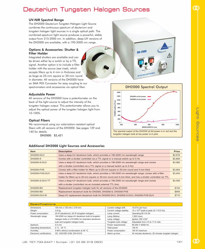
UV-NIR Spectral RangeThe DH2000 Deuterium Tungsten Halogen Light Sourcecombines the continuous spectrum of deuterium andtungsten halogen light sources in a single optical path. Thecombined-spectrum light source produces a powerful, stableoutput from 215-2000 nm. In addition, deep-UV versions ofthe DH2000 are available, with a 190-2000 nm range.
Options & Accessories: Shutter & Filter HolderIntegrated shutters are available and canbe driven either by a switch or by a TTLsignal. Another option is to include a filterholder with the source (see inset), whichaccepts filters up to 4 mm in thickness andas large as 25-mm square or 20-mm roundin diameter. All versions of the DH2000 havean SMA 905 Connector for easy coupling to ourspectrometers and accessories via optical fiber.
Adjustable PowerAll versions of the DH2000 have a potentiometer on theback of the light source to adjust the intensity of thetungsten halogen output. This potentiometer allows you toadjust the optical power of the tungsten halogen light from10-100%.
Optical FibersWe recommend using our solarization-resistant opticalfibers with all versions of the DH2000. See pages 139 and140 for details.
DH2000: $2,421
Dimensions: 150 mm x 135 mm x 319 mm
Weight: 3.8 kg
Power consumption: 25 W (deuterium); 20 W (tungsten halogen)
Wavelength range: 190-2000 nm (deep-UV deuterium bulb & tungsten
halogen bulb) or 215-2000 nm (standard deuterium
bulb and tungsten halogen bulb)
Aperture: 0.5 mm
Operating temperature: 5 °C - 35 °C
Humidity: 5-95% without condensation at 40 °C
Electronic certifications: CE; VDI/VDE 0160; EN 61010
Current voltage drift: <0.01% per hour
Current voltage stability: <5 x 10⁻⁶ peak-to-peak (0.1-10.0 Hz)
Lamp current: Operating 85 V/0.3A
Lamp lifetime: 1,000 hours
Lamp voltage: Ignition 350 V/20°
Tungsten bulb voltage: Adjustable from 4.5 to 11.5 volts
Power requirements: 85-264 V 50/60 Hz
Total power: 100 W
Power consumption: 190 W maximum
Warm-up time: 40 minutes deuterium; 20 minutes tungsten halogen
Item Description Price
DH2000-DUV Uses a deep-UV deuterium bulb, which provides a 190-2000 nm wavelength range $2,678
DH2000-S Comes with a shutter controlled via a TTL signal or a manual switch up to 5 Hz $2,808
DH2000-S-DUV Uses a deep-UV deuterium bulb, which provides a 190-2000 nm wavelength range and comes $3,066
with a shutter (controlled via a TTL signal or a manual switch up to 5 Hz)
DH2000-FHS Comes with a filter holder for filters up to 25-mm square or 20-mm round and 4-mm thick $3,064
DH2000-FHS-DUV Uses a deep-UV deuterium bulb, which provides a 190-2000 nm wavelength range; comes with a filter $3,454
holder for filters up to 25-mm square or 20-mm round and 4-mm thick; and has a shutter controlled via TTL
DH2000-S-DUV-TT Uses a deep-UV deuterium bulb, which provides a 190-2000 nm wavelength range and comes $3,456
with a shutter (controlled via an included external TTL line)
DH2000-BH Replacement tungsten halogen bulb for all versions of the DH2000 $142
DH2000-BD Replacement deuterium bulb for DH2000, DH2000-S, DH2000-FHS $594
DH2000-DUV-B Deep-UV replacement deuterium bulb for DH2000-DUV, DH2000-S-DUV, DH2000-FHS-DUV $710
DDeeuutteerriiuumm TTuunnggsstteenn HHaallooggeenn SSoouurrcceess
DH2000 Spectral Output
PO
WE
R (
µW
/cm
2/n
m)
200 400 600 800 1000
1600
1400
1200
1000
800
600
400
200
0
WAVELENGTH (nm)
The spectral output of the DH2000 at full power is in red and thetungsten halogen bulb at low power is in pink.
DH2000 at full power
DH2000 at low power
SSppeecciiffiiccaattiioonnss
Additional DH2000 Light Sources and Accessories
US: 727.733.2447 • Europe: +31 (0) 26 319 0500 121 oo
ooLLiigg
hhtt SS
oouurrcceess

MMiinnii DDeeuutteerriiuumm TTuunnggsstteenn HHaallooggeenn SSoouurrcceess
DT-MINI-2 DT-MINI-2-GS
Dimensions: 153.4 mm x 104.9 mm x 40.9 mm 140 mm x 50 mm x 125 mm
Weight: 330 g 475 g
Power consumption: 350 mA @ 12 VDC 350 mA @ 12 VDC
Spectral range: 200-410 nm (deuterium); 360-2000 nm (tungsten halogen) 200-410 nm (deuterium); 360-2000 nm (tungsten halogen)
Ignition delay: <2.0 seconds (delay for cold start-up may be longer) <2.0 seconds (delay for cold start-up may be longer)
Warm-up time: 10 minutes (deuterium); 1 minute (tungsten halogen) 10 minutes (deuterium); 1 minute (tungsten halogen)
Lamp power: 3.8 watts (deuterium); 1.2 watts (tungsten halogen) 3.8 watts (deuterium); 1.2 watts (tungsten halogen)
Bulb lifetime: ~800 hours (deuterium); 2,000 hours (tungsten halogen) ~800 hours (deuterium); 2,000 hours (tungsten halogen)
Stability: 0.3% peak-to-peak (over 4 hours) after 30-minute warm-up 0.3% peak-to-peak (over 4 hours) after 30-minute warm-up
Connector: SMA 905 SMA 905
SSppeecciiffiiccaattiioonnss
500
400
300
200
100
0
PO
WE
R (
µW
/cm
2/n
m)
200 300 400 500 600 700 800 900 1000
Spectral Output: DT-MINI-2 vs. DT-MINI
WAVELENGTH (nm)
For all your sensing needs, visit OceanOptics.com122
LLiigg
hhtt SS
oouurrcceess
oo
oo
DT-MINI-2 and DT-MINI-2-GS
DT-MINI
~200-1100 nm Spectral RangeOur DT-MINI-series Deuterium Tungsten HalogenLight Sources combine the continuous spectrum of ahigh-powered, RF-excited deuterium light source anda tungsten halogen light source in a single opticalpath. The combined-spectrum sources producestable spectral output from ~200-1100 nm in acompact package.
0.5 mm Aperture: More Powerful OutputThe original DT-MINI was our first foray into acompact and versatile UV-NIR light source, and isstill a great choice for a range of applications andmeasurements. The advantage of the newer DT-MINI-2 is that it uses a bulb with a 0.5 mm diameteraperture, which results in more focused, uniformbeam coupling to our optical fibers. Also, the DT-MINI-2 is only $100 more than the DT-MINI, whichwe will continue to offer.
Shutter VersionThe DT-MINI-2-GS Deuterium Tungsten HalogenLight Source (lower left), also utilizes the bulb withthe 0.5-mm diameter aperture. Its added feature is ashutter for blocking the light path, which can becontrolled via a manual switch or TTL. There is alsoa switch for turning the deuterium source on and off,and one for turning the tungsten halogen source onand off; each switch can be used independently ofthe other.
Rack-mount VersionRack-mount versions of DT-MINI-series lamps areavailable. These sources can be hard-wired to aspectrometer channel and racked into a Dual Box,Rack Box or Desktop Box with other accessories. Formore on rack-mount systems and enclosures, seepage 62.
DT-MINI-2: $1,499DT-MINI-2-GS: $1,611DT-MINI: $1,399DT-MINI-2-B Bulb*: $457DT-MINI-B Bulb*: $427
* The DT-MINI-2-B Bulb can only be used in the DT-MINI-2 and DT-MINI-2-GS sources. Likewise, the DT-MINI-B Bulb can onlybe used in the DT-MINI and DT-MINI-GS.

US: 727.733.2447 • Europe: +31 (0) 26 319 0500 123 oo
ooLLiigg
hhtt SS
oouurrcceess
UUSSBB--DDTT DDeeuutteerriiuumm TTuunnggsstteenn HHaallooggeenn SSoouurrccee
160
120
80
40
0
PO
WE
R (
µW
/cm
2/n
m)
WAVELENGTH (nm)
200 300 400 500 600 700 800 900
USB-DT Spectral Output
The USB-DT can beset up in a variety ofways. It can bestacked atop aUSB2000 with theUSB-ADP-DT2connector (above),or used as a stand-alone componentwith an OceanOptics spectrometer.
The USB-DT has a15-pin connectorfor interfacing tothe spectrometer.
Dimensions: 81 mm x 90 mm x 37 mm
Weight: 260 g
Power consumption: 1.5 A @ 5 VDC
Spectral range: 200-2000 nm
Time to stabilized output: 15 minutes
Bulb life: 800 hours for deuterium;
2,000 hours for tungsten
Connector: SMA 905
Power output: see Spectral Output graph at left
Stability: 0.5% peak-to-peak (after warm-up)
SSppeecciiffiiccaattiioonnss
USB-ADP-DT2Connector.
Spectrometer Directly Software Control
With USB-DT Stackable of all USB-DT Functions
USB2000 Yes, with Yes, when stacked atop the USB2000
USB-ADP-DT2 with a USB-ADP-DT2
HR2000 No No
HR2000+ No Yes, when used with HR4-BREAKOUT
HR4000 No Yes, when used with HR4-BREAKOUT
QE65000 No Yes, when used with HR4-BREAKOUT
Most Versatile Lamp We OfferThe USB-DT Deuterium Tungsten Light Source is our mostversatile combination UV-VIS light source. There are several waysto use the USB-DT: as a stand-alone source, stacked atop theUSB2000 via the USB-ADP-DT2 adapter, or connected to aspectrometer via a Breakout Box. Though the USB-DT can bestacked on top of the USB2000, it is not the kind of direct-attachsource that eliminates fibers; the USB-DT requires fibers. Thiscompact source is about the size of a deck of cards, providesstable, broadband output from 200-2000 nm, and requires asimple 5-volt wall transformer for power.
Software ControlWhen the USB-DT is stacked with the USB2000 or used with anHR4000, HR2000+ or QE65000 and the Breakout Box (seepage 47), you can control the following lamp functions throughsoftware:� adjusting the intensity of the tungsten source� activating the internal shutter to block the light path� controlling on/off switch of each source independently� utilizing a low-power shutdown mode� saving settings in memory
Novel Deuterium Tungsten Halogen SourcesOur deuterium tungsten halogen sources combine thecontinuous spectrum of deuterium and tungsten halogen lampsin a single optical path. These combined-spectrum sourcesproduce stable, continuous UV-VIS output that make them idealfor applications such as absorbance spectroscopy.
USB-DT: $1,499USB-DT-B Bulb: $205USB-ADP-DT2: $75HR4-BREAKOUT: $199

For all your sensing needs, visit OceanOptics.com124
LLiigg
hhtt SS
oouurrcceess
oo
oo DD22000000 DDeeuutteerriiuumm LLiigghhtt SSoouurrcceess
Dimensions: 150 mm x 135 mm x 319 mm
Weight: 3.8 kg
Power consumption: 830 mA @ 230 VDC or 1660 mA @ 115 VDC
Wavelength range: 215-400 nm (standard bulb); 190-400 nm (deep-UV bulb)
Peak-to-peak stability: <0.005% at 250 nm
Drift: ±0.5% per hour at 250 nm
Warm-up time: 40 minutes
Voltage and current: Ignition 350V/20°; operating 85 V/0.3A
Bulb lifetime: 1,000 hours for standard or deep-UV bulb
Operating temperature: 5 °C - 35 °C
Humidity: 5-95% without condensation at 40 °C
Radiation characteristic: Aperture 0.5 mm, numerical aperture 26° (13°)
Power requirements: 85-264 V 50/60 Hz
Electronic certifications: CE; VDI/VDE 0160; EN 61010
TTL-shutter input: Up to 5 Hz maximum (shutter versions only)
Shutter speed: 10 msec minimum
Additional D2000 Light Sources and Accessories
UV Range + Great PerformanceThe D2000 Deuterium Light Source producesa powerful, stable output from 215-400 nm.A deep-UV version is available for wavelengthcoverage of 190-400 nm. The D2000 is anextremely stable source, with peak-to-peakstability of <0.005% and drift of only ± 0.5% per hour.
Options & AccessoriesAll versions of the D2000 have an SMA 905Connector for easy coupling to ourspectrometers and fiber optic accessories, aswell as safety goggles and a cover forblocking the light when the fiber is notattached. The 1,000-hour deuterium bulbused in the D2000 can be replaced easily.
Shutter OptionThe D2000 is available with an optionalintegrated shutter. You can operate the shuttervia a manual switch on the front of the lamp.In addition, you can control the shutterelectronically via software or a TTL signal froman output port on the back of the lamp.
Optical FibersWe recommend using our solarization-resistant optical fibers with all versions of theD2000. See pages 139-140 for details.
D2000: $2,003
SSppeecciiffiiccaattiioonnss
Item Description Price
D2000-DUV Uses a deep-UV deuterium bulb, which provides a 190-400 nm wavelength range $2,282
D2000-S Comes with a shutter (controlled via a TTL signal or switch) $2,378
D2000-S-DUV Uses a deep-UV deuterium bulb, which provides a 190-400 nm wavelength range, and $2,647
comes with a shutter (controlled via a TTL signal or switch)
DH2000-BD Replacement deuterium bulb for the D2000 and the D2000-S $594
DH2000-DUV-B Replacement deuterium bulb for the D2000-DUV and the D2000-S-DUV $710
D2000 Spectral OutputP
OW
ER
(µ
W/c
m2/n
m)
300
200
100
0
200 300 400 500
WAVELENGTH (nm)

XXeennoonn SSoouurrcceess
HPX-2000 PX-2
Dimensions: 145 mm x 165 mm x 260 mm 153.4 mm x 104.9 mm x 40.9 mm
Weight: 4.3 kg 370 g
Power consumption: 60 W AC 1 A @ 12 VDC
Spectral range: 185-2000 nm 220-750 nm
Power output: 35 watts 45 microjoules per pulse maximum; 9.9 watts average power;
220 Hz pulse rate maximum
Trigger input: External TTL positive pulse via 15-pin connector (shutter) External TTL positive pulse via 15-pin connector
Pulse duration: Not applicable 5 microseconds (at 1/3 height of pulse)
Lifetime: 1,000 hours minimum; 2,000 hours typical 109 pulses (estimated 230 days continuous operation at
50 Hz pulse rate)
Connector: SMA 905 SMA 905
Timing signals: Not applicable Multiple mode available from S2000 -- up to 220 Hz;
single mode available from S2000 -- varies with scan rate
SSppeecciiffiiccaattiioonnss
PX-2 Spectral Output
200 300 400 500 600 700 800
WAVELENGTH (nm)
PO
WE
R (
µW
/cm
2/n
m)
HPX-2000 Spectral Output
RE
LA
TIV
E I
NT
EN
SIT
YU
NIT
S
300 400 500 600 700 800 900 1000
1.0
0.8
0.6
0.4
0.2
0
WAVELENGTH (nm)
150
100
50
0
Pulsed & Continuous Xenon Light Source
High-powered Continuous-wave Xenon Source
The PX-2 Pulsed Xenon Lamp is a high flash rate, short-arc xenon lamp from220-750 nm. The PX-2 is a great source for applications requiring absorbance,reflectance or fluorescence measurements, and is especially useful formeasuring optically or thermally labile samples. The PX-2 is a low-power lampwith excellent pulse-to-pulse stability. It provides two trigger modes for softwarecontrol of the flash rate. It comes with a regulated power supply and aninterface cable to connect to the spectrometer.
PX-2: $769PX-2-B Bulb: $379USB-ADP-PX2: $50
US: 727.733.2447 • Europe: +31 (0) 26 319 0500 125 oo
ooLLiigg
hhtt SS
oouurrcceess
The HPX-2000 Xenon Light Source (185-2000 nm) is especially useful forfluorescence applications, and for other applications where a high-intensitylamp is necessary. The HPX-2000 has an integrated shutter, which can be driveneither by a switch or by a TTL signal. It also comes equipped with a slot forfilters up to 25-mm diameter or square, and up to 14-mm thick. (If operatingthe HPX-2000 for ultraviolet applications, use the solarization-resistant fiberdescribed on pages 139-140.)
The bulb is housed in an easy-to-remove bulb module. If your bulb needs to bereplaced, you have two options. You can send the module back to us to replacethe bulb (HPX-2000-B), or you can order another bulb module (HPX-2000-BM).
HPX-2000: $5,517HPX-2000-B: $1,064HPX-2000-BM: $2,473

LLSS--11 TTuunnggsstteenn HHaallooggeenn LLiigghhtt SSoouurrcceess
360-2000 nm Spectral RangeThe LS-1 Tungsten Halogen Light Source is a versatilewhite-light source useful for absorbance, reflectance andcolor measurements for the VIS-NIR (360-2000 nm).The lamp offers high color temperature and an efficientoutput.
Rack-mountableInstall sources with spectrometers and other devices intoa Rack Box or Desktop Box. For details, see page 62.
Long LifeThe LS-1 comes with a 900-hour bulb. Also available isthe LS-1-LL, which comes with a 10,000-hour bulb forextra-long life bulb performance. LS-1 Light Sourcescome with a 12 VDC power supply (WT-12V).
Color-correcting & Signal-attenuatingAccessoriesThe LS-1 is one of the most popular miniaturespectroscopy light sources ever. That experience hasprovided us with lots of customer feedback, includingthe idea to add components to allow users to modify thelight output -- something we now include in the price ofthe light source:� a 12.7-mm diameter color-correcting filter that can
be installed into the light source to enhance thesignal in the blue and NIR regions
� three PTFE discs of various thickness to create a diffuse source -- by attenuating the light 50%, 75%or 99% -- when spectrometer saturation is an issue
Maximum FlexibilityThe LS-1 has an SMA 905 Connector for easy couplingto our spectrometers and accessories, including opticalfibers, cuvette holders and probes. A built-in slot acceptsoptical filters up to 3 mm in thickness.
LS-1: $499LS-1-LL: $549
Additional LS-1-series Light Sources and AccessoriesItem
R-LS-1
R-LS-1-LL
LS-1-B
LS-1-LL-B
OF2-LS
Bulb life: 900 hours (LS-1); 10,000 hours (LS-1-LL)
Output to bulb: 5 volts/1.3 amps
Output regulation: 0.2% voltage
Internal filter accessory: BG 34 balancing filter
External filter slot: Accepts filters up to 3-mm thickness
Spectral attenuation: 50%, 75% and 99% with PTFE disc accessories
Connector: SMA 905
Dimensions: 113.5 mm x 50.8 mm x 31.6 mm
Weight: 140 g
Power consumption: 600 mA @ 12 VDC
Spectral range: 360-2000 nm
Time to stabilized output: ~30 minutes
Bulb color temperature: 3100 K (900-hour bulb); 2800 K (10,000-hour bulb)
Power output: 6.5 watts (without a fiber)
Price
$499
$549
$45
$55
$100
SSppeecciiffiiccaattiioonnss
2500
2000
1500
1000
500
0
PO
WE
R (
µW
/cm
2/n
m)
WAVELENGTH (nm)
340 440 540 640 740 840 940
LS-1 (900-hour bulb)
LS-1-LL (10,000-hour bulb)
LS-1 and LS-1-LL Spectral Output
Description
Rack-mounted LS-1 with color-correcting filter and diffusers
Rack-mounted LS-1-LL with color-correcting filter and diffusers
900-hour replacement bulb for LS-1
10,000-hour replacement bulb for LS-1-LL
Additional filter set for use with LS-1 source includes: BG 34, GG 395 and OG 550 filters, as well as PTFE
diffusing discs
For all your sensing needs, visit OceanOptics.com126
LLiigg
hhtt SS
oouurrcceess
oo
oo

HHLL--22000000 TTuunnggsstteenn HHaallooggeenn LLiigghhtt SSoouurrcceess
Great VersatilityThe HL-2000 Tungsten Halogen Light Sources areversatile sources optimized from 360-2000 nm. Thelamps feature adjustable focusing of the SMA 905Connector to maximize light coupling into a fiber. A fankeeps the light sources cool and stable.
Long-lifetime OptionThe HL-2000 comes with a 1,500-hour bulb. A 10,000-hour long-life version is also available.
Filter SlotA built-in filter slot on all standard HL-2000s acceptsoptical filters up to 25.4-mm round or up to 50.8-mmsquare and 3 mm thick. The HL-2000-LVF-HP alsoaccepts our LVF Linear Variable Filters (see page 94.)
High-power VersionFor applications requiring large-diameter optical fibersor fiber and probe bundles, a special high-powerversion of the HL-2000 is available. The bulb used inthe HL-2000-HP is a 20-watt bulb. We recommend1000 µm diameter optical fiber for use with the high-power versions of the HL-2000.
Attenuator & Shutter OptionThe HL-2000-FHSA version of the HL-2000 includes ashutter and an attenuator that allows you to control theintensity of the light source from 0-100%. A lockingscrew allows you to manually fix the intensity position forthe long term. In addition, you can opt to control theattenuator and the TTL shutter via RS-232 with the HL-2000-HP-232.
HL-2000: $583
HL-2000 HL-2000-LL HL-2000-HP HL-2000-HP-232
Dimensions: 62 mm x 60 mm x 150 mm 62 mm x 60 mm x 150 mm 62 mm x 60 mm x 150 mm 70 mm x 100 mm x 160 mm
Weight: 500 g 500 g 500 g 600 g
Output: 7 watts 7 watts 20 watts 20 watts
Output to bulb: 1.4 A @ 5 VDC 0.970 A @ 5 VDC 1.6 A @ 24 VDC 1.6 A @ 24 VDC
Wavelength range: 360-2000 nm 360-2000 nm 360-2000 nm 360-2000 nm
Stability: 0.5% 0.5% 0.5% 0.5%
Drift: <0.3% per hour <0.3% per hour <0.3% per hour <0.3% per hour
Time to stabilize: ~5 minutes ~5 minutes ~5 minutes ~5 minutes
Bulb lifetime: 1,500 hours 10,000 hours 2,000 hours 2,000 hours
Bulb color temperature: 2,960 K 2,800 K 3,000 K 3,000 K
Temperature: 5 °C - 35 °C 5 °C - 35 °C 5 °C - 35 °C 5 °C - 35 °C
Humidity: 5-95% at 40 °C 5-95% at 40 °C 5-95% at 40 °C 5-95% at 40 °C
SSppeecciiffiiccaattiioonnss
US: 727.733.2447 • Europe: +31 (0) 26 319 0500 127 oo
ooLLiigg
hhtt SS
oouurrcceess
HL-2000 Spectral Output
PO
WE
R (
µW
/cm
2/n
m)
300 400 500 600 700 800 900 1000
14000
12000
10000
8000
6000
4000
2000
0
WAVELENGTH (nm)
Additional HL-2000 Light Sources & BulbsItem
HL-2000-LL
HL-2000-FHSA
HL-2000-FHSA-LL
HL-2000-HP
HL-2000-HP-FHSA
HL-2000-HP-232
HL-2000-LVF-HP
HL-2000-B
HL-2000-B-LL
HL-2000-HP-B
Description
Long-life version (10,000-hour)
Includes filter holder, attenuator and
shutter
Includes filter holder, attenuator,
shutter and long-life 10,000-hour bulb
High-powered, 20 W version
High-powered, 20 W version with
filter holder, attenuator and shutter
High-powered, 20 W version with
RS-232 control in rack mount housing;
comes with script for software control
High-powered, 20 W version with filter
slot for Linear Variable Filters; comes
with shutter and attenuator
Standard 1,500-hour spare bulb
Long-life 10,000-hour spare bulb
High-power 2,000-hour spare bulb
Price
$632
$1,232
$1,276
$1,000
$1,519
$2,156
$1,590
$72
$84
$121

Item
LED-380
LED-395
LED-470
LED-518
LED-590
LED-640
LED-WHITE
LED-KIT
Description
380 nm wavelength UV LED
395 nm wavelength VIS LED
470 nm wavelength VIS LED
518 nm wavelength VIS LED
590 nm wavelength VIS LED
640 nm wavelength VIS LED
450-630 nm wavelength VIS LED
Set of 6 LEDs: LED-380, LED-395, LED-518,
LED-590, LED-640, LED-WHITE
Color
UV
Light Blue
Blue
Green
Yellow
Red
White
Mixed
Power*
45 µW
25 µW
35 µW
35 µW
40 µW
50 µW
50 µW
Mixed
Price of
LED Alone
$100
$100
$100
$100
$100
$100
$100
$499
Price of LED
with Housing
$499
$499
$499
$499
$499
$499
$499
$998
LLEEDD LLiigghhtt SSoouurrcceess
* Power into a 600 µm Patch Cord Optical Fiber Assembly
300
200
100
0
PO
WE
R (
µW
/cm
2/n
m)
WAVELENGTH (nm)
80
60
40
20
0
PO
WE
R (
µW
/cm
2/n
m)
WAVELENGTH (nm)
350 400 450 500 550 600 650
395
White
590
380
470
518
640
Spectral Output for LED Bulbs:395 nm, White, 590 nm
Spectral Output for LED Bulbs:380 nm, 470 nm, 518 nm and 640 nm
350 400 450 500 550 600 650
Choose your LED in a stand-alone housing (above) or
rack-mounted with aspectrometer andother accessories(left). We also sellthe LEDs listed
below individually ina 12.7-mm barrel
(right) for easyinstallation and alignment.
You can order one of the LEDs listed below, either alone or installed in a housing/rack mount.We offer seven LEDs that can be used in the same housing. All LEDs can be used in pulsed orcontinuous mode through manual or software operation.
Additional LED Light Sources
Excellent Excitation Sources for FluorescenceOur LED Light Sources produce either pulsed or continuousoutput for high-sensitivity fluorescence measurements. Theywere designed for use with our fluorescence spectrometers(pages 32-33), sensors and other accessories.
Software Operation & Synching with DetectorThe LED Sources can be turned on/off through manual orsoftware operation. Or, configure lamp pulse rates via jumperblocks on the lamp or on the circuit board of the S2000Spectrometer.
Stand-alone and Rack-mount VersionsEach LED Source connects to a spectrometer via an interfacecable. First, decide if you want an LED in its own stand-alonehousing (see top left) or if you want the LED racked with aspectrometer (see inset). Then, choose the LED distinguishedby wavelength to install in the housing. For those with limitedspace, we can install two LEDs on one rack-mount card. Youcan also purchase just the LED; they come in easy-to-installbarrels.
LED with Housing: $499LED Rack-mounted: $499LED Bulb alone: $100
For all your sensing needs, visit OceanOptics.com128
LLiigg
hhtt SS
oouurrcceess
oo
oo

Direct-attach Lamp for USB2000 SpectrometerThe USB-LS-450 Pulsed Blue LED Light Source is designed as a direct-attach excitation source for the USB2000 Spectrometer. The USB-LS-450is an LED that produces either pulsed or continuous output centered at470 nm -- the blue region -- for fluorescence measurements. Itconnects to the spectrometer via a 10-pin connector. The USB2000provides power to the LED and also enables synchronization functions.
Benefit for O2 Sensor UsersThe USB-LS-450 features a built-in, 24-bit analog-to-digital converter that isconfigured for a 100 ohm platinumtemperature probe (USB-LS-450-TP). TheUSB-LS-450’s onboard memory can beprogrammed to store temperature andoxygen calibration coefficients.
Other LED OptionsYou can purchase the USB-LS-450, which comes withthe 470 nm LED, or you can purchase the USB-LS-LED,which includes everything but the LED. You can thenspecify one of the other LEDs we offer on page 128.
USB-LS-450: $549USB-LS-LED: $549USB-LS-450-TP: $99
Wavelength range: 460-490 nm
Power consumption: 60 mA @ 5 VDC
Power output: 60 µW (minimum) into a
600 µm optical fiber
PPuullsseedd BBlluuee LLEEDD LLiigghhtt SSoouurrccee
Dimensions: 89 mm x 57 mm x 34.5 mm
Weight: 120 g
Stability: ±1.0% drift after 2-minute
warm-up period
SSppeecciiffiiccaattiioonnss
Dimensions: 62 mm x 60 mm x 150 mm
Wavelength range: 460-490 nm
Power consumption: 25 mA @ 12 VDC
LED output: 50 µW with a 600 µm optical fiber
Stability: ± 1.0% drift after 2-minute warm-up
Connector: SMA 905
PO
WE
R (
µW
/cm
2/n
m)
LS-475 nm Spectral Output
350 400 450 500 550
300
200
100
0
SSppeecciiffiiccaattiioonnss
Lamp Available forAll SpectrometersThe LS-475 Blue LEDLight Source producespulsed or continuousspectral outputcentered at 475 nm.The LS-475 isdesigned as anexcitation source forfluorescence measurements. TheLS-475 often is paired with one of ourpreconfigured fluorescence spectrometers (page 33).
High-stability & Fan-cooled The LS-475 has a very stable output and keeps cool with a built-in fan. Thelamp provides better than ± 1.0% drift after a 2-minute warm-up time. It hasan SMA 905 Connector for coupling to optical fiber assemblies and a filterslot that accepts 25.4-mm round or 50.8-mm square filters up to 3-mmthick. An 800 mA, 12 VDC power supply comes with the unit.
LS-475: $711
DDiirreecctt--aattttaacchh LLEEDD LLiigghhtt SSoouurrccee
WAVELENGTH (nm)
PO
WE
R (
µW
/cm
2/n
m)
350 400 450 500 550
300
200
100
0
WAVELENGTH (nm)
USB-LS-450 Spectral Output
US: 727.733.2447 • Europe: +31 (0) 26 319 0500 129 oo
ooLLiigg
hhtt SS
oouurrcceess

RRaaddiioommeettrriicc CCaalliibbrraattiioonn SSttaannddaarrddss:: UUVV--NNIIRR
DH2000-CAL Spectral Output
PO
WE
R (
µW
/cm
2/n
m)
200 300 400 500 600 700 800 900 1000
0.6
0.5
0.4
0.3
0.3
0.1
0
WAVELENGTH (nm)
Dimensions: 150 mm x 135 mm x 319 mm
Weight: 3.8 kg
Power consumption: 25 W (deuterium); 20 W (tungsten halogen)
Calibrated range: 210-1050 nm
Calibration accuracy: ±5%
Calibration valid for: 50 hours
Lamp current: Operating 85 V/0.3A
Lamp voltage: 350 V
Power requirements: 85-264 V 50/60 Hz
Current voltage drift: <0.01% per hour
Current voltage stability: <5 x 10⁻⁶ peak-to-peak (0.1-10.0 Hz)
Operating temperature: 5 °C - 35 °C
Humidity: 5-95% without condensation at 40 °C
Total power: 100 watts
Max. power consumption: 190 watts
Warm-up time: 40 minutes (deuterium)
20 minutes (tungsten halogen)
Electronic certifications: CE; VDI/VDE 0160; EN 61010
SSppeecciiffiiccaattiioonnss
These spectral output graphs were taken separately for the deuterium(200-400 nm) and the tungsten halogen bulbs (400-1100 nm).
Deuterium
Tungsten Halogen
Calibrated from 210-1050 nmThe DH2000-CAL Deuterium Tungsten HalogenCalibration Standard is a UV-NIR light source used tocalibrate the absolute spectral response of aradiometric system. With the DH2000-CAL and ourOOIIrrad-C Irradiance Software, you can determineknown absolute intensity values at wavelengths from210-1050 nm.
Calibrated for Bare Fiber & Cosine CorrectorThe DH2000-CAL is calibrated for use with opticalfibers or a cosine corrector; the calibration dataincludes absolute intensities for wavelengths between210-1050 nm at the fiber entrance port for both a barefiber and an included CC-3-UV Cosine Corrector (page 107).
NIST-traceable Calibration CertificateThe DH2000-CAL is calibrated with a NIST-traceablestandard. The DH2000-CAL comes with a calibrationcertificate and a diskette with a data file compatiblewith our software. The calibration data -- absolutespectral intensity values in µW/cm2/nm measured atthe fiber port -- is provided for use with our IrradianceSoftware (not included, see page 81).
Recalibration of Your DH2000-CALThe DH2000-CAL typically provides 50 hours ofoperation before recalibration is necessary. Werecalibrate these lamps in-house. (For more informationon the DH2000-RECAL service, contact an ApplicationsScientist.)
DH2000-CAL: $3,148DH2000-RECAL: $399
In-house Calibration ServiceAlso, you don’t need a DH2000-CAL to take advantageof our in-house SPEC-CAL-UV radiometric calibrationservice for UV spectrometers. The calibration is goodfor about one year, provided the optical fiber is notremoved from the setup, as the system is calibrated foruse with a specific fiber.
SPEC-CAL-UV: $499
Radiometric Calibration Sources are not illumination sources forspectroscopic measurements. Use the DH2000-BAL (page 120) forillumination.
For all your sensing needs, visit OceanOptics.com130
LLiigg
hhtt SS
oouurrcceess
oo
oo
The DH2000-CAL iscalibrated for use with either a CC-3Cosine Corrector or with an optical fiber.The lamp comes with a CC-3.

The LS-1-CAL-INT is calibratedspecifically for use with the FOIS-1 Integrating Sphere.Notice the PTFE diffuser plugthat’s seated where an SMA 905Connector is usually installed.
This plug fits snugly into the sampleport of the FOIS-1.
RRaaddiioommeettrriicc CCaalliibbrraattiioonn SSttaannddaarrddss:: VVIISS--NNIIRR
SSppeecciiffiiccaattiioonnss
Power consumption: 600 mA @ 12 VDC
Spectral range: 300-1050 nm (calibrated)
Power output: 6.5 watts
Recalibration: Required after 50 hours of operation
Bulb color temperature: 3100 K
Output regulation: 0.2% voltage
Time to stabilized output: ~30 minutes
Connector: SMA 905 for fiber;
6.35-mm barrel for cosine corrector;
PTFE plug for integrating sphere
Above is the typical calibration output when using the LS-1-CAL or HL-2000-CAL with a CC-3 Cosine Corrector.
LS-1-CAL Spectral Output
PO
WE
R (
µW
/cm
2/n
m)
300 400 500 600 700 800 900 1000
90
80
70
60
50
40
30
20
10
0
WAVELENGTH (nm)
The LS-1-CAL iscalibrated for use with a fiber
and/or a CC-3 Cosine Corrector(not included).
Calibrated with Fiber & Cosine CorrectorThe LS-1-CAL is designed for calibrating the absolutespectral response of a complete system consisting of aspectrometer and an optical fiber and/or a CC-3-UVCosine Corrector (page 107). The HL-2000-CAL isdesigned for calibrating a system consisting of aspectrometer and a cosine corrector. The calibrationdata for both the LS-1-CAL and the HL-2000-CALincludes absolute intensities for wavelengths between300-1050 nm.
Calibrated for Use with Integrating SphereThe LS-1-CAL-INT is designed for calibrating theabsolute spectral response of a system that uses theFOIS-1 Fiber Optic Integrating Sphere (page 108) asthe sampling optic. The LS-1-CAL-INT comes with adiffuser plug that fits into the sample port of the FOIS-1to measure absolute spectral intensities of LEDs andother emission sources. The HL-2000-CAL-ISP isdesigned for calibrating the absolute spectral responseof your system when using the ISP-50-8-I IntegratingSphere (page 108) as your sampling optic.
What’s IncludedEach of these radiometric sources comes with aregulated 12 VDC power supply. Also included is acalibration certificate and a diskette with data files foruse with our Irradiance Software. Neither the LS-1-CALnor the HL-2000-CAL lamps comes with a CC-3 CosineCorrector.
Recalibrating Your SourceThese calibrated sources provide 50 hours of operationbefore an in-house recalibration (called the LS-1-RECALand the HL-2000-RECAL) is necessary.
LS-1-CAL: $749LS-1-CAL-INT: $749LS-1-RECAL: $199HL-2000-CAL: $815HL-2000-CAL-ISP: $825HL-2000-RECAL: $199
In-house CalibrationIf you do not want to purchase one of these calibrationsources, we offer the SPEC-CAL in-house radiometriccalibration service for 300-1050 nm.
SPEC-CAL: $499
The HL-2000-CAL is used for calibrating most radiometric systems,while the HL-2000-CAL-ISP is used withISP Integrating Spheres.
US: 727.733.2447 • Europe: +31 (0) 26 319 0500 131 oo
ooLLiigg
hhtt SS
oouurrcceess

WWaavveelleennggtthh CCaalliibbrraattiioonn SSttaannddaarrdd ffoorr UUVV--VVIISS
Wavelength Calibration SourcesThe HG-1 and CAL-2000 Mercury ArgonCalibration Sources are spectral wavelengthcalibration sources for spectrometer systems. TheHG-1 and the CAL-2000 produce low-pressuremercury and argon atomic emission lines from253-1700 nm for use in performing fast,reliable spectrometer wavelength calibrations. Alist of mercury and argon spectral emission linesis printed on each lamp's housing.
Drift Occurs in all SpectrometersOur spectrometers are carefully calibrated aspart of our standard quality assurance process.However, as is the case with all optical benches,slight drifts in wavelength occur due to time andenvironmental conditions. If wavelengthaccuracy is an important part of yourapplication, consider including calibrationspectra with every experiment.
Convenient OperationWavelength calibration with the HG-1 or theCAL-2000 requires a power supply (included)and an optical fiber to connect from the sourceto your spectrometer. You will need aspreadsheet program such as Microsoft Excel ora calculator that performs third-orderpolynomial regressions.
Convenient PortabilityBoth calibration sources operate with a 12 VDC power supply (included) or a 9V battery(not included) for field use. Both sources featurean SMA 905 Connector for interfacing to opticalfiber assemblies and have bulbs with a 3,500-hour lifetime. You can replace the bulb in theCAL-2000, but not in the HG-1.
HG-1: $399CAL-2000: $437CAL-2000-B Bulb: $175
For only $250 per spectrometer channel, you can purchasethe ASP Annual Service Package, which entitles you to ayearly spectrometer inspection, wavelength calibration,optical alignment, linearity calibration, signal-to-noiseanalysis and much more. See page 193 for more.
Mercury emission lines are <600 nm. Argon emission lines are >600 nm, andare shown on an exaggerated amplitude scale.
HG-1 CAL-2000
Dimensions: 125.7 mm x 70 mm x 25.8 mm 130 mm x 125 mm x 50 mm
Weight: 40 g 410 g
Power consumption: 250 mA @ 12 VDC 250 mA @ 12 VDC
Spectral range: 253-1700 nm 253-1700 nm
Power requirements: 12 VDC wall transformer (included) or 9 VDC battery (not included) 12 VDC wall transformer (included) or 9 VDC battery (not included)
Internal voltage: 600 volts at 30 kHz 600 volts at 30 kHz
Bulb lifetime: ~3,500 hours (at 20 mA) ~3,500 hours (at 20 mA)
Stabilization: 1 minute 1 minute
Connector: SMA 905 SMA 905
SSppeecciiffiiccaattiioonnss
200 300 400 500 600 700 800 900 1000
4000
3000
2000
1000
0
AR
BIT
RA
RY
INT
EN
SIT
Y
WAVELENGTH (nm)
HG-1 & CAL-2000 Spectral Output
The HG-1.
The CAL-2000.
For all your sensing needs, visit OceanOptics.com132
LLiigg
hhtt SS
oouurrcceess
oo
oo

WWaavveelleennggtthh CCaalliibbrraattiioonn SSttaannddaarrdd ffoorr NNIIRR
Dimensions: 125.7 mm x 70 mm x 25.8 mm
Weight: 40 g
Power consumption: 250 mA @ 12 VDC
Spectral range: 696-1704 nm
Power requirements: 12 VDC wall transformer
(included) or 9 VDC battery (not included)
Internal voltage: 600 volts at 30 kHz
Bulb lifetime: ~3,500 hours (at 20 mA)
Amplitude stabilization: ~1 minute
Connector: SMA 905
SSppeecciiffiiccaattiioonnss
1000 1100 1200 1300 1400 1500 1600 1700
4000
3500
3000
2500
2000
1500
1000
500
0
AR
BIT
RA
RY
INT
EN
SIT
Y
WAVELENGTH (nm)
AR-1 Spectral Output
CCuuvveettttee WWaavveelleennggtthh CCaalliibbrraattiioonn AAddaapptteerr
Calibration Source for NIR SpectrometersThe AR-1 Argon Calibration Source is a spectralwavelength calibration source specifically designed forNIR spectrometers like our NIR256 and NIR-512 (seepages 58-59). The AR-1 produces low-pressure argonatomic emission lines from 696-1704 nm for use inperforming fast, reliable spectrometer wavelengthcalibrations. The spectral emission lines are printed onthe lamp's housing.
Convenient OperationOur spectrometers are carefully calibrated as part ofour standard quality assurance process. However, as isthe case with all optical benches, slight drifts inwavelength occur due to time and environmentalconditions. With the AR-1, you can recalibrate yourspectrometer using a spreadsheet program such asMicrosoft Excel or a calculator that performs third-orderpolynomial regressions.
Conveniently PortableThe AR-1 operates with a 12 VDC power supply(included) or a 9V battery (not included) for field use.The AR-1 features an SMA 905 Connector forinterfacing to optical fiber assemblies.
AR-1: $399
US: 727.733.2447 • Europe: +31 (0) 26 319 0500 133 oo
ooLLiigg
hhtt SS
oouurrcceess
The PS-HG1-ADP Wavelength CalibrationAdapter is a 1-cm square fixture that fits intoa 1-cm pathlength sample chamber andthen connects to the HG-1 Mercury ArgonCalibration Standard or the AR-1 ArgonWavelength Calibration Standard via opticalfiber. (Neither Wavelength CalibrationStandard nor optical fiber is included.) Theadapter is designed for performing awavelength calibration for a USB2000Spectrometer and a direct-attach samplingsystem. However, the adapter can be usedwith any post-dispersive spectrometer and 1-cm cuvette holder, whether it’s designedby Ocean Optics or another manufacturer.
PS-HG1-ADP: $259

Price
$25
$29
$10
Item
CBL-PX-2
FCBARREL
FOT-SMA
WRENCH
Price
$25
$100
$20
$100
$50
Item
WT-12V
WT-12V-R
WT-12V-E
WT-12V-R-E
WT-24V
Description
12-volt power supply, 110/220
12-volt power supply, 110/220
12-volt power supply, 110/220
12-volt power supply, 110/220
24-volt power supply, 110/220
Plug Style
US
US
European
European
US
Current
800 milliamps
2.5 Amps
800 milliamps
2.5 Amps
2.5 Amps
Regulated
Yes
Yes
Yes
Yes
Yes
LLiigg
hhtt SS
oouurrcceess
oo
oo BBuullbbss,, PPoowweerr SSuupppplliieess && AAcccceessssoorriieess
Other Light Source Accessories
Bulbs for Ocean Optics Light Sources
Spare Power Supplies
Description
Cable for connecting PX-2 to S2000 Spectrometer
6.35-mm outer diameter stainless steel barrel threaded for FC connectors
that inserts into our 74-series Collimating Lenses
SMA wrench for easily attaching Laboratory-grade optical fibers to SMA
905 Connectors on Ocean Optics products
Item Description Price
DH2000-BD Spare or replacement deuterium bulb for D2000, DH2000 and $594
DH2000-BAL sources
DH2000-DUV-B Spare or replacement deep-UV deuterium bulb for D2000-DUV and $710
DH2000-DUV sources
DH2000-BH Spare or replacement tungsten halogen bulb for DH2000 and $142
DH2000-BAL sources
DT-MINI-B Spare bulb for DT-MINI and DT-MINI-GS (white or blue bulb housing) $427
DT-MINI-2-B Spare bulb for DT-MINI-2 and DT-MINI-2-GS (yellow bulb housing) $457
HL-2000-B Spare or replacement tungsten halogen bulb for the HL-2000 $72
(1,500-hour, 2,960 K)
HL-2000-B-LL Spare or replacement long-life tungsten halogen bulb for the HL-2000-LL $84
(10,000-hour, 2,800 K)
HL-2000-HP-B Spare or replacement tungsten halogen bulb for all HL-2000-HPs $121
HPX-2000-BM Spare or replacement xenon bulb module for the HPX-2000 $2,473
HPX-2000-B Spare or replacement xenon bulb for the HPX-2000 $1,064
LED-380 Interchangeable, 380-nm LED for LS-450 $100
LED-395 Interchangeable, 395-nm LED for LS-450 $100
LED-518 Interchangeable, 518-nm LED for LS-450 $100
LED-590 Interchangeable, 590-nm LED for LS-450 $100
LED-640 Interchangeable, 640-nm LED for LS-450 $100
LED-WHITE Interchangeable, white LED for LS-450 $100
LED-KIT LED kit with 380-nm, 395-nm, 518-nm, 590-nm, 640-nm and white LEDs, $499
for LS-450
LS-1-B Spare or replacement tungsten halogen bulb for LS-1 (900-hour, 3100 K bulb) $45
LS-1-LL-B Spare or replacement long-life tungsten halogen bulb for LS-1 or LS-1-LL $55
(10,000-hour, 2800 K bulb)
PX-2-B Spare or replacement xenon bulb for the PX-2 $379
USB-ISS-UV-B Spare or replacement deuterium and tungsten bulb for USB-ISS-UV-VIS $399
USB-ISS-VIS-B Spare or replacement tungsten bulb for the USB-ISS-VIS source $199
D-1000-B Spare or replacement deuterium bulb for the D-1000 $425
D-1000-REM-B Spare or replacement bulb for D-1000-REM systems $425
DT-1000-B Spare or replacement deuterium bulb for the DT-1000 $485
DT-1000-BT Spare or replacement tungsten halogen bulb for the DT-1000 $125
DT-1000-REM-B Spare or replacement bulb for DT-1000-REM systems $485
DT-1000-BT-CE CE-certified tungsten halogen bulb for the DT-1000 $125
The DH2000-BHtungsten halogenbulb used in allDH2000s.
Bulb for the HL-2000.
The CAL-2000-B.
WT-12V-E European Power Supply.
The DT-MINIbulb unit.
Bulb modulefor the HPX-2000.
The DH2000-BD deuteriumbulb used in all D2000s andDH2000s.
For all your sensing needs, visit OceanOptics.com134
The LS-1-Breplacement bulbfor the LS-1.

136 Overview
138 Laboratory-grade Assemblies
140 Premium-grade Assemblies
141 Unjacketed Bulk Optical Fiber
142 Custom Assembly Options
144 Process-grade Assemblies
144 Cosine-corrected Irradiance Probe
145 Flame Loop Fiber Optic Probe
146 Reflection/Backscattering Probes
148 Transmission Dip Probes
150 Industrial Process Probe
151 Vacuum Feedthroughs
152 Optical Fiber Kits
155 Fiber & Probe Fixtures & Holders
156 Fiber & Probe Accessories
FFiibb
eerrss &&
PPrroobbeess
oo
oo
FFiibbeerrss && PPrroobbeessFFiibbeerrss && PPrroobbeess

Pure silica core.
Doped fused-
silica cladding.
Fiber-diameter band. The
color corresponds to the
diameter of the fiber.
Polyimide buffer.
It strengthens the
fiber.
Patented black RTV buffer
available on custom orders.
It strengthens the fiber and
reduces stray light.
Jacketing protects
the fiber and
provides strain relief.
Color-coded boot collar. It
provides strain relief at fiber
end; the color indicates fiber
material type.
Captive end cap
protects fiber tips
against scratches
and contaminants.
Anatomy of an Assembly
OOvveerrvviieeww:: FFiibbeerrss && PPrroobbeess
Boot Collar Colors
Gray Solarization-resistant UV/SR-VIS 190-800 nm (most efficient)
Blue High OH content UV-VIS 300-800 nm (most efficient)
Red Low OH content VIS-NIR 400-2100 nm (most efficient)
Green Ultra Low OH content VIS-NIR 400-2500 nm (most efficient)
Color Bands
Purple: 8 µm
Blue: 50 µm
Green: 100 µm
Yellow: 200 µm
Gray: 300 µm
Red: 400 µm
Orange: 500 µm
Brown: 600 µm
Clear: 1000 µm
Ocean Optics is the most versatile supplier of optical fibers and accessories for spectroscopyin the industry. We offer everything from one-off patch cords and custom assemblies, toprocess-ready fiber and OEM builds for all sorts of applications. An array of assembly types,jacketing options, and connectors and terminations can be mixed and matched in hundredsof configurations. Our fiber accessories and fixtures allow you to easily connect ormanipulate fibers, and integrate them into tricky experiment set-ups. Bulk fibers and fiberassembly-making kits and components are also available. Ultimately, it’s the flexibility of ourcustom fiber-assembly capabilities that sets us apart. We’ve even developed an Internet-based custom fiber quoting system that delivers to you a quotation and CAD drawingquickly and efficiently.
A B
A
B
Precision SMA 905 Connector
precisely aligns to the
spectrometer’s slit and
ensures concentricity of fiber.
The Numerical
Aperture is 0.22
and yields an
acceptance angle
of 25° in air.
For all your sensing needs, visit OceanOptics.com136
FFiibb
eerrss &&
PPrroobbeess
oo
oo
Our optical fiber assemblies and probes are clearly and cleanly labeled in multiple waysso that you always know what kind of optical fiber you are working with. There are 2 main color indicators. A color band tells you what diameter fiber with whichyou are working. The assembly’s boot color lets you know the fiber type and themost efficient wavelength range in which your fiber will work. Throughout this section,you will see colored circles (� � � �) next to products to indicate the fiber type andwavelength range of the assembly. All of this information is printed on a white labelwrapped around the fiber. It also includes the serial number of your assembly.
AA
B
A white label on an assembly includes theproduct name and serial number.
B
New Production Flow Provides More Choices

Attenuation Spectra for Each Fiber Type
US: 727.733.2447 • Europe: +31 (0) 26 319 0500 137
FFiibb
eerrss &&
PPrroobbeess
oo
ooOOvveerrvviieeww:: FFiibbeerrss && PPrroobbeess
300 500 700 900 1100 1300 1500 1700 1900 2100 2300 2500
WAVELENGTH (nm)
VIS-NIR Low OH Fibers -- Red �
200 400 600 800 1000 1200
1.6
1.4
1.2
1.0
0.8
0.6
0.4
0.2
0
AT
TE
NU
AT
ION
(d
B/m
)
WAVELENGTH (nm)
UV/SR-VIS Fibers -- Gray �
200 400 600 800 1000 1200
1.0
0.8
0.6
0.4
0.2
0
AT
TE
NU
AT
ION
(d
B/m
)
WAVELENGTH (nm)
UV-VIS High OH Fibers -- Blue �
1.8
1.6
1.4
1.2
1.0
0.8
0.6
0.4
0.2
0
AT
TE
NU
AT
ION
(d
B/m
)
300 500 700 900 1100 1300 1500 1700 1900 2100 2300 2500
WAVELENGTH (nm)
VIS-NIR Ultra-low OH Fibers -- Green �1.4
1.2
1.0
0.8
0.6
0.4
0.2
0
AT
TE
NU
AT
ION
(d
B/m
)
Optical Fiber SpecificationsFiber & Probe Fiber Core Size Cladding Buffer Buffer Maximum Operating Long ShortAssemblies Type Diameter Thickness Thickness Material OD Temperature Bend Bend
Total Radius Radius
8 µm assemblies � � � 9 µm +/-0.5 µm 58 µm +/-3 µm 60 µm +/-5 µm Acrylate 250 µm -50 to 85 °C 4 cm 2 cm
50 µm assemblies � � � 50 µm +/-5 µm 35 µm +/-5 µm 17 µm +/-3 µm Polyimide 155 µm -65 to 300 °C 4 cm 2 cm
100 µm assemblies � � � 100 µm +/-3 µm 12 µm +/-5 µm 17 µm +/-3 µm Polyimide 155 µm -65 to 300 °C 4 cm 2 cm
200 µm Assemblies � 200 µm +/-4 µm 10 µm +/-3 µm 45 µm +/-21 µm Aluminum 331 µm -269 to 400 °C 4 cm 2 cm
200 µm assemblies � � � 200 µm +/-4 µm 10 µm +/-4 µm 10 µm +/-5 µm Polyimide 243 µm -65 to 300 °C 8 cm 4 cm
300 µm assemblies � 300 µm +/-6 µm 15 µm +/-7 µm 20 µm +/-10 µm Polyimide 380 µm -65 to 300 °C 12 cm 6 cm
300 µm Assemblies � 300 µm +/-6 µm 15 µm +/-3 µm 45 µm +/-21 µm Aluminum 441 µm -269 to 400 °C 6 cm 3 cm
400 µm Assemblies � 400 µm +/-8 µm 20 µm +/-3 µm 45 µm +/-21 µm Aluminum 551 µm -269 to 400 °C 8 cm 4 cm
400 µm Assemblies � � � 400 µm +/-8 µm 20 µm +/-3 µm 20 µm +/-7 µm Polyimide 487 µm -65 to 300 °C 16 cm 8 cm
500 µm assemblies � � � 500 µm +/-10 µm 25 µm +/-3 µm 20 µm +/-10 µm Polyimide 600 µm -65 to 300 °C 20 cm 10 cm
600 µm assemblies � � � 600 µm +/-10 µm 30 µm +/-3 µm 25 µm +/-10 µm Polyimide 720 µm -65 to 300 °C 24 cm 12 cm
1000 µm assemblies � 1000 µm +/-20 µm 25 µm +/-3 µm 50 µm +/-40 µm Acrylate 1065 µm -50 to 85 °C 30 cm 15 cm
1000 µm assemblies � 1000 µm +/-20 µm 50 µm +/-3 µm 50 µm +/-40 µm Acrylate 1120 µm -50 to 85 °C 30 cm 15 cm

LLaabboorraattoorryy--ggrraaddee AAsssseemmbblliieess
Item
� P8-2-SMA
� P50-2-UV-VIS
� P50-2-VIS-NIR
� P100-2-UV-VIS
� P100-2-VIS-NIR
� P200-2-UV-VIS
� P200-2-VIS-NIR
� P400-2-UV-VIS
� P400-2-VIS-NIR
� P600-2-UV-VIS
� P600-2-VIS-NIR
� P1000-2-UV-VIS
� P1000-2-VIS-NIR
Description
8 µm diameter optical fiber; single mode; VIS-NIR
50 µm diameter optical fiber; UV-VIS
50 µm diameter optical fiber; VIS-NIR
100 µm diameter optical fiber; UV-VIS
100 µm diameter optical fiber; VIS-NIR
200 µm diameter optical fiber; UV-VIS
200 µm diameter optical fiber; VIS-NIR
400 µm diameter optical fiber; UV-VIS
400 µm diameter optical fiber; VIS-NIR
600 µm diameter optical fiber; UV-VIS
600 µm diameter optical fiber; VIS-NIR
1000 µm diameter optical fiber;UV-VIS
1000 µm diameter optical fiber; VIS-NIR
Laboratory-grade Patch Cord Assemblies: 2-meter LengthsPrice
$100
$100
$100
$100
$100
$100
$100
$120
$120
$160
$160
$300
$300
Laboratory-grade Patch Cord Assemblies: 5-meter LengthsItem
� P50-5-UV-VIS
� P50-5-VIS-NIR
� P100-5-UV-VIS
� P100-5-VIS-NIR
� P200-5-UV-VIS
� P200-5-VIS-NIR
� P400-5-UV-VIS
� P400-5-VIS-NIR
� P600-5-UV-VIS
� P600-5-VIS-NIR
Description
50 µm diameter optical fiber; UV-VIS
50 µm diameter optical fiber; VIS-NIR
100 µm diameter optical fiber; UV-VIS
100 µm diameter optical fiber; VIS-NIR
200 µm diameter optical fiber; UV-VIS
200 µm diameter optical fiber; VIS-NIR
400 µm diameter optical fiber; UV-VIS
400 µm diameter optical fiber; VIS-NIR
600 µm diameter optical fiber; UV-VIS
600 µm diameter optical fiber; VIS-NIR
Price
$150
$150
$150
$150
$150
$150
$180
$180
$250
$250
Item
� P50-10-UV-VIS
� P50-10-VIS-NIR
� P100-10-UV-VIS
� P100-10-VIS-NIR
� P200-10-UV-VIS
� P200-10-VIS-NIR
� P400-10-UV-VIS
� P400-10-VIS-NIR
� P600-10-UV-VIS
� P600-10-VIS-NIR
Description
50 µm diameter optical fiber; UV-VIS
50 µm diameter optical fiber; VIS-NIR
100 µm diameter optical fiber; UV-VIS
100 µm diameter optical fiber; VIS-NIR
200 µm diameter optical fiber; UV-VIS
200 µm diameter optical fiber; VIS-NIR
400 µm diameter optical fiber; UV-VIS
400 µm diameter optical fiber; VIS-NIR
600 µm diameter optical fiber; UV-VIS
600 µm diameter optical fiber; VIS-NIR
Price
$200
$200
$200
$200
$200
$200
$280
$280
$350
$350
Our Laboratory-grade Optical Fiber Assemblies offer high quality at anaffordable price. These off-the-shelf assemblies include assemblies at variouslengths, solarization-resistant assemblies, and bifurcated and splitter assemblies.We terminate Laboratory-grade Assemblies with standard SMA 905 Connectors.Our standard Laboratory-grade Assemblies act as both illumination and readfibers and connect easily to Ocean Optics spectrometers, light sources andsampling accessories.
Laboratory-grade Patch Cord Assemblies: 10-meter Lengths
FFiibb
eerrss &&
PPrroobbeess
oo
oo
For all your sensing needs, visit OceanOptics.com138

A splitter is a 2-meter Y-shaped assembly with a stainless steel breakoutlocated midway from the ends of the assembly. Each splitter is madeup of three separate optical fibers, all of the same diameter, andepoxied at the nexus of the Y-shaped assembly. A splitter canroute light from two different sources to illuminate one sample orfrom one source to illuminate two samples. Splitters have lowertransmission efficiency than other fiber assemblies due to their design.
LLaabboorraattoorryy--ggrraaddee AAsssseemmbblliieess
Laboratory-grade Bifurcated Optical Fiber Assemblies
Item
� P300-1-AL/SR
� P300-1-SR
� P400-025-AL/SR
� P400-025-SR
� P400-2-AL/SR
� P400-2-SR
� P600-025-SR
� P600-1-SR
� P600-2-SR
Description
300 µm diameter optical fiber; aluminum-coated;
1 meter length
300 µm diameter optical fiber; 1-meter length
400 µm diameter optical fiber; aluminum-coated;
25-centimeter length
400 µm diameter optical fiber; 25-centimeter length
400 µm diameter optical fiber; aluminum-coated;
2-meter length
400 µm diameter optical fiber; 2-meter length
600 µm diameter optical fiber; 25-centimeter length
600 µm diameter optical fiber; 1-meter length
600 µm diameter optical fiber; 2-meter length
Price
$160
$100
$130
$100
$180
$130
$110
$120
$170
Item
� BIF50-UV-VIS
� BIF50-VIS-NIR
BIF50-MIXED
� BIF200-UV-VIS
� BIF200-VIS-NIR
BIF200-MIXED
� BIF400-UV-VIS
� BIF400-VIS-NIR
BIF400-MIXED
� BIF600-UV-VIS
� BIF600-VIS-NIR
BIF600-MIXED
Description
50 µm diameter bifurcated assembly; UV-VIS
50 µm diameter bifurcated assembly; VIS-NIR
50 µm diameter bifurcated assembly; MIXED
200 µm diameter bifurcated assembly; UV-VIS
200 µm diameter bifurcated assembly; VIS-NIR
200 µm diameter bifurcated assembly; MIXED
400 µm diameter bifurcated assembly; UV-VIS
400 µm diameter bifurcated assembly; VIS-NIR
400 µm diameter bifurcated assembly; MIXED
600 µm diameter bifurcated assembly; UV-VIS
600 µm diameter bifurcated assembly; VIS-NIR
600 µm diameter bifurcated assembly; MIXED
Price
$250
$250
$250
$250
$250
$250
$280
$280
$280
$330
$330
$330
Laboratory-grade Solarization-resistant AssembliesUltraviolet radiation <300 nm degrades transmission in standard silica fibers,resulting in solarization (increased light absorption in the UV fiber that caninvalidate data). For applications below 300 nm, we recommend Solarization-resistant Assemblies. Shorter lengths for Solarization-resistant Assembliesmaximize UV throughput. However, lengths over 2 meters are available.
These 2-meter Bifurcated Optical Fiber Assemblies are Y-shaped assembliesthat have two fibers of the same diameter side-by-side in the common end, orthe tail of the assembly. From the nexus or breakout of the assembly, the twofibers diverge into two separate legs. You may specify that both fibers in theassembly are UV-VIS, VIS-NIR or one of each -- a “mixed” bifurcated assembly.
US: 727.733.2447 • Europe: +31 (0) 26 319 0500 139
FFiibb
eerrss &&
PPrroobbeess
oo
oo
Item
� SPLIT200-UV-VIS
� SPLIT200-VIS-NIR
� SPLIT400-UV-VIS
� SPLIT400-VIS-NIR
Description
(1) 200 µm diameter fiber splitting into 2; UV-VIS
(1) 200 µm diameter fiber splitting into 2; VIS-NIR
(1) 400 µm diameter fiber splitting into 2; UV-VIS
(1) 400 µm diameter fiber splitting into 2; VIS-NIR
Price
$500
$500
$500
$500
Laboratory-grade Splitter Optical Fiber Assemblies

The Medical-grade Epoxy used in allPremium-grade Assemblies performsto 220 °C.
FFiibb
eerrss &&
PPrroobbeess
oo
oo
For all your sensing needs, visit OceanOptics.com140
PPrreemmiiuumm--ggrraaddee AAsssseemmbblliieess
Premium-grade Solarization-resistant Assemblies
Premium-grade Bifurcated Optical Fiber Assemblies
Item
� QBIF50-UV-VIS
� QBIF50-VIS-NIR
QBIF50-MIXED
� QBIF200-UV-VIS
� QBIF200-VIS-NIR
QBIF200-MIXED
� QBIF400-UV-VIS
� QBIF400-VIS-NIR
QBIF400-MIXED
� QBIF600-UV-VIS
� QBIF600-VIS-NIR
Price
$300
$300
$300
$300
$300
$300
$330
$330
$330
$370
$370
Description
50 µm diameter bifurcated assembly; UV-VIS
50 µm diameter bifurcated assembly; VIS-NIR
50 µm diameter bifurcated assembly; MIXED
200 µm diameter bifurcated assembly; UV-VIS
200 µm diameter bifurcated assembly; VIS-NIR
200 µm diameter bifurcated assembly; MIXED
400 µm diameter bifurcated assembly; UV-VIS
400 µm diameter bifurcated assembly; VIS-NIR
400 µm diameter bifurcated assembly; MIXED
600 µm diameter bifurcated assembly; UV-VIS
600 µm diameter bifurcated assembly; VIS-NIR
Item
� QP300-1-SR
� QP400-025-SR
� QP400-2-SR
� QP600-025-SR
� QP600-1-SR
� QP600-2-SR
Description
300 µm diameter optical fiber; 1-meter length
400 µm diameter optical fiber; 25-centimeter length
400 µm diameter optical fiber; 2-meter length
600 µm diameter optical fiber; 25 centimeter length
600 µm diameter optical fiber; 1-meter length
600 µm diameter optical fiber; 2-meter length
Price
$150
$120
$180
$130
$180
$220
Item
� QP8-2-SMA
� QP50-2-UV-VIS
� QP50-2-VIS-NIR
� QP100-2-UV-VIS
� QP100-2-VIS-NIR
� QP200-2-UV-VIS
� QP200-2-VIS-NIR
� QP400-2-UV-VIS
� QP400-2-VIS-NIR
� QP600-2-UV-VIS
� QP600-2-VIS-NIR
� QP1000-2-UV-VIS
� QP1000-2-VIS-NIR
Premium-grade Patch Cord AssembliesOur 2-meter Premium-grade Patch Cord Assemblies are terminated with precisionSMA 905 Connectors. They connect easily to spectrometers, light sources and samplingaccessories and are available in standard lengths or can be ordered in custom lengths.
Description
8 µm diameter optical fiber; single mode; VIS-NIR
50 µm diameter optical fiber; UV-VIS
50 µm diameter optical fiber; VIS-NIR
100 µm diameter optical fiber; UV-VIS
100 µm diameter optical fiber; VIS-NIR
200 µm diameter optical fiber; UV-VIS
200 µm diameter optical fiber; VIS-NIR
400 µm diameter optical fiber; UV-VIS
400 µm diameter optical fiber; VIS-NIR
600 µm diameter optical fiber; UV-VIS
600 µm diameter optical fiber; VIS-NIR
1000 µm diameter optical fiber; UV-VIS
1000 µm diameter optical fiber; VIS-NIR
Price
$160
$150
$150
$150
$150
$150
$150
$170
$170
$210
$210
$360
$360
The Premium-grade Assemblieshave a silicone-coated steelmonocoil jacketing with a Nomexbraid for superior strain relief andprotection.
Premium-grade Assembliescome with high-quality SMA 905 Connectors withextra-long ferrules for easymanipulation.
Our Premium-grade Optical Fiber Assemblies are durable, high-quality assemblies that consistentlydeliver uniform results with minimal signal variance. These assemblies are available in a wide variety ofoff-the-shelf configurations or can be customized per your specifications. With every order, you receivea Quality Control Report that includes both the serial number and transmission curve of the assembly.
Ultraviolet radiation below 300 nm degrades transmission in silica fibers, resultingin solarization (increased light absorption in the UV fiber that can invalidate data).For applications <300 nm, we recommend solarization-resistant assemblies.
Our 2-meter Premium-grade Bifurcated Optical Fiber Assemblies are Y-shapedassemblies with two fibers of the same diameter side-by-side in the common endof the assembly. From the breakout of the assembly, the two fibers diverge intotwo legs, which can be UV-VIS, VIS-NIR or one of each -- a “mixed” assembly.

FFiibb
eerrss &&
PPrroobbeess
oo
oo
US: 727.733.2447 • Europe: +31 (0) 26 319 0500 141
UUnnjjaacckkeetteedd BBuullkk OOppttiiccaall FFiibbeerr
Solarization-resistant Unjacketed Bulk Optical Fiber
Unjacketed Bulk Optical Fiber
Ultraviolet radiation <300 nm degrades transmission in standard silica fibers, resulting insolarization (increased light absorption in the UV fiber that can invalidate data). Forapplications <300 nm, we recommend Solarization-resistant fiber. Shorter lengths forSolarization-resistant fiber maximize UV throughput.
We offer spooled, unjacketed optical fiber primarily for thoseinterested in making their own assemblies. We offer various corediameters from 50 µm to 600 µm. To improve the fiber’s strength andflexibility, we triple-coat it with a polyimide buffer before spooling. Weoffer all types of unjacketed optical fiber: High OH (high hydroxylcontent for UV-VIS), Low OH (very low hydroxyl content for VIS-NIR)and Solarization-resistant (for UV-VIS). Each fiber type is optimized foruse in a particular wavelength range. Unjacketed bulk optical fiberdoesn’t include a colored boot collar that indicates the fiber type, butthey do fall into the same fiber types as our standard assemblies. Seemore on each fiber type on page 137.
Item 1 meter 10 meter 50 meter 100 meter 500 meter 1000 meter 1500 meter 2000 meter
� FIBER-50-UV $15.78 / meter $6.78 / meter $5.98 / meter $5.59 / meter $4.93 / meter $4.34 / meter $4.05 / meter $3.76 / meter
� FIBER-50-VIS $15.78 / meter $6.78 / meter $5.98 / meter $5.59 / meter $4.93 / meter $4.34 / meter $4.05 / meter $3.76 / meter
� FIBER-100-UV $15.78 / meter $6.78 / meter $5.98 / meter $5.59 / meter $4.93 / meter $4.34 / meter $4.05 / meter $3.76 / meter
� FIBER-100-VIS $15.78 / meter $6.78 / meter $5.98 / meter $5.59 / meter $4.93 / meter $4.34 / meter $4.05 / meter $3.76 / meter
� FIBER-200-UV $14.38 / meter $5.38 / meter $4.58 / meter $4.26/ meter $3.74 / meter $3.29 meter $3.07 / meter $2.85 / meter
� FIBER-200-VIS $14.38 / meter $5.38 / meter $4.58/ meter $4.26 / meter $3.74 / meter $3.29/ meter $3.07/ meter $2.85 / meter
� FIBER-300-UV $18.75 / meter $9.75 / meter $8.95 / meter $8.41 / meter $7.46 / meter $6.57 / meter $6.13 / meter $5.69 / meter
� FIBER-300-VIS $18.75 / meter $9.75 / meter $8.95 / meter $8.41 / meter $7.46 / meter $6.57 / meter $6.13 / meter $5.69 / meter
� FIBER-400-UV $23.38 / meter $14.38 / meter $13.58 / meter $12.81 / meter $11.39 / meter $10.04 / meter $9.37 / meter $8.70 / meter
� FIBER-400-VIS $23.38 / meter $14.38 / meter $13.58 / meter $12.81 / meter $11.39 / meter $10.04 / meter $9.37 / meter $8.70 / meter
� FIBER-500-UV $31.25 / meter $22.25 / meter $21.45 / meter $20.29 / meter $18.08 / meter $15.95 / meter $14.88 / meter $13.82 / meter
� FIBER-500-VIS $31.25 / meter $22.25 / meter $21.45 / meter $20.29 / meter $18.08 / meter $15.95 / meter $14.88 / meter $13.82 / meter
� FIBER-600-UV $36.88 / meter $27.88 / meter $27.08 / meter $25.63 / meter $22.86 / meter $20.17 / meter $18.82 / meter $17.47 / meter
� FIBER-600-VIS $36.88 / meter $27.88 / meter $27.08 / meter $25.63 / meter $22.86 / meter $20.17 / meter $18.82 / meter $17.47 / meter
Item 1 meter 10 meter 50 meter 100 meter 500 meter 1000 meter 1500 meter 2000 meter
� FIBER-200-SR $15.00 / meter $6.00 / meter $5.20 / meter $4.85 / meter $4.27 / meter $3.76 / meter $3.51 / meter $3.26 / meter
� FIBER-300-SR $19.38 / meter $10.38 / meter $9.58 / meter $9.01 / meter $7.99 / meter $7.04 / meter $6.57 / meter $6.10 / meter
� FIBER-400-SR $28.75 / meter $19.75 / meter $18.95 / meter $17.91 / meter $15.96 / meter $14.07 / meter $13.13 / meter $12.19 / meter
� FIBER-500-SR $40.00 / meter $31.00 / meter $30.20 / meter $28.60 / meter $25.52 / meter $22.51 / meter $21.01 / meter $19.51 / meter
� FIBER-600-SR $45.75 / meter $36.75 / meter $35.95 / meter $34.06 / meter $30.41 / meter $26.82 / meter $25.03 / meter $23.24 / meter
Fiber Types
Gray Solarization-resistant UV/SR-VIS 190-800 nm (most efficient)
Blue High OH content UV-VIS 300-800 nm (most efficient)
Red Low OH content VIS-NIR 400-2100 nm (most efficient)

* Custom printing available for OEMs.
FFiibb
eerrss &&
PPrroobbeess
oo
oo
For all your sensing needs, visit OceanOptics.com142
Custom is Our Standard!
CCuussttoomm AAsssseemmbbllyy OOppttiioonnss
Jacketing Options
Description Temp. Chemical Steam Mechanical Length
Limits Resistance Sterilizable Tolerance Limits
PVC Monocoil OEM applications only 70 °C Poor No Good 6 m
Zip Tube Blue PVC* Best for budget-conscious applications; 100 °C Poor No Good 50 m
standard in Laboratory-grade Assemblies
PEEK Good for hydrogen peroxide applications 260 °C Excellent Yes Good 10 m
Zip Tube Blue PVC* Best for budget-conscious applications; 100 °C Poor No Good 50 m
larger diameter than #2
PVC over Brass BX Tube Glossy PVC covered over brass BX tube 100 °C Good No Good 20 m
Silicone Monocoil High-end jacketing; standard in Premium- 250 °C Good Yes Good 20 m
grade Assemblies
Stainless-steel BX OEM applications only; optional polyolefin 250 °C Good Yes Poor 4 m
heatshrink overcoat
Stainless-steel Excellent stainless steel jacketing 250 °C Good Yes Excellent 40 m
fully interlocked BX supports longer lengths of fiber; optional
polyolefin heatshrink overcoat
Brake cable OEM applications only 120 °C Good No Good 20 m
Stainless-steel BX Neoprene synthetic rubber over stainless 120 °C Good No Excellent 10 m
with heat shrink steel; resists heat
Large-diameter OEM applications only; optional polyolefin 250 °C Good Yes Poor 4 m
stainless-steel BX heatshrink overcoat
1 2 3 4 5 7 8 9 10 11
1
2
3
4
5
6
7
8
9
10
11
If you haven’t yet found the exact assembly you need in our extensive off-the-shelf collection, then ask about our custom optical fiber and probedevelopment services. We stock a wide variety of jacketingmaterials, connectors, ferrules and fiber core sizes that allowus to design and deliver a custom solution.
Optical fiber technology has been paramount to our successand makes possible our “take the instrument to the sample”maxim. We've used optical fiber technology to create the world's most flexibleminiature fiber optic spectrometer, as well as to develop award-winning opto-chemicalsensors, innovative probes and sampling accessories. We create custom assemblies thatwork underwater and in high-temperature environments. We develop probes that are usedin harsh environments like smokestacks, as well as probes that are used in delicate in vivoapplications.� Our Custom Fiber Ordering System enhances communication and expedites your order.� Tell us about the environment and application in which the assembly will be used. We’ll
create the mechanical drawing and work with you to determine the final design.� We’ll provide you with specifications on jacketing material, connectors, core optical
fiber type, epoxy, temperature ratings and more.
Item
We were commissioned todesign this 90º Probe to solvea difficult fiber routing problem.
6

Description
1/4" diameter stainless-steel ferrule often used in solution transmission measurements
1/4" diameter PEEK ferrule used in harsh environments for solution transmission measurements
1/4" diameter stainless-steel ferrule used in reflection measurements
1/4" diameter Torlon ferrule with cap
1/4" diameter PEEK ferrule used in harsh environments
1/8" diameter stainless-steel ferrule
1/16" diameter stainless-steel ferrule
1/4" diameter stainless-steel ferrule with the tip angled to 30°
Fiber-to-lens ferrule that comes with a collimating lens
Our fiber assemblies are available with several connector options. For an upgrade feethat includes the cost of the custom connector and labor, we will replace the standardSMA 905 Connector (included in the assembly price) with any custom connector from the listbelow (priced separately). When ordering custom connectors, please specify the diameter sizeof the optical fiber to which it will be attached. You also can order connectors separately.
US: 727.733.2447 • Europe: +31 (0) 26 319 0500 143
FFiibb
eerrss &&
PPrroobbeess
oo
oo
Epoxy OptionsItem Description Operating Temp. Operating Temp. Chemical
Continuous Intermittent Compatibility
EPO-TEK 353ND Standard epoxy in all fiber assemblies 220 °C 350 °C Good
EPO-TEK 354ND Slightly lower curing stress on the fiber than 353ND 200 °C 300 °C Good
EPO-TEK OM125 Lowest curing stress on the fiber of the three epoxies 150 °C 250 °C Fair
EPOXY-TEST Free sample slide of all epoxies for compatibility testing NA NA NA
CCuussttoomm AAsssseemmbbllyy OOppttiioonnss
Ferrule Options
Connector & Connector Adapter Options
Item Description Connector
Price
CONN-ST Stainless-steel ST Connector $20
CONN-FC Stainless-steel FC Connector $18
CONN-QSMA Premium-grade SMA 905 Connector (standard in Premium-grade assemblies) $16
CONN-SMA Laboratory-grade SMA 905 Connector (standard in Laboratory-grade assemblies) $13
CONN-PSMA Process-grade SMA 905 Connector used with an assembly with Tefzel Jacketing $23
CONN-QSMA-O Premium-grade SMA 905 Connector with O-ring $26
CONN-SMA-O Laboratory-grade SMA 905 Connector with O-ring $23
CONN-PSMA-O Process-grade SMA 905 Connector with O-ring $33
CONN-LSMA Laser SMA 905 Connector for use during laser or other high-intensity applications $30
CONN-FC
1
2 3 4 5
1
2
3
4
5
6
Connector adapters allow you to mate an item with an SMA 905 Connector to an itemwith either an ST or FC Connector.
Connector Adapters
Item Description Price
SMA-ST-ADP SMA-to-ST Adapter for interfacing an item with an SMA 905 Connector to $50
an item that has an ST Connector
SMA-FC-ADP SMA-to-FC Adapter for interfacing an item with an SMA 905 Connector to $50
an item that has an FC Connector
CONN-QSMA CONN-SMA
SMA-ST-ADP
SMA-FC-ADP
6

The processgrade fiber isavailable in High OHfor the UV-VIS regionand Low OH for VIS-NIR. The UltraLow OH VIS-NIRfibers are designed for long cable lengths andfor use with our NIR256 and NIR-512 InGaAsSpectrometers that extend to 2.5 µm.
Our Process-grade Assemblies have excellent transmission efficiency, arevery robust, and can be used in conditions up to 220 °C. The fiber coreand cladding are covered with our patented Black RTV buffer toeliminate any stray light, and then coated with Teflon. The fiber isencased in an extruded Tefzel jacket with Kevlar strands toprovide superior pull strength for putting the fiber intoconduit in applications requiring long cable runs. Ourstainless steel process-grade connectors are used toprovide superior resistance to corrosion.
For all your sensing needs, visit OceanOptics.com144
FFiibb
eerrss &&
PPrroobbeess
oo
oo
CCoossiinnee--ccoorrrreecctteedd IIrrrraaddiiaannccee PPrroobbee
Item Description Length Price
� IP320-2-UV-VIS 320 µm diameter fiber; UV/VIS 2 meters $179
� IP320-2-VIS-NIR 320 µm diameter fiber; VIS/NIR 2 meters $179
� IP200-2-ULTRA 200 µm diameter fiber; Ultra Low OH 2 meters $159
� IP500-2-UV-VIS 500 µm diameter fiber; UV/VIS 2 meters $199
� IP500-2-VIS-NIR 500 µm diameter fiber; VIS/NIR 2 meters $199
� IP500-2-ULTRA 500 µm diameter fiber; Ultra Low OH 2 meters $209
� IP200-20-ULTRA 200 µm diameter fiber; Ultra Low OH 20 meters $559
� IP500-20-VIS-NIR 500 µm diameter fiber; VIS/NIR 20 meters $629
� IP500-20-ULTRA 500 µm diameter fiber; Ultra Low OH 20 meters $629
CC-3 CC-3-UV
Diffusing material: Opaline glass PTFE
Wavelength range: 350-1000 nm 200-1100 nm
Disc thickness: 7.9 mm 7.9 mm
Dimensions: 6.35 mm OD 6.35 mm OD
Field of view: 180° 180°
Connector: SMA 905 SMA 905
SSppeecciiffiiccaattiioonnss
The response of the PTFE disc (red trace) that’s used in the CC-3-UVnearly matches that of Lambert’s Cosine Law (purple trace).
CO
UN
TS
ANGLE
CC-3-UV Angular Response
0 10 20 30 40 50 60 70 80 90 100
PTFE Disc
Lambert’s Cosine Law
3500
3000
2500
2000
1500
1000
500
0
CC-3 and CC-3-UV Cosine Correctors collect radiationfrom a 180° solid angle. When screwed onto the end of anoptical fiber, the cosine corrector and optical fiber becomean irradiance probe, measuring the intensity of light normalto the probe surface defined by the diffusing material. Theprobe then couples to one of our spectrometers to make acomplete spectroradiometer for relative and absolutespectral intensity measurements, such as measuring UV-Aand UV-B in natural solar environments, evaluating emissivecolor sources and analyzing lightsources such as LEDs and lasers.
The CC-3 has an opalineglass diffuser for VIS-NIR; theCC-3-UV has a PTFE diffuserfor UV-NIR. Each disc sits flushat the end of 6.35-mm outerdiameter barrel, which is threadedon one side for SMA 905 Connectors. Call for details aboutour new HY-IRRAD irradiance collectors; one for air and onefor water. See pages 138-140 for selecting a fiber to coupleto a cosine corrector to create an irradiance probe.
CC-3: $99CC-3-UV: $129HY-IRRAD-A: $295HY-IRRAD-W: $295
PPrroocceessss--ggrraaddee SSttaannddaarrdd AAsssseemmbblliieess
IP500-2-VIS-NIR

Heat-resistant Fiber Optic ProbeThe FL-400 Flame Loop Fiber Optic Probe couples to our spectrometers to measurein situ emission spectra of samples such as dissolved metals and high-temperatureplasmas. The FL-400 consists of a high-temperature 400 µm gold-jacketed UV-VISoptical fiber in an 8-inch-long nickel sleeve. The assembly operates in temperaturesup to 700 °C. The probe connects to the 21-02 Splice Bushing and a P400-2-UV-VISOptical Fiber, which couples to a spectrometer to measure emission spectra.
Use as a Traditional Flame Loop ProbeThe FL-400 is especially beneficial as an emission spectroscopy teaching toolto observe atomic emission lines of dissolved metals. You simplydip the loop in your sample material and pass the loopover an open flame to take emission measurements.
Use as a Heat-resistant Fiber ProbeTo use the FL-400 as a heat-resistant emissionprobe, simply remove the flame loop. You canthen insert the FL-400 into a high-temperatureenvironment to monitor emission from a heatsource.
Ordering InfoComponents are sold separately; the probe, aP400-2-UV-VIS Optical Fiber and a 21-02 SpliceBushing are required for a complete assembly.
FL-400: $499P400-2-UV-VIS: $11921-02: $13
Fiber diameter: 400 µm core diameter
Fiber core/cladding: Fused silica core and doped, fused silica cladding
Fiber jacketing: Gold
Fiber type: 1 single-strand, multimode fiber
Wavelengths covered: 300-800 nm
Probe sleeve (ferrule): Nickel
Probe dimensions: 17.78 cm length, 20-gauge probes with 0.902 mm OD
Temperature range: -269 °C to 700 °C
Numerical aperture: 0.22
Connector: SMA 905
PPrroobbee AAsssseemmbbllyy SSppeecciiffiiccaattiioonnss
US: 727.733.2447 • Europe: +31 (0) 26 319 0500 145
FFiibb
eerrss &&
PPrroobbeess
oo
oo
These spectra were takenusing the FL-400 FlameLoop Fiber Optic Probe.
FFllaammee LLoooopp FFiibbeerr OOppttiicc PPrroobbee

RReefflleeccttiioonn//BBaacckkssccaatttteerriinngg PPrroobbeess
Our standard reflectionprobes use a 6-around-1close-packing design to
ensure parallel orientationof the fibers.
Our R200-7 and R400-7 Probes are based on a natural close-packing arrangement of optical fibers. Typically, thearrangement is a tight bundle of seven optical fibers -- sixillumination fibers around one read fiber. This arrangementensures parallel orientation of the fibers. The center or readfiber splits from the other six fibers and couples to aspectrometer. The outer six illumination fibers connect to thelight source. The R200-7 uses 200 µm diameter fibers and theR400-7 uses 400 µm diameter fibers. Each comes in astainless steel ferrule. Choose either UV-VIS (300-800 nm) orVIS-NIR (400-2100 nm) as standard options or use acombination of both ranges as a custom option.
� R200-7-UV-VIS: $399� R400-7-UV-VIS: $499� R200-7-VIS-NIR: $399� R400-7-VIS-NIR: $499
R200-7 & R400-7 Probes
The RP200-7-UV-VIS consists of a bundle of 200-µm fibersin a six-around-one design, but has a PEEK ferrule forapplications where samples may be corrosive to thestandard stainless-steel ferrule.
� RP200-7-UV-VIS: $499
RP200-7 PEEK Ferrule Option
R200-REF Reference Probe for LightSource Monitoring
Multiple Probe Options = Application VersatilityOur R-series Fiber Optic Reflection Probes are used formeasuring specular or diffuse reflectance from a surface,fluorescence from solid surfaces, or backscattering andfluorescence in solutions and powders. These probes can be optimized for the UV-VIS (300-800 nm) or VIS-NIR(400-2100 nm), or a combination of both ranges.
The R200-REF consists of an R200-7 and an additional fiber tomonitor the illumination (or reference) source, which is usefulfor any experiment in which variation or instability in thespectral output of the light source needs to be monitored.
� R200-REF-UV-VIS: $549� R200-REF-VIS-NIR: $549
This legattaches to thelight source.
This read leg attachesto a 2nd spectrometerto monitor the lightsource.
This read leg attaches toa spectrometer channeland monitors the sample.
The probe endis positionedover the sample.
For all your sensing needs, visit OceanOptics.com146
FFiibb
eerrss &&
PPrroobbeess
oo
oo

Angled Probe for Solutions & Powders
RReefflleeccttiioonn//BBaacckkssccaatttteerriinngg PPrroobbeess
Item Description Fiber Wavelength Ferrule PriceDiameter Range
� R200-7-UV-VIS 6 illumination fibers around 1 read 200 µm 300-800 nm 1/4" stainless steel $399
� R200-7-VIS-NIR 6 illumination fibers around 1 read 200 µm 400-2100 nm 1/4" stainless steel $399
� R200-ANGLE-UV 6 illumination fibers around 1 read (with a 30° window) 200 µm 300-800 nm 1/4" stainless steel $499
� R200-ANGLE-VIS 6 illumination fibers around 1 read (with a 30° window) 200 µm 400-2100 nm 1/4" stainless steel $499
� R200-REF-UV-VIS R200-7 with 8th fiber to monitor illumination source 200 µm 300-800 nm 1/4" stainless steel $549
� R200-REF-VIS-NIR R200-7 with 8th fiber to monitor illumination source 200 µm 400-2100 nm 1/4" stainless steel $549
R200-12-MIXED 14 fibers -- 6 UV-VIS and 6 VIS-NIR illumination fibers, 200 µm mixed 1/4" stainless steel $749
1 UV-VIS read fiber and 1 VIS-NIR read fiber
� R400-7-UV-VIS 6 illumination fibers around 1 read 400 µm 300-800 nm 1/4" stainless steel $499
� R400-7-VIS-NIR 6 illumination fibers around 1 read 400 µm 400-2100 nm 1/4" stainless steel $499
� R400-ANGLE-UV 6 illumination fibers around 1 read (with a 30° window) 400 µm 300-800 nm 1/4" stainless steel $599
� R400-ANGLE-VIS 6 illumination fibers around 1 read (with a 30° window) 400 µm 400-2100 nm 1/4" stainless steel $599
� R600-7-SR-125F 6 illumination fibers around 1 read 600 µm 190-800 nm 1/8" stainless steel $899
� R600-7-UV-125F 6 illumination fibers around 1 read 600 µm 300-800 nm 1/8" stainless steel $849
� R600-7-VIS-125F 6 illumination fibers around 1 read 600 µm 400-2100 nm 1/8" stainless steel $849
� RP200-7-UV-VIS 6 illumination fibers around 1 read; PEEK ferrule 200 µm 300-800 nm 1/4" PEEK ferrule $499
Reflection/Backscattering Probe Comparison
Terminations: SMA 905
Sheathing: Blue PVC with Kevlar reinforcement
Temperature range: -20 °C to 80 °C
Fiber length: 2 meters (breakout: 1 meter);
custom lengths available
Fiber core diameter: 200 µm, 400 µm and 600 µm
Fiber bundle: 6 illumination fibers around 1 read fiber
Ferrule: Stainless steel or PEEK
Ferrule dimensions: 76.2 mm x 6.35 mm
Numerical aperture: 0.22
SSppeecciiffiiccaattiioonnss
The R200-MIXED has 14 fibers -- six UV-VIS and six VIS-NIR illumination fibers, plusone UV-VIS and one VIS-NIR read fiber (see bundle photo at right). It couples easilyto a dual-channel spectrometer in which each channel is set for a differentwavelength range.
R200-12-MIXED: $749
Our angled reflection probes also have a six-around-one design, butemploy a 30° window to remove specular reflection effects when the probeis immersed in dense solutions and powders. We offer the angled probewith two different diameter fibers, 200 µm and 400 µm. This probe isespecially useful for fluorescence measurements.
� R200-ANGLE-UV: $499� R400-ANGLE-UV: $599� R200-ANGLE-VIS: $499� R400-ANGLE-VIS: $599
Reflection Probe Holders
Probe for Expanded Wavelength Coverage
RPH-2
US: 727.733.2447 • Europe: +31 (0) 26 319 0500 147
FFiibb
eerrss &&
PPrroobbeess
oo
oo
The RPH-1 and RPH-2 are anodized aluminum platforms with holes at 45° and90°. The RPH-1 holds 6.35-mm (1/4") diameter probes but with the RPH-ADP --an adapter that fits on the RPH-1 -- you can secure 3.17 mm (1/8") diameterprobes as well. The RPH-2 is for use with SMA 905-terminated optical fibers only.
RPH-1: $75RPH-ADP: $69RPH-2: $96 RPH-1

The stainless steel RT-series tips screwonto the end of the T300-RT or T200-RT.
TTrraannssmmiissssiioonn DDiipp PPrroobbeess
Fiber type: T300: 300 µm Solarization-resistant, 190-800 nm
T200: 200 µm VIS-NIR, 400-2100 nm
Pressure limit: 100 psi
Temperature limit: 100 °C without sleeve
Outer diameter: 6.35 mm
Probe length: 127 mm
Fiber length: 2 meters
Breakout: 1.5 meters from the end of the probe
Optics: Fused silica
Probe wetted materials: Stainless steel, fused silica, EPO-TEK 353ND
Pathlength: 2, 4, 5 or 10 mm
Fiber jacketing: PVC Monocoil
Connector: SMA 905
Probe sleeve: Stainless steel
SSppeecciiffiiccaattiioonnss
Illumination fiber
Plano-convex lens
Read fiber
Second-surface mirror
In Situ MonitoringOur T300-RT and T200-RT Transmission Dip Probes coupleto our spectrometers and light sources to measureabsorbance and transmission in solutions. These probesare especially useful for embedding into process streamsfor in situ, real-time sample monitoring.
Theory of OperationIn transmission dip probes, light is transmitted from
the illumination fiber through a plano-convex lensand through the sample compartment to a flat,
second-surface mirror. The light reflects from thismirror and is focused by the lens onto the read
fiber. The advantage of the transmission probeis its compact optical design, which fits into a
6.35-mm (1/4") outer diameter stainless steelbody, or ferrule. The trade-offs with these
probes are that they measure bothtransmitted light and backscattered light
from the sample and have internalreflections that limit the dynamic range
of the measurement. Still, at less than $1,000, transmissionprobes are a cost-effective option for many on-line and labapplications.
T300-RT DesignThe T300-RT-UV-VIS Transmission Dip Probe consists of two300-µm solarization-resistant optical fibers -- oneillumination optical fiber and one read optical fiber -- in a3.175-mm (1/8") outer diameter stainless steel assemblythat slides into a 127-mm long, 6.35-mm (1/4") outerdiameter stainless steel ferrule. Each leg of the assemblyhas an SMA 905 termination so that one leg can beattached to a light source and the other to a spectrometer.
T200-RT DesignThe T200-RT-VIS-NIR Transmission Dip Probe has the sameoptical design as the T300-RT-UV-VIS, but is made with two200-µm VIS-NIR optical fibers in its assembly.
Process ApplicationsBoth probes fit into a standard 1/4" Swagelok fitting forinstallation into a pipe or reactor. Probe optics are mountedwith an epoxy that offers superior chemical resistance tomost solvents and can tolerate high temperatures.
Screw-on Tips: Choose Your PathlengthAvailable separately are the screw-on, interchangeableprobe tips necessary to use either probe. The RT-series tipscome in pathlengths of 2 mm, 4, mm, 5 mm or 10 mm sothat sampling setups can be configured for optically denseor dilute solutions.
� T300-RT-UV-VIS: $750� T200-RT-VIS-NIR: $750
RT-2MM: $240RT-4MM: $240RT-5MM: $240RT-10MM: $240
Transmission Dip Probe Operation
For all your sensing needs, visit OceanOptics.com148
FFiibb
eerrss &&
PPrroobbeess
oo
oo

US: 727.733.2447 • Europe: +31 (0) 26 319 0500 149
Dip Probe for Hostile EnvironmentsThe TP300-UV-VIS Transmission Dip Probecouples to our spectrometers and lightsources to measure the absorbance andtransmission of solutions in harshenvironments.
Probe AssemblyThe TP300-UV-VIS consists of two 300-µmoptical fibers -- one illumination optical fiberand one read optical fiber -- in a 3.175-mm(1/8") outer diameter stainless steel assemblysealed into a PEEK polymer sleeve. You havethe option of choosing solarization-resistantfibers or VIS-NIR fibers for your assembly.
PEEK Polymer SleeveThe sleeve is designed for environments withtemperatures up to 200 °C. The PEEKmaterial is also radiation-resistant and haslow flammability and excellent chemicalresistance. The PEEK sleeve (TPSLEEVE) comeswith the TP300-UV-VIS. An additionalstainless steel sleeve (T300SLEEVE) is available.
Theory of OperationThe TP300 works the same way as the T300-RT andT200-RT probes. Light travels from the light sourceinto the illumination leg of the probe and through alens near the end of the probe. The light thentransmits through the sample compartment to asecond-surface mirror. The light reflects and travelsback through the sample compartment a second timeand is then focused by the lens onto the read fiberand through the read leg of the probe to thespectrometer.
Adjustable-pathlength TipsThere are two adjustable-pathlength tips (2 mm to 10 mm pathlengths or 10 mm to 20 mm pathlengths)available for the TP300-UV-VIS. Additionally, an RT-PHtip for mounting pH films in the optical path can beused for pH-sensing applications.
� TP300-UV-VIS: $750� TP300-VIS-NIR: $750
T300SLEEVE: $250TPSLEEVE: $250RTP-2-10 Tip: $240RTP-10-20 Tip: $240RT-PH Tip: $240
The RTP-series Tips (above)are for transmission andabsorbance measurements.The RT-PH Tip (left) turnsthe TP300 Probe into a pHSensor (see page 72).
Pathlength: Adjustable from 2-10 mm or from 10-20 mm
RT-PH - fixed 16-mm pathlength
Outer materials: PVC for jacketing, PEEK polymer for sleeve
Temperature limit: 200 °C with PEEK sleeve
Pressure limit: 100 psi
Fiber type: TP300-UV-VIS -- 300 µm Solarization-resistant, 190-800 nm
TP300-VIS-NIR -- VIS-NIR Low OH content, 400-2100 nm
Outer diameter: 3.175 mm
Length: 107.9 mm for probe, 2 meters for fiber
Optics: Fused silica
SSppeecciiffiiccaattiioonnss
TTrraannssmmiissssiioonn DDiipp PPrroobbeessFFiibb
eerrss &&
PPrroobbeess
oo
oo
The TP300 comeswith the TPSLEEVEPEEK sleeve. The T300SLEEVE
stainless steel sleeveis available.

For all your sensing needs, visit OceanOptics.com150
Industrial Environments up to 250 psi, 300 °COur TI300-series Transmission Industrial Dip Probes can beused in environments with pressure limits up to 250 psi and attemperatures up to 300 °C. The TI300-UV-VIS uses 300 µm
diameter solarization-resistant optical fiber (190-800 nm),while the TI300-VIS-NIR uses 300 µm diameter VIS-
NIR optical fiber (400-2200 nm). The TI300 probescouple to our spectrometers and light sources to
measure solutions absorbance and transmissionin industrial applications.
Sampling Tips Use O-rings,Replacing Epoxy
With our other transmission probeofferings, we use high-grade epoxy to
adhere the sampling optics to thesampling tips. However, most epoxies lose their adhesiveproperties in continuous heat over 220 °C. With the TI300s,we mounted the probe optics into the sampling tips usingParker perfluoroelastomer (Parofluor ULTRA) O-ring seals. Thematerial in these special O-rings offers broad chemicalresistance, excellent thermal stability and temperatureresistance up to 300 °C. The other materials in the screw-on,interchangeable sampling tips are grade 303 stainless steel, aback-coated quartz mirror and a quartz lens. The tips come inpathlengths of 2, 5, 10, 25 and 50 mm so that samplingsetups can be configured for optically dense or dilute solutions.
Probe Ferrule & JacketingThe TI300s use a fully-interlocked stainless-steel jacketing overTeflon tubing and have an outer diameter of 0.68 cm. Theimmersible part of the probe, the ferrule, is also made from303 stainless steel and measures 12.7 cm in length, with anouter diameter of 1.27 cm.
How it WorksIn a TI300 probe, there are two 300-µm optical fibers -- oneillumination optical fiber and one read optical fiber -- in a12.7-mm diameter stainless-steel ferrule. Light transmits viathe illumination fiber through a plano-convex lens and thesample compartment to a flat, second-surface mirror (seediagram on page 148). The light reflects from this mirror,travels back through the sample compartment and is focusedby the lens onto the read fiber and through the read leg of theprobe to the spectrometer. The trade-offs with these probes arethat they measure both transmitted light and backscatteredlight from the sample and have internal reflections that limitthe dynamic range of the measurement. But at less than$1,600 (for the TI300 probe and one sampling tip), a TI300probe, with its high pressure and temperature limits, is a greatoption for many industrial applications.
� TI300-UV-VIS: $1,299� TI300-VIS-NIR: $1,299
RT-TI-2MM: $299RT-TI-5MM: $299RT-TI-25MM: $299RT-TI-50MM: $299
IInndduussttrriiaall PPrroocceessss PPrroobbee
Fiber type: TI300-UV-VIS -- 300 µm diameter
Solarization-resistant fiber, 190-800 nm
TI300-VIS-NIR -- 300 µm diameter VIS-NIR
Low OH content fiber, 400-2100 nm
Wavelength range: TI300-UV-VIS -- 190-800 nm
TI300-VIS-NIR -- 400-2100 nm
Pressure limit: 250 psi
Temperature limit: 300 °C
Sampling tip body: 303 stainless steel
Sampling tip optics: Quartz back-coated mirror and quartz lens
Sampling tip O-ring: Parker perfluoroelastomer (Parofluor ULTRA)
O-ring seal
Probe ferrule: 12.7 mm outer diameter 303 stainless steel
Probe jacketing: Fully-interlocked stainless-steel jacketing over
Teflon tubing; total 6.8 mm outer diameter
Length: Fiber -- 2 meters
Ferrule -- 12.7 cm without tip
Tips -- 2.6 cm to 4.99 cm, depending on tip
Breakout distance: 1 meter from the end of the probe
Immersible length: 12.7 cm
Optical pathlengths: 2, 5, 10, 25 and 50 mm pathlengths available
Connectors: SMA 905
SSppeecciiffiiccaattiioonnss
FFiibb
eerrss &&
PPrroobbeess
oo
oo

Item Fiber Type Range Flange Type Price
� VFT-200-UV-133 200-µm diameter UV-VIS 300-800 nm 1.33" OD Conflat $279
� VFT-200-VIS-133 200-µm diameter VIS-NIR 400-2100 nm 1.33" OD Conflat $279
� VFT-400-UV-133 400-µm diameter UV-VIS 300-800 nm 1.33" OD Conflat $440
� VFT-400-VIS-133 400-µm diameter VIS-NIR 400-2100 nm 1.33" OD Conflat $440
� VFT-600-UV-133 600-µm diameter UV-VIS 300-800 nm 1.33" OD Conflat $450
� VFT-600-VIS-133 600-µm diameter VIS-NIR 400-2100 nm 1.33" OD Conflat $450
� VFT-1000-UV-133 1000-µm diameter UV-VIS 300-800 nm 1.33" OD Conflat $485
� VFT-1000-VIS-133 1000-µm diameter VIS-NIR 400-2100 nm 1.33" OD Conflat $485
� VFT-200-UV-275 200-µm diameter UV-VIS 300-800 nm 2.73" OD Conflat $450
� VFT-200-VIS-275 200-µm diameter VIS-NIR 400-2100 nm 2.73" OD Conflat $450
� VFT-400-UV-275 400-µm diameter UV-VIS 300-800 nm 2.73" OD Conflat $455
� VFT-400-VIS-275 400-µm diameter VIS-NIR 400-2100 nm 2.73" OD Conflat $455
� VFT-600-UV-275 600-µm diameter UV-VIS 300-800 nm 2.73" OD Conflat $465
� VFT-600-VIS-275 600-µm diameter VIS-NIR 400-2100 nm 2.73" OD Conflat $465
� VFT-1000-UV-275 1000-µm diameter UV-VIS 300-800 nm 2.73" OD Conflat $499
� VFT-1000-VIS-275 1000-µm diameter VIS-NIR 400-2100 nm 2.73" OD Conflat $499
� VFT-200-UV-16 200-µm diameter UV-VIS 300-800 nm 1.18" OD KF16 ISO $430
� VFT-200-VIS-16 200-µm diameter VIS-NIR 400-2100 nm 1.18" OD KF16 ISO $430
� VFT-400-UV-16 400-µm diameter UV-VIS 300-800 nm 1.18" OD KF16 ISO $435
� VFT-400-VIS-16 400-µm diameter VIS-NIR 400-2100 nm 1.18" OD KF16 ISO $435
� VFT-600-UV-16 600-µm diameter UV-VIS 300-800 nm 1.18" OD KF16 ISO $445
� VFT-600-VIS-16 600-µm diameter VIS-NIR 400-2100 nm 1.18" OD KF16 ISO $445
� VFT-1000-UV-16 1000-µm diameter UV-VIS 300-800 nm 1.18" OD KF16 ISO $480
� VFT-1000-VIS-16 1000-µm diameter VIS-NIR 400-2100 nm 1.18" OD KF16 ISO $480
� VFT-200-UV-40 200-µm diameter UV-VIS 300-800 nm 2.16" OD KF40 ISO $445
� VFT-200-VIS-40 200-µm diameter VIS-NIR 400-2100 nm 2.16" OD KF40 ISO $445
� VFT-400-UV-40 400-µm diameter UV-VIS 300-800 nm 2.16" OD KF40 ISO $450
� VFT-400-VIS-40 400-µm diameter VIS-NIR 400-2100 nm 2.16" OD KF40 ISO $450
� VFT-600-UV-40 600-µm diameter UV-VIS 300-800 nm 2.16" OD KF40 ISO $460
� VFT-600-VIS-40 600-µm diameter VIS-NIR 400-2100 nm 2.16" OD KF40 ISO $460
� VFT-1000-UV-40 1000-µm diameter UV-VIS 300-800 nm 2.16" OD KF40 ISO $495
� VFT-1000-VIS-40 1000-µm diameter VIS-NIR 400-2100 nm 2.16" OD KF40 ISO $495
These Vacuum Feedthroughs are welded into industry standard flanges, designed for monitoring high-vacuumapplications from inside a vacuum system with external equipment, such as our spectrometers. The optical fiberinside of the VFT is hermetically sealed into a stainless steel shell. These VFTs come in two standard flange types:Conflat Flanges and ISO KF Flanges. The flanges use surgical-grade stainless steel with glass-ceramic seals. Theflange-to-seal’s metal-to-glass design allows the entire assembly to perform up to either 250 °C and 10-10 Torr forthe Conflat Flanges or 150 °C and 10-8 Torr for the ISO KF Flanges.
VVaaccuuuumm FFeeeeddtthhrroouugghhss
US: 727.733.2447 • Europe: +31 (0) 26 319 0500 151
VFTs with Conflat Flanges VFTs with KF ISO Flanges VFT-Series
Temperature limit: 250 °C 150 °C 140 °C
Vacuum range: 1 x 10⁻¹⁰ Torr 1 x 10⁻⁸ Torr 1 x 10⁻⁹ Torr
Numerical aperture: 0.22, and acceptance angle of 24.8° 0.22, and acceptance angle of 24.8° 0.22, and acceptance angle of 24.8°
SSppeecciiffiiccaattiioonnss
VFT-1000-UV-16
VFT-1000-UV-275
VFT-1000-UV-133
VFT-1000-UV-40
Item Fiber Type Range Price
� VFT-200-SR 200-µm diameter SR fiber 190-800 nm $299
� VFT-200-VIS 200-µm diameter VIS-NIR fiber 400-2100 nm $299
� VFT-400-SR 400-µm diameter SR fiber 190-800 nm $299
� VFT-400-VIS 400-µm diameter VIS-NIR fiber 400-2100 nm $299
� VFT-600-SR 600-µm diameter SR fiber 190-800 nm $299
� VFT-600-VIS 600-µm diameter VIS-NIR fiber 400-2100 nm $299
� VFT-1000-UV 1000-µm diameter UV-VIS fiber 300-800 nm $299
� VFT-1000-VIS 1000-µm diameter VIS-NIR fiber 400-2100 nm $299
Feedthroughs with Industry-standard Flanges
FFiibb
eerrss &&
PPrroobbeess
oo
oo
Each end ofa VFT isterminatedwith anSMA 905Connectorand coupleseasily toopticalfibers via a21-02 SpliceBushing(two areincludedwith eachVFT).
VFT-series FeedthroughsOur general-purpose VFT-seriesVacuum Feedthroughs are designedto penetrate NEMA enclosures. TheVFT screws into a 3/8-24 externalthreaded hole in the vacuumchamber, or bolts into a smooth holewith the provided nut and washer.

BBaarree FFiibbeerr AAddaapptteerr KKiitt
The FT-KIT Fiber Tinkerer Kit (left) includesan assortment of randomly selected,unterminated UV-VIS and VIS-NIR opticalfibers. Each fiber included in the kit willbe at least 1 meter in length. The FiberTermination Kit (TERM-KIT) on thefollowing page includes all the toolsneeded to terminate and polish fiber.
FT-KIT: $99
FFiibbeerr TTiinnkkeerreerr’’ss KKiitt
For all your sensing needs, visit OceanOptics.com152
FFiibb
eerrss &&
PPrroobbeess
oo
ooThe BFA-KIT Bare Fiber Adapter Kit is for the fiber tinkererwho wants to polish bare (unjacketed) optical fiber. The kitcomes with fiber polishing holders for various sizes ofoptical fibers.
The Bare Fiber Adapter Kit includes the following:� 6 fiber polishing holders for various sizes of optical
fiber: (1 each for 100 µm, 200 µm, 300 µm, 400 µm,600 µm and 1000 µm optical fibers)
� a BFA-KIT-CHUCK connect-and-release adapter (whichcan be purchased separately as well) to fasten theSMAs onto bare optical fiber.
� several pieces of wire for cleaning out the polishingholders and connect-and-release adapter.
An SMA-PUCK polishing puck is not includedwith the BFA-KIT, but is available separately.The puck is used to polish the surface of
an optical fiber.
Need a special SMA 905 Connector? We candrill out an SMA 905 Connector from 149 µm to2705 µm. Custom-drilled connectors areavailable for $50 each.
BFA-KIT: $249BFA-KIT-CHUCK: $169SMA-PUCK: $129
Select the fiber polishing holderthat corresponds to the diameterof your bare optical fiber.
Attach the fiber polishing holder to thefront of the BFA-KIT-CHUCK connect-and-release adapter.
Thread your bareoptical fiber through theback of the chuck andinto the holder andfasten. The holderallows you to easilywork with the fiber forvarious purposes, suchas polishing.
How to Use the BFA-KIT
The SMA-PUCK,sold separatelyfrom the BFA-KIT.

Item Fiber Type For Use with Price
Fiber Diameters of
TERMKITSMA-150 10 SMA Connectors for 100-micron and 50-micron fibers 100 µm $75
TERMKITSMA-270 10 SMA Connectors for 200-micron fibers 200 µm $75
TERMKITSMA-380 10 SMA Connectors for 300-micron fibers 300 µm $75
TERMKITSMA-490 10 SMA Connectors for 400-micron fibers 400 µm $75
TERMKITSMA-710 10 SMA Connectors for 600-micron fibers 600 µm $75
TERMKITSMA-130 10 SMA Connectors for 1000-micron fibers 1000 µm $75
TERMKITQSMA-150 10 Premium SMA Connectors for 100-micron and 50-micron fibers 100 µm $170
TERMKITQSMA-270 10 Premium SMA Connectors for 200-micron fibers 200 µm $170
TERMKITQSMA-380 10 Premium SMA Connectors for 300-micron fibers 300 µm $170
TERMKITQSMA-490 10 Premium SMA Connectors for 400-micron fibers 400 µm $170
TERMKITQSMA-710 10 Premium SMA Connectors for 600-micron fibers 600 µm $170
TERMKITQSMA-130 10 Premium SMA Connectors for 1000-micron fibers 1000 µm $170
Inspect & Repair FibersThe TERM-KIT Termination Kit provides you with all the tools youneed to properly polish and terminate an optical fiber. The TERM-KIT is great for inspecting, repairing and polishing optical fiberassemblies. If you would like unterminated fibers for usewith the TERM-KIT, the FT-KIT Fiber Tinkerer Kit includesan assortment of optical fibers in lengths of atleast 1 meter (see page 152 for details).
Included in Each TERM-KIT� 4 SMA 905 Connectors for 50 µm or
100 µm fibers� 4 SMA 905 Connectors for 200 µm
optical fibers� 4 SMA 905 Connectors for 400 µm optical fibers� 4 SMA 905 Connectors for 600 µm optical fibers� 4 SMA 905 Connectors for 1000 µm optical fibers� polishing puck� glass polishing plate (15 cm x 15 cm)� dozens of polishing papers� 5-cavity crimp tool (for 2.6, 3.4, 3.8, 4.5 and 6.4 mm cavities)� scoring tool� inspection scope� 2-hour cure epoxy� optical wipes
TERM-KIT: $599
FFiibbeerr TTeerrmmiinnaattiioonn KKiitt
Our SMA 905 Connector Kits are anexcellent complement to the standardTermination Kit (above). We offer sixdifferent sizes, each with 10 SMA 905Connectors of the same size, drilled forprecise alignment with our optical fiber.The difference between each kit is thediameter size of the SMA 905 Connector.We offer 150 µm, 270 µm, 380 µm, 490 µm, 710 µm and 1300 µmdiameter connectors.
TTeerrmmiinnaattoorrss
TERMKIT-SMA-270
TERMKIT-QSMA-270
US: 727.733.2447 • Europe: +31 (0) 26 319 0500 153
FFiibb
eerrss &&
PPrroobbeess
oo
oo
TERMKIT-SMA-710
TERMKIT-Q SMA-710

FOP-VIS Items
P50-2-VIS-NIR
P200-2-VIS-NIR
P400-2-VIS-NIR
P600-2-VIS-NIR
21-02
21-01
FVA-UV
FOT-SMAWRENCH
CC-3
FCBARREL
FIBER-WRAP
74-UV
Description
(1) 50 µm diameter optical fiber; VIS-NIR
(1) 200 µm diameter optical fiber; VIS-NIR
(2) 400 µm diameter optical fibers; VIS-NIR
(1) 600 µm diameter optical fiber; VIS-NIR
(2) Splice bushings
(2) Bulkhead bushings
(1) Fiber Optic Variable Attenuator
(1) Fiber Wrench
(1) Cosine Corrector
(2) 6.35-mm OD barrel for FC connectors
(3) 2-foot-long pieces of fiber wrap
(1) Collimating Lens
Total, if purchased separately:
Price
$99
$99
$238
$159
$26
$18
$499
$10
$99
$58
$10
$159
$1,474
FOP-UV Items
P50-2-UV-VIS
P200-2-UV-VIS
P400-025-SR
P600-2-UV-VIS
21-02
21-01
FVA-UV
FOT-SMAWRENCH
CC-3-UV
FCBARREL
FIBER-WRAP
74-UV
Description
(1) 50 µm diameter optical fiber; UV-VIS
(1) 200 µm diameter optical fiber; UV-VIS
(2) 400 µm diameter optical fibers; UV, SR
(1) 600 µm diameter optical fiber; UV-VIS
(2) Splice bushings
(2) Bulkhead bushings
(1) Fiber Optic Variable Attenuator
(1) Fiber Wrench
(1) Cosine Corrector
(2) 6.35-mm OD barrel for FC connectors
(3) 2-foot-long pieces of fiber wrap
(1) Collimating Lens
Total, if purchased separately:
Price
$99
$99
$198
$159
$26
$18
$499
$10
$129
$58
$10
$159
$1,464
For all your sensing needs, visit OceanOptics.com154
FFiibb
eerrss &&
PPrroobbeess
oo
oo OOppttiiccaall FFiibbeerr KKiittss
We’ve taken our most popular laboratory-grade optical fiberassemblies and accessories and combined them into cost-savingOptical Fiber Kits -- perfect for testing, teaching or just plaintinkering. The FOP-UV Optical Fiber Kit consists of five patch cordoptical fiber assemblies, the Fiber Optic Variable Attenuator, aCC-3-UV Cosine Corrector, a fiber wrench and more. By buyinga kit instead of each product separately, you save over $400. Thetable below lists the items in the kit.
FOP-UV KIT: $999
Fiber Optic Kit -- UV-VIS
Fiber Optic Kit -- VIS-NIRThe FOP-VIS Optical Fiber Kit consists of five patch cord opticalfiber assemblies, the Fiber Optic Variable Attenuator, CC-3Cosine Corrector, fiber wrap, a fiber wrench and more. Bybuying a kit instead of each product separately, you save nearly$500. The table below lists the items included in the kit.
FOP-VIS KIT: $999
The FC-BARREL accepts FC-terminated fibers for use with ourlenses, lamps and other fixtures.
The 74-UV Collimating Lens canbe screwed onto the end of afiber to collimate light.
The FIBER-WRAP isused to bundle andprotect optical fibers.
The P400-2-VIS-NIRLaboratory-gradeOptical Fiber in theFOP-VIS Kit.
The 21-02 Splice Bushing is anin-line adapter that mates twoSMA 905 Connectors, such asthose on optical fibers.
The FOT-SMAWRENCH slips overSMA 905 Connectors to securefibers to spectrometers, collimatinglenses and accessories.
The FVA-UV Fiber Optic VariableAttenuator helps control theamount of light transmittedbetween two fibers.
The CC-3 Cosine Correctorattaches to optical fiber tocreate an irradiance probe.
The 21-01 SMA BulkheadBushing allows you to positionan optical fiber on a through-panel such as a chamber wall.

FFiibbeerr && PPrroobbee FFiixxttuurreess && HHoollddeerrss
US: 727.733.2447 • Europe: +31 (0) 26 319 0500 155
FFiibb
eerrss &&
PPrroobbeess
oo
ooC-Mounts
Phototubus Microscope Adapter
Right-angle Collimating Lens Holder
Reflection Probe Holders
Optical Stages
The 74-90-UV is an assembly for mounting lenses at right angles, and isespecially useful for applications involving awkward optical fiber routing. Ithas a mirror located under its cap that reflects light from the collimatinglens to 90°. Two ports accommodate 74-series Collimating Lenses (notincluded).
74-90-UV: $139
Our C-MOUNT-MIC Adapter Assembly with adjustable focusing barrel hasan SMA 905 Connector in its center for attaching to optical fibers. Theinternal C-mount threads of this assembly allow you to adapt fiber opticspectrometers to other optical devices such as microscopes and telescopes.
The MFA-C-MOUNT also connects to optical devices such as microscopesand telescopes, but its center connector is designed to accept probes with6.35-mm (1/4") outer diameter ferrules.
C-MOUNT-MIC: $125MFA-C-MOUNT: $400
The MFA-PT Phototubus Microscope Adapter adapts to a Phototubus outleton microscopes and accepts SMA 905-terminated optical fibers.
MFA-PT: $370
The RPH-1 (far right) and RPH-2 (near right) are anodized aluminumplatforms with holes drilled at 45° and 90° angles to the surface. TheRPH-1 holds 6.35-mm (1/4") diameter Reflection Probes. The RPH-2 is foruse only with reflection probes with SMA 905 Connectors. The CurvedSurface Probe Holders accommodate 6.35-mm (1/4") outer diameterprobes for measuring reflection of curved surfaces. The CSH (right) has ahole drilled at a 90° angle to the surface. The CSH-45 has a hole drilledat a 45° angle to the surface.
RPH-1: $75RPH-2: $96CSH: $93CSH-45: $126
The Single-Point Reflection Stage (at right) is a probe holder for reflectionmeasurements of optical layers and other substrates up to 150 mm in diameter. Theprobe holder accommodates fiber optic probes and other sampling devices up to6.35 mm in diameter.
The Stage-RTL-T is also a sampling system for analysis of substrate materials. TheSTAGE-RTL-T can be configured for reflection and transmission measurements. Fordetails on both stages, see page 115.
STAGE: $547STAGE-RTL-T: $1,995
The C-MOUNT-MICAdapter Assembly.
RPH-1
CSH
STAGE
The MFA-C-Mount.
The 74-90-UV Right-angleCollimating Lens Holder withoptical fiber.
The MFA-PT PhototubusMicroscope Adapter.
RPH-2

The 21-02 SMA Splice Bushings are in-line adapters that connect SMA 905-terminatedoptical fibers (or any two objects with SMA 905 terminations). A splice bushing consists of a 0.75" screw with female ends. The standard 21-02 is made of nickel-plated brasswhile the 21-02-SS is made of stainless steel. They are useful for coupling patch cordsto fiber optic probes and other devices, or for any multiple-fiber application wherecoupling our standard optical fibers and accessories is preferable to creatingcostly and complex fiber optic assemblies.
21-02: $1321-02-SS: $49
For all your sensing needs, visit OceanOptics.com156
FFiibb
eerrss &&
PPrroobbeess
oo
oo FFiibbeerr && PPrroobbee AAcccceessssoorriieess
The 21-01 SMA Bulkhead Bushing assembly is a device mount for optical fibers. The bulkheadbushing allows you to position an optical fiber on a through-panel such as achamber wall. For example, to monitor a chamber, you could configure asampling optic that consists of an SMA 905-terminated optical fiberscrewed into the bulkhead bushing and mounted to a chamber window.
21-01: $9
The 21-02-BH SMA Bulkhead Splice Bushing is an in-line adapter thatconnects SMA 905-terminated optical fibers through a chamber wall orpanel. The 21-02-BH features an O-ring for sealing against the inside ofthe panel wall and a nut and lockwasher for mounting to the outside ofthe panel wall.
21-02-BH: $23
FC Barrel
Modemixer/Modestripper
Bulkhead Bushing
Splice Bushing
Bulkhead & Splice Bushing Combo
Finger Fiber WrenchThe FOT-SMAWRENCH is a wrench that slips over the hex nut of the SMA 905 Connectorused in Laboratory-grade Optical Fibers and helps to easily attach the fiber to connectorson spectrometers, light sources, collimating lenses and many other accessories.
FOT-SMAWRENCH: $10
Fiber Wrap
The Modemixer/Modestripper is an in-line, 3-mm Suprasil rod that connects two SMA905-terminated optical fibers to mix core modes and eliminate clad modes throughout180-2100 nm.
ADP-SMA-SMA: $245
Fiber Safety Wrap is a protective spiral wrap used to bundle and protect optical fibers.The durable wrap comes in 2-foot sections of red, yellow and green.
FIBER-WRAP: $10
Our collimating lenses come standard with SMA 905 Connectors and interface to ourSMA-terminated fibers. If you have FC-terminated fiber, your could remove the inner6.35-mm OD SMA barrel and replace it with this FC Barrel to connect to our products.
FCBARREL: $29

158 Overview
159 Capabilities
160 Custom Filters & Optics
161 SeaChanger Color Engine
162 Specular Reflectance Standards
163 Collimation Testers
163 Optical Flats
164 Off-the-shelf Filters
oo
ooTThhiinn
FFiillmm
ss &&
OOppttiicc
ss
TThhiinn FFiillmmss && OOppttiiccssTThhiinn FFiillmmss && OOppttiiccss

OOvveerrvviieeww:: TThhiinn FFiillmmss && OOppttiiccss
Precision, Experience & New Technology
We have pioneered an optical coatingsproduction method that combinesoptical thin film deposition techniqueswith microlithographic procedures. Thispatented process enables micron-scaleprecision patterning of optical thin filmdichroic coatings -- which selectivelytransmit or reflect light according to itswavelength -- on a single substrate.
With this process, we createmultipatterned arrays of optical filtersfor use in various products, includingmicromechanical and opticalwaveguide-based devices and densewavelength division multiplexers. Theprocess also can be applied tomultipart bonded filter applicationscommon to the manufacture of digitaldata projectors, LCD display panelsand CCD camera detectors. In fact,many optical coatings can bepatterned, including dielectric multiple-layer reflectors, bandpass filters,dichroic edge filters and broadbandanti-reflection coatings. Our techniquealso is used to deposit enhanced metalreflectors, low-reflectivity opaque metalsand electrically conductive transparentpatterns.
High-precision Optics� Beamsplitters� Collimation Testers� Filters � Flats � Laser Mirrors and Optics � Lenses and Windows� Mirrors � Prisms & Spheres� Reticles
Coating Types� Antireflective� Beamsplitter� Dichroic, Dielectric,
and Interference(UV to NIR)
� Fluorides� High-reflective� Metals � Oxides� Custom
Patented CoatingTechnology
OOpp
ttiicc
ss
TThhiinn
FFiillmm
ssThe thin films and optics division that we established nearly five yearsago provides the most versatile of in-house manufacturing arts: theinnovation to create patented patterned dichroic filters for display andscientific applications, and the expertise to produce optics andcoatings in OEM volumes. We are often our own best customer,applying the kind of spectroscopy-savvy insight that few opticssuppliers can provide to the development of filters and optics thatenhance our spectrometers and accessories. Our “colored light”products are among the most robust in the world, making them idealfor theatrical and architectural applications. One such product is theSeaChanger Color Engine, a color-changing device for stage lighting.
It all starts with a patented dichroic filter array process (see sidebarbelow), which creates patterns precise enough to project still images.There's much more, including both custom and off-the-shelf filtersand precision optics for markets ranging from the entertainmentindustry to the military; optical metrology products such as laser-collimation testers and optical flats; and optical services frommachining and microlithography to etching and QC testing.
For all your sensing needs, visit OceanOptics.com158
TThhiinn
FFiillmm
ss &&
OOppttiicc
ss
oo
oo
SpecificationsSubstrates:
up to 455 mm diameterImage size:
up to 250 mm squarePattern resolution:
to 2 µm featuresSpatial resolution:
to 1 µmTemperature tolerance:
-80 °F to 700 °FCoating wavelength range:
200-2500 nmCoatings used in patterning:
see coating typesbelow
SpecificationsCurvature:
plano, concave, convex
Deviation/wedge:<0.002 mm
Wavefront:<1/20 wave
Flatness:λ/10 at 633 nm
Irregularity:<1/20 wave
Mechanical tolerance:<0.010 mm
Parallelism:<30 arc seconds
Surface quality:better than <10-5
Surface roughness:<10 angstrom RMS
Size of finished optic:1 mm to 200 mm

TThhiinn FFiillmmss && OOppttiiccss CCaappaabbiilliittiieess
Our expertise in electro-optics, spectroscopy, optical fibers and precision optics offers great value to researchersand OEMs seeking a flexible, full-service supplier. We offer a range of skills, techniques and services to provideyou with state-of-the-art, one-stop-shopping optical manufacturing. Since all grinding, polishing, coating andassembly operations are performed in-house, we have absolute control over the entire process, whether forprototype or production optics.
� Dichroic, Dielectric, and Interference (UV to NIR)
� Oxides� Beamsplitter� Antireflective
� Fluorides� High-reflective� Metals
Machining & Finishing
Reticles
Raw Materials
Assembly
Coating & Microlithography
QC Standards
QC Testing
We select only top-grade materials for machining into the optical component you need foryour application. Glasses and ceramics include Borosilicate glass, fused quartz, Zerodurand ULE.
Our full-size machine shop creates metal components and assemblies with equipmentsuch as CNC mills and lathes and other machine shop tools. Our shaping and finishingcapabilities -- double-side grinding, cutting and polishing equipment for plano, concaveand convex optics -- apply to materials up to 200 mm in diameter or 220 mm in length.
Our etch-and-fill reticles can be fabricated with line widths from 0.005 mm to 0.5 mm.Etchings are available with black, white or red fill. The middle photo in the column at rightis a close-up of a 0.015 mm line-width etching. In addition to etch & fill, reticles can beconstructed of dielectric and metal vacuum deposited materials.
Our in-house machining capabilities allow us to provide a wide range of assembly services,including optical cementing, thin film and surface mounting, thin film bonding, solderingand wiring.
Our patented optical coating technology combines optical thin film deposition techniqueswith microlithographic procedures to provide a variety of precise, cost-effective, optical thinfilm coatings. This high-precision patterning can be applied to whatever filteringconfiguration the customer requests, and provides color filtering, spatial resolution,transmission efficiency and durability that's superior to dye-colored gels and othercommonly used filtering technologies. All of the coatings listed below can be depositedonto optical substrates using this patented process.
Our standards program adheres to ISO 9001 guidelines and strict quality control pro-cedures. We meet military compliance requirements (MIL-PRF-13830), and adhere to SPCand Total Quality Management document control and manufacturing practices.
We perform optical-surface, spectral, environmental and mechanical testing on all productsto ensure the highest quality. Our full-service metrology department has at its disposalequipment such as interferometers, a radius bench, alignment telescopes andspectrophotometers.
US: 727.733.2447 • Europe: +31 (0) 26 319 0500 159 oo
ooTThhiinn
FFiillmm
ss &&
OOppttiicc
ss

CCuussttoomm FFiilltteerrss && OOppttiiccss
Our expertise in a wide range of optical applications offers great value to researchers and OEMs seeking aflexible, full-service supplier. We offer applications know-how that few manufacturers can match. Becauseof our applications knowledge and our high manufacturing standards -- a surface accuracy to 1/20λ anda scratch-to-dig rating of 10:5 -- we can meet most any optical specification. Our custom products can beintegrated into many applications, including coated envelopes for the architectural lighting industry, dataprojection color wheels for consumer electronics markets, CCD camera and spectral imaging filters forscientific instrumentation, and optical components for the telecom industry.
AR coatings for
GOBOs
Broadband antireflec-
tion coated filters for
entertainment
lighting
Coatings for light
envelopes
Dichroic filters for
stage lighting
Filters for special
effects lighting
Hot and cold mirrors
for lighting fixtures
Large-format still
images
Dielectric coatings for
personal digital
assistant screens
RGB filters for LCD
and projection
displays
Patterned GOBOs for
projection systems
Color wheels for
HDTV, high-def
monitors, and rear-
projection TVs
UVA-B-C filters in
cameras
Binoculars
Bore-sighting devices
Fire control
Precision optics for
E-O systems
Bandpass filters for
medical fiber optic
instruments
Hyper-spectral
imaging filters for
CCD cameras
RGB color filters for
CCD detectors
Second- and third-
order blocking filters
for spectroscopy
Spectroscopic kits for
optics inspection
Optics for optical
benches in
spectrometers
Flats for inspecting
optics
Collimation Testers for
examining and
adjusting the
collimation of laser
beams
Spectroscopic kits for
optics inspection
Reflectance stan-
dards, NIST-
traceable
Long Trace Profilom-
eter for large flats
and aspheres
AR coatings for net-
work components
Bandpass filters, gain
flatteners and
rejection filters for
DWDM
Coatings for MEMS,
waveguide relays
and switches
Filters for wavelength
add/drop couplers
Tunable filters for
transmitters and
receivers
� Available in standard sizes andcustom designs
� Excellent optical transmissionefficiency for superior brightness
� Temperature and humiditystability for consistent color
� Used in entertainment, displayand lighting fixtures
ReticlesVariable Saturation Filters Patterned MEMs Windows
� Patterned MEMs Windows on avariety of custom-sized wafers
� Antireflective coatings availablein ranges from 200-2500 nm
� Patterns aligned with greatprecision on both surfaces ofthe wafer
Examples of Custom Products
Applications
For all your sensing needs, visit OceanOptics.com160
TThhiinn
FFiillmm
ss &&
OOppttiicc
ss
oo
oo
Entertainment/ Consumer Reticles Instrumentation Metrology Optical
Lighting Electronics Networking
� Used for targeting systems,firearm scopes and binoculars
� Etch-and-fill or dielectric-and-metallic patterns
� Superior line and image quality

Dichroic Color Changer with UnmatchedColor, Brightness and VersatilityThe SeaChanger Color Engine is a dynamic new CYMcolor changer for ETC Source Four Ellipsoidals.SeaChanger uses Ocean Optics’ patented dichroic filtertechnology to create a virtually endless palette of stable,reproducible colors that do not shift or fade with time ortemperature. SeaChanger is a self-contained unit withan internal power supply and 6-channel DMX control.The unit installs within seconds -- without tools.
Advantages of Dichroic Color FiltersOcean Optics’ patented optical coatings productionmethod combines optical thin film deposition techniqueswith microlithographic procedures. This process allows us tocreate micron-scale precision patterning of dichroic coatingson a single substrate -- such as a monolithic colored filter forstage lighting -- with spatial resolution, transmission efficiencyand filter durability that's superior to dye-colored gels andother technologies. Our patented processes yield the most
robust and highest transmissiondichroics available -- filters sohardened they are essentiallyceramic in nature. These propertiesoffer great resistance to heat andhumidity, eliminating the need fornoisy cooling fans in theSeaChanger. Our dichroic patternedfilters allow you to control color,
intensity and saturation to unprecedented levels of precision.
Millions of Color CombinationsSeaChanger employs four patterned filters -- cyan, yellow,magenta and a neutral density (dimmer) filter -- in a 7.0" x 11.5" module that weighs less than 12 lb. and isdesigned to fit the ETC Source Four ERS. Users can configurefilters in up to 4 billion combinations to create a nearly infinitevariety of colors -- from delicate pastels to deep, saturatedprimaries. Also available is an optional high-saturationmagenta color wheel that, when used in place of the dimmerwheel, generates deeper reds and blues.
Color Matching & Other CapabilitiesThe SeaChanger is available with a DMX-to-USBconverter and will interface to a PC loaded with add-on software that matches the color engine’s CYMK combinations to more than 300 Rosco gel filters and other gel book values. For added convenience, SeaChanger also supports the Remote Device Management (RDM) protocol and can be programmed for stand-alone operation.
Pricing & Distribution OptionsThe SeaChanger Color Engine retails for $2,499, andcan be ordered with the optional XM Extreme Magentacolor wheel at no additional cost. (Spare color wheels are $299.) Distributor and volume pricing are available.For details, please contact us at 727.733.2447.
Size/weight: 7.0" x 11.5", 12 lb.
Power input: Internal 110/220 VAC auto-sensing (auto-switching)
Control: DMX512 5-pin male and female XLR; RDM also available
Channels: 8-bit DMX addressable via RDM or on-board display Channels 1,2,3: 0-90% saturation CYM color mixingChannel 4: 0-99% dimming Channel 5: 1-30 second wheel speedsChannel 6: Control
Ambient temperature: 40 °C (maximum); 0 °C (minimum)
White light efficiency: >85%
Beam characteristics: Preserves all ETC Source Four Ellipsoidal beam characteristics
Color mapping: Nearly infinite color mapping within a gamut of the CIE
triangulated color space
Mounting: Suspension on Source Four Ellipsoidal yoke from mounting
points. Bayonet mount to fixture -- no tools required.
Adaptable to Source Four tungsten or HID fixtures.
Maintenance: Easy-out color engine removal for cleaning; safety cable ring
SSeeaaCChhaannggeerr CCoolloorr EEnnggiinnee
The SeaChanger Color Gamut
US: 727.733.2447 • Europe: +31 (0) 26 319 0500 161 oo
ooTThhiinn
FFiillmm
ss &&
OOppttiicc
ss
The SeaChanger(left) fits betweenthe lamp and thelens module of theETC Source FourERS (above). TheSeaChanger’sbayonet mountsecures it to theSource Four.
SSppeecciiffiiccaattiioonnss
HPL Lamp
HID Lamp
Source Four is a registered trademark of Electronic Theatre Controls, Inc. (ETC).Neither Ocean Optics nor the SeaChanger Color Engine is affiliated with ETC.

For all your sensing needs, visit OceanOptics.com162
TThhiinn
FFiillmm
ss &&
OOppttiicc
ss
oo
oo
STAN-SSH STAN-SSH-NIST STAN-SSLSubstrate dimensions: 31.75 mm OD x 6.35 mm height 31.75 mm OD x 6.35 mm height 31.75 mm OD x 6.35 mm height
Housing dimensions: 38 mm OD x 19 mm height 38 mm OD x 19 mm height 38 mm OD x 19 mm height
Weight: 40 g 40 g 40 g
Reflectance material: Front-surface protected aluminum mirror Front-surface protected aluminum mirror Schott ND9 glass
on fused silica substrate on fused silica substrate
Reflectivity: ~87-93% (200-1000 nm) ~87-93% (200-1000 nm) ~5% (200-950 nm)
~93-98% (1000-2500 nm) ~93-98% (1000-2500 nm) ~4% (950-2500 nm)
SSppeecciiffiiccaattiioonnss
Reflectance of STAN-SSL at 6°
% R
EF
LE
CT
ION
300 500 700 900 1100 1300 1500 1700 1900
WAVELENGTH (nm)
10%
9%
8%
7%
6%
5%
4%
3%
2%
1%
0
Reflectance of STAN-SSH at 6°
% R
EF
LE
CT
ION
200 400 600 800 1000 1200 1400 1600 1800 2000
WAVELENGTH (nm)
98%
96%
94%
92%
90%
88%
86%
With the STAN-SSH High-reflectivity Specular ReflectanceStandard (above), you receive a certificate of calibration in paperand electronic formats.
SSppeeccuullaarr RReefflleeccttaannccee SSttaannddaarrddss
Versatile & Long-lifeWe offer three specular reflectance standards for use asreferences when measuring the reflection of surfaces withhigh or low specular reflectivity. Each standard consists of a31.7-mm outer diameter optical reflectance material in aprotective aluminum housing with screw-on top. The superiorcoatings on the substrates are environmentally stable; theyare able to withstand high temperatures and mechanicalstresses.
Software Referencing & CalibrationReflectivity values for the standards are built into our softwareto provide a reference for any specular measurement. Yousimply choose the standard from a software menu and thesoftware reads data from the electronic file shipped with thestandard.
For High ReflectivityThe STAN-SSH High-reflectivity Specular Reflectance Standardis a fused-silica substrate coated with aluminum andprotected by a thin layer of magnesium fluoride. It is designedas a standard reference when measuring the high-reflectancesurfaces of optical substrates, optical coatings, machinedmetals and semiconductor materials. Values for the STAN-SSHare calculated for any angle from 0-45°.
For Calibrated High Reflectivity Also available is a calibrated version of the STAN-SSH. TheSTAN-SSH-NIST is calibrated at a 6° angle traceable to NISTand is accurate to ± 0.1% from 250-2500 nm. The STAN-SSH-NIST comes with calibrated reflectivity values (from a 6°angle) in both paper and electronic formats.
For Low ReflectivityThe STAN-SSL Low-reflectivity Specular Reflectance Standard isa black glass standard that can be used as a reference whenmeasuring the low-reflectance surfaces of samples such asthin film coatings, anti-reflective coatings, blocking filters andsubstrates.
RecalibrationWe recommend a periodic recalibration of theSTAN-SSH-NIST, which costs $149. Should the calibratedsurface become corrupted, a recoat and calibration service isavailable ($299).
STAN-SSH: $499STAN-SSH-NIST: $999STAN-SSL: $499

Item Code Aperture Size Price
CT-10 10 mm $600
CT-20 20 mm $700
CT-50 50 mm $800
CT-75 75 mm $950
CT-100 100 mm $1,200
CT-125 125 mm $1,700
CT-150 150 mm $2,800
CT-200 200 mm $4,800
VersatileUse Shear-plate Collimation Testers to examine thecollimation of laser light, and as tools for measuringthe wavefront curvature and divergence/convergencemagnitude of optical components such as large-radius optics. Each tester consists of a wedged, high-quality optical flat housed in a heavy-duty anodizedaluminum frame.
Various Aperture SizesEach tester is available in apertures ranging from 10 mm to 200 mm in diameter, and is useable from350-2500 nm.
Easy OperationThe testers are remarkably easyto use: When a planar wavefrontis incident at an angle of 45°, tworeflected wavefronts result. Thelateral separation of thesewavefronts is referred to as shear.Fringes -- parallel patterns oflight and dark areas -- will beseen in the overlapping region ofthe two images. Collimating thelaser beam is a matter ofadjusting the collimating systemuntil the fringe pattern is parallelto the shadow of the collimationtester's reference wire.
SShheeaarr--ppllaattee CCoolllliimmaattiioonn TTeesstteerrss
Collimation Testers
US: 727.733.2447 • Europe: +31 (0) 26 319 0500 163 oo
ooTThhiinn
FFiillmm
ss &&
OOppttiicc
ss
OOppttiiccaall FFllaattss
Applications FlexibilityEach Optical Flat is a finely polished optical reference surface that can beused to visually inspect the flatness of optical components such as mirrors,filters, prisms and windows.
Extensive SelectionWe offer single-sided optical flats in either fused silica or Zerodur, each ofwhich can be enhanced with an aluminum coating to increase contrast andimprove the visual reference. There are nearly 50 different flats available,ranging from 1" to 6" in diameter and with flatness accuracies as precise as1/20 wave. For a complete list of prices and specifications, see page 112.
How Flats WorkWhen a flat is placed in contact with a test surface and illuminated withmonochromatic light, an interference pattern of light and dark bands isformed. The shape of this pattern is an accurate visual representation of theflatness of the test surface. A curved interference pattern indicates that theflatness of the test surface is less than that of the reference surface. Evenlyspaced interference patterns indicate that the flatness of the test surface isequal to or higher than that of the reference surface.
The photo above is a close up of thefront of a collimation tester.

Schott Glass FiltersSchott glass filters absorb light energy in certainregions of the spectrum. These filters fit easilyinto our light sources, cuvette holders and in-linefilter holders. Please check for availability.
High-pass FiltersHigh-pass Filters are transmissive approximately50% at the nominal cutoff wavelength, >99% atwavelengths 50 nm higher than the cutoff, andless than 0.1% at 50 nm lower than the cutoff.High-pass filters are used to eliminate second-and third-order effects, test for stray light, andblock excitation energy in fluorescenceexperiments.
Balancing FiltersBalancing Filters absorb energy in some regionswhile transmitting in others. The BG 34 filter, forexample, reduces the light’s intensity at 600 nmfrom a tungsten bulb while transmitting all ofthe light at the blue and red regions, wheredetector sensitivity in our spectrometers is lower.
Bandpass FiltersBandpass Filters pass energy in a certain regionand block energy above and below that region.
OF2, OF1 & Inline-OF FiltersWe offer OF2 Filters (see top photo) forinstalling into the optical path of thespectrometer setup. We also offer OF1 Filters(see top photo in the column below) that areinstalled permanently in the SMA 905 Connectorof the spectrometer. The OF1 filters are limitedto the filters listed on page 43 and come in4.75 mm diameter and 2 mm thickness.
AAbbssoorrbbiinngg GGllaassss FFiilltteerrss
BG 3
BG 4
BG 7
BG 12
BG 13
BG 14
BG 18
BG 20
BG 23
BG 24 A
BG 25
BG 26
BG 28
BG 34
BG 36
BG 38
BG 39
BG 40
BG 42
FG 3
FG 4
FG 10
FG 12
FG 13
FG 16
FG 17
GG 375
GG 385
GG 395
GG 400
GG 435
GG 455
GG 475
GG 495
GG 420
KG 1
KG 2
KG 3
KG 4
KG 5
NG 1
NG 3
NG 4
NG 5
NG 9
NG 10
NG 11
NG 12
OG 515
OG 530
OG 550
OG 570
OG 590
RG 6
RG 9
RG 610
RG 630
RG 645
RG 665
RG 695
RG 715
RG 725
RG 780
RG 830
RG 850
RG 1000
UG 1
UG 5
UG 11
VG 3
VG 4
VG 6
VG 9
VG 9
VG 10
WG 225
WG 280
WG 295
WG 305
WG 320
WG 335
WG 345
WG 360
Colored Glass
D0.15
D0.3
D0.6
D1.0
D1.3
D1.6
D2.0
D2.3
D2.6
D3.0
D3.3
D3.6
D4.0
D4.3
D4.6
D5.0
Schott Standard Filters
Filter Kit for use with LS-1 Light SourceOF2-LS BG34, GG395, OG550, Teflon diffusers $100
High-pass FiltersOF2-WG305 pass >305 nm square 25.4 x 25.4 x 3 mm $50
OF2-GG375 pass >375 nm square 25.4 x 25.4 x 3 mm $50
OF2-GG395 pass >395 nm square 25.4 x 25.4 x 3 mm $50
OF2-GG475 pass >475 nm square 50.8 x 50.8 x 3 mm or $50
square 25.4 x 25.4 x 3 mm
OF2-OG515 pass >515 nm square 25.4 x 25.4 x 3 mm $50
OF2-OG550 pass >550 nm square 25.4 x 25.4 x 3 mm $50
Balancing FiltersOF2-FG3 enhance blue and red square 25.4 x 25.4 x 3 mm $50
OF2-BG34 enhance blue and red square 25.4 x 25.4 x 3 mm $50
OF2-BG34R enhance blue and red round 12.7 mm OD $50
Bandpass FiltersOF2-KG3 >325 nm and <700 nm square 25.4 x 25.4 x 3 mm $50
OF2-U360 >340 nm and <380 nm square 25.4 x 25.4 x 3 mm $50
OF2-RG780 >780 nm and 50% square 25.4 x 25.4 x 3 mm $50
transmission <2.7 µm
ND Filters
For all your sensing needs, visit OceanOptics.com164
TThhiinn
FFiillmm
ss &&
OOppttiicc
ss
oo
oo
In addition, ourINLINE-FH FilterHolder (middle left)and FH-SMA FilterHolder (bottom left)also hold the filterslisted in thesetables, and are cutto 8 mm diameterand from 1 mm to7 mm thick to fitthese fixtures. Filtersused in the INLINE-FH and FH-SMAFilter Holders are$100 each. Seepage 96 for details.
Please check with us on filter availability.

166 Overview
167 Setup: Solutions Absorbance
168 Setup: Upwelling & Downwelling
169 Setup: O2 Sensing
170 Setup: Gas Absorbance
171 Setup: Fluorescence
172 Setup: LED Analysis
173 Setup: Laser Analysis
174 Setup: LIBS
175 Setup: Metrology
176 Setup: UV-VIS Reflection
177 Setup: Reflected Color
178 Spectral Identity
183 Indices
RReessoouurrcceessRReessoouurrcceess
oo
ooRR
eessoouurrcceess

OOvveerrvviieeww:: RReessoouurrcceess
For all your sensing needs, visit OceanOptics.com166
RReessoouurrcceess
oo
oo
We’ve sold over 55,000+Ocean Optics optical-sensingsystems since 1992, which hasprovided us with a body ofapplications knowledge that isunmatched in the industry. Ourspectrometers are used inapplications such as these:
� Air and soil in situmonitoring
� Astronomy
� Biological and chemicalwarfare agent detection
� Biotechnology
� Blood oximetry
� Cancer detection
� Chemistry
� Color measurement
� Crystal growth
� Display technologies
� Dissolved oxygen
� Elemental analysis
� Endpoint detection
� Exhaust emission analysis
� Flow injection analysis
� Fluorescence of corals
� Food processing
� Forensics
� Gemstone grading
� General R&D
� Headspace monitoring
� Laser characterization
� LED quality control
� Life sciences
� Manufacturing
� Medical research
� Non-destructive testing
� Optical filter transmission
� pH monitoring
� Pharmaceuticals
� Physics/Optics
� Physiological applications
� Plasma monitoring
� Process control
� Radiometry
� Raman spectroscopy
� Reaction kinetics
� Semiconductor processing
� Shelf life of food andbeverages
� Stack emissions
� Thin film thickness
� Tissue composition
Technical Information on the Web
American Standard Robotics in St. Petersburg, Fla.,prepares one of their VGTV-Xtreme ReconnaissanceVehicle robots equipped with an Ocean Opticsspectrometer to identify the chemical involved in asimulated hazardous-material tanker trailer.
We believe in easy access to information. That’s why we don’t hide our prices and that’swhy we provide easily accessible technical documentation on our website, so that you canview manuals before you buy the instrument. We also include the manufacturer’s nameand the model number of components that go into our instruments. We want to provideyou with all of the information you need not only to make the right purchasing decision,but also to get the best performance out of your Ocean Optics products.� OceanOptics.com/Technical.asp. Choose the TECHNICAL button on our website to
view and download information about our products and technology, including manualsand operating instructions, software downloads and system specifications.
� Operating Instructions. We provide hundreds of pages of easy-to-access operatinginstructions and specifications of our products so that you can read before you buy atOceanOptics.com/Technical/OperatingInstructions.asp.
� Software Downloads. Easily download the latest operating and application software,device drivers and code, utility programs and microcode atOceanOptics.com/Technical/SoftwareDownloads.asp.
� Spectrometer System Specifications. Spectrometer system performance depends ona host of factors, such as the detector, optical bench, grating, entrance aperture sizeand sampling optics, just to list a few. To help you understand how to configurespectrometer systems, visit OceanOptics.com/Technical/SystemSpecifications.asp.
� Applications Database. Choose the APPLICATIONS button from any Ocean Opticswebpage to view an up-to-date bibliographic listing of journal and magazine articlesthat reference our products. Visit OceanOptics.com/Applications/References.asp.
Find out more about our products, exper-ience and support through the following:
Live DemonstrationsEach year we exhibit at nearly 50 tradeshows around the world (OceanOptics.com/TradeShows.asp). At home, we conductformal seminars and can customize trainingsessions to your requirements.
Science CurriculaOur Educational Spectroscopy GrantProgram rewards educators and researchersfor their use of spectroscopy in curricula orresearch. Information about grant-winningprojects is posted at OceanOptics.com/Applications/GrantWinners.asp.
R&D ServicesOur Applications Group will take ownershipof your most challenging application needs.The Group provides optical and electronicdesign services, software engineering andspectral modeling, testing and validation,and rapid prototyping capabilities.
Reference LibraryWe have amassed nearly 300 technicalpapers featuring our spectrometers andaccessories. Citations are on our website atOceanOptics.com/Applications.asp.
Our Know-how = More Resources for You 55,000+ Spectrometers,1,000s of Applications

SSeettuupp:: SSoolluuttiioonnss AAbbssoorrbbaannccee
Components Page Price
1. USB2000-UV-VIS General Lab Spectrometer 34 $2,649
Grating #1, 200-850 nm range 44 included
25 µm Slit as entrance aperture 42 included
OFLV-200-850 Order-sorting Filter 43 included
UV2 Detector Upgrade 43 included
2. DH2000-BAL Deuterium Tungsten Halogen Light Source 120 $3,303
3. (2) QP400-025-SR Premium-grade SR Assemblies 140 $238
4. CUV-UV Cuvette Holder 90 $399
5. CV-Q-10 Quartz Cuvette 93 $75
6. STAN-ABS-UV Photometric Absorbance Standards 93 $335
7. SpectraSuite Spectroscopy Platform Software 76 $199
8. ASP Annual Service Package 193 $250
Total: $7,448
USB2000-UV-VIS
DH2000-BAL
QP400-025-SR(read fiber)
CUV-UV
CV-Q-10
QP400-025-SR(illumination fiber)
OverviewAbsorbance measurements are used to quantify the concentration of gases andsolutions (the latter is described here) that absorb light in a media that transmitslight. The signal in absorbance units is proportional to the molar absorptivity,pathlength and concentration of the sample (see Beer’s Law, page 178).
SpectrometerThe USB2000-UV-VIS Spectrometer is ideal for absorbance measurements from200-850 nm. The spectrometer is configured with Grating #1, which has peakefficiency at 300 nm. This configuration provides adequate resolution (~1.5 nmFWHM) for most solutions absorbance measurements. The built-in OFLV-200-850Order-sorting Filter eliminates second-and third-order effects that otherwise yieldfalse peaks in absorbance spectra. The preferred light source is the DH2000-BALDeuterium Tungsten Halogen Light Source. The DH2000 is a less expensive source,but lacks the filtering technology that eliminates problems associated with the D-alpha line in the deuterium source.
Sampling OpticsFor absolute absorbance measurements, use the 1-cm pathlength CUV-UV CuvetteHolder and the CV-Q-10 Quartz Cuvette. For relative absorbance, direct-attachUSB accessories, dip probes and flow cells are available. We recommend QP400-025-SR Premium-grade Solarization-resistant Optical Fibers as illumination andread fibers. Use NIST-traceable STAN-ABS Photometric Absorbance Standards toprovide certifiable results.
The ABCs of Absorbance
Like thousands of other educators,chemists at Miami (Ohio) University haveequipped their labs with Ocean Opticsspectrometers and accessories for basicspectroscopic measurements such assolutions absorbance.
Of particular interest is a PC-based setupfor measuring the UV-VIS absorptionspectrum of iodine crystals from 500-580 nm. This experiment is readilyperformed using an S2000 Spectrometer,LS-1 Tungsten Halogen Light Source,fiber optic patch cords and a 10-cmpathlength cuvette holder. Substitute aUSB2000 Spectrometer (see drawing atright) to eliminate the external A/D cardthat completes the Miami Universitysystem.
Another option is the CHEMUSB2-UV-VISLab Spectrophotometer, which consists ofa 200-850 nm USB-interfacespectrometer, a combination deuteriumtungsten halogen light source and 1-cmcuvette holder, high-speed electronicsand software.
Solutions absorbance experiments are notlimited to cuvette holder setups. Flowcells, on-line dip probes and othersampling optics are available, with thelatter especially useful for in situapplications. For example, one OceanOptics customer uses a UV-VISspectrometer and dip probe to measurethe absorbance of vanadiumoxytrichloride (VOCI3), a potentially toxicliquid used in the production of rubber(the absorptivity of VOCI3 relates to itsstability). Because the VOCI3 reacts withmoisture in the air and forms vanadicand hydrochloric acids, it must bemeasured in a moisture-freeenvironment. In situ measurementseliminate the need for potentially riskysample collection.
US: 727.733.2447 • Europe: +31 (0) 26 319 0500 167 oo
ooRR
eessoouurrcceess

SSeettuupp:: UUppwweelllliinngg//DDoowwnnwweelllliinngg
OverviewUpwelling radiation is radiation -- either reflected solar or emitted terrestrial -- thatis directed upward from the earth's surface. Downwelling radiation is radiation thatis directed toward the earth's surface from the sun or atmosphere. The relationshipbetween the two (albedo) can be used to derive spectral information fromvegetation, forest canopies, seabeds and more.
SpectrometerAn HR4000 Spectrometer with an HC-1 grating provides an elegant solution forupwelling and downwelling measurements. The HC-1 is a variable-blazed gratingthat covers the 200-1100 nm wavelength range; optical resolution is ~1.5 nm(FWHM) with a 50 µm slit as the entrance aperture. An OFLV-H4 Order-sortingFilter eliminates second- and third-order effects.
Sampling OpticsThe spectrometer connects to a patch cord that screws into the CC-3-UV CosineCorrector. The CC-3-UV can be used as part of a configuration for measuringabsolute spectral irradiance. You’ll need a DH2000-CAL (or LS-1-CAL for 300-1050 nm only) to calibrate the absolute spectral response of the system andOOIIrrad-C Software to calculate spectral intensity and photopic data in lumens, luxor candela. An alternative to the CC-3-UV is a Gershun tube, which has fixtures foradjusting the area of light from 1° to 28° and attaches directly to the spectrometeror to an optical fiber.
Components Page Price
1. HR4000 High-resolution Spectrometer 46 $3,999
Grating HC-1, 200-1100 nm range 52 $600
50 µm Slit as entrance aperture 50 $150
OFLV-H4 Order-sorting Filter 51 $250
UV4 Detector Upgrade 51 $150
2. QP400-2-UV-VIS Premium-grade Patch Cord Assembly 140 $170
3. CC-3-UV Cosine Corrector 144 $129
4. DH2000-CAL Radiometric Calibration Standard 130 $3,148
5. OOIIrrad-C Software (for absolute irradiance measurements) 81 $399
6. SpectraSuite Spectroscopy Platform Software 76 $199
7. ASP Annual Service Package 193 $250
Total: $9,444
Measuring Mining Effects
In the small Pacific island of NewCaledonia, a multinational team ofresearchers has used Ocean Opticsspectrometers to measure the effects ofstrip mining on coastal erosion, sea grassgrowth and coral reef health.
The team focused on the relationshipbetween above-water reflectance andturbidity profiles. The latter relates tofluxes in the presence of metals andvarious pollutants -- and thus, to seagrass growth and coral reef health.
A USB2000 Spectrometer set from 360-1100 nm measures reflectance andirradiance. The USB2000 connects to apatch cord that screws into a GershunTube, which has fixtures for adjusting thearea of light entering the fiber -- in thiscase, to reduce the field of view to 3°.Upwelling irradiance and downwellingradiance measurements -- the spectraldistribution of the underwater light field --add valuable data.
The researchers also have measured theconcentration of chlorophyll pigment incoastal waters and the reflectance ofsand and mud collected at Caribbean,Mediterranean and Pacific beaches. Thesand application used a dual-channelspectrometer for visible (410-900 nm)reflectance measurements of variousnatural sands. Reflectance spectra werededuced from successive measurementsof upwelling irradiance using aSpectralon plate and downwellingradiance captured under natural light.
Ultimately, researchers will use satellitemonitoring, spectroradiometricmeasurements and numerical models tobetter understand the nature ofparticulate transport in coral reeflagoons, especially as it relates to erosionrates in coastal areas.
DH2000-CALQP400-2-UV-VIS
CC-3-UV
HR4000
For all your sensing needs, visit OceanOptics.com168
RReessoouurrcceess
oo
oo

SSeettuupp:: OOxxyyggeenn SSeennssiinngg
OverviewOxygen is sensed by measuring the decrease in fluorescence intensity of afluorophore bound to the tip of an optical fiber. The sensor responds to thepartial pressure of oxygen in gases, liquids and even viscous samples.
SpectrometerOur oxygen-sensing systems include ruthenium-coated probes that usefluorescence quenching to measure the partial pressure of dissolved or gaseousoxygen. For the “typical” oxygen-sensing system we recommend the USB2000-FL-450 Fluorescence Spectrometer, which has a 200 µm Slit and Grating #3(360-1000 nm), which is blazed at 500 nm. Also included in the optical benchis an L2 Detector Collection Lens to increase light-collection efficiency andreduce stray light.
Sampling OpticsThe USB-LS-450 Pulsed Blue LED Excitation Source transmits light at ~475 nm to one leg of a QBIF600-VIS-NIR Bifurcated Optical Fiber Assembly.The bifurcated assembly connects to the oxygen sensor probe -- there are over12 probes from which to select -- via a 21-02 SMA Splice Bushing. If the excitedruthenium at the probe tip encounters an oxygen molecule, the fluorescencesignal decreases. The fluorescence is collected by the probe and is transmitted tothe spectrometer via the other leg of the bifurcated assembly. OOISensorsSoftware calculates partial pressure of the oxygen from this signal. For more onsensor operation, see page 65.
O2 Medical Diagnostics
Researchers at two Irish universities havemonitored dissolved oxygen in cellularmedia in order to validate the optimumgassing technique to induce hypoxia inirradiated cells.
Scientists from University College Corkand Cork University Hospital measuredirradiated HeLa cells -- a strain of humancells used for biological studies -- underboth oxic (rich in oxygen) and hypoxic(lacking oxygen) conditions. With oxygenpresent, the irradiation injury to the cellswas greater than when optimum levels of
hypoxia (~90%) were reached. To inducehypoxia, and thus mitigate any oxygen-enhancement injury, the cells weregassed with nitrogen. This hypoxia wasconfirmed with a FOXY Fiber OpticOxygen Sensor and a USB2000Spectrometer.
The FOXY Sensor has been used forother hypoxia experiments, including anapplication where clinicians determinehow much of a diseased human limbtargeted for amputation can be saved;the presence of oxygen correlates totissue health. Monitoring dissolvedoxygen in both human and animal tissueis a common application for the FOXYSensor, which offers the advantages ofbeing minimally invasive, not consumingthe sample, and working well in viscousmedia.
Ultimately, the cellular hypoxiaresearchers determined that oxygenmeasurements of the cellularenvironment made with the FOXY Sensormatched the predicted hypoxic saturationvalues, depending on the amount andduration of nitrogen flushed through thesample chamber. The FOXY Sensorproved to be a valuable tool inconfirming the desired level of hypoxia.
QBIF600-VIS-NIRFOXY-R
USB2000-FLconnected to aUSB-LS-450
21-02Splice Bushing
Components Page Price
1. USB2000-FL-450 Fluorescence Spectrometer (and light source) 33 $3,049
Grating #3, 360-1000 nm range 45 included
200 µm Slit as entrance aperture 42 included
L2 Detector Collection Lens 43 included
2. USB-LS-450 Pulsed Blue LED Excitation Source 129 included
3. QBIF600-VIS-NIR Premium-grade Bifurcated Fiber Assembly 140 $370
4. 21-02 Splice Bushing 156 $13
5. FOXY-R Fiber Optic Oxygen Sensor Probe 66 $499
6. OOISensors Software 81 $199
7. ASP Annual Service Package 193 $250
Total: $4,380
US: 727.733.2447 • Europe: +31 (0) 26 319 0500 169 oo
ooRR
eessoouurrcceess

SSeettuupp:: GGaass AAbbssoorrbbaanncceeActive volcanoes emit various gasesincluding sulphur dioxide (SO2), acolorless, pungent gas that can irritatethe skin and the mucous membranes ofthe eyes, nose and throat. Volcanologistsregularly monitor SO2, which absorbs inthe UV.
For example, on the Caribbean island ofMontserrat, researchers use three S2000Spectrometers to collect UV absorbance(from 245-380 nm) of SO2 in gasemissions. The spectrometers are set upat three plume sites, each of which isabout 3.5 km from the volcano's dome. The spectrometers are small, makingthem simple to transport and deploy atthe volcano site. The entire setup costsless than $10,000, within most budgetlimits and almost "disposable" (this is avolcano, after all).
The Montserrat researchers configured asystem that makes efficient use of light-collection optics and provides goodoptical resolution (~3.5 nm FWHM).Each spectrometer is connected to a1000 µm optical fiber, which screws intoa telescope mount.
At the Montserrat Volcano Observatory(www.mvo.ms) sampling sites, spectra arecollected every 4-6 seconds andtransmitted to researchers at theobservatory via modem; one completescan of the plume takes 4-6 minutes.Depending on wind direction, data fromtwo of the three spectrometers is used tocalculate plume height, by comparing theangles at which peaks in the SO2 plumeare measured.
Volcano Emissions
Components Page Price
1. HR4000 High-resolution Spectrometer 46 $3,999
Grating H7, 2400 lines per mm, 200-300 nm range 52 included
5 µm Slit as entrance aperture 50 $150
L4 Detector Collection Lens 51 $150
UV4 Detector Upgrade 51 $150
2. D2000 Deuterium Light Source 124 $2,003
3. CUV-UV-10 Cuvette Holder 90 $549
4. CV-Q-100 Cylindrical Cell 93 $165
5. (2) QP400-2-UV-VIS Premium-grade Patch Cord Assemblies 140 $340
6. SpectraSuite Spectroscopy Platform Software 76 $199
7. ASP Annual Service Package 193 $250
Total: $7,955
OverviewAbsorbance measurements are used to quantify the concentration of solutionsand gases (as described here) that absorb light in a media that transmits light.The signal in absorbance units is proportional to the molar absorptivity,pathlength and concentration of the sample. (See more on Beer’s Law on page 178.)
SpectrometerA setup for measuring benzene gas, for example, would call for an HR4000High-resolution Spectrometer with an H7 grating and a 200-300 nm wavelengthrange. Optical bench accessories include an L4 Detector Collection Lens forincreased light throughput, and a UV4 Detector Upgrade to transmit light in theUV. With a 5 µm slit, optical resolution of ~0.07 nm (FWHM) is possible. Thepreferred light source for work in the ultraviolet is the D2000 Deuterium LightSource.
Sampling OpticsThe 10-cm pathlength CUV-UV-10 Cuvette Holder, the CV-Q-10 Cylindrical Celland QP400-025-SR Premium-grade Solarization-resistant Optical Fibers (onefiber illuminates, the other reads signal) comprise the system’s sampling optics.For applications requiring shorter pathlengths or open-air monitoring (seesidebar), use an optical fibers-and-collimating lenses configuration.
D2000
QP400-2-UV-VIS
HR4000
QP400-2-UV-VIS
CUV-UV-10
For all your sensing needs, visit OceanOptics.com170
RReessoouurrcceess
oo
oo

SSeettuupp:: FFlluuoorreesscceenncceeAll That Glitters . . .
By some accounts, fluorescence ofminerals has been observed for morethan a century. For early miners,fluorescence of minerals such as calcitehelped to target drilling operations to therichest bodies of ore. For amateurgeologists, mineral fluorescence is amore esoteric pursuit: samples thatfluoresce simply look really cool.
Consider genthelvite, an opaque mineralthat fluoresces bright green under UVradiation and remains phosphorescentfor a short period. In 2003, mineralogistsEarl Verbeek and Herb Yeates measuredfluorescence of both genthelvite andwillemite (another fluorescent mineral)found in deposits at a site in New Jersey.
In a paper submitted to the Franklin-Ogdensburg Mineralogical Society,Verbeek and Yeates described using aUSB2000-VIS-NIR Spectrometer (350-1000 nm), a high-power UV excitationsource and a 600 µm probe to observeemission peaks of 511 nm for genthelviteand 528 nm for willemite.
Spectrometer integration times were setfor 1000 ms to measure the dim(although visible to the naked eye)genthelvite fluorescence, compared witha 10 ms integration to measure thebrighter willemite fluorescence.
To ensure that the light emitted from thesamples came from the mineralsthemselves, Verbeek and Yeatesmeasured the samples in a light-tightenclosure and filtered out excitationsource wavelengths and ambient light.
Why does genthelvite fluoresce? Verbeekand Yeates identified the cause asdivalent manganese -- a substitute forzinc in the genthelvite structure that isalso responsible for the color in amethyst.
USB2000-FL
R400-7-VIS-NIR
CUV-ALL
QP1000-2-UV-VIS
LVF and LVF-CUV-ADP(part of LVF-UV-KIT)
Spectrometer Components Page Price
1. USB2000-FL Spectrofluorometer 33 $2,499
Grating #3, 380-1000 nm range 44 included
200 µm Slit as entrance aperture 42 included
L2 Detector Collection Lens 43 included
SAG+UPG Mirrors 44 $250
OverviewFluorescence measurements require a sensitive detector and an effective filter fordiscriminating between powerful excitation source wavelengths and weak spectralemissions from the sample.
SpectrometerWe offer several spectrometers useful for fluorescence, but recommend the high-sensitivity, preconfigured USB2000-FL Spectrometer for most general fluorescenceapplications. The USB2000-FL is set to 360-1000 nm and comes with a 200-µm slitand an L2 Detector Collection Lens for increased light throughput.
Sampling OpticsYour standard excitation source option is our PX-2 Pulsed Xenon Source. Ourproprietary LVF Linear Variable Filters are excellent tools for spectrally shaping theexcitation energy from broadband sources used for fluorescence. Various samplingoptics are available for detecting picomolar-range concentrations of fluorophoresfrom surfaces and in solutions and powders.
Components for Use with Solutions Page Price
2. PX-2 Pulsed Xenon Source 125 $769
3. CUV-ALL-UV 4-way Cuvette Holder 90 $809
4. LVF-UV-KIT Linear Variable Filter Kit 94 $999
6. (2) QP1000-2-UV-VIS Premium-grade Patch Cord Assemblies 140 $720
7. (2) 74-MSP Mirrored Screw Plugs 90 $198
8. SpectraSuite Spectroscopy Platform Software 76 $199
Components for Use with Solids Page Price
2. PX-2 Pulsed Xenon Source 125 $769
3. R400-7-VIS-NIR Reflection/Backscattering Probe 146 $499
4. SpectraSuite Spectroscopy Platform Software 76 $199
PX-2
QP1000-2-UV-VIS
US: 727.733.2447 • Europe: +31 (0) 26 319 0500 171 oo
ooRR
eessoouurrcceess

SSeettuupp:: LLEEDD AAnnaallyyssiiss
LS-1-CAL-INT
LED-PS
FOIS-1
USB2000
QP400-2-VIS-NIR
QC of LED Curing Lights
High-output LEDs may be a viablealternative to other light sources forcuring ceramic materials used indentistry, according to researchers fromthe University of Manchester in England.
As researchers Adrian Bennett and DavidWatts suggested in a 2003 articlesubmitted to the journal Dental Materials,LEDs have longer lifetimes, are less proneto degradation and temperature effects,and require less power than tungstenhalogen curing units.
To assess LED performance, Bennett andWatts used a radiometrically calibratedUSB2000 Spectrometer to measure theabsolute spectral output and irradiance ofthree LED curing units. The spectrometerwas radiometrically calibrated using theLS-1-CAL Tungsten Halogen Light Source;a FOIS-1 Integrating Sphere collected theLED output and funneled it to an opticalfiber coupled to the spectrometer. Thespectral range of the LEDs also wasmeasured.
By most criteria, Bennett and Wattsconcluded, the LED curing unitscompared favorably with the tungstenhalogen curing units. However, longercuring times may be necessary with LEDs,which have lower irradiance than thetungsten halogen sources.
Similar studies also have been performedat the Indiana University School ofDentistry.
Whatever their ultimate application, LEDscan be analyzed for color and absolutespectral intensity very easily andinexpensively with Ocean Opticsspectrometers and accessories.
Components Page Price
1. USB2000 Plug-and-Play Spectrometer 38 $2,199
Grating #2, 350-1000 nm range 44 included
25 µm Slit as entrance aperture 42 $150
L2 Detector Collection Lens 43 $150
OFLV-350-1000 Order-sorting Filter 43 $150
2. LS-1-CAL-INT Tungsten Halogen Calibrated Light Source 131 $749
3. LED-PS LED Power Supply 107 $499
4. FOIS-1 Integrating Sphere for Emission 108 $499
5. QP400-2-VIS-NIR Premium-grade Patch Cord Assembly 140 $170
6. OOIIrrad-C Irradiance and Color Software 81 $399
7. ASP Annual Service Package 193 $250
Total: $5,215
OverviewTo measure the absolute spectral intensity and color of LEDs, specify theconfiguration described here or see page 16.
SpectrometerWe suggest a USB2000 Spectrometer with a 25 µm Slit and Grating #2 (350-1000 nm). An L2 Detector Collection Lens increases light-collection efficiencyand reduces stray light. An OFLV-350-1000 Order-sorting Filter eliminates second-and third-order effects. This optical bench configuration maximizes system sensitivity,mitigating the light loss inherent with use of an integrating sphere -- the samplingoptic of choice for most LED applications. (You also can collect LED signal with aCC-3-UV Cosine Corrector and fiber.)
Sampling OpticsThe LED is mounted in the NIST-traceable LED-PS-NIST LED Power Supply, whichprovides a white background for the LED and a controlled drive current tocharacterize LED output. The FOIS-1 Integrating Sphere is placed over the LED-PS-NIST and collects the LED output. The attached optical fiber collects the light energyfrom the LED and transmits it to the spectrometer. The power and color of the LED isdetermined by comparing the LED to a radiant standard -- the LS-1-CAL-INTCalibrated Source, which fits into the sample port of the FOIS-1. OOIIrrad-CIrradiance and Color Software calculates absolute irradiance and spectral featuressuch as dominant, central and centroid wavelength, and colorspace values such asX,Y,Z and L*, a*, b*.
For all your sensing needs, visit OceanOptics.com172
RReessoouurrcceess
oo
oo

HR4000
Optical Post
FOIS-1
QP400-2-VIS-NIR
SSeettuupp:: LLaasseerr AAnnaallyyssiiss
OverviewOur HR4000 High-resolution Spectrometer is ideal for measuring the spectralcharacteristics and intensity of continuous-wave and pulsed lasers. For high-powerlasers, an integrating sphere or cosine corrector attenuates the light to avoidsaturating the CCD array.
SpectrometerThe HR4000 Spectrometer uses the “HR” Optical Bench, which was designed toyield high optical resolution for resolving fine spectral features. For lasercharacterization, we recommend a grating with a high groove density, such as theH6 1200 mm-1 grating set to a 750-925 nm wavelength range and with a 5 µmSlit as the entrance aperture. This configuration provides ~0.12 nm resolution(FWHM). For better resolution consider an 1800 mm-1 or 2400 mm-1 grating.
Sampling OpticsThere are several possible sampling setups: a CC-3-UV Cosine Corrector with anoptical fiber; FOIS-1 Integrating Sphere with a fiber; or fiber assembly coupled tothe laser. Optical posts are used to hold fixtures in place.
Measurements Our operating software can detect the laser wavelength peak; OOIIrrad-CIrradiance and Color Software obtains peak, centroid and central wavelengthvalues, and full-width half-maximum values.
Laser Plume Analysis
Ocean Optics spectrometers andaccessories are useful tools for measuringthe spectral output and power of lasers,with configurations as simple as the setupshown at right.
But we also provide components forapplications involving what happens afterthe laser fires. Consider laser welding,which is now common to a number ofindustries. An Ocean Optics customerhas used our PC Plug-in Spectrometerand an optical fiber to measure theplume created by a CO2 laser used inwelding metals such as copper andstainless steel alloys. Researchers wereparticularly interested in the processesrelated to welding of dissimilar materials.
By measuring the concentration ofelements within the laser weld plume, aswell as the plume temperature, theresearchers were able to determine theefficiency of the weld. Speciesidentification is useful in controlling thewelding of dissimilar alloys; plumetemperature can be correlated to laserpower and speed.
The UV-VIS spectrometer used in thestudy had a wavelength range of 263-523 nm. One leg of a bifurcatedoptical fiber carried light from a diodelaser to the weld site; the other legsampled the plume emission.
Ultimately, real-time monitoring of thelaser weld plume makes it far simpler tocorrect process problems before largenumbers of parts are affected. Thisincreases manufacturing yields andspeeds up inspection processes.
Components Page Price
1. HR4000 High-resolution Spectrometer 46 $3,999
Grating #H6, 750-925 nm range 52 included
5 µm Slit as entrance aperture 50 $150
2. FOIS-1 Integrating Sphere for Emission 108 $499
3. OPM-3 Three-inch Optical Post (2) 89 $30
4. QP400-2-VIS-NIR Premium-grade Patch Cord Assembly 140 $170
5. OOIIrrad-C Application Software 81 $399
6. ASP Annual Service Package 193 $250
Total: $5,497
Optical Post
US: 727.733.2447 • Europe: +31 (0) 26 319 0500 173 oo
ooRR
eessoouurrcceess

SSeettuupp:: LLIIBBSS
OverviewThe LIBS2000+ Broadband Spectrometer is a detection system for real-timeelemental analysis in solids, solutions and gases. This high-resolution systemprovides full spectral analysis from 200-980 nm, with optical resolution of ~0.1 nm(FWHM), and is particularly useful for elemental identification.
Principle of OperationAn Nd:YAG pulsed laser beam is focused on the sample area. The energy of thelaser generates a plasma, in which a trace amount of the sample has been ablated.As the plasma decays or cools, the plasma emits light of wavelengths that aredistinct to each element. The emission is collected by a 7-fiber bundle and sent tothe spectrometers for analysis.
SpectrometersThe LIBS2000+ uses seven HR2000 High-resolution Spectrometers, each with a2048-element CCD array. This multiple-spectrometer system connects to a PC viaone USB port. All seven spectrometers acquire data simultaneously; softwaredisplays the results.
Sampling OpticsThe standard laser is a 50 mJ unit from Big Sky Laser, and comes with a powersupply. Signal is collected by a fiber bundle comprising (7) 600 µm UV-VIS patchcords, each with a collimating focusing lens built into the fiber termination. Thesample chamber has a remote laser safety lock.
MeasurementsOOILIBS Software allows users to set operating parameters such as the laser Q-switch delay (the time between the firing of the laser and the beginning of spectralacquisition) and signal averaging of laser pulses.
LIBS for Defense
In an earlier LIBS application, closelyrelated spores of the genus Bacillus weredeposited on silver membrane filters foranalysis using broadband Laser-inducedBreakdown Spectroscopy (LIBS). Theobserved spectral differences among thespores -- Bacillus subtilis, Geobacillusstearothermophilus and Bacillus pumilus -- provide evidence of the powerof Ocean Optics’ LIB2000+ Laser-induced Breakdown Spectrometer inresolving complex biological samples.
The presence of the spores’ uniquespectral lines, as well as differentcombinations of spectral lines, providemany opportunities for discrimination.While most of the unique peaks occurredin the G. stearothermophilus spectrum,spectral differences were observed in thespectra for all the spores. Sporecharacteristics such as surface profile andcoat mineralization may account for thesedifferences.
The results reported for the Bacillusspores, along with others obtained forbiological molecules including nucleicacids and proteins, provide excitingevidence of the discriminating capabilityof our LIBS2000+. In fact, we are nowworking with the Army ResearchLaboratory to develop a man-portableLIBS system for field detection of chemicaland biological warfare agents. Thesystem will be able to make a completeanalysis every one to two seconds, besmall enough to carry in a backpack,and require very little power to operate.
Components Page Price
1. LIBS2000+ Laser-induced Breakdown Spectrometer 20 $30,000
2. LIBS-FIBER-BUN 20 included
3. LIBS-LASER Nd:YAG 50 mJ Laser (from Big Sky Laser) 21 $14,500
4. LIBS-SC Sample Chamber 21 $9,800
5. OOILIBS Software 20 $500
Total: $54,800
LIBS-FIBER-BUN
LIBS2000+
LIBS-SC
LIBS-LASER
LIBS-LASERpower supply
For all your sensing needs, visit OceanOptics.com174
RReessoouurrcceess
oo
oo

Product developer Thickness DetectionSystems (TDS) of Salt Point, N.Y., hasintegrated an Ocean Optics multichannelspectrometer into a broadbanddissolution rate monitor (DRM) foranalyzing very thin resist films used in thesemiconductor and optics industries.
DRMs help to determine the thickness ofthin film layers and the rate at which thefilm resist material dissolves -- importantparameters in controlling thin filmproduction processes. In its initial testing,Thickness Detection Solutions focused onapplications involving films of <300 nmthickness, where existing monochromaticand polychromatic interferometric testingmethods have had limited effectiveness.
In testing, TDS used an SD2000 Dual-channel Spectrometer. Reflectionmeasurements were performed with an R-series Reflection Probe. As TDS reports onits website, results indicated that multi-wavelength DRMs would be able todetermine film thicknesses at discretetime intervals, to monitor photoresistphenomena that are difficult to separatewith traditional DRMs, and to provideadditional value to the researcher “byeliminating the need for discrete, staticoptical thickness measurement tools.”
Today, TDS offers 1-, 2-, 4- and 8-channel configurations. TDS just recentlyannounced the commercial release of itsL-Series DRM product line for photoresistR&D, formulation studies, photoresistmanufacturing QC, and polymer resinmanufacturing QC.
The L-series line includes multiwavelengthand multilayer analysis algorithms, whichenable discrete thickness measurementsto zero film thickness and provideaccurate data of non-linear dissolutionrate phenomena. For more details, visitwww.thicknessdetection.com.
SSeettuupp:: MMeettrroollooggyyThin Film Thickness
Components Page Price
1. USB2000-VIS-NIR General-purpose Spectrometer 34 $2,499
Grating #3, 600 lines per mm, blazed at 500 nm 44 included
25 µm Slit as entrance aperture 42 included
OFLV-350-1000 Order-sorting Filter 43 included
2. LS-1 Tungsten Halogen Light Source 126 $499
3. R400-7-VIS-NIR Reflection/Backscattering Probe 146 $499
4. RPH-1 Reflection Probe Holder 167 $75
5. STAN-SSH High-reflectivity Specular Reflectance Standard 111 $499
Total: $4,071
OverviewA thin film on a substrate can act as an etalon, creating an interference patternsuperimposed on the surface reflectivity when viewed in reflection. The spacing of thepattern’s sinusoidal peaks, when combined with the refraction index of the material,can be used to calculate the thickness of the material.
SpectrometerThe USB2000-VIS-NIR (350-1000 nm) is ideal for reflectometry of thin films. Thespectrometer is preconfigured with Grating #3, which is blazed at 500 nm; anOFLV-350-1000 Filter to eliminate second- and third-order effects; and a 25 µm slitfor optical resolution of ~1.5 nm (FWHM).
Sampling OpticsThe R400-7-VIS/NIR ReflectionProbe positioned at 90°measures specular reflectancefrom surfaces such as thin films.An LS-1 Tungsten Halogen Lampand a STAN-SSH High-reflectivitySpecular Reflectance Standardcomplete the sampling setup.
MeasurementsSpectra observed in ouroperating software (see above) reveal oscillations caused by optical interferencewithin the layers of the thin film substrate. Analysis of the wavelength position of theminima or maxima can determine either the thin film’s thickness (with the knownrefractive index of the film) or its refractive index (with the known film thickness).Keep in mind that the thickness of samples may not be uniform; we recommendmeasuring several locations on the film.
USB2000-VIS-NIR
R400-7-VIS-NIR
STAN-SSH
RPH-1
LS-1
RE
FL
EC
TIV
ITY
(%)
Interference Pattern of Thin Film80
70
60
50
40
375 475 575 675 775 875
WAVELENGTH (nm)
US: 727.733.2447 • Europe: +31 (0) 26 319 0500 175 oo
ooRR
eessoouurrcceess

SSeettuupp:: UUVV--VVIISS RReefflleeccttiioonn Plants and Reflectance
Spectral reflectance measurements offruits, vegetables and other plants havelong been performed using Ocean Opticsspectrometers, light sources and fiberoptic probes, with applications in the laband in the field.
For example, researchers at the Universityof Arkansas at Little Rock have measuredspectral reflectance of rice seedlings(pictured) in relation to soil salinity and tothe chlorophyll content of individual riceleaves -- two factors related to rice yield.The experiment setup included an S2000Spectrometer, LS-1 Tungsten HalogenLight Source and R-series Fiber OpticReflection Probe.
One of our favorite plant applications isa high school science fair-winning projectcovering similar territory. Then-studentNaomi Levine used one of our old S1000Spectrometers, a tungsten halogensource, and a fiber optic probe tomeasure the reflection at 90° ofphilodendron plant leaves. Naomibelieved that correlating reflectance tofertilization levels could be useful indetecting over-fertilization in crops.
What Naomi discovered was that plantreflectance at wavelengths >700 nm wasinsensitive to the stress of over-fertilization(samples were fertilized at 4x therecommended amount), while the peakwithin the 530-630 nm range wasnoticeably sensitive to stress (manifest asincreased leaf reflection). She concludedthat the latter related to a decrease inchlorophyll and to the effects of osmosis.Osmosis caused water to collect betweenthe cell membrane and cell wall andexposed more of the leaf surface, thusincreasing reflectance.
As for Naomi, she graduated fromPrinceton University in 2003.
USB2000-UV-VIS
DH2000-BAL
RPH-1
R400-7-UV-VIS
Components Page Price
1. USB2000-UV-VIS General Lab Spectrometer 34 $2,649
Grating #1, 200-850 nm range 44 included
25 µm Slit as entrance aperture 42 included
OFLV-200-850 Order-sorting Filter 43 included
2. DH2000-BAL Deuterium Tungsten Halogen Light Source 120 $3,303
3. R400-7-UV-VIS Reflection Probe 146 $499
4. RPH-1 Reflection Probe Holder 147 $75
5. SpectraSuite Spectroscopy Platform Software 76 $199
6. ASP Annual Service Package 193 $250
Total: $6,975
OverviewDiffuse reflection measurements can be used to determine information about thechemical content or color (see page 177) of a sample.
SpectrometerThe USB2000-UV-VIS (200-850 nm) is ideal for most UV-VIS reflectometry. Thespectrometer is preconfigured with Grating #1, which is efficient in the deep UV;an OFLV-200-850 Order-sorting Filter to eliminate second- and third-order effects;and a 25 µm slit for optical resolution of ~1.5 nm (FWHM).
Sampling OpticsThe R400-7-UV-VIS Reflection Probe measures diffuse or specular reflectance fromsurfaces, or backscattering from translucent materials and fluids. The RPH-1 ProbeHolder positions the R400-7 at either 45° for diffuse reflection or 90° for specularreflection. (For reflection measurements with an integrating sphere, see page 109.)For illumination, we recommend the DH2000-BAL Deuterium Tungsten HalogenLight Source. If your application requires portability, use the smaller DT-MINIDeuterium Tungsten Halogen Light Source. (Because the DT-MINI is a low-powersource, configure your spectrometer with a 50 µm Slit and an L2 DetectorCollection Lens.)
MeasurementsReflectance standards include the WS-1 Diffuse Reflectance Standard (page 110)for diffuse measurements and the STAN-SSH Specular Reflectance Standard (page111) for specular measurements. Use our software to correct data for deviationsfrom 100% reflectivity of standards, field tiles or NIST-traceable materials.
For all your sensing needs, visit OceanOptics.com176
RReessoouurrcceess
oo
oo

SSeettuupp:: RReefflleecctteedd CCoolloorr
OverviewColor measurement involves determining the reflection spectrum of a sample andapplying it to a standard illuminant. The amount of light energy the sample reflectsis manipulated and reduced to tristimulus values X, Y and Z. These valuescorrespond to the physiological response of the three types of color receptors in thehuman eye. X, Y and Z values are combined into uniform colorspace values such asL*, a* and b*.
SpectrometerA USB2000 with a 25 µm Slit and Grating #2 (350-1000 nm) works well for coloranalysis. For those using an integrating sphere as the sampling optic, werecommend an L2 Detector Collection Lens to improve sensitivity.
Sampling OpticsWhen taking reflective-color measurements, your data depends on samplinggeometry. The R400-7-VIS-NIR Reflection Probe provides illumination and detectionfrom the same direction. If you use the probe at a 45°, it measures diffusereflection. If you use the probe at a 90°, it measures specular reflection. Thedistance from the probe to the surface determines the sample size. An alternative isthe ISP-REF Integrating Sphere, which provides 180° illumination and detection fromflat surfaces for measuring specular and diffuse reflection.
MeasurementsReflectivity is measured against a reference standard such as the WS-1 DiffuseReflectance Standard. OOIIrrad-C Irradiance and Color Software calculates avariety of colorspace values from the reflection spectra.
Nice Asp!
No, it’s not an asp, but we couldn’t resist.Dr. Ted Rohr -- a wildlife biologist andlecturer at RMIT University in Melbourne,Australia -- is actually holding anAustralian Copperhead, which is one ofthe most venomous snakes in the world.
The Australian Copperhead is a front-fanged snake restricted to the coolerparts of Southeastern Australia. It preyson frogs, lizards, snakes andsmall mammals.
Rohr is studying the capacity of thesesnakes to undergo rapid color change --from several shades of brown or green toblack -- on the dorsal surface. Using aUSB2000 Spectrometer and a fiber opticprobe with a custom shield on its end(the shield helps to maintain a fixeddistance to the sample point of interest),Rohr measured the reflectance ofindividual snake scales, both in the fieldand in the laboratory.
According to Rohr, the snake’s ability tochange body color makes sense in acool-temperate environment, wherethermal conditions can change manytimes during the season and eventhroughout the day. Changing colors is aperfect mechanism for adapting tofluctuations in temperature. However,body coloration is also important forcamouflage. Being black may be great inorder to absorb solar radiation, but itmakes the snake more obvious to birdsof prey -- and wary researchers!
USB2000
ISP-REF
P400-2-VIS-NIR
R400-7-VIS-NIRWS-1
RPH-1
LS-1
Components for Color Measurements Page Price
1. USB2000 Plug-and-Play Spectrometer 38 $2,199
Grating #2, 350-1000 nm range 44 included
25 µm Slit as entrance aperture 42 $150
L2 Detector Collection Lens 43 $150
OFLV-350-1000 Order-sorting Filter 43 $150
2. WS-1 Diffuse Reflectance Standard 110 $299
3. OOIIrrad-C Color Application Software 81 $399
4. LS-1 Tungsten Halogen Light Source 126 $499
5. R400-7-VIS-NIR Reflection Probe 146 $499
6. RPH-1 Reflection Probe Holder 147 $75
7. ASP Annual Service Package 193 $250
Total: $4,670
US: 727.733.2447 • Europe: +31 (0) 26 319 0500 177 oo
ooRR
eessoouurrcceess

Chromophore System Max. Absorption Absorb. Intensityin nm
Acetylide —C≡C— 175-180 6 000
Aldehyde —CHO 210 strong
280-300 11-18
Amine —NH² 195 2 800
Azido >C=N— 190 5 000
Azo —N=N— 285-400 3-25
Bromide —Br 208 300
Carbonyl >C=O 195 1 000
270-285 18-30
Carboxyl —COOH 200-210 50-70
Disulfide —S—S— 194 5 500
255 400
Ester —COOR 205 50
Ether —O— 185 1 000
Ethylene —C=C— 190 8 000
Iodine —I 260 400
Nitrate —ONO² 270 (shoulder) 12
Nitrile —C≡N 160 —
Nitrite —ONO 220-230 1 000-2 000
300-400 10
Nitro —NO² 210 strong
Nitroso —NO 302 100
Oxime —NOH 190 5 000
Sulfone —SO²— 180 —
Sulfoxide >S=O 210 1 500
Thiocarbonyl >C=S 205 strong
Thioether —S— 194 4 600
215 1 600
Thiol —SH 195 1 400
—(C=C)²— (acrylic) 210-230 21 000
—(C=C)³— 260 35 000
—(C=C)4— 300 52 000
—(C=C)5— 330 118 000
—(C=C)²— (alicyclic) 230-260 3 000-8 000
C=C—C≡ C 219 6 500
C=C—C=N 220 23 000
C=C—C=O 210-250 10 000-20 000
300-350 weak
C=C—NO² 229 9 500
Benzene 184 46 700
204 6 900
255 170
Diphenyl 246 20 000
Naphthalene 222 112 000
275 5 600
312 175
Anthracene 252 199 000
375 7 900
RReessoouurrcceess
oo
oo SSppeeccttrraall IIddeennttiittyy
Absorption Wavelength Bands for Chromophores
It’s not uncommon for our customers to be unfamiliar with the absorbing oremitting wavelength or wavelength range of their analytes. In the next few pages,we’ve provided absorbance and emission data for many analytes. Our ApplicationsScientists are another good resource for this information -- after all, we’veconfigured more than 55,000 spectrometers -- as are Internet searches andcommercial ventures specializing in spectral data.
Beer’s Law
Beer-Lambert Law, more commonly knownas Beer’s Law, states that the opticalabsorbance of a chromophore in atransparent solvent varies linearly withboth the sample cell pathlength and thechromophore concentration. Beer’s Law isthe simple solution to the more generaldescription of Maxwell’s far field equationsdescribing the interaction of light withmatter. In practice Beer’s Law is accurateenough for a range of chromophores,solvents and concentrations, and is awidely used relationship in quantitativespectroscopy.
Absorbance is measured in a spectropho-tometer by passing a collimated beam oflight at wavelength λ through a planeparallel slab of material that is normal tothe beam. For liquids, the sample is heldin an optically flat, transparent containercalled a cuvette. Absorbance (Aλ) iscalculated from the ratio of light energyincident passing through the sample (I0) to the energy that is incident on thesample (I):
Aλ = -log (I/I0)
Beer’s Law follows:Aλ = ελbc
ελ = molar absorptivity or extinctioncoefficient of the chromophore atwavelength λ (the optical density of a1-cm thick sample of a 1 M solution).ελ is a property of the material andthe solvent.
b = sample pathlength in centimetersc = concentration of the compound in
the sample, in molarity (mol L-1)
In an absorbance experiment, light isattenuated not only by the chromophore,but also by reflections from the interfacebetween air and the sample, the sampleand the cuvette, and absorbance by thesolvent. These factors can be quantifiedseparately, but are often removed bydefining I0 as the light passing through asample “blank” or “baseline” or referencesample (for example, a cuvette filled withsolvent but zero concentration of thechromophore is used as the blank).
Many factors can affect the validity ofBeer’s Law. It is usual to check for thelinearity of Beer’s Law for a chromophoreby measuring the absorbance of a seriesof standards. This “calibration” can alsoremove errors in the experiment, theequipment and the batch of reagents(such as cuvettes of unknown pathlength).
For all your sensing needs, visit OceanOptics.com178
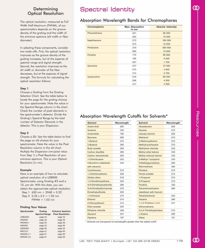
Solvent Wavelength Solvent Wavelength
Acetic Acid 260 Hexadecane 200
Acetone 330 Hexane 210
Acetonitrile 190 Isobutyl alcohol 230
Benzene 280 Methanol 210
1-Butanol 210 2-Methoxyethanol 210
2-Butanol 260 Methylcyclohexane 210
Butyl acetate 254 Methylene chloride 235
Carbon disulfide 380 Methyl ethyl ketone 330
Carbon tetrachloride 265 Methyl isobutyl ketone 335
1-Chlorobutane 220 2-Methyl-1-propanol 230
Chloroform (stabilized 245 N-Methylpyrrolidone 285
with ethanol) Nitromethane 380
Cyclohexane 210 Pentane 210
1,2-Dichloroethane 226 Pentyl acetate 212
Diethyl ether 218 1-Propanol 210
1,2-Dimethoxyethane 240 2-Propanol 210
N,N-Dimethylacetamide 268 Pyridine 330
N,N-Dimethylformamide 270 Tetrachloroethylene 290
Dimethylsulfoxide 265 (stabilized with thymol)
1,4-Dioxane 215 Tetrahydrofuran 220
Ethanol 210 Toluene 286
2-Ethoxyethanol 210 1,1,2-Trichloro-1,2,2- 231
Ethyl acetate 255 trifluoroethane
Ethylene chloride 228 2,2,4-Trimethylpentane 215
Glycerol 207 o-Xylene 290
Heptane 197 Water 191
The optical resolution, measured as FullWidth Half Maximum (FWHM), of ourspectrometers depends on the groovedensity of the grating and the width ofthe entrance aperture (slit width or fiberdiameter).
In selecting these components, considertwo trade-offs. First, the optical resolutionimproves as the groove density of thegrating increases, but at the expense ofspectral range and signal strength.Second, the resolution improves as theslit width or diameter of the fiberdecreases, but at the expense of signalstrength. The formula for calculating theoptical resolution follows:
Step 1Choose a Grating from the GratingSelection Chart. See the table below tolocate the page for the grating choicesfor your spectrometer. Note the value inthe Spectral Range column in the chart.Check the number of pixel elements inthe spectrometer’s detector. Divide theGrating’s Spectral Range by the totalnumber of Detector Elements in thedetector. This is your Dispersion.
Step 2Choose a Slit. See the table below to findthe page on slit choices for yourspectrometer. Note the value in the PixelResolution column in the slit chart.Multiply the Dispersion (nm/pixel valuefrom Step 1) x Pixel Resolution of yourentrance aperture. This is your OpticalResolution (in nm).
ExampleHere is an example of how to calculateoptical resolution of a USB000Spectrometer using Grating #3 and a10- µm slit. With this data, you canobtain the approximate optical resolution.
Step 1 650 nm ÷ 2048 = 0.32Step 2 0.32 x 3.2 = 1.02 nm
FWHM = 1.02 nm
Finding Your Values
oo
ooRR
eessoouurrcceess
SSppeeccttrraall IIddeennttiittyy
Chromophore Max. Absorption Absorb. Intensityin nm
Phenanthrene 251 66 000
292 14 000
Naphthacene 272 180 000
473 12 500
Pentacene 310 300 000
585 12 000
Pyridine 174 80 000
195 6 000
257 1 700
Quinoline 227 37 000
270 3 600
314 2 750
Isoquinoline 218 80 000
266 4 000
317 3 500
Absorption Wavelength Cutoffs for Solvents*
US: 727.733.2447 • Europe: +31 (0) 26 319 0500 179
DeterminingOptical Resolution
Spectrometer Grating Entrance Aperture
Spectral Range Pixel Resolution
USB2000: page 44 page 42
HR2000: page 52 page 50
HR2000+: page 52 page 50
HR4000: page 52 page 50
QE65000: page 56 page 55
NIR-512: page 61 page 60
NIR256-2.1: page 61 page 60
NIR256-2.5: page 61 page 60
Absorption Wavelength Bands for Chromophores
* Solvents are transparent at wavelengths greater than the stated cutoff.

RReessoouurrcceess
oo
oo SSppeeccttrraall IIddeennttiittyy
Absorption/Emission for FluorophoresFluorophore Absorption in nm Emission in nm
1,5 IAEDANS 336 490
4-Methylumbelliferone 385 502
5-Carboxynapthofluorescein 512/598 563/668
(pH 10)
5-Carboxytetramethylrhodamine 542 568
(5-TAMRA)
6-Carboxyrhodamine 6G 518 543
6-CR 6G 518 543
6-JOE 520 548
7-Amino-4-Methylcoumarin 351 430
7-Aminoactinomycin D (7-AAD) 546 647
7-Hydroxy-4-methylcoumarin 360 449,455
Acridine Orange +DNA 502 526
Alexa Fluor 350™ 346 442
342 441
Alexa Fluor 430™ 431 540
Alexa Fluor 488™ 495,492 519,520
Alexa Fluor 532™ 531,532 553,554
Alexa Fluor 546™ 556,557 572,573
Alexa Fluor 568™ 577,578 603
Alexa Fluor 594™ 590,594 617,618
Alexa Fluor 633™ 632 650
Alexa Fluor 647™ 647 666
Alexa Fluor 660™ 668 698
Alexa Fluor 680™ 679 702
Allophycocyanin (APC) 630,645 655,660
AMCA (Aminomethylcoumarin) 345 425
347 444
AMCA-X 353 442
ATTO-TAG™ FQ 486 591
BCECF (high pH) 492,503 520,528
BCECF (low pH) 482 520
Bodipy 505/515 502 510
Bodipy 558/568 558 569
Bodipy 564/570 564 570
Bodipy 576/589 579 590
Bodipy 581/591 584 592
Bodipy 630/650-X 625 642
Bodipy 650/665-X 647 665
Bodipy 665/676 605 676
Bodipy FI 504,505 511,513
Bodipy TMR 542 574
Bodipy TR 589 617
Calcein 494 517
Calcein Blue 373 440
Calcium Crimson™ 588,589 611,615
Calcium Green 501,506 531
Calcium Green-1 Ca2+ Dye 506 531
Calcium Orange 549 575
Calcofluor White 385,395,405 437,440,445
Cascade Blue™ 377 420
398 423
399
CFP - Cyan Fluorescent Protein 430,433,436,(453) 474,475,476,(501)
Non-linearity & CCDs
All CCD detectors exhibit a non-linearityin their response to light; i.e., doublingthe number of photons received duringthe sample interval results in slightly lessthan a doubling of the voltage output.The effects of non-linearity, if leftuncorrected, will be slight but detectableerrors in the calculation of normalizedvalues (absorbance, transmission orirradiance).
The non-linearity is a consequence of theR-C circuit used to read out the electronsthat are left on the CCD capacitor (thecharge well). The effect is independent oflight level, integration time and optics. Itdepends only on the charge in thecharge well.
The pattern of non-linearity is different forthe various detector models used in ourspectrometers. The magnitude of thelinearity varies from detector to detector,but fortunately it is the same for all pixelsin the detector. This makes it possible to1) measure the linearity, and 2) correctfor the errors in software.
The ILX511 has a maximum response at2000 counts (half well capacity). It dropsto ~94% at 4000 counts and near zerocounts. We can establish this curveprecisely using an automated programthat varies the integration time toprecisely control the amount of lightbeing sampled. This program(OOINLCorrect) is available for freedownload at our website atOceanOptics.com/Technical/SoftwareDownloads.asp.
The linearity is captured from theexperiments as a plot of normalizedcounts/sec versus counts for a constantlight source observed at a series ofintegration times. The data is fit to a 7thorder polynomial. The inverse of thisfunction is stored in the software and/oron the EEPROM. When the linearitycorrection feature is turned on, all spectraare multiplied by the stored coefficients.Uncorrected spectra are linear to ~92%.Corrected spectra are linear to >99.8%.
For all your sensing needs, visit OceanOptics.com180

Fluorophore Absorption in nm Emission in nm
CL-NERF (Ratio Dye, pH) 504/514 540
Cy2™ 489 506
Cy3.5™ 581 598
Cy3™ 514 566
Cy5.5™ 675 695
Cy5™ 649 666
Cy7™ 710,743 767,805
Dabcyl 453
Dansyl Cadaverine 335 518
DAPI 359 461
Di-4-ANEPPS 496 705
Di-8-ANEPPS (non-ratio) 488 605
498 713
DiA (4-Di-16-ASP) 456 591
DIDS 341 415
Dil (DilC18(3)) 549,551 565
Dinitrolphenol 349
DiO (DiOC18(3)) 484,487 501,502
DM-NERF (Ratio Dye, high pH) 497/510 540
ELF 97 345 530
Eosin 524 545
Erythrosin 529,532 554,555
Ethidium Bromide 510,523 595,605
Ethidium homodimer -1 (EthD-1) 528 617
Europium (III) chloride 337 613
Fast Blue 360 440
Fluo-3 480-506,506 520,527
Fluo-4 494 516
Fluorescein (FITC) 490,494 520,525
Fluoro-Gold (Hydroxystilbamidine) 361 536
FluorX 494 520
FM 1-43™ 479 598
Fura Red™ (high pH) 572 657
Fura-2, high calcium 335 505
(Excitation ratio dye)
Fura-2, low calcium 363 512
(Excitation ratio dye)
GFP (S65T) 498 516
Hoechst 33258 345 487
Hoechst 33342 347 483
JC-1 514 529
JO-JO-1 530 545
JO-PRO-1 532 544
Lucifer Yellow 425,428 528,536,540
Lyso Tracker Green 504,534 511,551
Mag-Fura-2 (Ratio Dye, Ca2+) 369/329 508
Mag-Fura-2 (Ratio Dye Mg2+) 369/330 511/491
Mag-Fura-5 (Ratio Dye, Ca2+) 369/330 505/500
Mag-Fura-5 (Ratio Dye, Mg2+) 369/332 505/482
Magnesium Green 506,507 531
Marina Blue 362 459
Mitotracker Green FM 490 516
oo
ooRR
eessoouurrcceess
SSppeeccttrraall IIddeennttiittyy
Absorption/Emission for Fluorophores (continued)The 74-UV and 74-VIS Collimating Lensesscrew onto the end of SMA 905-terminated fibers and other samplingoptics to convert divergent beams ofradiation (light) into a parallel beam. Theoptical fibers we sell have a field of view(FOV) of ~25° -- an acceptance anglethat may not be appropriate for someexperiments. Collimating lenses areadjustable, providing FOV angles fromcollimation (near 0°) to ~45°. Without thecollimating lenses, the light woulddisperse more than is required for efficienttransmission and collection of the signal.
Focus the Lamp’s Collimating LensIn order to obtain accurate data, the lightentering and exiting a sample by meansof a fiber/collimating lens assembly mustbe well collimated. Here are instructionsfor adjusting the focus of the collimatorsin a typical spectrometer setup.1. Connect to the light source the fiber
that you’re going to use as theillumination fiber in your setup. Thefemale SMA 905 Connector of the fibermust be screwed all the way into themale connector of the lamp.
2. Turn on the lamp and inspect the beamemitted from the other end of the fiberby pointing the fiber at a white piece ofpaper. The distance is not too criticalbut should be at least 3 inches fromthe surface.
3. Loosen the setscrew on the fiber barrelof the light source with an Allen wrench.
4. Slide the inner barrel of the collimatinglens until you see an even intensityacross the beam spot. The spot shouldbe uniform in intensity and color.
5. Once the inner barrel is positioned sothat a well-focused, uniform spot isobtained, tighten the setscrew. Don’tput down the fiber and then tighten thesetscrew as you may lose the focus.
Focus the Next Collimating Lens6. The illumination fiber is still connected
to the lamp and the lamp is on. Takethe second collimating lens in yoursetup (removed from a cuvette holder,for example) and screw it securely ontothe other end of the fiber. Point this endof the fiber at least 2 meters from awall.
7. Repeat Steps 3, 4 and 5. Then removethe lens from the end of the fiber andinstall it back into your setup (back intoa cuvette holder, for example).
8. Continue to adjust the focus of theother collimating lenses in your setup.
Collimating Lenses
US: 727.733.2447 • Europe: +31 (0) 26 319 0500 181

Fluorophore Absorption in nm Emission in nm
Mitotracker Orange 551 576
NBD 466 539
Nile Red 515-555,559 590,640
Oregon Green™ 503 522
Oregon Green™ 488 490,493 514,520
Oregon Green™ 500 497 517
Oregon Green™ 514 506 526
PKH26 (Sigma) 551 567
POPO-3 533 574
PO-PRO-3 539 567
Propidium Iodid (PI) (305), 536,538 617
Pyrene 360 387
QSY 7 560 591
Rhod-2 552 576
Rhodamine 110 496,497 520
Rhodamine 123 507 529
Rhodamine 6G 525 555
Rhodamine B 540 625
Rhodamine Green 502 527
Rhodamine Phalloidine 542 565
Rhodamine Red 570 590
R-phycoerythrin (PE) 565 578
SITS (Ion Channels) 336 436
SNAFL-1 (Ratio Dye, pH) 508/540 543/623
SNARF1 Excitation and emission 576/548 635/587
ratio dye
Sodium Green Na+, K+ 506,507 532
SpectrumGreen (Vysis) 497/30, 509/31 538/44,524/56
SpectrumOrange (Vysis) 559/38,560 588/48
SPQ (6-methoxy-N-(3-sulfopropyl) 344 443
SYTO 11Dye for DNA, RNA 508,510 527,530
SYTO 13Dye for DNA, RNA 488,491 509,514
SYTOX Green (Nucleic Acid Stain 504 523
SYTOX Orange (Nucleic Acid Stain 547 570
Tetramethylrhodamine (TRITC) 555 576
Texas Red™ 595 620
TO-PRO-1 515 531
TOTO-1 514 531,533
YFP (Yellow Fluorescent Protein) 513,520 527,532
YO-PRO-1 491 506
YOYO-1 491 508,509
RReessoouurrcceess
oo
ooAbsorption/Emission for Fluorophores (continued)
For all your sensing needs, visit OceanOptics.com182
SSppeeccttrraall IIddeennttiittyy Phosphorescence &Fluorescence
Phosphorescence and fluorescence are closelyrelated subcategories of luminescence. Thedifference between the two is in the nature ofa material’s ground and excited states.
In a singlet excited state, the higher-energyorbital electron spins opposite the lower-energy orbital. The two electrons areconsidered “paired.” In a triplet state, theelectrons are “unpaired,” and spin in thesame direction. A return to the ground statefrom a singlet excited state does not requireone of the electrons to change its spinorientation; a return from a triplet state to theground state does require an electron’s spinorientation to change.
Fluorescence is the photonic emission thatoccurs when the higher-energy electron in asinglet state returns to the lower-orbit electron.The laws of quantum mechanics permit thisrapid transition at a rate near 10-8 second.
The fluorescence lifetime is the average periodof time that a fluorophore remains in theexcited singlet state. By comparison,phosphorescence emission occurs as theelectronically excited condition of a material inthe triplet state returns to the singlet groundstate. Again, the laws of quantum mechanicsprevail, and the probability of this transition islower. The lifetime of an excited triplet state ismuch longer than that of an excited singletstate, producing phosphorescence lifetimesthat range from milliseconds to seconds.

oo
ooRR
eessoouurrcceess
US: 727.733.2447 • Europe: +31 (0) 26 319 0500 183
21-01 . . . . . . . . . . . . . . . . . . . . . . . . . 154, 156
21-02. . . . . . . . . . 65, 145, 151, 154, 156, 169
21-02-BH . . . . . . . . . . . . . . . . . . . . . . . . . . 156
21-02-SS . . . . . . . . . . . . . . . . . . . . . . . . . . 156
74-90-UV . . . . . . . . . . . . . . . . . . . . . . . 89, 155
74-ACH . . . . . . . . . . . . . . . . . . . . . . . . . 17, 89
74-ACR . . . . . . . . . . . . . . . . . . . . . . . . . . . . 88
74-DA . . . . . . . . . . . . . . . . . . . . . . . . . . . . . 88
74-MSP . . . . . . . . . . . . . . . . . . . . . . . . 90, 171
74-UV . . . . . . . . . . . . . . . . . . . . . . 17, 88, 154
74-UV-HT. . . . . . . . . . . . . . . . . . . . . . . . . . . 88
74-VIS . . . . . . . . . . . . . . . . . . . . . . . . . . . . . 88
84-UV-25 . . . . . . . . . . . . . . . . . . . . . . . . . . . 88
- A -
ACC-CON-US2 . . . . . . . . . . . . . . . . . . . . . . 38
ACH-CUV-VAR . . . . . . . . . . . . . . . . . . . . . . 89
ADC1000-USB . . . . . . . . . . . . . . . . 41, 62, 84
ADC2000-PCI+ . . . . . . . . . . . . . . . . . . . . . . 84
ADC-USB-SER . . . . . . . . . . . . . . . . . . . . . . 84
ADP-SMA-SMA . . . . . . . . . . . . . . . . . . . . . 156
AR-1 . . . . . . . . . . . . . . . . . . . . . . . . . 118, 133
ASP . . . . . . . . . . . . . . . . . . . . . . . . . . . . . . 193
ASP-ES . . . . . . . . . . . . . . . . . . . . . . . . . . . 193
ASP-NIR . . . . . . . . . . . . . . . . . . . . . . . . . . 193
ASP-QE. . . . . . . . . . . . . . . . . . . . . . . . . . . 193
ASP-R . . . . . . . . . . . . . . . . . . . . . . . . . . . . 193
ASP-R-E . . . . . . . . . . . . . . . . . . . . . . . . . . 193
- B -
BFA-KIT . . . . . . . . . . . . . . . . . . . . . . . . . . . 152
BFA-KIT-CHUCK . . . . . . . . . . . . . . . . . . . . 152
BIF200-MIXED . . . . . . . . . . . . . . . . . . . . . 139
BIF200-UV-VIS . . . . . . . . . . . . . . . . . . . . . 139
BIF200-VIS-NIR. . . . . . . . . . . . . . . . . . . . . 139
BIF400-MIXED . . . . . . . . . . . . . . . . . . . . . 139
BIF400-UV-VIS . . . . . . . . . . . . . . . . . . . . . 139
BIF400-VIS-NIR. . . . . . . . . . . . . . . . . . . . . 139
BIF50-MIXED . . . . . . . . . . . . . . . . . . . . . . 139
BIF50-UV-VIS . . . . . . . . . . . . . . . . . . . . . . 139
BIF50-VIS-NIR. . . . . . . . . . . . . . . . . . . . . . 139
BIF600-MIXED . . . . . . . . . . . . . . . . . . . . . 139
BIF600-UV-VIS . . . . . . . . . . . . . . . . . . . . . 139
BIF600-VIS-NIR. . . . . . . . . . . . . . . . . . . . . 139
BOX-DESKTOP. . . . . . . . . . . . . . . . . . . . . . 62
BOX-DUAL . . . . . . . . . . . . . . . . . . . . . . . . . 62
BOX-RACK . . . . . . . . . . . . . . . . . . . . . . . . . 62
BOX-SINGLE. . . . . . . . . . . . . . . . . . . . . . . . 62
- C -
CAL-2000 . . . . . . . . . . . . . . . . . . . . . 118, 132
CAL-2000-B. . . . . . . . . . . . . . . . . . . . 132, 134
CBL-2 . . . . . . . . . . . . . . . . . . . . . . . . . . . . . 84
CBL-PX-2 . . . . . . . . . . . . . . . . . . . . . . . . . 134
CC-3 . . . . . . . . . . . . . . . . . . . . . 107, 144, 154
CC-3-DA . . . . . . . . . . . . . . . . . . . . . . . . . . 107
CC-3-UV . . . . . . . . . . . . . . . . . . 107, 144, 168
CHEM2-UV-FIBER. . . . . . . . . . . . . . . . . 12-13
CHEM2-VIS-FIBER . . . . . . . . . . . . . . . . 12-13
CHEMTEST-PH. . . . . . . . . . . . . . . . . . . . . . 68
CHEMUSB2-UV-VIS . . . . . . . . . . . . . . . 12-13
CHEMUSB2-VIS-NIR. . . . . . . . . . . . . . . 12-13
C-MOUNT-MIC . . . . . . . . . . . . . . . . . . . . . 155
CONN-FC . . . . . . . . . . . . . . . . . . . . . . . . . 143
CONN-LSMA. . . . . . . . . . . . . . . . . . . . . . . 143
CONN-PSMA. . . . . . . . . . . . . . . . . . . . . . . 143
CONN-PSMA-O. . . . . . . . . . . . . . . . . . . . . 143
CONN-QSMA . . . . . . . . . . . . . . . . . . . . . . 143
CONN-QSMA-O . . . . . . . . . . . . . . . . . . . . 143
CONN-SMA. . . . . . . . . . . . . . . . . . . . . . . . 143
CONN-SMA-O. . . . . . . . . . . . . . . . . . . . . . 143
CONN-ST . . . . . . . . . . . . . . . . . . . . . . . . . 143
CSH. . . . . . . . . . . . . . . . . . . . . . . . . . . . . . 155
CSH-45 . . . . . . . . . . . . . . . . . . . . . . . . . . . 155
CT-series Collimation Testers . . . . . . 113, 163
CUV-ALL-UV . . . . . . . . . . . . . . . . . . . . 90, 171
CUV-CCE . . . . . . . . . . . . . . . . . . . . . . . . . . 99
CUV-COVER . . . . . . . . . . . . . . . . . . . . . 90, 93
CUV-COVER-TALL . . . . . . . . . . . . . . . . . . . 93
CUV-FL-DA . . . . . . . . . . . . . . . . . . . . . . . . . 90
CUV-TLC-50F . . . . . . . . . . . . . . . . . . . . . . . 91
CUV-TLC-ABSKIT . . . . . . . . . . . . . . . . . . . . 91
CUV-TLC-ADP. . . . . . . . . . . . . . . . . . . . . . . 91
CUV-TLC-BATH. . . . . . . . . . . . . . . . . . . . . . 91
CUV-TLC-FH . . . . . . . . . . . . . . . . . . . . . . . . 91
CUV-TLC-FLKIT . . . . . . . . . . . . . . . . . . . . . 91
CUV-TLC-IJ . . . . . . . . . . . . . . . . . . . . . . . . . 91
CUV-TLC-IL . . . . . . . . . . . . . . . . . . . . . . . . . 91
CUV-TLC-MP. . . . . . . . . . . . . . . . . . . . . . . . 91
CUV-TLC-MPKIT . . . . . . . . . . . . . . . . . . . . . 91
CUV-TLC-SP . . . . . . . . . . . . . . . . . . . . . . . . 91
CUV-UV. . . . . . . . . . . . . . . . . . . . . . . . 90, 167
CUV-UV-10 . . . . . . . . . . . . . . . . . . . . . 90, 170
CUV-VAR. . . . . . . . . . . . . . . . . . . . . . . . . . . 90
CUV-VAR-OPTION . . . . . . . . . . . . . . . . . . . 90
CVD-COVER. . . . . . . . . . . . . . . . . . . . . . . . 93
CVD-DIFFUSE . . . . . . . . . . . . . . . . . . . . . . 95
CVD-UV1S . . . . . . . . . . . . . . . . . . . . . . . . . 93
CVD-UV1S-SAM . . . . . . . . . . . . . . . . . . . . . 93
CVD-UV1U . . . . . . . . . . . . . . . . . . . . . . . . . 93
CVD-UV1U-SAM . . . . . . . . . . . . . . . . . . . . . 93
CVD-VIS1M. . . . . . . . . . . . . . . . . . . . . . . . . 93
CVD-VIS1S . . . . . . . . . . . . . . . . . . . . . . . . . 93
CVFL-Q-10 . . . . . . . . . . . . . . . . . . . . . . . . . 93
CVF-Q-10 . . . . . . . . . . . . . . . . . . . . . . . . . . 93
CV-Q-10 . . . . . . . . . . . . . . . . . . . 93, 167, 170
CV-Q-100 . . . . . . . . . . . . . . . . . . . . . . 93, 170
CVS-Q-10 . . . . . . . . . . . . . . . . . . . . . . . . . . 93
- D -
D-1000-B . . . . . . . . . . . . . . . . . . . . . . . . . . 134
D2000 . . . . . . . . . . . . . . . . . . . . 118, 124, 170
D2000-DUV . . . . . . . . . . . . . . . . . . . . 124, 134
D2000-S . . . . . . . . . . . . . . . . . . . . . . . . . . 124
D2000-S-DUV . . . . . . . . . . . . . . . . . . . . . . 124
DH2000 . . . . . . . . . . . . . . . . . . . . . . . 118, 121
DH2000-BAL . . . . . . . . . . . 118, 120, 167, 176
DH2000-BD. . . . . . . . . . . . . . . . 121, 124, 134
DH2000-BH . . . . . . . . . . . . . . . . . . . . 121, 134
DH2000-CAL . . . . . . . . . . . . . . . 118, 130, 168
DH2000-DUV. . . . . . . . . . . . . . . . . . . . . . . 121
DH2000-DUV-B. . . . . . . . . . . . . 121, 124, 134
DH2000-FHS. . . . . . . . . . . . . . . . . . . . . . . 121
DH2000-FHS-DUV . . . . . . . . . . . . . . . . . . 121
DH2000-RECAL . . . . . . . . . . . . . . . . . . . . 130
DH2000-S . . . . . . . . . . . . . . . . . . . . . 120, 121
DH2000-S-DUV, DH2000-S-DUV-TT . . . . 121
DH-BAL-KIT. . . . . . . . . . . . . . . . . . . . . . . . 120
DH-BAL-KIT-S . . . . . . . . . . . . . . . . . . . . . . 120
DT-1000-B . . . . . . . . . . . . . . . . . . . . . . . . . 134
DT-1000-BT, DT-1000-BT-CE . . . . . . . . . . 134
DT-1000REM-B . . . . . . . . . . . . . . . . . . . . . 134
DT-MINI . . . . . . . . . . . . . . . . . . . . . . . 118, 122
DT-MINI-2-B . . . . . . . . . . . . . . . . . . . 122, 134
DT-MINI-2-GS . . . . . . . . . . . . . . . . . . 118, 122
DT-MINI-B . . . . . . . . . . . . . . . . . . . . . 122, 134
- E -
EDS2000 . . . . . . . . . . . . . . . . . . . . . . . . . . . 23
EDS-TEST. . . . . . . . . . . . . . . . . . . . . . . . . . 23
EPOXY-TEST . . . . . . . . . . . . . . . . . . . . . . 143
- F -
F-BY . . . . . . . . . . . . . . . . . . . . . . . . . . . . . . 72
FCBARREL . . . . . . . . . . . . . . . . 134, 154, 156
F-CR . . . . . . . . . . . . . . . . . . . . . . . . . . . . . . 72
FH-SMA. . . . . . . . . . . . . . . . . . . . . . . . 96, 164
FHS-LVF . . . . . . . . . . . . . . . . . . . . . . . . . . . 95
FHS-UV . . . . . . . . . . . . . . . . . . . . . . . . . . . . 97
FHSA-RS232. . . . . . . . . . . . . . . . . . . . . . . . 97
FHSA-TTL . . . . . . . . . . . . . . . . . . . . . . . . . . 97
FIA-1000-Z . . . . . . . . . . . . . . . . . . . . . . . . 101
FIA-ASX260. . . . . . . . . . . . . . . . . . . . . . . . . 15
FIA-HEATER . . . . . . . . . . . . . . . . . . . . . . . . 15
FIA-LAB-2500 . . . . . . . . . . . . . . . . . . . . . . . 15
FIA-LOV. . . . . . . . . . . . . . . . . . . . . . . . . . . 102
FIA-P200-SR . . . . . . . . . . . . . . . . . . . . . . . 100
FIA-P400-SR . . . . . . . . . . . . . . . . . . . . . . . 100
FIA-PMT-FL. . . . . . . . . . . . . . . . . . . . . . . . 101
FIA-PUMP-C . . . . . . . . . . . . . . . . . . . . . . . 101
FIA-SIA . . . . . . . . . . . . . . . . . . . . . . . . . . . 102
FIA-SIA-LOV . . . . . . . . . . . . . . . . . . . . . . . 102
FIA-SMA-FL. . . . . . . . . . . . . . . . . . . . . . . . 101
FIA-ZCELL-PEEK . . . . . . . . . . . . . . . . . . . 100
FIA-ZCELL-PLEX . . . . . . . . . . . . . . . . . . . 100
FIA-ZCELL-SS. . . . . . . . . . . . . . . . . . . . . . 100
FIA-ZCELL-TEF. . . . . . . . . . . . . . . . . . . . . 100
FIA-ZSMA-20-PE. . . . . . . . . . . . . . . . . . . . 100
FIA-ZSMA-20-PLE. . . . . . . . . . . . . . . . . . . 100
FIA-ZSMA-20-SS. . . . . . . . . . . . . . . . . . . . 100
FIA-ZSMA-20-TEF. . . . . . . . . . . . . . . . . . . 100
FIA-ZSMA-50-PE. . . . . . . . . . . . . . . . . . . . 100
FIA-ZSMA-50-PLE. . . . . . . . . . . . . . . . . . . 100
FIA-ZSMA-50-SS. . . . . . . . . . . . . . . . . . . . 100
FIA-ZSMA-50-TEF. . . . . . . . . . . . . . . . . . . 100
FIA-Z-SMA-PEEK . . . . . . . . . . . . . . . . . . . 100
FIA-Z-SMA-PLEX . . . . . . . . . . . . . . . . . . . 100
FIA-Z-SMA-SS. . . . . . . . . . . . . . . . . . . . . . 100
FIA-Z-SMA-TEF. . . . . . . . . . . . . . . . . . . . . 100
FIBER-series Bare Fiber . . . . . . . . . . . . . . 141
FIBER-WRAP . . . . . . . . . . . . . . . . . . 154, 156
FILM . . . . . . . . . . . . . . . . . . . . . . . . . . . . . . 72
FILM300 . . . . . . . . . . . . . . . . . . . . . . . . . . . 72
FL-400 . . . . . . . . . . . . . . . . . . . . . . . . . 12, 145
FLOW2000 . . . . . . . . . . . . . . . . . . . . . . . . . 14
FLS-series Flats. . . . . . . . . . . . . . . . . . . . . 112
FLZ-series Flats. . . . . . . . . . . . . . . . . . . . . 112
F-MCP . . . . . . . . . . . . . . . . . . . . . . . . . . . . . 72
FNY-PR . . . . . . . . . . . . . . . . . . . . . . . . . . . . 72
FOIS-1 . . . . . . . . . 16, 107, 108, 131, 172-173
FOP-UV. . . . . . . . . . . . . . . . . . . . . . . . . . . 154
FOP-VIS . . . . . . . . . . . . . . . . . . . . . . . . . . 154
FOS-2X2-TTL . . . . . . . . . . . . . . . . . . . . . . 105
FOT-SMAWRENCH . . . . . . . . . . . . . 154, 156
FOXY-18G. . . . . . . . . . . . . . . . . . . . . . . 66, 68
FOXY-21G. . . . . . . . . . . . . . . . . . . . . . . 66, 68
FOXY-AF . . . . . . . . . . . . . . . . . . . . . . . . . . . 68
FOXY-AF-MG . . . . . . . . . . . . . . . . . . . . . . . 68
FOXY-AL300 . . . . . . . . . . . . . . . . . . . . . . . . 66
FOXY-AL300-TM . . . . . . . . . . . . . . . . . . . . . 66
FOXY-CAL. . . . . . . . . . . . . . . . . . . . . . . . . . 70
FOXY-CAL-EXT. . . . . . . . . . . . . . . . . . . . . . 70
FOXY-FLOW-CELL . . . . . . . . . . . . . . . . . . . 69
FOXY-GF. . . . . . . . . . . . . . . . . . . . . . . . . . . 68
FOXY-OR125 . . . . . . . . . . . . . . . . . . . . . . . 66
FOXY-OR125-G . . . . . . . . . . . . . . . . . . . . . 66
FOXY-OR125-GT . . . . . . . . . . . . . . . . . . . . 66
FOXY-PI600 . . . . . . . . . . . . . . . . . . . . . . . . 66
FOXY-R . . . . . . . . . . . . . . . 65-66, 69, 71, 169
FOXY-RECOV . . . . . . . . . . . . . . . . . . . . . . . 68
FOXY-RECOV-N . . . . . . . . . . . . . . . . . . . . . 68
FOXY-RESP . . . . . . . . . . . . . . . . . . . . . 66, 68
FOXY-RESP-FILM. . . . . . . . . . . . . . . . . . . . 68
FOXY-R-PNA. . . . . . . . . . . . . . . . . . . . . . . . 69
FOXY-SGS-M . . . . . . . . . . . . . . . . . . . . . . . 68
FOXY-T1000 . . . . . . . . . . . . . . . . . . . . . 66, 70
FOXY-T1000-RTD . . . . . . . . . . . . . . . . . 66, 70
FOXY-TK1 . . . . . . . . . . . . . . . . . . . . . . . . . . 70
FOXY-TK-1-W . . . . . . . . . . . . . . . . . . . . . . . 70
FOXY-T-MOD-1 . . . . . . . . . . . . . . . . . . . . . . 70
FOXY-T-MOD-K. . . . . . . . . . . . . . . . . . . . . . 70
FOXY-TS1 . . . . . . . . . . . . . . . . . . . . . . . . . . 70
IINNDDEEXX bbyy IItteemm CCooddee

F-PR . . . . . . . . . . . . . . . . . . . . . . . . . . . . . . 72
FR-BY . . . . . . . . . . . . . . . . . . . . . . . . . . . . . 72
FR-CR . . . . . . . . . . . . . . . . . . . . . . . . . . . . . 72
FR-MCP. . . . . . . . . . . . . . . . . . . . . . . . . . . . 72
FR-PR . . . . . . . . . . . . . . . . . . . . . . . . . . . . . 72
FR-TB . . . . . . . . . . . . . . . . . . . . . . . . . . . . . 72
F-TB. . . . . . . . . . . . . . . . . . . . . . . . . . . . . . . 72
FT-KIT . . . . . . . . . . . . . . . . . . . . . . . . . . . . 152
FVA-UV . . . . . . . . . . . . . . . . . . . 104, 119, 154
F-XXX . . . . . . . . . . . . . . . . . . . . . . . . . . . . . 72
- G -
GER-KIT . . . . . . . . . . . . . . . . . . . . . . . . . . 105
GRAMSAI . . . . . . . . . . . . . . . . . . . . . . . . . . 82
GRATING #1-14. . . . . . . . . . . . . . . . . . . 44-45
GRATING #H1-H14 . . . . . . . . . . 52-53, 56-57
GRATING #N1-N2. . . . . . . . . . . . . . . . . . . . 61
GRATING HC-1 . . . . . . 17, 30, 31, 37, 52, 56
GR-SPECID. . . . . . . . . . . . . . . . . . . . . . . . . 82
GR-PLSPLUS/IQ. . . . . . . . . . . . . . . . . . . . . 82
- H -
HG-1 . . . . . . . . . . . . . . . . . . . . . 118, 132, 133
HL-2000. . . . . . . . . . . . . . . . . . . . . . . 118, 127
HL-2000-B . . . . . . . . . . . . . . . . . . . . . 127, 134
HL-2000-B-LL . . . . . . . . . . . . . . . . . . 127, 134
HL-2000-CAL. . . . . . . . . . . . . . . . . . . 118, 131
HL-2000-CAL-ISP . . . . . . . . . . . . . . . 108, 131
HL-2000-FHSA . . . . . . . . . . . . . . . . . . . . . 127
HL-2000-FHSA-LL. . . . . . . . . . . . . . . . . . . 127
HL-2000-HP. . . . . . . . . . . . . . . . . . . . . . . . 127
HL-2000-HP-232 . . . . . . . . . . . . . . . . . . . . 127
HL-2000-HP-B. . . . . . . . . . . . . . . . . . 127, 134
HL-2000-HP-FHSA . . . . . . . . . . . . . . . . . . 127
HL-2000-LL . . . . . . . . . . . . . . . . . . . . . . . . 127
HL-2000-LVF-HP . . . . . . . . . . . . . . . . . . . . 127
HL-2000-RECAL . . . . . . . . . . . . . . . . . . . . 131
HOUND-7000 . . . . . . . . . . . . . . . . . . . . . . . 25
HOUND-CASE . . . . . . . . . . . . . . . . . . . . . . 25
HOUND-DEUT . . . . . . . . . . . . . . . . . . . . . . 25
HOUND-STAN. . . . . . . . . . . . . . . . . . . . . . . 25
HPX-2000 . . . . . . . . . . . . . . . . . . . . . 118, 125
HPX-2000-B . . . . . . . . . . . . . . . . . . . 125, 134
HPX-2000-BM . . . . . . . . . . . . . . . . . . 125, 134
HR2000 . . . . . . . . . . . , 37, 48, 50-53, 76, 123
HR2000+ . . . . . . . . . . . 37, 49, 50-53, 76, 123
HR2000+CG . . . . . . . . . . . . . . . . . . . . . . . . 31
HR4000 . . . 17, 37, 46, 50-53, 168, 170, 173
HR4000CG-UV-NIR. . . . . . . . . . . . . . . . . . . 30
HR4-BREAKOUT . . . . . . . . . . . . . . . . 47, 123
- I -
INLINE-FH. . . . . . . . . . . . . . . . . . . . . . 96, 164
INLINE-OF. . . . . . . . . . . . . . . . . . . . . . 96, 164
INLINE-TTL-S . . . . . . . . . . . . . . . . . . . . . . 105
IP200-2-ULTRA . . . . . . . . . . . . . . . . . . . . . 144
IP200-20-ULTRA . . . . . . . . . . . . . . . . . . . . 144
IP320-2-UV-VIS. . . . . . . . . . . . . . . . . . . . . 144
IP320-2-VIS-NIR . . . . . . . . . . . . . . . . . . . . 144
IP500-2-ULTRA . . . . . . . . . . . . . . . . . . . . . 144
IP500-2-UV-VIS. . . . . . . . . . . . . . . . . . . . . 144
IP500-2-VIS-NIR . . . . . . . . . . . . . . . . . . . . 144
IP500-20-ULTRA . . . . . . . . . . . . . . . . . . . . 144
IP500-20-VIS-NIR . . . . . . . . . . . . . . . . . . . 144
ISP-30-6-I . . . . . . . . . . . . . . . . . . . . . . . . . 108
ISP-30-6-R. . . . . . . . . . . . . . . . . . . . . . . . . 109
ISP-50-8-I . . . . . . . . . . . . . . . . . . . . . 108, 131
ISP-50-8-R. . . . . . . . . . . . . . . . . . . . . . . . . 109
ISP-50-8-R-GT . . . . . . . . . . . . . . . . . . . . . 109
ISP-80-8-I . . . . . . . . . . . . . . . . . . . . . . . . . 108
ISP-80-8-R. . . . . . . . . . . . . . . . . . . . . . . . . 109
ISP-LED-ADP . . . . . . . . . . . . . . . . . . . . . . 108
ISP-PORT-1 . . . . . . . . . . . . . . . . . . . . 108-109
ISP-PORT-2 . . . . . . . . . . . . . . . . . . . . 108-109
ISP-REF . . . . . . . . . . . . . . . . . . . . . . . . . . 109
ISP-REF-B. . . . . . . . . . . . . . . . . . . . . . . . . 109
ISS-2 . . . . . . . . . . . . . . . . . . . . . . . . . . . 13, 92
ISS-UV-VIS . . . . . . . . . . . . . . . . . . . . . . 13, 92
- L -
L2 . . . . . 37, 42-43, 50-51, 169, 171-172, 177
L4 . . . . . . . . . . . . . . . . . . . . . . . 37, 50-51, 170
LASER-785 . . . . . . . . . . . . . . . . . . . . . . . . . 26
LED-380 . . . . . . . . . . . . . . . . . . . . . . 128, 134
LED-395 . . . . . . . . . . . . . . . . . . . . . . 128, 134
LED-470 . . . . . . . . . . . . . . . . . . . . . . . . . . 128
LED-518 . . . . . . . . . . . . . . . . . . . . . . 128, 134
LED-590 . . . . . . . . . . . . . . . . . . . . . . 128, 134
LED-640 . . . . . . . . . . . . . . . . . . . . . . 128, 134
LED-KIT. . . . . . . . . . . . . . . . . . . . . . . 128, 134
LED-PS . . . . . . . . . . . . . . . . . . . . 16, 107, 172
LED-PS-NIST . . . . . . . . . . . . . . . 16, 107, 172
LED-PS-RECAL . . . . . . . . . . . . . . . . . . . . 107
LED-WHITE. . . . . . . . . . . . . . . . . . . . 128, 134
LIBS2000+ . . . . . . . . . . . . . . . 20, 21, 22, 174
LIBS-ELITE-90 . . . . . . . . . . . . . . . . . . . . . . 22
LIBS-ELITE-200 . . . . . . . . . . . . . . . . . . . . . 22
LIBS-FIBER-BUN . . . . . . . . . . . . . . . . . . . 174
LIBS-IM . . . . . . . . . . . . . . . . . . . . . . . . . . . . 21
LIBS-IM-C . . . . . . . . . . . . . . . . . . . . . . . . . . 21
LIBS-IM-MCIA . . . . . . . . . . . . . . . . . . . . . . . 21
LIBS-IM-PCI . . . . . . . . . . . . . . . . . . . . . . . . 21
LIBS-LAS200MJ . . . . . . . . . . . . . . . . . . . . . 21
LIBS-LASER . . . . . . . . . . . . . . . . . 20, 21, 174
LIBS-SC . . . . . . . . . . . . . . . . . . . . 20, 21, 174
LPC-1 . . . . . . . . . . . . . . . . . . . . . . . . . . . . . 98
LPC-5 . . . . . . . . . . . . . . . . . . . . . . . . . . . . . 98
LPC-CLEANKIT. . . . . . . . . . . . . . . . . . . . . . 98
LS-1 . . . . . . . . . . . . . . . . . . 118, 126, 175-176
LS-1-B . . . . . . . . . . . . . . . . . . . . . . . . 126, 134
LS-1-CAL. . . . . . . . . . . . . . . . . . . . . . 118, 131
LS-1-CAL-INT . . . . . . . . . . . 16, 108, 131, 172
LS-1-LL . . . . . . . . . . . . . . . . . . . . . . . 126, 134
LS-1-LL-B . . . . . . . . . . . . . . . . . . . . . 126, 134
LS-1-RECAL . . . . . . . . . . . . . . . . . . . . . . . 131
LS-450. . . . . . . . . . . . . . . . . . . . . . . . . . . . . 38
LS-475. . . . . . . . . . . . . . . . . . . . . . . . . . . . 129
LTP-V. . . . . . . . . . . . . . . . . . . . . . . . . . . . . 116
LTP-VMIR . . . . . . . . . . . . . . . . . . . . . . . . . 116
LVF-series Filters, Accessories . . . 94-95, 171
- M -
MC-2000-5. . . . . . . . . . . . . . . . . . . . . . . . . . 62
MFA-C-MOUNT. . . . . . . . . . . . . . . . . . . . . 155
MFA-PT . . . . . . . . . . . . . . . . . . . . . . . . . . . 155
MPM-2000-1X16-UV . . . . . . . . . . . . . . . . . 104
MPM-2000-1X16-VIS . . . . . . . . . . . . . . . . 104
MPM-2000-2X8-UV . . . . . . . . . . . . . . . . . . 104
MPM-2000-2X8-VIS . . . . . . . . . . . . . . . . . 104
- N -
NC-512-NIR. . . . . . . . . . . . . . . . . . . . . . . . . 18
NC-NIR . . . . . . . . . . . . . . . . . . . . . . . . . . . . 18
NC-NIR-HR . . . . . . . . . . . . . . . . . . . . . . . . . 18
NC-UV-VIS . . . . . . . . . . . . . . . . . . . . . . . . . 18
NC-UV-VIS-NIR. . . . . . . . . . . . . . . . . . . . . . 18
NC-VIS . . . . . . . . . . . . . . . . . . . . . . . . . . . . 18
NC-VIS-NIR. . . . . . . . . . . . . . . . . . . . . . . . . 18
NIR256-2.1. . . . . . . . . . . . . . . . . 58, 59, 60-61
NIR256-2.5. . . . . . . . . . . . . . . . . 58, 59, 60-61
NIR-512 . . . . . . . . . . . 58, 59-61, 82, 132, 143
- O -
OF1-GG375. . . . . . . . . . . . . . . . . . . 43, 51, 56
OF1-GG475. . . . . . . . . . . . . . . . . . . 43, 51, 56
OF1-OG515. . . . . . . . . . . . . . . . . . . 43, 51, 56
OF1-OG550. . . . . . . . . . . . . . . . . . . 43, 51, 56
OF1-OG590. . . . . . . . . . . . . . . . . . . 43, 51, 56
OF1-WG305 . . . . . . . . . . . . . . . . . . 43, 51, 56
OF2-BG34 . . . . . . . . . . . . . . . . . . . . . . . . . 164
OF2-BG34R. . . . . . . . . . . . . . . . . . . . . . . . 164
OF2-FG3 . . . . . . . . . . . . . . . . . . . . . . . . . . 164
OF2-GG375. . . . . . . . . . . . . . . . . . . . . . . . 164
OF2-GG395. . . . . . . . . . . . . . . . . . . . . . . . 164
OF2-GG475. . . . . . . . . . . . . . . . . . . . . . . . 164
OF2-KG3 . . . . . . . . . . . . . . . . . . . . . . . . . . 164
OF2-LS . . . . . . . . . . . . . . . . . . . . . . . 126, 164
OF2-OG515. . . . . . . . . . . . . . . . . . . . . . . . 164
OF2-OG550. . . . . . . . . . . . . . . . . . . . . . . . 164
OF2-RG780. . . . . . . . . . . . . . . . . . . . . . . . 164
OF2-U360 . . . . . . . . . . . . . . . . . . . . . . . . . 164
OF2-WG305 . . . . . . . . . . . . . . . . . . . . . . . 164
OFLV-200-1100 . . . . . . . . . . . . . . . . 31, 37, 51
OFLV-200-850 . . . 13-14, 34, 37, 43, 167, 176
OFLV-350-1000. . . . . 13, 34, 37, 43, 172, 175
OFLV-350-DW . . . . . . . . . . . . . . . . . . . . . . . 41
OFLV-DW . . . . . . . . . . . . . . . . . . . . . . . . . . 41
OFLV-H4 . . . . . . . . . . . 17, 30, 37, 46, 51, 168
OFLV-QE. . . . . . . . . . . . . . . . . . . . . 37, 54, 56
OOI-CURIE . . . . . . . . . . . . . . . . . . . . . . . . . 11
OOI-MAX. . . . . . . . . . . . . . . . . . . . . . . . 10, 68
OOIBASE32 . . . . . . . . . . . . . . . . . . . . . . . . 75
OOICHEM . . . . . . . . . . . . . . . . . . . . 75-76, 80
OOIIRRAD-C . . . 16, 75-76, 81, 130, 168, 172
OOILIBS . . . . . . . . . . . . . . . . . . . . . . . 20, 174
OOISENSORS. . . . . . . 65, 70, 75-76, 80, 169
OPM-1 . . . . . . . . . . . . . . . . . . . . . . . . . . . . . 89
OPM-2 . . . . . . . . . . . . . . . . . . . . . . . . . . . . . 89
OPM-3 . . . . . . . . . . . . . . . . . . . . . . . . . 89, 173
OPM-4 . . . . . . . . . . . . . . . . . . . . . . . . . . . . . 89
OPM-M . . . . . . . . . . . . . . . . . . . . . . . . . . . . 89
OPM-SMA . . . . . . . . . . . . . . . . . . . . . . . . . . 89
O-RING . . . . . . . . . . . . . . . . . . . . . . . . . . . 143
- P -
P8-2-SMA . . . . . . . . . . . . . . . . . . . . . . . . . 138
P50-10-UV-VIS . . . . . . . . . . . . . . . . . . . . . 138
P50-10-VIS-NIR. . . . . . . . . . . . . . . . . . . . . 138
P50-2-UV-VIS . . . . . . . . . . . . . . . . . . 138, 154
P50-2-VIS-NIR . . . . . . . . . . . . . . . . . 138, 154
P50-5-UV-VIS . . . . . . . . . . . . . . . . . . . . . . 138
P50-5-VIS-NIR. . . . . . . . . . . . . . . . . . . . . . 138
P100-10-UV-VIS . . . . . . . . . . . . . . . . . . . . 138
P100-10-VIS-NIR. . . . . . . . . . . . . . . . . . . . 138
P100-2-UV-VIS . . . . . . . . . . . . . . . . . . . . . 138
P100-2-VIS-NIR. . . . . . . . . . . . . . . . . . . . . 138
P100-5-UV-VIS . . . . . . . . . . . . . . . . . . . . . 138
P100-5-VIS-NIR. . . . . . . . . . . . . . . . . . . . . 138
P200-10-UV-VIS . . . . . . . . . . . . . . . . . . . . 138
P200-10-VIS-NIR. . . . . . . . . . . . . . . . . . . . 138
P200-2-UV-VIS . . . . . . . . . . . . . 100, 138, 154
P200-2-VIS-NIR . . . . . . . . . . . . . 16, 138, 154
P200-5-UV-VIS . . . . . . . . . . . . . . . . . . . . . 138
P200-5-VIS-NIR. . . . . . . . . . . . . . . . . . . . . 138
P300-1-AL/SR . . . . . . . . . . . . . . . . . . . . . . 139
P300-1-SR. . . . . . . . . . . . . . . . . . . . . . 13, 139
P400-025-AL/SR . . . . . . . . . . . . . . . . . . . . 139
P400-025-SR. . . . . . . . . . . . . . . 105, 139, 154
P400-10-UV-VIS . . . . . . . . . . . . . . . . . . . . 138
P400-2-AL/SR . . . . . . . . . . . . . . . . . . . . . . 139
P400-2-SR. . . . . . . . . . . . . . . . . . . . . . . . . 139
P400-2-UV-VIS . . . . . . . . . . 13, 100, 138, 145
P400-2-VIS-NIR . . . . . . . . . 16, 138, 154, 177
P400-5-UV-VIS . . . . . . . . . . . . . . . . . . . . . 138
P400-5-VIS-NIR. . . . . . . . . . . . . . . . . . . . . 138
P600-025-SR. . . . . . . . . . . . . . . . . . . . . . . 139
P600-10-UV-VIS . . . . . . . . . . . . . . . . . . . . 138
P600-10-VIS-NIR. . . . . . . . . . . . . . . . . . . . 138
P600-1-SR. . . . . . . . . . . . . . . . . . . . . . 17, 139
P600-2-SR. . . . . . . . . . . . . . . . . . . . . . . . . 139
IINNDDEEXX bbyy IItteemm CCooddee
For all your sensing needs, visit OceanOptics.com184
RReessoouurrcceess
oo
oo

IINNDDEEXX bbyy IItteemm CCooddee
US: 727.733.2447 • Europe: +31 (0) 26 319 0500 185
P600-2-UV-VIS . . . . . . . . . . . . . 101, 138, 154
P600-2-VIS-NIR . . . . . . . . . . . . . . . . 138, 154
P600-5-UV-VIS . . . . . . . . . . . . . . . . . . . . . 138
P600-5-VIS-NIR. . . . . . . . . . . . . . . . . . . . . 138
P1000-2-UV-VIS . . . . . . . . . . . . . . . . . . . . 138
P1000-2-VIS-NIR. . . . . . . . . . . . . . . . . . . . 138
PC2000 . . . . . . . . . . . . . . . . . . . 40, 42-45, 62
PC2000-PC104 . . . . . . . . . . . . . . . . . . . . . . 40
PC2000-S-ISA. . . . . . . . . . . . . . . . . . . . . . . 40
PCI2000-S. . . . . . . . . . . . . . . . . . . . . . . . . . 40
PIP-10-2 . . . . . . . . . . . . . . . . . . . . . . . . . . . 98
PIP-UCK . . . . . . . . . . . . . . . . . . . . . . . . . . . 98
PIP-UCK-CS . . . . . . . . . . . . . . . . . . . . . . . . 98
PLASCALC-UV-NIR . . . . . . . . . . . . . . . . . . 19
PS-HG1-ADP. . . . . . . . . . . . . . . . . . . . . . . 133
PUMP-IT-1000. . . . . . . . . . . . . . . . . . . . . . 103
PUMP-IT-PUMP . . . . . . . . . . . . . . . . . . . . 103
PX-2 . . . . . . . . . . . . . . . . . . 38, 118, 125, 171
PX-2-B. . . . . . . . . . . . . . . . . . . . . . . . 125, 134
- Q -
QBIF200-MIXED . . . . . . . . . . . . . . . . . . . . 140
QBIF200-UV-VIS . . . . . . . . . . . . . . . . . . . . 140
QBIF200-VIS-NIR . . . . . . . . . . . . . . . . . . . 140
QBIF400-MIXED . . . . . . . . . . . . . . . . . . . . 140
QBIF400-UV-VIS . . . . . . . . . . . . . . . . . . . . 140
QBIF400-VIS-NIR . . . . . . . . . . . . . . . . . . . 140
QBIF50-MIXED . . . . . . . . . . . . . . . . . . . . . 140
QBIF50-UV-VIS . . . . . . . . . . . . . . . . . . . . . 140
QBIF50-VIS-NIR . . . . . . . . . . . . . . . . . . . . 140
QBIF600-UV-VIS . . . . . . . . . . . . . . . . . . . . 140
QBIF600-VIS-NIR . . . . . . . . . . . . 65, 140, 169
QD-C-series EviDots . . . . . . . . . . . . . . . . . 106
QD-CS-series EviDots. . . . . . . . . . . . . . . . 106
QD-IR-series EviDots . . . . . . . . . . . . . . . . 106
QD-NIR-series EviDots . . . . . . . . . . . . . . . 106
QD-TAG-series EviTags . . . . . . . . . . . . . . 106
QE65000 . . . . . . . . . . . . . . . 26, 37, 54, 55-57
QP1000-2-UV-VIS . . . . . . . . . . . . . . . 140, 171
QP1000-2-VIS-NIR . . . . . . . . . . . . . . . . . . 140
QP100-2-UV-VIS . . . . . . . . . . . . . . . . . . . . 140
QP100-2-VIS-NIR . . . . . . . . . . . . . . . . . . . 140
QP200-2-UV-VIS . . . . . . . . . . . . . . . . . . . . 140
QP200-2-VIS-NIR . . . . . . . . . . . . . . . . . . . 140
QP300-1-SR . . . . . . . . . . . . . . . . . . . . . . . 140
QP400-025-SR . . . . . . . . . . . . . 140, 167, 170
QP400-2-SR . . . . . . . . . . . . . . . . . . . . . . . 140
QP400-2-UV-VIS. . . . . . . . . . . . 140, 168, 170
QP400-2-VIS-NIR . . . . . . . . . . . 140, 172-173
QP50-2-UV-VIS . . . . . . . . . . . . . . . . . . . . . 140
QP50-2-VIS-NIR . . . . . . . . . . . . . . . . . . . . 140
QP600-025-SR . . . . . . . . . . . . . . . . . . . . . 140
QP600-1-SR . . . . . . . . . . . . . . . . . . . . . . . 140
QP600-2-SR . . . . . . . . . . . . . . . . . . . . . . . 140
QP600-2-UV-VIS . . . . . . . . . . . . . . . . . . . . 140
QP600-2-VIS-NIR . . . . . . . . . . . . . . . . . . . 140
QP8-2-SMA . . . . . . . . . . . . . . . . . . . . . . . . 140
- R -
R200-12-MIXED . . . . . . . . . . . . . . . . . . . . 147
R200-7-UV-VIS. . . . . . . . . . . . . . . . . . 146-147
R200-7-VIS-NIR . . . . . . . . . . . . . . . . . 146-147
R200-ANGLE-UV . . . . . . . . . . . . . . . . . . . 147
R200-ANGLE-VIS . . . . . . . . . . . . . . . . . . . 147
R200-REF-UV-VIS . . . . . . . . . . . . . . . 146-147
R200-REF-VIS-NIR . . . . . . . . . . . . . . 146-147
R-3000-532 . . . . . . . . . . . . . . . . . . . . . . . . . 28
R-3000-785 . . . . . . . . . . . . . . . . . . . . . . . . . 28
R400-7-UV-VIS . . . . . . . . . . . . . 146-147, 176
R400-7-VIS-NIR. . . . . 146-147, 171, 175, 177
R400-ANGLE-UV . . . . . . . . . . . . . . . . . . . 147
R400-ANGLE-VIS . . . . . . . . . . . . . . . . . . . 147
R600-7-SR-125F . . . . . . . . . . . . . . . . . . . . 147
R600-7-UV-125F . . . . . . . . . . . . . . . . . . . . 147
R600-7-VIS-125F . . . . . . . . . . . . . . . . . . . 147
R-DT-MINI . . . . . . . . . . . . . . . . . . . . . . . . . . 62
REFERENCE. . . . . . . . . . . . . . . . . . . . . . . 113
RESP-BL2IN . . . . . . . . . . . . . . . . . . . . . . . . 69
RESP-BL4IN . . . . . . . . . . . . . . . . . . . . . . . . 69
RESP-BL6IN . . . . . . . . . . . . . . . . . . . . . . . . 69
RESP-CL2IN . . . . . . . . . . . . . . . . . . . . . . . . 69
RESP-CL4IN . . . . . . . . . . . . . . . . . . . . . . . . 69
RESP-CL6IN . . . . . . . . . . . . . . . . . . . . . . . . 69
RFP200-UV-VIS . . . . . . . . . . . . . . . . . . . . . 72
RIP-PA-SH. . . . . . . . . . . . . . . . . . . . . . . . . . 27
RIP-RP2 . . . . . . . . . . . . . . . . . . . . . . . . . . . 27
RIP-RPB . . . . . . . . . . . . . . . . . . . . . . . . . . . 27
RIP-RPP . . . . . . . . . . . . . . . . . . . . . . . . . . . 27
RIP-RPR-H . . . . . . . . . . . . . . . . . . . . . . . . . 27
RIP-RPR-S . . . . . . . . . . . . . . . . . . . . . . . . . 27
RIP-RPS . . . . . . . . . . . . . . . . . . . . . . . . . . . 27
R-LS-1 . . . . . . . . . . . . . . . . . . . . . . . . . 62, 126
R-LS-1-LL . . . . . . . . . . . . . . . . . . . . . . 62, 126
R-LS-450 . . . . . . . . . . . . . . . . . . . . . . . . . . . 62
RP200-7-UV-VIS . . . . . . . . . . . . . . . . 146-147
RPH-1 . . . . . . . . . . . . . . . . 147, 155, 175-177
RPH-2 . . . . . . . . . . . . . . . . . . . . . . . . 147, 155
RPH-ADP . . . . . . . . . . . . . . . . . . . . . . . . . 147
RSL-1 . . . . . . . . . . . . . . . . . . . . . . . . . . . . . 28
RSS-VA . . . . . . . . . . . . . . . . . . . . . . . . . . . 114
RSS-VA-ADP . . . . . . . . . . . . . . . . . . . . . . . 114
RT-PH . . . . . . . . . . . . . . . . . . . . . . . . . 72, 149
RT-series Dip Probe Tips . . . . . . . . . . . . . 148
RT-TI-series Dip Probe Tips . . . . . . . . . . . 150
RTP-series Dip Probe Tips . . . . . . . . . 72, 149
- S -
S1024DW. . . . . . . . . . . . . . . . . . 41, 42-45, 62
S1024DW-USB . . . . . . . . . . . . . . . . 41, 42-45
S1024DW X . . . . . . . . . . . . . . . . . . . 41, 42-45
S2000. . . . . . . . . . . . . . . . . . . . . 40, 42-45, 62
S2-1024DW. . . . . . . . . . . . . . . . . . . . . . . . . 41
S2-1024DWX. . . . . . . . . . . . . . . . . . . . . . . . 41
SAG+UPG. . . . . . . . . . . . . . . . . . . . . . 44, 171
SAG+UPG-HR. . . . . . . . . . . . . . . . . . . . 52, 55
SD2000 . . . . . . . . . . . . . . . . . . . . . . . . . . . . 40
SD2000-TR-UV . . . . . . . . . . . . . . . . . . . . . . 33
SD2000-TR-VIS. . . . . . . . . . . . . . . . . . . . . . 33
SENTRY-5000 . . . . . . . . . . . . . . . . . . . . . . . 24
SENTRY-CAL-KIT . . . . . . . . . . . . . . . . . . . . 24
SENTRY-CASE . . . . . . . . . . . . . . . . . . . . . . 24
SENTRY-DEUT . . . . . . . . . . . . . . . . . . . . . . 24
SENTRY-STAN . . . . . . . . . . . . . . . . . . . . . . 24
SENTRY-SUR-MT . . . . . . . . . . . . . . . . . . . . 24
SENTRY-TRIPOD . . . . . . . . . . . . . . . . . . . . 24
SE-VIS. . . . . . . . . . . . . . . . . . . . . . . . . . . . . 19
SHA-1 . . . . . . . . . . . . . . . . . . . . . . . . . . . . . 47
SLIT-10 . . . . . . . . . . . . . . . . . . . 42, 50, 56, 60
SLIT-100 . . . . . . . . . . . . . . . . . . 42, 50, 56, 60
SLIT-200 . . . . . . . . . . . . . . . . . . 42, 50, 56, 60
SLIT-25 . . . . . . . . . . . . . . . . . . . 42, 50, 56, 60
SLIT-5 . . . . . . . . . . . . . . . . . . . . . . . 42, 50, 56
SLIT-50 . . . . . . . . . . . . . . . . . . . 42, 50, 56, 60
SMA-FC-ADP . . . . . . . . . . . . . . . . . . . . . . 143
SMA-PUCK . . . . . . . . . . . . . . . . . . . . . . . . 152
SMA-ST-ADP. . . . . . . . . . . . . . . . . . . . . . . 143
SPEC-CAL. . . . . . . . . . . . . . . . . . . . . . . . . 131
SPEC-CAL-UV . . . . . . . . . . . . . . . . . . . . . 130
SPECLINE-P . . . . . . . . . . . . . . . . . . . . . . . . 83
SPECLINE-U. . . . . . . . . . . . . . . . . . . . . . . . 83
SPLIT-series Assemblies. . . . . . . . . . . . . . 139
STAGE. . . . . . . . . . . . . . . . . . . . . 87, 115, 155
STAGE-RTL-T . . . . . . . . . . . . . . . . . . 115, 155
STAN-ABS-UV. . . . . . . . . . . . . . . . . . . 93, 167
STAN-ABS-VIS . . . . . . . . . . . . . . . . . . . . . . 93
STAN-HOLDER . . . . . . . . . . . . . . . . . . . . . 111
STAN-RAM532 . . . . . . . . . . . . . . . . . . . . . . 26
STAN-RAM785 . . . . . . . . . . . . . . . . . . . . . . 26
STAN-SSH. . . . . . . . . . . . . 111, 114, 162, 175
STAN-SSH-NIST . . . . . . . . . . . . . . . . 111, 162
STAN-SSL . . . . . . . . . . . . . . . . . 111, 114, 162
- T -
T200-RT-VIS-NIR . . . . . . . . . . . . . . . . . . . 148
T300-RT-UV-VIS . . . . . . . . . . . . . . . . . . . . 148
T300SLEEVE . . . . . . . . . . . . . . . . . . . . . . 149
TERM-KIT . . . . . . . . . . . . . . . . . . . . . . . . . 153
TERMKITQSMA-series Connectors . . . . . 153
TERMKITSMA-series Connectors. . . . . . . 153
TI300-UV-VIS . . . . . . . . . . . . . . . . . . . . . . 150
TI300-VIS-NIR. . . . . . . . . . . . . . . . . . . . . . 150
TP300-UV-VIS. . . . . . . . . . . . . . . . . . . 72, 149
TP300-VIS-NIR . . . . . . . . . . . . . . . . . . . . . 149
TPSLEEVE . . . . . . . . . . . . . . . . . . . . . . . . 149
TR-2 . . . . . . . . . . . . . . . . . . . . . . . . . . . 33, 62
- U -
USB2000 . . . . . . . . . . . . 16, 37, 38-39, 42-45,
. . . . . . . . . . . . . . . 62, 76, 123, 129, 172, 177
USB2000-FL . . . . . . . . . . . . . . . . . 33, 65, 171
USB2000-FL-450 . . . . . . . . . . . . . . . . 33, 169
USB2000-FLG. . . . . . . . . . . . . . . . 23, 32, 106
USB2000-UV-VIS. . . . . 5, 13-14, 34, 167, 176
USB2000-VIS-NIR. . . . . . . . . . . . . 13, 34, 175
USB-ADP-DT2 . . . . . . . . . . . . . . . . . . 38, 123
USB-ADP-PC . . . . . . . . . . . . . . . . . . . . . . . 38
USB-ADP-PX2 . . . . . . . . . . . . . . . . . . 38, 125
USB-BP . . . . . . . . . . . . . . . . . . . . . . . . . . . . 39
USB-CBL-1 . . . . . . . . . . . . . . . . . . . . . . 38, 84
USB-CBL-PS. . . . . . . . . . . . . . . . . . . . . 38, 47
USB-DT . . . . . . . . . . . . . . . . . . . . 39, 118, 123
USB-DT-B . . . . . . . . . . . . . . . . . . . . . . . . . 123
USB-FHS. . . . . . . . . . . . . . . . . . . . . . . . 39, 97
USB-ISP-50. . . . . . . . . . . . . . . . . . . . . . . . 108
USB-ISP-80. . . . . . . . . . . . . . . . . . . . . . . . 108
USB-ISS-T. . . . . . . . . . . . . . . . . . . . . . . 39, 92
USB-ISS-UV-VIS. . . . . . . . . . . 13, 39, 92, 134
USB-ISS-UV-B. . . . . . . . . . . . . . . . . . . . . . 134
USB-ISS-VIS. . . . . . . . . . . . . . . . . . 13, 39, 92
USB-ISS-VIS-B . . . . . . . . . . . . . . . . . . . . . 134
USB-LS-450 . . . . . . . 33, 39, 65, 70, 129, 169
USB-LS-450-TP . . . . . . . . . . . . . . 33, 70, 129
USB-LS-450-TP16. . . . . . . . . . . . . . . . . . . . 70
USB-LS-LED . . . . . . . . . . . . . . . . . . . . . . . 129
UV2. . . . . . . . . . . . . . . . . . . 42-43, 50-51, 167
UV4 . . . . . . . . . . . . . . 17, 30, 50-51, 168, 170
- V -
VFT-series Vacuum Feedthroughs . . . . . . 151
VFT with Conflat Flanges . . . . . . . . . . . . . 151
VFT with KF16 ISO Flanges . . . . . . . . . . . 151
VFT with KF40 ISO Flanges . . . . . . . . . . . 151
- W -
WS-1 . . . . . . . . . . . . . . . . . . . . . . . . . 110, 177
WS-1-SL . . . . . . . . . . . . . . . . . . . . . . . . . . 110
WS-1-SS . . . . . . . . . . . . . . . . . . . . . . . . . . 110
WS-3-GEM . . . . . . . . . . . . . . . . . . . . . . . . 110
WT-12V . . . . . . . . . . . . . . . . . . . . . . . 126, 134
WT-12V-E . . . . . . . . . . . . . . . . . . . . . . . . . 134
WT-12V-R-E . . . . . . . . . . . . . . . . . . . . . . . 134
- Z -
XY(Z)-150 X150+ . . . . . . . . . . . . . . . . . . . . 99
XY(Z)-200X150+ . . . . . . . . . . . . . . . . . . . . . 99
XYZ-150 X150X100 . . . . . . . . . . . . . . . . . . 99
XYZ-200X150X100 . . . . . . . . . . . . . . . . . . . 99
Z-AXIS-100+ . . . . . . . . . . . . . . . . . . . . . . . . 99
oo
ooRR
eessoouurrcceess

For all your sensing needs, visit OceanOptics.com186
- A -
A/D Converters . . . . . . . . . . . . . . . . . . . . . . . . . . . . . . . . . . . . . 40, 41, 84
A/D Resolution, with NIR-series Spectrometers . . . . . . . . . . . . . . . . . . 61
A/D Resolution, with USB2000, HR2000, HR2000+,
HR4000, QE65000 . . . . . . . . . . . . . . . . . . . . . . . . . . . . . . . . . . . . . . . 37
Absorbance
Accessories . . . . . . . . . . . . . . . . . . . . . . . 87, 90-93, 98-99, 148-150
Beer’s Law . . . . . . . . . . . . . . . . . . . . . . . . . . . . . . . . . . . . . . . . . . 178
Filters . . . . . . . . . . . . . . . . . . . . . . . . . . . . . . . . . . 42, 50, 55, 96, 164
Gases . . . . . . . . . . . . . . . . . . . . . . . . . . . . . . . . . . . . . . . . . . . . . . 170
Solutions. . . . . . . . . . . . . . . . . . . . . . . . . . . . . . . . . . . . . . . . . . . . 167
Spectrometers, Educational . . . . . . . . . . . . . . . . . . . . . . . . . . . . . . 12
Spectrometers, Flow-through . . . . . . . . . . . . . . . . . . 14-15, 100, 102
Spectrometers, General-purpose . . . . . . . . . . . . . . . . . 10, 34, 39, 41
Absorption Wavelengths, of Selected Analytes . . . . . . . . . . . . . . 178-180
ACC-CON-US2 External Triggering Accessory . . . . . . . . . . . . . . . . . . . 38
ACH-CUV-VAR Adjustable Collimating Lens . . . . . . . . . . . . . . . . . . . . . 89
Acrylic Sampling Chambers. . . . . . . . . . . . . . . . . . . . . . . . . . . . . . . . . . 69
ADC1000-USB A/D Converter . . . . . . . . . . . . . . . . . . . . . . . . . . . . . . . . 41
ADC2000-PCI+ A/D Converter . . . . . . . . . . . . . . . . . . . . . . . . . . . . . . . 84
ADC-USB-SER Serial Cable . . . . . . . . . . . . . . . . . . . . . . . . . . . . . . . . . 84
Adjustable Collimating Lens Holder. . . . . . . . . . . . . . . . . . 17, 89, 97, 108
Air Monitoring Systems. . . . . . . . . . . . . . . . . . . . . . . . . . . . . . . . . . . 24-25
Antireflective Coatings . . . . . . . . . . . . . . . . . . . . . . . . . . . . . . . . . 158-160
AR-1 Argon Wavelength Calibration Standard. . . . . . . . . . . 118, 132, 133
ASP Annual Service Packages . . . . . . . . . . . . . . . . . . . . . . . . . . . . . . 193
Attenuation Control . . . . . . . . . . . . . . . . . . . . . . . . . . . . . . . . . . . . . . . 119
Attenuation Spectra for Optical Fibers. . . . . . . . . . . . . . . . . . . . . . . . . 137
- B -
Back-thinned TE-cooled Detector. . . . . . . . . . . . . . . . . . . . . 26, 37, 54-55
Balanced Deuterium Tungsten Halogen Source . . . . . . . . . . . . . . . . . 120
Balancing Filters . . . . . . . . . . . . . . . . . . . . . . . . . . . . . . . . . . 96, 119, 164
Bandpass Filters . . . . . . . . . . . . . . . . . . . . 11, 94, 96, 119, 158, 160, 164
Bare (Unjacketed) Fiber. . . . . . . . . . . . . . . . . . . . . . . . . . . . . . . . . . . . 141
Bare Fiber Adapter Kit . . . . . . . . . . . . . . . . . . . . . . . . . . . . . . . . . . . . . 152
Beamsplitters . . . . . . . . . . . . . . . . . . . . . . . . . . . . . . . . . . . . . . . . 158-159
Beer’s Law. . . . . . . . . . . . . . . . . . . . . . . . . . . . . . . . 10, 80, 167, 170, 178
Benzene, Spectra of . . . . . . . . . . . . . . . . . . . . . . . . . . . . . . . . . . . . . . . 48
BFA-KIT Bare Fiber Adapter Kit. . . . . . . . . . . . . . . . . . . . . . . . . . . . . . 152
BG34 Optical Filter. . . . . . . . . . . . . . . . . . . . . . . . . . . . . . . . . . . . . . . . 164
Bifurcated Optical Fiber Assemblies . . . . . . . . 65, 98, 105, 139-140, 169
BK7 Glass . . . . . . . . . . . . . . . . . . . . . . . . . . . . . . . . . . . . 42-43, 50-51, 88
Blocking Filters. . . . . . . . . . . . . . . . . . . . . . 43, 51, 56, 111, 119, 160, 162
Breakout Box for HR-series, QE65000 Spectrometers . . . 37, 39, 47, 123
Bulbs, Replacement and Other . . . . . . . . . . . . . . . 120-128, 130-133, 134
Bulkhead Bushing . . . . . . . . . . . . . . . . . . . . . . . . . . . . . . . . . . . . 154, 156
- C -
CAL-2000 Mercury Argon Calibration Source . . . . . . . . . . . . . . . . . . . 132
Calibrated Deuterium Tungsten Halogen Source . . . . . . . . . . . . 118, 130
Calibrated High-reflectivity Standards . . . . . . . . . . . . . . . . . . . . . 111, 162
Calibrated Tungsten Halogen Sources . . . . . . . . . . . . . . . . 108, 118, 131
Calibration
Services for FOXY Oxygen Sensors . . . . . . . . . . . . . . . . . . . . . . . 70
Services for Radiometric Sources. . . . . . . . . . . . . . . . . . . . . 130-131
Standards, Absorbance . . . . . . . . . . . . . . . . . . . . . . . . . . . . . 93, 167
Standards, Optical . . . . . . . . . . . . . . . . . . . . . . . . . . . . . . . . 112, 163
Standards, Radiometric . . . . . . . . . . . . . . . . . . . . . 108, 118, 130-131
Standards, Reflectance Diffuse . . . . . . . . . . . . . . . . . . . . . . . . . . 110
Standards, Reflectance Specular . . . . . . . . . . . . . . . . . . . . . 111, 162
Standards, Spectrometer Wavelength . . . . . . . . . . . . . . 118, 132-133
Capillary Electrophoresis . . . . . . . . . . . . . . . . . . . . . . . . . . . . . . . . . . . . 99
CC-3 Cosine Corrector . . . . . . . . . . . . . 107, 130-131, 144, 168, 172-173
CCD-array Detectors . . . . . . . . . . . . . . . . . . . . . . 36, 43, 54-55, 160, 180
CHEM2-series Spectrophotometers . . . . . . . . . . . . . . . . . . 8-9, 12-13, 68
Chemometric Analysis Software . . . . . . . . . . . . . . . . . . . . . . . . . . . . . . 82
Chromophores, Absorption Wavelengths of Selected . . . . . . . . . 178-179
C-mount Adapter . . . . . . . . . . . . . . . . . . . . . . . . . . . . . . . . . . . . . . . . . 155
Coatings, Analysis of . . . . . . . . . . . . . . . . . . . . . . . . . . . . . . . 18, 114, 163
Coatings, Optical Sensor . . . . . . . . . . . . . . . . . . . . . . . . . 5, 64, 67-69, 71
Coatings, Optical Types Available . . . . . . . . . . . . . . . . . . . . . 94, 158-162
Collection Lens . . . . . . . . . . . . . . . . . . . . . . . . . . . . . . . . . . . 42-43, 50-51
Collimating Lens Accessories . . . . . . . . . . . . . . . . . . . . . . . . . . . . . . . . 89
Collimating Lenses . . . . . . . . . . . . . . . . . . . . . . . . . . . . . . . . . . . . . . 88-89
Collimating Lenses, Focusing of . . . . . . . . . . . . . . . . . . . . . . . . . . . . . 181
Collimating Mirrors. . . . . . . . . . . . . . . . . . . . . . . . . . . . . . . . . . . 42, 50, 55
Collimation Testers. . . . . . . . . . . . . . . . . . . . . . . . . . . . . . . . . . . . 113, 163
Color-correcting Filter . . . . . . . . . . . . . . . . . . . . . . . . . . . . . . . . . 126, 164
Colorimetric Analyses, Software for. . . . . . . . . . . . . . . . . . . . . . . . . . . . 82
Color Measurement of LEDs & Other Sources . . . 16, 107, 108, 144, 172
Color Measurement Software. . . . . . . . . . . . . . . . . . . . . . . . . . . 76-77, 81
Compound Identification, Software for. . . . . . . . . . . . . . . . . . . . . . . . . . 83
Conflat Flanges . . . . . . . . . . . . . . . . . . . . . . . . . . . . . . . . . . . . . . . . . . 151
Connectors, Fiber . . . . . . . . . . . . . . . . . . . . . . . . . . . . . . . . . . . . . . . . 143
Cosine Correctors . . . . . . . . . . . . . . . . . 107, 130-131, 144, 168, 172-173
CT-series Collimation Testers . . . . . . . . . . . . . . . . . . . . . . . . . . . 113, 163
Curie Emission Spectrofluorometer . . . . . . . . . . . . . . . . . . . . . . . . . . . . 11
CUV-ALL-UV Cuvette Holder. . . . . . . . . . . . . . . . . . . . . . . . . . . . . 90, 171
CUV-CCE Electrophoresis Sample Cell . . . . . . . . . . . . . . . . . . . . . . . . 99
Cuvette Holders . . . . . . . . . . . . . . . . 12-13, 39, 90-92, 97, 133, 167, 170
Cuvette Holder for Absorbance and Fluorescence . . . . . . . . . . . . 90
Cuvette Holder with 1-cm pathlength . . . . . . . . . . . . . . . . . . . . . . . 90
Cuvette Holder with 10-cm pathlength . . . . . . . . . . . . . . . . . . . . . . 90
Cuvette Holder with Variable Pathlength . . . . . . . . . . . . . . . . . . . . 90
Cuvette Holder, Direct-attach . . . . . . . . . . . . . . . . . . . . . . . . . . . . 90
Cuvette Holder, Temperature-controlled . . . . . . . . . . . . . . . . . . . . 91
Integrated Sampling Systems, UV-VIS. . . . . . . . . . . . . . . . . . . . . . 92
Integrated Sampling Systems, VIS-NIR . . . . . . . . . . . . . . . . . . . . . 92
Cuvette Wavelength Calibration Adapter . . . . . . . . . . . . . . . . . . . . . . . 133
Cuvettes . . . . . . . . . . . . . . . . . . . . . . . . . . . . . . . . . . . . . . . . . . . . . . . . . 93
Covers for . . . . . . . . . . . . . . . . . . . . . . . . . . . . . . . . . . . . . . . . . . . . 93
Disposable . . . . . . . . . . . . . . . . . . . . . . . . . . . . . . . . . . . . . . . . . . . 93
Quartz . . . . . . . . . . . . . . . . . . . . . . . . . . . . . . . . . . . . . . . . . . . . . . . 93
CUV-FL-DA Direct-attach Cuvette Holder . . . . . . . . . . . . . . . . . . . . . . . 90
CUV-UV Cuvette Holder . . . . . . . . . . . . . . . . . . . . . . . . . . . . . . . . 90, 167
CUV-UV-10 Cuvette Holder . . . . . . . . . . . . . . . . . . . . . . . . . . . . . . 90, 170
CUV-VAR Variable Pathlength Cuvette Holder . . . . . . . . . . . . . . . . . . . 90
- D -
D2000 Deuterium Light Sources . . . . . . . . . . . . . . 48, 118, 122, 124, 170
Dark Noise, for NIR Spectrometers . . . . . . . . . . . . . . . . . . . . . . . . . 60-61
Dark Noise, for S1024DW Spectrometers . . . . . . . . . . . . . . . . . . . . 40-41
Dark Noise, for USB2000, HR2000, HR2000+, HR4000, QE65000 . . . 37
Data Acquisition . . . . . . . . . . . . . . . . . . . . . . . . . . . . . . . . . . . . . . . . 75-84
Deep Well Detector Spectrometers . . . . . . . . . . . . . . . . . . . . . . . . . . . . 41
Detectors
Hamamatsu G9204-512 InGaAs (NIR-series) . . . . . . . . . . . . . . . . 60
Hamamatsu G9206-256 InGaAs (NIR-series) . . . . . . . . . . . . . . . . 60
Hamamatsu G9208-256 InGaAs (NIR-series) . . . . . . . . . . . . . . . . 60
Hamamatsu S3903 and S3904 (Deep-well). . . . . . . . . . . . . . . . . . 41
Hamamatsu S7031 Back-thinned CCD (QE-series) . . . . . . . . 37, 55
Sony ILX511 Linear CCD (S- and HR-series) . . . . . . . . . . . . . 37, 43
Toshiba TCD1304AP Linear CCD (HR-series). . . . . . . . . . . . . 37, 51
Detectors, Accessories for
Deep Well Detector Spectrometers . . . . . . . . . . . . . . . . . . . . . . . . 41
HR-series Optical Bench Options. . . . . . . . . . . . . . . . . . . . . . . . . . 51
QE-series Optical Bench Options. . . . . . . . . . . . . . . . . . . . . . . . . . 56
S-series Optical Bench Options . . . . . . . . . . . . . . . . . . . . . . . . . . . 43
Sensitivity Comparison, HR-series Options . . . . . . . . . . . . . . . 50, 51
Detectors, Specifications for
HR-series . . . . . . . . . . . . . . . . . . . . . . . . . . . . . . . . . . . . . . . . . . . . 51
IINNDDEEXX bbyy AAllpphhaabbeettiiccaall OOrrddeerrRR
eessoouurrcceess
oo
oo

NIR-series. . . . . . . . . . . . . . . . . . . . . . . . . . . . . . . . . . . . . . . . . . . . 60
QE65000 . . . . . . . . . . . . . . . . . . . . . . . . . . . . . . . . . . . . . . . . . . . . 55
S-series . . . . . . . . . . . . . . . . . . . . . . . . . . . . . . . . . . . . . . . . . . . . . 43
Deuterium Light Sources . . . . . . . . . . . . . . . . . . . . . . . . . . . . . . . . . . . 124
Deuterium Tungsten Halogen Light Sources . . . . . . . . . . . . . . . . 120-123
Device Drivers . . . . . . . . . . . . . . . . . . . . . . . . . . . . . . . . . . . . . . . . . 78-79
DH2000 Deuterium Tungsten Halogen Light Source . . . . . . . . . . . . . 121
DH2000-BAL Deuterium Tungsten Halogen Light Source. . . . . . . . . . 120
DH2000-CAL Radiometric Calibration Standard . . . . . . . . . . . . . . . . . 130
Dichroic Coatings & Filters . . . . . . . . . . . . . . . . . . . . . . . 96, 120, 158-161
Dichroic Color Changer . . . . . . . . . . . . . . . . . . . . . . . . . . . . . . . . . . . . 161
Diffusing Material . . . . . . . . . . . . . . . . . . . . . . . . . . . . . . . . . 107-108, 144
Direct-attach Accessories
Cuvette Holder . . . . . . . . . . . . . . . . . . . . . . . . . . . . . . . . . . . . . . . . 90
Filter Holder . . . . . . . . . . . . . . . . . . . . . . . . . . . . . . . . . . . . . . . . . . 97
Integrating Sphere . . . . . . . . . . . . . . . . . . . . . . . . . . . . . . . . . . . . . 87
LED Light Source . . . . . . . . . . . . . . . . . . . . . . . . . . . . . . . . . . . . . 129
Dissolved Oxygen Measurements . . . . . . . . . . . . . 64-65, 67, 69, 71, 169
Distributors . . . . . . . . . . . . . . . . . . . . . . . . . . . . . . . . . . . . . . . . . . . . . . . . 6
Downwelling Measurement . . . . . . . . . . . . . . . . . . . . . . . . . . . . . . . . . 168
DT-MINI Deuterium Tungsten Halogen Light Sources . . . . . . . . . . . . 122
- E -
EDS2000 Endospore Detection System . . . . . . . . . . . . . . . . . . . . . . . . 23
Education Spectroscopy Grant Program . . . . . . . . . . . . . . . . . . . . . . 8, 12
Ellipsometer System . . . . . . . . . . . . . . . . . . . . . . . . . . . . . . . . . . . . . . . 19
Emission
Emission Spectrometers . . . . . . . . . . . . . . 11, 19-22, 32, 36, 46, 101
Sample Spectrometer Setups . . . . . . . . . . . . . . . . . . . . 171, 172-174
Sampling Accessories . . . . . . . . . . . . . . . . . . . . . . . 87, 106-108, 145
Selected Fluorophores, Wavelengths of . . . . . . . . . . . . . . . . 180-182
Emissive Color. . . . . . . . . . . . . . . . . . . . . . . . . . . . . . . . . . . . 81, 107, 144
Endospore Detection System . . . . . . . . . . . . . . . . . . . . . . . . . . . . . . . . 23
Entrance Slits. . . . . . . . . . . . . . . . . . . . . . . . . . . . . . . . . . . . 42, 50, 55, 60
Epoxy Options . . . . . . . . . . . . . . . . . . . . . . . . . . . . . . . . . . . . . . . . . . . 143
EviDot Nanocrystals. . . . . . . . . . . . . . . . . . . . . . . . . . . . . . . . . . . . . . . 106
EviTag Nanocrystals . . . . . . . . . . . . . . . . . . . . . . . . . . . . . . . . . . . . . . 106
Excitation Sources, Laser. . . . . . . . . . . . . . . . . . . . . . . . . . . . . . 20-22, 27
Excitation Sources, LED . . . . . . . . . 11, 32-33, 65, 67, 128-129, 169, 171
- F -
FC Barrel . . . . . . . . . . . . . . . . . . . . . . . . . . . . . . . . . . . . . . . 134, 154, 156
FC Connectors. . . . . . . . . . . . . . . . . . . . . . . . . . . . . . . . . . . 134, 143, 154
Ferrule Options . . . . . . . . . . . . . . . . . . . . . . . . . . . . . . . . . . . . . . . . . . 143
FH-LVF Filter Holder . . . . . . . . . . . . . . . . . . . . . . . . . . . . . . . . . . . . . . . 95
FH-SMA Filter Holder. . . . . . . . . . . . . . . . . . . . . . . . . . . . . . . . . . . 96, 164
FHSA Filter/Cuvette Holders . . . . . . . . . . . . . . . . . . . . . . . . . . . . . . . . . 97
FHSA-RS232 Filter/Cuvette Holders . . . . . . . . . . . . . . . . . . . . . . . . . . . 97
FHSA-TTL Filter/Cuvette Holders . . . . . . . . . . . . . . . . . . . . . . . . . . . . . 97
FHS-LVF In-line Filter Holder. . . . . . . . . . . . . . . . . . . . . . . . . . . . . . . . . 95
FHS-UV In-line Filter Holder . . . . . . . . . . . . . . . . . . . . . . . . . . . . . . . . . 97
FIA-LAB-2500 Flow Injection Analysis System . . . . . . . . . . . . . . . . . . . 15
FIA-LOV Lab-on-a-Valve Manifold . . . . . . . . . . . . . . . . . . . . . . . . . . . . 102
FIA-PMT-FL Photomultiplier Flow-through Detection System . . . . . . . 101
FIA-SIA Micro Sequential Injection Analyzer . . . . . . . . . . . . . . . . . . . . 102
FIA-SIA-LOV Lab-On-Valve System . . . . . . . . . . . . . . . . . . . . . . . . . . 102
FIA-SMA-FL Fluorescence Flow Cell. . . . . . . . . . . . . . . . . . . . . . . . . . 101
FIA-Z-CELL Cells . . . . . . . . . . . . . . . . . . . . . . . . . . . . . . . . . . . . . . . . 100
FIA-ZSMA Cells . . . . . . . . . . . . . . . . . . . . . . . . . . . . . . . . . . . . . . . . . . 100
Fiber, Optical
Assemblies, Laboratory-grade Optical Fiber. . . . . . . . . . . . . 138-139
Assemblies, Premium-grade Optical Fiber. . . . . . . . . . . . . . . . . . 140
Fiber Optic Dual Switch . . . . . . . . . . . . . . . . . . . . . . . . . . . . . . . . 105
Fiber Optic Kits . . . . . . . . . . . . . . . . . . . . . . . . . . . . . . . . . . . . . . . 154
Fiber Optic Oxygen Sensors . . . . . . . . . . . . . . . . . . . . . . . . . . . 65-71
Fiber Optic Variable Attenuator. . . . . . . . . . . . . . . . . . . 104, 119, 154
FIBER-series Bare Fiber . . . . . . . . . . . . . . . . . . . . . . . . . . . . . . . 141
Safety Wrap . . . . . . . . . . . . . . . . . . . . . . . . . . . . . . . . . . . . . 154, 156
Termination Kit. . . . . . . . . . . . . . . . . . . . . . . . . . . . . . . . . . . . 152-153
Tinkerer Kit . . . . . . . . . . . . . . . . . . . . . . . . . . . . . . . . . . . . . . 152-153
Wrench . . . . . . . . . . . . . . . . . . . . . . . . . . . . . . . . . . . . . . . . . 154, 156
Field of View. . . . . . . . . . . . . . . . . . . . 16, 86, 88, 105, 107-109, 144, 168
Filter Holders. . . . . . . . . . . . . . . . . . 39, 90-91, 95-97, 119, 121, 127, 164
Filter Kit for Linear Variable Filters . . . . . . . . . . . . . . . . . . . . . . . . . . . 171
Filter Kit for LS-1 Light Source . . . . . . . . . . . . . . . . . . . . . . . . . . . . . . 164
Filtering Technology. . . . . . . . . . . . . . . . . . . . . . . . . . 11, 94, 96, 120, 167
Filters
Dichroic. . . . . . . . . . . . . . . . . . . . . . . . . . . . . . . . . . . . . . . . . 158, 160
Glass. . . . . . . . . . . . . . . . . . . . . . . . . . . . . . . . . . . . . . . . . . . . . . . 164
Linear Variable . . . . . . . . . . . . . . . . . . . . . . . . . . 11, 94-95, 120, 127
Options for Modifying Light . . . . . . . . . . . . . . . . . 94-95, 96, 119, 164
Order-sorting Filters OF-1 . . . 37, 42-43, 50-51, 55-56, 96, 119, 164
Order-sorting Filters OFLV . . . . . . . . . . 37, 42-43, 50-51, 55-56, 119
Transmission Measurement of . . . . . . . . . . . . . . . . . . . . . . . . . . . . 17
Use in Spectrometers . . . . . . . . . . . . . . . . . . . . . 42-43, 50-51, 55-56
FL-400 Flame Loop Fiber Optic Probe . . . . . . . . . . . . . . . . . . . . . 12, 145
Flats, Optical . . . . . . . . . . . . . . . . . . . . . . . . . . . . . . . . . . . . . . . . 112, 163
Flow Cells . . . . . . . . . . . . . . . . . . . . . . . . . . . . . . . . . 15, 34, 98, 100, 167
Flow Injection Analysis . . . . . . . . . . . . . . . . . . . . . . . . . . . . . . 15, 100-102
FLOW2000 Flow-through Absorbance System . . . . . . . . . . . . . . . . . . . 14
FLS-series Flats . . . . . . . . . . . . . . . . . . . . . . . . . . . . . . . . . . . . . . 112, 163
Fluorescein, Spectra of . . . . . . . . . . . . . . . . . . . . . . . . . . . . . . . . . . . . . 11
Fluorescence
Flow Cell. . . . . . . . . . . . . . . . . . . . . . . . . . . . . . . . . . . . . . . . . . . . 101
Optical Sensors. . . . . . . . . . . . . . . . . . . . . . . . . . . . . . . . . 64-65, 169
Sampling Accessories . . . 87, 90-91, 93-96, 101-102, 106, 146-147
Solutions & Solids Measured with . . . . . . . . . . . . . . . . . . . . . . . . 171
Spectrometers . . . . . . . . . . . . . . . . . . . . . . . 11, 23, 32-33, 36, 39, 54
Fluorophores, Emission Wavelengths of Selected . . . . . . . . . . . . 180-182
FLZ-series Optical Flats . . . . . . . . . . . . . . . . . . . . . . . . . . . . . . . . . . . . 112
Focusing Mirrors . . . . . . . . . . . . . . . . . . . . . . . . . . . . . . . . . . . . 42, 50, 55
FOIS-1 Fiber Optic Integrating Sphere . . 16, 46, 107, 108, 131, 172-173
FOS-2X2-TTL Fiber Optic Dual Switch . . . . . . . . . . . . . . . . . . . . . . . . 105
FOT-SMAWRENCH. . . . . . . . . . . . . . . . . . . . . . . . . . . . . . . . . . . 154, 156
FOXY Fiber Optic Oxygen Sensor
Accessories. . . . . . . . . . . . . . . . . . . . . . . . . . . 33, 39, 66-69, 80, 169
Calibration. . . . . . . . . . . . . . . . . . . . . . . . . . . . . . . . . . . . . . . . . . . . 70
Chemical Compatibility . . . . . . . . . . . . . . . . . . . . . . . . . . . . . . . . . . 67
Flow Cell. . . . . . . . . . . . . . . . . . . . . . . . . . . . . . . . . . . . . . . . . . . . . 69
Handheld Oxygen Sensor . . . . . . . . . . . . . . . . . . . . . . . . . . . . . . . 71
Operation . . . . . . . . . . . . . . . . . . . . . . . . . . . . . . . . . . . . . . . . . . . . 65
Overcoats . . . . . . . . . . . . . . . . . . . . . . . . . . . . . . . . . . . . . . . . . . . . 68
Probes and Probe Specifications . . . . . . . . . . . . . . . . . . . . . . . 66-67
Software . . . . . . . . . . . . . . . . . . . . . . . . . . . . . . . . . . . . . . . . . . 70, 80
Temperature Compensation . . . . . . . . . . . . . . . . . . . . . . . . . . . . . . 70
FVA-UV Fiber Optic Variable Attenuator . . . . . . . . . . . . . . . 104, 119, 154
- G -
Gas Absorbance . . . . . . . . . . . . . . . . . . . . . . . . . . . . . . . . . . . . . . 46, 170
Gated Fluorescence Mode. . . . . . . . . . . . . . . . . . . . . . . . . . . . . 11, 23, 32
Gershun Tube Kit . . . . . . . . . . . . . . . . . . . . . . . . . . . . . . . . . . . . . . . . . 105
GOBOs. . . . . . . . . . . . . . . . . . . . . . . . . . . . . . . . . . . . . . . . . . . . . . . . . 160
GRAMS/AI Spectroscopy Software . . . . . . . . . . . . . . . . . . . . . . . . . . . . 82
Grant Program . . . . . . . . . . . . . . . . . . . . . . . . . . . . . . . . . . . . . . . . 4, 8, 12
Gratings
Efficiency Curve, HC-1 Grating . . . . . . . . . . . . . . . . . . . . . 31, 52, 56
Efficiency Curves, “HR” Optical Bench Options . . . . . . . . . . . . . . . 53
Efficiency Curves, “NIR” Optical Bench Options . . . . . . . . . . . . . . 61
Efficiency Curves, “QE” Optical Bench Options . . . . . . . . . . . . . . . 57
Efficiency Curves, “S” Optical Bench Options . . . . . . . . . . . . . . . . 45
Grating HC-1. . . . . . . . . . . . . . . . . . . . 17, 30, 31, 37, 51-52, 56, 168
Gratings #1-14. . . . . . . . . . . . . . . . . . . . . . . . . . . . . . . . . . . . . . 44-45
Gratings #H1-H14 . . . . . . . . . . . . . . . . . . . . . . . . . . . . . 52-53, 56-57
IINNDDEEXX bbyy AAllpphhaabbeettiiccaall OOrrddeerr
US: 727.733.2447 • Europe: +31 (0) 26 319 0500 187 oo
ooRR
eessoouurrcceess

Gratings #N1, N2 . . . . . . . . . . . . . . . . . . . . . . . . . . . . . . . . . . . . . . 61
Gratings, Location in Optical Bench. . . . . . . . . . . . . . . . . . 42, 50, 55
Selection Chart, “HR” Optical Bench . . . . . . . . . . . . . . . . . . . . . . . 52
Selection Chart, “NIR” Optical Bench. . . . . . . . . . . . . . . . . . . . . . . 61
Selection Chart, “QE” Optical Bench . . . . . . . . . . . . . . . . . . . . . . . 56
Selection Chart, “S” Optical Bench . . . . . . . . . . . . . . . . . . . . . . . . 44
- H -
Hamamatsu Back-thinned Area CCD Detector . . . . . . . . . . 26, 37, 54-55
Hamamatsu InGaAs Linear Array Detectors . . . . . . . . . . . . . 36-37, 58-61
Hamamatsu Linear Photodiode Array Detectors . . . . . . . . . . . . 36-37, 41
HC-1 Composite Grating . . . . . . . . . . . . . . 17, 30, 31, 37, 51-52, 56, 168
Heptane Absorbance, Spectra of . . . . . . . . . . . . . . . . . . . . . . . . . . . . . . 59
HG-1 Mercury Argon Calibration Standard. . . . . . . . . . . . . . . . . . 132-133
High OH Fiber . . . . . . . . . . . . . . . . . . . . . . . . . . . . 21, 136-137, 141, 144
High-pass Filters . . . . . . . . . . . . . . . . . . . . . . . . . . . . . . . 94, 96, 119, 164
High-resolution Spectrometers. . . . . . . . . . 20, 46-53, 168, 170, 173, 174
HR2000 High-resolution Spectrometer . . . 24-25, 37, 48, 50-53, 174
HR2000+ High-speed, High-resolution Spectrometer. . 37, 49, 50-53
HR2000+CG High-Speed, Broadband Spectrometer. . . . . . . . . . . 31
HR4000 High-resolution Spectrometer . . 17, 37, 46, 50-53, 168, 170
HR4000 High-resolution Spectrometer Accessories . . . . . . . . . . . 47
HR4000CG-UV-NIR Broadband Spectrometer . . . . . . . . . . . . . . . 30
HR4-BREAKOUT Box . . . . . . . . . . . . . . . . . . . . . . . . . . . . . . 47, 123
HR-series Optical Bench Options . . . . . . . . . . . . . . . . . . . . . . . 50-53
HIOXY Sensor Coating . . . . . . . . . . . . . . . . . . . . . . . . . . . . . . . . . . . . . 71
HL-2000 Tungsten Halogen Light Sources . . . . . . . . . . . . . . . . . . . . . 127
HOUND Air Monitoring System . . . . . . . . . . . . . . . . . . . . . . . . . . . . . . . 25
Housing Options, Spectrometer. . . . . . . . . . . . . . . . . . . . . . . . . . . . 40, 62
HPX-2000 Xenon Light Source . . . . . . . . . . . . . . . . . . . . . . . . . . 118, 125
- I -
Industrial Process Probe . . . . . . . . . . . . . . . . . . . . . . . . . . . . . . . . . . . 150
InGaAs Array Detectors . . . . . . . . . . . . . . . . . . . . . . . . . . . 36, 58-61, 144
In-line Filter Holders . . . . . . . . . . . . . . . . . . . . . . . . . . . . . 95-97, 119, 164
Integrated Sampling Systems . . . . . . . . . . . . . . . . . . . . . . . . . . . . . . . . 92
Integrating Spheres . . . . . . . . . . . . . 16, 107-109, 131, 172-173, 176-177
Integration Time, of NIR Spectrometers . . . . . . . . . . . . . . . . . . . . . . . . 60
Integration Time, of USB-, HR- and QE-series Spectrometers . . . . . . . 37
Integration Time, Setting as Method to Control Light . . . . . . . . . . . . . 119
IP-series Process Assemblies . . . . . . . . . . . . . . . . . . . . . . . . . . . . . . . 144
Irradiance
Calibrated Light Sources. . . . . . . . . . . . . . . . . . . . . . . . . . . . 130-131
Probes . . . . . . . . . . . . . . . . . . . . . . . . . . . . . . . . . . . . . . 107, 144-145
Sample Setups . . . . . . . . . . . . . . . . . . . . . . . . . . . . . . . 168, 172-173
Sampling Accessories . . . . . . . . . . . . . . . . . . . . . . 107-108, 144, 154
Software. . . . . . . . . . . . . . . . . . . . . . . . . . 81, 130-131, 168, 172-173
ISO KF Flanges . . . . . . . . . . . . . . . . . . . . . . . . . . . . . . . . . . . . . . . . . . 151
ISP Integrating Spheres . . . . . . . . . . . . . . . . . . . . . . . . 108-109, 131, 177
ISS-2 Integrated Sampling System . . . . . . . . . . . . . . . . . . . . . . . . . 13, 92
ISS-UV-VIS Integrated Sampling System . . . . . . . . . . . . . . . . . . . . 13, 92
- J, K -
Java Programming Language . . . . . . . . . . . . . . . . . . . . . . . . . . . . . 74-75
KF ISO Flanges . . . . . . . . . . . . . . . . . . . . . . . . . . . . . . . . . . . . . . . . . . 151
Kramers-Kronig Transform. . . . . . . . . . . . . . . . . . . . . . . . . . . . . . . . . . . 82
- L -
L2 Detector Collection Lens . . . . . . 37, 42-43, 50-51, 169, 171-172, 177
L4 Detector Collection Lens . . . . . . . . . . . . . . . . . . . . . . . . 37, 50-51, 170
Lab-on-Valve Technology. . . . . . . . . . . . . . . . . . . . . . . . . . . . . . . . . . . 102
Laboratory-grade Assemblies . . . . . . . . . . . . . . . . . . . . . . . . . . . . 138-139
Bifurcated Optical Fiber Assemblies. . . . . . . . . . . . . . . . . . . . . . . 139
Patch Cord Assemblies . . . . . . . . . . . . . . . . . . . . . . . . . . . . . . . . 138
Solarization-resistant Assemblies. . . . . . . . . . . . . . . . . . . . . . . . . 139
Splitter Optical Fiber Assemblies . . . . . . . . . . . . . . . . . . . . . . . . . 139
Laser Ablation Sampling System. . . . . . . . . . . . . . . . . . . . . . . . . . . . . . 22
Laser Analysis . . . . . . . . . . . . . . . . . . . . . . . . . . . . . . . . . . . . . . . . 46, 173
Laser SMA 905 Connector. . . . . . . . . . . . . . . . . . . . . . . . . . . . . . . . . . 143
LASER-785 Laser for Raman Measurement . . . . . . . . . . . . . . . . . . . . . 26
Lasers . . . . . 26-28, 46, 107-108, 113, 143, 144, 158, 160, 163, 173-174
LED Light-emitting Diodes
LED Analysis . . . . . . . . . . . . . . . . . . . . . . . . . . . . . . 16, 107-108, 172
LED Excitation Source . . . . . . . . . . . . . . . . . . . . 39, 65, 71, 128-129
LED Power Supply . . . . . . . . . . . . . . . . . . . . . . . . . 16, 107-108, 172
LEDs, Options Available . . . . . . . . . . . . . . . . . . . . . . . . . . . . 128-129
LIBS2000+ Laser-induced Breakdown Spectrometer . . . . . . . 20-22, 174
LIBS-ELITE Laser Ablation Sampling System. . . . . . . . . . . . . . . . . . . . 22
LIBS Imaging Modules. . . . . . . . . . . . . . . . . . . . . . . . . . . . . . . . . . . . . . 21
LIBS Laser Options . . . . . . . . . . . . . . . . . . . . . . . . . . . . . . . . . . . . . . . . 21
LIBS Sample Chamber . . . . . . . . . . . . . . . . . . . . . . . . . . . . . . . . . . . . . 21
Light Source Accessories . . . . . . . . . . . . . . . . . . . . . . . . . . . . . . . . . . 134
Light Source Monitoring. . . . . . . . . . . . . . . . . . . . . . . . . . . . . . . . . 33, 146
Light Sources . . . . . . . . . . . . . . . . . . . . . . . . . . . . . . . . . . . . . . . . 117-134
Balanced Deuterium Tungsten Source. . . . . . . . . . . . . . . . . . . . . 120
Bulbs, Power Supplies & Accessories . . . . . . . . . . . . . . . . . . . . . 134
Deuterium Light Sources . . . . . . . . . . . . . . . . . . . . . . . . . . . . . . . 124
Deuterium Tungsten Halogen Sources . . . . . . . . . . . . . . . . . 121-123
LED Light Sources . . . . . . . . . . . . . . . . . . . . . . . . . . . . . . . . 128-129
Mini Deuterium Tungsten Halogen Sources . . . . . . . . . . . . . 122-123
Overview . . . . . . . . . . . . . . . . . . . . . . . . . . . . . . . . . . . . . . . . . . . . 118
Radiometric Calibration Standards . . . . . . . . . . . . . . . . . . . . 130-131
Tungsten Halogen Light Sources . . . . . . . . . . . . . . . . . . . . . 126-127
Wavelength Calibration Standards . . . . . . . . . . . . . . . . . . . . 132-133
Ways to Modify Light . . . . . . . . . . . . . . . . . . . . . . . . . . . . . . . . . . 119
Xenon Sources . . . . . . . . . . . . . . . . . . . . . . . . . . . . . . . . . . . . . . . 125
Light-emitting Diodes . . . . . . . . . . . . . . . . See LED Light-emitting Diodes
Line Identification, Tools for Atomic Emission . . . . . . . . . . . . . . . . . . . . 83
Linear Variable Filters . . . . . . . . . . . . . . . . . . 11, 32, 94-95, 119, 127, 171
Linux Operating System . . . . . . . . . . . . . . . . . . . . . . . . . . . . . . . . . . 78-79
Long Trace Profilometer. . . . . . . . . . . . . . . . . . . . . . . . . . . . . . . . . . . . 116
Longpass Blocking Filters . . . . . . . . . . . . 11, 37, 43, 51, 56, 96, 119, 164
Longpass Flow Cells . . . . . . . . . . . . . . . . . . . . . . . . . . . . . . . . . . . . . . . 98
Low OH Optical Fibers . . . . . . . . . . . . . . . . . 136-137, 141, 144, 149-150
Low-pass Filters . . . . . . . . . . . . . . . . . . . . . . . . . . . . . . . . . . . . 94-96, 119
LPC-series Longpass Flow Cells. . . . . . . . . . . . . . . . . . . . . . . . . . . . . . 98
LS-1 Tungsten Halogen Light Source. . . . . . . . . . . . . . 118, 126, 175-176
LS-1-CAL Spectral Output . . . . . . . . . . . . . . . . . . . . . . . . . . . . . . . . . . 131
LS-1-CAL Tungsten Halogen Light Source . . . . . . . . . 118, 131, 168, 172
LS-1-CAL-INT Calibrated Light Source . . . . . . . . . . . . . 16, 108, 131, 172
LS-1-LL Spectral Output . . . . . . . . . . . . . . . . . . . . . . . . . . . . . . . . . . . 126
LS-450 Blue LED . . . . . . . . . . . . . . . . . . . . . . . . . . . . . . 38, 128-129, 134
LS-475 Blue LED Light Source . . . . . . . . . . . . . . . . . . . . . . . . . . . . . . 129
LTP-V Long Trace Profilometer . . . . . . . . . . . . . . . . . . . . . . . . . . . . . . 116
LVF Linear Variable Filter Accessories . . . . . . . . . . . . . . . . . . . 94-95, 171
LVF Linear Variable Filters . . . . . . . . . . . . . . 11, 32, 94-95, 119, 127, 171
- M -
Macintosh Operating System . . . . . . . . . . . . . . . . . . . . . . . . . . . . . . 76-79
Mapping Tables . . . . . . . . . . . . . . . . . . . . . . . . . . . . . . . . . . . . . 18, 22, 99
Maxwell Absorbance Spectrophotometer . . . . . . . . . . . . . . . . . . . . . . . 10
Measuring LEDs . . . . . . . . . . . . . . . . . . . . . . . . . . . . . . . . . . . . . . 107-108
MEMS . . . . . . . . . . . . . . . . . . . . . . . . . . . . . . . . . . . . . . . . . . . . . . . . . 160
Mercury Argon Calibration Sources . . . . . . . . . . . . . . . . . . . 118, 132-133
Metrology . . . . . . . . . . . . . . . . . . . . . . . . . . . . . 20, 111-116, 158-160, 175
Microlithography . . . . . . . . . . . . . . . . . . . . . . . . . . . . . . . . . . . . . . 158-159
Micro Sequential Injection Analyzer. . . . . . . . . . . . . . . . . . . . . . . . . . . 102
Miniature Deuterium Tungsten Halogen Sources. . . . . . . . . . . . . 122-123
Mirrored Screw Plugs . . . . . . . . . . . . . . . . . . . . . . . . . . . . . . . . 90-91, 171
Mirrors . . . . . . . 23, 32, 42, 44, 50, 52, 55, 89-91, 111-112, 158, 160, 162
Modemixer/Modestripper . . . . . . . . . . . . . . . . . . . . . . . . . . . . . . . . . . . 156
IINNDDEEXX bbyy AAllpphhaabbeettiiccaall OOrrddeerr
For all your sensing needs, visit OceanOptics.com188
RReessoouurrcceess
oo
oo

Modifying Light . . . . . . . . . . . . . . . . . . . . . . . . . . . . . . . . . . . . . . . . . . . 119
MPM-2000 Fiber Optic Multiplexers . . . . . . . . . . . . . . . . . . . . . . . . . . 104
Multipoint Sampling . . . . . . . . . . . . . . . . . . . . . . . . . . . . . . 33, 40-41, 104
- N -
N1 Grating Efficiency . . . . . . . . . . . . . . . . . . . . . . . . . . . . . . . . . . . . . . . 61
N2 Grating Efficiency . . . . . . . . . . . . . . . . . . . . . . . . . . . . . . . . . . . . . . . 61
NanoCalc Thin Film Reflectometry System. . . . . . . . . . . . . . . . . . . . . . 18
Nanocrystals . . . . . . . . . . . . . . . . . . . . . . . . . . . . . . . . . . . . . . . . . . . . 106
Neutral Density Filters . . . . . . . . . . . . . . . . . . . . . . . . . . . . . . . . . . 96, 164
NIR256 Extended-range NIR Spectrometers. . . . . . . . . . . . . . . . . . . . . 59
NIR512 Near-infrared Spectrometer . . . . . . . . . . . . . . . . . . . . . . . . . . . 58
NIR-series Optical Bench Options . . . . . . . . . . . . . . . . . . . . . . . . . . 60-61
NIR-series Spectrometers. . . . . . . . . . . . . . . . . . . . . . . . . . . . . . . . . 58-61
NIST-traceable Standards
Absorbance Standards . . . . . . . . . . . . . . . . . . . . . . . . . . . . . . 93, 167
LED Power Supply . . . . . . . . . . . . . . . . . . . . . . . . . . . . . 16, 107, 172
Optical Standards . . . . . . . . . . . . . . . . . . . . . . . . . . . . . . . . . 113, 163
Radiometric Standards . . . . . . . . . . . . . . . . . . . . . 108, 118, 130-131
Raman Standards. . . . . . . . . . . . . . . . . . . . . . . . . . . . . . . . . . . . . . 26
Reflectance Standards . . . . . . . . . . . . . . . . . . . . . . . . . . . . . 111, 162
Nitrate . . . . . . . . . . . . . . . . . . . . . . . . . . . . . . . . . . . . . . . . . . . . . . 15, 178
Nitrogen . . . . . . . . . . . . . . . . . . . . . . . . . . . . . . . . . . . . 22, 25, 58, 67, 169
Non-Linearity, of CCDs . . . . . . . . . . . . . . . . . . . . . . . . . . . . . . . . . . . . 180
- O -
OF-1 Filters . . . . . . . . . . . . . . . . . . . . . . 37, 42-43, 50-51, 55-56, 96, 164
OF-2 Filters . . . . . . . . . . . . . . . . . . . . . . . . . . . . . . . . . . . . . . . . . . 96, 164
OFLV Order-sorting Filters. . . . . . . . . . . . . . . . . . 37, 42-43, 50-51, 55-56
OFLV-200-850 Order-sorting Filter . . . . . 13-14, 34, 37, 43, 167, 176
OFLV-200-1100 Order-sorting Filter . . . . . . . . . . . . . . . 30-31, 37, 51
OFLV-350-1000 Order-sorting Filter . . . . . 34, 37, 43, 172, 175, 177
OFLV-350-DW Order-sorting Filter . . . . . . . . . . . . . . . . . . . . . . . . . 41
OFLV-DW Order-sorting Filter . . . . . . . . . . . . . . . . . . . . . . . . . . . . 41
OFLV-H4 Order-sorting Filter . . . . . . . . . . . . . . . . 17, 30, 37, 51, 168
OFLV-QE Order-sorting Filter . . . . . . . . . . . . . . . . . . . . . . . . . . 37, 56
OEMs . . . . . . . . . . . . . . . . . . . . . . . . . . . . . . . 5, 64, 77-78, 142, 159-160
OmniDriver Spectroscopy Development Platform . . . . . . . . . . . . . . 78-79
OOIBase32 Platinum Script-writing Software . . . . . . . . . . . . . . . . . . . . 75
OOIBase32 Spectrometer Operating Software . . . . . . . . . . . . . . . . . . . 75
OOIChem Software . . . . . . . . . . . . . . . . . . . . . . . . . . . . . . . . . . 75-76, 80
OOI-CURIE Emission Spectrofluorometer . . . . . . . . . . . . . . . . . . . . . . . 11
OOIIrrad-C Irradiance Software . . 16, 75-76, 81, 130, 168, 172-173, 177
OOILIBS Software . . . . . . . . . . . . . . . . . . . . . . . . . . . . . . . . . . . . . 20, 174
OOI-MAX Maxwell Absorbance System . . . . . . . . . . . . . . . . . . . . . 10, 68
OOISensors Application Software . . . . . . . . . . 65, 70, 72, 75-76, 80, 169
Open-Path Air Monitoring System . . . . . . . . . . . . . . . . . . . . . . . . . . . . . 24
OPM-1 Optical Post . . . . . . . . . . . . . . . . . . . . . . . . . . . . . . . . . . . . 89, 173
Optical Benches . . . . . . . . . . . . . . . . . . . . 36, 42-45, 50-53, 55-57, 60-61
"HR" Optical Bench . . . . . . . . . . . . . . . . . . . . . . . . . . . . . . . . . . 50-53
"NIR" Optical Bench . . . . . . . . . . . . . . . . . . . . . . . . . . . . . . . . . 60-61
"QE" Optical Bench . . . . . . . . . . . . . . . . . . . . . . . . . . . . . . . . . . 55-57
"S" Optical Bench . . . . . . . . . . . . . . . . . . . . . . . . . . . . . . . . . . . 42-45
Overview. . . . . . . . . . . . . . . . . . . . . . . . . . . . . . . . . . . . . . . . . . . . . 36
Optical Coatings . . . . . . . . . . . . . . . . . . . . . . . . . . . . . . . . . . 158, 161-162
Optical Fiber Assemblies . . . . . . . . . . . . . . . . . . . . . . . . . . . . . . . 136-144
Bifurcated Fiber Assemblies . . . . . . . . . . . . . . . . . . . . . . . . . 139-140
Jacketing Options . . . . . . . . . . . . . . . . . . . . . . . . . . . . . . . . . . . . . 142
Kits . . . . . . . . . . . . . . . . . . . . . . . . . . . . . . . . . . . . . . . . . . . . . . . . 154
Process Assemblies . . . . . . . . . . . . . . . . . . . . . . . . . . . . . . . . . . . 144
Solarization-resistant Assemblies . . . . . . . . . . . . . . . . . 139-141, 144
Specifications . . . . . . . . . . . . . . . . . . . . . . . . . . . . . . . . . . . . . . . . 137
Splitter Optical Fiber Assemblies . . . . . . . . . . . . . . . . . . . . . . . . . 139
Optical Flats . . . . . . . . . . . . . . . . . . . . . . . . . . . . . . . . . . . . . . . . . 112, 163
Optical Multiplexer . . . . . . . . . . . . . . . . . . . . . . . . . . . . . . . . . . . . . . . . 104
Optical Post . . . . . . . . . . . . . . . . . . . . . . . . . . . . . . . . . . . . . . . 88-89, 173
Optical Resolution . . . . . . . . . . . . . . . . . . . . . . . . . . . . . . . 45, 53, 57, 179
Optical Sensors . . . . . . . . . . . . . . . . . . . . . . . . . . . . . . . . . . . . 63-72, 169
Fiber Optic pH Sensors . . . . . . . . . . . . . . . . . . . . . . . . . . . . . . . . . 72
FOXY Oxygen Sensor Accessories . . . . . . . . . . . . . . . . . . . . . . . . 68
FOXY Oxygen Sensor Operation . . . . . . . . . . . . . . . . . . . . . . . . . . 65
FOXY Oxygen Sensor Probes . . . . . . . . . . . . . . . . . . . . . . . . . . . . 66
FOXY Oxygen Sensor Software. . . . . . . . . . . . . . . . . . . . . . . . . . . 70
FOXY Temperature Compensation . . . . . . . . . . . . . . . . . . . . . . . . 70
FOXY-LITE Handheld Oxygen Sensor . . . . . . . . . . . . . . . . . . . . . . 71
Overview. . . . . . . . . . . . . . . . . . . . . . . . . . . . . . . . . . . . . . . . . . . . . 64
Optical Stages . . . . . . . . . . . . . . . . . . . . . . . . . . . . . . . . . . . . . . . . . . . 115
Optics Capabilities . . . . . . . . . . . . . . . . . . . . . . . . . . . . . . . . . . . . . . . . 159
Order-sorting Filters OF-1 . . . . . . . 37, 42-43, 50-51, 55-56, 96, 119, 164
Order-sorting Filters OFLV . . . . . . . . . . . . . . 37, 42-43, 50-51, 55-56, 119
O-rings, for Fibers and Probes . . . . . . . . . . . . . . . . 27, 66, 143, 150, 156
Overcoats . . . . . . . . . . . . . . . . . . . . . . . . . . . . . . . . . . . . . . . . . . . . . 67-68
Oxides. . . . . . . . . . . . . . . . . . . . . . . . . . . . . . . . . . . . . . . . . . . 18, 158-159
Oxygen Gas. . . . . . . . . . . . . . . . . . . . . . . . . . . . . . . . . . . . . . . . 64, 67, 71
Oxygen Sensors . . . . . . . . . . . . . . . . . . . . . . . . . . . . . . . . . . . . 65-71, 169
Handheld Oxygen Sensor . . . . . . . . . . . . . . . . . . . . . . . . . . . . . . . 71
Oxygen Sensor Accessories . . . . . . . . . . . . . . . . . . . . . . . . . . . . . 68
Oxygen Sensor Operation . . . . . . . . . . . . . . . . . . . . . . . . . . . . . . . 65
Oxygen Sensor Probes . . . . . . . . . . . . . . . . . . . . . . . . . . . . . . . . . 66
Sensor Software . . . . . . . . . . . . . . . . . . . . . . . . . . . . . . . . . . . . . . . 70
O-Xylene, Spectral Characteristics of. . . . . . . . . . . . . . . . . 25-26, 54, 179
Ozone . . . . . . . . . . . . . . . . . . . . . . . . . . . . . . . . . . . . . . . . . . . . 14, 25, 67
- P -
PC2000 Miniature Fiber Optic Spectrometers . . . . . . . . . . . . . . . . . . . . 40
PEEK Polymer Probe Sleeve . . . . . . . . . . . . . . . . . . . . . . . . . . . . . . . 149
Peristaltic Pump. . . . . . . . . . . . . . . . . . . . . . . . . . . . . . . . . . . . . . . 15, 101
pH Sensors . . . . . . . . . . . . . . . . . . . . . . . . . . . . . . . . . . . . . . . . . . . . . . 72
pH Test Kit . . . . . . . . . . . . . . . . . . . . . . . . . . . . . . . . . . . . . . . . . . . . . . . 68
Photodiode Detectors . . . . . . . . . . . . . . . . . . . . . . . . . . . . . . . . . . . . . . 36
Photometric Absorbance Standards . . . . . . . . . . . . . . . . . . . . 12, 93, 167
Photomultiplier Flow-through Detection System . . . . . . . . . . . . . . . . . 101
Phototubus Microscope Adapter . . . . . . . . . . . . . . . . . . . . . . . . . . . . . 155
PIP-10-2 SpectroPipetter Microcell . . . . . . . . . . . . . . . . . . . . . . . . . . . . 98
Pixel Resolution, of Spectrometers . . . . . . . . . . . . . . . 42, 50, 56, 60, 179
Pixel Size, HR-series . . . . . . . . . . . . . . . . . . . . . . . . . . . . . . . . . . . . . . . 51
Pixel Size, NIR-series . . . . . . . . . . . . . . . . . . . . . . . . . . . . . . . . . . . . . . 60
Pixel Size, QE65000 . . . . . . . . . . . . . . . . . . . . . . . . . . . . . . . . . . . . . . . 55
Pixel Size, S-series . . . . . . . . . . . . . . . . . . . . . . . . . . . . . . . . . . . . . . . . 43
Plano-convex Mirrors, Use in Probe Optics . . . . . . . . . . . . . . . . 148, 150
PlasCalc Plasma Monitoring System. . . . . . . . . . . . . . . . . . . . . . . . . . . 19
Polyimide Buffer and Jacketing . . . . . . . . . . . . . . . . . . . 66, 136-137, 141
Portable Air Monitor . . . . . . . . . . . . . . . . . . . . . . . . . . . . . . . . . . . . . . . . 25
Positive Displacement Pump . . . . . . . . . . . . . . . . . . . . . . . . . . . . . . . . 103
Preconfigured Spectrometers . . . . . . . . . . . . . . . . . . . . . . . . . . . . . . 30-34
Premium-grade Assemblies
Premium-grade Bifurcated Fiber Assemblies . . . . . . . . . . . . . . . . 140
Premium-grade Optical Fiber Assemblies. . . . . . . . . . . 140, 170-171
Premium-grade Solarization-resistant Assemblies . . . . . . . . . . . . 140
Prisms . . . . . . . . . . . . . . . . . . . . . . . . . . . . . . . . . . . . . . . . . 112, 158, 163
Probe Accessories . . . . . . . . . . . . . . . . . . . . . . . . . . . . . . . . . . . . . . . . 156
Probe Assemblies . . . . . . . . . . . . . . . . . . . . . . . . . . . . . 144-150, 155-156
Cosine-corrected Irradiance Probe . . . . . . . . . . . . . . . . . . . . . . . 144
Flame Loop Fiber Optic Probe . . . . . . . . . . . . . . . . . . . . . . . . . . . 145
Industrial Process Probe . . . . . . . . . . . . . . . . . . . . . . . . . . . . . . . 150
Reflection/Backscattering Probes. . . . . . . . . . . . . . . . . . . . . . . . . 146
Transmission Dip Probes . . . . . . . . . . . . . . . . . . . . . . . . . . . . . . . 148
Probe Fixtures & Holders. . . . . . . . . . . . . . . . . . . . . . . . . . . . . . . . . . . 155
Process-grade Assemblies . . . . . . . . . . . . . . . . . . . . . . . . . . . . . . . . . 144
P-series Laboratory-grade Assemblies
P-series Laboratory-grade Bifurcated Fiber Assemblies . . . . . . . 139
P-series Laboratory-grade Fiber Assemblies . . . . . . . . . . . . 138-139
P-series Laboratory-grade Solarization-resistant Assemblies . . . 139
IINNDDEEXX bbyy AAllpphhaabbeettiiccaall OOrrddeerr
US: 727.733.2447 • Europe: +31 (0) 26 319 0500 189 oo
ooRR
eessoouurrcceess

P-series Laboratory-grade Splitter Optical Fiber Assemblies. . . . 139
PS-HG1-ADP Wavelength Calibration Adapter . . . . . . . . . . . . . . . . . . 133
PTFE Diffusing Material
in Cosine Correctors . . . . . . . . . . . . . . . . . . . . . . . . . . . 107-110, 144
in Cuvette Holders . . . . . . . . . . . . . . . . . . . . . . . . . . . . . . . . . . . . . 95
in Tungsten Halogen Light Sources . . . . . . . . . . . . . . . . . . . 126, 131
Pulsed Xenon Lamps. . . . . . . . . . . . . . . . . . . . . 11, 14, 23, 118, 125, 171
PUMP-IT-1000 Positive Displacement Pump . . . . . . . . . . . . . . . . . . . 103
PVC Monocoil. . . . . . . . . . . . . . . . . . . . . . . . . . . . . . . . . 28, 142, 147-149
PX-2 Pulsed Xenon Lamp . . . . . . . . . . . . . . . . . . . . . . . . . . . . . . 118, 125
- Q -
QD-C-series EviDots . . . . . . . . . . . . . . . . . . . . . . . . . . . . . . . . . . . . . . 106
QD-CS-series EviDots . . . . . . . . . . . . . . . . . . . . . . . . . . . . . . . . . . . . . 106
QD-IR-series EviDots. . . . . . . . . . . . . . . . . . . . . . . . . . . . . . . . . . . . . . 106
QD-NIR-series EviDots . . . . . . . . . . . . . . . . . . . . . . . . . . . . . . . . . . . . 106
QD-series Quantum Dots . . . . . . . . . . . . . . . . . . . . . . . . . . . . . . . . . . 106
QD-TAG-series EviTags. . . . . . . . . . . . . . . . . . . . . . . . . . . . . . . . . . . . 106
QE65000 Sample Configuration . . . . . . . . . . . . . . . . . . . . . . . . . . . . . . 26
QE65000 Scientific-grade Spectrometer . . . . . . . . 26, 37, 47, 54-57, 179
Q-series Premium-grade Assemblies . . . . . . . . . . . . . . . . . . . . . . . . . 139
QE-series Optical Bench Options. . . . . . . . . . . . . . . . . . . . . . . . . . . 55-57
Quantum Dots . . . . . . . . . . . . . . . . . . . . . . . . . . . . . . . . . . . . . . . . . 8, 106
Quantum Efficiency, in Scientific-grade Detector . . . . . . . . . 26, 36, 54-55
Quartz Cuvette Cells . . . . . . . . . . . . . . . . . . . . . . . . . . . . . . . . . . . 93, 167
- R -
R-3000 Raman Spectrometer and Accessories. . . . . . . . . . . . . . . . . . . 28
R200 Reflection/Backscattering Probes . . . . . . . . . . . . . . . . . . . . 146-147
R400 Reflection/Backscattering Probes . . . . . . . . . . . . . . . . . . . . 146-147
R600 Reflection/Backscattering Probes . . . . . . . . . . . . . . . . . . . . . . . 147
Rack-mount Options. . . . . . . . . . . . . . . . . . . . . . . . . . . . 62, 122, 126-128
Radiometric Calibration Sources . . . . . . . . . . . . . . . . . . . . . 108, 130-131
Raman
Raman Measurement Systems . . . . . . . . . . . . . . . . . . . . . . . . . . . 28
Raman Measurement Tools . . . . . . . . . . . . . . . . . . . . . 26-28, 54, 82
Raman Probes . . . . . . . . . . . . . . . . . . . . . . . . . . . . . . . . . . . . . 26-27
Raman Systems R-3000 . . . . . . . . . . . . . . . . . . . . . . . . . . . . . . . . 28
R-DT-MINI Deuterium Tungsten Halogen Light Source . . . . . . . . . . . . 62
Reagents, Measurement of . . . . . . . . . . . . . . . . . . . . . . . . . . . . . . 15, 102
Reagents, Measurement with . . . . . . . . . . . . . . . . . . . . . . . . . . . . . . . . 23
Reference Wafer . . . . . . . . . . . . . . . . . . . . . . . . . . . . . . . . . . . . . . . . . 113
Reflectance, of Sugar . . . . . . . . . . . . . . . . . . . . . . . . . . . . . . . . . . . . . . 59
Reflectance Standards. . . . . . . . . . . . . . . . . . . . . . 110-111, 162, 175-177
Reflectance/Reflection
Calibration Standards . . . . . . . . . . . . . . . . . . . . . . . . . . . . . . . . . . 162
of Solids . . . . . . . . . . . . . . . . . . . . . . . . . . . . . . . . . . . . . . . . . . . . . 34
of Thin Films . . . . . . . . . . . . . . . . . . . . . . . . . . . . . . . . . . . . . . . . . . 18
Reflection Probe Holders . . . . . . . . . . . . . . . . . . . . . . . . . . . 147, 155
Reflection Sampling Accessories Color . . . . . . . . . . . . . . . . . . . . 110
Reflection Sampling Accessories Metrology . . . . . 109, 111, 114-116
Reflection Sampling Accessories Optical . . . . . . . . . . . . . . . 111, 160
Reflection Stage . . . . . . . . . . . . . . . . . . . . . . . . . . . . . . . . . . 115, 155
Reflection/Backscattering Probe . . . . . . . . . . 146-147, 171, 175-177
Reflective Indicator Dye Films . . . . . . . . . . . . . . . . . . . . . . . . . . . . . . . . 72
Resolution, Optical . . . . . . . . . . . . . . . . . . . . . . . . . . . . . . 45, 53, 57, 179
Respiration Monitor . . . . . . . . . . . . . . . . . . . . . . . . . . . . . . . . . . . . . . . . 68
RESP-series Acrylic Sampling Chambers . . . . . . . . . . . . . . . . . . . . . . . 69
Reticles . . . . . . . . . . . . . . . . . . . . . . . . . . . . . . . . . . . . . . . . . . . . . 158-160
RFP200-series Probes. . . . . . . . . . . . . . . . . . . . . . . . . . . . . . . . . . . . . . 72
Right-angle Collimating Lens Holder . . . . . . . . . . . . . . . . . . . . . . . 89, 155
RIP-series Raman Probes . . . . . . . . . . . . . . . . . . . . . . . . . . . . . . . . 26-27
RPH-1 Reflection Probe Holder . . . . . . . . . . . 34, 110, 147, 155, 175-177
RPH-2 Reflection Probe Holder. . . . . . . . . . . . . . . . . . . . . . . . . . 147, 155
RPH-ADP Reflection Probe Holder Adapter . . . . . . . . . . . . . . . . . . . . 147
RP-series Reflection Probes . . . . . . . . . . . . . . . . . . . . . . . . . . . . 146-147
RSL-1 Handheld Raman Spectrometer . . . . . . . . . . . . . . . . . . . . . . . . . 28
RSS-VA Variable-angle Reflection Sampling System . . . . . . . . . . . . . 114
RTP-series Dip Probe Tips . . . . . . . . . . . . . . . . . . . . . . . . . . . . . . 72, 149
RT-series Dip Probe Tips . . . . . . . . . . . . . . . . . . . . . . . . . . . . . . . . . . . 148
- S -
S1000 Spectrometer . . . . . . . . . . . . . . . . . . . . . . . . . . . . . . . . . . . . 7, 176
S1024DW Deep Well Detector Spectrometer . . . . . . . . 14, 41-42, 62, 84
S1024DWX Extra Deep Well Spectrometer. . . . . . . . . . . . . . . . . . . . . . 41
S2000 Spectrometer . . . . . . . . . . . . . . . . . . . . . 40, 62, 84, 167, 170, 176
Saccharin, Reflectance Spectrum of . . . . . . . . . . . . . . . . . . . . . . . . . . . 59
SAG+UPG Mirrors for “S” Optical Bench. . . . . . . . . . . . . . . . . . . . . . . . 44
SAG+UPG-HR Mirrors for “HR” Optical Bench . . . . . . . . . . . . . . . . . . . 52
Sample Cells . . . . . . . . . . . . . . . . . . . . . . . . . . . . . . . . . . . . . . . . . . . . . 93
Sample Chambers, Acrylic. . . . . . . . . . . . . . . . . . . . . . . . . . . . . . . . . . . 69
Sample Holder, Integrated Sampling Systems . . . . . . . . . . . . . . . . . . . 92
Sample Holder, USB2000 Direct-attach Accessories . . . . . . . . . . . . . . 39
Sample Setups
Absorbance . . . . . . . . . . . . . . . . . . . . . . . . . . . . . . . . . . . . . . . . . 167
Fluorescence . . . . . . . . . . . . . . . . . . . . . . . . . . . . . . . . . . . . . . . . 171
Gas Absorbance . . . . . . . . . . . . . . . . . . . . . . . . . . . . . . . . . . . . . . 170
Laser Analysis . . . . . . . . . . . . . . . . . . . . . . . . . . . . . . . . . . . . . . . 173
LED Analysis . . . . . . . . . . . . . . . . . . . . . . . . . . . . . . . . . . . . . . . . 172
LIBS . . . . . . . . . . . . . . . . . . . . . . . . . . . . . . . . . . . . . . . . . . . . . . . 174
Metrology . . . . . . . . . . . . . . . . . . . . . . . . . . . . . . . . . . . . . . . . . . . 175
Oxygen Sensing . . . . . . . . . . . . . . . . . . . . . . . . . . . . . . . . . . . . . . 169
Reflected Color. . . . . . . . . . . . . . . . . . . . . . . . . . . . . . . . . . . . . . . 177
Upwelling/Downwelling. . . . . . . . . . . . . . . . . . . . . . . . . . . . . . . . . 168
UV-VIS Reflection. . . . . . . . . . . . . . . . . . . . . . . . . . . . . . . . . . . . . 176
Sampling Accessories . . . . . . . . . . . 10-24, 34, 36, 86-116, 138, 140, 142
Collimating Lenses . . . . . . . . . . . . . . . . . . . . . . . . . . . . . . . . . . . . . 88
Achromatic Collimating Lens . . . . . . . . . . . . . . . . . . . . . . . . . 88
Collimating Lens . . . . . . . . . . . . . . . . . . . . . . . . . . . . . . . . . . . 88
Collimating Lens for Collimation over Long Distances . . . . . . 88
Direct-attach Collimating Lens . . . . . . . . . . . . . . . . . . . . . . . . 88
High-temperature Collimating Lens . . . . . . . . . . . . . . . . . . . . 88
Collimating Lenses, Accessories for. . . . . . . . . . . . . . . . . . . . . . . . 89
Adjustable Collimating Lens Holder . . . . . . . . . . . . . . . . . . . . 89
Adjustable Collimating Lens Holder and Cuvette Holder . . . . 89
Optical Posts and Post Mounts. . . . . . . . . . . . . . . . . . . . . . . . 89
Right Angle Reflector (74-UV Collimating Lens excluded) . . . 89
Cuvette Holders & Cuvettes . . . . . . . . . . . . . . . . . . . . . . . . . . . 90-91
Cuvette Holder, Direct-attach . . . . . . . . . . . . . . . . . . . . . . . . . 90
Cuvette Holder for Absorbance and Fluorescence . . . . . . . . . 90
Cuvette Holder with 1-cm pathlength . . . . . . . . . . . . . . . . . . . 90
Cuvette Holder with 10-cm pathlength . . . . . . . . . . . . . . . . . . 90
Cuvette Holder with Variable Pathlength . . . . . . . . . . . . . . . . 90
Cuvette Holder, Temperature-controlled . . . . . . . . . . . . . . . . 91
Cuvettes, Covers for . . . . . . . . . . . . . . . . . . . . . . . . . . . . . . . . 93
Cuvettes, Disposable . . . . . . . . . . . . . . . . . . . . . . . . . . . . . . . 93
Cuvettes, Quartz . . . . . . . . . . . . . . . . . . . . . . . . . . . . . . . . . . . 93
Integrated Sampling Systems, UV-VIS . . . . . . . . . . . . . . . . . . 92
Integrated Sampling Systems, VIS-NIR . . . . . . . . . . . . . . . . . 92
Mirrored Screw Plug for Fluorescence Cuvette Holders . . . . 90
Emission Sampling . . . . . . . . . . . . . . . . . . . . . . . . 107-108, 144-145
Cosine Correctors . . . . . . . . . . . . . . . . . . . . . . . . . . . . . . . . . 107
Emission Collection Probes . . . . . . . . . . . . . . . . . . . . . . 144-145
Integrating Spheres for Emission . . . . . . . . . . . . . . . . . . . . . 108
LED Power Supply . . . . . . . . . . . . . . . . . . . . . . . . . . . . . . . . 107
Semiconductor Nanocrystals Used in . . . . . . . . . . . . . . . . . . 106
Filter Holders & Filters. . . . . . . . . . . . . . . . . . . . . . . . . . . . . . . . 94-97
Filter & Cuvette Holder Combination . . . . . . . . . . . . . . . . . . . 97
Filter Holders . . . . . . . . . . . . . . . . . . . . . . . . . . . . . . . . . . . 96-97
Linear Variable Filters . . . . . . . . . . . . . . . . . . . . . . . . . . . . 94-95
Fluid Analysis . . . . . . . . . . . . . . . . . . . . . . . . . . . . . . . . . . . . . 98-103
Capillary Electrophoresis Cell with Fittings and Fiber . . . . . . 99
Flow Cells . . . . . . . . . . . . . . . . . . . . . . . . . . . . . . . . . . . 100-101
IINNDDEEXX bbyy AAllpphhaabbeettiiccaall OOrrddeerr
For all your sensing needs, visit OceanOptics.com190
RReessoouurrcceess
oo
oo

Longpass Flow Cell. . . . . . . . . . . . . . . . . . . . . . . . . . . . . . . . . 98
Micro SIA with Lab-on-a-Valve System. . . . . . . . . . . . . . . . . 102
Peristaltic Pump . . . . . . . . . . . . . . . . . . . . . . . . . . . . . . . . . . 101
Positive Displacement Pump . . . . . . . . . . . . . . . . . . . . . . . . 103
SpectroPipetter Microcell . . . . . . . . . . . . . . . . . . . . . . . . . . . . 98
Integrated Sampling Systems . . . . . . . . . . . . . . . . . . . . . . . . . . . . 92
Light Control Systems . . . . . . . . . . . . . . . . . . . . . . . . . . . . . . 104-105
Electronic TTL Shutter . . . . . . . . . . . . . . . . . . . . . . . . . . . . . 105
In-line Dual Switch . . . . . . . . . . . . . . . . . . . . . . . . . . . . . . . . 104
Multiplexer . . . . . . . . . . . . . . . . . . . . . . . . . . . . . . . . . . . . . . . 104
Variable Attenuator . . . . . . . . . . . . . . . . . . . . . . . . . . . . . . . . 105
Metrology . . . . . . . . . . . . . . . . . . . . . . . . . . . . . . . . . . . . . . . . 112-116
Collimation Testers . . . . . . . . . . . . . . . . . . . . . . . . . . . . . . . . 113
Optical Flats. . . . . . . . . . . . . . . . . . . . . . . . . . . . . . . . . . . . . . 112
Long Trace Profilometer . . . . . . . . . . . . . . . . . . . . . . . . . . . . 116
Reflection and Transmission Stage. . . . . . . . . . . . . . . . . . . . 115
Reflection Stage . . . . . . . . . . . . . . . . . . . . . . . . . . . . . . . . . . 115
Thin Film Reference Wafer . . . . . . . . . . . . . . . . . . . . . . . . . . 113
Variable-angle Reflection Sampling System . . . . . . . . . . . . . 114
Reflection Sampling Systems . . . . . . . . . 109-111, 114-115, 146-147
Integrating Spheres for Reflectance . . . . . . . . . . . . . . . . . . . 109
Reflection, Diffuse Standards. . . . . . . . . . . . . . . . . . . . . 109-110
Reflection, Specular Standards . . . . . . . . . . . . . . . . . . . 109, 111
Reflection and Transmission Stage. . . . . . . . . . . . . . . . . . . . 115
Reflection Probes. . . . . . . . . . . . . . . . . . . . . . . . . . . . . . 146-147
Reflection Stage . . . . . . . . . . . . . . . . . . . . . . . . . . . . . . . . . . 115
Variable-angle Reflection Sampling System . . . . . . . . . . . . . 114
Schott Glass Filters, Absorbing . . . . . . . . . . . . . . . . . . . . . . . . . . . . . . 164
Screw-on Tips, Transmission Dip Probe . . . . . . . . . . . . . . . . . . . . . . . 148
SD2000 Dual-channel Spectrometer . . . . . . . . . . . . . . . . . 33, 40, 62, 175
SD2000-TR Temperature-Regulated Spectrometers . . . . . . . . . . . . . . . 33
SeaChanger Color Engine. . . . . . . . . . . . . . . . . . . . . . . . . . . . . . . . . . 161
Semiconductor Analysis. . . . . . . . . . . . . . . 14, 18, 21, 106, 111, 162, 175
Semiconductor Nanocrystals . . . . . . . . . . . . . . . . . . . . . . . . . . . . . . . . 106
Sensor Coating Services . . . . . . . . . . . . . . . . . . . . . . . . . . . . . . . . . . . . 64
Sensors. . . . . . . . . . . . . . . . . . . . . . . . . . . . . . . . . . . . . . . . . . . . . . . 64-72
Fiber Optic pH Sensors . . . . . . . . . . . . . . . . . . . . . . . . . . . . . . . . . 72
FOXY Oxygen Sensor Accessories . . . . . . . . . . . . . . . . . . . . . . . . 68
FOXY Oxygen Sensor Operation . . . . . . . . . . . . . . . . . . . . . . . . . . 65
FOXY Oxygen Sensor Probes . . . . . . . . . . . . . . . . . . . . . . . . . . . . 66
FOXY Oxygen Sensor Software. . . . . . . . . . . . . . . . . . . . . . . . . . . 70
FOXY Temperature Compensation . . . . . . . . . . . . . . . . . . . . . . . . 70
FOXY-LITE Handheld Oxygen Sensor . . . . . . . . . . . . . . . . . . . . . . 71
Sentry Air Monitoring System . . . . . . . . . . . . . . . . . . . . . . . . . . . . . . . . 24
Sequential Injection System . . . . . . . . . . . . . . . . . . . . . . . . . . . . . . . . 102
Services
In-House FOXY Temperature Calibration. . . . . . . . . . . . . . . . . . . . 70
R&D for OEMs . . . . . . . . . . . . . . . . . . . . . . . . . . 5, 74, 142, 158-159
Sales in Europe . . . . . . . . . . . . . . . . . . . . . . . . . . . . . . . . . . . . . . . . 6
Sensor Coatings Production. . . . . . . . . . . . . . . . . . . . . . . . . . . . . . 64
SpectraSuite Software Customization . . . . . . . . . . . . . . . . . . . . . . 76
SE-VIS, SpecEl Ellipsometer System . . . . . . . . . . . . . . . . . . . . . . . . . . 19
SHA-1 Spectral Hyper Adapter . . . . . . . . . . . . . . . . . . . . . . . . . . . . . . . 47
Shear-plate Collimation Testers . . . . . . . . . . . . . . . . . . . . . . . . . . 113, 163
Shutter Option, Light Sources Available with . . . . . . . . . . . 122, 124, 127
Signal Attenuation, Accessories for . . . . . . . . . . . . . . . . . . . . . . . . . . . 126
Silicone Monocoil, as Optical Fiber Jacketing . . . . . . . . . . . . . . . . . . . 142
Silicone Overcoats, Applied to FOXY Oxygen Sensor Coatings. . . . . . 68
Silicon-Silicon Dioxide Thin Film Reference Wafer . . . . . . . . . . . . . . . . 58
Silicon Wafer Reflectivity, NIR512 Sample Spectrum of . . . . . . . . . . . . 58
Single High-pass Filter, Linear Variable Filter Option . . . . . . . . . . . . . . 94
Single Low-pass Filter, Linear Variable Filter Option. . . . . . . . . . . . . . . 94
Single-Point Reflection Stage . . . . . . . . . . . . . . . . . . . . . . . . . . . 115, 155
SiNx, System for Measuring the Thickness of. . . . . . . . . . . . . . . . . . . . 18
Slide Carriers, Linear Variable Filter Types . . . . . . . . . . . . . . . . . . . 94-95
Slits, Optical Bench . . . . . . . . . . . . . . . . . . . . . . . . . . . . . . . 42, 50, 55, 60
SMA 905 Bulkhead Bushing Assembly . . . . . . . . . . . . . . . . . . . . 154, 156
SMA 905 Bulkhead Splice Bushing . . . . . . . . . . . . . . . . . . . . . . . . . . . 156
SMA 905 Connector . . . . . . . . . . . . . . . . . . . . . . 42, 50, 55, 60, 143, 153
SMA 905 Splice Bushings . . . . . . . . . . . . . . . . . . . . . . . . . . . . . . . . . . 156
SMA-FC-ADP, SMA 905-to-FC Adapter. . . . . . . . . . . . . . . . . . . . . . . . 143
SMA-PUCK, Fiber Polishing Puck . . . . . . . . . . . . . . . . . . . . . . . . . . . . 152
SMA-ST-ADP, SMA 905 to ST Adapter . . . . . . . . . . . . . . . . . . . . . . . . 143
SO2, Detection of . . . . . . . . . . . . . . . . . . . . . . . . . . . . . . . . . . . 24-25, 170
Software and Data Acquisition . . . . . . . . . . . . . . . . . . . . . . . . . . . . . 74-84
Solarization-resistant Optical Fiber. . . . . . . . . . . . . . . . . . . . 139-141, 144
Solutions Absorbance, Measurement of . . . . . . . . . . . . . . . . . . . . . . . 167
Sony ILX511 CCD-array Detector. . . . . . . . . . . . 36-38, 40, 43, 48-49, 51
SPEC-CAL-UV Radiometric Calibration Standard. . . . . . . . . . . . . . . . 130
SpecEl-2000-VIS Ellipsometer System . . . . . . . . . . . . . . . . . . . . . . . . . 19
SpecLine Software, for Compound Identification. . . . . . . . . . . . . . . . . . 83
Spectral Hyper Adapter . . . . . . . . . . . . . . . . . . . . . . . . . . . . . . . . . . . . . 47
Spectral Processing Module (SPAM). . . . . . . . . . . . . . . . . . . . . . . . . . . 79
Spectral Response Curves, of NIR Detectors . . . . . . . . . . . . . . . . . . . . 60
SpectraSuite Spectroscopy Platform Software . . . . . . . . . . . . . . . . . 76-77
Spectrometers
Absorbance, Educational . . . . . . . . . . . . . . . . . . . . . . . . . . . . . 12-13
Absorbance, Flow-through . . . . . . . . . . . . . . . . . . . . 14-15, 100, 102
Absorbance, General-purpose UV-VIS . . . . . . . . . . . . 10, 34, 39, 41
Air Monitoring Systems . . . . . . . . . . . . . . . . . . . . . . . . . . . . . . . 24-25
Broadband Spectrometers. . . . . . . . . . . . . . . . . . . . . . . . . . . . . 30-31
Calibration Standards (Wavelength) for . . . . . . . . . . . . . . . . 132-133
Comparison Chart of Selected . . . . . . . . . . . . . . . . . . . . . . . . . . . . 37
Deep Well Detector Spectrometers . . . . . . . . . . . . . . . . . . . . . . . . 41
Educational Spectrometers . . . . . . . . . . . . . . . . . . . . . . . . . . . . 12-13
Ellipsometer System. . . . . . . . . . . . . . . . . . . . . . . . . . . . . . . . . . . . 19
Emission Spectrofluorometer . . . . . . . . . . . . . . . . . . . . . . . . . . . . . 11
Emission Spectrometers . . . . . . . . 11, 12, 19-22, 32-33, 36, 46, 101
Endospore Detection System. . . . . . . . . . . . . . . . . . . . . . . . . . . . . 23
Flow Analysis. . . . . . . . . . . . . . . . . . . . . . . . . . . . . . . . . . . . . . . 14-15
Flow Injection Analysis System . . . . . . . . . . . . . . . . . . . . . . . . . . . 15
Flow-through Absorbance System . . . . . . . . . . . . . . . . . . . . . . . . . 14
Fluorescence Gated Spectrometer. . . . . . . . . . . . . . . . . . . . . . . . . 32
Fluorescence Spectrometers . . . . . . . . . . . 11, 23, 32-33, 36, 39, 54
General Purpose UV-VIS & VIS-NIR Spectrometers . . . . . . . . . . . 34
High Signal-to-Noise Spectrometers . . . . . . . . . . . . . . . . . . . . . . . 41
High-resolution Spectrometers . . . . . . . . . 46-53, 168, 170, 173-174
HR2000 High-resolution Spectrometer . . . . . . . . . . . . . . . . . . 48
HR2000+ High-speed, High-resolution Spectrometer. . . . . . . 49
HR2000+CG High-Speed, Broadband Spectrometer . . . . . . . 31
HR4000 High-resolution Spectrometer . . . . . . . . . . . . . . . . . . 46
HR4000CG-UV-NIR Broadband Spectrometer . . . . . . . . . . . . 30
HR-series Optical Bench Options . . . . . . . . . . . . . . . . . . . . . . 50
Housing Options for . . . . . . . . . . . . . . . . . . . . . . . . . . . . . . . . . . . . 62
Laser-induced Breakdown Spectrometer . . . . . . . . . . . . . . . . . . . . 20
LED Measurement Tools . . . . . . . . . . . . . . . . . . . . . . . . . . . . . . . . 16
Multichannel Stackable Options . . . . . . . . . . . . . . . . . . . . . . . . . . . 62
NIR256 Extended-range NIR Spectrometers . . . . . . . . . . . . . . . . . 59
NIR-512 Near-infrared Spectrometer . . . . . . . . . . . . . . . . . . . . . . . 58
NIR-series Optical Bench Options . . . . . . . . . . . . . . . . . . . . . . . . . 60
OEM . . . . . . . . . . . . . . . . . . . . . . . . . . . . . . . . . . . . . . . . . . . . . . . . . 5
Plasma Measurement System . . . . . . . . . . . . . . . . . . . . . . . . . . . . 19
QE65000 Scientific-grade Spectrometer. . . . . . . . . . . . . . . . . . 54-55
Raman Measurement Systems . . . . . . . . . . . . . . . . . . . . . . . . . . . 28
Raman Measurement Tools . . . . . . . . . . . . . . . . . . . . . . . . . . . . . . 26
Reflectometry System . . . . . . . . . . . . . . . . . . . . . . . . . . . . . . . . . . 18
S1024DW Deep Well Spectrometers . . . . . . . . . . . . . . . . . . . . . . . 41
S2000 & PC2000 Miniature Spectrometers . . . . . . . . . . . . . . . . . . 40
Scientific-grade Spectrometer . . . . . . . . . . . . . . . . . . . . . . . . . . . . 54
Sample Setups . . . . . . . . . . . . . . . . . . . . . . . . . . . . . . . . . . . 167-177
S-series Optical Bench Options . . . . . . . . . . . . . . . . . . . . . . . . . . . 42
Temperature-regulated Spectrometers . . . . . . . . . . . . . . . . . . . . . . 33
Thin-film Reflectometry System . . . . . . . . . . . . . . . . . . . . . . . . . . . 18
Transmission of Optics Tools . . . . . . . . . . . . . . . . . . . . . . . . . . . . . 17
USB2000 Plug-and-Play Spectrometer . . . . . . . . . . . . . . . . . . . . . 38
USB2000-FLG Gated Spectrometer for Fluorescence. . . . . . . . . . 32
IINNDDEEXX bbyy AAllpphhaabbeettiiccaall OOrrddeerr
US: 727.733.2447 • Europe: +31 (0) 26 319 0500 191 oo
ooRR
eessoouurrcceess

Spectrometers, Types of
Preconfigured Spectrometers . . . . . . . . . . . . . . . . . . . . . . . . . . 30-34
Spectrometer Systems & Setups . . . . . . . . . . . . . . . . . . . . . . . 10-28
User-configured Spectrometers. . . . . . . . . . . . . . . . . . . . . . . . . 36-61
Spectrophotometer, Photometric Accuracy of . . . . . . . . . . . . . . . . . . . . 93
Spectrophotometer, Small-footprint for Absorbance . . . . . . . . 12, 68, 167
Spectrophotometer, Turnkey for Absorbance . . . . . . . . . . . . . . . . . 10, 68
SpectroPipetter Microcell . . . . . . . . . . . . . . . . . . . . . . . . . . . . . . . . . . . . 98
Spectroradiometric Measurement Tools . . . . . . . . . . . . . 16, 107-108, 168
Specular Reflectance Standards . . . . . . . . . . . . . . . . . . . . . . . . . 111, 162
Splice Bushings . . . . . . . . . . . . . . . . . . . . . . . 65, 145, 151, 154, 156, 169
S-series Optical Bench Options. . . . . . . . . . . . . . . . . . . . . . . . . . . . . . . 42
ST Connector . . . . . . . . . . . . . . . . . . . . . . . . . . . . . . . . . . . . . . . . . . . . 143
Stackable Spectrometers and Components . . . . . . . . . . . . 40-41, 62, 123
STAGE, Optical Stages . . . . . . . . . . . . . . . . . . . . . . . . . . . . . . . . . . . . 155
Standards, Reflectance . . . . . . . . . . . . . . . . . . See Calibration Standards
Star Partners, OEM Program. . . . . . . . . . . . . . . . . . . . . . . . . . . . . . . . . . 5
Sugar, Reflectance Spectra of . . . . . . . . . . . . . . . . . . . . . . . . . . . . . . . . 59
- T -
Telescopes, Adapters for . . . . . . . . . . . . . . . . . . . . . . . . . . . . . . . 155, 159
Temperature Regulated Components . . . . . . . . . . . . . . . . . 33, 62, 87, 91
Cuvette Holders . . . . . . . . . . . . . . . . . . . . . . . . . . . . . . . . . . . . 87, 91
Spectrometers . . . . . . . . . . . . . . . . . . . . . . . . . . . . . . . . . . . . . 33, 62
Termination Kit, Optical Fiber . . . . . . . . . . . . . . . . . . . . . . . . . . . . 152-153
Test Kit, pH. . . . . . . . . . . . . . . . . . . . . . . . . . . . . . . . . . . . . . . . . . . . . . . 68
Test Kit, Quantum Dots . . . . . . . . . . . . . . . . . . . . . . . . . . . . . . . . . . . . 106
Test Tube Holders, Direct-attach USB2000 Accessory . . . . . . . . . . 39, 92
Thermistor/Thermocouples, Optical Sensors. . . . . . . . . . . . . . . . . . . . . 70
Thin Film Measurement Systems and Components . 18-19, 86, 113, 175
Thin Films and Optics . . . . . . . . . . . . . . . . . . . . . . . . . . . . . . . . . . . . . 159
Time-resolved Fluorometry . . . . . . . . . . . . . . . . . . . . . . . . . . . . . . . . . . 71
Tinkerer Kit, Optical Fiber . . . . . . . . . . . . . . . . . . . . . . . . . . . . . . . 152-153
Toshiba TCD1304AP CCD-array Detector . . . . . . . . . . . . . . 37, 50-51, 53
Transmission Dip Probes . . . . . . . . . . . . . . . . . . . . . . . . . . . . 12, 148-150
Transmission of Optics Tools . . . . . . . . . . . . . . . . . . . . . . . . . . . . . . . . . 17
Transmissive Indicator Dye Films, Fiber Optic pH Sensors . . . . . . . . . 72
Tungsten Halogen Light Sources . . . . . . . . . . 62, 118, 120-122, 126-127
- U -
Ultimate Fluorescence Spectrometer, USB2000-FLG . . . . . . . . . . . . . . 32
Unjacketed Bulk Optical Fiber . . . . . . . . . . . . . . . . . . . . . . . . . . . . . . . 141
Upwelling/Downwelling . . . . . . . . . . . . . . . . . . . . . . . . . . . . . . . . . . . . 168
USB Interface, Spectrometer Options . . . . . . . . . . . . . . . . . . . . . . . . . . 37
USB2000 Spectrometers
Direct-attach Accessories for . . . . . . . . . . . . . . . . . . . . . . . . . . . . . 39
USB2000 Plug-and-Play Spectrometer . . . . . . . . . . . . . 38, 172, 177
USB2000-FL Fluorescence Spectrometer . . . . . . . . 33, 65, 169, 171
USB2000-FL-450 Fluorescence Spectrometer . . . . . . . . . . . 33, 169
USB2000-FLG Gated Spectrometer for Fluorescence. . . . . . 32, 106
USB2000-UV-VIS Spectrometer . . . . . . . . . . . 5, 13-14, 34, 167, 176
USB2000-VIS-NIR Spectrometer . . . . . . . . . . . . . . 34, 114, 171, 175
User-configured Spectrometers . . . . . . . . . . . . . . . . . . . . . . . . . . . . 37-61
UV2 Detector Upgrade . . . . . . . . . . . . . . . . . . . . . . . . . 42-43, 50-51, 167
UV4 Detector Upgrade . . . . . . . . . . . . . . . . . . . . . . . . . . . 50-51, 168, 170
UV-VIS Preconfigured Spectrometers . . . . . . . . . . . . . . . . . . . . . . . . . . 34
UV-VIS Reflection, Setup. . . . . . . . . . . . . . . . . . . . . . . . . . . . . . . . . . . 176
- V -
Vacuum Feedthroughs. . . . . . . . . . . . . . . . . . . . . . . . . . . . . . . . . . . . . 151
Variable-angle Reflection Sampling System . . . . . . . . . . . . . . . . . . . . 114
- W -
Wafer, Silicon Wafer Reflectivity Spectra. . . . . . . . . . . . . . . . . . . . . . . . 58
Warranty Information . . . . . . . . . . . . . . . . . . . . . . . . . . . . . . . . . . . . . . 193
Wavelength Calibration Sources . . . . . . . . . . . . . . . . . . . . . . . . . 118, 132
Wavelength Calibration Standards . . . . . . . . . . . . . . . . . . . . . . . . 132-133
Windows, Software for . . . . . . . . . . . . . . . . . . . . . . . . . . . . . . . . . . . . . . 74
Worldwide Pricing Policy . . . . . . . . . . . . . . . . . . . . . . . . . . . . . . . . . . . 6-7
WS-1 Diffuse Reflectance Standard . . . . . . . . . . . . . . . . . . . 110, 176-177
- X -
Xenon Light Sources . . . . . . . . . . . . . . . . . . . . . . . . . . 118, 125, 134, 171
XYZ Mapping Tables . . . . . . . . . . . . . . . . . . . . . . . . . . . . . . 15-16, 18, 99
- Y -
YAG (Nd:YAG) Laser, LIBS Laser Options. . . . . . . . . . . . . . . . . . . . 21-22
- Z -
Z Flow Cells with Ferrules . . . . . . . . . . . . . . . . . . . . . . . . . . . . . . . . . . 100
Zip Tube Blue PVC, Optical Fiber Jacketing . . . . . . . . . . . . . . . . . . . . 142
IINNDDEEXX bbyy AAllpphhaabbeettiiccaall OOrrddeerr
For all your sensing needs, visit OceanOptics.com192
RReessoouurrcceess
oo
oo
Available Online: Engineering-level Documentswww.OceanOptics.com/Technical/EngineeringDocs.asp
ADC1000-USB A/D Converter: Serial Port Interface
Communications and Control Information
ADC2000-PCI "Unrecognized By Windows" Solution
Additional Troubleshooting Steps for the ADC2000-PCI
CCD Detector and Linearity
Correcting Device Driver Issues
Hamamatsu S3902/S3903-series Photodiode-array
HR2000 Spectrometer OEM Data Sheet
HR4000 Spectrometer OEM Data Sheet
Mini-D2T & CHEM2000 (ISS-UV-VIS) Lamp Replacement
NIR512 Alternating Dark Pixel Levels
PC2000/PC/104 OEM Data Sheet
Pixel Rotation with S2000 Spectrometers
PX2 Pulsed Xenon Lamp Stability
QE65000 Spectrometer OEM Data Sheet
Reprogramming a USB Device
Sony ILX511 CCD-array Detector Specifications
S2000 Spectrometer OEM Data Sheet
Toshiba TCD1304AP CCD-array Detector Specifications
USB Devices: Recovering a Corrupted EEPROM
USB-ADP-H Serial Adapter Connecting to Spectrometer,
Light Source, and Battery Pack
USB-ADP-H Serial Adapter Used with USB-BP Battery Pack
and/or USB LS-450 Light Source
USB-ADP-PC Serial Adapter
USB-ADP-PX2 Serial Adapter
USB-LS-450 Temperature Recalibration
USB2000 Spectrometer OEM Data Sheet
Available Online: System Specificationswww.OceanOptics.com/Technical/SystemSpecifications.asp
Spectrometer Operating Principles
Spectrometer Optical Resolution
Spectrometer System Sensitivity
Available Online: Manualswww.OceanOptics.com/Technical/OperatingInstructions.asp
Available Online: Softwarewww.OceanOptics.com/Technical/SoftwareDownloads.asp

TrademarksActiveX, Excel, Microsoft, Visual Basic, Visual C++, Windows, Windows 95, Windows 98,
Windows 2000, Windows NT, Windows Me, Windows XP and Windows CE are
registered trademarks of Microsoft Corporation.
Debian is a registered trademark of Software In The Public Interest Incorporated.
Delrin, Kevlar, Nomex, Tefzel, Teflon and Viton are registered trademarks of E. I. Du Pont
de Nemours and Company.
Dynasil is a registered trademark of Degussa-Huls Aktiengesellschaft.
EPO-TEK is a registered trademark of Epoxy Technology Inc.
ETC and Source Four are registered trademarks of Electronic Theatre Controls, Inc.
EviDot and EviTag are registered trademarks of Evident Technologies, Inc.
Fedora is a registered trademark of Red Hat, Inc.
S.u.S.E. is a registered trademark of S.u.S.E. Gesellschaft fur Software-und
Systementwicklung mbH, while openSUSE is a registered trademark of Novell, Inc.
FIAlab is a registered trademark of Alitea Instruments USA, Inc.
FireWire, Mac, Mac OS, Macintosh are registered trademarks of Apple Computer, Inc.
FluorX is a registered trademark of Panalytical B.V.
GRAMS/AI is a registered trademark of Galactic Industries Corporation.
Hamamatsu is a registered trademark of Hamamatsu Photonics Kabushiki Kaisha.
Hastelloy is a registered trademark of Haynes International, Inc.
LabVIEW is a registered trademark of National Instruments Corporation.
Linux is a registered trademark of Linus Torvalds.
Parker is a registered trademark of Parker Hannifin Corp.
PEEK is a registered trademark of Victrex PLC Corporation.
Red Hat is a registered trademark of Red Hat, Inc.
Schott and Zerodur are registered trademarks of Schott Glaswerke Corporation.
SolidWorks is a registered trademark of SolidWorks Corporation.
Spectralon is a registered trademark of Labsphere, Inc.
Starna is a registered trademark of Starna Cells, Inc.
Sun Microsystems, iForce and Java are registered trademarks of Sun Microsystems, Inc.
Suprasil is a registered trademark of Heraeus Quarzglas GmbH & Co.
Swagelok is a registered trademark of Crawford Fitting Company.
Torlon is a registered trademark of Solvay Advanced Polymers.
Tygon is a registered trademark of Norton Company.
VWR is a registered trademark of VWR International, Inc.
Zemax is a registered trademark of Focus Software, Incorporated.
SSttaannddaarrdd && EExxtteennddeedd WWaarrrraannttyy CCoovveerraaggee
Copyright © 2005 Ocean Optics, Inc.All rights reserved. No part of this publication may be reproduced or transmitted in any form or by any means, electronic or mechanical,
including photocopy, recording, or stored in a retrieval system, without written permission from Ocean Optics, Inc.
Item
ASP
ASP-ES
ASP-R
ASP-R-E
ASP-NIR
ASP-QE
Price
$250
$300
$250
$350
$1,000
$750
Description
Extends the standard warranty from 1 year to 2 years. Price is per
spectrometer channel.
A 1-year warranty package available to customers whose original warranty
has expired. Price is per spectrometer channel.
1-year renewal option for holders of expiring ASPs; price is per channel.
2-year renewal option for holders of expiring ASPs; price is per channel.
Extends the standard warranty on NIR Spectrometers from 1 year to 2 years.
Extends the standard warranty on QE Spectrometers from 1 year to 2 years.
For These Spectrometers
USB2000, S2000, PC2000,
HR2000, HR2000+, HR4000
USB2000, S2000, PC2000,
HR2000, HR2000+, HR4000
USB2000, S2000, PC2000,
HR2000, HR2000+, HR4000
USB2000, S2000, PC2000,
HR2000, HR2000+, HR4000
NIR256-2.1, NIR256-2.5, NIR512
QE65000
Choose Annual Service Package for Additional ValueAll products manufactured by Ocean Optics are warranted for one year. Ocean Optics alsooffers an Annual Service Package (ASP) that extends by one year the standard warranty on ourspectrometers. The holder of the ASP is entitled to several benefits during the one-year periodcommencing with the spectrometer invoice date:� Additional year of warranty protection and certification� Factory calibration and certification of your spectrometer, including optical alignment,
wavelength calibration, linearity calibration, stray light measurement and signal-to-noiseanalysis, optical resolution evaluation, baseline uniformity evaluation
� Waiver of $250 labor charge for upgrades to your spectrometer configuration, such aschanging a slit or grating.
� A spiffy new Maxwell’s Equations T-shirt – be the envy of all your friends
Also available is a two-year extended warranty renewal option for most of our spectrometers.Enjoy all the great ASP benefits with the additional year of coverage at a steep discount.

Ocean Optics Spectrometers Go for a Ride
HydroBio strapped their Ocean Optics gear to an all-terrainvehicle (ATV, above) and to a small airplane (at left) to collectspectral data. The sampling optics rigged to the ATV consisted ofa pair of optical fibers pointed toward the ground and a singlefiber with a cosine corrector pointed toward the sky. A similarsampling setup was used for the airplane measurements, withsampling optics positioned below the wing and aft of the canopy.
For more on HydroBio, visit their website at www.hydrobio.org.
830 Douglas AvenueDunedin, FL 34698
Phone: 727.733.2447Fax: 727.733.3962
Customer Number
Photo ChallengePhoto ChallengeGrand PGrand Prizerize
Winner of $1,000Winner of $1,000
This year’s Photo Challenge winner hascombined Ocean Optics near-infraredspectrometers and accessories into a remote-sensing system that measures the effects ofsaltgrass growth on a potentially harmfuldust-producing dry lakebed in California.
David Groeneveld and his colleagues atHydroBio, a New Mexico-based provider ofmapping and quantification services forbodies of water, marshes and irrigated land,are using an NIR512 Near-infraredSpectrometer, optical fiber and CC-3 CosineCorrector for hyperspectral measurements ofwet and dry saltcrusts and dust-emissive windscars on Owens Lake, a dry lakebed about180 miles north of Los Angeles.
The City of Los Angeles is cultivating 4 squaremiles of saltgrass -- a tough, wetland grassthat can be used to stabilize soil and preventerosion -- to help mitigate dust releases fromthe lakebed. Otherwise, windy conditionsthere could create the worst single sourceof PM10 particulates (aerosol particlessmaller than 10 microns in aerodynamicdiameter that can create a healthhazard) in the Western Hemisphere.
Owens Lake is dry because its water wasexported to Los Angeles in the 1920s.HydroBio has been hired to determinewhether sufficient plant cover exists toprevent dust release.