OSA Centur y of Optics
365
OSA Centur y of Optics
-
Upload
khangminh22 -
Category
Documents
-
view
0 -
download
0
Transcript of OSA Centur y of Optics

OSA Centuryof Optics

OSA Century of OpticsOn The CoverLeft to right from top left:
1. Color – © iStock.com/Roman Samokhin2. Lasers – TOPTICA Photonics AG 3. Spectroscopy – USGS Spectroscopy Lab4. LED – © iStock.com/BlackJack3D5. Fiber optic communications subsea
cables – Tyco Electronics Subsea Communications LLC
6. Medical imaging – © iStock.com/ingram_ publishing
7. Biometrics – © iStock.com/Сергей Хакимуллин
8. Photovoltaics – © iStock.com/alexandrumagurean
9. Remote sensing – Earth Science and Remote Sensing Unit, NASA Johnson Space Center
10. Optical clock – NPL11. Bose-Einstein condensate – NIST12. Night vision – © iStock.com/ThunderValleyHC13. Telescopes – gettymages.com/Stocktrek14. Laser fusion — University of Rochester Labo-
ratory for Laser Energetics, Eugene Kowaluk15. Power distribution of a donut-shaped laser
beam with higher-order modes — Gary Wagner
16. Thermal imaging – © iStock.com/Vladimir17. White light diffraction — Victor Canalejas
Tejero, CSIC, Madrid, Spain18. Data encryption – © iStock.com/
Danil Melekhin
21 3
54
6
87
9
1110
12
1413
1615
17
18

OSA Century of Optics


OSA Century of OpticsOSA History Book Committee
Paul Kelley (Chair)Govind Agrawal
Michael BassJeff Hecht
Carlos Stroud
History Book Advisory Group
Joseph H. EberlyStephen Fantone
John HowardErich Ippen
OSA Staff ContributorsElizabeth A. Rogan, Chief Executive Officer
Kathryn Amatrudo, Deputy Senior Director, Membership & Education Services
M. Scott Dineen, Senior Director of Publishing Production & Technology
Michael D. Duncan, Senior Science Adviser
Stu Griffith, Senior Production Manager
Grace Klonoski, Deputy Executive Director
Alice Markham, Copyeditor
Elizabeth Nolan, Deputy Executive Director & Chief Publishing Officer
Monique Rodriguez, Senior Director, Special Programs
Stephanie Scuiletti, Senior Production Editor
Chris Videll, Director of Publishing Production & Technology
2010 Massachusetts Ave NWWashington, D.C. 20036 USA
Copyright © 2015 by The Optical Society (OSA). All rights reserved. No part of this book may bereproduced or transmitted in any form or by any means, electronic or mechanical, includingphotocopying, recording, or by any information storage and retrieval system without the writtenpermission of OSA, except where permitted by law.
ISBN: 978-1-943580-04-0
Printed in the United States of America

Table of Contents
INTRODUCTION
IntroductionPaul Kelley 3
PRE–1940Introduction: Early TechnologyCarlos Stroud 9
Optics in the Nineteenth CenturyJeff Hecht 11
Spectroscopy from 1916 to 1940Patricia Daukantas 17
Government and Industrial Research LaboratoriesCarlos Stroud 23
Camera History 1900 to 1940Todd Gustavson 31
OSA and the Early Days of Vision ResearchPatricia Daukantas 38
Evolution of Color Science through the Lens of OSARoy S. Berns 43
1941–1959Introduction: Advances in Optical Science and TechnologyPaul Kelley 49
Inventions and Innovations of Edwin LandJeff Hecht 51
Birth of Fiber-Optic Imaging and EndoscopesJeff Hecht 53
Xerography: an Invention That Became a Dominant DesignMark B. Myers 57
U.S. Peacetime Strategic Reconnaissance Cameras, 1954–1974: Legacy of JamesG. Baker and the U-2Kevin Thompson 64
History of Optical Coatings and OSA before 1960Angus Macleod 68
1960–1974IntroductionJeff Hecht 79
The Discovery of the LaserJeff Hecht 81
Table of Contents v

Postwar Employment Bubble BurstsJeff Hecht 85
Gas Lasers—The Golden Decades, 1960–1980William B. Bridges 88
Discovery of the Tunable Dye LaserJeff Hecht 94
Remembrances of Spectra-PhysicsDavid Hardwick 97
The Birth of the Laser Industry: OverviewJeff Hecht 100
Lasers at American Optical and Laser IncorporatedBill Shiner 101
Solid-State LasersWilliam Krupke and Robert Byer 103
Semiconductor Diode Lasers: Early HistoryMarshall I. Nathan 107
Lasers and the Growth of Nonlinear OpticsJeff Hecht 114
Early Years of HolographyJeff Hecht 119
History of Laser Materials ProcessingDavid A. Belforte 124
Brief History of Barcode ScanningJay Eastman 128
Developing the Laser PrinterGary Starkweather 134
History of the Optical DiscPaul J. Wehrenberg 138
Interferometric Optical MetrologyJames C. Wyant 143
Half a Century of Laser WeaponsJeff Hecht 149
KH-9 Hexagon Spy in the Sky Reconnaissance SatellitePhil Pressel 153
CORONA Reconnaissance SatelliteKevin Thompson 157
Laser Isotope EnrichmentJeff Hecht 161
Lasers for Fusion ResearchJohn Murray 166
History of Laser Remote Sensing, Laser Radar, and LidarDennis K. Killinger 175
1975–1990IntroductionMichael Bass 183
vi Table of Contents

The Shift of Optics R&D Funding and Performers over the Past 100 YearsC. Martin Stickley 185
Through a Glass Brightly: Low-Loss Fibers for Optical CommunicationsDonald B. Keck 189
Erbium-Doped Fiber Amplifier: From Flashlamps and Crystal Fibers to 10-Tb/s CommunicationMichel Digonnet 195
Advent of Continuous-Wave Room-Temperature Operation of Diode LasersMichael Ettenberg 199
Remembering the Million Hour LaserRichard W. Dixon 203
Terabit-per-Second Fiber Optical Communication Becomes PracticalGuifang Li 209
Applied Nonlinear OpticsG. H. C. New and J. W. Haus 213
Linear and Nonlinear Laser SpectroscopyM. Bass and S.C. Rand 218
Optical Trapping and Manipulation of Small Particles by Laser Light PressureArthur Ashkin 223
High-Power, Reliable Diode Lasers and ArraysDan Botez 227
Tunable Solid-State LasersPeter F. Moulton 232
Ultrashort-Pulse LasersErich P. Ippen 237
Ground-Based Telescopes and InstrumentsJames Breckinridge 244
Space Telescopes for AstronomyJames Breckinridge 249
Contact Lenses for Vision Correction: A Journey from Rare to CommonplaceIan Cox 253
Excimer Laser Surgery: Laying the Foundation for Laser Refractive SurgeryJames J. Wynne 257
Intraocular Lenses: A More Permanent AlternativeIan Cox 262
Spectacles: Past, Present, and FutureWilliam Charman 265
Major Milestones in Liquid Crystal Display DevelopmentShin-Tson Wu 269
1991–PRESENT
IntroductionGovind Agrawal 277
Birth and Growth of the Fiber-Optic Communications IndustryJeff Hecht 278
Telecommunications Bubble Pumps Up the Optical Fiber Communications ConferenceJeff Hecht 282
Table of Contents vii

The Evolution of Optical Communications Networks since 1990Rod C. Alferness 287
Integrated PhotonicsRadhakrishnan Nagarajan 293
New Wave Microstructured Optical FibersPhilip Russell 297
Ultrafast-Laser Technology from the 1990s to PresentWayne H. Knox 304
Biomedical Optics: In Vivo and In Vitro ApplicationsGregory Faris 308
Novel Optical Materials in the Twenty-First CenturyDavid J. Hagan and Steven C. Moss 315
Quantum Information Science: Emerging No MoreCarlton M. Caves 320
THE FUTURE
Far Future of FibersPhilip Russell 327
View of the Future of LightSteven Chu 329
The 100-Year Future for OpticsJoesph H. Eberly 331
Future of EnergyEli Yablonovitch 332
Future of DisplaysByoungho Lee 333
Biomedical Optics—The Next 100 YearsRox Anderson 334
Lasers and Laser ApplicationsRobert L. Byer 336
Optical Communications: The Next 100 YearsAlan Willner 338
INDEX 341
viii Table of Contents

INTRODUCTION


IntroductionPaul Kelley
This book describes progress in optics during the period from 1916 to 2016, the firsthundred years of The Optical Society (OSA). Before we begin, let us consider how muchthe rate of advancement has increased over this period. A sense of this can be found in the
OSA membership and publication statistics. There were 30 Charter Members in 1916, and in1917 the membership was 74. The Society grew in the 1920s, but in the depression decade of the1930s the membership was fairly static at about 650. The membership rose sharply with theonset of World War II, roughly doubling by the end of the war. Government funding of scienceand technology and the increased use of optics in industry stimulated further growth so that by1960, the year of the laser, the membership stood at 2600. The development of the laser furtherenhanced this growth, and by the fiftieth anniversary of the Society in 1966 there were 4500members. In the 1980s, OSA passed the 10,000 member mark, and today the organization has19,000 members. The Society has endeavored to include all of optics. However, for a number ofreasons, including growth and divergence of interests, several subfields have left the organization.Because of this it is hard to do justice here to some topics in optics.
While this volume does not intend to discuss progress in optics before 1916 in any depth, it isuseful to consider where the field stood at the beginning of the period. Optics is the science andtechnology of light. As such, it is concerned with the generation, manipulation, and use of light.Light and the tools of optics are our principal means of directly sensing our world and allow us tovastly expand our knowledge of the universe and the microscopic world. While optics has a verylong history, its influence became particularly strong toward the end the nineteenth century. Theinvention of the electric light changed the way we lived by extending our nighttime activities ofwork, study, and pleasure. Eyeglasses, still and motion picture cameras, and other opticalinstruments had widespread impact on our lives. The industries that provided these devices setthe stage for the founding of OSA.
The development of optical spectroscopy led in 1913 to Bohr’s quantum theory of the atom.At about the same time, Einstein’s theory of blackbody radiation and the photoelectric effect gaveus an understanding of the quantization of light. The extension of quantum mechanics intomolecular physics and condensed matter physics provided the basis for much of the progress intwentieth century physical science and technology, including the invention and development ofthe laser.
At the start of OSA, principal areas of interest to OSA members included optical instru-ments, vision, optical materials, lens technology, theoretical optics, and the photographicprocess. The practical nature of most of these subjects reflected the backgrounds of the founders.In the 1920s and 1930s spectroscopic instrumentation was under rapid development. The use ofphotocells with vacuum tube amplifiers overcame many of the limitations of photographicrecording of spectra. New photocathode materials were developed to extend spectra ranges, andthe photomultiplier tube was invented in 1934. Silver-halide-based photographic materials weredeveloped with improved sensitivity and spectral range, and color photography became practicaland widespread. CCD image sensors replaced film in the 1990s, bringing further improvement insensitivity and dynamic range in photography. World War II saw the development of innovativecamera lens designs for use in reconnaissance and the widespread use of antireflection coatings.During the war, infrared spectroscopy became vital in the production of artificial rubber andcustom fuels. Analytical instrumentation using spectroscopy spread rapidly in the chemical
INTRODUCTION
3

industry at the end of the war. This period also saw the introduction of new civilian applications ofoptics such as instant photography, the Xerox copier, and the fiber endoscope.
Astronomy has seen a number of innovations in the last hundred years. The Schmidt wide-field-of-view camera was invented in 1930, and early versions were built at Hamburg Observatory and PalomarObservatory in the mid-1930s. The Schmidt camera and various variants are widely used in skysurveys, and a modified version was designed to track earth satellites. As astronomical telescopesbecame larger to provide greater light-gathering power and resolution, stability and weight ofmonolithic reflectors became serious problems. A segmented-mirror telescope design was proposedin 1977, two versions of which have been operated at Mauna Kea since the early 1990s. Since then,more segmented telescopes have been deployed by astronomers. Laser guide stars are being used tocorrect the optical wavefront for effects of atmospheric turbulence. The Hubble telescope, which uses aRitchey-Chretien Cassegrain wide-field design, has been operating in earth orbit since 1990.
One of the most important uses of light is illumination. While Edison’s incandescent lamp was awelcome replacement for gas and oil lamps, it was inefficient and not very long lasting. Thefluorescent lamp was commercialized in the 1930s. The need for 24-hour production in wartimefactories led to the widespread use of fluorescent lighting, and by the early 1950s it had surpassedincandescent lighting in the United States. In order to reduce energy consumption, new fluorescentlamp configurations were designed in the 1990s to mimic the incandescent lamp. Today fluorescentlighting is being replaced by even more efficient LED lighting. First developed as a cousin of thesemiconductor laser in the 1960s, LEDs were not considered useful for illumination because of theabsence of a blue source. This problem was solved in the mid-1990s. When fully deployed, theworldwide energy savings will be about 5 PWh/yr.
1960 began the age of the laser. The first laser had ruby as the active medium. Other pulsed solid-state lasers were developed that year, and in December came the He–Ne laser, the first continuouslyoperating system. After that, new lasers were invented at a rapid pace, including high-power gas lasersat wavelengths from the infrared to the ultraviolet as well as continuously operating solid-state lasers.Most lasers used optical or electrical excitation (pumping) of the active medium. Perhaps the mostsignificant early (1962) invention was the semiconductor diode laser, which operated with very highefficiency through electrical excitation. After considerable development, continuous operation wasachieved at room temperature, cementing the great practical value of this system. While individualsemiconductor lasers were not particularly powerful, they were small and could be fabricated in one-and two-dimensional arrays for use in optical pumping. Broadly tunable lasers were invented; earlyones used dyes but were supplanted by solid-state systems. The tunable laser was valuable for generalspectroscopy and is essential in ultrafast science. Diode-pumped rare-earth fiber lasers have successfullycompeted with gas lasers for a number of high-power industrial applications.
Because of the availability of lasers as sources of very intense light, it became possible to induce anonlinear response of material to radiation. Following the first report of second harmonic generation in1961, many nonlinear phenomena were observed, including stimulated inelastic light scattering,parametric oscillation and amplification, and self-action (four-wave mixing) effects. Parametricprocesses have been important in the understanding of entanglement and other quantum opticsphenomena. Octave frequency combs and optical solitons are a consequence of self-action. Nonlinearfrequency conversion is often used to extend the wavelength range of laser radiation.
Over the fifty-plus years since 1960, the laser has seen a wide variety of applications. Military usesinclude laser targeting and tracking; laser weapons have also been tested. In nuclear energy, lasers havebeen built to test concepts in inertial confinement fusion and for uranium isotope separation. Industriallasers such as CO2, diode-pumped solid-state, and diode-pumped fiber lasers are used for welding,marking, machining, and other industrial processes, representing business of greater than $2 billiondollars per year. This is about 25% of the laser market. Applications such as fiber optical communi-cation, optical storage, photolithography, and laser printing are on a similar scale. Access to worldwideinformation at very high bandwidth has changed the way people work and live in many ways. TheInternet, cable television, video on demand, cell phone networks, and many other information sourcesdepend on fiber optical connectivity. Fabrication of microelectronic devices with feature sizesapproaching 10 nm using excimer laser lithography has led to a mass market for inexpensive, powerful
4 Introduction

computers. Sales of microprocessor-based devices approach a trillion dollars per year. In medical optics,lasers are used in a variety of diagnostic and therapeutic applications, including refractive surgery of theeye (LASIK) and optical coherence tomography.
While it is hard to predict the future, it is apparent that rapid progress in optical science andtechnology is continuing. New ways of generating and applying ultrashort pulses are being found.Novel fiber structures and plasmonic devices are being actively studied. As nanofabrication techniquesare developed, it seems possible that a variety of sub-wavelength optical devices will be made. Suchdevices would function much like electronic devices. Optics should continue to play an important rolein our understanding of the theory of entangled states and the development of quantum computing andquantum cryptography.
Introduction 5


PRE–1940 1941–1959 1960–1974 1975–1990 1991–PRESENT


Introduction: Early TechnologyCarlos Stroud
This section of our centennial history of optics addresses two tasks: setting the stage bydescribing the situation at the beginning of our highlighted period, and then summarizingthe changes that occurred. The beginning and end of our period are both quite special
years in political and economic history. The United States was just entering the Great War, asWorld War I was called in 1916; and in 1940 it was on the inevitable path leading to its entry intoWorld War II. It is not an exaggeration to say that the course of civilization was dramaticallyaltered by each of these events, and the course of optical research and technology was no lessaltered.
In a very real sense modern instrumental optics began in a series of developments inGermany led by Carl Zeiss, Ernst Abbe, and Otto Schott. In his essay Jeff Hecht reviews theseand other earlier developments that formed the basis for the rapid developments in our field inthe first half of the twentieth century. The dawn of the new century found Germany recentlyunified and growing quickly in industrial output, Great Britain at the peak of her imperial era,and the United States, fresh from its victory in the Spanish–American War, rapidly becoming theworld’s leading industrial power. Technical inventions such as a practical light bulb, thetelegraph and telephone, phonograph, motion picture camera, and projector changed the waypeople lived. There was a great deal of optimism looking forward to the new century ofcontinued progress. There were a series of world’s fairs and exhibitions in which the latestinventions were touted. Perley G. Nutting, the prime mover in the founding of The OpticalSociety, apparently constructed the very first neon sign and exhibited it at the Louisiana PurchaseExhibition in 1904, proudly proclaiming “NEON” in glowing light.
It was in this heady environment that optics entered the twentieth century. Optics wascentrally involved in two scientific revolutions that shook confidence in the foundations of the oldNewtonian science that had served the science and industry of the nineteenth century so well:Einstein’s relativity and quantum mechanics. Patricia Daukantas reviews the advances inspectroscopy up to 1940 and their importance to the development of quantum theory andastronomy. Today it is difficult to imagine carrying out precision spectroscopic measurementswithout a laser, a computer, or a photomultiplier or photodiode. Photographic plates had tosuffice, unless you used Albert Michelson’s technique of calibrating dark-adapted students. Thatproved adequate for him to resolve the 1.7 GHz ground state hyperfine splitting of sodium bymeasuring the drop-off of the visibility of the fringes in his interferometer illuminated byfluorescence from sodium. By 1940 the new quantum theory was in place, and Paul Dirac andErwin Schrödinger had developed a quantum version of electrodynamics. The basic ideasunderlying modern quantum optics were in place awaiting the development of optical technologythat would allow controlled experiments one atom and one photon at a time. As we will see inlater chapters in this volume, these technological developments followed in the second half of thetwentieth century following the development of the laser.
Prior to the twentieth century, science and engineering were carried out mostly by universityprofessors and amateur scientists working mostly alone with only their own funds or perhaps arich patron’s munificent interest. This changed completely in the new century, first by theestablishment of a number of industrial and governmental research laboratories, and then bygovernmental science and engineering funding agencies following World War II. I review thefounding of these laboratories and their central importance to twentieth century optics.
PRE-1940
9

A very important optical industry has a history that almost exactly spans the first century of theexistence of The Optical Society: film-based photography. Todd Gustavson recounts the history ofphotography, concentrating particularly on the first 40 years of the twentieth century. A lot of opticalinstrumentation is fairly specialized in its application, with but a few thousand to a few tens ofthousands of units sold. With the introduction of George Eastman’s Brownie camera in 1900, opticsbecame “mass market” with sales of hundreds of thousands to millions. The economics of optics wascompletely changed, and with that technology changed equally rapidly.
A second mass-market development in optics was the production of affordable eyeglasses. Bauschand Lomb sold 20 million in 1903, and American Optical was not far behind. This supported rapidprogress in vision research, which Patricia Daukantas reviews. From the founding of OSA to today thishas remained a central concern of the Society and its members. As the average human lifespan increaseddue to improvements in sanitation, nutrition, and medical science, age-related vision problems becamemore important, and this field of optics responded with rapid developments.
The development of color photography and color printing as mass industries required standardi-zation of color measurements and the development of a better understanding of color vision. Roy Bernsrecounts these developments with particular emphasis on the role of OSA and its committees.
This series of essays takes us up to the beginning of World War II, after which the climate forresearch and development in optics changed dramatically into something approximating its currentform.
10 Introduction: Early Technology

Optics in the Nineteenth CenturyJeff Hecht
The nineteenth century laid the foundation for modern optics and for the establishment ofThe Optical Society in 1916. Optical science had come a long way from Newton’spioneering Optiks, but much remained to be learned. In 1800 Newton’s particle theory
of light still held sway, the interference of light had not been recognized, and the rest of theelectromagnetic spectrum was undiscovered. Only the wealthy and elite used spectacles, poorglass quality limited the use of refractive optics, and the world’s largest telescope was a 1.2-mreflector built by William Herschel in 1789 that required frequent repolishing.
Wave Nature of LightA landmark experiment at the start of the nineteenth century shaped the course of optical science.Thomas Young showed that light passing through two parallel slits interfered to produce regularlyspaced dark and light zones. In 1803, he told the Royal Society that the light was made of waves,not particles, as Newton had written in Optiks more than a century earlier.
Another new discovery came in 1808, when Etienne-Louis Malus found that turning abirefringent calcite crystal changed the reflection he saw from nearby windows. Malus called theeffect polarization but thought he could explain it by considering light as particles. DavidBrewster studied polarized reflection in more detail and showed its connection to a material’srefractive index, but he did not think wave theory was needed.
Acceptance of wave theory took time. In 1818, Augustin-Jean Fresnel used diffractiontheory to explain interference as a wave phenomenon. A few years later, Fresnel showed thatpolarization could be explained only if light consisted of transverse waves. Other researchbolstered the case for waves, which became the standard theory of light. But a big questionremained: how could light waves travel through space?
Nineteenth century physicists thought the logical answer was through an invisible mediumcalled the ether, which permeated space. Christiaan Huygens had proposed it as part of his wavetheory, before Newton published Optiks. Waves in the ether fit with Fresnel’s theory ofdiffraction. In 1820, Fresnel showed that transverse waves in the ether could explain polariza-tion. But the nature of the ether was hard to fathom and would become a major debate for therest of the century as physicists continued discovering new effects.
A series of experiments in the early 1800s showed that electricity and magnetism were closelyrelated effects. In 1845, Michael Faraday found that magnetic fields could affect light passingthrough certain materials. He later suggested that light was a transverse vibration of electric- andmagnetic-field lines.
James Clerk Maxwell built on those observations when he developed his theory ofelectromagnetism in 1860. Noting that light seemed to travel at the same speed as the forcesof electricity and magnetism, Maxwell concluded that all three propagated in the same mediumat a fixed velocity—the speed of light. That made light a form of electromagnetic radiation, whichHeinrich Hertz confirmed experimentally in 1887 and 1888.
However,anaggingproblemhademergedwithMaxwell’sassumption that the etherwasafixedreference frame for the universe. If that was the case, the Earth had to be moving relative to the ether,and that motion should be detectable as an “ether wind” by measuring the speed of light in two
PRE-1940
11

orthogonaldirectionsat the same time.Optical techniques were the most sen-sitive probes available. Yet no onecould measure any difference.
In 1887, Albert Michelsonteamed with Edward Morley usingan extraordinarily sensitive interfer-ometer in which a beamsplitter divid-ed light between its two orthogonalarms (Fig. 1). In theory, it was sensi-tive enough to spot the “ether wind”if an absolute reference frameexisted. But they could not measureany difference in the speed of light inthe two directions. That inability toconfirm an absolute reference framewould leave physicists scratchingtheir heads for many years.
Hertz’s experiments also found something unexpected: metal electrodes emitted sparks more easilyif ultraviolet light illuminated the metal. That began looking odder after J. J. Thomson discovered theelectron in 1897 and found that ultraviolet light was helping evaporate electrons from the metal surface,the photoelectric effect that Hertz had seen. But the sparks were not flying as expected. If light wavesgradually deposited energy until the electrons soaked up enough to escape, any wavelength shouldsuffice. But experiments showed that the electrons were freed only if the wavelength was shorter than avalue that depended on the metal—as if light was made up of particles carrying an amount of energyinversely dependent on the wavelength.
Yet another complication emerged when Lord Rayleigh used classical physics to analyze blackbodyradiation in 1900 and found that energy emissions should increase toward infinity as the wavelengthdecreased toward zero. Max Planck empirically resolved that “ultraviolet catastrophe” the followingyear by assuming that light could be emitted or absorbed only in discrete quanta. But not even Planckhimself knew at the time what that meant.
Albert Einstein found the answers in his “annus mirabilis” papers of 1905. To explain thephotoelectric effect, he proposed that light could be absorbed or emitted only as quanta, or chunks ofenergy, as Planck had proposed to account for blackbody emission. That paper led to the wave-particleduality of light and earned Einstein the 1921 Nobel Prize in Physics. His theory of special relativityexplained the failure of the Michelson–Morley experiment by stating that the speed of light was thesame in all inertial reference frames. Later, Einstein wrote that the experiment resulted in “a verdict of‘death’ to the theory of a calm ether-sea through which all matter moves” [1]. The Michelsoninterferometer remains a remarkably sensitive instrument and today is at the heart of the AdvancedLIGO (Laser Interferometer Gravitational-wave Observatory), which was to begin a new search forgravity waves in 2015.
Spectroscopy and Atomic PhysicsFresnel’s use of wave theory to calculate the diffraction of light gave physicists the first direct way tomeasure wavelength. Prisms had long been used to display the spectrum, and in 1814 Joseph vonFraunhofer incorporated one into a spectroscope to measure light absorption and emission lines(Fig. 2). In 1821, he assembled a diffraction grating made of many parallel wires and found thatdiffraction from the regularly spaced lines could be used to measure the wavelengths of light directly.
Spectroscopy brought new ways to identify atoms and molecules by looking at emission lines frombright flames or at the dark absorption lines from cool gases. In 1853 Anders Ångström showed that hotgases emitted at the same lines that they absorbed when cold. In the 1860s, Gustav Robert Kirchhoff and
▲Fig. 1. Milestone Michelson–Morely experiment was conducted in abasement at what was then the Case Institute of Technology. Courtesyof Special Collections and Archives Department, Nimitz Library, U.S.Naval Academy.
12 Optics in the Nineteenth Century

Robert Bunsen matched wavelengths that they measured in the lab with solar lines (Fig. 3). AstronomersWilliam and Margaret Huggins then showed that stellar spectra included lines found in sunlight, and theymeasured the Doppler shift of Sirius, the first stellar motion detected on Earth.
Spectroscopy also opened a new window on atomic physics. In 1885, Swiss mathematician JohannBalmer discovered a numerical pattern in a series of visible hydrogen wavelengths measured by Ångström.The wavelengths were equal to a constant multiplied by the quantity n2∕ðn2 − 22Þ where n was an integer.Balmer used the formula to predict additional wave-lengths in the ultraviolet, which William Hugginsand Hermann Wilhelm Vogel confirmed in thespectra of white stars. Later, Johannes Rydbergdeveloped a more general formula that explainedother series of lines.
Those patterns remained a mystery until NielsBohr recognized them as transitions between alimited number of electron orbits in the hydrogenatom and then developed the Bohr model ofhydrogen in 1913, a major step on the road toquantum theory.
Optical InstrumentsThe poor quality of optical glass limited opticalinstruments at the start of the nineteenth century.In 1757, John Dollond had combined crown andflint glass to make the first achromatic lens, but helacked high-quality glass and accurate dispersionmeasurements. Eighteenth century astronomershad turned to reflectors for a better view of thesky. The world’s largest telescope in 1800 was areflector with a 1.26-m mirror and 12-m focal
▲Fig. 2. Joseph von Fraunhofer demonstrates the spectroscope [13].
▲Fig. 3. Astronomical spectroscopy in the nineteenthcentury required attaching a spectrometer to thetelescope and viewing the dispersed spectrum withthe eye [14].
Optics in the Nineteenth Century 13

length built by William Herschel. But the tele-scope’s huge size and the poor reflectivity of itseasily tarnished speculum mirror limited its use.
Glass quality improved in the early nineteenthcentury after Swiss craftsman Pierre LouisGuinand tried stirring molten glass with clayrods rather than wood to remove bubbles.Fraunhofer used such glass to build a 24-cmtelescope for the Dorpat Observatory in 1824. Itwas the first modern achromatic refractor, andWilhelm Struve used it to survey over 120,000stars [4].
Astronomers came to prefer the high opticalquality of refractors. William Parsons built thelargest telescope of the century at his estate inIreland around a three-ton, 1.8-m mirror, and the“Leviathan” was used from 1845 to about 1890[5]. But refractors were more productive.
In 1847 the Harvard College Observatoryinstalled a 15-in. (38 cm) refractor built by Mehrand Mahler of Munich (Fig. 4). It was a twin toone built in 1839 for the Pulkovo Observatorythat Struve had just established in Russia, and thepair were the world’s largest refractors for some20 years. The Harvard “great refractor” remainsin the observatory on the Harvard campus, where
it is used for public observing nights. Later in the century, Alvan Clark and Sons in the U.S. wasfamed for big refractors. They built the 36-in. (91-cm) Lick Telescope, which was the world’s largestrefractor in 1887 when it was installed on Mount Hamilton, near Santa Cruz, California. The Clarksalso made the 40-in. (1.02-m) lens for the Yerkes Observatory in Lake Geneva, Wisconsin, finishedin 1897, which was among the first telescopes used primarily for photography and spectroscopy.
Better glass and achromatic lenses also revolutionized microscopy. Joseph Jackson Lister, father ofthe Joseph Lister who pioneered antiseptic surgery, redesigned the microscope with achromatic opticsin 1830, and his design was used widely for many years.
The birth of modern optical microscopes came from the partnership formed in Jena, Germany, byProfessor Ernst Abbe and instrument maker Carl Zeiss in 1866. They analyzed and refined the designof lenses, microscopes, and illumination systems for six years, leading to Abbe’s publication of histheory of microscopic imaging, and Zeiss’s later introduction of 17 microscope objectives based onthat theory [6].
Finding that glass quality limited performance of those microscopes, Abbe teamed with OttoSchott in 1881 to develop new glasses and improve their uniformity. That led to the formation ofSchott and Sons in Jena, which in 1886 introduced the “apochromat” objective, which reached Abbe’stheoretical limit of resolution [7]. Schott’s new glasses also enhanced the optical quality of Porroprisms, allowing production of the first high-performance modern binoculars in 1894.
Spread of SpectaclesAlthough Benjamin Franklin is famed for inventing—or at least popularizing—bifocals in 1784, fewpeople of his time wore spectacles. They were expensive, and visual science was not advanced enough togive a precise correction.
Thomas Young has been called “the father of physiological optics” based on his 1801 paper “On themechanism of the eye” [8,9]. He developed an optometer to measure visual accommodation, analyzed
▲Fig. 4. Harvard 15-in. refractor installed in 1847 wasthe world’s largest refractor for two decades. Courtesy ofthe Harvard College Observatory.
14 Optics in the Nineteenth Century

peripheral vision, and discovered astigmatism—previously unknown—in his own eyes. However, it tooktime to apply his insights. Only in 1827 were corrective lenses used to correct astigmatism in the eyes ofGeorge Airy, who measured his own eyes and had an optician make the lenses [10].
Spectacles spread slowly at first. In 1853, young German immigrant John Jacob Bausch found littlebusiness when he hung out his shingle as an “optician” in Rochester. In time, he took in a partner,Henry Lomb, and after Lomb returned from the Civil War, their company became Bausch and Lomb,Optician.
Business picked up after the war ended. German physicist and physiologist Hermann Helmholtzhad advanced optical science by inventing the ophthalmoscope in 1851 and writing his three-volumeHandbook of Physiological Optics, which The Optical Society had translated into English in the 1920s[11]. Furthermore, new technology was bringing down costs.
Bausch and Lomb introduced eyeglass frames made of vulcanite rubber, a material much lessexpensive than wire- or horn-rimmed glasses. Demand soared. The American Optical Company,founded in Southbridge, Massachusetts, by merging smaller companies dating back to 1833, specializedin steel eyeglass frames, first developed in 1843 by local jeweler William Beecher, who was frustrated bycheap imports.
The companies soon expanded. American Optical was one of the first U.S. spectacle firms to startmaking their own lenses in 1883. They started making other lenses a decade later [12]. Bausch andLomb began making microscopes in 1876, photographic lenses in 1880 [13], shutters in 1888, and theirown spectacle lenses in 1889. Meanwhile, Europe began importing American-made vulcanite frames.
By the waning years of the nineteenth century, photography also was emerging as an importantconsumer market for optics. Photography depends on light-sensitive materials, and early processes forexposing and developing such materials had been complex, requiring bulky cameras, heavy glass plates,and chemical processing. That changed after a Rochester bookkeeper named George Eastman took upphotography as a hobby in 1878.
Eastman started with wet-process plates but became intrigued by a new dry process based ongelatin, and he went to London to learn more about it. That led him to invent a new plate-coatingmachine, and in 1880 he opened a business making dry plates. In 1884 he introduced a flexible light-sensitive film on an oiled-paper base. He opened the floodgates to popular photography by announcingthe first Kodak camera in 1888, followed in 1889 by a new transparent film on a cellulose nitrate basethat quickly supplanted his earlier film [14].
Film was also a crucial technology for the new field of motion pictures. Thomas Edison, thearchetypical technology entrepreneur of the era, filed the first of his many patents in the field in 1888.Movie cameras and projectors required complex mechanical systems to move the film while it wasexposed and projected. They also needed special camera and projection lenses. The real growth of theindustry started after the turn of the century and led to new companies such as Bell and Howell,founded in 1907 by two projectionists.
By the turn of the century, optics had become a big business, especially in Rochester. In 1903,Bausch and Lomb reported making 20 million eyeglasses a year. Photography also was growing, withthe company reporting total sales of 500,000 photographic lenses and 550,000 camera shutters sinceentering the business in the 1880s. Smaller optics companies were proliferating.
Precision optics and optical instruments remained a smaller field, dominated by German companiessuch as Zeiss and Schott. That would become an important factor in the formation of The OpticalSociety, as military agencies sought to develop American sources of military optics after the start ofWorld War I cut off access to high-quality German glass and optics.
References1. A. Einstein and L. Infeld, The Evolution of Physics (Simon & Schuster, 1961).2. R. Wimmer, Essays in Astronomy (D. Appleton, Company, 1900). Public domain.3. A. B. Buckley, Through Magic Glasses, and Other Lectures (Appleton, New York, 1890).4. http://www.aip.org/history/cosmology/tools/tools-refractors.htm
Optics in the Nineteenth Century 15

5. http://www.birrcastle.com/things-to-do-in-offaly/the-great-telescope/info_12.html6. http://micro.magnet.fsu.edu/optics/timeline/people/abbe.html7. http://micro.magnet.fsu.edu/primer/museum/museum1800.html8. D. Atchison and W. N. Charman, “Thomas Young’s contribution to visual optics. The Bakerian lecture
‘on the mechanism of the eye,’” J. Vis. 10(12):16, 1–16 (2010).9. T. Young, “On the mechanism of the eye,” Phil. Trans. R. Soc. Lond. 91(Part I), 23–88 plus plates
(1801).10. E. Hill, “Eyeglasses and spectacles, history of,” in C. A. Wood, The American Encyclopedia and
Dictionary of Ophthalmology (Cleveland Press, 2015), Vol. 7, pp. 4894–4952.11. H. Helmholtz, Handbook of Physiological Optics (Dover, 1962, reprint of translation by J. P. S.
Southall).12. R. Kingslake, “A history of the Rochester, New York, camera and lens companies,” in R. Kingslake, The
Rochester Camera and Lens Companies (Photographic Historical Society, Rochester, New York, 1974).http://www.nwmangum.com/Kodak/Rochester.html
13. Wikipedia cites an 1883 date for the first Bausch & Lomb photographic lens, Wikipedia reference athttp://www.spartacus.schoolnet.co.uk/USAlomb.htm, but the most recent listing for that source, http://www.spartacus.schoolnet.co.uk/USAlomb.htm, at archive.org is 3 October, 2013.
14. http://www.nwmangum.com/Kodak/Rochester.html
16 Optics in the Nineteenth Century
Spectroscopy from 1916 to 1940Patricia Daukantas
During the first quarter century of The Optical Society (OSA), spectroscopy led to majorinsights into atomic and molecular physics and paved the way for important practicalapplications. Optical spectroscopy existed for decades before the formation of OSA, but
it was empirical and descriptive in its nature. Spectroscopists had carefully measured thewavelengths of spectral lines associated with various elements, but the subatomic mechanismsthat created these lines were not yet fully understood.
Twenty-four years later, as the world lurched toward the second all-encompassing war ofthe twentieth century, the spectroscopic fingerprints of atoms and molecules had provided vitalevidence for the emerging quantum theory. Experimentalists refined their techniques anddiscovered previously unknown phenomena.
Spectroscopy and Quantum MechanicsA few years before OSA was formed, Niels Bohr had proposed his model of the hydrogen atom,which explained the empirical Rydberg formula for the spectral lines of atomic hydrogen, at leastto a first approximation. Theodore Lyman completed his investigations of the ultravioletemission lines of hydrogen, beginning at 1216 Å in 1914.
Little happened in spectroscopy during World War I, but the field came raging back shortlyafter the armistice. In 1919, Arnold Sommerfeld, doctoral adviser to multiple Nobel Laureates,published Atombau und Spektralinien (Atomic Structure and Spectral Lines). William F.Meggers, who would become the 1949–1950 OSA president, opined that “spectroscopists wereamazed that our meager knowledge of atomic structure and the origin of spectra could beexpanded into such a big book” [1].
The same year, Sommerfeld and another German physicist, Walther Kossel, formulatedthe displacement law now named after them [1]. The law states that the singly ionized spectrumof an element resembles the neutral spectrum of the element preceding it in the periodic table.Likewise, the doubly ionized spectrum of an element resembles the singly ionized sparkspectrum of the element preceding it, or the neutral spectrum of the element with atomicnumber two less than the designated element. The neutral spectrum was usually obtained byrunning an arc of current through a vapor; ionized spectra came from the light of an electricspark in a gas or vapor.
In 1922, the English physicist Alfred Fowler and the German team of Friedrich Paschen andRichard Goetze published tables of observational data on spectral singlets, doublets, and tripletswithout interpreting them according to the fledgling quantum theory. Later the same year,Miguel A. Catalán of Spain published his finding that the arc spectra of complex atoms have linesthat occur in groups with certain numerical regularities [1]. He called these groups multiplets,and their discovery sparked a productive era of description and interpretation of the opticalspectra of most complex atoms, except those of the rare-earth elements.
The following year, Sommerfeld [1] posited the “inner-quantum number,” now known asthe azimuthal quantum number, represented by the script letter l and the familiar subshellss, p, d, and f. In OSA’s journal, Sommerfeld also proposed a model for the neutral helium atom,which had perplexed scientists since Bohr explained the hydrogen atom [2].
PRE-1940
17

Then in 1925, Americans Henry Norris Russell and Frederick A. Saunders examined the spectrumof calcium and discovered the type of spin-orbit coupling now known as LS coupling [3]. Thisbreakthrough led to, in short order, an outburst of important theories of atomic structure and atomicspectra. Meggers [1] listed the astonishing output of a single year, 1925:
• Wolfgang Pauli’s rule for equivalent electrons and his exclusion principle;
• Friedrich Hund’s correlation of spectral terms with electron configurations and his correlation ofmultiplet components to series limits; and
• the determination by George Uhlenbeck and Samuel Goudsmit of the contribution of electron spinto the complexity of spectra, and their postulation of the half-integral quantum numbers offermions.
Nearly simultaneously in 1925, Werner Heisenberg and Erwin Schrödinger formulated theirmatrix and wave mechanics formalisms, and quantum theory blossomed. Two years later, Heisenbergcame up with his uncertainty principle, which partially explains spectral line broadening (but iscertainly not the only cause of it).
The Astronomical ConnectionSome of the early spectroscopists, including Lyman, Russell, and Fowler, either worked as astro-physicists or had some background in the subject. The two specialties were synergistic: the discoveriesof lines in the spectra of sunlight and starlight had motivated the birth of spectroscopy in the first place,and, as more atoms yielded their secrets in earthbound laboratories, astronomers learned about thechemical composition of the universe.
For instance, as a young man Frederick Sumner Brackett observed infrared radiation from the Sunat the Mount Wilson Observatory in California; in 1922, he discovered the series of infrared spectral
lines, which bear his name, by studying the lightfrom a hydrogen discharge tube [4]. In 1924, Ira S.Bowen (see Fig. 1) and OSA Honorary MemberRobert A. Millikan modified their vacuum spectro-graph to make it easier to record the extremeultraviolet spectra of atoms heated by sparks [5].Their work extended the range of spectroscopy intomany light neutral atoms and multiply ionizedheavier atoms. In turn, the lab work enabled Bowento solve, in 1928, the mystery of the postulatedelement “nebulium.”
Nineteenth-century astronomers had observedbright green emission lines in the object known asNGC 6543, popularly called the Cat’s Eye Nebula.Since the lines matched those of no known elementon Earth, they were attributed to a new substancenamed after the nebula. With his knowledge of bothastronomy and spectroscopy, Bowen demonstratedthat the emitting element was not nebulium at all,but doubly ionized oxygen giving off forbidden lines—spectral lines not normally permitted by the se-lection rules of quantum mechanics, but spontane-ously occurring in the hard vacuum of a tenuousastrophysical gas cloud [6].
A decade later, astronomer–spectroscopistsWalter Grotrian and Bengt Edlén identified the
▴ Fig. 1. Ira S. Bowen. (Courtesy of AIP Emilio SegreVisual Archives, W. F. Meggers Collection.)
18 Spectroscopy from 1916 to 1940

true nature of “coronium,” another would-beelement found in the solar corona 70 years earlier.Coronium turned out to be highly ionized iron,nickel, and calcium [7]. Every place astrophysicistshave since looked, the rest of the universe consistsof the same chemical elements that are foundon Earth.
Advances in MolecularSpectroscopyWhile some physicists occupied themselves withsubatomic structures, other physicists and chemistsinvestigated new spectroscopic phenomena in mole-cules. The nineteenth-century observations of fluo-rescence by G. G. Stokes led to the American R. W.Wood’s discovery of resonance radiation of vaporsin 1918.
Wood (see Fig. 2), for whom an OSA award isnamed, began his career with detailed investigationsof the spectra of iodine, mercury, and other elementsin gaseous form. As a biographer wrote, Wood“discovered resonance radiation and studied itsmany puzzling features with great thoroughnessand amazing experimental ingenuity” [8].
By far the biggest boost to molecular spectros-copy during this time period was C. V. Raman’sdiscovery of the inelastic scattering of light—theeffect that came to bear his name. During hisEuropean trip in 1921, Raman (see Fig. 3), a nativeof India, spied the “wonderful blue opalescence” ofthe Mediterranean Sea and, as a result, was inspiredto study the scattering of light through liquids [9]. In1928, he and a colleague, K. S. Krishnan, discoveredthe inelastic scattering of photons now known as theRaman effect.
Lacking lasers, Raman and Krishnan had to usesunlight passed through a narrow-band photo-graphic filter as a monochromatic light source.Early scientists who studied Raman scattering usedmercury arc lamps or gas-discharge lamps as theirsources. Nevertheless, in the 1930s scientists usedRaman spectroscopy to develop the first catalog ofmolecular vibrational frequencies. The technique,however, would not reach its full flowering until thedevelopment of the laser in the 1960s.
Optical spectroscopy also played an importantrole in the understanding of nuclear structure. Al-though A. A. Michelson had observed hyperfinestructure as far back as 1881, it lacked an interpre-tation until 1924, when Pauli proposed that it
▴ Fig. 2. R. W. Wood. (Courtesy of The Observatoriesof the Carnegie Institution for Science Collection at theHuntington Library, San Marino, California.)
▴ Fig. 3. Chandrasekhara Venkata Raman.(Massachusetts Institute of Technology, courtesy AIPEmilio Segre Visual Archives.)
Spectroscopy from 1916 to 1940 19

resulted from a small nuclear magneticmoment. In a 1927 article on the hyperfinestructures of the spectral lines of lantha-num, Meggers and Keivan Burns pointedout the association between wide hyperfinesplitting and spectral terms that arise whena single s-type electron manages to pene-trate the atom’s core [10]. “These pene-trating electrons, so to speak, spy uponatomic nuclei and reveal in the hyperfinestructure of spectral lines certain proper-ties of the nuclei,” Meggers wrote in 1946[1]. “These properties are mechanical,magnetic, and quadrupole moments.”
Spectral Analysis andInstrumentationIn parallel with the investigations intoatomic and molecular structure, scientistsof the 1920s and 1930s still had much tolearn about the spectra of the various ele-ments. They also made improvements tospectroscopic instruments and measure-ment techniques.
Before 1922, according to Meggers(see Fig. 4), scientists had only three waysto make quantitative spectrochemicalanalyses: the length-of-line method, theresidual spectrum method, and the inten-sity-comparison with standards method[1]. During the following two decades, atleast three dozen new techniques werepublished in the literature, although somewere simply modifications of other proce-dures. Meggers and two of his colleaguesat the U.S. National Bureau of Standards,C. C. Kiess and F. J. Stimson, published a1922 monograph to bridge the gap be-tween semiquantitative and quantitativespectroscopic analysis [11]. In 1926,Bowen published a detailed how-to articleon vacuum ultraviolet spectroscopy [12],which David MacAdam later deemed oneof the milestone articles in the history ofthe Journal of The Optical Society ofAmerica (JOSA) [13].
In a major advance for pre-laser applied spectroscopy, Henrik Lundegårdh in 1929 developed anew flame-emission spectroscopy technique, which used a pneumatic nebulizer to spray a vaporizedsample into an air-acetylene flame. This method made it easier for scientists to process many samples ina single day [14].
▴ Fig. 4. William F. Meggers with his laboratory equipment.(Courtesy of AIP Emilio Segre Visual Archives, W. F. MeggersCollection.)
▴ Fig. 5. George R. Harrison working with laboratoryequipment. (Photograph by A. Bortzells Tryckeri, AIP EmilioSegre Visual Archives, W. F. Meggers Gallery of NobelLaureates.)
20 Spectroscopy from 1916 to 1940

Since each chemical element can emit as many different spectra as it has electrons, the 92naturally occurring elements can produce a total of 4278 spectra, according to Meggers [1]. Yet by1939, according to a report by Allen G. Shenstone, only 400 or so had been analyzed in any greatdetail [15]. Scientists still kept plugging away at their analyses. George R. Harrison (see Fig. 5), OSApresident in 1945 and 1946, once said that Meggers “determined the origins in atoms and ions ofmore spectrum lines than any other person,” though Harrison himself may have been a close secondin that race [16].
With the data they did have, though, scientists vigorously advanced the field of spectrochemicalanalysis of mixed or complex substances. Meggers credited Harrison with spurring progress in this areaby organizing 10 annual conferences on spectroscopy and applications, beginning in 1933. Researchersand technicians improved both prism spectrographs, which were favored in Europe, and gratingspectrographs, by far the choice of Americans.
In 1938, Harrison invented a high-speed automatic comparator to record the intensities andwavelengths of spectral lines, and the following year he published the MIT Wavelength Tables, whichlisted the precise wavelengths of more than 100,000 individual spectral lines. Thanks to the economiccircumstances of the era, Harrison procured funds from the U.S. Works Progress Administration to hire143 workers to assist with the measurement of all those spectral lines. (A second edition, revised 30years after its initial publication, is still in print.)
Toward the FutureDuring the first quarter-century of OSA’s existence, spectroscopy helped scientists consolidate theunderstanding of the structure of atoms and molecules, led to a greater understanding of the universe,and paved the way for many new practical applications.
As 1940 dawned, the laser—and the many new spectroscopy techniques it would spawn—was stilltwo decades in the future. From a kindling pile of quantum-related hypotheses, however, scientists onthree continents had assembled a coherent quantum theory largely resting on the evidence from opticalspectroscopy, and this quantum knowledge would in turn spawn the optical revolution of the last 60years.
References1. W. F. Meggers, “Spectroscopy, past, present, and future,” J. Opt. Sci. Am. 36, 431–443 (1946).2. A. Sommerfeld, “The model of the neutral helium atom,” J. Opt. Sci. Am. 7, 509–515 (1923).3. H. N. Russell and F. A. Saunders, “New regularities in the spectra of the alkaline earths,” Astrophys.
J. 61, 38–69 (1925).4. F. S. Brackett, “Visible and infra-red radiation of hydrogen,” Astrophys. J. 56, 154–161 (1922).5. L. A. Du Bridge and P. A. Epstein, “Robert A. Millikan,” in Biographical Memoirs (National Academy
of Sciences, 1959), p. 260.6. H. W. Babcock, “Ira S. Bowen,” in Biographical Memoirs (National Academy of Sciences, 1982),
Vol. 53, p. 92.7. P. Swings, “Edlén’s identification of the coronal lines with forbidden lines of Fe X, XI, XIII, XIV, XV;
Ni XII, XIII, XV, XVI; Ca XII, XIII, XV, A X, XIV,” Astrophys. J. 98, 116–128 (1943).8. G. H. Dieke, “Robert Williams Wood,” in Biographical Memoirs (National Academy of Sciences,
1993), Vol. 62, p. 445.9. C. V. Raman, “The molecular scattering of light,” Nobel lecture, 11 December 1930, online at www.
nobelprize.org/nobel_prizes/physics/laureates/1930/raman-lecture.pdf.10. W. F. Meggers and K. Burns, “Hyperfine structures of lanthanum lines,” J. Opt. Sci. Am. 14, 449–454
(1927).11. W. F. Meggers, C. C. Kiess, and F. J. Stimson, “Practical spectrographic analysis,” Scientific Paper 444,
Scientific Papers of the Bureau of Standards 18, 235–255 (1922).
Spectroscopy from 1916 to 1940 21
12. I. S. Bowen, “Vacuum spectroscopy,” J. Opt. Sci. Am. 13, 89–93 (1926).13. J. N. Howard, “Milestone JOSA articles from 1917–1973,” Opt. Photon. News 18(11), 20 (November
2007).14. A. W. D. Larkum, “Contributions of Henrik Lundegårdh,” Photosynth. Research 76, 105–110 (2003).15. W. Jevons and A. G. Shenstone, “Spectroscopy: I. atomic spectra,” Rep. Prog. Phys. 5, 210–226 (1938).16. J. N. Howard, “Honorary Members of the 1950s,” Opt. Photon. News 19(5), 24 (May 2008).17. G. R. Harrison and F. M. Phelps, Massachusetts Institute of Technology Wavelength Tables (MIT
Press, 1969).
22 Spectroscopy from 1916 to 1940
Government and Industrial ResearchLaboratoriesCarlos Stroud
A common impression is that each of the many types of lasers was invented in anindustrial research laboratory. While one can dispute the accuracy of that statement in afew cases, there is no argument that industrial and governmental research laboratories
were the locations of much of the development of optics in the twentieth century.The concept of an industrial research laboratory emerged just before the beginning of the
twentieth century. The first industrial optics research laboratory was Carl-Zeiss Stiftung,founded in 1889, in Jena, Germany, by Ernst Abbe. It grew out of earlier collaboration byAbbe, Otto Schott, and Carl Zeiss, and quickly became the source of optical glass and precisionoptical instruments for most of the world [1]. This German success did not go unnoticed andhelped to stimulate the founding of other laboratories. The contributions of industrial andgovernmental laboratories in the twentieth century were truly incredible, and this essay brieflyreviews how these various laboratories came to be; but it will leave, for the most part, theirenormous range of inventions and discoveries to be described in the later essays in this volume.
Several factors led to the rise of industrial and government research laboratories at thebeginning of the twentieth century. The harnessing of steam power, and then electricity, led tomass-consumer-product industries that had sufficient resources to support basic researchlaboratories. In 1903 Bausch & Lomb sold 20 million spectacle lenses and 500,000 photographiclenses per year; Eastman Kodak sold 150,000 Brownie cameras in 1900, the first year it was sold;and by 1914 General Electric sold 88.5 million lamps in the United States alone [2]. The generalpublic saw the night lit up by electric lights; radio, telephone, and motion pictures changed theway people lived and perceived the future. Thomas Edison, George Westinghouse, and NikolaTesla captured the popular imagination as scientific geniuses who would develop new technolo-gies that would revolutionize industry. Everything was aligned to enable and encourage largeinvestments in basic research. Small laboratories for quality and process control existed before,but not industrial and governmental research laboratories whose task was to develop whole newtechnologies and products that had never existed.
Following the Civil War, industry grew rapidly in the United States. The new companieswere receptive to change and optimistic about future technologies, so much of the earlydevelopment of industrial laboratories occurred in the United States. In 1900 General Electric(GE) established the first industrial basic research laboratory in Schenectady, New York, anoutgrowth of Edison’s earlier laboratories.
General Electric characterizes the nature of this laboratory:
The lab was the first industrial research lab of its kind. Prior to the formation of the GEResearch Lab the only industrial research labs were German pharmaceutical labs. In theGerman labs like Bayer scientists and researchers worked independently and competed withone another. At General Electric in Schenectady, New York engineers and scientists wereencouraged to share information and assist with problem solving. They were given greatfinancial support to buy materials. The best machinists and craftsmen were employed tohelp build prototypes. From the tungsten light bulb to the computerized hybrid car it is nowonder that the Schenectady lab produced a great proportion of our world's technology [3].
PRE-1940
23

While the General Electric laboratory was not focused on conventional optics, it did work onillumination and the development of x-ray sources. William Coolidge’s x-ray tube designs wereinstrumental in leading to the development of radiology, and his discovery of a method to maketungsten ductile provided a long-life filament for incandescent light bulbs. Soon GE was sellingthem by the millions, and Irving Langmuir’s studies of monatomic films on filaments led to GE’s firstNobel Prize. Most important, the GE Research Lab set the standard that other industrial labs usedas a model.
In 1918 the Westinghouse Research Laboratory was established with goals and organization muchlike those of the earlier General Electric laboratory. In particular, this research laboratory was separatefrom any manufacturing facility. Again, the early work in this laboratory was not devoted to optics,although it was soon working in optical spectroscopy, a pursuit that it maintained for most of thecentury. One notable contribution to optics from this Pittsburgh laboratory was that it provided thefirst job for Brian O’Brien, who was the first permanent director of the University of Rochester’sInstitute of Optics. O’Brien, working with Joseph Slepian, developed the first lightening arrestors,which are commonly used today [4].
In 1915 the Eastman Kodak Research Laboratory was founded, and before World War I (WWI)broke out, laboratories were established at Dupont, Standard Oil (Indiana), U.S. Rubber, and CorningGlass. Bausch & Lomb did not have a formal research laboratory at that time but were soon central tothe United States’ efforts in optical research and development. After WWI Major Fred E. Wright wrotethe following in a Journal of the Optical Society of America article [5]:
Before this country entered the war, it was realized that the making of optical glass mightprove to be a serious problem. Prior to 1914, practically all of the optical glass used in theUnited States had been imported from abroad; manufacturers followed the line of leastresistance and preferred to procure certain commodities, such as optical glass, chemical dyes,and other materials difficult to produce, direct from Europe, rather than to undertake theirmanufacture here. The war stopped this source of supply abruptly, and in 1915 experimentson the making optical glass were underway at five different plants: The Bausch & LombOptical Co. at Rochester, N.Y.; the Bureau of Standards at Pittsburgh, Pa.; the Keuffel &Esser Company at Hoboken, N.J.; the Pittsburgh Plate Glass Company at Charloi, Pa.; theSpencer Lens Company at Hamburg, Buffalo, N.Y. By April, 1917, the situation had becomeacute; some optical glass of fair quality had been produced, but nowhere had its manufacturein adequate quantities been placed on an assured basis. The glass-making processes were notadequately known. Without optical glass, fire-control instruments could not be produced;optical glass is a thing of high precision, and its manufacture, accurate control is requiredover all the factory processes. In this emergency the Government appealed to the GeophysicalLaboratory of the Carnegie Institution of Washington for assistance. This laboratory had beenengaged for many years in the study of solutions, such as optical glass, at high temperatures, andhad a corps of scientists trained along the lines essential to the successful production of opticalglass; it was the only group in the country with a personnel adequate and competent toundertake a manufacturing problem of this character and magnitude. A group of their scientists,with writer [Major Wright] in charge, was accordingly placed in April 1917, at the Bausch &Lomb Optical Company, and took over virtual direction of the plant.
The effort succeeded, and the United States became a serious player in optics and opticalinstrumentation, no longer depending on European supplies and technology.
The military importance of precision optics in WWI was enormously enhanced by two technolog-ical developments: (1) machining of artillery barrels was much more precise than ever before so thatshells could be directed much more accurately—if you knew with enough accuracy where your targetwas located; and (2) military aircraft, which required bomb sights and aerial cameras for the airplanesand ground-based binoculars and telescopes for the anti-aircraft artillery. Another development thatone does not usually associate with optics was the invention of camouflage to hide ships, airplanes, andland-based targets from the improved optics. Abstract artists were brought in to design the patterns,
24 Government and Industrial Research Laboratories

and the company cafeteria building at EastmanKodak was turned over to the military to developcamouflage, while other parts of the company de-veloped aerial cameras.
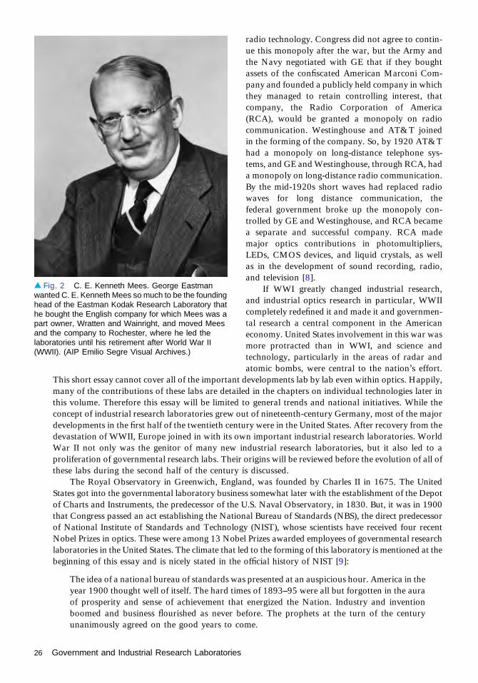
These people and industries involved in Ameri-can optics in WWI played a further enormous rolein the development of optics. A group of themincluding representatives from Eastman Kodak andBausch & Lomb met in the physics library at theUniversity of Rochester in November 1915 to foundthe Rochester Optical Society, with an explicit in-tention of also founding a national optical society,which they did when they led the founding of TheOptical Society at a meeting the following Februaryin Washington. Perley G. Nutting (Fig. 1) of theEastman Kodak Research Laboratory was the firstsociety president, and the second president was thesame Frederick E. Wright who led the glass effort atBausch & Lomb. Adolph Lomb was the first trea-surer of the society, and personally wrote checks tocover the budget deficits in the initial years. Thisconnection between the early industrial researchlaboratories and the founding of professionalsocieties and scientific journals was no coincidence.C. E. K. Mees, the founding head of the EastmanKodak Research Laboratories, wrote in his historyof the labs [6] that he and George Eastman dis-cussed the nature of the industrial research labora-tory that they planned to establish, and decided thatif they wanted to have the best scientists on theirstaff they would have to encourage them to publishand to interact with other scientists. Good scientists need this interaction to be happy and productive.Furthermore, there needed to be professional societies and journals to support their efforts. The wholedevelopment of the optical research establishment owes a debt to this industrial initiative. Theircontribution goes further. Mees and Eastman also decided that there needed to be an academicdepartment to train optical engineers and scientists and to carry out basic optics research. They, alongwith Edward Bausch, approached the President of the University of Rochester about founding such adepartment. In 1929 the Institute of Optics was founded with a promise of an initial $20,000 grant forequipment and continuing support of $20,000 per year for five years, renewable for five more. Meeshimself (Fig. 2) taught courses in photographic theory for many years in the Institute [7].
In 1925, Western Electric Research Laboratories and part of the engineering department of theAmerican Telephone & Telegraph Company joined to form Bell Telephone Laboratories, Inc., as aseparate entity. It was tasked to plan, design, and support the equipment that Western Electric built forBell System operating companies. A few workers were assigned to basic research, and the results wererather spectacular, as essays later in this volume attest, and include 14 Nobel Laureates for work carriedout in part or full at Bell Labs.
Another monopoly that led to the founding of an important industrial research laboratory was forradio communications. During WWI the Western Allies cut the German transatlantic telegraph cablesand the Central Powers maintained contact with neutral countries in the Americas via long-distanceradio communications. In 1917 the government of the United States took charge of the patents ownedby the major companies involved in radio manufacture to devote radio technology to military needs.After the war, the War and Navy departments sought to maintain a federal monopoly of all uses of
▴ Fig. 1. Perley G. Nutting unceasingly campaignedfor the establishment of a United States national opticalsociety. He started the campaign while working as oneof the first employees of the National Bureau ofStandards and later as one of the first employees of theEastman Kodak Research Laboratories. He led thesuccessful effort to found The Optical Society andserved as its first President. Courtesy of The OpticalSociety (OSA).
Government and Industrial Research Laboratories 25
radio technology. Congress did not agree to contin-ue this monopoly after the war, but the Army andthe Navy negotiated with GE that if they boughtassets of the confiscated American Marconi Com-pany and founded a publicly held company in whichthey managed to retain controlling interest, thatcompany, the Radio Corporation of America(RCA), would be granted a monopoly on radiocommunication. Westinghouse and AT&T joinedin the forming of the company. So, by 1920 AT&Thad a monopoly on long-distance telephone sys-tems, and GE and Westinghouse, through RCA, hada monopoly on long-distance radio communication.By the mid-1920s short waves had replaced radiowaves for long distance communication, thefederal government broke up the monopoly con-trolled by GE and Westinghouse, and RCA becamea separate and successful company. RCA mademajor optics contributions in photomultipliers,LEDs, CMOS devices, and liquid crystals, as wellas in the development of sound recording, radio,and television [8].
If WWI greatly changed industrial research,and industrial optics research in particular, WWIIcompletely redefined it and made it and governmen-tal research a central component in the Americaneconomy. United States involvement in this war wasmore protracted than in WWI, and science andtechnology, particularly in the areas of radar andatomic bombs, were central to the nation’s effort.
This short essay cannot cover all of the important developments lab by lab even within optics. Happily,many of the contributions of these labs are detailed in the chapters on individual technologies later inthis volume. Therefore this essay will be limited to general trends and national initiatives. While theconcept of industrial research laboratories grew out of nineteenth-century Germany, most of the majordevelopments in the first half of the twentieth century were in the United States. After recovery from thedevastation of WWII, Europe joined in with its own important industrial research laboratories. WorldWar II not only was the genitor of many new industrial research laboratories, but it also led to aproliferation of governmental research labs. Their origins will be reviewed before the evolution of all ofthese labs during the second half of the century is discussed.
The Royal Observatory in Greenwich, England, was founded by Charles II in 1675. The UnitedStates got into the governmental laboratory business somewhat later with the establishment of the Depotof Charts and Instruments, the predecessor of the U.S. Naval Observatory, in 1830. But, it was in 1900that Congress passed an act establishing the National Bureau of Standards (NBS), the direct predecessorof National Institute of Standards and Technology (NIST), whose scientists have received four recentNobel Prizes in optics. These were among 13 Nobel Prizes awarded employees of governmental researchlaboratories in the United States. The climate that led to the forming of this laboratory is mentioned at thebeginning of this essay and is nicely stated in the official history of NIST [9]:
The idea of a national bureau of standards was presented at an auspicious hour. America in theyear 1900 thought well of itself. The hard times of 1893–95 were all but forgotten in the auraof prosperity and sense of achievement that energized the Nation. Industry and inventionboomed and business flourished as never before. The prophets at the turn of the centuryunanimously agreed on the good years to come.
▴ Fig. 2 C. E. Kenneth Mees. George Eastmanwanted C. E. Kenneth Mees so much to be the foundinghead of the Eastman Kodak Research Laboratory thathe bought the English company for which Mees was apart owner, Wratten and Wainright, and moved Meesand the company to Rochester, where he led thelaboratories until his retirement after World War II(WWII). (AIP Emilio Segre Visual Archives.)
26 Government and Industrial Research Laboratories
At the recommendation of the Secretary of the Treasury, Congress passed a bill, which thepresident signed, to form NBS, which was to aid “manufacturing, commerce, the matters of scientificapparatus, the scientific work of the Government, of schools, colleges, and universities.” It was not justin the United States that the need for such a government laboratory was felt; in England the NationalPhysical Laboratory was founded in the very same year for these same purposes.
The staff of NBS in 1904 included in the Section on Light and Optical Instruments: Samuel W.Stratton, Perley G. Nutting, and Frederick J. Bates. This same Perley G. Nutting was already working tofound a national optical society before he was lured away to the newly formed Eastman KodakResearch Laboratory, where he led the effort to found the local Rochester society, and then OSA, ofwhich he was the first president.
We return our narrative to the onset of WWII when industrial and governmental optics researchhad a true phase transition in its development. As war broke out in Europe in 1939 a group of leadingscientists and academic administrators including Vannevar Bush, President of the Carnegie Institutionof Washington; James B. Conant, President of Harvard University; Frank B. Jewett, President of theNational Academy of Sciences and President of Bell Laboratories; Karl Compton, President of MIT;and Richard C. Tolman, Dean of the Graduate School at California Institute of Technology, wereconcerned with the lack of technological preparedness of the U.S. for its likely entry in the war. Theysuggested a plan for the establishment of the National Defense Research Committee (NRDC), whichVannevar Bush described in four paragraphs that he submitted to President Roosevelt. At the end of tenminutes he had an approval from the President, and an order creating NDRC was issued on 27 June1940. Some 30 years later in his biographical memoirs Bush describes the reasons for this initiative [10]:
There were those who protested that the action of setting up NDRC was an end run, a grab bywhich a small company of scientists and engineers, acting outside established channels, gothold of the authority and money for the program of developing new weapons. That, in fact, isexactly what it was. Moreover, it was the only way in which a broad program could belaunched rapidly and on an adequate scale. To operate through established channels wouldhave involved delays—and the hazard that independence might have been lost, that indepen-dence which was the central feature of the organization’s success.
Bush was appointed chairman, and the organization was established and expanded in 1942 tobecome the Office of Scientific Research and Development (OSRD), with Bush as director (Fig. 3). TheOSRD had three principal subdivisions at that time: the NDRC, with Conant as chairman; theCommittee on Medical Research (CMR), with A. Newton Richards as chairman; and the advisoryCouncil, with Bush as chairman. The latter included the chairmen of the National Advisory Committeeon Aeronautics (NACA), NDRC, and CMR, as well as representatives from the Army and Navy as acoordinating group. In addition, Bush was chairman of the Joint New Weapons Committee of the JointChiefs of Staff and, when the Manhattan District was created, chairman of its Military PolicyCommittee, which served as its board of directors [11].
Perhaps one might be tempted to say that the power grab was by Bush himself, but he had theconfidence of the President and Congress so that he was able to coordinate and to smooth the inevitablefriction between these varied groups remarkably well. Weisner summarizes quite nicely the organiza-tion that Bush set up:
The organization was a remarkable invention, but the most significant innovation was the planby which, instead of building large government laboratories, contracts were made withuniversities and industrial laboratories for research appropriate to their capabilities. OSRDresponded to requests from military agencies for work on specific problems, but it maintainedits independence and in many cases pursued research objectives about which military leaderswere skeptical. Military tradition was that a way had to be fought with weapons that existedat its beginning. Bush believed that World War II could be won only through advances intechnology, and he proved to be correct. In some instances, the armed forces were enthusias-tically cooperative. In others, resistance to innovation had to be overcome. Bush, himself, wentto Europe to make sure that the proximity fuse was introduced to the battlefield and usedeffectively.
Government and Industrial Research Laboratories 27

The major exception to the policy of avoiding the building of government laboratories was inthe development of the atomic bomb. After preliminary studies by NDRC and OSRD, itbecame clear that a colossal program would be needed, and Bush recommended to SecretaryStimson that the Army take over the responsibility. The result was the formation of ManhattanEngineering District by the Corps of Engineers. Bush with Conant as his deputy, maintained anactive scrutiny of the enterprise.
This was the foundation of science and engineering administration in the U.S. as it exists up untilnow. All of the developments in optics in the second half of the century grew up in this environment.Optics during the war was overseen by Division 16, Optics and Camouflage of the NDRC. It was led byGeorge Harrison. Paul Kelley describes elsewhere in this volume the optical developments during thisperiod. Well before the war was over, Bush started to plan how the momentum of research could besustained with new peacetime goals. President Roosevelt asked him to make recommendations ongovernment policies for combating disease, supporting research, developing scientific talent, anddiffusing scientific information. Four committees were set up to generate recommendations. On thebasis of these recommendations Bush submitted a report titled “Science—The Endless Frontier,” whichlaid out the proposals for organizing post-war science and technology. The argument for thegovernment to continue supporting research after the war was summed up in the report: “To createmore jobs we must make new and better and cheaper products. We want plenty of new, vigorousenterprises. But new products and processes are not born full-grown. They are founded on newprinciples and new conceptions which in turn result from basic scientific research. Basic scientificresearch is scientific capital.”
▴ Fig. 3 Vannevar Bush watches as President Truman presents James Conant with the Medal of Merit and BronzeOak Leaf Cluster in May, 1948. The nation was greatly appreciative of the leadership of Bush and Conant and otherscientists during the war, allowing Bush and Conant to build a structure to continue government support of researchafter the war through governmental laboratories and research grants for university basic research.
28 Government and Industrial Research Laboratories

The National Science Foundation was pro-posed, and a bill was introduced in Congress bySenator Warren Magnuson from Washington. Aftermuch argument in Congress and a veto by PresidentTruman, a modified version was signed by PresidentTruman in 1947. Vannevar Bush asked thatTruman not name him to the board of the newfoundation, suggesting that people were tired of hisrunning things. Even before the NSF was launched,the Office of Naval Research was established in1946 with the stated mission of “planning, foster-ing, and encouraging scientific research in recogni-tion of its paramount importance as related to themaintenance of future naval power and the preser-vation of national security.” The Air Force OfficeScientific Research would be formed in 1951 andthe Army Research Office in 1957, and the DefenseAdvanced Research Projects Agency (DARPA)was signed into existence by President Eisenhowerin 1958. Figure 4 shows the Laser Guide StarAdaptive Optics project, one of the technologiesthat came from the funding provided by thoseagencies. The National Aeronautics and Space Ad-ministration (NASA) grew out of the old NACAduring the administration of President Eisenhower.At present the Navy operates one laboratory andseventeen Warfare Centers. The Army operateseleven labs, and the Air Force operates one labora-tory and ten Technical Directorates.
The old Army-controlled Manhattan Projectduring the course of the war developed a numberof secret sites including Los Alamos, Hanford, andOak Ridge. There was also the reactor research labat the University of Chicago that spawned ArgonneNational Laboratory. After the war the Atomic Energy Commission took over the wartime laborato-ries, extending their lives indefinitely, and funding was obtained to establish a number of newlaboratories for classified as well as basic research. Each of the new laboratories was generally centeredaround some particle accelerators or nuclear reactors. At present, the organization in charge is theDepartment of Energy (DOE), and it administers 19 different national laboratories and provides morethan 40% of the total national funding for physics, chemistry, and materials science. While the DOEdirects most of its attention to nuclear, particle, and plasma physics, it supports major efforts in opticsas well, especially through its high-energy laser fusion programs and its x-ray light sources.
Another important source of funding for optics research is the independent research anddevelopment funds that are provided by indirect cost charges to military contracts, allowing militarycontractors to carry out internal research programs and keep their scientists and engineers busybetween contracts developing new technology. This supports long-term research efforts at manyindustrial laboratories.
This enormous research and development system that grew out of WWII is not without itsdetractors; many point to the address of Dwight David Eisenhower just three days before he left office.The President, who signed into existence many of the agencies that support this system warned, “In thecouncils of government, we must guard against the acquisition of unwarranted influence, whethersought or unsought, by the military–industrial complex. The potential for the disastrous rise ofmisplaced power exists and will persist.” As you look over the essays in this volume that review the
▴ Fig. 4 The Air Force Starfire Optical Range forlidar and laser guide star experiments is tuned to thesodium D2a line and used to excite sodium atomsin the upper atmosphere. This provides what isessentially a point source of light in the mesosphere touse for adaptive optics to remove blurring of groundbased imaging due to atmospheric turbulence.
Government and Industrial Research Laboratories 29

progress in optical science and technology, particularly over the past half century in which optics hasbecome an indispensable enabler in essentially every industry, it is hard to fault the model, given itsevident success. But even today, some 50 years after this speech, many would argue that we need to keepour guard up to see that this enormously beneficial system of research and development is notcorrupted.
References1. “Carl-Zeiss-Stiftung—Company profile, information, business description, history, background
information on Carl-Zeiss-Stiftung.” http://www.referenceforbusiness.com/history2/79/Carl-Zeiss-Stiftung.html.
2. R. Kane and H. Sell, Revolution in Lamps: A Chronicle of 50 Years of Progress, 2nd ed. (Fairmont Press,2001), p. 37, table 2–1.
3. “General Electric Research Lab,” http://www.edisontechcenter.org/GEresearchLab.html.4. C. R. Stroud, Jr., Brian O'Brien, 1898–1992, A Biographical Memoir (National Academy of Sciences,
2010).5. F. E. Wright, “War-time development of the optical industry,” J. Opt. Soc. Am. 2, 1 (1919).6. C. E. K. Mees, “The Kodak Research Laboratories,” Proc. R. Soc. Lond. 8 135, 133–147 (1948).7. C. Stroud, Jewel in the Crown (Meliora Press, 2004), p. 18.8. R. Sobel, RCA (Stein and Day, 1986).9. http://www.nist.gov/nvl/upload/MP275_06_Chapter_I-__AT_THE_TURN_OF_THE_CENTURY.
pdf.10. V. Bush, Pieces of the Action (William Morrow, 1970), p. 32.11. J. B. Wiesner, Vannevar Bush 1890–1974, Biographical Memoir (National Academy of Sciences, 1979).
30 Government and Industrial Research Laboratories
Camera History 1900 to 1940Todd Gustavson
IntroductionThe photographic process, announced in 1839 by the Frenchman Louis Jacques MandéDaguerre, captured and fixed the images that were viewed through a camera obscura. Thiswas accomplished through a combination of mechanics (the camera), optics (to improve theimage), and chemistry (to sensitize and process the image). Over the next forty years, improve-ments made to all aspects of the process—cameras, shutters, lenses, and chemistry—led tocheaper and simpler image making, generating a growing interest for the nonprofessionalphotographer.
The technicalities of early photography required the photographer to sensitize media shortlybefore exposure and then process the image immediately afterward. Although this system wasfine for the professional, it was generally too cumbersome and time-consuming for mostamateurs. On 13 April 1880, George Eastman of Rochester, New York, patented a machinefor coating gelatin dry plates. The following January, with the financial backing of Rochesterbusinessman Henry Strong, he formed the Eastman Dry Plate Company, one of the firstcommercial producers of light-sensitive photographic emulsions. With reliable plates nowavailable, companies worldwide began manufacturing cameras designed specifically to use them.
Eastman’s business expanded five years later with the introduction of his American Film, apaper-supported stripping film intended for the professional market. It was not well received bythe professionals, who considered it to be rather difficult to process. Undeterred, Eastman insteadused it in a new small box camera he named the Kodak. Introduced in 1888, the Kodak was aneasy-to-use “detective camera,” a box-style, point-and-shoot camera meant for the novicephotographer. Eastman’s camera required no adjustments, which was atypical of the time, butthe real innovation was after exposing the film: the camera was shipped back to the company forprocessing and reloading, marking the beginning of the professional photo-finishing industry.This novel feature was marketed with the advertising slogan “You press the button, we do therest,” which established the company’s business model: the promotion of cameras as the meansto selling highly profitable film and processing. Twelve years later, the Brownie camera wasadded to the camera line; its $1.00 selling price made photography available to just abouteveryone.
BrownieIntroduced by Eastman Kodak Company in 1900, the Brownie camera was an immediate publicsensation due to its simple-to-use design and inexpensive price. (See Fig. 1.) Now nearly anybody,regardless of age, gender, or race, could afford to be a photographer without the specializedknowledge or cost once associated with the capture and processing of images. An importantaspect of the Brownie camera’s rapid ascendancy in popular culture as a must-have possessionwas Eastman Kodak Company’s innovative marketing via print advertising. The company tookthe unusual step of advertising the Brownie in popular magazines instead of specialty photogra-phy or trade magazines with limited readership. George Eastman derived the camera’s name
PRE-1940
31

from a literary character in popular children’sbooks by the Canadian author Palmer Cox.Eastman’s astute union of product naming, witha built-in youth appeal, and inventive advertisingplacement had great consequence for the rise ofmodern marketing practices and mass consumerismin the twentieth century.
The Brownie was designed and manufacturedby Frank A. Brownell, who had produced all ofEastman Kodak’s cameras from the beginning. Theuse of inexpensive materials in the camera’s con-struction and George Eastman’s insistence that alldistributors sell the camera on consignment enabledthe company to control the camera’s $1 price tagand keep it within easy reach of consumers’ pocket-books. More than 150,000 Brownies were shippedin the first year of production alone, a staggeringsuccess for a company whose largest single-yearproduction to date had been 55,000 cameras (theNo. 2 Bullet, in 1896). The Brownie launched afamily of nearly 200 camera models and relatedaccessories, which over the next 60 years helped tomake Kodak a household name.
Folding Pocket KodakThe Kodak marketing plan was to sell new custo-mers interested in photography an affordableBrownie camera, then move them up to better, moreexpensive models. The company catalogs were fullof such model lines priced in incremental steps.From the basic box camera, the next logical stepwas the Folding Pocket Kodak. (See Fig. 2.) Intro-duced in 1897 (at the time it was an upgrade fromthe Pocket Kodak, the model replaced by theBrownie), the FPK, as it was commonly known,became the first of a long line of folding bellowscameras in common use for the next half century.These cameras were a popular travel accessorybecause they produced the large negative desiredby photographers, yet upon folding became smallenough to fit into a carrying case or coat pocket. Atthat time of undependable light sources and a cum-bersome enlargement process, the physical size ofthe camera usually determined the finished picturesize. The 3A (3A is a Kodak camera format intro-duced in 1903 with the No. 3A Folding Pocket
Kodak; it produced 3¼ × 5½-in. images on No. 122 film) was especially appealing, as it was availableat many price points. Largely determined by its various lens and shutter combinations, the 3Afunctioned both as a more serious entry-level camera, and also as the company’s flagship amateurproduct. Due to its prominent position in the company product line and long production run, the 3Areceived numerous upgrades throughout its history.
▴ Fig. 1. Brownie camera. Eastman KodakCompany, Rochester, New York, ca. 1901. Gift of AnselAdams, 1974.0037.1963.
▴ Fig. 2. No. 3A Folding Pocket Kodak Model B-4, w/Zeiss Tessar Lens. Eastman Kodak Company,Rochester, New York, ca. 1908. Gift of Eastman KodakCompany, 2001.1559.0012.
32 Camera History 1900 to 1940

In its early years, most 3A cameras were fitted with Bausch & Lomb (B&L) lenses and shutters.Eastman had first turned to B&L as the supplier of lenses for his original Kodak camera back in 1888, ayear after B&L produced its first photographic objective. However, Eastman Kodak offered otheroptions to the more serious photographer, as the 3A was available with the best lenses from Europe,including England’s Cooke Anastigmat (1907–1912) and Germany’s Georz Dagor (1903–1908), orZeiss Tessar (1908–1910). Bausch & Lomb signed a licensing agreement with Zeiss to produce theTessar in Rochester, and of course the 3A was available with those lenses (1906–1912). Eastman Kodakentered into its own agreement with Zeiss, and the 3A was produced with the Zeiss Kodak Anastigmat(1909–1912). Eastman Kodak Company began producing lenses of its own design in 1913; the 3Areceived the first version of the Kodak Anastigmat in 1914. The 3A was the first production camera tobe fitted with the coupled rangefinder, which put Kodak about 15 years ahead of most othermanufacturers. Beginning in the 1930s, high-end cameras such as the Contax (by Zeiss Ikon) andthe Leica (by E. Leitz) were fitted with coupled rangefinders. Even today, most higher-end digitalcameras use a form of this technology.
Institute of OpticsWorld War I changed the optical landscape in the United States. The industry relied on Germanmanufacturers for the supply of high quality optical glass, optics, and engineers. A number of steps weretaken to remedy the situation, the first being establishing The Optical Society (OSA) in 1916. Under theleadership of Perley G. Nutting, and with the support of optical scientists in Rochester, the opticalcenter of the United States, the OSA’s mission was to promote and disseminate knowledge of optics andphotonics. This was accomplished with published journals and by holding conferences, thus establish-ing a network of information exchange. The University of Rochester, with financial support from B&Land Eastman Kodak Company, established the Institute of Applied Optics (now known as the Instituteof Optics) in 1929. The president of the University, Reverend Benjamin Rush Rhees, hired RudolfKingslake, graduate of the Imperial College of Science and Technology in London, where he studiedunder Alexander Eugen Conrady, to teach at the new school. Kingslake became the head of EastmanKodak Company’s Optical Design Department in 1937, a position he held until retiring in 1968.Kingslake continued to teach at the University of Rochester during his “Kodak years”; he continuedteaching at the university into the 1980s.
Kodak Research Labs/Color PhotographyThe advancement of photography is about more than cameras and lenses; improvements in sensitizedmaterials has always played an extremely important role. The founding of the Kodak ResearchLaboratories may be George Eastman’s greatest contribution to photography. Established expressly forthe empirical study of sensitized materials, the Kodak Labs were among the first of their kind in theUnited States. Impressed with the laboratories he saw while visiting Germany in 1911, Eastman realizedthat the future of the industry would be color photography. He knew from his own early experimenta-tion in emulsion making that it would take more than lone individuals experimenting on their own inhome-brew labs to facilitate the future. For the founding director of the Kodak Labs, Eastman hired C.E. K. (Charles Edward Kenneth) Mees, managing director and a partner at Wratten & Wainwright, adry plate manufacturer in England best known for introducing panchromatic dry plates. To acquireMees’s services, Eastman bought his employer.
Of the many developments by the Kodak Labs, the most important was color film. The search forcolor in photography dates back to the medium’s earliest days. For the most part, colored photographswere exactly that, photographs with hand-applied color. There was a so-called color version of thedaguerreotype known as the Hillotype, though it is up for debate as to whether these plates had color ornot. Color photography largely remained a hand-applied art or rather complicated “laboratoryexperiment” based on James Clerk Maxwell’s three-color experiments until 1903 with the introduction
Camera History 1900 to 1940 33

of Autochrome plates by France’s Lumière brothers. Autochrome used the additive color process, withthe plates first coated with a mosaic screen made of microscopic potato starch grains, randomly dyedred, green, and blue; the empty spaces between the starch grains were filled with black and then coatedwith a panchromatic photographic emulsion. This rather odd-sounding system did work, but due to thefiltering nature of the plates, exposure times were quite long.
Kodachrome is usually considered to be the first practical color film. Two musician-scientists,Leopold Godowsky, Jr., and Leopold Mannes, began investigating color photography, filing their firstpatent application in 1921. (Godowsky and Mannes were boyhood friends who shared a commoninterest in music and photography. Mannes earned a bachelor’s degree in physics at Harvard Collegebut worked as a musical composer at the New York Institute of Art. Godowsky studied physics andchemistry as well as the violin at the University of California at Los Angeles. He was a soloist and firstviolinist with the Los Angeles and the San Francisco Symphony Orchestras.) C. E. K. Mees wasinformed of their research by a friend, Robert Wood, the next year, prompting Mees to travel to meetwith Mannes at New York City’s Chemist’s Club. Impressed with Mannes, Mees decided to assist thetwo young scientists in their work, first by supplying them with evenly coated plates, and then as ad hocmembers of the Kodak Research Labs. By 1930, Godowsky and Mannes had become regular membersof the company and moved to Rochester. The result was Kodachrome film, first introduced in 1935 as a16-mm ciné film and the next year for still photography as a 35-mm transparency film. The first multi-layered film, Kodachrome consisted of three separate black-and-white layers (with a yellow filteringlayer), for recording cyan, yellow, magenta, the subtractive color primary colors. When exposed, theseblack-and-white layers acted as “placeholders” to which color dyes were added during processing.Kodachome is still considered to be the most permanent color film.
35-mm Precision CamerasGeorge Eastman’s easy-to-use Kodak camera, introduced in 1888, marks the beginning of point-and-shoot photography. Since using it required no special knowledge, it was an ideal camera for the newlyconceived market of amateur novice photographers. Thomas Edison used film from the Kodak, slit to35 mm and then perforated on both edges, in his 1890s experiments perfecting the Kinetoscope, thefirst motion picture film viewer. 35-mm film became the standard film size of the motion pictureindustry. As film quality improved over the next couple of decades, a number of companiesaround the world began to experiment with the format for still photography. The Multi SpeedShutter Company of New York City (a company that also manufactured motion picture projectors)introduced the Simplex camera in 1914, the first still camera to use the now standard 24 × 36-mmimage size on 35-mm-wide film; this was twice that used for motion picture’s 18 × 24 mm. Soon after,other companies—such as Jules Richard of Paris, France, with the Homéos (the first 35-mm stereocamera) and New Ideas Manufacturing of New York City with the Tourist Multiple—would marketcameras using 35-mm film. These cameras used film acquired as leftover ends from the motion pictureindustry. It was a novel idea, but none were very successful, as most snapshot photographerspreferred using the well-established box or folding cameras. Still, a successful precision 35-mmcamera was on the horizon.
Leica AStarting about 1905, when he worked at the firm of Carl Zeiss in Jena, Germany, Oskar Barnack(1879–1936), an asthmatic who hiked to improve his health, tried to create a small pocketable camerato take on his outings. At the time, cameras using the most common format of 13 × 18 cm (5 × 7 in.)were quite large and not well suited for hiking. Around 1913, Barnack, by then an employee in chargeof the experimental department of the microscope maker Ernst Leitz Optical Works in Wetzlar,designed and hand built several prototypes of a small precision camera that produced 24 × 36-mmimages on leftover ends of 35-mm motion picture film. Three of these prototypes survive. The most
34 Camera History 1900 to 1940
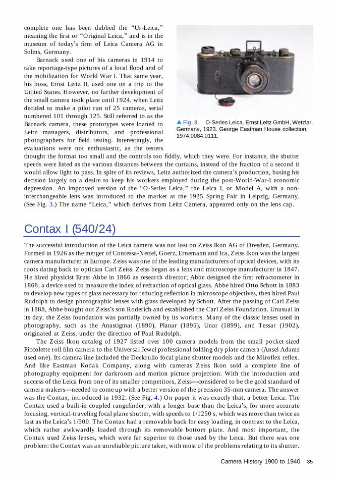
complete one has been dubbed the “Ur-Leica,”meaning the first or “Original Leica,” and is in themuseum of today’s firm of Leica Camera AG inSolms, Germany.
Barnack used one of his cameras in 1914 totake reportage-type pictures of a local flood and ofthe mobilization for World War I. That same year,his boss, Ernst Leitz II, used one on a trip to theUnited States. However, no further development ofthe small camera took place until 1924, when Leitzdecided to make a pilot run of 25 cameras, serialnumbered 101 through 125. Still referred to as theBarnack camera, these prototypes were loaned toLeitz managers, distributors, and professionalphotographers for field testing. Interestingly, theevaluations were not enthusiastic, as the testersthought the format too small and the controls too fiddly, which they were. For instance, the shutterspeeds were listed as the various distances between the curtains, instead of the fraction of a second itwould allow light to pass. In spite of its reviews, Leitz authorized the camera’s production, basing hisdecision largely on a desire to keep his workers employed during the post-World-War-I economicdepression. An improved version of the “O-Series Leica,” the Leica I, or Model A, with a non-interchangeable lens was introduced to the market at the 1925 Spring Fair in Leipzig, Germany.(See Fig. 3.) The name “Leica,” which derives from Leitz Camera, appeared only on the lens cap.
Contax I (540/24)The successful introduction of the Leica camera was not lost on Zeiss Ikon AG of Dresden, Germany.Formed in 1926 as the merger of Contessa-Nettel, Goerz, Ernemann and Ica, Zeiss Ikon was the largestcamera manufacturer in Europe. Zeiss was one of the leading manufacturers of optical devices, with itsroots dating back to optician Carl Zeiss. Zeiss began as a lens and microscope manufacturer in 1847.He hired physicist Ernst Abbe in 1866 as research director; Abbe designed the first refractometer in1868, a device used to measure the index of refraction of optical glass. Abbe hired Otto Schott in 1883to develop new types of glass necessary for reducing reflection in microscope objectives, then hired PaulRudolph to design photographic lenses with glass developed by Schott. After the passing of Carl Zeissin 1888, Abbe bought out Zeiss’s son Roderich and established the Carl Zeiss Foundation. Unusual inits day, the Zeiss foundation was partially owned by its workers. Many of the classic lenses used inphotography, such as the Anastigmat (1890), Planar (1895), Unar (1899), and Tessar (1902),originated at Zeiss, under the direction of Paul Rudolph.
The Zeiss Ikon catalog of 1927 listed over 100 camera models from the small pocket-sizedPiccolette roll film camera to the Universal Jewel professional folding dry plate camera (Ansel Adamsused one). Its camera line included the Deckrullo focal plane shutter models and the Miroflex reflex.And like Eastman Kodak Company, along with cameras Zeiss Ikon sold a complete line ofphotography equipment for darkroom and motion picture projection. With the introduction andsuccess of the Leica from one of its smaller competitors, Zeiss—considered to be the gold standard ofcamera makers—needed to come up with a better version of the precision 35-mm camera. The answerwas the Contax, introduced in 1932. (See Fig. 4.) On paper it was exactly that, a better Leica. TheContax used a built-in coupled rangefinder, with a longer base than the Leica’s, for more accuratefocusing, vertical-traveling focal plane shutter, with speeds to 1/1250 s, which was more than twice asfast as the Leica’s 1/500. The Contax had a removable back for easy loading, in contrast to the Leica,which rather awkwardly loaded through its removable bottom plate. And most important, theContax used Zeiss lenses, which were far superior to those used by the Leica. But there was oneproblem: the Contax was an unreliable picture taker, with most of the problems relating to its shutter.
▴ Fig. 3. O-Series Leica. Ernst Leitz GmbH, Wetzlar,Germany, 1923. George Eastman House collection,1974.0084.0111.
Camera History 1900 to 1940 35
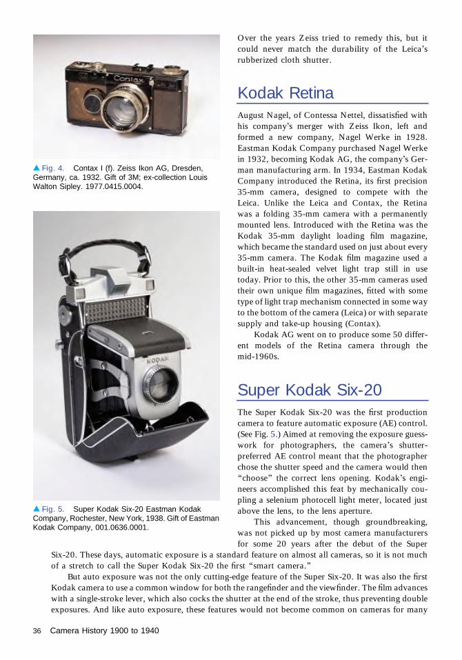
Over the years Zeiss tried to remedy this, but itcould never match the durability of the Leica’srubberized cloth shutter.
Kodak RetinaAugust Nagel, of Contessa Nettel, dissatisfied withhis company’s merger with Zeiss Ikon, left andformed a new company, Nagel Werke in 1928.Eastman Kodak Company purchased Nagel Werkein 1932, becoming Kodak AG, the company’s Ger-man manufacturing arm. In 1934, Eastman KodakCompany introduced the Retina, its first precision35-mm camera, designed to compete with theLeica. Unlike the Leica and Contax, the Retinawas a folding 35-mm camera with a permanentlymounted lens. Introduced with the Retina was theKodak 35-mm daylight loading film magazine,which became the standard used on just about every35-mm camera. The Kodak film magazine used abuilt-in heat-sealed velvet light trap still in usetoday. Prior to this, the other 35-mm cameras usedtheir own unique film magazines, fitted with sometype of light trap mechanism connected in some wayto the bottom of the camera (Leica) or with separatesupply and take-up housing (Contax).
Kodak AG went on to produce some 50 differ-ent models of the Retina camera through themid-1960s.
Super Kodak Six-20The Super Kodak Six-20 was the first productioncamera to feature automatic exposure (AE) control.(See Fig. 5.) Aimed at removing the exposure guess-work for photographers, the camera’s shutter-preferred AE control meant that the photographerchose the shutter speed and the camera would then“choose” the correct lens opening. Kodak’s engi-neers accomplished this feat by mechanically cou-pling a selenium photocell light meter, located justabove the lens, to the lens aperture.
This advancement, though groundbreaking,was not picked up by most camera manufacturersfor some 20 years after the debut of the Super
Six-20. These days, automatic exposure is a standard feature on almost all cameras, so it is not muchof a stretch to call the Super Kodak Six-20 the first “smart camera.”
But auto exposure was not the only cutting-edge feature of the Super Six-20. It was also the firstKodak camera to use a common window for both the rangefinder and the viewfinder. The film advanceswith a single-stroke lever, which also cocks the shutter at the end of the stroke, thus preventing doubleexposures. And like auto exposure, these features would not become common on cameras for many
▴ Fig. 5. Super Kodak Six-20 Eastman KodakCompany, Rochester, New York, 1938. Gift of EastmanKodak Company, 001.0636.0001.
▴ Fig. 4. Contax I (f). Zeiss Ikon AG, Dresden,Germany, ca. 1932. Gift of 3M; ex-collection LouisWalton Sipley. 1977.0415.0004.
36 Camera History 1900 to 1940

years. Features aside, the Super Kodak Six-20 is one of the most attractive cameras ever marketed. Itslovely clamshell exterior design was styled by legendary industrial designer Walter Dorwin Teague.
All this innovation came at a rather high cost, in both money and performance. The Super KodakSix-20, which in 1938 retailed for $225 (more than $2,000 today), had a reputation for beingsomewhat unreliable—the built-in self-timer was known to lock up the shutter. Since few units weremanufactured, just 719, it is one of the rarest of Kodak production cameras.
ConclusionCamera research and development largely went on hold during World War II. Much of the Germanphoto manufacturing industry was destroyed by the end of the war. The post-war era also saw thedivision of the Zeiss factories, split between East and West Germany. The low cost of post-World-War-II German labor had a direct impact on American manufacturing, causing most U.S. makers toconcentrate on inexpensive point-and-shoot cameras only. And the U.S., in trying to strengthen Japan,helped re-establish the fledgling camera manufacturing there, laying the seeds for what became thepremier camera manufacturing power for the rest of the century.
Camera History 1900 to 1940 37

OSA and the Early Days of VisionResearchPatricia Daukantas
By the second decade of the twentieth century, scientists studying human vision had come along way from the days of the ancient Greeks, who debated whether light rays shotthemselves out of the eyeball or emanated from objects in the visual field [1]. Neverthe-
less, the whole area of vision, especially the retina’s reaction to light, remained an important topicof research as The Optical Society (OSA) was organizing itself.
In the early days of the OSA, scientists had come to realize that vision sat at the intersectionof three fields: physiology, for the anatomy of the eye; physics, for the action of stimuli on the eye;and psychology, governing how the conscious brain interprets the eye’s sensations [2]. Reflectingthe interdisciplinary nature of the subject, vision-related articles published in 1920 weredistributed among 58 different journals from fields ranging from physics and engineering tozoology and pathology.
Between the two world wars, the scientists studying photochemistry—including two whowould become OSA Honorary Members—progressed from the simple eyes of sea creatures to thecomplexities of the human visual system. Researchers learned that the retina contains vitamin A,leading to generations of parents telling their children, “Eat your carrots—they’re good for youreyesight!” The new understanding of the eye paved the way for advances in vision correction andoptical instruments.
Visual Reception and Photochemical TheoryIn the very first issue of the Journal of The Optical Society of America (JOSA), two OSApresidents addressed some of the fundamental questions associated with human vision. LeonardThompson Troland (1889–1932) published his theory of how the eye responds to light [3]. PerleyG. Nutting (1873–1949) explored the status of a general photochemical theory that would applyto both the eye and photography and noted the similarities in the characteristic curves ofphotographic film and the eye’s response to light [4] (see Fig. 1).
Nutting, who had tried to start an optical society several years before OSA’s founding,served as the new organization’s president through 1917. In his later years his focus shifted togeophysics. Troland (Fig. 2), who served as OSA president in 1922 and 1923, died in the prime oflife when he fell off a cliff on Mount Wilson in California. Though he was never elected to theU.S. National Academy of Sciences, the academy gives an annual award in his name to youngresearchers who study the relationship between consciousness and the physical world. Inphotometry, the troland is a cgs unit for physical stimulation of the eye by light.
By 1919, OSA was becoming a leader in defining standards of visibility. That year, theSociety’s standards committee on visual sensitometry, led by Nutting, summarized [5] the extent ofscientists’ quantitative knowledge of the visibility of radiation, detection thresholds of intensity andcontrast, color vision, rates of adaptation to changes in light, and “absolute sensibility,” whichtakes into account the area of the retina exposed to light. For example, it was already wellestablished that the human cone is most sensitive to light with a wavelength of 556 nm.
PRE-1940
38

Photochemistry: Hecht,Hartline, and WaldDuring the 1920s and 1930s, three scientists whosetalents bridged the fields of physics, chemistry, andbiology made invaluable contributions to our un-derstanding of the molecules that react in the pres-ence or absence of light.
Born in an Austrian town now part of Poland,but raised in the United States, Selig Hecht (1892–1947) (Fig. 3) explored the photochemistry of visionby studying animals whose visual systems are muchsimpler than those of humans: the worm Ciona andthe clam Mya. Those organisms’ reactions to lightwere slow enough that they could be measuredwithout sophisticated apparatus [6].
Hecht began his studies of the photoreceptorprocess immediately after receiving his Ph.D., whenhe spent a summer at the facility now known as theScripps Institution of Oceanography. There he inves-tigated the sensitivity of Ciona to light. As he movedamong several institutions in the United States andEngland, he studied the rate at which visual purple(now known as rhodopsin) decomposes upon expo-sure to light [7], the bleaching of rhodopsin in solu-tion [6], and (with Robert E. Williams) the spectral sensitivity of human rod vision [8]. Hecht ended up atColumbia University, where, with his frequent collaborator Simon Shlaer, he built an instrument for
▴ Fig. 1. P. G. Nutting’s comparison of the sensitivity of photographic film (left) and human vision (right) to light [4].For film, optical density is plotted against the logarithm of exposure; for vision, reaction is plotted against thelogarithm of light intensity. The lower curve on the vision graph, “photometric sensibility,” was determinedexperimentally, according to Nutting, whereas the upper curve, “sensation,” was determined “by integration.”
▴ Fig. 2. Leonard Thompson Troland, OSApresident from 1922 to 1924. (AIP Emilio Segre VisualArchives.)
OSA and the Early Days of Vision Research 39

measuring the dark adaptation of the human eye,leading to one of the classic experiments in eyesensitivity, still taught today [9].
Hecht considered himself a physiologist, but heserved a term as an OSA director at large andanother term on JOSA’s editorial board [6]. In1941, OSA awarded him the Frederic Ives Medalfor overall distinction in optics.
Trained as a physician, Haldan Keffer Hartline(1903–1983) (Fig. 4) never practiced medicine. In-deed, after receiving his M.D. from Johns Hopkins,he spent a year Europe studying mathematics andphysics under Arnold Sommerfeld and WernerHeisenberg. He was disappointed that he lackedthe background to keep up with the pioneeringphysicists, but his quantitative bent served him wellin his research career.
Hartline spent the 1930s as a medical physicist atthe University of Pennsylvania, where he investigatedthe visual systems of the horseshoe crab (Limuluspolyphemus). In 1932, he and colleague Clarence H.Graham made the first recording of the electricalactivity of a single fiber taken from the optic nerveof a horseshoe crab. (Five years earlier, another teamhad studied the electrical pulses of the trunk of an eel’soptic nerve, but could not separate the fibers.) Theirwork revealed that the intensity of the light falling onthe photoreceptor is reflected in the rate of dischargeof the nerve’s electrical pulses [10,11].
Subsequently, Hartline progressed to studies ofsingle optic-nerve cells from vertebrate retinas andmeasured their varying responses to light: somesignaled during steady illumination, whereas othersresponded to the initiation or cessation of light[10,12]. By 1940, he came to realize that the gan-glion cells in the retina received exciting and inhi-biting stimuli through various pathways fromdifferent photoreceptors, and the optic nerve fiber,attached to the ganglion, serves as the final pipelineto transmit the signals to the brain [13]. Finally,Hartline discovered the effect now known as lateralinhibition in the Limulus compound eye sometimeduring the late 1930s, although he did not publish areport on it until 1949 [10].
George Wald (1906–1997) (Fig. 5), one ofHecht’s graduate students at Columbia University,took his mentor’s work further. As a student,Wald worked on the visual functioning of theDrosophila fruit fly and participated in Hecht’sphotoreceptor research. After he completed hisdoctorate in 1932, Wald identified the substanceknown as vitamin A—which was itself discoveredonly in 1931—in the retina.
▴ Fig. 3. Selig Hecht. (AIP Emilio Segre VisualArchives, Physics Today Collection.)
▴ Fig. 4. Haldan Keffer Hartline. (Eugene N. Kone,Rockefeller Institute, courtesy AIP Emilio Segre VisualArchives, Physics Today Collection.)
40 OSA and the Early Days of Vision Research

The German scientist Franz Christian Bollhad discovered rhodopsin, the primary light-sensitive pigment in the retina’s rod cells, backin 1876, but nobody before Wald knew the exactchemical mechanism that made the substancereact to light. During postdoctoral research in thelaboratory of German biochemist Otto Warburg,Wald took the absorption spectrum of rhodopsinand found that the pigment contains carotenoids,which he found intriguing, because physicians hadalready connected nutritional night blindness withvitamin A deficiency [14].
Working with a Swiss researcher, Paul Karrer,Wald extracted vitamin A from the retinas of cattle,sheep, and pigs, and then moved to the Heidelberglab of another Nobel laureate, Otto Meyerhof. Withthe clock ticking down on his time in Europe—afterAdolf Hitler came to power, the U.S. NationalResearch Council recalled the young Jewish postdochome—Wald used a shipment of frogs, deliveredwhile everyone else was vacationing, to gain arevolutionary insight. Since dark-adapted retinascontained a carotenoid slightly different from thevitamin A found in light-adapted retinas, he rea-soned that the carotenoid, which he initially called retinene, was bound to the protein in rhodopsin andwas released upon exposure to light, then gradually recombined to the rhodopsin protein to reverse theprocess [14]. (Later scientists changed retinene’s name to retinal.)
Wald moved to Harvard University in 1934 and continued studying the chemical reactions withinthe retina both at Harvard and the Marine Biological Laboratory at Woods Hole, Massachusetts. Hebegan investigating pigment molecules in the retina’s cone cells, but World War II duties interruptedthat line of work, so the important research he and his co-workers conducted on the red-sensitivepigment of the cones was not completed until the mid-1950s.
Hartline and Wald, along with Finnish–Swedish scientist Ragnar Granit (1900–1991), shared the1967 Nobel Prize in Physiology or Medicine for their studies of vision systems. Hartline’s 1940 JOSApaper was cited as one of the works for which he won the Nobel [15]. Hartline and Wald also werenamed OSA Honorary Members, the former in 1980, the latter in 1992.
Lasting ConsequencesMany of the discoveries about the eye as a visual system did not bear practical fruit until after theinterwar (1916–1940) period. The studies of sensitivity performance and contrast thresholds of thehuman eye formed the basis of everything from television and computer displays to the design ofhighway signs, which must be read in mere milliseconds for safety’s sake [16,17]. That early twentiethcentury work continues to enhance many aspects of our twenty-first century life.
References1. J. P. C. Southall, “Early pioneers in physiological optics,” J. Opt. Sci. Am. 6, 827–842 (1922).2. L. T. Troland, The Present Status of Visual Science, Bulletin of the National Research Council of the
National Academy of Sciences (U.S.A.) (1922), Vol. 5, No. 27, pp. 1–2.
▴ Fig. 5. George Wald. (Photo by Bachrach.)
OSA and the Early Days of Vision Research 41

3. L. T. Troland, “The nature of the visual receptor process,” J. Opt. Sci. Am. 1, 3–14 (1917).4. P. G. Nutting, “A photochemical theory of vision and photographic action,” J. Opt. Sci. Am. 1(1),
31–36 (1917).5. P. G. Nutting, “1919 report of standards committee on visual sensitometry,” J. Opt. Sci. Am. 4(2),
55–79 (1919).6. G. Wald, “Selig Hecht, 1892–1947: a biographical memoir,” in Biographical Memoirs (The National
Academy Press, 1991), Vol. 60, pp. 80–101.7. S. Hecht, “Photochemistry of visual purple: I. The kinetics of the decomposition of visual purple by
light,” J. Gen. Physiol. 3(1), 1–13 (1920).8. S. Hecht and R. E. Williams, “The visibility of monochromatic radiation and the absorption spectrum of
visual purple,” J. Gen. Physiol. 5(1), 1–33 (1922).9. S. Hecht and S. Shlaer, “An adaptometer for measuring human dark adaptation,” J. Opt. Sci. Am. 28,
269 (1938).10. F. Ratliff, “Haldan Keffer Hartline, 1903–1983: a biographical memoir” in Biographical Memoirs (The
National Academy Press, 1990), Vol. 59, pp. 196–213.11. H. K. Hartline and C. H. Graham, “Nerve impulses from single receptors in the eye, “J. Cell. Comp.
Physiol. 1, 277–295 (1932).12. H. K. Hartline, “Intensity and duration in the excitation of single photoreceptor units,” J. Cell. Comp.
Physiol. 5, 229–247 (1934).13. H. K. Hartline, “The nerve messages in the fibers of the visual pathway,” J. Opt. Sci. Am. 30, 239–247
(1940).14. J. E. Dowling, “George Wald, 1906–1997: a biographical memoir” in Biographical Memoirs (The
National Academy Press, 2000), Vol. 78, pp. 298–317.15. J. N. Howard, “Milestone JOSA articles from 1917–1973,” Opt. Photon. News 18(11), 20–21 (2007).16. A. Rose, “The sensitivity performance of the human eye on an absolute scale,” J. Opt. Sci. Am. 38,
196–208 (1948).17. H. R. Blackwell, “Contrast thresholds of the human eye,” J. Opt. Sci. Am. 36, 624–632 (1946).
42 OSA and the Early Days of Vision Research

Evolution of Color Science throughthe Lens of OSARoy S. Berns
The Optical Society (OSA) was the dominant professional society in the evolution of colorscience, both through its many technical committees and through the Journal. Thischapter highlights some of the many significant activities and publications that occurred
through the 1950s.OSA established the Committee on Colorimetry in 1919 chaired by I. G. Priest from the
National Bureau of Standards and during its first year circulated a preliminary draft [1]. Thecommittee’s first report was published in the Journal in 1922, authored by the currentchairman and president of the Society, L. T. Troland [2]. This remarkable 64-page reportoutlined the basis of photometry and colorimetry, including visibility and color-matchingfunction data (referred to as the OSA excitation curves), terminology for visual description,chromaticity diagrams, complementary wavelengths, standard illuminants, color temperature,optimal color filters for trichromatic color reproduction, visual colorimetry, and transforma-tion of primaries. All of these concepts would be central to establishing the 1924 Vλ visibilitycurve and the 1931 CIE colorimetric system, XYZ and xyY. The Colorimetry Committee wasa driving force in the evolution of modern colorimetry, culminating with the book The Scienceof Color published in 1953 [3]. The book indicates the breadth of expertise of the committeeand that color science is multi-disciplinary as it includes physics, optics, physiology, psycho-physics, and history beginning with our first use of colored materials hundreds of thousands ofyears ago.
The first color order system that was based on extensive psychophysics was the Munsellsystem. The Munsell Value scale quantified visual compression by establishing the relation-ship between incident light and perceived lightness [4]. It has been used to support Steven’sexponential model of visual compression and relate luminance factor to CIE lightness, L*. AnOSA committee performed extensive research leading to the current definition of the Munsellsystem [5]. These data were used by Adams to derive the precursor to CIELAB [6]. TheMunsell system is a cylindrical system, and as a consequence, neighboring samples are notequidistant. In addition, samples of constant hue vary in either lightness or chroma, but notboth simultaneously as occurs in common coloration. In the late 1940s an OSA committee,chaired by D. B. Judd from the National Bureau of Standards, was established to develop anew color order system where samples were equidistant in all three dimensions based on aregular rhombohedral crystal lattice structure to [7]. The OSA Uniform Color Scales were theresult thirty years later. Both systems are still used to develop and evaluate colorimetric-basedcolor spaces for visual uniformity.
Any quantitative color description of objects depends on measuring the spectral reflectancefactor. A breakthrough occurred during the 1930s when A. C. Hardy, a professor at theMassachusetts Institute of Technology, developed the first recording spectrophotometer whoseillumination geometry was optimized for measuring materials via an integrating sphere wherethe specular component could be included or excluded, the latter correlating with theappearance of glossy materials [8]. General Electric manufactured the Hardy spectrophotom-eter. By the late 1940s, it was possible to interface the instrument to an automatic tristimulusintegrator [9], and as a result, color measurements were reported as a spectral graph and CIE
PRE–1940
43

tristimulus values. One drawback of this approach was the high cost. Hunter made color measure-ment much more accessible with the development of a color-difference meter using color filters andthree photodetectors, first presented at an OSA Annual Meeting in 1948 [10].
When the CIE system was promulgated in 1931, there were three standard sources, A, B, and C,representing incandescent, sunlight, and daylight, respectively. Source C was produced by filteringincandescent lighting with bluish liquid filters. Such a light was very deficient in UV and short-wavelength visible radiation compared with natural daylight. Measurements of daylight, principalcomponent analysis, and a very clever approach to calculate the eigenvector scalars for a specificcorrelated color temperature resulted in the CIE D series illuminants [11, 12]. Today, CIE illuminantsD50 and D65 are used extensively in color reproduction and color manufacturing, respectively.
All specifications include tolerances, and as early as 1932 [13], the Journal began publishingresearch demonstrating the CIE system’s lack of uniformity with respect to color discrimination,research proposing linear and nonlinear transformations that improved correlation, and psychophysi-cal data from discrimination experiments. At the forefront of this research was D. L. MacAdam, astudent of Hardy at MIT, who went on to have a distinguished career at the Eastman Kodak ResearchLaboratories. In the early 1940s, he built an apparatus to measure color-matching variance thatresulted in the “MacAdam ellipses,” still used as a discrimination dataset [14]. His research andleadership resulted in the 1960 uv and 1976 u′v′ uniform chromaticity scale diagrams and the 1976L*a*b* and L*U*V* uniform color spaces.
An interesting research topic was designing color reproduction systems that could be related tocolorimetry by linear transformation. During the late 1930s, Hardy and Wurzburg [15], MacAdam[16], and Yule [17] laid the groundwork for today’s color management for both additive andsubtractive imaging systems.
We all use manufactured products meeting a color specification. Predicting and controlling a recipeis invaluable for coloration systems where the colorants and media both absorb and scatter light. Thetheory proposed in 1931 by P. Kubelka and F. Munk and published in the Journal in 1948 [18]continues to be used successfully in textiles, plastics, and coatings. In 1942, J. L. Saundersondemonstrated its effectiveness for the coloring of plastics, particularly by accounting for refractiveindex discontinuities at the surface [19].
Today, color science has evolved from tristimulus XYZ, through L*a*b* and L*u*v*, to color-appearance spaces such as CIECAM97s and CIECAM02. A key requirement of such spaces isaccounting for the effects of chromatic adaptation. Such research began in the 1950s and the seminalexperiments by R. W. Burnham, R. M. Evans, and S. M. Newhall from Eastman Kodak remain reliableand viable data [20].
I will end my highlight tour with Ref. [21], which describes how MacAdam created separation platesfor printing both the color gamut of a set of offset printing inks and a spectrum. A 19-page articleappeared in the 3 July 1944 issue of Life magazine, titled “Color: it is the response of vision to wavelengths of light” [22]. This remarkable article includes colored images of a dispersed spectrum, additiveand subtractive mixing, principles of selective absorption of colored filters, spectral reflectance curves of alemon and a tomato, the Hardy recording spectrophotometer, the visible spectrum, the Munsell system,an afterimage demonstration using the American flag, and several other optical illusions. The 1931 CIEsystem was used to calibrate the color separations where dominant wavelength represented the spectralhues and, in turn, mixtures of the printing inks. Incredibly, I have MacAdam’s copy of the article. Thearticle summarizes color science and, indirectly, the tremendous impact the OSA has had on its evolution.
References1. “1919 Report of the Standards Committee on Colorimetry,” J. Opt. Soc. Am. 4, 186–187 (1920).2. L. T. Troland, “Report of Committee on Colorimetry for 1920–21,” J. Opt. Soc. Am. 6, 527–591
(1922).3. Committee on Colorimetry of The Optical Society of America, The Science of Color (Thomas Y.
Crowell, 1953).
44 Evolution of Color Science through the Lens of OSA

4. A. E. O. Munsell, L. L. Sloan, and I. H. Godlove, “Neutral Value Scales. I. Munsell Neutral ValueScale,” J. Opt. Soc. Am. 23, 394–402 (1933).
5. S. M. Newhall, D. Nickerson, and D. B. Judd, “Final report of the O.S.A. Subcommittee on the Spacingof the Munsell Colors,” J. Opt. Soc. Am. 33, 385–411 (1943).
6. E. Q. Adams, “X-Z planes in the 1931 I.C.I. system of colorimetry,” J. Opt. Soc. Am. 32, 168–173(1942).
7. D. B. Judd, “Progress Report by Optical Society of America Committee on Uniform Color Scales,” J.Opt. Soc. Am. 45, 673–676 (1955).
8. A. C. Hardy, “A new recording spectrophotometer,” J. Opt. Soc. Am. 25, 30–310 (1935).9. H. R. Davidson and L. W. Imm, “A continuous, automatic tristimulus integrator for use with the
recording spectrophotometer,” J. Opt. Soc. Am. 39, 942–944 (1949).10. R. S. Hunter, “Photoelectric color difference meter,” J. Opt. Soc. Am. 48, 985–993 (1958).11. H. R. Condit and F. Grum, “Spectral energy distribution of daylight,” J. Opt. Soc. Am. 54, 937–940
(1964).12. D. B. Judd, D. L. MacAdam, G. Wyszecki, H. W. Budde, H. R. Condit, S. T. Henderson, and J. L.
Simonds, “Spectral distribution of typical daylight as a function of correlated color temperature,” J. Opt.Soc. Am. 54, 1031–1040 (1964).
13. D. B. Judd, “Chromaticity sensibility to stimulus differences,” J. Opt. Soc. Am. 22, 72–107 (1932).14. D. L. MacAdam, “Visual sensitivities to color differences in daylight,” J. Opt. Soc. Am. 32, 247–273
(1942).15. A. C. Hardy and F. L. Wurzburg, Jr., “The theory of three-color reproduction,” J. Opt. Soc. Am. 27,
227–240 (1937).16. D. L. MacAdam, “Photographic aspects of the theory of three-color reproduction,” J. Opt. Soc. Am. 28,
399–415 (1938).17. J. A. C. Yule, “The theory of subtractive color photography,” J. Opt. Soc. Am. 28, 419–426 (1938).18. P. Kubelka, “New contributions to the optics of intensely light-scattering materials. Part I,” J. Opt. Soc.
Am. 38, 448–448 (1948).19. J. L. Saunderson, “Calculation of the color of pigmented plastics,” J. Opt. Soc. Am. 32, 727–729 (1942).20. R. W. Burnham, R. M. Evans, and S. M. Newhall, “Prediction of color appearance with different
adaptation illuminations,” J. Opt. Soc. Am. 47, 35–42 (1957).21. D. L. MacAdam, “Design of a printed spectrum,” J. Opt. Soc. Am. 35, 293–293 (1945).22. Life magazine, 3 July 1944.
Evolution of Color Science through the Lens of OSA 45


PRE–1940 1941–1959 1960–1974 1975–1990 1991–PRESENT


Introduction: Advances in OpticalScience and TechnologyPaul Kelley
World War II and the Start of the Cold WarThe decades of the 1940s and 1950s saw tremendous change. The United States entered the waras the leading industrial power. It became even more dominant as the war progressed and theEuropean Allies and the Axis Powers suffered great damage. The Cold War, which startedshortly after World War II, led to further changes in the industrial outlook of the United Statesand the world in general. The harnessing of science in the national interest had become a priorityprior to the war, and the Cold War and the development of nuclear weapons made its applicationeven more imperative. At the same time, increased industrial sophistication led to more relianceon science to facilitate change and to the application of the tools of science in everyday industrialactivity. A diverse group of scientific entrepreneurs developed new technological applications inacademia, small start-ups, and corporate research laboratories. Optics and applications of opticsplayed an important role in this progress.
In war time, the United States could not rely on Germany for optical materials andsophisticated optical designs. This had occurred in the First World War, and the U.S. did notwant to have this problem repeated. Through the National Defense Research Committee(NRDC) a robust capability was developed for designing and manufacturing innovative opticsfor aerial reconnaissance. Optical scientists and engineers also contributed to the development ofgun sights, range finders, and submarine periscopes. Anti-reflection coatings, which had beenintroduced in the 1930s, were developed and applied to military optics. Camouflage was anotherimportant area of optics that rapidly progressed during the war.
In the 1950s Edwin Land and James Baker persuaded President Eisenhower to develop the U-2for surveillance of the Soviet Union. Baker had been a leading designer of aircraft reconnaissancecameras. His skill at optical design together with Land’s close collaboration with the aircraftdesigner, Kelly Johnson of Lockheed, led to a well-integrated, optimal system still in use today. TheU-2 was designed to fly above the existing intercept altitude of Soviet antiaircraft missiles and theU.S. was quite surprised when the USSR deployed a more capable missile system.
In 1947 Land introduced instant photography. In the black-and-white process, two sheets ofpaper are employed, one to produce a negative image, the other a positive. The same basicmethod as in conventional photography is used to produce a negative image. The negative paperis coated with small crystals of silver halide. Exposure to light produces some free silver atoms onthe crystallites. After exposure, liquid chemicals are released that begin the development. The freeatoms act as a nucleus for further free silver production, turning the exposed crystallites dark.Some of the silver halide crystals that are not initially exposed to light are transported to theadjacent second sheet of paper and then developed to produce a positive image. The Polaroidcamera soon became very popular because of the excitement of instantly seeing one’s photo-graphs. Polacolor that produced color prints was introduced in 1963.
Applied spectroscopy, which saw increased application during the war, blossomed after thewar as manufacturing became increasingly complex and diverse [1]. Synthetic rubber was crucial to
1941–1959
49
the military, and infrared spectroscopy played a vital role in the rubber manufacturing process. The entryof Perkin-Elmer and Beckman into the spectrometer business was motivated by the use of their equipmentin rubber manufacturing and fuel refining. Chemists, biologists, and other scientists soon came toembrace the use of physical measurements, most particularly optical spectroscopy in the infraredregion. In 1950, the first Pittsburgh Conference on Analytical Chemistry and Applied Spectroscopy(Pittcon) was held. Optical techniques continue to play a central role in this enormous conference,which in 2015 had 16,000 attendees, 925 exhibitors, and more than 2000 sessions.
In 1957 fiber endoscopes were used for medical imaging by Hirschowitz employing bundles of cladfibers developed by Peters and Curtiss at Michigan [2,3]. In 1930 Heinrich Lamm demonstrated theconcept of imaging through fiber bundles, H. H. Hopkins developed the fiberscope using coherent fiberbundles in the early 1950s [4], and, also in the early 1950s, A. C. S. van Heel proposed the use ofcladding to avoid crosstalk between fibers. Fiber endoscopes are now widely used in clinical medicine,and fiber optical communication relies on the use of clad fibers.
In 1961 Xerox announced the first Xerox copier, which was based on an invention by ChesterCarlson in 1938. The basic idea was to use optical transfer to produce an electrostatic pattern or imageon a drum. This pattern then attracted black material (toner), which could be transferred to paper.Other printing technology developments in the 1940s and 1950s included phototypesetting, inkjetprinters, and dye sublimation printing. A somewhat related area, photolithography of semiconductorcircuits, was initially developed by Andrus and Bond at Bell Labs [5,6]. This was based on techniquesused to make printed circuits. In one of its first large-scale applications, the printed circuit had been usedduring World War II for proximity fuses. The work of Andrus and Bond was quickly followed byefforts at Texas Instruments and Fairchild to miniaturize silicon circuits, an effort that would lead to themicroelectronics revolution.
The most revolutionary invention in the century of optics, the laser, was first realized just after thisperiod ended. Its precursor, the maser, came in the 1950s. Gordon, Zeiger, and Townes reported [7] theoperation of the ammonia maser in 1954; this was followed by the development of solid state masersused in radio astronomy [8]. In 1958 Schawlow and Townes published a paper [9] describing thephysics of masers and lasers and a proposed method for making a laser. The next year a conference washeld at Shawanga Lodge in New York State, where further discussions were held concerning thepossible operation of the laser [10]. The race was on.
References1. From Classical to Modern Chemistry: The Instrumental Revolution, P. J. T. Morris, ed. (Royal Society
of Chemistry, London, 2002).2. B. I. Hirschowitz, “Endoscopic examination of the stomach and duodenal cap with the fiberscope,”
Lancet 1, 1074–1078 (1961).3. L. E. Curtiss, B. I. Hirschowitz, and C. W. Peters, J. Opt. Soc. Am. 47, 117 (1957). Paper FC63 at the
OSA Annual Meeting.4. H. H. Hopkins and N. S. Kapany, “A flexible fiberscope using static scanning,” Nature 173, 39–41
(1954).5. J. Andrus, “Fabrication of semiconductor devices,” U.S. patent 3,122,817 (3 March 1964).6. J. Andrus and W. L. Bond, “Photoengraving in transistor fabrication,” in F. J. Biondi et al., eds.,
Transistor Technology, Vol. III (D. Van Nostrand, Princeton, 1958), pp. 151–162.7. J. P. Gordon, H. J. Zeiger, and C. H. Townes, “Molecular microwave oscillator and new hyperfine
structure in the microwave spectrum of NH3,” Phys. Rev. 95, 282 (1954).8. J. A. Giordmaine, “Centimeter wavelength radio astronomy including observations using the maser,”
Proc. Natl. Acad. Sci. 46, 267–276 (1960).9. A. L. Schawlow and C. H. Townes, “Infrared and optical masers,” Phys. Rev. 112, 1940 (1958).
10. Quantum Electronics, C. H. Townes, ed. (Columbia University, 1960). Shawanga Lodge ConferenceProceedings.
50 Introduction: Advances in Optical Science and Technology

Inventions and Innovationsof Edwin LandJeff Hecht
Edwin Land was the Thomas Edison of twentieth-century optics, a prolific inventor andentrepreneur. His milestone introduction of instant photography, at an Optical Societyspring meeting in New York on 21 February 1947, often overshadowed his other
contributions, ranging from 3D movies to surveillance satellites.Land’s first transformative invention was the plastic sheet polarizer in 1928, when he was
not yet 20. Fascinated by polarization, he tried growing large sheets of iodoquinine sulfate, apolarizing material invented in the nineteenth century. That did not work, but he found he couldmake polarizing sheets by applying an electric or magnetic field to align tiny crystals of thematerial, then embedding them in a celluloid film. Later he invented a process for makingpolarizing sheets by stretching the plastic to align the polarizing crystals. Those plastic sheetpolarizers became the foundation of the Polaroid Corporation.
Land also invented a polarizing filter system that he hoped could solve a major highwaysafety problem—headlights blinding other drivers at night. He proposed applying polarizersaligned one way to headlights and orthogonal polarizers to windshields. Light scatteredfrom the environment would lose its polarization, so the windshield polarizer would transmitit. But the polarized windshield would block light directly from the headlights, so only afew percent would reach the driver’s eyes. It sounded great, but the auto industry neverembraced it.
Instead, the polarized film found other applications. In 1934, Eastman Kodak contracted tobuy it for photographic filters. Kodak was also interested in polarizing sunglasses, but Land got abetter deal from American Optical and in 1935 signed a contract to supply them with polarizingfilm bonded to glass for sunglasses.
Meanwhile, Land invented polarization-based stereoscopy for 3D movies. The first genera-tion of 3D movies projected overlapping images in two colors, which viewers watched throughglasses with red and green or red and blue filters. Land realized that glasses with a pair ofpolarizers, one horizontal and the other vertical, could give the same effect for overlappingimages projected in horizontal and vertical polarization. A short polarized 3D film at theChrysler Pavilion was a hit at the 1939 New York World’s Fair. World War II interrupted 3Dmovie development but created a need for stereoscopic surveillance imaging that was met by thevectograph, a transparency-based process invented by Joseph Mahler and Land at Polaroid.Polarized 3D movies returned after the war to produce a brief boom in the early 1950s, includingthe first color 3D film, Bwana Devil.
A prescient question asked by Land’s young daughter during a 1943 vacation launched hisquest for instant photography. Why couldn’t she see the photo he had taken right away? Land’slogical mind realized it was a matter of chemistry, so he invented a self-developing film thatcombined exposure and processing of the negative and transfer to a positive. In early versions,the photographer pulled a paper tab or leader after exposure, starting a series of events. Inside thecamera, a pair of rollers pressed the positive and negative sheets together and spread a processingfluid between them. This then emerged from the camera and, after a brief specified waiting time,the photographer pulled the two sheets apart to display the image. Afterward, brushing a finalcoating across the image could preserve it.
1941–1959
51

The first Polaroid cameras had input rolls of negative and positive monochromatic film. Colorfilm followed in the late 1950s. Polaroid introduced film packs combining both types in the early1960s, simplifying handling. Instant photography delighted amateurs, and also found many otherapplications—notably, recording oscilloscope traces in research labs. Theodore Maiman’s notebookrecording the first laser includes Polaroid prints of laser pulse traces.
Land’s success lay in hiding the messy chemistry inside the film package. The most refined versionwas the SX-70 color film introduced in 1972, in which each photo was a separate dry plastic packageejected by the camera after exposure. The image area was pale green when ejected, then took on its finalcolor over several minutes. It marked the pinnacle of Polaroid’s instant-photography success; a 1977effort to introduce Polavision instant movies was a commercial failure.
Behind the scenes, Land was a pioneer in optical surveillance from aircraft and satellites. In 1952 heserved on a panel that recommended flying a spy plane at 70,000 feet over the Soviet Union tophotograph military facilities. He drew on that experience in 1954, when he was named to the steeringcommittee that proposed the U-2 spy plane, which performed exactly that mission, collecting the firstreliable data on Soviet nuclear and missile activity. Land was among the scientists that PresidentEisenhower assembled days after the 1957 Sputnik launch to discuss its implications. That led to Land’sinvolvement in the Corona series of photographic surveillance satellites, described elsewhere in thisbook, which provided hard evidence that debunked the myth of a missile gap, a key step in stabilizingCold War tensions.
52 Inventions and Innovations of Edwin Land
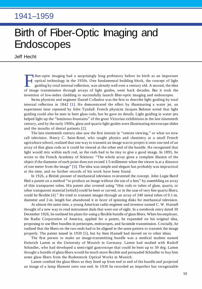
Birth of Fiber-Optic Imaging andEndoscopesJeff Hecht
Fiber-optic imaging had a surprisingly long prehistory before its birth as an importantoptical technology in the 1950s. One fundamental building block, the concept of lightguiding by total internal reflection, was already well over a century old. A second, the idea
of image transmission through arrays of light guides, went back decades. But it took theinvention of low-index cladding to successfully launch fiber-optic imaging and endoscopes.
Swiss physicist and engineer Daniel Colladon was the first to describe light guiding by totalinternal reflection in 1842 [1]. He demonstrated the effect by illuminating a water jet, anexperiment later repeated by John Tyndall. French physicist Jacques Babinet noted that lightguiding could also be seen in bent glass rods, but he gave no details. Light guiding in water jetshelped light up the “luminous fountains” of the great Victorian exhibitions in the late nineteenthcentury, and by the early 1900s, glass and quartz light guides were illuminating microscope slidesand the mouths of dental patients [2].
The late nineteenth century also saw the first interest in “remote viewing,” or what we nowcall television. Henry C. Saint-René, who taught physics and chemistry at a small Frenchagriculture school, realized that one way to transmit an image was to project it onto one end of anarray of thin glass rods so it could be viewed at the other end of the bundle. He recognized thatlight would mix within each rod, so the rods had to be tiny to give a good image. In 1895, hewrote to the French Academy of Sciences: “The whole array gives a complete illusion of theobject if the diameter of each point does not exceed 1/3 millimeter when the viewer is at a distanceof one meter from the image” [3]. The idea was simple and elegant but probably was impracticalat the time, and no further records of his work have been found.
In 1926, a British pioneer of mechanical television re-invented the concept. John Logie Bairdfiled a patent on a method “to produce an image without the use of a lens” by assembling an arrayof thin transparent tubes. His patent also covered using “thin rods or tubes of glass, quartz, orother transparent material [which] could be bent or curved, or in the case of very fine quartz fibers,could be flexible [4].” He tried to transmit images through an array of 340 metal tubes of 0.1-in.diameter and 2-in. length but abandoned it in favor of spinning disks for mechanical television.
At almost the same time, a young American radio engineer and inventor named C. W. Hansellthought of a new way to read instrument dials that were out of sight. In a notebook entry dated 30December 1926, he outlined his plans for using a flexible bundle of glass fibers. When his employer,the Radio Corporation of America, applied for a patent, he expanded on his original idea,proposing to use fiber bundles in periscopes, endoscopes, and facsimile transmission. Crucially, herealized that the fibers on the two ends had to be aligned in the same pattern to transmit the imageproperly. The patent issued in 1930 [5], but by then Hansell had moved on to other ideas.
The first person to make an image-transmitting bundle was a medical student namedHeinrich Lamm at the University of Munich in Germany. Lamm had studied with RudolfSchindler, who had developed a semi-rigid gastroscope that could be bent up to 30 deg. Lammthought a bundle of glass fibers would be much more flexible and persuaded Schindler to buy himsome glass fibers from the Rodenstock Optical Works in Munich.
Lamm combed the glass fibers so they lined up from end to end of the bundle and projectedan image of a lamp filament onto one end. In 1930 he recorded an imperfect but recognizable
1941–1959
53

image on the other end (Fig. 1). It wasenough to prove the principle, althoughLamm conceded that the images were notbright or sharp enough to be usable. Hetried to apply for a patent, but the GermanPatent Office told him that a British versionof Hansell’s patent had just issued.
Lamm described his experiment, butcould go no further [6]. The world wassinking into the Depression, and soonLamm had to flee Nazi Germany. WorldWar II followed. The concept of fiberimage transmission did not reappear untilaround 1950—when three people devel-oped it independently, two of them wellconnected in optics and the third an inde-pendent inventor.
The postwar Dutch navy turnedto one of its leading optics specialists,Abraham C. S. van Heel, to develop a newtype of periscope as it tried to rebuild itssubmarine fleet. The German optics indus-try was in ruins, and neither the UnitedStates nor Britain wanted to share theirperiscope technology with Holland. Aprofessor at the Technical University ofDelft, van Heel thought he could solve theproblem by guiding light through thin rodsof glass or plastic. But his experiments withbare fibers initially got nowhere because oflight leakage and scratching.
In neighboring Denmark, engineer and inventor Holger Møller Hansen, like Hansell, wanted topeer into inaccessible places. He thought of using a flexible fiber bundle to transmit images after lookingat insects’ segmented eyes. An avid experimenter, he first tried drawing his own fibers, then boughtsome fibers to test. He also discovered that light leaked between fibers if they touched but realized thathe could solve that problem if he clad the fiber with a material having a lower refractive index.However, when he sought a material with index close to one, the best candidate he could find wasmargarine, which did not work well.
Meanwhile, in 1951, British optical physicist Harold H. Hopkins found his inspiration at a dinnerparty where a physician discussed the horrors of trying to use a rigid endoscope [7]. Hopkins decidedthat a bundle of flexible glass fibers could do a better job and applied for a research grant to support aresearch student. When the money came through, he assigned the project to a young student from India,Narinder Kapany.
Hansell’s patent had been forgotten and expired in 1947. But the Danish Patent Office found itafter Møller Hansen filed his own application in 1951, and rejected the filing. With no support and noluck in finding a good cladding material, he gave up and turned to another invention. With moresupport, van Heel and Hopkins persevered.
When van Heel sought help with his fiber periscope design, the Dutch government referred him toBrian O’Brien, OSA president in 1951 and director of the University of Rochester’s Institute of Optics.The two knew each other as leaders in the parallel worlds of American and European optics; at the time,van Heel headed the International Commission on Optics. As it happened, O’Brien had already beenexperimenting with light guiding, and he recommended cladding the outside of the fiber with a lower-index material, so no dirt or scratches spoiled the total reflection, and light could not leak out if fibers
▲Fig. 1. Heinrich Lamm, M.D., combed thin glass fibers andpackaged them in a short bundle (a), then focused the imageof a light bulb filament (b) onto one end. The fibers were wellenough aligned to transmit a recognizable image of the filament(c) to the other end. Both filaments are shown in negative images.(Courtesy of Michael Lamm, M.D.)
54 Birth of fiber-optic imaging and endoscopes

touched. He had gotten the idea from his studies of light guiding in retinal cells, which had earned himOSA’s Frederick Ives Medal in 1951 [8]. Van Heel quickly embraced the idea, and the two promised tokeep in touch after their October 1951 discussion.
When he returned to Delft, van Heel tried coating fibers with beeswax and plastic. Both claddingmaterials improved fiber transmission, and the following year he sent light through a fiber bundle half ameter long, well beyond what Lamm had achieved. Then van Heel encountered another complication.On a visit to Britain, fellow Dutch optical physicist Frits Zernike discovered that Hopkins and Kapanywere also making fiber bundles. To establish his priority, van Heel quickly wrote a long article for theDutch-language weekly De Ingenieur and a short letter to the British weekly Nature. He also airmaileda letter to O’Brien, alerting him to the planned publications. The Dutch weekly published the paper inits 12 June 1953 issue [9], but Nature uncharacteristically sat on the short letter for months. Neithermentions O’Brien, who evidently never replied to van Heel’s letter.
Why O’Brien failed to reply is a mystery, and so is why Nature delayed publication of van Heel’sletter until 2 January 1954 [10], when it appeared in the same issue as a longer paper that Hopkins andKapany had submitted in November [11].
O’Brien was busy with other projects, including moving to head American Optical’s new researchlaboratory in Southbridge, Massachusetts, in 1953. He never published on clad fibers, but he did applyfor a patent through American Optical’s lawyers in November 1954. The patent office duly granted theapplication [12], but it was overturned in court because of a blunder by the lawyers. With a year to filethe patent after publication of the De Ingenieur paper, they interpreted the date 12/6/53 marked onO’Brien’s copy as the American style with the month first, rather than the European style with the datefirst, and missed the deadline.
In 1954, as today, Nature was one of the world’s best-read research journals, so the two paperscollectively put fiber optics into the public eye. Yet neither Hopkins nor van Heel could secure fundingfor further development.
Things were different in America. A young South African gastroenterologist working at theUniversity of Michigan named Basil Hirschowitz was excited by the idea of making a flexible fiber-opticendoscope. The Central Intelligence Agency picked up on an idea mentioned in van Heel’s paper—thatfiber bundles might make unbreakable image scramblers. And Kapany landed a research post atRochester.
At Michigan, Hirschowitz teamed with his supervisor Marvin Pollard and optics professorC. Wilbur “Pete” Peters on the project in mid-1955. They hired Lawrence E. Curtiss, a physicsstudent interested in medical instruments, to do the leg work. Hirschowitz did not know that Curtisswas just starting his sophomore year.
Curtiss ran into problems when he tested bare fibers that Hirschowitz had bought. Cleaning thefibers improved their light transmission, but every time he touched the fiber, transmission droppedabout five percent. The mysterious loss came from fingerprint oils, which dry to leave a residue with arefractive index of 1.5, close enough to the glass index to spoil total internal reflection. Drawing theirown fibers from glass rods with refractive index of 1.69 overcame that problem, but the bundled fibersscratched each other, again increasing losses.
Peters suggested applying a plastic or lacquer cladding, but that reduced light transmission. Curtisssuggested threading a high-index rod through a low-index tube and drawing the two into a clad fiber,but the older physicists said it would never work. For a few months he heeded their advice, and he andPeters made a three-foot-long bundle, which they described at an OSA meeting in Lake Placid, NewYork, in October 1956. But Curtiss still thought rod-in-tube fibers would work better. When Peters wasaway at a conference on 8 December 1956, Curtiss bought some tubes of soft glass from the chemistrysupply office, put rods in them, and drew the clearest glass fibers that had yet been made.
Curtiss had been lucky. Drawing good rod-in-tube fibers requires very clean rod surfaces, and theyhad happened to buy fire-polished rods. Nonetheless, they had a breakthrough, and the project wentinto overdrive. Hirschowitz wasted no time applying for a patent, and by February the group hadassembled the first fiber-optic endoscope.
Meanwhile, the CIA pressed American Optical to develop fiber-optic image scramblers forencoding and decoding secret documents. When O’Brien did not get the project going quickly enough,
Birth of fiber-optic imaging and endoscopes 55

the CIA hired Will Hicks, a young physicist from Greenville, South Carolina, and sent him to buildimage scramblers for American Optical. Like the Michigan group, he tested plastic and glass cladding,but he took a different course and developed rigid bundles of fused fibers suitable for image scramblers.
Image scramblers turned out to have a fatal flaw—they always scrambled images in the same way,so an enemy who intercepted enough of the scrambled images could eventually work out the key. Hickswas the first to spot the flaw, but through a friend he also came up with a new use for the fused fiberbundle technology, as fiber optic faceplates to guide light between stages of an image intensifier.
Rigid or fusedfiber bundles opened technological possibilities that were different from those offlexiblebundles. Melting bundles of fibers together and stretching them made the light-guiding cores of the fibersthinner than the cores of isolated fibers, and groups of fused fibers could be stacked together and drawnagain, to make them even thinner. Hicks noticed that fused bundles with the finest fibers showed oddcolored patterns on their cut and polished ends. American Optical managers showed the odd pattern toElias Snitzer when he interviewed for a job, and Snitzer recognized them as mode patterns, producedbecause the fibers had been drawn so thin that their cores were transmitting only a single optical mode.Snitzer got the job and became the first to describe single-mode transmission in an optical fiber [13]. Single-mode fibers would eventually become the backbone of the global fiber optic communications network.
Kapany took a different course at Rochester, writing a series of papers outlining the principles offiber optics. First published in Journal of the Optical Society of America, they became the core of thefield’s first textbook. The 46 papers he published through 1966 accounted for 30% of the field’s entireliterature during the period, including reports on medical treatment.
Hirschowitz and Curtiss helped American Cystoscope Makers develop the first fiber opticendoscope in 1960. It quickly replaced earlier semi-rigid endoscopes because it was far more flexibleand much safer to use, and it greatly expanded the use of endoscopy. American Optical and a spinoffcompany formed by Hicks in 1958, Mosaic Fabrications, developed fused fiber bundles into militaryand commercial products. Fused and flexible fibers soon found a range of applications, from readingpunched computer cards and inspecting the innards of NASA’s massive Saturn V rockets to decorativelamps. But none of them were transparent enough for communications.
Note: This essay based on material from [14].
References and Notes1. D. Colladon, “On the reflections of a ray of light inside a parabolic liquid stream,” Comptes Rendus 15,
800–802 (1842). (Translated by Julian A. Carey).2. S. B. Leiter, “Microscope illumination by means of quartz rod,” J. Opt. Soc. Am. 11, 187–189 (1925).3. K. Weedon, unpublished manuscript based on extended unpublished version of H. C. Saint-René, “On a
solution to the problem of remote viewing,” Comptes Rendus 150, 446–447 (1910).4. J. L. Baird, “An improved method of and means for producing optical images,” British patent
application 285,738; 15 October 1926. (Issued 15 February 1928.)5. C. W. Hansell, “Picture transmission,” U.S. patent 1,751,584; 25 March 1930. (Filed 13 August 1927.)6. H. Lamm, “Biegsame optische Geräte,” Z. Instrumentenkunde 50, 579–581 (1930). (“Flexible optical
instruments,” translated by Lamm many years later.)7. Hopkins credits Hugh Gainsborough of St. George’s Hospital in London: H. H. Hopkins, letter to the
editor of Photonics Spectra, dated 26 August 1982. (Unedited version supplied by W. L. Hyde; editedversion appeared in November 1982 Photonics Spectra).
8. B. O’Brien, Frederic Ives Medalist for 1951, J. Opt. Soc. Am. 41, 879–881 (1951).9. A. C. S. van Heel, “Optische afbeelding zonder lenzen of abfeeldingsspielgels,” De Ingenieur (12 June
1953).10. A. C. S. van Heel, “A new method of transporting optical images without aberrations,” Nature 173, 39
(1954).11. H. H. Hopkins and N. S. Kapany, “A flexible fiberscope using static scanning,” Nature 173, 39–41
(1954).12. B. O’Brien, “Optical image forming devices,” U.S. patent 2,825,260 (4 March 1958).13. E. Snitzer, “Cylindrical dielectric waveguide modes,” J. Opt. Soc. Am. 51, 491–498 (1961).14. J. Hecht, City of Light: The Story of Fiber Optics (Oxford, 1999).
56 Birth of fiber-optic imaging and endoscopes

Xerography: an Invention ThatBecame a Dominant DesignMark B. Myers
IntroductionXerography, or electrophotography, was one of the great inventions of the twentieth century.It was invented in 1938, 78 years ago, and remains in wide use today. The copier has becomea common presence in our workplace, and its availability is assumed. Prior to its invention anoffice worker would type an original with sheets of carbon paper and copy paper sandwichedbehind it in the typewriter carriage. Legibility limited the number of copies that could bemade. If more copies were required, the typing process would be repeated or a master wouldbe typed and offset printing would be employed. The xerographic copier radically changedall of that work and created a whole new communication chain between office workersand their organizations with the multiple copies of a copy sharing the remarks of therespondents.
Xerography’s creation and application closely parallels the 100-year history of The OpticalSociety. It was invented as a novel imaging system, which had no existing competitors. One of itsfirst public demonstrations was at The Optical Society’s Annual Meeting held in Detroit,Michigan, on 22 October 1948 [1,2]. Although seen as highly novel, the observers could notsee the future value of the technology. That was not unusual: the leading industrial laboratoriesof the time had previously been offered the opportunity for the development and commerciali-zation of the technology, but all had declined [3].
It would be 1959, owing to the combined efforts of Battelle Memorial Institute and the smallcompany Haloid that would become the Xerox Corporation, when the Xerox 914 copier madeits phenomenal market introduction. It would take the efforts of the inventor Chester Carlson,the Battelle Memorial Institute, and Xerox people over a period of 21 years to reach this 914success—and what a success it was! It is estimated that in 1955 before the introduction of the 914about 20 million copies per year were made worldwide, largely by typing carbons. In 1964, fiveyears after the introduction of the xerographic copier, 9.5 billion copies per year were made, andin 1985 the number had grown to 550 billion [4]. The revenues of the small Haloid-XeroxCorporation based on the 914 and the follow on products would grow at a 44% ratecompounded annually for the decade 1960 to 1970 to be greater than $1.5 billion. It was thefastest sustained corporate growth rate in history up to that time.
When invited to write this brief chapter on the history of the invention of xerography, theauthor was confronted with the question of what more can be usefully said that has not beenpreviously written. Two comprehensive books were published on the subject in 1965 by the keyearly participants, namely, Xerography and Related Processes by John Dessauer and HaroldClark [5] and Electrophotography by Roland Schaffert [6]. There are at least four other texts[7–10] written by practitioners over the period 1984 to 1998 as well as numerous scientificpapers and popular press reviews in the same period written by scientists who researched the keyprocesses during the further development of the technology. The value the author brings is that ofan early participant in the decade following the introduction of the 914. These are theobservations of a young scientist joining Xerox in 1964 to work with the individuals fromXerox and Battelle who created that first product success.
1941–1959
57

The InventionXerography is a photoelectric imaging process that creates high-fidelity copies. It is distinguished for itsability to image directly onto plain paper without the use of wet chemical agents, which were commonto silver halide and other sensitized paper photography. How xerography works is demonstrated in thefollowing six-step process (see Fig. 1.):
1. An insulator photoconductive sheet attached to an electrode substrate is uniformly electrostaticallycharged.
2. The photoconductive sheet is imagewise exposed with light. The electrical conductivity of thephotoconductor’s exposed areas is greatly increased and the surface charges are discharged throughthe photoreceptor, leaving a latent electrostatic image on the unexposed areas.
3. Pigmented polymer particles charged to the opposite polarity of the latent image are cascadedover the surface. The pigmented particles are electrostatically attracted and tacked to thecharged image area, whereas the particles do not stick to the uncharged areas. The latent imageis now visible.
4. Plain paper is placed on top of the powder image, and a charge is applied to its back surface withsufficient voltage to de-tack and transfer the image to the plain paper.
5. The plain paper is stripped away from the photoreceptor surface with the image.6. The polymer toner image on the paper is fused by heat. The photoreceptor surface is cleaned and
readied for the next imaging.
This six-step process is the formulation of the basic Chester Carlson 1938 invention as filed inhis patent application of 4 April 1939 and which was issued in 1942 [11]. The process has been sorobust over time that it still is the core design of all xerographic copiers and printers produced, 77years later.
The first commercial implementation of this process was the Xerox Model A processor introducedin 1949 (Fig. 2). It was a totally manual operation where the operator carried out each of the aboveprocess steps. As a new Xerox employee, the author was introduced to xerography with this machine byworking through all of the steps described above. The experience was reminiscent of an introductoryphysics lab, interesting to the technically trained but bothersome for office workers.
The time between these products, 1949 to 1959, required intensive improvements by the Battelleand Xerox teams in both process physics and materials. The major new challenge to realizing thepotential of this technology was the automation of the process steps requiring their systems integration
▴ Fig. 1 Six-step process.
58 Xerography: an Invention That Became a Dominant Design

and the creation of a manufacturingcapability for these new machines. Theoperating advances by the engineers wereremarkable. The 1949 Model A couldproduce one copy every four minutes inthe hands of a skilled operator. The 914would produce seven copies per minutewith a press of the “green” button in1959 (see Fig. 3). In 1968, the Xerox3600 would produce copies at 60 pagesper minute, or one every second. The au-tomated xerographic six-step process isshown in Fig. 4.
The InventorChester Carlson by every measure is themodel for the aspirations of all indepen-dent inventors: he created a great inven-tion that had tremendous societal benefitsas well as providing him with great per-sonal wealth. He is the individual inven-tor’s dream.
His story is compelling. He grew upas an only child in a family of very limitedresources. In his early years he became thesole provider for his parents. Living in asuburb of Los Angeles, he worked his waythrough two years at the Riverside JuniorCollege, from which he transferred toCalifornia Institute of Technology for hisfinal two years and graduated with adegree in physics. He started his careerin Bell Labs in New York, but was laid offduring the depression. He became a pat-ent attorney after attending the New YorkUniversity law school. It was his work asan attorney that drove his sense of pur-pose to find a solution to the need forcopies.
Chester Carlson first filed a patentapplication for his invention in October1937 and reduced it to practice in October1938 reproducing the image “10–22–38ASTORIA.” At this time he had funded anassistant, Otto Kornei, to help with thelaboratory work. This experimental pro-cess was his basis for working out the basic six-step process that was the core of his invention. Thephotoconductor they employed was amorphous sulfur, and they developed the image with dyedlycopodium powder. Charging was done by rubbing a cloth imparting a triboelectric charge on thesulfur film and shaking the powder in a container to impart a triboelectric charge of the opposite sign.The developed image was fused by heat from a Bunsen burner.
▴ Fig. 2. Xerox Model A, 1949. (Courtesy of XeroxCorporation.)
▴ Fig. 3. Xerox 914, 1959. (Courtesy of Xerox Corporation.)
Xerography: an Invention That Became a Dominant Design 59

Chester Carlson would contact over 20 companies to try to establish interest in his invention overthe period of 1938 to 1944, with no success. In 1944 he had the opportunity to describe the invention toRussell Dayton of the Battelle Memorial Institute. Dayton was visiting Carlson seeking counsel on anunrelated patent matter and became interested in the idea. Battelle and a yet to emerge small company,Haloid, would transform his ideas into a phenomenal success.
Working with both of these organizations, Carlson would relocate to Rochester, New York, andmake the Haloid (to become Xerox) labs his professional home. He would maintain an office therethrough the 1960s. His original xerographic patent would expire in 1955 just before the introduction ofthe 914. He actively protected his and Xerox’s interests by filing over 20 additional xerographic patents,with the final one granted in 1965. The author recalls his presence in the labs. He was a highly honoredfigure for the new and growing research staff. He was very shy, so few knew him well personally. Whenhe was seen walking the hallways, on second glance he would be gone, a ghostlike figure.
Chester Carlson’s wealth from his invention would reach $150 million. At the time of his passing in1968, that amount would be worth over $1 billion in today’s money. He spent the final period of his lifegiving away his wealth to causes that supported peace and social justice.
Battelle Memorial InstituteCarlson was invited to come to Columbus, Ohio, to demonstrate the concept to members of Battelle’smanagement and research staff, and although the invention was in a very early state, they were interested.A working agreement was concluded in 1944 for Battelle to undertake the development of xerography fora license on future revenues. The Battelle researchers undertook the investigation and selection of the keytechnology components of the six-step process to enable the system to work. Key advances were the use ofamorphous selenium as the photoreceptor, the design of corotrons for the charging processes, and theinvention of the two-component development and fusing systems to fix the image.
Battelle was innovative both in their research and in their willingness to break their own businessmodel. They were a contract research organization to which clients brought their problems andpurchased the necessary research and development. Battelle did not fund research on ideas from outsideinventors, but they changed this in the case of Carlson and xerography. In a sense they were modeling arole that venture capitalist investors would play much later. They would address the challenge of gettingto market by forming a partnership with Haloid in 1947. The rights that had been acquired fromCarlson would be sold to Haloid for an equity position in the growth of the business. Battelle
◂ Fig. 4. The automatedxerographic process using thesix-step process. In brief, theoriginal is scanned andprojected synchronously onto acharged rotating photoreceptordrum. A toner developmentstation develops the image onthe photoreceptor and the copypaper is fed to transfer theimage from the photoreceptor.The image is detached from thephotoreceptor and then passedthrough toner fuser rolls.
60 Xerography: an Invention That Became a Dominant Design

additionally gave exclusive rights to thexerographic patents that they had beengranted from their development efforts. Atthe conclusion of the Battelle and Xeroxrelationship in 1970, Battelle had in-creased the wealth of their endowmentmanyfold.
The Haloid Company(to Become Xerox)In 1944, John Dessauer, the head of Haloidresearch, and Joseph C. Wilson, who wouldsoon assume the Haloid presidency, werelooking for new directions for the compa-ny. Dessauer came upon an article describ-ing electrophotography in the July 1944addition of the Radio News. He shared thearticle with Wilson, and they agreed that acloser look was warranted.
Haloid was a small Rochester, New York, company formed 1906 by a group of individuals whohad left Eastman Kodak (see Fig. 5). For many years they had a small but successful business producinghigh-quality specialty silver halide photographic paper. They operated in the shadow of the much largerKodak Company, which limited their growth potential in photographic paper. In time, othercompetitors eroded the competitive advantage of their specialty product. The future of Haloid wasin doubt, and they needed a new vision and marketplace.
John Dessauer and Joseph C. Wilson, the soon-to-be president of Haloid, visited Battelle in Columbus,Ohio, in December 1945 to see the technology demonstrated. They approached Battelle early in 1946 torequest an exclusive license to the technology and to propose a joint development program. Battelle mostprobably would have preferred a more promising partner, but they, like Chester Carlson, had not foundany company interested. An agreement was reached to take effect 1 January 1947.
Joseph C. Wilson was the head of Haloid and Xerox in the period 1946 to 1967. He was from awealthy Rochester family and was the third in the line of Wilsons to be the head of Haloid. Hegraduated from the University of Rochester, where he studied literature, and received an MBA degreefrom the Harvard Business School. He was an exceptionally eloquent business speaker. He lovedpoetry, and many of his speeches would either begin or end with a poem by Robert Frost.
He also was a man who was willing to take actions that had large risks. The Haloid Companyrepresented most of his family’s wealth. He invested $12.5 million in the 914-product development,which amounted to all of the company’s profits for a decade, and he borrowed more. If the 914 hadfailed, the company would have gone under. After the great success of the 914 he would speak of one ofthe few disappointments. He spoke of friends who had offered to invest money for the development andhow they would later be unhappy with him because he declined their offer as he felt that the risk offailure was too great. He is honored at the Harvard Business School by named chair, the Joseph C.Wilson Professor of Entrepreneurship.
John Dessauer was a chemical engineer, educated in Germany, who had immigrated to the UnitedStates in the 1930s as a result of the social upheavals that were taking place in his native country. Hejoined the Haloid Company in 1935 as part of an acquisition that the company had made. He becamethe first director of research for Haloid, and it was his insight that brought Chester Carlson, Battelle,and Xerox together.
John Dessauer would make another important contribution to xerography. Over the period 1960to 1970, he would start the building of a Xerox research organization in Webster, New York, dedicated
▴ Fig. 5. Dr. John Dessauer, Haloid head of research to the left,Chester Carlson, and Joseph C. Wilson, president of Haloid,examining a xerographic printer prototype in the late 1940s.(Courtesy of Xerox Corporation.)
Xerography: an Invention That Became a Dominant Design 61
to evolving the company from the dependence on a core xerographic technology based on speculativeinvention to a predictive science base. The Xerox scientists and engineers would be challenged by thelack of relevant information to support increasingly sophisticated applications of the technology. Theunderlying sciences of triboelectricity, photo-generation, and charge transport in wide-bandgapsemiconductors, controlled corona discharge in ambient atmospheres, physics of surface charge states,and the thermal flow characteristics of pigmented polymers were not widely practiced in the externalscientific research of that time.
John Dessauer showed a personal interest in the new research recruits joining the organization. Hewould drop into the individual scientists’ labs to establish connection through wide-ranging conversa-tions. Dessauer developed a close consultative relationship to guide his organization building effortwith John Bardeen, Nobel Laureate, of the University of Illinois, who served as an advisor and whowould become a member of the Xerox board of directors from 1961 to 1974.
The research capability would continue to grow under the leadership of Jack Goldman, GeorgePake, and William Spencer with the establishment of Xerox PARC and Xerox Research Center ofCanada. From 1981 to 1991, the work of the three centers would rank Xerox among the ten mostinfluential academic and industrial research institutions in the United States as measured by reference totheir scientific papers [12].
Xerography, a Dominant DesignXerography has shown the characteristics of a dominant design [13]. Early in its history it establisheda competitive edge with respect to alternative technologies, thus becoming the customer and industrychoice. Many competitive firms became committed to its usage, offering improved versions. Finally,the technology has shown the capacity to grow in capability and not hit limits leading to earlyobsolescence.
This does not mean xerography did not have serious competition from alternative technologies.Many organizations including Xerox invested in copying and printing technologies that if successfulcould have become replacements. They included drop-on-demand inkjet, continuous-stream ink jet,photoactive pigment electrography, and ionography. They all had merits, but only the drop-on-demandinkjet had major market impact. In the drop-on-demand inkjet case, it was a new market for colordigital photography home printing that drove the demand. It was a market in which xerography wouldnot be competitive.
A number of market and technological factors have greatly extended the useful life of xerography.The following key events are suggested:
• There was a benefit to the expansion of xerography by offerings of new competition. Xeroxestablished through its relationship to Carlson, Battelle, and its own investments a patent positionthat limited competitive offerings. This patent exclusion was set aside in 1974 by a consent decreeagreement with the U.S. Federal Trade Commission. It required that Xerox license to all competitorsits xerographic patents for period of ten years and any new patents issued in that interval. Thiscreated an explosion of competitive offerings particularly from Japan.
• An important advance in 1969 was the invention of computer-driven laser writing onto axerographic photoreceptor [14]. This opened a new market for xerography in electronic imagingand printing. Xerox introduced the 9700 in 1977, which printed single-sheet, 300-spi (samplesper inch), single-sheet images at 120 pages per minute. Hewlett Packard introduced desktop laser300-spi printing in 1984 working at eight pages per minute. Both products revolutionized theirrespective market places. Most importantly, the application of xerography was transformed from itsanalog imaging role to become part of the emerging digital imaging future.
• Canon introduced the concept of a low-cost personal copier with a customer-replaceableconsumable cartridge in 1982. They creatively collected all of the high-maintenance elements ofthe xerographic processes into a customer-replaceable unit, thereby removing the need for frequent
62 Xerography: an Invention That Became a Dominant Design

service. This would open a new market, and desktop copying and printing and would become adesign standard for the industry.
• Organic photoreceptors [15,16] offered a breakthrough to a cost barrier, as they could becoated with much-lower-cost manufacturing, and they could be made into highly flexible beltsrather than the selenium alloys, thus offering new printer architectures for digital color. In 1975,Kodak introduced its Ektaprint 100 copier/duplication based on an organic photoreceptor.Xerox followed suit in 1982 with its active-matrix organic photoreceptor in its 10-Series 1075and 1090 duplicators.
• Canon, Hewlett Packard, Fuji-Xerox, and Xerox introduced very-high-quality digital colorreprographic and printing devices that extended xerography into the color printing andgraphics marketplace.
• The Total Quality Movement practiced by Japan manufacturers greatly improved thereliability of xerographic machine designs. Xerox improved its design and manufacture throughits learning from Fuji-Xerox.
It is the nature of dominant designs that they are not simply replaced by an alternative technology.Their dominance will end with a radical transformation of the market they serve. A current example ofthe decline of a dominant design is analog silver halide photography and its iconic Kodak yellow box.The magic was in the chemistry of the film and its later processing. The analog film businesses of Kodakrapidly declined with the ascendency of a whole new paradigm of consumer photography: the digitalcamera, the smart phone, and inkjet printers. Dominant designs do have lifetimes.
Similar changes are appearing for prints on paper. The internet, personal computing devices, andsocial media are reshaping the world of publishing newspapers, magazines, and books. Challenges tothe future use of print are seen in the processes of banking, legal, and other businesses.
Xerography is clearly in the mature stages of its lifetime. There still remain active literature creationand patent issuance every year, and there are at least a dozen companies producing products andservices. Whether xerography prospers or fades into the sunset will depend on innovation extending itsapplication into new markets.
References1. OSA Annual Meeting, Detroit, Michigan, 22 October 1948.2. R. M. Schaffert and C. D. Oughton, “Xerography: a new principle of photography and graphic
reproduction, J. Opt. Soc. Am. 38, 991–998 (1948).3. J. H. Dessauer, My Years at Xerox, The Billions Nobody Wanted (Manor, 1975), p 31.4. D. Owen, “Making Copies: at first, nobody bought Chester Carson’s strange idea, but trillions of
documents later, his invention is the biggest thing in printing since Gutenberg,” Smithsonian Mag.,August 2004.
5. J. H. Dessauer and C. H. Clark, Xerography and Related Processes (The Focal Press, 1965).6. R. Schaffert, Electrophotography (The Focal Press, 1965).7. M. Scharfe, Electrophotography Principles and Optimization (Research Studies Press, 1984), Vol. 3.8. J. Mort, The Anatomy of Xerography, Its Invention and Evolution (McFarland, 1989).9. L. B. Schein, Electrophotography and Development Physics (Springer, 1992).
10. P. Borsenberger, Organic Photoreceptors for Xerography (Marcel Dekker, 1998).11. C. Carlson, “Electrophotography,” U.S. patent 2,297,691 (6 October 1942).12. E. Garfield, “Citation index for scientific information,” Science Watch 4(2), 8 (1993).13. J. M. Utterback, Mastering the Dynamics of Innovation (Harvard Business Press, 1996), pp. 23–26.14. J. C. Urbach, T. S. Fisli, and G. K. Starkweather, “Laser scanning for electronic printing,” Proc. IEEE 70,
597–618 (1982).15. M. Stolka, D. M. Pai, and J. E. Yanus, “Imaging system with a diamine charge transport material in a
polycarbonate resin,” U.S. patent 4,265,990 (5 May 1981).16. M. Smith, M., C. F. Hackett, and R. W. Radler, “Overcoating the photoconductive layer with a charge
transfer compoundofaromaticpolynuclear structure;xerograph,”U.S.patent 4,282,298 (4August1981).
Xerography: an Invention That Became a Dominant Design 63

U.S. Peacetime StrategicReconnaissance Cameras,1954–1974: Legacy of JamesG. Baker and the U-2Kevin Thompson
James G. Baker contributed to optics, optical design, and, as this chapter describes, was apivotal player during the development and deployment of the U-2, and the optics of the U-2.To briefly mention some of his contributions outside of the U-2 is itself a challenge. Hegraduated from Harvard in 1942 with a Ph.D. in Astronomy and Astrophysics, advised by
leading astronomer Harold Shapely, and went on to make innovative contributions for nearly 70years including developing ray tracing and optical design code using the second largest computerever built (the first one was delivered to Richard Feynman for the Manhattan Project). He notonly designed large format cameras for reconnaissance but also fabricated and tested thelarge aspheric components personally. He is perhaps best known in the public for his designof the Baker–Nunn tracking cameras and for designing and supporting the fabrication ofthe first freeform surface in mass production as part of the Polaroid SX70 camera, to name afew examples.
This chapter features his work not only as the optical designer for the optics for the U-2, butalso his lesser known contributions as a leading member of the group that convinced thenPresident Eisenhower to authorize the U-2 program. The sources for this chapter were selected tobe as original as possible, and are dominantly CIA reports that were developed by the CIAHistory Staff in the 1980s and released as classified reports within the CIA. These were laterdeclassified with redactions when the existence of the National Reconnaissance Office (NRO)became known to the public in the late 1990s. All of the material in this chapter comes fromBaker’s personal files that were made available to the author by the Baker family.
Baker’s involvement in reconnaissance cameras began in 1941, when he was invited byMajor George Goddard to spend two months at the Wright Field in Dayton, Ohio [1]. Perhapsthe most succinct introduction to Baker’s role in the U-2 and related programs is from an NROpress release that announced the first “Pioneers of National Reconnaissance” on 18 August2000. The release states: “James G. Baker, Ph.D.—A Harvard astronomer, Dr. James Bakerdesigned most of the lenses and many of the cameras used in aerial over-flights of ‘deniedterritory,’ enabling the success of the U.S. peacetime strategic reconnaissance policy” [2].
To write only on his technical accomplishments for reconnaissance cameras would overlooka key role Baker played in bringing President Eisenhower to authorize the U-2 to carry thecamera. The first section of the chapter will highlight Baker’s roles in that area—roles that oftenconsisted of leading key technology committees, which led to the authorization of the U-2program specifically as described in [3]. In the context of the U-2 program, these roles began in1951 with the establishment of what came to be called the BEACON HILL Study Group, namedfor the location of the study group headquarters on Beacon Hill, in Boston. The group was madeup of chairman Carl Overage, a physicist at Kodak, Baker, Edward Purcell from Harvard, and atotal of 12 others that included Edwin Land of Polaroid, Richard Perkin of Perkin-Elmer, and
1941–1959
64

significantly, Lt. Richard Leghorn from the Wright Air Development Command, who later became thefounder of ITEK where the CORONA program was developed in later years. This grouptoured airbases, laboratories, and companies every weekend for two months in January and Februaryof 1952. From there the members invested three months preparing a classified document they presentedon 15 June 1952—the BEACON HILL Report. The report, with 14 chapters, discussed varioustechnologies from radio to photography including infrared and microwave reconnaissancesystems. One of the key recommendations from the report was the need to develop high-altitudereconnaissance.
Reaction to the BEACON HILL Report came a year later, in the summer of 1953, after Dwight D.Eisenhower became president. The specific timing of the president’s interest was driven by an early reportof a new Soviet intercontinental bomber, designated “Bison” by NATO. This was a B-52 class bomber(the B-52 was just entering production in the U.S.). This report was validated at the Moscow May Day airshow. In July of 1953, the Intelligence Systems Panel (ISP) was established, chaired by Baker, to adviseboth the Air Force and the CIA on ways to implement the construction of high-flying aircraft and high-acuity cameras. In parallel, during World War II (WWII), Baker had established a full-scale opticallaboratory, the Harvard University Optical Research Laboratory. After the war, Harvard asked that thelaboratory end its relationship with the university and it was moved to Boston University to become theBoston University Optical Research Laboratory (BUORL), with the move funded by the Air Force. Baker,however, elected to stay at Harvard where he continued to design lenses for use in photoreconnaissance.BUORL was destined to become ITEK in 1957 under the leadership of Richard Leghorn.
At the first meeting of the ISP on 3 August 1953 the discussion centered on the fact that the bestintelligence on the interior of the Soviet Union was based on German aerial photos taken near the endof WWII. Discussions continued to review incremental modifications that either were being attemptedor planned to create a high-altitude airframe from existing production aircraft. At the third ISPmeeting on 24–25 May 1954, a critical outcome was to establish that to be successful, a high-altitudeaircraft would need to fly above 70,000 feet, something that could not be achieved with modificationsto existing airframes. The other pivotal event at this meeting was that the panel learned of alightweight, high-flying aircraft that was being developed at Lockheed Aircraft Corporation. Bakerdispatched a member of the panel to learn more about the project. The plane was conceived by thenow legendary Kelly Johnson, leader of the Skunk Works, who had designed essentially a singleengine jet powered glider, which was called at the time the Lockheed CL-282. On 24 September 1954Baker convened the ISP panel to discuss the new airplane. The panel moved to support the CL-282,but the Air Force, which had been aware of the CL-282, had already made a decision not to fund thedevelopment of the aircraft.
Somewhat independently, on 26 July 1954, President Eisenhower commissioned another panel ofexperts, led this time by James Killian, then the president of MIT. This panel had 42 of the nation’sleading scientists, including Baker, segmented into three project groups. This group met 307 times overnine months and included field trips and conferences. Baker was a member of the Project 3 committee,which was led by Edwin (Din) Land of Polaroid. Land believed the optimal committee size was one thatcould fit into a taxi and, as a result, this was a small group consisting of Baker and only a few others,including notably mathematician John W. Tukey. In mid-August 1954, Land and Baker went toWashington where Land was shown the details of the CL-282, after which he is quoted as havingphoned Baker to say, “Jim, I think we have the plane you are after.” Following a somewhat convolutedpath that was dominantly political and too lengthy to describe here, Land and Killian met directly withPresident Eisenhower in November 1954 and the president directed that CL-282 be developed by theCIA. Even with the president’s support, the competitive situation was complicated, but a key decidingfactor in the end was that Kelly Johnson promised to deliver the plane in eight months for $22 million,which he did, under budget. A final contract was signed on 2 March 1955 with Lockheed to deliver 20planes between July 1955 and November 1956. To give some perspective on the priority of the project,Richard Bissell of the CIA wrote a check to prestart the work and mailed it to Kelly Johnson.
With this background on how the U-2 airframe, a version of which is shown in Fig. 1 [3], came tobe authorized, this section will present Baker’s work on some of the lenses that were considered or usedon cameras that flew on the U-2. This material is based on [4] and from the article written by Baker [5].
U.S. peacetime strategic reconnaissance cameras, 1954–1974: Legacy of James G. Baker and the U-2 65
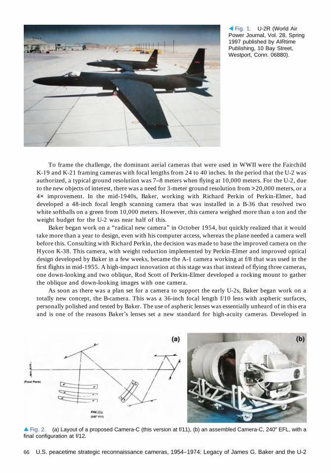
To frame the challenge, the dominant aerial cameras that were used in WWII were the FairchildK-19 and K-21 framing cameras with focal lengths from 24 to 40 inches. In the period that the U-2 wasauthorized, a typical ground resolution was 7–8 meters when flying at 10,000 meters. For the U-2, dueto the new objects of interest, there was a need for 3-meter ground resolution from >20,000 meters, or a4× improvement. In the mid-1940s, Baker, working with Richard Perkin of Perkin-Elmer, haddeveloped a 48-inch focal length scanning camera that was installed in a B-36 that resolved twowhite softballs on a green from 10,000 meters. However, this camera weighed more than a ton and theweight budget for the U-2 was near half of this.
Baker began work on a “radical new camera” in October 1954, but quickly realized that it wouldtake more than a year to design, even with his computer access, whereas the plane needed a camera wellbefore this. Consulting with Richard Perkin, the decision was made to base the improved camera on theHycon K-38. This camera, with weight reduction implemented by Perkin-Elmer and improved opticaldesign developed by Baker in a few weeks, became the A-1 camera working at f/8 that was used in thefirst flights in mid-1955. A high-impact innovation at this stage was that instead of flying three cameras,one down-looking and two oblique, Rod Scott of Perkin-Elmer developed a rocking mount to gatherthe oblique and down-looking images with one camera.
As soon as there was a plan set for a camera to support the early U-2s, Baker began work on atotally new concept, the B-camera. This was a 36-inch focal length f/10 lens with aspheric surfaces,personally polished and tested by Baker. The use of aspheric lenses was essentially unheard of in this eraand is one of the reasons Baker’s lenses set a new standard for high-acuity cameras. Developed in
◂ Fig. 1. U-2R (World AirPower Journal, Vol. 28, Spring1997 published by AIRtimePublishing, 10 Bay Street,Westport, Conn. 06880).
▴ Fig. 2. (a) Layout of a proposed Camera-C (this version at f/11), (b) an assembled Camera-C, 240” EFL, with afinal configuration at f/12.
66 U.S. peacetime strategic reconnaissance cameras, 1954–1974: Legacy of James G. Baker and the U-2

collaboration with Rod Scott of Perkin-Elmer, the B-camera used only one panoramic imaging lens with18 × 18 inch format frames. This lens, and variations on it, became a key component of all camerasthroughout the U-2 program.
Independently, Baker’s concept for the ultimate U-2 camera, called the C-camera (see Fig. 2 [6]),was a 240-inch focal length lens to be operated at f/20. However, in conversation with Kelly Johnson herealized this format would never be small enough or light enough for the U-2. Eventually he developed a180-inch focal length lens operating at f/13.85. While this design would typically have taken years tocomplete in that era, his state-of-the-art computer allowed it to be completed in 16 days. However, in atest flight of the Hycon manufactured lens, the conclusion was that the 5× longer focal length made thelenses too sensitive to vibration. Apparently this result was never relayed to Baker, who learned of ityears later. When he learned of the source of the decision to not use the C-camera, he wrote a terse letterstating he had solved that, should they have bothered to ask.
References1. The New England Section of OSA, “Highlighting past projects and camera systems in aerial
photography,” 23 October 1997, from J. G. Baker personal files.2. Press release from the NRO, 18 August 2000, from J. G. Baker personal files.3. From U-2 The Second Generation, a reprint from World Air Power Journal (AIRtime Publishing, Spring
1997), Vol. 28, from J. G. Baker personal files.4. G. W. Pedlow and D. E. Welzenbach, The CIA and the U-2 Program, 1954–1974 (Center for the Study
of Intelligence, 1998), pp. 17–66.5. J. G. Baker, “The U-2 B-camera, its creation and technical capabilities,” Proceedings of the U-2
Development Panel, The U-2 History Symposium, held at the National Defense University, 17September 1998.
6. Photo from J. G. Baker personal files.7. Personal correspondence between Bill McFadden (formerly of HYCON), and R. Cargill Hall, Air Force
History Support Office, on 10 September 1997, from J. G. Baker personal files.8. R. Cargill Hall, “The Eisenhower administration and the cold war: framing American astronautics to
serve national security,” draft manuscript, 10 January 1994, from J. G. Baker personal files.9. Personal correspondence between J. Baker and R. Cargill Hall, comments on the draft manuscript, 13
December 1993, from J. G. Baker personal files.
U.S. peacetime strategic reconnaissance cameras, 1954–1974: Legacy of James G. Baker and the U-2 67
History of Optical Coatings and OSAbefore 1960Angus Macleod
IntroductionThe full history of any scientific subject is impossibly complex, and any account can only be asimplified one. Like other technologies, optical coatings developed over a broad front in manycountries with many workers and over a long time. Some discoveries were made and thenforgotten and rediscovered later; others were simultaneous but independent. This account isintentionally heavily biased toward The Optical Society, and so, although we will try to retainsome breadth in the story, we will concentrate on those workers who were significant in theSociety. Others, many of whom we will not mention, were also involved in and made significantcontributions to the field.
BeginningsNo one knows exactly when the technology of optical coatings started. As far as opticalinstruments are concerned, the earliest was probably the simple mirror, and by 2000 B.C.mirrors were common all over the world. Early mirrors were made from anything that could bepolished, and their reflectance was simply that of the particular material. Obsidian, jade, bronze,silver, or gold, even pots of water, were all used. The idea of using a coating to improve thereflectance was a later development. We know that the Romans employed many differenttechniques for mirror manufacture, including some that we can classify as thin films. Glass was acommon substrate. Mass production of cheap mirrors involved pouring molten lead over glass,yielding irregular fragments that had somewhat raised reflectance from the lead that stuck to theglass, but quality was generally poor. Better, but more expensive, glass mirrors had films ofmercury or gold leaf. Metal mirrors often carried layers of polished tin. Outstandingly clear glasswas developed in Murano in the middle of the fifteenth century, and the production of what wewould describe as the first modern mirrors followed soon after. These mirrors carried a coatingthat was primarily a mercury amalgam of tin, although small amounts of other metals were alsosometimes added. Thus by the sixteenth century there was a well-established thin film coatingindustry but the coatings were solely of metals.
The development of interference coatings took rather longer. Of course, nature was first inthe use of thin film interference. Color in transparent thin films must have been observed at avery early stage of human development, but it was Isaac Newton who, in the late seventeenthand early eighteenth century, painstakingly established the relationship between film propertiesand perceived color [1]. He realized that the same effects he saw in his thin films wereresponsible for many colors in nature and, mistakenly, thought that such effects wereresponsible for all colors. Not much happened in thin film optics from then until the beginningof the nineteenth century.
Two major events in the early 1800s were the 1802 proposal by Thomas Young that light isa wave [2,3] and the publication in 1810 of Goethe’s great book on color [4].
1941–1959
68
Young was not the first to propose a wave theory for light, and, indeed, for a time the theory wasnot generally accepted. It took the 1818 work of Fresnel on diffraction [5] to convince the field. Thewave theory of light paved the way for the understanding of interference phenomena. Fresnel andPoisson developed the idea of the absentee half-wave and the quarter-wave perfect anti-reflectioncoating [6]. By the end of the nineteenth century interference in thin films was well understood, hadbeen recognized in nature, and was known to be responsible in the form of tarnish layers for an increasein the transmittance of high-refractive-index lenses.
Goethe’s book contained in its first edition a chapter by Seebeck, missing from subsequent editions,dealing with experiments on precipitates of silver chloride where illumination was followed byexhibition of reflection of the very colors used for illumination. Wilhelm Zenker [7] realized thatthis was an interference phenomenon that could be used in photography and also recognized that half-wave spacing of repeated features should give high reflectance at the corresponding wavelength.Zenker’s work was the precursor to the Lippmann emulsion that won Gabriel Lippmann the 1908Nobel Prize in Physics.
Metallic reflecting coatings had also considerably developed during the nineteenth century. Justusvon Liebig’s [8,9] development of a wet chemical deposition process for silver in the middle of thecentury had transformed the production of reflectors of all kinds. Interferometers required beam-splitters with semi-transparent reflectors. Astronomy adopted mirrors constructed from stable glasswith silver coatings rather than the older, somewhat unstable, speculum metal. Sputtering wassometimes used, but the general view was that it tended to distort the substrates and so it was notmuch in favor. Then an important paper by Pohl and Pringsheim in 1912 [10] suggested a vacuumprocess using what was then called distillation, but nowadays thermal evaporation, for mirror coatings.A great advantage of this method was that with a substrate exhibiting a sufficiently high quality ofsurface finish, the coatings would immediately form a mirror of equal quality without any further needof polishing.
At the beginning of the twentieth century, thin film applications were largely in photographicemulsions and in metallic reflectors. There was as yet no real need for other kinds of optical coatings.Also, strangely enough, although mirrors were much in demand, there seems to have been no great rushto adopt Pohl and Pringsheim’s technique.
Early EffortsThe first volume of the Journal of The Optical Society of America appeared in 1917. The second issue(numbered as 2 and 3) contains two papers that would appear of great significance to us today but,from their citations, seem to have received little notice at the time. The first paper, on what we wouldnow describe as an interference optical coating, was by Herbert Ives [11], who modified the treatmentof a Lippmann emulsion to produce a narrowband reflecting filter of high efficiency that we wouldnow call a notch filter. In the same issue Otto Stuhlmann [12] described his technique for depositingmetallic mirrors and beamsplitters by thermal evaporation from wire sources. Later, in volume 2,Frederick Kollmorgen describes a spinning process for the protection by lacquer of silver films,solving the then current problem of applying a thin, uniform film to protect silver surfaces fromtarnishing [13].
In the late 1920s and early 1930s, John Donovan Strong pioneered work in the deposition ofoptical coatings. 1930 he joined the California Institute of Technology and teamed with CharlesHawley Cartwright to investigate the deposition of an enormous number of metals and dielectrics [14].By early 1931 Strong had coated, with quartz-protected silver, a 6-in. (15.24-cm) reflector. Thefollowing year he replaced the coating with one of aluminum. Aluminum had two great advantages. Itstrongly reflected the ultraviolet and it had an innate environmental resistance due, Strong was sure, to afilm of oxide that naturally formed over the surface.
Meanwhile progress was being made in Germany and France. At the Carl Zeiss company in JenaAlexander (Oleksandr) Smakula [15], of Ukrainian origin, developed an anti-reflection coating forlenses, which for several years remained a close secret and was used primarily for military applications.
History of Optical Coatings and OSA before 1960 69
Walter Geffcken at the sister company Schott in Jena, around the same time, produced the firstnarrowband interference filters [16]. Like Smakula’s, most of Geffcken’s early advances were keptsecret. Alfred Thelen’s account of Geffcken’s work [17] makes fascinating reading. In France, PierreRouard, in a 1932 paper [18], described his observation of a significant reduction in internal reflectanceat a glass surface induced by an overcoat of a very thin metal layer. He presented his thesis in Paris in1936 [19], and it included an iterative technique for optical multilayer calculations.
In the United States, John Strong, completely independently of Smakula, realized that hisevaporated dielectric coatings could be used as a replacement for the tarnish layers that were knownto improve the transparency of glass elements. His paper [20] in the Journal of The Optical Society ofAmerica was the first account of such coatings to appear in the open literature. Strong coated the lensesof a Leica camera that was probably the first ever to be anti-reflection coated by a vacuum process.
August Hermann Pfund, 1939 Ives Medalist and President of The Optical Society from 1943 to1945, also made contributions in thin film optics. In 1934 he published [21] an account of a dielectricbeamsplitter based on a thermally evaporated film of zinc sulfide for use in interferometers and othersystems where transmission was followed by reflection at the same surface. In general, we see graduallyincreasing interest in thin film interference coatings, much of it, of course, directed toward anti-reflection.
A particularly interesting individual of this era was Katharine Blodgett. In 1920 she became the firstwoman to be employed as a research scientist by the General Electric Company, where she beganworking with Irving Langmuir, who won the Nobel Prize for Chemistry in 1932. In 1926, she becamethe first woman ever to be awarded a Cambridge Ph.D. in physics. She then returned to GE, where shecontinued the work that Langmuir had started on thin films. In the course of this work she devised anti-reflection coatings for glass. Her Journal publications primarily reported films of barium stearate mixedwith stearic acid the acid being removed later by soaking in benzene to leave a barium stearate skeletonbehind. Very low reflectances could be obtained in this way. Her 1940 patent [22], however, involvedthe anti-reflection of soda-lime window glass by adding to it a layer of glass containing a metal such aslead or barium that could then be leached out by acid treatment to leave an etched layer of lowerrefractive index that acted as an efficient anti-reflection coating and, of course, was environmentallyresistant.
In 1937, Arthur Francis Turner and Hawley Cartwright began their ground-breaking research ininterference coatings including anti-reflection coatings at MIT. The process they used was vacuumevaporation and the materials for the anti-reflection coatings metallic fluorides, magnesium fluoridebeing specifically mentioned in claim 6 of their 1940 patent [23]. The publication of this patent inducedGermany to publish the Smakula patent that had been kept secret. Turner and Cartwright made otheradvances in anti-reflection coatings including multilayers. Cartwright described to OSA the advantagesof anti-reflection for camera lenses [24], while Miller did the same for the moving-picture community[25]. Then Turner joined Bausch & Lomb in 1939, where he ran the Optical Physics Department untilhis retirement in 1971.
War YearsOptical instruments of all kinds including binocular telescopes, submarine periscopes, range finders,telescopic gun sights, and aircraft bomb sights were required for World War II. The performance of allof these could be much improved, especially for use at dusk or dawn, by the addition of anti-reflectioncoatings. All the participants on either side in the war were involved in anti-reflection coatings, yet theywere treated everywhere as highly secret.
Richard Denton joined the Frankford Arsenal in early 1942. In 1935 the staff consisted of elevenpeople. By the end of 1943 the staff numbered 1100. His account of his experiences at the Arsenal [26]paints a vivid picture of the rapid problem solving and innovation that was required by the needs of theconflict. Anti-reflection coatings represented only a part of his responsibilities. Magnesium fluoride hadbeen found most satisfactory, and soon virtually all optics were being coated to improve theirtransmittance.
70 History of Optical Coatings and OSA before 1960

Around this time, the importance of heating the substrate during the deposition of the magnesiumfluoride anti-reflection coatings was recognized. Cartwright and Strong had included heated substratesduring deposition in their investigations at the California Institute of Technology [14] and found thetenacity of silver much improved. Also with Turner he had secured a patent on post-deposition bakingof magnesium fluoride [27]. Then Dean Lyon, who had worked on thin films at MIT and now since1941 was working at the Naval Research Laboratory, “stumbled upon that old idea of heating theelements in a vacuum” [28]. He was eventually awarded a patent for this invention [29]. This processwas then used for the remainder of the war. After the war, the Bausch & Lomb company employed themagnesium fluoride process in the production of coated elements, and Lyon sued the company forinfringement of his patent in what was a celebrated case at the time and that in 1955 was finally decidedin his favor by the United States Second Circuit Court of Appeals.
There was tremendous activity in optical coatings during the war, but little of this appeared in theSociety Journal. Frank Jones from the Mellon Institute of the University of Pittsburgh, who had beenfunded since 1936 by the Bausch & Lomb company to investigate the deterioration of glass surfaces,published with Howard Homer [30] a study of anti-reflection of glass by chemical methods. However,the papers that we would recognize immediately as of fundamental significance in the development ofthin film optics were by Mary Banning.
Mary Banning gained her Ph.D. from Johns Hopkins in 1941, and, in the summer of 1941, foundherself at the Institute of Optics charged with the creation of an optical thin film laboratory [31]. Facedwith such a task nowadays we can turn to the established industry, obtain equipment, and studyinformation in books. She had to start from virtually nothing. Even what methods to use was not clear.She decided on vacuum processes as her primary technique, built and operated the equipment, andpublished four important papers in the Journal of The Optical Society of America [32–35], all of whichcontain a wealth of practical information and represent very much the foundation on which much of thefield was built. One of the papers [34] contains what is still the best and fullest description of the designand construction of an immersed polarizing beamsplitter.
Postwar YearsNow, after the war, the subject expanded rapidly. Part of the reason was the impetus given by the wareffort to the field. Many people were involved in optical coating and found it an attractive andrewarding field. But also optics was ready for it. Great improvements could be produced by coatingcamera lenses. High performance could be obtained from reflecting coatings, avoiding the unpleasant-ness and unpredictability of the wet chemical processes. Interference filters could be made as easily forone wavelength as another and had enormous energy grasp. Thin film polarizers showed high efficiencywithout the need for expensive crystals. There were, of course, many military needs, but all of opticswas expanding. The chemical industry needed infrared instrumentation, and astronomy neededtelescopes and instrumentation and especially narrowband filters for increasing contrast of diffusenebulosities. Binoculars, photographic cameras, microscoscopes, surveying equipment, and naviga-tional equipment all showed vastly improved performance with anti-reflection coatings.
Optical coatings had developed in Germany during the war, and now the results were beingbrought back to the United States. In 1946 Howard Tanner, who had been with the U.S. NavalTechnical Mission in Europe together with Luther Lockhart, both of the Naval Research Laboratory,published a paper on some of the German anti-reflection coatings. One of the coatings they described indetail was a three-layer one based on a quarter-wave of intermediate index next to the substrate,followed by a half-wave of high index and then finally a quarter-wave of low index. This gives highperformance over the visible region. It was further analyzed by Lockhart and Peter King [36], and theidea of the half-wave layer that broadens the anti-reflection performance has since appeared in coatingafter coating and in many publications and patents.
Accurate calculation of the properties of coatings was of considerable interest, and a good numberof the contributions to the Journal at this time were theoretical and concerned optical propertycalculation. Robert Mooney had two papers in the 1945–1946 volume of the Journal [38]. Antonin
History of Optical Coatings and OSA before 1960 71

Vasicek, the leading thin film worker in Czechoslovakia, published several theoretical studies [39–42],and Doris Cabellero [43] and Walter Welford [44] also contributed. Most of this work used iterativetechniques, but Welford succeeded in putting his method into matrix form. Meanwhile, in France, ayoung Florin Abelès was gaining his doctorate with a thesis that laid the theoretical foundation of thecalculation techniques involving characteristic matrices that we almost universally use for our thin filmstoday [45, 46].
It now becomes difficult to keep track of all that was happening in thin film optics, and we give upcompletely trying to track all of the significant contributions, even just those to the Journal of TheOptical Society of America.
Pierre Rouard, in early 1944, had returned as Professor of Physics to Marseille and to optical thinfilms from a forced two-year absence in Clermont-Ferrand working on acoustics. In 1949 the FrenchCentre National de la Recherche Scientifique, recognizing the tremendous expansion of opticalcoatings, asked him to organize an international conference on optical coatings in Marseille. Thiswas the first truly international conference devoted entirely to the “Optical Properties of Thin SolidFilms.” A special July 1950 issue of the Journal de Physique et le Radium carried the proceedings in amixture of English and French. Almost everyone of significance in the field was there. Rouard himself ofcourse, Strong (although now much more in astrophysics), Turner, Heavens, Dufour, Greenland, Ring,Abelès, are just a few of the names. Turner gave a paper [47] describing multilayer anti-reflectioncoatings, dielectric reflectors, reflection filters, narrowband transmission filters, and frustrated totalreflection filters.
At the end of the war, many German scientists were recruited to continue their work in the UnitedStates under Operation Paperclip run by the Office of Strategic Services. Two notable ones wereAlexander Smakula and Georg Hass. Hass was employed by the United States Army Signal Corps andbecame director of a significant infrared research activity at Fort Belvoir. He and his group wrote manyvaluable practical papers dealing with such matters as protection of metallic mirrors and the propertiesof new coating materials [48–52]. Turner was running his research group at Bausch & Lomb, and hebecame the recipient of a successful and important series of research contracts for infrared thin filmcoatings for which Hass was contract monitor. The Fort Belvoir contract reports, long out of print butpublicly available at the time, span the period 1950 to 1968 and include anti-reflection coatings,beamsplitters, multiple-cavity filters of many different kinds, and much theory on their designs. IvanEpstein was working with Turner and was responsible for the ideas of symmetrical periods in filterdesign that are still used to great effect today [53–55]. There were many other achievements. Turner andHarold Schroeder won a Technical Oscar from the Academy of Motion Picture Arts and Sciences in1961 for their development of a cold mirror coating for the condenser in movie projectors, muchreducing the constant fire risk of the extreme flammability of the film stock. He and Peter Berning [56]introduced the concept of potential transmission and devised the induced transmission filter. Moreinformation can be found here [57].
The 1950s marked great progress in optical coatings. Thin films could now be recognized as adiscipline with workers who could be described as specialists. Books on the subject began to appear,Herbert Mayer’s book on thin films appeared in 1950 [58], followed by Oliver Heavens’s in 1955 [59]and Leslie Holland’s in 1956 [60]. Then in 1960, Vasicek’s book was published [61]. Newcomers to thefield now had available excellent compact sources of information for rapid learning.
Astronomers began to be interested in narrowband filters. Many of the nebulosities that they wereobserving were weak emitters of the hydrogen alpha line at 656.3 nm and were difficult to examineagainst the broadband light from the night sky. Narrowband filters centered on the hydrogen alpha linewere found to improve contrast enormously. The study of solar prominences could also make use ofsuch filters, although for examination of features on the solar disk much narrower filters were requiredand beyond the ability of the thin film deposition methods available at that time. However, GeorgeDobrowolski showed in 1959 how to manufacture ultra-narrow filters using mica cavities [62].
Contemporary publications show clearly the great barrier to progress that was the volume ofcalculation necessary in deriving the theoretical performance of an optical coating. The theory hadmuch in common with transmission lines, and Smith Charts were commonly adapted for thin filmcalculations. Approximate techniques were very popular. Computers existed and were occasionally
72 History of Optical Coatings and OSA before 1960

used—Ivan Epstein was an early user for example—but were cumbersome and not always readilyavailable nor user friendly. Workers in the field tended to use empirical methods, tweaking performanceby inspired trial and error in the coating machine. Then in 1958, Philip Baumeister at the University ofCalifornia at Berkeley [63] showed what might be done in an account of the design of a filter bysuccessive approximations on an IBM 650 computer. This marked the beginnings of the computer-aided design of optical coatings.
By the end of the 1950s we could recognize the modern field of optical coatings. Many companieswere producing optical coatings, and there were other companies specializing in the supply ofequipment and materials.
Now two very significant events, especially for optical coatings but also for the entire field of optics,occurred. On 4 October 1957 the Soviet Union launched the first artificial earth satellite, Sputnik 1,ushering in the Space Age. Then on 16 May 1960, Theodore Maiman achieved successful operation ofthe first laser. Things were never the same again.
ConclusionOptics has long reached the stage where optical systems without coatings are unthinkable. Thin filmcoatings play a variety of roles. In many cases they enable optical components and systems better toperform their function that may be quite different from that of their optical coatings. The anti-reflectioncoating improves transmission and reduces glare, but the function of the system might be to magnifydistant objects. Enabling applications were the main driver for optical coatings in the very early days.Later, with the appearance of the narrowband filter and the thin film polarizer, we begin to seecomponents whose critical performance is purely that of the thin film system, thus extending the role ofcoatings well beyond that of a purely enabling technology. By 1960 that extension of the role of opticalcoatings was becoming clear.
References1. I. Newton, Opticks or a treatise of the reflections, refractions, inflections and colours of light (The Royal
Society, 1704).2. T. Young, “On the theory of light and colours (The 1801 Bakerian Lecture),” Philos. Trans. R. Soc.
Lond. 92, 12–48 (1802).3. T. Young, “Experiments and calculations relative to physical optics (The 1803 Bakerian Lecture),”
Philos. Trans. R. Soc. Lond. 94, 1–16 (1804).4. J. W. von Goethe, Zur Farbenlehre (1810).5. H. d. Senarmont, E. Verdet, and L. Fresnel, eds., Oeuvres completes d'Augustin Fresnel (Imprimerie
Impériale, Paris, 1866–1870).6. Z. Knittl, “Fresnel historique et actuel,” Opt. Acta 25, 167–173 (1978).7. R. Güther, “The Berlin scientist and educator Wilhelm Zenker (1829–1899) and the principle of color
selection,” Proc. SPIE 3738, 20–29 (1999).8. J. Liebig, “Ueber die Producte der Oxidation des Alcohols, Aldehyd,” Ann. Pharmacie 14(2), 134–144
(1835).9. J. von Liebig, “Ueber Versilberung und Vergoldung von Glas,” Ann. Chemie Pharmacie 98(1), 132–139
(1856).10. R. Pohl and P. Pringsheim, “Über der Herstellung von Metallspiegeln durch Destillation im Vakuum,”
Verhand. Deutsche Phys. Gesell. 14, 506–507 (1912).11. H. E. Ives, “Lippmann color photographs as sources of monochromatic illumination in photometry and
optical pyrometry,” J. Opt. Soc. Am. 1(2-3), 49–63 (1917).12. O. Stuhlmann, “The preparation of metallic mirrors, semitransparent and transparent metallic films and
prisms by distillation,” J. Opt. Soc. Am. 1(2-3), 78 (1917).13. F. Kollmorgen, “Protection of silvered surfaces,” J. Opt. Soc. Am. 2, 16–17 (1919).14. C. H. Cartwright and J. Strong, “An apparatus for the evaporation of various materials in high vacua,”
Rev. Sci. Instrum. 2, 189–193 (1931).
History of Optical Coatings and OSA before 1960 73

15. A. Smakula, “Verfahren zur Erhöhung der Lichtdurchlässigkeit optischer Teile durch Erniedrigung desBrechungsexponenten an den Grenzflächen dieser optischen Teile,” German patent DE 685767 (1935).
16. W. Geffcken, “Interferenzlichtfilter,” German patent DE 716153 (1939).17. A. Thelen, “The pioneering contributions of W. Geffcken,” in Thin Films on Glass, H. Bach and
D. Krause, eds. (Springer-Verlag, 1997), pp. 227–239.18. P.Rouard,“Sur lepouvoirréflecteurdesmétauxenlamestrèsminces,”C.R.Acad.Sci.195,869–872(1932).19. P. Rouard, “Etude des propriétés optiques des lames métalliques très minces. (Thèse presentée à la
Faculté des Sciences de Paris le 19 novembre 1936),” Ann. Phys. (Paris) 7, 291–384 (1937).20. J. Strong, “On a method of decreasing the reflection from non-metallic substances,” J. Opt. Soc. Am. 26,
73–74 (1936).21. A. H. Pfund, “Highly reflecting films of zinc sulphide,” J. Opt. Soc. Am. 24, 99–102 (1934).22. K. B. Blodgett, “Low-reflectance glass,” U.S. patent 2,220,862 (5 November, 1940).23. C. H. Cartwright and A. F. Turner, “Process of decreasing reflection of light from surfaces and articles so
produced,” U.S. patent 2,207,656 (27 December, 1938, 1940).24. C. H. Cartwright, “Treatment of camera lenses with low reflecting films,” J. Opt. Soc. Am. 30, 110–114
(1940).25. W. C. Miller, “Speed up your lens systems,” J. Soc. Motion Picture Eng. 36(7), 3–16 (1940).26. R. A. Denton, “The manufacture of military optics at the Frankford Arsenal during W.W. II,” Optics
News 15(7), 24–34 (1989).27. C. H. Cartwright and A. F. Turner, “Reducing reflection of light from surfaces and articles so
produced,” U.S. patent 2,281,475 (4 August, 1939, 1942).28. “The application of metallic fluoride reflection reduction films to optical elements” [Frankford Arsenal
(SVC Collection), 1943].29. D. A. Lyon, “Method for coating optical elements,” U.S. patent 2,398,382 (17 November, 1942, 1946).30. F. L. Jones and H. J. Homer, “Chemical methods for increasing the transparency of glass surfaces,”
J. Opt. Soc. Am. 31, 34–38 (1941).31. P. Baumeister, “Optical coatings in the 1940s: Coating under adverse conditions,” Opt. News 13(6),
10–14 (1987).32. M. Banning, “The far ultraviolet reflectivities of metallic films,” J. Opt. Soc. Am. 32, 98–102 (1942).33. M. Banning, “Neutral density filters of Chromel A,” J. Opt. Soc. Am. 37, 686–687 (1947).34. M. Banning, “Practical methods of making and using multilayer filters,” J. Opt. Soc. Am. 37, 792–797
(1947).35. M. Banning, “Partially reflecting mirrors of high efficiency and durability,” J. Opt. Soc. Am. 37, 688–
689 (1947).36. L. B. Lockhart and P. King, “Three-layered reflection-reducing coatings,” J. Opt. Soc. Am. 37, 689–694
(1947).37. R. L. Mooney, “An exact theoretical treatment of reflection-reducing optical coatings,” J. Opt. Soc. Am.
35, 574–583 (1945).38. R. L. Mooney, “Theory of an efficient interference filter,” J. Opt. Soc. Am. 36, 256–260 (1946).39. A. Vasicek, “Tables for the determination of the refractive index and of the thickness of the thin film by
the polarimetric method,” J. Opt. Soc. Am. 37, 979–980 (1947).40. A. Vasicek, “Polarimetric methods for the determination of the refractive index and the thickness of thin
films on glass,” J. Opt. Soc. Am. 37, 145–152 (1947).41. A. Vasicek, “The reflection of light from glass with double and multiple films,” J. Opt. Soc. Am. 37, 623–
634 (1947).42. A. Vasicek, “The reflecting power of glass with a thin and with a thick film,” J. Opt. Soc. Am. 39, 409
(1949).43. D. L. Caballero, “A theoretical development of exact solution of reflectance of multiple layer optical
coatings,” J. Opt. Soc. Am. 37, 176–178 (1947).44. W. Weinstein, “The reflectivity and transmissivity of multiple thin coatings,” J. Opt. Soc. Am. 37, 576–
581 (1947). (W. T. Welford published under the name W. Weinstein.)45. F. Abelès, “Recherches sur la propagation des ondes électromagnétiques sinusoïdales dans les milieus
stratifiés. Applications aux couches minces. I,” Ann. Phys. 12ième Serie 5, 596–640 (1950).46. F. Abelès, “Recherches sur la propagation des ondes électromagnétiques sinusoïdales dans les milieus
stratifiés. Applications aux couches minces. II,” Ann. Phys. 12ième Serie 5, 706–784 (1950).47. A. F. Turner, “Some current developments in multilayer optical films,” J. Phys. Rad. 11, 443–460
(1950).
74 History of Optical Coatings and OSA before 1960

48. G. Hass, “On the preparation of hard oxide films with precisely controlled thickness on evaporatedaluminum mirrors,” J. Opt. Soc. Am. 39, 532–540 (1949).
49. G. Hass and N. W. Scott, “Silicon monoxide protected front-surface mirrors,” J. Opt. Soc. Am. 39, 179–181 (1949).
50. G. Hass, “Preparation, properties and optical applications of thin films of titanium dioxide,” Vacuum 2,331–345 (1952).
51. G. Hass, J. B. Ramsay, and R. Thun, “Optical properties and structure of cerium dioxide films,”J. Opt. Soc. Am. 48, 324–327 (1958).
52. G. Hass, J. B. Ramsay, and R. Thun, “Optical properties of various evaporated rare earth oxides andfluorides,” J. Opt. Soc. Am. 49, 116–120 (1959).
53. L. I. Epstein, “The design of optical filters,” J. Opt. Soc. Am. 42, 806–810 (1952).54. L. I. Epstein, “Improvements in heat reflecting filters,” J. Opt. Soc. Am. 45, 360–362 (1955).55. L. I. Epstein, “Design of optical filters. Part 2,” Appl. Opt. 18, 1478–1479 (1979).56. P. H. Berning and A. F. Turner, “Induced transmission in absorbing films applied to band pass filter
design,” J. Opt. Soc. Am. 47, 230–239 (1957).57. J. N. Howard, “Presidential profile: Arthur Francis Turner,” Opt. Photon. News 23(1), 18–19 (2012).58. H. Mayer, Physik dünner Schichten (Wissenschaftliche Verlagsgesellschaft mbH, 1950).59. O. S. Heavens, Optical Properties of Thin Solid Films (Butterworths, 1955).60. L. Holland, Vacuum Deposition of Thin Films (Chapman & Hall, 1956).61. A. Vasicek, Optics of Thin Films (North-Holland, 1960).62. J. A. Dobrowolski, “Mica interference filters with transmission bands of very narrow half-widths,”
J. Opt. Soc. Am. 49, 794–806 (1959).63. P. W. Baumeister, “Design of multilayer filters by successive approximations,” J. Opt. Soc. Am. 48, 955–
958 (1958).
History of Optical Coatings and OSA before 1960 75


PRE–1940 1941–1959 1960–1974 1975–1990 1991–PRESENT


IntroductionJeff Hecht
Physics as a whole boomed in the middle of the twentieth century, but optics remained aseemingly sleepy backwater compared with hot fields such as nuclear physics, electronics,and astronautics. Yet the seeds of two technological revolutions were growing quietly,
fertilized by the generous government research funding that had fueled the rapid expansion ofphysics. One was the development of space optics for surveillance satellites, which in time wouldstabilize the uneasy balance of nuclear power. The other was the birth of the laser, which broughtnew excitement and ideas to optics.
The development of spy satellites was among the deepest of military secrets in 1960. Theeffort had begun quietly in 1955, as military and intelligence officials realized that satellitesmight offer a new window on the Soviet Union’s nuclear activities. That priority grew moreimportant with the Soviet Sputnik launch in 1957, which both showed that spaceflight waspossible and established the precedent that satellites above the atmosphere could fly overcountries without violating their airspace. Advanced optics were as crucial to the effort asrockets; without good optics, the satellites could not record images of the ground clearlyenough for intelligence analysts to interpret them. Just weeks after Sputnik, the U.S. started acrash optics program called CORONA, described in this section by Kevin Thompson, whicheventually succeeded in filming Soviet nuclear activity from space, helping to ease nucleartensions. The Hexagon program that followed, described by Phil Pressel, built on CORONA’ssuccess.
The laser was an outgrowth of a military program seeking higher-frequency microwavesources that led Charles Townes to develop the maser, then to think of how to extend theprinciple of amplifying stimulated emission to even higher frequencies. Laser light broughtdramatic new possibilities to optics—monochromatic and coherent light that could be concen-trated into a beam of energy.
Irnee D’Haenens, who assisted Ted Maiman in making the first laser, may have been the firstto call the laser “a solution looking for a problem,” and it was a cute joke in the early 1960s. Butin reality the laser opened the door to solving a host of previously intractable problems. Oneseries of articles in this section tells of the development of new varieties of lasers, made fromgases, new types of solids, semiconductors, and organic dyes in solution. Another article tellshow companies began manufacturing lasers for others to use.
The laser also opened up whole new fields of endeavor, covered in other articles in thissection. The intensity of laser light revealed nonlinear effects that had previously beenimpossible to observe. The coherence of laser light made practical a radically new form oftruly three-dimensional imaging called holography. Lasers offered precise new ways ofmeasurement, from remote sensing to ultra-precise metrology. Laser beams could cut or drillmaterials, print words on paper or record data on optical disks, or read printed patterns toautomate checkout at stores.
Lasers soon launched whole new government programs, described in other articles in thissection. Concern about nuclear attack led to efforts to develop laser weapons that could destroytargets at the speed of light, a program that would wax and wane with the arms race and progress(or lack of it) in building high-power lasers until the present day. The laser’s ability to focusintense energy onto pinpoint spots led to research on laser fusion, both as a way to generate
1960–1974
79

energy and to simulate nuclear weapons. The laser’s narrow linewidth and tunability led to efforts toenrich isotopes, both for nuclear reactors and to make bombs.
And the echoes of laser ideas, stimulated in the early years of the laser revolution, also resonatethrough the remaining sections of this history.
80 Introduction
The Discovery of the LaserJeff Hecht
Albert Einstein planted the seed that grew into the laser when he realized the possibility ofstimulated emission in 1916, the year The Optical Society (OSA) was founded. Experi-ments in the 1920s confirmed the existence of stimulated emission, then called “negative
absorption,” but it seemed only a matter of academic interest. Russian physicist ValentinFabrikant in 1939 proposed using stimulated emission to amplify light but did not pursue theidea at the time.
Charles Townes made the first major step toward the laser at Columbia University in 1951when he proposed isolating excited ammonia molecules in a resonant cavity so stimulatedemission could oscillate at microwave frequencies. In 1954, Townes and his student JamesGordon demonstrated the first maser, shown in Fig. 1, a word he coined from “microwaveamplification by the stimulated emission of radiation.” Microwave masers soon becameimportant as high-frequency oscillators and low-noise amplifiers.
With millimeter waves and the far infrared then vast terra incognita, the next logical step was todevelop stimulated emission at infrared and optical wavelengths. The key requirements were amedium with energy levels that could be inverted to produce stimulated emission in the opticalband, a way to produce a population inversion, and a cavity in which the light waves could oscillate.
That took some serious rethinking, and in the summer of 1957 Townes began a systematicanalysis of how to build what he called an “optical maser.” In essence, he formulated the physicsproblem that had to be solved to develop the laser. As part of his investigation, in late OctoberTownes talked with Gordon Gould, a graduate student under Polykarp Kusch, about opticalpumping, which Gould was using to excite thallium vapor for his dissertation research. Opticalpumping was new, and Townes thought it might produce an optical population inversion. Thetwo talked twice, then went their separate ways.
Townes enlisted the aid of his brother-in-law, Arthur Schawlow, who worked at Bell Labsand had experience in optics. Schawlow proposed using a pair of parallel mirrors to form aFabry–Perot resonator for the laser. They initially considered using thallium vapor as the activemedium, but Schawlow decided potassium vapor was more promising, so they focused theirattention on that system, and also noted that solids could be optically pumped. Reviewers at BellLabs, where Townes was a consultant, urged them to analyze cavity modes, which they includedin their pioneering paper, “Infrared and optical masers,” in the 15 December 1958 PhysicalReview [1], which laid the groundwork for early laser development.
They did not know that Gould had jumped on the idea earlier. At age 37, he was growingimpatient with his dissertation. Gould had worked with optics before, and within weeks aftertalking with Townes he described a Fabry–Perot laser resonator in a notebook that he hadnotarized on 13 November 1957, shown in Fig. 2. Filled with dreams of becoming an inventor,he left Columbia, talked with a patent lawyer, and holed up in his apartment with a pile ofreferences to work out his plans for what he called the LASER. Gould had solved the laserproblem on his own, and in time he would develop an extensive catalog of potential lasertransitions. But neither he nor Townes and Schawlow were close to building a working laser.They had the blueprint, but finding the right material was a serious problem.
Alkali metal vapors were attractive because they are simple systems easy to describe intheory. They did not offer much gain, but they looked promising for a proof-of-principle physicsexperiment. Townes thought it would make a good dissertation project, as the microwave maser
1960–1974
81

had been for Gordon, and put two of hisstudents, Herman Cummins and IsaacAbella, to work on it.
Schawlow pursued optical pumpingof solids, a natural because Bell Labs wasdeeply involved in solid-state physics.Schawlow initially focused on syntheticruby, which was also being used insolid-state microwave masers and wasreadily available at Bell. However, thespectroscopy of ruby discouraged him.The red transitions which had looked at-tractive turned out to be three-level transi-tions terminating in the ground state, mak-ing it hard to invert the population. More-over, other Bell researchers had found thatthe red emission was inefficient, so hebegan looking for other candidates.
As word of the laser circulated aroundBell, others developed their own ideas. AliJavan proposed a novel scheme for excit-ing a gas laser with an electric discharge ina mixture of helium and neon. The heliumwould absorb energy from the discharge,producing an excited state with energyvery close to a neon transition. Collisionswould excite the neon to a metastableupper laser level, which would then emit
on a transition to a level well above the ground state—a four-level system that looked attractive forcontinuous laser emission.
Gould, meanwhile, had gone to work at a defense contractor, Technical Research Group Inc., tosupport himself while working on his laser ideas. He had hoped to keep his ideas secret, but eventuallyworked out a deal to share patent rights with TRG, which helped him develop a patent and write a grantfor research on building a laser. In early 1959, Gould and TRG president Larry Goldmuntz pitchedtheir proposal to the Advanced Research Projects Agency, then less than a year old and chartered toexplore daring new ideas. ARPA was so impressed that they approved a contract for $999,000—morethan triple the $300,000 TRG had requested.
By then, publication of the Schawlow–Townes paper had put the laser into public view, interestingother researchers in trying to make one. The ARPA contract was serious money at the time, intended tosupport efforts to demonstrate laser action in a number of media. Laser development was becoming arace, but it would not be an easy one.
The first public reports on laser experiments came at a 15–18 June 1959 conference on opticalpumping at the University of Michigan. Worried that the Pentagon might classify all laser research, notjust its TRG project, Bell Labs management encouraged Javan to describe his work both at the meetingand in Physical Review Letters. Javan reported some progress in understanding energy transfer inhelium-neon discharges in experiments he had begun with William Bennett. Gould described his ideasand hinted at the size of TRG’s military program but was vague on details. Meanwhile, Gould washaving trouble getting the security clearance he needed to work on the TRG project because of his pastinvolvement with communists.
September saw a meeting much better remembered, the first Quantum Electronics Conference atShawanga Lodge in High View, New York. Sponsored by the Office of Naval Research, it was the first ina series of biennial meetings that became the International Quantum Electronics Conference. Only twospeakers at the 1959 meeting talked about lasers. Javan described the early stages of his helium-neon
▴ Fig. 1. Townes and Gordon with ammonia maser. (AIPEmilio Segre Visual Archives, Physics Today Collection.)
82 The Discovery of the Laser

research, but had little to say beyond hisPhysical Review Letters report [2]. Schaw-low wrote off pink ruby, with low chromi-um concentration, because as a three-levelsystem he thought it would emit light tooinefficiently for use in a laser.
Most speakers described microwavemaser research. Among them was Theo-dore Maiman, who had built a surprisinglycompact ruby maser at Hughes ResearchLaboratories in California, and was look-ing around for a new project. He hadthought about optically pumping a micro-wave maser, but the optical laser caughthis eye. Despite Schawlow’s doubts,Maiman decided to start with ruby be-cause he was familiar with it. He thoughtstudying where ruby’s energy went wouldhelp him identify a better material. But hiscareful measurements showed the quan-tum efficiency of ruby fluorescence wasnearly 100%.
Ruby did have another problem: itwas a three-level laser, with the groundstate as the lower laser level. Four-levellasers were better for the continuous-wavelasers that most groups were trying tomake. When Maiman sat down and calcu-lated the pump power requirements for ruby, he found that even the brightest arc lamp available wouldmake only a marginal continuous-wave laser.
Instead of giving up, he shifted gears and thought about making a pulsed laser to demonstrate theprinciple. He soon found that photographic flashlamps could emit peak power much higher than thebrightest arc lamp and ordered a few coiled flashlamps in three different sizes, all of which he calculatedcould pump a ruby laser.
To test his ideas, Maiman silvered the ends of a fingertip-size stubby ruby rod and scraped a hole inthe silver on one end for the beam to emerge. He slipped the ruby inside the coil of the smallestflashlamp, then slid the lamp inside a hollow metal cylinder, to reflect pump light back onto the rod andseparate the pump light from the red pulse he hoped the ruby would emit (see Fig. 3). Then, on 16 May1960, he and his assistant Irnee D’Haenens cranked up the voltage on the flashlamp power supply stepby step. Initially, the ruby fluoresced when the flashlamp pulsed, growing brighter as voltage increased.When they exceeded 950 volts, the red pulses grew much brighter, and an oscilloscope screen displayingthe pulse shape showed Maiman the changes he had expected for a laser.
Word of the success spread quickly through the lab, but Maiman insisted on performing furtherexperiments to verify the results. When those tests confirmed the laser, word went up the managementladder, and Maiman wrote a paper, which he airmailed to Physical Review Letters on 22 June. PRL hadjust published his report of ruby fluorescence, and he was confident that the laser paper—a far moreimportant achievement—would be quickly accepted.
He was stunned when editor Samuel Goudsmit summarily rejected the laser paper without sendingit to referees. Maiman had violated two of Goudsmit’s pet peeves. Tired of reports of minor progress onmicrowave masers, Goudsmit said he would run no more maser papers, but Maiman had titled hispaper “Optical maser action in ruby.” Goudsmit also disapproved of serial publication, and PhysicsReview Letters had just published Maiman’s report on ruby fluorescence. Maiman protested that thepaper was a major advance, but Goudsmit would not listen.
▴ Fig. 2. First page of Gould’s notebook defines LASER. (AIPEmilio Segre Visual Archives, Hecht Collection.)
The Discovery of the Laser 83
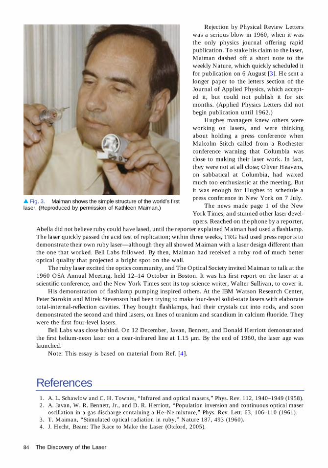
Rejection by Physical Review Letterswas a serious blow in 1960, when it wasthe only physics journal offering rapidpublication. To stake his claim to the laser,Maiman dashed off a short note to theweekly Nature, which quickly scheduled itfor publication on 6 August [3]. He sent alonger paper to the letters section of theJournal of Applied Physics, which accept-ed it, but could not publish it for sixmonths. (Applied Physics Letters did notbegin publication until 1962.)
Hughes managers knew others wereworking on lasers, and were thinkingabout holding a press conference whenMalcolm Stitch called from a Rochesterconference warning that Columbia wasclose to making their laser work. In fact,they were not at all close; Oliver Heavens,on sabbatical at Columbia, had waxedmuch too enthusiastic at the meeting. Butit was enough for Hughes to schedule apress conference in New York on 7 July.
The news made page 1 of the NewYork Times, and stunned other laser devel-opers. Reached on the phone by a reporter,
Abella did not believe ruby could have lased, until the reporter explained Maiman had used a flashlamp.The laser quickly passed the acid test of replication; within three weeks, TRG had used press reports todemonstrate their own ruby laser—although they all showed Maiman with a laser design different thanthe one that worked. Bell Labs followed. By then, Maiman had received a ruby rod of much betteroptical quality that projected a bright spot on the wall.
The ruby laser excited the optics community, and The Optical Society invited Maiman to talk at the1960 OSA Annual Meeting, held 12–14 October in Boston. It was his first report on the laser at ascientific conference, and the New York Times sent its top science writer, Walter Sullivan, to cover it.
His demonstration of flashlamp pumping inspired others. At the IBM Watson Research Center,Peter Sorokin and Mirek Stevenson had been trying to make four-level solid-state lasers with elaboratetotal-internal-reflection cavities. They bought flashlamps, had their crystals cut into rods, and soondemonstrated the second and third lasers, on lines of uranium and scandium in calcium fluoride. Theywere the first four-level lasers.
Bell Labs was close behind. On 12 December, Javan, Bennett, and Donald Herriott demonstratedthe first helium-neon laser on a near-infrared line at 1.15 μm. By the end of 1960, the laser age waslaunched.
Note: This essay is based on material from Ref. [4].
References1. A. L. Schawlow and C. H. Townes, “Infrared and optical masers,” Phys. Rev. 112, 1940–1949 (1958).2. A. Javan, W. R. Bennett, Jr., and D. R. Herriott, “Population inversion and continuous optical maser
oscillation in a gas discharge containing a He–Ne mixture,” Phys. Rev. Lett. 63, 106–110 (1961).3. T. Maiman, “Stimulated optical radiation in ruby,” Nature 187, 493 (1960).4. J. Hecht, Beam: The Race to Make the Laser (Oxford, 2005).
▴ Fig. 3. Maiman shows the simple structure of the world’s firstlaser. (Reproduced by permission of Kathleen Maiman.)
84 The Discovery of the Laser

Postwar Employment Bubble BurstsJeff Hecht
Optics prospered along with other areas of physics and engineering as American researchuniversities grew after World War II. Military programs encouraged universities toexpand basic research, both in hope of developing new defense technology and to train
specialists for defense research at government agencies or defense contractors. Over the yearsfrom 1938 to 1953, military support of university physics research soared by a factor of 20 to 25,after adjusting for inflation.
These programs provided both bright new ideas and bright people to help launch the laserera in optics. The Columbia Radiation Laboratory, founded in 1942 at Columbia University todevelop new microwave tubes for 30-GHz radar, received $250,000 a year after the war from theArmy Signal Corps to continue microwave research in Columbia’s physics department. At thetime, that was enough to support a staff of 20 and nearly as many graduate students, as well as topay several faculty members over the summer. Charles Townes headed the radiation lab from1950 to 1952, during the time he conceived of the microwave maser.
Military research dollars also produced new physicists. American universities had graduatedabout 150 new physics Ph.D.s annually just before the war, and the number dropped steeplyduring the conflict. But from 1945 to 1951 the number of physics Ph.D. graduates doubled every1.7 years, reaching about 500 per year, as shown in Fig. 1. Seeing where the jobs were, postwarstudents concentrated on experimental physics. Engineering likewise boomed in the postwaryears, with 159,600 bachelor’s degrees awarded from 1946 to 1950, more than from 1926through 1940.
Dwight Eisenhower had seen part of that growth as president of Columbia University from1948 to 1951, but as President of the United States he cut military research spending in 1953, andthe number of physics Ph.D.s remained in the 500–600 range through the 1950s. The cuts leduniversities to scale down their programs. Boston University went further, shutting the optics labit had inherited from Harvard; veterans of that group became the nucleus of the Itek Corpora-tion, founded in 1957 by Richard Leghorn with funding from the Rockefeller family.
Eisenhower changed course after the Soviet launch of Sputnik 1 on 4 October 1957 stunnedthe American physics community, the Pentagon, and politicians. Fearing the U.S. was fallingbehind in an arms race in space, his administration boosted funding for physics and engineeringresearch and education. The money brought quick results. The number of Ph.D.s graduatingfrom American universities rose exponentially from about 500 in 1960 to some 1600 in 1970,faster than the growth of Ph.D.s in any other field. The number of American universities offeringPh.D.s in physics climbed from 52 in 1950 to 78 in 1960 and reached 148 in 1970. The numberof undergraduate degrees in physics also climbed, from 1000 in 1945 to a peak above 6000 in1968. Engineering degrees also increased. The numbers reflected both growth in overall collegeenrollment and an increase in the fraction of students studying physics and engineering. It did notinclude the Postwar baby boom, who started to graduate from college in 1968.
The arms race, the space race, fast-growing industrial labs, and a booming technologyindustry created unprecedented demand, particularly for physicists. A 1964 report from theAmerican Institute of Physics found that in 1960 only 17,300 trained physicists were available tofill some 29,000 physics-related jobs in the U.S. It’s not clear how many of the excess jobs wentunfilled or were filled by people lacking physics degrees, but the deficit seemed formidable—andthe gap was projected to reach 20,000 by 1970.
1960–1974
85

A tripling of government research and development funding from 1955 to 1965 helped propel theboom, with defense and space programs leading the way. The birth of the laser and increasing militaryuse of electro-optics pumped up spending on optical research and development, and in 1962 OSA’sNeeds in Optics Committee concluded that existing training programs could fill only a quarter of theneed for 3500 new optics specialists in the coming five years [2].
Yet by the mid-1960s, the well-oiled machinery of growth had begun hitting serious bumps in theroad. Doubts were growing about America’s escalating involvement in Vietnam, and opponents wereraising questions about the presence of military research on university campuses. Budget watchersworried that the country could not afford to continue pumping more money into basic research whilefighting a war. Pentagon auditors found that military spending on basic research yielded a disappoint-ing return on investment and urged focusing narrowly on mission-oriented research and development.
Congress began pressing to cut military spending on basic research, and spending on new researchbuildings was stopped in early 1967, forcing some creative financing to build the new Optical SciencesCenter at the University of Arizona [2]. Congress complained that too much research money was goingto a few elite universities, and too little to other Congressional districts. Topping off the trend, theMansfield amendment in 1969 barred Pentagon spending on research lacking direct military applica-tions, although those restrictions were later eased.
Universities also began re-examining their military research policies, pushed by faculty and studentprotests. In 1967 Columbia, an early hotbed of protests, divested its Electronics Research Laboratory,which became the Riverside Research Institute. More would follow. Stanford in 1970 split off theStanford Research Institute, later SRI International, and in 1972 MIT divested its InstrumentationLaboratory, which became the Charles Stark Draper Laboratory. The most important split for theoptics world probably was the University of Michigan’s 1972 divestiture of its off-campus Willow RunLaboratories, the birthplace of laser holography and optical signal processing.
In retrospect, it should have been obvious that the rapid growth powered by the space and armsraces could not continue, but students recruited with promises of well-paying jobs were caught bysurprise. Recruitment advertisements, which had fattened campus newspapers at elite schools likeCaltech, began evaporating after 1967. Job fairs at physics conferences shrank. Only 253 jobs wereadvertised at the American Physical Society’s 1968 annual meeting, but nearly 1000 applicants showedup, and over 1500 people received Ph.D.s that year. Two years later, 1010 job-hunters chased 63 jobs atthe APS April meeting. “American physics had indeed reached a crisis by 1970, exactly when the 1964report had predicted,” wrote MIT historian David Kaiser [1]. But the crisis was a shortage of jobs ratherthan of physics graduates.
Inevitably, graduate enrollment shrank, and the number of new physics Ph.D.s dropped from apeak of 1600 at the start of the 1970s to about 1000 per year at the end. Physics research continuedgrowing, but at a much slower pace. One measure of research, the number of abstracts published eachyear in Physics Abstracts, increased about 3% a year from 1971 to 1999—only a quarter of the 12%
◂ Fig. 1. Number of Ph.D.physicists graduating fromAmerican universities annually,showing the dramatic postwarboom and post-1970 decline.(© 2002 by The Regents of theUniversity of California. All rightsreserved [1].)
86 Postwar Employment Bubble Bursts

annual growth from 1945 to 1971. Optics in general fared better than many other specialties, leadingsome physicists in hard-hit fields to move into optics.
Engineers were caught in a similar crunch. Ph.D.s in electrical engineering, the major most relatedto optics, peaked at 858 in 1971, then slid steadily to 451 in 1978, a 47% drop—larger than the 37%drop in physics Ph.D.s. The decline in bachelor’s degrees, which in the 1970s were typically the terminaldegree in engineering, was much less. Electrical engineering undergraduate degrees peaked at 12,288 in1970–1971, then bottomed out at 9874 in 1976, only a 20% drop [3]. Many of those engineers, andsome physicists, wound up in the fast-growing computer industry. Others ended up in optics.
Optics also felt the slowdown of the late 1960s and early 1970s, but with only a handful of schoolstraining optical engineers and physicists, optics still offered opportunities for young physicists andengineers. Many of the newcomers adapted their skills to work on lasers and fiber optics, the fastest-growing fields in optics in the 1970s and 1980s. The newcomers brought new skills, and helped opticsgrow into new areas as they developed their careers.
References1. D. Kaiser, “Cold war requisitions, scientific manpower, and the production of American physicists after
World War II,” in Historical Studies in the Physical and Biological Sciences, Vol. 33 (University ofCalifornia Press, 2002), Part 1, pp. 131–159.
2. S. Wilks, from the History of OSA (to be published).3. M. K. Fiegener, “Science and Engineering Degrees: 1966–2010: detailed statistical tables” (National
Science Foundation, June 2013).
Postwar Employment Bubble Bursts 87

Gas Lasers—The GoldenDecades, 1960–1980William B. Bridges
By all rights, gas lasers should have been discovered long before 1961, likely by accident.Einstein’s 1917 classic paper derived the relationship among spontaneous emission,stimulated emission, and absorption, but only considered a system in thermodynamic
equilibrium (guaranteed not to oscillate). It remained only to ask: “What if the system were not inthermodynamic equilibrium?” Yet despite countless experiments looking at the absorption ofradiation in gas discharge tubes (not in thermodynamic equilibrium), the first gas laser had towait for Ali Javan of Bell Telephone Laboratories.
First Gas LaserIn 1959 Javan proposed four different ways to make a gas laser:
(1) A gas discharge in pure neon.(2) A gas discharge in pure helium.(3) Resonant collisions in between excited krypton and mercury atoms in a discharge
exciting the Hg (91P) or Hg (61F) levels, creating an inversion in the mercury levels.(4) Helium atoms in the (23S) level in a gas discharge exciting Ne (2s) levels to create an
inversion in neon levels.The first three systems do not actually work, but fortunately Javan and his Bell coworkers
Bill Bennett and Don Herriott did the fourth experiment. They excited a mixture of helium andneon with a radio-frequency discharge in a gas tube with flat end mirrors coated for maximumreflectivity near 1-μm wavelength, as depicted in Fig. 1. Oscillation of the neon transition 2s2 →2p4 at 1.1523 μm made the first gas laser.
Gas Lasers Using Neutral AtomsOnce the word was out, everybody had to have a helium–neon laser, and a war-surplus nightvision ‘scope to see the infrared laser output. Hughes Research Laboratories was no exception,and the author found himself in the queue to get one from a mini production line that Hughes hadset up. The author had been interested in developing a microwave traveling wave tube (his formerprofessional interest) as a high-frequency photodetector for laser communications and hadalready done experiments with a pulsed ruby laser. The continuous operation of the He–Ne laserwas more attractive for communications, despite the need for a new detector. But fate intervened.
The author had planned to attend the annual Conference on Electron Device Research in lateJune with his boss, Don Forster, and Hughes Associate Director, Mal Currie. Currie decided theyshould visit Bell Labs on the way to see what was new and interesting. They were astounded tosee a red He–Ne laseroperatingatabout 10mW, in the lab shown inFig.2. The three researchers sawthenowfamiliar“redsandpaper” speckleof trulycoherent light (whichwasnot very evident in the IRHe–Ne laser viewed with a night-vision ‘scope). Alan White and J. Dane Rigden had found another
1960–1974
88

metastable level in helium, the 2s1S0, thatcollected population from higher-lying heli-um levels, and was near resonance with the3s2 level in neon. That created a populationinversion with the 2p4 level on the red laserline at 0.6328 μm and oscillation when red-reflecting mirrors were used for feedback.White and Rigden were in a different Belltechnical group from Javan, Bennett, andHerriot, and enjoyed the rivalry. When theyannounced the red laser the next week at theconference, the rivalry between the twogroups was quite evident.
That night on the drive back from Bellin New Jersey to our hotel in New York,the group discussed the new red laser.Currie (who was driving) ended by saying“We have to have one!” The author sensedthat he had just received a battlefield pro-motion to “Gas Laser Researcher.”
Helium–neon gas mixtures turn out tohave several infrared lines from 2s levels to 2p levels, and several lines from green to deep red betweenthe 3s2 level and 2p levels. In addition, several infrared lines in the 3-μm range have so much gain thatthey can easily suppress the red laser line. Arnold Bloom, Earl Bell, and Bob Rempel of Spectra-Physicsfound that they could prevent 3-μm emission by adding an intracavity prism.
Other researchers rushed to extend these results. Another Bell Labs group built a 10-m dischargetube to obtain oscillation on many more infrared lines to wavelengths beyond 100 μm in various noble-gas mixtures. This early burst of research showed that oscillation was possible in pure noble gasdischarges, without adding helium. That led to a burst of research on the noble gases, which are easy toinvestigate because they do not interact with the discharge tube walls or electrodes.
Interest soon turned to other materials, starting with the permanent gases such as oxygen, nitrogen,and chlorine, which dissociate into atoms in a discharge, and expanding to easily vaporized elementssuch as mercury, iodine, and sulfur. Reports of new lasers multiplied, and it seemed that almostanything that you could vaporize and put in a gas discharge would lase. Figure 3 shows how the ranksof lasing elements grew during the first two decades, the “golden age” of gas laser research. The author
▴ Fig. 1. Ali Javan, W. Bennett, and D. Herriott with the firstHe–Ne laser at Bell Laboratories. (Reprinted with permission ofAlcatel-Lucent USA Inc., courtesy AIP Emilio Segre VisualArchives, Physics Today Collection.)
▸ Fig. 2. J. D. Rigden, A. D. White,and W. W. Rigrod with the first redHe–Ne laser at Bell Laboratories.(Courtesy of Alan White.)
Gas Lasers—The Golden Decades, 1960–1980 89
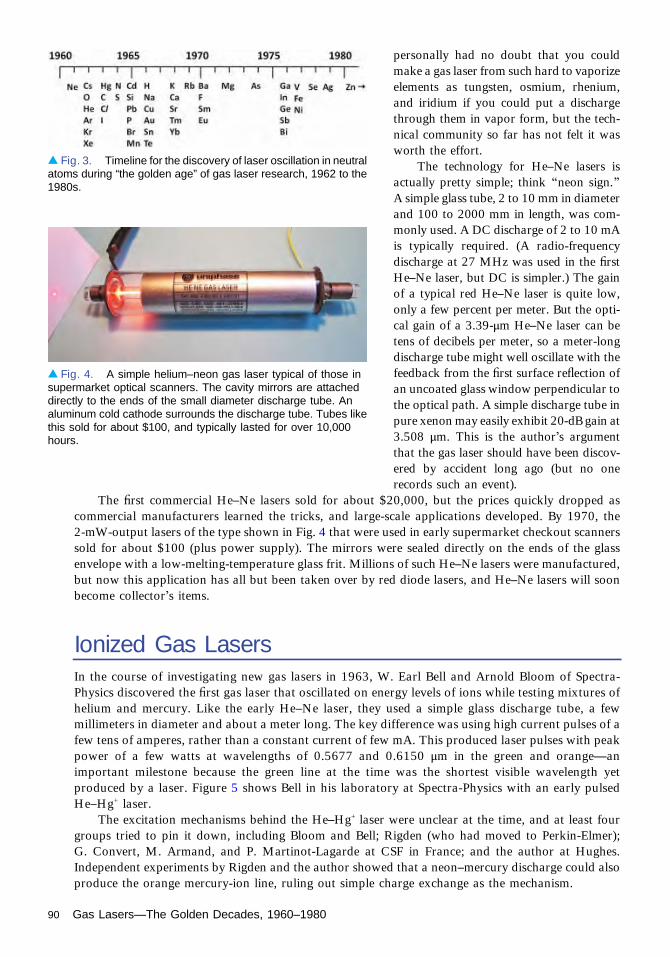
personally had no doubt that you couldmake a gas laser from such hard to vaporizeelements as tungsten, osmium, rhenium,and iridium if you could put a dischargethrough them in vapor form, but the tech-nical community so far has not felt it wasworth the effort.
The technology for He–Ne lasers isactually pretty simple; think “neon sign.”A simple glass tube, 2 to 10 mm in diameterand 100 to 2000 mm in length, was com-monly used. A DC discharge of 2 to 10 mAis typically required. (A radio-frequencydischarge at 27 MHz was used in the firstHe–Ne laser, but DC is simpler.) The gainof a typical red He–Ne laser is quite low,only a few percent per meter. But the opti-cal gain of a 3.39-μm He–Ne laser can betens of decibels per meter, so a meter-longdischarge tube might well oscillate with thefeedback from the first surface reflection ofan uncoated glass window perpendicular tothe optical path. A simple discharge tube inpure xenon may easily exhibit 20-dB gain at3.508 μm. This is the author’s argumentthat the gas laser should have been discov-ered by accident long ago (but no onerecords such an event).
The first commercial He–Ne lasers sold for about $20,000, but the prices quickly dropped ascommercial manufacturers learned the tricks, and large-scale applications developed. By 1970, the2-mW-output lasers of the type shown in Fig. 4 that were used in early supermarket checkout scannerssold for about $100 (plus power supply). The mirrors were sealed directly on the ends of the glassenvelope with a low-melting-temperature glass frit. Millions of such He–Ne lasers were manufactured,but now this application has all but been taken over by red diode lasers, and He–Ne lasers will soonbecome collector’s items.
Ionized Gas LasersIn the course of investigating new gas lasers in 1963, W. Earl Bell and Arnold Bloom of Spectra-Physics discovered the first gas laser that oscillated on energy levels of ions while testing mixtures ofhelium and mercury. Like the early He–Ne laser, they used a simple glass discharge tube, a fewmillimeters in diameter and about a meter long. The key difference was using high current pulses of afew tens of amperes, rather than a constant current of few mA. This produced laser pulses with peakpower of a few watts at wavelengths of 0.5677 and 0.6150 μm in the green and orange—animportant milestone because the green line at the time was the shortest visible wavelength yetproduced by a laser. Figure 5 shows Bell in his laboratory at Spectra-Physics with an early pulsedHe–Hg+ laser.
The excitation mechanisms behind the He–Hg+ laser were unclear at the time, and at least fourgroups tried to pin it down, including Bloom and Bell; Rigden (who had moved to Perkin-Elmer);G. Convert, M. Armand, and P. Martinot-Lagarde at CSF in France; and the author at Hughes.Independent experiments by Rigden and the author showed that a neon–mercury discharge could alsoproduce the orange mercury-ion line, ruling out simple charge exchange as the mechanism.
▴ Fig. 3. Timeline for the discovery of laser oscillation in neutralatoms during “the golden age” of gas laser research, 1962 to the1980s.
▴ Fig. 4. A simple helium–neon gas laser typical of those insupermarket optical scanners. The cavity mirrors are attacheddirectly to the ends of the small diameter discharge tube. Analuminum cold cathode surrounds the discharge tube. Tubes likethis sold for about $100, and typically lasted for over 10,000hours.
90 Gas Lasers—The Golden Decades, 1960–1980

To put an extra nail in the coffin of chargeexchange, the author tried an argon–mercury dis-charge. (Argon has an ionization potential wellbelow that of neon.) This initially did not producethe orange and green Hg II laser lines, so the mixturewas pumped out. After the tube was refilled with ahelium-mercury mixture, the discharge again pro-duced the orange and green Hg II laser lines—plus aturquoise blue laser output, which turned out to beionized argon, shown in Fig. 6. The blue pulsecoincided with the electron current, not the dis-charge afterglow, suggesting that electron collisionwas the mechanism behind the argon-ion oscilla-tion. That system, similar to the one shown with theauthor in Fig. 6, opened up a new chapter. It wasValentine’s Day, 14 February 1964.
It turned out that the groups at Spectra-Physics,CSF, and Hughes had independently discovered theAr II 0.4879-μm laser. So had W. R. Bennett, Jr., J.W. Knutson, Jr., G. N. Mercer, and J. L. Detch atYale University, who had not been studying mercu-ry-ion lasers but were trying to make an argon-ionlaser! It was clearly an idea whose time had come.Another group at Bell Laboratories, E. I. Gordon, E.F. Labuda, and R. C. Miller, found that the argon-ion laser could emit continuously, unlike the mer-cury-ion laser. In a matter of months, water-cooleddischarge tubes were emitting more than 2 W con-tinuously. The efficiency was below 0.1%, so sev-eral kilowatts of input was needed, requiring majorimprovements in discharge tubes.
Other noble-gas ion lasers followed quickly.More than two dozen laser lines in krypton andxenon ions were discovered within a week of theargon laser. Neon oscillation followed in a couple ofmonths, the time needed to obtain cavity mirrors atthe right wavelengths. Spectrographic platesrecorded laser oscillation on lines of oxygen, nitro-gen, and carbon left as impurities in the dischargetubes. Further spectroscopic research discoveredlaser emission from multiply ionized species athigher peak currents.
Watts of continuous-wave blue laser lightopened the possibility of new applications. Amongthe first was improving coagulation to repair de-tached retinas, which had been done with high-power xenon lamps and later ruby lasers. Kryp-ton-ion lasers, able to emit red, yellow, green, andblue light simultaneously, were quickly adopted for light shows. Their use at rock concerts introducednew types of customers to laser companies that were used to scientists; one customer arrived at Spectra-Physics with a wad of hundred-dollar bills to buy a krypton laser, put the laser in his station wagon, anddrove off to a show that night. By far the largest application for ion lasers became high-power pumpsfor dye lasers, making ion lasers the “power supply” for much science.
▴ Fig. 5. W. E. Bell in his laboratory at Spectra-Physics with an early pulsed helium-mercury ion laser.(AIP Emilio Segre Visual Archives, gift of W. Earl Bell.)
▴ Fig. 6. Photograph of the author with a pulsedargon-ion laser in his laboratory in February 1964: anair-cooled fused silica discharge tube with Brewster’sangle windows and external mirrors. Pulse lengths of afew microseconds with a simple capacitor dischargeand rates of a few hundred per second were used.
Gas Lasers—The Golden Decades, 1960–1980 91

Molecular Gas LasersNobel Laureate and former Optical Society President Arthur Schawlow once said, “A diatomicmolecule is a molecule with one atom too many.” However, for molecular lasers this author wouldsay instead, “If one atom is good, then several must be better.” Molecules have more degrees of freedomthan atoms or ions, including the number and kind of atoms, the molecular structure, the nature ofenergy levels, and type of pumping, leading to the demonstration of thousands of molecular lasers. Thefirst was carbon monoxide, which L. E. S. Mathias and J. T. Parker made oscillate on electronictransitions in a pulsed discharge at 0.8 to 1.2 μm. Close behind it was the 0.337-μm N2 laserdemonstrated by H. G. Heard. The third molecular laser would be the charm—and most success-ful—the 9- to 11-μm CO2 laser, discovered at Bell by C. K. N. Patel, W. L. Faust, and R. A. McFarlane.
The diatomic noble gases, noble-gas halides, and noble-gas oxides in the list exist only in anelectronically excited state, called an “excimer.” The population inversion occurs because the moleculequickly falls apart into atoms when it drops to the ground state. The rare gas-halide excimers havebecome commercially important because they produce powerful pulses in the vacuum ultraviolet. The193-nm argon-fluoride laser is used in laser ablation of the cornea to correct vision defects and in high-resolution lithography to make silicon integrated circuits.
Larger and more complex gas molecules also have been made to oscillate, mostly by opticalpumping with the 9- to 11-μm light from CO2 lasers. These larger molecules have hundreds ofrotational/vibrational transitions in the far-infrared region, and to make matters more complicated, thewavelengths depend on the hydrogen, carbon, nitrogen, and oxygen isotopes in the molecule.
The most important molecular gas laser, CO2, like the He–Ne laser, depends on energy transferfrom a more abundant species to the light emitter, so it might better be called the nitrogen–CO2 laser.Typically a discharge excites a gas mixture of ten parts N2 and one part CO2, with most energy going toexcite N2 molecules to their lowest vibrational level, which is metastable so it cannot radiate. However,they can transfer energy by colliding with CO2 molecules, which have a near-resonant energy level thatproduces a vibrational population inversion. CO2 oscillation occurs on rotational sublevels of theinverted vibrational level, which can be selected by tuning the cavity.
Carbon dioxide lasers can have efficiency of 10% or more, among the highest of any gas laser, anda factor of 100 higher than most atomic or ionic lasers. That makes CO2 the gas laser of choice whenpower is important. Applications including burning date codes or other identification on plastic bottles,cutting sheet metal, or even cutting the special glass used in cell phone displays.
In the mid-1960s, the AVCO Everett Research Laboratory produced record continuous CO2
output of 50 kW, shown in Fig. 7. This “gas-dynamic laser” burned fuel at high temperature
◂ Fig. 7. An experimentalgas-dynamic CO2 laserdeveloped by AVCOCorporation circa 1968. Theoutput was over 50 kW.
92 Gas Lasers—The Golden Decades, 1960–1980

(2000°F) and pressure (20 atm.) and then exhausted the mixture of 89% nitrogen, 10% CO2 and 1%water vapor through a supersonic expansion nozzle. This produced a CO2 population inversiondownstream, which could oscillate when passed through an optical cavity. The black circle above andto the right of the technician’s head was the beam output. The combustion chamber is at the right of thedevice, and the exhaust to the atmosphere is to the left of the picture. (The combustion exhaust wasrelatively harmless to the environment, but the highly poisonous cyanogen C2N2 was used as fuel tokeep the exhaust low in hydrogen, so extreme care was needed to make the fuel burn properly.) Later, a400-kW version was installed in the Airborne Laser Laboratory, a laser-weapon testbed built in the1970s.
Hydrogen–fluoride (HF) chemical lasers, which burn hydrogen and fluorine to produce HF gas thatlases in a system similar to the gas-dynamic laser, have reached megawatt-class powers in demonstra-tions on the ground. These are described by Jeff Hecht in his chapter on laser weapons.
SummaryThe two decades ending in the 1980s were the heyday of gas laser development. Today, the world of gaslasers is much quieter, with only a few types remaining, with mostly carbon dioxide in the factory andsome excimers and argon ion lasers in ophthalmologists’ offices.
A list of literature citations for the thousands of gas lasers implied by this chapter would be longerthan the chapter itself. The interested reader is referred to guides to that literature, such as [1].
Reference1. R. J. Pressley, ed., Handbook of Lasers (CRC Press, 1971 and subsequent editions).
Gas Lasers—The Golden Decades, 1960–1980 93

Discovery of the Tunable Dye LaserJeff Hecht
The narrow-emission bandwidth of laser light quickly attracted the attention of spectro-scopists in the early 1960s, but that narrow linewidth came at a cost—the wavelengthwas fixed. Laser researchers found that they could shift the fixed wavelength somewhat
by applying magnetic fields to the laser, they developed tunable parametric oscillators, andeventually they found a few laser lines that were tunable. But those arrangements werecumbersome and their range limited. As a student in the mid-1960s, spectroscopist TheodorHänsch felt “a sense of frustration” that he had no way to tune lasers “to wavelengths that wereinteresting.”
What spectroscopists really wanted was a laser that could be tuned across a broad range ofinteresting wavelengths. The first such tunable laser, the organic dye laser, was discovered byaccident in research on Q-switching ruby lasers. The first Q switches were active devices based onKerr cells or rotating mirrors, but in early 1964 the first passive Q switches were developed usingsaturable absorbers. Later that year, Peter Sorokin at the IBM Watson Research Center showedthat certain organic dyes dissolved in solvents made simpler and more convenient saturableabsorbers.
After that success, Sorokin found himself with a large collection of dye compounds that hadbeen prepared for the saturable absorber experiments. The dyes had interesting propertiesincluding strong fluorescence, so he decided to try producing stimulated Raman scattering. Hefired pulses from a big Korad ruby laser into a dye that had never been tested in Q switching. Thefirst experiment produced a black smudge on a photographic plate, but it was late Fridayafternoon and he had to leave. Monday morning, 7 February 1966, he told his assistant JackLankard they should try aligning a pair of mirrors with the dye cell before they fired the laseragain. “Jack came back from developing the plate with a big grin on his face. There was one placein the plate that the emulsion was actually burnt,” Sorokin later recalled. They knew it was laseraction because the bright line was at the peak of the dye fluorescence
Word of their experiments traveled slowly; Sorokin chose to publish his results in theMarch 1966 issue of the IBM Journal of Research and Development because he liked theeditor, but it was not widely read. That gave two other groups a chance to independently inventthe dye laser.
The idea of a dye laser came to Mary Spaeth, then at Hughes Aircraft Co., about the sametime Sorokin was working on his experiment. She recalls, “I was sitting on my bed with my twoyear old daughter on my lap, two months pregnant with my second daughter, and about 20papers spread out in front of me. I had been studying dyes that had been used for many yearsfor photographic purposes. In particular, I was studying models for how they are excited andhow they transfer energy from one molecule to another in the photographic process. Theexcited states of these dyes have a geometry very similar to their ground states, so they havevery strong absorption spectra. I suddenly realized that if a dye could be put in a suitablesolvent, you could have an enormous population inversion after illumination by a short-pulselaser. It was just like the light bulb pictures you see in the funny books. Boing! There it was,clear as day.”
She also realized that because dyes have huge numbers of rotational states, they should havea broad gain bandwidth, so that placing dispersive optics in a laser cavity with the dye solutionshould allow wavelength tuning. But first she wanted to try exciting the dye with pulses from a
1960–1974
94

ruby laser. It was not part of her job, so ittook her months to make arrangements topump dyes with a ruby laser in DaveBortfeld’s lab. As she sat epoxying a dyecell together, Bortfeld entered the roomand threw a paper airplane at her. Sherecalls, “I looked at him to try to figureout why he had done that. As I unfoldedthe airplane, I found it was a copy ofSorokin’s paper,” which Bortfeld hadjust spotted. She knew the dyes, so sheinstantly realized what it was about. “Wedecided, what the heck, we were workingindependently, and we continued onour way.”
Expecting the dye to emit at a wave-length a little longer than 700 nm, she didnot set up a detector, figuring she would beable to see the laser spot on a magnesiumoxide block. However she didn’t see any-thing. “I was about eight months pregnant, I had trouble reaching the knobs on the oscilloscope, it was7 in the evening, and I was very tired,” she recalls. Bortfeld told her to go home, while he set up aphotodetector and tried again. He called later that evening to tell her it had worked.
In further tests, they changed dye cells and moved their optics and found the oscillationwavelength of one dye changed from 761 to 789 nm when they tried cells from 8 mm to 10 cmlong, and mirror spacing from 10 to 40 cm. They sent a paper to Applied Physics Letters, whichreceived it 11 July 1966 and published it in the 1 September issue. It was the first report to show thatdye laser wavelength could be changed, although it was not yet practical tuning. Spaeth did not getthe chance to explore tuning further. Hughes management had no interest in dye lasers, and she had adifficult childbirth, so her immediate priorities became recovering and dealing with two smallchildren.
Fritz Schaefer wrote that his group at the Max Planck Institute in Germany was unaware of eithereffort when they stumbled upon the dye laser while studying saturation in a different group of organicdyes. A student was testing the effects of increasing the dye concentration by firing ruby pulses intothe solution, Schaefer wrote, when “he obtained signals about one thousand times stronger thanexpected, with instrument-limited risetime[s] that at a first glance were suggestive of a defective cable.Very soon, however, it became clear that this was laser action.” They may have learned of Sorokin’swork after submitting a paper on their results which Applied Physics Letters received on 25 July, twoweeks after Spaeth’s paper. (After revisions received by APL on 12 September, Schaefer’s paper waspublished in the 15 October 1966 issue, citing Sorokin’s paper but not Spaeth’s.) Like Spaeth, theyreported wavelength changes, in their case arising from changes in dye concentration.
Sorokin soon demonstrated flashlamp pumping, shown in Fig. 1, which proved important becauseit could pump dyes across a broader range of wavelengths than the ruby laser. In 1967 Bernard Sofferand Bill McFarland at Korad replaced one cavity mirror with an adjustable diffraction grating to makethe first continuously tunable dye laser. They tuned across 40 nm and also reduced emission linewidthby a factor of 100. At last, spectroscopists had a broadly tunable laser, and they soon were busyexploring the possibilities.
Triplet-state absorption in the dyes limited pulse duration to nanoseconds in those early pulsedlasers, but in 1969 Ben Snavely from Eastman Kodak and Schaefer found that adding oxygen to thesolvent could quench triplet absorption. Snavely then teamed with Kodak colleagues Otis Peterson andSam Tuccio to develop a continuous-wave (CW) dye laser. They first investigated prospects forpumping with intense plasma light sources, then tried pumping with an argon-ion laser. That requiredlongitudinal excitation and liquid flow to keep the dye solution cool, deplete triplet states, and avoid
▴ Fig. 1. Peter Sorokin with the flashlamp-pumped dyelaser in 1968. (Courtesy of International Business Machines,© International Business Machines Corporation.)
Discovery of the Tunable Dye Laser 95

thermal lensing. In 1970, they produced CW outputof about 30 mW at 597 nm when pumping a dyesolution flowing between a pair of dichroic mirrorswith a 1-W argon-ion laser.
Further refinements followed. Trying to in-crease CW dye output by increasing the pumppower and focusing it onto a smaller spot tendedto burn the coatings off the quartz windows cover-ing the dye. That problem was solved when PeterRunge and R. Rosenberg at Bell Labs developed away to flow a jet of dye solution through the pumpbeam in a laser cavity without confining it, so therewas no glass or coating to be damaged.
Pulsed dye lasers had launched tunable laserspectroscopy. CW dye lasers and higher powers ledto a series of landmark experiments. Conger Gabeland Mike Herscher at Rochester reached tunablesingle-mode dye power of 250 mW between 520
and 630 nm and used intracavity harmonic generation to produce tunable ultraviolet power of up to10 mW. Felix Schuda, Herscher, and Carlos Stroud at Rochester stabilized a CW dye laser to 10 to15 MHz to measure a the hyperfine absorption spectrum of the sodium D line, showing that dye laserscould do important experiments in fundamental physics.
Spectroscopy with CW dye lasers advanced rapidly. Two-photon Doppler free spectroscopy withdye lasers, which allows extremely precise wavelength measurement, was developed independently in1974 by David Pritchard at MIT and by Arthur Schawlow and Theodor Hänsch at Stanford.
CW operation of broadband dyes also opened the way to ultrashort laser pulses. In 1964, WillisLamb had showed that mode locking could generate extremely short laser pulses with duration limitedby the Fourier transform of the laser bandwidth. As long as laser bandwidth was limited, mode lockingcould not generate very short pulses. However, with suitable optics a CW dye laser could oscillateacross most of the dye’s emission bandwidth, allowing mode locking to generate ultrashort pulses. In1972, Erich Ippen and Charles Shank generated 1.5-ps pulses by passive mode locking of a dye laser, andin 1974 they generated subpicosecond pulses with kilowatt peak power. That launched the growth ofultrafast technology, described in a later section by Wayne Knox.
As Schawlow wrote in the speech he gave when receiving the 1981 Nobel Prize in Physics,“spectroscopy with the new [laser] light is illuminating many things we could not even hope to explorepreviously.” One of the amazing things was the small shifts of transition wavelengths between differentisotopes of elements such as uranium. Tunable narrow-line dye lasers could resolve those shifts, offeringthe possibility of selectively exciting the fissionable isotope U-235. As described in another article in thissection, the Lawrence Livermore National Laboratory used banks of dye lasers, pumped by largecopper-vapor lasers, to enrich both uranium and plutonium. At Livermore, Spaeth (Fig. 2) foundsupport for her interest in dye lasers, and managed development of massive CW dye lasers thatgenerated kilowatts for Livermore’s uranium-enrichment demonstrations.
▴ Fig. 2. Mary Spaeth at Livermore. (Courtesy ofLawrence Livermore National Laboratory.)
96 Discovery of the Tunable Dye Laser

Remembrances of Spectra-PhysicsDavid Hardwick
It was a cold February morning in Minnesota—really cold! The year was 1963 at theHoneywell Research Center, and the author, only recently graduated from college, helpedsome visitors bring in their product to demonstrate. Herb Dwight, one of the five founders of
Spectra-Physics, and Gene Watson, their star salesman, had stayed overnight in Minneapolis andleft their laser in the back of a station wagon. When their Model 110 He–Ne laser was broughtinto the lab, “steam” was pouring off every surface, befitting the change from below zero to roomtemperature. The unit was turned on and, miracle of miracles, a sharp red 632.8-nm beamemerged. It does not seem like much now, but the author was blown away—having only toorecently tried to build such a laser himself. With the optics of the time and his limitedunderstanding of the process, achieving the necessary alignment proved difficult indeed. Andhere were these guys, tanned by the California sun and braving the frigid temperatures, showingus pallid northerners in the depth of winter a commercial product that worked.
Some months later, convinced that he wanted to join the world of lasers, the author headedwest to join the company. Just before he set out, a call came in requesting that he stop at the JILAlab in Boulder, Colorado, to demonstrate a laser to Dr. John Hall, a future Nobelist. That laser,drop shipped to the author in Denver, did not work. It turned out that the power supply “on”switch was not wired in and the author was too clueless to determine the problem. The next dayanother laser arrived and was demonstrated to Dr. Hall and his staff, thus completing theauthor’s first sales call.
Early Spectra-Physics lasers consisted of a tube filled with a He–Ne gas mixture at a pressureof a few Torr placed in an optical cavity with mirrors at either end and a power source, whichwas radio-frequency (RF) coupled into the gas. Radio-frequency coupling avoided the necessityof placing anodes and cathodes in the tube itself; cathodes available at the time quicklydeteriorated, and the tube would go from a healthy pink glow to a sickly blue—death by gaspoisoning!
The Model 130 was introduced in 1963, a foot-long ten-pound laser that looked for all theworld like a lunch box complete with leather handle. Cost considerations demanded that DCpower be used instead of RF coupling. The tube was terminated with optical windows set atBrewster’s angle, and the confocal mirror cavity was protected from the outside world withflexible rubber boots. The problem was the cathodes were “borrowed” from neon signtechnology and were designed for use at pressures 10× that of the laser tube. These little metaltubes, terminated with a ceramic disc and filled with some rare-earth oxide mixture, simply didnot last very long; the neon was quickly “sputtered” away, and a few-hundred-hour lifetime wasconsidered good. What to do?
The author’s bosses, Arnold Bloom and Earl Bell, asked him to follow up on a paper by UrsHochuli of the University of Maryland in College Park describing aluminum cathodes for use inHe–Ne lasers. This assignment led to the author’s first real project at Spectra. A visit to Hochuliin College Park resulted in Spectra’s machine shop fabricating a few aluminum cathodes, tubesa few inches long and an inch in diameter, allowing some He–Ne tubes to be made. The resultswere very promising. So promising, in fact, that in a few months, the neon sign cathodes wereabandoned and only aluminum cathodes were used. Some 50 years have passed, He–Ne lasersare still being manufactured, and to the author’s knowledge aluminum cathodes remain thestandby.
1960–1974
97

That technology became the Model 130, which had quite a long life as a Spectra product. Earlydevices delivered about 0.5 mW at 632.8 nm; they cost $1525, a solid value at the time, although todaya laser pointer producing much more power can be purchased for a few dollars. The Model 130 foundmany applications, ranging from serving as a pointer in Arthur Schawlow’s lecture room to guiding agigantic borer with a ten-foot-diameter cutting face in a tunnel being drilled through a hillside inLlanelli, Wales.
Spectra-Physics was a wonderful place to “grow up” in the laser world. The five founders providedleadership, presented real opportunities to those younger and dumber, and created an enjoyable workenvironment. As an example, when it came time to crate the hundredth laser for shipment, work washalted, a keg of beer was produced, significant others were invited, and the factory floor witnessed aparty celebrating the event. Now, when millions of lasers in thousands of different configurations areproduced worldwide, it is fun to remember when coherent light was rare and customers clamored forthe first chance to employ it in their experiments.
Spectra-Physics was also a place where the workdays seemed to run on forever—it was theemployees’ choice to work overtime, not a company demand. The author recalls fiddling in his lab lateone night in 1964 when Earl Bell, a company founder, called out and asked him to come next door tohis lab. He had a three-meter-long, large-diameter laser tube attached to a vacuum system and fittedwith various gas sources. As usual, he was experimenting with different gases to investigate their laserpotential. There was a very bright beam coming out of the tube and Earl asked what color it was. Theanswer was obvious—a very intense green! Earl said, “I thought so but couldn’t really tell as I am quitecolor blind!” Thus the author was the second person, after Earl, to see an ion laser—a mercury-ionlaser. The gain was amazing—Earl took a Kennedy half-dollar out of his pocket and held it in the mirrorposition at the end of the tube, and the laser flickered on and off as he brought the “mirror” intoalignment.
After Earl’s discovery, Bill Bridges at Hughes built a pulsed argon-ion laser. Earl quickly followed,and soon the continuous wave argon-ion laser, now ubiquitous, came on the scene. Spectra quicklycommercialized it with the refrigerator-sized Model 135 argon-ion laser and power supply. Only a fewdozen were made; they were RF-coupled, temperamental, and short-lived. The author remembers manymiserable days at a Paris university trying to coax usable power out of one of these monsters during thedog days of August 1968, when all the more intelligent Parisians had left town for the seaside.
Spectra-Physics actively sought to sell their lasers in Europe from very early days. They employed asalesman stationed in Switzerland who visited universities and company laboratories, selling manylarge He–Ne lasers at prices favorable to the company. However, there was a problem: Europeancountries had firm tariff barriers that greatly increased the costs of buying American lasers. The solutionwas to set up manufacturing inside the tariff borders. When Herb Dwight asked if anyone wasinterested in setting up such an assembly operation, the author quickly volunteered and, in a couple ofmonths, moved to Scotland with his small family to do so, choosing a site in Glenrothes Fife, just northof Edinburgh. With the help of the Spectra team, friends of Herb at the local Hewlett-Packard factory,Scottish government representatives and a host of others, Spectra’s first Scottish-built Model 130 wasshipped three months later, in late 1967. During three years based in Scotland, the team demonstratedand sold Spectra lasers throughout Europe, from nearby England to far-off Athens and north toStockholm. It was a great adventure!
Back to Mountain View, California, and the author had a new assignment to be product managerfor the Spectra-Physics Geodolite Laser Distance Rangefinder, working with Ken Ruddock, one of thefive company founders. The Geodolite was based on a 25-mW He–Ne laser that was amplitudemodulated at five different frequencies while the return from the target was phase-detected. A one-inchtelescope broadcast the beam, and an eight-inch Cassegrain telescope gathered the return signal.
The team used the Geodolite for several ground-based and aerial applications, including iceroughness measurement and wave height determination from various air platforms including aLockheed TriStar, Convair 990, and Douglas DC-3. For the author, it was the travel gig of a lifetime.He was was in Barbados with the BOMEX project and a NASA team when Neil Armstrong landed onthe moon. Unfortunately, there was no live television feed to the island, so the team listened on the radioand celebrated with the local brew! As an aside, the very next day Thor Heyerdahl pulled into
98 Remembrances of Spectra-Physics

Bridgetown Harbor after having been rescued from the failed Ra rafting attempt across the Atlantic,and the team was there to greet him. Other remote sites visited with the Geodolite included Ireland, theShetland Islands, Hawaii, the north slope of Alaska, and Brazil. On the ground, the team used theGeodolite to survey in the primary markers for the Batavia, Illinois, accelerator.
Ken Ruddock was a great director and a lot of fun to work with. The Spectra team was testing theGeodolite in airborne applications using the open cargo bay of a rented DC-3 on a hot day flying overthe central California valley. Unfortunately, the plane was owned by a chicken raiser, who used it toship many thousands of baby chicks from his farm to customers located all over the western UnitedStates. These chicks leave a powerful odor, which was endured for many flight hours, but there wascompensation: the team was on one of those flights the day Spectra-Physics became a public company.Ken turned to the author and said, “I think I have just become a millionaire!”
The author also worked for Bob Rempel, a founder and our first president. Bob was a Ph.D.physicist by degree but a tinkerer and mechanical engineer in his heart. He had strong ideas as to howproducts should be built and expected all those in his sway to follow his lead. The author’s favoritevignette about Bob was his deep love of the Allen head bolt. Such fasteners were used in every possibleconfiguration in all Spectra products. Of course, to use such a bolt, one needed to have the correct Allenhead driver on hand. Somehow they were never at hand, and this dearth of drivers drove Bob up thewall. One day, in a fit of pique, he showed up in the lab areas with many boxes of these small driversand scattered them loosely over every conceivable work surface. With a satisfied smile, he took hisleave, saying as he left, “there, that should fix the problem!”
Life at Spectra-Physics was full, challenging, and instructional. The author worked at one time oranother for each of the five founders. Though young and dumb, he was treated as an equal partner andwas generously given the right to make mistakes and the encouragement to contribute ideas and energyto build a successful Spectra-Physics. The founders of Spectra-Physics are owed a debt of gratitude thatcannot be fully paid off.
Remembrances of Spectra-Physics 99

The Birth of the Laser Industry:OverviewJeff Hecht
Companies large and small began making lasers after Ted Maiman announced the rubylaser. The big companies had large industrial research laboratories and the resourcesneeded to develop a new technology. The little companies, many formed after Maiman’s
report, had energy, enthusiasm, and flexibility. Both would play important roles in the laserindustry.
Money, expertise, and military contracts gave some companies a head start. Hughes Aircraftstarted with Maiman’s design, as well as an Air Force contract to develop laser radars andrangefinders. The much smaller Technical Research Group already had an ARPA contract todevelop lasers based on Gordon Gould’s patent applications and were the first outside group toreplicate Maiman’s laser. Bell Labs had a formidable laser research group. Other big companiesincluding American Optical, IBM, General Electric, Raytheon, Varian, and Westinghouse beganinvestigating lasers, with their own funds or with military contracts.
American Optical, Hughes, and Raytheon became important early laser manufacturers, butmost other big companies never made many lasers. As part of the AT&T regulated phonemonopoly, Bell Labs had to license its patents. GE, IBM, Varian, and Westinghouse focused onother products.
A wave of small companies also set out to build lasers. Maiman left Hughes to found a lasergroup at a short-lived company called Quantatron in Santa Monica. When Quantatron’s backerssoured on lasers, Maiman founded Korad Inc. with investment from Union Carbide and keypeople from Hughes and Quantatron. Lowell Cross, Lee Cross (no relation), and Doug Linn leftthe University of Michigan’s Willow Run Laboratory in 1961 to establish Trion Instruments Inc.in Ann Arbor to build ruby lasers they had developed while at Michigan. Narinder Kapanyadded lasers to the product line of Optics Technology, which he founded in 1960 to make opticalfibers and other optical equipment.
Several books and articles, listed below, tell about the early days of laser development. In theessays that follow, two industry veterans recount their adventures as young men working in thevery young laser industry in the early 1960s.
Bibliography1. J. L. Bromberg, The Laser in America 1950–1970 (MIT Press, 1991).2. J. Hecht, “Lasers and the glory days of industrial research,” Opt. Photon. News 31, 20–27
(2010).3. T. Maiman, The Laser Odyssey (Laser Press, 2000).4. R. Waters, Maiman’s Invention of the Laser: How Science Fiction Became Reality (CreateSpace
Independent Publishing Platform, 2013).
1960–1974
100

Lasers at American Optical andLaser IncorporatedBill Shiner
American Optical (AO) entered the laser business early through its interests in opticalglass and optical fibers. Elias Snitzer, whom AO had hired to work on fiber optics, madethe first glass laser in 1961 by doping glass with neodymium, drawing it into a long, thin
rod and cladding the rod with lower-index glass to guide light along the rod by total internalreflection, just as in an optical fiber.
The author started at AO in 1962 as a technician working for the company’s chiefmetallurgist, George Granitsis, who was investigating potential use of lasers for welding. Theywere in the same building in Southbridge, Massachusetts, as Eli Snitzer, so the author also wasassigned the task of testing new laser glasses for Eli. Everyone was excited about lasers, and theauthor remembers AO putting out a press release touting that the company would become theIBM of the laser industry.
Those were fun days. Glass was easier to make in large rods than other solid-state lasers, solarger and larger powered lasers were made, such as the one Eli is working on in Fig. 1. WhenShiner worked in Eli’s laser lab, they had two big metal wastebaskets. One said “Eli” and onesaid “Bill.” The flashlamps that pumped the glass lasers sometimes blew up, so when theycharged the power supplies for them, they put the wastebaskets over their heads in case the lampfailed. When the lamps exploded, the glass would hit the metal wastebasket. These wastebasketswere also the first form of laser eye protection.
AO made the first Sun-powered laser, using a huge mirror to focus sunlight onto aneodymium-glass rod. AO produced the first laser capable of ranging off the Moon with agroup from Harvard University, using a glass laser and an amplifier. The company also had a lotof early military contracts and for a time held the world’s record for producing the most energy ina single laser pulse, 5000 J, which was classified at the time. The author’s lab had glass lasers thatput out 1500 to 3000 J per pulse, and they had to pump the rod with many times that energy, asthe efficiency was about 2% wall plug. The resulting heat caused thermal expansion thatsometimes blew up the glass rods. They also built the first large glass oscillator-amplifier systemsfor KMS Fusion and the Lawrence Livermore National Laboratory to use in the first laser fusionexperiments back in the late 1960s.
The author also did some early medical laser applications work with Dr. Charles Koester,some of which in retrospect was rather weird. He worked with a doctor at the DelawareVeteran’s Hospital who was working on a new procedure to stop ringing in the ear that wasplaguing Vietnam veterans. The standard procedure was to drill a hole to the brain with thepatient alert and knock out brain audio receivers until the ringing stopped. Many times morebrain tissue was destroyed than required. The laser application was to map the cochlea of theinner ear with a fiber laser to knock out the receptors rather than to knock out the receivers in thebrain. Monkeys were trained to respond to sound by pulling on a lever when they heard a soundat a certain frequency to avoid receiving a slight shock. This technique thus established a map ofthe threshold of sound as a function of frequency for the monkey. The side of the monkey’s facewas shaved, the diaphragm was folded back, and the fiber laser was inserted in the inner ear ofthe monkey. The procedure was to locate the fiber laser at a precise location and fire it toeliminate a receptor. In the cochlea the receptors are at a precise location as a function of
1960–1974
101

frequency. After the procedure the monkeywas tested to determine which receptor waseliminated. Many times as the diaphragmwas removed to reach the inner ear, theseventh cranial nerve would be damaged,creating distortion of the monkey’s face.The experiments went very well and theVeterans hospital called in the press. Photoswere taken of the doctor, the monkey, thelaser, and the author.
The author was very proud of hiscontribution to the project; the photoswent out over the Associated Press wire.When he came back to AO he was calledinto the president’s office, and the authorthought he was going to be congratulatedfor his contribution. Instead, he almost gotfired. The company made eyeglasses, andthe company slogan was about products to
enhance and protect the physical senses: animal groups from all over the country were calling,complaining about the photos showing the author with the poor monkey with a shaved head anddistorted face.
AO later bought a small company called Laser Incorporated in Briarcliff Manor, New York,headed by Tom Polanyi, which had developed an industrial carbon dioxide laser. They moved thepersonnel to Framingham, Massachusetts, and consolidated it with AO’s laser group. However, likemost other large companies, AO found it hard to make enough money from lasers to generate a profitand decided to close the laser division. At that time in June of 1973 the author was application managerand Albert Battista was engineering manager in the AO Laser Division. The two of them teamed up andpurchased the business from AO and renamed it Laser Inc. They did quite well and grew sales to severalmillion dollars, making the company quite profitable. In 1980 they sold Laser Inc. to Coherent, and itbecame the most profitable division of Coherent for the next three years.
This article was adapted from an interview by Jeff Hecht, 18 May 2012.
▴ Fig. 1. Elias Snitzer with glass laser. (Courtesy of the Snitzerfamily.)
102 Lasers at American Optical and Laser Incorporated
Solid-State LasersWilliam Krupke and Robert Byer
16 May 1960 marks the beginning of the laser era, in particular the era of the solid-state laser.On this date Dr. Ted Maiman and his colleagues at the Hughes Research Laboratories inMalibu, California, demonstrated the first ever laser, a ruby laser. The work leading up to thisevent is described elsewhere in this section, and in more detail in Joan Lisa Bromberg’s The Laserin America, 1950–1970, published in 1991 [1]. Ruby would be the first in a large family of solid-state lasers.
George F. Smith [2], a Hughes manager at the time, wrote the following: “Maiman felt thata solid state laser offered some advantages: (1) the relatively simple spectroscopy made theanalysis tractable, and (2) construction of a practical device should be simple.” Maiman initiallyconsidered making a gadolinium laser in a gadolinium salt, but soon turned to synthetic ruby, aform of sapphire (Al2O3) doped with trivalent chromium ions, which he knew from his earlierwork on microwave masers.
Maiman resolved doubts about ruby’s quantum efficiency, but producing a populationinversion was a problem because the laser transition terminated in the ground state. When hecalculated requirements for laser operation based on gain per pass and mirror reflectivity, Smithwrote, “He concluded that the brightest continuous lamp readily available, a high pressuremercury vapor arc lamp, would be marginal. A pulsed xenon flash lamp, on the other hand,appeared promising.”
Crucially, ruby offered a way to demonstrate the laser principle using commerciallyavailable materials, a ruby crystal made for use in precision watches, and a helically coiledflash lamp made for photography. Maiman’s success surprised many others working on thelaser. Looking back, Arthur L. Schawlow wrote, “I was surprised that lasers were so easy tomake. Since they had never been made, it seemed likely that the conditions needed might proveto be very special and difficult to attain. It was also surprising that the earliest laser was sopowerful” [3]. He told Optics News [4], “I thought if you could get it to work at all it might putout a few microwatts or something like that, and here he was getting kilowatts.”
Schawlow and others had realized the attractions of a solid-state laser, but had focused theirattention on continuous-wave (CW) lasers, which consisted of a four-level system, with thelower laser level above the ground state. Maiman showed that pulsed operation could be easierand could produce attractively high instantaneous power. His ruby laser was reproduced withinweeks at other labs, and use of his flashlamp-pumping approach quickly led to the demonstra-tion of other solid-state lasers.
Peter P. Sorokin and Mirek Stevenson at IBM had been working on their own approach tosolid-state lasers at the IBM Watson Research Laboratory. In Sorokin’s words [5]: “The mostvaluable and stimulating aspect of the Schawlow–Townes article [6] was the derivation of asimple, explicit formula applicable to a general system, showing the minimum rate at which atomsmust be supplied to an excited state for coherent generation of light to occur. The formula showedthat this rate (actually a measure of the necessary pump power) was inversely proportional to thelongest time that fluorescence from the excited state could be contained between the two cavity endmirrors in the parallel-plate geometry proposed by Schawlow and Townes.”
When Sorokin searched for suitable materials, he concentrated on those suitable for four-level laser action. Fluorite (CaF2) looked attractive as host material because of its optical quality,so he searched the literature for suitable emission lines from ions doped into CaF2. Looking back,
1960–1974
103

he wrote, “It was strongly felt that asuitable ionic candidate should displayluminescence primarily concentrated in atransition terminating on a thermally un-occupied state. It was also felt that thereshould be broad, strong absorption bandsthat could be utilized to populate thefluorescing state efficiently with broad-band incoherent light. These two require-ments generally define a four-level opticalpumping scheme.”
His search found spectral data thatidentified two promising four-level sys-tems in CaF2: trivalent uranium and diva-lent samarium. He and Stevenson orderedcustom-grown crystals of uranium- and
samarium-doped CaF2 grown by outside vendors, and started experimenting with them. Then hearingMaiman’s results stimulated a change in course.
Sorokin recalled, “We quickly had CaF2:U3+ and CaF2:Sm2+ samples still in hand fabricatedinto rods with plane-parallel silvered ends, purchased a xenon flashlamp apparatus, and within a fewmonths’ time successfully demonstrated stimulated emission with both materials. The materials CaF2:U3+
and CaF2: Sm2+ thus became the second and third lasers on record. When cooled to cryogenic temperatures,both systems operated in a striking manner as true four-level lasers. Threshold pumping energies werereduced from that required for ruby by two or three orders of magnitude. Our demonstration of thisimportant feature stimulated subsequent intensive research efforts in several laboratories to find a suitablerare earth ion for four-level laser operation at room temperature.” (See Fig. 1.)
Heavily-doped dark or “red” ruby (as opposed to the “pink” ruby used by Maiman) also has four-level transitions, on satellite lines arising from interactions of chromium atoms. In 1959, Schawlow hadrecognized the lower levels could be depopulated at cryogenic temperatures, but did not pursue it for alaser at the time. He and others returned to the system, and in February 1961, after the four-leveluranium and samarium lasers were reported, Schawlow and G. E. Devlin [7] and, independently, IrwinWieder and L. R. Sarles [8] reported achieving four-level laser action in the satellite lines of dark ruby atcryogenic temperatures.
The trivalent neodymium ion, Nd3+, first demonstrated in late 1961, proved to be the preferred ionfor constructing a room temperature four-level laser. L. F. Johnson and K. Nassau at Bell TelephoneLaboratories [9] first demonstrated laser emission on that line in a neodymium-doped calciumtungstate crystal. In the same year Elias Snitzer at American Optical Company [10] reported achievingsimilar room temperature laser action in neodymium-doped glass. Interestingly, Snitzer’s laser was in aglass rod clad with a lower-index glass—a large-core optical fiber—but the importance of thatinnovation would not be realized for many years. Not until 1964 did J. E. Geusic (Fig. 2) and hiscolleagues at Bell Laboratories [11] report robust room temperature laser action in neodymium-dopedyttrium aluminum garnet (YAG), the crystal destined to be the dominant solid-state laser material forcommercial and industrial laser applications to the present time.
Once rare earth ions were identified as a particularly fertile group of materials for near-infraredand visible lasers because of their characteristically narrow-band fluorescence transitions, an explosionof demonstrations of optically pumped solid-state lasers ensued, beginning in 1963. Rare-earth ionsincluded the trivalent thulium, holmium, erbium, praseodymium, ytterbium, europium, terbium,samarium ions, as well as divalent dysprosium and thulium ions; these ions were doped into a varietyof crystalline host materials. Z. J. Kiss and R. J. Pressley [12] give an excellent review of solid state laserdevelopment up to 1966.
All of the early solid-state lasers described so far have relatively narrowband laser transitionsoffering very limited spectral tunability. There also was growing interest in developing solid-state
▴ Fig. 1. Peter Sorokin and Mirek Stevenson adjust theiruranium laser at IBM. (Courtesy of AIP Emilio Segre VisualArchives, Hecht Collection.)
104 Solid-State Lasers

lasers, preferably four-level lasers operating at room temperature, with broadband laser transitionsthat would allow wide spectral tunability for scientific and commercial laser applications. The first suchsolid-state lasers were realized in 1963, when. L. F. Johnson, R. E. Dietz, and H. J. Guggenheim [13] ofBell Telephone Laboratories identified divalent nickel, cobalt, and vanadium in magnesium fluoridecrystals as four-level laser gain media for widely tunable lasers in the near-infrared spectral range. PeterMoulton details the development of these and later tunable solid state lasers elsewhere in this section.
The five or six years after Maiman’s successful demonstration were immensely fruitful for solid-state and other lasers, recalled Anthony Siegman of Stanford University. “The field was just exploding.And it turns out if you look into it, essentially every major laser that we have today had actually beendemonstrated or invented in at least some kind of primitive form by 1966” (OSA Oral History Project,May 2008).
The latter part of the 1960s and the 1970s saw the identification of many new crystalline hostmaterials doped with rare-earth and transition metal ions, described by A. A. Kaminskii [14]. Over thesame periods, the most promising of these solid-state lasers were developed technologically andindustrialized.
The next seminal advance in the history of solid-state lasers was replacing the pulsed or CWdischarge lamps used to pump the first generation of solid state lasers with emerging semiconductorlight sources, including light-emitting diodes (LEDs) and later semiconductor laser diodes (LDs).Lamps are inherently broadband pump sources, generally spanning the whole visible spectrum, so theycan pump many different materials, but solid-state laser materials have distinct pump bands, soinevitably much of the light would not excite the laser transition. In contrast, LEDs have bandwidths ofabout 20 nm, and laser diodes of about 2 nm. Adjusting the mixture of elements in a compoundsemiconductor can shift the peak emission wavelength to match many absorption lines, such as the808-nm absorption line of neodymium. As long as a suitable pump band is available, this generallyincreases coupling of pump radiation to the laser gain medium and significantly decreases deposition ofwaste heat in the gain medium. Generally, diode lasers are preferred for their higher efficiency andoutput power.
Diode pumping has a long history. In 1964 R. J. Keyes and T. M. Quist [15] reported transverselypumping a U3+:CaF2 crystal rod with a pulsed GaAs laser diode, with the entire laser enclosed within aliquid helium-filled dewar. M. Ross [16] was the first to report diode pumping of a Nd:YAG laser in1968, using a single GaAs diode in a transverse geometry. Reinberg and colleagues at TexasInstruments [17] used a solid-state LED to pump a YAG crystal doped with trivalent ytterbium atcryogenic temperatures.
Early progress in diode laser-pumped solid-state lasers was limited by the need for cryogeniccooling and by the low powers of the diode lasers. It was not until 1972, nearly a decade after thepioneering experiments, that Danielmeyer and Ostermayer [18] demonstrated diode laser pumping ofNd:YAG at room temperature. Room temperature CW operation was first demonstrated in 1976.Powers of diode-pumped solid-state lasers increased with the powers of the pump diodes and with thedevelopment of monolithic arrays of phase-locked diodes in 1978.
▸ Fig. 2. Joseph Geusic with a solid-statelaser and two amplifier stages at Bell Labs.(Reprinted with permission of Alcatel-LucentUSA Inc. Bell Laboratories/Alcatel-Lucent USAInc., courtesy AIP Emilio Segre Visual Archives,Hecht Collection.)
Solid-State Lasers 105

Initial development of diode-pumped solid-state lasers centered on neodymium because the 808-nm pump line was readily generated by gallium arsenide, the first high-power diode material. Furtherdevelopment of other compound semiconductors in the 900- to 1000-nm band allowed pumping oferbium- and ytterbium-doped lasers.
Development of higher-power diodes also allowed end pumping of optical fibers. Doped witherbium, they became optical amplifiers that powered the boom in long-haul fiber-optic communica-tions. Doped with ytterbium, they became high-power fiber lasers used in a growing range of industrialapplications, as described in another chapter.
References1. J. L. Bromberg, The Laser in America: 1950–1970 (MIT, 1991).2. G. F. Smith, “The early laser years at Hughes Aircraft Company,” IEEE J. Quantum Electron. QE-20,
577–584 (1984).3. A. L. Schawlow, “Lasers in historical perspective,” IEEE J. Quantum Electron. QE-20, 558 (1984).4. A. Schawlow, “Bloembergen, Schawlow reminisce on early days of laser development,” Optics News,
March/April 1983.5. P. P. Sorokin, “Contributions of IBM toward the development of laser sources—1960 to present,” IEEE
J. Quantum Electron. QE-20, 585 (1984).6. A. L. Schawlow and C. H. Townes, “Infrared and optical lasers,” Phys. Rev. 112, 1940 (1958).7. A. L. Schawlow and G. E. Devlin, “Simultaneous optical maser action in two ruby satellite lines,” Phys.
Rev. Lett. 6(3), 96 (1961).8. I. Wieder and L. R. Sarles, “Stimulated optical emission from exchange-coupled ions of Cr+++ in Al2O3,”
Phys. Rev. Let. 6, 95 (1961).9. L. F. Johnson and K. Nassau, “Infrared fluorescence and stimulated emission of Nd3+ in CaWO4,” Proc.
IRE 49, 1704 (1961).10. E. Snitzer, “Optical maser action of Nd3+ in a barium crown glass,” Phys. Rev. Lett. 7, 444 (1961).11. J. E. Geusic, H. M. Marcos, and L. G. Van Uitert, “Laser oscillations in Nd-doped yttrium aluminum,
yttrium gallium and gadolinium garnets,” Appl. Phys. Lett. 4, 182–184 (1964).12. Z. J. Kiss and R. J. Pressley, “Crystalline solid state lasers,” Appl. Opt. 5, 1474–1486 (1966).13. L. F. Johnson, R. E. Dietz, and H. J. Guggenheim, “Optical laser oscillation from Ni2+inMgF2 involving
simultaneous emission of phonons,” Phys. Rev. Lett. 11, 318 (1963).14. A. A. Kaminskii, Laser Crystals, Vol. 14 of Springer Series in Optical Sciences (Springer-Verlag, 1981).15. R. J. Keyes and T. M. Quist, “Injection luminescent pumping of CaF2:U3+ with GaAs diode lasers,”
Appl. Phys. Lett. 4, 50 (1964).16. M. Ross, “YAG laser operation by semiconductor laser pumping,” Proc. IEEE 56, 19 (1968).17. A. R. Reinberg, L. A. Riseberg, R. M. Brown, R. W. Wacker, and W. C. Holton, “GaAs:Si LED pumped
Yb doped laser,” Appl. Phys. Lett. 10, 11 (1971).18. H. G. Danielmeyer and F. W. Ostermayer, “Diode-pump-modulated Nd:YAG laser,” J. Appl. Phys. 43,
2911–2913 (1972).
106 Solid-State Lasers

Semiconductor Diode Lasers:Early HistoryMarshall I. Nathan
In 1958 Arthur Schawlow and Charles Townes [1] published a seminal paper suggesting howto extend maser action to the visible spectrum to make a laser. Only two years later in 1960Ted Maiman [2] made the first working laser by exciting R-line emission of ruby with a
flashlamp. Shortly thereafter Peter Sorokin and Mirek Stevenson [3] reported a four-level laser inuranium-doped calcium fluoride, which had a much lower excitation threshold, and Ali Javan [4]reported the helium-neon gas laser, which used radio frequency (RF) excitation.
All these lasers suffered from inherent shortcomings, they were large, bulky, and veryinefficient at transforming excitation energy into coherent light. Overcoming these difficultieswould be crucial because most applications of lasers require compact, highly efficient devices.
Semiconductors offered the possibility of high efficiency and compactness, but it was by nomeans obvious how to make a semiconductor laser. Many people proposed ideas, but there wasno experimental work. John von Neumann was the first to suggest light amplification bystimulated emission in a semiconductor in an unpublished paper in 1953 [5], five years beforeSchawlow and Townes’s groundbreaking paper. Von Neumann suggested using a p-n junction toinject electrons and holes into the same region to achieve stimulated emission, but the scientificcommunity was unaware of his idea. In 1958, months before Schawlow and Townes, PierreAigran also proposed stimulated emission from semiconductors in an unpublished talk [6]. Atabout the same time N. G. Basov, R. M. Vul, and Yu. M. Popov [7] made a similar suggestion.None of these ideas led to any experiments, perhaps because they did not specify whatsemiconductor or structure or electronic transitions to use.
M. G. Bernard and G. Durafforg [8] then put forth a condition for lasing when electronsdropped from the conduction band to the valence band: the difference between the quasi-Fermilevel of electrons in the conduction band, EFn, and that of the holes in the valence band, EFp, mustbe greater than the photon energy (EFn–EFp > hν). More to the point, Basov and co-workers [9]suggested that recombining electrons and holes could produce stimulated emission. However,their work attracted little attention because they said nothing about the crucial matter of whichsemiconductor to use.
W. P. Dumke [10] in early 1962 pointed out that indirect semiconductors such as silicon andgermanium would not work as lasers because the gain from conduction to valance bandtransitions is not sufficient to overcome the loss from free carrier absorption, which is intrinsicto the material. In contrast, the gain for interband transitions in direct materials such as GaAs islarge enough to overcome the loss. That prediction has stood up until the present time,notwithstanding the work of Kimerling and co-workers [11] who made a laser in Ge, whichwas made quasi-direct by stress caused by epitaxial growth on Si.
By far the most influential work leading to the GaAs injection laser was the observation ofinterband emission from forward biased GaAs p-n junctions at 900 nm at room temperature andat 840 nm at 77 K. This was first reported at the March 1962 American Physical Society Meetingby J. I. Pankove and M. J. Massoulie [12]. At the same meeting Sumner Mayburg and co-workers[13] presented a post-deadline paper claiming 100% emission efficiency of 840 nm radiationfrom a p-n junction at 77 K. However, their evidence was indirect—that the light at 840 nm wasvisible to the eye, indicating that it was very intense, and its intensity was linear with injection
1960–1974
107

current—and less than totally convincing. At about the same time D. N. Nasledov and co-workers [14]in the Soviet Union reported about 20% line narrowing of the radiation from a forward biased GaAsp-n junction. It was an interesting result but was not stimulated emission.
A few months later in June 1962 R. J. Keyes and T. M. Quist [15] presented direct evidence of thehigh efficiency of the GaAs p-n junction light at the Durham, New Hampshire, Device ResearchConference. They measured light intensity as a function of current with a calibrated light detector andfound near 100% efficiency for the conversion of electrical energy to optical energy. This work got wideattention, with an acount published the day after the conference presentation in The New York Times.The management at several industrial research laboratories took notice, and activity in GaAs emissionincreased substantially.
It was barely four months later that laser action in GaAs was reported at four separatelaboratories within five weeks of one another. The first two reports were published simultaneouslyon 1 November 1962. R. N. Hall, G. E. Fenner, J. D. Kingsley, T. J. Soltys, and R. O. Carlson [16]from General Electric in Schenectady, New York, had a received date 11 days before M. I. Nathan,W. P. Dumke, G. Burns, F. H. Dill, Jr., and G. J. Lasher [17] from IBM in Yorktown Heights,New York (see Figs. 1, 2, and 3). The GE paper was more complete in that it demonstrated anactual laser structure, shown in Fig. 1(a) of that paper (not reproduced here). The laser oscillated inthe plane of the junction and emitted coherent light from the polished end faces. On the other handthe IBM paper reported line narrowing in an etched diode. One and a half months later two more
◂ Fig. 1. IBM scientistsobserve electroniccharacteristics of their newgallium arsenide direct injectionlaser. From left to right: GordonJ. Lasher, William P. Dumke,Gerald Burns, Marshall I.Nathan, and Frederick H. Dill, Jr.The picture was taken on 1November 1962. (Courtesy ofInternational BusinessMachines Corporation,© International BusinessMachines Corporation.)
108 Semiconductor Diode Lasers: Early History
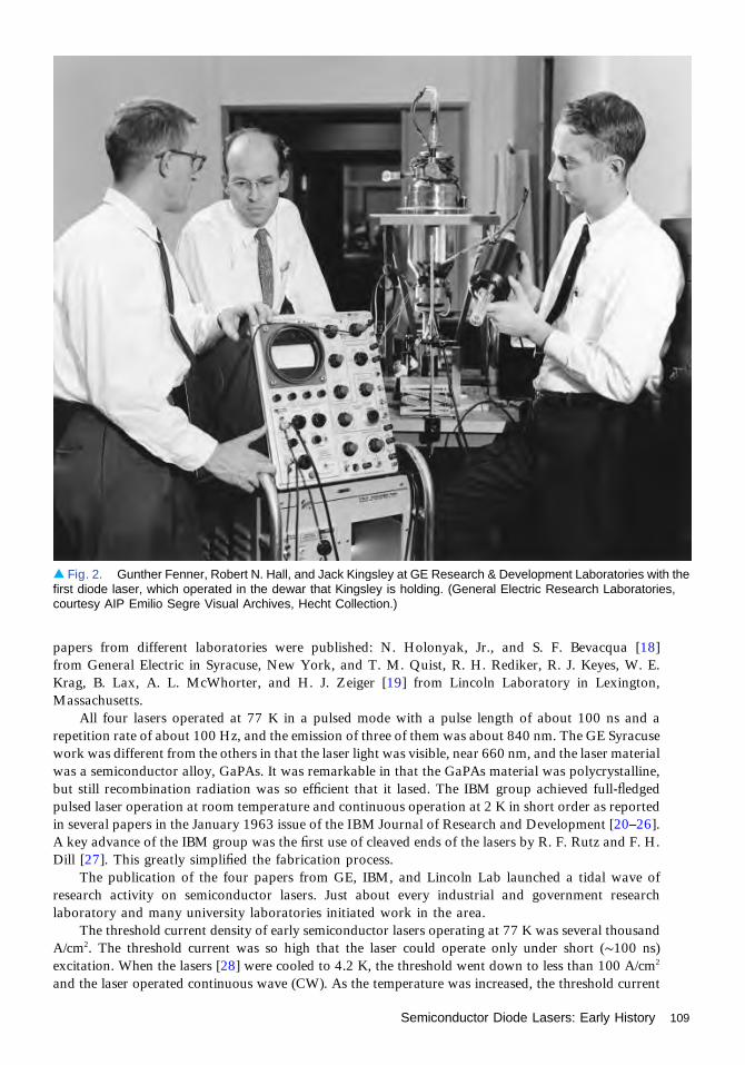
papers from different laboratories were published: N. Holonyak, Jr., and S. F. Bevacqua [18]from General Electric in Syracuse, New York, and T. M. Quist, R. H. Rediker, R. J. Keyes, W. E.Krag, B. Lax, A. L. McWhorter, and H. J. Zeiger [19] from Lincoln Laboratory in Lexington,Massachusetts.
All four lasers operated at 77 K in a pulsed mode with a pulse length of about 100 ns and arepetition rate of about 100 Hz, and the emission of three of them was about 840 nm. The GE Syracusework was different from the others in that the laser light was visible, near 660 nm, and the laser materialwas a semiconductor alloy, GaPAs. It was remarkable in that the GaPAs material was polycrystalline,but still recombination radiation was so efficient that it lased. The IBM group achieved full-fledgedpulsed laser operation at room temperature and continuous operation at 2 K in short order as reportedin several papers in the January 1963 issue of the IBM Journal of Research and Development [20–26].A key advance of the IBM group was the first use of cleaved ends of the lasers by R. F. Rutz and F. H.Dill [27]. This greatly simplified the fabrication process.
The publication of the four papers from GE, IBM, and Lincoln Lab launched a tidal wave ofresearch activity on semiconductor lasers. Just about every industrial and government researchlaboratory and many university laboratories initiated work in the area.
The threshold current density of early semiconductor lasers operating at 77 K was several thousandA/cm2. The threshold current was so high that the laser could operate only under short (∼100 ns)excitation. When the lasers [28] were cooled to 4.2 K, the threshold went down to less than 100 A/cm2
and the laser operated continuous wave (CW). As the temperature was increased, the threshold current
▴ Fig. 2. Gunther Fenner, Robert N. Hall, and Jack Kingsley at GE Research & Development Laboratories with thefirst diode laser, which operated in the dewar that Kingsley is holding. (General Electric Research Laboratories,courtesy AIP Emilio Segre Visual Archives, Hecht Collection.)
Semiconductor Diode Lasers: Early History 109

increased rapidly until at room temperature itapproached 105A/cm2. Work to reduce the thresholdcurrent by improving the geometric structure and theimpurity doping profile proceeded. By heroic effortsat heat sinking and optimizing the laser structurelimited CW operation was obtained at temperaturesas high as 205 K [29]. However, the high thresholdand the pulsed operation placed serious limitationson the possible application of semiconductor lasers.Much work needed to be done.
It was clear that poor guiding of the laser lightin the active region p-n junction caused the highthreshold. The light was spreading out into theinactive regions of the structure, where it wasbeing lost to diffraction and being reabsorbed. Theguiding due to the population inversion was veryweak. Manipulating the junction profile improvedthe situation some, but not enough to get to CWoperation at room temperature. Better guidingcould be obtained for modes perpendicular to thep-n junction because of the larger cross-sectionalarea. However the active region is so thin for thisdirection of propagation that the overall gain wouldbe very low, and the losses in the unexcited regionsof the laser would be very large. At that time a laserof this type was impractical.
In 1963 Herb Kroemer [30] suggested thatimproved guiding could be obtained by using different materials for the active layer and the adjacentcladding layers, creating heterojunctions on either side of the active layer. This structure came to beknown as the double heterojunction laser. If the cladding layers had a lower index of refraction than theactive layer, the guiding would be improved substantially. This could be accomplished by using amaterial with a higher energy gap for the cladding layers since the index decreases with increasingenergy gap. This index difference would be much larger, and hence, the wave guiding would be muchbetter in the heterojunctions than in a homojunction. Furthermore, the loss due to re-absorption of thelaser light in inactive cladding layers would be reduced because of the higher energy gap in the inactivecladding.
One material choice Kroemer suggested was using Ge, an indirect semiconductor, as the activelayer and GaAs in the cladding layers. This is an excellent choice for crystal growth because Ge andGaAs have the same lattice constant. With the direct gap in GaAs only 0.14 eV higher than the indirectgap in Ge, Kroemer hoped the population in the direct gap material would be sufficient to get lasing.This turns out not to be the case, although as mentioned earlier Kimmerling and co-workers [11] madea Ge laser by using growth-induced stress to make the direct gap closer to the indirect gap.
Alferov and R. F. Kazarinov [31,32] in the Soviet Union had similar ideas for heterojunctions. Theymade lasers with GaAs active regions and GaPAs cladding layers, but the lattice mismatch between thetwo materials made their lasers polycrystalline so they had high-threshold current densities.
Clearly, what were needed were direct gap materials with sufficiently different energy gaps so as toprovide a single crystal heterojunction with good mode guiding for the laser. This came in 1967 fromJerry Woodall and Hans Rupprecht [33] at IBM, who were working on solar cells, where they wanted alarge energy gap to let more light into the p-n junction in smaller-gap material. Using the alloy systemAlGaAs, which has a good lattice match to GaAs, they made single-crystal AlGaAs/GaAs heterojunc-tions. They grew their crystals with liquid phase epitaxy, which had been invented by H. Nelson [34]several years earlier and later became commercially important. They observed efficient electrolumines-cence. However, they did not apply their technique to lasers.
▴ Fig. 3. Marshall I. Nathan. (Courtesy AIP EmilioSegre Visual Archives, Physics Today Collection.)
110 Semiconductor Diode Lasers: Early History

This was left to H. Kressel and H. Nelson [35], who in 1967 reported an AlGaAs/GaAs single-heterojunction laser (structure shown in Fig. 1(b) from that paper [not reproduced here]) with its activeregion in the p-type region of the GaAs. Because of the improved guiding and reduced absorption of theAlGaAs the laser’s threshold current density was 8000 A/cm2, a factor of two to three times lower thanthe best homojunction lasers at the time. Shortly thereafter similar work was done by Hayashi, Panish,Foy, and Sumki [36,37], who obtained a threshold current density as low as 5000 A/cm2. However,these results were not good enough to obtain CW operation at room temperature.
Room-temperature continuous operation would take a further advance, namely, the double-heterojunction laser, shown in Fig. 1(c) from that paper (not reproduced here), in which the large-gapAlGaAs material is on both sides of the junction, providing better mode guiding and reduced loss onboth sides of the junction. The heterojunctions also confine the electrons and holes to a thin region,yielding higher gain. The first double-heterojunction lasers were made by Alferov, Andreev, Portnoi,and Trukan [38] in 1968. These lasers had threshold current density as low as 4300 but were not yetCW. In 1969 Hayashi, Panish, and Sumski [36] reported the achievement of double-heterostructureAlGaAs/GaAs lasers with a threshold as low as 2300 A/cm2 [39] By the following year (1970) they hadreduced the threshold down to 1600 A/cm2 and obtained CW operation at room temperature [40].Alferov’s group (see Fig. 4) achieved CW room temperature operation at about the same time in astripe-geometry laser [41].
At this point it was clear that the semiconductor laser was a device with many importantapplications. Research and development toward this end have continued and expanded since then.
▴ Fig. 4. Future Nobel Laureate Zhores Alferov (lower right) with colleagues (clockwise) Vladimir I. Korol’kov,Dmitry Z. Garbuzov, Vyacheslev M. Andreev, and Dmitriy N. Tret’yakov, the group that made the first CW diode laser.(Zhores I. Alferov, courtesy AIP Emilio Segre Visual Archives, Hecht Collection.)
Semiconductor Diode Lasers: Early History 111

References1. A. I. Schawlow and C. H. Townes, “Infrared and optical masers,” Phys. Rev. 112, 1940–1949 (1958).2. T. H. Maiman, “Stimulated optical radiation in ruby,” Nature 187, 493–494 (1960).3. P. P. Sorokin and M. J. Stevenson, “Stimulated infrared emission from trivalent uranium,” Phys. Rev.
Lett. 5, 557–559 (1960).4. A. Javan, W. Bennett, Jr., and D. R. Herriott, “Population inversion and continuous optical maser
oscillation in a gas discharge containing a He-Ne mixture,” Phys. Rev. Lett. 6, 106–108 (1961).5. J. von Neumann, unpublished manuscript, 1953.6. P. Agrain, unpublished lecture at the International Conference on Solid State Physics, Electronics, and
Telecommunications, Brussels, 1958.7. N. G. Basov, B. M. Vul, and Yu. M. Popov, “Quantum-mechanical semiconductor generators and
amplifiers of electromagnetic oscillations,” Sov. Phys. JETP 10, 416–417 (1959).8. M. G. Bernard and G. Duraffourg, “Laser conditions in semiconductors,” Phys. Stat. Solidi 1, 699–703
(1961).9. N. G. Basov, O. N. Krokhin, and Yu. M. Popov, “Production of negative-temperature states in P-N
junctions of degenerate semiconductors,” Sov. Phys. JETP 13, 1320–1321 (1961).10. W. P. Dumke, “Interband transitions and maser action,” Phys. Rev. 127, 1559–1563 (1962).11. X. C. Sun, J. F. Lu, L. C. Kimerling, and J. Michel, “Toward a germanium laser for integrated silicon
photonics,” IEEE J. Select. Topics Quantum Electron. 16, 124–131 (2010).12. J. I. Pankove and M. J. Massoulie, “Light-emitting diodes—LEDs,” Bull. Am. Phys. Soc. 7, 88–93
(1962).13. Because it was a post-deadline paper, the abstract does not appear in the Bull. Amer. Phys. Soc. but was
subsequently published: J. Black, H. Lockwood, and S. Mayburg, “Recombination radiation in GaAs,”J. Appl. Phys. 34, 178–180 (1963).
14. D. N. Nasledov, A. A. Rogachev, S. M. Ryvkin, and B. V. Tsarenkov, “Recombination radiation ofgallium arsenide,” Sov. Phys. Solid State 4, 782–784 (1962).
15. The Keyes and Quist paper was presented at the 1962 Device Research Conference I Durham, NewHampshire, and was subsequently published as R. J. Keys and T. M. Quist, “Recombination radiationemitted by gallium arsenide,” Proc. IRE 50, 1822–1829 (1962).
16. R. N. Hall, G. E. Fenner, J. D. Kingsley, T. J. Soltys, and R. O. Carlson, “Coherent light emission fromGaAs junctions,” Phys. Rev. Lett. 9, 366–368 (1962).
17. M. I. Nathan, W. P. Dumke, G. Burns, F. H. Dill, Jr., and G. Lasher, “Stimulated emission of radiationfrom GaAs p-n junctions,” Appl. Phys. Lett. 1, 62–64 (1962).
18. N. Holonyak, Jr., and S. F. Bevacqua, “Coherent visible light emission from Ga1-xPx junctions,” Appl.Phys. Lett. 1, 82–83 (1962).
19. T. M. Quist, R. H. Rediker, R. J. Keyes, W. E. Krag, B. Lax, A. L. McWhorter, and H. J. Zeiger,“Semiconductor maser of GaAs,” Appl. Phys. Lett. 1, 91–92 (1962).
20. G. J. Lasher, “Threshold relations and diffraction loss for injection lasers,” IBM J. Res. Devel. 7, 58–61(1963).
21. G. Burns, R. A. Laff, S. E. Blum, F. H. Dill, Jr., and M. I. Nathan, “Directionality effects of GaAs light-emitting diodes: part I,” IBM J. Res. Devel. 7, 62–63 (1963).
22. R. A. Laff, W. P. Dumke, F. H. Dill, Jr., and G. Burns, “Directionality effects of GaAs light-emittingdiodes: part II [Letter to the Editor],” IBM J. Res. Devel. 7, 63–65 (1963).
23. W. P. Dumke, “Electromagnetic mode population in light-emitting junctions,” IBM J. Res. Devel. 7, 66–67 (1963).
24. R. S. Title, “Paramagnetic resonance of the shallow acceptors Zn and Cd in GaAs” [Letter to the Editor],IBM J. Res. Devel. 7, 68–69 (1963).
25. G. Burns and M. I. Nathan, “Room-temperature stimulated emission,” IBM J. Res. Devel. 7, 72–73(1963).
26. W. E. Howard, F. F. Fang, F. H. Dill, Jr., and M. I. Nathan, “CW operation of a GaAs injection laser,”IBM J. Res. Devel. 7, 74–75 (1963).
27. Invention cited by G. Burns and M. I. Nathan, “P-N junction lasers,” Proc. IEEE 52, 770–794 (1964).28. G. Burns and M. I. Nathan, “The effect of temperature on the properties of GaAs laser,” Proc. IEEE 51,
947-948 (1963).29. J. C. Dyment and L. A. D'Asaro, “Continuous operation of GaAs junction lasers on diamond heat sinks
at 200°K,” Appl. Phys Lett. 11, 292–293 (1967).30. H. Kroemer, “A proposed class of hetero-junction injection lasers,” Proc. IEEE 51, 1782–1783 (1963).
112 Semiconductor Diode Lasers: Early History

31. Zh. I. Alferov and R. F. Kazarinov, Authors’ Certificate 28448 (U.S.S.R.) as cited in [32].32. Zh. I. Alferov, D. Z. Garbusov, V. S. Grigor’eva, Yu. V. Zhuylaev, I. V. Kradnova, V. I. Korol’kov, E. P.
Morosov, O. A. Ninoa, E. L. Portnoi, V. D. Prochukhan, and M. K. Trukan, “Injection luminescence ofepitaxial heterojunctions in GaP-GaAs system,” Sov. Phys. Solid State 9, 208 (1967).
33. J. M. Woodall, H. Rupprecht, and D. Pettit, “Efficient electroluminescence from epitaxial grown Ga1-x
Alx As p-n junctions,” presented at the Solid State Device Conference, 19 June 1967, Santa Barbara,California. Abstract published in IEEE Trans. Electron. Devices ED-14, 630 (1967).
34. H. Nelson, “Epitaxial growth from the liquid state and its application to the fabrication of tunnel andlaser diodes,” RCA Rev. 24, 603–615 (1963).
35. H. Kressel and H. Nelson, “Close-confinement GaAsp-n junction lasers with reduced optical loss atroom temperature,” RCA Rev. 30, 106–113 (1969).
36. I. Hayashi, M. B. Panish, and P. W. Foy, “A low-threshold room-temperature injection laser,” IEEE J.Quantum Electron. QE-5, 211–212 (1969).
37. M. B. Panish, I. Hayashi, and S. Sumski, “A technique for the preparation of low-threshold room-termperature GaAs laser diode structures,” IEEE J. Quantum Electron. QE-5, 210–211 (1969).
38. Zh. I. Alferov, V. M. Andreev, E. L. Portnoi, and M. K. Trukan, “AlAs-GaAs heterojunction injectionlasers with a low room-temperature threshold,” Sov. Phys. Semiconduct. 3, 1107–1110 (1970).
39. M. B. Panish, I. Hayashi, and S. Sumski, “Double heterostructure injection lasers with room-temperature thresholds as low as 2300 A/cm2,” Appl. Phys. Lett. 16, 326–328 (1969).
40. I. Hayashi, M. B. Panish, P. W. Foy, and S. Sumski, “Junction lasers which operate continuously at roomtemperature,” Appl. Phys. Lett. 17, 109–110 (1970).
41. Zh. I. Alferov, V. M. Andreev, D. Z. Garbuzov, Yu. V. Zhilyaev, E. P. Morozov, E. L. Portnoi, and V. G.Trofim, “Investigation of the influence of the AlAs-GaAs heterostructure parameters on the laserthreshold current and the realization of continuous emission at room temperature,” Fiz. Tekh.Poluprovodnikov 4, 1826 (1970). (English version: Sov. Phys. Semiconduct. 4, 1573–1575 (1971).
Semiconductor Diode Lasers: Early History 113

Lasers and the Growth ofNonlinear OpticsJeff Hecht
Nonlinear optical effects were seen long before the laser was invented. In 1926, RussiansSergey Vavilov and Vadim L. Levishin observed optical saturation of absorption whenthey focused bright microsecond pulses to power densities of kilowatts per square
centimeter. Vavilov introduced the term “nonlinear optics” in 1944, and during World War IIBrian O’Brien put saturation to practical use in his Icaroscope to spot Japanese bombersattacking with the sun behind them. The bright coherent light from the laser opened newpossibilities.
Peter Franken (Fig. 1) realized them as he sat in packed sessions on lasers at OSA’s springmeeting in early March of 1961. His mind wandered as speakers droned about applications incommunications and eye surgery. Seeking something really unusual, he calculated the intensityof a 5-kW laser pulse focused onto a 10-μm spot. His answer was megawatts per squarecentimeter, with electric fields of 100,000 V/cm—only three or four orders of magnitude belowthe electric field inside an atom.
“I realized then that you could do something with it,” Franken recalled in a 1985 interview[1]. Further calculations showed the fields should be able to produce detectable amounts of thesecond harmonic. Excited, he left the meeting and hurried back to the University of Michigan,where he and solid-state physicist Gabriel (Gaby) Weinreich began planning an experiment. Herented a ruby laser from Trion Instruments, a small Ann Arbor company that was the first tomanufacture them, and got Wilbur “Pete” Peters to set up a spectrograph and camera formeasurements. Weinrich told him to fire the laser into crystalline quartz, which can produce thesecond harmonic because it lacks a center of inversion.
They needed a long time to get usable results. Alignment requirements were demanding, andharmonic conversion was so inefficient that 3-J, 1-ms pulses containing about 1019 photonsyielded only about 1011 second harmonic photons. Nonetheless, their photographic plate clearlyshowed the small second harmonic spot. They submitted their paper in mid-July, a little overfour months after the meeting, and it appeared in the 15 August Physical Review Letters—without the faint second harmonic spot, which an engraver had removed because it looked like aflaw in the photo [2].
Optical harmonic generation experienced a breakthrough in 1961. “At that time, we wereall thinking photons, and you can’t change the frequency of a photon,” recalled Franken. Butworking with Willis Lamb at Oxford University in 1959 had taught Franken that classicalelectromagnetic wave theory applied to light, so he had realized that nonlinearities mightgenerate optical harmonics. The faint second harmonic spot that never made it into printlaunched modern nonlinear optics.
Franken’s results caught the eye of Joe Giordmaine, who just two months earlier had begunexploring the effects of ruby laser pulses on various materials at Bell Labs. He began testing Bell’slarge stock of crystals left from World War II research and within a few weeks was seeing moreharmonic power than Franken had. When he tested crystals of potassium dihydrogen phosphate(KDP) he was surprised to find that second harmonic emission was not just in the directionof the ruby beam, but in a ring centered on a different direction, and that the second harmonicwas many times higher at some angles than others. He had discovered the importance of phase
1960–1974
114

matching the fundamental and second harmonicbeams. It did not work in quartz, but it did inbirefringent crystals such as KDP. Bob Terhuneindependently discovered phase matching at thesame time at the Ford Motor Co. ResearchLaboratory.
At Harvard, Nicolaas Bloembergen (Fig. 2)gathered John Armstrong, Peter Pershan, and Jac-ques Ducuing to work on nonlinear optics after hesaw a preprint of Franken’s paper. Armstrong andDucuing began experiments, and all four worked ontheory. Bloembergen wrote the differential equa-tions describing harmonic generation, but solvingthe nonlinear problems posed a formidable task.The group spent several intense and exciting monthsfrom July 1961 to early 1962, dividing the taskamong themselves and working closely withBloembergen.
The result was a 22-page detailed analysis oflight interactions in nonlinear dielectrics, publishedin Physical Review in September 1962 [3]. “It wasby no means the last word, but it was a very completefirst word,” says Armstrong, whose name was firstin alphabetical order. The codification of nonlinearinteractions including harmonic generation andparametric conversion had a huge impact in theyoung field.
Meanwhile, experiments with high-power, sin-gle-pulse Q-switched ruby lasers at Hughes Air-craft’s Aerospace group revealed an unexpectednonlinear anomaly. In early 1962, Eric Woodburyand Won Ng measured output power at severalhundred megawatts, far more than expected, whenthey used a Kerr-cell Q-switch filled with nitroben-zene. Puzzled, they did other experiments, but thelight finally dawned when measured power droppedto the expected level after they inserted narrow-passfilters centered on the 694.3-μm ruby line. Furthermeasurements revealed unexpected light on threenear-infrared lines, the strongest at 766 nm, aweaker one at 851.5 nm, and a barely detectableline at 961 nm. The increments were roughly equalin frequency units.
They reported what they thought was a newtype of laser action, but it was up to RobertHellwarth and Gisela Eckhardt of Hughes Re-search Labs to suggest the infrared lines werecoming from stimulated Raman scattering by thenitrobenzene in the Q-switch. Experiments quicklyconfirmed that, and Hellwarth later developed a full theoretical model. It was a landmark discovery innonlinear optics, showing that light interacted with molecular vibrations to stimulate scattering atStokes-shifted wavelengths. Soon afterward, Terhune and Boris Stoicheff separately observed anti-Stokes emission.
▴ Fig. 1. Peter Franken. (OSA Historical Archives.)
▴ Fig. 2. Nicolaas Bloembergen. (Photograph byNorton Hintz, courtesy AIP Emilio Segre VisualArchives, Hintz Collection.)
Lasers and the Growth of Nonlinear Optics 115

Charles Townes, then at MIT, analyzedStoicheff’s results and wondered whether laserscould also stimulate Brillouin scattering. In just twoweeks, graduate student Ray Chiao, Townes, andStoicheff used a ruby laser to demonstrate Brillouinscattering in a solid. Soon another student, ElsaGarmire, demonstrated Brillouin scattering in aliquid. It took years to work out the details, andin 1972 Boris Ya. Zel’dovich—the son of notedSoviet nuclear physicist Yakov B. Zel’dovich—showed that stimulated Brillouin scattering couldproduce phase conjugation.
Townes suggested another research directionafter seeing thin filaments of optical damage in glassexposed to Q-switched megawatt pulses from aruby laser (see Fig. 3) by Michael Hercher of theUniversity of Rochester. Townes suspected thatoptical nonlinearities were self-trapping the beamand with Chiao and Garmire described how theintense beam changed the refractive index to createa waveguide. At the MIT Lincoln Laboratory, PaulKelley developed a theory of self-focusing showingscale lengths and the effects of beam power. Un-known to U.S. researchers, Vladimir Talanov wasworking on the same idea in the closed Soviet city ofGorky.
Rem V. Khokhlov and Sergey A. Akhmanovfounded Russia’s first nonlinear optics laboratory atMoscow State University in 1962, but Cold Wartensions allowed little communication with Ameri-can groups. During that year, they proposed atheory to extend parametric oscillation from radiofrequencies to light, offering a way to generatetunable output from fixed-wavelength lasers.Khokhlov and Akhmanov’s Problems in NonlinearOptics was the first book on the topic when it waspublished in Russian in 1964, but it did not appearin English until 1972. Bloembergen’s NonlinearOptics was published in 1965.
The Moscow lab soon developed efficientways of generating second, third, fourth, and fifthharmonics. A long series of experiments withAlexander Kovrigin demonstrated an opticalparametric oscillator in the spring of 1965, at
nearly the same time Giordmaine (Fig. 4) and crystal expert Robert Miller demonstrated one atBell Labs. Both pumped with the second harmonic of neodymium lasers, with the Moscow lab usingKTP and Bell using lithium niobate as the nonlinear crystals. The experiments were difficult, and BellLabs achieved only 5% conversion efficiency, but output was tunable across 70 nm, an impressivefigure in 1965.
Self-focusing led to self-phase modulation. When Kelley and MIT student Ken Gustafson studiedshock-wave generation in nonlinear materials, they found a phase shift that depended on the square ofthe field intensity. They did not make much of it at the time, but in 1967 Fujio Shimizu at the Universityof Toronto demonstrated that self-phase modulation in liquids could spread the spectral bandwidth of a
▴ Fig. 3. Trace of damage caused by a Q-switchedruby laser pulse. (Courtesy of Courtesy of MichaelHercher.)
116 Lasers and the Growth of Nonlinear Optics

pulse [4]. In 1970 Bob Alfano and Stan Shapiro at GTE Laboratories in Bayside, New York,demonstrated more frequency spreading in glass and crystals [5]. The higher the power, the broaderthe bandwidth, and over the years the effect spread the spectrum enough to make white-lightsupercontinua.
In 1973, Akira Hasegawa and F. Tappert took another important step, extending the concept ofself-trapping to describe optical temporal solitons in optical fibers [6]. Nonlinear phase modulation anddispersion interact such that pulse duration and frequency chirp increase and decrease cyclically alongthe length of the fiber, periodically reconstructing the original pulse. Hasegawa, Linn Mollenauer, andothers later showed that solitons could transmit signals through optical fibers.
Modern nonlinear optics has come a long way from its roots, yet the fundamental groundworkremains solid. “To this day, every time I make a discovery in nonlinear optics, I look at [Bloembergen’s]paper and he’s done it,” says Robert Boyd of Rochester. “He put the whole field together in 18months.” That feat earned Bloembergen the 1981 Nobel Prize in Physics.
Nonlinear optics is used in consumer products. Second harmonic generation turns the invisible1.06-μm line of neodymium into a bright 532-nm green beam. “It’s hard to believe you can buy thesethings. If you think of what’s inside, it’s just amazing,” says Garmire. Harmonic generation also findscutting-edge laboratory applications, generating pulses of attosecond duration or with wavelengths inthe extreme ultraviolet or x-ray bands. Self-phase modulation together with mode locking producesfemtosecond pulses and frequency combs. The more we try to do with optics, the more we have to thinkabout nonlinearities. Like the laser that was essential to its birth and its applications, nonlinear opticsseems to be everywhere.
Note: This chapter was adapted from [7].
References1. Peter Franken oral history interview, http://www.aip.org/history/ohilist/4612.html2. P. A. Franken, A. E. Hill, C. W. Peters, and G. Weinreich, “Generation of optical harmonics,” Phys. Rev.
Lett. 7, 118–120 (1961).3. J. A. Armstrong, N. Bloembergen, J. Ducuing, and P. S. Pershan, “Interactions between light waves in a
nonlinear dielectric,” Phys. Rev. 127, 1918–1939 (1962).
▸ Fig. 4. David Kleinman andJoe Giordmaine. (Courtesy ofAT&T Archives and HistoryCenter.)
Lasers and the Growth of Nonlinear Optics 117
4. F. Shimizu, “Frequency broadening in liquids by a short light pulse,” Phys. Rev. Lett. 19, 1097–1100(1967).
5. R. R. Alfano and S. L. Shapiro, “Observation of self-phase modulation and small-scale filaments incrystals and glasses,” Phys. Rev. Lett. 24, 592–594 (1970).
6. A. Hasegawa, “Soliton-based optical communications: an overview,” IEEE J. Select. Topics QuantumElectron. 6, 1161–1172 (2000).
7. J. Hecht, “How the laser launched nonlinear optics,” Opt. Photon. News 21(10), 34–40 (2010).
118 Lasers and the Growth of Nonlinear Optics

Early Years of HolographyJeff Hecht
The idea of holography came to Dennis Gabor while he was waiting for a tennis court onEaster Day in 1947. Born in Hungary in 1900, Gabor had earned a Ph.D. in electricalengineering from the Technical University of Berlin, then moved to Britain when Hitler
came to power. In 1947, he was working at the British Thoms-Houston Company in Rugby andwondering how to improve the resolution of electron microscopes.
Waiting for his tennis match, he wondered how to overcome the imperfections in electronoptics that limited resolution. “Why not take a bad electron picture, but one that contains thewhole information, and correct it by optical means?” he recalled later. He first thought ofilluminating an object with coherent electrons, so interference between electrons scattered fromthe object and those not deflected would record the phase and intensity of the wavefront. If herecorded the interference pattern and illuminated it with coherent light, he thought he couldreconstruct the electron wavefront and generate a high-resolution image.
Lacking a way to record electron interference patterns, Gabor tried using light as a model,although he had not worked with optics before. The best available coherent source at the timewas a high-pressure mercury lamp, but its coherence length was only 0.1 mm, and filtering itthrough a pinhole left only enough light to make 1-cm holograms of 1-mm transparencies.Nonetheless, he made recognizable holographic images in 1948 (Fig. 1), a dozen years beforeTheodore Maiman made the first laser.
Gabor’s report in Nature in 1948 [1] raised the possibility of three-dimensional (3D)imaging, generating considerable attention, and helped him land a professorship at ImperialCollege in London; but progress was slow, his design generated twin overlapping images, and theshort coherence lengths of available light sources limited imaging to small transparencies. By themid-1950s, Gabor and most others had largely abandoned holography.
The revival of holography grew from a completely independent direction: classified militaryresearch on synthetic aperture radar launched in 1953 at the University of Michigan’s Willow RunLaboratory. The following year, a young engineer named Emmett Leith who had studied opticsat Wayne State University began developing an optical system to perform Fourier transforms ofradar data collected byflying over the target terrain. He and Wendell Blikken started with incoherentoptics, but Leith later said many of their problems “just melted away” when they consideredcoherent light in1955.Theydid not need muchcoherence and they eventually found that focusingallthe light from a point source onto another point would suffice for radar processing.
In September 1955, Leith realized that the light waves diffracted from the data record werereplicas of the original radar signals converted to optical wavelengths. That led him to a theory thatmirrored Gabor’s wavefront-reconstruction holography but shrank the radio waves to opticalwavelengths rather than stretching electron waves to optical lengths. He knew nothing about otherresearch in holography until a year later, when he discovered a paper by Paul Kirkpatrick andHussein M. A. El-Sum in the Journal of The Optical Society of America (JOSA) [2].
Holography intrigued Leith, but the radar project kept him too busy to experiment until1960, when Willow Run hired Juris Upatnieks as a research assistant in the optics group. Born inLatvia in 1936, Upatnieks fled with his family when Soviet troops occupied Latvia in 1944. Theyspent years as refugees in Germany before moving to the U.S. in 1951. He had a fresh degree inelectrical engineering from the University of Akron (Ohio) but lacked a security clearance, so hecould not work on the radar project.
1960–1974
119

Leith put Upatnieks to work makingGabor-style holograms while they waitedfor his clearance. Despite lacking opticsexperience, Upatnieks succeeded. Thereconstructed images were fascinating buthad the same twin-image problem asGabor’s.
However, Leith’s theory of hologra-phy offered a crucial insight because itdescribed a signal modulating a carrierwave, which produces sidebands at thesum and difference frequencies, above andbelow the carrier frequency. Leith realizedthat Gabor’s twin images were the twosidebands. Eliminating one of them shouldleave a single clear image. (Figure 2 showsthem with their holographic setup.)
Leith suggested separating the objectand reference beams so that they reached
the photographic plate at different angles. However, that proved hard until they used a diffractiongrating to split light from a mercury-vapor lamp into different diffraction orders, and using one as thereference beam and the other as the object beam. That yielded the first off-axis holograms, andUpatnieks’s experiments confirmed Leith’s theory. Leith described the results at OSA’s October 1961meeting in Los Angeles and submitted a paper to JOSA [3].
By then, the military had called Upatnieks to fulfill his obligations from ROTC in college. When hereturned to Willow Run in November 1962, he started a new round of holography experiments with amercury lamp, but an early commercial helium-neon laser was sitting temptingly in a nearby laboratorywhere Anthony VanderLugt was using it in image-recognition experiments. Inevitably, as Upatniekssays, “We kind of talked him into letting us borrow his beam. We put a mirror in his room, andbounced the beam off to our setup.”
Based on a standard optical bench, their new setup expanded the laser beam and split it bypassing it through a wedge prism. Recording good holograms required extra-flat glass plates thatKodak had developed for spectroscopy. Exposure was very slow, so the laser’s higher intensity was abig advantage. Leith and Upatnieks reported a dramatic improvement in hologram quality at theMarch 1963 OSA meeting in Jacksonville and in a paper in the December 1963 issue of JOSA [4]. Theholographic reconstruction of a 1.5-cm slide in the published version is hard to tell from the original.Holographic reconstructions of slides of a child in an outdoor scene and an adult portrait are speckledbut clear.
Lasers brought speckle to holography, but their higher power and longer coherence length madeexperiments easier. More important in the long run, laser coherence allowed fully 3D holography of
▴ Fig. 1. Dennis Gabor’s first hologram. (Reprinted by permission from Macmillan Publishers Ltd.: Nature © 1948.)
▴ Fig. 2. Emmett Leith and Juris Upatnieks in 1965. (Courtesyof Juris Upatnieks.)
120 Early Years of Holography

opaque objects. Leith and Upatnieks spenta couple of days trying 3D holography inJuly 1963 but failed and turned to otherwork.
They returned to 3D holography afterthe JOSA paper came out and reportersasked Leith what might come next. “Heoffhand mentioned that 3D objects couldbe recorded and they would be three di-mensional, and no one believed it,” Up-atnieks recalled. “Since Emmett said itwould be done, we had to show it,” andthey went back to 3D holography.
They faced tough technical problemssuch as isolating their holographic setupfrom wavelength-scale vibrations. Movingto a massive granite optical bench im-proved image clarity, but the 3D images did not seem dramatic until Leith and Upatnieks startedusing objects a few inches across, large enough for the eye to see as three dimensional. Hologramsrecorded on 4- by 5-in. plates were “incredible, just totally incredible, the one thing that excited usmost,” Leith recalled.
Their first image was a pile of loose objects they obtained from the laboratory; it looked like a pileof junk, interesting only because it was a hologram. As they refined their technique, they found an iconicobject that made a striking hologram—an HO-gauge toy train engine that they filled with epoxy andglued to the tracks to stabilize it (Fig. 3). They recorded two holograms on the same photographic platemounted at different angles, then reconstructed the two images separately without crosstalk byilluminating the plate at the proper angles.
Visitors streamed through the lab to see the holograms, but the floodgates opened in April at OSA’s1964 spring meeting. Upatnieks presented a 15-minute paper on Friday afternoon, the last day of themeeting, titled “Lensless, three-dimensional photography by wavefront reconstruction,” but the talkcould not match a demonstration. Attendees lined up in the hall to see a He–Ne laser illuminate ahologram in a hotel suite rented by Spectra-Physics. They stood and studied the holographic toy trainfloating in space, then looked around to find the hidden projector that was fooling them. Leith calledthat “the high point in the dissemination of holography” [5].
The optics world was enchanted by holography, and specialists hurried home to try to make theirown holograms. Most failed on their first attempts and called Leith and Upatnieks for help. “Those callskept us quite busy for a while, but that was how holography took off,” Leith recalled.
Enthusiasm spread fast, as it had for the laser. It was a boom time for technology, and, like the rubylaser, holography could be duplicated in a well-equipped optics lab. Could holography be the problemthat the laser was searching to solve?
It took time to assimilate the concept. The first issue of Laser Focus in January 1965 called it “3-Dlasography” [6]. Others called it lensless photography or wavefront reconstruction. Scientific Americancalled its June 1965 article “Photography by laser” and showed two holographic chess pieces on thecover [7]. Leith and Upatnieks used Gabor’s term, hologram. By any name, holography had potential.Its images shimmering in mid-air looked so real that people reached out to touch them.
Among the burst of innovations in the holographic boom was the rediscovery of reflectionholography invented by Yuri Denisyuk at the Vavilov State Optical Institute in the Soviet Union.Instead of directing the object and reference beams onto the same side of the photographic plate,Denisyuk illuminated the object through the plate, with the reflected object light interfering with thereference beam in the plane of the plate. He demonstrated the technique with mercury lamps; but hisexperiments ended in 1961, and his two papers published in Russian in 1962 were ignored until threeAmerican labs stumbled upon the effect independently in 1965. Importantly, Denisyuk reflectionholograms can be viewed in white light.
▴ Fig. 3. Iconic photo of holographic toy train. (Courtesy ofJuris Upatnieks.)
Early Years of Holography 121

Another major imaging advance came was the invention of “rainbow” holograms by Steve Bentonat Polaroid in 1969. Seeking to make brighter images, he produced reflection holograms that displayeddepth only in the horizontal plane, the only one in which our eyes see parallax. This allows thehologram to diffract the whole visible spectrum, spread across a range of angles to produce a rainbowof colors. Easily visible under normal lighting, such holograms can be embossed onto metal films andthey have become the most widely used holograms.
In the early 1970s in San Francisco, Lloyd Cross developed a variation on rainbow holography thatoffered an illusion of motion. He produced the holograms in a two-stage process. First, he tookconventional photographic transparencies as he moved around a person or object, and then he recordedrainbow holograms of the series of transparencies as successive narrow stripes on film. Finally, the filmwas mounted in a 120-deg arc or a 360-deg cylinder.
The viewer’s eyes saw different frames, giving the parallax that the brain interprets as depth. If themodel moved between frames, a viewer saw the movement while moving around the curved hologram.Cross formed a company called Multiplex to make the holograms; the best known one shows PamBrazier blowing a kiss to the viewer (Fig. 4).
In October 1971, when the holographic imaging boom was in full flower, Dennis Gabor receivedthe Nobel Prize for “his invention and development of the holographic method.” Many in the opticscommunity felt that Leith and Upatnieks should have shared the prize for reviving holography withlasers and their solution of the twin image problem.
In his book Holographic Visions [8], science historian Sean Johnston blames George W. Stroke,who in 1963 started a holography program on the Michigan campus that came to compete with Leith’swork at Willow Run. Stroke eventually left Michigan carrying a grudge and claiming that his work wasmore important. This was long a common view in the optics community.
However, in her dissertation on the history of holography written at Cambridge University [9],holographer Susan Gamble argues that the problem was that Leith and Upatnieks worked at a militarylab. Michigan students had protested Willow Run’s military projects, and in 1971 opposition to theVietnam War was widespread in Europe. The Nobel committee may well have decided that awarding aNobel Prize for military work would send the world the wrong message.
If some optical Rip Van Winkle from 1970 woke up today after his long nap, he might ask,“Whatever happened to holography?” Holographic imaging never came to movies or television, andthe “holographic telepresence” of convention speakers is based on the old “Pepper’s Ghost” illusionrather than real holograms. Yet holographic displays have found some specialized niches. Furthermore,holograms are used in industry in many ways that go unrecognized, such as holographic optics, andsecurity imprints on packaging and some currencies. We may never watch wide-screen movies inglorious holovision, but who would have expected us to be carrying holograms in our pockets on creditcards?
Note: This chapter is adapted from [10].
▴ Fig. 4. “Mini Kiss II”: Pam Brazier in holographic stereogram. (Courtesy of MIT Museum. Mini Kiss II, Lloyd G.Cross, 1975. http://web.museum.mit.edu/imagerequest.phpimagenumberMOH-1978.52.01 [all three views].)
122 Early Years of Holography

References1. D. Gabor, “A new microscopic principle,” Nature 161, 777–778 (1948).2. P. Kirkpatrick and H. M. A. El-Sum, “Image formation by reconstructed wavefronts I. Physical
principles and methods of refinement,” J. Opt. Soc. Am. 46, 825–831 (1956).3. E. N. Leith and J. Upatnieks, “Reconstructed wavefronts and communication theory,” J. Opt. Soc. Am.
52, 1123–1130 (1962).4. E. N. Leith and J. Upatnieks, “Wavefront reconstruction with continuous tone objects,” J. Opt. Soc. Am.
53, 1377–1381 (1963).5. E. N. Leith and J. Upatnieks, “Wavefront reconstruction with diffused illumination and three-
dimensional objects,” J. Opt. Soc. Am. 54, 1295–1301 (1964).6. Anonymous, “3-D lasography: the month-old giant,” Laser Focus 1(1), 10–15 (1965).7. E. N. Leith and J. Upatnieks, “Photography by laser,” Sci. Am. 212(6), 34–35 (1965).8. S. Johnston, Holographic Visions: A History of a New Science (Oxford, 2006).9. S. A. Gamble, “The hologram and its antecedents 1891–1965: the illusory history of a three-dimensional
illusion,” Ph.D. dissertation (Wolfson College, University of Cambridge, 2004).10. J. Hecht, “Holography and the laser,” Opt. Photon. News 21(7–8), 34–41 (2010).
Early Years of Holography 123

History of Laser Materials ProcessingDavid A. Belforte
In the 100 years of OSA, laser technology has played a part for more than 50 years andindustrial laser materials processing has played a part for more than 40 years. This capsuleview presents the highlights of these years.Prior to 1970, a handful of commercial laser suppliers, located mostly in the United
States, attempted to satisfy requests from a number of industrial manufacturers that showedan interest in the possibility of a laser materials processing solution to a unique productionproblem. A 1966 publication stated, “This year will mark the beginning of an acceleratedgrowth for lasers. Many of the early problems involved in their use are nearing solution. Inthe commercial markets, the applications will center on welding and other high-power CO2
and neodymium YAG (yttrium aluminum garnet) lasers : : : ” [1]. Interestingly, this otherwiseoptimistic report ended with the statement, “The markets for lasers will gradually developover the next few years, but they are not nearly as imminent or as large as is frequentlyquoted.”
One reason behind this disparity may be found in the premise that the laser was “born fullygrown,” a view held by many who read about the amazing possibilities for this powerful energysource, as evidenced by the commonly quoted line that “lasers are a solution looking for aproblem” [2]. Industrial manufacturers that approached these scientific laser companies werefrom many different industries: glass, with interest in cutting flat plate glass [3]; mining, withinterest in rock drilling [4]; packaging, with interest in cutting steel rule dies [5]; aircraft engines,with interest in processing turbine engine components [6]; sheet metal cutting [7]; paper, forcutting and slitting paper [8]; and microelectronics, with accelerating interest in trimmingresistors and printed circuits [9] and cutting/scribing ceramic substrates [10]. Of these, onlythe latter two advanced to widespread industrial utilization stages in the late 1960s, pushed bysoaring growth in the microelectronics industry. The others, all technically good applications,languished for a few years, fulfilling the prophecy cited above, as the laser suppliers struggled todevelop devices with more power or better beam quality with improved reliability and mainte-nance procedures.
The most economically successful applications drawing attention from a wide segment of theworld’s media were the use of a CO2 laser beam to cut woven fabric for made-to-order men’ssuits [11] and the use of a pulsed ruby laser beam to drill holes in diamond dies used as wiredrawing dies [12]. The latter was the first industrial laser processing machine to be exhibited inthe Smithsonian Museum in Washington, D.C.
While technical and economic cases can be built to explain the slow commercial success ofthe laser as a manufacturing process tool, widespread implementation of laser processes wasinhibited to a degree by published articles. These articles were headlined, for example, “Deathrays benefit mankind,” a phrase that can be attributed to a number of journalists searching forattention-grabbing headlines in the early 1970s. Implementation was also stalled because of theunfortunate labeling, by engineering societies and the U.S. government, of laser processingsystems as a nonconventional materials processing technology.
One anecdote that illustrates the former is this author’s personal experience. Whilenegotiating the purchase of a high-power CO2 laser welding machine by a Fortune 500 company,he was startled to hear a company official sanction the purchase because he was impressed bysuccessful laser cataract surgery performed on his brother-in-law.
1960–1974
124
Thus, the industrial laser suppliers of the early 1970s were faced with an additional sellingburden, easing the concerns of uninformed, risk-wary buyers, and reassuring potential buyers thattheir lasers were reliable and safe. A common selling tactic was to identify a laser “champion” as thepotential customer and to educate this person to be an inside sales advocate. Many of thesechampions became laser industry advocates through their willingness to publish complimentaryarticles.
Overcoming the nonconventional tag took many years [13], and it was not until the late 1980s thatthis sobriquet was dropped by those charged with producing industry statistics. The 1970s, a periodthat saw the blooming of several industrial laser suppliers, is considered by most analysts to be thebeginning of the industrial laser market, with annual revenues for laser sales ramping from $2 million to$20 million in the first decade of the market, an almost 26% compound annual growth rate (CAGR).Several applications drove this growth: thin gauge sheet metal cutting [14], microelectronic packagesealing [15], cooling hole drilling in aircraft turbine engine blades and vanes [16], steel-rule die boardcutting [17], and semiconductor wafer dicing [18]—all applications that continue successfully today.
An interesting footnote to the early beginnings of the industrial laser material processing era is thatthese applications, and many that rose to prominence later, were accomplished using lasers that can bestbe called “industrialized scientific lasers,” which were controlled by analog programmable controllersor tape reader numerical control (NC) devices. MIT scientists developed numerical control formachining in the 1970s, and it became commonly used in the 1980s. This technology was a majorcontributor to the growth of lasers for industrial material processing applications. The evolution tocomputer numerical control (CNC) [19] and the industrial development of minicomputers in the 1980sand the microprocessor in the 1990s vaulted the industrial use of lasers to annual growth rates in themid-teens.
Through the 1980s and 1990s, solid-state lasers led by Nd:YAG devices and ultra-reliable low-power, sealed-off CO2 units remained the backbone of the industrial laser materials processingindustry. On a smaller scale, excimer lasers were used mostly in semiconductor processing [20] andmetal [21] and non-metal applications in the manufacture of medical devices. These lasers had evolvedfrom the scientific designs of the 1970s into ruggedized, reliable, low-maintenance products that werebeing integrated by system manufacturers into material processing products acceptable to a broadrange of global consumer product manufacturing companies.
The utilization of industrial lasers, very much advanced in the U.S. in the first two decades of thetechnology, was due in great part to the marketing prowess of domestic equipment suppliers. This iscounter to some international views, mainly in Europe, that the U.S. government, through theDepartment of Defense (DOD), funded the development of the laser products that were being usedin commercial industrial applications. In reality, the industrial laser and systems suppliers of the 1970sand 1980s were essentially a part of a bootstrap industry, self-funded in terms of equipment andapplications development. What little funding flowed from the U.S. government through its DODManufacturing Technology programs was focused on laser applications that could improve or repairdefense products. In part, this lack of a national initiative to support progress in manufacturingstultified the growth of the industrial laser economy.
Stepping into the void left by this modest industrial laser program, the government of Japan in the1980s and Germany (supported in part by the European Union) undertook university-based efforts tounderstand and improve the laser beam/material interaction on a broad range of materials. In Japan,most of the effort focused on defining and improving the process of laser cutting sheet metals [22],specifically stainless steel, at that time a major industry in that country. As a result, increased outputpower from new types of CO2 lasers, improved gas-assist nozzle signs, and purpose-built cuttingsystems entered the market from a number of suppliers, first in Japan to a large number of customcutting job shops and then exported to the international markets. In addition to this effort, theJapanese government funded a major program for flexible manufacturing, which had as a part thedevelopment of a very-high-power CO2 laser that vaulted the selected supplier to the top of the CO2
power chain.In the late 1980s, almost concurrent with the laser cutting development in Japan, European CO2
laser suppliers [23] made efforts to expand their markets by improving their product lines. This
History of Laser Materials Processing 125

spawned the development of RF excited high-power CO2 lasers and the consequent alliances withsystem integrators while educating the market about laser technology. In several countries, a “makeit with lasers” program found eager interest among manufacturers. In Germany, the federal andstate governments funded programs to improve the process of laser cutting, and one effort wasdesigned to improve the manufacturing capability of small- to medium-sized manufacturers so theycould become global competitors. As a consequence, the technology of laser material processingbecame familiar to manufacturers [24], paving the way for future employment of these processes intheir manufacturing operations. European industry became “laser aware,” a situation thatprompted the government to heavily sponsor laser and applications development, which has ledEurope to become the major center of industrial laser and material processing and developmenttoday.
The late 1980s and the 1990s have been judged as the “golden” years of industrial laser materialsprocessing. Abundant, pertinent, and beneficial development of laser applications, and the lasers andsystems to achieve the processes, occurred during this period, led by institutions such as the variousFraunhofers [25] that built upon the basic understandings necessary to expand the use of theseprocesses throughout the manufacturing world. As a consequence, industrial laser sales grew by morethan a factor of eight in the period from 1985 to 1999. Driving market growth were global industriessuch as automotive, aerospace, agriculture, and shipbuilding for high-power lasers, and semiconductor,microelectronics, and medical devices for low-power units. The lasers being used remained those thathad been introduced in the 1970s: Nd:YAG lamp and diode pumped at both the fundamental and thefrequency-shifted wavelengths, CO2 with output power up to 8 kW, and excimer that had a majorredesign into more reliable products.
The turn of the century marked the thirtieth year for industrial laser materials processing, and thetotal industrial laser system market was then approaching $3 billion and laser sales were almost $1billion, both experiencing a 23% CAGR [26]. The technology of laser applications was centered inEurope as was much of high-power laser development, while the U.S. retained leadership in the solid-state laser and microprocessing sectors and Japan, as a consequence of national economic conditions,slipped from a leadership role in the industrial laser market.
At this point, laser materials processing had become accepted by mainstream global manufacturingindustries and the technology no longer was classified as unconventional machining, perhaps due inpart to the fact that in 2000, laser machines represented about 10% of the total machine tools soldglobally.
In the first decade of the new century, industrial laser growth showed a dramatic increase until thegreat recession of 2008/2009. After this major setback, the industry rebounded to prerecession levels,rapidly led by surging sales of high-power fiber lasers that were replacing high-power CO2 lasers insheet metal cutting applications. The rise of fiber lasers in this decade as replacements for other lasersused in established applications was the first major shift in the types of industrial lasers selected tosatisfy industrial market demands. Low-power fiber lasers replaced solid-state lasers for marking andengraving applications, substituting for diode-pumped rod type devices in this market that installs morethan 20,000 units per year. In 2012, fiber lasers represented 27% of the laser materials processingsystems installed [26].
Also appearing in this period were high-power direct diode lasers with improved beam quality thatincreased the market for this efficient compact laser. Although output power for these focused beamdevices had yet to reach the multikilowatt level, these lasers created interest among the many cuttingsystem suppliers that had already converted to high-power fiber lasers.
As this is being written, the market for industrial lasers for material processing is well on the way tobreaking the $10 billion/year mark. In 2012, 50% of the world market for industrial lasers was in Asia.Major markets have been established in China and Southeast Asia, and looming on the horizon aremarkets in South America, Russia, and India, which are expected to add to growth opportunities forindustrial lasers.
Further, a new generation of laser and system suppliers is appearing in Asia with companies firstserving domestic needs but eventually entering the global markets, establishing competition for the oldline sellers that have dominated the market for decades.
126 History of Laser Materials Processing

References1. Anonymous, “Lasers: solutions finally finding problems,” Samson Trends, April 1966.2. J. Hecht, Beam: Race to Make the Laser (Oxford University Press, 2005), p. 9.3. Anonymous, “Laser materials processing enters new domain: controlled fracturing,” Laser Focus 4(9),
12 (1968).4. G. B. Clark, “Rock disintegration, the key to mining progress,” Eng. Mining J. (E&MJ) 23, 4751
(1971).5. A. G. Troka, “NC laser—new boost for steel rule die making,” in Machine and Tool Blue Book, Vol. 67,
No. 1 (1972), pp. 52–55.6. J. J. Marklew, “Rolls Royce evaluating high-power laser equipment,” Mach. Prod. Eng. 117(3018),
486–488 (1970).7. I. Slater and J. M. Webster, “Gas-jet laser beam machining,” in Proceedings of the American Society of
Mechanical Engineers (ASME) Conference (ASME, 1970), paper 70-GT-47.8. C. H. Miller and T. A. Osial, “Laser as a paper cutter,” presented at the Fifteenth Annual IEEE Pulp and
Paper Conference, Atlanta, Georgia, 7–10 May 1969.9. M. E. Cohen and J. P. Epperson, “Application of lasers to microelectronic fabrication,” Adv. Electron 4,
139–186 (1968).10. J. Longfellow and D. J. Oberholzer, “The application of the CO2 caser to cutting ceramic substrates,”
in IEEE 1969 International Conference Digest (IEEE, 1969), paper 3C.3, pp. 146–147.11. Anonymous, “Genesco expands laser cutting of fabric at suit plants in Baltimore and Virginia,” Laser
Focus 7(10), 9 (1971).12. J. G. Prout, Jr. and W. E. Prifiti, “Laser drilling of diamond wire drawing dies,” Laser Industrial
Application Notes, Nos. 1–70 (Raytheon Company Laser Advanced Development Center, 1970).13. Anonymous, “A laser ‘metal saw,’” Optical Spectra, February 1970, p. 33.14. M. J. Adams, “Gas jet laser cutting,” presented at the Welding Institute Conference, “Advances in
Wielding Processes,” Harrogate, England, 14 April 1970.15. E. T. Maloney and S. R. Bolin, “Limited penetration welding,” SME Technical Paper MRT74–956
(Society of Manufacturing Engineers, 1974).16. Anonymous, “Laser cuts costs of putting air holes in in jet blades,” American Metal Market/
Metalworking News, 3 April 1972, p. 21.17. Anonymous, “Laser beam cutting automates die making,” Boxboard Containers 78(1), 50–55 (1970).18. Anonymous, “Laser scribing of wafers offers two ways to save” Microwaves, August 1970, p. 71.19. Y. Koren, “Control of machine tools,” J. Manu. Sci. Eng. 119, 749–755 (1997).20. R. F. Wood, “Excimer laser processing of semiconductor devices: high-efficiency solar cells,” Proc. SPIE
0710, 63 (1987).21. A. J. Pedraza, “Excimer laser processing of metals,” J. Metals 29(2), 14–17 (1987).22. N. Karube and A. Egawa, “Laser cutting and welding using an RF excited fast axial CO2 laser,”
in Proceedings of ISATA Laser ‘21 Conference (ISATA, 1989), Vol. 1, p. 411.23. S. Jurg, “Process optimization in laser material processing,” Proc. SPIE 0236, 467 (1981).24. H. E. Puell, “High-power lasers for applications in European automotive manufacturing,” in Industrial
Laser Annual Handbook, 1988 ed., D. Belforte and M. Levitt, eds. (PennWell, 1988), pp. 95–99.25. D. A. Belforte, “A year we’ll gladly forget,” in Industrial Laser Solutions, Vol. 17, No. 1 (PennWell,
2002), pp. 14–21.26. D. A. Belforte, “2012 annual economic review and forecast,” in Industrial Laser Solutions, Vol. 28,
No. 1 (PennWell, 2013), pp. 6–16.
History of Laser Materials Processing 127

Brief History of Barcode ScanningJay Eastman
IntroductionIt is not an overstatement to say that barcodes are nearly everywhere you look—virtually everyproduct you purchase at a supermarket, hardware store, liquor store, book store, or elsewherecarries a universal product code (UPC) barcode printed on the package or an attached label.Most package delivery services, including Federal Express, UPS, and the United States PostalService, use barcodes on packages for tracking purposes. As a consequence we can track whetherthe book we ordered from Amazon has shipped, and at any time we please, know where ourbook is on the route from Amazon to our front door.
Barcode scanners are equally ubiquitous. Scanners are at most check-out counters where weshop. Some of us even carry a barcode scanner with us wherever we go—in the form of an app onour smartphone. One smartphone app can build a grocery shopping list by simply scanningbarcodes on empty packages before they go into the recycling bin.
This article provides an illustrated overview of the history of barcode scanning, beginningwith the development of the various barcode symbologies, and following through the develop-ment of the scanning devices used to read the barcodes. Since the barcode industry has been verycompetitive, little information was published in technical journals. Inventions were eitherpatented or treated as trade secrets. This article will illustrate the history of barcode scanningbased on key patents issued in the field. Figure 1 illustrates by year the number of patents issuedthat include either of the terms “barcode” or “bar code.” Issued barcode patents rose from atrickle in the early 1980s to a high of 265 patents in 2003.
Barcode SymbologiesThe first mention of encoding information into printed dark bars and white spaces was disclosedin U.S. patent 1,985,035 submitted by Kermode, Young, and Sparks in 1930. The patent wasultimately issued on 18 December 1934 and assigned to Westinghouse. The invention described acard sorting system for organizing electric bill payments by geographic region, thus simplifyingthe work of accurately tabulating customer payments.
The first true barcode was a circular “bullseye” symbol invented by Silver and Woodland(see Fig. 2). The two disclosed their invention to the U.S. Patent Office in 1949 and their patent,numbered 2,612,994, was issued on 7 October 1952. The patent contained claims covering acircular bullseye symbol on an item and an apparatus to read the symbol.
In the late 1960s a group of supermarket chains began to realize efficiencies could be gainedwith a more automated checkout process. Several checkout methodologies were formulated andsubsequently studied resulting in a recommendation to adopt an 11-digit product identificationcode. This effort ultimately resulted in the formation of the UPC Symbology Committee in March1971. The committee was charged with selecting a symbology concept and providing a detailedspecification for the selected symbology. The Symbology Committee also worked with suppliersof optical readers for the selected symbology.
The symbol ultimately adopted was the UPC symbol found on most products today, asshown in Fig. 3. In the U.S. the leading digits of a symbol, which identify a manufacturer, are
1960–1974
128

licensed by GS1 US, a private firm respon-sible for maintaining the assignment ofmanufacturers’ identification numbers.The following five digits are assigned bya manufacturer for each product it pro-duces. The final check sum digit is used toensure the data integrity of the scanningand decoding processes.
Numerous other symbologies havebeen developed over the years for otherapplications ranging from inventory con-trol through military logistics to packagetracking by delivery companies. Some ofthese, such as Code 3 of 9 (aka Code 39)and Interleaved 2 of 5, are purely numericcodes. Others, such as Code 93 and Code 128,are full alphanumeric codes. Examples of theseone-dimensional (1D) symbologies are illustratedin Fig. 4.
The need for labels containing ever-increasingamounts of data led to the development of stackedcodes and two-dimensional (2D) codes. A completediscussion of these higher information densitysymbologies is beyond the scope of this article.Examples of higher information density 2D symbol-ogies are shown in Fig. 5.
Supermarket BarcodeScannersIn 1971, RCA began the first system test of abullseye scanner at a Kroger supermarket in Cin-cinnati, Ohio. This test and others continuedthrough early 1974. The first full-scale implemen-tation of supermarket checkout scanning began atMarsh Supermarkets in Troy, Ohio, when a packof Wrigley’s chewing gum was scanned by a lasercheckout scanner on 26 June 1974. The scanner,jointly developed by NCR and Spectra Physics,Inc., is described in U.S. patent 4,064,390 (the“390 patent”) issued on 20 December 1977 andassigned to Spectra Physics. One of the originalscanners, Spectra Physics serial number 006, fromthe first Marsh Supermarket installation is now ondisplay at the Smithsonian Institute in Washing-ton, D.C.
These initial supermarket scanners were enor-mous in comparison to the laser scanners common in today’s checkout counters. The scanner was verylarge and sat directly on the floor. Its scanning window was at the end of a grocery conveyor that sat ontop of the checkout counter. The scanner’s dimensions were 30 inches high × 12 inches wide ×18 inches
▴ Fig. 1. Number of patents issued (including either of theterms “barcode” or “bar code”).
▴ Fig. 2. First true barcode using a circular “bullseye”
symbol.
0 12345 67999 5Cnty.Code Manufacturer # Product #
CheckDigit
▴ Fig. 3. UPC symbol.
Brief History of Barcode Scanning 129

deep. The scanner is aptly described as being about equally comprised of optics, mechanics, andelectronics.
Before beginning a discussion of the optical path through this scanner, is it useful to considerfactors involved in scanning a UPC barcode symbol. The UPC symbol was designed so that it could bescanned by a simple X configuration scanning pattern. As a result, the UPC symbol is split into twohalves that can be scanned in two separate scanning passes. In order to ensure that the two halves areassembled in the correct order, a check digit and design features such as differing “start” and “stop” barpatterns for the left- and right-hand halves of the symbol are included in the UPC symbologyspecification. Figure 6 illustrates that the beam labeled “A” scans through the entire left half of thelabel, while the beam scanning down and to the right (“B”) scans through the complete right half of thelabel. In principle, these two scans produce a scanning signal which allows the entire label to be decodedby the scanning system.
Figure 7 from the “390 patent” illustrates a portion of the optical path in the Spectra-Physicsscanner. A 24-facet optical polygon, denoted by “R,” provides a mechanism that produces orthogonalhorizontal and vertical scan lines on a product (the cube at the top of the illustration). A laser beamentering at the bottom right of the figure is directed by mirror 60 through a slot in the polygon mirrorassembly to mirror 82. This mirror subsequently sends the beam to mirror 84, through beamsplitter 86and lens 88 to mirror 42 and on to lens 90. Lenses 88 and 90 form a relay telescope used in generatingvertical scan lines. After lens 90, the beam is deflected by the polygon mirror and reflected by fold mirror94 through the scanner window 34 to impinge on the product. Light scattered from the barcode label onthe product follows a retro-directive path back through the optical system and ultimately impinges on aphotodetector (not shown).
Vertical scan lines are generated in a similar manner and follow a similar beam path as thehorizontal scan lines, however, each beam from beamsplitter assembly 54, 56, 58 makes two reflectionsfrom two separate polygon mirrors. An ingenious arrangement of facet tilt angles of sequential polygonmirrors results in three vertical scan lines for each horizontal scan line. The slots in the face of thepolygon assembly are designed so that only one horizontal or vertical scan line passes through thescanning window at any given time.
A large fractional horsepower AC motor rotated the “390” scanner polygon at 3400 RPMproducing scanning speeds of 8000 in./min. The retro-directive light collection path utilized asphericcollection optics to minimize spherical aberration and coma. Narrow-band optical filters rejectedambient light. These design features resulted in breathtaking, state-of-the-art, scanning performance. Itwas possible to literally throw a five-stick pack of chewing gum spinning across the scanning windowand have its barcode label decode on the first pass! Now, nearly 40 years later, present day supermarket
▴ Fig. 4. Examples of 1D symbologies.
▴ Fig. 5. Examples of higher information density 2D symbologies.
130 Brief History of Barcode Scanning

checkout scanners are hard pressed to achievethis degree of scanning performance, but they arecheaper, much smaller, and draw substantially lesselectrical power, all of which add to the bottom lineof the supermarket.
Handheld BarcodeScannersScanners used in supermarket applications quicklymoved to laser scanning due to the high scanningspeed and large depth of focus available from suchdevices. Initial industrial applications of barcodes,such as inventory control and tracking work inprocess, had significantly lower performancerequirements and required lower price points. Ini-tially simple barcode “wands” were used for thesepurposes. An early barcode wand is described byTurner and Elia in U.S. patent 3,916,184 assignedto Welch Allyn, Inc. (the “184 wand”). The “184wand” utilized an incandescent bulb or LED and afiber optic bundle to illuminate the barcode symbolthrough an opening in the case. A simple two-lenssystem and photocell or photodiode produced anelectrical signal representative of the barcode sym-bol as the wand was manually scanned across thelabel. Apertures in the two-lens system controlledthe depth of field and field of view (i.e., resolution ofthe barcode label) of the wand.
Since wands were in contact with the labelduring scanning, the label became degraded whenscanned multiple times. Another common problemwith wands was that paper “lint” would accumu-late in the entrance opening and degrade scanningperformance. To improve on early wands, Bayley ofHewlett Packard suggested the use of a sapphire balllens in the opening of the wand in U.S. patent4,855,582. Hewlett Packard’s commercial productbased on this patent had a compact hermetic elec-tronic package that housed the illumination LEDand a photosensor. The highly integrated design was cost effective and very rugged, an importantrequirement for any handheld device in an industrial or warehouse environment.
The contact nature of barcode wands was a disadvantage in many industrial environments sincethe label was often read several times during a manufacturing or inventory process, or in packagetracking. These applications drove the development of non-contact handheld scanners. An earlyexample is described in U.S. patent 4,560,862, first disclosed to the Patent Office in 1983. The conceptof this patent is illustrated Fig. 8. A rotating polygon with concave mirrors scans an image of anincandescent source across a barcode symbol. The illuminated scanning plane is then imaged backalong the optical path to a beamsplitter which directs the returning light through a relay lens, aperturestop and field stop to a photodetector. The curved mirrors on the polygon have various radii, thusproducing multiple temporally multiplexed focal planes on the photodetector due to rotation of the
0 12345 67999 5
A B
▴ Fig. 6. Simple X configuration scanning pattern.
▴ Fig. 7. A portion of the optical path in the Spectra-Physics scanner.
Brief History of Barcode Scanning 131

polygon. The commercial device utilized eight spherical mirrors on the polygon and was housed in agun shaped housing for convenient handling, and used a trigger for selection of a barcode label to beread.
Eastman and Boles disclosed the first laser diode based fixed-beam handheld laser scanner to thepatent office in 1983, resulting in issuance of U.S. patent 4,603,262 in July 1986. The fixed-beamscanner, similar in size to a child’s squirt gun and the first to use surface mount electronics to reduce sizeand weight, was scanned by the user’s wrist motion. The laser diode operated at 780 nm, so its light wasnot readily visible to a user. Consequently a visible “marker beam” propagated coaxially with the laserbeam to enable the user to point the scanner at a barcode label. The scanner had no moving parts otherthan its trigger button, so it was very rugged and capable of operating after a drop from a second-storywindow onto a concrete sidewalk with no ill effects.
Both of the above devices were quickly eclipsed by He–Ne-based moving beam handheld laserscanners. U.S. patent 4,409,470 by Shepard, Barkan, and Swartz disclosed a “narrow-bodied” laser barcode scanner that became successful in the early to mid-1980s as Symbol Technologies’ LS-7000. Theadvent of low-cost visible laser diodes quickly led to the availability of rugged handheld laser scannersin the late 1980s and early 1990s, as described in U.S. patents 4,760,248; 4,820,911; and 5,200, 579. Inorder to avoid the strong patent position of Symbol Technologies in handheld laser barcode scanners,Rockstein, Knowles, and their colleagues invented a “triggerless” handheld barcode scanner asdescribed in U.S. patent 5,260,553. This device automatically began scanning when a barcode symbolwas in close proximity. Several examples of visible laser diode barcode scanners are shown in Fig. 9, inapproximate chronological order from left to right.
◂ Fig. 8. Concept of U.S.patent 4,560,862: A rotatingpolygon with concave mirrorsscans an image of anincandescent source across abarcode symbol.
◂ Fig. 9. Examples of visiblelaser diode barcode scanners,in approximate chronologicalorder from left to right. (Courtesyof Cybarcode, Inc.)
132 Brief History of Barcode Scanning
Imaging Barcode ScannersAs higher-density stacked and matrix (i.e., “2D”) codes became prevalent, the need for handheldscanners capable of quickly and reliably reading these symbologies became important. Although laserscanner manufacturers attempted to adapt laser scanners to reading 2D codes using two dimensionalraster scanning (see, for example, U.S. patent 5,235,167) these devices never achieved the level ofperformance laser line scanners could achieve reading 1D barcodes. Thus, in the mid-1990s patentsbegan to appear for scanners that imaged the barcode symbol onto a CCD or CMOS array fordetection. Broad-area illumination of the symbol was provided using LEDs. Three early examples ofhandheld 2D imaging bar code scanning technology were disclosed by Wang and Ju in U.S. patents5,521,366 and 5,572,006, and by Krichever and Metlitsky in U.S. patent 5,396,054.
Details from patent 5,572,006 illustrate the basic configuration of an early handheld 2D imagingbarcode scanner. The barcode is illuminated by an illumination array that typically comprised a circuitboard, on which LEDs are mounted to broadly illuminate the target area in which the barcode symbol islocated. A lens images the illuminated barcode symbol onto a sensor array, which may be either a CCDor CMOS imaging array.
Numerous patents disclosed various techniques for decoding 2D barcode symbologies, butdiscussion of these techniques is beyond the scope of this short historical article. Readers interestedin this aspect of the technology are encouraged to read an excellent text specifically on barcodesymbologies: The Bar Code Book by Roger C. Palmer. Imaging scanners have several advantages overlaser scanners in that they are capable of capturing images of objects and people. Of course, thisfunctionality is dependent on the firmware built into the device. Image quality from a scanner may notrival that of today’s low-cost digital point and shoot cameras.
Many of us today routinely carry devices that can serve as 1D and 2D scanners—our smartphones.For example, there are currently at least 100 barcode scanning apps for an iPhone, most of which areavailable as free downloads. A search of either the Google Play or the Microsoft Marketplace app storelists numerous barcode scanning programs, many of which are also free. Some barcode scanning appscan decode a barcode, search the Internet to find product pricing, list nearby stores that carry theproduct, and display a map with directions to the store of your choice.
Use of these scanning apps is as simple as pointing your smartphone’s camera at the barcodesymbol. That’s it—no focusing, no careful alignment, and no tapping the screen to capture a picture.The app auto-focuses, auto-recognizes that a barcode is present, decodes the symbol, and finallysearches the Internet for available information. Nothing could be simpler; this is truly shopping madeeasy—and very impulsive!
Brief History of Barcode Scanning 133

Developing the Laser PrinterGary Starkweather
Inventors usually realize that any good idea owes some debt to earlier technological develop-ments. The laser printer is no exception. In 1938, Chester Carlson, a struggling patent attorney,needed a way to copy patents other than by hand. That led him to develop a technology now
known as “xerography” from which the company Xerox was born. The word xerography comesfrom the Greek words “xeros” and “graphein” which mean respectively “dry” and “writing.” Thelaser printer, as we now know it, depends on this wonderful imaging capability.
Xerox introduced the first real copier in 1959 and called it the “914,” with the numberstanding for the largest paper the machine could copy. Despite warnings by “market experts” tothe contrary, the 914 became one of the most profitable products ever produced in the Westernworld. Xerox started developing many different kinds of imaging machines. One of the mostinteresting and advanced for its time was a limited-volume product called LDX for Long DistanceXerography.
As a young engineer coming to Xerox in 1964, one of the challenges the author was givenwas to see if the LDX system could be made faster. The LDX system as built in the middle 1960swas a design with limited extensibility. A line scan cathode ray tube (CRT) was used with animaging lens to scan an original document. The light was picked up by a light sensor and sentover a 56-kilobaud (kBd) line to a receiver at a location perhaps hundreds of miles away. Thissort of bandwidth was not readily available but could be purchased if needed. The receivingstation also had a line scan CRT whose beam was modulated to generate a variable-intensitylight signal that a lens imaged to expose a xerographic drum similar to that used in a copier. Theproblem was that the CRT used for exposure was pushed hard to get enough light output. It tookmany seconds to print a document, and there was a real desire to go much faster. The immediatechallenge was to find a better way.
Being a graduate student at the University of Rochester Institute of Optics, the author wasusing a new light source: the helium–neon (He–Ne) laser, invented in 1961. Its main advantagewas its brightness or radiance. Because the laser beam was highly confined rather than aLambertian radiator, its radiance was thousands of times higher than the CRT. The red beamwas a concern for current photoreceptors in the copiers, but as a bright, deflectable light source, ithad no peer. The author set about to see what might be done with the laser as an illuminator forthe print and perhaps even the scan station.
A key advantage of the CRT was the fact that magnetic or electrostatic fields could deflectthe electron beam on the screen. Laser beams, as someone has described them, are “stiff” and sothey need something to deflect them. The only practical solution was putting several mirror facetson a rotating disk. Using 10 to 20 or more facets greatly reduced the required rotational speed.However, the mirror facets and rotational axis had to be kept within a very few arc seconds ofeach other while rotating at several thousand revolutions per minute. This is an exceedinglydifficult requirement for a cost-effective commercial product. The author built a laser facsimileprototype with a modified 914 (720 series) copier to scan an original and print the results. Hisskilled colleague Robert Kowalski built electronics generating about 1000 V to drive a specialPockels-cell beam modulator. Switching 1000 V in a small fraction of a microsecond even with asmall capacitance was not trivial.
The two researchers clamped, taped, and otherwise assembled a scan and print breadboardto the 720 copier with a special red-sensitive drum and made some laser fax copies in 1968–1969.
1960–1974
134

The lack of precision in the scanning mirror left bands in the images, but the demonstration showedwhat a laser system could do. However, a way had to be found to make a precise scanner withoutspending $20,000 each.
After thinking about the precision requirements for several days, the author came upon an ideawhile sketching the problem on a piece of paper. It looked as though a cylinder lens would solve theproblem. If it would, it was puzzling why no one else had discovered it. A 12-in. (30.48-cm)-longcylinder lens was ordered, which arrived the next day by air. What was the result? Eureka! It solvedthe scanner problem. A scanner with perhaps 1 or 2 arc min of error could perform a task thatwould have required 1 arc sec precision. The scanner was now going to be very inexpensive.Today, such a simple six-sided polygon and motor system for a personal laser printer costs less than$5–$10.
About this time, the author began to wonder about an idea after talking with a couple of otherpeople. Why not forget the input scanner and use a computer to generate the signal patterns for a printstation only?
Up to this time, every part the author and Robert Kowalski had used was already part of theirlaboratory equipment since no spending on this effort was permitted. Furthermore, about this time amore serious, non-technical issue arose.
The author’s immediate manager got wind of his idea and stated in no uncertain terms that this wasa bad idea and that he wanted all work on it stopped. This was the beginning of a real challenge: Tocontinue the project or let it go? The author decided to continue working on it less obviously. Thesituation was heading to a real confrontation when, one day in early 1970, the author read in thecompany newsletter about a new research center being started in Palo Alto, California. He called oneperson he knew in the starting group to ask how to tell them about the project and described what wasbeing worked on. They decided to fly the author out to California to make a case for the new printertechnology.
The trip was a rousing success. A group also becoming part of the new Palo Alto Research Center(PARC) was working on a personal computer that “bit-mapped” text and graphics onto a display muchlike today’s Macs and PCs. They needed a way to render their pixel-oriented screen image to paper. Thenew laser printer was a natural fit to their needs. They were willing to take the author into theirorganization, but there was one “problem”: management in Rochester would have to approve atransfer. The author promised to find a way to get this done.
Upon the author’s return to Rochester, his manager refused to permit the transfer to PARC.Technically, this was a violation of company policy. After some stressful discussions the author took theissue to a more senior level. Eventually, after some tense but productive discussions, George White, anenergetic and future-oriented Xerox vice president, approved the transfer to PARC, and the authormoved his young family to California in early January of 1971. Thus began work in earnest on the laserprinter.
Spearheaded by the visionary genius of Jack Goldman, PARC was a great place to build thismachine as well as being a font of other great technologies. The invaluable Bob Kowalski from theWebster, New York, Xerox facilities was hired. John Urbach, now deceased, provided a lot ofencouragement as well as financial support. He reported to one of the best managers and mentorsanyone could have, Bill Gunning, who helped the author set realistic and important goals for the firstprinter and provided very wise counsel.
The group decided to build a prototype that would print at one page per second and at a spatialdensity of 500 laser points per inch in both the fast and slow scan directions. A solution to the poor redsensitivity of standard Xerox photoreceptors emerged from a major optical system design error in theXerox 7000 duplicator that did not show up until early production. The only practical way to remedythis optical system problem was to replace the usual blue–green-sensitive photoreceptor with one moresensitive in the red part of the spectrum on the drum of the 7000. This error was a truly fortuitous eventallowing the laser printer work to proceed. It is unlikely that the printer would have had the necessarybacking if it alone had required a special photoreceptor.
The Xerox 7000 with the red-sensitive drum was going to be used to print one page per secondusing a He–Ne laser. This meant generating at least 20 million points per second from the scanner. The
Developing the Laser Printer 135

scanner was more than capable of doingthis, and the author designed an opticalsystem that would scan a 60–75 μm spotacross an 11-in. page in under 200 μs. BobKowalski and others began building a test-pattern generator that would produce gridpatterns and some character forms thatwould drive the laser modulator at therequired data rate. The actual operationaldata rate was closer to 30 Mb/s due to scaninefficiencies and other factors in theprototype.
In November 1971, after putting to-gether the prototype shown in Fig. 1, thegroup was able to print grid patterns andsome simple text lines at one page/s.
The results were exciting. There weresome competing efforts using other tech-nologies for computer printing, but thelaser printer won out as it used whatGeorge White liked to call “zero dimen-sional” imaging. When you print withpoints, you can print any arbitrary patternat quality levels the technology will permit.No more fixed letter formats as in a type-writer or line printer. Alan Kay and othersbuilt an experimental character generatorto drive the prototype printer through acable running from the character generatorin the computer science lab to the laserprinter lab because the character generatoralso had other uses.
PARC’s expansion as the prototype was developed further created another problem. The computerscience lab was moved to a newly acquired building half a mile away, and with a freeway in between, nocable could be run directly between the character generator (CG) and laser printer. How could thesystem be tested in the next one to two years before the group was all back together again in the newPARC facility on Coyote Hill Road? Fortunately, there was a clear line of sight between the twobuildings. Four 8-in. astronomical telescopes were bought, and two were placed in weatherized boxeson the roof of one building and two on the other. That way, a modulated He–Ne laser at each end sentsignals between the laser printer and the CG. For over a year the printer sent the start of the scan signalsto the CG and the CG sent us data back in synchronism with the critical start of the scan signal from theprinter. A 6-μs delay in the light travel time yielded a 1-in. (2.54 cm.) extra margin on the printed sheet,but that was quite tolerable for the development work. The group was back in business for the year theywere apart. In California, rain actually cleared the air, and measurements of the path transmissionefficiency showed improvements when it rained!
Once the group was back together in 1973, a new laser printer was built for general employee useat PARC, called EARS, for Electronic Array Raster Scanner. Ron Rider designed a hardware charactergenerator remarkable for its speed and capability. Everyone with an Alto computer at PARC could havetheir documents printed on this machine at 1 page/s. Over the 15 to 18 months or so that it was inservice, over four million pages were printed.
The next big step after EARS was to take advantage of the novel image generation capabilities ofthe Alto II computer and develop a 60-page/min. laser printer named Dover built on the same 7000copier base in 1976–1977. Figure 2 shows a Dover printer with the top covers open.
▴ Fig. 1. First PARC prototype laser printer.
▴ Fig. 2. Dover printer with covers open.
136 Developing the Laser Printer

Figure 3 shows the Dover laser headwith the laser beam light path. This ma-chine ran with a software image generatorcombined with a novel hardware boardresident in the Alto computer itself. Datawere printed at a spatial pixel density of384 pixels/in. This permitted a much lowercost system, and 35 of these machines werebuilt for selected users in conjunction withElectro Optical Systems in Pasadena.
The Dover printers had digital con-trols rather than the relay logic of the7000, yielding a streamlined design anda reproducible configuration at a modestprice for a machine with such novel capa-bilities. One of these machines can be seen in the new Computer History Museum in Mountain View,California.
In 1977, Xerox introduced the 9700 Electronic Printing System, which printed 2 pages/s at300 pixels/inch. The paper supplies were big enough to permit over 40 minutes of printing withoutpaper reloading, and the paper trays could be refilled while printing. Xerox management had hopedthat these printers would generate at least 250,000 prints per month on average. In actuality, theyaveraged well over one million prints per month! Now that the technology has come down in cost, onecan readily buy low-cost personal monochrome or color laser printers. Fast, high-end color laserprinters now challenge traditional ink-on-paper printing technologies. In fact, digital copiers today arereally a return to the original laser fax idea. Some things just seem to require time and patience toproperly unfold.
It is hard to be thankful enough for the opportunity of working at Xerox and PARC in developingthis technology. These were exciting times in a beautiful location. What was once a nearly career-limiting idea has become commonplace. A statement by Michelangelo is pertinent:
“I saw the angel in the marble, and I carved until I set him free.”
▴ Fig. 3. Dover printer laser head.
Developing the Laser Printer 137
History of the Optical DiscPaul J. Wehrenberg
American inventors including David Paul Gregg and James Russell originated some keyoptical storage concepts in the late 1950s and early 1960s, but initially envisionedwriting with electron beams and reading by directing laser beams through the material
to detectors on the other side. The concepts of a rotating disc and reflective media made opticalstorage a real possibility [1]. Rotating the disc and moving the optical pick-up (OPU) radiallygave the required two-dimensional access to the data surface. Reflective media meant the emittersand detectors could be on the same side of the disc, greatly easing optical alignment. Burying thedata surface in a transparent disc made the media robust in the hands of the consumer.
By the early 1970s, growing interest in read-only optical discs for Hollywood moviedistribution led to product development. A partnership between MCA and Philips, MCADiscoVision, introduced the first consumer laser video disc (later called Laservision) in theUnited States at the end of 1978. It used He–Ne gas lasers to read molded or embossed pits on a30-cm disc, the size of a vinyl LP record. Video information was encoded as a variable distancebetween the edges of pits in a spiral track, yielding a frequency-modulated analog signal as thedisc rotated past the laser spot.
The details of the tracking process were quite complex, and it took longer than expected todevelop a reliable and low-cost process to mass produce the discs. Philips made the first fullyplayable disk in 1976, but it took an intense engineering effort to launch the first qualified massproduction started at a factory in Blackburn, England, in 1981. The discs showed less wear thanVHS tape, and image quality was better, but those advantages were not enough for Laservision tooutcompete tape, which was less expensive and recordable (although most customers did not usethat aspect). In the end, VHS tape thoroughly dominated consumer video distribution until thearrival of DVD in the mid-1990s.
In 1974 Philips Research Laboratories and the Philips Audio Division began developing anoptical audio-disc system. Their design thinking, further detailed below, is an excellentexample of system integration using the best of current technologies and additionally antici-pating probable future developments in component technology, specifically digital processingpower of consumer integrated circuits and wavelength reduction of solid state lasers. Theproject grew internally in Philips, and it was decided that analog signal recording would notwork well enough and that a fully digital technique was a better approach. The magnitude ofthe development effort made it attractive to have partners, and after some negotiation, anagreement was reached with Sony in 1979. In-depth technical discussions were started,focusing primarily on the error-correction signal processing. The contributions from bothcompanies resulted in a system standard which forms the physical basis of the compact disc(CD) as we know it today.
Early in the project the disc size was chosen as 120 mm and called “compact disk“ because itwas smaller than the 300-mm Laservision disc. They knew that the available and affordable solidstate lasers for the playback devices would give them about 1 mW at approximately 800 nm, anddesigned the optical system accordingly (see Fig. 1) [2]. The laser beam passed through a 1.2-mmtransparent substrate to read data marks embossed onto the aluminized disk surface. Theembossing makes the data marks reflective phase objects.
After defining the CD-A disc standard, Philips and Sony set up a licensing organizationwhich Philips still administers. Licensees receive a copy of the “Red Book” which details the
1960–1974
138

standard and optical performance metrics.The physical standard focuses entirely onthe removable optical disc. The only con-straint on the disc player is that it must beable to read and play back standard-format discs. A great advantage of thissort of standard is that it allowed open-ended growth in the capabilities of discplayers. For example, today’s inexpensiveplayers transfer data at 16 times the1.41 Mb per second of initial players. Theoptics, servos, and electronics could han-dle twice that rate, but that would requirespinning the polycarbonate disk at 6400 to16,000 revolutions per minute, reachingspeeds where the centrifugal force couldshatter the plastic disc, a very disconcert-ing experience for the user.
Several aspects of optical disc systemdesign are brilliant. One example is writingdata tracks as a very long spiral ratherthan concentric circles, allowing mass-produced players to read data by followingthe track rather than creating it. Injectionmolding can replicate discs accurately andinexpensively, so this shifts the costs ofachieving the required precision to themastering machine, which is amortizedover millions of replicated discs. That alsoallowed most players to play discs withtrack pitch reduced to squeeze up to 99minutes of music onto a disc originallydesigned for 74 minutes. Inspired choicesof eight-to-fourteen modulation codingand cross-interleaved Reed–Solomonerror-correction code made the system re-silient to random bit errors that if uncor-rected could blow out speakers—vitalbecause replicated disks had raw byte errorrates of 10−4 to 10−5. Establishing 2352-byte blocks for CD-audio discs left roomfor the error-correction codes needed to meet computer requirements of bit-error rates less than 10−12,allowing development of CD-ROM for computer storage.
Writable and Re-Writable DiscsResearch on write-once and rewritable optical discs accelerated in the 1970s in the U.S., Europe,and Japan as read-only discs were being developed as products. A big challenge was the limitedlaser power available. In France, Thomson-CSF and later Alcatel Thomson Gigadisc developedglass-substrate discs coated with thin layers of a proprietary material probably similar tonitrocellulose, plus metals including a final malleable layer of gold. It was a clever way to write
▴ Fig. 1. Artist’s rendering of playback optics in first Philips CDproduct, CD100. Size was 12 mm x 45 mm. Philips TechnicalReview 40(6), 150 (1982).
History of the Optical Disc 139
data, as microscopic bumps in the gold layer, were formed by exploding the proprietary layer,but repeated laser readout deformed the gold bumps, increasing the error rate to an unacceptablelevel.
A more successful approach for write-once read-many-times (WORM) media was spin-coatingdye-polymer mixtures onto a glass or plastic substrate. The optics in the drive are the same as for read-only discs, so the only added requirement is a more powerful delivery of peak powers of 50–100 mWpeak. Philips and Sony specified the write-once CD, later called CD-R, in their 1988 Orange Book, andby the late 1990s the required lasers had become available and writing CD-R became the norm foroptical drives in computer systems. The wide variety of write-once media soon became a challenge,forcing optical drive developers to develop different writing strategies for various disks and install themin player firmware.
Magneto-optic (M-O) and phase change recording were the major contenders for rewritableoptical disks. Magneto-optics got off to a promising start in the early 1970s, based on synchronizinglaser heating (to the Curie point) of a magnetic recording medium with modulation of the magnetic fieldin the heated area. The write/read heads were complex, but the media offered an essentially unlimitednumber of write/read cycles, so the systems could easily fit with existing computer memorymanagement.
Phase-change media are purely optical systems based on a thin layer of a chalcogenide alloy, suchas AgInSbTe or GeSbTe, which can be stable in both amorphous and microcrystalline states withdifferent reflectivities. Illumination by a short high-energy laser pulse melts the chalcogenide layer,which cools to an amorphous state. A longer, lower-energy pulse heats the film but does not reach themelting point, causing crystallization of the amorphous layer, thus control of the laser profile rewritesthe material. A great deal of research from the 1970s through the 1990s went into finding the best alloycompositions and deposition procedures.
Industry AnecdotesThe author was deeply involved in developing those systems, so he saw the dynamics that shaped theirhistory. As a Senior Researcher in the R&D Division of Ampex Corporation in the 1970s, he wasoffered the opportunity to lead technical development of a either re-writable magneto-optic media orwrite-once media. He chose the write-once group because it seemed that write-once media werecertainly as useful as ink and paper and that the dye polymer media and drives could be produced atmuch lower cost than the M-O media and drives. These guesses turned out to be correct in the long run.What was not realized at the time was that the changes in computer operating systems required tomanage read-only and write-once media would be very slow in coming. Those file-system enhance-ments were not standardized and implemented until the late 1980 and 1990s, when software developersfinally understood that the utility and low cost of CD-ROM, and later CD-R, made them necessarysystem components.
By the mid-1980s the author was on “the other side of the fence,” as Manager of Optical Storageat Apple Computer. His initial goal in joining Apple had been to develop CD-A and CD-ROM for usewith Apple’s computers. Steve Jobs really liked optical storage and therefore provided good supportto the CD effort. At the time, M-O developers believed the unlimited re-writeability and removabilityof M-O media made it more attractive than conventional magnetic hard disk drives for computer use.After Steve left Apple, rumors spread that his new company called NeXT was going to used M-Odrives instead of magnetic discs in its new computer. That worried Apple management, which hadgreat respect for Steve’s product judgment, so the author’s group began working with a majorJapanese electronics company on M-O drives for Apple computers. As the possible performance andcosts were learned, analysis showed that computer performance would not be adequate with only aM-O drive. The slower access time and transfer rates of M-O drives would make the computers toosluggish for the market. Subsequent developments indicate that dropping the M-O disc was thecorrect choice.
140 History of the Optical Disc

DVD and Blu-Ray, the 120-mm OpticalDisc Drive beyond CDWhen 650-nm diode lasers became available, a group including Philips, Sony, Toshiba, and Matsushitadeveloped 120-mm dual-layer discs with capacities of nearly 5 GB on a single-layer disc and 8.5 GB on adual-layer disc. New video codecs could generate decent NTSC/PAL video from an average bit rate of4 Mb/s and a maximum bit rate of 11 Mb/s. The new standard also transported video data in blocks justlike computer data, avoiding the differences that had existed between CD-A and CD-ROM. Afterresolving some “last minute” engineering issues regarding copy protection, Hollywood put their contenton the new discs, and DVD became an incredibly successful consumer product for all concerned.
The DVD standard is almost purely “raising all the bars” from CDs. Shorter-wavelength lasers,better error correction codes, and more powerful VLSI chips are all evolutionary developmentsresulting from many person years ofR&D. This history shows that evolution-ary engineering developments can producerevolutionary effects. CD capacity is notlarge enough to support video; DVD cansupport video. A modern personal com-puter operating system will just fit on adual-layer DVD; it would require 12 CDsor 5400 floppy disks.
Because CD usage remained quitestrong, the new optical drives needed op-tics and electronics to support both 780 nmfor CD and 650 nm for DVD. Typicallythe multi-wavelength optics use dichroicbeamsplitters to combine optical axesthrough a single objective lens. In some
▴ Fig. 2. Twenty-year evolution of optical disc productcapabilities.
Table 1. Twenty-Year Evolution of Optical Disc Product Capabilities
1988 Optical Disc Drive (AppleCD SC)Volume of optical drive mechanism and electronics 122.2 cu''Volume of OPU 1.5 cu''
Media types Maximum Read Speed No Writing CapabilityCD-A 1× audio play onlyCD-ROM 2×
2008 Optical Disc Drive (Apple Superdrive)Volume of optical drive mechanism and electronics 11 cu''Volume of OPU 0.3 cu''
Media types Max. Read Speed Max. Write SpeedCD-A 24×CD-ROM 24×CD-R 24× 24×CD-RW 24× 16×DVD Video one layer 8×DVD-Video dual layer 8×DVD-ROM one layer 8×DVD-ROM dual layer 8×DVD-R one layer 8× 8×DVD-R dual layer 8× 6×DVD+R one layer 8× 8×DVD+R dual layer 8× 6×DVD-RW 8× 6×DVD+RW 8× 8×
History of the Optical Disc 141

cases the “lens” is actually a dual optic with a high-numerical-aperture (NA) annular zone giving asmall 650-nm spot and a smaller-NA region focusing 780 nm light to a larger spot.
Decades of research and development have dramatically reduced size and increased capabilities.Figure 2 and Tables 1 and 2 compare size and specifications of optical drives from 1988 to 2010. Fordemonstration, the top lid of the 2008 drive has been removed, and an unfinished 120 mm disc(metallization layer not yet applied) has been placed on the spindle. The optical pickup is visiblethrough the still transparent disc.
The bar was raised even further in 2006 with introduction of the Blu-Ray drive product, based onthe development with 405-nm lasers. Evolution in every aspect of the technology, as shown in Table 2,created a dual-layer 120-mm disc with 50-gigabyte capacity—which would have been unthinkable fourdecades earlier. Blu-Ray can support high definition video with four times as many pixels as NTSC/PALvideo.
The future of optical disc use and development will be strongly affected by other technologies. Willconsumers accept the lower-quality video distributed over the Internet or insist on the quality deliveredby a 120-mm HD Blu-Ray disc? Optical discs with properly made media are as archival as silver halide,so what role will they play in archiving the data our society continues to generate at an acceleratingrate?
References1. A. Kees, I. Schouhamer, and I. Immink, “The CD story,” J. Audio Eng. Soc. 46, 458–465 (1998).2. M. G. Carasso, J. B. H. Peek, and J. P. Sinjou, “The Compact Disc Digital Audio system,” Philips Tech.
Rev. 40(6), 150–156 (1982).
Table 2. History of 120-mm Disc Physical Parameters by Standard
Standard Name CD DVD Blu-Ray
Product Introduction 1982 1995 2003Laser Wavelength 780 nm 650 nm 405 nmObjective Numerical Aperture 0.5 0.6 0.85Cover Layer Thickness 1.2 mm 0.6 mm 0.1 mmTrack Pitch 1.6 μm 0.74 μm 0.32 μmMinimum Mark Length 0.80 μm 0.40 μm 0.15 μmSingle Layer Capacity 0.80 GB 4.7 GB 25 GBNumber of layers 1 2 2Disc Capacity 0.74 GB 8.5 GB 50 GB
142 History of the Optical Disc

Interferometric Optical MetrologyJames C. Wyant
Lasers have made truly revolutionary changes in optical metrology. The laser’s smallsource size and narrow linewidth made it so much easier to obtain good contrastinterference fringes that applications of interferometric optical metrology have increased
immensely during the 50 years since the laser was first developed. Single-mode frequency-stabilized lasers provided a standard for dimensional metrology, while ultra-short pulsed lasershave enabled high-resolution range finding.
The laser has greatly enhanced the testing of optical components and systems. Before thelaser, the use of interferometry in optical testing was limited because either the interferometerpaths had to be matched or the source size had to be very small to have good spatial coherence,and the filters needed to reduce spectral width left very little light for measurements. Once thelaser was introduced, Bob Hopkins from the Institute of Optics at the University of Rochesterwas quick to realize how much laser light could improve the testing of optical components [1],and he encouraged other researchers to design laser source optical interferometers [2–6]. By 1967lasers had become common in optical testing [7,8]. Figure 1 shows a laser unequal pathinterferometer (LUPI) designed by John Buccini and manufactured by Itek in the late 1960sand early 1970s.
Abe Offner from Perkin Elmer was quick to realize that adding null correctors to laserinterferometers would allow measurements of optical components with aspheric surfaces [9]. Nullcorrectors are a combination of lenses and mirrors having spherical surfaces, but when used in theproper way they produce an aspheric wavefront that matches the surface of an aspheric optic,producing interferograms with straight equally spaced fringes when the tested aspheric surface isperfect. Unfortunately, that use of null correctors received horrible publicity after initial orbitaltests of the Hubble Space Telescope showed its optics could not be brought to the expected sharpfocus. Analysis of the flawed images showed that the primary mirror had an incorrect shape.A commission headed by Lew Allen, director of the Jet Propulsion Laboratory, determined that thenull corrector used to test the primary mirror had been assembled incorrectly—one lens was1.3 mm from its proper position [10]. That caused the null corrector to produce an incorrectaspheric wavefront, so using it to test the primary mirror led to fabricating the mirror with thewrong shape. In correcting the error, the cost was more than a billion dollars to design andfabricate additional optics and install them on the Hubble telescope from the space shuttle.
Heterodyne and Homodyne InterferometryHeterodyne interferometry using the beat signal between two different laser frequencies permitsthe measurement of changes in distances or variations of surface height in the nanometer orangstrom range. The two frequencies are commonly obtained from a Zeeman split laser [11],rotating polarization components [12], or Bragg cells [13].
Homodyne interferometry using either a phase-shifting [14,15] or spatial-carrier [16]technique is now widely used to test optics. In phase-shifting interferometry three or moreinterferograms are captured where the phase difference between the two interfering beamschanges by some amount, typically 90 degrees, between consecutive interferograms. From thesethree or more interferograms the phase difference between the two interfering beams can be
1960–1974
143

determined. In spatial-carrier interferome-try a large amount of tilt is introducedbetween the two interfering beams, andthe resulting interferogram is sampled suchthat three or more measurements are madeper fringe.
Adding a computer to an interferome-ter creates a great metrology tool for use inmanufacturing many types of componentsincluding optics, hard disk drives, ma-chined parts, and semiconductors [17]. Fig-ure 2 shows a phase-shifting laser-basedFizeau interferometer manufactured by theWYKO Corporation in the late 1980s, andFig. 3 shows a phase-shifting interferencemicroscope also manufactured by WYKOin the mid-1980s for measuring surfacemicrostructure.
The great feature of phase-shiftinginterferometry is that it can measure dis-tances to nanometer or even angstromaccuracy, but it only measures phase overa range of 2π and wraps if the phase variesby more than 2π. The phase can beunwrapped if it varies slowly, but not ifthe surface has large steps or discontinu-ities. The problem arises from the mono-chromaticity of the laser light used in themeasurement. One way to get around theunwrapping problem is to measure a sur-face at two or more wavelengths and ob-serve how the phase changes when thewavelength is changed [18]. A second ap-proach is to observe how the phasechanges as the frequency changes whenusing a tunable laser source [19]. A thirdapproach is to reduce temporal coherenceof the source and observe how fringe visi-bility changes as the path difference be-tween the two interfering beams changes[20]. It is interesting that the use of a low-coherence-length source, essentially whitelight, is the same approach Michelson usedmore than a hundred years ago. The mod-
ern addition of electronics, computers, and software make the technique much more powerful anduseful for a wider variety of applications.
Holographic Interferometry and Speckle MetrologyThe laser allowed optical interferometry to expand to include interference of random optical fieldsscattered from diffuse surfaces. For example, the coherence of laser light is essential in holographicinterferometry [21] and speckle metrology [22]. One example is using holographic interferometry to
▴ Fig. 1. Laser unequal path Twyman–Green interferometer,often called a LUPI (1970).
▴ Fig. 2. Laser-based phase-shifting Fizeau interferometerhaving both a 6-in. and a 12-in. aperture (late 1980s).
144 Interferometric Optical Metrology

measure deformation, first discovered anddescribed by Karl Stetson [23]. First ahologram is recorded of a three-dimen-sional (3D) object, and then the object isdeformed so light from the reconstructedhologram can interfere with the opticalfield from the deformed object to yieldinterference fringes showing how the ob-ject was deformed. One particularly goodapplication of such holographic nonde-structive testing is the testing of automo-tive and aircraft tires pioneered by GordonBrown [24]. Changing tire pressure slight-ly between two holographic exposurescauses small bulges in weak areas thatshow up very clearly in the resulting holo-graphic interferogram.
Time-averaged holography effectivelymeasures surface vibration [25]. A holo-gram is made of a vibrating surface over atime long compared with the vibrationperiod. Interference fringes are recorded from the nodes of the vibration but are washed out bymovement of the vibrating part of the surface. The result is a fringe contour map showing the locationof the vibration nodes.
Two-wavelength holography can be used to contour surfaces [26]. One technique starts byrecording a hologram of a surface using a wavelength, λ1. Then both the surface being contouredand the hologram are illuminated with a second wavelength, λ2, and the optical wavefront recon-structed by the hologram is interfered with the optical wavefront from the object being illuminated withwavelength λ2. The resulting interference pattern gives the shape of the surface being measured at asynthetic wavelength, λeq given by λ1 λ2/(λ1−λ2). Diffuse surfaces can be contoured as long as λeq is largecompared with surface roughness.
Solid-state detectors now have sufficient resolution to record a hologram on a high-resolutionimage detector, and a computer can reconstruct the optical field [27]. Phase-shifting interferometricholography can measure deformation and vibrations and can contour complex surfaces by usingmultiple wavelengths.
Computer generated holograms (CGHs), invented by Adolf Lohmann [28], have become commonin the laser interferometric testing of aspheric surfaces [29]. Aspheric surfaces have become common inoptical systems because they can produce better images with fewer optical elements than sphericalsurfaces. A computer can calculate a CGH to provide a reference wavefront, and an electron-beamrecorder can fabricate the CHG. Then the CGH is put into the laser interferometer to produce therequired reference wavefront. The use of CGHs with laser interferometers has helped to greatly improvemodern optical systems.
Speckle photography and the interferometer are closely related to holographic interferometry.Illuminating a rough surface with a laser beam produces a grainy distribution of light, resulting fromcoherent superposition of the random optical fields scattered by the rough surface. Originallyconsidered a nuisance, this speckle pattern was later recognized as containing information aboutthe light-scattering surface. For example, the contrast of the speckles can give information about theroughness of the surface [30]. Speckle contrast as a function of position can give vibrationinformation [31]. Deforming the surface changes the speckle pattern by changing optical pathlengths,and comparing speckle patterns before and after deformation can determine distribution of thedeformation [32].
Speckle metrology has become more and more useful as high-resolution image sensors andsoftware analysis programs have improved.
▴ Fig. 3. Phase-shifting interference microscope for measuringsurface microstructure (1985).
Interferometric Optical Metrology 145

Improved Measurement CapabilityLasers make it easy to get interference fringes, but sometimes they can generate fringes from stray beamsin an interferometric setup. For example, surface reflections during the transmission measurement of aglass plate can produce spurious interference fringes that greatly reduce accuracy. Using a low-temporal-coherence source and matching the two arms of the interferometer can get around this, butmatching the lengths of the two arms can be difficult and reduce the usefulness of the interferometer. Abetter approach is to add an optical delay line that splits the source beam into two components andallows a controllable path difference between the two beams. That eliminates both the spuriousinterference fringes and the need to match the test and reference beam pathlengths [33].
The environment affects phase-shifting interferometry, and in many cases, especially inmanufacturing situations or testing large telescope optics, it can limit accuracy or sometimes evenprevent measurements. The problem is that in conventional phase-shifting interferometry three or moreinterferograms are obtained at different times for which the phase difference between the twointerfering beams changes by 90 degrees between consecutive interferograms. Vibrations can causeincorrect phase changes between consecutive interferograms. However, vibration effects can be reducedby taking all of the phase-shifted frames simultaneously, and now high-resolution image sensors offerseveral ways to obtain all of the phase-shifted frames simultaneously. One technique that works verywell is to have the test and reference beams have orthogonal circular polarizations and to put a polarizerin front of each detector pixel. The array of polarizers are arranged in groups of four where the axis ofthe polarizers are at 0, 45, 90, and 135 degrees [34]. It can be shown that the phase shift between thetwo interfering beams goes as twice the angle of the polarizer [35]. In this way, four phase-shifted beamsare obtained simultaneously. As long as there is enough light to make a short exposure, the effects of
▴ Fig. 4. Three-dimension contour maps showing shape of vibrating surface as a function of time.
146 Interferometric Optical Metrology

vibration are eliminated and precise measurements can be performed in the presence of vibration; manymeasurements can be averaged to reduce the effects of air turbulence. Also, if surface shape is changingwith time, the changes in surface shape can be measured and movies can be made showing how thesurface shape changes as a function of time, as shown in Fig. 4. Techniques such as this are extremelyuseful for increasing the applications of laser-based interferometric metrology.
Frequency CombsAn important recent development is the use of frequency comb lasers for determining the absolutedistance to an object. In 2005 John Hall and Theodor Hänsch shared half the Nobel Prize in physicsfor development of laser-based precision spectroscopy, including the use of frequency comb lasers.
Frequency comb lasers [36] have the potential to revolutionize long-distance absolute measure-ments by allowing better than sub-micrometer accuracy of distances up to, and possibly beyond,10,000 km. Comb lasers are pulsed (ultrafast) mode-locked lasers with a precisely controlled repetitionrate and pulse phase. Stabilizing the output of a femtosecond laser provides a spectrum of well-definedfrequencies. The periodic pulse train of a femtosecond laser generates a comb of equally spacedfrequencies for multi-wavelength interferometry. It is possible to link the time-of-flight domain of long-distance measurement with an interferometric measurement to obtain nanometer accuracy. The basicconcept is to use this incredibly regular pulse structure to measure a distance in units of the pulseseparation length. For accuracies down to the 10-μm level, it is sufficient to use Time of Flightmeasurement [37,38]. Sub-wavelength accuracy in the nanometer range can be obtained using spectralinterferometry where the distance is obtained by determining the slope of the phase as a function of theoptical frequency [39,40]. It is believed that distances of 500 km can be measured to accuracies betterthan 50 nm.
It continues to be a very exciting time for the use of lasers in optical metrology. With thecombination of new lasers, modern detectors, computers, and software, the capabilities and applica-tions of metrology are astonishing.
References1. R. E. Hopkins, “Re-evaluation of the problem of optical design,” J. Opt. Soc. Am. 52, 1218–1222
(1962).2. T. Morokuma, K. F. Neflen, T. R. Lawrence, and T. M. Ktlicher, “Interference fringes with long path
difference using He–Ne laser,” J. Opt. Soc. Am. 53, 394–395 (1963).3. R. M. Zoot, “Laser interferometry of small windows,” Appl. Opt. 3, 985–986 (1964).4. R. M. Zoot, “Laser interferometry of pentaprisms,” Appl. Opt. 3, 1187–1188 (1964).5. K. M. Baird, D. S. Smith, G. R. Hanes, and S. Tsunekane, “Characteristics of a simple single-mode
He-Ne laser,” Appl. Opt. 4, 569–571 (1965).6. D. R. Herriott, “Long-path multiple-wavelength multiple-beam interference fringes,” J. Opt. Soc. Am.
56, 719–721 (1966).7. U. Grigull and H. Rottenkolber, “Two-beam interferometer using a laser,” J. Opt. Soc. Am. 57,
149–155 (1967).8. J. B. Houston, Jr., C. J. Buccini, and P. K. O’Neill, “A laser unequal path interferometer for the optical
shop,” Appl. Opt. 6, 1237–1242, (1967).9. A. Offner, “A null corrector for paraboloidal mirrors,” Appl. Opt. 2, 153–155 (1963).
10. L. Allen, “The Hubble Space Telescope optical systems failure report,” NASA Technical Report, NASA-TM-103443 (1990).
11. J. N. Dukes and G. B. Gordon, “A two-hundred-foot yardstick with graduations every microinch,”Hewlett-Packard Journal 21, 2–8 (August 1970).
12. R. Crane, “Interference phase measurement,” Appl. Opt. 8, 538–542 (1969).13. J. F. Ebersole and J. C. Wyant, “Collimated light acoustooptic lateral shear interferometer,” Appl. Opt.
13, 1004–1005 (1974).
Interferometric Optical Metrology 147

14. J. H. Bruning, D. R. Herriott, J. E. Gallagher, D. P. Rosenfeld, A. D. White, and D. J. Brangaccio,“Digital wavefront measuring interferometer for testing optical surfaces and lenses,” Appl. Opt. 13,2693–2703 (1974).
15. J. C. Wyant, “Use of an ac heterodyne lateral shear interferometer with real-time wavefront correctionsystems,” Appl. Opt. 14, 2622–2626 (1975).
16. M. Takeda, H. Ina, and S. Kabayashi, “Fourier-transform method of fringe-pattern analysis forcomputer-based topography and interferometry,” J. Opt. Soc. Am. 72, 156–160 (1982).
17. J. C. Wyant, “Computerized interferometric surface measurements,” Appl. Opt. 52, 1–8 (2013).18. Y.-Y. Cheng and J. C. Wyant, “Multiple-wavelength phase-shifting interferometry,” Appl. Opt. 24,
804–807 (1985).19. H. Kikuta, K. Iwata, and R. Nagata, “Distance measurement by the wavelength shift of laser diode
light,” Appl. Opt. 25, 2976–2980 (1986).20. P. J. Caber, “An interferometric profiler for rough surfaces,” Appl. Opt. 32, 3438–3441 (1993).21. C. M. Vest, Holographic Interferometry (Wiley, 1979).22. J. W. Goodman, Speckle Phenomena in Optics: Theory and Applications (Roberts and Company,
2007).23. R. L. Powell and K. A. Stetson, “Interferometric analysis by wavefront reconstruction,” J. Opt. Soc. Am.
55, 1593–1598 (1965).24. G. M. Brown, “Pneumatic tire inspection,” in Holographic Nondestructive Testing, R. K. Erf, ed.
(Academic, 1974), pp. 355–364.25. R. L. Powell and K. A. Stetson, “Interferometric hologram evaluation and real-time vibration analysis of
diffuse objects,” J. Opt. Soc. Am. 55, 1694–1695 (1965).26. J. C. Wyant, “Testing aspherics using two-wavelength holography,” Appl. Opt 10, 2113–2118 (1971).27. K. Creath, “Phase-shifting speckle interferometry,” Appl. Opt 24, 3053–3058 (1985).28. A. W. Lohmann and D. P. Paris, “Binary Fraunhofer holograms, generated by computer,” Appl. Opt. 6,
1739–1748 (1967).29. A. J. MacGovern and J. C. Wyant, “Computer generated holograms for testing optical elements,” Appl.
Opt. 10, 619–624 (1971).30. R. A. Sprague, “Surface roughness measurement using white light speckle,” Appl. Opt. 11, 2811–2816
(1972).31. H. J. Tiziani, “Application of speckling for in-plane vibration analysis,” Opt. Acta. 18, 891–902 (1971).32. P. K. Rastogi, ed., Digital Speckle Pattern Interferometry and Related Techniques (Wiley, 2001).33. B. Kimbrough, J. Millerd, J. Wyant, and J. Hayes, “Low coherence vibration insensitive Fizeau
interferometer,” Proc. SPIE 6292, 62920F (2006).34. J. Millerd, N. Brock, J. Hayes, M. North-Morris, M. Novak, and J. C. Wyant, “Pixelated phase-mask
dynamic interferometer,” Proc. SPIE 5531, 304–314 (2004).35. S. Suja Helen, M. P. Kothiyal, and R. S. Sirohi, “Achromatic phase-shifting by a rotating polarizer,”
Opt. Commun. 154, 249–254 (1998).36. Th. Udem, R. Holtzwarth, and T. W. Hänsch, “Optical frequency metrology,” Nature 416, 233–237
(2002).37. K. Minoshima and H. Matsumoto, “High-accuracy measurement of 240-m distance in an optical tunnel
by use of a compact femtosecond laser,” Appl. Opt. 39, 5512–5517 (2000).38. H. Matsumoto, K. Minoshima, and S. Telada, “High-precision long-distance measurement using a
frequency comb of a femtosecond mode-locked laser,” Proc. SPIE 5190, 308–315 (2003).39. K.-N. Joo and S.-W. Kim, “Absolute distance measurement by dispersive interferometry using a
femtosecond pulse laser,” Opt. Express 14, 5954–5960 (2006).40. I. Coddington, W. C. Swann, L. Nenadovic, and N. R. Newbury, “Rapid and precise absolute distance
measurements at long range,” Nature Photon. 3, 351–356 (2009).
148 Interferometric Optical Metrology
Half a Century of Laser WeaponsJeff Hecht
The laser concept emerged at an ideal time to stimulate the emission of military researchcontracts. In early 1958, President Dwight Eisenhower established the AdvancedResearch Projects Agency (ARPA) to handle the high-risk, high-payoff projects that
cautious military bureaucrats had been avoiding. That May, ARPA director Roy Johnson toldCongress that his agency’s work “might lead to a death ray. That would be the weapon oftomorrow,” a step beyond the hydrogen bomb, able to destroy nuclear-armed ballistic missilesbefore they reached their targets.
Thus it was no wonder that ARPA welcomed Gordon Gould and Lawrence Goldmuntzwith open arms when they came bearing a proposal to build a laser in early 1959. As Gouldtold the author many years later, “Ray guns and so on were part of science fiction, butsomebody actually proposing to build this thing? And he has theoretical grounds for believingit’s going to work? Wow! That set them off, and, those colonels, they were just too eager tobelieve.” (See Fig. 1.)
Charles Townes and Arthur Schawlow were the first to propose the laser publicly, but theirvision was a modest-power oscillator. Gould had realized that the amplification of stimulatedemission in an oscillator might allow a laser to generate high power and concentrate light to ahigh intensity. His pitch to ARPA was laden with bold ideas. He said a laser pulse could markmilitary targets and measure their ranges for other weapons. He predicted that laser beams couldbe focused to be 10,000 times brighter than the Sun, enough to trigger chemical reactions.Ultimately, he suggested, lasers might be powerful enough to destroy targets or ignite nuclearfusion.
Paul Adams, who handled ARPA’s optics projects, loved the plan, and a review panelthought prospects for laser communications, target designation, and range finding were goodenough to justify the $300,000 grant requested. Adams was so enthusiastic that he pushedthrough a $999,000 contract for a bigger program at TRG Inc., the company Goldmuntzheaded. Then the Pentagon tossed a monkey wrench into the works by classifying the laserproject and denying Gould a security clearance because of his youthful dalliance with commu-nism. He could not work on the project he had created.
The press also focused on the idea of laser weapons. When Ted Maiman announced he hadmade the first laser, reporters asked if the laser was a “death ray.” After trying to duck thequestion, he finally admitted he could not rule out the possibility. When he returned toCalifornia, he found the Los Angeles Herald carrying a headline in two-inch red type: “L.A.Man Discovers Science Fiction Death Ray.”
After Maiman’s success, ARPA expanded its program to study laser mechanisms, materials,and beam interactions with targets. The Air Force gave Maiman a contract to develop rubylasers, and other military labs started their own laser projects. The armed services focused onnear-term applications in missile guidance and communications; ARPA focused on high-energylaser weapons.
Although many physicists were skeptical, they also hesitated to oppose Pentagon plans.After weapon scientists said nuclear re-entry vehicles were so sensitive to thermal shock that laserheating might shatter them, ARPA’s laser-weapon budget was boosted to $5 million. Air ForceChief of Staff General Curtis LeMay jumped on the laser bandwagon, saying on 28 March 1962that “beam directed energy weapons would be able to transmit energy across space with the
1960–1974
149

speed of light and bring about the technologicaldisarmament of nuclear weapons.” The Air ForceSystems Command budgeted $27 million for a five-year “Project Blackeye” to develop ground-basedanti-satellite lasers and perhaps a space-based laserweapon.
But early laser technology was not up to thetask. American Optical pushed neodymium-glasslasers to generate 35-J pulses, but thermal effectsshattered the rods. The same happened to rubyrods when Westinghouse pushed Q-switched pulseenergy to 60 to 80 J. Discouraged, ARPA scaleddown its solid-state laser weapon program around1965.
By that time, the carbon-dioxide laser wasshowing hints that gas lasers could reach highpowers—and could conduct away troublesomeheat. C. Kumar N. Patel generated 200 watts
continuous wave from CO2 at 10 μm in mid-1965. That was enough to satisfy his research needs,but it only whet the appetites of military labs, which began scaling CO2 lasers to impractical sizes.Hughes reached 1.5 kW using a 10-m oscillator followed by a 54-m amplifier.
The real breakthrough to high-energy lasers was the gasdynamic laser, developed by ArthurKantrowitz and Ed Gerry at the Avco Everett Research Laboratory near Boston. They knew thatsustained laser power would have to reach a megawatt to damage a military target—and figured theymight reach that level by drawing 0.1% of the energy from a rocket engine, which could generate agigawatt by burning chemical fuel to generate hot CO2. Expanding the gas through special nozzles atsupersonic speed produced a population inversion. “It was a very simple thing, but not a very efficientlaser,” recalled Gerry. First demonstrated in 1966, the gasdynamic laser was kept classified until1970. By then Avco had exceeded 100 kW, although Gerry was only allowed to report 50 kW atthe time.
That power level attracted interest from the armed forces, and Avco built three 150-kWgasdynamic lasers, one for each of them. Moving targets proved a challenge. When the Air Forcetried to hit a drone flying figure-eight patterns, the beam locked onto a weather tower and melted it. In1973, the laser finally shot down a weakened drone. The next step was squeezing a 400-kW gasdynamiclaser into a military version of a Boeing 707 to make the Airborne Laser Laboratory. Two years after anembarrassingly public failure in 1981, it finally shot down an air-to-air missile over the Naval WeaponsCenter in China Lake, California. That was the end of the line for the gasdynamic laser, a monster
of such size and complexity that critics called it aten-ton watch.
After the Big Demonstration Laser built byTRW exceeded 100 kW, the Navy focused itsattention on chemical lasers because moist airtransmits better at the 3.6- to 4.0-μm band ofdeuterium fluoride. In 1978, the 400-kW NavyARPA Chemical Laser (NACL) became the firstchemical laser to shoot down a missile in flight.TRW then built the first megawatt-class laser, theMid-Infrared Advanced Chemical Laser (MIR-ACL) (Fig. 2). The giant laser, finished in 1980,could emit 2 MW, but only for seconds at a time.Focusing that tremendous power through the air toa moving target proved an overwhelming chal-lenge, and by the early 1980s the armed services
▴ Fig. 1. Gordon Gould. Courtesy of Geoffrey Gould,1940.
▴ Fig. 2. MIRACL. Courtesy of U.S. Army Space andMissile Defense Command.
150 Half a Century of Laser Weapons

had lost their enthusiasm for deploying laserweapons.
DARPA, renamed the Defense Advanced Re-search Projects Agency in 1972, had spent the1970s trying to develop high-energy lasers at shortwavelengths. Projects included x-ray, free-electron,and excimer lasers. At the end of the decade,DARPA proposed building three testbeds for test-ing space-based defense against a nuclear missileattack: a high-frequency laser called Alpha emitting5 MW at 2.7 μm, a 4-m high-power space mirrorcalled the Large Optics Demonstration Experiment(LODE), and a pointing and tracking system calledTalon Gold.
Then Lockheed engineer Max Hunter pro-posed an even bolder plan, using that technologyto build a fleet of 18 orbiting chemical laser battlestations to block a Soviet nuclear attack. Heclaimed that 17,000-kg satellites could carry thelaser, the optics, and enough fuel to fire 1000 shotsat targets at targets up to 5000 km away, andproposed launching them on the space shuttle.Senator Malcolm Wallop embraced the plan andin 1979 claimed it could be built for $10 billion.
Ronald Reagan’s Strategic Defense Initiativetook over the DARPA space laser projects in 1983,envisioning them as part of a multi-layer defensesystem designed to block a Soviet nuclear attack.SDI also poured money into plans forspace-based x-ray lasers (Fig. 3) and massiveground-based free-electron lasers to be paired withorbiting relay mirrors. Most of the laser communi-ty was skeptical—to say the least—but SDI spend-ing on optics peaked around $1 billion a year in themid-1980s, including optics for beam direction, target tracking and other purposes, as well as high-energy lasers.
A ground-based demonstration of the Alpha laser achieved megawatt-class output in 1991, butafter the end of the Cold War, most of the big high-energy laser missile defense programs faded away.They were replaced by a missile defense program that at the time seemed more realistic than orbitinglaser battle stations: the Airborne Laser. The plan called for installing a megawatt-class chemicaloxygen-iodine laser (COIL) in a modified Boeing 747 to defend against a few missiles launched by a“rogue state” such as North Korea. Emitting at 1.3 μm, the COIL included an adaptive optics systemdesigned to deliver lethal power to missiles rising through the atmosphere up to a few hundredkilometers away. After falling several years behind schedule, it destroyed two test missiles in February2010, but results fell far short of operational requirements, and the program was canceled.
Ironically, as the Airborne Laser faltered in the 2000s, dramatic advances in diode-pumped solid-state lasers opened the door to a new class of laser weapons, vehicle-mounted systems poweredelectrically rather than by special chemical fuels. They are designed to stop rocket, artillery, and mortarattacks by detonating the munitions in the air at ranges to a few kilometers. A key demonstration wasthe Joint High Power Solid State Laser (JHPSSL) (Fig. 4), a diode-pumped neodymium-slab laser builtby Northrop Grumman, which fired 100 kW continuous wave for five minutes in March 2009. Morerecently, the multi-kilowatt beams from several industrial fiber lasers have been combined and used toshoot down rockets.
▴ Fig. 3. Space-based x-ray laser art. Courtesy ofLawrence Livermore National Laboratory.
▴ Fig. 4. Inside view of Joint High Power Solid StateLaser (JHPSSL). Courtesy of U.S. Army Space andMissile Defense Command.
Half a Century of Laser Weapons 151

Big challenges remain in making high-energy lasers that can fire reliably on the battlefield, with keyissues including keeping the optics clean, avoiding optical damage, buiding durable cooling systems,and making the lasers reliable and affordable. But the task is also vastly easier than SDI’s goal ofbuilding orbiting battle stations capable of blocking a massive Soviet nuclear attack.
Note: This article was adapted from [1].
Reference1. J. Hecht, “A half century of laser weapons,” Opt. Photon. News 20(2), 14–21 (2009).
152 Half a Century of Laser Weapons

KH-9 Hexagon Spy in the SkyReconnaissance SatellitePhil Pressel
In 1965, Central Intelligence Agency Director John McCone laid down a challenge to aselected few companies with experience in designing cameras for the intelligence community.He wanted a new generation of surveillance satellites that combined the broad area coverage
of CORONA with the high resolution of the KH-7 GAMBIT.Thus was born what would eventually become the KH-9 Hexagon spy satellite. It was the
last film-based orbiting reconnaissance camera for the United States government. It was amarvel of engineering achievements that resulted in a fine optical instrument that was capableof taking stereo photographs of the entire earth as well as concentrating on small areas ofinterest and able to distinguish objects two to three feet in size from an altitude of 90 milesabove the earth. The system would become an invaluable asset and provided intelligenceinformation credited with persuading President Nixon to sign the SALT-1 treaty in 1972. Itwas also acknowledged at the time to have been “the most complicated system ever put intoorbit.” The first launch was on 15 June 1971 and the last of 19 successful missions sadlyexploded 800 feet above the pad on 18 April 1986 just a few months after the tragic Challengerexplosion.
The vehicle weighed 30,000 pounds, was 60 feet long and 10 feet in diameter, and each ofthe two cameras carried 30 miles of film. The film traveled at speeds up to 204 in./s at the focalplane and was perfectly synchronized to the optical image captured by a constantly rotatingscanning camera. The exposed film was periodically returned to Earth in four re-entry vehiclescaught by an Air Force C-130 over the Pacific. A photograph of the entire vehicle and a schematicdiagram of the vehicle are shown in Figs. 1 and 2, respectively.
The story started out as the author was working for the Perkin-Elmer Corporation, and witha small group who studied the concept for over a year. The results were presented to the CIA atnight in an innocuous-looking safe house in Washington, DC. Albert “Bud” Wheelon, the firstCIA Deputy Director of Science and Technology (from 1963 to 1966) said that the agencythought highly of the group’s concept.
The group then spent an extremely intense six weeks writing a proposal. It culminated inMay 1966 when Perkin-Elmer CEO Chester Nimitz, Jr., the son of the famous World War IIadmiral, stood up at the end of the final proposal presentation to the CIA, put his foot up on atable and said, “We want this f———g job and we’re gonna get every f———g agency and everyf———g engineer from here to Florida. We recognize the importance to national security andwe’re capable of doing the job.” It was a memorable event.
A second memorable event came five months later on 10 October 1966, when the group wastold to gather at 10 a.m. in the large engineering room, in an isolated and secure area across thestreet from one of Perkin-Elmer’s two main plants. Group vice president Dick Werner, thegroup’s program manager Mike Maguire, and contract specialist Charley Hall walked in shortlyafter 10. They were all dressed in stylish suits. In those days everyone wore ties and jackets,although the latter were soon discarded as each day progressed. As they reached the front of theroom Dick reached into his right inside jacket pocket and took out one of the longest cigarsimaginable. The first words out of his mouth were “We won.” A great cheer went up from the
1960–1974
153

group. Dick and Mike then each spoke afew words of praise for the great teameffort along with wishes for success in thisnew adventure.
As soon as the meeting broke up,group members immediately made phonecalls. Many called their wives to say thatthe group had won a big program thatwould keep them employed for a longtime.
Some employees called their stock-brokers to buy as much Perkin-Elmer stockas they could afford. Of course, this wasillegal as it was trading using insider infor-mation. The next day a secretary wentaround asking everyone if they had pur-chased shares and if so, how many. Thislist was eventually given to the Perkin-Elmer legal department, and all who hadbought stock expected to be reprimandedand possibly made to sell the shares or voidthe purchases. But nothing further was
heard, and it turned out to be a lucrative investment, especially for those who had the courage toinvest “serious” funds. The company stock split seven times in the next dozen years.
Hiring a skilled technical staff was difficult because the program was top secret, so potentialcandidates could not be told the nature of the program or the specific tasks to which they would beassigned. In addition, completing the required background and security checks took from four monthsto a year, and permanent employment depended on clearing security screening.
New hires were told not to discuss or even speculate with others what the program was about.While awaiting their clearances, most of them worked on unclassified projects in a non-secure part ofthe building called “the tank.” It also was called “the mushroom patch,” because the people workingthere were kept in the dark and fed a lot of crap.
Everyone in the tank eagerly awaited their security clearance. Dick Carritol, a systems andservomechanism engineer, recalls being called to the security office. “I was given a bunch of documentsto read and sign. I remember being awed by the words I was reading. It seemed like I was being toldmore than I needed to know. After 40 years the memory is a little hazy, but I do remember somethinglike this: ‘ : : : a study program leading to the design and development of a photo reconnaissancesatellite, to conduct covert operations for the CIA, under cover as the Discoverer Program. This highresolution system is to carry out search and surveillance missions over the Sino-Soviet Bloc : : : theprogram name is FULCRUM.’” (It later was changed to Hexagon.)
Carritol continues: “The documents droned on about not revealing, acknowledging, or comment-ing on the existence of the program, the program name, the customer’s name, or any of the participantsin the program. This ban on discussion included everyone from one’s family and friends all the way toothers on the program with the proper security clearance but without an explicit need to know.”
“When I had finished all the reading and signing, the security officer asked if I was surprised. Ididn’t have a feeling of surprise. I felt numb. I had just read a lot of words and concepts that I had neverconsidered before. Covert Operations, Under Cover, Search and Surveillance of the Sino-Soviet Bloc,and compartmentalized security clearances were all new and quite foreign to me. I had a lot to learn!No, I didn’t feel surprise, I felt like I had just joined the ‘Big Leagues.’”
The design environment in the late 1960s was very different from that of today. Computers werelarge general-purpose mainframes which received input on punched cards and produced output onmagnetic tape or an impact printer. Analysis programs were limited to early versions of NASTRAN (formechanical structural analysis) and SINDA (for thermal analysis).
▴ Fig. 2. Schematic of the entire Hexagon vehicle.
▴ Fig. 1. Photo of the Hexagon vehicle (minus 2 re-entry filmcapsules).
154 KH-9 Hexagon Spy in the Sky Reconnaissance Satellite

There were no CAD (computer aideddesign) systems. Designs were drawn ondrafting boards using pencils, and majorchanges required much erasing or startinga new drawing from scratch. Largemachines that used ammonia and otherchemicals copied the drawings to makereal “blueprints.” The smell of ammoniapermeated the blueprinting department,and copies retained the odor for quite awhile. There were no graphic printers ordisplays, and drawings could not be rotat-ed on a screen and nor parts observed inthree dimensions. Most engineers did mathon slide rules or desktop calculators; pock-et electronic calculators did not arrive untilthe early 1970s. By modern standards, thetools used for testing, visualizing, and an-alyzing, and in some cases for fabrication,were antiques.
Each camera, called the optical bar,was an f/3 folded Wright optical systemwith a focal length of 60 in (152.4 cm). Itsconfiguration is shown in Fig. 3.
Each of the two identical optical barscontained an entrance window, a fold-flatmirror, a 26-in. primary mirror, and a fieldgroup of lenses. The mirrors were 4 in.thick and made of two faceplates fused to ahollowed-out core and made by the Her-aeus Corporation. Perkin-Elmer polishedthem to an rms wavefront quality of1/50th of a wave. The image was imposedon the focal plane located 1 in. behind thelast lens. One optical bar was tilted 10 deg to look forward, and the other 10 deg to look back, creatinga 20-degree stereo angle. A two-camera-assembly isometric is shown in Fig. 4.
The optical bars rotated continuously in opposite directions during photography, as did the othermajor rotating components of the vehicle, for momentum compensation. They rotated at a constantspeed depending on V/h (the orbital velocity divided by the altitude above the earth). Photographicimaging occurred only during scans of ±60 degrees or less on either side of nadir (looking straightdown). During photographic scans the film’s linear velocity and rotational speed (that was also afunction of V/h) in the platen had to be synchronized exactly with the moving image.
The film exited the supply reels at a constant velocity of 70 in./s. After the film left the supply, it hadto be moved in accordance with a prescribed film velocity profile to enable photography to occur at theproper time and to utilize as much of the film as possible. The film path, shown in Fig. 5, wasapproximately 100 feet long and contained many rollers over which the film traveled. The film wasaccelerated to photographic speed in the platen.
The platen was the assembly that controlled film speed and synchronization with the image at thefocal plane. At perigee, the lowest point in the satellite’s orbit, the film speed was 204 in./s. After theexposure occurred, the film was decelerated and driven backward so that the next exposure was madewith only 2 in. of film between exposures. The film was then stopped so that an electronic data blockcould be inscribed on the film in this narrow space. At altitudes higher than perigee, all of the film andcamera rotational speeds slowed down proportionately.
▴ Fig. 3. The optical bar.
▴ Fig. 4. Two-camera-assembly isometric.
KH-9 Hexagon Spy in the Sky Reconnaissance Satellite 155

The oscillating portion of the platenwas synchronized to the rotating portionof the optical bar. The real key to thesuccess of the Hexagon camera system wasthe invention of the twister. This relativelysimple device consisted of a few rollers andtwo pivoted air bars (D-shaped cylindersthrough which dry nitrogen passed, en-abling the film to ride linearly and up anddown on a thin air gap without incurringdamage). The twister was a self-aligning,passive device that allowed the film to berotated in synchronization with the opticalbar during photography.
The job of accommodating the filmvelocity profile from constant low velocityat the supply to variable high speed at thefocal plane in the platen and storing the
film during the non-photographic cycle (240 deg or more) of the optical bar was accomplished bymeans of a film storage device called the looper. It contained a carriage and many rollers. The carriagetraveled linearly back and forth. During motion in one direction it drew the proper quantity of filmfrom the supply reels into the entrance side of the looper while simultaneously feeding film into theplaten for exposure.
After exposure the film during the reverse motion was stored in the exit side of the looper. It wasthen wound up at constant velocity again at 70 in./s onto the take-up assembly in the forward section ofthe vehicle. After the first of four take-up reels (each in its own re-entry vehicle) was filled, the film waswound and cinched onto the core of the next take-up reel then cut. At the appropriate time during oneof the next orbits the filled re-entry vehicle was jettisoned and returned to earth.
It took almost five years of development and testing to reach the next big date, which was 15 June1971. The author sat next to Mike Maguire, the group’s director and general manager, and severalothers in the “war room” listening to the Vandenberg launch controller countdown to ignition andliftoff of a Titan 3D rocket with about 3 million pounds of thrust. Silence followed, then periodicupdates on altitude and speed. Eventually the controller confirmed that the payload had reached orbit.It would be the first of 19 successful launches.
Known to the public as “Big Bird,” Hexagon succeeded beyond anyone’s dreams. The programhelped ease Cold War tensions and became the most successful film-based spy satellite the United Statesever orbited. It was eventually succeeded by electronic digital imaging systems that could deliver imagesto the ground much faster than possible with film.
The last date etched in the author’s memory was 18 April 1986. For the twentieth time, thecountdown was heard: “Ten, nine, eight, seven, six, five, four, three, two, one, launch, we have liftoff.”A noisy and powerful exhaust came from the rocket as it rose off the pad at Vandenberg Air Force Basein California. Then disaster happened. The rocket exploded in a fiery blast before it reached 1,000 feet,destroying the last Hexagon. Those who worked on the program could not share their stories foranother quarter century, until the National Reconnaissance Office finally declassified the program in a17 September 2011 ceremony attended by the author along with many colleagues who had worked onthe Hexagon project.
This chapter was based on [1].
Reference1. P. Pressel, “Spy in the sky: the KH-9 Hexagon,” Opt. Photon. News 24(10), 28–35 (2013).
▴ Fig. 5. Overall system film path schematic (cameras notshown).
156 KH-9 Hexagon Spy in the Sky Reconnaissance Satellite
CORONA Reconnaissance SatelliteKevin Thompson
The CORONA program came at a time when classified optics programs were in theirsteepest ascent toward a mission to literally save the world. But very few people realized itat the time because it was among the most classified of all classified programs. Outside of
a team of fewer than 100 scientists, at one point only six people, including President Eisenhower,were aware of the work that together with the U2 surveillance plane helped save the world fromnuclear war. Significantly, a single person was behind the success of both CORONA and the U2missions: Richard Bissell of the CIA.
Initiated just weeks after the Soviet Sputnik launch, CORONA was at the cutting edge oftechnology and a remarkably visionary program. It anticipated that the high-altitude U2 could bebrought down, as it would be in 1960. Its crucial role was to cast the light of knowledge onto thedangerous shadows of speculation about Soviet capabilities. At one point, advisors toldEisenhower that the U.S. needed 10,000 nuclear warheads to catch up. The U2 and CORONAtogether provided hard evidence that if there was a “missile gap,” it was the Soviets who werebehind. The first successful CORONA mission acquired ten times more information than all ofthe preceding U2 missions combined. Eisenhower’s visionary program was a credit to hispresidency, and kept President Kennedy from overreacting to the Cuban missile crisis in 1962.
The saga of CORONA has been the subject of a number of good books since itsdeclassification in 2004. A major reference for this article was ITEK and the CIA [1], whichoffers a substantial, factual account of the CORONA program. The most readable history ofCORONA, which covers many of the technical and operational issues, is Eye in the Sky: TheStory of the CORONA Spy Satellites edited by Day, Logsdon, and Latell [2], in the SmithsonianHistory of Aviation Series. Another important resource for this essay was a plenary talk given atthe 2004 SPIE annual meeting by (the late) Robert S. Hilbert, one of the principal opticalengineers on CORONA for nearly a decade before becoming the leader of Optical ResearchAssociates. The author worked with him for nearly 20 years.
CORONA, like the U2, proceeded from concept to flight hardware in a matter of months, anincomprehensible pace today. The multidisciplinary team of engineers and scientists were armedprimarily with slide rules and engineering judgment, and they had only limited computersimulation capabilities. But they were unencumbered by any significant management or budgetconstraints and were driven by genuine personal urgency to move ahead at a pace that wasperhaps matched only by the earlier U2 program at the Burbank Skunk Works. The engineeringteam, fortuitously, had been together for some years. Nearly all had worked at a reconnaissanceresearch facility at Boston University. The university was in a financial crisis when Eisenhowercommissioned CORONA and was disbanding the reconnaissance group, which was quicklybought by the newly formed Itek Corporation, formed with funding from David Rockefeller.
Rockefeller was an outspoken conservative who decided that if he would not implement hisvision of a better world politically, he would create it by backing key technologies that enabledhis goals. He was a visionary who saw that gaining knowledge of the unknown was a key toensuring the future. At the time, Eisenhower was crippled by having no information at all aboutvast expanses of adversarial countries. This lack of knowledge led to speculation that potentialadversaries had vast arsenals, as well as strong pressure from the military, the press, and thepublic to arm the U.S. well beyond its means. Eisenhower made a key decision, that knowledge atany monetary cost was the best option.
1960–1974
157

Rockefeller’s role was vital because the president could not directly ensure that Itek had thefinancial resources needed for the program. Because Eisenhower’s key military advisors knew nothingabout CORONA, he was continually challenged as being indecisive in ways that were clearly rational inlight of the super-secret project. As one of the six people briefed on the program outside of Itek,Rockefeller understood this. However, he was the only Rockefeller briefed, and Itek needed so muchfinancing that he had to involve his brothers. This led to some suspense in the story of Itek, but in theend all the Rockefellers invested—and reaped the financial benefits by a timely exit from Itek beforePerkin-Elmer won a vital contract for the follow-on Hexagon (“Big Bird”) program.
Edwin Land, the founder of Polaroid, was a second key technology advisor and an important linkbetween the optics community and the president. At a time when the Air Force was pushing for a first-of-its-kind crash program in electronic imagery from space, it is likely, but unverified, that Land keptthe CORONA mission firmly based in film (although the film was to come from Kodak). Although theprogram was Eisenhower’s highest priority, its classification level made it impossible to get priorityaccess to new technology, in particular a critical polyester base film from Kodak. After the projectstalled because it lacked the special film they needed, Bissell quietly intervened and a large batchsuddenly arrived.
The exposed film had to be returned to Earth for processing, so it was jettisoned in a capsule thatwas supposed to be caught in the air by a C-130 aircraft. To make sure the film did not fall into thewrong hands, the capsules had salt plug seals that dissolved in an hour to drop them to the bottom ofthe sea. Only the film returned to earth, so each mission needed a new camera. The logistics of this werestaggering.
The CORONA program became the definition of perseverance, determination, and perhapsdesperation. The crash program went through a long series of failures, often with the rocket simplyblowing up on the launch pad, a problem not related to CORONA. That might be expected at thebeginning of the space age, but for a year it set a grueling pace for the scientists. Bob Hilbert wouldtypically arrive at the office between 10 a.m. and noon for technical meetings and exchanges and thenwork through to midnight. At midnight, he would put on his optics engineer hat and work on computersimulations until 4 a.m. because the computer time was too expensive at other hours. His wife alwayshad his dinner prepared when he arrived, at 4:15 a.m., seven days a week.
The stakes were raised after the Soviet Union shot down a U-2 over Siberia on 1 May 1960,stopping flights that had been the best source of surveillance data. On 10 August, the fourteenthCORONA launch successfully orbited a capsule carrying an American flag, but the recovery aircraftflew in the wrong direction. Fortunately, a Navy ship was able to retrieve the capsule. The next launchcame on 18 August, carrying a camera that operated successfully and ejected film that was successfullyrecovered.
The composite graphic in Fig. 1 gives a good overview of the CORONA equipment. Instead ofstabilizing the capsule by spinning it in orbit, which would make photography difficult, Itek scientistsstabilized it with small microjets. The camera itself needed to move back and forth in a pendulum-likemotion to image from side to side. These requirements prevented use of the Fairchild camera used forimaging in the Korean War, so Itek had to design their own based on earlier ideas for a panoramic camerafor imaging large swaths of the ground by sweeping in a cross-track direction as the satellite orbited.
The chosen orbit was a north–south one synchronous with the sun to provide maximum high-latitude coverage during daylight. Initial designs used an oscillating lens to focus the image onto acurved platen carrying the photographic film. Traditional aerial photography generally used long focallengths to produce large-scale images to record sufficient detail with the limited resolution ofphotographic film. However, the size and weight restrictions of early satellite systems limited thefocal length and the amount of film that could be carried to orbit. CORONA had to achieve very highresolution in a compact system constrained by film handling and dynamic limitations.
Robert Hopkins of the Institute of Optics suggested a Petzval-type design to meet the cameraresolution requirements. Itek engineers directed by Walter Levison, Frank Madden, and Dow Smithgenerated a novel Petzval design that mounted primary and large-aperture imaging components in aconstantly rotating lens barrel and put the lower-tolerance field flattening components near the focalsurface in a lightweight oscillating arm that defined the image location. These two assemblies operated
158 CORONA Reconnaissance Satellite

synchronously to “wipe” the image across the photographic film. The film was advanced when the lenswas rotating in a non-image collecting part of the cycle and was dynamically located relative to the lensjust at the time of exposure by rollers attached to the oscillating field flattener assembly.
The result was a minimum-weight camera that could fit across the width of the spacecraft andallowed the inclusion of two cameras to provide stereo coverage of the entire imaging swath. Theoptical components also needed to exhibit appropriate lateral shifts during the panoramic scan toprovide image motion compensation and reduce along track blur in the recorded image. Additionaloptics recorded stellar index images on the film to aid geo-location of targets. The result was aremarkable synthesis of optical, mechanical, and electrical systems that were the most complicated, andeventually reliable, systems of their kind to be incorporated in a spacecraft at the time.
Figure 2 shows a test exposure taken from an aircraft flying over Manhattan, which illustrates thestrong distortion of the wide-panorama photos. One of Bob Hilbert’s key responsibilities was theoptical design and manufacture of the “rectifier” lens based on a concept credited to Claus
▴ Fig. 1. A pair of convergent f/3.5 cameras produce stereo images of the ground on 70-mm film, with eachframe covering 7.4 by 119 nautical miles. (Courtesy of Bob Hilbert, Itek.)
▸ Fig. 2. Stereo camerasused in Corona have highresolution combined with largeintrinsic distortion, shown in thisimage of Manhattan taken from10,000 feet. (Courtesy of BobHilbert, Itek.)
CORONA Reconnaissance Satellite 159

Aschenbrenner. The idea was to construct a lens that exactly reverses the distortion of the taking lens,a very effective approach still used in cinematography. The rectifier lens imaged returned film onto asecond film image that was corrected for panoramic scan distortion.
Once it was finally successful, CORONA went on 85 successful missions, the last launched in1972. Its career, and that of Itek and Itek’s scientists and engineers, was ended somewhat unceremo-niously when the follow-on program was canceled in what was primarily a political battle and passedon to Perkin-Elmer, who successfully developed a wide area photographic imaging system with a newname, Hexagon, nicknamed “Big Bird.” Itek did later develop a precision large-format mapping camerawhich flew along with many of the Hexagon missions.
CORONA optics presented challenges, but the complex film transports represent impressiveengineering feats. The preceding article by Phil Pressel describes the film transports used in the largerHexagon program, sort of a CORONA on steroids.
These pioneering optical systems are now on display. You can view a CORONA camera at theNational Air and Space Museum in Washington, D.C. Samples of the Hexagon and GAMBIT systemsare viewable at the National Museum of the U.S. Air Force in Dayton, Ohio.
References1. J. E. Lewis, Spy Capitalism: Itek and the CIA (Yale University Press, 2002).2. D. A. Day, J. M. Logsdon, and B. Latell, Eye in the Sky: The Story of the Corona Spy Satellites
(Smithsonian Institution Press, 1998).
160 CORONA Reconnaissance Satellite
Laser Isotope EnrichmentJeff Hecht
The idea of laser isotope enrichment grew from the laser’s ability to concentrate its outputpower in a narrow range of wavelengths. Different isotopes of the same element are veryhard or impossible to separate chemically, but the difference in their masses leads to
differences in their spectra, which in principle can be used to selectively excite one isotope andisolate it by some photo-induced process.
The first proposal came from the Atomic Energy Commission’s (AEC’s) Mound Laborato-ries in Miamisburg, Ohio, which in 1961 began a classified investigation of using lasers to enrichthe concentration of fissionable uranium-235. Others independently proposed laser uraniumenrichment. A company called Radioptics proposed it to the AEC in 1963 and later unsuccess-fully sued the AEC for violating their trade secrets. A French group received a patent in France in1965, and by the time a U.S. version of the patent issued in 1969 the idea was looking attractive.
The impetus came from the development of the tunable dye laser and the growth of nuclearpower. The U.S. depended on the gaseous diffusion process developed during World War II toenrich U-235 concentration to the levels needed for atomic bombs. Gaseous diffusion is energy-intensive, expensive, and raises U-235 concentration only a small amount on each pass. Laserenrichment offered to reduce cost, improve efficiency, and increase recovery of U-235.
At the Avco-Everett Research Laboratory, Richard Levy and G. Sargent Janes developed atwo-step process to enrich U-235. First a dye laser would selectively excite U-235 atoms inuranium vapor, then an ultraviolet laser would ionize the excited U-235 atoms, so they could becollected [1]. (Figure 1 shows the process.) Avco lacked money to develop the technology, so theyformed a joint venture with Exxon Nuclear, hoping to build a private uranium enrichmentbusiness.
Avco-Everett founder Arthur Kantrowitz initially worried that laser enrichment might openthe door to nuclear proliferation. “At first glimpse it seems like it’s a garage operation. A garageoperation for separating uranium isotopes is a frightening thing,” he recalled in a 1985 interview.He imposed special security restrictions but eventually realized “this is not an easy way to make abomb. It might be an easy way to make 1000 bombs, but it is not a terrorist operation” becauseof its technical complexity [2].
In 1972 the AEC launched competing laser uranium enrichment projects at its Los Alamosand Livermore laboratories.
John Emmett, director of Livermore’s laser program, chose to try selective excitation ofU-235 atoms in uranium vapor with the relatively well-developed tunable dye laser. Thatparalleled the Avco approach but was based on earlier work by Ray Kidder of Livermore. Theyproposed a two-step process, starting with using visible output of a narrow-band dye laser tunedto excite U-235, then ionizing the excited uranium atoms. In early 1973 Livermore hired threedevelopers of the first continuous-wave dye laser from Eastman Kodak, Ben Snavely, OtisPeterson, and Sam Tuccio, to start and manage the program. “It seemed like an exciting thing todo at the time,” Snavely recalled many years later, an opinion echoed by the other two.
At Los Alamos, Reed Jensen and John Lyman chose to try selective enrichment in UF6, thecompound used in gaseous diffusion, which sublimes at about 55 deg Celsius and is easier tohandle than uranium vapor. They found a large isotope shift in a 16-μm absorption band of UF6
and discovered that ultraviolet photons could photodissociatiate excited UF6 molecules, precipi-tating solid UF5 from the gas phase reaction and releasing free fluorine into the gas. Developing
1960–1974
161
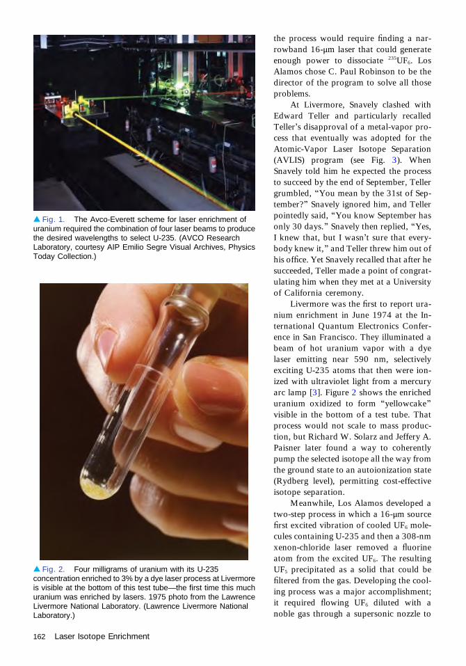
the process would require finding a nar-rowband 16-μm laser that could generateenough power to dissociate 235UF6. LosAlamos chose C. Paul Robinson to be thedirector of the program to solve all thoseproblems.
At Livermore, Snavely clashed withEdward Teller and particularly recalledTeller’s disapproval of a metal-vapor pro-cess that eventually was adopted for theAtomic-Vapor Laser Isotope Separation(AVLIS) program (see Fig. 3). WhenSnavely told him he expected the processto succeed by the end of September, Tellergrumbled, “You mean by the 31st of Sep-tember?” Snavely ignored him, and Tellerpointedly said, “You know September hasonly 30 days.” Snavely then replied, “Yes,I knew that, but I wasn’t sure that every-body knew it,” and Teller threw him out ofhis office. Yet Snavely recalled that after hesucceeded, Teller made a point of congrat-ulating him when they met at a Universityof California ceremony.
Livermore was the first to report ura-nium enrichment in June 1974 at the In-ternational Quantum Electronics Confer-ence in San Francisco. They illuminated abeam of hot uranium vapor with a dyelaser emitting near 590 nm, selectivelyexciting U-235 atoms that then were ion-ized with ultraviolet light from a mercuryarc lamp [3]. Figure 2 shows the enricheduranium oxidized to form “yellowcake”visible in the bottom of a test tube. Thatprocess would not scale to mass produc-tion, but Richard W. Solarz and Jeffery A.Paisner later found a way to coherentlypump the selected isotope all the way fromthe ground state to an autoionization state(Rydberg level), permitting cost-effectiveisotope separation.
Meanwhile, Los Alamos developed atwo-step process in which a 16-μm sourcefirst excited vibration of cooled UF6 mole-cules containing U-235 and then a 308-nmxenon-chloride laser removed a fluorineatom from the excited UF6. The resultingUF5 precipitated as a solid that could befiltered from the gas. Developing the cool-ing process was a major accomplishment;it required flowing UF6 diluted with anoble gas through a supersonic nozzle to
▴ Fig. 1. The Avco-Everett scheme for laser enrichment ofuranium required the combination of four laser beams to producethe desired wavelengths to select U-235. (AVCO ResearchLaboratory, courtesy AIP Emilio Segre Visual Archives, PhysicsToday Collection.)
▴ Fig. 2. Four milligrams of uranium with its U-235concentration enriched to 3% by a dye laser process at Livermoreis visible at the bottom of this test tube—the first time this muchuranium was enriched by lasers. 1975 photo from the LawrenceLivermore National Laboratory. (Lawrence Livermore NationalLaboratory.)
162 Laser Isotope Enrichment

cool it while keeping it in the gas state tomaintain a narrow line spectrum, andpulsing the gas flow in synchronizationwith the laser pulses.
Los Alamos first demonstrated enrich-ment in 1976, but the details were keptclassified until 1978, when the news wasreleased to Laser Focus in a remarkablyroundabout way. A reporter first visitedthe lab, but researchers who showed himaround the lab told him nothing abouturanium enrichment results. A few daysafter his visit, a university researcherphoned the author to suggest that he callLos Alamos and ask, “Have you enrichedmacroscopic quantities of uranium?” Theauthor did, and it was as if he had said“open sesame.” Los Alamos officials weredelighted to answer “yes” and providedetails on their two-step process [4]. Evi-dently security had authorized the disclo-sure only in response to those exact words.
By the late 1970s, uranium enrich-ment was a major research program. Thetwo competing government programs con-sumed a total of about a hundred milliondollars a year. Jersey Nuclear-Avco Iso-topes continued its atomic uranium enrich-ment research, spending a total of over $70million before shutting it down in 1981after the government refused to fund ademonstration plant [5].
The laser community tended to seeselective laser excitation as the big chal-lenge and focused its attention on thelasers. Livermore had the more straight-forward problem, and built a bank ofhigh-power copper-vapor lasers to pumplarge dye lasers for its AVLIS program. By1982, Livermore had a master oscillator/power amplifier (MOPA) array of copper-vapor lasers emitting 7 kW, pumping adye-laser MOPA array emitting 2.5 kWday in and day out (see Fig. 4). Los Alamos needed to develop a 16-μm source, which it achieved byRaman-shifting the output of carbon-dioxide lasers. Although details of that technology were keptunder security wraps, Los Alamos was able to generate the required power and linewidth with efficiencyconsidered reasonable at the time. The heart of that system was a hydrogen-fluoride optical parametricoscillator, developed by George Arnold and Robert Wenzel. That oscillator was originally used toperfect the spectroscopic data and was subsequently used as the seed source for the Raman-shiftedcarbon-dioxide laser amplifier.
Little mentioned at the time was a parallel, classified program aimed at purifying plutonium for usein nuclear weapons. Fissionable plutonium-239 is produced by irradiating U-238 with neutrons in aspecial reactor. However, some U-238 atoms absorb a second neutron, producing Pu-240, which
▴ Fig. 3. Benjamin Snavely (right) and Sam Tuccio examinethe laser system used to enrich U-235 concentration in hoturanium vapor at Livermore. (Lawrence Livermore NationalLaboratory.)
▴ Fig. 4. Copper-vapor pumped dye lasers scaled for uraniumenrichment at Livermore. Most of the green light from the copperlasers was tightly confined so it could efficiently pump dye lasers,which emitted red-orange light tuned to three absorption lines ofU-235 vapor. (Lawrence Livermore National Laboratory.)
Laser Isotope Enrichment 163
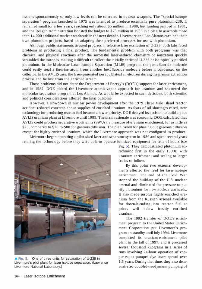
fissions spontaneously so only low levels can be tolerated in nuclear weapons. The “special isotopeseparation” program launched in 1975 was intended to produce essentially pure plutonium-239. Itremained small for a few years, reaching only about $5 million in 1980, but funding jumped in 1981,and the Reagan Administration boosted the budget to $76 million in 1983 in a plan to assemble morethan 14,000 additional nuclear warheads in the next decade. Livermore and Los Alamos each had theirown plutonium projects, based on adapting their preferred processes for use with plutonium.
Although public statements stressed progress in selective laser excitation of U-235, both labs facedproblems in producing a final product. The fundamental problem with both programs was thatchemical and physical reactions after the successful laser-induced chemistry or ionization quicklyscrambled the isotopes, making it difficult to collect the initially enriched U-235 or isotopically purifiedplutonium. In the Molecular Laser Isotope Separation (MLIS) program, the pentafluoride moleculecould easily steal a fluorine atom from another hexafluoride molecule before it condensed on thecollector. In the AVLIS case, the laser-generated ion could steal an electron during the plasma extractionprocess and be lost from the enriched stream.
Those problems did not deter the Department of Energy’s (DOE’s) support for laser enrichment,and in 1982, DOE picked the Livermore atomic-vapor approach for uranium and shuttered themolecular separation program at Los Alamos. As would be expected in such decisions, both scientificand political considerations affected the final outcome.
However, a slowdown in nuclear power development after the 1979 Three Mile Island reactoraccident reduced concerns about supplies of enriched uranium. As fears of oil shortages eased, newtechnology for producing reactor fuel became a lower priority. DOE delayed its decision to build a pilotAVLIS uranium plant at Livermore until 1985. The main rationale was economic: DOE calculated thatAVLIS could produce separative work units (SWUs), a measure of uranium enrichment, for as little as$25, compared to $70 to $80 for gaseous diffusion. The plan called for phasing out gaseous diffusionexcept for highly enriched uranium, which the Livermore approach was not configured to produce.
Livermore began operating a pilot-sized laser and separator system in 1986 and spent several yearsrefining the technology before they were able to operate full-sized equipment for tens of hours (see
Fig. 5). They demonstrated plutonium en-richment first in the early 1990s, withuranium enrichment and scaling to largerscales to follow.
By this point two external develop-ments affected the need for laser isotopeenrichment. The end of the Cold Warstopped the build-up of the U.S. nucleararsenal and eliminated the pressure to pu-rify plutonium for new nuclear warheads.It also made surplus highly enriched ura-nium from the Russian arsenal availablefor down-blending into reactor fuel atprices well below freshly enricheduranium.
The 1992 transfer of DOE’s enrich-ment program to the United States Enrich-ment Corporation put Livermore’s pro-gram on standby until July 1994. Livermorecompleted its uranium-enrichment pilotplant in the fall of 1997, and it processedseveral thousand kilograms in a series ofruns involving 24-hour operation of cop-per-vapor pumped dye lasers spread over1.5 years. During that time, they also dem-onstrated doubled-neodymium pumping of
▴ Fig. 5. One of three units for separation of U-235 inLivermore’s pilot plant for laser isotope separation. (LawrenceLivermore National Laboratory.)
164 Laser Isotope Enrichment

the dye lasers for future pumping in a production facility. But U.S. Enrichment halted those tests inJune 1999, citing low prices for enriched uranium and high internal expenses for other work [6]. Thosecuts also stopped plutonium enrichment. The motivation for continuing the laser program also was hurtby the continuing successes of the centrifuge programs that had been ongoing worldwide. All told,Livermore’s quarter century of laser isotope separation development had cost more than $2 billion.
By then, molecular laser isotope enrichment had been revived by two Australians, MichaelGoldsworthy and Horst Struve, who in 1990 began developing a process they called SILEX forSeparation of Isotopes by Laser EXcitation. Like the Los Alamos process, SILEX is based on coolingUF6 so resonances for molecules containing U-235 and U-238 are clearly separated and the moleculesare concentrated in the ground state. Excitation with a 16-μm laser source selectively excites moleculescontaining U-235, producing a product stream enriched in U-235 and a “tails” stream depleted inU-235 but richer in U-238. Details are classified, but the main differences from the old Los Alamosprocess are thought to be in extraction of the laser-excited U-235 fraction of the material. In theinformation about this process there has been no hint of the laser-induced chemistry or ionization thatinitiated the isotope scrambling that plagued the earlier programs.
U.S. Enrichment supported Goldworthy and Struve’s work from 1996 to 2002, and after thatfunding stopped, they formed a public company called Silex Systems Ltd. in Australia. Silex eventuallylicensed a joint venture of General Electric and Hitachi called GE Hitachi Nuclear Energy to use theprocess. After a few years of study, GE Hitachi Nuclear applied for a license to build a pilot plant inNorth Carolina, which the Nuclear Regulatory Commission approved in 2012. The plan is controver-sial, and the final outcome remains to be seen, but after a near-death experience, laser uraniumenrichment is clinging tenuously to life.
AcknowledgmentThanks to Otis Peterson for assisting with this essay.
References1. R. H. Levy and G. S. Janes, “Method of and apparatus for the separation of isotopes,” U.S. patent
3,772,519 (13 November 1973).2. Arthur Kantrowitz, interview by Robert W. Seidel for the Laser History Project, 25 September 1985.3. Anonymous, “Report from San Francisco,” Laser Focus 10(8), 10–25 (1974).4. Anonymous, “Molecular process enriched milligrams of uranium two years ago at Los Alamos,” Laser
Focus 14(5), 32–34 (May 1978).5. George Palmer and D. I. Bolef, “Laser isotope separation: the plutonium connection,” Bull. Atom. Sci.
40(3), 26–31 (March 1984).6. A. Heller, “Laser technology follows in Lawrence’s footsteps,” Sci. Technol. Rev., 13–21 (May 2000),
https://www.llnl.gov/str/Hargrove.html.
Laser Isotope Enrichment 165

Lasers for Fusion ResearchJohn Murray
Laser fusion research began [1] at several establishments shortly after the first laseroperated in 1960. John Nuckolls of the Lawrence Livermore National Laboratoroy andothers around the world quickly recognized that the laser had the potential to concentrate
power to the extreme levels required for small-scale fusion tests. Theoretical analysis showed[1,2] that achieving fusion and significant energy yield with the easiest targets to ignite, a mixtureof deuterium and tritium (DT), would require imploding them to extremely high density––perhaps ten thousand times normal liquid density—with nanosecond-scale pulses in the kilojouleto megajoule range. Producing the extreme pressure and fuel implosion velocity required to reachthe required density would require irradiance of 1014 W/cm2 with lasers expected to be availablein the near term. The challenge was to achieve significant energy yield at a size that lookedreasonable for laboratory experiments.
Two basic concepts for laser-driven fusion explosions were quickly developed, as shown inFig. 1. The direct-drive implosion uses laser energy that impinges directly on a spherical targetcontaining DT fuel within an ablator shell that absorbs laser energy and expands, compressingthe remaining ablator and fuel to a small volume in the center of the target and heating it toinitiate DT fusion. The indirect-drive implosion absorbs the laser energy on the inside of a heavymetal cavity or hohlraum, producing soft x-rays that illuminate the ablator and implode the fuelcapsule as in the direct-drive fusion.
The direct-drive implosion requires extremely uniform irradiance to achieve sphericalsymmetry. Indirect-drive fusion eases that requirement by converting the laser light to softx-rays that with proper design uniformly irradiate the central capsule. X-ray absorption in theablator is also simpler and less subject to nonlinear processes than laser absorption. However,indirect drive couples only 10%–20% of the drive energy to the fuel capsule, so it needs a higherlaser drive energy.
Laser sources for such small targets should store energy from a long pump pulse and delivera carefully shaped nanosecond pulse. Development of the Q-switch and the neodymium-glasslaser were important milestones, providing a nanosecond pulse source and an amplifier thatcould be made in large sizes and had rather low gain so that it did not break into spontaneousoscillation from stray light before the nanosecond extraction pulse. Those developmentsencouraged Ray Kidder of Livermore to estimate that a pulse of at least 100 kJ lasting lessthan 10 ns might be able to ignite a small amount of DT fuel [1].
The glass laser is not a perfect solution, however, and in the early years of inertial fusionmany other options were explored. The photolytically pumped iodine laser at 1.3 μm wasidentified as a promising fusion driver as soon as it was demonstrated in the early 1960s. Thegas medium makes the laser less limited by nonlinear processes and much less expensive than asolid. The Asterix laser system [3] at the Max Planck Institute for Quantum Optics in Garching,Germany, and the Iskra laser system [4] at the Research Institute of Experimental Physics inSarov, Russia (formerly Arzamas-16), were used in fusion research. Asterix, now operating inPrague, Czech Republic [5], produces up to 1 kJ in 350 ps, with frequency conversion to 657and 438 nm. Iskra-5 reached 120 TW in 12 beams in 1991. Pumping a photolytic iodine laserwith explosive-driven light sources, looked very appealing as a low-cost (but single-shot) routeto megajoule energies [6], but precision control proved too difficult for use in fusionexperiments.
1960–1974
166

The 10.6-μm carbon dioxide laser initially seemed an excellent candidate, with high efficiency, thepotential for large amplifiers in large sizes, and relatively inexpensive construction. The Antares project(see Fig. 2) [7] at the Los Alamos National Laboratory directed nanosecond CO2 pulses of up 40 kJ on afusion target from two final amplifiers, each with 12 roughly square 30-cm subapertures. Unfortu-nately, the long wavelength of the CO2 laser proved a severe handicap because laser-plasma instabilitiesscale with the square of the wavelength, so they are two orders of magnitude larger at 10.6 μm than at1.06 μm; therefore CO2 laser fusion was abandoned in 1985.
The 248-nm krypton fluoride laser has also been explored as a fusion driver. The short wavelengthis desirable for target interaction, but optics that far in the ultraviolet are difficult to develop. The KrFlaser has broad bandwidth, which is desirable for beam smoothing in direct-drive fusion. At the powerlevels needed for fusion, it generates pulses of 100 ns or longer, which must be optically compressed tothe few nanosecond pulses required for fusion. The Nike laser system [8] at the Naval ResearchLaboratory has explored KrF technology by stacking 56 pulses through an amplifier to give up to 4 kJon target in 4 ns, and the Ashura laser system [9] at the Electrotechnical Laboratories, Tsukuba, Japan,has operated with up to 2.7 kJ in 20-ns target pulses. Figure 3 shows the 60×60-cm final amplifier of theNike system.
The neodymium glass laser emerged as the most versatile and successful laser system for fusionresearch. A major advantage was that its 1.06-μm pulses can be converted efficiently to the second andthird harmonics at 532 and 355 nm, which proved less vulnerable to laser-plasma instabilities thanlonger wavelengths. Xenon flashlamps excite neodymium ions in the glass, which drop to the upperlevel of the 1.06-μm laser transition. The transition has a lifetime of 300–400 ms and a gain cross-section high enough that energy can be extracted efficiently in short pulses with fluences tolerable forlaser optics.
Early glass laser systems used cylindrical rods similar in concept to the first laser, a smallcylindrical rod of flashlamp-pumped synthetic ruby crystal. The Del’fin laser system [10] at theLebedev Institute, Moscow, Russia, used a large array of cylindrical rods serving as subapertures
▴ Fig. 1. In a direct-drive target, laser beams illuminate a fuel capsule uniformly. In an indirect-drive target, theyilluminate the inside of a heavy metal hohlraum surrounding the target and are converted to soft x-rays. The x-rays thenimplode the fuel capsule.
Lasers for Fusion Research 167

within a single beamline. Amplifiers that used zig-zag laser beam propagation through large laserglass slabs were also explored [11].
Fusion experiments in the U.S. began in the early 1970s, with three laboratories building a series ofneodymium-glass lasers initially operated at 1.06 μm.
Moshe Lubin established the Laboratory for Laser Energetics at the University of Rochester in1970 and built the four-beam Delta laser in 1972. When the lab’s new building was completed in 1978,the six-beam Zeta laser began operation, performing experiments for universities, government agencies,and industry.
The promise of laser fusion also attracted a private company, KMS Fusion, founded by physicistand entrepeneur Keeve M. Siegel in Ann Arbor, Michigan. KMS built its own glass laser, and had someearly experimental success, but the company ran short of money. Siegel suffered a fatal stroke whileasking Congress for government support in 1975, and KMS Fusion survived for a time on governmentcontracts.
John Emmett and Carl Haussmann led development of a series of glass lasers for fusionexperiments at Livermore. The one-beam, 10-J Janus laser conducted the first fusion shots in 1974.The one-beam Cyclops laser followed, a prototype of one beam in the 20-beam Shiva laser. The two-beam Argus laser came on line in 1976, followed in 1977 by Shiva, which reached 10 kJ.
The most popular design for modern neodymium glass lasers with apertures larger than 10-cm isthe Brewster’s-angle slab amplifier shown in Fig. 4. A laser beam polarized in the plane of the figure
◂ Fig. 2. Final amplifier of theAntares CO2 laser system.(Courtesy of Los AlamosNational Laboratory.)
168 Lasers for Fusion Research

sees no loss when it strikes the slab surfaces at Brewster’s angle, and the slab faces are also easilyaccessible for flashlamp pumping. Early examples [12] used circular disks of glass, forcing ellipticalbeam profiles. More modern designs use elliptical or rectangular slabs so that the laser beam can becircular or square.
Many large glass fusion lasers have been built with those amplifiers, such as Gekko [13] at OsakaUniversity, Japan; Vulcan [14] at the Rutherford-Appleton Laboratory, Didcot, UK; Omega [15] atthe University of Rochester; Phebus at the Commissariat a l’Energie Atomique, Limeil-Valenton,France; and the sequence of lasers [16] leading to the Nova laser at Livermore completed in 1984. There
▴ Fig. 3. The 60-cm aperture final amplifier of the Nike KrF laser. The amplifier is pumped from two sides by electronbeams generated by the cylindrical pulse-forming lines. (Courtesy of Naval Research Laboratory.)
▴ Fig. 4. A Brewster’s angle slab amplifier using neodymium glass. The laser beam sees no loss if it propagatesthrough this series of slabs with polarization in the plane of the figure. (Courtesy of Lawrence Livermore NationalLaboratory.)
Lasers for Fusion Research 169

have been many others [17]. Nova was the largest of its generation, with ten 46-cm beamlines abledeliver up to 30 kJ at 351 nm in shaped pulses of a few nanoseconds duration for indirect-driveexperiments.
The Omega Upgrade laser at Rochester [15] began experiments in 1995. It delivers 30 kJ in 20-cmdiameter beams at 351 nm in a 64-beam geometry optimized for direct-drive targets. The beams use atechnique [18] called “smoothing by spectral dispersion” (SSD) to smooth the irradiance to give a veryuniform profile on the target.
The largest fusion laser system now operating [19] is the National Ignition Facility at LawrenceLivermore National Laboratory (LLNL). Figure 5 is an artist’s sketch of the facility. It contains 192laser beamlines of 40-cm square aperture and was designed to irradiate targets with pulses to 1.8 MJ atthe third harmonic (351 nm), and to have very flexible output pulses for a wide variety of targetexperiments [20].
NIF irradiates indirect-drive targets with conical arrays of beams that illuminate three rings of 64beam spots each on the inside of a cylindrical hohlraum. This allows experimenters to tune the x-raydistribution within the hohlraum to optimize target implosions. The NIF beam arrangement can also beused to drive some direct-drive targets [21–23]. SSD smoothing is available if required.
Each beamline includes sixteen slabs, with the beam making four passes through the final amplifier(see Fig. 6) before exiting and being diretected into the target chamber. Such multipass amplifiers reducethe number of intermediate amplifiers and reduce cost of the facility, though they are harder to designand control than the single-pass amplifier chains used for most fusion laser systems in the past. Eachpreamplifier module in NIF injects about 1 J into each of four adjacent beamlines. The oscillator thatdrives the preamplifiers is a fiber laser that uses modulators and other hardware derived from thosedeveloped for fiber-optic communications systems.
The Laser Megajoule (LMJ) project under construction [23] by the Commissariat a l’EnergieAtomique at Le Barp near Bordeaux, France, will have amplfiers similar to NIF, but will have 240
▴ Fig. 5. The NIF laser fusion facility. NIF has 192 laser beams of 40-cm aperture and a 10-m diameter targetchamber seen at the right end of the picture. (Courtesy of Lawrence Livermore National Laboratory.)
170 Lasers for Fusion Research

beamlines with 18 slabs each, and somewhat higher energy output capability. An eight-beam prototypecalled Ligne d’Intégration Laser (LIL) is currently operating.
Omega Upgrade, NIF, and LMJ also will have the capability to deliver kilojoule-class, petawatt-power picosecond beams to target from beamlines that use grating compression of frequency-chirpedpulses [24]. This capability allows them to explore an advanced target design [25] called the “fastignition” target that uses the main laser output to compress a target, and a separate petawattpicosecond beam to heat the central spot of the target sufficiently for ignition. Target implosionsimulations suggest that such targets will offer higher net gain (fusion energy out divided by laser energyin) than conventional targets, highly desirable for future applications of laser fusion to energyproduction. Other laser facilities also have experimental programs investigating fast ignition. Petawattbeams are also useful for other experiments such as x-ray backlighting of imploding targets.
The National Ignition Facility succeeded in delivering pulses of more than 1.8 mJ to targets in2012. However, that design energy proved insufficient to ignite fusion targets. Further experimentshave increased yield, and Livermore researchers are focusing on improving target compression andreconciling theory with experimental results.
Researchers have long hoped to use laser fusion for electric power generation. The HiPER project[26] in the European Community, FIREX [27] in Japan, and LIFE [28,29] in the U.S. are all exploringenergy applications of advanced laser fusion concepts. These projects are developing concepts forhigh-average-power facilities to follow NIF and LMJ, either with advances from NIF/LMJ-liketechnologies or with advanced diode-pumped solid-state lasers that offer higher efficiency and betterthermal properties. Large slabs of laser-grade transparent ceramics [30,31], if developed in time, wouldbe very valuable for advanced laser fusion projects since they offer the laser and thermal properties of
▴ Fig. 6. A stack of four NIF slabs ready for insertion into the final amplifier. (Courtesy of Lawrence LivermoreNational Laboratory.)
Lasers for Fusion Research 171

laser crystals without the difficulty of growing large crystals. There are numerous other studies ofconceptual designs for laser fusion power plants using solid-state [32] or KrF [33,34] lasers.
Fifty years after its origins, fusion research with lasers is a vibrant research area that has sparkedmany developments in both fusion and laser technology, and continues to do so.
References1. R. E. Kidder, “Laser fusion: the first ten years,” Proc. SPIE 3343, 10–34 (1998).2. J. D. Lindl, Inertial Confinement Fusion (Springer, 1998). Most of the technical content can also be
found in the review article by the same author: J. D. Lindl, “Development of the indirect-drive approachto inertial confinement fusion and the target physics basis for ignition and gain,” Phys. Plasmas 2, 3933–4024 (1995). See also http://www.osti.gov/bridge/servlets/purl/10126383-6NAuBK/native/10126383.pdf and Lindl and Hammel IAEA NIC plan: http://fire.pppl.gov/iaea04_lindl.pdf.
3. H. Baumhacker, G. Brederlow, E. Fill, R. Volk, S. Witkowski, and K. J. Witte, “Layout and performanceof the Asterix IV iodine laser at MPQ, Garching,” Appl. Phys. B 61, 225–232 (1995).
4. V. I. Annenkov, V. A. Bagretsov, V. G. Bezuglov, L. M. Vinogradskiı̆, V. A. Gaı̆dash, I. V. Galakhov,A. S. Gasheev, I. P. Guzov, V. I. Zadorozhnyiı̆, V. A. Eroshenko, A. Yu. Il’in, V. A. Kargin, G. A. Kirillov,G. G. Kochemasov, V. A. Krotov, Yu. P. Kuz’michev, S. G. Lapin, L. V. L'vov, M. R. Mochalov, V. M.Murugov, V. A. Osin, V. I. Pankratov, I. N. Pegoev, V. T. Punin, A. V. Ryadov, A. V. Senik, S. K. Sobolev,N. M. Khudikov, V. A. Khrustalev, V. S. Chebotar, N. A. Cherkesov, and V. I. Shemyakin, “Iskra-5 pulsedlaser with an output power of 120 TW,” Sov. J. Quantum Electron. 21, 487 (1991). See also G. A. Kirillov,V. M. Murugov, V. T. Punin, and V. I. Shemyakin, “High power laser system ISKRA V,” Laser Part.Beams 8, 827–831 (1990) and G. A. Kirillov, G. G. Kochemasov, A. V. Bessarab, S. G. Garanin, L. S.Mkhitarian, V. M. Murugov, S. A. Sukharev, and N. V. Zhidkov, “Status of laser fusion research atVNIIEF (Arzamas-16),” Laser Part. Beams 18, 219–228 (2000).
5. http://www.pals.cas.cz/laboratory/.6. V. P. Arzhanov, B. L. Borovich, V. S. Zuev, V. M. Kazanskiı̆, V. A. Katulin, G. A. Kirillov, S. B. Kormer,
Yu. V. Kuratov, A. I. Kuryapin, O. Yu. Nosach, M. V. Sinitsyn, and Yu. Yu. Stoı̆lov, “Iodine laserpumped by radiation from a shock front created by detonating an explosive,” Sov. J. Quantum Electron.22, 118 (1992).
7. J. Jansen, “Review and status of Antares,” IEEE Pulsed Power Conference (IEEE, 1979), http://www.iaea.org/inis/collection/NCLCollectionStore/_Public/16/076/16076157.pdf; Antares main: http://library.lanl.gov/cgi-bin/getfile?00258820.pdf; Antares phase II http://library.lanl.gov/cgi-bin/getfile?00307486.pdf; http://library.lanl.gov/cgi-bin/getfile?00258902.pdf. See also H. Jansen, “A review of theAntares laser fusion facility,” in Proceedings of 1983 IAEA Technical Committee Meeting on ICFResearch (Osaka University, 1984), pp. 284–298 and P. D. Goldstone, G. Allen, H. Jansen, A. Saxman,S. Singer, and M. Thuot, “The Antares facility for inertial fusion experiments-status and plans,” in LaserInteraction and Related Plasma Phenomena, H. Hera, and G. Miley, eds. (Plenum, 1984), Vol. 6,pp. 21–32.
8. http://www.nrl.navy.mil/ppd/nike-facility. R. H. Lehmberg, J. L. Giuliani, and A. J. Schmitt, “Pulseshaping and energy storage capabilities of angularly multiplexed KrF laser fusion drivers,” J. Appl. Phys.106, 023103 (2009) and M. Karasik, J. L. Weaver, Y. Aglitskiy, T. Watari, Y. Arikawa, T. Sakaiya,J. Oh, A. L. Velikovich, S. T. Zalesak, J. W. Bates, S. P. Obenschain, A. J. Schmitt, M. Murakami, andH. Azechi, “Acceleration to high velocities and heating by impact using Nike KrF laser,” Phys. Plasmas17, 056317 (2010), http://www.dtic.mil/cgi-bin/GetTRDoc?AD=ADA521400.
9. Y. Owadano, I. Okuda, and Y. Matsumoto, “Overview of Super-Ashura KrF laser program,” FusionEng. Design 44, 91–96 (1999).
10. N. G. Basov, A. P. Allin, N. E. Bykovskii, and B. L. Vasin, “Del’fin-l laser-driven thermonuclear facility:operating assembly and development trends,” Trudy FIAN 178, 3–88 (1987).
11. M. E. Brodov, V. P. Degtyarova, A. V. Ivanov, P. I. Ivashkin, V. V. Korobkin, P. P. Pashinin, A. M.Prokhorov, and R. V. Serov, “A study into characteristics of a triple-pass amplifier using a neodymiumglass slab,” Kvant. Elekt. 9, 121–125 (1982).
12. S. W. Mead, R. E. Kidder, J. E. Swain, F. Rainer, and J. Petruzzi, “Preliminary measurements of x-rayand neutron emission from laser-produced plasmas,” Appl. Opt. 11, 345–352 (1972).
13. http://www.ile.osaka-u.ac.jp/research/csp/facilities_e.html.
172 Lasers for Fusion Research

14. I. N. Ross, M. S. White, J. E. Boon, D. Craddock, A. R. Damerell, R. J. Day, A. F. Gibson, P. Gottfeldt,D. J. Nicholas, and C. J. Reason, “Vulcan—a versatile high-power glass laser for multiuse experiments,”IEEE J. Quantum Electron. QE-17, 1653–1659 (1981).
15. http://www.lle.rochester.edu/omega_facility/.16. The development of these lasers through steps such as Janus, Cyclops, Argus, Shiva, Novette, and,
finally, Nova, is briefly reviewed in the following publications: https://lasers.llnl.gov/science_technology/pdfs/Lasers_1972_1997.pdf and https://lasers.llnl.gov/multimedia/interactive/book1/index.htm.
17. Wikipedia has a list of major current and former laser fusion facilities at http://en.wikipedia.org/wiki/List_of_fusion_experiments#Laser-driven. Also see http://laserstars.org/biglasers/pulsed/index.html.
18. S. Skupsky, R. W. Short, R. S. Craxton, S. Letzring, and J. M. Soures, “Improved laser beamuniformity using the angular dispersion of frequency-modulated light,” J. Appl. Phys. 66, 3456–3462(1989).
19. See the introductory review G. H. Miller, E. I. Moses, and C. R. Wuest, “The National IgnitionFacility,”Opt. Eng. 43, 2841–2853 (2004), and the papers in the special section following thereview. See also E. I. Moses, R. N. Boyd, B. A. Remington, C. J. Keane, and R. Al-Ayat, “TheNational Ignition Facility: ushering in a new age for high energy density science,” Phys. Plasmas16, 041006 (2009).
20. C. A. Haynam, P. J. Wegner, J. M. Auerbach, M. W. Bowers, S. N. Dixit, G. V. Erbert, G. M.Heestand, M. A. Henesian, M. R. Hermann, K. S. Jancaitis, K. R. Manes, C. D. Marshall, N. C.Mehta, J. Menapace, E. Moses, J. R. Murray, M. C. Nostrand, C. D. Orth, R. Patterson, R. A.Sacks, M. J. Shaw, M. Spaeth, S. B. Sutton, W. H. Williams, C. C. Widmayer, R. K. White, S. T.Yang, and B. M. Van Wonterghem, “National Ignition Facility laser performance status,” Appl.Opt. 46, 3276–3303 (2007). See also G. M. Heestand, C. A. Haynam, P. J. Wegner, M. W. Bowers,S. N. Dixit, G. V. Erbert, M. A. Henesian, M. R. Hermann, K. S. Jancaitis, K. Knittel, T. Kohut, J.D. Lindl, K. R. Manes, C. D. Marshall, N. C. Mehta, J. Menapace, E. Moses, J. R. Murray, M. C.Nostrand, C. D. Orth, R. Patterson, R. A. Sacks, R. Saunders, M. J. Shaw, M. Spaeth, S. B. Sutton,W. H. Williams, C. C. Widmayer, R. K. White, S. T. Yang, and B. M. Van Wonterghem,“Demonstration of high-energy 2ω (526.5 nm) operation on the National Ignition Facility,” Appl.Opt. 47, 3494–3499 (2008).
21. S. Skupsky, J. A. Marozas, R. S. Craxton, R. Betti, T. J. B. Collins, J. A. Delettrez, V. N. Goncharov,P. W. McKenty, P. B. Radha, T. R. Boehly, J. P. Knauer, F. J. Marshall, D. R. Harding, J. D. Kilkenny,D. D. Meyerhofer, T. C. Sangster, and R. L. McCrory, “Polar direct drive on the National IgnitionFacility,” Phys. Plasmas 11, 2763–2771 (2004).
22. NIF target experiment at 0.7 MJ: S. H. Glenzer, B. J. MacGowan, P. Michel, N. B. Meezan, L. J. Suter,and S. N. Dixit, “Symmetric inertial confinement fusion implosions at ultra-high laser energies,” Science5(3), 1228–1231 (2010).
23. Laser Megajoule (LMJ)—Ligne d’Intégration Laser (LIL): http://www.lmj.cea.fr/index.htm.24. As an example for LMJ, see http://petal.aquitaine.fr/spip.php?lang=en. Picosecond capabilities are also
discussed at the Omega and NIF websites.25. M. H. Key, “Status of, and prospects for the fast ignition inertial fusion concept,” Phys. Plasmas
14, 055502 (2007). R. Kodama, H. Shiraga, K. Shigemori, Y. Toyama, S. Fujioka, H. Azechi,H. Fujita, H. Habara, T. Hall, Y. Izawa, T. Jitsuno, Y. Kitagawa, K. M. Krushelnick, K. L. Lancaster,K. Mima, K. Nagai, M. Nakai, H. Nishimura, T. Norimatsu, P. A. Norreys, S. Sakabe, K. A. Tanaka,A. Youssef, M. Zepf, and T. Yamanaka, “Fast heating scalable to laser fusion ignition,” Nature 418,933–934 (2002).
26. http://www.hiper-laser.org/30aboutthehiperp.html.27. H. Azechi, K. Mima, Y. Fujimoto, S. Fujioka, H. Homma, M. Isobe, A. Iwamoto, T. Jitsuno, T. Johzaki,
and R. Kodama, “Plasma physics and laser development for the Fast-Ignition Realization Experiment(FIREX) Project,” Nucl. Fusion 49, 104024 (2009), http://dx.doi.org/10.1088/0029-5515/49/10/104024.
28. M. Dunne, “Igniting our energy future,” LLNL Sci. Technol. Rev. (July/August, 2011), https://str.llnl.gov/JulAug11/dunne.html; https://life.llnl.gov/.
29. E. I. Moses, “Powering the future with LIFE,” LLNL-TR-412603, https://e-reports-ext.llnl.gov/pdf/372750.pdf. See also K. J. Kramer, W. R. Meier, J. F. Latkowski, and R. P. Abbott, “Parameter studyof the LIFE engine nuclear design,” Energy Convers. Manag. 51, 1744–1750 (1 September 2010),https://e-reports-ext.llnl.gov/pdf/375549.pdf.
30. A. Ikesue and Y. L. Aung, “Ceramic laser materials,” Nature Photon. 2, 721–727 (2008).
Lasers for Fusion Research 173

31. H. Yagi, T. Yanagitani, K. Takaichi, K. Ueda, and A. A. Kaminskii, “Characterizations and laserperformances of highly transparent Nd3+:Y3Al5O12 laser ceramics,” Opt. Mater. 29, 1258–1262(2007).
32. J. D. Sethian, M. Friedman, R. H. Lehmberg, M. Meyers, S. P. Obenschain, J. Giuliani, P. Kepple, A. J.Schmitt, D. Colombant, and J. Gardner, “Fusion energy with lasers, direct drive targets, and dry wallchambers,” Nucl. Fusion 43, 1693 (2003), http://other.nrl.navy.mil/Preprints/Sethian.NuclFus.43.1693.2003.pdf; http://iopscience.iop.org/article/10.1088/0029-5515/43/12/015/meta;jsessionid=855FF07A770695E0EE8E7ED3B99D7D9A.c1; http://www.nrl.navy.mil/research/nrl-review/2002/particles-plasmas-beams/sethian/.
33. S. P. Obenschain, J. D. Sethian, and A. J. Schmitt, “A laser-based fusion test facility,” Fusion Sci.Technol. 56, 594–603 (2009), http://www.ans.org/pubs/journals/fst/a_8976.
34. E. I. Moses, T. Diaz de la Rubia, E. P. Storm, J. F. Latkowski, J. C. Farmer, R. P. Abbott, K. J. Kramer,P. F. Peterson, H. F. Shaw, and R. F. Lehman, “A sustainable nuclear fuel cycle based on laser inertialfusion energy,” Fusion Sci. Technol. 56, 547 (2009).
174 Lasers for Fusion Research

History of Laser Remote Sensing,Laser Radar, and LidarDennis K. Killinger
Lidar and remote sensing grew from developments in optical spectroscopy, opticalinstrumentation, and electronics in the 1930s to 1950s. Starting in 1930, searchlightswere directed upward and atmospheric scattering was measured with a separately located
telescope. Starting in 1938, pulsed electric sparks and flashlamps were used in searchlights tomeasure cloud base heights. Middleton and Spilhaus introduced the term LIDAR (for LightDetection and Ranging) in 1953.
The laser revolutionized lidar and launched laser remote sensing. In 1962 Louis Smullen ofMIT and visiting scientist Giorgio Fiocco (who had worked on radar at Marconi) detectedbackreflection from the Moon using 50-J, 0.5-ms pulses from a Raytheon ruby laser transmittedthrough a 12-inch telescope together with a 48-inch receiving telescope and a liquid-nitrogencooled photomultiplier at MIT Lincoln Laboratory. (See Fig. 1.) The signal that returned after2.5 s was very weak, including only about 12 photons, and had to be recorded by photographinga double-beam oscilloscope trace using “vast amounts of Polaroid film and time.” The projectwas called “Luna-See,” probably reflecting its difficulty. The following year a newly inventedrotating mirror Q-switch shortened a 0.5-J ruby pulse to 50 ns for a series of lidar studies of theupper atmosphere. The first use of the term lidar referring to such a laser radar system was usedby Goyer and Watson in 1963 and by Ligda in 1964.
During the next decade advances in laser technology drove improvements in laser remotesensing. Richard Schotland in 1964 detected the concentration of a gas in the atmosphere for thefirst time by temperature-tuning the wavelength of a ruby laser across a water vapor absorptionline. This was the first Differential-Absorption Lidar (DIAL) system.
Other groups went on to detect other species. After a detailed theoretical analysis of lidartechniques by Byer and Kildal in 1971, Hinkley and Kelley showed experimental detection of airpollutants using tunable diode lasers in 1971, and Byer and Garbuny detailed DIAL requirementsfor pollution detection in 1973. Karl Rothe and Herbert Walther’s group in Germany used DIALwith tunable dye lasers to detect NO2 and in 1974–1976 Ed Murray, Bill Grant, and colleagues atSRI detected the gas with a tunable CO2 laser. Menzies and Hinkley in 1978 measuredatmospheric gases with a laser absorption spectrometer (LAS), two waveguide CO2 lasers, andstripchart recorders mounted in a plane (see Fig. 2). In 1979, they measured atmospheric gaseswith the balloon-borne Laser Heterodyne Radiometer shown in Fig. 3. Sune Svanberg’s group atthe Lund Institute mapped the mercury emission from coal-fired power plants in a seminal DIALstudy in the 1980s, Jack Bufton at NASA Goddard measured atmospheric CO2 in 1983, EdBrowell at NASA Langley measured water vapor and ozone in the atmosphere and the flow ofSahara Desert dust from Africa to the Southeast United States, and Nobuo Sugimoto andKazuhiro Asai’s group measured similar Asian dust flow.
DIAL also performed landmark environmental observations. In 1993, Bill Heaps’ group atNASA Goddard and Stuart McDermid’s group at JPL tracked variations of stratospheric ozonelevels in time and space for the first time, validating data suggesting an “ozone hole” collectedby solar occultation instruments on NASA satellites in the 1980s. The satellite sensors haddetected the hole years earlier but had not transmitted the data to the ground because thesoftware considered the measured ozone levels too low to be accurate. The problem was
1960–1974
175

corrected by programing the satellite totransmit raw data for observations on andoff the absorption line instead of just theratio of the two.
The advent of tunable quantum cas-cade lasers, tunable optical parametricoscillators, and tunable solid-state andsemiconductor lasers now have madeDIAL measurements of atmospheric gasesalmost routine. DIAL instruments regular-ly monitor methane and CO2 emissions tothe atmosphere and measure ammoniaand other gases for industrial process con-trol. That’s a big advance from the 1960s,when ozone and smog levels in LosAngeles were monitored by timing thedeterioration of a rubber band placed out-side a window and stretched by a smallweight.
John Reagan’s group at the Universityof Arizona began lidar mapping of atmo-spheric aerosols in the late 1960s, andothers built on their effort. Pat McCormickand David Winker of NASA Langley flew
▴ Fig. 1. Photo of “Luna-See,” the first laser radar measurement of a laser beam backscattered from the Moon(white speck at the upper left) in May 1962 at Lincoln Laboratory by MIT Prof. Louise Smullen (left), Raytheonlaser scientist Dr. Stanley Kass (middle), and visiting radar scientist Dr. Giorgio Fiocco (right). (Courtesy MITMuseum.)
▴ Fig. 2. Photo of 1978 JPL laser absorption spectrometer(LAS) lidar system mounted in a Beechcraft Queen Air aircraft.(Courtesy of R. Menzies, JPL.)
176 History of Laser Remote Sensing, Laser Radar, and Lidar

one of the first lidars in space, the Laser Inspace Technology Experiment (LITE) in1994 on Space Shuttle mission STS-64,which mapped cloud-top heights andrange-resolved distributions on a globalscale. Lidar also proved valuable in ob-serving particulates injected into thestratosphere by volcanic eruptions, whichtake about six months to mix with theatmosphere and remain airborne for aboutfive years.
Hard-target lidar trackers and rangefinders were developed especially for mili-tary applications, with significant progressmade by Al Jelalian’s group at Raytheon,and Ingmar Renhorn and Ove Steinvall atthe Sweden NDRI. Al Gschwendtner’sgroup at MIT Lincoln Lab developed ahigh-speed imaging heterodyne Dopplerlidar that could take full-view Dopplerrange-resolved images at a 30-Hz framerate. Those heterodyne systems led tolidars with much higher pulse rates forscanning and mapping hard targets andterrain. Alan Carswell of the University ofToronto founded the Optech Corp., which developed suitcase-sized imaging lidar scanners that fire200,000 pulses per second. Linked to a precision GPS network, these systems have compiled detailed3D maps of urban buildings and discovered and mapped Mayan ruins hidden under jungle canopiesusing a foliage-penetrating lidar. Such precision mapping lidars have been so successful that they nowperform most detailed geographical coordinate measurements. Another sign of their importance is thatNIST has established a standards group for lidar mapping.
Laser-induced fluorescence (LIF) also can detect important species in the atmosphere. Doug Davisand Bill Heaps at Georgia Tech, Charlie Wang’s group at the Ford Scientific Research Center, and theauthor in 1975 were the first to detect the OH free radical under ambient conditions at a concentrationof 0.01 parts per trillion. OH is important as the major rate controller for chemical reactions thatdeplete ozone in the upper atmosphere.
Large flashlamp-pumped dye lasers often were used to produce frequency-doubled pulses near282.5 nm, and operating them could be interesting. The large dye lasers quickly photobleached the dye,so 55-gallon drums of pure ethanol were used to extend the lifetime of the circulating solvent. Federaltax had to be paid on the pure drinking alcohol— about $2000 a barrel— which was returned after dyewas added and the liquid disposed of to show it had not been drunk. Recirculating the dye–alcoholsolution stabilized fluid temperature, but the coaxial flashlamps had limited lifetimes and wouldexplode after a few hundred hours. The Ford group had put the dye–alcohol pump downside of theflashlamp, so when the lamp exploded the pump just sucked in air. Unfortunately, Bell Labs had placedthe dye–alcohol pump in front of the flashlamp, so it sprayed alcohol into the exploding flashlamp,causing a major fire. The arrangement was reversed in later laser designs.
In 1980, Jim Anderson of Harvard conducted a series of high-altitude balloon-borne lasermeasurements that confirmed the key roles of stratospheric OH and Freon in ozone depletion. BillHeaps’ group at NASA Goddard conducted similar measurements with a balloon-borne laserspectrometer, but in one case the parachute failed to deploy upon descent, creating what Heaps calledthe world’s first “Lidar Pancake.”
LIF lidar also studied the tenuous sodium layer that surrounds the Earth at an elevation near 90km. Early lidar studies in 1972 by Gibson and Sandford, and in 1978 by Marie Chanin’s group in
▴ Fig. 3. Photo of Bob Menzies and JPL laser heterodyneradiometer balloon instrument sitting in its gondola frame in 1979.(Courtesy of R. Menzies, JPL.)
History of Laser Remote Sensing, Laser Radar, and Lidar 177

France, measured sodium levels with a tunable yellow dye laser. They also observed gravity orbreathing waves of the upper atmosphere, dynamic waves that travel around the world. Separatestudies by L. Thomas’ group in 1979, Chet Gardner’s group at the University of Illinois in 1990, andC. Y. She’s group in 1992 at Colorado State University showed that LIF excitation of the sodium layercould provide a beacon or “guide star” for adaptive optics compensation of atmospheric turbulence inground telescopes. Most large ground-based telescopes now use laser-produced guide stars togetherwith compensating optics to remove turbulence effects in milliseconds.
Lidar observations of the small Doppler shift in backscattered light arising from target velocity arechallenging but can yield valuable results. In 1970, Milt Huffaker used a laser-Doppler system to detectaircraft trailing vortices. In the early 1980s, Freeman Hall and Mike Hardesty’s group at NOAA andChristian Werner’s group at DFVLR/Germany developed a coherent CO2 laser system that mappedrange-resolved wind-speed profiles near airports and within boundary flow geometries. Later, SammyHenderson and Huffaker’s group at Coherent Technologies Inc. developed coherent lidars basedon solid-state laser systems near 2 μm. Direct-detection lidars developed during the past decade canalso measure Doppler-shifted returns in ways that complement the coherent measurements. Now fiber-laser-based coherent Doppler lidars are mapping wind fields around wind turbines to increase efficiencyof the blade pitch and direction.
Laser-induced-breakdown spectroscopy (LIBS) has also shown promise in the past decade fordetecting chemicals at ranges from less than a meter out to a few hundred meters. Focusing a 0.1-J, 5-nspulse through a telescope can produce dielectric breakdown in the air, yielding identifiable lines ofatomic and ionized species in the plasma. It is a long way from the 3500-J, 1-μs CO2 pulses VladimirZuev of the Tomsk Laser Institute in Siberia used to produce a plasma spark 2 km from the laser—earning him a semi-serious prize at the 1986 International Laser Radar Conference in Toronto forhaving made the world’s longest cigarette lighter.
Conferences and workshops have played a vital role in the development of lidar and laser remotesensing. Much early and fundamental research was reported at Optical Society (OSA) Annual Meetingsand March American Physical Society meetings in the 1960s, and at early CLEA/CLEO/CLEOSconferences in the 1970s. The International Symposium on Remote Sensing of Environment, first heldin Ann Arbor in 1962, continues through today with an emphasis on passive satellite sensing.
One of the earliest conferences devoted to lidar was the 1968 Conference on Laser Radar Studies ofthe Atmosphere in Boulder, Colorado, chaired by Vernon Derr. It continues today as the InternationalLaser Radar Conference (ILRC), run by the International Coordination Group on Laser AtmosphericStudies (ICLAS). One of the first conferences to look at the wide range of lidar techniques for speciesdetection was the Workshop on Optical and Laser Remote Sensing, sponsored by the Army ResearchOffice (ARO) in Monterey, California, in 1982 and chaired by Aram Mooradian and the author; Fig. 4shows some attendees. An outgrowth of this was OSA’s Topical Meeting on Optical Techniques forRemote Probing of the Atmosphere, first held in Incline Village/Lake Tahoe in 1983 and heldbiannually for the next several decades, sometimes changing emphasis and name. The Coherent LaserRadar Conference held first in 1980 in Aspen, Colorado, by Milt Huffaker is still going strong todaywith the most recent meetings in Barcelona, Spain, in 2013 and Boulder in 2015.
For the past five decades, laser remote sensing and lidar has been an outstanding and rewardingresearch career, often following the growth and expansion of the laser industry. It has seen thedevelopment of many worldwide collaborations among lidar colleagues and friends. Figures 5 and 6shows a “lidar banquet dinner” at the 1994 17th International Laser Radar Conference in Sendai,Japan, with all participants obviously enjoying themselves.
Laser remote sensing has benefitted from the development of new lasers and improvements in theirease of use, compactness, cost, and reliability. Lidar systems in the 1970s occupied one or two opticaltables, had laser lifetimes of hours, and relied on computer data acquisition systems operating atmegahertz speeds. Over the past decade, lidar systems have started to use $10 tunable LEDs, 10 GHzcomputers on a chip, and mini-spectrometers—shrinking systems so that portable suitcase systems arenow routine.
Further reductions in size and cost are expected in the future. (Can we dream of tunable quantumcascade lasers for $100?) Metamaterials and quantum-confined photonics will impact lasers and
178 History of Laser Remote Sensing, Laser Radar, and Lidar

▴ Fig. 5. Good lidar friends attending a banquet dinner at the 17th International Laser Radar Conference inSendai, Japan in 1994. (Left to right) bottom: Takao Kobayashi, Pat McCormick, Chet Gardner, Dennis Killinger,Jack Bufton; top: Akio Nomura, Osamu Uchino, Hiromasa Ito, Yasuhiro Sasano, Kazuhiro Asai, Toshikazu Itabe.
▴ Fig. 4. Some attendees at the 1982 ARO Workshop on Optical and Laser Remote Sensing in Monterey,Calif. L-R: Dennis Killinger, Charles C. Wang, Gil Davidson, Paul Kelley, Norman Menyuk, and Phil Russell.
History of Laser Remote Sensing, Laser Radar, and Lidar 179

detection techniques such as femtosecond absorption spectroscopy. It is hard to predict the future, but itis certain that major technical improvements will occur : : : they always have. As the technologycontinues to improve and laser remote sensing and lidar techniques become more widely accepted,we will find uses for lidar in applications not yet imagined.
It is sobering to recall that 40 years ago we thought that the main use of lidar and laser remotesensing was going to be akin to Star Trek where Spock scans the distant planet surface with a “laser”beam and tells the Captain that there are two humanoids on the planet’s surface and one has a badkidney. Who would have guessed back then that one of the huge commercial successes for lidar todaywould be mapping of urban buildings and geological features, finding buried Mayan ruins, mappingwind fields for wind farms, detecting and mapping global climate change gases and pollutants in theatmosphere, and laser sensing of pharmaceuticals and chemicals at close ranges.
▴ Fig. 6. Humio Inaba, Rod Freulich, Jack Bufton, Kin Pui Chan, Mike Hardesty, and Dennis Killinger at 17thILRC in Sendai, Japan, 1994.
180 History of Laser Remote Sensing, Laser Radar, and Lidar

PRE–1940 1941–1959 1960–1974 1975–1990 1991–PRESENT


IntroductionMichael Bass
In 1980, just 20 years after the first laser was demonstrated and about 10 years after the wayto make low loss optical fibers was discovered, two miracles took place: one that lots ofpeople noticed and that some recall and another that few noticed and that changed the course
of human history. At the Winter Olympics at Lake Placid, New York, the Miracle on Ice inwhich the U.S.A. men’s hockey team beat the much vaunted Soviet Union team was seen by tensof millions on television—lots of people noticed. However, the television broadcast of theOlympic Games, including the hockey match, was transmitted over an optical communicationssystem using diode lasers and fiber optics. Virtually no one noticed this miracle at the time, butmany billions would be affected by the technology. Optics changed the world and commu-nications would never be the same. This section presents the pivotal events and technologiesleading to optical fiber communications becoming practical.
Perhaps a few people in the mid-1970s could have foreseen that ultra-low-loss optical fibersand diode lasers would enable optics to take over the world as the dominant means ofcommunications. Optics did just that. Not only are billions of kilometers of fiber opticscommunication cables in use with diode lasers as the light sources but progress continues as thedemand for more and more information-carrying capacity continues to grow. New techniquesfor multiplexing are still being developed to enable higher throughput.
The invention of the laser and the demonstration of nonlinear optics spurred a greatlyrenewed interest in optics. In the period 1975–1990 that interest blossomed into many majorapplications and scientific breakthroughs. Nonlinear optics benefited from demonstration ofexcellent new materials for use in both the visible and the infrared. Periodically poled nonlinearmaterial had been described as early as 1962 but was finally demonstrated in this period. Itturned out that the periodically poled material was often a more efficient harmonic generatorthan its single-crystal index-matched version. These materials and greatly improved engineeringmade optical parametric oscillators and amplifiers available for applications requiring wave-length tunable sources. Nonlinear optics also made possible achieving ultrashort pulses,6 picosec in this period (today 67 attosec) and supercontinuum pulses with spectral contentexceeding an octave in frequency.
The list of applications of optics that developed in this period is too long to list in itsentirety here. However, a few are worth mentioning because they are so common that theoutstanding optics and optical design that makes them possible can be easily overlooked. Theyare the bar code scanner, the CD/DVD player, the laser printer, the laser pointer, the laser cut,the drilled or welded part of a finished product, the laser-marked product, the variable-focusspectacle lens, self-darkening spectacle lenses, soft contact lenses, the optical mouse, and theremote control for an appliance, as well as the display screens of televisions, computers, andmobile phones.
Between 1975 and 1990 developments of new lasers and their applications spurreddemonstration of new medical innovations. The LASIK technique for vision correction basedon the use of an excimer laser was developed and has now been used on ∼30,000,000 patients.Optics and fiber optics have made detecting pathologies in patients more reliable and lessinvasive. Laparoscopic surgeries are performed today with minimal cuts because fiber opticendoscopes or miniaturized cameras can be inserted to give the surgeon vision of the problemthat must be dealt with. Photodynamic therapy in which a laser is used to excite a dye that
1975–1990
183

preferentially locates in tumorous tissues is another area in which optics and medical treatment havecome together.
During this period spectacular progress was made in optical astronomy. The Hubble SpaceTelescope was launched and, after its optics were repaired, it performed spectacularly. It provided dataon the content of the universe such as the number of galaxies and the presence of dark mattersurrounding galaxies. Ground-based telescopes were designed and built that took advantage ofadaptive optics to build large-aperture, segmented-mirror instruments that can minimize atmosphericdistortions and provide superb images. These telescopes could be much larger than space telescopesand could gather more light from distant objects. Using image processing techniques and moderncomputers, it is now possible to link optical telescopes to greatly enlarge their effective aperture.
Whenever the field of optics is mentioned to non-optics people in the field of optics, theyimmediately think of their eyeglasses or contact lenses. And why not? Almost everyone will usespectacles or contacts at some point in his or her life and if they live long enough will have an implantedlens as part of cataract surgery. Progress in these areas has been remarkable. Contact lenses wereinvented that allow air to pass through, enabling long periods of comfortable wearing. In addition,contact lenses can now provide astigmatic correction. Spectacle lenses with continuously variablestrength eliminated the need for bifocal lenses with a sharp delineation between near and distanceviewing sections. Then photochromic lens materials became available enabling the wearer to no longerneed different spectacles indoors and outdoors; the lenses would lighten and darken according to theambient light environment.
By 1990 optics included light sources from continuously operating very stable lasers to lasersproducing pulses as short as a few picoseconds (now a few tens of attoseconds). Optics includedcomponents small enough to be swallowed to 30-meter-diameter segmented telescope mirrors.Displays were getting so small as to be worn in a head-mounted device or so large as to be seenby 100,000 people in a stadium. Most interesting and important was that applications of optics beyondthose that aid vision had become part of everyday life and so ubiquitous that most went unnoticed.
184 Introduction

The Shift of Optics R&D Funding andPerformers over the Past 100 YearsC. Martin Stickley
In the earliest days of the past century, advancements in optics were led by newly createdoptics companies: Kodak and its research laboratory, Bausch & Lomb, and the AmericanOptical Company. George Eastman led the effort to found the Kodak Research Laboratory
in 1912 because he saw the connection between optical science and development of newproducts. The Institute of Optics at the University of Rochester was not founded until 1929,after ten years of discussions. As for government, Thomas Edison urged in 1915 that a nationallaboratory be formed to attack issues faced by the U.S. Navy. While this resulted in theestablishment of the Naval Research Laboratory in 1923, the (Physical) Optics Division wasnot formed until after World War II.
In July 1945 during the closing days of World War II, Vannevar Bush, the Director of theOffice of Scientific Research and Development, in response to a request from President FranklinRoosevelt issued an extensive report entitled “Science—the Endless Frontier,” which urged thegovernment to establish and fund a broad program in science and applied research to fightdisease, develop national security, and aid the public welfare. It urged that basic science and long-term applied research be supported in universities, that nearer-term applied research anddevelopment be funded in industry, and that military research be increased and tied to universityand industry R&D programs as appropriate. It estimated the cost of this program to be $10million at the outset rising to perhaps $50 million within five years. One of the recommendationswas to create the National Science Foundation
Congress created the Office of Naval Research (ONR) in 1946 with the Naval ResearchLaboratory being its principal operational arm. In light of the wartime success in developing theproximity fuse, the Division of Ordnance Research was transferred from the National Bureau ofStandards to create the Army’s Diamond Ordnance Fuse Laboratory. The Army also created alaboratory for electronics research at Ft. Monmouth in New Jersey. The Air Force was spun outof the U.S. Army in 1947, leading to the creation of the Wright-Patterson Air Force BaseLaboratories in Dayton, Ohio; the Air Force Cambridge Research Laboratory in Cambridge,Massachusetts, which had Infrared Optics as one of its major divisions; and the Air ForceWeapons Laboratory in Albuquerque, New Mexico. Further, the MIT Radiation Laboratory atMIT, which was so successful during the war in radar development, was expanded and relocatednear the small town of Lincoln, Massachusetts, and renamed the MIT Lincoln Laboratory. All ofthese played a major role in modern optics and laser development.
Corporate labs were established and grew after the war. Some of them were at GE, Bell Labs,RCA Laboratories, Hughes Research Laboratory, Westinghouse Research Laboratory,Raytheon, Texas Instruments, Perkin-Elmer, and Boeing. Figure 1 is an aerial photo of theiconic Bell Holmdel Laboratory. The growth of corporate labs was aided by fiscal help thatresulted from the Vannevar Bush report and two events that accelerated the science andtechnology of and funding for optics dramatically: the launch of the Soviet Sputnik in 1957and the demonstration of the laser in 1960.
In 1958 in direct response to Sputnik, President Eisenhower created the Advanced ResearchProjects Agency (ARPA) within the Defense Department. One of the U.S.’s limitations was a lackof broad and deep materials capability. Thus, ARPA initiated the Interdisciplinary Laboratories
1975–1990
185

(IDL) program in 1960 to ensure thatchemists, physicists, and electrical and me-chanical engineers work together to solvethe difficult research problems in materialsdevelopment. This program led to the cre-ation of the field of “materials science.”The 12 universities funded in this programwere MIT, Harvard, Cornell, Illinois,Stanford, University of Pennsylvania,Maryland, Brown, Chicago, Northwestern,Purdue, and University of North Carolina.A major success of the IDL program wasthe development of the science and technol-ogy of electronic materials, especially III-Vmaterials such as GaAs and ternary andquaternary mixtures of them. These mate-rials systems have been the success story of
diode lasers and photonics more generally, and the scientists who went on to industrial laboratories todevelop these materials systems for specific applications in optics were likely trained in one of the IDLs.
With government funding enabling universities to supply highly skilled people to industry whowould lead in the revolution in optics brought on by the laser, we will concentrate on that historybecause it is in many ways symbolic of the transitions that took place in basic research in optics.This is not to say that other subjects such as advances in still and motion picture photography, CCDcameras, polaroid photography, electrophotographic (xerographic) copiers, laser printers, point-of-sale scanners, optical storage devices, laser machining, and optical communication systemscould not show the same transitions; it is just that the laser revolution presents the changes mostpowerfully.
Simultaneously with the initiation of the IDL program was the demonstration of the first laser. Thisoccurred at an industrial research laboratory using internal funds—the Hughes Research Laboratory(HRL) in Malibu, California, on 16 May 1960. As soon as other corporate labs heard in July of TedMaiman’s success, their efforts accelerated. TRG, a small company on Long Island, New York, hadbeen funded by ARPA in 1959 to the tune of $990,000 for laser development and is thought to be thefirst to duplicate Maiman’s result. A number of military labs including MIT Lincoln Laboratoryimmediately initiated laser programs. The author was a 1st lieutenant in the U.S. Air Force at that timestationed at the Air Force Cambridge Research Laboratory (AFCRL) in Bedford, Massachusetts. Heand Rudolph Bradbury had a ruby laser like Maiman’s operating by November 1960. A request of$392 was made for the purchase of capacitors and flashlamps. This request was immediately approved,as everyone was excited about the prospects of having an operating red laser!
Military labs like AFCRL, Wright-Patterson Air Force Base, and Air Force Weapons Laboratory(AFWL) typically had sufficient funding not only to fund their own projects but also to fund industrialand university proposals in areas of laser R&D that they deemed important. So the decade of the 1960swas one of intense laser activity, especially in the development of laser range finders and targetdesignators at HRL and other companies, coherence studies of partially coherent lasers at Rochesterand Brandeis and at TRG, the phenomenon of mode locking that was discovered in Nd:glass lasers byTony DeMaria of United Technology Research Center in Connecticut, the development of parametricoscillators using LiNbO3 at Bell Labs by J. Giordmaine and R. C. Miller and at Stanford by SteveHarris, the study of the dynamics of laser operation at the University of Rochester’s Institute of Opticsby Mike Hercher, and laser-induced damage to ruby and glass at HRL by Connie Guiliano and atAmerican Optical Company by Charles Koester. These damage studies were funded by ARPA, but theother efforts (with the exception of the research on parametric oscillators at Bell Labs) were funded withmilitary laboratory and ONR monies.
Meanwhile, with corporate funding at Bell Labs, Kumar Patel developed the CO2 laser in 1964,and Joe Geusic developed the Nd:YAG laser in the same year; both lasers are still workhorses today.
▴ Fig. 1. Aerial view of Bell Holmdel Laboratory. (Courtesy ofAT&T/Bell Labs.)
186 The Shift of Optics R&D Funding and Performers over the Past 100 Years

At American Optical Company, EliasSnitzer developed the first Nd:glass rodlaser as well as a Nd:glass fiber laser.About that same time, Bill Bridges of HRLachieved lasing of argon and krypton.While these achievements were extremelynoteworthy, looking back at that decade,the most significant achievements forthe U.S. telecommunications industry werethe developments of GaAs homojunction(diode) lasers in 1962 at GE by Robert N.Hall and N. Holonyak, Jr., and at IBM byMarshall Nathan using corporate funds,and by T. M. Quist and R. J. Keyes at MITLincoln Laboratory, which had blockfunding by the U.S. Air Force. Initially,these lasers had to be cooled to liquidN2 temperatures or below and could oper-ate only as pulsed devices. It took the insight of Herb Kroemer of Varian Associates in Palo Alto,California, using corporate funds, to realize that if one formed a heterojunction at both sides of thehomojunction where lasing was occurring, the greater bandgap at the heterojuction would preventcarrier diffusion away from the homojunction, thus leading to the first continuous-wave diode laser ayear later. Kroemer received the Nobel Prize in 2000 for this achievement. Figure 2 is an aerial photo ofthe IBM Watson Laboratory.
With ARPA funding, Roy Paanenen at Raytheon demonstrated a 100-W argon laser that requireda huge flow of cooling water. Also at Raytheon, Dave Whitehouse was the first to demonstrate a 1-kWlaser with a longitudinal gas-flow CO2 system that seemed as large as a tennis court. Ed Gerry, withARPA funding, at AVCO/Everett Research Laboratory developed a flowing gas-dynamic CO2 laser thathad the potential for smaller size and ultra-high power because the waste heat in the gaseous mediumcould be removed by flowing the gas transversely out of the laser resonator. AVCO/Everett withcontinued ARPA funding went on to achieve very-high-power operation of the CO2 laser as well ashigh-peak-power pulsed operation of rare gas lasers.
As the powers that were achieved by the CO2 laser were high enough to fracture the “transparent”materials that were then available, a new effort had to be made to develop better optics for such lasers.Consequently, the author departed AFCRL in 1971 for ARPA to lead efforts to develop highlytransparent windows and reflecting and anti-reflecting coatings. The best of the window materials thatwere developed were ZnSe and ZnS, and BaF2 by Raytheon (Jim Pappis). Coating development was ledby Maurice Braunstein at HRL and resulted in thorium-containing coatings with reflection coefficientsexceeding 99%. Supporting university and industrial contractors were involved in these programs, withtheir roles ranging from modeling of optical distortions in high-power windows to development oftechniques to measure absorption coefficients as low as 0.00001 cm-1.
In the 1970s and 1980s, changes began to occur in the corporate world that led the corporations toreduce funding of research. First, Wall Street and the stock market expected companies to “make theirnumbers” on a quarterly basis as failure to do so would result in stock prices dropping. This led tocorporations investing their money in the short term to the detriment of funding research that paid offmostly in the long term. Second, it was becoming apparent to management that these labs were perhapsmore of a drain on profits than the corporation could afford as the research labs did not seem able toconvert research results to products that would boost sales. Third, the rise of globalization meant thatthese companies faced competition around the world that had not mattered previously. Fourth, the U.S.Congress had initiated the Small Business Innovative Research Program to fund product developmentat businesses with fewer than 500 employees. Each agency of the federal government that had R&Dfunds was (and is) required to set aside 2.5% of these funds for such awards. In 1995 this amounted to$950 million for product development by small businesses. While this is small compared to what U.S.
▴ Fig. 2. Aerial view of IBM Watson Laboratory. (Courtesyof IBM Research—Zurich. Unauthorized use not permitted.Copyright owner is IBM Zurich at http://www.zurich.ibm.com/imagegallery/.)
The Shift of Optics R&D Funding and Performers over the Past 100 Years 187

corporations spend annually for R&D, the availability of such funding attracted people to leavecorporate research laboratories to develop their new ideas rather than attempt to do so in the corporateenvironment.
At this point, it is natural to ask, “Why weren’t the research labs more efficient at developing newproducts?” It seems that the researchers were just not close enough to the companies’ customers toknow what was needed or what could be improved upon [1]. So large companies began cutting backtheir research laboratories in the 1970s–1990s, if not eliminating them altogether, and moving theirbest R&D people nearer to the front line. Instead of looking for major breakthroughs such as a laser,they concentrated instead on, as the Economist writes, “tinkering with today’s products rather than payresearchers to think big thoughts. More often than not, firms hungry for innovation look to mergersand acquisitions with their peers, partnerships with universities, and takeovers of venture-capital-backed start-ups” [1].
The several changes mentioned above led to a shift of basic research and long-term applied researchto universities and, to a smaller extent, government laboratories. While various government agenciesstill fund individual investigator proposals in optics, there has been a dramatic growth in Multi-University Research Initiatives (MURIs)—designed to tackle important long-range developmentobjectives. MURIs involve universities and private companies that would be likely to commercializethe developments of the research done in the MURI. These MURIs thus take on development effortsthat, 30 years ago, would have been done by a company that had its own research laboratory toperform the fundamental work necessary to develop the new product.
Reference1. http://www.economist.com/node/8769863.
188 The Shift of Optics R&D Funding and Performers over the Past 100 Years
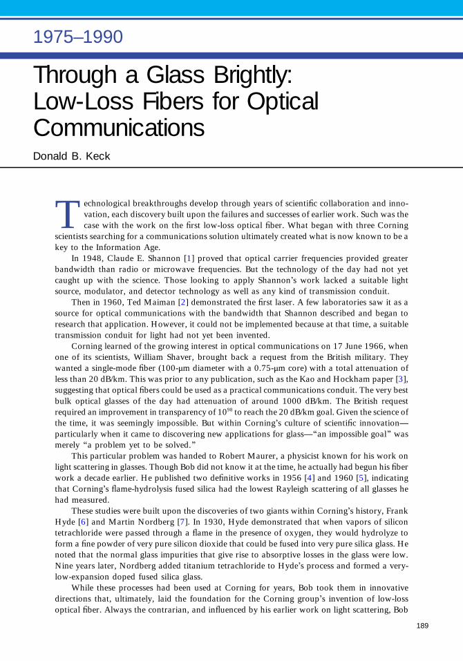
Through a Glass Brightly:Low-Loss Fibers for OpticalCommunicationsDonald B. Keck
Technological breakthroughs develop through years of scientific collaboration and inno-vation, each discovery built upon the failures and successes of earlier work. Such was thecase with the work on the first low-loss optical fiber. What began with three Corning
scientists searching for a communications solution ultimately created what is now known to be akey to the Information Age.
In 1948, Claude E. Shannon [1] proved that optical carrier frequencies provided greaterbandwidth than radio or microwave frequencies. But the technology of the day had not yetcaught up with the science. Those looking to apply Shannon’s work lacked a suitable lightsource, modulator, and detector technology as well as any kind of transmission conduit.
Then in 1960, Ted Maiman [2] demonstrated the first laser. A few laboratories saw it as asource for optical communications with the bandwidth that Shannon described and began toresearch that application. However, it could not be implemented because at that time, a suitabletransmission conduit for light had not yet been invented.
Corning learned of the growing interest in optical communications on 17 June 1966, whenone of its scientists, William Shaver, brought back a request from the British military. Theywanted a single-mode fiber (100-μm diameter with a 0.75-μm core) with a total attenuation ofless than 20 dB/km. This was prior to any publication, such as the Kao and Hockham paper [3],suggesting that optical fibers could be used as a practical communications conduit. The very bestbulk optical glasses of the day had attenuation of around 1000 dB/km. The British requestrequired an improvement in transparency of 1098 to reach the 20 dB/km goal. Given the science ofthe time, it was seemingly impossible. But within Corning’s culture of scientific innovation—particularly when it came to discovering new applications for glass—“an impossible goal” wasmerely “a problem yet to be solved.”
This particular problem was handed to Robert Maurer, a physicist known for his work onlight scattering in glasses. Though Bob did not know it at the time, he actually had begun his fiberwork a decade earlier. He published two definitive works in 1956 [4] and 1960 [5], indicatingthat Corning’s flame-hydrolysis fused silica had the lowest Rayleigh scattering of all glasses hehad measured.
These studies were built upon the discoveries of two giants within Corning’s history, FrankHyde [6] and Martin Nordberg [7]. In 1930, Hyde demonstrated that when vapors of silicontetrachloride were passed through a flame in the presence of oxygen, they would hydrolyze toform a fine powder of very pure silicon dioxide that could be fused into very pure silica glass. Henoted that the normal glass impurities that give rise to absorptive losses in the glass were low.Nine years later, Nordberg added titanium tetrachloride to Hyde’s process and formed a very-low-expansion doped fused silica glass.
While these processes had been used at Corning for years, Bob took them in innovativedirections that, ultimately, laid the foundation for the Corning group’s invention of low-lossoptical fiber. Always the contrarian, and influenced by his earlier work on light scattering, Bob
1975–1990
189

and a summer intern made a rod-in-tube(RIT) fiber (Fig. 1)—the best known pro-cessing method at that time—using Corn-ing’s fused silica as the cladding. Hepurposely added an impurity to the fusedsilica to raise the refractive index of thecore, Nordberg’s titanium doped silica, andobtain light guidance. Losses were still veryhigh, but Bob was encouraged enough torequest two additional scientists, PeterSchultz and Donald Keck (the author).
Peter took a fresh look at Hyde’sflame hydrolysis process. He built a smallboule furnace and began making variousdoped fused silicas and measuring their
properties. Based on Bob’s earlier results, the group of three focused their efforts exclusively on fusedsilica fibers made by flame hydrolysis. They continued the counterintuitive approach, adding animpurity to the pure fused silica to raise the refractive index and create the fiber core.
So began a time of trial and error. No human endeavor progresses more rapidly than can bemeasured. The group began to systematically measure and identify the sources of their optical losses.They knew absorptive losses were one source, and they struggled to examine the impurities introducedin the flame hydrolysis glasses that could cause absorption. The best analytic equipment of the daycould measure impurity levels only to the parts-per-million level, and parts-per-billion were needed. Anattempt was also made to evaluate losses in a few centimeters of bulk glass, but this still could notproduce the losses in an actual fiber that had gone through all the processing steps. Making their ownfibers was the only way to get a thorough understanding of optical losses.
Optical absorption from formation of reduced-titanium (Ti3+) color centers during the high-temperature fiber drawing step accounted for about half of the fiber loss. At first the losses wereannealed away by heat-treating the fibers at 800°C to 1200°C. Unfortunately this treatment drasticallyweakened the fibers as a result of surface crystallization. The other half of the loss originated from light-scattering defects at the core–cladding interface. No publication of the day ever mentioned this mostsignificant source of loss. The Corning group believed that this loss originated during the RIT processfrom dirt in the lab environment.
With each failure a little more was learned until an idea was hit upon that proved to be the key: thetraditional RIT method was abandoned and a new approach was invented. Rather than inserting a corerod, the group decided to directly deposit a thin layer of core glass inside a carefully flame-polishedcladding tube (Fig. 1). This produced intimate contact between core and clad materials and, it washoped, would get rid of the scattering defects observed in the RIT fiber.
For those who believe that excellent work can be done only with the very latest equipment, takenote of the Corning lab pictured in Fig. 2. The equipment was crude but effective. A portable latheheadstock held the rotating cladding tube in front of the flame hydrolysis burner. The burner produceda soot stream containing titania-doped silica. Initially the soot would not go into the 5–6-mm hole inour cladding tube. One of the group spotted the lab vacuum cleaner. Putting this at the end of thecladding tube beautifully sucked soot from the flame and deposited a uniformly thin layer onto theinside tube surface. This coated tube was then placed in the fiber draw furnace where the soot sinteredinto a clear glass layer, the hole collapsed to form a solid rod containing the doped core, and the entirestructure was drawn down into fiber.
Measuring that first low-loss fiber was an unforgettable experience. It was late afternoon, and, afterheat-treating a piece of the group’s latest fiber, the author positioned it in the attenuation measurementapparatus. With a viewing telescope he could observe and position the focused He-Ne laser beam on thefiber end. When the laser beam hit the fiber core, a blindingly bright returning laser beam was produced.It took a moment to realize that the laser was being retro-reflected off the far end of the fiber and comingback through the optical system.
▴ Fig. 1. Illustration of RIT and thin-film processes for makingan optical fiber preform. (Courtesy of Corning Incorporated.)
190 Through a Glass Brightly: Low-Loss Fibers for Optical Communications

The brilliant laser beam emanating from the end of the fiber was so dramatically different fromanything previously seen that it was apparent something special had occurred. With considerableanticipation, the author measured the fiber loss, and to his delight and surprise it was ∼17 dB/km. Withlittle sense of history, Donald Keck’s excitement was registered in his now fairly well-known lab-bookentry: “Whoopee!” (Fig. 3).
In 1970 the result was announced to the world when Bob presented the Corning group’s paper“Bending losses in single-mode fibers” at an Institution of Electrical Engineers Conference in Londonon analog microwave technology [8]. In that paper, he mentioned that the fiber had a total attenuationof only 17 dB/km, prompting scientists at the conference to remark that at least their 2-in. helicalmicrowave guides could be filled with lots of optical fibers. We also submitted our paper to AppliedPhysics Letters, and it was initially rejected! The reviewer commented, “It is rather difficult to visualizean amorphous solid with scattering losses below 20 decibels per kilometer, much less the totalattenuation.” Eventually, however, the paper was published [9]. (See Fig. 4.)
The Corning group had done it, but they were far from done. Though revolutionary, theirbreakthrough fiber solution was not exactly robust. Only small preforms could be made, and theheat treatment required to achieve low attenuation made the fibers brittle. Also, the preferred fiberdesign had shifted to multi- rather than single-mode. The larger core diameter was believed necessaryto more easily couple light into the fiber from the relatively crude semiconductor lasers of the day.
To make such fibers, Peter, our colleague Frank Zimar, and the author invented another flamehydrolysis approach later dubbed “outside vapor deposition.” In this method, first core and thencladding soot were deposited onto a removable rotating rod to build up a porous soot preform. Becauseof the lower temperature in this process, Peter found he could incorporate new dopants that hadvaporized in the higher-temperature boule process. One of these dopants was germania, a glass formerlike silica.
In June 1972, the first fiber incorporating germania was drawn in the core. The group wasobviously on the right track, as the bright light of the draw furnace was still visible through the end of akilometer of fiber on the wind-up drum. The loss measured was only 4 dB/km, no heat treatment wasneeded, and fiber strength was excellent. This was the first truly practical low low-loss fiber.
This writing marks the 42nd anniversary of the Corning group’s invention of low-loss optical fiber.With more than 1.6 billion kilometers of it wrapped around the globe, a world has been created that isdependent upon reliable, speed-of-light access to people and information anywhere, anytime, throughalmost any device of their choosing. The dramatic increase in users has brought with it unprecedenteddemand for bandwidth. Several sources, including a University of Minnesota Internet Traffic Study andCisco, have estimated that the average Internet traffic today worldwide is ∼150 Tb/s and growing atabout 50% per year.
▸ Fig. 2. Photograph ofapparatus for making the firstlow-loss optical fiber. (Courtesyof Corning Incorporated.)
Through a Glass Brightly: Low-Loss Fibers for Optical Communications 191

This growth rate is not surprising. Collectively we have moved from simple audio to increasingvideo content in our communications. Estimates are that two-thirds of the mobile data traffic will bevideo by 2015 as social networking continues to explode. People sending data is one thing, butmachines-talking-to-machines (M2M) as is happening increasingly is yet another. The latter willovertake the former in just two or three years—all this without even considering potential new data-generating applications. We are already seeing the deployment of fiber-enabled remote sensors tomonitor our environment. Power lines and highway and civil structure monitors provide an optical fibersafety net supporting the infrastructure we rely upon every day. Emerging biomedicine and biotech-nology applications ranging from transmission of x-ray data to real-time high-definition video forremote surgeries to the potential petabytes involved in DNA data transmission and analysis are still inthe future. It is now well established that creative people will invent new ways to use the “bits” iftechnology can provide improved “cost of transmitting the bit.”
The amount of information that can be transmitted over a single fiber today is staggering.Commercial core networks today operate at 50 Tb/s on a single fiber, and as reported at OFC2012, scientists are achieving in their labs record data rates of more than 305 Tb/s.
While this capacity is enormous, fiber bandwidth is finite—perhaps only 10 times higherthan today’s core network traffic level. Our current demand for bandwidth will most likely exceedour capacity before 2030. This would require a beginning over-build of the core networks evenas we finish the build-out of the local loop! We should not be surprised if the 1.6-billion-kilometer fiber network of today will be but a fraction of that which will exist in just a couple ofdecades.
◂ Fig. 3. Laboratorynotebook with the first sub-20-dB/km fiber measurement.(Courtesy of CorningIncorporated.)
192 Through a Glass Brightly: Low-Loss Fibers for Optical Communications
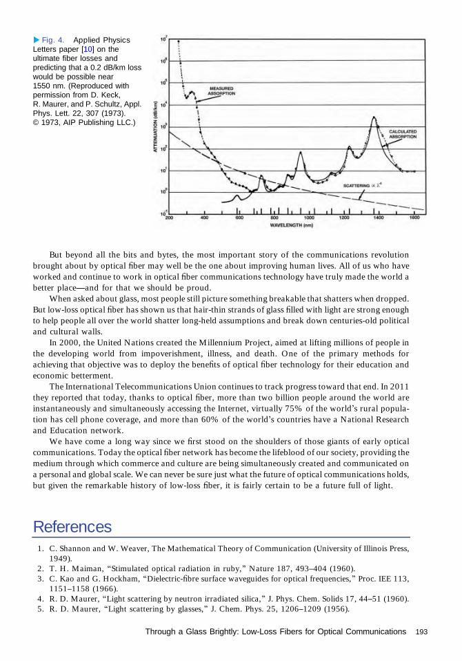
But beyond all the bits and bytes, the most important story of the communications revolutionbrought about by optical fiber may well be the one about improving human lives. All of us who haveworked and continue to work in optical fiber communications technology have truly made the world abetter place—and for that we should be proud.
When asked about glass, most people still picture something breakable that shatters when dropped.But low-loss optical fiber has shown us that hair-thin strands of glass filled with light are strong enoughto help people all over the world shatter long-held assumptions and break down centuries-old politicaland cultural walls.
In 2000, the United Nations created the Millennium Project, aimed at lifting millions of people inthe developing world from impoverishment, illness, and death. One of the primary methods forachieving that objective was to deploy the benefits of optical fiber technology for their education andeconomic betterment.
The International Telecommunications Union continues to track progress toward that end. In 2011they reported that today, thanks to optical fiber, more than two billion people around the world areinstantaneously and simultaneously accessing the Internet, virtually 75% of the world’s rural popula-tion has cell phone coverage, and more than 60% of the world’s countries have a National Researchand Education network.
We have come a long way since we first stood on the shoulders of those giants of early opticalcommunications. Today the optical fiber network has become the lifeblood of our society, providing themedium through which commerce and culture are being simultaneously created and communicated ona personal and global scale. We can never be sure just what the future of optical communications holds,but given the remarkable history of low-loss fiber, it is fairly certain to be a future full of light.
References1. C. Shannon and W. Weaver, The Mathematical Theory of Communication (University of Illinois Press,
1949).2. T. H. Maiman, “Stimulated optical radiation in ruby,” Nature 187, 493–404 (1960).3. C. Kao and G. Hockham, “Dielectric-fibre surface waveguides for optical frequencies,” Proc. IEE 113,
1151–1158 (1966).4. R. D. Maurer, “Light scattering by neutron irradiated silica,” J. Phys. Chem. Solids 17, 44–51 (1960).5. R. D. Maurer, “Light scattering by glasses,” J. Chem. Phys. 25, 1206–1209 (1956).
▸ Fig. 4. Applied PhysicsLetters paper [10] on theultimate fiber losses andpredicting that a 0.2 dB/km losswould be possible near1550 nm. (Reproduced withpermission from D. Keck,R. Maurer, and P. Schultz, Appl.Phys. Lett. 22, 307 (1973).© 1973, AIP Publishing LLC.)
Through a Glass Brightly: Low-Loss Fibers for Optical Communications 193

6. J. F. Hyde, “Method of making a transparent article of silica,” U.S. patent 2,272,342 (10 February1942).
7. M. Nordberg, “Glass having an expansion lower than that of silica,” U.S. patent 2,326,059 (3 August1943).
8. F. P. Kapron, D. Keck, and R. D. Maurer, “Bending losses in single-mode fibers,” in IEE Conference onTrunk Telecommunication by Guided Waves, London, 1970.
9. F. P. Kapron, D. Keck, and R. Maurer, “Radiation losses in glass optical waveguides,” Appl. Phys. Lett.17, 423–425 (1970).
10. D. Keck, R. Maurer, and P. Schultz, “On the ultimate lower limit of attenuation in glass opticalwaveguides,” Appl. Phys. Lett. 22, 307–309 (1973).
194 Through a Glass Brightly: Low-Loss Fibers for Optical Communications
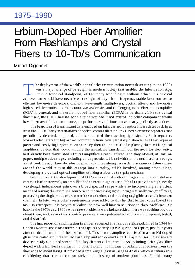
Erbium-Doped Fiber Amplifier:From Flashlamps and CrystalFibers to 10-Tb/s CommunicationMichel Digonnet
The deployment of the world’s optical telecommunication network starting in the 1980swas a major change of paradigm in modern society that enabled the Information Age.From a technical standpoint, of the many technologies without which this colossal
achievement would have never seen the light of day—from frequency-stable laser sources toefficient low-noise detectors, division wavelength multiplexers, optical filters, and low-noisehigh-speed electronics—perhaps none was as decisive and challenging as the fiber-optic amplifier(FOA) in general, and the erbium-doped fiber amplifier (EDFA) in particular. Like the opticalfiber itself, the EDFA had no good alternative; had it not existed, no other component wouldhave been available, then or now, to perform its vital function as nearly perfectly as it does.
The basic idea of transmitting data encoded on light carried by optical fibers dates back to atleast the 1960s. Early incarnations of optical communication links used electronic repeaters thatperiodically detected, amplified, and remodulated the traveling light signals. Such repeatersworked adequately for high-speed communications over planetary distances, but they requiredpower and costly high-speed electronics. By then the potential of replacing them with opticalamplifiers, devices that would amplify the modulated signals without the need for electronics,had already been formulated. Optical amplifiers already existed, and they offered, at least onpaper, multiple advantages, including an unprecedented bandwidth in the multiterahertz range.Yet it took nearly three decades of gradually intensifying research in numerous laboratoriesaround the world to turn this concept into a reality, which involved, among other things,developing a practical optical amplifier utilizing a fiber as the gain medium.
From the start, the development of FOAs was riddled with challenges. To be successful in acommunication network, an amplifier had to meet tough criteria. It had to provide a high, nearlywavelength independent gain over a broad spectral range while also incorporating an efficientmeans of mixing the excitation source with the incoming signal, being internally energy efficient,preserving the single-mode character of the trunk fiber, and inducing negligible crosstalk betweenchannels. In later years other requirements were added to this list that further complicated thetask. In retrospect, it is easy to trivialize the now well-known solutions to these problems. Butback in the 1970s and 1980s when these problems were being tackled, there was nothing obviousabout them, and, as in other scientific pursuits, many potential solutions were proposed, tested,and discarded.
The first report of amplification in a fiber appeared in a famous article published in 1964 byCharles Koester and Elias Snitzer in The Optical Society’s (OSA’s) Applied Optics, just four yearsafter the demonstration of the first laser [1]. This historic amplifier consisted in a 1-m Nd-dopedglass fiber coiled around a pulsed flashlamp and end-probed with 1.06-μm pulses. This visionarydevice already contained several of the key elements of modern FOAs, including a clad glass fiberdoped with a trivalent rare earth, an optical pump, and means of reducing reflections from thefiber ends to avoid lasing. It provided a small-signal gain as large as 47 dB, which is remarkableconsidering that it came out so early in the history of modern photonics. For his many
1975–1990
195
contributions to the fields of FOAs and lasers, Elias Snitzer was awarded the OSA’s Charles H. TownesAward in 1991 and the John Tyndall Award in 1994.
Like almost all the laser devices of the time, this fiber amplifier was side-pumped: the pump wasincident on the fiber transversally. This made the device bulky, inefficient, and ultimately impractical.The concept of a fiber amplifier in which the pump is end-coupled into the fiber emerged years later aspart of efforts carried out at Stanford University to develop a compact fiber amplifier. This workinvolved end-pumping Nd-doped crystal fibers with an argon-ion laser. This work demonstrated thatend-pumping could produce sizeable gain (∼5 dB) from a very short fiber (∼cm).
The second key improvement was the introduction of the wavelength-division-multiplexing(WDM) coupler to mix the pump and the signal and end-couple them simultaneously into the gainfiber. The advantages of this technique were overwhelming: it made it possible to efficiently inject, witha compact and mechanically stable device, both the pump and the signal into the gain medium. It tookseveral years before it was adopted, in part because commercial WDM couplers were almostnonexistent. It is now the standard technique used in the vast majority of FOAs.
Another concept critical to the performance of FOAs in general, and bench-tested first with EDFAs,is that they should use a single-mode fiber. Although in recent years new findings have suggested thatthe data transmission capacity could be increased by using multimode fibers, in current telecommuni-cation links a single-mode FOA offers two key advantages, namely, a higher gain per unit pump powerdue to the higher pump intensity and the elimination of modal coupling, which would otherwise inducetime-dependent losses at the trunk fiber/FOA interfaces.
It was known as early as the 1980s that the third communication window, centered around1550 nm, was the most promising candidate for long-haul fiber links, because in this spectral range boththe loss and dispersion of conventional single-mode silica fibers are minimum. Trivalent erbium ions(Er3+) in a variety of amorphous and crystalline hosts had also long been known to provide gain in thiswavelength range, so this ion was a natural candidate. David Payne, who would receive the OSA’s JohnTyndall Award in 1994 for his pioneering work on EDFAs, and his team at the University ofSouthampton were first to demonstrate this potential experimentally with the report of the first EDFAin 1987 [2,3]. This was followed later the same year by a similar paper from Bell Laboratories. Thesemilestone publications provided experimental proof that single-pass gains exceeding 20 dB were readilyattainable in single-mode Er-doped fibers (EDFs) end-pumped with the best laser wavelengths availableat the time, namely, 670 nm and 514.5 nm. Another key property that made Er3+ so attractive is that thelifetime of its 1550-nm transition is unusually long (∼5–10 ms); hence the population inversion and thegain essentially do not respond dynamically at the very high modulation frequencies of the signals
(unlike semiconductor amplifiers). The importantconsequence is that the crosstalk between signalsbeing amplified simultaneously in an EDFA can beexceedingly small (see Fig. 1) [4], a crucial propertyfor communications.
The EDFA seemed to be a great candidate, butseveral issues, some perceived to be critical by thecommunication community, made it difficult to beaccepted right away. In fact, it took nearly anotherdecade of detailed engineering and the developmentof several parallel technologies (diode lasers andfused WDM couplers, in particular) to make thisdevice a reality.
To be practical, the EDFA had to be pumpedwith a semiconductor laser. Over time several pumpsources and wavelengths were investigated. Thisbattle was one of the most technically challengingand interesting in the history of the EDFA. Theproliferation of inexpensive GaAs diode lasers inthe 800-nm range in the electronic products of the
▴ Fig. 1. Measured crosstalk between two channels,characterized by the peak-to-peak gain variationinduced in a first signal (channel A) by a second signal(channel B) sinusoidally modulated at frequency f.[C. R. Giles, E. Desurvire, and J. R. Simpson, Opt. Lett.14, 880–882 (1989)].
196 Erbium-Doped Fiber Amplifier: From Flashlamps and Crystal Fibers to 10-Tb/s Communication

late 1980s led to substantial research on 800-nmpumping, in particular at British Telecom ResearchLaboratories. However, they found that the gainefficiency was low. The reason was later identifiedas the unfortunate presence of excited-state absorp-tion around 800 nm in Er3+, a limitation that couldnot be sufficiently reduced by adjusting the pumpwavelength or the glass composition.
Much of this research soon focused on twopump wavelengths only, namely, 980 nm from thethen-emerging strained GaAlAs laser technologyand around 1480 nm from InGaAsP diode lasers.The prevalent thinking was initially that since anEDFA pumped at 1480 nm is nearly a two-levellaser system, it should be difficult to invert andexhibit a poor noise performance. The demonstra-tion of the first EDFA pumped at 1.49 μm by EliasSnitzer in 1988 quickly changed this perception.The following year saw the first report of an EDFApumped at 1480 nm with an InGaAsP diode laser, atNTT Optical Communication Laboratory in Japan.This spectacular result (12.5 dB of gain for 16 mWof absorbed pump power) put the EDFA on a newtrack by establishing that a packaged FOA was within reach. For a short while pumping at 980 nm wasthe underdog, in part because it had a higher quantum defect than 1480-nm pumping, hence anexpected lower efficiency, and in part because of the lower maturity of the strained GaAlAs technology.But 980-nm pumping nevertheless eventually won. Stimulated emission at 1480 nm turned out to be aserious penalty, which gave a lower pump efficiency and noise performance than with a 980-nm pump.M. Shimizu and his team at NTT illustrated this compromise clearly in a cornerstone paper [5] thatcompared the gain of an EDFA pumped at either wavelength (Fig. 2). The gain and the gain per unitpump power (11 dB/mW!) were all substantially higher with 980-nm pumping, and the transparencythreshold was lower. This new understanding triggered a substantial R&D effort in the semiconductorlaser community, which ultimately lead to the commercialization of reliable, high-power, long-lifetimediode lasers at 980 nm.
Many other important engineering issues were addressed through the mid-1990s. Two teamscontributed to this major effort more prominently than any other, namely, David Payne’s group at theUniversity of Southampton [2,3] and Emmanuel Desurvive, first at the AT&T Bell Laboratories, then atColumbia University and Alcatel in France [6]. Many other substantial contributions came out of academicand industrial laboratories around the world, especially in the U.S., UK, Denmark, Japan, and France.
A significant fraction of the research was consumed by the quest for ever greater gain bandwidth,lower noise, and a gain that is nearly independent of signal polarization, signal power, and number ofchannels. To increase the bandwidth a number of ingenious solutions were implemented, ranging fromhybrid EDFs concatenating fibers of different compositions and slightly offset gain spectra to adjusting thelevel of inversion to produce preferential gain in the C band (1530–1565 nm) or L band (1565–1625 nm)or designing the EDF so that it does not guide well above 1530 nm to produce efficient gain in the S band(1460–1530 nm). This effort was greatly complicated by the parallel need for a uniform gain (or flat gainspectrum) so that all channels have a similar power and signal-to-noise ratio at the receiver. Here too,clever solutions were conceived, from using passive filters to hybrid EDFAs, gain clamping, and the use oftelluride fibers. This last approach produced a gain with a remarkable bandwidth of 80 nm (see Fig. 3) [7].Later refinements produced EDFAs with a gain flatness well under 1 nm over wide bandwidths [8].
The EDFA rose from the status of research device to stardom remarkably rapidly, a resoundingmanifestation of its practical importance, exceptional performance, and timeliness. The first commer-cial EDFA appeared in 1992. By 1998 over 40 companies were selling EDFAs; the count ultimately
▴ Fig. 2. Measured gain and gain coefficient in anEDFA pumped at 980 nm and 1480 nm. Circles, 980 nm;triangles, 1480 nm. (Reproduced with permission of theInstitution of Engineering and Technology.)
Erbium-Doped Fiber Amplifier: From Flashlamps and Crystal Fibers to 10-Tb/s Communication 197

peaked above 100. Research on communica-tion systems followed suit, leading to the demon-stration of increasingly large and high-performanceexperimental and deployed systems. As one ofmany examples illustrating the phenomenal per-formance of communication links utilizing EDFAs,in a particular experiment a total of 365 signalswere simultaneously recirculated 13 times around a∼500-km fiber loop containing ten EDFAs (oneevery ∼50 km). At the output the power imbalancebetween channels was as low as -7 dB and the bit-error rate only 10-13. This system accomplished aremarkable total optical reach of 6850 km and atotal capacity as high as 3.65 Tb/s. Deployed linksnow exceed 10 Tb/s over even longer distances.
In the early 2000s, following the saturation ofthe telecommunication industry and the sharp de-cline in the world’s markets, a significant percentageof the optical communication task force redirected
its vast technical expertise to other areas of photonics. This concerted effort gave the EDFA and otherFOAs a second carrier in spectacular new applications, especially fiber sensors and high-power fiberlasers. Using an FOA to amplify the output of a fiber laser, in a now widely used configuration called themaster-oscillator power amplifier (MOPA), turned out to be the most energy-efficient way to produceextremely clean and spectrally pure laser outputs up to enormous power levels. Today, fiber MOPAsare the world’s brightest light sources, to a large extent thanks to the superb properties of fiberamplifiers. Yb3+, in particular, rapidly became the workhorse of high-power fiber lasers for its lowquantum defect and high quenching-free concentration. Power scaling posed significant challenges,including efficient coupling into the gain fiber of the high required pump powers, wavelengthconversion due to stimulated Brillouin and Raman scattering, optical damage, and photodarkening.These challenges were met with a number of clever engineering solutions, including large-mode-areafibers (in which the signal intensity, and hence nonlinear effects and optical damage, are reduced) andacoustic anti-guiding fibers (in which the spatial overlap between acoustic and optical modes, and hencethe nonlinearity, are reduced). Commercial fiber lasers utilizing MOPA configurations now offeraverage powers up to the 100-kW range, a feat that would not have been possible without the superbattributes of FOAs.
References1. C. J. Koester and E. Snitzer, “Amplification in a fiber laser,” Appl. Opt. 3, 1182–1186 (1964).2. R. J. Mears, L. Reekie, I. M. Jauncey, and D. N. Payne, “High gain rare-earth doped fibre amplifier
operating at 1.55 μm,” Proceedings of OFC, Reno, Nevada, 1987.3. R. J. Mears, L. Reekie, I. M. Jauncey, and D. N. Payne, “Low-noise erbium-doped fibre amplifier
operating at 1.54 μm,” Electron. Lett. 23, 1026–1028 (1987).4. C. R. Giles, E. Desurvire, and J. R. Simpson, “Transient gain and cross talk in erbium-doped fiber
amplifiers,” Opt. Lett. 14, 880–882 (1989).5. M. Shimizu, M. Yamada, M. Horiguchi, T. Takeshita, and M. Okayasu, “Erbium-doped fibre amplifiers
with an extremely high gain coefficient of 11.0 dB/mW,” Electron. Lett. 26, 1641–1643 (1990).6. M. Desurvire, Erbium-Doped Fiber Amplifiers—Principles and Applications (Wiley, 1994).7. Y. Ohishi, A. Mori, M. Yamada, H. Ono, Y. Nishida, and K. Oikawa, “Gain characteristics of tellurite-
based erbium-doped fiber amplifiers for 1.5-mm broadband amplification,” Opt. Lett. 23, 274–276(1998).
8. M. J. F. Digonnet, Rare-Earth-Doped Fiber Lasers and Amplifiers (Marcel Dekker, 2001).
▴ Fig. 3. Measured gain spectrum of a 0.9-m-longtellurite EDFA at various input-signal power levels. Thegain in the 1535–1570-nm range was compressed byusing higher-power input signals. [Y. Ohishi, A. Mori,M. Yamada, H. Ono, Y. Nishida, and K. Oikawa,Opt. Lett. 23, 274–276 (1998)].
198 Erbium-Doped Fiber Amplifier: From Flashlamps and Crystal Fibers to 10-Tb/s Communication
Advent of Continuous-WaveRoom-Temperature Operation ofDiode LasersMichael Ettenberg
The story of getting to room temperature continuous-wave (CW) operation of semicon-ductor diode lasers will start when the author arrived at RCA Labs with a fresh Ph.D. inJune of 1969. RCA had decided that GaAs would be the next important semiconducting
material in the solid-state electronics business after germanium, which at the time was the mostprevalent transistor material. While silicon transistors were already being manufactured, GaAstransistors would be far superior, and RCA Research Lab researchers would concentrate theirefforts on GaAs and related compounds to leapfrog silicon. The choice had some validity. GaAswas a direct-band semiconductor and thus had shorter electron hole lifetimes and a largerbandgap, making possible transistors with higher speed, less temperature dependence, higheroperational temperature ranges, and smaller size. While all this is true, silicon became the pervasiveelectronic device material for a variety of good reasons that will not be detailed here. But GaAs andits related direct bandgap materials could do something that silicon could not do, that is, emit lightefficiently. So RCA Labs moved its GaAs efforts to develop LEDs and diode lasers.
The author’s first assignment was to grow AlAs epitaxially on GaAs single-crystalsubstrates via vapor-phase epitaxy, where Al is transported by passing HCl gas over Al andAs is supplied by breaking down arsine. After AlAs growth characterization, devices became ofinterest. Since it seemed easier to make devices out of new materials than to create the materialsthemselves, the author joined a group headed by Henry Kressel working on laser diodes. Thesesmall devices were fascinating, as they were able to put out large amounts of reasonablydirected light, albeit they could be seen only with a night vision scope. There were fourrelatively large research efforts at the time: Bell Labs the largest by far, Standard Telecom-munications Laboratory (STL) in England, RCA Labs, and the Russian effort, about which lesswas known, mainly due to the cold war. At IBM, GE, and Lincoln Labs, even though diodelasers were first demonstrated there, research efforts were not substantial. The researchprojects at Bell Labs and STL were considerable, supported by telephone usage; telephonecompanies were utilities at time. The telephone giants first saw lasers as a potential source forfree-space communications, a secondary effort compared with microwave transmission in airand pipes until Charles Kao envisioned optical communications in fibers [1] and research atCorning demonstrated low-loss optical fibers in 1970 [2]. Then the laser efforts intensified.RCA’s research was driven by other applications such as optical disc recording and playbackand military usage. Since RCA had an Aerospace and Defense division, the diode laser effortscould be justified, but RCA as a corporation was focused on television, and lasers were not amainline effort. The research was about half supported by the corporation and half bygovernment research contracts. The first applications of laser diodes were military in nature,and RCA decided to make the devices commercially so they could supply them to their defensecustomers and potentially lower the price by supplying them for other commercial uses. In1969 RCA became the first commercial supplier of laser diodes, although it was a minisculebusiness, especially for a multi-billion-dollar corporation.
1975–1990
199

The author was introduced to diodelasers by Herb Nelson, who invented liq-uid-phase epitaxy (LPE) the process usedto fabricate lasers throughout their initialdevelopment, well past the first CWdemonstrations and many years beyond,through the first several years of CD playermanufacture. Today almost all lasers aremade by metal organic chemical vapordeposition (MOCVD): a much better con-trolled process and one that can be readilyscaled up to multiple large wafers. WhatHerb demonstrated was called a tippingfurnace (as shown in Fig. 1); it was a
tubular furnace about six inches in diameter mounted in a metal cage. The cage was in turn mountedin a seesaw arrangement at the center of the furnace so the furnace could be rocked back and forth ortipped. Inside the furnace was a sealed quartz tube with hydrogen flowing through it and a carbon boat;at one end of the boat was a small polished single-crystal GaAs wafer of about a square centimeter, andat the other end of the boat was a polycrystalline GaAs wafer with a glob of gallium on it. The processstarted with the furnace being heated to about 800°C with the polycrystalline GaAs and Ga side lower,and some time was allowed so the GaAs could go into solution in the Ga until saturation; then thefurnace was tipped the other way and the saturated Ga rolled onto the single-crystal wafer. Nextthe furnace was cooled and the GaAs in solution precipitated onto wafer to form an epitaxial layer onthe single crystal. This epitaxial layer was much superior in terms of contaminants and defects to theunderlying substrate and was also superior in terms of its luminescent properties and ability to makelower-threshold, more efficient lasers. Al was added to the Ga glob so that AlGaAs alloys couldbe grown. Al and Ga atoms are about the same size; therefore dislocations caused by lattice parametermismatch would not be formed when AlGaAs was grown on GaAs. In addition, adding Al to GaAsraised the bandgap and lowered the index of refraction of the alloy compared to GaAs, which proved tobe crucially important to the creation of low-threshold efficient lasers. The temperature was controlledby hand, using a variable transformer to control the current to the furnace and a 0–1000°C dialthermocouple readout. It was amazing how such a crude growth system could produce suchsophisticated devices, but Herb understood the materials and was an artist. Later the process wasbrought under better control using carbon boats with a wafer that slid under multiple bins to allowgrowth of multiple layers with controlled composition and remarkable submicrometer-thicknessaccuracy.
The first diode lasers were simply millimeter-sized cubes of GaAs containing a diffused p–n junctionwith polished faces for mirrors that operated at liquid nitrogen temperatures with multi-amp very-low-duty-cycle short pulses applied. It was remarkable that these devices lased, considering that all prior lasertypes required tens of centimeters of cavity length and mirror reflectivity greater than 95%. The gain inGaAs per unit length was exceptional, thus allowing the gain to exceed the loss even though the reflectivityat the natural mirror surface of GaAs is only about 30%. The applied current to these first devices wasmany tens of thousands of amperes per square centimeter at liquid nitrogen temperatures; the thresholdcurrent increased exponentially as the temperature increased, so room temperature CW lasing was a longway away. It was found early on that GaAs cleaved nicely on the 100-crystal plane, so the lasers weregrown on single-crystal wafers cut on the 100 plane. Then the mirror facets could be easily formed afterthe wafers had been thinned, metalized on the n and p sides by cleaving into bars. Next the bars weresawed into individual dies about 400 μm in length between the mirrors and 100 μm wide. The sawnroughened sides prevented lasing from occurring crosswise to the mirrors.
There were three important steps to room-temperature CW lasing: the addition of heterojunctionsto the laser structure, the double heterojunction, and finally, the stripe contact. In 1969 independentlyand simultaneously, Kressel and Nelson [3] and Panish et al. [4] published papers demonstrating thatadding heterojunctions of AlGaAs on GaAs and diffusing the p–n junction a micrometer or so from the
▴ Fig. 1. First liquid-phase epitaxy (LPE) growth apparatus forcreating laser diode (tipping furnace). (H. Nelson, RCA Rev.24, 603 [1963]. Courtesy of Alexander Magoun.)
200 Advent of Continuous-Wave Room-Temperature Operation of Diode Lasers

heterojunction formed a light waveguide. This waveguide confined the light, creating electron/holerecombination to that waveguide as illustrated in Fig. 2 [5]; consequently, the threshold current couldbe reduced to about 10,000 amps/cm2, still a factor of 10 or so away from what would be needed forCW operation. The reduction in threshold from the simple p-n homojunctions came from the fact thatthe light and the recombination of electron and holes was confined to a smaller volume, thus requiringless current to invert the population to the point of lasing. These single-heterojunction devices were thefirst laser diodes to go into production, becoming optical proximity sensors for the sidewinder missile.
Art D’Asaro and colleagues [6, 7] at Bell Labs developed the stripe contact, shown in Fig. 3, whichis a necessary and enduring feature for laser diodes, because it not only stops the cross lasing in a simplemanner but facilitates the heat sinking of the device with unpumped regions all along the laser cavity.
The final and most important step came from Alferov et al. [8]. Alferov was one of the leaders in thefield and came to United States to visit RCA and Bell Labs, among others. The visit was memorable,because it was very strange. We sat in a small office and discussed the progress of lasers. Alferov had alarge heavyset man with him who said very little and seemed to know little about lasers; it was surmisedthat he was KGB. Alferov did not disclose the double-heterojunction laser structure nor was he shownmuch because the work was partially supported by Department of Defense. It was learned later that hedid discuss the double-heterojunction work at Bell Labs, probably because they were more open. Therewas a race to achieve CW operation. Bell and RCA Labs were neck and neck, but Bell had the stripe-contact technology and learned about the double-hetrojunction structure. As a result, Hayashi and
▸ Fig. 2. Schematic crosssection of various laserstructures showing the electricfield distribution E in the activeregion, variation of the bandgapenergy Eg, and variation of therefractive index n at the lasingphoton energy.(a) Homojunction laser made byliquid phase epitaxy, (b) single-heterojunction “close-confinedlaser,” (c) double-heterojunctionlaser, and (d) large-optical-cavity (LOC) laser. Figure 5 fromH. Kressel, H. F. Lockwood, I.Ladany, M. Ettenberg, Opt. Eng.13, 417–422, 1974. (©1974SPIE [email protected].)
▸ Fig. 3. Schematic of atypical CW heterojunction laser,drawn upside down to show thestripe contact. Diffractioncauses the vertical spreading ofthe beam. Reproduced withpermission from Fig. 6 of H.Kressel, I. Ladany, M.Ettenberg, and H. Lockwood,Physics Today 29(5), 38 (1976).(Copyright 1976, AmericanInstitute of Physics.)
Advent of Continuous-Wave Room-Temperature Operation of Diode Lasers 201

Panish [9] won the race to CW. The addition of the second heterojunction forced the light and electron/hole recombination to be confined to a few tenths of a micrometer and allowed thresholds close to1000 A/cm2, which together with the stripe-heat sinking allowed CW operation at room temperature.But it was CW in name only. The initial devices lasted only minutes.
To be useful the devices had to live for many thousands of hours, and here the author was able tomake a contribution. One of his first projects on lasers came from a suggestion by Herb Nelson. He saidthey were evaporating SiO2 followed by gold as mirrors on the back facet of the devices to make thememit out of one end; many of the devices were shorting probably due to pinholes in the oxide. Could theprocess be improved? A multi-layer dichroic reflector was eventually developed consisting of Si andAl2O3 as the reflector and an Al2O3 passivating and reflectivity control layer on the emitting facet [10].The lifetime of AlGaAs lasers operating at low power was steadily increased to more than a millionhours median time to failure [11, 12] by growing on low-dislocation substrates to eliminate defectsinside the laser and applying the aforementioned passivating optical coatings to the emitting facets.Such devices helped create the early fiber-optic communications systems and were the light sourcesfor CD and DVD players.
The final steps to today’s modern laser diode were separately confining the light and the electron/hole recombination first described by Lockwood et al. [13] as shown in Fig. 2 and the understanding byYariv et al. [14] that by making the electron/hole recombination very thin (a few tens of nanometers),quantum effects would come into play and the gain would substantially exceed what might be expectedfor such thin layers. The changes allowed the threshold current to be reduced to close to 100 A/cm2,allowing lasers to be fabricated with electricity-to-light conversion efficiencies exceeding 75%. Theselasers, called separate confinement heterojunction quantum well lasers, are the most reliable andefficient light sources known to man and continue to change our world.
References1. C. Kao, IEEE Meeting in London, 1966.2. F. P. Kapron, D. B. Keck, and R. D. Maurer, “Radiation losses in glass optical waveguides,” Appl. Phys.
Lett. 17, 423–425 (1970).3. H. Kressel and H. Nelson, “Close-confinement gallium arsenide P-N junction lasers with reduced optical
loss at room temperature,” RCA Rev. 30, 106–113 (1969).4. M. B. Panish, I. Hayashi, and S. Sumski, “A technique for the preparation of low-threshold room-
temperature GaAs laser diode structures,” IEEE J. Quantum Electron. 5, 210 (1969).5. Figure 5 from H. Kressel, H. F. Lockwood, I. Ladany, and M. Ettenberg, “Heterojunction laser diodes
for room temperature operation,” Opt. Eng. 13(5), 417–422 (1974).6. Figure 6 from H. Kreseel, I. Ladany, M. Ettenberg, and H. Lockwood, “Light sources,” Physics Today
29(5), 38–42 (1976).7. J. E. Ripper, J. C. Dyment, L. A. D’Asaro, and T. L. Paoli, “Stripe‐geometry double heterostructure
junction lasers: mode structure and cw operation above room temperature,” Appl. Phys. Lett. 18, 155–157 (1971).
8. Zh. I. Alferov, V. M. Andreev, E. L. Portnoi, and M. K. Trukan, “AlAs-GaAs heterojunction injectionlasers with a low room-temperature threshold,” Sov. Phys. Semicond. 3, 1107–1110 (1970).
9. I. Hayashi, M. B. Panish, P. W. Foy, and S. Sumski, “Junction lasers which operate continuously at roomtemperature,” Appl. Phys. Lett. 17, 109–110 (1970).
10. M. Ettenberg, “A new dielectric facet reflector for semiconductor lasers,” Appl. Phys. Lett. 32, 724–725(1978).
11. R. L. Hartman, N. E. Schumaker, and R. W. Dixon, “Continuously operated (Al, Ga)As double‐heterostructure lasers with 70 °C lifetimes as long as two years,” J. Appl. Phys. 31, 756 (1977).
12. M. Ettenberg, Electron. Lett. 14, 615 (1978).13. H. F. Lockwood, H. Kressel, H. S. Sommers, Jr., and F. Z. Hawrylo, “An efficient large optical cavity
injection laser,” Appl. Phys. Lett. 17, 499–501 (1970).14. P. L. Derry, A. Yariv, K. Y. Lau, N. Bar-Chaim, K. Lee, and J. Rosenberg, “Ultralow‐threshold graded‐
index separate‐confinement single quantum well buried heterostructure (Al, Ga)As lasers with highreflectivity coatings,” Appl. Phys. Lett. 50, 1773–1775 (1987).
202 Advent of Continuous-Wave Room-Temperature Operation of Diode Lasers

Remembering the Million Hour LaserRichard W. Dixon
In the late 1960s, Bell Labs had a problem. The nation’s demand for long-distancetelecommunications services was steadily increasing, but the technologies then in use—coaxial cable and point-to-point microwave transmission through the air—could not keep
up with the pace. The major reductions in optical fiber waveguide losses reported in the early1970s were therefore of great interest. The lowest-loss regions of these fibers were in the 0.8 to0.9 μm range, which could in principle be accessed by devices built using the GaAs-GaAlAsmaterial system. Thought was given to the possible use of GaAs light-emitting diodes (LEDs), butit was immediately obvious that semiconductor lasers would be much better sources—if theycould be developed reliably in commercial quantities. One could easily imagine an efficient GaAslaser that could couple a milliwatt of optical power into a fiber with a core diameter of about50 μm. Thus was defined the first generation of fiber-optic telecommunication systems.
In the late 1960s and early 1970s, the author was a young supervisor working on thedevelopment of LEDs for Bell System applications. In that process, he learned quite a bit aboutthe physics, technology, and transfer-to-volume manufacture of III-V semiconductors. One resultof this program was the successful implementation of green-emitting GaP LEDs for nighttime dialillumination in the handset of the Dreyfuss-designed Trimline phone. Something like 100 millionof these sets were subsequently produced.
In 1973, the author transferred to a small exploratory development group working onsemiconductor lasers. The group had benefited from an excellent research effort that happenedjust down the hall. Most notable was the demonstration in 1970 of a continuously operatingroom-temperature GaAs-AlGaAs heterostructure semiconductor laser [1] (see Fig. 1). However,these broad-area lasers had high operating currents (around 400 mA) and very short lives (theywere sometimes referred to as flashbulbs), but they showed the way forward!
The group’s choice of a laser structure for initial development consisted of four planarepitaxial layers grown sequentially by liquid-phase epitaxy (LPE) on a GaAs substrate. Weinhibited lateral carrier flow by using proton bombardment to define a “stripe-geometry”wherein only a narrow stripe, 10 × 250 μm, was electrically pumped (see Fig. 2). These“stripe-geometry lasers” became the workhorses of the early Bell Labs semiconductor laserdevelopment. They allowed the sorting out of many reliability and device performance issues. Ina typical week, half a dozen or so wafers were processed into some thousands of lasers. Fastturnaround made it possible to quickly and systematically iterate device, processing, and materialinnovations.
Many of the early stripe-geometry lasers had very erratic properties. Some would lase for atime but would then suddenly become inoperable. Others would die slowly. Still others wouldnot work from the outset. Typical continuous-wave operating lifetimes at room temperaturewere on the order of minutes to days. Many devices also had other undesirable characteristics,for example, nonlinear light output versus current. It was clear that the group had a very difficultdevelopment project on its hands! Some thoughtful observers, including one key Bell Laborato-ries vice president, opined that success was unattainble.
Important clues to improvements came in early 1973 from an experiment in which“windows” were fabricated on the substrate side of stripe-geometry lasers in such a way thatspontaneous emission (and scattered stimulated emission if present) from the stripe region of thelaser could be observed with an infrared optical microscope. Dark-line defects (DLDs), which
1975–1990
203

grew in a laser’s active region during operation,were observed and were determined to be the prin-cipal failure mechanism in devices that stoppedworking in the first 100 hours or so [2].
This paper correctly stated that “the combina-tion of low-strain processes and extreme cleanlinessin materials growth should provide a dramaticincrease in laser life.” It galvanized a large technicalcommunity such that it seemed that everyone in theworld with an electron microscope then decided toinvestigate this area. A picture was, in this case,worth many thousand words!
The Bell group subsequently worked hard tounderstand and eliminate localized modes of degra-dation, including those associated with DLDs in thelong narrow-lasing region of the laser and thoseassociated with mirror surfaces. Subsequent experi-ments showed that DLDs identical to those seen inlasers could be generated by optical pumping ofundoped and unprocessed laser material, thus con-firming that DLD initiation and growth could resultfrom properties of laser material that were notassociated with proton bombardment, p-n junctiondopants, or contact metallization technology.
Many improvements in LPE growth technologyand its automation were also made during thisperiod. Fundamental difficulties with this “batch”process made it stubbornly difficult to reproduciblycontrol, but it was greatly improved in the skilledhands of the Bell group’s crystal growers.
By late 1974, with continuing work on manytechnology fronts, the reliability situation had im-
proved considerably, and selected lasers had been operating continuously for more than a year at roomtemperature (typically 30°C). On the basis of the data obtained, the group was able to conclude that“continuous room-temperature operation of these devices as lasers with power outputs exceeding1 mW per laser face for times in excess of 100,000 h is possible.” This was an important feasibilitydemonstration. However, it served to reinforce the urgency of finding ways to confidently “accelerate”diode aging so that lasers tested for short periods could be installed in the field with the expectation thatthey would last for decades.
▴ Fig. 1. Izuo Hayashi, holding a heat absorbingdevice, points to the location of a broad-areasemiconductor laser designed by Bell Laboratoriesscientists. (Bell Laboratories/Alcatel-Lucent USA Inc.,courtesy AIP Emilio Segre Visual Archives, HechtCollection.)
◂ Fig. 2. Schematic diagramof a proton-bombardment-delineated stripe geometryGaAs/GaAlAs semiconductorlaser with a “window” on thesubstrate side. Note the fourepitaxial layers of differentcomposition grown by liquid-phase epitaxy [B. C. De Loach,Jr., B. W. Hakki, R. L. Hartman,and L. A. D’Asaro, Proc. IEEE61, 1042 (1973)].
204 Remembering the Million Hour Laser

By early 1977, with continued work on growth and process improvements, screening techni-ques, and protocols for accelerated aging, it was felt that, for a set of randomly selected lasers, itwas possible to confidently predict a median lifetime at 22°C at 34 years and a mean time to failureat 22°C at 1.3 million hours (>100 years). The so-called “million hour paper,” which was publishedin 1977 [3], demonstrated that it was possible to construct semiconductor laser devices with verylong lifetimes.
Soon after these results were published, the author attended a conference in England on the generalsubject of light emission from semiconductors. During the Q&A, the head of the laser developmentprogram at the Standard Telecommunications Laboratory asked, publicly and rather pointedly, “Dick,would you please tell us the secret of your reliability success?” The author puzzled for a moment andthen blurted into the microphone, “We do everything very carefully.” This brought a good deal oflaughter from the audience, but it was not intended as a joke. It took some years to convince skepticsthat the success of the Bell group’s development program required the solution of hundreds ofproblems, innovation by scores of outstanding well-motivated people, millions of dollars, systematiciteration, and a good deal of time. Perhaps its key achievement was the “proof of principle” thatsemiconductor lasers with long lifetimes were possible—a little like Roger Bannister’s four-minute mile.In years since, it has appeared that most business and political leaders, as well as scientists who have notbeen involved in difficult high-tech development programs, do not appreciate what it takes to succeedwith these types of endeavors.
In any case, after the group’s considerable reliability achievements, the hard parts of the laserdevelopment program still lay ahead. The words of the great statesman Winston Churchill, referring tomuch more serious issues than ours, provided some encouragement: “Now this is not the end. It is noteven the beginning of the end. But it is, perhaps, the end of the beginning.”
As the Bell group became better able to fabricate and age lasers, the testing of device characteristicsand the ability to analytically model these devices were also refined. These developments greatly aidedthe early identification of lasers with deficiencies and also pointed the way to eliminating thoseproblems.
The first applications of these lasers in the Bell System were in system experiments that were notintended to carry commercial traffic. These used 50-μm-core multimode fiber and data rates of 45 and90 Mb/s. After that, they were tried in short-distance trials carrying live traffic, including a successfulMay 1977 installation in which fibers were used to connect three telephone central offices indowntown Chicago. The small physical size and large capacity of the fiber system helped to relievecrowding in the underground (and sometimes underwater) ducts that connected the offices. Then thetrials became ambitious: In February 1980 at the Winter Olympics at Lake Placid, New York, thetelevision feed was carried over an experimental optical fiber system and broadcast around the world.Fingers were crossed! In the end, it was fabulous to see the “Miracle on Ice” performance of the U.S.men’s ice hockey team via the superior television picture made possible by our fiber system (seeFig. 3). These first-generation lasers were subsequently used in the fiber systems for the Northeastcorridor and many other terrestrial trunk applications. Technology “proof of principle” had become“technology of choice!”
The second-generation lasers were designed for use in the 1.3-μm window of the improved, single-mode, 5-μm-core diameter fibers. Their buried-heterostructure design made use of two epitaxial growthsequences with an etching step in between. Figure 4 shows a 1.7-Gb/s transmitter developed by OpticalSociety Fellow Richard G. Smith and his group that made system implementation possible.
The complex fabrication process ultimately produced very high-yield, high-performance, high-reliability buried-heterostructure lasers that stayed in volume production from about 1984 to 1997.These multimode lasers could be used at data rates up to about 2 Gb/s. They were the mainstay of theBell System’s 417-Mb/s applications and, later, its FT series G 1.7-Gb/s applications providing the firsthigh-speed 1.7-Gb interconnects among some 200 major U.S. cities. These and subsequent lasers cameto possess such high reliability and could be applied in terrestrial trunk and undersea applicationsbecause the Bell System group became increasingly able to screen out lasers that had non-fundamentalmodes of degradation. Short-duration high-stress testing, specific to the individual laser design in thelaser certification process, was used.
Remembering the Million Hour Laser 205

Subsequently, more-sophisticated InP-based lasers, including designs with dis-tributed feedback gratings to produce asingle, stabilized wavelength [4] weredesigned, developed, and manufactured bythe group. An electro-absorption modula-tor was later incorporated, on the samechip, into this design. Descendants of thesedevices—operating at data rates as high as40 Gb/s, but more typically at 10 Gb/s—are useful for wavelength-division-multi-plexing applications and remain in volumeproduction in the United States, Japan,and other parts of the world. They make
use of the “ultimate” low-loss 1.5–1.6-μm region in modern single-mode fibers. Metal organic chemicalvapor deposition technology has now substantially replaced LPE in diode laser manufacture.
During these long, difficult years, the author sometimes pondered the meaning of WolfgangPauli’s characterization of condensed-matter physics as “Schmutzphysik.” Did he mean simplythat it was complex and therefore hard? Did he mean that it was difficult literally becauseimpurities (dirt) at unheard-of small concentrations affect everything? Or did he simply mean thatany elegant physics involved was hidden in an opaque matrix of mud? At times, the authorthought of the group’s researchers as the “mudders.” Fortunately, they ended up finding gold. BobRediker, a professor at MIT and MIT Lincoln Labs, expressed his view of the work leading tolong-lived diode lasers as follows: “In the 1980s and early 1990s, I mounted a campaign with
▴ Fig. 3. The televised feed for the 1980 Olympic Ice Hockey matches (like the one between Canada and theNetherlands shown here), including the famous “Miracle on Ice” game, was carried over an experimental fiber opticsystem.
▴ Fig. 4. 1.7-Gb/s transmitter.
206 Remembering the Million Hour Laser

others to insist that those who by much hard work made inventions practical be honored. Inparticular, I wanted recognition for the team at Bell Telephone Laboratory. They had increasedthe mean time to failure at room temperature of the double-heterostructure GaAs-based laser fromseveral minutes in 1970 to an extrapolated 8 million hours in 1978.” Rediker’s efforts along withothers led to B. C. DeLoach, R. W. Dixon, and R. L. Hartman receiving the IEEE Gold Medal forEngineering Excellence in 1993 for this work (see Fig. 5).
The group’s efforts in the 1970s, 1980s, and 1990s were aimed at Bell System applications in long-distance, high-volume voice, data and video transmission—both on land and undersea. Today,essentially all terrestrial and undersea telecommunications, data, and television traffic above the localdistribution level is carried in fiber using lasers as sources. The Internet would not be possible withoutthese laser devices. Undersea cables with long repeaterless spans (approaching 10,000 km) now oftenhave the high-performance lasers that encode digital information only at the land ends. Much simplercontinuously operating lasers, which carry no signal information, are used to pump fiber amplifiers thatare periodically spaced under the sea. Data rates in a single fiber, using very-high-speed modulation andwavelength division multiplexing, in high-volume applications, can approach 1 Tb/s—20,000 timeshigher than the group’s initial 45-Mb/s rates!
The program also supported what was then called “fiber-to-the-home,” or colloquially “the lastmile.” This application took longer to become a reality because of the breakup of the Bell System andthe high costs of serving individual customers. It was pleasing, and a little nostalgic, when about fiveyears ago Verizon brought their laser-based FiOS product to the author’s home. On the consumerproducts side, it has been extremely satisfying to witness the unexpectedly fast and widespreadapplication of lasers in products such as printers and CD/DVD players and/or the dramatic pricereductions made possible by these high-volume applications. Through the efforts of thousands ofscientists and engineers throughout the world, both the programs the author worked on and theirsubsequent applications have succeeded beyond his wildest dreams.
The author is grateful to each one of the scores of professional scientists, technologists, and manyothers who contributed to the success of the Bell Laboratories semiconductor laser developmentprogram during the last decades of the twentieth century. It was fun being along for the ride.
▴ Fig. 5. B. C. DeLoach, R. W. Dixon, and R. L. Hartman receiving the IEEE Gold Medal for EngineeringExcellence in 1993.
Remembering the Million Hour Laser 207

References1. I. Hayashi, M. B. Panish, P. W. Foy, and S. Sumski, “Junction lasers which operate continuously at room
temperature,” Appl. Phys. Lett. 17, 109–111 (1970).2. B. C. De Loach, Jr., B. W. Hakki, R. L. Hartman, and L. A. D’Asaro, “Degradation of CW GaAs double-
heterojunction lasers at 300 K,” Proc. IEEE 61, 1042–1044 (1973).3. R. L. Hartman, N. E. Schumaker, and R. W. Dixon, “Continuously operated (Al, Ga)As double‐
heterostructure lasers with 70°C lifetimes as long as two years,” Appl. Phys. Lett. 31, 756–759 (1977).4. J. L. Zilko, L. Ketelsen, Y. Twu, D. P. Wilt, S. G. Napholtz, J. P. Blaha, K. E. Strege, V. G. Riggs, D. L.
van Haren, S. Y. Leung, P. M. Nitzche, and J. A. Long, “Growth and characterization of high yield,reliable, high-power, high-speed, InP/InGaAsP capped mesa buried heterostructure distributed feedback(CMBH-DFB) lasers,” IEEE J. Quantum Electron. 25, 2091–2095 (1989).
5. D. P. Wilt, J. Long, W. C. Dautremont-Smith, M. W. Focht, T. M. Shen, and R. L. Hartman,“Channelled-substrate buried-heterostructure InGaAsP/InP laser with semi-insulating OMVPE basestructure and LPE regrowth,” Electron. Lett. 22, 869–870 (1986).
208 Remembering the Million Hour Laser

Terabit-per-Second FiberOptical Communication BecomesPracticalGuifang Li
Humans used optical signals intuitively for the purpose of communication in ancienttimes. Modern day optical communication systems are instead based on the funda-mental understanding of information theory and technological advances in optical
devices and components. The Optical Society (OSA) played a vital role in making fiber-opticcommunication practical for the information age.
It is well known that the capacity of a communication channel is constrained by the Shannonlimit, W log2(1 + S/N), where W is the spectral bandwidth and S/N is the signal-to-noise ratio(SNR). The bandwidth of a communication channel is proportional to the carrier frequency, whichis on the order of 200 THz for visible or near-infrared light. Therefore, a small fractionalbandwidth around the optical carrier can provide a capacity much larger than the limited capacitysupported by the spectrum of radio-frequency (RF) waves or microwaves [1]. The SNR of acommunication channel is proportional to the received power and inversely proportional to thenoise and distortion. The invention of the laser, which can produce high-power coherent opticalradiation at the transmitter, fueled the migration from RF/microwave communication to opticalcommunication. In fact, the first patent on lasers (more precisely masers) by Nobel LaureatesCharles Townes and Arthur Schawlow, both OSA Honorary Members, was entitled “Maser andmaser communication systems.”
To make optical communication practical, however, the received optical power (not only thetransmitted power) must be much stronger than the noise. This requires a low loss opticaltransmission channel. The loss in free-space transmission is determined by diffraction, which ismuch larger than that of RF/microwave in appropriate cables. Fortunately, light can also beguided by total internal reflection, a phenomenon known since the mid-nineteenth century. Anoptical fiber with a high-index core surrounded by a lower-index cladding can support guided“modes” inside the dielectric cylindrical waveguide that propagate without experiencing radia-tive loss [2]. As a consequence, the loss of the optical fiber is dominated by material loss. Glassfibers were initially deemed impractical for communication systems, as the measured attenuationwas >1000 dB/km.
In 1966, Kao and Hockham showed that the measured losses were due to impurities ratherthan fundamental loss mechanisms and, without impurities, glass fibers could achieve lossesbelow 5 dB/km. They also identified that fused silica fiber could have the lowest losses. OSAFellow Dr. Charles Kao was awarded the 2009 Nobel Prize in Physics for his “groundbreakingachievements concerning the transmission of light in fibers for optical communication,” whichhas fundamentally transformed the way we live our daily lives. It is the invention of the silicaoptical fiber and the semiconductor laser with significantly long life that ushered in the era ofmodern optical communication. (These inventions are described in separate essays in this sectionof this book.)
The first-generation fiber-optic communication system in the 1980s used multimodefibers and 0.8-μm multimode Fabry–Perot semiconductor diode lasers, supporting a data rate
1975–1990
209

of 45 Mbit/s [3], which was orders ofmagnitude larger than that of the micro-wave cable systems then in use. Since then,the capacity of optical fiber communica-tion systems has grown in leaps andbounds. Throughout its history, fiber-op-tic communication has invented and rein-vented itself many times over, as shown inFig. 1, making terabits per second (Tb/s)practical. For example, the second-gener-ation fiber-optic communication systemoperated at 1310 nm using single-modefibers and single-mode semiconductor di-ode lasers. This brought about twoimprovements over the first-generationsystems. First, the 0.3-dB/km loss of opti-cal fiber at 1310 nm is much lower than3 dB/km at 870 nm, which helped to over-
come noise. Second, 1310 nm is the zero-dispersion wavelength for standard single-mode fiber. All ofthese different stages of technology development overcame different physical limitations of the opticalcommunication system, pushing capacity toward the Tb/s fundamental limit. The physical limitationsfor fiber-optic communication arise from noise and distortion.
First let us focus on the sources of noises, which are closely related to modulation formats. Before1980, the modulation format for optical communication systems was intensity-modulation directdetection, which is thermal noise limited with a sensitivity of thousands of photons/bit. In an effort toovercome thermal noise, the third-generation optical communication systems moved to 1550 nm,which is the minimum-loss wavelength for single-mode fibers, to increase the received optical power. Asthe additional power budget allowed gigabits-per-second transmission, distortions due to fiberdispersion could sometimes be the limiting factor. So in some third-generation systems, dispersion-shifted fibers for which the zero-dispersion wavelength was shifted to 1550 nm through proper designof the fiber index profile were used. In such systems, the capacity was still limited by thermal noise.Thus, starting from the mid-1980s, the optical communications community embarked on the develop-ment of coherent detection. Phase-shift keying (PSK) using coherent homodyne detection is limited bythe shot noise of the local oscillator, and for binary PSK the sensitivity is 9 photons/bit, two orders ofmagnitude better than the thermal noise limit. However, coherent optical communication did notadvance into commercial deployment because (1) phase locking and polarization management of thelocal oscillator was too complex and unreliable, and (2) the advent of the erbium-doped fiber amplifier(EDFA) made it unnecessary.
As early as 1964, rare-earth metal-doped glass fiber was proposed and demonstrated as a gainmedium for optical amplification [4]. However, it was not until the late 1980s when two groupspublished work demonstrating high-gain EDFAs for fiber-optic communication—first by the group ledby David Payne [5] and then by Emmanuel Desurvire [6]—that EDFA revolutionized the field of opticalcommunication. Payne and Desurvire received the John Tyndall Award from OSA in 1991 and 2007,respectively. In terms of noise performance, optical pre-amplification (using an EDFA in front of thephotodetector) changes the dominant noise source to the amplified spontaneous emission of the EDFArather than the thermal noise of the photodetector. The fourth-generation optical communicationsystem employed pre-amplified direct detection, which has a sensitivity of 39 photons/bit. (An essay onfiber optical amplifiers is in this section of this book.)
In fact, the gain bandwidth of an EDFA is ∼3 THz, much wider than the single-channelbandwidth, which is limited by the speed of electronics. As a result, EDFAs enabled the fifthgeneration of wavelength-division-multiplexed (WDM) optical transmission systems. In these sys-tems independent data streams are simultaneously transmitted on multiple wavelength channels in asingle fiber and amplified together in a single EDFA, similar to frequency-division multiplexing in
▴ Fig. 1. History of fiber-optic communication systems.(Courtesy of Tingye Li, Alan Willner, and Herwing Kogelnik.)
210 Terabit-per-Second Fiber Optical Communication Becomes Practical
radio communication. WDM systems, championed by Dr. Tingye Li, 1995 OSA President, provided amultiplicative expansion of the fiber-optic bandwidth and thus multiplicative growth in fiber-opticcommunication system capacity. The development of WDM systems, a major leap forward in opticalcommunication, began in the late 1990s.
Now let us focus on distortions in fiber-optic communication. Chromatic dispersion andpolarization-mode dispersion (PMD) are linear distortions that exist in optical fibers. With theavailability of EDFAs, optical power became an abundant resource that was extremely useful incombating the effects of noise. But high optical power also introduced nonlinear distortions inoptical fiber that do not have analogies in radio communication. This is because optical fibers exhibitan intensity-dependent refractive index called the Kerr nonlinearity. Kerr nonlinearity leads to self-phase modulation and intensity-dependent spectral broadening, which in conjunction with disper-sion ultimately leads to amplitude noise and timing jitter. In addition, for WDM systems Kerrnonlinearity also manifests itself in cross-phase modulation and four-wave mixing (FWM). Four-wave mixing requires phase matching of the four waves or momentum conservation of the fourphotons. As a result, FWM is very strong in dispersion-shifted fiber and can be effectively suppressedin fibers with a small amount of dispersion. For WDM systems, FMW is a dominant nonlineardistortion. Therefore, WDM systems must have dispersion to avoid strong nonlinearity. Butdispersion is detrimental because it introduces linear distortion. The solution to this dilemma isthe dispersion- and nonlinearity-managed WDM system consisting of fibers with positive dispersionand negative dispersion in cascade. And because local chromatic dispersion is never zero, nonlineardistortions are suppressed. As a result, the net overall chromatic dispersion is zero, so there is nolinear distortion. Dispersion- and nonlinearity-managed WDM systems account for the majority ofundersea systems all over the world. Dr. Andrew Chraplyvy and Robert Thack received the JohnTyndall Award from the OSA in 2003 and 2008, respectively, for their contribution to thefundamental understanding of linear and nonlinear distortions.
After the turn of the new millennium, coherent optical communication made a comeback. Thiswas made possible by advances in digital signal processing (DSP) and large-scale application-specific integrated circuits. In sixth-generation digital coherent optical communication, hardwarephase locking and polarization management in conventional coherent optical communication of the1980s were replaced by digital phase estimation and electronic polarization demultiplexing usingmultiple-input–multiple-output techniques. On the surface, it may seem incremental to migrate intocoherent optical communication when the improvement in sensitivity is rather limited and the priceto pay is the complicated DSP. The answer lies in the fact that DSP can perform not only phase andpolarization management but also a number of other functionalities better than or impossible foroptics in WDM systems. First, digital coherent communication enables electronic compensation ofall linear distortions/impairments, including chromatic dispersion, PMD, and non-ideal frequencyresponse of all components in the transmitter and receiver. Electronic dispersion compensationeliminates the need for dispersion-compensation fibers (DCFs), which leads to even less nonlinearityconsidering that DCFs have a small effective area and fewer amplifiers, and thus reduced noise.Reduction in both nonlinear distortions and noises improves system performance. Theoretically, itis even possible to use DSP to compensate nonlinear distortions. Digital coherent optical commu-nication truly brought current fiber-optic systems to the fundamental capacity limit, the so-callednonlinear Shannon limit, of the single-mode fiber.
Fueled by emerging bandwidth-hungry applications and the increase in computer processing powerthat follows Moore’s law, internet traffic has sustained exponential growth. This trend is expected tocontinue for the foreseeable future. As today’s dense (D)WDM optical communication technology hasalready taken advantage of all degrees of freedom of a lightwave in a single-mode fiber, namely,frequency, polarization, amplitude, and phase, further multiplicative growth has to explore new degreesof freedom. Since the 2010 Optical Fiber Communications Conference, mode-division multiplexing inwhich every mode in a multimode fiber transmits independent information has emerged as a promisingcandidate for the next multiplicative capacity growth for optical communication. Suffice it to say thatinnovations for petabits-per-second (Pb/s) fiber-optic communication will continue in the foreseeablefuture.
Terabit-per-Second Fiber Optical Communication Becomes Practical 211

References1. R. Kompfner, “Optical communications,” Science 150, 149–155 (1965).2. D. Hondros and P. Debye, “Elektromagnetische Wellen an dielektrischen Draehten,” Ann. Phys. 32,
465 (1910).3. T. Li, “Advances in optical fiber communications: an historical perspective,” IEEE J. Sel. Areas
Communic. 1, 356–372 (1983).4. C. J. Koester and E. Snitzer, “Amplification in a fiber laser,” Appl. Opt. 3, 1182–1186 (1964).5. R. J. Mears, L. Reekie, I. M. Jauncey, and D. N. Payne, “Low-noise erbium-doped fibre amplifier
operating at 1.54 μm,” Electron. Lett. 23, 1026–1028 (1987).6. E. Desurvire, J. R. Simpson, and P. C. Becker, “High-gain erbium-doped travelling-wave fiber
amplifier,” Opt. Lett. 12, 888–890 (1987).
212 Terabit-per-Second Fiber Optical Communication Becomes Practical

Applied Nonlinear OpticsG. H. C. New and J. W. Haus
The recent fiftieth anniversary celebrations marking the invention of the laser andthe birth of modern nonlinear optics were major historical milestones. TheodoreMaiman’s observation of laser action in ruby in May 1960 [1] provided the essential
tool that enabled Peter Franken’s team at the University of Michigan to perform theirlegendary 1961 experiment in which they saw optical second harmonic generation for thefirst time [2]. From this small beginning, nonlinear optics has grown into the vast and vibrantfield that it is today.
The Optical Society Centennial provides an opportunity to reflect on developments innonlinear optics in the intervening years and, specifically, to focus on some of the highlights in thedevelopment of the field between 1975 and 1990. The theoretical foundations of opticalfrequency mixing were laid by Nicolaas Bloembergen’s Harvard team in a seminal 1962 paper[3], which was prescient for introducing innovative ideas that strongly influenced later devel-opments in the field; some specific examples will be mentioned later. In 1979, NicolaasBloembergen (see Fig. 1) was awarded The Optical Society’s Ives Medal, the society’s highestaward. He won a quarter share of the 1981 Nobel Prize “for his contribution to the developmentof laser spectroscopy,” in addition to his pioneering work on nonlinear optics.
By the early 1970s, many of the conceptual foundations of nonlinear optics had been laid,and a remarkable number of crude experimental demonstrations of techniques that are nowroutine had been performed. Progress over the ensuing decades was often prompted by advancesin laser technology and, crucially, in materials fabrication. Suddenly it would become possible toimplement an experiment so much more effectively than previously that it would soon become anestablished laboratory technique, or might even form the basis of a new commercial product.
A major achievement of the period was the fabrication of layered crystalline structures inwhich phase-matching is determined by the periodicity of the layers. Remarkably, this “quasi-phase-matching” (QPM) technique was originally suggested in the 1962 Harvard papermentioned earlier [3], and it is a prime example of a principle that took more than two decadesof gestation between original inspiration and final fruition.
Quasi-phase-matching materials have periodically reversed domains, each one coherencelength thick. The finished product is like a loaf of sliced bread in which alternate slices (ofanisotropic crystal) are inverted (see Fig. 2). The problem is that each “slice” has to be only a fewmicrometers thick, so it would be a little thin for one’s breakfast toast! It took more than twodecades to develop the sophisticated crystal growth techniques needed to fabricate media withsuch thin layers. Today, QPM is routine; indeed many researchers have abandoned traditionalbirefringent phase-matching altogether. The most well-known QPM medium is perhaps period-ically poled lithium niobate (abbreviated PPLN and pronounced “piplin”), and practical devicesof high conversion efficiency are commercially available. In 1998, Robert Byer (see Fig. 1) andMartin Fejer were awarded The Optical Society’s R. W. Wood Prize “for seminal contributionsto quasi-phase matching and its application to nonlinear optics.” More recently, in 2009, RobertByer received the Ives Medal, The Optical Society’s most prestigious award.
The need for tunable coherent light sources to replace tunable dye lasers drove thedevelopment of solid-state devices; these are not subject to messy chemical spills, and the tuningranges achievable in a single medium can extend from the ultraviolet to the mid-wave infrared(3–5-μm) regimes.
1975–1990
213

An important nonlinear optical process for creating a wideband coherent light source is opticalparametric generation. This is essentially sum-frequency generation (the generalized version of secondharmonic generation) running in reverse. A high-frequency “pump” wave drives two waves of lowerfrequency, known as the “signal” and the “idler”; in photon language, the pump photon divides itsenergy between the signal and idler photons. Without a seed to define a particular frequency band, thesignal and idler grow from noise, with frequencies determined by the phase-matching conditions. Anoptical parametric amplifier is a device of this kind with a signal or idler seed to fix the operatingfrequency. If the gain is high, the conversion efficiency can be quite large, even for a single-pass system.However, the efficiency can be greatly improved by placing the nonlinear medium within a well-designed cavity, creating an optical parametric oscillator (or OPO).
The first OPO was demonstrated by Giordmaine and Miller as early as 1965, but subsequentprogress was slow, largely because nonlinear crystals of the necessary high quality were not available.Indeed, the OPO is another example of a device where technological capability lagged seriously behind
▴ Fig. 1. Images of five scientists who have made major breakthroughs in the development of nonlinear optics.From top left to bottom right they are: Nicolaas Bloembergen, Robert L. Byer, Chuangtian Chen, Linn F. Mollenauer,and Stephen E. Harris. (Bloembergen, Mollenauer, and Harris photographs courtesy of AIP Emilio Segre VisualArchives, Physics Today Collection; Byer photograph courtesy of AIP Emilio Segre Visual Archives, Gallery ofMember Society Presidents; Chen photograph courtesy of Professor Chen Chuangtian.)
214 Applied Nonlinear Optics

concept. By the late 1980s, however, the introduc-tion of new nonlinear materials coupled with prog-ress in laser technology made it possible to realizelow-threshold OPOs. Synchronous pumping can beemployed, in which case the OPO is driven by atrain of short pulses with the repetition rate matchedto the round-trip time of the cavity. OPOs are nowstandard devices in the well-found laser lab.
A number of new nonlinear materials that arenow household names were developed in the 1980s.Using theoretical tools as a guide, C.-T. Chen(see Fig. 1) and co-workers discovered nonlinearmaterials such as BaB2O4 (beta barium borate, orBBO) and LiB3O5 (lithium borate, or LBO), both ofwhich are widely used today. Other materials stud-ied since that time include orientational-patternedIII-V semiconductors, ZGP (zinc germanium phos-phide) and DAST (4-dimethylamino-N-methyl-4-stilbazolium). Using a range of different nonlinear optical interactions, these have played anincreasingly important role in extending the range of tunable coherent sources to the long-wave infrared(8–12 μm) and beyond to the terahertz regime. In recognition of the central role of materials technology,The Optical Society sponsored a 1988 conference entitled “Nonlinear Optical Properties of Materials,”and key results were published in a special issue of the Journal of The Optical Society of America B [5].
The nonlinear interactions mentioned so far are all second order, which also means that theyinvolve the interaction of three waves. Third-order processes lead to a wide range of four-wavephenomena, which include third harmonic generation, self-phase modulation via the optical Kerr effect(nonlinear refraction), optical phase conjugation, and optical bistability, to name just a few. They alsoform the basis of much of nonlinear spectroscopy, and quantum optical effects too.
Many important applications are based on nonlinear refraction. In combination with diffraction, it isthe essential ingredient in the formation of spatial solitons, while with group velocity dispersion, it is crucialin the control of temporal pulse profiles. The 1970s and 1980s saw rapid progress in the understanding ofoptical pulse propagation and the development of nonlinear pulse compression techniques. Most of thetechniques involve judicious combinations of self-phase modulation (SPM) and group velocity dispersion(GVD). Both of these processes cause a pulse to acquire a carrier frequency sweep (or “chirp”),but the overall effect depends on whether the two processes work with or against each other and whetherthey occur simultaneously or in succession. If they act simultaneously and in opposition, pulse propagationis governed by the nonlinear Schrödinger equation, which supports optical solitons.
In the early 1970s, Hasegawa and Tappert had suggested that optical fibers offered the idealenvironment for solitons, but it was not until 1980 that Mollenauer, Stolen, and Gordon at what wasthen still Bell Telephone Labs actually observed optical soliton propagation in a fiber. Later, in 1988,Mollenauer and Smith demonstrated the transmission of 55-ps pulses over 400 km by supplying Ramangain at 42-km intervals. The possible use of solitons in optical communications was vigorously pursuedin the 1990s but has rarely been implemented commercially. Nevertheless, research on solitons (bothtemporal and spatial) had a significant impact on nonlinear optics and indeed on laser technology aswell. Linn Mollenauer (see Fig. 1) was awarded The Optical Society’s Charles Hard Townes award in1997 for his work on optical solitons and their applications to data transmission. Earlier, in 1982, hehad received the R. W. Wood Prize for his work on color-center lasers, which played a vital role in earlysoliton experiments.
The race to achieve ever shorter optical pulses began on the day Maiman demonstrated the first laserand is likely to run for as long as laser research continues. Its hallmark has always been the strong andhighly productive synergy between nonlinear optics and laser development. On the one hand, nonlinearinteractions are strengthened by the high peak power of short laser pulses, but nonlinear optical processesare themselves exploited in advanced laser systems to promote the generation of shorter pulses.
▴ Fig. 2. SEM image of a periodically poled lithiumniobate wafer. (Reproduced with permission from [4].Copyright 1990, AIP Publishing LLC.)
Applied Nonlinear Optics 215

The basic principle of pulse compressioninvolves the application of SPM and GVD in oppo-sition (as for solitons), but in succession rather thansimultaneously. The idea, which originated in thelate 1960s, is to start by imposing SPM to broadenthe pulse spectrum and create the bandwidth re-quired to support a shorter pulse. The widebandsignal is then compressed by using a dispersive delayline, usually based on a pair of diffraction gratingsin a Z-shaped configuration, which has a similareffect to that of negative GVD. An attractive optionis to introduce the SPM in an optical fiber since, fornon-trivial reasons, the simultaneous effect of SPMand positive GVD produces stretched profiles thatare ideal for efficient compression.
Fiber-grating compressors were firstdemonstrated in 1981, and there followeda series of record-breaking experiments thatincluded the remarkable 1984 demonstra-tion by Johnson, Stolen, and Simpson of acompression factor of ×80 (from 33 ps to410 fs, Fig. 3). The culmination of thiseffort was the famous achievement of a6-fs pulse by Fork, Shank, and Ippen in1987, a result that held the world record forthe shortest optical pulse for many yearsthereafter.
Other important nonlinear effects oc-cur when pulses are launched in a fiber.Under suitable conditions, the combina-
tion of SPM and stimulated Raman scattering (SRS) creates a signal that extends over more thanan octave in frequency bandwidth. A broadband signal of this kind is called a supercontinuum and hasvaluable applications in metrology and spectroscopy (Fig. 4).
Most developments in nonlinear optics in the 1960s involved solid media, especially crystals,although liquids also featured in experiments on the optical Kerr effect. By contrast, the 1970s and1980s saw the beginning of work on the nonlinear optics of atoms and molecules in the gas phase thatwould come to full fruition in the 1990s and 2000s in effects such as high harmonic generation (Fig. 5),attosecond pulse generation, electromagnetically induced transparency, and slow light.
The early work on third harmonic generation in the inert gases in the late 1960s, and experimentson third, fifth, and seventh harmonic generation in metal vapors in the 1970s by Harris, Reintjes, andothers, all exhibited characteristics typical of the perturbative (weak-field) regime, insofar as theconversion efficiency for higher harmonics fell away sharply. The first steps on the road that would laterlead to the gateway into high harmonic generation were taken in the late 1980s. By that time, laserintensities of ~100 TW/cm2 and above were becoming available, and some remarkable results on theinert gases were recorded that marked the entry into a new strong-field regime. For the lower harmonics(up to perhaps the ninth), the conversion efficiency dropped off as before, but higher harmonics lay on aplateau on which the efficiency remained essentially constant up to a well-defined high-frequency limit.The cut-off point could be extended further into the UV by increasing the laser intensity, although asaturation intensity existed beyond which no further extension was possible. These experiments laid thefoundation for work in the following decade in which harmonics in the hundreds and even thethousands were generated.
An equally dramatic line of development involved atomic systems in which the main actioninvolved three levels linked by two separate laser fields. A number of different effects of this kind were
▴ Fig. 3. Eighty times compression of a pulse.(Reproduced with permission from [6]. Copyright 1984,AIP Publishing LLC.)
▴ Fig. 4. Supercontinuum generation using a prism to dispersethe colors in the pulse. (Image courtesy of [7]. © 2008 SPIE,image credit: E. Goulielmakis, [email protected].)
216 Applied Nonlinear Optics

beginning to be studied in early 1980s,most of which exploited the effect of quan-tum interference in one way or another.Early examples included coherent popula-tion trapping and laser-induced continuumstructure, both of which were prefigured tosome degree in the much earlier work ofFano and others on Fano interference.
In the mid to late 1980s, the effect oflasing without inversion (LWI) caused aparticular stir, probably because it contra-dicted a principle that most peopleregarded as fundamental to laser physics,namely, that population inversion was anessential prerequisite of laser action. The scheme for LWI envisaged by Harris involved three levels in apattern roughly resembling an inverted V, or a capital Greek lambda Λ. Under normal circumstances,laser amplification on one arm of the Λ would occur only if a population inversion existed between thetwo levels. Crucially, however, this restriction is removed if a strong laser field is tuned to the resonancefrequency of the other arm of the Λ.
The simplest explanation of how LWI works involves another quantum interference process,highlighted by Harris in 1990, called electromagnetically induced transparency (EIT). A straightfor-ward density matrix calculation shows that the absorption and dispersion characteristics of one of thetransitions of the Λ are dramatically altered in the presence of the strong coupling field tuned to theother, and indeed that the absorption goes to zero on exact resonance. Quantum interference has ineffect canceled out the absorption process that normally competes with stimulated emission, therebyenabling lasing to occur in the absence of a population inversion.
Stephen Harris (See Fig. 1) received the Ives Medal in 1991 for his pioneering work in nonlinearoptics. The citation specifically mentioned his work on LWI and EIT.
Given the strict word limit that we have worked within, we have naturally been forced to be highlyselective in choosing the topics to cover. Literally thousands of research papers on nonlinear opticspresenting the work of many hundreds of researchers were written within the time frame covered in thischapter. In view of these numbers, it is inevitable that many people will consider topics we have left outto be more important than those we have included. We extend our apologies to the majority whosework it has not been possible to mention here.
References1. T. Maiman, “Stimulated optical radiation in ruby,” Nature 187, 493–494 (1960).2. P. A. Franken, A. E. Hill, C. W. Peters, and G. Weinreich, “Generation of optical harmonics,” Phys. Rev.
Lett. 7, 118–119 (1961).3. J. A. Armstrong, N. Bloembergen, J. Ducuing, and P. S. Pershan, “Interactions between light waves in a
nonlinear dielectric,” Phys. Rev. 127, 1918–1939 (1962).4. G. A. Magel, M. M. Fejer, and R. L. Byer, “Quasi‐phase‐matched second‐harmonic generation of blue
light in periodically poled LiNbO3,” Appl. Phys. Lett. 56, 108–110 (1990).5. C. M. Bowden and J. W. Haus, eds., “Nonlinear optical properties of materials,” J. Opt. Soc. Am. B 6
(April 1989).6. A. M. Johnson, R. H. Stolen, and W. M. Simpson, “80× single‐stage compression of frequency doubled
Nd:yttrium aluminum garnet laser pulses,” Appl. Phys. Lett. 44, 729–731 (1984).7. J. Hewett, “Ultrashort pulses create ultrabroad source,” historical archive, Optics.org.8. J. W. G. Tisch, Imperial College Attosecond Laboratory; reproduced from G. H. C. New, “Introduction
to nonlinear optics,” Cambridge University Press 2011, with permission.
▴ Fig. 5. Experimental manifestation of high harmonicgeneration. (Courtesy of [8]. Copyright 2011, CambridgeUniversity Press.)
Applied Nonlinear Optics 217
Linear and Nonlinear LaserSpectroscopyM. Bass and S. C. Rand
Spectroscopy has been a fundamental part of optics ever since Newton first showed thatwhite light could be dispersed into its constituent colors and later when Young showed thatlight was wavelike and provided a grating with which to measure its wavelength. The role
of The Optical Society (OSA) in spectroscopy during the pre-laser era is described in an essayentitled “Spectroscopy from 1916 to 1940” in an earlier part of this book. The first experimentaldemonstration of a laser, a ruby laser, was made by Theodore Maiman in 1960, and soon after,in 1964, a Nobel Prize was awarded for prior theory on the topic to Charles Townes, NikolayBasov, and Alexander Prokhorov. Additionally, parametric nonlinear optics was discovered byPeter Franken in 1961. The combination of lasers and nonlinear optics made possible incredibleadvances in spectroscopy leading to linear and nonlinear laser spectroscopy. Developments inthis field were so numerous that this short account can only hope to capture the principal eventsof an important chapter in optics and OSA history.
Almost immediately upon the invention of the laser, scientists recognized that the two mostobvious features of laser light, its high intensity and its spectral purity, were far beyond anythingthat had been available before. In less than a year following Maiman’s ruby laser, Franken tookadvantage of its high intensity to demonstrate optical second harmonic generation and open upthe field of nonlinear optics. This would lead to numerous nonlinear spectroscopies mentionedbelow. Different designs also permitted wide-ranging variations in the type of output obtainablefrom lasers. Very pure single-frequency light was created with continuous-wave lasers and verybroad, supercontinuum sources were created with ultrashort pulse lasers. The availability oflasers with large or small bandwidths and short or long pulse durations enabled the developmentof dozens of new and powerful approaches to precision optical measurements.
The Debut of Laser SpectroscopyIn 1960 the extraordinarily high intensity and short pulse duration available from the first rubylasers ushered in a whole new era of experimentation in optical spectroscopy. The shift to lasermethodology was rapid. Consider that G. Dieke and H. Crosswhite published a landmark paper in1963 on the spectroscopy of doubly and triply ionized rare earths. For emission experiments theyused pulsed discharges with currents in excess of kiloamperes together with photographicemulsions. For absorption measurements they employed high-pressure mercury and xenon lamps.Yet Dieke’s student, S. Porto, who had labored to record infrared spectra of molecular hydrogenwith the same apparatus only a few years earlier, was at that very moment pioneering the use oflasers in revolutionary spectroscopic techniques at Bell Labs in Murray Hill. There, Porto and hiscolleagues made the first observations of scattering from F-centers and spin waves, and introducedresonant Raman laser spectroscopy for the study of solids. Porto was a Fellow of OSA, and whenhe returned to Campinas, Brazil, in 1974 he was also elected a Fellow of the Brazilian Academy ofScience. The seeds of a quiet revolution in optics had been sown as far away as Brazil. This can beconsidered a key starting point in the internationalization of OSA as it heralded widespreadscientific exchange between the United States and many other countries.
1975–1990
218

Time-domain laser spectroscopy offered optical measurement capabilities on time scales that were sixorders of magnitude faster than stroboscopes. Pump–probe experiments with picosecond pulses couldtime-resolve the fastest luminescent processes and follow the pathways of rapid chemical reactions.Dynamic grating spectroscopies soon lent sophistication to the dynamical processes that could be read outfrom the interference patterns formed by intersecting beams in various systems. Processes that producedno luminescence at all, such as energy transport among excited states in molecular crystals (coherentexciton migration), began to be investigated using transient grating approaches.
The realization that all systems possessed finite third-order susceptibilities and could easily bephase-matched to yield intense signals led to widespread popularity of coherent four-wave-mixingspectroscopy. Degenerate four-wave mixing in a counterpropagating pump geometry came into vogue.Another approach was coherent anti-Stokes Raman (CARS) spectroscopy devised by P. Maker andR. Terhune. This and other “coherent spectroscopies” not only achieved high resolution but gave signalwaves that conveniently emerged from the sample as beams. As a consequence they are still used todayto study molecular dynamics in chemistry.
Monochromaticity, wavelength control, and frequency stabilization improved steadily throughoutthe late 1960s. Barger and Hall reported a versatile frequency-offset locking technique in 1969 thatpermitted the frequency of one laser to be tuned relative to that of a second laser locked to a saturatedabsorption feature of methane that was a candidate for an absolute frequency reference. Theirexperiment demonstrated tunable control over the frequency of light to a precision of ∼1 kHz forperiods as long as an hour. For the first time this hinted at the possibility of frequency references andclocks based on optical schemes rather than radio frequency sources.
Optical modulation spectroscopies yielded still other measurement tools. When more than onetransition of an atom was excited by a coherent optical pulse, excited-state fine or hyperfine structureproduced modulation effects in the emission known as “quantum beats.” At Columbia, D. Grischkowskyand S. Hartmann extracted frequency-domain splittings from time-domain photon echo signals inrare-earth-doped solids by simply Fourier transforming their data. This resolved the excited-statehyperfine structure with sub-megahertz precision and provided a beautiful example of the reciprocitybetween time- and frequency-domain measurements. In atomic spectroscopy the method of quantumbeats also proved to be effective in resolving extremely fine splittings of energy levels in atomic vapors.
Gradual improvements in laser frequency control and methods of locking lasers together had theeffect of encouraging researchers to think that the use of more than one laser in an experiment mighteventually become possible, or even routine. The idea still seemed futuristic in 1972, so it came as quitea shock when the speed of light was redefined that year in a remarkable experiment by K. Evenson andhis colleagues, who determined the speed of light to ten significant figures with an entire room full offrequency-locked lasers.
Following this, H. Dehmelt trapped ions in free space at the University of Washington, a feat forwhich he and W. Paul would share the 1989 Nobel Prize in Physics. A. Ashkin (see Fig. 1) at Bell Labs,and P. Toschek and H. Walther in Germany were thinking of ways to trap and cool individual neutralatoms. W. E. Moerner reported that single, isolated centers could be interrogated spectroscopically evenin the complex environment of solids. The field of spectroscopy was poised to take on the challenges oflaser cooling, Bose–Einstein condensation (BEC), single-molecule spectroscopy, and the control oftrapped atoms for quantum information science.
Nonlinear Optics and Nonlinear SpectroscopyA year after the (future OSA president) Peter Franken announced the experimental discovery ofnonlinear optics at the University of Michigan in 1961, M. Bass observed sum frequencygeneration and then optical rectification. OSA meetings buzzed with the anticipation of additionalpossible discoveries of nonlinear phenomena. A general analysis of nonlinear interactions waspublished in September of 1962 by J. A. Armstrong and his colleagues. It indicated that anenormous number of nonlinear effects were possible at high laser intensities, and reports ofexperiments by other groups began to pour in. Nonlinear optics provided spectroscopists with
Linear and Nonlinear Laser Spectroscopy 219

tools to reach otherwise inaccessible wave-lengths, inaccessible spectral resolution, andunimagined short pulse durations.
The push for better resolution took a leapforward with the introduction of “Doppler-free”laser spectroscopy. C. Borde, T. W. Hänsch, A. L.Schawlow, V. Chebotayev, and V. Letokhov movedforward quickly to investigate its implications inParis, Stanford, and Novosibirsk. It was widelyrecognized that spectral broadening due to motionof the atoms in a gas could be eliminated using avariety of methods: saturation spectroscopy, or2-photon absorption, or by trapping atoms. Theanticipated improvement in resolution from ∼104 to∼1011 using relatively simple experimental techni-ques was substantial enough that optical Lamb shiftmeasurements could provide stringent tests of quan-tum electrodynamics. By 1975, research at Stanfordbased on 2-photon Doppler-free spectroscopy ofhydrogen yielded a determination of the 1S Lambshift for the first time. A concerted effort began toimprove measurements of the Rydberg constant. Atthe time, the Rydberg constant was one of the mostpoorly determined fundamental quantities. In thedecades that followed, its precision would improvea millionfold.
In 1977 the next tool for precision spectroscopywas introduced when the Ramsey fringe methodwas adapted for high resolution optical spectrosco-py in Russia and in the U.S. This succeeded inextending the separated field technique from micro-wave to optical frequencies, for which NormanRamsey received the 1989 Nobel Prize.
T. Hänsch (see Fig. 2) and A. Schawlow pro-posed a technique to stop atoms in order to improvespectroscopic resolution using laser radiation tunedbelow resonance. Their 1975 paper galvanized thespectroscopic community focused on precise fre-quency measurements. That same year laser spec-troscopy on trapped barium ions was proposed, andby 1980 collaboration between Dehmelt andToschek had succeeded in trapping a single Ba+ ionin a quadrapole trap, cooling it to 10 mK with light,and observing its resonance fluorescence. Doppler-free spectroscopy of single Ba and Mg ions was onthe horizon, and “optical clock” transitions becamea topic of discussion. In 1982 H. Metcalf cooled abeam of neutral sodium atoms with a Zeeman“slower,” and the next year D. Pritchard suggesteda magnetic geometry to trap atoms. In 1985 S. Chu(see Fig. 3) reported an all-optical trap dubbed“optical molasses” and jointly with the MIT groupannounced an efficient magneto-optic trap in 1987
▴ Fig. 1. Arthur Ashkin. (AIP Emilio Segre VisualArchives, Physics Today Collection.)
▴ Fig. 2. Theodor Hänsch. (© OSA. Photo courtesyof Dr. W. John Tomlinson, Princeton, New Jersey.)
220 Linear and Nonlinear Laser Spectroscopy

that could rapidly cool a variety of atoms to milli-Kelvin temperatures. Then in 1988 P. Lett of W.Phillips’s group at NIST demonstrated cooling be-low the Doppler limit in alkali vapors. J. Dalibardand C. Cohen-Tannoudji (see Fig. 4) at ENSexplained Lett’s mechanism in a widely read1989 publication in the Journal of The OpticalSociety of America B. Halfway around the world,researchers in Japan were in close pursuit, applyingthese advances to laser cooling of noble gases.
In 1995 these activities, originally motivated toimprove spectroscopic resolution, culminated inthe creation of a new form of matter. E. Cornelland C. Wieman observed BEC of Rb atoms at JILAin Colorado. By this time A. Schawlow andN. Bloembergen had shared the 1981 NobelPrize for advances in spectroscopy. Chu, Cohen-Tannoudji, and Phillips were due to share thishonor in 1997 for laser cooling. For producingand studying properties of BECs, Wieman,Cornell, and Ketterle would receive the Prize in2001. J. Hall (see Fig. 5) and T. Hänsch would earnthe Nobel prize in 2005 for the development offrequency “combs” that enabled tests of the varia-tion of the gravitational constant and frequencyreferences with uncertainties at the level of a fewparts in 1015.
Laser Spectroscopy: AnEnabling ScienceThe transition from spectroscopic research in theperiod 1960–2000 to its many applications had along gestation period. D. Auston disclosed a methodof generating single cycles of terahertz radiation inthe 1980s. However, applications such as imagingthrough plastics and ceramics with terahertz waveswould not become routine until the beginning of thetwenty-first century. Similarly, as early as 1980,T. Heinz and Y. R. Shen found that second har-monic generation was allowed on the surfaces ofcentro-symmetric media but forbidden in their inte-rior. IBM exploited this interaction to inspect siliconwafers for electronic circuits, but decades passedbefore species-specific structural and dynamic stud-ies became popular with chemists. By the 1990s,experiments in the research groups of S. Harris andB. P. Stoicheff had established that opaque materialscould be rendered transparent through quantuminterference. This had immediate impact on spec-troscopy and the generation of short wavelength
▴ Fig. 3. Steven Chu. (Courtesy of U.S. Departmentof Energy.)
▴ Fig. 4. Claude Cohen-Tannoudji. (Photograph byStudio Claude Despoisse, Paris, courtesy AIP EmilioSegre Visual Archives, Physics Today Collection.)
Linear and Nonlinear Laser Spectroscopy 221
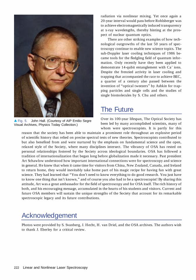
radiation via nonlinear mixing. Yet once again a20-year interval would pass before Rohlsberger wasto achieve electromagnetically induced transparencyat x-ray wavelengths, thereby hinting at the pros-pect of nuclear quantum optics.
There are other striking examples of how tech-nological outgrowths of the last 50 years of spec-troscopy continue to enable new science topics. Thesub-Doppler laser cooling techniques of 1986 be-came tools for the fledgling field of quantum infor-mation. Only recently have they been applied todemonstrate 14-qubit entanglement with Ca+ ions.Despite the frenzied activity in laser cooling andtrapping that accompanied the race to achieve BEC,a quarter of a century also passed between theinvention of “optical tweezers” by Ashkin for trap-ping particles and single cells and the studies ofsingle biomolecules by S. Chu and others.
The FutureOver its 100-year lifespan, The Optical Society hasbeen led by many accomplished scientists, many ofwhom were spectroscopists. It is partly for this
reason that the society has been able to maintain a prominent role throughout an explosive periodof scientific history that relied on precise spectral tests of new theories. Spectroscopists contributed tobut also benefited from and were nurtured by the emphasis on fundamental science and the open,relaxed style of the Society, where many disciplines intersect. The vibrancy of OSA has rested onpersonal relationships fostered by the Society across ideological boundaries. OSA has followed atradition of internationalization that began long before globalization made it necessary. Past presidentArt Schawlow understood how important international connections were for spectroscopy and sciencein general. He knew that when it came time for visitors from China, New Zealand, Canada, and Irelandto return home, they would inevitably take home part of his magic recipe for having fun with greatscience. They had learned that “You don’t need to know everything to do good research. You just haveto know one thing that isn’t known,” and of course you also had to be a spectroscopist! By sharing thisattitude, Art was a great ambassador for the field of spectroscopy and for OSA itself. The rich history ofboth, and his encouraging message, accumulated in the hearts of his students and visitors. Current andfuture OSA members will sustain the unique strengths of the Society that account for its remarkablespectroscopic legacy and its future contributions.
AcknowledgementPhotos were provided by S. Svanberg, J. Hecht, H. van Driel, and the OSA archives. The authors wishto thank J. Eberley for a critical review.
▴ Fig. 5. John Hall. (Courtesy of AIP Emilio SegreVisual Archives, Physics Today Collection.)
222 Linear and Nonlinear Laser Spectroscopy

Optical Trapping and Manipulationof Small Particles by LaserLight PressureArthur Ashkin
The invention of the laser has made possible the use of radiation pressure to optically trapand manipulate small particles. The particles can range in size from tens of micrometersto individual atoms and molecules. Laser radiation pressure has also been used to cool
atoms to exceptionally low temperatures, enabling a new branch of atomic physics. See [1] for anextensive summary of the many varieties of work done with laser radiation pressure.
Inspired by a long interest in radiation pressure, in 1969 the author focused a TEM00 modelaser beam of about 30-μm diameter on a 20-μm transparent dielectric latex particle suspended inwater. Strong motion in the direction of the incident light was observed. If the particle was offaxis, at the edge of the beam, a strong gradient force component to the light force pulling theparticle into the high-intensity region on the axis was observed. The particle motion was closelydescribed by these two force components: one called the “scattering force” in the direction of theincident light and the other the “gradient force” in the direction of the intensity gradient. Withthese two components, and using two oppositely directed beams of equal intensity, it waspossible to devise a stable three-dimensional all-optical trap for confining small particles.Particles moving about by Brownian motion that entered the fringes of the beam were drawninto the beams, moved to the equilibrium point, and were stably trapped. If the axial gradientforce is made to exceed the scattering force, and this can be done, then a single-beam trap ispossible, as shown in Fig. 1.
Because this was the first example of stable optical trapping, this discovery was submitted toPhysical Review Letters. Since single atoms are just small neutral particles and should behavemuch as single dielectric spheres, it was postulated that trapping of single atoms and moleculesshould also be possible. At Bell Labs, if one wanted to submit a paper to Physical Review Lettersone had to pass an internal review by the prestigious theoretical physics department to preservethe Lab’s good name. So the author submitted a manuscript and it was rejected. Upon therecommendation of his boss, Rudi Kompfner, the inventor of the traveling-wave tube, the paperwas resubmitted and was accepted with no problem [2]. A second theoretical paper wassubmitted to Physical Review Letters in 1970 on acceleration, deceleration, and deflection ofatomic beams by resonance radiation pressure [3]. This was followed by a number of experi-ments on optical traps for micrometer-size solid spheres or liquid drops demonstrating opticallevitation against gravity in air and as a function of pressure down to high vacuum and forvarious beam convergence angles. By using optical levitation in conjunction with feedbackstabilization of the levitated particle’s position, it was possible to study the wavelength depen-dence of the optical levitation forces with dye lasers. A series of complex size-dependentresonances were observed that were found to be in close agreement with Mie–Debye electro-magnetic theory calculations. These results are probably the most exact confirmation ofMaxwell’s theory for light scattering by transparent dielectric spheres. The frequencies of theseresonances allow one to determine the particle size and index of refraction to six or sevensignificant figures. Using the position stabilization technique it was possible to perform a modern
1975–1990
223
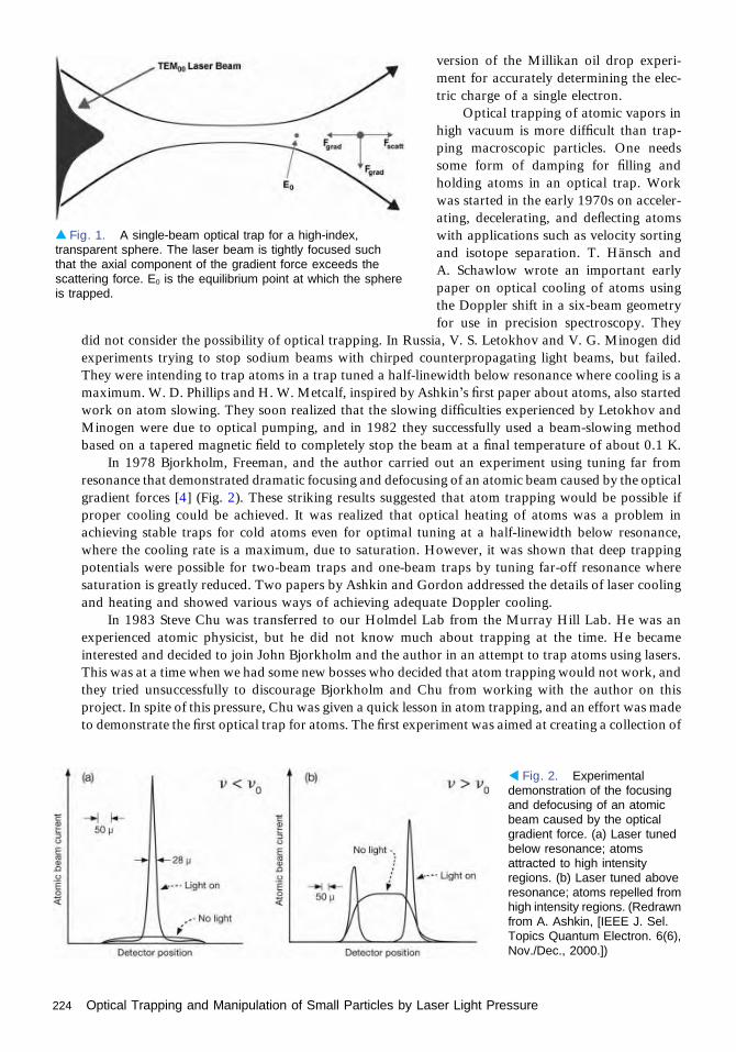
version of the Millikan oil drop experi-ment for accurately determining the elec-tric charge of a single electron.
Optical trapping of atomic vapors inhigh vacuum is more difficult than trap-ping macroscopic particles. One needssome form of damping for filling andholding atoms in an optical trap. Workwas started in the early 1970s on acceler-ating, decelerating, and deflecting atomswith applications such as velocity sortingand isotope separation. T. Hänsch andA. Schawlow wrote an important earlypaper on optical cooling of atoms usingthe Doppler shift in a six-beam geometryfor use in precision spectroscopy. They
did not consider the possibility of optical trapping. In Russia, V. S. Letokhov and V. G. Minogen didexperiments trying to stop sodium beams with chirped counterpropagating light beams, but failed.They were intending to trap atoms in a trap tuned a half-linewidth below resonance where cooling is amaximum. W. D. Phillips and H. W. Metcalf, inspired by Ashkin’s first paper about atoms, also startedwork on atom slowing. They soon realized that the slowing difficulties experienced by Letokhov andMinogen were due to optical pumping, and in 1982 they successfully used a beam-slowing methodbased on a tapered magnetic field to completely stop the beam at a final temperature of about 0.1 K.
In 1978 Bjorkholm, Freeman, and the author carried out an experiment using tuning far fromresonance that demonstrated dramatic focusing and defocusing of an atomic beam caused by the opticalgradient forces [4] (Fig. 2). These striking results suggested that atom trapping would be possible ifproper cooling could be achieved. It was realized that optical heating of atoms was a problem inachieving stable traps for cold atoms even for optimal tuning at a half-linewidth below resonance,where the cooling rate is a maximum, due to saturation. However, it was shown that deep trappingpotentials were possible for two-beam traps and one-beam traps by tuning far-off resonance wheresaturation is greatly reduced. Two papers by Ashkin and Gordon addressed the details of laser coolingand heating and showed various ways of achieving adequate Doppler cooling.
In 1983 Steve Chu was transferred to our Holmdel Lab from the Murray Hill Lab. He was anexperienced atomic physicist, but he did not know much about trapping at the time. He becameinterested and decided to join John Bjorkholm and the author in an attempt to trap atoms using lasers.This was at a time when we had some new bosses who decided that atom trapping would not work, andthey tried unsuccessfully to discourage Bjorkholm and Chu from working with the author on thisproject. In spite of this pressure, Chu was given a quick lesson in atom trapping, and an effort was madeto demonstrate the first optical trap for atoms. The first experiment was aimed at creating a collection of
▴ Fig. 1. A single-beam optical trap for a high-index,transparent sphere. The laser beam is tightly focused suchthat the axial component of the gradient force exceeds thescattering force. E0 is the equilibrium point at which the sphereis trapped.
◂ Fig. 2. Experimentaldemonstration of the focusingand defocusing of an atomicbeam caused by the opticalgradient force. (a) Laser tunedbelow resonance; atomsattracted to high intensityregions. (b) Laser tuned aboveresonance; atoms repelled fromhigh intensity regions. (Redrawnfrom A. Ashkin, [IEEE J. Sel.Topics Quantum Electron. 6(6),Nov./Dec., 2000.])
224 Optical Trapping and Manipulation of Small Particles by Laser Light Pressure

very cold atoms capable of being confined in the shallow atom traps. The experiment was based on thetheoretical ideas proposed by Hänsch and Schawlow, mentioned earlier, and it worked beautifully. Itprovided a cloud of atoms having a temperature of about 240 μK, as expected, which is ideal fortrapping. That cooling technique has become to be known as “optical molasses.” Now that it waspossible to generate cold atoms, Bjorkholm suggested trying a single-beam gradient trap in spite of itssmall size. The trap worked flawlessly, and shortly afterward, in December 1986, the work wasfeatured on the front page of the Sunday New York Times. Surprisingly, a new trapping proposal byDave Pritchard of MIT appeared in the same issue of Physical Review Letters as our trapping paper. Itwas for a large-volume magneto-optic scattering-force trap rendered stable via a quadrupole Zeeman-shifting magnetic field. The magneto-optical trap (MOT) is a relatively deep trap and is easily filledbecause of its large size. As later shown, it did not even require any atomic beam slowing.
Shortly after the atom trapping experiment, Chu left Bell Labs for Stanford and continued his atomtrapping work. At Bell Labs, Bjorkholm and Ashkin turned to other work. Use of MOT trapsdominated over dipole traps for atom work for about the next ten years. In 1997 the Nobel Prizein Physics was awarded to Chu, Phillips, and Cohen-Tannoudji for cooling and trapping of atoms.
In the lab, with the help of Joe Dziedzic, the author started looking at the use of focused laser beamsas tweezers for the trapping and manipulation of Rayleigh particles. They made a surprising discoveryone morning when while examining a sample that had been kept in solution overnight. Wild scatteringwas seen emanating from the focus of the trap. A joke was made about having caught some bugs. Oncloser examination it turned out that that this had happened. Bacteria had contaminated the sample,and they had fallen into the trap. The sample was placed under a microscope where the trapping couldbe observed in detail. In fact, the trap could be maneuvered to chase, capture, and release fast-swimming bacteria with green argon-ion laser light. If the laser power was turned up, “opticution” wasobserved; that is, the cell exploded. It was found that infrared YAG laser power was very much lessdamaging. Samples of E. coli bacteria obtained from Tets Yamane of Murray Hill were seen toreproduce right in the trap. Internal-surgery was performed in which the location of organelles wasrearranged and the organelles were attached in new locations. The visco-elasticity of living cell’scytoplasm and the elasticity of internal membranes were also studied. This early work was the start of anew, unexpected, and very important application of laser trapping. A Nobel Prize winner at Bell Labsmentioned, amusingly in retrospect, that the author “should not exaggerate” by predicting thattrapping would someday be important for the biological sciences.
Meanwhile, work to better understand optical molasses cooling of atoms was carried out at NISTand Stanford. Importantly, at NIST Phillips had made the surprising discovery of cooling to tem-peratures as low as 40 μK in “optical molasses.” This was of great interest to those racing to achieveBose–Einstein condensation (BEC) at very low temperatures and high densities. Anderson et al. wonthis race in 1995 using evaporative cooling from a magnetic trap reaching a temperature of about170 nK at a density of 2×10¹² atoms/cm3 with a loss of evaporated atoms by a factor of 500 from anoriginal 107 atoms. Eric Cornell, Carl Weiman, and Wolfgang Ketterle received the 2001 Nobel Prize inPhysics for the experimental demonstration of BEC.
The Nobel Committee in their 1997 press releases “Addendum B” on additional material mainlyfor physicists says “To become really useful one needed a trap deeper than the focused laser beam trapproposed by Letokhov and Ashkin and realized by Chu and coworkers in optical molasses experi-ments.” On the contrary, far-off-resonance traps built according to Ashkin’s design are the traps used invirtually every current Bose–Einstein experiment.
The story of the application of tweezer traps to biophysics and the biological sciences is morestraightforward [5–7]. After the early work of the author on living cells, Ashkin and collaborators andSteven Block with Howard Berg showed the usefulness of optical tweezers for studying single motormolecules such as dynein, kinesin, and rotary flagella motors. Block and his co-workers continue toextend tweezer techniques to DNA replication and protein folding at even higher resolution (fractionsof an angstrom) and lower force levels using super-steady optically levitated low-noise traps held in ahelium gas environment.
Light-pressure forces are probably the smallest controllable and measurable forces in nature. Otherlow-force techniques such as atomic force microscopy (AFM) have their unique features but cannot
Optical Trapping and Manipulation of Small Particles by Laser Light Pressure 225

function deep inside living cells, for example. Looking to the future, one expects the interesting work onmotors and protein folding to continue. Perhaps we will see optical tweezers serving as gravitationalwave detectors. Large improvements in atomic clocks have been made in the past using atomic fountaintechniques. Recently another breakthrough has been made using ultracold optical lattice clocksapproaching a stability of one part in 1018. This achievement in time keeping by NIST has manypotential applications.
The study of light is fundamental to physics. As such, one expects that applications of opticaltrapping and manipulation of particles by laser light pressure will continue well into the future.
The importance of using lasers for the trapping and cooling of atoms has been recognized by anumber of prizes and awards, including the Nobel Prizes mentioned above. In addition, Arthur Ashkinhas been recognized for his work in that field by The Optical Society (OSA) with the Charles H. Townesaward in 1988, with the Ives Medal/Quinn Award in 1998, and by being elected an Honorary Memberof OSA in 2010.
Many thanks to John Bjorkholm for his help in editing this essay.
References1. A. Ashkin, Optical Trapping and Manipulation of Neutral Particles Using Lasers: A Reprint Volume
with Commentaries (World Scientific, 2006).2. A. Ashkin, “Acceleration and trapping of particles by radiation pressure,” Phys. Rev. Lett. 24, 156–159
(1970).3. A. Ashkin and J. M. Dziedzic, “Observation of resonances in the radiation pressure on dielectric
spheres,” Phys. Rev. Lett. 38, 1351–1354 (1977).4. J. E. Bjorkholm, R. R. Freeman, A. Ashkin, and D. B. Pearson, “Observation of focusing of neutral
atoms by the dipole forces of resonance-radiation pressure,” Phys. Rev. Lett. 41, 1361–1364 (1978).5. K. C. Neuman and S. M. Block, “Optical trapping,” Rev. Sci. Instrum. 75, 2787–2809 (2004).6. K. Dholakia, P. Reece, and M. Gu, “Optical micromanipulation,” Chem. Soc. Rev. 37, 42–55 (2008).7. D. G. Grier, “A revolution in optical micromanipulation,” Nature 424, 810–816 (2003).
226 Optical Trapping and Manipulation of Small Particles by Laser Light Pressure
High-Power, Reliable DiodeLasers and ArraysDan Botez
The long-lived diode lasers demonstrated at Bell Laboratories in 1977 produced only acouple of milliwatts (mWs), good enough for fiber-optical communications and later forcompact disc reading. Other applications, such as high-speed optical recording, required
quasi-continuous-wave (CW) powers in the 50–100-mW range delivered reliably in a singlespatial mode.
Since the reliable power is closely related to the optical power density that can damage theemitting facet, designs were needed for enlarging the laser spot size both transversely (i.e., in adirection perpendicular to the plane of the grown layers) and laterally, while maintaining asingle spatial mode. In conventional double-heterojunction devices, for which single transverseoptical-mode operation is ensured, the main challenge was to create single-mode structures oflarge lateral spot size. This was realized by introducing mode-dependent radiation losses inso-called antiguided structures, in either the lateral or the transverse directions, on both sides ofthe defined lateral waveguide. Laterally antiguided diode lasers [1] emitting single-mode peakpowers in the 50–80-mW range at 20%–50% duty cycle enabled RCA Laboratories in 1980 torealize high-speed optical recording. At about the same time, Hitachi Central ResearchLaboratory reported single-mode CW powers as high as 40 mW employing optimizedtransversely antiguided double-heterojunction devices [2].
In 1980 a breakthrough occurred in high-power diode-laser design with the implementationof the large-optical-cavity concept for increased spot size in the transverse direction [1]. Thesestructures provided transverse spot sizes about 60% larger than in double-heterojunctiondevices, enabling record-high reliable powers [1]. As a result, the constricted double-hetero-junction, large-optical-cavity laser became the most powerful single-mode commercially avail-able diode laser between 1981 and 1986.
In the 1980s the maximum reliable CW power was only about 25% of the maximumachievable power set by catastrophic optical-mirror damage. Mirror damage in diode lasers iscaused by thermal runaway at the mirror facets due to increased light absorption and non-radiative recombination with increased drive current [3]. Solutions to suppressing damagerequired nonabsorbing regions at the mirror facets. As early as 1978 researchers from NECLaboratories showed that Zn diffusion provides nonabsorbing regions at the mirror facets. Thisled to a fourfold increase in the maximum achievable CW output power. Then, in 1984researchers from RCA Laboratories demonstrated mirror-damage suppression by creating, via asingle etch-and-regrowth cycle, two-dimensional (2D) waveguiding structures at the mirrorfacets that were transparent to the laser light. Those devices [3] provided peak output powersof 1.5 W, a fourfold increase over the highest previously reported. However, the earlynonabsorbing-mirror approaches were impractical to implement. It took over five years beforepractical nonabsorbing-mirror lasers were developed and became commercially available.
Around 1982, interest arose in replacing flashlamps with diode-laser arrays as pumps forsolid-state lasers. This drive picked up steam with the advent of quantum-well diode laserssince much lower threshold currents could be achieved than in standard double-heterojunctionlasers. In early 1983 researchers from Xerox PARC reported very high (>2.5 W CW) CWpower quantum-well lasers with optimized facet coatings [3]. Thus, they achieved an eightfold
1975–1990
227
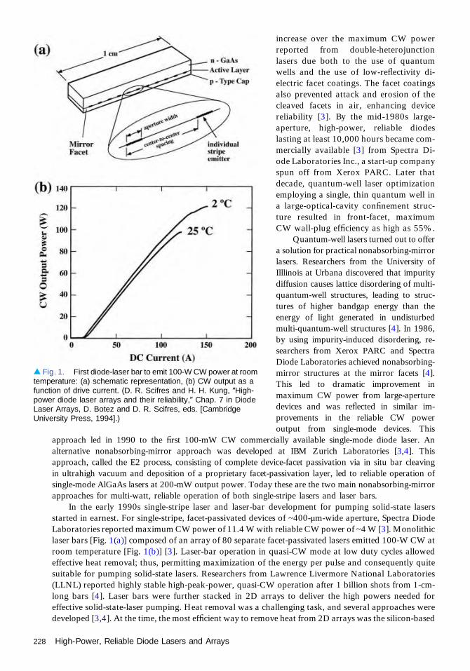
increase over the maximum CW powerreported from double-heterojunctionlasers due both to the use of quantumwells and the use of low-reflectivity di-electric facet coatings. The facet coatingsalso prevented attack and erosion of thecleaved facets in air, enhancing devicereliability [3]. By the mid-1980s large-aperture, high-power, reliable diodeslasting at least 10,000 hours became com-mercially available [3] from Spectra Di-ode Laboratories Inc., a start-up companyspun off from Xerox PARC. Later thatdecade, quantum-well laser optimizationemploying a single, thin quantum well ina large-optical-cavity confinement struc-ture resulted in front-facet, maximumCW wall-plug efficiency as high as 55%.
Quantum-well lasers turned out to offera solution for practical nonabsorbing-mirrorlasers. Researchers from the University ofIlllinois at Urbana discovered that impuritydiffusion causes lattice disordering of multi-quantum-well structures, leading to struc-tures of higher bandgap energy than theenergy of light generated in undisturbedmulti-quantum-well structures [4]. In 1986,by using impurity-induced disordering, re-searchers from Xerox PARC and SpectraDiode Laboratories achieved nonabsorbing-mirror structures at the mirror facets [4].This led to dramatic improvement inmaximum CW power from large-aperturedevices and was reflected in similar im-provements in the reliable CW poweroutput from single-mode devices. This
approach led in 1990 to the first 100-mW CW commercially available single-mode diode laser. Analternative nonabsorbing-mirror approach was developed at IBM Zurich Laboratories [3,4]. Thisapproach, called the E2 process, consisting of complete device-facet passivation via in situ bar cleavingin ultrahigh vacuum and deposition of a proprietary facet-passivation layer, led to reliable operation ofsingle-mode AlGaAs lasers at 200-mW output power. Today these are the two main nonabsorbing-mirrorapproaches for multi-watt, reliable operation of both single-stripe lasers and laser bars.
In the early 1990s single-stripe laser and laser-bar development for pumping solid-state lasersstarted in earnest. For single-stripe, facet-passivated devices of ~400-μm-wide aperture, Spectra DiodeLaboratories reported maximum CW power of 11.4 W with reliable CW power of ~4 W [3]. Monolithiclaser bars [Fig. 1(a)] composed of an array of 80 separate facet-passivated lasers emitted 100-W CW atroom temperature [Fig. 1(b)] [3]. Laser-bar operation in quasi-CW mode at low duty cycles allowedeffective heat removal; thus, permitting maximization of the energy per pulse and consequently quitesuitable for pumping solid-state lasers. Researchers from Lawrence Livermore National Laboratories(LLNL) reported highly stable high-peak-power, quasi-CW operation after 1 billion shots from 1-cm-long bars [4]. Laser bars were further stacked in 2D arrays to deliver the high powers needed foreffective solid-state-laser pumping. Heat removal was a challenging task, and several approaches weredeveloped [3,4]. At the time, the most efficient way to remove heat from 2D arrays was the silicon-based
▴ Fig. 1. First diode-laser bar to emit 100-W CW power at roomtemperature: (a) schematic representation, (b) CW output as afunction of drive current. (D. R. Scifres and H. H. Kung, “High-power diode laser arrays and their reliability,” Chap. 7 in DiodeLaser Arrays, D. Botez and D. R. Scifres, eds. [CambridgeUniversity Press, 1994].)
228 High-Power, Reliable Diode Lasers and Arrays

micro-channel cooling technology developed atLLNL [4]. Using that technology LLNL demonstrated41-bar stacks delivering 3.75-kW peak power [4].By the end of the decade steady development led tosignificantly improved performance.
Spectra Diode Laboratories was at the forefrontof commercializing high-power diode-laser bars.Donald R. Scifres, the CEO of Spectra Diode Lab-oratories, was recognized by The OSA in 1996,when he was the awarded the Edwin H. LandMedal for his pioneering scientific and entrepre-neurial contributions to the field of high-powersemiconductor lasers (Fig. 2). A year later, Dr.Scifres and his wife, Carol, endowed the OSA NickHolonyak, Jr. Award, dedicated to recognize indi-viduals who have made significant contributions tooptics based on semiconductor-based opticaldevices and materials, including basic science andtechnological applications.
In the mid-1990s two major developments ledto significant increases in the output powers ofsingle-stripe diode lasers: the broad-waveguide-device concept and the use of Al-free, active-region structures. The broad-waveguide conceptfor asymmetric and symmetric structures involveda large-optical-cavity structure of large equivalent(transverse) spot size as well as low internal cavityloss [5]. The total thickness of theoptical-confinement layer of the broad-waveguide structure is quite large, whilemaking sure that lasing of high-ordertransverse modes is suppressed via lossesto the metal contact [5]. Diodes capableof over 10-W CW power were achievedusing active regions composed of Al-free,indium (In)-containing material with rel-atively high mirror-damage power densi-ty (see Fig. 3). Later it became clear thatadding In to the active-region materialsignificantly decreases the surface recom-bination velocity, which in turn increasesthe mirror-damage power density [4].Indium had another highly beneficial ef-fect with respect to laser-device reliabili-ty: it was found to suppress crystal-defectpropagation in GaAs-based lasers [4].That is why currently the most reliable0.81-μm emitting devices have eitherInGaAsP or InAlGaAs active regions.
Another key issue that was tackled inthe mid-1990s was suppression of carrier leakage out of the lasers’ active regions. Since carrier leakageis a thermally activated effect a substantial amount of it causes a significant decrease in the laser slopeefficiency as the heat-sink temperature increases. This decrease in slope efficiency is characterized by a
▴ Fig. 2. Donald R. Scifres, recipient of the 1996Edwin Land Medal (at the time). (Courtesy of Dr. W.John Tomlinson, Princeton, New Jersey.)
▴ Fig. 3. Light-current characteristics in CW and quasi-CWoperation for the first single-stripe (100-μm-wide aperture) diodelaser to emit over 10-W CW power. (Reproduced with permissionfrom A. Al-Muhanna, L. J. Mawst, D. Botez, D. Z. Garbuzov, R. U.Martinelli, and J. C. Connolly, “High-power (>10 W) continuous-wave operation from 100-μm-aperture 0.97-μm-emitting Al-freediode lasers,” Appl. Phys. Lett. 73(9), 1182 [1998].)
High-Power, Reliable Diode Lasers and Arrays 229

temperature coefficient T1 [5]. When car-rier leakage is suppressed via bandgapengineering, the T1 parameter has a highvalue, which reduces the active-regionheating [5] and increases the maximumachievable CW power. A high T1 valuealso leads to reduced mirror-facet heating;thus, it results in high mirror-damagepower-density values [5] and subsequentlylong-term reliable operation at high CWpower levels.
To minimize heating in diode lasersand decrease the heat load as well asimprove the lasers’ reliability in CWoperation the value of the electrical-to-optical power conversion efficiency, theso-called wall-plug efficiency ηp needed tobe increased. In 1996, by using broad-waveguide structures with suppressedcarrier leakage [6], researchers at the Uni-versity of Wisconsin–Madison achieved ηp
as high as 66%. At the time it was noticedthat the devices could not reach their ulti-
mate maximum ηp value due to a built-in voltage differential in the laser structure. Efforts to increase ηp
re-started in 2003. By 2005, reductions in the built-in voltage differential as well as laser-structureoptimization led to CW wall-plug efficiencies of 73%–75% for laser bars from Alfalight, Inc., nLightInc., and JDSU Corp. A typical result is shown in Fig. 4, which shows a 50-W CW output delivered with73% wall-plug efficiency, at 0.97 μm from a 1-cm-wide laser bar [7]. The achievement of record-highwall-plug efficiency was quite a significant development in that it led the typical ηp of commercial laserbars to increase from ~45% to ~65%. Consequently, the dissipated heat that needed to be removed wasreduced by more than a factor of 2, which is very important since thermal load management drives thepackaged laser weight.
With the advent of the “telecom bubble,” feverish activity started around 1999 to create single-spatial-mode, high-power (~1-W CW) 0.98-μm emitting diode lasers for use as pumps for erbium-doped fiber amplifiers to be employed as signal boosters in long-distance fiber-optical communications.Although many complex and elegant approaches were tried, in the end, facet-passivated, 4–5-μm-wideconventional ridge-guide devices prevailed [8]. Even though single-spatial-mode CW powers as high as1 W are achievable, reliability limits output to ∼0.7 W CW due to bulk degradation [8].
Attempts to achieve long-term, reliable operation at higher coherent CW powers by using unstableresonator or master oscillator–power amplifier semiconductor-based configurations have failed [2, 9].Other approaches consisted of incorporating periodic features, such as distributed-feedback gratings, inthe device structure to realize so-called photonic-crystal lasers. However, when using photonic-crystaldistributed-feedback devices, the induced periodic refractive-index steps are so small that they arecomparable to thermally induced index steps in quasi-CW or CW operation. In turn, these lasersperform well only in low-duty-cycle (≤1%) pulsed operation; thus they are impractical since mostapplications require high average powers. Only high-index-contrast photonic-crystal lasers that possesslong-range coupling between the photonic-crystal sites [2, 9] appear, at present, as the solution toachieving multi-watt CW coherent power from monolithic semiconductor lasers. High-index-contrast,long-range coupling photonic-crystal lasers were realized [9] as early as 1989 in the form of laterallyresonant, phase-locked arrays of antiguided lasers, so-called resonant-optical-waveguide arrays. Thelateral resonance feature ensures strong coupling between all array elements, in spite of large built-inindex steps [9]. In 1991 the resonant-optical-waveguide array became the first diode laser to demonstrate1-W peak power in a diffraction-limited beam [9], and in 1992 it was theoretically shown to be equivalent
▴ Fig. 4. Light-current characteristics and wall-plug efficiencyfor the first diode-laser bar to emit with over 70% CW wall-plugefficiency at room temperature. (Reproduced by permission ofthe Institution of Engineering & Technology. Full acknowledgmentto M. Kanskar, T. Earles, T. J. Goodnough, E. Stiers, D. Botez,and L. J. Mawst, “73% CW power conversion efficiency at50 W from 970 nm diode laser bars,” Electron. Lett. 41(5),245–247 [2005].)
230 High-Power, Reliable Diode Lasers and Arrays

to a lateral distributed-feedback structure for whichboth index and gain vary periodically [9]: that is, anactive photonic-crystal laser structure. Thus, theresonant-optical-waveguide array did constitute thefirst photonic-crystal laser developed for high-power,single-mode operation from large-aperture semicon-ductor lasers. In 1999, resonant-optical-waveguidearrays of an index step more than an order of magni-tude larger than in photonic-crystal distributed-feed-back structures demonstrated 1.6-W CW power [10]in a nearly diffraction-limited beam from a 200-μm-wideaperture. In2010, the OSApresented Dan Botez,Philip Dunham Reed Professor at the University ofWisconsin–Madison and co-founder of Alfalight Inc.,the Nick Holonyak, Jr. Award for the achievement ofactive photonic-crystal semiconductor-laser struc-tures for high-coherent-power generation (Fig. 5).
High-power, reliable diode-laser technologyreached a high degree of maturity by about 2005.Single-stripe devices with 10-W reliable outputpower and wall-plug efficiencies of ~65% are avail-able from diode-laser manufacturers for variousapplications including single-diode pumping ofsolid-state lasers and fiber lasers. Laser bars, usedmostly for pumping solid-state lasers, are commer-cially available with 200-W CW output powers,∼65% wall-plug efficiency and are guaranteed tooperate for 30,000 hours. Future developments may involve the commercial realization of activephotonic-crystal lasers for watt-range coherent CW powers as well as the use of photonic-crystalstructures for emission of the generated light through the substrate (i.e., surface emission) for evenhigher coherent powers delivered in a reliable fashion.
References1. D. Botez, D. J. Channin, and M. Ettenberg, “High-power single-mode AlGaAs laser diodes,” Opt. Eng.
21(6), 216066 (1982).2. N. W. Carlson, Monolithic Diode-Laser Arrays (Springer-Verlag, 1994).3. D. R. Scifres and H. H. Kung, “High-power diode laser arrays and their reliability,” Chap. 7 in Diode
Laser Arrays, D. Botez and D. R. Scifres, eds. (Cambridge University Press, 1994).4. R. Solarz, R. Beach, B. Bennett, B. Freitas, M. Emanuel, G. Albrecht, B. Comaskey, S. Sutton, and
W. Krupke, “High-average-power semiconductor laser arrays and laser array packaging with anemphasis on pumping solid state lasers,” Chap. 6 in Diode Laser Arrays, D. Botez and D. R. Scifres, eds.(Cambridge University Press, 1994).
5. D. Botez, “Design considerations and analytical approximations for high continuous-wave power,broad-waveguide diode lasers,” Appl. Phys. Lett. 74(21), 3102–3104 (1999).
6. D. Botez, “High-power Al-free coherent and incoherent diode lasers,” Proc. SPIE 3628, 2–10 (1999).7. M. Kanskar, T. Earles, T. J. Goodnough, E. Stiers, D. Botez, and L. J. Mawst, “73% CW power
conversion efficiency at 50 W from 970 nm diode laser bars,” Electron. Lett. 41(5), 245–247 (2005).8. G. Yang, G. M. Smith, M. K. Davis, D. A. S. Loeber, M. Hu, Chung-en Zah, and R. Bhat, “Highly
reliable high-power 980-nm pump laser,” IEEE Photon. Tech. Lett. 16(11), 2403–2405 (2004).9. D. Botez, “Monolithic phase-locked semiconductor laser arrays,” Chap. 1 in Diode Laser Arrays,
D. Botez and D. R. Scifres, eds. (Cambridge University Press, 1994).10. H. Yang, L. J. Mawst, and D. Botez, “1.6 W continuous-wave coherent power from large-index-step
(Δn≈0.1) near-resonant, antiguided diode laser arrays,” Appl. Phys. Lett. 76(10), 1219–1221 (2000).
▴ Fig. 5. Dan Botez, recipient of the 2010 NickHolonyak, Jr. Award (at the time). (OPN June 2010Optical Society Awards.)
High-Power, Reliable Diode Lasers and Arrays 231

Tunable Solid State LasersPeter F. Moulton
While the wavelength of any laser can be varied, lasers get classified as tunable whentheir tuning range becomes a substantial fraction of their center wavelength.Despite having lower optical gain than narrow-line rare-earth doped crystal
lasers such as Nd3+-doped YAG, tunable lasers are desirable for a number of reasons. Inlaser-based spectroscopy, laser tuning allows one to access spectral features of interest, whilein laser propagation through the atmosphere, tuning can be used to avoid atmosphericabsorption lines. A large tuning range implies the ability to generate and amplify shortpulses of light. The development of practical and efficient tunable solid state lasers has led toa scientific revolution and an emerging industrial revolution in laser processing of materials,based on the generation of electromagnetic pulses with femtosecond and recently attosecondduration.
Most broadly tunable lasers employ ions from the “3d” portion of the periodic table.Figure 1 presents so-called configuration-coordinate diagrams that help explain the broadtunability of 3d ions. The diagrams are a greatly simplified schematic representation of thecombined energy of the laser-active ion and its environment as a function of the positions of theatoms surrounding the ion. In equilibrium, the overall energy is minimized, and the systemenergy increases as the coordinate deviates from the equilibrium position. Deviation occurs as aresult of the always present vibrations of the atoms, which appear even at the lowest tempera-tures from the uncertainty principle of quantum mechanics. The left-hand diagram shows thecase where, when the ion energy level changes from a “ground” state to an “excited” state, theequilibrium position for the configuration coordinate is unchanged. The right-hand side showsthe case where the equilibrium position does change.
An important concept regarding the linewidth of the transitions between the ion ground andexcited states is the Franck–Condon principle. Stated in classical terms, when an active ionundergoes a transition, it occurs so quickly that the atomic surroundings do not move, as shownby the vertical arrows in the diagrams. The left-hand diagram is representative of the type ofnarrow-linewidth transitions among levels of the rare-earth ions, since changing the electronicstate of the spatially compact wavefunctions of the rare earths has negligible effect on thesurrounding atoms.
The electronic wavefunctions of 3d ions have a larger spatial extent than those of rare-earthsand have a stronger interaction with their environment. The case illustrated in the right-handdiagram shows what happens with a strong interaction, exciting the electronic level leads to anew equilibrium position. As is evident from the arrows, the energy associated with ground-to-excited-state transitions does vary with the displacement, leading to a large spread in energiesand hence a large linewidth. The energies for the absorption (ground-to-excited) transitions aregenerally distinct and higher than those for emission and possible laser operation (excited-to-ground transitions). As a result, even with only two electronic transitions, one can observe four-level laser operation (as shown by the numbers in Fig. 1) as the peak absorption and emissionwavelengths do not overlap. These types of transitions are often referred to as “vibronic,” aconcatenation of vibrational and electronic.
After the demonstration of the ruby laser, and around the same time as the development ofrare-earth-doped lasers, there were demonstrations of the first broadly tunable solid state lasers,based on 3d-ion transitions. In particular, in 1963 L. F. Johnson and co-workers at Bell Labs
1975–1990
232

reported “optical maser oscillation from Ni2+ in MgF2 involving simultaneous emission of phonons,”which, translated to now-accepted terminology, would be “laser operation on vibronic transitions.”Subsequent work by the same group showed operation on vibronic transitions from Co2+ ion in MgF2
and ZnF2 around 1750–2150 nm, prism-based tuning, albeit in discontinuous segments from Ni:MgF2,and operation from V2+-doped MgF2 around 1100 nm. The major drawback to these first vibroniclasers was that, because of thermally induced non-radiative processes, relatively low-threshold opera-tion with lamp pumping required cooling of the laser crystals to cryogenic temperatures. The author,working at MIT Lincoln Laboratory in the 1970s, became aware of the early Bell Labs work andrealized that the use of lasers, rather than lamps, as pump sources could greatly reduce the engineeringcomplexity of the systems. In particular, Nd-doped solid state lasers operating around 1300 nm provedeffective in pumping both Ni2+ and Co:MgF2 lasers. In the subsequent work, he had some success withthe Co:MgF2 laser, which proved capable of tuning from 1630–2080 nm at LN2 temperatures and1750–2500 nm at room temperature. Other 3d systems he studied showed clear evidence of a problemthat has plagued many tunable solid state lasers: excited-state absorption (ESA). For most ions there area number of 3d levels above the first excited state, i.e., the upper laser level. Depending on the positionsof the levels in the configuration-coordinate diagram, it is possible that, for the desired laser wavelength,induced transitions to one or several of these levels may be possible. The net cross section thatdetermines the laser gain is the cross section for transitions to the lower laser level minus the crosssection for transitions to the higher-lying states, and this reduces laser efficiency and can even preventlaser operation.
The announcement of room-temperature, 750-nm-wavelength-region, tunable laser operationfrom Cr3+-doped BeAl2O4 (alexandrite) in 1979 re-ignited interest in Cr3+-doped lasers beyond ruby.At first, laser operation was thought to be, like ruby, on a narrow-line transition but spectroscopicinvestigation showed that it was in fact a vibronic. However, the gain in alexandrite lasers is relativelylow, limiting applications, and today the most widespread use of alexandrite is in lamp-pumped, long-pulse lasers used for a variety of medical applications. The majority of other Cr3+-doped tunablematerials studied showed low conversion of pump to laser power, generally attributed to ESA. Oneclass (colquirite structure) of materials, first developed at Lawrence Livermore National Laboratory,includes the crystals LiCaAlF6 (LiCAF) and LiSrAlF6 (LiSAF) and was shown to have relatively weakESA and thus high efficiency. However, the thermo-mechanical properties of the colquirite host crystals(with thermal conductivities 10%–20% of the sapphire and alexandrite host crystals) significantly limittheir ability to generate high average powers free of significant thermo-optic distortion of the outputbeam and, ultimately, free of fracture to the laser material.
While listening to a presentation on a particular type of color-center laser the author noted thesimplicity of that system: there were no excited states above the upper laser level that could causeESA. A subsequent review of the periodic table showed that one 3d ion, Ti3+, has only a single 3delectron. The five-fold degenerate free-space state for that electron placed in a typical crystal, to firstorder, splits into a three-fold degenerate ground state, 2T2, and a doubly degenerate upper state, 2E.Any higher-lying states result from transitions that take the single electron out of the 3d shell and
▸ Fig. 1. Configuration-coordinate diagrams for twocases of paramagnetic-iontransitions.
Tunable Solid State Lasers 233

could be so high in energy as to not create ESA. There were reports on the basic spectroscopy ofTi3+-doped Al2O3 (Ti:sapphire) with data on absorption and fluorescence. Given the superior thermo-mechanical properties of sapphire, proven with the ruby laser, it looked to be a good choice for aTi3+ host.
The author obtained crystal samples from Robert Coble’s group at MIT, where they had beenstudying the diffusion of oxygen in sapphire by using the oxidation state of Ti as a tracer. (Coble wasthe developer of the first transparent ceramics, paving the way for sodium arc lamps and, later, laser-quality ceramics.) The author’s measurements of the absorption cross section and fluorescence spectra,shown in Fig. 2, showed much broader emission than earlier reports. When one converts the emissiondata to gain cross section (also plotted in Fig. 2), multiplying by the necessary (wavelength)5 correction,the tuning range is unusually broad. The spectral breadth of the emission results, in part, fromJahn–Teller splitting of both the ground and upper levels of the ion, leading to a more complicatedconfiguration coordinate than shown in Fig. 1, where both the ground and excited states have multiple-energy versus displacement curves. The author also determined the fluorescence decay time and found aroom-temperature value of 3.15 μs. The short lifetime seemed to indicate low quantum efficiency, but ifone estimates the radiative value based on the strength of the measured absorption in the material, aswell as on optical gain measurements, one finds high quantum efficiency, on the order of 80% at roomtemperature. The short lifetime and associated high gain cross section (in the range 3–4 × 10-19 cm2)result from the trigonal symmetry of the Ti3+ site in sapphire, which acts to strongly activate the dipole-forbidden 2E→2T2 transitions.
The author first obtained laser operation from the material in May of 1982 and reported the resultsin June at the Twelfth International Quantum Electronics Conference in Munich. There was a delay inpublication in a fully refereed journal until 1985 while the author worked, unsuccessfully, to patent thesystem, became engaged in other technical work, and left MIT Lincoln Laboratory to help start acompany. The results published in 1985 included demonstrations of pulsed laser operation with lamp-pumped, dye-laser pumps, frequency-doubled, Q-switched, Nd:YAG laser pumps, and continuous-wave (CW) operation with argon-ion-laser pumps, with cryogenic cooling used to obtain true-CWoperation. In laser operation, tuning experiments showed that the observed tuning range and thatpredicted by fluorescence measurements were in good agreement, confirming that ESA was not a factorin laser operation.
The first commercial Ti:sapphire laser product, an argon-ion-laser pumped CW device, wasintroduced by Spectra-Physics in 1988 and was followed shortly after by one from the author’scompany, Schwartz Electro-Optics, that included an option for a single-frequency, ring-laser configu-ration. Early applications of the products included use as a diode-laser substitute in the development of
◂ Fig. 2. Absorption (green)and emission (red) crosssections for Ti:sapphire and arelative plot (dashed graycurve) of the measuredfluorescence spectrum. Thenoise in the long-wavelengthregion is from the detectionsystem.
234 Tunable Solid State Lasers

other solid state lasers, notably Er-doped fiber amplifiers pumped at 980 nm for telecom applicationsand later Yb-doped, high-efficiency crystal lasers. With the discovery that nonlinear effects in the CWTi:sapphire laser crystal, namely Kerr-effect lensing, could lead to generation of 60-fs-duration pulses,the utility of Ti:sapphire lasers greatly expanded. The irony of this is that the nonlinearity in the solidstate laser medium might have been expected to be a limit to the mode-locking properties of the system,but it in fact provided a path to generation of femtosecond pulses. Subsequent technology improve-ments, including dispersion-compensating intracavity elements, broadband mirrors with appropriateoptical dispersion and phase characteristics, and sophisticated pulse diagnostics, led to direct generationof 3.6-fs-duration pulses at 800 nm, slightly more than one optical cycle. These are claimed to be theshortest pulses directly generated by any laser system and close to the limit expected from the 100-THzgain bandwidth of Ti:sapphire. Commercial mode-locked Ti:sapphire lasers emerged in 1991 withpicosecond-duration pulses, followed shortly by Kerr-lens-based systems providing 100-fs-durationpulses, and brought reliable ultrafast-laser technology to a broader base of users, replacing dye-laser-based sources that required long setup times with “turn-key” sources that allowed users to devote moretime to science and much less to laser maintenance. The high Ti:sapphire laser gain cross section yields apulse saturation fluence on the order of 0.8 J/cm2, comparable with 0.7 J/cm2 of Nd:YAG-generatedhigh-energy pulses. If one uses a Q-switched, frequency-doubled, Nd:YAG solid state pump laser, theTi:sapphire medium will be able to integrate and store the pump energy, which must then be extractedwithin a microsecond or so of the pump pulse.
The combination of femtosecond-duration pulses produced by CW Ti:sapphire lasers and high-gain, high-energy amplifiers pumped by pulsed, Q-switched lasers has led to widely used systems forhigh-intensity pulse generation. A key technology for this combination is the chirped-pulse amplifi-cation (CPA) technique of Strickland and Mourou, first reported in 1985 and nicely matched to theproperties of Ti:sapphire. With the availability of large-aperture Ti:sapphire crystals, the ultimatelimit on energy is set by the pump laser, and the limit on pulse rate is set by a combination of the pumplaser and thermal effects in the Ti:sapphire material. At present, regenerative systems are widelyavailable on a commercial basis, with pulse energies of tens of millijoules and pulsewidths <40 fs,with cryogenic cooling used for systems producing 20–30 W average power. In sum, commercialsales of Ti:sapphire lasers to date, including associated green-wavelength pump lasers, are on theorder of $1 billion, not counting very-high-power systems installed or being built at major researchlaboratories.
At this writing, there is active devel-opment to scale up the peak power/energyof Ti:sapphire CPA systems. The highestreported power is 2×10¹⁵ W (2 PW), froma system in Shanghai, with a final stagepumped by a Nd:glass laser providing140 J of 527 nm pump energy. The APPO-LON Ti:sapphire laser system, under con-struction in France, has a goal of 10 PW ina pulse of 150 J in 15 ps. Figure 3 showsthe pumped final stage of the one theGemini amplifiers at the Central LaserFacility (CLF), Rutherford Appleton Lab-oratory, Oxford, UK, generating 25 J ofpulse energy in a 30-fs pulse.
Key new advances in tunable solidstate lasers are now almost entirely drivenby their application to ultrafast pulsegeneration and include diode-pumped,rare-earth, Yb-doped crystals that can gen-erate pulses on the order of 100 fs, andCr2+-doped ZnSe and similar II-VI
▴ Fig. 3. One of the two Gemini amplifiers at RutherfordAppleton Laboratory, showing, in the center, a green-laser-pumpedTi:sapphire crystal 90 mm in diameter and 25 mm thick. With 60 J ofpump energy the system has generated 25 J of output energy in a30 fs pulse. (STFC Gemini Laser Facility/Chris Hooker).
Tunable Solid State Lasers 235

semiconductor hosts, providing high-gain operation similar to that of Ti:sapphire lasers but centered at2500 nm. The longer wavelength is of great interest for attosecond pulse generation in the x-raywavelength region through high-harmonic generation. The limited number of pages for this articlerequires that we leave out further discussion of these developments in tunable solid state lasers.
Other articles in this book provide details of the exciting science and Nobel-prize-winning workthat has been enabled by the development of tunable solid state lasers.
236 Tunable Solid State Lasers

Ultrashort-Pulse LasersErich P. Ippen
IntroductionA particularly remarkable aspect of lasers is their ability to emit shorter flashes (pulses) of lightthan achievable with any other means. This ability has, over the years, advanced theobservation and measurement of events from the nanosecond timescale down to the picosec-ond (10−12), femtosecond (10−15), and even attosecond (10−18) timescales. To use such pulses hasrequired the development of new methods for measuring and characterizing the pulsesthemselves on ultrafast timescales beyond the reach of electronics. These methods have, inturn, made it possible to study ultrafast phenomena in ways that produced completely newinsights into the evolution of such phenomena in physics, chemistry, and biology [1]. Asultrashort-pulse laser technology has developed, its other characteristics such as the high peakpower and ultrabroad bandwidth packed into a short pulse have also found importantapplications. The compression of even very modest amounts of pulse energy into femtoseconddurations produces sufficiently high peak power for precision machining and micro-surgerywithout unwanted damage and for nondestructive nonlinear methods of microscopy thatproduce three-dimensional (3D) biological imaging with micrometer resolution. The ultra-broad bandwidths associated with femtosecond pulses have made possible 3D medical imagingvia optical coherence tomography (OCT), simultaneous creation of many wavelength-multiplexed optical communication channels with only one source, and major advances inprecision spectroscopy and optical clocks [2,3].
The Optical Society (OSA) played a major role in supporting the field, starting with itscreation of the first International Conference on Picosecond Phenomena in 1978 (name changedin 1984 to Ultrafast Phenomena to reflect the emergence of femtosecond science and technology).Held every two years since then (for the 19th time in 2014, the year of this writing) withcontinuing OSA support, this successful conference has provided perhaps the greatest testamentto the continuous technological development and widespread impact of the field with its 19-volume series of hardcover proceedings [4]. OSA journals became the primary source ofpublications on ultrafast optics and photonics. Multiple sessions on ultrafast optics and itsapplications every year at conferences like CLEO, QELS, IQEC, and OFC have been essential toadvancing the technology and its applications to science and engineering.
Flashlamp-Pumped Picosecond Systems
Nd:glass LasersThe era of ultrashort pulses began in earnest with the demonstrations in the mid-1960s, byDeMaria and co-workers at United Aircraft, of passive (self) mode-locking in a Nd:glass laser.Mode locking was achieved with a cell of absorbing dye inside the laser that was designed tobleach (saturate) sufficiently and rapidly enough to favor transmission of high intensity peaksover continuous emission and, therefore, the development of short pulses. The passive,saturable absorber technique, in various forms, remains the basis for ultrashort-pulse
1975–1990
237

generation today. The mode-locked Nd:glass laser pulses, too short to measure at first, were laterverified to be on the order of 5–10 picoseconds in duration. For almost a decade, this laser systemdominated and drove the development of ultrashort-pulse technology and its applications. For thesecond decade and a half, mode-locked dye lasers reigned and pushed pulse durations into thefemtosecond domain. Finally, with the emergence of new techniques in the late 1980s, passive mode-locking of solid state lasers regained importance and led to the wide range of compact, robust,femtosecond laser systems we have today.
Ultrafast Measurement Techniques and ApplicationsStimulated by mode-locked Nd:glass laser demonstrations, many of the ultrashort-pulse characteri-zation, manipulation, and application methods still in use today were invented and developed in the1960s [5]. Within a year of the invention of the passively mode-locked Nd:glass laser, several methodsfor pulse measurement with sub-picosecond resolution had been proposed and demonstrated. Thesetechniques essentially use optical pulses to measure themselves. The laser output beam is split intotwo, one is delayed with respect to the other, and they are combined in a nonlinear crystal to generatesecond harmonic light (SHG). SHG is a maximum when the two pulses exactly overlap and decreaseswith delay in either direction. A plot of SHG versus delay yields the second-order autocorrelationfunction of the pulse intensity I(t). Fitting the observed intensity autocorrelation function to thatexpected for the pulses requires some assumptions about pulse shape, as this simple method isinherently insensitive to pulse asymmetry. Nevertheless, information about substructure and fre-quency chirp within the pulse can be deduced by comparing the assumed fit with that expected fromthe optical frequency spectrum. Methods for complete pulse characterization via frequency-resolvedoptical gating (FROG) were not developed until the early 1990s. The relatively slow repetition rate offlashlamp-pumped systems made the requirement of repetitive measurements at variable delaysomewhat tedious at first. More rapid progress was permitted by the invention of a single-shotmethod in which two identical copies of a pulse are passed through a two-photon absorbing mediumin counterpropagating fashion. The two-photon-induced fluorescence (TPF) intensity pattern, viewedfrom the side, provides another direct measure of the second-order autocorrelation function.Although widely used and valuable in early work, the TPF method subsequently gave way againto SHG-based methods with the advent of high repetition-rate continuous wave (CW) systems in themid-1970s.
Most other present-day methods for manipulating pulses and applying them also developedrapidly during this period. It was shown that pairs of gratings can compensate for the chirpproduced by linear dispersion in a laser. It followed that pulses could be shortened further byexternal self-phase modulation followed by a grating pair. Ultrafast responses in materials wereobserved by splitting a pulse beam into two, an excitation (pump) and a probe, and varying the timedelay between them. Continuum generation, discovered by Alfano and Shapiro, made possible thesimultaneous probing of changes over broad spectra. The ultrafast optical Kerr shutter, invented byDuguay and co-workers, was used as a picosecond camera to captured dramatic images of lightpulses in flight (see Fig. 1 [6,7]) and to carry out the first demonstrations of 3D imaging via variabledelay optical gating that later inspired the development by Jim Fujimoto of OCT for medicalimaging (see Fig. 2). Other still-useful techniques such as up-conversion gating and transient gratingspectroscopy were also demonstrated during this era. Scientific applications expanded to wide-ranging studies of nonlinear optics, picosecond interactions in liquids, and ultrafast processes inchemistry and biology [5].
Pulsed Dye LasersKnown to have even more broadband potential than the Nd:glass laser, dye lasers were pursued shortlythereafter. The first experiments utilized picosecond pulses from frequency-doubled Nd:glass lasers togenerate similarly short pulses from dye lasers. Passive mode-locking of the flashlamp-pumpedRhodamine 6G laser with a saturable dye soon followed. Within a few years the wavelength coverageof ultrashort-pulse dye lasers ranged from almost 400 nm to 1150 nm and amplified peak powers in the
238 Ultrashort-Pulse Lasers
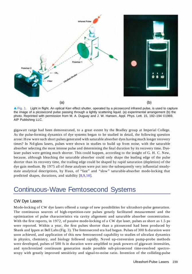
gigawatt range had been demonstrated, to a great extent by the Bradley group at Imperial College.As the pulse-forming dynamics of dye systems began to be studied in detail, the following questionarose: How were such short pulses generated with saturable absorber dyes having much longer recoverytimes? In Nd:glass lasers, pulses were shown in studies to build up from noise, with the saturableabsorber selecting the most intense pulse and determining the final duration by its recovery time. Dye-laser pulses were getting much shorter. This could happen, according to the insight of G. H. C. New,because, although bleaching the saturable absorber could only shape the leading edge of the pulseshorter than its recovery time, the trailing edge could be shaped by rapid saturation (depletion) of thedye gain medium. By 1975 all of these analyses were put into the subsequently very influential steady-state analytical descriptions, by Haus, of “fast” and “slow” saturable-absorber mode-locking thatpredicted shapes, durations, and stability [8,9,10].
Continuous-Wave Femtosecond Systems
CW Dye LasersMode-locking of CW dye lasers offered a range of new possibilities for ultrashort-pulse generation.The continuous sources of high-repetition-rate pulses greatly facilitated measurement and theoptimization of pulse characteristics via cavity alignment and saturable absorber concentration.With the first reports, in 1972, of passive mode-locking of a CW dye laser, pulses as short as 1.5 pswere reported. Within a year, the first pulses shorter than a picosecond had been produced byShank and Ippen at Bell Labs (Fig. 3). The femtosecond era had begun. Pulses of 300 fs duration weresoon achieved, and application of this new femtosecond capability to studies of ultrafast dynamicsin physics, chemistry, and biology followed rapidly. Novel up-conversion pump-probe methodswere developed, pulses of 500 fs in duration were amplified to peak powers of gigawatt intensities,and synchronized continuum generation made possible sub-picosecond time-resolved spectro-scopy with greatly improved sensitivity and signal-to-noise ratio. Invention of the colliding-pulse
▴ Fig. 1. Light in flight. An optical Kerr effect shutter, operated by a picosecond infrared pulse, is used to capturethe image of a picosecond pulse passing through a lightly scattering liquid. (a) experimental arrangement (b) thephoto. Reprinted with permission from M. A. Duguay and J. W. Hansen, Appl. Phys. Lett. 15, 192–194 ©1969,AIP Publishing LLC.
Ultrashort-Pulse Lasers 239

mode-locked (CPM) geometry in 1981 at Bell Labs reduced pulse durations to the 100-fs level andfurther improved stability. The interplay between self-phase modulation and internal dispersion wasanalyzed theoretically and optimized experimentally via prism pairs to reduce durations further tobelow 30 fs. Rapid progress was made by several groups, and with amplification and externalcompression, a record duration of 6 fs, a record that lasted more than a decade, was achieved.Amplified systems, pumped by either 10-Hz frequency-doubled Nd:YAG lasers (Fig. 4) or by kHzcopper-vapor lasers, further extended the capability of femtosecond technology and its range ofapplications. The experiments leading to the 1999 Nobel Prize for chemistry [1] were achieved withthis early femtosecond dye-laser technology.
Semiconductor Diode LasersRecognized as having gain response times very similar to those of dye lasers, semiconductor diode lasersalso became the subject of mode-locking attempts. Shortly after active mode-locking was firstdemonstrated at MIT in 1978, passive mode-locking of a GaAlAs diode laser in an external cavityproduced 5-ps pulse durations at a repetition rate of 850 MHz. Sub-picosecond pulses were laterachieved at higher repetition rates, and integrated CPM geometry devices produced pulses as short as640 fs at a repetition rate of 350 GHz. Impressive demonstrations of high-power, sub-picosecond pulses
◂ Fig. 2. MIT Ultrafast OpticsLab 1985. Erich Ippen andstudent James Fujimoto viewexperiment achieving the firstdemonstration of optical rangingthrough skin, prelude to thedevelopment of OpticalCoherence Tomography byJames Fujimoto.
240 Ultrashort-Pulse Lasers

were achieved by Delfyett and co-workers with pulse compression and semiconductor opticalamplification. Stable, transform-limited pulse generation with semiconductor diodes has, however,for the most part depended on external-cavity-controlled picosecond sources. Pump-probe investiga-tions revealed that ultrafast nonequilibrium carrier dynamics in a semiconductor make the generationof pulses shorter than 1 ps problematic.
Color-Center LasersAn important capability for early 1.5-μm-wavelength ultrafast research was provided by the CWcolor-center laser. First mode-locked by synchronous pumping, the KCl color center laser was thrustinto further prominence by Mollenauer’s demonstration at Bell Labs that it could producefemtosecond pulses by operating as a “soliton laser.” This was achieved by coupling the laseroutput into an anomalously dispersive, soliton-shaping, optical fiber, the output of which was thencoupled back into the laser. It was soon discovered, however, that soliton formation in the fiber wasnot necessary since this coupled-cavity approach also worked with normal-dispersion fiber.Experiments at MIT further revealed the underlying pulse-shortening mechanism to be theinterference of each pulse with a copy of itself that had been self-phase modulated in the fiber.This method, dubbed additive-pulse mode locking (APM), was shown to be compatible with theHaus fast-absorber model. Recognized as a means of creating an “artificial” fast absorber out ofreactive nonlinearity in a lossless dielectric, APM then stimulated the application of this technique toa variety of other lasers [11].
Fiber LasersInterest in fiber lasers developed rapidly after demonstrations at Southhampton of efficient opticalamplification in low-loss fibers doped with rare earths. The key mechanism for ultrashort-pulsegeneration in fiber lasers—nonlinear polarization rotation—was also found to be describable by thefast-absorber model of Haus developed in the context of APM analysis. Earliest progress was madeusing Nd:fiber lasers, in both actively mode-locked and passively mode-locked configurations. By 1992pulse durations as short as 38 fs had been generated at 1.06 μm in a Nd:fiber laser utilizing nonlinearpolarization rotation and prism pairs for dispersion compensation. By the turn of the century, however,
▴ Fig. 3. The first femtosecond laser, a Rhodamine 6G dye laser passively mode-locked by a DODCI saturableabsorber dye. (a) Instruments record the pulse train and a sub-picosecond-resolution pump-probe trace of a molecularresponse. (b) Chuck Shank and Erich Ippen with their laser.
Ultrashort-Pulse Lasers 241

development of the much more efficient Yb:fiber laser led to considerably higher powers at 1 μmwavelengths, with similarly short pulses and more compact geometries. In the late 1980s the attentionof researchers also turned to Er:fiber lasers for wavelengths being used for optical fiber communicationsand where fibers were anomalously dispersive, permitting soliton pulse shaping and shortening. Sub-picosecond pulses were first achieved, at NRL and at Southhampton in figure-eight geometries that useda nonlinear loop mirror for intensity modulation and pulse stabilization, and then, at MIT andSouthhampton, in the ring geometry stabilized by nonlinear polarization rotation that achievedcommon usage. The MIT stretched-pulse laser achieved shorter pulses and higher pulse energies andwas soon commercialized. Although not geared to the high-power applications of Yb:fiber lasers,Er:fiber lasers continue to be pursued for silicon photonics, fiber-based communications, and a varietyof eye-safe applications.
Free-space Solid-state LasersThe discovery of APM and the prospect it offered for CW mode-locked solid-state lasers led to itsapplication to Nd:YAG, Nd:YLF, and Ti:sapphire systems. To permit amplification to high power,Strickland and Mourou in 1985 demonstrated the chirped-pulse amplification (CPA) scheme thatwould ultimately open the door to attosecond and petawatt optical physics. With the discovery of theKerr-lens mode-locked (KLM) Ti:sapphire laser in 1991 by the Sibbett group in St. Andrews, KLMbecame the dominant ultrashort-pulse generation mechanism in free-space solid-state lasers. Femto-second science and technology entered a new era, one with a wider variety of femtosecond-laser media,shorter pulses, extreme powers, ultrabroad bandwidths, and, quite dramatically, the convergence ofultrashort-pulse lasers with ultranarrow-linewidth lasers, precision spectroscopy, and optical clocks.This modern era is the subject of a following article.
References1. A. H. Zewail, Nobel Prize in Chemistry, 1999.2. T. W. Hänsch, Nobel Prize in Physics, 2005.3. J. L. Hall, Nobel Prize in Physics, 2005.4. Ultrafast Phenomena I–XVIII, Springer Series in Chemical Physics (Springer, 1978–2012).5. S. L. Shapiro, ed., Ultrashort Light Pulses, 2nd ed., Vol. 18 of Topics in Applied Physics, (Springer-
Verlag, 1984).6. M. A. Duguay and J. W. Hansen, “An ultrafast light gate,” Appl. Phys. Lett. 15, 192–194 (1969).
◂ Fig. 4. High power, 3-stage,femtosecond dye laser amplifierpumped by frequency-doubledNd:YAG laser at 10 Hz.
242 Ultrashort-Pulse Lasers

7. M. A. Duguay, “Light photographed in flight: Ultrahigh-speed photographic techniques now give us aportrait of light in flight as it passes through a scattering medium,” Am. Sci. 5, 550–556 (1971).
8. H. A. Haus, “Theory of mode locking with a fast saturable absorber,” J. Appl. Phys 46, 3049–3058(1975).
9. H. A. Haus, “Theory of mode locking with a slow saturable absorber,” IEEE J. Quantum Electron. 11,736–746 (1975).
10. E. P. Ippen, “Principles of passive mode locking,” Appl. Phys. B 58, 159–170 (1994).11. A. M. Weiner, Ultrafast Optics (Wiley, 2009).
Ultrashort-Pulse Lasers 243

Ground-Based Telescopesand InstrumentsJames Breckinridge
By 1916, the American astronomer George Ellery Hale (see Fig. 1), a founding member ofThe Optical Society (OSA), had designed and built an optical solar telescope onMt. Wilson and measured the strength of magnetic fields on the Sun using his new
invention: the solar magnetograph. This opened a new era in astronomy and demonstrated to allthe merits of adding optical physics to astronomy. In 1916 the Mt. Wilson Observatory, underthe direction of Hale, had just completed the 60-inch reflecting telescope and it was becomingproductive. Hale hired George Ritchey to figure the 60-inch mirror with a hyperbolic primaryand secondary to extend the field of view (FOV) of the standard Cassegrain telescope. Mostastronomical telescopes today use this optical configuration.
Hale’s career started out at the University of Chicago, where he met A. A. Michelson (OSAHonorary Member) in 1889 when he arrived at the University of Chicago. Hale nominatedMichelson for the Nobel Prize in Physics in 1907. In 1916 Hale, director of Mt. WilsonObservatory, was elected vice-president of OSA. Later (in 1935) he would be awarded theFrederic Ives Medal. Obsessed with optical astronomy since childhood, Hale graduated fromMIT in physics and studied solar physics at Harvard. Hale recognized the advantages ofreflectors and in 1908 used a 60-inch-diameter glass disk given to him by his father to buildthe world’s largest telescope on Mt. Wilson in southern California. By 1916 Hale had obtainedfunds from John D. Hooker, a Chicago philanthropist, and he was building, once again, theworld’s largest telescope: the 100-inch, dedicated in 1917. The 100-inch Hooker ground-basedtelescope is the same size as the Hubble Space Telescope of today. By 1935, Hale had sold theRockefeller Foundation on supporting the design and construction of a 200-inch telescope andset off for a third time to build the world’s largest telescope. George Ellery Hale engaged privatefinancial support for optical telescopes from wealthy barons of the industrial revolution: Yerkes,Carnegie, Hooker, and Rockefeller. Figure 2 shows Hale with Andrew Carnegie in 1910. Haleestablished the tradition of private support that continues today with the Keck telescopes, SloanDigital Sky Survey, and others.
Using new sensitive photographic emulsions developed by C. E. K. Mees (for whom the OSAMees Medal is named), Edwin Hubble (shown in Fig. 3) imaged several Cepheid variables in theAndromeda Galaxy (M-31). The average luminosity of these variables is constant. Therefore, ameasurement of the brightness of these very faint objects in M31 gives a direct measure of thedistance. The measured distance was well outside our galaxy, demonstrating that spiral nebulaewere outside our galaxy and thus proving that the universe was very large indeed! Hubble wenton to show that the universe was expanding, thus providing fundamental evidence for today’s“big bang” cosmology.
In 1930 an Estonian optician, Bernard Schmidt, developed his Schmidt camera for theimaging of large areas of the sky. For the first time, astronomers could make wide-FOVsurveys needed to study the large-scale structure of our galaxy and to create catalogs ofspectral types and variable stars in an efficient manner. The first large-aperture Schmidtcameras were the 40-cm-aperture at Mt. Palomar (1936) and the 60-cm at Case WesternReserve University (1939).
1975–1990
244
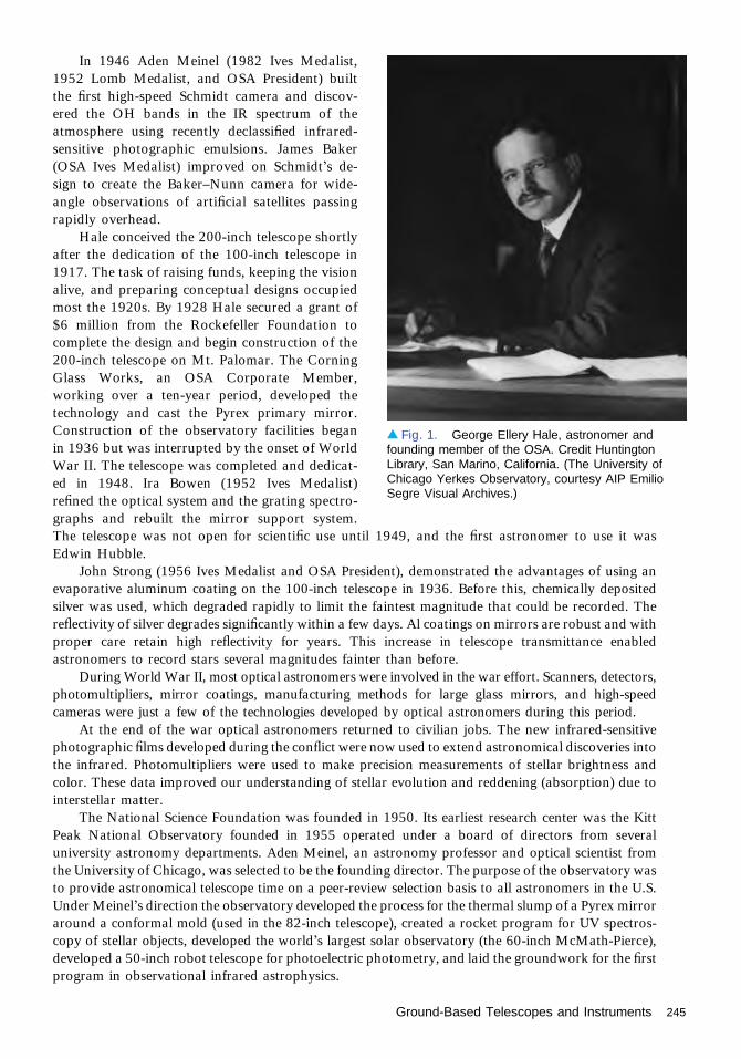
In 1946 Aden Meinel (1982 Ives Medalist,1952 Lomb Medalist, and OSA President) builtthe first high-speed Schmidt camera and discov-ered the OH bands in the IR spectrum of theatmosphere using recently declassified infrared-sensitive photographic emulsions. James Baker(OSA Ives Medalist) improved on Schmidt’s de-sign to create the Baker–Nunn camera for wide-angle observations of artificial satellites passingrapidly overhead.
Hale conceived the 200-inch telescope shortlyafter the dedication of the 100-inch telescope in1917. The task of raising funds, keeping the visionalive, and preparing conceptual designs occupiedmost the 1920s. By 1928 Hale secured a grant of$6 million from the Rockefeller Foundation tocomplete the design and begin construction of the200-inch telescope on Mt. Palomar. The CorningGlass Works, an OSA Corporate Member,working over a ten-year period, developed thetechnology and cast the Pyrex primary mirror.Construction of the observatory facilities beganin 1936 but was interrupted by the onset of WorldWar II. The telescope was completed and dedicat-ed in 1948. Ira Bowen (1952 Ives Medalist)refined the optical system and the grating spectro-graphs and rebuilt the mirror support system.The telescope was not open for scientific use until 1949, and the first astronomer to use it wasEdwin Hubble.
John Strong (1956 Ives Medalist and OSA President), demonstrated the advantages of using anevaporative aluminum coating on the 100-inch telescope in 1936. Before this, chemically depositedsilver was used, which degraded rapidly to limit the faintest magnitude that could be recorded. Thereflectivity of silver degrades significantly within a few days. Al coatings on mirrors are robust and withproper care retain high reflectivity for years. This increase in telescope transmittance enabledastronomers to record stars several magnitudes fainter than before.
During World War II, most optical astronomers were involved in the war effort. Scanners, detectors,photomultipliers, mirror coatings, manufacturing methods for large glass mirrors, and high-speedcameras were just a few of the technologies developed by optical astronomers during this period.
At the end of the war optical astronomers returned to civilian jobs. The new infrared-sensitivephotographic films developed during the conflict were now used to extend astronomical discoveries intothe infrared. Photomultipliers were used to make precision measurements of stellar brightness andcolor. These data improved our understanding of stellar evolution and reddening (absorption) due tointerstellar matter.
The National Science Foundation was founded in 1950. Its earliest research center was the KittPeak National Observatory founded in 1955 operated under a board of directors from severaluniversity astronomy departments. Aden Meinel, an astronomy professor and optical scientist fromthe University of Chicago, was selected to be the founding director. The purpose of the observatory wasto provide astronomical telescope time on a peer-review selection basis to all astronomers in the U.S.Under Meinel’s direction the observatory developed the process for the thermal slump of a Pyrex mirroraround a conformal mold (used in the 82-inch telescope), created a rocket program for UV spectros-copy of stellar objects, developed the world’s largest solar observatory (the 60-inch McMath-Pierce),developed a 50-inch robot telescope for photoelectric photometry, and laid the groundwork for the firstprogram in observational infrared astrophysics.
▴ Fig. 1. George Ellery Hale, astronomer andfounding member of the OSA. Credit HuntingtonLibrary, San Marino, California. (The University ofChicago Yerkes Observatory, courtesy AIP EmilioSegre Visual Archives.)
Ground-Based Telescopes and Instruments 245

In 1960 Meinel left the Kitt Peak National Observatory to become the director of StewardObservatory. There he led the academic program, developed a 92-inch telescope for the University ofArizona on Kitt Peak Mountain and led an initiative to establish a national center of excellence inoptical sciences and engineering, focused on many issues related to technology for astronomicaltelescopes and instruments. In 1964 funding became available, and the University of Arizonaestablished the Optical Sciences Center under Aden’s leadership. Aden established a distinguishedfaculty composed of A. F. Turner (Ives Medalist), R. R. Shannon (1985 OSA President), R. V. Shack(David Richardson Medalist), J. C. Wyant (2010 OSA President), and Roger Angel (OSA Fellow).Figure 4 shows Aden Meinel in 1985 while at NASA/JPL. In 1973 Aden resigned from the directorshipto continue research in solar thermal energy, and Peter Franken (OSA Wood Prize and OSA President)became director.
In the late 1970s Roger Angel (OSA member) experimented with spin casting Pyrex mirrors forastronomical telescopes. This development has led to a family of 8-meter ground-based telescopes,which are revolutionizing our astrophysical understanding of the universe around the world.
In 1920 optical physicist A. A. Michelson (OSA Honorary Member) made the first measurementsof the diameter of a star using a white-light spatial interferometer mounted to the top of the 100-inchtelescope. Atmospheric seeing and telescope stability prohibited useful data using the photographicplates of the time, and both he and his colleague F. G. Pease resorted to visual observations offlickering fringes to measure the diameter of stars. Breckinridge (OSA Fellow) recorded the first directimages of the fringes more than 50 years later. C. H. Townes (1996 Ives Medalist and Nobel
▴ Fig. 2. George Ellery Hale (right) possibly discussing future telescopes with Andrew Carnegie (center) in 1910.(Image courtesy The Observatories of the Carnegie Institution for Science Collection at the Huntington Library, SanMarino, California.)
246 Ground-Based Telescopes and Instruments

Laureate) developed the heterodyne-interferometermethod and made early measurements of details ofstellar atmospheres. Townes also invented thelaser, which astronomers use in conjunction withadaptive optics to provide reference laser guidestars to remove atmospheric turbulence and enablediffraction-limited imaging from large-apertureground-based astronomical telescopes. Over thepast 30 years stellar optical interferometry hasadvanced to become a highly useful tool for theastronomy community. Today, several ground-based observatories use optical interferometry tomeasure high-angular-resolution (<0.001 arc sec)details across the surfaces of stars in the presence ofEarth’s atmospheric turbulence.
This 25-year period from 1975 to 2000 in thehistory of the OSA saw an explosive growth intechnologies to make very large mirrors, long-base-line interferometers, large-area detectors, and spacetelescope systems. Angular resolution on the skywent from 0.5 arc sec to 0.001 arc sec and thesurfaces of hundreds of stars were resolved. Thehigh-speed electronics developed for military andcommercial applications and innovative optical sys-tems enabled long-baseline Michelson stellar inter-ferometers for high-angular-resolution astronomy.Astronomers used atmospheric-turbulence-inducedspeckle patterns to create diffraction-limited imagesat large optical telescopes and thus make the firstdirect images across the surfaces of stars. The Orbit-ing Astronomical Observatory (OAO) was built andlaunched, and the Hubble Space Telescope (HST)was built and corrected.
Mt. Wilson astronomers discovered that largertelescopes, while collecting more photons thansmaller telescopes, did not necessarily mean ob-serving fainter objects. Atmospheric turbulenceintroduces wavefront errors as a function of time.Three major problems confronted the implementa-tion of a system to correct atmospherically inducedtime-dependent phase perturbations. These werethe need for (1) wavefront sensing, (2) a deform-able mirror, and (3) signal and control processing.
Several OSA members pioneered practical solu-tions to these problems to increase the angularresolution on the sky from the seeing-limited 0.5arc sec to 0.005 arc sec for a gain of 10,000 in arearesolution. Although no one person was responsiblefor the invention of adaptive optics, OSA FellowsJohn Hardy and Mark Ealey and others from ITEKOptical Systems (OSA Corporate Member at thetime) led the technology development of ground-based telescope systems to image distant objects
▴ Fig. 3. Edwin Hubble, who proved that theuniverse is much larger than we thought and isexpanding. (Hale Observatories, courtesy AIP EmilioSegre Visual Archives.)
▴ Fig. 4. Aden Meinel in 1985 while at NASA/JPL.(Courtesy NASA/JPL-Caltech P-31041A.)
Ground-Based Telescopes and Instruments 247

through atmospheric turbulence for theAir Force. At Kirtland Air Force Base BobFugate (OSA Fellow) demonstrated laserguide star adaptive optics, a technology incommon use today at the Keck Telescopeand a critical part of the new very large 30-meter-class telescopes. Figure 5 shows alaser guide star being used to compensatefor atmospheric distortion.
Today there are four optical tele-scopes with apertures over 10 meters andnine 8-meter-class optical telescopes in op-eration nightly recording faint radiationfrom the cosmos. The Keck Ten-Meter-Diameter Telescope Project, under thetechnical leadership of Jerry Nelson (OSASenior Member) pioneered the large aper-ture segmented phased telescope in com-mon use today. OSA Corporate MembersCorning Glass and Schott Glass and theUniversity of Arizona under the leadershipof OSA Fellow Roger Angel pioneered thedesign and cost-effective manufacture ofmonolithic mirror blanks 8 meters indiameter.
In 2016, on the occasion of the 100thanniversary of the OSA, there are threevery ambitious projects underway to buildastronomical optical telescopes with 30-meter-aperture-class phased primary mir-rors. Each of these will be equipped withlaser guide star adaptive optics to removethe effects of atmospheric turbulence andthus enable diffraction-limited imagingat resolutions approaching 3 milliarcsecsteerable over a FOV on the order of 20
arc min. The Thirty Meter Telescope (TMT) will have over 500 phased mirror segments. The GiantMagellan Telescope (GMT) will have seven 8-meter mirrors in a hexagonal pattern with one of themirrors at the center. The Extremely Large Telescope (ELT) will have 798 hexagonal segments each1.45 meters across to create a 40-meter-diameter primary mirror.
The past 100 years of optical telescope development has led to profound changes in ourunderstanding of the universe. The next 100 years of optical astronomy may reveal that mankindis not alone in the universe and that life exists and flourishes on planets around distant stars—stars sofar away that our only contact will be with the optical photons reflected from the surface of exoplanets.Innovative spectrometers and polarimeters will be used to estimate the presence of life. Only if humansinvent a way around the limits of speed-of-light travel will two-way communication with exoplanet lifebe possible.
▴ Fig. 5. A laser guide star tuned to the wavelength of sodiumatoms in the atmosphere, providing information on atmosphericturbulence to allow for adaptive optics to compensate andenable improved telescope resolution. (©Laurie Hatch.)
248 Ground-Based Telescopes and Instruments

Space Telescopes for AstronomyJames Breckinridge
In 1946, Lyman Spitzer of Princeton University proposed the construction of a spacetelescope for astrophysics, and Princeton astronomers launched several balloon-bornetelescopes (Stratoscope project) to operate in the dry excellent seeing provided by the upper
stratosphere to demonstrate the value of space science.At the very beginning of NASA, Nancy Roman, Lyman Spitzer, and Art Code laid out a
space satellite program that envisioned a series of modest-aperture telescopes for UV and opticalastronomy [the Orbiting Astronomical Observatory (OAO)] and an R&D program leading to a“large space telescope.” The seeds of the Hubble Space Telescope were sown 35 years before itslaunch.
In 1962 the world’s first space telescope was launched, and it recorded the UV spectrum ofthe Sun. The OAO program became a series of three space telescopes. The first OAO was to carryexperiments, and observing time was to be shared between the two university groups thatproduced the instruments. However, when that satellite was launched, it almost immediately self-destructed before the scientific instruments could be turned on.
NASA quickly organized an additional launch using flight spares of the satellite and thescientific instruments. That satellite was successful and is referred to now as OAO-2. It waslaunched 7 December 1968, carried 11 UV telescopes, and operated until 1973. OAO-2discovered that comets are surrounded by enormous halos of hydrogen several hundredthousand kilometers across and made observations of novae to find that their UV brightnessoften increased during the decline in their optical brightness.
OAO-3 (Copernicus) was orbited in August of 1972 and carried an 80-cm-diameter telescopefor UV astronomy. OAO-3 successfully operated for 14 years and established an excellentreputation for the highest-quality astronomical data at the time. The Copernicus mission playeda large role in winning the support of the wider astronomical community for space astronomy, notonly because of the very high-quality data it produced, covering the UV to below the Lyman limit,but also because of the serious commitment Spitzer and his Princeton colleagues showed to makingthe data available and easily interpretable. Complete spectra were obtained for only about 500stars, very modest by today’s standards. But the scientific impact of those spectra was huge!
The concept for a series of four large telescopes, called the “Great Observatories,” evolved atNASA starting in the 1980s. In order of increasing wavelength they were Compton Gamma RayObservatory (CGRO), Advanced X-Ray Astrophysics Facility (AXAF), now called Chandra, theHubble Space Telescope (HST), and the Space Infrared Telescope Facility (SIRTF), now calledSpitzer. Optical Society (OSA) members had a major role in the development of AXAF, Chandra,and Spitzer.
HST started out as the Large Space Telescope (LST) with a 3-meter aperture. Soon the realityof the launch vehicle capacity set in and NASA issued a request for information to the industryfor a 2.4-meter-diameter telescope. Three optics companies, all corporate members of OSA,responded with feasibility studies: Eastman Kodak, Itek, and Perkin-Elmer. Perkin-Elmer wasselected as the primary telescope provider. NASA recognized that the longest lead item in theprocurement would be the primary mirror and directed Perkin-Elmer to fund Eastman Kodak toprovide a back-up mirror. This mirror is now at the Smithsonian Air and Space Museum. Corningmanufactured both of the ultra-low expansion (ULE) honeycomb 2.4-meter mirror blanks. PEwas responsible for the telescope, and Lockheed Sunnyvale was the spacecraft system integrator.
1975–1990
249

“Large” was dropped from the LST name during its development, and later it was renamed afterEdwin Hubble to become the HST. NASA Headquarters issued a competitive-science solicitation forinstruments. These UV/optical/IR science instruments were designed to be replaced on-orbit.
The HST became the world’s first scientific instrument with the capability to be serviced multipletimes on-orbit. The instruments selected were the Wide-Field Planetary Camera (WF/PC), the FaintObject Camera (FOC), the Faint Object Spectrograph (FOS), the Goddard High Resolution Spectro-graph (GHRS), and the High Speed Photometer (HSP). The HST primary mirror was maintained nearroom temperature. That combined with the poor IR detectors at the time prohibited an infraredastronomy instrument.
HST was scheduled for launch in 1986 soon after the Challenger mission that ended in disaster.The shuttle fleet was grounded for 32 months, delaying the HST launch to late April 1990. By the end ofMay 1990 it was discovered that the telescope could not be focused, and in June the error was suggestedto be spherical aberration. NASA headquarters formed two teams. One, the official NASA opticalfailure review board led by Dr. Lew Allen (a retired four-star general and JPL director) had membershipand support from Optical Society Fellows Roger Angel, Bob Shannon, John Mangus, Jim Breckinridge,and Bob Parks. This team investigated the root cause of the error. The other board, the HubbleIndependent Optical Review Panel (HIORP) was led by Optical Society Fellow Duncan Moore. OpticalSociety Fellows Aden and Marjorie Meinel, Dietrich Korsch, Dan Schulte, Art Vaughan, and GeorgeLawrence, among others, were members. The HIORP had broad membership from the optics andastronomy communities and was charged with making recommendations on how to fix the error. Thenation’s optics community came together to establish that the error was on the primary. Nine opticsgroups composed of many Optical Society Members and Fellows across the country made independentmeasurements on the PE test apparatus hardware and on digital images recorded by the hardware on-orbit. The recording of star images across the field of view and at different telescope focus settingsprovided a diverse set of image data for the new prescription retrieval algorithms. For the first time, theon-orbit optical prescription was determined precisely. The intensity of this work is evidenced by thefact that it was completed over a ten-week period to meet the instrument rebuild schedule for a repairmission launch.
An accurate value for the telescope primary-mirror conic constant and the fact that the error wasisolated to the primary enabled corrective optics to be integrated into a newly built WF/PC2 (designedand built by NASA/JPL), and a new optical system called COSTAR. COSTAR was designed and builtby Ball, an Optical Society Corporate Member. Both instruments were inserted into HST on the firstrepair mission. The COSTAR optical system replaced the HSP instrument. This new opticalsystem corrected the wavefront for the Faint Object Spectrograph (FOS), the Faint Object Camera
(FOC), and the GHRS. In 1997 the IRsystem NICMOS was launched replacingCOSTAR to give the telescope its first IRcapability to 2-μm wavelength.
Today, at the one hundredth anniver-sary of The Optical Society, the HST hasbeen successfully operating for 26 years.By far it is the most productive scientificUV/optical instrument ever known, a spec-tacular monument to the space optics com-munity and the many dedicated OpticalSociety members who saved the missionfrom disaster. Figure 1 is a photo of theHST in orbit taken from the space shuttleafter a service mission. One of the mostfamous and spectacular photos taken byHST is shown in Fig. 2. It is the so-called“pillars of creation” in the Eagle Nebulawhere stars, and by implication their▴ Fig. 1. The HST in orbit. (Image courtesy of NASA.)
250 Space Telescopes for Astronomy

exoplanet systems, are seen forming in thedust clouds.
The x-ray telescope mission, Chan-dra, was launched in 1999, 33 yearsafter the proposal by Riccardo Giacconiand Harvey Tananbaum. Chandra usestwo sets of nested-cylinder mirrors in thehyperbola–parabola configuration of theWoljter type-2-configuration grazing-incidence x-ray telescope built by East-man Kodak. Chandra’s angular resolu-tion is unmatched: between 80% and95% of the incoming x-ray energy isfocused into a 1-arcsec circle. Leon vanSpeybroek led the details of the opticaldesign and the fabrication of the mirrors.Furthermore, x-rays reflect only at glanc-ing angles, like skipping pebbles across apond, so the mirrors must be shaped likecylinders rather than the familiar dishshape of mirrors on optical telescopes.The Chandra X-ray Observatory con-tains four co-aligned pairs of mirrors.Figure 3 shows an image of the CrabNebula recorded with the ACIS instrument superposed upon an image recorded with HST to showthe value of multispectral (visible and x-ray) imaging science.
Today, at the one hundredth anniversary of Optical Society, the Chandra has been successfullyoperating for 15 years, three times its design lifetime, and it remains in highly productive operation.
Much excellent IR astronomy from telescopes on the ground has been done through those spectralwindows in the IR not absorbed by the Earth’s atmosphere. However, many exciting astrophysicsproblems require the measurements of cold gas and dust available only using IR space telescopes, whichmeasure the temperature of the universe and need to be colder than the sky they measure. Two majorspace cryogenic IR telescopes were designed, built, and launched to map the IR sky: the Infrared
▴ Fig. 2. The “pillars of creation.” Star formation in the Eaglenebula photographed by the HST. (Image courtesy of NASA,ESA, STScI, J. Hester and P. Scowen [Arizona State University].)
▸ Fig. 3. This composite image uses datafrom three of NASA’s Great Observatories. TheChandra x-ray image is shown in light blue, theHST optical images are in green and dark blue,and the Spitzer Space Telescope’s infraredimage is in red. The size of the x-ray image issmaller than the others because ultra-high-energy x-ray-emitting electrons radiate awaytheir energy more quickly than the lower-energyelectrons emitting optical and infrared light. Theneutron star, which has mass equivalent to theSun crammed into a rapidly spinning ball ofneutrons 12 miles across, is the bright white dotin the center of the image. (X-Ray: NASA/CXC/J. Hester [ASU]; Optical: NASA/ESA/J. Hester &A. Loll [ASU]; Infrared: NASA/JPL-Caltech/R. Gehrz [Univ. Minn.])
Space Telescopes for Astronomy 251

Astronomical Satellite (IRAS) and Spitzer. Launched in 1983, the IRAS telescope system, whosescientific development was led by Gerry Neugebauer, was the first space observatory to perform an all-sky survey at IR wavelengths. Engineering and development of the optical system was completed at BallAerospace, an Optical Society Corporate Member, teamed with Steve Macenka, an Optical SocietyFellow, at JPL. IRAS discovered over 350,000 new sources, including stellar gas and dust envelopesnow known to be the birthplaces of exoplanet systems, some possibly similar to our own solar system.The Spitzer telescope system, the fourth and final telescope in the Great Observatory series, waslaunched in 2003 into an Earth-trailing orbit. The primary, secondary, and metering structure are allfabricated from berylium. The optics were configured at Tinsley, and cryo testing was carried out atJPL. Diffraction-limited imaging at 6.5 μm over a 30-arc-min field of view was achieved.
By the year 2000, plans were underway to build an even larger space telescope, and NASA fundedthe Next Generation Space Telescope (NGST) study, which led to the James Webb Space Telescope(JWST), now scheduled for launch in 2019, in time to start the second hundred years of The OpticalSociety. John Mather, Nobel Prize Laureate in Physics 2006 and Optical Society Fellow, was the chiefscientist for the project during its formative years. This telescope builds on the success of the largeground-based segmented telescopes, e.g., Keck. Telescopes with segmented primary mirrors that aremechanically deployed once the spacecraft is in orbit make possible very large space telescopes.
Recently several smaller space optics systems have revolutionized our understanding of theuniverse. These are: WISE, COBE, GALEX, Herschel, Planck, WIRE, WISE, and WMAP. The SOFIAis a 3-meter telescope mounted in a B747 for IR observations above the atmosphere. The Kepler spacetelescope launched March 2009 is a 0.95-meter clear-aperture Schmidt camera precision radiometerthat contains arrays of CCDs totaling 95 megapixels staring at 140,000 stars across a FOV of 105 deg2
in the constellation of Cygnus. The Kepler mission has discovered several thousand exoplanets and willcontinue to revolutionize our understanding of the evolution of planetary systems, stellar atmospheres,and stellar interiors as the enormous database is analyzed in detail over the coming decade.
Today one of the most exciting space optics programs is the design and construction of hyper-contrast optical systems to characterize exoplanets in the presence of the intense radiation from thecentral star of the exoplanet system. Terrestrial planets are 1 part per trillion as bright as the centralstar. Spectrometric measurements are required of the radiation reflecting and emitting from theexoplanet. These measurements provide data to estimate planetary surface and atmospheric composi-tion! Direct observation of rocky terrestrial planets, which might harbor life as we know it, requireslarge-aperture telescopes. This is an opportunity to answer one of humanity’s most compellingquestions: Are we alone in the universe?
In addition to using spectrometric measurements to resolve the question of composition, opticalspectrometers are also used to determine the radial (along the line of sight) velocity as a function of timeto an accuracy of centimeters per second. Precision optical astrometry is used to determine the motionof stars across the sky to precisions approaching microarcsec. These two measurements provide thedata we need to calculate the orbit of the planet about its parent star.
Direct images and spectra of exoplanets at contrast levels of 10-10 are needed so astronomers canrecord the light reflected from the exoplanet and search for life signatures in the atmosphere and on thesurface. All of these require new-technology optical systems operating in the harsh space environmentout from under the turbulence of the Earth’s atmosphere. Today, astronomical science, enabled byinnovative optical telescope and instrument design, is on the threshold of revealing details on theevolution of the universe and the presence of life beyond Earth.
The JWST is the largest space optical system under construction now. It represents the state of theart in optical design, engineering, fabrication, and testing. The JWST will replace the spectacularlysuccessful Hubble Space Telescope with a much more capable system promising further astoundingdiscoveries.
252 Space Telescopes for Astronomy
Contact Lenses for VisionCorrection: A Journey from Rareto CommonplaceIan Cox
Although the first practical contact lens was described in 1888 [1], glass-blown shellsformed individually to rest on the sclera and vault across the cornea were the norm untilthe 1930s. The advent of polymethyl methacrylate (PMMA) made it possible, in a
method pioneered by William Feinbloom [2], to process an all-plastic lens that could be fitted bycustom molding or trial fitting from a range of premade lenses. This reduced the weight and costof lenses while improving comfort and wearing times. It was not until 1948 that Kevin Tuohy, anoptician, made the first corneal contact lens [3]. Accidentally cutting through a scleral shell at theedge of the optic zone, Tuohy tried the small-diameter lens that was left on his own eye andquickly realized that a lens fitted within the cornea could be more comfortable and provide longerwearing times than a scleral shell. The realization by Smelser and Ozanics that oxygen for cornealmetabolism came directly from the atmosphere led to a major shift to corneal contact lensesbecause the fit could be adjusted to replenish the oxygenated tear film with every blink, thusextending comfortable wearing times from just a few hours. The contact lens market expandedwith commercially available corneal contact lens designs enabling the correction of myopia,hyperopia, astigmatism, and even novel bifocal designs for presbyopia correction.
Otto Wichterle (Fig. 1) was a brilliant Czech polymer chemist who made the world’s first“soft” contact lenses from his newly invented HEMA hydrogel material [4]. This 38% watercontent material was highly flexible, oxygen permeable, and significantly more comfortable thanthe rigid PMMA corneal contact lenses that were available. Although working behind the “IronCurtain,” an American patent company acquired the intellectual property rights from Wichterleand licensed them to Bausch & Lomb (B&L). The company licensed both the material and thenovel “spincasting” manufacturing technique that Wichterle had developed in his own kitchen.The prototype for this production method was built from an erector set, powered by the electricmotor from his phonograph (Fig. 2). Henry Knoll, a physicist working at B&L and one of a teamassigned to developing the Wichterle prototypes, pointed out the difficulty in working with thishydrogel material. “The first lens we released commercially was called the C series lens, we builtthe A series and the B series but neither would stay on the eye after a few blinks. Managementsaid if the third design didn’t work we would give up on the project.” The C-series contact lensdesign (Fig. 3) fitted the eye, and although the optics were compromised by the wildy asphericposterior lens surface produced by the “spincasting” manufacturing process, the lens was acommercial success when launched in 1971 following FDA approval. The dramatically improvedcomfort changed the contact lens industry in the U.S., and ultimately the world, with rigidcorneal contact lenses today accounting for less than 10% of the lenses fitted worldwide. OttoWichterle was recognized for his great contributions to the world of optics when he was awardedthe R. W. Wood Medal by The Optical Society (OSA) in 1984.
Initially available only in spherical powers to correct myopia and later hyperopia, softlenses to correct astigmatism were first introduced in the U.S. in the early 1980s. Unlike rigidlenses which “mask” the astigmatic component of the cornea, soft lenses conform to the
1975–1990
253
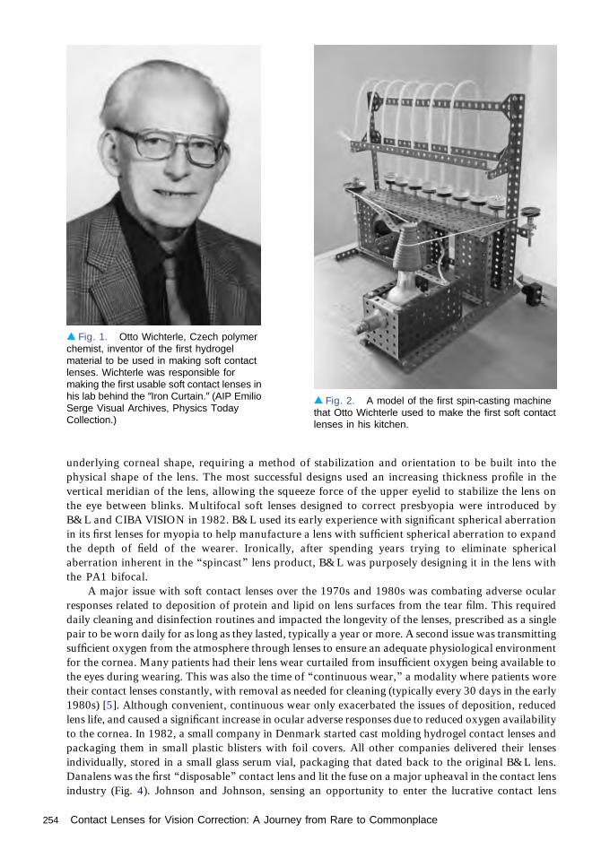
underlying corneal shape, requiring a method of stabilization and orientation to be built into thephysical shape of the lens. The most successful designs used an increasing thickness profile in thevertical meridian of the lens, allowing the squeeze force of the upper eyelid to stabilize the lens onthe eye between blinks. Multifocal soft lenses designed to correct presbyopia were introduced byB&L and CIBA VISION in 1982. B&L used its early experience with significant spherical aberrationin its first lenses for myopia to help manufacture a lens with sufficient spherical aberration to expandthe depth of field of the wearer. Ironically, after spending years trying to eliminate sphericalaberration inherent in the “spincast” lens product, B&L was purposely designing it in the lens withthe PA1 bifocal.
A major issue with soft contact lenses over the 1970s and 1980s was combating adverse ocularresponses related to deposition of protein and lipid on lens surfaces from the tear film. This requireddaily cleaning and disinfection routines and impacted the longevity of the lenses, prescribed as a singlepair to be worn daily for as long as they lasted, typically a year or more. A second issue was transmittingsufficient oxygen from the atmosphere through lenses to ensure an adequate physiological environmentfor the cornea. Many patients had their lens wear curtailed from insufficient oxygen being available tothe eyes during wearing. This was also the time of “continuous wear,” a modality where patients woretheir contact lenses constantly, with removal as needed for cleaning (typically every 30 days in the early1980s) [5]. Although convenient, continuous wear only exacerbated the issues of deposition, reducedlens life, and caused a significant increase in ocular adverse responses due to reduced oxygen availabilityto the cornea. In 1982, a small company in Denmark started cast molding hydrogel contact lenses andpackaging them in small plastic blisters with foil covers. All other companies delivered their lensesindividually, stored in a small glass serum vial, packaging that dated back to the original B&L lens.Danalens was the first “disposable” contact lens and lit the fuse on a major upheaval in the contact lensindustry (Fig. 4). Johnson and Johnson, sensing an opportunity to enter the lucrative contact lens
▴ Fig. 1. Otto Wichterle, Czech polymerchemist, inventor of the first hydrogelmaterial to be used in making soft contactlenses. Wichterle was responsible formaking the first usable soft contact lenses inhis lab behind the “Iron Curtain.” (AIP EmilioSerge Visual Archives, Physics TodayCollection.)
▴ Fig. 2. A model of the first spin-casting machinethat Otto Wichterle used to make the first soft contactlenses in his kitchen.
254 Contact Lenses for Vision Correction: A Journey from Rare to Commonplace

market in the U.S., acquired the Danalens produc-tion process and a small contact lens companycalled Vistakon whose hydrogel lens material wasalready approved by the FDA. Within five yearsVistakon launched the first disposable lens in theUnited States (1987). Launched as a continuous-wear lens to be replaced weekly, the marketplaceeventually dictated its use as a daily wear only (noovernight wear) lens with a biweekly replacementschedule. Although the oxygen permeability of thesenew lenses was no better, the fact that patients couldbuy them for only a few dollars each (previouslypatients would typically pay hundreds of dollars fora pair of lenses) and replace them frequently madethem a rapid success. Toric and multifocal optionssoon followed as companies invested in themanufacturing capacity necessary to process thesecomplex designs for a low cost. As manufacturingtechnology improved and cost of goods decreased,the option of a truly disposable lens, one that wasworn once and then discarded, became a reality.Vistakon again led the industry by launching thefirst daily disposable contact lens in 1994. Althoughthe cost of each lens was less than one dollar to thepatient, the high annual cost prohibited rapid adop-tion of daily disposables, and it was another decadebefore this modality made any significant inroadsinto the marketplace.
In the intervening years, others were stillchasing the ultimate in convenience, a lens thatwas so physiologically compatible with the eyethat it could be worn continuously for 30 dayswithout the risk of adverse ocular responses. The massive oxygen permeability of silicone elastomerled researchers to develop lenses made from this material in the late 1970s, with Dow Corning beingthe most well-known manufacturer to try this alternative material. Although physiologicallysuccessful, silicone elastomer lenses had one undesirable and potentially dangerous flaw: theirrubber-like nature generated negative pressure under the lens during wear and resulted in the lenssticking to the eye. The only path forward was a hybrid material, a silicone hydrogel. Althoughseemingly simple, material scientists were essentially trying to mix “oil and water” and maintain atransparent material. B&L, the first company to bring soft hydrogel contact lenses to the market in1972, were also the first to develop a commercially viable silicone hydrogel lens. This lens providedfour times the oxygen transmission of hydrogel lenses, and it was approved for up to 30 days ofcontinuous wear in 1999. Clinicians immediately noted that highly oxygen transmissive lenseseradicated significant adverse responses related to oxygen deprivation at the cornea, but they wereslow to adopt silicone hydrogel lenses due to the up to 30 days continuous-wear indication awardedby the FDA. Experience over the years had shown that corneal ulcers, or microbial keratitis, was thesingle most significant adverse response associated with continuous wear, with the FDA limitingapproval of all hydrogel lenses to six nights maximum in 1989 over their concern with incidencelevels. Clinicians and companies now recommend silicone hydrogel lenses for daily wear or extendedwear with monthly or more-frequent replacement, but the largest area of growth within the contactlens industry is the daily wear modality.
Currently available soft lens materials provide excellent physiological compatibility with the eye,and the cornea specifically, when worn in a daily wear modality, and so the focus of the industry has
▴ Fig. 3. The first commercially available soft lens inthe U.S., the Bausch & Lomb “C” Series. (Courtesy ofAndrew Gasson.)
Contact Lenses for Vision Correction: A Journey from Rare to Commonplace 255

moved to improving end-of-day comfort throughdesign and material formulation, as well as im-proved optical performance. This last developmenthas been driven by the development of clinicallyapplicable Hartmann–Schack wavefront sensors.Porter et al. [5] measured the wavefront error ofthe eye of a large contact-lens-wearing population,identifying that the Strehl ratio of the eye can besignificantly improved by correcting at least themajor higher-order wavefront aberrations. Thistechnique proved to be an ideal method to evaluatethe optical performance of contact lenses on and offthe eye, and OSA members led the development ofstandards for reporting the optical aberrations ofeyes. Ideally, individual prescription contact lensesshould be made for each eye based on wavefrontmeasurements performed in a clinical setting, en-abling correction of all higher-order aberrations forimproved low-light vision. Although the feasibilityof this concept has been demonstrated by Marsack,the challenge for industry is to deliver these custom-optics contact lenses in the same low-cost, dispos-able paradigm that patients and clinicians are cur-rently using. In the meantime, at least one manufac-turer (B&L) is altering the inherent spherical aber-ration of their spherical and toric contact lens
products using aspheric optical surfaces to minimize the spherical aberration magnitude of the eyewith the lens in place and improve the quality of vision under low-illumination conditions.
References1. R. M. Pearson and N. Efron, “Hundredth anniversary of August Müller’s inaugural dissertation on
contact lenses,” Surv. Ophthalmol. 34, 133–141 (1989).2. R. B. Mandell, Contact Lens Practice, 4th ed. (Charles C. Thomas, 1988).3. K. M. Tuohy, “Contact lens,” U.S. patent 2,510,438, filed 28 February 1948. Issued 6 June 1950.4. O. Wichterle and D. Lim, “Hydrophilic gels for biological use,” Nature 185, 117–118 (1960).5. J. Porter, A. Guirao, I. G. Cox, and D. R. Williams, “Monochromatic aberrations of the human eye in a
large population,” J. Opt. Soc. Am. A 18, 1793–1803 (2001).
▴ Fig. 4. Examples of the first disposable soft contactlens. Although the Danalens lens design and materialwere not unique, the packaging and delivery conceptwere innovative and ultimately changed the waycontact lenses were sold the world over. (Courtesy ofAndrew Gasson.)
256 Contact Lenses for Vision Correction: A Journey from Rare to Commonplace

Excimer Laser Surgery: Layingthe Foundation for LaserRefractive SurgeryJames J. Wynne
Discovery of Excimer Laser SurgeryOn 27 November 1981, the day after Thanksgiving, Rangaswamy Srinivasan brought Thanks-giving leftovers into the IBM Thomas J. Watson Research Center, where he irradiated turkeycartilage with ∼10-ns pulses of light from an argon fluoride (ArF) excimer laser. This irradiationproduced a clean-looking “incision,” as observed through an optical microscope. Subsequently,Srinivasan and his IBM colleague, Samuel E. Blum, carried out further irradiation ofcartilage samples. Srinivasan gave a sample to the author, and, for comparison, it was irradiatedwith ∼10-ns pulses of 532-nm light from a Q-switched, frequency-doubled, Nd:YAG laser. Thisirradiation did not incise the sample; rather it created a burned, charred region of tissue. Figure 1shows three different views and magnifications of scanning electron micrographs (SEMs) of thesample, revealing the stunningly different morphology of the two irradiated regions: the cleanincision with no evidence of thermal damage, etched steadily deeper by a sequence of pulses of193-nm light, and the damaged region produced by the pulses of 532-nm light.
Realizing that Srinivasan, Blum, and the author had discovered something novel andunexpected, they wrote an invention disclosure, describing multiple potential surgical applica-tions. They anticipated that the absence of collateral damage to the tissue underlying andadjacent to the incision produced in vitro would result in minimal collateral damage when thetechnique was applied in vivo. The ensuing healing would not produce scar tissue. This insight, aradical departure from all other laser surgery, was unprecedented and underlies the subsequentapplication of their discovery to laser refractive surgery.
Background to This DiscoveryAs manager of the Laser Physics and Chemistry department at the Watson Research Center, oneof the author’s responsibilities was to ensure that there was access to the best and latest laserinstrumentation. When the excimer laser became commercially available, the author purchasedone for use by the scientists in his department. Since 1960, Srinivasan had been studying theaction of ultraviolet radiation on organic materials, e.g., polymers. In 1980, he and his technicalassistant, Veronica Mayne-Banton, discovered that the ∼10-ns pulses of far ultraviolet radiationfrom the excimer laser could photo-etch solid organic polymers, if the fluence of the radiationexceeded an ablation threshold [1,2].
Srinivasan and the author then speculated about whether an animal’s structural protein,such as collagen, which contains the peptide bond as the repeating unit along the chain, wouldalso respond to the ultraviolet laser pulses. They knew that when skin was incised with a sharpblade, the wound would heal without fibrosis and, hence, no scar tissue. Conceivably, living skin
1975–1990
257

or other tissue, when incised by irradiationfrom a pulsed ultraviolet light source,would also heal without fibrosis andscarring.
Physics of AblationAblation occurs when the laser fluence issuch that the energy deposited in a volumeof tissue is sufficient to break the chemicaland physical bonds holding the tissue to-gether producing a gas that is under highpressure. The gas then expands away fromthe irradiated surface, carrying with itmost of the energy that was deposited intothe volume that absorbed the energy. If theabsorption depth is sufficiently shallowand the pulse duration is sufficiently short,the expanding gas can escape from thesurface in a time that is short comparedwith thermal diffusion times, leaving aclean incision with minimal collateraldamage. These conditions are readily sat-isfied by a short pulse of short-wavelengthlight having sufficient energy/unit area,given that protein and lipids are verystrong absorbers of ultraviolet light.
Next StepsTo develop practical innovative applica-tions, Srinivasan, Blum, and the authorneeded to collaborate with medical/surgicalprofessionals. To interest these profes-sionals, they etched a single human hair bya succession of 193-nm ArF excimer laserpulses, producing an SEM micrograph(Fig. 2), showing 50-μm-wide laser-etchednotches.
While IBM was preparing a patentapplication, Srinivasan, Blum, and theauthor were constrained from discussingtheir discovery with people outside IBM.But a newly hired IBM colleague, RalphLinkser, with an M.D. and a Ph.D. in
physics, obtained fresh arterial tissue from a cadaver, and Linsker, Srinivasan, Blum, and the authorirradiated a segment of aorta with both 193-nm light from the ArF excimer laser and 532-nm light fromthe Q-switched, frequency-doubled Nd:YAG laser. Once again the morphology of the tissue adjacent tothe irradiated/incised regions, examined by standard tissue pathology techniques (Fig. 3), wasstunningly different, with irradiation by the 193-nm light showing no evidence of thermal damageto the underlying and adjacent tissue [3].
▴ Fig. 1. Three scanning electron micrographs of laser-irradiated turkey cartilage, recorded from different perspectivesand with different magnification. In the bottom micrograph, arrowsindicate the regions irradiated with 193-nm light and 532-nm light.For each wavelength, the fluence/pulse and number of pulses ofirradiation are given.
▴ Fig. 2. Scanning electron micrograph of a human hair etchedby irradiation with an ArF excimer laser; the notches are 50 μm wide.
258 Excimer Laser Surgery: Laying the Foundation for Laser Refractive Surgery

This experimental study on freshlyexcised human tissue confirmed that exci-mer laser surgery removed tissue by afundamentally new process. Srinivasan,Blum, and the author’s vision—that exci-mer laser surgery would allow tissue tobe incised so cleanly that subsequenthealing would not produce scar tissue—was more than plausible; it was likely,subject to experimental verification onlive animals.
First Public DisclosureAfter their patent application was filed,Srinivasan, Blum, and the author submit-ted a paper to Science magazine. Theirpaper was rejected because one of thereferees argued that irradiation with far-ultraviolet radiation (far-UV) would becarcinogenic, making the technique moreharmful than beneficial. Since Srinivasanhad been invited to speak about his workon polymers at the upcoming CLEO 1983conference co-sponsored by the OSA,Srinivasan, Blum, and the author wantedto get a publication into print as soon aspossible. Therefore, they resubmitted theirpaper to Laser Focus, including someremarks about the new experiments onhuman aorta, and the Laser Focus issuecontaining their paper [4] was pub-lished simultaneously with CLEO 1983.Srinivasan’s talk on 20 May, entitled“Ablative photodecomposition of organicpolymer films by far-UV excimer laserradiation,” included the first public disclosure that the excimer laser cleanly ablated biologicalspecimens, as well as organic polymers.
From Excimer Laser Surgery to ArF ExcimerLaser-based Refractive SurgeryAt that very same CLEO 1983 meeting, Stephen Trokel and Francis L’Esperance, two renownedophthalmologists, gave invited talks on applications of infrared lasers to ophthalmic surgery. Theauthor attended both of their talks and was amazed at the results they obtained in successfully treatingtwo very different ophthalmic conditions that were not candidates for excimer laser treatment.However, Trokel knew of ophthalmic conditions, such as myopia, that could be corrected by modifyingthe corneal curvature. A treatment known as radial keratotomy (RK) corrected myopia by using a coldsteel scalpel to make radial incisions at the periphery of the cornea. Upon healing, the curvature of thefront surface of the cornea was reduced, thereby reducing myopia. While this technique rarely yielded
▴ Fig. 3. Left side: Photo micrographs of human aortairradiated by 1000 pulses of ArF excimer laser 193-nm light; lowerimage is a magnified view of the right-hand side of the laser-irradiated region. Right side: Photo micrographs of human aortairradiated by 1000 pulses of Q-switched, frequency-doubledNd:YAG laser 532-nm light; lower image is a magnified view ofthe right-hand side of the laser-irradiated region. (By permissionof John Wiley & Sons, Inc.)
Excimer Laser Surgery: Laying the Foundation for Laser Refractive Surgery 259

uncorrected visual acuity of 20/20, the patient’s myopia was definitely reduced. One serious drawbackof RK was that the depth of the radial incisions left the cornea mechanically less robust. The healed eyewas more susceptible to “fracture” under impact, such as might occur during an automobile collision.Trokel speculated that the excimer laser might be a better scalpel for creating the RK incisions.
Upon learning of Srinivasan, Blum, and the author’s discovery of excimer laser surgery, Trokel,who was affiliated with Columbia University’s Harkness Eye Center in New York City, contactedSrinivasan and brought enucleated calf eyes (derived from slaughter) to the Watson Research Center on20 July 1983. Srinivasan’s technical assistant, Bodil Braren, participated in an experiment using the ArFexcimer laser to precisely etch the corneal epithelial layer and stroma of these calf eyes. The publishedreport of this study is routinely referred to by the ophthalmic community as the seminal paper in laserrefractive surgery [5].
To conduct studies on live animals, the experiments were moved to Columbia’s laboratories. Suchexperiments were necessary to convince the medical community that living cornea etched by the ArFexcimer laser does not form scar tissue at the newly created surface and the etched volume is not filled inby new growth. The first experiment on a live rabbit in November 1983 showed excellent results inthat, after a week of observation, the cornea was not only free from any scar tissue but the depressionhad not filled in. Further histological examination of the etched surface at high magnification showedan interface free from detectable damage.
L’Esperance, also affiliated with Columbia, thought beyond RK and filed a patent applicationdescribing the use of excimer laser ablation to modify the curvature of the cornea by selectivelyremoving tissue from the front surface, not the periphery of the cornea. His U.S. patent 4,665,913 [6]specifically describes this process, which was later named photorefractive keratectomy (PRK).
Soon ophthalmologists around the world, who knew of the remarkable healing properties of thecornea, were at work exploring different ways to use to excimer lasers to reshape the cornea. From liveanimal experiments, they moved to enucleated human eyes, then to blind eyes of volunteers, where theycould study the healing. Finally, in 1988, a sighted human was treated with PRK and, after the corneahad healed by epithelialization, this patient’s myopia was corrected.
Development of an alternative technique, known as laser in situ keratomileusis (LASIK) com-menced in 1987. In LASIK, a separate tool is used to create a hinged flap at the front of the cornea,preserving the epithelial layer and exposing underlying stroma, which is then irradiated and reshapedby the ArF excimer laser. After such irradiation, the flap is repositioned over the irradiated area, itadheres rather quickly, and the patient is soon permitted to blink, while the surgeon makes sure that theflap stays in place. No sutures are required. The flap acts like the cornea’s own “bandaid,” minimizingthe discomfort of blinking. LASIK offers the patient much less discomfort than PRK and much morerapid attainment of ultimate visual acuity following surgery. For these reasons patients prefer LASIK toPRK, and far more LASIK procedures are performed than PRK procedures.
However, patients whose corneas are much thinner than average are not good candidates forLASIK, because a post-LASIK cornea is mechanically weaker than a post-PRK cornea, making thecornea more susceptible to impact or high-acceleration injury. In fact, the U.S. Navy accepts candidatesinto training programs for the Naval Air Force who had their visual acuity improved by PRK, but itdoes not accept candidates who had LASIK.
Pervasiveness of Laser Refractive SurgerySince the U.S. Food and Drug Administration (FDA) granted approval to manufacturers of laserrefractive surgery systems in 1995, more than 30 million patients have undergone the procedure toimprove their eyesight. While patients choose to undergo this procedure for the obvious cosmeticreasons, many patients are unable to comfortably wear contact lenses. PRK and LASIK offer them a safealternative that actually may cost less than the accumulated cost of wearing and maintaining contactlenses. Further, the U.S. military encourages its ground troops to have laser refractive surgery toeliminate the problems inherent in wearing glasses or contact lenses in combat situations (e.g., the desertsands of the Middle East). Laser refractive surgery can restore visual acuity to better than 20/20 as is
260 Excimer Laser Surgery: Laying the Foundation for Laser Refractive Surgery

required for certain aviators. With further refinements in so-called “custom wavefront-guided” laserrefractive surgery, soon there may be a time when patients undergoing laser refractive surgery mayexpect to achieve visual acuity of 20/10.
Public awareness and interest in laser eye surgery was intense even before FDA approval. On 30January 1987, The Wall Street Journal published an article entitled “Laser shaping of cornea showspromise at correcting eyesight,” and on 29 September 1988, The New York Times published its firstarticle on PRK, entitled “Laser may one day avert the need for eyeglasses.” Subsequent articles in thepress dealt with the progress in the research on PRK, the formation of three U.S. companies to marketthis procedure and approval by the FDA in 1995. At this point, the surgical procedure was discussed atlength in all the popular media, including The Washington Post, The San Francisco Chronicle,Newsweek, and The New York Magazine. On 11 October 1999, Time magazine published a coverstory entitled “The laser fix.”
In August 1998, The National Academy of Sciences issued a pamphlet entitled “Preserving theMiracle of Sight: Lasers and Eye Surgery,” the stated purpose of which was to show “The Path fromResearch to Human Benefit.” One section describes the first experiments that were done at IBMResearch and, subsequently, at Columbia University, leading to the development of PRK [7].
As for the size of the “business” of laser refractive surgery, at a typical cost of $2000/procedure,patients have spent more than $90 billion on PRK and LASIK through the end of 2012.
Srinivasan, Blum, and the author opened the door to this revolution in eye care through theirseminal discovery and subsequent transfer of the technology to the medical/surgical profession. TheOSA presented this group with the R. W. Wood Prize in 2004 “for the discovery of pulsed ultravioletlaser surgery, wherein laser light cuts and etches biological tissue by photoablation with minimalcollateral damage, leading to healing without significant scarring.” In 2013, Srinivasan, Blum, and theauthor received the National Medal of Technology and Innovation from President Obama and the FritzJ. and Dolores H. Russ Prize from the National Academy of Engineering.
References1. R. Srinivasan and V. Mayne-Banton, “Self-developing photoetching of poly(ethylene terephthalate)
films by far-ultraviolet excimer laser radiation,” Appl. Phys. Lett. 41, 576–578 (1982).2. R. Srinivasan and W. J. Leigh, “Ablative photodecomposition: the action of far-ultraviolet (193 nm)
laser radiation on poly(ethylene terephthalate) films,” J. Am. Chem. Soc. 104, 6784–6785 (1982).3. R. Linsker, R. Srinivasan, J. J. Wynne, and D. R. Alonso, “Far-ultraviolet laser ablation of
atherosclerotic lesions,” Lasers Surg. Med. 4, 201–206 (1984).4. R. Srinivasan, J. J. Wynne, and S. E. Blum, “Far-UV photoetching of organic material,” Laser Focus 19,
62–66 (1983).5. S. L. Trokel, R. Srinivasan, and B. Braren, “Excimer laser surgery of the cornea,” Am. J. Ophthalmol.
96, 710–715 (1983).6. F. A. L’Esperance, Jr., “Method for ophthalmological surgery,” U.S. patent 4,665,913 (19 May 1987).7. R. Conlan, “Preserving the miracle of sight: lasers and eye surgery,” in Beyond Discovery: The Path from
Research to Human Benefit (National Academy of Sciences, 1998). http://www.nasonline.org/publications/beyond-discovery/miracle-of-sight.pdf.
Excimer Laser Surgery: Laying the Foundation for Laser Refractive Surgery 261
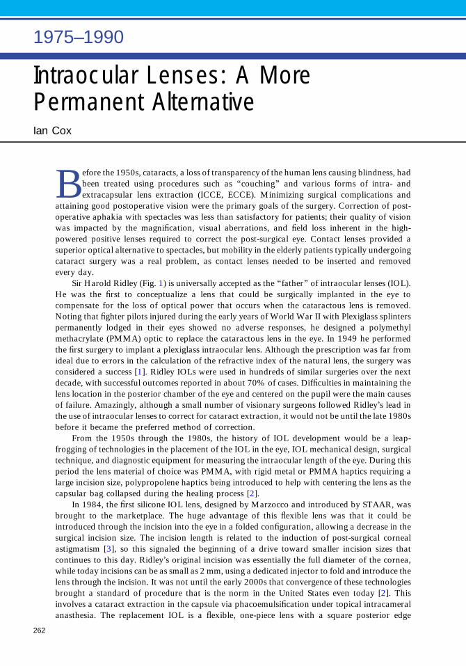
Intraocular Lenses: A MorePermanent AlternativeIan Cox
Before the 1950s, cataracts, a loss of transparency of the human lens causing blindness, hadbeen treated using procedures such as “couching” and various forms of intra- andextracapsular lens extraction (ICCE, ECCE). Minimizing surgical complications and
attaining good postoperative vision were the primary goals of the surgery. Correction of post-operative aphakia with spectacles was less than satisfactory for patients; their quality of visionwas impacted by the magnification, visual aberrations, and field loss inherent in the high-powered positive lenses required to correct the post-surgical eye. Contact lenses provided asuperior optical alternative to spectacles, but mobility in the elderly patients typically undergoingcataract surgery was a real problem, as contact lenses needed to be inserted and removedevery day.
Sir Harold Ridley (Fig. 1) is universally accepted as the “father” of intraocular lenses (IOL).He was the first to conceptualize a lens that could be surgically implanted in the eye tocompensate for the loss of optical power that occurs when the cataractous lens is removed.Noting that fighter pilots injured during the early years of World War II with Plexiglass splinterspermanently lodged in their eyes showed no adverse responses, he designed a polymethylmethacrylate (PMMA) optic to replace the cataractous lens in the eye. In 1949 he performedthe first surgery to implant a plexiglass intraocular lens. Although the prescription was far fromideal due to errors in the calculation of the refractive index of the natural lens, the surgery wasconsidered a success [1]. Ridley IOLs were used in hundreds of similar surgeries over the nextdecade, with successful outcomes reported in about 70% of cases. Difficulties in maintaining thelens location in the posterior chamber of the eye and centered on the pupil were the main causesof failure. Amazingly, although a small number of visionary surgeons followed Ridley’s lead inthe use of intraocular lenses to correct for cataract extraction, it would not be until the late 1980sbefore it became the preferred method of correction.
From the 1950s through the 1980s, the history of IOL development would be a leap-frogging of technologies in the placement of the IOL in the eye, IOL mechanical design, surgicaltechnique, and diagnostic equipment for measuring the intraocular length of the eye. During thisperiod the lens material of choice was PMMA, with rigid metal or PMMA haptics requiring alarge incision size, polypropolene haptics being introduced to help with centering the lens as thecapsular bag collapsed during the healing process [2].
In 1984, the first silicone IOL lens, designed by Marzocco and introduced by STAAR, wasbrought to the marketplace. The huge advantage of this flexible lens was that it could beintroduced through the incision into the eye in a folded configuration, allowing a decrease in thesurgical incision size. The incision length is related to the induction of post-surgical cornealastigmatism [3], so this signaled the beginning of a drive toward smaller incision sizes thatcontinues to this day. Ridley’s original incision was essentially the full diameter of the cornea,while today incisions can be as small as 2 mm, using a dedicated injector to fold and introduce thelens through the incision. It was not until the early 2000s that convergence of these technologiesbrought a standard of procedure that is the norm in the United States even today [2]. Thisinvolves a cataract extraction in the capsule via phacoemulsification under topical intracameralanasthesia. The replacement IOL is a flexible, one-piece lens with a square posterior edge
1975–1990
262

(to reduce posterior capsule opacification),introduced through a 3.0-mm or smallerincision in the cornea and placed fullywithin the capsular bag, with a slight vaultagainst the posterior surface of the capsule.
Having spent 50 years developing thisprocedure to be the preferred option for allcataract surgeries, even in children, theindustry moved its sights to optimizing theoptical performance of IOLs. In 1989David Atchison identified the considerableincrease in spherical aberration created byremoving the natural lens and recom-mended spherical surfaced lens forms thatwould correct the majority of this aberra-tion [4]. He followed this with the sugges-tion that using aspheric surfaces would notbe beneficial, due to the aberrations in-duced by tilt and decentration of the finalIOL after healing. Not to be deterred,Antonio Guirao and several colleagues,including Pablo Artal and Sverker Norrby,measured the image quality of the normalpopulation with age and then of the typicalpsuedophakic population. Led by Norrby,an IOL was developed to correct the aver-age spherical aberration of the post-surgi-cal IOL implanted eye. The lens, releasedto the market by Abbott Medical Optics(AMO) as the TecnisIOL, was designedwith an aspheric anterior lens surface andconsideration of the typical decentrationsthat occur with IOL surgical placementand postoperative healing. A rapid response from Alcon provided lenses that corrected a portion ofthe spherical aberration of the eye and IOL in combination, and Bausch and Lomb provided a sphericalaberration-free IOL design, ignoring the spherical aberration inherent in the aphakic eye. All threelenses met with successful use by surgeons around the world, the more technology minded exploring theconcept of using all three lenses along with Zernike analysis of corneal topography measurements todetermine which lens would come closest to nullifying the spherical aberration of an individual eye.
The next challenge was correcting near vision in the pseudophakic eye, which of course, has noaccommodation after removal of the natural lens. Early attempts at multizonal IOLs for correctingpresbyopia demonstrated marginal success due to poor image quality and led to withdrawal from themarket by the early 1990s, but in 1997 AMO released a simultaneous refractive multifocal lens(distance, intermediate, and near zones of the design were within the patient’s pupil under normalillumination) that gained traction in the marketplace until the early 2000s, when complaints of reducedcontrast and halos at night led to a reduction in use [2]. About this time Alcon introduced a diffractivebifocal IOL design, based on patents bought from 3M but updated with a smaller optic zone (only thecentral 3.6 mm encapsulated the bifocal diffractive element) and an apodized energy profile. The lenshad greatest near power at the center of the pupil (equal distance and near), and a shift biased towarddistance power moving from the center to the periphery of the optic zone, with all light focused atdistance outside the 3.6-mm central diffractive zone. Under its marketed name of ReSTOR, this productmet with great enthusiasm when presented to clinicians and continues to grow in popularity, especiallyin the latest version, which has a lower add power (reduced from +4 D in the original design to +3 D).
▴ Fig. 1. Sir Harold Ridley, universally accepted as the “father”of IOLs, being the first to devise, produce, and implant thefirst PMMA IOL. (© National Portrait Gallery, London. Sir(Nicholas) Harold Lloyd Ridley by Bassano Ltd., half-plate filmnegative, 19 May 1972, NPG x171529.)
Intraocular Lenses: A More Permanent Alternative 263

AMO responded with a modified refractive multifocal marketed as the ReZoom in 2005, and thenreleased a diffractive design in 2010, which was similar to the Alcon product, without the apodizationfeature. Although these types of designs are generally successful, some patients do experience reducedcontrast, ghosting, and doubling with large pupil sizes, particularly in lenses that are decentered relativeto the center of the pupil, as one might expect with designs of this type.
Stuart Cummings, a surgeon, observed in 1989 that patients who had plate haptic silicone IOLsinserted often showed better near reading performance than those fitted with other conventional loophaptic IOL designs, leading him to invent a lens specifically designed to optimize this feature. By addinga weakened portion or “hinge” to the plate haptic, the silicone lens was designed to bend under theintraocular forces occurring with ciliary muscle contraction during accommodation. In this way, theoptics of the lens were traditional monofocal spherical surfaces, but good image quality could beprovided at both distance and near as the optic of the lens moved forward with the accommodativeresponse. Brought to the market under the tradename Crystalens in 2005, this lens was the first, and isstill the only, IOL to have the claim approved by the FDA that it demonstrates “accommodation” of upto 1 D. The exact mechanism of action has not been verified, but it is most probably a combination ofoptic displacement, optic tilt, and optic zone distortion brought about by the accommodative forces ofthe eye increasing the depth of field. Regardless of the mechanism, clinical studies have shown superiornear vision over monofocal lenses, while maintaining equivalent distance visual acuity.
Correction of postoperative astigmatism induced by surgery was always an issue with cataractsurgery, as large incisions closed by sutures led to significant changes in corneal topography [3].Typically these changes would be corrected by progressive spectacles worn by the pseudophakic patientpostoperatively. However, the acceptance of multifocal IOLs through the 2000s in conjunction withsmall, sutureless incision sizes led to an expectation from many patients that they could spend most oftheir waking hours without a distance spectacle correction. This paradigm opened the demand for toricIOLs in those patients who had significant corneal astigmatism prior to cataract surgery. Althoughoffered to the industry in 1994 by STAAR on their plate silicone lens platform, significant adoption oftoric IOLs only began with the introduction of the Acrysof Toric IOL by Alcon in 2005. Althoughoptically the design is straightforward, a successful toric IOL must demonstrate stability of the cylinderaxis from lens placement at the time of surgery until complete healing 3 to 6 months postoperatively.This lens, along with competitor offerings, typically shows stability that makes the use of toric lenses abenefit in eyes with 1.25 D of astigmatism or greater postoperatively.
IOLs have come a long way since their beginnings in 1949, and today they are the preferred methodof correction following cataract surgery regardless of patient age or refractive status.
References1. H. Ridley, “Intra-ocular acrylic lenses—past, present and future,” Trans. Ophthalmol. Soc. UK 84(5),
5–14 (1964).2. J. A. Davison, G. Kleinmann, and D. J. Apple, “Intraocular lenses,” Chap. 11 in Duane’s
Ophthalmology (CD-ROM), W. Tasman and E. A. Jaeger, eds. (Lippincott Williams & Wilkins, 2006).3. K. Hayashi, H. Hayashi, F. Nakao, and F. Hayashi, “The correlation between incision size and corneal
shape changes in sutureless cataract surgery,” Ophthalmology 102, 550–556 (1995).4. D. A. Atchison, “Optical design of intraocular lenses. I. On-axis performance,” Optom. Vis. Sci. 66,
492–506 (1995).
264 Intraocular Lenses: A More Permanent Alternative

Spectacles: Past, Present,and FutureWilliam Charman
Spectacles probably have a longer history than any other optical device, apart frommagnifiers, and their development has continued throughout the era of The OpticalSociety (OSA). A fascinating aspect of this history is that spectacle lens design and
technology involve not only optical solutions to the visual needs of the wearer but alsoconsiderations of comfort, fashion, and appearance. In particular, the diameter of lens requiredto fit any frame may put serious constraints on the optical characteristics of the lens.
The optics of the human eye should form an image of the outside world on the light-sensitiveretina. Since objects of interest may lie anywhere between distant and relatively close distances ofthe order of arm’s length or less, either the depth of focus of the eye must be very large or, morerealistically in view of the eye’s relatively large maximal numerical aperture, ∼0.25, an activefocusing mechanism is required. Focusing is achieved by active changes in the shape of the elasticcrystalline lens, a process known as accommodation. With accommodation relaxed, the eyeought to be focused for distance, when it is called emmetropic.
Unfortunately, our evolutionary development has left us with two problems. First, the oculardioptics may not form a sharply focused image of distant objects, so that the eye suffers fromametropia. If the optics are too powerful, the image lies in front of the retina, and the eye ismyopic (“short-sighted”); if too weak, the image lies behind the retina and the eye is hyperopic(often erroneously called “long-sighted”). Evidently the myopic eye can focus clearly on nearobjects and the hyperopic eye may be able to increase its power by accommodation to focus bothdistant and some near objects. The second problem is that while accommodation was adequateto the needs of our short-lived ancestors, most of us are now living too long for accommodationto remain effective in the later part of life. The objective amplitude of accommodation (i.e., themaximum change in ocular power) for each of us declines steadily from the early teenage years toreach zero at about 50, when the individual becomes fully presbyopic. Thus, older uncorrectedemmetropes and hyperopes inevitably have poor near vision, although myopes have lessdifficulty. Almost all older individuals need some form of optical assistance if they are to seeboth distant and near objects clearly, the only exceptions being a few happy anisometropicindividuals, having one near-emmetropic eye and one mildly myopic eye.
By 1916, at the time when the OSA was founded, basic spectacle lens design was reasonablywell understood. A variety of types of bifocals were available, including the fused form, where thebifocal near segment was made of flint glass and the distance carrier was made of crown so thatthe “add” effect could be obtained with a lens having no surface discontinuities. Prisms had beenintroduced by Von Graefe and Donders to help those with convergence problems. Tints ofvarious colors and transmittances were available (indeed, as early as Christmas Eve 1666, thegreat diarist Samuel Pepys was writing “I did buy me a pair of green spectacles, to see whetherthey will help my eyes or no”). After seven centuries of development, could spectacle lenses beimproved further?
Spectacle lens design and the materials used have, in fact, advanced to a surprising degreeduring the “OSA century.” The earliest relevant paper in the OSA’s brave new flagshippublication, Journal of The Optical Society of America, appeared in the first volume underthe title “The reflected images in spectacle lenses” [1]. These reflections may interfere with the
1975–1990
265

wearer’s vision but are generally considered to be most important from the cosmetic point of view. Sincefor normal incidence the reflectance at the surface of a lens of refractive index n is (n−1)2/(n+1)2, theproblem increases as the lens index is raised. Single-layer and multi-layer coatings have, in recentdecades, provided a solution, but questions remain on the optimal coating characteristics, since underconditions of spectacle use fingerprints and other dirt may, on the lens, be more obvious on the coatedlens, and regular cleaning is required. It is, incidentally, of interest that as late as 1938 Tillyer, in adiscussion on optical glasses given at an OSA symposium on optical materials, still thought it worthcommenting “more light gets through the lens when it is tarnished slightly”—an earlier, less controlledform of lens coating!
The question of lens index is also, of course, of great importance in relation to lens thickness and theconsequent appearance of the spectacles when worn. Surface power is given by (n−1)/r, where r is thesurface radius. Thus, for any required corrective power, the difference between the two surfacecurvatures of a meniscus spectacle lens will be reduced if its index is increased. This means that apositive lens can have smaller central thickness and a negative lens will have reduced edge thickness forany given lens diameter. This is of particularly cosmetic value for high myopes wanting a frame thatdemands a large lens diameter. Depending upon the material density, the weight of the thinner lens mayalso be reduced. Thus, over recent decades there have been continuing and successful attempts toproduce materials of higher refractive index, in both glass and plastic. Whereas traditional crown andflint glasses had indices of 1.52 and 1.62, respectively, materials are now available with indices up to 1.9.
Refractive index and density are, however, not the only consideration with lens materials.Dispersive characteristics are also important, since when directing the visual axis away from the lenscenter the wearer is effectively looking through a prism, resulting in transverse chromatic aberrationand color fringing around objects. Thus, as well as having high index and low density, the ideal lensmaterial should have as high a constringence (Abbe number, V-Value) as possible. Currently glasses ofrefractive index 1.8 have a constringence of about 35.
A major advance in materials was the appearance of plastic lenses. Although polyethyl methacry-late (PMMA, Plexiglass, Perspex) had been introduced before the second world war, it was relativelysoft and easily scratched. The breakthrough came with a wartime development, CR39, a polymerizable,thermosetting plastic with a refractive index (1.498) similar to that of crown glass and a V-value of 58.Importantly, it had better scratch resistance than PMMA, a high impact resistance, and half the densityof crown glass. The first ophthalmic lenses in the material were produced by Armorlite in 1947. Lensescan be either surfaced or molded. Demands for still higher impact resistance led to the introduction ofpolycarbonate lenses in the late 1950s, first for safety eyeware and later, as optical quality improved, forall powers of ophthalmic lens. Polycarbonate is a thermoplastic, and lenses can again be made by eithermolding or surfacing techniques. Its index (1.586) is a little higher than crown glass but its V-value (30)is lower: since the scratch resistance is not high, the surface is usually protected by a hard coating, suchas thermally cured polysiloxane. The specific gravity and UV transmittance are low. Other higher indexplastics are now available. Various hard and anti-reflection coatings can be applied to all these plasticlenses, whose many attractive features have given them a dominant position in the spectacle market.Ultimately gradient-index media may find a role in spectacle lens design [2].
From the design point of view, the advent of computers has allowed the impact of aspherizationon the performance of single-vision lenses to be explored in considerable detail [3]. Such work hasrevealed that aspherization widens the range of lens forms that yield zero oblique astigmatism ascompared to those lying on the Tscherning ellipse. Modern ray-tracing techniques have also greatlybenefited the design of progressive addition (varifocal) lenses. These are lenses for presbyopes in whichthe discrete power zones of traditional bifocals and trifocals are replaced by a smooth variation inpower across the lens surface, from that appropriate for distance vision to that for near, with goodvision for intermediate distances between the distance and near zones and an absence of visible dividinglines on the lens surface. First proposed by Aves in 1907, with his “elephant’s trunk” design, the firstsuccessful lenses of this type were the French Varilux designed by Maitenaz (Essilor) and, in the U.S., theOmnifocal (Univis). Since then numerous variations have been produced. Optically, the challenge isthat the shorter the progressive corridor between stable distance and near corrections, the narrower thecorridor and the greater the unwanted astigmatism in neighboring lens areas (Fig. 1). Since the visual
266 Spectacles: Past, Present, and Future

axes converge during near vision, separate right andleft eye lenses are required. Moreover the “ideal” lensdepends on such factors as the extent to which theindividual patient moves the eyes or the head whenchanging fixation. Thus, the concept of “custom-ized” lenses has been introduced, where details ofthe design depend upon the characteristics of theindividual wearer and the frame used. The manufac-ture of such lenses is only possible through the recentavailability of digital surfacing or “freeform” tech-nology. An obvious downside is that the advantagesof customization may be destroyed if the lenses are inthe incorrect position as a result of frame movementor distortion.
While neutral and color-tinted lenses have beenavailable for many centuries, with progressive refine-ment in bulk, coated, or laminated forms, one strikinginnovation in the OSA era was the introduction, byCorning in the mid-1960s, of photochromic lenses.These actively change their transmittance in responseto the ambient light level, obviating addi-tional prescription sunglasses. The originalglass-based photochromics relied on silverhalide, in which electron exchange under theinfluence of high levels of short-wavelengthlight yielded opaque colloidal metallic silver.The resultant loss in transmittance wasreversed when the light levels lowered, withtransition times of the order of a few min-utes. Subsequent advances have resulted inmore stable lenses with shorter transitiontimes and photochromic plastics usingorganic dyes.
One specialized area of spectacle use isfor low-vision patients, who require mag-nification for either distance or near tasks.Ellerbrock [5] gave a valuable account ofthe aids available at that time, and theOSA later honored an outstanding practi-tioner in the field, Louise Sloan, by theaward of its Tillyer Medal in 1971 [6](Fig. 2). The question of whether wearers of bioptic spectacles, with their limitations on field of view,should be allowed to drive remains controversial. “Press-on” plastic Fresnel lenses and prisms havefound application in patients with binocular vision problems such as squint.
What does the future hold? One challenge is the search for a full-aperture lens of variable power forthe correction of presbyopia, so that the accommodational ability of the young eye can be mimicked.While multi-lens “zoom” spectacles exist, their appearance makes them unacceptable to all except aminority of presbyopes. Variable-power lenses with a fluid reservoir enclosed by a flexible membrane,so that the surface curvature can be varied by pumping liquid in or out, have a long history but have sofar found only a limited market. Alvarez lenses, consisting of two closely spaced component lenses withsurfaces following a cubic equation that are translated laterally with respect to each other, have foundsome application recently. Like membrane lenses they are difficult to incorporate into standard frames.Possibly more promising are electrically switched devices, such as liquid-crystal refractive or diffractive
▴ Fig. 1. Zones of a progressive addition lens (PAL).The distance D and near N zones are connected by aprogressive intermediate zone (I). Areas of poor visionbecause of unwanted surface astigmatism are shownby shading. (Reproduced with permission of [4].Copyright 1993, The Optical Society.)
▴ Fig. 2. Louise Sloan receiving the Tillyer Medal in 1971.
Spectacles: Past, Present, and Future 267

lenses, but the latter suffer from the problem of large amounts of transverse chromatic aberration.The search continues.
Finally, there is continuing interest in the interaction of spectacles with the growth of the eye andthe development of refractive error. In recent decades the prevalence of myopia has increased,particularly in many Asian countries, presumably associated with lifestyle changes for those involvingnear work or outdoor activity. Can a child’s wearing of suitable spectacles eliminate, or at least reduce,these myopic changes? Animal experiments suggest that the axial length of the growing eye is affectedby lens wear and that peripheral as well as axial imagery are of importance. Thus current studies areexploring the possible beneficial effects of bifocal or other lenses to relieve accommodation demand andlenses that modify the pattern of peripheral refraction.
Many spectacle challenges remain for future members of the OSA!
References1. W. B. Rayton, “The reflected images in spectacle lenses,” J. Opt. Soc. Am. 1(5–6), 137–148 (1917).2. S. P. Wu, E. Nihei, and Y. Koike, “Large radial graded-index polymer,” Appl. Opt. 35, 28–32 (1996).3. D. A. Atchison, “Spectacle lens design: a review,” Appl. Opt. 31, 3579–3585 (1992).4. C. W. Fowler, “Method for the design and simulation of progressive addition spectacle lenses,” Appl.
Opt. 32, 4144–4146 (1993).5. V. J. Ellerbrock, “Report on survey of optical aids for subnormal vision,” J. Opt. Soc. Am. 36, 679–695
(1946).6. L. L. Sloan, “Optical magnification for subnormal vision: historical survey,” J. Opt. Soc. Am. 62,
162–168 (1972).
268 Spectacles: Past, Present, and Future

Major Milestones in Liquid CrystalDisplay DevelopmentShin-Tson Wu
The earliest display of moving images was the motion picture projector, in which lightfrom a bright lamp was passed through an image on a film that was then imaged onto ascreen. In the 1920s and 1930s the first black and white television broadcasts were made
and viewed on small black-and-white cathode ray tube displays. Such a display was achieved bywriting a visible image on a phosphor screen with an electron beam. It required a vacuum tubeand high voltage electronics, yet it produced a reasonable image. Over time cathode ray tubedisplays became larger and capable of color images. They also became very heavy, bulky, andpower hungry, though they had good color rendition. However, they were all there were, and theindustry developed color CRTs with screen sizes as large as 1 m in diagonal dimension.Alternative displays were tried such as plasma screens (an array of tiny, energy-hungry plasmasthat excited special phosphors for each color that quickly were bleached by the UV in the plasma)or micro-mirror scanner displays. However, all of these were supplanted by the advent of theliquid crystal display, the LCD. Today these displays dominate the display marketplace due totheir ability to be used in all sizes, from as small as a wristwatch to over 2.8-m-diagonal televisionscreens. LCDs can be reflective, requiring just ambient light to be viewed, transmissive, requiringa backlight to enable viewing, or transreflective, in which a pixel is split into reflective and trans-missive subpixels. In either case their advantages of light weight, lower energy demand, andscalability have won LCDs a dominant place in today’s display marketplace. This essay exploreshow that happened.
Liquid crystal is a mesogenic phase existing between crystalline solid and isotropic liquid.In 1888, Austrian botanist Friedrich Reinitzer and German physicist Otto Lehmann discoveredsuch an anisotropic liquid crystal. However, in the early days only a few compounds with aliquid crystal phase were available, and their melting points were quite high. Moreover, toutilize its large optical anisotropy the liquid crystal has to be aligned and an external fieldapplied. Before the optically transparent and electrically conductive indium-tin-oxide (ITO)film was available, an alternative way to align a liquid crystal was by applying a magnetic field.Therefore, in the first few decades major research focused on magnetic-field-induced molecularreorientation effects. But the electromagnet required to align the liquid crystals was too bulkyto be practically useful. Then in the 1930s Russian scientist V. Fréedericksz and colleaguesstarted to investigate the electro-optic effects in nematic liquid crystals. Some basic conceptswere formulated such as the Fréedericksz transition threshold and order parameter, whichdescribed the crystalline state of a liquid crystal. In the 1950s and 1960s, the dynamic behaviorof a liquid crystal cell subjected to an external force, such as a magnetic field or electric field,was investigated by C. W. Oseen, F. C. Frank, J. L. Ericksen, and F. M. Leslie. These conceptsand models provided the foundation for the rapid development of the useful electro-opticdevices that followed.
In the 1960s, American scientists George Heilmeier, Richard Williams, and their collea-gues at RCA (Radio Corporation of America) Labs developed the dynamic scatteringmode and demonstrated the first LCD panel [1]. This opened a new era for electronicdisplays. Heilmeier was credited with the invention of the LCD. In 2006, he received theOSA Edwin H. Land Medal, and in 2009 he was inducted into the National Inventors Hall of
1975–1990
269

Fame. However, the dynamic scattering LCD, which utilized the electric-current-induced electro-hydrodynamic effect, was intrinsically unstable. Also, its contrast ratio was poor and powerconsumption was high. As a result, it had a short life and was ultimately abandoned as a practicaldisplay technology.
In the 1970s, to overcome the instability, poor contrast ratio, and high operation voltage of thedynamic scattering mode display, Martin Schadt and Wolfgang Helfrich, and James Fergasonindependently, invented the twisted nematic (TN) effect and steered LCD in a new and productivedirection. TN is regarded as a major invention of the twentieth century. In 1998, James Fergason wasinducted into the National Inventors Hall of Fame. In 2008 Schadt, Helfrich, and Fergason received theIEEE Jun-Ichi Nishizawa medal in recognition of their outstanding contribution.
Also in the 1970s, a landmark equally important to TN was the development of stable liquidcrystals called cyanobiphenyls by George Gray’s group at Hull University [2]. Amazingly, these positivedielectric anisotropy (Δε∼15) materials are still being used in some wristwatches and calculators in2016. Meanwhile, to obtain a uniform domain new liquid crystal alignment techniques were developed.Among them, buffed polyimide deserves special mention because it enables large panel LCDs to befabricated. This technique is still commonly used in modern LCD fabrication lines. Liquid crystals needa small pre-tilt angle (3°–5°) to guide their reorientation direction when activated by an electric field.Otherwise, different domains could be formed, which caused spatially inhomogeneous electro-opticbehaviors. In addition to TN, vertical alignment (VA) and in-plane switching (IPS) were invented in the1970s. In TN and VA cells, the electric field is in the longitudinal direction, while in an IPS cell theelectric field is in the lateral direction, also called the fringing field. These three modes form the bases ofmodern LCD technologies. TN is used in notebook computers and personal TVs in some aircraftbecause of its low cost and high transmittance; multi-domain VA is widely used in high-definition TVsbecause of its unprecedented contrast ratio; and IPS is commonly used in mobile displays, such asiPhones and iPads, because of its robustness to external mechanical pressure allowing use in touchscreens.
Another crucial development in the 1970s was the thin film transistor liquid crystal display (TFTLCD) led by Bernard Lechner at RCA and Peter Brody’s group at Westinghouse. In 1972, a group atWestinghouse led by A. G. Fisher demonstrated that a color TV could be made by integrating red (R),green (G), and blue (B) spatial color filters with liquid crystal pixels as intensity modulators [3]. Eachcolor pixel was independently controlled by a TFT. This combination of TFT and LCD enabled highinformation content and became the foundation of today’s display industry. In 2011, three TFTpioneers—Bernard Lechner, Peter Brody, and Fang-Chen Luo—received the IEEE Jun-Ichi Nishizawamedal, and in 2012 Heilmeier, Helfrich, Schadt, and (the late) Brody received the prestigious NationalAcademy of Engineering’s Charles Stark Draper Prize to recognize their engineering development ofLCD utilized in billions of consumer and professional devices.
The early TFTs developed by Brody and his colleagues were based on cadmium selenide (CdSe),which was never commercialized because of high off-current and reliability issues. Today, most LCDsuse silicon TFTs: amorphous silicon for large panels [>10-in. (25 cm) diagonal], poly-silicon for small-to-medium panels such as iPhones/iPads, and single-crystal silicon for micro-displays. Recently, oxidesemiconductors, e.g., InGaZnO2 with mobility about 20× higher than that of amorphous silicon, havebeen attempted in TFT LCDs by major display producers. The high mobility of oxide semiconductorshelps to shrink TFT feature size, which in turn leads to a larger aperture for higher backlightthroughput.
In the 1980s, passive matrix and active matrix addressed LCDs were pursued in parallel. In thepassive matrix camp, a new LC mode called super-twisted nematic (STN; twist angle >90°) wasdeveloped to steepen the voltage-dependent transmittance curve to increase information content.However, the viewing angle, contrast ratio, and response time of STN are far from satisfactory. Inthe active matrix camp, Seiko, Epson, and several Japanese display leaders invested heavily in activematrix TFT-LCD production facilities. In the meantime, new high-resistivity fluorinated liquid crystalswere developed; this technology is required for active matrix operation to avoid image flickering. Afternearly a decade of fierce competition, active matrix outperformed passive matrix and is commonly usedin display products.
270 Major Milestones in Liquid Crystal Display Development

Figure 1 shows the device structure(one color pixel consisting of three RGBsub-pixels) of a TFT-LCD. LCD is a non-emissive display, so it requires a backlightor edge light, such as a cold cathode fluo-rescent lamp (CCFL) or a light-emitting-diode (LED) array. A thin liquid crystallayer is sandwiched between the activematrix substrate and color filter substrate,functioning as a spatial light modulator.Each sub-pixel is controlled by a TFTswitch.
An important advancement in the1990s was wide-view technology. Liquidcrystal is a birefringent material, so its elec-tro-optic property depends on the viewingdirection. This problem gets worse as thepanel size increases. To widen the viewingangle, two major approaches were undertaken: (1) multi-domain structure, e.g., four domains, and(2) phase-compensation films to reduce light leakage at oblique angles. To create four domains, zigzagelectrode patterns were used. The viewer sees the average effect from four domains with size around100μm. Therefore, the viewing angle is widened dramatically. Once the viewing angle issue was overcome,there was a huge movement toward producing large-panel LCDsby Korean and Taiwanese manufacturers,in addition to those in Japan.
In the 2000s, in addition to large screen sizes and high resolution, LCD received two importantenhancements: LED backlights and touch panels. The traditional backlight was a CCFL. It has anarrow green emission, but the red and blue are broad. As a result, some blue–green and yellow–redemissions leak through the corresponding blue and red color filters, so that the color gamut is limited to∼75%, similar to that of a CRT. To improve color saturation and reduce power consumption, twotypes of LED backlight were considered: white LEDs and RGB LEDs. White light can be generated byusing a blue LED to excite yellow-emitting phosphors or combining RGB LEDs. The former approachis quite efficient, but its yellow emission is quite broad. Consequently, the color gamut is also limited to∼75%. The RGB approach greatly extends the color gamut to over 120%; however, it requires threedriving circuits for the RGB LEDs. Moreover, there is a so-called “green gap” in the LED industry. Thatmeans there is limited choice for green LEDs in terms of color and efficacy. Both approaches wereutilized by some major LCD developers, but eventually white LEDs won out. Nowadays, benefitingfrom progress in the general lighting industry, the efficacy of white LEDs has exceeded 100 lm/W. Thetouch-panel LCD was another important technological development in the 2000s. The Apple iPhoneand iPad are examples of touch-panel LCDs. Numerous touch technologies were developed, includingresistive, capacitive, surface acoustic wave, infrared, and optical.
In 2004, as a consequence of the rapid growth in the display industry, IEEE and OSA jointlylaunched a new journal, called the Journal of Display Technology (JDT). The author served as thefounding editor-in-chief. The scope of JDT covers all aspects of display technologies, from under-standing the basic science and engineering of devices, to device fabrication, system design, applications,and human factors.
In the 2010s, major research and development focused on faster response time, more vivid colors,higher resolution, larger panel sizes, curved displays, and lower power consumption. CRT is animpulse-type display; once the high-energy electrons bombard phosphors, the emitted light decaysrapidly. Therefore, the displayed images do not remain at the viewer’s eye, which means the images areclear. The only problem is that the frame rate should be fast enough (∼120 Hz) to minimize imageflickering. Unlike CRT, TFT-LCD is a holding-type display. Once the gate channel is open, theincoming data signals charge the capacitor and stay there until the next frame comes. Therefore, TFT-LCD is ideal for displaying static images, such as paintings. When displaying fast-moving objects, the
▴ Fig. 1. Device structure of a color pixel of thin-film-transistorLCD.
Major Milestones in Liquid Crystal Display Development 271

holding-type TFT LCD causes image blurs.To suppress image blurring, we can in-crease the frame rate, blink the backlightto make CRT-like impulses, and reduce theLC response time, which is governed bythe visco-elastic coefficient of the LC ma-terial and the square of the cell gap. Withcontinued improvement in developinglow-viscosity LC materials and advancedmanufacturing technology to control thecell gap at ∼3 μm, the response time can beas small as ∼4 ms.
Another issue for LCDs to overcomeis color. Most LCDs use single-chip whiteLED backlighting: a blue InGaN LED topump a yellow phosphor (cerium-dopedyttrium aluminum garnet: Ce:YAG). Thisapproach is efficient and cost effective,but its color gamut is ∼75% and cannotfaithfully reproduce the natural colors. Re-cently, quantum-dot (QD) LEDs are emerg-ing as a new backlight source. Resultingfrom the quantum confinement effect, a QDLED exhibits high quantum efficiency, nar-row-emission linewidth (∼30 nm), and con-trollable emission peak wavelength. Incomparison with conventional backlightsolutions, QD backlight offers a wider col-or gamut. Figure 2 shows the simulatedcolor gamut of the iPhone 6 (which useswhite LED) and QD-enhanced LCD, whosecolor gamut is over 115% NTSC in CIE1931 color space [4].
Power consumption affects the batterylife of a mobile display and the electricitybill of a LCD TV. To be eco-friendly,Energy Star 6 sets the maximum powerconsumption for a given display size re-gardless of which technology is used. Fig-ure 3 shows the maximum power con-sumption of a display panel with 16∶9aspect ratio. For example, the maximumpower consumption of a 60-in. (1.52 m)diagonal HDTV (resolution 1920 × 1080)is ∼100 W. As the resolution density keeps
increasing, the TFT aperture ratio is reduced and power consumption is increased. To reduce powerconsumption, several approaches can be considered, such as a more efficient LED backlight, backlightrecycling, a high-mobility oxide semiconductor to increase the TFT aperture ratio, and color sequentialdisplay to remove spatial color filters.
In the past five decades, we have witnessed the amazing progress of liquid crystal displaysfrom concept proof to widespread applications. The technology trend is to go with a thinnerprofile, flexibility and bendability, lighter weight, more vivid color, lower power consumption, andlower cost.
▴ Fig. 2. Simulated color gamut of the iPhone 6 and quantum-dot-enhanced LCD.
▴ Fig. 3. Maximum power consumption set by Energy Star 6.Aspect ratio: 16∶9.
272 Major Milestones in Liquid Crystal Display Development

References1. M. Schadt, “Milestone in the history of field-effect liquid crystal displays and materials,” Jpn. J. Appl.
Phys. 48, 03B001 (2009).2. J. W. Goodby, “The nanoscale engineering of nematic liquid crystals for displays,” Liq. Cryst. 38,
1363–1387 (2011).3. Y. Ishii, “The world of liquid-crystal display TVs—past, present, and future,” J. Disp. Technol. 7,
351–360 (2007).4. Z. Luo, Y. Chen, and S. T. Wu, “Wide color gamut LCD with a quantum dot backlight,” Opt. Express
21, 26269–26284 (2013).
Major Milestones in Liquid Crystal Display Development 273


PRE–1940 1941–1959 1960–1974 1975–1990 1991–PRESENT


IntroductionGovind Agrawal
This section covers the 25-year period extending from 1990 to 2014. This period is oftenreferred to as the Information Age because of the advent of the Internet during the early1990s. It is also the period during which computer technology became mature enough
that it became difficult to imagine life without a computer. These developments affected quitedramatically both the field of optics and The Optical Society devoted to serving it. The articles inthis section make an attempt to document the advances made during this recent period and howthey impacted the functioning of The Optical Society.
The most dramatic story of the 1990s is the exponential growth in the capacity of opticalcommunication networks, fueled by the advances such as wavelength division multiplexingand erbium-doped fiber amplifiers. A set of three articles provides the sense of history of thisperiod. In the first one, Jeff Hecht discusses the birth and growth of fiber-optic communicationindustry starting in 1970 when Corning first announced the invention of the low-loss fiber. Inthe second of his articles, Jeff Hecht describes how the telecommunication industry grew sorapidly during the 1990s that it led to a “telecom bubble” in the stock market that bursteventually in 2001. In the third article, Rod Alferness, who was at the forefront of thisrevolution taking place during the 1990s, provides his perspective on the evolution of opticalcommunication networks since 1990.
A set of six articles provides a flavor of how the field of optics is evolving in the twenty-firstcentury. They cover diverse research areas ranging from integrated photonics to biomedicaloptics to quantum information. The first article by Radha Nagarajan focuses on the recentadvances in the area of integrated photonics that are behind the revival of the telecommunicationindustry after bursting of the “telecom bubble” in 2001. It is followed by Phillip Russell’s articleon the new wave of microstructured optical fibers. Russell was the first one to make fibers knownas photonic crystal and photonic bandgap fibers. Here is your chance to hear the history from theinventor himself.
The third article in this section, by Wayne Knox, covers the history of ultrafast lasertechnology. Knox has been involved with ultrafast lasers for a long time and knows their historywell. The fourth article is devoted to advances in biomedical optics. Greg Faris describes in thisarticle both the in vivo and in vitro applications made possible by recent advances in the area ofbiomedical optics. In the next article, David Hagan and Steven Moss focus on novel opticalmaterials that are likely to revolutionize the twenty-first century. The last article by CarltonCaves is devoted to the history of the emerging field of quantum information.
It was difficult to choose among a wide range of topics, and many could not be includedbecause of space limitations, among other things. It is my hope that the reader will gain anappreciation of how the field of optics is evolving during the twenty-first century.
1991-PRESENT
277

Birth and Growth of the Fiber-OpticCommunications IndustryJeff Hecht
Fiber-optic communications was born at a time when the telecommunications industry hadgrown cautious and conservative after making telephone service ubiquitous in the UnitedStates and widely available in other developed countries. The backbones of the long-
distance telephone network were chains of microwave relay towers, which engineers had plannedto replace by buried pipelines carrying millimeter waves in the 60-GHz range, starting in the1970s. Bell Telephone Laboratories were quick to begin research on optical communicationsafter the invention of the laser, but they spent the 1960s studying beam transmission throughburied hollow confocal waveguides, expecting laser communications to be the next generationafter the millimeter waveguide, on a technology timetable spanning decades.
Corning’s invention of the low-loss fiber in 1970 changed all that. Bell abandoned thehollow optical guide in 1972 and never put any millimeter waveguide into commercial serviceafter completing a field test in the mid-1970s. But telephone engineers remained wary ofinstalling fiber without exhaustive tests and field trials. Bell engineers developed and exhaustivelytested the first generation of fiber-optic systems, based on multimode graded-index fiberstransmitting 45 Mb/s at 850 nm over spans of 10 km, connecting local telephone central offices.Deployment began slowly in the late 1970s, and soon a second fiber window opened at 1300 nm,allowing a doubling of speed and transmission distance. In 1980, AT&T announced plans toextend multimode fiber into its long-haul network, by laying a 144-fiber cable between Bostonand Washington with repeaters spaced every 7 km along an existing right of way.
Yet by then change was accelerating in the no-longer stodgy telecommunications industry.Two crucial choices in system design and the breakup of AT&T were about to launch themodern fiber-optic communications industry. In 1980, Bell Labs announced that the nextgeneration of transoceanic telephone cables would use single-mode fiber instead of the coppercoaxial cables used since the first transatlantic phone cable in 1956. In 1982, the upstart MCICommunications picked single-mode fiber as the backbone of its new North American long-distance phone network, replacing the microwave towers that gave the company its originalname, Microwave Communications Inc. That same year, AT&T agreed to divest its sevenregional telephone companies to focus on long-distance service, computing, and communica-tions hardware.
The submarine fiber decision was a bold bet on a new technology based on desperation.Regulators had barred AT&T from operating communication satellites since the mid-1960s.Coax had reached its practical limit for intercontinental cables. Only single-mode fiber trans-mitting at 1310 nm could transmit 280 Mb/s through 50-km spans stretching more than6000 km across the Atlantic. AT&T and its partners British Telecom and France Telecom seta target of 1988 for installing TAT-8, the first transatlantic fiber cable. More submarine fibercables would follow.
In 1982, MCI went looking for new technology to upgrade its long-distance phone network.Visits to British Telecom Research Labs and Japanese equipment makers convinced them thatsingle-mode fiber transmitting 400 Mb/s at 1310 nm was ready for installation. AT&T andSprint soon followed, with Sprint ads promoting the new fiber technology by claiming that callerscould hear a pin drop over it.
1991-PRESENT
278
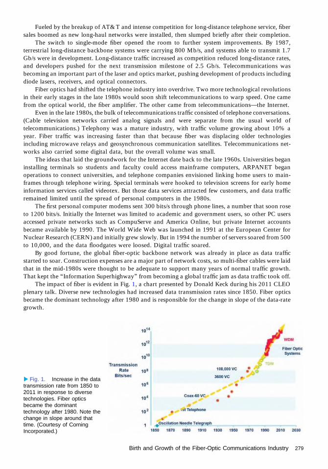
Fueled by the breakup of AT&T and intense competition for long-distance telephone service, fibersales boomed as new long-haul networks were installed, then slumped briefly after their completion.
The switch to single-mode fiber opened the room to further system improvements. By 1987,terrestrial long-distance backbone systems were carrying 800 Mb/s, and systems able to transmit 1.7Gb/s were in development. Long-distance traffic increased as competition reduced long-distance rates,and developers pushed for the next transmission milestone of 2.5 Gb/s. Telecommunications wasbecoming an important part of the laser and optics market, pushing development of products includingdiode lasers, receivers, and optical connectors.
Fiber optics had shifted the telephone industry into overdrive. Two more technological revolutionsin their early stages in the late 1980s would soon shift telecommunications to warp speed. One camefrom the optical world, the fiber amplifier. The other came from telecommunications—the Internet.
Even in the late 1980s, the bulk of telecommunications traffic consisted of telephone conversations.(Cable television networks carried analog signals and were separate from the usual world oftelecommunications.) Telephony was a mature industry, with traffic volume growing about 10% ayear. Fiber traffic was increasing faster than that because fiber was displacing older technologiesincluding microwave relays and geosynchronous communication satellites. Telecommunications net-works also carried some digital data, but the overall volume was small.
The ideas that laid the groundwork for the Internet date back to the late 1960s. Universities beganinstalling terminals so students and faculty could access mainframe computers, ARPANET beganoperations to connect universities, and telephone companies envisioned linking home users to main-frames through telephone wiring. Special terminals were hooked to television screens for early homeinformation services called videotex. But those data services attracted few customers, and data trafficremained limited until the spread of personal computers in the 1980s.
The first personal computer modems sent 300 bits/s through phone lines, a number that soon roseto 1200 bits/s. Initially the Internet was limited to academic and government users, so other PC usersaccessed private networks such as CompuServe and America Online, but private Internet accountsbecame available by 1990. The World Wide Web was launched in 1991 at the European Center forNuclear Research (CERN) and initially grew slowly. But in 1994 the number of servers soared from 500to 10,000, and the data floodgates were loosed. Digital traffic soared.
By good fortune, the global fiber-optic backbone network was already in place as data trafficstarted to soar. Construction expenses are a major part of network costs, so multi-fiber cables were laidthat in the mid-1980s were thought to be adequate to support many years of normal traffic growth.That kept the “Information Superhighway” from becoming a global traffic jam as data traffic took off.
The impact of fiber is evident in Fig. 1, a chart presented by Donald Keck during his 2011 CLEOplenary talk. Diverse new technologies had increased data transmission rates since 1850. Fiber opticsbecame the dominant technology after 1980 and is responsible for the change in slope of the data-rategrowth.
▸ Fig. 1. Increase in the datatransmission rate from 1850 to2011 in response to diversetechnologies. Fiber opticsbecame the dominanttechnology after 1980. Note thechange in slope around thattime. (Courtesy of CorningIncorporated.)
Birth and Growth of the Fiber-Optic Communications Industry 279

Even more fortunately, Internet traffic was growing in phase with the development of a vital newoptical technology, the optical fiber amplifier. Early efforts to develop all-optical amplifiers focusedon semiconductor sources, because they could be easily matched to signal wavelengths, but experi-ments in the middle to late 1980s found high noise levels. Attention turned to fiber amplifiersafter David Payne demonstrated the first erbium-doped fiber amplifier in 1987. (See Digonnet’schapter on p. 195.)
Elias Snitzer had demonstrated a neodymium-doped optical amplifier at American Optical in 1964,but it had not caught on because it required flashlamp pumping. Erbium was the right material at theright time. Its gain band fell in the 1550-nm window where optical fibers have minimum attenuation.Within a couple of years, British Telecom Labs had identified a diode-laser pump band at 980 nm andSnitzer, then at Polaroid, had found another at 1480 nm. By 1989, diode-pumped fiber amplifierslooked like good replacements for cumbersome electro-optic repeaters.
What launched the bandwidth revolution was the ability of fiber amplifiers to handle wavelength-division multiplexed signals. The first tests started with only a few wavelengths and a single amplifier;then developers added more wavelengths and additional amplifiers. The good news was that wave-length-division multiplexing (WDM) multiplied capacity by the number of channels that could besqueezed into the transmission band. The bad news was that WDM also multiplied the number ofpotential complications.
Design of 1310-nm systems was straightforward because it required considering fiber and amplifierperformance at only one wavelength. WDM required balancing fiber and amplifier performance acrossthe usable spectrum, as well as dealing with other complications including crosstalk, combining signalsat the input, and separating them at the output. All posed optical challenges.
Both erbium-amplifier gain and fiber attenuation vary with wavelength, but communicationsystems have to deliver the same power at all wavelengths. This meant developing ways to flattenamplifier gain and fiber attenuation along the system.
Chromatic dispersion became a challenge. The 1310-nm window was picked for early single-modesystems because it was the zero-dispersion wavelength. Chromatic dispersion was high enough at1550 nm to require ways to reduce it. Corning and British Telecom had developed fiber with zerodispersion shifted to 1550 nm in the 1980s, and that technology was used in early optical-amplifiercable systems transmitting at 1550 nm, including the TAT-12/13 transatlantic cable. However,experiments showed a serious problem with WDM in dispersion-shifted fibers. Signals at uniformlyspaced wavelengths remain in phase over long distances, causing four-wave mixing and crosstalkexceeding system tolerances.
That problem led Corning to develop non-zero dispersion-shifted fibers, which have enoughdispersion at 1550 nm to avoid four-wave mixing. However, the variation in dispersion across theWDM range nonetheless required dispersion management to meet system dispersion tolerances as datarates increased.
WDM also posed optical challenges. Systems required narrow-line lasers spaced evenly across thespectrum, as well as optics to combine and separate the optical signals at the ends of the fiber. Thatrequired new types of optical filters with sharp cutoffs to slice the spectrum into the desired bands.Through the 1990s, the bands grew narrower and narrower as designers sought to squeeze as manychannels as possible into the limited gain band of erbium-fiber amplifiers.
WDM, optical amplifiers, and the Internet combined to give the young fiber optics a big boost. In1990, when the new technologies were still in the lab, Kessler Marketing Intelligence (now part of CRUInternational) estimated that sales of cable, transceivers, and connectors in the United States were $948million, up only 2% from the previous year in a slow economy. Sales overseas were comparable, so thewhole market was around $2 billion. Global sales of fiber reached 6.74 million kilometers.
By 1995, when the optical amplifier/WDM revolution was in full swing, the company estimated theglobal fiber-optic component market at $7.1 billion, with global fiber sales more than tripling to 22.87million kilometers. The web was in takeoff mode, and as the number of servers soared, Internet trafficmay have been doubling every three months, although few reliable numbers are available. Long-distance and international calling had grown with a decline in phone rates. Phone lines were hummingwith faxes carrying documents that would have been sent by express carrier or mail in 1990.
280 Birth and Growth of the Fiber-Optic Communications Industry

That growth was a welcome boost foroptics as a whole. The wind-down ofRonald Reagan’s Strategic Defense Initiativehad left many optickers out of work in1990. Telecommunications companies inneed of optics specialists hired some ofthem. Others went to work for fast-growingfirms building components or instrumentsfor the fiber market, or started their owncompanies. Figure 2 shows CRU’s data onfiber sales in millions of kilometers, withChinese sales tracked separately, from 1980to 2013. The trend in 1995 was clearlyupward.
At the postdeadline session of OFC1996, a team from Fujitsu Laboratories inJapan reported sending a record 1.1 Tb/sthrough 150 km of fiber, transmitting 20Gb/s on each of 55 channels, with erbium-fiber amplifiers on both transmitter andreceiver ends. Two other teams reportedreaching 1 Tb/s over shorter distances byother means, one from AT&T Researchand Bell Laboratories and the second fromNTT. Fiber had become the key to deliv-ering high bandwidth to a telecommunica-tions industry convinced that you couldnever have enough bandwidth. The futurelooked bright.
In fact, as Fig. 2 shows, the light woulddim after the bubble burst in 2001. Salesoutside of China, little affected by the bub-ble, dropped from a peak of 80 millionkilometers in 2000 to a low of 43 millionkilometers in 2003. But then the lightbrightened. CRU International reports thatgrowth returned outside of China, reaching128 million kilometers in 2013. China’saggressive modernization program broughtits fiber sale to 123 million kilometers in2013, just short of the rest of the worldcombined. All told, as shown in Fig. 3,CRU says that cumulative global installa-tion of optical fiber for communicationsthrough 2013 exceeds a staggering 2.1 billion kilometers. Optics now connects the world as thebackbone of the global telecommunications network.
AcknowledgmentPart of this material is adapted, with permission, from Jeff Hecht, City of Light: The Story of FiberOptics (Oxford, 2004).
▴ Fig. 2. Total length (in millions of kilometers) of the opticalfiber installed each year from 1980 through 2013, dividedbetween China and the rest of the world. (Courtesy of CRUInternational, http://www.crugroup.com.)
▴ Fig. 3. Cumulative installations of communications fiberaround the world from 1980 through 2013. (Courtesy of CRUInternational, http://www.crugroup.com.)
Birth and Growth of the Fiber-Optic Communications Industry 281
Telecommunications Bubble PumpsUp the Optical Fiber CommunicationsConferenceJeff Hecht
Fiber-optic amplifiers and wavelength-division multiplexing (WDM) developed almostperfectly in phase with the explosive growth of the Internet in the 1990s. The new opticaltechnology promised the bandwidth needed to carry fast-growing Internet traffic. Initially
the parallel advances of optical and Internet technology seemed an ideal match. Unfortunately,that pairing ignited a speculative bubble that went out of control, creating trillions of dollars ofvastly inflated stock valuation that vanished when the bubble collapsed.
An earlier chapter describes how fiber became the backbone of the global telecommunica-tions network. The roots of the Internet go back to the late 1960s, when low-loss fibers were stillin development. The Defense Advanced Research Projects Agency (DARPA) (then called ARPA)began funding computer links among university and government laboratories.
A Changing Landscape in TelecommunicationsSeparately, telecom companies began experimenting with information services connecting homeconsoles and television screens to mainframe computers through copper telephone lines. In the1980s, personal computers became the preferred home connections to private services such asCompuServe. Modem speeds carrying these services over phone lines rose from 300 baud in theearly 1980s to 56,000 baud in the 1990s.
Public Internet access began about 1989 and took off after the World Wide Web openedthe Internet to a wider range of services. In 1994, the Web grew from 500 to 10,000 servers,and data traffic soared. For a brief, heady period in 1995 and 1996, the volume of Internetdata may have doubled every three months as hordes of new users explored the Web. Internettraffic then was a small fraction of voice traffic (including faxes), but it was clear that if itcontinued increasing at that rate it would soon eclipse voice traffic, which was growing about10% a year.
The emergence of competition and the breakup of the old AT&T monopoly in 1984 hadalready shaken the telephone industry. Once considered a natural monopoly, telephony hadbecome fragmented. Many competing carriers and the construction of new high-speed, high-capacity fiber networks cut the prices of long-distance and international calls, greatly increasingvoice and fax traffic.
Competition also brought more subtle changes that would have a large impact. As amonopoly AT&T published data on its traffic and system capacity to persuade regulators toapprove expansion plans. With deregulation and competition, that information became propri-etary, and no carrier knew total network traffic or how fast its competitors were growing.
Meanwhile, new technology was expanding capacity of single-mode fiber systems, whichhad reached 2.5 Gb/s on the busiest routes by the mid-1990s. The first WDM systems reached themarket in 1996. The same year saw installation of TAT-12 across the Atlantic, the first
1991-PRESENT
282

submarine cable with optical amplifiers. WDM promised the bandwidth needed to cope with therapidly growing demand.
Yet in the new competitive environment, nobody knew exactly what that demand was. Traditionalphone network managers considered bandwidth a scarce commodity. Market analysts and the pressheralded the doubling of Internet traffic every 90 to 100 days. Soon the Federal CommunicationsCommission was citing the same numbers, although the original source—a 1996 Worldcom report—was forgotten.
Few in the industry paid much attention in early 1998 when Andrew Odlyzko reported that AT&T’sInternet traffic had only doubled during 1997. The dot-com boom was underway, and critical thinkingwas not in fashion. Writers, business analysts, and stock promoters waxed exuberant about how the Webwould revolutionize the economy. With money readily available at low interest, investors poured moneyinto upstart web companies with little more than a handful of employees, a web site, and—perhaps—awarehouse. As the new companies began to go public, their stock prices soared, pumping up thetechnology-heavy NASDAQ index.
Investors began looking beyond the dot-coms to the telecommunications companies thatwould provide vital infrastructure for the new economy. Fiber and optics companies wereparticularly hot commodities because they offered breakthroughs in bandwidth. Investors soonbordered on the euphoric about fiber. Even hard-headed optical engineers decided that if investorswere going to throw money at anything optical, they might as well hold out their hats and catchsome of it. The boom brought a gold-rush atmosphere to the Optical Fiber CommunicationsConference (OFC).
The Growth of OFCOFC began as a small biennial topical meeting on optical fiber transmission first held in 1975. Thefirst Optical Fiber Communications conference in 1979 had a small trade show and 1082attendees. It went annual in 1981 and grew along with the fiber industry. In 1986, when fiberhad become the backbone of U.S. long-distance traffic, OFC drew 1801 people to Atlanta for thetechnical sessions, plus 1071 exhibitors and 777 people who only visited the trade show of 150companies occupying 27,100 square feet. It was the first time more than half of OFC attendeescame only for the exhibits. Figure 1 shows how the number of attendees changed over a periodextending from 1979 to 2012.
A decade later at San Jose in 1996, only a few more people came for the technical session, but theexhibits had more than doubled, to 2756 exhibit staff and 1990 exhibit-only visitors. Exhibit space hadincreased over 50%, to 42,700 square feet. Fiber technology had come a long way, and WDM wasreaching the market. Ciena squeezed 16 optical channels at 1.6-nm intervals into the erbium-amplifierspectrum. Lucent Technologies and Pirelli also introduced WDM systems. The post-deadline sessionheard of hero experiments that sent atrillion bits per second through a singleoptical fiber, although chromatic disper-sion and nonuniform amplifier gain limit-ed transmission span to 150 km in the bestresult, from Fujitsu.
The 1997 OFC, held in Dallas, wasonly slightly larger than the 1996 event.But the 22–27 February 1998 OFC in SanJose was a big step up. The Optical Societyand IEEE had expected total attendance totop 7000, but it jumped 30% to 8446,with technical attendance up 25% to arecord 2672. Exhibit space was up 26%to 61,000 square feet, and the number of
▴ Fig. 1. Total attendance over a period extending from 1979 to2012 showing the sharp peak in the bubble years.
Telecommunications Bubble Pumps Up the Optical Fiber Communications Conference 283

exhibitors rose nearly 16% to 342. Fig-ure 2 shows how the total square footageof the exhibit space changed over a periodextending from 1979 to 2012.
Hero experiments reported at the 1998post-deadline sessions reached a keymilestone—the dense-WDM demonstra-tions that sent a terabit per second hundredsof kilometers througha series offiber ampli-fiers. Bell Labs sent a hundred 10-Gb/schannels 400 km, and NTT sent fifty20 Gb/s channels 600 km. The highest datarate carried commercially at a single wave-length was only 2.5 Gb/s at the time, butLucent said they would have hardware in
service by the end of the year transmitting 10 Gb/s on each of 40 wavelengths. Meanwhile, regional andmetropolitan networks were installing WDM systems to increase capacity without costly construction.
Meanwhile, the technology-heavy NASDAQ index was rising about as fast as OFC attendance—closing at 1766 in the middle of OFC, up 29% from a year earlier. Fiber’s potential bandwidth waspulling the optics industry along with Internet stocks, and at the end of 1998 the NASDAQ index wasup 39% for the year.
The trend continued in 1999, when OFC moved to the larger San Diego Convention Center anddrew a record 10,206 people, up 21%, including 3331 technical registrants, a 25% increase. Thenumber of companies rose a comparatively modest 13%, but booth sizes grew faster as big companiespumped up their presence, occupying 83,700 square feet of space, a hefty 37% increase. Stock valueswere also up, with the NASDAQ at 2339 during the February show, up 32% from during the 1998OFC.
Wall Street Discovers OpticsAs fiber technology improved and the demand for bandwidth soared, sales increased and Wall Streetbegan taking optics seriously.
Optics and telecommunication stocks soared during the late 1990s. The stock of JDS-Fitel,formed in 1981, doubled after it went public in 1996, then doubled again in 1997 and in 1998. Inearly 1999 JDS announced a $6.1 billion merger with another fast-growing optics company,Uniphase.
In May, Enron announced it was forming a bandwidth market to trade capacity on installed fibersystems. It seemed like a good idea at the time. Fortune magazine had repeatedly ranked Enron as themost innovative company in the country, and the demand for bandwidth seemed almost unlimited.
JDS Uniphase stock took off, soaring almost a factor of nine in 1999 as it continued a wave ofacquisition. In November it announced it would buy Optical Coating Laboratory Inc. for $2.8 billion instock. Stocks of other optics companies such as Corning and of system makers such as Nortel andLucent likewise multiplied in price. The whole NASDAQ index nearly doubled during 1999, climbingfrom 2193 to 4069, but optics stocks rose even faster as investors clamored for optical stocks. Friendsand family asked optickers for stock tips. Figure 3 shows how the price of JDSU stock varied over aperiod extending from 2 January 1996 to 2 January 2004.
January 2000 saw another blockbuster merger, with JDS Uniphase buying E-Tek Dynamics in adeal that would close for $17 billion in June.
OFC recognized the importance of the booming market in selecting technology author and analystGeorge Gilder as the opening plenary speaker. Gilder had become a fiber enthusiast because he thoughtthe seemingly infinite bandwidth of optics could transform the world. His stock recommendations hadlured investors into optical and telecommunication companies, and his presence on the program helped
▴ Fig. 2. Total square footage of the exhibit area over a periodextending from 1979 to 2012 showing the sharp peak in thebubble years.
284 Telecommunications Bubble Pumps Up the Optical Fiber Communications Conference

draw throngs of stock analysts, venturecapitalists, and investors to join a recordcrowd of engineers and scientists.
Lines wound around the BaltimoreConvention Center, overwhelming showmanagers. Technical registration was6636, almost double the previous year, andtotal attendance was 16,934, up 65%.Exhibits from 483 companies sprawledover 121,300 square feet.
As if to celebrate Gilder’s talk, theNASDAQ index crossed the 5000 markfor the first time on 7 March 2000, the dayof his opening talk. The NASDAQ con-tinued upward during the conference,peaking at 5132 on the final day before closing at 5049. As attendees went home to recoverfrom the show, the chief analyst of Prudential Securities said the index could reach 6000 by theend of 2000.
The market had reached dizzying heights. MCI Worldcom’s market capitalization reached $168billion in April 1999. Lucent Technologies reached $285 billion in December 1999. But those were theirpeak valuations, and other technology stocks were slipping as well. The Monday after OFC theNASDAQ dropped 141 points and did not see 5000 again until July 2015. May saw the first big dot-com failures, and more followed in the summer. The NASDAQ closed the year at 2470, and did not see3000 again until 2012.
Optical stocks were slower to slip. JDSU’s market capitalization peaked at $181 billion during thesummer. On 10 July, JDSU announced a mind-boggling plan to buy SDL Inc. for stock then worth $41billion. That made SDL CEO Donald Scifres a billionaire on paper in August, when Forbes ranked himnumber 218 on its list of the 400 richest Americans. But JDSU stock started sliding downhill inSeptember, and when the deal closed on February 2001, the stock was worth only $13.5 billion.
Aside from stocks slipping to more realistic values, the fiber industry seemed healthy going into2001. Needing more space, OFC booked the sprawling Anaheim Convention Center for 19–22 March2001. Booth space sold like hotcakes. A record 970 companies occupied 270,000 square feet at thetrade show; both numbers had doubled from 2000. Total attendance more than doubled to 37,806,with technical registration reaching 10,888, a 64% increase.
Industry executives, analysts, and investors packed the OSA Photonics and TelecommunicationsExecutive Forum on the fiber market held across the street at the Disneyland Hotel. Optimism was inthe air, but so were hints of trouble. Opening speaker John Dexheimer cited concerns including the firstfailures in telecommunications, a “massive debt hangover” from some $250 billion in dubious loans tolay new fiber, and many companies trying to do the same thing.
The number of startups in the exhibit hall showed the massive investment in cutting-edge opticaltechnology. The technical sessions included such impressive feats as Alcatel’s transmission of 3 Tb/sthrough 7380 km of fiber, enough to span the Atlantic. But that capacity was far beyond what anyoneneeded in April 2001, too many companies on the show floor offered nearly identical products, andsome booths displayed no identifiable product but stock.
Within sight of Disneyland, the optics industry had slipped into a cartoon world. Like Wile E.Coyote, the industry had run off clear off the cliff, but in cartoon physics the law of gravity lets you hangin mid-air with your legs churning until you look down. Only then does gravity take hold and bring theinevitable “splat.”
The bubble was collapsing and sales were slumping. In April JDSU laid off 5000 people, about afifth of its employees. In a 9 May plenary talk at CLEO, JDSU CEO Josef Straus said he had learned“the laws of gravity apply up and down.” The telecomm industry was learning that it is hard to makemoney selling cheap bandwidth, especially when projected Internet traffic growth rates turned out to beas exaggerated as Worldcom’s profit statements.
▴ Fig. 3. Price of JDSU stock over a period extending from2 January 1996 to 2 January 2004 showing the sharp peak in thebubble years.
Telecommunications Bubble Pumps Up the Optical Fiber Communications Conference 285

Enron’s bandwidth market never took off, and by the summer of 2001 the whole company waslooking wobbly. By year’s end, Enron became the biggest bankruptcy in U.S. history.
By September, Nortel stock worth $1000 a year earlier was worth only $72. A grim joke noted thatinvesting the same amount in Budweiser—the beer, not the stock—would have left empty bottles worth$76 in a state with a deposit law. JDS wrote off nearly $50 billion in “goodwill” and slashed its staff toless than half its peak level. In January 2002, Global Crossing, which had built a global fiber network,filed for bankruptcy with $12 billion in debt, the fifth largest in U.S. history.
The magic was gone when OFC returned to Anaheim in March 2002, but the industry’s legs werestill churning furiously in mid-air. OFC sold 320,000 square feet of booth space to 1204 exhibitors,over 20% more companies than in 2011. But some exhibitors never showed, having run out of money.With 32,944 attendees, the show was busy, but many were job-hunting.
At the OSA Executive Forum, market analyst John Ryan looked back at 1999 to 2001 as “thedrunken sailor years” when network operators spent tens of billions of dollars on equipment they didnot need. But he held out hope, declaring “Unlike the concept of selling dog food on the Internet,telecom isn’t going away.” The audience laughed, a bit uneasily. Four months later, MCI Worldcomeclipsed Enron’s record to become the largest bankruptcy in American history, toppled by some $11billion in accounting fraud that earned CEO Bernie Ebbers a 25-year jail sentence.
That was the last giant OFC. Attendance dropped by more than half in 2003, as 15,023 peoplespread thinly through the sprawling Atlanta Convention Center. Exhibitor count and booth spaceshrank less precipitously, perhaps because the space was sold in advance, and as in 2002 somecompanies never showed up.
Plots of OFC attendance and exhibits show the bubble years as aberrant spikes, not quite as dramaticas peaks in company stock prices. The most recent OFC, shown in Figs. 1 and 2, in 2012 in Los Angeles,drew 11,617 attendees, with 560 exhibitors occupying 91,000 square feet—putting the 2012 OFCmidway between the 1999 and 2000 gatherings. Growth has resumed, at a more rational level.
Looking back, Gilder was right in calling fiber a disruptive technology. But he failed to understandthat such a disruption could cause a destructive bubble in stock prices. The bubble’s inevitable collapsevaporized illusory gains many times the $65 billion fraud of Bernard Madoff’s Ponzi scheme. Themarket capitalization of JDSU alone shrank from a peak of $181 billion to a current few billion dollars,a loss of 2.5 Madoffs.
The industry survived the bubble, although scars remain. Someday your brother-in-law mayforgive you for saying JDSU stock was a good investment in 2000.
Further Readings1. L. Endlich, Optical Illusions: Lucent and the Crash of Telecom (Simon & Schuster, 2004).2. J. Hecht, City of Light: The Story of Fiber Optics, Revised and Expanded Edition (Oxford University
Press, 2004).3. O. Malik, Broadbandits: Inside the $750 Billion Telecom Heist (Wiley, 2003).4. B. McLean and P. Elkind, The Smartest Guys in The Room: The Amazing Rise and Scandalous Fall of
Enron (Portfolio-Penguin, 2004).5. A. Odlyzko, “Internet growth, myth and reality, use and abuse,” http://www.dtc.umn.edu/~odlyzko/
doc/internet.growth.myth.pdf.
286 Telecommunications Bubble Pumps Up the Optical Fiber Communications Conference

The Evolution of OpticalCommunications Networkssince 1990Rod C. Alferness
IntroductionOptical communication networks have played a critical role in the information/communicationrevolution and in turn have fundamentally changed the world and daily life for billions aroundthe globe. Without cost-effective, high-capacity optical networks that span continents and connectthem via undersea routes, the worldwide Internet would not be possible. Optical access systems,both fiber/cable and fiber-to-the home, are also essential to bring broadband access to that globalInternet to homes and businesses. Increasingly important, ubiquitous broadband optical networksprovide the high-bandwidth backhaul essential for wireless access networks that enabletoday’s smartphone users. These networks also provide the always available broadband accessthat will make cost-effective and energy-efficient cloud services available to all in the future.
All this has been made possible because, as capacity demand has grown exponentiallyfollowing the advent of the Internet, optical technology has made possible a dramatic reductionin the cost per bit carried over an optical fiber, allowing cost-effective capacity scaling. Onaverage, transmission capacity over a single fiber has increased at a rate of ∼100-fold every tenyears over the last thirty years. As a result, as traffic has grown and is aggregated at the ingressand disaggregated at egress nodes, new higher-capacity generations of long-haul and metrooptical systems have been deployed at a total cost that has grown sub-linearly relative to capacity.
Of course, the advantage of the optical frequencies for communication is the inherent ability toserve as a carrier for very-high-bandwidth information. Fiber provides an extremely attractivetransmission medium that offers both ultra-low loss and low chromatic dispersion. The latterresults in minimal pulse spreading, resulting in low inter-pulse (bit) interference after transmissionover large distances. At its most basic implementation, an optical transmission system requires anoptical source whose generated dc optical signal can be modulated with information at theinformation bandwidth of interest, a fiber, and an optical detector and supporting electronics.
Figure 1 captures the progress of the “hero” research transmission experiments [1]. Shown isthe maximum information capacity carried on a single fiber versus the year the research resultswere achieved. For this review, it is convenient to describe the research progress in fiber optictransmission capacity in three waves or eras. In what follows, we use those generations, eachenabled by a set of critically important optical component technology innovations, to provide anoverview of the advances in optical communications since 1990.
At the start of the 1990s, commercially deployed systems provided per fiber capacities ofabout 1 Gb/s. They were used primarily in long-haul intercity applications to carry highlyaggregated voice service. At that time, increase in capacity demand was still driven mostly bypopulation growth as well as some increase in new services such as fax. The wavelength windowutilized was the minimum chromatic dispersion 1.3-μm window. To increase time divisionmultiplexed bit rates (TDM) for fixed distance between electrical regenerations, both signalstrength relative to noise and quality of the detected signal with respect to pulse-to-pulse
1991-PRESENT
287
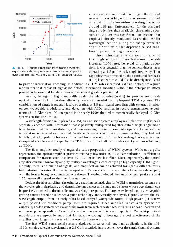
interference are important. To mitigate the reducedreceiver power at higher bit rates, research focusedon moving to the lowest-loss wavelength windowaround 1.55 μm. Unfortunately, for the standardsingle-mode fiber then available, chromatic disper-sion at 1.55 μm was significant. For systems thatemployed directly modulated lasers that exhibitwavelength “chirp” during the change from the“on” to “off” state, that dispersion caused prob-lematic pulse spreading interference.
Three technology advances were instrumentalin strongly mitigating these limitations to enableincreased TDM rates. To avoid chromatic disper-sion, it was essential that the semiconductor laseroperating at 1.5 μm be truly single frequency. Thatcapability was provided by the distributed feedback(DFB) laser, which could also be directly modulated
to provide information encoding. In addition, as TDM rates increased, external optical waveguidemodulators that provided high-speed optical information encoding without the “chirping” effectsproved to be essential for data rates above several gigabits per second.
Finally, high-gain, high-bandwidth avalanche photodiodes (APDs) to provide reasonableoptical to electrical conversion efficiency were also needed for high-speed TDM systems. Thecombination of single-frequency lasers operating at 1.5 μm, signal encoding with external interfer-ometer waveguide modulators, and detection with APDs resulted in record transmission experi-ments (2–16 Gb/s over 100-km spans) in the early 1990s that led to commercially deployed 10 Gb/ssystems in the late 1990s.
Wavelength division multiplexed (WDM) transmission systems employ multiple wavelengths, eachseparately encoded with information that is passively multiplexed together onto a single single-modefiber, transmitted over some distance, and then wavelength demultiplexed into separate channels whoseinformation is detected and received. While such systems had been proposed earlier, they had notinitially gained popularity because of the need for a regenerator for each wavelength at repeater sites.Compared with increasing capacity via TDM, the approach did not scale capacity as cost effectivelyas TDM.
The fiber amplifier totally changed the value proposition of WDM systems. While not a pulseregenerator, the optical amplifier provides relatively low-noise 20–30-dB amplification—sufficient tocompensate for transmission loss over 50–100 km of low loss fiber. Most importantly, the opticalamplifier can simultaneously amplify multiple wavelengths, each carrying a high-capacity TDM signal.Notably, there is no mixing of signals, and amplification can be achieved for signals with arbitrarilyhigh information rates. Both erbium-doped and Raman-based fiber amplifiers have been developed,with the former being the commercial workhorse. The erbium-doped fiber amplifier gain peaks at about1.55 μm—well aligned to the fiber loss minimum.
Besides the fiber amplifier, the other key enabling technologies for WDM transmission systems arethe wavelength multiplexing and demultiplexing devices and single-mode lasers whose wavelength canbe precisely matched to the mux/demux wavelength response. For large wavelength counts, waveguidegrating routers based on silica waveguide technology are typically employed. Figure 2 shows the 80-wavelength output from an early silica-based arrayed waveguide router. High-power (∼100-mWoutput power) semiconductor pump lasers are required. Fiber amplified transmission systems areessentially analog systems where amplifier noise from each repeater accumulates, as does dispersive andnonlinear pulse spreading. Careful dispersion management is very important. Zero-chirp opticalmodulators are especially important for signal encoding to leverage the cost effectiveness of theamplifier over longer distances without electrical regenerators.
The first WDM commercial systems, deployed in terrestrial long-haul applications in the mid-1990s, employed eight wavelengths at 2.5 Gb/s, a tenfold improvement over the single-channel systems
▴ Fig. 1. Reported research transmission systemsexperiments showing maximum transmission capacityover a single fiber vs. the year of the research results.
288 Evolution of Optical Communications Networks since 1990

previously available. As multiplexing devices and amplifier performance was improved, the number ofwavelengths was soon doubled and then quadrupled. In the research lab, work focused on WDM forhigher TDM rates, 10 Gb/s and beyond.
The first WDM systems were deployed over existing “standard” single-mode fiber. However, toreduce the phase-matched nonlinear mixing effect of fiber at its zero-dispersion wavelength, so called“non-zero-dispersion shifted” fibers were developed. Such fibers could be used as the transmission fiberor in the repeater site as a “dispersion compensating fiber” to undo dispersion accumulation. In thiscase the transmission fiber has sufficient dispersion over the transmission distance to avoid four-wavemixing but produces pulse spreading that is undone by the compensating fiber.
Undersea lightwave systems were an important driver and early adopter of fiber amplified WDMtransmission systems that were especially attractive because they avoid undersea high-speed electronics,which reduced the lead time for reliability testing. In addition, properly designed WDM transmissionsystems offered the potential for future capacity growth by increasing the wavelength bit rate or thenumber of wavelengths. The first such system, a transatlantic system, included 16 wavelengths at2.5 Gb/s each with repeater spacing of 100 km.
In research labs around the world, as multiplexing devices and amplifier performance wereimproved and techniques to mitigate dispersive and nonlinear transmission impairments developed,single-fiber transmission capacity results were improved, sometimes quite dramatically, every year.These extraordinary “hero” transmission systems experiments became the highlight of the post-deadline session of The Optical Society (OSA, and IEEE Photonics and Communications) sponsoredOptical Fiber Conference (OFC) each year. Increased capacity in transmission systems experimentalresults over the years (Fig. 1) were achieved by increasing the per wavelength bit rate from 2.5 Gb/s to10 Gb/s to 40 Gb/s to 100 Gb/s. Key issues that needed to be addressed included demonstrating high-speed electronics, modulators, and receivers at the higher rates; mitigating nonlinear fiber; andmanaging dispersive effects. Total capacity was also increased by increasing the number of wave-lengths. This was achieved either by increasing the bandwidth of the amplifier or by finding ways toreduce the wavelength spacing without reducing the information rate/wavelength, resulting inimproved spectral efficiency.
The adoption of WDM transmission led to wavelength-based reconfigurable optical networks thatprovide wavelength-level, cost-effective network bandwidth management. That evolution is shownschematically in Fig. 3. Initially WDM was employed over linear links where all wavelengths wereaggregated onto the fiber at one node and carried with periodic amplification to an end node. However,in real networks, especially as the distance achievable without electronic regeneration has beenincreased, the sources and destinations of traffic require off and on ramps for traffic entering between
▸ Fig. 2. Measuredwavelength response of a silicawaveguide based grating router80-wavelength channelmultiplexer/demultiplexer with50 GHz channel spacing.
Evolution of Optical Communications Networks since 1990 289
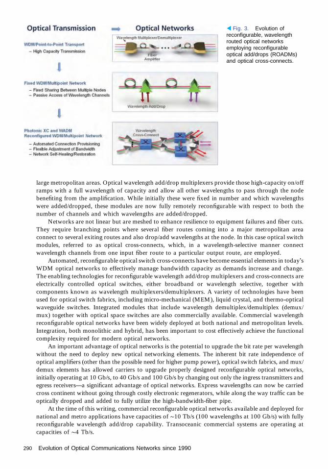
large metropolitan areas. Optical wavelength add/drop multiplexers provide those high-capacity on/offramps with a full wavelength of capacity and allow all other wavelengths to pass through the nodebenefiting from the amplification. While initially these were fixed in number and which wavelengthswere added/dropped, these modules are now fully remotely reconfigurable with respect to both thenumber of channels and which wavelengths are added/dropped.
Networks are not linear but are meshed to enhance resilience to equipment failures and fiber cuts.They require branching points where several fiber routes coming into a major metropolitan areaconnect to several exiting routes and also drop/add wavelengths at the node. In this case optical switchmodules, referred to as optical cross-connects, which, in a wavelength-selective manner connectwavelength channels from one input fiber route to a particular output route, are employed.
Automated, reconfigurable optical switch cross-connects have become essential elements in today’sWDM optical networks to effectively manage bandwidth capacity as demands increase and change.The enabling technologies for reconfigurable wavelength add/drop multiplexers and cross-connects areelectrically controlled optical switches, either broadband or wavelength selective, together withcomponents known as wavelength multiplexers/demultiplexers. A variety of technologies have beenused for optical switch fabrics, including micro-mechanical (MEM), liquid crystal, and thermo-opticalwaveguide switches. Integrated modules that include wavelength demultiplex/demultiplex (demux/mux) together with optical space switches are also commercially available. Commercial wavelengthreconfigurable optical networks have been widely deployed at both national and metropolitan levels.Integration, both monolithic and hybrid, has been important to cost effectively achieve the functionalcomplexity required for modern optical networks.
An important advantage of optical networks is the potential to upgrade the bit rate per wavelengthwithout the need to deploy new optical networking elements. The inherent bit rate independence ofoptical amplifiers (other than the possible need for higher pump power), optical switch fabrics, and mux/demux elements has allowed carriers to upgrade properly designed reconfigurable optical networks,initially operating at 10 Gb/s, to 40 Gb/s and 100 Gb/s by changing out only the ingress transmitters andegress receivers—a significant advantage of optical networks. Express wavelengths can now be carriedcross continent without going through costly electronic regenerators, while along the way traffic can beoptically dropped and added to fully utilize the high-bandwidth-fiber pipe.
At the time of this writing, commercial reconfigurable optical networks available and deployed fornational and metro applications have capacities of ∼10 Tb/s (100 wavelengths at 100 Gb/s) with fullyreconfigurable wavelength add/drop capability. Transoceanic commercial systems are operating atcapacities of ∼4 Tb/s.
◂ Fig. 3. Evolution ofreconfigurable, wavelengthrouted optical networksemploying reconfigurableoptical add/drops (ROADMs)and optical cross-connects.
290 Evolution of Optical Communications Networks since 1990

The ubiquitous deployment of broadband wireless systems together with massive sharing ofconsumer produced video and growing demand to access “cloud” based computational servicescontinues to drive bandwidth demand at 25%–40% per year. There is every indication that demandwill continue to grow at ∼10× over the next ten years. Given the state of current commercial systems,this suggests the need for 1 Pb/s systems in the next 8–10 years. Commercially, the next targeted bit rateis likely to be 400 Gb/s followed by 1 Tb/s. To achieve higher speeds requires continued advancement inhigh-speed electronics, photo detectors, modulators, and integration. It also requires the ability tolaunch higher optical power while mitigating nonlinear effects. The number of wavelength channels islimited by the required bandwidth per channel and the total transmission bandwidth limited by theamplifier. Optimizing system spectral efficiency is essential. Achieving long-distance transmissionwithout regeneration is also important for cost-effective networks.
To achieve higher effective per wavelength channel capacity while limiting speed requirement,research has focused on advanced coding techniques that use both amplitude and phase information asoffered by coherent detection. By employing coherent techniques it is also possible to apply polarizationmultiplexing to effectively double channel capacity. Coherent techniques also allow the use ofelectronics to mitigate deleterious transmission impairments. These modulation formats, includingquadrature phase-shifted keying (QPSK) and quadrature amplitude modulation (QAM), require the useof high-speed digital signal processors to convert the input signal information into the coded amplitudeand phase-modulation signals to drive complex nested optical amplitude and phase modulators toencode the optical signal. As an example, with polarization multiplexing and 64-QAM (64 symbols perbit), one can transmit at an effective rate of 320 Gb/s with electronics, modulator, and receiveroperating at only 80 Gbaud/s. The benefits come with transmission trade-offs as well as the complexityof high-speed digital signal processors. There has been substantial research progress in this area over thelast five years as reflected in the systems results of Fig. 1.
Within the past several years, concern has been growing that keeping up with bandwidth demandwill require another major technological leap—an additional dimension of multiplexing. The proposeddimension is to use space division as implemented either via multiple cores in a fiber or multi-modes of asingle-core fiber. For the system to be cost effective compared to simply building parallel fiber opticsystems, it likely will be necessary to also demonstrate optical amplifiers, at least, to act upon multiplespatial modes simultaneously. Integration is likely to be essential.
Because of limited space we have focused here on long-haul and metro optical communicationnetworks. However, leveraging the technologies outlined here, there has been tremendous progress inoptical access systems as well. Fiber optic technology has been used to feed coaxial cable systems,allowing increased reach and per user capacity. There is also increasing deployment of fiber-to-the-home systems, especially using TDM-based passive optical network (PON) technology. Recently,combined WDM and TDM PON technologies have been deployed to provide per home/businesscapacities of 1 Gb/s.
In addition, optical technology to provide intrabuilding interconnection in data centers is agrowing application that will become even more critical as cloud services evolve. Distances arerelatively short, and low cost is especially important. Optical and opto-electronic integration, eitherhybrid or monolithic, will be essential. The role of optical switching in data centers is beingexplored.
Throughout this history of incredible progress, OSA has played a critically important role infostering and nurturing the continuous discovery, invention, and demonstration of optical componentsand systems that have been key to the dramatic progress of this field. OFC, a premier global conferenceon optical communications, was first held (as the Topical Meeting on Optical Fiber Transmission) in1975 in Williamsburg, Virginia. OFC/NFOEC 2013 had more than 12,000 attendees from all over theworld. The OFC post-deadline sessions are standing-room only events where researchers around theglobe present their latest breakthrough results.
OSA has also nurtured newly emerging technologies in their formative stages, includingfiber amplifiers, reconfigurable optical networks, and fiber to the home through highly focusedtopical meetings that offer ample opportunity for discussion and debate. The Journal of LightwaveTechnology, co-sponsored by OSA and IEEE, has been a key journal for sharing and archiving
Evolution of Optical Communications Networks since 1990 291

advances in the field. Many of the members of the optical communication field have played leadershiproles in OSA as well.
AcknowledgementsIn this short historic overview, scope and space have not allowed proper citations [2]. My thanks to thelarge global community—many of whom are members of OSA—who have contributed to theextraordinary progress in optical networks described here.
References1. Adapted from R. W. Tkach, “Scaling optical communications for the next decade and beyond,” Bell
Labs Tech. J. 14, 3–9 (2010).2. Suggested further reading for recent overview and update: Special issue on the Evolution of Optical
Networks, Proc. IEEE 100(5) (2012).
292 Evolution of Optical Communications Networks since 1990

Integrated PhotonicsRadhakrishnan Nagarajan
An essay on the history of integrated photonics invariably starts with the seminal paper byMiller [1]. In 1969 the idea was way ahead of its time, and many of the componentsneeded to make such an integrated circuit a reality had yet to be invented. Hayashi and
Panish’s demonstration of the continuous wave (CW) room temperature operation of asemiconductor laser, a critical device for the photonic integrated circuit (PIC), was still a yearaway [2]. Optical transport, where PICs find their applications, got its somewhat fortuitous startin 1970 as well with the report of a low-loss optical fiber by the group at Corning [3].
There is always some personal bias in presenting the historical evolution of any technology.Figure 1 graphically shows one such historical progression of PIC complexity, as measured in thenumber of integrated components on a single InP substrate, with time. The details of the devicesand references presented in Fig. 1 are in [4]. InP and its alloys are the material of choice infabricating light emitters for optical transport applications. This is due to the low-loss window at1550 nm and the low-dispersion point at 1300 nm in the standard silica optical fiber.
For the first decade or so after the demonstration of the CW laser in the GaAs system, InPlasers started to mature. In the mid-1980s there was active work in the area of opto-electronicintegrated circuits (OEICs), where the integration of electronic devices such as HBT (hetero-junction bipolar transistor) and FET (field effect transistor) with laser diodes and photodetectorswas pursued. In the late 1980s three-section tunable DBR (distributed Bragg reflector) lasers wereintroduced. This was also when electro-absorption modulators (EAMs) integrated with distrib-uted feedback (DFB) lasers were demonstrated. The trend continued with more complicated (fourand five section) tunable laser sources that were also integrated with an EAM or a semiconductoroptical amplifier (SOA). The next step was the demonstration of the arrayed waveguide grating(AWG) or PHASAR (phased array) router integrated with photodetectors for multi-channelreceivers or with gain regions and EAM for multi-frequency lasers and multi-channel modulatedsources. One of the most complex PICs reported in the last century was a four-channel opticalcross-connect integrating 2 AWGs with 16 MZI (Mach–Zehnder interferometer) switches. Atthis stage the most sophisticated laboratory devices still had component counts below 20 whilethose in the field had component counts of about 4.
The trend in low-level photonic integration continued into the 2000s with one of the largerchips reported being a 32-channel WDM channel selector. In 2003, ThreeFive Photonicsreported a 40-channel WDM monitor chip, integrating 9 AWGs with 40 detectors. MetroPho-tonics reported a 44-channel power monitor based with an echelle grating demultiplexer. Thecommercial development of both chips was subsequently discontinued. The first successfulattempt at a commercial large-scale photonic integrated chip (LS-PIC) was made in 2004 whenInfinera introduced a 10-channel transmitter, with each channel operating at 10 Gbit/s. Thisdevice with an integration count in excess of 50 individual components was the first LS-PICdevice deployed in the field to carry live network traffic. This was quickly followed in 2006 by a40-channel monolithic InP transmitter, each channel operating at 40 Gbit/s, with a totalcomponent count larger than 240, and aggregate data rate of 1.6 Tbit/s. The complementary40-channel receiver PIC also had an integrated, polarization independent, multi-channel SOA atthe input.
2004, the year when the first commercial large-scale photonic integrated circuit wasdeployed, proved to be a watershed year for silicon photonics as well when Intel demonstrated
1991–PRESENT
293

the first gigabit per second optical silicon (Si)-on-insulator (SOI) modulator [5]. Si as a platform foroptical integration dates back to the 1980s [6,7]. In [6] can be found an excellent review of the earlyyears of Si photonics. Unlike InP, Si has a centro-symmetric crystalline structure and does not exhibitthe linear electro-optic effect that is commonly used for modulating light in InP. Most Si modulatorsare based on the carrier plasma effect, change of refractive index with carrier accumulation, ordepletion. Although this is a weak material effect, the capacitor structure, which allows for a largeeffective charge transfer, improves the efficiency considerably [6]. Although there are reports ofintegrated Ge lasers on Si substrates [8], for the most part the light sources for Si photonics are madeof InP and are integrated using hybrid techniques [9].
In Fig. 1 we saw the progression of PIC complexity thru the 2005 timeframe. Although some ofthe PICs, such as the switches and CW sources, were modulation format agnostic, for the most partthese operated using OOK (on–off keying). Figure 2 shows the progression of PICs used foradvanced modulation formats such as QPSK (quadrature phase shift keying) used in opticalcoherent communication. The details of the devices and references presented in Fig. 2 can befound in [10].
Coherent optical communication development started in the mid-1980s. After a gap of more thanten years, in the mid-2000s the field went through a revival with the availability of high-speed Si ASICsand advanced digital signal processing algorithms that eliminated the need for ultra-stable opticalsources and analog phase/frequency/polarization tracking of the optical carrier at the receiver. Earlycoherent receiver PICs were all single channel. They were designed for binary phase shift keying(BPSK) modulation format. BPSK is similar to QPSK except that there are no data in the quadrature
▴ Fig. 1. Historical trend and timeline for monolithic, photonic integration on InP (without including verticalcavity InP devices). The vertical scale is linear, and the red filled circles start at 1 and go to 240. Thetrend shows an exponential growth in PIC complexity in recent years. Unlike silicon ICs where the transistorcount is a universal metric, there is no unique benchmark for complexity in photonic integration. For thisexercise, we have counted a functional unit (which may be a combination of other optical elements) as adevice. For example, an MZI is counted as 1 and not as 3. Likewise an AWG is counted as 1 irrespective ofthe fraction of the PIC real estate it occupies.
294 Integrated Photonics

component of the signal. A simple, single-stage MZ modulator (MZM) may be used to generate aBPSK signal. BPSK signals have lower spectral efficiency but better noise margin for longertransmission distances. There were early attempts to integrate a LO (local oscillator) on the receiverPIC as well. A multi-channel PIC with I/Q MZM integrated with an optical source was reported in2008. There have been a number of variants on the DQPSK and QPSK (with external LO) receiverPICs reported since then. The DQPSK PICs also have the polarization components integrated onto thesame substrate. The first multichannel, dual polarization, QPSK receiver PIC with an integrated LOper wavelength was reported in 2011. Unlike the first phase of the history of integrated photonicsdiscussed in Fig. 1, the evolution of coherent PICs shown in Fig. 2 has devices on both the InP and Siplatforms.
References1. S. Miller, “Integrated optics: an introduction,” Bell Syst. Tech J. 48, 2059–2069 (1969).2. I. Hayashi, M. Panish, P. Foy, and S. Sumski, “Junction lasers which operate continuously at room
temperature,” Appl. Phys. Lett. 17, 109–111 (1970).3. I. Kapron, D. Keck, and R. Maurer, “Radiation losses in glass optical waveguides,” Appl. Phys. Lett. 17,
423–425 (1970).4. R. Nagarajan, M. Kato, J. Pleumeekers, P. Evans, S. Corzine, S. Hurtt, A. Dentai, S. Murthy, M. Missey,
R. Muthiah, R. Salvatore, C. Joyner, R. Schneider, M. Ziari, F. Kish, and D. Welch, “InP photonicintegrated circuits,” J. Sel. Top. Quantum Electron. 16, 1113–1125 (2010).
5. D. Samara-Rubio, L. Liao, A. Liu, R. Jones, M. Paniccia, O. Cohen, and D. Rubin, “A gigahertz silicon-on-insulator Mach-Zehnder modulator,” in Optical Fiber Communication Conference (Optical Societyof America, 2004), post-deadline paper 15.
6. G. Reed, W. Headley, and C. Png, “Silicon photonics: the early years,” Proc. SPIE 5730, 596921 (2005).
▴ Fig. 2. A timeline for the development of coherent PICs. There is a gap between the early 1990s, whenEDFAs were first introduced, and late 2000s when coherent communication systems saw deployment.Key: Mode = BPSK, QPSK; Pol = number of polarizations detected; LO = whether a LO was integrated intothe PIC; CH = number of channels integrated onto a PIC. Most of these PIC’s are receivers, with exception in2008 when a 10 channel transmitter PIC was reported which included an I /Q modulator integrated with anoptical source, for each channel, on the same substrate.
Integrated Photonics 295

7. R. Soref, “The past, present, and future of silicon photonics,” IEEE J. Sel. Top. Quantum Electron. 12,1678–1687 (2006).
8. R. Camacho-Aguilera, Y. Cai, N. Patel, J. Bessette, M. Romagnoli, L. Kimerling, and J. Michel, “Anelectrically pumped germanium laser,” Opt. Express 20, 11316–11320 (2012).
9. M. Heck and J. Bowers, “Hybrid and heterogeneous photonic integration,” in Handbook of SiliconPhotonics, L. Vivien and L. Pavesi, eds. (CRC Press, 2013), Chap. 11.
10. R. Nagarajan, C. Doerr, and F. Kish, “Semiconductor photonic integrated circuit transmitters andreceivers,” in Optical Fiber Telecommunications, Vol. VI A: Components and Subsystems, I. Kaminow,T. Li, and A. Willner, eds. (Elsevier, 2013), Chap. 2.
296 Integrated Photonics

New Wave MicrostructuredOptical FibersPhilip Russell
BackgroundIn the early 1990s there was a good deal of excitement about three-dimensional periodicstructures in which light cannot exist at frequencies within a photonic bandgap (PBG) [1]. Henryvan Driel (Optical Society Fellow, University of Toronto) even compared the atmosphere at apacked-out Quantum Electronics and Laser Science (QELS) session on PBGs (on the afternoon ofthe last day of the conference) to 1969 Woodstock! At that time it occurred to the author that, ifone could create a two-dimensional PBG crystal of microscopic hollow channels in the cladding ofan optical fiber, low-loss guidance of light in a hollow core might be possible [2,3]. The challengewould be to design a suitable structure and not least work out a way of making it (in pioneeringwork at Bell Laboratories in the early 1970s, primitive structures with a small number of largehollow channels had been made, the aim being air-clad glass fiber cores [4]). (See Fig. 1.)
Actually, the first hints that total internal reflection—the workhorse of conventional fiberoptics—might not be the only way to guide light had emerged in 1968 with the little knowntheoretical work of Melekhin and Manenkov in the Soviet Union [5], followed by a more detailedstudy—again purely theoretical—by Yariv and Yeh at Caltech in 1976 [6]. Their idea was tocreate a cylindrical Bragg stack from concentric tubular layers of alternating high and lowrefractive index. Rays of light traveling within a certain range of conical angles would be Braggreflected back into the core for all azimuthal directions. The trick then was to choose a corediameter that supports a Mie-like resonance at conical angles where the cylindrical Bragg stackhas a radial stop-band, resulting in a low-loss guided mode (note that such “Bragg fibers” do notpossess a PBG since light is free to propagate azimuthally).
The operating principle of both of these proposals is closely linked to anti-resonant reflectingoptical waveguiding (ARROW), in which light is partially confined by a structure of one or morepairs of anti-resonant layers. Originally proposed by Duguay (AT&T Bell Laboratories) in 1986,these are essentially Fabry–Perot cavities operating off resonance so that they reflect lightstrongly back into the core [7,8]. When the number of such layers becomes large the ARROWstructure begins to resemble a Bragg waveguide; i.e., the anti-resonance condition coincides withthe presence of a radial stop-band [9].
Although solid-core versions of Bragg fibers have been produced using modified chemicalvapor deposition (MCVD) (at IRCOM in Limoges, France) [10], for guidance in a hollow coreone is up against the need for the radial stop-band to appear at values of axial refractive indexless than 1. This means that individual layers must be very thin (~0.69 λ, where λ is the vacuumwavelength), enhancing the effects of dopant diffusion during fiber drawing and further reducingthe already weak index contrast. Small index contrast also has the drawback that, for goodconfinement, a large number of periods is needed and the structure must be highly perfect toavoid leakage through defect states in the cladding layers.
The ideal structure would consist of a series of concentric glass layers with air betweenthem, but of course this would not hold together mechanically. A possible compromise is tofabricate a structure of rings held together with thin glass membranes, but the losses so farreported are quite high [11]. One could think of increasing the index contrast using two solid
1991-PRESENT
297

materials, but here the problems areextreme for another reason. Pairs ofdrawable glasses with compatible melt-ing and mechanical properties, a largerefractive index difference and high op-tical transparency are hard to found.More exotic combinations of chalcogen-ide and polymer overcome the mechani-cal problems, offering moderately lowlosses even though the absorption is ex-tremely high in the polymer layers. Nev-ertheless, the company Omniguide hasachieved 1 dB/m at 10 μm in such Braggfibers [12], which are now used in lasersurgery [13].
Making the FirstPhotonic Crystal Fiber(PCF)When the author proposed what he firstcalled “holey fiber,” defusing any anxiouslooks by adding that the word needed an“e,” he was met with a good deal ofskepticism. Would this new thing, the“photonic bandgap,” really work—wasn’tthe refractive index of silica glass toosmall? The literature suggested that two-dimensional PBGs appear only if the
refractive index ratio is very large, say 2.2:1 for a two-dimensional dielectric–air structure [1] (actuallythis turns out to be true only for purely in-plane propagation [14]). Even if it did work, would the bendlosses not be huge? And then there were the practicalities of making it. The author remembers CliveDay, who had been at the Post Office Research Laboratories in Martlesham (UK) in the 1970s, recallinghow difficult the “single-material” fibers had been to make (in 1997 British Telecom donated Day’sthree-legged drawing tower to the author’s then group at the University of Bath, allowing them to makemany of the first discoveries about photonic crystal fibers (PCFs)). (See Fig. 2.)
Although conventional lithography worked well for very thin photonic crystal structures, it washard to see how it could be adapted to produce even millimeter lengths of PCF. More promising waswork at Naval Research Laboratories in Washington, where Tonucci had shown that multi-channelglass plates with hole diameters as small as 33 nm, in a tightly packed array, could be produced usingdraw-down and selective etching techniques [15]. The maximum channel length was limited by theetching chemistry to ~1 mm, and though the structures were impressively perfect, they were not fibers.The earliest attempt, in 1991, involved drilling a pattern of holes into a stub of silica glass, the hopebeing that it could be drawn into fiber. Machining an array of 1 mm holes in a stub of silica ~2.5 cm indiameter (the largest the drawing furnace would accommodate) proved beyond the capabilities of theultrasonic drill, so this approach was abandoned. Since then it has been shown that drilling works wellfor softer materials such as compound glasses or polymers. Another versatile technique is extrusion, inwhich a molten glassy material is forced through a die containing a suitably designed pattern of holes.Although not yet successfully used for fused silica (existing die materials contaminate the glass at thehigh temperatures needed [16]), extrusion works well for both polymers [17,18] and soft glasses [19].(See Fig. 3.)
▴ Fig. 1. Three-core fiber made by Kaiser and colleagues atBell Labs in the early 1970s. (Reprinted with permission ofAlcatel-Lucent USA Inc.)
298 New Wave Microstructured Optical Fibers

After various different approacheshad been tried, the first successfulsilica–air PCF structure emerged from thedrawing tower in late 1995, the result ofthe efforts of Tim Birks and JonathanKnight—postdocs in the author’s groupat the Optoelectronics Research Center(ORC) in Southampton. The preform wasconstructed by stacking 217 silica capillar-ies (eight layers outside the central capil-lary) into a tight-packed hexagonal array.The diameter-to-pitch ratio of the holes inthe final fiber was too small for PBGguidance in a hollow core, so we decidedto make a PCF with a solid central coresurrounded by 216 air channels [16]. Theresult was a working PCF, which guidedby a kind of modified total internal reflec-tion. The results were reported in 1996 in apost-deadline paper at OSA’s Conferenceon Optical Fiber Communications andsubsequently published in Optics Letters[20,21]. (See Fig. 4.)
Breakthroughs andApplicationsThis work led to the discovery of “endlesslysingle-mode” (ESM) PCF, which, if it guidesat all, supports only the fundamental guidedmode [14]. There is a story behind thepublication of this result. Submitted toOptics Letters, the manuscript receivedlukewarm or negative reviews and wasinitially rejected. Feeling that justice was ontheir side, the group appealed to the editor,Anthony Campillo, who took a look at itand decided to accept it. Currently (October2015), with more than 1700 citations, it isone of the most frequently cited in the field.ESM behavior is also a feature of ridgewaveguides formed by etching a thin filmof dielectric material so as to produce araised strip, and in fact Kaiser points thisout in his 1974 paper [4]. The reason issimple: thinner structures support modeswith lower refractive indices, which meansthat the fundamental mode of the thickerridge will be trapped by the equivalent totalinternal reflection. Compared to planarridge waveguides, however, ESM-PCF is
▴ Fig. 2. Clive Day working with his three-legged drawing towerat the Post Office Research Laboratories in Martlesham (UK) inthe 1970s. (Courtesy Dr. Clive Day and the Post Office ResearchCentre, Martlesham Health, UK.)
▴ Fig. 3. Maryanne Large, Martijn van Eijkelenborg and AlexArgyros drawing polymer PCF at the University of Sydney.(Photograph by Justin Digweed.)
New Wave Microstructured Optical Fibers 299

free of birefringence, provided its structurehas perfect sixfold symmetry [22].
Armed with a technique suitable forroutine manufacture of microstructuredfibers, they set off to explore what could bedone—the fun had begun. A string of resultsfollowed, the first being an ESM-PCF withan ultra-large mode area [23]. This arosefrom the realization that ESM behaviorallowed one to operate in regimes where aconventional fiber would be multimode. Attheother extreme, itwaspointedout in 1999that cores of diameter ~1μm, surrounded bylarge hollow channels, would have very highanomalous dispersion at 1550 nm, which itwas later realized would push the zero dis-persion to wavelengths much shorter thanthe canonical 1.29 μm associated with con-ventional silica single-mode fiber [24]. Thiswas to lead to perhaps the biggest break-through so far in applications of PCF: thedemonstration by a team at Bell Laborato-ries thatanoctave-spanning frequencycombcould be produced using ~100 fs pulses offew nanoJoule energies from a mode-lockedTi:sapphire oscillator [25,26]. This createdhuge excitement when it was presented as apost-deadlinepaper atOSA’s Conference onLasers and Electro-Optics in 1999, and con-tributed materially to the award of the 2005Nobel Prize for Physics to Jan Hall of NISTin Boulder, Colorado, and Ted Hänsch ofthe Max-Planck Institute for QuantumOptics in Munich [27,28]. (See Fig. 5.)
The year 1999 also saw the first reportof a hollow-core PCF, indicating that onecould indeed guide light using the newphysics of PBGs [29]. Fred Leonberger,the program chair of CLEO 2002 in LongBeach, California, was kind enough toinvite the author to give one of the plenarytalks—a sure sign that PCF had, withinonly a few years, attracted considerableattention. The next technological steps fo-cused mostly on improving the perfor-mance, mainly the loss, of these new fibers.Following intensive development at Corn-ing and BlazePhotonics (a post-deadlinepaper at OFC in 2004 reported 1.7 dB/km
[30]), the lowest published loss of hollow core PCF stands at 1.2 dB/km at 1550 nm [31]. Just beforeBlazePhotonics closed down, the R&D team actually had reduced the value still further to 0.8 dB/km.
It was rapidly realized that thermal post-processing, together with pressure control, twisting, andstretching, could be used to make radical changes in the local fiber characteristics post-fabrication.
▴ Fig. 4. Right to left: Tim Birks, Jonathan Knight, and theauthor at the University of Bath in 2011. (Courtesy Universityof Bath.)
▴ Fig. 5. Iconic photograph of white-light supercontinuumtaken in 2002 by Ph.D. student Will Reeves. (Courtesy Universityof Bath.)
300 New Wave Microstructured Optical Fibers

These techniques have thrown up a large number of useful devices, including long-period gratings,rocking filters, helical fibers, and the remarkable “photonic lanterns” now used to filter out atmosphericemission lines in fiber-based astronomy [32,33]. Based on all-solid multi-core fibers, these devicesperform the astonishing feat of adiabatically channeling each mode of a multi-mode fiber into separatesingle-mode fibers.
Applications of the new fiber structures continue to emerge, an obvious highlight being broadbandlight sources millions of time brighter than incandescent lamps and extending into the UV, pumped byQ-switched Nd:YAG microchip lasers or Yb-doped fiber lasers at 1-μm wavelength. These are now tobe found in many laboratory instruments, including commercial microscopes. New types of sensing,fiber have emerged, some of them reminiscent of the original single-material fibers of Kaiser (e.g., the so-called “Mercedes” fiber [34]). Hollow core PCF has perhaps opened up the greatest number of newopportunities. For example, it is being employed as a microfluidic system for monitoring chemicalreactions, in which guided light is used both to photo-excite and to measure changes in the absorptionspectrum [35]. (See Fig. 6.) Compared to conventional microfluidic circuits, the quantity of liquidrequired is very small, the long path-length means that very small absorption changes can be detected,and the high intensity achievable in the narrow core for moderate optical power means that reactionscan be rapidly initiated. PCF is also being used in many other optical sensors, with applications inenvironmental detection, biomedical sensing, and structural monitoring.
The unique ability of hollow-core PCF to keep light tightly focused in a single mode in a gas iscreating a revolution in nonlinear optics. For the first time it is possible to explore ultrafast nonlinearoptics in gases in a system where the dispersion can be tuned by changing the gas pressure andcomposition [36]. Raman frequency combs spanning huge ranges of frequency, from the UV to the mid-IR, can be generated at quite modest power levels [37,38]. Atomic vapors of, e.g., Rb and Cs can beincorporated into the hollow core, permitting experiments on EIT and few-photon switching [39].Hollow core also adds a new dimension to the important field of optical tweezers: the absence ofdiffraction means that radiation forces can be employed to transversely trap and continuously propeldielectric particles over curved paths many meters in length [40].
In ConclusionThe Optical Society, through its conferences and publications (especially Optics Letters and OpticsExpress), has played and continues to play a major role in promoting a disruptive technology that,through delivering orders of magnitude improvement over prior art, seems likely over the next decadesto have an increasing impact in both commercial and scientific research.
References1. E. Yablonovitch, “Photonic band-gap structures,” J. Opt. Soc. Am. B 10, 283–295 (1993).2. P. St.J. Russell, “Photonic-crystal fibers,” J. Lightwave Tech. 24, 4729–4749 (2006).3. P. St.J. Russell, “New age fiber crystals,” IEEE Lasers Electro-Opt. Soc. Newsletter 21, 11 (2007). http://
2photonicssociety.org/newsletters/oct7/21leos05.pdf.
▸ Fig. 6. Scanning electronmicrographs of a selection ofdifferent photonic crystal andmicrostructured fibers.(Courtesy Max-Planck Institutefor the Science of Light.)
New Wave Microstructured Optical Fibers 301

4. P. V. Kaiser and H. W. Astle, “Low-loss single-material fibers made from pure fused silica,” Bell Syst.Tech. J. 53, 1021–1939 (1974).
5. V. N. Melekhin and A. B. Manenkov, “Dielectric tube as a low-loss waveguide,” Sov. Phys. Tech. Phys.USSR 13, 1698–1699 (1969).
6. P. Yeh and A. Yariv, “Bragg reflection waveguides,” Opt. Commun. 19, 427–430 (1976).7. M. A. Duguay, Y. Kokubun, T. L. Koch, and L. Pfeiffer, “Antiresonant reflecting optical wave-guides in
SiO2-Si multilayer structures,” Appl. Phys. Lett. 49, 13–15 (1986).8. J. L. Archambault, R. J. Black, S. Lacroix, and J. Bures, “Loss calculations for antiresonant
waveguides,” J. Lightwave Technol. 11, 416 (1993).9. N. M. Litchinitser, S. C. Dunn, B. Usner, B. J. Eggleton, T. P. White, R. C. McPhedran, and C. M.
de Sterke, “Resonances in microstructured wavetuides,” Opt. Express 11, 1243–1251 (2003).10. F. Brechet, P. Roy, J. Marcou, and D. Pagnoux, “Single mode propagation in depressed-core-index
photonic-bandgap fiber designed for zero-dispersion propagation at short wavelengths,” Electron. Lett.36, 514–515 (2000).
11. A. Argyros, M. A. van Eijkelenborg, M. C. J. Large, and I. M. Bassett, “Hollow-core microstructuredpolymer optical fiber,” Opt. Lett. 31, 172–174 (2006).
12. B. Temelkuran, S. D. Hart, G. Benoit, J. D. Joannopoulos, and Y. Fink, “Wavelength-scalable hollowoptical fibres with large photonic bandgaps for CO2 laser transmission,” Nature 420, 650–653(2002).
13. F. C. Holsinger, C. N. Prichard, G. Shapira, O. Weisberg, D. S. Torres, C. Anastassiou, E. Harel,Y. Fink, and R. S. Weber, “ Use of the photonic bandgap fiber assembly CO2 laser system in head andneck surgical oncology,” Laryngoscope 116, 1288–1290 (2006).
14. T. A. Birks, J. C. Knight, and P. St.J. Russell “Endlessly single-mode photonic crystal fiber,” Opt. Lett.22, 961–963 (1997).
15. R. J. Tonucci, B. L. Justus, A. J. Campillo, and C. E. Ford, “Nanochannel array glass,” Science 258,783–785 (1992).
16. D. C. Allan, J. A. West, J. C. Fajardo, M. T. Gallagher, K. W. Koch, and N. F. Borrelli, “Photonic crystalfibers: effective index and bandgap guidance,” in Photonic Crystals and Light Localisation in the 21stCentury, C. M. Soukoulis, ed. (Kluwer, 2001), pp. 305–320.
17. H. Ebendorff-Heidepriem, T. M. Monro, M. A. van Eijkelenborg, and M. C. J. Large, “Extruded high-NA microstructured polymer optical fiber,” Opt. Commun. 273, 133–137 (2007).
18. M. A. van Eijkelenborg, M. C. J. Large, A. Argyros, J. Zagari, S. Manos, N. A. Issa, I. M. Bassett,S. Fleming, R. C. McPhedran, C. M. de Sterke, and N. A. P. Nicorovici, “Microstructured polymeroptical fibre,” Opt. Express 9, 319–327 (2001).
19. H. Ebendorff-Heidepriem, K. Kuan, M. R. Oermann, K. Knight, and T. M. Monro, “Extruded telluriteglass and fibers with low OH content for mid-infrared applications,” Opt. Mater. Express 2, 432–442(2012).
20. J. C. Knight, T. A. Birks, P. St.J. Russell, and D. M. Atkin, “Pure silica single-mode fiber with hexagonalphotonic crystal cladding,” in Conference on Optical Fiber Communications (Optical Society ofAmerica, 1996).
21. J. C. Knight, T. A. Birks, P. St.J. Russell, and D. M. Atkin, “All-silica single-mode fiber with photoniccrystal cladding,” Opt. Lett. 21, 1547–1549 (1996).
22. M. J. Steel, T. P. White, C. M. de Sterke, R. C. McPhedran, and L. C. Botten, “Symmetry and degeneracyin microstructured optical fibers,” Opt. Lett. 26, 488–490 (2001).
23. J. C. Knight, T. A. Birks, R. F. Cregan, P. St.J. Russell, and J. P. De Sandro, “Large mode area photoniccrystal fibre,” Electron. Lett. 34, 1347–1348 (1998).
24. T. A. Birks, D. Mogilevtsev, J. C. Knight, and P. St.J. Russell, “Dispersion compensation using single-material fibers,” IEEE Photon. Technol. Lett. 11, 674–676 (1999).
25. J. K. Ranka, R. S. Windeler, and A. J. Stentz, “Visible continuum generation in air-silica microstructureoptical fibers with anomalous dispersion at 800 nm,” Opt. Lett. 25, 25–27 (2000).
26. J. K. Ranka and R. S. Windeler, “Nonlinear interactions in air-silica microstructure optical fibers,” Opt.Photon. News 20(8), 21–25 (2000).
27. T. W. Hänsch, “Nobel Lecture: Passion for precision,” Rev. Mod. Phys. 78, 1297–1309 (2006).28. J. L. Hall, “Nobel Lecture: Defining and measuring optical frequencies,” Rev. Mod. Phys. 78, 1279
(2006).29. R. F. Cregan, B. J. Mangan, J. C. Knight, T. A. Birks, P. St.J. Russell, P. J. Roberts, and D. C. Allan,
“Single-mode photonic band gap guidance of light in air,” Science 285, 1537–1539 (1999).
302 New Wave Microstructured Optical Fibers

30. B. J. Mangan, L. Farr, A. Langford, P. J. Roberts, D. P. Williams, F. Couny, M. Lawman, M. Mason,S. Coupland, R. Flea, H. Sabert, T. A. Birks, J. C. Knight, and P. St.J. Russell, “Low-loss (1 dB/km)hollow core photonic bandgap fiber,” in Optical Fiber Communications Conference (OSA TechnicalDigest), post-deadline paper PDP24 (2004).
31. P. J. Roberts, F. Couny, H. Sabert, B. J. Mangan, D. P. Williams, L. Farr, M. W. Mason, A. Tomlinson,T. A. Birks, J. C. Knight, and P. St.J. Russell, “Ultimate low loss of hollow-core photonic crystal fibres,”Opt. Express 13, 236–244 (2005).
32. S. G. Leon-Saval, T. A. Birks, J. Bland-Hawthorn, and M. Englund, “Multimode fiber devices withsingle-mode performance,” Opt. Lett. 30, 2545–2547 (2005).
33. T. A. Birks, B. J. Mangan, A. Diez, J. L. Cruz, and D. F. Murphy, “‘Photonic lantern’ spectral filters inmullti-core fiber,” Opt. Express 20, 13996–14008 (2012).
34. C. M. B. Cordeiro, M. A. R. Franco, C. J. S. Matos, F. Sircilli, V. A. Serrao, and C. H. B. Cruz, “Single-design-parameter microstructured optical fiber for chromatic dispersion tailoring and evanescent fieldenhancement,” Opt. Lett. 32, 3324–3326 (2007).
35. J. S. Y. Chen, T. G. Euser, N. J. Farrer, P. J. Sadler, M. Scharrer, and P. St.J. Russell, “Photochemistry inphotonic crystal fiber nanoreactors,” Eur. J. 16, 5607–5612 (2010).
36. J. C. Travers, W. Chang, J. Nold, N. Y. Joly, and P. St.J. Russell, “Ultrafast nonlinear optics in gas-filledhollow-core photonic crystal fibers [Invited],” J. Opt. Soc. Am. B 28, A11–A26 (2011).
37. F. Couny, F. Benabid, P. J. Roberts, P. S. Light, and M. G. Raymer, “Generation and photonic guidanceof multi-octave optical-frequency combs,” Science 318, 1118–1121 (2007).
38. A. Abdolvand, A. M. Walser, M. Ziemienczuk, T. Nguyen, and P. St.J. Russell, “Generation of a phase-locked Raman frequency comb in gas-filled hollow-core photonic crystal fiber,” Opt. Lett. 37, 4362–4364 (2012).
39. M. Bajcsy, S. Hofferberth, V. Balic, T. Peyronel, M. Hafezi, A. S. Zibrov, V. Vuletic, and M. D. Lukin,“Efficient all-optical switching using slow light within a hollow fiber,” Phys. Rev. Lett. 102, 203902(2009).
40. O. A. Schmidt, M. K. Garbos, T. G. Euser, and P. St.J. Russell, “Reconfigurable optothermalmicroparticle trap in air-filled hollow-core photonic crystal fiber,” Phys. Rev. Lett. 109, 024502 (2012).
New Wave Microstructured Optical Fibers 303

Ultrafast-Laser Technology from the1990s to PresentWayne H. Knox
The field of femtosecond lasers was in a difficult state in January 1984. Lasers thatgenerated pulses of 100 fs or less in duration were few and far between, but there were agrowing number of research applications they could be applied to. For example, at Bell
Laboratories in Holmdel, New Jersey, David A. B. Miller and Daniel S. Chemla were veryinterested in studying the excitonic nonlinear optical response and electro-optic properties ofGaAs-based quantum wells, which were rather new back then. The author was a post-doc withthat group and was able to take advantage of the magnificent femtosecond laser labs that hadbeen developed by Richard L. Fork and Charles V. Shank to work on the generation of infraredfemtosecond pulses, which were perfect to use to study the dynamics of GaAs-based quantumwells. A few years before, Chuck Shank’s group had developed the first colliding pulse mode-locked laser that reliably gave pulses of great stability and always shorter than 100 fs around625 nm wavelength [1]. They had built a multi-stage dye-cell amplifier system pumped by afrequency-doubled Q-switched Nd:YAG laser at 10 Hz rate, producing millijoule pulse energiesthat were more than intense enough to generate a beautiful white-light continuum. Pumped by anargon laser with a few watts of green light, the dye laser produced average powers of a few tens ofmilliwatts in a train of femtosecond pulses as long as the dye jets were behaving well. Badbehavior included clogging, popping hoses squirting dye all over the lab. And, of course, the dyewould eventually turn bad and have to be changed. So, given that the laser was generating onlyone color of light in the visible at low power and was running on 40 kW of electrical line power,while using five gallons per minute of chilled water, it was very difficult to imagine how such alaser technology could be useful in the world someday.
The development of Ti:sapphire lasers by Peter Moulton while at MIT Lincoln Labs andsubsequent demonstration of Kerr-lens mode locking by Wilson Sibbett’s group [2, 3] were atremendous advance for the field, offering much higher powers and near-infrared tunability aswell. Chirped-pulse amplification, by Gerard Mourou’s group at the University of Rochester in1985 [4], led to widely scalable oscillator-amplifier systems of great variety and complexity.Simultaneously, development of erbium and then later ytterbium fiber gain media togetherwith the development of cheap high-power laser diode pump sources were driven strongly bydemand during the telecommunications bubble that peaked in March 2000 with the NASDAQbriefly hitting 5000. Combining these advances in solid-state as well as fiber technologies nowhas made possible a new generation of practical ultrafast compact laser sources that areoffered by more than 30 commercial suppliers, many of which are still in search of their“killer application.” Figure 1 shows the state of the ultrafast-laser field in 1995, plottingshortest pulse width as a function of photon energy. We can see that the attosecond short-wavelength frontier had been identified, but not explored yet, and note the tremendousadvances in that field have been driven by science and technology developments in many fieldssince then.
The Optical Society (OSA) has been at the forefront in promoting ultrafast laser technolo-gy through its various journals and conferences. In 1995 a CLEO (Conference on Lasers andElectro-Optics) tutorial entitled “Ultrafast Optical Power Supplies” was given by the author[5], which reviewed the progress of the field and laid out some of the challenges for laser
1991-PRESENT
304

developers. Figure 2 shows an “UltrafastCatch-22” that seemed to exist then andstill seems to be true today. With the rapiddevelopments in source technologies andmaterials in the late 1990s, it appearedthat it would be possible to develop com-pact reliable sources of femtosecondpulses covering a variety of parameterranges; however, few commercial applica-tions had been developed, and thereforethere were few incentives to invest in thosetechnologies. Figure 3 shows that a widerange of applications require a wide rangeof versatile sources, and no single lasercan satisfy all of them; therefore, individ-ual unit volumes remain low. In 1996 aplenary talk was given by the author atCLEO titled “Ultrafast Epiphany: TheRise of Ultrafast Science and Technologyin the Real World” [6]. The Epiphany wasthat ultrafast lasers could actually be useful for things beyond the obvious ones in high-speedmeasurements. This is indeed the most important consideration about the use of ultrafast lasertechnology. In some cases, there may be absolute value in the use of ultrafast laser technology. In sucha case, there is simply no other way to carry out a certain application without the use of femtosecondlasers. Those cases may not be very numerous. But in most of the other cases, there is competingtechnology, and then femtosecond laser technology has to offer enhanced value but at a price that iscommensurate with the increased value that it offers. Most ultrafast laser oscillators still cost$50–$150K today, so they need to add a lot of value to justify that expense.
A number of applications for femtosecond technology were predicted by the author in 1995 and1996; it might be interesting to see how those predictions have come out. The first known commercialapplication of femtosecond technology was coherent phonon generation and detection for multilayerthin film metrology, by Rudolph Instruments in New Jersey. For this, an OEM laser source wasdeveloped by Coherent, Inc. In 1995, the author predicted that a high-power chirp-pulse amplifiedfemtosecond laser would be mounted on a truck and used by the military forces. Today, indeed such atruck has been developed and sold by Applied Energetics for detection and detonation of IEDs(improvised explosive devices). The TeraMobile project has taken atmospheric propagation offemtosecond pulses truly throughout the globe in search of applications. In 1995, the authorpredicted that ultrafast electro-optic sam-pling systems would be commerciallyavailable, and indeed such systems areavailable from Ando and others. In1996, the author predicted that ultrafastsources would power new generations oftwo-photon microscopes, and severalcompanies now offer these, includingZeiss/IMRA and BioRad/Spectra-Physics,but they are not yet widely used in clinicalpractice. In 1995, the author predictedthat someday there would be commercialterahertz radiation spectrometers. Indeed,this area has advanced tremendously,with commercial systems available fromseventeen companies [7]. Applications for
▲Fig. 1. Survey of the ultrafast laser field in 1994. The short-wavelength attosecond frontier had been identified, but notexplored.
▲Fig. 2. The incentive to invest in development of practical“real-world” femtosecond lasers comes from the applications.Lasers and applications must be developed in parallel.
Ultrafast Laser Technology from the 1990s to Present 305

terahertz measurements have exploded,including at least the following: insulatingfoam analysis, chemical analysis, explo-sive detection, concealed weapons detec-tion, moisture content, coating thickness,basis weight measurement, product uni-formity, and structural integrity. In 1996,however, the author certainly did not pre-dict that ultrashort lasers spanning greaterthan one octave range would produce arevolution in high-precision frequencymeasurements, yet that has emerged as animportant new area, and there are now atleast three companies supplying femtosec-ond lasers with 6-fs or shorter pulses. In1985, such an experiment was worthy ofthe Guinness Book of World Records, but
now it is commercially available. Micromachining in many materials using femtosecond pulses hasdeveloped into a significant commercial area. In 1996, although there was research in that area, theauthor did not predict that it would become commercially significant. Several companies, includingClark-MXR, now offer commercial versions of ultrafast manufacturing systems. It should be pointedout that terahertz systems that are based on femtosecond lasers are currently offered by fourcompanies; however, thirteen other companies offer terahertz systems based on continuous-wavesources [7]. Similarly, ultrafast manufacturing systems have to compete with excimer lasers and otherconventional types of advanced manufacturing approaches. Both of these examples illustrate thatwhile ultrafast laser technology may offer enhanced value to certain applications, the extra costinvolved puts it on a par with competing technologies.
And this leads us to the most important application of femtosecond laser technology to date. Oneoutgrowth of femtosecond material-damage studies occurred at the University of Michigan in the 1990s[8]. A very well-developed technology for excimer laser ablation of the human cornea (LASIK) had beendeveloped, but it required the creation of a corneal flap. A technique was developed using a rapidlyvibrating razor blade to create a corneal incision and horizontal flap that could be lifted off to exposethe middle part of the stroma, which is the tough structural part of the cornea. Ophthalmologists gotused to using the razor blade system, which cost them about $30,000. But it turns out that a newapproach developed involving the use of focused femtosecond light pulses could create a dense array ofmicrobubbles that, once interconnected, could be lifted like a “flap.” With this new approach, patientswould not have to worry about their corneas being cut with a razor blade. This technique gainedexcellent market acceptance, and with additional benefits in enhanced precision of the corneal flapthickness and positioning, it was found that patients greatly preferred this technology. Over time,during 2000 and up to the present, it has been firmly established that femtosecond-laser flap cutting isthe one preferred by patients. Ophthalmologists have been able to work out successful business plansinvolving the new systems (which cost over $500,000 and have expensive annual maintenance plans).So, it is clear that one application has risen far above all others in economic value and marketacceptance, and this was unpredictable back in 1996.
Looking to the future of vision correction, a new approach is being developed that does notinvolve cutting of the cornea. This technology creates a controlled index of refraction change [9–11]using high-repetition-rate femtosecond lasers. It is hoped that this approach will replace much if notall of currently used refractive correction technologies; however, much work to do remains to bedone.
It is expected that many new areas of application will continue to emerge for femtosecond lasers inthe future. In each case, there will be a definitive test of the value of the new technology, and each onewill be an interesting story. Will we be writing about applications of attosecond technology some day?Surely we will!
▲Fig. 3. The various needs for ultrafast optical laser systemsidentified in 1995. A wide range of applications requires a widerange of laser technology options.
306 Ultrafast Laser Technology from the 1990s to Present
References1. R. L. Fork, B. I. Greene, and C. V. Shank, “Generation of optical pulses shorter than 0.1 psec by
colliding pulse mode locking,” Appl. Phys. Lett. 38, 671–673 (1981).2. D. E. Spence, P. N. Kean, and W. Sibbett, “Sub-100 fs pulse generation from a self-mode-locked
titanium-sapphire laser,” in Conference on Lasers and Electro-Optics, Vol. 7 of 1990 OSA TechnicalDigest Series (Optical Society of America, 1990), p. 619.
3. D. E. Spence, P. N. Kean, and W. Sibbett, “60-fsec pulse generation from a self-mode-locked Ti:sapphirelaser,” Opt. Lett. 16, 42–44 (1991).
4. D. Strickland and G. Mourou, “Compression of amplified chirped optical pulses,” Opt. Commun. 56,219 (1985).
5. W. H. Knox, “Ultrafast optical power supplies,” tutorial presented at Conference on Lasers and Electro-Optics (CLEO) (Optical Society of America, 1995).
6. W. H. Knox, “Ultrafast epiphany: the rise of ultrafast science and technology in the real world,” inConference on Lasers and Electro-Optics (CLEO) (plenary presentation), OSA Technical Digest(Optical Society of America, 1996), paper JMC2.
7. Private communication, X.-C. Zhang and A. Redo-Sanchez, 2012.8. R. R. Krueger, T. Juhasz, A. Gualano, and V. Marchi, “The picosecond laser for nonmechanical laser in
situ keratomileusis,” J. Refract. Surg. 14, 467–469 (1998), and references therein.9. L. Ding, R. Blackwell, J. F. Kunzler, and W. H. Knox, “Large refractive index change in silicone-based
and non-silicone-based hydrogel polymers induced by femtosecond laser micro-machining,” Opt.Express, 14, 11901–11909 (2006).
10. L. S. Xu and W. H. Knox, “Lateral gradient index microlenses written in ophthalmic hydrogel polymersby femtosecond laser micromachining,” Opt. Mater. Express 1, 1416–1424 (2011).
11. L. S. Xu, W. H. Knox, M. DeMagistris, N. D. Wang, and K. R. Huxlin, “Noninvasive intratissuerefractive index shaping (IRIS) of the cornea with blue femtosecond laser light,” Investig. Ophthalmol.Vis. Sci. 52, 8148–8155 (2011).
Ultrafast Laser Technology from the 1990s to Present 307

Biomedical Optics: In Vivo andIn Vitro ApplicationsGregory Faris
Call it what you will: biomedical optics, biophotonics, optics in the life sciences, or lasersin medicine; light, lasers, and optics have played a tremendous role in biology andmedicine over the last few decades, and this role is growing. This chapter covers
activities on biomedical optics for in vivo and in vitro applications. Additional material onbiomedical optics can be found in the chapter by Jim Wynne on LASIK.
Optical methods are used in medicine and biology for both diagnostics and therapeutics.Important aspects of optical methods for these applications include the ability to use multiplewavelengths to perform spectroscopy (i.e., detect or stimulate specific transitions to providemolecular information) or to perform multiplexing with multi-color probes, the ability topenetrate tissue (particularly in the near infrared), the ability to produce changes in molecules,and the potential to produce low-cost and portable instrumentation.
Clinical use of optical methods has a long history. Early methods relied on the observer’s eyefor imaging through human tissue, with reports of detection of hydrocephalus (accumulation ofcerebrospinal fluid within the cranium, 1831) [1], hydrocele (accumulation of fluid around thetestis, 1843) [2], and breast cancer (1929) [3]. The advent of the laser and microelectronicsenabled applications such as retinal surgery using argon lasers in the 1960s [4] and pulseoximetry in the 1970s [5]. However, the largest growth in biomedical optics methods began inthe 1990s, where advances in lasers, image sensors, and genetic modification led to the advent ofmany new biomedical optics methods, among them optical coherence tomography (OCT) [6], invivo diffuse optical imaging, multi-photon microscopy [7], revival of coherent anti-StokesRaman spectroscopy (CARS) microscopy [8], photoacoustic imaging, bioluminescence imaging[9], green fluorescence protein as a marker for gene expression [10], and bioimaging usingquantum dots [11,12].
In Vivo Imaging and SpectroscopyOptical imaging in tissue generally falls into two classes: those based on unscattered light(“ballistic” photons), which can provide very high spatial resolution (on the order of micro-meters, i.e., the cellular level) but with limited tissue penetration (on the order of 1–2 mm), andthose based on scattered light (diffuse imaging), which can provide good tissue penetration(many centimeters) at the expense of resolution (limited to on the order of 1 cm). Examples ofhigh-resolution in vivo imaging include OCT, confocal imaging, and nonlinear microscopy.Examples of diffuse methods include diffuse optical tomography, tissue oximetry, and pulseoximetry.
In Vivo Molecular Probes and Image Contrast. The ability to perform molecular imagingor spectral multiplexing is one of the primary advantages of optical methods. For in vivoimaging, a range of targets is available with endogenous contrast. For absorption measure-ments, these include most notably oxyhemoglobin and deoxyhemoglobin (the basis for pulseoximetry, tissue oxygenation monitoring, optical brain monitoring and imaging, and diffuseoptical tomography), as well as spectral variation of scattering, melanin, bilirubin, and
1991-PRESENT
308

cytochrome oxidase. Endogenous fluorophores in vivoinclude nicotinamide adenine dinucleotide (NADPH),flavins, collagen, and elastin. Exogenous chromophoresand fluorophores in clinical use include fluorescein forretinal angiography and corneal abnormalities, indocyaninegreen (ICG) for monitoring vasculature and perfusion,isosulfan blue for tracing the lymph system, and sensitizersfor photodynamic therapy. More advanced chromophoresand fluorophores are under development, including molec-ular beacons and nanoparticles. The latter can potentiallycombine diagnostic and therapeutic capabilities. A signifi-cant hurdle in the use of advanced chromophores in humansis regulatory approval, though the various advanced con-trast agents are currently used in animal studies. There areseveral commercial systems available today for optical mo-lecular imaging of small animals.
Diffuse optical imaging in vivo has been pioneeredby Britton Chance (Fig. 1) and others. Significant appli-cation areas of diffuse optical imaging include small-animal imaging, brain monitoring and imaging, andcancer detection. In diffuse optical tomography, imagereconstruction is used to produce two- or three-dimen-sional images from a set of absorption or fluorescenceimages. Dynamic or differential imaging can be used toenhance contrast from diffuse optical imaging. An ex-ample is shown in Fig. 2, which displays an image ofinternal organs in a mouse derived fromthe dynamics of dye uptake followinginjection.
Photoacoustic imaging and spectros-copy combine the relative advantages ofoptical and acoustic methods. Absorptionof a laser pulse produces an acoustic wavethat is detected by an acoustic transducer.This method provides the molecular spec-ificity of optical methods (e.g., localizingblood vessels through optical absorptionof blood) with the spatial resolution ofacoustic methods, which is superior to thatof diffuse optics. An example of photoa-coustic imaging of blood vessels withoptical resolution in a mouse ear is shownin Fig. 3.
Optical coherence tomography (OCT).OCT, pioneered by James Fujimoto (Fig. 4)and others, is an interferometric method forreflectance in vivo microscopy providinghigh resolution (approximately a micron) atdepths of approximately a millimeter in bio-logical tissue. Early work on OCT was pri-marily performed in the time domain usingvery-short-coherence light sources [6].Morerecently, spectral domain or Fourier domain
▴ Fig. 1. Britton Chance (The Optical Society[OSA]). (AIP Emilio Segre Visual Archives,Physics Today Collection.)
▴ Fig. 2. In vivo, non-invasive anatomical mapping of internalorgans in a mouse derived from temporal response of ICG uptakefollowing injection. Nine organ-specific regions are found from thedifferent circulatory, uptake, and metabolic responses. (Copyright© 2007, Nature Publishing Group.)
Biomedical Optics: In Vivo and In Vitro Applications 309
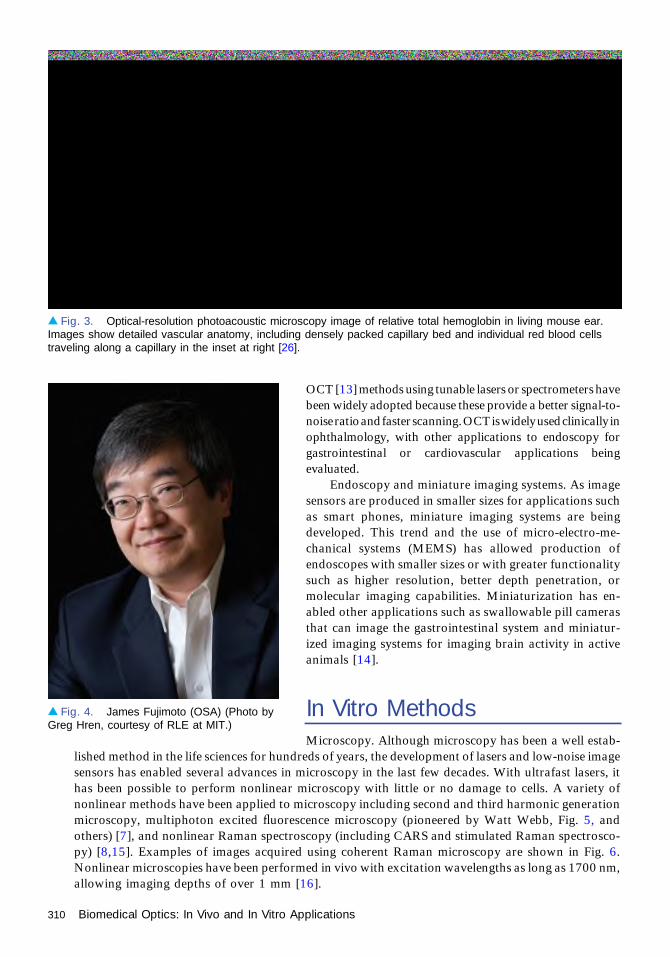
OCT [13] methods using tunable lasers or spectrometers havebeen widely adopted because these provide a better signal-to-noiseratioandfasterscanning.OCTiswidelyusedclinically inophthalmology, with other applications to endoscopy forgastrointestinal or cardiovascular applications beingevaluated.
Endoscopy and miniature imaging systems. As imagesensors are produced in smaller sizes for applications suchas smart phones, miniature imaging systems are beingdeveloped. This trend and the use of micro-electro-me-chanical systems (MEMS) has allowed production ofendoscopes with smaller sizes or with greater functionalitysuch as higher resolution, better depth penetration, ormolecular imaging capabilities. Miniaturization has en-abled other applications such as swallowable pill camerasthat can image the gastrointestinal system and miniatur-ized imaging systems for imaging brain activity in activeanimals [14].
In Vitro MethodsMicroscopy. Although microscopy has been a well estab-
lished method in the life sciences for hundreds of years, the development of lasers and low-noise imagesensors has enabled several advances in microscopy in the last few decades. With ultrafast lasers, ithas been possible to perform nonlinear microscopy with little or no damage to cells. A variety ofnonlinear methods have been applied to microscopy including second and third harmonic generationmicroscopy, multiphoton excited fluorescence microscopy (pioneered by Watt Webb, Fig. 5, andothers) [7], and nonlinear Raman spectroscopy (including CARS and stimulated Raman spectrosco-py) [8,15]. Examples of images acquired using coherent Raman microscopy are shown in Fig. 6.Nonlinear microscopies have been performed in vivo with excitation wavelengths as long as 1700 nm,allowing imaging depths of over 1 mm [16].
▴ Fig. 3. Optical-resolution photoacoustic microscopy image of relative total hemoglobin in living mouse ear.Images show detailed vascular anatomy, including densely packed capillary bed and individual red blood cellstraveling along a capillary in the inset at right [26].
▴ Fig. 4. James Fujimoto (OSA) (Photo byGreg Hren, courtesy of RLE at MIT.)
310 Biomedical Optics: In Vivo and In Vitro Applications
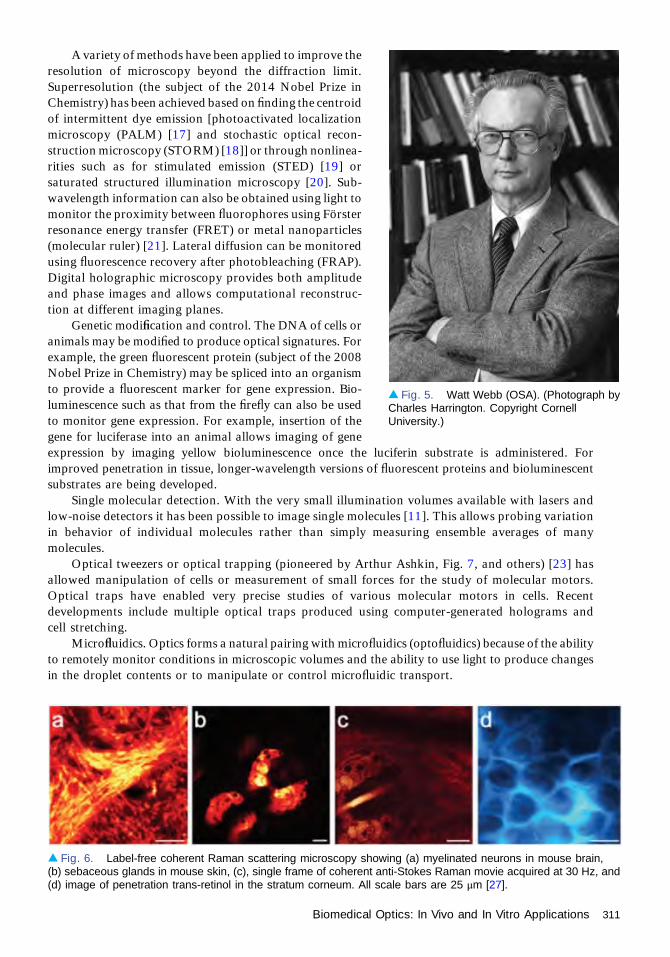
A variety of methods have been applied to improve theresolution of microscopy beyond the diffraction limit.Superresolution (the subject of the 2014 Nobel Prize inChemistry) has been achieved based on finding the centroidof intermittent dye emission [photoactivated localizationmicroscopy (PALM) [17] and stochastic optical recon-struction microscopy (STORM) [18]] or through nonlinea-rities such as for stimulated emission (STED) [19] orsaturated structured illumination microscopy [20]. Sub-wavelength information can also be obtained using light tomonitor the proximity between fluorophores using Försterresonance energy transfer (FRET) or metal nanoparticles(molecular ruler) [21]. Lateral diffusion can be monitoredusing fluorescence recovery after photobleaching (FRAP).Digital holographic microscopy provides both amplitudeand phase images and allows computational reconstruc-tion at different imaging planes.
Genetic modification and control. The DNA of cells oranimals may be modified to produce optical signatures. Forexample, the green fluorescent protein (subject of the 2008Nobel Prize in Chemistry) may be spliced into an organismto provide a fluorescent marker for gene expression. Bio-luminescence such as that from the firefly can also be usedto monitor gene expression. For example, insertion of thegene for luciferase into an animal allows imaging of geneexpression by imaging yellow bioluminescence once the luciferin substrate is administered. Forimproved penetration in tissue, longer-wavelength versions of fluorescent proteins and bioluminescentsubstrates are being developed.
Single molecular detection. With the very small illumination volumes available with lasers andlow-noise detectors it has been possible to image single molecules [11]. This allows probing variationin behavior of individual molecules rather than simply measuring ensemble averages of manymolecules.
Optical tweezers or optical trapping (pioneered by Arthur Ashkin, Fig. 7, and others) [23] hasallowed manipulation of cells or measurement of small forces for the study of molecular motors.Optical traps have enabled very precise studies of various molecular motors in cells. Recentdevelopments include multiple optical traps produced using computer-generated holograms andcell stretching.
Microfluidics. Optics forms a natural pairing with microfluidics (optofluidics) because of the abilityto remotely monitor conditions in microscopic volumes and the ability to use light to produce changesin the droplet contents or to manipulate or control microfluidic transport.
▴ Fig. 5. Watt Webb (OSA). (Photograph byCharles Harrington. Copyright CornellUniversity.)
▴ Fig. 6. Label-free coherent Raman scattering microscopy showing (a) myelinated neurons in mouse brain,(b) sebaceous glands in mouse skin, (c), single frame of coherent anti-Stokes Raman movie acquired at 30 Hz, and(d) image of penetration trans-retinol in the stratum corneum. All scale bars are 25 μm [27].
Biomedical Optics: In Vivo and In Vitro Applications 311

Other Applications. Optical methods have found otherwidespread uses in biomedicine. Examples include immu-nohistochemistry and fluorescence immunohistochemistryto label specific molecules on tissue sections in pathology,photolithography and fluorescence microscopy to mapgene expression or genotype on DNA microarrays (genechips), and matrix-assisted laser desorption/ionization(MALDI) for soft ionization of samples for massspectroscopy.
Quantum dots are semiconductor nanoparticles forwhich quantum confinement leads to different colors basedon the nanoparticle size and provides advantages for bio-imaging [11,12]. Important qualities for quantum dots arethe lack of photobleaching and wide range of colors thatcan be produced. Quantum dots are used for researchincluding both in vitro and in vivo applications in animalstudies.
Surface plasmon resonance. Surface plasmon reso-nance, particularly in noble metals, can be used in sensingand imaging. The resonance of the light field with thenatural frequency of surface electrons at a gold layer is apowerful method for probing molecular interactions be-
cause of the high sensitivity, and no probe molecule is required. This method, commercialized notablyby Biacore, is very widely used in biology laboratories. Surface plasmon resonance of single noble metalnanoparticles also allows detection of multiple colors using dark field microscopy.
Correlation methods and particle tracking. A number of other optical methods are well developedand commonly used in biomedical studies, such as dynamic light scattering and fluorescence correlationspectroscopy for monitoring the size and interactions of small particles such as proteins or micelles. Forparticles with stronger scattering, microscopic imaging can provide information on the cell’s physicalproperties or intracellular interactions based on single particle tracking.
Therapeutics and PhotomodificationOne of the earliest applications of lasers in medicine was the use of argon ion lasers for retinalsurgery. Other ophthalmic therapeutic applications include corrective surgeries such as LASIK andnow ultrafast lasers for assistance in cataract surgery. Photodynamic therapy is used for treatmentof certain cancers. Lasers are widely used for various cosmetic skin therapies including skinresurfacing, hair removal, vein treatment, acne scar treatment, tattoo removal, and treatment ofport wine stain.
Cellular control and modification. Light may also be used to trigger changes in cells. For example,light may be used to turn on or off ion channels in vivo based on the proteins such as channelrhodopsin[24]. In this way light carried by optical fibers can activate different portions of the brain in awakeanimals. Ultrafast lasers are being used to perform nanosurgery and nanoporation on cells.
OSA’s Role in Biomedical OpticsThroughout its history, OSA has played an active role in biomedical optics. The first issue of theJournal of The Optical Society of America in 1917 included articles titled “The nature of the visualreceptor process” and “A photochemical theory of vision and photographic action,” and this journalhas been a significant publication for vision research since. As new journals were offered (AppliedOptics, Optics Letters, and Optics Express) these, too, became important journals for
▴ Fig. 7. Arthur Ashkin. (AIP Emilio SegreVisual Archives, Physics Today Collection.)
312 Biomedical Optics: In Vivo and In Vitro Applications

instrumentation and techniques in biomedical optics. In 2006, the Society created the Virtual Journalfor Biomedical Optics to collect biomedical optics papers in a single place (Greg Faris, foundingeditor). In 2010, OSA initiated a journal dedicated to the field, Biomedical Optics Express (foundingeditor, Joe Izatt). This journal follows the open access, online format of Optics Express. OSAmeetings, including the Annual Meeting (later Frontiers in Optics) and the Conference on Lasers andElectro-Optics (CLEO) have regularly had significant content in biomedical optics and vision. Atopical meeting “Topics in Biomedical Optics” (BIOMED) with heavy emphasis on in vivo methodswas launched in 1994, and OSA is the cosponsor of the European Conferences on Biomedical Optics(ECBO) together with SPIE. A second meeting, Optics in the Life Sciences, with particular focus onmicroscopy, optical trapping, and contrast methods was begun in 2009, occurring in alternate yearswith BIOMED.
References1. R. Bright, “Diseases of the brain and nervous system,” in Reports of Medical Cases Selected with a View
of Illustrating the Symptoms and Cure of Diseases by a Reference to Morbid Anatomy (Longman, Rees,Orms, Brown and Green, 1831), Vol. II, Case CCV, p. 431.
2. T. B. Curling, “Simple hydrocele of the testis,” in A Practical Treatise on the Diseases of the Testis and ofthe Spermatic Cord and Scrotum (Samuel Highley, 1843), pp. 125–181.
3. M. Cutler, “Transillumination as an aid in the diagnosis of breast lesions,” Surg. Gynecol. Obstet. 48,721–729 (1929).
4. F. A. L’Esperance, Jr., “An opthalmic argon laser photocoagulation system: design, construction, andlaboratory investigations,” Trans. Am. Ophthalmol. Soc. 66, 827–904 (1968).
5. J. W. Severinghaus and Y. Honda, “History of blood gas analysis. VII. Pulse oximetry,” J. Clin. Monit.3, 135–138 (1987).
6. D. Huang, E. A. Swanson, C. P. Lin, J. S. Schuman, W. G. Stinson, W. Chang, M. R. Hee, T. Flotte,K. Gregory, C. A. Puliafito, and J. G. Fujimoto, “Optical coherence tomography,” Science 254, 1178–1181 (1991).
7. W. Denk, J. H. Strickler, and W. W. Webb, “Two-photon laser scanning fluorescence microscopy,”Science 248, 73–76 (1990).
8. A. Zumbusch, G. R. Holtom, and X. S. Xie, “Three-dimensional vibrational imaging by coherent anti-Stokes Raman scattering,” Phys. Rev. Lett. 82, 4142–4145 (1999).
9. C. H. Contag, P. R. Contag, J. I. Mullins, S. D. Spilman, D. K. Stevenson, and D. A. Benaron, “Photonicdetection of bacterial pathogens in living hosts,” Mol. Microbiol. 18, 593–603 (1995).
10. M. Chalfie, Y. Tu, G. Euskirchen, W. W. Ward, and D. C. Prasher, “Green fluorescent protein as amarker for gene expression,” Science 263, 802–805 (1994).
11. W. C. W. Chan and S. Nie, “Quantum dot bioconjugates for ultrasensitive nonisotopic detection,”Science 281, 2016–2018 (1998).
12. M. Bruches, Jr., M. Moronne, P. Gin, S. Weiss, and A. P. Alivisatos, “Semiconductor nanocrystals asfluorescent biological labels,” Science 281, 2013–2016 (1998).
13. A. F. Fercher, C. K. Hitzenberger, G. Kamp, and S. Y. Elzaiat, “Measurement of intraocular distances bybackscattering spectral interferometry,” Opt. Commun. 117, 43–48 (1995).
14. K. K. Ghosh, L. D. Burns, E. D. Cocker, A. Nimmerjahn, Y. Ziv, A. E. Gamal, and M. J. Schnitzer,“Miniaturized integration of a fluorescence microscope,” Nat. Methods 8, 871–878 (2011).
15. M. D. Duncan, J. Reintjes, and T. J. Manuccia, “Scanning coherent anti-Stokes Raman microscope,”Opt. Lett. 7, 350–352 (1982).
16. N. G. Horton, K. Wang, D. Kobat, F. Wise, and C. Xu, “In vivo three-photon microscopy of subcorticalstructures within an intact mouse brain,” in 2012 Conference on Lasers and Electro-Optics (CLEO),OSA Techincal Digest (Optical Society of America, 2012).
17. E. Betzig, G. H. Patterson, R. Sougrat, O. W. Lindwasser, S. Olenych, J. S. Bonifacino, M. W. Davidson,J. Lippincott-Schwartz, and H. F. Hess, “Imaging intracellular fluorescent proteins at nanometerresolution,” Science 313, 1642–1645 (2006).
18. M. J. Rust, M. Bates, and X. Zhuang, “Sub-diffraction-limit imaging by stochastic opticalreconstruction microscopy (STORM),” Nat. Methods 3, 793–795 (2006).
Biomedical Optics: In Vivo and In Vitro Applications 313
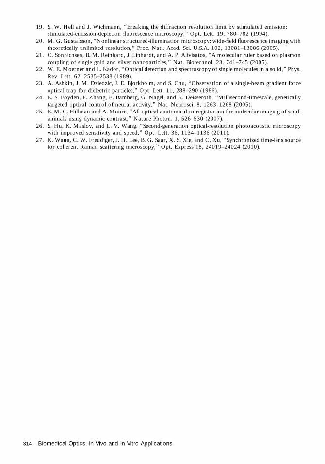
19. S. W. Hell and J. Wichmann, “Breaking the diffraction resolution limit by stimulated emission:stimulated-emission-depletion fluorescence microscopy,” Opt. Lett. 19, 780–782 (1994).
20. M. G. Gustafsson, “Nonlinear structured-illumination microscopy: wide-field fluorescence imaging withtheoretically unlimited resolution,” Proc. Natl. Acad. Sci. U.S.A. 102, 13081–13086 (2005).
21. C. Sonnichsen, B. M. Reinhard, J. Liphardt, and A. P. Alivisatos, “A molecular ruler based on plasmoncoupling of single gold and silver nanoparticles,” Nat. Biotechnol. 23, 741–745 (2005).
22. W. E. Moerner and L. Kador, “Optical detection and spectroscopy of single molecules in a solid,” Phys.Rev. Lett. 62, 2535–2538 (1989).
23. A. Ashkin, J. M. Dziedzic, J. E. Bjorkholm, and S. Chu, “Observation of a single-beam gradient forceoptical trap for dielectric particles,” Opt. Lett. 11, 288–290 (1986).
24. E. S. Boyden, F. Zhang, E. Bamberg, G. Nagel, and K. Deisseroth, “Millisecond-timescale, geneticallytargeted optical control of neural activity,” Nat. Neurosci. 8, 1263–1268 (2005).
25. E. M. C. Hillman and A. Moore, “All-optical anatomical co-registration for molecular imaging of smallanimals using dynamic contrast,” Nature Photon. 1, 526–530 (2007).
26. S. Hu, K. Maslov, and L. V. Wang, “Second-generation optical-resolution photoacoustic microscopywith improved sensitivity and speed,” Opt. Lett. 36, 1134–1136 (2011).
27. K. Wang, C. W. Freudiger, J. H. Lee, B. G. Saar, X. S. Xie, and C. Xu, “Synchronized time-lens sourcefor coherent Raman scattering microscopy,” Opt. Express 18, 24019–24024 (2010).
314 Biomedical Optics: In Vivo and In Vitro Applications

Novel Optical Materials in theTwenty-First CenturyDavid J. Hagan and Steven C. Moss
It is a somewhat daunting task to speculate on optical materials for the next century. Beforeproceeding, it is perhaps useful to imagine how someone may have tried to write such anessay 100 years ago. Looking back at volume 1 of the Journal of The Optical Society of
America, discussion of materials was limited to photographic emulsions, metallic films, andcolor filters. Of course, an optical scientist of that time could have had no inkling of therevolutions that were to follow (lasers, semiconductor electronics, fiber optics, to name but afew) that would transform our concept of optics, give birth to the field of “photonics,” and inmany ways redefine what we mean by an “optical material.” Although it is hard to imagine thatthe twenty-first century could be as revolutionary as the twentieth century was for the field ofoptics and photonics, it certain that things will change in ways that we cannot imagine. Withthat in mind, this essay focuses on some recent advances in materials that in our opinion arepromising. Whether they will significantly impact our field well into the twenty-first century,time will tell.
Even in the last few decades, the face of photonic materials research has changed markedly.Thirty years ago, the field was dominated by the development of new bulk materials, such as newIR glasses, nonlinear crystals, or doped laser crystals, while today research in new photonicmaterials has more emphasis on advances at the nano or micro scale that can result in materialswith new or enhanced properties. There is also a great deal of research in integration of differentphotonic materials for enhanced functionality, resulting in flexible photonic platforms, infraredphotonics devices, semiconductor-core fibers and integration of III-Vs, organics, or carbonelectronics into silicon electronic platforms. The tremendous growth in the breadth and depth ofthe field of optical materials resulted in The Optical Society’s decision to launch a new journaldevoted to the subject, Optical Materials Express, in 2011.
New Optical MaterialsSome of the most interesting work in the development of new materials for optics andphotonics is in cases where the “newness” is related to the physical structure of the material atthe nanoscale, rather than to its chemical structure. One may categorize these into three maintypes. In the first types nanostructuring modifies the electronic structure directly producingnew material properties that are quite unlike the bulk, as observed, for example, in plasmonicnanoparticles; semiconductor quantum dots; or two-dimensional monolayer structures suchas graphene, silicene, germanene, molybdenum disulfide, or boron nitride. Graphene is one ofsix different basic forms of nanocarbon: graphene, graphite, fullerenes, nanodiamond,nanotubes, and nanocones. These forms of nanocarbon provide an attractive set of buildingblocks for future nanoelectronic and nano-optic devices [1]. Both graphene and carbonnanotubes are particularly interesting since their optical absorption extends smoothly acrossan extremely wide wavelength range, allowing for diverse applications such as infrareddetectors and solar cells. Quantum-confined semiconductors, i.e., quantum wells, wires, and
1991-PRESENT
315
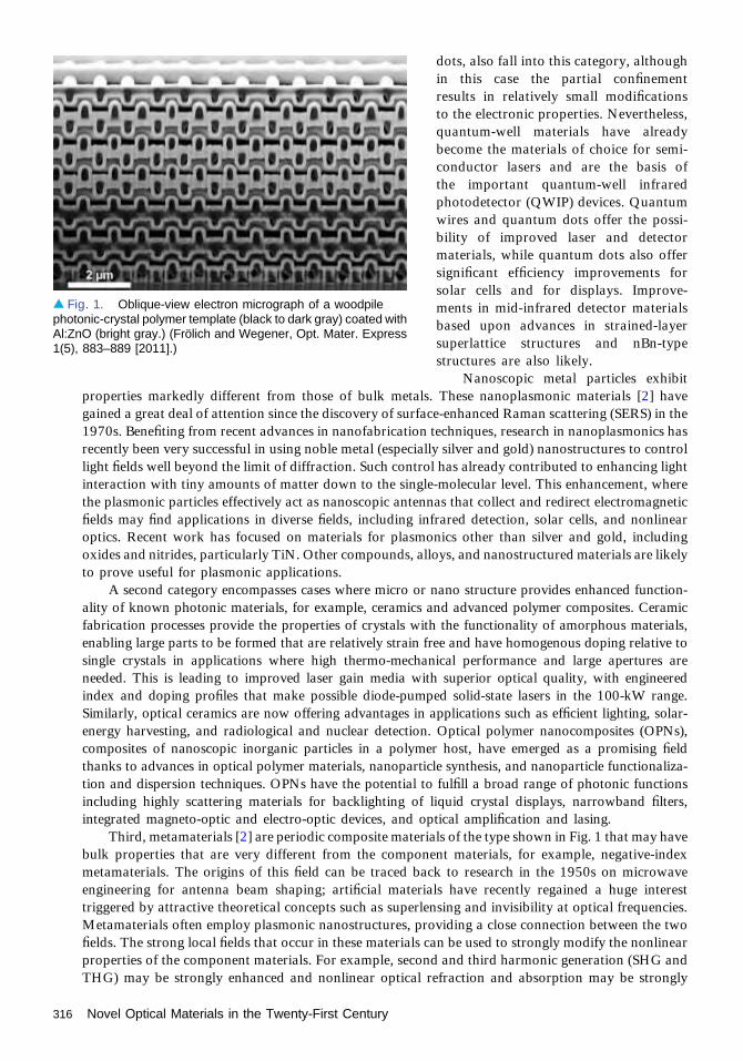
dots, also fall into this category, althoughin this case the partial confinementresults in relatively small modificationsto the electronic properties. Nevertheless,quantum-well materials have alreadybecome the materials of choice for semi-conductor lasers and are the basis ofthe important quantum-well infraredphotodetector (QWIP) devices. Quantumwires and quantum dots offer the possi-bility of improved laser and detectormaterials, while quantum dots also offersignificant efficiency improvements forsolar cells and for displays. Improve-ments in mid-infrared detector materialsbased upon advances in strained-layersuperlattice structures and nBn-typestructures are also likely.
Nanoscopic metal particles exhibitproperties markedly different from those of bulk metals. These nanoplasmonic materials [2] havegained a great deal of attention since the discovery of surface-enhanced Raman scattering (SERS) in the1970s. Benefiting from recent advances in nanofabrication techniques, research in nanoplasmonics hasrecently been very successful in using noble metal (especially silver and gold) nanostructures to controllight fields well beyond the limit of diffraction. Such control has already contributed to enhancing lightinteraction with tiny amounts of matter down to the single-molecular level. This enhancement, wherethe plasmonic particles effectively act as nanoscopic antennas that collect and redirect electromagneticfields may find applications in diverse fields, including infrared detection, solar cells, and nonlinearoptics. Recent work has focused on materials for plasmonics other than silver and gold, includingoxides and nitrides, particularly TiN. Other compounds, alloys, and nanostructured materials are likelyto prove useful for plasmonic applications.
A second category encompasses cases where micro or nano structure provides enhanced function-ality of known photonic materials, for example, ceramics and advanced polymer composites. Ceramicfabrication processes provide the properties of crystals with the functionality of amorphous materials,enabling large parts to be formed that are relatively strain free and have homogenous doping relative tosingle crystals in applications where high thermo-mechanical performance and large apertures areneeded. This is leading to improved laser gain media with superior optical quality, with engineeredindex and doping profiles that make possible diode-pumped solid-state lasers in the 100-kW range.Similarly, optical ceramics are now offering advantages in applications such as efficient lighting, solar-energy harvesting, and radiological and nuclear detection. Optical polymer nanocomposites (OPNs),composites of nanoscopic inorganic particles in a polymer host, have emerged as a promising fieldthanks to advances in optical polymer materials, nanoparticle synthesis, and nanoparticle functionaliza-tion and dispersion techniques. OPNs have the potential to fulfill a broad range of photonic functionsincluding highly scattering materials for backlighting of liquid crystal displays, narrowband filters,integrated magneto-optic and electro-optic devices, and optical amplification and lasing.
Third, metamaterials [2] are periodic composite materials of the type shown in Fig. 1 that may havebulk properties that are very different from the component materials, for example, negative-indexmetamaterials. The origins of this field can be traced back to research in the 1950s on microwaveengineering for antenna beam shaping; artificial materials have recently regained a huge interesttriggered by attractive theoretical concepts such as superlensing and invisibility at optical frequencies.Metamaterials often employ plasmonic nanostructures, providing a close connection between the twofields. The strong local fields that occur in these materials can be used to strongly modify the nonlinearproperties of the component materials. For example, second and third harmonic generation (SHG andTHG) may be strongly enhanced and nonlinear optical refraction and absorption may be strongly
▴ Fig. 1. Oblique-view electron micrograph of a woodpilephotonic-crystal polymer template (black to dark gray) coated withAl:ZnO (bright gray.) (Frölich and Wegener, Opt. Mater. Express1(5), 883–889 [2011].)
316 Novel Optical Materials in the Twenty-First Century
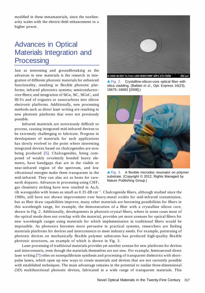
modified in these metamaterials, since the nonline-arity scales with the electric-field enhancement to ahigher power.
Advances in OpticalMaterials Integration andProcessingJust as interesting and groundbreaking as theadvances in new materials is the research in inte-gration of different photonic materials for enhancedfunctionality, resulting in flexible photonic plat-forms; infrared photonics systems; semiconductor-core fibers; and integration of SiGe, SiC, SiGeC, andIII-Vs and of organics or nanocarbons into siliconelectronic platforms. Additionally, new processingmethods such as direct laser writing are resulting innew photonic platforms that were not previouslypossible.
Infrared materials are notoriously difficult toprocess, causing integrated mid-infrared devices tobe extremely challenging to fabricate. Progress indevelopment of materials for such applicationshas slowly evolved to the point where interestingintegrated devices based on chalcogenides are nowbeing produced [5]. Chalcogenides, being com-posed of weakly covalently bonded heavy ele-ments, have bandgaps that are in the visible ornear-infrared region of the spectrum, and lowvibrational energies make them transparent in themid-infrared. They can also act as hosts for rare-earth dopants. Advances in processing using CHF3
gas chemistry etching have now resulted in As2S3
rib waveguides with losses as small as 0.35 dB cm−1. Chalcogenide fibers, although studied since the1980s, still have not shown improvement over heavy-metal oxides for mid-infrared transmission,but as fiber draw capabilities improve, many other materials are becoming possibilities for fibers inthis wavelength range, for example, the demonstration of a fiber with a crystalline silicon core,shown in Fig. 2. Additionally, developments in photonic-crystal fibers, where in some cases most ofthe optical mode does not overlap with the material, provides yet more avenues for optical fibers fornew wavelength ranges using materials for which implementation in traditional fibers would beimpossible. As photonics becomes more pervasive in practical systems, researchers are findingmaterials platforms for devices and interconnects to meet industry needs. For example, patterning ofphotonic devices on mechanically flexible polymer substrates has produced high-quality flexiblephotonic structures, an example of which is shown in Fig. 3.
Laser processing of traditional materials provides yet another avenue for new platforms for devicesand interconnects, even though the materials themselves are not new. For example, femtosecond directlaser writing [7] relies on nonequilibrium synthesis and processing of transparent dielectrics with short-pulse lasers, which open up new ways to create materials and devices that are not currently possiblewith established techniques. The main advantage remains in the potential to realize three-dimensional(3D) multifunctional photonic devices, fabricated in a wide range of transparent materials. This
▴ Fig. 2. Crystalline-silicon-core optical fiber withsilica cladding. (Ballato et al., Opt. Express 16(23),18675–18683 [2008].)
▴ Fig. 3. A flexible microdisc resonator on polymersubstrate. (Copyright © 2012, Rights Managed byNature Publishing Group.)
Novel Optical Materials in the Twenty-First Century 317

technique offers enormous potential in the development of a new generation of 3D components formicro-optics, telecommunications, optical data storage, imaging, astrophotonics, microfluidics, andbiophotonics at the micro and nano scale. Another related advance in laser-written photonicscomponents is photo-thermo-refractive (PTR) glass, which requires heat treatment to develop laser-written index changes, usually in the form of gratings. This produces very-high-quality Bragg diffractivegratings with absolute diffraction efficiency in excess of 95%, allowing highly stable volume holo-graphic elements to be fabricated.
In this century, full 3D design at the nanoscale will play an important role in the architecturaldesign of optoelectronic components. At present, fabrication processing is mostly limited to stacks oftwo-dimensional (2D) layers with some coarse modifications in the plane. Laser direct writing,hierarchical self-assembly, and other advances in lithography will allow placement of structures ofpre-determined size and topology at will anywhere within a 3D solid architecture. This will involvemanipulation of single atoms for applications such as quantum computing (e.g., N-V complex indiamond, P in silicon, SiC, and other materials with defects) as well as structures involving anywherefrom a few atoms to a few dozen atoms for other applications, such as optical modulators, laserdiodes (quantum cascade lasers, QCLs), and nonlinear optical materials [improved SHG, THG,optical parametric oscillators, and optical parametric amplifiers (OPOs and OPAs)].
SummaryAdvances in optical materials over the last thirty years have resulted in both evolutionary andrevolutionary advancements of optics, optoelectronics, and photonics. However, this short articlecannot begin to cover the areas that we expect to be impacted by optical materials. Advances inoptical materials have begun to impact biophotonics and biomedicine with promise for improvementsin human health and the treatment of disease [8]. The impact of advanced optical materials on solarcells is briefly discussed above but is not discussed in detail. Advances in manufacturing forinexpensive solar cell materials including amorphous silicon, materials containing organic dyes,and nanopatterning may speed their integration into power infrastructure. Work on developingquarternary and quinternary materials including dilute nitride materials may enhance efficiencies inhigh-efficiency multi-junction solar cells. Advances in optical materials will have a broader impact onenergy consumption and sustainability through development of new, more efficient devices andapplications such as photochromic and electrochromic materials for climate control in buildings andvehicles. Optical materials, including LCDs and organic light-emitting diodes (OLEDs) have led to arevolution in display technology. This will likely continue, resulting in even better displays, monitors,and TVs with brighter colors, blacker blacks, better contrast, better resolution, and wider field ofview using new OLEDs or organic/inorganic composite LEDs incorporating rare earth and othermaterials. Polymer and organic/inorganic systems that enable wearable electronics and optoelec-tronics, including materials for neuroprosthetics incuding retinal imaging, are likely to becomeimportant. In short, we expect advances in optical materials to pervade almost every aspect of humanlife. The future of optical materials is bright.
References1. Feature issue on Nanocarbon for Photonics and Optoelectronics, Opt. Mater. Express 2(6) (2012).2. Focus issue on Nanoplasmonics and Metamaterials, Opt. Mater. Express 1(6) (2011).3. A. Frölich and M. Wegener, “Spectroscopic characterization of highly doped ZnO films grown by
atomic-layer deposition for three-dimensional infrared metamaterials,” Opt. Mater. Express 1(5),883–889 (2011).
4. J. Ballato, T. Hawkins, P. Foy, R. Stolen, B. Kokuoz, M. Ellison, C. McMillen, J. Reppert, A. M. Rao,M. Daw, S. Sharma, R. Shori, O. Stafsudd, R. R. Rice, and D. R. Powers, “Silicon optical fibre,” Opt.Express 16(23), 18675–18683 (2008).
318 Novel Optical Materials in the Twenty-First Century

5. Focus issue on chalcogenide glass, Opt. Express 18(25) (2010).6. Y. Chen, H. Li, and M. Li, “Flexible and tunable silicon photonic circuits on plastic substrates,” Sci.
Rep. 2, 622 (2012).7. Virtual feature issue on femtosecond laser direct writing and structuring of materials, Opt. Mater.
Express 1(5) (2011).8. N. J. Halas, “The photonic nanomedicine revolution: let the human side of nanotechnology emerge,”
Nanomedicine (London) 4, 369–371 (2009).
Novel Optical Materials in the Twenty-First Century 319

Quantum Information Science:Emerging No MoreCarlton M. Caves
Quantum information science (QIS) is a new field of inquiry, nascent in the 1980s,founded firmly in the 1990s, exploding in the 2010s, now established as a discipline forthe twenty-first century.Born in obscurity, then known as the foundations of quantum mechanics, the field
began in the 1960s and 1970s with studies of Bell inequalities. These showed that the predictionsof quantum mechanics cannot be squared with the belief, called local realism, that physicalsystems have realistic properties whose pre-existing values are revealed by measurements. Thepredictions of quantum mechanics for separate systems, correlated in the quantum way that wenow call entanglement, are at odds with any version of local realism. Experiments in the early1980s demonstrated convincingly that the world comes down on the side of quantum mechanics.With local realism tossed out the window, it was natural to dream that quantum correlationscould be used for faster-than-light communication, but this speculation was quickly shot down,and the shooting established the principle that quantum states cannot be copied.
A group consisting of quantum opticians, electrical engineers, and mathematical physicistsspent the 1960s and 1970s studying quantum measurements, getting serious about what can bemeasured and how well, going well beyond the description of observables that was (and oftenstill is) taught in quantum-mechanics courses. This was not an empty exercise: communicationsengineers needed a more general description of quantum measurements to describe commu-nications channels and to assess their performance. These developments led, by the early 1980s,to a general formulation of quantum dynamics, capable of describing all the state changespermitted by quantum mechanics, including the dynamics of open quantum systems and the statetransformations associated with the most general measurements. An important advance was aquantitative understanding of the inability to determine reliably the quantum state of a singlesystem from measurements.
The 1980s spawned several key ideas. A major discovery was quantum-key distribution,the ability to distribute secret keys to distant parties. The keys can be used to encode messagesfor secure communication between the parties, conventionally called Alice and Bob, with thesecurity guaranteed by quantum mechanics. In addition, early in the decade, physicists andcomputer scientists began musing that the dynamics of quantum systems might be a form ofinformation processing. Powerful processing it would be, since quantum dynamics is difficultto simulate, difficult because when many quantum systems interact, the number of probabilityamplitudes grows exponentially with the number of systems. Unlike probabilities, one cannotsimulate the evolution of the amplitudes by tracking underlying local realistic properties thatundergo probabilistic transitions: the interference of probability amplitudes forbids; there areno underlying properties. If quantum systems are naturally doing information processing thatcannot be easily simulated, then perhaps they can be turned to doing information-processingjobs for us. So David Deutsch suggested in the mid-1980s, and thus was born the quantumcomputer.
As the 1990s dawned, two new capabilities emerged. The first, entanglement-basedquantum-key distribution, relies for security on the failure of local realism, which says thatthere is no shared key until Alice and Bob observe it. This turns quantum entanglement and the
1991-PRESENT
320

associated failure of local realism from curiosities into a tool. The second capability, teleportation, letsthe ubiquitous Alice and Bob, who share prior entanglement, transfer an arbitrary quantum state of asystem at Alice’s end to a system at Bob’s end, at the cost of Alice’s communicating a small amount ofclassical information to Bob. Surprising this is, because the state must be transferred without identifyingit or copying it, both of which are forbidden. Sure enough, the classical bits that Alice sends to Bob bearno evidence of the state’s identity, nor is any remnant of the state left at Alice’s end. The correlations ofpre-shared entanglement provide the magic that makes teleportation work.
These two protocols fed a growing belief that quantum mechanics is a framework describinginformation processing in quantum systems. The basic unit of this quantum information, called a qubit,is any two-level system. The general formulation of quantum dynamics provides the rules for preparingquantum systems, controlling and manipulating their evolution to perform information-processingtasks, and reading out the results as classical information.
The mid-1990s brought a revolution, sparked by discoveries of what can be done in principle,combining with laboratory advances in atomic physics and quantum optics that expanded what canbe done in practice. The first discovery, from Peter Shor, was an efficient quantum algorithm forfactoring integers, a task for which there is believed to be no efficient classical algorithm. The secondwas a proposal from Ignacio Cirac and Peter Zoller for a realistic quantum computer using trappedions. This proposal drew on a steady stream of advances that promised the ability to control andmanipulate individual neutral atoms or ions, all the while maintaining quantum coherence, andapplied these to the design of the one- and two-qubit gates necessary for quantum computation. Thethird discovery, quantum error correction, was perhaps the most surprising and important findingabout the nature of quantum mechanics since its formulation in the 1920s. Discovered independentlyby Peter Shor and Andrew Steane, quantum error correction (Fig. 1) allows a quantum computer tocompute indefinitely without error, provided that the occurrence of errors is reduced below athreshold rate.
Definitely a field by 2000, QIS galloped into the new millennium, an amalgam of researchersinvestigating the foundations of quantum mechanics, quantum opticians and atomic physicists buildingon a legacy of quantum coherence in atomic and optical systems, condensed-matter physicists workingon implementing quantum logic in condensed systems, and a leavening of computer scientists bringingan information-theoretic perspective to all of quantum physics.
▴ Fig. 1. (a) Coding circuit for Shor nine-qubit quantum code. An arbitrary superposition of the 0 and 1 (physical)states of the top qubit is encoded into an identical superposition of the 0 and 1 (logical) states of nine qubits. (b) Error(syndrome) detection and error-correction circuit for Shor nine-qubit code. Six ancilla qubits are used to detect a bit flip(exchange of 0 and 1) in any of the nine encoded qubits, and two ancilla qubits are used to detect a relative signchange between 0 and 1 in any of the nine encoded qubits. Correction operations repair the errors. The code detectsand corrects all single-qubit errors on the encoded qubits and some multi-qubit errors.
Quantum Information Science: Emerging No More 321

QIS researchers are implementing the fundamental processing elements for constructing aquantum computer in a variety of systems: ions trapped in electromagnetic fields, controlled bylaser pulses and herded to interaction sites by electric fields (Fig. 2); circuit-QED, in which super-conducting qubits are controlled by microwaves in cavities and transmission lines; neutral atomscooled and trapped, interacting via cold collisions or by excitation to Rydberg levels; impurity atoms,vacancies, and quantum dots in semiconductor or other substrates, controlled electronically orphotonically; and photonic qubits processed through complicated linear-optical interferometers,capable of implementing efficient quantum computation provided that they are powered by single-photon sources and the photons can be counted efficiently. As experimenters develop these basicelements for quantum information processing, theorists integrate them into architectures for full-scalequantum computers, including quantum error correction to suppress the deleterious effects of noiseand of unwanted couplings to the external world that destroy quantum coherence. An active researcheffort explores the space of quantum error-correcting codes to find optimal codes for fault-tolerantquantum computation.
Other researchers investigate exotic architectures for quantum computation, such as topologicalquantum computation, which encodes quantum information in many-body systems in a way that isnaturally resistant to error, obviating or reducing the need for active quantum error correction. A primecandidate uses as qubits the quasi-particle excitations known as non-Abelian anyons, neither bosonsnor fermions, but occurring naturally in fractional quantum-Hall states. Braiding of the anyons is usedto realize quantum gates.
Experimenters verify the performance of quantum-information-processing devices using quantum-state and quantum-process tomography, techniques invented by quantum opticians to identify aquantum state when one can generate the same state over and over again. The inefficiency of thesetomographic techniques drives a search for more efficient ways to benchmark the performance of suchdevices.
Computer scientists explore the space of quantum algorithms, searching for algorithms thatperform useful tasks more efficiently than can be done on a classical computer and seeking tounderstand generally the class of problems for which quantum computers provide an efficiencyadvantage. One class of problems, present from the beginning of thinking about quantum computers,
▴ Fig. 2. (a) Linear ion trap. Ions (red) are trapped by a combination of DC and RF voltages. Two internal states ofeach ion, labeled 0 and 1, act as qubits. Laser beams (blue) drive quantum gate operations; two-qubit gates aremediated by the Coulomb repulsion between ions. Readout is by resonance fluorescence recorded by a CCD camera:absence or presence of fluorescence signals a qubit’s 0 or 1 state. The inset shows detection of nine ions. (b) NISTRacetrack surface ion trap. Made of a quartz wafer coated with gold in an oval shape roughly two by four millimeters,this trap features 150 work zones, which are located just above the surface of the center ring structure and the sixchannels radiating out from its edge. Qubits are shuttled between zones, where they can be stored or manipulatedfor quantum information processing. The trap could be scaled up to a much larger number of zones. (Fig. 2(a) courtesyof R. Blatt, Quantum Optics and Spectroscopy Group, University of Innsbruck. Fig. 2(b) courtesy of J. Amini, IonStorage Group, NIST.)
322 Quantum Information Science: Emerging No More

is the simulation of complex quantum systems, including complex materials, molecular structure, andthe field theories of high-energy physics.
Quantum communications, the home of much early QIS thinking, now hosts the field’s premierpractical application, quantum-key distribution. Secret keys, distributed to distant parties over opticalfiber and through free space, are used to encode messages for secure communication. Fundamentalresearch continues on ensuring security in practical situations; using properties of the data exchanged inkey distribution to guarantee security, instead of relying on an assumption that quantum mechanics iscorrect; the design of quantum repeaters, which, by using pre-shared entanglement, can extend thereach of key distribution beyond the usual limit set by losses in optical fiber; and the communicationcomplexity of distributed information-processing tasks.
The theory of entanglement is used in condensed-matter physics to characterize the ground andthermal states of many-body quantum systems with local interactions. The degree and locality ofentanglement become important variables for such systems, useful, for example, in characterizing whenthe low-energy states of the system can be efficiently described and simulated.
From its beginning, QIS has been a productive mixture of quantum weirdness and applications.The field has advanced by interplay between experiment and theory: experimental breakthroughsinspire theorists to dream of what might be, and the dreams of theorists inspire experimentalists toreduce the dreams to quantum reality. Physicists were forced to quantum mechanics, the highlysuccessful framework for all of physical law, because the causal, deterministic, realistic narrative ofclassical physics fails for microscopic systems. Within the quantum framework, it is not surprising thatone can do things that cannot be encompassed within a classical narrative; QIS is the discipline thatdoes those things. In a broad sense, QIS is a sort of quantum engineering: though still rooted infundamental science, QIS seeks ways to control the behavior of quantum systems and turn them toperforming tasks we want done, instead of their doing what comes naturally.
QIS has burst well outside the bounds of what can be summarized in a brief history. To providean illustration of what this means, the author searched the website of Reviews of Modern Physics, thepremier journal for physics review articles, for all articles that have the phrase “quantum information”in the title or abstract. The search turned up 26 articles, the first of which appeared in 1999. These 26articles collectively have 7,370 citations, 283 per article, and an h-index of 23. Promote the field to a fulldiscipline.
There is more. Searching titles and abstracts misses many RMP articles associated with quantuminformation, so the author searched the tables of contents of all issues of RMP from 2000 to the end of2012, adding to the previous list all those articles on quantum information that somehow neglected toinclude quantum information in the title or abstract, articles on the foundations of quantum mechanics,and articles on open quantum systems. This gives 44 review articles since 2000. In the period from 2000to 2006, there were 16 articles, a rate of 2.6 per year. Since 2007, the pace has accelerated: there havebeen 28 review articles in RMP, a rate of 4.7 per year, more than one article per quarterly issue. Andmind you, these are review articles, each of which cites dozens to hundreds of primary research papers.
It is time to stop talking about quantum information science as an “emerging field.” A disciplinerepresented in every issue of RMP is no longer emerging. It has arrived.
Quantum Information Science: Emerging No More 323


THE FUTURE


Far Future of FibersPhilip Russell
Over the next century it seems likely that glass optical fibers, in many as-yet-uninventedforms, will continue to penetrate more and more deeply into science, technology,engineering and their applications.
Ultra-Low-Loss FiberPerhaps there will be hollow-core photonic crystal fibers, with specially treated ultra-smoothinternal surfaces, that offer transmission losses of 0.001 dB/km in the mid-infrared. Such ultra-low loss will allow extremely long repeaterless communications spans (perhaps more than20,000 km) and greatly simplify long-haul communications by rendering the ubiquitous Er-doped fiber amplifier, with its thirst for expensive pump lasers, largely redundant. All the world'soceans may then be spanned by single continuous lengths of such fiber: Sydney to Los Angeles,Auckland to Lima, or Sao Paolo to London. The resulting greatly reduced cost of long-haulcommunications will make access to the World Wide Web a realistic and cost-friendly possibilityfor all the world's populations. Of course, this may also entail the development of a range of newsources, modulators, and detectors for the mid-infrared, but semiconductor science and tech-nology will certainly meet this challenge.
The extremely low loss of these fibers and the lack of optical damage in the empty core mightalso allow them to be used in power distribution systems. They will thus replace old-fashionedelectrical power lines, which will vanish from the landscape in many countries, replaced byunderground fiber optical power cables carrying light generated by the highly efficient laser“power stations” of the future. These high-power fibers will be so ultra-lightweight (a 100 kmlength with the newest high-strength carbon fiber coatings will weigh only 10 kg and have atransmission loss of 0.1 dB, i.e., a loss of 1%) that they could be suspended vertically in theatmosphere using computer-controlled balloons placed at regular intervals. Spiraling up into thesky, they will deliver megawatts of optical power to the Earth's surface from Sun- or fusion-driven lasers in space.
Domestic power outlets of the future may also be based on light, delivered via low-lossoptical fibers. Such a power socket might consist of a low-loss optical fiber that, when a plug isinserted, sends a signal to a computer-controlled network specifying the amount of powerrequired. Fiber power delivery to remote devices, using highly efficient laser diodes, will havebecome ubiquitous, providing an elegant and cost-effective replacement for awkward and often-unreliable electrical supply cables and batteries.
Sensing SystemsIn an exotic sensor system of the future, a small “sensing” particle is picked up using lasertweezers and propelled into a length (which might be kilometers long) of hollow-core opticalfiber. Enclosed and protected by the glass sheath, the particle can be propelled along a flexiblepath even through harsh environments. It can be held stationary or moved backward andforward by varying the power ratio between counterpropagating optical modes, and its position
THE FUTURE
327

monitored using time-domain reflectometry or (to interferometric precision) using laser Dopplervelocimetry. It can also be optically addressed in many different ways, permitting sensitive measure-ments of external parameters with high spatial resolution. A further exotic particle type, made possibleby future advances in semiconductor nanofabrication, is a micrometer-scale optoelectronic “microbot”that is powered by the propelling light and capable of sending signals back to the fiber input using lightof a different wavelength or perhaps via a radio signal. It will be designed to sense many differentphysical quantities, including acting as a small microphone for detecting vibrations in inaccessible orharsh environments, as a point source for illumination or probing, as a light detector, or as a probe forlocal oscillating electric or magnetic fields. Perhaps the microbot could, by varying its orientation (ifnon-spherical) or its reflection coefficients against the incoming light, “swim” freely to and fro in theoptical field upon instructions coded into the counterpropagating laser fields.
In the future it may be essential to monitor radiation levels and other parameters close to the core ofa nuclear fusion reactor. Electronics cannot be used and solid-core fibers darken rapidly upon exposureto high levels of radiation. Flying particle sensors in hollow-core fibers will provide a solution: lightgenerated by a radioluminescent particle is relayed back to the fiber input, providing a direct measure ofradiation level, as well as other parameters.
MedicineEndoscopy systems of the future will be multi-functional, enabling surgeons to carry out keyholediagnosis, treatments, and surgery using a thin flexible cable containing a multi-core microstructuredoptical fiber with many advanced functions built into it. Such a fiber will be able to deliver drugs(perhaps photo-activated for treating all kinds of conditions including invasive cancer) in preciseamounts through a hollow channel, transmit many different wavelengths of light appropriate fordiagnosing the health of tissue, deliver selectable wavelengths of high-power laser light for tissue cuttingand blood coagulation, and produce deep-UV light for killing cancerous cells. Each system is likely tohave as standard a multi-mode fiber microscope for high-resolution “structured light” imaging of tissueat many different wavelengths. It will also have a built-in distributed electrically controllable transducersystem (with feedback provided by optical bend and twist sensors) that will allow the fiber to be twisted,turned, coiled, and bent at the surgeon’s command.
So there you have it—a future where glass fibers will play an ever-increasing role in society andeveryday life. Do some of these applications seem outrageous? Just think what has been achieved overthe past half century in optical fiber communications. Maybe they are not outrageous enough : : : .
328 Far Future of Fibers

View of the Future of LightSteven Chu
Niels Bohr, the great Dane wisely noted, “Prediction is very difficult, especially about thefuture,” while the American philosopher of the twentieth century, Yogi Berra quipped,“You can observe a lot by just watching.” To be asked to write seriously about what
we can expect from light-based technologies over the next hundred years is serious foolishness.With this caveat, here are some predictions of what light will allow us to see and do in that future.
The interferometers of Michelson of 100 years ago are superseded by matter interferometersthat use light as beamsplitters and mirrors to measure the interference of atom matter-waves. Theprecision of the Michelson–Morley experiment 100 years ago saw no measurable shift ofdistances Δl /l ∼ 3 × 10⁻⁹ parallel and perpendicular to the motion of the Earth. With atominterferometers, the precision improves by 19 orders of magnitude—the equivalent of measuringa change in the distance to the nearest star 3 light years away to one millionth of the width of ahuman hair. Gravity-wave astronomy becomes a reality, and space–time distortions due toquantum fluctuations of the vacuum enlarged during the epoch of inflation are mapped directly.
Photostable, near-infrared optical probes smaller than the average protein are routinely usedto label and observe the molecular interactions of RNA strands and dozens of proteinssimultaneously with sub-millisecond time resolution. While tissue is relatively transparent atthese wavelengths, light is strongly scattered. Adaptive optics using multi-megapixel arrays andultrafast correction methods are used to restore full optical resolution, peering centimeters intotissue. Voltage-sensitive versions of these probes record the real-time individual firing of billionsof synapses in the human brain. Coupled with full knowledge of the Human Connectome, wenow understand, at the circuit wiring level and at the molecular level, human consciousness andself-awareness. This understanding has allowed us to significantly slow the progression ofvarious forms of dementia.
Optical probes allow us to track the expression levels and location of the full suite of RNAexpression in time and space within individual cells in live tissue. DNA sequencing identificationmethods based on optics help us identify many diseases and greatly reduce misdiagnoses. Opticalmethods of understanding the genetic mutations that cause many cancers are routinely used todevelop targeted drug therapies and in helping recruit the human immune system to cleanse thebody of oncogenes with minimal side effects.
To handle the stupendous computing needs of the achievements listed above, quantumcomputers, quantum simulators, and nanoscale memory are widely used. We use them tosimulate complex systems with sufficient detail to discover improved room temperature super-conductors. We use this computational prowess to understand how our brains perceive and howwe analyze and respond to stimuli, as well as to perform massive simulations that reliably predictclimate change caused by human-generated greenhouse gas emission.
Solar power is the lowest-cost source of energy in many parts of the world. This energy isbeginning to be distributed across oceans via ultra-high DC voltage lines in undersea cablescapable of moving tens of gigawatts of power greater than 4000 km with less than 5% loss.Regions of the world with poor solar irradiation and reduced winter solar generation aresupplied with clean energy.
Unfortunately, the integrated carbon emission by 2065 was not reduced quickly enough.With our deeper understanding of climate change, the errors of not heeding early warningsigns are starkly seen. The advanced visible and infrared Earth monitoring sensors and orbiting
THE FUTURE
329

atom-wave gravity gradiometers allow us to measure with remarkable precision how the climate ischanging. The demonstration of reliable long-term weather predictions allows us to forecast withconfidence the climate of 2100 and 2200. Just as exposure to carcinogens such as asbestos or cigarettesmoke can trigger a series of multiple mutations that lead to cancer many decades later, we now realizethat greenhouse gas emissions put our world on an extremely disruptive and destructive course for asignificant fraction of the population.
Is this last prediction too dire? Possibly, but I also believe there is hope. While science alone will notchange political policy, the massive use of optical technologies will provide compelling evidence (andcompelling predictions) to convince a vast majority of people and governments of the world to make thenecessary investments for future generations. In addition, the near future is ripe with the promise ofunderstanding the human brain and body at breathtaking new levels, again with optics-enabledtechnologies. These advances will not only lead to better health and longer and better life spans. Withour optics-enhanced ability see the future, we will likely observe that global altruism and compassionwill serve our own self-interest exceedingly well.
Of course, what happens beyond 50 years is very difficult to predict. The first power flight by theWright Brothers was in 1903, and we landed men on the moon in 1969. All that can be reliably foreseenis that there will be many wondrous surprises in optics in the next 100 years.
330 View of the Future of Light

The 100-Year Future for OpticsJoseph H. Eberly
The most interesting part of a 100-year future is the last three-quarters of it, following thearrival of the predictable stuff. Even obvious insights can quickly look silly—think of theconfident predictions of personal airplanes for commuting to work made in the 1930s
and 1940s, while we′ve managed only bigger highways and longer-lasting traffic jams since then.Meanwhile, entire generations of music playing systems arrived unpredicted, became universallyadopted, and are already forgotten. How many futurists imagined xerography, or personalcomputers, or intelligent telephones that are also cameras and computers, to say nothing of theFANG team—Facebook, Amazon, Netflix, and Google?
What we need is an unconstrained view of the future of optics, and Quantum Optics is nearlyideal for this because we think we know what it is, but it’s still far from fully explored. Themeaning of quantum mechanics itself is steadily debated while more and more optical processesare being given quantum properties. On the near horizon, and easy to connect to current researchthemes, one expects to see and possibly benefit from optical control of cars and roadways,photon counting without photon annihilation, wide uses for optical entanglement both quantumand classical, quantum optical networks for secure identity hacking, the development ofpowerful sources of squeezed light, 4-photon down-conversion crystals and quantum-commu-nicating telescope arrays, in addition to inexpensive consumer items such as invisibility cloaksthat will fit in ladies’ purses.
Farther out, but inevitable, will be lethal hand-held optical weapons and wide-area satellitemonitoring of their use. Entirely speculative, but more fascinating, will be fundamentaldiscoveries employing quantum optical sensitivity, including: (i) experimental proof that aconnection between quantum mechanics and gravity cannot exist, (ii) detection of coherentquantum opto-galactic signals pervading space, (iii) discovery of the origin of quantumrandomness, (iv) prediction of the longest possible electromagnetic wavelength and its detection,(v) real-time optics for in-vivo whole-body DNA correction, (vi) verification of the macroscopiclimit to quantum superposition, and (vii) reliable quantum-optical disassembly and recovery ofbio-systems, allowing practical teleportation. In the end, all of these projections will turn out tobe too conventional. To reorient a remark attributed to Steve Jobs, and thinking of Marie Curie,the optical scientist doesn′t know what she′ll be most thrilled to find until she finds it.
THE FUTURE
331

Future of EnergyEli Yablonovitch
Civilization is presently in the hunter/gatherer mode of energy production. Nonetheless,the continual drop in cost of solar panels will lead to an agrarian model in which energythat is harvested from the Sun, optically, will satisfy all of society’s needs.
Solar panels are optical. By recognizing the optical physics in solar cells, scientists are, for thefirst time, approaching the theoretical limit of ∼33.5% efficiency from a single bandgap.
At the same time, solar panels have dropped in price by a factor of approximately three timesper decade, for the last four decades, cumulatively a ∼100-fold reduction in real price. Since solarpanels are manufactured in factories under controlled conditions where continuous improvementis possible, these panels will continue to drop in price until solar electricity becomes the cheapestform of primary energy (likely to occur around 2030). At that point, solar electricity will becomecheap enough to be converted into fuels, which can be stored summer to winter. The creation offuel requires panels that are three to four times cheaper than today’s already depressed solarpanel cost, while maintaining the highest efficiency.
The highly successful petroleum industry is over 150 years old. It has taken advantage oftechnology, but it appears resistant to disruptive technical changes that could sweep it away, asso many industries have been irrevocably changed or entirely eliminated by the advance oftechnology. Nonetheless, the application of solar electricity to create fuel could sweep away thepetroleum exploration industry, which the author calls the “hunter/gatherer” mode.
Future solar cells will all have direct bandgaps, allowing them to be very thin. The cost of thematerial elements composing the cell will be small, since a film as thin as 100 nm can fully absorbsunlight using light trapping. Even if the chemical elements were to be expensive, there would beso little material used in such thin photovoltaic films that the cost would be low. Indeed, there aremethods to produce free-standing, highest-quality, single-crystal thin films economically.
The key to high performance from a solar cell is external luminescence efficiency, an insightwhich has produced record open-circuit voltage and power efficiency. This has everything to dowith light extraction, in agreement with the mantra “a great solar cell needs to also be a greatlight emitting diode”—again the application of optics.
Solar electricity in the open field will be brought to nearby locations where it will be used forthe recycling and electrolysis of CO2 solutions. There have been great strides in electrolysis,which can produce various proportions of H2, CH4, and higher hydrocarbons as products. Thecarbon–carbon bond is particularly prized, since such compounds can be readily converted intodiesel fuel and jet fuel. The study of such selective electro-catalytic surfaces is still in its infancy.Even if only H2 were ever to be produced, there are industrial methods of using H2 to reduce CO2,and make useful liquid fuels, among many other products.
The ability to create fuels would increase the size of the photovoltaic panel industry at leasttenfold, allowing the adoption of new cell technology, which is better than the current outdated1950s crystalline silicon solar cell technology.
Thus we see that the application of optical science in making solar cells more efficient andlower in cost will produce a revolution in mankind’s energy source, playing a role analogous tothe agricultural revolution of 10,000 years ago.
THE FUTURE
332
Future of DisplaysByoungho Lee
Displays have been created as a way to convey information. From 2D to 3D, displaytechnology has been evolving to cope with the complexity of the information we try todeliver. But what comes next? Based on current research progress in the field, it is
possible to predict that in the next decade we will be reading news from newspaper-like flexibledisplays with real-time videos (instead of still pictures) and live internet feeds. But if we go evenfurther and predict what displays are going to be like 100 years from now, we can expect thatdisplays will substantially affect the way we live.
The year is 2116, and as his windows turn from opaque to transparent, Mark wakes upfeeling the sun in his face. Mark’s house already knows that he is awake and the coffee is alreadybrewing. As Mark looks out to an awakening New York, he is presented with the weatherforecast as well as a reminder about his dinner with his girlfriend. While taking his shower, Marklikes to read the morning news in the shower-box glass door. In the kitchen Mark is distracted bythe football highlights being shown on the table-top display when he gets a call from his mother.It is a hologram call. She is having trouble with the new robot vacuum cleaner she was given forChristmas. Mark then activates the 3D interactions mode, and his 3D image appears in hismother’s house where he can show her how to fix her problem. Mark’s smartwatch buzzes,telling him that he should leave home if he wants to catch the subway on time. He then transfersthe call to his watch and continues to see his mother through his contact lenses. As an architect,Mark has always struggled to visualize and interact with his creations in three dimensions, so heis excited to work on his new interactive desk with a built-in volumetric 3D flexible transparentdisplay. To get a better perspective of what a client’s structure is going to look like, Mark uses thevirtual reality feature on his contact lenses and walks around the structure fixing the last details.He then invites his boss and clients to his virtual model, where they can look at it together andtalk over details using a 3D virtual reality call. The client is happy, and Mark could not behappier. He copies the design documents to his foldable transparent screen. Before folding it, hechecks the status of his own house with the display. His house seems a little bit dark. He opensthe curtain with the Internet of Things menu of the display and orders his robot cleaner to cleanthe living room. In addition, since he wants to invite his girlfriend to his home after dinner, headjusts the temperature of a nice bottle of wine. Now everything is perfect!
Technology development goes faster and faster, and predicting “10 years later” often looksmeaningless. However, predicting “100 years later” might be easier because a century is plenty oftime to pass through the “trial and error” stage, and we can expect that what we originallyimagined as a technology will have come true in real life. The whole idea of displayinginformation that started from people’s imagination will be implemented, and we might hopethat all the bugs will be worked out in 100 years. Think of a seamless display technology likeperfect, anytime, completely life-like augmented reality, where users see appropriate virtualimages overlapped with real scenes at any time and at any place. 100 years is enough to make thatpossible. The only limitation would be the lack of our imagination rather than an incompletetechnology.
THE FUTURE
333

Biomedical Optics—The Next100 YearsRox Anderson
The previous century of biomedical optics strongly suggests that our technology andcapability will be much improved in the next 100 years. Today we have artificial lightsources emitting thousands to billions of watts that are routinely used to treat children;
photodynamic therapy drugs designed to hit specific molecular targets; reading an individualperson’s genetic code using molecular-optical probes; changing brain functions by inserting light-activated genes into mammals; and reading human brain activity with light, to name just a fewcurrent capabilities.
But what comes next, next, and next? Some doctors, including this author, have beenaccused of being “often wrong, but never in doubt.” With that caveat, what follows is certainlywhat will happen during the next 100 years.
Optical diagnostics will improve, miniaturize, proliferate, become mainstream, replaceconventional biopsies, guide medical and surgical therapy in real time, and then be fullyintegrated via the extension of what we now call robotics. Optical systems already provide anunprecedented combination of high-speed imaging, resolution, point-of-care molecular assays,and minimally invasive access deep inside the body. By 2040, optical diagnostics will becomparably as different as today’s smart phones are from the telephones of 1985—an equaltime gap. What will drive this? At the least, cancer detection, surgical guidance, instant diagnosisof infections including their antibiotic sensitivity, and the need for common lab tests done quicklyon a single drop of blood, probably as a smart phone app. By 2050, user-friendly opticaldiagnostics will be nearly everywhere in medicine, surgery, school, public, and home. Data anddecision analysis will be rapid, highly automated, almost free, and simultaneously personal andwidely shared.
Most of our optical treatments using lasers and light-activated drugs aim to destroy someundesirable “target.” But light also stimulates, modulates, heals, controls, or creates. By 2065,the tables will have turned—most of the therapeutic realm of biomedical optics will be non-destructive. An early example now is optogenetics. Rhodopsin genes linked to specific promotersequences are used to express light-activated action potentials in neuronal systems. The techniquestarted as a way to study brain function. By 2025, it will provide a cure for blindness from thegenetic disease retinitis pigmentosa. This is just the first example of a “designer optical interface”with our central nervous system. Other examples will hail from the natural and somewhatenigmatic phenomenon of “photobiostimulation,” in which light activates mitochondria, thecellular power plant that produces ATP. Apparently every cell in our bodies has at least onephotoreceptor system, and probably several. During this century, light will be used to activatemuch more than transfected neurons, mitochondria, or naturally occurring photosystems. Therewill be a steady trend to use light for controlling biological systems. Microscale implanted opticalmachines will be developed, powered, and controlled by light. Think, “designer tattoos.”
Optical technology itself will benefit directly and greatly from biology! The first live-cell laserwas demonstrated only a few years ago. Useful optical components occur in natural organisms,including waveguides, gain media, energy storage and transfer, charge separation, quantum-levellight detectors at body temperature, and narrow-band emitters. We use a lot of optical devices tostudy biology, but the flow of capability between optics and biology is ultimately a two-way
THE FUTURE
334

street. Can you imagine using optical components that respond to their environment, self-align,replicate, and/or repair themselves (because they are alive)? This revolution has already started, bymaking optical components from natural biomaterials. Some useful optical cyborgs will be around wellbefore 2115.
The past 100 years has seen a steady trend in optics and electronics, toward smaller and smallerdevices. Enzymes, RNA, and other macromolecules are incredibly agile nanomachines that specificallymanipulate other molecules. Combining three current trends of (a) ever-smaller-devices, (b) designermolecular biology, and (c) near-field optics, one comes up with diagnostic and therapeutic, nanoscale,inside-you, optical robots that work in concert with our natural nanomachinery. This will lead to thedesign of circulating, biocompatible, harmless, controllable, self-reporting, intervention-capablecyborgic devices that are the size of your cells or smaller. At the end of this century, such thingswill be in clinical trials. It will be impossible—and irrelevant—to decide if they are devices, drugs, ordiagnostics. Eventually, even the FDA will stop caring about that.
Energy, global warming, and environmental change are all, at heart, biomedical optics problems.Evolution came up with photosynthetic algae and forests that are barely 1% energy efficient, yet theyare the only power source for life on the planet (except for a few, very weird organisms). Can we dobetter than photosynthesis? A delocalized, efficient, solar-driven, self-repairing, replicating, energy-generating, non-polluting equivalent of photosynthesis is sorely needed. Like it or not, we have becomeshepherds of this world. A century ago, Mark Twain famously quoted a friend : : : “everybodycomplains about the weather, but nobody does anything about it!” A century from now, globalwarming may be viewed as an uncontrolled but positive feasibility experiment—yes, we can change theweather! Other global challenges will be faced and attacked using biomedical optical technologies. By2115, people themselves may have the option of being photosynthetic. What if food were plentiful andfree? What if people were healthy for a very long time? Traditionally, species populations are controlledby disease, famine, and unfortunately for us, war. Population control is probably going to be an evenbigger issue in 2115. Maybe biomedical optics will help that, somehow.
Finally, there is optical exobiology. Bioscience has been fundamentally limited by looking at life,well, here. Optical telescopes are the tool that recently allowed us to detect many other planets, orbitingmany other stars. Exobiology is likely to be a robust science by 2115, and surely it will depend on muchbetter optics. Someone or some team will use optical spectroscopy to probe what’s on those planets.Telescopes now look at a small patch of sky for a small patch of time, with limited spatial and spectralresolution. Why not look at all of it, all the time, with detecting life in mind? If life is found, biosciencewill take a giant leap forward thanks to optics.
Biomedical Optics—The Next 100 Years 335

Lasers and Laser ApplicationsRobert L. Byer
The year 2015 was declared by the United Nations to be the International Year of Lightand light-based technologies. The opening ceremonies not only celebrated the present butalso acknowledged the past and hinted at what was in store for the future. In the modern
world, 50 years after the demonstration of the laser, light impacts everything we do fromcommunicating, to manufacturing, to health care. This is not surprising, because 50 to 100 yearsis the adoption cycle of a new technology for widespread use by society. Just think for a momentabout railroads, electrification, air transportation, the national highway system, electromagneticcommunication from the radio, television, and the Internet.
So what about the future of lasers and laser technology? We are now six years into the x-ray-laser age, and x-ray lasers based on linear accelerators are being constructed around the world.What will the characteristics and applications of the x-ray laser be 50 years from now? We canexpect that, like the radio and the laser, in 50 years the x-ray laser will be integrated into wide useby society in applications such as precision medical imaging, protein structure determination,and coherent transmission of information at rates 105 times higher than with visible light. We canalso expect advances in x-ray power that will allow for controlling matter at the high densitiessuitable for small-scale inertial fusion power generation. The field of x-ray nonlinear interactionswill be extended from x-ray to gamma ray frequencies suitable for probing nuclear energy levelsand for pumping gamma ray lasers.
Laser-driven accelerators will open up a host of applications in the future. Going fromKlystrons to laser-driven accelerators reduces physical device scale by 5 orders of magnitude.Accelerators could even be made as all-solid-state devices on a wafer scale. For example, a few-centimeter-long accelerator will generate MeV-energy electrons at a mode-locked laser repetitionrate of 100 MHz and would be ideal for treating patients. Such an accelerator, if fitted into acatheter, would revolutionize radiation medicine. This same technology could enable an all-solid-state scanning electron microscope of centimeter length that is driven by compact fiber lasers.
A 1-m laser accelerator with 1 GeV electrons of 10-attosec duration at a 100-MHz repetitionrate is ideal for driving a free-electron laser (FEL) that operates at x-ray frequencies. The 100-MHz repetition rate allows the consideration of an FEL laser with a resonator to match the 100-MHz period. Using, for example, diamond mirrors, this sync-pumped FEL opens the door toupconverting a comb of modes from the visible to x-ray frequencies. This in turn leads toopportunities for precision clocks, precision spectroscopy, and attosecond-timing resolutionmeasurements in the hard-x-ray region, as well as field strengths adequate to ionize the vacuum.Imagine the vacuum as the ideal nonlinear medium for future experiments.
High-average-power lasers have opened the door to new applications. As the power levelincreases in the future to approach and exceed the 1-MW level, new and surprising applicationsare enabled. For example, a laser of 15-MW average power operating at 100 pulses per second,located on the ground, will enable the launching of satellites into low earth orbit, each with amass of greater than one ton. A laser of 35-MW average power operating at a 15-Hz repetitionrate is ideal for driving a laser inertial fusion power plant with a 1-GW electrical output. Whenthat happens, laser energy will become the carbon-free energy of choice: stars burning undercontrol on the surface of the earth.
In the future, if laser propulsion were used to launch hundreds of 2-m-diameter telescopesand the telescopes were directed into formation as a constellation of satellites, then optical
THE FUTURE
336

telescopes of 1000-m diameter and greater would be possible. How would these mirrors be aligned?Again the laser offers the solution through the use of precision clocks and precision interferometry tolocate each 2-m mirror to better than 1/100 of an optical wave in space–time. Such a telescope arraywould enable detailed studies of exoplanets using precision spectroscopy based on laser frequencycombs.
It seems appropriate that in 2060, 100 years after the demonstration of the laser, the amazing laserwill continue to serve society across multiple dimensions from energy to manufacturing to health andthe environment.
Lasers and Laser Applications 337

Optical Communications:The Next 100 YearsAlan E. Willner
Over the past few decades, the field of optical communications has produced astoundingscientific and engineering feats. In addition, it has helped transform the way societyfunctions since the Internet as we know it could not exist without it. Given the exciting
nature of optical science and the ubiquity of communications in our world, there is much reasonto hope that this rate of technical progress and impactful applications will continue for manydecades to come.
The following predictions might capture the future of our field, or just tickle the imagination.We know that technological advances have made the transmission of enormous amounts of
data across the planet commonplace, with the exponential growth in capacity continuing into thefuture. Many past advances in transmission capacity have utilized the multiplexing of multipledata-carrying optical waves with each beam inhabiting a unique optical parameter, such as isdone with different wavelengths. Although recent research experiments have shown significantcapacity increases due to space-division multiplexing, we are just scratching the surface. Basicoptical science tells us that the spatial domain has an enormous number of orthogonal spatialstates, and we will find new ways to exploit space to enable many orders of magnitudeimprovement. Whatever the technology, we will have an endless cycle of thinking we haveenough capacity followed by the panic of needing more, followed by innovation. We will befeverishly following a Moore’s Law-like growth, and always worried that we are coming tofundamental physical limits—but not.
We are always intrigued by the single photon itself. Present single-photon systems are fairlylimited in terms of data rate, transmission distance, complexity, and cost. However, utilizingfuture advances in quantum repeaters and high-speed single-photon sources and detectors, wewill be able to control and communicate using single photons for many types of low-power, long-distance, and secure systems.
It is quite likely that advances in the coming decades in the performance and massproduction of photonic integrated circuits will enable optics to be ubiquitously deployedwherever and whenever it can bring benefit to the system, just as we use electronic integratedcircuits today without thought. Furthermore, optics will bring low-loss and high-bandwidthconnections between and within computer chips. Furthermore, with future advances in highlynonlinear devices, optics will perform specific signal processing operations and logic functionsalongside electronics to enable higher speed and lower power consumption, such that electronicsand optics will be used in a hybridized and harmonized fashion. In some applications, optics willnot even need electronics to process data.
Optical networks have enabled many users to communicate with each other very efficiently.However, these networks are still made up of discrete nodes, such that data is sent away from onenode and independently received by a different node, without different nodes actually interacting asa single unit. Indeed, think of a computer chip. It is a brain, with many operations occurring inparallel but all working toward a single end goal. With advances in highly accurate optical clocks,networks covering large geographic areas will be designed to act like a large computer brain andsynchronously communicate and process data efficiently. Distances will truly disappear.
THE FUTURE
338

For the past 100 years, radio has been king of the free-space communications world, with opticsbarely registering an impact. However, with the constant increase in needed capacity, optical links willbecome commonplace. Indeed, with the future ubiquity of solid-state lighting, almost any bulb can beused for communications.
Sir Charles Kao, the Nobel Laureate credited with proposing that low-loss glass can be used for acommunication system, had said that silica might last 1000 years as the medium of choice. So, going outon a limb, is it possible that silica fiber will give way to a new material with lower loss and lowernonlinearity? Such materials have been envisioned, and the economics may one day demand that a newtype of fiber be adopted and laid around the world.
Since there has been exponential growth in the fiber transmission capacity and the demand for thatcapacity, our field is now cemented as being essential for economic and societal growth. For the past fewdecades, fiber transmission capacity has increased ∼100× every decade. We have seen names flyby—Mega, Giga, Tera, and now even Petabits/sec on a single fiber. Will this continue? In 100 years andif—a big “if!”—advances continue at the same pace, we will see words like Exa, Zetta, Zotta, and evenBrontobits/sec (1027 bits/sec). It is thrilling to imagine the enabling technologies and potentialapplications for such capacity.
If past is prologue, either the above-mentioned or other transforming advances will occur. If thishappens, the exponential growth in the capacity of communication systems will enhance our ability tointeract with each other, our environment, and machines in unforeseen ways.
Optical Communications: The Next 100 Years 339


Index
Note: Page numbers in italics designate illustrations and captions.
AA-1 camera, 66Abbe, Ernst, 9, 14, 23, 35Abbe number, 266Abelès, Florin, 72Abella, Isaac, 82, 84achromatic lens, 13achromatic optics, 14Acrysof Toric, 264Adams, Ansel, 35Adams, E.Q., 43Adams, Paul, 149adaptive optics, 29, 151, 178, 184, 247,
248, 248, 329additive-pulse mode locking (APM),
241, 242Advanced LIGO (Laser Interferometer
Gravitational-wave Observatory),12
Advanced Research Projects Agency(ARPA), 82, 100, 149, 150,185–187, 282
Advanced X-Ray Astrophysics Facility(AXAF), 249
AEC (Atomic Energy Commission), 29,161
aerial cameras, 24, 25, 66aerial reconnaissance. See spy satellites;
surveillance imagingAFCRL (Air Force Cambridge Research
Laboratory), 186, 187AFM (atomic force microscopy), 225–226AFWL (Air Force Weapons Laboratory),
185, 186Agrawal, Govind, 277Aigran, Pierre, 107Air Force Cambridge Research Laboratory
(AFCRL), 186, 187Air Force Office of Scientific Research, 29Air Force Weapons Laboratory (AFWL),
185, 186Airborne laser, 151Airborne Laser Laboratory, 93, 150Airy, George, 15Akhmanov, Sergey A., 116Alcatel, 197, 285Alcatel Thomson Gigadisc, 139Alcon, 263, 264Alfalight Inc., 230, 231Alfano, R.R., 117, 238Alferness, Rod C., 277, 287Alferov, Zh. I., 110, 111, 111, 201AlGaAs, 110, 200AlGaAs/GaAs, 110–111AlGaAs lasers, 202, 228Allen, Lew, 143, 250Alpha laser, 151Alvan Clark and Sons, 14Alvarez lenses, 267American Cystoscope Makers, 56American Film, 31American Marconi Co., 26, 175American Optical Co., 10, 15, 51, 55, 56,
100, 101–102, 104, 150, 185, 186,187, 280
American Physical Society, 86, 107, 178American Telephone & Telegraph Co.
(AT&T), 25, 26, 100, 197, 278, 279,281, 282, 283, 297
ammonia maser, 50, 81, 82
AMO, 263, 264Ampex Corp., 140Anastigmat lens, 33, 35Anderson, Jim, 177Anderson, Rox, 334Ando, 305Andreev, Vyacheslev M., 111, 111Andrus, J., 50Angel, Roger, 246, 248, 250Ångstrom, Anders, 12, 13Antares project, 167, 168anti-reflection coatings, 3, 49, 69, 70,
71–72, 73, 266anti-resonant reflecting optical
waveguiding (ARROW), 297APDs (avalanche photodiodes), 288APM (additive-pulse mode locking), 241,
242“apochromat” objective, 14Apple Computer, 140Applied Energetics, 305applied nonlinear optics, 213–217,
214–217Applied Optics (journal), 195, 312Applied Physics Letters (journal), 84, 95,
191applied spectroscopy, 20, 49–50argon-fluoride laser, 92argon-ion lasers, 91, 91, 95, 96, 98, 196,
225, 234argon-mercury discharge, 91Argonne National Laboratory, 29Argyros, Alex, 299Armand, M., 90Armstrong, John, 115, 219Army Research Office (ARO), 29, 178Arnold, George, 163ARO (Army Research Office), 29, 178ARPA (Advanced Research Projects
Agency), 82, 100, 149, 150,185–187, 282
ARPANET, 279arrayed waveguide grating (AWG), 293,
294ARROW (anti-resonant reflecting optical
waveguiding), 297Artal, Pablo, 263Arzamas-16, 166Asai, Kazuhiro, 175, 179Aschenbrenner, Claus, 159–160Ashkin, Arthur, 119, 220, 222, 223–226,
311, 312Ashura laser system, 167Asterix laser system, 166astigmatism, 15, 253, 262, 264, 266, 267astronomical spectroscopy, 13, 13astronomy, 4, 9, 71, 184
Cat’s Eye Nebula, 18fiber-based astronomy, 301gravity-wave astronomy, 329ground-based telescopes, 244–248,
245–248Hubble Space Telescope (HST), 4, 13,
143, 184, 247, 249–250, 250, 251,252
laser guide star, 4, 29, 178, 247, 248,248
mirrors, 69, 245, 247, 251, 252optical astronomy, 184, 247, 248, 249,
252
Orbiting Astronomical Observatory(OAO), 247, 249
refractors, 14space telescopes, 249–252, 250, 251spectroscopy and, 13, 13, 18–19stellar interferometers, 247stellar spectra, 13See also telescopes
AT&T (American Telephone andTelegraph Co.), 25, 26, 100, 197,278, 279, 281, 282, 283, 297
AT&T Bell Laboratories, 197Atchison, David, 263atom interferometers, 329atom trapping, 224, 225atom-wave gravity gradiometers, 330Atombau und Spektralinien
(Sommerfeld), 17atomic clocks, 226Atomic Energy Commission (AEC),
29, 161atomic force microscopy (AFM),
225–226atomic physics, spectroscopy and,
12–13, 13atomic structure
quantum theory, 3subshells, 17
Atomic Structure and Spectral Lines(Sommerfeld), 17
Atomic-Vapor Laser Isotope Separation(AVLIS) program, 162, 163, 163,164
Auston, D., 221auto industry, 51Autochrome plates, 34automatic exposure (AE) control, 36automatic tristimulus integrator, 43avalanche photodiodes (APDs), 288AVCO Everett Research Laboratory, 92,
150, 161, 187AVLIS program, 162, 163, 163, 164AWG (arrayed waveguide grating), 293,
294AXAF (Advanced X-Ray Astrophysics
Facility), 249azimuthal quantum number, 1, 7
BBabinet, Jacques, 53Baird, John Logie, 53Baker, James G., 49, 64–67, 245Baker–Nunn camera, 245Ball Aerospace, 250, 252“ballistic” photons, 308Balmer, Johann, 13Balmer formula, 13bandwidth, 4, 191–192, 211, 280, 291Banning, Mary, 71The Bar Code Book (Palmer), 133barcode scanners, 128, 129–133, 130–132barcodes, 128–133
scanners, 128, 129–133, 131, 132symbologies, 128–129, 129, 130
Bardeen, John, 62Barger, R.L., 219Barnack, Oskar, 34–35Barnack camera, 35Basov, N.G., 107, 218
Index 341

Bass, Michael, 183, 218, 219Bates, Frederick J., 27Battelle Memorial Institute, 57, 60–61Battista, Albert, 102Baumeister, Philip, 73Bausch, John Jacob, 15Bausch & Lomb, 10, 15, 23, 24, 25, 33,
70, 71, 72, 185, 253, 254, 256BBO (beta barium borate), 215BEACON HILL Report, 65BEACON HILL Study Group, 64Beckman, 50Beecher, William, 15Belforte, David A., 124Bell, Earl, 89, 90, 97, 98Bell and Howell, 15Bell Holmdel Laboratory, 185, 186, 224Bell inequalities, 320Bell Telephone Laboratories, 25, 50, 81,
82, 84, 88, 89, 91, 92, 96, 100, 104,105, 114, 116, 177, 185, 186, 196,199, 201, 204, 205, 215, 218, 223,227, 232–233, 239, 240, 278, 284,297, 304
Bennett, William, 82, 84, 88, 89, 89, 91Benton, Steve, 122Berg, Howard, 225Bernard, M.G., 107Berns, Roy S., 10, 43beta barium borate (BBO), 215Bevacqua, S.F., 109Biacore, 312bifocals, 14, 184, 253, 254, 263, 265, 266,
268“Big Bird,” 156, 158Big Demonstration Laser, 150binary phase shift keying (BPSK)
modulation, 294–295binoculars, 14, 24, 71bioluminescence, 311BIOMED meeting, 313biomedical optics, 277, 308–313,
309–312, 334–335See also ophthalmic surgery; vision
correctionBiomedical Optics Express (journal), 313BioRad/Spectra-Physics, 305Birks, Tim, 299, 300“Bison” (Soviet bomber), 65Bissell, Richard, 65, 157, 158Bjorkholm, John, 224, 225, 226blackbody radiation, 3, 12BlazePhotonics, 300Blikken, Wendell, 119Block, Steven, 225Blodgett, Katharine, 70Bloembergen, Nicolaas, 115, 115, 213,
214, 221Bloom, Arnold, 89, 90, 97Blu-Ray, 142, 142Blum, Samuel E., 257, 258, 259, 260, 261Boeing, 150, 151, 185Bohr, Niels, 3, 13, 17, 329Bohr atom, 3, 13, 17Boll, Franz Christian, 41BOMEX project, 98Bond, W.L., 6Borde, C., 220Bortfeld, Dave, 95Bose–Einstein condensation, 219, 221,
225Boston University, 85Boston University Optical Research
Laboratory (BUORL), 65Botez, Dan, 227, 231, 231Bowen, Ira S., 18, 18, 20, 245Boyd, Robert, 117BPSK modulation (binary phase shift
keying modulation), 294–295
Brackett, Frederick Sumner, 18Bradbury, Rudolph, 186Bragg fibers, 297, 298Brandeis University, 186Braren, Bodil, 260Braunstein, Maurice, 187Brazier, Pam, 122, 122Breckinridge, James, 244, 246, 249, 250Brewster, David, 11Brewster’s angle, 91, 97, 169Brewster’s angle slab amplifier, 168–169,
169Bridges, William B., 88–93, 91, 98, 187Brillouin scattering, 116British Telecom Research Laboratories,
197, 278, 280Brody, Peter, 270Bromberg, Joan Lisa, 103Browell, Ed, 175Brown, Gordon, 145Brown University, 186Brownell, Frank A., 32Brownie camera, 10, 31–32, 32Buccini, John, 143Bufton, Jack, 175, 179, 180Bunsen, Robert, 13BUORL (Boston University Optical
Research Laboratory), 65Burbank Skunk Works, 157Bureau of Standards, 20, 24, 25, 26, 27,
43, 185Burnham, R.W., 44Burns, Gerald, 108, 108Burns, Keivan, 20Bush, Vannevar, 27, 28, 28, 29, 185Byer, Robert L., 103, 213, 214, 336
CC-camera, 66, 67C-series contact lenses, 253Cabellero, Doris, 72cadmium selenide, 270calcium, spectrum, 18Caltech, 86, 297Cambridge Research Laboratory, 185, 186camera lenses, 3, 33, 35cameras, 10, 15, 33–36, 36, 37
A-1 camera, 66aerial cameras, 24, 25, 66automatic exposure (AE) control, 36Baker–Nunn camera, 245Barnack camera, 35Brownie camera, 31–32, 32C-camera, 66, 67Contax I, 33, 35–36, 36Deckrullo focal plane shutter cameras,
35Faint Object Camera (FOC), 250Fairchild K-19, 66film, 10, 15, 34, 39, 51, 52folding Pocket Kodak (FPK),
32–33, 32Homéos stereo camera, 34K-19 camera, 66Kodak Retina camera, 36Leicas, 33–35, 35lenses, 3, 33, 35Miroflex reflex camera, 35Model A, 35Pocket Kodak, 32Polaroid process, 49, 52, 158Polaroid SX70 camera, 64reconnaissance cameras, 64–67Schmidt camera, 4, 244, 245Simplex camera, 34Super Kodak Six-20, 36–37, 3635-mm precision cameras, 34Tourist Multiple camera, 34
Universal Jewel professional folding dryplate camera, 35
Wide-Field Planetary camera (WF/PC),250
See also photography; surveillanceimaging
Campillo, Anthony, 299Canon, 62, 63carbon dioxide lasers, 92–93, 92, 102,
124, 150, 163, 167, 168, 186, 187carbon monoxide lasers, 92carbon nanotubes, 315Carl Zeiss Co., 69Carl Zeiss Foundation, 35Carl-Zeiss Stiftung, 23Carlson, Chester, 50, 57, 58, 59–60, 61,
61, 62, 134Carlson, R.O., 108Carnegie, Andrew, 244, 246carotenoids, 41carrier frequency sweep, 215carrier leakage, 229Carritol, Dick, 154CARS spectroscopy (coherent anti-Stokes
Raman spectroscopy), 219, 308Carswell, Alan, 177Cartwright, Charles Hawley, 69, 70, 71Case Western Reserve University, 244Catalán, Miguel A., 17cataract surgery, 124, 184, 262–264, 312cathode ray tubes (CRTs), 269Cat’s Eye Nebula, 18Caves, Carlton, 277, 320CDs (compact discs), 138, 140, 141, 141,
142cellular control, 312cellulose nitrate film, 15Central Intelligence Agency (CIA), 55, 65,
153, 157Central Laser Facility, 235Centre National de la Recherche
Scientifique, 72ceramic fabrication processes, 316ceramics, 97, 124, 171, 221, 234, 316CERN (European Center for Nuclear
Research), 279CGHs (computer generated holograms),
145CGRO (Compton Gamma Ray
Observatory), 249chalcogenide fibers, 317chalcogenides, 317Chan, Kin Pui, 180Chance, Britton, 309, 309Chandra X-ray Observatory, 249, 251,
251Chanin, Marie, 177–178Charles Stark Draper Laboratory, 86Charman, William, 265Chebotayev, V., 220chemical elements, 19, 21chemical lasers, 93, 150, 151chemical oxygen-iodine laser (COIL), 151Chemla, Daniel S., 304Chen, Chuangtian, 214, 215Chiao, Ray, 116“chirp,” 117, 171, 215, 224, 238, 288chirp-pulse amplified femtosecond lasers,
305chirped-pulse amplification, 235, 242, 304Chraplyvy, Andrew, 211chromatic dispersion, 211, 280, 283, 288chromophores, 309Chu, Steven, 220, 221, 221, 222, 224, 225,
329Churchill, Winston, 205CIA (Central Intelligence Agency), 55, 65,
153, 157CIBA VISION, 254
342 Index

CIE system, 43, 44CIECAM02, 44CIECAM97s, 44Cirac, Ignacio, 321CL-282 (aircraft), 65Clark, Alvan, 14Clark, Harold, 57Clark-MXR, 306CLEO (Conference on Lasers and Electro-
Optics), 178, 237, 259, 279, 285,300, 304, 305, 313
climate change, 329–330coatings
anti-reflection coatings, 3, 49, 69, 70,71–72, 73, 266
interference coatings, 68–70mirrors, 68, 69, 187, 245, 329optical coatings, 3, 68–73, 142
COBE space telescope, 252Coble, Robert, 234Code, Art, 249Cohen-Tannoudji, C., 221, 221, 225coherent anti-Stokes Raman (CARS)
spectroscopy, 219, 308coherent anti-Stokes Raman spectroscopy
(CARS) microscopy, 308Coherent, Inc., 102, 305Coherent Laser Radar Conference, 178coherent lidar, 178coherent light, 79, 88, 98, 107, 108, 114,
119, 213, 214coherent optical communication, 210,
211, 294–295, 295coherent phonons, 305coherent population trapping, 217Coherent Technologies, 178coherent Raman microscopy, 310, 311COIL (chemical oxygen-iodine
laser), 151Cold War, 49–50, 52, 85, 116, 151, 156,
157, 164, 199See also spy satellites; surveillance
imagingColladon, Daniel, 53colliding-pulse mode-locked (CPM)
geometry, 239–240colliding pulse mode-locked lasers, 304color-center lasers, 215, 241, 333color-matching function data, 43color measurements, standardization, 10color order system, 43color photography, 3, 10, 33, 34color printing, 10color science, 43–44color television, 270Colorado State University, 178colorimetry, 43Columbia Electronics Research
Laboratory, 86Columbia Radiation Laboratory, 85Columbia University, 30, 40, 81, 84, 85,
86, 197, 219, 261Columbia University Harkness Eye Center,
260Commissariat a l’Energie Atomique,
169, 170Committee on Medical Research
(CMR), 27communications, 327
bandwidth, 4, 191–192, 211, 280, 291coherent optical communication, 210,
211, 294–295, 295continuous-wave (CW) room-tempera-
ture diode lasers, 199–202, 200, 201data transmission, 196, 215, 279–280,
279erbium-doped fiber amplifier (EDFA),
195–198, 196–198, 210, 230, 277,280, 281, 288
fiber-optic communications, 4, 50,209–210, 210, 227, 230, 278–281,279, 281
future trends in, 338–339Internet, 4, 63, 133, 142, 191, 193, 207,
211, 277, 279, 280, 282, 283, 285,286, 287, 333
low-loss fibers for, 189–193, 190–193,241, 282
modems, 279, 282optical communications networks, 183,
186, 189, 193, 195, 199, 205, 209–211, 215, 237, 277, 289–292, 289,290, 338
quantum communications, 323telecommunications industry, 282–286telephony, 26, 203–207, 204, 206, 207,
279, 282terabit-per-second fiber, 209–211, 210World Wide Web, 279, 282
compact discs (CDs), 138, 140, 141, 141,142
Compton, Karl, 27Compton Gamma Ray Observatory
(CGRO), 249computer generated holograms (CGHs),
145computers
personal computers, 135, 141, 279,282, 331
quantum computers, 320–323, 329Conant, James B., 27condensed-matter physics, 3, 206, 323Conference on Electron Device Research,
88Conference on Laser Radar Studies of the
Atmosphere, 178Conference on Lasers and Electro-Optics
(CLEO), 178, 237, 259, 279, 285,300, 304, 305, 313
Conrady, Alexander Eugen, 33contact lenses, 183, 184, 253–256, 254,
255, 260, 262, 333Contax I camera, 33, 35–36, 36Contessa Nettel, 36continuous-stream inkjet, 62continuous wave argon-ion laser, 98continuous-wave (CW) dye lasers, 95–96,
103, 161continuous-wave femtosecond laser
systems, 239–242, 241continuous-wave (CW) room-temperature
diode lasers, 199–202, 200, 201continuous wear contact lenses, 254–255,
256Convert, G., 90Coolidge, William, 24Copernicus mission, 249copiers, 57, 62–63, 134
xerography, 57–63, 58–61, 134–137,136, 137
copper-vapor lasers, 96, 163, 240copper-vapor pumped dye lasers, 163, 164Cornell, Eric, 221, 225Cornell University, 186Corning, 189, 190, 191, 199, 267, 277,
278, 280, 284, 300Corning Glass Works, 24, 245, 248CORONA program, 52, 65, 79, 153,
157–160, 159“coronium,” 19COSTAR optical system, 250couching, 262Cox, Ian, 253Cox, Palmer, 32CPM (colliding-pulse mode-locked
geometry), 239–240Cross, Lee, 100Cross, Lloyd, 122
Cross, Lowell, 100Crosswhite, H., 218CRTs (cathode ray tubes), 269CRU International, 280Crystalens, 264CSF, 90, 91Cummings, Stuart, 264Cummins, Herman, 82Currie, Mal, 88, 89Curtiss, Lawrence E., 50, 55, 56“custom wavefront-guided” laser
refractive surgery, 261Cyclops laser, 168
DDagor lens, 33Daguerre, Louis Jacques Mandé, 31Dàlibard, J., 221Danalens, 255, 255Danielmeyer, H.G., 105dark-field microscope, 312dark-line defects (DLDs), 203DARPA (Defense Advanced Research
Projects Agency), 29, 151, 282D’Asaro, Art, 201DAST (4-dimethylamino-N-methyl-4-
stilbazolium), 215data transmission, 196, 215, 279–280,
279Daukantas, Patricia, 9, 10, 17, 38Davidson, Gil, 179Davis, Doug, 177Day, Clive, 298, 299Day, D.A., 157Dayton, Russell, 60DCFs (dispersion-compensation fibers),
211“death ray,” 149Deckrullo focal plane shutter cameras, 35Defense Advanced Research Projects
Agency (DARPA), 29, 151, 282Dehmelt, H.G., 220Del’fin laser system, 167Delfyett, P.J., 241DeLoach, B.C., 207Delta laser, 168DeMaria, Tony, 186, 237dementia, advances in treatment, 329Denisyuk, Yuri, 121Denton, Richard, 70Department of Energy (DOE), 29, 164Depot of Charts and Instruments, 26Derr, Vernon, 178designer optical interfaces, 334Dessauer, John, 57, 61–62, 61Desurvive, Emmanuel, 197, 210Detch, J.L., 91Deutsch, David, 320Devlin, G.E., 104Dexheimer, John, 285DFB (distributed feedback) lasers, 288,
293D’Haeens, Irnee, 79, 83DIAL system (Differential-Absorption
Lidar system), 175Dieke, G., 218Dietz, R.E., 105Differential-Absorption Lidar (DIAL)
system, 175diffraction, 69diffraction grating, 12diffuse optical imaging in vivo, 309digital holographic microscopy, 311digital signal processing (DSP), 211Digonnet, Michel, 195Dill, Frederick H., Jr., 108, 108, 1094-dimethylamino-N-methyl-4-stilbazolium
(DAST), 215
Index 343

diode-laser bars, 229diode laser-pumped solid-state lasers,
105–106diode lasers, 105
continuous-wave room-temperaturediode lasers, 199–202, 200, 201
high-power diode lasers, 227–231,228–230
InGaAsP diode lasers, 197long-lived diode lasers, 206–207mirror damage in, 227semiconductor diode lasers, 4,
107–111, 199, 209, 210, 240–241diode-pumped neodymium-slab laser, 151diodes, LEDs, 4, 26, 105, 133, 178, 199,
203, 271, 272, 318Dirac, Paul, 9direct-detection lidar, 178DiscoVision, 138dispersion-compensation fibers (DCFs),
211display technology, future trends in, 333disposable contact lenses, 255distributed Bragg reflector lasers, 293distributed feedback (DFB) lasers, 288,
293Dixon, Richard W., 203, 205, 207, 207DLDs (dark-line defects), 203DNA
genetic modification, 311microarrays, 312
Dobrowolski, George, 72DOE (Department of Energy), 29, 164Dollond, John, 13dominant designs, 62, 63Donders, F.G., 265“Doppler-free” laser spectroscopy, 220Dorpat Observatory, 14dot-com boom, 283double heterojunction lasers, 110, 111,
201, 201, 227, 228Dover printer, 136, 137, 137Dow Corning, 255drop-on-demand inkjet, 62DSP (digital signal processing), 211duality of light, 12Duguay, Michel, 238, 297Dumke, William P., 107, 108, 108Dupont, 24Durafforg, G., 107DVDs, 141, 141, 142Dwight, Herb, 97, 98dye lasers, 95, 304dye sublimation printing, 50dynamic grating spectroscopy, 219dynamic light scattering, 312dysprosium ions, 104Dziedzic, Joe, 225
EE-Tek Dynamics, 284Ealey, Mark, 247EAMs (electro-absorption modulators),
293EARS (Electronic Array Raster Scanner),
136Eastman, George, 10, 15, 25, 31, 33, 185Eastman, Jay, 128Eastman Dry Plate Co., 31Eastman Kodak Co., 23, 25, 31, 36, 44,
51, 95, 161Eastman Kodak Research Laboratory, 24,
25, 27, 33–34, 185Ebbers, Bernie, 286ECBO (European Conferences on
Biomedical Optics), 313ECCE (extracapsular lens extraction), 262Eckhardt, Gisela, 115
EDFA (erbium-doped fiber amplifier),195–198, 196–198, 210, 230, 277,280, 281, 288
Edison, Thomas, 4, 15, 23, 34, 185Edlén, Bengt, 18Einstein, Albert, 3, 12, 81, 88Eisenhower, Dwight D., 29, 49, 52, 64, 65,
85, 148, 157, 158, 185EIT (electromagnetically induced
transparency), 217Ektaprint 100 copier, 63El-Sum, Hussein M.A., 119electric power
laser fusion for, 171solar power, 329, 332
electricity, 11electro-absorption modulators (EAMs),
293electromagnetic radiation, 11electromagnetically induced transparency
(EIT), 217electromagnetism, 11electron microscope, 119, 204, 336electron spin, 18Electronic Array Raster Scanner (EARS),
136electrophotography, 57
See also xerographyElectrophotography (Schaffert), 57Electrotechnical Laboratories (Japan), 167Ellerbrock, V.J., 267ELT (Extremely Large Telescope), 248emission lines, 12Emmett, John, 161, 168end-pumping, 196endlessly single-mode (ESM) PCF, 299endoscopy, 50, 55, 310
fiber-optic endoscope, 50, 55, 56future trends in, 328
energy, future trends in, 332Energy Star 6, 272engineering, post-World War II statistics,
85, 87Enron, 284, 286entangle-based quantum-key distribution,
320–321Epson, 270Epstein, Ivan, 72erbium, 280, 304erbium-doped fiber amplifier (EDFA),
195–198, 196–198, 210, 230, 277,280, 281, 288
erbium-doped lasers, 106erbium ions, 104, 196Ericksen, J.L., 269Ernst Leitz Optical Works, 33, 34ESM-PCF, 299Essilor, 266ether, 11“ether wind,” 11–12Ettenberg, Michael, 199European Center for Nuclear Research
(CERN), 279European Conferences on Biomedical
Optics (ECBO), 313europium ions, 104Evans, R.M., 44evaporated dielectric coatings, 70excimer laser, 183excimer laser ablation, 260, 306excimer laser lithography, 4excimer laser surgery, 257–261, 258, 259,
306excitation curves, 43exclusion principle, 18exobiology, 335exoplanets, 252extracapsular lens extraction (ECCE), 262Extremely Large Telescope (ELT), 248
Exxon Nuclear, 161Eye in the Sky: The Story of the CORONA
Spy Satellite (Day, Logsdon, &Latell), 157
eye surgery. See ophthalmic surgeryeyeglasses, 10, 11, 14–15, 265–268, 267
astigmatism, 15bifocals, 14, 184, 253, 254, 263, 265,
266, 268frames for, 15lenses, 184, 265, 266for low-vision patients, 267polarizing sunglasses, 51
FFabrikant, Valentin, 81Fabry–Perot resonator, 81Faint Object Camera (FOC), 250Faint Object Spectrograph (FOS), 250Fairchild K-19, 66Fano interference, 217Faraday, Michael, 11Faris, Gregory, 277, 308“fast ignition” target, 171Faust, W.L., 92Feinbloom, William, 253Fejer, Martin, 213FELs (free-electron lasers), 151, 336femtosecond absorption spectroscopy, 180femtosecond direct laser writing, 317–318femtosecond lasers, 147, 238, 239–242,
241, 304, 305, 306Fenner, G.E., 108, 109Fergason, James, 270fermions, 18, 322FETs (field effect transistors), 293fiber amplifiers, 195–196, 288fiber attenuation, 280fiber-based astronomy, 301fiber-grating compressors, 216fiber lasers, 241–242fiber-optic communications, 4, 50,
209–210, 210, 227, 230, 278–281,279, 281
fiber-optic connectivity, 4fiber-optic endoscope, 50, 55, 56fiber-optic image scramblers, 55fiber-optic imaging, 53–56“fiber-to-the-home,” 207fiber-optic amplifier (FOA), 195–198, 282fibers
Bragg fibers, 297, 298chalcogenide fibers, 317dispersion-compensation fibers (DCFs),
211fiber structure, 301future trends in, 327–328glass fibers, 53–54, 55, 187, 195, 209,
210, 297, 328high-power fibers, 327hollow-core photonic crystal fibers,
297, 299, 300, 301, 327, 328low-loss fibers, 189–193, 190–193,
241, 278, 282“Mercedes” fiber, 301microstructured optical fibers, 277,
297–301, 298–301, 328multi-core fibers, 301, 328non-zero dispersion-shifted fibers, 280,
289photonic bandgap fibers, 277photonic crystal fiber (PCF), 298–299,
299, 317, 327rod-in-tube fibers, 55, 190single-mode fibers, 55–56, 191, 206,
210, 279, 301terabit-per-second fiber, 209–211, 210ultra-low-loss fibers, 327
344 Index
fiberscope, 50field effect transistors (FETs), 293film-based photography, 10film, photographic. See photographic filmFiocco, Giorgio, 175, 176FIREX project, 171first-generation lasers, 205Fisher, A.G., 270Fizeau interferometer, 144, 144flame-emission spectroscopy, 20flame hydrolysis, 190flashlamp-pumped picosecond systems,
237–239flashlamp pumping, 84, 95, 95, 103, 169,
280flowing gas-dynamic carbon dioxide
lasers, 187fluorescence correlation spectroscopy, 312fluorescence microscope, 312fluorescence recovery after photobleaching
(FRAP), 311fluorescent lamp, 4, 271fluorite, 103fluorophores, 309, 311FOA (fiber-optic amplifier), 195–198, 282FOC (Faint Object Camera), 250folding Pocket Kodak (FPK) camera,
32–33, 32Ford Motor Co. Research Laboratory, 115Ford Scientific Research Center, 177Fork, Richard L., 216, 304Forster, Don, 88Förster resonance energy transfer (FRET),
311Fort Belvoir, 72FOS (Faint Object Spectrograph), 250four-level lasers, 83, 104four-wave mixing (FWM), 211, 219Fowler, Alfred, 17Foy, P.W., 111Franck–Condon principle, 232Frank, F.C., 269Franken, Peter, 114, 115, 213, 218, 219,
246Frankford Arsenal, 70FRAP (fluorescence recovery after
photobleaching), 311Fraunhofer, Joseph von, 12, 13free-electron lasers (FELs), 151, 336free-space solid-state lasers, 242Fréedericksz, V., 269Freeman, R.R, 224frequency combs, 4, 117, 147, 221, 300,
301, 337frequency-resolved optical gating (FROG),
238Fresnel, Augustin-Jean, 11, 12, 69FRET (Förster resonance energy transfer),
311Freulich, Rod, 180FROG (frequency-resolved optical gating),
238fuels, 332Fuji-Xerox, 63Fujimoto, James, 238, 240, 309, 310Fujitsu Laboratories, 281FULCRUM program, 154fullerenes, 315fused fiber bundles, 55, 56fusion research, with lasers, 166–172,
167–171FWM (four-wave mixing), 211, 219
GGaAlAs lasers, 197, 203, 240GaAs-GaAlAs heterostructure
semiconductor lasers, 203, 204GaAs homojunction (diode) lasers, 187
GaAs injection laser, 107–109Gabel, Conger, 96Gabor, Dennis, 119, 122GALEX space telescope, 252GAMBIT system, 160Gamble, Susan, 122GaPAs, 109Garbuzov, Dmitry Z., 111Gardner, Chet, 178, 179Garmire, Elsa, 116, 117gas-dynamic lasers, 92–93, 92, 150gas lasers, 88–93
ionized gas lasers, 90–91, 91GE Hitachi Nuclear Energy, 165Geffcken, Walter, 70Gekko laser, 169gelatin dry plates, 31Gemini amplifiers, 235, 235gene chips, 311gene expression, 311General Electric Co. (GE), 23–24, 70, 100,
108, 109, 165, 185, 187, 199genetics
genetic modification, 311optogenetics, 334
Geodolite Laser Distance Rangefinder, 98–99
Georgia Tech, 177germania, 191germanium, 107, 110, 199Gerry, Ed, 150, 187Geusic, J.E., 104, 105, 186GHRS (Goddard High Resolution
Spectrograph), 250Giant Magellan Telescope (GMT), 248Gilder, George, 284, 285Giordmaine, Joe, 114, 116, 117, 186, 214glass
anti-reflection coatings, 3, 49, 69, 70,71–72, 73, 266
optical glass, 13, 23, 24, 33, 35, 101,189, 266
photo-thermo-refractive (PTR) glass,318
quality for lenses, 13, 14rare-earth metal-doped glass fiber, 210
glass fibers, 53–54, 55, 187, 195, 209, 210,297, 328
glass fusion lasers, 169glass lasers, 101, 104, 150, 166, 167, 168,
186, 237, 238, 239glass mirrors, 68, 245GMT (Giant Magellan Telescope), 248Goddard, George, 64Goddard High Resolution Spectrograph
(GHRS), 250Godowsky, Leopold, Jr., 34Goethe, J.W. von, 68, 69Goetze, Richard, 17Goldman, Jack, 62, 135Goldmuntz, Lawrence, 82, 149Goldsworthy, Michael, 165Gordon, E.I., 91Gordon, James, 7, 81, 82, 82, 215, 224Goudsmit, Samuel, 18, 83Gould, Gordon, 81, 82, 83, 100, 149, 150governmental and industrial research
laboratories. See industrial andgovernmental research laboratories
governmental funding agencies, 9,185–188
Graham, Clarence H., 40Granit, Ragnar, 41Granitsis, George, 101Grant, Bill, 175graphene, 315graphite, 315gravity-wave astronomy, 329Gray, George, 270
Great Britain, 9Great Observatories, 249, 252green fluorescent protein, 311“green gap,” 271Gregg, David P., 138Grotrian, Walter, 18–19ground-based telescopes, 244–248,
245–248group velocity dispersion (GVD), 215Gschwendtner, Al, 177GTE Laboratories, 117Guggenheim, H.J., 105Guiliano, Connie, 186Guinand, Pierre Louis, 13Guirao, Antonio, 263Gustafson, Ken, 116Gustavson, Todd, 10, 31GVD (group velocity dispersion), 215
HHagan, David J., 277, 315Hale, George Ellery, 244, 245, 245, 246half-integral quantum numbers, 18Hall, Charles, 153Hall, Freeman, 178Hall, Jan, 300Hall, J.L., 219, 222Hall, John, 97, 147Hall, Robert N., 108, 109, 187Haloid Co., 57, 60, 61Hamburg Observatory, 4Handbook of Physiological Optics
(Helmholtz), 15handheld barcode scanners, 131–132Hänsch, Theodor, 94, 96, 147, 220, 220,
221, 224, 225, 300Hansell, C.W., 53Hardesty, Mike, 178, 180Hardwick, David, 97Hardy, A.C., 43, 44Hardy, John, 247Hardy spectrophotometer, 43Harris, Stephen E., 186, 214, 216, 217,
221Harrison, George, 20, 21, 28Hartline, Haldan Keffer, 40, 40, 41Hartman, R.L., 207, 207Hartmann–Schack wavefront sensors, 256Harvard College Observatory, 14, 14Harvard “great refractor,” 14, 14Harvard University, 101, 177, 186Harvard University Optical Research
Laboratory, 65Hasegawa, Akira, 117, 215Hass, Georg, 72Haus, H.A., 239Haus, J., 213Haussmann, Carl, 168Hayashi, Izuo, 111, 201–202, 204, 293HBTs (hetero-junction bipolar transistors),
293Heaps, Bill, 175, 177Heard, H.G., 92Heavens, Oliver, 72, 84Hecht, Jeff, 9, 11, 51, 53, 79, 81, 85, 94,
100, 102, 114, 119, 149, 161, 277,278, 282
Hecht, Selig, 39–40, 40Heilmeier, George, 269Heinz, T., 221Heisenberg, Werner, 18, 40Helfrich, Wolfgang, 270helium, model for neutral atom, 17helium-mercury ion laser, 90–91, 91helium-neon lasers, 4, 84, 88–89, 89, 90,
97, 98, 107, 120, 134, 135, 136,138, 190
Hellwarth, Robert, 115
Index 345

Helmholtz, Hermann, 15Henderson, Sammy, 178Heraeus Corp., 155Hercher, Michael, 116, 186Herriott, Donald, 84, 88, 89, 89Herschel, William, 11, 14Herschel space telescope, 252Herscher, Mike, 96Hertz, Heinrich, 11, 12hetero-junction bipolar transistors (HBTs),
293heterodyne Doppler lidar, 177heterodyne interferometry, 143, 247Hewlett-Packard, 62, 63, 98, 131Hexagon program, 79, 154, 158, 160Hexagon spy satellite, 153–156, 154–156,
158Heyerdahl, Thor, 98Hicks, Will, 55, 56hierarchical self-assembly, 318high-average-power lasers, 336high-power diode lasers, 227–231,
228–230high-power fiber lasers, 106, 126, 198high-power fibers, 327high-power gas lasers, 4High Speed Photometer (HSP), 250Hilbert, Robert S., 157, 158, 159Hillotype, 33HIORP (Hubble Independent Optical
Review Panel), 250HiPER project, 171Hirschowitz, Basil I., 50, 55, 56Hitachi Central Research Laboratory, 165,
227Hochuli, Urs, 97Hockham, G., 189, 209hohlraum, 166, 170Holland, Leslie, 72hollow-core photonic crystal fibers, 297,
299, 300, 301, 327, 328holmium ions, 104holographic interferometry, 144–145holography, 79, 119–122
computer generated holograms(CGHs), 145
phase-shifting interferometric, 145reflection holography, 121, 122time-averaged holography, 145two-wavelength holography, 145
Holonyak, N., Jr., 109, 187Homéos stereo camera, 34Homer, Howard, 71homodyne interferometry, 143–144Hooker, John K., 244Hopkins, Harold H., 50, 54Hopkins, Robert, 143, 158HRL (Hughes Research Laboratory), 88,
91, 98, 100, 103, 115, 185, 186, 187HSP (High Speed Photometer), 250Hubble, Edwin, 244, 245, 247Hubble Independent Optical Review Panel
(HIORP), 250Hubble Space Telescope (HST), 4, 13, 143,
184, 247, 249–250, 250, 251, 252Huffaker, Milt, 178Huggins, Margaret, 13Huggins, William, 13Hughes Aircraft Co., 94, 98, 100, 115Hughes Research Laboratories (HRL), 88,
91, 98, 100, 103, 115, 185, 186, 187Hull University, 270Hund, Friedrich, 18Hunter, Max, 151Hunter, R.S., 44Huygens, Christiaan, 11Hycon, 67Hycon K-38, 66Hyde, Frank, 189
hydrogen, Bohr model, 13hydrogen-fluoride chemical lasers, 93hydrogen-fluoride optical parametric
oscillator, 163hyper-contrast optical systems, 252hyperfine splitting, 9, 20hyperfine structure, 19
IIBM, 100, 108, 108, 110, 187, 199, 221IBM Watson Research Center, 84, 94, 103,
104, 187, 187, 257IBM Zurich Laboratories, 228Icaroscope, 114ICCE (intracapsular lens extraction), 262ICG (indocyanine green), 309ICLAS (International Coordination
Group on Laser AtmosphericStudies), 178
illuminationfluorescent lamp, 4, 271incandescent light bulbs, 4, 24solid-state lighting, 339
ILRC (International Laser RadarConference), 178, 179
image scramblers, 55imaging barcode scanners, 133imaging machines, xerography, 57–63,
58–61, 134–137, 136, 137Inaba, Humio, 180incandescent bulbs, 4, 24indium-tin-oxide (ITO) film, 269indocyanine green (ICG), 309industrial and governmental research
laboratories, 9, 23–30Infrared Astronomical Satellite (IRAS),
251–252infrared materials, 317infrared optical microscope, 203–204infrared spectroscopy, 3infrared thin film, 72InGaAsP diode lasers, 197inkjet printers, 50, 62, 63inner-quantum number, 17InP-based lasers, 206, 293, 294Institute of Optics (University of
Rochester), 25, 33, 54, 134, 143,158, 168, 169, 170, 185, 186, 304
instrumental optics, 9integrated photonics, 277, 293–295, 294,
295Intel, 293Intelligence Systems Panel (ISP), 65intensity-comparison with standards
method, 20intensity-modulation direct detection, 210interference coatings, 68–70interference phenomena, 69interferometers, 9, 12, 69, 70, 143–146,
144, 247, 293, 322, 329interferometric optical metrology,
143–147interferometry
heterodyne and homodyne interferom-etry, 143–144, 247
metrology and, 143–147phase-shifting interferometry, 143, 144,
146–147stellar interferometers, 247
International Conference on PicosecondPhenomena, 237
International Conference on UltrafastPhenomena, 237
International Coordination Group onLaser Atmospheric Studies (ICLAS),178
International Laser Radar Conference(ILRC), 178, 179
International Quantum ElectronicsConference, 82, 162, 234
International Symposium on RemoteSensing of Environment, 178
International Telecommunications Union,193
Internet, 4, 63, 133, 142, 191, 193, 207,211, 277, 279, 280, 282, 283, 285,286, 287, 333
Internet of Things, 333intracapsular lens extraction (ICCE), 262intraocular lenses, 262–264iodoquinine sulfate, 51ionized gas lasers, 90–91, 91ionography, 62iPhone 6, 272, 272Ippen, Erich P., 96, 216, 232, 239, 240IRAS (Infrared Astronomical Satellite),
251–252IRCOM (France), 297Iskra laser system, 166isosulfan blue, 309isotope enrichment, 161–165, 162–164ISP (Intelligence Systems Panel), 65Itabe, Toshikazu, 179ITEK and the CIA (Lewis), 157ITEK Corp., 65, 143, 157, 158ITEK Optical Systems, 247Ito, Hiromasa, 179ITO film (indium-tin-oxide film), 269Ives, Herbert, 69Izatt, Joe, 313
JJahn–Teller splitting, 234James Webb Space Telescope (JWST), 252Janes, G. Sargent, 161Janus laser, 168Javan, Ali, 82–83, 84, 88, 89, 89, 107JDS Uniphase, 284JDSU Corp., 230, 285Jelalian, Al, 177Jensen, Reed, 161Jersey Nuclear-Avco Isotopes, 163Jet Propulsion Lab (JPL), 175Jewett, Frank B., 27JHPSSL (Joint High Power Solid State
Laser), 151, 151JILA, 97, 221Jobs, Steve, 140Johnson, A.M., 216Johnson, Kelly, 49, 65Johnson, L.F., 104, 105, 232–233Johnson, Roy, 149Johnson and Johnson, 255Johnston, Sean, 122Joint High Power Solid State Laser
(JHPSSL), 151, 151Jones, Frank, 71Journal of Applied Physics, 84Journal of Display Technology, 271Journal of Lightwave Technology,
291–292Journal of the Optical Society of America
(JOSA), 20, 38, 40, 41, 44, 56, 69,119, 121, 221, 265, 312, 315
JPL (Jet Propulsion Lab), 175Judd, D.B., 43JWST (James Webb Space Telescope), 252
KK-19 camera, 66Kaiser, David, 86Kaminskii, A.A., 105Kantrowitz, Arthur, 150, 161Kao, Charles, 189, 199, 209, 339Kapany, Narinder, 54, 56, 100Karrer, Paul, 41
346 Index

Kass, Stanley, 176Kay, Alan, 136Kazarinov, R.F., 110Keck, Donald B., 189, 190, 191, 279Keck Ten-Meter-Diameter Telescope
Project, 248Kelley, Paul, 3, 28, 49, 116, 179Kepler mission, 252Kepler space telescope, 252Kerr-effect lensing, 236Kerr-lens mode-locked lasers, 242, 304Kerr nonlinearity, 211Kessler Marketing Intelligence, 280Ketterle, Wolfgang, 221, 225Keuffel & Esser Co., 24Keyes, R.J., 105, 108, 109, 187KH-7 GAMBIT, 153KH-9 Hexagon spy satellite, 153–156,
154–156, 158Khokhlov, Rem V., 116Kidder, Ray, 161, 166Kiess, C.C, 20Killinger, Dennis K., 175, 177, 178, 179,
180Kimmerling, L.C., 107, 110Kinetoscope, 34King, Peter, 71Kingslake, Rudolf, 33Kingsley, Jack, 108, 109Kirchhoff, Gustav Robert, 12–13Kirkpatrick, Paul, 119Kirtland Air Force Base, 248Kiss, Z.J., 104Kitt Peak National Observatory,
245, 246Kleinman, David, 117KMS Fusion, 101, 168Knight, Jonathan, 299, 300Knoll, Henry, 253Knox, Wayne H., 96, 277, 304, 305, 306Knutson, J.W., Jr., 91Kobayashi, Takao, 179Kodachrome film, 34Kodak AG, 36Kodak camera, 31Kodak Co., 61, 158, 185Kodak Research Laboratories. See
Eastman Kodak ResearchLaboratory
Kodak Retina camera, 36Koester, Charles, 101, 186, 195Kollmorgen, Frederick, 69Kompfner, Rudi, 223Korad Inc., 100Kornei, Otto, 59Korol’kov, Vladimir I., 111Korsch, Dietrich, 250Kossel, Walther, 17Kowalski, Robert, 134, 135Krag, W.E., 109Kressel, Henry, 111, 199, 200Krishnan, K.S., 19Kroemer, Herb, 110, 187Krupke, William, 103krypton fluoride lasers, 167krypton-ion lasers, 91Kubelka, P., 44Kusch, Polykarp, 81
LLabuda, E.F., 91Lamb, Willis, 96, 114Lamb shift, 220Lamm, Heinrich, 50, 53–54Land, Edwin, 49, 51–52, 64, 65, 158Langmuir, Irving, 24Lankard, Jack, 94Large, Maryanne, 299
Large Optics Demonstration Experiment(LODE), 151
large-scale photonic integrated chip(LS-PIC), 293
Large Space Telescope (LST), 249laser ablation, 92, 257, 258, 260, 306laser-bars, 228laser-based phase-shifting Fizeau
interferometer, 144, 144laser-based spectroscopy, 147, 232laser cooling, 221laser diode pump, 304laser diodes, 105, 199, 200, 201, 202, 293,
304, 318, 327laser Doppler velocimetry, 328Laser Focus (magazine), 121, 259laser fusion experiments, 101laser guide star, 4, 29, 178, 247, 248, 248Laser Heterodyne Radiometer, 175, 177The Laser in America (Bromberg), 103laser in situ keratomileusis (LASIK), 5,
183, 260, 261, 306, 308, 312Laser In Space Technology Experiment
(LITE), 177Laser Inc., 102laser-induced-breakdown spectroscopy
(LIBS), 178laser-induced continuum structure, 217laser-induced fluorescence (LIF), 177, 178Laser Interferometer Gravitational-wave
Observatory (LIGO), 12laser isotopeenrichment,161–165,162–164Laser Megajoule (LMJ) project, 170, 171laser oscillation, 90, 91laser printers, 134–137, 136, 137,
183–186laser printing, 4, 62laser radar, 175–178laser radiation pressure, 223laser spectroscopy, 218–219, 221–222laser trapping, 225laser unequal path interferometer (LUPI),
143, 144laser video disc, 138laser weapons, 149–152lasers, 3, 4, 9, 50, 52, 79, 163, 209, 218
Airborne laser, 151AlGaAs lasers, 202, 228Alpha laser, 151at American Optical Co., 10, 15, 51, 55,
56, 100, 101–102applications, 4argon-ion lasers, 91, 91, 95, 96, 98,
196, 225, 234Ashura laser system, 167Asterix laser system, 166carbon dioxide lasers, 92–93, 92, 102,
124, 150, 163, 167, 168, 186, 187chemical lasers, 93, 150, 151chemical oxygen-iodine lasers (COILs),
151chirp-pulse amplified femtosecond
lasers, 305colliding pulse mode-locked lasers, 304color-center lasers, 215, 241, 333continuous wave argon-ion lasers, 98continuous-wave (CW) dye lasers,
95–96, 103, 161continuous-wave femtosecond systems,
239–242, 241copper-vapor lasers, 96, 163, 240copper-vapor pumped dye lasers, 163,
164Cyclops laser, 168Del’fin laser system, 167Delta lasers, 168development, 81–84, 88–93diode laser-pumped solid-state lasers,
105–106
diode lasers. See diode lasersdiode-pumped neodymium-slab lasers,
151distributed Bragg reflector lasers, 293distributed feedback (DFB) lasers, 288,
293double heterojunction lasers, 110, 111,
201, 201, 227, 228dye lasers, 95, 304erbium-doped lasers, 106excimer lasers, 183, 257–261, 258, 259femtosecond direct laser writing, 317–
318femtosecond lasers, 147, 238, 239–242,
241, 304, 305, 306fiber lasers, 241–242flashlamp-pumped picosecond systems,
237–239flowing gas-dynamic carbon dioxide
lasers, 187four-level laser action, 83, 104free-electron lasers (FELs), 151, 336free-space solid-state lasers, 242frequency comb lasers, 147fusion research with, 166–172future trends in, 336–337GaAlAs lasers, 197, 203, 240GaAs-GaAlAs heterostructure semi-
conductor lasers, 203, 204GaAs homojunction (diode)
lasers, 187GaAs injection lasers, 107–109gas-dynamic lasers, 92–93, 92, 150gas lasers, 88–93Gekko lasers, 169glass fusion lasers, 169glass lasers, 101, 104, 150, 166, 167,
168, 186, 237, 238, 239helium-mercury ion lasers, 90–91, 91helium-neon lasers, 4, 84, 88–89, 89,
90, 97, 98, 107, 120, 134, 135, 136,138, 190
high-average-power lasers, 336high-power diode lasers, 227–231,
228–230high-power fiber lasers, 106, 126, 198holography and, 120–121hydrogen-fluoride chemical lasers, 93industrial growth, 100industrial lasers, 124–126InGaAsP diode lasers, 197InP-based lasers, 206, 293, 294interferometric optical metrology,
143–147Iskra laser system, 166for isotope enrichment, 161–165,
162–164Joint High Power Solid State Laser
(JHPSSL), 151, 151Kerr-lens mode-locked lasers, 242, 304krypton fluoride lasers, 167krypton-ion lasers, 91laser-based precision spectroscopy, 147laser-induced-breakdown spectroscopy
(LIBS), 178laser isotope enrichment, 161–165,
162–164Laser Megajoule (LMJ) project, 170, 171laser unequal path interferometer
(LUPI), 143, 144Ligne d’Intégration Laser (LIL), 170liquid-phase epitaxy (LPE), 200, 200,
203, 204, 206live-cell lasers, 334as manufacturing process tool, 124materials processing with, 124–126matrix-assisted laser desorption/ioniza-
tion (MALDI), 312
Index 347

medical applications. See medicalapplications
mercury-ion lasers, 91, 98Mid-Infrared Advanced Chemical
Lasers (MIRACLs), 150, 150“million hour paper,” 205mirrors, 81, 88, 89, 90, 90, 91, 91, 94,
96, 97, 103, 130, 131, 132, 132,143, 200, 202, 235, 336–337
molecular gas lasers, 92–93, 92Navy ARPA Chemical Laser (NACL),
150neodymium:fiber lasers, 241neodymium-glass fiber lasers, 187neodymium-glass lasers, 104, 150, 166,
167, 186, 237–238neodymium-glass rod lasers, 187neodymium-YAG lasers, 104, 105, 124,
125, 186, 240, 242, 257, 258, 259,301, 304
NIF lasers, 170, 171Nike laser system, 167noble-gas ion lasers, 91nonlinear optics and, 114–117Nova lasers, 169, 170Omega lasers, 169Omega Upgrade lasers, 170, 171Phebus lasers, 169photolytically pumped iodine lasers, 166picosecond lasers, 237–239printers, 134–137, 136, 137for propulsion, 336–337pulsed argon ion lasers, 91, 98pulsed dye lasers, 96, 238–239pumped dye lasers, 95, 163, 164, 177,
234Q-switching ruby lasers, 94, 115, 116,
116quantum cascade lasers (QCLs), 176,
178, 318quantum-well lasers, 202, 227, 228radio-frequency coupling, 97rare earth fiber lasers, 4remote sensing, laser radar, and lidar,
175–178, 176, 177, 179, 180, 180room-temperature GaAs-AlGaAs het-
erostructure semiconductor lasers,203
ruby lasers, 83, 84, 88, 94, 95, 100,103, 114, 115, 116, 116, 121, 124,149, 175, 186, 218, 232, 234
semiconductor diode lasers, 4,107–111, 199, 209, 210, 240–241
separate confinement heterojunctionquantum well lasers, 202
Shiva lasers, 168single-stripe lasers, 228, 229, 229, 231solid-state lasers, 4, 84, 101, 103–106,
125, 126, 131, 178, 227, 228, 231,242, 316
soliton lasers, 241at Spectra-Physics, 89, 90, 91, 97–99spectroscopy with, 96stretched-pulse lasers, 242stripe-geometry lasers, 111, 203Sun-powered lasers, 101in telescopes, 184, 245–248, 251, 25210-J Janus lasers, 168three-section tunable DBR lasers, 293titanium:sapphire lasers, 234, 235, 236,
242, 304tunable dye lasers, 4, 94–96, 95, 161tunable quantum cascade lasers, 176tunable solid state lasers, 105, 232–236,
233–235types, 4ultrafast-laser technology, 304–306,
305, 306ultrashort lasers, 306
ultrashort-pulse lasers, 96, 237–242,239–242
vibronic lasers, 233vision correction. See vision correctionVulcan lasers, 169weapons, 149–152Yb:fiber lasers, 242ytterbium-doped lasers, 106yttrium aluminum garnet (YAG) lasers,
104, 105, 124, 125, 186, 225, 240,242, 257, 258, 259, 301, 304
Zeta lasers, 168Laservision, 138Lasher, Gordon J., 108, 108LASIK (laser in situ keratomileusis), 5,
183, 260, 261, 306, 308, 312lasing without inversion (LWI), 217Latell, B., 157lateral inhibition, 40Lawrence, George, 250Lawrence Livermore National Laboratory
(LLNL), 96, 101, 161, 162, 163,164, 165, 166, 169, 170, 228, 233
Lax, B., 109LBO (lithium borate), 215LCD TV, 272LCDs (liquid crystal display), 269–272,
271, 272, 318LDs (semiconductor laser diodes), 105,
132LDX (Long Distance Xerography), 134Lebedev Institute (Russia), 167Lechner, Bernard, 270LED lighting, 4LEDs (light-emitting diodes), 4, 26, 105,
133, 178, 199, 203, 271, 272, 318Lee, Byoungho, 333Leghorn, Richard, 65, 85Lehmann, Otto, 269Leica cameras, 33–35, 35Leith, Emmett, 119–121, 120, 122Leitz, Ernest, II, 35LeMay, Curtis, 149length-of-line method, 20lens index, 266lenses, 13
achromatic lens, 13for cameras, 3, 33, 35contact lenses, 183, 184, 253–256, 254,
255, 260, 262, 333eyeglasses, 184, 265, 266intraocular lenses, 262–264lens index, 266photochromic lenses, 267prism lenses, 265
lensless photography, 121Leonberger, Fred, 300Leslie, F.M., 269L’Esperance, Francis L., 259, 260Letokhov, V., 220, 224, 225Lett, P., 221“Leviathan” mirror, 14Levishin, Vadim L., 114Levison, Walter, 158Levy, Richard, 161Li, Guifang, 209Li, Tingye, 211LIBS (laser-induced-breakdown
spectroscopy), 178Lick Telescope, 14lidar, 175–178“Lidar Pancake,” 177LIF (laser-induced fluorescence), 177, 178LIFE project, 171light
coherent light, 79, 88, 98, 107, 108,114, 119, 213, 214
as electromagnetic radiation, 11illumination, 4, 24, 271, 339
inelastic scattering, 19particle theory, 11quantization, 3as trigger for changes in cells, 312wave nature, 11–12wave–particle duality, 12wave theory, 11, 69
light-emitting diodes (LEDs), 4, 26, 105,133, 178, 199, 203, 271,272, 318
light guiding, 53, 54light in flight, 238, 239light waveguide, 201lighting. See illuminationLigne d’Intégration Laser (LIL), 170LIGO (Laser Interferometer Gravitational-
wave Observatory), 12Lincoln Laboratory. See MIT Lincoln
Laboratorylinear ion trap, 322linear spectroscopy, 218–219Linkser, Ralph, 258Linn, Doug, 100Lippmann, Gabriel, 69Lippmann emulsion, 69liquid crystal display (LCD), 269–272,
271, 272, 318liquid-phase epitaxy (LPE), 200, 200, 203,
204, 206Lister, Joseph (son; surgeon), 14Lister, Joseph Jackson (father), 14LITE (Laser In Space Technology
Experiment), 177lithium borate (LBO), 215lithography, 4, 50, 318live-cell lasers, 334LLNL (Lawrence Livermore National
Laboratory), 96, 101, 161, 162, 163,164, 165, 166, 169, 170,228, 233
LMJ project (Laser Megajoule project),170, 171
local realism, 320Lockhart, Luther, 71Lockheed, 65Lockheed CL-282 (aircraft), 65Lockheed Sunnyvale, 249Lockwood, H.F., 202LODE (Large Optics Demonstration
Experiment), 151Logsdon, J.M., 157Lohmann, Adolf, 145Lomb, Adolph, 25Lomb, Henry, 15long-distance telephone, 26Long Distance Xerography
(LDX), 134Los Alamos Laboratory, 161–162, 163low-loss fibers, 189–193, 190–193, 241,
278, 282low-vision patients, 267LPE (liquid-phase epitaxy), 200, 200, 203,
204, 206LS coupling, 18LS-PIC (large-scale photonic integrated
chip), 293LST (Large Space Telescope), 249Lubin, Moshe, 168Lucent Technologies, 283–285Lumière brothers, 34Luna-See project, 175, 176Lundegårdh, Henrik, 20Luo, Fang-Chen, 270LUPI (laser unequal path interferometer),
143, 144LWI (lasing without inversion), 217Lyman, John, 161Lyman, Theodore, 17Lyon, Dean, 71
348 Index

MMacAdam, David, 20, 44MacAdam ellipses, 44Macenka, Steve, 252Macleod, Angus, 68Madden, Frank, 158magnesium fluoride, for anti-reflective
coatings, 70–71magnetism, 11magneto-optic (M-O) recording, 140magneto-optical trap (MOT), 220–221,
225Magnuson, Warren, 29Maguire, Mike, 153, 154, 156Mahler, Joseph, 51Maiman, Theodore, 52, 73, 79, 83–84, 84,
100, 103, 104, 107, 119, 149, 186,189, 213, 215, 218
Maitenaz, 266Maker, P., 219MALDI (matrix-assisted laser desorption/
ionization), 312Malus, Etienne-Louis, 11Manenkov, A.B., 297Mangus, John, 250Manhattan Project, 29Mannes, Leopold, 34Martinot-Lagarde, P., 90Marzocco, B., 262masers, 50, 79, 81, 82, 83, 85, 103, 107,
209, 233Massoulie, M.J., 107master-oscillator power amplifier
(MOPA), 163, 198Mather, John, 252Mathias, L.E.S., 92matrix-assisted laser desorption/ionization
(MALDI), 312matrix TFT-LCD, 270Mauna Kea telescope, 4Maurer, Robert, 189–190, 191Max-Planck Institute for Quantum Optics,
95, 166, 300Maxwell, James Clerk, 11, 33Mayburg, Sumner, 107Mayer, Herbert, 72Mayne-Banton, Veronica, 257MCA, 138McCone, John, 153McCormick, Pat, 176–177, 179McDermid, Stuart, 175McFarland, Bill, 95McFarlane, R.A., 92MCI Communications, 278MCI Worldcom, 285, 286MCVD (modified chemical vapor
deposition), 297McWhorter, A.L., 109medical applications, 306
biomedical optics, 277, 308–313,309–312, 334–335
excimer laser ablation, 260, 306excimer laser surgery, 257–261, 258,
259, 306future trends in, 328imaging, 50, 309, 328intraocular lenses, 262–264LASIK technique, 5, 183, 260, 261,
306, 308, 312medical instruments, 55, 91photodynamic therapy, 183–184, 309,
312, 334photorefractive keratectomy (PRK),
260, 261radial keratotomy (RK), 259–260
medical imaging, 50, 309, 328medical optics, 4Mees, C.E.K., 25, 26, 33, 34, 244Meggers, William F., 17, 18, 20, 20, 21
Mehr and Mahler, 14Meinel, Aden, 245, 246, 247, 250Meinel, Marjorie, 250Melekhin, V.N., 297Mellon Institute (University of Pittsburgh),
71MEMS (micro-electro-mechanical
systems), 310Menyuk, Norman, 179Menzies, Bob, 175, 177“Mercedes” fiber, 301Mercer, G.N., 91mercury-ion laser, 91, 98metal nanoparticles, 311metallic mirrors, 68, 69–72metamaterials, 316, 316Metcalf, H., 220, 224metrology, interferometric, 143–147Meyerhof, Otto, 41Michelson, Albert, 9, 12, 19, 144, 244,
246Michelson interferometer, 12, 247, 329Michelson–Morley experiment, 12, 12,
329micro-electro-mechanical systems
(MEMS), 310microbots, 328microfluidics, 301, 311, 318micromachining, 306micrometer-scale optoelectronic
“microbots,” 328microscopes, 3, 14, 15, 34, 35, 53, 237,
301, 309–313, 323atomic force microscopy (AFM),
225–226coherent anti-Stokes Raman spectros-
copy (CARS) microscopy, 308dark-field microscope, 312digital holographic microscopy, 311electron microscope, 119, 204, 336fluorescence microscope, 312infrared optical microscope, 203–204multi-mode fiber microscope, 328multi-photon microscope, 305nonlinear microscope, 308optical microscopes, 14, 257phase-shifting interference microscope,
144, 145photoacoustic microscope, 310photoactivated localization microscopy
(PALM), 311stochastic optical reconstruction
microscopy (STORM), 311two-photon microscopes, 305
microstructured optical fibers, 277,297–301, 298–301, 328
microwave masers, 81, 83Mid-Infrared Advanced Chemical Laser
(MIRACL), 150, 150military laboratories, 186military optics, 49, 55, 64, 79
anti-reflection coatings, 69fiber-optic image scramblers, 55fused fiber bundles, 55, 56laser weapons, 149–152See also spy satellites; surveillance
imagingMillennium Project, 193Miller, David A.B., 304Miller, R.C., 91, 116, 186, 214Miller, S., 293Miller, W.C., 70Millikan, Robert A., 18“million hour paper,” 205miniaturization, 310Minogen, V.G., 224MIRACL (Mid-Infrared Advanced
Chemical Laser), 150, 150Miroflex reflex camera, 35
mirrors, 151, 155astronomy, 69, 245, 247, 251, 252coatings, 68, 69, 245, 329early history, 68glass mirrors, 68, 245lasers, 81, 88, 89, 90, 90, 91, 91, 94, 96,
97, 103, 130, 131, 132, 132, 143,200, 202, 235, 336–337
“Leviathan” mirror, 14metallic mirrors, 68, 69–72in telescopes, 245
MIT, 86, 96, 116, 175, 186, 206, 220,240, 241, 242
MIT Lincoln Laboratory, 109, 116, 175,177, 185, 186, 187, 199, 206,233, 304
MIT Ultrafast Optics Lab, 240MIT Wavelength Tables (Harrison), 21MLIS program, 164M-O (magneto-optic) recording, 140mobile display, 272mode locking, 147, 186, 237, 238, 239mode patterns, 55Model A camera, 35modems, 279, 282modified chemical vapor deposition
(MCVD), 297molecular gas lasers, 92–93, 92molecular imaging, 308molecular laser isotope enrichment, 165molecular physics, 3molecular ruler, 311molecular spectroscopy, 19–20Mollenauer, Linn F., 214, 215, 241Mooney, Robert, 71Mooradian, Aram, 178Moore, Duncan, 250MOPA (master-oscillator power
amplifier), 163, 198Morley, Edward, 12Mosaic Fabrications, 56Moscow State University, 116Moss, Steven C., 277, 315MOT (magneto-optical trap), 220–221,
225motion picture film, 15motion pictures, 34Moulton, Peter F., 105, 232, 233, 234, 304Mourou, Gerard, 235, 242, 304movies, 51, 52, 72, 138Mt. Palomar observatory, 4, 18, 244, 245Mt. Wilson observatory, 18, 244, 247multi-core fibers, 301, 328multi-layer dichroic reflector, 202multi-megapixel arrays, 329multi-mode fiber microscope, 328multi-photon microscope, 305Multi Speed Shutter Co., 34Multi-University Research Initiatives
(MURIs), 188multifocal contact lenses, 254, 255multiplets, 17Multiplex, 122Munk, F., 44Munsell Value scale, 43Murray, Ed, 175Murray, John, 166Myers, Mark B., 57MZ modulator (MZM), 295Møller Hansen, Holger, 54
NNACL (Navy ARPA Chemical Laser), 150Nagarajan, Radha, 277, 293Nagel, August, 36Nagel Werke, 36nanocarbon, 315nanocones, 315
Index 349

nanodiamond, 315nanofabrication, 5nanoparticles, 309, 312, 316
metal nanoparticles, 311plasmonic nanoparticles, 315quantum dots, 312, 315–316semiconductor nanoparticles, 312
nanoplasmonic materials, 316nanoporation, 312nanoscale memory, 329nanoscopic metal particles, 316nanostructuring, 315nanosurgery, 312nanotubes, 315narrowband interference filters, 70NASA (National Aeronautics and Space
Administration), 29, 175, 176, 177,249, 250, 252
NASA Goddard, 175, 177NASA Langley, 175, 176Nasledov, D.N., 108Nassau, K., 104NASTRAN program, 154Nathan, Marshall I., 107, 108, 108, 110National Academy of Sciences, 261National Aeronautics and Space
Administration (NASA), 29, 175,176, 177, 249, 250, 252
National Bureau of Standards (NBS), 20,24, 25, 26, 27, 43, 185
National Defense Research Committee(NDRC), 27, 28, 49
National Ignition Facility, 170, 170, 171National Institute of Standards and
Technology (NIST), 26, 177, 221,225, 226, 300
National Reconnaissance Office(NRO), 64
National Science Foundation (NSF),29, 245
Naval Research Laboratory (NRL), 71,167, 185, 298
Navy ARPA Chemical Laser (NACL), 150NCR, 129NDRC (National Defense Research
Committee), 27, 28, 49near-infrared optical probes, 329“nebulium,” 18negative-index metamaterials, 316Nelson, Herb, 111, 200Nelson, Jerry, 248neodymium-doped calcium tungstate, 104neodymium-doped glass fiber, 195neodymium-doped optical amplifier, 280neodymium-fiber lasers, 241neodymium-glass fiber lasers, 187neodymium-glass lasers, 104, 150, 166,
167, 186, 237–238neodymium-glass rod, 101neodymium-glass rod lasers, 187neodymium ion, 104neodymium-YAG lasers, 104, 105, 124,
125, 186, 240, 242, 257, 258, 259,301, 304
neon sign, 9Neugebauer, Gerry, 252New, G.H.C., 213, 239New Ideas Manufacturing, 34Newhall, S.M., 44Newton, Isaac, 68NeXT, 140Next Generation Space Telescope (NGST),
252Ng, Won, 115NGC 6543, 18NGST (Next Generation Space Telescope),
252NICMOS system, 250NIF laser, 170, 171
Nike laser system, 167Nimitz, Chester, Jr., 153NIST (National Institute of Standards and
Technology), 26, 177, 221, 225,226, 300
nitrogen lasers, 92Nixon, Richard M., 153nLight Inc., 230noble-gas ion lasers, 91noble metals, 312, 316Nomura, Akio, 179non-zero dispersion-shifted fibers, 280,
289nondestructive testing, holographic, 45nonlinear frequency conversion, 4nonlinear microscope, 308“Nonlinear Optical Properties of
Materials,” 215nonlinear optics, 114–117, 183, 213–217,
219–220, 238applied, 213–217, 214–217lasers and, 114–117parametric nonlinear optics, 218
Nonlinear Optics (Bloembergen), 116nonlinear phenomena, 4nonlinear refraction, 215nonlinear spectroscopy, 215, 219–221Nordberg, Martin, 189, 190Norrby, Sverker, 263Nortel, 284, 286Northrop Grumman, 151Northwestern University, 186Nova laser, 169, 170NRL (Naval Research Laboratory), 71,
167, 185, 298NRO (National Reconnaissance Office),
64NSF (National Science Foundation), 29,
245NTT, 197nuclear structure, optical spectroscopy, 19nuclear technology
fusion research with lasers, 166–172,167–171
laser isotope enrichment, 161–165,162–164
Three Mile Island nuclear accident, 164null correctors, 143Nutting, Perley G., 9, 25, 25, 27, 33,
38, 39
OO-Series Leica camera, 35, 35OAO (Orbiting Astronomical
Observatory), 247, 249O’Brien, Brian, 24, 54, 55, 114OCT (optical coherence tomography), 5,
309octave frequency combs, 4Odlyzko, Andrew, 283OEICs (opto-electronic integrated
circuits), 293OFCC (Optical Fiber Communications
Conference), 211, 283–284, 283,284, 286, 289, 291
Office of Naval Research (ONR), 29, 82,185
Office of Scientific Research andDevelopment (OSRD), 27
Offner, Abe, 143OLEDs (organic light-emitting diodes),
318Omega laser, 169Omega Upgrade laser, 170, 171Omnifocal lenses, 266Omniguide, 298on–off keying (OOK), 294“On the mechanism of the eye”
(Young), 14
ONR (Office of Naval Research), 29, 82,185
OOK (on–off keying), 294Operation Paperclip, 72ophthalmic surgery, 306
biomedical optics, 277, 308–313,309–312, 334–335
cataract surgery, 124, 184, 262–264,312
excimer laser ablation, 260, 306excimer laser surgery, 257–261, 258,
259, 306intraocular lenses, 262–264LASIK technique, 5, 183, 260, 261,
306, 308, 312photorefractive keratectomy (PRK),
260, 261radial keratotomy (RK), 259–260
ophthalmoscope, 15OPNs (optical polymer nanocomposites),
316OPO (optical parametric oscillator), 214Optech Corp., 177optical astronomy, 184, 247, 248, 249,
252optical bistability, 215optical ceramics, 316“optical clock” transitions, 220Optical Coating Laboratory Inc., 284optical coatings, 3, 68–73, 142
anti-reflection coatings, 3, 69, 70Blu-Ray, 142computer-aided design, 73early history, 68
optical coherence tomography (OCT), 5,309
optical communications, 183, 186, 189,193, 195, 199, 205, 209–211, 215,237, 277, 289–292, 289, 290, 338
future trends in, 338terabit-per-second fiber, 209–211, 210
optical diagnostics, 334optical discs
history, 138–142, 141, 142writable and re-writable discs, 139–140
optical exobiology, 335Optical Fiber Communications
Conference (OFCC), 211, 283–284,283, 284, 286, 289, 291
optical glass, 13, 23, 24, 33, 35, 101, 189,266
optical imaging, in vivo, 308–310optical instruments, 13–15, 23optical interferometers, 143optical Kerr effect, 215optical levitation, 223optical masers, 81optical materials, 315–318, 316, 317Optical Materials Express (journal), 315optical microscopes, 14, 257optical modulation spectroscopy, 219“optical molasses,” 220, 225optical networks, 338optical parametric generation, 214optical parametric oscillator (OPO), 214optical phase conjunction, 215optical pick-up (OPU), 138optical polymer nanocomposites (OPNs),
316optical pumping, 81Optical Research Associates, 157The Optical Society (OSA), 17, 19, 20, 25,
27, 33, 38, 40, 57, 70, 84, 120,178, 213, 219, 222, 237, 246,291, 304
areas of interest, 3biomedical optics and, 312–313color science, 43–44Committee on Colorimetry, 43
350 Index
Committee on Needs in Optics, 86membership, 3The Science of Color, 43Uniform Color Scales, 43
optical solitons, 4, 25optical spectroscopy, 3, 17, 19, 21, 24, 50,
175, 218, 220, 335optical surveillance. See spy satellites;
surveillance imagingoptical trapping, 223–226, 224, 311, 313optical tweezers, 222, 225, 226, 301, 311,
327optics, 277, 284
adaptive optics, 29, 151, 178, 184, 247,248, 248, 329
biomedical optics, 277, 308–313,309–312, 334–335
future trends in, 331industrial and governmental research
laboratories, 9, 23–30microfluidics and, 301, 311, 318military optics, 49, 55, 56, 64, 69, 79,
149–152nonlinear optics, 114–117, 183,
213–217, 219–220, 238physiological optics, 14, 15quantum optics, 4, 9, 166, 222, 300,
321, 331R&D funding, 9, 185–188
optics (history), 3–5pre-1800, 11pre-1940, 3–4, 9–441941–1959, 49–73, 85–871960–1974, 79–1801970’s status, 85–871975–1990, 183–2361991–present, 277–323future trends in, 327–339
Optics Express (journal), 312, 313Optics in the Life Sciences (meeting), 313Optics Letters (journal), 299, 312Optics Technology, 100opticution, 225Optiks (Newton), 11opto-electronic integrated circuits
(OEICs), 293Optoelectronics Research Center (ORC),
299optogenetics, 334optometer, 14Orange Book (optical discs), 140Orbiting Astronomical Observatory
(OAO), 247, 249ORC (Optoelectronics Research Center),
299organic/inorganic composite LEDs, 318organic light-emitting diodes (OLEDs),
318organic photoreceptors, 63Osaka University, 169Oseen, C.W., 269OSRD (Office of Scientific Research and
Development), 27Ostermayer, F.W., 105Overage, Carl, 64Oxford University, 114oxide semiconductors, 270Ozanics, V., 253
PPaanenen, Roy, 187Paisner, Jeffery A., 162Pake, George, 62PALM (photoactivated localization
microscopy), 311Palmer, Roger C., 133Palo Alto Research Center (PARC), 135,
136
Panish, M.B., 111, 200, 201–202, 293Pankove, J.I., 107Pappis, Jim, 187parametric nonlinear optics, 218parametric oscillators, 186parametric processes, 4Parker, J.T., 92Parks, Bob, 250Parsons, William, 14particle theory of light, 11particle tracking, 312Paschen, Friedrich, 17passive optical network (PON), 291Patel, C.K.N., 92, 150, 186Pauli, Wolfgang, 18, 19–20, 206Payne, David, 196, 197, 210, 280PBG (photonic bandgap), 297, 298PCF (photonic crystal fiber), 298–299,
299, 317, 327Pease, F.G., 246Pepys, Samuel, 265Perilli, 283periodically poled lithium niobate (PPLN),
213periscope, 53Perkin, Richard, 64, 66Perkin-Elmer Corp., 50, 66, 90, 143, 153,
155, 185, 249Pershan, Peter, 115personal computers, 135, 141, 279, 282,
331Peters, C. Wilbur “Pete,” 50, 55, 114Peterson, Otis, 95, 161petroleum industry, 332Pfund, August Hermann, 70PHASAR routers, 293phase change recording, 140phase-shift keying (PSK), 210, 291,
294–295, 295phase-shifting interference microscope,
144, 145phase-shifting interferometric holography,
145phase-shifting interferometry, 143, 144,
146–147phased array routers, 293Philips, 138, 139, 140Philips Audio Division, 138Philips Research Laboratories, 138Phillips, W., 220, 221, 224, 225Phebus laser, 169photo-finishing industry, 31photo-thermo-refractive (PTR) glass, 318photoablation, 261photoacoustic imaging, 309photoacoustic microscope, 310photoactivated localization microscopy
(PALM), 311photoactive pigment electrography, 62photobiostimulation, 334photocathode materials, 3photochromic lenses, 267photocopiers, 50photodynamic therapy, 183–184, 309,
312, 334photoelectric effect, 3, 12photographic emulsions, 31photographic film, 10, 15, 34, 39, 51, 52photographic filters, 51photography, 3, 10, 15
in the 1800’s, 31cellulose nitrate, 15color film, 34, 52color photography, 3, 10, 33, 34dry plates, 15film, 10, 15, 34, 39, 51, 52instant photography, 51Kinetoscope, 34lensless photography, 121
motion pictures, 15, 34movies, 51, 52, 72, 138Polaroid process, 49, 52, 158, 186speckle photography, 145three-dimensional movies, 51See also cameras; spy satellites
“Photography by laser” (ScientificAmerican), 121
photolithography, 4, 50, 312photolytically pumped iodine laser, 166photometry, 43photomodification of cells, 312photomultiplier tubes, 3photomultipliers, 26, 245photonic bandgap (PBG), 297, 298photonic bandgap fibers, 277photonic crystal fiber (PCF), 298–299,
299, 317, 327photonic integrated circuit (PIC), 293, 338photonic lanterns, 301photonic materials, 315photoreceptors, 40, 63, 134, 135photoreconnaissance. See spy satellites;
surveillance imagingphotorefractive keratectomy (PRK), 260,
261phototypesetting, 50Physical Review Letters (journal), 82, 83,
114, 115, 223, 225physicists, post-World War II statistics, 85,
86physiological optics, 14, 15PIC (photonic integrated circuit), 293, 338picosecond lasers, 237–239“pillars of formation” (star formation),
250–251, 251“piplin,” 213Pittsburgh Conference on Analytical
Chemistry and AppliedSpectroscopy, 50
Pittsburgh Plate Glass, 24Planck, Max, 12Planck space telescope, 252plasmonic nanoparticles, 315plastic sheet polarizer, 51plutonium, laser isotope enrichment,
163–164PMD (polarization-mode dispersion), 211Pocket Kodak camera, 32Pohl, R., 68Polacolor, 49Polanyi, Tom, 102polarization, 11, 51–52, 143, 146, 169,
197, 210, 211, 241–242, 291, 294,295
polarization-based stereoscopy, 51polarization-mode dispersion (PMD), 211polarized reflection, 11polarized windshields, 51polarizing sheets, 51polarizing sunglasses, 51Polaroid Corp., 51, 65, 122, 158, 280Polaroid process, 49, 52, 136, 158Polaroid SX70 camera, 64Polavision instant movies, 52Pollard, Marvin, 55polycarbonate, 266PON (passive optical network), 291Popov, Yu. M., 107Porro prisms, 14Porter, J., 256Portnoi, E.L., 111Porto, S., 218Post Office Research Laboratories (UK),
298potassium dihydrogen phosphate, 114,
116PPLN (periodically poled lithium niobate),
213
Index 351

praseodymium ions, 104“Preserving the Miracle of Sight: Lasers
and Eye Surgery” (NationalAcademy of Sciences), 261
Pressel, Phil, 79, 160Pressley, R.J., 104Priest, I.G., 43Princeton University, 249Pringsheim, P., 69printers
inkjet printers, 50laser printers, 134–137, 136, 137
printing technology, 50prism lenses, 265prisms, 12, 14, 21, 89, 120, 216, 233, 240,
241, 265, 266, 267Pritchard, David, 96, 220PRK (photorefractive keratectomy), 260,
261Problems in Nonlinear Optics (Khokhlov
and Akhmanov), 116Project 3 committee, 65Project Blackeye, 150Prokhorov, Alexander, 218PSK (phase-shift keying), 210, 291,
294–295, 295PTR glass (photo-thermo-refractive glass),
318Pulkovo Observatory, 14pulse compression, 216, 216pulsed argon ion laser, 91, 98pulsed dye lasers, 96, 238–239pumped dye lasers, 95, 163, 164, 177, 234pumping (lasers), 4Purcell, Edward, 64Purdue University, 186
QQ-switching ruby lasers, 94, 115, 116, 116QAM (quadrature amplitude modulation),
291QCLs (quantum cascade lasers), 176, 178,
318QD LEDS (quantum-dot LEDs), 272QIS (quantum information science),
320–323, 321, 322QPM (quasi-phase-matching) technique,
213quadrature amplitude modulation (QAM),
291quadrature phase-shifted keying (QPSK),
291, 294quadropole trap, 220Quantatron, 100quantization of light, 3quantum algorithms, 321, 322quantum cascade lasers (QCLs), 176, 178,
318quantum communications, 323quantum computers, 320–323, 329quantum-confined semiconductors, 178,
315–316quantum-dot (QD) LEDs, 272quantum dots, 308, 312, 315–316, 322Quantum Electronics Conference (High
View, NY), 82quantum error correction, 321, 321quantum information, 222quantum information science (QIS),
320–323, 321, 322quantum-key distribution, 320quantum mechanics, 3, 9, 17–18, 232,
320–323, 331quantum optical sensitivity, 331quantum optics, 4, 9, 166, 222, 300, 321,
331quantum simulators, 329quantum theory, 3, 9, 13, 17, 18, 21
quantum-well infrared photodetectors(QWIPs), 316
quantum-well lasers, 202, 227, 228quantum-well materials, 316quantum wells, 228, 304, 315, 316quantum wires, 316quasi-phase-matching (QPM) technique,
213qubit, 321, 321, 322, 322Quist, T.M., 105, 108, 109, 187QWIPs (quantum-well infrared
photodetectors), 316
Rradial keratotomy (RK), 259–260radiation pressure, 223radio communication, 26Radio Corporation of America (RCA), 26,
53, 129, 269, 270radio technology, World War I, 25–26radioastronomy, 50Radioptics, 161Raman, Chandrasekhara Venkata, 19, 19Raman effect, 19Raman frequency combs, 301Raman spectroscopy, 19, 218, 219, 308,
310Ramsey, Norman, 220Rand, S.C., 28rare earth fiber lasers, 4rare earth ions, 104rare-earth metal-doped glass fiber, 210rare gas-halide excimers, 92“ray guns,” 149Rayleigh, Lord, 12Raytheon, 100, 178, 185, 187RCA (Radio Corporation of America), 26,
53, 129, 269, 270RCA Laboratories, 185, 199, 201, 227re-writable discs, 139–140Reagan, John, 176reconnaissance cameras, 64–67
See also spy satellites; surveillanceimaging
reconnaissance satellitesCORONA program, 52, 65, 79, 153,
157–160, 159KH-9 Hexagon spy satellite, 153–156,
154–156, 158Sputnik, 52, 73, 79, 85, 157, 185
recording spectrophotometer, 43“rectifier” lens, 159Red Book (optical discs), 138–139Rediker, R.H., 109, 206Reeves, Will, 300reflection holography, 121, 122refractometer, 35refractors, 14Reinberg, A.R., 105Reinitzer, Friedrich, 269Reintjes, J., 216remote sensing, 175–178Rempel, Bob, 89, 99Renhorn, Ingmar, 178Research Institute of Experimental Physics
(Russia), 166residual spectrum method, 20resonance radiation pressure, 223resonant Raman spectroscopy, 218ReSTOR lens, 263retina, 40, 41retinal, 41retinene, 41ReZoom lens, 264Rhees, Benjamin Rush, 33rhodopsin, 39, 41Richard, Jules, 34Richards, A. Newton, 27
Rider, Ron, 136Ridley, Sir Harold, 262, 263Rigden, J. Dane, 88, 89, 89, 90Rigrod, W.W., 89RIT method, 190, 190Ritchey-Chretien Cassegrain wide-field
design, 4Ritchey, George, 244Riverside Research Institute, 86RK (radial keratotomy), 259–260Robinson, C. Paul, 162Rochester Optical Society, 25Rockefeller, David, 157–158Rockefeller family, 85Rockefeller Foundation, 244, 245rod-in-tube fibers, 55, 190Rohlsberger, R., 222Roman, Nancy, 249room-temperature GaAs-AlGaAs
heterostructure semiconductorlasers, 203
Roosevelt, Franklin D., 27, 28, 185Rosenberg, R., 96Ross, M., 105Rossell, Henry Norris, 18Rothe, Karl, 175Rouard, Pierre, 70, 72Royal Observatory (Greenwich), 26rubber manufacturing, 50ruby lasers, 83, 84, 88, 94, 95, 100, 103,
114, 115, 116, 116, 121, 124, 149,175, 186, 218, 232, 234
ruby masers, 83Ruddock, Ken, 98, 99Rudolph, Paul, 35Rudolph Instruments, 305Runge, Peter, 96Rupprecht, Hans, 110Russell, Henry Norris, 18Russell, James, 138Russell, Phillip, 179, 277, 297, 300, 300,
327Rutherford Appleton Laboratory (UK),
169, 235, 235Rutz, R.F., 109Ryan, John, 286Rydberg, Johannes, 13Rydberg constant, 220Rydberg formula, 17
SSaint-René, Henry C., 53samarium-doped calcium fluoride, 104samarium ions, 104Sarles, L.R., 104Sasano, Yasuhiro, 179satellites. See spy satellites; surveillance
imagingSaunders, Frederick A., 18Saunderson, J.L., 44scanners, for barcodes. See barcode
scannersSchadt, Martin, 270Schaefer, Fritz, 95Schaffert, Roland, 57Schawlow, Arthur, 50, 81–83, 92, 96, 98,
103, 104, 107, 149, 209, 220, 221,222, 224, 225
Schindler, Rudolf, 53Schmidt, Bernard, 244Schmidt camera, 4, 244, 245Schotland, Richard, 175Schott, Otto, 9, 14, 23, 35Schott and Sons, 14, 15, 70Schott Glass, 248Schrödinger, Erwin, 9, 18Schroeder, Harold, 72Schuda, Felix, 96
352 Index

Schulte, Dan, 250Schultz, Peter, 190, 191Schwartz Electro-Optics, 234The Science of Color (Optical Society of
America), 43Scifres, Carol, 229Scifres, Donald R., 229, 229, 285Scott, Rod, 66SDI (Strategic Defense Initiative), 151second-generation lasers, 205second harmonic generation (SHG), 4, 117,
213, 214, 218, 221, 238, 316, 318second order nonlinear interactions, 215secret keys, 323segmented telescope, 3Seiko, 270self-developing film, 51self-phase modulation (SPM), 117, 215self-trapping, 117semiconductor circuits, 50semiconductor diode lasers, 4, 107–111,
199, 209, 210, 240–241semiconductor laser diodes (LDs), 105semiconductor lasers, “million hour
paper,” 205semiconductor nanoparticles, 312sensing “particles,” 327–328sensor systems, 327–328separate confinement heterojunction
quantum well lasers, 202SERS (surface-enhanced Raman
scattering), 316Shack, R.V., 246Shank, Charles V., 96, 216, 239, 241, 304Shannon, Claude E., 189Shannon, R.R., 246, 250Shannon limit, 209Shapiro, S.L., 117, 238Shaver, William, 189She, C.Y., 178Shen, Y.R., 221Shenstone, Allen G., 21SHG (second harmonic generation), 4, 117,
213, 214, 218, 221, 238, 316, 318Shimizu, Fujio, 116Shimizu, M., 197Shiner, Bill, 101–102Shiva laser, 168Shlaer, Simon, 39Shor, Peter, 321short-wave radio, 26Sibbett, Wilson, 242, 304Sieder, Irwin, 104Siegel, Keeve M., 168Siegman, Anthony, 105SILEX process, 165Silex Systems Ltd., 165silicon-on-insulator (SOI) modulator, 294silicon photonics, 242, 293, 294silicon TFTs, 270Simplex camera, 34Simpson, W.M., 217SINDA program, 154single-mode fibers, 55–56, 191, 206, 210,
279, 301single molecular detection, 311single-photon systems, 338single-stripe lasers, 228, 229, 229, 231SIRTF (Space Infrared Telescope Facility),
249Skunk Works, 65Slepian, Joseph, 24Smakula, Alexander, 69, 70, 72Small Business Innovative Research
Program, 187Smelser, G.K., 253Smith, Dow, 158Smith, George F., 103Smith, Richard G., 205
smoothing by spectral dispersion (SSD),170
Smullen, Louis, 175Snavely, Ben, 95, 161, 162, 163Snitzer, Elias, 56, 101, 102, 104, 187,
195–196, 197, 280Soffer, Bernard, 95SOFIA telescope, 252soft contact lenses, 253, 256SOI modulator (silicon-on-insulator
modulator), 294solar cells, 332solar panels, 332solar power, 329, 332Solarz, Richard W., 162solid-state lasers, 4, 84, 101, 103–106,
125, 126, 131, 178, 227, 228, 231,242, 316
diode laser-pumped solid-state lasers,105–106
free-space solid-state lasers, 242tunable lasers, 105, 232–236, 233–235
solid-state lighting, 339solid-state masers, 50soliton laser, 241solitons, 4, 25, 117, 215, 216Soltys, T.J., 108Sommerfeld, Arnold, 17, 40Sommerfeld–Kossel displacement, 17Sony, 138, 140, 141Sorokin, Peter, 94, 103, 104, 104, 107Space Infrared Telescope Facility (SIRTF),
249space race, 85Spaeth, Mary, 94–95, 96, 96special relativity, 12speckle photography, 145spectacles. See eyeglassesspectra, 20–21
chemical elements, 21infrared spectral lines, 18multiplets, 17singlets, doublets, and triplets, 17Sommerfeld–Kossel displacement, 17stellar spectra, 13
Spectra Diode Laboratories Inc., 228, 229Spectra-Physics, 89, 90, 91, 97–99, 121,
129, 130, 131, 234, 305spectral multiplexing, 308spectral reflectance factor, 43spectrometers, 50, 305spectrophotometers, 43, 44spectroscopic instruments, 20spectroscopy, 9, 218
applied spectroscopy, 20, 49–50astronomy and, 13, 13, 18–19atomic physics and, 12–13, 13coherent anti-Stokes Raman (CARS)
spectroscopy, 219, 308with continuous-wave dye lasers, 96“Doppler-free” laser spectroscopy, 220dynamic grating spectroscopy, 219early history, 17–21femtosecond absorption spectroscopy,
180flame-emission spectroscopy, 20fluorescence correlation spectroscopy,
312laser-based spectroscopy, 147, 232laser-induced-breakdown spectroscopy
(LIBS), 178laser spectroscopy, 218–219, 221–222linear spectroscopy, 218–219nonlinear spectroscopy, 215, 219–221optical modulation spectroscopy, 219optical spectroscopy, 3, 17, 19, 21, 24,
50, 175, 218, 220, 335quantum mechanics and, 17–18Raman spectroscopy, 19, 310
resonant Raman spectroscopy, 218time-domain laser spectroscopy, 219transient grating spectroscopy, 238
spectrum, 12Spencer, William, 62Spencer Lens Co., 24spin-orbit coupling, 18“spincasting” manufacturing technique,
253, 254Spitzer, Lyman, 249, 252Spitzer telescope system, 249, 251, 252SPM (self-phase modulation), 117, 215Sprint, 278Sputnik, 52, 73, 79, 85, 157, 185spy satellites, 79
CORONA program, 52, 65, 79, 153,157–160, 159
KH-9 Hexagon spy satellite, 153–156,154–156, 158
Sputnik, 52, 73, 79, 85, 157, 185See also surveillance imaging
SRI International, 86Srinivasan, R., 257, 258, 259, 260, 261SSD (smoothing by spectral dispersion),
170STAAR, 262, 264Standard Oil (Indiana), 24Standard Telecommunications Laboratory
(STL), 199Stanford Research Institute, 86Stanford University, 96, 105, 186, 196,
220, 225Starfire Optical Range, 29Starkweather, Gary, 134, 135Steane, Andrew, 321STED (stimulated emission depletion
microscopy), 311Steinvall, Ove, 178stellar spectra, 13stereoscopic surveillance imaging, 51Stetson, Karl, 145Stevenson, Mirek, 84, 103, 104, 104, 107Steward Observatory, 246Stickley, C. Martin, 185, 186still photography, 34Stimson, F.J., 20stimulated emission depletion microscopy
(STED), 311Stitch, Malcolm, 84STL (Standard Telecommunications
Laboratory), 199STN (super-twisted nematic), 270stochastic optical reconstruction
microscopy (STORM), 311Stoicheff, Boris, 115, 116, 221Stokes, G.G., 19Stolen, R.H., 215, 216STORM (stochastic optical reconstruction
microscopy), 311Strategic Defense Initiative (SDI), 151Stratoscope project, 249Stratton, Samuel W., 27Straus, Josef, 285Strehl ratio, 256stretched-pulse lasers, 242Strickland, D., 235, 242stripe-contact technology, 201, 203stripe-geometry lasers, 111, 203Stroke, George W., 122Strong, Henry, 31Strong, John, 69, 70, 71, 245Stroud, Carlos, 9, 23, 96“structured light” imaging, 328Struve, Horst, 165Struve, Wilhelm, 14Stuhlmann, Otto, 69sub-Doppler laser cooling, 222subshells, 17Sugimoto, Nobuo, 175
Index 353

Sullivan, Walter, 84Sumski, S., 111Sun-powered laser, 101Super Kodak Six-20 camera, 36–37, 36super-twisted nematic (STN), 270supercontinuum, 216, 216supermarket barcode scanners, 129–131superresolution, 311surface-enhanced Raman scattering
(SERS), 316surface plasmon resonance, 312surgery, 306
biomedical optics, 277, 308–313,309–312, 334–335
excimer laser surgery, 257–261, 258,259, 306
intraocular lenses, 262–264LASIK technique, 5, 183, 260, 261,
306, 308, 312nanosurgery, 312photorefractive keratectomy (PRK),
260, 261radial keratotomy (RK), 259–260See also ophthalmic surgery
surveillance imaging1954–1974, 64–67CORONA program, 52, 65, 79, 153,
157–160, 159KH-9 Hexagon spy satellite, 153–156,
154–156, 158Sputnik, 52, 73, 79, 85, 157, 185stereoscopic surveillance imaging, 51U-2 spy plane, 49, 52, 64–67, 66, 157,
158See also spy satellites
Svanberg, Sune, 175Sweden NDRI, 177SX-70 color film, 52Symbol Technology, 132synthetic rubber, 49–50
TTalanov, Vladimir, 116Talon Gold, 151Tanner, Howard, 71Tappert, F., 117, 215TAT-12, 282–283TDM PON technology, 291Teague, Walter Dorwin, 37Technical Research Group Inc. (TRG), 82,
84, 100, 149, 186TecnisIOL lens, 263“telecom bubble,” 277, 304telecommunications industry, 282–286telephony, 26, 203–207, 204, 206, 207,
279, 282teleportation, 321telescopes, 4, 11, 13–14, 184, 249–252,
250, 251Advanced X-Ray Astrophysics Facility
(AXAF), 249Chandra X-ray Observatory, 249, 251,
251Compton Gamma Ray Observatory
(CGRO), 249Extremely Large Telescope (ELT), 248Giant Magellan Telescope (GMT), 248Great Observatories, 249, 252ground-based telescopes, 244–248,
245–248Hubble Space Telescope (HST), 4, 13,
143, 184, 247, 249–250, 250, 251,252
James Webb Space Telescope (JWST),252
Keck Ten-Meter-Diameter TelescopeProject, 248
Kepler space telescope, 252
Kitt Peak National Observatory, 245,246
Large Space Telescope (LST), 249laser propulsion, 336–337lasers in, 184, 245–248, 251, 252Mt. Palomar observatory, 4, 18, 244,
245Mt. Wilson Observatory, 18, 244, 247Next Generation Space Telescope
(NGST), 252refractors, 14SOFIA telescope, 252Space Infrared Telescope Facility
(SIRTF), 249space telescopes, 249–252, 250, 251spectroscopy and, 13, 13Spitzer telescope system, 249, 251, 252Thirty Meter Telescope (TMT), 248
television, 53, 270Teller, Edward, 16210-J Janus laser, 168terabit-per-second fiber, 209–211, 210TeraMobile project, 305terbium ions, 104Terhune, R., 115, 219Tesla, Nikola, 23Tessar lens, 32, 33, 35tetrahertz radiation spectrometer, 305Texas Instruments, 50, 105, 185TFT LCD (thin film transistor liquid
crystal display), 270–272, 271Thack, Robert, 211Thelen, Alfred, 70theory of entanglement, 323theory of special relativity, 12thermal evaporation, 69thin film coatings, 73thin film interference, 68thin film polarizers, 71thin film transistor liquid crystal display
(TFT LCD), 270–272, 271thin films, 72third-order nonlinear interactions, 21535-mm precision cameras, 34Thirty Meter Telescope (TMT), 248Thomas, L., 178Thompson, Kevin, 64, 79, 157Thomson, J.J., 12Thomson-CSF, 139three-dimensional movies, 51three-level lasers, 83Three Mile Island nuclear accident, 164three-section tunable DBR lasers, 293ThreeFive Photonics, 293thulium ions, 104time-averaged holography, 145time-domain laser spectroscopy, 219time-domain reflectometry, 328tipping furnace, 200, 200titanium:sapphire laser, 234, 235, 236,
242, 304TMT (Thirty Meter Telescope), 248TN effect (twisted nematic effect), 270Tolman, Richard C., 27Tomsk Laser Institute (Russia), 178Tonucci, R.J., 298Topics in Biomedical Optics (BIOMED
meeting), 313topological quantum computation, 322toric contact lenses, 255, 256toric intraocular lenses, 264Toschek, P.E., 220Total Quality Movement, 63touch panels, 271Tourist Multiple camera, 34Townes, Charles, 50, 79, 81, 82, 82, 85,
103, 107, 116, 149, 209, 218,246–247
TPF (two-photon-induced fluorescence),238
transient grating spectroscopy, 238Tret’yakov, Dmitriy N., 111TRG (Technical Research Group Inc.), 82,
84, 100, 149, 186Trion Instruments Inc., 100, 114triplet-state absorption, of dyes, 95tristimulus integrator, 43Trokel, Stephen, 259, 260troland (unit), 38Troland, Leonard Thompson, 38, 39, 43Trukan, M.K., 111Truman, Harry, 29TRW, 150Tuccio, Sam, 95, 161, 163Tukey, John W., 65tunable dye lasers, 4, 94–96, 95, 161tunable optical parametric oscillators, 176tunable quantum cascade lasers, 176tunable solid state lasers, 105, 232–236,
233–235Tuohy, Kevin, 253Turner, Arthur Francis, 70, 72, 246Twain, Mark, 335twisted nematic (TN) effect, 270two-photon-induced fluorescence (TPF),
238two-photon microscopes, 305two-wavelength holography, 145Twyman–Green interferometer, 144Tyndall, John, 53
UU-2 spy plane, 49, 52, 64–67, 66, 157, 158U-235, laser isotope enrichment, 161Uchino, Osamu, 179Uhlenbeck, George, 18ultra-low-loss fibers, 327ultrafast electro-optic sampling systems,
305“Ultrafast Epiphany: The Rise of Ultrafast
Science and Technology in the RealWorld” (CLEO paper), 305
ultrafast-laser technology, 304–306, 305,306
ultrafast manufacturing systems, 306ultrashort lasers, 306ultrashort-pulse lasers, 96, 237–242,
239–242Unar lenses, 35uncertainty principle, 18United States Army Signal Corps, 72United States Enrichment Corp., 164, 165United Technology Research Center, 186Universal Jewel professional folding dry
plate camera, 35University of Arizona, 176, 246, 248University of Arizona, Optical Sciences
Center, 86University of Chicago, 29, 186University of Illinois, 62, 178, 186, 228University of Maryland, 97, 186University of Michigan, 213, 306University of Michigan, Willow Run
Laboratories, 86, 100, 119, 120, 122University of North Carolina, 186University of Pennsylvania, 186University of Pittsburgh, Mellon Institute,
71University of Rochester, Institute of
Optics, 25, 33, 54, 134, 143, 158,168, 169, 170, 185, 186, 304
University of Southampton, 196, 197, 242University of Toronto, 116, 177University of Wisconsin–Madison, 230Univis, 266up-conversion gating, 238
354 Index
Upatniek, Juris, 119–120, 120UPC symbol, 128, 129UPC Symbology Committee, 128Ur-Leica camera, 35uranium, laser isotope enrichment,
161–163uranium-doped calcium fluoride, 104Urbach, John, 135U.S. Department of Energy (DOE), 29, 164U.S. National Bureau of Standards, 20, 24,
25, 26, 27, 43, 185U.S. Naval Observatory, 26U.S. Rubber, 24
Vvacuum ultraviolet spectroscopy, 20van Driel, Henry, 297van Eijkelenborg, Martijn, 299van Heel, Abraham C.S., 50, 54VanderLugt, Anthony, 120Varian Associates, 100, 187Vasicek, Antonin, 71–72Vaughan, Art, 250Vavilov, Sergey, 114Vavilov State Optical Institute, 121vectograph, 51VHS tape, 138vibronic lasers, 233videotex, 279Virtual Journal for Biomedical Optics, 313visibility, 43vision, 38–39, 39vision correction, 306
contact lenses, 183, 184, 253–256, 254,255, 260, 262, 333
excimer laser surgery, 257–261, 258,259, 306
intraocular lenses, 262–264LASIK (laser in situ keratomileusis), 5,
183, 260, 261, 306, 308, 312photorefractive keratectomy (PRK),
260, 261radial keratotomy (RK), 259–260in vitro methods, 310–312in vivo imaging, 308–310See also eyeglasses; ophthalmic surgery
vision research, 10, 38–41Vistakon Co., 255visual reception, 38–39vitamin A, 40, 41Vogel, Hermann Wilhelm, 13von Fraunhofer, Joseph, 12, 13Von Graefe, A., 265von Neumann, John, 107Vul, R.M., 107Vulcan laser, 169vulcanite, 15
WWald, George, 40–41, 41Wallop, Malcolm, 151Walther, Herbert, 175Wang, Charles C., 177, 179Warburg, Otto, 41Watson, Gene, 97
Watson Research Center, 84, 94wave nature of light, 11–12wave–particle duality, 12wave theory of light, 11, 69wavefront reconstruction, 121wavelength-division multiplexing (WDM),
210–211, 280, 282–283, 284,288–289, 290, 291, 293
wavelength-division-multiplexing (WDM)coupler, 196, 210, 211
Webb, Watt, 310, 311Wehrenberg, Paul J., 138, 140Weiman, Carl, 221, 225Weinreich, Gabriel, 114Weisner, J.B., 27Welch Allyn, Inc., 131Welford, Walter, 72Wenzel, Robert, 163Werner, Christian, 178Werner, Dick, 153, 154Western Electric Research Laboratories,
25Westinghouse, George, 23Westinghouse Research Laboratory, 24,
26, 100, 128, 150, 185, 270WF/PC (Wide-Field Planetary Camera),
250Wheelon, Albert “Bud,” 153White, Alan, 88, 89, 89White, George, 135, 136white-light continuum, 304white-light supercontinuum, 300, 300Whitehouse, Dave, 187Wichterle, Otto, 253, 254wide-field-of-view camera, 4Wide-Field Planetary Camera (WF/PC),
250Williams, Richard, 269Williams, Robert E., 39Willner, Alan E., 338Willow Run Laboratories, 86, 100, 119,
120, 122Wilson, Joseph C., 61, 61windshield polarizer, 51Winker, David, 176WIRE space telescope, 252WISE space telescope, 252WMAP space telescope, 252Wood, Robert, 34Wood, R.W., 19, 19Woodall, Jerry, 110Woodbury, Eric, 115Workshop on Optical and Laser Remote
Sensing, 178World War I, 15, 24, 25, 33, 49World War II, 3, 26, 41, 49–50, 51, 85,
185, 245aerial cameras, 66optical coatings, 70–71
World Wide Web, 279, 282WORM media (write-once
read-many-times media), 140Worokin, Peter, 84Wratten & Wainwright, 33Wright, Fred E., 24, 25Wright Air Development Command, 65
Wright-Patterson Air Force Base, 186writable and re-writable discs,
139–140write-once read-many-times (WORM)
media, 140Wu, Shin-Tson, 269, 271Wurzburg, E.L., Jr., 44Wyant, James C., 143, 246WYKO Corp., 144Wynne, James J., 257–261, 308
Xx-ray tube, 24xerography, 57–63, 58–61, 134Xerography and Related Processes
(Dessauer), 57Xerox 914, 57, 59Xerox 7000, 135–136Xerox 9700 Electronic Printing System,
137Xerox copiers, 50Xerox Corp., 50, 57, 63, 134,
135, 137Xerox Model A processor, 58, 58Xerox PARC, 227, 228
YYablonovitch, Eli, 332YAG lasers (yttrium aluminum garnet
lasers), 104, 105, 124, 125, 186,225, 240, 242, 257, 258, 259, 301,304
Yahashi, I., 111Yale University, 91Yamane, Tets, 225Yariv, A., 297Yeh, P., 297Yerkes Observatory, 14, 244Young, Thomas, 11, 14, 68, 69ytterbium-doped lasers, 106ytterbium fiber, 304ytterbium-fiber lasers, 242ytterbium ions, 104, 105yttrium aluminum garnet (YAG) lasers,
104, 105, 124, 125, 186, 225, 240,242, 257, 258, 259, 301, 304
Yule, J.A.C., 44
ZZeiger, H.J., 50, 109Zeiss, Carl, 9, 14, 23, 35Zeiss, Roderich, 35Zeiss (company), 15, 33Zeiss Foundation, 35Zeiss Ikon AG, 35Zeiss/IMRA, 305Zel’dovich, Boris Ya., 116Zenker, Gabriel, 69Zernike, Frits, 54Zeta laser, 168Zimar, Frank, 191zinc germanium phosphide (ZGP), 215Zoller, Peter, 321Zuev, Vladimir, 178
Index 355